Embed Size (px)
Citation preview
User Guide
Optidrive Plus 3GV Compact & Optidrive PCE
Compact AC Variable Speed Drive & Motor Mount Enclosure 0.75 – 1.5kW (1 – 2HP)
Installation and Operating Instructions

Optidrive Plus 3GV Compact ‐ User Guide
www.invertek.co.uk 2
Declaration of Conformity Invertek Drives Ltd hereby states that the Optidrive Plus 3GV Compact and Optidrive PCE product ranges conform to the relevant safety provisions of the Low Voltage Directive 2006/95/EC and the EMC Directive 2004/108/EC, and have been designed and manufactured in accordance with the following harmonised European standards: EN 61800‐5‐1: 2003 Adjustable speed electrical power drive systems. Safety requirements. Electrical, thermal and energy.
EN 61800‐3 2nd Ed: 2004 Adjustable speed electrical power drive systems. EMC requirements and specific test methods
EN 55011: 2007 Limits and Methods of measurement of radio disturbance characteristics of industrial, scientific and medical (ISM) radio‐frequency equipment (EMC)
EN60529 : 1992 Specifications for degrees of protection provided by enclosures
Electromagnetic Compatibility (EMC)
The Optidrive Plus 3GV Compact is designed to be mounted in close proximity to the driven motor. Within the European Union, equipment into which this product is incorporated must comply with the EMC Directive 2004/108/EC. It is the responsibility of the installer to ensure that the equipment or system into which the product is incorporated complies with the EMC legislation of the country of use. Drive versions are available fitted with an internal EMC filter, designed to reduce the conducted emissions back into the supply via the power cables for compliance with the harmonised European standards. Installation must always be carried out by qualified installation engineers, observing good wiring practice such as power and signal cable segregation and correct screening techniques to minimise emissions. Where the unit is remotely mounted from the motor, screened motor cables must be used with the screen bonded to earth through the largest possible surface area at both ends. When using the internal or optional external filter, compliance with the following EMC Categories, as defined by EN61800‐3:2004 can be achieved:
Drive Type / Rating EMC Category Cat C1 Cat C2 Cat C3
1 Phase, 230 Volt Input OPC‐1‐12xxx‐1KB1x
Use External Filter OD‐Fx12x No additional filtering required Use screened (shielded) motor cable
3 Phase, 400 Volt Input OPC‐1‐14xxx‐1KA1x
Use External Filter OD‐Fx34x No additional filtering required
Use screened (shielded) motor cable
Note
In a domestic or residential environment, this product may cause radio frequency interference for which the installer may need to take countermeasures.
Copyright Invertek Drives Ltd © 2007
All rights reserved. No part of this User Guide may be reproduced or transmitted in any form or by any means, electrical or mechanical including photocopying, recording or by any information storage or retrieval system without permission in writing from the publisher. All Invertek Optidrives carry a 2 year warranty against manufacturing defects from the date of manufacture. The manufacturer accepts no liability for any damages caused during or resulting from transport, receipt of delivery, installation or commissioning. The manufacturer also accepts no liability for damages or consequences resulting from inappropriate, negligent or incorrect installation, incorrect adjustment of the operating parameters of the drive, incorrect matching of the drive to the motor, incorrect installation, unacceptable dust, moisture, corrosive substances, excessive vibration or ambient temperatures outside of the design specification. The local sales partner may offer different terms and conditions at their discretion, and in all cases concerning warranty, the local sales partner should be contacted first. The contents of this User Guide are believed to be correct at the time of printing. In the interest of a commitment to a policy of continuous improvement, the manufacturer reserves the right to change the specification of the product or its performance or the contents of the User Guide without notice. This User Guide is for use with V3.10 Firmware.
User Guide Issue 2.00 05/10 Invertek Drives Ltd adopts a policy of continuous improvement and whilst every effort has been made to provide accurate and up to date information, the information contained in this user guide should be used for guidance purposes only and does not form the part of any contract.

Optidrive Plus 3GV Compact ‐ User Guide
3 www.invertek.co.uk
1. INTRODUCTION .................................................................................................................................... 4 1.1. Important safety information .......................................................................................................4 2. TECHNICAL DATA .................................................................................................................................. 5 2.1. Environmental ...............................................................................................................................5 2.2. Rating tables .................................................................................................................................5 2.3. Part Number Explanation ..............................................................................................................5 3. MECHANICAL INSTALLATION ................................................................................................................ 6 3.1. General ..........................................................................................................................................6 3.2. Mechanical dimensions and mounting – Compact Drive Module ................................................6 3.3. Enclosure mounting ......................................................................................................................6 3.4. Mechanical Dimensions and Mounting – Optidrive PCE Motor Mount........................................7 3.5. Mounting the Optidrive PCE to a Motor .......................................................................................8 3.6. Motor Mounting Guidelines .........................................................................................................9 4. POWER AND CONTROL CONNECTIONS ............................................................................................... 10 4.1. Grounding the Drive ................................................................................................................... 10 4.2. Wiring Precautions ..................................................................................................................... 10 4.3. Connection Diagram .................................................................................................................. 10 Drive and motor connections .................................................................................................... 11 4.4. 11 4.5. Motor Terminal Box Connections .............................................................................................. 11 4.6. Control terminal connections .................................................................................................... 11 5. OPERATION ........................................................................................................................................ 12 5.1. Optional Optiport Plus Keypad .................................................................................................. 12 5.2. Changing Parameters ................................................................................................................. 12 5.3. Reset All Parameters to Factory Default Settings ...................................................................... 13 5.4. Terminal Control ........................................................................................................................ 13 5.5. Keypad Control ........................................................................................................................... 13 5.6. Motor Autotuning ...................................................................................................................... 14 5.7. Operating in Sensorless Vector Speed Control Mode ................................................................ 14 5.8. Sensorless Vector Torque Control Mode ................................................................................... 14 6. PARAMETERS ...................................................................................................................................... 15 6.1. Parameter Group 1 – Basic Parameters ..................................................................................... 15 6.2. Parameter Group 2 ‐ Extended parameters ............................................................................... 16 6.3. Parameter Group 3 – PID Control .............................................................................................. 18 1. Parameter Group 4 – High Performance Motor Control ........................................................... 18 6.4. Parameter Group 0 – Monitoring Parameters (Read Only) ....................................................... 19 7. ANALOG AND DIGITAL INPUT CONFIGURATIONS ................................................................................ 20 7.1. Terminal mode (P1‐12 =0) ......................................................................................................... 20 Keypad mode (P1‐12 = 1 or 2) .................................................................................................... 21 7.2. 21 7.3. User PI control mode (P1‐12 = 3) ............................................................................................... 21 8. PARAMETER SETTING RECORD............................................................................................................ 22 9. TROUBLESHOOTING ............................................................................................................................ 24
Optidrive Plus 3GV Compact ‐ User Guide
www.invertek.co.uk 4
1. Introduction
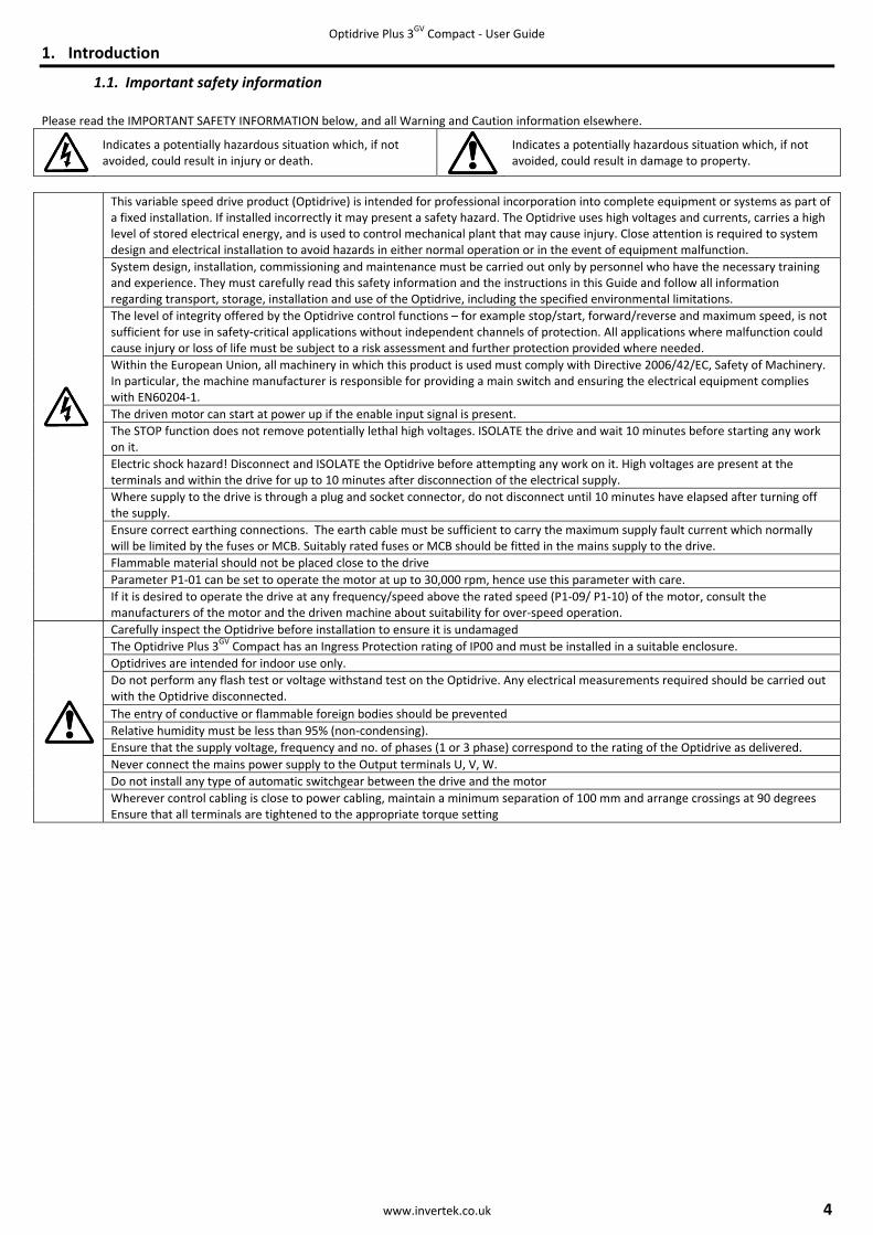
1.1. Important safety information Please read the IMPORTANT SAFETY INFORMATION below, and all Warning and Caution information elsewhere.
Indicates a potentially hazardous situation which, if not avoided, could result in injury or death.
Indicates a potentially hazardous situation which, if not avoided, could result in damage to property.
This variable speed drive product (Optidrive) is intended for professional incorporation into complete equipment or systems as part of a fixed installation. If installed incorrectly it may present a safety hazard. The Optidrive uses high voltages and currents, carries a high level of stored electrical energy, and is used to control mechanical plant that may cause injury. Close attention is required to system design and electrical installation to avoid hazards in either normal operation or in the event of equipment malfunction. System design, installation, commissioning and maintenance must be carried out only by personnel who have the necessary training and experience. They must carefully read this safety information and the instructions in this Guide and follow all information regarding transport, storage, installation and use of the Optidrive, including the specified environmental limitations. The level of integrity offered by the Optidrive control functions – for example stop/start, forward/reverse and maximum speed, is not sufficient for use in safety‐critical applications without independent channels of protection. All applications where malfunction could cause injury or loss of life must be subject to a risk assessment and further protection provided where needed. Within the European Union, all machinery in which this product is used must comply with Directive 2006/42/EC, Safety of Machinery. In particular, the machine manufacturer is responsible for providing a main switch and ensuring the electrical equipment complies with EN60204‐1. The driven motor can start at power up if the enable input signal is present. The STOP function does not remove potentially lethal high voltages. ISOLATE the drive and wait 10 minutes before starting any work on it. Electric shock hazard! Disconnect and ISOLATE the Optidrive before attempting any work on it. High voltages are present at the terminals and within the drive for up to 10 minutes after disconnection of the electrical supply. Where supply to the drive is through a plug and socket connector, do not disconnect until 10 minutes have elapsed after turning off the supply. Ensure correct earthing connections. The earth cable must be sufficient to carry the maximum supply fault current which normally will be limited by the fuses or MCB. Suitably rated fuses or MCB should be fitted in the mains supply to the drive. Flammable material should not be placed close to the drive Parameter P1‐01 can be set to operate the motor at up to 30,000 rpm, hence use this parameter with care. If it is desired to operate the drive at any frequency/speed above the rated speed (P1‐09/ P1‐10) of the motor, consult the manufacturers of the motor and the driven machine about suitability for over‐speed operation.
Carefully inspect the Optidrive before installation to ensure it is undamaged The Optidrive Plus 3GV Compact has an Ingress Protection rating of IP00 and must be installed in a suitable enclosure. Optidrives are intended for indoor use only. Do not perform any flash test or voltage withstand test on the Optidrive. Any electrical measurements required should be carried out with the Optidrive disconnected. The entry of conductive or flammable foreign bodies should be prevented Relative humidity must be less than 95% (non‐condensing). Ensure that the supply voltage, frequency and no. of phases (1 or 3 phase) correspond to the rating of the Optidrive as delivered. Never connect the mains power supply to the Output terminals U, V, W. Do not install any type of automatic switchgear between the drive and the motor Wherever control cabling is close to power cabling, maintain a minimum separation of 100 mm and arrange crossings at 90 degrees Ensure that all terminals are tightened to the appropriate torque setting

Optidrive Plus 3GV Compact ‐ User Guide
5 www.invertek.co.uk
2. Technical data
2.1. Environmental Operational ambient temperature range : ‐10 … 60°C, Frost and condensation free Storage ambient temperature range : ‐40 … 60°C Maximum altitude : 2000m. Derate above 1000m : 1% / 100m Maximum humidity : 95%, non‐condensing
2.2. Rating tables
200‐240V ±10% ‐ 1 Phase Input – 3 Phase Output, Without EMC Filter
Model kW HP Nominal Input Current
Fuse or
MCB (type B)
Supply Cable Size
Nominal Output Current
150% Output Current 60 secs
Motor Cable Size
Max Motor Cable Length
Amps Amps mm2 Amps Amps mm2 m OPC‐1‐12075‐1K01x 0.75 1 12.5 16 1.5 4.3 6.4 1 10 OPC‐1‐12150‐1K01x 1.5 2 14.8 16 1.5 7 10.5 1.5 10 200‐240V ±10% ‐ 1 Phase Input – 3 Phase Output, With EMC Filter
Model kW HP Nominal Input Current
Fuse or
MCB (type B)
Supply Cable Size
Nominal Output Current
150% Output Current 60 secs
Motor Cable Size
Max Motor Cable Length
Amps Amps mm2 Amps Amps mm2 m OPC‐1‐12075‐1KB1x 0.75 1 12.5 16 1.5 4.3 6.4 1 10 OPC‐1‐12150‐1KB1x 1.5 2 14.8 16 1.5 7 10.5 1.5 10
380‐480V ±10% ‐ 3 Phase Input – 3 Phase Output Without EMC Filter
Model kW HP Nominal Input Current
Fuse or MCB
(type B)
Supply Cable Size
Nominal Output Current
150% Output Current 60 secs
Motor Cable Size
Max Motor Cable Length
Amps Amps mm2 Amps Amps mm2 m OPC‐1‐14075‐3K01x 0.75 1 2.9 6 1 2.2 3.3 1 10 OPC‐1‐14150‐3K01x 1.5 2 5.4 6 1 4.1 6.1 1 10
380‐480V ±10% ‐ 3 Phase Input – 3 Phase Output With EMC Filter
Model kW HP Nominal Input Current
Fuse or MCB
(type B)
Supply Cable Size
Nominal Output Current
150% Output Current 60 secs
Motor Cable Size
Max Motor Cable Length
Amps Amps mm2 Amps Amps mm2 m OPC‐1‐14075‐3KA1x 0.75 1 2.9 6 1 2.2 3.3 1 10 OPC‐1‐14150‐3KA1x 1.5 2 5.4 6 1 4.1 6.1 1 10
2.3. Part Number Explanation OPC ‐ 1 ‐ 1 2 075 ‐ 1 K B 1 2 Product Family Enclosure 2 = IP00 Module OnlyGeneration N = IP55 Motor MountFrame Size S = IP55 Motor Mount with Pot & SwitchInput Voltage Rating 2 = 200 – 240 Volt + / ‐ 10% Brake Transistor 1 = No Brake Transistor 4 = 380 – 480 Volt + / ‐ 10% Filter Type 0 = No Internal FilterPower Rating 075 = 0.75kW A = Internal EMCFilter 150 = 1.5kW B = Internal EMC Filter Power Type K = kW Input Phases 1 = Single Phase Supply 3 = 3 Phase Supply

Optidrive Plus 3GV Compact ‐ User Guide
www.invertek.co.uk 6
3. Mechanical Installation
3.1. General Store the Optidrive in its box until required. Storage should be clean and dry and within the temperature range –40°C to +60°C The Optidrive must be installed in a pollution degree 1 or 2 environment
3.2. Mechanical dimensions and mounting – Compact Drive Module Top View Base View
Mounting Location Holes Four Total, located at each corner, 4.3mm Diameter suitable for M4 screws, 2.5Nm Max.
Power Connection End View Motor & Control Terminals End View
3.3. Enclosure mounting • The Optidrive Plus 3GV Compact is supplied in an IP20 enclosure, designed to be mounted by the user on a thermally conductive material
to dissipate the heat generated by the drive. Typically, this can be a motor or steel control panel. • The temperature of the heatsink and drive module must be maintained in the range ‐10 to + 65°C • The ambient temperature around the drive must not exceed 60°C • Typically power losses are approximately 3% of motor absorbed power • If the external environment contains contamination particles (e.g. dust), the unit should be suitably protected to ensure no damage can
occur. • High moisture, salt or chemical content environments should use a suitably sealed (non‐vented) enclosure.
66mm
120mm
106mm
104.5mm
91.5mm

Optidrive Plus 3GV Compact ‐ User Guide
7 www.invertek.co.uk
3.4. Mechanical Dimensions and Mounting – Optidrive PCE Motor Mount Top View (Switched version shown) Side View
End View

Optidrive Plus 3GV Compact ‐ User Guide
www.invertek.co.uk 8
3.5. Mounting the Optidrive PCE to a Motor In order to mount the enclosure onto a motor, a suitable adaptor place should be used. In general, this will require removal of the motor terminal box. A range of adaptor plates are available, as shown below :‐
Adaptor Plate Part Number OPT‐PCEAP‐01 Shallow Adaptor Plate
Adaptor Plate Part Number OPT‐PCEAP‐02 Deep Adaptor Plate

Optidrive Plus 3GV Compact ‐ User Guide
9 www.invertek.co.uk
3.6. Motor Mounting Guidelines Remove the motor terminal box and mount the adaptor plate to the motor.
Assemble the Adaptor Plate to the Motor Assemble the Enclosure to the Adaptor PLate

4. Po
GrounEach Oshould regulatThe OpindustrGrounIf a systper Opt
SafetyThis is ta floor
Connecand Derefer to
IncomiConnec For 3 PConnecFor 1 PConnec Protect Contro1 2
3 4
5 6
ower and C
4.1. Grou
This manuanon‐complipersonal inj
This OptidriOptidrive, eFailure to o
Only qualifiinstall, adjubefore proc
nding Guidelinptidrive shouldnot loop from tions. To meet Uptidrive Safety Grial safety regulnd Fault Monittem ground fautidrive.
y Ground the safety grouground rod, or 4.2. Wirin
ct the Optidriveelta. It is essentio section 4.5.
4.3. Connng Supply ctions
hase Drives, ct L1, L2, L3 hase Drives, ct L1 / L and L2
tive Earth
l Terminal Strip+ 24 Volt Com
Digital In
Digital InAnalog In
Analog In0 Volt Com
Control Con
unding the Dral is intended asance to any codjury and/or equ
ive contains higensure isolationbserve this preed electrical peust, operate, or ceeding. Failurenes d be individuallyone Optidrive tUL regulations, Ground must beations and/or etoring ult monitor is to
nd for the Optibus bar. Grounng Precautioe according to sial to ensure th
nection Diagr
/ N
p mmon nput 1
nput 2 nput 1
nput 2 mmon
nections
rive s a guide for prode, national, louipment exists
gh voltage capan of main supplyecaution could rersonnel familiaservice this eque to observe thi
y connected DIRto another, or tUL approved re connected to electrical codes
o be used, only
idrive that is rending points muons section 0, ensurat the motor is
ram – Non S
Optidrive Plu
ww
oper installatiocal or otherwisif codes are ign
acitors that takey from line inpuresult in severear with the conuipment. Read is precaution co
RECTLY to the sto, or from any ing crimp termsystem ground
s. The integrity
Type B devices
quired by codeust comply with
ring that motors connected in a
Switched Uni
us 3GV Compact
ww.invertek.co
n. Invertek Drivse, for the propnored during ins
e time to dischauts. Wait ten (1e bodily injury ostruction and oand understanould result in se
site ground busother equipmeinals should bed. Ground impeof all ground co
s should be use
e. One of these h national and l
r terminal box caccordance wit
its & Module
t ‐ User Guide
o.uk
ves Ltd cannot er installation ostallation.
arge after remo10) minutes for or loss of life. operation of thid this manual aevere bodily inj
s bar (through tent. Ground looe used for all groedance must coonnections sho
d to avoid nuis
points must belocal industrial
connections areh the voltage a
es
assume responof this drive or
oval of main supcapacitors to d
s equipment anand other appliury or loss of li
he filter if instaop impedance mound wiring cononform to the reuld be checked
ance tripping. A
e connected to safety regulatio
e correct. Theret which it will b
nsibility for the associated equ
pply. Before wodischarge to saf
nd the hazards cable manuals fe.
alled). Optidrivemust confirm tonnections. equirements ofd periodically.
An individual de
adjacent buildions and/or elec
e are two connebe operated. Fo
compliance or ipment. A haza
orking on the fe voltage levels
involved shoulin their entiret
e ground conneo local industria
f national and lo
evice should be
ng steel (girderctrical codes.
ections in geneor more informa
Motor Connec (Fast On Type
Control TerStrip
Volt Free Relay Output
10
the ard of
s.
d ty
ections al safety
ocal
e used
r, joist),
ral: Star ation,
ctions
)
rminal
7 8

11
For 1 pFor 3 pThe mo
Most g This ophigher
4.4. Drivehase supply pohase supplies potor should be c
4.5. Motoeneral purpose
perational voltaof the two volt
4.6. ContrControl Terminal
1 +2
2 D
3 D
4 A(o
5 A(o
6 0V
7 R
8 R
e and motor ower should be power should bconnection to tor Terminal Be motors are wo
ge is normally sage ratings.
Incoming
rol terminal Signal
24V User Outpu
Digital Input 1
Digital Input 2
nalog Input 1 or Digital Input Analog Input 2 or Digital Input
V
elay Common
elay NO Contac
connectionsconnected to Le connected tothe U, V, and WBox Connectound for operat
selected when
g Supply Voltag
230
400
400
connections
ut, +24V, 10
Positive “Logic 1”“Logic 0”Input : P“Logic 1”“Logic 0”
3) Digital: 8Analog:
4) Analog: Digital:
User gro
ct Contact
Optidrive Plu
ww
s L1/L, L2/N Screwo L1, L2, and L3W ‘Fast On’ termtions tion on dual vo
installing the m
e Motor Na
2
4
2
s Desc
00mA user cont
logic ” input voltage” input voltagePositive logic ” input voltage” input voltage8 to 30V 0 to 24V, 0 – 100 to 10V, 0 to 28 to 30V DC
ound connected
250Vac, 6A / 3
us 3GV Compact
ww.invertek.co
w Terminals. Screw Termina
minals.
oltage supplies.
motor by selecti
meplate Voltag
230 / 400
400 / 690
230 / 400
cription
trol output
range: 8V … 30 range: 0V … 4V
range: 8V … 30 range: 0V … 4V
0V, ‐10 ‐ +10V, 20mA or 4 to 20
d terminal 7
0Vdc, 5A
t ‐ User Guide
o.uk
als. Phase sequ
This is indicate
ing either STAR
ges Connect
Delta
Star
0V DC V DC
0V DC V DC
‐24 ‐ +24V 0mA
uence is not imp
ed on the name
R or DELTA conn
tion
De
portant.
eplate of the mo
nection. STAR a
efault Connectio
otor
always gives th
ons
e

The tabare not
Switch Po
(Pr
(Pr
(Analog
Ru
Ru
5. O
The Opsoftwa
ProceduPower o
The pa
4.7. Settinble below showt recommended
osition
Run eset Speed 1, P
Run eset Speed 2, P
Run ReverseRun Reverse
Run Input 2 Speed
un in Speed Con
un in Speed Con
Operation
ptidrive should re. 5.1. Optio
NAVIGATE
UP
DOWN
RESET / STOP
START
Chanure on Drive
arameter value
ngs for typicws the recommed unless using e
P1‐11)
P2‐02) e e
Reference)
ntrol
ntrol
be configured p
onal Optipor
Used to disparameter
Used to incparameter
Used to deparameter
Used to resWhen in Ke
When in kereverse themode is en
nging Param
The anS
Use th
is now adjuste
cal Run / Stoended parametexternal contro
Stop
Stop
Stop Stop
Stop
Stop
Stop
prior to first op
rt Plus Keypa
splay real‐time edit mode and
crease speed invalues in param
ecrease speed invalues in param
set a tripped dreypad mode is
eypad mode, use direction of ronabled
eters
Press and hold
Press
nd can bSelect the requ
Press t
he and k
Press
ed and automatop
Optidrive Plu
ww
op switch coner settings for ul wiring, as the
Run Forw(Pot Speed Ref
Run(Preset Speed 1
Run ForwRun Forw
Run(Pot Speed Ref
Run in PID C
Run in PID C
eration via the
ad
information, tod to store param
n real‐time modmeter edit mod
n real‐time modmeter edit mod
rive. used to Stop a
sed to Start a stotation if bi‐dir
the for >
s the Key
e used to selecired parameter
the butto
keys to adjust t
s the key
tically stored. Perating mode
us 3GV Compact
ww.invertek.co
nfigurations use with the swir functions are
P1
ward ference)
1, P1‐11) ward ward
ference)
ontrol
ontrol
optionally avai
o access and exmeter changes
de or to increasde
de or to decreade
running drive.
topped drive orectional keypad
>2 seconds
y
t the desired pr, e.g. P1‐02
on
the value, e.g. s
y
Press the
t ‐ User Guide
o.uk
(Enclosed Swwitched enclosue not designed t
1‐12 P2‐0
0 0
0 1, 2
0 30 5
0 19
3 17
3 11
ilable Optiport
xit
e
ase
r to d
arameter
set to 10
key for >2 seco
witched Versure. Other parato operate with
1 Notes Factory Preset Sdefine th
Preset Sdefine thPotentioPreset SAnalog I
In SpeedIn PID CoIn SpeedIn PID Co
Plus remote ke
onds to return
sion) meter settings h the internal sw
Default ConfiguSpeed can be pohe direction of Speeds can be phe direction of ometer Speed RSpeed 1 (P1‐11)nput required,
d Control, Pot control, pot cond Control, P1‐11ontrol, pot con
eypad, or Optiw
Display s
P
to
are possible, wwitch wiring.
uration ositive or negatrotation positive or negarotation Reference Speed Referenconnect to ter
controls speedtrols setpoint 1 sets the Presetrols setpoint
wand PDA Pocke
shows... Stop
P1-01
P1-02
P1-03 etc...
P1-02
0.0
10.0
P1-02
Stop
12
which
tive to
ative to
nce minal 5.
et Speed
et PC

13
To resebutton
When ddefault
• • • • • • •
•
• •
•
•
•
• • •
To allow• •
•
•
•
•
• •
•
•
• •
•
•
•
•
5.3. Reset
et all Optidrive to acknowledg5.4. Term
delivered, the Ot values as indic
Connect theConnect theEnter the mConnect a coConnect a p
With the poClose the copotentiome
On first enacontrol swit
Following coTurn the pot
control of thIf the potenof the decelpotentiome
To display m
Press a
Press aTo stop the
If the enable5.5. Keyp
w the OptidriveConnect the
Enable the O
Press the
above. On c
Press t
The Optidriv
Press in P1‐04
Press the
The display
To preset a
the &
Pressing the
To allow theOperation is
Press the
Press t
The Optidrivspeed is the
To reverse t
t All Parame
parameters to ge and reset theminal ControlOptidrive is in tcated in sectione Optidrive to the motor to the Ootor data fromontrol switch botentiometer (
otentiometer seontrol switch, teter.
ble from factorch closed an al
ompletion of thtentiometer to
he accelerationtiometer is turneration ramp Pter.
motor current (A
again to display
again to return motor, disable
e/disable switcpad Control e to be controlle supply and mo
Optidrive by clo
key. If this i
ompletion of th
to increase spe
ve will run forw
to decrease sp
key. The Op
will finally show
target speed pr
keys to ad
e key will
e Optidrive to bs the same as w
key. The di
to increase spe
ve will run forwe speed set in P
the direction of
eters to Facto
factory default e Optidrive. l he factory defan 6 Parameters.he supply, ensuOptidrive, ensu motor namepletween the con1kΩ min to 10
et to zero, switcerminals 1‐2. Th
ry default paramlow this to com
he Autotune, th maximum. The
ramp time P1‐ned to minimumP1‐04. The outp
Amps), briefly p
y the motor pow
to speed displathe Optidrive b
h is opened the
ed from the keotor as for term
osing the switch
is the first enab
he Autotune, th
ed.
ward, increasing
eed. The Optid
ptidrive will dec
w StoP at whi
rior to enable, p
djust as require
start the Optid
be controlled frowhen P1‐12=1 fo
isplay changes t
ed
ward, increasing1‐01.
f rotation of the
Optidrive Plu
ww
ory Default S
settings, press
ault state, mean. uring the correcuring the correclate; P1‐07 = mntrol terminals kΩ max) betwe
ch on the supplyhe Optidrive is
meters, the Optmplete.
e display showe motor will acc
‐03. The displaym, the motor wput speed can b
press the (
wer.
ay. by opening the
e Optidrive will
ypad in a forwaminal control ab
h between cont
ble from factory
he display show
g speed until
rive will decrea
celerate to rest
ich point the Op
press the
ed then press th
drive acceleratin
om the keypador start, stop an
to H 00.
g speed until
e motor, press t
us 3GV Compact
ww.invertek.co
Settings
s , and
ning that it is se
ct voltage and fct star/delta conotor rated volt1 and 2 ensurieen terminals 5
y to the Optidrnow ‘enabled’
tidrive will carr
ws zero speed incelerate to 50H
y shows 50Hz (Hwill decelerate tbe adjusted any
(Navigate) key.
control switch
decelerate to s
ard direction onbove.
trol terminals 1
y default param
ws H 00.
is released.
ase speed until
t at the rate set
ptidrive is disab
key whilst the
he key to
ng to the target
in a forward annd changing sp
is released.
the key a
t ‐ User Guide
o.uk
d for >2s.
et to operate in
fusing / circuit bnnection for theage, P1‐08 = mng that the con and 7, and the
ive. The displayand the output
y out an Autotu
n Hz (H 00) Hz, (60Hz for US
H 500) at to 0Hz, the defawhere between
(terminals 1‐2)
stop at which ti
nly, set P1‐12 =
1 & 2. The displa
meters, the Opti
is release
in P1‐04.
bled
Optidrive is sto
return the disp
t speed.
nd reverse direeed.
Acceleration is
again.
The display sh
terminal contr
breaker protecte voltage ratingotor rated currntact is open (de wiper to term
y will show Stot frequency/spe
une, and the di
with the potenSA drives), the d
max speed. ault minimum sn minimum and
).
ime the display
1:
ay will show St
idrive will carry
ed. The rate of
opped. The disp
play to StoP.
ection, set P1‐12
s limited by the
hows ìP-dEFî
rol mode and a
tion – see sectiog ‐ see section 0rent, P1‐09 = mrive disabled). inal 6.
oP. eed are control
splay shows Au
ntiometer turnedefault value of
speed set in P1‐d maximum spe
y will show Sto
toP.
y out an Autotu
deceleration is
play will show t
2 =2:
e setting in P1‐0
. Press the
ll parameters h
on 2.2 on page 0 on page 11. otor rated freq
led by the
uto-t. Leave
ed to minimumf P1‐01, under t
‐02, under the ceed using the
oP.
ne as described
s limited by the
he target speed
03. The maximu
have the
5.
quency.
the
m. the
control
d
setting
d, use
um

Optidricontroloperate
AutotuFollowi(Motor
automaprocedand no User SThe useEnsure Set P1‐
Set P4‐
Optidrispeed rprovideEnsure FrequeSet P1‐The Mofor guidSet P4‐Set P4‐Paramedetails,
For appoperatestoppin
5.6. Motove Plus uses a sl method requires correctly, an
Whilst theuncouple
une after Facting a factory rer Rated Current
atically carry ouure may take s further autotuSelected Autoer can programthe motor nam14 = 101 to allo
02 = 1 and pres
The autotthe motorrisk arises
5.7. Operve Plus can be regulation regae adequate perthe motor namncy) 14 = 101 to allootor Rated Powdance. 01 = 0 to select02 = 1 to carry eters P4‐03 and, or the Optidriv
The autotthe motorrisk arises
5.8. Sensoplications whiche in Torque Conng. Please refer
or Autotuninsophisticated Vres the Optidrivnd reduce the ri
e autotune procthe load from t
tory Reset or set (See sectiont) and P1‐09 (M
ut an autotune everal minutesuning will be reqtune
m the Optidrive tmeplate values ow access to Pa
ss the but
une will begin ir shaft may turns from the poss
rating in Senprogrammed brdless of load aformance, howmeplate values
ow access to pawer Factor from
t Sensorless Veout an motor ad P4‐04 have a sve Plus Advanc
une will begin ir shaft may turns from the poss
orless Vectoh require the Ontrol mode. Whr to the Optidriv
ng Voltage Vector Cve to carry out isk of nuisance
cedure does nothe motor; how
from Factoryn 5.3), the corre
Motor Rated Fre
on the motor ts to complete dquired unless th
to carry out an are correctly enarameter Group
tton.
immediately wn. It is not normible movement
sorless Vectby the user to oand accurate cowever if Sensorlare correctly en
arameter group the motor nam
ctor Speed Conautotune significant effeced User Guide.
immediately wn. It is not normible movement
r Torque Conptidrive to conthen operating tve Plus Advance
Optidrive Plu
ww
Control Methodan autotune totripping.
ot drive or spin wever the user s
y Set Parametect data from tquency). Provid
the first time it epending on thhe motor or dri
autotune if reqntered as descrps 2, 3 and 4
hen P4‐02 is semally necessaryt of the motor s
tor Speed Coperate in Sensoontrol of the moess Vector opentered in P1‐07
ps 2, 3 and 4 meplate MUST b
ntrol
ct on the behav
hen P4‐02 is semally necessaryt of the motor s
ntrol Modetrol motor torqthis way, the dred User Guide f
us 3GV Compact
ww.invertek.co
d as a factory do measure certa
the motor, theshould ensure t
ers he motor nameding that P1‐08
is enabled. Durhe motor. Onceive control mod
quired, as followribed above.
et to 1, and no ey to uncouple thshaft.
ntrol Mode orless Vector motor torque. In ration is requir7 (Motor Rated
be entered in P
viour of the mo
et to 1, and no ey to uncouple thshaft.
que as opposedrive internal ramfor further info
t ‐ User Guide
o.uk
efault setting tain motor param
motor shaft mthat no risk aris
eplate should b8 is adjusted fro
ring the autotu the autotune ide is changed (P
ws:‐
external enablehe load from th
mode, which promost applicatioed, the followinVoltage), P1‐08
P4‐05. If this dat
otor when oper
external enablehe load from th
to motor speemp times (P1‐03ormation on this
o ensure best pmeters prior to
may still turn. It ses from the po
be entered in P1om the factory d
ne, the display is completed, thP4‐01).
e signal is require motor; howe
ovides enhanceons, the defaultng procedure s8 (Motor Rated
ta is not availab
ating in vector
e signal is require motor; howe
ed, the Optidriv3 and P1‐04) ars.
possible motor operation, to e
is not normallyossible moveme
1‐07 (Motor Radefault setting,
will show Authe Optidrive wi
red. During theever the user sh
ed low speed tot Voltage Vectohould be followd Current) and P
ble, consult the
mode, see sect
red. During theever the user sh
e Plus can be pre disabled exce
operation. Thisensure this func
necessary to ent of the moto
ted Voltage), Pthe Optidrive w
o-t. The test ill operate as no
e autotune prochould ensure th
orque, optimumor control modewed:‐ P1‐09 (Motor R
e motor manufa
tion 1.1 for furt
e autotune prochould ensure th
programmed to ept during start
14
s ction
or shaft.
P1‐08 will
ormal,
cedure, at no
m motor e will
Rated
acturer
ther
cedure, at no
ting and
Optidrive Plus 3GV Compact ‐ User Guide
15 www.invertek.co.uk
6. Parameters
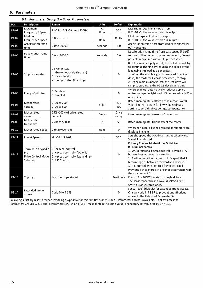
6.1. Parameter Group 1 – Basic Parameters
Following a factory reset, or when installing a Optidrive for the first time, only Group 1 Parameter access is available. To allow access to Parameters Groups 0, 2, 3 and 4, Parameters P1‐14 and P2‐37 must contain the same value. The factory set value for P2‐37 = 101
Par. Description Range Units Default Explanation
P1‐01 Maximum Frequency / Speed
P1‐02 to 5*P‐09 (max 500Hz) Hz Rpm
50.0 Maximum speed limit – Hz or rpm. If P1‐10 >0, the value entered is in Rpm
P1‐02 Minimum Frequency / Speed
0.0 to P1‐01 Hz Rpm
0.0Hz Minimum speed limit – Hz or rpm. If P1‐10 >0, the value entered is in Rpm
P1‐03 Acceleration ramp time
0.0 to 3000.0 seconds 5.0 Acceleration ramp time from 0 to base speed (P1‐09) in seconds
P1‐04 Deceleration ramp time
0.0 to 3000.0 seconds 5.0 Deceleration ramp time from base speed (P1‐09) to standstill in seconds. When set to zero, fastest possible ramp time without trip is activated
P1‐05 Stop mode select
0 : Ramp stop (brown‐out ride‐through) 1 : Coast to stop 2 : Ramp to stop (fast stop)
‐ 0
0 : If the mains supply is lost, the Optidrive will try to continue running by reducing the speed of the load using the load as a generator. 1 : When the enable signal is removed from the drive, the motor will coast (freewheel) to stop 2 : If the mains supply is lost, the Optidrive will ramp to stop using the P2‐25 decel ramp time
P1‐06 Energy Optimiser 0: Disabled 1: Enabled
‐ 0 When enabled, automatically reduces applied motor voltage on light load. Minimum value is 50% of nominal
P1‐07 Motor rated voltage
0, 20 to 250 0, 20 to 500
Volts 230 400
Rated (nameplate) voltage of the motor (Volts). Value limited to 250V for low voltage drives. Setting to zero disables voltage compensation
P1‐08 Motor rated current
25% ‐100% of drive rated current
Amps Drive rating
Rated (nameplate) current of the motor
P1‐09 Motor rated frequency
25Hz to 500Hz Hz 50 Rated (nameplate) frequency of the motor
P1‐10 Motor rated speed 0 to 30 000 rpm Rpm 0 When non‐zero, all speed related parameters are displayed in rpm
P1‐11 Preset Speed 1 ‐P1‐01 to P1‐01 Hz 50.0 Sets the speed the Optidrive runs at when Preset Speed 1 is selected
P1‐12
Terminal / Keypad / PID Drive Control Mode Selection
0.Terminal control 1. Keypad control – fwd only 2. Keypad control − fwd and rev3. PID Control
‐ 0
Primary Control Mode of the Optidrive. 0 : Terminal control 1 : Uni‐directional keypad control. Keypad START button does not reverse direction. 2 : Bi‐directional keypad control. Keypad START button toggles between forward and reverse. 3 : PID control with external feedback signal
P1‐13 Trip log Last four trips stored ‐ Read only
Previous 4 trips stored in order of occurrence, with the most recent first. Press UP or DOWN to step through all four. The most recent trip is always displayed first. UV trip is only stored once.
P1‐14 Extended menu access
Code 0 to 9 999 ‐ 0 Set to “101” (default) for extended menu access. Change code in P2‐37 to prevent unauthorised access to the Extended Parameter Set

Optidrive Plus 3GV Compact ‐ User Guide
www.invertek.co.uk 16
6.2. Parameter Group 2 ‐ Extended parameters Par. Description Range Units Default Explanation
P2‐01 Digital input function select
0 to 22 ‐ 0
Defines the function of the digital inputs depending on the control mode setting in P‐12. See section 7 Analog and Digital Input Configurations for more information.
P2‐02 Preset Speed 2 ‐P1‐01 to P1‐01 Hz 0.0 Sets jog / preset speed 2 P2‐03 Preset Speed 3 ‐P1‐01 to P1‐01 Hz 0.0 Sets jog / preset speed 3 P2‐04 Preset Speed 4 ‐P1‐01 to P1‐01 Hz 0.0 Sets jog / preset speed 4 P2‐05 Preset Speed 5 ‐P1‐01 to P1‐01 Hz 0.0 Sets jog /preset speed 5 P2‐06 Preset Speed 6 ‐P1‐01 to P1‐01 Hz 0.0 Sets jog / preset speed 6 P2‐07 Preset speed 7 ‐P1‐01 to P1‐01 Hz 0.0 Sets jog / preset speed 7 P2‐08 Preset speed 8 ‐P1‐01 to P1‐01 Hz 0.0 Sets jog / preset speed 8
P2‐09 Skip frequency P1‐02 to P1‐01 Hz 0.0 Centre point of skip frequency band set up in conjunction with P2‐10
P2‐10 Skip frequency band 0.0 to P1‐01 Hz 0.0 Width of skip frequency band centred on frequency set in P2‐09
P2‐11 Reserved P2‐12 Reserved
P2‐13 User Relay Output Function Select
0 : Drive enabled 1 : Drive healthy 2 : Motor at target speed 3 : Motor Speed >0 4 : Motor speed >= limit 5 : Motor torque >= limit 6 : 2nd Analog Input >= limit
1
Selects the function assigned to the relay output. 0 : Logic 1 when the drive is enabled (Running) 1: Logic 1 When no Fault condition exists on the drive 2 : Logic 1 when the motor speed matches the setpoint speed 3 : Logic 1 when the motor runs above zero speed Options 4 to 6 : the Digital output is enabled using the level set in P2‐14h and P2‐14L
P2‐14h Relay Output Control High Limit
0.0 to 200.0 % 100.0 With P2‐13 = 4 to 6, the User Relay Output is set to Logic 1 (+24V DC) when the value set in P2‐14h is exceeded, and returns to Logic 0 (0V) when the selected value reduces below the limit set in P2‐12L
P2‐14L Relay Output Control Low Limit
0.0 to 200.0 % 100.0
P2‐15 Relay Output Mode 0 : Normally Open 1 : Normally Closed
‐ 0
Inverts the operating status of the User Relay 0 : Logic 1 = Relay Contacts Closed 1 : Logic 1 = Relay Contacts Open The Optidrive must be powered for the contacts to close
P2‐16 Zero Speed Holding Time
0.0 to 60.0 s 0.2 Determines the time for which the Optidrive output is held at zero speed when stopping, before the drive output is disabled
P2‐17 Start Mode Select Edge-r
Auto-0
Auto-1 to 5 ‐ Auto-0
Edge‐r : Following Power on or reset, the Optidrive will not start if Digital Input 1 remains closed. The Input must be closed following a power on or reset to start the drive. Auto‐0 : Following a Power On or Reset, the Optidrive will automatically start if Digital Input 1 is closed. Auto 1 to 5 : Following a Fault, the Optidrive will make up to 5 attempts to restart at 20 second intervals. The drive must be powered down to reset the counter
P2‐18 Reserved ‐ ‐ No Function
P2‐19 Keypad Restart Mode
0 : Minimum Speed, Edge‐r 1 : Previous Speed, Edge‐r 2 : Minimum Speed, Auto‐r 3: Previous Speed, Auto‐r
‐ 0
Active when P1‐12 = 1 or 2 0 : Following a stop and restart, the Optidrive will run at minimum speed 1 : Following a stop and restart, the Optidrive will run at the last setpoint speed 2 : As per setting 0, except that the Run command will be determined by the status of Digital Input 1, and the user is not required to press the keypad start button 3 : As per setting 1, except that the Run command will be determined by the status of Digital Input 1, and the user is not required to press the keypad start button
P2‐20 Standby Mode 0.0 : Disabled 0.1 to 60
s 0.0 When P2‐20 >0, the Optidrive enters standby mode if the minimum speed is maintained for the time period set in P2‐20

Optidrive Plus 3GV Compact ‐ User Guide
17 www.invertek.co.uk
Par. Description Range Units Default Explanation
P2‐21 Display Scaling Factor
0.000 to 30.000 ‐ 0.000 Disabled if P2‐21 is set to 0. If P2‐21 is set >0, the variable selected in P2‐22 is multiplied by the factor entered in P2‐21, and displayed whilst the Optidrive is running
P2‐22 Display Scaling Source
0 : 2nd Analog Input 1 : Motor Speed 2 : Motor Torque 3 : Motor Current
‐ 0
P2‐24 Effective Switching Frequency
4 to 16 / 24 / 32 Drive Power Rating Dependent
kHz 16 8
Effective power stage switching frequency. Higher frequencies reduce the audible ‘ringing’ noise from the motor, and improve the output current waveform, at the expense of increased drive losses
P2‐25 2nd Deceleration Ramp time
0.0 to 30.0 s 0.0
Deceleration 2nd ramp down time Selected Automatically on mains power loss if P1‐05 = 2 Can also be selected by digital inputs, dependent on P2‐01 setting. When set to 0, the Optidrive decelerates as quickly as possible, whilst preventing an overvoltage trip
P2‐26 Reserved ‐ ‐ No Function
P2‐27 Drive Communication Address
0: Disabled 1 to 63
‐ 1 Sets the communication address for the drive when connected on an Optibus Network
P2‐28 Master / Slave Mode Select
0 : Slave Mode 1 : Master Mode
‐ 0
When in Master Mode, the Optidrive transmits its operational status via the serial data link. All Optidrives on the data link must have unique addresses. Only one Optidrive can be programmed as a Master
P2‐29 Digital / Slave speed reference scaling factor
0.0 to 500.0 % 100.0
Scaling factor applied to any speed reference on the serial data link, e.g. in Master / Slave operation, a Slave Optidrive will apply this scaling factor to the transmitted Master speed reference
P2‐30 Analog Input 1 format
U 0-24 = 0 ‐ 24V DC
U 0-10 = 0 ‐ 10V DC ‐ V 0-24
Configures the analog input signal to match the reference connected to terminal 6. Only voltage signals can be directly connected, mA reference signals require an external resistor connection.
P2‐31 Analog Input 1 scaling
0.0 to 500.0 % 100.0
Scales the analog input by this factor, e.g. if P2‐30 is set for 0 – 10V, and the scaling factor is set to 200.0%, a 5 volt input will result in the drive running at maximum speed (P1‐01)
P2‐32 Analog Input 1 offset ‐500.0 to 500.0 % 0.0 Sets an offset, as a percentage of the full scale range of the input, which is applied to the analog input signal
P2‐33 Analog Input 2 format
D 0-24 = Digital
U 0-10 = 0 to 10V DC A 4-20 = 4 to 20mA
A0-20 = 0 to 20mA
‐ D 0-24 Selects the format for the 2nd analog input Selecting d 0-24 sets the input up as a digital input
P2‐34 Analog Input 2 scaling
0.0 to 500.0 % 100.0 Scales the 2nd analog input by the factor set in this parameter
P2‐35 Digital speed reference scaling control
0 : Disabled (No Scaling) 1 : Scaled by P2‐29 2 : Scaled by P2‐29, then bipolar analog input added as an offset 3 : Scaled by P2‐29 and by bipolar analog input
‐ 0
Active in Keypad mode (P1‐12 = 1 or 2) and Master / Slave mode only. 1 : Actual Speed = Digital Speed x P2‐29 2: Actual Speed = (Digital Speed x P2‐29) + bipolar analog reference 3 : Actual Speed = Digital Speed x P2‐29 x bipolar analog reference
P2‐36 Reserved ‐ ‐ No Function
P2‐37 Extended menu access code
0 to 9999 ‐ 101 Defines the access code which must be entered in P1‐14 to access parameter groups above Group 1
P2‐38 Parameter Lock 0 : Unlocked 1 : Locked
‐ 0 When locked, all parameter changes are prevented
P2‐39 Hours Run Counter 0 to 99999 Hours ‐ Indicates the number of hours for which the Optidrive has run
P2‐40 Drive Type / Rating N/A ‐ ‐ Read only parameter, showing the Optidrive type and power rating

Optidrive Plus 3GV Compact ‐ User Guide
www.invertek.co.uk 18
6.3. Parameter Group 3 – PID Control
Parameter Group 4 – High Performance Motor Control
Par. Description Range Units Default Explanation
P3‐01 Proportional gain 0.1 to 30.0 ‐ 2.0
PID Controller Proportional Gain. Higher values provide a greater change in the Optidrive output frequency in response to small changes in the feedback signal. Too high a value can cause instability
P3‐02 Integral time constant
0.0 to 30.0 s 1.0 PID Controller Integral Time. Larger values provide a more damped response for systems where the overall process responds slowly
P3‐03 Differential time constant
0.00 to 1.0 s 0.00 PID Differential Time Constant
P3‐04 PID operating mode 0 : Direct 1 : Inverse
‐ 0
Direct operation – Motor speed increases with an increase in the feedback signal Inverse Operation – Motor speed decreases with an increase in the feedback signal
P3‐05 PID Setpoint / reference select
0 : Digital 1 : Analog
‐ 0 Selects the source for the PID Reference / Setpoint 0 : P3‐06 is used 1 : Bipolar analog input is used
P3‐06 PID digital reference 0.0 to 100.0 % 0.0 Sets the preset digital PID reference / setpoint
P3‐07 PID controller high limit output
P3‐08 to 100.0 % 100.0 Limits the maximum value output from the PID controller
P3‐08 PID controller low limit output
0.0 to P3‐07 % 0.0 Limits the minimum output from the PID controller
P3‐09 User PID output limit / function control
0 : Digital output limits 1 : Analog Upper Limit 2: Analog Lower Limit 3 : PID added to Bipolar analog input reference
‐ 0
0 : PID output range limited by P3‐07 & P3‐08 1 : PID maximum output limited by the signal applied to the bipolar analog input 2: PID minimum output limited by the signal applied to the bipolar analog input 3: PID output is added to the speed reference applied to the bipolar analog input
P3‐10 PID feedback source select
0 : 2nd Analog Input 1 : Bipolar analog input
‐ 0 Selects the source of the PID feedback signal
Par. Description Range Units Default Explanation
P4‐01 Control Mode 0 : Vector Speed Control 1 : Vector Torque Control 2 : V/F Speed Control
‐ 2 Selects the motor control method. An autotune must be performed following a change, see section 6.4
P4‐02 Motor parameter autotune
0 : Disabled 1 : Enabled
‐ 0 When set to 1, the Optidrive immediately carries out a non‐rotating autotune to measure the motor parameters for optimum control and efficiency
P4‐03 Speed controller proportional gain
0 to 4096 ‐ 300 Sets the proportional gain value for the speed controller. Higher values provide better output frequency regulation and response. Too high a value may cause instability
P4‐04 Speed controller integral time
0.050 to 1.000 seconds 0.050 Set the integral time for the speed controller. Smaller values provide a faster response in reaction to motor load changes, at the risk of introducing instability
P4‐05 Motor power factor
0.50 to 1.00 ‐ ‐ Motor nameplate power factor, which must be entered for Vector operation (P4‐01 = 0 or 1)
P4‐06 Torque reference source select
0 : Preset Value 1 : Bipolar analog input 2 : 2nd analog input
‐ 0 When operating in vector mode (P4‐01 = 0 or 1), selects the source of the torque reference
P4‐07 Maximum torque limit / torque reference
0.0 to 200.0 % 200.0 If P4‐01 = 1 and P4‐06 = 0, sets the preset torque reference If P4‐01 = 0, sets the maximum torque limit
P4‐08 Minimum torque limit
0.0 to 150.0 % 0.0 Sets a minimum torque limit, see the warning below
P4‐09 V/F characteristic adjustment frequency
0.0 to P1‐09 Hz 0.0
When operating in V/F mode (P4‐01 = 2), sets a frequency point at which the voltage applied in P4‐10 is applied to the motor. Care must be taken to avoid over heating and damaging the motor when using this feature
P4‐10 V/F characteristic adjustment voltage
0 to P1‐07 ‐ 0 In conjunction with P4‐09, in V/F mode (P4‐01 = 2), sets the voltage applied to the motor at the adjustment frequency set in P4‐09
Incorrect adjustment of parameters in menu group 4 can cause unexpected behaviour of the motor and any connected machinery. It is recommended that these parameters are only adjusted by experienced users

Optidrive Plus 3GV Compact ‐ User Guide
19 www.invertek.co.uk
6.4. Parameter Group 0 – Monitoring Parameters (Read Only) Par. Description Display range Units Explanation P0‐01 Bipolar analog input value 0 to 100 % 100% = max input voltage P0‐02 2nd Analog input value 0 to 100 % 100% = max input voltage P0‐03 Post Ramp Speed Reference ‐500 to 500 % 100% = P1‐09 P0‐04 Digital speed reference ‐P1‐01 to P1‐01 Hz / Rpm Digital speed reference P0‐05 Torque controller reference 0 to 200 % Torque reference setpoint P0‐06 PID Reference 0 to 100 % PID reference / setpoint P0‐07 PID Feedback 0 to 100 % PID controller feedback value P0‐08 PID error 0 to 100 % Actual PID error P0‐09 PID P Term 0 to 100 % Proportional component P0‐10 PID I term 0 to 100 % Integral component P0‐11 PID D term 0 to 100 % Differential component P0‐12 PID Output 0 to 100 % Output from PID controller P0‐13 Output Torque 0 to 200 % 100% = motor rated torque P0‐14 Magnetising current Drive dependent A Motor rms magnetising current P0‐15 Rotor Current Drive dependent A Rotor rms current P0‐16 Field Strength 0 to 100 % Magnetic field strength P0‐17 Stator resistance Drive dependent Ohms Phase to phase stator resistance P0‐18 Stator Inductance Drive dependent H Stator inductance P0‐19 Rotor resistance Drive dependent Ohm Calculated rotor resistance P0‐20 DC Bus Voltage 0 to 1000 Volts Internal DC Bus voltage P0‐21 Drive Temperature 0 to 120 ºC Measured heatsink temperature P0‐22 Reserved ‐ ‐ P0‐23 Reserved ‐ ‐ P0‐24 Reserved ‐ ‐ P0‐25 Estimated rotor speed Drive dependent Hz / Rpm In vector mode, estimated speed of motor P0‐26 kWh meter 0 to 999.9 kWh Cumulative energy consumption P0‐27 MWh meter 0 to 60,000 MWh Cumulative energy consumption P0‐28 Software ID – IO Processor Drive dependent ‐ Version number & checksum P0‐29 Software ID – Motor Control Drive dependent ‐ Version number & checksum P0‐30 Drive serial number Drive dependent ‐ Unique drive serial number

Optidrive Plus 3GV Compact ‐ User Guide
www.invertek.co.uk 20
7. Analog and Digital Input Configurations
7.1. Terminal mode (P1‐12 =0)
P2‐01 Digital input 1 (T2) Digital input 2 (T3) Analog Input 1 (T4)(or Digital Input 3)
Analog input 2 (T5)(or Digital Input 4)
0 Open: Stop (disable) Closed: Run (enable)
Open : Bipolar analog speed refClosed : Preset speed ref
Bipolar Analog Input Open : Preset Speed 1Closed : Preset Speed 2
1 Open: Stop (disable) Closed: Run (enable)
Open: Preset Speed 1Closed: Preset speed 2
Open : Preset Speed 1 / 2 / 3Closed : Preset Speed 4
Open : Preset Speed 1 / 2Closed : Preset Speed 3
2 Open: Stop (disable) Closed: Run (enable)
Digital Input 2 Digital Input 3 Digital Input 4 Speed SetpointOpen Open Open Preset Speed 1Closed Open Open Preset Speed 2Open Open Closed Preset Speed 3Closed Open Closed Preset Speed 4Open Closed Open Preset Speed 5Closed Closed Open Preset Speed 6Open Closed Closed Preset Speed 7Closed Closed Closed Preset Speed 8
3 Open: Stop (disable) Closed: Run (enable)
Open : Forward Closed : Reverse
Bipolar Analog Input Open: Bipolar analog ref Closed: Preset Speed 1
4 Open: Stop (disable) Closed: Run (enable)
Open : Forward Closed : Reverse
Bipolar Analog Input Analog input 2(E.g. Torque reference)
5 Open: Stop (disable) Closed: Run (enable)
Open : Forward Closed : Reverse
Digital Input 3 Digital Input 4 Speed SetpointOpen Open Preset Speed 1Open Closed Preset Speed 2Closed Open Preset Speed 3Closed Closed Preset Speed 4
6 Open: Stop (disable) Closed: Run (enable)
Open : Forward Closed : Reverse
Bipolar Analog Input External trip input :Open: Trip, Closed: No Trip
7 Open: Stop (disable) Closed: Fwd Run (enable)
Open: Stop (disable) Closed: Rev Run (enable)
Bipolar Analog Input Open: Bipolar analog speed ref Closed: Preset Speed 1
8 Open: Stop (disable) Closed: Fwd Run (enable)
Open: Stop (disable) Closed: Rev Run (enable)
Bipolar Analog Input Open: Bipolar analog speed ref Closed: Preset Speed 1
9 Open: Stop (disable) Closed: Forward Run (enable)
Open: Stop (disable) Closed: Reverse Run (enable)
Digital Input 3 Digital Input 4 Preset SpeedOpen Open Preset Speed 1Open Closed Preset Speed 2Closed Open Preset Speed 3Closed Closed Preset Speed 4
10 Open: Stop (disable) Closed: Forward Run (enable)
Open: Stop (disable) Closed: Reverse Run (enable)
Bipolar Analog Input External trip input :Open: Trip, Closed: No Trip
11 Open: Stop (disable) Closed: Run (enable)
Open : Bipolar analog speed ref Closed : Preset speed 1
Bipolar Analog Input External trip input :Open: Trip, Closed: No Trip
12 Open: Stop (disable) Closed: Run (enable)
Open : Preset Speed 1 Closed : Bipolar analog speed ref
Bipolar Analog Input External trip input :Open: Trip, Closed: No Trip
13 Normally Open (NO) Momentarily Close to Run
Normally Closed (NC)Momentarily Open to Stop
Bipolar Analog Input Open: Bipolar analog speed ref Closed: Preset Speed 1
14 Normally Open (NO) Momentarily Close to Run Fwd
Normally Closed (NC)Momentarily Open to Stop
Bipolar Analog Input Normally Open (NO)Momentarily Close to Run Rev
15 Open: Stop (disable) Closed: Run (enable)
Open : Forward Closed : Reverse
Bipolar Analog Input Open: Decel Ramp 1 (P1‐04) Closed: Decel Ramp 2 (P2‐25)
16 Open: Stop (disable) Closed: Run (enable)
Open : Forward Closed : Reverse
Open: Preset Speed 1 Closed: Preset Speed 2
Open: Decel Ramp 1 (P1‐04) Closed: Decel Ramp 2 (P2‐25)
17 Normally Open (NO) Momentarily Close to Run Fwd
Normally Closed (NC)Momentarily Open to Stop
Open : Preset Speed 1Closed : Keypad Mode
Normally Open (NO)Momentarily Close to Run Rev
18 Open: Stop (disable) Closed: Run (enable)
Digital Input 2 Digital Input 4
Open : Terminal Mode Closed : Keypad Mode
Preset Speed RefOpen Open Preset Speed 1Closed Open Preset Speed 2Open Closed Preset Speed 3Closed Closed Preset Speed 4
19 Open: Stop (disable) Closed: Run (enable)
Open : Bipolar analog speed refClosed : Analog input 2 speed ref
Bipolar Analog Input Analog input 2
20 Open: Stop (disable) Closed: Run (enable)
No Function Bipolar Analog Input Open : Bipolar analog speed refClosed : Preset Speed 1
21 Open: Stop (disable) Closed: Run (enable)
No Function Bipolar Analog Input Open : ForwardClosed : Reverse
22 Open: Stop (disable) Closed: Run (enable)
No Function Bipolar Analog Input External trip input :Open: Trip, Closed: No Trip
NOTE Negative Preset Speeds will be inverted if Run Reverse selected.The external trip input can be used to connect a motor thermistor by connecting the thermistor between terminals 1 and 4

21
P2‐01
0
1
2
3..9, 1314 & 16
10
11
12
15
17
18
19
20, 21
22
NOTE
P2‐01
0..10, 13..16, 18
OC
11 OC
12 OC
17 OC
19 OC
20, 21 OC
22 OC
NOTE
7.2. Keyp
Digital inp
Open: Stop (dClosed: Run (
Open: Stop (dClosed: Run (
Open: Stop (dClosed: Run (
3, 6
Open: Stop (dClosed: Run (
Open: Stop (dClosed: Run (
Open: Stop (dClosed: Run (
Open: Stop (dClosed: Run (
Open: Stop (dClosed: Run (Open: Stop (dClosed: Run (
Open: Stop (dClosed: Run (
Open: Stop (dClosed: Run (
1 Open: Stop (dClosed: Run (
Open: Stop (dClosed: Run (
By default, if
signal is pres
In keypad moaddition to pThe reverse i- P1‐12 =- P1‐12 =The external
7.3. User
Digital inp
Open: Stop (disabClosed: Run (ena
Open: Stop (disabClosed: Run (ena
Open: Stop (disabClosed: Run (ena
Open: Stop (disabClosed: Run (enaOpen: Stop (disabClosed: Run (enaOpen: Stop (disabClosed: Run (ena
Open: Stop (disabClosed: Run (ena
When P3‐05 = setting) The external tr
pad mode (P1
put 1 (T2)
disable) (enable)
Cl
disable) (enable)
Cl
disable) (enable)
Cl
disable) (enable)
Cl
disable) (enable)
OCl
disable) (enable)
OCl
disable) (enable)
OCl
disable) (enable)
OCl
disable) (enable)
OCl
disable) (enable)
OCl
disable) (enable)
OCl
disable) (enable)
N
disable) (enable)
N
f the enable signa
sent set P2‐19 = 2
ode, the speed capushbuttons conninput only functio= 1, P2‐19 = 2 or = 2. P 2‐35 must trip input can be
PI control m
put 1 (T2)
ble) ble)
ble) ble)
ble) ble)
ble) ble) ble) ble) ble) ble)
ble) ble)
1, Bipolar analog
rip input only fun
1‐12 = 1 or 2
Digital in
losed : remote U
losed : remote U
losed : remote U
losed : remote U
pen : Digital speelosed : Bipolar an
pen : Digital speelosed : Preset spe
pen : Preset speelosed : Digital spe
pen : Digital speelosed : Preset spepen : Digital speelosed : Bipolar an
pen : Digital speelosed : Preset spe
pen : Digital speelosed : Analog inp
o Function
o Function
al is present the d
2 or 3. This then
an be adjusted usnected to the digons under the fol3. P2‐35 must nonot be 2 or 3 e used to connect
mode (P1‐12
Digit
No Function
Open : PID contClosed : Preset
Open : Preset sClosed : PID co
Open : PID ConClosed : BipolarOpen : PID ConClosed : Analog
No Function
No Function
g input controls P
ctions when the
Optidrive Plu
ww
2)
nput 2 (T3)
P push‐button
P push‐button
P push‐button
P push‐button
ed ref nalog speed ref
ed ref eed 1
ed 1 eed ref
ed ref eed 1 ed ref nalog speed ref
ed ref eed ref
ed ref put 2 ref
drive will not Ena
disables the use
sing the & ital inputs llowing conditionot be 2 or 3
t a motor thermis
= 3)
tal input 2 (T3)
trol speed 1
speed 1 ntrol
ntrol r analog ref ntrol g input 2 ref
ID setpoint. The f
feedback source
us 3GV Compact
ww.invertek.co
No Function
Closed : rem
Open : ForwClosed : RevOpen : ForwClosed : Rev
Bipolar Anal
Open : ForwClosed : Rev
Open : ForwClosed : Rev
Open : ForwClosed : Rev
Bipolar Anal
Digital InputOpenOpenClosedClosedOpen : ForwClosed : RevOpen : ForwClosed : Rev
Open : ForwClosed : Rev
ble until the
of the &
keys on th
ns
stor by connectin
Bipolar
Bipolar
Bipolar
Bipolar
Bipolar
Bipolar
Bipolar
feedback must th
is the Bipolar an
t ‐ User Guide
o.uk
Analog Input 1 (or Digital Inpu
mote DOWN push
wardverse wardverse
og Input
ward verse
ward verse
wardverse
og Input
t 3
wardverse wardverse
ward verse
button is press
buttons
he built in keypad
ng the thermistor
Analog Inpu(or Digital I
r Analog Input
r Analog Input
r Analog Input
r Analog Input
r Analog Input
r Analog Input
r Analog Input
hen be connected
alog input (P3‐10
(T4)ut 3)
‐button
Digital Input 4 OpenClosedOpenClosed
sed. To automati
d, or a remote mo
r between termin
ut 1 (T4)Input 3)
d to Analog input
0 = 1)
Anal(or D
Closed : remo
External trip Open: Trip, Closed: No TrOpen: Digital Closed: Prese
Closed : remo
External trip Open: Trip, Closed: No TrExternal trip Open: Trip, Closed: No TrExternal trip Open: Trip, Closed: No TrOpen: Decel RClosed: DecelOpen : DigitalClosed : Prese
PPPPP
Analog input
Open : DigitalClosed : PreseExternal trip Open: Trip, Closed: No Tr
cally enable the d
ounted Optiport
nals 1 and 4
An(o
Analog inp
External triOpen: Trip, Closed: No External triOpen: Trip, Closed: No
Analog inpu
Analog inpu
Analog inpu
External triOpen: Trip, Closed: No
t 2 and P3‐10 mu
log input 2 (T4)Digital Input 4)
ote DOWN push‐b
input :
rip speed refet speed 1
ote DOWN push‐b
input :
rip input :
rip input :
rip Ramp 1 (P1‐04) Ramp 2 (P2‐25)l / Analog refet speed 1 Preset referencePreset Speed 1Preset Speed 2Preset Speed 3Preset Speed 4
2
l speed refet speed 1 input :
rip
drive when the e
Plus keypad, in
nalog input 2 (T4or Digital Input 4
ut 2
p input : Trip p input : Trip
ut 2
ut 2
ut 2
p input : Trip st be set to 0 (De
button
button
nable
4))
efault

Optidrive Plus 3GV Compact ‐ User Guide
www.invertek.co.uk 22
8. Parameter Setting Record
Parameter Description Value P1‐01 Maximum Frequency / Speed P1‐02 Minimum Frequency / Speed P1‐03 Acceleration ramp time P1‐04 Deceleration ramp time P1‐05 Stop mode select P1‐06 Energy Optimiser P1‐07 Motor rated voltage P1‐08 Motor rated current P1‐09 Motor rated frequency P1‐10 Motor rated speed P1‐11 Preset Speed 1 P1‐12 Terminal / Keypad / PID Drive Control Mode Selection P1‐13 Trip log P1‐14 Extended menu access
P2‐01 Digital input function select P2‐02 Preset Speed 2 P2‐03 Preset Speed 3 P2‐04 Preset Speed 4 P2‐05 Preset Speed 5 P2‐06 Preset Speed 6 P2‐07 Preset speed 7 P2‐08 Preset speed 8 P2‐09 Skip frequency P2‐10 Skip frequency band P2‐11 Reserved P2‐12 Reserved P2‐13 User Relay Output Function Select P2‐14h Relay Output Control High Limit P2‐14L Relay Output Control Low Limit P2‐15 Relay Output Mode P2‐16 Zero Speed Holding Time P2‐17 Start Mode Select P2‐18 Reserved P2‐19 Keypad Restart Mode P2‐20 Standby Mode P2‐21 Display Scaling Factor P2‐22 Display Scaling Source P2‐24 Effective Switching Frequency P2‐25 2nd Deceleration Ramp time P2‐26 Communication Baud Rate P2‐27 Drive Communication Address P2‐28 Master / Slave Mode Select P2‐29 Digital / Slave speed reference scaling factor P2‐30 Analog Input 1 format P2‐31 Analog Input 1 scaling P2‐32 Analog Input 1 offset P2‐33 Analog Input 2 format P2‐34 Analog Input 2 scaling P2‐35 Digital speed reference scaling control P2‐36 Reserved P2‐37 Extended menu access code P2‐38 Parameter Lock P2‐39 Hours Run Counter P2‐40 Drive Type / Rating

Optidrive Plus 3GV Compact ‐ User Guide
23 www.invertek.co.uk
P3‐01 Proportional gain P3‐02 Integral time constant P3‐03 Differential time constant P3‐04 PID operating mode P3‐05 PID Setpoint / reference select P3‐06 PID digital reference P3‐07 PID controller high limit output P3‐08 PID controller low limit output P3‐09 User PID output limit / function control P3‐10 PID feedback source select
P4‐01 Control Mode P4‐02 Motor parameter autotune P4‐03 Speed controller proportional gain P4‐04 Speed controller integral time P4‐05 Motor power factor P4‐06 Torque reference source select P4‐07 Maximum torque limit / torque reference P4‐08 Minimum torque limit P4‐09 V/F characteristic adjustment frequency P4‐10 V/F characteristic adjustment voltage

Optidrive Plus 3GV Compact ‐ User Guide
www.invertek.co.uk 24
9. Troubleshooting
Fault Code Description Corrective Action
P-def Factory Default parameters have been loaded
Press STOP key, Optidrive is ready to configure for particular application
O-I
hO-I
PS-trp
Instantaneous over current on drive output. Excess load on the motor. Over temperature on the drive heatsink
If the fault occurs immediately when enabling the Optidrive, disconnect the motor cable from the output terminals of the Optidrive and restart the drive. If the fault re‐occurs with no motor connected, contact your local Invertek Sales Partner. If the Optidrive runs correctly with no motor connected, check the motor, motor cable and any connections or junction boxes for phase – phase and phase – earth short circuits. Wherever possible, motors and connection cables should be checked with a high voltage insulation tester (Megga) prior to connection to the Optidrive. Ensure that no switching devices, such as contactors or local isolators are switching during operation of the Optidrive. Check the motor cable length does not exceed the specified maximum Ensure the motor nameplate parameters are correctly entered, P1‐07, P1‐08, P1‐09. If operating in Vector mode (P4‐01 – 0 or 1), also check the motor power factor in P4‐05. Ensure an autotune has been successfully completed for the connected motor. Check the load mechanically for a jam or stalled condition, or shock loads. Increase the ramp up time in P1‐03. If operating in Vector mode (P4‐01 – 0 or 1), reduce the speed loop gain in P4‐03
I. t-trP Drive has tripped on overload after delivering >100% of value in P1‐08 for a period of time.
Check to see when the decimal points are flashing (drive in overload) and either increase acceleration rate or reduce the load. Check motor cable length is within spec. Ensure the motor nameplate parameters are correctly entered, P1‐07, P1‐08, and P1‐09. If operating in Vector mode (P4‐01 – 0 or 1), also check the motor power factor in P4‐05. Ensure an autotune has been successfully completed for the connected motor. Check the load mechanically to ensure it is free, and no jams, blockages or other mechanical faults exist
OI-b Brake channel over current Over current in the brake resistor circuit. Check the cabling to the brake resistor. Check the brake resistor value. Ensure minimum resistance values form the rating tables are observed.
O.Uo1t Over voltage on DC bus Supply problem, or increase decel ramp time P‐04.
U.Uo1t Under voltage on DC bus This occurs routinely when power is switched off. If it occurs during running, check power supply voltage.
O-t Heatsink over temperature Check drive ambient temp. Additional space or cooling required.
U-t Under temperature Trip occurs when ambient temperature is less than ‐10°C. Temperature must be raised over ‐10°C in order to start the Optidrive.
th-Flt Faulty thermistor on heatsink.
Refer to your IDL Authorised Distributor.
E-triP External trip (on digital Input 3)
E‐trip requested on digital input 3. Normally closed contact has opened for some reason. If motor thermistor is connected check if the motor is too hot.
4-20 F 4‐20mA Input Signal Loss The level of the 4‐20mA signal applied to analog input 2 (Terminal 4) has dropped below the minimum threshold of 3mA. Check for wiring or signal transducer faults
data-F Internal memory fault. Parameters not saved, defaults reloaded. Try again. If problem recurs, refer to your local Invertek Sales Partner.
At-F01 Autotune Failed Measured motor stator resistance varies between phases. Ensure the motor is correctly connected and free from faults. Check the windings for correct resistance and balance.
At-F02 Measured motor stator resistance is too large. Ensure the motor is correctly connected and free from faults. Check that the power rating corresponds to the power rating of the connected Optidrive.
At-f03 Measured motor inductance is too low. Ensure the motor is correctly connected and free from faults.
At-F04 Measured motor inductance is too large. Ensure the motor is correctly connected and free from faults. Check that the power rating corresponds to the power rating of the connected Optidrive.
At-F05 Measured motor parameters are not convergent. Ensure the motor is correctly connected and free from faults. Check that the power rating corresponds to the power rating of the connected Optidrive.
Spin-F Spin Start Failure Spin start function (P2‐18=1) failed to detect motor speed Check motor and connections. Ensure motor speed is less than maximum speed (P1‐01). Make sure motor base frequency (P1‐09) is <100Hz