Embed Size (px)
Citation preview
I
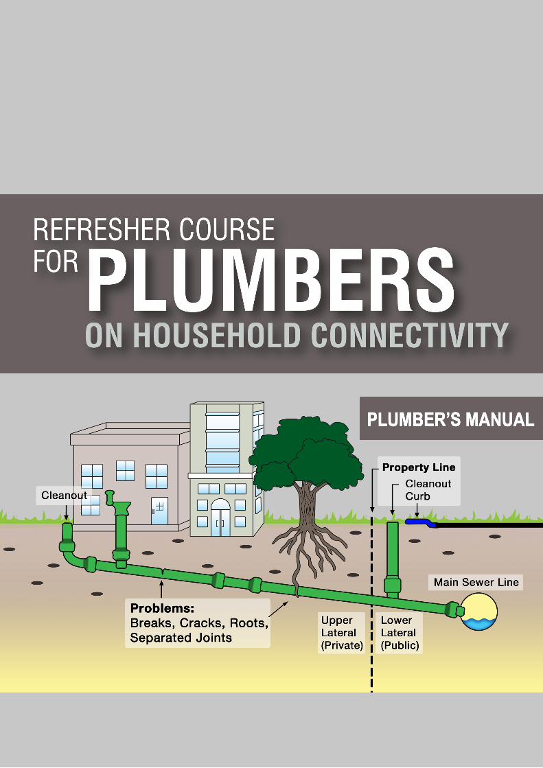
PLUMBER’S MANUAL
II
Conceptualised byGIZ programme “Support to National Urban Sanitation Policy”
Agency/CoConceptualised byGIZ programme “Support to National Urban Sanitation Policy”
Developed byAsia Society for Social Improvement & Sustainable Transformation (ASSIST)NNo- 9, Desika Road, Mylapore, Chennai, India – 600004Tel No: (+91) 44- 4554 8438Website: www.assistasia.org
Creative TeamASSIST Development Services
Contact DDeutsche Gesellschaft fuer Internationale Zusammenarbeit (GIZ) GmbH2nd Floor, B-5/2; Safdarjung EnclaveNew Delhi-110029-INDIATel: +91 (0)11 4949 5353 Fax: +91 (0)11 4949 5391
GIZ Programme – Support to National Urban Sanitation PolicyDr. Regina Dube, Programme DirectorDirk Walther, Senior Advisor JiJitendra Yadav, Technical Expert Rahul Sharma, Technical Expert
Conceptualised byGIZ programme “Support to National Urban Sanitation Policy”
Developed byAsia Society for Social Improvement & Sustainable Transformation (ASSIST)No- 9, Desika Road, Mylapore, Chennai, India – 600004TTel No: (+91) 44- 4554 8438Website: www.assistasia.org
Contact Deutsche Gesellschaft für Internationale Zusammenarbeit (GIZ) GmbH2nd Floor, B-5/2; Safdarjung EnclaveNew Delhi-110029-INDIATel: +91 (0)11 4949 5353 Fax: +91 (0)11 4949 5391
GIZ Programme – Support to National Urban Sanitation PolicyGIZ Programme – Support to National Urban Sanitation PolicyDr. Regina Dube, Programme DirectorDirk Walther, Senior Advisor Jitendra Yadav, Technical Expert Rahul Sharma, Technical Expert
December 2013
Terms of Use
GIZ poses no restriction to reproduction/translation of materials. We just kindly ask that GIZ programme – SNUSP is made reference of, and that the representatives are informed. In case you wish to change or further
develop the materials, please also contact the working group.
The graphs and many pictures has been sourced from various sources which have been mentioned and acknowledged in the book.
I
FOREWORD
India is urbanizing and very soon every second Indian will live in cities. There is an urgent need to build livable cities, providing adequate opportunities and services for all, as clearly stated in the National Urban Sanitation Policy issued by Ministry of Urban Development, Government of India in 2008. The enormous urban growth and transformation requires skills on all levels. Besides of urban planners, managers and engineers there is also a need to strengthen the practical implementation on the ground.
This specifically applies to plumbing, as the rapid transition has put forth serious pressure on civic infrastructure systems for sanitation. Provision of water supply ser-vices, household level connectivity to septic tanks and to sewerage systems, improper disposal of wastewater are becoming critical to maintaining health and environment in Indian cities. It is crucial that plumbers understand the concept and design of a city’s water supply and sewerage system which will enable them to guide and install proper household connections in the city.
This publication is a training manual for plumbers covering the plumbing aspects for connecting households to the septic tanks or sewerage systems. I hope this manual helps to improve the capacities of the plumbers, whose impacts on overall sanitation in the city is most important.
I would like to thank our partners and my SNUSP team for the efforts undertaken in addressing this important issue.
Dr. Regina Dube
Programme Director – SNUSPGIZ - India

1
Table of Contents
LIST OF FIGURES ................................................................................................................................. 2LIST OF TABLES ................................................................................................................................... 4LIST OF ACRONYMS .............................................................................................................................. 5INTRODUCTION .................................................................................................................................... 6ABOUT THE MANUAL ............................................................................................................................. 7
CHAPTER 1: Basic Concepts of Plumbing ....................................................................................................11SECTION 1: Importance of plumbing ........................................................................................................................................11SECTION 2: Introduction to sewerage system ..........................................................................................................................13SECTION 3: Cross connections .................................................................................................................................................16SECTION 4: Water saving / conservation techniques in plumbing ............................................................................................19SECTION 5: Green plumbing practices .....................................................................................................................................20
CHAPTER 2: Overview to Public Sanitation Systems and Process .......................................................................25SECTION 1: Building sewerage & its components ....................................................................................................................25SECTION 2: Connecting building drain to public sewer ............................................................................................................28SECTION 3: Simplified sewers and small bore systems ...........................................................................................................32QUICK TEST: To recap the key points in the chapter .................................................................................................................34
CHAPTER 3: Sewerage Connections – When New Public Sewerage Network is Commissioned . ...................................39SECTION 1: New PSS network ................................................................................................................................................. 39SECTION 2: Alteration of building drain to PSS (bypassing the septic tank) and alteration via septic tank to PSS ...................40
CHAPTER 4: Connecting Building Drainage to Septic Tank and Other Decentralised Systems .......................................44SECTION 1: Septic tanks – basic definitions and workings .......................................................................................................44SECTION 2: Connecting building drain to a septic tank ............................................................................................................45SECTION 3: Construction / connections in septic tanks – plumbers point of view ....................................................................47SECTION 4: Effluent disposal ....................................................................................................................................................51QUICK TEST: To recap the key points in the chapter .................................................................................................................58
CHAPTER 5: Sewerage Connections – High Altitude and High Water Table Terrain ...................................................61SECTION 1: Terrain conditions ..................................................................................................................................................61SECTION 2: High altitude / sub zero regions .............................................................................................................................61SECTION 3: High water table Area ............................................................................................................................................63QUICK TEST: To recap the key points in the chapter .................................................................................................................64
CHAPTER 6: Manual Scavenging and Occupational Health & Safety .....................................................................69SECTION 1: Manual scavenging .............................................................................................................................................. 69SECTION 2: The bill ..................................................................................................................................................................69SECTION 3: Salient features of the bill ......................................................................................................................................69 SECTION 4: Occupational health and safety during plumbing ...................................................................................................70
APPENDIX .........................................................................................................................................72REFERENCES .....................................................................................................................................81GLOSSARY OF PLUMBING ......................................................................................................................83
2
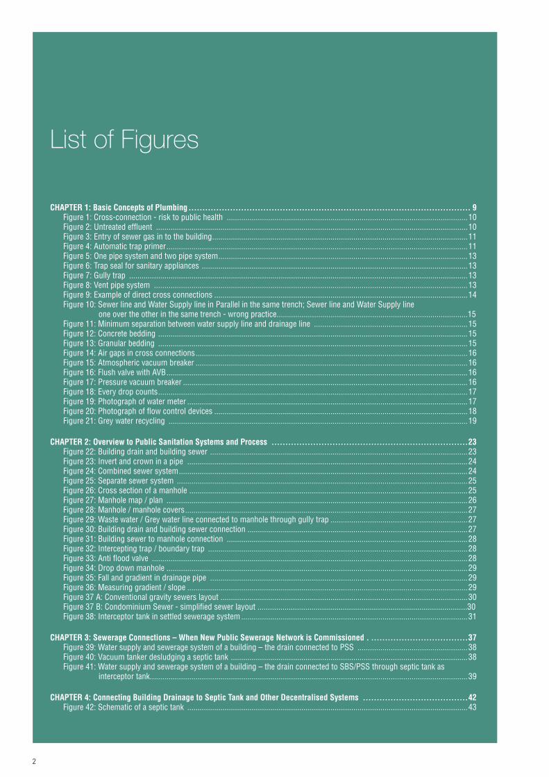
List of Figures
CHAPTER 1: Basic Concepts of Plumbing ...................................................................................................... 9Figure 1: Cross-connection - risk to public health ....................................................................................................................10Figure 2: Untreated effluent ......................................................................................................................................................10Figure 3: Entry of sewer gas in to the building ...........................................................................................................................11Figure 4: Automatic trap primer .................................................................................................................................................11Figure 5: One pipe system and two pipe system ........................................................................................................................13Figure 6: Trap seal for sanitary appliances ................................................................................................................................13Figure 7: Gully trap ...................................................................................................................................................................13Figure 8: Vent pipe system .......................................................................................................................................................13Figure 9: Example of direct cross connections ..........................................................................................................................14Figure 10: Sewer line and Water Supply line in Parallel in the same trench; Sewer line and Water Supply line one over the other in the same trench - wrong practice............................................................................................15Figure 11: Minimum separation between water supply line and drainage line ..........................................................................15Figure 12: Concrete bedding .....................................................................................................................................................15Figure 13: Granular bedding .....................................................................................................................................................15Figure 14: Air gaps in cross connections ...................................................................................................................................16Figure 15: Atmospheric vacuum breaker ...................................................................................................................................16Figure 16: Flush valve with AVB .................................................................................................................................................16Figure 17: Pressure vacuum breaker .........................................................................................................................................16Figure 18: Every drop counts .....................................................................................................................................................17Figure 19: Photograph of water meter .......................................................................................................................................17Figure 20: Photograph of flow control devices ..........................................................................................................................18Figure 21: Grey water recycling ................................................................................................................................................19
CHAPTER 2: Overview to Public Sanitation Systems and Process .......................................................................23Figure 22: Building drain and building sewer ............................................................................................................................23Figure 23: Invert and crown in a pipe .......................................................................................................................................24Figure 24: Combined sewer system ...........................................................................................................................................24Figure 25: Separate sewer system ............................................................................................................................................25Figure 26: Cross section of a manhole ......................................................................................................................................25Figure 27: Manhole map / plan .................................................................................................................................................26Figure 28: Manhole / manhole covers ........................................................................................................................................27Figure 29: Waste water / Grey water line connected to manhole through gully trap ..................................................................27Figure 30: Building drain and building sewer connection ..........................................................................................................27Figure 31: Building sewer to manhole connection ....................................................................................................................28Figure 32: Intercepting trap / boundary trap .............................................................................................................................28Figure 33: Anti flood valve ........................................................................................................................................................28Figure 34: Drop down manhole .................................................................................................................................................29Figure 35: Fall and gradient in drainage pipe ............................................................................................................................29Figure 36: Measuring gradient / slope .......................................................................................................................................29Figure 37 A: Conventional gravity sewers layout .......................................................................................................................30Figure 37 B: Condominium Sewer - simplified sewer layout .....................................................................................................30Figure 38: Interceptor tank in settled sewerage system .............................................................................................................31
CHAPTER 3: Sewerage Connections – When New Public Sewerage Network is Commissioned . ...................................37Figure 39: Water supply and sewerage system of a building – the drain connected to PSS .....................................................38Figure 40: Vacuum tanker desludging a septic tank ..................................................................................................................38Figure 41: Water supply and sewerage system of a building – the drain connected to SBS/PSS through septic tank as interceptor tank .........................................................................................................................................................39
CHAPTER 4: Connecting Building Drainage to Septic Tank and Other Decentralised Systems ......................................42Figure 42: Schematic of a septic tank .......................................................................................................................................43

3
List of Figures
Figure 43: Typical layout of a septic tank sewarage system .......................................................................................................44Figure 44: T shaped dip inlet pipe .............................................................................................................................................44Figure 45: T shaped dip outlet pipe ............................................................................................................................................45Figure 46: Position of invert of inlet and outlet pipe in a septic tank ..........................................................................................45Figure 47: Typical sketch of two compartment septic tank for population upto 50 ....................................................................46Figure 48: Typical sketch of two compartment septic tank for population over 50 ....................................................................46Figure 49: Twin inlets for septic tank where width exceeds 1.2 m .............................................................................................47Figure 50: Precast concrete septic tank ....................................................................................................................................47Figure 51: Pipe connection to precast septic tank .....................................................................................................................50Figure 52: Polyethylene septic tank .......................................................................................................................................... 50Figure 53: Installation of precast septic tank ............................................................................................................................50Figure 54: Leach pit ..................................................................................................................................................................52Figure 55: Dispersion trench .....................................................................................................................................................53Figure 56: Sand mound ............................................................................................................................................................53Figure 57: Rectangular biological filter .....................................................................................................................................54Figure 58: Circular biological filter ............................................................................................................................................54Figure 59: Single chamber rectangular up flow anaerobic filter ................................................................................................54Figure 60: Double chamber rectangular up flow anaerobic filter ...............................................................................................55Figure 61: Multi chambered up flow anaerobic filters ...............................................................................................................55Figure 62: Baffle reactor septic tank .........................................................................................................................................56Figure 63: Surface flow constructed wetlands ..........................................................................................................................57Figure 64: Horizontal subsurface constructed wetlands ...........................................................................................................57Figure 65: Vertical subsurface constructed wetlands ...............................................................................................................57
CHAPTER 5: Sewerage Connections – High Altitude and High Water Table Terrain ...................................................59Figure 66: Insulation of pipes ...................................................................................................................................................60Figure 67: Elastometric sealing ring joints ................................................................................................................................61
CHAPTER 6: Manual Scavenging and Occupational Health & Safety .....................................................................67Figure 68 A: Woman engaging in manual scavenging ..............................................................................................................67Figure 68 B: Woman engaging in manual scavenging ..............................................................................................................68Figure 69: A sewerage worker clears a choked drain ................................................................................................................68
APPENDIX .........................................................................................................................................71Figure 70: Water test ................................................................................................................................................................77Figure 71: Air test .....................................................................................................................................................................77

4
List of Tables
CHAPTER 1: Basic Concepts of Plumbing ....................................................................................................11Table 1: One pipe system vs two pipe system ...........................................................................................................................14Table 2: Recommended rate of flow for various fixtures ...........................................................................................................19
CHAPTER 2: Overview to Public Sanitation Systems and Process .......................................................................25Table 3: Alternative sewerage options for residential areas: ......................................................................................................34
CHAPTER 4: Connecting Building Drainage to Septic Tank and Other Decentralised Systems ......................................44Table 4: Recommended size for up to 20 users ........................................................................................................................45Table 5: Recommended size for residential colonies .................................................................................................................46Table 6: Recommended size for hostels and boarding schools .................................................................................................46Table 7: Recommended method for disposal of septic tank effluent .........................................................................................51Table 8: Allowable rate of effluent application to soil absorption system. ..................................................................................51
CHAPTER 5: Sewerage Connections – High Altitude and High Water Table Terrain ...................................................61Table 9: Recommended size of septic tank at 20 °C ..................................................................................................................62Table 10: Recommended size of septic tank at 10 °C ................................................................................................................62
APPENDIX .........................................................................................................................................72Table 11: Types of pipes used in water supply and drainage works ..........................................................................................73
GLOSSARY OF PLUMBING ......................................................................................................................83
Table 12: Plumbers Tool kit ........................................................................................................................................................87
5
List of Acronyms
ABR Anaerobic Baffled ReactorAC Asbestos CementAVB Atmospheric Vacuum BreakerBD Building DrainBOD Biochemical Oxygen DemandBT Bath TubBVP Branch Vent PipesCI Cast IronDI Ductile IronDWV Drain, Waste and VentEPDM Ethylene Propylene Diene Monomer-RubberGDP Gross domestic productGI Galvanized Iron GoI Government of IndiaHDPE High Density PolyethleneHRT Hydraulic Retention Time IC Inspection ChamberIPC International Plumbing Code IS Indian Standard LDPE Low Density PolyethyleneLEED Leadership in Energy & Environmental Designlpcd liters per capita per daylpm liters per minuteMH ManholeMoUD Ministry of Urban DevelopmentMS Mild Steel
MSL Mean Sea LevelMSP Main Soil Pipe MVP Main Ventilating Pipe MWP Main Waste Pipe NBC National Building CodeNRV Non Return ValveNUSP National Urban Sanitation PolicyOHT Over Head tankPRV Pressure Reducing ValvePSS Public Sewerage SystemPVB Pressure vacuum breakerPVC Polyvinyl ChlorideRCC Reinforced Cement ConcreteS SinkSBR Styrene Butadiene RubberSBS Small Bore SystemSITS Sewered Interceptor Tank SystemsST Septic TankSTEDS Septic Tank Effluent Disposal SchemeSTP Sewerage Treatment PlantSTS Secondary Treatment System TWL Top Water LevelUG Under GroundUPC Uniform Plumbing CodeUPVC Unplasticized Poly Vinyl ChlorideWB Wash BasinWC Water Closet

6
IntroductionNUSP reiterates the process of sanitation-related utility management and encourages Urban Local Bodies (ULBs) to re-gain ownership of the same. However, lack of human resources and capacities to handle problems hamper this process. Therefore, the role of capacity development is crucial in achieving and sustaining 100% sanitation. This can be addressed through training, recruitment of manpower, organisational restructuring and establishment of Standard Operating Procedures.
During the preparation of City Sanitation Plans (CSPs) it was observed that issues relating to household level connectiv-ity to septic tanks and to sewage systems, improper disposal of wastewater, etc. are affecting overall city sanitation. One of the main reason for the above mentioned issues is weak capacities of human resources engaged in these activities. It has been realized that the aspect of household level connectivity to sewerage systems or septic tanks is neglected by residents and workforce involved in this activities due to lack of knowledge/capacities. The ground reality, therefore, calls for strengthening of the capacities of stakeholders engaged in plumbing at municipal level. It is crucial that plumbers understand the concept and design of a city’s water supply and sewerage system which will enable them to install proper household connections and understand its impacts on overall sanitation in city. To address the issue of weak capacities in this sector and to bridge the institutional gap GIZ has developed a training module for municipal plumbers focusing on household level connectivity.
Objective
The overall goal is improvement of citywide sanitation, health and environment through introduction of good practices for household level wastewater discharge. The objective of the training module is to help plumbers improve their skills on household level connectivity. The module will also be integrated into existing plumbing training courses.
Approach
The focus was to develop a training module on specific plumbing aspects for connecting households to the septic tanks or sewerage systems. A desk review of existing training manuals and technical specifications was done that includes Indian Standard Codes (IS code), Uniform Plumbing Code India 2011, CPHEEO manual, existing plumbing courses etc. The desk review was followed by an appraisal study in four GIZ supported cities to understand on the ground problems in connectivity issues and incorporate the lessons learned into the training module. Partner training institutes such as Maharashtra Environmental Engineering Research and Training Academy (MEETRA) in Nashik, Maharashtra, Industrial Training Institute, Shimla, Himachal Pradesh, Training division of Kerala Water Authority, Thiruvananthapuram, Kerala, PHED training Division, Raipur, Chhattisgarh were identified for technical support and for review of the content of newly developed plumber training module on time to time.
Test run trainings were organized for municipal plumbers in Shimla, Nashik, Kochi and Raipur for ground testing of the manual and for getting feedback from plumbers working on field. The target group for the test trainings were plumbers registered with Municipal Corporations. Training of trainers programmes were also conducted to train the instructors from various institutes in Himachal Pradesh and Maharashtra.
The training module developed by GIZ-SNUSP is expected to help in reducing the capacity gaps and to be part of on-going plumbing courses or refresher trainings for already certified plumbers.
7
About the Manual
Guide to the trainers
India is witnessing an increase in urbanization, increase to the tune of 31.8% decadal in urban population. According to 2011 census, 81.4% of the total urban households have access to toilet facilities within the premises, 11% defecate in the open and the rest dependent on shared or commu-nity toilets. Around a fifth of the households do not have access to drainage net work. More than 37% of the total human excreta generated in urban India is unsafely disposed. This discharge of untreated domestic/municipal waste water has resulted in contamination of 75% of all surface water across India. This imposes significant public health and environmental costs to urban areas that contribute more than 60% of the country’s GDP.
Water supply and sanitation in Public Health Engineering have acquired a very important place in the building construction and maintenance field. Development in plumbing engineering, sanitary fixtures and pipes is taking place at a fast pace. New materials and designs are coming in the market every day. The subject gains more importance as more and more vertical rise buildings are being constructed in India. But the personnel involved in the implementation of the sanitary system, especially the plumbing engineers and plumbers, are not well acquainted with modern and systematic steps of working, standards & newer materials and designs, thus resulting in poor hygiene causing pollution in general.
In October 2008, to address the issues of urban sanitation, Ministry of Urban Development, GoI adopted National Urban Sanitation Policy (NUSP). The role of capacity building and training for the plumbing engineers and plumbers is crucial in achieving and sustaining 100% sanitation. Plumb-ers constitute a major proposition of ground staff and are important as they are crucial work force in implementation, operation and maintenance of water related infrastructure. Hence it is necessary to train the cadre and help them update their knowledge and skills on current practices so that the hygiene and service delivery could be improved.
GIZ (Deutsche Gesellschaft für Internationale Zusammenarbeit) under its programme on “Advisory support to the NUSP” supports the MoUD, GoI, for implementation of NUSP to achieve and sustain 100% sanitation conforming to the standards. A Module/Hand Book supported by GIZ under the above programme on Plumbing with particular reference to the connectivity of household sewage to the septic tanks or sewerage system is now prepared to deal with basic design and installation procedures in a very simple manner.
The Refresher Course for Plumbers on Household Connectivity to Septic Tanks & Sewerage System is a manual designed to upgrade plumbers’ understanding of link between household and plumbing network, provide a step by step instruction, tips, and practical field exercises to drive down the right plumbing approaches.
Even though the scope of plumbing work in this manual is restricted to connecting the building drain to the septic tank or sewerage system, the ultimate aim of the manual is to improve plumbers’ understanding of designing and implementing household connectivity to available sewerage system in all environments, including high altitude and high water table areas. This manual also includes additional material for creating sewerage systems for small communities, areas and settlements in a cost effective and innovative manner. Focus is also given on green plumbing concepts and the status of septic tanks when new sewerage connection is given. The manual will refresh theoretical concepts, reinforce right approaches through lab experiments, showcase common mistakes committed by plumbers through field visits, and access their level of understanding through simple class based test and home assignments.
Who are the target group?
The target group for this training are
• Plumbers who are practicing the trade • Those aspiring to be plumbers
The minimum qualification is expected to be at the higher secondary level. The manual is designed keeping in mind the fact that the practicing plumbers might or might not have undergone a formal plumbers training course before.
How the manual was developed?
This manual was compiled by a panel of senior and competent subject matter experts. They conducted desk review of existing technical specifica-tions, undertook field visits to various cities (Kochi, Shimla, Nasik, Pune) to study the ground problems in connectivity issues and discussed with trainers from leading plumbers training institutions to identify gaps/ needs in the plumbers training. The lessons learnt from the field studies and insights gained from the discussion were used to compile the appraisal reports and design the manual. The manual was prepared with details obtained from the suppliers of fixtures and pipes, the plumbing engineers and contractors. The Uniform Plumbing Code-India, various IS codes and available printed manuals and materials from secondary sources were also researched.
8
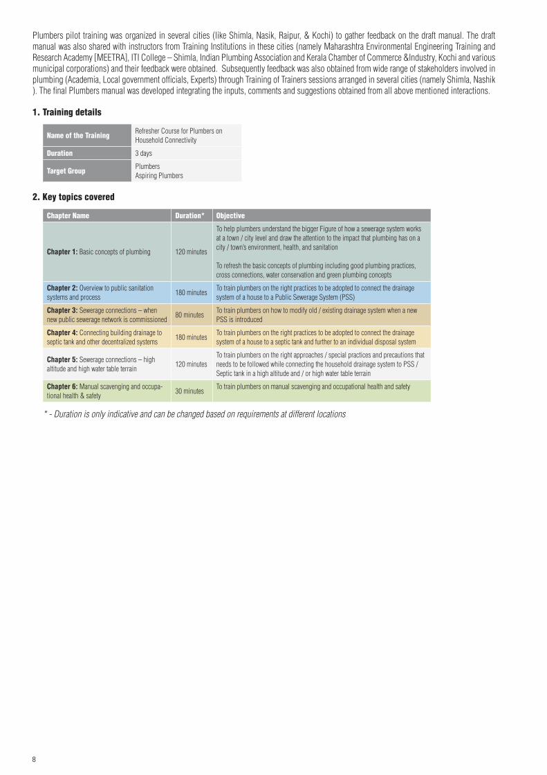
Plumbers pilot training was organized in several cities (like Shimla, Nasik, Raipur, & Kochi) to gather feedback on the draft manual. The draft manual was also shared with instructors from Training Institutions in these cities (namely Maharashtra Environmental Engineering Training and Research Academy [MEETRA], ITI College – Shimla, Indian Plumbing Association and Kerala Chamber of Commerce &Industry, Kochi and various municipal corporations) and their feedback were obtained. Subsequently feedback was also obtained from wide range of stakeholders involved in plumbing (Academia, Local government officials, Experts) through Training of Trainers sessions arranged in several cities (namely Shimla, Nashik ). The final Plumbers manual was developed integrating the inputs, comments and suggestions obtained from all above mentioned interactions.
1. Training details
Name of the Training Refresher Course for Plumbers on Household Connectivity
Duration 3 days
Target Group Plumbers Aspiring Plumbers
2. Key topics covered
Chapter Name Duration* Objective
Chapter 1: Basic concepts of plumbing 120 minutes
To help plumbers understand the bigger Figure of how a sewerage system works at a town / city level and draw the attention to the impact that plumbing has on a city / town’s environment, health, and sanitation
To refresh the basic concepts of plumbing including good plumbing practices, cross connections, water conservation and green plumbing concepts
Chapter 2: Overview to public sanitation systems and process
180 minutesTo train plumbers on the right practices to be adopted to connect the drainage system of a house to a Public Sewerage System (PSS)
Chapter 3: Sewerage connections – when new public sewerage network is commissioned
80 minutesTo train plumbers on how to modify old / existing drainage system when a new PSS is introduced
Chapter 4: Connecting building drainage to septic tank and other decentralized systems
180 minutesTo train plumbers on the right practices to be adopted to connect the drainage system of a house to a septic tank and further to an individual disposal system
Chapter 5: Sewerage connections – high altitude and high water table terrain
120 minutesTo train plumbers on the right approaches / special practices and precautions that needs to be followed while connecting the household drainage system to PSS / Septic tank in a high altitude and / or high water table terrain
Chapter 6: Manual scavenging and occupa-tional health & safety
30 minutesTo train plumbers on manual scavenging and occupational health and safety
* - Duration is only indicative and can be changed based on requirements at different locations

9

10
OneChapter 1

11
Basic Concepts of Plumbing
Chapter Objective:
The chapter will help refresh a plumber’s understanding of:
• Importance of plumbing • Key plumbing concepts • Various types of plumbing systems inside a building • Good plumbing practices, viz,
– How to avoid cross connections – Water conservation techniques – General principles of green plumbing
Plumbers need to be aware of these principles while connecting house / building piping systems with public systems (water supply / sewerage). This knowledge will help plumbers adopt right approaches, techniques in connecting house sewerage systems to septic tanks or public sewers.
Chapter Duration: 120 minutes*
SECTION 1: Importance of plumbing
Plumbing defined
Plumbing, in general, refers to the system as well as the material fix-tures and the apparatus used inside a building for supplying water, removing the used water with other liquid and water-borne wastes as well as the connected ventilating system.
In practice it also includes the storm water or roof drainage and exterior system components connecting to a source of water supply or a point of disposal of waste or used water.
The plumber should achieve the best possible plumbing levels to en-
DID yOu kNOw?
The three roles a competent plumber must assume are:1. To design, install and maintain water supply and waste removal
systems;2. To manage health risk and cost associated with plumbing;3. To help conserve water.
sure the highest health benefits from use of sound plumbing practices.
Any building should be built with an eye for general sanitation and, an effective intelligently planned plumbing. Many buildings have been de-signed without sufficient regard to these factors and the plumbing has suffered accordingly and the unsatisfactory plumbing causes serious inconveniences to the building users. Protected water is supplied for use and wastewater is collected for carrying outside the building. The possibility of contamination of protected water supply through cross-connections between the piping systems and at plumbing fixtures has to be borne in mind in the plumbing work, failing which, the contami-nation of protected water supply will pose health risk to the inmates.
An important aspect in plumbing is to look into the structure’s sewer-age and water supply layouts, which requires the skills and knowledge of a licensed plumber. In the absence of the above, the building will suffer from the following:
weakened and unstable structureWhen the overall water flow system is not properly laid out, leakage can occur in any part of the construction. When this happens anywhere near the structure’s steel foundation, the steel reinforcement can get rusty and eventually give way.
Lack of sanitationBadly plotted plumbing can definitely be a threat to the health of the future occupants. Leaks and defective plumbing system, which leads
Chapter 1
*duration is only indicative and can be changed based on requirements at different locations
12
to the growth of moulds and mildews - two major agents that can cause different kinds of illnesses in an enclosed space. Added to this foul smell coming from the clogged toilet will be a threat to the health of the occupants.
Diminished appealThe sight of leaks on the ceilings or moulds on the walls is not only unsanitary; it is definitely a sore to the eyes.
Noise due to faulty plumbingAnother important factor to be considered is the noise caused due to unsatisfactory plumbing. The serious annoyance and even ill effects on health of residents due to noise caused by the operation of plumbing systems, particularly in the case of apartments, is to be noted.
Impact on city sanitation:The house plumbing is the beginning of the drainage system and the ter-mination of the water distributing system. It is here that a cross connec-tion between the protected water supply system and the waste water dis-posal system is possible due to bad plumbing. It is therefore necessary that all works relating to plumbing within and outside the premises are properly executed under the supervision of the authorities at all stages.
Due to improper plumbing within the user’s plumbing system, when backflow occurs then it is possible to contaminate the public water sys-tem. Backflows usually are caused by a backpressure or backsiphonage.
Backsiphonage is the reversal of normal flow in a system caused by negative pressure, vacuum or partial vacuum in the supply piping. This can be created when there is a stoppage of the water supply due to fire fighting, main repairs or main breaks or leaks.
Impacts on environment: Unsatisfactory plumbing in any building may pose concern to the sur-rounding environment. The following are the few examples:
1. Contamination of drinking water source - The effluent sub soil dispersion system should be at least 18 m away from any source of drinking water. If such distance is not maintained, there is every possibility of the drinking water source get polluted.
2. Disposal of treated effluent - The effluent from the septic tank/compact sewage treatment plant shall be disposed of by adequate treatment approved by the Authority on the site. It shall be discharged into a natural watercourse or on the surface of the ground. In the case of dilution into a natural stream course, the
quality of the effluent shall confirm the requirements of the Au-thority controlling the prevention of pollution of streams. In the absence, the local source of water supply gets polluted causing environmental damage.
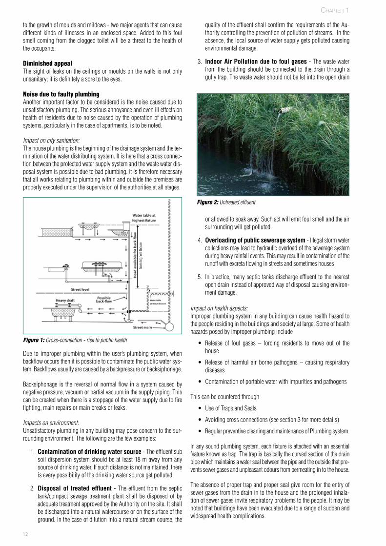
3. Indoor Air Pollution due to foul gases - The waste water from the building should be connected to the drain through a gully trap. The waste water should not be let into the open drain
or allowed to soak away. Such act will emit foul smell and the air surrounding will get polluted.
4. Overloading of public sewerage system - Illegal storm water collections may lead to hydraulic overload of the sewerage system during heavy rainfall events. This may result in contamination of the runoff with excreta flowing in streets and sometimes houses
5. In practice, many septic tanks discharge effluent to the nearest open drain instead of approved way of disposal causing environ-ment damage.
Impact on health aspects:Improper plumbing system in any building can cause health hazard to the people residing in the buildings and society at large. Some of health hazards posed by improper plumbing include
• Release of foul gases – forcing residents to move out of the house
• Release of harmful air borne pathogens – causing respiratory diseases
• Contamination of portable water with impurities and pathogens
This can be countered through
• Use of Traps and Seals
• Avoiding cross connections (see section 3 for more details)
• Regular preventive cleaning and maintenance of Plumbing system.
In any sound plumbing system, each fixture is attached with an essential feature known as trap. The trap is basically the curved section of the drain pipe which maintains a water seal between the pipe and the outside that pre-vents sewer gases and unpleasant odours from permeating in to the house.
The absence of proper trap and proper seal give room for the entry of sewer gases from the drain in to the house and the prolonged inhala-tion of sewer gases invite respiratory problems to the people. It may be noted that buildings have been evacuated due to a range of sudden and widespread health complications.
Figure 2: Untreated effluent
Chapter 1
Figure 1: Cross-connection - risk to public health
from
hig
hest
fixtu
re
13
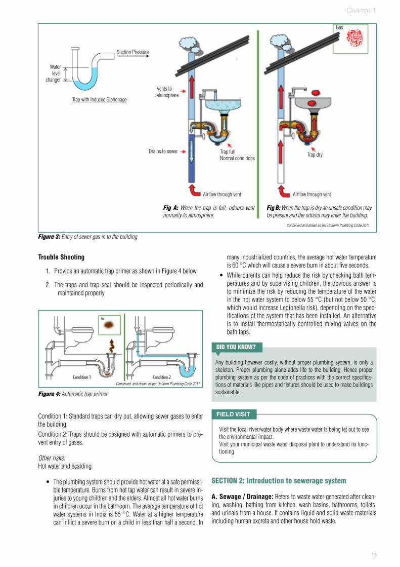
Figure 3: Entry of sewer gas in to the building
Trouble Shooting
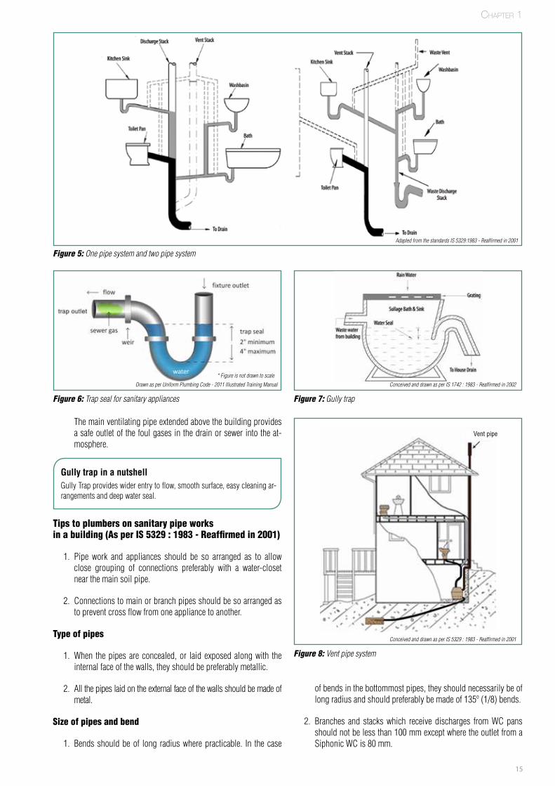
1. Provide an automatic trap primer as shown in Figure 4 below.
2. The traps and trap seal should be inspected periodically and maintained properly
Condition 1: Standard traps can dry out, allowing sewer gases to enter the building.Condition 2: Traps should be designed with automatic primers to pre-vent entry of gases.
Other risks: Hot water and scalding
• The plumbing system should provide hot water at a safe permissi-ble temperature. Burns from hot tap water can result in severe in-juries to young children and the elders. Almost all hot water burns in children occur in the bathroom. The average temperature of hot water systems in India is 55 °C. Water at a higher temperature can inflict a severe burn on a child in less than half a second. In
Figure 4: Automatic trap primer
many industrialized countries, the average hot water temperature is 60 °C which will cause a severe burn in about five seconds.
• While parents can help reduce the risk by checking bath tem-peratures and by supervising children, the obvious answer is to minimize the risk by reducing the temperature of the water in the hot water system to below 55 °C (but not below 50 °C, which would increase Legionella risk), depending on the spec-ifications of the system that has been installed. An alternative is to install thermostatically controlled mixing valves on the bath taps.
DID yOu kNOw?
Any building however costly, without proper plumbing system, is only a skeleton. Proper plumbing alone adds life to the building. Hence proper plumbing system as per the code of practices with the correct specifica-tions of materials like pipes and fixtures should be used to make buildings sustainable.
SECTION 2: Introduction to sewerage system
A. Sewage / Drainage: Refers to waste water generated after clean-ing, washing, bathing from kitchen, wash basins, bathrooms, toilets, and urinals from a house. It contains liquid and solid waste materials including human excreta and other house hold waste.
Field Visit
Visit the local river/water body where waste water is being let out to see the environmental impact.Visit your municipal waste water disposal plant to understand its func-tioning
Chapter 1
Fig A: When the trap is full, odours vent normally to atmosphere.
Fig B: When the trap is dry an unsafe condition may be present and the odours may enter the building.
Water level
changer
Trap with Induced Siphonage
Suction Pressure
Vents to atmosphere
Drains to sewer
Airflow through vent Airflow through vent
Trap fullNormal conditions
Trap dry
Gas
Conceived and drawn as per Uniform Plumbing Code 2011
Conceived and drawn as per Uniform Plumbing Code 2011

14
Sewage is of two types:
• Black water – Refers to waste water discharged from wa-ter closets and urinals. It contains human excreta. The black water is discharged into public sewerage system or a septic tank.
The black water in the septic tank is broken down by bacteria in the septic tank and is partially digested. This black water which undergoes treatment in septic tank is called Septage.
Septage is generally split into three parts in a septic tank:
– Scum – which floats to the top and is generally where the bacteria live which treat the waste.
– Effluent – which is the semi-treated liquid that comprises the majority of the material in the septic tank
– Sludge – the solids which collect at the bottom of the tank
potable water and sewage system. Care should be taken to avoid contamination of clean water with waste water. This is discussed sepa-rately in section 3 (Cross-connections).
D. Types of sanitary pipe system: There are two broad types of sanitary pipe systems used in houses/ buildings
• One Pipe system • Two Pipe system
The key differences between the two types of sanitary pipe system are listed in Table 1 below
Parameters One Pipe System Two Pipe System
Black & Grey water collection
Collected through one pipe • Collected through two separate pipes
Black water discharge
Black & Grey water is mixed and connected directly to building drain.
• Connected directly to building drain.
Reuse of grey water
As grey and black water are mixed, water can’t be reused with moderate treatment.
• As the grey water is col-lected separately, it can be reused with moderate treatment for gardening, flushing toilets and in cool-ing towers
Preferred conditions
Preferred when cost is the driving factor. initial cost of single pipe system is approximately 60% of a double pipe system/s
• It is the traditional and recommended system for any house.
• Best suited when fitments are scattered and widely separated.
Ventilating pipe There is one ventilating pipe which discharges foul gases to the air. All traps of grey / black water appliances are ventilated through this ventilating pipe.
• There are two separate ventilating pipes for black and grey water.
• All traps of grey / black water appliances are ventilated separately.
Gully Traps Not used. • Grey water is connected to building drain through a Gully trap.
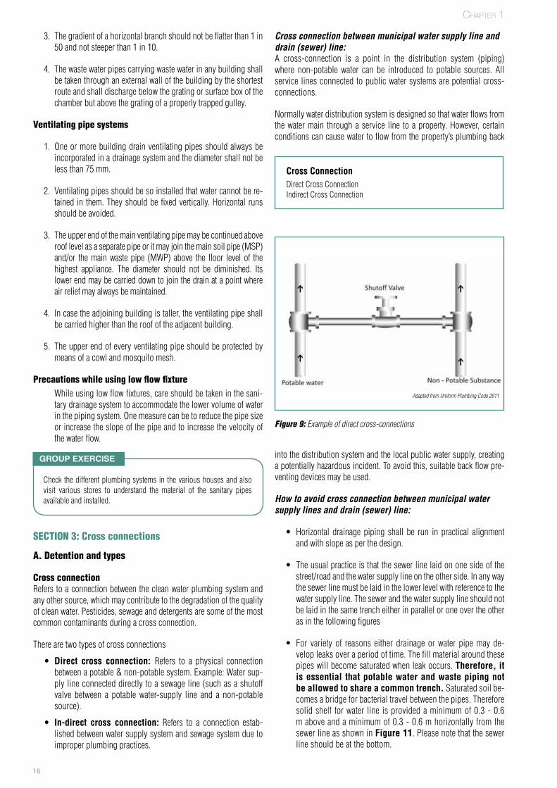
• Trap seal for sanitary appliances – Attached to each fixture, either externally or internally, is an essential feature known as trap. The trap is basically the curved section of the drainpipe which maintains water seal between the pipe and the outside that prevents sewer gases and unpleasant odours from permeating in to the house.
• Gully trap – This is provided at junctions in the drainage system. There are two entry locations for these types of traps. Waste from bathrooms, kitchen etc. enters through horizontal inlet. Water from floor cleaning or from rain water system en-ters from top grating screen. These traps provide wider entry to flow, smooth surface, easy cleaning arrangements and deep water seal.
• Vent pipe system - The vent pipe or anti-siphonage pipe is installed to provide flow of air to or from a drainage system or to provide circulation of air within such system to protect trap seals from system consists of siphonage and back flow. The system consist of one Main Ventilating Pipe (MVP) to which are con-nected the Branch Vent Pipes (BVP) of each storey.
Chapter 1
Table 1: One pipe system vs two pipe systemIS 5329 :1983 - Reaffirmed in 2001
DID yOu kNOw?
Misuse of the storm drain:A storm drain is a pipe or culvert system that collects and carries rainwater from streets, yards, parking lots and rooftops and dis-charges it untreated into streams and lakes.
Many people believe that storm drains are connected to sanitary sewer systems and that storm water is treated at sewage treatment plants. THIS IS NOT TRUE! Storm water is not treated.
• Grey water – Refers to waste water discharged from bathtubs, showers, wash basins, kitchen sink, and washing machine. It does not contain human excreta. This is also called Sullage. (Ref: IS 1742 : 1983 - Reaffirmed in 2002)
Some people have the habit of discharging grey water or effluent from the septic tank from their house in to the storm drain without knowing that they are damaging the environment and cause nuisance or injury to health of the people and animals living nearby as the grey water and the effluent from the septic tank contain diseases causing pathogens and bacteria.
Hence the grey water or the effluent should not be let into the storm water drain. It should be treated as per the local rules and disposed off in to the land or water body.
B. Plumbing system: Refers to closed system of pipes used for the distribution of water (clean & used) in a building.
This in turn has 2 systems –
• Potable / clean water system – Refers to the closed system of pipes which circulates clean water in the building. This water source can be public water supply from corporations / munici-palities or private well / tube well.
• Sewerage system – Refers to a closed system of pipes which collects waste waters (black / grey) from the house and discharg-es it into the septic tank /public sewerage system.
C. Fixtures: These are bridging elements which connect both the
15
The main ventilating pipe extended above the building provides a safe outlet of the foul gases in the drain or sewer into the at-mosphere.
Figure 5: One pipe system and two pipe system
Figure 6: Trap seal for sanitary appliances
Figure 8: Vent pipe system
Figure 7: Gully trap
Gully trap in a nutshellGully Trap provides wider entry to flow, smooth surface, easy cleaning ar-rangements and deep water seal.
Tips to plumbers on sanitary pipe works in a building (As per IS 5329 : 1983 - Reaffirmed in 2001)
1. Pipe work and appliances should be so arranged as to allow close grouping of connections preferably with a water-closet near the main soil pipe.
2. Connections to main or branch pipes should be so arranged as to prevent cross flow from one appliance to another.
Type of pipes
1. When the pipes are concealed, or laid exposed along with the internal face of the walls, they should be preferably metallic.
2. All the pipes laid on the external face of the walls should be made of metal.
Size of pipes and bend
1. Bends should be of long radius where practicable. In the case
of bends in the bottommost pipes, they should necessarily be of long radius and should preferably be made of 135º (1/8) bends.
2. Branches and stacks which receive discharges from WC pans should not be less than 100 mm except where the outlet from a Siphonic WC is 80 mm.
* Figure is not drawn to scale
Drawn as per Uniform Plumbing Code - 2011 Illustrated Training Manual Conceived and drawn as per IS 1742 : 1983 - Reaffirmed in 2002
Conceived and drawn as per IS 5329 : 1983 - Reaffirmed in 2001
Chapter 1
Adapted from the standards IS 5329:1983 - Reaffirmed in 2001
Vent pipe
16
3. The gradient of a horizontal branch should not be flatter than 1 in 50 and not steeper than 1 in 10.
4. The waste water pipes carrying waste water in any building shall be taken through an external wall of the building by the shortest route and shall discharge below the grating or surface box of the chamber but above the grating of a properly trapped gulley.
Ventilating pipe systems
1. One or more building drain ventilating pipes should always be incorporated in a drainage system and the diameter shall not be less than 75 mm.
2. Ventilating pipes should be so installed that water cannot be re-tained in them. They should be fixed vertically. Horizontal runs should be avoided.
3. The upper end of the main ventilating pipe may be continued above roof level as a separate pipe or it may join the main soil pipe (MSP) and/or the main waste pipe (MWP) above the floor level of the highest appliance. The diameter should not be diminished. Its lower end may be carried down to join the drain at a point where air relief may always be maintained.
4. In case the adjoining building is taller, the ventilating pipe shall be carried higher than the roof of the adjacent building.
5. The upper end of every ventilating pipe should be protected by means of a cowl and mosquito mesh.
Precautions while using low flow fixture While using low flow fixtures, care should be taken in the sani-
tary drainage system to accommodate the lower volume of water in the piping system. One measure can be to reduce the pipe size or increase the slope of the pipe and to increase the velocity of the water flow.
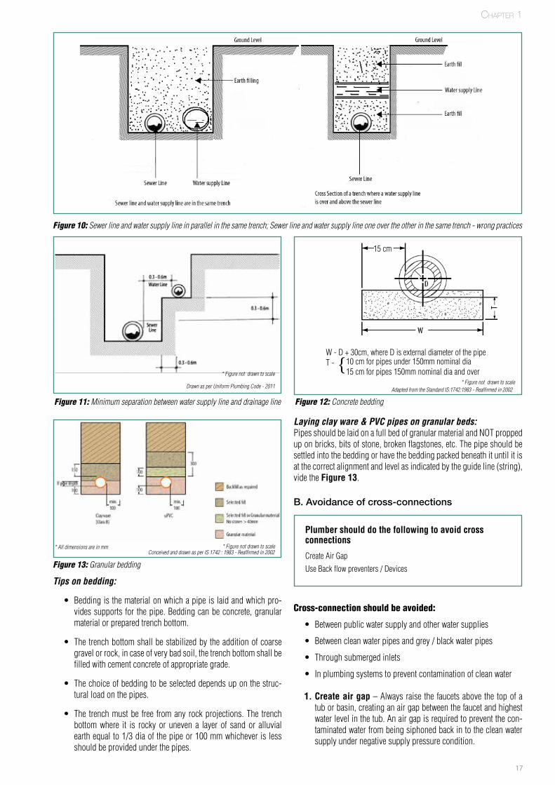
Cross connection between municipal water supply line and drain (sewer) line:A cross-connection is a point in the distribution system (piping) where non-potable water can be introduced to potable sources. All service lines connected to public water systems are potential cross-connections.
Normally water distribution system is designed so that water flows from the water main through a service line to a property. However, certain conditions can cause water to flow from the property’s plumbing back
SECTION 3: Cross connections
A. Detention and types
Cross connectionRefers to a connection between the clean water plumbing system and any other source, which may contribute to the degradation of the quality of clean water. Pesticides, sewage and detergents are some of the most common contaminants during a cross connection.
There are two types of cross connections
• Direct cross connection: Refers to a physical connection between a potable & non-potable system. Example: Water sup-ply line connected directly to a sewage line (such as a shutoff valve between a potable water-supply line and a non-potable source).
• In-direct cross connection: Refers to a connection estab-lished between water supply system and sewage system due to improper plumbing practices.
into the distribution system and the local public water supply, creating a potentially hazardous incident. To avoid this, suitable back flow pre-venting devices may be used.
How to avoid cross connection between municipal water supply lines and drain (sewer) line:
• Horizontal drainage piping shall be run in practical alignment and with slope as per the design.
• The usual practice is that the sewer line laid on one side of the street/road and the water supply line on the other side. In any way the sewer line must be laid in the lower level with reference to the water supply line. The sewer and the water supply line should not be laid in the same trench either in parallel or one over the other as in the following figures
• For variety of reasons either drainage or water pipe may de-velop leaks over a period of time. The fill material around these pipes will become saturated when leak occurs. Therefore, it is essential that potable water and waste piping not be allowed to share a common trench. Saturated soil be-comes a bridge for bacterial travel between the pipes. Therefore solid shelf for water line is provided a minimum of 0.3 - 0.6 m above and a minimum of 0.3 - 0.6 m horizontally from the sewer line as shown in Figure 11. Please note that the sewer line should be at the bottom.
Group exercise
Check the different plumbing systems in the various houses and also visit various stores to understand the material of the sanitary pipes available and installed.
Cross ConnectionDirect Cross ConnectionIndirect Cross Connection
Figure 9: Example of direct cross-connections
Adapted from Uniform Plumbing Code 2011
Chapter 1
17
Figure 10: Sewer line and water supply line in parallel in the same trench; Sewer line and water supply line one over the other in the same trench - wrong practices
Figure 11: Minimum separation between water supply line and drainage line
Tips on bedding:
• Bedding is the material on which a pipe is laid and which pro-vides supports for the pipe. Bedding can be concrete, granular material or prepared trench bottom.
• The trench bottom shall be stabilized by the addition of coarse gravel or rock, in case of very bad soil, the trench bottom shall be filled with cement concrete of appropriate grade.
• The choice of bedding to be selected depends up on the struc-tural load on the pipes.
• The trench must be free from any rock projections. The trench bottom where it is rocky or uneven a layer of sand or alluvial earth equal to 1/3 dia of the pipe or 100 mm whichever is less should be provided under the pipes.
Laying clay ware & PVC pipes on granular beds:Pipes should be laid on a full bed of granular material and NOT propped up on bricks, bits of stone, broken flagstones, etc. The pipe should be settled into the bedding or have the bedding packed beneath it until it is at the correct alignment and level as indicated by the guide line (string), vide the Figure 13.
B. Avoidance of cross-connections
Cross-connection should be avoided:
• Between public water supply and other water supplies
• Between clean water pipes and grey / black water pipes
• Through submerged inlets
• In plumbing systems to prevent contamination of clean water
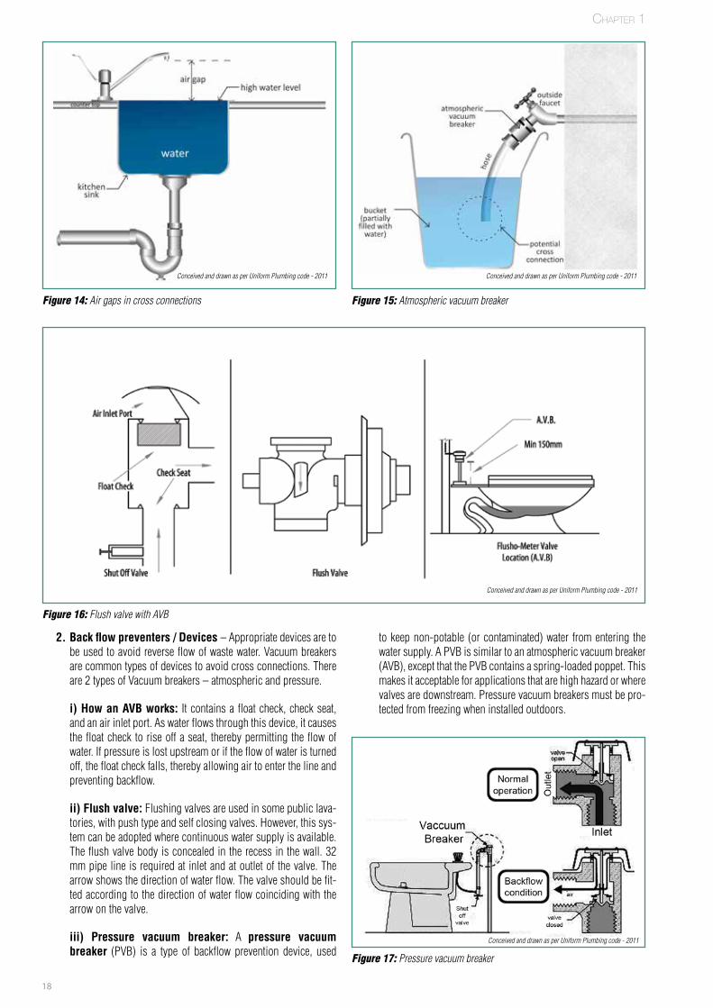
1. Create air gap – Always raise the faucets above the top of a tub or basin, creating an air gap between the faucet and highest water level in the tub. An air gap is required to prevent the con-taminated water from being siphoned back in to the clean water supply under negative supply pressure condition.
Plumber should do the following to avoid cross connections
Create Air GapUse Back flow preventers / Devices
* Figure not drawn to scale
Chapter 1
Drawn as per Uniform Plumbing Code - 2011
FPO
15 cm
W - D + 30cm, where D is external diameter of the pipeT - {10 cm for pipes under 150mm nominal dia
15 cm for pipes 150mm nominal dia and over
Adapted from the Standard IS:1742:1983 - Reaffirmed in 2002* Figure not drawn to scale
Figure 12: Concrete bedding
Figure 13: Granular bedding
FPO
* Figure not drawn to scaleConceived and drawn as per IS 1742 : 1983 - Reaffirmed in 2002
* All dimensions are in mm
18
Figure 14: Air gaps in cross connections Figure 15: Atmospheric vacuum breaker
Figure 16: Flush valve with AVB
2. Back flow preventers / Devices – Appropriate devices are to be used to avoid reverse flow of waste water. Vacuum breakers are common types of devices to avoid cross connections. There are 2 types of Vacuum breakers – atmospheric and pressure.
i) How an AVB works: It contains a float check, check seat, and an air inlet port. As water flows through this device, it causes the float check to rise off a seat, thereby permitting the flow of water. If pressure is lost upstream or if the flow of water is turned off, the float check falls, thereby allowing air to enter the line and preventing backflow.
ii) Flush valve: Flushing valves are used in some public lava-tories, with push type and self closing valves. However, this sys-tem can be adopted where continuous water supply is available. The flush valve body is concealed in the recess in the wall. 32 mm pipe line is required at inlet and at outlet of the valve. The arrow shows the direction of water flow. The valve should be fit-ted according to the direction of water flow coinciding with the arrow on the valve.
iii) Pressure vacuum breaker: A pressure vacuum breaker (PVB) is a type of backflow prevention device, used
to keep non-potable (or contaminated) water from entering the water supply. A PVB is similar to an atmospheric vacuum breaker (AVB), except that the PVB contains a spring-loaded poppet. This makes it acceptable for applications that are high hazard or where valves are downstream. Pressure vacuum breakers must be pro-tected from freezing when installed outdoors.
Figure 17: Pressure vacuum breaker
Chapter 1
Conceived and drawn as per Uniform Plumbing code - 2011 Conceived and drawn as per Uniform Plumbing code - 2011
Conceived and drawn as per Uniform Plumbing code - 2011
Conceived and drawn as per Uniform Plumbing code - 2011

19
Figure 18: Every drop counts
SECTION 4: water saving/conservation techniques in plumbing
A. Definition and rationale
Water conservation: Refers to strategies, actions and techniques adopted to use water wisely. This is important as:
• Fresh water is a scarce resource • Water tables are fast depleting • Rainfall is unpredictable & • Moral responsibility to conserve water for future generation
DID yOu kNOw?
Importance of water conservation to house / building septic system
Water conservation is not only important from a sustainable consumption perspective but also relevant to house – septic systems / environment.
• Extends the life of septic system by reducing soil saturation • Reduces any pollution due to leaks from septic tank with excess
water • Over loaded municipal sewer systems can also cause untreated sew-
age to flow to lakes and rivers. • Lesser the amount of water flowing through septic systems, the
lower the likelihood of pollution.
B. Tips to conserve water
The different ways to conserve / save water in plumbing are listed below:
1. As per IPC, water pressure in water distribution system should be limited to 80 psi or 55 m of water column in order to remove water hammer, unnecessary use of water, splashing, excessive discharge of pressure relief valves, and to protect appliance valves. Hence reduce the pressure in the distribution line by pro-viding Pressure Reducing Valves (PRVs) to regulate and to save water consumption. As recommended the pressure at any fixture unit shall not exceed 2.5 – 3 bar.
No. Fixtures Rate of flow in litres /second
1 WC with flushing cistern 0.12
2 Wash Basin 0.15
3 Wash Basin with spray taps 0.04
4 Bath Tub (Private) 0.30
5 Bath Tub (Public) 0.60
6 Shower with nozzle 0.12
7 Sink with 15mm tap 0.20
8 Sink with 20mm tap 0.30
9 Sink with 35mm tap 0.40
Table 2: Recommended rate of flow for various fixtures
2. The above Table from IS 12183 (Part 1) : 1987 - Reaffirmed in 2004, recommends the rate flow for various fixture units. Hence fixtures which satisfy the minimum flow rate should be used to save water consumption in any building.
3. Water conservation products such as Automatic taps, Flushometers, Pint flush urinals, high efficiency toilets and water saving shower heads can also be used. Standard showerheads use about 11 lpm and performance shower heads use about 8 lpm. The older toilets flush with about 13 litres per flush. New high-efficiency dual flush toilets use less than 6 litres per flush.
4. Leakages Check for leakage in the pipe line and faucets and seal them. It is estimated that faucet leaks a drop per second will account to 15- 30 litres per day.
5. Water meters – It is important to install water meters in key pipe line connection. This will help measure the water usage and can help in measuring output of any efforts to conserve water.
Tips to conserve water•PressureReducingValves(PRVs)•Leakages•Watermeters•Flowcontroldevices•GreyWaterUse
6. Flow control devices - Significant water savings results from simply installing new faucet flow-control devices (aerators).
7. Grey water use - Grey water can be used by home owners for home gardening, lawn maintenance, landscaping, and other in-novative uses with moderate treatment.
Figure 19: Photograph of water meter
70% of the earth’s surface is covered with water, but only 2.5% of that water is fresh water. Of this only 30% is available for drinking as groundwater and is relatively easily obtainable.
FPO
DID yOu kNOw?
* Figure not drawn to scale
Chapter 1
Water wasted per day
30 Litres / day
Adapted from Sourcebook of Alternative Technologies for Freshwater Augumentation in Small Island Developing States
14 to 90
Amount of potential water loss per tap has been calculated based on rate of water leakage from 2 drops per minute to a slow stream breaking into drops. The figure is shown to highlight the potential loss and need for water conservation only
20
Certified 26-32 pointsSilver Level 33-38 pointsGold Level 39-51 pointsPlatinum Level 52+ points with a possible 69 points available.
One of the listed areas in the LEED programme is Water Efficiency. The category is sub divided into three sub categories that allow points to be earned by achieving certain criteria established to reduce water con-sumption.
1. Utilise water efficient Landscaping2. Reduction in the use of municipal potable water3. Reduction in wastewater through Innovative Wastewater Tech-
nologies
• Utilizing water-efficient landscaping will reduce the amount of potable water used for irrigation/gardening by 50 percent. This is typically accomplished by using a highly efficient irrigation sys-tem, capturing rainwater, or using recycled site water to reduce the consumption of potable water.
• Reduction of the use of municipal potable water, a minimum of 50 percent or treating 100 percent of the wastewater on-site to tertiary standards is required.
• Under Innovative Wastewater Technologies providing ultra-low consumption plumbing fixtures find predominant place in wa-ter efficiency. Reductions in water usage beyond what is required can be obtained by using the following in the plumbing system.
1. Lavatory faucets with flow rates 1.9 lpm, 2. Showerheads with flow rates of 5.7 lpm, 3. Water closets that use dual-flush technology4. The use of infrared faucets and flush valves
• Waterless urinals have been developed to use a biodegradable, immiscible fluid that is less dense than normal liquid waste and allows the waste to pass through a special trap and then to the drainage system. These products do not connect to the building water supply and do not use water.
• Composting water closet systems use little or no wa-ter. An incinerating water closet does not use water and utilizes a combustion chamber in order to incinerate wastes. Use of these units is typically limited to remote locations or locations where water availability is limited. Again, the limitations of code should be examined prior to using these units.
• Grey water system is one of the technologies becoming more prevalent in the design of green plumbing. Grey water is defined as untreated household wastewater which has not come into con-tact with toilet waste. Grey water includes used water from bath-tubs, showers, bathroom wash basins, and water from clothes washing machines and laundry tubs and car washing. It shall not include wastewater from kitchen sinks or dishwashers. In build-ing plumbing work in a two pipe system grey water is dealt with separately. Typically, grey water systems are used to flush water closets, urinals, and gardening and for cooling towers after the required treatment.
• Black water: Grey water does not include the wastewater from toilets, urinals or bidets. The discharges from these fixtures are classified and sometimes referred as black water, because they contain high levels of pathogenic organisms and solids. Such discharges should undergo specialized treatment prior to any sec-ondary use.
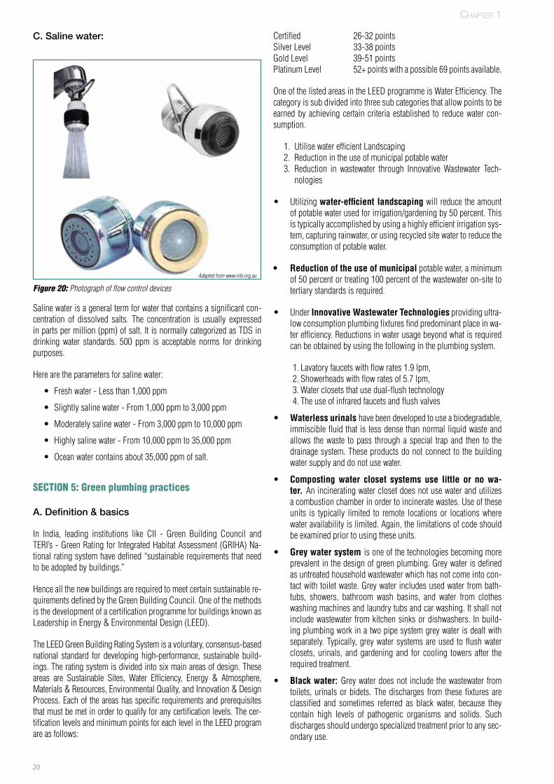
Figure 20: Photograph of flow control devices
C. Saline water:
Saline water is a general term for water that contains a significant con-centration of dissolved salts. The concentration is usually expressed in parts per million (ppm) of salt. It is normally categorized as TDS in drinking water standards. 500 ppm is acceptable norms for drinking purposes.
Here are the parameters for saline water:
• Fresh water - Less than 1,000 ppm
• Slightly saline water - From 1,000 ppm to 3,000 ppm
• Moderately saline water - From 3,000 ppm to 10,000 ppm
• Highly saline water - From 10,000 ppm to 35,000 ppm
• Ocean water contains about 35,000 ppm of salt.
SECTION 5: Green plumbing practices
A. Definition & basics
In India, leading institutions like CII - Green Building Council and TERI’s - Green Rating for Integrated Habitat Assessment (GRIHA) Na-tional rating system have defined “sustainable requirements that need to be adopted by buildings.”
Hence all the new buildings are required to meet certain sustainable re-quirements defined by the Green Building Council. One of the methods is the development of a certification programme for buildings known as Leadership in Energy & Environmental Design (LEED).
The LEED Green Building Rating System is a voluntary, consensus-based national standard for developing high-performance, sustainable build-ings. The rating system is divided into six main areas of design. These areas are Sustainable Sites, Water Efficiency, Energy & Atmosphere, Materials & Resources, Environmental Quality, and Innovation & Design Process. Each of the areas has specific requirements and prerequisites that must be met in order to qualify for any certification levels. The cer-tification levels and minimum points for each level in the LEED program are as follows:
Adapted from www.nitv.org.au
Chapter 1

21
Figure 21: Grey water recycling
FPO
– In building plumbing, other than two pipe system, both grey water and black water are collected together and the com-bination called sewage is disposed. Under green plumbing concept, the sewage is treated in a STP (Sewage Treatment Plant) and the treated water is used for gardening and toilet flushing etc. Here the sewage which consists of black water and grey water is termed as RAW SEWAGE. The sewage treat-ment design is based on the characteristic of raw sewage.
Under green plumbing concept, the sewage is treated in a compact STP (Sewage Treatment Plant) and the treated wa-ter is used for gardening and toilet flushing etc.
– Rain water collection: Under the green plumbing con-cept, rain water collection and Use for gardening and other purposes considerably reduce the consumption of potable municipal water. The collection systems require the storage of the rainwater, usually in underground storage tanks that can be quite large.
– The amount of storage depends on the requirement for ir-rigation water, as well as the amount of rainwater anticipated. Moderate water treatment and filtration is necessary to keep the sprinkler heads from fouling and becoming clogged with debris.
Chapter 1
Common mistakes done by the plumbers:
Comment:1. Plumbing pipes must be routed in such a way that minimum
number of bends are involved.2. The vent pipe should be extended above the roof top and
should be provided with a cowl and covered with a mosquito mesh.
Comment:1. The rain water pipe should generally be connected to the
street drain/storm water drain and local authority clearance is required for connecting to the sewer system.
FPO
Waste water pipe
Soil pipe Vent pipe
Rain waterpipe
Rain water pipeManhole
• •
•
22
Case study: Basic concepts of plumbing
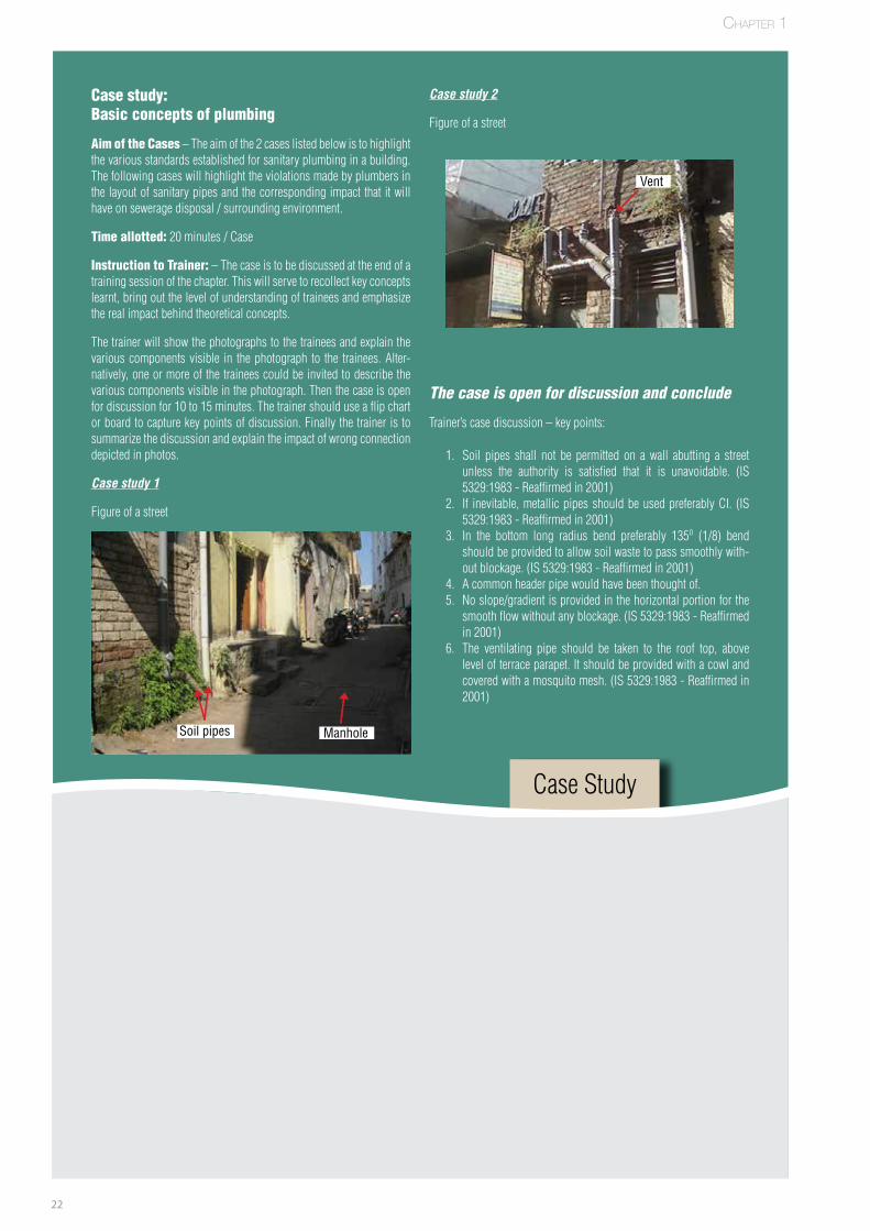
Aim of the Cases – The aim of the 2 cases listed below is to highlight the various standards established for sanitary plumbing in a building. The following cases will highlight the violations made by plumbers in the layout of sanitary pipes and the corresponding impact that it will have on sewerage disposal / surrounding environment.
Time allotted: 20 minutes / Case
Instruction to Trainer: – The case is to be discussed at the end of a training session of the chapter. This will serve to recollect key concepts learnt, bring out the level of understanding of trainees and emphasize the real impact behind theoretical concepts.
The trainer will show the photographs to the trainees and explain the various components visible in the photograph to the trainees. Alter-natively, one or more of the trainees could be invited to describe the various components visible in the photograph. Then the case is open for discussion for 10 to 15 minutes. The trainer should use a flip chart or board to capture key points of discussion. Finally the trainer is to summarize the discussion and explain the impact of wrong connection depicted in photos.
Case study 1
Figure of a street
Case study 2
Figure of a street
The case is open for discussion and conclude
Trainer’s case discussion – key points:
1. Soil pipes shall not be permitted on a wall abutting a street unless the authority is satisfied that it is unavoidable. (IS 5329:1983 - Reaffirmed in 2001)
2. If inevitable, metallic pipes should be used preferably CI. (IS 5329:1983 - Reaffirmed in 2001)
3. In the bottom long radius bend preferably 135o (1/8) bend should be provided to allow soil waste to pass smoothly with-out blockage. (IS 5329:1983 - Reaffirmed in 2001)
4. A common header pipe would have been thought of.5. No slope/gradient is provided in the horizontal portion for the
smooth flow without any blockage. (IS 5329:1983 - Reaffirmed in 2001)
6. The ventilating pipe should be taken to the roof top, above level of terrace parapet. It should be provided with a cowl and covered with a mosquito mesh. (IS 5329:1983 - Reaffirmed in 2001)
Case Study
FPO
FPO
Vent
ManholeSoil pipes
Chapter 1

23
Notes
24
TwoChapter 2
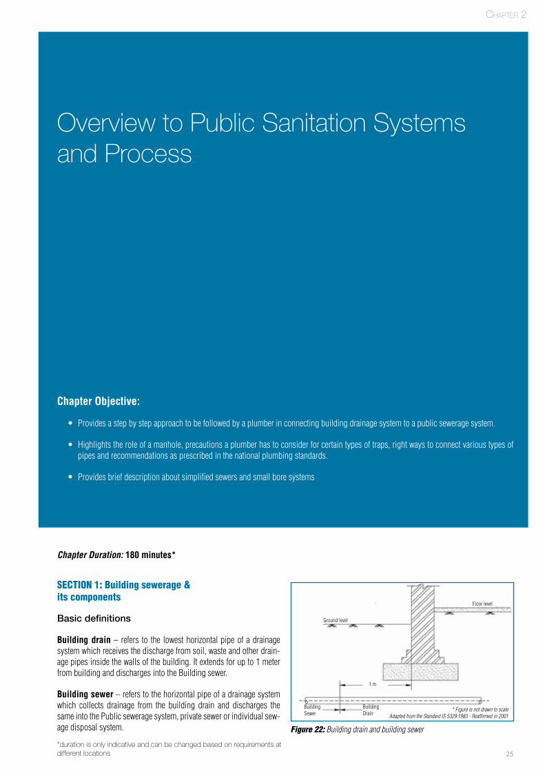
25
Basic Concepts of Plumbing
Overview to Public Sanitation Systems and Process
Chapter Objective:
• Provides a step by step approach to be followed by a plumber in connecting building drainage system to a public sewerage system.
• Highlights the role of a manhole, precautions a plumber has to consider for certain types of traps, right ways to connect various types of pipes and recommendations as prescribed in the national plumbing standards.
• Provides brief description about simplified sewers and small bore systems
Chapter Duration: 180 minutes*
SECTION 1: Building sewerage & its components
Basic definitions
Building drain – refers to the lowest horizontal pipe of a drainage system which receives the discharge from soil, waste and other drain-age pipes inside the walls of the building. It extends for up to 1 meter from building and discharges into the Building sewer.
Building sewer – refers to the horizontal pipe of a drainage system which collects drainage from the building drain and discharges the same into the Public sewerage system, private sewer or individual sew-age disposal system. Figure 22: Building drain and building sewer
Chapter 2
*duration is only indicative and can be changed based on requirements at different locations
Adapted from the Standard IS 5329:1983 - Reaffirmed in 2001* Figure is not drawn to scale
Ground level
Floor level
Building Sewer
Building Drain
1 m
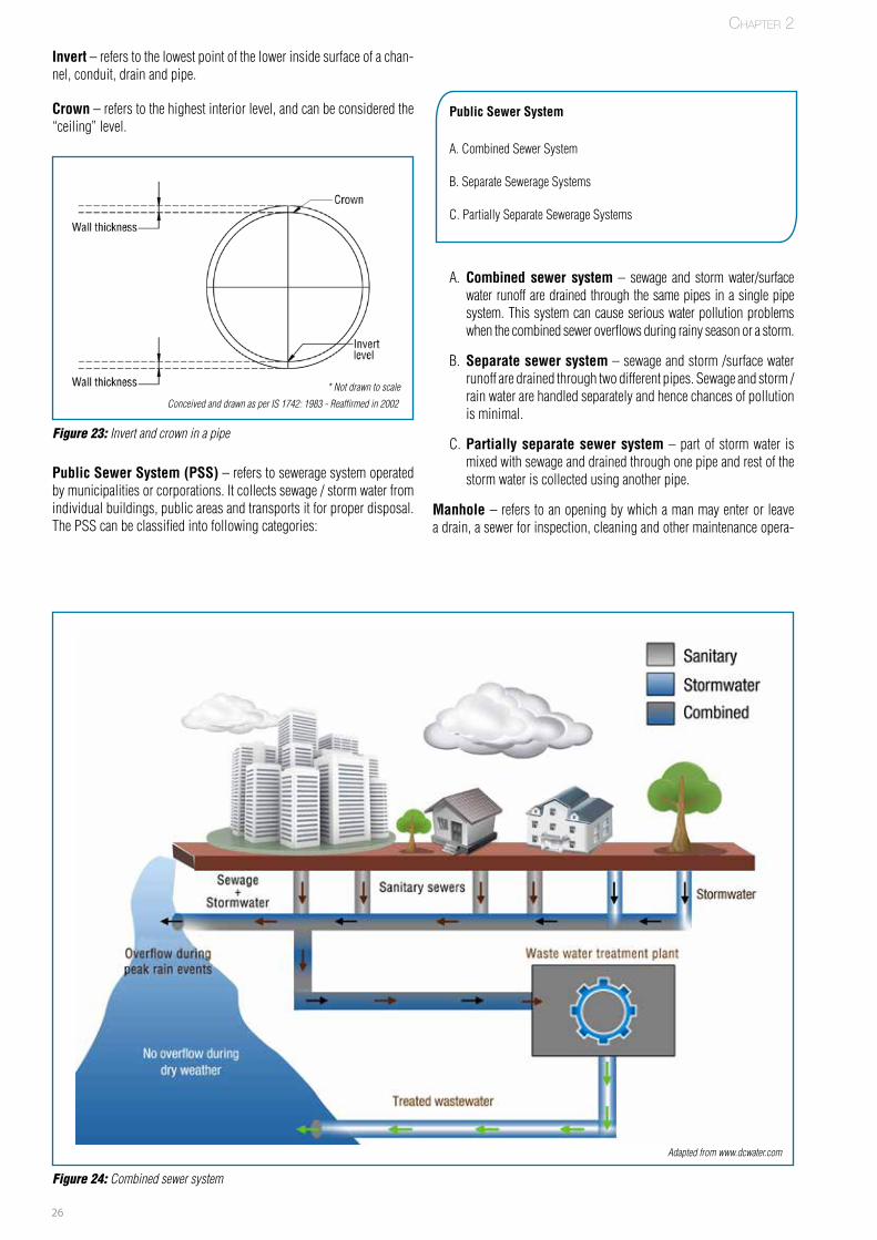
26
Public Sewer System (PSS) – refers to sewerage system operated by municipalities or corporations. It collects sewage / storm water from individual buildings, public areas and transports it for proper disposal. The PSS can be classified into following categories:
Public Sewer System
A. Combined Sewer System
B. Separate Sewerage Systems
C. Partially Separate Sewerage Systems
A. Combined sewer system – sewage and storm water/surface water runoff are drained through the same pipes in a single pipe system. This system can cause serious water pollution problems when the combined sewer overflows during rainy season or a storm.
B. Separate sewer system – sewage and storm /surface water runoff are drained through two different pipes. Sewage and storm / rain water are handled separately and hence chances of pollution is minimal.
C. Partially separate sewer system – part of storm water is mixed with sewage and drained through one pipe and rest of the storm water is collected using another pipe.
Manhole – refers to an opening by which a man may enter or leave a drain, a sewer for inspection, cleaning and other maintenance opera-
Figure 24: Combined sewer system
Invert – refers to the lowest point of the lower inside surface of a chan-nel, conduit, drain and pipe.
Crown – refers to the highest interior level, and can be considered the “ceiling” level.
Figure 23: Invert and crown in a pipe
Adapted from www.dcwater.com
Chapter 2
Conceived and drawn as per IS 1742: 1983 - Reaffirmed in 2002
* Not drawn to scale
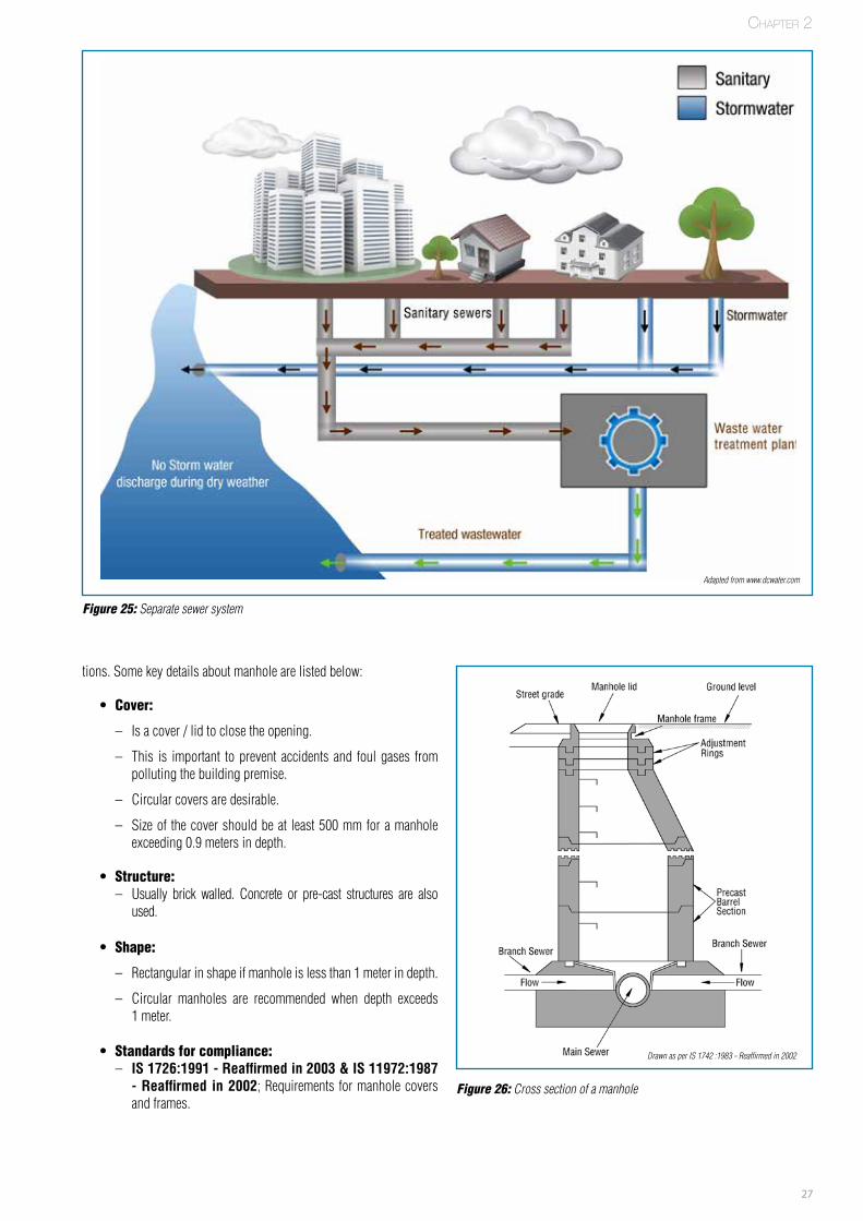
27
tions. Some key details about manhole are listed below:
• Cover:
– Is a cover / lid to close the opening.
– This is important to prevent accidents and foul gases from polluting the building premise.
– Circular covers are desirable.
– Size of the cover should be at least 500 mm for a manhole exceeding 0.9 meters in depth.
• Structure: – Usually brick walled. Concrete or pre-cast structures are also
used.
• Shape:
– Rectangular in shape if manhole is less than 1 meter in depth.
– Circular manholes are recommended when depth exceeds 1 meter.
• Standards for compliance: – IS 1726:1991 - Reaffirmed in 2003 & IS 11972:1987
- Reaffirmed in 2002; Requirements for manhole covers and frames.
Figure 25: Separate sewer system
Figure 26: Cross section of a manhole
Adapted from www.dcwater.com
Drawn as per IS 1742 :1983 - Reaffirmed in 2002
Chapter 2
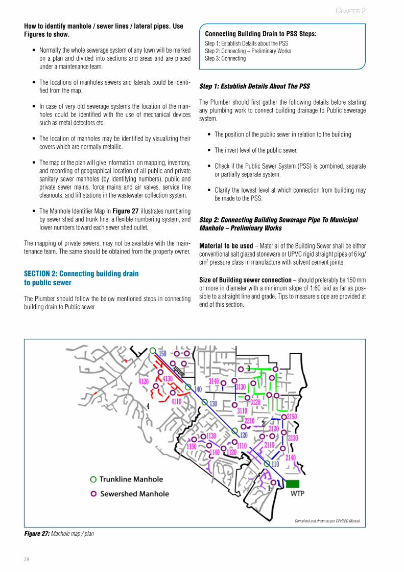
28
How to identify manhole / sewer lines / lateral pipes. Use Figures to show.
• Normally the whole sewerage system of any town will be marked on a plan and divided into sections and areas and are placed under a maintenance team.
• The locations of manholes sewers and laterals could be identi-fied from the map.
• In case of very old sewerage systems the location of the man-holes could be identified with the use of mechanical devices such as metal detectors etc.
• The location of manholes may be identified by visualizing their covers which are normally metallic.
• The map or the plan will give information on mapping, inventory, and recording of geographical location of all public and private sanitary sewer manholes (by identifying numbers), public and private sewer mains, force mains and air valves, service line cleanouts, and lift stations in the wastewater collection system.
• The Manhole Identifier Map in Figure 27 illustrates numbering by sewer shed and trunk line, a flexible numbering system, and lower numbers toward each sewer shed outlet,
The mapping of private sewers, may not be available with the main-tenance team. The same should be obtained from the property owner.
SECTION 2: Connecting building drain to public sewer
The Plumber should follow the below mentioned steps in connecting building drain to Public sewer
Connecting Building Drain to PSS Steps:Step 1: Establish Details about the PSSStep 2: Connecting – Preliminary WorksStep 3: Connecting
Step 1: Establish Details About The PSS
The Plumber should first gather the following details before starting any plumbing work to connect building drainage to Public sewerage system.
• The position of the public sewer in relation to the building
• The invert level of the public sewer.
• Check if the Public Sewer System (PSS) is combined, separate or partially separate system.
• Clarify the lowest level at which connection from building may be made to the PSS.
Step 2: Connecting Building Sewerage Pipe To Municipal Manhole – Preliminary Works
Material to be used – Material of the Building Sewer shall be either conventional salt glazed stoneware or UPVC rigid straight pipes of 6 kg/cm2 pressure class in manufacture with solvent cement joints.
Size of Building sewer connection – should preferably be 150 mm or more in diameter with a minimum slope of 1:60 laid as far as pos-sible to a straight line and grade. Tips to measure slope are provided at end of this section.
Figure 27: Manhole map / plan
FPO
Conceived and drawn as per CPHEEO Manual
Chapter 2
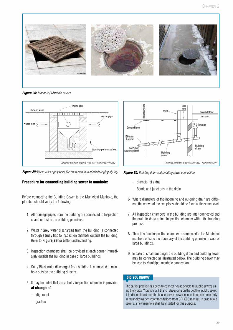
29
Procedure for connecting building sewer to manhole:
Before connecting the Building Sewer to the Municipal Manhole, the plumber should verify the following:
1. All drainage pipes from the building are connected to Inspection chamber inside the building premises.
2. Waste / Grey water discharged from the building is connected through a Gully trap to Inspection chamber outside the building. Refer to Figure 29 for better understanding.
3. Inspection chambers shall be provided at each corner immedi-ately outside the building in case of large buildings.
4. Soil / Black water discharged from building is connected to man-hole outside the building directly.
5. It may be noted that a manhole/ inspection chamber is provided at change of
– alignment
– gradient
– diameter of a drain
– Bends and junctions in the drain
6. Where diameters of the incoming and outgoing drain are differ-ent, the crown of the two pipes should be fixed at the same level.
7. All inspection chambers in the building are inter-connected and the drain leads to a final inspection chamber within the building premise.
8. Then this final inspection chamber is connected to the Municipal manhole outside the boundary of the building premise in case of large buildings.
9. In case of small buildings, the building drain and building sewer may be connected as illustrated below. The building sewer may be lead to Municipal manhole connection.
Figure 28: Manhole / Manhole covers
FPO FPO FPO
Chapter 2
Figure 29: Waste water / grey water line connected to manhole through gully trap
Conceived and drawn as per IS 1742:1983 - Reaffirmed by in 2002
Figure 30: Building drain and building sewer connection
Conceived and drawn as per IS 5329 : 1983 - Reaffirmed in 2001
below GL
DID yOu kNOw?
The earlier practice has been to connect house sewers to public sewers us-ing the typical Y branch or T branch depending on the depth of public sewer. It is discontinued and the house service sewer connections are done only in manholes as per recommendations from CPHEEO manual. In case of old sewers, a new manhole shall be inserted for this purpose.
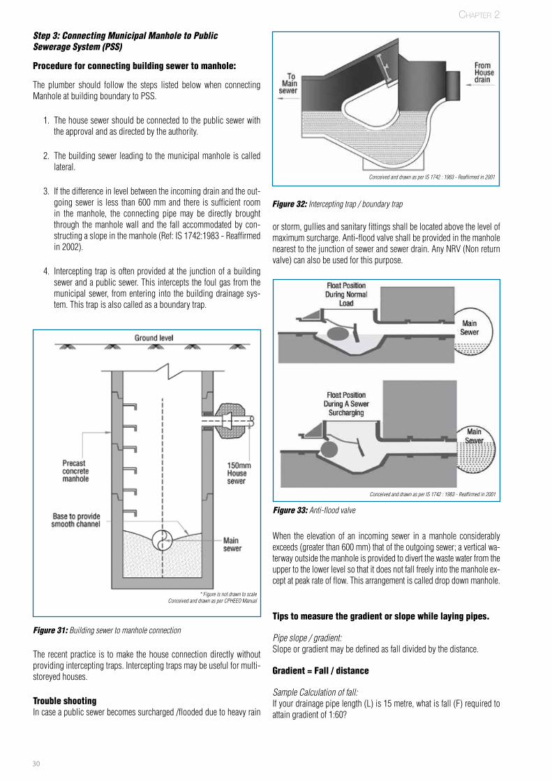
30
or storm, gullies and sanitary fittings shall be located above the level of maximum surcharge. Anti-flood valve shall be provided in the manhole nearest to the junction of sewer and sewer drain. Any NRV (Non return valve) can also be used for this purpose.
When the elevation of an incoming sewer in a manhole considerably exceeds (greater than 600 mm) that of the outgoing sewer; a vertical wa-terway outside the manhole is provided to divert the waste water from the upper to the lower level so that it does not fall freely into the manhole ex-cept at peak rate of flow. This arrangement is called drop down manhole.
Step 3: Connecting Municipal Manhole to Public Sewerage System (PSS)
Procedure for connecting building sewer to manhole:
The plumber should follow the steps listed below when connecting Manhole at building boundary to PSS.
1. The house sewer should be connected to the public sewer with the approval and as directed by the authority.
2. The building sewer leading to the municipal manhole is called lateral.
3. If the difference in level between the incoming drain and the out-going sewer is less than 600 mm and there is sufficient room in the manhole, the connecting pipe may be directly brought through the manhole wall and the fall accommodated by con-structing a slope in the manhole (Ref: IS 1742:1983 - Reaffirmed in 2002).
4. Intercepting trap is often provided at the junction of a building sewer and a public sewer. This intercepts the foul gas from the municipal sewer, from entering into the building drainage sys-tem. This trap is also called as a boundary trap.
The recent practice is to make the house connection directly without providing intercepting traps. Intercepting traps may be useful for multi-storeyed houses.
Trouble shooting In case a public sewer becomes surcharged /flooded due to heavy rain
Tips to measure the gradient or slope while laying pipes.
Pipe slope / gradient:Slope or gradient may be defined as fall divided by the distance.
Gradient = Fall / distance
Sample Calculation of fall:If your drainage pipe length (L) is 15 metre, what is fall (F) required to attain gradient of 1:60?
Chapter 2
Figure 31: Building sewer to manhole connection
* Figure is not drawn to scaleConceived and drawn as per CPHEEO Manual
Figure 32: Intercepting trap / boundary trap
Conceived and drawn as per IS 1742 : 1983 - Reaffirmed in 2001
Figure 33: Anti-flood valve
Conceived and drawn as per IS 1742 : 1983 - Reaffirmed in 2001
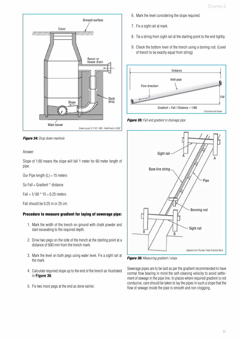
31
Answer:
Slope of 1:60 means the slope will fall 1 meter for 60 meter length of pipe.
Our Pipe length (L) = 15 meters
So Fall = Gradient * distance
Fall = 1/ 60 * 15 = 0.25 meters
Fall should be 0.25 m or 25 cm.
Procedure to measure gradient for laying of sewerage pipe:
1. Mark the width of the trench on ground with chalk powder and start excavating to the required depth.
2. Drive two pegs on the side of the trench at the starting point at a distance of 600 mm from the trench mark.
3. Mark the level on both pegs using water level. Fix a sight rail at the mark.
4. Calculate required slope up to the end of the trench as illustrated in Figure 36.
5. Fix two more pegs at the end as done earlier.
6. Mark the level considering the slope required.
7. Fix a sight rail at mark.
8. Tie a string from sight rail at the starting point to the end tightly.
9. Check the bottom level of the trench using a boning rod. (Level of trench to be exactly equal from string)
Sewerage pipes are to be laid as per the gradient recommended to have normal flow bearing in mind the self-cleaning velocity to avoid settle-ment of sewage in the pipe line. In places where required gradient is not conducive, care should be taken to lay the pipes in such a slope that the flow of sewage inside the pipe is smooth and non clogging.
Figure 34: Drop down manhole
Drawn as per IS 1742 :1983 - Reaffirmed in 2002
Figure 36: Measuring gradient / slope
FPO
Adapted from Plumber Trade Practical Book
Chapter 2
Figure 35: Fall and gradient in drainage pipe
Conceived and drawn
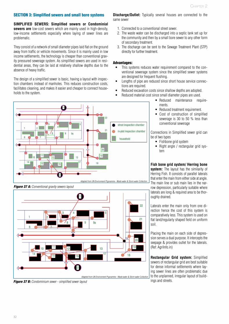
32
SECTION 3: Simplified sewers and small bore systems
SIMPLIFIED SEWERS: Simplified sewers or Condominial sewers are low-cost sewers which are mainly used in high-density, low-income settlements especially where laying of sewer lines are problematic.
They consist of a network of small diameter pipes laid flat on the ground away from traffic or vehicle movements. Since it is mainly used in low income settlements, the technology is cheaper than conventional grav-ity pressured sewerage system. As simplified sewers are used in resi-dential areas, they can be laid at relatively shallow depths due to the absence of heavy traffic.
The design of a simplified sewer is basic, having a layout with inspec-tion chambers instead of manholes. This reduces construction costs, facilitates cleaning, and makes it easier and cheaper to connect house-holds to the system.
Discharge/Outlet: Typically several houses are connected to the same sewer
1. Connected to a conventional street sewer.2. The waste water can be discharged into a septic tank set up for
the community and then by a small bore sewer to any other form of secondary treatment.
3. The discharge can be sent to the Sewage Treatment Plant (STP) directly for further treatment.
Advantages: • This systems reduces water requirement compared to the con-
ventional sewerage system since the simplified sewer systems are designed for frequent flushing.
• Lengths of pipe are reduced since short house service connec-tions are required.
• Reduced excavation costs since shallow depths are adopted. • Reduced material cost since small diameter pipes are used.
Chapter 2
Figure 37 A: Conventional gravity sewers layout
Adapted from UN Environment Prgoramme - Waste water & Storm water Collection
Figure 37 B: Condominium sewer - simplified sewer layoutAdapted from UN Environment Prgoramme - Waste water & Storm water Collection
• Reduced maintenance require-ments.
• Reduced treatment requirement. • Cost of construction of simplified
sewerage is 30 to 50 % less than conventional sewerage
Connections in Simplified sewer grid can be of two types
• Fishbone grid system • Right angle / rectangular grid sys-
tem
Fish bone grid system/ Herring bone system: The layout has the similarity of Herring Fish. It consists of parallel laterals that enter the main from either side at angle. The main line or sub main lies in the nar-row depression, particularly suitable where laterals are long & required area to be thor-oughly drained.
Laterals enter the main only from one di-rection hence the cost of this system is comparatively less. This system is used on flat land/regularly shaped field on uniform soil.
Placing the main on each side of depres-sion serves a dual purpose. It intercepts the seepage & provides outlet for the laterals. (Ref: AgriInfo.in)
Rectangular Grid system: Simplified sewers of rectangular grid are best suitable for dense informal settlements where lay-ing sewer lines are often problematic due to the unplanned, irregular layout of build-ings and streets.

33
Small bore system – settled sewerage system
Settled sewerage system or solid free sewers refer to the sewerage system required for conveying the wastewater that is pre-settled and where solids have been removed. Ideally solids would have settled for example in a septic tank.
Settled sewerage systemThis method is known as Septic Tank Effluent Disposal Scheme (STEDS). The idea is that only liquid water flows through the system. Settled sewerage requires that only connections from septic tank are made to the settled sewer. Septic tanks are regularly emptied of solids to prevent solids from passing through.
Sewered interceptor tankThis system is known as Sewered Interceptor Tank Systems (SITS). Where there is no existing septic tank, an interceptor box or tank can be used and functions like a septic tank. As a result, since there is no requirement for the self-cleansing velocity to remove solids, small bore sewers can be used. Since the sewers are not required to carry solids, large quantities of water are not needed for solids transport. The cost of settled sewerage is between a third and a half of conventional sewer-age. The waste water from a group of houses can be connected to one
interceptor tank. Just like in a septic tank, the accumulation of sludge has to be removed regularly from an interceptor tank. The sewers are small bore plastic pipes of minimum diameter of 100 mm. The effluent from interceptor tanks transported through small-bore sewerage can be discharged into conventional sewerage or treated locally in a decentral-ized wastewater treatment plant.
Vacuum sewers:
Low-cost sewers conveying wastewater to distributed treatment sys-tems and various alternative and advanced onsite systems are known collectively as “decentralized wastewater technologies”. The collection systems typically are called “alternative collection systems”. One such system is vacuum sewers.
The vacuum sewer collects sewage from multiple sources and coveys it to a central location where it can be treated. As the name suggests, a vacuum is maintained in the collection system and when a house sewer is opened to atmospheric pressure, sewage and air are pulled in to the sewer, whereby the air forms a “plug” in the line, and air pressure pushes the sewage to the vacuum station. This differential pressure comes from a central vacuum station.
These sewers can take advantage of available slope in the terrain, but are most economical in flat terrain. Vacuum sewers have the limited capacity to pull water uphill may be to 9 m. Vacuum sewers are de-signed to be watertight since any air leakage in to the system reduces the available vacuum.
Vacuum sewers do not require a septic tank at each waste water source. All of the domestic waste water and waste constituents are collected and transported by this collection method. Sewage from one are more homes flows by gravity in to a small valve pit. A service line connects the valve pit to the main vacuum line.
Vacuum stations will consist of two or more vacuum pumps and a large vacuum tank. The pumps run 3 – 5 minutes cycles or long enough to create adequate vacuum in the system. The tank at the vacuum station holds the vacuum on the collection network and prevents the vacuum pump from having to operate continuously. As valve pits are activated, there is loss in the vacuum (negative pressure) in the system. When the negative pressure reaches a threshold level, the vacuum pumps reen-gage to pull more vacuum. When sewage reaches the vacuum station, it flows in to a collection tank. Sewage pumps are then used to convey the collected sewage through a force main to the treatment component.
A disadvantage is the need to ensure unfailing power supply to the pumps and hence this system is perhaps limited high profile condo-miniums
Figure 38: Interceptor tank in settled sewerage systemAdapted from UN Environment Prgoramme - Waste water & Storm water Collection
Chapter 2
DID yOu kNOw?
Settled sewerage originated to convey the overflow from septic tanks where the soil cannot cope or absorb the overflow. This usually occurs when the groundwater table is high, or where the soil permeability is low, or where there are rock outcrops. This was developed to overcome problems with failing septic tanks; it has been used quite widely to upgrade septic tank systems.
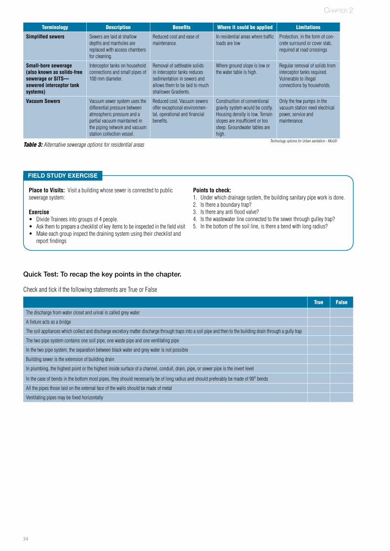
34
Quick Test: To recap the key points in the chapter.
Check and tick if the following statements are True or False
True False
The discharge from water closet and urinal is called grey water
A fixture acts as a bridge
The soil appliances which collect and discharge excretory matter discharge through traps into a soil pipe and then to the building drain through a gully trap
The two pipe system contains one soil pipe, one waste pipe and one ventilating pipe
In the two pipe system, the separation between black water and grey water is not possible
Building sewer is the extension of building drain
In plumbing, the highest point or the highest inside surface of a channel, conduit, drain, pipe, or sewer pipe is the invert level
In the case of bends in the bottom most pipes, they should necessarily be of long radius and should preferably be made of 90o bends
All the pipes those laid on the external face of the walls should be made of metal
Ventilating pipes may be fixed horizontally
Field Study exerciSe
Place to Visits: Visit a building whose sewer is connected to public sewerage system:
Exercise • Divide Trainees into groups of 4 people. • Ask them to prepare a checklist of key items to be inspected in the field visit• Make each group inspect the draining system using their checklist and
report findings
Points to check: 1. Under which drainage system, the building sanitary pipe work is done.2. Is there a boundary trap?3. Is there any anti flood valve?4. Is the wastewater line connected to the sewer through gulley trap?5. In the bottom of the soil line, is there a bend with long radius?
Chapter 2
Terminology Description Benefits where it could be applied Limitations
Simplified sewers Sewers are laid at shallow depths and manholes are replaced with access chambers for cleaning.
Reduced cost and ease of maintenance.
In residential areas where traffic loads are low
Protection, in the form of con-crete surround or cover slab, required at road crossings
Small-bore sewerage (also known as solids-free sewerage or SITS— sewered interceptor tank systems)
Interceptor tanks on household connections and small pipes of 100 mm diameter.
Removal of settleable solids in interceptor tanks reduces sedimentation in sewers and allows them to be laid to much shallower Gradients.
Where ground slope is low or the water table is high.
Regular removal of solids from interceptor tanks required. Vulnerable to illegal connections by households.
Vacuum Sewers Vacuum sewer system uses the differential pressure between atmospheric pressure and a partial vacuum maintained in the piping network and vacuum station collection vessel.
Reduced cost. Vacuum sewers offer exceptional environmen-tal, operational and financial benefits.
Construction of conventional gravity system would be costly. Housing density is low. Terrain slopes are insufficient or too steep. Groundwater tables are high.
Only the few pumps in the vacuum station need electrical power, service and maintenance.
Table 3: Alternative sewerage options for residential areasTechnology options for Urban sanitation - MoUD
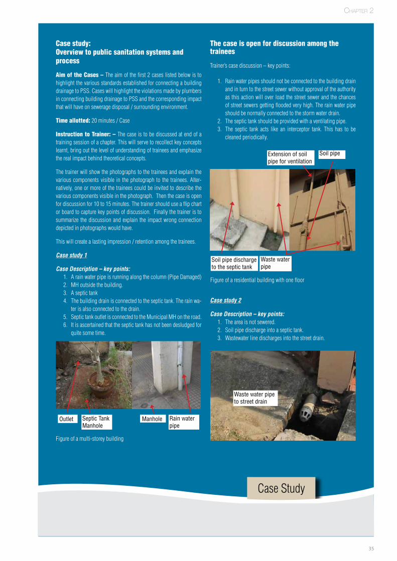
35
Case study: Overview to public sanitation systems and process
Aim of the Cases – The aim of the first 2 cases listed below is to highlight the various standards established for connecting a building drainage to PSS. Cases will highlight the violations made by plumbers in connecting building drainage to PSS and the corresponding impact that will have on sewerage disposal / surrounding environment.
Time allotted: 20 minutes / Case
Instruction to Trainer: – The case is to be discussed at end of a training session of a chapter. This will serve to recollect key concepts learnt, bring out the level of understanding of trainees and emphasize the real impact behind theoretical concepts.
The trainer will show the photographs to the trainees and explain the various components visible in the photograph to the trainees. Alter-natively, one or more of the trainees could be invited to describe the various components visible in the photograph. Then the case is open for discussion for 10 to 15 minutes. The trainer should use a flip chart or board to capture key points of discussion. Finally the trainer is to summarize the discussion and explain the impact wrong connection depicted in photographs would have.
This will create a lasting impression / retention among the trainees.
Case study 1
Case Description – key points:1. A rain water pipe is running along the column (Pipe Damaged)2. MH outside the building.3. A septic tank4. The building drain is connected to the septic tank. The rain wa-
ter is also connected to the drain.5. Septic tank outlet is connected to the Municipal MH on the road.6. It is ascertained that the septic tank has not been desludged for
quite some time.
The case is open for discussion among the trainees
Trainer’s case discussion – key points:
1. Rain water pipes should not be connected to the building drain and in turn to the street sewer without approval of the authority as this action will over load the street sewer and the chances of street sewers getting flooded very high. The rain water pipe should be normally connected to the storm water drain.
2. The septic tank should be provided with a ventilating pipe.3. The septic tank acts like an interceptor tank. This has to be
cleaned periodically.
Figure of a multi-storey building
FPO
Rain waterpipe
Septic TankManhole
ManholeOutlet
Figure of a residential building with one floor
Soil pipe dischargeto the septic tank
Extension of soil pipe for ventilation
Waste waterpipe
Soil pipe
Chapter 2
Case Study
Case study 2
Case Description – key points:1. The area is not sewered.2. Soil pipe discharge into a septic tank.3. Wastewater line discharges into the street drain.
Waste water pipeto street drain
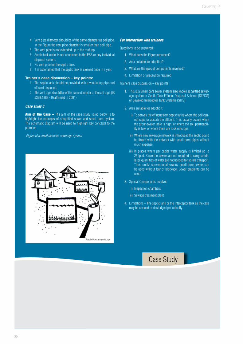
36
Chapter 2
For interaction with trainees
Questions to be answered:
1. What does the Figure represent?
2. Area suitable for adoption?
3. What are the special components involved?
4. Limitation or precaution required
Trainer’s case discussion – key points
1. This is a Small bore sewer system also known as Settled sewer-age system or Septic Tank Effluent Disposal Scheme (STEDS) or Sewered Interceptor Tank Systems (SITS)
2. Area suitable for adoption:
i) To convey the effluent from septic tanks where the soil can-not cope or absorb the effluent. This usually occurs when the groundwater table is high, or where the soil permeabil-ity is low, or where there are rock outcrops.
ii) Where new sewerage network is introduced the septic could be linked with the network with small bore pipes without much expense.
iii) In places where per capita water supply is limited up to 25 lpcd. Since the sewers are not required to carry solids, large quantities of water are not needed for solids transport. Thus, unlike conventional sewers, small bore sewers can be used without fear of blockage. Lower gradients can be used.
3. Special Components involved
i) Inspection chambers
ii) Sewage treatment plant
4. Limitations – The septic tank or the interceptor tank as the case may be cleaned or desludged periodically.
4. Vent pipe diameter should be of the same diameter as soil pipe. In the Figure the vent pipe diameter is smaller than soil pipe.
5. The vent pipe is not extended up to the roof top. 6. Septic tank outlet is not connected to the PSS or any individual
disposal system.7. No vent pipe for the septic tank.8. It is ascertained that the septic tank is cleaned once in a year.
trainer’s case discussion – key points:1. The septic tank should be provided with a ventilating pipe and
effluent disposed.2. The vent pipe should be of the same diameter of the soil pipe (IS
5329:1983 - Reaffirmed in 2001)
Case study 3
Aim of the Case – The aim of the case study listed below is to highlight the concepts of simplified sewer and small bore system. The schematic diagram will be used to highlight key concepts to the plumber.
Figure of a small diameter sewerage system
Adapted from akvopedia.org
Case Study

37
Notes
38
ThreeChapter 3
39
Sewerage Connections – When New Public Sewerage Network is Commissioned
Chapter Objective:
• Thechapterhighlightstheadditionaldetailsthatplumbersshouldknowinconnectingbuildingsewagetothenewpublicseweragesystem.
• ItbriefsaboutthedelinkingoftheexistingseptictankandconnectingthebuildingdrainagetothePSS.Secondly,theseptictankbeingconnectedtothePSSthroughsmallboresystem.
Chapter Duration: 80 minutes*
SECTION 1: New PSS network
Municipal byelaws
The Municipal byelaws provide laws for the owner of any propertyto dispose off his wastewater in a proper manner without causinganynuisance toothers.WhereverMunicipal sewers existwith somespecifieddistance, it isobligatorythat thewastewaterof thepropertyisdischargedintoit.Thebyelawsprovideforactionagainstdefaultingowners.
However, inthecaseofareasnotoriginallyservedwithseweragefa-cilities,theownersmayhavetobepersuadedtoavailofthefacilitiesprovidedtodisposeofftheirwastewatersandinsomecasesitmayevenbecomenecessaryforthelocalbodytoshowsomeincentivelikeloan/subsidyforgettingtheworksnecessarytodisposethewastewaterintosuchmunicipalsewers.
AdvantageofPSS:
1. Thepropertyisfreefrompollution.2. Theownerneednotbotheraboutthedisposalofsludgeandsafe
disposalofeffluentfromtheseptictankbythewayofsecondarytreatment.
3. IntheabsenceofPSS,thesightofSeptictankandtheventilationpipesisaneyesoreinthepremises.
4. IntheabsenceofPSS,theseptictanksandtheeffluentdisposaloccupyasizablequantityoflandarea.
5. Iftheeffluentisnotdisposedsafely,theincumbentsmaybesub-jectedtohealthproblems.
Disposals of building drainage
Itistheusualpracticewherepublicseweragesystemisavailable;thehousedrainshouldbeconnectedtothepublicsewerwiththeapprovalandasdirectedbytheauthority.
Wheredischargeintoapublicsewerisnotpossible, thedrainageofthebuildingnormallydonethroughoneofthefollowingindividualdis-posalsystems:
a) Leachingcesspoolb) Collecting in well, cleared periodically and wastes taken to a
centraltreatmentanddisposalsite;andc) Septictankandtheeffluentisdischargedintosoilabsorption
system,Biologicalfiltersandupflowanaerobicfilters.
Chapter 3
*duration is only indicative and can be changed based on requirements at different locations

40
Now when a new sewerage network is commissioned, the buildingownerisleftwiththefollowingoptions:
AlterBuildingdrainagesystemandconnecttoPSS
• bypassingtheseptictank• viatheseptictank
SECTION 2: Alteration of building drain to PSS (bypassing the septic tank) and alteration via septic tank to PSS
Drain Connected to Septic TankOption1–DelinkingOption2–SepticTankasinterceptortank
5. Sludgeshouldbewithdrawnusingadippipeofnotlessthan150mmunderahydrostaticpressureof450mm.
6. Thesludgepipeshalldeliverthesludgetoasumpandpro-videdwithadeliveryvalvetodrawthesludgeasrequired.
7. Portablepumpsmaybeusedavoidingsludgepipeandpump.
8. Thesludgeshouldbeconveyedtoasuitablevehicleforre-movalfromthesite.
9. ThelatesttrendistoengageaVacuumtankerfordesludgingaseptictank.
10. Supposing,thetankisfullandtankstartdeliveringthewastewater entering the tank and the septic tank is connected tothePSSthroughSBS,thenthesmallborepipedesignedtocarryliquidonlymaynotbeabletoconveythesolidwastecausingblockage.This shouldbe avoidedbypre-planningthedesludgingactivity.
B. Option 2
Figure 39: Water supply and sewerage system of a building – the drain connected to PSS
A. Option 1
Delink thedrainage connection to the existing septic tank inside thepremises,getanewserviceconnectionfromtheauthorityandconnectthehousedraintoPSS with the approval of the authority.TheconnectingbuildingdraintopublicsewersystemisalreadyexplainedinChapter2:Section2.Theexistingseptictankshouldbedesludgedandthestructureshouldberemovedimmediately.
• Stepsinvolvedindesludgingtheseptictank:
1. Manual handling of sludge is prohibited on public healthpointofview.
2. Careshouldbetakenthatthesludgedoesnotspreadontheground.
3. Theplumber shouldbear inmind thedesignperiodof theseptictankforsludgewithdrawal.
4. Beforetheendofdesignperiod,itshouldbeensuredthatthetankisnotfullandattaintheconditionofoverflow.Thenstartdesludging.Ifthesludgelayeriswithin300mmofthebottomofeithertheinletoroutlet,orifthebottomofthescumlayeriswithin75mmofthebottomoftheoutlet,thetankshouldbedesludged.
Conceived and drawn from IS 12183 (Part 1): 1987 - Reaffirmed in 2004 & IS 1742: 1983 - Reaffirmed in 2002
• TheeffluentfromtheseptictankmaybeconnectedtoPublicsew-eragesystemorsmallboresystemasthecasemaybewiththeapproval of the authority.
• InthiscaseasthesolidsareretainedintheseptictankitselfandonlyliquidwastealoneistransportedtothePSS,thecostofex-ecutionwillbeless.
• Asmalldiameterpipeof100mmmaybeused.Buttheseptictankwillactasacollectiontank.
Chapter 3
Figure 40: Vacuum tanker desludging a septic tank
Conceived and drawn from IS 2470 (Part 1) : 1985 - Reaffirmed in 2001
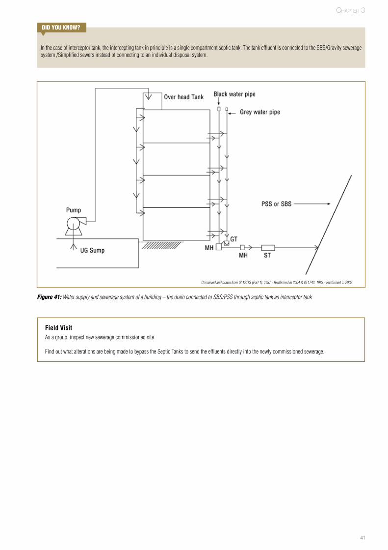
41
DID yOu kNOw?
Inthecaseofinterceptortank,theinterceptingtankinprincipleisasinglecompartmentseptictank.ThetankeffluentisconnectedtotheSBS/Gravityseweragesystem/Simplifiedsewersinsteadofconnectingtoanindividualdisposalsystem.
Chapter 3
Figure 41: Water supply and sewerage system of a building – the drain connected to SBS/PSS through septic tank as interceptor tank
Field VisitAsagroup,inspectnewseweragecommissionedsite
FindoutwhatalterationsarebeingmadetobypasstheSepticTankstosendtheeffluentsdirectlyintothenewlycommissionedsewerage.
Conceived and drawn from IS 12183 (Part 1): 1987 - Reaffirmed in 2004 & IS 1742: 1983 - Reaffirmed in 2002

42
Notes
43
Chapter 4

44
Basic Concepts of Plumbing
Connecting Building Drainage to Septic Tank and Other Decentralised Systems
Chapter Objective:
• Thechapterprovidesastepbystepapproachtobefollowedbyaplumberinconnectingbuildingdrainagesystemtoindividualdisposalsystems.Itisrecommendedintheabsenceofapublicseweragesystem.
• Ithighlightsthevarioustypesofseptictanks,precautionsaplumberhastoconsiderinconnectingbuildingdraintoseptictank,septictankssuitableforvariousterrainsandsoilconditions,needforcertaintypesoftraps,designspecificationaplumberhastoadheretoinaseptictank,rightwaystoconnectvarioustypesofpipesandrecommendationsasprescribedinthenationalplumbingstandards.
• Abriefdescriptionaboutthevariousotherdecentralisedeffluentdisposalsystemssuchassoakpitsdispersiontrench,biologicalfiltersandmoundisalsoprovided.
Chapter Duration: 180 minutes*
SECTION 1: Septic tanks – basic definitions and workings
Basic definitions
Septic tank–referstoawatertightconcretebox,buriedinthegroundjustoutsidethebuilding,butwithinthepremises.Septictankisapop-ular type of Individual disposal system for safe disposal of buildingsewerageinIndia.
Wherepublicseweragesystemisabsent,thebuildingdrainageisdis-chargedintotheSeptictank.Itactsasasmall-scalesewagetreatmentsystemhelpinginsafedisposalofbothblackandgreywater.
Fewkeypointsaplumbershouldfollowwithrespecttoseptictanksare:
• Septictankshouldbelocatedatanopenplaceandasfarawayaspossiblefromtheexteriorwallofthebuilding.
• Itshould not be locatedinswampyareasorareaspronetoflooding.
• Itshouldbelocatedinaplace,whichisaccessibleforcleaning.• Design and layout of septic tank shall be done as per IS 2470(Part-1):1985-Reaffirmedin2001.Thisisexplainedinsection 3 ofthischapter
• Septic tanks is a formof primary treatment and the dischargefromtheseptictankshouldalwaysbeconnectedtoappropriate
forms of secondary treatment like soak pit, dispersion trench,wetlands,biologicalfilters,anaerobicfiltersetc.
How a septic tank works?
It is important foraplumber tounderstandhowaseptic tankworks.Basicworkingprinciplesarelistedbelow:
• Wastewater from building is discharged into the septic tankthroughaT-shapedinletpipe.
• Heavysolidssettleatthebottomofthetank.• Lightersolidssuchasgrease,oilsandfats,risetothetopandformascumlayer.Solidsthatarenotdecomposedremainintheseptictank.
• Bacteriagrowintheseptictankanddigestthesolidsandreducethesolidsintoliquid,fatsandgrease,andinsolubleparticles.
• AT-shapedoutletpipepreventsthesludgeandscumfromleav-ingthetankandcloggingthedrainfieldarea.
• ArelativelyclearwastewaterflowsoutoftheseptictankthroughtheT-shapedoutletpipe.
DID yOu kNOw?
Septictankusesanaerobicbacteriatodigesttheseptage.Anaerobicbacte-riaarecapableoflivingorgrowinginanenvironmentlackingfreeoxygen.
Wastescontainingexcessivedetergents,greaseanddisinfectantsshouldnotbetreatedinseptic tankastheyadverselyaffect theanaerobicdecomposi-tion.
Chapter 4
*duration is only indicative and can be changed based on requirements at different locations
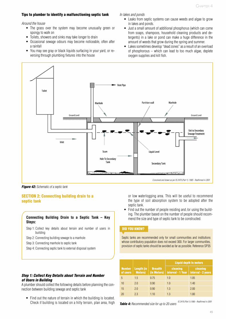
45
Tips to plumber to identify a malfunctioning septic tank
Around the house• The grass over the system may become unusually green orspongytowalkon
• Toilets,showersandsinksmaytakelongertodrain• Occasional sewageodoursmaybecomenoticeable,oftenafterarainfall
• Youmayseegrayorblackliquidssurfacinginyouryard,orre-versingthroughplumbingfixturesintothehouse
In lakes and ponds• Leaksfromsepticsystemscancauseweedsandalgaetogrowinlakesandponds.
• Justasmallamountofadditionalphosphorus(whichcancomefrom soaps, shampoos, household cleaning products and de-tergents) in a lakeor pond canmake a hugedifference in theamountofweedsthatgrowduringthespringandsummer.
• Lakessometimesdevelop“deadzones”asaresultofanoverloadof phosphorous –which can lead to toomuch algae, depleteoxygensuppliesandkillfish.
Figure 42: Schematic of a septic tank
SECTION 2: Connecting building drain to a septic tank
or lowwaterlogging area. Thiswill beuseful to recommendthe type of soil absorption system to be adopted after theseptictank.
• Findoutthenumberofpeopleresidingand/orusingthebuild-ing.Theplumberbasedonthenumberofpeopleshouldrecom-mendthesizeandtypeofseptictanktobeconstructed.Connecting Building Drain to a Septic Tank – Key
Steps:
Step1:Collect key details about terrain and number of users inbuilding
Step2:ConnectingbuildingsewagetoamanholeStep3:ConnectingmanholetoseptictankStep4:Connectingseptictanktoexternaldisposalsystem
Step 1: Collect Key Details about Terrain and Number of Users in BuildingAplumbershouldcollectthefollowingdetailsbeforeplanningthecon-nectionbetweenbuildingsewageandseptictank
• Findoutthenatureofterraininwhichthebuildingislocated.Checkifbuildingislocatedonahillyterrain,planarea,high
DID yOu kNOw?
Septic tanks are recommended only for small communities and institutionswhosecontributorypopulationdoesnotexceed300.Forlargercommunities,provisionofseptictanksshouldbeavoidedasfaraspossible.ReferenceSP35
Liquid depth in meters
Number of users
Length (in Meters)
Breadth (in Meters)
cleaning interval - 1 year
cleaning interval - 2 years
5 1.5 0.75 1.0 1.05
10 2.0 0.90 1.0 1.40
15 2.0 0.90 1.3 2.00
20 2.3 1.10 1.3 1.80
Table 4: Recommended size for up to 20 usersIS 2470 (Part 1):1985 - Reaffirmed in 2001
Chapter 4
Conceived and drawn as per IS 2470 (Part 1) :1985 - Reaffirmed in 2001
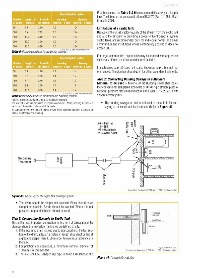
46
PlumbercanusetheTable 5 & 6 torecommendthesize/typeofseptictank.ThetablesareasperspecificationofIS2470(Part1):1985-Reaf-firmedin2001.
Limitations of a septic tankBecauseoftheunsatisfactoryqualityoftheeffluentfromtheseptictankandalsothedifficultyinprovidingapropereffluentdisposalsystem,septic tanks are recommended only for individual homes and smallcommunitiesandinstitutionswhosecontributorypopulationdoesnotexceed300.
Forlargercommunities,septictanksmaybeadoptedwithappropriatesecondaryeffluenttreatmentanddisposalfacilities.
Insuchcasessoakpit(Leechpitisalsoknownassoakpit)isnotrec-ommended.Theplumbershouldgoinforothersecondarytreatments.
Step 2: Connecting Building Sewage to a Manhole Material to be used–Materialof theBuildingSewershallbeei-therconventionalsaltglazedstonewareorUPVCrigidstraightpipesof6 kg/cm2pressureclassinmanufactureandasperIS15328:2003withsolventcementjoints.
• Thebuildingsewageintotaliscollectedinamanholeforcon-veyingtotheseptictankfortreatment.(Referto Figure 43)
Liquid depth in meters
Number of users
Length (in Meters)
Breadth (in Meters)
cleaning interval - 1 year
cleaning interval - 2 years
50 5.0 2.00 1.0 1.24
100 7.5 2.65 1.0 1.24
150 10.0 3.00 1.0 1.24
200 12.0 3.30 1.0 1.24
300 15.0 4.00 1.0 1.24
Liquid depth in meters
Number of users
Length (in Meters)
Breadth (in Meters)
cleaning interval - 1 year
cleaning interval - 2 years
50 5.0 1.60 1.3 1.4
100 5.7 2.10 1.4 1.7
150 7.7 2.40 1.4 1.7
200 8.9 2.70 1.4 1.7
300 10.7 3.30 1.4 1.7
Table 5: Recommended size for residential colonies
Note:Aprovisionof300mmshouldbemadeforfreeboard.Thesizesofseptictankarebasedoncertainassumptions.Whilechoosingthesizeofaseptictank,theexactcalculationshallbemade.forpopulationover100,thetankmaybedividedintoindependentparallelchambersforeaseofmaintenanceandcleaning.
Table 6: Recommended size for hostels and boarding schools
Figure 43: Typical layout of a septic tank sewarage system
Figure 44: T shaped dip inlet pipe
• Thelayoutshouldbesimpleandpractical.Pipesshouldbeasstraightaspossible.Bendsshouldbeavoided.Whereit isnotpossible,longradiusbendsshouldbeused.
Step 3: Connecting Manhole to Septic Tank Thisisthemostimportantconnectioninthisformofdisposalandtheplumbershouldfollowbelowmentionedguidelinesstrictly.
1. Iftheincomingdrainissteepduetositeconditions,thelastsec-tionofthedrain,atleast12metersinlengthshouldnotbelaidatagradientsteeperthan1:50inordertominimizeturbulenceinthetank.
2. For practical considerations, a minimum nominal diameter of100mmisrecommended.
3. TheinletshallbeT-shapeddippipetoavoidturbulenceinthe
* Figure not drawn to scale
IS 2470 (Part 1):1985 - Reaffirmed in 2001
IS 2470 (Part 1):1985 - Reaffirmed in 2001
Adapted from the Standard IS 2470 (Part 1): 1985 - Reaffirmed in 2001
Chapter 4
Conceived and drawn as per IS 2470 (Part 1) :1985 - Reaffirmed in 2001
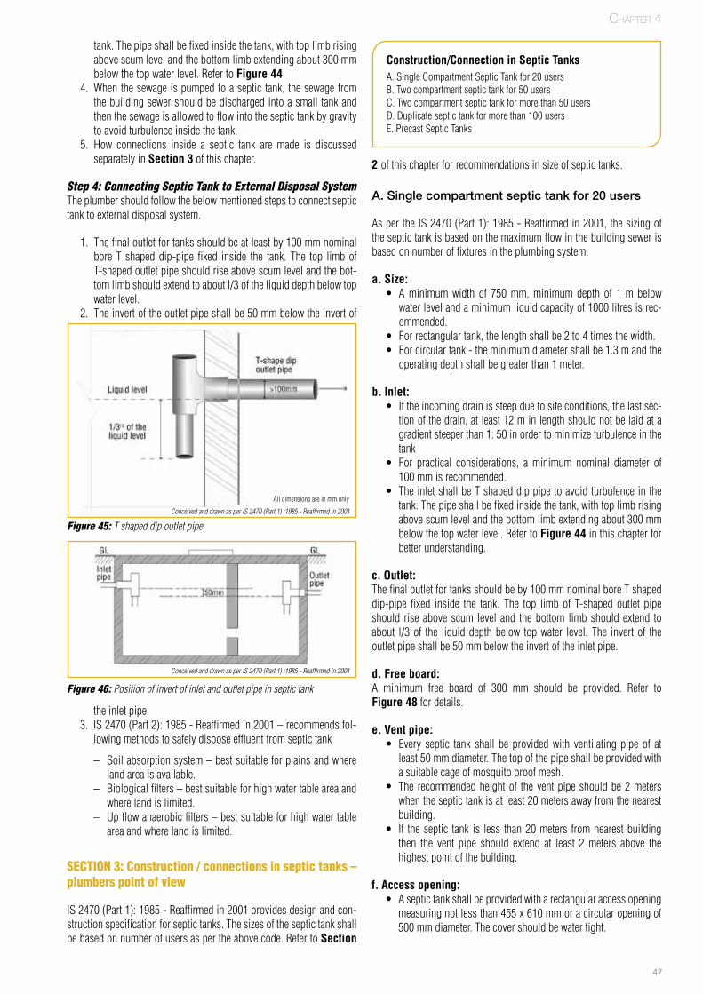
47
tank.Thepipeshallbefixedinsidethetank,withtoplimbrisingabovescumlevelandthebottomlimbextendingabout300 mmbelowthetopwaterlevel.RefertoFigure 44.
4. Whenthesewageispumpedtoaseptictank,thesewagefromthebuildingsewershouldbedischargedintoasmall tankandthenthesewageisallowedtoflowintotheseptictankbygravitytoavoidturbulenceinsidethetank.
5. How connections inside a septic tank are made is discussedseparatelyinSection 3ofthischapter.
Step 4: Connecting Septic Tank to External Disposal System Theplumbershouldfollowthebelowmentionedstepstoconnectseptictanktoexternaldisposalsystem.
1. Thefinaloutletfortanksshouldbeatleastby100mmnominalbore T shapeddip-pipe fixed inside the tank. The top limbofT-shapedoutletpipeshouldriseabovescumlevelandthebot-tomlimbshouldextendtoaboutl/3oftheliquiddepthbelowtopwaterlevel.
2. Theinvertoftheoutletpipeshallbe50mmbelowtheinvertof
2 ofthischapterforrecommendationsinsizeofseptictanks.
A. Single compartment septic tank for 20 users
AspertheIS2470(Part1):1985-Reaffirmedin2001,thesizingoftheseptictankisbasedonthemaximumflowinthebuildingsewerisbasedonnumberoffixturesintheplumbingsystem.
a.Size: • Aminimumwidth of 750mm,minimum depth of 1m belowwaterlevelandaminimumliquidcapacityof1000litresisrec-ommended.
• Forrectangulartank,thelengthshallbe2to4timesthewidth.• Forcirculartank-theminimumdiametershallbe1.3mandtheoperatingdepthshallbegreaterthan1meter.
b.Inlet: • Iftheincomingdrainissteepduetositeconditions,thelastsec-tionofthedrain,atleast12minlengthshouldnotbelaidatagradientsteeperthan1:50inordertominimizeturbulenceinthetank
• For practical considerations, a minimum nominal diameter of100mmisrecommended.
• TheinletshallbeTshapeddippipetoavoidturbulenceinthetank.Thepipeshallbefixedinsidethetank,withtoplimbrisingabovescumlevelandthebottomlimbextendingabout300mmbelowthetopwaterlevel.RefertoFigure 44inthischapterforbetterunderstanding.
c.Outlet: Thefinaloutletfortanksshouldbeby100mmnominalboreTshapeddip-pipe fixed inside the tank. The top limb of T-shaped outlet pipeshould rise above scum level and thebottom limbshould extend toabout l/3of the liquiddepthbelow topwater level.The invertof theoutletpipeshallbe50mmbelowtheinvertoftheinletpipe.
d.Free board: A minimum free board of 300 mm should be provided. Refer toFigure 48fordetails.
e.Vent pipe:• Every septic tank shall be providedwith ventilating pipe of atleast50 mmdiameter.Thetopofthepipeshallbeprovidedwithasuitablecageofmosquitoproofmesh.
• The recommendedheightof theventpipeshouldbe2meterswhentheseptictankisatleast20metersawayfromthenearestbuilding.
• If theseptic tank is less than20meters fromnearestbuildingthen the vent pipe should extend at least 2meters above thehighestpointofthebuilding.
f.Access opening:• Aseptictankshallbeprovidedwitharectangularaccessopeningmeasuringnotlessthan455x610mmoracircularopeningof500mmdiameter.Thecovershouldbewatertight.
theinletpipe.3. IS2470(Part2):1985-Reaffirmedin2001–recommendsfol-
lowingmethodstosafelydisposeeffluentfromseptictank
– Soilabsorptionsystem–bestsuitableforplainsandwherelandareaisavailable.
– Biologicalfilters–bestsuitableforhighwatertableareaandwherelandislimited.
– Upflowanaerobicfilters–bestsuitableforhighwatertableareaandwherelandislimited.
SECTION 3: Construction / connections in septic tanks – plumbers point of view
IS2470(Part1):1985-Reaffirmedin2001providesdesignandcon-structionspecificationforseptictanks.Thesizesoftheseptictankshallbebasedonnumberofusersaspertheabovecode.RefertoSection
Construction/Connection in Septic TanksA.SingleCompartmentSepticTankfor20usersB.Twocompartmentseptictankfor50usersC.Twocompartmentseptictankformorethan50usersD.Duplicateseptictankformorethan100usersE.PrecastSepticTanks
Figure 46: Position of invert of inlet and outlet pipe in septic tank
Figure 45: T shaped dip outlet pipe
Alldimensionsareinmmonly
Chapter 4
Conceived and drawn as per IS 2470 (Part 1) :1985 - Reaffirmed in 2001
Conceived and drawn as per IS 2470 (Part 1) :1985 - Reaffirmed in 2001
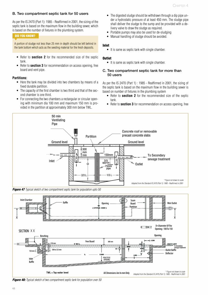
48
B. Two compartment septic tank for 50 users
AspertheIS2470(Part1):1985-Reaffirmedin2001,thesizingoftheseptictankisbasedonthemaximumflowinthebuildingsewer,whichisbasedonthenumberoffixturesintheplumbingsystem.
DID yOu kNOw?
Aportionofsludgenotlessthan25mmindepthshouldbeleftbehindinthetankbottomwhichactsastheseedingmaterialforthefreshdeposits.
• Refer to section 2 for the recommended size of the septictank.
• Refertosection 3 forrecommendationonaccessopening,freeboardandventpipe.
Partitions:• Herethetankmaybedividedintotwochambersbymeansofafixeddurablepartition.
• Thecapacityofthefirstchamberistwothirdandthatofthesec-ondchamberisonethird.
• Forconnectingthetwochambersarectangularorcircularopen-ingwithminimumdia100mmandmaximum150mmispro-videdinthepartitionatapproximately300mmbelowTWL.
• Thedigestedsludgeshouldbewithdrawnthroughadippipeun-derahydrostaticpressureofatleast450mm.Thesludgepipeshalldeliverthesludgetothesumpandbeprovidedwithade-liveryvalvetodrawthesludgeasrequired.
• Portablepumpsmayalsobeusedforde-sludging• Manualhandlingofsludgeshouldbeavoided.
Inlet• Itissameasseptictankwithsinglechamber.
Outlet • Itissameasseptictankwithsinglechamber.
C. Two compartment septic tank for more than 50 users
AspertheIS2470(Part1):1985-Reaffirmedin2001,thesizingoftheseptictankisbasedonthemaximumflowinthebuildingsewerisbasedonnumberoffixturesintheplumbingsystem
• Refer to section 2 for the recommended size of the septictank.
• Refertosection 3 forrecommendationonaccessopening,free
Figure 48: Typical sketch of two compartment septic tank for population over 50
Chapter 4
TWL = Top water level * Figure not drawn to scaleAdapted from the Standard IS 2470 (Part 1): 1985 - Reaffirmed in 2001
XX
Figure 47 Typical sketch of two compartment septic tank for population upto 50
* Figure not drawn to scaleAdapted from the Standard IS 2470 (Part 1): 1985 - Reaffirmed in 2001
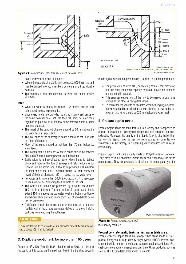
49
boardandventpipeandoutletpipe.• Wherethecapacityofaseptictankexceeds2000litres,thetankmaybedividedintotwochambersbymeansofafixeddurablepartition.
• The capacity of the first chamber is twice that of the secondchamber.
Inlet• When thewidthof the tanksexceeds1.2meters, twoormoresubmergedinletsarepreferable.
• Submerged inlets are provided by using submerged bends ofthesamenominalbore (not less than100mm)set ascloselytogetheraspractical inashallowsump formedwithinasmallbenchedchamber.
• Theinvertofthebenchedchannelshouldbe50mmabovethetopwaterlevelinseptictank
• Theinletendsofthesubmergedbendsshouldbesetflushwiththefloorofthesump.
• Floor of the sump should be not less than 75mmbelow topwaterlevel.
• Theinvertsoftheoutletendsofthesebendsshouldbebetween300and525mmbelowtopwaterlevelinthetank.
• Baffle refers to a flow-directing panel which helps to deflect,checkandregulatetheflowofsewageandhelpsreduceturbu-lenceinsidetheseptictank.Itshouldbeprovided150mmfromthe inlet end of the tank. It should extend 150mmbelow theinvertoftheinletpipesand150mmabovethetopwaterlevel.
• Forwidertanks(morethan2000litrescapacity),itisnecessarytouseaweiroutletextendingthefullwidthofthetank.
• The weir outlet should be protected by a scum board fixed150mm from theweir.The topportionofscumboardshouldextend150mmabovethetopwaterlevelandbottomportionofscumboardshouldextendtoonethird(l/3)ofliquiddepthbelowthetopwaterlevel.
• Adeflectorshouldbe formedeither in thestructureof theend(outlet) wall or by a purpose-made deflector to prevent risingparticlesfromreachingtheoutletweir.
D. Duplicate septic tank for more than 100 users
AspertheIS2470(Part1):1985-Reaffirmedin2001,thesizingoftheseptictankisbasedonthemaximumflowinthebuildingsewer.In
Figure 49: Twin inlets for septic tank where width exceeds 1.2 m
DID yOu kNOw?
Thisdeflectorshouldbelocated150mmbelowthebaseofthescumboardandprotrude150mmintothetank
PLAN SECTION * Figure not drawn to scale
Alldimensionsareinmmonly
SubmergedInlet
SubmergedInlet
TWL = Top Water Level
Adapted from the Standard IS 2470 (Part 1): 1985 - Reaffirmed in 2001
thedesignofseptictankgivenbelow,itistakenas9litresperminute.
• For population of over 100, duplicating tanks, each providinghalf the total calculated capacity required, should be installedandoperatedinparallel.
• Thisarrangementpermitsalltheflowtobepassedthroughoneunitwhiletheotherisbeingdesludged.
• Toenablethetopwatertobedecantedwhendesludging,adecant-ingvalveshouldbeprovidedinthewalldividingthetwotanks;theinvertofthisvalveshouldbe625mmbelowtopwaterlevel.
E. Precast septic tanks
PrecastSepticTanksaremanufacturedinafactoryandtransportedtothesiteforinstallation,therebyreducingInstallationtimeandcostcon-siderably.Moreover, thequalityof theSepticTank isalsobetter thanCast-in-situSepticTanksas theyaremanufactured incontrolleden-vironments in the factory, thusensuringwater-tightnessandmaterialconsistency.
Precast Septic Tanks are usuallymade of Polyethylene or Concrete.They havemultiple chambers within them and amanhole for futuremaintenance.Theyareavailable incircularor in rectangular type for
Figure 50: Precast concrete septic tankthecapacityrequired.
Precast concrete septic tanks in high water table area:Precast concrete septic tanks are stronger than tanksmade of steel,plastic,fiberglass,orhigh-densitypolyethylene(HDPE).Precastcon-creteisflexibleenoughtowithstandextremeloadingconditions.Pre-castconcretegraduallystrengthensovertime.Otherproducts,suchassteelorHDPE,candeteriorateandlosestrength.
Adapted from keralaarchitect.blogspot.com
Chapter 4
SectionXX
525 mm max300 mm min
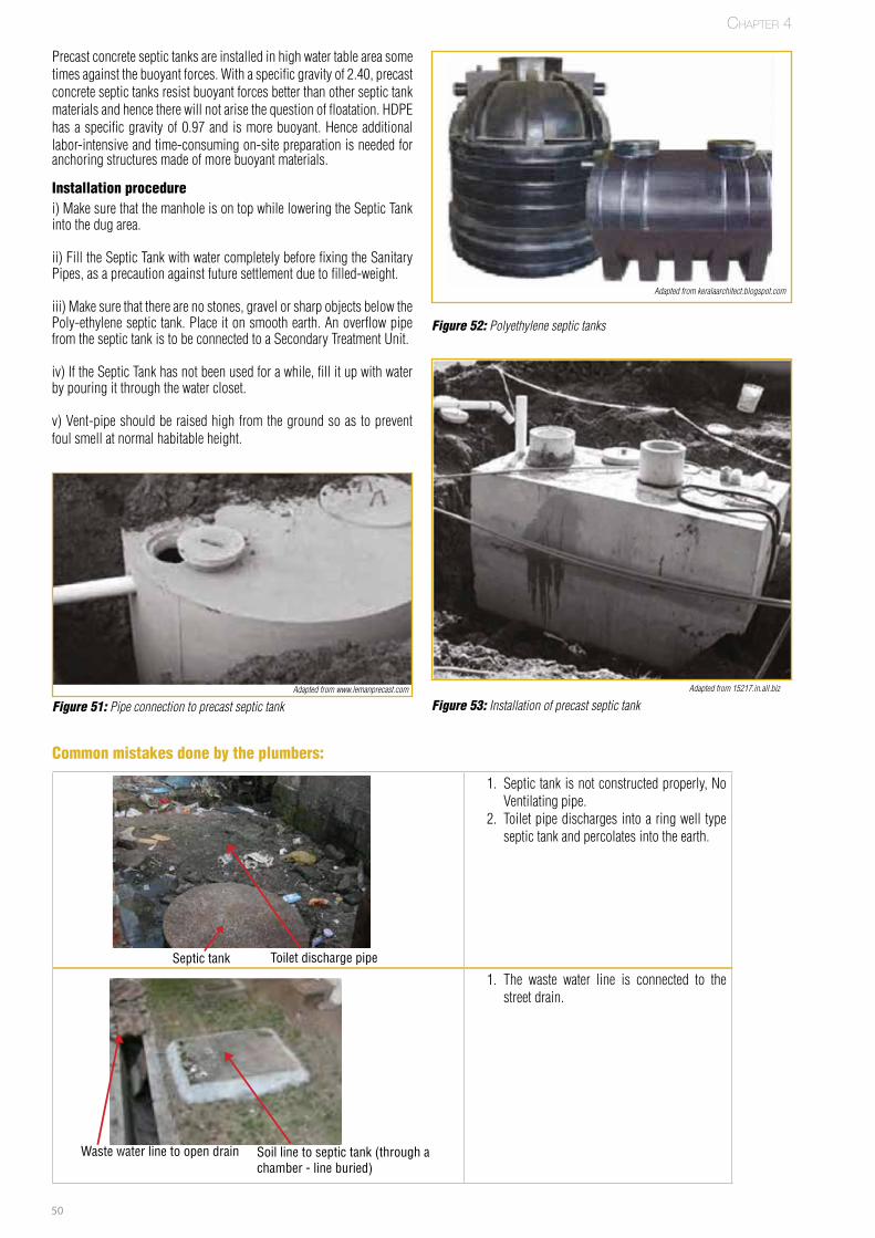
50
Precastconcreteseptictanksareinstalledinhighwatertableareasometimesagainstthebuoyantforces.Withaspecificgravityof2.40,precastconcreteseptictanksresistbuoyantforcesbetterthanotherseptictankmaterialsandhencetherewillnotarisethequestionoffloatation.HDPEhasaspecificgravityof0.97and ismorebuoyant.Henceadditionallabor-intensiveandtime-consumingon-sitepreparationisneededforanchoringstructuresmadeofmorebuoyantmaterials.
Installation procedurei)MakesurethatthemanholeisontopwhileloweringtheSepticTankintothedugarea.
ii)FilltheSepticTankwithwatercompletelybeforefixingtheSanitaryPipes,asaprecautionagainstfuturesettlementduetofilled-weight.
iii)Makesurethattherearenostones,gravelorsharpobjectsbelowthePoly-ethyleneseptictank.Placeitonsmoothearth.AnoverflowpipefromtheseptictankistobeconnectedtoaSecondaryTreatmentUnit.
iv)IftheSepticTankhasnotbeenusedforawhile,fillitupwithwaterbypouringitthroughthewatercloset.
v)Vent-pipeshouldberaisedhighfromthegroundsoas topreventfoulsmellatnormalhabitableheight.
Figure 52: Polyethylene septic tanks
Adapted from keralaarchitect.blogspot.com
Figure 53: Installation of precast septic tankAdapted from 15217.in.all.biz
Figure 51: Pipe connection to precast septic tankAdapted from www.lemanprecast.com
1. Septictankisnotconstructedproperly,NoVentilatingpipe.
2. Toiletpipedischargesintoaringwell typeseptictankandpercolatesintotheearth.
FPO
Toilet discharge pipeSeptic tank
Chapter 4
Common mistakes done by the plumbers:
1. The waste water line is connected to thestreetdrain.
FPO
Soil line to septic tank (through a chamber - line buried)
Waste water line to open drain
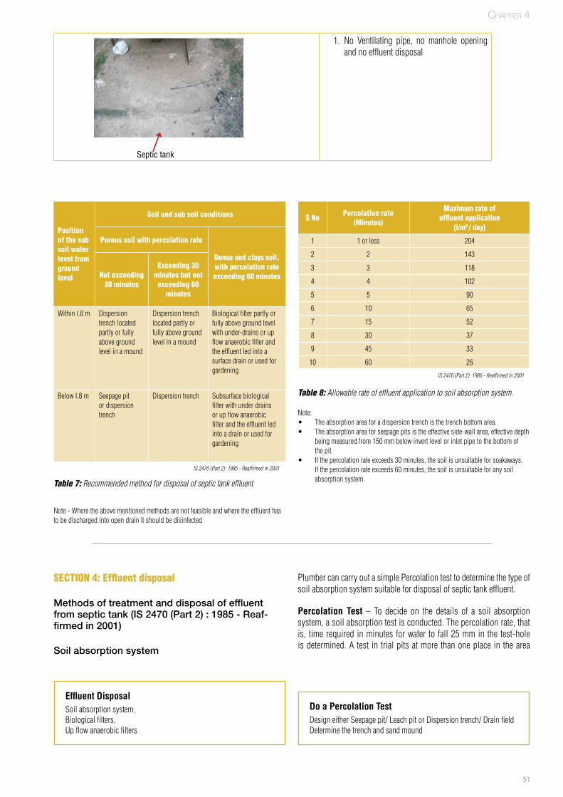
51
1. No Ventilating pipe, no manhole openingandnoeffluentdisposal
PlumbercancarryoutasimplePercolationtesttodeterminethetypeofsoilabsorptionsystemsuitablefordisposalofseptictankeffluent.
Percolation Test – To decide on the details of a soil absorptionsystem,asoilabsorptiontestisconducted.Thepercolationrate,thatis, timerequiredinminutes forwater to fall25mmin the test-holeisdetermined.Atest in trialpitsatmorethanoneplacein thearea
Effluent DisposalSoilabsorptionsystem,Biologicalfilters,Upflowanaerobicfilters
Do a Percolation TestDesigneitherSeepagepit/LeachpitorDispersiontrench/DrainfieldDeterminethetrenchandsandmound
Position of the sub soil water level from ground level
Soil and sub soil conditions
Porous soil with percolation rate
Dense and clays soil, with percolation rate exceeding 60 minutesNot exceeding
30 minutes
Exceeding 30 minutes but not exceeding 60
minutes
Withinl.8m Dispersiontrenchlocatedpartlyorfullyabovegroundlevelinamound
Dispersiontrenchlocatedpartlyorfullyabovegroundlevelinamound
Biologicalfilterpartlyorfullyabovegroundlevelwithunder-drainsorupflowanaerobicfilterandtheeffluentledintoasurfacedrainorusedforgardening
BelowI.8m Seepagepitordispersiontrench
Dispersiontrench Subsurfacebiologicalfilterwithunderdrainsorupflowanaerobicfilterandtheeffluentledintoadrainorusedforgardening
Table 7: Recommended method for disposal of septic tank effluent
Note-Wheretheabovementionedmethodsarenotfeasibleandwheretheeffluenthastobedischargedintoopendrainitshouldbedisinfected
FPO
S No Percolation rate(Minutes)
Maximum rate of effluent application
(l/m2 / day)
1 1orless 204
2 2 143
3 3 118
4 4 102
5 5 90
6 10 65
7 15 52
8 30 37
9 45 33
10 60 26
Table 8: Allowable rate of effluent application to soil absorption system.
IS 2470 (Part 2): 1985 - Reaffirmed in 2001
IS 2470 (Part 2): 1985 - Reaffirmed in 2001
SECTION 4: Effluent disposal
Methods of treatment and disposal of effluent from septic tank (IS 2470 (Part 2) : 1985 - Reaf-firmed in 2001)
Soil absorption system
Septic tank
Note:• Theabsorptionareaforadispersiontrenchisthetrenchbottomarea.• Theabsorptionareaforseepagepitsistheeffectiveside-wallarea,effectivedepth
beingmeasuredfrom150mmbelowinvertlevelorinletpipetothebottomofthepit.
• Ifthepercolationrateexceeds30minutes,thesoilisunsuitableforsoakaways.Ifthepercolationrateexceeds60minutes,thesoilisunsuitableforanysoilabsorptionsystem.
Chapter 4
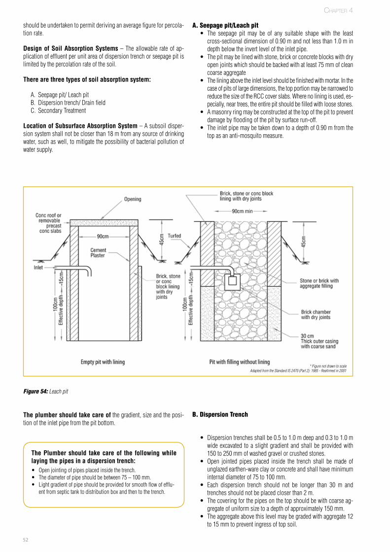
52
shouldbeundertakentopermitderivinganaveragefigureforpercola-tionrate.
Design of Soil Absorption Systems–Theallowable rateofap-plicationofeffluentperunitareaofdispersiontrenchorseepagepitislimitedbythepercolationrateofthesoil.
There are three types of soil absorption system:
A. Seepagepit/LeachpitB. Dispersiontrench/DrainfieldC. SecondaryTreatment
Location of Subsurface Absorption System–Asubsoildisper-sionsystemshallnotbecloserthan18mfromanysourceofdrinkingwater,suchaswell,tomitigatethepossibilityofbacterialpollutionofwatersupply.
A. Seepage pit/Leach pit • The seepage pit may be of any suitable shape with the leastcross-sectionaldimensionof0.90mandnotlessthan1.0mindepthbelowtheinvertleveloftheinletpipe.
• Thepitmaybelinedwithstone,brickorconcreteblockswithdryopenjointswhichshouldbebackedwithatleast75mmofcleancoarseaggregate
• Theliningabovetheinletlevelshouldbefinishedwithmortar.Inthecaseofpitsoflargedimensions,thetopportionmaybenarrowedtoreducethesizeoftheRCCcoverslabs.Wherenoliningisused,es-pecially,neartrees,theentirepitshouldbefilledwith loosestones.
• Amasonryringmaybeconstructedatthetopofthepittopreventdamagebyfloodingofthepitbysurfacerun-off.
• Theinletpipemaybetakendowntoadepthof0.90mfromthetopasananti-mosquitomeasure.
Figure 54: Leach pit
The plumber should take care ofthegradient,sizeandtheposi-tionoftheinletpipefromthepitbottom.
B. Dispersion Trench
• Dispersiontrenchesshallbe0.5to1.0mdeepand0.3to1.0mwideexcavated toaslightgradientandshallbeprovidedwith150to250mmofwashedgravelorcrushedstones.
• Open jointed pipes placed inside the trench shall bemade ofunglazedearthen-wareclayorconcreteandshallhaveminimuminternaldiameterof75to100mm.
• Each dispersion trench should not be longer than 30 m andtrenchesshouldnotbeplacedcloserthan2m.
• Thecoveringforthepipesonthetopshouldbewithcoarseag-gregateofuniformsizetoadepthofapproximately150mm.
• Theaggregateabovethislevelmaybegradedwithaggregate12to15mmtopreventingressoftopsoil.
The Plumber should take care of the following while laying the pipes in a dispersion trench:• Openjointingofpipesplacedinsidethetrench.• Thediameterofpipeshouldbebetween75–100mm.• Lightgradientofpipeshouldbeprovidedforsmoothflowofefflu-
entfromseptictanktodistributionboxandthentothetrench.
* Figure not drawn to scaleAdapted from the Standard IS 2470 (Part 2): 1985 - Reafirmed in 2001
Chapter 4
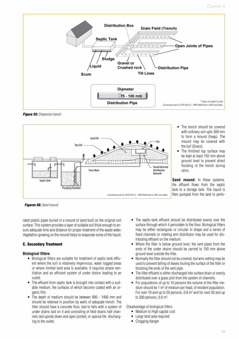
53
• The trench should be coveredwithordinarysoilupto300mmto form a mound (heap). Themound may be covered withtheturf(Grass).
• The finished top surface maybekeptatleast150mmaboveground level to prevent directflooding of the trench duringrains.
Sand mound: In these systems,the effluent flows from the septictank to a storage tank. The liquid isthenpumped from the tank toperfo-
Figure 55: Dispersion trench
Figures 56: Sand mound
ratedplasticpipesburiedinamoundofsandbuiltontheoriginalsoilsurface.Thissystemprovidesalayerofsuitablesoilthickenoughtoen-sureadequatetimeanddistanceforpropertreatmentofthewastewater.Vegetationgrowingonthe moundhelpstoevaporatesomeoftheliquid.
C. Secondary Treatment
Biological filters • Biologicalfiltersaresuitablefortreatmentofseptictankefflu-entwherethesoilisrelativelyimpervious,waterloggedareasorwherelimitedlandareaisavailable.Itrequiresampleven-tilationandanefficientsystemofunderdrains leading toanoutlet.
• Theeffluentfromseptictankisbroughtintocontactwithasuit-ablemedium,thesurfacesofwhichbecomecoatedwithanor-ganicfilm.
• Thedepthofmediumshouldbebetween900-1400mmandshouldberetainedinpositionbywallsofadequatetrench.Thefiltershouldhaveaconcretefloor,laidtofallswithasystemofunderdrainslaidonitandconsistingoffielddrainshalfchan-nelslaidupsidedownandopenjointed,orspecialtiledischarg-ingtotheoutlet.
• The septic-tank effluent should be distributed evenly over thesurfacethroughwhichitpercolatestothefloor.Biologicalfiltersmaybe either rectangular or circular in shape and a series offixedchannelsorrotatingarmdistributormaybeusedfordis-tributingeffluentonthemedium.
• Where thefilter isbelowground level, theventpipes fromtheends of the under drains should be carried to 150mmabovegroundleveloutsidethefilter.
• Normallythefiltershouldnotbecovered,butwirenettingmaybeusedtopreventfallingofleavesfoulingthesurfaceofthefilterorblockingtheendsoftheventpipe.
• Thefiltereffluentiseitherdischargedintosurfacedrainorevenlydistributedoveragrassplotfromthesystemofchannels.
• Forpopulationsofupto10personsthevolumeofthefilterme-diumshouldbe1m3ofmediumperhead,ofresidentpopulation.Forover10andupto50persons,0.8m3andforover50andupto300persons,0.6m3.
Disadvantageofbiologicalfilters• MediumtoHighcapitalcost• Largelandarearequired• Cloggingdanger
FPO
FPO
* Figure not drawn to scaleConceived as per IS 2470 (Part 2) : 1985 Reaffirmed in 2001 and drawn
Conceived as per IS 2470 (Part 2) : 1985 Reaffirmed in 2001 and drawn
Chapter 4
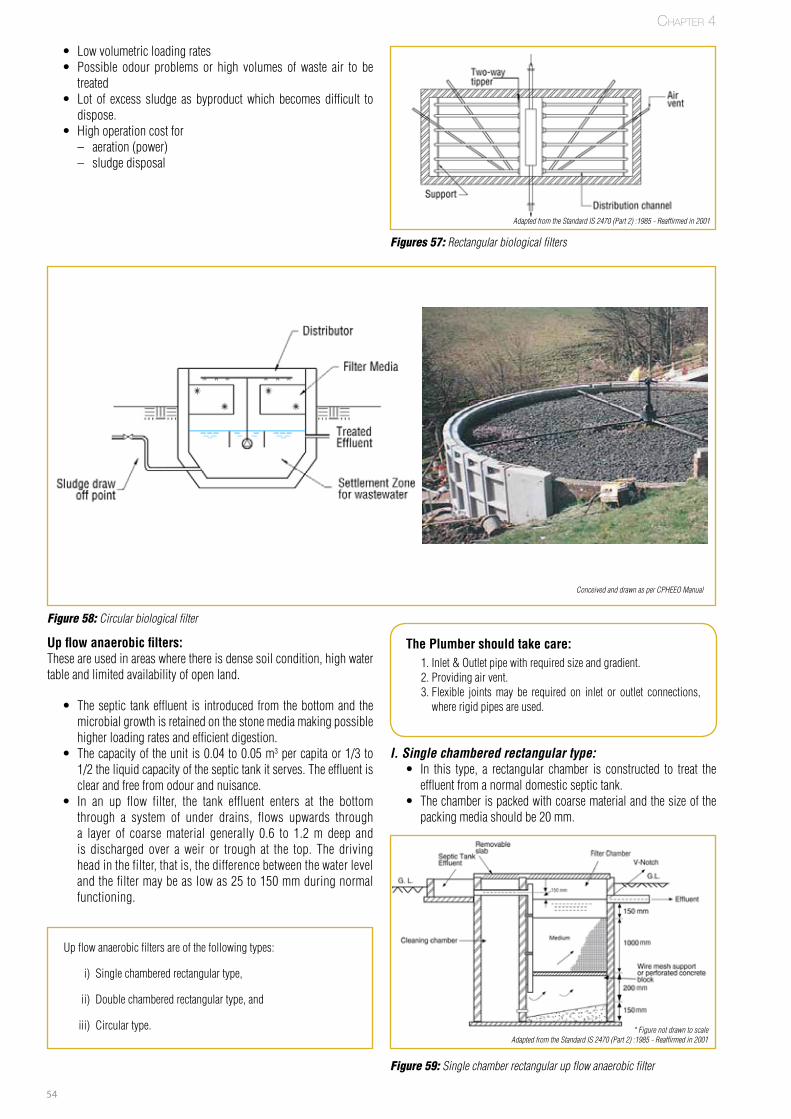
54
• Lowvolumetricloadingrates• Possible odour problems or high volumes of waste air to betreated
• Lot of excess sludge as byproductwhich becomes difficult todispose.
• Highoperationcostfor– aeration(power)– sludgedisposal
Up flow anaerobic filters: Theseareusedinareaswherethereisdensesoilcondition,highwatertableandlimitedavailabilityofopenland.
• Theseptic tankeffluent is introduced from thebottomand themicrobialgrowthisretainedonthestonemediamakingpossiblehigherloadingratesandefficientdigestion.
• Thecapacityoftheunitis0.04to0.05m3percapitaor1/3to1/2theliquidcapacityoftheseptictankitserves.Theeffluentisclearandfreefromodourandnuisance.
• In an up flow filter, the tank effluent enters at the bottomthrough a system of under drains, flows upwards througha layer of coarsematerial generally 0.6 to 1.2m deep andis discharged over a weir or trough at the top. The drivingheadinthefilter,thatis,thedifferencebetweenthewaterlevelandthefiltermaybeaslowas25to150mmduringnormalfunctioning.
Figures 57: Rectangular biological filters
Figure 58: Circular biological filter
Figure 59: Single chamber rectangular up flow anaerobic filter
The Plumber should take care:1.Inlet&Outletpipewithrequiredsizeandgradient.2.Providingairvent.3.Flexible jointsmay be required on inlet or outlet connections,whererigidpipesareused.
I. Single chambered rectangular type: • In this type, a rectangular chamber is constructed to treat theeffluentfromanormaldomesticseptictank.
• Thechamberispackedwithcoarsematerialandthesizeofthepackingmediashouldbe20mm.
Upflowanaerobicfiltersareofthefollowingtypes:
i) Singlechamberedrectangulartype,
ii) Doublechamberedrectangulartype,and
iii) Circulartype. * Figure not drawn to scale
Adapted from the Standard IS 2470 (Part 2) :1985 - Reaffirmed in 2001
Adapted from the Standard IS 2470 (Part 2) :1985 - Reaffirmed in 2001
Chapter 4
Conceived and drawn as per CPHEEO Manual
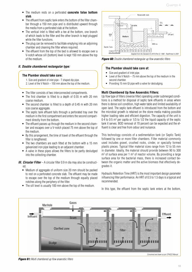
55
• The medium rests on a perforated concrete false bottom slab.
• Theeffluentfromseptictankentersthebottomofthefiltercham-ber througha150mmpipeandisdistributedupwardthroughthemediafromaperforatedslabatthebottom.
• Thevertical inlet isfittedwitha teeat thebottom,onebranchofwhichleadstothefilterandtheotherbranchiskeptpluggedwhilethefilterfunctions.
• Theplugcanberemovedtofacilitateemptyingintoanadjoiningchamberandcleaningthefilterwhererequired.
• TheeffluentfromthetopofthebedisallowedtoescapeoveraV-notchwhosesill(bottom)leveliskept150mmabovethetopofthemedium.
II. Double chambered rectangular type:
Multi Chambered Up flow Anaerobic Filters:Upflowtypeoffilters(reversefilter)operatingundersubmergedcondi-tions isamethodfordisposalofseptic tankeffluents inareaswherethereisdensesoilcondition,highwatertableandlimitedavailabilityofopenland.Theseptictankeffluentisintroducedfromthebottomandthemicrobialgrowthisretainedonthestonemediamakingpossiblehigherloadingratesandefficientdigestion.Thecapacityoftheunitis0·4to0·5m3percapitaor1/3to1/2theliquidcapacityoftheseptictankitserves.BODremovalof70percentcanbeexpectedandtheef-fluentisclearandfreefromodourandnuisance.
This technologyconsistsof asedimentation tank (orSepticTank)followedbyoneormorefilterchambers.Filtermaterialcommonlyused includes gravel, crushed rocks, cinder, or specially formedplasticpieces.Typicalfiltermaterialsizesrangefrom12to55 mmindiameter.Ideally,thematerialshouldprovidebetween90to300m2ofsurfaceareaper1m3ofreactorvolume.Byprovidingalargesurfacearea for thebacterialmass, there is increasedcontactbe-tweentheorganicmatterandtheactivebiomassthateffectivelyde-gradesit.
HydraulicRetentionTime(HRT)isthemostimportantdesignparameterinfluencingfilterperformance.AnHRTof0.5to1.5daysisatypicalandrecommended.
In this type, the effluent from the septic tank enters at the bottom,
The Plumber should take care:1.Sizeandgradientofinletpipe-Tshapeddippipe.2.LeveloftheVNotch–150mmabovethetopofthemedium.
The Plumber should take care of:• Sizeandgradientofinletpipe.• LeveloftheVNotch–75mmabovethetopofthemediuminthe
secondchamber.• Providing15mmGIpipewithavalvefordesludging.
• Thefilterconsistsoftwointerconnectedcompartments.• The first chamber is filled to a depth of 0.55m with 20mmcoarsemedium.
• Thesecondchamberisfilledtoadepthof0.45mwith20mmsizecoarseaggregate.
• Theseptic tankeffluent falls throughaperforated trayover themediuminthefirstcompartmentandentersthesecondcompart-mentdirectlyfromthebottom.
• Theeffluentpassesupthroughthemediuminthesecondcham-berandescapesoveraV-notchplaced75mmabovethetopofthemedium.
• Bythisarrangement,thetimeoftraveloftheeffluentthroughthefilterislengthened.
• The twochambersareeachfittedat thebottomwitha15mmgalvanizedironpipeleadingtoanadjacentchamber.
• Avalve in thesepipesallowsthefilters tobepartlydesludgedintothecollectingchamber.
III. Circular Filter –Acircularfilter0.9mdiamayalsobeconstruct-ed.• Mediumofaggregateofuniformsize20mmshouldbepackedtorestonaperforatedconcreteslab.Theeffluentmaybemadeto escape over the top of themedium through equally placednotchesalongtheperipheryofthefilter.
• Thesilllevelisusually100mmabovethetopofthemedium.
Figure 60: Double chambered rectangular up flow anaerobic filters
Figure 61: Multi chambered up flow anaerobic filters
Adapted from the Standard IS 2470 (Part 2) :1985 - Reaffirmed in 2001
Conceived and drawn as per CPHEEO Manual
Chapter 4
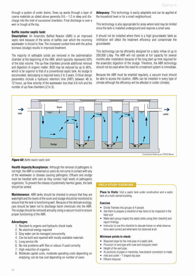
56
throughasystemofunderdrains,flowsupwards througha layerofcoarsematerialsasstatedabovegenerally0.6–1.2mdeepanddis-chargeintotheinletofsuccessivechambers.Finaldischargeisoveraweirortroughatthetop.
Baffle reactor septic tank: Description: An Anaerobic Baffled Reactor (ABR) is an improvedseptic tankbecauseof the seriesofbafflesoverwhich the incomingwastewaterisforcedtoflow.Theincreasedcontacttimewiththeactivebiomass(sludge)resultsinimprovedtreatment.
The majority of settleable solids are removed in the sedimentationchamberatthebeginningoftheABR,whichtypicallyrepresents50%ofthetotalvolume.Theup-flowchambersprovideadditionalremovalanddigestionoforganicmatter:BODmaybereducedbyupto90%,whichisfarsuperiortothatofaconventionalseptictank.Assludgeisaccumulated,desludgingisrequiredevery2to3years.Criticaldesignparameters include a hydraulic retention time (HRT) between 48 to72hours,up-flowvelocityofthewastewaterlessthan0.6m/handthenumberofup-flowchambers(2to3).
Adequacy: Thistechnologyiseasilyadaptableandcanbeappliedatthehouseholdlevelorforasmallneighborhood.
Thistechnologyisalsoappropriateforareaswherelandmaybelimitedsincethetankisinstalledundergroundandrequiresasmallarea.
Itshouldnotbe installedwhere there isahighgroundwater tableasinfiltration will affect the treatment efficiency and contaminate thegroundwater.
Thistechnologycanbeefficientlydesignedforadailyinflowofupto200,000 L/day. The ABRwill not operate at full capacity for severalmonthsafterinstallationbecauseofthelongstartuptimerequiredfortheanaerobicdigestionof thesludge.Therefore, theABRtechnologyshouldnotbeusedwhentheneedforatreatmentsystemisimmediate.
Because theABRmust be emptied regularly, a vacuum truck shouldbeabletoaccessthelocation.ABRscanbeinstalledineverytypeofclimatealthoughtheefficiencywillbeaffectedincolderclimates.
Figure 62: Baffle reactor septic tank
Field Study exerciSe
Place to Visits:Visit a septic tankunderconstructionandaseptictankofamulti-storiedbuilding.
Exercise • DivideTraineesintogroupsof4people.• Askthemtoprepareachecklistofkeyitemstobeinspectedinthe
fieldvisit• Makeeachgroupinspecttheseptictanksusingtheirchecklistand
reportfindings• Instructortousethischecklisttoeducatetraineronwhatobserva-
tionswerecorrectandwhatwerenotobservedatall.
Minimum points to check: • Requiredslopefortheinletpipeofaseptictank.• Provisionofventpipewithcowlandmosquitomesh.• Heightoftheventpipe.• Atjunctionsofpipesinmanholes,howbranchconnectionismade.• Inletandoutlet–Tshapeddippipe.• Effluentdisposal.
Health Aspects/Acceptance: Althoughtheremovalofpathogensisnothigh,theABRiscontainedsousersdonotcomeincontactwithanyof thewastewaterordiseasecausingpathogens.Effluent andsludgemustbehandledwithcareas theycontainhigh levelsofpathogenicorganisms.Topreventthereleaseofpotentiallyharmfulgases,thetankshouldbevented.
Maintenance: ABRtanksshouldbecheckedtoensurethattheyarewatertightandthelevelsofthescumandsludgeshouldbemonitoredtoensurethatthetankisfunctioningwell.Becauseofthedelicateecology,careshouldbetakennot todischargeharshchemicals into theABR.ThesludgeshouldberemovedannuallyusingavacuumtrucktoensureproperfunctioningoftheABR.
Advantages:1. Resistanttoorganicandhydraulicshockloads2. Noelectricalenergyrequired3. Greywatercanbemanagedconcurrently4. Canbebuiltandrepairedwithlocallyavailablematerials5. Longservicelife6. Norealproblemswithfliesorodoursifusedcorrectly7. Highreductionoforganics8. Moderatecapitalcosts,moderateoperatingcostsdependingon
emptying;canbelowcostdependingonnumberofusers
Chapter 4
Conceived and drawn as per CPHEEO Manual
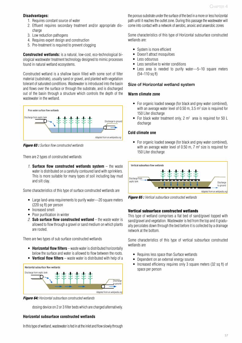
57
Disadvantages: 1. Requiresconstantsourceofwater2. Effluent requires secondary treatment and/or appropriate dis-
charge3. Lowreductionpathogens4. Requiresexpertdesignandconstruction5. Pre-treatmentisrequiredtopreventclogging
Constructed wetlands:isanatural,low-cost,eco-technologicalbi-ologicalwastewatertreatmenttechnologydesignedtomimicprocessesfoundinnaturalwetlandecosystems.
Constructedwetland isashallowbasinfilledwithsomesortoffiltermaterial(substrate),usuallysandorgravel,andplantedwithvegetationtolerantofsaturatedconditions.Wastewaterisintroducedintothebasinandflowsoverthesurfaceorthroughthesubstrate,andisdischargedout of the basin through a structurewhich controls the depth of thewastewaterinthewetland.
Thereare2typesofconstructedwetlands
1. Surface flow constructed wetlands system – the wastewaterisdistributedonacarefullycontouredlandwithsprinklers.Thisismoresuitableformanytypesofsoilincludingbaymudandsiltclay.
Somecharacteristicsofthistypeofsurfaceconstructedwetlandsare
• Largeland-arearequirementstopurifywater—20squaremeters(220sqft)perperson
• Increasedsmell• Poorpurificationinwinter
2. Sub surface flow constructed wetland–thewastewaterisallowedtoflowthroughagravelorsandmediumonwhichplantsarerooted.
Therearetwotypesofsubsurfaceconstructedwetlands
• Horizontal flow filters–wastewaterisdistributedhorizontallybelowthesurfaceandwaterisallowedtoflowbetweenthe roots.
• Vertical flow filters–wastewaterisdistributedwithhelpofa
dosingdeviceon2or3filterbedswhicharechargedalternatively.
Horizontal subsurface constructed wetlands
Inthistypeofwetland,wastewaterisfedinattheinletandflowslowlythrough
theporoussubstrateunderthesurfaceofthebedinamoreorlesshorizontalpathuntilitreachestheoutletzone.Duringthispassagethewastewaterwillcomeintocontactwithanetworkofaerobic,anoxicandanaerobiczones
SomecharacteristicsofthistypeofHorizontalsubsurfaceconstructedwetlandsare:
• Systemismoreefficient• Doesn’tattractmosquitoes• Lessodourous• Lesssensitivetowinterconditions• Less area is needed to purify water—5–10 square meters(54–110sqft)
Size of Horizontal wetland system
Warm climate zone
• Fororganicloadedsewage(forblackandgreywatercombined),withanaveragewaterlevelof0.50m,3.5m2 sizeisrequiredfor150Literdischarge
• Forblackwater treatmentonly,2m2 area isrequired for50Ldischarge
Cold climate one
• Fororganicloadedsewage(forblackandgreywatercombined),withanaveragewaterlevelof0.50m,7m2 sizeisrequiredfor150Literdischarge
Vertical subsurface constructed wetlandsThis typeofwetlandcomprisesaflatbedofsand/gravel toppedwithsand/gravelandvegetation.Wastewaterisfedfromthetopanditgradu-allypercolatesdownthroughthebedbeforeitiscollectedbyadrainagenetworkatthebottom.
Some characteristics of this type of vertical subsurface constructedwetlandsare
• RequireslessspacethanSurfacewetlands• Dependentonanexternalenergysource• Increasedefficiencyrequiresonly3squaremeters(32sqft)ofspaceperperson
Figure 63 : Surface flow constructed wetlands
Adapted from en.wikipedia.org
Dischargefromseptictank
Dischargetoground
Figure 65 : Vertical subsurface constructed wetlands
Adapted from en.wikipedia.org
Dischargefromseptictank Discharge
toground
Figure 64: Horizontal subsurface constructed wetlands
Adapted from en.wikipedia.org
Dischargefromseptictank
Dischargetoground
Chapter 4
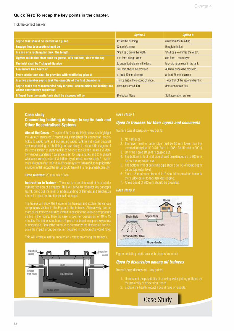
58
Quick Test: To recap the key points in the chapter.
Tickthecorrectanswer
Option A Option B
Septic tank should be located at a place Insidethebuilding awayfromthebuilding
Sewage flow to a septic should be Smooth/laminar Rough/turbulent
In case of a rectangular tank, the length Shallbe5timesthewidth. Shallbe2–4timesthewidth.
Lighter solids that float such as grease, oils and fats, rise to the top andformsludgelayer andformascumlayer
The inlet shall be T shaped dip pipe tocreateturbulenceinthetank. toavoidturbulenceinthetank.
A minimum free board of 300mmshouldbeprovided. 400mmshouldbeprovided.
Every septic tank shall be provided with ventilating pipe of atleast50mmdiameter atleast75mmdiameter
In a two chamber septic tank the capacity of the first chamber is Thricethatofthesecondchamber. Twicethatofthesecondchamber.
Septic tanks are recommended only for small communities and institutions whose contributory population
doesnotexceed400 doesnotexceed300
Effluent from the septic tank shall be disposed off by Biologicalfilters Soilabsorptionsystem
Chapter 4
Case studyConnecting building drainage to septic tank and Other Decentralised Systems
Aim of the Cases – Theaimofthe2caseslistedbelowistohighlightthe various standards / procedures established for connecting house-holds to septic tankandconnectingseptic tank to individualdisposalsystemplumbinginabuilding.Incasestudy1aschematicdiagramofthecrosssectionofseptictankistobeusedtoelicitthetraineestoiden-tifyvariousstandards/parameterssetforseptictanksandtohighlightwhatarecommonareasofviolationsbyplumber.Incasestudy2–sche-maticdiagramofanindividualdisposalsystemistoused,tohighlighttheenvironmentalimpactthesetupcouldhaveifitisnotplannedcorrectly.
Time allotted:20minutes/Case
Instruction to Trainer –Thecaseistobediscussedattheendofatrainingsessionofachapter.Thiswillservetorecollectkeyconceptslearnt,bringoutthelevelofunderstandingoftraineesandemphasizetherealimpactbehindtheoreticalconcepts.
ThetrainerwillshowtheFiguretothetraineesandexplainthevariouscomponents visible in theFigure to the trainees.Alternatively, oneormoreofthetraineescouldbeinvitedtodescribethevariouscomponentsvisibleintheFigure.Thenthecaseisopenfordiscussionfor10to15minutes.Thetrainershoulduseaflipchartorboardtocapturekeypointsofdiscussion.Finallythetraineristosummarizethediscussionandex-plaintheimpactwrongconnectiondepictedinphotographswouldhave.
Thiswillcreatealastingimpression/retentionamongthetrainees.
CaseStudy
Case study 1
Open to trainees for their inputs and comments
Trainer’scasediscussion–keypoints:
1. Noventpipe.2. Theinvert levelofoutletpipemustbe50mmlowerthanthe
invertofinletpipe.(IS2470(Part1):1985-Reaffirmedin2001)3. Onlytheliquideffluentispassedout.4. Thebottomlimbofinletpipeshouldbeextendedupto300mm
belowthetopwaterlevel.5. Thebottomlimbofoutletdippipeshouldbe1/3ofliquiddepth
belowtopwaterlevel.6. Floor-Aminimumslopeof1:10shouldbeprovidedtowards
thesludgeoutlettofacilitatedesludging.7. Afreeboardof300mmshouldbeprovided.
Case study 2
Figuredepictingseptictankwithdispersiontrench
Open to discussion among all trainees
Trainer’scasediscussion–keypoints:
1. Understandthepossibilityofdrinkingwatergettingpollutedbytheproximityofdispersiontrench.
2. Explainthehealthimpactitcouldhaveonpeople.

59
Notes

60
Chapter 6Chapter 5
61
Basic Concepts of Plumbing
Sewerage Connections – High Altitude and High Water Table Terrain
Chapter Objective:
• The chapter highlights the additional details that a plumber should know in connecting building sewage to public sewerage system or septic tank in areas of high altitudes and in areas of high water table.
Chapter Duration: 120 minutes*
SECTION 1: Terrain conditions
In any building, the sewage generated should be disposed safely with-out disturbing the environment.
Where public sewerage system is available, the house drain is con-nected to the public sewerage system with the approval and as directed by the authority.
Where discharge into a public sewer is not possible, the drainage of the building is to be done through any of the individual disposal systems, the predominant being the septic tank.
Though the method of connecting the household sewage either to the sewerage network or to the septic tank is similar to plains (as explained in Chapter 2 and 3), plumber needs to take into consid-eration certain additional care to address problems posed by the nature of terrain.
SECTION 2: High altitude / sub zero regions
Impact of high altitude on sewage disposal systems
In high altitudes and /or sub-zero temperature regions the tempera-
ture can reach below 4°C and atmospheric pressure could reach below 0.086 N/Sq.mm
The low pressure and temperature will affect the property of water, chemicals, microbes (bacteria) and pumping. This will pose challeng-es to normal working of a sewerage system and septic tanks.
Effect of low temperatures
Effect of low temperatureA. Physical effect on waterB. Behaviour of chemicalsC. Biological Impact
Chapter 5
*duration is only indicative and can be changed based on requirements at different locations
A. Physical effect on water – Low temperature will have following impact on water
• Water reaches its maximum density at 4°C. • Water crystallized into ice at 0°C and its volume will expand by
approximately one-twelfth. • The viscosity of water and liquids increases with falling tem-
peratures thus affecting the settling velocities of particles carried in sewage suspension.
B. Behaviors of chemicals – Low temperature will have following impact on chemicals
• Most chemicals react much slower at lower temperature (freez-

62
ing temperature) than they do at normal temperatures. • As a result, longer reaction times are required for satisfactory
performance in the sewage / grey water treatment units, where chemicals are used.
C. Biological impact – Low temperatures will have following impact on microbes (bacteria)
• For every 10°C fall in temperature, the biological activity of mi-crobes reduces by 50%.
• As a result sewage decomposition processes in a septic tanks, which depend on biological activities of micro-organisms are af-fected (slower).
DID yOu kNOw?
Effect of Low Pressure • Low pressure limits the pump suction.
Tips for plumbers – at high altitude region
The Plumber should follow the instructions to counter the challenges created by low temperature and pressure
Plumber should look intoA. Sewerage workB. Septic TankC. Seepage PitD. InsulationE. Tips to Handle Gradient Pressure in Pipes F. Tips to measure slope in a terrain
A. Sewerage works:
• All sewers should be laid below the frost line (at least 1.2 meters below the ground level).
• Intercepting traps if any should be located below the frost line. • Manholes should be made air-tight to prevent the cold air from
entering the manhole and freezing the sewage. • The trenches for sewers shall be loosely filled with earth after
laying sewers since loose soil is a better insulator than com-pacted soil.
• Adequate insulation should be done for sewer which needs to be laid under traffic ways and other places, where soil compaction is expected.
• Where ever feasible, sewers shall be so located in such a way that the trench line is not in shadow, when the sun is shining.
• Adequate insulation should be provided to concrete, cast iron and stoneware pipe as they conduct heat (and cold) relatively rapidly.
• Lavatories and bath rooms shall be kept heated to avoid freezing of water inside the traps and flushing cisterns.
B. Septic tanks – Septic tanks can function normally only when contents inside do not freeze during low temperature. Plumber should follow the below points to ensure the normal functioning of septic tank
• The septic tanks should be located well below the frost line. • The location of manhole opening shall be marked by staves.
• Fencing around the septic tanks shall be provided for discourag-ing traffic over it.
• Plumber should follow the recommend size of septic tanks to ensure normal biological activity. This action is taken to counter the lower biological activity at lower temperature.
Number of users
Length (in Meters)
Breadth (in Meters)
Liquid depth in meters
cleaning interval - 1 year
cleaning interval - 2 years
5 1.5 0.75 1.0 1.05
10 2.0 0.90 1.0 1.40
15 2.0 0.90 1.3 2.00
20 2.3 1.10 1.3 1.80
Number of users
Length (in Meters)
Breadth (in Meters)
Liquid depth in meters
cleaning interval - 1 year
cleaning interval - 2 years
5 3 0.75 1.0 1.05
10 3.6 1 1.0 1.40
15 3.6 1 1.3 2.00
20 3.9 1.3 1.3 1.80
C. Seepage pits
• Seepage pits can function only when the soil and sub-soil condi-tions are favorable. Frozen soil extending to a great depth would preclude the use of such disposal devices in view of the lower water absorption capacity.
• The discharge of effluent should be made below the frost line.
D. Insulation:
• Materials for Insulation of Pipes – The normal practice in India is to surround the pipe with straw, grass, hessian cloth/strip or jute wrapped over with gunny and painting with bitumen; alternatively other materials like 85 percent magnesia, glass wool or asbestos coated lagging ropes may also be used.
• A extra layer of mulch (200 – 300 mm) over the pipes, tank and soil treatment system will provide extra insulation. This mulch could be straw, leaves, hay or any other loose material that will not compact and stay in place.
• IS 6295:1986 - Reaffirmed in 2001 recommends Asbestos Lag-
IS 2470 (Part 1):1985 - Reaffirmed in 2001
This table is derived from Table 5 of IS 2470 (Part 1) : 1985 as per Clause 5.5.2 IS 6295 : 1986
Chapter 5
Table 9: Recommended size of septic tank at 20 °C
Table 10: Recommended size of septic tank at 10 °C
Adapted from the Standard IS 6295 : 1986 - Reaffirmed in 2001
Figure 66: Insulation of pipes
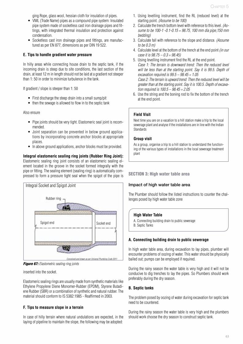
63
ging Rope, glass wool, hessian cloth for insulation of pipes. • VML (Trade Name) pipes as a compound pipe system: Insulated
pipe system made of socketless cast iron drainage pipes and fit-tings, with integrated thermal insulation and protection against condensation.
• Socketless cast iron drainage pipes and fittings, are manufac-tured as per EN 877, dimensions as per DIN 19 522.
E. Tips to handle gradient water pressure
In hilly areas while connecting house drain to the septic tank, if the incoming drain is steep due to site conditions, the last section of the drain, at least 12 m in length should not be laid at a gradient not steeper than 1: 50 in order to minimize turbulence in the tank.
If gradient / slope is steeper than 1: 50
• First discharge the steep drain into a small sump/pit • then the sewage is allowed to flow in to the septic tank
Also ensure
• Pipe joints should be very tight. Elastomeric seal joint is recom-mended.
• Joint separation can be prevented in below ground applica-tions by incorporating concrete anchor blocks at appropriate places.
• In above ground applications, anchor blocks must be provided.
Integral elastomeric sealing ring joints (Rubber Ring Joint): Elastomeric sealing ring joint consists of an elastomeric sealing el-ement located in the groove in the socket formed integrally with the pipe or fitting. The sealing element (sealing ring) is automatically com-pressed to form a pressure tight seal when the spigot of the pipe is
1. Using levelling instrument, find the RL (reduced level) at the starting point. (Assume to be 100)
2. Calculate the trench bottom level with reference to this level. (As-sume to be 100-1 -0.1-0.15 = 98.75, 100 mm dia pipe,150 mm bedding)
3. Calculate fall with reference to the slope and distance. (Assume to be 0.3 m)
4. Calculate level at the bottom of the trench at the end point (in our case it is 98.75 – 0.3 = 98.45)
5. Using levelling instrument find the RL at the end point. Case 1: The terrain is downward trend: Then the reduced level
will be less than at the starting point. Say it is 99.5. Depth of excavation required is 99.5 – 98.45 = 1.05
Case 2: The terrain is upward trend: Then the reduced level will be greater than at the starting point. Say it is 100.5. Depth of excava-tion required is 100.5 – 98.45 = 2.05
6. Use the string and the boning rod to fix the bottom of the trench at the end point.
Field VisitNext time you are on a vacation to a hill station make a trip to the local sewerage plant and analyse if the installations are in line with the Indian Standards
Group visitAs a group, organise a trip to a hill station to understand the function-ing of the various types of installations in the local sewerage treatment plant
SECTION 3: High water table area
Impact of high water table area
The Plumber should follow the listed instructions to counter the chal-lenges posed by high water table zone
High Water TableA. Connecting building drain to public sewerageB. Septic Tanks
A. Connecting building drain to public sewerage
In high water table area, during excavation to lay pipes, plumber will encounter problems of oozing of water. This water should be physically bailed out; pumps can be employed if required.
During the rainy season the water table is very high and it will not be conducive to dig trenches to lay the pipes. So Plumbers should work preferably during the dry season.
B. Septic tanks
The problem posed by oozing of water during excavation for septic tank need to be countered.
During the rainy season the water table is very high and the plumbers should work choose the dry season to construct septic tank.
Chapter 5
inserted into the socket.
Elastomeric sealing rings are usually made from synthetic materials like Ethylene Propylene Diene Monomer-Rubber (EPDM), Styrene Butadi-ene Rubber (SBR) or a combination of synthetic and natural rubber. The material should conform to IS 5382:1985 - Reaffirmed in 2003.
F. Tips to measure slope in a terrain
In case of hilly terrain where natural undulations are expected, in the laying of pipeline to maintain the slope, the following may be adopted:
Conceived and drawn as per Univeral Plumbing Code 2011
Figure 67: Elastometric sealing ring joints
Integral Socket and Spigot Joint
Rubber ring
Spigot end Socket end
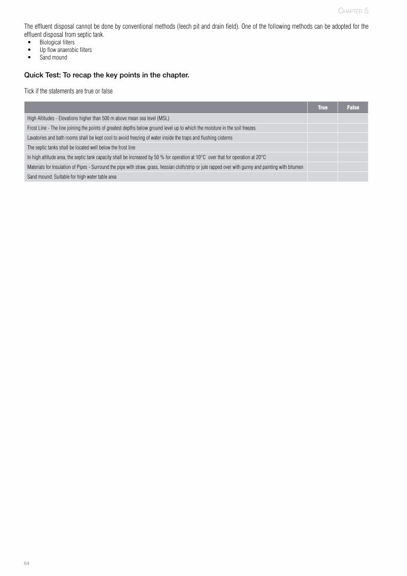
64
The effluent disposal cannot be done by conventional methods (leech pit and drain field). One of the following methods can be adopted for the effluent disposal from septic tank.• Biological filters• Up flow anaerobic filters• Sand mound
Quick Test: To recap the key points in the chapter.
Tick if the statements are true or false
True False
High Altitudes - Elevations higher than 500 m above mean sea level (MSL)
Frost Line - The line joining the points of greatest depths below ground level up to which the moisture in the soil freezes
Lavatories and bath rooms shall be kept cool to avoid freezing of water inside the traps and flushing cisterns
The septic tanks shall be located well below the frost line
In high altitude area, the septic tank capacity shall be increased by 50 % for operation at 10°C over that for operation at 20°C
Materials for Insulation of Pipes - Surround the pipe with straw, grass, hessian cloth/strip or jute rapped over with gunny and painting with bitumen
Sand mound: Suitable for high water table area
Chapter 5
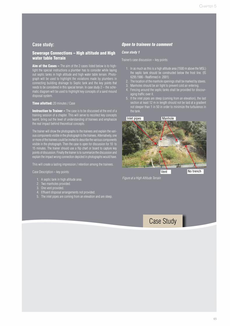
65
Case study:
Sewerage Connections – High altitude and High water table Terrain
Aim of the Cases – The aim of the 2 cases listed below is to high-light the special instructions a plumber has to consider while laying out septic tanks in high altitude and high water table terrain. Photo-graph will be used to highlight the violations made by plumbers in connecting building drainage to Septic tank and the key points that needs to be considered in this special terrain. In case study 2 – the sche-matic diagram will be used to highlight key concepts of a sand mound disposal system.
Time allotted: 20 minutes / Case
Instruction to Trainer – The case is to be discussed at the end of a training session of a chapter. This will serve to recollect key concepts learnt, bring out the level of understanding of trainees and emphasize the real impact behind theoretical concepts.
The trainer will show the photographs to the trainees and explain the vari-ous components visible in the photograph to the trainees. Alternatively, one or more of the trainees could be invited to describe the various components visible in the photograph. Then the case is open for discussion for 10 to 15 minutes. The trainer should use a flip chart or board to capture key points of discussion. Finally the trainer is to summarize the discussion and explain the impact wrong connection depicted in photographs would have.
This will create a lasting impression / retention among the trainees.
Case Description – key points:
1. A septic tank in high altitude area.2. Two manholes provided.3. One vent provided.4. Effluent disposal arrangements not provided.5. The inlet pipes are coming from an elevation and are steep.
Open to trainees to comment
Case study 1
Trainer’s case discussion – key points:
1. In as much as this is a high altitude area (1500 m above the MSL) the septic tank should be constructed below the frost line. (IS 6295:1986 - Reaffirmed in 2001)
2. The location of the manhole openings shall be marked by staves.3. Manholes should be air tight to prevent cold air entering.4. Fencing around the septic tanks shall be provided for discour-
aging traffic over it.5. If the inlet pipes are steep (coming from an elevation), the last
section at least 12 m in length should not be laid at a gradient not steeper than 1 in 50 in order to minimize the turbulence in the tank.
Case Study
Chapter 5
Figure at a High Altitude Terrain
No trenchVent
Inlet pipes Manhole
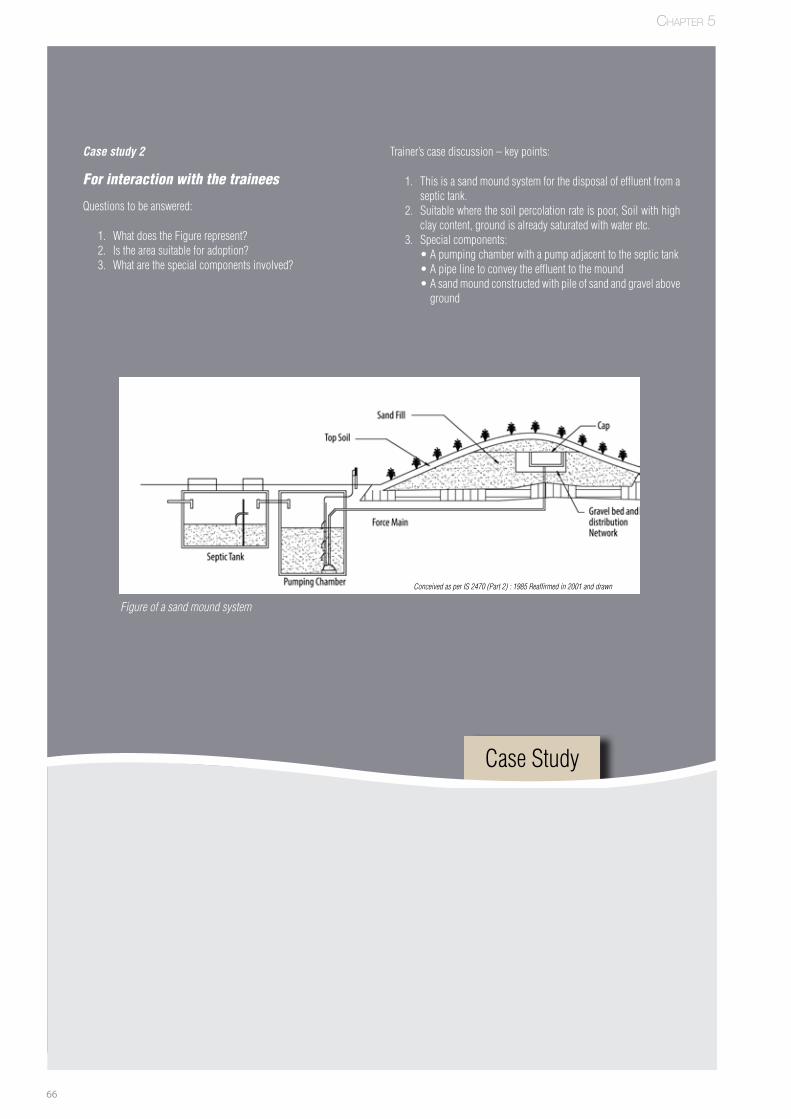
66
Case study 2
For interaction with the trainees
Questions to be answered:
1. What does the Figure represent?2. Is the area suitable for adoption?3. What are the special components involved?
Trainer’s case discussion – key points:
1. This is a sand mound system for the disposal of effluent from a septic tank.
2. Suitable where the soil percolation rate is poor, Soil with high clay content, ground is already saturated with water etc.
3. Special components: •Apumpingchamberwithapumpadjacenttotheseptictank •Apipelinetoconveytheeffluenttothemound •Asandmoundconstructedwithpileofsandandgravelabove
ground
Figure of a sand mound system
Chapter 5
Case Study
Conceived as per IS 2470 (Part 2) : 1985 Reaffirmed in 2001 and drawn

67
Notes
68
Chapter 6Chapter 6
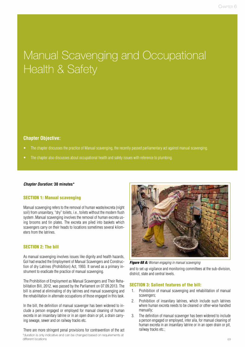
69
Basic Concepts of Plumbing
Manual Scavenging and Occupational Health & Safety
Chapter Objective:
• The chapter discusses the practice of Manual scavenging, the recently passed parliamentary act against manual scavenging.
• The chapter also discusses about occupational health and safety issues with reference to plumbing.
Chapter Duration: 30 minutes*
SECTION 1: Manual scavenging
Manual scavenging refers to the removal of human waste/excreta (night soil) from unsanitary, “dry” toilets, i.e., toilets without the modern flush system .Manual scavenging involves the removal of human excreta us-ing brooms and tin plates. The excreta are piled into baskets which scavengers carry on their heads to locations sometimes several kilom-eters from the latrines.
SECTION 2: The bill
As manual scavenging involves issues like dignity and health hazards, GoI had enacted the Employment of Manual Scavengers and Construc-tion of dry Latrines (Prohibition) Act, 1993. It served as a primary in-strument to eradicate the practice of manual scavenging.
The Prohibition of Employment as Manual Scavengers and Their Reha-bilitation Bill, 2012, was passed by the Parliament on 07.09.2013. The bill is aimed at eliminating of dry latrines and manual scavenging and the rehabilitation in alternate occupations of those engaged in this task.
In the bill, the definition of manual scavenger has been widened to in-clude a person engaged or employed for manual cleaning of human excreta in an insanitary latrine or in an open drain or pit, a drain carry-ing sewage, sewer and on railway tracks etc.
There are more stringent penal provisions for contravention of the act
and to set up vigilance and monitoring committees at the sub-division, district, state and central levels.
SECTION 3: Salient features of the bill:1. Prohibition of manual scavenging and rehabilitation of manual
scavengers;2. Prohibition of insanitary latrines, which include such latrines
where human excreta needs to be cleaned or other-wise handled manually;
3. The definition of manual scavenger has been widened to include a person engaged or employed, inter alia, for manual cleaning of human excreta in an insanitary latrine or in an open drain or pit, railway tracks etc.;
Chapter 6
Figure 68 A: Woman engaging in manual scavenging
*duration is only indicative and can be changed based on requirements at different locations
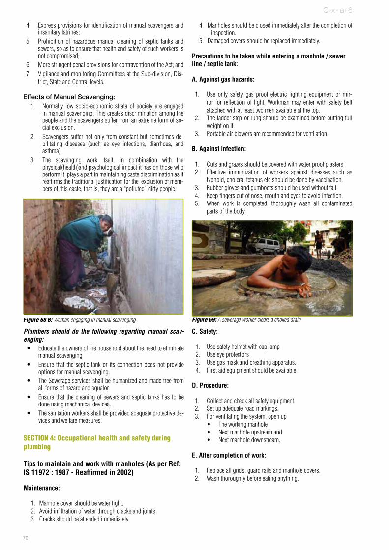
70
4. Express provisions for identification of manual scavengers and insanitary latrines;
5. Prohibition of hazardous manual cleaning of septic tanks and sewers, so as to ensure that health and safety of such workers is not compromised;
6. More stringent penal provisions for contravention of the Act; and7. Vigilance and monitoring Committees at the Sub-division, Dis-
trict, State and Central levels.
Effects of Manual Scavenging:1. Normally low socio-economic strata of society are engaged
in manual scavenging. This creates discrimination among the people and the scavengers suffer from an extreme form of so-cial exclusion.
2. Scavengers suffer not only from constant but sometimes de-bilitating diseases (such as eye infections, diarrhoea, and asthma)
3. The scavenging work itself, in combination with the physical(health)and psychological impact it has on those who perform it, plays a part in maintaining caste discrimination as it reaffirms the traditional justification for the exclusion of mem-bers of this caste, that is, they are a “polluted” dirty people.
Plumbers should do the following regarding manual scav-enging: • Educate the owners of the household about the need to eliminate
manual scavenging• Ensure that the septic tank or its connection does not provide
options for manual scavenging. • The Sewerage services shall be humanized and made free from
all forms of hazard and squalor. • Ensure that the cleaning of sewers and septic tanks has to be
done using mechanical devices. • The sanitation workers shall be provided adequate protective de-
vices and welfare measures.
SECTION 4: Occupational health and safety during plumbing
Tips to maintain and work with manholes (As per Ref: IS 11972 : 1987 - Reaffirmed in 2002)
Maintenance:
1. Manhole cover should be water tight.2. Avoid infiltration of water through cracks and joints3. Cracks should be attended immediately.
Figure 68 B: Woman engaging in manual scavenging
Chapter 6
C. Safety:
1. Use safety helmet with cap lamp2. Use eye protectors3. Use gas mask and breathing apparatus.4. First aid equipment should be available.
D. Procedure:
1. Collect and check all safety equipment.2. Set up adequate road markings.3. For ventilating the system, open up
• The working manhole• Next manhole upstream and• Next manhole downstream.
E. After completion of work:
1. Replace all grids, guard rails and manhole covers.2. Wash thoroughly before eating anything.
4. Manholes should be closed immediately after the completion of inspection.
5. Damaged covers should be replaced immediately.
Precautions to be taken while entering a manhole / sewer line / septic tank:
A. Against gas hazards:
1. Use only safety gas proof electric lighting equipment or mir-ror for reflection of light. Workman may enter with safety belt attached with at least two men available at the top.
2. The ladder step or rung should be examined before putting full weight on it.
3. Portable air blowers are recommended for ventilation.
B. Against infection:
1. Cuts and grazes should be covered with water proof plasters.2. Effective immunization of workers against diseases such as
typhoid, cholera, tetanus etc should be done by vaccination.3. Rubber gloves and gumboots should be used without fail.4. Keep fingers out of nose, mouth and eyes to avoid infection.5. When work is completed, thoroughly wash all contaminated
parts of the body.
Figure 69: A sewerage worker clears a choked drain

71
Notes
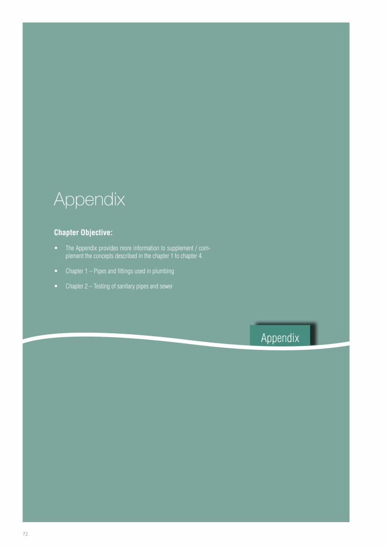
72
Appendix
Appendix
Chapter Objective:
• TheAppendixprovidesmoreinformationtosupplement/com-plementtheconceptsdescribedinthechapter1tochapter4.
• Chapter1–Pipesandfittingsusedinplumbing
• Chapter2–Testingofsanitarypipesandsewer
73
Chapter 1: Pipes and Fittings Used in Plumbing
Pipes and Fittings used in Plumbing works: Any plumbingsystem involvesuseofpipes foreitherwatersupplyor fordrainagesystem.
Jointsandallpartsof plumbing systemmustbebothgas-tight and water tight. Improper joints on water piping will result inleaks,whichcancauseagreatwasteofwaterandimproper jointson drainage piping will result in leaks, which can cause a greathealth hazard.
Type of Pipe Location/where normally used
Cast Iron
FPO
Watersupplymains,distributionandconveyanceofsewage.Pipes:IS1536:2001.CIFittings:IS1538:1993-Reaffirmedin1999.
DI pipes
FPO
Watersupplymains,distributionandconveyanceofsewage.Pipes:IS8329:2004-Reaffirmedin2005.DIFittings:IS9523:2000-Reaffirmedin2005
Steel
FPO
MS(GIpipes)–Watersupplydistribution(generallysmallerdiameterpipes)Pipes&Fittings:IS1239(Part1):2004&IS1239(Part2):2011.Watersupplymains(generallylargerdiameterpipes)Pipes:IS3589:2001.
Concrete
FPO
Conveyanceofwaterandsewage.Pipes:IS458:2003.CIFittings:Fabricated.
Stoneware
FPO
Conveyancesewage.Pipes:IS651:2007.
Plastic – UPVC
FPO
Potablewatersupply(UG):IS4985:2000-Reaffirmedin2005SoilandWasteDischargeSystemInsideBuildingsincludingRainWaterSystem:IS13592:1992-Reaffirmedin2002TypeA–Ventilation&RainwaterTypeB–Soil&WasteUGSewerage&DrainageSystemIS15328:2003CPVC-InternalWaterSupplyinsidetheBuildings
Appendix
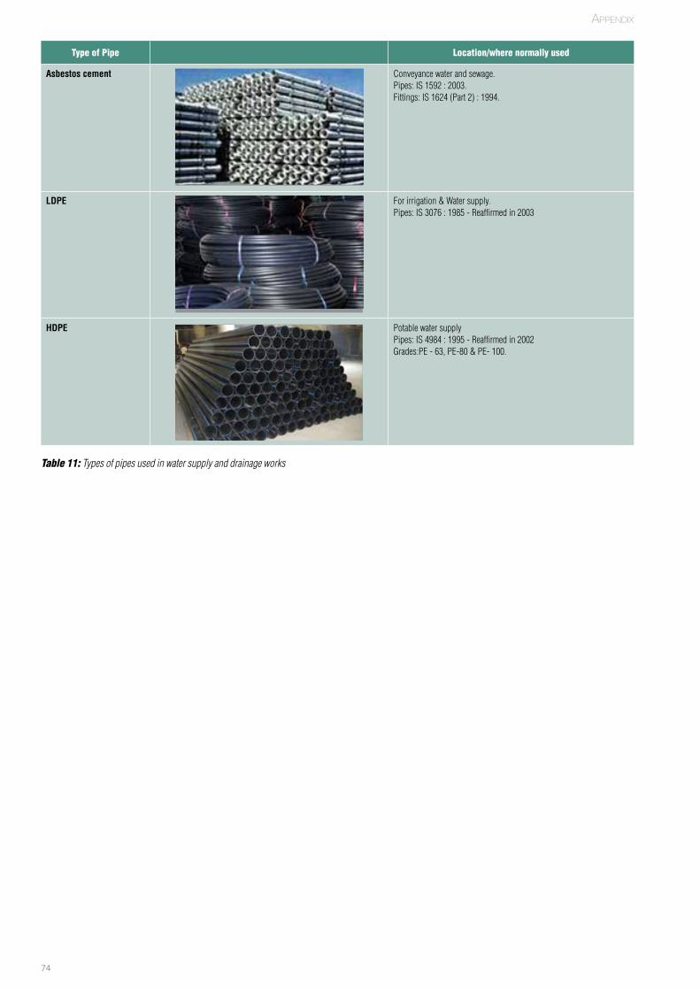
74
Type of Pipe Location/where normally used
Asbestos cement
FPO
Conveyancewaterandsewage.Pipes:IS1592:2003.Fittings:IS1624(Part2):1994.
LDPE
FPO
Forirrigation&Watersupply.Pipes:IS3076:1985-Reaffirmedin2003
HDPE
FPO
PotablewatersupplyPipes:IS4984:1995-Reaffirmedin2002Grades:PE-63,PE-80&PE-100.
Table 11: Types of pipes used in water supply and drainage works
Appendix

75
CI PIPE FITTINGS – IS 1538 : 1993 - Reaffirmed in 1999
Bends 22.5º Bends - 45º
FPO FPO
Bends - 90º Tee Joint
FPO FPO
Tee Junction
FPO
Appendix
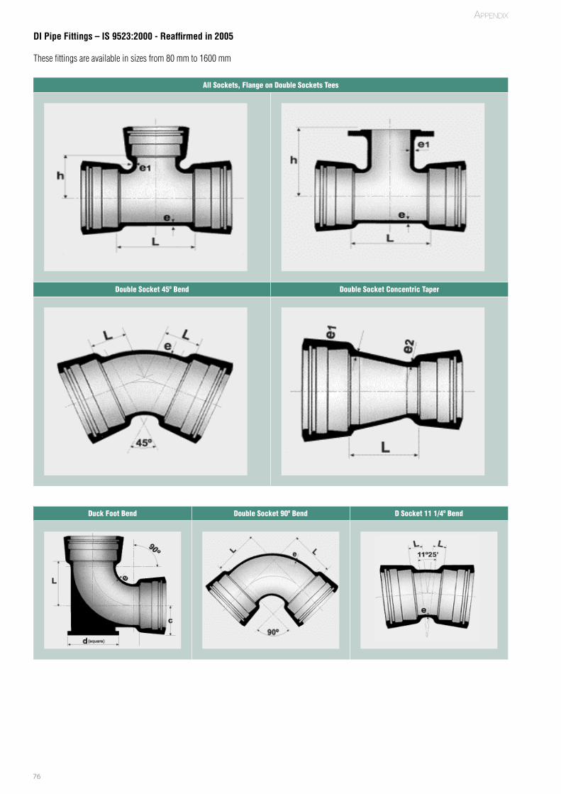
76
DI Pipe Fittings – IS 9523:2000 - Reaffirmed in 2005
Thesefittingsareavailableinsizesfrom80mmto1600mm
All Sockets, Flange on Double Sockets Tees
FPO FPO
Double Socket 45º Bend Double Socket Concentric Taper
FPO FPO
Duck Foot Bend Double Socket 90º Bend D Socket 11 1/4º Bend
FPO FPO FPO
Appendix
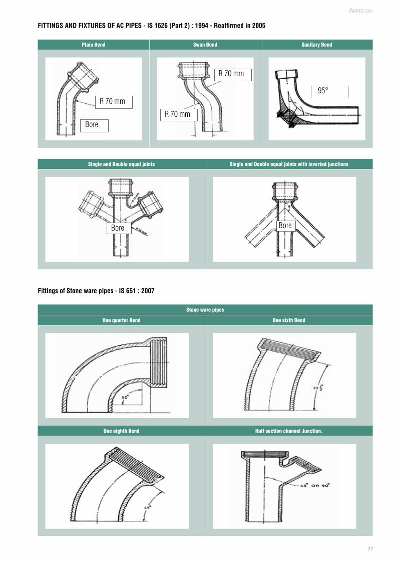
77
FITTINGS AND FIXTURES OF AC PIPES - IS 1626 (Part 2) : 1994 - Reaffirmed in 2005
Fittings of Stone ware pipes - IS 651 : 2007
Plain Bend Swan Bend Sanitary Bend
FPO FPO FPO
Single and Double equal joints Single and Double equal joints with inverted junctions
FPO FPO
Stone ware pipes
One quarter Bend One sixth Bend
FPO FPO
One eighth Bend Half section channel Junction.
FPO FPO
R70mm
Bore
R70mm
R70mm
95°
Bore Bore
Appendix
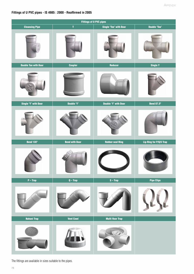
78
Fittings of U PVC pipes - IS 4985 : 2000 - Reaffirmed in 2005
Fittings of U PVC pipes
Cleansing Pipe T Single ‘Tee’ with Door Double ‘Tee’
FPO FPO FPO FPO
Double Tee with Door Coupler Reducer Single Y
FPO FPO FPO FPO
Single ‘Y’ with Door Double ‘Y’ Double ‘Y’ with Door Bend 87.5º
FPO FPO FPO FPO
Bend 135º Bend with Door Rubber seal Ring Lip Ring for P/Q/S Trap
FPO FPO FPO FPO
P – Trap Q – Trap S – Trap Pipe Clips
FPO FPO FPO FPO
Nahani Trap Vent Cowl Multi floor Trap
FPO FPO FPO
Thefittingsareavailableinsizessuitabletothepipes.
Appendix
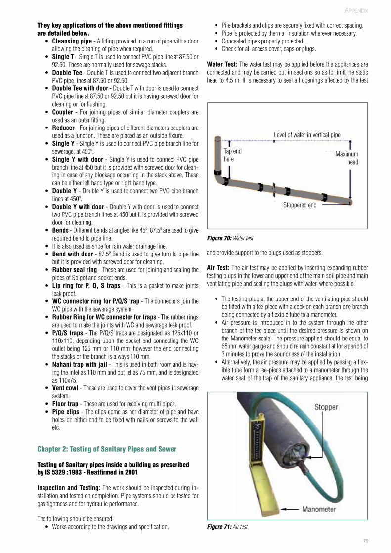
79
They key applications of the above mentioned fittings are detailed below.
• Cleansing pipe-Afittingprovidedinarunofpipewithadoorallowingthecleaningofpipewhenrequired.
• Single T-SingleTisusedtoconnectPVCpipelineat87.50or92.50.Thesearenormallyusedforsewagestacks.
• Double Tee-DoubleTisusedtoconnecttwoadjacentbranchPVCpipelinesat87.50or92.50.
• Double Tee with door-DoubleTwithdoorisusedtoconnectPVCpipelineat87.50or92.50butitishavingscreweddoorforcleaningorforflushing.
• Coupler - For joining pipes of similar diameter couplers areusedasanouterfitting.
• Reducer-Forjoiningpipesofdifferentdiameterscouplersareusedasajunction.Theseareplacedasanoutsidefixture.
• Single Y-SingleYisusedtoconnectPVCpipebranchlineforsewerage,at450º.
• Single Y with door-SingleY isused toconnectPVCpipebranchlineat450butitisprovidedwithscreweddoorforclean-ingincaseofanyblockageoccurringinthestackabove.Thesecanbeeitherlefthandtypeorrighthandtype.
• Double Y-DoubleYisusedtoconnecttwoPVCpipebranchlinesat450º.
• Double Y with door-DoubleYwithdoorisusedtoconnecttwoPVCpipebranchlinesat450butitisprovidedwithscreweddoorforcleaning.
• Bends-Differentbendsatangleslike45º,87.5ºareusedtogiverequiredbendtopipeline.
• Itisalsousedasshoeforrainwaterdrainageline.• Bend with door-87.5ºBendisusedtogiveturntopipelinebutitisprovidedwithscreweddoorforcleaning.
• Rubber seal ring-TheseareusedforjoiningandsealingthepipesofSpigotandsocketends.
• Lip ring for P, Q, S traps-This isagasket tomakejointsleakproof.
• WC connector ring for P/Q/S trap-TheconnectorsjointheWCpipewiththeseweragesystem.
• Rubber Ring for WC connector for traps-TherubberringsareusedtomakethejointswithWCandsewerageleakproof.
• P/Q/S traps-TheP/Q/S trapsaredesignatedas125x110or110x110, depending upon the socket end connecting theWCoutletbeing125mmor110mm;however theendconnectingthestacksorthebranchisalways110mm.
• Nahani trap with jail-Thisisusedinbathroomandishav-ingtheinletas110 mmandoutletas75mm,andisdesignatedas110x75.
• Vent cowl-Theseareusedtocovertheventpipesinseweragesystem.
• Floor trap-Theseareusedforreceivingmultipipes.• Pipe clips-Theclipscomeasperdiameterofpipeandhaveholesoneitherendtobefixedwithnailsorscrewstothewalletc.
Chapter 2: Testing of Sanitary Pipes and Sewer
Testing of Sanitary pipes inside a building as prescribed by IS 5329 :1983 - Reaffirmed in 2001
Inspection and Testing:Theworkshouldbe inspectedduring in-stallationandtestedoncompletion.Pipesystemsshouldbetestedforgastightnessandforhydraulicperformance.
Thefollowingshouldbeensured:• Worksaccordingtothedrawingsandspecification.
• Pilebracketsandclipsaresecurelyfixedwithcorrectspacing.• Pipeisprotectedbythermalinsulationwherevernecessary.• Concealedpipesproperlyprotected.• Checkforallaccesscover,capsorplugs.
Water Test:Thewatertestmaybeappliedbeforetheappliancesareconnectedandmaybecarriedoutinsectionssoastolimitthestaticheadto4.5m.Itisnecessarytosealallopeningsaffectedbythetest
FPO
FPO
Figure 70: Water test
Figure 71: Air test
andprovidesupporttotheplugsusedasstoppers.
Air Test:Theair testmaybeappliedby insertingexpandingrubbertestingplugsinthelowerandupperendofthemainsoilpipeandmainventilatingpipeandsealingtheplugswithwater,wherepossible.
• Thetestingplugattheupperendoftheventilatingpipeshouldbefittedwithatee-piecewithacockoneachbranchonebranchbeingconnectedbyaflexibletubetoamanometer.
• Air pressure is introduced in to the system through the otherbranchof the tee-pieceuntil thedesiredpressure isshownontheManometerscale.Thepressureappliedshouldbeequalto65mmwatergaugeandshouldremainconstantatforaperiodof3minutestoprovethesoundnessoftheinstallation.
• Alternatively,theairpressuremaybeappliedbypassingaflex-ibletubeformatee-pieceattachedtoamanometerthroughthewater seal of the trap of the sanitary appliance, the test being
Appendix
Levelofwaterinverticalpipe
Maximumhead
Tapendhere
Stopperedend

80
carriedoutasdescribed.
Smoke TestFaultsindicatedbytheairtestmaybelocatedbypumpingsmokeintothesystemwithasmokemachine.Careshouldbetakentoensurethatthesystemisfilledwithsmokebeforesealingwithplugs.
Hydraulic PerformanceDischargetestshouldbemadefromalltheappliances,singlyandcol-lectively.Obstructionsfromanyofthepipelineshouldbetracedandthewholesystemexaminedforproperhydraulicperformance,includ-ingtheretentionofanadequatewatersealineachtrap.
Hydraulic Testing of pipe sewers as prescribed in Central Public Health and Environmental Engineering Organization Manual
Water TestEachsectionofsewershallbetestedforwatertightnesspreferablybe-tweenmanholes.
• Thesewersaretestedbypluggingtheupperendwithaprovisionforanairoutletpipewithstopcock.Thewaterisfilledthroughafunnelconnectedatthelowerendprovidedwithaplug.Aftertheairhasbeenexpelledthroughtheairoutlet, thestopcockclosedandthewaterlevelinthefunnelisraisedto2.5mabovetheinvertattheupperend.
• Waterlevelinthefunnelisnotedafter30minutesandthequan-tity of water required to restore the original water level in thefunnelisdetermined.
• Thepipelineunderpressureistheninspectedwhilethefunnel
isstillinposition.• Thereshallnotbeanyleaksinthepipeorjoints(smallsweatingonthepipesurfaceispermitted).
• Anysewerorpart thereof thatdoesnotmeet the testshallbeemptiedandrepairedorrelaidasrequiredandtestedagain.
• Theleakageorquantityofwatertobesuppliedtomaintainthetestpressureduringtheperiodof10minutesshallnotexceed0.2liters/mmdiameterofpipesperkilometerlengthperday.
• Fornon-pressurepipesitisbettertoobservetheleakageforaperiodf24hoursiffeasible.
Air TestAir testbecomesnecessaryparticularly in largediameterpipeswhentherequiredquantityofwaterisnotavailablefortesting.
• Itisdonebysubjectingthestretchofpipetoanairpressureof100mmwatercolumnbymeansofhandpump.Ifthepres-sure ismaintainedat75mmthe jointsshallbeassumed tobewatertight.Incasethedropismorethan25mmtheleak-ingjointsshallbetracedandsuitablytreatedtoensurewatertightness.
• Theexactpointofleakagecanbedetectedbyapplyingsoapso-lutiontoallthejointsinthelineandlookingforairbubbles.
Other TestsSmoke testSmoketestingisoneofthemostefficientandcosteffectivemethodsoflocatingsourcesofinflowandinfiltrationproblemswithsewers.
Dye testing is amethodused to locate rain or groundwater entrypointsintothesanitary sewer system.
Appendix
81
References
References
82
References
BureauofIndianStandards,SP35:1987HandbookonWaterSupplyandDrainage(withSpecialEmphasisonPlumbing)
CodeofPracticeforInstallationofSepticTanks-IS2470(Part1):1985-Reaffirmedin2001
CodeofPracticeforInstallationofSepticTanks-IS2470(Part2):1985-Reaffirmed2001
ER.GSBajwa,PracticalHandBookonPublicHealthEngineering
IS458:2003–PrecastConcretePipes(WithandWithoutReinforcement)-Specification(FourthRevision)
IS1172:1993-Reaffirmedin1998–CodeofBasicRequirementsforWaterSupply,DraingeandSanitation
IS1200(Part19):1981-Reaffirmedin2002–MethodofMeasurementofBuildingandCivilEngineeringWorks(ThirdRevision)-Part19WaterSupply,Plumb-ingandbains
IS1536:2001-CentrifugallyCast(Spun)IronPressurePipesforWater,GasandSewageSpecification(FourthRevision)
IS1538:1993-Reaffirmedin1999-CastIronFittingsforPressurePipesforWater,GasandSewage-Specification(ThirdRevision)
IS1742:1983-Reaffirmedin2002-CodeofPracticeforBuildingDrainage(SecondRevision)
IS2065:1983-Reaffirmedin2001-CodeofPracticeforWaterSupplyinBuildings(SecondRevision)
IS3589:2001-SteelPipesForWaterAndSewage-Specification(ThirdRevision)
IS4984:1995-Reaffirmedin2002-HighdensityPolyethylenePipesforWaterSupply-Specification(FourthRevision)
IS4985:2000-Reaffirmedin2005-UnplasticizedPVCPipesforPotableWaterSupplies—Specification(ThirdRevision)
IS5329:1983-Reaffirmedin2001-CodeofPracticeforSanitaryPipeWorkAboveGroundforBuilding(FirstRevision)
IS5611:1987-Reaffirmedin2002-CodeofPracticeforConstructionofWasteStabilizationPonds(FaculativeType)(FirstRevision)
IS6295:1986-Reaffirmedin2001-CodeofPracticeforWaterSupplyandDrainageinHighAltitudesand/orSub-ZeroTemperatureRegions(FirstRevision)
IS8329:2000-Reaffirmedin2005-CentrifugallyCast(Spun)DuctileIronPressurePipesforWater,GasandSewage-Specification(ThirdRevision)
IS9523:2000-Reaffirmedin2005-DuctileIronFittingsforPressurePipesforWater,Gas&Sewage-Specification(FirstRevision)
IS11208:1985-Reaffirmedin2007-GuidelinesforRegistrationofPlumbers
IS11972:1987-Reaffirmedin2002-CodeofPracticeforSafetyPrecautionstobeTakenWhenEnteringaSewerageSystem
IS12183(Part1):1987-Reaffirmedin2004-CodeofPracticeforPlumbinginMulti-StoreyedBuildings
IS13592:1992-Reaffirmedin2002-UnplasticizedPolyvinylChloride(UPVC)PipesForSoilandWasteDischargeSystemInsideBuildingsIncludingVentilationandRainWaterSystem-Specification
IS15328:2003-Unplasticizednon-PressurepolyvinylChloride(PVC-U)PipesForUseinUndergroundDrainageandSewerageSystems-Specification
ManualonSewerageandSewageTreatment-MinistryofUrbanDevelopment-December1993&FinalDraftMay2012
ManualonWaterSupplyandTreatment-MinistryofUrbanDevelopment-May1999
AlternateSewageOptionsforResidents-TechnologyOptionsforUrbanSanitations
SP7:NationalBuildingCodeofIndia1983PARTIXPlumbingServices
UniformPlumbingCodeIndia–2011
WaterandEnvironmentResearchFoundation–FactSheetC4andCPHEEOManualonSewerageandsewageTreatment
RefeRences
83
Glossary of plumbing
Glossary
84
Back Flow: Theactofwatertravelingfromonesystembackintoanypartofthemaindistributionsystem(usuallybysiphoning).
Back Flow Preventer: Adevicetopreventbackflowi.e.intoapotablewatersupply.Usuallyrequiredforsprinklersystems,handheldshowers,pulloutfaucetspouts,kitchensprayers,etc.
Back Pressure:Pressurethatresiststheflowoffluidinapipingsystem.
Back Siphonage:Thenegativepressurethatcausesbackflow.
Back Vent:Plumbingfixture’sseparateventinabuildingdrainagesystem.
Back Wash:Theprocessofcleaningafilterbyreversingtheflowofwaterthroughit.Accumulatedsedimentsaresenttowaste.
Back Siphonage:Thenegativepressurethatcausesbackflow.
Black Water:ThedischargefromwaterclosetandurinaliscalledBlackwater.
Biological filters: It isaSoilAbsorptionSystemsusedtotreattheeffluentfromtheSTwherethesoil is relatively impervious, water logged areasorwherelimitedlandareaisavailable.
Building Drain (BD):Thebuildingdrainisthepartofthelowesthorizontalpipingofadrainagesystemwhichreceivesthedischargefromsoil,wasteandotherdrainagepipesinsidethewallsofthebuildingandconveysittothebuildingsewerbeginningonemeteroutsidethebuildingwall.
Building drainage systemconsistsofplumbingfixtures,drainagepipes&fittingsandseptictanks/publicsewer.
Building Sewer:Thebuildingseweristhepartofthehorizontalpipingofadrainagesystemwhichextendsfromtheendofthebuildingdrainandwhichreceivesthedischargeofbuildingdrainandconveyittoapublicsewer,privatesewer,individualsewagedisposalsystemorotherpointofdisposal.
Check Valve:Atypeofbackflowpreventerinstalledinapiperunthatallowswatertoflowinonlyonedirection.
Dispersion Trench:ItisaSoilAbsorptionSystemsusedtotreattheeffluentfromtheST.
Drain/waste/soil pipesarelargepipesthatcarrywastewaterandotherwastesawayfromthehomeandintoappropriateplacessuchasseptictanksorsewermains.
Filter Effluent:Theliquiddischargedfromabiologicalfilter.
Filter Media:Materials,suchasclinker,brokenstoneandgravel throughwhichsewageflowsandon thesurfaceofwhichzoologicalfilmsdevelop.
Frost Line:Thelinejoiningthepointsofgreatestdepthsbelowgroundleveluptowhichthemoistureinthesoilfreezes.
Galvanizing:Theprocessofapplyingacoatingofzinctothefinishedproducttoprovidecorrosionprotection.Thecoatingcanbeappliedbyhotdippingorelectrolyticdeposition.
Grey Water: Thedischargefrombathtubs,showers,washbasins,kitchensink,washingmachinewhichdoesnotcontainhumanexcretaiscalledGreyWater.
Hard Water:Naturalwatercontainingimpuritiesinvariousproportions.Traditionalhardnessisameasureofcalciumordissolvedsolidsinasolution,measuredinpartspermillion.Hardwatergenerallyrangesfrom100to250ppm.
High Altitudes:Elevationshigherthan1500mabovemeansealevel(MSL).
Hydraulic Pressure:Pressurethatexistsinasystemcontainingnon-compressibleliquid.
Invert Level:Thedistancebetweenthegroundsurfaceleveltothebaseinteriorlevelofasewerpipe.
Lagging:Thermalinsulationonpipes.
Leach Field:Poroussoilarea,throughwhichseptictankleachlinesrun,emptyingthetreatedwaste.
Leach Lines:Pipesthatcarryeffluentfromthesepticsystemouttotheleachfield.
Leach pit:Leachpits/Soakpits/Seepagepitsareusedtoremovecontaminantsandimpuritiesfromtheliquidthatemergesfromtheseptictankandsafelydispersesthesameintothesoil.
GlossARy

85
GlossARy
Leakage:Lossoffluidusuallyduetomechanicalbreakdownorgasketwear.
Manhole:Accessopeningtoahole,usuallywithacover,throughwhichapersonmayenterasewer,boiler,drain,etc.(usuallyroundtopreventthecoverfromfallingintotheopening).
Manhole Cover:Amanholecoverisaremovableplateformingthelidovertheopeningofamanhole,topreventanyoneoranythingfromfall-ingin,andtokeepoutunauthorizedpersonsandmaterial.
Outlet / Discharge:Theopeningthroughwhichthewaterexitsthepump.
Outlet Sewer:Pipesectioninasepticsystemwhichrunsbetweentheseptictankandthedrainagefield.
Overflow Tube:Theverticaltubeinsideatoilettankthatdirectswaterintothebowlincasetheballcockmalfunctions.Itisusuallypartoftheflushvalve.Itpreventspotentialwaterdamagecausedbyatankoverflow.A“constant-running”conditionalertstheusertoaproblem.Onmosttoilets,theoverflowtubealsohasarefilltubeflowingintoit,whichdirectswaterfromtheballcockthroughtheoverflowtubetothebowl,afterasiphonbreak.
PlumberAplumberisapersonwhoinstallsandmaintainspipingforwaterandtheirdrainsandwastesystemsinadwelling,businessorindustrialfacil-ity.Heinstallsbathroomappliancessuchasshowers,toilets,sinks,kitchenappliances(e.g.dishwashers),waterheatersrequiredinaneworremodelledhousesorbuildings.
Plumbersneedvariousskillstoperformtheirjobssuccessfullylikeblueprintreading,abilitytolocatethroughdiagramslocationsforinstallationofpipes,fittingpipestogetherforthecorrectfunctioningofplumbingsystems.AplumbershallbeawareofbasicPlumbingCodesandStandardsspecified.
PlumbingPipes,fixturesandotherapparatusinsideabuildingforbringinginwatersupplyandremovingthewastewateroutof thebuildingconstituteplumbingsystem.Plumbingisaskilledtradeofworkingwiththeabovepipes,fixturesandapparatusforusewithwateranddrainage.
Plumbing FixtureAgeneraltermappliedtoanyplumbingreceptacle,deviceorappliancethatcanbetemporarilyorpermanentlyfixedinplace.Itisconnectedtothedrinking-watersupplyortothedrainagesystemeitherbyanindirectordirectconnection.
Plumbing Vent Pipesareanintegralpartofaplumbingsystemastheyallowthepipingto“breathe”.Airflowisnecessarytoequalizepressureinplumbingsystemsandplumbingventsallowforproperflowofairthroughthepipes.
Pressure Pipesthatcarryfreshwatertovariousfixtures.
Public Sewerage System (PSS):Theseweragesystemwhichistakencarebylocalauthority.
• Combined PSS:TheSeweragesystemthatcollectsbothStromwaterandBuildingSewer. • Separate PSS:CollectsonlyBuildingSewer.
Raw WaterWatersuppliedtotheplantbeforeanytreatment.
Safety Shutoff Valve:Adeviceonagasappliancethatshutsoffthegassupplytopreventahazardoussituation.Aflamesafetyshutoffoperateswhentheactuatingflamebecomesextinguished.
Sand Mound:Itisusedforthetreatmentofeffluentinareaswherethesoilhastoomuchclaytoallowthewatertoseepthroughattheproperrate,orthe water table is too close to the ground surface.
Sanitary Fitting:Fittingthatjoinstheassortedpipesinadrain,waste,andventsystem,designedtoallowsolidmaterialtopassthroughwithoutclogging.
Sanitary Sewer:Housedrainthatcarrieswastewaterawayfromthehousetoasewersystemorseptictank.
Scale:Athincoatingorlayer,usuallycalciumonthebottomofatankorinteriorpartsthatmaypreventheattransfer.
Sewer Gas:Gases,esp.methane,whichmaybecombustibleandpoisonousfromthedecayoforganicmaterialsinthesewersystem.
Septic Tank (ST):ASeptic Tankisawatertightconcretebox,buriedinthegroundjustoutsidethehome.Theseptictankactsasasmall-scalesewagetreatmentsystemcommoninareaswherenoconnectiontomainseweragesystemprovidedbythelocalbody.Ithelpsindisposingofhouseholdsewage/wastewatersafely.
Septage:BlackWaterwhichundergoestreatmentinseptictankiscalledSeptage.

86
Sewageisthewater,carryingbodywastesincludinghumanexcretaandotherhouseholdwaste.
a) ThedischargefromwaterclosetandurinaliscalledSoilorBlack Water.b) The discharge from bathtubs, showers, wash basins, kitchen sink, washingmachinewhich does not contain human excreta is called
Waste Water / Sullage / Grey Water.
Sewerage system:Seweragesystemisaclosedsystemofpipesfromthewastereceptacletothefinaldisposalpointeitheronlandorintoabodyofwaterandtheflowisgravitationalorfreeflowandnotunderpressureasinthecaseofwatersupplypipes.
Simplified sewerage system:Simplifiedsewerageisanoff-sitesanitationtechnologythatremoveallwastewaterfromthehouseholdenvi-ronment.Conceptuallyitisthesameasconventionalsewerage,butwithconsciouseffortsmadetoeliminateunnecessarilyconservativedesignfeaturesandtomatchdesignstandardstothelocalsituation.
Siphoning:Thesuctionorpullingeffectthattakesplaceinthetrapwayofatoiletasitisfilledwithoutgoingwaterandwaste.
Small Bore System:Smallboresewersystemsaredesignedtoreceiveonlytheliquidportionofhouseholdwastewaterforoff-sitetreatmentanddisposal.
Sovent Single Stack DWV System: TheSoventSystemisanengineeredsinglestackdrainagesystem.Itoffersadifferentconceptofwasteandventingbyslowingthevelocityofliquidsandsolidsthroughaseriesofaeratorfittingsanddoubleoffsets.Beforeenteringthebuildingdrainadeaeratorfittingisplacedatthebaseofthestacktominimizesolidbuildupandslowthedrainagebeforeenteringthebuildingdrain.
Stack:Anyverticalpipeinthesystemlikeverticalsoilorventpipeiscalledstack.
Sub-Zero Temperature Regions:Regionswheretemperaturesfallbelow0°Candfreezingconditionsoccur.
Sullage:SullageisnothingbuttheGreyWater.
Tank Effluent:Thesupernatantliquiddischargefromaseptictank.
Trap:Curvedsectionofdrainlinethatpreventssewerodorsfromescapingintotheatmosphere.Allfixturesthathavedrainsmusthavea“P”trapinstalled.Atoiletistheonlyplumbingfixturewithan“S”trap.
Trap Seal:Heightofwaterinatoiletbowl“atrest.”.Itprovidesthewatersealwhichpreventssewergasesfromenteringthehome.Itismeasuredfromthetopofthedamdowntotheinletofthetrapway.Alsoreferredtoasdeepseal.
Thawing:Themeltingoficeorsnowbyheat.
Up flow anaerobic filters:ItisalsoaSoilAbsorptionSystemsusedtotreattheeffluentfromtheSTin areas where dense soil condition, high water tableandlimitedavailabilityofopenlandarefactorstobeconsideredforsuccessfuldisposalofeffluentsbysecondarytreatment.
Utilidor:Largeinsulatedorheatedconduitsusedforhousingwaterpiping,insomeinstanceswastewaterpiping.(Utilidors,however,arenotatpresentusedinIndia).
Vacuum Breaker:Ananti-siphondevicethatpreventsthebackflowofcontaminatedwaterintothewatersupplysystem.
Vent Stack:Upperportionofthesoilstackabovethetopmostfixturethroughwhichgasesandodorsescape.
Weir:Alongnotchwithahorizontaledge,asinthetopofaverticalplateorplank,throughwhichwaterflows,usedinmeasuringthequantityofflowingwater.
GlossARy
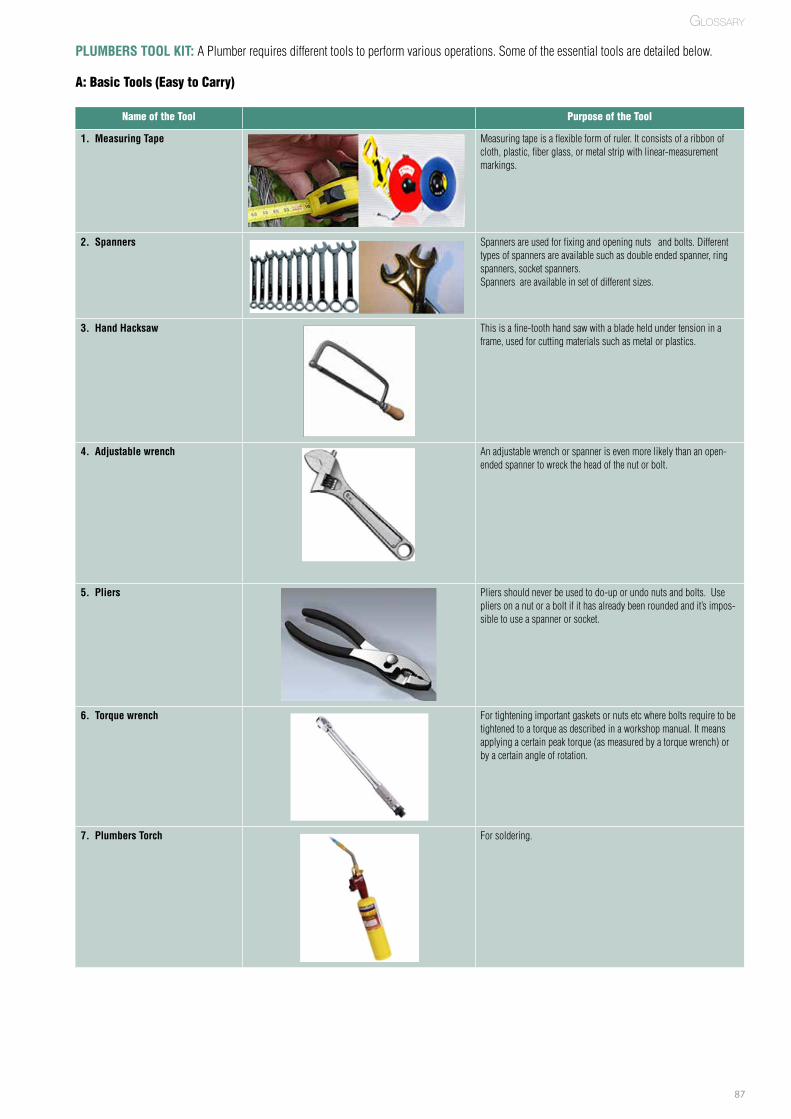
87
PLUMBERS TOOL KIT: APlumberrequiresdifferenttoolstoperformvariousoperations.Someoftheessentialtoolsaredetailedbelow.
A: Basic Tools (Easy to Carry)
Name of the Tool Purpose of the Tool
1. Measuring Tape Measuringtapeisaflexibleformofruler.Itconsistsofaribbonofcloth,plastic,fiberglass,ormetalstripwithlinear-measurementmarkings.
2. Spanners Spannersareusedforfixingandopeningnutsandbolts.Differenttypesofspannersareavailablesuchasdoubleendedspanner,ringspanners,socketspanners.Spannersareavailableinsetofdifferentsizes.
3. Hand Hacksaw Thisisafine-toothhandsawwithabladeheldundertensioninaframe,usedforcuttingmaterialssuchasmetalorplastics.
4. Adjustable wrench Anadjustablewrenchorspannerisevenmorelikelythananopen-endedspannertowrecktheheadofthenutorbolt.
5. Pliers Pliersshouldneverbeusedtodo-uporundonutsandbolts.Usepliersonanutoraboltifithasalreadybeenroundedandit’simpos-sibletouseaspannerorsocket.
6. Torque wrench Fortighteningimportantgasketsornutsetcwhereboltsrequiretobetightenedtoatorqueasdescribedinaworkshopmanual.Itmeansapplyingacertainpeaktorque(asmeasuredbyatorquewrench)orbyacertainangleofrotation.
7. Plumbers Torch Forsoldering.
GlossARy

88
Name of the Tool Purpose of the Tool
8. Pipe die set Thepipediesetisusedforthreadingexternaltaperthreadsonpipes.Thediesetisavailableinthesizesvaryingbetween6.35mmto50.8mm.
9. Taps and Tap Handle Tapsareusedforcuttinginternalthreads.Normallytheseareavail-ablefrom1.4mmto60mm(1/16to3inch)size.
10. Plunger Usedforuncloggingdrains.Thiscanusuallycleartheblockageifit’snottoofarintothemaindrain.
B: Secondary / Supportive Tools
Name of the Tool Purpose of the Tool
1. Bench vice Benchviceisusedforholdingflatorsquareworkpiece.
2. Pipe vice Pipeviceisusedforholdingthepipeforperformingvariousopera-tions.
3. Basin wrench Thebasinwrenchisusefulforgettingatfaucetnutsinspacesnoteasilyaccessible.
4. Spud wrench Aspudwrenchisusedforworkingonthefittingsbeneathsinks,suchasthenutholdingthedraintailpieceinplace.
5. Pipe cutter Pipecutterisusedtocutthepipes.
GlossARy
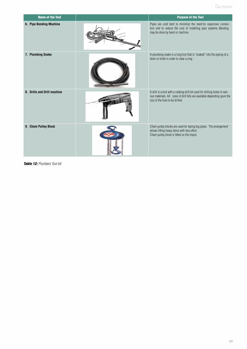
89
GlossARy
Name of the Tool Purpose of the Tool
6. Pipe Bending Machine Pipesarecoldbenttominimizetheneedforexpensiveconnec-torsandtoreducethecostofinstallingpipesystems.Bendingmaybedonebyhandormachine.
7. Plumbing Snake Aplumbingsnakeisalongtoolthatis“snaked”intothepipingofadrainortoiletinordertoclearaclog.
8. Drills and Drill machine Adrillisatoolwitharotatingdrillbitusedfordrillingholesinvari-ousmaterials.Allsizesofdrillbitsareavailabledependinguponthesizeoftheholetobedrilled.
9. Chain Pulley Block Chainpulleyblocksareusedforlayingbigpipes.Thearrangementallowsliftingheavyitemswithlesseffort.Chainpulleyblockisfittedonthetripod.
Table 12: Plumbers Tool kit

90
Disclaimer:
Thispublicationhasbeensolelycompiledasarefreshercourseandtrainingmoduleonhouseholdconnectivityforplumbers.Theinformationcontainedinthispublicationdoesnotoverrideanystateorcentralgovernmentregulationsandstandardsormanufacturer’sinstallationrequire-ments,allofwhichmustbeadheredtoatalltimes.
Thetechnicaldiagramsinthispublicationreflectthegeneralprinciplebehindthetechnologyorprocessandmaydifferinappearancefromtheactualproducts.Thispublicationisonlyareferenceguideandreadersshouldobtainappropriateprofessionaladvicerelevanttotheirparticularcircumstances.
Whilereasonableeffortshavebeenmadetoensurethatthecontentsofthispublicationarefactuallycorrect,DeutscheGesellschaftfurInternation-aleZusammenarbeit(GIZ)GmbHandAsiaSocietyforSocialImprovementandSustainableTransformation(ASSIST),donotprovideguaranteeorwarrantythattheinformationcontainedinthispublicationarecorrect,completeorreliable.Usersareresponsibleformakingtheirownassess-mentsandjudgementofallinformationcontainedhere.ASSISTandGIZdoesnotassumeresponsibilityforanydirect,indirectorconsequentialliability,lossordamageresultingfromtheuseoforrelianceonanyinformation,apparatus,methodorprocessgiveninthispublication.
91
About GIZDeutsche Gesellschaft für Internationale Zusammenarbeit (GIZ) GmbH is a federal enterprise with operations around the globe.It supports the German Government in the fields of international cooperation for sustainable development and internationaleducation. GIZ supports people and societies in shaping their own futures and improving their living conditions.
About GIZ -SNUSPIn 2008 Ministry of Urban Development (MoUD) approved the National Urban Sanitation Policy (NUSP) with the aim to improvethe sanitation situation in urban areas of India.
The National Urban Sanitation Policy (NUSP) based on the 74th Constitutional Amendment Act (1992), aims to strengthenUrban Local Bodies (ULBs). The overall goal of the policy is to transform urban India into sanitised, healthy and liveable citiesand towns. Particular focus is given to improvement of hygienic conditions for the urban poor and women through cost-efficienttechnologies. The NUSP incorporates a paradigm shift and follows integrated concepts in the design and implementation ofsanitation strategies. All cities and states are requested to act at par with the NUSP to develop State Sanitation Strategies (SSS)and City Sanitation Plans (CSPs) respectively. A City Sanitation Plan is a planning document that shall achieve the stepwiseimplementation of the goals spelt out in NUSP whereas SSS creates enabling environment for the latter.
As part of its programme 'Support to the National Urban Sanitation Policy (SNUSP)', Deutsche Gesellschaft für InternationaleZusammenarbeit (GIZ) GmbH supports the MoUD in the aforementioned implementation of policy guidelines at national, stateand city level. The programme also supports the government to improve the management of the sanitation sector in poorer partsof the cities.
ApproachThe project is simultaneously working at three levels - national, state and city level. A three-tiered approach has been designedfor the achievemnet of desired outcomes at each tier as well as constant interaction and knowledge sharing to support theelevator effect".
Central levelThe program formed Technical Advisory Committee (TAC), an advisory body to the programme that recommends on specifictechnical issues and provide guiding directions to the stepwise implementation and improvement of water and sanitation sectorwith particular focus on two themes; Indian Water & Sanitation Utility 2020 and Integrated Septage Management.SNUSP supports MoUD in evaluating the City Sanitation Plans (CSP) prepared so far and documenting the best practices andlessons learnt. This was achieved by providing guidelines and through workshops.
State LevelAt state level the program supported selected states in improving/preparing their State Sanitation Strategies (SSS). It providedtechnical inputs concerning capacity enhancement, skill development, and outsourcing of urban services such aspublic/community toilet complex and sewerage system.
City LevelSNUSP provided handholding support at city level. The program supported preparation of city sanitation planning documents(CSP). The program supports cities in implementing the CSPs by enabling a decision process based on cost-efficient and long-term planning at city level. It supports the cities in developing bankable projects by creating sector-wise financial sustainabilitywhile strengthening service delivery.
"

92
Contact Deutsche Gesellschaft für Internationale Zusammenarbeit (GIZ) GmbH2nd Floor, B-5/2; Safdarjung EnclaveNew Delhi-110029-INDIA Tel: +91 (0)11 4949 5353 Fax: +91 (0)11 4949 5391


![Wiley,.AUDEL Plumber's Pocket Manual, 10th Edition.[2004.ISBN9780764569951]](https://img.dokumen.tips/doc/110x75/54500488b1af9f05098b492f/wileyaudel-plumbers-pocket-manual-10th-edition2004isbn9780764569951.jpg)


