Embed Size (px)
Citation preview

Installation Instructions
H908Plug-in Power Connection Kit with End Seal
DescriptionThe Raychem® H908 is a plug-in, ground-fault-protected power connectionkit for use with WinterGard® H311, WinterGard Plus H611, and WinterGardWet H612 120 V heating cables.This kit ensures compliance with Tyco Thermal Controls, NEC and CECrequirements for ground-fault protection of equipment. It does not pro-tect people against the hazards of shock. The kit includes materials forone power connection and end seal. All WinterGard, WinterGard Plus,and WinterGard Wet heating cables are designed for water-pipe freezeprotection applications. Only the H612 heating cable can be used forboth pipe freeze protection and roof and gutter de-icing applications. For additional technical support call Tyco Thermal Controls at (800) 542-8936.
Tools Required• Needle nose pliers • Propane torch or heat gun • Utility knife • Panduit crimp tools CT100 and CT570• Diagonal cutters
Additional Materials Required• Grounded, UL Listed 15-amp, 120-volt receptacle (receptacle must be
approved for wet locations if exposed to weather)• Additional cable ties may be required for roof and gutter applications.• Your application may require additional Raychem accessories; for example,
H903 application tape for pipe applications; H913/H914 roof clips and/orH915 downspout hangers for roof and gutter de-icing applications.
Kit ContentsItem Qty DescriptionA 1 Plug-in ground-fault equipment protection deviceB 2 Black cloth tapes (6" long x 1" wide)C 1 Uninsulated braid crimpD 2 Insulated bus wire crimpsE 2 Heat-shrinkable tubes (1" long x 1/8" dia.)F 2 Clamp tiesG 1 Heat-shrinkable tube (8" long x 1" dia.)H 2 Warning labels for pipe-trace applicationsI 2 De-icing and snow melting equipment labelsJ 2 Mastic strips (2" long x 1" wide)K 1 Gel-filled end sealL 1 Heat-shrinkable tube (5" long x 3/4" dia.)
A
H
BCDE
F
G
I
J
K
L
WARNING
Fire and Shock Hazard
Self-regulating electric
al
heating cable attached to this pipe:
Disconnect before sevicing
Electric Deicing and
Snow Melting Equipment
on Premises
WARNING
Fire and Shock Hazard
Self-regulating electrical
heating cable attached to this pipe:
Disconnect before sevicing
Electric Deicing and
Snow Melting Equipment
on Premises
Approvals
These components are electrical devices. They must beinstalled correctly to ensure proper operation and toprevent shock or fire. Carefully follow all of the installa-tion instructions and read these important warnings.• To minimize the danger of fire from sustained
electrical arcing if the heating cable is damaged orimproperly installed, and to comply with therequirements of Tyco Thermal Controls and thenational electrical codes, ground-fault equipmentprotection must be used on each heating cablebranch circuit. Arcing may not be stopped by con-ventional circuit protection.
• Component approvals and performance are basedon the use of specified parts only. Do not substituteparts or use vinyl electrical tape.
• The black heating-cable core is conductive and canshort. It must be properly insulated and kept dry.
• Keep components and heating cable ends drybefore and during installation.
• Damaged bus wires can overheat or short. Do notbreak braid or bus wire strands when scoring thejacket or core.
• Bus wires will short if they contact each other.Keep bus wires separated.
• Heat-damaged components can short. Use a heatgun or a torch with a soft, yellow, low-heat flame,not a blue focused flame. Keep the flame moving toavoid overheating, blistering, or charring the heat-shrinkable tubes. Avoid heating other components.Replace any damaged parts.
• Use only fire-resistant insulation materials such asfiberglass wrap.
• Leave these installation instructions with the userfor future reference.
Charring or burning the heat-shrinkable tubes in this kit will produce fumes that may cause eye,skin, nose, and throat irritation. Consult MaterialSafety Data Sheet RAY/3122. 24-hour emergency telephone: CHEMTREC (800) 424-9300. Non-emergency health and safety information:(650) 361-4907.
WARNING: CAUTION:
Pipe Heating Cable 718 KAlso Listed as De-icing and Snow MeltingEquipment
Desig.2E, 3A, 3B, 3C, 3D

2
H908 Design and Installation Information for Heating Cable on Pipes Only (WinterGard H311, WinterGard Plus H611, and WinterGard Wet H612 Heating Cables)
Table 1. For METAL pipes with fiberglass insulation or equivalent (based on 40°F maintain temperature, 10% safety factor)
Articles 422 and 427 of the National ElectricalCode (NEC) and Part I, Section 62 of the Canadian Electrical Code (CEC), govern theinstallation of Raychem heating cable for pipefreeze protection.
Important: For the Tyco Thermal Controls war-ranty to be valid, you must comply with all therequirements outlined in these guidelines.
All thermal and design information providedhere is based upon a “standard” installation withheating cable fastened to an insulated pipe. Forany other application or method of installation,consult Tyco Thermal Controls at (800) 542-8936.
Make sure that the heating cable being used issuitable for your application. Refer to theRaychem Commercial and Residential ProductsApplication and Design Guide (H53585) forheating cable application information.
1. Determine the heating cable type.Use Table 1 to select heating cables for insu-lated metal pipes. Use Table 2 to select heatingcables for insulated plastic pipes. Read acrossthe table to find your pipe size, then dropdown to the line corresponding to the lowestair temperature for that application and thecorrect insulation thickness. The cell at thatintersection has a particular shading and mayhave a number. The shading indicates whichheating cable to use (key to the shadingappears above the table headings). A numberrepresents the spiraling ratio (feet of heatingcable per foot of pipe).
If no number appears in the cell, straight tracethe pipe. If a number does appear in the cell,spiral trace the pipe.If your spiraling ratio is 2.0, multiple trace thepipe using two straight traces at the 4 o’clockand 8 o’clock positions.If your spiraling ratio is 3.0, multiple trace thepipe using three straight traces at the 11o’clock or 1 o’clock position, and at the 4o’clock and 8 o’clock positions.
Example 1:
Pipe size: 1"Lowest air temp.: 0°FInsul. thickness: 1/2"
Metal pipe: WinterGard H311
Plastic pipe: WinterGard Plus H611or WinterGard Wet H612
Example 2:
Pipe size: 2 1/2"Lowest air temp.: –20°FInsul. thickness: 1/2"
Metal pipe: WinterGard Plus H611or WinterGard Wet H612
(Use 1.3 feet of heating cable per foot of pipe.)
Plastic pipe: WinterGard Plus H611or WinterGard Wet H612
(Use two straight traces at the 4 o’clock and 8 o’clock positions.)
2.0
1.3
Heating cable selection and design
Electrical codes
Lowest airtemp. (°F)
Insulationthickness
Nominal pipe size1/2" 8"6"4"3"2 1/2"2"1 1/2"1 1/4"1"3/4"
1/2"1"
1 1/2"1/2"1"
1 1/2"2"
1/2"1"
1 1/2"2"
0
–20
–40
3.01.81.31.3
3.01.81.51.31.11.91.51.11.31.1
3.02.01.71.41.21.13.01.91.41.11.71.41.41.1
Key to Table 1: = H311 = H611, H612, H621, H622
= Use a thicker insulation
Table 2. For PLASTIC pipes with fiberglass insulation or equivalent (based on 40°F maintain temperature, 10% safety factor)
3.02.01.72.0
3.01.81.51.31.13.01.81.4
3.01.7
3.03.02.01.81.51.13.01.61.41.2
3.03.03.01.8
1.41.21.61.21.2 1.5
2.01.21.1
1.31.11.71.4
1.11.1 1.9
1.71.41.21.11.31.1
Lowest airtemp. (°F)
Insulationthickness
Nominal pipe size1/2" 8"6"4"3"2 1/2"2"1 1/2"1 1/4"1"3/4"
1/2"1"
1 1/2"1/2"1"
1 1/2"2"
1/2"1"
1 1/2"2"
0
–20
–40
Key to Table 2: = H311 = H611, H612 H621, H622
= Use a thicker insulation

3
2. Calculate the total heating cable lengthPipe length × spiraling ratio+ 4 ft × # gate/globe valves × valve length (ft) × spiraling ratio+ 2 ft × # ball/butterfly valves × valve length (ft) × spiraling ratio+ 2 ft × # flanges × (pipe diameter / 12) × spiraling ratio+ 2 ft × # pipe supports × (pipe diameter / 12) × spiraling ratio+ 1 ft for each power connection+ 2 ft for each splice connection+ 3 ft for each tee connection
= Total heating cable length (ft)
3. Determine the maximum heating cable circuit length allowedSee Table 3 on the next page. Ensure that your circuits do not exceedthe maximum circuit length listed in Table 3. If necessary, use additionalshorter circuits.
Example (taken from Example 2 [on metal pipe], pg. 2):Pipe length: 50 ftSpiral ratio: 1.3 (from Table 1, pg. 2)Globe valves: 3 (each 0.5 ft long)Pipe supports: 10 supports for 1" pipePower connections: 1Splice connections: 1End Seals: 1
WinterGard heating cable required:Pipe length × spiral ratio = 50 ft × 1.3 = 65.0 ft3 globe valves (.5 ft each) = 4 ft × 3 × .5 × 1.3 = 7.8 ft10 pipe supports = 2 ft × 10 × (1 / 12) × 1.3 = 2.2 ft1 power connection = 1 ft × 1 = 1.0 ft1 splice connection = 2 ft × 1 = 2.0 ft1 end seal = 0.5 ft × 1 = 0.5 ft
Total heating cable length required = 78.5 ft
Heating cable installation
1. Prepare for installation• Store the heating cable in a clean, dry place.• Complete piping pressure test.• Review the heating cable design and com-
pare to materials received to verify that theproper Raychem heating cable and acces-sories are available. The heating cable willhave the heating cable type printed on theouter jacket.
• Walk the system and plan the routing ofthe WinterGard heating cable on the pipe.
2. Cut the heating cable to length• Cut the heating cable to the length
required. This can be done before or afterthe cable is attached to the pipe. Leave aminimum of 1 foot extra heating cable forconnection to power. For splice and teeconnections, leave a minimum of 1 foot foreach section of heating cable. Raychemheating cable can be cut to length withoutaffecting its heat output per foot.
• Protect the heating cable ends frommoisture or mechanical damage if theywill be left exposed before connection.
3. Position and attach heating cable to pipe• Be sure all piping to be traced is dry.• Install heating cable, using straight tracing,
spiraling, or multiple tracing according tothe “Heating cable selection and design”section on page 2.
• For straight tracing, install the heating cableon a lower half of the pipe; for example, inthe 4 o’clock or 8 o’clock position.
• Be sure to install the additional heatingcable required for valves, flanges, etc. asindicated in Step 2 of the “Heating cableselection and design” section.
• When the design calls for spiraling, beginby suspending a loop every 10 feet asshown in Figure 1. To determine the looplength, obtain the spiral factor from Table1 or 2 and multiply by 10. For example, if
a spiral factor of 1.3 is called for, leave a13-foot loop of heating cable at every 10-foot section of pipe. Grasp the loop inits center and wrap it around the pipe.Even out the distance between spirals bysliding the wraps along the pipe. Useglass tape to secure the center of the loopto the pipe. Secure the heating cable flatto the pipe to obtain good contact.
• Tape the heating cable to the pipe at 2-footintervals using H903 fiberglass applicationtape or nylon cable ties. Do not use vinylelectrical tape, duct tape, metal bands, orwire.
44.. IInnssttaallll hheeaattiinngg ccaabbllee eenndd sseeaallss,, sspplliicceess,, tteeeess,,aanndd ppoowweerr ccoonnnneeccttiioonn..• Test each circuit before installing the H908
ground-fault device, according to theinstructions in the “Heating cable testingand maintenance” section.
• Install all end seals, splices, tees, andpower connection prior to plugging in.
• Follow the H908 kit installation instruc-tions beginning on page 8.
• Use only weatherproof receptaclesapproved for wet locations when installingWinterGard Wet H612 heating cable withthe H908 Power Connection Kit for Roofand Gutter De-Icing Applications.
55.. CChheecckk tthhee iinnssttaallllaattiioonn• Prior to installing thermal insulation, make
sure the heating cable is free of mechanicaldamage (from cuts, clamps, etc.) and ther-mal damage (from solder, overheating, etc.).
• Visually check all power connections, endseals, splices, and tees.
10 ft
Glass tape(typical)
Heatingcable
Tape afterspiraling heatingcable on pipe
Wrap loopsin oppositedirection
Pull heatingcable looplength
Apply glasstape beforespiralingheating cableon pipe
Figure 1. Spiraled heat tracing
H908 Design and Installation Information for Heating Cable on Pipes Only (continued)(WinterGard H311, WinterGard Plus H611, and WinterGard Wet H612 Heating Cables)
4
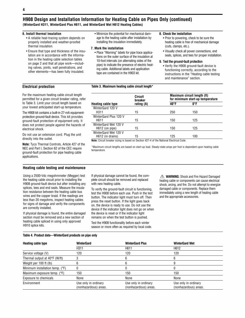
Table 4. Product data—WinterGard products on pipe only
Heating cable type WinterGard WinterGard Plus WinterGard WetH311 H611 H612
Service voltage (V) 120 120 120Thermal output at 40°F (W/ft) 3 6 6Weight per 100 ft (lb) 6 6 9Minimum installation temp. (°F) 0 0 0Maximum exposure temp. (°F) 150 150 150Exposure to chemicals None None NoneEnvironment Use only in ordinary Use only in ordinary Use only in ordinary
(nonhazardous) areas. (nonhazardous) areas. (nonhazardous) areas.
6. Install thermal insulation• A reliable heat-tracing system depends on
properly installed and weather-proofedthermal insulation.
• Ensure that type and thickness of the insu-lation are in accordance with the informa-tion in the heating cable selection tableson page 2 and that all pipe work—includ-ing valves, joints, wall penetrations, andother elements—has been fully insulated.
• Minimize the potential for mechanical dam-age to the heating cable after installation byinstalling the insulation immediately.
7. Mark the installation• Place “Warning” labels for pipe trace applica-
tions on the outer surface of the insulation at10-foot intervals (on alternating sides of thepipe) to indicate the presence of electric heat-ing cable. Additional labels and applicationtape are contained in the H903 kit.
8. Check the installation• Prior to powering, check to be sure the
heating cable is free of mechanical damage(cuts, clamps, etc.).
• Visually check all power connections, endseals, splices, and tees for proper installation.
99.. TTeesstt tthhee ggrroouunndd--ffaauulltt pprrootteeccttiioonn• Verify the H908 ground-fault device is
functioning correctly, according to theinstructions in the “Heating cable testingand maintenance” section.
Using a 2500-Vdc megohmmeter (Megger) testthe heating cable circuit prior to installing theH908 ground-fault device but after installing anysplices, tees and end seals. Measure the insula-tion resistance between the heating cable buswires and the copper braid. If the readings areless than 20 megohms, inspect heating cablesfor signs of damage and verify the componentsare correctly installed.
If physical damage is found, the entire damagedsection must be removed and a new section ofheating cable spliced in using only approvedH910 splice kits.
If physical damage cannot be found, the com-plete circuit should be removed and replacedwith new heating cable.
To verify the ground-fault circuit is functioning,test the H908 before each use. Push in the testbutton. The indicator light must turn off. Thenpress the reset button. If the light goes backon, the device is ready to use. Do not use thedevice if the indicator light does not go on whenthe device is reset or if the indicator lightremains on when the test button is pushed.
Test the H908 functionality before each winterseason or more often as required by local code.
WARNING: Shock and Fire Hazard Damagedheating cable or components can cause electricalshock, arcing, and fire. Do not attempt to energizedamaged cable or components. Replace themimmediately using a new length of heating cableand the appropriate accessories.
Heating cable testing and maintenance
Electrical protection
For the maximum heating cable circuit lengthpermitted for a given circuit breaker rating, referto Table 3. Limit your circuit length based onyour lowest anticipated start-up temperature.
The H908 kit contains a built-in 27-mA equipment-protection ground-fault device. This kit providesground-fault protection of equipment only. Itdoes not protect people against the hazards ofelectrical shock.
Do not use an extension cord. Plug the unitdirectly into the outlet.
Note: Tyco Thermal Controls, Article 427 of theNEC and Part I, Section 62 of the CEC requireground-fault protection for pipe heating cableapplications.
Table 3. Maximum heating cable circuit length*
Circuit Maximum circuit length (ft)breaker for minimum start-up temperature
Heating cable type rating (A) 40°F 0°FWinterGard 120 V
H311 15 250 150 WinterGard Plus 120 V
H611 15 150 125 WinterGard Wet 120 V
H612 (on pipe) 15 150 125WinterGard Wet 120 V
H612 (in drains) 15 125 100Note: Circuit breaker sizing is based on Section 427-4 of the National Electrical Code.
*Maximum circuit lengths are based on start-up load. Steady-state amps per foot is dependent upon heating cabletemperature.
H908 Design and Installation Information for Heating Cable on Pipes Only (continued)(WinterGard H311, WinterGard Plus H611, and WinterGard Wet H612 Heating Cables)
Article 426 of the National Electrical Code andPart I, Section 62 of the Canadian ElectricalCode govern the installation of Raychemheating cable systems for roof and gutter de-icing.
Important: For the Tyco Thermal Controls war-ranty to be valid, you must comply with all therequirements outlined in these guidelines.
All design information provided here is based ona “standard” shake or shingle roof application.For any other roof de-icing installation, refer tothe WinterGard Wet Design, Installation andMaintenance manual (H56804) or contact TycoThermal Controls at (800) 542-8936.
5
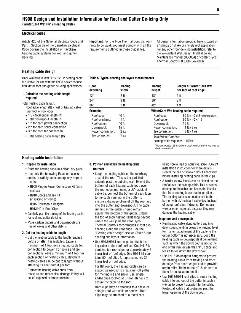
H908 Design and Installation Information for Roof and Gutter De-Icing Only(WinterGard Wet H612 Heating Cable)
Table 5. Typical spacing and layout measurements
Roof Tracing Tracing Length of WinterGard Wet overhang width height per foot of roof edge
12" 2 ft 18" 2 ft24" 2 ft 30" 3 ft36" 2 ft 42" 4 ft
Only WinterGard Wet H612 120 V heating cableis suitable for use with the H908 power connec-tion kit for roof and gutter de-icing applications.
1. Calculate the heating cable length required.
Total heating cable length:Roof edge length (ft) × feet of heating cable
per foot of roof edge+ 1.5 x total gutter length (ft)+ Total downspout length (ft)+ 1 ft for each power connection+ 2 ft for each splice connection+ 3 ft for each tee connection= Total heating cable length (ft)
1. Prepare for installation• Store the heating cable in a clean, dry place.• Use only the following Raychem acces-
sories to satisfy code and agency require-ments:- H908 Plug-in Power Connection Kit (with
end seal)- H910 Splice and Tee Kit
(if splicing or teeing)- H915 Downspout Hangers- H913/H914 Roof Clips
• Carefully plan the routing of the heating cablefor roof and gutter de-icing.
• Make certain gutters and downspouts arefree of leaves and other debris.
2. Cut the heating cable to length• Cut the heating cable to the length required
before or after it is installed. Leave aminimum of 1 foot extra heating cable forconnection to power. For splice and teeconnections leave a minimum of 1 foot foreach section of heating cable. Raychemheating cable can be cut to length withoutaffecting its heat output per foot.
• Protect the heating cable ends frommoisture and mechanical damage if they willbe left exposed before connection.
3. Position and attach the heating cableOn roofs• Loop the heating cable on the overhang
area of the roof. This is the part thatextends past the building wall. Extend thebottom of each heating cable loop overthe roof edge and, using a UV-resistantcable tie, connect the bottom of each loopto the cable running in the gutter toensure a drainage channel off the roof andinto the gutter and downspout. The cablerunning in the gutter should remainagainst the bottom of the gutter. Extendthe top of each heating cable loop beyondwhere the wall joins the roof. TycoThermal Controls recommends 2-foot clip-spacing along the roof edge. See the“Heating cable design” section (Table 5) forspacing and layout information.
• Use H913/H914 roof clips to attach heat-ing cable to the roof surface. One H913 kitcontains ten roof clips for approximately 7linear feet of roof edge. One H914 kit con-tains 50 roof clips for approximately 35linear feet of roof edge.For flat roofs, the heating cable can bespaced as needed to create run-off pathsfor melting ice and snow. Use single-ended clips located at 3-foot intervals tosecure the cable to the roof.Roof clips may be attached to a shake orshingle roof with nails or screws. Roofclips may be attached to a metal roof
using screw, nail or adhesive. (See H56723installation instruction for more details.)Reseal the nail or screw holes if necessarybefore installing heating cable in the clips.
• A barrier (snow fence) can be placed on theroof above the heating cable. This preventsdamage to the cable and keeps the installa-tion from coming loose due to ice slides.The heating cable can be attached to thebarrier with UV-resistant cable ties, insteadof using roof clips, if desired. Do not usewire or other materials because they maydamage the heating cable.
In gutters and downspouts• Run heating cable along gutters and into
downspouts, ending below the freezing level.Permanent attachment of the cable to thegutter bottom is not necessary. Loop theheating cable in downspouts if convenient,such as when the downspout is not at theend of the run, or use the H910 splice andtee kit to tee down the downspout.
• Use H915 downspout hangers to protectthe heating cable from fraying and fromdamage from sharp edges and to providestrain relief. Refer to the H915 kit instruc-tions for installation details.
• Use H913/H914 roof clips to route heatingcable into and out of the gutter in such away as to prevent abrasion to the cable.Protect all cable that protrudes past thelower opening of the downspout.
Heating cable design
Heating cable installation
Example:Roof edge: 40 ftRoof overhang: 1 ftRoof gutter: 40 ftDownspout: 15 ftPower connection: 2 eaTee connection: 1 ea
WinterGard Wet heating cable required:Roof edge: 80 ft = 40 × 2 (from table above)
Roof gutter: 60 ft = 40 x 1.5Downspout: 15 ftPower connection: 1 ft x 2 eaTee connection: 3 ft x 1 ea
Total WinterGard Wet heating cable required: 160 ft** This total exceeds 125-ft maximum circuit length, therefore two separate
circuits are required.
Electrical codes

H908 Design and Installation Information for Roof and Gutter De-Icing Only (continued)(WinterGard Wet H612 Heating Cable)
Product data–WinterGard Wet H612 heating cable for roof and gutter de-icing only
Service voltage (V) 120
Thermal output at 32°F (W/ft) (in ice and snow) 8
Weight per 100 ft (lb) 9
Minimum installation temp. (°F) 0
Maximum exposure temp. (°F) 150
Exposure to chemicals None
Environment Use only in ordinary (nonhazardous) areas.
6
4. IInnssttaallll hheeaattiinngg ccaabbllee eenndd sseeaallss,, sspplliicceess,, tteeeess,,aanndd ppoowweerr ccoonnnneeccttiioonn• Using a megohmmeter, test each circuit
before installing the H908 ground-faultdevice, according to the instructions inthe “Heating cable testing andmaintenance” section.
• Install all end seals, splices, tees, andpower connection prior to plugging in.
• Follow the H908 kit installationinstructions beginning on page 8.
• Use only weatherproof receptaclesapproved for wet locations when installingWinterGard Wet H612 heating cable withthe H908 Power Connection Kit for Roofand Gutter De-Icing Applications.
5. Mark the installation• Two labels indicating the presence of
electric de-icing and snow-melting equip-ment on the premises are included with thisunit. One label must be posted at the elec-trical outlet cover. The other label must beposted at the fuse or circuit breaker panel.The labels must be clearly visible.
6. CChheecckk tthhee iinnssttaallllaattiioonn• Prior to powering, check to be sure the
heating cable is free of mechanicaldamage (cuts, clamps, etc.).
• Visually check all power connections, endseals, splices, and tees for properinstallation.
77.. TTeesstt tthhee ggrroouunndd--ffaauulltt pprrootteeccttiioonn• Verify the H908 ground-fault device is
functioning correctly, according to theinstructions in the “Heating cable testingand maintenance” section.
Make sure that gutter and downspouts are freeof leaves and other debris prior to the winterseason.
Using a 2500-Vdc megohmmeter (Megger) testthe WinterGard Wet heating cable circuit priorto installing the H908 ground-fault device butafter installing any splices, tees and end seals.Measure the insulation resistance between theheating cable bus wires and the copper braid. Ifthe readings are less than 20 megohms, inspectheating cables for signs of damage and verifythe components are correctly installed.
If physical damage is found, the entire damagedsection must be removed and a new section ofheating cable spliced in using only approved
H910 splice kits.
If physical damage cannot be found, the com-plete circuit should be removed and replacedwith new heating cable.
To verify the ground-fault circuit is functioning,test the H908 before each use. Push in the testbutton. The indicator light must turn off. Thenpress the reset button. If the light goes back on,the device is ready to use. Do not use thedevice if the indicator light does not go onwhen the device is reset or if the indicator lightremains on when the test button is pushed.
Test the H908 functionality before each winterseason or more often as required by local code.
WARNING: Shock and Fire Hazard.Damaged heating cable or components cancause electrical shock, arcing, and fire. Do notattempt to energize damaged cable or compo-nents. Replace them immediately using a newlength of heating cable and the appropriateRaychem accessories.
Electrical protection
WinterGard Wet H612
Voltage rating: 120 V
Circuit breaker rating: 15 A max.
Max. heating cable length (ft)per circuit for minimumstart-up temperature of 0°F: 100
Max. heating cable length (ft)per circuit for minimumstart-up temperature of 40°F: 125
The H908 plug contains a built-in 27-mAequipment-protection ground-fault device.This kit provides ground-fault protection ofequipment only. It does not protect peopleagainst the hazards of electrical shock.
Do not use an extension cord. Plug the unitdirectly into the outlet.
Note: Tyco Thermal Controls and the nationalelectrical codes require ground-fault protectionof equipment for de-icing systems.
Heating cable testing and maintenance

7
H913/H914 Roof clip
H915Downspouthanger
Cable tie(typical)
H910 Tee
End seal
End seal
Clamp ties (two places)
H915Downspout hanger
Power connection splice(included with the H908)
H908Ground-fault
equipmentprotection
device
Weatherproofedoutlet approvedfor wet locations
Note:• In all locations, route and secure cable to avoid possiblemechanical damage, such as from ladders, etc.
• Neither the ground-fault unit nor the power connectionsplice can be submerged.
H908 Design and Installation Information for Roof and Gutter De-Icing Only (continued)(WinterGard Wet H612 Heating Cable)

8
H908 Installation Instructions – Power Connection Kit
Outer jacket Braid Bus wires
Conductive coreInner jacket
Braid Bus wires
Conductive coreInner jacket
Identify heating cable
WinterGard H311 and WinterGard Plus H611Heating cables with braid and no outer jacket
WinterGard Wet H612Heating cables with braid
and outer jacket
5" tube 8" tube
2-3/4"
• Unravel 2 3/4" of braid.
• Straighten the braid andtwist into a pigtail.
2 For H311 and H611 heating cables only1 For all heating cables
• Slide 8-inch tube and 5-inch tubeover end of the plug-in cord.
Note: Instructions generally show heating cable with braid and outer jacket. Cables with no outer jacket look slightly different from those illustrated.
Black and whitepower wires
Green ground wire
Plug-in cord3"
Stripped end of ground-fault protection device

9
2-3/4"
2b For H612 heating cable only 2c For H612 heating cable only
1/4"
5 Expose bus wires (continued) 6 Prepare bus wires
1-3/4" 1/4"
1/4"
3 Remove inner jacket (H612 cable shown) 4 Expose bus wires
12
34
56
78
9
• Score betweenbus wires atinner jacket.
• Slide 1/8˝ x 1˝ shrinktubes over bus wires.
• To shrink tubingmove heat sourcecontinuously fromside to side.
• While shrinking,ensure that tubesremain up againstblack core.
• Trim buswires.
• Bend core to break freeat inner jacket.
• Peel core andany remainingmaterial frombus wires.
• Lightly score completely aroundand then down outer jacket.
• Lightly score completely aroundand then down inner jacket.
• Bend heating cable tobreak jacket at score, thenpeel off inner jacket.
Do notcut buswires.
• Notch core at the end.
• Twist back andpeel bus wiresfrom core.
Do not cut braid or inner jacket.
• Unravel the braid back to theouter jacket.
• Straighten the braid andtwist into a pigtail.
H908 Installation Instructions – Power Connection Kit (continued)

10
Heat-shrink tube
Plug-in cord
Green wire
Black andwhite wires
Mastic
7 Connect bus wires 8 Apply mastic to bus wires
Black cloth tape
Green ground wire
Braid
10 Connect ground wire
Note: Ring of adhesive will appear at both ends
9 Apply 5-inch shrink tube
• Use insulated buswire crimps andCT-100 crimp toolto connect blackand white wires tobus wires of heat-ing cable. Polaritydoes not matter.
• Use uninsulated braid crimp andCT-570 crimp tool to connectbraid to ground wire.
• Wrap black cloth tape evenlyaround crimp and splice.
• Cover crimp completely.
• Center the 5-inch heat-shrinkabletube over the splice. Make suretube extends over the end of eachheating cable and the cord.
• Shrink the tube completely. Startat the middle and work towardeach end. Keep heating after tubehas shrunk, to melt mastic andadhesive inside tube. Total heating time should be about 2 minutes.
• Immediately aftershrinking, pinch firstone end of the tubeand then the otherend with needle-nose pliers until theends stay sealed.This normally takes10 seconds per end.
• Remove release paper from mastic strips.• Wrap one strip of mastic around thewhite wire against the end of the splice to provide a water block.
• Repeat for the black wire.
• Squeezethe mastictogether.
H908 Installation Instructions – Power Connection Kit (continued)

11
Note: Ring of adhesive will appear at both ends
11 Apply 8-inch shrink tube
• Center the 8-inch heat-shrinkable tube over the splice.Make sure that the tube extends over the end of theheating cable and cord.
• Shrink the tube completely. Start at the middle andwork toward each end. Keep heating after tube has shrunk, to melt adhesive inside tube. Total heating time should be about 3 minutes.
H908 Installation Instructions – Power Connection Kit (continued)

12
H908 Installation Instructions – End Seal
12
34
56
78
9
Note: The end seal is designed to be installed only once; it cannot be removed from the heating cable once installed. Do not use until ready for final installation.
1"
2"
• Remove theouter jacket.
• Do not cut ordamage innerjacket.
• Push the braid back 2 inches from the cable end.
• Slide the braid up against the end seal and secure with the6-inch length of tape provided.
• Firmly push end seal onto the cable (at least 1 1/2 inches).Some gel may ooze out.
• Do not twist or try to remove the end seal during or afterinsertion. Do not reuse an end seal.
• Firmly push end seal onto the cable (at least 1 1/2 inches).Some gel may ooze out.
• Do not twist or try to remove the end seal during or afterinsertion. Do not reuse an end seal.
• Unravel and remove exposed braid.
• Cleanly cut off the end of the cable.• Score down and around outer jacket1 inch from the end.
1 End Seal for H612
3
2 2
4
• Cleanly cut off the endof the cable.
1 End Seal for H311, H611
3

13
H908 Installation Instructions – Securing the Ground-Fault Device
Clampties
WARNINGFire and Shock Hazard
Self-regulating electricalheating cable attached to this pipe:
Disconnect before servicing
Cord labelWARNING
Fire and Shock HazardSelf-regulating electrical
heating cable attached to this pipe:
Disconnect before servicing
1a For pipe freeze protection 2a For pipe freeze protection (continued)
Clamp ties De-icingequipmentlabel
Cord label
1b For roof and gutter de-icing 2b For roof and gutter de-icing (continued)
• To prevent damage to the ground-fault equipment protectiondevice and to provide strain relief, use clamp ties to securethe device to the wall near the receptacle. Be careful not todamage either the cord or the ground-fault unit.
Note: Pipe must be fully insulated.
• Plug the heating cable into a 15-A, 120-Vac grounded outlet.• Make sure that:
– Cord label is readily visible.– Indicator light on the ground-fault equipment protection
device is on.– Receptacle is properly weatherproofed (if outdoors).– Ground-fault equipment protection device and power
connection splice will not be submerged.
Note: Pipe must be fully insulated
• To prevent damage to the ground-fault equipment protectiondevice and to provide strain relief, use clamp ties to securethe device to the wall near the receptacle. Be careful not todamage either the cord or the ground-fault unit.
• The H908 should be mounted high up, away from passersbyto prevent damage to the unit and the risk of shock.
• Plug the heating cable into a 15-A, 120-Vac groundedoutlet approved for wet locations.
• Make sure that:– Cord label is readily visible.– Indicator light on the ground-fault equipment protection
device is on.– Receptacle is properly weatherproofed. – Ground-fault equipment protection device and power
connection splice will not be submerged.

14
Tyco Thermal Controls warrants allWinterGard, WinterGard Plus and WinterGardWet self-regulating heating cables and compo-nents against faulty workmanship and use ofdefective materials for two (2) years from thedate of purchase. This warranty can beamended only by a written instrument signedby a duly authorized officer of Tyco ThermalControls. Buyer's exclusive remedy under thiswarranty shall be to have Tyco ThermalControls, within a reasonable time, repair suchgoods or supply replacement goods or creditBuyer's account for such goods and accepttheir return whichever Tyco Thermal Controlsmay elect at its sole discretion. Tyco ThermalControls shall in no event be liable for the costof removal or installation, for loss or damageto or loss of use of facilities or other property,loss of revenue, loss of use of revenue, loss ofanticipated profits, or other damages or costsof any kind whatsoever, whether direct, indi-rect, incidental, or consequential.
Notwithstanding the foregoing, Tyco ThermalControls shall have no liability whatsoeverunless: (a) Buyer promptly notifies TycoThermal Controls in writing after discovery of analleged nonconformity and includes a detailedexplanation of the alleged nonconformity; (b)Buyer promptly returns the goods to TycoThermal Controls postage prepaid, at 300Constitution Drive, Menlo Park, California94025-1164, USA; and (c) Tyco ThermalControls examination of such goods establishesto Tyco Thermal Controls satisfaction thatsuch alleged nonconformities actually existand occurred in the cause of proper and normaluse and were not caused by accident, misuse,neglect, alteration or improper installation,repair or testing or such other cause outsideof the responsibility of Tyco Thermal Controlsunder this Limited Warranty.
THE FOREGOING WARRANTY IS IN LIEU OFALL OTHER REPRESENTATIONS, WARANTIES,OR CONDITIONS, EXPRESS OR IMPLIED,
INCLUDING WITHOUT LIMITATION ANYIMPLIED WARRANTY OF MERCHANTABILITY,FITNESS FOR A PARTICULAR PURPOSE ORNONINFRINGEMENT, AND OF ANY OTHEROBLIGATION OR LIABILITY ON THE PART OFTYCO THERMAL CONTROLS, WHETHER BYSTATUTE, CONTRACT, STRICT LIABILITY,TORT OR OTHERWISE.
If the goods are a consumer product in buyer'sjurisdiction, the above exclusion or limitation ofincidental or consequential damages and theabove disclaimer of implied warranties may notapply. The term of any such implied warranty islimited to the term of this two-year LimitedWarranty. Some jurisdictions do not allowlimitations on how long an implied warrantylasts, so the above limitation may not apply.This warranty gives consumers specific legalrights, and consumers may also have otherrights, which vary by jurisdiction.
H908 Warranty Information

15
H908 Design and Installation Information
Notes

16
H908 Design and Installation Information
USATyco Thermal Controls300 Constitution DriveMenlo Park, CA 94025-1164Tel: (800) 545-6258Fax: (800) [email protected]
CanadaTyco Thermal Controls250 West StreetTrenton, Ontario Canada K8V 5S2Tel: (800) 545-6258Fax: (800) 596-5004
Tyco, Raychem, WinterGard, WinterGard Plus and WinterGard Wet are trademarks of Tyco Thermal Controls, LLC or its affiliates. ©20
06 T
yco
Ther
mal
Con
trols
Prin
ted
in U
SA
H54
789
(P
N 04
8227
)
6/06