Embed Size (px)
Citation preview

WIN\PLC\PLCDMAN.WRI REV: 11-99
PLC STEP MOTION DRIVE SYSTEM
MODEL NUMBERS:
PMD 2.0/4.0 or PML 2.0/4.0
OPERATION AND INSTALLATION MANUAL
SECTION 1: PLC 2.0/4.0 DRIVER CASE
SECTION 2: PL 2.0 DRIVER CARD
FOR QUICK REFERENCE - REFER TO THE APPENDIX SECTIONS


!!!! ATTENTION !!!!
Mis-wiring of motor or power supplies WILL damage motor drivers IMMEDIATELY. Motor coils A or B can be reversed; motor will run in the opposite direction. Pairs can be reversed; pair A in coil B for example. CROSS-WIRING, an A and B wire crossed, WILL damage driver. Allowing exposed motor leads to touch each other, ground, or power MAY damage driver. Refer to Appendix D in the PL driver section for wiring schemes.
SMOKE, POPPING, ELECTRONIC ODOR, OR FUSE FAILURE INDICATES DRIVER FAILURE.
Call the Service Center. Do NOT change fuse or attempt repair without instructions. ADDITIONAL DAMAGE CAN OCCUR !!! Shorted drivers can easily be repaired by replacing the socketed driver arrays.
!!!! WARNING !!!!
NEVER connect or disconnect any of the motor leads or power supply (VMM) leads before disconnecting AC power! Unit may be safely operated WITHOUT motor. However, pause 30 seconds after power off before reconnecting motor (Bleed-Down time).

SECTION 1: PMD or PML - Stepper Motor Drive & Power Supply Assembly
This chassis system supports two configurations: PMD 2/4 (+5v Interface) or PML 2/4 (+24v Interface).
The PLC system is used with an external PLC controller, PLC indexer card, or other device in positioning applications. The input connector supports controller input signals and the Limit-Loop safety.
CONFIGURATIONS OF PLC INTERFACES. The PL Series supports 4 types of interfaces.
1) PD Sinking Style (SN). The PD SN is for +5v interfaces in which the PLC will sink the output signals (step & direction) to ground when active. The P1-4 pin of the connector will source +5v supply for the PLC card and the optical interface. See page 6.
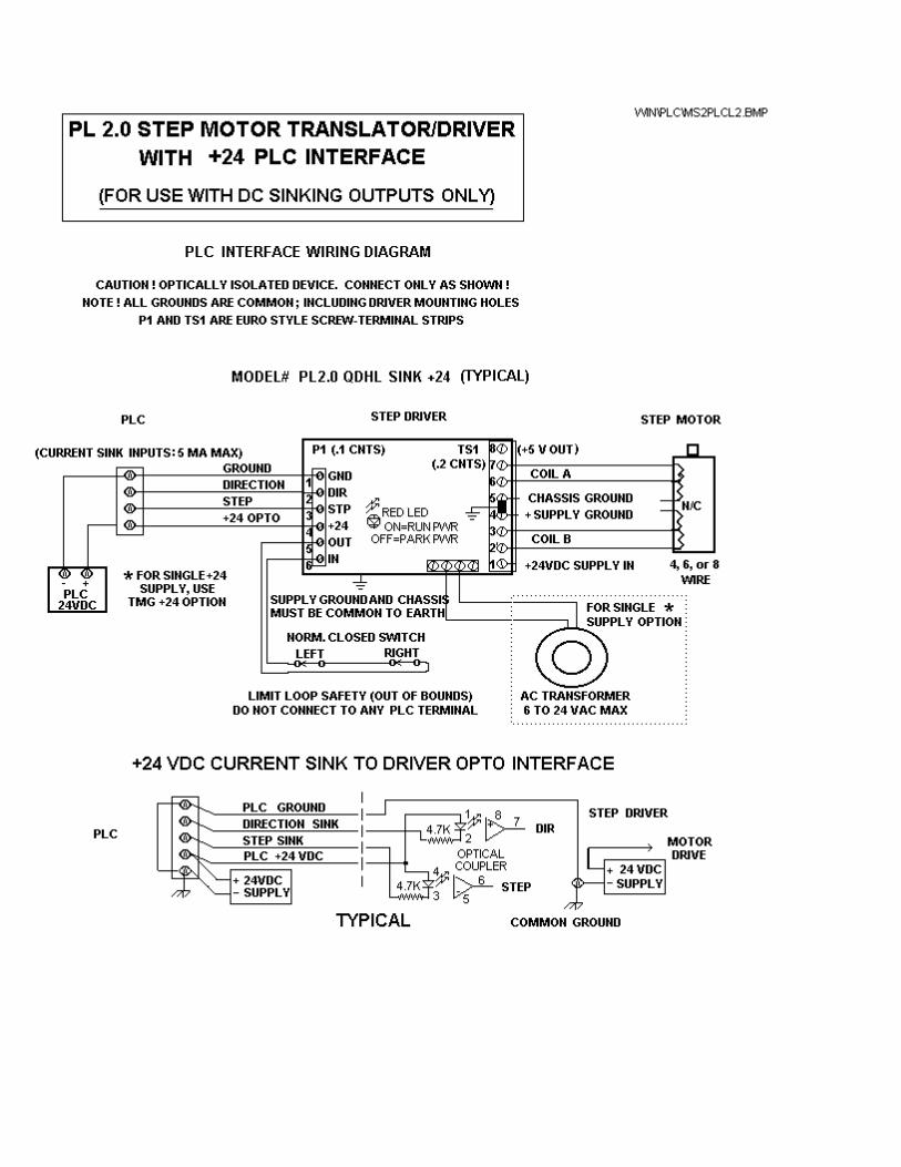
2) PB Sourcing Style (SO). The PB SO is for +5v interfaces in which the PLC will source the output signals (step & direction) to +5v when active. The P1-4 pin of the connector will source +5v supply for the PLC card and the optical interface. See page 7. 3) PL Sinking Style (SN). The PL SN is for +24v interfaces in which the PLC will sink the output signals (step & direction) to ground. The P1-4 pin of the connector must be connected to the source of +24v for the optical interface. See page 8.
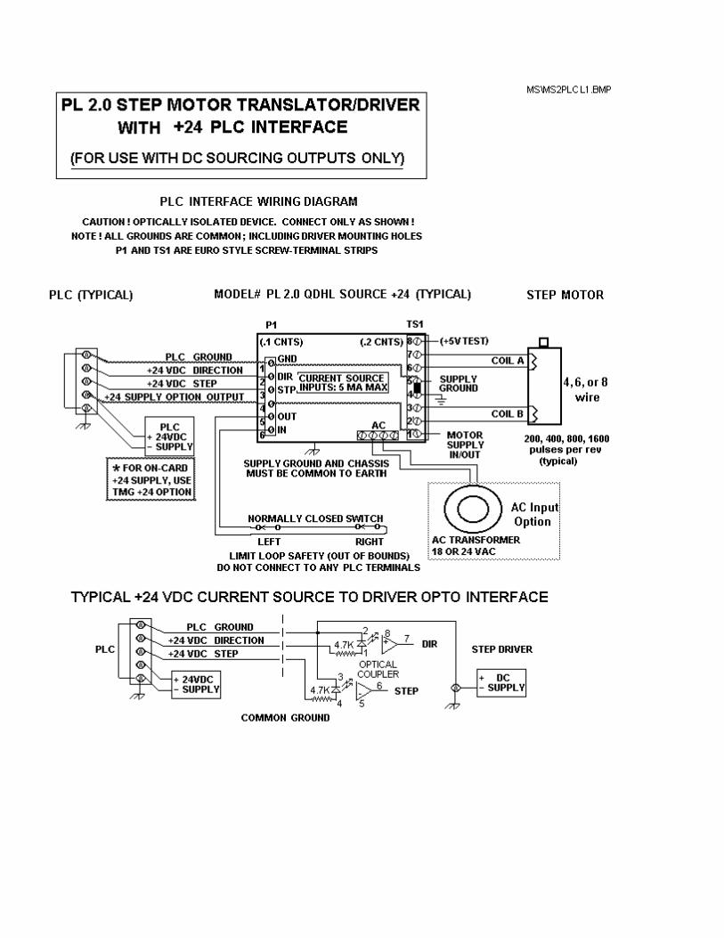
4) PL Sourcing Style (SO). The PL SO is for +24v interfaces in which the PLC will source the output signals (step & direction) to +24v. The P1-1 pin of the connector must be connected to the return (ground) of the source of the +24v for the optical interface. See page 9.
Note: On PML boxes wired with the TS connector, +24v is supplied for the PLC system and is also connected to P1-4 for the optical interface. On PMD boxes wired with the TS connector, +24v is supplied for the PLC system but MUST NOT BE connected to P1-4. PML or PMD systems with the optional high-performance +40v power supply can not have the +24v TS connector. See page 10.

GENERAL DESCRIPTION. All configurations of the PLC modules are a rectangular, aluminum-cased unit combining a high-speed, high-power step motor driver with a matched power supply. The driver is an adjustible current, chopper style, with 2 or 4 amps per phase maximum. The power supply is 24 or 40 vdc. This system will operate step motors withcoil currents from .1 to 2 (1 to 4) amps; 4, 5, 6, or 8 wire. Larger motors up to 5 amps can also be used, however, coils must be in series. During operation, any typical motor, either unipolar or bipolar, is connected to the output terminals (refer to Appendix D). Full, Half, or Quarter step angle is available (step increments of 1/200, 1/400, 1/800, 1/1600, 1/3200 of a rev per pulse). When the unit is in stop mode, the motor will hold (parking) at either 25%, 50% or 0% (free) of full power. This system can be stalled without damage. Over-temp, over-current, over-voltage, and over-drive protection is standard. Output current (torque adjust) is "dial-able". See Appendix C.
The unit comes standard with translator-driver card, power supply with fuse, power switch, line filter, and IEC power cord. Input voltage is 110 vac, 60 cycle only; 220 vac, 50/60 cycle is optional. Signal connectors are de-plug screw-terminal for input and 6-pin Molex for motor output. Tapped 6/32 (4 each) allow mounting from the bottom of the case. Cooling is conventional convection. No dropping resistors or fans are normally required. Indicators include "DC OK" and "AC ON".
PLC SYSTEM. The PLC system requires 2 inputs from an external device. A STEP pulse (STP) and a DIRECTION level (DIR). The Limit Loop must be closed or wired through safety limits at the P1 connector. The AP option (Auto-Park) will automatically reduce or PARK the motor power at stand-still. All input signals must be at +24 VDC (PML) or TTL +5 vdc (PMD) depending on the optical isolation installed. Refer to the PL driver card section for details of the PLC interface.
PLC ASSEMBLY. All PML or PMD assemblies include a step motor driver, DC power supply (+24 vdc or +40 vdc), and an IEC style power entry / line filter AC connector combination. Surge protection is included. The DC power supplies also provide +5 vdc TTL. The VCC (opto) supply is over-current protected. In addition, a 2 amp fuse protects the entire assembly. The green chassis lamp indicates VMM power on. The neon lamp in the power switch indicates that AC power is present. Each assembly includes a motor connector; see Appendix D. On PLC's, the 7 pin cable connector provides access to the motion signals, limit loop, and VCC (opto) power/ground. Refer to the following pages for connection to the front panel or circuit card.


PLman.wri 3-97
PL 2.0 or PD 2.0
MiniStep translator /motor driver card
OPERATION AND INSTALLATION
MANUAL
FOR PL SERIES
STEP MOTOR DRIVERS


PRODUCT DESCRIPTIONThe PL (PL or PD Series) stepper motor driver, is a switching type, constant- current regulator which drives current pulses through the windings of a stepper motor. All stepper motors are stepped or rotated by changing the direction of the current flow through the windings in a unique sequence. Each change of current direction results in a step.
The driver contains two sections: (1) the step generator; and the (2) power drivers. The step generator is a digital logic system which receives input commands from a controller (typically a microprocessor) and generates a series of step signals. The power drivers receive the step signals and switch the phase of current in the motor windings.
The driver requires two input signals: (1) the step pulse - STP, (2) the direction level - DIR. The enable loop - ABR must be closed. The step pulse (or step clock) to the input of the driver will cause a corresponding change of the output current resulting in one step (one unit of motor rotation). The direction input is a level which controls the direction of motor rotation. If the signal is ON, the motor rotates in CW direction; if the signal is OFF, the motor rotates in CCW direction. In addition to the step and direction controls, the driver PARK signal will automatically reduce output power delivered to the motor windings to park power when stationary. If the park LED off, the driver is at reduced current; if the LED is on (pulsing), the driver is at full current.
The LIMIT LOOP sets the current to either off or on. If the loop is OPEN or floating, the driver is FREE (no current); if CLOSED, the driver is enabled. NEVER CONNECT THE LOOP TO ANY POWERED CIRCUITS OR SOLID STATE CONTROLS; THIS LOOP IS NOT OPTICALLY ISOLATED.
In addition to the input signals, the PL driver also requires a power supply input of unregulated D.C. voltage. The driver functions to control the current furnished by the D.C. supply. The combination of a D.C. supply and the PL driver is referred to as a current-regulated power supply, or constant- current motor driver. The driver regulates the current through the motor winding by rapidly switching on and off the D.C. voltage. This technique is referred to as switch-mode or chopper regulation. The driver also provides an internal +5vdc (DC-DC) supply for the digital sections. An optional AC transformer input is also available.
OPERATIONAL MODESThe driver operates in three step angles: FULL-step or HALF- step, and QUAD-step only depending on the step prom installed and the mode-jumper.
THEORY OF OPERATIONThe unique element in the driver is the current regulator device, refered to as the "driver chip". This driver has three main inputs: (1) the phase-control, F; (2) current-control, I0; (3) current-control, I1. The outputs of a driver are the connections to a single motor winding. Internally an output section contains four power transistors configured in an H-bridge with two pair sourcing current and two pair sinking current. The motor winding is connected across the bridge. If one source transistor (at one end of the winding) and one sink transistor (at the other end) are turned on, then current flows through the winding. Alternately, if the other pair is on, then the current will flow through the windings in the opposite direction. The D.C. Supply is connected to the top (positive) and bottom (negative) of th H-bridge transistor pairs. An external resistor (typically 1 ohm or less) is inserted in series between the negative of the H-bridge and the negative of the power supply negative so that the total winding current flows through the resistor. When full winding current flows, the small voltage (400 mv) across the resistor is fed back to the comparator section and turns off the H-bridge transistors. After a fixed-time off to allow the transistors to settle and the feed-back voltage to dissipate, the bridge again turns on and current builds up in the winding until the voltage across the sense-resistor again trips the comparator.

The digital phase-input (F) level (HI or LO) selects which pair turns on and corresponds to the direction of current flow through the winding. The current controls, (I0 and I1) select one of four comparators; zero, low, medium, or full. The output is therefore a series of current pulses equal in amplitude and separated by the period of fixed time off. The value ofthe current sense resistor is pre-selected to produce a current amplitude equal to that of the current rating of the motor winding. If I0 and I1 select a comparator other that FULL, then the sense resistor feed-back voltage trips at less than full current. The reference voltage of the comparators is also available as an input to the device. By externally controlling this reference input, the output current can be varied between zero and full (i.e. microstepping).
The driver card contains three sections: (1) the step generator, which controls the digital levels of the phase control; (2) the power drivers; and (3) the Auto-Park gate, which controls the output current automatically. The step generator is a counter-PROM configured as a four-eight- sixteen step counter. The outputs of the counter are combined through PROM gates into two outputs which control the phases of the two driver IC's. Each step-clock causes the step counter to toggleone step and the PROM decodes a pair of phase commands to the drivers which cause a winding current direction changeresulting in a one step rotation of he motor. The direction input directs the decode to produce a CW or CCW rotation sequence.INSTALLATION AND OPERATIONBefore operating the PL series, verify that this is the correct model for the intended PLC. APPLICATION OF INCORRECT VOLTAGE WILL DAMAGE THE SYSTEM. Set the Mode-Jumper for the desired step-mode. Refer to the specific installation wiring diagram found in the back of this manual. Locations of jumpers and signals are identified on the top side of the unit circuit board.
The configuration of the PL series requires attention to four areas: step-jumper and PROM type, power supply voltage, motor winding connection, and current control dial-pot setting. Refer to driver label for maximum current and voltage limits of the particular model. Refer to the Appendix section in the rear of this manual for details.
(1) POWER SUPPLY & MOTOR CONNECTIONS
Signal Name Terminal Strip TS1 Data Connector P1
VMM TS1-1 N/AIn general, the PL series requires an unregulated source of D.C. voltage connected to VMM. The current output must equal 1.414 the full rating of one motor winding. The voltage can be between 12 and 40 volts D.C. (maximum). The higher voltage is required only for higher step rates. In general, do not use a regulated power supply as performance is reduced. Refer to the unit label for the VMM maximum of that model. See AC Input Option.
VCC TS1-8 P1-4TS1-8 is a Test Point for on-board +5vdc supply. P1-4 is an output for PLC's requiring +5vdc. GND TS1-4 & 5 P1-1In all cases, TS1-4 and 5 are COMMON to all grounds; digital VCC, analog VMM, chassis ground and green wire ground (AC power ground). Always bridge the supply returns and connect to chassis. If separate supplies are used, connect the VMM supply and ground to the TS1 connector. In all cases, connect chassis ground (green wire ground or earth) to the driver or supply grounds.
COIL-A/COIL-B TS1-2 & 3, TS1-6 & 7 N/AA pair of motor windings are connected across each coil connection. Bipolar motors have FOUR leads (two pair). Unipolar motors with SIX leads can be used provided a coil end and a center tap are connected (unused wires MUST be INSULATED and cut off or tied back). Refer to Appendix D.(2) INPUT SIGNALS Opto Inputs P1- 2 (DIR) & P1-3 (STEP) See Appendix A

Step Input (STP) P1- 3The step input, thru the opto isolation, must toggle from OFF (0vdc) to ON (+5 to 28vdc) to OFF (0vdc); pulse transition. The step input MUST be normally OFF and go ON only long enough to toggle the counter (100us to 1PL). The resistor installed in series with the step input opto sets the maximum input voltage allowed.
Direction Input (DIR) P1- 2The direction level, thru the opto isolation, reverses the direction of motor rotation when ON or OFF. The resistor installed in series with the direction input opto sets the maximum voltage allowed. Motor rotation with respect to the state of the direction input may be reversed by reversing a motor winding pair.
Limit Loop Pins (ABR) P1- 5 & 6These pins normally constitute the Limit Loop Safety (limits) System. The limit loop must be CLOSED to step. If the input is disconnected, the driver control output will output zero current and the motor will free-wheel. NOTE: the driver is not OFF, power is still being regulated to the zero condition. The limit loop is used in series with safety switches or other emergency stop conditions.
This signal is not opto isolated and can be connected to ISOLATED CONTACTS (dry relay) only! If the loop is not used, the jumper between pins 5 & 6 must be installed. Never connect these signals to any potential or device except passive switches or relays. Door locks and other safety switches may be inserted in the loop. See Appendix B.
(3) FULL / HALF / QUARTER STEP SELECT This series will operate either in FULL/HALF step or QUARTER step only mode. FULL/HALF requires the FH PROM to be installed and the mode pin to be jumped either FULL or HALF with a clip jumper. The jumper pins are located next to the top of the PROM socket. See Appendix F. In QUAD step mode, the QD PROM is installed and the mode pin is jumped to the QUAD pin. Conversion is a field operation.
The PROMS are also labeled with the current control selection.
HO: shifts power HIGH (100%) to OFF (00%) during parking.HL: shifts power HIGH (100%) to LOW (25%) during parking.HM: shifts power HIGH (100%) to MED (60%) during parking.AP: All systems are AP (Auto-Park)
(4) CURRENT CONTROL DIAL The current dial sets the 100% power level of the driver outputs as required. Refer to App C. The current sense resistor adjusts a percentage of the highest current of the driver model. Select the correct % value for the desired current. For example, a 1 amp per coil motor requires a 50% (5).In general, always consult the TMG before modifying the driver. NOTE: High levels of current (full power park or constant low speed stepping) may cause the driver chip's overtemp limit sensors to cut back the output to a safe (cooler) level resulting in reduced power and erratic stepping.
NEVER add additional resistance in series with the motor windings or add caps across them. NEVER connect the center taps of SIX WIRE (unipolar) motors to VMM (see Appendix D). NEVER confuse the sense or feedback resistors (SA,SB) with "dropping resistors" which are NOT used in constant-current, bi-polar drivers like the PL or MM series. Always simply call the Service Center if there are questions about the operation of the units.
(5) AC INPUT PINS AC-2 & 3If the optional AC input is used, connect a 24 VAC (max) transformer to AC-2 & AC-3. The motor voltage peak (+VM) will be 1.414 times the AC peak. AC-1 and AC-4 pins are connected to the pilot lamp (surge protection). The optional 2 pin lamp connector may also be used instead of AC-1 and AC-4. Refer to Appendix for AC Option Wiring Diagram.

APPENDIX A: WIRING DIAGRAM FOR PL SERIES CARDS

APPENDIX B: DESCRIPTION OF HOMING AND ABORT LOOP PAGE 1/2
HOMING. A major advantage of a digital Open-Loop step system is the ability to operate plus or minus zero steps (no error). Two conditions are required. One is that the motor is sufficient for the load in normal operation and second, that a reference position, commonly called the "home position", be consistently established during initialization of the system. When step motors are rotated by counting (clocking) out a number of steps, in theory, the motion will take place +/- zero steps. The exact mechanical position of the motor can vary by the motor step accuracy; typically +/- 3 % of one step (non-cumlative). A proof of +/- zero step operation is, first, to reference a starting positon of the motor or "home". During homing, the motor is stepped backwards into a switch, reversed, and then stepped forward until the switch opens. The point of interest is not the exact mechanical position but rather on which step the switch changed state. For that reason, only high resolution "PHOTO-LOGIC" optical-beam switches are used in TMG systems.
SLIP-DETECTION. After the motor is home, the controller position counter is reset to the home position, typically position1 (one step out of the sensor). The motor is then stepped CW to any position. To slip-detect the system, the motor is returned to position 1. If the sensor remains open, then the motor is stepped to positon 0. If the sensor closes, the system is operating +/- zero steps (error free). Note that a single step lost (slip) will always result in at least a movement of 4 full steps away from the correct position. Open loop systems are slip-detected at regular intervals to prove continuing slip-free operation.
CENTER HOME AND CONTIGUOUS SLIP DETECTION. If the home sensor is located at the center of axis motion and a step bar is mounted along the entire motion path, then the home position can be verified each time the system crosses the center line. A stepped bar is thin strip with a left high side and a right low side. The high to low edge is the center line. LASH COMPENSATION. A major advantage of steppers is in their "repeatability" which is typically less than .01 % because the digital controls are not affected by temperature, aging, voltage or adjustment. This allows errors such as lash and distortion to be zeroed-out.
Lash compensation adds or subtracts steps, at each change of direction or because of other forces, to take-up the lash error. Lash compensation is accomplished during the slip-detection process. When the system is slip-detected the first time, the sensor will not close at position 0 because of the lash; home LED remains off. At this point, the system is single-stepped CCW until the sensor closes; home LED is on. The number of CCW steps is the lash compensation value. The system is re-homed and the counter loaded with this value (see At home command). The motor is then moved some number of steps CW, returned to position 1 (sensor open), and finally position 0 (sensor closed). The system is +/- zero steps.
Screw distortion error occurs when the screw pitch, which is so many turns per inch, does not move the correct distance after the correct number of turns of the motor. For example, a 10 turn screw should cause linear travel of 1 inch every 2000 steps (200 step/rev motor). If, rather than commanding the motor controller to go in 2000 step increments, the controller moves to absolute positions such as 2000, 4001, 6003, 7999, ect.; the error is eliminated. This technique requires a control system which carries a "map" with each individual machine. The EEPROM memory is suitable for this purpose.

APPENDIX B: DESCRIPTION OF HOMING AND ABORT LOOP PAGE 2/2
SUPER HOMING. In high resolution systems, two sensors are used. The first sensor, the home sensor, is mounted to themotion platform in the typical configuration. The second sensor, the index sensor, is located as an index detector on the motor shaft. The index can be either a disk with a tab or a long pin. During the homing operation, the motor is stepped backwards until the first sensor is blocked. The motor, however, continues to rotate until the second or index mark is detected. The system is now "homed to the step". Super-Homing use two identical sensors wire-ORed together so that both must be blocked before the home signal is detected.
ABORT LOOP FUNCTION. In TMG systems, the ABORT loop is used to remove all winding power to the motor during an out-of-bounds condition. The ABORT feature can be used to provide hard-limits, emergency stop, door inter-locks, and other safety features. The ABR loop, to the driver, must be CLOSED for the driver to step; opening the loop will stop (free) the motor. The diagram is typical of TMG "Fail-Safe" limit loops.
NOTE: CONTRARY TO POPULAR PRACTICE, IT IS UNWISE AND UNSAFE TO SENSE LIMITS AND OTHER SAFETY CONDITIONS THROUGH THE PLC INPUTS.
All motion products, regardless of their final intended form, should initially incorporate home sensors and slip-detection in order to prove correct positioning during product development, particularly during software de-bugging. Typically, a test routine is established which passes slip-detection. Any detrimental modification or code flaw will be flagged by this routine.
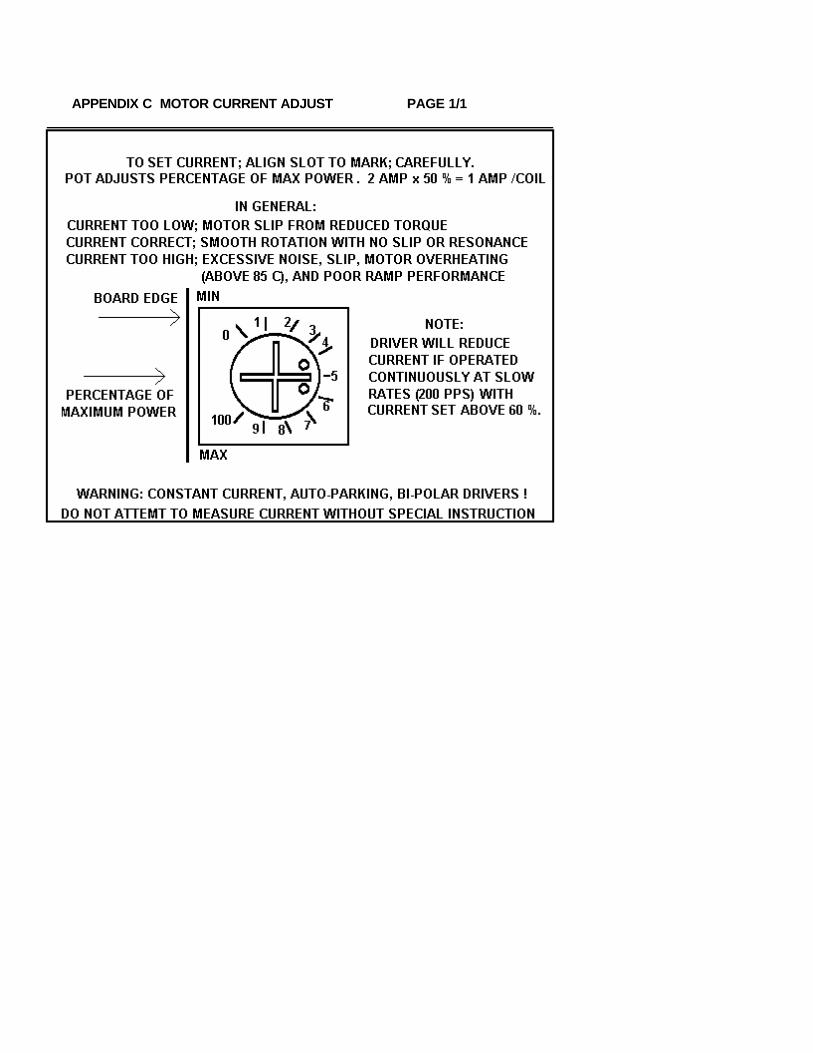
APPENDIX C MOTOR CURRENT ADJUST PAGE 1/1

APPENDIX D MOTOR WIRING SCHEMES PAGE 1/2Performance of a stepper motor based system depends more on the electronic drivers used than it does on the motor itself. A step motor (both PM and
Hybrid type) is made to step by sequencing the orientations of the magnetic fields in two coils. The UNIPOLAR drive method of is illustrated, in the
figure, using just ONE coil of the motor. Note that the center tap of the coil is connected to the positive motor supply voltage. An electronic circuit,
represented by the switch, then connects one end or the other to ground for current to flow from the center tap to the grounded end. The most
significant factor is that only one-half of the coil is used at any given time and that the magnetic field intensity (motor torque) is proportional to the
product of the number of turns in the coil and the current passing through the coil.
Motors designed for BIPOLAR drivers will often have only four leads. However some manufactures will provide the motors in 8 wire versions to offer a
performance choice for bipolar drive users as in figures C & D. Four lead bipolar motors may use larger wire, since only half the windings are required
in the given space of the motor body. The paralleling in figure C is the equivalent of this to achieve lower winding resistance and thereby doubling
motor efficiency. The other alternative for the motor designers is to use a greater number of turns in the winding space. This is shown by figures B & D
and results in more torque with a lower coil current but a subsequent loss of high speed torque.
Although step motors are often classified as bipolar or unipolar (2 phase or 4 phase), these terPL are more accurately applied to the types of electronic
circuit used to drive the motor. Bipolar drivers can drive 4,5,6 and 8 wire motors. When the motor is described as unipolar, the specifications are
presented with the assumption that the motor will be driven with a unipolar drive. Therefore the specifications must be translated to bipolar when the
motor is used with a bipolar driver. In general, the translation is similar to a unipolar driver with dropping resistors in series with the center taps;
referred to as L over x R with R equal to the motor winding resistance. For example, a L over 4R unipolar driver has a resistor equal to 4 times the
winding resistance. In bipolar, the L over R ratio is the ratio of the motor voltage to the supply voltage. A L over 4R bipolar drive, for example, would
be a 6 volt motor and a 24 volt power supply. Performance would be similar to the L/4R torque curve of a unipolar motor. The figures identify the
various connection options when using a bipolar driver with 6 or 8 wire motors.
A: SINGLE COILS. Identical to unipolar specification (if the supply voltage equals the specified motor voltage). Normal connection of a bipolar driver
to 6 wire motor.
B & D: SERIES COILS. This configuration will produce torque greater than the unipolar specification indicates. To stay within the power (wattage)
rating of the motor, reduce the unipolar specified current by 30%; depending on the duty-cycle of the system (park time). Note that the torque curve of
this configuration is considerably fore-shortened as this motor is now the same as a motor with a rating of twice the voltage (slower motor).
C: PARALLEL COILS. When this configuration is driven at the unipolar current, the motor will perform identical to the specification but the motor will
dissipate only one-half the power (it is twice as efficient). When the current is increased by 1.414, to drive the motor at it"s full power rating, the motor
torque is increased by approximately 60% Note that this torque curve is extended by four times (high speed system).
Resonance (vibration) of a step motion system depends on the speed and power range of the motor. Fast windings (A & C) are "quicker" and may
break into resonance easier than slow (B & D). Power windings (B & D) may deliver "excessive" power (torque) to the system and produce resonance.
In general, resonance indicates, except at the low (100 sps) and mid-frequency (1000 sps) bands, excessive power; therefore reduce the driver current
for smoother operation or wire the motor for "softer" response.
NOTES: If a motor runs "backwards" with respect to software direction, transpose the connections of ONE coil. For PL series driver cards, pins 2 & 3 or
6 & 7; SID / PLC driver boxes, pins 1 & 3 or $ & 6.
Five wire motors are really 6 wire motors with the center tap common. The center tap must be connected to the motor supply voltage. If phases 1, 2,
3 or 4 are crossed, motor will not rotate (hums). For cards, pin 1 is VMM, for SID /PLC, pin 5 is VMM and pin 2 is GND.
Systems with pin 5 & 2 connected are used to power external relays or solinoid valves. The pins are keyed (reversed). Never attempt to connect any
motor leads to pin 2 and only 5 wire center taps to pin 5. Pins 2 & 5 are normally not connected and used to store the unused leads of 6 or 8 wire
motors.


APPENDIX I PAGE 1/1
MOLEX - WALDOM NYLON CONNECTOR SYSTEM USED BY THE MOTION GROUP
The connectors used on Motion Group equipment are nylon connectors are manufactured by Molex and are refered to as .062 style (pin diameter) or .093 (large driver motors only). They are available from Newark, Allied, and Digi-Key and come in 1 to 36 positions with locking and mounting tabs which snap-in to punched holes on brackets or enclosures.
TYPICAL $ POLES TYPE PART # NEWARK # USED ON
$5.84/10 4 (.062) MALE HOOD 03-06-2041 31F1004 HOME SENSOR ASSY
$5.95/10 4 (.062) FEMALE RECT 03-06-1041 31F1005 HOME SENSOR CABLE
$1.86/5 6 (.062) MALE HOOD 03-06-2062 31F1008 STEP MOTOR ASSY
$2.07/5 6 (.062) FEMALE RECT 03-06-1061 31F1009 MOTOR OUTPUT
(Strain Relief Hoods are available on request)
Contacts for Connector Sets .062 SIZE
$6.79/100 FEMALE SOCKETS LARGE TAB 02-06-1103 31F1027 22-18 GUAGE WIRE
MALE PINS LARGE TAB 02-06-2103 31F1026 22-18 GUAGE WIRE
FEMALE SOCKETS SMALL TAB 02-06-1132 31F1029 30-22 GUAGE WIRE
MALE PINS SMALL TAB 02-06-2132 31F1028 30-22 GUAGE WIRE
In general, single wires use small tab contact; double wires the large tab
Tooling .062 SIZE
$105 ea RATCHET TOOL .062 DIA HTR-2262 (11-01-006) 30F338 MAKES PERFECT CRIMPS
$13 ea HAND TOOL HT-1921 (11-01-0015) 31F1049 REQUIRES PRACTICE
$12 ea EXTRACTOR .062 DIA HT-2285 (11-03-0002) 30F773 SPRING-LOADED PUNCH
Nylon Connector Designer/Service Kit
Contains male/female housing assortment, hand crimper, pin extractor (not as easy to use as spring extractor; see above), contacts, and case.
$40 ea DESIGNER KIT .062 WM-072 30F774
Contact factory for any of the above, custom cable sets, or Heavy-Duty connectors with shell and strain-relief.
SERVICE NOTE: When disconnecting, grasp the mounting tabs, (not the wires) and rock from top to bottom (unseat the locking bump) rather than side to side and then pull the connection apart. Disconnection is easy with the right technique.

SPECIFICATIONS - PL or PD 2.0
PARAMETER MIN MAX UNIT
Motor supply voltage 12 40 VDCCurrent (no motor) 150 160 ma PWM frequency
MD10A 18 24 KhzMotor current PL / PD 2.0 0.05 2.0 AmpMotor current PL / PD 4.0 0.55 4.0 Amp
Step input PD 2.0/4.0 0 5.5 VDCStep input PL 2.0/4.0 0 40 VDCSink current 3 10 maPulse high 1 uSecPulse low 1 uSecRise time 0.5 uSecFall time 0.5 uSecFrequency 500 KHz
Direction input Voltage PD 2.0/4.0 0 7.5 VDCVoltage PL 2.0/4.0 0 40 VDCSink current 3 10 maNote: The step pulse input must be OFF during direction input change.
EnvironmentalOperating temperature -20 +50 CHumidity (non-condensing) 0 95 %Shock 100 GAltitude 30.000 FT
MechanicalWeight PL / PD 2.0 3 lbWeight PL / PD 4.0 4 lbDimensions 2" x 3.5" x 11.0"Mounting hole centers 2.625" x 8.250"Mounting screw size #6-32 x 1/2" max