Embed Size (px)
Citation preview
Proceedings of the 2013 ASEE North-Central Section Conference
Copyright © 2013, American Society for Engineering Education
PLC Safety
William T. Evans, PhD, PE
University of Toledo: Email:[email protected]
Abstract:
It has been considered a responsibility when teaching the principles of PLC programming to train
students to be aware of the general rules for constructing an electrical control panel. Both
general practice and rules that have become part of the OSHA requirements have to be
considered. The present state of electrical control has outdistanced what was considered
acceptable practice as little as 20 years ago. In addition to these rules, new Safe PLCs have been
introduced to the marketplace and have significantly changed the design of control systems.
Safe PLCs have the promise of consolidating control in a programmable device with the promise
of safe operation. The purpose of this paper is to distinguish areas of safety that should be
emphasized, the depth of that discussion, and the inclusion of the Safe PLC in present
coursework. It is not enough to just discuss the fact that processes should be designed safely.
The methods for safe design should be taught as well.
Introduction:
It has been observed that a need exists in the EET curriculum to teach the safety aspect of
electrical controls. Included in a safety discussion is that of Safety PLCs. In an attempt to
become more knowledgeable on Safety PLCs, several safety PLC schools and seminars have
been attended. In addition, questions have been asked of vendors and Industrial Advisory Board
members as to the viability of teaching the subject of safety PLC to EET students. The inclusion
of market material also gives encouragement in preparation of teaching this topic.
Current Curriculum:
The NEC or National Electric Code will continue to be discussed with students in the PLC
classes. Concepts such as the tap rules have been in place for many years but should be
understood and serve as a discussion point for students.
Determination of wire size in a panel as well as to field devices must be considered. Wire size is
determined in general by the current load of the wire and the insulation rating of the wire. The
NEC includes tables for determining the proper size of wire for all electrical applications.
Arc Flash is the result of a rapid release of energy due to an arcing fault between a phase bus bar
and another phase bus bar, neutral or a ground. During an arc fault the air is the conductor. Arc
faults are generally limited to systems where the bus voltage is in excess of 120 volts. Lower
voltage levels normally will not sustain an arc. An arc fault is similar to the arc obtained during
Proceedings of the 2013 ASEE North-Central Section Conference
Copyright © 2013, American Society for Engineering Education
electric welding and the fault has to be manually started by something creating the path of
conduction or a failure such as a breakdown in insulation.
Market Survey of Safe PLCs:
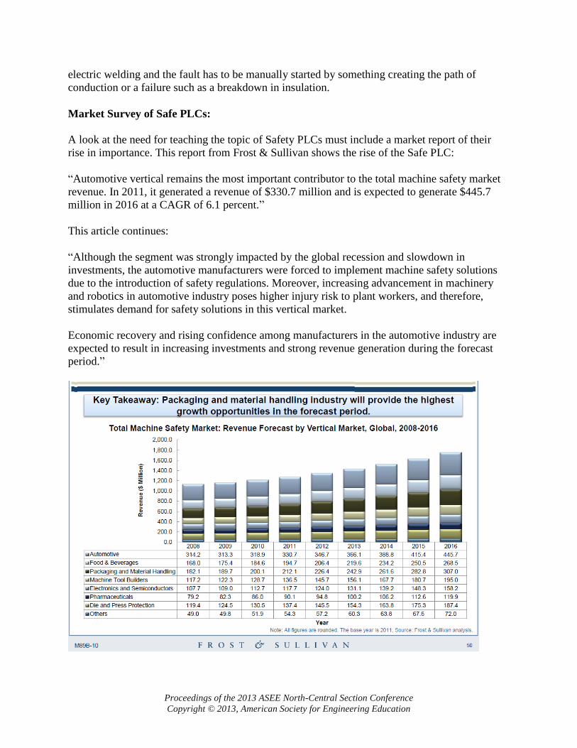
A look at the need for teaching the topic of Safety PLCs must include a market report of their
rise in importance. This report from Frost & Sullivan shows the rise of the Safe PLC:
“Automotive vertical remains the most important contributor to the total machine safety market
revenue. In 2011, it generated a revenue of $330.7 million and is expected to generate $445.7
million in 2016 at a CAGR of 6.1 percent.”
This article continues:
“Although the segment was strongly impacted by the global recession and slowdown in
investments, the automotive manufacturers were forced to implement machine safety solutions
due to the introduction of safety regulations. Moreover, increasing advancement in machinery
and robotics in automotive industry poses higher injury risk to plant workers, and therefore,
stimulates demand for safety solutions in this vertical market.
Economic recovery and rising confidence among manufacturers in the automotive industry are
expected to result in increasing investments and strong revenue generation during the forecast
period.”
Proceedings of the 2013 ASEE North-Central Section Conference
Copyright © 2013, American Society for Engineering Education
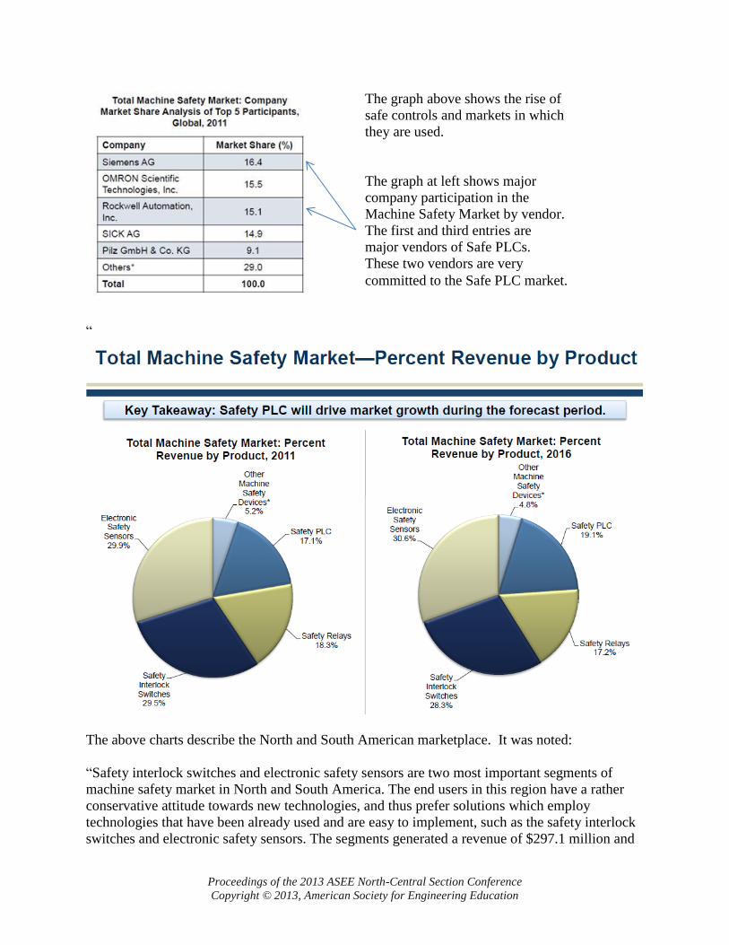
“
The above charts describe the North and South American marketplace. It was noted:
“Safety interlock switches and electronic safety sensors are two most important segments of
machine safety market in North and South America. The end users in this region have a rather
conservative attitude towards new technologies, and thus prefer solutions which employ
technologies that have been already used and are easy to implement, such as the safety interlock
switches and electronic safety sensors. The segments generated a revenue of $297.1 million and
The graph above shows the rise of
safe controls and markets in which
they are used.
The graph at left shows major
company participation in the
Machine Safety Market by vendor.
The first and third entries are
major vendors of Safe PLCs.
These two vendors are very
committed to the Safe PLC market.
Proceedings of the 2013 ASEE North-Central Section Conference
Copyright © 2013, American Society for Engineering Education
accounted for 59.1 percent of the machine safety market in 2011. Safety interlock switches
segment is expected to grow at a CAGR of 5.2 percent, and electronic safety sensors at a CAGR
of 6.6 percent during 2011-2016.”
Finally:
“Safety PLC is the segment that has the highest growth potential. It generated a revenue of $85.0
million in 2011 and is expected to witness a CAGR of 8.8 percent during 2011-2016. Currently,
it accounts for 16.9 percent of the machine safety, however, in 2016, it is forecast to account for
19.2 percent, as the demand for safety PLCs in North and South America is rising.
Safety relays, machine safeguarding panels, and safety contractors accounted for 23.9 percent of
the machine safety market in 2011. Their aggregated market share is expected to decrease over
the forecast period by 1.5 percent point.”1
The conclusion of this study points to the need for the study of the Safety PLC by EET students.
Industrial Advisory Board members have given encouragement as well for the study of the Safe
PLC.
Encouragement for This Topic’s Use:
The following was recently announced in the Toledo Section of:
International Society of Automation
Vendor Exhibit and Seminars
March 19, 2013 11am – 6pm
Seminars:
PDH Certificates will be provided. All Seminars are in the “Forum”, Reservations not required.
11:00 AM – “Architecture Selection for SIL3 Applications”, Rockwell Automation
2:00 PM – “Siemens Safety Integration”, Steve Wright, Safety Specialist at C&E Sales, Inc.
3:30 PM - “Integrating SIL3 I/O with Standard I/O”, Rockwell Automation
5:00 PM – “ISO 13849-1 on ‘Functional Safety’ ”, Heinz Knackstedt, Safety Engineer
These topics are the topics chosen by the local ISA Chapter for inclusion in this year’s bi-annual
convention in the Toledo area and the topics serve as the most pertinent topics as viewed by the
local ISA chapter. They should be the foundation of the topic for EET and will be reviewed to
teach from as much as possible.
Proceedings of the 2013 ASEE North-Central Section Conference
Copyright © 2013, American Society for Engineering Education
Inclusion of PLC Open Specification:
To teach the Safety PLC, the PLCopen2 specification should be investigated. The PLCopen
Committee has provided a technical specification for use with Safe PLCs. While vendor specific
instructions are always to be included, those instructions and material that cross across vendor
lines and is common to most or all vendors is to be considered first in a study of this nature. The
PLCopen report includes the following excerpts:
“PLCopen - Technical Committee 5
–
Safety Software
Technical Specification
Part 1: Concepts and Function Blocks
1.1. The Rationale of a New Safety Standard
Machine builders are faced with a large set of safety-related standards. This makes it expensive
and in some cases unfeasible for machine builders to understand them all fully. Yet in the end
they are still responsible for their products and related safety aspects. This risk situation is not
very healthy, especially since legislation imposes greater constraints on the equipment suppliers.
And their liability increases. Nowadays there is often a clear separation between the safety-
related part and the functional application part. This separation can be made be using different
systems for the environments, different tools, and even different people can be involved. This
separation often results in the safety aspects being included at the end, and not integrated into the
whole system philosophy from the beginning, and often with only limited tests performed. This
clearly does not contribute to the overall safety aspects. Also, the on-going technological
innovation now provides safety-approved digital communication buses. This supports the trend
away from hard-wired systems towards software-oriented solutions. A parallel can be drawn
with the movement away from hard-wired relay logic towards programmable logic controllers,
PLCs. Such a trend, of course, involves a change in the mindset. This type of change requires
time, widespread support from the industry as a whole, support from educational institutes as
well as from certification bodies.
In addition, governmental requirements add to the complexity. For instance, the US-based FDA,
Food and Drugs Administration, has set strict regulations that must be complied with. Non-
compliance can result in heavy financial penalties, again weakening the sustainability of the
organization.”
Function Blocks:
The standardization of function blocks seems to include several vendors. Included in the
Appendices are:
Appendix 1: Siemens Safety School Syllabus
Appendix 2:
Proceedings of the 2013 ASEE North-Central Section Conference
Copyright © 2013, American Society for Engineering Education
SAFEBOOK 3 (Rockwell) (Allen-Bradley)
Both vendors stress standardize function blocks as generally specified by PLCopen. To give
some examples of these blocks, the following examples are included from the PLCopen
Specification:
“2.4. Description of the PLCopen Function Blocks
An example follows of these standardized function blocks:
SF_ModeSelector
The SF_ModeSelector handles a mode selector switch with up to 8 positions to distinguish
different safety relevant operation modes. The FB basically monitors the switch in that way, that
only one mode gets pre-selected. If for any reason the position signal is not definite (e.g. two
SAFEBOOL input bits or more are HIGH for a longer time than the MonitoringTime), the output
gets set to the fail-safe state value (no mode selected). Depending on the control bits, the output
signals get activated either immediately or has to be confirmed by an additional input first.
Note: Most applications differentiate between two safety relevant operation modes only. Either
the machine is in automatic mode or the machine is in a mode which requires additional
functional safety.
Normally, this FB is followed by additional function blocks.
Today, the PLC is most preferred for the safety function but prior to the acceptance of the PLC
there were discrete devices that provided the same function as the function block that is now
included in the PLC. These discrete devices should be discussed as well as the reason to move
now to the PLC instead.
EET’s Need for Hands On:
The inclusion of function block study is important but equally important is the need for hands-on
lab experiences and the equipment associated with these labs. The inclusion of safe motion and
standards governing motion of the machine, especially in robotics operation should be
considered. While expenditures for lab equipment may frighten the administrator as too costly,
they should be considered part of this module.
Wiring of Safety PLC components is to be considered. Use of double contacts is required for
most applications as well as the inclusion of the power source from a safe power supply. Since
the use of safety components other than the PLC has been present for some time, the comparison
of the safe PLC to these components is advised.
Proceedings of the 2013 ASEE North-Central Section Conference
Copyright © 2013, American Society for Engineering Education
Equipment cost is a primary consideration. Each attempt for a grant or laboratory expenditure is
met with much scrutiny. The instructor must not compromise with administration in the
utilization of equipment that is less than that used in industry. The inclusion in a hands-on
curriculum of equipment used primarily in industry is strongly advised. Development of a list of
equipment needed should be on hand so that when funding is found, the purchase is done
quickly.
Summary:
The EET student of today should be educated in the use of controls equipment being used in
today’s markets. This includes the Safe PLC. While there may be questions from educators and
administrators as to the need for the inclusion of Safe PLCs in the curriculum, these questions
should be answered by the faculty with the consent of the Industrial Advisory Board, good
market research and independent study of the subject. The instructor should be ready to invest in
the needed equipment and provide the principles of Safe PLC programming to the student. The
Market Survey quote “Key Takeaway: Safety PLC will drive market growth during the forecast
period” should not be ignored but the instructor should be encouraged to begin the process of
adding this equipment and teaching module to an advanced PLC course.
Allen-Bradley uses red to denote their Safe PLC components. Siemens uses yellow. This should
not be all the EET student is aware of as he or she enters the factory environment ready to begin
their work experience.
Bibliography
1 Strategic Analysis of Global Machine Safety Market Rising Manufacturing Sectors in Emerging
Economies Drive Demand for Machine Safety Solutions – Frost & Sullivan
M89B-10 October 2012
2 “PLCopen - Technical Committee 5: Safety Software: Technical Specification
Proceedings of the 2013 ASEE North-Central Section Conference
Copyright © 2013, American Society for Engineering Education
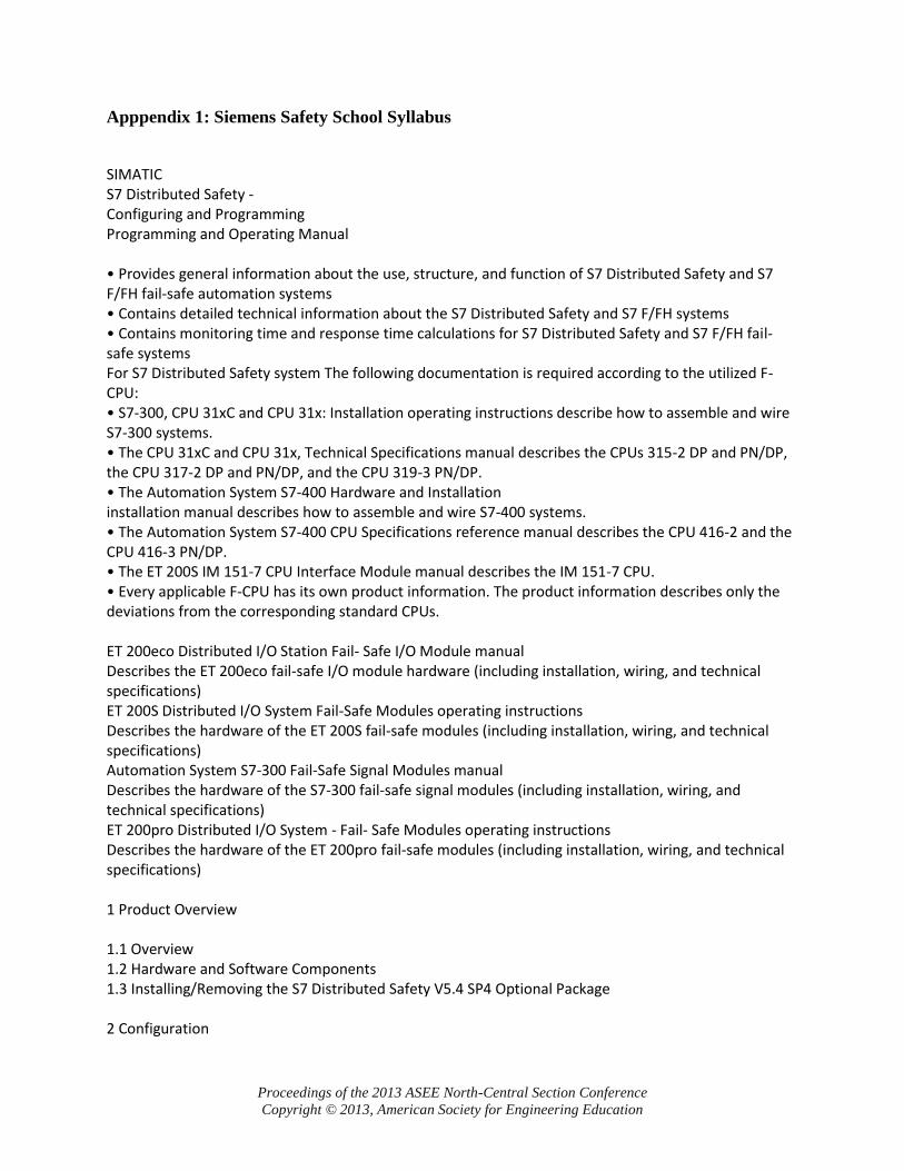
Apppendix 1: Siemens Safety School Syllabus
SIMATIC S7 Distributed Safety - Configuring and Programming Programming and Operating Manual • Provides general information about the use, structure, and function of S7 Distributed Safety and S7 F/FH fail-safe automation systems • Contains detailed technical information about the S7 Distributed Safety and S7 F/FH systems • Contains monitoring time and response time calculations for S7 Distributed Safety and S7 F/FH fail-safe systems For S7 Distributed Safety system The following documentation is required according to the utilized F-CPU: • S7-300, CPU 31xC and CPU 31x: Installation operating instructions describe how to assemble and wire S7-300 systems. • The CPU 31xC and CPU 31x, Technical Specifications manual describes the CPUs 315-2 DP and PN/DP, the CPU 317-2 DP and PN/DP, and the CPU 319-3 PN/DP. • The Automation System S7-400 Hardware and Installation installation manual describes how to assemble and wire S7-400 systems. • The Automation System S7-400 CPU Specifications reference manual describes the CPU 416-2 and the CPU 416-3 PN/DP. • The ET 200S IM 151-7 CPU Interface Module manual describes the IM 151-7 CPU. • Every applicable F-CPU has its own product information. The product information describes only the deviations from the corresponding standard CPUs. ET 200eco Distributed I/O Station Fail- Safe I/O Module manual Describes the ET 200eco fail-safe I/O module hardware (including installation, wiring, and technical specifications) ET 200S Distributed I/O System Fail-Safe Modules operating instructions Describes the hardware of the ET 200S fail-safe modules (including installation, wiring, and technical specifications) Automation System S7-300 Fail-Safe Signal Modules manual Describes the hardware of the S7-300 fail-safe signal modules (including installation, wiring, and technical specifications) ET 200pro Distributed I/O System - Fail- Safe Modules operating instructions Describes the hardware of the ET 200pro fail-safe modules (including installation, wiring, and technical specifications) 1 Product Overview 1.1 Overview 1.2 Hardware and Software Components 1.3 Installing/Removing the S7 Distributed Safety V5.4 SP4 Optional Package 2 Configuration
Proceedings of the 2013 ASEE North-Central Section Conference
Copyright © 2013, American Society for Engineering Education
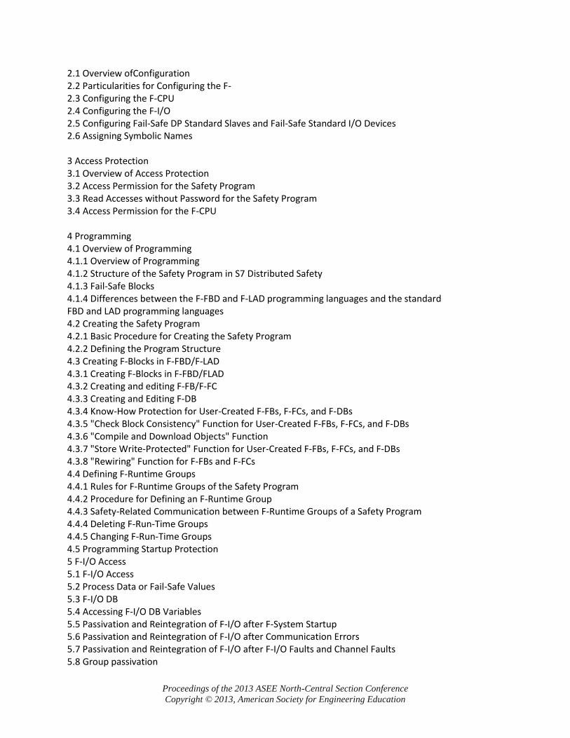
2.1 Overview ofConfiguration 2.2 Particularities for Configuring the F- 2.3 Configuring the F-CPU 2.4 Configuring the F-I/O 2.5 Configuring Fail-Safe DP Standard Slaves and Fail-Safe Standard I/O Devices 2.6 Assigning Symbolic Names 3 Access Protection 3.1 Overview of Access Protection 3.2 Access Permission for the Safety Program 3.3 Read Accesses without Password for the Safety Program 3.4 Access Permission for the F-CPU 4 Programming 4.1 Overview of Programming 4.1.1 Overview of Programming 4.1.2 Structure of the Safety Program in S7 Distributed Safety 4.1.3 Fail-Safe Blocks 4.1.4 Differences between the F-FBD and F-LAD programming languages and the standard FBD and LAD programming languages 4.2 Creating the Safety Program 4.2.1 Basic Procedure for Creating the Safety Program 4.2.2 Defining the Program Structure 4.3 Creating F-Blocks in F-FBD/F-LAD 4.3.1 Creating F-Blocks in F-FBD/FLAD 4.3.2 Creating and editing F-FB/F-FC 4.3.3 Creating and Editing F-DB 4.3.4 Know-How Protection for User-Created F-FBs, F-FCs, and F-DBs 4.3.5 "Check Block Consistency" Function for User-Created F-FBs, F-FCs, and F-DBs 4.3.6 "Compile and Download Objects" Function 4.3.7 "Store Write-Protected" Function for User-Created F-FBs, F-FCs, and F-DBs 4.3.8 "Rewiring" Function for F-FBs and F-FCs 4.4 Defining F-Runtime Groups 4.4.1 Rules for F-Runtime Groups of the Safety Program 4.4.2 Procedure for Defining an F-Runtime Group 4.4.3 Safety-Related Communication between F-Runtime Groups of a Safety Program 4.4.4 Deleting F-Run-Time Groups 4.4.5 Changing F-Run-Time Groups 4.5 Programming Startup Protection 5 F-I/O Access 5.1 F-I/O Access 5.2 Process Data or Fail-Safe Values 5.3 F-I/O DB 5.4 Accessing F-I/O DB Variables 5.5 Passivation and Reintegration of F-I/O after F-System Startup 5.6 Passivation and Reintegration of F-I/O after Communication Errors 5.7 Passivation and Reintegration of F-I/O after F-I/O Faults and Channel Faults 5.8 Group passivation
Proceedings of the 2013 ASEE North-Central Section Conference
Copyright © 2013, American Society for Engineering Education
6 Implementation of user acknowledgment 6.1 Implementing User Acknowledgment in the Safety Program of a DP Master F-CPU or IO Controller 6.2 Implementing User Acknowledgment in the Safety Program of a I-Slave F-CPU 7 Data Exchange between Standard User Programs and Safety Program 7.1 Data Transfer from the Safety Program to the Standard User Program 7.2 Data Transfer from the Standard User Program to the Safety Program 8 Configuring and Programming Communication 8.1 Overview of safety-related communication 8.2 Safety-Related Master-Master Communication 8.2.1 Configuring Address Areas (Safety-Related Master-Master Communication) 8.2.2 Configuring Safety-Related Master-Master Communication 8.2.3 Communication by Means of F_SENDDP and F_RCVDP (Safety-Related Master-Master Communication) 8.2.4 Programming Safety-Related Master-Master Communication 8.2.5 Limits for Data Transfer (Safety-Related Master-Master Communication) 8.3 Safety-Related Master-I-Slave Communication 8.3.1 Configuring Address Areas (Safety-Related Master-I-Slave Communication) 8.3.2 Configuring Safety-Related Master-I-Slave Communication 8.3.3 Communication by Means of F_SENDDP and F_RCVDP (Safety-Related Master-ISlave/ I-Slave-I-Slave Communication) 8.3.4 Programming Safety-Related Master-I-Slave and I-Slave-I-Slave Communication 8.3.5 Limits for Data Transfer (Safety-Related Master-I-Slave or I-Slave-I-Slave Communication) 8.4 Safety-Related I-Slave-I-Slave Communication 8.4.1 Configuring Address Areas (Safety-Related I-Slave-I-Slave Communication) 8.4.2 Configuring Safety-Related I-Slave-I-Slave Communication 8.4.3 Communication by Means of F_SENDDP and F_RCVDP (Safety-Related I-Slave-I-Slave Communication) 8.4.4 Programming Safety-Related I-Slave-I-Slave Communication 8.4.5 Limits for Data Transfer (Safety-Related I-Slave-I-Slave Communication) 8.5 Safety-Related I-Slave-Slave Communication 8.5.1 Configuring Address Areas (Safety-Related I-Slave-Slave Communication) 8.5.2 Configuring Safety-Related I-Slave-Slave Communication 8.5.3 F-I/O Access for Safety-Related I-Slave-Slave Communication 8.5.4 Limits for Data Transfer (Safety-Related I-Slave-Slave Communication) 8.6 Safety-Related IO Controller-IO Controller Communication 8.7 Safety-Related Communication via S7 Connections 8.7.1 Configuring safety-related communication using S7 connections 8.7.2 Communication via F_SENDS7, F_RCVS7, and F-Communication DB 8.7.3 Programming Safety-Related CPU-CPU Communication via S7 Connections 8.7.4 Limits for Data Transfer (Safety-Related Communication via S7 Connections) 8.8 Safety-Related Communication between S7 Distributed Safety and S7 F System 9 F-Libraries 9.1 Distributed Safety F-library (V1) 9.1.1 Overview of Distributed Safety F-Library (V1) 9.1.2 F-Application Blocks

Proceedings of the 2013 ASEE North-Central Section Conference
Copyright © 2013, American Society for Engineering Education
9.1.2.1 Overview of F-application blocks 9.1.2.2 FB 179 "F_SCA_I": Scale Values of Data Type INT 9.1.2.3 FB 181 "F_CTU": Count Up 9.1.2.4 FB 182 "F_CTD": Count Down 9.1.2.5 FB 183 "F_CTUD": Count Up and Down 9.1.2.6 FB 184 "F_TP": Create Pulse 9.1.2.7 FB 185 "F_TON": Create ON Delay 9.1.2.8 FB 186 "F_TOF": Create OFF Delay 9.1.2.9 FB 187 "F_ACK_OP": Fail-Safe Acknowledgment 9.1.2.10 FB 188 "F_2HAND": Two-Hand Monitoring 9.1.2.11 FB 189 "F_MUTING": Muting 9.1.2.12 FB 190 "F_1oo2DI": 1oo2 Evaluation with Discrepancy Analysis 9.1.2.13 FB 211 "F_2H_EN": Two-Hand Monitoring with Enable 9.1.2.14 FB 212 "F_MUT_P": Parallel Muting 9.1.2.15 FB 215 "F_ESTOP1": Emergency STOP up to Stop Category 1 9.1.2.16 FB 216 "F_FDBACK": Feedback Monitoring 9.1.2.17 FB 217 "F_SFDOOR": Safety Door Monitoring 9.1.2.18 FB 219 "F_ACK_GL": Global acknowledgment of all F-I/Os in an F-Runtime group 9.1.2.19 FB 223 "F_SENDDP" and FB 224 "F_RCVDP": Send and Receive Data via PROFIBUS DP 9.1.2.20 FB 225 "F_SENDS7" and FB 226 "F_RCVS7": Communication via S7 Connections 9.1.2.21 FC 174 "F_SHL_W": Shift Left 16 Bits 9.1.2.22 FC 175 "F_SHR_W": Shift Right 16 Bits 9.1.2.23 FC 176 "F_BO_W": Convert 16 Data Elements of Data Type BOOL to a Data Element of Data Type WORD 9.1.2.24 FC 177 "F_W_BO": Convert a Data Element of Data Type WORD to 16 Data Elements of Data Type BOOL 9.1.2.25 FC 178 "F_INT_WR": Write Value of Data Type INT Indirectly to an F-DB 9.1.2.26 FC 179 "F_INT_RD": Read Value of Data Type INT Indirectly from an F-DB 9.1.3 F-System Blocks 9.1.4 F-Shared DB 9.1.5 Custom F-Libraries 10 Compiling and commissioning a safety program 10.1 "Safety Program" Dialog 10.2 Safety Program States 10.3 Compiling Safety Program 10.4 Downloading the Safety Program 10.5 Work Memory Requirement for Safety Program 10.6 Function Test of Safety Program and Protection through Program Identification 10.7 Modifying the Safety Program 10.7.1 Modifying the safety program in RUN mode 10.7.2 Comparing Safety Programs 10.7.3 Deleting the Safety Program 10.7.4 Logbook of the Safety Program 10.8 Printing out project data 10.8.1 Printed Project Data for the Hardware Configuration 10.8.2 Printed Project Data for the Safety Program 10.9 Testing the Safety Program
Proceedings of the 2013 ASEE North-Central Section Conference
Copyright © 2013, American Society for Engineering Education
10.9.1 Overview of Testing the Safety Program 10.9.2 Deactivating Safety Mode 10.9.3 Testing the Safety Program 11 System Acceptance Test 11.1 Overview of System Acceptance Test 11.2 Checking the Printouts 11.2.1 Acceptance Test for the Configuration of the F-CPU and the F-I/O 11.2.2 Safety Program Acceptance Test 11.3 Checks after Downloading the Safety Program to the F-CPU 11.4 Acceptance Test of Changes 12 Operation and Maintenance 12.1 Notes on Safety Mode of the Safety Program 12.2 Replacing Software and Hardware Components 12.3 Guide to Diagnostics S7_Distributed_Safety_Configuring_and_Programming.pdf Scope of this documentation SIMATIC Safety - Configuring and Programming Programming and Operating Manual 08/2011 A5E02714440-01 Important notes Product Overview Overview Hardware and Software Components Installation/uninstallation of the STEP 7 Safety Advanced V11 optional package Migration of projects from S7 Distributed Safety V5.4 SP5 to STEP 7 Safety Advanced V11 First steps Configuration Overview of Configuration Particularities for configuring the F-System Configuring the F-CPU Configuring the F-I/O Configuring fail-safe DP standard slaves and fail-safe standard I/O devices Safety Administration Editor "General" tab "F-blocks" tab "Settings" tab Access protection Overview of Access Protection Setting up, changing and revoking access permission for the safety program Setting up access permission for the F-CPU Programming

Proceedings of the 2013 ASEE North-Central Section Conference
Copyright © 2013, American Society for Engineering Education
Overview of Programming Defining F-Runtime Groups Creating F-blocks in FBD / LAD Programming startup protection F-I/O access Process Data or Fail-Safe Values F-I/O DB Accessing F-I/O DB Variables Passivation and reintegration of F-I/O Implementation of user acknowledgment Implementing User Acknowledgment in the Safety Program of the FCPU of a DP Master or IO Controller Implementing user acknowledgment in the safety program of the F-CPU of a I-slave or I-device Data exchange between standard user program and safety program Data Transfer from the Safety Program to the Standard User Program Data Transfer from Standard User Program to Safety Program Configuring and Programming Communication Overview of communication Safety-related IO controller-IO controller communication Safety-related master-master communication Safety-related communication between I/O-controller and I-device Safety-related master-I-slave communication Safety-related I-slave-I-slave communication Safety-Related I-Slave-Slave Communication Safety-related IO Controller-I-slave communication Safety-related communication via S7 connections Safety-related communication with S7 F-systems Compiling and commissioning a safety program Compiling the safety program Downloading the Safety Program Work Memory Requirement for Safety Program Function Test of Safety Program and Protection through Program Identification Comparing Safety Programs Printing project data Testing safety program System Acceptance Test Overview of System Acceptance Test Correctness of the safety program including hardware configuration Completeness of the safety printout Compliance of the used instructions with the TÜV certificate
Proceedings of the 2013 ASEE North-Central Section Conference
Copyright © 2013, American Society for Engineering Education
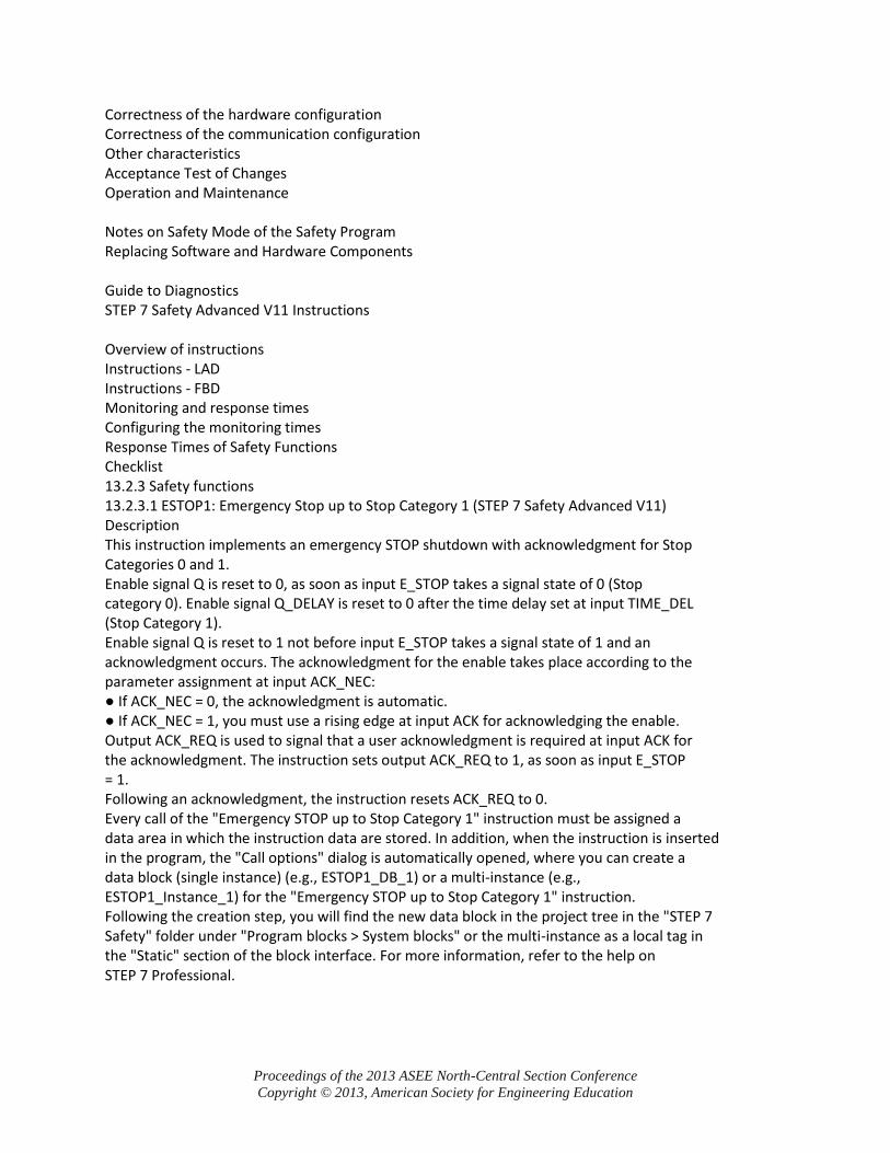
Correctness of the hardware configuration Correctness of the communication configuration Other characteristics Acceptance Test of Changes Operation and Maintenance Notes on Safety Mode of the Safety Program Replacing Software and Hardware Components Guide to Diagnostics STEP 7 Safety Advanced V11 Instructions Overview of instructions Instructions - LAD Instructions - FBD Monitoring and response times Configuring the monitoring times Response Times of Safety Functions Checklist 13.2.3 Safety functions 13.2.3.1 ESTOP1: Emergency Stop up to Stop Category 1 (STEP 7 Safety Advanced V11) Description This instruction implements an emergency STOP shutdown with acknowledgment for Stop Categories 0 and 1. Enable signal Q is reset to 0, as soon as input E_STOP takes a signal state of 0 (Stop category 0). Enable signal Q_DELAY is reset to 0 after the time delay set at input TIME_DEL (Stop Category 1). Enable signal Q is reset to 1 not before input E_STOP takes a signal state of 1 and an acknowledgment occurs. The acknowledgment for the enable takes place according to the parameter assignment at input ACK_NEC: ● If ACK_NEC = 0, the acknowledgment is automatic. ● If ACK_NEC = 1, you must use a rising edge at input ACK for acknowledging the enable. Output ACK_REQ is used to signal that a user acknowledgment is required at input ACK for the acknowledgment. The instruction sets output ACK_REQ to 1, as soon as input E_STOP = 1. Following an acknowledgment, the instruction resets ACK_REQ to 0. Every call of the "Emergency STOP up to Stop Category 1" instruction must be assigned a data area in which the instruction data are stored. In addition, when the instruction is inserted in the program, the "Call options" dialog is automatically opened, where you can create a data block (single instance) (e.g., ESTOP1_DB_1) or a multi-instance (e.g., ESTOP1_Instance_1) for the "Emergency STOP up to Stop Category 1" instruction. Following the creation step, you will find the new data block in the project tree in the "STEP 7 Safety" folder under "Program blocks > System blocks" or the multi-instance as a local tag in the "Static" section of the block interface. For more information, refer to the help on STEP 7 Professional.
Proceedings of the 2013 ASEE North-Central Section Conference
Copyright © 2013, American Society for Engineering Education
Appendix 2: Allen-Bradley Safety Text Table of Contents
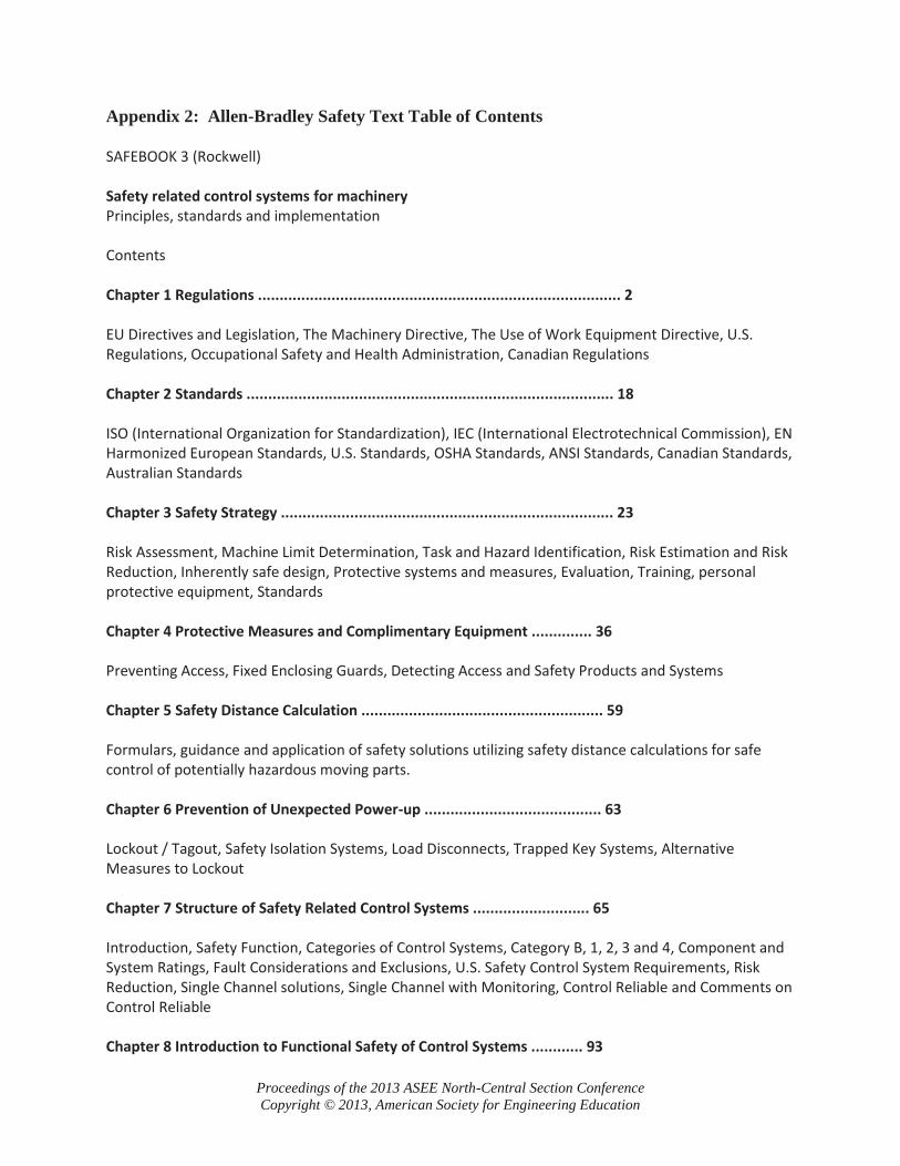
SAFEBOOK 3 (Rockwell) Safety related control systems for machinery Principles, standards and implementation Contents Chapter 1 Regulations .................................................................................... 2 EU Directives and Legislation, The Machinery Directive, The Use of Work Equipment Directive, U.S. Regulations, Occupational Safety and Health Administration, Canadian Regulations Chapter 2 Standards ..................................................................................... 18 ISO (International Organization for Standardization), IEC (International Electrotechnical Commission), EN Harmonized European Standards, U.S. Standards, OSHA Standards, ANSI Standards, Canadian Standards, Australian Standards Chapter 3 Safety Strategy ............................................................................. 23 Risk Assessment, Machine Limit Determination, Task and Hazard Identification, Risk Estimation and Risk Reduction, Inherently safe design, Protective systems and measures, Evaluation, Training, personal protective equipment, Standards Chapter 4 Protective Measures and Complimentary Equipment .............. 36 Preventing Access, Fixed Enclosing Guards, Detecting Access and Safety Products and Systems Chapter 5 Safety Distance Calculation ........................................................ 59 Formulars, guidance and application of safety solutions utilizing safety distance calculations for safe control of potentially hazardous moving parts. Chapter 6 Prevention of Unexpected Power-up ......................................... 63 Lockout / Tagout, Safety Isolation Systems, Load Disconnects, Trapped Key Systems, Alternative Measures to Lockout Chapter 7 Structure of Safety Related Control Systems ........................... 65 Introduction, Safety Function, Categories of Control Systems, Category B, 1, 2, 3 and 4, Component and System Ratings, Fault Considerations and Exclusions, U.S. Safety Control System Requirements, Risk Reduction, Single Channel solutions, Single Channel with Monitoring, Control Reliable and Comments on Control Reliable Chapter 8 Introduction to Functional Safety of Control Systems ............ 93
Proceedings of the 2013 ASEE North-Central Section Conference
Copyright © 2013, American Society for Engineering Education
What is Functional Safety? IEC/EN 62061 and EN ISO 13849-1:2008, SIL and IEC/EN 62061, PL and EN ISO 13849-1:2008, Comparison of PL and SIL Chapter 9 System Design According to IEC/EN 62061 .............................. 97 Subsystem Design – IEC/EN 62061, Affect of the Proof Test Interval, Affect of Common Cause Failure Analysis, Transition methodology for Categories, Architectural Constraints, B10 and B10d, Common Cause Failure (CCF), Diagnostic Coverage (DC), Hardware Fault Tolerance, Management of Functional Safety, Probability of Dangerous Failure (PFHD), Proof Test Interval, Safe Failure Fraction (SFF), Systematic Failure Chapter 10 System design according to EN ISO 13849-1:2008 ............... 110 Safety System Architectures (Structures), Mission Time, Mean Time to Dangerous Failure (MTTFd), Diagnostic Coverage (DC), Common Cause Failure (CCF), Systematic Failure, Performance Level (PL), Subsystem Design and Combinations, Validation, Machine Commissioning, Fault Exclusion