Embed Size (px)
Citation preview

Short C
ourse on PLC
s in S
hort Course on P
LCs in
Autom
ationA
utomation
System
s Engineering D
epartment
System
s Engineering D
epartment
KF
UP
MK
FU
PM
PLC OPERATION
& PROGRAMMING
Dr. ONUR TOKERDr. ONUR TOKER

Short C
ourse on PLC
s in S
hort Course on P
LCs in
Autom
ationA
utomation
System
s Engineering D
epartment
System
s Engineering D
epartment
KF
UP
MK
FU
PM
What is a PLC ?
PLC is a computer system controlling a process.
inputs - the keyboard is analogous to a proximity switch
input circuits - the serial input chip is like a 24Vdc input card
computer - the 686 CPU is like a PLC CPU unit
output circuits - a graphics card is like a triac output card
outputs - a monitor is like a light
storage - memory in PLCs is similar to memories in personal computers

Short C
ourse on PLC
s in S
hort Course on P
LCs in
Autom
ationA
utomation
System
s Engineering D
epartment
System
s Engineering D
epartment
KF
UP
MK
FU
PM
What is a PLC ?
•It is also possible to implement a PLC using a normal Personal Computer, although this is not advisable.
•In the case of a PLC the inputs and outputs are designed to be more reliable and rugged for harsh production environments.

Short C
ourse on PLC
s in S
hort Course on P
LCs in
Autom
ationA
utomation
System
s Engineering D
epartment
System
s Engineering D
epartment
KF
UP
MK
FU
PM
What is a PLC ?

Short C
ourse on PLC
s in S
hort Course on P
LCs in
Autom
ationA
utomation
System
s Engineering D
epartment
System
s Engineering D
epartment
KF
UP
MK
FU
PM
A PLC wiring example

Short C
ourse on PLC
s in S
hort Course on P
LCs in
Autom
ationA
utomation
System
s Engineering D
epartment
System
s Engineering D
epartment
KF
UP
MK
FU
PM
Doing a PLC based design
1. Read the English or Arabic word description of the problem.
2. Draw the ladder diagram (PLC Program development)
3. Enter your program to the PLC (Programming the PLC)
4. AFTER ELECTRICAL WIRING, TEST YOUR SYSTEM !
Short C
ourse on PLC
s in S
hort Course on P
LCs in
Autom
ationA
utomation
System
s Engineering D
epartment
System
s Engineering D
epartment
KF
UP
MK
FU
PM
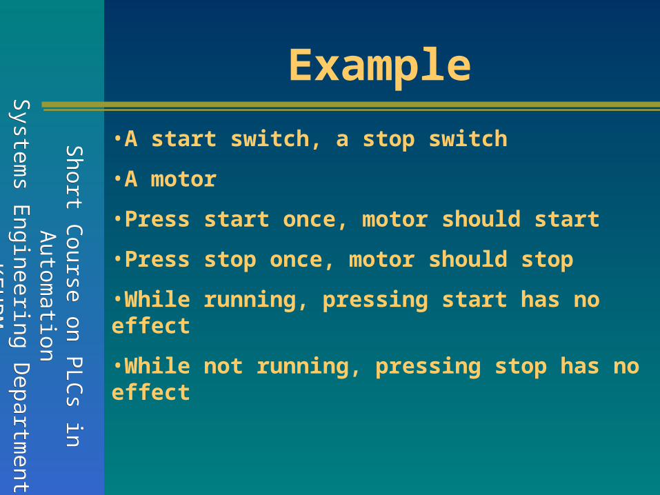
Example
•A start switch, a stop switch
•A motor
•Press start once, motor should start
•Press stop once, motor should stop
•While running, pressing start has no effect
•While not running, pressing stop has no effect
Short C
ourse on PLC
s in S
hort Course on P
LCs in
Autom
ationA
utomation
System
s Engineering D
epartment
System
s Engineering D
epartment
KF
UP
MK
FU
PM
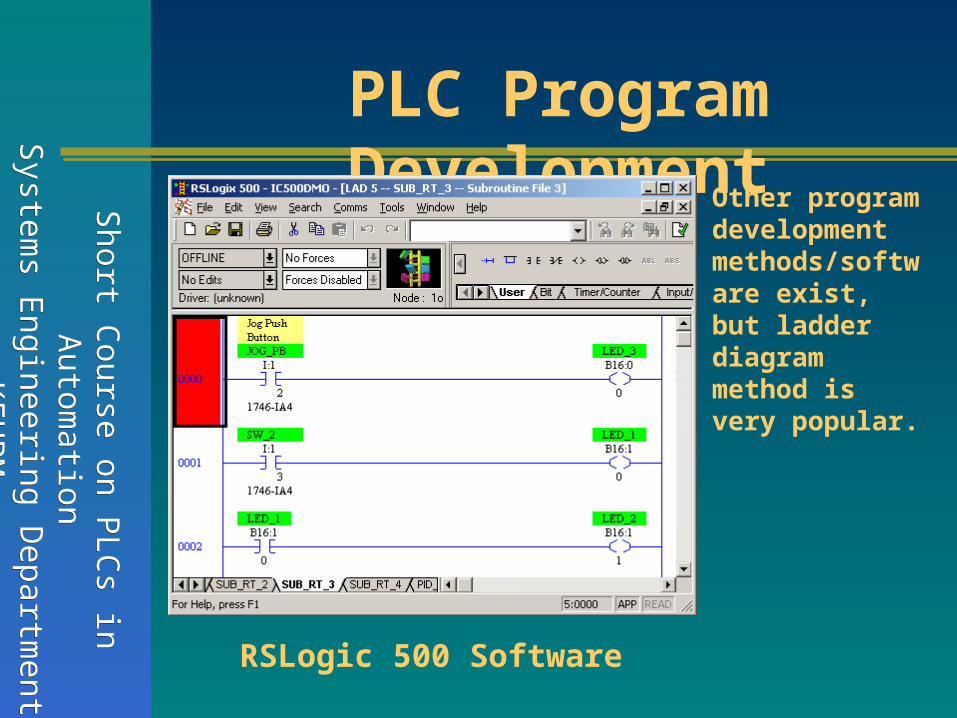
PLC Program Development
RSLogic 500 Software
Other program development methods/software exist, but ladder diagram method is very popular.

Short C
ourse on PLC
s in S
hort Course on P
LCs in
Autom
ationA
utomation
System
s Engineering D
epartment
System
s Engineering D
epartment
KF
UP
MK
FU
PM
Programming the PLCSome PLCs have simple “keyboards” for programming.
RSLogic 500 Software

Short C
ourse on PLC
s in S
hort Course on P
LCs in
Autom
ationA
utomation
System
s Engineering D
epartment
System
s Engineering D
epartment
KF
UP
MK
FU
PM
IEC 1131 Programming Standards
Text based programming
(Instruction List or Mnemonic)
Graphical programming
(Ladder diagram, …)

Short C
ourse on PLC
s in S
hort Course on P
LCs in
Autom
ationA
utomation
System
s Engineering D
epartment
System
s Engineering D
epartment
KF
UP
MK
FU
PM
PLC Operation Sequence
All PLCs have four basic stages of operations that are repeated many times per
second. Initially when turned on the first time it will check it’s own hardware and software
for faults. If there are no problems it will copy all the input and copy their values into
memory, this is called the input scan. Using only the memory copy of the inputs the ladder
logic program will be solved once, this is called the logic scan. While solving the ladder
logic the output values are only changed in temporary memory. When the ladder scan is
done the outputs will updated using the temporary values in memory, this is called the output
scan. The PLC now restarts the process by starting a self check for faults. This process
typically repeats 10 to 100 times per second as is shown in the above figure.

Short C
ourse on PLC
s in S
hort Course on P
LCs in
Autom
ationA
utomation
System
s Engineering D
epartment
System
s Engineering D
epartment
KF
UP
MK
FU
PM
PLC Operation Sequence
•SELF TEST - Checks to see if all cards error free, reset watch-dog timer, etc. (A watchdog
timer will cause an error, and shut down the PLC if not reset within a short period of
time - this would indicate that the ladder logic is not being scanned normally).
•INPUT SCAN - Reads input values from the chips in the input cards, and copies their values
to memory. This makes the PLC operation faster, and avoids cases where an input
changes from the start to the end of the program (e.g., an emergency stop). There are
special PLC functions that read the inputs directly, and avoid the input tables.
•LOGIC SOLVE/SCAN - Based on the input table in memory, the program is executed 1
step at a time, and outputs are updated. This is the focus of the later sections.
•OUTPUT SCAN - The output table is copied from memory to the output chips. These
chips then drive the output devices.

Short C
ourse on PLC
s in S
hort Course on P
LCs in
Autom
ationA
utomation
System
s Engineering D
epartment
System
s Engineering D
epartment
KF
UP
MK
FU
PM
When the inputs to the PLC are scanned the physical input values are copied into
memory. When the outputs to a PLC are scanned they are copied from memory to
the physical outputs. When the ladder logic is scanned it uses the values in
memory, not the actual input or output values. The primary reason for doing this
is so that if a program uses an input value in multiple places, a change in the input
value will not invalidate the logic. Also, if output bits were changed as each bit was
changed, instead of all at once at the end of the scan the PLC
would operate much slower.
The Input and Output Scans

Short C
ourse on PLC
s in S
hort Course on P
LCs in
Autom
ationA
utomation
System
s Engineering D
epartment
System
s Engineering D
epartment
KF
UP
MK
FU
PM
Ladder logic programs are modelled after relay logic. In relay logic each element
in the ladder will switch as quickly as possible. But in a program elements can only
be examined one at a time in a fixed sequence.
The Logic Scan
Consider the ladder logic in Figure 8.4,
the ladder logic will be interpreted
left-to-right, top-to-bottom. In the
figure the ladder logic scan begins at
the top rung. At the end of the rung it
interprets the top output first, then the output branched below it. On the second
rung it solves branches, before moving along the ladder logic rung.

Short C
ourse on PLC
s in S
hort Course on P
LCs in
Autom
ationA
utomation
System
s Engineering D
epartment
System
s Engineering D
epartment
KF
UP
MK
FU
PM
The Logic Scan

Short C
ourse on PLC
s in S
hort Course on P
LCs in
Autom
ationA
utomation
System
s Engineering D
epartment
System
s Engineering D
epartment
KF
UP
MK
FU
PM
Ladder Diagram Format
Reverse flow not allowed

Short C
ourse on PLC
s in S
hort Course on P
LCs in
Autom
ationA
utomation
System
s Engineering D
epartment
System
s Engineering D
epartment
KF
UP
MK
FU
PM
Order in ladder diagrams

Short C
ourse on PLC
s in S
hort Course on P
LCs in
Autom
ationA
utomation
System
s Engineering D
epartment
System
s Engineering D
epartment
KF
UP
MK
FU
PM
PLC Status
The lack of keyboard, and other input-output devices is very noticeable on a PLC.
On the front of the PLC there are normally limited status lights. Common lights
indicate:
•power on - this will be on whenever the PLC has power
•program running - this will often indicate if a program is running, or if no program
is running
•fault - this will indicate when the PLC has experienced a major hardware or software
problem

Short C
ourse on PLC
s in S
hort Course on P
LCs in
Autom
ationA
utomation
System
s Engineering D
epartment
System
s Engineering D
epartment
KF
UP
MK
FU
PM
PLC Status
These lights are normally used for debugging. Limited buttons will also be provided
for PLC hardware. The most common will be a run/program switch that will be
switched to program when maintenance is being conducted, and back to run when in
production.
This switch normally requires a key to keep unauthorized personnel from altering
the PLC program or stopping execution. A PLC will almost never have an on-off
switch or reset button on the front. This needs to be designed into the remainder of
the system.

Short C
ourse on PLC
s in S
hort Course on P
LCs in
Autom
ationA
utomation
System
s Engineering D
epartment
System
s Engineering D
epartment
KF
UP
MK
FU
PM
INTRODUCTION TO PLC PROGRAMMING
Dr. ONUR TOKERDr. ONUR TOKER

Short C
ourse on PLC
s in S
hort Course on P
LCs in
Autom
ationA
utomation
System
s Engineering D
epartment
System
s Engineering D
epartment
KF
UP
MK
FU
PM
Ladder diagrams

Short C
ourse on PLC
s in S
hort Course on P
LCs in
Autom
ationA
utomation
System
s Engineering D
epartment
System
s Engineering D
epartment
KF
UP
MK
FU
PM
Boolean programming
Boolean mnemonics

Short C
ourse on PLC
s in S
hort Course on P
LCs in
Autom
ationA
utomation
System
s Engineering D
epartment
System
s Engineering D
epartment
KF
UP
MK
FU
PM
Ladder Diagram Symbols

Short C
ourse on PLC
s in S
hort Course on P
LCs in
Autom
ationA
utomation
System
s Engineering D
epartment
System
s Engineering D
epartment
KF
UP
MK
FU
PM
EXAMINE-ON

Short C
ourse on PLC
s in S
hort Course on P
LCs in
Autom
ationA
utomation
System
s Engineering D
epartment
System
s Engineering D
epartment
KF
UP
MK
FU
PM
EXAMINE-OFF

Short C
ourse on PLC
s in S
hort Course on P
LCs in
Autom
ationA
utomation
System
s Engineering D
epartment
System
s Engineering D
epartment
KF
UP
MK
FU
PM
Output Coil

Short C
ourse on PLC
s in S
hort Course on P
LCs in
Autom
ationA
utomation
System
s Engineering D
epartment
System
s Engineering D
epartment
KF
UP
MK
FU
PM
A Simple Example
Activate the device at location Y
IF
A or C switch is ON
AND
B switch is ON

Short C
ourse on PLC
s in S
hort Course on P
LCs in
Autom
ationA
utomation
System
s Engineering D
epartment
System
s Engineering D
epartment
KF
UP
MK
FU
PM
Latch
Short C
ourse on PLC
s in S
hort Course on P
LCs in
Autom
ationA
utomation
System
s Engineering D
epartment
System
s Engineering D
epartment
KF
UP
MK
FU
PM
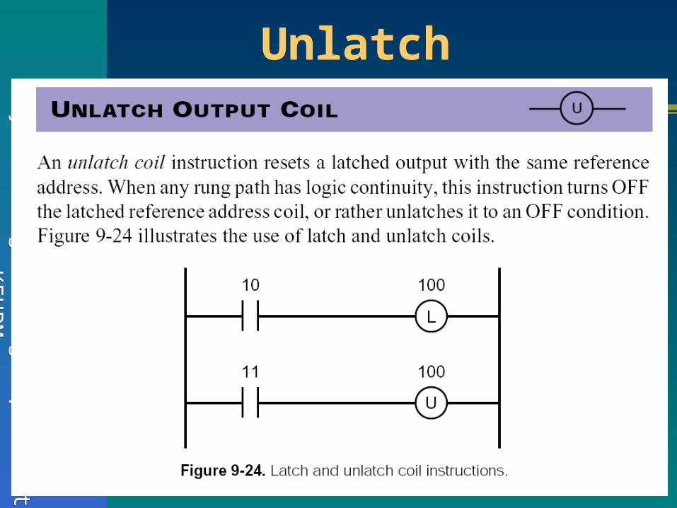
Unlatch

Short C
ourse on PLC
s in S
hort Course on P
LCs in
Autom
ationA
utomation
System
s Engineering D
epartment
System
s Engineering D
epartment
KF
UP
MK
FU
PM
One-Shot Output

Short C
ourse on PLC
s in S
hort Course on P
LCs in
Autom
ationA
utomation
System
s Engineering D
epartment
System
s Engineering D
epartment
KF
UP
MK
FU
PM
Transitional Contact

Short C
ourse on PLC
s in S
hort Course on P
LCs in
Autom
ationA
utomation
System
s Engineering D
epartment
System
s Engineering D
epartment
KF
UP
MK
FU
PM
Summary

Short C
ourse on PLC
s in S
hort Course on P
LCs in
Autom
ationA
utomation
System
s Engineering D
epartment
System
s Engineering D
epartment
KF
UP
MK
FU
PM
An example

Short C
ourse on PLC
s in S
hort Course on P
LCs in
Autom
ationA
utomation
System
s Engineering D
epartment
System
s Engineering D
epartment
KF
UP
MK
FU
PM
PLC PROGRAMING
BY EXAMPLES
Dr. ONUR TOKERDr. ONUR TOKER

Short C
ourse on PLC
s in S
hort Course on P
LCs in
Autom
ationA
utomation
System
s Engineering D
epartment
System
s Engineering D
epartment
KF
UP
MK
FU
PM
A simple example
Short C
ourse on PLC
s in S
hort Course on P
LCs in
Autom
ationA
utomation
System
s Engineering D
epartment
System
s Engineering D
epartment
KF
UP
MK
FU
PM
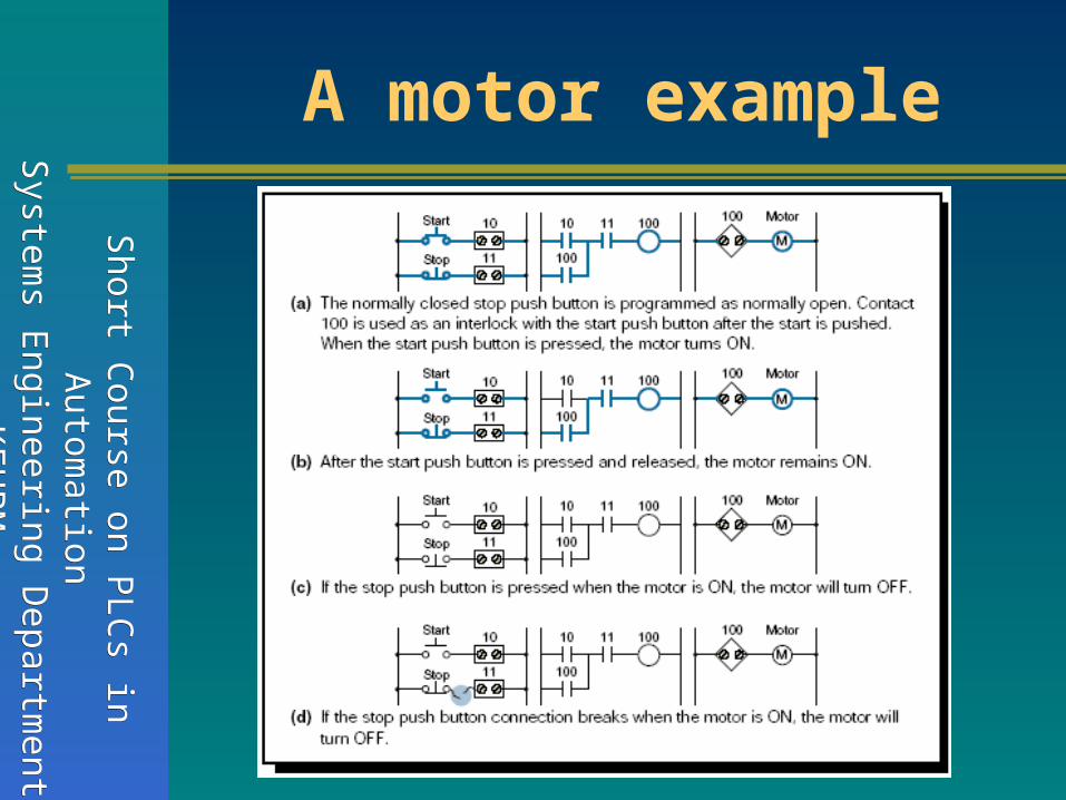
A motor example

Short C
ourse on PLC
s in S
hort Course on P
LCs in
Autom
ationA
utomation
System
s Engineering D
epartment
System
s Engineering D
epartment
KF
UP
MK
FU
PM
Fail-safe designs

Short C
ourse on PLC
s in S
hort Course on P
LCs in
Autom
ationA
utomation
System
s Engineering D
epartment
System
s Engineering D
epartment
KF
UP
MK
FU
PM
A more complex problem

Short C
ourse on PLC
s in S
hort Course on P
LCs in
Autom
ationA
utomation
System
s Engineering D
epartment
System
s Engineering D
epartment
KF
UP
MK
FU
PM
Design 1
Press Forward then Backward ?
Should stop first before backward !

Short C
ourse on PLC
s in S
hort Course on P
LCs in
Autom
ationA
utomation
System
s Engineering D
epartment
System
s Engineering D
epartment
KF
UP
MK
FU
PM
Design 2
A better design

Short C
ourse on PLC
s in S
hort Course on P
LCs in
Autom
ationA
utomation
System
s Engineering D
epartment
System
s Engineering D
epartment
KF
UP
MK
FU
PM
Alternative Design (Safety)

Short C
ourse on PLC
s in S
hort Course on P
LCs in
Autom
ationA
utomation
System
s Engineering D
epartment
System
s Engineering D
epartment
KF
UP
MK
FU
PM
Design modification 1
1. In forward mode, SB button should stop the motor
2. In backward mode, SF button should stop the motor

Short C
ourse on PLC
s in S
hort Course on P
LCs in
Autom
ationA
utomation
System
s Engineering D
epartment
System
s Engineering D
epartment
KF
UP
MK
FU
PM
Design modification 21. Add emergency shutdown/reset functionality

Short C
ourse on PLC
s in S
hort Course on P
LCs in
Autom
ationA
utomation
System
s Engineering D
epartment
System
s Engineering D
epartment
KF
UP
MK
FU
PM
Complex Example 1

Short C
ourse on PLC
s in S
hort Course on P
LCs in
Autom
ationA
utomation
System
s Engineering D
epartment
System
s Engineering D
epartment
KF
UP
MK
FU
PM
Complex Example 2

Short C
ourse on PLC
s in S
hort Course on P
LCs in
Autom
ationA
utomation
System
s Engineering D
epartment
System
s Engineering D
epartment
KF
UP
MK
FU
PM
Complex Example 3
Tank with Low and High limit switches, and start/stop

Short C
ourse on PLC
s in S
hort Course on P
LCs in
Autom
ationA
utomation
System
s Engineering D
epartment
System
s Engineering D
epartment
KF
UP
MK
FU
PM
Complex Example 4
“Locking trick” (Alternative to using a latch)

Short C
ourse on PLC
s in S
hort Course on P
LCs in
Autom
ationA
utomation
System
s Engineering D
epartment
System
s Engineering D
epartment
KF
UP
MK
FU
PM
Complete PLC Design
1. Understand the problem
2. Learn about extras & limitations of your PLC
3. Ladder diagram programming
4. Program your PLC
5. Learn hardware details, I/O terminals and wiring diagrams of your PLC
6. Do actual wiring and then test your system

Short C
ourse on PLC
s in S
hort Course on P
LCs in
Autom
ationA
utomation
System
s Engineering D
epartment
System
s Engineering D
epartment
KF
UP
MK
FU
PM
Micro Logic1200 Terminals

Short C
ourse on PLC
s in S
hort Course on P
LCs in
Autom
ationA
utomation
System
s Engineering D
epartment
System
s Engineering D
epartment
KF
UP
MK
FU
PM
Micro Logic1200 Input Wiring

Short C
ourse on PLC
s in S
hort Course on P
LCs in
Autom
ationA
utomation
System
s Engineering D
epartment
System
s Engineering D
epartment
KF
UP
MK
FU
PM
Micro Logic1200 Output Wiring

Short C
ourse on PLC
s in S
hort Course on P
LCs in
Autom
ationA
utomation
System
s Engineering D
epartment
System
s Engineering D
epartment
KF
UP
MK
FU
PM
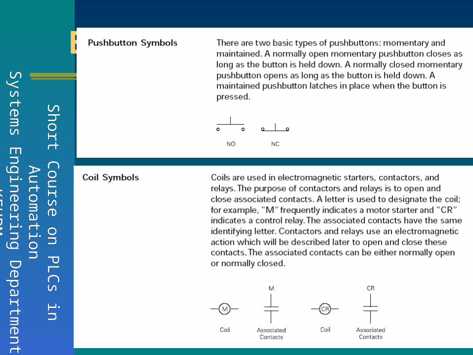
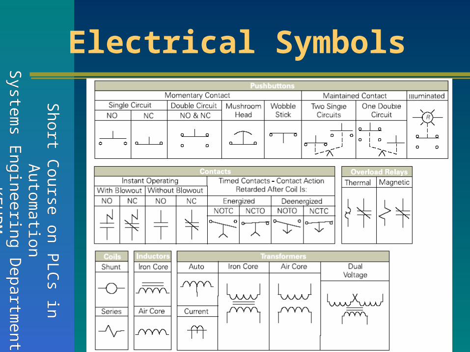
Electrical Symbols
Short C
ourse on PLC
s in S
hort Course on P
LCs in
Autom
ationA
utomation
System
s Engineering D
epartment
System
s Engineering D
epartment
KF
UP
MK
FU
PM
Electrical Symbols

Short C
ourse on PLC
s in S
hort Course on P
LCs in
Autom
ationA
utomation
System
s Engineering D
epartment
System
s Engineering D
epartment
KF
UP
MK
FU
PM
Electrical Symbols

Short C
ourse on PLC
s in S
hort Course on P
LCs in
Autom
ationA
utomation
System
s Engineering D
epartment
System
s Engineering D
epartment
KF
UP
MK
FU
PM
Electrical Symbols
Short C
ourse on PLC
s in S
hort Course on P
LCs in
Autom
ationA
utomation
System
s Engineering D
epartment
System
s Engineering D
epartment
KF
UP
MK
FU
PM
Electrical Symbols

Short C
ourse on PLC
s in S
hort Course on P
LCs in
Autom
ationA
utomation
System
s Engineering D
epartment
System
s Engineering D
epartment
KF
UP
MK
FU
PM
Electrical Symbols

Short C
ourse on PLC
s in S
hort Course on P
LCs in
Autom
ationA
utomation
System
s Engineering D
epartment
System
s Engineering D
epartment
KF
UP
MK
FU
PM
Electrical Symbols

Short C
ourse on PLC
s in S
hort Course on P
LCs in
Autom
ationA
utomation
System
s Engineering D
epartment
System
s Engineering D
epartment
KF
UP
MK
FU
PM
QUESTIONS
&
THANK YOU