Embed Size (px)
Citation preview
EUROPEAN WORKSHOP ON INDUSTRIALCOMPUTER SYSTEMSTECHNICAL COMMITTEE 7(Safety, Reliability and Security)
Guidelines for the use of Programmable LogicControllers in Safety-related Systems
Edited by
Helmut Bezecny1, Dennis Inverso2, Vic Maggioli3, Gerd Rabe4andAlbrecht Weinert5
Working Paper 6009
Version 13, October 1997
1DOW Deutschland, Stade, Germany 2DuPont Engineering, USA3Feltronics, Newark, USA 4TÜV Nord, Hamburg, Germany5Siemens, Germany (since March1997: Fachhochschule Bochum)
2
EWICS TC 7 (European Workshop on Industrial Computer Systems, Technical Committee 7) is aninternational body of experts in the field of dependable industrial computer systems and focuses itsinterest on safety, reliability and security.
The Programmable Logic Controllers (PLC) Working Group was set up within EWICS TC7 in 1992.Throughout its life-span the Group attracted attention of more than twenty experts from ten countries.The members are from industry, universities and government institutions. The main industriesrepresented include transportation, process control and atomic energy. Government agencies includeregulatory, assessment and testing authorities.
The utilization of PLCs in safety-related Systems (SrS) is receiving much favour amongst industry.The need for good engineering practices in this area is a vital tool for the industrial users not only inthe European Community.
This guideline addresses important areas in the use of PLCs in SrS for hazardous processes, such asglobal requirements, specifications, procurement, hardware and software design, implementation,verification, validation, security, operations, maintenance, and documentation. References areprovided to allow the reader to review issues in greater depth. The guideline is intended for personsknowledgeable in basic PLC characteristics.
Gerd RabeTÜV Nord e.V.Grosse Bahnstr. 3122525 Hamburg, Germany
DISCLAIMER OF WARRANTIES AND LIMITATION OF LIABILITIES
THIS DOCUMENT WAS PREPARED BY THE MEMBERS OF THE TECHNICAL COMMITTEE 7 OF THE EUROPEANWORKSHOP ON INDUSTRIAL COMPUTER SYSTEMS (EWICS TC 7). NEITHER THE MEMBERS OF EWICS TC 7, THEIRCOMPANIES, NOR ANY PERSON ACTING ON BEHALF OF ANY OF THEM;
(A) MAKES ANY WARRANTY OR REPRESENTATION WHATSOEVER, EXPRESS OR IMPLIED, (I) WITH RESPECTTO THE USE OF ANY INFORMATION, APPARATUS, METHOD, PROCESS, OR SIMILAR ITEM DISCLOSED IN THISREPORT, INCLUDING MERCHANTABILITY AND FITNESS FOR A PARTICULAR PURPOSE, (II) THAT SUCH USE DOESNOT INFRINGE ON OR INTERFERE WITH PRIVATELY OWNED RIGHTS, INCLUDING ANY PARTY’S INTELLECTUALPROPERTY, OR (III) THAT THIS REPORT IS SUITABLE TO ANY PARTICULAR USER’S CIRCUMSTANCE; OR
(B) ASSUMES RESPONSIBILITY FOR ANY DAMAGES OR OTHER LIABILITY WHATSOEVER RESULTING FROMYOUR SELECTION OR USE OF THIS DOCUMENT OR ANY INFORMATION, APPARATUS, METHOD, PROCESS, ORSIMILAR ITEM DISCLOSED IN THIS DOCUMENT.
3
EWICS TC 7Programmable Logic Controllers (PLC)
Working Group
The list below contains the names and affiliations of individuals who attended at least one meetingduring the years 1995-1996 and contributed to the Guideline produced by the Group by providing a
new input and /or reviewing the existing material.
Gerd Rabe Chairman TÜV Nord, D
Stuart Anderson Edinburgh University, UK
Helmut Bezecny DOW Deutschland, D
Robin Bloomfield Adelard, UK
George Cleland Edinburgh University, UK
Andy Harrison Railtrack, UK
Dennis Inverso DuPont Engineering, USA
Jouko Järvi Technical Inspection Centre, FIN
Tjabbe Kloppenburg Daimler Benz AG, D
Hamid Lesan Lloyds Register, UK
Victor Maggioli Feltronics, USA
Meine van der Meulen Simtech, NL
Johannes Rainer BFPZ-Arsenal, A
Erwin Schoitsch Austrian Research Center Seibersdorf, A
Ian Smith CLA, UK
Gerald Sonneck Austrian Research Center Seibersdorf, A
Albrecht Weinert Fachhochschule Bochum , D

4
Contents
PART I ABOUT THE GUIDELINE ......................................................................... 8
I.1 Scope .................................................................................................................. 8
I.2 Intended Audience............................................................................................. 9
I.3 Structure of the Guideline................................................................................. 9
I.4 How to use the Guideline................................................................................ 10
I.5 Tailoring the Guideline.................................................................................... 12
I.6 Relevance of Guideline ................................................................................... 12
I.7 Conformance clause ....................................................................................... 12
PART II SAFETY REQUIREMENTS ..................................................................... 13
II.1 Global requirements....................................................................................... 13II.1.1 Plant........................................................................................................... 13II.1.2 Environment............................................................................................... 13II.1.3 Modes of operation .................................................................................... 13II.1.4 Control / safety system .............................................................................. 13II.1.5 Global hazard analysis .............................................................................. 13II.1.6 Validation planning .................................................................................... 13II.1.7 Procurement plan - standards and guidelines ........................................... 14
II.2 Programmable Electronic System (PES) requirements .............................. 14II.2.1 Process behaviour and interface .............................................................. 14II.2.2 Operator role and interface....................................................................... 14II.2.3 Functionality of the PES ........................................................................... 14II.2.4 Integration plan ......................................................................................... 15II.2.5 Risk classification and risk reduction ........................................................ 15II.2.6 Performance ............................................................................................. 15II.2.7 Maintenance requirements ....................................................................... 15II.2.8 Requirements Specification .................................................................. 15
II.2.8.1 General ................................................................................................ 15II.2.8.2 Non safety related requirements specification..................................... 15II.2.8.3 Safety Requirements Specification...................................................... 16
II.2.8.3.1 General .......................................................................................... 16II.2.8.3.2 Functional Safety Requirement Specification ................................ 16II.2.8.3.3 Safety integrity requirements specification .................................... 17
II.3 Safety PLC requirements ............................................................................... 18II.3.1 General .................................................................................................. 18
II.3.1.1 Control of failures and avoidance of failures........................................ 18II.3.1.2 Classification of the safety PLC states ................................................ 19
II.3.2 Software Design Specification ................................................................... 20
5
II.3.2.1 Structure and function of PLC software ................................................ 21II.3.2.2 Characteristics of PLC software ........................................................... 23II.3.2.3 Partitioning of Software into Modules ................................................... 24II.3.2.4 Execution Rates.................................................................................... 25II.3.2.5 Event-Logging / Data-Historian Requirements .................................... 25
II.3.3 Hardware Design Specification.................................................................. 26II.3.3.1 General ................................................................................................ 26II.3.3.2 Keywords for hardware requirements.................................................. 26
II.3.4 Security aspects ........................................................................................ 28II.3.4.1 Data Access and Manipulation ............................................................. 28II.3.4.2 Separation ............................................................................................ 29
II.3.5 Documentation........................................................................................... 30II.3.5.1 Objectives ............................................................................................ 30II.3.5.2 Requirements ...................................................................................... 30II.3.5.3 Execution ............................................................................................. 31II.3.5.4 Additional Information in a Project Using Third Party Certified SafetyPLC................................................................................................................... 31
PART III SELECTION GUIDE FOR A SAFETY PLC SYSTEM ........................... 32
III.1 General .......................................................................................................... 32
III.2 Potential vendor selection ........................................................................... 32
III.3 Evaluation of quotations.............................................................................. 32
III.4 Safety aspects of PLC languages ............................................................... 33III.4.1 Criteria for selecting programming languages .......................................... 33
III.4.1.1 About the application of these criteria................................................. 34
III.5 Questions to ask potential suppliers.......................................................... 35
PART IV PLC SYSTEM IMPLEMENTATION ...................................................... 36
IV.1 Application development............................................................................. 36IV.1.1 Hardware design ...................................................................................... 36
IV.1.1.1 Separation of non safety and safety system functions .................... 36IV.1.1.2 Hardware design life cycle stages...................................................... 36IV.1.1.3 Reviews.............................................................................................. 37
IV.1.2 Software design........................................................................................ 37IV.1.2.1 Software design life cycle stages ....................................................... 37IV.1.2.2 Software module design..................................................................... 38
IV.1.2.2.1 Objectives..................................................................................... 38IV.1.2.2.2 Requirements ............................................................................... 38
IV.1.3 Programming............................................................................................ 39IV.1.3.1 Implementing PLC application programs ........................................... 39IV.1.3.2 Objectives........................................................................................... 39IV.1.3.3 Requirements ..................................................................................... 39
IV.1.4 Verification of Module Design and Programming Phase.......................... 40IV.1.4.1 Objective ............................................................................................ 40IV.1.4.2 General requirements for software verification................................... 40
6
IV.1.4.3 Special requirements for verification in the software module design 40IV.1.4.4 Special requirements for verification in the programming phase ...... 41
IV.1.5 Detailed recommendations for software module design and programming ............................................................................................................................ 41
IV.1.5.1 Quality of software engineering practices .......................................... 41IV.1.5.2 Techniques for compliance with safety related requirements ............ 42IV.1.5.3 Use of existing software ..................................................................... 42
IV.2 Safety PLC system integration and validation ..................................... 42IV.2.1 Integration of PLC hardware and software............................................... 42IV.2.2 Safety validation against PLC requirements ............................................ 43IV.2.3 Development of procedures ..................................................................... 44
PART V PLANT LEVEL INTEGRATION AND VALIDATION .............................. 45
V.1 Installation ..................................................................................................... 45
V.2 System Test ................................................................................................... 45
V.3 Safety validation against global requirements........................................... 46V.3.1 Objectives................................................................................................. 46V.3.2 Validation.................................................................................................. 46
PART VI CERTIFICATION / ASSESSMENT ....................................................... 48
VI.1 Review of development ............................................................................... 48
VI.2 Assessment of the safety PLC.................................................................... 48VI.2.1 General...................................................................................................... 48VI.2.2 Analytical approval .................................................................................... 49VI.2.3 On-site approval ........................................................................................ 49
PART VII COMMISSIONING AND USE .............................................................. 51
VII.1 Operation and Maintenance ....................................................................... 51VII.1.1 Operating Procedures ............................................................................. 51
VII.1.1.1 Critical Operations Procedures ......................................................... 51VII.1.1.1.1 Bypassing criteria for safety PLC ................................................ 52VII.1.1.1.2 On-line calibration of safety PLC.................................................. 53VII.1.1.1.3 Response to safety PLC Alarms .................................................. 53
VII.1.1.2 Abnormal Condition Procedures ........................................................ 53VII.1.1.3 Turnover Procedures.......................................................................... 53VII.1.1.4 Facility Change Procedures ............................................................... 54VII.1.1.5 Safety Review Procedures ................................................................. 55VII.1.1.6 Security Procedures ........................................................................... 55
VII.1.2 Maintenance Facilities Planning............................................................. 56VII.1.2.1 Maintenance and Engineering Work-Stations ................................... 57VII.1.2.2 Spare Parts ........................................................................................ 57VII.1.2.3 Third Party Maintenance .................................................................... 58
VII.1.3 Testing Frequency Requirements .......................................................... 58VII.1.3.1 Safety PLC System Testing ............................................................... 58

7
VII.1.3.1.1 Application Software Testing........................................................ 59VII.1.3.1.2 Functional System Testing ........................................................... 59
VII.1.4 Plant Operations Training with Installed Controls .................................. 59VII.1.4.1 Normal Conditions.............................................................................. 60VII.1.4.2 Start-up Conditions............................................................................ 60VII.1.4.3 Shutdown Conditions ........................................................................ 60VII.1.4.4 Abnormal Conditions .......................................................................... 61
VII.2 Modification and retrofit ............................................................................. 61
VII.3 Decommissioning ....................................................................................... 61
PART VIII CONTRACTUAL ISSUES .................................................................... 63
VIII.1 Tender ......................................................................................................... 63
VIII.2 Liability........................................................................................................ 64
APPENDICES ........................................................................................................... 65
A-1 Hardware questionnaire ............................................................................ 65
A-2 Questions to ask potential suppliers ....................................................... 68
A-3 Safety life cycle related information ............................................................ 74
A-4 Abbreviations ................................................................................................. 75
REFERENCES ....................................................................................................... 77

8
Part I About the Guideline
I.1 Scope
The Programmable Logic Controller (PLC)-Subgroup of EWICS TC 7 has provided a guideline definingthe proper use of Programmable Logic Controllers in Safety-related Systems (safety PLC) according toSafety Integrity Levels (SIL) 1-3 (typically in demand mode, de-energized to trip) as defined in dIEC1508 [IEC 97] or according to requirements classes 1-6 as defined in DIN V 19250 [DIN 94] in a waythat
• utilizes existing and developing practices, guidelines and standards
• considers users, procurers, developers, engineering, and certifiers / assessors needs
• allows a path forward to guideline development for other programmable electronic controllers (e.g.DCSC = distributed control system controller, SLC = single loop control etc.)
• allows guideline users to implement computer technology to improve safety in their plant.
Higher safety integrity levels such as SIL 4 (IEC) or requirements classes 7/8 (DIN) typically requireadditional design considerations that are not provided in this guideline.
A PLC is a special purpose computer having a central processing unit (CPU), power supply, a pro-gramming panel and/or interface to a programming system, inputs, and outputs. A PLC should alsoprovide the capability to support remote I/O, special purpose I/O, I/O housings, connection, cables,additional power supplies, communication boards etc.
At the advent of PLCs they offered relay ladder diagramming as their principal 'problem oriented' lan-guage to allow an easy migration from conventional electromechanical control equipment. PLCs offeradditional programming features including:
• application specific languages
• textual and graphical languages conforming to IEC 1131, Part 3, ProgrammingLanguages [IEC 93]
• proprietary variants of the languages defined in IEC 1131
The following features are characteristic of PLCs and may be used as guidance when determiningwhether or not a given programmable device is a PLC.
- A PLC real-time response should match electromechanical relay operating speeds.
- Logic ground is isolated from PLC safety (enclosure) ground, hence single point ground is notrequired.
- Power supplies are provided with line noise rejection features (e.g. chokes, RC circuits, filters,isolation transformers with Faraday shields etc.), thus not requiring power line conditioning.
- PLCs have high electrical noise rejection threshold as compared to other programmable devices.
- Equipment is rated to 60° C.

9
I.2 Intended Audience
The PLC Guideline is intended for:
• Persons with an understanding of control systems and with experience with PLCs in non-safety-related control systems (as a minimum).
• Persons with experience using electrical and electronics technology in safety-related systems.
• Persons who have properly completed all steps in a safety life cycle (e.g. [AIChE 93], [ISA 96] or[IEC 97]) leading to the development of a safety PLC.
• Customers who require a PLC based safety system. The customer should have a safetymanagement strategy in place. The customer is also referred to as the user or end-user.
• Suppliers of these safety PLC if they are charged with the task of commissioning the PLC systemon behalf of the customers.
Note: The two major roles filled by the suppliers are application developer and PLCequipment manufacturer . The equipment manufacturer is responsible for the PLC-basedsystem hardware, system, and utility software.The application developer is typically responsible for the design, installation and start-up of thePLC-based system. The application software may fall to either the application developer orequipment manufacturer.
• Assessors of safety PLC System.Assessors are responsible for certifying that the safety PLC System functions per the safetyrequirement specification. The assessor could be:
- regulatory body (government), e.g., (UK HSE, USA OSHA and EPA) or regulatory body
(government)
- independent agency (e.g. TÜV, FM) or independent agency
• independent company
• internal group of customer company
• internal group of contracting company
• same group as customer or supplier above
I.3 Structure of the Guideline
This guideline focuses primarily on the activities of the customer, supplier and assessor. The guidelineis structured as follows:
Part I About the Guideline
Part II Safety Requirements
Part III PLC Selection Guide for PLC systems
Part IV PLC System Implementation
Part V Plant Level Integration and Validation
Part VI Certification/Assessment
Part VII Commissioning and Use
Part VIII Contractual and Other Issues
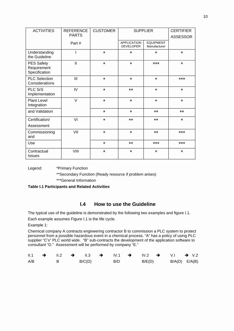
Table I.1 provides an overview of the relationship of the customer, supplier and assessor to therequired safety PLC.
10
ACTIVITIES REFERENCEPARTS
CUSTOMER SUPPLIER CERTIFIER
ASSESSOR
Part # APPLICATIONDEVELOPER
EQUIPMENTManufacturer
Understandingthe Guideline
I * * * *
PES SafetyRequirementSpecification
II * * *** *
PLC SelectionConsiderations
III * * * ***
PLC SrSImplementation
IV * ** * *
Plant LevelIntegration
V * * * *
and Validation * * ** **Certification/
Assessment
VI * ** ** *
Commissioningand
VII * * ** ***
Use * ** *** ***ContractualIssues
VIII * * * *
Legend: *Primary Function
**Secondary Function (Ready resource if problem arises)
***General Information
Table I.1 Participants and Related Activities
I.4 How to use the Guideline
The typical use of the guideline is demonstrated by the following two examples and figure I.1.
Each example assumes Figure I.1 is the life cycle.
Example 1:
Chemical company A contracts engineering contractor B to commission a PLC system to protectpersonnel from a possible hazardous event in a chemical process. “A” has a policy of using PLCsupplier “C’s” PLC world wide. “B” sub-contracts the development of the application software toconsultant “D.” Assessment will be performed by company “E.”
II.1 � II.2 � II.3 � IV.1 � IV.2 � V.I � V.2
A/B B B/C(D) B/D B/E(D) B/A(D) E/A(B)

11
Example 2:
Motor car manufacturer P requires a PLC based safety system. It will procure the PLC from anexternal supplier Q (or R or S), but will perform all other development and integration functions itself:
II.1 � II.2 � II.3 � III � IV.1 � IV.2 � V � VI
P P P P/Q P P P P
Selectionof PLCIII
ApplicationdevelopmentIV.1.1-1.3
PLC systemrequirementsII.3
VerificationIV.1.4
Integrationof PLCIV.2.1
SafetyvalidationIV.2.2
PESrequirements
II.2
Plant levelintegration
V.1
GlobalrequirementsII.1
Plant levelvaldationV.2-3
System
design
System
development
Legend: � Life Cycle Progression
� Information Resource Path
Figure I.1 - Example Life Cycle
12
I.5 Tailoring the Guideline
It is recommended that the guideline is carefully studied by the responsible project personal (customer,supplier) in order to ensure that the scope is fully understood. Then a judgement should be made as tohow much of the guideline applies to the project in question. The result of these deliberations shouldhave some contractual significance associated with them.
Documentation produced in accordance with this guideline is expected to be relevant to the need of allpotential customers. However, if due regard is not taken of the particular project requirements, thisdocumentation may be insufficient. The need to minimise both the cost and the bulk of information iswell recognised. This can be achieved if a project's specific requirements are clearly identified.
I.6 Relevance of Guideline
The relevance of this guideline has been brought about because of the success the PLC has had incontrolling processes. The natural flow of applications from control to safety requires the need forguidelines to ensure the correct use of PLCs in safety applications.
I.7 Conformance clause
In the statements which follow, the organisation will be understood to be the company, institution orother uniquely identifiable body which is claiming conformance to this guideline.
In order to claim conformance with this guideline the organisation must:
- Identify, within its procedures the existence of activities corresponding to each step or phasedefined in this guideline.
- Identify the safety body or bodies who are charged with the responsibility for assuring that thesteps in these guidelines are followed.
13
Part II Safety Requirements
II.1 Global requirements
A PLC should not be used in a safety related application without process hazards analysis (PHA). Forguidance in developing a PHA, see reference [AIChE 93].
II.1.1 Plant
This should include all everything which can be affected by the Safety PLC System's operation andany other layers of protection needed to provide a safe unit of operation.
II.1.2 Environment
The environment in which this process operates should also be considered. This will certainly includethe immediate area in which the plant is sited and the enclosing building, compound or vehicle. Iffailure of the process (not necessarily caused by failure of the PLC) is likely to have effects beyond theboundary of this enclosure the description should extend to the maximum expected geographical limitsof such effects.
II.1.3 Modes of operation
The mode of operation of the process should be described. This should include the whole process, notjust the interface with the PLC. Operator responsibility in the process should be made clear.
II.1.4 Control / safety system
The required behaviour of the safety systems should be described, both in normal process operationand in the presence of potential process safety hazards. The role of the specific Safety PLC System tobe procured should be further identified.
II.1.5 Global hazard analysis
Constraints on the control systems are not to be considered without its environment. Hazard analysisof the plant including its control system identifies the constraints on the control system part (and onrest of equipment and process).
Techniques which may be used to assess process safety hazards include:
• Process Hazard Analysis (PHA)
• Checklists
• Fault Tree Analysis (FTA)
• Hazard and Operability Study (HAZOP)
• Failure Mode and Effect Analysis (FMEA)
• Event Tree Analysis (ETA)
• Quantitative Risk Assessment (QRA)
For guidance to these techniques see [Bish 90].
II.1.6 Validation planning
Safety validation planning is necessary to optimise the validation phase and to guarantee the feasibilityof the validation.
The Safety Validation should describe:
- right formulation of the safety criteria (safe status)
- test pattern for the inputs
- required environment in which the test will be placed
- procedure to be used for validation of each safety function (the right method).

14
The Safety Validation should consider all phases of the EUC (equipment under control) operation.These are the start-up, steady state, shut down, maintenance, all enhancements and reasonably fore-seeable abnormal conditions.
At the development of the validation it should be considered that the main PLC safety validationmethods are expected to be testing. Simulation and modelling methods and analysing may be used tosupport the validation process. It should be considered that the Safety Validation may have to beassessed by an independent person.
II.1.7 Procurement plan - standards and guidelines
At this point an overall procurement approach should be finalised. This will be influenced by severalconsiderations.
First the activities to be carried out internally to the company should be identified, and specifications fortendering and contracting out the remaining work drawn up. At one extreme all requirement,specification, application software development, integration, installation testing, certification, andacceptance may be carried out internally, with only the PLC being bought externally. At the otherextreme, the company may draw up a performance specification, and contract out all other aspects ofthe procurement. In reality the work is likely to be spread amongst several organisations or groups(both internal and external), so sequencing of activities and flow of information and responsibilitiesmust also be considered. Flow of information could be a constraint if commercially sensitive. Use oflanguage and its subsets may be a constraint.
The second task will be to identify aspects of company practice, including any standards or guidelineswhich will apply to the remainder of the procurement. The company may have an approved list of PLChardware suppliers; it may have internal guidelines; it may demand certain international or nationalstandards to be applied; it may simply always have used a particular PLC, and for ease of future sup-port demand its continued use; it may have specific coding standards, or prefer particular languages tobe used; the relevance of the IEC 1131 family of standards should be considered.
Decisions made at this point will influence and pervade all remaining activities in the procurement so itis important to consider this area properly.
II.2 Programmable Electronic System (PES) requirements
This chapter describes the requirements needed for the specific PES system to be commissioned. Fordetails see reference [IEC 97].
II.2.1 Process behaviour and interface
All aspects of the process which are to be protected or monitored by the PES must be specified. Thisincludes detailed behaviour of the process during normal operation, in the presence of (possiblymultiple) failures and in any other operating mode such as maintenance or diagnostic operation.Interfaces, at physical, electrical and protocol levels between the process and the PES should bespecified in detail.
II.2.2 Operator role and interface
All modes of communication between the operator and the PES should be defined. Indirect communi-cation should also be considered (e.g. via the plant or the environment). The behaviour of the operatorfor correct operation of the plant should be defined, and as far as possible the impact of operatorfailure (and the consequent impact on plant safety) considered.
There is a need to consider Identification & Authentication as well as Access Control of the operator.Also the security log should record the operator actions.
II.2.3 Functionality of the PES
The expected functional behaviour of the PES should be specified to take account of both normaloperation and operation with failures such that under any event or any combination of events sodescribed, the system as a whole will remain in or move to a safe state.

15
II.2.4 Integration plan
Procedures for unit test and assessment, system integration, system test and assessment and finalacceptance should be clearly documented including a detailed description of responsibilities (a transferthereof at different stages) between customer, supplier and assessor.
II.2.5 Risk classification and risk reduction
Starting with the potential process danger one can identify a 'risk class' (applying the risk graph fromrelevant standards, e.g. [IEC 97], [DIN 94], [ISA 96]). This analysis leads to system integrity levels.
II.2.6 Performance
It is important that overall process timing characteristics are clearly documented and the timing andsynchronisation of the PES meets timing needs.
Integrity levels [IEC 97] for both hardware and software components shall be identified both in normalsystem operation and in the presence of external failures to which the PES should respond.
Mechanisms for diagnosing problems and monitoring the operation of the PES shall be described.
II.2.7 Maintenance requirements
Mechanisms for maintenance and replacement of components and systems (including software)should be documented. The effect of invoking these on the whole plant should also be described.
II.2.8 Requirements Specification
II.2.8.1 General
Here, it should be stated clearly and in the appropriate detail, what the BPCS (Basic Process ControlSystem) has to do with the plant or process. For example:
- generate electricity
• adjust boiler control to meet load demand
- nylon press
• packages nylon in a transportable bale
This is called a non safety related requirement specification which has to be distinguished from thesafety related requirement specification e.g.:
- generate electricity in a safe way (very general)
• under no circumstances blow up the boiler
• do not open a burner fuel valve without having ventilated for at least 10 minutes
- operator interface eliminates injury to operator from press.
These functional requirements should be separated as described chapter IV.1.1.1.
II.2.8.2 Non safety related requirements specification
The following list of keywords should guide the user / customer to come to a complete specification.After analysis each feature mentioned must (at least) fall into one of the categories:
- mandatory
- optional
- not required
- not applicable
According to such a weighted list a BPCS and supplier should be chosen, keeping in mind, that idealsolutions are rare. There is no sense in requesting all (and having no money).
Keywords:
- size of data to be controlled
• numbers and types of sensors
• numbers and types of actuators

16
• timing requirementsinterrupt processingprocessing on demand
- report system
• time stamps
• ordering of (the sequence of) events
• system wide clock
• granularity and accuracy of system wide clock/ single clocks
- human machine interface (HMI)
• interfaces for operatorsconventional (lamps, switches, mimics etc.)monitors, keyboards (alphanumeric or symbolic), mouse, trackballlightpen, touch-screen etc.access rights for operators: Which changes to the process control are required / to beallowed / to be hindered on-line?national language support for HMIuniform I/O to the user
• engineering system (programming environment)conventional programminguse of standard software modulesmanagement of change, on-line or only off-linegraphical / textual inputgraphical / textual documentationcommunications between BPCS and engineering system use of standards
• national language guidelines and documentation
II.2.8.3 Safety Requirements Specification
II.2.8.3.1 General
The Safety Requirements Specification should comprise the functional Safety RequirementsSpecification and the Safety Integrity Requirements Specification.
The Safety Requirements Specification should contain all the requirements necessary for the designphase to achieve functional safety of the PES. The Specification should encompass both function andsafety properties.
To the extent required by the Safety Integrity Levels the Safety Requirements Specification should beexpressed and structured in such a way that it is clear, precise, unequivocal, verifiable, testable, main-tainable and feasible.
The Safety Requirements Specification should include modes of expression and descriptions whichare understandable, and appropriate to the duties they have to perform, to personnel involved in thedesign, operation and maintenance of the PES.
II.2.8.3.2 Functional Safety Requirement Specification
The objective is to develop the PES function requirements Specification for the safety-related systemnecessary to implement the required safety functions. The safety functions may be required to put theEUC (Equipment Under Control) into a safe state (for safety-related protection systems) or to maintaina safe state (for safety-related continuous control systems).
The functional Safety Requirements Specification should specify:
a) the required safety functions in order to achieve functional safety;
b) whether the safety function is applicable to a safety-related protection system or a safety-relatedcontinuous control system;
c) the safety-related system that is to implement the safety functions;
d) throughput and response time performance;
17
e) system and operator interfaces;
f) any other safety relevant information which may have an influence on the safety-related systemdesign.
g) all interfaces between the safety-related system and any other systems (either directlyassociated within, or outside, the EUC);
h) all relevant modes of operation of the EUC;
i) all required modes of behaviour of the safety-related system. In particular, failure behaviour andthe required response of the safety-related system should be detailed;
j) the significance of all hardware/software interactions. In particular, where relevant, any con-straints between the hardware and the software should be identified and documented;
k) those parts of the safety-related system, if any, that are required to perform non-safety functions;
l) all environmental conditions which are necessary to achieve functional safety;
m) the procedures for starting up and restarting the PES;
n) those requirements necessary to enable monitoring of the PES hardware to be undertaken;
o) requirements for periodic testing of the safety functions;
p) anticipated future requirements.
II.2.8.3.3 Safety integrity requirements specification
The objective is to develop the Safety Integrity Requirements Specification for each of the safetyfunctions.
II.2.8.3.3.1 General
The Safety Integrity Level for the designated safety-related system function should be qualified toindicate whether the target failure measure for the specified Safety Integrity Level is applicable tosafety-related protection systems or safety-related control systems.
The Safety Integrity Requirements Specification should include requirements to enable all safety func-tions to be tested.
Where the PES safety-related system is to implement both safety and non-safety functions then thehardware and software should be treated as safety-related unless it can be shown that there isadequate independence between the safety and non-safety functions. If the system is to be treated assafety-related then the guidelines in this text should be met.
Relaxation from this requirement should only be permissible if it can be shown that:
- the safety functions are independent
- the implementation is independent
- the failure of any non-safety-related functions does not affect the safety-related functions.
Where the PES is to implement safety functions of different Safety Integrity Levels then thePLC logic solver hardware and software should be treated as belonging to the highest SafetyIntegrity Level.
II.2.8.3.3.2 Requirements for safety integrity
The requirements for safety integrity, as they relate to "the control of errors" in the PES design, shouldbe composed of requirements for:
- hardware integrity
- software integrity
- system integrity comprising
• environment
• operation
- data integrity and application (software) integrity checks.
The requirements for the above error clauses are discussed in [IEC 97] Part 2 and are typical for otherstandards also.
18
II.3 Safety PLC requirements
II.3.1 General
From the hazard analysis of the process as well as PES safety integrity level requirements thefollowing constraints on the PLC have to be derived:
- What safety layer is the safety PLC in? I.e. what is the criticality of the safety PLC functioning,and what are the relations of the safety PLC to the other safety layers of the process? Importantis also the question how to realise independence of safety layers.
NOTE: According to [AIChE 93] safety layer means independent protection layer (IPL). This inturn is defined as: A system or subsystem specifically designed to reduce the likelihood orseverity of the impact of an identified hazardous event by a large factor, i.e. at least by a 100 foldreduction in likelihood. An IPL must be independent of other protection layers associated with theidentified hazardous event, as well as dependable and auditable.
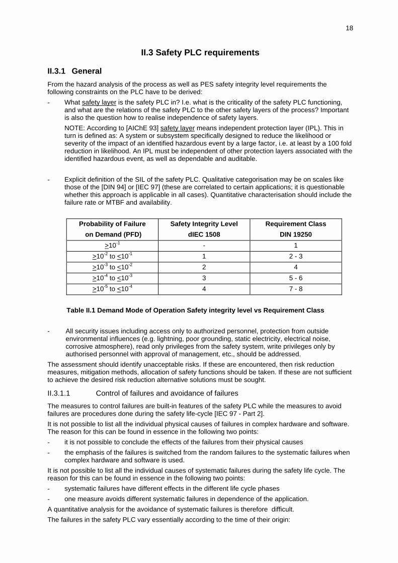
- Explicit definition of the SIL of the safety PLC. Qualitative categorisation may be on scales likethose of the [DIN 94] or [IEC 97] (these are correlated to certain applications; it is questionablewhether this approach is applicable in all cases). Quantitative characterisation should include thefailure rate or MTBF and availability.
Probability of Failure
on Demand (PFD)
Safety Integrity Level
dIEC 1508
Requirement Class
DIN 19250
>10-1 - 1
>10-2 to <10-1 1 2 - 3
>10-3 to <10-2 2 4
>10-4 to <10-3 3 5 - 6
>10-5 to <10-4 4 7 - 8
Table II.1 Demand Mode of Operation Safety integrity level vs Requirement Class
- All security issues including access only to authorized personnel, protection from outsideenvironmental influences (e.g. lightning, poor grounding, static electricity, electrical noise,corrosive atmosphere), read only privileges from the safety system, write privileges only byauthorised personnel with approval of management, etc., should be addressed.
The assessment should identify unacceptable risks. If these are encountered, then risk reductionmeasures, mitigation methods, allocation of safety functions should be taken. If these are not sufficientto achieve the desired risk reduction alternative solutions must be sought.
II.3.1.1 Control of failures and avoidance of failures
The measures to control failures are built-in features of the safety PLC while the measures to avoidfailures are procedures done during the safety life-cycle [IEC 97 - Part 2].
It is not possible to list all the individual physical causes of failures in complex hardware and software.The reason for this can be found in essence in the following two points:
- it is not possible to conclude the effects of the failures from their physical causes
- the emphasis of the failures is switched from the random failures to the systematic failures whencomplex hardware and software is used.
It is not possible to list all the individual causes of systematic failures during the safety life cycle. Thereason for this can be found in essence in the following two points:
- systematic failures have different effects in the different life cycle phases
- one measure avoids different systematic failures in dependence of the application.
A quantitative analysis for the avoidance of systematic failures is therefore difficult.
The failures in the safety PLC vary essentially according to the time of their origin:
19
- failures, which occur before the system installation (inclusive), (e.g. software: specification fail-ures and program failures or in the hardware: manufacturing failures and incorrect selection ofcomponents)
- failures, which occur after the system installation (e.g. random failures in the hardware or failurescaused by incorrect use).
In order to avoid such failures or control such failures when they occur one single measure is normallynot sufficient. Indeed, a large number of measures are necessary to avoid or control the failures.
In the safety PLC Safety Requirements Specification an appropriate group of measures andtechniques to be used for safety integrity as they relate to the control of failures and the avoidance offailures should be composed.
Safety PLC design architectures have been developed. Information on fault diagnostic coverage andoff-line proof test interval is available in references [IEC 97], [AIChE 93], [ISA 96], and [ISA 97].These references contain information on measures and techniques for integrity that are suitable forprocessing unit, memory, I/O units & interface, data paths, power supply, programme sequence,ventilation, clock and communication measures and techniques.
For the control of failures in systematic integrity there is information on measures and techniques forhardware, environmental and operational failures.
Measures and techniques for the avoidance of failures during the different phases of the PES safetylife cycle (e.g. safety requirement specification development, design & development, operation &maintenance procedures, integration, validation, etc.) should be considered [IEC 97].
II.3.1.2 Classification of the safety PLC states
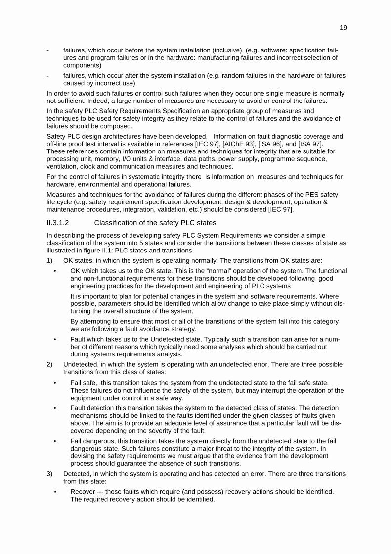
In describing the process of developing safety PLC System Requirements we consider a simpleclassification of the system into 5 states and consider the transitions between these classes of state asillustrated in figure II.1: PLC states and transitions
1) OK states, in which the system is operating normally. The transitions from OK states are:
• OK which takes us to the OK state. This is the “normal” operation of the system. The functionaland non-functional requirements for these transitions should be developed following goodengineering practices for the development and engineering of PLC systems
It is important to plan for potential changes in the system and software requirements. Wherepossible, parameters should be identified which allow change to take place simply without dis-turbing the overall structure of the system.
By attempting to ensure that most or all of the transitions of the system fall into this categorywe are following a fault avoidance strategy.
• Fault which takes us to the Undetected state. Typically such a transition can arise for a num-ber of different reasons which typically need some analyses which should be carried outduring systems requirements analysis.
2) Undetected, in which the system is operating with an undetected error. There are three possibletransitions from this class of states:
• Fail safe, this transition takes the system from the undetected state to the fail safe state.These failures do not influence the safety of the system, but may interrupt the operation of theequipment under control in a safe way.
• Fault detection this transition takes the system to the detected class of states. The detectionmechanisms should be linked to the faults identified under the given classes of faults givenabove. The aim is to provide an adequate level of assurance that a particular fault will be dis-covered depending on the severity of the fault.
• Fail dangerous, this transition takes the system directly from the undetected state to the faildangerous state. Such failures constitute a major threat to the integrity of the system. Indevising the safety requirements we must argue that the evidence from the developmentprocess should guarantee the absence of such transitions.
3) Detected, in which the system is operating and has detected an error. There are three transitionsfrom this state:
• Recover --- those faults which require (and possess) recovery actions should be identified.The required recovery action should be identified.
20
• Fail safe --- the requirement to safely move from some particular fault condition to a particularsafe state along some given trajectory should be captured
• Fail dangerous --- arguments demonstrating the impossibility of such a transition should beadded to the safety requirements analysis.
4) Fail Dangerous, in which the system has failed in a dangerous manner.
5) Fail Safe, in which the system has failed safely.
OK undetectedfail
dangerous
detected
fail
safe
recover
recover
fault
detect
recover
Figure II.1 PLC states and transitions
II.3.2 Software Design Specification
Critical to achieving correct normal operation is careful dialogue with the producer of the PLC system.Care should be taken to establish agreed, non-ambiguous nomenclature and to arrive at well-definedfunctional and non-functional requirements.
In constructing the software requirements one should consider the following classes of potential faultsand attempt to identify distinct faults that can arise and give them a characterisation of the faults.
• Failure of some integrity property of the state of the system. This may either be an inconsistencyarising from the internal variables of the intended software or on the input/output relation com-puted by the program.
• Failure to meet some progress or timing constraint. This will express a requirement that thesoftware delivers certain responsiveness.
• Failure to obtain the format/range etc. of data from some hardware interface.
• Failure of the system software, kernel failure.
• Failure of compiler/assembler/translator from the coding language to the executed code.
It is important to plan for potential changes in the system and software requirements. Where possibleparameters should be identified which allow changes to take place simply without disturbing the overallstructure of the system.

21
II.3.2.1 Structure and function of PLC software

22
Other Systems
Communicationfunctions
Signalprocessingfunctions
APPLICATIONPROGRAMExecution
Powersupplyfunction
Mainsupply
MAN-MACHINEINTERFACEfunctions
Programming,debugging andtesting functions
OPERATINGSYSTEMfunctions
APPLICATIONPROGRAMstorage functions
DATAstoragefunctions
INTERFACE functions tosensors and actuators
Machine / Process
Figure II.2 - Basic functional structure of a PLC system

23
The [IEC 92] standard identifies the following functions which can be found in typical ProgrammableControllers:
• Signal processing function --- consisting of the application program storage, the data storage,the operating system or kernel, the execution of the application program. It processes signalsobtained from sensors plus internal data storage to generate the signals to the actuators and thenew state of the internal data storage.
• Interface function to sensors and actuators --- this involves the conversion of discrete, digitaland analogue sensor data to the internal representation used by he programmable controller andvice versa for the actuators.
• Communication function --- this provides the support of interaction between the controller,sensor, actuator and the human operator.
• Human-machine interface function --- this provides the support of interaction between thecontroller and the human operator.
• Programming, debugging, testing and documentation function --- these provide forapplication program generation and loading, monitoring, testing and debugging as well as forapplication documentation and archiving.
• Power supply function --- provides the conversion and isolation of the PLC power supply fromthe mains.
All these functions may involve software in their provision. We have three different types of softwarehere: system software (kernel, sensor interface, man-machine interface), application software(supplying the specific part of the signal processing function), and the support or development software(programming, debugging, testing, etc.). In this guideline we concentrate on the application softwarebecause this is the variable part of the software in a PLC.
II.3.2.2 Characteristics of PLC software
Though there is wide variation in the form of PLCs, there are a number of common features whichinfluence their software development and, consequently, the evidence which can be used to argue forthe safety of an application.
• Application specific languages --- Most PLCs are intended for a particular application area, andas a result, they use a programming notation which is close to engineering notation from theproblem domain. The argument in favour of this approach is that the validation problem ofmoving from requirements to specification is reduced because familiar notation is used and that itmay be that the specification is close to a system level design since the application specificlanguage may be a design notation which is also used as a specification language. Examples ofthis is the schematic notation used in process control applications and the use of railwaysignalling notation in the programming of railway signalling interlocks.
• Limited variability --- In practice, many systems presume that the basic modules in any systemwill be drawn from some fixed set of pre-coded modules. Such limitation in the variability of adesign can be seen as eliminating the need for module design, code and test. In addition, it maybe that the range of possible configurations of the modules is limited to a few standard designs.Such an approach further reduces the complexity of system design.
• Kernels --- The kernel is the fixed software which is used by all applications on the PLC. Becausethe software is reused extensively, there is an economic justification for subjecting it to rigorousevaluation to ensure its safety. The design of such software can greatly influence the safety ofsystems; entire classes of potential software faults can be eliminated given suitably designedkernels. Also, if the kernel is large and ill-structured, it could pose insurmountable problems tothe use of such a system in a safety context. In terms of the standard model of softwaredevelopment, a small, well designed kernel can simplify system testing greatly.
24
• Size --- PLCs can vary widely in size. Small systems can be readily configured with a minimalsoftware engineering process. However, as size increases, the advantages of PLCs and thefactors that allow a much simplified process to be used become weaker. For example, thedevelopment of a very large system in an application-specific language will loose the advantagesof ready comprehension and verification, will have interfaces between subsystems and teamsand begin to exhibit the characteristics and problems of conventional software.
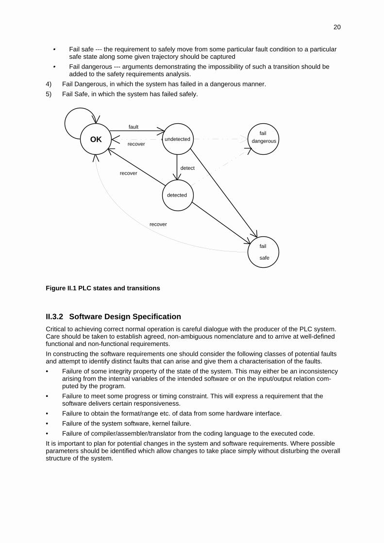
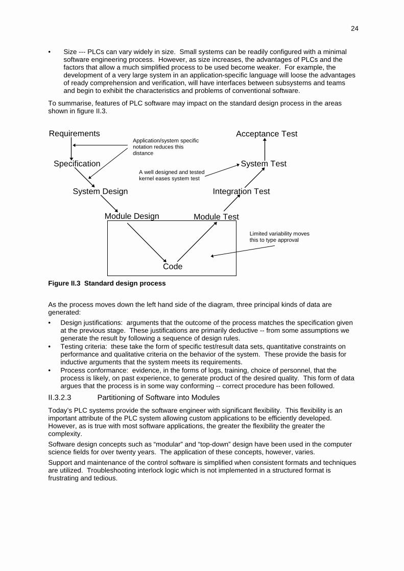
To summarise, features of PLC software may impact on the standard design process in the areasshown in figure II.3.
Requirements
Specification
System Design
Module Design Module Test
Code
Acceptance Test
System Test
Integration Test
Application/system specificnotation reduces thisdistance
A well designed and testedkernel eases system test
Limited variability movesthis to type approval
Figure II.3 Standard design process
As the process moves down the left hand side of the diagram, three principal kinds of data aregenerated:
• Design justifications: arguments that the outcome of the process matches the specification givenat the previous stage. These justifications are primarily deductive -- from some assumptions wegenerate the result by following a sequence of design rules.
• Testing criteria: these take the form of specific test/result data sets, quantitative constraints onperformance and qualitative criteria on the behavior of the system. These provide the basis forinductive arguments that the system meets its requirements.
• Process conformance: evidence, in the forms of logs, training, choice of personnel, that theprocess is likely, on past experience, to generate product of the desired quality. This form of dataargues that the process is in some way conforming -- correct procedure has been followed.
II.3.2.3 Partitioning of Software into Modules
Today’s PLC systems provide the software engineer with significant flexibility. This flexibility is animportant attribute of the PLC system allowing custom applications to be efficiently developed.However, as is true with most software applications, the greater the flexibility the greater thecomplexity.
Software design concepts such as “modular” and “top-down” design have been used in the computerscience fields for over twenty years. The application of these concepts, however, varies.
Support and maintenance of the control software is simplified when consistent formats and techniquesare utilized. Troubleshooting interlock logic which is not implemented in a structured format isfrustrating and tedious.
25
Developing a safety system which provides for ease of operation and maintenance requires that thecontrol engineers, software engineers, production supervisors, and maintenance supervisors agree on:
• Design of the operator interface including overview displays, and troubleshooting/maintenancedisplays.
• Format of the safety program documentation.
• Partitioning of safety program into simple modules which can be reused throughout the safetyPLC.
Agreement on a structured approach is imperative before any configuration of the software begins.This approach should provide the basis for a design specification document which defines the systemdevelopment scope.
Typically, 80% of the configuration process can be partitioned into modules that are reusablethroughout the PLC system. Examples include interlock logic, control valve tracking, timers, and flowtotalizers. Once a module is developed and tested using simulation techniques, it can be reused withlittle risk. It is important that these modules be well documented so that they are easily understood bythe person wishing to make use of the module. It is important to minimize the misapplication ofmodules.
The other 20% may represent custom logic which is unique for that area of the process. Throughconsistent formats, variable utilization, and effective documentation within the logic, custom logic canbe made easy to understand and maintain.
Through the use of a structured and modular architecture the software becomes easier to read,troubleshoot, modify and extend. Many “war stories” exist with systems that were configured withoutusing these techniques. The system may have been proven to function per the control specifications,but when it came time to troubleshoot a problem or to implement a modification, the task becamenightmarish. It quickly becomes obvious that a structured approach is vital in these flexible yetcomplex PLC systems.
II.3.2.4 Execution Rates
Control devices with multiloop capability typically allow variable scan rates in order to minimize CPUloading. This allows the user to select the frequency at which the control algorithm is executed. Therange of execution times normally runs from 0.1 to 60 seconds. While execution times of 0.2 to 0.3second are adequate for most loops, applications such as compressor surge control may requirescans less than 0.1 second. It is important for the user to recognize these applications and design forthese requirements.
II.3.2.5 Event-Logging / Data-Historian Requirements
The ability to go back in time and trace a series of events and operator actions is an important featurerequired in most process situations. The following list represents the type of events that shouldgenerally be logged.
• Alarms:
- Activated.
- Cleared
• Operator requested changes to:
- Set points
- Modes
- Outputs
• Operator messages:
- System asks for operator input
- Operator response
• Operator starts operation or sequence.
- operator status message for each step.
The user needs to understand where this logging function takes place and how the messages aregenerated in order to interpret the data generated correctly. The message logging may not, dependingon the system, provide messages in chronological order.

26
II.3.3 Hardware Design Specification
II.3.3.1 General
The hardware configuration of the safety PLC(s), is a direct result of the Safety RequirementSpecification, see chapter II.1.6. But, there are some configuration independent hardwareconsiderations and requirements. These are dealt with in the following chapter.
Please refer to the questionnaire in Appendix A-1 on page 65.
II.3.3.2 Keywords for hardware requirements
The following list of keywords should guide the user / customer to come to a complete specification.After analysis each feature mentioned must (at least) fall into one of the categories
- mandatory
- optional
- not required
- not applicable.
List of keywords:
- quality of the supplier
• quality support system ; according to accepted standards DIN/ISO 900x, EN 2900x, largecompany standards
• guaranteed supply of spare part
• documentation, guidelines
• training for users
- types of actuator/sensor signals
• load / driving capability of/for these signals
• binaryTTL, 24 V DC (most common), NAMUR, 110 VAC, 220 VACLoad 50 mA, 1 A, 2 A, 4 A
• relays (output only)Load, voltage, type
• analogvoltage -10..+10 V, 0..10 V, 0.. 24 Vcurrent 0..20 mA, 4..20 mAthermocouple, thermoresistorvarious mV
• HART
• sensor supply
• Ex(i)
• self testing facilities for I/O
- power supply
• 110 VAC, 230 VAC
• 24 VDC
• redundancy
• un-interruptible power supply (UPS)
• battery back-up
• buffering of supply within the units (most user standards expect uninterrupted operation for5 ms-0 V-drop-out of 24 V, NAMUR expects 20 ms, see also IEC 550)
27
- grounding, shielding
• shielded process cables necessary or not?
• electrical safety (VDE 0100, IEC 950, 536, 529)
• EMI / EMC
• filtering / robustness of signal inputs
• test voltages (e.g. 2,5 kV, 4 kV, 8 kV IEC 801)
- housing
• distributed units / centralised units
• wall-mounting / cabinets
robust cabinets (transport, earthquake, according to standards, e.g. 1,5 mm at 2...9Hz, 5 m/s2 at 9...200 Hz)
• cooling
no ventilators (often requested)if ventilators / air conditioners: redundancy / supervision
• floor plan
• cabling
- hardware redundancy
• aim : availability or / and safety
• redundancy of communication
system property
transparency to user / programmer
• redundancy of processing units
system propertytransparency to user / programmer
• redundancy of I/O units
system support
flexibility of redundancy structures (none, 1 out of 2, 2 out of 2,...)
• quality of redundancy
system property or user responsibility
transparency to user / programmer
fault detection
fault localisation
error latency
on-line repair
self testing facilities
fault isolation
error confinement

28
- environment
• temperature range (operation/transport, e.g. 5...40° C)
• humidity-range (operation/transport, e.g. 5...85%)
• temperature gradient (e.g. 10 K/h)
• air pressure (e.g. min 70 kPa)
• exposure to gas/dust
• use of filters
• exposure to radiation
• vibration
Adherence to the required ambient conditions such as humidity, temperature, vibration, dirt, EMI etc.has to be checked for all elements. Especially the characteristics and requirements for the elements inthe field have to be looked after.
The convenience and ergonomics of the installation place of data terminal devices and Human-machine-interface has to be checked, also the maintainability of all the equipment.
II.3.4 Security aspects
II.3.4.1 Data Access and Manipulation
In a safety PLC any change to any kind of software may result in a potentially hazardous condition.Therefore all software of a safety PLC should reside in a secure and controlled environment tomaintain system integrity.
Software to be considered is the:
• Application Program
• Application Modules
• Compiler
• Operating Software
• Utility Software
Besides the software, hardware platforms involved during operation and development are important.This includes:
• Development Systems
• Application System
• Data Network
• Data Storage
Data access and manipulation may be requested for the following reasons:
• Engineering activities (create, modify, delete etc.)
• Implementation (copy, transfer)
• Operation of the process
• Maintenance (repair, preventive)
This may require multiple levels of security which may result in a combination of hardware andsoftware design as well as security procedures.
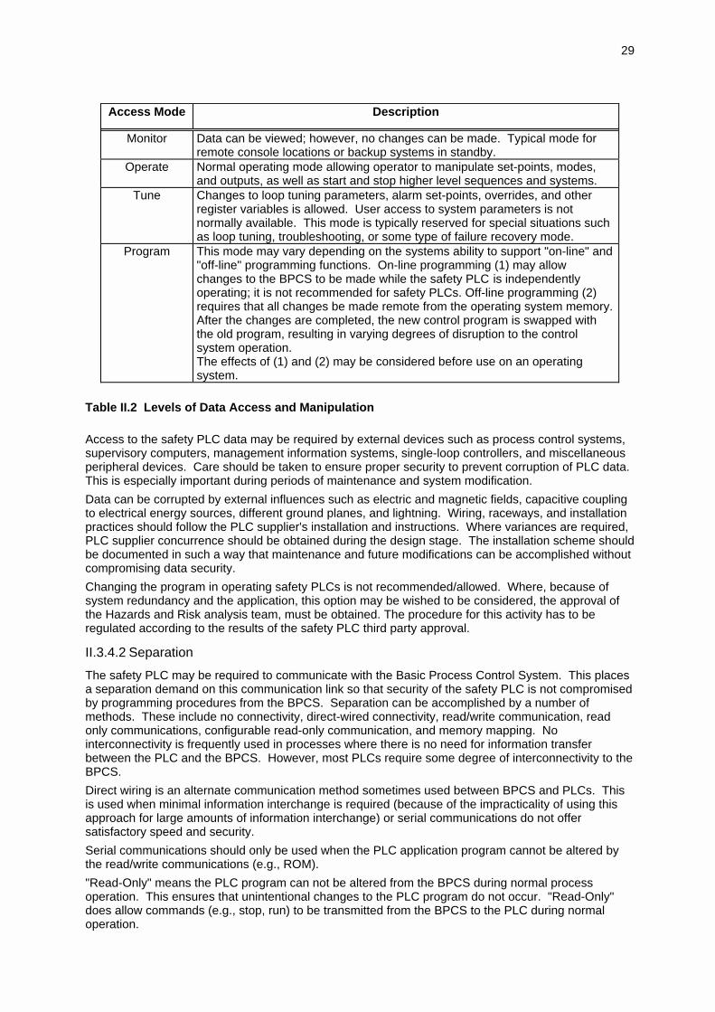
A classification method for the levels of data access and manipulation is shown in Table II.2. Theselevels are normally password or keylock protected.
29
Access Mode Description
Monitor Data can be viewed; however, no changes can be made. Typical mode forremote console locations or backup systems in standby.
Operate Normal operating mode allowing operator to manipulate set-points, modes,and outputs, as well as start and stop higher level sequences and systems.
Tune Changes to loop tuning parameters, alarm set-points, overrides, and otherregister variables is allowed. User access to system parameters is notnormally available. This mode is typically reserved for special situations suchas loop tuning, troubleshooting, or some type of failure recovery mode.
Program This mode may vary depending on the systems ability to support "on-line" and"off-line" programming functions. On-line programming (1) may allowchanges to the BPCS to be made while the safety PLC is independentlyoperating; it is not recommended for safety PLCs. Off-line programming (2)requires that all changes be made remote from the operating system memory.After the changes are completed, the new control program is swapped withthe old program, resulting in varying degrees of disruption to the controlsystem operation.The effects of (1) and (2) may be considered before use on an operatingsystem.
Table II.2 Levels of Data Access and Manipulation
Access to the safety PLC data may be required by external devices such as process control systems,supervisory computers, management information systems, single-loop controllers, and miscellaneousperipheral devices. Care should be taken to ensure proper security to prevent corruption of PLC data.This is especially important during periods of maintenance and system modification.
Data can be corrupted by external influences such as electric and magnetic fields, capacitive couplingto electrical energy sources, different ground planes, and lightning. Wiring, raceways, and installationpractices should follow the PLC supplier's installation and instructions. Where variances are required,PLC supplier concurrence should be obtained during the design stage. The installation scheme shouldbe documented in such a way that maintenance and future modifications can be accomplished withoutcompromising data security.
Changing the program in operating safety PLCs is not recommended/allowed. Where, because ofsystem redundancy and the application, this option may be wished to be considered, the approval ofthe Hazards and Risk analysis team, must be obtained. The procedure for this activity has to beregulated according to the results of the safety PLC third party approval.
II.3.4.2 Separation
The safety PLC may be required to communicate with the Basic Process Control System. This placesa separation demand on this communication link so that security of the safety PLC is not compromisedby programming procedures from the BPCS. Separation can be accomplished by a number ofmethods. These include no connectivity, direct-wired connectivity, read/write communication, readonly communications, configurable read-only communication, and memory mapping. Nointerconnectivity is frequently used in processes where there is no need for information transferbetween the PLC and the BPCS. However, most PLCs require some degree of interconnectivity to theBPCS.
Direct wiring is an alternate communication method sometimes used between BPCS and PLCs. Thisis used when minimal information interchange is required (because of the impracticality of using thisapproach for large amounts of information interchange) or serial communications do not offersatisfactory speed and security.
Serial communications should only be used when the PLC application program cannot be altered bythe read/write communications (e.g., ROM).
"Read-Only" means the PLC program can not be altered from the BPCS during normal processoperation. This ensures that unintentional changes to the PLC program do not occur. "Read-Only"does allow commands (e.g., stop, run) to be transmitted from the BPCS to the PLC during normaloperation.
30
A method that may be acceptable is called "Soft Read-Only". Here the BPCS and PLC offer softwaresecurity (e.g., passwords, keylocks) to protect against inadvertent changes to the safety PLC.Consider this method for low-integrity PLCs and for higher integrity PLCs where supplemented byhardware "write" protect feature. PHA team approval is required.
An infrequently used separation concept found in some packaged safety systems integrates the BPCSand safety PLC logic into a single PLC. The BPCS program is partitioned from the safety PLCprogram to guarantee the integrity of the safety program and to minimize the potential for inadvertentchanges to the PLC program while working on the BPCS program. This independence may be thirdparty certified.
Note: This does not provide the same degree of separation as the previous techniques, andmay not be acceptable for the highest integrity level systems (SIL 4).
II.3.5 Documentation
The following is in accordance with [IEC 97].
II.3.5.1 Objectives
The objective of the requirements of documentation is to define it so as to make it possible to performthe following functions of the product
- design and develop
- produce
- install
- commission
- operate
- maintain
- decommission
In this text the term ‘document’ is normally understood as information and not as physical documentsunless this is explicitly declared or understood in the context.
II.3.5.2 Requirements
- The documentation should
a) describe exhaustively the installation, system or equipment and the use of it;
b) be accurate and concise;
c) be easy to understand;
d) suit the purpose for which it is intended;
e) be easy to handle and maintain
- The documents or set of information should have unique identities so it will be possible toreference the different parts.
- The documents or set of information should have document kind designations indicating the typeof information.
- The documents or set of information should have titles/names indicating the scope of thecontent.
- The documents or set of information should have a revision index (version numbers) to make itpossible to identify different versions of the document.
- The documents or set of information should be structured in document list or physical binders tomake it possible to search for relevant information concerning an object or functions and theirrelations. It should be possible from at least one of the lists to identify the latest revision (version)of a document or set of information.
31
II.3.5.3 Execution
[IEC 97] part 5 Annex G provides a detailed description of the documents to be supplied under thefollowing sub headers:
• G.1 General
Results from most of the activities during the design and the development phases aredocuments, which are used as inputs for activities that follow.
Basic Document Kinds are: Specification, Description, Instruction, Plan, Diagram, List, Log,Report, Request
• G.2 Safety-Lifecycle document structure
It is used to explain the chronological relation between the different documents, when they areproduced (appendix A-3 of this document reflects this relation).
There may be documents giving detailed additional information or information structured for aspecific purpose like: Parts lists, Signal lists, Cable lists, Wiring tables and Loop diagrams.
• G.4 Delivery specific versus standard product documentation
• G.5 Documentation of computer system vs. application software
• G.6 Physical document structure
• G.7 List of documents
II.3.5.4 Additional Information in a Project Using Third Party Certified Safety PLC
Some of the additional information to consider in a chemical process project using a third partycertified Safety PLC are discussed here.
The information (e.g. Safety Planning, Safety Functional Requirements, Safety Integrity Requirements,security operating procedures, technical security policies, etc.) previously discussed for Safety PLCsare still required in projects using third party certification Safety PLCs. The difference occurs in thatself-certification is replaced by third party certification.
When this occurs, ensure appropriate information from the supplier and certifier of the Safety PLC isconsidered. It should include the regulation certification and its conditions of the hardware and systemsoftware. The application software needs separate information.
Important separate information may also include:
- Log, Dealings with the authorities
- Report, Hazard and Risk Analysis, All loops included in the PES
- Functional Safety Assessment Reports
- Test and Analysis Report, PLC Safety Validation (Factory Acceptance Test)
- Test and Analysis Report, Overall Safety System Validation (Site Acceptance Test)
- Instructions, Overall Safety System Operation
- Instructions, Overall Safety System Maintenance
- Modification Request, Overall Safety System
- Report, Overall System Modification/ Retrofit Impact Analysis
- Report, Overall System Maintenance
- Log, Overall System Modification / Retrofit

32
Part III Selection guide for a safety PLC system
III.1 General
The depth of the requirement specification will vary with the end-user technical culture and scope to bedelivered. The end-user will need to make a contract with a supplier or manufacturer, called "vendor"hereafter. Many activities can be contracted with a vendor, but the final responsibility stays with theend-user (see also Part VIII). Therefore a detailed, qualified quotation should be asked for.
III.2 Potential vendor selection
After specifying the requirements (see Part II) possible vendors can be investigated. Key features tolook for should be:
- availability of certification, check for application restrictions
- does the programming language meet your requirements, are there references for similar appli-cations
- are your hardware requirements met
- is the operator interface adequate
- does the supplier guarantee maintenance / spare part over the intended life time of the system(e.g. for 15 years after having stopped selling the system, as required for German power plantcontrol systems)
- is the system maintainability given during the whole life cycle, and is there a clear split inresponsibility
- can the system be easily integrated into the environment
III.3 Evaluation of quotations
After receiving the quotations a detailed check against the requirement specification is necessary. Allrequirements which were not specifically answered or met in the quotation have to be re-asked.
The following list is a collection of experiences and recommendations:
- qualification of the application software is rather difficult for an end-user if he does not have hisown experts. However at least the documentation of the top-layer should be understandable forany engineer.
- the cost of ownership should be taken in consideration and carefully calculated. Software changesand -maintenance have a very high impact.
- all people involved in the various life cycle phases (do not forget operators and maintenancepeople) should agree with the relevant product features.
- the operational quality and safety of the system is also influenced by the operator interface sincethis determines the subjective confidence level.
- the vendor must be able to perform the various training sessions with adequate training material.
- a good system documentation including as built is vital for a safe and reliable operation.
- spare part delivery, embedded software update service and software backup possibilities must bedefined.
- the end-user may ask the organisation which has issued a certificate for this PLC system for theiropinion on the product/services.
- the end-user should have only one contract for a PLC system. Any subcontractor of the vendorshould be known to the end-user.
33
III.4 Safety aspects of PLC languages
This chapter aims at compiling some criteria for evaluating and selecting programming languages forsafety-related PLCs. It is mainly based on previously published criteria for selecting general computerlanguages suitable for safety-critical systems.
III.4.1 Criteria for selecting programming languages
The following list of criteria should give some guidance to those who intend to evaluate aprogramming language for safety-related applications. The list has been compiled from varioussources ([CGW 91], Chapter 3 "A Guideline for the Development of Critical Software" in [Redm 88],Chapter 1 "Guidelines to Design Computer Systems for Safety" in [Redm 89]. Most criteria listed inthis section has been developed originally for the selection of general computer languages, while PLCsgenerally utilize limited variability application programming languages [IEC 97 Part 3]. However, muchof the criteria is general enough to serve as a checklist for limited variability application programminglanguages found in PLCs as well as serving as a guide in those applications where a general computerlanguage is being used. The list includes main criteria C1 to C9, auxiliary criteria supporting them, andcomments (in parentheses).
C1: The language is fully defined (syntax and semantics).
- Semantics should be well and completely specified and easy to understand.
- There should be a rigorous implementation of both integer and floating point arithmetic within thelanguage standard (as applicable).
- There should be procedures for checking that the operational program obeys the model ofarithmetic when running on the target processor (as applicable).
- At least, the semantics of the language should be defined sufficiently for the translation processneeded for static code analysis to be feasible.
- Language syntax should be completely and unambiguously defined.
- The language should be defined by an accepted standard.
C2: The use of a subset of a standard language or limited variability application programminglanguageis recommended.
- This allows portability. It is also possible in this way to limit the techniques and instructions used tothose which comply with the other criteria that can be analysed or proven correct, e.g. nointerrupts, no global variables, no computed jumps, and, on a small application, no indirect ad-dressing.
- A code of practice, designed to enforce a subset of the chosen language, is an essential elementwhen implementing safety-critical software.
C3: The control flow is totally determined and restricted with respect to software safety.
- It can be shown that the program cannot jump to an arbitrary store location (i.e. the control flow istotally determined)
- The language contains a sufficiently large set of control structures. (There is no need to 'emulate' acontrol construct).
- Computed branching should be avoided.
- Arithmetical IFs should be avoided.
C4: The data flow is restricted with respect to software safety.
- There are language features which prevent an arbitrary store location being overwritten.
- Variables and their types should be explicitly declared.
- The means of data typing are strong enough to prevent misuse of variables.
- The type, range and precision of each variable and expression should be fixed.
- Types are checked across the module boundaries.
- Global variables should be avoided.
C5: There are mechanisms to facilitate recovery.
- There are mechanisms to facilitate recovery e.g. from malfunctions detected by software atruntime. (e.g. global exception handlers)
34
- Such mechanisms may in themselves introduce hazards if used unwisely. Exception mechanismsand handler should be utilised for exceptions only and not misused for influencing the programcontrol flow.
C6: Language constructs help to guard against running out of memory.
- There are facilities in the language to guard against running out of memory at runtime (e.g. toprevent stack or heap overflow).
- Dynamic allocation of memory space can be a source of difficulty. it must not be used in safetycritical applications.
C7: Appropriate notations of the language help preventing faults.
- Syntactic notations should be uniform; only one notion should be allowed for any one concept.
- Ease of reading of produced code is more important than ease of writing during programming.
- (In addition to the language constructs, an appropriate coding style should be defined andapplied.)
Besides criteria applying to the language itself, some additional criteria about understanding the lan-guage, experience with the language and its development tools should also be considered.
C8: The language is sufficiently understood and enough experience is available.
- The designers and programmers will understand the programming language sufficiently to writesafety-critical software.
- Do not underrate the importance of experience in the use of a given language or the advantage ofa wide range of supporting tools. But, also, do not overrate it. It is unwise to stick to badenvironments only because one owns it.
C9: The development tools support software safety.
- Translator, linkage editor and loader should be thoroughly tested prior to use; operationalexperience is considered very important.
- More recent guidelines like [DEF 91] even require verification of supporting tools.
- The problem of the reliability of high-level language compilers is a serious issue, as revealed by aspecial tool [WiDa 89].
- A very powerful method is the back-engineering of the specification out of a low level (assembly)listing or memory dumps. This method detects errors of the implementers and of the tool chain.
- The language provides facilities for separate compilation of modules.
- Language, compiler and linkage editor should together provide for detection of as many program-ming errors as possible during compilation and on-line execution.
- The run-time system which is part of any compiled program should fulfil the same set of safety-re-lated requirements as the program itself.
- (For safety-related applications, some vendors offer restricted, pre-certified runtime systems, e.g.[Alsys 92].)
- There should be a support service for the development tools, including a formal fault- reporting andupdating procedure.
- (Safety systems often have long lifetimes (5 to 30 years) so that obsolescence or plannedreplacement is an important consideration.)
There is a need to list security requirements for languages and to consider both the hardware andsoftware design environment, and configuration control.
III.4.1.1 About the application of these criteria
Probably, there is no programming language which scores perfectly according to the above set of cri-teria. Published results for general computer programming languages demonstrate mixed results. Forexample, based on their set of criteria (a subset of the above criteria), the authors of [CGW 91] con-cluded: Structured assembly language may be acceptable in projects with limited risk. The use of C forsafety-critical software must be very strongly deprecated.
A subset of ISO Pascal (SPADE Pascal) is suitable for safety-critical applications. ADA semantics arenot completely defined; some ADA-subsets, like 'Safe ADA' and SPARK have been defined, which aremore appropriate for safety-critical applications [Wich 89], [Alsys 92].

35
For limited variability application programming languages [IEC 93] available in PLCs the above issuesonly come into focus when verifying a PLC application software for adequacy.
III.5 Questions to ask potential suppliers
In Appendix A-2 on page 68 you will find a detailed list of questions that have to be considered whennegotiating with potential suppliers.
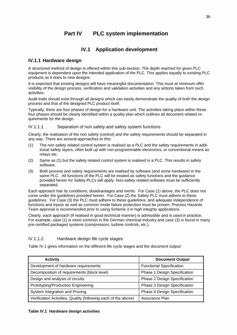
36
Part IV PLC system implementation
IV.1 Application development
IV.1.1 Hardware design
A structured method of design is offered within this sub-section. The depth reached for given PLCequipment is dependent upon the intended application of the PLC. This applies equally to existing PLCproducts as it does to new designs.
It is expected that existing designs will have meaningful documentation. This must at minimum offervisibility of the design process, verification and validation activities and any actions taken from suchactivities.
Audit trails should exist through all designs which can easily demonstrate the quality of both the designprocess and that of the designed PLC product itself.
Typically, there are four phases of design for a hardware unit. The activities taking place within thesefour phases should be clearly identified within a quality plan which outlines all document related re-quirements for the design.
IV.1.1.1 Separation of non safety and safety system functions
Clearly, the realisation of the non safety (control) and the safety requirements should be separated inany way. There are several approaches to this:
(1) The non safety related control system is realised as a PLC and the safety requirements in addi-tional safety layers, often built up with non-programmable electronics, or conventional means asrelays etc.
(2) Same as (1) but the safety related control system is realised in a PLC. This results in safetysoftware.
(3) Both process and safety requirements are realised by software (and some hardware) in thesame PLC. All functions of the PLC will be treated as safety functions and the guidanceprovided herein for Safety PLCs will apply. Non-safety related software must be sufficientlyseparated.
Each approach has its conditions, disadvantages and merits. For Case (1) above, the PLC does notcome under the guidelines provided herein. For Case (2) the Safety PLC must adhere to theseguidelines. For Case (3) the PLC must adhere to these guidelines, and adequate independence offunctions and inputs as well as common mode failure protection must be proven. Process HazardsTeam approval is recommended prior to using Scheme 3 in high integrity applications.
Clearly, each approach (if realised in good technical manner) is admissible and is used in practice.For example, case (1) is more common in the German chemical industry and case (3) is found in manypre-certified packaged systems (compressors, turbine controls, etc.).
IV.1.1.2 Hardware design life cycle stages
Table IV.1 gives information on the different life cycle stages and the document output:
Activity Document Output
Development of hardware requirements Functional Specification
Decomposition of requirements (block level) Phase 1 Design Specification
Design and analysis of circuits Phase 2 Design Specification
Prototyping/Production Engineering Phase 3 Design Specification
System Integration and Proving Phase 4 Design Specification
Verification Activities, Quality (following each of the above) Assurance Plan
Table IV.1 Hardware design activities
37
Suitable guidelines are provided within the following standards:
• dIEC 1508 Part 2 [IEC 97]
• MIL-HDBK 338 Volume 1 [MIL 84] Electronic Reliability Design Handbook, US DoD October1984
• DIN V VDE 0801 [DIN 93] Principles for Computers in Safety - Related Systems
Each of the four phases of design is described as follows:
• Phase 1This is the preliminary design stage, where the key blocks or elements within a hardware itemare defined:
- Generation of block diagram
- Translation of sub-system requirements and interface criteria
- Detailed parameter definition
• Phase 2This is essentially the most detailed stage which will comprise the generation of circuit diagrams,design analysis, detailed calculations and test philosophies /procedures.
• Phase 3This is the prototype stage of the development. Prototypes are tested and aged prior to con-tinuation of the development. Any prototype software that may be required is used at this stagefor testing.
• Phase 4This is the stage at which the hardware documentation is collated, showing test results and finalproduction information - prior to system integration.
IV.1.1.3 Reviews
Reviews follow each phase of the design. These cover Verification and Validation activities and shouldinvolve the user.
The product reviews objectives at all design phases are to verify the following:
• Consistency between requirements and the specification at each level
• Performance Criteria
• Completeness of Design (level)
• Numerical Factors
• Safety and Reliability
• Correctness of Design
• Traceability to previous levels/specifications
• Testability
• Maintainability
• Useability of product/documentation
• Software / Hardware Co-ordination
• Design for manufacture
IV.1.2 Software design
It is assumed that a "Software Design Specification" is available as a result of previous activities.
IV.1.2.1 Software design life cycle stages
Software design and development should be split into four phases with information as shown below:

38
Activity Information output
Software Design Software Design SpecificationSoftware Design Test Specification
Software Module Design Software Module Design Specification SoftwareModule Test Specification
Coding Source Code and supporting documentation
Software Testing Software Module Test ReportSoftware Design Test ReportSoftware Requirements Test Report
Table IV.2 Software design activities
Within each of the above phases, there are two additional information requirements recording theverification activities: Software Verification Planning and Software Verification Report (see IV.1.4Verification of Module Design and Programming Phase).
Validation is dealt with in Chapter IV.2 and in part V.
IV.1.2.2 Software module design
IV.1.2.2.1 Objectives
The objective is to create PLC software of a defined integrity level from the software design specifi-cation. The module design will enable the implementation of software, which not only achieves therequired integrity level, but which is also analysable, verifiable and maintainable.
IV.1.2.2.2 Requirements
The Software Design Specification should be available prior to the start of the module design process.If the Software Design Specification contains either safety-related functions and non-safety-relatedfunctions or safety-related functions of different integrity level, then the Software Module DesignSpecification should indicate how independence between these functions is achieved.
The software produced should be minimum in size and complexity.
In accordance with the required integrity level the module design method chosen should possessfeatures that facilitate
i) Abstraction, modularity and other features which control complexity;
ii) The clear and precise expression of:
- Functionality;
- Information flow between components;
- Sequencing and time related information;
- Concurrence; and
- Data structures and properties
iii) Human comprehension; and
iv) Verification and validation
The module design method chosen should possess features that facilitate software maintenance. Suchfeatures include modularity, information hiding and encapsulation.
The module design should include self-monitoring of control flow and data movements. On failuredetection appropriate actions should be taken.
If standard or previously developed software is to be used as part of the design then it should beclearly identified and documented. A separate report justifying the software's suitability in satisfying theSoftware Design Specification should be produced. Suitability should be based upon evidence ofsatisfactory operation in a similar application or having been subject to the same verification and

39
validation procedure from the coding phase on, as would be expected for any newly developedsoftware.
Wherever possible existing verified software modules (or function blocks) should be used in thedesign.
Each software module should be readable, understandable and testable.
Examples for representations of module design are function plan, decision table, state graph and thoseused in structured design.
IV.1.3 Programming
IV.1.3.1 Implementing PLC application programs
Many PLC application programs are implemented or programmed in one of two different ways. Thefirst one, more applicable to smaller software application programs, is by writing a new programcompletely. The second is by configuring a set of predefined functional blocks, provided e.g. by thePLC vendor. Configuring means to select the appropriate blocks, to set the interconnections betweenthem and to set the parameters within the blocks. For the selection of suitable PLC programminglanguages, the standard IEC 1131-3 offers some guidance by defining a set of five languages:Instruction List (IL), Structured Text (ST), Ladder Diagram (LD), Function Block Diagram (FBD) andSequential Function Chart (SFC). Languages like IL, LD and FBD are in common use; ST is a high-level language similar to other general programming languages like C, Pascal and ADA. IL and ST areexamples of textual languages, whereas LD, FBD and SFC are graphical 'languages'.
What also influences the programming style and language, is the size and complexity of the appli-cation program. Small scale applications typically are programmed by the user; large scaleapplications (e.g. in control) should be configured from standard function blocks as completely aspossible. Only those functions for which no standard block is available, should be programmed. Thisminimises coding errors.
IV.1.3.2 Objectives
The objective is to implement software, which achieves the required integrity level, and which is alsoanalysable, verifiable and maintainable. A sub-objective is to select a suitable set of coding tools, forthe required integrity level, over the whole life cycle of the software which assists verification, valida-tion, assessment and maintenance.
IV.1.3.3 Requirements
A suitable set of tools, including languages, (graphical) editors, compilers and configuration tools,should be selected for the required integrity level over the whole life cycle of the software. Whenapplicable automatic testing tools and integrated development tools should be used.
The tools used for programming (e.g. compiler, configuration tools) either have a "Certificate ofValidation" to a recognised national / international standard or an assessment report which details itsfitness for purpose. The same applies for programming equipment wherever it is applied.
The PLC programming language selected should be completely and unambiguously defined orrestricted to unambiguously defined features. When this requirement cannot be satisfied a justificationfor any alternative language detailing its fitness for purpose should be recorded in the Software DesignSpecification.
The language(s) chosen should meet the following requirements:
i) A programming language should be selected that relates to the characteristics of the application.
ii) The language chosen should contain features that facilitate the identification of programmingerrors.
iii) The language chosen should support features that match the design method.
A more detailed list of criteria for evaluating PLC languages is included in Chapter III.4.
Programming standards should be developed and used for the development of all software and shouldbe reviewed by the assessor. The coding standard should specify good programming practice,proscribe unsafe language features and describe procedures for source code documentation. As aminimum the following information should be contained in the source code documentation: author,description; inputs and outputs; and configuration history.

40
IV.1.4 Verification of Module Design and Programming Phase
IV.1.4.1 Objective
The objective of this clause is to the extent required by the integrity level, to test and evaluate theproducts of a given phase to assure correctness and consistency with respect to the products andstandards provided as inputs to these phases.
IV.1.4.2 General requirements for software verification
Software Verification Planning should be established, concurrently with the development, for eachphase of the software life cycle and detailed in suitable and appropriate documentation.
Software Verification Planning should address all criteria, techniques and tools to be utilised in theverification process for that phase.
Software Verification Planning should describe the activities to be performed to ensure correctnessand consistency with respect to the products and standards provided as input to that phase.
Software Verification Planning should address the following:
i) The selection of verification strategies and techniques;
ii) The selection and utilisation of the software test equipment;
iii) The selection and recording of verification activities;
iv) The evaluation of verification results gained from verification equipment directly and from tests;and
v) The evaluation of the reliability requirements.
In each development phase it should be shown that the functional, reliability, performance and safetyrequirements are met.
Verification shall be carried out by an independent party to the extent required by the integrity level.Function blocks made available by the PLC vendor, have been verified in advance on behalf of thevendor.
The results of each verification should be retained in a form that is auditable.
After each verification activity produce Software Verification results stating either that the softwarehas passed the verification or the reasons for the failures. The Software Verification results shouldaddress the following:
vi) Items which do not conform to the Software Requirements Specification, Software DesignSpecification or Software Module Specifications;
vii) Items which do not conform to the design standards;
viii) Items which do not conform to the Quality Assurance Procedures; and
ix) Modules, data, structures and algorithms poorly adapted to the problem.
IV.1.4.3 Special requirements for verification in the software module design
After the Software Module Specification has been established and before the coding begins, verifi-cation should address the:
i) Adequacy of the Software Module Specification in fulfilling the Software Design Specification;
ii) Adequacy of the Software Module Test Specification in fulfilling the Software Design Specifi-cation;
iii) The decomposition of the Software Design Specification into software modules and the SoftwareModule Specifications with reference to:
- Feasibility of the performance required;
- Testability for further verification;
- Readability by the development and verification team; and
- Maintainability to permit further evolution;
and should check for incompatibilities between:
iv) The Software Module Specification and the Software Design Specification;
v) The Software Module Specification and the Software Module Test Specification.
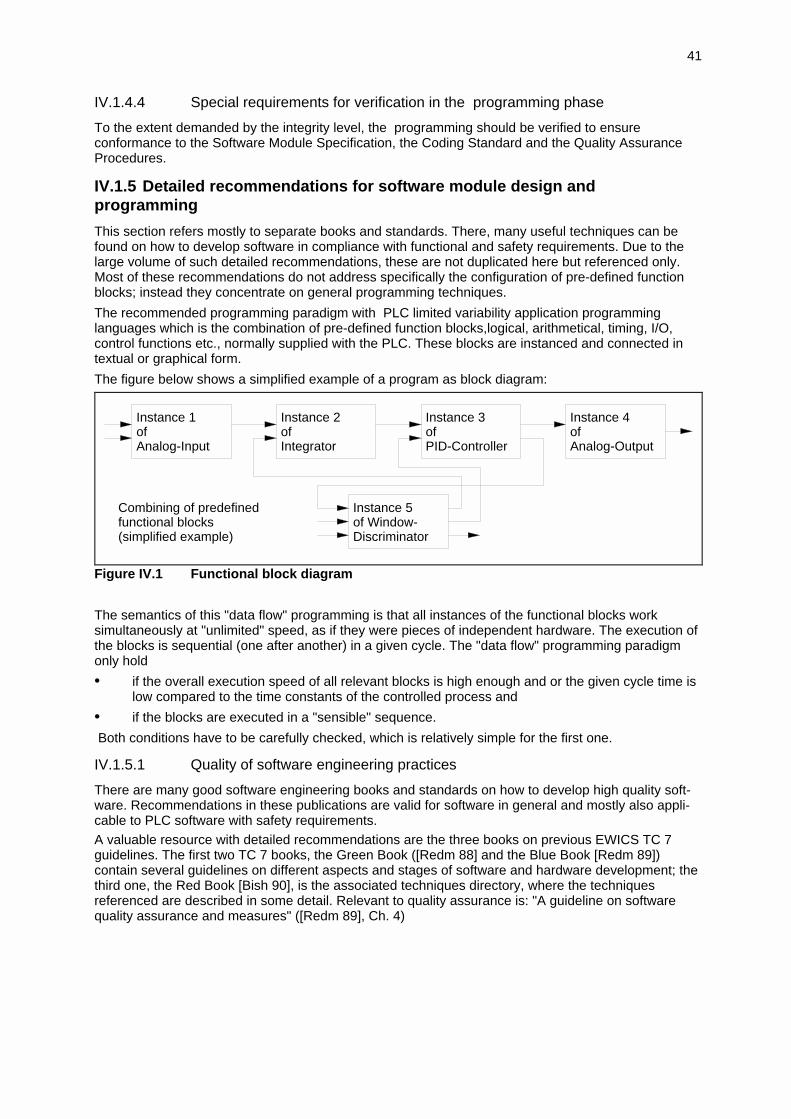
41
IV.1.4.4 Special requirements for verification in the programming phase
To the extent demanded by the integrity level, the programming should be verified to ensureconformance to the Software Module Specification, the Coding Standard and the Quality AssuranceProcedures.
IV.1.5 Detailed recommendations for software module design andprogramming
This section refers mostly to separate books and standards. There, many useful techniques can befound on how to develop software in compliance with functional and safety requirements. Due to thelarge volume of such detailed recommendations, these are not duplicated here but referenced only.Most of these recommendations do not address specifically the configuration of pre-defined functionblocks; instead they concentrate on general programming techniques.
The recommended programming paradigm with PLC limited variability application programminglanguages which is the combination of pre-defined function blocks,logical, arithmetical, timing, I/O,control functions etc., normally supplied with the PLC. These blocks are instanced and connected intextual or graphical form.
The figure below shows a simplified example of a program as block diagram:
Instance 1ofAnalog-Input
Instance 2ofIntegrator
Instance 3ofPID-Controller
Instance 4ofAnalog-Output
Instance 5of Window-Discriminator
Combining of predefinedfunctional blocks(simplified example)
Figure IV.1 Functional block diagram
The semantics of this "data flow" programming is that all instances of the functional blocks worksimultaneously at "unlimited" speed, as if they were pieces of independent hardware. The execution ofthe blocks is sequential (one after another) in a given cycle. The "data flow" programming paradigmonly hold
• if the overall execution speed of all relevant blocks is high enough and or the given cycle time islow compared to the time constants of the controlled process and
• if the blocks are executed in a "sensible" sequence.
Both conditions have to be carefully checked, which is relatively simple for the first one.
IV.1.5.1 Quality of software engineering practices
There are many good software engineering books and standards on how to develop high quality soft-ware. Recommendations in these publications are valid for software in general and mostly also appli-cable to PLC software with safety requirements.A valuable resource with detailed recommendations are the three books on previous EWICS TC 7guidelines. The first two TC 7 books, the Green Book ([Redm 88] and the Blue Book [Redm 89])contain several guidelines on different aspects and stages of software and hardware development; thethird one, the Red Book [Bish 90], is the associated techniques directory, where the techniquesreferenced are described in some detail. Relevant to quality assurance is: "A guideline on softwarequality assurance and measures" ([Redm 89], Ch. 4)
42
IV.1.5.2 Techniques for compliance with safety related requirements
In its relevant clause tables, detailed tables and its bibliography of techniques, the dIEC 1508 givesgeneric guidance on how to select the appropriate techniques and measures to achieve compliancewith the proposed standard.
IEC 97, Part 3 provides guidance on software requirements for each SIL, including general techniqueson good programming practices.
In the HSE guideline volume 2 "General technical guidelines" [HSE 87], it contains a set of checklists,where the purpose is "to provide a stimulus to critical appraisal of all aspects of the system rather thanto lay down specific requirements". Four checklists are related to this part of the PLC guideline:
Checklist No. 11: Software designChecklist No. 12: Software codingChecklist No. 14: Embedded softwareChecklist No. 15: Application programming
Section A of these checklists describes general aspects, Section B covers common cause failures inredundancy configurations and applies to redundant safety-related systems using diverse software.
In [Redm 88] there are two additional guidelines relevant to software module design and coding undersafety requirements:Chapter 1 is a guideline for the documentation of critical computer systemsChapter 3 is a guideline for the development of critical software.
Also the [DEF 91] gives some detailed recommendations in its Part 2, Clause 30 "Design" and Clause31 "Coding".
As there are many more standards and proposed standards relevant to this PLC Guideline, it is im-possible to refer the reader to every relevant standard. Instead, the reader is referred to some surveysof these standards ([Bloo 92], [Rata 93], [Wall 92]).
IV.1.5.3 Use of existing software
Application software for PLCs normally uses libraries of pre-defined modules / blocks. Use of existingproven software is encouraged, but nevertheless it is important that the existing software fulfils thesame functional and safety requirements as the newly written software. This is usually the case withthe standard function blocks available for certified PLCs.
IV.2 Safety PLC system integration and validation
IV.2.1 Integration of PLC hardware and software
This activity would appear to correspond to the System Testing Phase in [IEC 97] document.
Objective
The objective of this activity is to integrate the verified application software with the target PLChardware and to demonstrate that all the PLC System Requirements have been met.
Inputs
i) PLC System Requirements Specification derived in accordance with the guidelines of Part II,Section 3. This document includes functional and safety requirements.
ii) Plant Level Validation Plan produced in accordance with the guidelines of Part II, Section 1.6
iii) PLC Hardware Subsystem selected in accordance with the guidelines of Part III
iv) Verified PLC application software, developed in accordance with the guidelines of Part IV,Section 1: Application Development.
Activities
The integration procedure should proceed in accordance with System Integration Planning. Thisplanning will contain information on the sequence and nature of the verification and validation activitieswhich will take place when application software and target hardware are brought together. The SystemIntegration Planning may also contain the criteria for completion of the integration procedure.

43
Verification activities should focus on demonstrating that the integrated hardware and software systemsatisfies the functional and safety requirements in the Requirements Specification produced inaccordance with the guidelines in Part II, Section 2: PES Requirements.
Verification techniques may include testing on test beds with I/O simulation equipment, and ideally willallow the eventual operators of the system to test the software with simulated I/O.
Statistical testing may also be performed with simulated I/O if "typical" operational data is available.
It may be possible to verify the behaviour of the integrated hardware and software system throughsoftware modelling of an integrated set of system components.
As part of the integration activities evidence needs to be collected that system functional and safetyrequirements will be maintained during operation. To achieve this the following should be investigated:
i) the effects of failure of individual software and hardware modules on the maintenance of systemrequirements
ii) in multi-PLC systems, the effects of a single PLC failure on other PLCs and the effects of inter-PLC communication failures
iii) the implementation aspects of the PLCs being used and their configurations e.g. scan times,power-on & power-off behaviour
iv) PLC and system performance under load
v) safety aspects of software and hardware system architecture and their behaviour in the event ofoperation e.g. fault tolerance through redundancy, exception handlers, recovery blocks etc.
To achieve a demonstration of higher safety integrity levels the following techniques are available:
a) functional testing outside the specification to check for unintended events e.g. sabotage,operator errors etc.
b) functional testing based on partitioning of input data specifications, using boundary valueanalysis
c) dynamic coverage of system states provided by function test data through the use of statetransition diagram models
d) statistical testing for robustness involving continuous operation test but with an additionalsignificant amount of unexpected input conditions e.g. regular bad data as expected from faultyinput device
e) working back from hazardous system states to determine dangerous input data sets with whichto perform further functional testing.
Outputs
The information from the integration activities should form part of PLC System Integration Report. Thisreport should summarise the conclusions drawn from the results of the integration activities as to thedegree to which the integrated PLC system meets its function and safety requirements.
IV.2.2 Safety validation against PLC requirements
This section deals with the testing of the safety functions implemented by a PLC-based safety systemafter the integration and installation of the system.
Objectives are gaining of
• confidence in the availability of the safety functions under all specified conditions (assessor)
• experience with the implemented safety functions and procedures (vendor, operators)
Inputs to the activities are
• Specification of the safety functions
• Outcome of prior off-line-tests and type approvals
• Checkout procedure for the correctness of the installation
• Start-up and shut down procedures
• Run in procedures (if appropriate for controlled process)

44
• Manually executed complementary safety shut down procedure (if appropriate for controlledprocess)
Activities are
• Testing of the correctness of the installation
• Running in the controlled process (if applicable)
• Testing of all automatic safety related functions during run-in
• Start up of the controlled process
• Testing the safety functions with manual safety functions and with simulated dangerous conditions
• Shut down of the controlled process
Except for the first one all or some of these steps will have to be re-iterated according to the test plan.
Some processes require a run-in phase before final operation. This phase is distinguished form normaloperation by:
- use of non dangerous material in chemical plants (e.g. water instead of gasoline)- running a boiler at very low load (only one burner at lowest possible load) and blowing off thegenerated steam- running at lowest speed and / or with no persons or dangerous material on board (transportsystems)
The character of such run-in phases differs widely from process to process (and there are processeswhere no sensible run-in phase can be defined for). The run-in procedures and the tests to be carriedout in this phase may be clearly defined. The main goal will be the testing of the plant - installation,pipes, vessels etc. - and of the basic process control functions - sensors, actors, man-machineinterface, operating procedures - as well as the gaining of first experiences of the operators. This timeis the biggest opportunity to test all safety functions in the integrated environment and monitor theprocess response.
The testing of some safety functions requires the process to be in a dangerous state. The test maydemonstrate that the safety system would bring the process into a non-dangerous state by theappropriate action (e.g. shut down). Of course, in test steps like these, any "real danger" has to beavoided. This can often be done by taking these test steps in the run-in phase or by havingcomplementary (manual) shut down facilities available.
An alternative way is to simulate a dangerous state of the process at the sensor level in order to testsome of the safety functions.
The testing of the safety functions has to be planned and carried out very carefully.At one hand the testing has to be complete in a specified sense (cover all functions) - at the other handthe on-line-testing of safety functions can be expensive and potentially dangerous. The reports ofprevious off-line-tests and the type-approval of the safety PLC should be considered, as to notunnecessarily repeat test steps.
An important key to a later safe operation of the process is the involvement of plant operations andmaintenance personnel during the on-line-testing phase to assure a clear understanding of all aspectsof the process, the control system, and the Safety related System (PLC).
Outputs of the activities are
• Information of used tools and calibration data
• Information of the activities and of the conclusions
• Final Test information for the safety PLC.
• Skilled operators well acquainted with the system
• Well trained maintenance people
IV.2.3 Development of procedures
Operating procedures to safely operate and maintain the system may be written during design,development and implementation phases. For detailed requirements see Chapter VII, Commissioningand Use.
45
Part V Plant level integration and validation
V.1 Installation
The objective of this phase is to install the total safety-related PLC system. Installation should proceedaccording to Installation Planning.
The elements of the safety-related PLC system include:
- hardware cabinets
- monitors
- data busses (also to non-safety-related systems)
- configuring / programming devices (also for the non safety-related systems communicated to)
- printers
- sensors & transmitters
- actuators
- cabling
- uninterruptible power supplies
- power feed and fuses
- manual bypassing and resetting devices
- manual shutdown system
- testing possibilities, e.g. shut-off valves and their alarms
- system software
- application software
- documentation
- spares, back-up software.
The installation planning should identify:
- the phases of installation, i.e. the sequence in which the various elements are integrated;
- the criteria for declaring the safety-related PLC system, or parts thereof, ready for installation andfor declaring installation phases complete;
- resolution of failures and incompatibilities;
- the kinds of checks (where, by whom, type etc.) to ensure the elements are ready for installation;
- the kinds of checks (e.g. pre-testing all loops, communications, data presentation, motorrotation, etc.) required to approve the installation phase complete prior to validation, assessmentand commissioning.
Security measures should guarantee that code has not been modified.
Noticed failures or incompatibilities are to be reported. They could include:
- not reliable enough power supply;
- partitioning of connections to the safety-related process or I/O-cards could be better;
- not sound data transfer.
V.2 System Test
System test includes factory acceptance test (FAT) and field test. Evidence for sufficient coverage maybe given, e.g. by statistical techniques.
System test is a major step in determining reliability behaviour of PLCs. Depending on the quality ofthe development process the coverage of the test may be high or low. High reliability PLCs requirealmost complete coverage of the test of the safety related functions in the PLC.

46
PLCs where extensive validation procedures have been performed need less stringent field tests. Ofcourse, properties which are asserted by third party certification as intrinsic system functions(coverage of built in self tests) need not be re-tested for every individual installation.
As always, a good allocation of the given resources is the key to suitable reliability given a particularapplication: it may be wiser to invest in a "good" approved system base and having less effort (an re-development) in the field tests.
V.3 Safety validation against global requirements
V.3.1 Objectives
The objective of this life cycle phase is to test the integrated system to ensure compliance with theRequirements Specification at the intended safety level.
Testing should be the main validation activity, simulation and modelling may be used to supplementthe validation process.
For the overall safety validation the following tests should be performed at system level:
- function tests
• all sequences
• all functions
• all inputs
• all outputs
- time behaviour tests
• all operating conditions
• all timing requirements
- interface tests all interfaces
• all operational modes
V.3.2 Validation
The results of the validation should be in an auditable form, stating either that the PLC has passed thevalidation or the detailed reasons for its failure.
The Validation should identify all
- hardware and software used,
- the equipment used,
- equipment calibration,
- simulation models used,
- discrepancies found.
Information characteristics
'Test' is used here in its wider sense, e.g. as encompassing all kinds of verification and validation.
All information related to the assurance work on safety of PLCs for critical applications should includethe following characteristics and aspects.
The main points should correspond to the main steps of the testing work. They should contain thefollowing pattern:
- presentation of the test objective and test tools
- synopsis of safety principles of the test object
- detailed description of the tests
- summary of the work including final judgement
The presentation part should include an overview of the test object based on the requirementsspecification and functional analyses. The following information should be included:

47
a) presentation of the test object
- purpose, application, function
- general data and specification
- safety concept of the whole system (hardware and software)
- explanation of the structure and function of the hardware
- explanation of the structure and function of the software
b) presentation of the test tools
- applied test methods
- applied test equipment
The synopsis of the safety principles of the test object is resulting from functional analyses and couldbe presented in form of a table for better readability. Based on this safety principle synopsis thefulfilling of specification requirements by the test object can be assessed.
In the description part, the test carried out should be listed and their results should be described insufficient depth to ensure complete understanding. Tests that are available include:
for hardware:
a) functional analyses
b) detailed failure analyses (FMEA, FTA, Error Sequence Analysis, quantification etc.)
for software:
c) functional analyses (black-box, white-box, etc.)
d) detailed failure analyses (investigations regarding structure and dependence / independence
of software modules)
The description part consists of all measurement configuration, tables and diagrams (e.g. fault trees,FMEA-tables, structograms, flow-charts, listing reviews, specific test results, wiring diagrams ifnecessary etc.) made in course of the whole testing work.
The summary of the work should give a short description of the whole test work. It should include:
e) functional safety principles of the test object
f) tests carried out
g) test conditions
h) applied test methods
i) final judgement in relation to the requirements.
48
Part VI Certification / Assessment
VI.1 Review of development
It is important that the user monitors the development to ensure that it is happening as defined in thecontract. This activity should be scheduled to fit into the defined development phases. Thedevelopment should have 'hold points' beyond which development should not proceed until the user issatisfied that the safety requirements as defined in the specification are being implemented correctly.
The types of checks will include:
- compliance with standards and guidelines specified in the contract
- system configuration
- V&V activities
- testing
- production of development documentation, as specified in the contract
- evidence of compliance with development procedures (i.e. signatures on procedures as they arecompleted)
- evidence of internal reviews
- inspection of the safety log (safety problems encountered, and how they are resolved)
- evidence of the software repair and re-test procedures
The purpose of the above activities is to ensure that safety is being implemented into the product asthe development proceeds, so that if safety problems occur, they can be resolved as soon as theymanifest themselves. If the above activities are not carried out, the problems might only be manifestedduring the FAT when it might be too late to resolve them satisfactorily, due to time scale pressures.
VI.2 Assessment of the safety PLC
VI.2.1 General
The assessment should:
- address expected behaviour in the case of (component) failure, fire and other abnormal events
- explicitly address accepted failure modes
- cover acceptance criteria (quantitative and qualitative)
- review relation between safety layers and process: ESD, control system, procedures, mitigationsystems
- cover how the supplier should verify the correctness of the safety PLCs; formal methods,qualitative / quantitative methods, FAT
- make acceptance criteria explicit
- verify integrity levels according to the required standards, e.g. IEC, DIN
- address maintainability: practical issues as ease, availability of spare parts, training of personnel,required personnel education level, maximum down time.
If necessary the assessment should cover any given evidence or calculations for:
- Probability of Failure on Demand (PFD) and/or
- mean time to failure.
With the application dependent approval it should be demonstrated that the hardware as well as thesoftware system meet the requirements for a specific application. The approval normally concentrateson the application software and the integration of the whole system.The procedure is divided into the analytical approval and on-site approval.
49
VI.2.2 Analytical approval
During this phase a lot of questions concerning the system and its behavior in the presence of failureshave to be verified. The following list is an extract of all these questions:
- Is a safety philosophy described for all safety functions ?- Can each individual safety function be specified (e.g., logic diagram, flow diagram, state diagram
etc.)?- Which PLC system is the best one to meet the requirements ?- Does the safety function include redundancy and / or diversity ?- Is the safety system safe ?- Does there exist a prescription of a safety philosophy or failure calculation in the application
dependent standards ?- What are the timing constraints for individual safety functions ?- Is the application software separable into safety related and non-safety related parts ?- Where in the application are non-fail-safe actuator operations considered ?- Which control signals are static, which ones are dynamic ?- What kind of strategies are applied to find passive failures ?- Is the link / communication between BPCS and safety PLC secure ?
The following concrete steps are conducted during the analytical approval:
- inspection of the documentation with respect to completeness, validity and consistency- verification of logic diagrams- verification of the application software * The application software is verified with respect to the specifications and the logic diagrams which have to be pre-verified by the process engineer. * extraction of all safety critical parts (modules, subroutines) of the software * control flow and data flow analysis * verification of all specified functions * if possible simulation of all functions and time behavior under normal and erroneous conditions on a simulator (recommended, but not prescribed)- verification of hardware design and installation documents.
VI.2.3 On-site approval
The first step in this phase is to control the physical installation of the PLC hardware and theapplication software on the target system. It is being validated whether both the hardware system aswell as the application software are in accordance with the pre-validated information.With respect to the hardware the following tests are conducted:
- test of the installation of the PLC system with respect to the aspects * field wiring, e.g. separate installation of redundant wiring * protective and functional earthing * noise and transient suppression measures: # separation of cables for inputs, outputs and power circuits # correct length of wiring # separation of the field wiring from internal I/O cabling and from bus lines # control of mechanical contacts which are in series with inductive loads
- test of compliance with the actual service and environmental conditions, e.g. temperature, shock and vibration, electromagnetic influence etc.
- loop checks (interaction between PLC and process periphery) * binary inputs checking binary and digital input signals to ensure that physical states of sensors comply with signal latches (memory elements) in the PLC * analog inputs checking analog input signals to ensure equivalence of physical value and data received by the PLC

50
* binary outputs ability to switch; checking that no forced binary and digital outputs are set * analog outputs * supervised inputs and outputs: detection of opens and shorts
The second step is to test all system functions. During these tests the functional behavior of thesystem with respect to the specified functions is validated. All functions are being tested underoperational conditions.
In a third step fault simulations are conducted based on a pre-defined list of failures. Generally themajority of failures can be located in I/O and otherperiphery. Therefore failures are simulated with respect to * sensors, contacts and actuators * inputs and outputs * field wiring, e.g. exchanged connections * interlocks
During failure simulations it may be validated that the system - in the case of failures - is being broughtinto a safe state. The kind of this state is depending on the application. It can be a de-energized stateof all outputs or the shutdown of certain parts of the application.
In the final step it is being assessed whether all restrictions fixed in the type approval report (if acertified PLC is used) are fulfilled.

51
Part VII Commissioning and Use
VII.1 Operation and Maintenance
The objective is to properly operate and maintain the safety PLC.Implementation of a safety PLC should include the initiation of a number of actions:- implement procedures;- follow maintenance schedules;- maintain records;- carry out of functional safety audits periodically;- implement the Safety Management System.
The performance of the safety PLC should be compared on a regular basis with the designcharacteristics (e.g. failure and demand rates.)Any deviation from the original assumptions should be assessed for their effect on the functionalsafety. Modification procedures should be initiated if the deviations increase the risk.
This section contains:- Operating Procedures- Maintenance Facility Planning- Testing Frequency Requirements- Plant Operations Training
VII.1.1 Operating Procedures
The development of all procedures related to safety PLC should involve participation of management,engineering, maintenance, operations, safety, and other groups as appropriate.
Also all operating procedures should be reviewed with operations personnel periodically.This will allow to introduce any practical changes that are to be considered and incorporated into theprocedures and uncover any undocumented changes that might have taken place. This review alsoserves as a training tool to reinforce the operators’ and support personnel’s knowledge of safety PLCoperation.
During the development of safety PLC operating procedures, particular attention has to be paid to:- Unit start-ups and shutdowns.- Initial start-ups versus routine start-ups.- Start-ups after maintenance.- Switching to backup units.- Starting or stopping equipment.- Changing of personnel at shift change time.- Preparing equipment for maintenance.- Performing maintenance on operating equipment.- Verifying the accuracy of input signals.- Switching from one operating mode to another (e.g., manual to automatic and vice versa).- Switching from one operating state to another (e.g., start-up to normal, or hold to normal).- Making significant operating rate changes.- Converting operation to an alternate product.- Performing on-line tests.- Performing on-line maintenance.- Response to any pre-alarms on trip signals.
When these situations occur, additional instructions on the safety implications of the safety functionsmay be necessary and have to be described in the procedures.
VII.1.1.1 Critical Operations Procedures
Safety System Operating Procedures may have some instructions that are specific to a safety PLCand require a special procedure. Areas that should be covered by these procedures include:
- Bypassing criteria.- On-line calibration.- Response to safety alarms.All these topics are described further in the following subtitles.
52
Procedures for operation of a safety PLC should emphasize the importance of the interlocks and howthey provide the desired safety function. Training should be provided for all personnel to ensureadequate understanding of, and the reasons for, these interlocks.
The long-term integrity of the safety PLC systems still depends on the proper actions of human beings.Engineers design the systems. Operators monitor and direct the operation of the plant. Maintenancepersonnel maintain the integrity of the various components. It is, therefore, important that appropriatemanagement and administrative procedures and controls be in place to ensure that the integrity of thesafety PLC is maintained. The implementation and enforcement of these procedures demonstratemanagement's support and commitment to the safe operation of the plant.
Minimum procedural requirements have to be described for:• Operating during normal and abnormal conditions of the plant.• Making changes to safety PLC Systems.• Maintaining the equipment and software.• Testing of the systems.• Training personnel on the use and maintenance of the systems.• Providing adequate information for the systems.• Maintaining information of the systems.• Auditing the systems.• Maintaining performance history on the systems.
The importance of having these procedures developed and in place prior to starting operation of theplant is also stressed.
VII.1.1.1.1 Bypassing criteria for safety PLC
Bypassing of safety PLC functions during operation of the process can have significant safetyimplications. It is recommended that each facility establish a policy concerning this action. The policyshould be applied uniformly throughout the facility to ensure that movement of personnel among unitsdoes not result in different interpretations of the policy.
A policy is recommended that does not permit master bypasses (action that bypasses all trip initiatorssimultaneously) on a safety PLC. This will prevent loosing protection on all interlocks of a safety PLCwhile working on a specific one.
Bypasses on individual safety PLC trip initiators may be acceptable, provided that written proceduresand proper authorization are established defining how they may be used, e.g. monitoring of specificprocess conditions with other instruments while the bypass is being used.
The accepted bypassing method should be determined ahead of initial operation of the safety PLC,and special operating procedures should be established and be approved in writing by appropriateplant management prior to use of the bypass.
Usually it may be appropriate to establish a time limit for which a bypass may be in place and a meansby which to prevent return to normal operation until the bypass has been removed.
The bypass procedures should include a cautionary note identifying improper ways that safetyinterlocks could be bypassed through some seemingly unrelated actions, such as:• Elevating or suppressing zeros on transmitters.• Adjusting spans on the transmitters.• Adjusting transmitter purge rates.• Providing hand jacks on automatic valves.• Installing bypasses around automatic valves.• Installing filters to reduce noise on instrument signals.• Leaving span gas open to analyzers.• Defeating limit switches.
Bypass procedures should require special tagging on all safety PLC trip initiators that are in a bypassmode during operation of the plant. The tags should be visible and may include items such as:• Identifies the function bypassed.• When bypass initiated.• Who approved the bypass.• Personnel authorized to remove the tag.
The tags should not be removed until the system is returned to a normal operating mode. The timeremoved and the individual removing the tag should be noted in the operations logbook.
53
VII.1.1.1.2 On-line calibration of safety PLC
During normal operation of a unit, the need may arise for verifying the calibration or status of an inputto the safety PLC. Procedures should be developed prior to initial operation of the unit, detailing thesteps to be followed during this verification process.
Consideration should be given to the following points:• if verification can be accomplished without disrupting normal operations.• if the calibration can be accomplished while complying with bypass procedures.• the time allotted to perform the calibration.• how the calibration is to be done.• who can authorize the work.
VII.1.1.1.3 Response to safety PLC Alarms
Pre-alarms may be an indication of impending safety PLC action if preventive action cannot be takenimmediately. Safety system pre-alarms situations should be defined and procedures and trainingdeveloped ahead of time to prevent confusion when these alarms occur.
Safety PLC alarms are directly followed by an action to force the equipment under control to a safestate. Operators have to be trained how to react to these conditions and what to do with the related ordependent systems to avoid additional developing hazards or equipment damage. Possible cascadingof safety PLC actions may be considered in procedures and training.
VII.1.1.2 Abnormal Condition Procedures
Operators may need specific guidance on actions to be taken when addressing such situations as:
• Indicated loss of instrument power or air.
• Indicated loss of key utilities to the plant, such as cooling water, steam, and electricity.
• Loss of a feed-stock or some other key ingredient.
• A fire or chemical release especially with potential impact on the community.
• Failure of a pump seal.
• Pipe breakage.
• A phoned-in threat, or the occurrence of other acts of terrorism.
• Severe weather conditions.
• Blank screens during normal operation.
• An indication that the safety PLC has failed in a "stall" position (i.e., the program sequencehas stopped in an unknown condition).
Whether or not the safety PLC is affected directly by the abnormal condition may not be the criticalconcern. The fact that out-of-the-ordinary conditions exist may require operators to respond in adifferent manner. However the safety PLC should automatically react in a safe way if necessary.
All identifiable abnormal situations should be defined ahead of time and appropriate responseprocedures should be developed.
Providing both the procedure and the training ahead of time may prevent a serious incident when anabnormal situation occurs.
VII.1.1.3 Turnover Procedures
When responsibility for plant facilities are transferred from one functional group to another, there ispotential for compromising safety that might not otherwise be present. This is primarily due to changeof personnel and the potential for loss of critical information. Procedures should be establisheddescribing those criteria that should be covered in the turnover operation.
These might include such things as:• Transition information to be handed over.• Special tagging of equipment to identify responsible functional group.• Special requirements when checking out equipment.• Special requirements for equipment start-up (e.g., any run-in requirements).• Special conditioning (e.g., like seals in valves, pumps).• Establishing initial conditions for control equipment.

54
The smooth transition of information between functional groups to prevent compromising safety canbe accomplished with the establishment of checklists, with a sign-off procedure for both the grouptransferring the facility responsibility and the one receiving the responsibility.
A list of some items that might be included in a checklist for transferring a Safety PLC System frommaintenance to operations after major maintenance work might include:
• Hardware components, whether different or exact replacements, used in maintenance activitieshave been verified as compatible with current system configuration.
• Field sensor calibrations have been verified against a master list of ranges for field instruments.
• Wiring and communication links from field to control room equipment have been verified andtested to ensure correct operation.
• Failure directions of all final elements worked on during the maintenance activities have beenverified as correct.
• Operator displays modified or developed during the maintenance activities have been tested withoperator actions.
• Software operating system upgrades made during maintenance have been tested to ensuresafety controls still function as designed.
• New control applications have been tested to verify correct function.
• Operators have been trained on any new features and control applications implemented duringmaintenance.
Another area where turnover procedures are very important is at shift change time. Transfer of plantequipment and safety PLC status from those leaving the plant to those coming into the plant can becritical to plant safety. The lack of information or the transfer of incomplete information could potentiallycompromise safety. Procedures may consider information (e.g. checklists) of the status of criticalequipment and the safety PLC between the two shifts involved and verbal review of the information atshift change time. This will ensure that the necessary information has been transferred in both a timelyand understandable manner.
VII.1.1.4 Facility Change Procedures
Modifications can have significant impact on operating plant safety. Processes frequently undergochanges to improve efficiency and productivity, conserve energy, reduce waste materials, etc. Thesechanges may be in the process itself or in the safety PLC and may create problems unless anadequate safety review of the proposed changes is performed.
Changes to a safety PLC function require a formal procedure to ensure that the safety functionprovided by the safety PLC is not compromised.
Additional considerations that should be reviewed include changes to the following:• Trip initiator values.• Logic within the control processor.• Any valve actions.• Sequencing.• Type of hardware used for inputs, outputs, or other components.• Addition/deletion of any trip initiators.• Addition/deletion of any final-control elements.• Type of control processor.
This concern also applies when software upgrades are made by equipment vendors. A revision tosystem software may impact a Safety PLC System in an unexpected manner. It is therefore importantthat software revisions and updates be controlled.
Examples when changes are required include:• Suppliers no longer support the revision level of your spare parts• Vendor initiated revision correcting defects in the utility and system software version you are
using.
55
The review process should include proper approval(s) before implementation. Testing of the changesis mandatory prior to placing the modified system in operation. The testing required may include a fullfunctional test as described in this chapter.
Information defining the changes, approval, and testing are all very important. A modified systemshould never be placed in operation unless the information has been completed and appropriatepersonnel have received instructions and training on the operation of the revised system.
The concept known in the chemical industry as "Management of Change" addresses these issues.Details of this concept are outlined in [AIChE 89]. The concept of managing change is also addressedin the [OSHA 92]. Both of these documents stress the importance of establishing a plant-wide reviewof all proposed changes before they are implemented.
VII.1.1.5 Safety Review Procedures
Process safety reviews address the overall process safety philosophy and cover such things as whena formal review should take place, of what the review should consist, who should perform the review,etc. The Safety PLC System is an integral part of those reviews, but there may be instances wherethe Safety PLC Systems themselves require separate and independent reviews. The makeup of thegroup performing such a review should include qualified process control, process, and hardware- andsoftware-knowledgeable individuals with input from operations, maintenance, and safety personnelwhere appropriate. It may be desirable to involve personnel from other company locations in thesesafety reviews, if applicable, to provide fresh, unbiased input. There may also be a need to include themanufacturer of the equipment, or their representative, in the review process to ensure allconsiderations relating to the operation of the system are covered.
The complexity of some Safety PLC Systems makes them difficult to analyze in a simple manner. Thismay not be evident in the safety review technique being used for the process. There is a danger oflooking at the safety-related system only as a „black box“ controller (i.e., the variable being measuredand the variable being controlled), and evaluating the effects of changes or modifications to thesevariables on the process safety. Especially with complex functions this may obscure side effects orintermediate conditions which may occur.
For this reason at least a simplified complete functional diagram should be available and it shouldbelong to the controlled safety documents.
Procedures should be established for performing adequate reviews. Considerations that should beaddressed include:
• Verification of wiring to input and output devices in the Safety PLC System.
• Analysis of control logic as it may impact other loops.
• Consequences if the Safety PLC System halts.
• Status of any redundant (backup) system in terms of how it is updated to current operatingconditions.
• Methods of making hardware changes or replacements for faulty equipment and how they mightimpact safe operation.
• The policy concerning facility changes discussed previously.
• Consequences of loss of HMI.
This is not an exhaustive list, but one can see the need for adequate review covering all the identifiablesituations that can occur as well as some that may be highly speculative.
VII.1.1.6 Security Procedures
The use of Safety PLC Systems also introduces security concerns in various ways as described inchapter II.3.4. Any unauthorized change to the safety relevant software may compromise thefunctionality and a potentially hazardous condition could result. Therefore, security methods andprocedures are recommended to maintain the control logic integrity of the safety relevant systems.Security procedures should be implemented in the following areas:
• Engineering activities that modify, add, or delete software.
• Maintenance activities that diagnose, replace, or repair components or systems.
• Operations activities relating to changes in informational alarms, set-points of control loops, datareporting, and sequence of events.

56
• Vendor activities related to the upgrading of vendor- supplied operating systems and hardwaremodifications.
These procedures should address:
1. who is authorized to perform these activities,
2. what method will be used to prevent unauthorized access to the system
3. how authorized or approved activities will be implemented.
This may require multiple levels of security. Changes made by the operator or maintenance technicianthat have no adverse impact on process safety may not require special access to the system. Changesimpacting software should require access through a key or password available only to supervisorypersonnel.
VII.1.2 Maintenance Facilities Planning
In the operational life of the plant the PLC will have to undergo three types of maintenance activities.
• Improvements of the process control, i.e. perfective maintenance
• Replacement of failed parts, i.e. repair
• Replacement/upgrading of operable parts which are considered liable to fail, i.e. preventivemaintenance
It can be considered probable that all three types of maintenance activities will occur during the lifetime of the plant. The facilities for these activities have to be planned with two goals in mind
- to make these activities possible (no spare parts - no repair, see below)
- to carry out these activities with no decrements in safety
All activities with this type of changes to control parameters, PLC-software, PLC-hardware and planthardware have to be considered as (perfective) maintenance activities. Hardware changes can andshall be controlled by procedures. The same applies to procedures for parameter and softwarechanges. Besides that, the facilities for these changes have to be planned and implemented carefully(see subchapter "maintenance engineering workstations" below).
The character of repair is obvious. Nevertheless, the facilities have to be planned. They are
- good written procedures for all types of repairs to be expected
- skilled maintenance personal
- spare parts (see subchapter below)
These considerations and facilities are also needed for preventive maintenance. Above this, thepreventive maintenance activities themselves need careful planning. The questions to be asked (andanswered) are
• For which types of the parts used preventive maintenance is feasible?
For parts, that fail only statistically (even distribution over long time scales), there is no sense inpreventive maintenance. This is true for the great majority of electronic parts.
• For which parts of the plant or PLC, that fall into this category (i.e. are subject to wear or ageing)is preventive maintenance sensible?
To answer this question one has to ask for every part:
• If the part fails, is that detrimental to the availability and / or the safety of the plant?
If the availability is at stake the answer to the question of planning preventive maintenance for that partwill be found by economical reasons. And the answer will often be No, as preventive maintenance canbe expensive. If safety is at stake, preventive maintenance will become mandatory. But, it may also beconsidered to reduce the safety criticality of that part by other means, e.g. redundancy.
If one decides or has to decide for the preventive maintenance of a certain part, the followingquestions have to be answered:
• Can the part be replaced by time schedule as repair criterion?
• Can the near end of the operational life be detected by tests?
And if so
• What is the procedure and the time schedule for the tests?
• Can the near end of the operational life be calculated by certain criteria?
57
These criteria could be operational hours, perhaps weighted by some further stress factors(temperature, speed, etc.), counting of switching on and off and the like. And if so
• Are the resources to calculate these criteria (sensors, software) planned?
After the planning of the range of preventive maintenance activities, the following questions have to beanswered for each planned activity:
• Can the maintenance / test be carried out on-line?
• Is the activity potentially dangerous?
Often, the answer to the last question is yes. One has to be very careful not to give raise to morepotential danger by preventive maintenance activities than that activity is assumed to avoid or reduce(see chapter on testing frequencies below).
The preventive maintenance activities that can not or should not be carried out on-line have to beplanned in co-ordination with the planned down times of the plant.
VII.1.2.1 Maintenance and Engineering Work-Stations
Human Machine Interfaces (HMI) - or Engineering Workstations - exist for five types of activities:
• configuring and programming the safety PLC (functions)
• setting parameters (e.g. trip levels) for the safety PLC (functions)
• configuring and programming the non-safety PLC (functions)
• setting parameters (e.g. control loop coefficients) for the non-safety PLC (functions)
• surveillance and interaction for the (normal) plant operation
The criticality of the need for (re-) assessment and, hence, the level of access rights or authorisationincreases from the last to the first named activity. Facilities have to be planned to ensure that none ofthese activities can be carried out without proper authorisation. Authorisation may only be given toindividuals with the necessary level of familiarity with
- the process,
- the technical aspects of the control logic
- its impact on plant safety
- functional operation of the Safety PLC System
- the steps required to effect changes both during operation and during plant downtime
The topic can be handled as a security issue.
A good practise often (but not necessarily ) used, is to have the work stations used to configure SafetyPLC Systems and perform certain maintenance functions separate from the operator interfaces usedin normal plant operation. They can be separate devices located in separate locations.
A security technique that limits access to engineering work-stations and / or to the tools for theactivities named above should be in place. This may be accomplished by a key lock arrangement onthe station, but may also include software password protection to further ensure proper authorisation.The use of passwords by themselves may provide a level of security, but it should be recognised thatthey may be easily compromised.
According to the very different character of the named activities several separate levels of security willhave to be planned and implemented. Communication of a written policy on engineering work-stationsecurity should take place prior to plant start-up.
VII.1.2.2 Spare Parts
A key consideration in planning for maintenance of a Safety PLC System is the provision for spareparts. An important issue is that the spare parts have the same or compatible revision level as theoriginal equipment. Also the vendor has to commit to deliver spare parts during the specified life cycle(e.g. 15 years). Components will fail and most likely at the most inopportune time. When this occurs,having the required replacement parts available and in working order will not only ensure rapid returnto normal operation but also will provide a measure of safety.
To guarantee the having of spare parts on hand in time there are, basically, two strategies:
• having a store of spare parts at the plant
• having the PLC vendor’s commitment to deliver spare parts in time
The first alternative is contractually and logistically simpler.
58
Economical and technical reasons favour the second alternative. The technical reasons are that thenecessary facilities for testing and storing spare parts are usually implemented by (large) suppliers ofPLCs, but, can not normally be expected at the site of the user's plant. Without these facilities, havingspare parts on hand does not necessarily guarantee that they are operational. The conditions underwhich the parts are stored may result in inoperable components when they are needed.
Topics addressed to achieve these requirements may include:
- Availability of spare components.
- Provision for the verification of operational status.
- Adequate storage facilities with special respect totemperatureexcessive humidity,dust and gases,potential for mechanical damagemagnetic and electric fields,static electricity
- Provision for security of the spare parts to prevent their unauthorised use and hence undetectedchange of operational status.
As said, it may be desirable to store spare parts off-site at a vendor warehouse, for example. Whenthis is done, the accessibility of parts on a 24 hours a day basis should be considered along with theother contractual issues.
VII.1.2.3 Third Party Maintenance
The trend toward the use of contract personnel for maintenance of Safety PLC System rather than in-house maintenance personnel, presents some additional considerations relative to the Safety PLCSystem. There are at least three methods by which this is implemented:
1) contracting with the supplier of the Safety PLC System for maintenance,
2) contracting with a third party service organisation for the maintenance, or less probable
3) contracting with individuals to perform the maintenance.
Considerations that should apply to the selection of a third party maintenance method or supplierinclude:
• Capability of the personnel relative to the system to be maintained.
• Availability of personnel in a timely manner.
• Will there be capability for maintaining the process technology with an external serviceorganisation?
• Will the contract personnel be committed to meeting your needs?
• Stability of the contract organisation for long-term support.
• Are you willing to transfer critical safety system know-how to an external source?
• Confidentiality and security concerns.
• Contractual issues. For example, if the maintenance organisation chosen is not the supplier of thePLC, additional contracts or contract terms may be needed. The support by the supplier (spareparts, information etc.) the user is entitled to, may or will not necessarily be given to third parties.
There may be other concerns that should also be included in the evaluation of the most satisfactorymethod for providing the required maintenance. Those listed have been highlighted to precipitateplanning prior to action.
VII.1.3 Testing Frequency Requirements
VII.1.3.1 Safety PLC System Testing
The frequency of testing required for Safety PLC Systems is dependent on the required SIL. If the SILis minimal, the testing interval may allow longer periods between tests. If the SIL is higher (SIL 2…4),the testing will have to be done more frequently.
Another factor that can impact the testing frequency is the finding of faults or failures of any systemcomponents during a test. The number of failures may dictate more frequent testing or the lack offailures could allow longer intervals between tests. There should be balance, however, between the

59
time taken for testing and the estimated time the equipment will be out of service due to failures. In noinstance should the frequency of testing be less than that included in the risk assessment analysisperformed on the plant.
This testing should be performed prior to initial operation of the Safety PLC System for all newinstallations. It should be repeated for all modifications prior to their initial operation. It should berepeated completely after all major turnarounds where work has been done that might impact anySafety PLC System components. For critical safety systems, a periodic repeat of this test may berequired, even if known changes have not occurred. The frequency of testing of Safety PLC Systemcomponents is typically defined in the overall plant risk assessment and shall be used.
The testing after minor maintenance or minor modifications to a Safety PLC System may not requirethe same level of testing that would be required for initial validation or after major modifications.Procedures should establish whether or not the Safety PLC System is still capable of meeting thesafety requirements specifications by appropriate testing. Some sound engineering judgement willobviously be required in this area.
The internal diagnostics which are part of the vendor-supplied system, should not run at a frequencythat could have an adverse impact on the sequencing time of the CPU, as it might affect plant safety. Itshould, however, operate at a frequency no less than that time included in the calculated availability forthe equipment.
VII.1.3.1.1 Application Software Testing
This testing or reviewing of the program logic should be completed prior to installation of the system. Itshould be repeated after any changes are made to control logic or at any time an operating systemupgrade is performed.
VII.1.3.1.2 Functional System Testing
This test should be performed prior to placing any Safety PLC System in operation for the first time. Itshould be repeated any time changes have been made to Safety PLC System logic or when physicalchanges have been made to arrangement of inputs or outputs. For minimal-risk safety systems, itshould be repeated no less than every other year or during the scheduled major turnarounds,whichever is more frequent. For high-risk safety systems, it should be repeated as defined in theoverall plant risk assessment, at least annually or at times of major maintenance, whichever is morefrequent.
VII.1.4 Plant Operations Training with Installed Controls
If Safety PLC Systems are to perform properly, it is recommended that those who design, install,operate, and maintain the systems be properly trained. A plant management commitment to providethe training is recommended. Since this requires no small commitment of resources, adequate timeand money should be allocated prior to the need. Those performing the design configuration mayrequire training in the methods and procedures necessary to accomplish their work. Those who willmaintain the equipment may require training in the necessary routine, breakdown and preventivemaintenance techniques. Those who will operate the process using this equipment may requiretraining in how to perform the functions required of an operator quickly and efficiently. All of thesepersonnel should be able to perform their functions without compromising a safety function or creatinga potentially unsafe condition.
A continuing training effort is just as important as the initial training on the installed system. Provisionshould be made for providing scheduled training updates for both operations and maintenancepersonnel to ensure they do not become "rusty" on the use and operation of the Safety PLC System.This should cover not only changes made to the system but also functions that may not be used on aregular basis.
A concept currently being considered in the chemical processing industry is that of certification ofoperators and maintenance personnel. In such a program, specified skills and abilities would bedetermined for each job or classification level; the individuals at these levels, or aspiring to them,would be tested to determine their adequacy. This would not be a one-time occurrence, but ascheduled and continuing procedure to ensure that those operating and maintaining e.g. the SafetyPLC System equipment are, in fact, qualified to do so. A continuing training program will be anecessary part of such a certification program.
[OSHA 92] also addresses the requirements of training for personnel who have an impact on processsafety. This regulation should be consulted in the development of any training programs to ensurethose working with Safety PLC Systems meet the requirements.

60
One method that may be useful in training involves simulation of the safety PLC system
There are four basic operational conditions where specific training in the use of the Safety PLC Systemequipment is necessary:
• Normal conditions.
• Start-up conditions.
• Shutdown conditions.
• Abnormal conditions.
VII.1.4.1 Normal Conditions
During normal operation of the plant, there are functions that the operator may be required to performon a regular basis to maintain control of the plant. These include monitoring of:
• Control loop status, automatic or manual.
• Set points.
• The status of any interlocks or safety-related systems.
Training should address the means of accomplishing each of these tasks and also include things tolook for that might indicate deviate conditions. This may include:
• Responding to routine alarm messages.
• Identifying input variables that might be false or out of normal bounds.
• Determining inferred flows from control valve positions.
• Comparing the indicated pressure and temperature profiles to those expected.
Training should be specific to the operating plant and process, whenever possible, but generic trainingin use of equipment, diagnostic procedures, and the like should also be included. Again, it should bestressed that when changes are made, follow-up with training to cover the changes is recommended.
All operating procedures relating to process safety should be reviewed with operations personnel on aregularly scheduled basis. An annual review of these procedures should be considered a minimum.
VII.1.4.2 Start-up Conditions
In general, the most potentially hazardous time in any process is during start-up or shutdown. Duringtraining, emphasis should be placed on the transitional nature of these times and the increasedpotential for problems. Strict adherence to predefined procedures, operational sequences, use of start-up permissives, and perhaps, different variable-controlled levels should be covered in detail. Specialrequirements such as safety software initialization and alarm suppression during start-up should alsobe addressed. The use of training simulators should be considered whenever practical. Areas wherestrict adherence to procedures/sequence of operation is required for safe operation should be definedand emphasis on why this is necessary should be communicated to operations personnel prior to initialstart-up and on a regular basis afterwards to prevent any "forgetting" that might take place due to lackof use.
VII.1.4.3 Shutdown Conditions
In any training program, special emphasis should be given to the shutting down of plants or equipment.This may be especially true when the purpose of shutting down is for the performance of maintenancework. In addition to the normal process-related concerns, emphasis should include the preparation ofequipment for direct personnel contact. There may also be special considerations related to the SafetyPLC Systems themselves, such as updating to a new software release, testing of any systemcomponents, functional testing of any Safety PLC System, or any other work that can only be donewhen the plant is not in operation. If system re-initialization is required prior to restart, it should also becovered.
After power-off and shutdown at least in the process industry the process should not be restored tonormal operation without manual reset.

61
VII.1.4.4 Abnormal Conditions
There may be conditions that require advance training relating to abnormal situations in the plant. Thismight include potential emergency situations arising during the operation of the plant; preparation foron-line maintenance; operation without a backup system, such as reserve power, for some timeperiod; or other similar situations. Operating personnel should be trained in the proper responses tothese potential situations. The use of simulation training may prove helpful in this instance also.
VII.2 Modification and retrofit
The objective is to ensure that the target integrity level for the PLC system and external risk reductionfacilities is appropriate during and after modification and retrofitting activities have taken place.
Prior to carrying out any modification or retrofit activity procedures should be documented.
The modification and retrofit phase should only be initiated by the issue or an authorised request. Thereason for the request could arise from, for example:
- Existing risk reduction not adequate;
- Systematic fault experience;
- New or amended safety legislation;
- Modifications to the equipment under control or its use;
- Modification to the overall safety requirements.
An impact analysis should be carried out which should include an assessment of the impact of the pro-posed modification or retrofit activity on the functional safety of any safety-related system or externalrisk reduction facility. The assessment should include a hazard and risk analysis sufficient to determinethe breadth and depth to which subsequent Safety Life cycle activities will need to be undertaken. Theassessment should also consider the functional safety both during and after the modification and retro-fitting activities have taken place.
The information obtained in the Modification/Retrofit Impact Analysis should be recorded.
Authorisation to carry out the required modification or retrofit activity should be dependent on the resultof the impact analysis.
All modifications which have an impact on the functional safety of any safety-related system or externalrisk reduction facility should initiate a return to an appropriate phase of the Safety Life cycle. All subse-quent phases should then be carried out in accordance with the procedures for the allocated Safety In-tegrity Levels for the safety PLC.
It may be necessary to implement a full hazard and risk analysis which may generate a need fordifferent System Integrity Levels for the safety PLC system. All relevant documents should be revised,amended, reviewed, approved and be under the control of an appropriate document quality controlscheme.
Information defining modification or retrofit activity, reverification and revalidation shall be available.
A chronological record should be established and maintained which should record details of all modifi-cations and retrofits.
VII.3 Decommissioning
The objective is to ensure that the target integrity level for the safety PLC is appropriate during andafter the decommissioning process of the EUC.
Prior to implementing any decommissioning activity procedures should be documented.
An impact analysis should be carried out which should include an assessment of the impact of the pro-posed decommissioning process on the functional safety of any safety-related system or adjacentEUCs and the impact on their safety-related systems and external risk reduction facilities. Theassessment should include a hazard and risk analysis sufficient to determine external risk reductionfacility associated with the EUC. The impact analysis should also consider the breadth and depth thatsubsequent Safety Life cycle phases will need to be undertaken.
The results obtained in the impact analysis should be recorded.
Authorisation to carry out the required decommissioning should be dependent on the results of theimpact analysis.

62
Prior to decommissioning taking place a plan should be prepared. This should include procedures for:
- the closing down of the PLC system;
- dismantling the PLC system.
If the decommissioning process has an impact on the functional safety of any safety PLC this shouldinitiate a return to the appropriate phase of the Safety Lifecycle. All subsequent phases should then becarried out in accordance with the procedures specified for the allocated System Integrity Levels forthe safety-related systems.
NOTE: 1) It may be necessary to implement a full hazard and risk analysis which may generate a needfor different Safety Integrity Level for the PLC system and external risk reduction facility.
NOTE: 2) The functional safety requirements during the decommissioning phase may be different fromthose required during the operational phase.
A chronological record should be established and maintained which should record details of thedecommissioning process.
63
Part VIII Contractual issues
VIII.1 Tender
The tender documents will normally include a full functional specification together with sections cover-ing commercial matters. It is important to ensure that in a tender for the procurement of a safety re-lated system that a section covering safety related matters is also included. Such issues include:
- a statement of the safety aspects to be met by safety related systems
• an overview of the overall plant process safety strategy
• where the asked for safety related systems fit into the overall plant process safety
• the integrity level demanded by the asked for safety PLC arrived at by reference to theoverall plant or process safety strategy and the statement on where the asked safety PLCfits into the overall strategy.
- a statement of the basis on which the purchaser will accept that the as supplied safety PLCmeets the stated integrity levels
• a statement on whether particular guidelines and/or standards are to be complied with
• a statement on how the suppliers should demonstrate to the purchaser conformance tostandards / guidelines
• a statement as to whether or not an independent third party assessment will be required
• a statement on access requirements by the purchaser or an independent third party as-sessor to proprietary information relating to the supplied products or to the process used,such as:
• number and nature of project audits
• any additional testing or validation & verification to be carried out by the purchaser ora third party
• a statement on the extent to which the purchaser wishes to witness tests andinspections and monitor the process
• a statement on the minimum acceptable level of documentation
• a statement on the nature and timing of any hold points
- a statement on safety specific design requirements
• have particular levels of probability of failure on demand, availability, spurious activationrate etc. to be met
• is there a requirement to fail to a preferred state
• is segregation between redundant safety channels a requirement
• what is the full range of environmental conditions under which the equipment shouldfunction
- a statement of the basis on which the purchaser will accept that the as supplied safety PLCmeets the safety specific design requirements
- a statement on the relationship between the purchaser, the supplier and any regulatory body orany internal or external safety body
• statement identifying any regulatory body, internal or external safety body
• statement specifying the communication routes and procedures between parties
• statement specifying the contractual position in relation to this three-way relationship
In all the above the purchaser may choose to invite the supplier to propose statements for negotiationfollowed by mutual agreement. Where possible it is very desirable that the agreed statements are alsoendorsed by any internal or external safety body.

64
VIII.2 Liability
Discuss liability issues in an early stage of the development process. Later it may not be possible.Liability is best covered with a good specification and assessment guideline, especially when designresponsibility is attributed explicitly to persons / organisations. Experience and field data after commis-sioning is also a way to show non-compliance to specification, but it takes a long time beforesignificant data is available and damage may already have occurred.

65
Appendices
A-1 Hardware questionnaire
1. System level
1.1 General
Does a definitive requirement specification exist?
Does a system overview exist?
Does a quality plan exist?
Has the period of support for the system been specified?
Is training available for the operation of the system?
Are hardware reliability calculations (reliability used here in the generic sense) auditable ?
Has the type of technology been specified?
Are there any intrinsically safe requirements?
What are the maximum and minimum electrical loads?
What are the maximum and minimum loads upon the safety in throughput or communications terms?
Have communications distances been specified?
Have the electrical noise conditions been specified for communications links?
Have baud rates for the communications links been specified?
Have all modes of operation been specified?
Have maintenance spares been specified?
1.2 Fault tolerance, fault detection
Does a preliminary safety case exist?
Does the safety inherently possess self stimulation / testing facilities (e.g. for input and output circuitry?
Has the factory testing philosophy for the system been specified?
Has the philosophy for testing the system during commissioning been specified?
Has the on-line testing philosophy for the system been specified?
Is on-line repair a specified feature?
Has a differentiation been specified between different modes of failure within the reliability analysis ?
Have common mode failure points been specified to be kept to a minimum and identified whereverpossible?
Has the level of fault tolerance been specified?
Is memory back-up specified?
Is non-volatile program/data storage media specified?
How is fault tolerance specified (hardware implemented fault tolerance / software implemented faulttolerance)?
Has the level of fault localisation been specified?
Have modes of operation in the presence of faults been specified?
1.3 Environmental constraints
Have EMI / EMC parameters been specified?
Have the operating, maximum and minimum temperatures been specified along with their rates ofchange?
Has the level of ventilation been specified?
Has the maximum tolerable audible noise been specified?

66
Have the withstanding levels of the ingress of fungus, solid particles, poisonous and corrosive gasses,liquids and mists been specified?
1.4 I / O, HMI
Have all electronic interfaces to / from the system been specified?
Have all human interfaces with the system been specified?
Have the specified limits for analog and digital signals been specified?
Has the resolution for analog signals been specified?
Are analog inputs and outputs tested on-line?
Are binary inputs and outputs tested on-line, e.g. short circuits ?
Have the sensor and actuator parameters been specified ?
Have human operator requirements been specified?
1.5 Power supply
Have the power supply requirements been specified?
Are un-interruptible power supplies (UPS) specified?
Is the monitoring of power supplies specified ?
Are redundant power supplies available?
How is the system's earthing to be implemented?
2. Electronic Module / Circuit level
2.1 General
Are fixed rather than variable components used in the design wherever possible?
Where redundancy is used, have considerations been made as to the possibility of common modefailures?
Has the use of limited life expectancy components been kept to a minimum e.g. potentiometers,tantalum bead capacitors, EEPROMS etc.?
2.2 Fault tolerance, fault detection
Does a component level fault tree exist?
Has a failure mode and effect analysis been carried out on each component within the module toassess Overt and Covert modes, and is the level required, i.e. Overt-safe, Overt-dangerous, Covert-safe, Covert-dangerous appropriate for the specified requirements?
Has thermal analysis been carried out for each component or component type i.e. junction to casecoefficients, heat sinking requirements, dissipation, hot-spots etc.?
Has sneak circuit analysis (SCA) been carried out?
Has component level fault simulation been carried out?
Have the results of predictions been used to increase reliability by:
reduction of ambient temperature conditions;
reduction of internal temperature rises;
reduction of stresses by further de-rating;
utilisation of redundancy;
increases in quality levels for purchased components?
Has protective circuitry been utilised in the design of the module?
Has the scope of in-service testability been stated and proved through simulation?
2.3 Reliability

67
Has a reliability prediction been carried out?
Do reliability predictions meet specified criteria?
Does a reliability prediction exist, and have failure rates been apportioned according to the modes asidentified above?
Are reliability data traceable to their respective sources ?

68
A-2 Questions to ask potential suppliers
1. General
1.1. Type of programmable controllers
1.2. Company selling the controllers
1.3. Engineering company developing the system
1.4. How many systems of this type have been installed ?
1.5. References:
1.5.1. Types of applications and start-up dates:
1.5.2. Are records of the service available?
1.6. Manufacturer quality assurance:
1.6.1. Has the manufacturer a certified quality assurance procedure?
1.6.2. Has any third party laboratory assessed or tested the system, hardware or software ? Ifso, how, what laboratory and are the results available ?
1.6.3. Has any authorised laboratory certified the system ? If so, what laboratory, according towhat test program and for which use ?
1.6.4. Have any regulating authorities approved the system? If so, who and for what use ?
2. General presentation of the system
2.1. Methods or tools used for the development
2.2. Architecture:
2.2.1. Schematic diagram (please show clearly the various units of the system: CPU, I/O's,communications, redundancies, test or voting unit, etc...)
2.2.2. Justification of the architecture (based on the following criteria: safety, security,availability, maintainability, reliability, price, market, kind of application etc...)
2.2.3. Is the system designed, constructed and tested according to any guidelines or standardson safety critical programmable systems? If so, what are they ?
2.2.4. Are there other architectures proposed? If so, what are they ?
2.2.5. Functional description of each used unit (programmable controllers, redundancycontroller, voter, bus, hardware test unit, etc...)
2.2.6. What is the type of connections between these units ?
2.2.7. Inputs / outputs
How many digital and analog inputs/outputs are allowed? How many are on one card?
How many are controlled together ? How many are tested ?
Are the connections between I/O and other elements duplicated ?
2.2.8 Central processing unit
Time to run a 1 Kbyte application program
Time to run a given test program
2.2.9. Memory
What is the size of the memory for the embedded software and application programs?
What type of memory is used ?
Is the program memory protected against overwriting ?
69
2.3. System specifics
2.3.1. Description and simplified flow-chart (scanning of I/O, application processing, diagnostics,switching to stand-by, etc...)
2.3.2. Output functioning modes
Functioning type (impulse or permanent)
Maximum response time to a change at the input ?
To what degree is the system claimed to be fail-safe ?
2.3.3. System (embedded) software
Has any software engineering method and tools been used for the development ?
What principles are used to ensure safety integrity of the embedded software ?
Are the manufacturer's software validation and verification procedures and resultsavailable ?
Release number of embedded software in the past six months and the past 2 years ?
2.3.4. Other information
2.4. Application software development and maintenance
2.4.1. Description of the programming device
Is it specific? With colour screen ? What type of keyboard ?
Withstanding disturbances (temperature, humidity, vibration and shock, EMC etc.)
Is the device connectable on-line to the programmable controller or to a local areanetwork ?
Must the device be connected for programming ?
May the programming access be locked by hardware or software key ?
2.4.2. Programming aid
2.4.2.1. Software characteristics
Release number of programming device software, in the past six months and the pasttwo years
Describe the software assistance that you furnish
Description of the used languages
In case of programming relying on a sequential function chart structure, is there a realsimultaneity of the sequence processing (rule No. 4 of the IEC 848 standard on thesynchronous sequential function chart) ?
Do macro-instructions of function blocks exist ? Are they defined by the manufacturer ?(In this case, describe them.) Can the user define them ?
Sub-routines: Do they exist ? Number of levels ? Addressing modes ? May they beparameterized ?
Is self-documentation of logic functions available within the system ?
2.4.2.2. Application program
What method and tools are used to ensure safety integrity of the application software ?
What third party do you recommend for assessment or certification ?
Describe the structuring principles provided
May the executable code be produced by software engineering products ? Specify them.
2.4.3. Assistance to the modification and the maintenance of the application
2.4.3.1. Is there a trace of any software modification ?
2.4.3.2. Simulation
Looping the outputs on the inputs
Other means and possibilities (procedure)
2.4.3.3. Program execution mode:
What are the different modes (line by line, stage by stage, by program cycle, etc...) ?
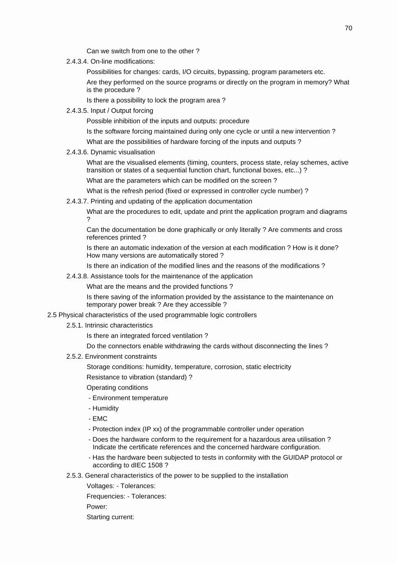
70
Can we switch from one to the other ?
2.4.3.4. On-line modifications:
Possibilities for changes: cards, I/O circuits, bypassing, program parameters etc.
Are they performed on the source programs or directly on the program in memory? Whatis the procedure ?
Is there a possibility to lock the program area ?
2.4.3.5. Input / Output forcing
Possible inhibition of the inputs and outputs: procedure
Is the software forcing maintained during only one cycle or until a new intervention ?
What are the possibilities of hardware forcing of the inputs and outputs ?
2.4.3.6. Dynamic visualisation
What are the visualised elements (timing, counters, process state, relay schemes, activetransition or states of a sequential function chart, functional boxes, etc...) ?
What are the parameters which can be modified on the screen ?
What is the refresh period (fixed or expressed in controller cycle number) ?
2.4.3.7. Printing and updating of the application documentation
What are the procedures to edit, update and print the application program and diagrams?
Can the documentation be done graphically or only literally ? Are comments and crossreferences printed ?
Is there an automatic indexation of the version at each modification ? How is it done?How many versions are automatically stored ?
Is there an indication of the modified lines and the reasons of the modifications ?
2.4.3.8. Assistance tools for the maintenance of the application
What are the means and the provided functions ?
Is there saving of the information provided by the assistance to the maintenance ontemporary power break ? Are they accessible ?
2.5 Physical characteristics of the used programmable logic controllers
2.5.1. Intrinsic characteristics
Is there an integrated forced ventilation ?
Do the connectors enable withdrawing the cards without disconnecting the lines ?
2.5.2. Environment constraints
Storage conditions: humidity, temperature, corrosion, static electricity
Resistance to vibration (standard) ?
Operating conditions
- Environment temperature
- Humidity
- EMC
- Protection index (IP xx) of the programmable controller under operation
- Does the hardware conform to the requirement for a hazardous area utilisation ?Indicate the certificate references and the concerned hardware configuration.
- Has the hardware been subjected to tests in conformity with the GUIDAP protocol oraccording to dIEC 1508 ?
2.5.3. General characteristics of the power to be supplied to the installation
Voltages: - Tolerances:
Frequencies: - Tolerances:
Power:
Starting current:

71
Isolation transformer necessity ?
Admissible micro failure duration (e.g., PLC power ride-thru capability)
3. Safety characteristics and detailed description of the operating units
3.1.Digital and analog Inputs
3.1.1. Schematic and electrical diagram of the input system
3.1.2. Description of the normal operation
3.1.3. Stated reliability
3.1.4. Fault detection
Types of faults detected ?
What is the method of detection ?
Specifically what happens when an analog input goes far over scale, e.g. in a range of 20mA to 22 ... 30 mA or short-circuited field loop ?
Are there different configurations and methods for pronounced and slow data flowchanges ?
How is the result of fault localisation displayed ?
3.1.5. Period and duration of the tests
3.1.6. Maintenance procedure
3.1.7. Action taken in response to fault detection
How are the faults managed by
- the safety system (redundancy - switching to stand-by mode...) ?
- the user ?
Procedure for communicating fault information to the user and other parts of the system:
Justification of action taken according to criteria of:
- safety:
- availability:
Restart procedure:
3.2. Processing unit:
3.2.1. Schematic diagram of the processing unit
3.2.2. Description of normal operation
3.2.3. Stated reliability
3.2.4. Fault detection
Types of faults detected ?
Detection method ?
How is the result of fault localisation displayed?
3.2.5. Period and duration of tests
3.2.6. Maintenance procedure
3.2.7. Action taken in response to fault detection (description of data path)
How are the faults managed by
- the safety system
- the user:
Justification of the action by criteria of
- safety
- availability
Restart procedure
3.3. Power supplies

72
3.3.1. Schematic and electrical diagram of power supplies partition and fusing (main andauxiliary)
3.3.2. Description of normal operation
3.3.3. Stated reliability
3.3.4. Fault detection
Types of faults detected
- main power supply
- auxiliary power supply
How is detection performed ?
How is the result of fault localisation displayed ?
3.3.5. Period and duration of tests
3.3.6. Maintenance procedure
3.3.7. Action taken in response to fault detection
How are the faults managed by
- the safety system
- the user
Procedure for communicating fault information to the user and other parts of the system
Justification of action by criteria of
- safety
- availability
Restart procedure
3.4. Test system:
3.4.1. Schematic and electrical diagram of the hardware part of the test systems
3.4.2. Description of normal operation
3.4.3. Stated reliability
3.4.4. Fault detection
Types of faults detected
How is detection performed
Are tests performed during safety responses ?
How is the result of fault localisation displayed ?
3.4.5. Period and duration of the tests
3.4.6. Maintenance procedure
Are there specifications and procedures for the system tests ?
3.4.7. Action taken in response to fault detection (description of data path)
How are the faults managed by
- the safety system
- the user
Procedure for communicating the information on faults to the user and to other parts ofthe system
Justification of the action according to criteria of
- safety
- availability
Restart procedure
3.5. Outputs
3.5.1. Schematic and electrical diagram of the output system
3.5.2. Description of normal operation
3.5.3. Stated reliability
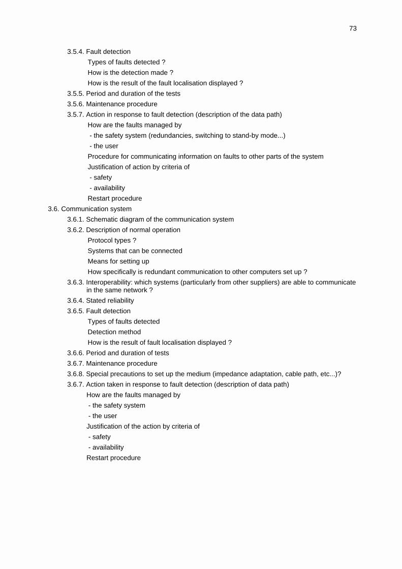
73
3.5.4. Fault detection
Types of faults detected ?
How is the detection made ?
How is the result of the fault localisation displayed ?
3.5.5. Period and duration of the tests
3.5.6. Maintenance procedure
3.5.7. Action in response to fault detection (description of the data path)
How are the faults managed by
- the safety system (redundancies, switching to stand-by mode...)
- the user
Procedure for communicating information on faults to other parts of the system
Justification of action by criteria of
- safety
- availability
Restart procedure
3.6. Communication system
3.6.1. Schematic diagram of the communication system
3.6.2. Description of normal operation
Protocol types ?
Systems that can be connected
Means for setting up
How specifically is redundant communication to other computers set up ?
3.6.3. Interoperability: which systems (particularly from other suppliers) are able to communicatein the same network ?
3.6.4. Stated reliability
3.6.5. Fault detection
Types of faults detected
Detection method
How is the result of fault localisation displayed ?
3.6.6. Period and duration of tests
3.6.7. Maintenance procedure
3.6.8. Special precautions to set up the medium (impedance adaptation, cable path, etc...)?
3.6.7. Action taken in response to fault detection (description of data path)
How are the faults managed by
- the safety system
- the user
Justification of the action by criteria of
- safety
- availability
Restart procedure
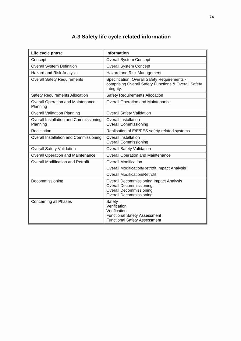
74
A-3 Safety life cycle related information
Life cycle phase Information
Concept Overall System Concept
Overall System Definition Overall System Concept
Hazard and Risk Analysis Hazard and Risk Management
Overall Safety Requirements Specification; Overall Safety Requirements -comprising Overall Safety Functions & Overall SafetyIntegrity.
Safety Requirements Allocation Safety Requirements Allocation
Overall Operation and MaintenancePlanning
Overall Operation and Maintenance
Overall Validation Planning Overall Safety Validation
Overall Installation and CommissioningPlanning
Overall InstallationOverall Commissioning
Realisation Realisation of E/E/PES safety-related systems
Overall Installation and Commissioning Overall InstallationOverall Commissioning
Overall Safety Validation Overall Safety Validation
Overall Operation and Maintenance Overall Operation and Maintenance
Overall Modification and Retrofit Overall Modification
Overall Modification/Retrofit Impact Analysis
Overall Modification/Retrofit
Decommissioning Overall Decommissioning Impact AnalysisOverall DecommissioningOverall DecommissioningOverall Decommissioning
Concerning all Phases SafetyVerificationVerificationFunctional Safety AssessmentFunctional Safety Assessment

75
A-4 Abbreviations
AIChE American Institute of Chemical Engineers
AS Automation System
BPCS Basic Process Control System
CCPS AIChE, Center for Chemical Process Safety
CFC Continuos Function Chart
DCSC Distributed Control System Controller
DIN Deutsches Institut für Normung
DoD Department of Defence
E/E/PES Electrical / Electronic / Programmable Electronic System
EWICS European Workshop on Industrial Computer Systems
EMC Electro Magnetic Compatibility
EMI Electro Magnetic Interference
EN European Norm
ESD Emergency Shutdown
ETA Event Tree Analysis
EUC Equipment Under Control
FAT Factory Acceptance Test
FBD Function Block Diagram
FMEA Failure Modes and Effects Analysis
FTA Fault Tree Analysis
HAZOP Hazard and Operability study
HDBK Handbook
HMI Human Machine Interface
HSE Health and Safety Executive (UK)
IEC International Electrotechnical Commission
IL Instruction List
ITSEC Information Technology Security Evaluation Criteria
LD Ladder Diagram
MTBF Mean Time Between Failures
MTTR Mean Time To Repair
NAMUR Normenausschuß für Meß und Regelungstechnik
NEMA National Electrical Manufacturers Association (USA)

76
OSHA Occupational Safety and Health Administration, US
PES Programmable Electronic System
PEC Programmable Electronic Controller
PHA Process Hazard Analysis
PFD Probability of Failure (of Safety Action) on Demand
PLC Programmable Logic Controller
QRA Quantitative Risk Assessment
SCA Sneak Circuit Analysis
SFC Sequential Function Chart
SIL Safety Integrity Level
SLC Single Loop Controller
SrS Safety-related System
SRS Safety Requirements Specification
ST Structured Text
TC 7 EWICS Technical Committee 7 on Reliability, Safety and Security
TÜV Technischer Überwachungsverein
VDE Verein Deutscher Elektrotechniker
VDI Verein Deutscher Ingenieure
WG Working Group

77
REFERENCES
[AIChE 89] American Institute of Chemical Engineers (AIChE), Center for Chemical Process Safety(CCPS): Guidelines for Technical Management of Chemical Process Safety, 1989
[AIChE 93] American Institute of Chemical Engineers (AIChE), Center for Chemical Process Safety(CCPS): Guidelines for Safe Automation of Chemical Process, 1993.
[Alsys 92] Alsys, The Real-Time ADA Handbook from Alsys, Alsys Inc., 1992
[Alsys 94] Alsys, Safety Critical Handbook, Alsys Inc., 1994
[Bish 90] Bishop, P.G. (editor), Dependability of Critical Computer Systems 3 - TechniquesDirectory - Guidelines produced by The European Workshop on Industrial ComputerSystems, Technical Committee 7 (EWICS TC 7), 1990
[Bloo 92] R. E. Bloomfield: Standards for safety related computer systems: a tour through currentand emerging standards, CSR 9th Annual Conference on Software Safety, Luxembourg7-10 April 1992
[CGW 91] Cullyer, W.J.; Goodenough, S.J.; Wichmann, B.A.: The choice of computer languages foruse in safety-critical systems, Software Engineering Journal, March 1991, pp. 51-58
[DEF 91] Ministry of Defence, The Procurement of Safety Critical Software in Defence Equipment,Interim Defence Standard 00-55, April 1991
[DIN 93] DIN V VDE 0801 Principles for Computers in Safety - Related Systems, 1993 plusAppenix A1, 1994
[DIN 94] DIN V 19250 Fundamental safety aspects to be considered for measurement and control,May 1994
[HSE 87] Health and Safety Executive: Guideline on programmable electronic systems in safetyrelated applications, 1987 (reprinted 1993)
[IEC 92] International Electrotechnical Commission (IEC) Standard 1131-1: ProgrammableControllers--Part 1; General Information
[IEC 93] International Electrotechnical Commission (IEC) Standard 1131-3: ProgrammableControllers--Part 3; Programming Languages
[IEC 97] International Electrotechnical Commission (IEC) draft Standard 1508 - Functional Safety:Safety Related Systems, Parts 1 - 7, 1997
[ISA 96] American National Standards Institute (ANSI) / Instrument Society of America (ISA)Standard (S)84.01-1996: Application of Safety Instrumented Systems for the ProcessIndustries, 1996
[ISA 97] Instrument Society of America (ISA) Draft Technical Report (dTR) 84.02 Electrical(E)/Electronic (E)/Programmable Electronic Systems (PES) -- Safety Integrity Level (SIL)Evaluation Techniques, 1997
[MIL 84] MIL-HDBK 338 Volume 1 Electronic Reliability Design Handbook US DoD, 1984
[OSHA 92] Occupational Safety and Health Administration. Regulation on "Process SafetyManagement of Highly Hazardous Chemicals" OSHA 29CFR 1910.119, 1992
[Rata 93] J.M. Rata: Standardisation efforts world-wide, in: Phil Bennett (ed.): Safety aspects ofcomputer control, 1993
[Redm 88] F.J. Redmill (editor): Dependability of critical computer systems Vol. 1 - Guidelinesproduced by The European Workshop on Industrial Computer Systems, TechnicalCommittee 7 (EWICS TC 7), 1988
[Redm 89] F.J. Redmill (editor): Dependability of critical computer systems Vol. 2 - Guidelinesproduced by The European Workshop on Industrial Computer Systems, TechnicalCommittee 7 (EWICS TC 7), 1989
[VDE 89] VDE0116 Electrical equipment of furnaces, October 1989
[Wall 92] D. R. Wallace: An analysis of selected software safety standards, Proc. of the SeventhAnnual Conference on Computer Assurance, June 15-18 1992, Gaithersburg, MD, USA
78
[Wich 89] Wichmann, B.A.: Insecurities in the ADA programming language, NPL Report DITC137/89, January 1989
[WiDa 89] Wichman, B.A.; Davies, M.: Experience with a compiler testing tool, NPL Report DITC138/89, 1989