Embed Size (px)
Citation preview

PLC Connection Guide
1
PLC Connection Guide
AIBUS ............................................................................ 2
Allen-Bradley CompactLogix/FlexLogix .......................... 5
Allen-Bradley DF1 .......................................................... 9
Allen-Bradley DF1 (BCC) ............................................. 12
Allen-Bradley DH485 .................................................... 15
Allen-Bradley EtherNet/IP (CompactLogix) .................. 19
Allen-Bradley EtherNet/IP (CompactLogix) – Free Tag
Names .......................................................................... 22
Allen-Bradley EtherNet/IP (ControlLogix) – Free Tag
Names .......................................................................... 26
Allen-Bradley EtherNet/IP (DF1) .................................. 30
Allen-Bradley PLC5 ...................................................... 33
Altus ALNET-I .............................................................. 37
Baumuller ..................................................................... 40
Change ........................................................................ 42
Cimon CM1-CP4A/ECO1A .......................................... 44
Cimon CM1-SC02A...................................................... 46
Copley Controls ........................................................... 48
CROUZET M3 (FBD) ................................................... 50
CROUZET M3 (LAD) ................................................... 52
Danfoss ECL Apex20 ................................................... 55
Danfoss FC Series ....................................................... 57
Danfoss VLT2800 Series ............................................. 59
DELTA DVP ................................................................. 61
Embedded PC (BECKHOFF) ....................................... 63
EMERSON PLC EC20 ................................................. 71
F930GOT Server .......................................................... 73
FATEK FB Series ......................................................... 76
Fuji NB Series .............................................................. 79
GE Fanuc CMM ........................................................... 81
GE Fanuc RX3i ............................................................ 84
GE Fanuc Series 90-30 (Ethernet) ............................... 86
GE Fanuc SNP-X ......................................................... 89
HanYoung Series ......................................................... 92
Heng Yuan Sensor ....................................................... 94
HITACHI EH-SIO ......................................................... 96
HITACHI EHV Series (Ethernet) .................................. 99
HITACHI H/EH/EHV Series ........................................ 101
HUST H4X ................................................................. 106
IAI X-SEL CONTROLLER .......................................... 108
IDEC Micro ................................................................. 111
INOVANCE H2U/H1U ................................................ 114
Intelligent Servo ......................................................... 116
Justfi controller ........................................................... 118
Kernel sistemi ............................................................. 120

PLC Connection Guide
2
KEYENCE KV-10/16/24/40/80/Visual KV Series ....... 122
KEYENCE KV-5000 (Ethernet) .................................. 124
KEYENCE KV-700/1000/3000/5000 Series ............... 126
Korenix 6550 .............................................................. 128
Koyo CLICK ............................................................... 130
KOYO DIRECT .......................................................... 132
Koyo Ethernet ............................................................ 137
Lenze ......................................................................... 139
LIYAN EX series ........................................................ 141
LS GLOFA Cnet ......................................................... 143
LS GLOFA GM3467 (LOADER) ................................. 146
LS MASTER-K Cnet ................................................... 148
LS MASTER-K10S1 ................................................... 150
LS MASTER-K300S CPU .......................................... 152
LS XGB/XGT .............................................................. 154
LS XGB/XGT FEnet (Ethernet) .................................. 156
LS XGL-CH2A Cnet ................................................... 159
LS XGL-EFMT FEnet (Ethernet) ................................ 161
LS XGT/XGK CPU DIRECT ....................................... 163
Master (Master-Slave Protocol) ................................. 165
Memobus (Yaskawa MP Series Controllers) .............. 168
Memory Map .............................................................. 173
MITSUBISHI A1S ....................................................... 175
MITSUBISHI A2A ....................................................... 178
MITSUBISHI A2US .................................................... 181
MITSUBISHI A3N/A1SH ............................................ 184
MITSUBISHI AJ71 ..................................................... 187
MITSUBISHI FX0n/FX2.............................................. 189
MITSUBISHI FX232/485BD ....................................... 191
MITSUBISHI FX2n ..................................................... 194
MITSUBISHI FX3u (Ethernet) .................................... 196
MITSUBISHI FX3u/FX3G ........................................... 203
MITSUBISHI MELSEC-Q (Ethernet) .......................... 205
MITSUBISHI Q00/Q00UJ/Q01/QJ71 ......................... 210
MITSUBISHI Q00J ..................................................... 215
MITSUBISHI Q00U/Q01U/Q02U/QnUD/QnUDH ....... 217
MITSUBISHI Q00UJ/QnU/QnUD/QnUDH/QnUDEH (mini
USB)........................................................................... 219
MITSUBISHI Q02/02H ............................................... 221
MITSUBISHI Q06H .................................................... 223
MITSUBISHI QJ71E71 (Ethernet) .............................. 225
MODBUS ASCII ......................................................... 233
MODBUS RTU ........................................................... 236
MODBUS RTU (0x/1x Range Adjustable) .................. 240
MODBUS RTU (zero-based addressing) ................... 248
MODBUS Server (Modbus RTU Slave)...................... 252
MODBUS TCP/IP (Ethernet) ...................................... 255
MODBUS TCP/IP (zero-based addressing) ............... 257
PLC Connection Guide
3
MODBUS TCP/IP 32Bit .............................................. 259
Moeller XC-CPU101 ................................................... 261
Modicon Twido ........................................................... 263
OEMAX Series ........................................................... 265
OMRON C/CQM1 Series ........................................... 267
OMRON CJ/CS/CP .................................................... 270
OMRON CJ1/CS1 (Ethernet) ..................................... 273
OMRON E5CN ........................................................... 276
Panasonic FP ............................................................. 278
Panasonic FP (Ethernet) ............................................ 282
Panasonic FP2 (Ethernet) .......................................... 285
Panasonic MINAS A4 ................................................. 287
Parker ACR9000 ........................................................ 291
Parker Compax3 ........................................................ 293
Parker SLVD Series ................................................... 297
SAIA PCD PGU Mode ................................................ 299
SAIA PCD S-BUS Mode ............................................ 301
SAIA S-BUS (Ethernet) .............................................. 311
Schleicher XCS 20C .................................................. 314
Schleicher XCX 300 ................................................... 316
SEW Movilink ............................................................. 319
SIEMENS S7/1200 (Ethernet) .................................... 321
SIEMENS S7/200....................................................... 326
SIEMENS S7/200 (Ethernet) ...................................... 328
SIEMENS S7/300 ....................................................... 330
SIEMENS S7/300 (Ethernet) ...................................... 333
SIEMENS S7/300 MPI ............................................... 335
SIEMENS S7/400 (Ethernet) ...................................... 337
SIMATIC TI505 .......................................................... 342
TAIAN TP02 Series .................................................... 345
TAIAN TP03 Series .................................................... 347
TECO Inverter ............................................................ 349
TELEMECANIQUE UniTelway ................................... 351
Topvert ....................................................................... 353
Toshiba T Series ........................................................ 355
Toshiba TC mini Series .............................................. 358
Toshiba VF-S11 ......................................................... 360
VIGOR........................................................................ 362
YAMAHA ERCD ......................................................... 364
YASKAWA MP Series Ethernet (Extension) .............. 367
YASKAWA SMC 3010................................................ 371
YASKAWA SMC 3010 (Ethernet) ............................... 374
Yokogawa FA-M3 ....................................................... 378
Yokogawa FA-M3 (Ethernet) ...................................... 384
MT6050i/MT8050i Com Port Pin Assignment ............ 386

PLC Connection Guide
2
AIBUS Supported series: UDIAN Automation AI-501, AI-518, AI-519, AI-701, AI-702M, AI-704M,
AI-706M, AI-719.
Website: http://www.yudian.us
HMI Setting: Parameters Recommend Option Notes PLC type AIBUS PLC I/F RS485 2W RS232 Baud rate 9600 9600, 19200 Parity None Data bits 8 Stop bits 2 HMI st. no. 0 PLC st. no. 1 0-100
On-line simulation YES
Extend address mode NO
Device Address:
AI-518 Bit/Word Device type Format Range Memo
W 0 00H DD SV/STEP
W 1 01H DD -1999 ~ 9999 HIAL
W 2 02H DD -1999 ~ 9999 LoAL
W 3 03H DD 0 ~ 9999 dHAL
W 4 04H DD 0 ~ 9999 dLAL
W 5 05H DD 0 ~ 2000 dF
W 6 06H DD 0 ~ 4 CtrL
W 7 07H DD 0 ~ 9999 M5
W 8 08H DD 1 ~ 9999 P
W 9 09H DD 0 ~ 2000 t
W 10 0AH DD 0 ~ 125 CtI
W 11 0BH DD 0 ~ 37 Sn (read only)
W 12 0CH DD 0 ~ 3 dIP (read only)

PLC Connection Guide
3
W 13 0DH DD -1999 ~ 9999 dIL
W 14 0EH DD -1999 ~ 9999 dIH
W 15 0FH DD 0 ~ 9999 ALP
W 16 10H DD -1999 ~ 4000
0.1H Sc
W 17 11H DD 0 ~ 48 Op1
W 18 12H DD -110 ~ 110% oPL
W 19 13H DD 0 ~ 110% oPH
W 20 14H DD 0 ~ 127 CF (read only)
W 21 15H DD 0 ~ 19.2K
Baud rate�bAud�
/808Pstatus word:
run: 0 suspend: 4 stop: 12
(read only)
W 22 16H DD 0 ~ 100 ADDR
W 23 17H DD 0 ~ 20 dL
W 24 18H DD 0 ~ 127 Run
W 25 19H DD 0 ~ 9999 Loc
AI-701
Bit/Word Device type Format Range Memo
W 1 01H DD -9990 ~ 30000 HIAL
W 2 02H DD -9990 ~ 30000 LoAL
W 3 03H DD -9990 ~ 30000 HdAL
W 4 04H DD -9990 ~ 30000 LdAL
W 5 05H DD 0 ~ 2000 AHYS
W 11 0BH DD 0 ~ 37 InP (read only)
W 12 0CH DD 0 ~ 3 dPt
W 13 0DH DD -9999 ~ 30000 SCL
W 14 0EH DD -9999 ~ 30000 SCH
W 15 0FH DD 0 ~ 4444 AOP
W 16 10H DD -1999 ~ 4000
0.1H Scb
W 17 11H DD 0 ~ 48 Opt
W 21 15H DD 0 ~ 19.2K Baud rate�bAud�

PLC Connection Guide
4
/808P status word
run: 0 suspend: 4 stop: 12
(read only)
W 22 16H DD 0 ~ 80 ADDR
W 23 17H DD 0 ~ 40 FILt
W 25 19H DD 0 ~ 255 Loc
Wiring Diagram:
HMI COM1
RS485 2W 9P
D-Sub Female
HMI COM3
RS485 2W 9P
D-Sub Female
RS485 2W Port
1 RX- 6 Data- 4 COMM A
2 RX+ 9 Data+ 3 COMM B
5 GND 5 GND
Driver Version:
Version Date Description
V1.20 Dec/30/2008

PLC Connection Guide
5
Allen-Bradley CompactLogix/FlexLogix Supported series: Allen-Bradley ControlLogix, CompactLogix, FlexLogix CH0 DF1.
Website: http://www.ab.com
HMI Setting:
Parameters Recommend Option Notes
PLC type Allen-Bradley CompactLogix/FlexLogix
PLC I/F RS232
Baud rate 19200 9600, 19200,
38400
Parity None Even, Odd, None
Data bits 8 8
Stop bits 1 1
HMI st. no. 0
PLC st. no. 1 1-31
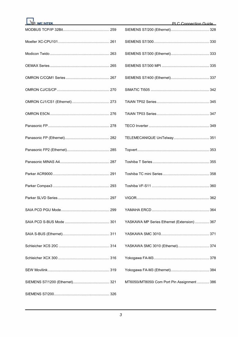
PLC Setting:
Communication mode DF1 Full Duplex protocol 19200, None, 8, 1 (default)
Error Check: BCC, Station Address: 1
ControlLogix, CompactLogix CPU CH0 setting:
PLC Connection Guide
6
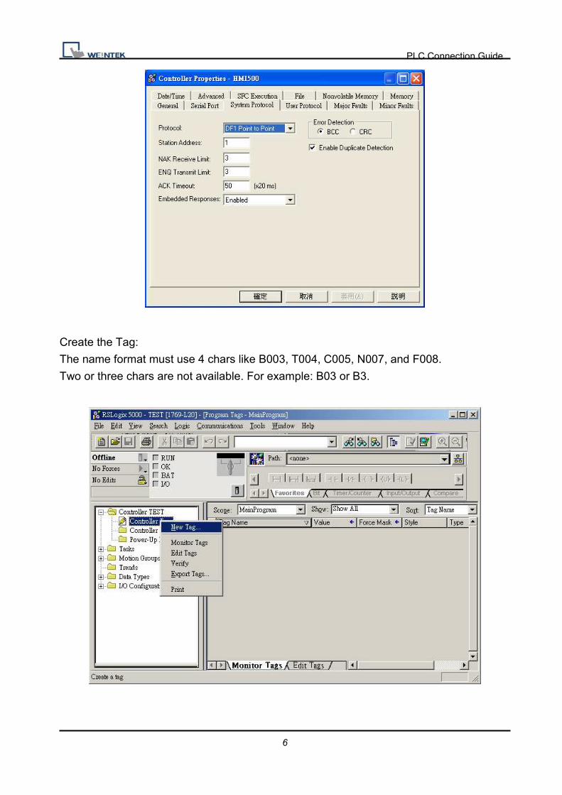
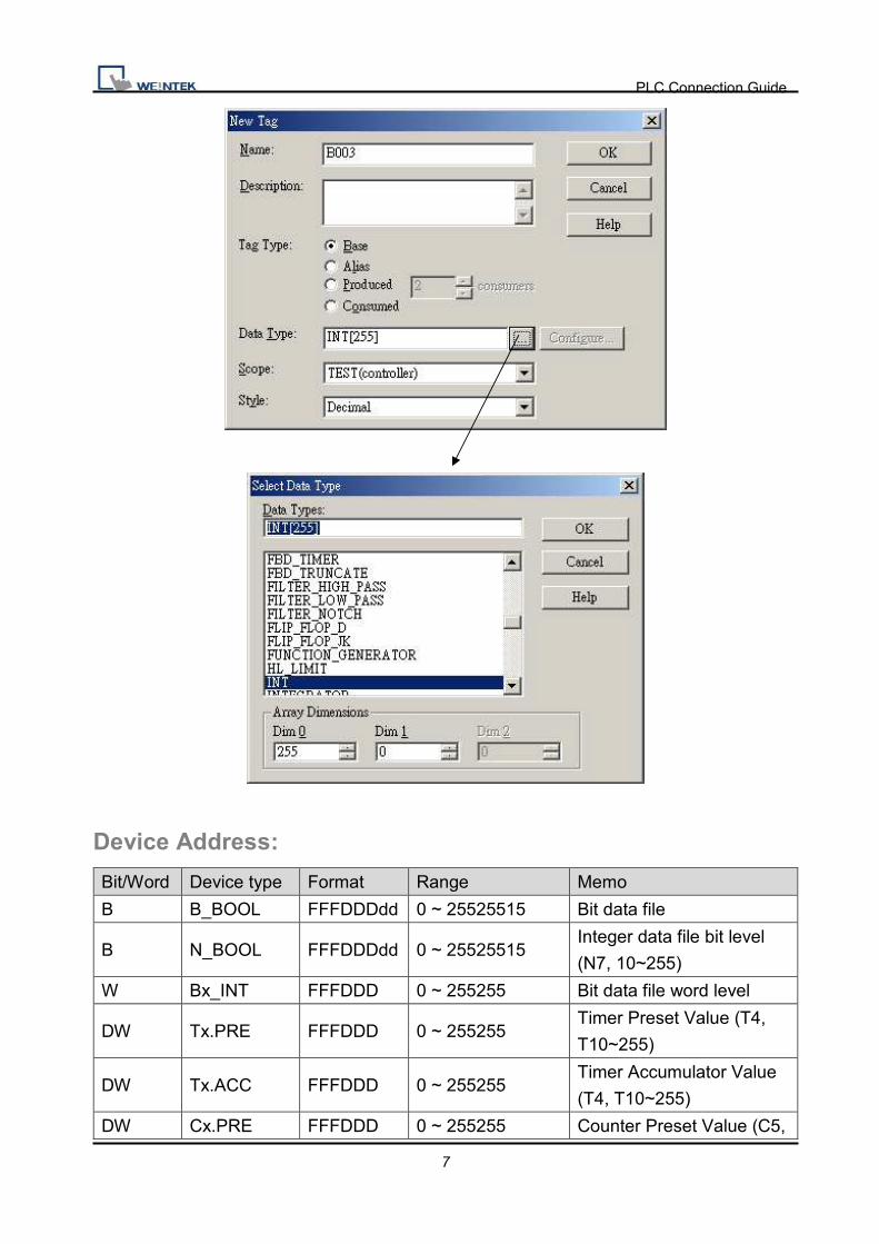
Create the Tag:
The name format must use 4 chars like B003, T004, C005, N007, and F008.
Two or three chars are not available. For example: B03 or B3.
PLC Connection Guide
7
Device Address:
Bit/Word Device type Format Range Memo
B B_BOOL FFFDDDdd 0 ~ 25525515 Bit data file
B N_BOOL FFFDDDdd 0 ~ 25525515 Integer data file bit level
(N7, 10~255)
W Bx_INT FFFDDD 0 ~ 255255 Bit data file word level
DW Tx.PRE FFFDDD 0 ~ 255255 Timer Preset Value (T4,
T10~255)
DW Tx.ACC FFFDDD 0 ~ 255255 Timer Accumulator Value
(T4, T10~255)
DW Cx.PRE FFFDDD 0 ~ 255255 Counter Preset Value (C5,

PLC Connection Guide
8
C10~255)
DW Cx.ACC FFFDDD 0 ~ 255255 Counter Accumulator
Value (C5, C10~255)
W F8_REAL DDD 0 ~ 255 Floating point data file (F8)
W Fx_REAL FFFDDD 0 ~ 255255 Floating point data file
(F008, F010~F255)
DW Nx_INT FFFDDD 0 ~ 255255 Integer data file (N7,
10~255)
Wiring Diagram:
HMI COM1
RS232 9P
D-Sub Male
HMI COM2
RS232 9P
D-Sub Male
HMI COM3
RS232 9P
D-Sub Female
AB CPU CH0 RS232 9P D-Sub
Male
2 RX 6 RX 8 RX 3 TD
3 TX 4 TX 7 TX 2 RD
5 GND 5 GND 5 GND 5 GND
Driver Version: Version Date Description
V1.20 Dec/30/2008

PLC Connection Guide
9
Allen-Bradley DF1 Supported series: Allen-Bradley MicroLogix 1000, 1100, 1200, 1400, 1500, SLC 5/03,
5/04, 5/05.
Website: http://www.ab.com
Note: Allen-Bradley DF1 driver is used CRC checksum.
HMI Setting: Parameters Recommend Option Notes PLC type Allen-Bradley DF1 PLC I/F RS232
Baud rate 9600 9600, 19200, 38400
Parity None Even, Odd, None Data bits 8 8 Stop bits 1 1 HMI st. no. 0 PLC st. no. 1 1-31
PLC Setting:
Communication mode DF1 Full Duplex protocol 19200, None, 8, 1 (default)
Error Check: CRC
Device Address:
Bit/Word Device type Format Range Memo B I1 DDDdd 0 ~ 25515 Input (I) B O0 DDDdd 0 ~ 25515 Output (O)
B S_Bit DDDdd 0 ~ 25515 Status (S) bit level
B B3 DDDdd 0 ~ 25515 Bit data file (B3)
B B10~13 DDDdd 0 ~ 25515 Bit data file (B10~13) B Bfn FFFDDDdd 0 ~ 25525515 Bit data file (B3, 10~254)
B NfnBit FFFDDDdd 0 ~ 25525515 Integer data file bit level (N7, 10~254)
W S DDD 0 ~ 255 Status (S) W T4SV DDD 0 ~ 255 Timer Preset Value (T4) W TfnSV FFFDDD 0 ~ 255255 Timer Preset Value
W T4PV DDD 0 ~ 255 Timer Accumulator Value (T4)

PLC Connection Guide
10
Bit/Word Device type Format Range Memo W TfnPV FFFDDD 0 ~ 255255 Timer Accumulator Value W C5SV DDD 0 ~ 255 Counter Preset Value (C5) W CfnSV FFFDDD 0 ~ 255255 Counter Preset Value
W C5PV DDD 0 ~ 255 Counter Accumulator Value (C5)
W CfnPV FFFDDD 0 ~ 255255 Counter Accumulator Value W N7 DDD 0 ~ 255 Integer data file (N7) W N10~15 DDD 0 ~ 255 Integer data file (N10~15) W F8 DDD 0 ~ 255 Floating point data file (F8)
W Nfn FFFDDD 0 ~ 255255 Integer data file (N7, 10~254)
W Ffn FFFDDD 0 ~ 255255 W Lfn FFFDDD 0 ~ 255255
Wiring Diagram:
9P D-Sub to 8P Mini-DIN: MicroLogix 1000, 1100, 1200, 1400, 1500
HMI COM1
RS232 9P
D-Sub Male
HMI COM2
RS232 9P
D-Sub Male
HMI COM3
RS232 9P
D-Sub Female
MicroLogix RS232 8P Mini-DIN
2 RX 6 RX 8 RX 7 TXD
3 TX 4 TX 7 TX 4 RXD
5 GND 5 GND 5 GND 8 GND
9P D-Sub to 9P D-Sub: SLC5/03, 04, 05 CH0
HMI COM1
RS232 9P
D-Sub Male
HMI COM2
RS232 9P
D-Sub Male
HMI COM3
RS232 9P
D-Sub Female
AB CPU CH0 RS232 9P D-Sub
Male
2 RX 6 RX 8 RX 3 TD
3 TX 4 TX 7 TX 2 RD
5 GND 5 GND 5 GND 5 GND

PLC Connection Guide
11
Driver Version:
Version Date Description
V2.20 Jan/05/2010
PLC Connection Guide
12
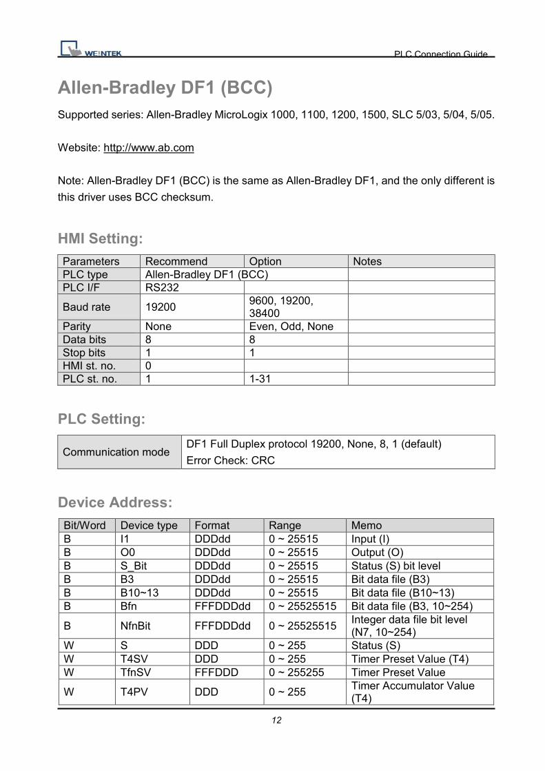
Allen-Bradley DF1 (BCC) Supported series: Allen-Bradley MicroLogix 1000, 1100, 1200, 1500, SLC 5/03, 5/04, 5/05.
Website: http://www.ab.com
Note: Allen-Bradley DF1 (BCC) is the same as Allen-Bradley DF1, and the only different is
this driver uses BCC checksum.
HMI Setting: Parameters Recommend Option Notes PLC type Allen-Bradley DF1 (BCC) PLC I/F RS232
Baud rate 19200 9600, 19200, 38400
Parity None Even, Odd, None Data bits 8 8 Stop bits 1 1 HMI st. no. 0 PLC st. no. 1 1-31
PLC Setting:
Communication mode DF1 Full Duplex protocol 19200, None, 8, 1 (default)
Error Check: CRC
Device Address:
Bit/Word Device type Format Range Memo B I1 DDDdd 0 ~ 25515 Input (I) B O0 DDDdd 0 ~ 25515 Output (O) B S_Bit DDDdd 0 ~ 25515 Status (S) bit level B B3 DDDdd 0 ~ 25515 Bit data file (B3) B B10~13 DDDdd 0 ~ 25515 Bit data file (B10~13) B Bfn FFFDDDdd 0 ~ 25525515 Bit data file (B3, 10~254)
B NfnBit FFFDDDdd 0 ~ 25525515 Integer data file bit level (N7, 10~254)
W S DDD 0 ~ 255 Status (S) W T4SV DDD 0 ~ 255 Timer Preset Value (T4) W TfnSV FFFDDD 0 ~ 255255 Timer Preset Value
W T4PV DDD 0 ~ 255 Timer Accumulator Value (T4)

PLC Connection Guide
13
Bit/Word Device type Format Range Memo W TfnPV FFFDDD 0 ~ 255255 Timer Accumulator Value W C5SV DDD 0 ~ 255 Counter Preset Value (C5) W CfnSV FFFDDD 0 ~ 255255 Counter Preset Value
W C5PV DDD 0 ~ 255 Counter Accumulator Value (C5)
W CfnPV FFFDDD 0 ~ 255255 Counter Accumulator Value W N7 DDD 0 ~ 255 Integer data file (N7) W N10~15 DDD 0 ~ 255 Integer data file (N10~15) W F8 DDD 0 ~ 255 Floating point data file (F8)
W Nfn FFFDDD 0 ~ 255255 Integer data file (N7, 10~254)
W Ffn FFFDDD 0 ~ 255255 W Lfn FFFDDD 0 ~ 255255
Wiring Diagram:
9P D-Sub to 8P Mini-DIN: MicroLogix 1000, 1100, 1200, 1500
HMI COM1
RS232 9P
D-Sub Male
HMI COM2
RS232 9P
D-Sub Male
HMI COM3
RS232 9P
D-Sub Female
MicroLogix RS232 8P Mini-DIN
2 RX 6 RX 8 RX 7 TXD
3 TX 4 TX 7 TX 4 RXD
5 GND 5 GND 5 GND 8 GND
9P D-Sub to 9P D-Sub: SLC5/03, 04, 05 CH0
HMI COM1
RS232 9P
D-Sub Male
HMI COM2
RS232 9P
D-Sub Male
HMI COM3
RS232 9P
D-Sub Female
AB CPU CH0 RS232 9P D-Sub
Male
2 RX 6 RX 8 RX 3 TD
3 TX 4 TX 7 TX 2 RD
5 GND 5 GND 5 GND 5 GND

PLC Connection Guide
14
Driver Version:
Version Date Description
V2.30 Apr/26/2010
PLC Connection Guide
15
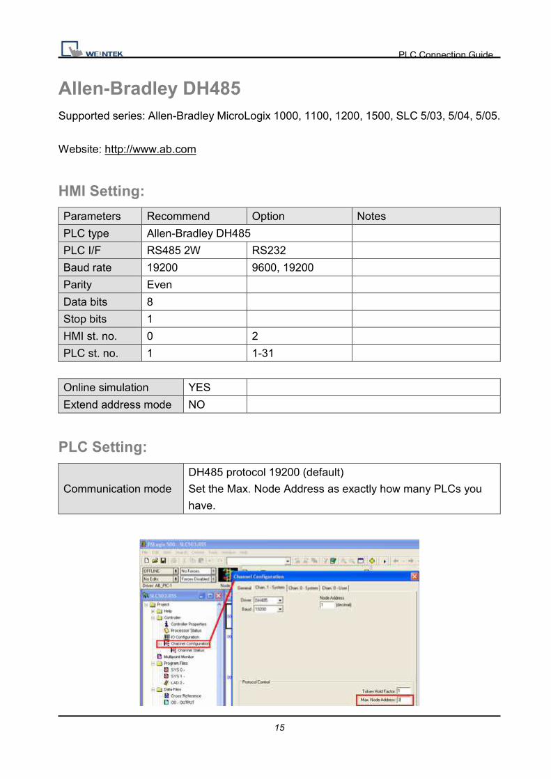
Allen-Bradley DH485 Supported series: Allen-Bradley MicroLogix 1000, 1100, 1200, 1500, SLC 5/03, 5/04, 5/05.
Website: http://www.ab.com
HMI Setting:
Parameters Recommend Option Notes
PLC type Allen-Bradley DH485
PLC I/F RS485 2W RS232
Baud rate 19200 9600, 19200
Parity Even
Data bits 8
Stop bits 1
HMI st. no. 0 2
PLC st. no. 1 1-31
Online simulation YES
Extend address mode NO
PLC Setting:
Communication mode
DH485 protocol 19200 (default)
Set the Max. Node Address as exactly how many PLCs you
have.

PLC Connection Guide
16
Device Address:
Bit/Word Device type Format Range Memo
B I1 DDDdd 0 ~ 25515 Input (I)
B O0 DDDdd 0 ~ 25515 Output (O)
B B3 DDDdd 0 ~ 25515 Bit data file (B3)
B B10~13 DDDdd 0 ~ 25515 Bit data file (B10~13)
B Bfn FFFDDDdd 0 ~ 25525515 Bit data file (B3, 10~254)
B NfnBit FFFDDDdd 0 ~ 25525515
Integer data file bit level
(N7,
10~254)
B S_Bit DDDdd 0 ~ 25515 Status file
W T4SV DDD 0 ~ 255 Timer Preset Value (T4)
W T4PV DDD 0 ~ 255 Timer Accumulator Value
(T4)
W C5SV DDD 0 ~ 255 Counter Preset Value
(C5)
W C5PV DDD 0 ~ 255 Counter Accumulator
Value (C5)
W TfnSV FFFDDD 0 ~ 255255 Timer Preset Value
W TfnPV FFFDDD 0 ~ 255255 Timer Accumulator Value
W CfnSV FFFDDD 0 ~ 255255 Counter Preset Value
W CfnPV FFFDDD 0 ~ 255255 Counter Accumulator
Value
W N7 DDD 0 ~ 255 Integer data file (N7)
W N10~15 DDD 0 ~ 255 Integer data file (N10~15)
W F8 DDD 0 ~ 255 Floating point data file
(F8)
W Nfn FFFDDD 0 ~ 255255 Integer data file (N7,
10~254)
W S DDD 0 ~ 255 Status file

PLC Connection Guide
17
Wiring Diagram:
RS-485: SLC500 Fixed type, SLC5/01, 02, 03 CH1.
HMI can’t connect to 1747-AIC peripheral port.
HMI COM1
RS485 2W 9P
D-Sub Female
HMI COM3
RS485 2W 9P
D-Sub Female
AB SLC500 DH485
RJ8 clip style port
1 RX- 6 Data- 2 SDB
2 RX+ 9 Data+ 1 SDA
5 GND 5 GND 7 GND
9P D-Sub to 8P Mini-DIN: MicroLogix 1000, 1100, 1200, and 1500 must set DH485
protocol.
HMI COM1
RS232 9P
D-Sub Male
HMI COM2
RS232 9P
D-Sub Male
HMI COM3
RS232 9P
D-Sub Female
MicroLogix RS232 8P Mini-DIN
2 RX 6 RX 8 RX 7 TXD
3 TX 4 TX 7 TX 4 RXD
5 GND 5 GND 5 GND 8 GND
9P D-Sub to 9P D-Sub: SLC5/03, 04, 05 CH0 must set DH485 protocol.
HMI COM1
RS232 9P
D-Sub Male
HMI COM2
RS232 9P
D-Sub Male
HMI COM3
RS232 9P
D-Sub Female
AB CPU CH0 RS232 9P D-Sub
Male
2 RX 6 RX 8 RX 3 TD
3 TX 4 TX 7 TX 2 RD
5 GND 5 GND 5 GND 5 GND

PLC Connection Guide
18
Note: AB DH485 supports HMI X and iH series only.
Driver Version:
Version Date Description
V1.20 Apr/17/2009

PLC Connection Guide
19
Allen-Bradley EtherNet/IP (CompactLogix) Supported series: Allen-Bradley ControlLogix, CompactLogix, FelxLogix Ethernet.
Website: http://www.ab.com
HMI Setting:
Parameters Recommend Option Notes
PLC type Allen-Bradley EtherNet/IP (CompactLogix)
PLC I/F Ethernet
Port no. 44818
PLC st. no. 1
PLC Setting:
RSLogix 5000 setting
Create the Tag:
The name format must use 4 chars like B003, T004, C005, N007, and F008.
Two or three chars are not available. For example: B03 or B3.

PLC Connection Guide
20
Device Address:
Bit/Word Device type Format Range Memo
B Bx_BOOL FFFDDDdd 0 ~ 25525515 Bit data file
B Nx_BOOL FFFDDDdd 0 ~ 25525515 Integer data file bit level
(N7, 10~99)
W Bx_INT FFFDDD 0 ~ 255255 Bit data file word level
W Nx_INT FFFDDD 0 ~ 255255 Integer data file (N7,
10~99)
F F8_REAL DDD 0~ 255 Floating point data file (F8)
F Fx_REAL FFFDDD 0 ~ 255255 Floating point data file (F8)
DW Tx.PRE FFFDDD 0 ~ 255255 Timer Preset Value (T4,
T10~255)
DW Tx.ACC FFFDDD 0 ~ 255255 Timer Accumulator Value
(T4, T10~255)
DW Cx.PRE FFFDDD 0 ~ 255255 Counter Preset Value (C5,
C10~255)
DW Cx.ACC FFFDDD 0 ~ 255255 Counter Accumulator Value
(C5, C10~255)

PLC Connection Guide
21
Wiring Diagram:
Direct connect (crossover cable):
HMI RJ45 Female Wire Color PLC RJ45 Female
1 TX+ White/Orange 3 RX+
2 TX- Orange 6 RX-
3 RX+ White/Green 1 TX+
4 BD4+ Blue 4 BD4+
5 BD4- White/Blue 5 BD4-
6 RX- Green 2 TX-
7 BD3+ White/Brown 7 BD3+
8 BD3- Brown 8 BD3-
Through a hub:
HMI RJ45 Female Wire Color PLC RJ45 Female
1 TX+ White/Orange 1 TX+
2 TX- Orange 2 TX-
3 RX+ White/Green 3 RX+
4 BD4+ Blue 4 BD4+
5 BD4- White/Blue 5 BD4-
6 RX- Green 6 RX-
7 BD3+ White/Brown 7 BD3+
8 BD3- Brown 8 BD3-
Driver Version:
Version Date Description
V1.10 Dec/30/2008

PLC Connection Guide
22
Allen-Bradley EtherNet/IP (CompactLogix) – Free
Tag Names
Supported series: Allen-Bradley CompactLogix, FelxLogix Ethernet
Website: http://www.ab.com
HMI Setting:
Parameters Recommend Option Notes
PLC type Allen-Bradley EtherNet/IP
(CompactLogix) – Free Tag Names
PLC I/F Ethernet
Port no. 44818
PLC st no. 1
PLC Setting:
1. Set PLC IP address.

PLC Connection Guide
23
2. Create Tags.
3. Export Tags data to CSV file.
4. In EB8000, create Allen-Bradley EtherNet/IP-Tag (CompactLogix) driver.
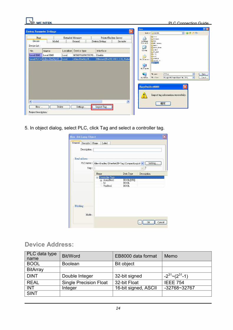
Input PLC IP address. In System Parameter Settings dialog click [Import Tag…] button.
PLC Connection Guide
24
5. In object dialog, select PLC, click Tag and select a controller tag.
Device Address: PLC data type name Bit/Word EB8000 data format Memo
BOOL Boolean Bit object BitArray DINT Double Integer 32-bit signed -231~(231-1)
REAL Single Precision Float 32-bit Float IEEE 754 INT Integer 16-bit signed, ASCII -32768~32767 SINT

PLC Connection Guide
25
Wiring Diagram:
Direct connect (crossover cable):
HMI RJ45 Female Wire Color PLC RJ45 Female
1 TX+ White/Orange 3 RX+
2 TX- Orange 6 RX-
3 RX+ White/Green 1 TX+
4 BD4+ Blue 4 BD4+
5 BD4- White/Blue 5 BD4-
6 RX- Green 2 TX-
7 BD3+ White/Brown 7 BD3+
8 BD3- Brown 8 BD3-
Through a hub:
HMI RJ45 Female Wire Color PLC RJ45 Female
1 TX+ White/Orange 1 TX+
2 TX- Orange 2 TX-
3 RX+ White/Green 3 RX+
4 BD4+ Blue 4 BD4+
5 BD4- White/Blue 5 BD4-
6 RX- Green 6 RX-
7 BD3+ White/Brown 7 BD3+
8 BD3- Brown 8 BD3-
Driver Version:
Version Date Description
V1.10 Aug/25/2010
PLC Connection Guide
26
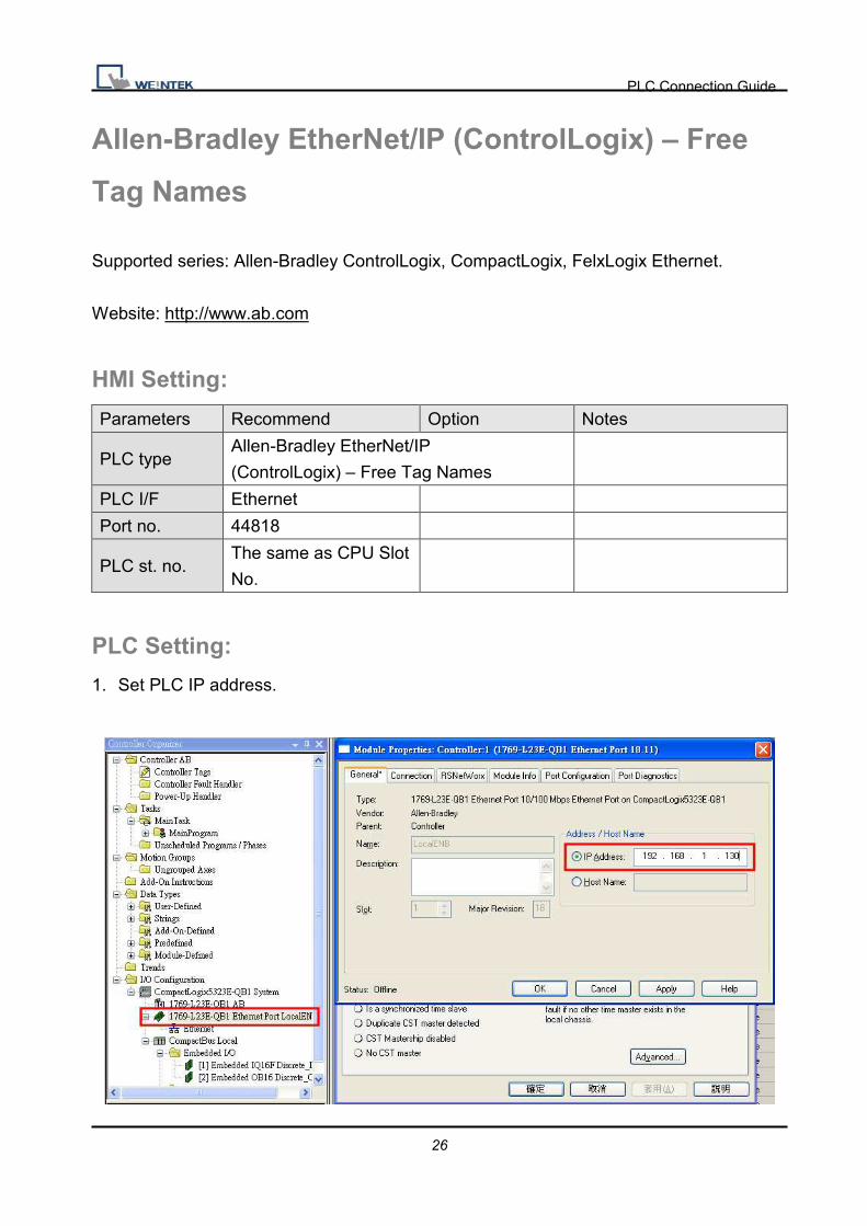
Allen-Bradley EtherNet/IP (ControlLogix) – Free
Tag Names
Supported series: Allen-Bradley ControlLogix, CompactLogix, FelxLogix Ethernet.
Website: http://www.ab.com
HMI Setting:
Parameters Recommend Option Notes
PLC type Allen-Bradley EtherNet/IP
(ControlLogix) – Free Tag Names
PLC I/F Ethernet
Port no. 44818
PLC st. no. The same as CPU Slot
No.
PLC Setting:
1. Set PLC IP address.

PLC Connection Guide
27
2. Create Tags.
3. Export Tags data to CSV file.
4. In EB8000, create Allen-Bradley EtherNet/IP-Tag (ControlLogix) driver.
Input PLC IP address. In System Parameter Settings dialog click [Import Tag…] button.

PLC Connection Guide
28
5. In object dialog, select PLC, click Tag and select a controller tag.
Device Address: PLC data type name Bit/Word EB8000 data format Memo
BOOL Boolean Bit object BitArray DINT Double Integer 32-bit signed -231~(231-1)
REAL Single Precision Float 32-bit Float IEEE 754 INT Integer 16-bit signed, ASCII -32768~32767 SINT

PLC Connection Guide
29
Wiring Diagram:
Direct connect (crossover cable):
HMI RJ45 Female Wire Color PLC RJ45 Female
1 TX+ White/Orange 3 RX+
2 TX- Orange 6 RX-
3 RX+ White/Green 1 TX+
4 BD4+ Blue 4 BD4+
5 BD4- White/Blue 5 BD4-
6 RX- Green 2 TX-
7 BD3+ White/Brown 7 BD3+
8 BD3- Brown 8 BD3-
Through a hub:
HMI RJ45 Female Wire Color PLC RJ45 Female
1 TX+ White/Orange 1 TX+
2 TX- Orange 2 TX-
3 RX+ White/Green 3 RX+
4 BD4+ Blue 4 BD4+
5 BD4- White/Blue 5 BD4-
6 RX- Green 6 RX-
7 BD3+ White/Brown 7 BD3+
8 BD3- Brown 8 BD3-
Driver Version:
Version Date Description
V1.10 Oct/05/2010
PLC Connection Guide
30
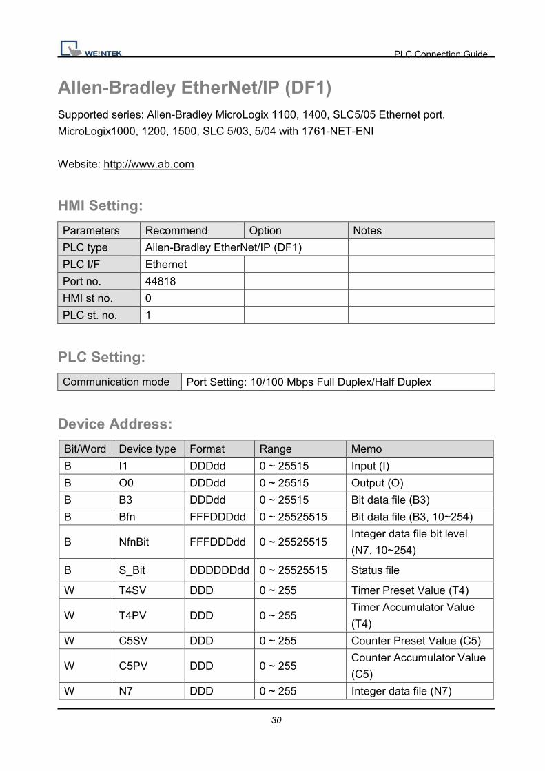
Allen-Bradley EtherNet/IP (DF1) Supported series: Allen-Bradley MicroLogix 1100, 1400, SLC5/05 Ethernet port.
MicroLogix1000, 1200, 1500, SLC 5/03, 5/04 with 1761-NET-ENI
Website: http://www.ab.com
HMI Setting:
Parameters Recommend Option Notes
PLC type Allen-Bradley EtherNet/IP (DF1)
PLC I/F Ethernet
Port no. 44818
HMI st no. 0
PLC st. no. 1
PLC Setting:
Communication mode Port Setting: 10/100 Mbps Full Duplex/Half Duplex
Device Address:
Bit/Word Device type Format Range Memo
B I1 DDDdd 0 ~ 25515 Input (I)
B O0 DDDdd 0 ~ 25515 Output (O)
B B3 DDDdd 0 ~ 25515 Bit data file (B3)
B Bfn FFFDDDdd 0 ~ 25525515 Bit data file (B3, 10~254)
B NfnBit FFFDDDdd 0 ~ 25525515 Integer data file bit level
(N7, 10~254)
B S_Bit DDDDDDdd 0 ~ 25525515 Status file
W T4SV DDD 0 ~ 255 Timer Preset Value (T4)
W T4PV DDD 0 ~ 255 Timer Accumulator Value
(T4)
W C5SV DDD 0 ~ 255 Counter Preset Value (C5)
W C5PV DDD 0 ~ 255 Counter Accumulator Value
(C5)
W N7 DDD 0 ~ 255 Integer data file (N7)
PLC Connection Guide
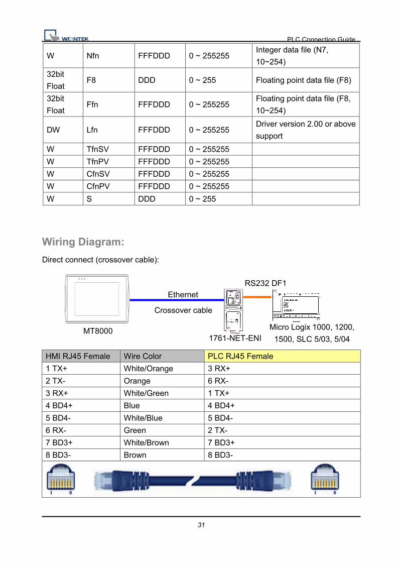
31
W Nfn FFFDDD 0 ~ 255255 Integer data file (N7,
10~254)
32bit
Float F8 DDD 0 ~ 255 Floating point data file (F8)
32bit
Float Ffn FFFDDD 0 ~ 255255
Floating point data file (F8,
10~254)
DW Lfn FFFDDD 0 ~ 255255 Driver version 2.00 or above
support
W TfnSV FFFDDD 0 ~ 255255
W TfnPV FFFDDD 0 ~ 255255
W CfnSV FFFDDD 0 ~ 255255
W CfnPV FFFDDD 0 ~ 255255
W S DDD 0 ~ 255
Wiring Diagram:
Direct connect (crossover cable):
HMI RJ45 Female Wire Color PLC RJ45 Female
1 TX+ White/Orange 3 RX+
2 TX- Orange 6 RX-
3 RX+ White/Green 1 TX+
4 BD4+ Blue 4 BD4+
5 BD4- White/Blue 5 BD4-
6 RX- Green 2 TX-
7 BD3+ White/Brown 7 BD3+
8 BD3- Brown 8 BD3-
Ethernet
Crossover cable
MT8000 1761-NET-ENI
Micro Logix 1000, 1200,
1500, SLC 5/03, 5/04
RS232 DF1 COM CPU PWR
PLC Connection Guide
32
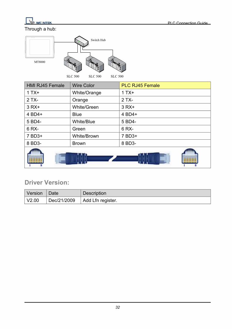
Through a hub:
SLC 500 SLC 500 SLC 500
MT8000
Switch Hub
HMI RJ45 Female Wire Color PLC RJ45 Female
1 TX+ White/Orange 1 TX+
2 TX- Orange 2 TX-
3 RX+ White/Green 3 RX+
4 BD4+ Blue 4 BD4+
5 BD4- White/Blue 5 BD4-
6 RX- Green 6 RX-
7 BD3+ White/Brown 7 BD3+
8 BD3- Brown 8 BD3-
Driver Version:
Version Date Description
V2.00 Dec/21/2009 Add Lfn register.

PLC Connection Guide
33
Allen-Bradley PLC5
Website: http://www.ab.com
HMI Setting:
Parameters Recommend Option Notes
PLC type Allen-Bradley PLC5
PLC I/F RS232
Baud rate 19200 9600, 19200
Parity Even Even, Odd, None
Data bits 8 8
Stop bits 1 1
HMI st. no. 0
PLC st. no. 1 1-31
PLC Setting:
Communication mode DF1 Full Duplex protocol 19200, None, 8, 1 (default)
Allen-Bradley PLC-5 Family PLCs using the DF1 Full Duplex protocol.
For the PLC-5/10, PLC-5/15 and PLC-5/25 the MT8000 should be connected to the DF1
port on the 1785-KE module; for the PLC-5/11, PLC-5/20, PLC-5/30 and PLC-5/40 the
MT8000 should be connected to the Channel 0 Port on the PLC.
Device Address:
Bit/Word Device type Format Range Memo
B I1 DDDdd 0 ~ 25515 Input (I)
B O0 DDDdd 0 ~ 25515 Output (O)
B B3 DDDdd 0 ~ 25515 Bit data file (B3)
B B10~13 DDDdd 0 ~ 25515 Bit data file (B10~13)
B S_Bit DDDDDDdd 0 ~ 25599915
B Bfn FFFDDDdd 0 ~ 25599915
B NfnBit FFFDDDdd 0 ~ 25599915
W T4SV DDD 0 ~ 999 Timer Preset Value (T4)
W T4PV DDD 0 ~ 999 Timer Accumulator Value (T4)

PLC Connection Guide
34
Bit/Word Device type Format Range Memo
W C5SV DDD 0 ~ 999 Counter Preset Value (C5)
W C5PV DDD 0 ~ 999 Counter Accumulator Value
(C5)
W N7 DDD 0 ~ 999 Integer data file (N7)
W N10~15 DDD 0 ~ 999 Integer data file (N10~15)
W F8 DDD 0 ~ 999 Floating point data file (F8)
W Nfn FFFDDD 0 ~ 255999 Integer data file (V2.5.0 or
newer)
W Ffn FFFDDD 0 ~ 255999 Floating point data file (V2.5.0
or newer)
W TfnSV FFFDDD 0 ~ 255999
W TfnPV FFFDDD 0 ~ 255999
W CfnSV FFFDDD 0 ~ 255999
W CfnPV FFFDDD 0 ~ 255999
W S DDD 0 ~ 255
Wiring Diagram:
9P D-Sub to 25P D-Sub: PLC5 CPU CH0
HMI COM1
RS232 9P
D-Sub Male
HMI COM2
RS232 9P
D-Sub Male
HMI COM3
RS232 9P
D-Sub Female
AB CPU CH0 RS232 25P
D-Sub Male
2 RX 6 RX 8 RX 3 TD
3 TX 4 TX 7 TX 2 RD
5 GND 5 GND 5 GND 5 GND
PLC Connection Guide
35
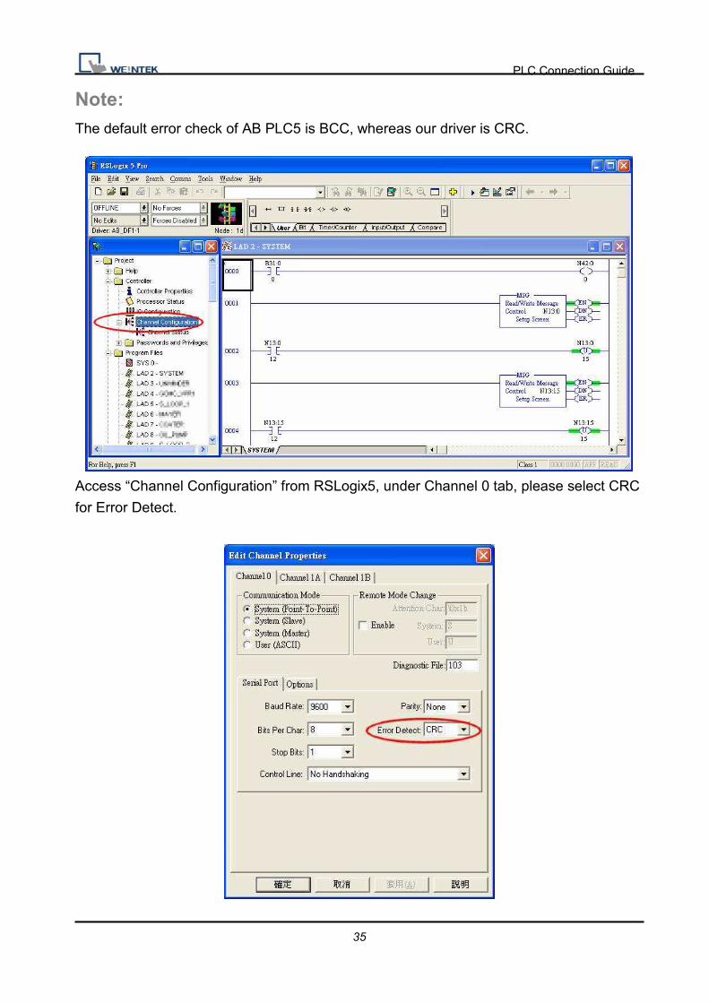
Note: The default error check of AB PLC5 is BCC, whereas our driver is CRC.
Access “Channel Configuration” from RSLogix5, under Channel 0 tab, please select CRC
for Error Detect.

PLC Connection Guide
36
Driver Version:
Version Date Description
V1.20 Apr/17/2009
PLC Connection Guide
37
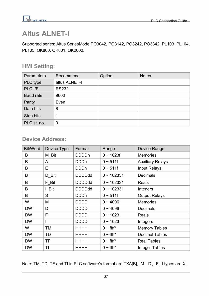
Altus ALNET-I Supported series: Altus SeriesMode PO3042, PO3142, PO3242, PO3342, PL103 ,PL104,
PL105, QK800, QK801, QK2000.
HMI Setting:
Parameters Recommend Option Notes
PLC type altus ALNET-I
PLC I/F RS232
Baud rate 9600
Parity Even
Data bits 8
Stop bits 1
PLC st. no. 0
Device Address:
Bit/Word Device Type Format Range Device Range
B M_Bit DDDDh 0 ~ 1023f Memories
B A DDDh 0 ~ 511f Auxiliary Relays
B E DDDh 0 ~ 511f Input Relays
B D_Bit DDDDdd 0 ~ 102331 Decimals
B F_Bit DDDDdd 0 ~ 102331 Reals
B I_Bit DDDDdd 0 ~ 102331 Integers
B S DDDh 0 ~ 511f Output Relays
W M DDDD 0 ~ 4096 Memories
DW D DDDD 0 ~ 4096 Decimals
DW F DDDD 0 ~ 1023 Reals
DW I DDDD 0 ~ 1023 Integers
W TM HHHH 0 ~ ffff* Memory Tables
DW TD HHHH 0 ~ ffff* Decimal Tables
DW TF HHHH 0 ~ ffff* Real Tables
DW TI HHHH 0 ~ ffff* Integer Tables
Note: TM, TD, TF and TI in PLC software’s format are TXA[B], �, �, �, I types are X.
PLC Connection Guide
38
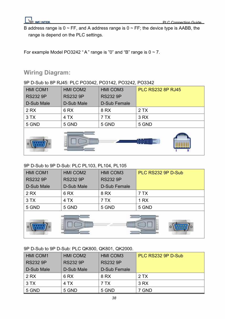
B address range is 0 ~ FF, and A address range is 0 ~ FF; the device type is AABB, the
range is depend on the PLC settings.
For example Model PO3242 “�” range is ”0” and “B” range is 0 ~ 7.
Wiring Diagram:
9P D-Sub to 8P RJ45: PLC PO3042, PO3142, PO3242, PO3342
HMI COM1
RS232 9P
D-Sub Male
HMI COM2
RS232 9P
D-Sub Male
HMI COM3
RS232 9P
D-Sub Female
PLC RS232 8P RJ45
2 RX 6 RX 8 RX 2 TX
3 TX 4 TX 7 TX 3 RX
5 GND 5 GND 5 GND 5 GND
9P D-Sub to 9P D-Sub: PLC PL103, PL104, PL105
HMI COM1
RS232 9P
D-Sub Male
HMI COM2
RS232 9P
D-Sub Male
HMI COM3
RS232 9P
D-Sub Female
PLC RS232 9P D-Sub
2 RX 6 RX 8 RX 7 TX
3 TX 4 TX 7 TX 1 RX
5 GND 5 GND 5 GND 5 GND
9P D-Sub to 9P D-Sub: PLC QK800, QK801, QK2000.
HMI COM1
RS232 9P
D-Sub Male
HMI COM2
RS232 9P
D-Sub Male
HMI COM3
RS232 9P
D-Sub Female
PLC RS232 9P D-Sub
2 RX 6 RX 8 RX 2 TX
3 TX 4 TX 7 TX 3 RX
5 GND 5 GND 5 GND 7 GND

PLC Connection Guide
39
Driver Version:
Version Date Description
V1.10 Jul/24/2009

PLC Connection Guide
40
Baumuller Website: http://www.baumuller.com/
HMI Setting:
Parameters Recommend Option Notes
PLC type Baumuller
PLC I/F RS485 4W
Baud rate 19200 9600, 19200
Parity Even Even, Odd, None
Data bits 8 7 or 8
Stop bits 1 1 or 2
HMI st. no. 0
PLC st. no. 0 Defaults
PLC Setting:
Communication mode RK 512 Protocol, 19200, 8, 1, Even
Device Address:
Bit/Word Device type Format Range Memo
B DB0_bit ~
DB29_bit DDDh 0 ~ 255f
W DB0 ~ DB29 DDD 0 ~ 255

PLC Connection Guide
41
Wiring Diagram:
9P D-Sub to 9P D-Sub:
HMI COM1
RS485 4W 9P
D-Sub Female
Baumuller servo RS422 9P
D-Sub Female
1 RX- 1 TXD-
2 RX+ 9 TXD+
3 TX- 5 RXD-
4 TX+ 6 RXD+
5 GND 8 GND
Driver Version:
Version Date Description
V1.10 Apr/17/2009

PLC Connection Guide
42
Change Supported series: Compressor controller
HMI Setting:
Parameters Recommend Option Notes
PLC type Change
PLC I/F RS485 2W
Baud rate 9600
Parity None
Data bits 8
Stop bits 1
PLC st. no. 1 1~6
Device Address: Bit/Word Device type Format Range Memo B CTL DDD 0 ~ 5, 128, 150 Write only DW SET DDD 1 ~ 57, 128 DW STATUS DD 1 ~ 20 Read only
Wiring Diagram:
9P D-Sub to 9P D-Sub:
HMI COM1
RS485 2W 9P
D-Sub Female
HMI COM3
RS485 2W 9P
D-Sub Female
Change RS485 2W
1 RX- 6 Data- 15 D-
2 RX+ 9 Data+ 16 D+
5 GND 5 GND

PLC Connection Guide
43
Driver Version:
Version Date Description
V1.00 Jan/07/2011 Driver released

PLC Connection Guide
44
Cimon CM1-CP4A/ECO1A Supported series: Cimon CM1 series, CP4A module
Website: http://www.kdtsys.com
HMI Setting:
Parameters Recommend Option Notes
PLC type Cimon CM1-CP4A/ECO1A
PLC I/F RS232
Baud rate 38400
Data bits 8
Parity None
Stop bits 1
PLC st. no. 1
Device Address:
Bit/Word Device type Format Range Memo
B X DDh 0 ~ 23f 0-1F read only
B Y DDh 0 ~ 23f
B M DDDh 0 ~ 511f
B K DDDh 0 ~ 127f
B T DDDh 0 ~ 102f
B C DDDh 0 ~ 102f
B L DDDh 0 ~ 127f
B F DDDh 0 ~ 127f Read only
W D DDDD 0 ~ 4999
W S DD 0 ~ 99 Max. range: 99
W TS DDDD 0 ~ 1023
W TC DDDD 0 ~ 1023
W CC DDDD 0 ~ 1023
W CS DDDD 0 ~ 1023

PLC Connection Guide
45
Wiring Diagram:
9P D-Sub to 6P RJ11:
HMI COM1
RS232 9P
D-Sub Male
HMI COM2
RS232 9P
D-Sub Male
HMI COM3
RS232 9P
D-Sub Female
CM1-CP4A RS232 6P RJ11
Female
2 RX 6 RX 8 RX 2 TXD
3 TX 4 TX 7 TX 3 RXD
5 GND 5 GND 5 GND 5 GND
Driver Version:
Version Date Description
V1.20 Nov/30/2009

PLC Connection Guide
46
Cimon CM1-SC02A Supported series: Cimon CM series, SC02A module
Website: http://www.kdtsys.com
HMI Setting:
Parameters Recommend Option Notes
PLC type Cimon CM1-SC02A
Com port RS232
Baud rate 38400
Data bits 8
Parity None
Stop bits 1
PLC st. no. 1
Device Address:
Bit/Word Device type Format Range Memo
B X DDh 0 ~ 23f 0-1F read only
B Y DDh 0 ~ 23f 0-F read only
B M DDDh 0 ~ 511f
B K DDDh 0 ~ 127f
B T DDDh 0 ~ 102f
B C DDDh 0 ~ 102f
B L DDDh 0 ~ 127f
B F DDDh 0 ~ 127f Read only
W D DDDD 0 ~ 4999
W S DD 0 ~ 99 Max. range: 99
W TS DDDD 0 ~ 1023
W TC DDDD 0 ~ 1023
W CC DDDD 0 ~ 1023
W CS DDDD 0 ~ 1023
PLC Connection Guide
47
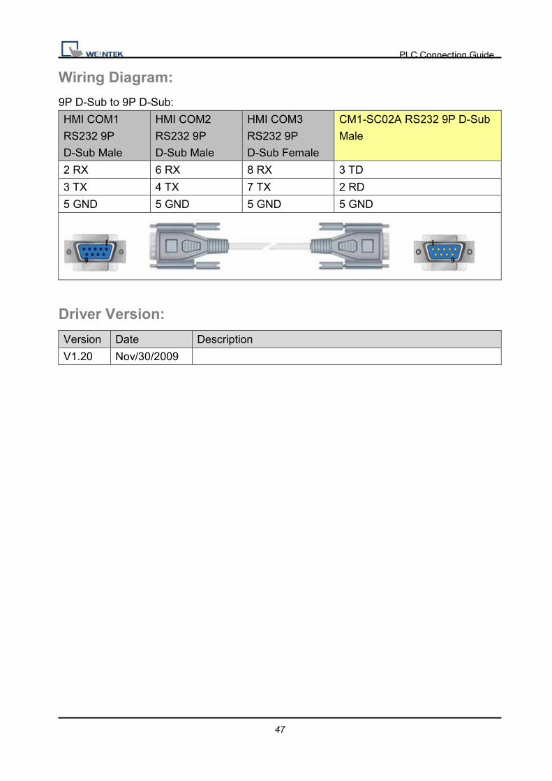
Wiring Diagram:
9P D-Sub to 9P D-Sub:
HMI COM1
RS232 9P
D-Sub Male
HMI COM2
RS232 9P
D-Sub Male
HMI COM3
RS232 9P
D-Sub Female
CM1-SC02A RS232 9P D-Sub
Male
2 RX 6 RX 8 RX 3 TD
3 TX 4 TX 7 TX 2 RD
5 GND 5 GND 5 GND 5 GND
Driver Version:
Version Date Description
V1.20 Nov/30/2009
PLC Connection Guide
48
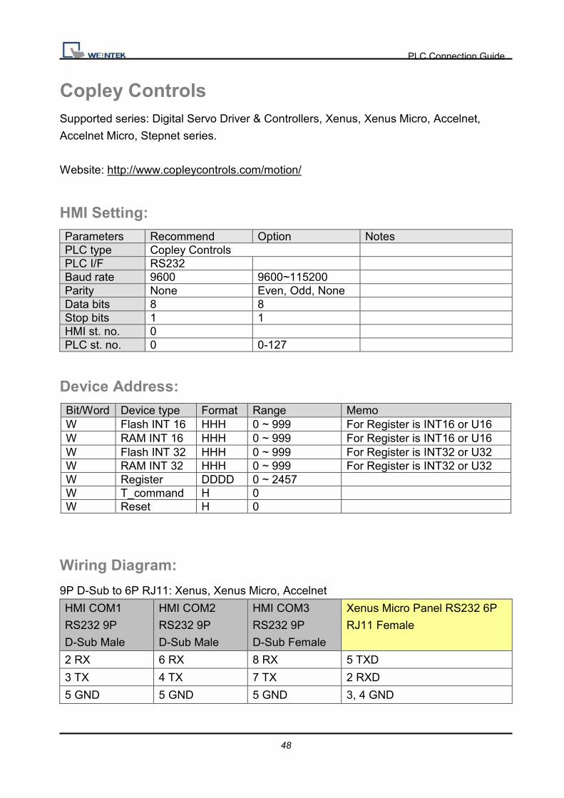
Copley Controls Supported series: Digital Servo Driver & Controllers, Xenus, Xenus Micro, Accelnet,
Accelnet Micro, Stepnet series.
Website: http://www.copleycontrols.com/motion/
HMI Setting: Parameters Recommend Option Notes PLC type Copley Controls PLC I/F RS232 Baud rate 9600 9600~115200 Parity None Even, Odd, None Data bits 8 8 Stop bits 1 1 HMI st. no. 0 PLC st. no. 0 0-127
Device Address:
Bit/Word Device type Format Range Memo W Flash INT 16 HHH 0 ~ 999 For Register is INT16 or U16 W RAM INT 16 HHH 0 ~ 999 For Register is INT16 or U16 W Flash INT 32 HHH 0 ~ 999 For Register is INT32 or U32 W RAM INT 32 HHH 0 ~ 999 For Register is INT32 or U32 W Register DDDD 0 ~ 2457 W T_command H 0 W Reset H 0
Wiring Diagram:
9P D-Sub to 6P RJ11: Xenus, Xenus Micro, Accelnet
HMI COM1
RS232 9P
D-Sub Male
HMI COM2
RS232 9P
D-Sub Male
HMI COM3
RS232 9P
D-Sub Female
Xenus Micro Panel RS232 6P
RJ11 Female
2 RX 6 RX 8 RX 5 TXD
3 TX 4 TX 7 TX 2 RXD
5 GND 5 GND 5 GND 3, 4 GND

PLC Connection Guide
49
9P D-Sub to 6P RJ11: Stepnet
HMI COM1
RS232 9P
D-Sub Male
HMI COM2
RS232 9P
D-Sub Male
HMI COM3
RS232 9P
D-Sub Female
Stepnet RS232 6P RJ11
Female
2 RX 6 RX 8 RX 5 TXD
3 TX 4 TX 7 TX 2 RXD
5 GND 5 GND 5 GND 3, 4 GND
Accelnet Micro:
HMI COM1
RS232 9P
D-Sub Male
HMI COM2
RS232 9P
D-Sub Male
HMI COM3
RS232 9P
D-Sub Female
Accelnet Micro Panel RS232 J5
Cable Connector
2 RX 6 RX 8 RX 29 TXD
3 TX 4 TX 7 TX 14 RXD
5 GND 5 GND 5 GND 15 GND
Driver Version:
Version Date Description
V1.20 Dec/30/2008

PLC Connection Guide
50
CROUZET M3 (FBD)
HMI Setting:
Parameters Recommend Option Notes
PLC type CROUZET M3 (FBD)
PLC I/F RS232
Baud rate 115200
Data bits 7
Parity Even
Stop bits 1
PLC st. no. 1
Device Address:
Bit/Word Device type Format Range Memo
B SLI_Bit DDh 1(0) ~ 24(f) Serial link input
B SLO_Bit DDh 25(0) ~ 48(f) Serial link output (read only)
W IA DD 1 ~ 99 Analogy input (default: 1 ~ 4)
W SL_IN DD 1 ~ 24 Serial link input
W SL_OUT DD 25 ~ 48 Serial link output (read only)
Wiring Diagram:
9P D-Sub to 9P D-Sub:
HMI COM1
RS232 9P
D-Sub Male
CROUZET M3 RS232 9P
D-Sub Female (Extension
Cable)
2 RX 2 TD
3 TX 3 RD
5 GND 5 GND
7 RTS 4 DTR

PLC Connection Guide
51
(3m serial link cable)
Note: Please use 3m serial link cable
(Accessories from Millenium 3) and extension
cable (as above) to communicate with HMI
series.
Driver Version:
Version Date Description
V1.10 Oct/26/2010

PLC Connection Guide
52
CROUZET M3 (LAD)
HMI Setting:
Parameters Recommend Option Notes
PLC type CROUZET M3 (LAD)
PLC I/F RS232
Baud rate 115200
Data bits 7
Parity Even
Stop bits 1
PLC st. no. 1
Device Address:
Bit/Word Device type Format Range Memo
B I DD 1 ~ 99 Input (default: 1 ~ 4)
B O DD 1 ~ 99 Output (default: 1 ~ 4)
B M DD 1 ~ 28 Relay
B SLI_Bit DDh 1(0) ~ 24(f) Serial link input
B SLO_Bit DDh 25(0) ~ 48(f) Serial link output (read only)
W IA DD 1 ~ 99 Analogy input (default: 1 ~ 4)
W T DD 1 ~ 12 Timer
W C DD 1 ~ 16 Counter
W SL_IN DD 1 ~ 24 Serial link input
W SL_OUT DD 25 ~ 48 Serial link output (read only)

PLC Connection Guide
53
Wiring Diagram:
9P D-Sub to 9P D-Sub:
HMI COM1
RS232 9P
D-Sub Male
CROUZET M3 RS232 9P
D-Sub Female (Extension
Cable)
2 RX 2 TD
3 TX 3 RD
5 GND 5 GND
7 RTS 4 DTR
(3m serial link cable)
Note: Please use 3m serial link cable
(Accessories from Millenium 3) and extension
cable (as above) to communicate with HMI
series.

PLC Connection Guide
54
Driver Version:
Version Date Description
V1.20 Oct/26/2010
PLC Connection Guide
55
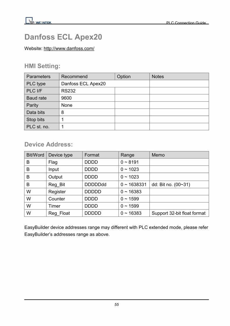
Danfoss ECL Apex20 Website: http://www.danfoss.com/
HMI Setting:
Parameters Recommend Option Notes
PLC type Danfoss ECL Apex20
PLC I/F RS232
Baud rate 9600
Parity None
Data bits 8
Stop bits 1
PLC st. no. 1
Device Address:
Bit/Word Device type Format Range Memo
B Flag DDDD 0 ~ 8191
B Input DDDD 0 ~ 1023
B Output DDDD 0 ~ 1023
B Reg_Bit DDDDDdd 0 ~ 1638331 dd: Bit no. (00~31)
W Register DDDDD 0 ~ 16383
W Counter DDDD 0 ~ 1599
W Timer DDDD 0 ~ 1599
W Reg_Float DDDDD 0 ~ 16383 Support 32-bit float format
EasyBuilder device addresses range may different with PLC extended mode, please refer
EasyBuilder’s addresses range as above.

PLC Connection Guide
56
Wiring Diagram:
9P D-Sub to 9P D-Sub:
HMI COM1
RS232 9P
D-Sub Male
HMI COM2
RS232 9P
D-Sub Male
HMI COM3
RS232 9P
D-Sub Female
ECL Apex20 Controller RS232
9P D-Sub Male
2 RX 6 RX 8 RX 3 TXD
3 TX 4 TX 7 TX 2 RXD
5 GND 5 GND 5 GND 5 GND
7 RTS circuit
8 CTS
HMI COM1
RS485 2W 9P
D-Sub Female
HMI COM3
RS485 2W 9P
D-Sub Female
ECL Apex20 Controller
Port#1 / Port#0
1 RX- 6 Data- 11 / 29
2 RX+ 9 Data+ 12 / 28
5 GND 5 GND
Driver Version:
Version Date Description
V1.30 Jan/10/2011

PLC Connection Guide
57
Danfoss FC Series Supported series: FC051, FC100, FC200, FC300, VLT Micro Driver.
Website: http://www.danfoss.com/
HMI Setting:
Parameters Recommend Option Notes
PLC type Danfoss FC Series
PLC I/F RS485 2W
Baud rate 9600
Parity Even
Data bits 8
Stop bits 1
PLC st. no. 1
Device Address:
Para_Index 310.1=31001, Para_Index310.0=31000
Wiring Diagram:
HMI COM1
RS485 2W 9P
D-Sub Female
HMI COM3
RS485 2W 9P
D-Sub Female
FC RS485
1 RX- 6 Data- 69 D-
2 RX+ 9 Data+ 68 D+
5 GND 5 GND
Bit/Word Device type Format Range Memo
W Parameter 09 DDDD 0 ~ 9999 Set Parameter DW Reference 10 D 0 ~ 1 Control Bus Reference DW Para_Index 11 DDDDDD 0 ~ 999999 Set Parameter(Index)

PLC Connection Guide
58
*RW100 set PCD1 Control Word of station 1
*RW101 read PCD1 Status Word of station 1
*RW102 set PCD2 Control Word of station 2
*RW103 read PCD2 Status Word of station 2
*RW104 set PCD3 Control Word of station 3
*RW105 read PCD3 Status Word of station 3
*RW106 set PCD4 Control Word of station 4
*RW107 read PCD4 Status Word of station 4
Driver Version:
Version Date Description
V1.10 Jan/14/2010

PLC Connection Guide
59
Danfoss VLT2800 Series Supported series: VLT2800 series
Website: http://www.danfoss.com/
HMI Setting:
Parameters Recommend Option Notes
PLC type Danfoss VLT2800 Series
PLC I/F RS485 2W
Baud rate 9600
Parity Even
Data bits 8
Stop bits 1
PLC st. no. 1 0-126 According to PLC
PLC Setting:
Communication mode 9600, Even, 8, 1 (default)
Device Address:
Bit/Word Device type Format Range Memo W Reference D 0 ~ 1 Control Bus Reference DW Parameter DDDD 0 ~ 2000 Set Parameter
It is relate to station number, if station number is 1, control word is RW100 and RW101; if
station number is 2, the control word is RW102 and RW103…following this rule.

PLC Connection Guide
60
Wiring Diagram:
HMI COM1
RS485 2W 9P
D-Sub Female
HMI COM3
RS485 2W 9P
D-Sub Female
VLT2800 RS485
1 RX- 6 Data- 69 D-
2 RX+ 9 Data+ 68 D+
5 GND 5 GND
Driver Version:
Version Date Description
V1.10 Dec/30/2008
PLC Connection Guide
61
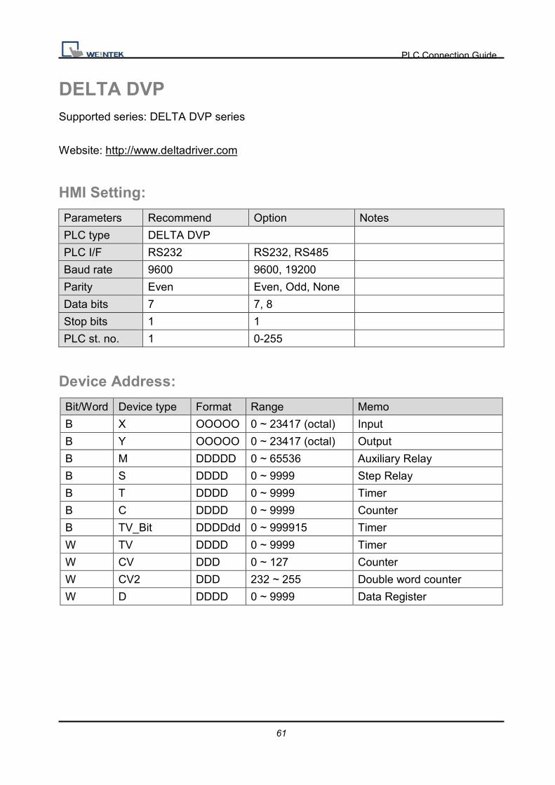
DELTA DVP Supported series: DELTA DVP series
Website: http://www.deltadriver.com
HMI Setting:
Parameters Recommend Option Notes
PLC type DELTA DVP
PLC I/F RS232 RS232, RS485
Baud rate 9600 9600, 19200
Parity Even Even, Odd, None
Data bits 7 7, 8
Stop bits 1 1
PLC st. no. 1 0-255
Device Address:
Bit/Word Device type Format Range Memo
B X OOOOO 0 ~ 23417 (octal) Input
B Y OOOOO 0 ~ 23417 (octal) Output
B M DDDDD 0 ~ 65536 Auxiliary Relay
B S DDDD 0 ~ 9999 Step Relay
B T DDDD 0 ~ 9999 Timer
B C DDDD 0 ~ 9999 Counter
B TV_Bit DDDDdd 0 ~ 999915 Timer
W TV DDDD 0 ~ 9999 Timer
W CV DDD 0 ~ 127 Counter
W CV2 DDD 232 ~ 255 Double word counter
W D DDDD 0 ~ 9999 Data Register

PLC Connection Guide
62
Wiring Diagram:
9P D-Sub to 8P Mini-DIN:
HMI COM1
RS232 9P
D-Sub Male
HMI COM2
RS232 9P
D-Sub Male
HMI COM3
RS232 9P
D-Sub Female
DELTA DVP CPU Port RS232
8P Mini-DIN
2 RX 6 RX 8 RX 5 TXD
3 TX 4 TX 7 TX 4 RXD
5 GND 5 GND 5 GND 3/8 GND
Driver Version:
Version Date Description
V1.00 Dec/30/2008
PLC Connection Guide
63
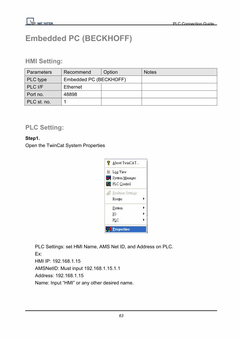
Embedded PC (BECKHOFF)
HMI Setting:
Parameters Recommend Option Notes
PLC type Embedded PC (BECKHOFF)
PLC I/F Ethernet
Port no. 48898
PLC st. no. 1
PLC Setting:
Step1.
Open the TwinCat System Properties
PLC Settings: set HMI Name, AMS Net ID, and Address on PLC.
Ex:
HMI IP: 192.168.1.15
AMSNetID: Must input 192.168.1.15.1.1
Address: 192.168.1.15
Name: Input “HMI” or any other desired name.

PLC Connection Guide
64
Step2.
Simulate PLC on PC. 2 Twincat drivers must be installed as follows:

PLC Connection Guide
65
PLC Connection Guide
66
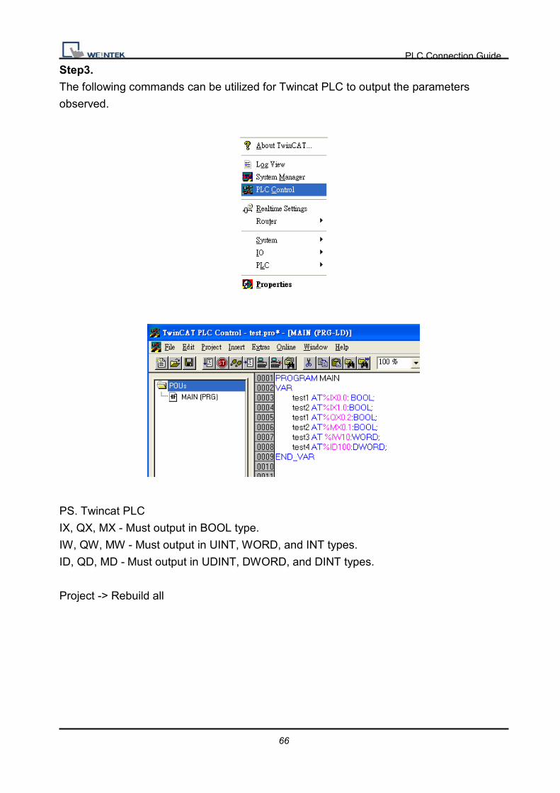
Step3.
The following commands can be utilized for Twincat PLC to output the parameters
observed.
PS. Twincat PLC
IX, QX, MX - Must output in BOOL type.
IW, QW, MW - Must output in UINT, WORD, and INT types.
ID, QD, MD - Must output in UDINT, DWORD, and DINT types.
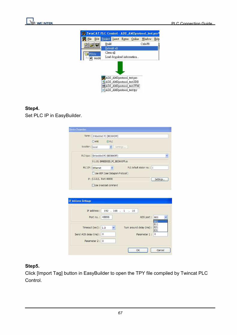
Project -> Rebuild all
PLC Connection Guide
67
Step4.
Set PLC IP in EasyBuilder.
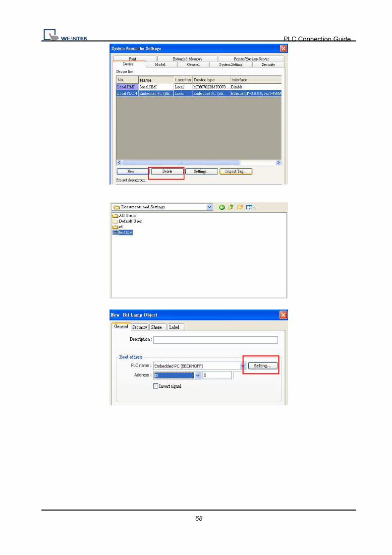
Step5.
Click [Import Tag] button in EasyBuilder to open the TPY file compiled by Twincat PLC
Control.
PLC Connection Guide
68
PLC Connection Guide
69
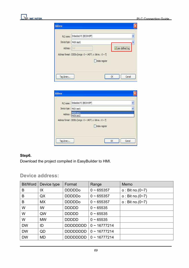
Step6.
Download the project compiled in EasyBuilder to HMI.
Device address:
Bit/Word Device type Format Range Memo
B IX DDDDDo 0 ~ 655357 o : Bit no.(0~7)
B QX DDDDDo 0 ~ 655357 o : Bit no.(0~7)
B MX DDDDDo 0 ~ 655357 o : Bit no.(0~7)
W IW DDDDD 0 ~ 65535
W QW DDDDD 0 ~ 65535
W MW DDDDD 0 ~ 65535
DW ID DDDDDDDD 0 ~ 16777214
DW QD DDDDDDDD 0 ~ 16777214
DW MD DDDDDDDD 0 ~ 16777214

PLC Connection Guide
70
Wiring Diagram:
Direct connect (crossover cable):
HMI RJ45 Female Wire Color PLC RJ45 Female
1 TX+ White/Orange 3 RX+
2 TX- Orange 6 RX-
3 RX+ White/Green 1 TX+
4 BD4+ Blue 4 BD4+
5 BD4- White/Blue 5 BD4-
6 RX- Green 2 TX-
7 BD3+ White/Brown 7 BD3+
8 BD3- Brown 8 BD3-
Through a hub:
HMI RJ45 Female Wire Color PLC RJ45 Female
1 TX+ White/Orange 1 TX+
2 TX- Orange 2 TX-
3 RX+ White/Green 3 RX+
4 BD4+ Blue 4 BD4+
5 BD4- White/Blue 5 BD4-
6 RX- Green 6 RX-
7 BD3+ White/Brown 7 BD3+
8 BD3- Brown 8 BD3-
Driver Version:
Version Date Description
V1.00 Dec/08/2010 Driver released.
PLC Connection Guide
71
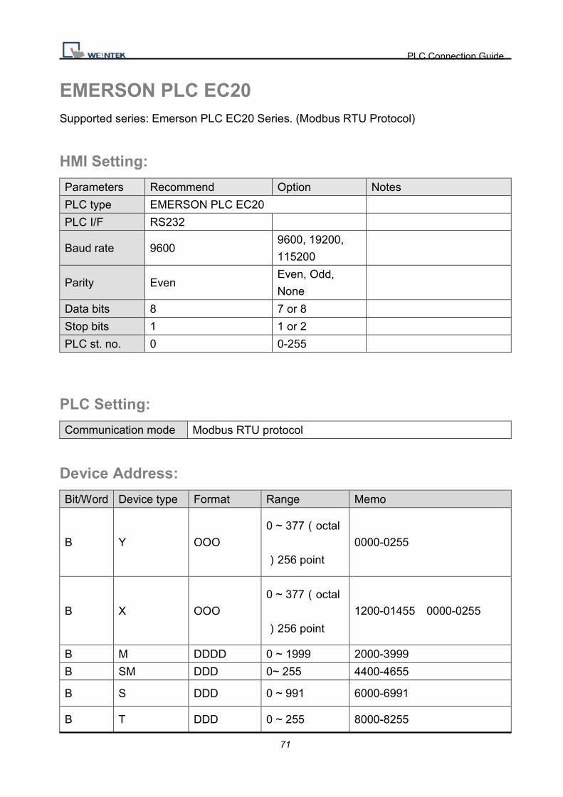
EMERSON PLC EC20 Supported series: Emerson PLC EC20 Series. (Modbus RTU Protocol)
HMI Setting:
Parameters Recommend Option Notes
PLC type EMERSON PLC EC20
PLC I/F RS232
Baud rate 9600 9600, 19200,
115200
Parity Even Even, Odd,
None
Data bits 8 7 or 8
Stop bits 1 1 or 2
PLC st. no. 0 0-255
PLC Setting:
Communication mode Modbus RTU protocol
Device Address:
Bit/Word Device type Format Range Memo
B Y OOO 0 ~ 377�octal
�256 point
0000-0255
B X OOO 0 ~ 377�octal
�256 point
1200-01455 0000-0255
B M DDDD 0 ~ 1999 2000-3999
B SM DDD 0~ 255 4400-4655
B S DDD 0 ~ 991 6000-6991
B T DDD 0 ~ 255 8000-8255
PLC Connection Guide
72
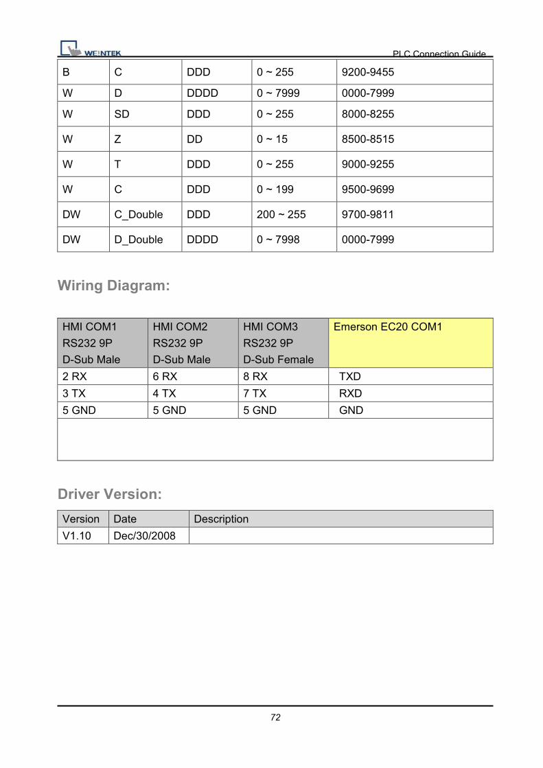
B C DDD 0 ~ 255 9200-9455
W D DDDD 0 ~ 7999 0000-7999
W SD DDD 0 ~ 255 8000-8255
W Z DD 0 ~ 15 8500-8515
W T DDD 0 ~ 255 9000-9255
W C DDD 0 ~ 199 9500-9699
DW C_Double DDD 200 ~ 255 9700-9811
DW D_Double DDDD 0 ~ 7998 0000-7999
Wiring Diagram:
HMI COM1
RS232 9P
D-Sub Male
HMI COM2
RS232 9P
D-Sub Male
HMI COM3
RS232 9P
D-Sub Female
Emerson EC20 COM1
2 RX 6 RX 8 RX TXD
3 TX 4 TX 7 TX RXD
5 GND 5 GND 5 GND GND
Driver Version:
Version Date Description
V1.10 Dec/30/2008

PLC Connection Guide
73
F930GOT Server Supported series: F930GOT general-purpose communication Type 1.
HMI Setting: Parameters Recommend Option Notes PLC type F930GOT Server PLC I/F RS232 Baud rate 38400 9600, 115200 Parity None Even, Odd, None Data bits 8 7 or 8 Stop bits 1 1 or 2 PLC st. no. 1
Device Address: Bit/Word Device type Format Range Memo B RB DDDD 0 ~ 2047 W RW DDDDD 0 ~ 65535
Note: In PLC name pull down menu don’t select F930GOT Server.
Please select Local HMI, Device type=RW.
Wiring Diagram:
9P D-Sub to 9P D-Sub:
HMI COM1
RS232 9P
D-Sub Male
HMI COM2
RS232 9P
D-Sub Male
HMI COM3
RS232 9P
D-Sub Female
Micro Computer Board RS232
2 RX 6 RX 8 RX TD
3 TX 4 TX 7 TX RD
5 GND 5 GND 5 GND GND

PLC Connection Guide
74
Protocol:
Read Command:
PC è HMI
02 ‘0’ CR
02 30 30 30 30 30 30 32 0D
Read RW0 1 word (2 bytes) STX = 0x02, ‘0’ = Read command, CR = 0x0D
Read address (hexadecimal)
0 ~ FFFF = RW0 ~ 65535
Size (hexadecimal)
2 ~ FE = 2 ~ 254 bytes = 1 ~ 127 word.
Size must be even.
HMI è PC (response)
02 CR
02 30 30 31 30 0D
RW0 = 0x0010 = 16
Write Command:
PC è HMI
02 ‘1’ CR
02 31 30 30 30 30 30 32 12 34 0D
Write RW0 = 0x1234
Read address (hexadecimal)
0 ~ FFFF = RW0 ~ 65535
Size (hexadecimal)
2 ~ FE = 2 ~ 254 bytes = 1 ~ 127 word.
Size must be even.
HMI è PC (response)
06
ACK = 0x06
Read address Size
Data1 …….Data2
Read address Size Data1 Data2 …….

PLC Connection Guide
75
Driver Version:
Version Date Description
V1.00 Aug/14/2009 Driver released.
PLC Connection Guide
76
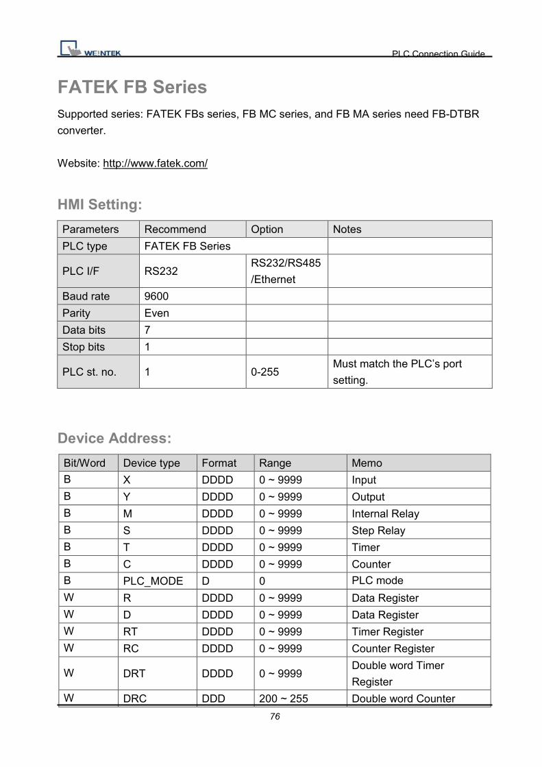
FATEK FB Series Supported series: FATEK FBs series, FB MC series, and FB MA series need FB-DTBR
converter.
Website: http://www.fatek.com/
HMI Setting:
Parameters Recommend Option Notes
PLC type FATEK FB Series
PLC I/F RS232 RS232/RS485
/Ethernet
Baud rate 9600
Parity Even
Data bits 7
Stop bits 1
PLC st. no. 1 0-255 Must match the PLC’s port
setting.
Device Address:
Bit/Word Device type Format Range Memo B X DDDD 0 ~ 9999 Input
B Y DDDD 0 ~ 9999 Output B M DDDD 0 ~ 9999 Internal Relay B S DDDD 0 ~ 9999 Step Relay B T DDDD 0 ~ 9999 Timer B C DDDD 0 ~ 9999 Counter B PLC_MODE D 0 PLC mode
W R DDDD 0 ~ 9999 Data Register W D DDDD 0 ~ 9999 Data Register W RT DDDD 0 ~ 9999 Timer Register W RC DDDD 0 ~ 9999 Counter Register
W DRT DDDD 0 ~ 9999 Double word Timer
Register W DRC DDD 200 ~ 255 Double word Counter

PLC Connection Guide
77
Register W WX DDDD 0 ~ 9999 Input word
W WY DDDD 0 ~ 9999 Output word
W WM DDDD 0 ~ 9999 Internal Relay word
Wiring Diagram:
9P D-Sub to 4P Mini-DIN: FBs Port0
HMI COM1
RS232 9P
D-Sub Male
HMI COM2
RS232 9P
D-Sub Male
HMI COM3
RS232 9P
D-Sub Female
FBs RS232 4P Mini-DIN
2 RX 6 RX 8 RX 3 TX
3 TX 4 TX 7 TX 4 RX
5 GND 5 GND 5 GND 2 GND
9P D-Sub to 9P D-Sub: FBs communication module
HMI COM1
RS232 9P
D-Sub Male
HMI COM2
RS232 9P
D-Sub Male
HMI COM3
RS232 9P
D-Sub Female
FBs communication module
RS232 9P D-Sub Male
2 RX 6 RX 8 RX 2 TX
3 TX 4 TX 7 TX 3 RX
5 GND 5 GND 5 GND 5 GND
FBs communication module 3P Terminal Block
HMI COM1
RS485 2W 9P
D-Sub Female
HMI COM3
RS485 2W 9P
D-Sub Female
FBs communication module
3P Terminal Block
1 RX- 6 Data- D-
2 RX+ 9 Data+ D+
5 GND 5 GND

PLC Connection Guide
78
9P D-Sub to 15P D-Sub: CPU Port
HMI COM1
RS232 9P
D-Sub Male
HMI COM2
RS232 9P
D-Sub Male
HMI COM3
RS232 9P
D-Sub Female
FB CPU Port RS232 15P
D-Sub Male
2 RX 6 RX 8 RX 2 TX
3 TX 4 TX 7 TX 1 RX
5 GND 5 GND 5 GND 6 GND
3 RTS circuit
4 CTS
9P D-Sub to 15P D-Sub: CPU Port RS485 2W
HMI COM1
RS485 2W 9P
D-Sub Female
HMI COM3
RS485 2W 9P
D-Sub Female
FB CPU Port RS485 2W 15P
D-Sub Male
1 RX- 6 Data- 7 D-
2 RX+ 9 Data+ 5 D+
5 GND 5 GND
Driver Version:
Version Date Description
V1.50 Jul/26/2010

PLC Connection Guide
79
Fuji NB Series Website: http://www.fujielectric.co.jp/fcs/eng/
HMI Setting:
Parameters Recommend Option Notes
PLC type Fuji NB Series
PLC I/F RS485 4W
Baud rate 19200
Parity Odd
Data bits 8
Stop bits 1
PLC st. no. 0
PLC Setting:
Communication mode NITP protocol / PLC Password (default is 0)
Device Address:
Bit/Word Device type Format Range Memo
B Y HHH 0 ~ 7ff Output Relay
B X HHH 0 ~ 3ff Input Relay
B M HHH 0 ~ fff Internal Relay
B L HHH 0 ~ fff Latch Relay
B C HH 0 - ff Counter
B M_Spe HHHH 0 ~ 81ff Special Relay
B T HHH 0 ~ 1ff Timer
W CV HHH 0 ~ 3ff Counter value
W TV HHH 0 ~ 3ff Timer value
W D HHHH 0 ~ 1fff Data Register
W D_Spe HHHH 0 ~ 81ff Special Register

PLC Connection Guide
80
Wiring Diagram:
9P D-Sub to 8P RJ45:
HMI COM1
RS485 4W 9P
D-Sub Female
Fuji NB Series RS422 8P RJ45
1 RX- 4 TX-
2 RX+ 3 TX+
3 TX- 6 RX-
4 TX+ 5 RX+
5 GND
Driver Version:
Version Date Description
V1.10 May/05/2009

PLC Connection Guide
81
GE Fanuc CMM Website: http://www.ge.com
HMI Setting:
Parameters Recommend Option Notes
PLC type GE Fanuc CMM
PLC I/F RS232 RS232/RS485
Baud rate 19200 9600,19200,38400,5
7600,115200
Parity Odd Even, Odd, None
Data bits 8 7,8 Must set as 8 to this protocol
Stop bits 1 1, 2
PLC st. no. 0 0-255 Does not apply to this
protocol
PLC Setting:
Refer to related PLC manual.
Device Address:
Bit/Word Device type Format Range Memo
B I DDDDD 1 ~ 10000 Input relay
B Q DDDDD 1 ~ 10000 Output relay
B M DDDDD 1 ~ 10000 Auxiliary relay
B G DDDD 1 ~ 7680
B T DDD 1 ~ 256
B SA DDD 1 ~ 128
B SB DDD 1 ~ 128
B SC DDD 1 ~ 128
B S DDD 1 ~ 128
W AI DDDDD 1 ~ 10000 Analog input register
W AQ DDDDD 1 ~ 10000 Analog output register
W R DDDDD 1 ~ 32640 Data register

PLC Connection Guide
82
Wiring Diagram:
9P D-Sub to 15P D-Sub: CPU Port 90-30/VersaMax
HMI COM1
RS485 4W 9P
D-Sub Male
90-30/VersaMax RS485 2W
15P D-Sub
1 RX- 12 SDA
2 RX+ 13 SDB
5 GND 7 GND
3 TX- 10 RDA
4 TX+ 11 RDB circuit
9 RT
6 RTSA circuit
15 CTSA
8 RTSB circuit
14 CTSB
9P D-Sub to 6P RJ11: CPU �ort�(90-30 series CPU351/352/363/364)
HMI COM1
RS232 9P
D-Sub Female
90-30/90-70 series RS232 6P
RJ11
2 RX 2 TX
3 TX 5 RX
5 GND 3 GND

PLC Connection Guide
83
9P D-Sub to 9P D-Sub: CPU �ort�(VersaMax series CPU001/002/005/E05)
HMI COM1
RS232 9P
D-Sub Male
HMI COM2
RS232 9P
D-Sub Male
HMI COM3
RS232 9P
D-Sub Female
VersaMax series RS232 9P
D-Sub Female
2 RX 6 RX 8 RX 2 TX
3 TX 4 TX 7 TX 3 RX
5 GND 5 GND 5 GND 5 GND
Driver Version:
Version Date Description
V1.00 Jul/09/2009 Driver released.

PLC Connection Guide
84
GE Fanuc RX3i Website: http://www.ge.com
HMI Setting:
Parameters Recommend Option Notes
PLC type GE Fanuc RX3i
PLC I/F RS232 RS232, RS485
Baud rate 19200 1200~115200
Data bits 8
Parity Odd None, Even, Odd
Stop bits 1 1 or 2
PLC st. no. 1 1~99
PLC Setting:
Refer to related PLC manual.
Device Address:
Bit/Word Device type Format Range Memo
B I DDDDD 1 ~ 32768
B Q DDDDD 1 ~ 32768
B M DDDDD 1 ~ 32768
B G DDDD 1 ~ 7680
B T DDDD 1 ~ 1024
B SA DDD 1 ~ 128
B SB DDD 1 ~ 128
B SC DDD 1 ~ 128
B S DDD 1 ~ 128
W AI DD 1 ~ 64
W AQ DD 1 ~ 64
W R DDDD 1 ~ 2048
PLC Connection Guide
85
Wiring Diagram:
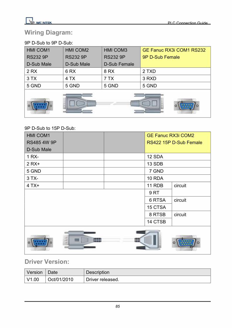
9P D-Sub to 9P D-Sub:
HMI COM1
RS232 9P
D-Sub Male
HMI COM2
RS232 9P
D-Sub Male
HMI COM3
RS232 9P
D-Sub Female
GE Fanuc RX3i COM1 RS232
9P D-Sub Female
2 RX 6 RX 8 RX 2 TXD
3 TX 4 TX 7 TX 3 RXD
5 GND 5 GND 5 GND 5 GND
9P D-Sub to 15P D-Sub:
HMI COM1
RS485 4W 9P
D-Sub Male
GE Fanuc RX3i COM2
RS422 15P D-Sub Female
1 RX- 12 SDA
2 RX+ 13 SDB
5 GND 7 GND
3 TX- 10 RDA
4 TX+ 11 RDB circuit
9 RT
6 RTSA circuit
15 CTSA
8 RTSB circuit
14 CTSB
Driver Version:
Version Date Description
V1.00 Oct/01/2010 Driver released.
PLC Connection Guide
86
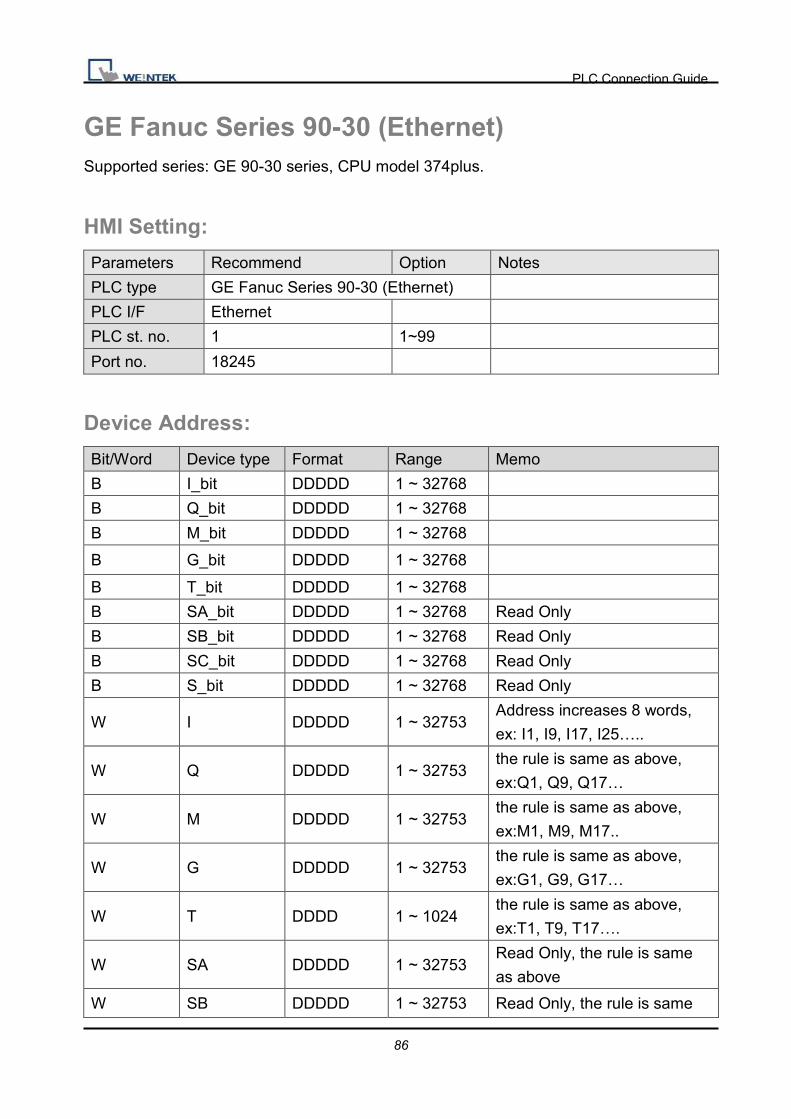
GE Fanuc Series 90-30 (Ethernet) Supported series: GE 90-30 series, CPU model 374plus.
HMI Setting:
Parameters Recommend Option Notes
PLC type GE Fanuc Series 90-30 (Ethernet)
PLC I/F Ethernet
PLC st. no. 1 1~99
Port no. 18245
Device Address:
Bit/Word Device type Format Range Memo
B I_bit DDDDD 1 ~ 32768
B Q_bit DDDDD 1 ~ 32768
B M_bit DDDDD 1 ~ 32768
B G_bit DDDDD 1 ~ 32768
B T_bit DDDDD 1 ~ 32768
B SA_bit DDDDD 1 ~ 32768 Read Only
B SB_bit DDDDD 1 ~ 32768 Read Only
B SC_bit DDDDD 1 ~ 32768 Read Only
B S_bit DDDDD 1 ~ 32768 Read Only
W I DDDDD 1 ~ 32753 Address increases 8 words,
ex: I1, I9, I17, I25…..
W Q DDDDD 1 ~ 32753 the rule is same as above,
ex:Q1, Q9, Q17…
W M DDDDD 1 ~ 32753 the rule is same as above,
ex:M1, M9, M17..
W G DDDDD 1 ~ 32753 the rule is same as above,
ex:G1, G9, G17…
W T DDDD 1 ~ 1024 the rule is same as above,
ex:T1, T9, T17….
W SA DDDDD 1 ~ 32753 Read Only, the rule is same
as above
W SB DDDDD 1 ~ 32753 Read Only, the rule is same
PLC Connection Guide
87
as above
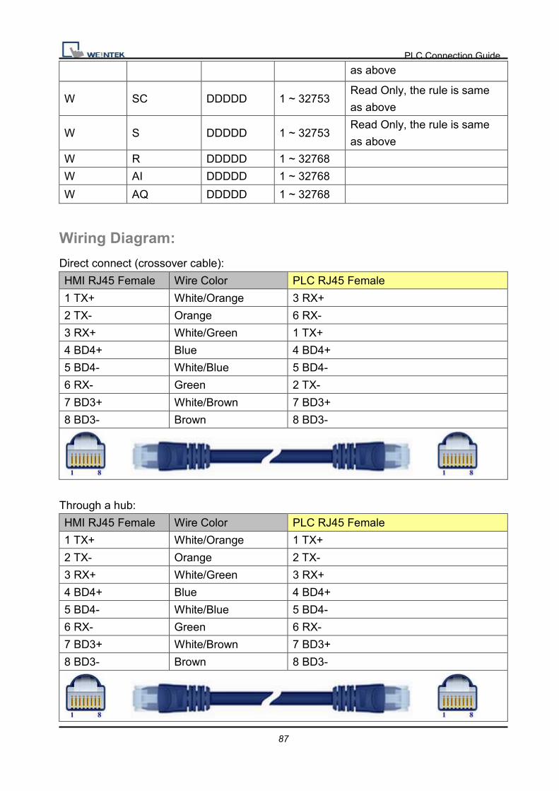
W SC DDDDD 1 ~ 32753 Read Only, the rule is same
as above
W S DDDDD 1 ~ 32753 Read Only, the rule is same
as above
W R DDDDD 1 ~ 32768
W AI DDDDD 1 ~ 32768
W AQ DDDDD 1 ~ 32768
Wiring Diagram:
Direct connect (crossover cable):
HMI RJ45 Female Wire Color PLC RJ45 Female
1 TX+ White/Orange 3 RX+
2 TX- Orange 6 RX-
3 RX+ White/Green 1 TX+
4 BD4+ Blue 4 BD4+
5 BD4- White/Blue 5 BD4-
6 RX- Green 2 TX-
7 BD3+ White/Brown 7 BD3+
8 BD3- Brown 8 BD3-
Through a hub:
HMI RJ45 Female Wire Color PLC RJ45 Female
1 TX+ White/Orange 1 TX+
2 TX- Orange 2 TX-
3 RX+ White/Green 3 RX+
4 BD4+ Blue 4 BD4+
5 BD4- White/Blue 5 BD4-
6 RX- Green 6 RX-
7 BD3+ White/Brown 7 BD3+
8 BD3- Brown 8 BD3-

PLC Connection Guide
88
Driver Version:
Version Date Description
V1.70 Apr/09/2010
PLC Connection Guide
89
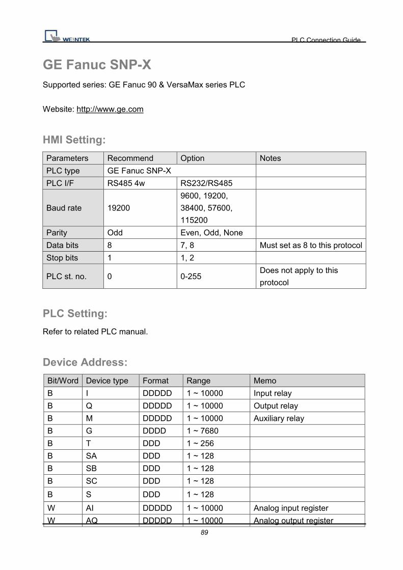
GE Fanuc SNP-X Supported series: GE Fanuc 90 & VersaMax series PLC
Website: http://www.ge.com
HMI Setting:
Parameters Recommend Option Notes
PLC type GE Fanuc SNP-X
PLC I/F RS485 4w RS232/RS485
Baud rate 19200
9600, 19200,
38400, 57600,
115200
Parity Odd Even, Odd, None
Data bits 8 7, 8 Must set as 8 to this protocol
Stop bits 1 1, 2
PLC st. no. 0 0-255 Does not apply to this
protocol
PLC Setting:
Refer to related PLC manual.
Device Address:
Bit/Word Device type Format Range Memo
B I DDDDD 1 ~ 10000 Input relay
B Q DDDDD 1 ~ 10000 Output relay
B M DDDDD 1 ~ 10000 Auxiliary relay
B G DDDD 1 ~ 7680
B T DDD 1 ~ 256
B SA DDD 1 ~ 128
B SB DDD 1 ~ 128
B SC DDD 1 ~ 128
B S DDD 1 ~ 128
W AI DDDDD 1 ~ 10000 Analog input register
W AQ DDDDD 1 ~ 10000 Analog output register

PLC Connection Guide
90
W R DDDDD 1 ~ 32640 Data register
Wiring Diagram:
Memo: 90 VersaMax series PLC of GE FANUC includes such series as 90-30, 90-70,
VersaMax Micro, VersaMax Nano and VersaMax,etc., CPU of 90-30series can pass
RS485 serial com port on module, utilize SNP serial communication protocol of GE to
connect with EasyView MT8000HMI, In addition,
CPU331/340/341/350/351/352/360/363/364 can also connect through CMM311
Communication Module, CPU351/352/363/364 also can connect through serial com port
on CPU Unit90-70 series CPU can also connect through CMM711 Communication
Module or connect through serial com port on CPU UnitRelevant software and hardware
are set up concretely please consult the technical manual that GE GE Fanuc offered.
9P D-Sub to 15P D-Sub: CPU �ort�(90-30/VersaMax)
HMI COM1
RS485 4W 9P
D-Sub Male
90-30/VersaMax RS422 15P
D-Sub Female
1 RX- 12 SDA
2 RX+ 13 SDB
5 GND 7 GND
3 TX- 10 RDA
4 TX+ 11 RDB circuit
9 RT
6 RTSA circuit
15 CTSA
8 RTSB circuit
14 CTSB

PLC Connection Guide
91
9P D-Sub to 6P RJ11: CPU �ort�(90-30 series CPU351/352/363/364)
HMI COM1
RS232 9P
D-Sub Female
90-30/90-70 series RS232 6P
RJ11
2 RX 2 TX
3 TX 5 RX
5 GND 3 GND
9P D-Sub to 9P D-Sub: CPU �ort�(VersaMax series CPU001/002/005/E05)
HMI COM1
RS232 9P
D-Sub Male
HMI COM2
RS232 9P
D-Sub Male
HMI COM3
RS232 9P
D-Sub Female
VersaMax series RS232 9P
D-Sub Female
2 RX 6 RX 8 RX 2 TX
3 TX 4 TX 7 TX 3 RX
5 GND 5 GND 5 GND 5 GND
Driver Version:
Version Date Description
V1.20 Jan/09/2009

PLC Connection Guide
92
HanYoung Series Supported series: Temperature Controller.
Website: http://hynux.com/kor/
HMI Setting: Parameters Recommend Option Notes PLC type Han Young Seires PLC I/F RS485 4W
Baud rate 9600
Parity None Even, Odd, None
Data bits 8 7 or 8
Stop bits 1 1 or 2
PLC st. no. 1 0-255
Device Address:
Bit/Word Device type Format Range Memo B I DDDD 1 ~ 9999 W D DDDD 1 ~ 9999
Wiring Diagram:
HMI COM1
RS485 4W 9P
D-Sub Female
Han Young RS422
1 RX- 32 TX-
2 RX+ 31 TX+
3 TX- 34 RX-
4 TX+ 33 RX+
5 GND

PLC Connection Guide
93
Driver Version:
Version Date Description
V1.60 Jun/14/2010

PLC Connection Guide
94
Heng Yuan Sensor Supported series : EU sereis, EU5 series, EU10 series.
Website : http://www.hysensor.com.cn
HMI Setting: Parameters Recommend Option Notes PLC type Heng Yuan Sensor PLC I/F RS485 2W
Baud rate 9600
Parity Even
Data bits 8
Stop bits 1
PLC st. no. 2 1-31
Online Simulator YES
Extend address mode YES
Device Address:
Bit/Word Device type Format Range Memo W Parameter DDDD 0 ~ 2000
Wiring Diagram:
9P D-Sub to 7P Mini-DIN: EU05 series
HMI COM1
RS485 2W 9P
D-Sub Female
HMI COM3
RS485 2W 9P
D-Sub Female
Heng Yuan Sensor RS485
1 RX- 6 Data- 7 RX- (Yellow)
2 RX+ 9 Data+ 6 RX+ (Green)
5 GND 5 GND 4 GND (Black)

PLC Connection Guide
95
Driver Version:
Version Date Description
V1.00 Dec/30/2008 Driver released.

PLC Connection Guide
96
HITACHI EH-SIO
HMI Setting:
Parameters Recommend Option Notes
PLC type HITACHI EH-SIO
PLC I/F RS232 RS232, RS485
Baud rate 19200 9600, 19200,
38400
Parity Even Even
Data bits 7 7
Stop bits 1 1
PLC st. no. 0
PLC Setting:
Communication mode 19200, E, 7, 1 (default)
Device Address:
Bit/Word Device type Format Range Memo
B X HHHHh 0 ~ ffff External Input-bit(X)
B Y HHHHh 0 ~ ffff External Output-bit(Y)
B M HHHHh 0 ~ ffff Data area-bit(M)
B T HHHHh 0 ~ ffff Timer(T)
B R HHHHh 0 ~ ffff Internal Output(R)
B L HHHHh 0 ~ ffff Link area-bit(L)
W TC HH 0 ~ ff Timer/Counter current value
W WX HHHH 0 ~ 270f External Input-word(X)
W WY HHHH 0 ~ 270f External Output-word(Y)
W WR HHHH 0 ~ 270f Internal Output-word(R)
W WL HHHH 0 ~ 270f Link area-word(L)
W WM HHHH 0 ~ 270f Data area-word(M)
PLC Connection Guide
97
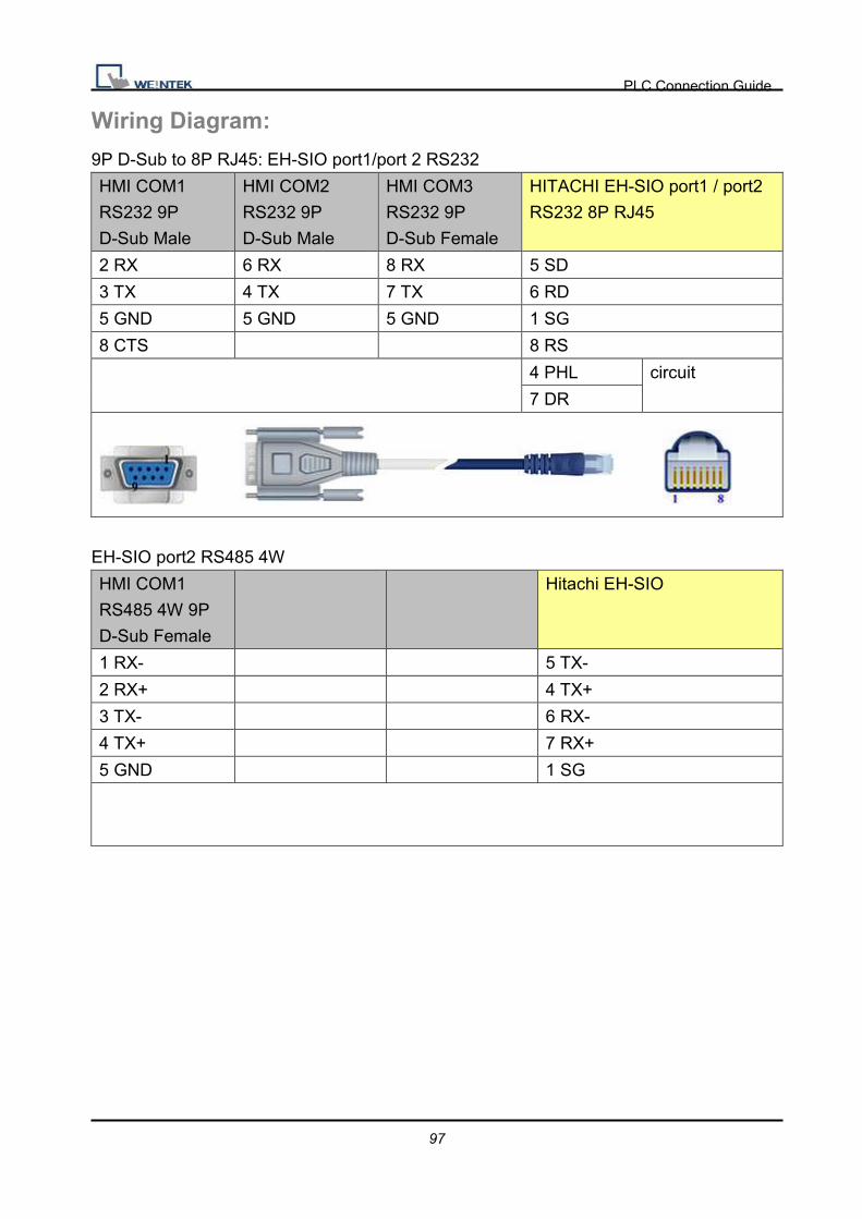
Wiring Diagram:
9P D-Sub to 8P RJ45: EH-SIO port1/port 2 RS232
HMI COM1
RS232 9P
D-Sub Male
HMI COM2
RS232 9P
D-Sub Male
HMI COM3
RS232 9P
D-Sub Female
HITACHI EH-SIO port1 / port2
RS232 8P RJ45
2 RX 6 RX 8 RX 5 SD
3 TX 4 TX 7 TX 6 RD
5 GND 5 GND 5 GND 1 SG
8 CTS 8 RS
4 PHL circuit
7 DR
EH-SIO port2 RS485 4W
HMI COM1
RS485 4W 9P
D-Sub Female
Hitachi EH-SIO
1 RX- 5 TX-
2 RX+ 4 TX+
3 TX- 6 RX-
4 TX+ 7 RX+
5 GND 1 SG

PLC Connection Guide
98
EH-SIO port2 RS485 4W
HMI COM1
RS485 4W 9P
D-Sub Female
Hitachi EH-SIO
1 RX- 5 TX- circuit
3 TX- 6 RX-
2 RX+ 4 TX+ circuit
4 TX+ 7 RX+
5 GND 1 SG
Driver Version:
Version Date Description
V1.00 May/25/2010 Driver released.
PLC Connection Guide
99
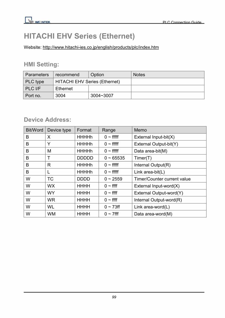
HITACHI EHV Series (Ethernet) Website: http://www.hitachi-ies.co.jp/english/products/plc/index.htm
HMI Setting:
Parameters recommend Option Notes
PLC type HITACHI EHV Series (Ethernet)
PLC I/F Ethernet
Port no. 3004 3004~3007
Device Address:
Bit/Word Device type Format Range Memo
B X HHHHh 0 ~ fffff External Input-bit(X)
B Y HHHHh 0 ~ fffff External Output-bit(Y)
B M HHHHh 0 ~ fffff Data area-bit(M)
B T DDDDD 0 ~ 65535 Timer(T)
B R HHHHh 0 ~ fffff Internal Output(R)
B L HHHHh 0 ~ fffff Link area-bit(L)
W TC DDDD 0 ~ 2559 Timer/Counter current value
W WX HHHH 0 ~ ffff External Input-word(X)
W WY HHHH 0 ~ ffff External Output-word(Y)
W WR HHHH 0 ~ ffff Internal Output-word(R)
W WL HHHH 0 ~ 73ff Link area-word(L)
W WM HHHH 0 ~ 7fff Data area-word(M)

PLC Connection Guide
100
Wiring Diagram:
Direct connect (crossover cable):
HMI RJ45 Female Wire Color PLC RJ45 Female
1 TX+ White/Orange 3 RX+
2 TX- Orange 6 RX-
3 RX+ White/Green 1 TX+
4 BD4+ Blue 4 BD4+
5 BD4- White/Blue 5 BD4-
6 RX- Green 2 TX-
7 BD3+ White/Brown 7 BD3+
8 BD3- Brown 8 BD3-
Through a hub:
HMI RJ45 Female Wire Color PLC RJ45 Female
1 TX+ White/Orange 1 TX+
2 TX- Orange 2 TX-
3 RX+ White/Green 3 RX+
4 BD4+ Blue 4 BD4+
5 BD4- White/Blue 5 BD4-
6 RX- Green 6 RX-
7 BD3+ White/Brown 7 BD3+
8 BD3- Brown 8 BD3-
Driver Version:
Version Date Description
V1.00 Jan/12/2010 Driver released
PLC Connection Guide
101
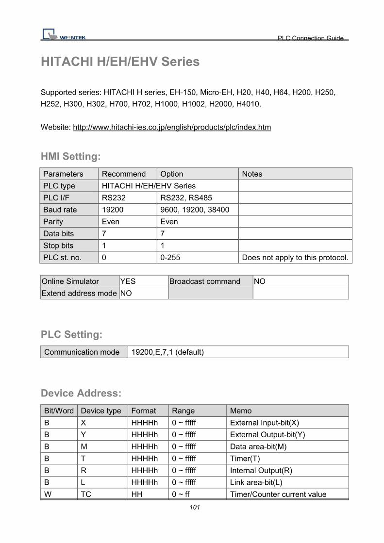
HITACHI H/EH/EHV Series
Supported series: HITACHI H series, EH-150, Micro-EH, H20, H40, H64, H200, H250,
H252, H300, H302, H700, H702, H1000, H1002, H2000, H4010.
Website: http://www.hitachi-ies.co.jp/english/products/plc/index.htm
HMI Setting:
Parameters Recommend Option Notes
PLC type HITACHI H/EH/EHV Series
PLC I/F RS232 RS232, RS485
Baud rate 19200 9600, 19200, 38400
Parity Even Even
Data bits 7 7
Stop bits 1 1
PLC st. no. 0 0-255 Does not apply to this protocol.
Online Simulator YES Broadcast command NO
Extend address mode NO
PLC Setting:
Communication mode 19200,E,7,1 (default)
Device Address:
Bit/Word Device type Format Range Memo
B X HHHHh 0 ~ fffff External Input-bit(X)
B Y HHHHh 0 ~ fffff External Output-bit(Y)
B M HHHHh 0 ~ fffff Data area-bit(M)
B T HHHHh 0 ~ fffff Timer(T)
B R HHHHh 0 ~ fffff Internal Output(R)
B L HHHHh 0 ~ fffff Link area-bit(L)
W TC HH 0 ~ ff Timer/Counter current value
PLC Connection Guide
102
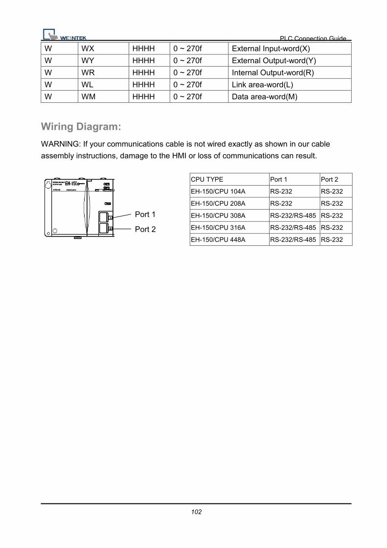
W WX HHHH 0 ~ 270f External Input-word(X)
W WY HHHH 0 ~ 270f External Output-word(Y)
W WR HHHH 0 ~ 270f Internal Output-word(R)
W WL HHHH 0 ~ 270f Link area-word(L)
W WM HHHH 0 ~ 270f Data area-word(M)
Wiring Diagram:
WARNING: If your communications cable is not wired exactly as shown in our cable
assembly instructions, damage to the HMI or loss of communications can result.
CPU TYPE Port 1 Port 2
EH-150/CPU 104A RS-232 RS-232
EH-150/CPU 208A RS-232 RS-232
EH-150/CPU 308A RS-232/RS-485 RS-232
EH-150/CPU 316A RS-232/RS-485 RS-232
EH-150/CPU 448A RS-232/RS-485 RS-232
Port 1
Port 2

PLC Connection Guide
103
Switch Number
1 OFF Normal mode
2 OFF TRNS0 operation
3, 4 3 4 Port1 transmission speed
ON ON 4,800 bps Doesn’t support
OFF ON 9,600 bps
ON OFF 19,200 bps Default
OFF OFF 38,400 bps
5 ON Dedicated port
6 6 PHL Port2 transmission speed
ON Low 9,600 bps
ON High 38,400 bps
OFF Low 4,800 bps Doesn’t support
OFF High 19,200 bps Default
7 OFF (System mode) Do not turn on.
8 OFF (System mode) Do not turn on.
9P D-Sub to 8P RJ45: EH-150 port1/port 2 RS232 / MICRO-EH port1 RS232
HMI COM1
RS232 9P
D-Sub Male
HMI COM2
RS232 9P
D-Sub Male
HMI COM3
RS232 9P
D-Sub Female
HITACHI EH-150 port1 / port2
RS232 8P RJ45
2 RX 6 RX 8 RX 5 SD
3 TX 4 TX 7 TX 6 RD
5 GND 5 GND 5 GND 1 SG
8 CTS 8 RS
4 PHL circuit
7 DR
Toggle-Switch
PHL
Low
PHL
High
PLC Connection Guide
104
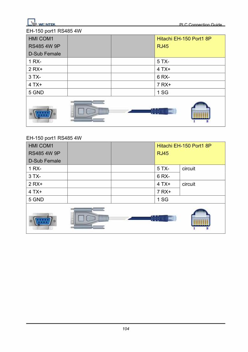
EH-150 port1 RS485 4W
HMI COM1
RS485 4W 9P
D-Sub Female
Hitachi EH-150 Port1 8P
RJ45
1 RX- 5 TX-
2 RX+ 4 TX+
3 TX- 6 RX-
4 TX+ 7 RX+
5 GND 1 SG
EH-150 port1 RS485 4W
HMI COM1
RS485 4W 9P
D-Sub Female
Hitachi EH-150 Port1 8P
RJ45
1 RX- 5 TX- circuit
3 TX- 6 RX-
2 RX+ 4 TX+ circuit
4 TX+ 7 RX+
5 GND 1 SG
PLC Connection Guide
105
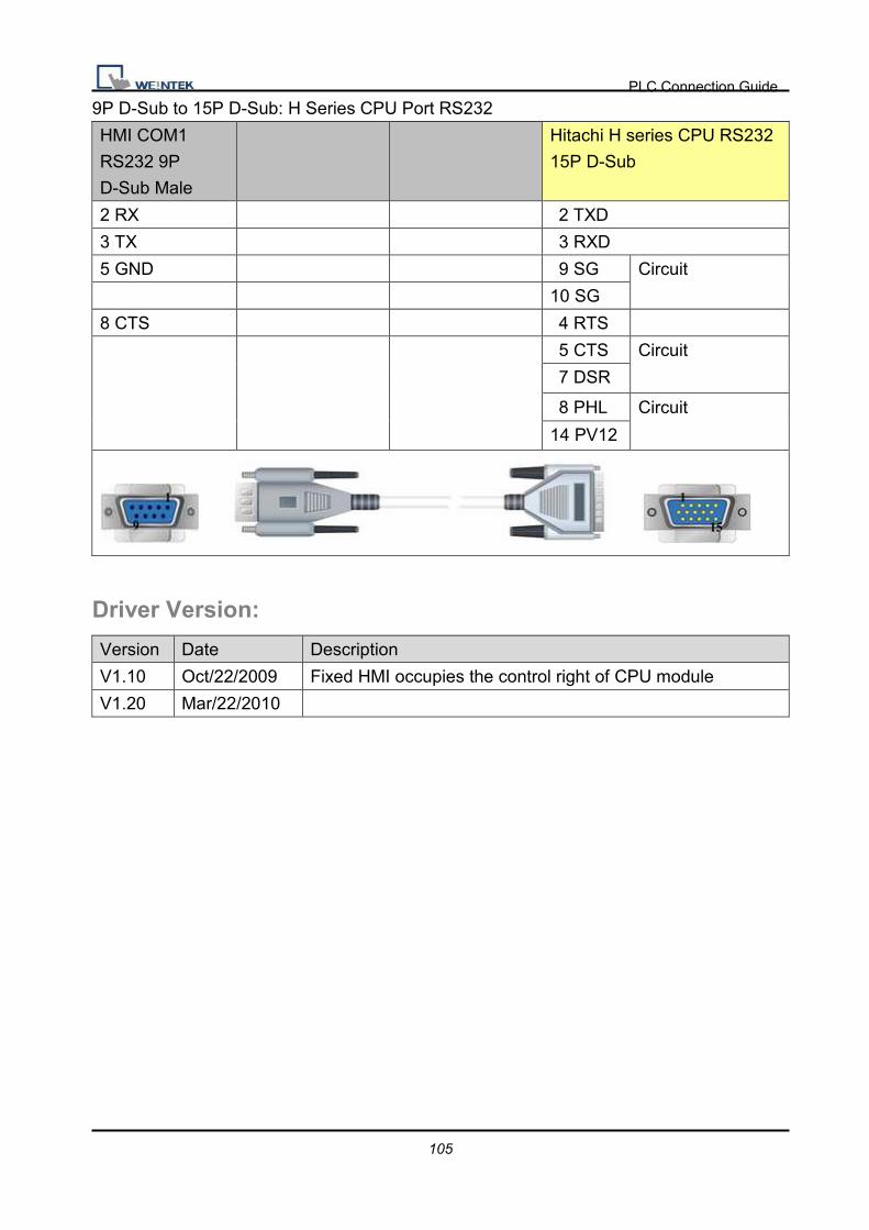
9P D-Sub to 15P D-Sub: H Series CPU Port RS232
HMI COM1
RS232 9P
D-Sub Male
Hitachi H series CPU RS232
15P D-Sub
2 RX 2 TXD
3 TX 3 RXD
5 GND 9 SG Circuit
10 SG
8 CTS 4 RTS
5 CTS Circuit
7 DSR
8 PHL Circuit
14 PV12
Driver Version:
Version Date Description
V1.10 Oct/22/2009 Fixed HMI occupies the control right of CPU module
V1.20 Mar/22/2010

PLC Connection Guide
106
HUST H4X Supported series: HUST CNC Controller H4 Series.
Website: http://www.hust.com.tw/
HMI Setting:
Parameters Recommend Option Notes
PLC type HUST H4X
PLC I/F RS-232 CPU port
PLC st. no. 1
Baud rate 38400 9600,19200,38400,57600
Data bits 7
Parity Even
Stop bits 2
Turn delay 5
Device Address:
Bit/Word Device type Format Range Memo
B I DDD 0 ~ 255 Mapping to VM 10800 ~ 10807
(read only)
B O DDD 0 ~ 255 Mapping to VM 10808 ~ 10815
(read only)
B C DDD 0 ~ 255 Mapping to VM 10816 ~ 10823
(read only)
B S DDD 0 ~ 255 Mapping to VM 10824 ~ 10831
(read only)
B A DDD 0 ~ 255 Mapping to VM 10832 ~ 10863
(read only)
B VM_bit DDDDDdd 1 ~ 99999(31) Bit address (dd): 00~31
DW VM DDDDD 1 ~ 99999 Please refer to specification of
Controller for registers range.
DW R DDD 0 ~ 255 Mapping to VM 10000~10255
(read only)
DW Cn DDD 0 ~ 255 Mapping to VM 10256~10511
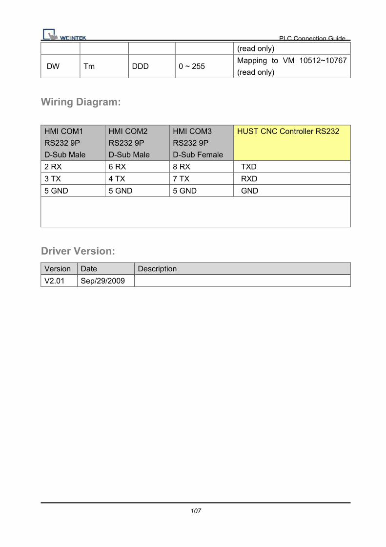
PLC Connection Guide
107
(read only)
DW Tm DDD 0 ~ 255 Mapping to VM 10512~10767
(read only)
Wiring Diagram:
HMI COM1
RS232 9P
D-Sub Male
HMI COM2
RS232 9P
D-Sub Male
HMI COM3
RS232 9P
D-Sub Female
HUST CNC Controller RS232
2 RX 6 RX 8 RX TXD
3 TX 4 TX 7 TX RXD
5 GND 5 GND 5 GND GND
Driver Version:
Version Date Description
V2.01 Sep/29/2009

PLC Connection Guide
108
IAI X-SEL CONTROLLER Website: http://www.iai-robot.co.jp/
HMI Setting:
Parameters Recommend Option Notes
PLC type IAI X-SEL CONTROLLER
PLC I/F RS232
Baud rate 9600 9600~19200
Parity None Even, Odd, None
Data bits 7 7 or 8
Stop bits 1 1 or 2
PLC st. no. 0
Device Address:
Bit/Word Device type Format Range Memo
W Servo_On_Off H 1~8
Address 1~8 represent the
corresponding axis.
Write 1 means ON and 0 means
OFF.
W Servo_Origin H 1~8 Address 1~8 represent the
corresponding axis.
Back to origin.
W RunProgram H 0 Data written indicates which program
to run.
W EndProgram H 0 Data written indicates which program
to stop. W SoftWareReset H 0 Reset soft ware.
W CurrentAxisPos H 1~8
For reading current position. The
state of current axis is put in RW
axis*100.
i.e., for the state of axis 2,
2*100=200, so it is in RW200.
W PointMove H 0~8 Address 1~8 represent the
corresponding axis. The data written
indicates which point to reach. Put

PLC Connection Guide
109
parameters ACC, DEC, SPEED in
axis*100+1, axis*100+2 and
axis*100+3 respectively.
W JoggingMove H 0~8
Jogging. Address 1~8 represent the
corresponding axis. Put parameters
ACC, DEC, SPEED and Position in
axis*100+11, axis*100+12,
axis*100+13 and axis*100+14
respectively.
W AbsoluteMove H 0~8
Jog to the set absolute coordinate.
Address 1~8 represent the
corresponding axis. Put parameters
ACC, DEC, SPEED and Position in
axis*100+21, axis*100+22,
axis*100+23 and axis*100+24
respectively.
W PointChange H 0~8
To change the value of the point.
Address 1~8 represent the
corresponding axis. Put parameters
ACC, DEC, SPEED and Position in
axis*100+31, axis*100+32,
axis*100+33 and axis*100+34
respectively.
Note: ddd: Decimal, hhh: Hexadecimal, ooo: Octal.
Every model of CPU is different; we suggest user to refer to PLC manual’s Device List.
Wiring Diagram:
HMI COM1
RS232 9P
D-Sub Male
HMI COM2
RS232 9P
D-Sub Male
HMI COM3
RS232 9P
D-Sub Female
Host RS232
2 RX 6 RX 8 RX TX
3 TX 4 TX 7 TX RX
5 GND 5 GND 5 GND GND

PLC Connection Guide
110
Driver Version:
Version Date Description
V1.00 Jun/01/2010 Driver released

PLC Connection Guide
111
IDEC Micro Supported series: IDEC Micro3, Micro3C, MicroSmart, OpenNet Controller series.
Website: http://www.idec.com
HMI Setting:
Parameters Recommend Option Notes
PLC type IDEC Micro
PLC I/F RS232 RS232, RS485
Baud rate 9600 9600, 19200
Parity Even Even, Odd, None
Data bits 7 7, 8
Stop bits 1 1
PLC st. no. 255 (for 1:1
connect) 0-255
255 or same as the PLC
setting
Online Simulator YES
Extend address mode YES Don’t set the PLC Station No.= 255
PLC Setting:
Communication mode 9600, E, 7, 1 (default), Use Computer Link Protocol
Device Address:
Bit/Word Device type Format Range Memo
B X DDDDo 0 ~ 20477 Input(I)
B Y DDDDo 0 ~ 20477 Output(Q)
B M DDDDo 0 ~ 20477 Internal Relay(M)
W RT DDDD 0 ~ 9999 Timer(T)
W RC DDDD 0 ~ 9999 Counter(C)
W D DDDD 0 ~ 9999 Data Register(D)

PLC Connection Guide
112
Wiring Diagram:
9P D-Sub to 8P Mini-DIN: Micro3C, MicroSmart, OpenNet Controller CPU Ladder Port
HMI COM1
RS232 9P
D-Sub Male
HMI COM2
RS232 9P
D-Sub Male
HMI COM3
RS232 9P
D-Sub Female
CPU Port1 or Port2 RS232 8P
Mini-DIN
2 RX 6 RX 8 RX 3 TXD
3 TX 4 TX 7 TX 4 RXD
5 GND 5 GND 5 GND 7 GND
9P D-Sub to 8P Mini-DIN: Micro3 CPU Port, MicroSmart with FC4A-PC2 RS485
Communication Adapter
HMI COM1
RS485 2W 9P
D-Sub Male
HMI COM3
RS485 2W 9P
D-Sub Male
CPU Port RS485 8P Mini-DIN
1 RX- 6 Data- 2 RXD-
2 RX+ 9 Data+ 1 RXD+
5 GND 5 GND 7 GND
9P D-Sub to Terminals: Micro3C, OpenNet Controller Data Link Terminals,
MicroSmart with FC4A-PC3 RS485 Communication Adapter
HMI COM1
RS485 2W 9P
D-Sub Male
HMI COM3
RS485 2W 9P
D-Sub Male
Data Link Terminals
1 RX- 6 Data- A RXD-
2 RX+ 9 Data+ B RXD+
5 GND 5 GND SG GND

PLC Connection Guide
113
Driver Version:
Version Date Description
V1.20 Jun/19/2009

PLC Connection Guide
114
INOVANCE H2U/H1U Website: http://www.inovance.cn/
HMI Setting:
Parameters Recommend Option Notes
PLC type INOVANCE H2U/H1U
PLC I/F RS485 4W
Baud rate 9600 9600~19200
Parity Even Even, Odd, None
Data bits 7 7 or 8
Stop bits 1 1 or 2
PLC st. no. 0
Device Address:
Bit/Word Device type Format Range Memo
B X OOO 0 ~ 377 Input Bits
B Y OOO 0 ~ 377 Output Bits
B M DDDD 0 ~ 7999 Auxiliary Relay
B SM DDDD 8000 ~ 9999 Special Auxiliary Relay
B T DDD 0 ~ 255 Timer Relay
B C DDD 0 ~ 255 Counter Relay
B D_Bit DDDDdd 0 ~ 799915
B S DDDD 0 ~ 4095
W TV DDD 0 ~ 255 Timer Memory
W CV DDD 0 ~ 199 Counter Memory
DW CV2 DDD 200 ~ 255 Counter Memory (32bit)
W D DDDD 0 ~ 7999 Data Registers
W SD DDDD 8000 ~ 9999 Special Data Register
Note: ddd: Decimal, hhh: Hexadecimal, ooo: Octal.
Every model of CPU is different, and we suggest user to refer to PLC manual’s Device
List.
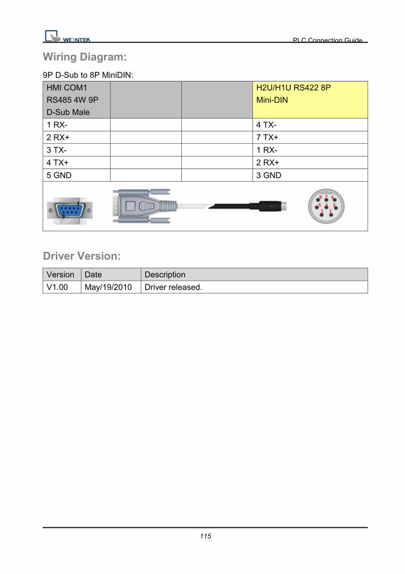
PLC Connection Guide
115
Wiring Diagram:
9P D-Sub to 8P MiniDIN:
HMI COM1
RS485 4W 9P
D-Sub Male
H2U/H1U RS422 8P
Mini-DIN
1 RX- 4 TX-
2 RX+ 7 TX+
3 TX- 1 RX-
4 TX+ 2 RX+
5 GND 3 GND
Driver Version:
Version Date Description
V1.00 May/19/2010 Driver released.
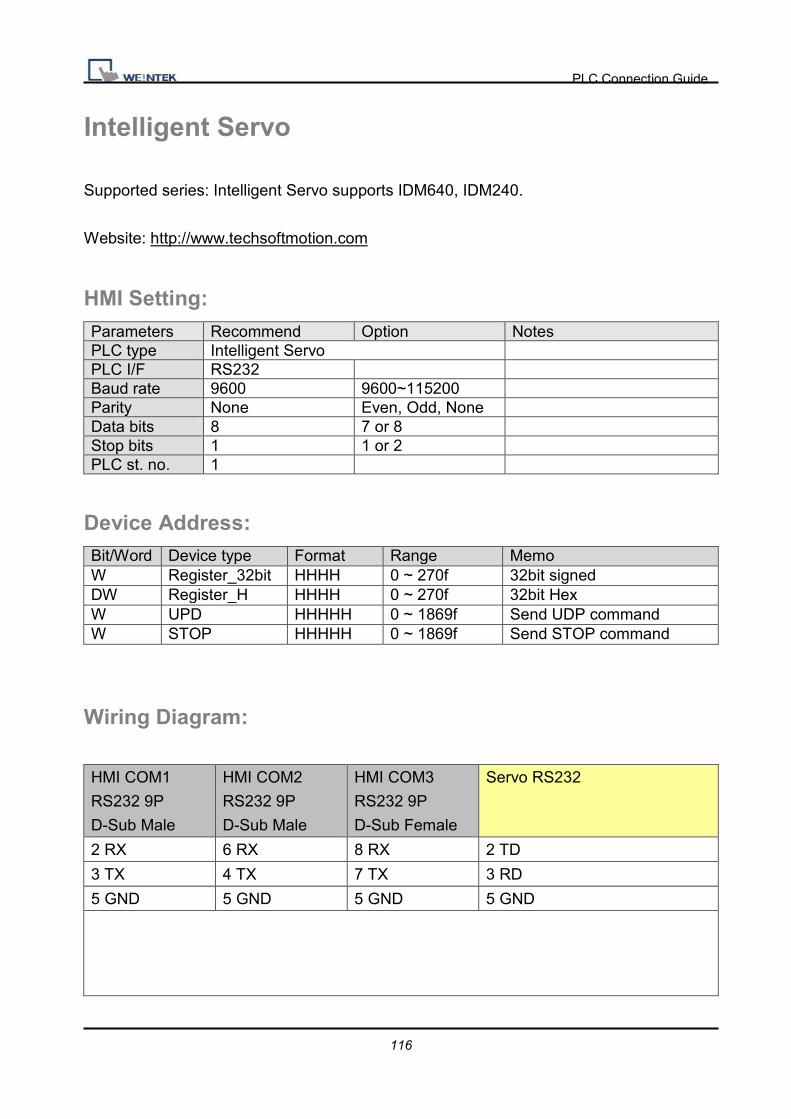
PLC Connection Guide
116
Intelligent Servo
Supported series: Intelligent Servo supports IDM640, IDM240.
Website: http://www.techsoftmotion.com
HMI Setting: Parameters Recommend Option Notes PLC type Intelligent Servo PLC I/F RS232 Baud rate 9600 9600~115200 Parity None Even, Odd, None Data bits 8 7 or 8 Stop bits 1 1 or 2 PLC st. no. 1
Device Address: Bit/Word Device type Format Range Memo W Register_32bit HHHH 0 ~ 270f 32bit signed DW Register_H HHHH 0 ~ 270f 32bit Hex W UPD HHHHH 0 ~ 1869f Send UDP command W STOP HHHHH 0 ~ 1869f Send STOP command
Wiring Diagram:
HMI COM1
RS232 9P
D-Sub Male
HMI COM2
RS232 9P
D-Sub Male
HMI COM3
RS232 9P
D-Sub Female
Servo RS232
2 RX 6 RX 8 RX 2 TD
3 TX 4 TX 7 TX 3 RD
5 GND 5 GND 5 GND 5 GND

PLC Connection Guide
117
Driver Version:
Version Date Description
V1.00 Nov/06/2009 Driver released.

PLC Connection Guide
118
Justfi controller Supported series: Justfi weighing instruments, Industrial Batching Controller supports
XK31CB4, XK31CB6.
Website: http://www.justfi.com
HMI Setting: Parameters Recommend Option Notes PLC type Justfi controller PLC I/F RS232 Baud rate 9600 9600, 19200 Parity Even Even, Odd, None Data bits 7 7 or 8 Stop bits 1 1 or 2 PLC st. no. 1
Device Address: Bit/Word Device type Format Range Memo W Func DD 0 ~ 99 Read/Write DW Func_DW DD 0 ~ 99 Read/Write W RW H 0 Weight (Read only) W RF H 0 Read result (Read only) W RT H 0 Read total (Read only)
W RG H 0 Read prescription group
W RC H 0 Circle
W RB H 0 Read Status (Read only)
W MZ H 0 Zero (Write only)
W MT H 0 Tare (Write only)
W CT H 0 Clear tare (Write only)
W DT H 0 Clear total (Write only)
W BB H 0 Start (Write only)
W HB H 0 Stop (Write only)
W BD H 0 Discharge (Write only)
W
RP1t …. …. RP6F
H 0 Read/Write Recipe
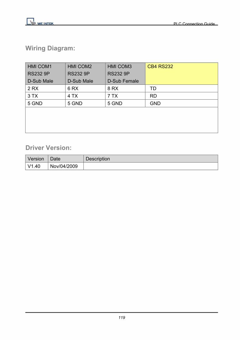
PLC Connection Guide
119
Wiring Diagram:
HMI COM1
RS232 9P
D-Sub Male
HMI COM2
RS232 9P
D-Sub Male
HMI COM3
RS232 9P
D-Sub Female
CB4 RS232
2 RX 6 RX 8 RX TD
3 TX 4 TX 7 TX RD
5 GND 5 GND 5 GND GND
Driver Version:
Version Date Description
V1.40 Nov/04/2009
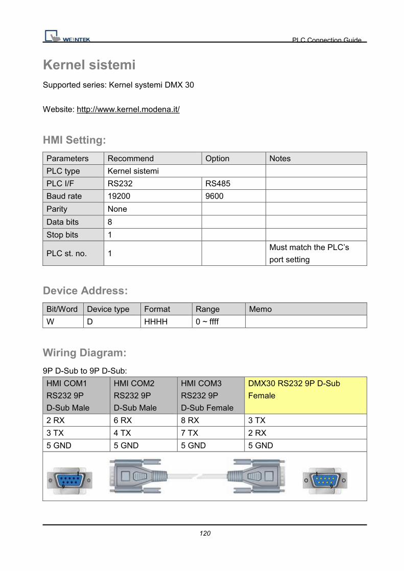
PLC Connection Guide
120
Kernel sistemi Supported series: Kernel systemi DMX 30
Website: http://www.kernel.modena.it/
HMI Setting:
Parameters Recommend Option Notes
PLC type Kernel sistemi
PLC I/F RS232 RS485
Baud rate 19200 9600
Parity None
Data bits 8
Stop bits 1
PLC st. no. 1 Must match the PLC’s
port setting
Device Address:
Bit/Word Device type Format Range Memo
W D HHHH 0 ~ ffff
Wiring Diagram:
9P D-Sub to 9P D-Sub:
HMI COM1
RS232 9P
D-Sub Male
HMI COM2
RS232 9P
D-Sub Male
HMI COM3
RS232 9P
D-Sub Female
DMX30 RS232 9P D-Sub
Female
2 RX 6 RX 8 RX 3 TX
3 TX 4 TX 7 TX 2 RX
5 GND 5 GND 5 GND 5 GND
PLC Connection Guide
121
Driver Version:
Version Date Description
V1.00 Feb/06/2010 Driver releasesd.

PLC Connection Guide
122
KEYENCE KV-10/16/24/40/80/Visual KV Series Supported series: KEYENCE KV series, KV16~80
Website: http://www.keyence.com/
HMI Setting:
Parameters Recommend Option Notes
PLC type KEYENCE KV-10/16/24/40/80/Visual
KV Series
PLC I/F RS232 RS232
Baud rate 9600
Parity Even
Data bits 8
Stop bits 1
PLC st. no. 0 Must match the PLC’s port
setting.
Device Address: Bit/Word Device type Format Range Memo B RLY DDDdd0* 0 ~ 655150* bb:0~15
B DM_Bit DDDDDh 0 ~ 65535f
W DM DDDDD 0 ~ 65535
W TM DDDD 0 ~ 8999
W T DDDD 0 ~ 9999
W T_Curr DDDD 0 ~ 9999 Timer_Current
W T_Preset DDDD 0 ~ 9999
W C DDDD 0 ~ 9999
W C_Curr DDDD 0 ~ 9999 Counter_Current
W C_Preset DDDD 0 ~ 9999
Precaution:*
If you use the Relay(bit) register, Please place zero behind address.
For example, If you want to read Relay(bit)100, you just set the address as “1000”.
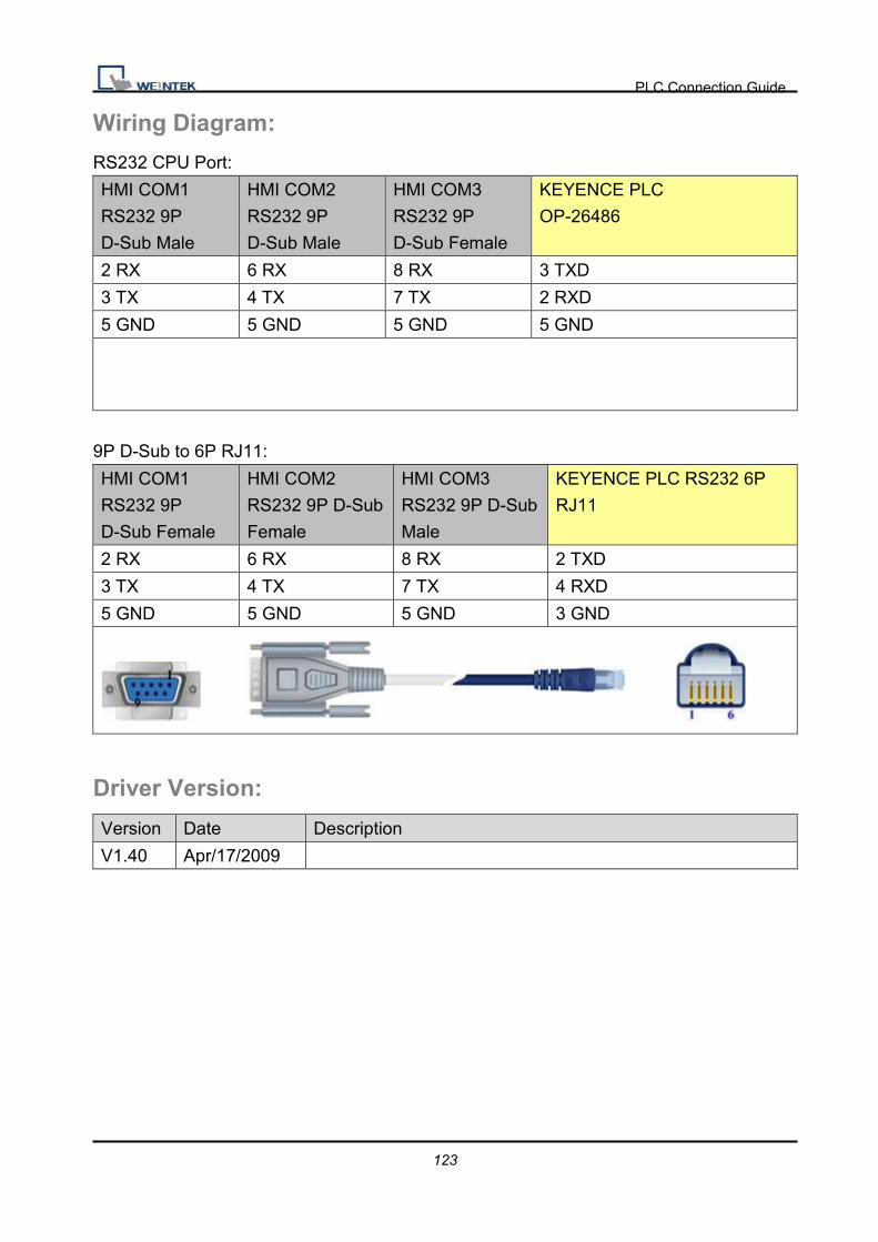
PLC Connection Guide
123
Wiring Diagram:
RS232 CPU Port:
HMI COM1
RS232 9P
D-Sub Male
HMI COM2
RS232 9P
D-Sub Male
HMI COM3
RS232 9P
D-Sub Female
KEYENCE PLC
OP-26486
2 RX 6 RX 8 RX 3 TXD
3 TX 4 TX 7 TX 2 RXD
5 GND 5 GND 5 GND 5 GND
9P D-Sub to 6P RJ11:
HMI COM1
RS232 9P
D-Sub Female
HMI COM2
RS232 9P D-Sub
Female
HMI COM3
RS232 9P D-Sub
Male
KEYENCE PLC RS232 6P
RJ11
2 RX 6 RX 8 RX 2 TXD
3 TX 4 TX 7 TX 4 RXD
5 GND 5 GND 5 GND 3 GND
Driver Version:
Version Date Description
V1.40 Apr/17/2009

PLC Connection Guide
124
KEYENCE KV-5000 (Ethernet) Website: http://www.keyence.com/
HMI Setting:
Parameters Recommend Option Notes
PLC type KEYENCE KV-5000 (Ethernet)
PLC I/F Ethernet
Port no. 8501 Must match the PLC’s port
setting.
PLC st. no. 0 Must match the PLC’s port
setting.
Device Address: Bit/Word Device type Format Range Memo B RLY DDDdd 0 ~ 99915
B MR DDDdd 0 ~ 99915
B LR DDDdd 0 ~ 99915
B CR DDDdd 0 ~ 99915
W DM DDDDD 0 ~ 65535
W TM DDDD 0 ~ 9999
W CM DDDDD 0 ~ 65535
W EM DDDDD 0 ~ 65535
W FM DDDDD 0 ~ 65535
W T DDDD 0 ~ 9999
W T_Curr DDDD 0 ~ 9999 Timer Current
W T_Preset DDDD 0 ~ 9999 Timer Preset
W C DDDD 0 ~ 9999
W C_Curr DDDD 0 ~ 9999
W C_Preset DDDD 0 ~ 9999
Precaution:
If you use the RLY(bit) register, Please place zero behind address.
For example, if you want to read RLY 100, you just set the address as “1000”.

PLC Connection Guide
125
Wiring Diagram:
Direct connect (crossover cable):
HMI RJ45 Female Wire Color PLC RJ45 Female
1 TX+ White/Orange 3 RX+
2 TX- Orange 6 RX-
3 RX+ White/Green 1 TX+
4 BD4+ Blue 4 BD4+
5 BD4- White/Blue 5 BD4-
6 RX- Green 2 TX-
7 BD3+ White/Brown 7 BD3+
8 BD3- Brown 8 BD3-
Through a hub:
HMI RJ45 Female Wire Color PLC RJ45 Female
1 TX+ White/Orange 1 TX+
2 TX- Orange 2 TX-
3 RX+ White/Green 3 RX+
4 BD4+ Blue 4 BD4+
5 BD4- White/Blue 5 BD4-
6 RX- Green 6 RX-
7 BD3+ White/Brown 7 BD3+
8 BD3- Brown 8 BD3-
Driver Version:
Version Date Description
V1.00 Dec/25/2009 Driver released.

PLC Connection Guide
126
KEYENCE KV-700/1000/3000/5000 Series Website: http://www.keyence.com/
HMI Setting:
Parameters Recommend Option Notes
PLC type KEYENCE KV-700/1000/3000/5000
Series
PLC I/F RS232 RS232
Baud rate 115200
Parity Even
Data bits 8
Stop bits 1
PLC st. no. 0 Must match the PLC’s port
setting.
Device Address:
Bit/Word Device type Format Range Memo
B RLY DDDdd 0 ~ 99915
B MR DDDdd 0 ~ 99915
B LR DDDdd 0 ~ 99915
B CR DDDdd 0 ~ 99915
W DM DDDDD 0 ~ 65535
W TM DDDD 0 ~ 9999
W CM DDDDD 0 ~ 65535
W EM DDDDD 0 ~ 65535
W FM DDDDD 0 ~ 65535
W T DDDD 0 ~ 9999
W T_Curr DDDD 0 ~ 9999 Timer_Current
W T_Preset DDDD 0 ~ 9999
W C DDDD 0 ~ 9999
W C_Curr DDDD 0 ~ 9999 Counter_Current
W C_Preset DDDD 0 ~ 9999
Precaution:
If you use the Relay(bit) register, Please place zero behind address.

PLC Connection Guide
127
For example, If you want to read Relay(bit)100, you just set the address as “1000”.
Wiring Diagram:
HMI COM1
RS232 9P
D-Sub Male
HMI COM2
RS232 9P
D-Sub Male
HMI COM3
RS232 9P
D-Sub Female
KENEYCE OP-26486 RS232
2 RX 6 RX 8 RX 3 TXD
3 TX 4 TX 7 TX 2 RXD
5 GND 5 GND 5 GND 5 GND
Driver Version:
Version Date Description
V2.20 Jul/28/2009

PLC Connection Guide
128
Korenix 6550 Supported series: http://www.korenix.com/
HMI Setting:
Parameters Recommend Option Notes
PLC type Korenix 6550 Modbus protocol
PLC I/F Ethernet
PLC st. no. 0
Port no. 502
Device Address:
Bit/Word Device type Format Range Memo
B 0X DDDDD 1 ~ 65535
B 1X DDDDD 1 ~ 65535
B 3x_Bit DDDDDdd 1 ~ 6553515
B 4x_Bit DDDDDdd 1 ~ 6553515
B 6x_Bit DDDDDdd 1 ~ 6553515
W 3X DDDDD 1 ~ 65535
W 4X DDDDD 1 ~ 65535
W 5X DDDDD 1 ~ 65535
W 6X DDDDD 1 ~ 65535
Wiring Diagram:
Direct connect (crossover cable):
HMI RJ45 Female Wire Color PLC RJ45 Female
1 TX+ White/Orange 3 RX+
2 TX- Orange 6 RX-
3 RX+ White/Green 1 TX+
4 BD4+ Blue 4 BD4+
5 BD4- White/Blue 5 BD4-
6 RX- Green 2 TX-
7 BD3+ White/Brown 7 BD3+
8 BD3- Brown 8 BD3-
PLC Connection Guide
129
Through a hub:
HMI RJ45 Female Wire Color PLC RJ45 Female
1 TX+ White/Orange 1 TX+
2 TX- Orange 2 TX-
3 RX+ White/Green 3 RX+
4 BD4+ Blue 4 BD4+
5 BD4- White/Blue 5 BD4-
6 RX- Green 6 RX-
7 BD3+ White/Brown 7 BD3+
8 BD3- Brown 8 BD3-
Driver Version:
Version Date Description
V1.61 Apr/17/2009

PLC Connection Guide
130
Koyo CLICK Supported series: KOYO CLICK PLC series.
Website: http://www.automationdirect.com
HMI Setting:
Parameters Recommend Option Notes
PLC type Koyo CLICK
PLC I/F RS232
Baud rate 38400 Communications Port1
(fixed)
Reference PLC
Specification
Parity Odd Communications Port1
(fixed)
Reference PLC
Specification
Data bits 8 Communications Port1
(fixed)
Reference PLC
Specification
Stop bits 1 Communications Port1
(fixed)
Reference PLC
Specification
PLC st. no. 1 Communications Port1
(fixed)
Reference PLC
Specification
Device Address:
Bit/Word Device type Format Range Memo
B X Ddd 001 ~ 816 Input Status (Read Only)
B Y Ddd 001 ~ 816 Output Status
B C DDDD 1 ~ 2000 Control Bit
B T DDD 1 ~ 500 Timer Status (Read Only)
B CT DDD 1 ~ 250 Counter Status (Read Only)
B SC DDDD 1 ~ 1000 System Control Bit (Read Only)
W DS DDDD 1 ~ 4500 Data Registers
W DD DDDD 1 ~ 1000 Data Registers (Double word)
W DH DDD 1 ~ 500 Data Registers
W DF DDD 1 ~ 500 Data Registers (Double word)
W XD D 0 ~ 8 Input Status Registers (Read Only)
W YD D 0 ~ 8 Output Status Registers
W TD DDD 1 ~ 500 Timer Current Values (Read Only)

PLC Connection Guide
131
W CTD DDD 1 ~ 250 Counter Current Values (Double
word/Read Only)
W SD DDDD 1 ~ 1000 System Data Registers (Read
Only)
W TXT DDDD 1 ~ 1000 Text Data Registers
ddd: Decimal / hhh:Hexadecimal / ooo:Octal
Wiring Diagram:
KOYO CLICK PLC Com Port:
9P D-Sub to 6P RJ12 Jack:
HMI COM1
RS232 9P
D-Sub Male
HMI COM2
RS232 9P
D-Sub Male
HMI COM3
RS232 9P
D-Sub Female
KOYO CLICK PLC RS232 6P
RJ12 Jack
2 RX 6 RX 8 RX 4 TXD
3 TX 4 TX 7 TX 3 RXD
5 GND 5 GND 5 GND 1 GND
Driver Version:
Version Date Description
V1.50 Jun/22/2010

PLC Connection Guide
132
KOYO DIRECT
Supported series: KOYO DirectLogic series PLC DL05, DL06�DL105, DL205, DL305, and
DL405 series.
Website: http://www.automationdirect.com
HMI Setting:
Parameters Recommend Option Notes
PLC type KOYO DIRECT
PLC I/F RS232 RS232, RS485
Baud rate 9600 9600, 19200,
38400
Parity Odd Even, Odd, None
Data bits 8 7, 8
Stop bits 1 1
PLC st. no. 1 1-90
PLC Setting: 1. The PLC must not have a password.
2. PLC must be set for Full Duplex operation.
3. PLC must be set for No Hardware Handshaking.
4. The PLC must be set to use the ‘K’ Sequence Protocol.
5. Set the mode switch to the TERM mode
6. When using the D4-440 CPU, you must set the station number to 1.
Device Address:
Bit/Word Device type Format Range Memo
B X OOOO 0 ~ 4000 Input Bits
B Y OOOO 0 ~ 4000 Output Bits
B C OOOOO 0 ~ 10000 Control Relays
B T OOOO 0 ~ 1000 Timer Status Bits
B CT OOOO 0 ~ 1000 Counter Status Bits
B S OOOO 0 ~ 2000

PLC Connection Guide
133
B SP OOOO 0 ~ 2000
B GX OOOOO 0 ~ 10000
B GY OOOOO 0 ~ 10000
W Timer OOOO 0 ~ 1000
W Counter OOOO 0 ~ 1000
W V OOOOO 0 ~ 77777 V Memory
Wiring Diagram:
9P D-Sub to 6P RJ12 Jack: CPU unit:
DL05/DL06/DL105/DL230/DL240/DL250/DL350/DL450 RS232 port
HMI COM1
RS232 9P
D-Sub Male
HMI COM2
RS232 9P
D-Sub Male
HMI COM3
RS232 9P
D-Sub Female
KOYO CLICK PLC RS232 6P
RJ12 Jack
2 RX 6 RX 8 RX 4 TX
3 TX 4 TX 7 TX 3 RX
5 GND 5 GND 5 GND 1 GND
9P D-Sub to 15P D-Sub: CPU unit: DL06/DL250 CPU Port2 RS232
HMI COM1
RS232 9P
D-Sub Female
HMI COM2
RS232 9P D-Sub
Female
HMI COM3
RS232 9P D-Sub
Male
KOYO DirectLogic PLC CPU
RS232 Port2 15P D-Sub
2 RX 6 RX 8 RX 2 TX
3 TX 4 TX 7 TX 3 RX
5 GND 5 GND 5 GND 7 GND
4 RTC circuit
5 CTS

PLC Connection Guide
134
9P D-Sub to 15P D-Sub: CPU unit: DL06/DL250 CPU Port2 RS422
HMI COM1
RS485 4W 9P
D-Sub Female
KOYO DirectLogic PLC CPU
RS422 Port2 15P D-Sub
1 RX- 10 TX-
2 RX+ 9 TX+
3 TX- 6 RX-
4 TX+ 13 RX+
5 GND 7 GND
11 RTS+ Circuit
14 CTS+
12 RTS- Circuit
15 CTS-
Note: DL06/DL250 CPU Port2 include RS232 and RS422
9P D-Sub to 15P D-Sub: CPU unit: DL430/DL440/DL450 CPU unit Port0 RS232
HMI COM1
RS232 9P
D-Sub Female
HMI COM2
RS232 9P D-Sub
Female
HMI COM3
RS232 9P D-Sub
Male
KOYO DirectLogic PLC
DL405 CPU RS232 Port0
15P D-Sub
2 RX 6 RX 8 RX 2 TX
3 TX 4 TX 7 TX 3 RX
5 GND 5 GND 5 GND 13 GND
1 YOP circuit
7 CTS
2 YOM
4 ONLINE circuit
14 GND

PLC Connection Guide
135
9P D-Sub to 25P D-Sub: CPU unit: DL430/DL440/DL450 CPU unit Port1 & DL350 CPU
unit Port2 RS232
HMI COM1
RS232 9P
D-Sub Male
HMI COM2
RS232 9P D-Sub
Mmale
HMI COM3
RS232 9P D-Sub
Male
KOYO DirectLogic PLC
DL305/405 CPU RS232 Port
25P D-Sub
2 RX 6 RX 8 RX 2 TX
3 TX 4 TX 7 TX 3 RX
5 GND 5 GND 5 GND 7 GND
4 RTC Circuit
5 CTS
9P D-Sub to 25P D-Sub: CPU unit: DL430/DL440/DL450 CPU unit Port1 & DL350 CPU
unit Port2 RS422
HMI COM1
RS485 4W 9P
D-Sub Male
KOYO DirectLogic PLC
DL305/405 CPU RS422 Port
25P D-Sub
1 RX- 16 TX-
2 RX+ 14 TX+
3 TX- 10 RX-
4 TX+ 9 RX+
5 GND 7 GND
19 RTS+ circuir
11 CTS+
18 RTS- circuir
23 CTS-

PLC Connection Guide
136
9P D-Sub to 25P D-Sub: CPU unit: DL450 CPU unit Port3 RS422
HMI COM1
RS485 4W 9P
D-Sub Male
KOYO DirectLogic PLC
DL405 CPU RS422 Port3
25P D-Sub
1 RX- 13 TX-
2 RX+ 12 TX+
3 TX- 25 RX-
4 TX+ 24 RX+
5 GND 7 GND
9P D-Sub to 25P D-Sub: Communication unit: DL205 series D2-DCM and DL405 series
D4-DCM RS232
HMI COM1
RS232 9P
D-Sub Male
HMI COM2
RS232 9P D-Sub
Male
HMI COM3
RS232 9P D-Sub
Female
KOYO DirectLogic PLC
DL205/405 DCM RS232 Port
25P D-Sub
2 RX 6 RX 8 RX 2 TX
3 TX 4 TX 7 TX 3 RX
5 GND 5 GND 5 GND 7 GND
4 RTC circuit
5 CTS
Driver Version:
Version Date Description
V1.30 Nov/02/2010
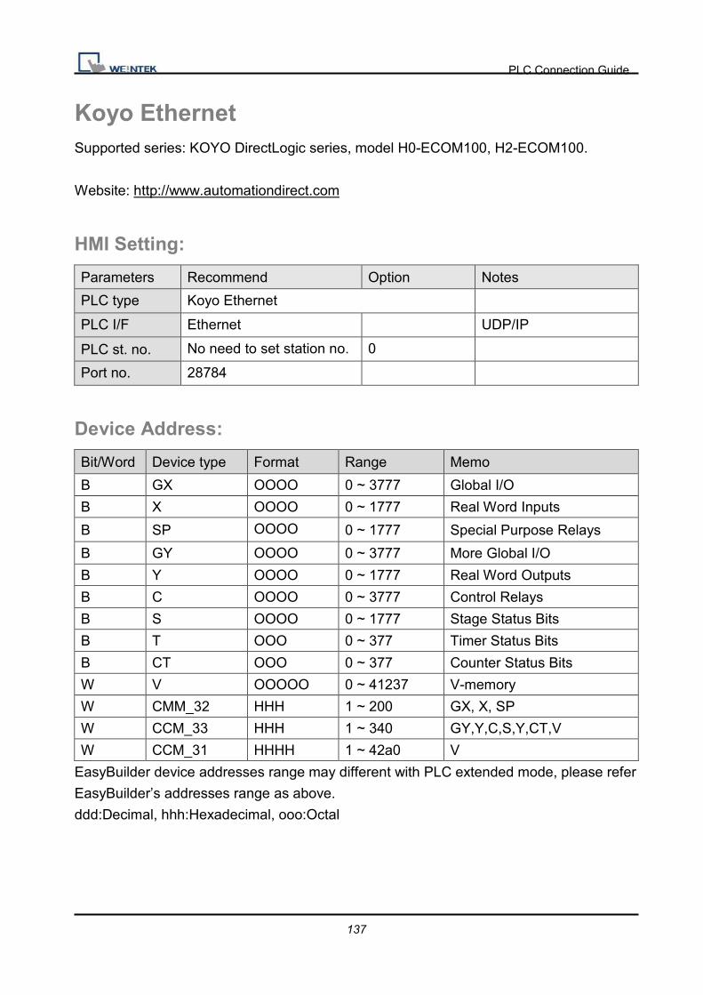
PLC Connection Guide
137
Koyo Ethernet Supported series: KOYO DirectLogic series, model H0-ECOM100, H2-ECOM100.
Website: http://www.automationdirect.com
HMI Setting:
Parameters Recommend Option Notes
PLC type Koyo Ethernet
PLC I/F Ethernet UDP/IP
PLC st. no. No need to set station no. 0
Port no. 28784
Device Address:
Bit/Word Device type Format Range Memo
B GX OOOO 0 ~ 3777 Global I/O
B X OOOO 0 ~ 1777 Real Word Inputs
B SP OOOO 0 ~ 1777 Special Purpose Relays
B GY OOOO 0 ~ 3777 More Global I/O
B Y OOOO 0 ~ 1777 Real Word Outputs
B C OOOO 0 ~ 3777 Control Relays
B S OOOO 0 ~ 1777 Stage Status Bits
B T OOO 0 ~ 377 Timer Status Bits
B CT OOO 0 ~ 377 Counter Status Bits
W V OOOOO 0 ~ 41237 V-memory
W CMM_32 HHH 1 ~ 200 GX, X, SP
W CCM_33 HHH 1 ~ 340 GY,Y,C,S,Y,CT,V
W CCM_31 HHHH 1 ~ 42a0 V
EasyBuilder device addresses range may different with PLC extended mode, please refer
EasyBuilder’s addresses range as above.
ddd:Decimal, hhh:Hexadecimal, ooo:Octal

PLC Connection Guide
138
Wiring Diagram:
Direct connect (crossover cable):
HMI RJ45 Female Wire Color PLC RJ45 Female
1 TX+ White/Orange 3 RX+
2 TX- Orange 6 RX-
3 RX+ White/Green 1 TX+
4 BD4+ Blue 4 BD4+
5 BD4- White/Blue 5 BD4-
6 RX- Green 2 TX-
7 BD3+ White/Brown 7 BD3+
8 BD3- Brown 8 BD3-
Through a hub:
HMI RJ45 Female Wire Color PLC RJ45 Female
1 TX+ White/Orange 1 TX+
2 TX- Orange 2 TX-
3 RX+ White/Green 3 RX+
4 BD4+ Blue 4 BD4+
5 BD4- White/Blue 5 BD4-
6 RX- Green 6 RX-
7 BD3+ White/Brown 7 BD3+
8 BD3- Brown 8 BD3-
Driver Version:
Version Date Description
V1.10 Jul/03/2009
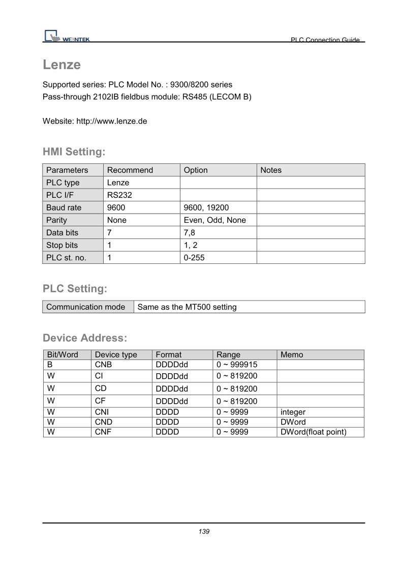
PLC Connection Guide
139
Lenze Supported series: PLC Model No. : 9300/8200 series
Pass-through 2102IB fieldbus module: RS485 (LECOM B)
Website: http://www.lenze.de
HMI Setting:
Parameters Recommend Option Notes
PLC type Lenze
PLC I/F RS232
Baud rate 9600 9600, 19200
Parity None Even, Odd, None
Data bits 7 7,8
Stop bits 1 1, 2
PLC st. no. 1 0-255
PLC Setting:
Communication mode Same as the MT500 setting
Device Address: Bit/Word Device type Format Range Memo B CNB DDDDdd 0 ~ 999915 W CI DDDDdd 0 ~ 819200
W CD DDDDdd 0 ~ 819200
W CF DDDDdd 0 ~ 819200 W CNI DDDD 0 ~ 9999 integer W CND DDDD 0 ~ 9999 DWord W CNF DDDD 0 ~ 9999 DWord(float point)

PLC Connection Guide
140
Wiring Diagram:
HMI COM1
RS485 2W 9P
D-Sub Female
HMI COM3
RS485 2W 9P
D-Sub Female
Lenze 2102IB LECOM-B
RS485 plug-in terminal 4-pole
1 RX- 6 Data- 72 T/R (A)
2 RX+ 9 Data+ 71 T/R (B)
5 GND 5 GND
Driver Version:
Version Date Description
V1.10 Apr/17/2009

PLC Connection Guide
141
LIYAN EX series Supported series : LIYAN PLC Ex/Ex1s/Ex1n/Ex2n series
Website: http://www.liyanplc.com/
HMI Setting: Parameters Recommend Option Notes PLC type Mitsubishi FX0n/FX2 PLC I/F RS232 RS232 Baud rate 9600 9600~115200 Parity Even Even, Odd, None Data bits 7 7,8 Stop bits 1 1,2
PLC st. no. 0 0-255 Must match the PLC’s port setting.
Device Address:
Bit/Word Device type Format Range Memo B X ooo 0-377 Input relay B Y ooo 0-377 Output relay B M ddd 0-9999 Internal bit memory B T ddd 0-255 Timer bit memory B C ddd 0-255 Counter bit memory W TV ddd 0-255 Timer register W CV ddd 0~199 Counter Register W D ddd 0-9999 data Register W CV2 ddd 200-255 Counter Register(Double word) W SD ddd 8000-9999 Special data register
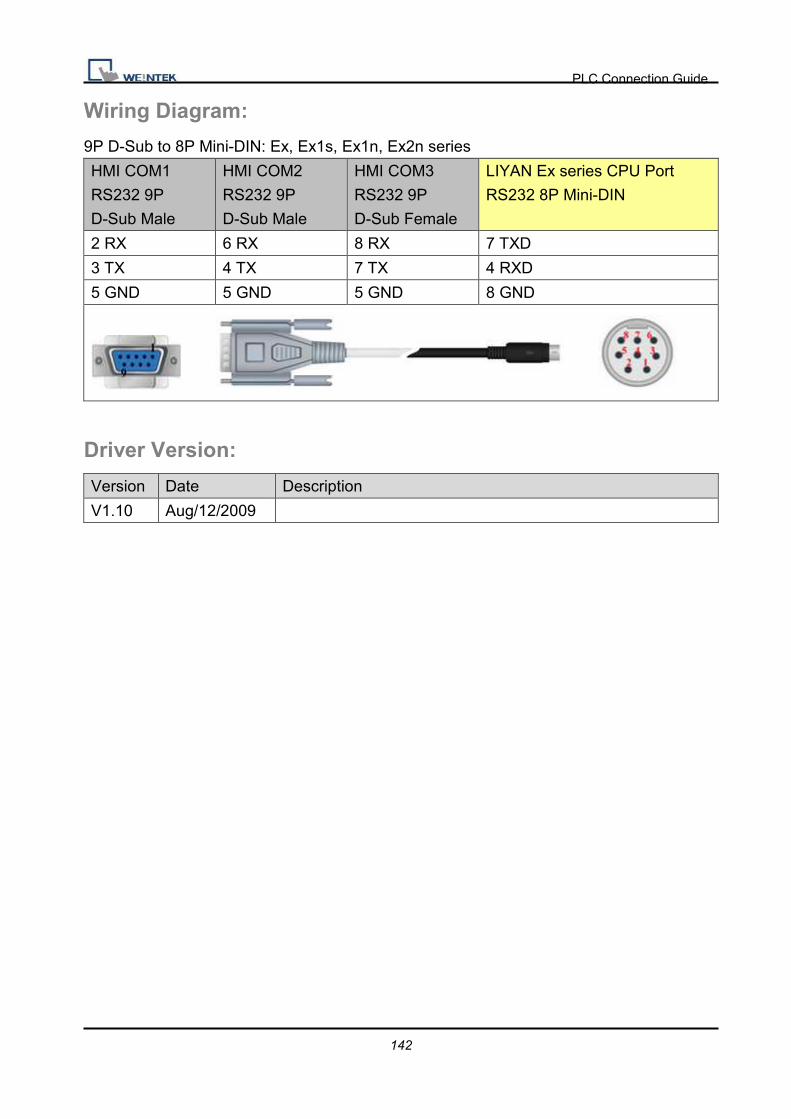
PLC Connection Guide
142
Wiring Diagram:
9P D-Sub to 8P Mini-DIN: Ex, Ex1s, Ex1n, Ex2n series
HMI COM1
RS232 9P
D-Sub Male
HMI COM2
RS232 9P
D-Sub Male
HMI COM3
RS232 9P
D-Sub Female
LIYAN Ex series CPU Port
RS232 8P Mini-DIN
2 RX 6 RX 8 RX 7 TXD
3 TX 4 TX 7 TX 4 RXD
5 GND 5 GND 5 GND 8 GND
Driver Version:
Version Date Description
V1.10 Aug/12/2009

PLC Connection Guide
143
LS GLOFA Cnet Supported series: LS GLOFA GM6/GM7 CPU port. G7L-CUEB / G6L-CUEB / G4L-CUEA /
G3L-CUEA Cnet module
Website: http://www.lgis.com/
HMI Setting:
Parameters Recommend Option Notes
PLC type LS GLOFA Cnet
PLC I/F RS232 RS232/RS485
2W/4W
Baud rate 9600 9600~115200
Parity None Even, Odd, None
Data bits 8 7, 8
Stop bits 1 1
PLC st. no. 0 0~31
PLC Setting:
Communication mode 9600,N,8,1 (default), Cnet protocol
Communication module Applicable mode: 1 Dedicated communication
Device Address: Bit/Word Device type Format Range Memo B IX ddDdd 0 ~ 63763 Input
B QX ddDdd 0 ~ 63763 Output
B MX DDDDD 0 ~ 32767 Internal relay
W MW DDDDD 0 ~ 32767 Data register
DW MD DDDDD 0 ~ 16383 Double word

PLC Connection Guide
144
Wiring Diagram:
9P D-Sub to 9P D-Sub:
HMI COM1
RS232 9P
D-Sub Male
HMI COM2
RS232 9P
D-Sub Male
HMI COM3
RS232 9P
D-Sub Female
LS GLOFA GM CPU Port
RS232 9P D-Sub
2 RX 6 RX 8 RX 7 TXD
3 TX 4 TX 7 TX 4 RXD
5 GND 5 GND 5 GND 5 GND
9P D-Sub to 9P D-Sub: Communication Module (G7L-CUEB / G6L-CUEB / G4L-CUEA /
G3L-CUEA Cnet RS232)
HMI COM1
RS232 9P
D-Sub Male
HMI COM2
RS232 9P
D-Sub Male
HMI COM3
RS232 9P
D-Sub Female
LS GLOFA GM RS232 9P
D-Sub
2 RX 6 RX 8 RX 3 TXD
3 TX 4 TX 7 TX 2 RXD
5 GND 5 GND 5 GND 5 GND
1 CD circuit
7 RTS
8 CTS
4 DTR circuit
6 DSR
Communication Module (G7L-CUEC / G6L-CUEC / G4L-CUEA / G3L-CUEA Cnet RS422) HMI COM1
RS485 4W 9P
D-Sub Female
RS422
1 RX- SDA
2 RX+ SDB
3 TX- RDA
PLC Connection Guide
145
4 TX+ RDB
5 GND GND
Driver Version:
Version Date Description
V1.80 Jun/08/2010

PLC Connection Guide
146
LS GLOFA GM3467 (LOADER) Supported series: LS GLOFA series GM3, GM4, GM6, GM7 CPU port.
Website: http://www.lgis.com/
HMI Setting:
Parameters Recommend Option Notes
PLC type LS GLOFA GM3467 (LOADER)
PLC I/F RS232
Baud rate 38400
Data bits 8
Parity None
Stop bits 1
PLC st. no. 1
Device Address:
Bit/Word Device type Format Range Memo
B MX DDDDDD 0 ~ 524272
B IX ddDdd 0 ~ 63763 00.0.0 ~63.7.63
(dd.D.dd)
B QX ddDdd 0 ~ 63763 00.0.0 ~63.7.63
(dd.D.dd)
W MW DDDDD 0 ~ 32767
W MD DDDDD 0 ~ 16383
W IW HHH 0 ~ 273
W QW HHH 0 ~ 273

PLC Connection Guide
147
Wiring Diagram:
9P D-Sub to 9P D-Sub:
HMI COM1
RS232 9P
D-Sub Male
HMI COM2
RS232 9P
D-Sub Male
HMI COM3
RS232 9P
D-Sub Female
LS GLOFA series RS232 9P
D-Sub
2 RX 6 RX 8 RX 3 TD
3 TX 4 TX 7 TX 2 RD
5 GND 5 GND 5 GND 5 GND
Driver Version:
Version Date Description
V1.30 Mar/08/2010

PLC Connection Guide
148
LS MASTER-K Cnet Supported series: LS MASTER-K series: K80S, K200S, K300S, and K1000S
Website: http://www.lgis.com/
HMI Setting:
Parameters Recommend Option Notes
PLC type LS MASTER-K Cnet
PLC I/F RS232 RS232/RS485
Baud rate 38400 9600, 19200, 38400
Parity None Even, Odd, None
Data bits 8 8
Stop bits 1 1
PLC st. no. 0 0-31 Must match the PLC’s
port setting.
Online Simulator YES
Device Address:
Bit/Word Device type Format Range Memo
B P DDDh 0 ~ 255f I/O Relay (P)
B K DDDh 0 ~ 255f Keep Relay (K)
B M DDDh 0 ~ 255f Auxiliary Relay (M)
B L DDDh 0 ~ 255f Link Relay (L)
B F DDDh 0 ~ 255f Special Relay (F)
W TV DDD 0 ~ 255 Timer Present Value
W CV DDD 0 ~ 255 Counter Present Value
W D DDDD 0 ~ 9999 Data Register (D)

PLC Connection Guide
149
Wiring Diagram:
9P D-Sub to 9P D-Sub:
HMI COM1
RS232 9P
D-Sub Male
HMI COM2
RS232 9P
D-Sub Male
HMI COM3
RS232 9P
D-Sub Female
CPU Port Cnet I/F RS232 9P
D-Sub
2 RX 6 RX 8 RX 7 TX
3 TX 4 TX 7 TX 4 RX
5 GND 5 GND 5 GND 5 GND
If connecting with Cnet module, please refer Cnet module’s document.
Driver Version:
Version Date Description
V1.00 Apr/19/2010 Driver released.
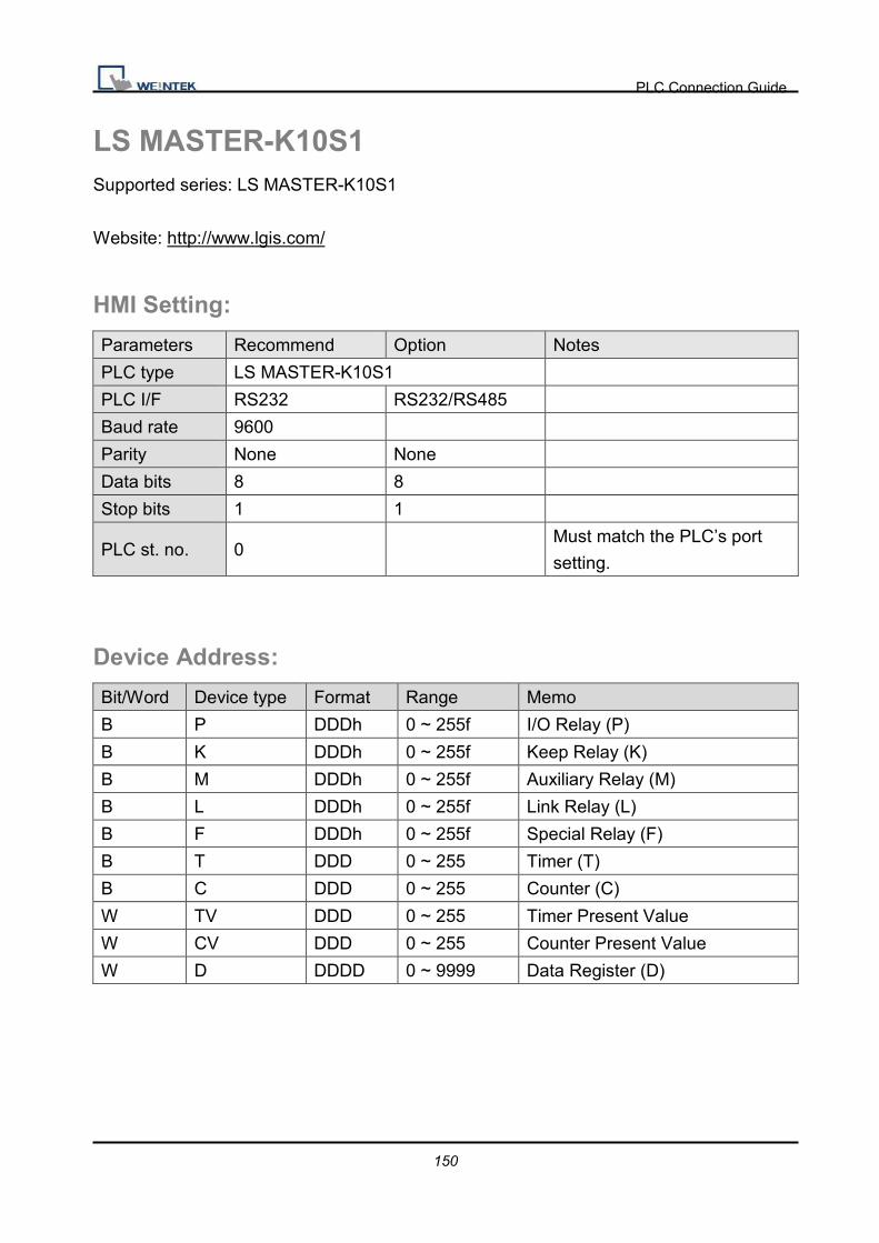
PLC Connection Guide
150
LS MASTER-K10S1 Supported series: LS MASTER-K10S1
Website: http://www.lgis.com/
HMI Setting:
Parameters Recommend Option Notes
PLC type LS MASTER-K10S1
PLC I/F RS232 RS232/RS485
Baud rate 9600
Parity None None
Data bits 8 8
Stop bits 1 1
PLC st. no. 0 Must match the PLC’s port
setting.
Device Address:
Bit/Word Device type Format Range Memo
B P DDDh 0 ~ 255f I/O Relay (P)
B K DDDh 0 ~ 255f Keep Relay (K)
B M DDDh 0 ~ 255f Auxiliary Relay (M)
B L DDDh 0 ~ 255f Link Relay (L)
B F DDDh 0 ~ 255f Special Relay (F)
B T DDD 0 ~ 255 Timer (T)
B C DDD 0 ~ 255 Counter (C)
W TV DDD 0 ~ 255 Timer Present Value
W CV DDD 0 ~ 255 Counter Present Value
W D DDDD 0 ~ 9999 Data Register (D)

PLC Connection Guide
151
Wiring Diagram:
9P D-Sub to 9P D-Sub:
HMI COM1
RS232 9P
D-Sub Male
HMI COM2
RS232 9P
D-Sub Male
HMI COM3
RS232 9P
D-Sub Female
CPU Port RS232 9P D-Sub
2 RX 6 RX 8 RX 3 TX
3 TX 4 TX 7 TX 2 RX
5 GND 5 GND 5 GND 5 GND
Driver Version:
Version Date Description
V1.00 Sep/08/2009 Driver released.

PLC Connection Guide
152
LS MASTER-K300S CPU Supported series: LS MASTER-K series: K80S, K120S, K200S, K300S, K1000S
Website: http://www.lgis.com/
HMI Setting:
Parameters Recommend Option Notes
PLC type LG MASTER-K300S CPU
PLC I/F RS232 RS232/RS485
Baud rate 38400 9600, 19200, 38400
Parity None Even, Odd, None
Data bits 8 8
Stop bits 1 1
PLC st. no. 0 0-31 Must match the PLC’s
port setting.
Online Simulator YES
Device Address:
Bit/Word Device type Format Range Memo
B P DDDh 0 ~ 255f I/O Relay (P)
B K DDDh 0 ~ 255f Keep Relay (K)
B M DDDh 0 ~ 255f Auxiliary Relay (M)
B L DDDh 0 ~ 255f Link Relay (L)
B F DDDh 0 ~ 255f Special Relay (F)
W TV DDD 0 ~ 255 Timer Present Value
W CV DDD 0 ~ 255 Counter Present Value
W D DDDD 0 ~ 9999 Data Register (D)

PLC Connection Guide
153
Wiring Diagram:
9P D-Sub to 9P D-Sub:
HMI COM1
RS232 9P
D-Sub Male
HMI COM2
RS232 9P
D-Sub Male
HMI COM3
RS232 9P
D-Sub Female
CPU Port RS232 9P D-Sub
2 RX 6 RX 8 RX 3 TX
3 TX 4 TX 7 TX 2 RX
5 GND 5 GND 5 GND 5 GND
Driver Version:
Version Date Description
V1.10 Dec/30/2008

PLC Connection Guide
154
LS XGB/XGT Supported series : LS XGB/XGT Series
Website: http://www.lgis.com/
HMI Setting: Parameters Recommend Option Notes
PLC type LS XGB/XGT
PLC I/F RS232 RS232/RS485
Baud rate 115200 9600~115200
Parity None Even, Odd, None
Data bits 8 7, 8
Stop bits 1 1
PLC st. no. 1 0-31 Must match the PLC’s port
setting.
Device Address:
Bit/Word Device type Format Range Memo B P DDDDh 0 ~ 2047f I/O device_2,048 points
B M DDDDh 0 ~ 2047f Internal device_4,096 points
B L DDDDDh 0 ~ 11263f Communication device_20,480
points
B K DDDDh
0 ~ 2559f Preservation device_4,096
points
B F DDDDh 0 ~ 2047f Special device_4,096 point
B T DDDD 0 ~ 2047 Timer device_256 point
B C DDDD 0 ~ 2047 Counter device_256 point
B S DDDDD 0 ~ 12799 Relay for step control
B D_Bit DDDDDh 0 ~ 32767f Data register_Bit expression
(D0000.0)
B U_Bit DH.DDh 0.000 ~ 7f.31f XGK-CPUE:hh(0~1f)
W D DDDDD 0 ~ 32767 Data register_5120 words
W U DH.DD 0.00 ~ 7f.31 Analog data register_256 words

PLC Connection Guide
155
W N DDDDD 0 ~ 21503 Communication data
register_3,936 words
W Z DDD 0 ~ 127 Index register_128 words
W T DDDD 0 ~ 2047 Timer current value
register_256 words
W C DDDD 0 ~ 2047 Counter current value
register_256 words
Wiring Diagram:
9P D-Sub to 6P Mini-DIN:
HMI COM1
RS232 9P
D-Sub Male
HMI COM2
RS232 9P
D-Sub Male
HMI COM3
RS232 9P
D-Sub Female
XGB main unit RS232 6P
Mini-DIN
2 RX 6 RX 8 RX 6 TXD
3 TX 4 TX 7 TX 2 RXD
5 GND 5 GND 5 GND 3 GND
Driver Version:
Version Date Description
V1.30 Apr/17/2009

PLC Connection Guide
156
LS XGB/XGT FEnet (Ethernet) Supported series: LS XGB/XGT with XBL-EMTA
Website: http://www.lgis.com/
HMI Setting:
Parameters Recommend Option Notes
PLC type LS XGB/XGT FEnet (Ethernet)
PLC I/F Ethernet
PLC st. no. 0 0~255
Port no. 2004
PLC Setting:
Communication mode FEnet Potocol
Device Address:
Bit/Word Device type Format Range Memo B P DDDDh 0 ~ 2047f I/O device_2,048 points
B M DDDDh 0 ~ 2047f Internal device_4,096 points
B L DDDDDh 0 ~ 11263f Communication device_20,480
points
B K DDDDh
0 ~ 2559f Preservation device_4,096
points
B F DDDDh 0 ~ 2047f Special device_4,096 point
B T DDDD 0 ~ 2047 Timer device_256 point
B C DDDD 0 ~ 2047 Counter device_256 point
B S DDDDD 0 ~ 12799 Relay for step control
B D_Bit DDDDDh 0 ~ 32767f Data register_Bit expression
(D0000.0)
B U_Bit DH.DDh 0.000 ~ 7f.31f XGK-CPUE:hh(0~1f)
W D DDDDD 0 ~ 32767 Data register_5120 words
W U DH.DD 0.00 ~ 7f.31 Analog data register_256 words

PLC Connection Guide
157
W N DDDDD 0 ~ 21503 Communication data
register_3,936 words
W Z DDD 0 ~ 127 Index register_128 words
W T DDDD 0 ~ 2047 Timer current value
register_256 words
W C DDDD 0 ~ 2047 Counter current value
register_256 words
Wiring Diagram:
Direct connect (crossover cable):
HMI RJ45 Female Wire Color PLC RJ45 Female
1 TX+ White/Orange 3 RX+
2 TX- Orange 6 RX-
3 RX+ White/Green 1 TX+
4 BD4+ Blue 4 BD4+
5 BD4- White/Blue 5 BD4-
6 RX- Green 2 TX-
7 BD3+ White/Brown 7 BD3+
8 BD3- Brown 8 BD3-
Through a hub:
HMI RJ45 Female Wire Color PLC RJ45 Female
1 TX+ White/Orange 1 TX+
2 TX- Orange 2 TX-
3 RX+ White/Green 3 RX+
4 BD4+ Blue 4 BD4+
5 BD4- White/Blue 5 BD4-
6 RX- Green 6 RX-
7 BD3+ White/Brown 7 BD3+
8 BD3- Brown 8 BD3-

PLC Connection Guide
158
Driver Version:
Version Date Description
V1.20 Apr/17/2009

PLC Connection Guide
159
LS XGL-CH2A Cnet Supported series: LS XGT series communication module XGL-CH2A
Website: http://www.lgis.com/
HMI Setting:
Parameters Recommend Option Notes
PLC type LS XGL-CH2A Cnet
PLC I/F RS232 RS232/RS485
2W/4W
Baud rate 115200 9600~115200
Parity None Even, Odd, None
Data bits 8 7, 8
Stop bits 1 1
PLC st. no. 0 1
Device Address: Bit/Word Device type Format Range Memo B P DDDDh 0 ~ 2047f I/O device
B M DDDDh 0 ~ 2047f Internal device
B L DDDDDh 0 ~ 11263f Communication device
B K DDDDh 0 ~ 2047f Preservation device
B F DDDDh 0 ~ 2047f Special device( write available
from 1025)
B T DDDD 0 ~ 2047 Timer device
B C DDDD 0 ~ 2047 Counter device
B S DDDDD 0 ~ 12799 Relay for step control
B D_Bit DDDDDh 0 ~ 32767f Data register_Bit expression
(D0000.0)
B U_Bit DH.DDH 0.000 ~ 3f.31f XGK-CPUE : hh(0~1f)
W D DDDDD 0 ~ 32767 Data register
W U DH.DD 0.00 ~ 3f.31 Analog data register
XGK-CPUE : hh(0~1f)
W N DDDDD 0 ~ 21503 Communication data register
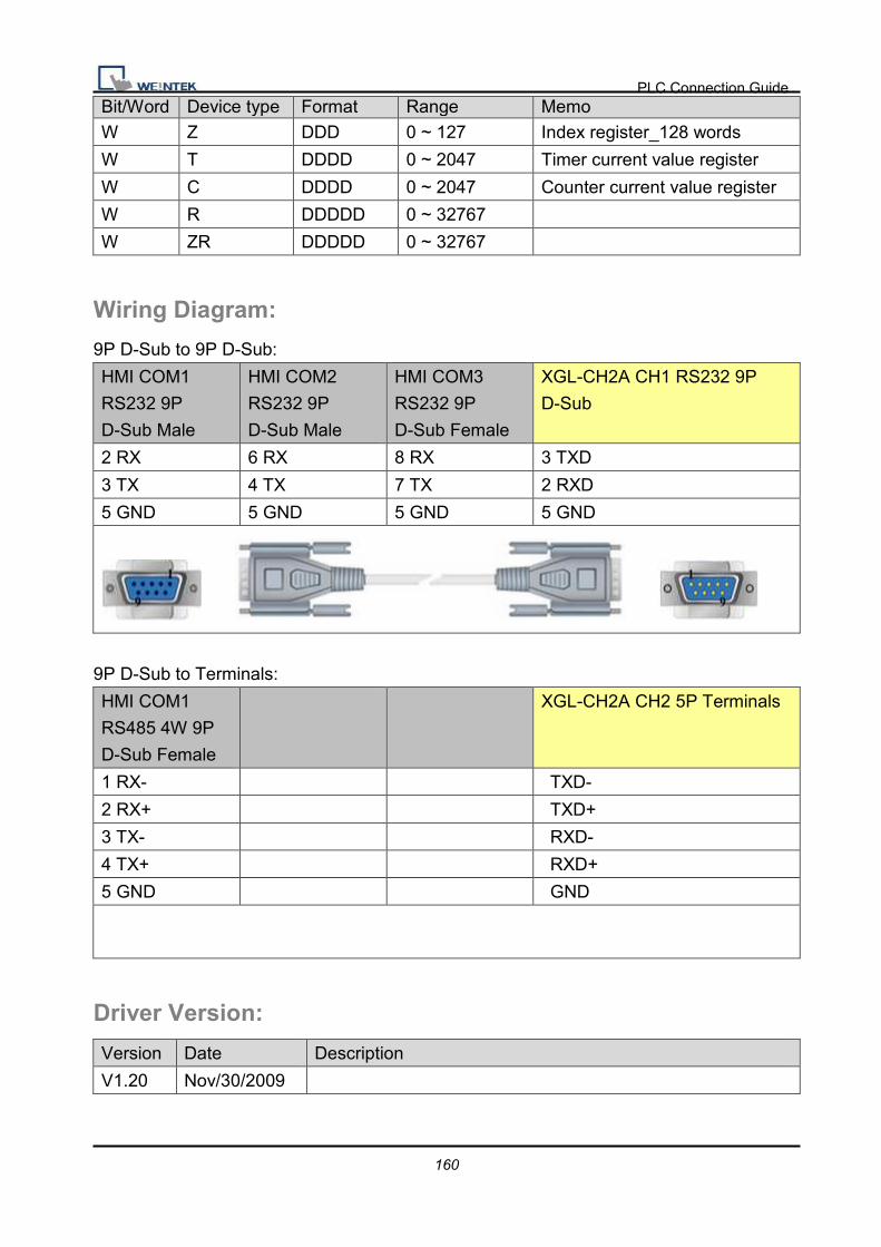
PLC Connection Guide
160
Bit/Word Device type Format Range Memo W Z DDD 0 ~ 127 Index register_128 words
W T DDDD 0 ~ 2047 Timer current value register
W C DDDD 0 ~ 2047 Counter current value register
W R DDDDD 0 ~ 32767
W ZR DDDDD 0 ~ 32767
Wiring Diagram:
9P D-Sub to 9P D-Sub:
HMI COM1
RS232 9P
D-Sub Male
HMI COM2
RS232 9P
D-Sub Male
HMI COM3
RS232 9P
D-Sub Female
XGL-CH2A CH1 RS232 9P
D-Sub
2 RX 6 RX 8 RX 3 TXD
3 TX 4 TX 7 TX 2 RXD
5 GND 5 GND 5 GND 5 GND
9P D-Sub to Terminals:
HMI COM1
RS485 4W 9P
D-Sub Female
XGL-CH2A CH2 5P Terminals
1 RX- TXD-
2 RX+ TXD+
3 TX- RXD-
4 TX+ RXD+
5 GND GND
Driver Version:
Version Date Description
V1.20 Nov/30/2009

PLC Connection Guide
161
LS XGL-EFMT FEnet (Ethernet) Supported series: LS XGT series XGL-EFMT Ethernet module.
Website: http://www.lgis.com/
HMI Setting:
Parameters Recommend Option Notes
PLC type LS XGL-EFMT FEnet (Ethernet)
PLC I/F Ethernet
Port No. 2004
PLC st. no. 0
Device Address: Bit/Word Device type Format Range Memo B P DDDDh 0 ~ 2047f I/O device
B M DDDDh 0 ~ 2047f Internal device
B L DDDDDh 0 ~ 11263f Communication device
B K DDDDh 0 ~ 2047f Preservation device
B F DDDDh 0 ~ 2047f Special device( write available
from 1025)
B T DDDD 0 ~ 2047 Timer device
B C DDDD 0 ~ 2047 Counter device
B S DDDDD 0 ~ 12799 Relay for step control
B D_Bit DDDDDh 0 ~ 32767f Data register_Bit expression
(D0000.0)
B U_Bit DH.DDH 0.000 ~ 3f.31f XGK-CPUE : hh(0~1f)
W D DDDDD 0 ~ 32767 Data register
W U DH.DD 0.00 ~ 3f.31 Analog data register
XGK-CPUE : hh(0~1f)
W N DDDDD 0 ~ 21503 Communication data register
W Z DDD 0 ~ 127 Index register_128 words
W T DDDD 0 ~ 2047 Timer current value register
W C DDDD 0 ~ 2047 Counter current value register
W R DDDDD 0 ~ 32767
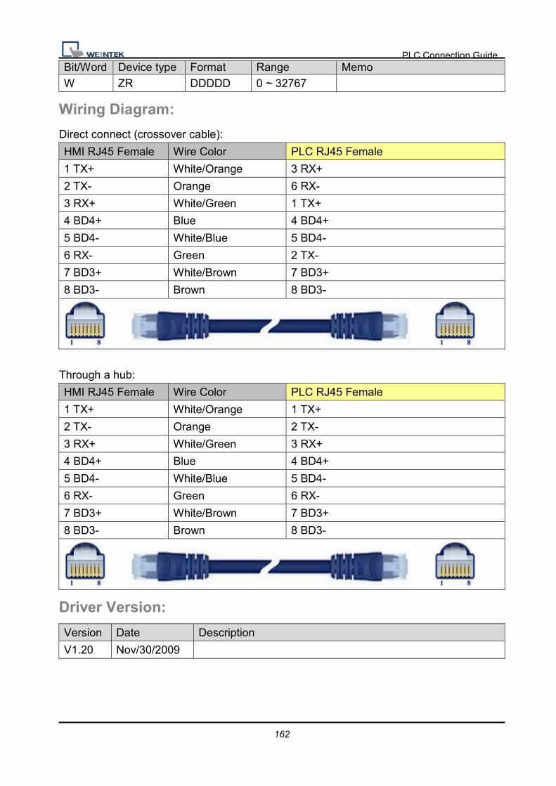
PLC Connection Guide
162
Bit/Word Device type Format Range Memo W ZR DDDDD 0 ~ 32767
Wiring Diagram:
Direct connect (crossover cable):
HMI RJ45 Female Wire Color PLC RJ45 Female
1 TX+ White/Orange 3 RX+
2 TX- Orange 6 RX-
3 RX+ White/Green 1 TX+
4 BD4+ Blue 4 BD4+
5 BD4- White/Blue 5 BD4-
6 RX- Green 2 TX-
7 BD3+ White/Brown 7 BD3+
8 BD3- Brown 8 BD3-
Through a hub:
HMI RJ45 Female Wire Color PLC RJ45 Female
1 TX+ White/Orange 1 TX+
2 TX- Orange 2 TX-
3 RX+ White/Green 3 RX+
4 BD4+ Blue 4 BD4+
5 BD4- White/Blue 5 BD4-
6 RX- Green 6 RX-
7 BD3+ White/Brown 7 BD3+
8 BD3- Brown 8 BD3-
Driver Version:
Version Date Description
V1.20 Nov/30/2009
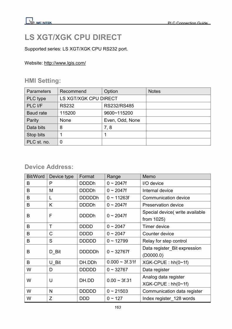
PLC Connection Guide
163
LS XGT/XGK CPU DIRECT Supported series: LS XGT/XGK CPU RS232 port.
Website: http://www.lgis.com/
HMI Setting:
Parameters Recommend Option Notes
PLC type LS XGT/XGK CPU DIRECT
PLC I/F RS232 RS232/RS485
Baud rate 115200 9600~115200
Parity None Even, Odd, None
Data bits 8 7, 8
Stop bits 1 1
PLC st. no. 0
Device Address: Bit/Word Device type Format Range Memo B P DDDDh 0 ~ 2047f I/O device
B M DDDDh 0 ~ 2047f Internal device
B L DDDDDh 0 ~ 11263f Communication device
B K DDDDh 0 ~ 2047f Preservation device
B F DDDDh 0 ~ 2047f Special device( write available
from 1025)
B T DDDD 0 ~ 2047 Timer device
B C DDDD 0 ~ 2047 Counter device
B S DDDDD 0 ~ 12799 Relay for step control
B D_Bit DDDDDh 0 ~ 32767f Data register_Bit expression
(D0000.0)
B U_Bit DH.DDh 0.000 ~ 3f.31f XGK-CPUE : hh(0~1f)
W D DDDDD 0 ~ 32767 Data register
W U DH.DD 0.00 ~ 3f.31 Analog data register
XGK-CPUE : hh(0~1f)
W N DDDDD 0 ~ 21503 Communication data register
W Z DDD 0 ~ 127 Index register_128 words
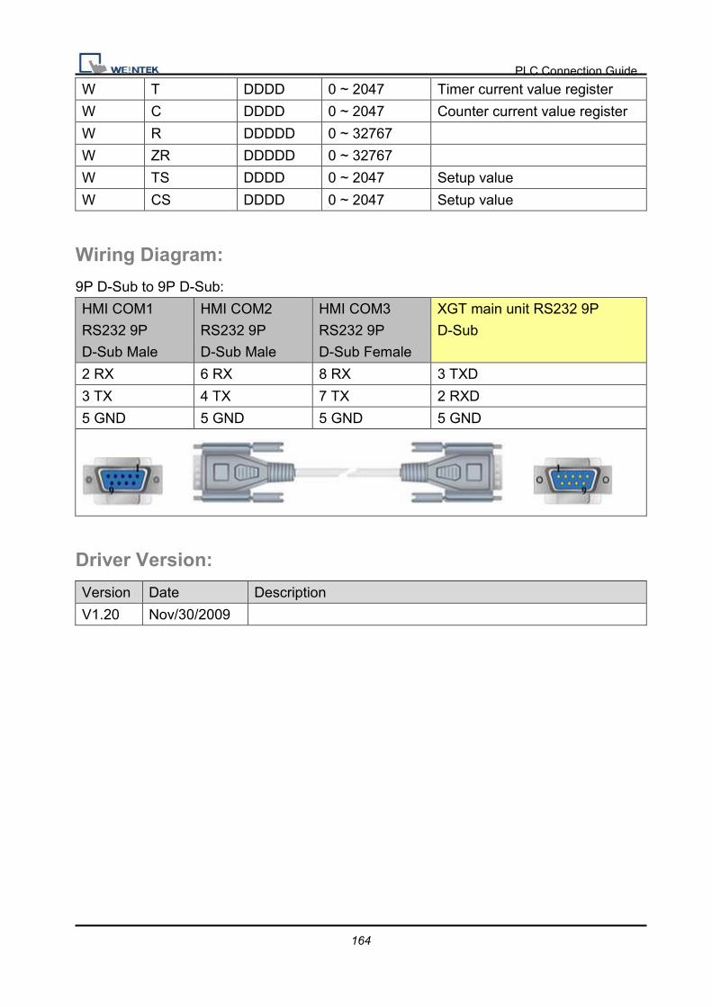
PLC Connection Guide
164
W T DDDD 0 ~ 2047 Timer current value register
W C DDDD 0 ~ 2047 Counter current value register
W R DDDDD 0 ~ 32767
W ZR DDDDD 0 ~ 32767
W TS DDDD 0 ~ 2047 Setup value
W CS DDDD 0 ~ 2047 Setup value
Wiring Diagram:
9P D-Sub to 9P D-Sub:
HMI COM1
RS232 9P
D-Sub Male
HMI COM2
RS232 9P
D-Sub Male
HMI COM3
RS232 9P
D-Sub Female
XGT main unit RS232 9P
D-Sub
2 RX 6 RX 8 RX 3 TXD
3 TX 4 TX 7 TX 2 RXD
5 GND 5 GND 5 GND 5 GND
Driver Version:
Version Date Description
V1.20 Nov/30/2009

PLC Connection Guide
165
Master (Master-Slave Protocol) To connect HMI with MT500, MT500 has to set as [Slave].
HMI Setting:
Parameters Recommend Option Notes
PLC type Master (Master-Slave Protocol)
PLC I/F RS232
Baud rate 115200 38400, 115200
Parity Even
Data bits 8
Stop bits 1
HMI st. no. 0
PLC st. no. 0
Parameter 1 MT500 PLC ID Use PLCAddressView.exe to find PLC ID.
PLC Setting:
Communication mode MT500 Multiple HMI set Slave.

PLC Connection Guide
166

PLC Connection Guide
167
Device Address:
Bit/Word MT500 MT8000 Range Memo
B Ms_RB RW_Bit ddd:0~4095 (h):
0~f
B Ms_LB LB dddd:0~9999
W Ms_RW RW ddd:0~65535
W Ms_LW LW ddd:0~9999
Driver Version:
Version Date Description
V1.00 Dec/30/2008 Driver released.

PLC Connection Guide
168
Memobus (Yaskawa MP Series Controllers) Supported series: YASKAWA MP2200, MP2300, MP2300S, MP9xx communication
module.
Website: http://www.yaskawa.com/
HMI Setting:
Parameters Recommend Option Notes
PLC type Memobus (Yaskawa MP Series Controllers)
PLC I/F RS485/Ethernet RS232/RS485 2w/4w,
Ethernet
Baud rate 19200 9600~57600
Parity Even
Data bits 8
Stop bits 1
PLC st. no. 1 1-31 Must match the PLC’s
port setting.
Port no. 502 default Ethernet Module only
PLC Setting:
Communication mode MEMOBUS, Slave, RTU
PLC Ethernet Setting:
1. User MPE720 program software, Open Module Configuration. Double click “218IFA”.

PLC Connection Guide
169
2. In Transmision Parameters input MP2300S IP address, subnet Mask, Gateway IP.
In Connection Parameter, CNO -1 input: Local Port=502, Node IP
address=000.000.000.000, Node Port=00000, Connect Type=TCP, Protocol
Type=MEMOBUS, Code=RTU.

PLC Connection Guide
170
3. Click MECHATROLINK to set up MP2300S PLC as Master.
4. Close all dialogs and save to MP2300S.
Note:
1. Only CNO 01 able to auto communication with one HMI. Other CNO need create
ladder program to communication.
2. DIP SW2-2 of MP2300S must be OFF position when normal communication, if it is ON
position, IP address will be erased after reset power, and it is unable to communicate with
HMI when ON position.
Device Address:
Bit/Word Device type Format Range Memo
B MB_1 DDDDh 0 ~ 9999f MB 0~9999
B MB_2 DDDDDh 100000 ~ 65534f MB 10000~65535
B IB HHHHH 0 ~ a7ff0 Read only
B IW_Bit HHHHdd 0~ a7ff15
W IW HHHH 0 ~ a7ff Read only
DW IL HHHH 0 ~ a7ff Read only
F IF HHHH 0 ~ a7ff Read only
W MW DDDDD 0 ~ 65534 Holding Register

PLC Connection Guide
171
DW ML DDDDD 0 ~ 65533 Double word
F MF DDDDD 0 ~ 65533 Floating point *: When connect via Ethernet interface the max range of IW, IL and IF would be restricted.
Wiring Diagram:
9P D-Sub to 9P D-Sub: 217IF-01, 218IF-01
HMI COM1
RS232 9P
D-Sub Male
HMI COM2
RS232 9P
D-Sub Male
HMI COM3
RS232 9P
D-Sub Female
217IF-01 RS232 9P D-Sub
2 RX 6 RX 8 RX 2 TX
3 TX 4 TX 7 TX 3 RX
5 GND 5 GND 5 GND 7 GND
217IF-01:
HMI COM1
RS485 2W 9P
D-Sub Female
HMI COM3
RS485 2W 9P
D-Sub Female
217IF-01 RS485 14P
Connector
1 RX- 6 Data- 2, 4 D-
2 RX+ 9 Data+ 1, 3 D+
5 GND 5 GND 14 GND
217IF-01:
HMI COM1
RS485 4W 9P
D-Sub Female
217IF-01 RS422 14P
Connector
1 RX- 2 TX-
2 RX+ 1 TX+
3 TX- 4 RX-
4 TX+ 3 RX+
5 GND 14 GND

PLC Connection Guide
172
Direct connect (crossover cable):
HMI RJ45 Female Wire Color PLC RJ45 Female
1 TX+ White/Orange 3 RX+
2 TX- Orange 6 RX-
3 RX+ White/Green 1 TX+
4 BD4+ Blue 4 BD4+
5 BD4- White/Blue 5 BD4-
6 RX- Green 2 TX-
7 BD3+ White/Brown 7 BD3+
8 BD3- Brown 8 BD3-
Through a hub:
HMI RJ45 Female Wire Color PLC RJ45 Female
1 TX+ White/Orange 1 TX+
2 TX- Orange 2 TX-
3 RX+ White/Green 3 RX+
4 BD4+ Blue 4 BD4+
5 BD4- White/Blue 5 BD4-
6 RX- Green 6 RX-
7 BD3+ White/Brown 7 BD3+
8 BD3- Brown 8 BD3-
Driver Version:
Version Date Description
V1.70 Dec/20/2010

PLC Connection Guide
173
Memory Map Memory Map protocol is similar to IBM 3764R communication protocol. The EasyBuilder
reserves 512 words of Data memory for use with this protocol. The EasyBuilder must
update the values in these words. The EasyBuilder uses the words to display data and
control parts status on its screen. When touch actions are taken, data is sent to the other
once, and then update the memory in it. The HMI is always responsible for updating the
Data memory.
HMI Setting:
Parameters Recommend Option Notes
PLC type Memory Map
PLC I/F RS232 RS232, RS485 4W, 2W RS232 default
Baud rate 115200 9600~115200
Parity Even Even, Odd, None
Data bits 8
Stop bits 1
Device Address: Bit/Word Device type Format Range Memo B MB DDDDh 0 ~ 9999f W MW DDDD 0 ~ 9999
The MB and MW are using same area to store data.
MW 0 = MB 000000 ~ MB 0000f
MW 1 = MB 000100 ~ MB 0001f
Wiring Diagram:
9P D-Sub to 9P D-Sub:
HMI COM1
RS232 9P
D-Sub Male
HMI COM1 RS232 9P D-Sub
Male
2 RX 3 TX
3 TX 2 RX
5 GND 5 GND

PLC Connection Guide
174
HMI COM1
RS485 2W 9P
D-Sub Female
HMI COM1 RS485 2W 9P
D-Sub Female
1 RX- 1 RX-
2 RX+ 2 RX+
5 GND 5 GND
HMI COM1
RS485 4W 9P
D-Sub Female
HMI COM1 RS485 4W 9P
D-Sub Female
1 RX- 3 TX-
2 RX+ 4 TX+
3 TX- 1 RX-
4 TX+ 2 RX+
5 GND 5 GND
Note:
For Memory map information, please refer to user manual [chapter 31 Memory Map
communication].
Driver Version:
Version Date Description
V1.00 Mar/19/2009 Driver released.

PLC Connection Guide
175
MITSUBISHI A1S Supported series: MITSUBISHI A1S
Website: http://www.mitsubishi-automation.com/
HMI Setting:
Parameters Recommend Option Notes
PLC type MITSUBISHI A1S
PLC I/F RS232
Baud rate 9600
Parity Odd
Data bits 8
Stop bits 1
PLC st. no. 0
Device Address:
Bit/Word Device type Format Range Memo
B X HHHH 0 ~ ffff Input Relay
B Y HHHH 0 ~ ffff Output Relay
B M DDDDD 0 ~ 65535 Auxiliary Relay
B B HHHH 0 ~ ffff
B F DDDDD 0 ~ 65535
W TV DDDDD 0 ~ 65535 Timer Memory
W CV DDDDD 0 ~ 65535 Counter Memory
W D DDDDD 0 ~ 65535 Data Register
W W HHHH 0 ~ ffff
W R DDDDD 0 ~ 65535

PLC Connection Guide
176
Wiring Diagram: Use the RS422 to RS232 PLC programming cable (show as follows)
MITSUBISHI AnS CPU
HMI COM1 RS232
9P D-Sub Male
PLC Programing
Cable
Mitsubishi RS422 25P D-Sub
3 TD RD 2 RX+
2 RD TD 3 TX+
5 GND GND 4 DSR+
8 CTS RTS 7 GND
7 RTS CTS 15 RX-
16 TX-
17 DSR-
PLC Connection Guide
177
Driver Version: Version Date Description
V1.00 Sep/18/2009 Driver released.

PLC Connection Guide
178
MITSUBISHI A2A Supported series: MITSUBISHI A2A, A2USH
Website: http://www.mitsubishi-automation.com/
HMI Setting:
Parameters Recommend Option Notes
PLC type MITSUBISHI A2A
PLC I/F RS232
Baud rate 9600
Parity Odd
Data bits 8
Stop bits 1
PLC st. no. 0
Device Address:
Bit/Word Device type Format Range Memo
B X HHHH 0 ~ 270f Input Relay
B Y HHHH 0 ~ 270f Output Relay
B M DDDD 0 ~ 9999 Auxiliary Relay
B B HHHH 0 ~ ffff
B F DDDDD 0 ~ 65535
W TV DDD 0 ~ 255 Timer Memory
W CV DDD 0 ~ 255 Counter Memory
W D DDDD 0 ~ 9999 Data Register
W W HHHH 0 ~ ffff
W R DDDDD 0 ~ 65535
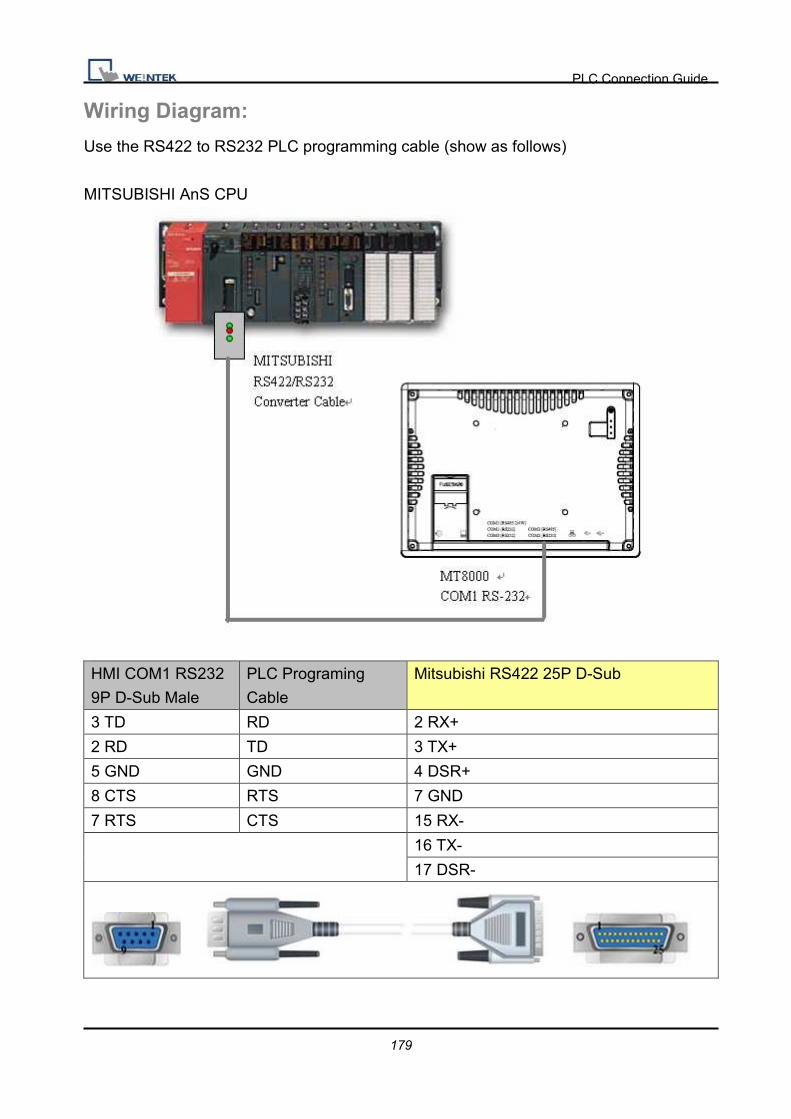
PLC Connection Guide
179
Wiring Diagram:
Use the RS422 to RS232 PLC programming cable (show as follows)
MITSUBISHI AnS CPU
HMI COM1 RS232
9P D-Sub Male
PLC Programing
Cable
Mitsubishi RS422 25P D-Sub
3 TD RD 2 RX+
2 RD TD 3 TX+
5 GND GND 4 DSR+
8 CTS RTS 7 GND
7 RTS CTS 15 RX-
16 TX-
17 DSR-

PLC Connection Guide
180
Driver Version:
Version Date Description
V1.00 Aug/12/2009 Driver released.

PLC Connection Guide
181
MITSUBISHI A2US Supported series: MITSUBISHI A2US
Website: http://www.mitsubishi-automation.com/
HMI Setting:
Parameters Recommend Option Notes
PLC type MITSUBISHI A2US
PLC I/F RS232
Baud rate 9600
Parity Odd
Data bits 8
Stop bits 1
PLC st. no. 0
Device Address:
Bit/Word Device type Format Range Memo
B X HHHH 0 ~ 270f Input Relay
B Y HHHH 0 ~ 270f Output Relay
B M DDDD 0 ~ 9999 Auxiliary Relay
W TV DDD 0 ~ 255 Timer Memory
W CV DDD 0 ~ 255 Counter Memory
W D DDDD 0 ~ 9999 Data Register

PLC Connection Guide
182
Wiring Diagram:
Use the RS422 to RS232 PLC programming cable (show as follows)
MITSUBISHI AnS CPU
HMI COM1 RS232
9P D-Sub Male
PLC Programing
Cable
Mitsubishi RS422 25P D-Sub
3 TD RD 2 RX+
2 RD TD 3 TX+
5 GND GND 4 DSR+
8 CTS RTS 7 GND
7 RTS CTS 15 RX-
16 TX-
17 DSR-

PLC Connection Guide
183
Driver Version:
Version Date Description
V1.00 Mar/20/2009 Driver released.
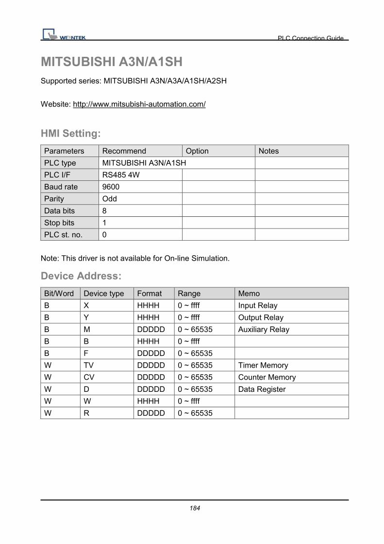
PLC Connection Guide
184
MITSUBISHI A3N/A1SH Supported series: MITSUBISHI A3N/A3A/A1SH/A2SH
Website: http://www.mitsubishi-automation.com/
HMI Setting:
Parameters Recommend Option Notes
PLC type MITSUBISHI A3N/A1SH
PLC I/F RS485 4W
Baud rate 9600
Parity Odd
Data bits 8
Stop bits 1
PLC st. no. 0
Note: This driver is not available for On-line Simulation.
Device Address:
Bit/Word Device type Format Range Memo
B X HHHH 0 ~ ffff Input Relay
B Y HHHH 0 ~ ffff Output Relay
B M DDDDD 0 ~ 65535 Auxiliary Relay
B B HHHH 0 ~ ffff
B F DDDDD 0 ~ 65535
W TV DDDDD 0 ~ 65535 Timer Memory
W CV DDDDD 0 ~ 65535 Counter Memory
W D DDDDD 0 ~ 65535 Data Register
W W HHHH 0 ~ ffff
W R DDDDD 0 ~ 65535

PLC Connection Guide
185
Wiring Diagram:
Use the RS422 to RS232 PLC programming cable (show as follows)
MITSUBISHI AnS CPU
HMI COM1 RS232
9P D-Sub Male
PLC Programing
Cable
Mitsubishi RS422 25P D-Sub
3 TD RD 2 RX+
2 RD TD 3 TX+
5 GND GND 4 DSR+
8 CTS RTS 7 GND
7 RTS CTS 15 RX-
16 TX-
17 DSR-

PLC Connection Guide
186
Driver Version:
Version Date Description
V1.00 Oct/20/2009 Driver released.

PLC Connection Guide
187
MITSUBISHI AJ71 Supported series: Mitsubishi A series PLC with AJ71C24 communication module using the
Computer Link protocol.
Website: http://www.mitsubishi-automation.com
HMI Setting:
Parameters Recommend Option Notes
PLC type MITSUBISHI AJ71
MITSUBISHI AJ71
(AnA/AnU CPU),
MITSUBISHI AJ71 (Format
4)
PLC I/F RS485 4W RS485 4W, RS232
Baud rate 19200 9600, 19200
Parity Even Even, Odd, None
Data bits 8 8
Stop bits 1 1
PLC st. no. 0
PLC Setting:
Communication mode Computer Link protocol 9600, Even, 8, 1 (default)
Mode Setting Switch Format 1
Parity Check Enable
Sum Check Enable
Device Address:
Bit/Word Device type Format Range Memo
B X HHHH 0 ~ ffff Input Bits
B Y HHHH 0 ~ ffff Output Bits
B M DDDDD 0 ~ 65535 Internal Relays
B T DDDDD 0 ~ 65535
B C DDDDD 0 ~ 65535
B B HHHH 0 ~ ffff
B F DDDDD 0 ~ 65535

PLC Connection Guide
188
W TV DDDDD 0 ~ 65535 Timer Preset Value
W CV DDDDD 0 ~ 65535 Counter Preset Value
W D DDDDD 0 ~ 65535 Data Registers
W W HHHH 0 ~ ffff
W R DDDDD 0 ~ 65535
Wiring Diagram:
HMI COM1
RS485 4W 9P
D-Sub Female
AJ71C24 RS422
1 RX- SDB
2 RX+ SDA
3 TX- RDB
4 TX+ RDA
5 GND GND
HMI COM1
RS232 9P
D-Sub Male
HMI COM2
RS232 9P
D-Sub Male
HMI COM3
RS232 9P
D-Sub Female
A1SJ71UC24-R2 RS232 9P
D-Sub
2 RX 6 RX 8 RX 3 TXD
3 TX 4 TX 7 TX 2 RXD
5 GND 5 GND 5 GND 5 GND
1 DCD circuit
4 DTR
6 DSR
7 RTS circuit
8 CTS
Driver Version:
Version Date Description
V1.50 Mar/11/2010

PLC Connection Guide
189
MITSUBISHI FX0n/FX2 Supported series: Mitsubishi FX0s/FX0n/FX1s/FX2 PLC
Website: http://www.mitsubishi-automation.com
HMI Setting:
Parameters Recommend Option Notes
PLC type Mitsubishi FX0n/FX2
PLC I/F RS485 4W RS232/RS485
Baud rate 9600 9600/19200/38400/
57600/115200
Parity Even Even, Odd, None
Data bits 7 7,8
Stop bits 1 1,2
PLC st. no. 0 0-255 must same as the PLC setting
Device Address:
Bit/Word Device type Format Range Memo
B X OOO 0 ~ 377 Input Relay
B Y OOO 0 ~ 377 Output Relay
B M DDDD 0 ~ 9999 Auxiliary Relay
B T DDD 0 ~ 255 Timer Relay
B C DDD 0 ~ 255 Counter Relay
B D_Bit DDDDdd 0 ~ 999915 Data Register Bit (D)
B S DDDD 0 ~ 4095 States
B SM DDDD 8000 ~ 9999 Special Aux. Relays
W TV DDD 0 ~ 255 Timer Memory
W CV DDD 0 ~ 199 Counter Memory
W D DDDD 0 ~ 9999 Data Register
DW CV2 DDD 200 ~ 255 Counter Memory(D Word)
W SD DDDD 8000 ~ 9999 Special Data Register

PLC Connection Guide
190
Wiring Diagram:
9P D-Sub to 8P MiniDIN:
HMI COM1
RS485 4W 9P
D-Sub Female
Mitsubishi PLC CPU RS422
Port 8P Mini-DIN
1 RX- 4 TX-
2 RX+ 7 TX+
3 TX- 1 RX-
4 TX+ 2 RX+
5 GND 3 GND
9P D-Sub to 25P D-Sub:
HMI COM1
RS485 4W 9P
D-Sub Female
Mitsubishi PLC CPU RS422
Port 25P D-Sub
1 RX- 16 TXD-
2 RX+ 3 TXD+
3 TX- 15 RXD-
4 TX+ 2 RXD+
5 GND 7 GND circuit
4 DSR+
8 GND
13 +5V circuit
17 DSR-
Driver Version:
Version Date Description
V1.10 Sep/ 01/2009 Add address type [S], [SM], [D_bit].

PLC Connection Guide
191
MITSUBISHI FX232/485BD Supported series: Mitsubishi FX0n/FX2/FX2n COM For Communication Module BD
FX2N-485-BD, FX2N-232-BD, FX1N-485-BD and FX1N-232-BD.
Website: http://www.mitsubishi-automation.com
HMI Setting:
Parameters Recommend Option Notes
PLC type MITSUBISHI FX232/485BD
PLC I/F RS232/RS485 RS232/RS485
2w/4w
in accordance with the BD
module
Baud rate 19200 9600/19200
Parity Even Even, Odd, None
Data bits 7 7,8
Stop bits 1 1,2
PLC st. no. 1 0-15
Note: we suggest the turn around delay to set 8. (For i series HMI)
Online Simulator YES Extend address mode YES
PLC Setting:
Communication mode Must set PLC station when use the BD Module
Register D8120 setting: set b9 and b8 of BFM#0 as 0

PLC Connection Guide
192
FX2N-485-BD, FX1N-485-BD FX2N-232-BD, FX1N-232-BD
Device Address:
Bit/Word Device type Format Range Memo
B X OOO 0 ~ 377 Input Relay
B Y OOO 0 ~ 377 Output Relay
B M DDDD 0 ~ 7999 Auxiliary Relay
B T DDD 0 ~ 511 Timer Relay
B C DDD 0 ~ 255 Counter Relay
B SM DDDD 8000 ~ 9999
W TV DDD 0 ~ 255 Timer Memory
W CV DDD 0 ~ 199 Counter Memory
W D DDDD 0 ~ 7999 Data Register
W CV2 DDD 200 ~ 255 Counter Memory(D Word)
W SD DDDD 8000 ~ 9999
Wiring Diagram:
9P D-Sub to 9P D-Sub: Communication Module RS232BD
HMI COM1
RS232 9P
D-Sub Male
HMI COM2
RS232 9P
D-Sub Male
HMI COM3
RS232 9P
D-Sub Female
232BD Module RS232 9P
D-Sub
2 RX 6 RX 8 RX 3 TXD
3 TX 4 TX 7 TX 2 RXD
5 GND 5 GND 5 GND 5 GND
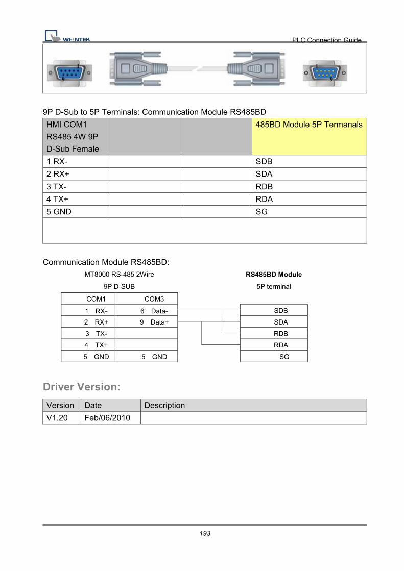
PLC Connection Guide
193
9P D-Sub to 5P Terminals: Communication Module RS485BD
HMI COM1
RS485 4W 9P
D-Sub Female
485BD Module 5P Termanals
1 RX- SDB
2 RX+ SDA
3 TX- RDB
4 TX+ RDA
5 GND SG
Communication Module RS485BD: MT8000 RS-485 2Wire
9P D-SUB
RS485BD Module
5P terminal
COM1 COM3
1 RX- 6 Data- SDB
2 RX+ 9 Data+ SDA
3 TX- RDB
4 TX+ RDA
5 GND 5 GND SG
Driver Version:
Version Date Description
V1.20 Feb/06/2010

PLC Connection Guide
194
MITSUBISHI FX2n Supported series: Mitsubishi FX1n/FX2n series PLC
Website http://www.mitsubishi-automation.com
HMI Setting:
Parameters Recommend Option Notes
PLC type MITSUBISHI FX2n
PLC I/F RS485 4W RS232/RS485
Baud rate 19200 9600/19200/38400
/57600/115200
Parity Even
Data bits 7
Stop bits 1
PLC st. no. 0
Online Simulator YES Extend address mode NO
Device Address:
Bit/Word Device type Format Range Memo
B X OOO 0 ~ 377 Input Relay
B Y OOO 0 ~ 377 Output Relay
B M DDDD 0 ~ 7999 Auxiliary Relay
B T DDD 0 ~ 255 Timer Relay
B C DDD 0 ~ 255 Counter Relay
B SM DDDD 8000 ~ 9999 Special Auxiliary Relay
B D_Bit DDDDdd 0 ~ 799915 Data Register Bit (D)
B S DDDD 0 ~ 4095 State Relay (S)
W TV DDD 0 ~ 255 Timer Memory
W CV DDD 0 ~ 199 Counter Memory
W D DDDD 0 ~ 7999 Data Register
DW CV2 DDD 200 ~ 255 Counter Memory(D Word)
W SD DDDD 8000 ~ 9999 Special Data Register

PLC Connection Guide
195
Wiring Diagram:
9P D-Sub to 8P Mini-DIN:
HMI COM1
RS485 4W 9P
D-Sub Female
Mitsubishi FX series PLC CPU
Port RS422 8P Mini-DIN
1 RX- 4 TX-
2 RX+ 7 TX+
3 TX- 1 RX-
4 TX+ 2 RX+
5 GND 3 GND
Driver Version:
Version Date Description
V1.60 Sep/10/2009

PLC Connection Guide
196
MITSUBISHI FX3u (Ethernet) Supported series: MITSUBISHI FX SERIES, Module: FX3U-ENET.
Website: http://www.mitsubishi-automation.com
HMI Setting:
Parameters Recommend Option Notes
PLC type MITSUBISHI FX3u (Ethernet)
PLC I/F Ethernet
PLC st. no. 0 (default) Refer Module Setting
Port no. 5001(default) Refer Module Setting
PLC Setting:
Fx3u-ENET module setting:
Before using Ethernet module, using GX Developer / FX Configurator-EN to set the
Ethernet module, the FX3u-ENET module settings as below steps.
1. Open GX Developer, select “Read from PLC” in Online list.

PLC Connection Guide
197
2. Select “FXCPU” in PLC series.
3. Users have to connect PLC via series port for setting IP address at first time.
4. After finishing the PLC settings, select Tools/FX special function utility/FX
Configurator-EN.

PLC Connection Guide
198
5. Select “Module 0” in Ethernet Module settings.
(If more than one module, please setting modules step by step)

PLC Connection Guide
199
5. In Ethernet operational settings, select the related parameters and IP address and then
press ”End” to finish the settings.
6. In Ethernet open settings, press “End” after setting the below parameters.
(The first Protocol means using GX Developer to communicate with module, The max.
“Fixed buffer communication preocedure” is 4 units.)
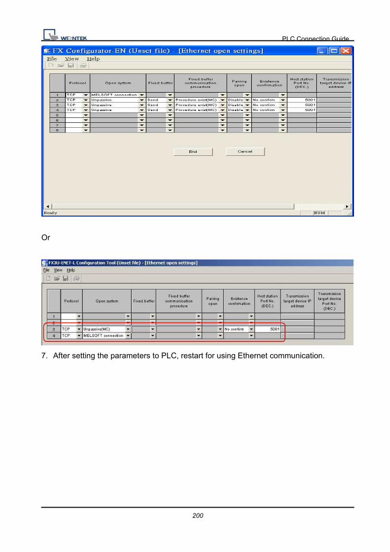
PLC Connection Guide
200
Or
7. After setting the parameters to PLC, restart for using Ethernet communication.

PLC Connection Guide
201
Device Address:
Bit/Word Device type Format Range Memo
B X OOO 0 ~ 571 Input
B Y OOO 0 ~ 571 Output Relay
B M DDDD 0 ~ 7999 Internal Relay
B S DDDD 0 ~ 4095 Step Relays
B T DDD 0 ~ 511 Timer Contacts
B C DDD 0 ~ 255 Counter Contacts
B SM DDDD 8000 ~ 8511 Special Int. Relays
B D_Bit DDDDDdd 0 ~ 1799915 Data Register Bit Access
W TV DDD 0 ~ 511 Timer Value
W R DDDDD 0 ~ 32767 File Register
W CV DDD 0 ~ 199 Counter Value
W D DDDD 0 ~ 7999 Data Registers
W CV2 DDD 200 ~255 Counter Value
W SD DDDD 8000 ~ 8511 Special Data Registers
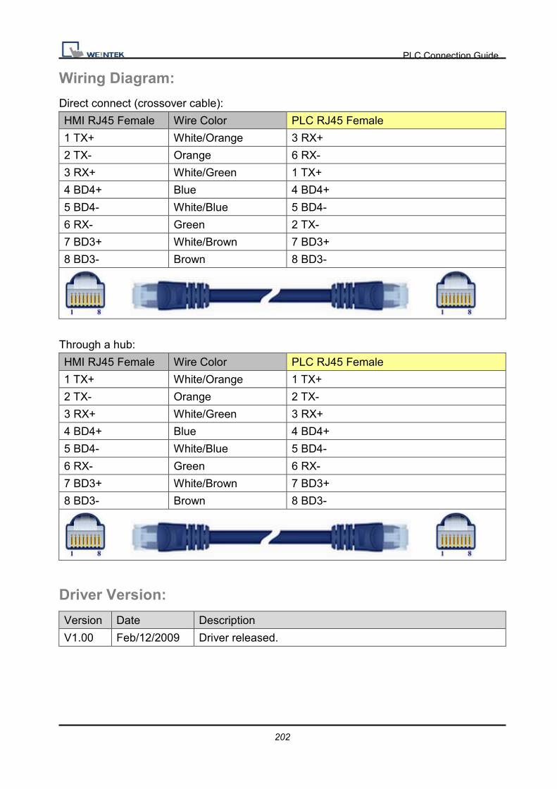
PLC Connection Guide
202
Wiring Diagram:
Direct connect (crossover cable):
HMI RJ45 Female Wire Color PLC RJ45 Female
1 TX+ White/Orange 3 RX+
2 TX- Orange 6 RX-
3 RX+ White/Green 1 TX+
4 BD4+ Blue 4 BD4+
5 BD4- White/Blue 5 BD4-
6 RX- Green 2 TX-
7 BD3+ White/Brown 7 BD3+
8 BD3- Brown 8 BD3-
Through a hub:
HMI RJ45 Female Wire Color PLC RJ45 Female
1 TX+ White/Orange 1 TX+
2 TX- Orange 2 TX-
3 RX+ White/Green 3 RX+
4 BD4+ Blue 4 BD4+
5 BD4- White/Blue 5 BD4-
6 RX- Green 6 RX-
7 BD3+ White/Brown 7 BD3+
8 BD3- Brown 8 BD3-
Driver Version:
Version Date Description
V1.00 Feb/12/2009 Driver released.
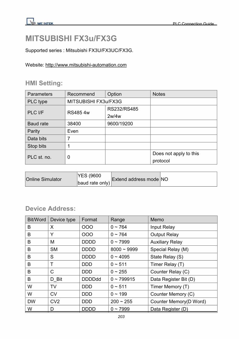
PLC Connection Guide
203
MITSUBISHI FX3u/FX3G Supported series : Mitsubishi FX3U/FX3UC/FX3G.
Website: http://www.mitsubishi-automation.com
HMI Setting:
Parameters Recommend Option Notes
PLC type MITSUBISHI FX3u/FX3G
PLC I/F RS485 4w RS232/RS485
2w/4w
Baud rate 38400 9600/19200
Parity Even
Data bits 7
Stop bits 1
PLC st. no. 0 Does not apply to this
protocol
Online Simulator YES (9600
baud rate only) Extend address mode NO
Device Address:
Bit/Word Device type Format Range Memo
B X OOO 0 ~ 764 Input Relay
B Y OOO 0 ~ 764 Output Relay
B M DDDD 0 ~ 7999 Auxiliary Relay
B SM DDDD 8000 ~ 9999 Special Relay (M)
B S DDDD 0 ~ 4095 State Relay (S)
B T DDD 0 ~ 511 Timer Relay (T)
B C DDD 0 ~ 255 Counter Relay (C)
B D_Bit DDDDdd 0 ~ 799915 Data Register Bit (D)
W TV DDD 0 ~ 511 Timer Memory (T)
W CV DDD 0 ~ 199 Counter Memory (C)
DW CV2 DDD 200 ~ 255 Counter Memory(D Word)
W D DDDD 0 ~ 7999 Data Register (D)
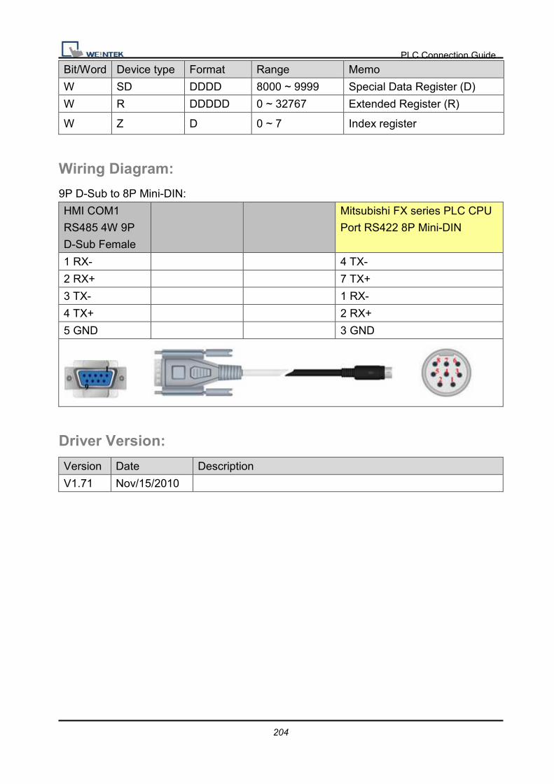
PLC Connection Guide
204
Bit/Word Device type Format Range Memo
W SD DDDD 8000 ~ 9999 Special Data Register (D)
W R DDDDD 0 ~ 32767 Extended Register (R)
W Z D 0 ~ 7 Index register
Wiring Diagram:
9P D-Sub to 8P Mini-DIN:
HMI COM1
RS485 4W 9P
D-Sub Female
Mitsubishi FX series PLC CPU
Port RS422 8P Mini-DIN
1 RX- 4 TX-
2 RX+ 7 TX+
3 TX- 1 RX-
4 TX+ 2 RX+
5 GND 3 GND
Driver Version:
Version Date Description
V1.71 Nov/15/2010

PLC Connection Guide
205
MITSUBISHI MELSEC-Q (Ethernet) Supported series: MITSUBISHI Q series (Q03UDE, Q04UDEH, Q06UDEH, Q10UDEH,
Q13UDEH, Q20UDEH, Q26UDEH), MELSEC-Q protocol application to CPU of Ethernet
interface or Ethernet module.
Website: http://www.mitsubishi-automation.com
HMI Setting:
Parameters Recommend Option Notes
PLC type MITSUBISHI MELSEC-Q (Ethernet)
PLC I/F Ethernet
PLC st. no. It must same as the PLC
setting 255 Q13UDEH has to set 255
Parameter1 Networking no. (it must
the same as PLC setting) 0~255 Q13UDEH has to set 0
Port no. It must same as the PLC
setting Advice to set port no. to 4999
PLC Setting:
MITSUBISHI Q series Ethernet module setting:
Remark: If using QJ71E71 module, please refer MITSUBISHI QJ71E71 connection guide.
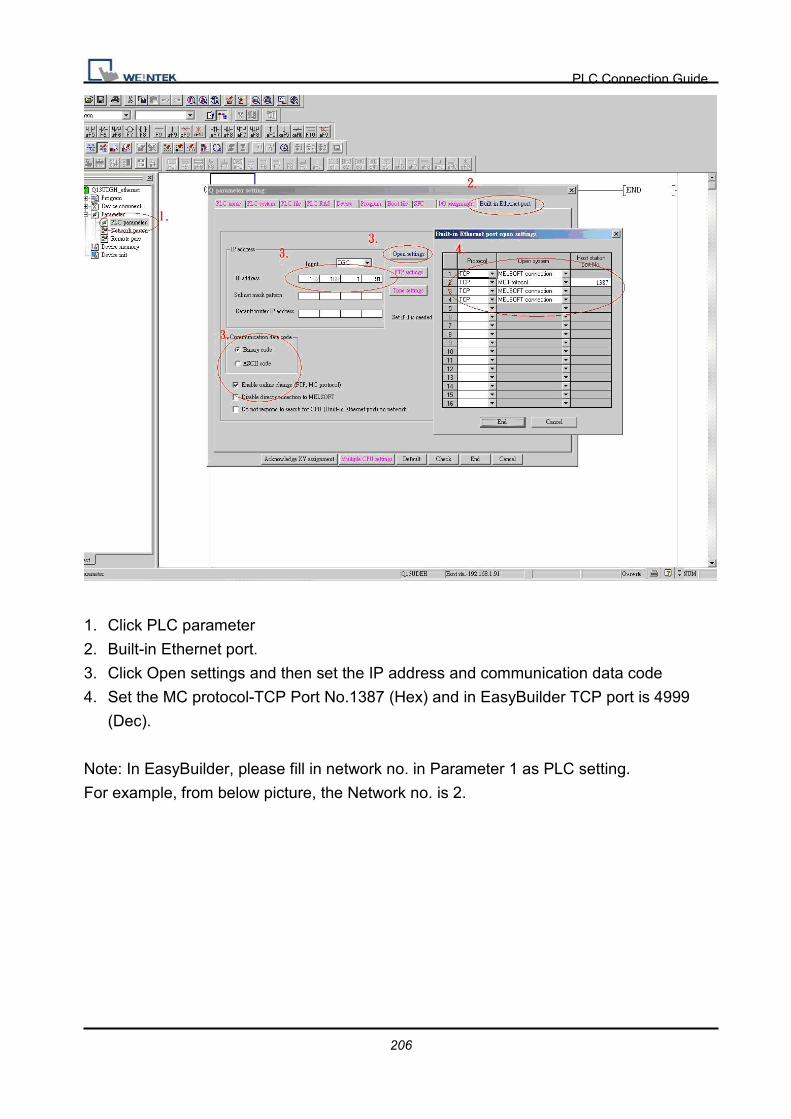
PLC Connection Guide
206
1. Click PLC parameter
2. Built-in Ethernet port.
3. Click Open settings and then set the IP address and communication data code
4. Set the MC protocol-TCP Port No.1387 (Hex) and in EasyBuilder TCP port is 4999
(Dec).
Note: In EasyBuilder, please fill in network no. in Parameter 1 as PLC setting.
For example, from below picture, the Network no. is 2.
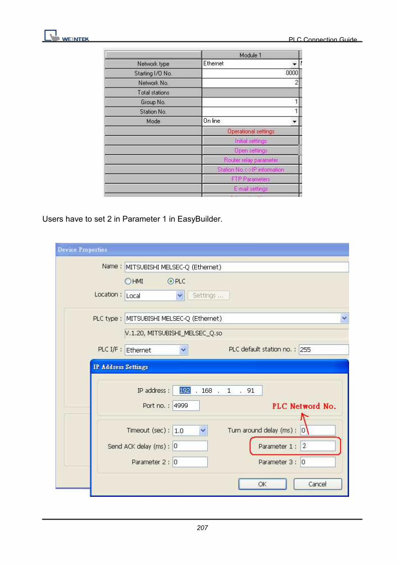
PLC Connection Guide
207
Users have to set 2 in Parameter 1 in EasyBuilder.
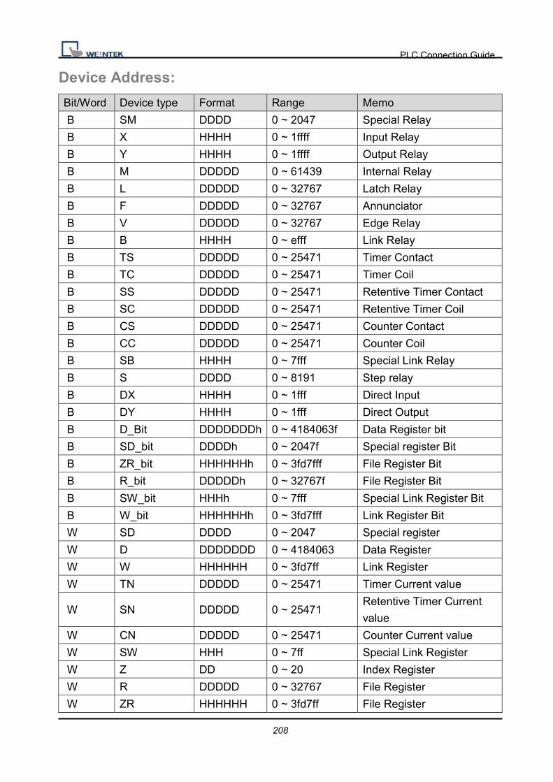
PLC Connection Guide
208
Device Address:
Bit/Word Device type Format Range Memo
B SM DDDD 0 ~ 2047 Special Relay
B X HHHH 0 ~ 1ffff Input Relay
B Y HHHH 0 ~ 1ffff Output Relay
B M DDDDD 0 ~ 61439 Internal Relay
B L DDDDD 0 ~ 32767 Latch Relay
B F DDDDD 0 ~ 32767 Annunciator
B V DDDDD 0 ~ 32767 Edge Relay
B B HHHH 0 ~ efff Link Relay
B TS DDDDD 0 ~ 25471 Timer Contact
B TC DDDDD 0 ~ 25471 Timer Coil
B SS DDDDD 0 ~ 25471 Retentive Timer Contact
B SC DDDDD 0 ~ 25471 Retentive Timer Coil
B CS DDDDD 0 ~ 25471 Counter Contact
B CC DDDDD 0 ~ 25471 Counter Coil
B SB HHHH 0 ~ 7fff Special Link Relay
B S DDDD 0 ~ 8191 Step relay
B DX HHHH 0 ~ 1fff Direct Input
B DY HHHH 0 ~ 1fff Direct Output
B D_Bit DDDDDDDh 0 ~ 4184063f Data Register bit
B SD_bit DDDDh 0 ~ 2047f Special register Bit
B ZR_bit HHHHHHh 0 ~ 3fd7fff File Register Bit
B R_bit DDDDDh 0 ~ 32767f File Register Bit
B SW_bit HHHh 0 ~ 7fff Special Link Register Bit
B W_bit HHHHHHh 0 ~ 3fd7fff Link Register Bit
W SD DDDD 0 ~ 2047 Special register
W D DDDDDDD 0 ~ 4184063 Data Register
W W HHHHHH 0 ~ 3fd7ff Link Register
W TN DDDDD 0 ~ 25471 Timer Current value
W SN DDDDD 0 ~ 25471 Retentive Timer Current
value
W CN DDDDD 0 ~ 25471 Counter Current value
W SW HHH 0 ~ 7ff Special Link Register
W Z DD 0 ~ 20 Index Register
W R DDDDD 0 ~ 32767 File Register
W ZR HHHHHH 0 ~ 3fd7ff File Register

PLC Connection Guide
209
Note: Every mdel of CPU is different, we suggest user to refer to MITSUBISHI MELSEC-Q
manual’s Device List.
Wiring Diagram:
Direct connect (crossover cable):
HMI RJ45 Female Wire Color PLC RJ45 Female
1 TX+ White/Orange 3 RX+
2 TX- Orange 6 RX-
3 RX+ White/Green 1 TX+
4 BD4+ Blue 4 BD4+
5 BD4- White/Blue 5 BD4-
6 RX- Green 2 TX-
7 BD3+ White/Brown 7 BD3+
8 BD3- Brown 8 BD3-
Through a hub:
HMI RJ45 Female Wire Color PLC RJ45 Female
1 TX+ White/Orange 1 TX+
2 TX- Orange 2 TX-
3 RX+ White/Green 3 RX+
4 BD4+ Blue 4 BD4+
5 BD4- White/Blue 5 BD4-
6 RX- Green 6 RX-
7 BD3+ White/Brown 7 BD3+
8 BD3- Brown 8 BD3-
Driver Version:
Version Date Description
V1.21 Jan/06/2011

PLC Connection Guide
210
MITSUBISHI Q00/Q00UJ/Q01/QJ71 Supported series: Mitsubishi Q series PLC with QJ71C24 communication module, Q00,
Q00J, Q00UJ, Q01, Q02H, Q06H, Q12H, Q25H, Q12PH, Q25PH CPU port.
Website: http://www.mitsubishi-automation.com
HMI Setting:
Parameters Recommend Option Notes
PLC type MITSUBISHI Q00/Q00UJ/Q01/QJ71
PLC I/F RS232 RS485 4W, RS232
Baud rate 9600 9600~115200
Parity Odd
Data bits 8
Stop bits 1
PLC st. no. 0
Online Simulator YES
Extend address mode NO
PLC Setting:
Q00, Q01 CPU port setting:
1. In the GX Developer “PLC data list” click the “PLC
parameter”
2. In the “PLC parameter” select “Serial” page.
3. Select “Use serial communication”
4. Set the “Transmission speed”. 9600~115200.
5. Select “Sum check”
6. Select “Transmission wait time” to 10ms.
7. Select “RUN write setting”
8. Click “End” close the dialog.
9. Write the PLC Parameter to PLC.
10. RESET the PLC, the parameter will active.
Note: Please check “Permit” in “RUN write setting” item.

PLC Connection Guide
211
QJ71 setting:
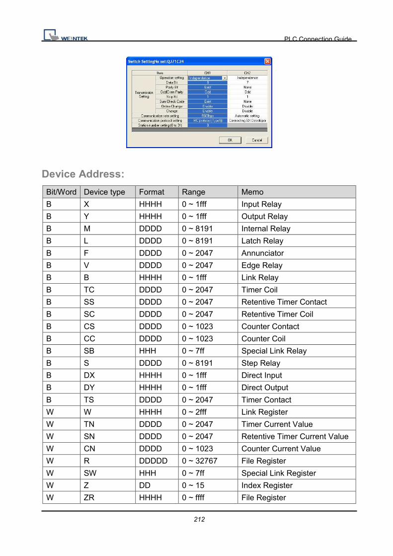
PLC Connection Guide
212
Device Address:
Bit/Word Device type Format Range Memo
B X HHHH 0 ~ 1fff Input Relay
B Y HHHH 0 ~ 1fff Output Relay
B M DDDD 0 ~ 8191 Internal Relay
B L DDDD 0 ~ 8191 Latch Relay
B F DDDD 0 ~ 2047 Annunciator
B V DDDD 0 ~ 2047 Edge Relay
B B HHHH 0 ~ 1fff Link Relay
B TC DDDD 0 ~ 2047 Timer Coil
B SS DDDD 0 ~ 2047 Retentive Timer Contact
B SC DDDD 0 ~ 2047 Retentive Timer Coil
B CS DDDD 0 ~ 1023 Counter Contact
B CC DDDD 0 ~ 1023 Counter Coil
B SB HHH 0 ~ 7ff Special Link Relay
B S DDDD 0 ~ 8191 Step Relay
B DX HHHH 0 ~ 1fff Direct Input
B DY HHHH 0 ~ 1fff Direct Output
B TS DDDD 0 ~ 2047 Timer Contact
W W HHHH 0 ~ 2fff Link Register
W TN DDDD 0 ~ 2047 Timer Current Value
W SN DDDD 0 ~ 2047 Retentive Timer Current Value
W CN DDDD 0 ~ 1023 Counter Current Value
W R DDDDD 0 ~ 32767 File Register
W SW HHH 0 ~ 7ff Special Link Register
W Z DD 0 ~ 15 Index Register
W ZR HHHH 0 ~ ffff File Register

PLC Connection Guide
213
Bit/Word Device type Format Range Memo
W D DDDDD 0 ~ 12287 Data Register
Wiring Diagram:
HMI COM1
RS485 4W 9P
D-Sub Female
QJ71C24 CH.2 RS422
1 RX- SDB
2 RX+ SDA
3 TX- RDB
4 TX+ RDA
5 GND GND
9P D-Sub to 9P D-Sub:
HMI COM1
RS232 9P
D-Sub Male
HMI COM2
RS232 9P
D-Sub Male
HMI COM3
RS232 9P
D-Sub Female
QJ71C24 CH.1 RS232 9P
D-Sub
2 RX 6 RX 8 RX 3 TXD
3 TX 4 TX 7 TX 2 RXD
5 GND 5 GND 5 GND 5 GND
1 DCD circuit
4 DTR
6 DSR
7 RTS circuit
8 CTS

PLC Connection Guide
214
9P D-Sub to 6P Mini-DIN: Q00, Q01 CPU port RS232
HMI COM1
RS232 9P
D-Sub Male
HMI COM2
RS232 9P
D-Sub Male
HMI COM3
RS232 9P
D-Sub Female
Q00, Q01 CPU Port RS232 6P
Mini-DIN
2 RX 6 RX 8 RX 4 TXD
3 TX 4 TX 7 TX 3 RXD
5 GND 5 GND 5 GND 5 GND
9P D-Sub to 6P Mini-DIN: Q00UJ CPU port RS232
HMI COM1
RS232 9P
D-Sub Male
HMI COM2
RS232 9P
D-Sub Male
HMI COM3
RS232 9P
D-Sub Female
Q00UJ CPU Port RS232 6P
Mini-DIN
2 RX 6 RX 8 RX 4 TXD
3 TX 4 TX 7 TX 3 RXD
5 GND 5 GND 5 GND 5 GND
1 RTS circuit
6 CTS
Driver Version:
Version Date Description
V1.46 Oct/22/2010

PLC Connection Guide
215
MITSUBISHI Q00J
Supported series: MITSUBISHI Q00J CPU
HMI Setting:
Parameters Recommend Option Notes
PLC type MITSUBISHI Q00J
PLC I/F RS232 CPU port
Baud rate 115200 9600,19200,38400,
57600,115200
Data bits 8
Parity Odd
Stop bits 1
PLC st. no.
Device Address:
Bit/Word Device type Format Range Memo
B SM DDDD 0 ~ 1023
B X HHH 0 ~ 7ff
B Y HHH 0 ~ 7ff
B M DDDD 0 ~ 8191
B L DDDD 0 ~ 2047
B F DDDD 0 ~ 1023
B V DDDD 0 ~ 1023
B B HHH 0 ~ 7ff
B SB HHH 0 ~ 3ff
W SD DDDD 0 ~ 1023
W W HHH 0 ~ 7ff
W T DDD 0 ~ 511
W SW HHH 0 ~ 3ff
W Z D 0 ~ 9
W C DDD 0 ~ 511
W D DDDDD 0 ~ 11135

PLC Connection Guide
216
Wiring Diagram:
9P D-Sub to 6P Mini-DIN: Q00 CPU port RS232
HMI COM1
RS232 9P
D-Sub Male
HMI COM2
RS232 9P
D-Sub Male
HMI COM3
RS232 9P
D-Sub Female
Q00 CPU Port RS232 6P
Mini-DIN
2 RX 6 RX 8 RX 4 TXD
3 TX 4 TX 7 TX 3 RXD
5 GND 5 GND 5 GND 5 GND
MT8-Mitsubishi-Q-3M cable is able to connect MT8000 and Mitsubishi Q series directly.
Driver Version:
Version Date Description
V1.10 Sep/18/2009

PLC Connection Guide
217
MITSUBISHI Q00U/Q01U/Q02U/QnUD/QnUDH Supported series: MITSUBISHI Q00U, Q01U, Q02U, Q03UD, Q04UDH, Q06UDH,
Q10UDH, Q13UDH, Q20UDH, Q26UDH CPU.
HMI Setting:
Parameters Recommend Option Notes
PLC type MITSUBISHI
Q00U/Q01U/Q02U/QnUD/QnUDH
PLC I/F RS232 RS485 4W,
RS232 CPU port connect directly
Baud rate 115200 115200 only
9600,19200,38400,57600,11520
0
For Q00UJ, only 9600 available
Parity Odd
Data bits 8
Stop bits 1
PLC st. no. No
Device Address:
Bit/Word Device type Format Range Memo
B X HHHH 0 ~ 1fff Input Relay
B Y HHHH 0 ~ 1fff Output Relay
B M DDDD 0 ~ 8191 Internal Relay
B L DDDD 0 ~ 8191 Latch Relay
B F DDDD 0 ~ 2047 Annunciator
B V DDDD 0 ~ 2047 Edge Relay
B B HHHH 0 ~ 1fff Link Relay
B SB HHH 0 ~ 7ff Special Link Relay
W W HHHH 0 ~ 1fff Link Register
W T DDDD 0 ~ 0247 Timer Current Value
W SW HHH 0 ~ 7ff Special Link Register
W Z DD 0 ~ 19 Index Register
W C DDDD 0 ~ 1023 Counter Current Value
W D DDDDD 0 ~ 12287 Data Register

PLC Connection Guide
218
Bit/Word Device type Format Range Memo
W R DDDDD 0 ~ 32767
Note:
EasyBuilder doesn’t support MITSUBISHI Q02U CPU to do on-line simulation on PC.
When using Q02U driver, HMI needs 10 seconds to initial the PLC Q02U driver. Before
finishing initial, we suggest users don’t wrire data to PLC, or it could cause the “PLC no
response” if the wiring diagram or the data are incorrect, it could cause PLC locked. If the
PLC locked, users have to restart PLC or reinstall PLC module.
Wiring Diagram:
9P D-Sub to 6P Mini-DIN: Q02 CPU port RS232
HMI COM1
RS232 9P
D-Sub Male
HMI COM2
RS232 9P
D-Sub Male
HMI COM3
RS232 9P
D-Sub Female
Q02 CPU Port RS232 6P
Mini-DIN
2 RX 6 RX 8 RX 3 TXD
3 TX 4 TX 7 TX 4 RXD
5 GND 5 GND 5 GND 5 GND
1 RTS circuit
6 CTS
Driver Version:
Version Date Description
V1.40 Jul/08/2009

PLC Connection Guide
219
MITSUBISHI Q00UJ/QnU/QnUD/QnUDH/QnUDEH
(mini USB) Supported series: MITSUBISHI Q00UJ, Q00U, Q01U, Q02U, Q03UDE, Q03UD,
Q04UDEH, Q04UDH, Q06UDEH, Q06UDH, Q10UDEH, Q10UDH, Q13UDEH, Q13UDH,
Q20UDEH, Q20UDH, Q26UDEH, Q26UDH USB Port.
HMI Setting:
Parameters Recommend Option Notes
PLC type MITSUBISHI
Q00UJ/QnU/QnUD/QnUDH/QnUDEH
(mini USB)
PLC I/F USB CPU port connect directly
PLC st. no.
Device Address:
Bit/Word Device type Format Range Memo
B X HHHH 0 ~ 1fff Input Relay
B Y HHHH 0 ~ 1fff Output Relay
B M DDDD 0 ~ 8191 Internal Relay
B L DDDD 0 ~ 8191 Latch Relay
B F DDDD 0 ~ 2047 Annunciator
B V DDDD 0 ~ 2047 Edge Relay
B B HHHH 0 ~ 1fff Link Relay
B SB HHH 0 ~ 7ff Special Link Relay
W W HHHH 0 ~ 1fff Link Register
W T DDDD 0 ~ 0247 Timer Current Value
W SW HHH 0 ~ 7ff Special Link Register
W Z DD 0 ~ 19 Index Register
W C DDDD 0 ~ 1023 Counter Current Value
W D DDDDD 0 ~ 12287 Data Register
W R DDDDD 0 ~ 32767

PLC Connection Guide
220
Note:
EasyBuilder doesn’t support MITSUBISHI Q02U CPU to do on-line simulation on PC.
When using Q02U driver, HMI needs 10 seconds to initial the PLC Q02U driver. Before
finishing initial, we suggest users don’t wrire data to PLC, or it could cause the “PLC no
response”If the wiring diagram or the data are incorrect, it could causes PLC locked. If
the PLC locked, users have to restart PLC or reinstall PLC module.
Driver Version:
Version Date Description
V1.00 May/05/2010 Driver released

PLC Connection Guide
221
MITSUBISHI Q02/02H Supported series; Mitsubishi Q02/Q02H CPU port.
Website: http://www.mitsubishi-automation.com
HMI Setting:
Parameters Recommend Option Notes
PLC type MITSUBISHI Q02/02H
PLC I/F RS232 RS485 4W, RS232
Baud rate 115200 115200 only
Parity Odd
Data bits 8
Stop bits 1
PLC st. no. 0
Online Simulator YES Extend address mode NO
Broadcast command NO
Device Address:
Bit/Word Device type Format Range Memo
B X HHHH 0 ~ 1fff Input Relay
B Y HHHH 0 ~ 1fff Output Relay
B M DDDD 0 ~ 8191 Internal Relay
B L DDDD 0 ~ 8191 Latch Relay
B F DDDD 0 ~ 2047 Annunciator
B V DDDD 0 ~ 2047 Edge Relay
B B HHHH 0 ~ 1fff Link Relay
B TC DDDD 0 ~ 2047 Timer Coil
B SS DDDD 0 ~ 2047 Retentive Timer Contact
B SC DDDD 0 ~ 2047 Retentive Timer Coil
B CS DDDD 0 ~ 1023 Counter Contact
B CC DDDD 0 ~ 1023 Counter Coil
B SB HHH 0 ~ 7ff Special Link Relay
B S DDDD 0 ~ 8191 Step Relay
B DX HHHH 0 ~ 1fff Direct Input

PLC Connection Guide
222
Bit/Word Device type Format Range Memo
B DY HHHH 0 ~ 1fff Direct Output
B TS DDDD 0 ~ 2047 Timer Contact
W W HHHH 0 ~ 1fff Link Register
W TN DDDD 0 ~ 2047 Timer Current Value
W SN DDDD 0 ~ 2047 Retentive Timer Current Value
W CN DDDD 0 ~ 1023 Counter Current Value
W R DDDDD 0 ~ 32767 File Register
W SW HHH 0 ~ 7ff Special Link Register
W Z DD 0 ~ 15 Index Register
W ZR HHHH 0 ~ ffff File Register
W D DDDDD 0 ~ 12287 Data Register
Wiring Diagram:
9P D-Sub to 6P Mini-DIN: Q02 CPU port RS232
HMI COM1
RS232 9P
D-Sub Male
HMI COM2
RS232 9P
D-Sub Male
HMI COM3
RS232 9P
D-Sub Female
Q02 CPU Port RS232 6P
Mini-DIN
2 RX 6 RX 8 RX 3 TXD
3 TX 4 TX 7 TX 4 RXD
5 GND 5 GND 5 GND 5 GND
1 RTS circuit
6 CTS
Driver Version:
Version Date Description
V1.50 Jan/05/2010 Fixed communication problem.

PLC Connection Guide
223
MITSUBISHI Q06H Supported series: Mitsubishi Q06H CPU port.
Website: http://www.mitsubishi-automation.com
HMI Setting:
Parameters Recommend Option Notes
PLC type MITSUBISHI Q06H
PLC I/F RS232 RS485 4W, RS232
Baud rate 115200 115200 only
Parity Odd
Data bits 8
Stop bits 1
PLC st. no. 0
Online Simulator YES Extend address mode NO
Broadcast command NO
Device Address:
Bit/Word Device type Format Range Memo
B X HHHH 0 ~ 1fff Input Relay
B Y HHHH 0 ~ 1fff Output Relay
B M DDDD 0 ~ 8191 Internal Relay
B L DDDD 0 ~ 8191 Latch Relay
B F DDDD 0 ~ 2047 Annunciator
B V DDDD 0 ~ 2047 Edge Relay
B B HHHH 0 ~ 1fff Link Relay
B TC DDDD 0 ~ 2047 Timer Coil
B SS DDDD 0 ~ 2047 Retentive Timer Contact
B SC DDDD 0 ~ 2047 Retentive Timer Coil
B CS DDDD 0 ~ 1023 Counter Contact
B CC DDDD 0 ~ 1023 Counter Coil
B SB HHH 0 ~ 7ff Special Link Relay
B S DDDD 0 ~ 8191 Step Relay
B DX HHHH 0 ~ 1fff Direct Input

PLC Connection Guide
224
Bit/Word Device type Format Range Memo
B DY HHHH 0 ~ 1fff Direct Output
B TS DDDD 0 ~ 2047 Timer Contact
W W HHHH 0 ~ 1fff Link Register
W TN DDDD 0 ~ 2047 Timer Current Value
W SN DDDD 0 ~ 2047 Retentive Timer Current Value
W CN DDDD 0 ~ 1023 Counter Current Value
W R DDDDD 0 ~ 32767 File Register
W SW HHH 0 ~ 7ff Special Link Register
W Z DD 0 ~ 15 Index Register
W ZR HHHH 0 ~ ffff File Register
W D DDDDD 0 ~ 12287 Data Register
Wiring Diagram:
9P D-Sub to 6P Mini-DIN: Q02 CPU port RS232
HMI COM1
RS232 9P
D-Sub Male
HMI COM2
RS232 9P
D-Sub Male
HMI COM3
RS232 9P
D-Sub Female
Q02 CPU Port RS232 6P
Mini-DIN
2 RX 6 RX 8 RX 4 TXD
3 TX 4 TX 7 TX 3 RXD
5 GND 5 GND 5 GND 5 GND
1 RTS circuit
6 CTS
Driver Version:
Version Date Description
V1.50 Jan/06/2010

PLC Connection Guide
225
MITSUBISHI QJ71E71 (Ethernet) Supported series ; Mitsubishi Q type, MELSEC-Q series PLC (Q00J, Q00, Q01, Q02,
Q02H, Q06H, Q12H, Q25H, Q12PH, Q25PH) QJ71E71-100 Ethernet module.
Website: http://www.mitsubishi-automation.com
HMI Setting:
Parameters Recommend Option Notes
PLC type MITSUBISHI QJ71E71 (Ethernet)
PLC I/F Ethernet
PLC st. no. 2 1~99
Port no. 5002
Note: MITSUBISHI QJ71E71 only supports PLC Network no. 1.
If PLC’s Network no. is not 1, please use “MISTSUBISHI MELSEC-Q(Ethernet)” driver and
fill in the Network no. in Parameter 1. Please refer MISTSUBISHI MELSEC-Q(Ethernet)
for further information.
PLC Setting:
QJ71E71-100 Ethernet module settings:
1. Use Q-CPU’s USB or RS232 setting PLC parameters.
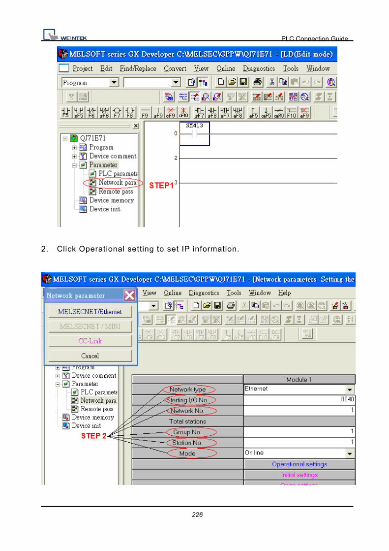
PLC Connection Guide
226
2. Click Operational setting to set IP information.

PLC Connection Guide
227
3. Select Ethernet (2.0) for communicating with HMI.
4. Click “Open settings” to set the system.
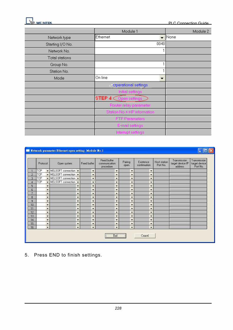
PLC Connection Guide
228
5. Press END to finish settings.

PLC Connection Guide
229
6. Restart PLC software and select [READ FROM PLC], click QCPU(Qmode)
and press OK.
7. Select “Ethernet board” in PC Side I/F to set Network and Station no. (the
Station no.1 is PC’s station no. not Ethernet module’s, range from 2~64, the
Network no. can not the same as PC’s number)
8. Select “Ethernet module” in PLC Side I/F to set QJ71E71’s IP address.(IP
address = Network Parameter’s IP address)

PLC Connection Guide
230
9. In “Other station”, click “Other station(Single network)” setting “Check at
communication time” and “Retry times”.
After finishing settings as above, click “Connection test” for testing the
communication and sending the PLC’s program.
Device Address:
Bit/Word Device type Format Range Memo
B SM DDDD 0 ~ 2047
B X HHHH 0 ~ 1fff Input Relay
B Y HHHH 0 ~ 1fff Output Relay
B M DDDD 0 ~ 8191 Internal Relay
B L DDDD 0 ~ 8191 Latch Relay
B F DDDD 0 ~ 2047 Annunciator
B V DDDD 0 ~ 2047 Edge Relay

PLC Connection Guide
231
Bit/Word Device type Format Range Memo
B B HHHH 0 ~ 1fff Link Relay
B TS DDDD 0 ~ 2047
B TC DDDD 0 ~ 2047
B SS DDDD 0 ~ 2047
B SC DDDD 0 ~ 2047
B CS DDDD 0 ~ 1023
B CC DDDD 0 ~ 1023
B SB HHH 0 ~ 7ff Special Link Relay
B S DDDD 0 ~ 8191
B DX HHHH 0 ~ 1fff Direct Input
B DY HHHH 0 ~ 1fff Direct Output
W SD DDDD 0 ~ 2047
W W HHHH 0 ~ 1fff Link Register
W R DDDDD 0 ~ 32767 File Register
W SW HHH 0 ~ 7ff Special Link Register
W Z DD 0 ~ 15 Index Register
W ZR HHHHH 0 ~ fe7ff File Register
W D DDDDD 0 ~ 12287 Data Register
W TN DDDD 0 ~ 2047
W SN DDDD 0 ~ 2047
W CN DDDD 0 ~ 1023
Wiring Diagram:
Direct connect (crossover cable):
HMI RJ45 Female Wire Color PLC RJ45 Female
1 TX+ White/Orange 3 RX+
2 TX- Orange 6 RX-
3 RX+ White/Green 1 TX+
4 BD4+ Blue 4 BD4+
5 BD4- White/Blue 5 BD4-
6 RX- Green 2 TX-
7 BD3+ White/Brown 7 BD3+
8 BD3- Brown 8 BD3-

PLC Connection Guide
232
Through a hub:
HMI RJ45 Female Wire Color PLC RJ45 Female
1 TX+ White/Orange 1 TX+
2 TX- Orange 2 TX-
3 RX+ White/Green 3 RX+
4 BD4+ Blue 4 BD4+
5 BD4- White/Blue 5 BD4-
6 RX- Green 6 RX-
7 BD3+ White/Brown 7 BD3+
8 BD3- Brown 8 BD3-
Driver Version:
Version Date Description
V2.10 Feb/05/2009

PLC Connection Guide
233
MODBUS ASCII Supported series: MODBUS ASCII CONTROLLER
Website: http://www.modbus.org
HMI Setting:
Parameters Recommend Option Notes
PLC type MODBUS ASCII
PLC I/F RS485 RS232/RS485
Baud rate 9600 9600/19200/38400/
57600/115200
Parity Even Even, Odd, None
Data bits 8 7,8
Stop bits 1 1,2
PLC st. no. 1 0-255
Online Simulator YES Broadcast command YES
Extend address mode YES
PLC Setting:
Communication mode Modbus ASCII protocol
Device Address:
Bit/Word Device type Format Range Memo
B 0x DDDDD 1 ~ 65535 Output bit
B 1x DDDDD 1 ~ 65535 Input bit (read only)
B 3x_Bit DDDDDdd 100 ~ 6553515 Input Register bit (read only)
B 4x_Bit DDDDDdd 100 ~ 6553515 Output Register bit
W 3x DDDDD 1 ~ 65535 Input Register (read only)
W 4x DDDDD 1 ~ 65535 Output Register
W 6x DDDDD 1 ~ 65535
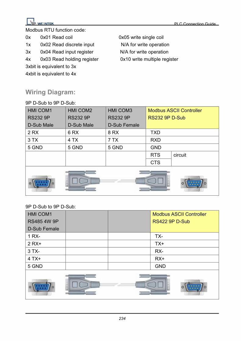
PLC Connection Guide
234
Modbus RTU function code:
0x 0x01 Read coil 0x05 write single coil
1x 0x02 Read discrete input N/A for write operation
3x 0x04 Read input register N/A for write operation
4x 0x03 Read holding register 0x10 write multiple register
3xbit is equivalent to 3x
4xbit is equivalent to 4x
Wiring Diagram:
9P D-Sub to 9P D-Sub:
HMI COM1
RS232 9P
D-Sub Male
HMI COM2
RS232 9P
D-Sub Male
HMI COM3
RS232 9P
D-Sub Female
Modbus ASCII Controller
RS232 9P D-Sub
2 RX 6 RX 8 RX TXD
3 TX 4 TX 7 TX RXD
5 GND 5 GND 5 GND GND
RTS circuit
CTS
9P D-Sub to 9P D-Sub:
HMI COM1
RS485 4W 9P
D-Sub Female
Modbus ASCII Controller
RS422 9P D-Sub
1 RX- TX-
2 RX+ TX+
3 TX- RX-
4 TX+ RX+
5 GND GND

PLC Connection Guide
235
9P D-Sub to 9P D-Sub:
HMI COM1
RS485 2W 9P
D-Sub Female
HMI COM3
RS485 2W 9P
D-Sub Female
Modbus ASCII Controller
RS485 9P D-Sub
1 RX- 6 Data- D-
2 RX+ 9 Data+ D+
5 GND 5 GND GND
Driver Version:
Version Date Description
V1.40 Apr/17/2009

PLC Connection Guide
236
MODBUS RTU Supported series : MODBUS RTU CONTROLLER
Website : http://www.modbus.org
HMI Setting:
Parameters Recommend Option Notes
PLC type MODBUS RTU
PLC I/F RS485 RS232/RS485
Baud rate 9600 9600~115200
Parity Even Even, Odd, None
Data bits 8 7, 8
Stop bits 1 1, 2
PLC st. no. 1 0-255
Online Simulator YES Broadcast command YES
Extend address mode YES
PLC Setting:
Communication mode Modbus RTU protocol
Device Address:
Bit/Word Device type Format Range Memo
B 0x DDDDD 1 ~ 65535 Output bit B 0x_multi_coils DDDDD 1 ~ 65535 Write Multiple Coils
B 1x DDDDD 1 ~ 65535 Input bit (read only)
B 3x_Bit DDDDDdd 1 ~ 6553515 Input Register bit (read only)
B 4x_Bit DDDDDdd 1 ~ 6553515 Output Register bit
B 6x_Bit DDDDDdd 1 ~ 6553515 Output Register bit
W 3x DDDDD 1 ~ 65535 Input Register (read only)
W 4x DDDDD 1 ~ 65535 Output Register
DW 5x DDDDD 1 ~ 65535 4x double word swap
W 6x DDDDD 1 ~ 65535 4x single word write W 4x_32Bit DDDDD 1 ~ 65535 4x High/low byte swap

PLC Connection Guide
237
NOTE:
Address type “5x” are mapping to Hold Reg. The communication protocol of 5x is almost
same as “4x” except “5x”making double word swap.
If 4x has following information
Address 1 2 3 4 5 6 ...
Data in word 0x1 0x2 0x3 0x4 0x5 0x6
Data 0x20001 0x40003 0x60005
For 5x, it become
Address 1 2 3 4 5 6 ...
Data in word 0x2 0x1 0x4 0x3 0x6 0x5
Data 0x10002 0x30004 0x50006
Modbus RTU function code:
0x 0x01 Read coil 0x05 write single coil
0x_multi_coils 0x01 Read coil 0x0f write multiple coil
1x 0x02 Read discrete input N/A for write operation
3x 0x04 Read input register N/A for write operation
4x 0x03 Read holding register 0x10 write multiple register
5x 0x03 Read holding register 0x10 write multiple register
(note: reverse word order in double word format)
3xbit is equivalent to 3x
4xbit is equivalent to 4x
6x 0x03 Read holding register 0x06 write single register
(note: use 6x device is limited to device of one word only)

PLC Connection Guide
238
Wiring Diagram:
9P D-Sub to 9P D-Sub:
HMI COM1
RS232 9P
D-Sub Male
HMI COM2
RS232 9P
D-Sub Male
HMI COM3
RS232 9P
D-Sub Female
Modbus RTU Controller RS232
9P D-Sub
2 RX 6 RX 8 RX TXD
3 TX 4 TX 7 TX RXD
5 GND 5 GND 5 GND GND
RTS circuit
CTS
9P D-Sub to 9P D-Sub:
HMI COM1
RS485 4W 9P
D-Sub Female
Modbus RTU Controller
RS422 9P D-Sub
1 RX- TX-
2 RX+ TX+
3 TX- RX-
4 TX+ RX+
5 GND GND
9P D-Sub to 9P D-Sub:
HMI COM1
RS485 2W 9P
D-Sub Female
HMI COM3
RS485 2W 9P
D-Sub Female
Modbus RTU Controller
RS485 9P D-Sub
1 RX- 6 Data- D-
2 RX+ 9 Data+ D+
5 GND 5 GND GND
PLC Connection Guide
239
Driver Version:
Version Date Description
V1.90 May/05/2010 Fixed when receiving data from modbus rtu over 8 bytes,
LW-9570 can not calculate correctly.
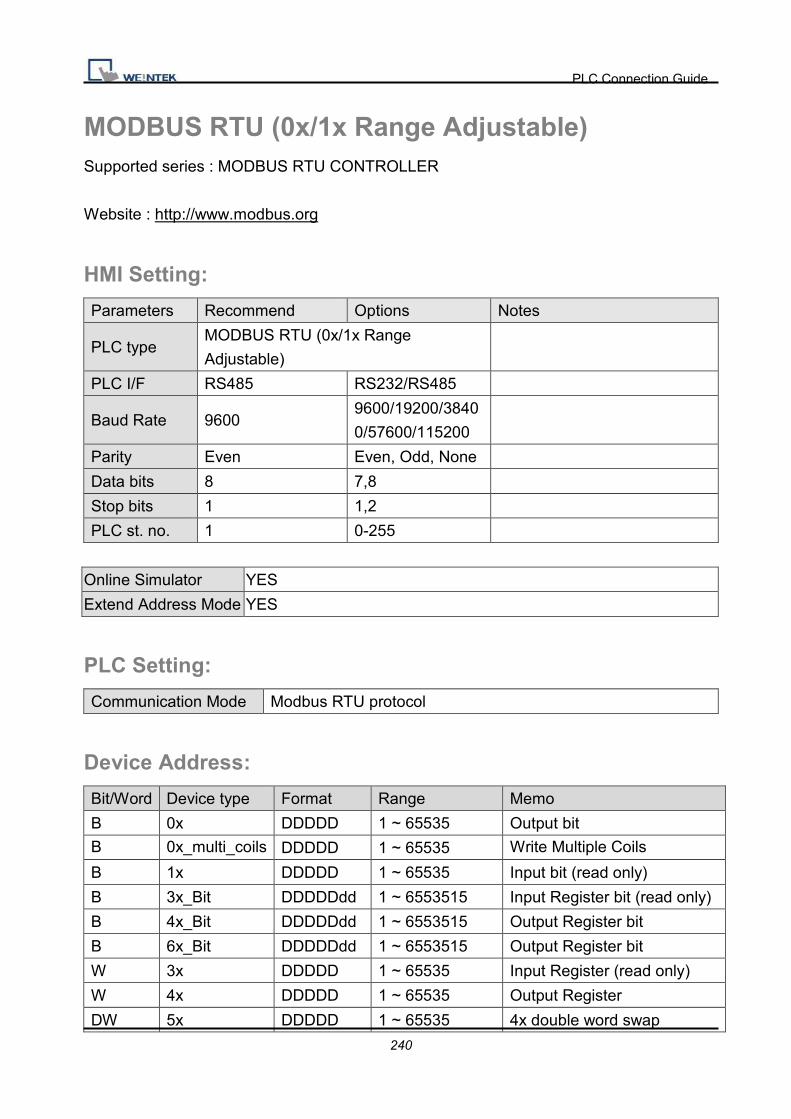
PLC Connection Guide
240
MODBUS RTU (0x/1x Range Adjustable) Supported series : MODBUS RTU CONTROLLER
Website : http://www.modbus.org
HMI Setting:
Parameters Recommend Options Notes
PLC type MODBUS RTU (0x/1x Range
Adjustable)
PLC I/F RS485 RS232/RS485
Baud Rate 9600 9600/19200/3840
0/57600/115200
Parity Even Even, Odd, None
Data bits 8 7,8
Stop bits 1 1,2
PLC st. no. 1 0-255
Online Simulator YES
Extend Address Mode YES
PLC Setting:
Communication Mode Modbus RTU protocol
Device Address:
Bit/Word Device type Format Range Memo
B 0x DDDDD 1 ~ 65535 Output bit B 0x_multi_coils DDDDD 1 ~ 65535 Write Multiple Coils
B 1x DDDDD 1 ~ 65535 Input bit (read only)
B 3x_Bit DDDDDdd 1 ~ 6553515 Input Register bit (read only)
B 4x_Bit DDDDDdd 1 ~ 6553515 Output Register bit
B 6x_Bit DDDDDdd 1 ~ 6553515 Output Register bit
W 3x DDDDD 1 ~ 65535 Input Register (read only)
W 4x DDDDD 1 ~ 65535 Output Register
DW 5x DDDDD 1 ~ 65535 4x double word swap

PLC Connection Guide
241
W 6x DDDDD 1 ~ 65535 4x single word write W 4x_32Bit DDDDD 1 ~ 65535 4x High/low byte swap
NOTE:
Address type “5x” is mapping to Hold Reg. The communication protocol of “5x” is almost
same as “4x” except that “5x”makes double words swap.
If 4x contains the following information:
Address 1 2 3 4 5 6 ...
Data in
word
0x1 0x2 0x3 0x4 0x5 0x6
Data 0x20001 0x40003 0x60005
For 5x, it becomes:
Address 1 2 3 4 5 6 ...
Data in
word
0x2 0x1 0x4 0x3 0x6 0x5
Data 0x10002 0x30004 0x50006
Modbus RTU function code:
0x 0x01 Read coil 0x05 Write single coil
0x_multi_coils 0x01 Read coil 0x0f Write multiple coil
1x 0x02 Read discrete input N/A for writing operation
3x 0x04 Read input register N/A for writing operation
4x 0x03 Read holding register 0x10 Write multiple register
5x 0x03 Read holding register 0x10 Write multiple register
(Note: reverse word order in double words format)
3xbit is equivalent to 3x
4xbit is equivalent to 4x
6x 0x03 Read holding register 0x06 write single register
(Note: using 6x device is limited to device of one word only)
Setting Illustrations:
1. Go to [System Parameter Settings] �click [New] to add a new device -Modbus
RTU (0x 1x range adjustable)�as shown below:

PLC Connection Guide
242
2. After adding Modbus RTU (0x 1x Range Adjustable) driver, [Add Address Range
Limit] button will be enabled as below. Users can set maximum read/write command
size here.
Ø Max.read-command size (words): Pull down to select PLC reading range.
Ø Max.write-command size (words): Pull down to select PLC writing range.
Note: Setting [Add Address Range Limit] is enabled only when bit address is not a multiple
of 16bit.

PLC Connection Guide
243
3. Click [Add Address Range Limit] button, Users can define 0x and 1x address range in
[0x 1x Address Range] dialogue box, referring to bit range of the device used.

PLC Connection Guide
244
Add�Set [Station No.], [Device Type], [Max. Address] then click [OK] to finish adding as
below:
Delete�The selected items will be deleted.
Settings�Set [Station No.], [Device Type], [Max. Address] then click [OK] to finish adding
as below:
Example�
Take D2 and D8 of SCON as example, the settings depend on maximum bit range of
different PLC types. Set [Station No.] and address first.
For D2, set [Station No.] to 20, [Device Type] 0x, [Max. Address] 36.
For D8, set [Station No.] to 2, [Device Type] 0x, [Max. Address] 51.
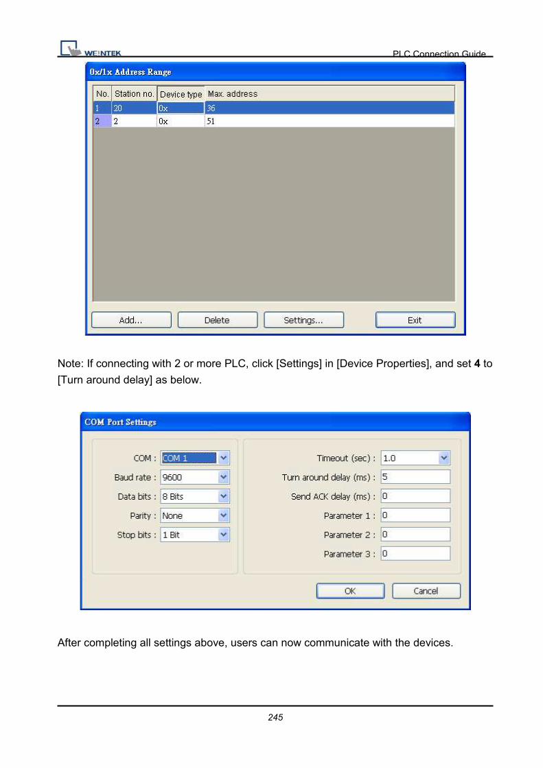
PLC Connection Guide
245
Note: If connecting with 2 or more PLC, click [Settings] in [Device Properties], and set 4 to
[Turn around delay] as below.
After completing all settings above, users can now communicate with the devices.

PLC Connection Guide
246
Wiring Diagram:
9P D-Sub to 9P D-Sub:
HMI COM1
RS232 9P
D-Sub Male
HMI COM2
RS232 9P
D-Sub Male
HMI COM3
RS232 9P
D-Sub Female
Modbus RTU Controller RS232
9P D-Sub
2 RX 6 RX 8 RX TXD
3 TX 4 TX 7 TX RXD
5 GND 5 GND 5 GND GND
RTS circuit
CTS
9P D-Sub to 9P D-Sub:
HMI COM1
RS485 4W 9P
D-Sub Female
Modbus RTU Controller
RS422 9P D-Sub
1 RX- TX-
2 RX+ TX+
3 TX- RX-
4 TX+ RX+
5 GND GND
9P D-Sub to 9P D-Sub:
HMI COM1
RS485 2W 9P
D-Sub Female
HMI COM3
RS485 2W 9P
D-Sub Female
Modbus RTU Controller
RS485 9P D-Sub
1 RX- 6 Data- D-
2 RX+ 9 Data+ D+
5 GND 5 GND GND

PLC Connection Guide
247
Driver Version:
Version Date Description
V1.10 Aug/25/2010

PLC Connection Guide
248
MODBUS RTU (zero-based addressing) Supported series : MODBUS RTU CONTROLLER
Website : http://www.modbus.org
HMI Setting:
Parameters Recommend Option Notes
PLC type MODBUS RTU (zero-based
addressing)
PLC I/F RS485 RS232/RS485
Baud rate 9600 9600~115200
Parity Even Even, Odd, None
Data bits 8 7,8
Stop bits 1 1,2
PLC st. no. 1 0-255
Online Simulator YES Broadcast command YES
Extend address mode YES
PLC Setting:
Communication mode Modbus RTU protocol
Device Address:
Bit/Word Device type Format Range Memo
B 0x DDDDD 0 ~ 65535 Output bit
B 1x DDDDD 0 ~ 65535 Input bit (read only)
B 0x_multi_coils DDDDD 0 ~ 65535 Write Multiple Coils
B 3x_Bit DDDDDdd 0 ~ 6553515 Input Register bit (read only)
B 4x_Bit DDDDDdd 0 ~ 6553515 Output Register bit
W 3x DDDDD 0 ~ 65535 Input Register (read only)
W 4x DDDDD 0 ~ 65535 Output Register
DW 5x DDDDD 0 ~ 65535 4x double word swap
W 6x DDDDD 0 ~ 65535 4x single word write
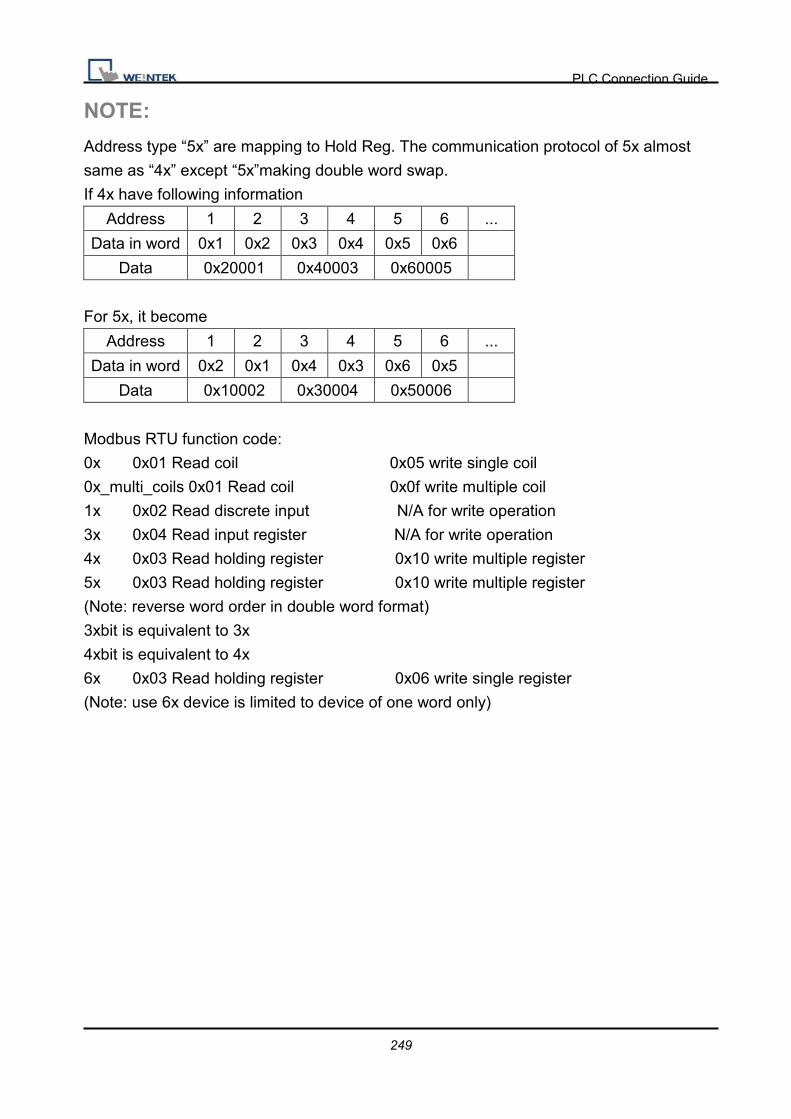
PLC Connection Guide
249
NOTE:
Address type “5x” are mapping to Hold Reg. The communication protocol of 5x almost
same as “4x” except “5x”making double word swap.
If 4x have following information
Address 1 2 3 4 5 6 ...
Data in word 0x1 0x2 0x3 0x4 0x5 0x6
Data 0x20001 0x40003 0x60005
For 5x, it become
Address 1 2 3 4 5 6 ...
Data in word 0x2 0x1 0x4 0x3 0x6 0x5
Data 0x10002 0x30004 0x50006
Modbus RTU function code:
0x 0x01 Read coil 0x05 write single coil
0x_multi_coils 0x01 Read coil 0x0f write multiple coil
1x 0x02 Read discrete input N/A for write operation
3x 0x04 Read input register N/A for write operation
4x 0x03 Read holding register 0x10 write multiple register
5x 0x03 Read holding register 0x10 write multiple register
(Note: reverse word order in double word format)
3xbit is equivalent to 3x
4xbit is equivalent to 4x
6x 0x03 Read holding register 0x06 write single register
(Note: use 6x device is limited to device of one word only)

PLC Connection Guide
250
Wiring Diagram:
9P D-Sub to 9P D-Sub:
HMI COM1
RS232 9P
D-Sub Male
HMI COM2
RS232 9P
D-Sub Male
HMI COM3
RS232 9P
D-Sub Female
Modbus RTU Controller RS232
9P D-Sub
2 RX 6 RX 8 RX TXD
3 TX 4 TX 7 TX RXD
5 GND 5 GND 5 GND GND
RTS circuit
CTS
9P D-Sub to 9P D-Sub:
HMI COM1
RS485 4W 9P
D-Sub Female
Modbus RTU Controller
RS422 9P D-Sub
1 RX- TX-
2 RX+ TX+
3 TX- RX-
4 TX+ RX+
5 GND GND
9P D-Sub to 9P D-Sub:
HMI COM1
RS485 2W 9P
D-Sub Female
HMI COM3
RS485 2W 9P
D-Sub Female
Modbus RTU Controller
RS485 9P D-Sub
1 RX- 6 Data- D-
2 RX+ 9 Data+ D+
5 GND 5 GND GND

PLC Connection Guide
251
Note: MODBUS RTU (adjustable) usage
Users can decide the address range via setting value on Parameter 1. For example, when
users set 5 to Parameter 1, the address range become 5 ~ 65535.
Driver Version:
Version Date Description
V1.30 Aug/26/2009
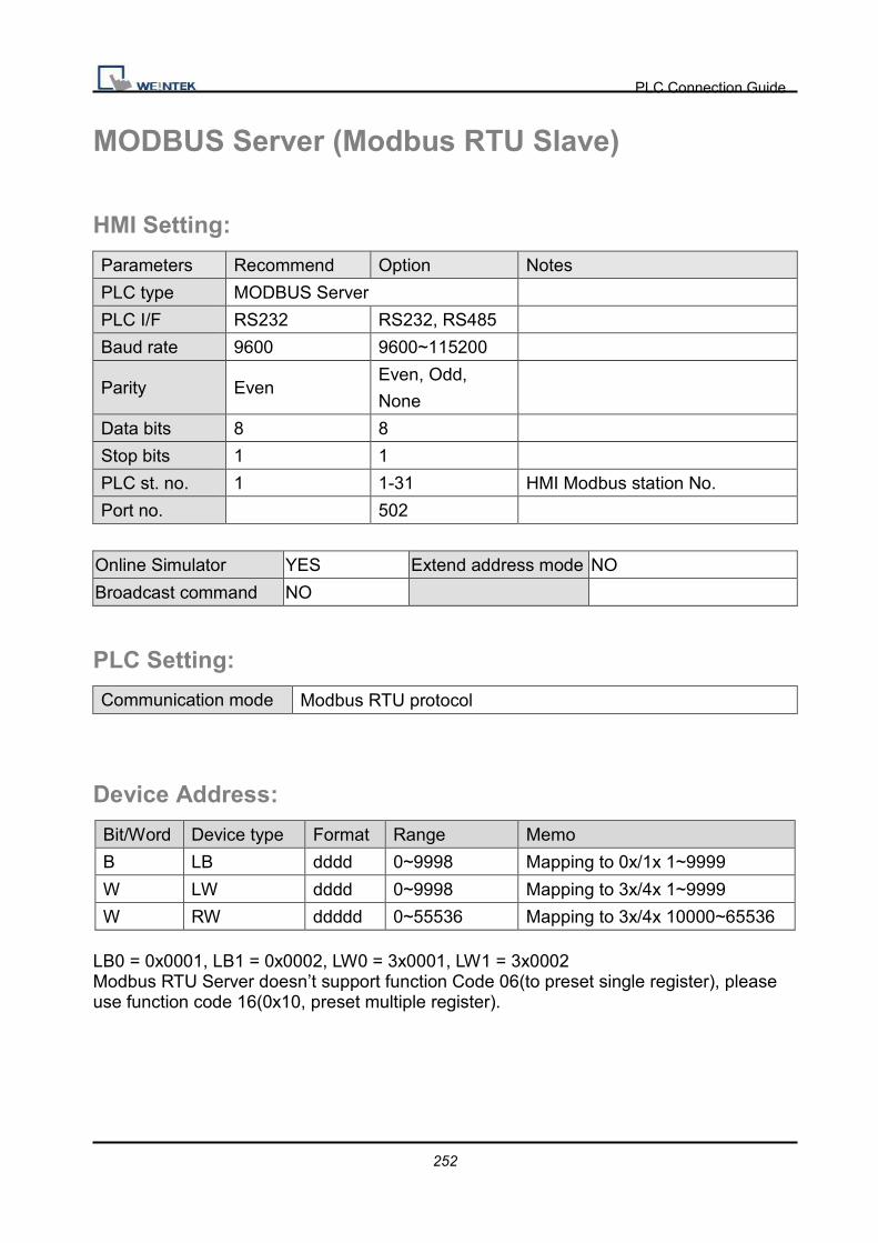
PLC Connection Guide
252
MODBUS Server (Modbus RTU Slave)
HMI Setting:
Parameters Recommend Option Notes
PLC type MODBUS Server
PLC I/F RS232 RS232, RS485
Baud rate 9600 9600~115200
Parity Even Even, Odd,
None
Data bits 8 8
Stop bits 1 1
PLC st. no. 1 1-31 HMI Modbus station No.
Port no. 502
Online Simulator YES Extend address mode NO
Broadcast command NO
PLC Setting:
Communication mode Modbus RTU protocol
Device Address:
Bit/Word Device type Format Range Memo
B LB dddd 0~9998 Mapping to 0x/1x 1~9999
W LW dddd 0~9998 Mapping to 3x/4x 1~9999
W RW ddddd 0~55536 Mapping to 3x/4x 10000~65536 LB0 = 0x0001, LB1 = 0x0002, LW0 = 3x0001, LW1 = 3x0002 Modbus RTU Server doesn’t support function Code 06(to preset single register), please use function code 16(0x10, preset multiple register).

PLC Connection Guide
253
Wiring Diagram:
9P D-Sub to 9P D-Sub:
HMI COM1
RS232 9P
D-Sub Male
HMI COM2
RS232 9P
D-Sub Male
HMI COM3
RS232 9P
D-Sub Female
Modbus RTU Controller RS232
9P D-Sub
2 RX 6 RX 8 RX TXD
3 TX 4 TX 7 TX RXD
5 GND 5 GND 5 GND GND
RTS circuit
CTS
9P D-Sub to 9P D-Sub:
HMI COM1
RS485 4W 9P
D-Sub Female
Modbus RTU Controller
RS422 9P D-Sub
1 RX- TX-
2 RX+ TX+
3 TX- RX-
4 TX+ RX+
5 GND GND
9P D-Sub to 9P D-Sub:
HMI COM1
RS485 2W 9P
D-Sub Female
HMI COM3
RS485 2W 9P
D-Sub Female
Modbus RTU Controller
RS485 9P D-Sub
1 RX- 6 Data- D-
2 RX+ 9 Data+ D+
5 GND 5 GND GND

PLC Connection Guide
254
Precaution: Setting more than one Modbus server in HMI device list is useless.
Driver Version:
Version Date Description
V1.00 Dec/30/2008 Driver released.

PLC Connection Guide
255
MODBUS TCP/IP (Ethernet) Supported series: Modbus RTU TCP/IP device.
Website: http://www.modbus.org
HMI Setting:
Parameters Recommend Option Notes
PLC type MODBUS TCP/IP (Ethernet)
PLC I/F Ethernet
PLC st. no. 1 0~255
Port no. 502
Device Address: Bit/Word Device type Format Range Memo B 1x DDDDD 1 ~ 65535 Output bit B 0x DDDDD 1 ~ 65535 Input bit B 0x_multi_coils DDDDD 1 ~ 65535 Write Multiple Coils
B 3x_bit DDDDDdd 100 ~ 6553515 Input Register bit (read only)
B 4x_bit DDDDDdd 100 ~ 6553515 Output Register bit B 6x_bit DDDDDdd 100 ~ 6553515 Output Register bit W 3x DDDDD 1 ~ 65535 Input Register W 4x DDDDD 1 ~ 65535 Output Register DW 5x DDDDD 1 ~ 65535 4x double word swap W 6x DDDDD 1 ~ 65535 4x single word write

PLC Connection Guide
256
Wiring Diagram:
Direct connect (crossover cable):
HMI RJ45 Female Wire Color PLC RJ45 Female
1 TX+ White/Orange 3 RX+
2 TX- Orange 6 RX-
3 RX+ White/Green 1 TX+
4 BD4+ Blue 4 BD4+
5 BD4- White/Blue 5 BD4-
6 RX- Green 2 TX-
7 BD3+ White/Brown 7 BD3+
8 BD3- Brown 8 BD3-
Through a hub:
HMI RJ45 Female Wire Color PLC RJ45 Female
1 TX+ White/Orange 1 TX+
2 TX- Orange 2 TX-
3 RX+ White/Green 3 RX+
4 BD4+ Blue 4 BD4+
5 BD4- White/Blue 5 BD4-
6 RX- Green 6 RX-
7 BD3+ White/Brown 7 BD3+
8 BD3- Brown 8 BD3-
Driver Version:
Version Date Description
V1.50 Aug/26/2009
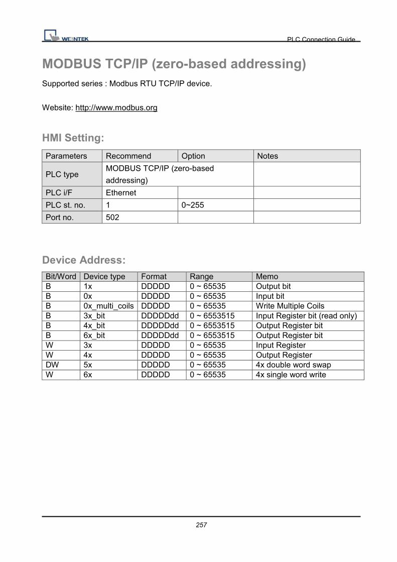
PLC Connection Guide
257
MODBUS TCP/IP (zero-based addressing) Supported series : Modbus RTU TCP/IP device.
Website: http://www.modbus.org
HMI Setting:
Parameters Recommend Option Notes
PLC type MODBUS TCP/IP (zero-based
addressing)
PLC i/F Ethernet
PLC st. no. 1 0~255
Port no. 502
Device Address: Bit/Word Device type Format Range Memo B 1x DDDDD 0 ~ 65535 Output bit B 0x DDDDD 0 ~ 65535 Input bit B 0x_multi_coils DDDDD 0 ~ 65535 Write Multiple Coils B 3x_bit DDDDDdd 0 ~ 6553515 Input Register bit (read only) B 4x_bit DDDDDdd 0 ~ 6553515 Output Register bit B 6x_bit DDDDDdd 0 ~ 6553515 Output Register bit W 3x DDDDD 0 ~ 65535 Input Register W 4x DDDDD 0 ~ 65535 Output Register DW 5x DDDDD 0 ~ 65535 4x double word swap W 6x DDDDD 0 ~ 65535 4x single word write

PLC Connection Guide
258
Wiring Diagram:
Direct connect (crossover cable):
HMI RJ45 Female Wire Color PLC RJ45 Female
1 TX+ White/Orange 3 RX+
2 TX- Orange 6 RX-
3 RX+ White/Green 1 TX+
4 BD4+ Blue 4 BD4+
5 BD4- White/Blue 5 BD4-
6 RX- Green 2 TX-
7 BD3+ White/Brown 7 BD3+
8 BD3- Brown 8 BD3-
Through a hub:
HMI RJ45 Female Wire Color PLC RJ45 Female
1 TX+ White/Orange 1 TX+
2 TX- Orange 2 TX-
3 RX+ White/Green 3 RX+
4 BD4+ Blue 4 BD4+
5 BD4- White/Blue 5 BD4-
6 RX- Green 6 RX-
7 BD3+ White/Brown 7 BD3+
8 BD3- Brown 8 BD3-
Driver Version:
Version Date Description
V1.40 Aug/27/2009

PLC Connection Guide
259
MODBUS TCP/IP 32Bit Supported series: Modbus RTU TCP/IP device.
Website: http://www.modbus.org
HMI Setting:
Parameters Recommend Option Notes
PLC type MODBUS TCP/IP 32Bit
PLC I/F Ethernet
PLC st. no. 1 0~255
Port no. 502
Device Address: Bit/Word Device type Format Range Memo B 1x DDDDD 1 ~ 65535 Output bit B 0x DDDDD 1 ~ 65535 Input bit B 0x_multi_coils DDDDD 1 ~ 65535 Write Multiple Coils
B 3x_bit DDDDDdd 100 ~ 6553515 Input Register bit (read only)
B 4x_bit DDDDDdd 100 ~ 6553515 Output Register bit B 6x_bit DDDDDdd 100 ~ 6553515 Output Register bit W 3x DDDDD 1 ~ 65535 Input Register W 4x DDDDD 1 ~ 65535 Output Register DW 5x DDDDD 1 ~ 65535 4x double word swap W 6x DDDDD 1 ~ 65535 4x single word write W 4x_32Bit DDDDD 1 ~ 65535

PLC Connection Guide
260
Wiring Diagram:
Direct connect (crossover cable):
HMI RJ45 Female Wire Color PLC RJ45 Female
1 TX+ White/Orange 3 RX+
2 TX- Orange 6 RX-
3 RX+ White/Green 1 TX+
4 BD4+ Blue 4 BD4+
5 BD4- White/Blue 5 BD4-
6 RX- Green 2 TX-
7 BD3+ White/Brown 7 BD3+
8 BD3- Brown 8 BD3-
Through a hub:
HMI RJ45 Female Wire Color PLC RJ45 Female
1 TX+ White/Orange 1 TX+
2 TX- Orange 2 TX-
3 RX+ White/Green 3 RX+
4 BD4+ Blue 4 BD4+
5 BD4- White/Blue 5 BD4-
6 RX- Green 6 RX-
7 BD3+ White/Brown 7 BD3+
8 BD3- Brown 8 BD3-
Driver Version:
Version Date Description
V1.00 Aug/27/2009 Driver released.
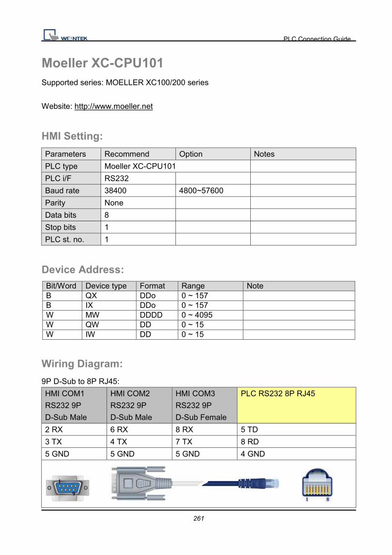
PLC Connection Guide
261
Moeller XC-CPU101 Supported series: MOELLER XC100/200 series
Website: http://www.moeller.net
HMI Setting:
Parameters Recommend Option Notes
PLC type Moeller XC-CPU101
PLC i/F RS232
Baud rate 38400 4800~57600
Parity None
Data bits 8
Stop bits 1
PLC st. no. 1
Device Address: Bit/Word Device type Format Range Note B QX DDo 0 ~ 157 B IX DDo 0 ~ 157 W MW DDDD 0 ~ 4095 W QW DD 0 ~ 15 W IW DD 0 ~ 15
Wiring Diagram:
9P D-Sub to 8P RJ45:
HMI COM1
RS232 9P
D-Sub Male
HMI COM2
RS232 9P
D-Sub Male
HMI COM3
RS232 9P
D-Sub Female
PLC RS232 8P RJ45
2 RX 6 RX 8 RX 5 TD
3 TX 4 TX 7 TX 8 RD
5 GND 5 GND 5 GND 4 GND
PLC Connection Guide
262
Driver Version:
Version Date Description
1.00 Apr/01/2010 Driver released.
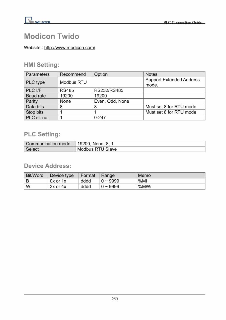
PLC Connection Guide
263
Modicon Twido Website : http://www.modicon.com/
HMI Setting: Parameters Recommend Option Notes
PLC type Modbus RTU Support Extended Address mode.
PLC I/F RS485 RS232/RS485 Baud rate 19200 19200 Parity None Even, Odd, None Data bits 8 8 Must set 8 for RTU mode Stop bits 1 1 Must set 8 for RTU mode PLC st. no. 1 0-247
PLC Setting: Communication mode 19200, None, 8, 1 Select Modbus RTU Slave
Device Address:
Bit/Word Device type Format Range Memo B 0x or 1x dddd 0 ~ 9999 %Mi W 3x or 4x dddd 0 ~ 9999 %MWi
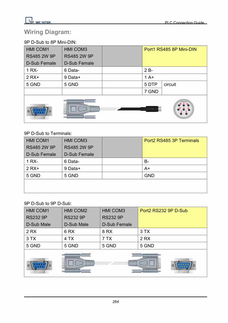
PLC Connection Guide
264
Wiring Diagram:
9P D-Sub to 8P Mini-DIN:
HMI COM1
RS485 2W 9P
D-Sub Female
HMI COM3
RS485 2W 9P
D-Sub Female
Port1 RS485 8P Mini-DIN
1 RX- 6 Data- 2 B-
2 RX+ 9 Data+ 1 A+
5 GND 5 GND 5 DTP circuit
7 GND
9P D-Sub to Terminals:
HMI COM1
RS485 2W 9P
D-Sub Female
HMI COM3
RS485 2W 9P
D-Sub Female
Port2 RS485 3P Terminals
1 RX- 6 Data- B-
2 RX+ 9 Data+ A+
5 GND 5 GND GND
9P D-Sub to 9P D-Sub:
HMI COM1
RS232 9P
D-Sub Male
HMI COM2
RS232 9P
D-Sub Male
HMI COM3
RS232 9P
D-Sub Female
Port2 RS232 9P D-Sub
2 RX 6 RX 8 RX 3 TX
3 TX 4 TX 7 TX 2 RX
5 GND 5 GND 5 GND 5 GND

PLC Connection Guide
265
OEMAX Series Supported series: OEMax NX7/NX7s Controllers.
Website: http://www.oemax.co.kr
HMI Setting: Parameters Recommend Option Notes PLC type OEMAX Series PLC I/F RS232
Baud rate 9600 9600, 19200, 38400
Parity None Even, Odd, None Data bits 8 8 Stop bits 1 1 PLC st. no. 0
Device Address: Bit/Word Device type Format Range Memo B R DDDdd 0 ~ 25515 B L DDDdd 0 ~ 25515 B M DDDDdd 0 ~ 199915 B K DDDdd 0 ~ 25515 Keep contact B F DDDdd 0 ~ 99115 Special contact B TC DDD 0 ~ 255 Timer/Counter W W DDDD 0 ~ 7999 Data register W SV DDD 0 ~ 255 Timer/Counter Set Value W PV DDD 0 ~ 255 Timer/Counter Preset Value W SR DDD 0 ~ 255 Special register W WR DDD 0 ~ 255 W WL DDD 0 ~ 255 W WM DDDD 0 ~ 1999 W WK DDD 0 ~ 255 W WF DDD 0 ~ 991

PLC Connection Guide
266
Wiring Diagram:
9P D-Sub to 9P D-Sub:
HMI COM1
RS232 9P
D-Sub Male
HMI COM2
RS232 9P
D-Sub Male
HMI COM3
RS232 9P
D-Sub Female
PLC Port1 RS232 9P D-Sub
Female
2 RX 6 RX 8 RX 2 TXD
3 TX 4 TX 7 TX 3 RXD
5 GND 5 GND 5 GND 5 GND
Driver Version:
Version Date Description
V1.00 Dec/30/2008 Driver released.

PLC Connection Guide
267
OMRON C/CQM1 Series Supported series: OMRON C, CPM, CPL, CQM Series (Host Link Protocol)
Website: http://oeiweb.omron.com/oei/Products-PLC.htm
HMI Setting:
Parameters Recommend Option Notes
PLC type OMRON C/CQM1 Series
PLC I/F RS232 RS232, RS422,
RS485
Baud rate 9600 9600, 19200
Parity Even Even, Odd, None
Data bits 7 7 or 8
Stop bits 2 1 or 2
PLC st. no. 0 0-31 Host Link Station No.
Online Simulator YES Broadcast command YES
Extend address mode YES
PLC Setting:
Communication mode Host Link protocol
Device Address:
Bit/Word Device type Format Range Memo
B IR DDDDdd 0 ~ 409515 I/O and internal Relay
B HR DDDDdd 0 ~ 409515 Hold Relay
B LR DDDDdd 0 ~ 409515 Link Relay
B IR (Force Set/Reset) DDDDdd 0 ~ 409515
B HR(Force Set/Reset) DDDDdd 0 ~ 409515
B LR(Force Set/Reset) DDDDdd 0 ~ 409515
B AR DDDDdd 0 ~ 409515 Auxiliary Relay
W AR_W DDDD 0 ~ 4095
W IR_W DDDD 0 ~ 4095

PLC Connection Guide
268
W HR_W DDDD 0 ~ 4095
W LR_W DDDD 0 ~ 4095
W TC DDD 0 ~ 255
W DM DDDD 0 ~ 9999 Data register
Wiring Diagram:
CPU Port (CPM2A,CQM1/1H,C200H/HS/ALPHA series)
Communication Module:
CPM1-CIF01 adapter (for CPM1/CPM1A/CPM2A series, CQM1/CQM1H series)
CPM1H-SCB41 communication module (for CQM1H-CPU51/61)
9P D-Sub to 9P D-Sub:
HMI COM1
RS232 9P
D-Sub Male
HMI COM2
RS232 9P
D-Sub Male
HMI COM3
RS232 9P
D-Sub Female
OMRON CPU RS232 9P D-Sub
2 RX 6 RX 8 RX 2 SD
3 TX 4 TX 7 TX 3 RD
5 GND 5 GND 5 GND 9 GND
4 RS circuit
5 CS
C200h-LK201,3G2A6-LK201 communication module
C200HW-COM02/03/04/05/06 communication module
9P D-Sub to 9P D-Sub:
HMI COM1
RS232 9P
D-Sub Male
HMI COM2
RS232 9P
D-Sub Male
HMI COM3
RS232 9P
D-Sub Female
OMRON CPU RS232 9P D-Sub
2 RX 6 RX 8 RX 2 SD
3 TX 4 TX 7 TX 3 RD
5 GND 5 GND 5 GND 7 GND
4 RS circuit
5 CS

PLC Connection Guide
269
Driver Version:
Version Date Description
V1.80 Apr/14/2010

PLC Connection Guide
270
OMRON CJ/CS/CP Supported series: OMRON CP1L, CP1H, CJ1M, CJ1H, CJ1G, CS1H and CS1G. (Host
Link Protocol FINS command), this driver supports Extend Addressing mode.
Website: http://oeiweb.omron.com/oei/Products-PLC.htm
HMI Setting:
Parameters Recommend Option Notes
PLC type OMRON CJ/CS/CP
PLC I/F RS232 RS232, RS422,
RS485
Baud rate 9600 9600~115200
Parity Even Even, Odd, None
Data bits 7 7 or 8
Stop bits 2 1 or 2
PLC st. no. 0 0-31 Host Link Station No.
Online Simulator YES Extend address mode YES
Broadcast command NO
PLC Setting:
Communication mode Host Link protocol
Device Address:
Bit/Word Device type Format Range Memo
B D_Bit DDDDDdd 0 ~ 3276715 Data Memory (DM)
B H_Bit DDDDDdd 0 ~ 3276715 Holding Area (HR)
B W_Bit DDDDDdd 0 ~ 3276715 Work Area (WR)
B CIO_Bit DDDDDdd 0 ~ 3276715 Channel I/O (CIO)
B A_Bit DDDDDdd 0 ~ 3276715 Auxiliary Relay (AR)
B T_Bit DDDDDdd 0 ~ 3276715 Timer (TIM)
B C_Bit DDDDDdd 0 ~ 3276715 Counter (CNT)
B C_flag DDDD 0 ~ 4095

PLC Connection Guide
271
Bit/Word Device type Format Range Memo
B F_flag DDDD 0 ~ 4095
W D DDDDD 0 ~ 32767 Data Memory (DM)
W H DDDDD 0 ~ 32767 Holding Area (HR)
W W DDDDD 0 ~ 32767 Work Area (WR)
W CIO DDDDD 0 ~ 32767 Channel I/O (CIO)
W A DDDDD 0 ~ 32767 Auxiliary Relay (AR)
W T DDDDD 0 ~ 32767 Timer (TIM)
W C DDDDD 0 ~ 32767 Counter (CNT)
W EM0 ~ EMC DDDDD 0 ~ 32767 Extend Memory
Wiring Diagram:
9P D-Sub to 9P D-Sub:
HMI COM1
RS232 9P
D-Sub Male
HMI COM2
RS232 9P
D-Sub Male
HMI COM3
RS232 9P
D-Sub Female
OMRON CPU RS232 9P D-Sub
2 RX 6 RX 8 RX 2 SD
3 TX 4 TX 7 TX 3 RD
5 GND 5 GND 5 GND 9 GND
4 RS circuit
5 CS
9P D-Sub to Termainals: CP1H/CP1L CP1W-CIF11 RS422
HMI COM1
RS485 4W 9P
D-Sub Female
CP1W-CIF11 RS422
Terminals
1 RX- SDA
2 RX+ SDB
3 TX- RDA
4 TX+ RDB
5 GND FG

PLC Connection Guide
272
CP1W-CIF11: SW1 ON, others OFF.
Driver Version:
Version Date Description
V1.70 Mar/24/2010

PLC Connection Guide
273
OMRON CJ1/CS1 (Ethernet) Supported series: OMRON CJ1M, CJ1H, CJ1G, CS1H, and CS1G. (Ethernet FINS)
Website: http://oeiweb.omron.com/oei/Products-PLC.htm
HMI Setting:
Parameters Recommend Option Notes
PLC type OMRON CJ1/CS1 (Ethernet)
PLC I/F Ethernet
Port no. 9600
PLC st. no. 0
PLC Setting:
Communication mode FINS Ethernet protocol
Device Address:
Bit/Word Device type Format Range Memo
B D_Bit DDDDDdd 0 ~ 3276715 Data Memory (DM)
B H_Bit DDDDDdd 0 ~ 3276715 Holding Area (HR)
B W_Bit DDDDDdd 0 ~ 3276715 Work Area (WR)
B CIO_Bit DDDDDdd 0 ~ 3276715 Channel I/O (CIO)
B A_Bit DDDDDdd 0 ~ 3276715 Auxiliary Relay (AR) (Read
only)
B T_Bit DDDDDdd 0 ~ 3276715 Timer (TIM)
B C_Bit DDDDDdd 0 ~ 3276715 Counter (CNT)
B C_Flag DDDD 0 ~ 4095
B T_Flag DDDD
0 ~ 4095
W D DDDDD 0 ~ 32767 Data Memory (DM)
W H DDDDD 0 ~ 32767 Holding Area (HR)
W W DDDDD 0 ~ 32767 Work Area (WR)
W CIO DDDDD 0 ~ 32767 Channel I/O (CIO)

PLC Connection Guide
274
W A DDDDD 0 ~ 32767 Auxiliary Relay (AR) (Read
only)
W T DDDDD 0 ~ 32767 Timer (TIM)
W C DDDDD 0 ~ 32767 Counter (CNT)
W EM0 ~ EMC DDDDD 0 ~ 32767 Extend Memory
Wiring Diagram:
Direct connect (crossover cable):
HMI RJ45 Female Wire Color PLC RJ45 Female
1 TX+ White/Orange 3 RX+
2 TX- Orange 6 RX-
3 RX+ White/Green 1 TX+
4 BD4+ Blue 4 BD4+
5 BD4- White/Blue 5 BD4-
6 RX- Green 2 TX-
7 BD3+ White/Brown 7 BD3+
8 BD3- Brown 8 BD3-
Through a hub:
HMI RJ45 Female Wire Color PLC RJ45 Female
1 TX+ White/Orange 1 TX+
2 TX- Orange 2 TX-
3 RX+ White/Green 3 RX+
4 BD4+ Blue 4 BD4+
5 BD4- White/Blue 5 BD4-
6 RX- Green 6 RX-
7 BD3+ White/Brown 7 BD3+
8 BD3- Brown 8 BD3-

PLC Connection Guide
275
Driver Version:
Version Date Description
V1.50 Jun/30/2010
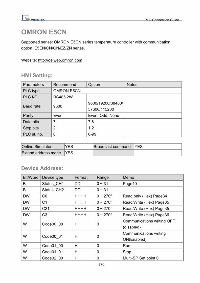
PLC Connection Guide
276
OMRON E5CN Supported series: OMRON E5CN series temperature controller with communication
option. E5EN/CN/GN/EZ/ZN series.
Website: http://oeiweb.omron.com
HMI Setting:
Parameters Recommend Option Notes
PLC type OMRON E5CN
PLC I/F RS485 2W
Baud rate 9600 9600/19200/38400/
57600/115200
Parity Even Even, Odd, None
Data bits 7 7,8
Stop bits 2 1,2
PLC st. no. 0 0-99
Online Simulator YES Broadcast command YES
Extend address mode YES
Device Address:
Bit/Word Device type Format Range Memo
B Status_CH1 DD 0 ~ 31 Page40
B Status_CH2 DD 0 ~ 31
DW C0 HHHH 0 ~ 270f Read only (Hex) Page34
DW C1 HHHH 0 ~ 270f Read/Write (Hex) Page35
DW C21 HHHH 0 ~ 270f Read/Write (Hex) Page35
DW C3 HHHH 0 ~ 270f Read/Write (Hex) Page36
W Code00_00 H 0 Communications writing OFF
(disabled)
W Code00_01 H 0 Communications writing
ON(Enabled)
W Code01_00 H 0 Run
W Code01_01 H 0 Stop
W Code02_00 H 0 Multi-SP Set point 0

PLC Connection Guide
277
Bit/Word Device type Format Range Memo
W Code02_01 H 0 Multi-SP Set point 1
W Code02_02 H 0 Multi-SP Set point 2
W Code02_03 H 0 Multi-SP Set point 3
W Code03_00 H 0 AT cancel
W Code03_01 H 0 AT execute
W Code04_00 H 0 Write mode (Backup)
W Code04_01 H 0 Write mode (Ram)
W Code05_00 H 0 Save RAM data
W Code06_00 H 0 Software reset
W Code07_00 H 0 Move to setup area 1
W Code08_00 H 0 Move to protect level
Wiring Diagram:
9P D-Sub to 9P D-Sub:
HMI COM1
RS485 2W 9P
D-Sub Female
HMI COM3
RS485 2W 9P
D-Sub Female
OMRON E5CN
1 RX- 6 Data- 12 B
2 RX+ 9 Data+ 11 A
5 GND 5 GND GND
Note:
For communication with OMRON E5EZ, please set communication setting to 9600, E, 7, 2,
station no. to 1.
Driver Version:
Version Date Description
V1.21 Dec/21/2010

PLC Connection Guide
278
Panasonic FP Supported series: NAIS (Matsushita) FP series include FP-X, FP-Σ, FP0, FP1, FP2,
FP2SH, FP10SH and FP3 Ethernet support FP-X with AFPX-COM5.
Website:http://pewa.panasonic.com/
HMI Setting:
Parameters Recommend Option Notes
PLC type Panasonic FP
PLC I/F RS232 RS232/RS485
Baud rate 9600 9600, 19200, 38400,
57600, 115200
Parity Odd Even, Odd, None
Data bits 8 7 or 8
Stop bits 1 1 or 2
PLC st. no. 1 0-255
Must match the PLC’s port
setting.
FP3 must set 0.
Device Address:
Bit/Word Device type Format Range Memo
B X DDDDh 0 ~ 9999f Input(X)
B Y DDDDh 0 ~ 9999f Output(Y)
B R DDDDh 0 ~ 9999f Internal Relay(R)
B L DDDD 0 ~ 9999 Link Relay(L)
B L_Bit DDDDh 0 ~ 9999f
B T DDDD 0 ~ 9999 Timer(T)
B C DDDD 0 ~ 9999 Counter(C)
W SV DDDD 0 ~ 9999 Timer/Counter set value(SV)
W EV DDDDD 0 ~ 65535 Timer/Counter elapse
value(EV)
W DT DDDDD 0 ~ 99999 Data Register(DT)
W LD DDDD 0 ~ 8447 Link Register(LD)
W WX DDDD 0 ~ 9999 Input(WX) (read only)
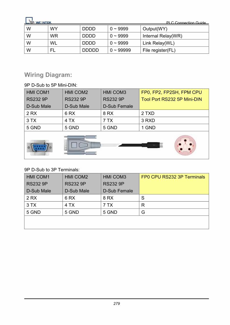
PLC Connection Guide
279
W WY DDDD 0 ~ 9999 Output(WY)
W WR DDDD 0 ~ 9999 Internal Relay(WR)
W WL DDDD 0 ~ 9999 Link Relay(WL)
W FL DDDDD 0 ~ 99999 File register(FL)
Wiring Diagram:
9P D-Sub to 5P Mini-DIN:
HMI COM1
RS232 9P
D-Sub Male
HMI COM2
RS232 9P
D-Sub Male
HMI COM3
RS232 9P
D-Sub Female
FP0, FP2, FP2SH, FPM CPU
Tool Port RS232 5P Mini-DIN
2 RX 6 RX 8 RX 2 TXD
3 TX 4 TX 7 TX 3 RXD
5 GND 5 GND 5 GND 1 GND
9P D-Sub to 3P Terminals:
HMI COM1
RS232 9P
D-Sub Male
HMI COM2
RS232 9P
D-Sub Male
HMI COM3
RS232 9P
D-Sub Female
FP0 CPU RS232 3P Terminals
2 RX 6 RX 8 RX S
3 TX 4 TX 7 TX R
5 GND 5 GND 5 GND G

PLC Connection Guide
280
9P D-Sub to 9P D-Sub:
HMI COM1
RS232 9P
D-Sub Male
HMI COM2
RS232 9P
D-Sub Male
HMI COM3
RS232 9P
D-Sub Female
FP1, FP2, FP2SH, FP10SH
CPU RS232 9P D-Sub
2 RX 6 RX 8 RX 2 TXD
3 TX 4 TX 7 TX 3 RXD
5 GND 5 GND 5 GND 7 GND
4 RTS circuit
5 CTS
8 CD circuit
9 ER
9P D-Sub to 8P MiniDIN:
HMI COM1
RS485 4W 9P
D-Sub Female
FP1 CPU RS422 8P Hirose
1 RX- 2 TXDA
2 RX+ 5 TXDB
3 TX- 3 RXDA
4 TX+ 6 RXDB
5 GND 1 GND

PLC Connection Guide
281
9P D-Sub to 15P D-Sub:
HMI COM1
RS485 4W 9P
D-Sub Female
FP3 CPU RS422 15P D-Sub
1 RX- 9 TXDA
2 RX+ 2 TXDB
3 TX- 10 RXDA
4 TX+ 3 RXDB
5 GND 7 GND
4 RTS+ circuit
5 CTS+
11 RTS- circuit
12 CTS-
Driver Version:
Version Date Description
V1.80 Apr/09/2010 Add FL device type.
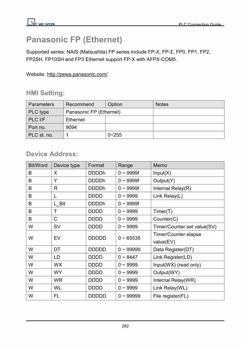
PLC Connection Guide
282
Panasonic FP (Ethernet) Supported series: NAIS (Matsushita) FP series include FP-X, FP-Σ, FP0, FP1, FP2,
FP2SH, FP10SH and FP3 Ethernet support FP-X with AFPX-COM5.
Website: http://pewa.panasonic.com/
HMI Setting:
Parameters Recommend Option Notes
PLC type Panasonic FP (Ethernet)
PLC I/F Ethernet
Port no. 9094
PLC st. no. 1 0~255
Device Address:
Bit/Word Device type Format Range Memo
B X DDDDh 0 ~ 9999f Input(X)
B Y DDDDh 0 ~ 9999f Output(Y)
B R DDDDh 0 ~ 9999f Internal Relay(R)
B L DDDD 0 ~ 9999 Link Relay(L)
B L_Bit DDDDh 0 ~ 9999f
B T DDDD 0 ~ 9999 Timer(T)
B C DDDD 0 ~ 9999 Counter(C)
W SV DDDD 0 ~ 9999 Timer/Counter set value(SV)
W EV DDDDD 0 ~ 65535 Timer/Counter elapse
value(EV)
W DT DDDDD 0 ~ 99999 Data Register(DT)
W LD DDDD 0 ~ 8447 Link Register(LD)
W WX DDDD 0 ~ 9999 Input(WX) (read only)
W WY DDDD 0 ~ 9999 Output(WY)
W WR DDDD 0 ~ 9999 Internal Relay(WR)
W WL DDDD 0 ~ 9999 Link Relay(WL)
W FL DDDDD 0 ~ 99999 File register(FL)

PLC Connection Guide
283
Wiring Diagram:
Direct connect (crossover cable):
HMI RJ45 Female Wire Color PLC RJ45 Female
1 TX+ White/Orange 3 RX+
2 TX- Orange 6 RX-
3 RX+ White/Green 1 TX+
4 BD4+ Blue 4 BD4+
5 BD4- White/Blue 5 BD4-
6 RX- Green 2 TX-
7 BD3+ White/Brown 7 BD3+
8 BD3- Brown 8 BD3-
Through a hub:
HMI RJ45 Female Wire Color PLC RJ45 Female
1 TX+ White/Orange 1 TX+
2 TX- Orange 2 TX-
3 RX+ White/Green 3 RX+
4 BD4+ Blue 4 BD4+
5 BD4- White/Blue 5 BD4-
6 RX- Green 6 RX-
7 BD3+ White/Brown 7 BD3+
8 BD3- Brown 8 BD3-
Ethernet connect
TCP port: 9094
Ethern
et MT8000 AFPX-COM5
RS232
FP-X

PLC Connection Guide
284
Driver Version:
Version Date Description
V1.80 Apr/12/2010

PLC Connection Guide
285
Panasonic FP2 (Ethernet) Supported series: NAIS (Matsushita) FP2 series include FP2, FP2SH, and FP10SH CPU.
Website: http://pewa.panasonic.com/
HMI Setting:
Parameters Recommend Option Notes
PLC type Panasonic FP2 (Ethernet)
PLC I/F Ethernet
Port no. 8500
PLC st. no. 2 0~255
Device Address:
Bit/Word Device type Format Range Memo
B X DDDDh 0 ~ 9999f Input(X)
B Y DDDDh 0 ~ 9999f Output(Y)
B R DDDDh 0 ~ 9999f Internal Relay(R)
B L DDDD 0 ~ 9999 Link Relay(L)
B L_Bit DDDDh 0 ~ 9999f
B T DDDD 0 ~ 9999 Timer(T)
B C DDDD 0 ~ 9999 Counter(C)
W SV DDDD 0 ~ 9999 Timer/Counter set value(SV)
W EV DDDDD 0 ~ 65535 Timer/Counter elapse
value(EV)
W DT DDDDD 0 ~ 99999 Data Register(DT)
W LD DDDD 0 ~ 8447 Link Register(LD)
W WX DDDD 0 ~ 9999 Input(WX) (read only)
W WY DDDD 0 ~ 9999 Output(WY)
W WR DDDD 0 ~ 9999 Internal Relay(WR)
W WL DDDD 0 ~ 9999 Link Relay(WL)
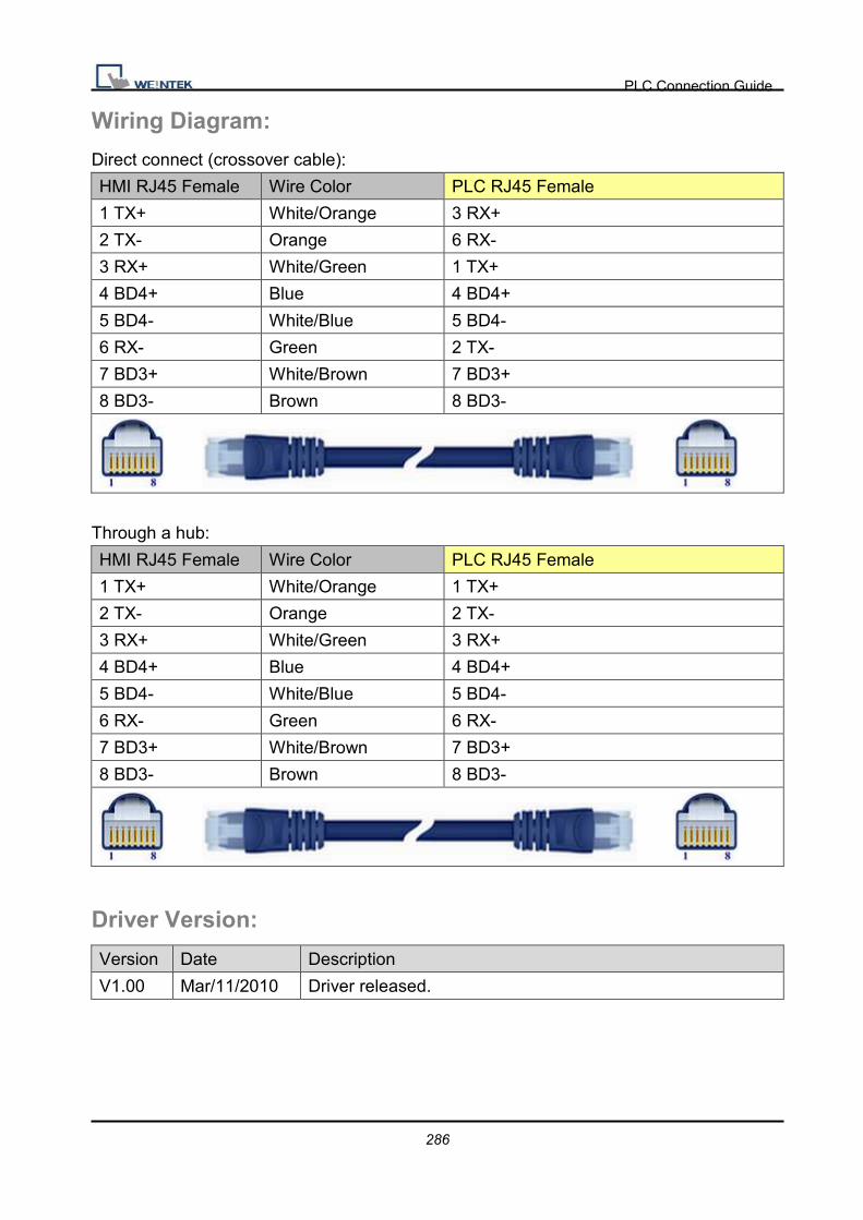
PLC Connection Guide
286
Wiring Diagram:
Direct connect (crossover cable):
HMI RJ45 Female Wire Color PLC RJ45 Female
1 TX+ White/Orange 3 RX+
2 TX- Orange 6 RX-
3 RX+ White/Green 1 TX+
4 BD4+ Blue 4 BD4+
5 BD4- White/Blue 5 BD4-
6 RX- Green 2 TX-
7 BD3+ White/Brown 7 BD3+
8 BD3- Brown 8 BD3-
Through a hub:
HMI RJ45 Female Wire Color PLC RJ45 Female
1 TX+ White/Orange 1 TX+
2 TX- Orange 2 TX-
3 RX+ White/Green 3 RX+
4 BD4+ Blue 4 BD4+
5 BD4- White/Blue 5 BD4-
6 RX- Green 6 RX-
7 BD3+ White/Brown 7 BD3+
8 BD3- Brown 8 BD3-
Driver Version:
Version Date Description
V1.00 Mar/11/2010 Driver released.

PLC Connection Guide
287
Panasonic MINAS A4 Supported series: Panasonic MINAS A4 series Servo Drive.
HMI Setting:
Parameters Recommend Option Notes
PLC type Panasonic MINAS A4
PLC I/F RS232
Axis no. 0 (master station only) 0 ~ F (slave)
Baud rate 9600
Parity None
Data bits 8
Stop bits 1
Device Address:
Bit/Word Device type Format Range Memo
B Command 20 D 0 ~ 7 States (Note 3)
B Command 27 DD 0 ~ 31 input signal (Note 3)
B Command 28 DD 0 ~ 31 output signal (Note 3)
W Command 01 D 0 cpu version (Numeric format:16-bit
Hex)
W Command 05 DD 0 ~ 11 driver version (ASCII / 12 words)
W Command 06 DD 0 ~ 11 motor version (ASCII / 12 words)
W Command 21 D 0 ~ 1 command pulse counter
(Numeric format: 32-bit Signed)
W Command 22 D 0 ~ 1 feedback pulse counter
(Numeric format: 32-bit Signed)
W Command 24 D 0 present speed
(Numeric format: 16-bit Unsigned)
W Command 25 D 0 present torque
(Numeric format: 16-bit Unsigned)
W Command 26 D 0 ~ 1 present deviation counter
(Numeric format: 32-bit Signed)
W Command 84 D 0 write parameter to EEPROM (Note 1)
W Command 90 D 0 present Alarm Data
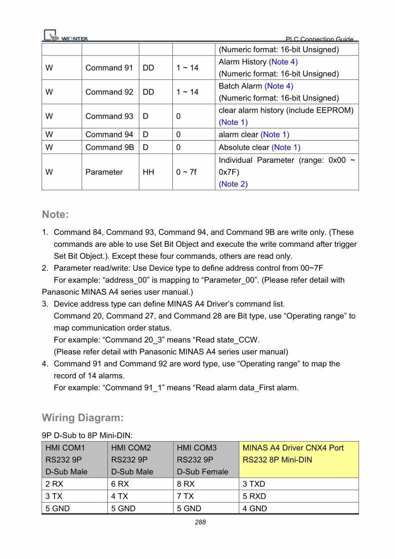
PLC Connection Guide
288
(Numeric format: 16-bit Unsigned)
W Command 91 DD 1 ~ 14 Alarm History (Note 4)
(Numeric format: 16-bit Unsigned)
W Command 92 DD 1 ~ 14 Batch Alarm (Note 4)
(Numeric format: 16-bit Unsigned)
W Command 93 D 0 clear alarm history (include EEPROM)
(Note 1)
W Command 94 D 0 alarm clear (Note 1)
W Command 9B D 0 Absolute clear (Note 1)
W Parameter HH 0 ~ 7f
Individual Parameter (range: 0x00 ~
0x7F)
(Note 2)
Note:
1. Command 84, Command 93, Command 94, and Command 9B are write only. (These
commands are able to use Set Bit Object and execute the write command after trigger
Set Bit Object.). Except these four commands, others are read only.
2. Parameter read/write: Use Device type to define address control from 00~7F
For example: “address_00” is mapping to “Parameter_00”. (Please refer detail with
Panasonic MINAS A4 series user manual.)
3. Device address type can define MINAS A4 Driver’s command list.
Command 20, Command 27, and Command 28 are Bit type, use “Operating range” to
map communication order status.
For example: “Command 20_3” means “Read state_CCW.
(Please refer detail with Panasonic MINAS A4 series user manual)
4. Command 91 and Command 92 are word type, use “Operating range” to map the
record of 14 alarms.
For example: “Command 91_1” means “Read alarm data_First alarm.
Wiring Diagram:
9P D-Sub to 8P Mini-DIN:
HMI COM1
RS232 9P
D-Sub Male
HMI COM2
RS232 9P
D-Sub Male
HMI COM3
RS232 9P
D-Sub Female
MINAS A4 Driver CNX4 Port
RS232 8P Mini-DIN
2 RX 6 RX 8 RX 3 TXD
3 TX 4 TX 7 TX 5 RXD
5 GND 5 GND 5 GND 4 GND
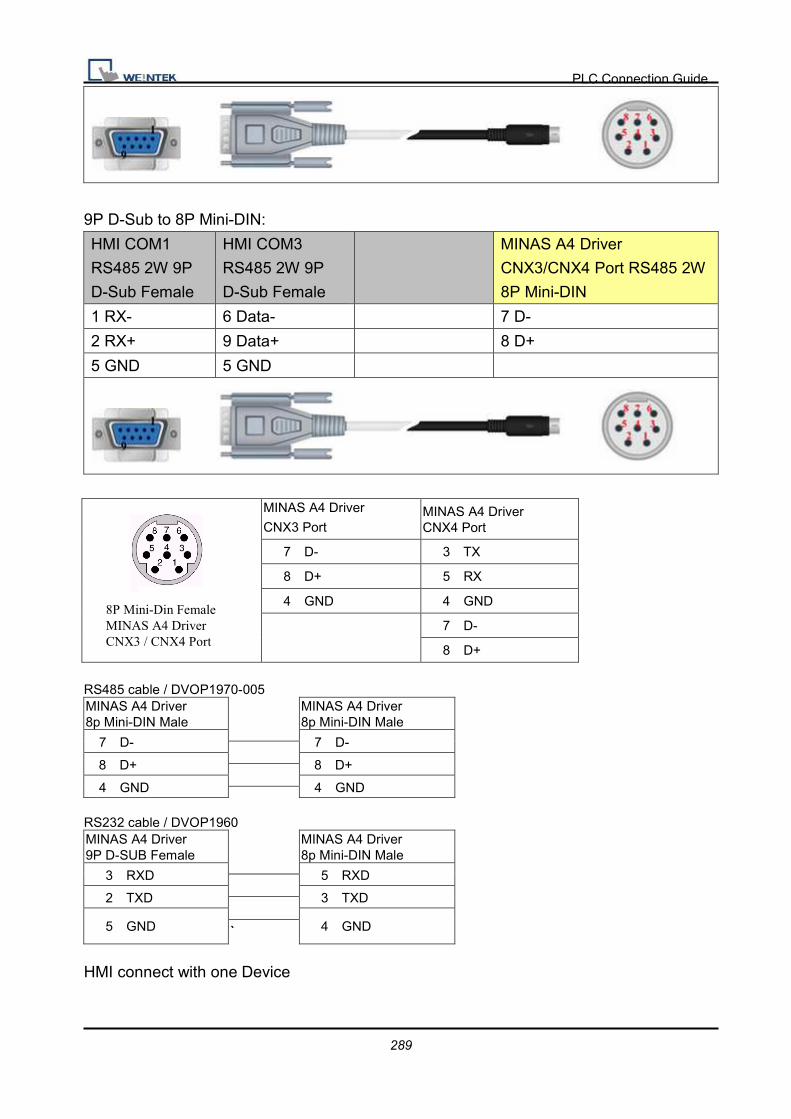
PLC Connection Guide
289
9P D-Sub to 8P Mini-DIN:
HMI COM1
RS485 2W 9P
D-Sub Female
HMI COM3
RS485 2W 9P
D-Sub Female
MINAS A4 Driver
CNX3/CNX4 Port RS485 2W
8P Mini-DIN
1 RX- 6 Data- 7 D-
2 RX+ 9 Data+ 8 D+
5 GND 5 GND
MINAS A4 Driver CNX3 Port
MINAS A4 Driver CNX4 Port
7 D- 3 TX
8 D+ 5 RX
4 GND 4 GND
7 D-
8 D+
RS485 cable / DVOP1970-005 MINAS A4 Driver 8p Mini-DIN Male
MINAS A4 Driver 8p Mini-DIN Male
7 D- 7 D-
8 D+ 8 D+
4 GND 4 GND
RS232 cable / DVOP1960 MINAS A4 Driver 9P D-SUB Female
MINAS A4 Driver 8p Mini-DIN Male
3 RXD 5 RXD
2 TXD 3 TXD
5 GND 4 GND ` HMI connect with one Device
8P Mini-Din Female MINAS A4 Driver CNX3 / CNX4 Port

PLC Connection Guide
290
HMI connect with multi devices
Driver Version:
Version Date Description
V1.10 Jan/11/2010
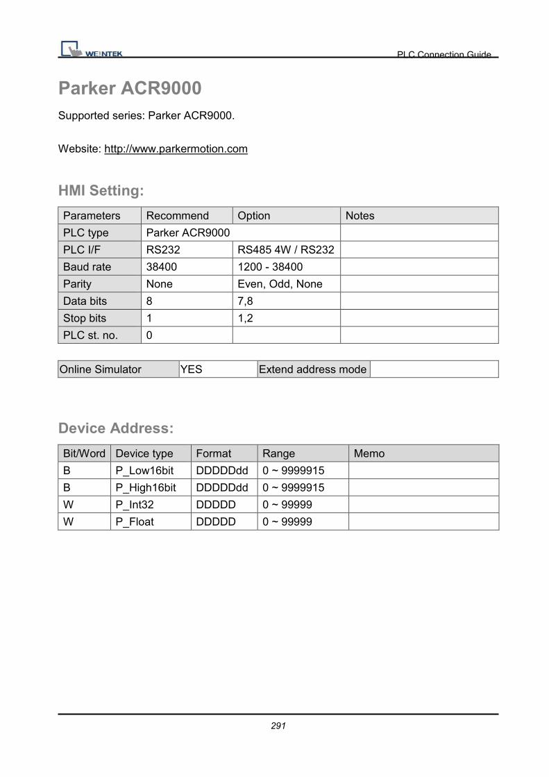
PLC Connection Guide
291
Parker ACR9000 Supported series: Parker ACR9000.
Website: http://www.parkermotion.com
HMI Setting:
Parameters Recommend Option Notes
PLC type Parker ACR9000
PLC I/F RS232 RS485 4W / RS232
Baud rate 38400 1200 - 38400
Parity None Even, Odd, None
Data bits 8 7,8
Stop bits 1 1,2
PLC st. no. 0
Online Simulator YES Extend address mode
Device Address:
Bit/Word Device type Format Range Memo
B P_Low16bit DDDDDdd 0 ~ 9999915
B P_High16bit DDDDDdd 0 ~ 9999915
W P_Int32 DDDDD 0 ~ 99999
W P_Float DDDDD 0 ~ 99999

PLC Connection Guide
292
Wiring Diagram:
9P D-Sub to 9P D-Sub:
HMI COM1
RS232 9P
D-Sub Male
HMI COM2
RS232 9P
D-Sub Male
HMI COM3
RS232 9P
D-Sub Female
Parker AC9000 RS232 Port 9P
D-Sub
2 RX 6 RX 8 RX 3 TXD
3 TX 4 TX 7 TX 2 RXD
5 GND 5 GND 5 GND 5 GND
Driver Version:
Version Date Description
V1.00 Dec/30/2008 Driver released.

PLC Connection Guide
293
Parker Compax3 Supported series: Parker Compax3 Servo Drive.
Website: http://www.parker.com
HMI Setting:
RS232
Parameters Recommend Option Notes
PLC type Parker Compax3
PLC I/F RS232
Baud rate 115200
Parity None Even, Odd, None
Data bits 8 7 or 8
Stop bits 1 1 or 2
PLC st. no. 0 0 Must be 0 for RS232
RS485
Parameters Recommend Option Notes
PLC type Parker Compax3
PLC I/F RS485 2W
Baud rate 9600
Parity None Even, Odd, None
Data bits 8 7 or 8
Stop bits 1 1 or 2
PLC st. no. 1 1-99
Range from 1 to 99 for
RS485, according to the
PLC’s setting.

PLC Connection Guide
294
PLC Setting:
How to setting Compax 3 servo to RS485 mode?
1. Open C3 ServoManager2, select “Communication” => “RS-485 Settings”.
2. Click to Configure “RS-485/POP Settings”.
2. Setting parameters as below

PLC Connection Guide
295
4. Downloading settings to Compax3 Servo.
5. Setting EasyBuilder system parameter and connecting with PLC for communication of
HMI and Servo.
Device Address:
Bit/Word Device type Format Range Memo B R_Low16bit DDDDDDDDh 0 ~ 99999999f B R_High16bit DDDDDDDDh 0 ~ 99999999f
DW Register_Int DDDDDD 0 ~ 999999 For Register is INT32 or U32
DW Register_float DDDDDD 0 ~ 999999 For Register is INT32 or U32
W Register_Short DDDDDD 0 ~ 999999 For Register is INT16 or U16

PLC Connection Guide
296
Wiring Diagram:
9P D-Sub to 9P D-Sub:
HMI COM1
RS232 9P
D-Sub Male
HMI COM2
RS232 9P
D-Sub Male
HMI COM3
RS232 9P
D-Sub Female
Parker Compax3 PLC X10 9P
D-Sub
2 RX 6 RX 8 RX 3 TXD
3 TX 4 TX 7 TX 2 RXD
5 GND 5 GND 5 GND 5 GND
9P D-Sub to 9P D-Sub:
HMI COM1
RS485 2W 9P
D-Sub Female
HMI COM3
RS485 2W 9P
D-Sub Female
Parker Compax3 PLC X10
9P D-Sub
1 RX- 6 Data- 3 RXD
2 RX+ 9 Data+ 7 TXD
5 GND 5 GND 5 GND
1 nable RS485 circuit
9 +5V
Driver Version:
Version Date Description
V1.70 Mar/30/2009

PLC Connection Guide
297
Parker SLVD Series Supported series : Parker SLVD Servo, SLVD1N, SLVD2N, SLVD5N, SLVD7N,
SLVD10N, SLVD15N, SLVD17N.
Website: http://www.parker.com/portal/site/PARKER/
HMI Setting:
Parameters Recommend Option Notes
PLC type Parker SLVD Series
PLC I/F RS485 4W
Baud rate 9600 9600/19200
Parity Even Even, Odd, None
Data bits 8 7,8
Stop bits 1 1,2
PLC st. no. 0 0-31
Online Simulator YES Extend address mode
Device Address:
Bit/Word Device type Format Range Memo
B Par_Binary DDDDdd 0 ~ 999915 Set a bit of Parameter
W Par_One_Word DDDD 0 ~ 9999 Set 2 bytes Parameter
W Par_One_Byte DDDD 0 ~ 9999 Set 1 byte Prarmeter
DW Par_Two_Word DDDD 0 ~ 9999 Set 4 bytes Parameter
W RESET D 0
W RUN D 0

PLC Connection Guide
298
Wiring Diagram:
9P D-Sub to 15P D-Sub:
HMI COM1
RS485 4W 9P
D-Sub Female
Parker SLVD Servo Serial Link
X1 15P D-Sub
1 RX- 7 TX-
2 RX+ 12 TX+
3 TX- 2 RX-
4 TX+ 1 RX+ circuit
6 TER
5 GND 3 GND
Driver Version:
Version Date Description
V1.00 Jan/27/2010 Driver released.

PLC Connection Guide
299
SAIA PCD PGU Mode Supported series : SAIA PCD series PGU mode.
Website :http://www.saia-burgess.com/
HMI Setting:
Parameters Recommend Option Notes
PLC type SAIA PCD PGU Mode PDS driver
PLC I/F RS232 RS232, RS485
Baud rate 9600 9600, 19200
Parity Even Even, Odd, None
Data bits 7 7,8
Stop bits 1 1
PLC st. no. 1 0-255
Device Address:
Bit/Word Device type Format Range Memo
B Flag DDDD 0 ~ 8191
B Input DDD 0 ~ 511
B Output DDD 0 ~ 511
W Register DDDD 0 ~ 4095
W Counter DDDD 0 ~ 1599
W Timer DDDD 0 ~ 1599
W Reg_Float DDDD 0 ~ 4095 support single float point
W Reg_Word DDDD 0 ~ 4095

PLC Connection Guide
300
Wiring Diagram:
9P D-Sub to 9P D-Sub:
HMI COM1
RS232 9P
D-Sub Male
RS232 9P D-Sub
2 RX 3 TXD
3 TX 2 RXD
5 GND 5 GND
7 RTS 6 DSR
7 RTS circuit
8 CTS
6 DSR (Of PGU Port): PGU connected.
Driver Version:
Version Date Description
V1.02 Dec/30/2008
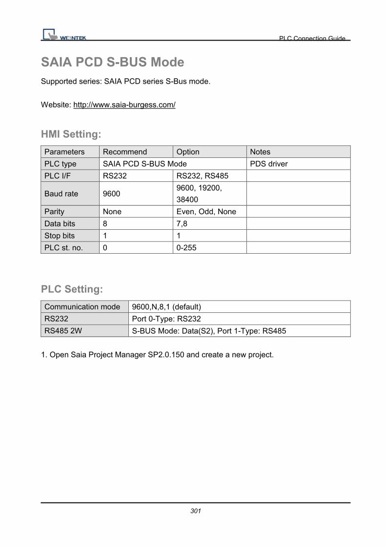
PLC Connection Guide
301
SAIA PCD S-BUS Mode Supported series: SAIA PCD series S-Bus mode.
Website: http://www.saia-burgess.com/
HMI Setting:
Parameters Recommend Option Notes
PLC type SAIA PCD S-BUS Mode PDS driver
PLC I/F RS232 RS232, RS485
Baud rate 9600 9600, 19200,
38400
Parity None Even, Odd, None
Data bits 8 7,8
Stop bits 1 1
PLC st. no. 0 0-255
PLC Setting:
Communication mode 9600,N,8,1 (default)
RS232 Port 0-Type: RS232
RS485 2W S-BUS Mode: Data(S2), Port 1-Type: RS485
1. Open Saia Project Manager SP2.0.150 and create a new project.

PLC Connection Guide
302
3. Give a project name.
3. Create a new project as below,

PLC Connection Guide
303
4. Go to Online Setting
4. Select PGU

PLC Connection Guide
304
6. Go to ”Device Configurator”

PLC Connection Guide
305
8. Press ” Change Device Type” to select your PLC model.
8. Select RS232 (PGU) in Type and then right click mouse on Onboard Communications
and select ” Properties”

PLC Connection Guide
306
9. Select Yes in Series S-Bus Port: Enabled
10. Setting parameters in S-Bus Mode and Timing and upload to PLC.

PLC Connection Guide
307
10. Go to Online Settins >> Open to select S-Bus for finishing the PLC settings.

PLC Connection Guide
308
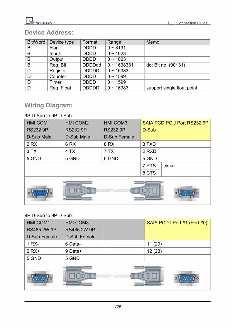
PLC Connection Guide
309
Device Address: Bit/Word Device type Format Range Memo B Flag DDDD 0 ~ 8191 B Input DDDD 0 ~ 1023 B Output DDDD 0 ~ 1023 B Reg_Bit DDDDdd 0 ~ 1638331 dd: Bit no. (00~31) D Register DDDDD 0 ~ 16383 D Counter DDDD 0 ~ 1599 D Timer DDDD 0 ~ 1599 D Reg_Float DDDDD 0 ~ 16383 support single float point
Wiring Diagram:
9P D-Sub to 9P D-Sub:
HMI COM1
RS232 9P
D-Sub Male
HMI COM2
RS232 9P
D-Sub Male
HMI COM3
RS232 9P
D-Sub Female
SAIA PCD PGU Port RS232 9P
D-Sub
2 RX 6 RX 8 RX 3 TXD
3 TX 4 TX 7 TX 2 RXD
5 GND 5 GND 5 GND 5 GND
7 RTS circuit
8 CTS
9P D-Sub to 9P D-Sub:
HMI COM1
RS485 2W 9P
D-Sub Female
HMI COM3
RS485 2W 9P
D-Sub Female
SAIA PCD1 Port #1 (Port #0)
1 RX- 6 Data- 11 (29)
2 RX+ 9 Data+ 12 (28)
5 GND 5 GND
PLC Connection Guide
310
Driver Version:
Version Date Description
V1.20 Dec/22/2010

PLC Connection Guide
311
SAIA S-BUS (Ethernet) Supported series : SAIA PCD series Ethernet-TCP/IP.
Website : http://www.saia-burgess.com/
HMI Setting:
Parameters Recommend Option Notes
PLC type SAIA S-BUS (Ethernet)
PLC I/F Ethernet
Port no. 5050
PLC st. no. 0
PLC Setting:
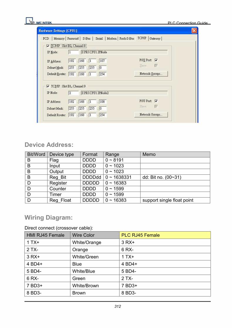
PLC Connection Guide
312
Device Address: Bit/Word Device type Format Range Memo B Flag DDDD 0 ~ 8191 B Input DDDD 0 ~ 1023 B Output DDDD 0 ~ 1023 B Reg_Bit DDDDdd 0 ~ 1638331 dd: Bit no. (00~31) D Register DDDDD 0 ~ 16383 D Counter DDDD 0 ~ 1599 D Timer DDDD 0 ~ 1599 D Reg_Float DDDDD 0 ~ 16383 support single float point
Wiring Diagram:
Direct connect (crossover cable):
HMI RJ45 Female Wire Color PLC RJ45 Female
1 TX+ White/Orange 3 RX+
2 TX- Orange 6 RX-
3 RX+ White/Green 1 TX+
4 BD4+ Blue 4 BD4+
5 BD4- White/Blue 5 BD4-
6 RX- Green 2 TX-
7 BD3+ White/Brown 7 BD3+
8 BD3- Brown 8 BD3-

PLC Connection Guide
313
Through a hub:
HMI RJ45 Female Wire Color PLC RJ45 Female
1 TX+ White/Orange 1 TX+
2 TX- Orange 2 TX-
3 RX+ White/Green 3 RX+
4 BD4+ Blue 4 BD4+
5 BD4- White/Blue 5 BD4-
6 RX- Green 6 RX-
7 BD3+ White/Brown 7 BD3+
8 BD3- Brown 8 BD3-
Driver Version:
Version Date Description
V1.10 Nov/30/2010 Add Reg_Bit register.

PLC Connection Guide
314
Schleicher XCS 20C Supported series: Schleicher XCx-Systems Ethernet port. Schleicher XCS series, 20C
model.
Website: http://www.schleicher-electronic.com
HMI Setting:
Parameters Recommend Option Notes
PLC type Schleicher XCS 20C
PLC I/F RS232
Baud rate 38400
Parity N
Data bits 8
Stop bits 1
PLC st. no. 0
Device Address: Bit/Word Device type Format Range Memo B IX DDDDDo 0 ~ 655357 Input %IX B QX DDDDDo 0 ~ 655357 Output %QX B MX DDDDDo 0 ~ 655357 %MX W IW DDDDD 0 ~ 65535 %IW W QW DDDDD 0 ~ 65535 %QW W MW DDDDD 0 ~ 65535 %MW DW ID DDDDD 0 ~ 65535 %ID DW QD DDDDD 0 ~ 65535 %QD DW MD DDDDD 0 ~ 65535 %WD
l Word address must be even.
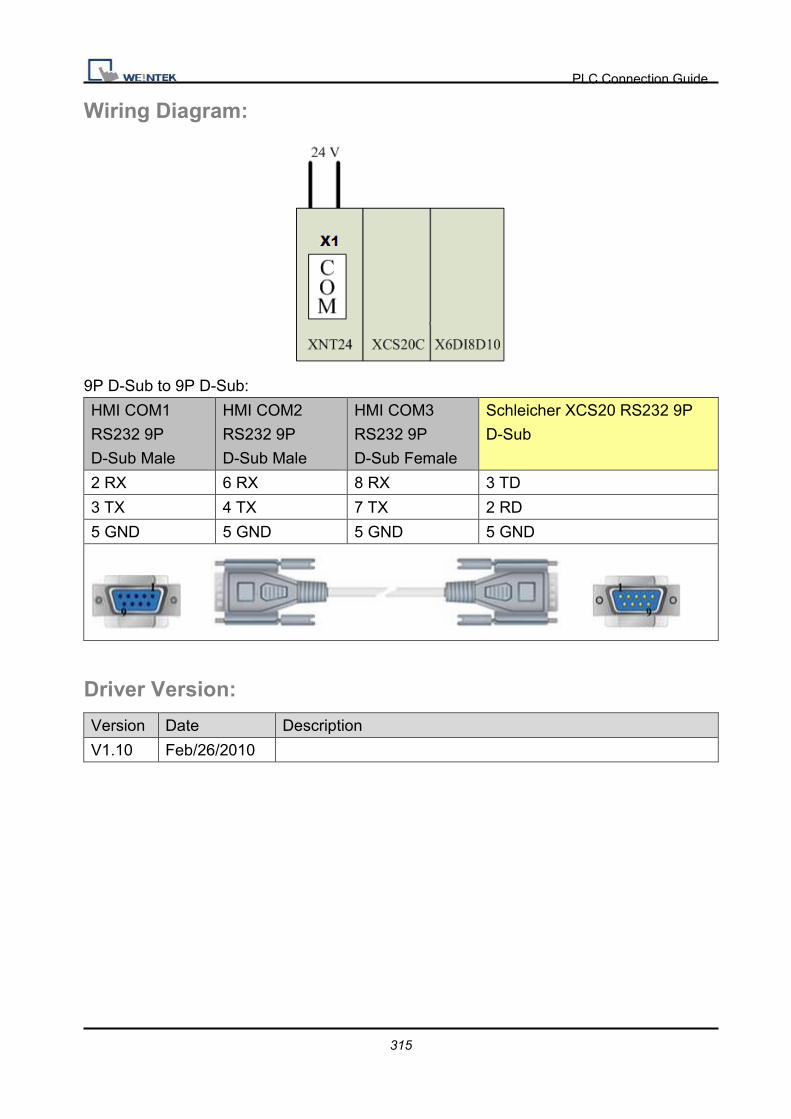
PLC Connection Guide
315
Wiring Diagram:
9P D-Sub to 9P D-Sub:
HMI COM1
RS232 9P
D-Sub Male
HMI COM2
RS232 9P
D-Sub Male
HMI COM3
RS232 9P
D-Sub Female
Schleicher XCS20 RS232 9P
D-Sub
2 RX 6 RX 8 RX 3 TD
3 TX 4 TX 7 TX 2 RD
5 GND 5 GND 5 GND 5 GND
Driver Version:
Version Date Description
V1.10 Feb/26/2010

PLC Connection Guide
316
Schleicher XCX 300 Website: http://www.schleicher-electronic.com
HMI Setting:
Parameters Recommend Option Notes
PLC type Schleicher XCX 300
PLC I/F Ethernet RS232, RS422,
Ethernet
Port No. 20547
PLC st. no. 2
PLC Setting:
Must create variable for HMI access.
Device Address: Bit/Word Device type Format Range Memo B IX DDDDDo 0 ~ 655357 Input %IX B QX DDDDDo 0 ~ 655357 Output %QX B MX DDDDDo 0 ~ 655357 %MX W IW DDDDD 0 ~ 65535 %IW W QW DDDDD 0 ~ 65535 %QW W MW DDDDD 0 ~ 65535 %MW DW ID DDDDD 0 ~ 65535 %ID
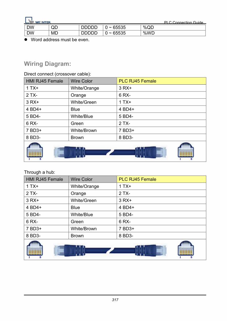
PLC Connection Guide
317
DW QD DDDDD 0 ~ 65535 %QD DW MD DDDDD 0 ~ 65535 %WD
l Word address must be even.
Wiring Diagram:
Direct connect (crossover cable):
HMI RJ45 Female Wire Color PLC RJ45 Female
1 TX+ White/Orange 3 RX+
2 TX- Orange 6 RX-
3 RX+ White/Green 1 TX+
4 BD4+ Blue 4 BD4+
5 BD4- White/Blue 5 BD4-
6 RX- Green 2 TX-
7 BD3+ White/Brown 7 BD3+
8 BD3- Brown 8 BD3-
Through a hub:
HMI RJ45 Female Wire Color PLC RJ45 Female
1 TX+ White/Orange 1 TX+
2 TX- Orange 2 TX-
3 RX+ White/Green 3 RX+
4 BD4+ Blue 4 BD4+
5 BD4- White/Blue 5 BD4-
6 RX- Green 6 RX-
7 BD3+ White/Brown 7 BD3+
8 BD3- Brown 8 BD3-

PLC Connection Guide
318
9P D-Sub to 9P D-Sub:
HMI COM1
RS232 9P
D-Sub Male
HMI COM2
RS232 9P
D-Sub Male
HMI COM3
RS232 9P
D-Sub Female
Schleicher XCX300 RS232 Port
2 RX 6 RX 8 RX TXD
3 TX 4 TX 7 TX RXD
5 GND 5 GND 5 GND GND
9P D-Sub to 9P D-Sub:
HMI COM1
RS485 4W 9P
D-Sub Female
Schleicher XCX300 RS422 Port
1 RX- TX-
2 RX+ TX+
3 TX- RX-
4 TX+ RX+
5 GND GND
Driver Version:
Version Date Description
V1.00 Nov/30/2009 Driver released.
V1.10 Jun/28/2010 Support RS232, RS422 interface connection.

PLC Connection Guide
319
SEW Movilink Supported series: SEW Eurodrive series, model MOVITRAC-07 inverter, MovitracB.
Website: http://sg.sew-eurodrive.com/
HMI Setting:
Parameters Recommend Option Notes
PLC type SEW Movilink
PLC I/F RS485 2W
Baud rate 9600
Data bits 8
Parity Even
Stop bits 1
PLC st. no. 0 0~255
Device Address:
Bit/Word Device type Format Range Memo
W INDEX DDDDDDDD 0 ~ 25525000
B INDEX_Bit DDDDDDDDdd 0 ~ 2552500031
� The MOVITRAC-07 doesn’t support Sub index�other series maybe support�, please
fixed to input 000.
� When input D and d, the correct format example as follow�Sub index 15, Index 8359,
Format is 01508359.
Wiring Diagram:
9P D-Sub to 4P:
HMI COM1
RS485 2W 9P
D-Sub Female
HMI COM3
RS485 2W 9P
D-Sub Female
Movitrac-07 RS485
1 RX- 6 Data- D- (Green)
2 RX+ 9 Data+ D+ (Red)

PLC Connection Guide
320
5 GND 5 GND
Driver Version:
Version Date Description
V1.31 Jun/25/2010
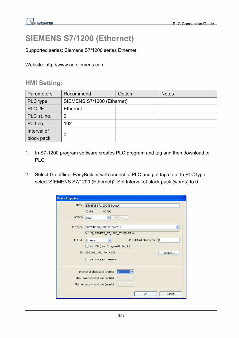
PLC Connection Guide
321
SIEMENS S7/1200 (Ethernet) Supported series: Siemens S7/1200 series Ethernet.
Website: http://www.ad.siemens.com
HMI Setting:
Parameters Recommend Option Notes
PLC type SIEMENS S7/1200 (Ethernet)
PLC I/F Ethernet
PLC st. no. 2
Port no. 102
Interval of
block pack 0
1. In S7-1200 program software creates PLC program and tag and then download to
PLC.
2. Select Go offline, EasyBuilder will connect to PLC and get tag data. In PLC type
select“SIEMENS S7/1200 (Ethernet)”. Set Interval of block pack (words) to 0.

PLC Connection Guide
322
3. Click “Settings…”, input PLC IP address.
4. Check the PLC has not any PC connected. Click “Get tag info…”, it will show a
successful message.

PLC Connection Guide
323
5. Create an object and click read address “Setting…”
In PLC name select S7-1200 then click Tag.
Select PLC tag.

PLC Connection Guide
324
Support Device Type: S7-1200 data type EasyBuilder data format Memo Bool bit
Word 16-bit BCD, Hex, Binary, Unsigned
Int 16-bit BCD, Hex, Binary, Signed
DWord 32-bit BCD, Hex, Binary, Unsigned
Dint 32-bit BCD, Hex, Binary, Signed
Real 32-bit Float
Array Word array for ASCII input and ASCII display Length=word
Note:
On-line Simulation OK Multi-PLC connect OK

PLC Connection Guide
325
Wiring Diagram:
Direct connect (crossover cable):
HMI RJ45 Female Wire Color PLC RJ45 Female
1 TX+ White/Orange 3 RX+
2 TX- Orange 6 RX-
3 RX+ White/Green 1 TX+
4 BD4+ Blue 4 BD4+
5 BD4- White/Blue 5 BD4-
6 RX- Green 2 TX-
7 BD3+ White/Brown 7 BD3+
8 BD3- Brown 8 BD3-
Through a hub:
HMI RJ45 Female Wire Color PLC RJ45 Female
1 TX+ White/Orange 1 TX+
2 TX- Orange 2 TX-
3 RX+ White/Green 3 RX+
4 BD4+ Blue 4 BD4+
5 BD4- White/Blue 5 BD4-
6 RX- Green 6 RX-
7 BD3+ White/Brown 7 BD3+
8 BD3- Brown 8 BD3-
Driver Version:
Version Date Description
V1.70 Sep/24/2010
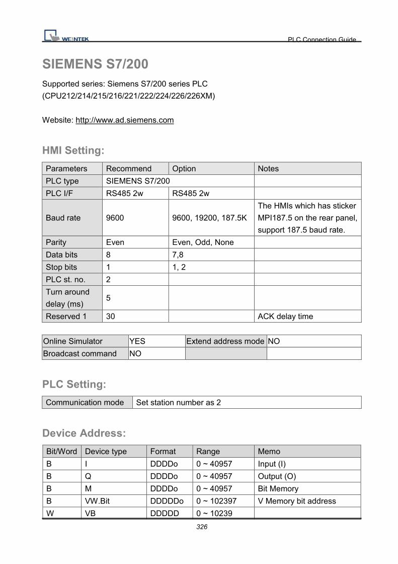
PLC Connection Guide
326
SIEMENS S7/200 Supported series: Siemens S7/200 series PLC
(CPU212/214/215/216/221/222/224/226/226XM)
Website: http://www.ad.siemens.com
HMI Setting:
Parameters Recommend Option Notes
PLC type SIEMENS S7/200
PLC I/F RS485 2w RS485 2w
Baud rate 9600 9600, 19200, 187.5K
The HMIs which has sticker
MPI187.5 on the rear panel,
support 187.5 baud rate.
Parity Even Even, Odd, None
Data bits 8 7,8
Stop bits 1 1, 2
PLC st. no. 2
Turn around
delay (ms) 5
Reserved 1 30 ACK delay time
Online Simulator YES Extend address mode NO
Broadcast command NO
PLC Setting:
Communication mode Set station number as 2
Device Address:
Bit/Word Device type Format Range Memo
B I DDDDo 0 ~ 40957 Input (I)
B Q DDDDo 0 ~ 40957 Output (O)
B M DDDDo 0 ~ 40957 Bit Memory
B VW.Bit DDDDDo 0 ~ 102397 V Memory bit address
W VB DDDDD 0 ~ 10239

PLC Connection Guide
327
W VW DDDDD 0 ~ 10239 V memory
W VW_Odd DDDDD 0 ~ 10239 V memory
DW VD DDDDD 0 ~ 10239 V memory double word
DW VD_Odd DDDDD 0 ~ 10239 V memory double word
W VD_String DDDDD 0 ~ 10239 String
W VD_String_Odd DDDDD 0 ~ 10239 String
W VW_String DDDDD 0 ~ 10239 String
W VW_String_Odd DDDDD 0 ~ 10239 String
W MB DDDDD 0 ~ 10239 byte memory
W MW DDDDD 0 ~ 10239 Word memory
W MW_Odd DDDDD 0 ~ 10239 Word memory
W T DDD 0 ~ 127 Timer
W C DDD 0 ~ 127 Counter
l Double word and Floating point value must use VD device type.
Wiring Diagram:
9P D-Sub to 9P D-Sub:
HMI COM1
RS485 2W 9P
D-Sub Female
HMI COM3
RS485 2W 9P
D-Sub Female
Siemens S7-200 CPU Port
RS485 2W 9P D-Sub
1 RX- 6 Data- 8 D-
2 RX+ 9 Data+ 3 D+
5 GND 5 GND 5 GND
Driver Version:
Version Date Description
V2.30 Aug/17/2009

PLC Connection Guide
328
SIEMENS S7/200 (Ethernet) Supported series: Siemens S7/200 Ethernet Series PLC
(CPU212/214/215/216/221/222/224/226/226XM)
Website: http://www.ad.siemens.com
HMI Setting:
Parameters Recommend Option Notes
PLC type Siemens S7/200 (Ethernet)
PLC I/F Ethernet
Port no. 102
PLC st. no. 1 0-31
Device Address:
Bit/Word Device type Format Range Memo
B I DDDDo 0 ~ 40957 Input (I)
B Q DDDDo 0 ~ 40957 Output (O)
B M DDDDo 0 ~ 40957 Bit Memory
B VW_Bit DDDDo 0 ~ 40957 V Memory bit address
W VW DDDDD 0 ~ 10239 V memory
W VW_String DDDDD 0 ~ 10239 String
DW VD DDDDD 0 ~ 10239 V memory double word
DW VD_String DDDDD 0 ~ 10239 String
l Double word and Floating point value must use VD device type.

PLC Connection Guide
329
Wiring Diagram:
Direct connect (crossover cable):
HMI RJ45 Female Wire Color PLC RJ45 Female
1 TX+ White/Orange 3 RX+
2 TX- Orange 6 RX-
3 RX+ White/Green 1 TX+
4 BD4+ Blue 4 BD4+
5 BD4- White/Blue 5 BD4-
6 RX- Green 2 TX-
7 BD3+ White/Brown 7 BD3+
8 BD3- Brown 8 BD3-
Through a hub:
HMI RJ45 Female Wire Color PLC RJ45 Female
1 TX+ White/Orange 1 TX+
2 TX- Orange 2 TX-
3 RX+ White/Green 3 RX+
4 BD4+ Blue 4 BD4+
5 BD4- White/Blue 5 BD4-
6 RX- Green 6 RX-
7 BD3+ White/Brown 7 BD3+
8 BD3- Brown 8 BD3-
Driver Version:
Version Date Description
V1.20 Dec/30/2008

PLC Connection Guide
330
SIEMENS S7/300 Supported series: Siemens S7/300 series PLC
Website: http://www.ad.siemens.com
HMI Setting:
Parameters Recommend Option Notes
PLC type SIEMENS S7/300
PLC I/F RS232
Baud rate
19200,
38400,
187.5K
9600~187.5K
Must same as the PLC setting
The HMIs which has sticker
MPI187.5 on the rear panel,
support 187.5 baud rate.
Parity Odd
Data bits 8
Stop bits 1
PLC st. no. 2 Must same as the PLC setting
Device Address:
Bit/Word Device type Format Range Memo
B I DDDDo 0 ~ 40957 Input (I)
B Q DDDDo 0 ~ 40957 Output (O)
B M DDDDo 0 ~ 40957 Bit Memory
B DBnBit FFFFDDDDo 0 ~ 409681927 Data register bit
B DB0Bit ~
DB99Bit DDDDo 0 ~ 81927
W IW DDDD 0 ~ 4095 Input (I)
W QW DDDD 0 ~ 4095 Output (O)
W MW DDDD 0 ~ 4095 Bit Memory
W MD DDDD 0 ~ 4094
W DB0-DB99 DDDD 0 ~ 8192 Data register(must be
even)
W DBn FFFFDDDD 0 ~ 40968192 Data register(must be
even)
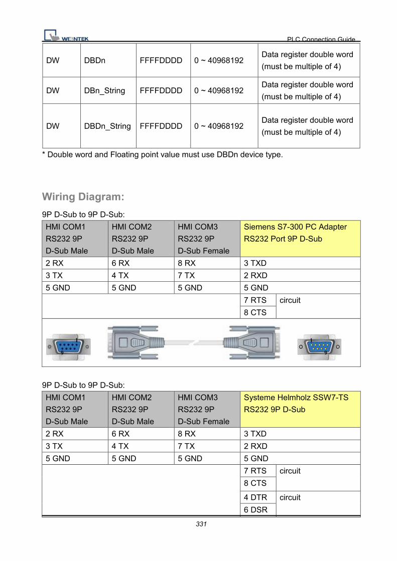
PLC Connection Guide
331
DW DBDn FFFFDDDD 0 ~ 40968192 Data register double word
(must be multiple of 4)
DW DBn_String FFFFDDDD 0 ~ 40968192 Data register double word
(must be multiple of 4)
DW DBDn_String FFFFDDDD 0 ~ 40968192 Data register double word
(must be multiple of 4)
* Double word and Floating point value must use DBDn device type.
Wiring Diagram:
9P D-Sub to 9P D-Sub:
HMI COM1
RS232 9P
D-Sub Male
HMI COM2
RS232 9P
D-Sub Male
HMI COM3
RS232 9P
D-Sub Female
Siemens S7-300 PC Adapter
RS232 Port 9P D-Sub
2 RX 6 RX 8 RX 3 TXD
3 TX 4 TX 7 TX 2 RXD
5 GND 5 GND 5 GND 5 GND
7 RTS circuit
8 CTS
9P D-Sub to 9P D-Sub:
HMI COM1
RS232 9P
D-Sub Male
HMI COM2
RS232 9P
D-Sub Male
HMI COM3
RS232 9P
D-Sub Female
Systeme Helmholz SSW7-TS
RS232 9P D-Sub
2 RX 6 RX 8 RX 3 TXD
3 TX 4 TX 7 TX 2 RXD
5 GND 5 GND 5 GND 5 GND
7 RTS circuit
8 CTS
4 DTR circuit
6 DSR

PLC Connection Guide
332
Driver Version:
Version Date Description
V2.80 Dec/07/2010
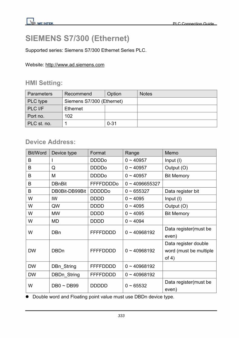
PLC Connection Guide
333
SIEMENS S7/300 (Ethernet) Supported series: Siemens S7/300 Ethernet Series PLC.
Website: http://www.ad.siemens.com
HMI Setting:
Parameters Recommend Option Notes
PLC type Siemens S7/300 (Ethernet)
PLC I/F Ethernet
Port no. 102
PLC st. no. 1 0-31
Device Address:
Bit/Word Device type Format Range Memo
B I DDDDo 0 ~ 40957 Input (I)
B Q DDDDo 0 ~ 40957 Output (O)
B M DDDDo 0 ~ 40957 Bit Memory
B DBnBit FFFFDDDDo 0 ~ 4096655327
B DB0Bit-DB99Bit DDDDDo 0 ~ 655327 Data register bit
W IW DDDD 0 ~ 4095 Input (I)
W QW DDDD 0 ~ 4095 Output (O)
W MW DDDD 0 ~ 4095 Bit Memory
W MD DDDD 0 ~ 4094
W DBn FFFFDDDD 0 ~ 40968192 Data register(must be
even)
DW DBDn FFFFDDDD 0 ~ 40968192
Data register double
word (must be multiple
of 4)
DW DBn_String FFFFDDDD 0 ~ 40968192
DW DBDn_String FFFFDDDD 0 ~ 40968192
W DB0 ~ DB99 DDDDD 0 ~ 65532 Data register(must be
even)
l Double word and Floating point value must use DBDn device type.

PLC Connection Guide
334
Wiring Diagram:
Direct connect (crossover cable):
HMI RJ45 Female Wire Color PLC RJ45 Female
1 TX+ White/Orange 3 RX+
2 TX- Orange 6 RX-
3 RX+ White/Green 1 TX+
4 BD4+ Blue 4 BD4+
5 BD4- White/Blue 5 BD4-
6 RX- Green 2 TX-
7 BD3+ White/Brown 7 BD3+
8 BD3- Brown 8 BD3-
Through a hub:
HMI RJ45 Female Wire Color PLC RJ45 Female
1 TX+ White/Orange 1 TX+
2 TX- Orange 2 TX-
3 RX+ White/Green 3 RX+
4 BD4+ Blue 4 BD4+
5 BD4- White/Blue 5 BD4-
6 RX- Green 6 RX-
7 BD3+ White/Brown 7 BD3+
8 BD3- Brown 8 BD3-
Driver Version:
Version Date Description
V1.90 Dec/07/2010

PLC Connection Guide
335
SIEMENS S7/300 MPI Supported series: Siemens S7/300 series PLC.
Website: http://www.ad.siemens.com
HMI Setting:
Parameters Recommend Option Notes
PLC type SIEMENS S7/300 MPI
PLC I/F RS485 2W
Baud rate 187.5K
Parity Even
Data bits 8
Stop bits 1
PLC st. no. 2
Device Address:
Bit/Word Device type Format Range Memo
B I DDDDo 0 ~ 40957 Input (I)
B Q DDDDo 0 ~ 40957 Output (O)
B M DDDDo 0 ~ 40957 Bit Memory
B DBnBit FFFFDDDDo 0 ~ 409681927
B DB0Bit-DB99Bit DDDDDo 0 ~ 655327 Data register bit
W IW DDDD 0 ~ 4095 Input (I)
W QW DDDD 0 ~ 4095 Output (O)
W MW DDDD 0 ~ 4095 Bit Memory
W MD DDDD 0 ~ 4094
W DBn FFFFDDDD 0 ~ 40968192 Data register(must be
even)
DW DBDn FFFFDDDD 0 ~ 40968192
Data register double
word (must be multiple
of 4)
DW DBn_String FFFFDDDD 0 ~ 40968192
DW DBDn_String FFFFDDDD 0 ~ 40968192
W DB0 ~ DB99 DDDDD 0 ~ 65532 Data register(must be

PLC Connection Guide
336
even)
* Double word and Floating point value must use DBDn device type.
Wiring Diagram:
9P D-Sub to 9P D-Sub:
HMI COM1
RS485 2W 9P
D-Sub Female
HMI COM3
RS485 2W 9P
D-Sub Female
S7-200 PPI RS485 2W 9P
D-Sub
S7-300 MPI RS485 2W 9P
D-Sub
1 RX- 6 Data- 8 D-
2 RX+ 9 Data+ 3 D+
5 GND 5 GND 5 GND
Driver Version:
Version Date Description
V1.50 Dec/07/2010

PLC Connection Guide
337
SIEMENS S7/400 (Ethernet) Supported series: Siemens S7/400 Ethernet PLC.
Website: http://www.ad.siemens.com
HMI Setting:
Parameters Recommend Option Notes
PLC type Siemens S7/400 (Ethernet)
PLC I/F Ethernet
Port no. 102
PLC st. no. 0 0-31
Link type PG PC, OP
Rack 0 0-7
CPU slot 3 2-31
Device Address:
Bit/Word Device type Format Range Memo
B I DDDDo 0 ~ 40957 Input (I)
B Q DDDDo 0 ~ 40957 Output (O)
B M DDDDo 0 ~ 40957 Bit Memory
B DBnBit FFFFDDDDo 0 ~ 4096655327
B DB0Bit-DB99Bit DDDDDo 0 ~ 655327 Data register bit
W IW DDDD 0 ~ 4095 Input (I)
W QW DDDD 0 ~ 4095 Output (O)
W MW DDDD 0 ~ 4095 Bit Memory
W MD DDDD 0 ~ 4094
W DBn FFFFDDDD 0 ~ 40968192 Data register(must
be even)
DW DBDn FFFFDDDD 0 ~ 40968192
Data register double
word (must be
multiple of 4)
DW DBn_String FFFFDDDD 0 ~ 40968192
DW DBDn_String FFFFDDDD 0 ~ 40968192
W DB0 ~ DB99 DDDDD 0 ~ 65532 Data register(must

PLC Connection Guide
338
be even)
* Double word and Floating point value must use DBDn device type.
Wiring Diagram:
Direct connect (crossover cable):
HMI RJ45 Female Wire Color PLC RJ45 Female
1 TX+ White/Orange 3 RX+
2 TX- Orange 6 RX-
3 RX+ White/Green 1 TX+
4 BD4+ Blue 4 BD4+
5 BD4- White/Blue 5 BD4-
6 RX- Green 2 TX-
7 BD3+ White/Brown 7 BD3+
8 BD3- Brown 8 BD3-
Through a hub:
HMI RJ45 Female Wire Color PLC RJ45 Female
1 TX+ White/Orange 1 TX+
2 TX- Orange 2 TX-
3 RX+ White/Green 3 RX+
4 BD4+ Blue 4 BD4+
5 BD4- White/Blue 5 BD4-
6 RX- Green 6 RX-
7 BD3+ White/Brown 7 BD3+
8 BD3- Brown 8 BD3-

PLC Connection Guide
339
EasyBuilder Device Setting Steps
1. Open EasyBuilder, and File -> NEW, select HMI model and press ok button
2. Then, you will see the window of ”system parameter settings”, press “New” button.
3. Select “SIEMENS S7/400(ETHERNET)”.
4. Press “Settings” button.
1.
2.
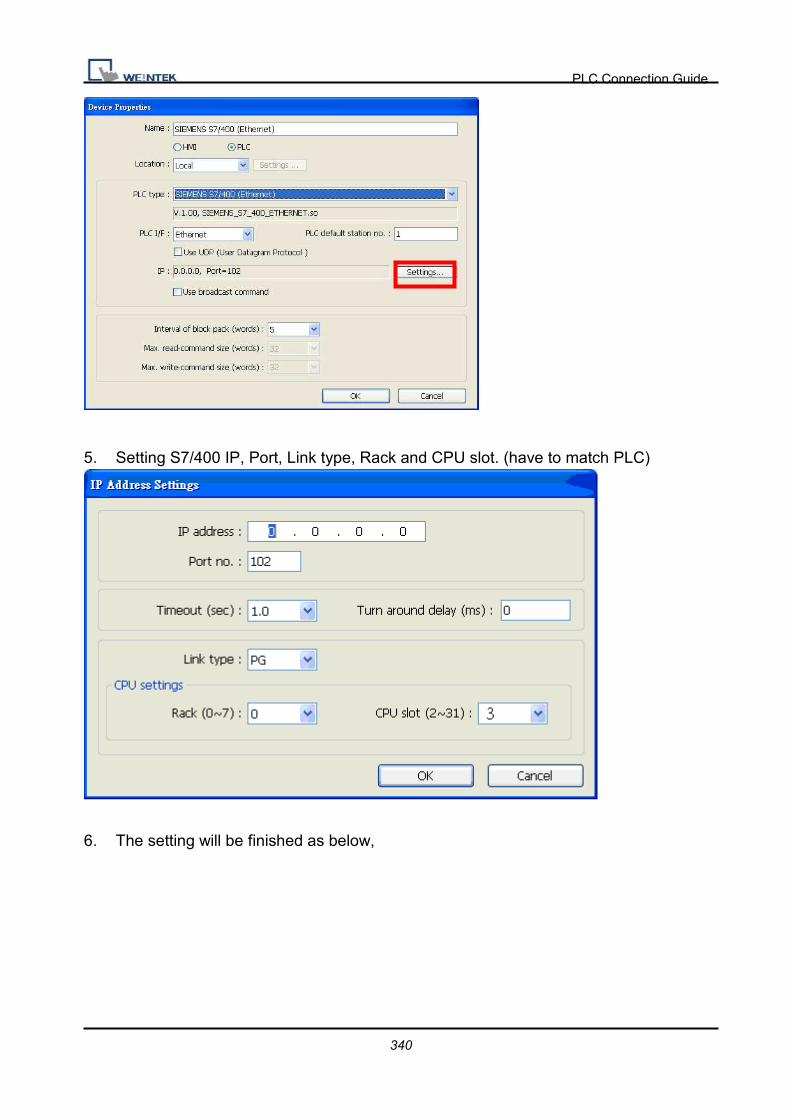
PLC Connection Guide
340
5. Setting S7/400 IP, Port, Link type, Rack and CPU slot. (have to match PLC)
6. The setting will be finished as below,

PLC Connection Guide
341
Driver Version:
Version Date Description
V1.10 Dec/07/2010
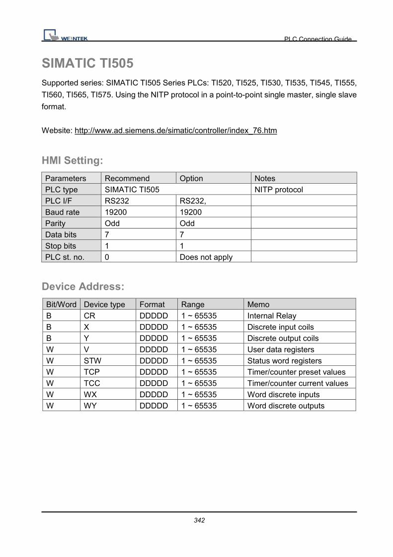
PLC Connection Guide
342
SIMATIC TI505 Supported series: SIMATIC TI505 Series PLCs: TI520, TI525, TI530, TI535, TI545, TI555,
TI560, TI565, TI575. Using the NITP protocol in a point-to-point single master, single slave
format.
Website: http://www.ad.siemens.de/simatic/controller/index_76.htm
HMI Setting:
Parameters Recommend Option Notes PLC type SIMATIC TI505 NITP protocol PLC I/F RS232 RS232, Baud rate 19200 19200 Parity Odd Odd Data bits 7 7 Stop bits 1 1 PLC st. no. 0 Does not apply
Device Address:
Bit/Word Device type Format Range Memo B CR DDDDD 1 ~ 65535 Internal Relay B X DDDDD 1 ~ 65535 Discrete input coils B Y DDDDD 1 ~ 65535 Discrete output coils W V DDDDD 1 ~ 65535 User data registers W STW DDDDD 1 ~ 65535 Status word registers W TCP DDDDD 1 ~ 65535 Timer/counter preset values W TCC DDDDD 1 ~ 65535 Timer/counter current values W WX DDDDD 1 ~ 65535 Word discrete inputs W WY DDDDD 1 ~ 65535 Word discrete outputs

PLC Connection Guide
343
Wiring Diagram:
9P D-Sub to 25P D-Sub:
HMI COM1
RS232 9P
D-Sub Male
HMI COM2
RS232 9P D-Sub
Male
HMI COM3
RS232 9P D-Sub
Female
SIMATIC TI505 RS232 25P
D-Sub
2 RX 6 RX 8 RX 2 TXD
3 TX 4 TX 7 TX 3 RXD
5 GND 5 GND 5 GND 7 GND
4 RTS circuit
5 CTS
6 DSR
circuit 8 DCD
20 DTR
9P D-Sub to 9P D-Sub:
HMI COM1
RS232 9P
D-Sub Male
HMI COM2
RS232 9P
D-Sub Male
HMI COM3
RS232 9P
D-Sub Female
SIMATIC TI505 RS232 9P
D-Sub
2 RX 6 RX 8 RX 3 TXD
3 TX 4 TX 7 TX 2 RXD
5 GND 5 GND 5 GND 5 GND
7 RTS circuit
8 CTS
1 DCD
circuit 4 DTR
6 DSR

PLC Connection Guide
344
9P D-Sub to 9P D-Sub:
HMI COM1
RS485 4W 9P
D-Sub Female
SIMATIC TI505 RS422 9P
D-Sub
1 RX- 7 DO (-)
2 RX+ 1 DO (+)
3 TX- 8 DI (-)
4 TX+ 5 DI (+)
5 GND 6 GND
Driver Version:
Version Date Description
V1.10 Apr/22/2009

PLC Connection Guide
345
TAIAN TP02 Series Supported series: TAIAN TP02 series.
Website: http://www.taian-technology.com
HMI Setting:
Parameters Recommend Option Notes
PLC type TAIAN TP02 Series
PLC I/F RS485 4W/2W RS485 4W/2W MMI 422 port: 4W; RS485
terminals: 2W
Baud rate 19200 9600, 19200,
38400
Parity Even Even, Odd, None
Data bits 7 7, 8
Stop bits 2 1, 2
PLC st. no. 1 0-255
PLC Setting:
RS422 port: WS041=120, WS042=1;
RS485 terminals: WS044=120, WS045=1.
Device Address:
Bit/Word Device type Format Range Memo B X DDD 1 ~ 384 Input relay B Y DDD 1 ~ 384 Output relay
B C DDDD 1 ~ 2048 Auxiliary relay
W X DDD 1 ~ 369 Input register (must be 1 or a multiple of plus 1)
W Y DDD 1 ~ 369 Output register(must be 1 or a multiple of plus 1)
W V DDDD 1 ~ 1024 Auxiliary register
W D DDDD 1 ~ 2048 Auxiliary register
W WS DDD 1 ~ 128 System register
W C DDDD 1 ~ 2033 Auxiliary relay register(must
be 1 or a
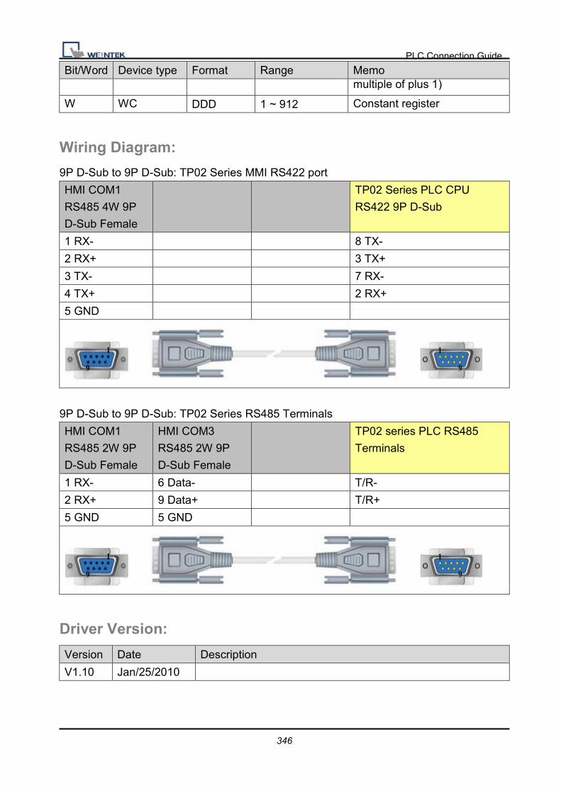
PLC Connection Guide
346
Bit/Word Device type Format Range Memo multiple of plus 1)
W WC DDD 1 ~ 912 Constant register
Wiring Diagram:
9P D-Sub to 9P D-Sub: TP02 Series MMI RS422 port
HMI COM1
RS485 4W 9P
D-Sub Female
TP02 Series PLC CPU
RS422 9P D-Sub
1 RX- 8 TX-
2 RX+ 3 TX+
3 TX- 7 RX-
4 TX+ 2 RX+
5 GND
9P D-Sub to 9P D-Sub: TP02 Series RS485 Terminals
HMI COM1
RS485 2W 9P
D-Sub Female
HMI COM3
RS485 2W 9P
D-Sub Female
TP02 series PLC RS485
Terminals
1 RX- 6 Data- T/R-
2 RX+ 9 Data+ T/R+
5 GND 5 GND
Driver Version:
Version Date Description
V1.10 Jan/25/2010

PLC Connection Guide
347
TAIAN TP03 Series Supported series: TECO (TAIAN TP03) series PLC.
Website: http://www.teco.com.tw/sa/en/
HMI Setting:
Parameters Recommend Option Notes
PLC type TAIAN TP03 Series
PLC I/F RS485 4W
Baud rate 19200 9600, 19200
Parity None Even, Odd, None
Data bits 8 8
Stop bits 2 1
PLC st. no. 1 1-31
Device Address:
Bit/Word Device type Format Range Memo B C DDDD 0 ~ 9999 B M DDDD 0 ~ 9999 B S DDDD 0 ~ 9999
B T DDDD 0 ~ 9999
B X OOO 0 ~ 377
B Y OOO 0 ~ 377
W D DDDD 0 ~ 9999 W V DDDD 0 ~ 9999 W Z DDDD 0 ~ 9999 W T_Curent DDDD 0 ~ 9999 W C_Curent DDDD 0 ~ 9999 W T_Preset DDDD 0 ~ 9999 W C_Preset DDDD 0 ~ 9999
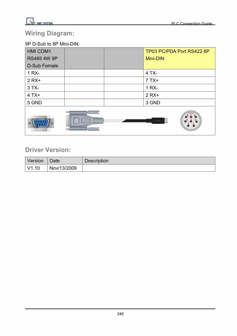
PLC Connection Guide
348
Wiring Diagram:
9P D-Sub to 8P Mini-DIN:
HMI COM1
RS485 4W 9P
D-Sub Female
TP03 PC/PDA Port RS422 8P
Mini-DIN
1 RX- 4 TX-
2 RX+ 7 TX+
3 TX- 1 RX-
4 TX+ 2 RX+
5 GND 3 GND
Driver Version:
Version Date Description
V1.10 Nov/13/2009

PLC Connection Guide
349
TECO Inverter Supported series: TECO Inverter series, 7300CV model.
HMI Setting:
Parameters Recommend Option Notes
PLC type TECO Inverter
PLC I/F RS232 RS232/RS485
Baud rate 38400
Parity None
Data bits 8
Stop bits 1
PLC st. no. 1
Device Address: Bit/Word Device type Format Range Memo B 0x DDDDD 1 ~ 65535 Output bit B 1x DDDDD 1 ~ 65535 Input bit (read only) B 3x_Bit DDDDDdd 100 ~ 6553515 Input Register bit (read only) B 4x_Bit DDDDDdd 100 ~ 6553515 Output Register bit B 6x_Bit DDDDDdd 100 ~ 6553515 B 0x (0x0f) DDDDD 1 ~ 65535 Write Multiple Coils W 3x DDDDD 1 ~ 65535 Input Register (read only) W 4x DDDDD 1 ~ 65535 Output Register DW 5x DDDDD 1 ~ 65535 4x double word swap W 6x DDDDD 1 ~ 65535 4x single word write
Wiring Diagram:

PLC Connection Guide
350
9P D-Sub to 9P D-Sub:
HMI COM1
RS232 9P
D-Sub Male
TECO Inverter RS232
2 RX 2 TX
3 TX 3 RX
5 GND 5 GND
7 RTS 7 VCC
Driver Version:
Version Date Description
V1.00 Jul/27/2009 Driver released.

PLC Connection Guide
351
TELEMECANIQUE UniTelway Supported series: Modicon TSX Micro&Nano&Neza series PLC.
Website: http://www.modicon.com
HMI Setting:
Parameters Recommend Option Notes
PLC type TELEMECANIQUE UniTelway
PLC I/F RS485 2W RS232/RS485
Baud rate 19200 9600~115200
Parity Odd Even, Odd, None
Data bits 8 7,8 Must set as 8 to this protocol
Stop bits 1 1, 2
HMI st. no. 5 1-8
PLC st. no. 0 0-3
Online Simulator YES Extend address mode YES
Broadcast command NO
PLC Setting:
Communication mode UniTelWay protocol, set PLC as master
Device Address:
Bit/Word Device type Format Range Memo
B S DDDDD 0 ~ 32767 Internal relay
B M DDDDD 0 ~ 32767 Auxiliary relay
B MW.B DDDDDdd 0 ~ 3276715 Data register bit
W MW DDDDD 0 ~ 32767 Data register

PLC Connection Guide
352
Wiring Diagram:
9P D-Sub to 9P D-Sub: TSX37-XX/TSX07-XX CPU
HMI COM1
RS485 2W 9P
D-Sub Female
HMI COM3
RS485 2W 9P
D-Sub Female
TSX Series CPU Port RS485
2W 8P Mini-DIN
1 RX- 6 Data- 2 D-
2 RX+ 9 Data+ 1 D+
5 GND 5 GND 7 GND
Driver Version:
Version Date Description
V1.30 Sep/24/2009
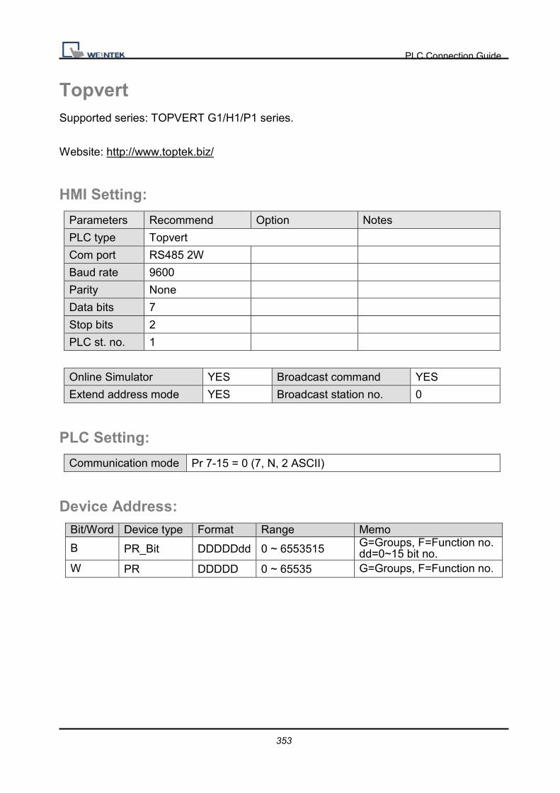
PLC Connection Guide
353
Topvert Supported series: TOPVERT G1/H1/P1 series.
Website: http://www.toptek.biz/
HMI Setting:
Parameters Recommend Option Notes
PLC type Topvert
Com port RS485 2W
Baud rate 9600
Parity None
Data bits 7
Stop bits 2
PLC st. no. 1
Online Simulator YES Broadcast command YES
Extend address mode YES Broadcast station no. 0
PLC Setting:
Communication mode Pr 7-15 = 0 (7, N, 2 ASCII)
Device Address: Bit/Word Device type Format Range Memo
B PR_Bit DDDDDdd 0 ~ 6553515 G=Groups, F=Function no. dd=0~15 bit no.
W PR DDDDD 0 ~ 65535 G=Groups, F=Function no.
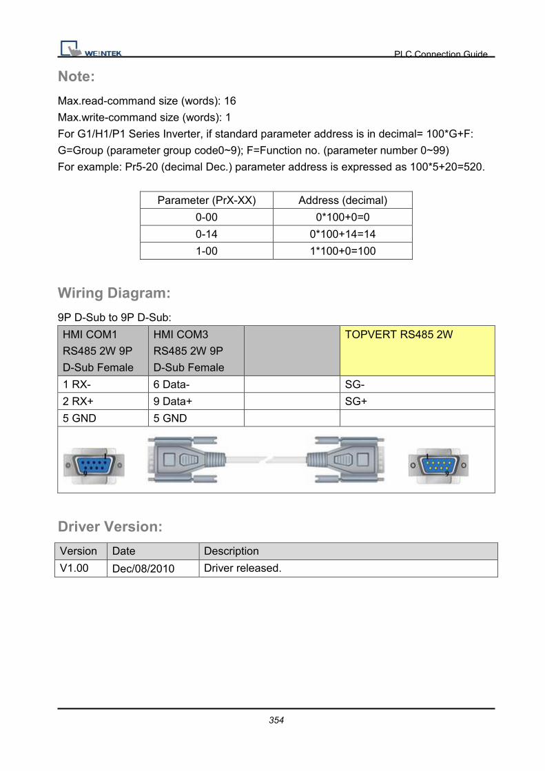
PLC Connection Guide
354
Note:
Max.read-command size (words): 16
Max.write-command size (words): 1
For G1/H1/P1 Series Inverter, if standard parameter address is in decimal= 100*G+F:
G=Group (parameter group code0~9); F=Function no. (parameter number 0~99)
For example: Pr5-20 (decimal Dec.) parameter address is expressed as 100*5+20=520.
Parameter (PrX-XX) Address (decimal)
0-00 0*100+0=0
0-14 0*100+14=14
1-00 1*100+0=100
Wiring Diagram:
9P D-Sub to 9P D-Sub:
HMI COM1
RS485 2W 9P
D-Sub Female
HMI COM3
RS485 2W 9P
D-Sub Female
TOPVERT RS485 2W
1 RX- 6 Data- SG-
2 RX+ 9 Data+ SG+
5 GND 5 GND
Driver Version:
Version Date Description
V1.00 Dec/08/2010 Driver released.
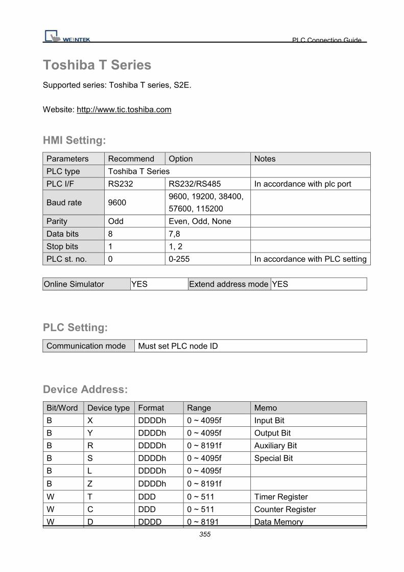
PLC Connection Guide
355
Toshiba T Series Supported series: Toshiba T series, S2E.
Website: http://www.tic.toshiba.com
HMI Setting:
Parameters Recommend Option Notes
PLC type Toshiba T Series
PLC I/F RS232 RS232/RS485 In accordance with plc port
Baud rate 9600 9600, 19200, 38400,
57600, 115200
Parity Odd Even, Odd, None
Data bits 8 7,8
Stop bits 1 1, 2
PLC st. no. 0 0-255 In accordance with PLC setting
Online Simulator YES Extend address mode YES
PLC Setting:
Communication mode Must set PLC node ID
Device Address:
Bit/Word Device type Format Range Memo
B X DDDDh 0 ~ 4095f Input Bit
B Y DDDDh 0 ~ 4095f Output Bit
B R DDDDh 0 ~ 8191f Auxiliary Bit
B S DDDDh 0 ~ 4095f Special Bit
B L DDDDh 0 ~ 4095f
B Z DDDDh 0 ~ 8191f
W T DDD 0 ~ 511 Timer Register
W C DDD 0 ~ 511 Counter Register
W D DDDD 0 ~ 8191 Data Memory

PLC Connection Guide
356
Bit/Word Device type Format Range Memo
W SW DDD 0 ~ 255 Special Register
W XW DDD 0 ~ 255 Input Register
W YW DDD 0 ~ 255 Output Register
W RW DDD 0 ~ 511 Auxiliary Register
W LW DDD 0 ~ 255
W W DDDD 0 ~ 1023
W F DDDD 0 ~ 8191
Wiring Diagram:
9P D-Sub to 8P Mini-DIN:
HMI COM1
RS232 9P
D-Sub Male
HMI COM2
RS232 9P
D-Sub Male
HMI COM3
RS232 9P
D-Sub Female
Toshiba T1 PRG Port RS232
8P Mini-DIN
2 RX 6 RX 8 RX 6 TXD
3 TX 4 TX 7 TX 8 RXD
5 GND 5 GND 5 GND 5 GND
4 RTS circuit
7 CTS
9P D-Sub to 9P D-Sub:
HMI COM1
RS232 9P
D-Sub Male
HMI COM2
RS232 9P
D-Sub Male
HMI COM3
RS232 9P
D-Sub Female
Toshiba T2 PRG Port RS232
9P D-Sub
2 RX 6 RX 8 RX 3 TXD
3 TX 4 TX 7 TX 2 RXD
5 GND 5 GND 5 GND 5 GND
7 RTS circuit
8 CTS

PLC Connection Guide
357
9P D-Sub to 15P D-Sub:
HMI COM1
RS485 4W 9P
D-Sub Female
Toshiba T2 LINK Port RS422
15P D-Sub
1 RX- 11 TXB
2 RX+ 3 TXA
3 TX- 10 RXB
4 TX+ 2 RXA
5 GND 7 SG
5 RTSA circuit
4 CTSA
13 RTSB circuit
12 CTSB
Driver Version:
Version Date Description
V1.00 Sep/15/2009 Driver released.
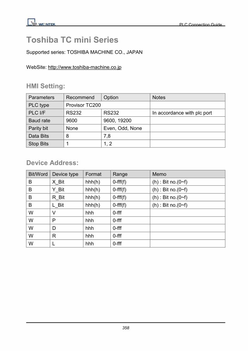
PLC Connection Guide
358
Toshiba TC mini Series Supported series: TOSHIBA MACHINE CO., JAPAN
WebSite: http://www.toshiba-machine.co.jp
HMI Setting:
Parameters Recommend Option Notes
PLC type Provisor TC200
PLC I/F RS232 RS232 In accordance with plc port
Baud rate 9600 9600, 19200
Parity bit None Even, Odd, None
Data Bits 8 7,8
Stop Bits 1 1, 2
Device Address:
Bit/Word Device type Format Range Memo
B X_Bit hhh(h) 0-fff(f) (h) : Bit no.(0~f)
B Y_Bit hhh(h) 0-fff(f) (h) : Bit no.(0~f)
B R_Bit hhh(h) 0-fff(f) (h) : Bit no.(0~f)
B L_Bit hhh(h) 0-fff(f) (h) : Bit no.(0~f)
W V hhh 0-fff
W P hhh 0-fff
W D hhh 0-fff
W R hhh 0-fff
W L hhh 0-fff

PLC Connection Guide
359
Wiring Diagram:
9P D-Sub to 9P D-Sub:
HMI COM1
RS232 9P
D-Sub Male
HMI COM2
RS232 9P
D-Sub Male
HMI COM3
RS232 9P
D-Sub Female
TC mini series RS232 9P
D-Sub
2 RX 6 RX 8 RX 2 TXD
3 TX 4 TX 7 TX 3 RXD
5 GND 5 GND 5 GND 5 GND
7 RTS circuit
9 CTS

PLC Connection Guide
360
Toshiba VF-S11 Supported series: Toshiba Invertor Protocol (ASCII code).
HMI Setting:
Parameters Recommend Option Notes
PLC type Toshiba VF-S11
PLC I/F RS485 2W RS422, RS485
Baud rate 9600 9600, 19200
Parity Even Even, Odd, None
Data bits 8 7 or 8
Stop bits 1 1 or 2
PLC st. no. 0 0-99
Online Simulator YES Extend address mode YES
Broadcast command YES
Device Address:
Bit/Word Device type Format Range Memo
B Cmd. No B HHHHdd 0 ~ 270f15
W Cmd. No HHHH 0 ~ ffff Parameters and data memory
Wiring Diagram:
Pay Attention:
Before you connect the VF-S11, make sure you to put both switches of SW1 to the related
position. (SW1: Wiring method selector switch)
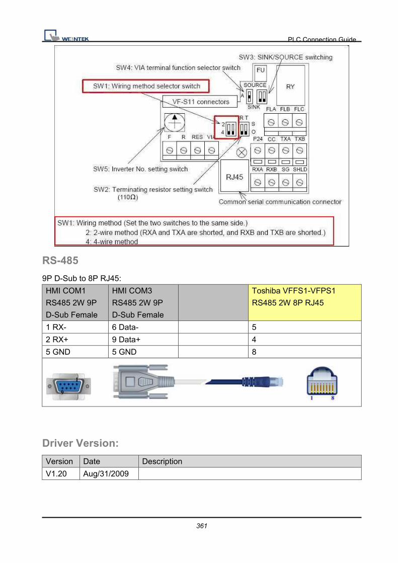
PLC Connection Guide
361
RS-485
9P D-Sub to 8P RJ45:
HMI COM1
RS485 2W 9P
D-Sub Female
HMI COM3
RS485 2W 9P
D-Sub Female
Toshiba VFFS1-VFPS1
RS485 2W 8P RJ45
1 RX- 6 Data- 5
2 RX+ 9 Data+ 4
5 GND 5 GND 8
Driver Version:
Version Date Description
V1.20 Aug/31/2009

PLC Connection Guide
362
VIGOR Supported series: VIGOR M Series.
Website: http://www.vigorplc.com.tw/
HMI Setting:
Parameters Recommend Option Notes
PLC type VIGOR
PLC I/F RS232 RS232, RS485
4wires,
Baud rate 19200
Parity Even
Data bits 7
Stop bits 1
PLC st. no. 1
Device Address:
Bit/Word Device type Format Range Memo
B X OOO 0 ~ 377
B Y OOO 0 ~ 377
B M DDDD 0 ~ 7999
B SM DDDD 9000 ~ 9255
B T DDD 0 ~ 255
B C DDD 0 ~ 255
W TV DDD 0 ~ 255
W CV DDD 0 ~ 199
W D DDDD 0 ~ 9255
W CV2 DDD 200 ~ 255
W SD DDDD 9000 ~ 9255

PLC Connection Guide
363
Wiring Diagram:
9P D-Sub to 6P Terminals:
HMI COM1
RS485 4W 9P
D-Sub Female
Vigor M series 6P Terminals
1 RX- TX-
2 RX+ TX+
3 TX- RX-
4 TX+ RX+
5 GND SG
24V
9P D-Sub to 9P D-Sub:
HMI COM1
RS232 9P
D-Sub Male
HMI COM2
RS232 9P
D-Sub Male
HMI COM3
RS232 9P
D-Sub Female
Vigor M series COM Port
2 RX 6 RX 8 RX 3 TXD
3 TX 4 TX 7 TX 2 RXD
5 GND 5 GND 5 GND 5 GND
Driver Version:
Version Date Description
V1.10 Dec/30/2008

PLC Connection Guide
364
YAMAHA ERCD
HMI Setting:
Device Address:
Bit/Word Device type Format Range Memo
Word P DDD 0 ~ 999 Read/Write, PNT point data
Word SWI D 0 Write only�RW0=program number�Switches program number to be run
Word ORG D 0 Write only�Returns to origin
Word RESET D 0 Write only�Reset program
Word RUN D 0 Write only�Starts automatic operation
Word MOVD D 0 Write only�Directly moves to specified
position
RW1=X-axis position(mm), RW2=speed
Word X_ADD D 0 Write only�X� command
Word X_SUB D 0 Write only�X� command
Parameters Recommend Option Notes
PLC type YAMAHA ERCD
PLC I/F RS232
Data bits 8 7 or 8
Stop bits 1 1 or 2
Baud rate 9600 1200-19200
Parity Odd None/Even/Odd
PLC st. no. 0 Do not need to set the station No.

PLC Connection Guide
365

PLC Connection Guide
366
Wiring Diagram:
9P D-Sub to 9P D-Sub:
HMI COM1
RS232 9P
D-Sub Male
HMI COM2
RS232 9P
D-Sub Male
HMI COM3
RS232 9P
D-Sub Female
PB RS232
2 RX 6 RX 8 RX 3 TX
3 TX 4 TX 7 TX 2 RX
5 GND 5 GND 5 GND 5 GND
7 RTS circuit
8 CTS
Driver Version:
Version Date Description
V1.30 Jan/04/2010
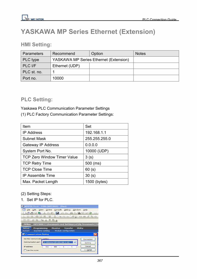
PLC Connection Guide
367
YASKAWA MP Series Ethernet (Extension)
HMI Setting:
Parameters Recommend Option Notes
PLC type YASKAWA MP Series Ethernet (Extension)
PLC I/F Ethernet (UDP)
PLC st. no. 1
Port no. 10000
PLC Setting:
Yaskawa PLC Communication Parameter Settings
(1) PLC Factory Communication Parameter Settings:
Item Set
IP Address 192.168.1.1
Subnet Mask 255.255.255.0
Gateway IP Address 0.0.0.0
System Port No. 10000 (UDP)
TCP Zero Window Timer Value 3 (s)
TCP Retry Time 500 (ms)
TCP Close Time 60 (s)
IP Assemble Time 30 (s)
Max. Packet Length 1500 (bytes)
(2) Setting Steps:
1. Set IP for PLC.
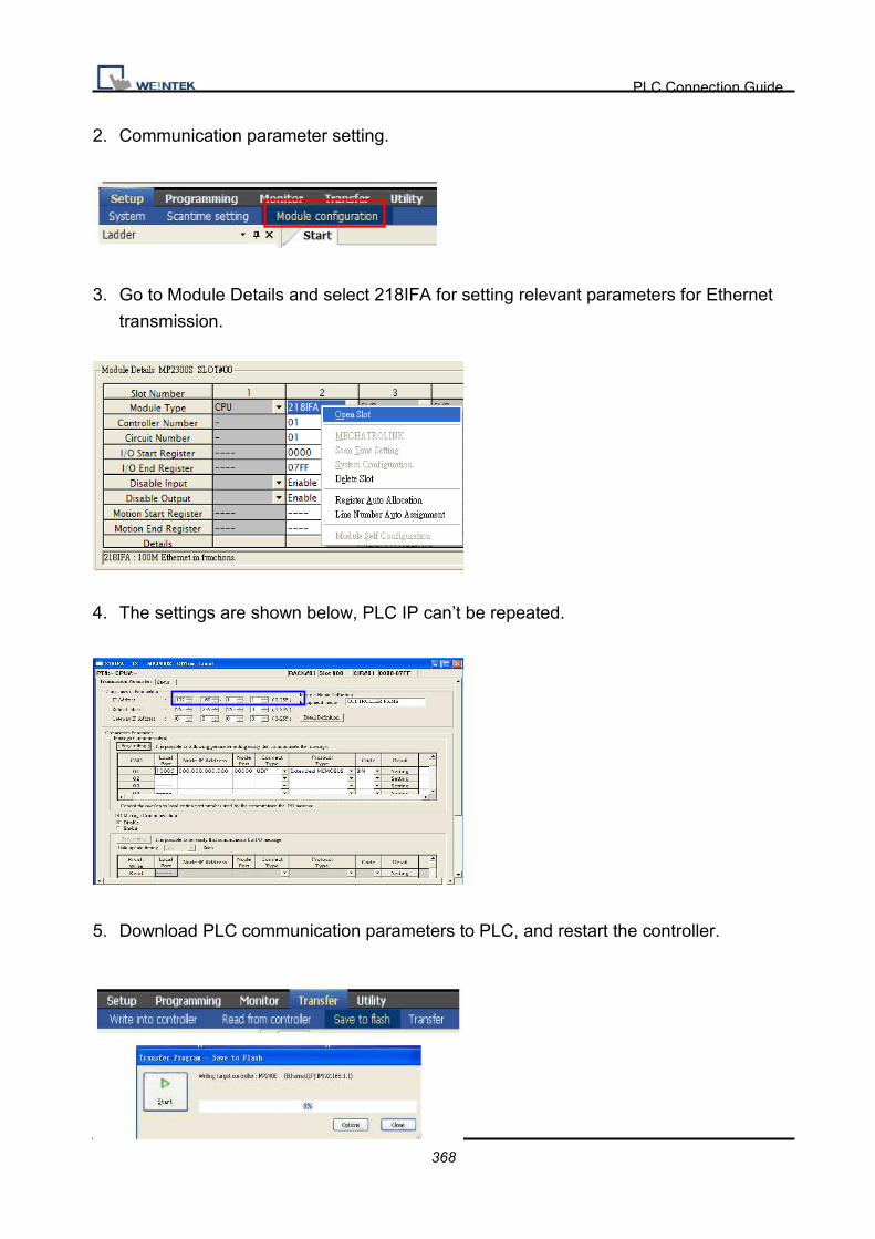
PLC Connection Guide
368
2. Communication parameter setting.
3. Go to Module Details and select 218IFA for setting relevant parameters for Ethernet
transmission.
4. The settings are shown below, PLC IP can’t be repeated.
5. Download PLC communication parameters to PLC, and restart the controller.

PLC Connection Guide
369
(3) HMI Settings:
1. Select Ethernet for PLC I/F.
2. Tick UDP.
3. Set PLC IP and Port, the default Port is 10000.
Device Address:
Bit/Word Device type Format Range Memo
B IB HHHHh 0 ~ fffff
B OB HHHHh 0 ~ fffff
B MB DDDDDh 0 ~ 65534f
B SB DDDDh 0 ~ 8191f
W IW HHHH 0 ~ ffff
W OW HHHH 0 ~ ffff
W MW DDDDD 0 ~ 65534
W SW DDDD 0 ~ 8191
Wiring Diagram:
Direct connect (crossover cable):
HMI RJ45 Female Wire Color PLC RJ45 Female
1 TX+ White/Orange 3 RX+
2 TX- Orange 6 RX-
3 RX+ White/Green 1 TX+
4 BD4+ Blue 4 BD4+

PLC Connection Guide
370
5 BD4- White/Blue 5 BD4-
6 RX- Green 2 TX-
7 BD3+ White/Brown 7 BD3+
8 BD3- Brown 8 BD3-
Through a hub:
HMI RJ45 Female Wire Color PLC RJ45 Female
1 TX+ White/Orange 1 TX+
2 TX- Orange 2 TX-
3 RX+ White/Green 3 RX+
4 BD4+ Blue 4 BD4+
5 BD4- White/Blue 5 BD4-
6 RX- Green 6 RX-
7 BD3+ White/Brown 7 BD3+
8 BD3- Brown 8 BD3-
Driver Version:
Version Date Description
V1.00 Dec/28/2010 Driver released.

PLC Connection Guide
371
YASKAWA SMC 3010 Supported series: YASKAWA SMC Series Servo Motor Controller.
HMI Setting:
Parameters Recommend Option Notes
Device type YASKAWA SMC 3010
PLC I/F RS232
Baud rate 19200 9600, 19200
Parity None
Data bits 8
Stop bits 1
Device Address:
Bit/Word Device type Format Range Memo
B AF D 0 ~ 1
B BN D 0 ~ 1 Write only
B BP D 0 ~ 1 Write only
B BV D 0 ~ 1 Write only
B CB DDDD 0 ~ 9999 Write only
B CM D 0 ~ 1 Read only
B DV D 0 ~ 1
B EB D 0 ~ 1
B OE D 0 ~ 1
B RS D 0 ~ 1 Write only
B ST D 0 ~ 1 Write only
B TB Do 0 ~ 17 Read only
B V_Bit DDDdd 0 ~ 99931 *2
B D_arr_Bit DDDdd 0 ~ 99931
DW AC D 0 ~ 4
DW DC D 0 ~ 4
DW BL D 0 ~ 4
W CD D 0 ~ 2 Write only
W CE D 0 ~ 2
DW DE D 0 ~ 4
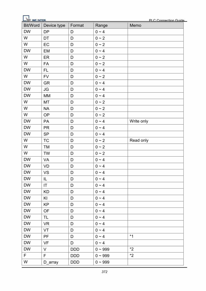
PLC Connection Guide
372
Bit/Word Device type Format Range Memo
DW DP D 0 ~ 4
W DT D 0 ~ 2
W EC D 0 ~ 2
DW EM D 0 ~ 4
W ER D 0 ~ 2
W FA D 0 ~ 2
DW FL D 0 ~ 4
W FV D 0 ~ 2
DW GR D 0 ~ 4
DW JG D 0 ~ 4
DW MM D 0 ~ 4
W MT D 0 ~ 2
W NA D 0 ~ 2
W OP D 0 ~ 2
DW PA D 0 ~ 4 Write only
DW PR D 0 ~ 4
DW SP D 0 ~ 4
W TC D 0 ~ 2 Read only
W TM D 0 ~ 2
W TW D 0 ~ 2
DW VA D 0 ~ 4
DW VD D 0 ~ 4
DW VS D 0 ~ 4
DW IL D 0 ~ 4
DW IT D 0 ~ 4
DW KD D 0 ~ 4
DW KI D 0 ~ 4
DW KP D 0 ~ 4
DW OF D 0 ~ 4
DW TL D 0 ~ 4
DW VR D 0 ~ 4
DW VT D 0 ~ 4
DW PF D 0 ~ 4 *1
DW VF D 0 ~ 4
DW V DDD 0 ~ 999 *2
F F DDD 0 ~ 999 *2
W D_array DDD 0 ~ 999

PLC Connection Guide
373
Bit/Word Device type Format Range Memo
W R_array DDD 0 ~ 999
Note:
*1 PF is the communication parameter of SMC_3010, default is 10.4, if the value is not
10.4, all values will be displayed incorrect.
*2 User define integer variable V000~V999, floating point variable F000~F999.
Wiring Diagram:
9P D-Sub to 9P D-Sub:
HMI COM1
RS232 9P
D-Sub Male
HMI COM2
RS232 9P
D-Sub Male
HMI COM3
RS232 9P
D-Sub Female
SMC3010 CN6 RS232 9P
D-Sub
2 RX 6 RX 8 RX 2 TXD
3 TX 4 TX 7 TX 3 RXD
5 GND 5 GND 5 GND 5 GND
7 RTS circuit
8 CTS
Driver Version:
Version Date Description
V1.30 Mar/29/2010

PLC Connection Guide
374
YASKAWA SMC 3010 (Ethernet) Supported series: YASKAWA SMC Series Servo Motor Controller.
HMI Setting:
Parameters Recommend Option Notes
Device type YASKAWA SMC 3010 (Ethernet)
PLC I/F Ethernet
Port no. 23
Device Address:
Bit/Word Device type Format Range Memo
B AF D 0 ~ 1
B BN D 0 ~ 1 Write only
B BP D 0 ~ 1 Write only
B BV D 0 ~ 1 Write only
B CB DDDD 0 ~ 9999 Write only
B CM D 0 ~ 1 Read only
B DV D 0 ~ 1
B EB D 0 ~ 1
B OE D 0 ~ 1
B RS D 0 ~ 1 Write only
B ST D 0 ~ 1 Write only
B TB Do 0 ~ 17 Read only
B V_Bit DDDdd 0 ~ 99931 *2
B D_arr_Bit DDDdd 0 ~ 99931
DW AC D 0 ~ 4
DW DC D 0 ~ 4
DW BL D 0 ~ 4
W CD D 0 ~ 2 Write only
W CE D 0 ~ 2
DW DE D 0 ~ 4
DW DP D 0 ~ 4
W DT D 0 ~ 2
W EC D 0 ~ 2

PLC Connection Guide
375
Bit/Word Device type Format Range Memo
DW EM D 0 ~ 4
W ER D 0 ~ 2
W FA D 0 ~ 2
DW FL D 0 ~ 4
W FV D 0 ~ 2
DW GR D 0 ~ 4
DW JG D 0 ~ 4
DW MM D 0 ~ 4
W MT D 0 ~ 2
W NA D 0 ~ 2
W OP D 0 ~ 2
DW PA D 0 ~ 4 Write only
DW PR D 0 ~ 4
DW SP D 0 ~ 4
W TC D 0 ~ 2 Read only
W TM D 0 ~ 2
W TW D 0 ~ 2
DW VA D 0 ~ 4
DW VD D 0 ~ 4
DW VS D 0 ~ 4
DW IL D 0 ~ 4
DW IT D 0 ~ 4
DW KD D 0 ~ 4
DW KI D 0 ~ 4
DW KP D 0 ~ 4
DW OF D 0 ~ 4
DW TL D 0 ~ 4
DW VR D 0 ~ 4
DW VT D 0 ~ 4
DW PF D 0 ~ 4 *1
DW VF D 0 ~ 4
DW V DDD 0 ~ 999 *2
F F DDD 0 ~ 999 *2
W D_array DDD 0 ~ 999
W R_array DDD 0 ~ 999

PLC Connection Guide
376
Note:
*1 PF is the communication parameter of SMC_3010, default is 10.4, if the value is not
10.4, all values will be displayed incorrect.
*2 User define integer variable V000~V999, floating point variable F000~F999.
Wiring Diagram:
Direct connect (crossover cable):
HMI RJ45 Female Wire Color PLC RJ45 Female
1 TX+ White/Orange 3 RX+
2 TX- Orange 6 RX-
3 RX+ White/Green 1 TX+
4 BD4+ Blue 4 BD4+
5 BD4- White/Blue 5 BD4-
6 RX- Green 2 TX-
7 BD3+ White/Brown 7 BD3+
8 BD3- Brown 8 BD3-
Through a hub:
HMI RJ45 Female Wire Color PLC RJ45 Female
1 TX+ White/Orange 1 TX+
2 TX- Orange 2 TX-
3 RX+ White/Green 3 RX+
4 BD4+ Blue 4 BD4+
5 BD4- White/Blue 5 BD4-
6 RX- Green 6 RX-
7 BD3+ White/Brown 7 BD3+
8 BD3- Brown 8 BD3-

PLC Connection Guide
377
Driver Version:
Version Date Description
V1.10 Mar/29/2010
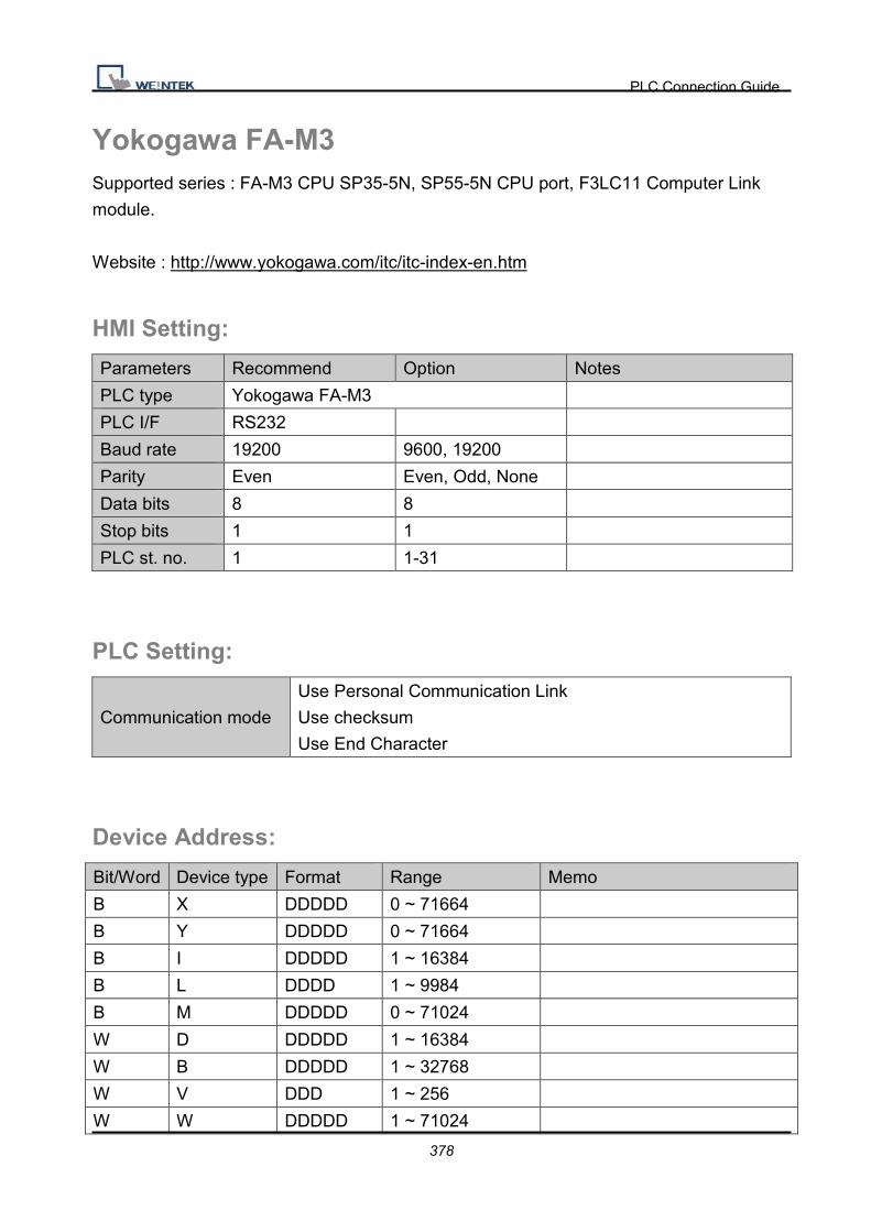
PLC Connection Guide
378
Yokogawa FA-M3 Supported series : FA-M3 CPU SP35-5N, SP55-5N CPU port, F3LC11 Computer Link
module.
Website : http://www.yokogawa.com/itc/itc-index-en.htm
HMI Setting:
Parameters Recommend Option Notes
PLC type Yokogawa FA-M3
PLC I/F RS232
Baud rate 19200 9600, 19200
Parity Even Even, Odd, None
Data bits 8 8
Stop bits 1 1
PLC st. no. 1 1-31
PLC Setting:
Communication mode
Use Personal Communication Link
Use checksum
Use End Character
Device Address:
Bit/Word Device type Format Range Memo
B X DDDDD 0 ~ 71664
B Y DDDDD 0 ~ 71664
B I DDDDD 1 ~ 16384
B L DDDD 1 ~ 9984
B M DDDDD 0 ~ 71024
W D DDDDD 1 ~ 16384
W B DDDDD 1 ~ 32768
W V DDD 1 ~ 256
W W DDDDD 1 ~ 71024

PLC Connection Guide
379
W Z DDDD 1 ~ 1024
Wiring Diagram:
9P D-Sub to 9P D-Sub:
HMI COM1
RS232 9P
D-Sub Male
HMI COM2
RS232 9P
D-Sub Male
HMI COM3
RS232 9P
D-Sub Female
CPU Port Cable KM11 RS232
2 RX 6 RX 8 RX 2 TXD
3 TX 4 TX 7 TX 3 RXD
5 GND 5 GND 5 GND 5 GND
9P D-Sub to 9P D-Sub: LC11
HMI COM1
RS232 9P
D-Sub Male
HMI COM2
RS232 9P
D-Sub Male
HMI COM3
RS232 9P
D-Sub Female
LC11 Computer Link Module
RS232 Port
2 RX 6 RX 8 RX 3 TXD
3 TX 4 TX 7 TX 2 RXD
5 GND 5 GND 5 GND 5 GND
7 RTS circuit
8 CTS
How to get the WideField communication setting
If you want get the WideField communication setting, select [Tool]->[Set Environment]
default is Automatic. Using the Automatic Recognition, Wide Field software will connect
the Current PLC and get the PLC communication setting. If you have know the PLC
communication configuration, you alse can select the Fixed mode, It will connect the PLC
quickly.
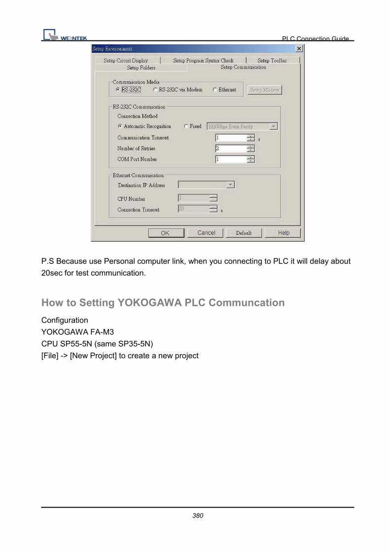
PLC Connection Guide
380
P.S Because use Personal computer link, when you connecting to PLC it will delay about
20sec for test communication.
How to Setting YOKOGAWA PLC Communcation
Configuration
YOKOGAWA FA-M3
CPU SP55-5N (same SP35-5N)
[File] -> [New Project] to create a new project

PLC Connection Guide
381
Click “Configuration” for setup communication.

PLC Connection Guide
382

PLC Connection Guide
383
Driver Version:
Version Date Description
V1.20 Oct/23/2009
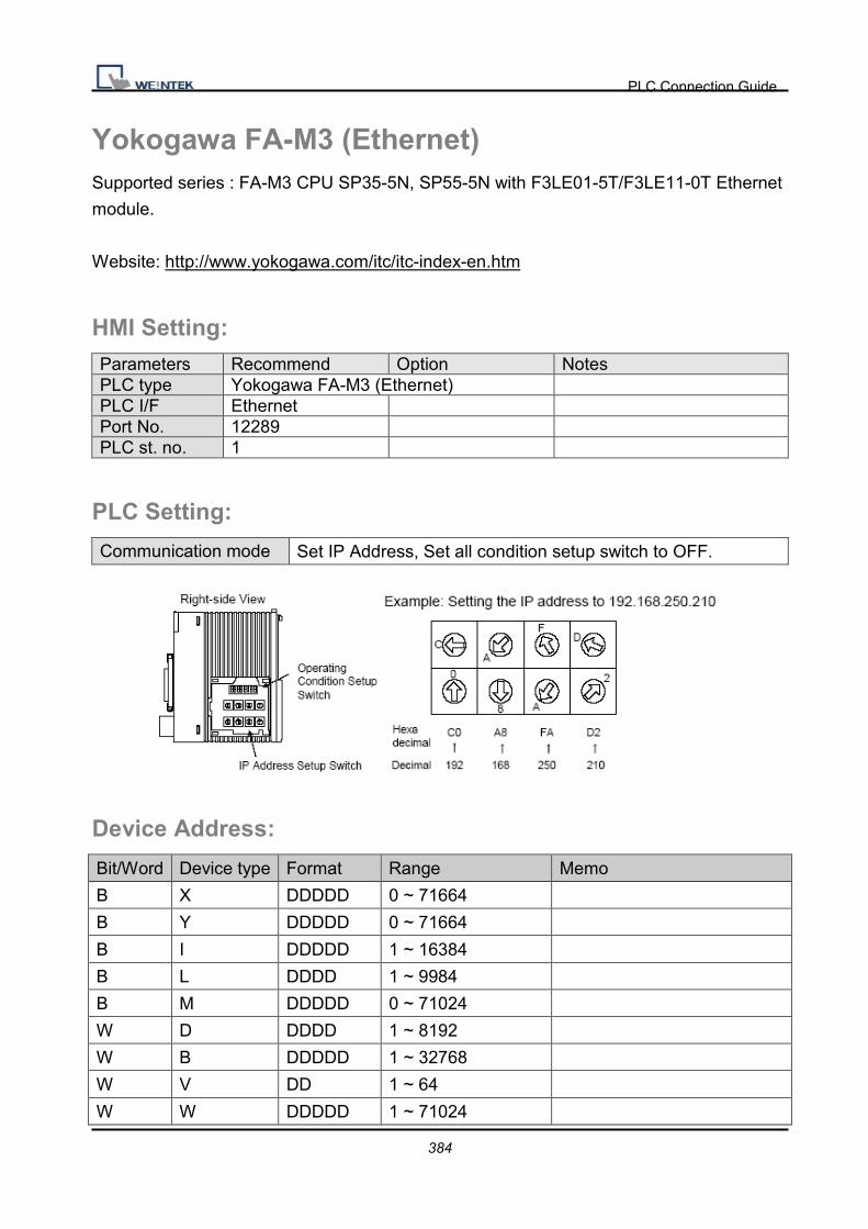
PLC Connection Guide
384
Yokogawa FA-M3 (Ethernet) Supported series : FA-M3 CPU SP35-5N, SP55-5N with F3LE01-5T/F3LE11-0T Ethernet
module.
Website: http://www.yokogawa.com/itc/itc-index-en.htm
HMI Setting: Parameters Recommend Option Notes PLC type Yokogawa FA-M3 (Ethernet) PLC I/F Ethernet Port No. 12289 PLC st. no. 1
PLC Setting:
Communication mode Set IP Address, Set all condition setup switch to OFF.
Device Address:
Bit/Word Device type Format Range Memo
B X DDDDD 0 ~ 71664
B Y DDDDD 0 ~ 71664
B I DDDDD 1 ~ 16384
B L DDDD 1 ~ 9984
B M DDDDD 0 ~ 71024
W D DDDD 1 ~ 8192
W B DDDDD 1 ~ 32768
W V DD 1 ~ 64
W W DDDDD 1 ~ 71024

PLC Connection Guide
385
W Z DDD 1 ~ 512
Wiring Diagram:
Direct connect (crossover cable):
HMI RJ45 Female Wire Color PLC RJ45 Female
1 TX+ White/Orange 3 RX+
2 TX- Orange 6 RX-
3 RX+ White/Green 1 TX+
4 BD4+ Blue 4 BD4+
5 BD4- White/Blue 5 BD4-
6 RX- Green 2 TX-
7 BD3+ White/Brown 7 BD3+
8 BD3- Brown 8 BD3-
Through a hub:
HMI RJ45 Female Wire Color PLC RJ45 Female
1 TX+ White/Orange 1 TX+
2 TX- Orange 2 TX-
3 RX+ White/Green 3 RX+
4 BD4+ Blue 4 BD4+
5 BD4- White/Blue 5 BD4-
6 RX- Green 6 RX-
7 BD3+ White/Brown 7 BD3+
8 BD3- Brown 8 BD3-
Driver Version:
Version Date Description
V1.00 Dec/30/2008 Driver released.

PLC Connection Guide
386
MT6050i/MT8050i Com Port Pin Assignment
Bottom View
MT6050i/MT8050i
Pin assignment of the 9 Pin, Male, Pin assignment of the 9 Pin, Male, SUB-D, COM1 [RS-232]/ [RS-485], COM3 [RS-485] Port. Only
Com1[RS485 2W] support MPI 187.5K.
Pin# Symbol Com1[RS485] Com1[RS232] Com3[RS485]
4 wire 2 wire
1 Rx- Rx- Data-
2 Rx+ Rx+ Data+
3 Tx- Tx-
4 Tx+ Tx+
5 GND GND
6 TxD Transmit
7 Data- Data-
8 Data+ Data+
9 RxD Receive

PLC Connection Guide
387
Wiring Diagram:
MT6050i COM1 [RS-232]
9P D-SUB Female
PLC RS-232
Communication Com Port interface
9 RXD TXD
6 TXD RXD
5 GND GND
MT6050i COM1 [RS-485 2w]
9P D-SUB Female
PLC RS-485 2w
Communication Com Port interface
1 Data- Data-
2 Data+ Data+
MT6050i COM3* [RS-485 2w]
9P D-SUB Female
PLC RS-485 2w
Communication Com Port interface
7 Data- Data-
8 Data+ Data+
*RS485 2W COM3 is only available for MT6050iv2
MT6050i COM1 [RS-485 4w]
9P D-SUB Female
PLC RS-485 2w
Communication Com Port interface
1 RX- TX-
2 RX TX+
3 TX- RX-
4 TX+ RX+