Embed Size (px)
Citation preview

Elgaaly, M. “Plate and Box Girders”Structural Engineering HandbookEd. Chen Wai-FahBoca Raton: CRC Press LLC, 1999

Plate and Box Girders
Mohamed ElgaalyDepartment of Civil &Architectural Engineering,Drexel University,Philadelphia, PA
19.1 Introduction19.2 Stability of the Compression Flange
Vertical Buckling • Lateral Buckling • Torsional Buckling •Compression Flange of a Box Girder
19.3 Web Buckling Due to In-Plane Bending19.4 Nominal Moment Strength19.5 Web Longitudinal Stiffeners for Bending Design19.6 Ultimate Shear Capacity of the Web19.7 Web Stiffeners for Shear Design19.8 Flexure-Shear Interaction19.9 Steel Plate Shear Walls19.10In-Plane Compressive Edge Loading19.11Eccentric Edge Loading19.12Load-Bearing Stiffeners19.13Web Openings19.14Girders with Corrugated Webs19.15Defining TermsReferences
19.1 Introduction
Plate and box girders are used mostly in bridges and industrial buildings, where large loads and/orlong spans are frequently encountered. The high torsional strength of box girders makes them idealfor girders curved in plan. Recently, thin steel plate shear walls have been effectively used in buildings.Such walls behave as vertical plate girders with the building columns as flanges and the floor beamsas intermediate stiffeners. Although traditionally simply supported plate and box girders are builtup to 150 ft span, several three-span continuous girder bridges have been built in the U.S. with centerspans exceeding 400 ft.
In its simplest form a plate girder is made of two flange plates welded to a web plate to form an Isection, and a box girder has two flanges and two webs for a single-cell box and more than two webs inmulti-cell box girders (Figure 19.1). The designer has the freedom in proportioning the cross-sectionof the girder to achieve the most economical design and taking advantage of available high-strengthsteels. The larger dimensions of plate and box girders result in the use of slender webs and flanges,making buckling problems more relevant in design. Buckling of plates that are adequately supportedalong their boundaries is not synonymous with failure, and these plates exhibit post-buckling strengththat can be several times their buckling strength, depending on the plate slenderness. Although plate
c©1999 by CRC Press LLC
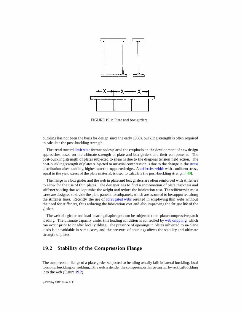
FIGURE 19.1: Plate and box girders.
buckling has not been the basis for design since the early 1960s, buckling strength is often requiredto calculate the post-buckling strength.
The trend toward limit state format codes placed the emphasis on the development of new designapproaches based on the ultimate strength of plate and box girders and their components. Thepost-buckling strength of plates subjected to shear is due to the diagonal tension field action. Thepost-buckling strength of plates subjected to uniaxial compression is due to the change in the stressdistribution after buckling, higher near the supported edges. An effective width with a uniform stress,equal to the yield stress of the plate material, is used to calculate the post-buckling strength [40].
The flange in a box girder and the web in plate and box girders are often reinforced with stiffenersto allow for the use of thin plates. The designer has to find a combination of plate thickness andstiffener spacing that will optimize the weight and reduce the fabrication cost. The stiffeners in mostcases are designed to divide the plate panel into subpanels, which are assumed to be supported alongthe stiffener lines. Recently, the use of corrugated webs resulted in employing thin webs withoutthe need for stiffeners, thus reducing the fabrication cost and also improving the fatigue life of thegirders.
The web of a girder and load-bearing diaphragms can be subjected to in-plane compressive patchloading. The ultimate capacity under this loading condition is controlled by web crippling, whichcan occur prior to or after local yielding. The presence of openings in plates subjected to in-planeloads is unavoidable in some cases, and the presence of openings affects the stability and ultimatestrength of plates.
19.2 Stability of the Compression Flange
The compression flange of a plate girder subjected to bending usually fails in lateral buckling, localtorsional buckling, or yielding; if the web is slender the compression flange can fail by vertical bucklinginto the web (Figure 19.2).
c©1999 by CRC Press LLC

FIGURE 19.2: Compression flange modes of failure.
19.2.1 Vertical Buckling
The following limiting value for the web slenderness ratio to preclude this mode of failure [4] can beused,
h/tw ≤[0.68E/
√Fyf
(Fyf + Fr
)] √Aw/Af (19.1)
where h and tw are the web height and thickness, respectively; Aw is the area of the web; Af is thearea of the flange; E is Young’s modulus of elasticity; Fyf is the yield stress of the flange material;and Fr is the residual tension that must be overcome to achieve uniform yielding in compression.This limiting value may be too conservative since vertical buckling of the compression flange intothe web occurs only after general yielding of the flange. This limiting value, however, can be helpfulto avoid fatigue cracking under repeated loading due to out-of-plane flexing, and it also facilitatesfabrication.
The American Institute of Steel Construction (AISC) specification [32] uses Equation 19.1 whenthe spacing between the vertical stiffeners, a, is more than 1.5 times the web depth, h (a/h > 1.5).In such a case the specification recommends that
h/tw ≤ 14,000/√
Fyf (Fyf + 16.5) (19.2)
where a minimum value of Aw/Af = 0.5 was assumed and the residual tension was taken to be 16.5ksi. Furthermore, when a/h is less than or equal to 1.5, higher web slenderness is permitted, namely
h/tw ≤ 2000/√
Fyf (19.3)
19.2.2 Lateral Buckling
When a flange is not adequately supported in the lateral direction, elastic lateral buckling can occur.The compression flange, together with an effective area of the web equal to Aw/6, can be treated asa column and the buckling stress can be calculated from the Euler equation [2]:
Fcr = π2E/(λ)2 (19.4)
where λ is the slenderness ratio, which is equal to Lb/rT ; Lb is the length of the unbraced segment ofthe beam; and rT is the radius of gyration of the compression flange plus one-third of the compressionportion of the web.
The AISC specification adopted Equation 19.4, rounding π2E to 286,000 and assuming that elasticbuckling will occur when the slenderness ratio, λ, is greater than λr(= 756/
√Fyf ).
Furthermore, Equation 19.4 is based on uniform compression; in most cases the bending is notuniform within the length of the unbraced segment of the beam. To account for nonuniform bending,
c©1999 by CRC Press LLC

Equation 19.4 should be multiplied by a coefficient, Cb [25], where
Cb = 12.5Mmax/(2.5Mmax + 3MA + 4MB + 3MC) (19.5)
whereMmax = absolute value of maximum moment in the unbraced beam segmentMA = absolute value of moment at quarter point of the unbraced beam segmentMB = absolute value of moment at centerline of the unbraced beam segmentMC = absolute value of moment at three-quarter point of the unbraced beam segment
When the slenderness ratio, λ, is less than or equal to λp(= 300/√
Fyf ), the flange will yield beforeit buckles, and Fcr = Fyf . When the flange slenderness ratio, λ, is greater than λp and smaller thanor equal to λr , inelastic buckling will occur and a straight line equation must be adopted betweenyielding (λ ≤ λp) and elastic buckling (λ > λr) to calculate the inelastic buckling stress, namely
Fcr = CbFyf
[1 − 0.5(λ − λp)/(λr − λp)
] ≤ Fyf (19.6)
19.2.3 Torsional Buckling
If the outstanding width-to-thickness ratio of the flange is high, torsional buckling may occur. If oneneglects any restraint provided by the web to the flange rotation, then the flange can be treated as along plate, which is simply supported (hinged) at one edge and free at the other, subjected to uniaxialcompression in the longitudinal direction. The elastic buckling stress under these conditions can becalculated from
Fcr = kcπ2E/12(1 − µ2)λ2 (19.7)
where kc is a buckling coefficient equal to 0.425 for a long plate simply supported and free at itslongitudinal edges; λ is equal to bf /2tf ; bf and tf are the flange width and thickness, respectively;and E and µ are Young’s modulus of elasticity and the Poisson ratio, respectively.
The AISC specification adopted Equation 19.7, rounding π2E/12(1−µ2) to 26,200 and assumingkc = 4
√h/tw , where 0.35 ≤ kc ≥ 0.763. Furthermore, to allow for nonuniform bending, the
buckling stress has to be multiplied by Cb, given by Equation 19.5. Elastic torsional buckling of thecompression flange will occur if λ is greater than λr(= 230/
√Fyf /kc). When λ is less than or equal
to λp(= 65/√
Fyf ), the flange will yield before it buckles, and Fcr = Fyf . When λp < λ ≤ λr ,inelastic buckling will occur and Equation 19.6 shall be used.
19.2.4 Compression Flange of a Box Girder
Lateral-torsional buckling does not govern the design of the compression flange in a box girder.Unstiffened flanges and flanges stiffened with longitudinal stiffeners can be treated as long platessupported along their longitudinal edges and subjected to uniaxial compression. In the AASHTO(American Association of State Highway and Transportation Officials ) specification [1], the nominalflexural stress, Fn, for the compression flange is calculated as follows:If w/t ≤ 0.57
√kE/Fyf , then the flange will yield before it buckles, and
Fn = Fyf (19.8)
If w/t > 1.23√
kE/Fyf , then the flange will elastically buckle, and
Fn = kπ2E/12(1 − µ2)(w/t)2
orFn = 26,200k(t/w)2 (19.9)
c©1999 by CRC Press LLC

If 0.57√
kE/Fyf < w/t ≤ 1.23√
kE/Fyf , then the flange buckles inelastically, and
Fn = 0.592Fyf [1 + 0.687 sin(cπ/2)] (19.10)
In Equations 19.8 to 19.10,w = the spacing between the longitudinal stiffeners, or the flange width for unstiffened flangesc = [
1.23− (w/t)√
Fyf /kE]/0.66
k = (8Is/wt3
)1/3 ≤ 4.0, for n = 1
k = (14.3Is/wt3n4
)1/3 ≤ 4.0, for n = 2, 3, 4, or 5n = number of equally spaced longitudinal stiffenersIs = the moment of inertia of the longitudinal stiffener about an axis parallel to the flange and
taken at the base of the stiffener
The nominal stress, Fn, shall be reduced for hybrid girders to account for the nonlinear variationof stresses caused by yielding of the lower strength steel in the web of a hybrid girder. Furthermore,another reduction is made for slender webs to account for the nonlinear variation of stresses causedby local bend buckling of the web. The reduction factors for hybrid girders and slender webs willbe given in Section 19.3. The longitudinal stiffeners shall be equally spaced across the compressionflange width and shall satisfy the following requirements [1].
The projecting width, bs , of the stiffener shall satisfy:
bs ≤ 0.48ts√
E/Fyc (19.11)
wherets = thickness of the stiffenerFyc = specified minimum yield strength of the compression flange
The moment of inertia, Is , of each stiffener about an axis parallel to the flange and taken at thebase of the stiffener shall satisfy:
Is ≥ 9wt3 (19.12)
where9 = 0.125k3 for n = 1
= 0.07k3n4 for n = 2, 3, 4, or 5n = number of equally spaced longitudinal compression flange stiffenersw = larger of the width of compression flange between longitudinal stiffeners or the distance
from a web to the nearest longitudinal stiffenert = compression flange thicknessk = buckling coefficient as defined in connection with Equations 19.8 to 19.10
The presence of the in-plane compression in the flange magnifies the deflection and stresses in theflange from local bending due to traffic loading. The amplification factor, 1/(1 − σa/σcr ), can beused to increase the deflections and stresses due to local bending; where σa and σcr are the in-planecompressive and buckling stresses, respectively.
19.3 Web Buckling Due to In-Plane Bending
Buckling of the web due to in-plane bending does not exhaust its capacity; however, the distributionof the compressive bending stress changes in the post-buckling range and the web becomes lessefficient. Only part of the compression portion of the web can be assumed effective after buckling.A reduction in the girder moment capacity to account for the web bend buckling can be used, andthe following reduction factor [4] has been suggested:
R = 1 − 0.0005(Aw/Af )(h/t − 5.7√
E/Fyw) (19.13)
c©1999 by CRC Press LLC
It must be noted that when h/t = 5.7√
E/Fyw , the web will yield before it buckles and there isno reduction in the moment capacity. This can be determined by equating the bend buckling stressto the web yield stress, i.e.,
kπ2E/[12(1 − µ2)(h/t)2
]= Fyw (19.14)
where k is the web bend buckling coefficient, which is equal to 23.9 if the flange simply supports theweb and 39.6 if one assumes that the flange provides full fixity; the 5.7 in Equation 19.13 is based ona k value of 36.
The AISC specification replaces the reduction factor given in Equation 19.13 by
RPG = 1 − [ar/(1,200+ 300ar)] (h/t − 970/√
Fcr) (19.15)
where ar is equal to Aw/Af and 970 is equal to 5.7√
29000; it must be noted that the yield stressin Equation 19.13 was replaced by the flange critical buckling stress, which can be equal to or lessthan the yield stress as discussed earlier. It must also be noted that in homogeneous girders the yieldstresses of the web and flange materials are equal; in hybrid girders another reduction factor, Re, [39]shall be used:
Re =[12+ ar(3m − m3)
]/(12+ 2ar) (19.16)
where ar is equal to the ratio of the web area to the compression flange area (≤ 10) and m is the ratioof the web yield stress to the flange yield or buckling stress.
19.4 Nominal Moment Strength
The nominal moment strength can be calculated as follows.Based on tension flange yielding:
Mn = SxtReFyt (19.17a)
orBased on compression flange buckling:
Mn = SxcRPGReFcr (19.17b)
whereSxc andSxt are the section moduli referred to the compression and tension flanges, respectively;Fyt is the tension flange yield stress; Fcr is the compression flange buckling stress calculated accordingto Section 19.2; RPG is the reduction factor calculated using Equation 19.15; and Re is a reductionfactor to be used in the case of hybrid girders and can be calculated using Equation 19.16.
19.5 Web Longitudinal Stiffeners for Bending Design
Longitudinal stiffeners can increase the bending strength of plate girders. This increase is due tothe control of the web lateral deflection, which increases its flexural stress capacity. The presence ofthe stiffener also improves the bending resistance of the flange due to a greater web restraint. If onelongitudinal stiffener is used, its optimum location is 0.20 times the web depth from the compressionflange. In this case the web plate elastic bend buckling stress increases more than five times thatwithout the stiffener. Tests [8] showed that an adequately proportioned longitudinal stiffener at 0.2hfrom the compression flange eliminates bend buckling in girders with web slenderness, h/t , as largeas 450. Girders with larger slenderness will require two or more longitudinal stiffeners to eliminate
c©1999 by CRC Press LLC

web bend buckling. It must be noted that the increase in the bending strength of a longitudinallystiffened thin-web girder is usually small because the web contribution to the bending strength issmall. However, longitudinal stiffeners can be important in a girder subjected to repeated loadsbecause they reduce or eliminate the out-of-plane bending of the web, which increases resistance tofatigue cracking at the web-to-flange juncture and allows more slender webs to be used [42].
The AISC specification does not address longitudinal stiffeners; on the other hand, the AASHTOspecification states that longitudinal stiffeners should consist of either a plate welded longitudinallyto one side of the web or a bolted angle, and shall be located at a distance of 0.4 Dc from the innersurface of the compression flange, where Dc is the depth of the web in compression at the section withthe maximum compressive flexural stress. Continuous longitudinal stiffeners placed on the oppositeside of the web from the transverse intermediate stiffeners, as shown in Figure 19.3, are preferred.If longitudinal and transverse stiffeners must be placed on the same side of the web, it is preferable
FIGURE 19.3: Longitudinal stiffener for flexure.
that the longitudinal stiffener not be interrupted for the transverse stiffener. Where the transversestiffeners are interrupted, the interruptions must be carefully detailed with respect to fatigue.
To prevent local buckling, the projecting width, bs of the stiffener shall satisfy the requirements ofEquation 19.11. The section properties of the stiffener shall be based on an effective section consistingof the stiffener and a centrally located strip of the web not exceeding 18 times the web thickness.The moment of inertia of the longitudinal stiffener and the effective web strip about the edge incontact with the web, Is , and the corresponding radius of gyration, rs , shall satisfy the followingrequirements:
Is ≥ ht3w
[2.4(a/h)2 − 0.13
](19.18)
andrs ≥ 0.234a
√Fyc/E (19.19)
wherea = spacing between transverse stiffeners
19.6 Ultimate Shear Capacity of the Web
As stated earlier, in most design codes buckling is not used as a basis for design. Minimum slendernessratios, however, are specified to control out-of-plane deflection of the web. These ratios are derivedto give a small factor of safety against buckling, which is conservative and in some cases extravagant.
c©1999 by CRC Press LLC

Before the web reaches its theoretical buckling load the shear is taken by beam action and theshear stress can be resolved into diagonal tension and compression. After buckling, the diagonalcompression ceases to increase and any additional loads will be carried by the diagonal tension. Invery thin webs with stiff boundaries, the plate buckling load is very small and can be ignored and theshear is carried by a complete diagonal tension field action [41]. In welded plate and box girders theweb is not very slender and the flanges are not very stiff; in such a case the shear is carried by beamaction as well as incomplete tension field action.
Based on test results, the analytical model shown in Figure 19.4 can be used to calculate the ultimateshear capacity of the web of a welded plate girder [5]. The flanges are assumed to be too flexible to
FIGURE 19.4: Tension field model by Basler.
support the vertical component from the tension field. The inclination and width of the tension fieldwere defined by the angle 2, which is chosen to maximize the shear strength. The ultimate shearcapacity of the web, Vu, can be calculated from
Vu = [τcr + 0.5σyw(1 − τcr/τyw) sin2d
]Aw (19.20)
whereτcr = critical buckling stress in shearτyw = yield stress in shearσyw = web yield stress2d = angle of panel diagonal with flangeAw = area of the web
In Equation 19.20, if τcr ≥ 0.8τyw , the buckling will be inelastic and
τcr = τcri = √0.8τcrτyw (19.21)
It was shown later [23] that Equation 19.20 gives the shear strength for a complete tension fieldinstead of the limited band shown in Figure 19.4. The results obtained from the formula, however,were in good agreement with the test results, and the formula was adopted in the AISC specification.
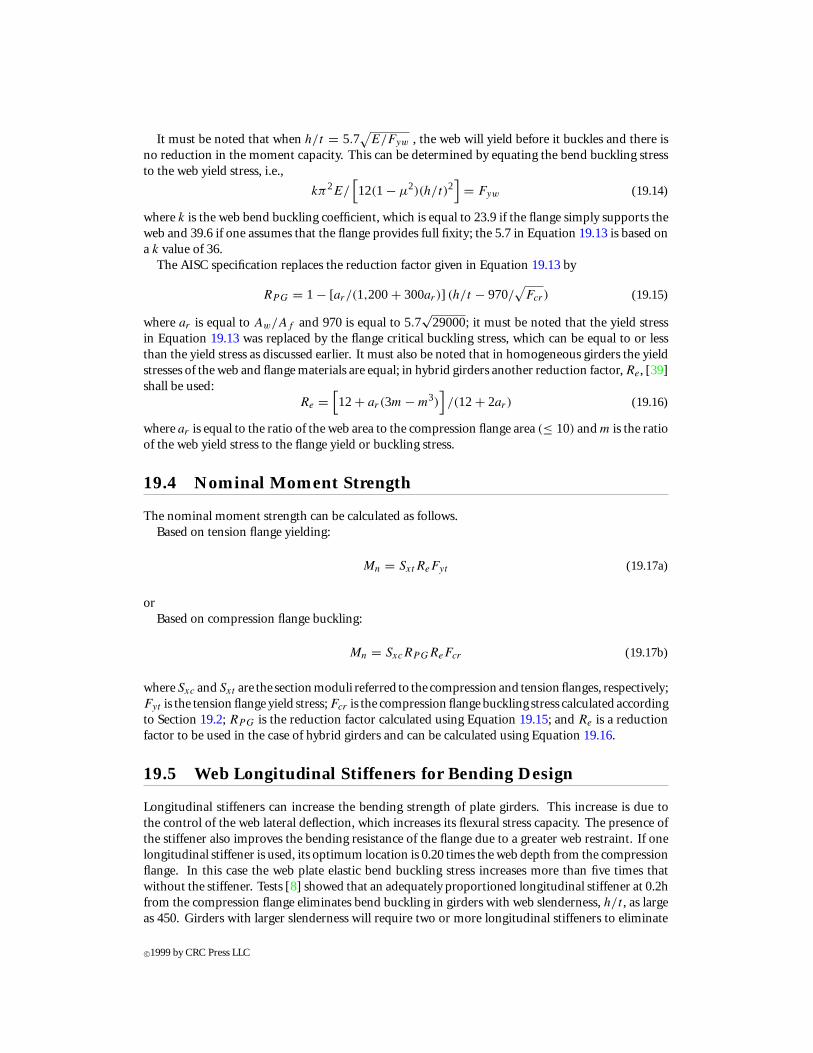
Many variations of this incomplete tension field model have been developed; are view can befound in the SSRC Guide to Stability Design Criteria for Metal Structures [22]. The model shown inFigure 19.5 [36, 38] gives better results and has been adopted in codes in Europe. In the model shownin Figure 19.5, near failure the tensile membrane stress, together with the buckling stress, causesyielding, and failure occurs when hinges form in the flanges to produce a combined mechanism thatincludes the yield zone ABCD. The vertical component of the tension field is added to the shear atbuckling and combined with the frame action shear to calculate the ultimate shear strength. The
c©1999 by CRC Press LLC
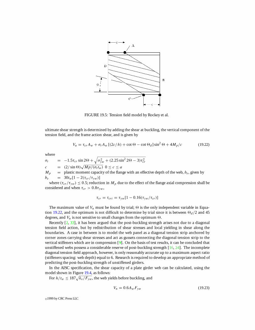
FIGURE 19.5: Tension field model by Rockey et al.
ultimate shear strength is determined by adding the shear at buckling, the vertical component of thetension field, and the frame action shear, and is given by
Vu = τcrAw + σtAw [(2c/h) + cot2 − cot2d ] sin2 2 + 4Mp/c (19.22)
where
σt = −1.5τcr sin 22 +√
σ 2yw + (2.25 sin2 22 − 3)τ2
cr
c = (2/ sin2)√
Mp/(σt tw) 0 ≤ c ≤ a
Mp = plastic moment capacity of the flange with an effective depth of the web, be, given bybe = 30tw[1 − 2(τcr/τyw)]
where (τcr/τyw) ≤ 0.5; reduction in Mp due to the effect of the flange axial compression shall beconsidered and when τcr > 0.8τyw ,
τcr = τcri = τyw[1 − 0.16(τyw/τcr )]
The maximum value of Vu must be found by trial; 2 is the only independent variable in Equa-tion 19.22, and the optimum is not difficult to determine by trial since it is between 2d/2 and 45degrees, and Vu is not sensitive to small changes from the optimum 2.
Recently [2, 33], it has been argued that the post-buckling strength arises not due to a diagonaltension field action, but by redistribution of shear stresses and local yielding in shear along theboundaries. A case in between is to model the web panel as a diagonal tension strip anchored bycorner zones carrying shear stresses and act as gussets connecting the diagonal tension strip to thevertical stiffeners which are in compression [9]. On the basis of test results, it can be concluded thatunstiffened webs possess a considerable reserve of post-buckling strength [16, 24]. The incompletediagonal tension field approach, however, is only reasonably accurate up to a maximum aspect ratio(stiffeners spacing: web depth) equal to 6. Research is required to develop an appropriate method ofpredicting the post-buckling strength of unstiffened girders.
In the AISC specification, the shear capacity of a plate girder web can be calculated, using themodel shown in Figure 19.4, as follows:
For h/tw ≤ 187√
kv/Fyw , the web yields before buckling, and
Vn = 0.6AwFyw (19.23)
c©1999 by CRC Press LLC

For h/tw > 187√
kv/Fyw , the web will buckle and a tension field will develop, and
Vn = 0.6AwFyw
[Cv + (1 − Cv)/1.15
√1 + (a/h)2
](19.24)
wherekv = buckling coefficient = 5 + 5/(a/h)2
= 5, if (a/h) > 3 or [260/(h/tw)]2Cv = ratio of the web buckling stress to the shear yield stress of the web
= 187√
kv/Fyw/(h/tw), for 187√
kv/Fyw ≤ h/tw ≤ 234√
kv/Fyw
= 44,000 kv/[(h/tw)2Fyw], for h/tw > 234√
kv/Fyw
It must be noted that, in the above, the web buckling is elastic when h/tw > 234√
kv/Fyw .The AISC specification does not permit the consideration of tension field action in end panels,
hybrid andweb-taperedplate girders, andwhena/h exceeds3.0or [260/(h/tw)]2. This is contrary tothe fact that a tension field can develop in all these cases; however, little or no research was conducted.Furthermore, tension field can be considered for end panels if the end stiffener is designed for thispurpose. When neglecting the tension field action, the nominal shear capacity can be calculated from
Vn = 0.6AwFywCv (19.25)
Care must be exercised in applying the tension field models developed primarily for welded plategirders to the webs of a box girder. The thin flange of a box girder can provide very little or noresistance against movements in the plane of the web. If the web of a box girder is transverselystiffened and if the model shown in Figure 19.4 is used, it may overpredict the web strength. Hence,it is advisable to use the model shown in Figure 19.5, assuming the plastic moment capacity of theflange to be negligible.
19.7 Web Stiffeners for Shear Design
Transverse stiffeners must be stiff enough to prevent out-of-plane displacement along the panelboundaries in computing shear buckling of plate girder webs. To provide the out-of-plane supportan equation, developed for an infinitely long web with simply supported edges and equally spacedstiffeners, to calculate the required moment of inertia of the stiffeners, Is , namely for a ≤ h,
Is = 2.5ht3w[(h/a) − 0.7(a/h)] (19.26)
The AASHTO formula for load-factor design is
Is = Jat3w (19.27)
whereJ = [2.5(h/a)2 − 2] ≥ 0.5
Equation 19.27 is the same as Equation 19.26 except that the coefficient of (a/h) in the secondterm between brackets is 0.8 instead of 0.7. Equation 19.27 was adopted by the AISC specification aswell. The moment of inertia of the transverse stiffener shall be taken about the edge in contact withthe web for single-sided stiffeners and about the mid-thickness of the web for double-sided stiffeners.
To prevent local buckling of transverse stiffeners, the width, bs , of each projecting stiffener ele-ment shall satisfy the requirements of Equation 19.11 using the yield stress of the stiffener materialrather than that of the flange, as in Equation 19.11. Furthermore, bs shall also satisfy the followingrequirements:
16.0ts ≥ bs ≤ 0.25bf (19.28)
c©1999 by CRC Press LLC

wherebf = the full width of the flange
Transverse stiffeners shall consist of plates or angles welded or bolted to either one or both sidesof the web. Stiffeners that are not used as connection plates shall be a tight fit at the compressionflange, but need not be in bearing with the tension flange. The distance between the end of the web-to-stiffener weld and the near edge of the web-to-flange fillet weld shall not be less than 4tw or morethan 6tw . Stiffeners used as connecting plates for diaphragms or cross-frames shall be connected bywelding or bolting to both flanges.
In girders with longitudinal stiffeners the transverse stiffener must also support the longitudinalstiffener as it forces a horizontal node in the bend buckling configuration of the web. In such a caseit is recommended that the transverse stiffener section modulus, ST , be equal to SL(h/a), where SL
is the section modulus of the longitudinal stiffener and h and a are the web depth and the spacingbetween the transverse stiffeners, respectively. In the AASHTO specification, the moment of inertiaof transverse stiffeners used in conjunction with longitudinal stiffeners shall also satisfy
It ≥ (bt/bl)(h/3a)Il (19.29)
where bt and bl = projecting width of transverse and longitudinal stiffeners, respectively, and It andIl = moment of inertia of transverse and longitudinal stiffeners, respectively.
Transverse stiffeners in girders that rely on a tension field must also be designed for their role inthe development of the diagonal tension. In this situation they are compression members, and somust be checked for local buckling. Furthermore, they must have cross-sectional area adequate forthe axial force that develops. The axial force, Fs , can be calculated based on the analytical model [5]shown in Figure 19.4, and is given by
Fs = 0.5Fywatw[1 − (
τcr/τyw
)](1 − cos2d) (19.30)
The AISC and AASHTO specifications assume that a width of the web equal to 18tw acts with thestiffener and give the following formula for the cross-sectional area, As , of the stiffeners:
As ≥[0.15Bhtw(1 − Cv)Vu/0.9Vn − 18t2
w
](Fyw/Fys) (19.31)
where the new notations are0.9Vu = shear due to factored loadsB = 1.0 for double-sided stiffeners
= 1.8 for single-sided angle stiffeners= 2.4 for single-sided plate stiffeners
If longitudinally stiffened girders are used, h in Equation 19.31 shall be taken as the depth of theweb, since the tension field will occur between the flanges and the transverse stiffeners.
The optimum location of a longitudinal stiffener that is used to increase resistance to shear bucklingis at the web mid-depth. In this case the two subpanels buckle simultaneously and the increase in thecritical stress is substantial. To obtain the tension field shear resistance one can assume that only onetension field is developed between the flanges and transverse stiffeners even if longitudinal stiffenersare used.
19.8 Flexure-Shear Interaction
The shear capacity of a girder is independent of bending as long as the applied moment is less than themoment that can be taken by the flanges alone, Mf = σyf Af h; any larger moment must be resistedin part by the web, which reduces the shear capacity of the girder. When the girder is subjected to
c©1999 by CRC Press LLC

pure bending with no shear, the maximum moment capacity is equal to the plastic moment capacity,Mp , due to yielding of the girder’s entire cross-section. In view of the tension field action and basedon test results [3], a simple conservative interaction equation is given by
(V/Vu)2 + (M − Mf )/(Mp − Mf ) = 1 (19.32)
where M and V are the applied moment and shear, respectively.In the AISC specification, plate girders with webs designed for tension field action and when the
ultimate shear, Vu, is between 0.54 and 0.9Vn, and the ultimate moment, Mu, is between 0.675 and0.9Mn, where Vn and Mn are the nominal shear and moment capacities in absence of one another;the following interaction equation must be satisfied,
Mu/0.9Mn + 0.625(Vu/0.9Vn) ≤ 1.375 (19.33)
19.9 Steel Plate Shear Walls
Although the post-buckling behavior of plates under monotonic loads has been under investigationfor more than half a century, post-buckling strength of plates under cyclic loading has not beeninvestigated until recently [7]. The results of this investigation indicate that plates can be subjectedto few reversed cycles of loading in the post-buckling domain, without damage. In steel plate shearwalls, the boundary members are stiff and the plate is relatively thin; in such cases a complete tensionfield can be developed. The plate can be modeled as a series of tension bars inclined at an angle,φ [27]. The angle of inclination, φ, is a function of the panel length and height, the plate thickness,the cross-sectional areas of the surrounding beams and columns, and the moment of inertia of thecolumns. It can be determined by applying the principle of least work and is given by
tan4 α = [(2/twL) + (1/Ac)] /[(2/twL) + (2h/AbL) + (h4/180IcL
2)]
(19.34)
whereα = angle of inclination of tension field with the vertical axisL = panel lengthh = panel heighttw = wall thicknessAb = cross-sectional area of beamAc = cross-sectional area of columnIc = moment of inertia of column about axis perpendicular to the plane of the wall
Although this model can predict the ultimate capacity to a reasonable degree of accuracy it cannotdepict the load-deflection characteristics to the same degree of accuracy. Based on test results andfinite element analysis [17, 18], the stresses in the inclined tensile plate strips are not uniform butare higher near the supporting boundaries than the center of the plate, and yielding of these stripsstarts near their ends and propagates toward the midlength. The following method can be used tocalculate the ultimate capacity and determine the load-deflection characteristics of a thin-steel-plateshear wall.
The plate in the shear wall is replaced by a series of truss elements in the diagonal tension direction,as shown in Figure 19.6. A minimum of four truss members shall be used to replace the plate panelin order to depict the panel behavior to a reasonable degree of accuracy; however, six members arerecommended. The stress-strain relationship for the truss elements shall be assumed to be bilinearlyelastic perfectly plastic, as shown in Figure 19.7, where E is Young’s modulus of elasticity and σy
is the tensile yield stress of the plate material. In Figure 19.7 the first slope represents the elastic
c©1999 by CRC Press LLC

FIGURE 19.6: Steel plate shear wall analytical model.
FIGURE 19.7: Stress-strain relationship for truss element.
response and the second represents the reduced stiffness caused by partial yielding; σy1 and E2 canbe determined using a semi-empirical approach for welded as well as bolted shear walls, and can becalculated using the following equations:
σy1 = (0.423+ 0.816be/L)σy (19.35)
where
be =[14.6π2E/12(1 − ν2)τy
]0.5t (19.36)
L = length of the stript = thickness of the plate
andE2 = [
(σy2 − σy1)(3 − σy1)/σy2(2 + α)]E (19.37)
c©1999 by CRC Press LLC

where α is the ratio between the plastic strain, εp , and the strain at the initiation of yielding, εy . Thisratio is in the range of 5 to 20, depending on the stiffness of the columns relative to the thicknessof the plate; a value of 10 can be used in design. In the derivation of Equations 19.35 and 19.36the inclination angle of the equivalent truss elements was assumed to be 45 degrees. The angle ofinclination is usually in the range of 38 to 43 degrees and the effect of this assumption on the overallbehavior of the wall is negligible.
In order to define the load displacement relationship of the truss elements in a bolted shear wall,the parameters Py1, K1, Py , and K2 shown in Figure 19.8 need to be calculated. For a bolted plate,
FIGURE 19.8: Load-displacement relationship for truss element.
the initial yielding can occur when the plate at the bolted connection starts slipping or when it locallyyields near the boundaries as in the welded plate. The load due to slippage is controlled by the frictioncoefficient between the connected surfaces and the normal force applied by the bolts. In case thebolts were pre-tensioned to 70% of their ultimate tensile strength, slip will occur at a load equal to
Py1 = n(0.7µFbu Ab) (19.38)
where n is the number of bolts at one end of the truss element; Fbu and Ab are the ultimate tensile
strength and cross-section area of the bolt, respectively; and µ is the friction coefficient between theconnected surfaces. The load that causes initial yielding at the ends of the strip is the same as for thewelded plate, and can be obtained from Equation 19.35 by multiplying the stress, σy1, by the stripcross-sectional area, Ap .
The usable load is the smaller of the loads that causes slippage or initial yielding at the ends of thestrip. The initial stiffness of the equivalent truss element can be calculated as follows:
K1 = EAp/L (19.39)
The ultimate load is controlled by the total yielding of the plate strip, tearing at the bolt holes,or shearing of the bolts. The smallest failure load is the controlling ultimate capacity of the trusselement. The ultimate load due to the strip yielding along its entire length,
P ′y = σyA
p (19.40)
The bolted shear wall should be designed such that plate yielding controls.
c©1999 by CRC Press LLC

Tearing at the bolt holes will occur when the edge distance is small or the bolt spacing is large,which should be avoided in design because it is a brittle failure. The tearing load, denoted as P ′′
y , canbe calculated using the following formula:
P ′′y = 1.4nσu(Le − D/2)t (19.41)
where n is the number of bolts at the end of the truss element, σu is the ultimate tensile strength of theplate material, Le is the distance from the edge of the plate to the centroid of the bolt hole, D is thediameter of the bolt, and t is the thickness of the plate. Note that in the above formula the ultimatestrength of the plate material in shear was assumed to be 0.7, its ultimate strength in tension.
The shear failure of the bolts can occur if the shear strength of the bolts is small or the spacingbetween them is large. In such case the ultimate capacity of the truss element, which is denoted asP ′′′
y , can be calculated from one of the following formulas:
P ′′′y = 0.45nFb
u Ab (19.42a)
P ′′′y = 0.60nFb
u Ab (19.42b)
where n is the number of bolts and Fbu and Ab are the ultimate strength and the gross cross-section
area of the bolts, respectively. Equation 19.42a is used if the shear plane is within the threaded partof the bolt and Equation 19.42b is used if the shear plane is not within the threaded part of the bolt.
The ultimate load of the truss element is the smallest value of the plate total yielding capacity, thetearing capacity, and the bolt shearing capacity, i.e.,
Py = min(P ′y, P
′′y , P ′′′
y ) (19.43)
As stated earlier, the plate yielding shall control and the designer must ensure that P ′y is the smallest
of the three values.As can be seen in Figure 19.8, in order to define the stiffness, K2, the displacement of the truss
element when the load reaches the ultimate capacity, Py , needs to be determined. This ultimatedisplacement includes the stretchingof the element aswell as the slippage and thebearingdeformationof the plate and the bolts at the connections. The plate strip represented by the truss element isstretched under load; the elongation includes both elastic and plastic deformations. As discussedearlier, due to the nonuniform strain distribution along the length of the strip, the plastic deformationwill occur mostly near the ends. If one assumes that the strain distribution along the length of thestrip is a second-degree parabola, and using a plastic deformation factor a, the elongation of thetruss element due to the plate elastic and plastic deformations can be calculated using the followingequation:
1def = (σy/3E)(2 + α)L (19.44)
The elongation of the truss element due to slippage can be approximated by two times the holeclearance, taking into consideration the slippage at both ends of the element [26]. The local defor-mation at the bolt holes includes the effects of shearing, bending, and bearing deformations of thefastener as well as local deformation of the connected plates, and can be taken as 0.2 times the boltdiameter [21]. Having defined the ultimate elongation of the truss element, its reduced stiffness afterslippage and/or initial yielding can be obtained using the following equation:
K2 = (Py − Py1)/[0.125+ 0.2D + σy(α − 1)L/(3E)
](19.45)
c©1999 by CRC Press LLC
19.10 In-Plane Compressive Edge Loading
Webs of plate and box girders and load-bearing diaphragms in box girders can be subjected to localin-plane compressive loads. Vertical (transverse) stiffeners can be provided at the location of the loadto prevent web crippling; however, this is not always possible, such as in the case of a moving load,and it involves higher cost. Failure of the web under this loading is always due to crippling [10], asshown in Figure 19.9; in thin webs crippling occurs before yielding of the web and in stocky websafter yielding. The formula in the AISC specification predicts the crippling load, Pcr , to a reasonable
FIGURE 19.9: Deformed shape under in-plane edge loading (only half of the beam is shown).
degree of accuracy [37]; this formula is
Pcr = 135t2w
[1 + 3(N/d)
(tw/tf
)1.5] (
Fywtf /tw)0.5
(19.46)
The formula given by Equation 19.46 is applicable if the load is applied at a distance not less thanhalf the member’s depth from its end; if the load is at a distance less than half the member’s depth,the following formulae shall be used [14]:
For N/d ≤ 0.2, Pcr = 68t2w
[1 + 3(N/d)
(tw/tf
)1.5] (
Fywtf /tw)0.5
(19.47a)
For N/d > 0.2, Pcr = 68t2w
[1 + (4N/d − 0.2)(tw/tf )1.5
] (Fywtf /tw
)0.5(19.47b)
In addition to web crippling, the AISC specification requires a web yielding check; furthermore,when the relative lateral movement between the loaded compression flange and the tension flange isnot restrained at the point of load application, sidesway buckling must be checked.
c©1999 by CRC Press LLC

19.11 Eccentric Edge Loading
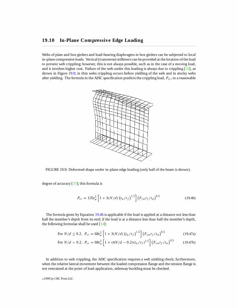
Eccentricities in loading with respect to the plane of the web are unavoidable, and it was found thatthere is a reduction in the web capacity due to the presence of an eccentricity [13, 14]; for example,in one case, an eccentricity of 0.5 in. reduced the web ultimate capacity to about half its capacityunder in-plane load. Furthermore, it was found that the effect of the load eccentricity in reducing theultimate capacity decreases as the ratio of the flange-to-web thickness increases. A deformed beamsubjected to eccentric load near failure is shown in Figure 19.10. Web strength reduction factors forvarious eccentricities as a function of the flange width and for various flange-to-web thickness ratiosare given in Figure 19.11.
FIGURE 19.10: Deformed shape under eccentric edge loading.
The failure mechanism in the case of eccentric loading is different from that for in-plane loading.The flange twisting moment acting at the web-flange intersection can cause failure due to bendingrather than crippling of the web, if the eccentricity is large enough. In most cases, however, the failuremode is due to a combination of web bending and crippling. Failure mechanisms were developed, andformulas to calculate the ultimate capacity of the web under eccentric edge loading were derived [15].Currently, the AISC specification does not address the effect of the eccentricity on the reduction of theweb crippling load. Eccentricities can also arise due to moments applied to the top flange in additionto vertical loads. An example would be a beam resting on the top flange of another beam and thetwo flanges are welded together. Rotation of the supported beam will impose a twisting moment inthe flange of the supporting beam and bending of its web, which will reduce its crippling load.
c©1999 by CRC Press LLC
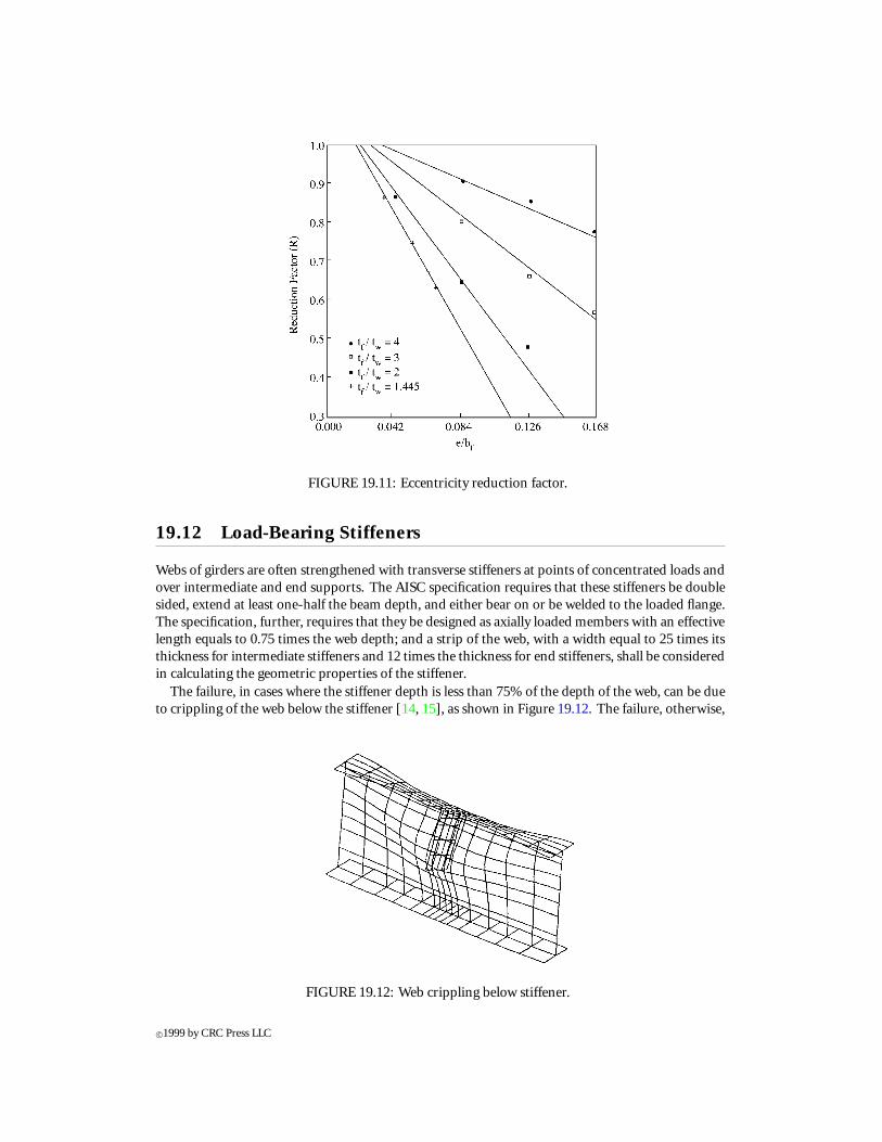
FIGURE 19.11: Eccentricity reduction factor.
19.12 Load-Bearing Stiffeners
Webs of girders are often strengthened with transverse stiffeners at points of concentrated loads andover intermediate and end supports. The AISC specification requires that these stiffeners be doublesided, extend at least one-half the beam depth, and either bear on or be welded to the loaded flange.The specification, further, requires that they be designed as axially loaded members with an effectivelength equals to 0.75 times the web depth; and a strip of the web, with a width equal to 25 times itsthickness for intermediate stiffeners and 12 times the thickness for end stiffeners, shall be consideredin calculating the geometric properties of the stiffener.
The failure, in cases where the stiffener depth is less than 75% of the depth of the web, can be dueto crippling of the web below the stiffener [14, 15], as shown in Figure 19.12. The failure, otherwise,
FIGURE 19.12: Web crippling below stiffener.
c©1999 by CRC Press LLC

is due to global buckling of the stiffener, provided that the thickness of the stiffener is adequate toprevent local buckling. The optimum depth of the stiffener is 0.75 times the web depth. The AISCspecification does not account for factors such as the stiffener depth and load eccentricity.
Inboxgirders intermediatediaphragmsareprovided to limit cross-sectional deformationand load-bearing diaphragms are used at the supports to transfer loads to the bridge bearings. Diaphragmdesign is treated in the BS 5400: Part 3 (1983) [6] and discussed in Chapter 7 of the SSRC guide [22].
19.13 Web Openings
Openings are frequently encountered in the webs of plate and box girders. Research on the bucklingand ultimate strength of plates with rectangular and circular openings subjected to in-plane loadshas been performed by many investigators. The research has included reinforced and unreinforcedopenings. A theoreticalmethodofpredicting theultimate capacityof slenderwebs containing circularand rectangular holes, and subjected to shear, has been developed [34, 35]. The solution is obtainedby considering the equilibrium of two tension bands, one above and the other below the opening.These bands have been chosen to conform to the failure pattern observed in tested plate girders withholes. Experimental results showed that the method gives satisfactory and safe predictions. Thecalculated values were found to be between 5 and 30% below the test results.
Solutions for transversely stiffened webs subjected to shear and bending with centrally locatedholes are available [28, 30] and are applicable for webs with depth-to-thickness ratios of 120 to 360,panel aspect ratio between 0.7 and 1.5, hole depth greater than 1/10th of the web depth, and forcircular, elongated circular, and rectangular holes.
19.14 Girders with Corrugated Webs
Corrugated webs can be used in an effort to decrease the weight of steel girders and reduce itsfabrication cost. Studies have been conducted in Europe and Japan and girders with corrugated webshave been used in these countries [12]. The results of the studies indicate that the fatigue strengthof girders with corrugated webs can be 50% higher compared to girders with flat stiffened webs. Inaddition to the improved fatigue life, the weight of girders with corrugated webs can be as much as 30to 60% less than the weight of girders with flat webs and have the same capacity. Due to the weightsavings, larger clear spans can be achieved. Beams and girders with corrugated webs are economicalto use and can improve the aesthetics of the structure. Beams manufactured and used in Germanyfor buildings have a web thickness that varies between 2 and 5 mm, and the corresponding webheight-to-thickness ratio is in the range of 150 to 260. The corrugated webs of two bridges built inFrance were 8 mm thick and the web height-to-thickness ratio was in the range of 220 to 375.
Failure in shear is usually due to buckling of the web and the failure in bending is due to yielding ofthe compression flange and its vertical buckling into the corrugated web, which buckles [19, 20]. Theshear buckling mode is global for dense corrugation and local for course corrugation, as shown inFigure 19.13. The load-carrying capacity of the specimens drops after buckling, with some residualload-carrying capacity after failure. In the local buckling mode, the corrugated web acts as a seriesof flat-plate subpanels that mutually support each other along their vertical (longer) edges and aresupported by the flanges at their horizontal (shorter) edges. These flat-plate subpanels are subjectedto shear, and the elastic buckling stress is given by
τcre = ks
[π2E/12(1 − µ2)(w/t)2
](19.48)
c©1999 by CRC Press LLC

FIGURE 19.13: Local and global buckling.
whereks = buckling coefficient, which is a function of the panel aspect ratio, h/w, and the boundary
support conditionsh = the web deptht = the web thicknessw = the flat-plate subpanel width — the horizontal or the inclined, whichever is biggerE = Young’s modulus of elasticityµ = the Poisson ratio
The buckling coefficient, ks, is given byks = 5.34+ 2.31(w/h) − 3.44(w/h)2 + 8.39(w/h)3, for the longer edges simply supported and
the shorter edges clampedks = 8.98+ 5.6(w/h)2, in the case where all edges are clamped
An average local buckling stress, τav(= 0.5[τssf + τf x]), is recommended, and in the case ofτcre ≥ 0.8τy , inelastic buckling will occur and the inelastic buckling stress, τcri , can be calculated byτcri = (0.8 ∗ τcre ∗ τy)
0.5, where τcri ≤ τy .As stated earlier, the mode of failure is local and/or global buckling; when global buckling controls,
the buckling stress can be calculated for the entire corrugated web panel, using orthotropic-platebuckling theory. The global elastic buckling stress, τcre, can be calculated from
τcre = ks
[(Dx)
0.25 (Dy
)0.75]/th2 (19.49)
whereDx = (q/s)Et3/12Dy = EIy/q
Iy = 2bt (hr/2)2 + {t (hr)3/6 sin2}
ks = Buckling coefficient, equal to 31.6 for simply supported boundaries and 59.2 for clampedboundaries
t = corrugated plate thicknessb, hr , q, s, and 2 are as shown in Figure 19.14.
c©1999 by CRC Press LLC

In the aforementioned, when τcre ≥ 0.8τy , inelastic buckling will occur and the inelastic bucklingstress, τcri , can be calculated by τcri = (0.8 ∗ τcre ∗ τy)
0.5, where τcri ≤ τy . For design, it isrecommended that the local and global buckling values be calculated and the smaller value controls.
As stated earlier, the failure in bending is due to compression flange yielding and vertical bucklinginto the web, as shown in Figure 19.15. The failure is sudden, with no appreciable residual strength.The web offers negligible contribution to the moment carrying capacity of the beam, and for design,
FIGURE 19.14: Dimensions of corrugation profile.
FIGURE 19.15: Bending failure of a beam with corrugate web.
the ultimate moment capacity can be calculated based on the flange yielding, ignoring any contribu-tion from the web. The stresses in the web are equal to zero except near the flanges. This is becausethe corrugated web has no stiffness perpendicular to the direction of the corrugation, except for a
c©1999 by CRC Press LLC

very small distance which is adjacent to and restrained by the flanges, and the stresses are appreciableonly within the horizontal folds of the corrugation.
It must be noted that the common practice is to fillet weld the web to the flanges from one sideonly; under static loading this welding detail was found to be adequate and there is no need to weldfrom both sides. Finally, the bracing requirements of the compression flange in beams and girderswith corrugated webs are less severe compared to conventional beams and girders with flat webs.Lateral-torsional buckling of beams and girders with corrugated webs has been investigated [20].
19.15 Defining Terms
AASHTO: American Association of State Highway and Transportation Officials.
AISC: American Institute of Steel Construction.
Buckling load: The load at which a compressed element or member assumes a deflected posi-tion.
Effective width: Reduced flat width of a plate element due to buckling, the reduced width istermed the effective width.
Corrugated web: A web made of corrugated steel plates, where the corrugations are parallel tothe depth of the girder.
Factored load: The nominal load multiplied by a load factor to account for unavoidable devi-ations of the actual load from the nominal load.
Limit state: A condition at which a structure or component becomes unsafe (strength limitstate) or no longer useful for its intended function (serviceability limit state).
LRFD (Load and Resistance Factor Design): A method of proportioning structural compo-nents such that no applicable limit state is exceeded when the structure is subjectedto all appropriate load combinations.
Shear wall: A wall in a building to carry lateral loads from wind and earthquakes.
Stress: Force per unit area.
Web crippling: Local buckling of the web plate under local loads.
Web slenderness ratio: The depth-to-thickness ratio of the web.
References
[1] American Association of State Highway and Transportation Officials. 1994. AASHTO LRFDBridge Design Specifications, Washington, D.C.
[2] Ajam, W. and Marsh, C. 1991. Simple Model for Shear Capacity of Webs, ASCE Struct. J.,117(2).
[3] Basler, K. 1961. Strength of Plate Girders Under Combined Bending and Shear, ASCE J. Struct.Div., October, vol. 87.
[4] Basler K. and Thurlimann, B. 1963. Strength of Plate Girders in Bending, Trans. ASCE, 128.[5] Basler, K. 1963. Strength of Plate Girders in Shear, Trans. ASCE, Vol. 128, Part II, 683.[6] British Standards Institution. 1983. BS 5400: Part 3, Code of Practice for Design of Steel Bridges,
BSI, London.[7] Caccese, V., Elgaaly, M., and Chen, R. 1993. Experimental Study of Thin Steel-Plate Shear Walls
Under Cyclic Load, ASCE J. Struct. Eng., February.[8] Cooper, P.B. 1967. Strength of Longitudinally Stiffened Plate Girders, ASCE J. Struct. Div.,
93(ST2), 419-452.
c©1999 by CRC Press LLC
[9] Dubas, P. and Gehrin, E. 1986. Behavior and Design of Steel Plated Structures, ECCS Publ. No.44, TWG 8.3, 110-112.
[10] Elgaaly, M. 1983. Web Design Under Compressive Edge Loads, AISC Eng. J., Fourth Quarter.[11] Elgaaly, M. and Nunan W. 1989. Behavior of Rolled Sections Webs Under Eccentric Edge
Compressive Loads, ASCE J. Struct. Eng., 115(7).[12] Elgaaly, M. and Dagher, H. 1990. Beams and Girders with Corrugated Webs, Proceedings of
the SSRC Annual Technical Session, St. Louis, MO.[13] Elgaaly, M. and Salkar, R. 1990. Behavior of Webs Under Eccentric Compressive Edge Loads,
Proceedings of IUTAM Symposium, Prague, Czechoslovakia.[14] Elgaaly, M. and Salkar, R. 1991. Web Crippling Under Edge Loading, Proceedings of the AISC
National Steel Construction Conference, Washington, D.C.[15] Elgaaly, M., Salkar, R., and Eash, M. 1992. Unstiffened and Stiffened Webs Under Compressive
Edge Loads, Proceedings of the SSRC Annual Technical Session, Pittsburgh, PA.[16] Evans, H.R. and Mokhtari, A.R. 1992. Plate Girders with Unstiffened or Profiled Web Plates, J.
Singapore Struct. Steel Soc., 3(1), December.[17] Elgaaly, M., Caccese, V., and Du, C. 1993. Postbuckling Behavior of Steel-Plate Shear Walls
Under Cyclic Loads, ASCE J. Struct. Eng., 119(2).[18] Elgaaly, M., Liu, Y., Caccese, V., Du, C., Chen, R., and Martin, D. 1994. Non-Linear Behav-
ior of Steel Plate Shear Walls, Computational Structural Engineering for Practice, edited byPapadrakakis and Topping, Civil-Comp Press, Edinburgh, UK.
[19] Elgaaly, M., Hamilton, R., and Seshadri, A. 1996. Shear Strength of Beams with CorrugatedWebs, J. Struct. Eng., 122(4).
[20] Elgaaly, M., Seshadri, A., and Hamilton, R. 1996. Bending Strength of Beams with CorrugatedWebs, J. Struct. Eng., 123(6).
[21] Fisher, J.W. 1965. Behavior of Fasteners and Plates with Holes, J. Struct. Eng., ASCE, 91(6).[22] Galambos, T.V., Ed. 1988. Guide to Stability Design Criteria for Metal Structures, 4th ed.,
Wiley Interscience, New York.[23] Gaylord, E.H. 1963. Discussion of K. Basler Strength of Plate Girders in Shear, Trans. ASCE,
128, Part II, 712.[24] Hoglund, T. 1971. Behavior and Load Carrying Capacity of Thin Plate I-Girders, Division of
Building Statics and Structural Engineering, Royal Institute of Technology, Bulletin No. 93,Stockholm.
[25] Kirby, P.A. and Nethercat, D.A. 1979. Design for Structural Stability, John Wiley & Sons, NewYork.
[26] Kulak, G.L., Fisher, J.W., and Struik, J.H.A. 1987. Guide to Design Criteria for Bolted andRiveted Joints, 2nd ed., Wiley Interscience, New York.
[27] Kulak, G.L. 1985. Behavior of Steel Plate Shear Walls, Proc. of the AISC Int. Eng. Symp. onStruct. Steel, American Institute of Steel Construction (AISC), Chicago, IL.
[28] Lee, M.M.K., Kamtekar, A.G., and Little, G.H. 1989. An Experimental Study of Perforated SteelWeb Plates, Struct. Engineer, 67(2/24).
[29] Lee, M.M.K. 1990. Numerical Study of Plate Girder Webs with Holes, Proc. Inst. Civ. Eng., Part2.
[30] Lee, M.M.K. 1991. A Theoretical Model for Collapse of Plate Girders with Perforated Webs,Struct. Eng., 68(4).
[31] Lindner, J. 1990. Lateral-Torsional Buckling of Beams with Trapezoidally Corrugated Webs,Proceedings of the 4th International Colloquium on Stability of Steel Structures, Budapest,Hungary.
[32] American Institute of Steel Construction. 1993. Load and Resistance Factor Design Specifica-tion for Structural Steel Buildings, AISC, Chicago.
[33] Marsh, C. 1985. Photoelastic Study of Postbuckled Shear Webs, Canadian J. Civ. Eng., 12(2).
c©1999 by CRC Press LLC
[34] Narayanan, R. and Der Avanessian, N.G.V. 1983. Strength of Webs Containing Cut-Outs, IABSEProceedings P-64/83.
[35] Narayanan, R. and Der Avanessian, N.G.V. 1983. Equilibrium Solution for Predicting theStrength of Webs with Rectangular Holes, Proc. ICE, Part 2.
[36] Porter, D.M., Rockey, K.C., and Evans, H.R. 1975. The Collapse Behavior of Plate GirdersLoaded in Shear, Struct. Eng., 53(8), 313-325.
[37] Roberts, T.M. 1981. Slender Plate Girders Subjected to Edge Loading, Proc. Inst. Civil Eng.,Part 2, 71.
[38] Rockey, K.C. and Skaloud, M. 1972. The Ultimate Load Behavior of Plate Girders Loaded inShear, Struct. Eng., 50(1).
[39] Schilling, C.G. and Frost, R.W. 1964. Behavior of Hybrid Beams Subjected to Static Loads,ASCE, J. Struct. Div., 90(ST3), 55-88.
[40] Von Karman, T., Sechler, E.F., and Donnell, L.H. 1932. The Strength of Thin Plates in Com-pression, Trans. ASME, 54(2).
[41] Wagner, H. 1931. Flat Sheet Metal Girder with Very Thin Metal Web, NACA Tech. Memo. Nos.604, 605, 606.
[42] Yen, B.T. and Mueller, J.A. 1966. Fatigue Tests of Large-Size Welded Plate Girders, Weld. Res.Counc. Bull., No. 118, November.
c©1999 by CRC Press LLC


![Stability Behavior of Plate Girders with Laterally ... · Stability Behavior of Plate Girders with Laterally Unbraced Ends ... Timoshenko and Gere [4] systematically studied the](https://img.dokumen.tips/doc/110x75/5b91710909d3f215288ba76c/stability-behavior-of-plate-girders-with-laterally-stability-behavior-of.jpg)