Embed Size (px)
Citation preview

ALPlastics oyonnax 10/07/13
Plastication in injection moulding :Principles, Numerical modelingand in line Visualisation
Yves Béreaux1,a, Jean-Yves Charmeau2,a, Thuy Linh Pham2,a
Jean Balcaen2, Maël Moguedet3, Richard Apaloo
1LaMCoS UMR5259, INSA-Lyon2IMP@INSA UMR5223, INSA-Lyon3PEP,Centre Technique de la PlasturgieaFilière Génie Mécanique Procédés Plasturgie, INSA-Lyon
BACK � page 1 � FULL SCREEN

ALPlastics oyonnax 10/07/13
Outline• Polymer Processing : Challenges
• Injection Moulding
• Plastication in injection Moulding
– Physics
– Visualization
– Modelling
– Fibre breakage
• Flow in screw channel
BACK � page 2 � FULL SCREEN

ALPlastics oyonnax 10/07/13
Thermo-Plastics Processing : Challenges
liquid solidpart
aspect
plastication
pressure, flow rate, viscosity
moulding
shear rate, Tfusion
solidepellets, powder
melting
molten polymer
solidificationgeometry
mechanical properties
flow and shaping
temperature, rpm Tcryst., Tmould
Heat transfer Mechanics Physics, Heat transfer
• Processing bears an impact on thermo-mechanical history from material to part
• Processing parameters 6= Physics variables
• Analysis on the product (consequences)→ Physics causes
• Instrumented machine 6= Scientific instrument
BACK � page 3 � FULL SCREEN

ALPlastics oyonnax 10/07/13
Injection-MouldingCyclic Process : widely used for making thin parts (not hollow)
1 plastication
3 injection
5 holding
2 metering
4 packing 6 cooling
7 part ejection
Research group’s main interests :
Plastication & Flow in screw barrel system
Surface defects of injection-molded parts not today
BACK � page 4 � FULL SCREEN

ALPlastics oyonnax 10/07/13
VisualisationLooking for a visualization device :
• Scale relevant to polymer processing machines
• Applicable to screw barrel units
• continuous in line flow visualisation : 3D, no blind spots
• Automated particle tracking ( particle : pellet, fibre, fluorescent tracer )
• Post-treatment of position : Velocities
Literature review• Extruder with glass windows to observe solid bed motion and plasticising:
Wong (1999) [WLLZ99], Gao (2000) [GJC00].
• Transparent barrel with (one or two ) video cameras to record a particle motion:Campbell 1992 [CSF92], Choo 1980 [CNP80].
• Magnetic Resonance Imaging (MRI) on a non-metallic barrel and screw unit :Amin (2003) [AHH+03], Agemura (1995) [AKM95].
BACK � page 5 � FULL SCREEN

ALPlastics oyonnax 10/07/13
Visiovis Data acquisition
camera V2
camera V1
led
camera H1
camera H2
calibrator
computer V
computer Hmobile rack
firewire
firewire
clock
usb
usb
particle
barrel
led
Barrel : PMMA Fluorescent Particle (0.4 mm)
Screw D400.4 mmlength 6D continuously monitored by 2 over 4 cameras
Silicone oil 100Pas recording two sets of 2D pathlines
[Mog05]M. Moguedet. Développement d’un outil d’aide à la conception et au fonctionnement d’un ensemble vis/fourreau
industriel -Application à l’injection de thermoplastiques chargés fibres de verre longues. PhD thesis, INSA-Lyon, 12
Décembre 2005
BACK � page 6 � FULL SCREEN
ALPlastics oyonnax 10/07/13
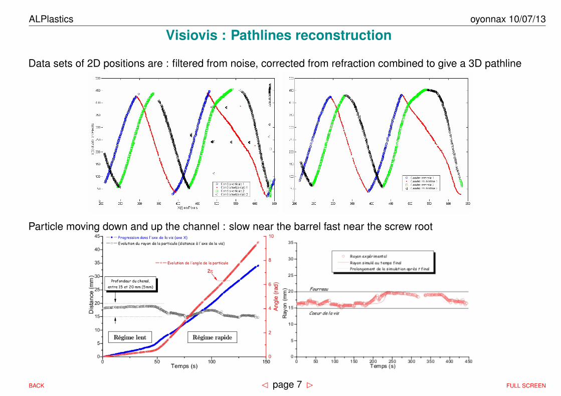
Visiovis : Pathlines reconstruction
Data sets of 2D positions are : filtered from noise, corrected from refraction combined to give a 3D pathline
Particle moving down and up the channel : slow near the barrel fast near the screw root
BACK � page 7 � FULL SCREEN

ALPlastics oyonnax 10/07/13
BACK � page 8 � FULL SCREEN

ALPlastics oyonnax 10/07/13
Visual Barrel design
Standard size barrel with :
3 optical glass windows
3 plane surfaces for visualization
and lightening (laser sheet option)
3 cameras monitoring :
plastication , flow charge dispersion
[Pha13]T.-L. Pham. Plastification des polymères fonctionnels et chargés. PhD thesis, INSA-Lyon, 2013. en cours
BACK � page 9 � FULL SCREEN

ALPlastics oyonnax 10/07/13
Transparent Barrel Plastication
melt poolsolid bed
channelflow
flight
Solid bed width increases with screw frequency Lateral film increases when screw is idle
BACK � page 10 � FULL SCREEN

ALPlastics oyonnax 10/07/13
Plastication
rpm
barrelsolid bed
melt film melt pool
pellets
hopper
nozzle
screw
Pellets melt along the screw following Maddock/Tadmor model : [Mad59, TDK67]
• Solid bed of compacted pellets with continuously decreasing width
• Molten polymer film at the barrel inner surface ...
• ... continuously wiped by the screw flights ...
• accumulates in a melt pool
Unresolved issues :solid bed permeability [NOF04], Solid bed velocity and acceleration, [FkSN82], lateral melt films[Lin85]?
BACK � page 11 � FULL SCREEN

ALPlastics oyonnax 10/07/13
Plastication in extrusion: Tadmor’s model
��������������������������������������������������������������������������������
��������������������������������������������������������������������������������
Tb
Vbx
δ
vis
fourreau
W
Vsy
XTm
• Fusion : contact and melt renewal
• Thermo-dependent power-law viscosity η =
K exp(−a(T − Tm))γn−1
• Solid bed : width X, velocity Vsz. Channel H,W . Mass flow rate mlt :
mlt =d
dz(ρsHXVsz)
mlt =
√√√√VbxU2ρmkm(Tb − Tm) (1 +BrU1)X
∆Ethlpy
• dimensionless numbers : Br self heating (vis-cous dissipation), A Thermo-dependence
Br =KV n+1
r δ1−n
km(Tb − Tm)
A =a(Tb− Tm)
n
• Melt film thickness :
δ =mlt
ρmVbxU2(A)
BACK � page 12 � FULL SCREEN

ALPlastics oyonnax 10/07/13
Plastication : Results
Solid fraction X/W along the screw length :
0
0.1
0.2
0.3
0.4
0.5
0.6
0.7
0.8
0.9
1
2 4 6 8 10 12 14 16 18
Sol
id b
ed W
idth
/ C
hann
el W
idth
N screw/turn
Pryltex
PP
HDPE
Feed Transition Metering
rpm 40
screw 90mm
0
0.1
0.2
0.3
0.4
0.5
0.6
0.7
0.8
0.9
1
2 4 6 8 10 12 14 16 18
Sol
id b
ed W
idth
/ C
hann
el W
idth
N screw/turn
screw 90mm
Transition MeteringFeed
Pryltex rpm 40 Tb 240C
rpm +50%
rpm +50% BP +50%
Tb +50C
Plastication length :
• increases with shear rate (increase viscous dissipation) (at a given throughput)
• decreases with higher screw rpm
• higher barrel temperature conflicting : increases conduction but decreases viscosity
BACK � page 13 � FULL SCREEN

ALPlastics oyonnax 10/07/13
Plastication in Injection Moulding
Specifics :
• not continuous (steady state) but cyclic
• sequence of steps : rotation (extrusion-like), dwelland forward injection
• melting depending on the time when pellets enterfeed zone
Modelling Nunn’s approach [Nun86]
• screw forward motion: additional melting (no solidbed motion)
X = X0 exp
(−∆tinj
km(Tb − Tm) + ηS2inj
δHρm∆Ethlpy
)
• dwell : film thickness increases by transient con-duction
δ =
√km(Tb − Tm)∆tdwell
ρs+ δ0
• At the beginning of rotation the solid bed reorgan-ises
00,10,20,30,40,50,60,70,80,9
1
0 5 10 15 20
InjectionExtrusionInjectionExtrusion
10,90,80,70,60,50,40,30,20,10
1 5 10 15 20
melting length shorterresidence time is much longer[Apa05] R. E. Apaloo. Plastification en injection. simplast.
Master’s thesis, Insa-Lyon, GMPP, 2005
BACK � page 14 � FULL SCREEN

ALPlastics oyonnax 10/07/13
Fibre Breakage• Fibres anchored at one end in solid bed, submitted at the other end to intense shear
������������������������������������
������������������������������������
���������������������������
���������������������������
������������������������������������������������������������������������������������
����������������������������������������������������������������������������������������
����
l d
Vbx
θ
fourreau
δ
lit solide
vis
• Mittal’s [MGS88] model extended to power-law fluid :
σapplied =128δ3−nKV n
r
d3An−1
(exp(A)− 1)n
∫ lδ
0
(1− exp(−Ax))x
log(7.4Re
)dx
depends on film thickness δ, shear rate, viscosity K, fibre diameter d and orientation l
• Fibre breaks when σapplied > σmax
• New layer of fibres uncovered as the solid bed is melting
• Fibre length distribution obtained starting from a uniform distribution with random orientation
BACK � page 15 � FULL SCREEN

ALPlastics oyonnax 10/07/13
Fibre breakage in extrusion
Screw extraction and fibre length measurement Gupta [GMS+89]
Comparison between measured and calculated mass (Lw) and number(Ln) averaged fibre length
Ln =
∑i niLi∑i ni
Lw =
∑i niL
2i∑
i niLi
0
2
4
6
8
10
0 5 10 15 20
Ln,L
w (
mm
)
N D_Vis
Ln expLn calcLw expLw calc
0
5
10
15
20
25
30
35
40
0 1 2 3 4 5 6 7 8 9
fra
ction e
n m
asse %
longueur fibre (mm)
Lw exp = 3.85 mm
Lw calc = 3.60 mm
0
10
20
30
40
50
60
70
80
0 1 2 3 4 5 6 7 8 9
fra
ction e
n n
om
bre
%
longueur fibre (mm)
Ln exp = 1.05 mm
Ln calc = 1.10 mm
PP LGF 9mm on a 38mm diameter screw
agreement is good at low rpm, less so at higher rpm[Mog05]M. Moguedet. Développement d’un outil d’aide à la conception et au fonctionnement d’un ensemble vis/fourreau
industriel -Application à l’injection de thermoplastiques chargés fibres de verre longues. PhD thesis, INSA-Lyon, 12
BACK � page 16 � FULL SCREEN

ALPlastics oyonnax 10/07/13Décembre 2005
BACK � page 17 � FULL SCREEN

ALPlastics oyonnax 10/07/13
Flow in a screw channelFlow provoked by screw rotation and back pressure of the die downstream
φ
H
W
z
N
z
y
x
Vz
φVx
V
x
y D
L
Parallel Plates Model :
• Rotating barrel around a static screw : steady-state problem
• Unwound Channel: H � RB : no direct effects of torsion and curvature
• High aspect ratio: H � W : no direct effects of screw flights
BACK � page 18 � FULL SCREEN

ALPlastics oyonnax 10/07/13
Single screw throughput calculations
LmeterLcomp
Pressure
Lfeed
BackPressure
Scre
w Di
amet
er Hfeed
rpm
Q ?
Hmeter
• 3 zone screw viewed as a melt pump where :
– screw forward displacement (drag flow),
– pressure gradient in the screw channel.
– Pressure development begins at atmosphericpressure and ends at Back pressure imposedon the screw
BackPressure = ∆Palim + ∆Pcomp + ∆Pmeter
•
m = ρmQliq + ρsVszHX
=W−XW
1− HXαHalimWalim
ρmQ
• 1D relationship between flow rate and local pres-sure gradient for power-law fluids:
Q =VbzWH
(1 + s)(1 + 2s)|6G|ssgn(G)f(λ)
G =Hn+1(z)
6KV n0
dP
dz
BACK � page 19 � FULL SCREEN

ALPlastics oyonnax 10/07/13
Throughput and Pressure profiles
20
30
40
50
60
70
80
90
100
20 30 40 50 60 70 80 90 100
modele
Debit (
kg/h
)
essai Debit (kg/h)
PS Styron, T 211C
PC Lexan, T 285C
−10%
0 0
5 5
10
10
15
15
20
20
25
25
30
30
0
35
5
40
10 0 15 5 20 10 25 15 30 20pre
ssure
(M
Pa)
N screw turn
model Md=35.9 kg/h
25
model + plast. Md=35.5 kg/h
30
exp. Md=32.2 kg/h
rpm=100rpm=40
pre
ssure
(M
Pa)
N screw turn
model + plast. Md=90.8 kg/h.
model Md=103.4 kg/h
exp. Md=99.6 kg/h
Throughput :
1. Screw geometry
2. Polymer Rheology
3. Plastication length[BCM09] Y. Béreaux, J.-Y. Charmeau, and M. Moguedet. A simple model of throughput and pressure development for
single screw. Journal of Material Technology and Processing, 209(1):611–618, 2009
BACK � page 20 � FULL SCREEN

ALPlastics oyonnax 10/07/13
Aims
Specific effects of helical geometry on flow of viscous and viscoelastic fluid
Hypotheses
• Incompressible fluid in steady-state creeping flow
• Screw channel :
– constant depth and pitch
– curvature, torsion
– flights
– rectangular cross-section
• No leakage flow through barrel/screw clearance
• Perturbation method
– pressure & drag flow of viscous fluids
– pressure flow of viscoelastic fluids
BACK � page 21 � FULL SCREEN

ALPlastics oyonnax 10/07/13
Rectangular helical screw channel
2πPy x
RW/2
θr
z
B
T
NH/2
Geometry Dimensionless Numbers
Hydraulic Diameter D = 2HWH +W λ = W
H
Curvature κ = RR2 + P 2 ε = Dκ
Torsion τ = PR2 + P 2 α = Dτ
Helix Angle tan(φ) = PR tan(φ) = α
ε
BACK � page 22 � FULL SCREEN

ALPlastics oyonnax 10/07/13
Applicability
Visiovis Extruder (pumping zone)
Aspect ratio λ 6.9 21.8
Curvature ε 0.44 0.15
Torsion α 0.16 0.05
tan(φ) αε 0.36 0.33
• Curvature ε and torsion α are small but not negligible dimensionless parameters
• Aspect ratios λ are very large
BACK � page 23 � FULL SCREEN

ALPlastics oyonnax 10/07/13
Overview
Fluid Flow type Flow direction Helicity
viscous drag down-channel w curvature ε
viscoelastic pressure cross-channel u, v, ψ torsion α
Ducts
XZ
y
ZYX
Z
y
Tore (ε) Helix (α, ε) Straight twisted duct (α)
BACK � page 24 � FULL SCREEN

ALPlastics oyonnax 10/07/13
Pressure flow/Newtonian fluid
w0 w0 + α2wα2 w0 + εwε + ε2wε2
λ = 1
-0.5 -0.4 -0.3 -0.2 -0.1 0 0.1 0.2 0.3 0.4 0.5
outer wall <--- x --> inner wall
-0.5
-0.4
-0.3
-0.2
-0.1
0
0.1
0.2
0.3
0.4
0.5
y
-0.5 -0.4 -0.3 -0.2 -0.1 0 0.1 0.2 0.3 0.4 0.5
outer wall <--- x --> inner wall
-0.5
-0.4
-0.3
-0.2
-0.1
0
0.1
0.2
0.3
0.4
0.5
y
-0.5 -0.4 -0.3 -0.2 -0.1 0 0.1 0.2 0.3 0.4 0.5
outer wall <--- x --> inner wall
-0.5
-0.4
-0.3
-0.2
-0.1
0
0.1
0.2
0.3
0.4
0.5
y
λ = 1/5
-0.5 -0.4 -0.3 -0.2 -0.1 0 0.1 0.2 0.3 0.4 0.5
outer wall <--- x --> inner wall
-0.5
-0.4
-0.3
-0.2
-0.1
0
0.1
0.2
0.3
0.4
0.5
y
-0.5 -0.4 -0.3 -0.2 -0.1 0 0.1 0.2 0.3 0.4 0.5
outer wall <--- x --> inner wall
-0.5
-0.4
-0.3
-0.2
-0.1
0
0.1
0.2
0.3
0.4
0.5
y
-0.5 -0.4 -0.3 -0.2 -0.1 0 0.1 0.2 0.3 0.4 0.5
outer wall <--- x --> inner wall
-0.5
-0.4
-0.3
-0.2
-0.1
0
0.1
0.2
0.3
0.4
0.5
y
Curvature : max velocity shifting towards the inner wall
Torsion : max velocity decreases
BACK � page 25 � FULL SCREEN

ALPlastics oyonnax 10/07/13
Pressure flow, curvature effects
0
0.5
1
1.5
2
2.5
−0.5 −0.4 −0.3 −0.2 −0.1 0 0.1 0.2 0.3 0.4 0.5
w/w
0av
x, y
w plfw, y = 0
w plfw, x = 0
w0 + εwε + ε2wε2 , y = 0
w0 + εwε + ε2wε2 , x = 0
w0 + εwε, y = 0
ε = 0.66, α = 0, λ = 0.5
large shift of the down-channel velocity w towards the inner wall (deep channel)
BACK � page 26 � FULL SCREEN

ALPlastics oyonnax 10/07/13
Pressure flow, torsion effects
Down-channel velocity w Cross-channel velocity u, v, ψ
0
0.2
0.4
0.6
0.8
1
1.2
1.4
1.6
1.8
2
−0.5 −0.4 −0.3 −0.2 −0.1 0 0.1 0.2 0.3 0.4 0.5
Z
y
w/w
0av
x, y
w0 + α2wα2 , y = 0
w0 + α2wα2 , x = 0
w0, y = 0w0, x = 0
w plfw, y = 0
w plfw, x = 0
x
y
−0.25
−0.2
−0.15
−0.1
−0.05
0
0.05
0.1
0.15
0.2
0.25
−0.5 −0.4 −0.3 −0.2 −0.1 0 0.1 0.2 0.3 0.4 0.5
u/w
0av
x, y
y
x
u plfw, y = 0.25
αuα, y = 0.25
u plfw, x = 0αuα, x = 0
u plfw, x = 0.25αuα, x = 0.25
λ = 2, α = 0.6, ε = 0 λ = 5, α = 0.15, ε = 0
Narrower w profile Secondary flow created
uα scales like α 1+λ4w0av when λ > 1
BACK � page 27 � FULL SCREEN

ALPlastics oyonnax 10/07/13
Drag & pressure flow, down-channel velocity w
Visiovis design λ = 7 α = 0.16 ε = 0.52, at closed discharge
drag pressure flow - W
0dp - aspect 5
1 0.9 0.8 0.7 0.6 0.5 0.4 0.3 0.2 0.1
0.0 -0.1 -0.2 -0.3
-0.5-0.4
-0.3-0.2
-0.1 0
0.1 0.2
0.3 0.4
0.5
outer wall <--- x --> inner w
all
-0.5
-0.4
-0.3
-0.2
-0.1
0 0.1
0.2
0.3
0.4
0.5y
w0d −GPw0
drag pressure flow - W
dp - aspect 5
1 0.9 0.8 0.7 0.6 0.5 0.4 0.3 0.2 0.1
0.0 -0.1 -0.2 -0.3
-0.5-0.4
-0.3-0.2
-0.1 0
0.1 0.2
0.3 0.4
0.5
outer wall <--- x --> inner w
all
-0.5
-0.4
-0.3
-0.2
-0.1
0 0.1
0.2
0.3
0.4
0.5y
w0d + εwεd + α2/εwα2/ε −GP (w0 + εwε + ε2wε2 + α2wα2)
BACK � page 28 � FULL SCREEN

ALPlastics oyonnax 10/07/13
Drag & pressure flow, cross-channel velocity V , λ = 1
−0.5 0 0.5−0.5
0
0.5
V 0
x
y
−0.5 0 0.5−0.5
0
0.5
−0.5
V
x
y
Cavity-lid driven flow (unwound channel) perturbation solution (helical geometry)
At closed discharge with λ = 1, α = 0.25, ε = 0.5
BACK � page 29 � FULL SCREEN
ALPlastics oyonnax 10/07/13
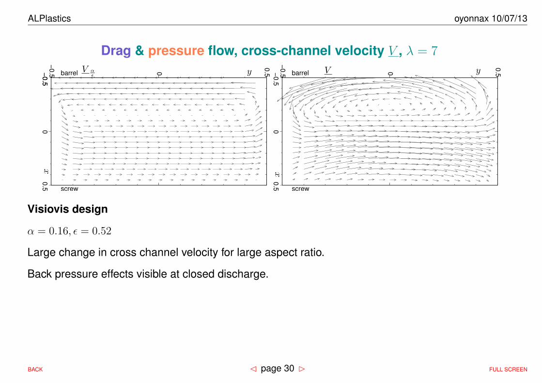
Drag & pressure flow, cross-channel velocity V , λ = 7
−0
.50
0.5
−0
.5 barrel
screw
0
0.5−
0.5
V αε
x
y −0
.50
0.5
−0
.5 barrel
screw
0
0.5V
x
y
Visiovis design
α = 0.16, ε = 0.52
Large change in cross channel velocity for large aspect ratio.
Back pressure effects visible at closed discharge.
BACK � page 30 � FULL SCREEN

ALPlastics oyonnax 10/07/13
Viscoelastic fluid flow
• Differential viscoelastic model : Upper-Convected Maxwell
S + λr5S +2ηλr
5d= 0 (1)
5S=
∂S
∂t+∇S · v − S · ∇vt −∇v ·S (2)
• First normal stress difference & constant shear viscosity
• Developed in Frenet basis ( 1000 terms)
• Zero order analytic solution available in pressure flow only
• Expansion of each stress component in power of α, ε
• At a given order, stress components are now explicit functions of known velocity gradients
• Creates specific contribution to the flow :
– Deborah number: De = <w>0
D
– w = . . .+ αDewα + εD2ewε
– ψ = . . .+Deψε
BACK � page 31 � FULL SCREEN

ALPlastics oyonnax 10/07/13
Viscoelastic fluid, pressure flow, w
Curvaturepressure flow - Wp Newton - aspect 1
2 1.5 1
0.5
-0.5 -0.4 -0.3 -0.2 -0.1 0 0.1 0.2 0.3 0.4 0.5
outer wall <--- x --> inner wall
-0.5
-0.4
-0.3
-0.2
-0.1
0
0.1
0.2
0.3
0.4
0.5
y
pressure flow - Wp Maxwell - aspect 1
2 1.5 1
0.5
-0.5 -0.4 -0.3 -0.2 -0.1 0 0.1 0.2 0.3 0.4 0.5
outer wall <--- x --> inner wall
-0.5
-0.4
-0.3
-0.2
-0.1
0
0.1
0.2
0.3
0.4
0.5
y
λ = 1, ε = 0.5 w0 + εwε with De = 0 w0 + εwε + εD2ewmxwlε with ε = 0.5, De = 1
Torsionpressure flow - Wp Newton - aspect 1
2 1.5 1
0.5
-0.5 -0.4 -0.3 -0.2 -0.1 0 0.1 0.2 0.3 0.4 0.5
outer wall <--- x --> inner wall
-0.5
-0.4
-0.3
-0.2
-0.1
0
0.1
0.2
0.3
0.4
0.5
y
pressure flow - Wp Maxwell - aspect 1
2 1.5 1
0.5
-0.5 -0.4 -0.3 -0.2 -0.1 0 0.1 0.2 0.3 0.4 0.5
outer wall <--- x --> inner wall
-0.5
-0.4
-0.3
-0.2
-0.1
0
0.1
0.2
0.3
0.4
0.5
y
λ = 1, α = 0.25 w0 + α2wα2 with De = 0 w0 + α2wα2 + αDewα with α = 0.25, De = 1
BACK � page 32 � FULL SCREEN

ALPlastics oyonnax 10/07/13
Viscoelastic fluid, pressure flow, w
pressure flow - W
p Maxw
ell - aspect 5
1.6 1.4 1.2 1 0.8 0.6 0.4 0.2
-0.5-0.4
-0.3-0.2
-0.1 0
0.1 0.2
0.3 0.4
0.5
outer wall <--- x --> inner w
all
-0.5
-0.4
-0.3
-0.2
-0.1
0 0.1
0.2
0.3
0.4
0.5y
Curvature, w0 + εwε + εD2ewmxwlε with ε = 0.5, De = 1, λ = 5
Large change in contours of w near the side walls
pressure flow - W
p Maxw
ell - aspect 5
1.6 1.4 1.2 1 0.8 0.6 0.4 0.2
-0.5-0.4
-0.3-0.2
-0.1 0
0.1 0.2
0.3 0.4
0.5
outer wall <--- x --> inner w
all
-0.5
-0.4
-0.3
-0.2
-0.1
0 0.1
0.2
0.3
0.4
0.5y
Torsion, w0 + αDewα + α2wα2 with α = 0.25, De = 2, λ = 5
Small twist in contours of w near the side walls
BACK � page 33 � FULL SCREEN
ALPlastics oyonnax 10/07/13
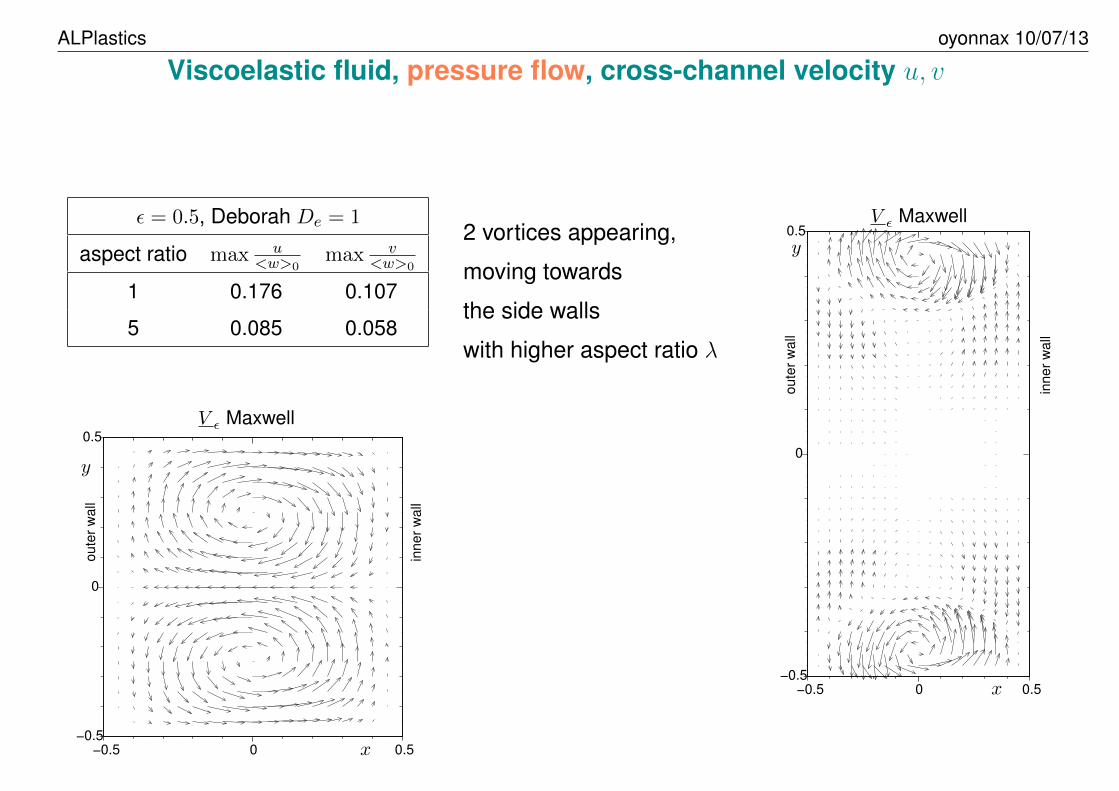
Viscoelastic fluid, pressure flow, cross-channel velocity u, v
ε = 0.5, Deborah De = 1
aspect ratio max u<w>0
max v<w>0
1 0.176 0.107
5 0.085 0.058
2 vortices appearing,
moving towards
the side walls
with higher aspect ratio λ
−0.5
ou
ter
wa
ll
inn
er
wa
ll
0 0.5
−0.5
0
0.5
V ε Maxwell
x
y
−0.5
ou
ter
wa
ll
inn
er
wa
ll
0 0.5
−0.5
0
0.5
V ε Maxwell
x
y
BACK � page 34 � FULL SCREEN

ALPlastics oyonnax 10/07/13
Viscoelastic fluid, pressure flow, w
0
0.5
1
1.5
2
2.5
−0.5 −0.4 −0.3 −0.2 −0.1 0 0.1 0.2 0.3 0.4 0.5
w/ < w >0
x
w0 + εwε, y = 0
w0 + ε(wε +D2ewmxwlε), y = 0
w pflw y = 0
w0 + εwε, y = 0.25
w0 + ε(wε +D2ewmxwlε), y = 0.25
w pflw y = 0.25
ε = 0.2, De = 0.73 : shift towards the outer wall validated by F.E. Calculations
BACK � page 35 � FULL SCREEN

ALPlastics oyonnax 10/07/13
Conclusions• 2D 1/2 viscous & viscoelastic fluids flow has been solved in a screw channel
– constant pitch and depth, rectangular cross-section
– with torsion and curvature taken into account
• New model backed precisely by 3D F.E. calculations
• Pressure flow is more sensitive to helical geometry than drag flow
• In pressure flow, torsion of the helical channel puts the fluid in cross channel motion
• Torsion effects are important for aspect ratio larger than one
• Curvature effects diminish with large aspect ratios for Newtonian fluid ...
• ... but remain present for viscoelastic (UCM) fluid
• Strong corrections to the PPM model are needed in view of finer
– calculations of mixing efficiency and overall residence time
– and screw design[BMR+04] Y. Béreaux, M. Moguedet, X. Raoul, JY. Charmeau, J. Balcaen, and D. Graebling. Series solutions for viscous
and viscoelastic fluids flow in the helical rectangular channel of an extruder screw. Journal of Non-Newtonian Fluid
Mechanics, 123(2-3):237–257, 2004
BACK � page 36 � FULL SCREEN

ALPlastics oyonnax 10/07/13
Plastication: synthesis and perspectives
Visiovis Barrel Windows
screw design
transient non−isothermal3D
1D Flow Analysis Network
non−Newtonian
1D plastication extrusion and injection
fibre breakage (solid/melt)
stationnary (static vis, rotating barrel)
2D 1/2 helicoidal
viscoelastic
velocity field
Newtonian
temperature parameterisothermal
plastication profilescrew characteristicsdistribution longueur fibres
buckling
criterion pathlines
heat transfer
non−newtonian melting multiphasic
non−isothermal
fibre
melt
breakage
BACK � page 37 � FULL SCREEN

ALPlastics oyonnax 10/07/13
Thank You for your attention
BACK � page 38 � FULL SCREEN

ALPlastics oyonnax 10/07/13
References
[AHH+03] M H G Amin, A D Hanlon, L D Hall, C Marriott, S Ablett, W Wang, and W J Frith. A versatilesingle-screw-extruder system designed for magnetic resonance imaging measurements.Measurement Science and Technology, 14(10):1760–1768, October 2003.
[AKM95] Cynthia K. Agemura, R. J. Kauten, and K. L. McCarthy. Flow fields in straight and taperedscrew extruders using magnetic resonance imaging. Journal of Food Engineering, 24:55–72, 1995.
[Apa05] R. E. Apaloo. Plastification en injection. simplast. Master’s thesis, Insa-Lyon, GMPP,2005.
[BCM09] Y. Béreaux, J.-Y. Charmeau, and M. Moguedet. A simple model of throughput and pres-sure development for single screw. Journal of Material Technology and Processing,209(1):611–618, 2009.
[BMR+04] Y. Béreaux, M. Moguedet, X. Raoul, JY. Charmeau, J. Balcaen, and D. Graebling. Seriessolutions for viscous and viscoelastic fluids flow in the helical rectangular channel of anextruder screw. Journal of Non-Newtonian Fluid Mechanics, 123(2-3):237–257, 2004.
[CNP80] K. P. Choo, N. R. Neelakantan, and J. F. T. Pittman. Experimental deep-channel velocity
BACK � page 39 � FULL SCREEN

ALPlastics oyonnax 10/07/13
profiles and operating characteristics for a single-screw extruder. Polymer Engineeringand Science, 20(5):349–356, 1980.
[CSF92] G A Campbell, P A Sweeney, and J N Felton. Experimental investigation of the drag flowassumption in extruder analysis. Polymer Engineering and Science, 32(23):1765–1768,1992.
[FkSN82] H Fukase, T kunio, S Shinya, and K Nomura. A plasticating model for single-screwextruders. Polymer Engineering and Science, 22(9):578–586, June 1982.
[GJC00] F Gao, Z Jin, and X Chen. A visual barrel system study of reciprocating screw injectionmolding. Polymer Engineering and Science, 40(6):1334–1343, June 2000.
[GMS+89] V. B. Gupta, R. K. Mittal, P. K. Sharma, G. Menning, and J. Wolters. Some studies onglass fiber-reinforced polypropylene. part 1: Reduction in fiber length during processing.Polymer composites, 10(1):8–15, February 1989.
[Lin85] J. T. Lindt. Mathematical modeling of melting of polymers in a single-screw extruder acritical review. Polymer Engineering and Science, 25(10):585–588, July 1985.
[Mad59] B. H. Maddock. A visual analysis of flow and mixing in extruder screws. SPE Journal,pages 383–389, May 1959.
[MGS88] R. K. Mittal, V. B. Gupta, and P. K. Sharma. Theoretical and experimental study of fibre
BACK � page 40 � FULL SCREEN

ALPlastics oyonnax 10/07/13
attrition during extrusion of glass fibre-reinforced polypropylene. Composites Scienceand Technology, 31:295–313, 1988.
[Mog05] M. Moguedet. Développement d’un outil d’aide à la conception et au fonctionnement d’unensemble vis/fourreau industriel -Application à l’injection de thermoplastiques chargésfibres de verre longues. PhD thesis, INSA-Lyon, 12 Décembre 2005.
[NOF04] M. Noriega, T. A. Osswald, and N. Ferrier. In line measurement of the polymer meltingbehavior in single-screw extruders. SPE-ANTEC Technical papers, 50:154–161, 2004.
[Nun86] R E Nunn. The reciprocating Screw Process, chapter 3, pages 56–83. 1986.
[Pha13] T.-L. Pham. Plastification des polymères fonctionnels et chargés. PhD thesis, INSA-Lyon,2013. en cours.
[TDK67] Z Tadmor, IJ Duvdevani, and I Klein. Melting in plasticating extruders. theory and experi-ments. Polymer Engineering and Science, pages 198–217, July 1967.
[WLLZ99] A C-Y Wong, T Liu, J C M Lam, and F Zhu. Dynamic performance of single-screws ofdifferent configurations. International polymer processing, 14(1):35–43, 1999.
BACK � page 41 � FULL SCREEN