Embed Size (px)
Citation preview

PLASTIC METHODS FOR STEEL AND CONCRETE STRUCTURES
Other engineering titles from Macmillan Education
Malcolm Bolton, A Guide to Soil Mechanics
J. G. Croll and A. C. Walker, Elements of Structural Stability
J. A. Fox, An Introduction to Engineering Fluid Mechanics, Second Edition
N. Jackson (ed.), Civil Engineering Materials, Second Edition
W. H. Mosley and J. H. Bungey, Reinforced Concrete Design
Ivor H. Seeley, Civil Engineering Quantities, Third Edition
Ivor H. Seeley, Civil Engineering Specification, Second Edition
J.D. Todd, Structural Theory and Analysis
E. M. Wilson, Engineering Hydrology, Second Edition

Plastic Methods for Steel and Concrete Structures
Stuart S. J. Moy Department of Civil Engineering, University of Southampton
M
©StuartS. J. Moy 1981 Softcover reprint of the hardcover 1st edition 1981 978-0-333-27563-4
All rights reserved. No part of this publication may be reproduced or transmitted, in any form or by any means, without permission.
First published 1981 by THE MACMILLAN PRESS LTD London and Basingstoke Companies and representatives throughout the world
Typeset in 10/12pt Press Roman by STYLESET LIMITED Salisbury . Wiltshire
ISBN 978-0-333-27564-1 ISBN 978-1-349-16549-0 (eBook) DOI 10.1007/978-1-349-16549-0
The paperback edition of this book is sold subject to the condition that it shall not, by way of trade or otherwise, be lent, resold, hired out, or otherwise circulated without the publisher's prior consent in any form of binding or cover other than that in which it is published and without a similar condition including this condition being imposed on the subsequent purchaser.
CONTENTS
Preface
Notation
1 Some general concepts
1.1 Introduction
ix
xi
1.2 Mild steel - the almost perfect material for plastic analysis 1 1.3 How structures behave under varying load 4 1.4 Summary 15
2 Plastic bending 16
2.1 Introduction 16 2.2 What happens to a beam when it bends? 16 2.3 Calculation of the plastic moment 20 2.4 Why the plastic moment and plastic hinge are idealisations 24 2.5 Factors which can alter the plastic moment 28 2.6 Summary 32 2.7 Problems 33
3 Collapse of simple frames
3.1 Introduction 3.2 The behaviour of a portal frame under increasing load 3.3 The theorems of plastic analysis 3.4 The number of hinges required in a mechanism 3.5 Free and reactant BM method for fmding collapse loads 3.6 The virtual work method for fmding collapse loads 3.7 Summary 3 .8 Problems
35
35 35 40 41 42 48 65 67
1
1
vi CONTENTS
4 Limit analysis 69
4.1 Introduction 69 4.2 Elementary mechanisms 72 4.3 Combination of mechanisms 73 4.4 Summary 86 4.5 Problems 87
s Design using plastic theory 90
5.1 Introduction 90 5.2 Load factors 91 5.3 Example of design by plastic theory 92 5.4 Optimum design 100 5.5 Summary 110 5.6 Problems 110
6 Deflections and stability 113
6.1 Introduction 113 6.2 Calculation of deflections at the point of collapse 114 6.3 The effect of deflection on the collapse load 123 6.4 Summary 132 6.5 Problems 132
7 Application of plastic methods to reinforced concrete structures 135
7.1 Introduction 135 7.2 The behaviour of reinforced concrete in bending 135 7.3 What happens if there is insufficient plastic rotation capacity? 143 7.4 The compromise adopted in codes of practice 145 7.5 Summary 149 7.6 Problems 150
8 Yield line analysis and the Hillerborg strip method for reinforced 152 concrete slabs
8.1 Introduction 152 8.2 Yield line theory 152 8.3 Hillerborg's strip method 180 8.4 Summary 190 8.5 Problems 190
Appendix A AppendixB Appendix C
References
CONTENTS
Yield criteria A redundancy test Bending moment diagrams
Solutions to Problems
Index
vii
194 200 202
211
213
219
PREFACE
This book owes much to the many students, undergraduate and postgraduate, who have patiently sat through my lectures on the plastic methods. Their questions during and after the lectures have shown that certain aspects of the subject consistently create difficulties for them. I perhaps flatter myself that this is not due to shortcomings in my teaching technique, but because those points need greater attention than is possible in a lecture. It has been my intention to give this extra attention in the book.
The book is intended to cover most of the requirements of students at both undergraduate and postgraduate levels, but will also be of general interest to practising engineers who wish to use the plastic methods. The emphasis throughout is on the ideas behind, and application of, the plastic methods, rather than their mathematical justification (I have given references to appropriate texts for this). To do this I have simplified some of the arguments - I hope that this does not offend the purists, but I make no apology for it.
The book is divided into eight chapters. The first two deal with the concepts of plastic behaviour, and plastic bending in particular. Chapters 3 and 4 describe the various techniques for finding the collapse loads of steel frames. Chapter 5 shows how the plastic methods are used to design steel structures. Chapter 6 is divided into two parts. The frrst describes a method for calculating the deflections in a structure at the point of collapse. The second part deals briefly with the effect that those deflections, and instability, have on the collapse load of a structure. The effect is complex and detailed study is beyond the scope of this book, but it would be wrong to omit all reference to instability. Chapters 7 and 8 deal with reinforced concrete structures: chapter 7 examines the problems of applying the plastic methods to concrete frames, and chapter 8 describes the powerful yield-line and strip methods for slabs.
As a rough guide, based on my own courses, the first three chapters provide a solid introduction which would be appropriate to second-year undergraduate level, while chapters 4, 5 and parts of 6 and 8 would be suitable for a third-year course. A postgraduate, M.Sc., course could make use of all the material.

X PREFACE
I have tried to be consistent in the layout of each chapter. There is an introduction which gives, where appropriate, the background theory. The meat of each chapter is usually presented in a series of examples which have been carefully graded. The first example introduces the ideas in the simplest possible manner, the subsequent ones introduce new ideas or examine those areas which can cause difficulties. The whole is then brought together briefly in a summary. At the end of each chapter (apart from the first) there is a series of examples, designed to bring out the various points made in the chapter. I cannot encourage the reader too strongly to work through the examples, preferably in order. Practice really is the best way of getting to grips with the plastic methods.
STUARTS. J. MOY
NOTATION
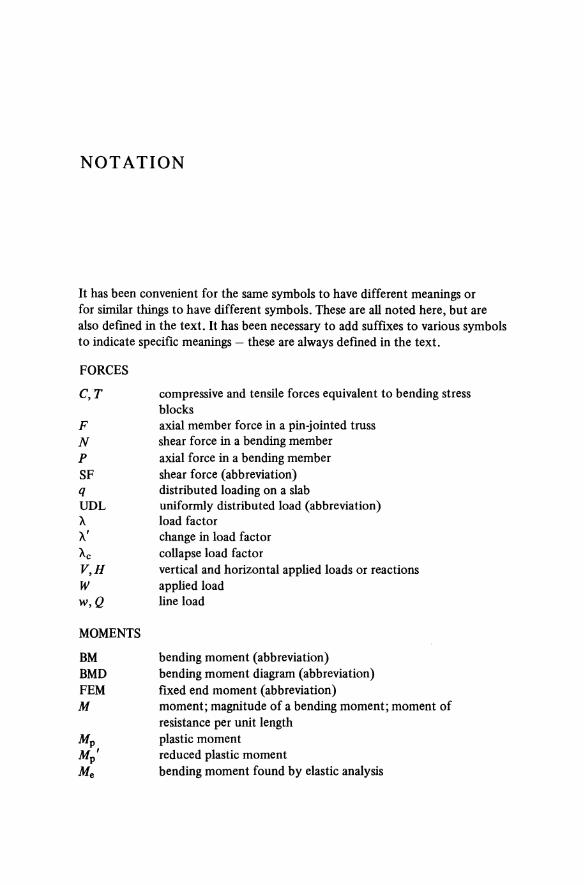
It has been convenient for the same symbols to have different meanings or for similar things to have different symbols. These are all noted here, but are also defined in the text. It has been necessary to add suffixes to various symbols to indicate specific meanings - these are always defmed in the text.
FORCES
C, T compressive and tensile forces equivalent to bending stress blocks
F axial member force in a pin-jointed truss N shear force in a bending member P axial force in a bending member SF shear force (abbreviation) q distributed loading on a slab UDL uniformly distributed load (abbreviation) X load factor X' change in load factor Ac collapse load factor V, H vertical and horizontal applied loads or reactions W appliedload w, Q line load
MOMENTS
BM bending moment (abbreviation) BMD bending moment diagram (abbreviation) FEM fixed end moment (abbreviation) M moment; magnitude of a bending moment; moment of
resistance per unit length Mp plastic moment Mp' reduced plastic moment Me bending moment found by elastic analysis

xii NOTATION
Mn moment per unit length normal to a yield-line f3red redistribution factor (CP 110 notation)
MATERIAL AND SECTION PROPERTIES
A As b d dl E
Esh
fc G G' g I l 1/r r s tr fw X
z 'Y €
a
Oy
T
Ty
cross-sectional area cross sectional area of steel reinforcement width over-all depth; effective depth of tensile reinforcement effective depth of compression reinforcement Young's modulus slope of stress-strain curve at the start of strain hardening characteristic cube strength of concrete structure weight function variable part of weight function weight per unit length second moment of area effective length slenderness ratio radius of gyration [ = y(I/A)] plastic modulus flange thickness web thickness depth to axis of zero strain in a concrete beam (CP 110 notation) section modulus shear strain direct strain direct stress yield stress shear stress yield shear stress
LENGTHS AND DISPLACEMENTS
e L,h I, a, b R s x,y,z cx,{3, "f, 8, ct>
Ll, 8
X
eccentricity overall dimensions dimensions radius distance along a yield line coordinate axes; distances in coordinate directions angles; rotations displacements curvature
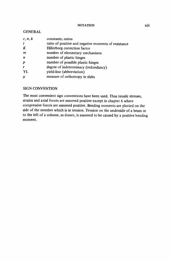
GENERAL
c,n,k i K m n p r YL
J1
NOTATION
constants; ratios ratio of positive and negative moments of resistance Hillerborg correction factor number of elementary mechanisms number of plastic hinges number of possible plastic hinges degree of indeterminacy (redundancy) yield-line (abbreviation) measure of orthotropy in slabs
SIGN CONVENTION
xiii
The most convenient sign conventions have been used. Thus tensile stresses, strains and axial forces are assumed positive except in chapter 6 where compressive forces are assumed positive. Bending moments are plotted on the side of the member which is in tension. Tension on the underside of a beam or to the left of a column, as drawn, is assumed to be caused by a positive bending moment.


![International Journal of Adhesion & Adhesivesrbatra/pdfpapers/Mukherjee_etal_2016.pdf · element method (FEM) by Hillerborg et al. [19] to study fracture problems, significant progress](https://img.dokumen.tips/doc/110x75/5e8fc0e2b01eb965804baab0/international-journal-of-adhesion-rbatrapdfpapersmukherjeeetal2016pdf.jpg)