Embed Size (px)
Citation preview

PlantPAx Distributed Control SystemSystem Release 4.5
Selection GuideOriginal Instructions
PlantPAx System ScopeThe PlantPAx® system provides a modern approach to distributed control. The system shares common technology (Integrated Architecture® system) with all other automation disciplines in the plant. This approach creates a seamless information flow across the plant for optimization opportunities and enables a connected enterprise.
Our scalable platform provides you with the flexibility to implement a system appropriate for your application. Figure 1 shows the documents (this manual in the highlighted section) that are available to help design and implement your system requirements.
Figure 1 -- PlantPAx System Implementation and Documentation Strategy
• Define and Procure - Helps you understand the elements of the PlantPAx system to make sure you buy theproper components.
• Install - Provides direction on how to install the PlantPAx system.• Prep - Provides guidance on how to get started and learn the best practices to follow before you develop
your application.• Develop - Describes the actions and libraries necessary to construct your application that resides on the
PlantPAx system.
• Operate – Provides guidance on how to verify and maintain your systems for operation of your plant.
Purpose of Selection Guide
This PlantPAx Selection Guide is designed to step you through the selection of system elements for creating a bill of materials for ordering your system. Using the prescribed architecture and recommendations explained in this manual, you can use the PlantPAx System Estimator tool to select a PlantPAx system. The PlantPAx System Estimator tool is part of the Integrated Architecture Builder software. See page 11 for details.
You do not need to read the sections in the order outlined on page 3. However, we do recommend that you start with the Overview to acquaint yourself with the system elements and architecture that comprise the PlantPAx system.
Install PrepDefine and
Procure Develop Operate
• Selection GuidePROCES-SG001
• Virtualization User Manual9528-UM001
• Infrastructure User ManualPROCES-UM001
• Reference ManualPROCES-RM001
• Application User ManualPROCES-UM003
• Reference ManualPROCES-RM001
• Library of Process ObjectsPROCES-RM002PROCES-RM013PROCES-RM014
• Verify and Troubleshoot User ManualPROCES-UM004
• Reference ManualPROCES-RM001

Select a PlantPAx System
Servers and Workstations
Controllers, Field Networks, and I/O
System Infrastructure
Process Safety Systems
Select:• PASS servers• Engineering workstations• Operator workstations
• Independent workstations• Application servers• Domain controllers
Select:• ControlLogix SIL 2 systems• AADvance and Trusted SIL 2,
SIL 3, and TMR systems• SIL-rated instruments
• PowerFlex SIL 2 and SIL 3 Systems
• OptiSIS Safety Integrated Systems
Page 26
Page 49
Page 12
Page 65
Select:• Simplex controllers• Redundant controllers• Skid-based controllers
• I/O products• Process network I/O• Motor Control devices
Overview
Select:• Regulatory control options• Supervisory control options
• PlantPAx MPCAdvanced Process Control
Page 69
Select:• Traditional infrastructure• Virtual infrastructure• VMware component
requirements
• Network topologies• Ethernet switches
Services and Support
Page 73
Select:• Access to Remote Service
Engineers• On-site delivery of
replacement parts
• Emergency on-site engineering services
MPC SystemArchitecture
Overview
Page 7
Review:
• Process system elements
• Scalable architectures
• High Availability architectures
• PlantPAx System Estimator
• Software release information
Rockwell Automation Publication PROCES-SG001K-EN-P - December 2018 3

Select a PlantPAx System
What’s Inside
This revision of the PlantPAx Selection Guide updates system rules to support the latest characterized software versions and incorporates additional information on the following topics.
Additional Resources
These documents contain additional information concerning related products from Rockwell Automation.
Topic Description Pages
Adds references to new PlantPAx library manuals in Additional Resources Added Logic Instructions and Display Elements reference manuals. 4
Adds new PASS - C option for small- to medium-sized systems Option (for systems with fewer than 2000 I/O points) locates functions from multiple system elements on single PASS.
7, 14, 27, 29
Updates ‘Scalable’ and ‘System’ architectures in Overview section Redesigned gray images for simplicity. 8, 9
Updates redundant I/O module options 1715 redundant I/O and 1719 I/O adapter descriptions and links. 10, 53
Describes abbreviations for virtual template distribution methods Description of delivery methods for virtual templates. 14
Adds new images for network topologies, such as PRP Advances in system infrastructure are depicted in graphics. 16…21
Updates electronic delivery option for software products Download copies of virtual image templates for products with catalog numbers that end with the letter E.
29…46
Adds ThinManager® server options Configure the AppServ-OWS as your ThinManager server and deploy up to 10 OWS sessions to simplify system management.
34
Adds skid-based controller CompactLogix™ 1769-L19ER-BB1 controller added as an option. 52
Adds communication modules for PowerFlex® 755TL / 755TR Description of communication option kits. 61
Adds medium voltage drives and relays Equipment benefits motor control and electrical protection. 62
Table 1 - Additional Resources
Resource Description
System Core
PlantPAx Distributed Control System Reference Manual, publication PROCES-RM001 Provides characterized recommendations for implementing your PlantPAx system.
PlantPAx Distributed Control System Infrastructure Configuration User Manual,publication PROCES-UM001
Provides procedures to configure infrastructure components for your PlantPAx system.
PlantPAx Distributed Control System Application Configuration User Manual,publication PROCES-UM003
Provides procedures to start the development of your PlantPAx system.
Rockwell Automation® Library of Process Objects: Logic Instructions Reference Manual,publication PROCES-RM013
Provides controller codes and tags for Rockwell Automation Library objects. Objects are grouped by family and attached as Microsoft® Excel® files to the manual PDF file.
Rockwell Automation Library of Process Objects: Display Elements Reference Manual,publication PROCES-RM014
Provides common display elements for the Rockwell Automation Library. For improved accessibility, the elements are combined into one manual.
PlantPAx Distributed Control System Verification and Troubleshooting User Manual,publication PROCES-UM004
Provides procedures on how to verify that your system design aligns with PlantPAx system recommendations and for system troubleshooting.
PlantPAx Hardware Specifications and Certifications, publication PROCES-SR027 Provides information on PlantPAx system hardware specifications and certifications.
ControlLogix® System User Manual, publication 1756-UM001 Explains how to use traditional and extreme environment ControlLogix controllers.
ControlLogix Selection Guide, publication 1756-SG001 Explains how to select a ControlLogix system that is based on your application requirements.
CompactLogix Selection Guide, publication 1769-SG001 Explains how to select a CompactLogix system that is based on your application needs.
Process Automation System Training Curriculum, publication PROCES-CA001A-EN-P Describes the courses that are available for a better understanding of the PlantPAx system.
Redundant I/O System User Manual, publication 1715-UM001 Explains how to install and set up the 1715 Redundant I/O system.
4 Rockwell Automation Publication PROCES-SG001K-EN-P - December 2018

Select a PlantPAx System
You can view or download publications at http://www.rockwellautomation.com/literature. To order paper copies of technical documentation, contact your local Allen-Bradley distributor or Rockwell Automation sales representative.
http://www.rockwellautomation.com/solutions/process Provides general information about Rockwell Automation process capabilities. From themenu bar, select Support> Modernization Support for DCS migration information.
http://www.migratemyprocess.com/webinars Features prerecorded webinars on the DCS migration program and capabilities forprocess customers.
Infrastructure
PlantPAx Virtualization User Manual, publication 9528-UM001 Describes the catalog numbers and details for using virtual image templates to configurevirtual machines.
Ethernet Design Considerations Reference Manual,publication ENET-RM002
Explains the infrastructure components that allow this open network to communicate seamlessly throughout a plant, from shop floor to top floor.
Industrial Ethernet Media, Complete Solution for Ethernet Networks and Integrated Architecture®, publication 1585-BR001
Provides information on Rockwell Automation 1585 Ethernet cables.
Stratix® Ethernet Device Specifications Technical Data, publication 1783-TD001 Contains product specifications, certifications, and catalog numbers for Ethernet switch devices.
Converged Plantwide Ethernet (CPwE) Design and Implementation Guide,publication ENET-TD001
Provides information on Ethernet security and firewalls.
Product Compatibility and Download Center athttp://www.rockwellautomation.com/rockwellautomation/support/pcdc.page
Website helps you find product-related downloads including firmware, release notes, associated software, drivers, tools, and utilities.
Field Device Integration
FLEX™ I/O, FLEX I/O XT, and FLEX Ex™ Selection Guide, publication 1794-SG002 Explains how to select a distributed I/O system for safe and hazardous environments.
POINT I/O™ Selection Guide, publication 1734-SG001 Explains how to select modular I/O modules for your system requirements.
ArmorBlock® I/O Selection Guide, publication 1732-SG001 Explains how to select ArmorBlock I/O blocks that are suitable for On-Machine™ use.
ArmorPOINT® I/O selection Guide, publication 1738-SG001 Explains how to select ArmorPOINT I/O modules.
Dynamix™ -1444 Series Monitoring System User Manual, publication 1444-UM001 Explains how to install and wire the Dynamix1444 Series Monitoring System.
http://www.endress.com/eh/home.nsf/#products/~products-instruments List of instruments from Endress+Hauser.
Integrate E+H Instruments in a PlantPAx System Integration Document,publication PROCES-SG003
Provides pre-engineered, pre-tested, supported, and maintained integrated solutions forplant-wide diagnostics and lifecycle management.
Region Locations for Panduit Corporation, Product category Provides information on connected cabling systems and infrastructure management from Encompass™ partner Panduit Corporation.
Process Safety
http://www.rockwellautomation.com/products/certification Complete list of ControlLogix products that are certified for SIL 1 and SIL 2 applications.
Using ControlLogix in SIL 2 Applications Safety Reference Manual, publication 1756-RM001 ControlLogix components that are supported in SIL 2 configurations.
AADvance® Solutions Handbook, publication ICSTT-RM447 Explains the features, performance, and functionality of the AADvance controller and systems. The handbook sets guidelines on how to specify a system to meet your application requirements.
AADvance System Build Manual, publication ICSTT-RM448 Provides experienced panel builders with information on how to assemble a system, switch on and validate the operation of a controller.
AADvance Configuration Guide, publication ICSTT-RM405 Defines how to configure an AADvance controller by using the AADvance Workbench to meet your Safety Instrument Function (SIF) application requirements.
AADvance Safety Manual, publication ICSTT-RM446 Defines mandatory standards and makes recommendations to apply AADvancecontrollers for a SIF application. Explains how to use ControlLogix controllers.
AADvance Troubleshooting and Repair Manual, publication ICSTT-RM406 Provides plant maintenance personnel with information on how to trace and repair a fault in an AADvance system and perform routine maintenance tasks.
Table 1 - Additional Resources
Resource Description
Rockwell Automation Publication PROCES-SG001K-EN-P - December 2018 5

Select a PlantPAx System
Notes:
6 Rockwell Automation Publication PROCES-SG001K-EN-P - December 2018

Select a PlantPAx System
Overview
Welcome and thank you for choosing the PlantPAx Distributed Control System. The PlantPAx system is an integrated control and information solution that provides plant-wide optimization in a wide range of industries. This single-platform system is built on open industry standards to help support the seamless integration of system components, and to provide connectivity to high levelbusiness systems.
This section provides an overview on the system elements and architectures that comprise the PlantPAx system.
Process System Elements
To get started building your system, Table 2 summarizes the system elements. These elements (combinations of hardware and software products) are explained throughout this guide with corresponding catalog numbers to assist you with your equipment procurement.
Table 2 - System Element Descriptions
System Element Description
Process Automation System Server (PASS) The PASS is a required system element that can host displays, alarms, and data connections to controllers. Multiple PASS servers can be used to provide additional system capacity or to create logical segregation of application content that is based on the process. See page 27 for guidance on how many PASS servers you need.For smaller systems, the PASS - C (consolidated PASS server) supports functions that otherwise would be hosted on application servers. For details, see Chapter 5 in the PlantPAx Virtualization User Manual, publication 9528-UM001.
Operator workstation (OWS) and Application server (AppServ-OWS) The OWS and AppServ-OWS provides an interactive graphical interface to monitor and control the process. TheAppServ-OWS uses Microsoft® Remote Desktop Services (RDS) technology to serve multiple instances of the OWS as thin clients from a single server. The technology provides for FactoryTalk® View SE thin clients running applications and processing data on a remote computer.
Engineering workstation (EWS) and Application server (AppServ-EWS) The EWS and AppServ-EWS provides a central location for configuring the system and monitoring/maintainingsystem operation. The AppServ-EWS uses Microsoft Remote Desktop Services (RDS) technology to serve multiple instances of the EWS as thin clients from a single server. The technology provides for FactoryTalk View SE thin clients running applications and processing data on a remote computer.
AppServ-Asset management The asset management server acts as a centralized tool for managing automation-related asset information (both Rockwell Automation and third-party assets). The asset management application server includes capabilities for source control, audits, change notifications, calibration of instrumentation, reporting, and security.
AppServ-Batch The batch application server provides comprehensive batch management, including unit supervision, recipe management, process management, and material management. The batch application server can be linked with visualization elements on the OWS and configuration clients on the EWS.
AppServ-Info (Historian, VantagePoint®, SQL) Data management storage can include a Historian or SQL server. There are three different types of AppServ-Info servers depending on the function that is being provided: FactoryTalk Historian software, FactoryTalk® VantagePoint® software, and the SQL server.
Controllers The ControlLogix and CompactLogix controllers support continuous process and batch applications. These controllers also support discrete and motion applications.
Independent workstation (IndWS) The independent workstation acts as a PASS, EWS, and OWS for single-station systems (independent class).
Domain controller A domain controller is a server that manages security authentication requests within the Windows® server domain. PlantPAx uses a domain controller to store user account information, authenticate users, and enforce security policies.
Review these options:• Process System Elements• Scalable Architectures• High Availability Architectures• PlantPAx System Estimator• Software Release Information
Rockwell Automation Publication PROCES-SG001K-EN-P - December 2018 7

Select a PlantPAx System
Scalable Architectures
Rockwell Automation characterizes the PlantPAx system that is based on its size or architecture class. A ‘characterized’(system-tested) classification yields system performance data and recommended hardware and software configurations. The classes of PlantPAx architecture offer system scalability while organizing Integrated Architecture products consistent with process industry expectations.
The architecture classes that are shown in the illustration include the following:• Skid architecture with skid controller and PanelView for monitoring data• System architecture with single station that acts as PASS, OWS, and EWS• Distributed system architecture for single PASS server with multiple OWS and EWS• Distributed system architecture for multiple PASS servers and multiple OWS and EWS
Use these system elements in your process architecture.
Table 3 - Architectures and System Elements
System Element
Skid Architecture Station Architecture Distributed Architecture(single PASS (consolidated))
Distributed Architecture(single to multiple PASS servers)
PASS Not applicable. Single workstation serves as PASS, EWS, and OWS in an independent workstation.
For smaller systems, one PASS (consolidated) is required that typically includes the following:• FactoryTalk Directory server• HMI server • Data server• Alarm and Event serverThe PASS-C supports functions that would otherwise be hosted on separate application servers. The PASS-C single computer includes the following in an independent workstation:• PASS• FactoryTalk Historian• AppServ-Asset Management• AppServ-VantagePoint• AppServ-Info (SQL)
IMPORTANT: An additional PASS-C is required for redundancy.
One PASS required that typically includesthe following:• FactoryTalk Directory server• HMI server • Data server• Alarm and Event serverAdditional PASS as needed (up to 10 servers or redundant server pairs).(1)
EWS Included in independent workstation. 1 EWS required. 1 EWS required.Can have as many as 5 EWSs.
Scalable
Distributed Architecture - Single to Multiple PASS Servers
Station ArchitectureSkid Architecture
Distributed Architecture - Single PASS Server
8 Rockwell Automation Publication PROCES-SG001K-EN-P - December 2018
Select a PlantPAx System
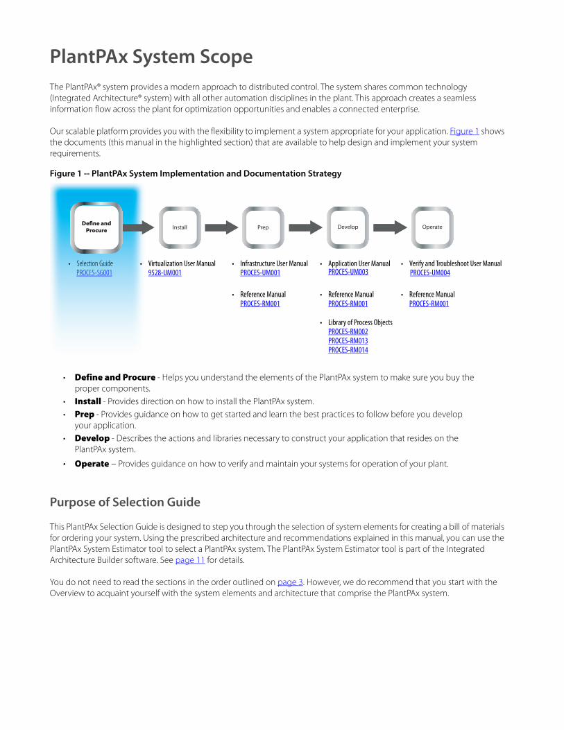
PlantPAx System Overview
The PlantPAx system is built on open industry standards, leveraging the EtherNet/IP™ network as its backbone. The EtherNet/IP network helps support seamless integration of the system components. The PlantPAx system also supports the ControlNet™ network. Both networks provide device-level communication for a business solution with real-time results from the plant floor to the top floor.
OWS Not applicable. Operator interface typically accomplished with PanelView™ Plus operator terminal or thin client connected to a distributed architecture.
Included in independent workstation. Included in PASS-C.An .ISO file is available for any single, physical computer.IMPORTANT: PASS-C supports up to10 clients.
Can have as many as 80 OWS clients.(1)
Controllers CompactLogix controller. 1...5 ControlLogix controllers. 1...5 ControlLogix controllers.
IMPORTANT: PASS-C supports up to five redundant controllers.Use the PlantPAx System Estimator to verify your design. See page 11.
There is no hard limit to the number of controllers. The number of controllers that can be supported per PASS (data server) depends on controller selection, controller loading, and number of OWS.
Application servers
Not applicable. In chassis historian and in controller batch capabilities are available. Can be also integrated with a distributed architecture.
AppServ-Asset Management as needed.AppServ-Batch as needed.AppServ-Information Management (SQL, Historian, or VantagePoint)as needed.
Additional servers can be added as your system scales. For example, AppServ-Batch, AppServ-Information Management.
IMPORTANT: An additional PASS-C is required for redundancy.
AppServ-Asset Management as neededAppServ-Batch as needed.AppServ-Information Management (SQL, Historian, or VantagePoint) as needed.AppServ-OWS as needed.
(1) These values are product maximum limits. It’s possible that achieving these limits on your system is not feasible based on your system design. Use the PlantPAx System Estimator to make sure your system is sized properly (see page 11).
Table 3 - Architectures and System Elements
System Element
Skid Architecture Station Architecture Distributed Architecture(single PASS (consolidated))
Distributed Architecture(single to multiple PASS servers)
EWS PASS Domain Controller Application Servers Multiple OWS
Redundant Controllers
Device Level Ring Topology
MCC
Local, Distributed, and Intelligent I/O
Variable Speed Drives
Rockwell Automation Publication PROCES-SG001K-EN-P - December 2018 9

Select a PlantPAx System
High Availability Architectures
In process automation, maintaining critical operations requires doing your engineering best to make sure that nothing gets lost, stops working, or is damaged. This work ethic generally involves implementing a highly available automation system. The PlantPAx platform enables high availability by offering redundancy options at each level of the architecture. You can choose the level of redundancy you need without paying for redundant components you don’t need.
High availability encompasses productivity, including reliability and maintainability. Reliability is the likelihood that a deviceperforms its intended function during a specific period of time. Maintainability is the ability of a system to be changedor repaired.
See the PlantPAx Distributed Control System Reference Manual, publication PROCES-RM001, for additional redundant components and features, such as alarms and events.
Table 4 - Redundant Element Options
System Element High Availability Options
Networks The following applies for Ethernet networks:• NIC teaming on servers and workstation uses two physical Ethernet cards on each server and workstation• Dual Ethernet media can connect the NIC cards to two separate Layer 2 switches.• Dual Ethernet fiber media can connect Layer 2 switches to Layer 3 switches via an EtherChannel connection.• A Device Level Ring network can be used to connect the I/O racks and devices to your simplex or redundant controllers.• PRP solution can be used to connect 1756 I/O or Stratix switches to your simplex or redundant controllers.
The ControlNet network supports redundant media and adapters.For more information, see Network Topologies on page 16.
Servers PASS servers can be configured as redundant for the following software components:• HMI server• Alarm and Event server• Data server
See each application server section, starting on page 37, for additional high availability options.The PlantPAx system supports off-the-shelf hardware high availability options for servers from our Encompass™ partner Stratus or through virtualization by using the VMware ESXi architecture on Industrial Data Centers. See page 12.
Server-to-Controller Communication PlantPAx system provides several methods for enabling redundant controllers via shortcuts:• Single path - ‘Traditional’ path with auto swap of single IP address for switchover of Simplex and redundant controllers.• Dual path (see illustration) - Two adapters in a controller have their own IP address.• Redundant ControlLogix controller - Primary IP address and a secondary IP address configured for a redundant pair of
Ethernet adapters. For more information, see the PlantPAx Distributed Control System Infrastructure Configuration User Manual,publication PROCES-UM001
Controllers ControlLogix controllers support enhanced redundancy on EtherNet/IP or ControlNet networks.
For more information, see Redundant Controller Hardware Requirements on page 51.
I/O modules The 1715 redundant I/O system offers redundant digital and analog I/O. The 1719 I/O adapter provides for an intrinsically safeI/O system.
For more information, see I/O Products on page 53.
Field devices Redundant process network interfaces are available for FOUNDATION Fieldbus and PROFIBUS PA networks.
For more information, see FOUNDATION Fieldbus Devices on page 59and PROFIBUS PA Devices on page 60.
Path 1Path 2
10 Rockwell Automation Publication PROCES-SG001K-EN-P - December 2018

Select a PlantPAx System
PlantPAx System Estimator
Rockwell Automation offers the PlantPAx System Estimator tool as part of the Integrated Architecture® Builder software. The System Estimator tool lets you define your PlantPAx system and verifies that your architecture and system elements are sized properly.
The System Estimator tool creates a workspace and opens a wizard (shown at right) to help you select system elements and size the system. The sizing guidelines are based on the rules and recommendations from PlantPAx system characterization to achieve known performance and reliability.
The following items are created based on your inputs:
• Supervisory Ethernet network with all servers, operator, and engineering workstations and controller chassis
• List of required software catalog numbers• ControlNet or Ethernet network for each controller that includes all I/O requirements• Various hardware views to support the various devices and chassis
After selecting the system elements as defined in this guide, use the PlantPAx System Estimator tool to modify their properties. You can then create a bill of material (BOM) with the Integrated Architecture® Builder software. The BOM includes controllers, I/O, networks, drives, cabling and wiring, and other devices that comprise your Distributed Control System.
To access the Integrated Architecture Builder software to use the PlantPAx System Estimator tool,see http://www.rockwellautomation.com/en/e-tools/configuration.html.
Software Release Information
The rules that are contained within this selection guide are based on using the following characterized software releases:• Studio 5000 Logix Designer® application, version 31.x• Studio 5000 Architect™ application, version 3.0• Studio 5000® Application Code Manager, version 1.0• FactoryTalk View software, version 10.x• FactoryTalk Batch software, version 13.x• FactoryTalk AssetCentre software, version 8.0 or later• FactoryTalk VantagePoint software, version 8.0 or later• FactoryTalk Historian software, version 5.0 or later
Performance guidelines are based on the use of the software versions listed. For new PlantPAx systems, we recommend that you use these versions of software.
For the latest compatible software information, see the Product Compatibility and Download Centerat http://www.rockwellautomation.com/rockwellautomation/support/pcdc.page.
Rockwell Automation Publication PROCES-SG001K-EN-P - December 2018 11
Select a PlantPAx System
System Infrastructure
When building your system, you must decide whether your server and client workstations are in a virtual or traditional environment. Traditional, for our purposes, means one operating system (OS) that is natively on one computer. Virtual machines are hardware independent; not tied directly to a specific hardware or OS.
This section describes the basics of the traditional and virtual infrastructures, network topologies, and Ethernet switches to help you select your system infrastructure. The Server and Workstations section (page 26) provides recommended specifications that are based on your selection of a traditional or virtual infrastructure.
Traditional Infrastructure
In a traditional infrastructure, each server and workstation is installed on its own physical machine. Software and hardware updates are performed on each server and workstation individually. In addition, there is a conventional relationship between switch ports and servers ports and a standard network management.
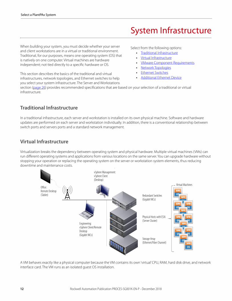
Virtual Infrastructure
Virtualization breaks the dependency between operating system and physical hardware. Multiple virtual machines (VMs) can run different operating systems and applications from various locations on the same server. You can upgrade hardware without stopping your operation or replacing the operating system on the server or workstation system elements, thus reducing downtime and maintenance costs.
A VM behaves exactly like a physical computer because the VM contains its own ‘virtual’ CPU, RAM, hard disk drive, and network interface card. The VM runs as an isolated guest OS installation.
Select from the following options:• Traditional Infrastructure• Virtual Infrastructure• VMware Component Requirements• Network Topologies• Ethernet Switches• Additional Ethernet Device
vSphere Management:vSphere Client(Desktop)
Engineering:vSphere Client/Remote Desktop(Gigabit NICs)
Office:Remote Desktop(Tablet) Redundant Switches
(Gigabit NICs)
Physical Hosts with ESXi(Server Cluster)
Storage Array(Ethernet/Fiber Channel)
Virtual Machines
12 Rockwell Automation Publication PROCES-SG001K-EN-P - December 2018

Select a PlantPAx System
The Industrial Data Center (IDC) is a centralized hub for hosting virtual servers and workstations. The IDC pre-assembled unit includes on-site commission of your system by a Rockwell Automation representative. The IDCs have different capacities based on application workloads and are available with scalable layers of support.
For purchase information, contact your local Allen-Bradley distributor or Rockwell Automation sales representative. Provide the representatives with a list of applications that you plan to deploy in an IDC.
If you are not using an IDC from Rockwell Automation, you can acquire your own dedicated or shared hosting infrastructure. For typical systems, we recommend that you use a VMware vSphere Standard license. If you want to leverage high availability across more than one Storage Area Network, we recommend that you use a VMware vSphere Enterprise license.
Rockwell Automation offers virtual image templates as an option to deploy the PlantPAx distributed control system. The PlantPAx Virtual Image Templates deliver the core system elements as pre-configured, drop-in templates. A single virtual image template needs only to be ordered. Multiple images can be deployed from a single template.
Table 5 - IDC Model Types
Model Type Description
E-2000 Cabinet (19 in.) that includes the following:
• 2 Host servers• 1 Management server• Software defined storage• VMWare vSphere standard• VMWare vCenter standard• VMWare Horizon View• Redundant server access switches• Virtual machine backup solution
Optional items:• Expands up to 10 physical servers• UPS or redundant UPS• Thin clients
E-3000 Cabinet (19 in.) that includes the following:
• 3 Host servers• 1 Management server• Software defined storage• VMWare vSphere Enterprise• VMWare vCenter standard• VMWare Horizon View• Redundant server access switches• Virtual machine backup solution
Optional items:• Expands up to 10 physical servers• UPS or redundant UPS• Thin clients
For more information, see the Industrial Data Center Product Profile at http://literature.rockwellautomation.com/idc/groups/literature/documents/pp/gsmn-pp001_-en-p.pdf.
Table 6 - Virtual Image Templates on USB Devices
Virtual Template Cat. No. Description
PASS 9528-PASSVTENM USB device contains the virtual image template for the PASS and a Microsoft® Windows® license for the Server 2012 R2 Standard. All required Rockwell Automation software is pre-installed but not activated.
EWS 9528-EWSVTENM USB device contains the virtual image template for the EWS and a Microsoft Windows license for the Windows 10 operating system. All required Rockwell Automation software is pre-installed but not activated.
OWS 9528-OWSVTENM USB device contains the virtual image template for the OWS and a Microsoft Windows license for the Windows 10 operating system. All required Rockwell Automation software is pre-installed but not activated.
AppServ-OWS, AppServ-EWS 9528-APPXWSENM USB device contains the virtual image template for AppServ-OWS and AppServ-EWS. USB device contains a Microsoft Windows license for the Server 2012 R2 Standard operating systems. All required Rockwell Automation software is pre-installed butnot activated. You also must purchase the appropriate Windows CAL from a Microsoft distributor.IMPORTANT: Each client needs an RDS CAL license.
AppServ-Info (Historian) 9528-APPHISENM USB device contains the virtual image template for AppServ-Info (Historian) and a Microsoft Windows license for the Server 2012 R2 Standard operating system. All required Rockwell Automation software is pre-installed but not activated.
AppServ-Asset 9528-APPASMENM USB device contains the virtual image template for AppServ-Asset and a Microsoft Windows license for the Server 2012 R2 Standard operating system. All required Rockwell Automation software is pre-installed but not activated.
Rockwell Automation Publication PROCES-SG001K-EN-P - December 2018 13

Select a PlantPAx System
Each template USB device includes a single OS system for each applicable type. If you are considering virtualization, we suggest that you visit the Rockwell Automation Network and Support Services website, athttp://www.rockwellautomation.com/services/networks.
Template Distribution
PlantPAx virtual image templates are obtained by the following methods:
Media -- Order a physical copy of the virtual image template and receive a Microsoft license.
Electronic Software Delivery (ESD) -- You must purchase licensed media before downloading an electronic copy of the virtual image template from the Product Compatibility and Download Center (PCDC) website.
For additional information, see the following documents:• PlantPAx Virtualization User Manual, publication 9528-UM001 — Describes the PlantPAx virtual images for the
deployment of the PlantPAx system on virtual architectures.• PlantPAx Distributed Control System Reference Manual, publication PROCES-RM001 — Provides recommendations
and guidelines for best practice of system architecture and elements.
AppServ-Info (SQL) 9528-APPSQLENM USB device contains the virtual image template for AppServ-Info (SQL) and a Microsoft Windows license for the Server 2012 R2 Standard operating system. All required Microsoft software is pre-installed and activated.
AppServ-Info (VantagePoint) 9528-APPVTPENM USB device contains the virtual image template for AppServ-Info (VantagePoint) and a Microsoft Windows license for the Server 2012 R2 Standard operating system. Most required Rockwell Automation software is pre-installed but not activated. The FactoryTalk VantagePoint software is not pre-installed for your convenience. For details, see the PlantPAx Virtualization User Manual,publication 9528-UM001.
AppServ-Batch 9528-APPBATENM USB device contains the virtual image template for AppServ-Batch and a Microsoft Windows license for the Server 2012 R2 Standard operating system. Most required Rockwell Automation software is pre-installed but not activated. The FactoryTalk Batch software is not pre-installed for your convenience. For details, see the PlantPAx Virtualization User Manual, publication 9528-UM001.
Domain controller 9528-PADCVTENM USB device contains the virtual image template for a Domain controller and a Microsoft Windows license for the Server 2012 R2 Standard operating system. You also must purchase the appropriate Windows CAL from a Microsoft distributor.
Table 7 - Installation File on USB Devices
System Element Cat. No. Description
PASS - C (consolidated) 9528-PASSCENM USB device contains a bootable image to install a consolidated PASS on a physical machine. The consolidated PASS includes Historian, VantagePoint, Asset Management, OWS, and EWS. PASS-C purchase includes a Microsoft license for the Server 2012 R2 Standard. A Rockwell Automation license is required for software activation.
OWS ISO 9528-OWSISOENM USB device contains a bootable image to install an operator workstation on a physical machine. The device contains a Microsoft license for the Windows 10 operating system. A Rockwell Automation license is required for software activation.
Table 6 - Virtual Image Templates on USB Devices
Virtual Template Cat. No. Description
14 Rockwell Automation Publication PROCES-SG001K-EN-P - December 2018

Select a PlantPAx System
VMware Component Requirements
When you purchase hardware, consider future expansion plans by adding an additional 20…30% of resources. VMware makes it simple to scale the system size upward by adding servers in the future to provide additional resources.
The VMware vCenter server provides a centralized platform for managing your VMware vSphere environments. The virtual desktop and virtual server require resources from the physical infrastructure to operate. For ESXi servers, we suggest that you reserve 2 vCPUs and 4 GB of vRAM.
Remember to divide the total system requirements by the minimum number of servers that are required to run the system at any given time. For example, with a three-server system that uses VMware fault tolerance or high availability, you divide by two. This type of calculation makes sure that the system can continue to run with two servers if one server fails.
VMware Sizing
Virtual Machines are always limited by the CPU megahertz of the physical core. A common misconception is that aVM can use as much CPU megahertz as needed from the combined total available. A single vCPU VM can never use moremegahertz than the maximum of one CPU/core. If a VM has two vCPUs, it can never use more megahertz than the maximum of each CPU/core.
Table 8 shows the number of physical cores and vCPU requirements for a PlantPAx system with a known architecture.
To calculate specific virtual requirements for your system, use the PSE. For information on the PSE tool, see page 11.
Table 8 - CPU Consolidation Ratios and PlantPAx Resource Requirements
Server and Workstation Type Ratio (vCPU: 1) vRAM vCPU
Process Automation Domain Controller (PADC) 2 4 1
Process Automation System Server (PASS) 2 8 4
Operator Workstation (OWS) 6 4 2
Engineering Workstation (EWS) 2 4 2
Operator Workstation Application Server (AppServ-OWS) 2 16 8
Engineering Workstation Application Server (AppServ-EWS) 2 8 4
Information Management Application Server Historian (AppServ-Info Historian) 2 4 2
Information Management Application Server VantagePoint (AppServ-Info VantagePoint) 2 4 2
Information Management Application Server SQL (AppServ-Info SQL) 2 4 2
Asset Management Server (AppServ-Asset) 2 4 2
Batch Management Server (AppServ-Batch) 2 4 2
VMware vCenter Server 1 4 2
System Reservation (specify percent to be reserved) 10 N/A
Rockwell Automation Publication PROCES-SG001K-EN-P - December 2018 15

Select a PlantPAx System
Network Topologies
A traditional distributed control system (DCS) is typically limited to a single option for network topologies and network switches. This traditional approach makes it difficult to integrate the DCS system with other automation or business systems to streamline operations or enable new value through a Connected Enterprise.
The PlantPAx system leverages a more modern approach, providing for more open information flow and the convergence ofIT/OT systems without sacrificing system performance and functionality. This can reduce costs through less duplicate infrastructure and can create new opportunities for optimization with improved data flow.
This section describes the selection of network topologies and components based on your specific requirements. Bulleted subheadings include considerations that are critical to quality attributes.
Application RequirementsThe following application requirements must be understood before you select the appropriate network infrastructure for your system.
• Virtualization — When virtualizing your system servers, you can also virtualize the network connections between those servers leveraging the high availability and speed advantages inherent to the platform. Make surethat you take this into consideration when determining switches and port counts in your architecture.
• High Availability — Network design is critical to engineering a robust system. The PlantPAx system offers high availability options at each level of the architecture to match your requirements. You can choose the level of high availability you need without paying for capabilities you don't need.
– You can leverage virtualization for high availability connections between servers.– You can choose to implement NIC teaming for hardware redundancy between servers and workstations.– You can leverage dual connections between your PASS servers and controllers.– You can duplicate network components so that a switch failure does not cause loss of communication. For
high availability, we recommend that you use the Converged Plantwide Ethernet (CPwE) Designand Implementation Guide, publication ENET-TD001.
– You can select network topologies like DLR or PRP for controller-to-controller, or controller-to-I/O connections. Make sure that you select the correct Ethernet adapters to support these topologies.
– You can use network switches to bridge these topologies and the broader system. In the case of DLR, you can use switches to route DLR traffic. In the case of PRP, you can use a switch as a ‘RedBox’ to connect to outside the PRP network. Regardless, you must select the correct network switch hardware to support this capability.
• Connectivity — The PlantPAx system offers many connectivity options through CPWe or specialty protocols.Connectivity requirements to consider include: MCC, Cloud Connectivity, integration with other automation systems, mobility/wireless, requirements and so on.
• Functionality — The PlantPAx system provides extensible functionality, including batch management, process safety integration, advanced controls, and so on.
System Requirements
Consider the following system attributes to select the appropriate network infrastructure for your system.• Routing — Avoid routing for critical communication, such as controller-to-controller communication, controller-to-PASS
communication, server/workstation/domain communication and controller-to-I/O communication.• Non-critical communication — Routing is okay for maintenance functions, such as FTAC PDC-to-I/O. Convergence time of
three to five seconds for failure recovery can be expected and likely handled by the system.• Multicast communication — Redundant controllers require multi-cast communication, which has to be considered in your
network design.
Redundant controllers use IP address switching to make sure of high-speed switchover of I/O communication, including critical controller-to-controller communication. IP address switching can confuse Microsoft operating systems. Therefore, we suggest to enhance redundant controller communication to an HMI server, use a dual path approach where IP addresses are not swapped. It is imperative to separate critical I/O communication from critical server communication.
16 Rockwell Automation Publication PROCES-SG001K-EN-P - December 2018

Select a PlantPAx System
The following pages show illustrations of PlantPAx system topologies. These topologies are examples only. Your application can contain firmware that is not shown in the illustrations.
Example 1: Redundant Controllers with DLR
DLR (device-level network) topology helps prevent a loss of communication between devices if a fault occurs. Multiport EtherNet/IP devices equipped with DLR technology connect directly to neighboring nodes and form a ring topology at the end devices. If a break in the line is detected, the network provides an alternate routing of the data to help recover the network at fast rates. For more information, see page 51.
Table 9 - Properties of Example 1Topology
Layer Topic Description
Supervisory Network NIC teaming Used between workstations and the system into redundant switches for high availability. Stratix 5400/5410 switches are being used as access switches for their Gigabit (Gb) port access, but Stratix 5700 switches could be used as well.
Control Network Virtual application servers Servers are being virtualized with the virtualized infrastructure connected directly into the Stratix 5410 switches. The 5410 switches are used as distribution switches by using Gb ports.
Server-to-Controller communication 1. First DLR is being used between the controllers and access switches for server-to-controller communication into redundant access switches. As these are redundant controllers, the associated network adapters in the redundant controllers can be setup to disable IP address switching for resilient HMI communication.
Supervisory Network
Control Network
I/O Network
1
2 3 MCC
Operator and Engineering Workstations
Application Servers(hypervisor)
Secondary Controller
Primary Controller
PanelView
1715 Redundant I/O
Field Devices
Rockwell Automation Publication PROCES-SG001K-EN-P - December 2018 17

Select a PlantPAx System
IMPORTANT: The DLR network provides a level of fault tolerance that permits a single point of failure, similar to a ControlNet ring. However, unlike ControlNet, powering down a device that is on a DLR network acts as a break on the ring. Consider this aspect when doing your network topology selection. If the devices on the DLR network are controlling multiple pieces of equipment and there are more than four nodes, consider the impact of de-energizing or disconnecting a panel, rack, adapter, or device that can occur as part of regular maintenance procedures. Using a star topology (or redundant ControlNet) can be a better topology to make sure these types of maintenance actions do not impact operations when compared to a large DLR network.
I/O Network I/O communication 2. Second DLR is being used for I/O communication. For devices without DLR, a 1783-ETAP module can be used to connect to the DLR ring.
MCC communication 3. Third DLR is being used for communication to an IntelliCENTER® motor control center (MCC). This ring was separated as a network to stay below device limits for DLR and the network adapter. This DLR can be shared across multiple controllers and also used for controller-to-controller communication. Typically, there are a number of DLR ring connections in the MCC through Stratix 5700 switches inside the IntelliCENTER MCC. You need to make sure the IntelliCENTER MCC is ordered properly to easily accept this topology.
Table 9 - Properties of Example 1Topology
Layer Topic Description
18 Rockwell Automation Publication PROCES-SG001K-EN-P - December 2018
Select a PlantPAx System
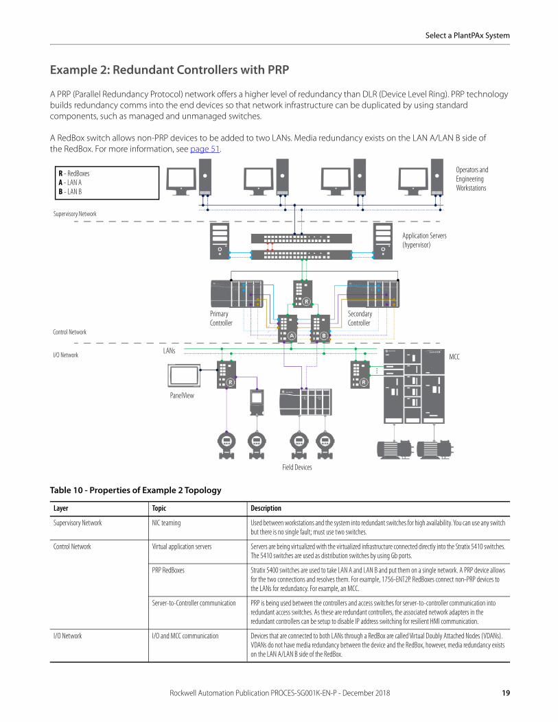
Example 2: Redundant Controllers with PRP
A PRP (Parallel Redundancy Protocol) network offers a higher level of redundancy than DLR (Device Level Ring). PRP technology builds redundancy comms into the end devices so that network infrastructure can be duplicated by using standard components, such as managed and unmanaged switches.
A RedBox switch allows non-PRP devices to be added to two LANs. Media redundancy exists on the LAN A/LAN B side ofthe RedBox. For more information, see page 51.
Table 10 - Properties of Example 2 Topology
Layer Topic Description
Supervisory Network NIC teaming Used between workstations and the system into redundant switches for high availability. You can use any switch but there is no single fault; must use two switches.
Control Network Virtual application servers Servers are being virtualized with the virtualized infrastructure connected directly into the Stratix 5410 switches. The 5410 switches are used as distribution switches by using Gb ports.
PRP RedBoxes Stratix 5400 switches are used to take LAN A and LAN B and put them on a single network. A PRP device allows for the two connections and resolves them. For example, 1756-ENT2P. RedBoxes connect non-PRP devices to the LANs for redundancy. For example, an MCC.
Server-to-Controller communication PRP is being used between the controllers and access switches for server-to-controller communication into redundant access switches. As these are redundant controllers, the associated network adapters in the redundant controllers can be setup to disable IP address switching for resilient HMI communication.
I/O Network I/O and MCC communication Devices that are connected to both LANs through a RedBox are called Virtual Doubly Attached Nodes (VDANs). VDANs do not have media redundancy between the device and the RedBox, however, media redundancy exists on the LAN A/LAN B side of the RedBox.
Supervisory Network
Control Network
I/O Network
Operators and Engineering Workstations
Application Servers(hypervisor)
Primary Controller
Secondary Controller
MCC
Field Devices
LANs
R - RedBoxesA - LAN AB - LAN B
PanelView
Rockwell Automation Publication PROCES-SG001K-EN-P - December 2018 19

Select a PlantPAx System
Example 3: Simplex Controllers and Network
Simplex controllers are often used in a Star topology, which has device nodes connected directly to a network switch. One benefit of this topology is there are no disruptions to the network when you connect or remove devices. A disadvantage is if a connecting network device fails, there is no redundancy so connected nodes cannot communicate on the network. For more information, see page 50.
Table 11 - Properties of Example 3Topology
Layer Topic Description
Supervisory Network NIC teaming (optional) NIC team is not necessary for high availability but can be used. Stratix 5400/5410 switches are being used as access switches for their Gigabit (Gb) port access, but there is no redundancy.
Control Network Virtual application servers Servers are being virtualized with the virtualized infrastructure connected directly into the Stratix 5410 switches. The 5410 switches are used as distribution switches by using Gb ports.
Server-to-Controller communication There is no DLR. Stratix 5400 switches are used in a Star configuration.
I/O Network I/O communication Access switches serve as an uplink from the servers to the workstations.
Field Devices
Supervisory Network
Control Network
I/O Network
1715 Redundant I/O
MCC
Application Servers(hypervisor)
Operators and Engineering Workstation
Primary Controller
ControlLogix I/O
PanelView
20 Rockwell Automation Publication PROCES-SG001K-EN-P - December 2018
Select a PlantPAx System
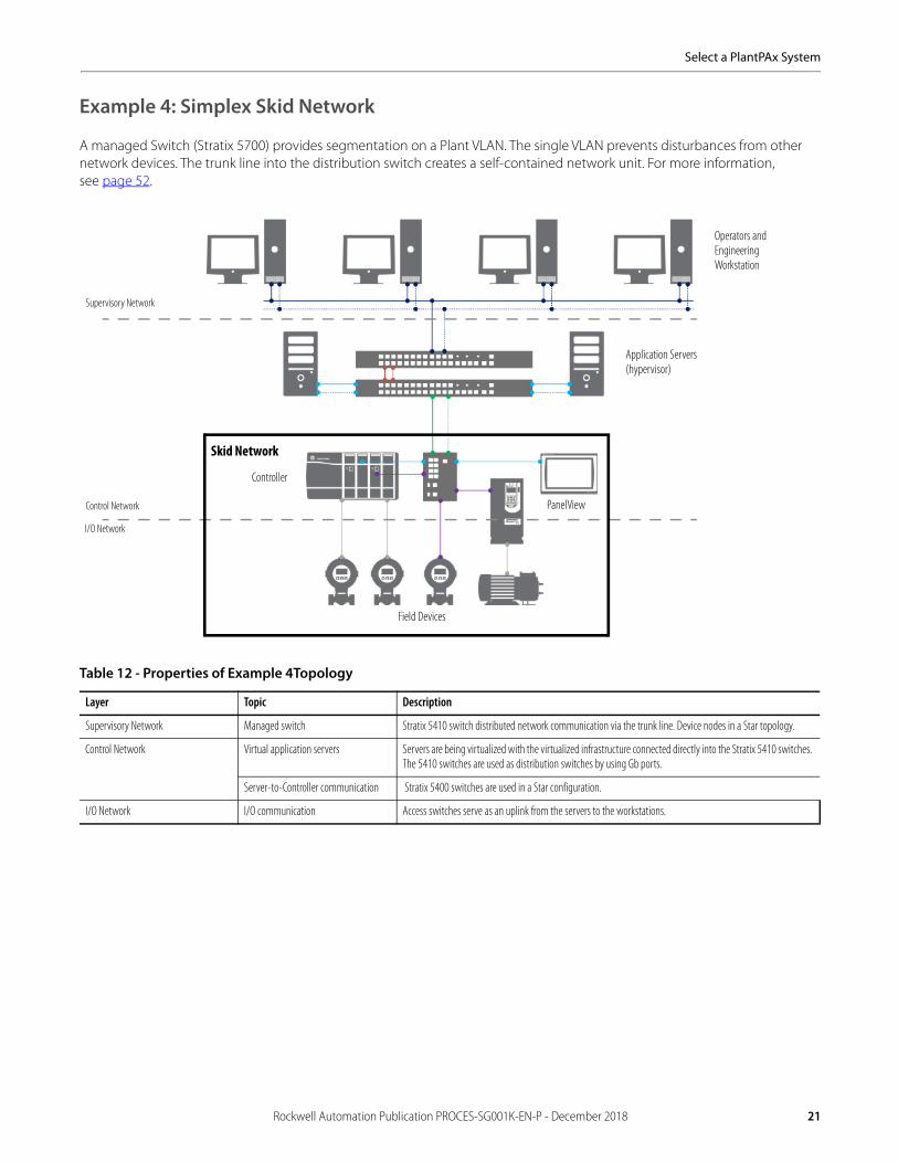
Example 4: Simplex Skid Network
A managed Switch (Stratix 5700) provides segmentation on a Plant VLAN. The single VLAN prevents disturbances from other network devices. The trunk line into the distribution switch creates a self-contained network unit. For more information,see page 52.
Table 12 - Properties of Example 4Topology
Layer Topic Description
Supervisory Network Managed switch Stratix 5410 switch distributed network communication via the trunk line. Device nodes in a Star topology.
Control Network Virtual application servers Servers are being virtualized with the virtualized infrastructure connected directly into the Stratix 5410 switches. The 5410 switches are used as distribution switches by using Gb ports.
Server-to-Controller communication Stratix 5400 switches are used in a Star configuration.
I/O Network I/O communication Access switches serve as an uplink from the servers to the workstations.
Field Devices
Operators and Engineering Workstation
Application Servers(hypervisor)
Controller
Supervisory Network
Control Network
I/O Network
Skid Network
PanelView
Rockwell Automation Publication PROCES-SG001K-EN-P - December 2018 21

Select a PlantPAx System
Other Supported Topologies
Other topologies are supported as prescribed by the Converged PlantWide Ethernet Design and Implementation Guide. However, the PlantPAx system deployment guides are based on the topologies in the previous examples.
Supported topologies include the following:• Linear network — Used between controllers and I/O. This provides lower cost due to minimal amount of cabling and
network hardware, but is sensitive to single points of failure. Ethernet adapters for devices on this network need to have dual ports embedded switch technology, such as the 1756-EN2TR.
• Switch ring — Used between switches used for server and workstation communication. The switch ring is resilient to a single media failure, in which case it becomes a linear topology and sensitive to additional failures.
• ControlNet network — Used between controllers and I/O. The ControlNet network is a different physical layer than Ethernet, so you have to support each device connected to this network. The ControlNet network also supports the option of redundant media.
For more information on ControlNet media and components, see the ControlNet Media System Components List,publication AG-PA002.
22 Rockwell Automation Publication PROCES-SG001K-EN-P - December 2018

Select a PlantPAx System
Ethernet Switches
A network switch is a computer networking device that is used to connect devices on a computer network by performing a form of packet switching. A switch is considered more advanced than a hub. A switch sends a message only to the device that needs or requests it, rather than broadcasting the same message out of each of its ports. Leveraging the collaboration of Rockwell Automation with Cisco® on products and services, the PlantPAx system integrates technical and business systems by using EtherNet/IP and industrial grade Ethernet switches.
All applications require proper configuration to achieve the best system performance. If you do not configure the managed switch, it’s possible that system performance can be adversely affected. We provide network configuration guidance in the PlantPAx System Infrastructure User Manual, publication PROCES-UM001. In any case, we recommend that you contact your system administrator if there are any doubts on the installation and configuration.
The following catalog numbers are recommended options for the PlantPAx system. For switch specifications, certifications, and the latest product information available, see the Stratix Ethernet Device Specifications Technical Data, publication 1783-TD001.
Table 13 - 5410 Ethernet Managed Switches (19-in. Rack Mount)
Cat. No. Total Ports SFP Slots(2)
(2) GE = Gigabit Ethernet; TEN = 10 Gigabit Ethernet. Use GE connections for distance up to 550 m (1804 ft). FE (fast Ethernet) provides distance up to 10 km (32,808 ft). See Table 17 on page 25.
Firmware Type Power Supply(3)
(3) One power supply ships pre-installed in each Stratix 5410 switch.
1783-IMS28NDC 28 12 GE + 4 TEN Layer 2 Low DC:24…60V DC, 10 A
1783-IMS28NAC AC/High DC:100…240V AC, 2 A or 100…250V DC, 12 A
1783-IMS28RDC Layer 3 Low DC:24…60V DC, 10 A
1783-IMS28RAC AC/High DC:100…240V AC, 2 A or 100…250V DC, 12 A
Optional Power Supplies(1)
(1) The switch supports an optional second power supply of any voltage type to provide redundancy and additional power for PoE devices. One power supply provides 60 W for PoE/PoE+. Two power supplies provide 185 W for PoE/PoE+.
1783-IMXDC Low DC
1783-IMXAC AC/High DC
Stratix 5410
Stratix 5400 Stratix 5700
Rockwell Automation Publication PROCES-SG001K-EN-P - December 2018 23

Select a PlantPAx System
Table 14 - Distribution 5400 Layer 3 Ethernet Managed Switches (DIN Rail)(1)
(1) All 5400 switches require 24V DC power. Redundant power sources recommended.
Cat. No. Total Ports RJ45 Ports(2)
(2) GE = Gigabit Ethernet. Use GE connections for distance up to 550 m (1804 ft). FE (fast Ethernet) provides distance up to 10 km (32,808 ft). See Table 17 on page 25.
Combo Ports SFP Ports
1783-HMS8TG4CGR 12 8 GE 4GE N/A
1783-HMS8SG4CGR N/A 8 GE
1783-HMS4EG8CGR 8 GE
1783-HMS4SG8EG4CGR 16 4 GE 4 GE
1783-HMS16TG4CGR 20 16 GE 4 GE N/A
1783-HMS8TG8EG4CGR 8 GE
Table 15 - Access 5400 Layer 2 Ethernet Managed Switches(1)
(1) All 5400 switches require 24V DC power. Redundant power sources recommended.
Cat. No. Total Ports RJ45 Ports(2)
(2) FE = Fast Ethernet; GE = Gigabit Ethernet. Use GE connections for distance up to 550 m (1804 ft). FE (fast Ethernet) provides distance up to 10 km (32,808 ft). See Table 17 on page 25.
Combo Ports SFP Ports
1783-HMS4C4CGN 8 N/A 4 FE, 4 GE N/A
1783-HMS8T4CGN 12 8 FE 4 GE
1783-HMS8S4CGN N/A 8 FE
1783-HMS4T4E4CGN 4 FE N/A
1783-HMS4S8E4CGN 16 N/A 4 FE
1783-HMS16T4CGN 20 16 FE N/A
1783-HMS8TG4CGN 12 8 GE
1783-HMS8SG4CGN N/A 8 GE
1783-HMS4EG8CGN 8 GE N/A
1783-HMS4SG8EG4CGN 16 4 GE 4 GE
1783-HMS16TG4CGN 20 16 GE N/A
1783-HMS8TG8EG4CGN 8 GE
Table 16 - Access 5700 Layer 2 Ethernet Managed Switches (1) (2)
(1) For configuration back up and restore, we recommend 1 GB industrial SD Card, catalog number 1784-SD1.(2) All 5700 switches require 24V DC power. Redundant power sources recommended.
Cat. No.(3)
(3) Conformal Coating is available. For more information, see the Stratix Ethernet Device Specifications Technical Data, publication 1783-TD001.
Total Ports RJ45 Ports(4)
(4) FE = Fast Ethernet; GE = Gigabit Ethernet. Use GE connections for distance up to 550 m (1804 ft). FE (fast Ethernet) provides distance up to 10 km (32,808 ft). See Table 17 on page 25.
Combo Ports SFP Slots CIP Sync (IEEE 1588)
NAT DLR
1783-BMS10CGP 10 8 FE 2 GE N/A Yes N/A Yes
1783-BMS10CGN Yes
1783-BMS12T4E2CGP 18 12 FE N/A
1783-BMS12T4E2CGNK Yes
1783-BMS20CGP 20 16 FE 2 FE N/A
1783-BMS20CGN Yes
1783-BMS20CGPK N/A
24 Rockwell Automation Publication PROCES-SG001K-EN-P - December 2018

Select a PlantPAx System
Additional Switch Information
See the Stratix Ethernet Device Specifications Technical Data, publication 1783-TD001, for information on thefollowing switch components:
• Stratix 5950 Security Appliance• Embedded EtherNet/IP Taps
We also support the use of Cisco switches. To help make sure of performance, we recommend that all system switches are Cisco or Stratix for common use of protocols.
The following switches are supported on the PlantPAx system:• Cisco Catalyst 3850 (Layer 3)• Cisco Catalyst 4500x (Layer 3)• Cisco Catalyst 2960G (Layer 2)• Cisco Catalyst 9300 (Layer 3)
For more information, see the Cisco website at www.cisco.com.
Additional Ethernet Device
The Stratix 5950 is a firewall and deep packet inspection (DPI) device. The following catalog numbers are recommended for this network device.
Table 17 - SFP Transceivers
Cat. No. SFP Description Wavelength (nm) Core Size/Cladding Size (micron)
Modal Bandwidth (MHz/km)
Cable Length
1783-SFP100FX FE 100Base-FX multi-mode transceiver
1310 50/125 500 2 km (6562 ft)
62.5/125
1783-SFP100LX 100Base-LX single-mode transceiver
G.652 N/A 10 km (32,808 ft)
1783-SFP1GSX GE 1000Base-SX multi-mode transceiver
850 62.5/125 160 220 m (722 ft)
62.5/125 200 275 m (902 ft)
50/125 400 500 m (1640 ft)
50/125 500 550 m (1804 ft)
1783-SFP1GLX 1000Base-LX/LH single-mode transceiver
1310 G.652 N/A 10 km (32,808 ft)
Table 18 - Stratix 5950 Security Appliance
Category Cat. No. Description
Security appliance • 1783-SAD4T0SBK9• 1783-SAD4T0SPK9• 1783-SAD2T2SBK9• 1783-SAD2T2SPK9
• Industrial EtherNet/IP Security Appliance, 4x10/100/1000 Base-T, K9 encryption• Industrial EtherNet/IP Security Appliance, 4x10/100/1000 Base-T, K9 encryption with VPN for SSL• Industrial EtherNet/IP Security Appliance, 2x10/100/1000 Base-T, 2x1GbE SFP, K9 encryption• Industrial EtherNet/IP Security Appliance, 2x10/100/1000 Base-T, 2x1GbE SFP, K9 encryption with VPN for SSL
Software licenses (optional) • 1783C-SADTA1YENT• 1783C-SADTA1YENTA1• 1783C-SADTA1YENTM• 1783C-SADTA1YENTMA1
• 1-year term subscription license to Threat and Application Identifiers, electronic delivery• 1-year term subscription license to Threat and Application Identifiers, electronic delivery, 24x7 TechConnectSM uplift• 1 -year term subscription license to Threat and Application Identifiers, physical media delivery• 1-year term subscription license to Threat and Application Identifiers, physical media, 24x7 TechConnectSM uplift
Stratix 5950
Rockwell Automation Publication PROCES-SG001K-EN-P - December 2018 25
Select a PlantPAx System
Servers and Workstations
The supervisory layer of the PlantPAx system can include several servers and workstations. This section explains the server and workstation system elements to help you define a bill-of-material.
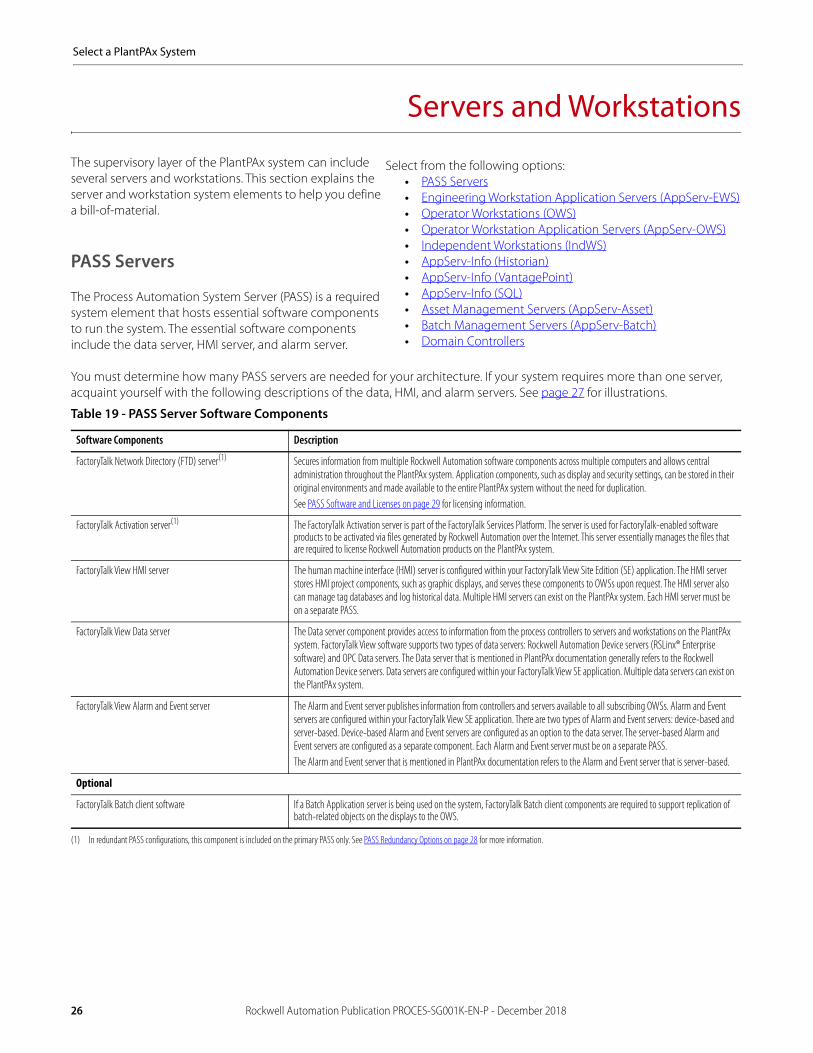
PASS Servers
The Process Automation System Server (PASS) is a required system element that hosts essential software components to run the system. The essential software components include the data server, HMI server, and alarm server.
You must determine how many PASS servers are needed for your architecture. If your system requires more than one server, acquaint yourself with the following descriptions of the data, HMI, and alarm servers. See page 27 for illustrations.
Table 19 - PASS Server Software Components
Software Components Description
FactoryTalk Network Directory (FTD) server(1)
(1) In redundant PASS configurations, this component is included on the primary PASS only. See PASS Redundancy Options on page 28 for more information.
Secures information from multiple Rockwell Automation software components across multiple computers and allows central administration throughout the PlantPAx system. Application components, such as display and security settings, can be stored in their original environments and made available to the entire PlantPAx system without the need for duplication.See PASS Software and Licenses on page 29 for licensing information.
FactoryTalk Activation server(1) The FactoryTalk Activation server is part of the FactoryTalk Services Platform. The server is used for FactoryTalk-enabled software products to be activated via files generated by Rockwell Automation over the Internet. This server essentially manages the files that are required to license Rockwell Automation products on the PlantPAx system.
FactoryTalk View HMI server The human machine interface (HMI) server is configured within your FactoryTalk View Site Edition (SE) application. The HMI server stores HMI project components, such as graphic displays, and serves these components to OWSs upon request. The HMI server also can manage tag databases and log historical data. Multiple HMI servers can exist on the PlantPAx system. Each HMI server must be on a separate PASS.
FactoryTalk View Data server The Data server component provides access to information from the process controllers to servers and workstations on the PlantPAx system. FactoryTalk View software supports two types of data servers: Rockwell Automation Device servers (RSLinx® Enterprise software) and OPC Data servers. The Data server that is mentioned in PlantPAx documentation generally refers to the Rockwell Automation Device servers. Data servers are configured within your FactoryTalk View SE application. Multiple data servers can exist on the PlantPAx system.
FactoryTalk View Alarm and Event server The Alarm and Event server publishes information from controllers and servers available to all subscribing OWSs. Alarm and Event servers are configured within your FactoryTalk View SE application. There are two types of Alarm and Event servers: device-based and server-based. Device-based Alarm and Event servers are configured as an option to the data server. The server-based Alarm and Event servers are configured as a separate component. Each Alarm and Event server must be on a separate PASS.The Alarm and Event server that is mentioned in PlantPAx documentation refers to the Alarm and Event server that is server-based.
Optional
FactoryTalk Batch client software If a Batch Application server is being used on the system, FactoryTalk Batch client components are required to support replication of batch-related objects on the displays to the OWS.
Select from the following options:• PASS Servers• Engineering Workstation Application Servers (AppServ-EWS)• Operator Workstations (OWS)• Operator Workstation Application Servers (AppServ-OWS)• Independent Workstations (IndWS)• AppServ-Info (Historian)• AppServ-Info (VantagePoint)• AppServ-Info (SQL)• Asset Management Servers (AppServ-Asset)• Batch Management Servers (AppServ-Batch)• Domain Controllers
26 Rockwell Automation Publication PROCES-SG001K-EN-P - December 2018

Select a PlantPAx System
Determining the Number of PASS Servers
The following graphics illustrate how many servers are needed when you are not considering redundancy options. If you are using redundant servers, see page 28.
Server Options Description
Option 1 - One PASS System Server This option has all of the essential software components housed in a single PASS server. The components are FTD, Data server, HMI server, and alarm and event server. See page 26 for descriptions.There are additional system elements, such as batch management, asset management, FactoryTalk Historian, and FactoryTalk VantagePoint. You can deploy these elements on separate servers or you can deploy elements on the same server as detailed in Option 2.
One HMI server license is required.
Option 2 - One PASS Consolidated Server (small/medium systems)
The PASS - C option is for valid small and medium systems with fewer than 2000 I/O points. This option provides the ability to locate multiple system elements on the same physical computer.A bootable USB device contains the system elements shown in the illustration for Option 2. See page 28 for more information.
One HMI server license is required.
Option 3 - Multiple PASS Servers (additional data capacity) This option contains all of the software components in one server as shown in Option 1. Option 3 also adds an additional server for extra data and alarm capacity without adding an additional HMI server.If the PASS server is being used as a data server, and additional capacity is needed, you can add more PASS servers. Use the PSE to determine if more PASS servers are needed. A PASS server can typically handle1…8 controllers.We recommend that you have an HMI server on the PASS if you are segregating the application into individual operational areas. See Option 4.
One HMI server license is required.
Option 4 - Multiple PASS Servers (logically segregated plant) This option lets you configure separate areas, each one with its own server that is based on theparticular process. See Option 5 on page 28 for fully independent operational areas.
An HMI server license is required for each PASS.
Option 5 - Multiple PASS Servers (logically segregated plant with independent work areas)
You can place the FTD on its own server to manage applications that exist on multiple client servers.If an area needs to be shut down, the other separate areas are not affected because the FTD is on its own server. For example, you can perform maintenance on one area without affecting another operational area of the plant. FTD can be a workstation class machine.
An HMI server license is required for each PASS containing an HMI server.
FTDData serverHMI serverAlarm server
FTDData serverHMI serverAlarm serverHistorianVantagePointAssetCentre SQL
Data serverAlarm server
FTDData serverHMI serverAlarm server
Data serverAlarm server
FTDData serverHMI serverAlarm server
Data serverHMI serverAlarm server
Data serverHMI serverAlarm server
FTD
Rockwell Automation Publication PROCES-SG001K-EN-P - December 2018 27

Select a PlantPAx System
PASS-C OptionA consolidated PASS (PASS-C) is available for small and medium systems with fewer than 2000 I/O points. The PASS-C has a full complement of HMI, data collection, decision-making, and asset management servers. The combination of these tools provides a basic PlantPAx system in a single server.
PASS Redundancy Options
PASS servers can be configured as redundant for the following software components:• HMI server• Alarm server• Data server
Redundancy can be added to be sure of the availability of critical operations. For PASS servers, you can choose the level of redundancy that you need. When a PASS is made redundant, typically all of the above elements that are hosted on the PASS are made redundant. Redundant PASS servers require duplicate hardware as listed in Table 20.1.
The PASS-C can be made redundant by duplicating the hardware as well.
Selecting redundant data servers impacts controller memory and communication bandwidth.
For more information, see the following:• High Availability Architectures on page 10• PlantPAx Distributed Control System Reference Manual, publication PROCES-RM001
Table 20.1 - PASS Virtual Requirements
Category Requirement(1)
(1) All numbers and figures are referenced for initial sizing only. The values can be adjusted for system performance if needed.
Virtual infrastructure Required: • 4 vCPU• 8 GB vRAM minRecommended CPU and memory allocation:• High priority Resource pool(2)
(2) See the PlantPAx Distributed Control System Reference Manual, publication PROCES-RM001, for Resource Pool Allocation.
Operating system Windows Server 2012 R2 operating system, 64 bit
Additional third-party software Antivirus software(3)
(3) Rockwell Automation has tested the use of Symantec Endpoint Protection. For more information, see Knowledgebase Answer ID 35330 at https://www.rockwellautomation.custhelp.com.
28 Rockwell Automation Publication PROCES-SG001K-EN-P - December 2018
Select a PlantPAx System
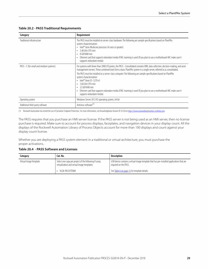
The PASS requires that you purchase an HMI server license. If the PASS server is not being used as an HMI server, then no license purchase is required. Make sure to account for process displays, faceplates, and navigation devices in your display count. All the displays of the Rockwell Automation Library of Process Objects account for more than 100 displays and count against your display count license.
Whether you are deploying a PASS system element in a traditional or virtual architecture, you must purchase theproper activations..
Table 20.2 - PASS Traditional Requirements
Category Requirement
Traditional infrastructure The PASS must be installed on server-class hardware. The following are sample specifications based on PlantPAxsystem characterization:• Intel® Xeon Multicore processor (4 cores or greater)• 2.40 GHz CPU min• 8 GB RAM min• Ethernet card that supports redundant media if NIC-teaming is used (If you plan to use a motherboard-NIC make sure it
supports redundant media)
PASS - C (for small and medium systems) For systems with fewer than 2000 I/O points, the PASS - Consolidated contains HMI, data collection, decision-making, and asset management servers. These combined tools form a basic PlantPAx system in a single server, referred to as consolidated.The PASS must be installed on a server-class computer. The following are sample specifications based on PlantPAxsystem characterization:• Intel® Xeon E3-1270 v5• 3.60 GHz CPU min• 32 GB RAM min• Ethernet card that supports redundant media if NIC-teaming is used (If you plan to use a motherboard-NIC make sure it
supports redundant media)
Operating system Windows Server 2012 R2 operating system, 64 bit
Additional third-party software Antivirus software(1)
(1) Rockwell Automation has tested the use of Symantec Endpoint Protection. For more information, see Knowledgebase Answer ID 35330 at https://www.rockwellautomation.custhelp.com.
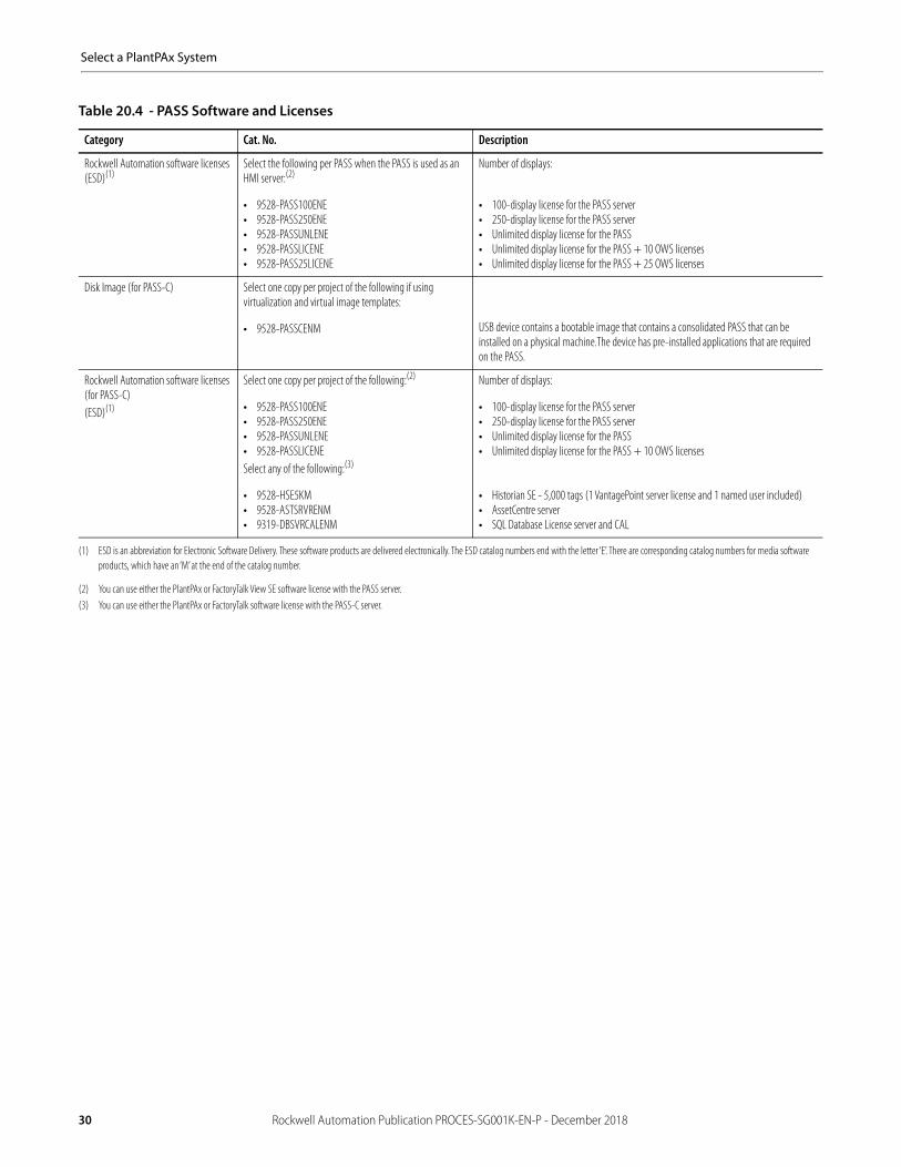
Table 20.4 - PASS Software and Licenses
Category Cat. No. Description
Virtual Image Template Select one copy per project of the following if using virtualization and virtual image templates:
• 9528-PASSVTENM
USB device contains a virtual image template that has pre-installed applications that are required on the PASS.
See Table 6 on page 13 for template details.
Rockwell Automation Publication PROCES-SG001K-EN-P - December 2018 29
Select a PlantPAx System
Rockwell Automation software licenses (ESD)(1)
Select the following per PASS when the PASS is used as an HMI server:(2)
• 9528-PASS100ENE• 9528-PASS250ENE• 9528-PASSUNLENE• 9528-PASSLICENE• 9528-PASS25LICENE
Number of displays:
• 100-display license for the PASS server• 250-display license for the PASS server• Unlimited display license for the PASS• Unlimited display license for the PASS + 10 OWS licenses• Unlimited display license for the PASS + 25 OWS licenses
Disk Image (for PASS-C) Select one copy per project of the following if using virtualization and virtual image templates:
• 9528-PASSCENM USB device contains a bootable image that contains a consolidated PASS that can be installed on a physical machine.The device has pre-installed applications that are required on the PASS.
Rockwell Automation software licenses (for PASS-C)(ESD)(1)
Select one copy per project of the following:(2)
• 9528-PASS100ENE• 9528-PASS250ENE• 9528-PASSUNLENE• 9528-PASSLICENESelect any of the following:(3)
• 9528-HSE5KM• 9528-ASTSRVRENM• 9319-DBSVRCALENM
Number of displays:
• 100-display license for the PASS server• 250-display license for the PASS server• Unlimited display license for the PASS• Unlimited display license for the PASS + 10 OWS licenses
• Historian SE - 5,000 tags (1 VantagePoint server license and 1 named user included)• AssetCentre server• SQL Database License server and CAL
(1) ESD is an abbreviation for Electronic Software Delivery. These software products are delivered electronically. The ESD catalog numbers end with the letter ‘E’. There are corresponding catalog numbers for media software products, which have an ‘M’ at the end of the catalog number.
(2) You can use either the PlantPAx or FactoryTalk View SE software license with the PASS server.(3) You can use either the PlantPAx or FactoryTalk software license with the PASS-C server.
Table 20.4 - PASS Software and Licenses
Category Cat. No. Description
30 Rockwell Automation Publication PROCES-SG001K-EN-P - December 2018

Select a PlantPAx System
Engineering Workstations (EWS)
The engineering workstation (EWS) supports system configuration, application development, and maintenance functions. The EWS is the central location for monitoring and maintaining the systems operation. The recommended limit is five EWS per system.
Whether you are deploying an EWS system element in a traditional or virtual architecture, you must purchase theproper activations.
Table 21.1 - EWS Virtual Requirements
Category Requirement(1)
(1) All numbers and figures are referenced for initial sizing only. The values can be adjusted for system performance if needed.
Virtual infrastructure Required:• 2 vCPU• 4 GB vRAM minRecommended CPU and memory allocation:• Normal priority Resource pool(2)
(2) See the PlantPAx Distributed Control System Reference Manual, publication PROCES-RM001, for Resource Pool Allocation.
Operating system Windows 10 operating system, 64 bit
Additional third-party software Antivirus software(3)
(3) Rockwell Automation has tested the use of Symantec Endpoint Protection. For more information, see Knowledgebase Answer ID 35330 at https://www.rockwellautomation.custhelp.com.
Table 21.2 - EWS Traditional Requirements
Category Requirement
Traditional infrastructure The EWS must be installed on workstation-class hardware. The following are sample specifications based on PlantPAxsystem characterization:• Intel Core 2 Duo• 2.40 GHz CPU min• 4 GB RAM min• Ethernet card that supports redundant media if NIC-teaming is used (If you plan to use a motherboard-NIC make sure that it
supports redundant media)
Operating system Windows 10 operating system, 64 bit
Additional third-party software Antivirus software(1)
(1) Rockwell Automation has tested the use of Symantec Endpoint Protection. For more information, see Knowledgebase Answer ID 35330 at http://www.rockwellautomation.custhelp.com.
Table 22 - EWS Automation System Software and License
Category Cat. No. Description
Virtual Image Template Select one per project of the following if using virtualization and virtual image templates:
• 9528-EWSVTENM
USB device contains a virtual image template that has pre-installed all applications that are required on the EWS.
See Table 6 on page 13 for template details.
Rockwell Automation software license (ESD)(1)
(1) ESD is an abbreviation for Electronic Software Delivery. These software products are delivered electronically. The ESD catalog numbers end with the letter ‘E’. There are corresponding catalog numbers for media software products, which have an ‘M’ at the end of the catalog number.
For each client that is served by the AppServ-EWS:
• 9528-EWSLICENE(2)
(2) This EWS software license is equivalent to a FactoryTalk View Studio license (9701-VWSTENE), FactoryTalk View SE Client license (9701-VWSCWAENE), and Studio 5000 Logix Designer applicationlicense (9324-RLD700NXENE). You can use the PlantPAx or FactoryTalk and Logix Designer Application licenses with the EWS.
This license is a software activation for the EWS virtual and traditional environments.
Rockwell Automation Publication PROCES-SG001K-EN-P - December 2018 31

Select a PlantPAx System
Engineering Workstation Application Servers (AppServ-EWS)
The AppServ-EWS uses Microsoft Remote Desktop Services (RDS) technology to serve multiple instances of the EWS as thin clients from a single server. Thin clients can run applications and process data on a remote computer. The recommended limitis five RDS client connections per AppServ-EWS.
Whether you are deploying an AppServ-EWS system element in a traditional or virtual architecture, you must purchase the proper activations.
Table 23.1 - AppServ-EWS Virtual Requirements
Category Description(1)
(1) All numbers and figures are referenced for initial sizing only. The values can be adjusted for system performance if needed.
Virtual Infrastructure Required:4 vCPU8 GB vRAM minRecommended CPU and memory allocation:Normal priority Resource pool
Thin client We recommend a maximum of five FactoryTalk View SE clients per application server.
Operating system Windows Server 2012 R2 operating system, 64 bit
Table 23.2 - AppServ-EWS Automation System Software and License
Category Cat. No. Description
Virtual Image Template Select one per project of the following if using virtualization and virtual image templates:
• 9528-APPXWSENM
USB device contains a virtual image template that has pre-installed all applications that are required on the EWS.
See Table 6 on page 13 for template details.
Rockwell Automation software license (ESD)(1)
IMPORTANT: A Rockwell Automation license must be purchased for each client connected to the AppServ-EWS.
(1) ESD is an abbreviation for Electronic Software Delivery. These software products are delivered electronically. The ESD catalog numbers end with the letter ‘E’. There are corresponding catalog numbers for media software products, which have an ‘M’ at the end of the catalog number.
For each AppServ-EWS:
• 9528-EWSLICENE(2)
(2) This EWS software license is equivalent to a FactoryTalk View Studio license (9701-VWSTENE), FactoryTalk View SE Client license (9701-VWSCWAENE), and Studio 5000 Logix Designer applicationlicense (9324-RLD700NXENE). You can use the PlantPAx or FactoryTalk and Logix Designer Application licenses with the EWS.
This license is a software activation for the EWS virtual and traditional environments.
32 Rockwell Automation Publication PROCES-SG001K-EN-P - December 2018

Select a PlantPAx System
Operator Workstations (OWS)
The operator workstation (OWS) provides the graphical view and interface into the process. The OWS supports operator interaction and is not meant to support development or maintenance activities, although these activities are possible if desired.
Whether you are deploying an OWS system element in a traditional or virtual architecture, you must purchase theproper activations.
Table 24.1 - OWS Virtual Requirements
Category Requirement(1)
(1) All numbers and figures are referenced for initial sizing only. The values can be adjusted for system performance if needed.
Virtual infrastructure Required:• 2 vCPU• 4 GB vRAM minRecommended CPU and memory allocation:• High priority Resource pool(2)
(2) See the PlantPAx Distributed Control System Reference Manual, publication PROCES-RM001, for Resource Pool Allocation.
Operating system Windows 10 operating system, 64 bit
Additional third-party software Antivirus software(3)
(3) Rockwell Automation has tested the use of Symantec Endpoint Protection. For more information, see Knowledgebase Answer ID 35330 at http://www.rockwellautomation.custhelp.com.
Table 24.2 - OWS Traditional Requirements
Category Requirement
Traditional infrastructure The OWS must be installed on workstation-class hardware. The following are sample specifications based on PlantPAxsystem characterization:• Intel Core 2 Duo• 2.40 GHz CPU min• 4 GB RAM min• Ethernet card that supports redundant media if NIC-teaming is used (If you plan to use a motherboard-NIC make sure that it
supports redundant media)
Operating system Windows 10 operating system, 64 bit
Additional third-party software Antivirus software(1)
(1) Rockwell Automation has tested the use of Symantec Endpoint Protection. For more information, see Knowledgebase Answer ID 35330 at http://www.rockwellautomation.custhelp.com.
Table 24.3 - OWS Automation System Software and License
Category Cat. No. Description
Virtual image template Select one per project of the following if using virtualization and virtual image templates:
• 9528-OWSVTENM
USB device contains a virtual image template that has pre-installed all applications that are required on the OWS.
See Table 6 on page 13 for template details.
Rockwell Automation software license (ESD)(1)
(1) ESD is an abbreviation for Electronic Software Delivery. These software products are delivered electronically. The ESD catalog numbers end with the letter ‘E’. There are corresponding catalog numbers for media software products, which have an ‘M’ at the end of the catalog number.
For each OWS:
• 9528-OWSLICENE(2)
(2) This PlantPAx software license is equivalent to a FactoryTalk View SE Client license (9701-VWSCWAENE). You can use either a PlantPAx or FactoryTalk View SE software license with the OWS.
This license is a software activation for the OWS virtual and traditional environments.
Rockwell Automation Publication PROCES-SG001K-EN-P - December 2018 33

Select a PlantPAx System
Operator Workstation Application Servers (AppServ-OWS)
The AppServ-OWS uses Microsoft Remote Desktop Services (RDS) technology to serve multiple instances of the OWS as thin clients from a single server. Thin clients can run applications and process data on a remote computer to minimize the amount of information on a network. The AppServ-OWS is only configured to run FactoryTalk View SE clients and the recommended limit is 10 clients per application server.
Whether you are deploying an AppServ-OWS system element in a traditional or virtual architecture, you must purchase the proper activations.
ThinManager Server Options
The AppServ-OWS system element virtual image template is pre-configured with Remote Desktop Services (RDS). The AppServ-OWS includes the ThinManager Server installation file. You can configure the AppServ-OWS as your ThinManager Server and deploy up to 10 OWS sessions to simplifying the management of all devices and users.
Table 25.1 - AppServ-OWS Virtual Requirements
Category Requirement(1)
(1) All numbers and figures are referenced for initial sizing only. The values can be adjusted for system performance if needed.
Virtual infrastructure Required:• 8 vCPU• 16 GB vRAM minRecommended CPU and memory allocation:• High priority Resource pool(2)
(2) See the PlantPAx Distributed Control System Reference Manual, publication PROCES-RM001, for Resource Pool Allocation.
Operating system Windows Server 2012 R2 operating system, 64 bit
Thin client We recommend a maximum of 10 FactoryTalk View SE clients per application server.
Additional third-party software Microsoft Internet Explorer™Antivirus software(3)
(3) Rockwell Automation has tested the use of Symantec Endpoint Protection. For more information, see Knowledgebase Answer ID 35330 at http://www.rockwellautomation.custhelp.com.
Table 25.2 - AppServ-OWS Automation System Software and License
Category Cat. No. Description
Virtual image template Select one per project of the following if using virtualization and virtual image templates:
• 9528-APPXWSENM
USB device contains a virtual template for the AppServ-OWS.
See Table 6 on page 13 for template details.
Rockwell Automation software license(EDS)(1)
IMPORTANT: A Rockwell Automation license must be purchased for each client connected to the AppServ-OWS.
(1) ESD is an abbreviation for Electronic Software Delivery. These software products are delivered electronically. The ESD catalog numbers end with the letter ‘E’. There are corresponding catalog numbers for media software products, which have an ‘M’ at the end of the catalog number.
For each client that the AppServ-OWS serves:
• 9528-OWSLICENE(2)
(2) This PlantPAx software license is equivalent to a FactoryTalk View SE Client license (9701-VWSCWAENE). You can use either a PlantPAx or FactoryTalk View SE software license with the OWS.
This license is a software activation for the OWS client that is being served by theAppServ-OWS (up-to-10 per server).
34 Rockwell Automation Publication PROCES-SG001K-EN-P - December 2018

Select a PlantPAx System
ThinManager increases your productivity, visualization, mobility, and security from one easy-to-use, centralized, and scalable management platform.
Safely and securely deliver your content to any combination of device, user, and location with the following features:• Boost productivity by reducing the time spent in managing computers• Enhance visualization by delivering your content to where you need it and the way you want it shown• Extend security through encrypted communications, active directory, and secure thin clients• Smart mobility where QR codes, Bluetooth, Wi-Fi, and GPS make sure that devices receive content in authorized areas
For more information, contact your Rockwell Automation representative.
ThinManager
Deliver multiple sessions to multiple monitors and customized virtual screens on a single thin client.
Access feeds from USB and IP cameras.
Deliver applications based on what is assigned to the terminal or user. Deliver content to the right person
at the right time and place.
Get mobile access to applications specific to a user’s role.
Manage and deliver virtual desktops while running PCs
as a thin client.
Remote Desktop Servers Virtual Resources
Rockwell Automation Publication PROCES-SG001K-EN-P - December 2018 35

Select a PlantPAx System
Independent Workstations (IndWS)
The independent workstation (IndWS) combines the roles of the PASS, EWS, and OWS in one computer. This workstation can be used as a ‘shadow system’ for emergency purposes.
If you are deploying an IndWS system element, you must purchase the proper activations.
Table 26.1 - IndWS Traditional Requirements
Category Requirement
Traditional infrastructure The IndWS must be installed on workstation-class hardware. The following are sample specifications based on PlantPAxsystem characterization:• Intel Multicore processor (4 cores or greater)• 2.40 GHz CPU min• 8 GB RAM min• Ethernet card that supports redundant media if NIC-teaming is used (If you plan to use a motherboard-NIC make sure that it
supports redundant media)
Operating system Windows 10 operating system, 64 bit
Additional third-party software Antivirus software(1)
(1) Rockwell Automation has tested the use of Symantec Endpoint Protection. For more information, see Knowledgebase Answer ID 35330 at http://www.rockwellautomation.custhelp.com.
Table 26.2 - IndWS Automation System Software and Licenses
Category Cat. No. Description
PlantPAx software One per IndWS if being used as EWS:
• 95324-RLD700NXENE • Studio 5000 Logic Designer Professional Edition, English version
Rockwell Automation software licenses Select one of the following:
• 9701-VWSB100AENE• 9701-VWSB250AENE• 9701-VWSB000AENE
Number of displays:
• 100 display license with FactoryTalk View SE network station• 250 display license with FactoryTalk View SE network station• Unlimited display license with FactoryTalk View SE network station
36 Rockwell Automation Publication PROCES-SG001K-EN-P - December 2018
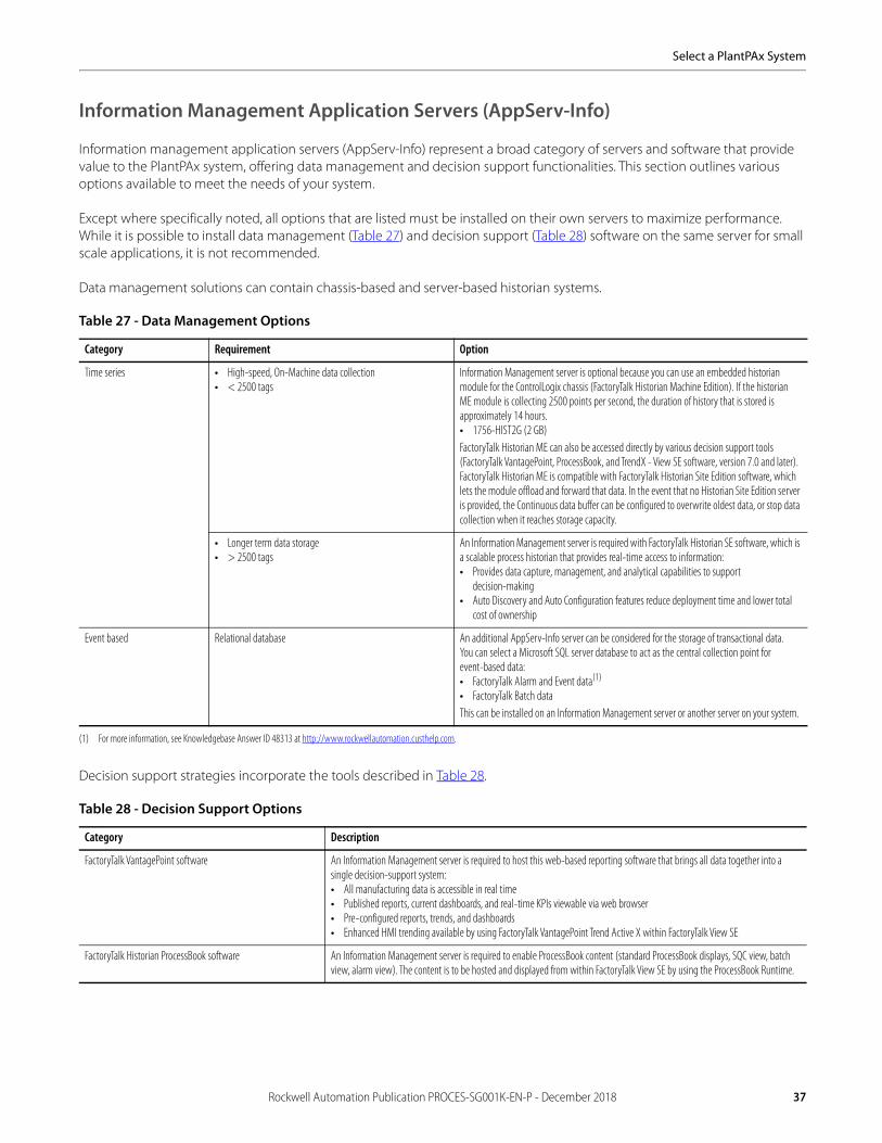
Select a PlantPAx System
Information Management Application Servers (AppServ-Info)
Information management application servers (AppServ-Info) represent a broad category of servers and software that provide value to the PlantPAx system, offering data management and decision support functionalities. This section outlines various options available to meet the needs of your system.
Except where specifically noted, all options that are listed must be installed on their own servers to maximize performance. While it is possible to install data management (Table 27) and decision support (Table 28) software on the same server for small scale applications, it is not recommended.
Data management solutions can contain chassis-based and server-based historian systems.
Decision support strategies incorporate the tools described in Table 28.
Table 27 - Data Management Options
Category Requirement Option
Time series • High-speed, On-Machine data collection• < 2500 tags
Information Management server is optional because you can use an embedded historian module for the ControlLogix chassis (FactoryTalk Historian Machine Edition). If the historianME module is collecting 2500 points per second, the duration of history that is stored is approximately 14 hours.• 1756-HIST2G (2 GB)FactoryTalk Historian ME can also be accessed directly by various decision support tools (FactoryTalk VantagePoint, ProcessBook, and TrendX - View SE software, version 7.0 and later). FactoryTalk Historian ME is compatible with FactoryTalk Historian Site Edition software, which lets the module offload and forward that data. In the event that no Historian Site Edition server is provided, the Continuous data buffer can be configured to overwrite oldest data, or stop data collection when it reaches storage capacity.
• Longer term data storage• > 2500 tags
An Information Management server is required with FactoryTalk Historian SE software, which is a scalable process historian that provides real-time access to information:• Provides data capture, management, and analytical capabilities to support
decision-making• Auto Discovery and Auto Configuration features reduce deployment time and lower total
cost of ownership
Event based Relational database An additional AppServ-Info server can be considered for the storage of transactional data.You can select a Microsoft SQL server database to act as the central collection point forevent-based data:• FactoryTalk Alarm and Event data(1)
• FactoryTalk Batch dataThis can be installed on an Information Management server or another server on your system.
(1) For more information, see Knowledgebase Answer ID 48313 at http://www.rockwellautomation.custhelp.com.
Table 28 - Decision Support Options
Category Description
FactoryTalk VantagePoint software An Information Management server is required to host this web-based reporting software that brings all data together into a single decision-support system:• All manufacturing data is accessible in real time• Published reports, current dashboards, and real-time KPIs viewable via web browser• Pre-configured reports, trends, and dashboards• Enhanced HMI trending available by using FactoryTalk VantagePoint Trend Active X within FactoryTalk View SE
FactoryTalk Historian ProcessBook software An Information Management server is required to enable ProcessBook content (standard ProcessBook displays, SQC view, batch view, alarm view). The content is to be hosted and displayed from within FactoryTalk View SE by using the ProcessBook Runtime.
Rockwell Automation Publication PROCES-SG001K-EN-P - December 2018 37

Select a PlantPAx System
We recommend that you host FactoryTalk Historian and FactoryTalk VantagePoint applications on separate information management servers. The same server requirements apply for each server.
See Knowledgebase Answer ID 62869 at http://www.rockwellautomation.custhelp.com for guidance on whether one or more servers are required.
AppServ-Info (Historian)
One of the ways to configure the AppServ-Info is as a historian to collect data. Follow these guidelines if you are adding a Historian server to your PlantPAx system..AppServ-Info (VantagePoint).
Table 29.1 - AppServ-Info (Historian) Virtual Requirements
Category Requirement(1)
(1) All numbers and figures are referenced for initial sizing only. The values can be adjusted for system performance if needed.
Virtual infrastructure Required:• 2 vCPU• 4 GB vRAM minRecommended CPU and memory allocation:• Normal priority Resource pool(2)
(2) See the PlantPAx Distributed Control System Reference Manual, publication PROCES-RM001, for Resource Pool Allocation.
Operating system Windows Server 2012 R2 operating system, 64 bit (3)
(3) To install FactoryTalk View SE Historian software, version 4.0, with Windows Server 2012, you must install a patch from the Product Compatibility and Download Center athttp://www.rockwellautomation.com/rockwellautomation/support/pcdc.page.
Additional third-party software Antivirus software(4)
(4) Rockwell Automation has tested the use of Symantec Endpoint Protection. For more information, see Knowledgebase Answer ID 35330 at http://www.rockwellautomation.custhelp.com.
Table 29.2 - AppServ-Info (Historian) Traditional Requirements
Category Requirement
Traditional infrastructure The Information Management server must be installed on server-class hardware:• Intel Xeon Multicore processor (4 cores or greater)• 2.40 GHz CPU min• 4 GB RAM min• Ethernet card that supports redundant media if NIC-teaming is used (If you plan to use a motherboard-NIC make sure that it
supports redundant media)
Operating system Windows Server 2012 R2 operating system, 64 bit (1)
(1) To install FactoryTalk View SE Historian software, version 4.0, with Windows server 2012, you must install a patch from the Product Compatibility and Download Center athttp://www.rockwellautomation.com/rockwellautomation/support/pcdc.page
Additional third-party software Antivirus software(2)
(2) Rockwell Automation has tested the use of Symantec Endpoint Protection. For more information, see Knowledgebase Answer ID 35330 at http://www.rockwellautomation.custhelp.com.
Table 29.3 - AppServ-Info (Historian) Software
Category Requirement Description
Virtual image template Select one per project of the following if using virtualization and virtual image templates:
• 9528-APPHISENM
USB device contains a virtual template for the AppServ-Info (Historian).
See Table 6 on page 13 for template details.
38 Rockwell Automation Publication PROCES-SG001K-EN-P - December 2018

Select a PlantPAx System
Whether you are deploying a Historian system element in a traditional or virtual architecture, you must purchase theproper activations.
Table 29.4 - FactoryTalk Historian Licenses
Category Cat. No.(1) (2)
(1) English version is listed. Different languages are available by contacting your local Allen-Bradley distributor or Rockwell Automation sales representative.(2) If you plan to use redundant Historian for high availability, you must duplicate the number of licenses. Licenses on the backup Historian must mirror the licenses on the primary Historian.
Description
FactoryTalk Historian software includes a FactoryTalk VantagePoint software license and one named user client. The number of users is cumulative, and can be a mixed number of named users and concurrent users. If you choose concurrent on the PSE, you must purchase a license for the server based on the number of active CPUs on the server.
Virtual server license(ESD)(3) (4)
(3) ESD is an abbreviation for Electronic Software Delivery. These software products are delivered electronically. The ESD catalog numbers end with the letter ‘E’. There are corresponding catalog numbers for media software products, which have an ‘M’ at the end of the catalog number.
(4) The Virtual server software licenses are equivalent to FactoryTalk Historian licenses that start with 9518. You can use a virtual server or a FactoryTalk Historian software license with a Historian system element.
Select one of the licenses:(5)
• 9528-HSE250• 9528-HSE500• 9528-HSE1K• 9528-HSE2K5• 9528-HSE5K• 9528-HSE10K
(5) These Historian server licenses are equivalent to a FactoryTalk Historian software licenses: 9518-HSE250, 9518-HSE500, 9518-HSE1Km 9518-HSE2K5, 9518-HSE5K, and 9518-HSE10K. You can use either the PlantPAx or FactoryTalk Historian software license.
License for:• 250 tags for the Historian server• 500 tags for the Historian server• 1000 tags for the Historian server• 2500 tags for the Historian server• 5000 tags for the Historian server• 10,000 tags for the Historian server
ProcessBook(ESD)
Select for each client that is using ProcessBook:
• 9518-HPBENE• 9518-HPBENFE
License for:• FactoryTalk Historian ProcessBook - Single User• FactoryTalk Historian ProcessBook - Concurrent User
Excel Add-in(ESD)
Select the following:
• 9518-HDLENE• 9518-HDLENFE
License for:• FactoryTalk Historian DataLink Excel Add-In - Single User• FactoryTalk Historian DataLlink Excel Add-In - Concurrent User
Rockwell Automation Publication PROCES-SG001K-EN-P - December 2018 39

Select a PlantPAx System
AppServ-Info (VantagePoint)
AppServ-Info can be configured as a decision support tool by using VantagePoint software.
Whether you are deploying a VantagePoint system element in a traditional or virtual architecture, you must purchase the proper activations.
Table 30.1 - AppServ-Info (VantagePoint) Virtual Requirements
Category Requirement(1)
(1) All numbers and figures are referenced for initial sizing only. The values can be adjusted for system performance if needed.
Virtual infrastructure Required:• 2 vCPU• 4 GB vRAM minRecommended CPU and memory allocation:• Normal priority Resource pool(2)
(2) See the PlantPAx Distributed Control System Reference Manual, publication PROCES-RM001, for Resource Pool Allocation.
Operating system Windows Server 2012 R2 operating system, 64 bit
Additional third-party software Antivirus software(3)
(3) Rockwell Automation has tested the use of Symantec Endpoint Protection. For more information, see Knowledgebase Answer ID 35330 at http://www.rockwellautomation.custhelp.com.
Table 30.2 - AppServ-Info (VantagePoint) Traditional Requirements
Category Requirement
Traditional infrastructure The Information Management server must be installed on server-class hardware:• Intel Xeon Multicore processor (4 cores or greater)• 2.40 GHz CPU min• 4 GB RAM min• Ethernet card that supports redundant media if NIC-teaming is used (If you plan to use a motherboard-NIC make sure that it
supports redundant media)
Operating system Windows Server 2012 R2 operating system, 64 bit
Additional third-party software Antivirus software(1)
(1) Rockwell Automation has tested the use of Symantec Endpoint Protection. For more information, see Knowledgebase Answer ID 35330 at http://www.rockwellautomation.custhelp.com.
Table 30.3 - AppServ-Info (VantagePoint) Software
Category Requirement Description
Virtual image template Select one per project of the following if using virtualization and virtual image templates:
• 9528-APPVTPENM
USB device contains a virtual template for the AppServ-Info (VantagePoint).
See Table 6 on page 13 for template details.
Table 30.4 - FactoryTalk VantagePoint Licenses
Category Cat. No.(3) Description
FactoryTalk VantagePoint software licenses consist of user clients. The number of users is cumulative, and can be a mixed number of named users and concurrent users. If you choose concurrent on the PSE, you must purchase a license for the server based on the number of active CPUs on the server.(1)
Virtual server license (ESD)(2) Select the following:
• 9528-VPSERVERENE This license is for activation of the FactoryTalk VantagePoint EMI server software
Virtual server named user licenses(ESD)
Select one or more of the following for FactoryTalk VantagePoint Client named users:
• 9528-VPNL01ENE• 9528-VPNL03ENE• 9528-VPNL05ENE
License for:• 1 named user• 3 named users• 5 named users
40 Rockwell Automation Publication PROCES-SG001K-EN-P - December 2018

Select a PlantPAx System
Virtual server named user licenses(ESD)
Select one or more of the following for FactoryTalk VantagePoint Client concurrent users:
• 9528-VPCL01ENE• 9528-VPCL03ENE• 9528-VPCL05ENE• 9528-VPCL010ENE
License for:• 1 concurrent user• 3 concurrent users• 5 concurrent users• 10 concurrent users
Virtual server concurrent user licenses(ESD)
If VantagePoint is being used for concurrent users, select one for each CPU of the hosting server:
• 9528-VPCPPENE This license is for activation of the FactoryTalk VantagePoint Concurrent User CPU License (per CPU)
Virtual server data connector licenses(ESD)
Select the following:
• 9528-VPHSCENE• 9528-VPRTCENE
This license if for activation of the FactoryTalk VantagePoint 3rd Party Historian ConnectorThis license is for activation of the FactoryTalk VantagePoint 3rd Party Real-time Connector
(1) This charge applies if you purchase concurrent users and use the SQL server license that is included with VantagePoint. If you have your own SQL server license this charge does not apply. A separate license is required for each physical processor on the server running the SQL server used by VantagePoint (the SQL server identified during the install of VantagePoint).
(2) ESD is an abbreviation for Electronic Software Delivery. These software products are delivered electronically. The ESD catalog numbers end with the letter ‘E’. There are corresponding catalog numbers for media software products, which have an ‘M’ at the end of the catalog number.
(3) English version is listed. Different languages are available by contacting your local Allen-Bradley distributor or Rockwell Automation sales representative.
Table 30.4 - FactoryTalk VantagePoint Licenses
Category Cat. No.(3) Description
FactoryTalk VantagePoint software licenses consist of user clients. The number of users is cumulative, and can be a mixed number of named users and concurrent users. If you choose concurrent on the PSE, you must purchase a license for the server based on the number of active CPUs on the server.(1)
Rockwell Automation Publication PROCES-SG001K-EN-P - December 2018 41
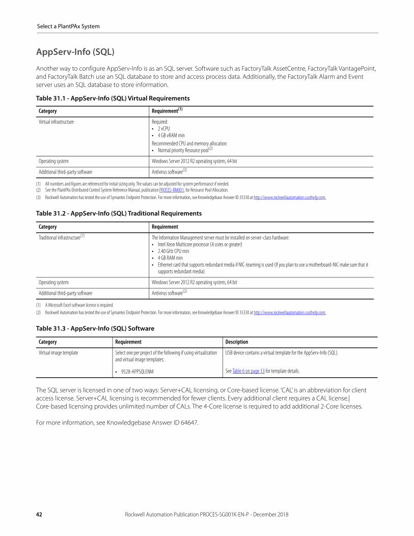
Select a PlantPAx System
AppServ-Info (SQL)
Another way to configure AppServ-Info is as an SQL server. Software such as FactoryTalk AssetCentre, FactoryTalk VantagePoint, and FactoryTalk Batch use an SQL database to store and access process data. Additionally, the FactoryTalk Alarm and Event server uses an SQL database to store information.
The SQL server is licensed in one of two ways: Server+CAL licensing, or Core-based license. ‘CAL’ is an abbreviation for client access license. Server+CAL licensing is recommended for fewer clients. Every additional client requires a CAL license.|Core-based licensing provides unlimited number of CALs. The 4-Core license is required to add additional 2-Core licenses.
For more information, see Knowledgebase Answer ID 64647.
Table 31.1 - AppServ-Info (SQL) Virtual Requirements
Category Requirement(1)
(1) All numbers and figures are referenced for initial sizing only. The values can be adjusted for system performance if needed.
Virtual infrastructure Required:• 2 vCPU• 4 GB vRAM minRecommended CPU and memory allocation:• Normal priority Resource pool(2)
(2) See the PlantPAx Distributed Control System Reference Manual, publication PROCES-RM001, for Resource Pool Allocation.
Operating system Windows Server 2012 R2 operating system, 64 bit
Additional third-party software Antivirus software(3)
(3) Rockwell Automation has tested the use of Symantec Endpoint Protection. For more information, see Knowledgebase Answer ID 35330 at http://www.rockwellautomation.custhelp.com.
Table 31.2 - AppServ-Info (SQL) Traditional Requirements
Category Requirement
Traditional infrastructure(1)
(1) A Microsoft Excel software license is required.
The Information Management server must be installed on server-class hardware:• Intel Xeon Multicore processor (4 cores or greater)• 2.40 GHz CPU min• 4 GB RAM min• Ethernet card that supports redundant media if NIC-teaming is used (If you plan to use a motherboard-NIC make sure that it
supports redundant media)
Operating system Windows Server 2012 R2 operating system, 64 bit
Additional third-party software Antivirus software(2)
(2) Rockwell Automation has tested the use of Symantec Endpoint Protection. For more information, see Knowledgebase Answer ID 35330 at http://www.rockwellautomation.custhelp.com.
Table 31.3 - AppServ-Info (SQL) Software
Category Requirement Description
Virtual image template Select one per project of the following if using virtualization and virtual image templates:
• 9528-APPSQLENM
USB device contains a virtual template for the AppServ-Info (SQL).
See Table 6 on page 13 for template details.
42 Rockwell Automation Publication PROCES-SG001K-EN-P - December 2018

Select a PlantPAx System
Whether you are deploying a SQL system element in a traditional or virtual architecture, you must purchase theproper activations.
Asset Management Servers (AppServ-Asset)
An asset management server (AppServ-Asset) is an extension to the PlantPAx system that adds maintenance and plant operations to the system. This server provides controller data backup for disaster recovery, diagnostics, calibration, real-time monitoring, as well as auditing equipment and network health to improve overall resource availability.
The asset management server provides centralized system management for Rockwell Automation and third-partyfield assets.
Table 31.4 - FactoryTalk SQL Server Licenses
Category Cat. No.(2)
(2) English version is listed. Different languages are available by contacting your local Allen-Bradley distributor or Rockwell Automation sales representative.
Description
Virtual server licenses(1)
(1) The Virtual server software licenses are equivalent to FactoryTalk Database licenses that start with 9319. You can use a virtual server or a FactoryTalk Database software license with a SQL server system element.
Select one of the following:
• 9319-DBSVRCALENM(3)
• 9319-DBADCALENE(4)
• 9319-DBCOR4ENM(3)
• 9319-DBADCOR2ENE
(3) One catalog number (either 9319-DBSVRCALENM or 9319-DBCOR4ENM) is required for each Database server to be licensed. These products (all 9319 Bulletin catalogs in table 32.4 can only be sold to a customer that is using this SQL server license with a qualifying FactoryTalk product: AssetCentre, VantagePoint, Metrics, EnergyMetrix, Historian SE, Historian Classic. If such a product is not included at the time of placing the order, a serial number for a listed qualifying FactoryTalk product must be provided.
(4) Catalog numbers 9319-DBADCALENM and 9319-DBADCOR2ENM require prior or simultaneous purchase of 9319-DBSVRCALENM or 9319-DBCOR4ENM. Any number can be purchased, one for each user or device.
License for:• FactoryTalk Database 1 Server and 1 Client Access License (CAL)• FactoryTalk Database 1 CAL• 4 Cores (unlimited CALs)• 2 Cores (unlimited CALs)
Table 32.1 - AppServ-Asset Virtual Requirements
Category Requirement(1)
(1) All numbers and figures are referenced for initial sizing only. The values can be adjusted for system performance if needed.
Virtual infrastructure Required: • 2 vCPU• 4 GB vRAM minRecommended CPU and memory allocation:• Normal priority Resource pool(2)
(2) See the PlantPAx Distributed Control System Reference Manual, publication PROCES-RM001, for Resource Pool Allocation.
Operating system Windows Server 2012 R2 operating system, 64 bit
Additional third-party software Antivirus software(3)
(3) Rockwell Automation has tested the use of Symantec Endpoint Protection. For more information, see Knowledgebase Answer ID 35330 at http://www.rockwellautomation.custhelp.com.
Table 32.2 - AppServ-Asset Traditional Requirements
Category Requirement
Traditional infrastructure The Asset Management server must be installed on server-class hardware:• Intel Xeon Multicore processor (4 cores or greater)• 2.40 GHz CPU min• 4 GB RAM min• Ethernet card that supports redundant media if NIC-teaming is used (If you plan to use a motherboard-NIC make sure that it
supports redundant media)
Operating system Windows Server 2012 R2 operating system, 64 bit
Additional third-party software Antivirus software(1)
(1) Rockwell Automation has tested the use of Symantec Endpoint Protection. For more information, see Knowledgebase Answer ID 35330 at http://www.rockwellautomation.custhelp.com.
Rockwell Automation Publication PROCES-SG001K-EN-P - December 2018 43

Select a PlantPAx System
Whether you are deploying an AppServ-Asset system element in a traditional or virtual architecture, you must purchase the proper activations.
Table 32.3 - AppServ-Asset Software
Category Requirement Description
Virtual image template Select one per project of the following if using virtualization and virtual image templates:
• 9528-APPASMENM
USB device contains a virtual template for the AppServ-Asset.
See Table 6 on page 13 for template details.
Table 32.4 - AppServ-Asset Licenses
Category Cat. No.(1)
(1) Additional licenses are available for disaster recovery and calibration management. English version is listed. Different languages are available by contacting your local Allen-Bradley distributor or Rockwell Automationsales representative.
Description
Virtual server licenses(ESD)(2)
(2) ESD is an abbreviation for Electronic Software Delivery. These software products are delivered electronically. The ESD catalog numbers end with the letter ‘E’. There are corresponding catalog numbers for media software products, which have an ‘M’ at the end of the catalog number.
The following is required to include anyoption below:
• 9528-ASTSRVRENE This license is for activation of the FactoryTalk AssetCentre server software
Virtual server asset licenses(ESD)
Select one or more of the following so that the sum of licenses is equal to or greater than the number of assets that is to be managed by the Asset Management server:(3)
• 9528-ASTCAP0005E• 9528-ASTCAP0025E• 9528-ASTCAP0100E• 9528-ASTCAP0500E
(3) The Virtual server licenses are equivalent to FactoryTalk AssetCentre licenses that start with 9515. You can use a virtual server or a FactoryTalk AssetCentre software license with an Asset Management system element.
License for:• 5 additional assets for your Asset Management server• 25 additional assets for your Asset Management server• 100 additional assets for your Asset Management server• 500 additional assets for your Asset Management server
Virtual server process device configuration (ESD)
If process device configuration is to be used,select the following:
• 9528-ASTPRDCFENE This license is for FactoryTalk AssetCentre process device configuration
Virtual server disaster recovery licenses (ESD)
If disaster recovery is to be used, select all ofthe following:
• 9528-ASTDRROKENE• 9528-ASTDRRCENE
License for:• Disaster recovery for Rockwell Automation• Disaster recovery for remote computers
Virtual server calibration licenses(ESD)
If calibration management is to be used, the first license is required and the remainder are optional:
• 9515-ASTCLMANENE• 9515-ASTCLWRKENEE• 9515-ASTCLFLKENE
License for:• FactoryTalk AssetCentre calibration management• FactoryTalk AssetCentre calibration management remote workstation• FactoryTalk AssetCentre calibration management FLUK documenting calibration
44 Rockwell Automation Publication PROCES-SG001K-EN-P - December 2018

Select a PlantPAx System
Batch Management Servers (AppServ-Batch)
The batch management server (AppServ-Batch) offers equipment-independent recipe management, batch-independent equipment control, and regulatory compliance. System size varies from small to large and system requirements vary from simple to complex.
Basic solutions provide capabilities for small or simple systems to use core system functions, including Logix5000™ controllers and FactoryTalk View HMI. Generally these solutions do not need the functionality provided by server-based FactoryTalk Batch software solutions. Comprehensive solutions provide capability for large or complex systems to use modular software components. This solution includes FactoryTalk Batch software, eProcedure® software, and Material Manager software.
You need a batch server when any of the following apply for your system:• Equipment allocation and arbitration• Complex recipes (product recipes with loops, branches, and transitions; phases with more than four inputs
and four outputs)• Multiple unit coordination (product is made across multiple, coordinated units)• More than 32 recipes• String values or numeration-required for parameter and report values• Number of parameters or report values required by phase > 4• Require class-based recipes• Manual and electronic work instructions (web-based instructions, embedded pictures, video)• Material management (materials, containers, lots, locations, and inventory tracking.
Table 33.1 - AppServ-Batch Virtual Requirements
Category Requirement(1)
(1) All numbers and figures are referenced for initial sizing only. The values can be adjusted for system performance if needed.
Virtual infrastructure Required:• 2 vCPU• 4 GB vRAM minRecommended CPU and memory allocation:• Normal priority Resource pool(2)
(2) See the PlantPAx Distributed Control System Reference Manual, publication PROCES-RM001, for Resource Pool Allocation.
Operating system Windows Server 2012 R2 operating system, 64 bit
Additional third-party software Antivirus software(3)
(3) Rockwell Automation has tested the use of Symantec Endpoint Protection. For more information, see Knowledgebase Answer ID 35330 at http://www.rockwellautomation.custhelp.com.
Table 33.2 - AppServ-Batch Traditional Requirements
Category Requirement
Traditional infrastructure The Batch Management server must be installed on server-class hardware:• Intel Xeon Multicore processor (4 cores or greater)• 2.40 GHz CPU min• 4 GB RAM min• Ethernet card that supports redundant media if NIC-teaming is used (If you plan to use a motherboard-NIC make sure that it
supports redundant media)
Operating system Windows Server 2012 R2 operating system, 64 bit
Additional third-party software Antivirus software(1)
(1) Rockwell Automation has tested the use of Symantec Endpoint Protection. For more information, see Knowledgebase Answer ID 35330 at http://www.rockwellautomation.custhelp.com.
Rockwell Automation Publication PROCES-SG001K-EN-P - December 2018 45

Select a PlantPAx System
Whether you are deploying an AppServ-Batch in a traditional or virtual architecture, you must purchase the proper activations.
Table 33.3 - AppServ-Batch Software
Category Requirement Description
Virtual image template Select one per project of the following if using virtualization and virtual image templates:
• 9528-APPBATENM
USB device contains a virtual template for the AppServ-Asset.
See Table 6 on page 13 for template details.
Table 33.4 - AppServ-Batch Licenses
Category Cat. No. Description
Batch unit software licenses(ESD)(1)
(1) ESD is an abbreviation for Electronic Software Delivery. These software products are delivered electronically. The ESD catalog numbers end with the letter ‘E’. There are corresponding catalog numbers for media software products, which have an ‘M’ at the end of the catalog number.
Purchase multiple licenses to obtain the desired number of batch units. For example, purchase 3 licenses if you have 100 units on a single batch unit -- 1 license with 10 units, 1 license for 30 units, and 1 license for 60 units:
• 9358-FTB01ENE• 9358-FTB03ENE• 9358-FTB10ENE• 9358-FTB30ENE• 9358-FTB60ENE
License for:• FactoryTalk Batch - 1 unit• FactoryTalk Batch - 3 units• FactoryTalk Batch - 10 units• FactoryTalk Batch - 30 units• FactoryTalk Batch - 60 units
Batch backup software licenses(ESD)
If a back-up server is enabled on the PlantPAx System Estimator, an additional server is added to the BOM with an equal number of back-up server unit licenses. These are license options:
• 9358-FTBKY01ENE• 9358-FTBKY03ENEE• 9358-FTBKY10ENE• 9358-FTBKY30ENE• 9358-FTBKY60ENE
License for:• FactoryTalk Batch Back-up Key - 1 unit• FactoryTalk Batch Back-up Key - 3 units• FactoryTalk Batch Back-up Key - 10 units• FactoryTalk Batch Back-up Key - 30 units• FactoryTalk Batch Back-up Key - 60 units
eProcedure software licenses(ESD)
eProcedure is included with Batch licenses listed above. The listed catalog numbers in this row are to order eProcedure software separately. These are license options:
• 9358-EP03ENE• 9358-EP10ENE• 9358-EP30ENE• 9358-EP60ENE
License for:• FactoryTalk eProcedure - 3 units• FactoryTalk eProcedure - 10 units• FactoryTalk eProcedure - 30 units• FactoryTalk eProcedure - 60 units
eProcedure backup software licenses(ESD)
eProcedure is included with Batch licenses listed above. The listed catalog numbers in this row are to order backup eProcedure software separately. These are license options:
• 9358-EPBKY03ENE• 9358-EPBKY10ENE• 9358-EPBKY30ENE• 9358-EPBKY60ENE
License for:• FactoryTalk eProcedure Back-up Key - 3 units• FactoryTalk eProcedure Back-up Key - 10 units• FactoryTalk eProcedure Back-up Key - 30 units• FactoryTalk eProcedure Back-up Key - 60 units
46 Rockwell Automation Publication PROCES-SG001K-EN-P - December 2018

Select a PlantPAx System
AppServ-Batch High Availability Options
Batch high availability options depend on the hardware and software options in the system:
• For the application server in a system where a bump in the process cannot be tolerated, FactoryTalk Batch software helps support a real-time, uninterrupted high availability option. This option leverages Stratus servers or VMware virtualization.
• Standard FactoryTalk Batch software supports a warm back-up option that allows a Batch server to start up and rebuild the active batches from the Event Journals and Logs and places them on the batch list in a held state. The primary server copies real-time data to the back-up server. On failure, the process goes to a controlled state. On restart of the back-up server, you clear the failure and the process resumes where it left off.
• A redundant ControlLogix system with PhaseManager™ software provides protection so that the control platform continues to execute during a hardware failure.
• If your system requirements include the batch not going to ‘hold’ on a controller switchover, the connection bridge (1756-CN2R) module between the component and a redundant chassis on the ControlNet network needs to be paired with a 1756-EN2TR bridge to the EtherNet/IP network. If the batch going to ‘hold’ upon a controller switchover is acceptable, you can connect to the FactoryTalk Batch server directly from an EtherNet/IP module placed in the redundant chassis.
For an illustration, see Chapter 7 in the PlantPAx Distributed Control System Reference Manual,publication PROCES-RM001.
Domain ControllersA domain controller is a server that responds to security authentication requests (logging in, checking permissions, and so forth) within the Windows server domain. A domain grants you access to a number of network resources (such as applications and printers) with the use of a single user name and password combination. PlantPAx uses a domain controller to store user account information, authenticate users, and enforce security policies.
Domain authentication is recommended, whether it’s an existing domain or a new one. Follow these guidelines for thedomain controller:
• A domain controller is required if there are 10 or more workstations or servers.• The domain controllers are separate computers. Do not load any application software on a domain controller. Load all
system application software on the other computers, such as the PASS, application server, OWS, and EWS.• Microsoft support does not recommend running applications on a domain controller, and not applications that require
more than Authenticated User privileges to run.• The domain controllers must be local to the system workstations and servers (within the local firewall) and not remote to
the system.
Table 34.1 - Domain Virtual Requirements
Category Requirement(1)
(1) All numbers and figures are referenced for initial sizing only. The values can be adjusted for system performance if needed.
Virtual infrastructure Required:• 1 vCPU• 4 GB vRAM minRecommended CPU and memory allocation:• Low priority Resource pool(2)
(2) See the PlantPAx Distributed Control System Reference Manual, publication PROCES-RM001, for Resource Pool Allocation.
Operating system Windows Server 2012 R2 operating system, 64 bit
Additional third-party software Antivirus software(3)
(3) Rockwell Automation has tested the use of Symantec Endpoint Protection. For more information, see Knowledgebase Answer ID 35330 at http://www.rockwellautomation.custhelp.com.
Rockwell Automation Publication PROCES-SG001K-EN-P - December 2018 47
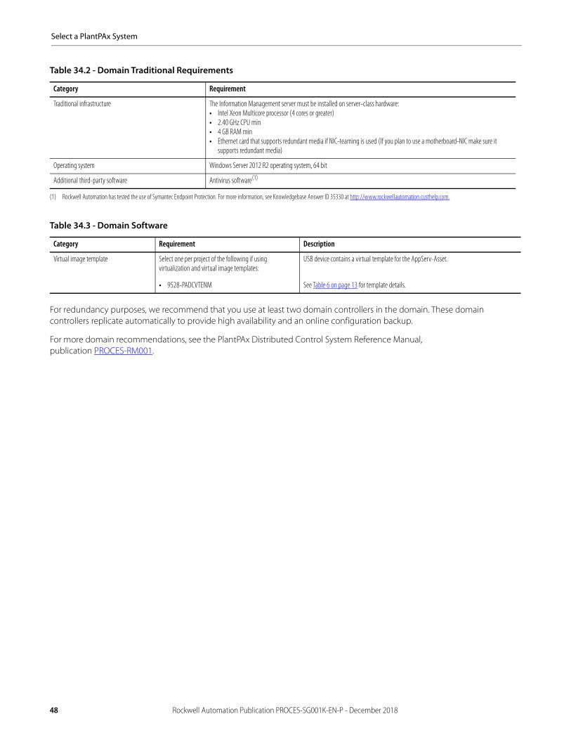
Select a PlantPAx System
For redundancy purposes, we recommend that you use at least two domain controllers in the domain. These domain controllers replicate automatically to provide high availability and an online configuration backup.
For more domain recommendations, see the PlantPAx Distributed Control System Reference Manual,publication PROCES-RM001.
Table 34.2 - Domain Traditional Requirements
Category Requirement
Traditional infrastructure The Information Management server must be installed on server-class hardware:• Intel Xeon Multicore processor (4 cores or greater)• 2.40 GHz CPU min• 4 GB RAM min• Ethernet card that supports redundant media if NIC-teaming is used (If you plan to use a motherboard-NIC make sure it
supports redundant media)
Operating system Windows Server 2012 R2 operating system, 64 bit
Additional third-party software Antivirus software(1)
(1) Rockwell Automation has tested the use of Symantec Endpoint Protection. For more information, see Knowledgebase Answer ID 35330 at http://www.rockwellautomation.custhelp.com.
Table 34.3 - Domain Software
Category Requirement Description
Virtual image template Select one per project of the following if using virtualization and virtual image templates:
• 9528-PADCVTENM
USB device contains a virtual template for the AppServ-Asset.
See Table 6 on page 13 for template details.
48 Rockwell Automation Publication PROCES-SG001K-EN-P - December 2018

Select a PlantPAx System
Controllers, Field Networks, and I/O
This section describes controller elements, field devices, how toselect appropriate I/O, how to determine I/O count, and basic sizing guidelines.
The optimal number of controllers for the PlantPAx system depends on the size of your application, physical layout of your plant, and the design of your process. Consider segregating non-related process equipment into separate controllers so that maintenance activities in one area do not impact the operation of another area.
Controllers are also capacity limited. This capacity can be roughly estimated based on I/O count, but also is greatly impacted by the design of your application. These limitations can include the amount of automation code required, the amount of information being read by supervisory applications, and the number of alarms in your system.
Controller Sizing
The I/O count for controller sizing is often determined directly from the application P&ID or plant design. On existing systems where classic I/O is used only (for example, 4…20 mA, 24V DC dry contacts), the I/O count can be determined by the number of I/O channels available on the I/O cards.
When you have integrated smart devices, such as drives or transmitters on an EtherNet/IP network, any signal from the device used by your control strategy is considered an I/O point.
For example, an I/O count for a system comprised with the following:• Two 8-channel 4…20 mA input cards• One 8-channel 4…20 mA output cards• Two 16-channel 24V DC dry-contact input cards• One Motor Control Center (MCC) with six drives
– Each drive provides six signals to the control strategy: speed reference, actual speed, start, stop, running, and fault• Two Coriolis flowmeters on PROFIBUS PA, each providing three signals for flow, temperature, and density
We can roughly calculate the following I/O count for the example system:
4…20 mA AI 2 x 8 = 16
4…20 mA AO 1 x 8 = 8
24V DC DI 2 x 16 = 32
MCC 6 x 6 = 36 (6 AI, 6 AO, 12 DI, 12 DO)
Smart instruments 2 x 3 = 6 (6 AI)
___Controller I/O count 98
When considering I/O count by using the method as described, not all I/O points map to individual process objects (for example, P_DIn, P_AIn). For example, a P_VSD object processes all of the I/O points associated with a variable speed drive. However, this I/O count method enables you to enter I/O counts into the PSE to determine an appropriate number of control strategy footprints to determine sizing.
Review controller sizing and then select fromthe following options:
• Simplex Controllers• Redundant Controllers• Controllers for Skid-based Equipment• I/O Products• Process Network I/O• Motor Control Devices
Rockwell Automation Publication PROCES-SG001K-EN-P - December 2018 49

Select a PlantPAx System
Simplex Controllers
Non-redundant controllers are referred to as simplex controllers.
Table 35 - Simplex Controller Hardware Requirements(1)
(1) If environmental conditions warrant, you can use an extreme temperature controller, for example, the 1756-L74XT. Conformal coating options are also available for protection from harsh environments that can contain moisture and or chemical contaminants.
Category Cat. No.
Process controller (2)
(2) As the PlantPAx system release 4.5 uses controller firmware revision 31, implementation requires use of the 1756-L7x controller family. PlantPAx system release 4.5 can co-exist with older generation controllers, such as the 1756-L6x.
ControlLogix 1756-L71, 1756-L72, 1756-L73, 1756-L74, or 1756-L75 controller
Ethernet interface • For direct DLR connection: 1756-EN2TR• For direct PRP connection: 1756-EN2TP• For secure connections: 1756-EN2TSC• Otherwise: 1756-EN2T, 1756-EN2F (no DLR support)• For converting topology or media: 1783-ETAP, 1783-ETAP1F, 1783-ETAP2F (supports DLR topology)
ControlNet interface (if applicable) • 1756-CN2, 1756-CN2R• 1756-CNB, 1756-CNBR
Table 36 - Simplex ControlLogix Controller Sizing
Category(1)
(1) These values are recommended maximum limits. It’s possible that achieving all of these values in a single controller is not doable. For more detailed sizing, you can use the PSE (see page 11).
1756-L71 1756-L72 1756-L73 1756-L74 1756-L75(2)
(2) The advantages to using the 1756-L75 controller are to maintain common spare parts with redundant systems or if you are doing some memory intensive storage not accounted for in sizing model.
User memory 2 MB 4 MB 8 MB 16 MB 32 MB
Total I/O recommended, max 375 750 1500 2250 2250
Recommended control strategies, max(3)
(3) Recommended maximum control strategies are based on all controller strategies being simple regulatory control. See Sizing Control Strategies in the PlantPAx Distributed Control System Reference Manual,publication PROCES-RM001.
60 125 250 450 450
Total control strategies @ 250 ms, max 60 125 250 250 250
Total control strategies @ 500 ms, max 60 125 250 450 450
Tags/sec delivered to data server, max 10,000 20,000 20,000 20,000 20,000
50 Rockwell Automation Publication PROCES-SG001K-EN-P - December 2018

Select a PlantPAx System
Redundant Controllers
ControlLogix controllers support redundancy on ControlNet and EtherNet/IP networks. In a redundant controller system on the PlantPAx system, you need these components:
• Two 1756 chassis each with matching configuration on the following aspects:– Number of slots– Modules in the same slots– Redundancy firmware revisions in each module– Two additional ControlNet nodes outside the redundant chassis pair
• One of the two nodes outside of the redundant chassis must be at a lower node address than the ControlNet modules in the redundant chassis.
• If your ControlNet uses fewer than four nodes, and a switchover occurs, connections can drop and outputs connected to that node can change state during the switchover.
– One 1756-RM2 module per chassis
Table 37 - Redundant Controller Hardware Requirements(1)
(1) If environmental conditions warrant, you can use an extreme temperature controller, for example, the 1756-L74XT. Conformal coating options are also available for protection from harsh environments that can contain moisture and or chemical contaminants.
Category Cat. No.
Process controller ControlLogix 1756-L73, 1756-L74, or 1756-L75 controller(2)
(2) ControlLogix 1756-L71 and 1756-L72 controllers are not recommended for PlantPAx systems due to memory constraints.
Redundancy module 1756-RM2(3)
(3) The PlantPAx system recommendation is to use only one redundant controller in a chassis with a 1756-RM2 redundancy module. While a 1756-RM2 module can support two controllers, the resulting performance of each controller is not easily predicted.
Ethernet interface • For direct DLR connection: 1756-EN2TR• For direct PRP connection: 1756-EN2TP• For secure connections: 1756-EN2TSC• Otherwise: 1756-EN2T, 1756-EN2F (no DLR support)• For converting topology or media: 1783-ETAP, 1783-ETAP1F, 1783-ETAP2F (supports DLR topology)
ControlNet interface (if applicable) • 1756-CN2, 1756-CN2R• 1756-CNB, 1756-CNBR
Table 38 - Redundant ControlLogix Controller Sizing
Category(1)
(1) These values are recommended maximum limits. To achieve all of these values in a redundant controller pair is likely not feasible. For more detailed sizing, you can use the PSE (see page 11).
1756-L73 1756-L74 1756-L75(2)
(2) The advantages to using the 1756-L75 controller is to maintain common spare parts with redundant systems or if you are doing some memory intensive storage not accounted for in the sizing model.
User memory 8 MB 16 MB 32 MB
Total I/O recommended, max 750 1500 2250
Recommended control strategies, max(3)
(3) Maximum controller strategy is based on all controller strategies being simple regulatory control. See Process Controller I/O Considerations in the PlantPAx Distributed Control System Reference Manual,publication PROCES-RM001.
125 250 450
Total control strategies @ 250 ms, max 120 120 120
Total control strategies @ 500 ms, max 125 220 220
Tags/sec delivered to data server, max 20,000 20,000 20,000
Rockwell Automation Publication PROCES-SG001K-EN-P - December 2018 51
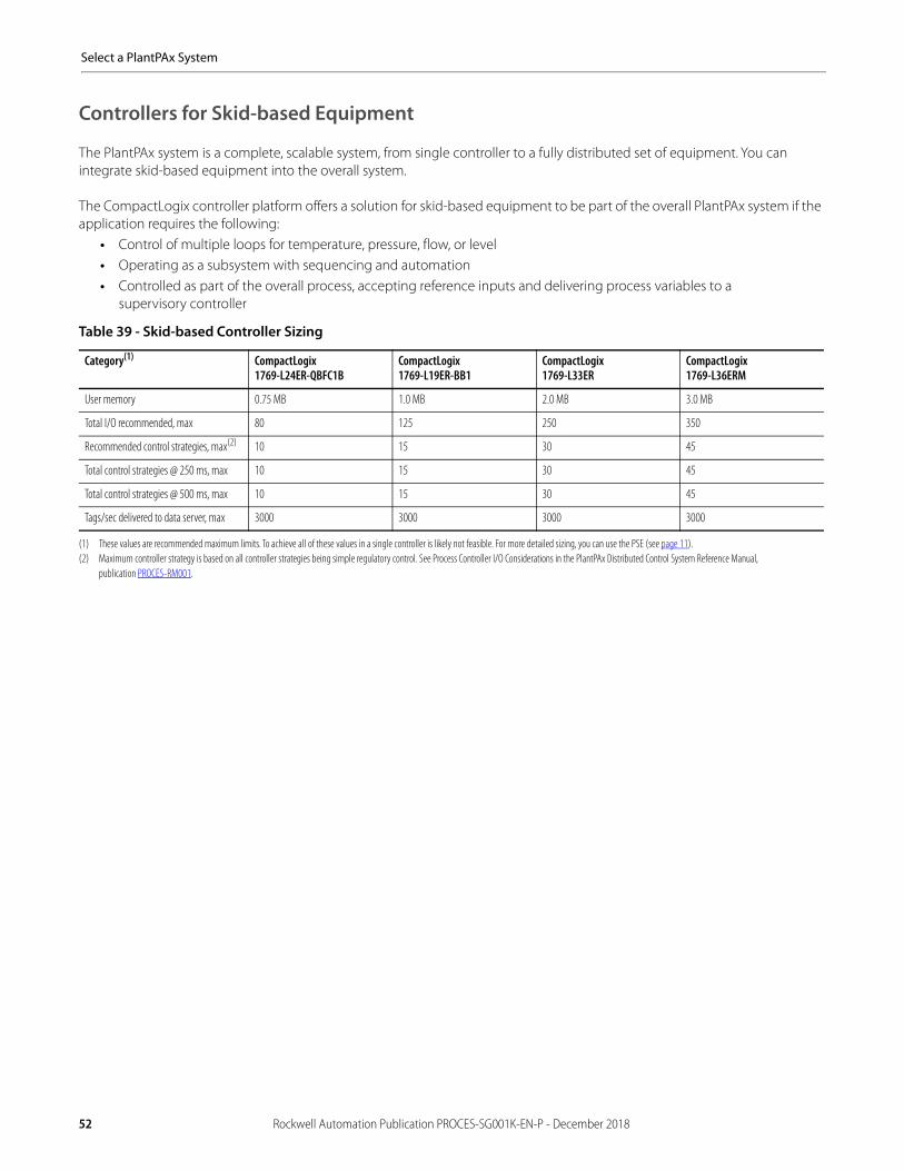
Select a PlantPAx System
Controllers for Skid-based Equipment
The PlantPAx system is a complete, scalable system, from single controller to a fully distributed set of equipment. You can integrate skid-based equipment into the overall system.
The CompactLogix controller platform offers a solution for skid-based equipment to be part of the overall PlantPAx system if the application requires the following:
• Control of multiple loops for temperature, pressure, flow, or level• Operating as a subsystem with sequencing and automation• Controlled as part of the overall process, accepting reference inputs and delivering process variables to a
supervisory controller.
Table 39 - Skid-based Controller Sizing
Category(1)
(1) These values are recommended maximum limits. To achieve all of these values in a single controller is likely not feasible. For more detailed sizing, you can use the PSE (see page 11).
CompactLogix1769-L24ER-QBFC1B
CompactLogix1769-L19ER-BB1
CompactLogix1769-L33ER
CompactLogix1769-L36ERM
User memory 0.75 MB 1.0 MB 2.0 MB 3.0 MB
Total I/O recommended, max 80 125 250 350
Recommended control strategies, max(2)
(2) Maximum controller strategy is based on all controller strategies being simple regulatory control. See Process Controller I/O Considerations in the PlantPAx Distributed Control System Reference Manual,publication PROCES-RM001.
10 15 30 45
Total control strategies @ 250 ms, max 10 15 30 45
Total control strategies @ 500 ms, max 10 15 30 45
Tags/sec delivered to data server, max 3000 3000 3000 3000
52 Rockwell Automation Publication PROCES-SG001K-EN-P - December 2018
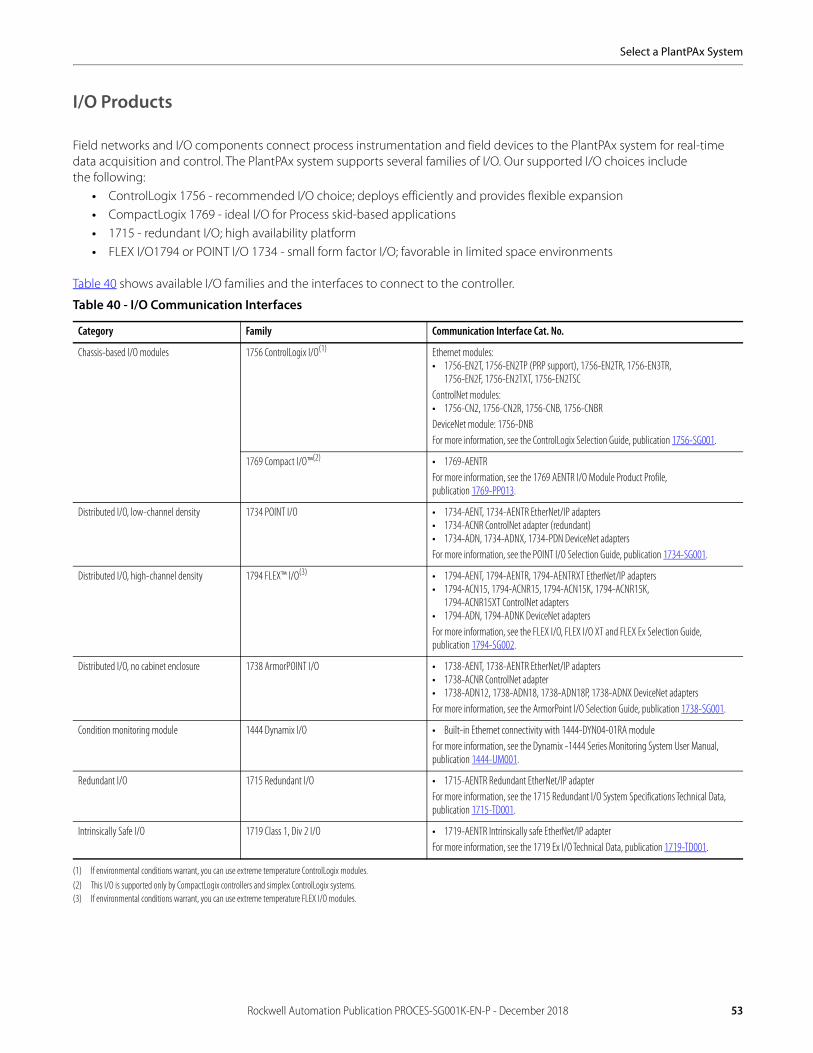
Select a PlantPAx System
I/O Products
Field networks and I/O components connect process instrumentation and field devices to the PlantPAx system for real-time data acquisition and control. The PlantPAx system supports several families of I/O. Our supported I/O choices includethe following:
• ControlLogix 1756 - recommended I/O choice; deploys efficiently and provides flexible expansion• CompactLogix 1769 - ideal I/O for Process skid-based applications• 1715 - redundant I/O; high availability platform• FLEX I/O1794 or POINT I/O 1734 - small form factor I/O; favorable in limited space environments
Table 40 shows available I/O families and the interfaces to connect to the controller.
Table 40 - I/O Communication Interfaces
Category Family Communication Interface Cat. No.
Chassis-based I/O modules 1756 ControlLogix I/O(1)
(1) If environmental conditions warrant, you can use extreme temperature ControlLogix modules.
Ethernet modules:• 1756-EN2T, 1756-EN2TP (PRP support), 1756-EN2TR, 1756-EN3TR,
1756-EN2F, 1756-EN2TXT, 1756-EN2TSCControlNet modules: • 1756-CN2, 1756-CN2R, 1756-CNB, 1756-CNBRDeviceNet module: 1756-DNB For more information, see the ControlLogix Selection Guide, publication 1756-SG001.
1769 Compact I/O™(2)
(2) This I/O is supported only by CompactLogix controllers and simplex ControlLogix systems.
• 1769-AENTRFor more information, see the 1769 AENTR I/O Module Product Profile,publication 1769-PP013.
Distributed I/O, low-channel density 1734 POINT I/O • 1734-AENT, 1734-AENTR EtherNet/IP adapters• 1734-ACNR ControlNet adapter (redundant)• 1734-ADN, 1734-ADNX, 1734-PDN DeviceNet adaptersFor more information, see the POINT I/O Selection Guide, publication 1734-SG001.
Distributed I/O, high-channel density 1794 FLEX™ I/O(3)
(3) If environmental conditions warrant, you can use extreme temperature FLEX I/O modules.
• 1794-AENT, 1794-AENTR, 1794-AENTRXT EtherNet/IP adapters• 1794-ACN15, 1794-ACNR15, 1794-ACN15K, 1794-ACNR15K,
1794-ACNR15XT ControlNet adapters• 1794-ADN, 1794-ADNK DeviceNet adaptersFor more information, see the FLEX I/O, FLEX I/O XT and FLEX Ex Selection Guide,publication 1794-SG002.
Distributed I/O, no cabinet enclosure 1738 ArmorPOINT I/O • 1738-AENT, 1738-AENTR EtherNet/IP adapters• 1738-ACNR ControlNet adapter• 1738-ADN12, 1738-ADN18, 1738-ADN18P, 1738-ADNX DeviceNet adaptersFor more information, see the ArmorPoint I/O Selection Guide, publication 1738-SG001.
Condition monitoring module 1444 Dynamix I/O • Built-in Ethernet connectivity with 1444-DYN04-01RA moduleFor more information, see the Dynamix -1444 Series Monitoring System User Manual, publication 1444-UM001.
Redundant I/O 1715 Redundant I/O • 1715-AENTR Redundant EtherNet/IP adapterFor more information, see the 1715 Redundant I/O System Specifications Technical Data, publication 1715-TD001.
Intrinsically Safe I/O 1719 Class 1, Div 2 I/O • 1719-AENTR Intrinsically safe EtherNet/IP adapterFor more information, see the 1719 Ex I/O Technical Data, publication 1719-TD001.
Rockwell Automation Publication PROCES-SG001K-EN-P - December 2018 53

Select a PlantPAx System
Table 41 shows some of the modules that you can add to the Controller Organizer in the Logix Designer application when the controller is in Run mode.
Table 41 - Online Addition of Module and Connection Types
Module Type and Connection Method
In Local Chassis Remote Via a ControlNet Network Remote Via an EtherNet/IP Network
Configure Hold Last Output State
Offline Runtime Offline Runtime Offline Runtime
Scheduled Unscheduled Scheduled Unscheduled
Digital - direct Yes Yes Yes Yes No Yes Yes Yes Yes - 1756 I/O digital output modules
Digital - rack-optimized N/A N/A Yes No Yes No Yes Yes Yes - 1756 I/O digital output modules
Analog - direct Yes Yes Yes Yes No Yes Yes Yes Yes
Generic third-party - direct Yes Yes Yes Yes No Yes Yes Yes N/A
1756-CNx - no connection Yes Yes Yes Yes No Yes N/A N/A N/A
1756-CNx - rack-optimized N/A N/A Yes N/A N/A N/A N/A N/A N/A
Generic ControlNet third-party - direct
N/A N/A Yes Yes No Yes N/A N/A N/A
1788-EN2FFR or1788-EN2PAR
N/A N/A N/A N/A N/A N/A Yes Yes N/A
1788-CN2FFR or 1788-CN2PAR
N/A N/A Yes Yes No Yes N/A N/A N/A
1715 Redundant I/O N/A N/A N/A N/A N/A N/A Yes Yes Yes – both analog and digital modules
1719 Intrinsically safe I/O N/A N/A N/A N/A N/A N/A Yes Yes Yes – both analog and digital modules
1756-ENx - no connection Yes Yes N/A N/A N/A N/A Yes Yes N/A
1756-ENx - rack-optimized N/A N/A N/A N/A N/A N/A Yes Yes N/A
Generic EtherNet/IP third party - direct
N/A N/A N/A N/A N/A N/A Yes Yes N/A
1794 FLEX I/O N/A N/A Yes Yes No No Yes No Yes - Analog output modules only
1734 POINT I/O N/A N/A Yes Yes No No Yes No Yes(1)
(1) When you lose communication to the controller, POINT I/O ignores the last output state configuration, and sets the outputs to zero.
54 Rockwell Automation Publication PROCES-SG001K-EN-P - December 2018
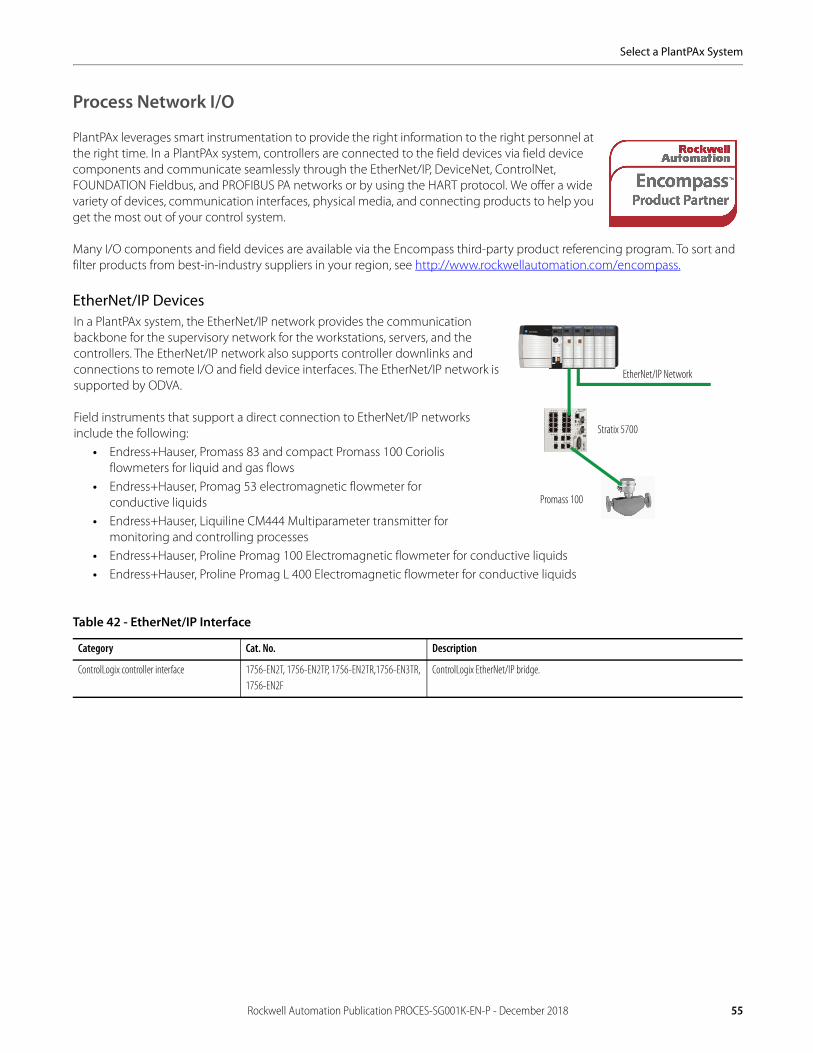
Select a PlantPAx System
Process Network I/O
PlantPAx leverages smart instrumentation to provide the right information to the right personnel at the right time. In a PlantPAx system, controllers are connected to the field devices via field device components and communicate seamlessly through the EtherNet/IP, DeviceNet, ControlNet, FOUNDATION Fieldbus, and PROFIBUS PA networks or by using the HART protocol. We offer a wide variety of devices, communication interfaces, physical media, and connecting products to help you get the most out of your control system.
Many I/O components and field devices are available via the Encompass third-party product referencing program. To sort and filter products from best-in-industry suppliers in your region, see http://www.rockwellautomation.com/encompass.
EtherNet/IP Devices
Table 42 - EtherNet/IP Interface
Category Cat. No. Description
ControlLogix controller interface 1756-EN2T, 1756-EN2TP, 1756-EN2TR,1756-EN3TR,1756-EN2F
ControlLogix EtherNet/IP bridge.
In a PlantPAx system, the EtherNet/IP network provides the communication backbone for the supervisory network for the workstations, servers, and the controllers. The EtherNet/IP network also supports controller downlinks and connections to remote I/O and field device interfaces. The EtherNet/IP network is supported by ODVA.
Field instruments that support a direct connection to EtherNet/IP networks include the following:
• Endress+Hauser, Promass 83 and compact Promass 100 Coriolis flowmeters for liquid and gas flows
• Endress+Hauser, Promag 53 electromagnetic flowmeter forconductive liquids
• Endress+Hauser, Liquiline CM444 Multiparameter transmitter for monitoring and controlling processes
• Endress+Hauser, Proline Promag 100 Electromagnetic flowmeter for conductive liquids• Endress+Hauser, Proline Promag L 400 Electromagnetic flowmeter for conductive liquids
EtherNet/IP Network
Stratix 5700
Promass 100
Rockwell Automation Publication PROCES-SG001K-EN-P - December 2018 55

Select a PlantPAx System
ControlNet Devices
DeviceNet Devices
Table 43 - ControlNet Interface
Category Cat. No. Description
ControlLogix controller interface 1756-CN2, 1756-CN2R1756-CNB, 1756-CNBR
ControlLogix ControlNet scanner.
1788-CN2FFR ControlNet to FOUNDATION Fieldbus linking device. Supports H1 FOUNDATION Fieldbus networks. Compatible with ControlLogix redundancy and redundant ControlNet media.
1788-CN2PAR ControlNet to PROFIBUS PA linking device. Supports redundant PROFIBUS PA media and redundant ControlNet media.
Table 44 - DeviceNet Interface
Category Cat. No. Description
ControlLogix controller interface 1756-DNB ControlLogix DeviceNet scanner
Fieldbus orPROFIBUS PANetwork
HART Devices
ControlNet Network
The ControlNet™ network is an open, control network forreal-time, high-throughput applications. The network uses theCommon Industrial Protocol™ (CIP) to combine the functionalityof an I/O network and a peer-to-peer network, providinghigh-speed performance for both functions. The ControlNet network is supported by ODVA.
In a PlantPAx system, the ControlNet network supportscontroller downlinks and connections to remote I/O and field device interfaces.
CENTERLINE®Motor Control Center
DeviceNet Network
PowerFlex Drives
The DeviceNet™ network is an open, device-level network that provides connections between simple industrial devices (such as sensors and actuators) and higher-level devices (such as controllers and computers). The DeviceNet network uses the proven Common Industrial Protocol (CIP) to provide the control, configuration, and data collection capabilities for industrial devices. The DeviceNet network is supported by ODVA.
In a PlantPAx system, the DeviceNet network connects networked control devices.
56 Rockwell Automation Publication PROCES-SG001K-EN-P - December 2018
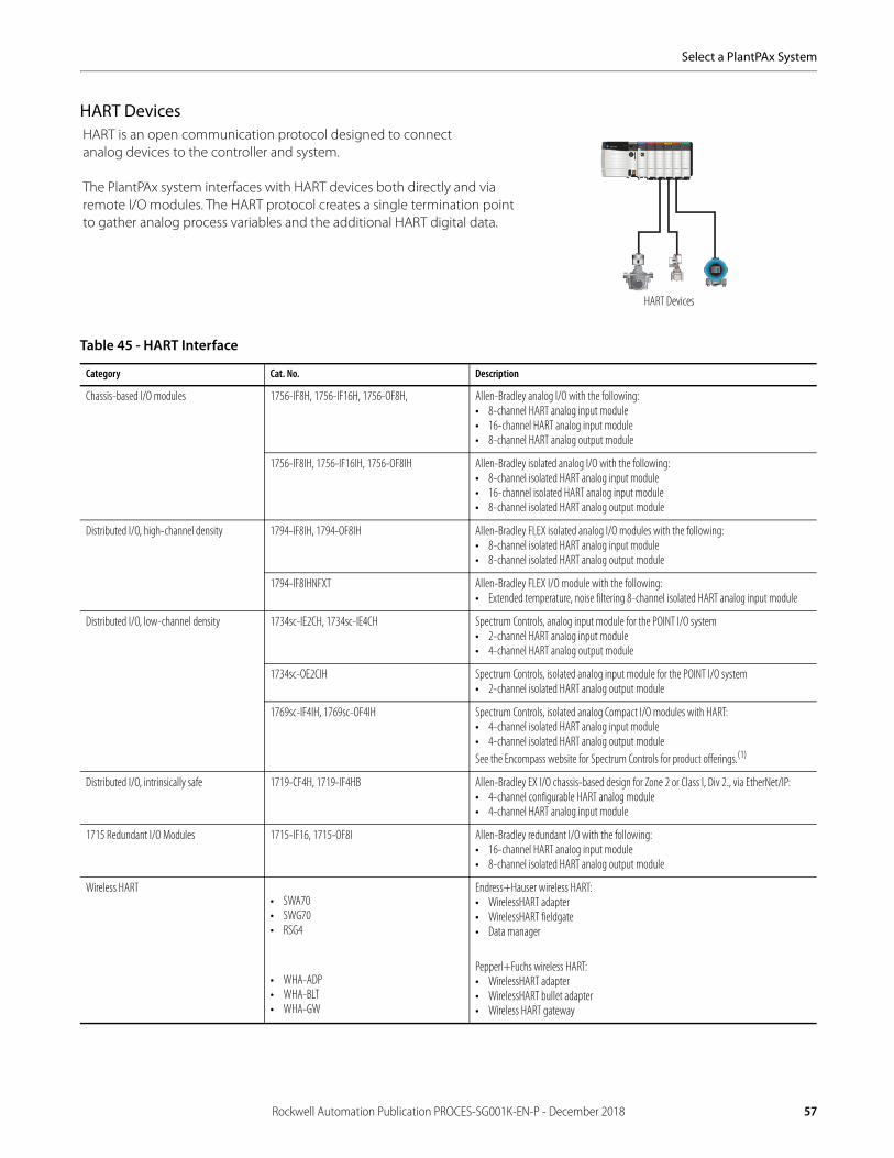
Select a PlantPAx System
HART Devices
.
Table 45 - HART Interface
Category Cat. No. Description
Chassis-based I/O modules 1756-IF8H, 1756-IF16H, 1756-OF8H, Allen-Bradley analog I/O with the following:• 8-channel HART analog input module• 16-channel HART analog input module• 8-channel HART analog output module
1756-IF8IH, 1756-IF16IH, 1756-OF8IH Allen-Bradley isolated analog I/O with the following:• 8-channel isolated HART analog input module• 16-channel isolated HART analog input module• 8-channel isolated HART analog output module
Distributed I/O, high-channel density 1794-IF8IH, 1794-OF8IH Allen-Bradley FLEX isolated analog I/O modules with the following:• 8-channel isolated HART analog input module• 8-channel isolated HART analog output module
1794-IF8IHNFXT Allen-Bradley FLEX I/O module with the following:• Extended temperature, noise filtering 8-channel isolated HART analog input module
Distributed I/O, low-channel density 1734sc-IE2CH, 1734sc-IE4CH Spectrum Controls, analog input module for the POINT I/O system• 2-channel HART analog input module• 4-channel HART analog output module
1734sc-OE2CIH Spectrum Controls, isolated analog input module for the POINT I/O system• 2-channel isolated HART analog output module
1769sc-IF4IH, 1769sc-OF4IH Spectrum Controls, isolated analog Compact I/O modules with HART:• 4-channel isolated HART analog input module• 4-channel isolated HART analog output moduleSee the Encompass website for Spectrum Controls for product offerings.(1)
Distributed I/O, intrinsically safe 1719-CF4H, 1719-IF4HB Allen-Bradley EX I/O chassis-based design for Zone 2 or Class I, Div 2., via EtherNet/IP:• 4-channel configurable HART analog module• 4-channel HART analog input module
1715 Redundant I/O Modules 1715-IF16, 1715-OF8I Allen-Bradley redundant I/O with the following:• 16-channel HART analog input module• 8-channel isolated HART analog output module
Wireless HART• SWA70• SWG70• RSG4
• WHA-ADP• WHA-BLT• WHA-GW
Endress+Hauser wireless HART:• WirelessHART adapter• WirelessHART fieldgate• Data manager
Pepperl+Fuchs wireless HART:• WirelessHART adapter• WirelessHART bullet adapter• Wireless HART gateway
HART Devices
HART is an open communication protocol designed to connectanalog devices to the controller and system.
The PlantPAx system interfaces with HART devices both directly and via remote I/O modules. The HART protocol creates a single termination point to gather analog process variables and the additional HART digital data.
Rockwell Automation Publication PROCES-SG001K-EN-P - December 2018 57

Select a PlantPAx System
Network configuration Field Xpert Handheld device Endress+Hauser, handheld configuration and diagnostic device.See the Encompass website for Endress+Hauser product offerings.(1)
Hart Interface Tools Interface from HART device to personal computer Pepperl+Fuchs interfaces:• Viator Bluetooth HART interface• Viator USB HART interface with PowerXpress
Multiplexers/gateways• 2700• 2700• MVI69• IP Point HART Input• IP Point HART Output
Pepperl+Fuchs interfaces:• HART multiplexer• HART MuxTerm Panel• Prosoft Protocol Solutions• Aparian• Single Channel HART for EtherNet/IPSee the Encompass website for Pepperl+Fuchs, Prosoft Technology, and Aparian product offerings.(1)
(1) For more information on Encompass third-party products, see https://locator.rockwellautomation.com/Encompass.
Table 45 - HART Interface
Category Cat. No. Description
58 Rockwell Automation Publication PROCES-SG001K-EN-P - December 2018

Select a PlantPAx System
FOUNDATION Fieldbus Devices
The FOUNDATION Fieldbus network is a protocol designed for robust, distributed process application control. Devices connected by a FOUNDATION Fieldbus network can be used for sophisticated process control with seamless data distribution from the H1 device-level network.
PlantPAx systems communicate with FOUNDATION Fieldbus devices through EtherNet/IP and ControlNet linking devices as shown in the examples. Other configurations are available for simple and redundant topologies.
Table 46 - FOUNDATION Fieldbus Interface
Category Cat. No. Description
EtherNet/IP interface 1788-EN2FFR Bridge from an Ethernet network to an H1 network. Supports redundant media and DLR-capable Ethernet network. Linking devices have built-in termination.
ControlNet interface 1788-CN2FFR Bridge from a ControlNet network to an H1 network; compatible with ControlLogix redundancy and redundant ControlNet media. Linking devices have built-in termination.
FOUNDATION Fieldbus network components Power conditioning Both linking devices have built-in power conditioning.
1788-FBJB4R Intelligent junction box supports redundancy, includes four drop ports and four trunk ports.
1788-FBJB6 Intelligent junction box with six drop ports and two trunk ports.
Additional components Pepperl+Fuchs(1), FOUNDATION Fieldbus components, such as valve couplers, surge protectors, and distributors.See the Encompass website for Pepperl+Fuchs product offerings.
(1) For more information on Encompass third-party products, see http://www.rockwellautomation.com/encompass.
Segment protection Helps protect against device or line faults with short- and open-circuit protection.Pepperl+Fuchs(1), intrinsic safety components, such as isolated barrier systems, hazardous area enclosures, and equipment.See the Encompass website for Pepperl+Fuchs product offerings.
1788-FBJB6 Junction Box
EtherNet/IP
1788-EN2FFR Linking Device
FF Field Devices
EtherNet/IP Network
EtherNet/IP Device Level Ring
1788-EN2FFR Linking Devices
FF Field Devices
EtherNet/IP Network
1788-FBJB4R Junction Boxes
H1 Network
Redundant ControlNet
1788-CN2FFR Linking Devices
FF Field Devices
ControlNet Network
1788-FBJB4R Junction Boxes
Rockwell Automation Publication PROCES-SG001K-EN-P - December 2018 59
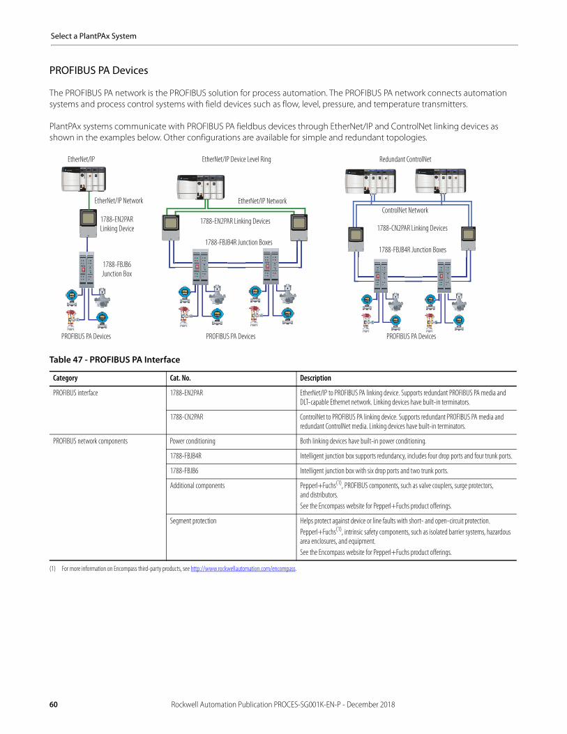
Select a PlantPAx System
PROFIBUS PA Devices
The PROFIBUS PA network is the PROFIBUS solution for process automation. The PROFIBUS PA network connects automation systems and process control systems with field devices such as flow, level, pressure, and temperature transmitters.
PlantPAx systems communicate with PROFIBUS PA fieldbus devices through EtherNet/IP and ControlNet linking devices as shown in the examples below. Other configurations are available for simple and redundant topologies.
Table 47 - PROFIBUS PA Interface
Category Cat. No. Description
PROFIBUS interface 1788-EN2PAR EtherNet/IP to PROFIBUS PA linking device. Supports redundant PROFIBUS PA media and DLT-capable Ethernet network. Linking devices have built-in terminators.
1788-CN2PAR ControlNet to PROFIBUS PA linking device. Supports redundant PROFIBUS PA media and redundant ControlNet media. Linking devices have built-in terminators.
PROFIBUS network components Power conditioning Both linking devices have built-in power conditioning.
1788-FBJB4R Intelligent junction box supports redundancy, includes four drop ports and four trunk ports.
1788-FBJB6 Intelligent junction box with six drop ports and two trunk ports.
Additional components Pepperl+Fuchs(1), PROFIBUS components, such as valve couplers, surge protectors,and distributors.See the Encompass website for Pepperl+Fuchs product offerings.
(1) For more information on Encompass third-party products, see http://www.rockwellautomation.com/encompass.
Segment protection Helps protect against device or line faults with short- and open-circuit protection.Pepperl+Fuchs(1), intrinsic safety components, such as isolated barrier systems, hazardous area enclosures, and equipment.See the Encompass website for Pepperl+Fuchs product offerings.
PROFIBUS PA Devices
EtherNet/IP Device Level Ring
1788-EN2PAR Linking Device
EtherNet/IP Redundant ControlNet
PROFIBUS PA Devices
1788-CN2PAR Linking Devices
PROFIBUS PA Devices
1788-FBJB6 Junction Box
1788-FBJB4R Junction Boxes
EtherNet/IP NetworkControlNet Network
EtherNet/IP Network
1788-EN2PAR Linking Devices
1788-FBJB4R Junction Boxes
60 Rockwell Automation Publication PROCES-SG001K-EN-P - December 2018

Select a PlantPAx System
Motor Control Devices
Rockwell Automation offers a broad range of motor control solutions to complement a variety of application requirements. The portfolio of motor control includes more simplified programming and configuration along with safety features to help protect personnel and assets that helps to reduce downtime.
Low Voltage Drives
Table 48 - PowerFlex Drives and Communication Modules
Drive Cat. No. Description Available Communication Modules
Cat. No. Description
25B-(1)
(1) For a complete list of catalog numbers, see the PowerFlex Low Voltage AC Drives Selection Guide, publication PFLEX-SG002.
PowerFlex 525 AC drive with an embedded EtherNet/IP port and an embedded Safe Torque Off (STO).
• 25-COMM-E2P• 25-COMM-D
• Dual-port EtherNet/IP, supports DLR functionality• DeviceNet
20F-(1) PowerFlex 753 AC drive • 20-750-BNETIP• 20-750-CNETC• 20-750-DNET• 20-750-ENETR• 20-750-PBUS• 20-750-PNET• 20-750-PNET2P• 20-COMM-C(2)
• 20-COMM-D(2)
• 20-COMM-E(2) (3)
• 20-COMM-H(2)
• 20-COMM-K(2)
• 20-COMM-L(2)
• 20-COMM-M(2)
• 20-COMM-P(2)
• 20-COMM-Q(2)
• 20-COMM-S(2)
(2) Requires a Communication Carrier Card (20-750-20COMM or 20-750-COMM-F1). Refer to the PowerFlex 750-series Technical Data, publication 750-TD001 for details.(3) The PowerFlex 755 drive has the Ethernet card embedded from the factory.
• BACnet/IP option modules• Coaxial ControlNet option module• DeviceNet option module• Dual-port EtherNet/IP option module• Profibus DPV1 option module• Single-port Profinet I/O option module• Dual-port Profinet I/O option module• ControlNet communication adapter (coax)• DeviceNet communication adapter• EtherNet/IP communication adapter• HVAC communication adapter• CANopen communication adapter• LonWorks communication adapter• Modbus/TCP communication adapter• PROFIBUS DP communication adapter• ControlNet communication adapter (fiber)• RS485 DF1 communication adapter
20G-(1) PowerFlex 755 drive
20G-(1) PowerFlex 755TL/755TR • 20-750-CNETC• 20-750-DNET• 20-750-ENETR• 20-750-PBUS• 20-750-PNET• 20-750-PNET2P
• Coaxial ControlNet option module• DeviceNet option module• Dual-port EtherNet/IP option module• Profibus DPV1 option module• Single-port Profinet I/O option module• Dual-port Profinet I/O option module
Select from the following options:• Low Voltage Drives• Medium Voltage Drives and Relays• Soft Starters• Across-the-Line Starters• Motor Control Centers
PowerFlex® Low Voltage AC drives provide scalable motor control solutions and are designed to deliver more powerful performance and flexibility for process applications. As part of a PlantPAx system, PowerFlex drives offer seamless integration into your process control system for simplified development, use, and maintenance. The benefits of this exceptional level of integration between the drives and Logix controllers provides distinctive time-saving features for the PowerFlex drives.
With Automatic Device Configuration, a Logix controller can automatically detect a replaced PowerFlex 525, 753(1), or 755 drive and download all configuration parameters, minimizing the need for manual reconfiguration.
(1) PowerFlex 753 AC drives require a dual-port EtherNet/IP communication card.
RUN SD OKFORCE
Logix5575 EtherNet/IP™
PowerFlex 525
Switch
PowerFlex 753 PowerFlex 755ControlLogix L7x
EtherNet/IP Network
Rockwell Automation Publication PROCES-SG001K-EN-P - December 2018 61

Select a PlantPAx System
Medium Voltage Drives and Relays
PowerFlex medium voltage AC drives andAllen-Bradley® relays provide scalable motor control solutions and electrical protection. Standalone drives control speed, torque, direction, starting, and stopping of standard asynchronous or synchronous AC motors. As part of a PlantPAx system, PowerFlex drives incorporate leading-edge technology, embedded communications, and significant commonality across multiple platforms, networks, operator interface programming and hardware. The benefits of this exceptional level of integration between the drives and Logix controllers provides distinctive time-saving features for the PowerFlex 6000 and 7000 drives.
The PowerFlex 7000 Drive System with ArcShield™ technology is the first arc resistant medium voltage drive with full regeneration capabilities. The arc resistant system is certified to meet the most comprehensive set of global arc resistant standards. This system provides an arc fault rating up to 50 kA and meets Type 2B accessibility protection standards.
The Allen-Bradley 857 relay includes all the essential protection functions needed to protect feeders and motors in distribution networks of utilities, heavy industry, power plants, and offshore applications. The 865 relay provides selective differential overcurrent, short-circuit protection of generators, transformers, and motors in solidly or impedance earthed power systems. The relay can also be used for single-, two-, or three-phase overcurrent and/or sensitive earth fault protection.
Table 49 - Medium Voltage Drives and Relays
Drive Cat. No. Description Available Communication Modules
Cat. No. Description
PF-6000 PowerFlex 6000 • Anybus-AB7007• USB-RS-232
• Third party, EtherNet/IP gateway• Configuration adapter (order code 019570)
PF-7000 PowerFlex 7000 • 20-750-ENETR• 20-COMM-E(1)
(1) Requires a Communication Carrier Card (20-750-20COMM or 20-750-COMM-F1). Refer to the PowerFlex 7000 User Manual, publication 7000-UM151 for details.
• Dual-port EtherNet/IP option module• EtherNet/IP communication adapter
Bulletin 857 Allen-Bradley 857 relay Embedded with product; depends on application requirement
See the Product Configuration Assistant or contact your Rockwell Automation representative
Bulletin 865 Allen-Bradley 865 relay Embedded with product; depends on application requirement
See the Product Configuration Assistant or contact your Rockwell Automation representative
RUN SD OKFORCE
Logix5575 EtherNet/IP™
EtherNet/IP Network
ControlLogix L7x
EWS
PowerFlex 7000 PowerFlex 6000
857 Relay 865 Relay
62 Rockwell Automation Publication PROCES-SG001K-EN-P - December 2018

Select a PlantPAx System
Soft Starters
SMC™ Soft Starters are designed to help minimize cost by reducing overall system power requirements and wear and tear on equipment. Our soft starters can be easily integrated into your process control system to offer higher productivity and shorter downtimes.
We offer a diverse line of soft-starters to meet your communication, control, and space requirements.
Across-the-Line Starters
We offer a full line of versatile and robust starters for both IEC and NEMA applications. Our light industrial IEC starters are environmentally friendly, versatile, and flexible. Our heavy-duty NEMA starters are renowned for a more-rugged construction, more dependable performance, and longer electrical life. In addition, this portfolio offers Electronic Overload Relays that provide integration between the starters and Logix controllers. The diagnostic capabilities of the overload relays help maximize uptime for motor control in an automation system.
Table 50 - SMC Soft Starters and Communication Modules
Cat. No. Description Available Communication Modules
Cat. No. Description
150-F(1)
(1) For additional product information, see the Smart Motor Controllers – SMC-3, SMC Flex, and SMC-50 Soft Starters Family Brochure, publication 150-BR144.
SMC Flex Smart Motor Controllers • 20-COMM-C• 20-COMM-D• 20-COMM-E• 20-COMM-ER
• ControlNet communication adapter (Coax)• DeviceNet communication adapter• EtherNet/IP communication adapter• Dual-port EtherNet/IP communication adapter
150-S(1) SMC 50 Solid State Smart Motor Controllers • 20-COMM-C• 20-COMM-D• 20-COMM-E• 20-COMM-ER• 20-COMM-Q
• ControlNet communication adapter (Coax)• DeviceNet communication adapter• EtherNet/IP communication adapter• Dual-port EtherNet/IP communication adapter• ControlNet communication adapter (Fiber)
Table 51 - Electronic Overload Relays and Communication Modules
Cat. No. Description Available Communication Modules
Cat. No. Description
193/592-EE(1)
(1) For additional product information, see the Bulletin 193, 592, and 825 Overload Relay Family Brochure, publication 193-BR029.
E1 Plus™ Electronic Overload Relays • 193-ETN• 193-EDN
• EtherNet/IP module• DeviceNet module
193/592-EC(1) E3 Plus™ Electronic Overload Relays with embedded DeviceNet 193-DNENCAT EtherNet/IP communication auxiliary DeviceNetto EtherNet/IP linking device, single port
193-DNENCATR EtherNet/IP communication auxiliary DeviceNetto EtherNet/IP linking device, dual port
193/592-E300(2)
(2) For more information, see the E300 Electronic Overload Relay Selection Guide, publication 193-SG010.
E300™ Electronic Overload Relays 193-ECM-ETR EtherNet/IP communication module
RUN SD OKFORCE
Logix5575 EtherNet/IP™
ControlLogix L7x
Switch
EtherNet/IP Network
SMC Flex SMC-50
RUN SD OKFORCE
Logix5575 EtherNet/IP™
ControlLogix L7x
Switch
EtherNet/IP Network
E-1 Plus
E-300
E-3 Plus
Rockwell Automation Publication PROCES-SG001K-EN-P - December 2018 63

Select a PlantPAx System
Motor Control Centers
As an alternative to wiring each device individually, Rockwell Automation offers two, low-voltage motor control centers (MCC) that feature a rugged, high-performance packaging solution for all your motor control needs that integrate control and power in one centralized location. Consider CENTERLINE 2100 or CENTERLINE 2500 MCCs to house your starters, soft-starters, and drives to meet IEC, UL, and NEMA standards.
Benefit from embedded network systems with IntelliCENTER technology and software. EtherNet/IP™ networks provide enhanced integration between the plant floor and corporate operations by using a single programming environment, and built-in DeviceNet™ technology is designed and tested to ODVA specifications to help assure reliable communication. Use IntelliCENTER software for seamless integration into your Logix architecture and gain valuable access to your MCCoperating data.
CENTERLINE MCCs are available with safety options that help reduce exposure to electrical hazards and arc flash mitigation and containment. Remove units without opening the door and help reduce exposure to electrical hazards with SecureConnect™ units for CENTERLINE 2100 MCCs. ArcShield enclosure options for both 2100 and 2500 MCCs help mitigate and contain arc flash incidents.
Table 52 - Low Voltage Motor Control Centers
Category(1)
(1) For more information, see the website at http://www.ab.rockwellautomation.com/Motor-Control/Motor-Control-Centers.
Cat. No. Description
CENTERLINE 2100 MCC 2100 • Designed to meet UL and NEMA standards• Allen-Bradley motor control devices: starters, soft-starters, and drives • Available with SecureConnect units• ArcShield arc resistant enclosures also available• EtherNet/IP and DeviceNet networking• IntelliCENTER software
CENTERLINE 2500 MCC 2500 • Designed to meet IEC standards • Allen-Bradley motor control devices: starters, soft-starters, and drives • ArcShield arc resistant enclosures also available• EtherNet/IP and DeviceNet networking• IntelliCENTER software
EWS Control Room HMI Controller Maintenance PC
EtherNet/IP Network
CENTERLINE 2500 MCC PowerFlex Drives CENTERLINE 2100 MCC Medium Voltage Equipment
64 Rockwell Automation Publication PROCES-SG001K-EN-P - December 2018
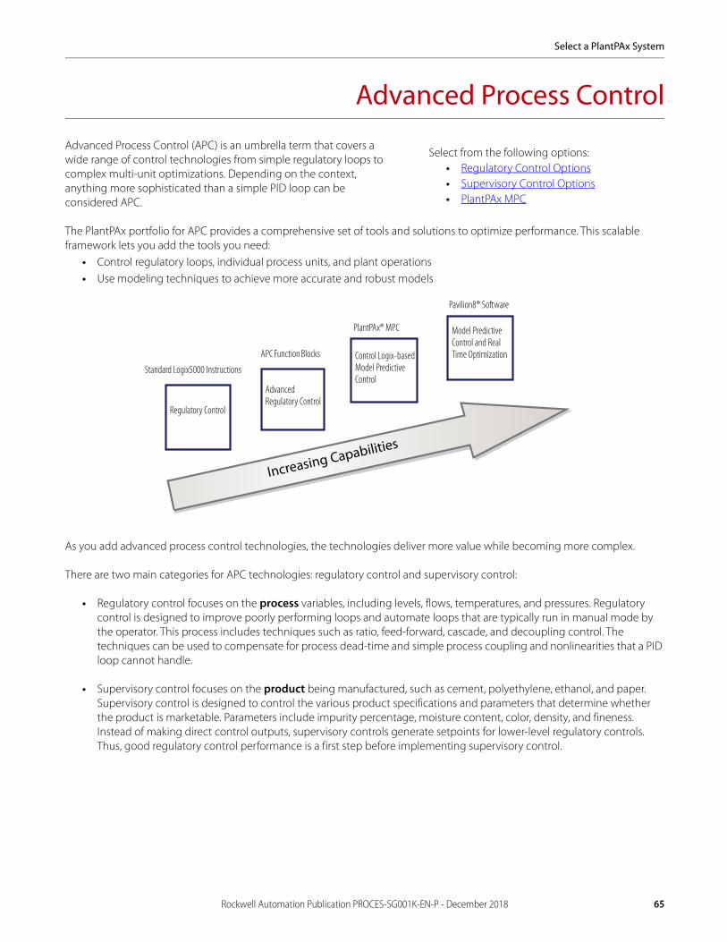
Select a PlantPAx System
Advanced Process Control
Advanced Process Control (APC) is an umbrella term that covers a wide range of control technologies from simple regulatory loops to complex multi-unit optimizations. Depending on the context, anything more sophisticated than a simple PID loop can be considered APC.
The PlantPAx portfolio for APC provides a comprehensive set of tools and solutions to optimize performance. This scalable framework lets you add the tools you need:
• Control regulatory loops, individual process units, and plant operations• Use modeling techniques to achieve more accurate and robust models
As you add advanced process control technologies, the technologies deliver more value while becoming more complex.
There are two main categories for APC technologies: regulatory control and supervisory control:
• Regulatory control focuses on the process variables, including levels, flows, temperatures, and pressures. Regulatory control is designed to improve poorly performing loops and automate loops that are typically run in manual mode by the operator. This process includes techniques such as ratio, feed-forward, cascade, and decoupling control. The techniques can be used to compensate for process dead-time and simple process coupling and nonlinearities that a PID loop cannot handle.
• Supervisory control focuses on the product being manufactured, such as cement, polyethylene, ethanol, and paper. Supervisory control is designed to control the various product specifications and parameters that determine whether the product is marketable. Parameters include impurity percentage, moisture content, color, density, and fineness. Instead of making direct control outputs, supervisory controls generate setpoints for lower-level regulatory controls. Thus, good regulatory control performance is a first step before implementing supervisory control.
Select from the following options:• Regulatory Control Options• Supervisory Control Options• PlantPAx MPC
Regulatory Control
Advanced Regulatory Control
Control Logix-basedModel Predictive Control
Model Predictive Control and Real Time Optimization
Standard Logix5000 Instructions
APC Function Blocks
PlantPAx® MPC
Pavilion8® Software
Increasing Capabilities
Rockwell Automation Publication PROCES-SG001K-EN-P - December 2018 65

Select a PlantPAx System
Regulatory Control Options
APC function blocks can be used in place of PID instructions for loops with long dead-times and interacting loops. TheAPC function blocks are licensed, run on the EWS, and require the Logix Designer application.
Supervisory Control Options
The most common supervisory control technique is Model Predictive Control (MPC). MPC can handle large multivariable processes and control these product parameters while optimizing the production process through maximizing rates andyields, reducing raw material usage and minimizing energy.
The Pavilion8 workstation-based software platform is a modular design that includes modules to help control, analyze, monitor, visualize, warehouse, and integrate information. MPC technology is an intelligence layer on top of basic automation systems that continuously drives the plant. The technology helps achieve multiple business objectives, such as cost reductions, decreased emissions, consistent quality, and production increases—every production minute.
MPC technology also assesses current and predicted operational data and compares them to desired results. Once computed, new control targets help reduce in-process variability to improve process performance.
Use the Pavilion® platform within a PlantPAx system to add model predictive control, environmental performance management, and production performance management.
Table 53 - APC Function Block Descriptions
APC Instruction Description
Internal model control (IMC) Controls a single process variable (such as a temperature or pressure) with a single control variable (such as a valve position or pump speed).Compares actual process error against error calculated by an internal first order lag plus dead-time model.Suitable for long dead-time processes, which are difficult to control with standard PID loops.
Coordinated control (CC) Controls a single process variable with up to three control variables.It is good for situations where multiple outputs are available for control, and costs need to be minimized or for situations where additional process information is available for feed-forward control.Target values and priorities for outputs are used to optimize your process.
Modular multivariable control (MMC) Controls two process variables with up to three control variables.It is good for situations where there is significant interaction between the various control variables and process variables.
Table 53.1 - APC Software
Category Cat. No.(1)
(1) Different languages are available, but you must contact your local Allen-Bradley distributor or Rockwell Automation sales representative.
Description
Automation software • 9324-RLDAPCENE for first controller• 9324-RLDAPCCLENE for subsequent controllers
• Logix Designer APC Design License• Logix Designer APC Runtime License
MPC System Architecture
66 Rockwell Automation Publication PROCES-SG001K-EN-P - December 2018

Select a PlantPAx System
PlantPAx MPC
PlantPAx model predictive control (MPC) is a fully functional, rack-based option of MPC. The rack-based option runs in the Rockwell Automation ControlLogix chassis. Configuration software available to create the application is called PlantPAx MPC Builder. PlantPAx MPC Builder software lets you configure and integrate a developed application as an Add-On Instruction. In the Studio 5000 Logix Designer application, you can move the created MPC Add-On Instruction into a Logix controller.
PlantPAx MPC has a dynamic form that is identical to Pavilion 8 MPC dynamic transforms. PlantPAx MPC supports up to 10 controlled variables (CV), 10 manipulated variables (MV) and 10 disturbance variables (DV). A single PlantPAx MPC module (required) can support up to five independent MPC applications. The five applications can share information with each other. Therefore, large applications can be controlled with a single PlantPAx MPC module when appropriately segmented. This approach facilitates development, integration, commissioning and execution of your application.
For purchase information, contact your local Allen-Bradley distributor or Rockwell Automation sales representative.
Table 54 - PlantPAx MPC Software and License
Category Cat. No. Description
Automation software 1756-PPMPC(1)
(1) The version of the PlantPAx MPC firmware and PlantPAx MPC Builder configuration software must match.
ControlLogix MPC module
MPC License 9529-PPMPCENM(1) PlantPAx MPC firmware
MPC Modeling Editors • 9529-PPMPCBENE• 9529-PPMPCBENM
PlantPAx MPC Builder configuration software
Rockwell Automation Publication PROCES-SG001K-EN-P - December 2018 67

Select a PlantPAx System
Notes:
68 Rockwell Automation Publication PROCES-SG001K-EN-P - December 2018
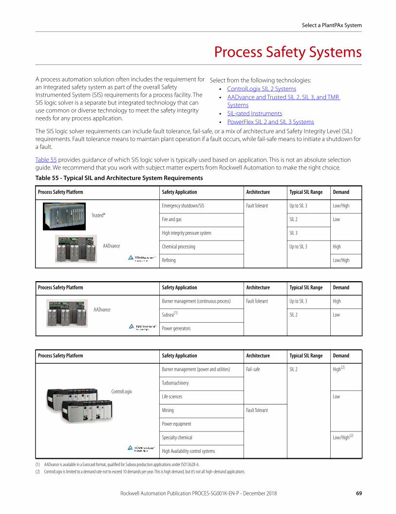
Select a PlantPAx System
Process Safety Systems
A process automation solution often includes the requirement for an integrated safety system as part of the overall Safety Instrumented System (SIS) requirements for a process facility. The SIS logic solver is a separate but integrated technology that can use common or diverse technology to meet the safety integrity needs for any process application.
The SIS logic solver requirements can include fault tolerance, fail-safe, or a mix of architecture and Safety Integrity Level (SIL) requirements. Fault tolerance means to maintain plant operation if a fault occurs, while fail-safe means to initiate a shutdown for a fault.
Table 55 provides guidance of which SIS logic solver is typically used based on application. This is not an absolute selection guide. We recommend that you work with subject matter experts from Rockwell Automation to make the right choice.
Table 55 - Typical SIL and Architecture System Requirements
Process Safety Platform Safety Application Architecture Typical SIL Range Demand
Emergency shutdown/SIS Fault Tolerant Up to SIL 3 Low/High
Fire and gas SIL 2 Low
High integrity pressure system SIL 3
Chemical processing Up to SIL 3 High
Refining Low/High
Process Safety Platform Safety Application Architecture Typical SIL Range Demand
Burner management (continuous process) Fault Tolerant Up to SIL 3 High
Subsea(1)
(1) AADvance is available in a Eurocard format, qualified for Subsea production applications under ISO13628-6.
SIL 2 Low
Power generators
Process Safety Platform Safety Application Architecture Typical SIL Range Demand
Burner management (power and utilities) Fail-safe SIL 2 High(2)
(2) ControlLogix is limited to a demand rate not to exceed 10 demands per year. This is high demand, but it’s not all high-demand applications.
Turbomachinery
Life sciences Low
Mining Fault Tolerant
Power equipment
Specialty chemical Low/High(2)
High Availability control systems
Select from the following technologies:• ControlLogix SIL 2 Systems• AADvance and Trusted SIL 2, SIL 3, and TMR
Systems• SIL-rated Instruments• PowerFlex SIL 2 and SIL 3 Systems
Trusted®
AADvance
AADvance
ControlLogix
Rockwell Automation Publication PROCES-SG001K-EN-P - December 2018 69

Select a PlantPAx System
Safe, reliable systems safeguard people, property, the environment, and company or corporate reputations. Third-party certification for applying technologies in applications up to a specific SIL level significantly reduces complexity when complying with national and international process safety standards worldwide.
Process safety technology selection is based on functional and target SIL requirements, defined in the projects Safety Requirements Specification (SRS). For example, if the SRS requirement is for the Safety Instrumented Function to always fail safely upon a fault, you can select a fail-safe only technology. If, however, some level of fault tolerance is defined for your process safety system, you can select a fault tolerant technology.
There are different levels of fault tolerance available. For example:
• 1oo2d refers to a voting and degradation architecture where diagnostics is used to determine the validity of two values or states. When both values are ‘healthy’, then either one out of the two (1oo2) available is used in the outcome of the Safety instrumented Function (SIF). When one of the two values or states is determined to be ‘invalid’, that value or state is no longer considered when determining the outcome of the SIF (the voting degrades to 1oo1, one out of the remaining good one). This dramatically reduces the nuisance trip rate of a basic 1oo2 architecture, while maintaining safety performance.
• 2oo3 refers to a voting and degradation architecture where comparison diagnostics are used to determine the outcome of the SIF. Two ‘out of’ the three (2oo3) available values or states are required to determine the outcome of a SIF. This architecture, often referred to as Triple Modular Redundancy (TMR), lets a failed value or state to be ignored when resolving the SIF.
TIP: In addition to the comparison diagnostics, active diagnostics are also used to validate states and values used in the outcome of the SIF.
Table 56 shows the capabilities of the process safety systems. Your solution can include one or a combination of technologies.
ControlLogix SIL 2 Systems
ControlLogix supports process safety applications up to SIL 2 requiring fault tolerance and redundancy. ControlLogix supports 1oo2d fault tolerance with the 1715 I/O system. However, ControlLogix redundancy does not use a voting mechanism, rather it acts as a hot standby. The components of the 1715 I/O system comprise a pair of partnered Ethernet adapters that communicate to ControlLogix controllers via an EtherNet/IP network, and digital and analog I/O modules that are configurable in simplex and duplex modes.
The ControlLogix L7x controller complies with the requirements of the relevant standards (SIL 2 according to IEC 61508) and can be used in low demand applications up to SIL 2 according to IEC 61508). The instructions of the associated Safety Reference Manual and User Manuals are to be considered.
Table 56 - Process Safety System Capabilities
Process Safety System Specification ControlLogix AADvance Trusted
SIL 2 Yes Yes Yes
SIL 3 No Yes Yes
Fault tolerant (1oo2d) Yes(1)
(1) The 1oo2d mechanism for the ControlLogix SIL 2 system is provided by the 1715 I/O platform. A ControlLogix SIL 2 system also provides fault tolerance through controller redundancy, but ControlLogix redundancy acts as a hot backup and is not a voting architecture.
Yes Yes
Fault tolerant (2oo3/TMR) No Yes Yes
Diverse safety system (programmed with diverse hardware and programming software) No Yes Yes
Integrated safety system (programmed with common hardware and programming software) Yes No No
Single project spanning controllers (distributed safety environment) No Yes No
70 Rockwell Automation Publication PROCES-SG001K-EN-P - December 2018

Select a PlantPAx System
ControlLogix SIL 2 systems use the same programming software and data interfaces as used for process control on the PlantPAx system. The hardware that is used for process safety must be dedicated for process safety applications.
Specific hardware, firmware revisions, and software versions are required to meet SIL certifications. To make sure that you have the correct equipment, see the Using ControlLogix in SIL 2 Application Safety Reference Manual, publication 1756-RM001.
AADvance and Trusted SIL 2, SIL 3, and TMR Systems
Diverse SIS logic solvers use different hardware and software platforms for process safety applications than that used for process control on the PlantPAx system. This approach is used to minimize common cause faults from influencing the overall safety integrity. Triple redundancy minimizes the possibility of any single component failure to cause a spurious or false trip. Diverse process safety integrates with the basic process control on the PlantPAx system by using CIP connectivity including profile support in Logix Designer software (AADvance) or via OPC connectivity (AADvance or Trusted).
Both the Trusted and AADvance systems share a common EtherNet/IP network within a PlantPAx system. In addition, AADvance and Trusted support redundant Ethernet networks, while the AADvance system supports the CIP producer and consumer communication protocol.
SIL-rated Instruments
SIL-rated instruments are typically required for process safety loops. Rockwell Automation provides premier integration between ControlLogix systems and Endress+Hauser SIL-rated instruments. For more details, see the Endress+Hauser websiteat http://www.us.endress.com.
Table 57 - Diverse SIL 2 and SIL 3 Products
Category Description
AADvance system The AADvance technology is the following:• Configurable for SIL 2 and SIL 3• Scalable redundancy for fault tolerance• Simplex, duplex, or triplex configuration
Trusted system Trusted technology uses 3-2-0 (3-2-2-0 optionally) fault-tolerant control to virtually eliminate spurious trips. Triple modular redundancy (TMR) uses majority voting to identify a source of failure. Available with OPC or CIP integration.
Table 58 - Additional Resources
Resource Description
AADvance Solutions Handbook, publication ICSTT-RM447 Explains the features, performance, and functionality of the AADvance controller and systems. It sets out some guidelines on how to specify a system to meet your application requirements.
AADvance System Build Manual, publication ICSTT-RM448 Provides experienced panel builders with information on how to assemble a system, switch on and validate the operation of a controller.
AADvance Configuration Guide, publication ICSTT-RM405 Defines how to configure an AADvance controller by using the AADvance Workbench to meet your Safety Instrument Function (SIF) application requirements.
AADvance Safety Manual, publication ICSTT-RM446 Provides mandatory guidance on how to apply AADvance to meet various industry standards and makes recommendations to safely apply AADvance in SIS applications. Explains how to use ControlLogix controllers.
AADvance Troubleshooting and Repair Manual, publication ICSTT-RM406 Provides plant maintenance personnel with information on how to trace and repair a fault in an AADvance system and perform routine maintenance tasks.
Rockwell Automation Publication PROCES-SG001K-EN-P - December 2018 71

Select a PlantPAx System
PowerFlex SIL 2 and SIL 3 Systems
PowerFlex AC drives offer SIL ratings up to and including SIL 3. Specifically, the PowerFlex 525 AC drive offers Safe Torque Off (STO) as a standard embedded feature with a safety rating of PLd/SIL2 Cat. 3. The PowerFlex 753 and 755 AC drives are available with optional STO functionality with a safety rating of PLe/SIL3 Cat. 3. In addition, the PowerFlex 753 and 755 offer aSafe Speed Monitor option for applications that can benefit from access to a safety zone while there is limited motion. TheSafe Speed Monitor option has a rating of PLe/SIL3 Cat. 4.
PowerFlex STO functionality is designed to help safely remove power from the gate firing circuits of the drive’s output power devices (IGBT’s). This helps prevent the drive’s output power devices from switching in the pattern necessary to generateAC power to the motor. Can be used in combination with other safety devices to satisfy the requirements of IEC 61508,IEC 61800-5-2 SIL 3, ISO 13849-1 PL e, and Category 3 for STO.
For more information, see the PowerFlex Low Voltage AC Drives Selection Guide, publication PFLEX-SG002.
OptiSIS Safety Integrated Systems
The OptiSIS® safety system uses an AADvance safety logic solver for a process safety solution that is ready to install and configure with no programming required. OptiSIS lets you configure safety functions by using an intuitive Cause and Effect interface from the HMI display.
OptiSIS includes options for:• Fail-safe or fault tolerant architectures• Indoor or outdoor environments• Floor and wall mount• 50 or 100 I/O count
OptiSIS is a great solution for small process safety applications. In addition, if you have an existing process safety system(for example, an older relay or legacy system) that can no longer be maintained, OptiSIS can provide a cost-effective andshort delivery replacement.
For more information, see the OptiSIS Product Profile, publication SSB-PP030.
72 Rockwell Automation Publication PROCES-SG001K-EN-P - December 2018

Select a PlantPAx System
Services and Support
Rockwell Automation offers annual support agreements that help keep your systems running by combining our world-class service capabilities into a service and support process tailored to your unique needs.
Assurance™ Integrated Support features a range of services and support options to help keep your plant operational.
Access to Remote Support Engineers
We offer system-wide support for troubleshooting. Specialized engineers examine your system to help prevent downtime for optimal performance. A senior engineer is with you every step of the way and assists you throughout the process.
On-site Delivery of Replacement Parts
A parts management agreement helps to reduce the operating costs associated with managing spare parts. We own, locate, and manage the Rockwell Automation inventory at your site, which provides you access to parts 24 hours, 7 days a week, all year. This agreement is backed by our remanufacturing and renewal parts services to replenish any used inventory.
Emergency On-site Engineering Services
Day or night, Rockwell Automation field service professionals across the globe are available for dispatch on an as-needed basis. These professionals help troubleshoot and resolve unplanned downtime events, problems affecting critical operations, and other automation-related issues.
Benefits and features include the following:• 24 x 7 breakdown support• Factory-trained engineers with skills matched to your application or anomaly• Assistance for startup, special projects, and peak workloads• Technical support during maintenance activity
Additionally, support can be expanded to include the following:• On-site preventative maintenance• Enhanced and ongoing Installed Base Evaluations and Storeroom Assessments• Customized application level support• Network performance assessments• Full-time resident engineering and/or asset management professionals
Select from the following options:• Access to Remote Support Engineers• On-site Delivery of Replacement Parts• Emergency On-site Engineering Services
Rockwell Automation Publication PROCES-SG001K-EN-P - December 2018 73
Select a PlantPAx System
Simple - You make only one call to initiate technical assistance. If needed, we coordinate the shipment of parts or dispatch a service professional for no additional cost. No new purchase orders to assign. No additional calls to make.
Flexible - We offer multiple service levels to help you meet your business goals. You choose the guaranteed level of response for replacement parts to arrive on-site, the arrival time of a service professional, and other pro-active services you need to be successful.
Worry free - We can help you avoid unplanned costs and reduce downtime. Achieve greater peace of mind knowing you have the support you need when the unexpected happens.
Easy to Order - Contact your Rockwell Automation Distributor or Account Manager for a personalized estimate that includes all the services you need.
For more information, see the Rockwell Automation Assurance Integrated Support website at www.rockwellautomation.com.
74 Rockwell Automation Publication PROCES-SG001K-EN-P - December 2018


Publication PROCES-SG001K-EN-P - December 2018Supersedes Publication PROCES-SG001J-EN-P - August 2018 Copyright © 2018 Rockwell Automation, Inc. All rights reserved. Printed in the U.S.A.
Rockwell Automation SupportUse the following resources to access support information.
Documentation FeedbackYour comments will help us serve your documentation needs better. If you have any suggestions on how to improve this document, complete the How Are We Doing? form at http://literature.rockwellautomation.com/idc/groups/literature/documents/du/ra-du002_-en-e.pdf.
Technical Support Center Knowledgebase Articles, How-to Videos, FAQs, Chat, User Forums, and Product Notification Updates. https://rockwellautomation.custhelp.com/
Local Technical Support Phone Numbers Locate the phone number for your country. http://www.rockwellautomation.com/global/support/get-support-now.page
Direct Dial Codes Find the Direct Dial Code for your product. Use the code to route your call directly to a technical support engineer. http://www.rockwellautomation.com/global/support/direct-dial.page
Literature Library Installation Instructions, Manuals, Brochures, and Technical Data. http://www.rockwellautomation.com/global/literature-library/overview.page
Product Compatibility and Download Center (PCDC)
Get help determining how products interact, check features and capabilities, and find associated firmware. http://www.rockwellautomation.com/global/support/pcdc.page
.
Rockwell Otomasyon Ticaret A.Ş., Kar Plaza İş Merkezi E Blok Kat:6 34752 İçerenköy, İstanbul, Tel: +90 (216) 5698400
Rockwell Automation maintains current product environmental information on its website at http://www.rockwellautomation.com/rockwellautomation/about-us/sustainability-ethics/product-environmental-compliance.page.
AADvance, ArcShield, Allen-Bradley, ArmorBlock, ArmorPOINT, Assurance, CENTERLINE, Compact I/O, CompactLogix, ControlLogix, Dynamix, Encompass, E1 Plus, E3 Plus, E300, eProcedure, FactoryTalk, FLEX, FLEX Ex, Integrated Architecture, IntelliCENTER, LISTEN. THINK. SOLVE., Logix5000, On-Machine, OptiSIS, PanelView, Pavilion8, PhaseManager, PlantPAx, POINT I/O, PowerFlex, Rockwell Automation, Rockwell Software, RSLinx, Secure Connect, SMC, Studio 5000, Studio 5000 Architect, Studio 5000 Logix Designer, Stratix, Trusted, and VantagePoint are trademarks of Rockwell Automation, Inc.
Cisco is a trademark of Cisco Systems, Inc.
Common Industrial Protocol, ControlNet, DeviceNet, and EtherNet/IP are trademarks of the ODVA.
Intel is a trademark of the Intel Corporation.
Microsoft, Excel, and Windows are trademarks of the Microsoft Corporation.
TUV Rheinland is a trademark of TUV Rheinland.
Trademarks not belonging to Rockwell Automation are property of their respective companies.


![Procurement Specification PlantPAx Distributed Control ... · [PROJECT NUMBER] [PROJECT NAME] [DATE] [PROJECT LOCATION] Rockwell Automation PlantPAx Distributed Control System –](https://img.dokumen.tips/doc/110x75/5e7ce35022c0846aac0ad669/procurement-specification-plantpax-distributed-control-project-number-project.jpg)