Embed Size (px)
Citation preview

Copyright 2008 RIC MIDDLETON, PE
Document Title:
Hotside ESP Planning For ADA 37 Additive
Page No.:
1
Rev. Date:
November 2008
Plant Robert, W. Scherer
Unit 1 & Unit 2
Hot Side Electrostatic Precipitator
Planning For PRB Coal
With ADA 37 Additive
June, 2000
Oglethorpe Power Corporation
Ric Middleton, P.E.
(Modified for Web Presentation)

Copyright 2008 RIC MIDDLETON, PE
Document Title:
Hotside ESP Planning For ADA 37 Additive
Page No.:
2
Rev. Date:
November 2008
Table of Contents
Section Page
Cover 1
Table of Contents 2
Introduction 3
Executive Summary 6
Objectives 9
Fuels and Combustion 10
ADA-37 Chemical Injection System 17
Precipitator Models 20
Site Visits and Testimonials 34
Recommendations And Conclusions 42
References 47
Appendix 48
I. ADA System
II. ADA 37 Chemical Effectiveness
Copyright 2008 RIC MIDDLETON, PE
Document Title:
Hotside ESP Planning For ADA 37 Additive
Page No.:
3
Rev. Date:
November 2008
Introduction
Electrostatic Precipitators, (ESPs), remove particulate matter from boiler flue gas at a high rate
of efficiency. ESPs operate by charging the particles inductively with an electric field and then
attracting them to collector plates that are charged with opposite polarity. After the particles
accumulate on the collector plates the ESP removes the particles mechanically for disposal.
Electrostatic Precipitator Design Basics
Coal fired boiler flue gas consists primarily of the products of combustion resulting from
chemical reaction of fuel with air in the furnace. The products of combustion include Oxygen,
Nitrogen, Carbon Dioxide, Carbon Monoxide, and Water vapor. In addition, flue gas also
includes unburned fuel particles due to process inefficiency, traces of gaseous pollutants
resulting from undesirable fuel and air constituents, and non-combustible matter included with
the fuel which is referred to as “coal ash”, or “ash”. Electrostatic precipitators are applied in
power plants to remove the particulate (solid matter) from flue gas consisting primarily of ash.
In power plant applications, electrostatic precipitators are massive, enclosed duct elements
located in the exhaust ducts of coal-fired boilers, which transfer the products of combustion (flue
gas), to the stack and to the atmosphere. In most power plants, precipitators are downstream of
the air preheaters and are referred to as “cold-side” precipitators. In some cases, precipitators are
located upstream of the air preheaters and are referred to as “hot-side precipitators”. For Plant
Scherer Unit 1 and Unit 2, hot-side ESPs are used.
When Plant Scherer was designed, the choice of hot-side or cold-side ESP locations was based
upon expected ash properties at hot and cold side temperatures. Specifically, high resistivity ash
suffers from power limitations at temperatures below about 600 Deg. F. Sophisticated ESP
controls limit the applied voltage to the precipitator electrodes when an eminent electrical
discharge (spark-over) is detected. Above ~600 Deg. F the ash resistivity drops considerably
allowing for increased applied voltages. This relationship was the design basis for hot-side
installations. Because of this relationship, relatively small sized ESPs were specified for Hot-
Side applications.
The efficiency of an ESP can be calculated based on two quantities. These quantities are the inlet
and outlet particulate concentrations. The ESP efficiency is calculated as:
Eff = 100% x (1-inlet concentration/outlet concentration)
The guaranteed efficiency of the Plant Scherer Unit #1 and #2 ESPs, based on design inlet
concentration of 2.87 grains/cu ft of flue gas and outlet concentration of 0.019 grains/cu ft of flue
gas is:
Eff = 100% x (1- 0.019 / 2.87) = 99.34%

Copyright 2008 RIC MIDDLETON, PE
Document Title:
Hotside ESP Planning For ADA 37 Additive
Page No.:
4
Rev. Date:
November 2008
The efficiency of an ESP is also calculated using the Deutch equation as:
Eff = 1-exp (-wA/V)
Where exp = base of natural logarithm = 2.718
w = precipitation constant, ft/s
A = collecting plate area sqft
V = gas volume handled, cu ft/s
The quantity A/V is referred to as the specific collection area (SCA) of the ESP. SCA is used to
make comparisons of various ESP configurations. ESP efficiency increases with increasing SCA
and decreases with decreasing SCA. For a given flue gas flow, ESP efficiency can be increased
by increasing collecting plate area. For a given precipitator, ESP efficiency can be increased by
decreasing the flue gas flow.
ESP efficiency increases with the precipitation constant, w. The value of w is dependent on the
applied ESP voltage and other factors including ash physical properties, ESP electrical
clearances, and ESP internal electrode geometry.
Figure from Std. Handbook of Powerplant Engineering, 2
nd
Edition
Referring to the above figure, as collection proceeds, the collected ash layer obtains a voltage
equal to the ash resistance times the ash layer thickness. This voltage limits the effective voltage
applied across the gas passage over time. The higher the ash resistivity, the higher the voltage
drop across the collected ash, the lower the effective voltage drop across the gas passage. After
mechanical removal of the collected ash, the voltage levels can cycle to increased levels.
Sodium Depletion Theory
This theory states that over time, Sodium ions migrate within ash layers on collecting electrodes
as they are attracted to the negatively charged emitting electrodes. After the outer, Sodium rich,
layer of collected ash is removed by rapping, the permanently attached inner layer of ash is
Copyright 2008 RIC MIDDLETON, PE
Document Title:
Hotside ESP Planning For ADA 37 Additive
Page No.:
5
Rev. Date:
November 2008
depleted of Sodium ions which are the principal carriers of electric charge. This inner layer of
ash is not removed by rapping and increases the required applied voltage while reducing the
effective applied voltage across the gas passage. This phenomenon is predominant in ash from
fuels with low Sodium content (PRB Coal). This phenomenon was not understood prior to the
design of Plant Scherer.
Current Investigation
As a part of the Plant Scherer ”NOx Mitigation Strategies for Coal-Fired Boilers”, the use of low
Sulfur coal from the Powder River Basin, (PRB coal) is being considered. The potential change
in ash properties resulting from the proposed fuel switch is expected to have negative effects on
the ESP performance for Unit 1 and Unit 2. The ESPs for Plant Scherer Unit 1 and Unit 2 were
originally designed for PRB coal, but were not capable of successful operation. PRB coal, a low
Sodium fuel, is known to produce an ash of increased resistivity, as in the above two paragraphs,
which limits the ability to apply voltage to the ESP. Referring to the efficiency equation, reduced
applied voltage would result in reduced w and reduced ESP efficiency.
To eliminate the problem of increased fly ash resistivity of PRB ash, ADA Environmental
Solutions, LLC proposes their chemical additive, ADA-37, for injection into the flue gas
upstream of the electrostatic precipitators for Plant Scherer, Unit 1 and Unit 2.
Advantages of the use of ADA-37 are advertised as:
1. Effective at temperatures up to 800 Deg. F, providing hot-side (>500F) and warm-side
(<350F) ESP users with a flue gas conditioning option.
2. Effective on ESP’s suffering from Sodium Depletion.
3. Conditioned ash is suitable for use in concrete and other commercial uses.
4. The conditioning agent can condition most fly ashes allowing users a wider range of
options in purchasing coal.
5. The injection system is simple and low capital cost.
6. The chemical can be used during start-up and shut down to control “off-line emissions”.
7. The chemical is less hazardous and easier to handle than SO3/NH3.
This paper will summarize results of investigation of the use of ADA flue gas additives on Plant
Scherer Unit 1 and Unit 2. Included in the analysis will be ESP computer modeling utilizing
EPRI ESPM Beta software. A system for injecting the ADA chemical additive will be described
in conjunction with ADA Environmental Solutions, LLC. Recommendations on the use of the
ADA chemical additive system will be made.
Copyright 2008 RIC MIDDLETON, PE
Document Title:
Hotside ESP Planning For ADA 37 Additive
Page No.:
6
Rev. Date:
November 2008
Executive Summary
A proposed switch to sub-bituminous PRB coal, the design coal for Unit 1 & Unit 2 boilers at
Plant Robert, W. Scherer, is part of present air pollution control (APC) strategy which targets
0.07 to 0.15 Lbs NOx/MBtu heat input as the performance standard for future NOx mitigation.
PRB coal produces an ash that is difficult to collect, due to its relatively high resistivity, which
results in excessive voltages across ash layers on the plates of electrostatic precipitators. This
characterization is based upon the “Sodium Depletion Theory” which states that Sodium ions in
the collected fly ash, which are the principal charge carriers, migrate to the outer ash layers as
the Sodium ions are attracted to oppositely charged emitting electrodes. The Sodium ions are
consequently removed by the rapping step of the electrostatic precipitation process, leaving
behind a layer of ash that sticks to the collecting plates and is depleted of charge carrying
capacity and thus highly resistive to the flow of charging current. This Sodium Depletion
Phenomenon was not understood when Plant Scherer was designed. The design fuel, PRB coal,
is not currently used in boilers for Scherer Unit 1 & Unit 2.
ADA Environmental Solutions, LLC markets a family of chemical additives, which reportedly,
are effective in correcting the problem of high resistivity ash associated with PRB coal
combustion. The reduction in resistivity would allow for acceptable electrostatic precipitator
performance.
ADA Environmental Solutions, LLC and their chemical additive systems were presented to Plant
Scherer Operator personnel by the President of ADA including an update on information
presented at the EPRI-DOE-EPA Mega Symposium in Atlanta dated August, 1999. As a result of
the presentation, Georgia Power Engineering was invited to participate in the evaluation of ADA
and to attend plant tours at ADA installations.
Documentation in the form of charts showing chemical injection rates and ESP outlet opacity
readings or ESP input power levels have indicated that the ADA family of chemical additives is
indeed effective at decreasing the resistivity of collected ash by a factor of approximately 10 to
1, (See Appendix II.). In addition, the data presented is associated with conditions that are fairly
representative of Plant Scherer Unit 1 & Unit 2.
Modeling of the ADA chemical additive injection utilizing EPRI ESPM Version 1.0 Beta
software for Windows was an objective of the research. ADA however, did not guarantee a
change in resistivity, or provide disclosure of the chemical constituents of the ADA - 37 additive.
The results of modeling will therefore be limited to specifying a range of ash resistivity reduction
that would be required to meet projected opacity limits. An additional desired result of the ESPM
Version 1.0 Beta modeling was validation of Beta results by comparison with a previous ESPM
for DOS Version 1.0 software model. The Beta software provided results nearly identical to
ESPM Version 1.0 for DOS based on the exact input from previous modeling at Plant Scherer
which may be considered to be a check on the integrity of the Windows based Beta software.

Copyright 2008 RIC MIDDLETON, PE
Document Title:
Hotside ESP Planning For ADA 37 Additive
Page No.:
7
Rev. Date:
November 2008
Problems with the ADA chemical injection system are due to the lack of fully developed
solutions for injection of the chemical into typical utility electrostatic precipitator inlet flow
streams. A great deal of basic engineering is required by ADA Environmental Solutions, LLC,
before their chemical injection system can be applied in utility station service.
The chemical is highly reactive with a pH of ~12 and would tend to be highly corrosive to metal
surfaces. Deposits of chemicals accumulate in the flue gas ducts downstream of the injection
nozzles, and at the injection nozzles themselves, creating mounds of toxic, corrosive chemical,
which must be removed, and require unit shut-down. ADA’s charge that chemical deposits are
due to lack of inspection and maintenance, were not well received by the writer, and leaves the
impression that ADA tends to blame others for the failure of their systems.
The chemical is hazardous and would introduce risks for workers exposed to it during delivery,
transfer, filling, operation, inspection, maintenance, and clean up of spills. The level of “Haz-
Mat” personnel required for chemical handling, and the classification of the chemical must be
verified after full disclosure of the chemical formulation. Chemical handling by maintenance
personnel is not recommended.
The chemical additive may cause problems with plant operation related to the required addition
of a remedial anti-cementing chemical (ADA-110) prior to transfer to Plant Scherer’s wet ash
piping to the ash pond to avoid blockage of the piping. As a priority, permission to pipe the ash
containing ADA-37 and ADA-110 to the ash pond, which is adjacent to Lake Scherer and the
Rum Creek Wilderness Sanctuary, would be required from environmental authorities.
Traces of the chemical would be attached to ash, which is not captured by the ESP, and would be
released to the atmosphere at the stack exhaust. Permission to release the chemical would be
required from environmental authorities.
The ADA – 37 additive system is not recommended for the following reasons:
1. Failure of the injection system to prevent accumulation, deposits, un-even chemical
distribution, and un-even chemical treatment.
2. Frequency of required inspection and maintenance to remove chemical deposits.
3. Lack of disclosure of formulation to allow for complete evaluation.
4. Lack of experience with re-circulation of flue gas and the resultant high temperature
chemical exposure.
5. Poor quality of the inspected system components.
6. ADA’s lack of operating experience.

Copyright 2008 RIC MIDDLETON, PE
Document Title:
Hotside ESP Planning For ADA 37 Additive
Page No.:
8
Rev. Date:
November 2008
7. Severely corrosive nature of the chemical.
8. Unknown environmental impact or regulation.
9. Excessive human interface.
10. Inability of system to work without baseline Sodium concentration.
11. Poor controllability characteristics primarily associated with long response time.
12. Unknown long term human exposure risks.
13. Lack of performance guarantees and remedies.
14. Lack of liability guarantees and remedies.

Copyright 2008 RIC MIDDLETON, PE
Document Title:
Hotside ESP Planning For ADA 37 Additive
Page No.:
9
Rev. Date:
November 2008
Objectives
During the course of research, the following objectives are to be achieved:
1. Introduce Georgia Power Corporation’s Plant Scherer Staff To ADA Environmental
Solutions, LLC
2. Approximate PRB/Eastern Coal Mixture Analysis
3. Model ESPs With EPRI ESPM Beta Software Based on Eastern Coal
4. Model ESP Performance With PRB and Mixture Coals
5. Estimate System Requirements For ADA Additive Injection In Conjunction With ADA
Environmental Solutions, LLC
6. Interview Users of ADA Family of Flue Gas Additives
7. Make Recommendations On The Use Of ADA Flue Gas Additives

Copyright 2008 RIC MIDDLETON, PE
Document Title:
Hotside ESP Planning For ADA 37 Additive
Page No.:
10
Rev. Date:
November 2008
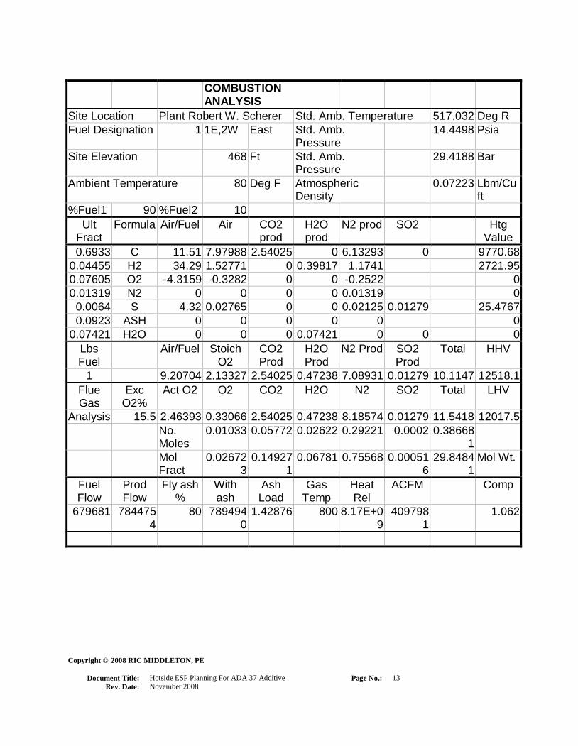
Summary of Fuels and Combustion
For the analysis of fuel combustion, a simplistic approach was deemed to be appropriate. In the
most crucial part of the analysis, the Sodium, Sulfur, and moisture content of the coal being
burned in the boiler would be of interest. The results of reviews of coal and ash samples and
discussions with personnel from multiple plants indicate that sample analyses vary according to
source, time of year, from one day to the next, month to month, and even from one rail car to
another. For these reasons, typical and average coal and ash data was used. Fuel and ash analyses
were provided by Georgia Power Company.
A typical/average Low Sulfur Eastern coal analysis is designated as Fuel 1, a typical/ average
Low Sulfur Western PRB coal analysis is designated as Fuel 2, and mixtures of 10, 20, 30, 40, &
50% based on mass are designated as percent mixtures.
Required fuel flow rates are based upon an assumed flow rate of 640,000 Lbs/ Hr of Fuel 1 with
15.5% excess air to achieve full load for Unit 1 or Unit 2. With this flow rate of Fuel 1, an
equivalent heat input of 8.17*E9 Btu/Hr is assumed for calculation of the required fuel flow
rates for Fuel 2, and the percent mixtures.
“As received” fuel analyses were referenced to the feeder belts. 100% of the fuel is assumed to
enter the furnace including all moisture. Total moisture varied from 7 to 11% of the flue gas for
this analysis.
The gaseous products of combustion are treated as an ideal gas based on standard fuel to air
ratios and combustion product ratios.
In addition, a constant fly-ash ratio of 80% of total ash was assumed along with an ESP inlet
temperature of 800 Deg. F.

Copyright 2008 RIC MIDDLETON, PE
Document Title:
Hotside ESP Planning For ADA 37 Additive
Page No.:
11
Rev. Date:
November 2008
COMBUSTION
ANALYSIS
Site Location Plant Robert W. Scherer Std. Amb. Temperature 517.032 Deg R
Fuel Designation 1 1E,2W East Std. Amb.
Pressure
14.4498 Psia
Site Elevation 468 Ft Std. Amb.
Pressure
29.4188 Bar
Ambient Temperature 80 Deg F Atmospheric
Density
0.07223 Lbm/Cu
ft
Ult
Fract
Formula Air/Fuel Air CO2
prod
H2O
prod
N2 prod SO2 Htg
Value
0.7076 C 11.51 8.14448 2.59265 0 6.25943 0 9972.21
0.04524 H2 34.29 1.55115 0 0.40428 1.192114 2763.72
0.07267 O2 -4.3159 -0.3137 0 0 -
0.240978
0
0.01365 N2 0 0 0 0 0.013655 0
0.00671 S 4.32 0.02898 0 0 0.022274 0.0134 26.7022
0.09596 ASH 0 0 0 0 0 0
0.05815 H2O 0 0 0 0.05815 0 0 0
Lbs
Fuel
Air/Fuel Stoich
O2
CO2
Prod
H2O
Prod
N2 Prod SO2
Prod
Total HHV
0.99998 9.41096 2.18052 2.59265 0.46242 7.246495 0.0134 10.315 12762.6
Flue
Gas
Exc
O2%
Act O2 O2 CO2 H2O N2 SO2 Total LHV
Analysis 15.5 2.5185 0.33798 2.59265 0.46242 8.367213 0.0134 11.7737 12272.6
No.
Moles
0.01056 0.05891 0.02567 0.298685 0.00021 0.39404
Mol
Fract
0.02681 0.14950
6
0.06514
2
0.758015
4
0.00053
1
29.8797 Mol Wt.
Fuel
Flow
Prod
Flow
Fly ash
%
With
ash
Ash
Load
Gas
Temp
Heat Rel ACFM Comp
640000 753514
8
80 758428
1
1.45779 800 8.17E+09 393212
4
1

Copyright 2008 RIC MIDDLETON, PE
Document Title:
Hotside ESP Planning For ADA 37 Additive
Page No.:
12
Rev. Date:
November 2008
COMBUSTION
ANALYSIS
Site Location Plant Robert W. Scherer Std. Amb. Temperature 517.032 Deg R
Fuel Designation 2 1E,2W West Std. Amb.
Pressure
14.4498 Psia
Site Elevation 468 Ft Std. Amb.
Pressure
29.4188 Bar
Ambient Temperature 80 Deg F Atmospheric
Density
0.07223 Lbm/Cu
ft
Ult
Fract
Formula Air/Fuel Air CO2
prod
H2O
prod
N2 prod SO2 Htg
Value
0.5646 C 11.51 6.49855 2.06869 0 4.99445 0 7956.91
0.0384 H2 34.29 1.31674 0 0.34318 1.01196 2346.05
0.1064 O2 -4.3159 -0.4592 0 0 -0.3528 0
0.009 N2 0 0 0 0 0.009 0
0.00363 S 4.32 0.01568 0 0 0.01205 0.00725 14.4474
0.0593 ASH 0 0 0 0 0 0
0.2188 H2O 0 0 0 0.2188 0 0 0
Lbs
Fuel
Air/Fuel Stoich
O2
CO2
Prod
H2O
Prod
N2 Prod SO2
Prod
Total HHV
1.00013 7.37175 1.70803 2.06869 0.56198 5.67464 0.00725 8.31257 10317.4
Flue
Gas
Exc
O2%
Act O2 O2 CO2 H2O N2 SO2 Total LHV
Analysis 15.5 1.97278 0.26475 2.06869 0.56198 6.55252 0.00725 9.45519 9721.87
No.
Moles
0.00827
4
0.04701 0.03119 0.23391 0.00011 0.32049
3
Mol
Fract
0.02581
5
0.14666
6
0.09733
3
0.72983
2
0.00035
3
29.5020
7
Mol Wt.
Fuel
Flow
Prod
Flow
Fly ash
%
With
ash
Ash
Load
Gas
Temp
Heat
Rel
ACFM Comp
840176 794402
2
80 798388
0
1.10754
6
800 8.17E+0
9
419855
4
1.31277
Copyright 2008 RIC MIDDLETON, PE
Document Title:
Hotside ESP Planning For ADA 37 Additive
Page No.:
13
Rev. Date:
November 2008
COMBUSTION
ANALYSIS
Site Location Plant Robert W. Scherer Std. Amb. Temperature 517.032 Deg R
Fuel Designation 1 1E,2W East Std. Amb.
Pressure
14.4498 Psia
Site Elevation 468 Ft Std. Amb.
Pressure
29.4188 Bar
Ambient Temperature 80 Deg F Atmospheric
Density
0.07223 Lbm/Cu
ft
%Fuel1 90 %Fuel2 10
Ult
Fract
Formula Air/Fuel Air CO2
prod
H2O
prod
N2 prod SO2 Htg
Value
0.6933 C 11.51 7.97988 2.54025 0 6.13293 0 9770.68
0.04455 H2 34.29 1.52771 0 0.39817 1.1741 2721.95
0.07605 O2 -4.3159 -0.3282 0 0 -0.2522 0
0.01319 N2 0 0 0 0 0.01319 0
0.0064 S 4.32 0.02765 0 0 0.02125 0.01279 25.4767
0.0923 ASH 0 0 0 0 0 0
0.07421 H2O 0 0 0 0.07421 0 0 0
Lbs
Fuel
Air/Fuel Stoich
O2
CO2
Prod
H2O
Prod
N2 Prod SO2
Prod
Total HHV
1 9.20704 2.13327 2.54025 0.47238 7.08931 0.01279 10.1147 12518.1
Flue
Gas
Exc
O2%
Act O2 O2 CO2 H2O N2 SO2 Total LHV
Analysis 15.5 2.46393 0.33066 2.54025 0.47238 8.18574 0.01279 11.5418 12017.5
No.
Moles
0.01033 0.05772 0.02622 0.29221 0.0002 0.38668
1
Mol
Fract
0.02672
3
0.14927
1
0.06781 0.75568 0.00051
6
29.8484
1
Mol Wt.
Fuel
Flow
Prod
Flow
Fly ash
%
With
ash
Ash
Load
Gas
Temp
Heat
Rel
ACFM Comp
679681 784475
4
80 789494
0
1.42876 800 8.17E+0
9
409798
1
1.062

Copyright 2008 RIC MIDDLETON, PE
Document Title:
Hotside ESP Planning For ADA 37 Additive
Page No.:
14
Rev. Date:
November 2008
COMBUSTION
ANALYSIS
Site Location Plant Robert W. Scherer Std. Amb. Temperature 517.032 Deg R
Fuel Designation 1 1E,2W East Std. Amb.
Pressure
14.4498 Psia
Site Elevation 468 Ft Std. Amb.
Pressure
29.4188 Bar
Ambient Temperature 80 Deg F Atmospheric
Density
0.07223 Lbm/Cu
ft
%Fuel1 80 %Fuel2 20
Ult
Fract
Formula Air/Fuel Air CO2
prod
H2O
prod
N2 prod SO2 Htg
Value
0.679 C 11.51 7.81529 2.48786 0 6.00643 0 9569.15
0.04387 H2 34.29 1.50427 0 0.39206 1.15608 2680.18
0.07942 O2 -4.3159 -0.3428 0 0 -0.2633 0
0.01272 N2 0 0 0 0 0.01272 0
0.00609 S 4.32 0.02632 0 0 0.02023 0.01217 24.2512
0.08863 ASH 0 0 0 0 0 0
0.09028 H2O 0 0 0 0.09028 0 0 0
Lbs
Fuel
Air/Fuel Stoich
O2
CO2
Prod
H2O
Prod
N2 Prod SO2
Prod
Total HHV
1.00001 9.00312 2.08602 2.48786 0.48233 6.93212 0.01217 9.91449 12273.6
Flue
Gas
Exc
O2%
Act O2 O2 CO2 H2O N2 SO2 Total LHV
Analysis 15.5 2.40936 0.32333 2.48786 0.48233 8.00427 0.01217 11.31 11762.5
No.
Moles
0.0101 0.05653 0.02677 0.28573 0.00019 0.37932
7
Mol
Fract
0.02663
8
0.14902
6
0.07058
2
0.75325
3
0.00050
1
29.8159 Mol Wt.
Fuel
Flow
Prod
Flow
Fly ash
%
With
ash
Ash
Load
Gas
Temp
Heat
Rel
ACFM Comp
694420 785387
0
80 790310
8
1.39861 800 8.17E+0
9
410721
7
1.08503

Copyright 2008 RIC MIDDLETON, PE
Document Title:
Hotside ESP Planning For ADA 37 Additive
Page No.:
15
Rev. Date:
November 2008
COMBUSTION
ANALYSIS
Site Location Plant Robert W. Scherer Std. Amb. Temperature 517.032 Deg R
Fuel Designation 1 1E,2W East Std. Amb.
Pressure
14.4498 Psia
Site Elevation 468 Ft Std. Amb.
Pressure
29.4188 Bar
Ambient Temperature 80 Deg F Atmospheric
Density
0.07223 Lbm/Cu
ft
%Fuel1 70 %Fuel2 30
Ult
Fract
Formula Air/Fuel Air CO2
prod
H2O
prod
N2 prod SO2 Htg
Value
0.6647 C 11.51 7.6507 2.43546 0 5.87994 0 9367.62
0.04319 H2 34.29 1.48083 0 0.38595 1.13807 2638.42
0.08279 O2 -4.3159 -0.3573 0 0 -0.2745 0
0.01226 N2 0 0 0 0 0.01226 0
0.00579 S 4.32 0.02499 0 0 0.01921 0.01156 23.0257
0.08496 ASH 0 0 0 0 0 0
0.10634 H2O 0 0 0 0.10634 0 0 0
Lbs
Fuel
Air/Fuel Stoich
O2
CO2
Prod
H2O
Prod
N2 Prod SO2
Prod
Total HHV
1.00003 8.7992 2.03877 2.43546 0.49229 6.77494 0.01156 9.71425 12029.1
Flue
Gas
Exc
O2%
Act O2 O2 CO2 H2O N2 SO2 Total LHV
Analysis 15.5 2.35478 0.31601 2.43546 0.49229 7.82281 0.01156 11.0781 11507.4
No.
Moles
0.00988 0.05534 0.02733 0.27925 0.00018 0.37197
3
Mol
Fract
0.02654
9
0.14877
2
0.07346
3
0.75073
1
0.00048
5
29.7821 Mol Wt.
Fuel
Flow
Prod
Flow
Fly ash
%
With
ash
Ash
Load
Gas
Temp
Heat
Rel
ACFM Comp
709812 786339
1
80 791163
8
1.36726 800 8.17E+0
9
411686
2
1.10908

Copyright 2008 RIC MIDDLETON, PE
Document Title:
Hotside ESP Planning For ADA 37 Additive
Page No.:
16
Rev. Date:
November 2008
COMBUSTION
ANALYSIS
Site Location Plant Robert W. Scherer Std. Amb. Temperature 517.032 Deg R
Fuel Designation 1 1E,2W East Std. Amb.
Pressure
14.4498 Psia
Site Elevation 468 Ft Std. Amb.
Pressure
29.4188 Bar
Ambient Temperature 80 Deg F Atmospheric
Density
0.07223 Lbm/Cu
ft
%Fuel1 60 %Fuel2 40
Ult
Fract
Formula Air/Fuel Air CO2
prod
H2O
prod
N2 prod SO2 Htg
Value
0.6504 C 11.51 7.4861 2.38307 0 5.75344 0 9166.09
0.0425 H2 34.29 1.45739 0 0.37984 1.12005 2596.65
0.08616 O2 -4.3159 -0.3719 0 0 -0.2857 0
0.01179 N2 0 0 0 0 0.01179 0
0.00548 S 4.32 0.02366 0 0 0.01819 0.01094 21.8003
0.0813 ASH 0 0 0 0 0 0
0.12241 H2O 0 0 0 0.12241 0 0 0
Lbs
Fuel
Air/Fuel Stoich
O2
CO2
Prod
H2O
Prod
N2 Prod SO2
Prod
Total HHV
1.00004 8.59528 1.99153 2.38307 0.50225 6.61775 0.01094 9.51401 11784.5
Flue
Gas
Exc
O2%
Act O2 O2 CO2 H2O N2 SO2 Total LHV
Analysis 15.5 2.30021 0.30869 2.38307 0.50225 7.64134 0.01094 10.8463 11252.3
No.
Moles
0.00965 0.05415 0.02788 0.27277 0.00017 0.36461
8
Mol
Fract
0.02645
7
0.14850
7
0.07646 0.74810
6
0.00046
9
29.7469
3
Mol Wt.
Fuel
Flow
Prod
Flow
Fly ash
%
With
ash
Ash
Load
Gas
Temp
Heat
Rel
ACFM Comp
725903 787334
3
80 792055
4
1.33465 800 8.17E+0
9
412694
5
1.13422

Copyright 2008 RIC MIDDLETON, PE
Document Title:
Hotside ESP Planning For ADA 37 Additive
Page No.:
17
Rev. Date:
November 2008
COMBUSTION
ANALYSIS
Site Location Plant Robert W. Scherer Std. Amb. Temperature 517.032 Deg R
Fuel Designation 1 1E,2W East Std. Amb.
Pressure
14.4498 Psia
Site Elevation 468 Ft Std. Amb.
Pressure
29.4188 Bar
Ambient Temperature 80 Deg F Atmospheric
Density
0.07223 Lbm/Cu
ft
%Fuel1 50 %Fuel2 50
Ult
Fract
Formula Air/Fuel Air CO2
prod
H2O
prod
N2 prod SO2 Htg
Value
0.6361 C 11.51 7.32151 2.33067 0 5.62694 0 8964.56
0.04182 H2 34.29 1.43395 0 0.37373 1.10203 2554.88
0.08954 O2 -4.3159 -0.3864 0 0 -0.2969 0
0.01133 N2 0 0 0 0 0.01133 0
0.00517 S 4.32 0.02233 0 0 0.01716 0.01033 20.5748
0.07763 ASH 0 0 0 0 0 0
0.13847 H2O 0 0 0 0.13847 0 0 0
Lbs
Fuel
Air/Fuel Stoich
O2
CO2
Prod
H2O
Prod
N2 Prod SO2
Prod
Total HHV
1.00006 8.39136 1.94428 2.33067 0.5122 6.46057 0.01033 9.31377 11540
Flue
Gas
Exc
O2%
Act O2 O2 CO2 H2O N2 SO2 Total LHV
Analysis 15.5 2.24564 0.30136 2.33067 0.5122 7.45987 0.01033 10.6144 10997.2
No.
Moles
0.00942 0.05296 0.02843 0.2663 0.00016 0.35726
4
Mol
Fract
0.02636
1
0.14823
2
0.07958
1
0.74537
4
0.00045
1
29.7103
2
Mol Wt.
Fuel
Flow
Prod
Flow
Fly ash
%
With
ash
Ash
Load
Gas
Temp
Heat
Rel
ACFM Comp
742739 788375
7
80 792988
5
1.30069 800 8.17E+0
9
413749
6
1.16053

Copyright 2008 RIC MIDDLETON, PE
Document Title:
Hotside ESP Planning For ADA 37 Additive
Page No.:
18
Rev. Date:
November 2008
ADA Chemical Injection System
The ADA chemical injection system injects a dilute, aqueous solution of ADA 37 into the flue
gas ducts just upstream of the electrostatic precipitator. Plant Scherer Unit 1 & Unit 2 have two
economizer outlet ducts each, that feed four electrostatic precipitator inlet ducts per unit. ADA
37 chemical additive would be injected into the two economizer outlet ducts. At full load, the
temperature of the flue gas at the injection location would be approximately 800 F.
The following major equipment would be required:
Chemical Bulk Storage Tank – A Polyethylene storage tank that receives concentrated ADA 37
additive from a contractor’s chemical tank truck and includes thermal insulation and a sight level
glass. Provision for containment of chemical in the case of a spill or tank failure must be
provided.
Additive Feed And Mixing Skid – This flow control skid includes all pumps, filters, valves,
tubing, microprocessor controls, and all associated equipment for transferring concentrated
chemical from the storage tank, mixing of dilution condensate, and delivery of aqueous ADA 37
solution to the chemical additive supply line. With an Allen-Bradley PLC, ADA incorporates on-
line monitoring of storage tank level, flow rates, and other system parameters via phone line
from the ADA headquarters in Colorado.
Atomizing Air Compressor – This may be a stand alone air compressor or compressed air may
be derived from existing station service, if installed capacity is sufficient. The compressed air is
required for atomization at the chemical injection nozzles. ADA estimates that approximately
850 scfm at 80 to 90 psi would be required for a unit at Plant Scherer. (700 scfm for atomization,
150 scfm at mixing skid)
Shield Air Blower – Shielding air is applied at the injection nozzles to prevent deposit formation
and pluggage. The shield air blowers are located outside of the duct at the injection location and
they feed ambient air to the injection lance manifolds.
Injection Grid Assembly – Aqueous ADA 37 chemical additive, Atomizing Air, and Purge Air
flow through the injection lance manifolds where the compressed air mixes with the liquid
chemical just prior to injection. The shield air is routed outside of the nozzle piping but inside of
the lance protective shroud and around the injection nozzles to prevent flue gas contact with the
nozzle tips. Lances and nozzles are constructed of 304 or 316 stainless.
Lance Overhead Support – An overhead beam is provided to mount a winch (rail mounted air
motor) used for pulling injection lances out of the duct for inspection and maintenance.

Copyright 2008 RIC MIDDLETON, PE
Document Title:
Hotside ESP Planning For ADA 37 Additive
Page No.:
19
Rev. Date:
November 2008
The Owner must provide the following items:
Foundations and containment for the Chemical Bulk Storage Tank.
Chemical Bulk Storage Tank. ADA recommends 8000 gal minimum size.
Compressed Air Supply to Atomizing Air Control Panel and to the Additive Feed And
Mixing Skid. (ADA estimates that 850 scfm at 80-90 psi is required.)
Dual 480v, 30A supply to Additive Feed and Mixing Skid.
Condensate supply estimated at ~12 gpm by ADA.
Analog signal for stack opacity and unit Mega-Watt output.
All permitting requirements.
Lance Overhead Support.
Crane and operator for placement of heavy equipment.
Telephone line to skid.
Labor support for periodic maintenance.
Additional items may be recommended.
** Please refer to Appendix II for ADA’s system description.

Copyright 2008 RIC MIDDLETON, PE
Document Title:
Hotside ESP Planning For ADA 37 Additive
Page No.:
20
Rev. Date:
November 2008
-------- ESPM Version 1.0 --------
Efficiency = 98.03 %
Penetration = 1.97 %
Emissions = 0.02870 gr/acf
= 0.130 lb/MBtu
PM10 = 0.02412 gr/acf
Opacity = 17.3 % @ 12. ft
Rappers OFF
Efficiency = 98.62 %
Penetration = 1.38 %
Emissions = 0.02006 gr/acf
= 0.091 lb/MBtu
PM10 = 0.01695 gr/acf
Opacity = 15.4 % @ 12. ft
Rapping Contribution = 30.1 % of total
Field SCA Area Volt Cur jcalc W-W W-pl W dia Leng Corona Pk/Avg
# ft² kV mA nA/cm² in in in ft Factor Ratio
1 79.1 311040 31.0 3368 11.65 9.0 4.5 0.101 6.00 1.00 1.00
2 79.1 311040 24.5 1235 4.27 9.0 4.5 0.101 6.00 1.00 1.00
3 79.1 311040 21.5 726 2.51 9.0 4.5 0.101 6.00 1.00 1.04
4 79.1 311040 20.0 1407 4.87 9.0 4.5 0.101 6.00 1.00 1.19
5 79.1 311040 17.8 507 1.75 9.0 4.5 0.101 6.00 1.00 1.19
6 79.1 311040 16.5 62 0.21 9.0 4.5 0.101 6.00 1.00 1.18
----- ------- ------
474.6 1866240 36.00
Height Volume Velocity Temp Press Resistivity Viscosity
ft acfm ft/s °F atm ohm-cm poise
36.0 3932124 3.34 800 1.00 5.68 E10 3.58E-04
Nonideal Factors Fitting Factors
Velocity Sections Out Misalign Sneak ____Rapping____ Steady Turb Core
sigma 1 2 (in) Frac Frac MMD Sg Frac Number
0.200~ 0.00 0.00 0.00 0.050 0.075 7.0 1.50 0.00 1.00
Program Information
Master File : Fuel1
Coal File : Fuel1
Design File : Fuel1
Flue Gas File : Fuel1
SRT File : Fuel1
Ash/Res File : Fuel1
Boiler File : Fuel1
Particle File : Fuel1
Base Model
Maximum Load
Copyright 2008 RIC MIDDLETON, PE
Document Title:
Hotside ESP Planning For ADA 37 Additive
Page No.:
21
Rev. Date:
November 2008
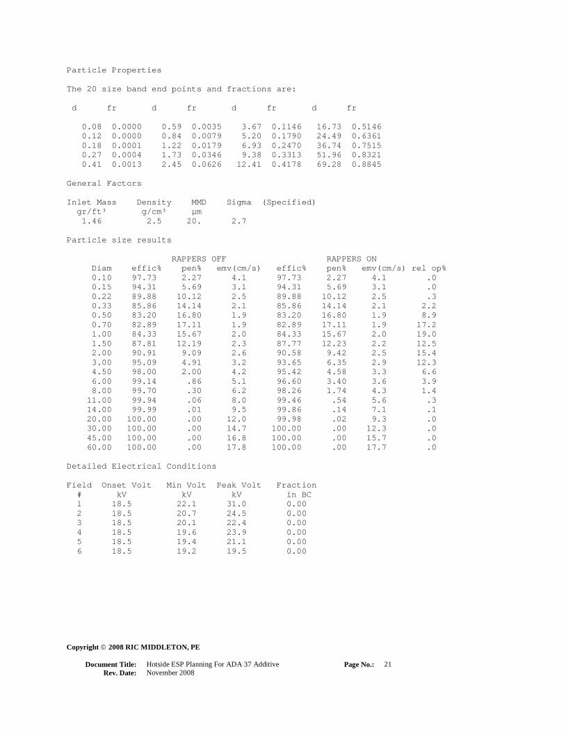
Particle Properties
The 20 size band end points and fractions are:
d fr d fr d fr d fr
0.08 0.0000 0.59 0.0035 3.67 0.1146 16.73 0.5146
0.12 0.0000 0.84 0.0079 5.20 0.1790 24.49 0.6361
0.18 0.0001 1.22 0.0179 6.93 0.2470 36.74 0.7515
0.27 0.0004 1.73 0.0346 9.38 0.3313 51.96 0.8321
0.41 0.0013 2.45 0.0626 12.41 0.4178 69.28 0.8845
General Factors
Inlet Mass Density MMD Sigma (Specified)
gr/ft³ g/cm³ µm
1.46 2.5 20. 2.7
Particle size results
RAPPERS OFF RAPPERS ON
Diam effic% pen% emv(cm/s) effic% pen% emv(cm/s) rel op%
0.10 97.73 2.27 4.1 97.73 2.27 4.1 .0
0.15 94.31 5.69 3.1 94.31 5.69 3.1 .0
0.22 89.88 10.12 2.5 89.88 10.12 2.5 .3
0.33 85.86 14.14 2.1 85.86 14.14 2.1 2.2
0.50 83.20 16.80 1.9 83.20 16.80 1.9 8.9
0.70 82.89 17.11 1.9 82.89 17.11 1.9 17.2
1.00 84.33 15.67 2.0 84.33 15.67 2.0 19.0
1.50 87.81 12.19 2.3 87.77 12.23 2.2 12.5
2.00 90.91 9.09 2.6 90.58 9.42 2.5 15.4
3.00 95.09 4.91 3.2 93.65 6.35 2.9 12.3
4.50 98.00 2.00 4.2 95.42 4.58 3.3 6.6
6.00 99.14 .86 5.1 96.60 3.40 3.6 3.9
8.00 99.70 .30 6.2 98.26 1.74 4.3 1.4
11.00 99.94 .06 8.0 99.46 .54 5.6 .3
14.00 99.99 .01 9.5 99.86 .14 7.1 .1
20.00 100.00 .00 12.0 99.98 .02 9.3 .0
30.00 100.00 .00 14.7 100.00 .00 12.3 .0
45.00 100.00 .00 16.8 100.00 .00 15.7 .0
60.00 100.00 .00 17.8 100.00 .00 17.7 .0
Detailed Electrical Conditions
Field Onset Volt Min Volt Peak Volt Fraction
# kV kV kV in BC
1 18.5 22.1 31.0 0.00
2 18.5 20.7 24.5 0.00
3 18.5 20.1 22.4 0.00
4 18.5 19.6 23.9 0.00
5 18.5 19.4 21.1 0.00
6 18.5 19.2 19.5 0.00

Copyright 2008 RIC MIDDLETON, PE
Document Title:
Hotside ESP Planning For ADA 37 Additive
Page No.:
22
Rev. Date:
November 2008
-------- ESPM Version 1.0 --------
Efficiency = 97.71 %
Penetration = 2.29 %
Emissions = 0.02539 gr/acf
= 0.118 lb/MBtu
PM10 = 0.02127 gr/acf
Opacity = 15.1 % @ 12. ft
Rappers OFF
Efficiency = 98.38 %
Penetration = 1.62 %
Emissions = 0.01791 gr/acf
= 0.083 lb/MBtu
PM10 = 0.01507 gr/acf
Opacity = 13.5 % @ 12. ft
Rapping Contribution = 29.4 % of total
Field SCA Area Volt Cur jcalc W-W W-pl W dia Leng Corona Pk/Avg
# ft² kV mA nA/cm² in in in ft Factor Ratio
1 74.1 311040 31.0 4279 14.81 9.0 4.5 0.101 6.00 1.00 1.00
2 74.1 311040 24.5 1581 5.47 9.0 4.5 0.101 6.00 1.00 1.00
3 74.1 311040 21.5 932 3.23 9.0 4.5 0.101 6.00 1.00 1.04
4 74.1 311040 20.0 1671 5.78 9.0 4.5 0.101 6.00 1.00 1.19
5 74.1 311040 17.8 624 2.16 9.0 4.5 0.101 6.00 1.00 1.19
6 74.1 311040 16.5 105 0.36 9.0 4.5 0.101 6.00 1.00 1.18
----- ------- ------
444.5 1866240 36.00
Height Volume Velocity Temp Press Resistivity Viscosity
ft acfm ft/s °F atm ohm-cm poise
36.0 4198554 3.57 800 1.00 3.42 E09 3.52E-04
Nonideal Factors Fitting Factors
Velocity Sections Out Misalign Sneak ____Rapping____ Steady Turb Core
sigma 1 2 (in) Frac Frac MMD Sg Frac Number
0.200~ 0.00 0.00 0.00 0.050 0.075 7.0 1.50 0.00 1.00
Program Information
Master File : Fuel2
Coal File : Fuel2
Design File : Fuel2
Flue Gas File : Fuel2
SRT File : Fuel2
Ash/Res File : Fuel2
Boiler File : Fuel2
Particle File : Fuel2
Base Model
Maximum Load

Copyright 2008 RIC MIDDLETON, PE
Document Title:
Hotside ESP Planning For ADA 37 Additive
Page No.:
23
Rev. Date:
November 2008
Particle Properties
The 20 size band end points and fractions are:
d fr d fr d fr d fr
0.08 0.0000 0.59 0.0035 3.67 0.1146 16.73 0.5146
0.12 0.0000 0.84 0.0079 5.20 0.1790 24.49 0.6361
0.18 0.0001 1.22 0.0179 6.93 0.2470 36.74 0.7515
0.27 0.0004 1.73 0.0346 9.38 0.3313 51.96 0.8321
0.41 0.0013 2.45 0.0626 12.41 0.4178 69.28 0.8845
General Factors
Inlet Mass Density MMD Sigma (Specified)
gr/ft³ g/cm³ µm
1.11 2.5 20. 2.7
Particle size results
RAPPERS OFF RAPPERS ON
Diam effic% pen% emv(cm/s) effic% pen% emv(cm/s) rel op%
0.10 97.28 2.72 4.1 97.28 2.72 4.1 .0
0.15 93.46 6.54 3.1 93.46 6.54 3.1 .0
0.22 88.65 11.35 2.5 88.65 11.35 2.5 .3
0.33 84.36 15.64 2.1 84.36 15.64 2.1 2.1
0.50 81.51 18.49 1.9 81.51 18.49 1.9 8.6
0.70 81.13 18.87 1.9 81.13 18.87 1.9 16.7
1.00 82.58 17.42 2.0 82.58 17.42 2.0 18.6
1.50 86.19 13.81 2.3 86.15 13.85 2.3 12.4
2.00 89.50 10.50 2.6 89.15 10.85 2.5 15.6
3.00 94.11 5.89 3.2 92.51 7.49 3.0 12.8
4.50 97.49 2.51 4.2 94.58 5.42 3.3 6.8
6.00 98.87 1.13 5.1 96.00 4.00 3.7 4.1
8.00 99.58 .42 6.3 97.89 2.11 4.4 1.5
11.00 99.91 .09 8.0 99.33 .67 5.7 .4
14.00 99.98 .02 9.6 99.83 .17 7.3 .1
20.00 100.00 .00 12.3 99.98 .02 9.7 .0
30.00 100.00 .00 15.3 100.00 .00 13.0 .0
45.00 100.00 .00 17.8 100.00 .00 16.6 .0
60.00 100.00 .00 19.0 100.00 .00 18.8 .0
Detailed Electrical Conditions
Field Onset Volt Min Volt Peak Volt Fraction
# kV kV kV in BC
1 18.5 21.4 31.0 0.00
2 18.5 20.3 24.5 0.00
3 18.5 19.8 22.4 0.00
4 18.5 19.5 23.9 0.00
5 18.5 19.2 21.1 0.00
6 18.5 19.1 19.5 0.00

Copyright 2008 RIC MIDDLETON, PE
Document Title:
Hotside ESP Planning For ADA 37 Additive
Page No.:
24
Rev. Date:
November 2008
-------- ESPM Version 1.0 --------
Efficiency = 97.91 %
Penetration = 2.09 %
Emissions = 0.02988 gr/acf
= 0.135 lb/MBtu
PM10 = 0.02509 gr/acf
Opacity = 17.8 % @ 12. ft
Rappers OFF
Efficiency = 98.53 %
Penetration = 1.47 %
Emissions = 0.02098 gr/acf
= 0.095 lb/MBtu
PM10 = 0.01770 gr/acf
Opacity = 15.9 % @ 12. ft
Rapping Contribution = 29.8 % of total
Field SCA Area Volt Cur jcalc W-W W-pl W dia Leng Corona Pk/Avg
# ft² kV mA nA/cm² in in in ft Factor Ratio
1 75.9 311040 31.0 3420 11.84 9.0 4.5 0.101 6.00 1.00 1.00
2 75.9 311040 24.5 1244 4.31 9.0 4.5 0.101 6.00 1.00 1.00
3 75.9 311040 21.5 727 2.51 9.0 4.5 0.101 6.00 1.00 1.04
4 75.9 311040 20.0 1413 4.89 9.0 4.5 0.101 6.00 1.00 1.19
5 75.9 311040 17.8 505 1.75 9.0 4.5 0.101 6.00 1.00 1.19
6 75.9 311040 16.5 56 0.19 9.0 4.5 0.101 6.00 1.00 1.18
----- ------- ------
455.4 1866240 36.00
Height Volume Velocity Temp Press Resistivity Viscosity
ft acfm ft/s °F atm ohm-cm poise
36.0 4097981 3.48 800 1.00 4.65 E10 3.52E-04
Nonideal Factors Fitting Factors
Velocity Sections Out Misalign Sneak ____Rapping____ Steady Turb Core
sigma 1 2 (in) Frac Frac MMD Sg Frac Number
0.200~ 0.00 0.00 0.00 0.050 0.075 7.0 1.50 0.00 1.00
Program Information
Master File : 10%PRB
Coal File : 10%PRB
Design File : 10%PRB
Flue Gas File : 10%PRB
SRT File : 10%PRB
Ash/Res File : 10%PRB
Boiler File : 10%PRB
Particle File : 10%PRB
Base Model
Maximum Load
Particle Properties

Copyright 2008 RIC MIDDLETON, PE
Document Title:
Hotside ESP Planning For ADA 37 Additive
Page No.:
25
Rev. Date:
November 2008
The 20 size band end points and fractions are:
d fr d fr d fr d fr
0.08 0.0000 0.59 0.0035 3.67 0.1146 16.73 0.5146
0.12 0.0000 0.84 0.0079 5.20 0.1790 24.49 0.6361
0.18 0.0001 1.22 0.0179 6.93 0.2470 36.74 0.7515
0.27 0.0004 1.73 0.0346 9.38 0.3313 51.96 0.8321
0.41 0.0013 2.45 0.0626 12.41 0.4178 69.28 0.8845
General Factors
Inlet Mass Density MMD Sigma (Specified)
gr/ft³ g/cm³ µm
1.43 2.5 20. 2.7
Particle size results
RAPPERS OFF RAPPERS ON
Diam effic% pen% emv(cm/s) effic% pen% emv(cm/s) rel op%
0.10 97.49 2.51 4.1 97.49 2.51 4.1 .0
0.15 93.86 6.14 3.1 93.86 6.14 3.1 .0
0.22 89.23 10.77 2.5 89.23 10.77 2.5 .3
0.33 85.10 14.90 2.1 85.10 14.90 2.1 2.2
0.50 82.38 17.62 1.9 82.38 17.62 1.9 8.8
0.70 82.07 17.93 1.9 82.07 17.93 1.9 17.0
1.00 83.57 16.43 2.0 83.56 16.44 2.0 18.8
1.50 87.14 12.86 2.3 87.10 12.90 2.3 12.5
2.00 90.36 9.64 2.6 90.02 9.98 2.6 15.4
3.00 94.73 5.27 3.3 93.23 6.77 3.0 12.4
4.50 97.82 2.18 4.3 95.12 4.88 3.4 6.6
6.00 99.05 .95 5.2 96.39 3.61 3.7 4.0
8.00 99.66 .34 6.4 98.13 1.87 4.4 1.4
11.00 99.93 .07 8.1 99.42 .58 5.7 .3
14.00 99.98 .02 9.7 99.85 .15 7.3 .1
20.00 100.00 .00 12.4 99.98 .02 9.6 .0
30.00 100.00 .00 15.2 100.00 .00 12.8 .0
45.00 100.00 .00 17.4 100.00 .00 16.3 .0
60.00 100.00 .00 18.5 100.00 .00 18.3 .0
Detailed Electrical Conditions
Field Onset Volt Min Volt Peak Volt Fraction
# kV kV kV in BC
1 18.5 22.1 31.0 0.00
2 18.5 20.7 24.5 0.00
3 18.5 20.1 22.4 0.00
4 18.5 19.6 23.9 0.00
5 18.5 19.4 21.1 0.00
6 18.5 19.2 19.5 0.00

Copyright 2008 RIC MIDDLETON, PE
Document Title:
Hotside ESP Planning For ADA 37 Additive
Page No.:
26
Rev. Date:
November 2008
-------- ESPM Version 1.0 --------
Efficiency = 97.81 %
Penetration = 2.19 %
Emissions = 0.03057 gr/acf
= 0.139 lb/MBtu
PM10 = 0.02565 gr/acf
Opacity = 18.1 % @ 12. ft
Rappers OFF
Efficiency = 98.46 %
Penetration = 1.54 %
Emissions = 0.02152 gr/acf
= 0.098 lb/MBtu
PM10 = 0.01814 gr/acf
Opacity = 16.2 % @ 12. ft
Rapping Contribution = 29.6 % of total
Field SCA Area Volt Cur jcalc W-W W-pl W dia Leng Corona Pk/Avg
# ft² kV mA nA/cm² in in in ft Factor Ratio
1 75.7 311040 31.0 3475 12.03 9.0 4.5 0.101 6.00 1.00 1.00
2 75.7 311040 24.5 1258 4.35 9.0 4.5 0.101 6.00 1.00 1.00
3 75.7 311040 21.5 732 2.53 9.0 4.5 0.101 6.00 1.00 1.04
4 75.7 311040 20.0 1423 4.93 9.0 4.5 0.101 6.00 1.00 1.19
5 75.7 311040 17.8 506 1.75 9.0 4.5 0.101 6.00 1.00 1.19
6 75.7 311040 16.5 53 0.18 9.0 4.5 0.101 6.00 1.00 1.18
----- ------- ------
454.4 1866240 36.00
Height Volume Velocity Temp Press Resistivity Viscosity
ft acfm ft/s °F atm ohm-cm poise
36.0 4107217 3.48 800 1.00 4.98 E10 3.58E-04
Nonideal Factors Fitting Factors
Velocity Sections Out Misalign Sneak ____Rapping____ Steady Turb Core
sigma 1 2 (in) Frac Frac MMD Sg Frac Number
0.200~ 0.00 0.00 0.00 0.050 0.075 7.0 1.50 0.00 1.00
Program Information
Master File : 20%PRB
Coal File : 20%PRB
Design File : 20%PRB
Flue Gas File : 20%PRB
SRT File : 20%PRB
Ash/Res File : 20%PRB
Boiler File : 20%PRB
Particle File : 20%PRB
Base Model
Maximum Load

Copyright 2008 RIC MIDDLETON, PE
Document Title:
Hotside ESP Planning For ADA 37 Additive
Page No.:
27
Rev. Date:
November 2008
Particle Properties
The 20 size band end points and fractions are:
d fr d fr d fr d fr
0.08 0.0000 0.59 0.0035 3.67 0.1146 16.73 0.5146
0.12 0.0000 0.84 0.0079 5.20 0.1790 24.49 0.6361
0.18 0.0001 1.22 0.0179 6.93 0.2470 36.74 0.7515
0.27 0.0004 1.73 0.0346 9.38 0.3313 51.96 0.8321
0.41 0.0013 2.45 0.0626 12.41 0.4178 69.28 0.8845
General Factors
Inlet Mass Density MMD Sigma (Specified)
gr/ft³ g/cm³ µm
1.4 2.5 20. 2.7
Particle size results
RAPPERS OFF RAPPERS ON
Diam effic% pen% emv(cm/s) effic% pen% emv(cm/s) rel op%
0.10 97.33 2.67 4.0 97.33 2.67 4.0 .0
0.15 93.56 6.44 3.1 93.56 6.44 3.1 .0
0.22 88.81 11.19 2.4 88.81 11.19 2.4 .3
0.33 84.59 15.41 2.1 84.59 15.41 2.1 2.2
0.50 81.83 18.17 1.9 81.83 18.17 1.9 8.8
0.70 81.51 18.49 1.9 81.51 18.49 1.9 16.9
1.00 83.03 16.97 2.0 83.03 16.97 2.0 18.7
1.50 86.66 13.34 2.3 86.62 13.38 2.2 12.5
2.00 89.95 10.05 2.6 89.60 10.40 2.5 15.5
3.00 94.45 5.55 3.2 92.90 7.10 3.0 12.6
4.50 97.68 2.32 4.2 94.88 5.12 3.3 6.7
6.00 98.97 1.03 5.1 96.21 3.79 3.7 4.0
8.00 99.63 .37 6.3 98.03 1.97 4.4 1.5
11.00 99.92 .08 8.0 99.38 .62 5.7 .3
14.00 99.98 .02 9.6 99.84 .16 7.2 .1
20.00 100.00 .00 12.2 99.98 .02 9.6 .0
30.00 100.00 .00 15.1 100.00 .00 12.7 .0
45.00 100.00 .00 17.4 100.00 .00 16.3 .0
60.00 100.00 .00 18.4 100.00 .00 18.3 .0
Detailed Electrical Conditions
Field Onset Volt Min Volt Peak Volt Fraction
# kV kV kV in BC
1 18.5 22.1 31.0 0.00
2 18.5 20.7 24.5 0.00
3 18.5 20.1 22.4 0.00
4 18.5 19.7 23.9 0.00
5 18.5 19.4 21.1 0.00
6 18.5 19.2 19.5 0.00

Copyright 2008 RIC MIDDLETON, PE
Document Title:
Hotside ESP Planning For ADA 37 Additive
Page No.:
28
Rev. Date:
November 2008
-------- ESPM Version 1.0 --------
Efficiency = 97.82 %
Penetration = 2.18 %
Emissions = 0.02986 gr/acf
= 0.136 lb/MBtu
PM10 = 0.02505 gr/acf
Opacity = 17.7 % @ 12. ft
Rappers OFF
Efficiency = 98.46 %
Penetration = 1.54 %
Emissions = 0.02101 gr/acf
= 0.096 lb/MBtu
PM10 = 0.01771 gr/acf
Opacity = 15.8 % @ 12. ft
Rapping Contribution = 29.6 % of total
Field SCA Area Volt Cur jcalc W-W W-pl W dia Leng Corona Pk/Avg
# ft² kV mA nA/cm² in in in ft Factor Ratio
1 75.7 311040 31.0 3549 12.28 9.0 4.5 0.101 6.00 1.00 1.00
2 75.7 311040 24.5 1289 4.46 9.0 4.5 0.101 6.00 1.00 1.00
3 75.7 311040 21.5 752 2.60 9.0 4.5 0.101 6.00 1.00 1.04
4 75.7 311040 20.0 1446 5.01 9.0 4.5 0.101 6.00 1.00 1.19
5 75.7 311040 17.8 518 1.79 9.0 4.5 0.101 6.00 1.00 1.19
6 75.7 311040 16.5 59 0.20 9.0 4.5 0.101 6.00 1.00 1.18
----- ------- ------
454.4 1866240 36.00
Height Volume Velocity Temp Press Resistivity Viscosity
ft acfm ft/s °F atm ohm-cm poise
36.0 4116862 3.48 800 1.00 2.55 E10 3.57E-04
Nonideal Factors Fitting Factors
Velocity Sections Out Misalign Sneak ____Rapping____ Steady Turb Core
sigma 1 2 (in) Frac Frac MMD Sg Frac Number
0.200~ 0.00 0.00 0.00 0.050 0.075 7.0 1.50 0.00 1.00
Program Information
Master File : 30%PRB
Coal File : 30%PRB
Design File : 30%PRB
Flue Gas File : 30%PRB
SRT File : 30%PRB
Ash/Res File : 30%PRB
Boiler File : 30%PRB
Particle File : 30%PRB
Base Model
Maximum Load

Copyright 2008 RIC MIDDLETON, PE
Document Title:
Hotside ESP Planning For ADA 37 Additive
Page No.:
29
Rev. Date:
November 2008
Particle Properties
The 20 size band end points and fractions are:
d fr d fr d fr d fr
0.08 0.0000 0.59 0.0035 3.67 0.1146 16.73 0.5146
0.12 0.0000 0.84 0.0079 5.20 0.1790 24.49 0.6361
0.18 0.0001 1.22 0.0179 6.93 0.2470 36.74 0.7515
0.27 0.0004 1.73 0.0346 9.38 0.3313 51.96 0.8321
0.41 0.0013 2.45 0.0626 12.41 0.4178 69.28 0.8845
General Factors
Inlet Mass Density MMD Sigma (Specified)
gr/ft³ g/cm³ µm
1.37 2.5 20. 2.7
Particle size results
RAPPERS OFF RAPPERS ON
Diam effic% pen% emv(cm/s) effic% pen% emv(cm/s) rel op%
0.10 97.35 2.65 4.1 97.35 2.65 4.1 .0
0.15 93.59 6.41 3.1 93.59 6.41 3.1 .0
0.22 88.86 11.14 2.5 88.86 11.14 2.5 .3
0.33 84.64 15.36 2.1 84.64 15.36 2.1 2.2
0.50 81.88 18.12 1.9 81.88 18.12 1.9 8.8
0.70 81.55 18.45 1.9 81.55 18.45 1.9 16.9
1.00 83.06 16.94 2.0 83.06 16.94 2.0 18.7
1.50 86.68 13.32 2.3 86.64 13.36 2.2 12.5
2.00 89.96 10.04 2.6 89.61 10.39 2.5 15.5
3.00 94.45 5.55 3.2 92.90 7.10 3.0 12.6
4.50 97.68 2.32 4.2 94.88 5.12 3.3 6.7
6.00 98.97 1.03 5.1 96.21 3.79 3.7 4.0
8.00 99.63 .37 6.3 98.03 1.97 4.4 1.5
11.00 99.92 .08 8.0 99.38 .62 5.7 .3
14.00 99.98 .02 9.6 99.84 .16 7.2 .1
20.00 100.00 .00 12.2 99.98 .02 9.6 .0
30.00 100.00 .00 15.1 100.00 .00 12.7 .0
45.00 100.00 .00 17.4 100.00 .00 16.3 .0
60.00 100.00 .00 18.5 100.00 .00 18.3 .0
Detailed Electrical Conditions
Field Onset Volt Min Volt Peak Volt Fraction
# kV kV kV in BC
1 18.5 22.0 31.0 0.00
2 18.5 20.7 24.5 0.00
3 18.5 20.1 22.4 0.00
4 18.5 19.6 23.9 0.00
5 18.5 19.4 21.1 0.00
6 18.5 19.2 19.5 0.00

Copyright 2008 RIC MIDDLETON, PE
Document Title:
Hotside ESP Planning For ADA 37 Additive
Page No.:
30
Rev. Date:
November 2008
-------- ESPM Version 1.0 --------
Efficiency = 97.78 %
Penetration = 2.22 %
Emissions = 0.02957 gr/acf
= 0.135 lb/MBtu
PM10 = 0.02480 gr/acf
Opacity = 17.5 % @ 12. ft
Rappers OFF
Efficiency = 98.44 %
Penetration = 1.56 %
Emissions = 0.02083 gr/acf
= 0.095 lb/MBtu
PM10 = 0.01755 gr/acf
Opacity = 15.7 % @ 12. ft
Rapping Contribution = 29.6 % of total
Field SCA Area Volt Cur jcalc W-W W-pl W dia Leng Corona Pk/Avg
# ft² kV mA nA/cm² in in in ft Factor Ratio
1 75.4 311040 31.0 3625 12.54 9.0 4.5 0.101 6.00 1.00 1.00
2 75.4 311040 24.5 1317 4.56 9.0 4.5 0.101 6.00 1.00 1.00
3 75.4 311040 21.5 768 2.66 9.0 4.5 0.101 6.00 1.00 1.04
4 75.4 311040 20.0 1467 5.08 9.0 4.5 0.101 6.00 1.00 1.19
5 75.4 311040 17.8 527 1.82 9.0 4.5 0.101 6.00 1.00 1.19
6 75.4 311040 16.5 62 0.22 9.0 4.5 0.101 6.00 1.00 1.18
----- ------- ------
452.2 1866240 36.00
Height Volume Velocity Temp Press Resistivity Viscosity
ft acfm ft/s °F atm ohm-cm poise
36.0 4126945 3.51 800 1.00 1.40 E08 3.57E-04
Nonideal Factors Fitting Factors
Velocity Sections Out Misalign Sneak ____Rapping____ Steady Turb Core
sigma 1 2 (in) Frac Frac MMD Sg Frac Number
0.200~ 0.00 0.00 0.00 0.050 0.075 7.0 1.50 0.00 1.00
Program Information
Master File : 40%PRB
Coal File : 40%PRB
Design File : 40%PRB
Flue Gas File : 40%PRB
SRT File : 40%PRB
Ash/Res File : 40%PRB
Boiler File : 40%PRB
Particle File : 40%PRB
Base Model
Maximum Load

Copyright 2008 RIC MIDDLETON, PE
Document Title:
Hotside ESP Planning For ADA 37 Additive
Page No.:
31
Rev. Date:
November 2008
Particle Properties
The 20 size band end points and fractions are:
d fr d fr d fr d fr
0.08 0.0000 0.59 0.0035 3.67 0.1146 16.73 0.5146
0.12 0.0000 0.84 0.0079 5.20 0.1790 24.49 0.6361
0.18 0.0001 1.22 0.0179 6.93 0.2470 36.74 0.7515
0.27 0.0004 1.73 0.0346 9.38 0.3313 51.96 0.8321
0.41 0.0013 2.45 0.0626 12.41 0.4178 69.28 0.8845
General Factors
Inlet Mass Density MMD Sigma (Specified)
gr/ft³ g/cm³ µm
1.33 2.5 20. 2.7
Particle size results
RAPPERS OFF RAPPERS ON
Diam effic% pen% emv(cm/s) effic% pen% emv(cm/s) rel op%
0.10 97.30 2.70 4.1 97.30 2.70 4.1 .0
0.15 93.50 6.50 3.1 93.50 6.50 3.1 .0
0.22 88.73 11.27 2.5 88.73 11.27 2.5 .3
0.33 84.49 15.51 2.1 84.49 15.51 2.1 2.2
0.50 81.71 18.29 1.9 81.71 18.29 1.9 8.7
0.70 81.38 18.62 1.9 81.38 18.62 1.9 16.8
1.00 82.89 17.11 2.0 82.88 17.12 2.0 18.7
1.50 86.52 13.48 2.3 86.48 13.52 2.2 12.5
2.00 89.82 10.18 2.6 89.47 10.53 2.5 15.5
3.00 94.35 5.65 3.2 92.79 7.21 3.0 12.6
4.50 97.63 2.37 4.2 94.80 5.20 3.3 6.7
6.00 98.95 1.05 5.1 96.15 3.85 3.7 4.0
8.00 99.62 .38 6.3 97.99 2.01 4.4 1.5
11.00 99.92 .08 8.0 99.37 .63 5.7 .3
14.00 99.98 .02 9.6 99.84 .16 7.2 .1
20.00 100.00 .00 12.2 99.98 .02 9.6 .0
30.00 100.00 .00 15.1 100.00 .00 12.8 .0
45.00 100.00 .00 17.5 100.00 .00 16.4 .0
60.00 100.00 .00 18.5 100.00 .00 18.4 .0
Detailed Electrical Conditions
Field Onset Volt Min Volt Peak Volt Fraction
# kV kV kV in BC
1 18.5 21.9 31.0 0.00
2 18.5 20.7 24.5 0.00
3 18.5 20.1 22.4 0.00
4 18.5 19.6 23.9 0.00
5 18.5 19.4 21.1 0.00
6 18.5 19.2 19.5 0.00
Copyright 2008 RIC MIDDLETON, PE
Document Title:
Hotside ESP Planning For ADA 37 Additive
Page No.:
32
Rev. Date:
November 2008
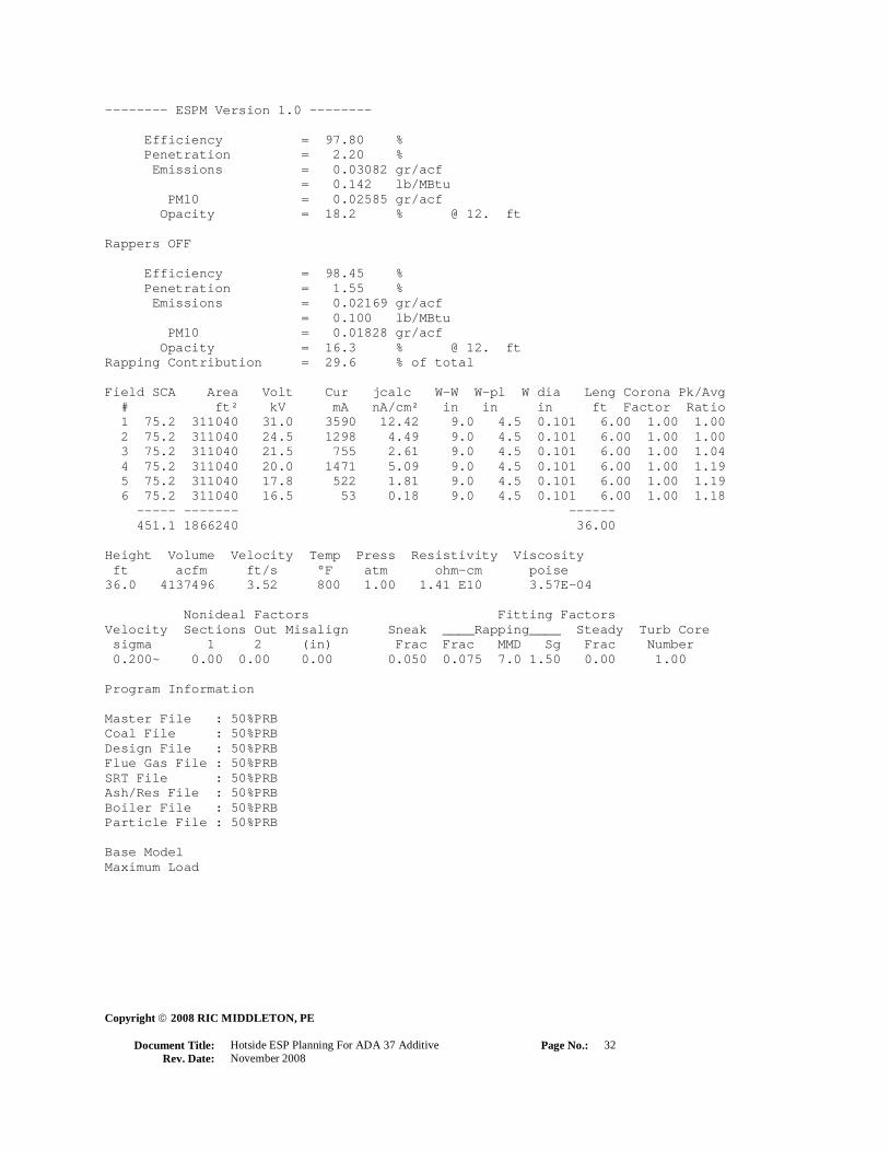
-------- ESPM Version 1.0 --------
Efficiency = 97.80 %
Penetration = 2.20 %
Emissions = 0.03082 gr/acf
= 0.142 lb/MBtu
PM10 = 0.02585 gr/acf
Opacity = 18.2 % @ 12. ft
Rappers OFF
Efficiency = 98.45 %
Penetration = 1.55 %
Emissions = 0.02169 gr/acf
= 0.100 lb/MBtu
PM10 = 0.01828 gr/acf
Opacity = 16.3 % @ 12. ft
Rapping Contribution = 29.6 % of total
Field SCA Area Volt Cur jcalc W-W W-pl W dia Leng Corona Pk/Avg
# ft² kV mA nA/cm² in in in ft Factor Ratio
1 75.2 311040 31.0 3590 12.42 9.0 4.5 0.101 6.00 1.00 1.00
2 75.2 311040 24.5 1298 4.49 9.0 4.5 0.101 6.00 1.00 1.00
3 75.2 311040 21.5 755 2.61 9.0 4.5 0.101 6.00 1.00 1.04
4 75.2 311040 20.0 1471 5.09 9.0 4.5 0.101 6.00 1.00 1.19
5 75.2 311040 17.8 522 1.81 9.0 4.5 0.101 6.00 1.00 1.19
6 75.2 311040 16.5 53 0.18 9.0 4.5 0.101 6.00 1.00 1.18
----- ------- ------
451.1 1866240 36.00
Height Volume Velocity Temp Press Resistivity Viscosity
ft acfm ft/s °F atm ohm-cm poise
36.0 4137496 3.52 800 1.00 1.41 E10 3.57E-04
Nonideal Factors Fitting Factors
Velocity Sections Out Misalign Sneak ____Rapping____ Steady Turb Core
sigma 1 2 (in) Frac Frac MMD Sg Frac Number
0.200~ 0.00 0.00 0.00 0.050 0.075 7.0 1.50 0.00 1.00
Program Information
Master File : 50%PRB
Coal File : 50%PRB
Design File : 50%PRB
Flue Gas File : 50%PRB
SRT File : 50%PRB
Ash/Res File : 50%PRB
Boiler File : 50%PRB
Particle File : 50%PRB
Base Model
Maximum Load

Copyright 2008 RIC MIDDLETON, PE
Document Title:
Hotside ESP Planning For ADA 37 Additive
Page No.:
33
Rev. Date:
November 2008
Particle Properties
The 20 size band end points and fractions are:
d fr d fr d fr d fr
0.08 0.0000 0.59 0.0035 3.67 0.1146 16.73 0.5146
0.12 0.0000 0.84 0.0079 5.20 0.1790 24.49 0.6361
0.18 0.0001 1.22 0.0179 6.93 0.2470 36.74 0.7515
0.27 0.0004 1.73 0.0346 9.38 0.3313 51.96 0.8321
0.41 0.0013 2.45 0.0626 12.41 0.4178 69.28 0.8845
General Factors
Inlet Mass Density MMD Sigma (Specified)
gr/ft³ g/cm³ µm
1.4 2.5 20. 2.7
Particle size results
RAPPERS OFF RAPPERS ON
Diam effic% pen% emv(cm/s) effic% pen% emv(cm/s) rel op%
0.10 97.31 2.69 4.1 97.31 2.69 4.1 .0
0.15 93.53 6.47 3.1 93.53 6.47 3.1 .0
0.22 88.77 11.23 2.5 88.77 11.23 2.5 .3
0.33 84.54 15.46 2.1 84.54 15.46 2.1 2.2
0.50 81.77 18.23 1.9 81.77 18.23 1.9 8.8
0.70 81.45 18.55 1.9 81.45 18.55 1.9 16.9
1.00 82.94 17.06 2.0 82.94 17.06 2.0 18.7
1.50 86.58 13.42 2.3 86.54 13.46 2.3 12.5
2.00 89.88 10.12 2.6 89.52 10.48 2.5 15.5
3.00 94.39 5.61 3.2 92.84 7.16 3.0 12.6
4.50 97.65 2.35 4.2 94.83 5.17 3.3 6.7
6.00 98.96 1.04 5.1 96.17 3.83 3.7 4.0
8.00 99.62 .38 6.3 98.00 2.00 4.4 1.5
11.00 99.92 .08 8.0 99.38 .62 5.7 .3
14.00 99.98 .02 9.6 99.84 .16 7.3 .1
20.00 100.00 .00 12.3 99.98 .02 9.6 .0
30.00 100.00 .00 15.2 100.00 .00 12.8 .0
45.00 100.00 .00 17.5 100.00 .00 16.4 .0
60.00 100.00 .00 18.6 100.00 .00 18.4 .0
Detailed Electrical Conditions
Field Onset Volt Min Volt Peak Volt Fraction
# kV kV kV in BC
1 18.5 22.1 31.0 0.00
2 18.5 20.7 24.5 0.00
3 18.5 20.1 22.4 0.00
4 18.5 19.7 23.9 0.00
5 18.5 19.4 21.1 0.00
6 18.5 19.2 19.5 0.00
Copyright 2008 RIC MIDDLETON, PE
Document Title:
Hotside ESP Planning For ADA 37 Additive
Page No.:
34
Rev. Date:
November 2008
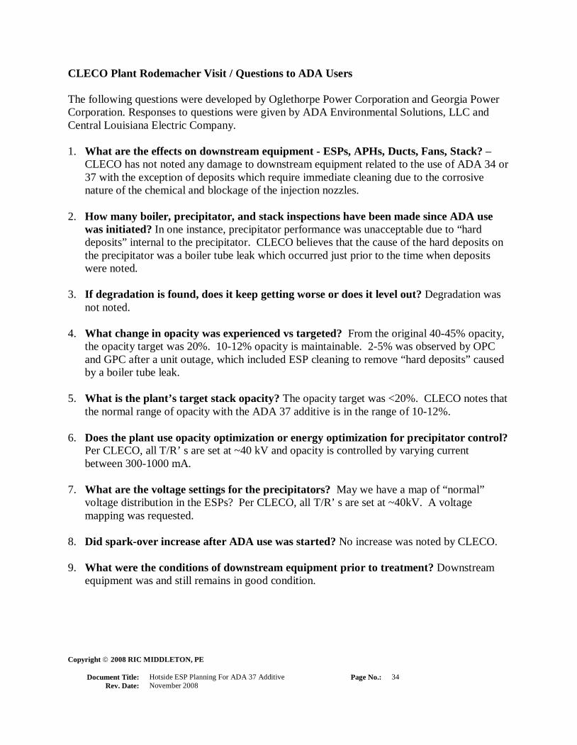
CLECO Plant Rodemacher Visit / Questions to ADA Users
The following questions were developed by Oglethorpe Power Corporation and Georgia Power
Corporation. Responses to questions were given by ADA Environmental Solutions, LLC and
Central Louisiana Electric Company.
1. What are the effects on downstream equipment - ESPs, APHs, Ducts, Fans, Stack? –
CLECO has not noted any damage to downstream equipment related to the use of ADA 34 or
37 with the exception of deposits which require immediate cleaning due to the corrosive
nature of the chemical and blockage of the injection nozzles.
2. How many boiler, precipitator, and stack inspections have been made since ADA use
was initiated? In one instance, precipitator performance was unacceptable due to “hard
deposits” internal to the precipitator. CLECO believes that the cause of the hard deposits on
the precipitator was a boiler tube leak which occurred just prior to the time when deposits
were noted.
3. If degradation is found, does it keep getting worse or does it level out? Degradation was
not noted.
4. What change in opacity was experienced vs targeted? From the original 40-45% opacity,
the opacity target was 20%. 10-12% opacity is maintainable. 2-5% was observed by OPC
and GPC after a unit outage, which included ESP cleaning to remove “hard deposits” caused
by a boiler tube leak.
5. What is the plant’s target stack opacity? The opacity target was <20%. CLECO notes that
the normal range of opacity with the ADA 37 additive is in the range of 10-12%.
6. Does the plant use opacity optimization or energy optimization for precipitator control?
Per CLECO, all T/R’ s are set at ~40 kV and opacity is controlled by varying current
between 300-1000 mA.
7. What are the voltage settings for the precipitators? May we have a map of “normal”
voltage distribution in the ESPs? Per CLECO, all T/R’ s are set at ~40kV. A voltage
mapping was requested.
8. Did spark-over increase after ADA use was started? No increase was noted by CLECO.
9. What were the conditions of downstream equipment prior to treatment? Downstream
equipment was and still remains in good condition.
Copyright 2008 RIC MIDDLETON, PE
Document Title:
Hotside ESP Planning For ADA 37 Additive
Page No.:
35
Rev. Date:
November 2008
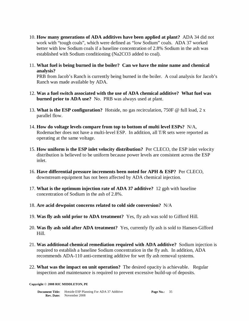
10. How many generations of ADA additives have been applied at plant? ADA 34 did not
work with “tough coals”, which were defined as “low Sodium” coals. ADA 37 worked
better with low Sodium coals if a baseline concentration of 2.8% Sodium in the ash was
established with Sodium conditioning (Na2CO3 added to coal).
11. What fuel is being burned in the boiler? Can we have the mine name and chemical
analysis?
PRB from Jacob’s Ranch is currently being burned in the boiler. A coal analysis for Jacob’s
Ranch was made available by ADA.
12. Was a fuel switch associated with the use of ADA chemical additive? What fuel was
burned prior to ADA use? No. PRB was always used at plant.
13. What is the ESP configuration? Hotside, no gas recirculation, 750F @ full load, 2 x
parallel flow.
14. How do voltage levels compare from top to bottom of multi level ESPs? N/A,
Rodemacher does not have a multi-level ESP. In addition, all T/R sets were reported as
operating at the same voltage.
15. How uniform is the ESP inlet velocity distribution? Per CLECO, the ESP inlet velocity
distribution is believed to be uniform because power levels are consistent across the ESP
inlet.
16. Have differential pressure increments been noted for APH & ESP? Per CLECO,
downstream equipment has not been affected by ADA chemical injection.
17. What is the optimum injection rate of ADA 37 additive? 12 gph with baseline
concentration of Sodium in the ash of 2.8%.
18. Are acid dewpoint concerns related to cold side conversion? N/A
19. Was fly ash sold prior to ADA treatment? Yes, fly ash was sold to Gifford Hill.
20. Was fly ash sold after ADA treatment? Yes, currently fly ash is sold to Hansen-Gifford
Hill.
21. Was additional chemical remediation required with ADA additive? Sodium injection is
required to establish a baseline Sodium concentration in the fly ash. In addition, ADA
recommends ADA-110 anti-cementing additive for wet fly ash removal systems.
22. What was the impact on unit operation? The desired opacity is achievable. Regular
inspection and maintenance is required to prevent excessive build-up of deposits.

Copyright 2008 RIC MIDDLETON, PE
Document Title:
Hotside ESP Planning For ADA 37 Additive
Page No.:
36
Rev. Date:
November 2008
23. How well did automatic injection equipment work? This appears to be a major problem.
Chemical deposits attach to the injection nozzles and form mounds at the injection lance
locations. A new shield air chamber is installed around the injection nozzles and provides
ambient air to cool the gas at the nozzle location to prevent rapid evaporation and blow the
chemical away from the nozzle. The shield air is obtained from a local blower. Inspection of
nozzle lances following 2 days of operation with shield air indicated that shield air is not
sufficient to prevent deposit formation on the nozzles and lances. Frequent nozzle and lance
inspection is required (100% in 1 to 2 weeks) to prevent blockage of injection nozzles and
duct deposits. Chemical deposits are cleaned from injection lances with a wire brush.
24. What additional maintenance costs are associated with ADA additive and injection
equipment? Deposits in the duct require removal because the deposit’s corrosive effects
(pH~12) are not known. Nozzle/lance inspection is performed on-line on the top of ducts
operating at approximately 750 F. The nozzle/lance inspection is facilitated with an
overhead crane (air motor and rail) but requires flange bolt removal. ADA has attributed
deposit formation to a lack of inspection and maintenance. CLECO does not use the flange
bolts due to manifold cracks attributed to lance vibration, which is not acceptable. The writer
feels that ADA should provide an improvement to the injection system. In an isolated
incident, hard deposits were found in the precipitator, which were attributed by ADA to a
tube leak. Traces of chemical were found at many locations on the flow control skid.
Human contact with the chemical would result in severe irritation and damage to tissue if not
immediately washed away. The integrity of the skid piping system is sub-standard and should
be improved to avoid spills, leakage, and failure.
25. Were any EFOR changes related to the precipitator noted after ADA chemical use was
initiated? The removal of deposits (mounds) in the ductwork required plant down time.
Inability to respond to load swings and fuel Sodium level excursions resulted in poor
performance and opacity problems, which required a minimum injection rate to correct.
26. What is the temperature at the ESP inlet at full load? 750F.
27. What is the temperature at the APH inlet and outlet at full load? Approximately 640F
and 322F respectively.
28. Were any chemical additives in use prior to injection of ADA additive? Sodium
conditioning (Na2CO3 added on conveyor belt) was used prior to ADA use. Prior to the
current coal side Sodium injection, dry pneumatic injection was used and abandoned due to
poor performance of conveying equipment.

Copyright 2008 RIC MIDDLETON, PE
Document Title:
Hotside ESP Planning For ADA 37 Additive
Page No.:
37
Rev. Date:
November 2008
29. Is a blend of Sodium product used with ADA? What % of each if so? ADA disclosed
that the chemical is essentially Sodium. In addition, the chemical formula is typically given
to a local chemical processing company that blends the required chemicals in solution and
transports the chemical to the plant. Apparently special processes are not required to make
the solution and chemical constituents are common.
30. Are Gas Recirculation Fans Utilized? No.
31. What is the capacity of the unit(s)? 550 MW
32. Was a change in LOI noted? N/A.
33. How long did it take for the ADA additive to be effective? Approximately 12 hours is
required. This means that a minimum flow rate must be established and that load response is
limited. The required amount of chemical must be on the collected ash prior to ash loading
increases to avoid opacity excursions. This is complicated by precipitator plate rapping.
34. Were any deposits traced to the ADA additive? Yes, mounds of a chemical and flue gas
mixture were found in front of the injection lances. At times the height of the mounds
exceeded the nozzle height and prohibited re-insertion of the lances into the dugout formed
by continuous chemical injection after inspection. ADA advised that the unit be shut down
to remove deposits because in their words, “We didn’t want to come in and find the bottom
of the duct lying at grade with our chemical on top of it”.
35. Does the plant have a cost contract (# of Years)? No.
36. Can you cycle the usage to save on additive? No, as stated previously, the required amount
of chemical must be on the collected ash prior to ash loading increases. During lower loads,
more chemical than required is continuously injected at an established minimum flow rate.
37. What is the SCA of ESP and Size of Boiler in MW? The reported SCA is 340 and the unit
output is 550 MW.
38. Does ADA stand by their product? CLECO reports that ADA is very responsive and eager
to make sure that the system works properly. One negative comment from CLECO was that,
“At the beginning it seemed as if their only response to poor performance was to add more
chemical”. CLECO was sensitive to the cost of the chemical purchases. CLECO indicated
that “they thought that they were paying for ADA’s lack of R&D and experience”.
39. Did ADA guarantee that no adverse effects would result from use of the additive? ADA
can not make such a guarantee.

Copyright 2008 RIC MIDDLETON, PE
Document Title:
Hotside ESP Planning For ADA 37 Additive
Page No.:
38
Rev. Date:
November 2008
40. Did ADA provide a performance guarantee? ADA’s response to this issue is that the best
remedy available to the purchaser is, “ If you do not like the system or are not satisfied for
any reason, then stop buying the chemical and discontinue usage”.
41. Was EPRI a sponsor of the project? No, plant does not fund EPRI.
42. Did EPRI provide a report of project success? N/A.
43. Was chemical composition disclosed during permitting? Yes, this is possible with a non-
disclosure statement. MSDS data sheets also describe chemical properties and
characteristics.
44. Will ADA accept liability for damage to plant and equipment associated with ADA
chemical addition? ADA does not have the ability to accept liability for damage to plant
equipment, business interruption, design flaws, …, etc.

Copyright 2008 RIC MIDDLETON, PE
Document Title:
Hotside ESP Planning For ADA 37 Additive
Page No.:
39
Rev. Date:
November 2008
SCS Plant Daniel Representatives’ Discussion at Plant Scherer in reference to ADA
Environmental Solutions, LLC
Unit 1 - ADA 23
The following points were represented by SCS personnel.
45. ADA chemical additive ADA 23 was not satisfactory for SCS Plant Daniel. ADA 23
contained Phosphoric Acid, which drastically reduced concrete set time and eliminated the
possibility of PRB ash sales.
46. An injection rate of 20 gal/min of dilute ADA 23 was required to reduce opacity readings.
47. Non-uniform flow of ADA chemical was traced to poor system design.
48. Chemical injection system was not effective in treating coarse material on lower precipitators
for piggyback arrangement similar to Plant Scherer Units 1 & 2 ESPs.
49. Corrosion of ESP surfaces and ductwork was noted with ADA 23 and was attributed to
Phosphoric Acid in deposits that were found in the ESP, ductwork, and air preheater.
50. An increase in air preheater differential pressure was attributed to carry over of deposits.
Unit 2 - ADA 34
The following points were represented by SCS personnel.
51. A high rate of injection of ADA 34 was required to reduce opacity readings within 1 hr.
ADA recommended a lower injection rate.
52. The high rate of injection resulted in carry over of chemical to equipment downstream of the
precipitator including ductwork and air preheaters.
53. Problems with concrete set time were eliminated with ADA 34.
54. Compressive strength of concrete was not adversely effected.
55. A lawsuit resulted from ADA’s failure to do adequate engineering design. In SCS words,
“they did not do their homework”. SCS charged that salesmen ran ADA.

Copyright 2008 RIC MIDDLETON, PE
Document Title:
Hotside ESP Planning For ADA 37 Additive
Page No.:
40
Rev. Date:
November 2008
Pictures courtesy of SCS/GPC Mr. Damon Woodson, P.E.
CLECO - External Injection Lance Manifolds on top of Hotside ESP Duct
CLECO - Flow Control Skid

Copyright 2008 RIC MIDDLETON, PE
Document Title:
Hotside ESP Planning For ADA 37 Additive
Page No.:
41
Rev. Date:
November 2008
CLECO - Chemical Bulk Storage Tank

Copyright 2008 RIC MIDDLETON, PE
Document Title:
Hotside ESP Planning For ADA 37 Additive
Page No.:
42
Rev. Date:
November 2008
Recommendations and Conclusions
1. ADA to take primary responsibility for system design.
ADA Environmental Solutions, LLC must be held accountable for the failure of their systems to
perform in an acceptable manner when applied to utility station service. In too many instances,
representatives of ADA claimed that failure was due to negligence on the part of power plant
operators. To remedy this situation a well-written system specification is required to measure the
proposed system definition from ADA.
For instance, with the knowledge that the freezing point of ADA 37 solution is approximately 45
Deg. F, ADA should not furnish any system without heat tracing. The impression left is that
ADA would leave details like this to be discovered by the owner after the system is installed, or
even worse, undiscovered!
Another example of this type of problem, is the question of whether or not contact with the
chemical should be restricted. A light dusting of the dry chemical on a dry fingertip will result in
a severe burning sensation in approximately 10 seconds. Despite this reality, during inspection of
the system, dry chemical was found everywhere. The flow control skid had multiple instances of
chemical leaking from valves and fittings and from all components of the obviously sub-standard
piping system. Dry chemical was found on the dirt directly under the Polyethylene storage tank
(which was furnished without containment), on the hoses and copper tubing connected to the
flow control skid, and on the floor in the control house. In addition, chemical deposits inside the
duct and on the nozzle lances must be removed. The disposal of the duct deposits may present
additional problems for the Owner. Workers who would be required to interface with the control
skid, inspect the nozzle lances (daily), clean nozzle lances, and remove duct deposits would
clearly require specialized training in the handling of the chemical and would require special
protective wear to avoid contact with human tissue. The mandatory use of respirators should not
be ruled out.
2. ADA must re-design injection system to eliminate deposits.
Deposition of the chemical inside of the flue gas ductwork is a major issue. ADA must do
additional engineering related to the injection of the chemical into a duct, which operates at 800
Deg. F for hotside applications. Rapid evaporation of moisture from the aqueous solution at the
nozzle tips and in front of the nozzle lances appears to be the problem. It is not acceptable to
claim that the problem is due to lack of inspection and maintenance. If this problem is solved, the
prospects for utilization improve greatly. Without a workable solution to duct deposits, ADA can
not be recommended. ADA’s current solution consisting of providing “shield air” at the nozzle
location may prove to correct the problem in the future, however, inspection of lances that were
in use for less than 72 hours indicated deposit formation had occurred with shield air in service.

Copyright 2008 RIC MIDDLETON, PE
Document Title:
Hotside ESP Planning For ADA 37 Additive
Page No.:
43
Rev. Date:
November 2008
3. ADA to integrate conventional Sodium conditioning, if required.
ADA has indicated that coal properties that vary continuously, like the Sodium concentration,
have a pronounced effect on the performance and response of the ADA chemical injection
system, and hence, the performance of the ESP. This is tantamount to saying that the response of
the ADA chemical injection system is inadequate to handle variance in coal properties that may
occur from hour to hour, day to day, month to month, season to season, one coal mine to another,
or even from one rail car to the next. During unit load swings, the effectiveness of the ADA
chemical additive system depends upon the quantity of chemical, which is deposited, on the
collected ash. This is also a function of the rapping operation, which removes much of the
treated and collected ash from the plates of the ESP. If pre-conditioning with Sodium injection is
required to establish a baseline ash resistivity, then ADA should incorporate pre-conditioning
into their system scope. In discussions with Plant Scherer personnel and in their literature and
system proposals, Sodium pre-conditioning is not mentioned as a requirement. The cost of
Sodium conditioning must be added to the ADA 37 system cost for Plant Scherer. Even with
Sodium pre-conditioning, opacity can not be completely controlled without establishing a
minimum flow rate of ADA 37 chemical. This practice wastes a great deal of chemical, but is the
only way to check opacity excursions.
4. ADA to improve supports for injection lances.
During inspection of the chemical injection lance installation at the Rodemacher plant, it was
noticed that the plant personnel had adopted the practice of inspecting the lances on-line and not
"flange bolting" back in place after re-insertion. The lances where held in place by gravity alone
and tight shut off of air in-leakage was obviously sacrificed. At first it was thought that the
reason for this practice was the frequency of the required inspections. In discussions with plant
personnel, it was discovered that cracking of the nozzle lance manifolds was occurring due to
flow induced vibration of the lances when rigidly attached to the duct flanges.
The lances are fixed support, cantilevers extending down into the flue gas flow path. With this
arrangement, one duct penetration is required and the lances can be worked on from one side of
the duct. A solution relating to the drag forces exerted by the gas flow and the ability of the
flanges and manifolds to absorb cyclic stresses is required from ADA Environmental Solutions,
LLC.
5. Owner to have experts review ADA 37 MSDS to determine acceptability and
classification
ADA 37 is a highly reactive chemical that is harmful when in contact with human tissue. The
notion that Plant Scherer Unit 1 or Unit 2 could start using the ADA 37 chemical injection
system without going through a lengthy permitting process should not be considered.
Engineering specifications should reduce the possibility of chemical leakage from substandard
piping systems. However, our normal disposition of fly-ash may be problematic. Collected ash,

Copyright 2008 RIC MIDDLETON, PE
Document Title:
Hotside ESP Planning For ADA 37 Additive
Page No.:
44
Rev. Date:
November 2008
if not sold to others, is currently sent to our ash settlement area (ponds). As we all know, this
settlement area is adjacent to Lake Juliette, a wildlife conservation area. Traces of chemical
would also be exhausted to the atmosphere through the flue gas stacks. We may have to apply for
a permit and we should consider if this would expose us to environmental auditing that would
effect other plant systems.
Contingencies for leakage, deposits, and spills must also be considered including containment
bases for tanks and flow skids, eyewashes, burn response contingencies, respirators, neutralizers,
and transport vessels for disposal of chemical deposits after removal from ducts. Concerns about
the propriety of this newly patented chemical and the degree of disclosure of the exact chemical
constituents can not be overstated.
6. Owners must obtain performance guarantees from ADA.
The first criteria used to evaluate ADA Environmental Solutions, LLC was to inquire about
performance guarantees. The desired effect of applying the ADA chemical additives is to reduce
the fly-ash resistivity to a level that would permit efficient ESP operation with PRB coal. It
would be desirable to obtain a guaranteed reduction of ash resistivity from ADA. ADA explained
early in the evaluation process that this type of guarantee could not be made. In addition, ADA
representatives explained that, “the best guarantee available is the ability to discontinue chemical
addition if desired performance is not obtainable”. From the point of view of an applications
engineer, the ADA response is entirely unacceptable and totally irresponsible. The ADA position
was re-enforced by senior ADA personnel.
7. Owners must obtain product liability guarantees from ADA.
The second criteria used to evaluate ADA Environmental Solutions, LLC was to inquire about
liability guarantees. If ADA is not willing to disclose the chemical formulation, then the effects
of chemical injection can not be evaluated by plant engineers and experts. ADA indicated that
product liability guarantees could not be made. This means that any potential for damage to
plant equipment that is exposed to the chemical additive is a potential damage risk. The
chemical formula must therefore be disclosed and evaluated, and in addition, a product liability
guarantee must be incorporated into all contracts with ADA Environmental Solutions, LLC. If a
liability guarantee is not obtained, then a mechanism must be found for recovering the cost of
equipment, installation, and any resultant consequential damage in the event that the system must
be removed from service.
8. Owners to exercise caution in dealing with ADA Environmental Solutions, LLC.
One ADA user representative has charged that, “ADA are salesmen and not engineers, and they
do not do their homework”. In two instances, while interviewing a senior member of ADA’s
team, it was revealed that ADA does not share Oglethorpe’s view that a switch to PRB coal
could result in reduction of NOx to the 0.15Lbs/Mbtu level. Despite this admission, ADA
included reduction of NOx through the use of PRB coal as a benefit of ADA chemical addition.

Copyright 2008 RIC MIDDLETON, PE
Document Title:
Hotside ESP Planning For ADA 37 Additive
Page No.:
45
Rev. Date:
November 2008
When questioned about the inconsistency of these statements, the ADA representative indicated
that it was included because OPC believes it. This issue may have resulted from ADA’s lack of
knowledge of the possibility of NOx reduction and it may have been an error in judgement
resulting from the desire to make a sale, but it could also represent unethical conduct on ADA’s
behalf.
9. Owners must consider if Scherer Unit 1 & Unit 2 are suitable for a R&D project.
ADA has a chemical additive that is effective in reducing the resistivity of PRB ash to levels that
allow for efficient operation of hot-side ESPs. ADA has not performed sufficient R&D to
guarantee the performance of their system or to provide for the reliability and system integrity
required for utility station service. The owners of Scherer Unit 1 & Unit 2 must determine if it is
in their interest to invest in the development of a solution which involves injection of ADA
chemical additives into the plant systems. The costs for preparation for burning PRB coal are
known to an accuracy that is sufficient to determine that these costs should not be incurred if the
ADA systems do not work. The knowledge that the current ADA chemical additive systems have
unacceptable performance would tend to dictate that development of the basic engineering of a
working system must first be established. It would be prudent to allow time for ADA to develop
expertise in areas where they are deficient.
10. Owners to consider new alternatives for removal of PRB coal ash.
The available options for removing particulate from the flue gas stream should be evaluated.
Technologies would include conversion of the hot-side precipitator to cold-side operation,
installing a baghouse, or the combination of the two alternatives.
11. Owners to review overall APC strategy to consider new and alternative technologies.
The proposed switch to PRB coal from the current Eastern coal is a part of one solution to an
overall air pollution control (APC) strategy which depends upon Ultra Low NOx combustion
technology utilizing PRB coal as the fuel. It may be desirable to once again look at many
technologies to determine which mix of technology will result in the most reliable, low cost,
flexible, and effective APC strategy. This could possibly involve the continued use of Eastern
coal and the current hot-side ESPs, which have acceptable performance, and avoids problems
associated with PRB use.
12. Owners to investigate reduced cost options for SCR.
The combined cost of low NOx combustion technology and minimum reduction SCR
requirements (~80%) may be less expensive than Ultra Low NOx combustion technology
combined with conversion to PRB coal combustion including the required conversion to coldside
precipitators. In addition, the combination of SCR with low NOx combustion technology takes
advantage of excellent work already performed on Plant Scherer Unit 1 & Unit 2 which has
resulted in NOx levels in the 0.35 Lb/MBtu range, and maintains fuel flexibility since the

Copyright 2008 RIC MIDDLETON, PE
Document Title:
Hotside ESP Planning For ADA 37 Additive
Page No.:
46
Rev. Date:
November 2008
combination is not dependent upon PRB coal combustion. The SCR is a NOx solution that may
work for more than one coal even though this probably excludes PRB for the present time. On
the other hand, if PRB conversion takes place along with cold-side ESP conversion and
implementation of Ultra Low NOx combustion technology, mandated use of SCR technology,
which is a possibility, could mean that PRB coal could no longer be used because it may not be
compatible with the SCR. In addition, PRB and/or cold-side precipitators would drive up the cost
of the mandatory SCR, which would have to handle particulate laden gas. Implementation of
technologies with short-term obsolescence should be avoided.

Copyright 2008 RIC MIDDLETON, PE
Document Title:
Hotside ESP Planning For ADA 37 Additive
Page No.:
47
Rev. Date:
November 2008
References
Standard Handbook of Power Plant Engineering, 2
nd
edition, Article 9.2.1 –
Electrostatic Precipitators, D.P. Tonn, 1997.
Electrostatic Precipitator Guidelines, Volume 1, Design Specifications, EPRI CS-5198, Ebasco
Services, Incorporated, June 1987.
Electrostatic Precipitator Performance Investigation, Units One and Two, W. Scott Ramsey,
Jason Dorsey, Oglethorpe Power Corporation, October 19, 1998.
NOx Mitigation Strategies for Coal-Fired Boilers, W. Scott Ramsey, Kerry Faulkner, Oglethorpe
Power Corporation, May 13, 1999.
Western Sub-bituminous Coals and Lignites, EPRI CS-1768, Bechtel National, Inc., April 1981.
Full-Scale Experience With ADA-34 2
nd
Generation Flue Gas Conditioning For Hot-Side and
Cold Side ESPs, ADA Environmental Solutions, LLC, EPRI-DOE-EPA Atlanta Mega
Symposium, -August 16, 1999.
Nearman Creek Electrostatic Precipitator Conversion, A.W. Ferguson, D.S Lindberg – Black &
Veatch Engineers-Architects; J.R. Meinders – Board of Public Utilities, Kansas City, KS,
October 27, 1988.
Special Report: Environmental technologies help meet strict regulations, CarolAnn Giovando,
Associate Editor, Power Magazine, May/June 2000.

Copyright 2008 RIC MIDDLETON, PE
Document Title:
Hotside ESP Planning For ADA 37 Additive
Page No.:
48
Rev. Date:
November 2008
Appendix
I. ADA System
II. ADA 37 Chemical Effectiveness
III. MSDS Material Safety Data Sheet (Not available from ADA Environmental)

Copyright 2008 RIC MIDDLETON, PE
Document Title:
Hotside ESP Planning For ADA 37 Additive
Page No.:
49
Rev. Date:
November 2008
Appendix I. ADA System

Copyright 2008 RIC MIDDLETON, PE
Document Title:
Hotside ESP Planning For ADA 37 Additive
Page No.:
50
Rev. Date:
November 2008
Appendix II. ADA 37 Chemical Effectiveness