Embed Size (px)
Citation preview

- 1 -
Planning Checklist for new IGSS projects

- 2 -
Table of Contents
Checklist for Planning a New IGSS Project ................................................ 3
Introduction ...................................................................................................................... 3
Mandatory Checklist ......................................................................................................... 3
Mandatory Checklist .................................................................................... 5
Checkpoint 1: Understand your customer’s needs ........................................................... 5
Checkpoint 2: Understand that IGSS objects can hold many tags ................................... 5
Checkpoint 3: Establish a naming and color convention for objects ................................. 6
Checkpoint 4: Establish a standard for alarm parameters ................................................ 8
Checkpoint 5: Create templates before objects ................................................................ 9
Checkpoint 6: Plan the area / diagram hierarchy ........................................................... 10
Checkpoint 7: Stick to the PLC addressing rules / best practices .................................. 11
Checkpoint 8: Create an I/O list – objects and tags ....................................................... 11
Checkpoint 9: Test communication between equipment and IGSS ................................ 12
Checkpoint 10: Determine which station types are needed ............................................ 12
Checkpoint 11: Design for the correct screen resolution ................................................ 14
Advanced Checklist ................................................................................... 16
Checkpoint 12: Exploit the Group object for bulk configuration ...................................... 16
Checkpoint 13: Show / hide objects with Layers and Views ........................................... 16
Checkpoint 14: Design correctly for multiple monitor solutions ...................................... 17
Checkpoint 15: Plan for multiple languages in one project ............................................. 18

- 3 -
Checklist for Planning a New IGSS Project
Introduction Before you start a new IGSS project, you should always go through the mandatory checklist below. For more advanced projects, expand with the advanced checklist. The checklists ensure that you make the necessary planning considerations and decisions. Experience has shown that if you start up the wrong way in IGSS, you end up using a lot of time correcting your initial mistakes. The motto is – do it right the first time. We know you want to get hands-on with the software, but the initial planning will save you many hours as the project proceeds.
Mandatory Checklist
Checkpoint Task Mark as completed
1 Understand your customer’s needs
2 Understand that IGSS objects can hold many tags (very important when migrating from other SCADA/HMI systems)
3 Establish a naming convention and color standard for objects
4 Establish alarm priorities/colors/numbers
5 Create templates before objects
6 Plan the area / diagram hierarchy
7 Stick to the PLC addressing rules / best practices
8 Create an I/O list – objects and tags
9 Test the communication between IGSS and the equipment
10 Determine which station types are needed
11 Design for the correct screen resolution and use vector-based
- 4 -
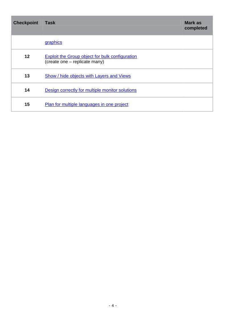
Checkpoint Task Mark as completed
graphics
12 Exploit the Group object for bulk configuration (create one – replicate many)
13 Show / hide objects with Layers and Views
14 Design correctly for multiple monitor solutions
15 Plan for multiple languages in one project
- 5 -
Mandatory Checklist
Checkpoint 1: Understand your customer’s needs The key to success for your automation project is a good cooperation with the end users. Follow this checklist from the beginning of the project.
Visit the customer’s site to get insight into the plant’s daily operation and meet the users
Understand the process to be monitored
Understand the role of IGSS at the plant – supervision only or both supervision/control ?
Create Project Specifications and Project Requirements - Collect as many details as you can - Make sure that you and the customer approve the requirements - Changing requirements later on will cost time and money - Create an I/O list for all the objects
Get computer network and PLC network drawings
Which PLCs are used? Make sure that you have the same PLCs for testing at your office.
Determine which IGSS station types are needed – dualized server, Single User Backup Server, Distributed Driver station, etc.
Does the customer need alarm notification with IGSS Notifier ?
Are there any special requirements that must be addressed? Batch process, recipe handling, VBA coding, special reports, etc.
Checkpoint 2: Understand that IGSS objects can hold many tags One of the greatest challenges for new users is to understand the IGSS object orientation. An object in IGSS can hold many I/O points or tags. Other SCADA/HMI systems are tag-based. An IGSS object typically represents a physical process component. This may be a pump, a valve, a motor, a level gauge, a flow meter, etc. Additionally, IGSS also has a number of internal object types. IGSS automatically collects all properties relating to one physical component into one IGSS object. This means that one object may contain up to 10 data tags or I/O points. In IGSS, we call these "atoms". As an example, an analog object can include the following atoms: High Alarm, High Limit, Actual Value, Set Point, Low Limit, Low Alarm, Alarm-In, Alarm-Out, High Scale, Low Scale. Before you purchase an IGSS license, you must know the approximate number of objects required by the customer. The licenses come in steps from 100, 200, 300 and up to 400,000 objects. Feel free to contact IGSS Support at Schneider Electric for assistance in calculating the correct number of objects.

- 6 -
Checkpoint 3: Establish a naming and color convention for objects
Object names
A good, solid naming convention is paramount to a well-functioning SCADA project. I guess we’ve all created mimic diagrams with object names like “Pump 1”, “Pump 2” and another diagram with “Pump A” and “Pump B”, although these four pumps were actually identical and based on the same pump template. This kind of unorganized naming convention must be avoided in any SCADA project. You must define a standard for the object names right from the outset. The advantages are many:
You always know how to name your objects
If you have several designers on the same project, names will still be consistent
You can always add new objects, because your convention allows expansion
Users will have a hunch of what a given object is just by looking at the name
Users can quickly find objects, because they know the naming convention
Users can quickly filter out objects to show in graphs, Audit Trail and Object Historian, etc.
Filtering becomes much easier in the Alarm List, for SMS alarm notification to staff, etc. There is no one, global object naming standard for SCADA/HMI systems in the world. There are international and national standards. But the best advice is – use your common sense and plan ahead. Take inspiration from the existing standards and adapt to the current project. Or if you have many projects, you can develop your own standard and hope that the customer will adhere to it. Here are a few, good tips for a well-functioning standard:
Establish prefixes which make sense to the operator.
Example Explanation
Area name ASB for Assembly, PAC for Packaging, DIS for Distribution, UNP for Unpacking, etc. The prefix would be a short form of the IGSS area name in the project.
Component type PU for pump, PR for pressure, FL for flow, MO for motor.
Functional type Pump station. Used in the IGSS demo for the pump station. The prefix is followed by a number, for example, PST01-p1. See example below.
Use a fixed length for prefixes.
Do not use illegal or inappropriate characters. Illegal characters: #, %, space, Inappropriate characters: - (may mean dash or minus sign).
Make sure to add enough digits for easy expansion. Instead of writing PST01-p1, you might need PST001-p1 to allow more than 100 pump stations.
Related to the name convention – write explanatory object descriptions. If the operator is in doubt, he should be able to read the description and know what the object does.

- 7 -
For inspiration, here’s the naming convention used on the Pump Station diagram in the IGSS Demo. The convention is: PST##-*
Where: ## are the two digits * is the actual object name Using this naming convention, also allows you to exploit the Group object. First you create Pump Station 1 and then you can replicate to Pump Station 2 by simply replacing the two digits to 02. Read more about the Group object here.
Object colors
Before you start creating your first objects, create a standard for the object colors. Again, it will make you more efficient when creating new objects. You can also add new designers to your team, who can quickly adopt the object color standard. Remember that quite a few people are color blind. As for the object names, there is no one global standard for object colors. Take inspiration from the international and national standards and develop your own standard. The standard must be well-documented allowing you to hire new people who can adhere to the standard immediately.

- 8 -
For inspiration, the tables below outline some ideas for digital and analog objects (which will typically take up 90 % of your IGSS project.
Digital objects
Examples of object color standards applied to digital objects:
Digital state Color
Stopped / Closed / Auto Stop / Auto Closed
Running / Open / Auto running / Auto opened
Manual stopped HMI / Manual closed HMI
Manual open HMI / Manual open HMI
Manual stopped Board / Manual closed Board
Manual open Board / Manual open Board
Stopping / Closing
Starting / Opening
Analog objects
Examples of object color standards applied to analog objects:
Analog state Color
Normal operation (often different colors for flow, temperature, level, etc.)
High alarm / Low alarm
High limit / Low limit
Alarm from PLC
Alarm acknowledged by operator
Alarm acknowledged by system
Checkpoint 4: Establish a standard for alarm parameters
Alarm colors and priorities
IGSS allows you to define up to 255 alarm priorities. In practice, most end users are applying 4, 6 or 10 priorities. To make the priority / color matrix as efficient as possible, you must match each priority with a color. The alarm color will, of course, be visible on mimic diagrams and in alarm lists. The higher the alarm priority, the more critical the alarm is in IGSS. The highest priority alarm among the active alarms will color the alarm icon. Notice that IGSS has a built-in alarm see-thru effect. The color is defined on alarm no. 1. Here’s an example where the customer is using 6 alarm priorities:
Alarm priority Color
6 (most critical)
5
4
3
2
1 (least critical)

- 9 -
Alarm numbers
One of the great features in IGSS is its ability to reuse alarm numbers for different objects. If you have several flow meters, each with a high and a low alarm, the two alarms can easily be shared by all objects. When creating the I/O list, you must match all alarm tags (atoms) with an alarm number. By planning ahead, you will surely be able to reuse the same alarm number/text for many objects. The alarm itself will still be object-specific, because the object name will appear in the Alarm List. Alarm numbers 1-100 are reserved for system use. From 101 and up to 99999, it’s up to you to create a numbering system, which is logical and expandable. For inspiration, here’s an example of a numbering structure:
Alarm type Alarm numbers
Analog limits 1000 – 1999
Analog alarm input 2000 – 2999
Digital alarm input 3000 – 3999
Counter limits 4000 – 4099
Maintenance alarms 5000 – 5099
IGSS station alarms (Dead man’s button,Distributed driver object, etc.)
6000 – 6099
IGSS PLC-related alarms (Node status object, Remote node status object, etc.)
6100 – 6199
Checkpoint 5: Create templates before objects IGSS templates can save you hundreds of hours of work, if you use them correctly. In the planning phase, you must identify process components in the I/O list, which are very similar and share several properties. When identified, you find out how many templates you need. Finally, you match each component with the right template. When the IGSS templates have been defined correctly, the repetitive task of entering the same information for each component has been eliminated. In fact, you only need to enter the unique object name and the specific I/O addresses to make a new process component. Of course, template-based objects subscribe to changes in the template. So you can now make one change in the template, which will be immediately distributed to hundreds of objects. This example is taken from the IGSS Demo.
The pumps are based on the PUMP template
The valves are based on the VALVE_1 template

- 10 -
Checkpoint 6: Plan the area / diagram hierarchy When you create an IGSS project, the area / diagram hierarchy is the backbone of the user’s navigation. An IGSS project is divided into a number of areas. An area is a collection of diagrams, graphs and other IGSS objects.
Areas are used to divide an IGSS configuration into logical parts. As an example, this may be the individual sub processes in a production line:
Raw Material
Unpacking
Assembly Line
Packaging
Distribution The next step is to define the individual diagrams (mimics) for each area. As an example, the Assembly Line area might contain these diagrams:

- 11 -
Assembly line start
Assembly line pre-processing
Assembly line mounting
Assembly line post-processing
Assembly line stop When the user activates the Assembly Line area, the diagrams above will appear in the menu. Diagrams from other areas will be closed and will not be visible in the menu. It is thus extremely important to plan the area / diagram hierarchy, so that the user always has access to the relevant diagrams.
Checkpoint 7: Stick to the PLC addressing rules / best practices When planning the I/O data list and the associated PLC addresses, there are a number of common and IGSS specific considerations to take into account:
Plan the PLC memory layout right from the start
Separate input values from output values
Combine polled communication with event-driven communication, if required
Establish the four predefined scanning/polling intervals applicable to all objects in the project
Locate process components with the same scan interval in the same memory block of the PLC to optimize communication efficiency
Most IGSS communication drivers use 16 bits for one digital command (some drivers also support 1-bit and 8-bit addressing)
Checkpoint 8: Create an I/O list – objects and tags This is probably the most important checkpoint. The more information you have about the objects in the I/O list, the easier it gets to enter the data in IGSS. To make your I/O list as specific to IGSS as possible, we recommend that you extract the relevant object information from the Property Table View. This will ensure that you enter the appropriate data for each object/atom in the system. And it will make you understand what’s inside an object in IGSS. The example below has been created from the Pump Station diagram in the IGSS Demo. You can adapt the example to your own project. The example focuses on the object names, PLC addresses and reuse of alarm numbers. Of course, if you know even more about the objects, enter it in the I/O list.

- 12 -
Checkpoint 9: Test communication between equipment and IGSS Before you continue the planning process, make sure that you can connect to the customer’s PLC equipment.
1. Find the right IGSS communication driver for the PLCs. 2. Connect the PLC to the test PC. 3. In the IGSS Definition module, create an analog object and test that you retrieve values
from the PLC as well as send values to the PLC. 4. If you have remote PLCs where you need to collect historical data, this should also be
tested at this point. 5. Test that you get alarms in IGSS, if you disconnect the equipment. 6. Determine how many drivers to use in the project. You must state the number of drivers in
the IGSS license. Up to 8 drivers can run simultaneously.
Checkpoint 10: Determine which station types are needed IGSS features 9 different station types. You configure the stations in the System Configuration module. At this checkpoint, you need answers to the following questions:
1. Is it a single-user or multiuser system? If it’s a single-user system, you can go straight to the next checkpoint.
2. Does the customer want a standalone server or a dualized (redundant) server system?
3. How many normal operator stations are needed? A normal operator station does not have any physical connections to the PLCs.
4. Are any PLCs connected directly to the operator stations? Or would it be more practical, if they were? Sometimes a lot of wiring can be avoided by using the distributed driver system in IGSS.
5. If yes, you have two options in IGSS -
- 13 -
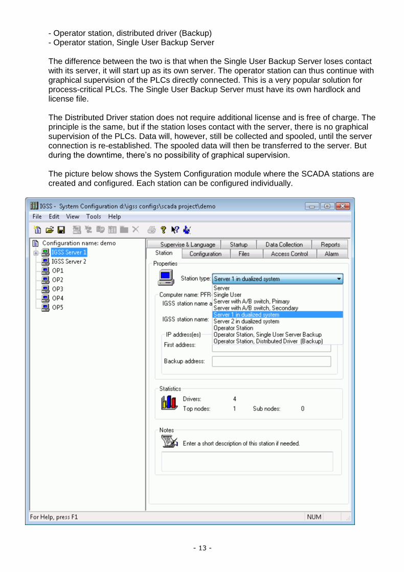
- Operator station, distributed driver (Backup) - Operator station, Single User Backup Server The difference between the two is that when the Single User Backup Server loses contact with its server, it will start up as its own server. The operator station can thus continue with graphical supervision of the PLCs directly connected. This is a very popular solution for process-critical PLCs. The Single User Backup Server must have its own hardlock and license file. The Distributed Driver station does not require additional license and is free of charge. The principle is the same, but if the station loses contact with the server, there is no graphical supervision of the PLCs. Data will, however, still be collected and spooled, until the server connection is re-established. The spooled data will then be transferred to the server. But during the downtime, there’s no possibility of graphical supervision. The picture below shows the System Configuration module where the SCADA stations are created and configured. Each station can be configured individually.

- 14 -
Checkpoint 11: Design for the correct screen resolution Resizing and scaling graphics and text have always been a big challenge for SCADA system developers. The challenge has not diminished today where screen resolutions can vary from 600 x 800 (4:3 aspect) to 1440 x 900 (16:9 aspect) or even HD screen resolutions. If you are lucky, all monitors will run the same screen resolution in the plant. But often plant personnel will have laptops with other resolutions. You will achieve the best results for all screen resolutions by following these tips:
1. Inform the customer about the challenge of screen resolutions and resizing of mimic diagrams. No need to keep it secret from the customer.
2. Find out whether the customer needs a multi-monitor solution. Many users prefer to have multiple screens to view diagrams, alarms and dashboards at the same time. This has a deep impact on your design work. You need to plan for multiple monitors.
3. Make a list of all the screen resolutions that are currently in play. Try to minimize the number of screen resolutions to make your design work and testing easier.
4. Design the diagrams in IGSS using the screen resolution used by most of the monitors. You must choose between a 16:9 format or a 4:3 format. As an example, the IGSS Demo is designed in a 16:9 format, but displays just fine on a 4:3 format. For this to work correctly, you must enable the Keep Aspect Ratio check box in Diagram Properties in IGSS.
5. Use vector-based graphics formats for diagram backgrounds and other purposes. Vector-based graphics will resize better than pixel-based formats. 7T recommends using the Windows-based formats, Windows Metafile (wmf) and Enhanced Metafile (emf). These formats can be exported from all serious drawing packages, including Adobe InDesign and Corel Draw.
6. Only use scalable fonts. Use TrueType fonts. Do not use the System font which is not scalable.
7. When using standard symbols in IGSS, remember to make them scalable. This is done on the Symbol Definition tab in the Object Properties dialog box.

- 15 -
8. When you connect different graphics on a diagram in IGSS, make sure that they do not “disconnect” when resizing the diagram or running on another screen resolution. In this example, we have a T-split + three individual pipes connected.
9. Always test that monitors are truly 16:9. We have seen that some monitors are designated as 16:9, but the resolution does not have the correct aspect ratio.
10. Test the graphics by resizing diagrams in the Supervise module. Remember to test on all relevant screen resolutions.
The Diagram Properties form where you select the background graphic. IGSS supports a long list of graphics formats, but vector-based formats generally resize better than other formats.

- 16 -
Advanced Checklist
Checkpoint 12: Exploit the Group object for bulk configuration One of the most powerful features in IGSS is the Group object. When you have many similar or even identical diagrams, regulators, machines, etc. you want to automate the replication (copying) process. The Group Object allows you to reuse a whole collection of IGSS objects and visuals. The principle is: Design the First, Copy the Rest. Imagine that you need to create 50 completely identical pump stations for a wastewater treatment plant. Simple copy/paste will get you far and save time, but using the Group object, it’s a snap. The illustration below shows what we want to do. Notice that the object naming convention allows us to replace the two digits to create a new object name. Also the PLC node number will be changed for each pump station.
The picture shows three pump stations created using the Group object
To create these pump stations, you must 1. Design the first pump station diagram. 2. Select all objects on the diagram and create a new Group object. 3. Define an object name mask allowing you to replace the two digits for each pump station. 4. Enable PLC node substitution for each pump station. 5. Copy/paste the Group object and input the two substitution digits and the new node number. 6. Repeat step 5 for each pump station you want to create.
7T recommends doing this example to get some hands-on experience with the Group object.
Checkpoint 13: Show / hide objects with Layers and Views Many SCADA projects contain a lot of objects and graphical displays of process components. Sometimes this huge amount of information may cause that operators will not be able to act as fast as expected in a critical situation. However, using layers and views you may simplify the process diagrams by hiding irrelevant objects in a given situation and thus optimize the monitoring process.

- 17 -
Here are a few examples of what Layers and Views may be used for:
To show/hide operator controls depending on the operation mode (for example automatic/manual)
To show a normal operation view and a view for emergency situations
To show/hide selected objects which the operator wants to view in isolation The illustration below shows the auto/manual example. The operator controls will only be visible when the motor is running in manual mode.
Operator controls can be shown or hidden using layers and views.
Checkpoint 14: Design correctly for multiple monitor solutions From the beginning, find out whether the customer wants a multi-monitor solution. You may be able to sell a multi-monitor solution to the customer, because it provides a number of advantages to the plant staff:
View details on very large diagrams – for example, distributed over 3 or 4 monitors
View diagrams, graphs, dashboards, Audit Trail, etc. on multiple monitors Example: Many users have a permanent overview screen + a graph monitor + an alarm list monitor.
Pan large diagrams on single-screen stations
When you design a multi-monitor solution, you must set up a few parameters in the Definition module right from the start.
IGSS supports the following key features:
Up to 9 screens – both vertical and horizontal setup is available
The system designer can design on other screen resolutions than the final output
A positioning grid makes it very easy to place IGSS windows on different screens
Single-screen behavior can be set up, including scroll bar behavior
Panning of multi-screen windows on IGSS stations with fewer screens than the master setup
- 18 -
Checkpoint 15: Plan for multiple languages in one project With more than 10 languages supported, IGSS is a truly multi-lingual SCADA system. The user interface of the individual IGSS modules have been translated by experienced system integrators. However, the texts on the mimic diagrams and the alarm texts can also be translated into multiple languages. Multi-language projects may be relevant in different situations:
The plant staff is multi-lingual. This is true for many crews on ships, for example.
The system integrator and/or the plant technician is not fluent in the customer’s language. In that case, you can translate the alarm texts and diagram texts in the IGSS project database.