Embed Size (px)
Citation preview

Planning and System Manual Access ProfessionalIssue 2020
2
Contents
1 Safety remarks
Electrical distribution boards and IT cabinet systems 4
Electrical voltage 4
Devices with 230 V connection 4
Electrostatic charging 4
Device placement 5
Protect your network! 5
Protect your property! 5
User access and passwords for the Access system 5
Warranty 6
Legal notice 6
2 Installation and operating conditions 7
3 System description 8
Performance features / Functions 8
Fields of application 9
System overview 10
Time synchronisation in the Access system (NTP server) 11
Push Notification Service (Siedle App) 13
Connection to telephone systems 15
4 System structure, con-ductor material and range
General planning information 16
Planning areas 16
Permitted conductor material / Ranges 17
Switching inputs / Ranges 17
Connection method 17
Supply limits ATLC/NG 670-… 18
Supply units – digital call 20
PoE – Power over Ethernet 20
Network LAN 21
Cabling structure/areas 21
Network characteristics 21
Cabling for indoor devices 22
Cameras 23
Location of the video camera 24
5 System components
Overview 29
Door stations (outdoor/indoor area) 31
Access cameras 34
External cameras + Accessory 35
Door loudspeaker 36
Status display module 37
Digital call 37
Call buttons 39
System upgrading 39
Indoor stations (audio/video) 40
Accessory 42
Distribution components – Door controller 43
Distribution components – Active/passive system expansion 44
Distribution components – Anti-pilfer controller 45
Distribution components – Line rectifiers 46
Distribution components – Transformers 47
Space requirements in distribu-tion boards/IT cabinets (19 inch) 48
Access server variants 49
System conditions 52
System conditions Access Professional 52
Virtualization 52
Additional requirements imposed on virtualization 52
Upgrade (server) 53
Client-Software 54
Siedle App 54
3
RemarksThis document serves as a guide for the planning and technical implementation of the Siedle Access system. It is designed to provide an overview of the key points that need to be observed.
This document supplements and is supplemented by the Access server commissioning instructions.To supplement this system manual, you will find the latest edition in the download area of our website on www.siedle.com
For complex systems or special requirements, the technical consult-ants in Project Sales will be pleased to advise you.(For detailed information, see page 157)
We accept no liability for modi-fications / additions, mistakes or printing errors.
6 Licences and test period 55
Licences 55
Test period 55
Access user licences 56
Optional Access application licences 56
Microsoft licences (CAL) 57
Third party device licences 57
Licence purchasing 58
7 Maintenance agreements 59
8 Configuration – Access System 5… 60
9 Digital call 63
Supply units – digital call 63
10 Access circuit diagrams
Overview 64
Switching outputs/inputs 66
11 Commissioning and operation
Commissioning 136
Commissioning requirements 136
Commissioning instruction 136
Operating manual 137
Updates 137
Firewall – Used network ports 138
Initial commissioning/Login 139
As-delivered status (ASH 670-05…) 140
12 Servicing
Service requirement 141
Warranty 141
Exchanging devices 141
Exchanging ATLM/ATLE 67x-… 141
Exchanging a defective server AS 670-…/ASH 670-… 141
Update process 141
Start process 141
LED displays 142
Terminal connections and measured values 144
13 Glossary 146
14 Index
Access components 154
Access topics 155
15 Siedle service
Customer support and customer advice 156

4
1 Safety remarks
Electrical voltage
Mounting, installation and servicing work on electrical devices may only be performed by a suitably qualified electrician. Failure to observe this reg-ulation could result in the risk of serious damage to health or fatal injury due to electric shocks.
Devices with 230 V connection In accordance with DIN VDE 0100 part 410, section 411.1.3 attention must be paid to ensuring a safe sepa-ration between system lines and the mains voltage; i.e. system and mains cores must not be permitted to touch! The system line cable (extra-low safety voltage) must be stripped back by the minimum possible.
Electrostatic charging
As a result of electrostatic charging, direct contact with the circuit board can result in destruction of the device. Direct contact with the circuit board must therefore be avoided.
• When working at the device, observe the remarks relating to mains cut-off.• Observe the DIN EN 60065 standard! When establishing the electronic connection, observe the requirements of VDE 0805 or EN 60950.• The building installation must include an all-pole mains switch with a contact separation of at least 3 mm.• Ensure maximum fusing of 16 A for the mains connection in the building installation.• When planning large-scale (complex) systems, the distributor space required for the switch panel mounting devices must be taken into consideration in the distributor planning process. • No external voltages >30 V AC/DC may be applied to system users.
Electrical distribution boards and IT cabinet systems
Please make sufficient provisions in the electrical distribution boards/IT cabinet system for later expansion, changes or subsequent disassembly (service/maintenance).
Plan the electrical distribution board/the IT cabinet system so that the heat generated by all installed com-ponents is adequately dissipated and cannot impair any functions or cause damage to the components or infra-structure at the installation site.
During planning, take the applicable legal provisions, standards, directives and safety instructions for the opera-tion/installation site into account.
All system components which are designed for/suitable for installation in an electrical distribution board or in an IT cabinet system/housing may only be installed in the permitted installation position according to the enclosed product information.If system components are operated in improper installation positions or with improper operating parameters (e.g. excessive ambient tempera-ture), this will render their warranty rights void in the event of service.
Be aware of inrush currents, including when power is restored after power failures. Protect max. 6 ATLC/NG 670-… with a B 16A circuit breaker; if necessary, an appropriate inrush current limiter must be pro-vided by the customer.
5
Protect your network! Only use up-to-date components and terminals in the network in line with the latest state of the art. Regularly update the operating sys-tems of all components and termi-nals. Exchange obsolete components and terminals for up-to-date models. Use professional protective software (antivirus, firewall, …) in all termi-nals. Issue secure passwords. Secure your network with the highest secu-rity standards available in the net-work. Protect your network against unauthorized attack from inside and outside.
Protect your property! The Siedle App can be used from any location as a door release! Keep smartphones/tablets on which the Siedle App is activated safe from theft. Protect these devices against unauthorized usage with a code/password/fingerprint. Always use the latest protection mechanisms avail-able for your smartphone/tablet.
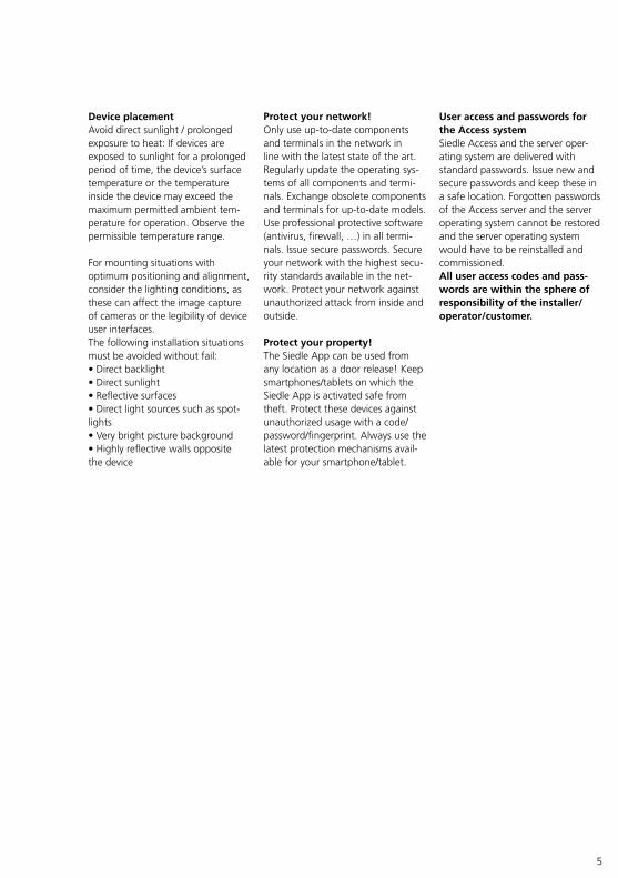
Device placement Avoid direct sunlight / prolonged exposure to heat: If devices are exposed to sunlight for a prolonged period of time, the device’s surface temperature or the temperature inside the device may exceed the maximum permitted ambient tem-perature for operation. Observe the permissible temperature range.
For mounting situations with optimum positioning and alignment, consider the lighting conditions, as these can affect the image capture of cameras or the legibility of device user interfaces.The following installation situations must be avoided without fail:• Direct backlight• Direct sunlight• Reflective surfaces• Direct light sources such as spot-lights• Very bright picture background• Highly reflective walls opposite the device
User access and passwords for the Access system Siedle Access and the server oper-ating system are delivered with standard passwords. Issue new and secure passwords and keep these in a safe location. Forgotten passwords of the Access server and the server operating system cannot be restored and the server operating system would have to be reinstalled and commissioned.All user access codes and pass-words are within the sphere of responsibility of the installer/operator/customer.
6
1 Safety remarks
Warranty Siedle excludes the guarantee for configurable functions and system properties on hardware and software supplied by Siedle if com-missioning was not carried out by the Access Service Centre or our Access Certified Partners and this can be verified. Statutory rights for the delivery of defect-free goods are not affected.All system components which are designed for/suitable for installation in an electrical distribution board or in an IT cabinet system/housing may only be installed in the permitted installation position according to the enclosed product information.If system components are operated in improper installation positions or with improper operating parameters (e.g. excessive ambient tempera-ture), this will render their warranty rights void in the event of service.
Legal notice Photographs of individuals taken without their knowledge may not be published or stored in publicly acces-sible video memory facilities.Individuals who have been photo-graphed without their knowledge are entitled to request that pictures be deleted based on the right of persons to their own likeness. Never store pictures of persons you do not know in social networks or send them by email to others/public groups. This will infringe their per-sonal rights.If stored images are used as part of private / criminal law proceedings or in a police investigation, this requires prior clarification with a lawyer or the responsible police authority.Systems with video cameras which are operated within the European Union and are aimed at a publicly accessible area or part of one, and film and record this, are subject to the EU General Data Protection Regulation (EU GDPR) as of May 25, 2018. It is the sole responsibility of the operator to operate such systems in accordance with data protection regulations.

7
The following requirements must be met in order for the Siedle Access system to operate properly:• In the configured server operating system, install only the Siedle Access system. In addition, no other server services may be installed, as this can result in impaired performance of the Siedle Access server. (Rule: 1 server service per server operating system installation.) • As server operating system, you can either use Debian Linux 9... Stretch (installation without graphical user interface), Microsoft Server 2016 or 2012 R2 Standard or Datacenter as a standard pre-installation (installation with graphic user interface).• The server hardware or virtual machine (from VMware vSphere 6) you have provided complies at least with the technically specified system requirements for the Access server.• Only activate the services necessary for operating the Access server.• Optionally: Assign the server operating system the role of the DHCP server and where applicable the NTP server, if there is no DHCP and NTP server operating in your network. • Assign a static IP address for the server operating system.• The network infrastructure cor-responds to the prescribed specifica-tion for Siedle Access. • All network users of the Access server are operated using this net-work infrastructure.
2 Installation and operating conditions
8
3 System description
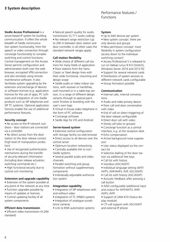
Siedle Access Professional is a server-based IP system for building communication. It offers the whole breadth of Siedle communica-tion system functionality, from the speech or video connection through concierge functionality to complex switching and control functions. Central management on the Access Server permits configuration and administration both over the web browser, encrypted VPN connection and also remotely using remote maintenance software. It also facilitates system upgrading by the extension and exchange of devices or software licences (e.g. application licences for the use of apps, PC soft-ware and integration of non-Siedle products such as SIP telephones and SIP TC systems). Optional application licences enable the use of additional performance features. Security concept • No access to the IP network out-doors - door stations are connected via a controller • No direct access from the door station to the door release contact (high level of manipulation protec-tion) • Use of recognized authentication mechanisms during the transfer of security-relevant information (including door release actuation, switching commands etc.) • High functional security due to cyclical unit monitoring Extension and upgrade capability • Extension of the system possible at any point of the network at any time • Function upgrades possible by means of updates or licences • Central updating facility of all system components Efficient data transmission • Efficient video transmission (H.264 standard)
• Natural speech quality for audio transmission (G.711 audio coding) • No relevant range restriction (up to 200 m between door station and door controller, in all other cases the standard network ranges apply) Call station flexibility • Wide choice of different call sta-tions for many fields of application • Door stations from the Vario, Classic or Steel design lines with their wide functional, mounting and design scope • Siedle audio or video indoor sta-tions, with receiver or handsfree, wall mounted or in a table-top ver-sion, in a range of different design variants through to special paint-work finishes or branding with the user's own logo • Virtual in-house video telephone in the form of PC software • Concierge software • Siedle App for iOS and Android Server-based system • Extensive central configuration with storage facility via web browser • Direct access to all devices over the central server • Optimum location networking • Centrally available link to non-Siedle systems • Several parallel audio and video channels • Parallel switching and group formation without supplementary components • Individually adjustable authoriza-tion system Integration capability • Integration of SIP telephones with and without video • Integration of TC (PABX) systems • Integration of analogue surveil-lance cameras • Link to KNX automation systems
System • Up to 640 devices per system • New system concept: there are only devices and groups • New permission concept: more flexibility in system configuration (access down to the individual switching contact) • Access Professional 5 is released to run on Debian Linux 9.9.0 (Stretch), Windows Server 2016 and 2012 R2 • Support for several network cards • Distribution of system services to different network cards configurable • Group formation possible Communication • Internal calls, internal conversa-tions • Audio and video privacy device • Door call and door conversation with video • End of call on direct triggering of the door release configurable • Direct door call with video • Storey call (also to groups) • Concierge function as a central interface, e.g. at the reception desk • Echo compensation • Active background noise suppres-sion • User status displayed via the con-tact list • Selective dialling of the door sta-tion via additional free keys • Call list with history • Voicebox (ASC/ASHT) • Individual language setting (AHT/AHTV, AHF/AHFV, AVP, ASC/ASHT) • Call list with history (ASC/ASHT) • Acoustic feedback after pressing a call button • AZIO configurable (additional input and output for AHT/AHTV, AHF/AHFV, AVP) • Support of ZAM 670 (Status dis-play module) • CTI call support with ASC/ASHT and external IP phone
Performance features / Functions

9
Video • Central video memory • Deactivating of the video memory function (GDPR) • Digital video decoupling of incoming door calls (e.g. for building automation panels) • Automatic and selective recording of camera images during a door call • Selective display and deletion of images • Camera selection using contact list or in the video section • Scanning mode (ASC) Telephony • Connection of a TC (PABX) system to the Access server (VoIP only) • Support DTMF tones (RCF2833 / SIP-Info) for telephony connection • Digital calling: Calls via the public telephone network • Dialing of public numbers from the contact list or via direct dial function (ASC) • Calling the public telephone net-work via a code lock • Hold, call waiting (ASC/ASHT) • Music on hold • Call rerouting (manual, in the event of absence or if the line is busy) • Call forwarding attended, unat-tended (ASC)
Automation • Time profiles for the time-dependent execution of any system functions (e.g. time-controlled (auto-mated) call forwarding or doormatic) • Extended doormatic function (device-related, door-related) Switching/Control • Extended door release function (2nd door release contact can be configured depending on call des-tination, any switching contacts (potential-free) can be configured as door release) • Extended KNX functionality (KNX contact as door release, status feedback) • Switching functions configurable on call buttons
Fields of application
• Extended button function / status display for Siedle terminals • Support of ATLCE • Inverting an Output • Re-triggering an output • Mail Notification system Commissioning • Browser-based commissioning • Browser compatibility (latest ver-sion required): Google Chrome, Microsoft Edge, Mozilla Firefox • Central management and configu-ration of devices • Group management • Remote configuration via the web interface of the Access server • Extended DHCP setting options • DHCP IP address range configur-able • NTP server configurable • Check of the system configuration (database validation function) • 8 ring tones freely selectable Servicing • Remote maintenance and remote update (only in the case of cus-tomer-side set-up; Internet connec-tion necessary!) • Manual user monitoring • Management of software sta-tuses in the server (e.g. automatic updating of Siedle devices) • Detailed logging for Siedle support Interfaces • Link to IP telephone systems conforming to the standard (also via telephony converters/gateways: Analog/ISDN/SBC) • LiExternal analogue cameras (with Access Interface Analog Video Standard - AIVS 670... to ATLC...) • KNX or other building automa-tion systems (e.g. JUNG, Crestron or Control4) • Link to video recording devices, operating display as and video servers via the Access video decou-pler • Access control (via Vario bus) • Connection to the push notifica-tion service for the Siedle App
Hardware clients • AVP with KNX • AHF/AHFV • AHT/AHTV • External devices (SIP) • Android panel with pre-installed Siedle app (e.g. JUNG Smart Control…) Client-Software (ASC/ASHT) • Show entire application on incoming call (ASHT only) • Automatic login and minimiza-tion at Windows startup (Minimize: ASHT only) • Security prompt before closing the application • Switching functions can be trig-gered during a call • Status displays of switching inputs • USB handset support (Jabra®) • Changed scope of functions for the software clients from Access Professional 5: the functions central Doormatic Lock, individual voice announcements and sending/receiving text messages have been removed from the software clients App • Siedle App for Android and iOS
Fields of application Projects with• a large number of users (door stations and/or indoor devices) and long distances• stringent demands on audio and video transmission• several (also geographically) sepa-rate building sections• concierge functions• heterogeneous utilization (private and commercial mixed use)• fundamental requirement for structured cabling and IP technology

10
3 System description System overview
ATLC/NG 670
ASHT
10:1012 1 20.05.2013Start 08:00 | 16.12.2014
AVP
AHTV AHF AHFV
Router
Internet
Internet
Internet
Smartphone /iPhone
Tablet / iPad
Tablet / iPad
Smartphone /iPhone
Router
Internet
ASHT
ASC
Tablat / iPad
Smartphone /iPhone
Public mobil network
Public WLAN
Local network
Local telephone networkLocal Access network
Door station
Access serverSwitch
Switch
SIP telephone SIP telephone SIP telephone SIP telephone SIP telephone
SIP telephone system
Door release
WLAN
WLAN
Switch
Customer server(e.g. mail server)
3G / 4G
11
Time synchronisation in the Access system (NTP server)
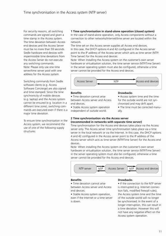
For security reasons, all switching commands are signed and given a time stamp in the Access system. The time deviation between Access end devices and the Access Server must be no more than 59 seconds. Siedle hardware end devices with impermissible time deviations from the Access Server do not execute any switching commands.Note: Please only use one time server/time server pool with one address for the Access system.
Switching commands from Siedle software clients (e.g. Access Software Concierge) are also signed and time-stamped. Since the time synchronicity of mobile devices (e.g. laptop) and the Access system cannot be ensured (e.g. location in a different time zone), switching com-mands are executed even if there is a major time deviation.
To ensure time synchronisation in the Access system, we recommend the use of one of the following supply structures:
1 Time synchronisation in stand-alone operation (closed system)In the case of stand-alone operation, only Access components without a connection to other networks/Internet/time server are located within the network.The time set on the Access server supplies all Access end devices.In this case, the DHCP options 4 and 42 configured in the Access server point to the IP address of the Access server which acts as time server (NTP/Time Server) for the Access end devices.Note: When installing the Access system on the customer’s own server hardware or virtualisation solution, the time server service (NTP/Time Server) in the server operating system must also be configured, otherwise a time server cannot be provided for the Access end devices.
Benefits• Time deviation cannot arise between Access server and Access end devices.• Stable Access system operation independent of outside world.
Drawbacks• Access system time and the time for the outside world are not syn-chronised and may drift apart.• The time must be corrected manu-ally.
2 Time synchronisation via the Access server (recommended in networks with separate time server)Time synchronisation for the Access end devices takes place via the Access server only. The Access server time synchronisation takes place via a time server in the local network or via the Internet. In this case, the DHCP options 4 and 42 configured in the Access server point to the IP address of the Access server which acts as time server (NTP/Time Server) for the Access end devices.Note: When installing the Access system on the customer’s own server hardware or virtualisation solution, the time server service (NTP/Time Server) in the server operating system must also be configured, otherwise a time server cannot be provided for the Access end devices.
Benefits• Time deviation cannot arise between Access server and Access end devices.• Stable Access system operation, even if the Internet or a time server is down.
Drawbacks• If the connection to the NTP server is interrupted (e.g. Internet connec-tion fails, modified firewall rules), the Access system time and the time of the outside world will no longer be synchronised. In the event of a longer interruption, this can result in a time deviation. However this will not have any negative effect on the Access system operation.
Access Server Access end devicesNTP
Access Server Access end devicesNTP NTPNTP server

12
3 Time synchronisation via separate NTP supply
The time synchronisation of all Access components only takes place via a separate time server in the local network or via the Internet.In both cases, the DHCP options 4 and 42 configured in the Access server point to the customer’s time server (NTP/Time Server).
Benefits• The time is in sync across the entire Access network.
Drawbacks• If the connection to the NTP server is interrupted (e.g. Internet connec-tion fails, modified firewall rules), the Access system time between the Access server and Access end devices may differ.• If there is a longer interruption, this may result in a time deviation.• If the time deviation is more than 59 seconds, no more switching commands are executed for safety reasons.
Note on time synchronisation in virtualisation solutions:Please note the relevant manufacturer recommendations for your virtualisation solution.
VM-Ware:https://kb.vmware.com/selfservice/microsites/search.do?language=en_US&cmd=displayKC&externalId=1318
Microsoft:https://blogs.msdn.microsoft.com/virtual_pc_guy/2010/11/19/time-synchronization-in-hyper-v/
NTP
NTP
Access Server
NTP server
Access end devices
3 System description Time synchronisation in the Access system (NTP server)

13
Push Notification Service (Siedle App)
From the Access system version 5.1 onwards, the “Siedle App” (black logo) can be used on mobile devices with the iOS or Android operating system. Incoming calls are signalled from the Siedle Server to the app by means of push notification via the respective app platform (Apple Push Notification Service (APNS) or Google Cloud Messaging (GCM)).• An internet connection for the Siedle App and the Access system is required for commissioning.• The mobile end device must be connected to the internet for push notifications to be received. For this, the DNS server and the standard gateway must be configured in the LAN/WLAN and the Access Server and Siedle App must be known. Other operating methods (e.g. local stand-alone operation without internet connection) are no longer supported. • Provided there is an internet connection and the Siedle App is registered on the Access system, App users are always informed of incoming calls (Always On), regard-less of the operating state of the Siedle App. Due to the iOS oper-ating system, an app that is active in the foreground will respond the quickest.
System conditionsThe following requirements apply when using the Siedle App:• Access Professional Version 5.1 or higher• Siedle App (black logo)• Mobile device with installed operating system from iOS 11.4 or Android 7 or higher• Permanent Internet connection for the Access system• Permanent Internet connection for the mobile device• Receipt of push notifications must not be blocked on the mobile device• Non-blocked port 443 (HTTPS) for the Access system (in addition to the ports required for operation of the Access system)
System initialisation/ initial operationThe following processing take place during commissioning/initial operation so that the Siedle App can receive push notifications:• Siedle App and mobile device: When the Siedle App is started for the first time on the mobile device with an Internet connection, the device establishes a connection to the respective push notification ser-vice. The Service generates a unique ID (push token) which can only be attributed to this device, from various identification characteristics. The Service saves the push token in its database and sends this to the Siedle App.A unique push token is always gen-erated for each app.The unique recipient (this Siedle App on this mobile device) is stored in each push token. The process is automatically repeated in the back-ground with every change (e.g. new smartphone) after re-registering the app.• Access system: The Access system received the push token during the app registration. Each Siedle App can be reached individually via the Push Notification Service in the Internet using the information in the push token. The notifications are transferred with encryption.
Standard operationThe call button is pressed at the door station. The call destination is a mobile device with Internet connec-tion and installed Siedle App.
Sequence
A A call is initiated at the door sta-tion. The call destination is a mobile device with the Siedle App.B The Access system sends a noti-fication about the incoming door call to the Siedle notification Service (Siedle Server) in the Internet.C The Siedle notification service forwards the notification to the Push Notification Service (Apple Push Notification Service (APNS) or Google Cloud Messaging (GCM)).D The Service sends the notification to the mobile end device via the existing internet connection.E The mobile device signals the noti-fication about the incoming door call to the Siedle App.F The user can open the Siedle App via the displayed push notification in order to accept the pending call. The Siedle App connects to the Access system via the mobile device.G The Access system establishes the connection to the door station and opens the communication channels to the Siedle App. The door call can take place.

14
G
A B
C
FF
E D
Notification service /Siedle Server
Access system
Door station
Smartphone with installed Siedle app
Siedle App Push Notification Service (Apple Push Notification Service / Google Cloud Messaging)
F
3 System description Push Notification Service (Siedle App)
Properties of the entire system• Communication is encrypted.• Access systems only connect to the Siedle Server. There is no direct con-nection to a third-party provider or Push service.• Mobile end devices with a reg-istered Siedle app are always con-nected to the Push service and are ready-to-receive when there is an Internet connection. • The Siedle notification service (Siedle Server) only forwards notifi-cations on incoming calls (door calls or internal calls) to the Siedle App.
Note: Technical details and require-ments for receiving Push Notification on mobile devices may change over time. Please contact the support of the respective app platform if required.
15
Connection to telephone systems
In order to connect telephone systems (TC system) to the Access system, the following system requirements must be met (from Access system version V. 2.1.x):• VoIP standard: SIP protocol• Audio codec: G.711 a-law or µ-law• Length of the audio packets (framing size): 40 ms (can be changed to 20 ms)• Protocol for DTMF tones: RFC 2833 or SIP info
A TC system can be connected to the Access system via SIP trunk or PABX gateway. TC systems without VoIP-capable network interface can be connected via analogue, ISDN or SBC gateway.Depending on the TC system, it may need to be extended in order to con-nect to the Access system:• Hardware: (e.g. retrofitting VoIP assemblies/PCBs)• Software/software licences: (e.g. system update and additional licences from the TC manufacturer)
These extensions are not part of the scope of supply of the Access system and must not be confused with the user and application licenses which are needed for the operation of the Access system.
Information about PABX gateway (single channel connection)Connecting the Access system to the TC system as a PBX extension:• One connection channel per con-figured PABX gateway connection in the Access system (max. 50 con-nention channels can be configured per Access system, including via the same prefix), one ALT 270-0 telephony connection Access licence is required per connection channel.• A PBX extension/user for connec-tion of the Access system is also created in the TC system. This con-nection may vary depending on the TC system.• Each call from the Access system to the TC system is shown with the same PBX extension call number in the TC system (call differentiation is not possible).
As of Access system V. 5.1.0, the protocol and port can be configured individually for negotiating the SIP communication parameters of the TC connection:• Protocol: UDP, TCP or TLS• Port: 1–65535
Important!The selected protocol and port must also be configured in the remote party. Please note the respective standard ports of the protocols:• UDP/TCP: 5060 – Session Initiation Protocol (SIP)• TLS: 5061 – Session Initiation Protocol (SIP) over TLS
Notes on the SIP trunk (bundle channel connection)Network-side connection of the Access system to a TC system via SIP trunk:• Up to 50 connection channels in the Access system (without authen-tication), one ALT 270-0 telephony connection Access licence is required per connection channel.• A uniform call number plan is recommended (each assigned call number in the common Access and TC system group is unique).• A gateway for connection to the Access system is also created in the TC system. This connection may vary depending on the TC system.• Each call from the Access system to the TC system is shown with the relevant Access user call number (call differentiation is possible).
As of Access system V. 5.0.0, both the call number and the device name is transmitted to the TC system. Many TC systems include display of transmitted user names as a configurable performance feature, which must be activated and config-ured in the TC system if necessary.
16
4 System structure, conductor material and range
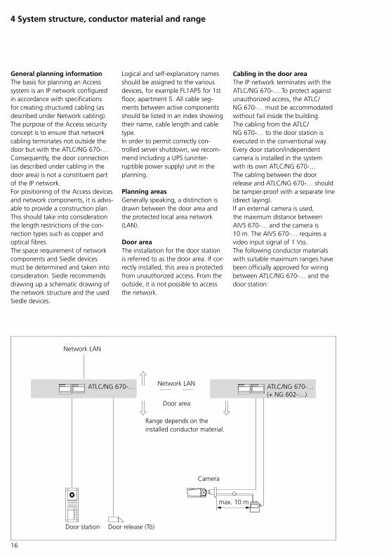
General planning information The basis for planning an Access system is an IP network configured in accordance with specifications for creating structured cabling (as described under Network cabling).The purpose of the Access security concept is to ensure that network cabling terminates not outside the door but with the ATLC/NG 670-… Consequently, the door connection (as described under cabling in the door area) is not a constituent part of the IP network.For positioning of the Access devices and network components, it is advis-able to provide a construction plan. This should take into consideration the length restrictions of the con-nection types such as copper and optical fibres. The space requirement of network components and Siedle devices must be determined and taken into consideration. Siedle recommends drawing up a schematic drawing of the network structure and the used Siedle devices.
ATLC/NG 670-… ATLC/NG 670-…(+ NG 602-…)
max. 10 m
Door station
Camera
Door area
Network LAN
Range depends on the installed conductor material.
Network LAN
Door release (Tö)
Logical and self-explanatory names should be assigned to the various devices, for example FL1AP5 for 1st floor, apartment 5. All cable seg-ments between active components should be listed in an index showing their name, cable length and cable type.In order to permit correctly con-trolled server shutdown, we recom-mend including a UPS (uninter-ruptible power supply) unit in the planning.
Planning areas Generally speaking, a distinction is drawn between the door area and the protected local area network (LAN).
Door area The installation for the door station is referred to as the door area. If cor-rectly installed, this area is protected from unauthorized access. From the outside, it is not possible to access the network.
Cabling in the door area The IP network terminates with the ATLC/NG 670-… To protect against unauthorized access, the ATLC/NG 670-… must be accommodated without fail inside the building.The cabling from the ATLC/NG 670-… to the door station is executed in the conventional way. Every door station/independent camera is installed in the system with its own ATLC/NG 670-…The cabling between the door release and ATLC/NG 670-… should be tamper-proof with a separate line (direct laying).If an external camera is used, the maximum distance between AIVS 670-… and the camera is 10 m. The AIVS 670-… requires a video input signal of 1 Vss.The following conductor materials with suitable maximum ranges have been officially approved for wiring between ATLC/NG 670-… and the door station:
17
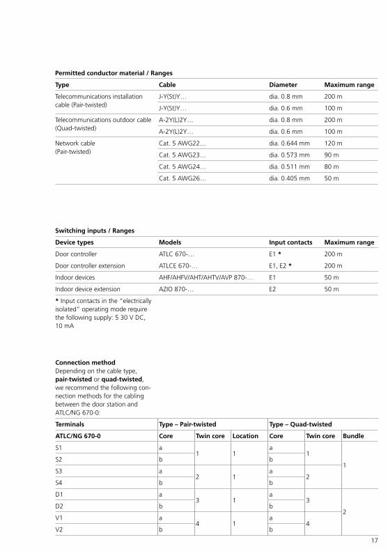
Permitted conductor material / Ranges
Type Cable Diameter Maximum range
Telecommunications installation cable (Pair-twisted)
J-Y(St)Y… dia. 0.8 mm 200 m
J-Y(St)Y… dia. 0.6 mm 100 m
Telecommunications outdoor cable (Quad-twisted)
A-2Y(L)2Y… dia. 0.8 mm 200 m
A-2Y(L)2Y… dia. 0.6 mm 100 m
Network cable(Pair-twisted)
Cat. 5 AWG22… dia. 0.644 mm 120 m
Cat. 5 AWG23… dia. 0.573 mm 90 m
Cat. 5 AWG24… dia. 0.511 mm 80 m
Cat. 5 AWG26… dia. 0.405 mm 50 m
Connection method Depending on the cable type, pair-twisted or quad-twisted, we recommend the following con-nection methods for the cabling between the door station and ATLC/NG 670-0:
Terminals Type – Pair-twisted Type – Quad-twisted
ATLC/NG 670-0 Core Twin core Location Core Twin core Bundle
S1 a1 1
a1
1S2 b b
S3 a2 1
a2
S4 b b
D1 a3 1
a3
2D2 b b
V1 a4 1
a4
V2 b b
Switching inputs / Ranges
Device types Models Input contacts Maximum range
Door controller ATLC 670-… E1 * 200 m
Door controller extension ATLCE 670-… E1, E2 * 200 m
Indoor devices AHF/AHFV/AHT/AHTV/AVP 870-… E1 50 m
Indoor device extension AZIO 870-… E2 50 m
* Input contacts in the “electrically isolated” operating mode require the following supply: 5 30 V DC, 10 mA
18
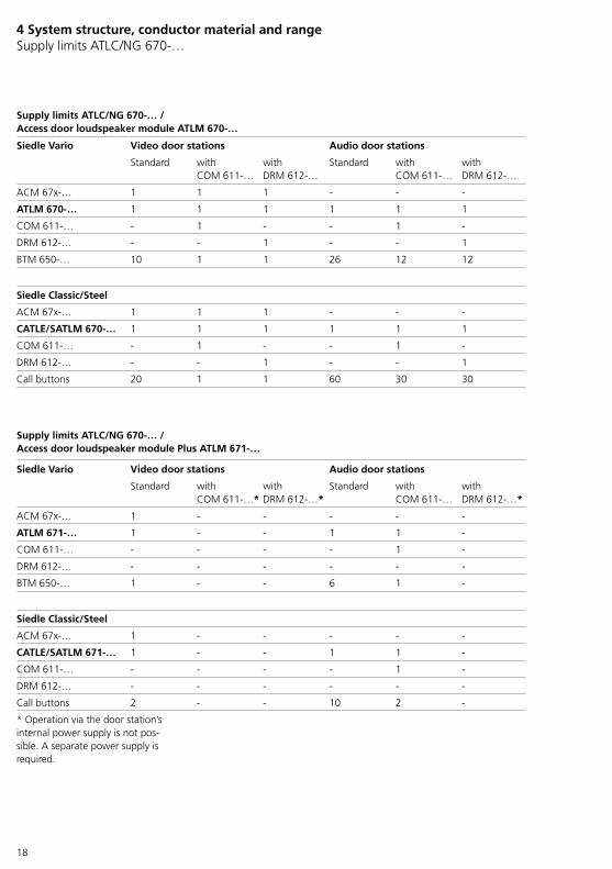
Supply limits ATLC/NG 670-… /Access door loudspeaker module ATLM 670-…
Siedle Vario Video door stations Audio door stations
Standard with COM 611-…
with DRM 612-…
Standard with COM 611-…
with DRM 612-…
ACM 67x-… 1 1 1 - - -
ATLM 670-… 1 1 1 1 1 1
COM 611-… - 1 - - 1 -
DRM 612-… - - 1 - - 1
BTM 650-… 10 1 1 26 12 12
Siedle Classic/Steel
ACM 67x-… 1 1 1 - - -
CATLE/SATLM 670-… 1 1 1 1 1 1
COM 611-… - 1 - - 1 -
DRM 612-… - - 1 - - 1
Call buttons 20 1 1 60 30 30
Supply limits ATLC/NG 670-… /Access door loudspeaker module Plus ATLM 671-…
Siedle Vario Video door stations Audio door stations
Standard with COM 611-…*
with DRM 612-…*
Standard with COM 611-…
with DRM 612-…*
ACM 67x-… 1 - - - - -
ATLM 671-… 1 - - 1 1 -
COM 611-… - - - - 1 -
DRM 612-… - - - - - -
BTM 650-… 1 - - 6 1 -
Siedle Classic/Steel
ACM 67x-… 1 - - - - -
CATLE/SATLM 671-… 1 - - 1 1 -
COM 611-… - - - - 1 -
DRM 612-… - - - - - -
Call buttons 2 - - 10 2 -
* Operation via the door station’s internal power supply is not pos-sible. A separate power supply is required.
4 System structure, conductor material and range Supply limits ATLC/NG 670-…
19
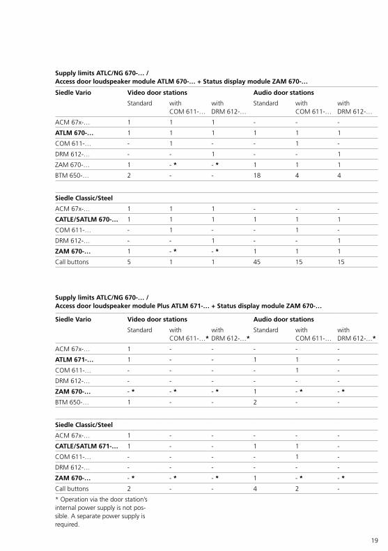
Supply limits ATLC/NG 670-… /Access door loudspeaker module ATLM 670-… + Status display module ZAM 670-…
Siedle Vario Video door stations Audio door stations
Standard with COM 611-…
with DRM 612-…
Standard with COM 611-…
with DRM 612-…
ACM 67x-… 1 1 1 - - -
ATLM 670-… 1 1 1 1 1 1
COM 611-… - 1 - - 1 -
DRM 612-… - - 1 - - 1
ZAM 670-… 1 - * - * 1 1 1
BTM 650-… 2 - - 18 4 4
Siedle Classic/Steel
ACM 67x-… 1 1 1 - - -
CATLE/SATLM 670-… 1 1 1 1 1 1
COM 611-… - 1 - - 1 -
DRM 612-… - - 1 - - 1
ZAM 670-… 1 - * - * 1 1 1
Call buttons 5 1 1 45 15 15
Supply limits ATLC/NG 670-… /Access door loudspeaker module Plus ATLM 671-… + Status display module ZAM 670-…
Siedle Vario Video door stations Audio door stations
Standard with COM 611-…*
with DRM 612-…*
Standard with COM 611-…
with DRM 612-…*
ACM 67x-… 1 - - - - -
ATLM 671-… 1 - - 1 1 -
COM 611-… - - - - 1 -
DRM 612-… - - - - - -
ZAM 670-… - * - * - * 1 - * - *
BTM 650-… 1 - - 2 - -
Siedle Classic/Steel
ACM 67x-… 1 - - - - -
CATLE/SATLM 671-… 1 - - 1 1 -
COM 611-… - - - - 1 -
DRM 612-… - - - - - -
ZAM 670-… - * - * - * 1 - * - *
Call buttons 2 - - 4 2 -
* Operation via the door station’s internal power supply is not pos-sible. A separate power supply is required.

20
PoE – Power over Ethernet The supply for the indoor stations must be ensured by the customer via PoE. Routers/switches used must be PoE-capable according to IEEE802.3af, as a minimum. To pre-vent supply problems, we recom-mend the use of PoE switches which can supply each PoE port according to standard “IEEE 802.3af” with up to PoE class 3.Depending on the network infra-structure, the decentral PoE supply of individual devices can take place with PoE injectors, and the central PoE supply of several devices can take place with PoE-capable routers/switches.
* Is only required if the door station’s supply limit (ATLC/NG 670-0 Access door loudspeaker controller with line rectifier) no longer suffices.For detailed information, see page 18
PoE budget
Model Designation PoE class Required operating voltage
Required power on switch port (Watt)
Recommended transfer speed in network
AGW 670-… Access gateway – – – 100 Mbit/s
AHF 870-… Access handsfree telephone
2 PoE according to IEEE 802.3af
7,0 100 Mbit/s
AHFV 870-… Access video hands-free telephone
2 PoE according to IEEE 802.3af
7,0 100 Mbit/s
AHT 870-… Access in-house tel-ephone
2 PoE according to IEEE 802.3af
7,0 100 Mbit/s
AHTV 870-… Access video in-house telephone
2 PoE according to IEEE 802.3af
7,0 100 Mbit/s
ASH 670-… Access server hard-ware
– – – 1000 MBit/s
ATLC/NG 670-…
Access door loud-speaker controller with line rectifier
– – – 100 Mbit/s
AVP 870-… Access video panel 3 PoE according to IEEE 802.3af
15,4 100 Mbit/s
Supply units – digital call
Input unit Supply unit For detailed information, see page
COM 611-… TR 603-…*
37, 47DRM 612-… TR 603-…*
COM 611-… + DRM 612-… TR 603-…
Siedle Touch… ANG 600-… + TR 603-… 32, 46, 47
4 System structure, conductor material and range

21
Network LAN The requirement for integration of an Access system is a network infra-structure created in accordance with the stipulations for generic cabling (from Category 5e).Rules for generic cabling are set out in various standards:• EN 50173-1 General requirementsFor individual building types, the fol-lowing standards apply in addition:• EN 50173-2 (ISO/IEC 11801) for office buildings• EN 50173-3 (ISO/IEC 24702) for industrially used locations• EN 50173-4 (ISO/IEC 15018) for apartmentsInternationally, the ISO/IEC standards apply.
Cabling structure/areas The cabling is broken down into 3 areas.
Primary area • Fibre optic cables• Cabling between individual buildings and/or within buildings between several main building dis-tributors.• In the case of copper wire con-nections, adequate equipotential bonding must be guaranteed.
Secondary area • Fibre optic cables• The storeys are networked by means of storey distributors. Both fibre optic and copper connections can be used. This is dependent upon the switches used and their distance from the main distributor/switch.
Tertiary area • Twisted pair for fixed installation plus patch cable for cabling from the network junction box to the terminal.
ATLC/NG 670
ServerSwitch
Door station
Primary area
Tertiary area
Seco
ndar
y ar
ea
Door release (Tö)
Network characteristics Access system• Maximum of 150 ms delay in one direction (one way delay)• Maximum of 300 ms total delay• Packet loss < 1%• Maximum of 20 ms jitter

22
Cabling for indoor devices All indoor devices are always con-nected via an RJ45 8/8 (or RJ45 socket modules 8(8)) network socket. This is divided into two sockets. The left-hand socket is reserved for the network (LAN area). The right-hand socket is independent of the network and is used for connecting other control elements permitting additional uses.Supplementary functions such as a storey call button are also connected via the RJ45 network socket (right-hand socket/side) or the RJ45 socket modules 8(8).The range between ERT and the indoor device is max. 50 m (Cat 5 AWG22).The Access indoor devices can be installed without problems using standard RJ45 flush mounting net-work junction boxes.In this case, simply install the net-work junction box without the frame and panel. The Siedle indoor device can be mounted above the junction box and connected to the network with a plug-in connector.
If there is no flush mounted network socket at the required mounting height due to circumstances on site, the indoor call station can be surface mounted with the AZA 870-… In this case, the connection from the indoor call station to the network is established using a patch cable (not provided).
If the indoor call station is intended for use as a table-top unit, the device can be converted using the AZTV 870-… with 3 metre long con-necting cable.
165
cm
Eye level
Junction boxRJ45
Installation with patch cable
150
cm
165
cm
Eye levelJunction boxRJ45
Installation on flush mounted junctio box
Ideally, an RJ45 flush mounted junc-tion box should be positioned at the mounting height for the indoor device (display height less 15 cm).
Mounting with Access surface mounting accessory AZA 870-… and patch cable provided on site.
4 System structure, conductor material and range
23
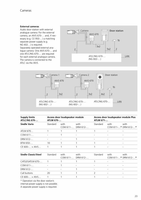
Cameras
External cameras Audio door station with external analogue camera: For the external camera, an AIVS 670-… and, if nec-essary (e.g. CE 950-…) a matching separate power supply (e.g. NG 602…) is required.Separately operated external ana-logue camera: One AIVS 670-… and one ATLC/NG 670-… are required for each external analogue camera. The camera is connected to the ATLC via the AIVS.
2 24x23x23x2
AIVS 670 AIVS 670
ATLC/NG 670-…ATLC/NG 670-…(NG 602-…)
ATLC/NG 670-…(NG 602-…)
Tö
2
AIVS 670
Access Interface Analog-Video Standard
AIVS 670
Access Interface Analog-Video Standard
Door stationCamera 1 Camera 2
LAN
25x23x2
2
Tö
AIVS 670
ATLC/NG 670-…(NG 602-…)
AIVS 670
Access Interface Analog-Video Standard
Door stationCamera
LAN
Supply limits ATLC/NG 670-…
Access door loudspeaker module ATLM 670-…
Access door loudspeaker module Plus ATLM 671-…
Siedle Vario Standard with COM 611-…
with DRM 612-…
Standard with COM 611-…*
with DRM 612-…*
ATLM 670… 1 1 1 1 - -
COM 611-… - 1 - - - -
DRM 612-… - - 1 - - -
BTM 650-… 10 1 1 1 - -
CE 600-… + AIVS… 1 1 1 1 - -
Siedle Classic/Steel Standard with COM 611-…
with DRM 612-…
Standard with COM 611-…*
with DRM 612-…*
CATLE/SATLM 670-… 1 1 1 1 - -
COM 611-… - 1 - - - -
DRM 612-… - - 1 - - -
Call buttons 20 1 1 2 - -
CE 600-… + AIVS… 1 1 1 1 - -
* Operation via the door station’s internal power supply is not possible. A separate power supply is required.
24
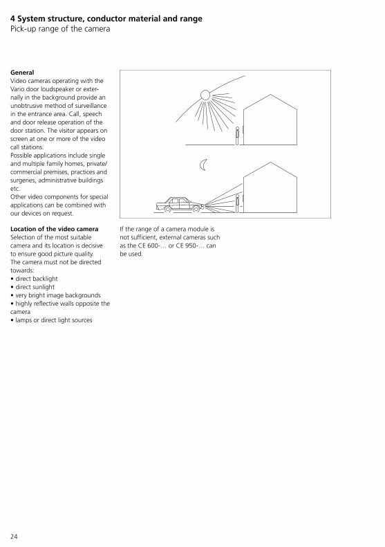
General Video cameras operating with the Vario door loudspeaker or exter-nally in the background provide an unobtrusive method of surveillance in the entrance area. Call, speech and door release operation of the door station. The visitor appears on screen at one or more of the video call stations.Possible applications include single and multiple family homes, private/commercial premises, practices and surgeries, administrative buildings etc.Other video components for special applications can be combined with our devices on request.
Location of the video camera Selection of the most suitable camera and its location is decisive to ensure good picture quality. The camera must not be directed towards:• direct backlight• direct sunlight• very bright image backgrounds• highly reflective walls opposite the camera• lamps or direct light sources
If the range of a camera module is not sufficient, external cameras such as the CE 600-… or CE 950-… can be used.
4 System structure, conductor material and rangePick-up range of the camera
25
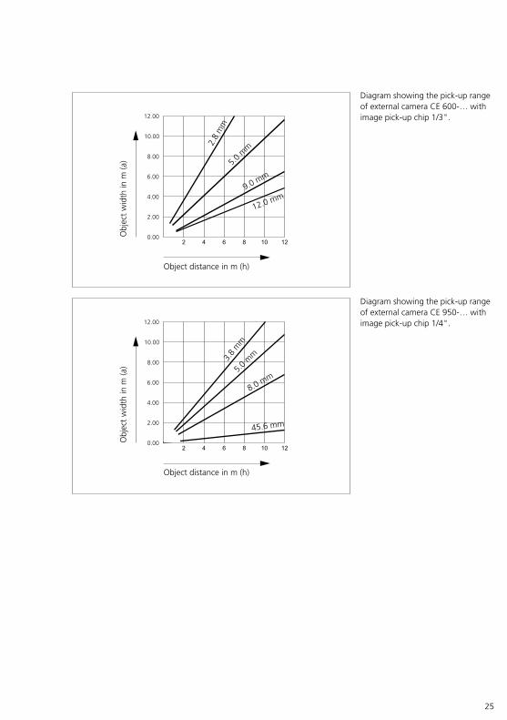
Diagram showing the pick-up range of external camera CE 950-… with image pick-up chip 1/4".
Object distance in m (h)
Obj
ect
wid
th in
m (a
)
3.8
mm
5.0 m
m
8.0 mm
45.6 mm
12.00
10.00
8.00
6.00
4.00
2.00
0.00
Diagram showing the pick-up range of external camera CE 600-… with image pick-up chip 1/3".
Object distance in m (h)
Obj
ect
wid
th in
m (a
)12.00
10.00
8.00
6.00
4.00
2.00
0.00
2.8
mm
5.0 m
m
9.0 mm
12.0 mm
26
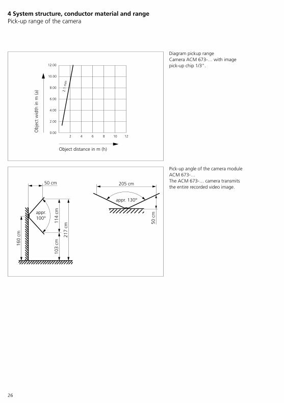
Diagram pickup rangeCamera ACM 673-… with image pick-up chip 1/3".
Pick-up angle of the camera module ACM 673-…The ACM 673-… camera transmits the entire recorded video image.
50 cm
114
cm10
3 cm
217
cm
160
cm
appr.100°
2 4 6 8 10 12
Object distance in m (h)
Obj
ect
wid
th in
m (a
)
12.00
10.00
8.00
6.00
4.00
2.00
0.00
2.1
mm
205 cm
50 c
m
appr. 130°
4 System structure, conductor material and range Pick-up range of the camera
27
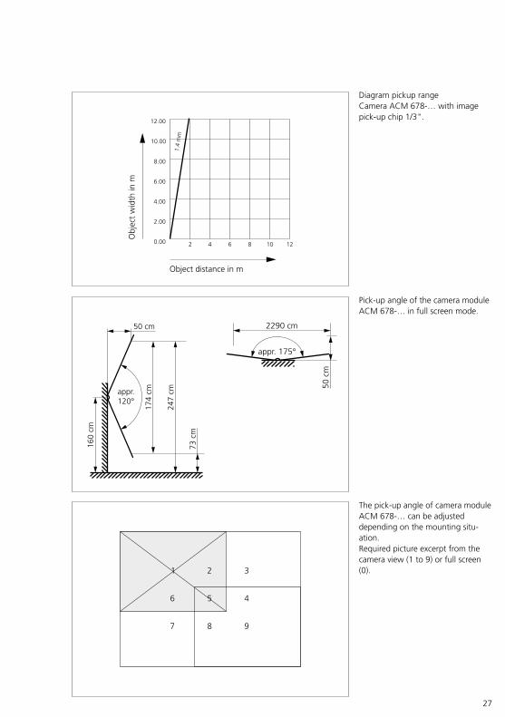
Diagram pickup rangeCamera ACM 678-… with image pick-up chip 1/3".
Pick-up angle of the camera module ACM 678-… in full screen mode.
appr.120°
160
cm
50 cm
174
cm
73 c
m
247
cm
2 4 6 8 10 12
12.00
10.00
8.00
6.00
4.00
2.00
0.00
1.4
mm
Object distance in m
Obj
ect
wid
th in
m
appr. 175°
2290 cm50
cm
The pick-up angle of camera module ACM 678-… can be adjusted depending on the mounting situ-ation.Required picture excerpt from the camera view (1 to 9) or full screen (0).1 2 3
456
7 8 9
28
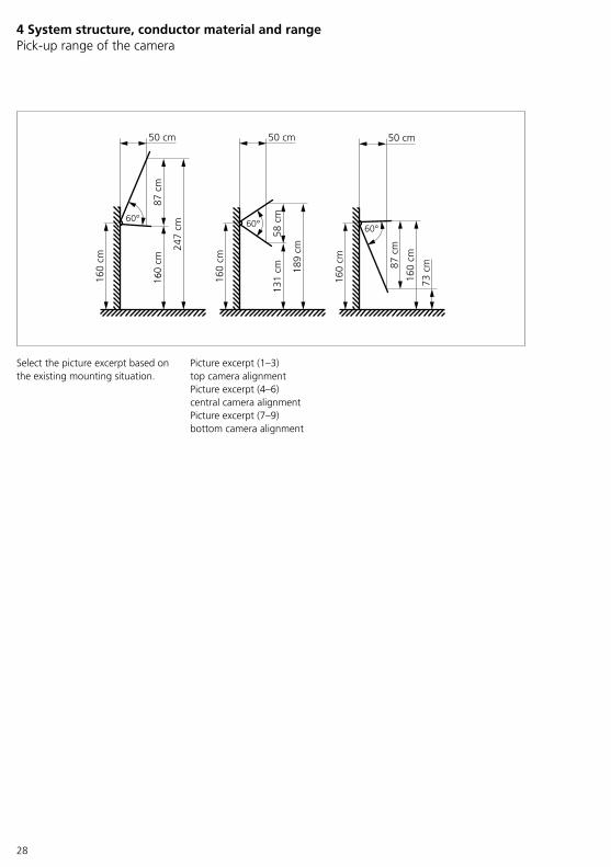
Select the picture excerpt based on the existing mounting situation.
Picture excerpt (1–3) top camera alignmentPicture excerpt (4–6) central camera alignmentPicture excerpt (7–9) bottom camera alignment
60° 60° 60°
160
cm
160
cm
160
cm
50 cm 50 cm 50 cm
247
cm
131
cm 189
cm
87 c
m
73 c
m
160
cm
58 c
m
87 c
m16
0 cm
4 System structure, conductor material and range Pick-up range of the camera

29
5 System components Overview
* Can also be used for customer’s existing door stations/letterbox sys-tems.
Door stations (outdoor/indoor area) (Possible designs: Vario/Classic/Steel)• ACM 673-…Access camera 130 for Siedle Vario
• ACM 678-…Access camera 180 for Siedle Vario
• ATLE 670-… *Access custom-fit door loudspeaker incl. Bus call button matrix
• ATLM 670-…Access door loudspeaker module
• ATLM 671-…Access door loudspeaker module Plus
• BRMA 050-… *Bus call button matrix
• BTM 650-01 to -04Bus call button module
• COM 611-…Code lock module
• DRM 612-…Display call module
• PME…Mail notification system (Classic/Steel)
• ST 10Siedle Touch 10 (Steel)
• STE 10-0Siedle Touch 10 built-in
• TÖ 61x-…Door release (DIN left or right)
• ZAM 670-…Status display module
• ZDS 601-0Anti-pilfer accessory (Siedle Vario)
External cameras/ Surface-mounted components • AIVS 670-…Access Interface analog-video standard
• CE 600-…External colour CCD video camera for external mounting
• CE 950-…External colour CCD video camera for external mounting
Indoor stations (audio/video) • AHF 870-…Access handsfree telephone
• AHFV 870-…Access video handsfree telephone
• AHT 870-…Access in-house telephone
• AHTV 870-…Access video in-house telephone
• AVP 870-…Access video panel
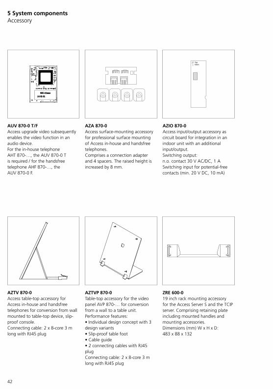
Upgrade (audio indoor station) • AUV 870-…Access for video upgrade
Accessory • AZA 870-…Access surface-mount accessory
• AZIO 870-…Access input/output accessory
• AZTV 870-…Access table-top accessory
• AZTVP 870-…Access table-top accessory
• ZRE 600-…19 inch rack mounting accessory
Distribution components • ANG 600-…Access line rectifier
• ATLC/NG 670-…Access door loudspeaker controller with line rectifier
• ATLCE 670-…Access door loudspeaker controller extension
• AVA 670-…Access video decoupler
• DSC 602-…Anti-pilfer controller (Siedle Vario)
• NG 602-…Line rectifier
• TR 602-…Transformer
• TR 603-…Transformer
• VNG 602-…Video line rectifier
• ZDS/CL (SDSC 602-…)Anti-pilfer controller + Anti-pilfer accessory (Siedle Classic)
• ZWA 640-…Western socket accessory

30
5 System components Overview
Client-Software • ASC 170-…Access Software Concierge
• ASHT 170-…Access Software In-house telephone
• Siedle App(App for smartphones/tablets with Android/iOS)
Access server variantsSoftware variant• Access Professional V 5…
Hardware variant • ASH 670-05 MAccess server hardware M
• ASH 670-05 SAccess server hardware S
Upgrade (server) • ASU 670-05Access server upgrade package
Access user licences (Server operation) • APR 670-0 10 Access Professional
• APR 670-0 20 Access Professional
• APR 670-0 40 Access Professional
• APR 670-0 80 Access Professional
• APR 670-0 160 Access Professional
• APR 670-0 320 Access Professional
• APR 670-0 640 Access Professional
Optional Access application licences (Models) • ALFA 270-…Access licence for external audio device
• ALKNX 270-…Access licence for KNX gateway
• ALSA 270-…
Access licence for Siedle App
• ALT 270-…Access licence for telephony connection
• ASC 170-…Access Software Concierge
• ASHT 170-…Access Software In-house telephone
31
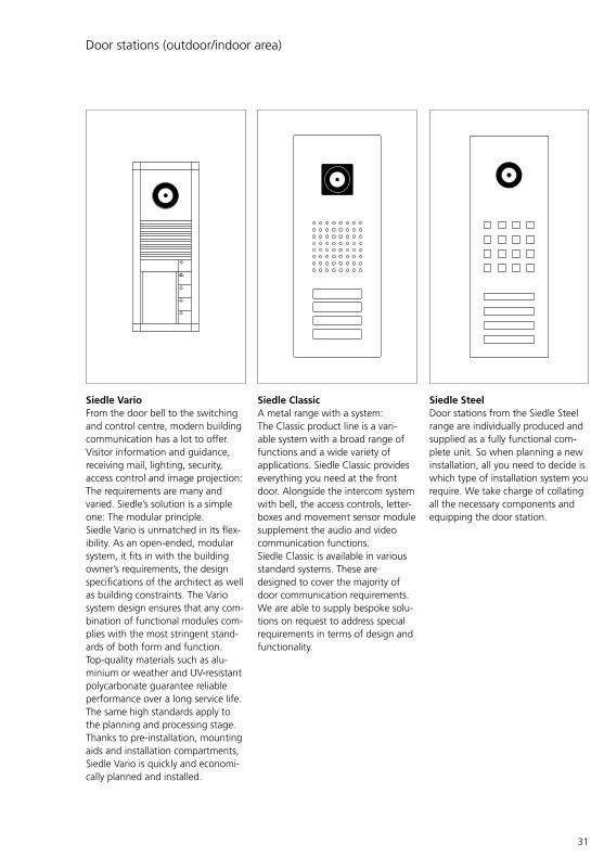
Siedle Vario From the door bell to the switching and control centre, modern building communication has a lot to offer. Visitor information and guidance, receiving mail, lighting, security, access control and image projection: The requirements are many and varied. Siedle’s solution is a simple one: The modular principle.Siedle Vario is unmatched in its flex-ibility. As an open-ended, modular system, it fits in with the building owner’s requirements, the design specifications of the architect as well as building constraints. The Vario system design ensures that any com-bination of functional modules com-plies with the most stringent stand-ards of both form and function.Top-quality materials such as alu-minium or weather and UV-resistant polycarbonate guarantee reliable performance over a long service life.The same high standards apply to the planning and processing stage. Thanks to pre-installation, mounting aids and installation compartments, Siedle Vario is quickly and economi-cally planned and installed.
Siedle Classic A metal range with a system:The Classic product line is a vari-able system with a broad range of functions and a wide variety of applications. Siedle Classic provides everything you need at the front door. Alongside the intercom system with bell, the access controls, letter-boxes and movement sensor module supplement the audio and video communication functions.Siedle Classic is available in various standard systems. These are designed to cover the majority of door communication requirements. We are able to supply bespoke solu-tions on request to address special requirements in terms of design and functionality.
Door stations (outdoor/indoor area)
Siedle Steel Door stations from the Siedle Steel range are individually produced and supplied as a fully functional com-plete unit. So when planning a new installation, all you need to decide is which type of installation system you require. We take charge of collating all the necessary components and equipping the door station.

32
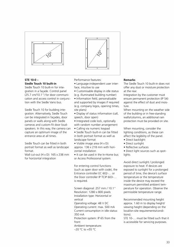
Performance features:• Language-independent user inter-face, intuitive to use• Customisable display in idle status (e.g. illuminated building number)• Information field, personalizable and supported by images if required (e.g. company logos, opening times, site plans)• Display of status information (call, speech, door open)• Integrated code lock, optionally with random number arrangement• Calling via numeric keypad• Siedle Touch built-in can be fitted in both portrait format as well as landscape format• Visible image area (H x D): approx. 136 x 218 mm with hori-zontal installation• It can be used in the In-Home bus or Access Professional system.
For entering control functions (such as open door with code), the Entrance controller EC 602-… or the Door controller IP TCIP 603-… is required.
Screen diagonal: 257 mm / 10.1" Resolution: 1280 x 800 pixels Installation type: Horizontal or vertical Operating voltage: 48 V DCOperating current: max. 500 mACurrent consumption in idle status: 350 mAProtection system: IP 65 from the frontAmbient temperature: –20 °C to +55 °C
ST 10-0 – Siedle Touch 10Siedle Touch 10: 25.7 cm (10.1") control panel for door communica-tion and access control in conjunc-tion with the Siedle Vario bus.For making door calls via digital call buttons or call numbers as well as for setting codes for control func-tions / access control.
Siedle Touch in the Steel design line: Steel systems are individually planned and produced, assembled in the factory, tested and supplied ready to install.
Siedle Touch can be fitted in both portrait format as well as landscape format.
RemarksWhen mounting, consider the lighting conditions, as these can affect the legibility of the panel.• Direct backlight• Direct sunlight• Reflective surfaces• Direct light sources such as spotlights
Avoid direct sunlight / prolonged exposure to heat: If devices are exposed to sunlight for a prolonged period of time, the device’s surface temperature or the temperature inside the device may exceed the maximum permitted ambient tem-perature for operation. Observe the permissible temperature range.
Recommended mounting height approx. 1.60 m to display height/viewing height (depending on the local/on-site requirements/condi-tions).
5 System componentsDoor stations (outdoor/indoor area)
33
STE 10-0 – Siedle Touch 10 built-inSiedle Touch 10 built-in for inte-gration in a façade. Control panel (25.7 cm/10.1") for door communi-cation and access control in conjunc-tion with the Siedle Vario bus.
Siedle Touch 10 for building inte-gration: Alternatively, Siedle Touch can be integrated in façades, door panels or walls along with Siedle cameras and custom-fit door loud-speakers. In this way, the camera can capture an optimum image of the entrance area at all times.
Siedle Touch can be fitted in both portrait format as well as landscape format.Wall cut-out (H x D): 165 x 238 mm for horizontal integration
Performance features:• Language-independent user inter-face, intuitive to use• Customisable display in idle status (e.g. illuminated building number)• Information field, personalizable and supported by images if required (e.g. company logos, opening times, site plans)• Display of status information (call, speech, door open)• Integrated code lock, optionally with random number arrangement• Calling via numeric keypad• Siedle Touch built-in can be fitted in both portrait format as well as landscape format• Visible image area (H x D): approx. 136 x 218 mm with hori-zontal installation• It can be used in the In-Home bus or Access Professional system.
For entering control functions (such as open door with code), the Entrance controller EC 602-… or the Door controller IP TCIP 603-… is required.
Screen diagonal: 257 mm / 10.1" Resolution: 1280 x 800 pixels Installation type: Horizontal or vertical Operating voltage: 48 V DCOperating current: max. 500 mACurrent consumption in idle status: 350 mAProtection system: IP 65 from the frontAmbient temperature: –20 °C to +55 °C
RemarksThe Siedle Touch 10 built-in does not offer any dust or moisture protection at the rear.Integration by the customer must ensure permanent protection (IP 54) against the effect of dust and mois-ture.When mounting on the weather side of the building or in free-standing walls/columns, an additional rain protection must be provided on site.
When mounting, consider the lighting conditions, as these can affect the legibility of the panel.• Direct backlight• Direct sunlight• Reflective surfaces• Direct light sources such as spot-lights
Avoid direct sunlight / prolonged exposure to heat: If devices are exposed to sunlight for a prolonged period of time, the device’s surface temperature or the temperature inside the device may exceed the maximum permitted ambient tem-perature for operation. Observe the permissible temperature range.
Recommended mounting height approx. 1.60 m to display height/viewing height (depending on the local/on-site requirements/condi-tions).STE 10-… must be fitted such that it is accessible for servicing purposes.
34
5 System componentsAccess cameras
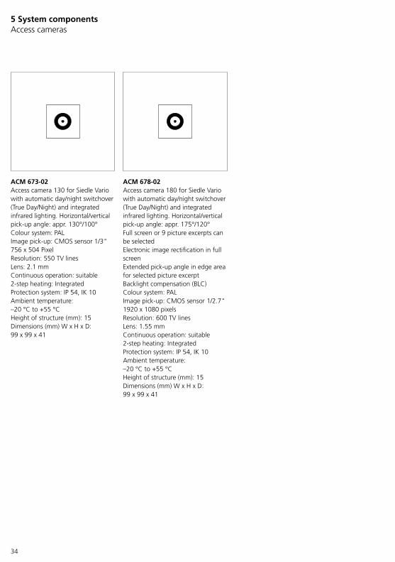
ACM 673-02 Access camera 130 for Siedle Vario with automatic day/night switchover (True Day/Night) and integrated infrared lighting. Horizontal/vertical pick-up angle: appr. 130°/100°Colour system: PALImage pick-up: CMOS sensor 1/3" 756 x 504 PixelResolution: 550 TV linesLens: 2.1 mmContinuous operation: suitable2-step heating: IntegratedProtection system: IP 54, IK 10Ambient temperature: –20 °C to +55 °CHeight of structure (mm): 15Dimensions (mm) W x H x D: 99 x 99 x 41
ACM 678-02Access camera 180 for Siedle Vario with automatic day/night switchover (True Day/Night) and integrated infrared lighting. Horizontal/vertical pick-up angle: appr. 175°/120°Full screen or 9 picture excerpts can be selectedElectronic image rectification in full screenExtended pick-up angle in edge area for selected picture excerptBacklight compensation (BLC)Colour system: PALImage pick-up: CMOS sensor 1/2.7" 1920 x 1080 pixelsResolution: 600 TV linesLens: 1.55 mmContinuous operation: suitable2-step heating: IntegratedProtection system: IP 54, IK 10Ambient temperature: –20 °C to +55 °CHeight of structure (mm): 15Dimensions (mm) W x H x D: 99 x 99 x 41
35
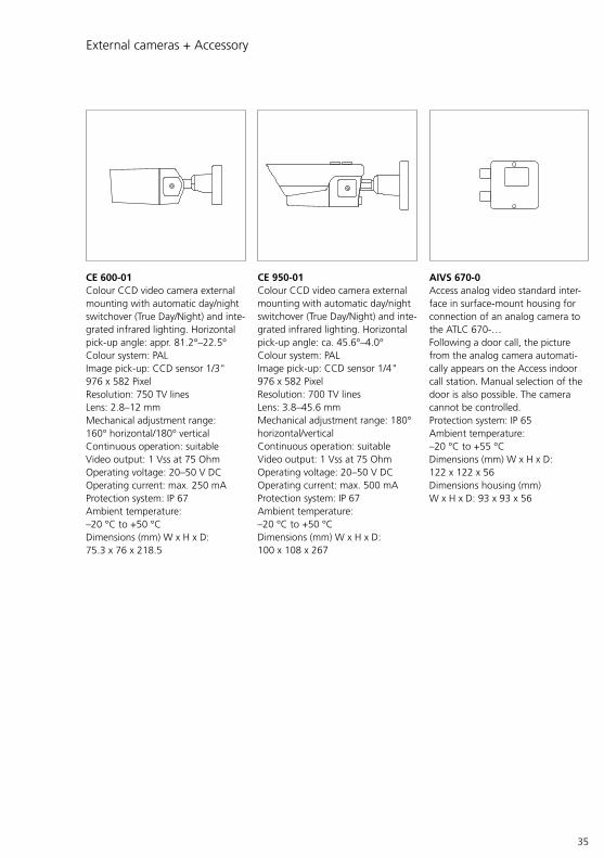
CE 950-01 Colour CCD video camera external mounting with automatic day/night switchover (True Day/Night) and inte-grated infrared lighting. Horizontal pick-up angle: ca. 45.6°–4.0°Colour system: PALImage pick-up: CCD sensor 1/4" 976 x 582 PixelResolution: 700 TV linesLens: 3.8–45.6 mmMechanical adjustment range: 180° horizontal/verticalContinuous operation: suitableVideo output: 1 Vss at 75 OhmOperating voltage: 20–50 V DCOperating current: max. 500 mAProtection system: IP 67Ambient temperature: –20 °C to +50 °CDimensions (mm) W x H x D: 100 x 108 x 267
CE 600-01 Colour CCD video camera external mounting with automatic day/night switchover (True Day/Night) and inte-grated infrared lighting. Horizontal pick-up angle: appr. 81.2°–22.5°Colour system: PALImage pick-up: CCD sensor 1/3" 976 x 582 PixelResolution: 750 TV linesLens: 2.8–12 mmMechanical adjustment range: 160° horizontal/180° verticalContinuous operation: suitableVideo output: 1 Vss at 75 OhmOperating voltage: 20–50 V DCOperating current: max. 250 mAProtection system: IP 67Ambient temperature: –20 °C to +50 °CDimensions (mm) W x H x D: 75.3 x 76 x 218.5
External cameras + Accessory
AIVS 670-0 Access analog video standard inter-face in surface-mount housing for connection of an analog camera to the ATLC 670-…Following a door call, the picture from the analog camera automati-cally appears on the Access indoor call station. Manual selection of the door is also possible. The camera cannot be controlled. Protection system: IP 65Ambient temperature: –20 °C to +55 °CDimensions (mm) W x H x D: 122 x 122 x 56Dimensions housing (mm) W x H x D: 93 x 93 x 56

36
ATLM 670-0 Access door loudspeaker module for Siedle Vario with integrated loudspeaker and microphone.Performance features:• Front grille made of weather and UV-resistant polycarbonate• Loudspeaker, voice volume can be adjusted• Durable electret microphone• Light button with LED-lit light symbol• Connection of a ZAM 670-… status display module for optical and acoustic signalling of the operating state• Acoustic feedback when pressing a call button can be activatedUp to max. 48 call button modules can be connected in any combina-tion, allowing up to max. 192 call buttons to be connected.Ambient temperature: –20 °C to +55 °CProtection system: IP 54Height of structure (mm): 9Dimensions (mm) W x H x D: 99 x 99 x 35
The ATLM 670-0 draws 48 V DC over terminals S1-S4 from the ATLC/NG 670-0. This converts the voltage into 15 V DC with max. 400 mA and outputs this to terminals b1 and c1 of the terminal block.Within the door station, only the intended components may be supplied via the terminals b1 and c1.
ATLE 670-0 Access custom-fit door loudspeaker with bus call button matrix for instal-lation in the customer’s intercom compartments, door constructions, letterboxes, etc.Up to 12 of the customer’s call but-tons can be directly connected to the BRMA 050-… bus call button matrix.Performance features:• Loudspeaker• Durable electret microphone• Connection of a ZAM 670-… status display module for optical and acoustic signalling of the operating state• Control output for external camera• Universal fastening options, when used with the ZJ 051-… grille, it can be screwed onto this directlyMax. 16 BRMA 050-… can be con-nected to 1 ATLE 670-…Protection system: Dependent on the mounting conditionsDimensions (mm) W x H x D: ATLE 670-0 124 x 60 x 31, BRMA 050-01 53 x 100 x 17Dimensions housing (mm) W x H x D: 100 x 60 x 31
5 System componentsDoor loudspeaker
ATLM 671-0Access door loudspeaker module Plus for Siedle Vario with integrated loudspeaker and microphone, as well as additional audio amplifier and noise filter.Performance features:• Front grille made of weather and UV-resistant polycarbonate (via the Access server)• Loudspeaker, voice volume can be adjusted• Voice volume can be doubled via the audio amplifier• Durable electret microphone• Light button with LED-lit light symbol• Connection of a ZAM 670-… status display module for optical and acoustic signalling of the operating state is possible• Acoustic feedback when pressing a call button can be activatedAmbient temperature: –20 °C to +55 °CProtection system: IP 54Height of structure (mm): 9Dimensions (mm) W x H x D: 99 x 99 x 35
The ATLM 671-0 draws 48 V DC over terminals S1-S4 from the ATLC/NG 670-0. This converts the voltage into 15 V DC with max. 400 mA and outputs this to terminals b1 and c1 of the terminal block.Within the door station, only the intended components may be supplied via the terminals b1 and c1.
37
Status display module
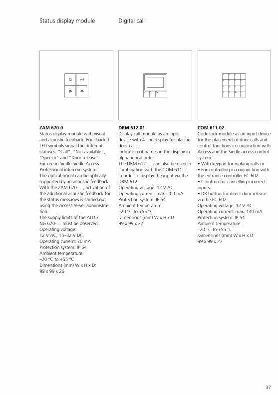
ZAM 670-0 Status display module with visual and acoustic feedback. Four backlit LED symbols signal the different statuses: “Call”, “Not available”, “Speech” and “Door release”.For use in Siedle Siedle Access Professional intercom system.The optical signal can be optically supported by an acoustic feedback.With the ZAM 670-…, activation of the additional acoustic feedback for the status messages is carried out using the Access server administra-tion.The supply limits of the ATLC/NG 670-… must be observed.Operating voltage: 12 V AC, 15–32 V DCOperating current: 70 mAProtection system: IP 54Ambient temperature: –20 °C to +55 °CDimensions (mm) W x H x D: 99 x 99 x 26
DRM 612-01 Display call module as an input device with 4-line display for placing door calls.Indication of names in the display in alphabetical order. The DRM 612-… can also be used in combination with the COM 611-… in order to display the input via the DRM 612-…Operating voltage: 12 V ACOperating current: max. 200 mAProtection system: IP 54Ambient temperature: –20 °C to +55 °CDimensions (mm) W x H x D: 99 x 99 x 27
COM 611-02 Code lock module as an input device for the placement of door calls and control functions in conjunction with Access and the Siedle access control system.• With keypad for making calls or• For controlling in conjunction with the entrance controller EC 602-…• C button for cancelling incorrect inputs• DR button for direct door release via the EC 602-…Operating voltage: 12 V ACOperating current: max. 140 mAProtection system: IP 54Ambient temperature: –20 °C to +55 °CDimensions (mm) W x H x D: 99 x 99 x 27
Digital call
1 2 3
4 5 6
F 0 C
7 8 9
OK
38
5 System componentsDigital call
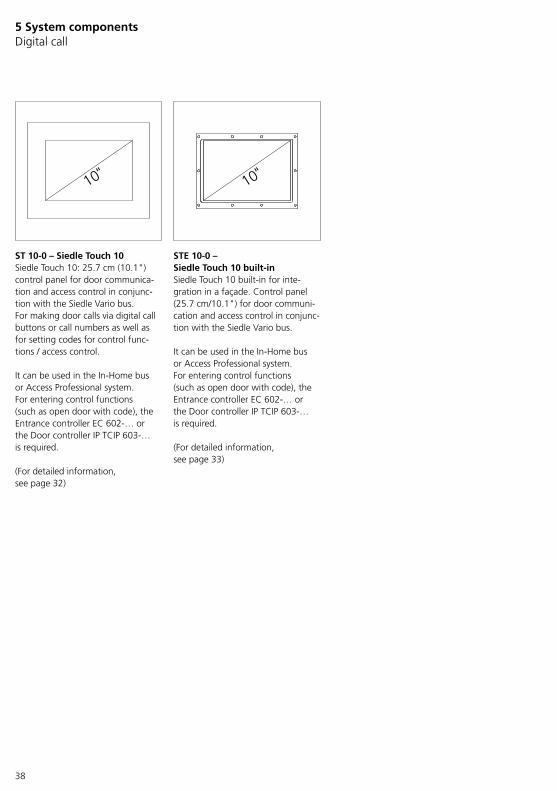
ST 10-0 – Siedle Touch 10Siedle Touch 10: 25.7 cm (10.1") control panel for door communica-tion and access control in conjunc-tion with the Siedle Vario bus.For making door calls via digital call buttons or call numbers as well as for setting codes for control func-tions / access control.
It can be used in the In-Home bus or Access Professional system.For entering control functions (such as open door with code), the Entrance controller EC 602-… or the Door controller IP TCIP 603-… is required.
(For detailed information, see page 32)
STE 10-0 – Siedle Touch 10 built-inSiedle Touch 10 built-in for inte-gration in a façade. Control panel (25.7 cm/10.1") for door communi-cation and access control in conjunc-tion with the Siedle Vario bus.
It can be used in the In-Home bus or Access Professional system.For entering control functions (such as open door with code), the Entrance controller EC 602-… or the Door controller IP TCIP 603-… is required.
(For detailed information, see page 33)

39
BTM 650-01 to -04 Bus call button modules BTM 650-… with 1, 2, 3 or 4 call buttons. The BTM 650-… is connected to the ATLM 670-… via ribbon cable.Nameplate size (mm) W x H: 65 x 19.5Call button (mm) W x H: 24 x 24Protection system: IP 54Ambient temperature: –20 °C to +55 °CDimensions (mm) W x H x D: 99 x 99 x 27
PME-… Mail notification system for signal-ling incoming post on any Access indoor station.The mail notification system must be taken into account during planning for the letterbox system, as it is no longer technically possible to retrofit it later on.To use this function, the relevant indoor station must be configured via the Access administration inter-face.
TÖ-… (Door release) Siedle door release units are high-resistance > 20 Ohm and provide operating reliability even over long ranges.Standard commercially available door release units 8 – 12 V AC, 20 Ohm can be connected.
BRMA 050-01 Bus call button matrix for con-necting 12 on-site call buttons to the BTLE 050-…/ATLE 670-… custom-fit door loudspeaker.Max. 160 call buttons can be con-nected. However, a bus call button matrix BRMA 050-… is required for each started group of 12 call but-tons.Max. 14 BRMA 050-… can be connected to 1 BTLE 050-…Max. 16 BRMA 050-… can be connected to 1 ATLE 670-…
The connection of the call buttons for Siedle Classic is described in the call button wiring diagram.(For detailed information, see page 106)
Call buttons System upgrading
40
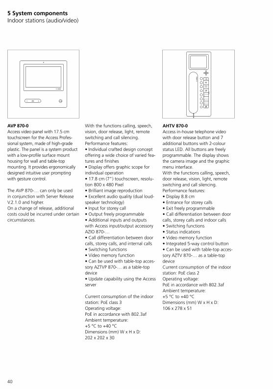
AVP 870-0 Access video panel with 17.5 cm touchscreen for the Access Profes-sional system, made of high-grade plastic. The panel is a system product with a low-profile surface mount housing for wall and table-top mounting. It provides ergonomically designed intuitive user prompting with gesture control.
The AVP 870-… can only be used in conjunction with Server Release V.2.1.0 and higher.On a change of release, additional costs could be incurred under certain circumstances.
With the functions calling, speech, vision, door release, light, remote switching and call silencing.Performance features:• Individual crafted design concept offering a wide choice of varied fea-tures and finishes• Display offers graphic scope for individual operation • 17.8 cm (7") touchscreen, resolu-tion 800 x 480 Pixel• Brilliant image reproduction• Excellent audio quality (dual loud-speaker technology)• Input for storey call• Output freely programmable• Additional inputs and outputs with Access input/output accessory AZIO 870-…• Call differentiation between door calls, storey calls, and internal calls• Switching functions• Video memory function• Can be used with table-top acces-sory AZTVP 870-… as a table-top device• Update capability using the Access server
Current consumption of the indoor station: PoE class 3Operating voltage: PoE in accordance with 802.3afAmbient temperature: +5 °C to +40 °CDimensions (mm) W x H x D: 202 x 202 x 30
AHTV 870-0 Access in-house telephone video with door release button and 7 additional buttons with 2-colour status LED. All buttons are freely programmable. The display shows the camera image and the graphic menu interface.With the functions calling, speech, door release, vision, light, remote switching and call silencing.Performance features:• Display 8.8 cm• Entrance for storey calls• Exit freely programmable• Call differentiation between door calls, storey calls and indoor calls• Switching functions• Status indications• Video memory function• Integrated 5-way control button• Can be used with table-top acces-sory AZTV 870-… as a table-top deviceCurrent consumption of the indoor station: PoE class 2Operating voltage: PoE in accordance with 802.3afAmbient temperature: +5 °C to +40 °CDimensions (mm) W x H x D: 106 x 278 x 51
5 System componentsIndoor stations (audio/video)

41
AHT 870-0 Access in-house telephone with door release button and 7 additional but-tons with 2-colour status LED. All buttons are freely programmable. The display shows the graphic menu interface, but not a camera image. It is possible to upgrade to a fully functional video station.With the functions calling, speech, door release, light, remote switching and call barring.With the additional purchase of the AUV 870-… T, the AHT 870-… can be transformed into a fully valid video indoor device.Performance features:• Display 8.8 cm• Input for storey call• Output freely programmable• Call differentiation between door calls, storey calls, and internal calls• Switching functions• Status messages• Can be used with table-top acces-sory AZTV 870-… as a table-top deviceCurrent consumption of the indoor station: PoE class 2Operating voltage: PoE in accordance with 802.3afAmbient temperature: +5 °C to +40 °CDimensions (mm) W x H x D: 106 x 278 x 51
AHFV 870-0 Access handsfree telephone video with speech/control button, door release button and 7 additional but-tons with 2-colour status LED. All buttons are freely programmable. The display shows the camera image and the graphic menu interface.With the functions calling, speech, door release, vision, light, remote switching and call silencing. Performance features:• Display 8.8 cm• Entrance for storey calls• Exit freely programmable• Call differentiation between door calls, storey calls and indoor calls• Switching functions• Status indications• Video memory function• Integrated 5-way control button• Can be used with table-top acces-sory AZTV 870-… as a table-top deviceCurrent consumption of the indoor station: PoE class 2Operating voltage: PoE in accordance with 802.3afAmbient temperature: +5 °C to +40 °CDimensions (mm) W x H x D: 106 x 278 x 32
AHF 870-0 Access handsfree telephone with speech/control button, door release button and 7 additional buttons with 2-colour status LED. All buttons are freely programmable. The display shows the graphic menu interface, but not a camera image. It is pos-sible to upgrade to a fully functional video station.With the functions calling, speech, door release, light, remote switching and call barring.With the additional purchase of the AUV 870-… F, the AHF 870-… can be transformed into a fully valid video indoor device.Performance features:• Display 8.8 cm• Input for storey call• Output freely programmable• Call differentiation between door calls, storey calls, and internal calls• Switching functions• Status messages• Can be used with table-top acces-sory AZTV 870-… as a table-top deviceCurrent consumption of the indoor station: PoE class 2Operating voltage: PoE in accordance with 802.3afAmbient temperature: +5 °C to +40 °CDimensions (mm) W x H x D: 106 x 278 x 32
42
AUV 870-0 T/F Access upgrade video subsequently enables the video function in an audio device.For the in-house telephone AHT 870-…, the AUV 870-0 T is required / for the handsfree telephone AHF 870-…, the AUV 870-0 F.
5 System componentsAccessory
AZTV 870-0 Access table-top accessory for Access in-house and handsfree telephones for conversion from wall mounted to table-top device, slip-proof console.Connecting cable: 2 x 8-core 3 m long with RJ45 plug
AZA 870-0 Access surface-mounting accessory for professional surface mounting of Access in-house and handsfree telephones.Comprises a connection adapter and 4 spacers. The raised height is increased by 8 mm.
AZIO 870-0 Access input/output accessory as circuit board for integration in an indoor unit with an additional input/output.Switching output:n.o. contact 30 V AC/DC, 1 ASwitching input for potential-free contacts (min. 20 V DC, 10 mA)
AZTVP 870-0 Table-top accessory for the video panel AVP 870-… for conversion from a wall to a table unit.Performance features:• Individual design concept with 3 design variants• Slip-proof table foot• Cable guide• 2 connecting cables with RJ45 plugConnecting cable: 2 x 8-core 3 m long with RJ45 plug
ZRE 600-0 19 inch rack mounting accessory for the Access Server S and the TCIP server. Comprising retaining plate including mounted handles and mounting accessories.Dimensions (mm) W x H x D: 483 x 88 x 132
TopOben

43
ATLC/NG 670-0 Access door loudspeaker controller with line rectifier in switch panel housing as an interface for the connection and power supply of door components to the Access Professional network.
Set consisting of ATLC 670-0 and ANG 600-0.
ATLC 670-0 Access door loudspeaker controller in switch panel housing as interface for connecting the door station to a network.Switch contact for door release and freely programmable switching input.Optional connection facility for a maximum of 3 extension modules ATLCE 670-…Supply via ANG 600-0Supply voltage 48 V DCOutput voltage: 10–16 V AC/DCOutput current: max. 700 mA AC/300 mA DCContact type: Contact 30 V, 2 AProtection system: IP 20Ambient temperature: 0 °C to +40 °CHorizontal pitch (HP): 6Dimensions (mm) W x H x D: 107 x 89 x 60
Storey callWith Access Professional V. 4.2.0 and above, each switching input can be configured for the storey call function.
Distribution components – Door controller
ANG 600-0 Access line rectifier in switch panel housing with 230 V AC switching contact.Admissible switching output:• Light bulbs max. 1300 W• Fluorescent lamps max. 800 W• Twin fluorescent lamps max. 1200 W• Parallel compensated fluorescent lamps max. 400 WOperating voltage: 100–240 V AC, +/-10 %, 50/60 HzOperating current: 0.5–1 AOutput voltage: 48 V DCOutput current: 800 mAFusing: primary thermal fuse, secondary short circuit proofContact type: changeover switch max. 250 V AC, 6 AProtection system: IP 20Ambient temperature: 0 °C to +40 °CHorizontal pitch (HP): 6Dimensions (mm) W x H x D: 107 x 89 x 60

44
ATLCE 670-0 Access door loudspeaker controller extension in switch panel housing with 4 outputs and 2 inputs.A maximum of 3 ATLCE 670-… units can be connected in series to an ATLC 670-… by means of ribbon cable.Protection system: IP 20Ambient temperature: 0 °C to +40 °CHorizontal pitch (HP): 3Dimensions (mm) W x H x D: 53.5 x 89 x 60
AVA 670-0 Access video decoupler in switch panel housing. Permits the decou-pling of an analogue video signal from the Access Professional system.Operating voltage: 10–50 V DCOperating current: max. 25 mAProtection system: IP 20Ambient temperature: 0 °C to +40 °CHorizontal pitch (HP): 3Dimensions (mm) W x H x D: 53.5 x 89 x 60
ZWA 640-0 Western socket accessory for switch panel mounting. Integrated socket for 4/6/8-pin western plug.Connection by means of screw-type terminals.Protection system: IP 20Ambient temperature: 0 °C to +40 °CHorizontal pitch (HP): 1Dimensions (mm) W x H x D: 18 x 90 x 60
5 System componentsDistribution components – Active/passive system expansion

45
DSC 602-0 (Siedle Vario)Pilfer safeguard controller in a switch panel housing to control a maximum of 2 pilfer safeguard accessories ZDS 601-…At one DSC 602-…, a maximum of two ZDS 601-… units can be con-nected, allowing up to four modules to be secured through a DSC 602-… . Locking is only possible with the Vario key removed. In order to guarantee reliable switching of the DSC 602-…, the buttons must be actuated for at least 1 second. A pause of at least 5 seconds must elapse between two actuations. After every mounting frame locking process using the DSC 602-… the Vario door station must be checked with the Vario key without fail, as the integrated LED does not include status monitoring.Using 2 integrated buttons, the mounting frame can be locked and unlocked. An LED flashes to indi-cate that the release button at the DSC 602-… has been activated. It is only possible to lock the mounting frame after removing the Vario key.Operating voltage: 12 V ACOperating current: max. 100 mAProtection system: IP 20Ambient temperature: 0 °C to +40 °CHorizontal pitch (HP): 3Dimensions (mm) W x H x D: 53.5 x 89 x 60
Distribution components – Anti-pilfer controller
ZDS/CL (Siedle Classic)Anti-pilfer accessory for mounting in the Siedle Classic door station as a concealed electromagnetic locking mechanism to secure the mounting screws.With anti-pilfer controller SDSC 602-01 in switch panel housing, for actuation of the anti-pilfer accessory ZDS/CL (for 1 pair), with status LED.This can be mounted in any system with one or more function modules, in vertical arrangement.For mounting in the door station as a concealed electromagnetic locking mechanism for the control panel.Operating voltage: 12 V ACOperating current: max. 850 mAProtection system: IP 20Ambient temperature: SDSC 602-01 0 °C to +40 °C, Locking –20 °C to +55 °CHorizontal pitch (HP): 3Dimensions (mm) W x H x D: SDSC 602-01 53.5 x 89 x 60, Locking 25 x 70 x 32
ZDS 601-0 (Siedle Vario)Anti-pilfer accessory with bistable magnet for integration into mounting frame MR 611-…A stable metal plate is used to lock the release mechanism and prevents the removal of function modules.Ambient temperature: –20 °C to +55 °CDimensions (mm) W x H x D: 22.4 x 9 x 13.5

46
VNG 602-02 Video line rectifier in switch panel housing for centrally supplying video door intercom systems or for sup-plying additional components (e.g. external camera).Operating voltage: 230 V AC, +/-10 %, 50/60 HzOperating current: 250 mAOutput voltage: 30 V DCOutput current: 1.1 AFusing: Si 1 T 315 mA, secondary side thermal fuseProtection system: IP 20Ambient temperature: 0 °C to +40 °CHorizontal pitch (HP): 10Dimensions (mm) W x H x D: 180 x 89 x 60
NG 602-01 Line rectifier in switch panel housing for supplying additional components (e.g. external camera).Operating voltage: 230 V AC, +/-10 %, 50/60 HzOperating current: 200 mAOutput voltage: 23.3 V DC, 12 V ACOutput current: 0.3 A DC, 1.6 A ACFusing: primary Si1 T 200 mA L, secondary side with thermal fuseProtection system: IP 20Ambient temperature: 0 °C to +40 °CHorizontal pitch (HP): 6Dimensions (mm) W x H x D: 107 x 89 x 60
5 System components Distribution components – Line rectifiers
ANG 600-0 Access line rectifier in switch panel housing with 230 V AC switching contact.Admissible switching output:• Light bulbs max. 1300 W• Fluorescent lamps max. 800 W• Twin fluorescent lamps max. 1200 W• Parallel compensated fluorescent lamps max. 400 WOperating voltage: 100–240 V AC, +/-10 %, 50/60 HzOperating current: 0.5–1 AOutput voltage: 48 V DCOutput current: 800 mAFusing: primary thermal fuse, secondary short circuit proofContact type: changeover switch max. 250 V AC, 6 AProtection system: IP 20Ambient temperature: 0 °C to +40 °CHorizontal pitch (HP): 6Dimensions (mm) W x H x D: 107 x 89 x 60
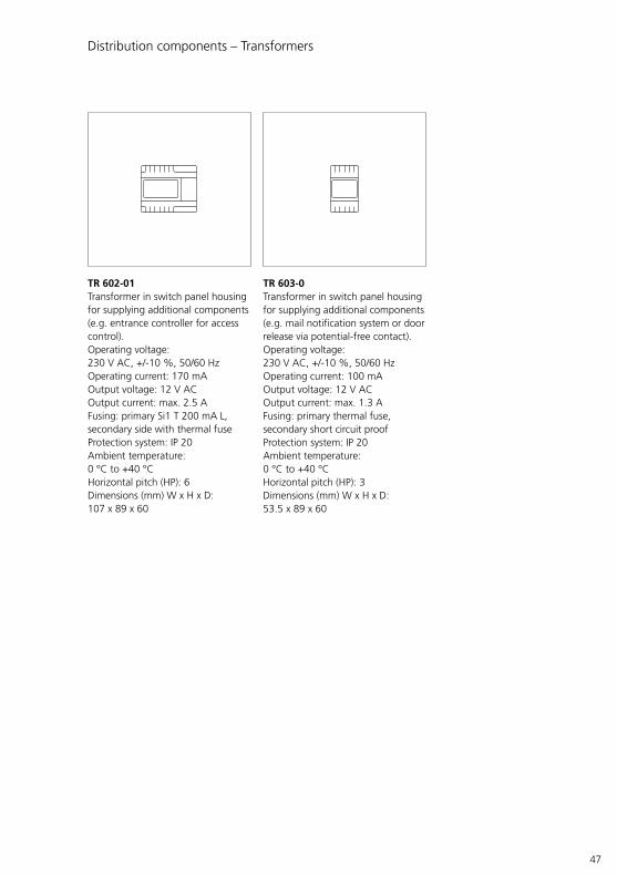
47
TR 602-01Transformer in switch panel housing for supplying additional components (e.g. entrance controller for access control).Operating voltage: 230 V AC, +/-10 %, 50/60 HzOperating current: 170 mAOutput voltage: 12 V ACOutput current: max. 2.5 AFusing: primary Si1 T 200 mA L, secondary side with thermal fuseProtection system: IP 20Ambient temperature: 0 °C to +40 °CHorizontal pitch (HP): 6Dimensions (mm) W x H x D: 107 x 89 x 60
TR 603-0Transformer in switch panel housing for supplying additional components (e.g. mail notification system or door release via potential-free contact).Operating voltage: 230 V AC, +/-10 %, 50/60 HzOperating current: 100 mAOutput voltage: 12 V ACOutput current: max. 1.3 AFusing: primary thermal fuse, secondary short circuit proofProtection system: IP 20Ambient temperature: 0 °C to +40 °CHorizontal pitch (HP): 3Dimensions (mm) W x H x D: 53.5 x 89 x 60
Distribution components – Transformers

48
5 System components Space requirements in distribution boards/IT cabinets (19 inch)
Space required (height) in IT cabinet system/housing (19 inch)
Models Rack units (RU)
ASH 670-05 M 2
ASH 670-05 S * (2)
* with rack installation kit: ZRE 600-0 2
1 RU = 44,45 mm
Please make sufficient provisions in the electrical distribution boards/IT cabinet system for later expansion, changes or subsequent disassembly (service/maintenance).All system components which are designed for/suitable for installation in an electrical distribution board or in an IT cabinet system/housing may only be installed in the permitted installation position according to the enclosed product information. If system components are operated in improper installation positions or with improper operating parameters (e.g. excessive ambient tempera-ture), this will render their warranty rights void in the event of service.During planning, take the applicable legal provisions, standards, directives and safety instructions for the opera-tion/installation site into account.
Space requirement (width) in the distribution
Models Horizontal pitches (HP)
ANG 600-0 6
ATLC 670-0 6
ATLCE 670-0 3
ATLC/NG 670-0 2 x 6 HP
AVA 670-0 3
NG 602-01 6
TR 602-01 6
TR 603-0 3
VNG 602-02 10
1 HP = 18 mm

49
Access server variants
Access Professional Access system software for installa-tion and operation on existing server hardware/virtualization with installed server operating system according to requirements. An Access user licence is required for standard operation.In order to use all the functions of Access Professional correctly as a software variant, the provided server hardware/virtual machine and the network infrastructure must meet the minimum requirements of the Access system. For detailed informa-tion, see page 51.
ASH 670-05 MAccess Server hardware M for the IP-based building communication system Siedle Access Professional for up to 640 users. An Access user licence is required for the regular use of Access Server hardware.Version in a housing for IT cabinet systems (482.6 mm / 19") – space requirement (height): 2 rack units (RU).Scope of supply: Access Server hardware in 19" housing incl. pre-installed server operating system GNU/Linux Debian… and Access Professional with 30-day test licence as well as electrical connecting cable and small mounting items for installation in an existing 19" IT cabinet system.Components:CPU: Intel Xeon E-2124GWorking memory: 4 GB SO-DIMM DDR4 2400 MHzGraphics: OnboardHard disc: 256 GB SSDLAN: 2 x gigabitOperating voltage: 90–264 V AC, 47–63 HzTypical current consumption: max. 78 WAmbient temperature: +10 °C to +50 °CDimensions (mm) W x H x D: 463 x 88 x 460
NoteIn the as-delivered status, the DHCP server of the Siedle Access Server is active.
ASH 670-05 SAccess Server hardware S for the IP-based building communication system Siedle Access Professional for up to 50 users. An Access user licence is required for the regular use of Access Server hardware.Version in a metal housing. Capable of integration in the existing IT landscape (with optional accessory ZRE 600-0 rack installation kit (486.6mm/19") – space require-ment (height): 2 rack units (RU)).Scope of supply: Access Server hardware in desktop housing incl. pre-installed server operating system GNU/Linux Debian… and Access Professional with 30-day test licence as well as electrical connecting cable.Components:CPU: Intel Atom C3338Working memory: 4 GB DDR4 2400 MHzGraphic: OnboardHard disc: 128 GB SSDLAN: 2 x gigabitOperating voltage: 90–264 V AC, 47–63 HzTypical current consumption: max. 45 WAmbient temperature: +10 °C to +50 °CDimensions (mm) W x H x D: 328 x 88,8 x 201
NoteIn the as-delivered status, the DHCP server of the Siedle Access Server is active.

50
Access server variant Access Professional ASH 670-05 M ASH 670-05 S
Versions Software without server operating system/virtualization
Hardware server + pre-installed Access Professional
Hardware server + pre-installed Access Professional
Access system version Access Professional V 5… Access Professional V 5… Access Professional V 5…
Possible number of users (User licences)
10–640 10–640 10–50
Possible number of communication con-nections (simultane-ously)
25(Call signalling of up to 50 devices)
25(Call signalling of up to 50 devices)
10(Call signalling of up to 20 devices)
Conditions • Hardware server / virtualization• Server operating system (Debian Linux… (Stretch) / MS Server 2012 R2 Standard/Datacenter / Windows Server 2016 Standard/Datacenter)• Microsoft .NET Framework 4.6.1 for Windows Server 2012 R2 (offline installer or web installer if internet connection exists).• Network/VLAN as required• Indoor stations with POE supply • Software clients on terminals with network connection
• Network/VLAN as required• Indoor stations with POE supply • Software clients on terminals with network connection
• Network/VLAN as required• Indoor stations with POE supply • Software clients on terminals with network connection
As-delivered status • The Access server must be installed and commissioned.• User and application licences are needed for operating the Access system.• After the basic parameters have been saved, a 30-day test period begins with the initial commissioning during which all system functions with a maximum number of devices can be used without restriction.• The server hardware/virtualization and server operating system must be provided by the customer and must be available.• Microsoft licences: Please check whether any Microsoft server access licences (Client Access License – CAL) are required by the customer for operation of the Access users, or whether these already exist.(For detailed information, see Planning and System Manual Access Professional)
• The Access server is installed ready for operation and prepared for commissioning by the customer.• User and application licences are needed for oper-ating the Access system.• After the basic parameters have been saved, a 30-day test period begins with the initial commis-sioning during which all system functions with a maximum number of devices can be used without restriction.
RemarkThe standard login data for the server operating system of a Access Server Hardware (from ASH 670-05…) are:
User Password * SSH loginroot SiedleAccessMain2019 –
access SiedleAccessMain2015 Active
* Please change the password on initial commis-sioning, taking note of the security instructions.
5 System components A comparison of Access server variants
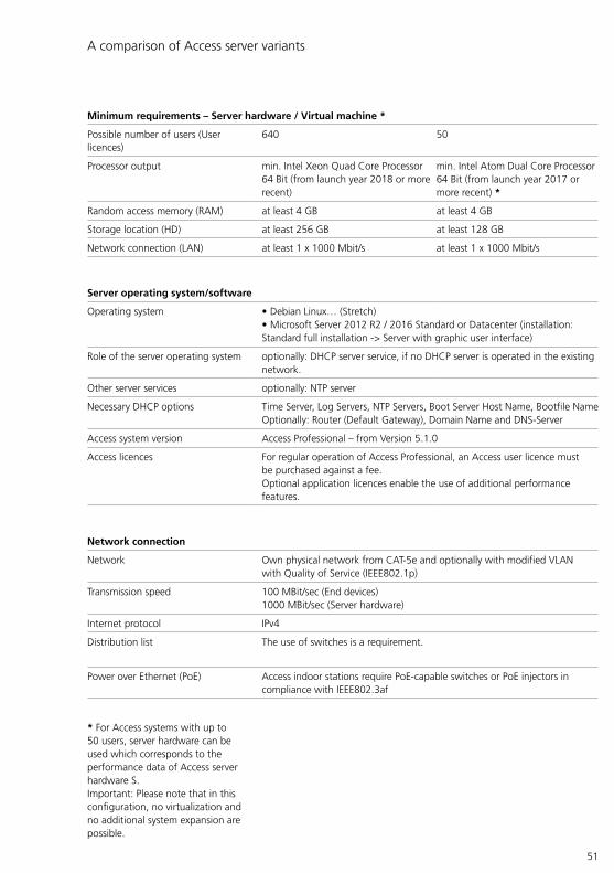
51
A comparison of Access server variants
Minimum requirements – Server hardware / Virtual machine *
Possible number of users (User licences)
640 50
Processor output min. Intel Xeon Quad Core Processor 64 Bit (from launch year 2018 or more recent)
min. Intel Atom Dual Core Processor 64 Bit (from launch year 2017 or more recent) *
Random access memory (RAM) at least 4 GB at least 4 GB
Storage location (HD) at least 256 GB at least 128 GB
Network connection (LAN) at least 1 x 1000 Mbit/s at least 1 x 1000 Mbit/s
Server operating system/software
Operating system • Debian Linux… (Stretch)• Microsoft Server 2012 R2 / 2016 Standard or Datacenter (installation: Standard full installation -> Server with graphic user interface)
Role of the server operating system optionally: DHCP server service, if no DHCP server is operated in the existing network.
Other server services optionally: NTP server
Necessary DHCP options Time Server, Log Servers, NTP Servers, Boot Server Host Name, Bootfile NameOptionally: Router (Default Gateway), Domain Name and DNS-Server
Access system version Access Professional – from Version 5.1.0
Access licences For regular operation of Access Professional, an Access user licence must be purchased against a fee.Optional application licences enable the use of additional performance features.
Network connection
Network Own physical network from CAT-5e and optionally with modified VLAN with Quality of Service (IEEE802.1p)
Transmission speed 100 MBit/sec (End devices)1000 MBit/sec (Server hardware)
Internet protocol IPv4
Distribution list The use of switches is a requirement.
Power over Ethernet (PoE) Access indoor stations require PoE-capable switches or PoE injectors in compliance with IEEE802.3af
* For Access systems with up to 50 users, server hardware can be used which corresponds to the performance data of Access server hardware S.Important: Please note that in this configuration, no virtualization and no additional system expansion are possible.

52
System conditions Access Professional In order to use all the functions of Access Professional correctly as a software variant, the provided server hardware/virtual machine and the network infrastructure must meet the minimum requirements of the Access system.
RemarksIn order to work with Access Server Administration, you need an PC with the latest version of the web browser Google Chrome / Microsoft Edge / Mozilla Firefox.If you use a different web browser, display errors can occur.
Important!Avoid operating further applica-tions and server services on the server operating system intended for Siedle Access. This can lead to performance impairments and mal-functions.
Additional requirements imposed on virtualization • For virtualization, from VMware vSphere 6 upwards a virtualization solution configured for server systems must be used.• The minimum requirements imposed on the virtual machine are the same on principle as server hard-ware provided by the customer for up to 640 devices. With the virtual machine, remember that at least 2 virtual and separate processor units (CPUs) must be made available.• If virtualization is used, the host (physically present server on which the virtual machine is operated) must have sufficient performance to make available the output needed for the virtual machine.
RemarksThe size of the hard disk storage capacity which should be selected depends on various factors when using a virtualization solution:• Number of groups and terminals• Utilization scenario and incidence of communication• Activated video memory func-tion: If no video memory function is used, we recommend a hard disk storage capacity of at least 30 Gigabytes. When using the video memory function, please contact the Access Service Center to be advised on the minimum capacity required for the hard disk memory.• For Access systems with up to 50 users, server hardware can be used which corresponds to the performance data of Access server hardware S.• Important: Please note that in this configuration, no virtualization and no additional system expansion are possible.
Virtualization 5 System components System conditions
53
Upgrade (server)
ASU 670-05 Access Server upgrade for upgrading existing Access Server hardware with Access server software V. 4… to Access Professional V. 5.0.0.The Access server upgrade can be purchased exclusively through an Access Certified Partner. To place the order, the serial number of the server hardware and the hardware ID of the existing access system are required. The upgrade may only be performed by an Access Certified Partner (ACP) or by the Access Service Center (ASC).Existing licences for the previous Access system remain valid, but must be converted.
www.siedle.de/access

54
ASHT 170-0 Access application licence “Access in-house telephone software” for the operation of ASHT software on the Access Professional system. The ASHT enables audio and video door communication via Windows-based PCs or control panels.Function overview:• Call differentiation between door calls, storey calls and indoor calls• Device and user overview • Users, doors and devices can be selected from lists• Global contact list• Status displays of switchgear • Switching functions via ATLC/ATLCE or KNXSystem requirements:• Microsoft® Windows 8, 8.1, 10• Microsoft® .NET Framework 4.6.2 or later• Microsoft® VC++ 2015 Redistributable Package (x86)• Microsoft® Media Feature Pack (Windows N and KN editions only)• At least Microsoft® DirectX® 9.0c
• CPU: Dual-Core from 2.0 GHz• At least 2 GB RAM• Graphics card with at least 1280 x 800 pixel, 128 MB RAM• Ethernet card/Network connection: 100 Mbit• Sound card
ASC 170-0 Access application licence “Access Software Concierge” for the opera-tion of the ASC software on the Access Professional system.The ASC is the central communica-tion interface at the reception.Function overview:• Several audio and video links can be depicted simultaneously• Convenient forwarding functions • Music-on-hold• Status overview of all Doormatic door statuses• Convenient switching/control and display functions• Global contact list (incl. personal contact management)• Camera scan function • Answering machine functionsSystem requirements:• Microsoft® Windows 8, 8.1, 10• Microsoft® .NET Framework 4.6.2 or later• Microsoft® VC++ 2015 Redistributable Package (x86)• Microsoft® Media Feature Pack (Windows N and KN editions only)• At least Microsoft® DirectX® 9.0c
• CPU: Dual-Core from 2.0 GHz• At least 2 GB RAM• Graphics card with at least 1280 x 800 pixel, 128 MB RAM• Ethernet card/Network connection: 100 Mbit• Sound card
Siedle App 5 System components Client-Software
Siedle App (As of Access 5.1)The Siedle app turns a smartphone (iOS, Android) into a mobile exten-sion of a door intercom system from Siedle, via the Siedle server. The app has been specially developed for the requirements of door communica-tion. It receives the door call, shows a live video feed (depending on the system), establishes a speech con-nection and opens the door. With built-in security and the ultimate in convenience. The video feed is available before the call is accepted. The speech quality fulfils Siedle’s stringent standards, and the door is opened by pressing the familiar key symbol.
The Siedle app is the mobile comple-ment to a door intercom system and does not replace an indoor device. For this reason, Siedle recommends always including a wired indoor sta-tion in your system planning along-side the app. The Siedle app is being continuously further developed. Current informa-tion on the functional scope and illustrations of the relevant valid ver-sion statuses are available in the App Store/Play Store.Equipped with consistent basic functionality, the interfaces of the apps for iOS and Android differ in certain details. The user interfaces of the apps can be viewed in the App Store/Play Store. The Siedle App is optimized for use on the iPhone, iPad and Android smartphone, and can be used on Android tablets - but not optimized for this.
www.siedle.de/access www.siedle.de/access
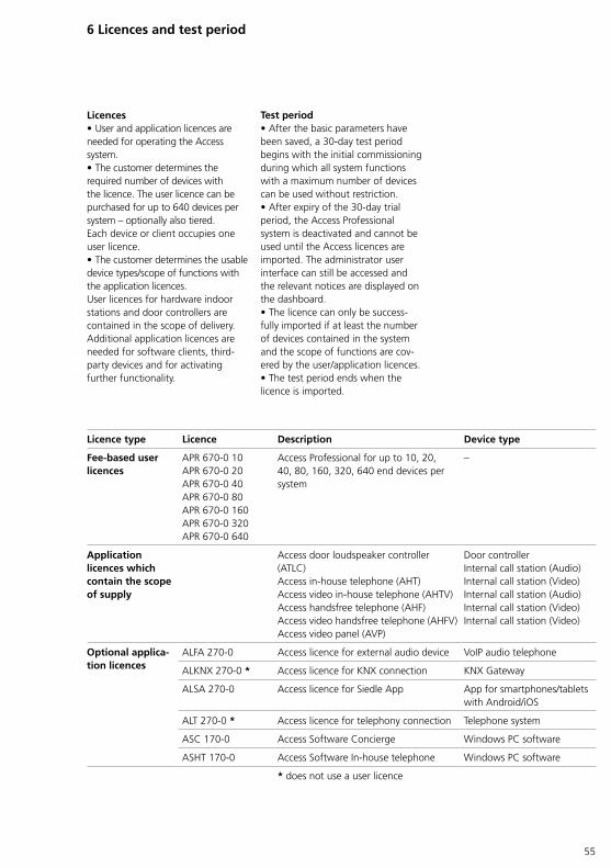
55
6 Licences and test period
Test period • After the basic parameters have been saved, a 30-day test period begins with the initial commissioning during which all system functions with a maximum number of devices can be used without restriction.• After expiry of the 30-day trial period, the Access Professional system is deactivated and cannot be used until the Access licences are imported. The administrator user interface can still be accessed and the relevant notices are displayed on the dashboard.• The licence can only be success-fully imported if at least the number of devices contained in the system and the scope of functions are cov-ered by the user/application licences.• The test period ends when the licence is imported.
Licences • User and application licences are needed for operating the Access system. • The customer determines the required number of devices with the licence. The user licence can be purchased for up to 640 devices per system – optionally also tiered.Each device or client occupies one user licence.• The customer determines the usable device types/scope of functions with the application licences. User licences for hardware indoor stations and door controllers are contained in the scope of delivery. Additional application licences are needed for software clients, third-party devices and for activating further functionality.
Licence type Licence Description Device type
Fee-based user licences
APR 670-0 10APR 670-0 20APR 670-0 40APR 670-0 80APR 670-0 160APR 670-0 320APR 670-0 640
Access Professional for up to 10, 20, 40, 80, 160, 320, 640 end devices per system
–
Application licences which contain the scope of supply
Access door loudspeaker controller (ATLC)Access in-house telephone (AHT)Access video in-house telephone (AHTV)Access handsfree telephone (AHF)Access video handsfree telephone (AHFV)Access video panel (AVP)
Door controllerInternal call station (Audio)Internal call station (Video)Internal call station (Audio)Internal call station (Video)Internal call station (Video)
Optional applica-tion licences
ALFA 270-0 Access licence for external audio device VoIP audio telephone
ALKNX 270-0 * Access licence for KNX connection KNX Gateway
ALSA 270-0 Access licence for Siedle App App for smartphones/tablets with Android/iOS
ALT 270-0 * Access licence for telephony connection Telephone system
ASC 170-0 Access Software Concierge Windows PC software
ASHT 170-0 Access Software In-house telephone Windows PC software
* does not use a user licence

56
6 Licences and test period
Access user licences
Licence type Description
APR 670-0 [xx]:• APR 670-0 10• APR 670-0 20• APR 670-0 40• APR 670-0 80• APR 670-0 160• APR 670-0 320• APR 670-0 640
An Access user licence is required for the regular use of Access Professional. The Access user licence allows Siedle Access Professional to be enabled and used in Version 5… for up to 640 terminals per system (optionally inclusive of licensed hardware indoor stations/door stations and/or optional hardware and software terminals to be licensed). Access user licences can be purchased for 10, 20, 40, 80, 160, 320 or 640 terminals and combined for up to 640 devices. The trial period for an Access system without a valid Access user licence ends after 30 days. Existing licences for the previous Access system remain valid, but must be converted.
Optional Access application licences
Licence type Description
Third-party audio device (ALFA 270-0)
Access application licence “Access licence for non-Siedle audio device” for the operation of a VoIP audio telephone on the Access Professional system.Using a VoIP-ATA adapter, it is also possible to connect an analog telephone.Third-party devices are subject to authorization by Siedle.
KNX link (ALKNX 270-0)
Access application licence “Access licence for KNX gateway” for the use of a KNX gateway on the Access Professional system. A separate licence is required per gateway.
Siedle App(ALSA 270-0)
Access application license “Access License for Siedle App” for the operation of a smartphone/tablet with Android/iOS on the Access Professional system. A license is required for each device with Siedle App installed.
Telephony link (ALT 270-0)
Access application licence “Access licence for telephony connection” for the use of an external connection channel on the Access Professional system.A separate licence is required per channel.Third-party devices are subject to authorization by Siedle.
Access software concierge(ASC 170-0)
Access application licence “Access Software Concierge” for the operation of the ASC software on the Access Professional system.The ASC is the central communication interface at the reception.A separate licence is required per client.(Currently only PCs/laptops/tablets with Windows 8, 8.1, 10)
Access in-house telephone(ASHT 170-0)
Access in-house telephone licence for connection of the software client in-house telephone to the Access system. A separate licence is required per client.(Currently only PCs/laptops/tablets with Windows 8, 8.1, 10)
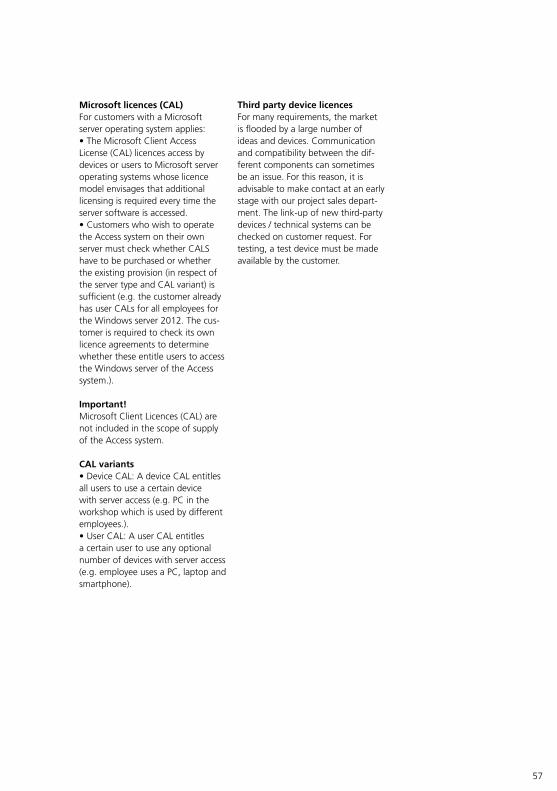
57
Third party device licences For many requirements, the market is flooded by a large number of ideas and devices. Communication and compatibility between the dif-ferent components can sometimes be an issue. For this reason, it is advisable to make contact at an early stage with our project sales depart-ment. The link-up of new third-party devices / technical systems can be checked on customer request. For testing, a test device must be made available by the customer.
Microsoft licences (CAL)For customers with a Microsoft server operating system applies:• The Microsoft Client Access License (CAL) licences access by devices or users to Microsoft server operating systems whose licence model envisages that additional licensing is required every time the server software is accessed.• Customers who wish to operate the Access system on their own server must check whether CALS have to be purchased or whether the existing provision (in respect of the server type and CAL variant) is sufficient (e.g. the customer already has user CALs for all employees for the Windows server 2012. The cus-tomer is required to check its own licence agreements to determine whether these entitle users to access the Windows server of the Access system.).
Important!Microsoft Client Licences (CAL) are not included in the scope of supply of the Access system.
CAL variants• Device CAL: A device CAL entitles all users to use a certain device with server access (e.g. PC in the workshop which is used by different employees.).• User CAL: A user CAL entitles a certain user to use any optional number of devices with server access (e.g. employee uses a PC, laptop and smartphone).

58
Procedure – Licence purchasing
Access Professional(Software variant)
ASH 670-05 M/S(Access server hardware + Access Professional)
Test periodAfter the basic parameters have been saved, a 30-day test period begins with the initial commis-sioning during which all system functions with a maximum number of devices can be used without restriction.For regular operation of Access Pro fessional, an Access user licence must be purchased against a fee.After expiry of the 30-day test period, the Access system is deacti-vated and cannot be used until the Access user licence is imported.Optional application licences enable the use of additional performance features.
Test periodAfter the basic parameters have been saved, a 30-day test period begins with the initial commis-sioning during which all system functions with a maximum number of devices can be used without restriction.For regular operation of Access Pro fessional, an Access user licence must be purchased against a fee.After expiry of the 30-day test period, the Access system is deacti-vated and cannot be used until the Access user licence is imported.Optional application licences enable the use of additional performance features.
Time of placement of orderThe Access user licence and optional application licences must be ordered from an Access Certified Partner after Access Professional has been started for initial commissioning and the hardware ID has been gener-ated. For licence orders, the hard-ware ID generated by the Access system is required.
Time of placement of orderThe Access user licence and optional application licences must be ordered from an Access Certified Partner after Access Professional has been started for initial commissioning and the hardware ID has been gener-ated. For licence orders, the hard-ware ID generated by the Access system is required.
Microsoft licencesFor customers with a Microsoft server operating system applies:Please check whether any Microsoft server access licences (Client Access License – CAL) are required by the customer for operation of the Access users, or whether these already exist. Microsoft Client Licences (CAL) are not included in the scope of supply of the Access server.
Microsoft licences –
6 Licences and test period
Licence purchasing • Customers and sales partners from Germany, please consult one of our Access Certified Partners. *• Customer and sales partners out-side Germany please contact your Siedle representative in your country.For detailed information, see page 156.
* Access Certified Partners (ACPs) are authorized to commission Access systems. They have proven their competency as planners and admin-istrators of Siedle Access systems, have passed audits and are certified by Siedle.Contact details are available on the internet at www.siedle.com/acp

59
7 Maintenance agreements
• For each Access system, Siedle offers optional maintenance agree-ments. The maintenance agree-ments include permanent software updating and regular updates for maintaining security and function-ality.• Maintenance contracts for the Siedle Access system can be pur-chased both through the Siedle Project Sales and through an Access Certified Partner (ACP).
• The maintenance period is initially 1 year after first commissioning of the Access server for all systems. After this, all customers can decide whether they wish to extend the maintenance period for their system by paying for an extended mainte-nance contract.• Alternatively, updates/upgrades must be purchased for a fee in cer-tain circumstances.
Maintenance contract recommendation
t1t0 t2t
A B C
t3
Periods Description Note
A Free warranty period 30-day test period and 1-year software maintenance
B Fee-based maintenance period Maintenance contract with 2-year minimum term
C Fee-based maintenance period Annual extension of the mainte-nance contract with 1-year term
Time pointst0 Initial commissioning of the Access
system and start of the 30-day unre-stricted test period
–
t1 Latest time point for the import of the Access licences and end of the test period
–
t2 Start of the fee-based maintenance period and end of the free warranty period
–
t3 Continuation of the fee-based maintenance period
–

60
8 Configuration – Access System 5…
* from Access-Server V 5.1… (Siedle App) / from Access-Server V 6… (Jung TKM Client) • = available- = Not available
ATL
C 6
70-…
AH
F 87
0-…
AH
FV 8
70-…
AH
T 87
0-…
AH
TV 8
70-…
AV
P 87
0-…
ASC
170
-…
ASH
T 17
0-…
Jung
TK
M C
lient
*
Sied
le A
pp *
SIP
audi
o te
leph
one
General
Name • • • • • • • • • • •
Description • • • • • • • • • • •
Call number (Internal) • • • • • • • • • • •
User name - - - - - - • • - - -
Password - - - - - - • • - - •
Directory - • • • • • • • - - •
Call Profile • • • • • • • • • - -
CTI device (via Drag&Drop) - - - - - - • • - - -
MAC address • • • • • • - - • - -
Installation type (Wall / table) - • • • • • - - - - -
Activate building automation - - - - - • - - - - -
URL building automation - - - - - • - - - - -
Ringtone volume - • • • • • - - - - -
Speech volume • • • • • • - - - - -
Display time at the terminal - • • • • • - - - - -
Microphone sensitivity • - - - - - - - - - -
Acoustic button acknowledgements (Call Key Acknowledgement
• - - - - - - - - - -

61
ATL
C 6
70-…
AH
F 87
0-…
AH
FV 8
70-…
AH
T 87
0-…
AH
TV 8
70-…
AV
P 87
0-…
ASC
170
-…
ASH
T 17
0-…
Jung
TK
M C
lient
*
Sied
le A
pp *
SIP
audi
o te
leph
one
Button configuration
Single click - • • • • - - - - - -
Double click - • • • • - - - - - -
Press button - • • • • - - - - - -
Release button - • • • • - - - - - -
Light button (Door light) • - - - - - - - - - -
Call buttons (Button): The number is dependent on the equipment of the door stations)
• - - - - - - - - - -
Door release button / 2–8 - • • • • - - - - - -
Button / tile 1–44 - - - - - • - - - - -
Switching outputs/inputs
Voltage mode output 23,24 • - - - - - - - - - -
Output Terminals 23,24 • - - - - - - - - - -
Output Terminals 13,14 • - - - - - - - - - -
Output ANG Terminals 11,12,14 • - - - - - - - - - -
Output RJ45 Terminals 4,5 - • • • • • - - - - -
Inversion • • • • • • - - - - -
Retriggering • • • • • • - - - - -
Input Terminals 15,16,17,18 • - - - - - - - - - -
Input RJ45 Terminals 3,6 - • • • • • - - - - -

62
• = available- = Not available
* Activation is only possible via a Siedle device or via the Access system administration.
8 Configuration – Access System 5…
ATL
C 6
70-…
AH
F 87
0-…
AH
FV 8
70-…
AH
T 87
0-…
AH
TV 8
70-…
AV
P 87
0-…
ASC
170
-…
ASH
T 17
0-…
Jung
TK
M C
lient
*
Sied
le A
pp *
SIP
audi
o te
leph
one
Extension of the switching outputs/inputs
Door controller extension ATLCE 670-… (max. 3 ATLCE units per ATLC)
• - - - - - - - - - -
Hardware device extension AZIO 870-…(max. 1 AZIO per hardware terminal)
- • • • • • - - - - -
Doormatic
Time in seconds • • • • • • • • • - •
Doormatic function can be activated • • • • • • • • • - (•)*

63
9 Digital call
As an alternative to making calls via the call buttons, the door call can optionally be made via the COM 611-… or DRM 612-… modules, also optionally with the COM 611-… + DRM 612-… combi-nation or via a touchpanel, like on the Siedle Touch ST 10-….In the case of properties with many call destinations or constantly changing call recipients, it is advis-able to use digital calls, either with or without display, instead of many call buttons and nameplates.
As door stations in Access systems are supplied via the Vario bus, var-ious input devices for making door calls (digital calls) can be directly connected at the door station:• Depending on the technical features of the door station, the COM 611-… can be fully connected without additional power supply within the door station.• Please note that for the connec-tion with an additional power supply 2 free wires are required for the power supply.
* Is only required if the door station’s supply limit (ATLC/NG 670-0 Access door loudspeaker controller with line rectifier) no longer suffices.For detailed information, see page 18
Supply units – digital call
Input unit Supply unit For detailed information, see page
COM 611-… TR 603-…*
37, 47DRM 612-… TR 603-…*
COM 611-… + DRM 612-… TR 603-…
Siedle Touch… ANG 600-… + TR 603-… 32, 46, 47

64
10 Access circuit diagrams Overview
Device category Page Door loudspeaker/ Status display module
Con-troller
Cameras/distributors Video interfaces
Digital call Peripherals
Models
ATL
M 6
70-…
ATL
M 6
71-…
ZAM
670
-…
CA
TLE
670-
…
SATL
M 6
70-…
ATL
E 67
0-…
ATL
C/
NG
670
-…
AC
M 6
73-…
CA
CM
673
-…
CE
600-
…
SAC
M 6
73-…
SVTM
C 6
40-…
AIV
S 67
0-…
AVA
670
-…
DRM
612
-…
CO
M 6
11-…
ZWA
640
-…
DSC
602
-… /
SDSC
602
-…
PME
600-
…
Siedle Vario Basic circuit diagram (Video) 68 • • •
Potential-free door release work contact A2 70 • • •
Potential-free door release changeover contact A3 72 • • •
Additional power supply 74 • • •
Pilfer safeguard 76 • • • •
Video decoupler (camera in switching operation) 78 • • • •
Video decoupler (camera in continuous operation) 80 • • • •
External camera 82 • • • •
External camera and video decoupler 84 • • • • •
Code lock module (Digital call) 86 • • • •
Display call module (Digital call) 88 • • • • •
2 door stations/display call modules (Digital call) 90 • • • • •
Radio chime 92 • • •
Basic circuit diagram (Audio) 94 • •
Basic circuit diagram (Video) + Status display module 96 • • • •
Basic circuit diagram (Audio) + Status display module 98 • • • •
Access custom-fit door loudspeaker
Access camera module 100 • • •
External camera 102 • • • •
Basic circuit diagram (Audio) 104 • •
Siedle Classic Wiring diagram for call buttons 106
Basic circuit diagram (Video) 108 • • •
Pilfer safeguard 110 • • • •
Video decoupler (camera in continuous operation) 112 • • • •
2 mail notification systems 114 • • • •
Code lock module (Digital call) 116 • • • •
Display call module (Digital call) 118 • • • • •
Siedle Steel Basic circuit diagram (Video) 120 • • •
Video decoupler (camera in continuous operation) 122 • • • •
2 mail notification systems 124 • • • •
Code lock module (Digital call) 126 • • • •
Display call module (Digital call) 128 • • • • •
Camera connection
External camera 130 • • •
External camera with video distributor 132 • • • •
Storey call button Customer-side signalling device 134
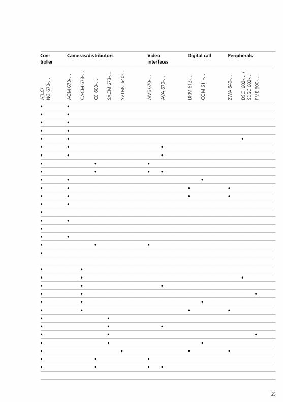
65
Device category Page Door loudspeaker/ Status display module
Con-troller
Cameras/distributors Video interfaces
Digital call Peripherals
Models
ATL
M 6
70-…
ATL
M 6
71-…
ZAM
670
-…
CA
TLE
670-
…
SATL
M 6
70-…
ATL
E 67
0-…
ATL
C/
NG
670
-…
AC
M 6
73-…
CA
CM
673
-…
CE
600-
…
SAC
M 6
73-…
SVTM
C 6
40-…
AIV
S 67
0-…
AVA
670
-…
DRM
612
-…
CO
M 6
11-…
ZWA
640
-…
DSC
602
-… /
SDSC
602
-…
PME
600-
…
Siedle Vario Basic circuit diagram (Video) 68 • • •
Potential-free door release work contact A2 70 • • •
Potential-free door release changeover contact A3 72 • • •
Additional power supply 74 • • •
Pilfer safeguard 76 • • • •
Video decoupler (camera in switching operation) 78 • • • •
Video decoupler (camera in continuous operation) 80 • • • •
External camera 82 • • • •
External camera and video decoupler 84 • • • • •
Code lock module (Digital call) 86 • • • •
Display call module (Digital call) 88 • • • • •
2 door stations/display call modules (Digital call) 90 • • • • •
Radio chime 92 • • •
Basic circuit diagram (Audio) 94 • •
Basic circuit diagram (Video) + Status display module 96 • • • •
Basic circuit diagram (Audio) + Status display module 98 • • • •
Access custom-fit door loudspeaker
Access camera module 100 • • •
External camera 102 • • • •
Basic circuit diagram (Audio) 104 • •
Siedle Classic Wiring diagram for call buttons 106
Basic circuit diagram (Video) 108 • • •
Pilfer safeguard 110 • • • •
Video decoupler (camera in continuous operation) 112 • • • •
2 mail notification systems 114 • • • •
Code lock module (Digital call) 116 • • • •
Display call module (Digital call) 118 • • • • •
Siedle Steel Basic circuit diagram (Video) 120 • • •
Video decoupler (camera in continuous operation) 122 • • • •
2 mail notification systems 124 • • • •
Code lock module (Digital call) 126 • • • •
Display call module (Digital call) 128 • • • • •
Camera connection
External camera 130 • • •
External camera with video distributor 132 • • • •
Storey call button Customer-side signalling device 134
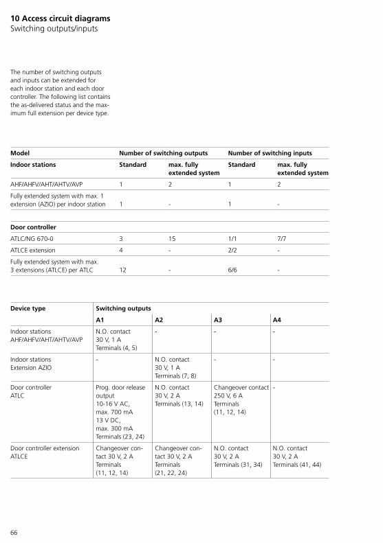
66
10 Access circuit diagrams Switching outputs/inputs
Model Number of switching outputs Number of switching inputs
Indoor stations Standard max. fully extended system
Standard max. fully extended system
AHF/AHFV/AHT/AHTV/AVP 1 2 1 2
Fully extended system with max. 1 extension (AZIO) per indoor station 1 - 1 -
Door controller
ATLC/NG 670-0 3 15 1/1 7/7
ATLCE extension 4 - 2/2 -
Fully extended system with max. 3 extensions (ATLCE) per ATLC 12 - 6/6 -
Device type Switching outputs
A1 A2 A3 A4
Indoor stationsAHF/AHFV/AHT/AHTV/AVP
N.O. contact 30 V, 1 ATerminals (4, 5)
- - -
Indoor stationsExtension AZIO
- N.O. contact 30 V, 1 ATerminals (7, 8)
- -
Door controllerATLC
Prog. door release output10-16 V AC, max. 700 mA13 V DC, max. 300 mATerminals (23, 24)
N.O. contact 30 V, 2 ATerminals (13, 14)
Changeover contact 250 V, 6 ATerminals (11, 12, 14)
-
Door controller extensionATLCE
Changeover con-tact 30 V, 2 ATerminals (11, 12, 14)
Changeover con-tact 30 V, 2 ATerminals (21, 22, 24)
N.O. contact 30 V, 2 ATerminals (31, 34)
N.O. contact 30 V, 2 ATerminals (41, 44)
The number of switching outputs and inputs can be extended for each indoor station and each door controller. The following list contains the as-delivered status and the max-imum full extension per device type.
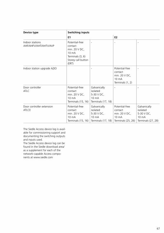
67
Device type Switching inputs
E1 E2
Indoor stationsAHF/AHFV/AHT/AHTV/AVP
Potential-free contactmin. 20 V DC, 10 mATerminals (3, 6)Storey call button (ERT)
- - -
Indoor station upgrade AZIO - Potential-free contactmin. 20 V DC, 10 mATerminals (1, 2)
-
Door controllerATLC
Potential-free contactmin. 20 V DC, 10 mATerminals (15, 16)
Galvanically isolated5-30 V DC, 10 mATerminals (17, 18)
- -
Door controller extensionATLCE
Potential-free contactmin. 20 V DC, 10 mATerminals (15, 16)
Galvanically isolated5-30 V DC, 10 mATerminals (17, 18)
Potential-free contactmin. 20 V DC, 10 mATerminals (25, 26)
Galvanically isolated5-30 V DC, 10 mATerminals (27, 28)
The Siedle Access device log is avail-able for commissioning support and documenting the switching outputs and inputs used.The Siedle Access device log can be found in the Siedle download area/as a supplement for each of the network-capable Access compo-nents at www.siedle.com
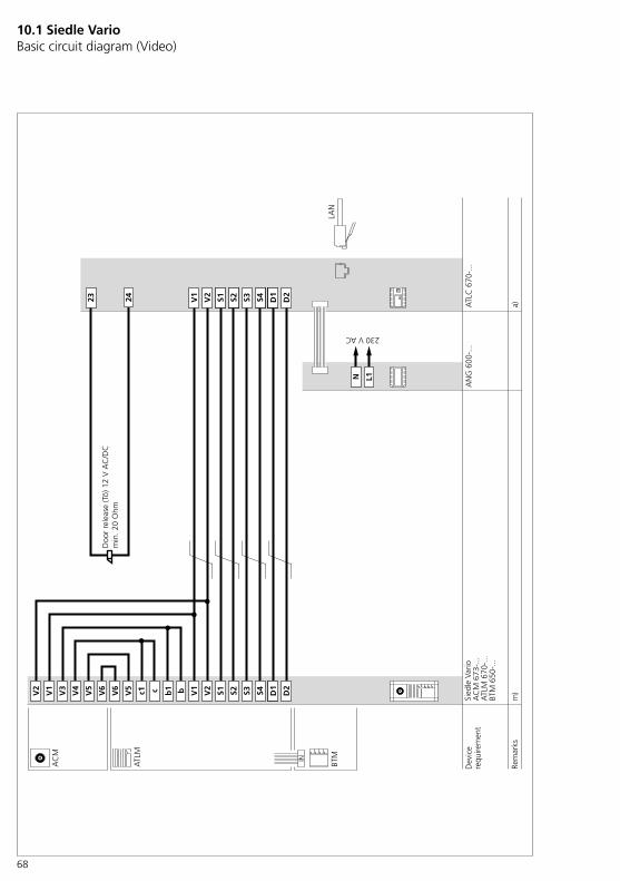
68
ATL
M
BTM
23 24 V1
D2
S2S1 S3 D1
S4V2
V5
V6
V6
V5
S4S3 D2
D1
S2V2
S1V1 c1 bc V2
V1
V4
V3
L1N
AC
M
ATL
C 6
70-.
..A
NG
600
-...
LAN
a)m
)b1
Sied
le V
ario
AC
M 6
73-.
..A
TLM
670
-...
BTM
650
-...
IN
Rem
arks
Dev
ice
requ
irem
ent
Doo
r re
leas
e (T
ö) 1
2 V
AC
/DC
min
. 20
Ohm
230 V AC
10.1 Siedle Vario Basic circuit diagram (Video)

69
Notes on the circuit diagrama) If door releases or gate control systems are fitted and their con-nected values do not correspond to 12 V AC/DC and min. 20 Ohm, then either switching output 2 (ATLC ter-minals 13/14 (output)) or switching output 3 (ANG terminals 11/12/14 (output)) can be used as a potential-free door release contact.To use switching output 2 or 3 as a potential-free door release contact, you must configure the corre-sponding ATLC switching output in the Access administration interface.• The use of the potential-free switching outputs is described in separate diagrams.(For detailed information, see page 70, 72)
m) Where there are more than 10 BTM 650-… units, an addi-tional 12 V AC supply, for instance TR 603-…, must be installed due to the current consumption. To use the additional supply, the jumpers on the ATLM are removed from b1/c1 to b/c and the b/c terminals are directly connected to the additional supply. The jumpers for the ACM camera module between the terminals V3/V4 and the terminals b1/c1 remain as they are.• Supply limits ATLC/NG 670-… (For detailed information, see page 18, 23)• The use of an additional power supply is described in a separate diagram.(For detailed information, see page 74)

70
Sied
le V
ario
ATL
M 6
70-.
..BT
M 6
50-.
..
AC
M 6
73-.
..
ATL
M
BTM
13 14 V1
D2
S2S1 S3 D1
S4V2
V5
V6
V6
V5
S4S3 D2
D1
S2V2
S1V1 c1 bc V2
V1
V4
V3
L1
230 V AC
N
AC
M
ATL
C 6
70-.
..A
NG
600
-...
LAN
a)
b1
A2
m)
IN
Rem
arks
Dev
ice
requ
irem
ent
Pote
ntia
l-fre
e co
ntac
tD
oor
rele
ase
actu
atio
nm
ax. 3
0 V
AC
/DC
, 2 A
e.g.
for
exi
stin
g ac
cess
con
trol
or
doo
r re
leas
e on
site
10.1 Siedle Vario Potential-free door release work contact A2
71
Notes on the circuit diagrama) If door releases or gate control systems are fitted and their con-nected values do not correspond to 12 V AC/DC and min. 20 Ohm, then either switching output 2 (ATLC ter-minals 13/14 (output)) or switching output 3 (ANG terminals 11/12/14 (output)) can be used as a potential-free door release contact.To use switching output 2 or 3 as a potential-free door release contact, you must configure the corre-sponding ATLC switching output in the Access administration interface.• The use of the door release switching output A1 (ATLC terminals 23, 24) is described in the video basic circuit diagram.(For detailed information, see page 68)
m) Where there are more than 10 BTM 650-… units, an addi-tional 12 V AC supply, for instance TR 603-…, must be installed due to the current consumption. To use the additional supply, the jumpers on the ATLM are removed from b1/c1 to b/c and the b/c terminals are directly connected to the additional supply. The jumpers for the ACM camera module between the terminals V3/V4 and the terminals b1/c1 remain as they are.• Supply limits ATLC/NG 670-… (For detailed information, see page 18, 23)• The use of an additional power supply is described in a separate diagram.(For detailed information, see page 74)

72
A3
14 11 12
Sied
le V
ario
ATL
M 6
70-.
..BT
M 6
50-.
..
AC
M 6
73-.
..
ATL
M
BTM
V1
D2
S2S1 S3 D1
S4V2
V5
V6
V6
V5
S4S3 D2
D1
S2V2
S1V1 c1 bc V2
V1
V4
V3
L1
230 V AC
N
AC
M
ATL
C 6
70-.
..A
NG
600
-...
LAN
a)
b1
m)
IN
Rem
arks
Dev
ice
requ
irem
ent
Pote
ntia
l-fre
e co
ntac
tm
ax. 2
50 V
AC
/DC
, 6 A
e.g.
for
exi
stin
g ac
cess
con
trol
or
doo
r re
leas
e on
site
10.1 Siedle Vario Potential-free door release changeover contact A3

73
Notes on the circuit diagrama) If door releases or gate control systems are fitted and their con-nected values do not correspond to 12 V AC/DC and min. 20 Ohm, then either switching output 2 (ATLC ter-minals 13/14 (output)) or switching output 3 (ANG terminals 11/12/14 (output)) can be used as a potential-free door release contact.To use switching output 2 or 3 as a potential-free door release contact, you must configure the corre-sponding ATLC switching output in the Access administration interface.• The use of the door release switching output A1 (ATLC terminals 23, 24) is described in the video basic circuit diagram.(For detailed information, see page 68)
m) Where there are more than 10 BTM 650-… units, an addi-tional 12 V AC supply, for instance TR 603-…, must be installed due to the current consumption. To use the additional supply, the jumpers on the ATLM are removed from b1/c1 to b/c and the b/c terminals are directly connected to the additional supply. The jumpers for the ACM camera module between the terminals V3/V4 and the terminals b1/c1 remain as they are.• Supply limits ATLC/NG 670-… (For detailed information, see page 18, 23)• The use of an additional power supply is described in a separate diagram.(For detailed information, see page 74)
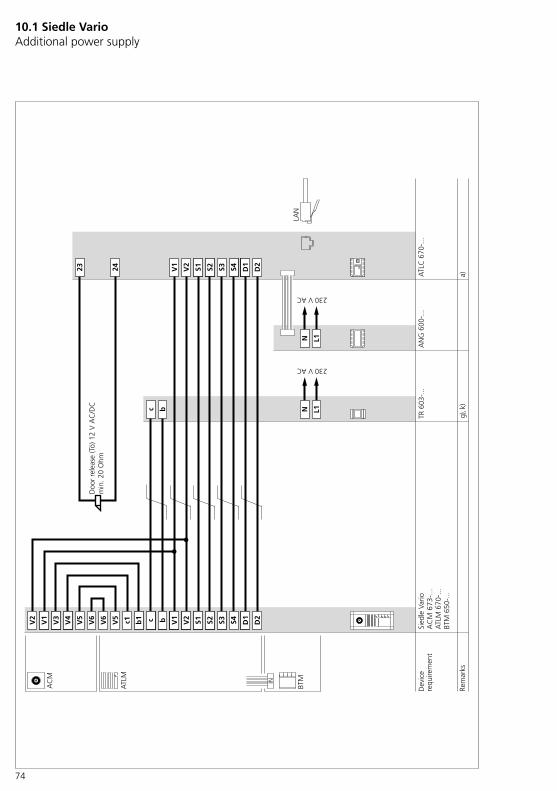
74
10.1 Siedle Vario Additional power supply
Sied
le V
ario
ATL
M 6
70-.
..BT
M 6
50-.
..
AC
M 6
73-.
..
ATL
M
BTM
23 24 V1
D2
S2S1 S3 D1
S4V2
V5
V6
V6
V5
S4S3 D2
D1
S2V2
S1V1 c1 bb1
V2
V1
V4
V3
L1
230 V AC
NN
L1c b
230 V AC
AC
M
ATL
C 6
70-.
..A
NG
600
-...
LAN
TR 6
03-.
..
a)g)
, k)
c
IN
Rem
arks
Dev
ice
requ
irem
ent
Doo
r re
leas
e (T
ö) 1
2 V
AC
/DC
min
. 20
Ohm
75
Notes on the circuit diagrama) If door releases or gate control systems are fitted and their con-nected values do not correspond to 12 V AC/DC and min. 20 Ohm, then either switching output 2 (ATLC ter-minals 13/14 (output)) or switching output 3 (ANG terminals 11/12/14 (output)) can be used as a potential-free door release contact.To use switching output 2 or 3 as a potential-free door release contact, you must configure the corre-sponding ATLC switching output in the Access administration interface.• The use of the potential-free switching outputs is described in separate diagrams. (For detailed information, see page 70, 72)
g) Is only required if more than 10 BTM 650-… units are installed at this door station.
k) If the BTM 650-… units are sup-plied via a separate transformer, no connection between c1 and c / b1 and b may exist at the ATLM 670-… terminal block.• Supply limits ATLC/NG 670-… (For detailed information, see page 18, 23)

76
Sied
le V
ario
ATL
M 6
70-.
..BT
M 6
50-.
..
AC
M 6
73-.
..
ATL
M
BTM
23 24 V1
D2
S2S1 S3 D1
S4V2
V5
V6
V6
V5
S4S3 D2
D1
S2V2
S1V1 c1 bc V2
V1
V4
V3
L1
230 V AC
NN
L1c b
230 V AC
AC
M
ATL
C 6
70-.
..A
NG
600
-...
LAN
TR 6
03-.
..
c b M1
M2
DSC
602
-...
+ZD
S�60
1-…
a)m
)b1
bl
bl
gr
gr
g)
ZDS�
601-
…
IN
Rem
arks
Dev
ice
requ
irem
ent
Doo
r re
leas
e (T
ö) 1
2 V
AC
/DC
min
. 20
Ohm
10.1 Siedle Vario Pilfer safeguard
77
Notes on the circuit diagrama) If door releases or gate control systems are fitted and their con-nected values do not correspond to 12 V AC/DC and min. 20 Ohm, then either switching output 2 (ATLC ter-minals 13/14 (output)) or switching output 3 (ANG terminals 11/12/14 (output)) can be used as a potential-free door release contact.To use switching output 2 or 3 as a potential-free door release contact, you must configure the corre-sponding ATLC switching output in the Access administration interface.• The use of the potential-free switching outputs is described in separate diagrams.(For detailed information, see page 70, 72)
g) Operation via the door station’s internal power supply is not possible. A separate power supply is required.
m) Where there are more than 10 BTM 650-… units, an addi-tional 12 V AC supply, for instance TR 603-…, must be installed due to the current consumption. To use the additional supply, the jumpers on the ATLM are removed from b1/c1 to b/c and the b/c terminals are directly connected to the additional supply. The jumpers for the ACM camera module between the terminals V3/V4 and the terminals b1/c1 remain as they are.• Supply limits ATLC/NG 670-… (For detailed information, see page 18, 23)• The use of an additional power supply is described in a separate diagram.(For detailed information, see page 74)
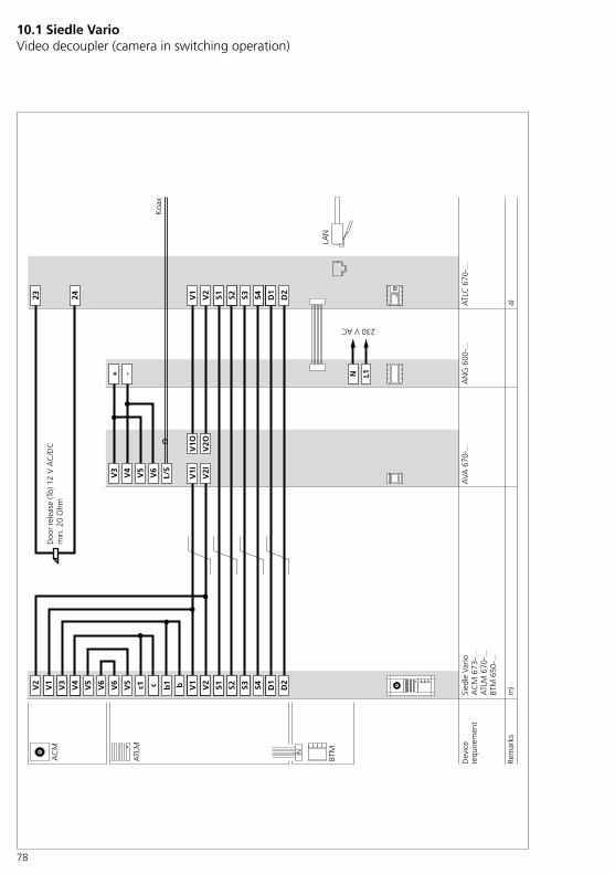
78
Sied
le V
ario
ATL
M 6
70-.
..BT
M 6
50-.
..
AC
M 6
73-.
..
ATL
M
BTM
23 24 V1
D2
S2S1 S3 D1
S4V2
V3
V6
V5
L/S
V4
+ -
V1I
V2I
V1O
V2O
V5
V6
V6
V5
S4S3 D2
D1
S2V2
S1V1 c1 bc V2
V1
V4
V3
L1
230 V AC
N
AC
M
ATL
C 6
70-.
..A
NG
600
-...
AVA
670
-...
LAN
b1
Koa
x
a)m
)
IN
Dev
ice
requ
irem
ent
Rem
arks
Doo
r re
leas
e (T
ö) 1
2 V
AC
/DC
min
. 20
Ohm
10.1 Siedle Vario Video decoupler (camera in switching operation)
79
Notes on the circuit diagrama) If door releases or gate control systems are fitted and their con-nected values do not correspond to 12 V AC/DC and min. 20 Ohm, then either switching output 2 (ATLC ter-minals 13/14 (output)) or switching output 3 (ANG terminals 11/12/14 (output)) can be used as a potential-free door release contact.To use switching output 2 or 3 as a potential-free door release contact, you must configure the corre-sponding ATLC switching output in the Access administration interface.• The use of the potential-free switching outputs is described in separate diagrams.(For detailed information, see page 70, 72)
m) Where there are more than 10 BTM 650-… units, an addi-tional 12 V AC supply, for instance TR 603-…, must be installed due to the current consumption. To use the additional supply, the jumpers on the ATLM are removed from b1/c1 to b/c and the b/c terminals are directly connected to the additional supply. The jumpers for the ACM camera module between the terminals V3/V4 and the terminals b1/c1 remain as they are.• Supply limits ATLC/NG 670-… (For detailed information, see page 18, 23)• The use of an additional power supply is described in a separate diagram.(For detailed information, see page 74)
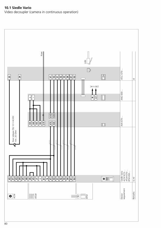
80
Sied
le V
ario
ATL
M 6
70-.
..BT
M 6
50-.
..
AC
M 6
73-.
..
ATL
M
BTM
23 24 V1
D2
S2S1 S3 D1
S4V2
V3
V6
V5
L/S
V4
+ –
V1I
V2I
V1O
V2O
V5
V6
V6
V5
S4S3 D2
D1
S2V2
S1V1 c1 bc V2
V1
V4
V3
L1
230 V AC
N
AC
M
ATL
C 6
70-.
..A
NG
600
-...
AVA
670
-...
LAN
b1
Koa
x
a)c)
, m)
IN
Dev
ice
requ
irem
ent
Rem
arks
Doo
r re
leas
e (T
ö) 1
2 V
AC
/DC
min
. 20
Ohm
10.1 Siedle Vario Video decoupler (camera in continuous operation)
81
Notes on the circuit diagrama) If door releases or gate control systems are fitted and their con-nected values do not correspond to 12 V AC/DC and min. 20 Ohm, then either switching output 2 (ATLC ter-minals 13/14 (output)) or switching output 3 (ANG terminals 11/12/14 (output)) can be used as a potential-free door release contact.To use switching output 2 or 3 as a potential-free door release contact, you must configure the corre-sponding ATLC switching output in the Access administration interface.• The use of the potential-free switching outputs is described in separate diagrams.(For detailed information, see page 70, 72)
c) The camera used must be suitable for continuous operation. Alternatively, the camera must be used in switching operation. (For detailed information, see page 78)• In addition, the camera should only be used in continuous opera-tion within its permitted operating parameters (e.g. ambient tempera-ture).(For detailed information, see page 34)
m) Where there are more than 10 BTM 650-… units, an addi-tional 12 V AC supply, for instance TR 603-…, must be installed due to the current consumption. To use the additional supply, the jumpers on the ATLM are removed from b1/c1 to b/c and the b/c terminals are directly connected to the additional supply. The jumpers for the ACM camera module between the terminals V3/V4 and the terminals b1/c1 remain as they are.• Supply limits ATLC/NG 670-… (For detailed information, see page 18, 23)• The use of an additional power supply is described in a separate diagram.(For detailed information, see page 74)
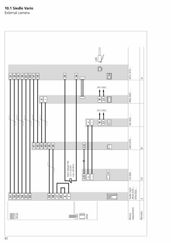
82
10.1 Siedle Vario External camera
Sied
le V
ario
ATL
M 6
70-.
..BT
M 6
50-.
..
ATL
M
BTM
L/S + -
+ -
N L1+ -
L/S
V6
23 24
V5
V4
V1
V3
V2
b1c1 cbV6
V5
V2
V1
S4 D2
D1
D2
D1
S1 S3S2
S4S1 S3S2
ATL
C 6
70-…
AN
G 6
00-…
CE
600-
…A
IVS
670-
...
b)
230 V AC
N L1
230 V AC
LAN
a)
NG
602
-…
j)w
)
IN
Rem
arks
Dev
ice
requ
irem
ent
Doo
r re
leas
e (T
ö)12
V A
C/D
Cm
in. 2
0 O
hm
83
Notes on the circuit diagrama) If door releases or gate control systems are fitted and their con-nected values do not correspond to 12 V AC/DC and min. 20 Ohm, then either switching output 2 (ATLC ter-minals 13/14 (output)) or switching output 3 (ANG terminals 11/12/14 (output)) can be used as a potential-free door release contact.To use switching output 2 or 3 as a potential-free door release contact, you must configure the corre-sponding ATLC switching output in the Access administration interface.• The use of the potential-free switching outputs is described in separate diagrams.(For detailed information, see page 70, 72)
b) Distance between the camera and AIVS 670-… max. 10 m
j) Where there are more than 26 BTM 650-… units, an addi-tional 12 V AC supply, for instance TR 603-…, must be installed due to the current consumption. To use the additional supply, the jumpers on the ATLM are removed from b1/c1 to b/c and the b/c terminals are directly connected to the additional supply.• Supply limits ATLC/NG 670-… (For detailed information, see page 18, 23)• The use of an additional power supply is described in a separate diagram.(For detailed information, see page 74)
w) Separate power supply required.

84
10.1 Siedle Vario External camera and video decoupler
Sied
le V
ario
ATL
M 6
70-.
..BT
M 6
50-.
..
ATL
M
BTM
L/S + -
N L1+ -
L/S
V6
23 24
V5
V1
V2
cb V6
V5
V2
V1
S4 D2
D1
D2
D1
S1 S3S2
S4S1 S3S2
ATL
C 6
70-…
AN
G 6
00-…
CE
600-
…A
IVS
670-
...
b)
LAN
a)
AVA
670
-…
V1I
V2I
V1O
V2O
V6
V5
V4
V3
b1c1
L/S
w)
j)
V4
V3
IN
Dev
ice
requ
irem
ent
Rem
arks
Supp
ly v
olta
ge
48 V
DC
!C
oaxi
al
conn
ectio
nL
= le
adS
= s
hiel
d
230 V AC
Doo
r re
leas
e (T
ö)
12 V
AC
/DC
min
. 20
Ohm
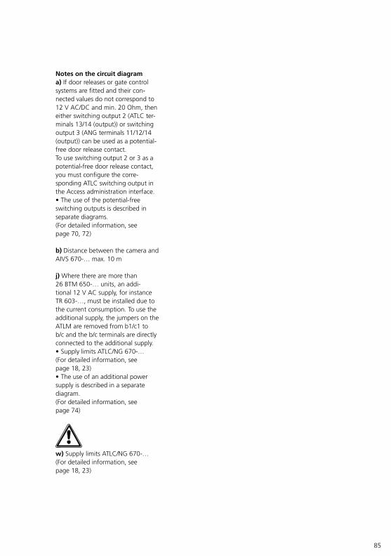
85
Notes on the circuit diagrama) If door releases or gate control systems are fitted and their con-nected values do not correspond to 12 V AC/DC and min. 20 Ohm, then either switching output 2 (ATLC ter-minals 13/14 (output)) or switching output 3 (ANG terminals 11/12/14 (output)) can be used as a potential-free door release contact.To use switching output 2 or 3 as a potential-free door release contact, you must configure the corre-sponding ATLC switching output in the Access administration interface.• The use of the potential-free switching outputs is described in separate diagrams.(For detailed information, see page 70, 72)
b) Distance between the camera and AIVS 670-… max. 10 m
j) Where there are more than 26 BTM 650-… units, an addi-tional 12 V AC supply, for instance TR 603-…, must be installed due to the current consumption. To use the additional supply, the jumpers on the ATLM are removed from b1/c1 to b/c and the b/c terminals are directly connected to the additional supply.• Supply limits ATLC/NG 670-… (For detailed information, see page 18, 23)• The use of an additional power supply is described in a separate diagram.(For detailed information, see page 74)
w) Supply limits ATLC/NG 670-… (For detailed information, see page 18, 23)
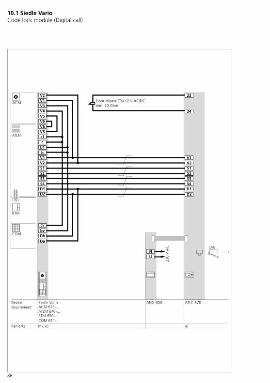
86
10.1 Siedle Vario Code lock module (Digital call)
Siedle Vario
ATLM 670-...BTM 650-...COM 611-...
ACM 673-...
ATLM
BTM
V1
D2
S2S1
S3
D1S4
V2
V5V6V6V5
S4S3
D2D1
bvcv
Da
S2
V2
S1
V1
c1c
bb1
V2V1
V4V3
NL1
230
V A
C
ACM
ATLC 670-...ANG 600-...
LAN
DbCOM
a)m), o)
23
24
IN
Büchner ClaudiaMaier KlausSchuhmacher BerndNamensuche mit
Remarks
Devicerequirement
Door release (Tö) 12 V AC/DCmin. 20 Ohm

87
Notes on the circuit diagrama) If door releases or gate control systems are fitted and their con-nected values do not correspond to 12 V AC/DC and min. 20 Ohm, then either switching output 2 (ATLC ter-minals 13/14 (output)) or switching output 3 (ANG terminals 11/12/14 (output)) can be used as a potential-free door release contact.To use switching output 2 or 3 as a potential-free door release contact, you must configure the corre-sponding ATLC switching output in the Access administration interface.• The use of the potential-free switching outputs is described in separate diagrams.(For detailed information, see page 70, 72)
m) Where there are more than 10 BTM 650-… units, an addi-tional 12 V AC supply, for instance TR 603-…, must be installed due to the current consumption. To use the additional supply, the jumpers on the ATLM are removed from b1/c1 to b/c and the b/c terminals are directly connected to the additional supply. The jumpers for the ACM camera module between the terminals V3/V4 and the terminals b1/c1 remain as they are.• Supply limits ATLC/NG 670-… (For detailed information, see page 18, 23)• The use of an additional power supply is described in a separate diagram.(For detailed information, see page 74)
o) The COM 611-… code lock module is always available for making calls (direct dial via numeric code).
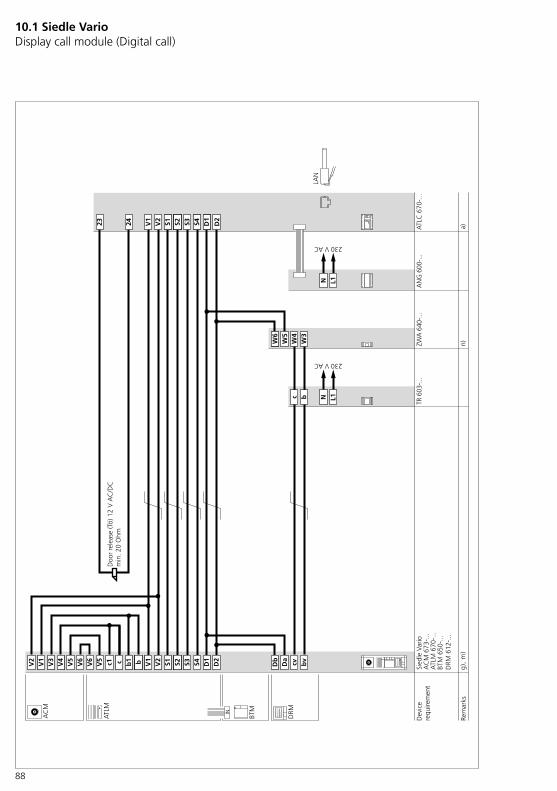
88
10.1 Siedle Vario Display call module (Digital call)
Sied
le V
ario
ATL
M 6
70-.
..BT
M 6
50-.
..D
RM 6
12-.
..
AC
M 6
73-.
..
ATL
M
BTM
23 24 V1
D2
S2S1 S3 D1
S4V2
V5
V6
V6
V5
S4S3 D2
D1
Da
Db
W5
W6
bvS2V2
S1V1 c1 c bb1
V2
V1
V4
V3
N L1
230 V AC
AC
M
ATL
C 6
70-.
..A
NG
600
-...
N L1
230 V ACTR
603
-...
LAN
cvbc
W3
W4
DRM
a)n)
g),
m)
ZWA
640
-...
IN
Büch
ner
Cla
udia
Schu
hmac
her
Mic
hael
Nam
ensu
che
mit
OK
Mai
er K
laus
Büch
ner
Cla
udia
Schu
hmac
her
Mic
hael
Nam
ensu
che
mit
OK
Mai
er K
laus
Rem
arks
Dev
ice
requ
irem
ent
Doo
r re
leas
e (T
ö) 1
2 V
AC
/DC
min
. 20
Ohm
89
Notes on the circuit diagramThe wiring of 2 door stations with a display call module each is described in a separate diagram(For detailed information, see page 90)
a) If door releases or gate control systems are fitted and their con-nected values do not correspond to 12 V AC/DC and min. 20 Ohm, then either switching output 2 (ATLC ter-minals 13/14 (output)) or switching output 3 (ANG terminals 11/12/14 (output)) can be used as a potential-free door release contact.To use switching output 2 or 3 as a potential-free door release contact, you must configure the corre-sponding ATLC switching output in the Access administration interface.• The use of the potential-free switching outputs is described in separate diagrams. (For detailed information, see page 70, 72)
g) To ensure smooth operation, the DRM 612-… display call module must be supplied with its own power supply.
m) Where there are more than 10 BTM 650-… units, an addi-tional 12 V AC supply, for instance TR 603-…, must be installed due to the current consumption. To use the additional supply, the jumpers on the ATLM are removed from b1/c1 to b/c and the b/c terminals are directly connected to the additional supply. The jumpers for the ACM camera module between the terminals V3/V4 and the terminals b1/c1 remain as they are.• Supply limits ATLC/NG 670-… (For detailed information, see page 18, 23)• The use of an additional power supply is described in a separate diagram.(For detailed information, see page 74)
n) For programming the names, pro-gramming software PRS 602-… and programming interface PRI 602-… are required. The names are now entered in the display call module using the PRS 602-… • The PRI 602-… is supplied via the power supply connected to the ZWA 640-…, (terminals W3/W4).
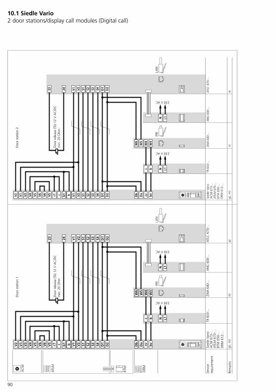
90
10.1 Siedle Vario 2 door stations/display call modules (Digital call)
Sied
le V
ario
ATL
M 6
70-.
..BT
M 6
50-.
..D
RM 6
12-.
..
AC
M 6
73-.
..
ATL
M
BTM
23 24 V1
D2
S2S1 S3 D1
S4V2
V5
V6
V6
V5
S4S3 D2
D1
Da
Db
W5
W6
bvS2V2
S1V1 c1 c bb1
V2
V1
V4
V3
N L1
AC
M
ATL
C 6
70-.
..A
NG
600
-...
N L1
TR 6
03-..
.
cv
bc
W3
W4
DRM
a)n)
g),
m)
ZWA
640
-...
IN
Büch
ner
Cla
udia
Schu
hmac
her
Mic
hael
Nam
ensu
che
mit
OK
Mai
er K
laus
Büch
ner
Cla
udia
Schu
hmac
her
Mic
hael
Nam
ensu
che
mit
OK
Mai
er K
laus
Sied
le V
ario
ATL
M 6
70-.
..BT
M 6
50-.
..D
RM 6
12-.
..
AC
M 6
73-.
..
23 24 V1
D2
S2S1 S3 D1
S4V2
V5
V6
V6
V5
S4S3 D2
D1
Da
Db
W5
W6
bvS2V2
S1V1 c1 c bb1
V2
V1
V4
V3
N L1
ATL
C 6
70-.
..A
NG
600
-...
N L1
TR 6
03-..
.
cv
bc
W3
W4
a)n)
g),
m)
ZWA
640
-...
LAN
Büch
ner
Cla
udia
Schu
hmac
her
Mic
hael
Nam
ensu
che
mit
OK
Mai
er K
laus
LAN
PRI
PRI
Rem
arks
Dev
ice
requ
irem
ent
Doo
r st
atio
n 1
Doo
r st
atio
n 2
230 V AC
230 V AC
230 V AC
230 V AC
Doo
r re
leas
e (T
ö) 1
2 V
AC
/DC
min
. 20
Ohm
Doo
r re
leas
e (T
ö) 1
2 V
AC
/DC
min
. 20
Ohm
91
Notes on the circuit diagrama) If door releases or gate control systems are fitted and their con-nected values do not correspond to 12 V AC/DC and min. 20 Ohm, then either switching output 2 (ATLC ter-minals 13/14 (output)) or switching output 3 (ANG terminals 11/12/14 (output)) can be used as a potential-free door release contact.To use switching output 2 or 3 as a potential-free door release contact, you must configure the corre-sponding ATLC switching output in the Access administration interface.• The use of the potential-free switching outputs is described in separate diagrams.(For detailed information, see page 70, 72)
g) To ensure smooth operation, the DRM 612-… display call module must be supplied with its own power supply.
m) Where there are more than 10 BTM 650-… units, an addi-tional 12 V AC supply, for instance TR 603-…, must be installed due to the current consumption. To use the additional supply, the jumpers on the ATLM are removed from b1/c1 to b/c and the b/c terminals are directly connected to the additional supply. The jumpers for the ACM camera module between the terminals V3/V4 and the terminals b1/c1 remain as they are.• Supply limits ATLC/NG 670-… (For detailed information, see page 18, 23)• The use of an additional power supply is described in a separate diagram.(For detailed information, see page 74)
n) For programming the names, pro-gramming software PRS 602-… and programming interface PRI 602-… are required. The names are now entered in the display call module using the PRS 602-… • The PRI 602-… is supplied via the power supply connected to the ZWA 640-…, (terminals W3/W4).
In the case of several door stations, the wiring of one door station must not be connected to the wiring of another door station (bridged).
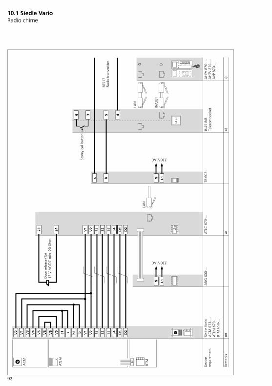
92
10.1 Siedle Vario Radio chime
c b N L1
Sied
le V
ario
TR 6
03-.
..
ATL
M 6
70-.
..BT
M 6
50-.
..
AC
M 6
73-.
..
ATL
M
BTM
23 24 V1
D2
S2S1 S3 D1
S4V2
V5
V6
V6
V5
S4S3 D2
D1
S2V2
S1V1 c1 bc V2
V1
V4
V3
L1N
AC
M
ATL
C 6
70-.
..A
NG
600
-...
LAN
a)m
)b1
45
IN/O
UT
36
RJ45
8/8
G D
LAN
AH
FV 8
70-…
AH
TV 8
70-…
AV
P 87
0-…
u)u)
RTS1
7
230 V AC
230 V AC
IN
Rem
arks
Dev
ice
requ
irem
ent
Tele
com
soc
ket
Radi
o tr
ansm
itter
Stor
ey c
all b
utto
n
Doo
r re
leas
e (T
ö)12
V A
C/D
C m
in. 2
0 O
hm
93
Notes on the circuit diagrama) If door releases or gate control systems are fitted and their con-nected values do not correspond to 12 V AC/DC and min. 20 Ohm, then either switching output 2 (ATLC ter-minals 13/14 (output)) or switching output 3 (ANG terminals 11/12/14 (output)) can be used as a potential-free door release contact.To use switching output 2 or 3 as a potential-free door release contact, you must configure the corre-sponding ATLC switching output in the Access administration interface.• The use of the potential-free switching outputs is described in separate diagrams. (For detailed information, see page 70, 72)
m) Where there are more than 10 BTM 650-… units, an addi-tional 12 V AC supply, for instance TR 603-…, must be installed due to the current consumption. To use the additional supply, the jumpers on the ATLM are removed from b1/c1 to b/c and the b/c terminals are directly connected to the additional supply. The jumpers for the ACM camera module between the terminals V3/V4 and the terminals b1/c1 remain as they are.• Supply limits ATLC/NG 670-… (For detailed information, see page 18, 23)• The use of an additional power supply is described in a separate diagram.(For detailed information, see page 74)
u) To use the RTS17 radio trans-mitter, the secondary signal unit aux-iliary script must be imported into the Access server and the affected indoor station must be configured. Incoming calls are signalled on the indoor station and on the plug-in socket pager.
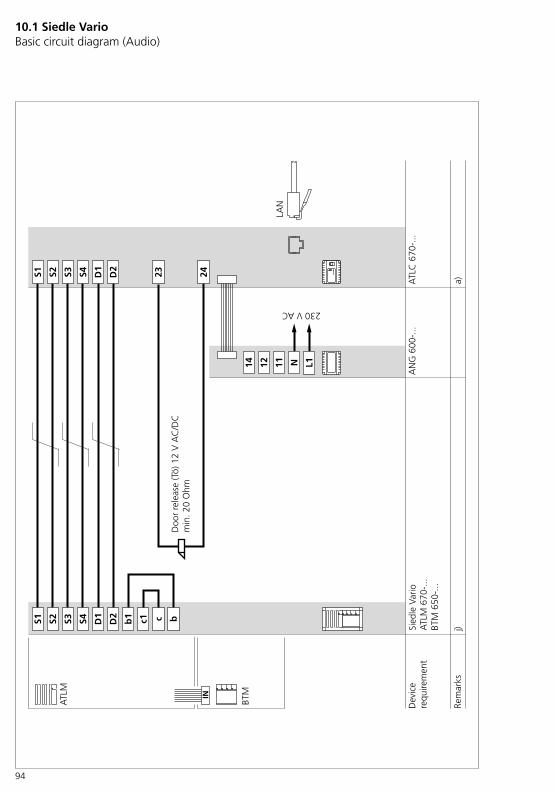
94
10.1 Siedle Vario Basic circuit diagram (Audio)
Sied
le V
ario
ATL
M 6
70-.
..BT
M 6
50-.
..
ATL
M
BTM
N111214 L1
23 24
c1b1 bc
S4 D2
D1
D2
D1
S1 S3S2
S4S1 S3S2
ATL
C 6
70-.
..A
NG
600
-...
230 V AC
LAN
a)j)
IN
Rem
arks
Dev
ice
requ
irem
ent
Doo
r re
leas
e (T
ö) 1
2 V
AC
/DC
min
. 20
Ohm

95
Notes on the circuit diagrama) If door releases or gate control systems are fitted and their con-nected values do not correspond to 12 V AC/DC and min. 20 Ohm, then either switching output 2 (ATLC ter-minals 13/14 (output)) or switching output 3 (ANG terminals 11/12/14 (output)) can be used as a potential-free door release contact.To use switching output 2 or 3 as a potential-free door release contact, you must configure the corre-sponding ATLC switching output in the Access administration interface.• The use of the potential-free switching outputs is described in separate diagrams.(For detailed information, see page 70, 72)
j) Where there are more than 26 BTM 650-… units, an addi-tional 12 V AC supply, for instance TR 603-…, must be installed due to the current consumption. To use the additional supply, the jumpers on the ATLM are removed from b1/c1 to b/c and the b/c terminals are directly connected to the additional supply.• Supply limits ATLC/NG 670-… (For detailed information, see page 18, 23)• The use of an additional power supply is described in a separate diagram.(For detailed information, see page 74)
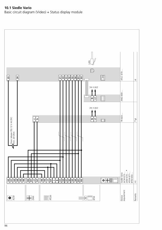
96
10.1 Siedle Vario Basic circuit diagram (Video) + Status display module
Sied
le V
ario
AC
M 6
73-…
ZAM
670
-… *
ATL
M 6
71-…
BTM
650
-…
ATL
M
BTM
23 24 V1
D2
S2S1 S3 D1
S4V2
V5
V6
V6
V5
S4S3 D2
D1
S2V2
S1V1 c1 bb1
V2
V1
V4
V3
L1
230 V AC
NN
L1c b
230 V AC
AC
M
ATL
C 6
70-.
..A
NG
600
-...
LAN
TR 6
03-.
..
a)*
g)
c
ZAM
b1c1D1
D2
m)
IN
Rem
arks
Dev
ice
requ
irem
ent
Doo
r re
leas
e (T
ö) 1
2 V
AC
/DC
min
. 20
Ohm

97
Notes on the circuit diagrama) If door releases or gate control systems are fitted and their con-nected values do not correspond to 12 V AC/DC and min. 20 Ohm, then either switching output 2 (ATLC ter-minals 13/14 (output)) or switching output 3 (ANG terminals 11/12/14 (output)) can be used as a potential-free door release contact.To use switching output 2 or 3 as a potential-free door release contact, you must configure the corre-sponding ATLC switching output in the Access administration interface.• The use of the potential-free switching outputs is described in separate diagrams. (For detailed information, see page 70, 72)
g) ZAM 670-0: Operation via the door station’s internal power supply is not possible. A separate power supply is required.• Supply limits ATLC/NG 670-… (For detailed information, see page 18, 19, 23)
m) Where there are more than 1 BTM 650-… units, an additional 12 V AC supply, for instance TR 603-…, must be installed due to the current consumption. To use the additional supply, the jumpers on the ATLM are removed from b1/c1 to b/c and the b/c terminals are directly connected to the additional supply. The jumpers for the ACM camera module between the terminals V3/V4 and the terminals b1/c1 remain as they are.• Supply limits ATLC/NG 670-… (For detailed information, see page 18, 19, 23)• The use of an additional power supply is described in a separate diagram.(For detailed information, see page 74)
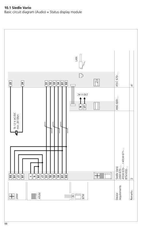
98
10.1 Siedle Vario Basic circuit diagram (Audio) + Status display module
ATL
M
ZAM
BTM
Sied
le V
ario
ZAM
670
-…A
TLM
670
-… /
ATL
M 6
71-…
BTM
650
-…
j)
AN
G 6
00-…
ATL
C 6
70-…
23 24
D2
D1 c1 b1 S4S3 D2
D1
S2S1c b b1 c1
S4S3 D2
D1
S2S1
N L1
a)
Dev
ice
requ
irem
ents
Rem
arks
Tö 1
2�V
�AC
/DC
min
. 20�
Ohm
230 V AC
LAN
99
Notes on the circuit diagrama) If door releases or gate control systems are fitted and their con-nected values do not correspond to 12 V AC/DC and min. 20 Ohm, then either switching output 2 (ATLC ter-minals 13/14 (output)) or switching output 3 (ANG terminals 11/12/14 (output)) can be used as a potential-free door release contact.To use switching output 2 or 3 as a potential-free door release contact, you must configure the corre-sponding ATLC switching output in the Access administration interface.• The use of the potential-free switching outputs is described in separate diagrams.(For detailed information, see page 70, 72)
j) Where there are more than 18 BTM 650-… units (ATLM 670-…) / 2 BTM 650-… units (ATLM 671-…), an additional 12 V AC supply, for instance TR 603-…, must be installed due to the current con-sumption. To use the additional supply, the jumpers on the ATLM are removed from b1/c1 to b/c and the b/c terminals are directly connected to the additional supply.• Supply limits ATLC/NG 670-… (For detailed information, see page 18, 19, 23)• The use of an additional power supply is described in a separate diagram.(For detailed information, see page 74)
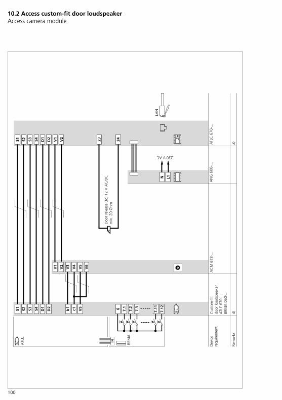
100
10.2 Access custom-fit door loudspeaker Access camera module
ATL
E
BRM
A
ATL
C 6
70-.
..
6 7.1
7.2
7.3
7.11
230 V AC
N L1
AN
G 6
00-.
..
7.12
V6
23 24
V5
D2
S2S1 D1
S4S3
V5
V4
V1
V3
c1b1
V2
V2
V1
S4 D2
D1
S1 S3S2
LAN
a)d)
AC
M 6
73-.
..
IN
Dev
ice
requ
irem
ent
Rem
arks
Cus
tom
-fit
door
loud
spea
ker
ATL
E 67
0-...
BRM
A 0
50-.
..
Doo
r re
leas
e (T
ö) 1
2 V
AC
/DC
min
. 20
Ohm

101
Notes on the circuit diagrama) If door releases or gate control systems are fitted and their con-nected values do not correspond to 12 V AC/DC and min. 20 Ohm, then either switching output 2 (ATLC ter-minals 13/14 (output)) or switching output 3 (ANG terminals 11/12/14 (output)) can be used as a potential-free door release contact.To use switching output 2 or 3 as a potential-free door release contact, you must configure the corre-sponding ATLC switching output in the Access administration interface.• The use of the potential-free switching outputs is described in separate diagrams.(For detailed information, see page 70, 72)
d) A maximum of 12 call but-tons can be connected at one BRMA 050-…The maximum configuration is 16 BRMA 050-… units/192 buttons.
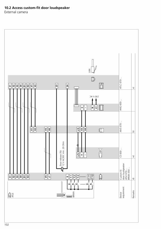
102
10.2 Access custom-fit door loudspeaker External camera
ATL
E
BRM
A
b)
ATL
C 6
70-.
..
c1 6 7.1
7.2
7.3
7.11
L/S + -
230 V AC
N L1
AN
G 6
00-.
..
+ -
L/S
7.12
V6
23 24
V5
D2
S2S1 D1
S4S3
V5
V4
V1
V3
V2
V2
V1
S4 D2
D1
S1 S3S2
CE
600-
…A
IVS
670-
...
LAN
a)d)
w)
IN
Dev
ice
requ
irem
ent
Rem
arks
Cus
tom
-fit
door
loud
spea
ker
ATL
E 67
0-...
BRM
A 0
50-.
..
Doo
r re
leas
e (T
ö)
12 V
AC
/DC
min
. 20
Ohm
103
Notes on the circuit diagrama) If door releases or gate control systems are fitted and their con-nected values do not correspond to 12 V AC/DC and min. 20 Ohm, then either switching output 2 (ATLC ter-minals 13/14 (output)) or switching output 3 (ANG terminals 11/12/14 (output)) can be used as a potential-free door release contact.To use switching output 2 or 3 as a potential-free door release contact, you must configure the corre-sponding ATLC switching output in the Access administration interface.• The use of the potential-free switching outputs is described in separate diagrams.(For detailed information, see page 70, 72)
b) Distance between the camera and AIVS 670-… max. 10 m
d) A maximum of 12 call but-tons can be connected at one BRMA 050-…The maximum configuration is 16 BRMA 050-… units/192 buttons.
w) Supply limits ATLC/NG 670-… (For detailed information, see page 18, 23)

104
10.2 Access custom-fit door loudspeaker Basic circuit diagram (Audio)
ATL
E
BRM
A
ATL
C 6
70-.
..
6 7.1
7.2
7.3
7.11
230 V AC
N L1
AN
G 6
00-.
..
7.12
23 24
D2
S2S1 D1
S4S3
S4 D2
D1
S1 S3S2
LAN
d)a)
IN
Rem
arks
Acc
ess
cust
om-fi
t do
or lo
udsp
eake
rA
TLE
670-
...BR
MA
050
-...
Dev
ice
requ
irem
ent
Doo
r re
leas
e (T
ö) 1
2 V
AC
/DC
min
. 20
Ohm
105
Notes on the circuit diagrama) If door releases or gate control systems are fitted and their con-nected values do not correspond to 12 V AC/DC and min. 20 Ohm, then either switching output 2 (ATLC ter-minals 13/14 (output)) or switching output 3 (ANG terminals 11/12/14 (output)) can be used as a potential-free door release contact.To use switching output 2 or 3 as a potential-free door release contact, you must configure the corre-sponding ATLC switching output in the Access administration interface.• The use of the potential-free switching outputs is described in separate diagrams.(For detailed information, see page 70, 72)
d) A maximum of 12 call but-tons can be connected at one BRMA 050-…The maximum configuration is 16 BRMA 050-… units/192 buttons.
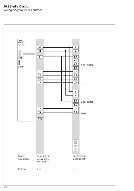
106
10.3 Siedle Classic Wiring diagram for call buttons
ACM
ATLE
BRMA
Tö 12 V ACmin. 20 Ohm
ATLC 670-...
c1
6
7.1
7.2
7.3
7.11
230
V A
C
N
L1
ANG 600-...
+-
7.12
V2
23
24
V5
D2
S2
S1
D1
S4
S3
V1
V4
V5
V3
V6
V2
V1
S4
D2
D1
S1
S3
S2
LAN
a)d)
IN
Gerätebedarf
Hinweise
Classic TürstationACM 670-...ATLE 670-...BRMA 050-...
l), q) y)Remarks
2 call buttons
4 call buttons

107
Notes on the circuit diagraml) The internal wiring of the Classic door station is completed on site by the customer.
q) Where there are more than 20 backlit call buttons, an additional 12 V AC supply, for instance TR 603-…, must be installed due to the current consumption. To use the additional supply, the jumpers between the CATLE and the call but-tons from b1/c1 to b/c are removed and the b/c terminals are directly connected to the additional supply. The jumpers from the ACM camera module to CATLE between the ter-minals V3/V4 and the terminals b1/c1 remain as they are.• Supply limits ATLC/NG 670-… (For detailed information, see page 18)
Call button block
Button Terminal designa-tions for the button
Button back-lighting
7.1
6.1
7.2
6.2
7.3
6.3
7.4
6.4
JP7.1
JP7.2
JP7.3
JP7.4
With 1 button
1 6 7 b, c
With 2 buttons
1 6.1 7.1 b, c
2 6.2 7.2
With 3 buttons
1 6.1 7.1 b, c
2 6.2 7.2
3 6.3 7.3
With 4 buttons
1 6.1 7.1 b, c
2 6.2 7.2
3 6.3 7.3
4 6.4 7.4
y) The circuit diagram shows an exemplary connection of call buttons with the BRMA.• In the case of Siedle Classic, the call button blocks come in designs with 1, 2, 3 and 4 call buttons. On call button blocks with more than one call button, all terminals 6… are connected to one another (see table and image). If a button is to be potential-free, the corresponding JP… bridge must be disconnected on the PCB of the call button block. • If more than 4 call buttons are required, the call button blocks are cascaded accordingly (e.g. 7 call but-tons = call button block with 4 and 3 call buttons).• If there is more than one call button block, then at least one of the terminal 6… must be connected straight through between all call button blocks.
Example: In the case of 7 call but-tons, terminal 6.1 of the first call button block is bridged with ter-minal 6.1 of the second call button block (see wiring diagram). Terminals 6… are bridged with one another on each call button block and do not need to be additionally wired/bridged (exception: a button is used independently as a potential-free contact and the corresponding jumpers have been disconnected).
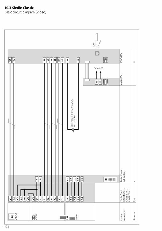
108
ACM
ATLE
BRMA
Tö 12 V ACmin. 20 Ohm
ATLC 670-...
c1
6
7.1
7.2
7.3
7.11
230
V A
C
N
L1
ANG 600-...
+-
7.12
V2
23
24
V5
D2
S2
S1
D1
S4
S3
V1
V4
V5
V3
V6
V2
V1
S4
D2
D1
S1
S3
S2
LAN
a)d)
IN
Gerätebedarf
Hinweise
Classic TürstationACM 670-...ATLE 670-...BRMA 050-...
CA
CM
CA
TLE
BRM
A
ATL
C 6
70-.
..
c1 6 7.1
7.2
7.3
230 V AC
N L1
AN
G 6
00-.
..
b1
V2
23 24
V5
D2
S2S1 D1
S4S3V1
V4
V6
V3
V5
V2
V1
S4 D2
D1
S1 S3S2
LAN
a)
Sied
le C
lass
icC
AC
M 6
73-.
..C
ATL
E 67
0-...
BRM
A 0
50-.
..
l), q
)
Sied
le C
lass
ic
y)
7.4
7.4
IN
Dev
ice
requ
irem
ent
Rem
arks
Doo
r re
leas
e (T
ö) 1
2 V
AC
/DC
min
. 20
Ohm
Cal
l but
tons
10.3 Siedle Classic Basic circuit diagram (Video)
109
Notes on the circuit diagrama) If door releases or gate control systems are fitted and their con-nected values do not correspond to 12 V AC/DC and min. 20 Ohm, then either switching output 2 (ATLC ter-minals 13/14 (output)) or switching output 3 (ANG terminals 11/12/14 (output)) can be used as a potential-free door release contact.To use switching output 2 or 3 as a potential-free door release contact, you must configure the corre-sponding ATLC switching output in the Access administration interface.• The use of the potential-free switching outputs is described in separate diagrams.(For detailed information, see page 70, 72)
l) The internal wiring of the Classic door station is completed on site by the customer.• The connection of the call button modules is described in a separate diagram. (For detailed information, see page 106)
q) Where there are more than 20 backlit call buttons, an additional 12 V AC supply, for instance TR 603-…, must be installed due to the current consumption. To use the additional supply, the jumpers between the CATLE and the call but-tons from b1/c1 to b/c are removed and the b/c terminals are directly connected to the additional supply. The jumpers from the ACM camera module to CATLE between the ter-minals V3/V4 and the terminals b1/c1 remain as they are.• Supply limits ATLC/NG 670-… (For detailed information, see page 18, 23)• The use of an additional power supply is described in a separate diagram.(For detailed information, see page 74)
y) The circuit diagram shows an exemplary connection of call buttons with the BRMA.• (For detailed information, see page 107)

110
10.3 Siedle Classic Pilfer safeguard
CA
CM
CA
TLE
BRM
A
ATL
C 6
70-.
..
c1 6 7.1
7.2
7.3
230 V AC
N L1
AN
G 6
00-.
..
b1
V2
23 24V
5
D2
S2S1 D1
S4S3V1
V4
V6
V3
V5
V2
V1
S4 D2
D1
S1 S3S2
LAN
a)
Sied
le C
lass
icC
AC
M 6
73-.
..C
ATL
E 67
0-...
BRM
A 0
50-.
..
l), q
)
Sied
le C
lass
ic
y)
TR�6
02-…
SDSC
�602
-…+
2 x
ZDS/
CL
N L1
230 V AC
M1
M2
blgr blgrZD
S/C
L
ZDS/
CL
g)
7.4
7.4
IN
Dev
ice
requ
irem
ent
Rem
arks
Doo
r re
leas
e (T
ö) 1
2 V
AC
/DC
min
. 20
Ohm
Cal
l but
tons

111
Notes on the circuit diagrama) If door releases or gate control systems are fitted and their con-nected values do not correspond to 12 V AC/DC and min. 20 Ohm, then either switching output 2 (ATLC ter-minals 13/14 (output)) or switching output 3 (ANG terminals 11/12/14 (output)) can be used as a potential-free door release contact.To use switching output 2 or 3 as a potential-free door release contact, you must configure the corre-sponding ATLC switching output in the Access administration interface.• The use of the potential-free switching outputs is described in separate diagrams.(For detailed information, see page 70, 72)
g) Operation via the door station’s internal power supply is not possible. A separate power supply is required.
l) The internal wiring of the Classic door station is completed on site by the customer.• The connection of the call button modules is described in a separate diagram. (For detailed information, see page 106)
q) Where there are more than 20 backlit call buttons, an additional 12 V AC supply, for instance TR 603-…, must be installed due to the current consumption. To use the additional supply, the jumpers between the CATLE and the call but-tons from b1/c1 to b/c are removed and the b/c terminals are directly connected to the additional supply. The jumpers from the ACM camera module to CATLE between the ter-minals V3/V4 and the terminals b1/c1 remain as they are.• Supply limits ATLC/NG 670-… (For detailed information, see page 18, 23)• The use of an additional power supply is described in a separate diagram.(For detailed information, see page 74)
y) The circuit diagram shows an exemplary connection of call buttons with the BRMA.• (For detailed information, see page 107)
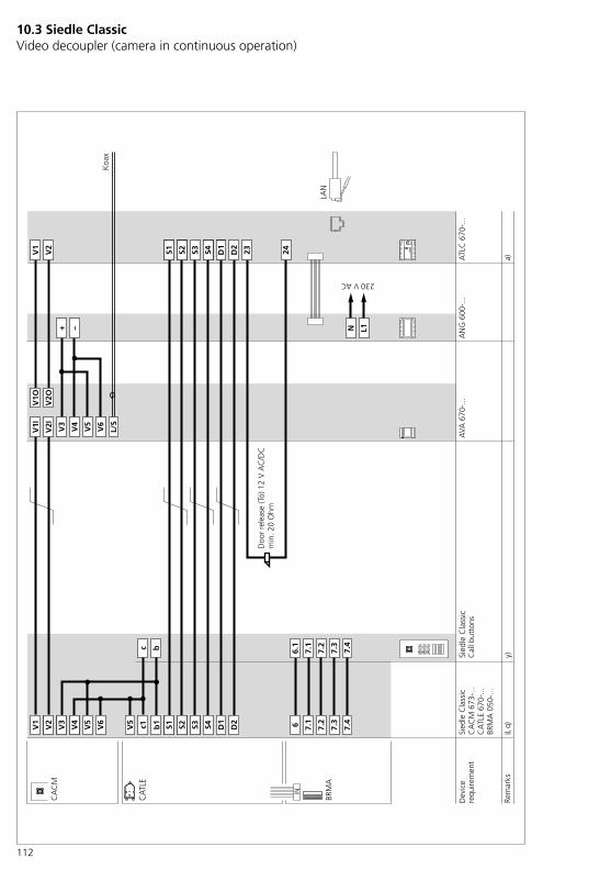
112
10.3 Siedle ClassicVideo decoupler (camera in continuous operation)
Sied
le C
lass
ic
CA
TLE
670-
...BR
MA
050
-...
CA
CM
673
-...
CAT
LE
BRM
A
23 24V1
D2
S2S1 S3 D1
S4V2
V3
V6
V5
L/S
V4
+ –
V1I
V2I
V1O
V2O
V5
V6
V5
S4S3 D2
D1
S2V1
S1V2 c1V4
V3
L1
230 V AC
N
ATL
C 6
70-.
..A
NG
600
-...
AVA
670
-...
LAN
b1
Koa
x
a)i),
q)
CA
CM
6 7.1
7.2
7.3
y)Sied
le C
lass
ic
6.1
7.4
7.4
IN
Dev
ice
requ
irem
ent
Rem
arks
Doo
r re
leas
e (T
ö) 1
2 V
AC
/DC
min
. 20
Ohm
Cal
l but
tons
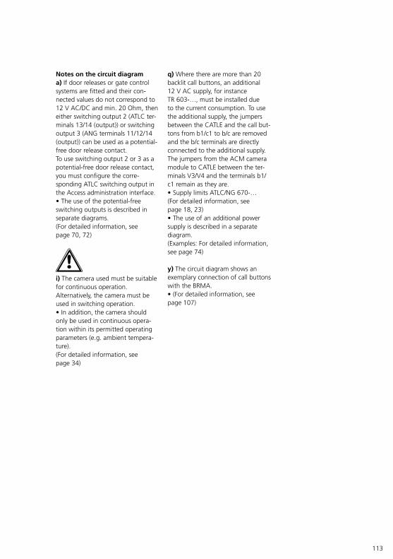
113
Notes on the circuit diagrama) If door releases or gate control systems are fitted and their con-nected values do not correspond to 12 V AC/DC and min. 20 Ohm, then either switching output 2 (ATLC ter-minals 13/14 (output)) or switching output 3 (ANG terminals 11/12/14 (output)) can be used as a potential-free door release contact.To use switching output 2 or 3 as a potential-free door release contact, you must configure the corre-sponding ATLC switching output in the Access administration interface.• The use of the potential-free switching outputs is described in separate diagrams.(For detailed information, see page 70, 72)
i) The camera used must be suitable for continuous operation. Alternatively, the camera must be used in switching operation.• In addition, the camera should only be used in continuous opera-tion within its permitted operating parameters (e.g. ambient tempera-ture).(For detailed information, see page 34)
q) Where there are more than 20 backlit call buttons, an additional 12 V AC supply, for instance TR 603-…, must be installed due to the current consumption. To use the additional supply, the jumpers between the CATLE and the call but-tons from b1/c1 to b/c are removed and the b/c terminals are directly connected to the additional supply. The jumpers from the ACM camera module to CATLE between the ter-minals V3/V4 and the terminals b1/c1 remain as they are.• Supply limits ATLC/NG 670-… (For detailed information, see page 18, 23)• The use of an additional power supply is described in a separate diagram.(Examples: For detailed information, see page 74)
y) The circuit diagram shows an exemplary connection of call buttons with the BRMA.• (For detailed information, see page 107)

114
10.3 Siedle Classic 2 mail notification systems
ACM
ATLE
BRMA
Tö 12 V ACmin. 20 Ohm
ATLC 670-...
c1
6
7.1
7.2
7.3
7.11
230
V A
C
N
L1
ANG 600-...
+-
7.12
V2
23
24
V5
D2
S2
S1
D1
S4
S3
V1
V4
V5
V3
V6
V2
V1
S4
D2
D1
S1
S3
S2
LAN
a)d)
IN
Gerätebedarf
Hinweise
Classic TürstationACM 670-...ATLE 670-...BRMA 050-...
ACM
ATLE
BRMA
Tö 12 V ACmin. 20 Ohm
ATLC 670-...
c1
6
7.1
7.2
7.3
7.11
230
V A
C
N
L1
ANG 600-...
+-
7.12
V2
23
24
V5
D2
S2
S1
D1
S4
S3
V1
V4
V5
V3
V6
V2
V1
S4
D2
D1
S1
S3
S2
LAN
a)d)
IN
Gerätebedarf
Hinweise
Classic TürstationACM 670-...ATLE 670-...BRMA 050-...
CA
CM
CA
TLE
BRM
A
ATL
C 6
70-.
..
c1 6 7.1
7.2
7.3
230 V AC
N L1
AN
G 6
00-.
..
b1
V2
23 24V
5
D2
S2S1 D1
S4S3V1
V4
V6
V3
V5
V2
V1
S4 D2
D1
S1 S3S2
LAN
a)
Sied
le C
lass
icC
AC
M 6
73-.
..C
ATL
E 67
0-...
BRM
A 0
50-.
..
l), q
)
ATL
CE
670-
...
1615
1615
PME
600-
...PM
E 60
0-...
1615
1615 bc
bc
x)x)
230 V AC
N L1bc
TR 6
03-.
..
w)
Sied
le C
lass
ic
y)
6.1
IN
Dev
ice
requ
irem
ent
Rem
arks
Doo
r re
leas
e (T
ö) 1
2 V
AC
/DC
min
. 20
Ohm
Cal
l but
tons
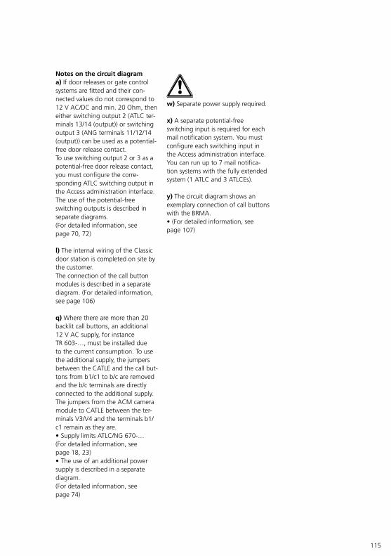
115
Notes on the circuit diagrama) If door releases or gate control systems are fitted and their con-nected values do not correspond to 12 V AC/DC and min. 20 Ohm, then either switching output 2 (ATLC ter-minals 13/14 (output)) or switching output 3 (ANG terminals 11/12/14 (output)) can be used as a potential-free door release contact.To use switching output 2 or 3 as a potential-free door release contact, you must configure the corre-sponding ATLC switching output in the Access administration interface.The use of the potential-free switching outputs is described in separate diagrams.(For detailed information, see page 70, 72)
l) The internal wiring of the Classic door station is completed on site by the customer.The connection of the call button modules is described in a separate diagram. (For detailed information, see page 106)
q) Where there are more than 20 backlit call buttons, an additional 12 V AC supply, for instance TR 603-…, must be installed due to the current consumption. To use the additional supply, the jumpers between the CATLE and the call but-tons from b1/c1 to b/c are removed and the b/c terminals are directly connected to the additional supply. The jumpers from the ACM camera module to CATLE between the ter-minals V3/V4 and the terminals b1/c1 remain as they are.• Supply limits ATLC/NG 670-… (For detailed information, see page 18, 23)• The use of an additional power supply is described in a separate diagram.(For detailed information, see page 74)
w) Separate power supply required.
x) A separate potential-free switching input is required for each mail notification system. You must configure each switching input in the Access administration interface. You can run up to 7 mail notifica-tion systems with the fully extended system (1 ATLC and 3 ATLCEs).
y) The circuit diagram shows an exemplary connection of call buttons with the BRMA.• (For detailed information, see page 107)
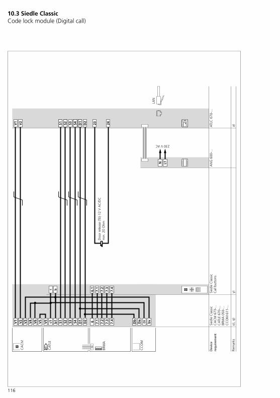
116
10.3 Siedle Classic Code lock module (Digital call)
Sied
le C
lass
ic
CA
TLE
670-
...BR
MA
050
-...
CC
OM
611
-...
CA
CM
673
-...
CA
TLE
BRM
A
23V1
D2
S2S1 S3 D1
S4V2
c1V5
V5
V6
S4S3 D2
D1
Da
Db
bvS2V1
S1V2
b1
V4
V3
N L1
230 V AC
CA
CM
ATL
C 6
70-.
..A
NG
600
-...
LAN
cvC
CO
M
a)o)
, q)
247.
37.
27.
16
Sied
le C
lass
ic
y)
7.4
7.3
7.2
7.1
6.1
7.4
IN
Rem
arks
Device
requ
iremen
t
Doo
r re
leas
e (T
ö) 1
2 V
AC
/DC
min
. 20
Ohm
Cal
l but
tons

117
Notes on the circuit diagrama) If door releases or gate control systems are fitted and their con-nected values do not correspond to 12 V AC/DC and min. 20 Ohm, then either switching output 2 (ATLC ter-minals 13/14 (output)) or switching output 3 (ANG terminals 11/12/14 (output)) can be used as a potential-free door release contact.To use switching output 2 or 3 as a potential-free door release contact, you must configure the corre-sponding ATLC switching output in the Access administration interface.The use of the potential-free switching outputs is described in separate diagrams.(For detailed information, see page 70, 72)
o) The COM 611-… code lock module is always available for making calls (direct dial via numeric code).Together with the EC 602-… entrance controller, additional con-trol functions (e.g. access control) can be carried out for this door station.
q) Where there are more than 20 backlit call buttons, an additional 12 V AC supply, for instance TR 603-…, must be installed due to the current consumption. To use the additional supply, the jumpers between the CATLE and the call but-tons from b1/c1 to b/c are removed and the b/c terminals are directly connected to the additional supply. The jumpers from the ACM camera module to CATLE between the ter-minals V3/V4 and the terminals b1/c1 remain as they are.• Supply limits ATLC/NG 670-… (For detailed information, see page 18, 23)• The use of an additional power supply is described in a separate diagram.(Examples: For detailed information, see page 74)
y) The circuit diagram shows an exemplary connection of call buttons with the BRMA.• (For detailed information, see page 107)
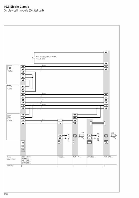
118
10.3 Siedle Classic Display call module (Digital call)
CATLE
ATLC 670-...
N
L1
ANG 600-...
N
L1
TR 603-...
c
b
23
24
D2
S2
S1
D1
S4
S3
V1
V2 V2
V1
S4
D2
D1
S1
S3
S2
LAN
CACM
Siedle ClassicCACM 673-...CATLE 670-...CDRM 612-...
CDRM W4
W3
W6
W5
PRI
Db
Da
cv
bv
ZWA 640-...
g) a)n)
V3
V4
V6
V5
V5
c1
b1
Büchner Claudia
Schuhmacher Michael
Namensuche mit
OK
Maier Klaus
Büchner Claudia
Schuhmacher Michael
Namensuche mit
OK
Maier Klaus
Devicerequirement
230
V A
C
230
V A
C
Remarks
Door release (Tö) 12 V AC/DCmin. 20 Ohm
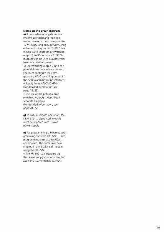
119
Notes on the circuit diagrama) If door releases or gate control systems are fitted and their con-nected values do not correspond to 12 V AC/DC and min. 20 Ohm, then either switching output 2 (ATLC ter-minals 13/14 (output)) or switching output 3 (ANG terminals 11/12/14 (output)) can be used as a potential-free door release contact.To use switching output 2 or 3 as a potential-free door release contact, you must configure the corre-sponding ATLC switching output in the Access administration interface.• Supply limits ATLC/NG 670-… (For detailed information, see page 18, 23)• The use of the potential-free switching outputs is described in separate diagrams.(For detailed information, see page 70, 72)
g) To ensure smooth operation, the DRM 612-… display call module must be supplied with its own power supply.
n) For programming the names, pro-gramming software PRS 602-… and programming interface PRI 602-… are required. The names are now entered in the display call module using the PRS 602-… • The PRI 602-… is supplied via the power supply connected to the ZWA 640-…, (terminals W3/W4).

120
Siedle Steel
SATLM 670-...SACM 673-...
SATLM
23
24
V1
D2
S2
S1
S3
D1
S4
V2
S4
S3
D2
D1
S2
S1
V2
V1
N
L1
230
V A
C
SACM
ATLC 670-...ANG 600-...
LAN
a)Remarks
Devicerequirement
Buttons
Door release (Tö) 12 V AC/DCmin. 20 Ohm
10.4 Siedle Steel Basic circuit diagram (Video)
121
Notes on the circuit diagrama) If door releases or gate control systems are fitted and their con-nected values do not correspond to 12 V AC/DC and min. 20 Ohm, then either switching output 2 (ATLC ter-minals 13/14 (output)) or switching output 3 (ANG terminals 11/12/14 (output)) can be used as a potential-free door release contact.To use switching output 2 or 3 as a potential-free door release contact, you must configure the corre-sponding ATLC switching output in the Access administration interface.• Supply limits ATLC/NG 670-… (For detailed information, see page 18, 23)• The use of the potential-free switching outputs is described in separate diagrams.(For detailed information, see page 70, 72)
• Where there are more than 20 backlit call buttons, an additional 12 V AC supply for instance TR 603-… must be installed due to the current consumption. To use the additional supply, remove the jumpers on the SATLM… connection board from b1/c1 to b/c and connect the terminals b/c of the call buttons directly to the additional supply.• Supply limits ATLC/NG 670-… (For detailed information, see page 18, 23)
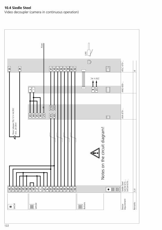
122
10.4 Siedle Steel Video decoupler (camera in continuous operation)
Sied
le S
teel
SATL
M 6
70-.
..SA
CM
673
-...
SATL
M
23 24 V1
D2
S2S1 S3 D1
S4V2
V3
V6
V5
L/S
V4
+ –
V1I
V2I
V1O
V2O
V5
V6
V6
V5
S4S3 D2
D1
S2V2
S1V1 c1 bc V2
V1
V4
V3
L1
230 V AC
N
ATL
C 6
70-.
..A
NG
600
-...
AVA
670
-...
LAN
b1
Koa
x
a)i),
z)
SAC
M
Dev
ice
requ
irem
ent
Rem
arks
Doo
r re
leas
e (T
ö) 1
2 V
AC
/DC
min
. 20
Ohm
Butt
ons
Not
es o
n th
e ci
rcui
t di
agra
m!

123
Notes on the circuit diagrama) If door releases or gate control systems are fitted and their con-nected values do not correspond to 12 V AC/DC and min. 20 Ohm, then either switching output 2 (ATLC ter-minals 13/14 (output)) or switching output 3 (ANG terminals 11/12/14 (output)) can be used as a potential-free door release contact.To use switching output 2 or 3 as a potential-free door release contact, you must configure the corre-sponding ATLC switching output in the Access administration interface.• Supply limits ATLC/NG 670-… (For detailed information, see page 18, 23)• The use of the potential-free switching outputs is described in separate diagrams.(Examples: For detailed information, see page 70, 72)
• Where there are more than 20 backlit call buttons, an additional 12 V AC supply for instance TR 603-… must be installed due to the current consumption. To use the additional supply, remove the jumpers on the SATLM… connection board from b1/c1 to b/c and connect the terminals b/c of the call buttons directly to the additional supply.• Supply limits ATLC/NG 670-… (For detailed information, see page 18, 23)
i) The camera used must be suit-able for continuous operation. Alternatively, the camera must be used in switching operation.• In addition, the camera should only be used in continuous opera-tion within its permitted operating parameters (e.g. ambient tempera-ture).(For detailed information, see page 34)
z) Before wiring, the 6-pole ribbon cable between the con-nection pcb SACM and the connection pcb SATLM must be removed.
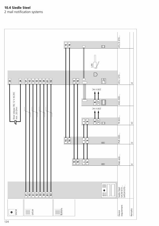
124
10.4 Siedle Steel 2 mail notification systems
SAC
M
ATL
C 6
70-.
..
230 V AC
N L1
AN
G 6
00-.
..
V2
23 24
D2
S2S1 D1
S4S3V1
V2
V1
S4 D2
D1
S1 S3S2
LAN
a)
Sied
le S
teel
SAC
M 6
73-.
..SA
TLM
670
-...
ATL
CE
670-
...
1615
1615
PME
600-
...PM
E 60
0-...
1615
1615 bc
bc
x)x)
230 V AC
N L1bc
TR 6
03-.
..
w)
SATL
M
Dev
ice
requ
irem
ent
Rem
arks
Butt
ons
Doo
r re
leas
e (T
ö) 1
2 V
AC
/DC
min
. 20
Ohm

125
Notes on the circuit diagrama) If door releases or gate control systems are fitted and their con-nected values do not correspond to 12 V AC/DC and min. 20 Ohm, then either switching output 2 (ATLC ter-minals 13/14 (output)) or switching output 3 (ANG terminals 11/12/14 (output)) can be used as a potential-free door release contact.To use switching output 2 or 3 as a potential-free door release contact, you must configure the corre-sponding ATLC switching output in the Access administration interface.• Supply limits ATLC/NG 670-… (For detailed information, see page 18, 23)• The use of the potential-free switching outputs is described in separate diagrams.(For detailed information, see page 70, 72)
• Where there are more than 20 backlit call buttons, an additional 12 V AC supply for instance TR 603-… must be installed due to the current consumption. To use the additional supply, remove the jumpers on the SATLM… connection board from b1/c1 to b/c and connect the terminals b/c of the call buttons directly to the additional supply.• Supply limits ATLC/NG 670-… (For detailed information, see page 18, 23)
w) Separate power supply required.
x) A separate potential-free switching input is required for each mail notification system.• You must configure each switching input in the Access administration interface.• You can run up to 7 mail notifica-tion systems with the fully extended system (1 ATLC and 3 ATLCEs).
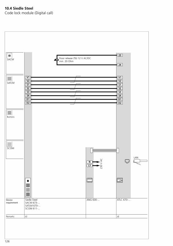
126
10.4 Siedle Steel Code lock module (Digital call)
Siedle Steel
SATLM 670-...SCOM 611-...
SACM 673-...
SATLM
23
V1
D2
S2S1
S3
D1S4
V2
S4S3
D2D1
S2
V1
S1V2
NL1
230
V A
C
SACM
ATLC 670-...ANG 600-...
LAN
SCOM
a)o)
24
Remarks
Devicerequirement
Buttons
Door release (Tö) 12 V AC/DCmin. 20 Ohm
127
Notes on the circuit diagrama) If door releases or gate control systems are fitted and their con-nected values do not correspond to 12 V AC/DC and min. 20 Ohm, then either switching output 2 (ATLC ter-minals 13/14 (output)) or switching output 3 (ANG terminals 11/12/14 (output)) can be used as a potential-free door release contact.To use switching output 2 or 3 as a potential-free door release contact, you must configure the corre-sponding ATLC switching output in the Access administration interface.• Supply limits ATLC/NG 670-… (For detailed information, see page 18, 23)• The use of the potential-free switching outputs is described in separate diagrams.(For detailed information, see page 70, 72)
o) The COM 611-… code lock module is always available for making calls (direct dial via numeric code).Together with the EC 602-… entrance controller, additional con-trol functions (e.g. access control) can be carried out for this door station.
• Where there are more than 20 backlit call buttons, an additional 12 V AC supply for instance TR 603-… must be installed due to the current consumption. To use the additional supply, remove the jumpers on the SATLM… connection board from b1/c1 to b/c and connect the terminals b/c of the call buttons directly to the additional supply.• Supply limits ATLC/NG 670-… (For detailed information, see page 18, 23)
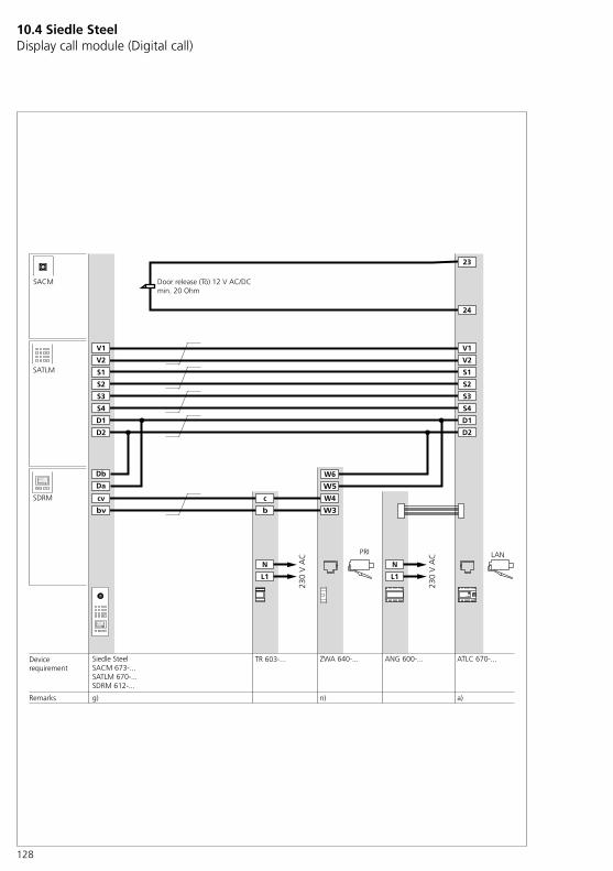
128
SATLM
ATLC 670-...
N
L1
ANG 600-...
N
L1
TR 603-...
c
b
23
24
D2
S2
S1
D1
S4
S3
V1
V2 V2
V1
S4
D2
D1
S1
S3
S2
LAN
SACM
Siedle SteelSACM 673-...SATLM 670-...SDRM 612-...
SDRM W4
W3
W6
W5
PRI
Db
Da
cv
bv
ZWA 640-...
g) a)n)
Büchner Claudia
Schuhmacher Michael
Namensuche mit
Maier Klaus
OK
Büchner Claudia
Schuhmacher Michael
Namensuche mit
Maier Klaus
OK
Devicerequirement
230
V A
C
230
V A
C
Remarks
Door release (Tö) 12 V AC/DCmin. 20 Ohm
10.4 Siedle Steel Display call module (Digital call)
129
Notes on the circuit diagrama) If door releases or gate control systems are fitted and their con-nected values do not correspond to 12 V AC/DC and min. 20 Ohm, then either switching output 2 (ATLC ter-minals 13/14 (output)) or switching output 3 (ANG terminals 11/12/14 (output)) can be used as a potential-free door release contact.To use switching output 2 or 3 as a potential-free door release contact, you must configure the corre-sponding ATLC switching output in the Access administration interface.• Supply limits ATLC/NG 670-… (For detailed information, see page 18, 23)• The use of the potential-free switching outputs is described in separate diagrams.(For detailed information, see page 70, 72)
g) To ensure smooth operation, the DRM 612-… display call module must be supplied with its own power supply.
n) For programming the names, pro-gramming software PRS 602-… and programming interface PRI 602-… are required. The names are now entered in the display call module using the PRS 602-… • The PRI 602-… is supplied via the power supply connected to the ZWA 640-…, (terminals W3/W4).
• Where there are more than 20 backlit call buttons, an additional 12 V AC supply for instance TR 603-… must be installed due to the current consumption. To use the additional supply, remove the jumpers on the SATLM… connection board from b1/c1 to b/c and connect the terminals b/c of the call buttons directly to the additional supply.• Supply limits ATLC/NG 670-… (For detailed information, see page 18, 23)

130
10.5 Camera connection External camera
p)y)
ATL
C 6
70-.
..
L/S+ -
230 V AC
N L1
AN
G 6
00-.
..
+ -
L/S
V5
V6
V4
V1
V3
V2
V2
V1
CE
600-
...A
IVS
670-
...
LAN
Rem
arks
Dev
ice
requ
irem
ent

131
FunctionalViewing/monitoring a certain area using an Access indoor call station set up for the purpose.Each camera is specifically selected via the ATLC 670-… The number of cameras/Access users is limited by the server used.Using the buttons defined during configuration, each camera can be selected. This function must be con-figured for every authorized user.
Notes on the circuit diagramp) Camera in continuous operationThe camera used must be suit-able for continuous operation. Alternatively, the camera must be used in switching operation. (For detailed information, see page 78)• In addition, the camera should only be used in continuous opera-tion within its permitted operating parameters (e.g. ambient tempera-ture).(For detailed information, see page 34)
y) Distance between the camera and AIVS 670-… max. 10 m
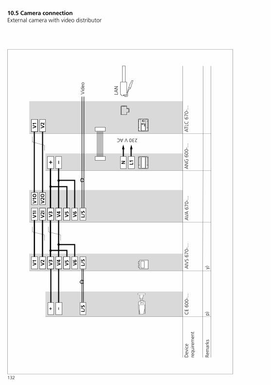
132
y)p)
ATL
C 6
70-.
..
+ –
230 V AC
N L1
AN
G 6
00-.
..
+ –
L/S
V6
V5
V4
V1
V3
V2
V2
V1
CE
600-
...A
IVS
670-
...
LAN
Vid
eo
V6
V5
V1I
V2I
L/S
AVA
670
-...
V4
V3
V1O
V2O
L/S
Rem
arks
Dev
ice
requ
irem
ent
10.5 Camera connection External camera with video distributor
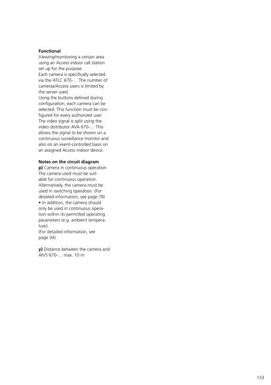
133
FunctionalViewing/monitoring a certain area using an Access indoor call station set up for the purpose.Each camera is specifically selected via the ATLC 670-… The number of cameras/Access users is limited by the server used.Using the buttons defined during configuration, each camera can be selected. This function must be con-figured for every authorized user.The video signal is split using the video distributor AVA 670-… This allows the signal to be shown on a continuous surveillance monitor and also on an event-controlled basis on an assigned Access indoor device.
Notes on the circuit diagramp) Camera in continuous operationThe camera used must be suit-able for continuous operation. Alternatively, the camera must be used in switching operation. (For detailed information, see page 78)• In addition, the camera should only be used in continuous opera-tion within its permitted operating parameters (e.g. ambient tempera-ture).(For detailed information, see page 34)
y) Distance between the camera and AIVS 670-… max. 10 m
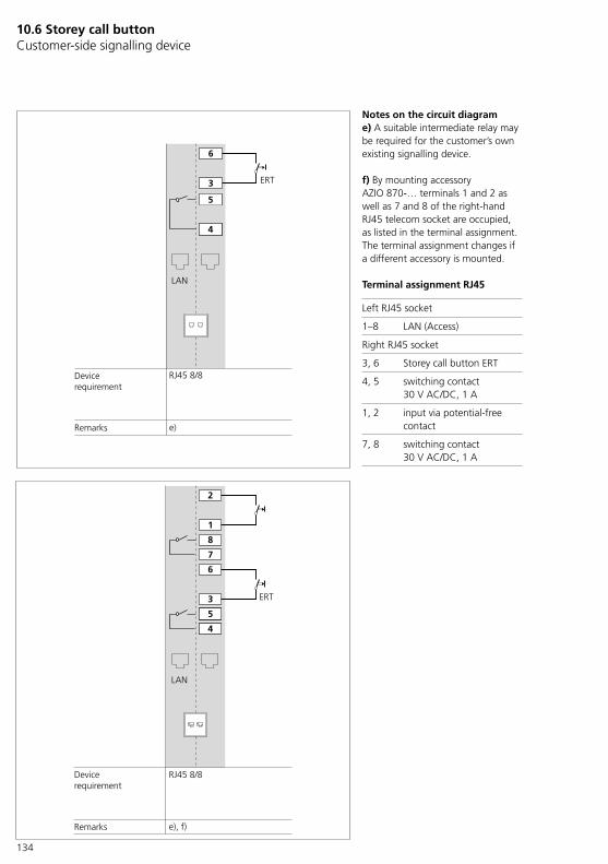
134
10.6 Storey call button Customer-side signalling device
4
5
RJ45 8/8
LAN
e)
ERT3
6
Remarks
Devicerequirement
RJ45 8/8
LAN
ERT3
6
4
5
1
2
7
8
e), f)Remarks
Devicerequirement
Notes on the circuit diagrame) A suitable intermediate relay may be required for the customer’s own existing signalling device.
f) By mounting accessory AZIO 870-… terminals 1 and 2 as well as 7 and 8 of the right-hand RJ45 telecom socket are occupied, as listed in the terminal assignment. The terminal assignment changes if a different accessory is mounted.
Terminal assignment RJ45
Left RJ45 socket
1–8 LAN (Access)
Right RJ45 socket
3, 6 Storey call button ERT
4, 5 switching contact 30 V AC/DC, 1 A
1, 2 input via potential-free contact
7, 8 switching contact 30 V AC/DC, 1 A
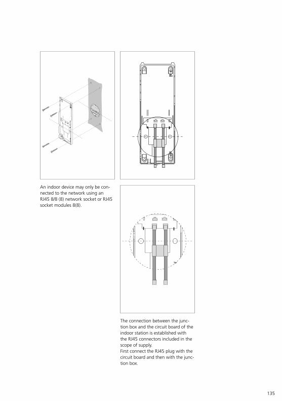
135
An indoor device may only be con-nected to the network using an RJ45 8/8 (8) network socket or RJ45 socket modules 8(8).
The connection between the junc-tion box and the circuit board of the indoor station is established with the RJ45 connectors included in the scope of supply.First connect the RJ45 plug with the circuit board and then with the junc-tion box.
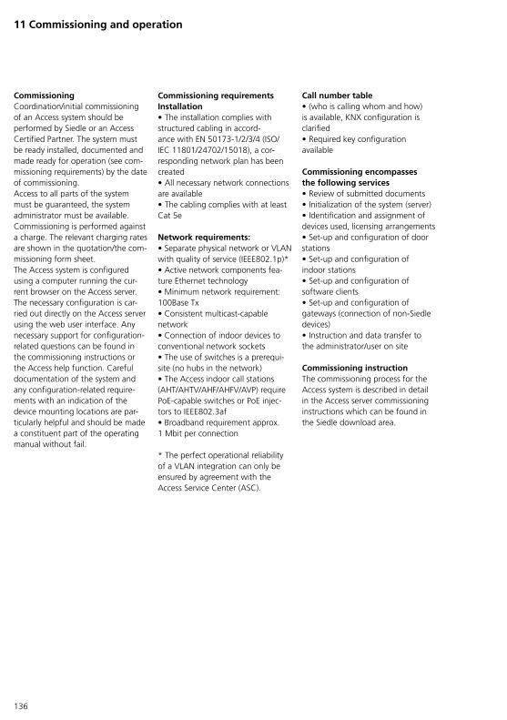
136
Commissioning Coordination/initial commissioning of an Access system should be performed by Siedle or an Access Certified Partner. The system must be ready installed, documented and made ready for operation (see com-missioning requirements) by the date of commissioning.Access to all parts of the system must be guaranteed, the system administrator must be available. Commissioning is performed against a charge. The relevant charging rates are shown in the quotation/the com-missioning form sheet.The Access system is configured using a computer running the cur-rent browser on the Access server. The necessary configuration is car-ried out directly on the Access server using the web user interface. Any necessary support for configuration-related questions can be found in the commissioning instructions or the Access help function. Careful documentation of the system and any configuration-related require-ments with an indication of the device mounting locations are par-ticularly helpful and should be made a constituent part of the operating manual without fail.
Commissioning requirements Installation• The installation complies with structured cabling in accord-ance with EN 50173-1/2/3/4 (ISO/IEC 11801/24702/15018), a cor-responding network plan has been created• All necessary network connections are available• The cabling complies with at least Cat 5e
Network requirements: • Separate physical network or VLAN with quality of service (IEEE802.1p)* • Active network components fea-ture Ethernet technology • Minimum network requirement: 100Base Tx • Consistent multicast-capable network • Connection of indoor devices to conventional network sockets • The use of switches is a prerequi-site (no hubs in the network) • The Access indoor call stations (AHT/AHTV/AHF/AHFV/AVP) require PoE-capable switches or PoE injec-tors to IEEE802.3af • Broadband requirement approx. 1 Mbit per connection
* The perfect operational reliability of a VLAN integration can only be ensured by agreement with the Access Service Center (ASC).
11 Commissioning and operation
Call number table • (who is calling whom and how) is available, KNX configuration is clarified• Required key configuration available
Commissioning encompasses the following services• Review of submitted documents• Initialization of the system (server)• Identification and assignment of devices used, licensing arrangements• Set-up and configuration of door stations• Set-up and configuration of indoor stations• Set-up and configuration of software clients• Set-up and configuration of gateways (connection of non-Siedle devices)• Instruction and data transfer to the administrator/user on site
Commissioning instruction The commissioning process for the Access system is described in detail in the Access server commissioning instructions which can be found in the Siedle download area.
137
Operating manual To ensure that you can retrace the status of a system at any time, an operating manual should be drawn up and regularly maintained.Siedle recommends compiling an operating manual to document the network and the Access system.The operating manual must be accessible to servicing personnel and contain fundamental information:• Contact data of the system admin-istrator (with deputization arrange-ments)• Hardware list• Documentation of the server configuration• Server backup• Documentation of the software status and device configuration• Construction plan with structured cabling (LAN policy)• Issue of passwords and possibilities for remote login access• IP address and device names of the network components• Process descriptions (e.g. creating a user, exchanging devices etc.)• Documentation of changes made• Documentation of errors/remedy of errors
Updates
• The software for all Siedle Access products with network connection is capable of updating. From Access Professional 5... (Linux variant), the server operating system and the Access system software are updated via command line command. Internet access to the Access system is required for this.• The update is initialised by the administrator and centrally executed at the server for all the devices. It is not possible to carry out a single update for an individual indoor device or server.• During the update process, the entire system is non-operational. No calls or functions can be initiated or received. Updates should therefore be carried out during periods of minimal activity and with sufficient advance notice. All buttons flash yellow to visually indicate that the indoor devices are being updated. After the update is complete, the devices are automatically restarted.• During the update process, the power supply to the Siedle devices must not be interrupted, as this can result in damage. In this case, a repeat update is no longer possible, and the devices will have to be sent in for repair.
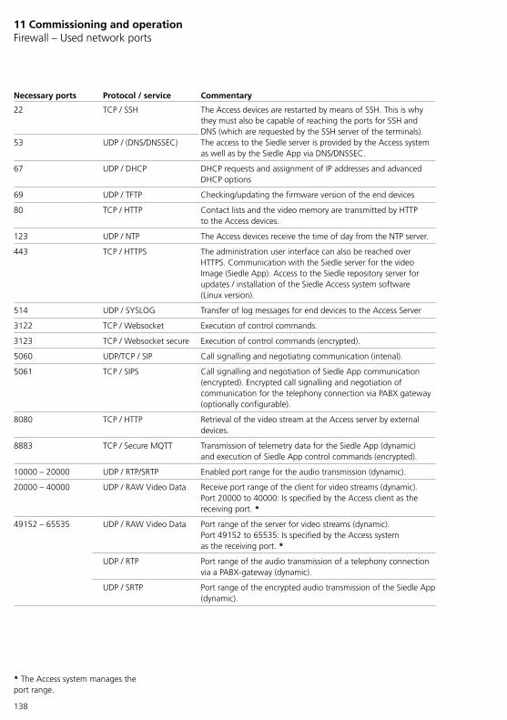
138
11 Commissioning and operation Firewall – Used network ports
* The Access system manages the port range.
Necessary ports Protocol / service Commentary
22 TCP / SSH The Access devices are restarted by means of SSH. This is why they must also be capable of reaching the ports for SSH and DNS (which are requested by the SSH server of the terminals). The access to the Siedle server is provided by the Access system as well as by the Siedle App via DNS/DNSSEC.
53 UDP / (DNS/DNSSEC)
67 UDP / DHCP DHCP requests and assignment of IP addresses and advanced DHCP options
69 UDP / TFTP Checking/updating the firmware version of the end devices
80 TCP / HTTP Contact lists and the video memory are transmitted by HTTP to the Access devices.
123 UDP / NTP The Access devices receive the time of day from the NTP server.
443 TCP / HTTPS The administration user interface can also be reached over HTTPS. Communication with the Siedle server for the video Image (Siedle App). Access to the Siedle repository server for updates / installation of the Siedle Access system software (Linux version).
514 UDP / SYSLOG Transfer of log messages for end devices to the Access Server
3122 TCP / Websocket Execution of control commands.
3123 TCP / Websocket secure Execution of control commands (encrypted).
5060 UDP/TCP / SIP Call signalling and negotiating communication (intenal).
5061 TCP / SIPS Call signalling and negotiation of Siedle App communication (encrypted). Encrypted call signalling and negotiation of communication for the telephony connection via PABX gateway (optionally configurable).
8080 TCP / HTTP Retrieval of the video stream at the Access server by external devices.
8883 TCP / Secure MQTT Transmission of telemetry data for the Siedle App (dynamic) and execution of Siedle App control commands (encrypted).
10000 – 20000 UDP / RTP/SRTP Enabled port range for the audio transmission (dynamic).
20000 – 40000 UDP / RAW Video Data Receive port range of the client for video streams (dynamic). Port 20000 to 40000: Is specified by the Access client as the receiving port. *
49152 – 65535 UDP / RAW Video Data Port range of the server for video streams (dynamic). Port 49152 to 65535: Is specified by the Access system as the receiving port. *
UDP / RTP Port range of the audio transmission of a telephony connection via a PABX-gateway (dynamic).
UDP / SRTP Port range of the encrypted audio transmission of the Siedle App (dynamic).

139
Initial commissioning/Login
Access server variantASH 670-05 S/M
Customer’s own server with installed Access system
Access to the system:The Siedle Access servers can be reached in the network as standard over http://192.168.1.1
Procedure1 Connect the commissioning com-puter directly to the Access server by switch.2 Start the browser on the commis-sioning computer. 3 Enter the pre-configured IP address of the Access server.4 The login screen of the Access system is accessed and opens in the browser window.5 Select the operating language of the Access System Administration.6 Log into the Access system (account name: admin / password: admin). *
Access to the system:The customer’s own server operating system can be reached in the net-work under the individually assigned static IP address.
Procedure1 Connect the commissioning com-puter directly to the Access server by switch.2 Start the browser on the commis-sioning computer. 3 Enter the individually assigned IP address of the server operating system.4 The login screen of the Access system is accessed and opens in the browser window.5 Select the operating language of the Access System Administration.6 Log into the Access system (account name: admin / password: admin). *
* Please change the password on initial commissioning, taking note of the security instructions.
Additional functions at the login window There is one active link provided at the login window:Downloads / Licences: Here, you have dual-language access to information on system require-ments and licence agreements, to the Access software clients (Access Software Concierge and Access Software In-house telephone) and to necessary Windows soft-ware components for operation at Windows PCs.

140
11 Commissioning and operationAs-delivered status (ASH 670-05…)
Accessing the Access system
IP address of the Access Server 192.168.1.1
Subnet mask 255.255.255.0
Standard login data – server operating system (Linux)
User Password * SSH loginroot SiedleAccessMain2019 –
access SiedleAccessMain2015 Active
Standard login data – Access server administration
User Password *admin admin
User access and passwords for the Access system Siedle Access and the server oper-ating system are delivered with standard passwords. Issue new and secure passwords and keep these in a safe location. Forgotten passwords of the Access server and the server operating system cannot be restored and the server operating system would have to be reinstalled and commissioned.All user access codes and pass-words are within the sphere of responsibility of the installer/operator/customer.

141
12 Servicing
Service requirement Access systems are serviced by the regional Access Certified Partner (service specialists). Customers/administrators request this services as the need arises.For services specialists, access must be afforded to all parts of the system at all times. The administrator and all necessary documents appertaining to the system must be available for the duration of the servicing work.
Warranty Siedle excludes the guarantee for configurable functions and system properties on hardware and software supplied by Siedle if com-missioning was not carried out by the Access Service Centre or our Access Certified Partners and this can be verified. Statutory rights for the delivery of defect-free goods are not affected.All system components which are designed for/suitable for installation in an electrical distribution board or in an IT cabinet system/housing may only be installed in the permitted installation position according to the enclosed product information.If system components are operated in improper installation positions or with improper operating parameters (e.g. excessive ambient tempera-ture), this will render their warranty rights void in the event of service.
Exchanging devices All devices which are connected directly to the network (indoor devices and ATLC 670-…) can be exchanged in running operation.Procedure:• The administrator overwrites the MAC address for the device with the MAC address of the new replace-ment device in the server.• Exchange the defective device.• The configuration remains unchanged, making the function identical with the predecessor device.
Exchanging ATLM/ATLE 67x-… Procedure:• Only the line rectifier which sup-plies the ATLC 670-… has to be disconnected from the mains. The Access system can remain opera-tional.• Exchange the defective ATLM/ATLE 670-…• Switch the line rectifier back on.• The system is now completely ready to resume operation. No con-figuration is required.
Exchanging a defective server AS 670-…/ASH 670-… Procedure:1 Sever all connections to the mains and the power supply.2 Exchange the defective server and restore all the connections3 Set up the supplied licences on the new server4 Restore the backup of the current configuration. If no backup exists, the system must be reconfigured.
Update process The update is initialised by the administrator and centrally executed at the server for all the devices. It is not possible to carry out a single update for an individual indoor device or server.During the update process, the entire system is non-operational. No calls or functions can be initiated or received. Updates should therefore be carried out during periods of minimal activity and with sufficient advance notice. All buttons flash yellow to visually indicate that the indoor devices are being updated. After the update is complete, the devices are automatically restarted.During the update process, the power supply to the Siedle devices must not be interrupted, as this can result in damage. In this case, a repeat update is no longer possible, and the devices will have to be sent in for repair.
Start process The start process can be initiated centrally by the administrator at the server. Unplugging and reconnecting the internal devices also initiates a restart. The Access door loudspeaker controller can be restarted by briefly disconnecting the relevant line recti-fier or by actuating the reset button.A restart of the internal devices is signalled by a yellow flashing light, starting with button 8 and ending with button 6, and the display lights up in white. If the start is successful and when the device has received all the information from the server, the system goes to the operating status. In the event of a fault, e.g. the internal device is not configured, all the buttons light up continuously in red.
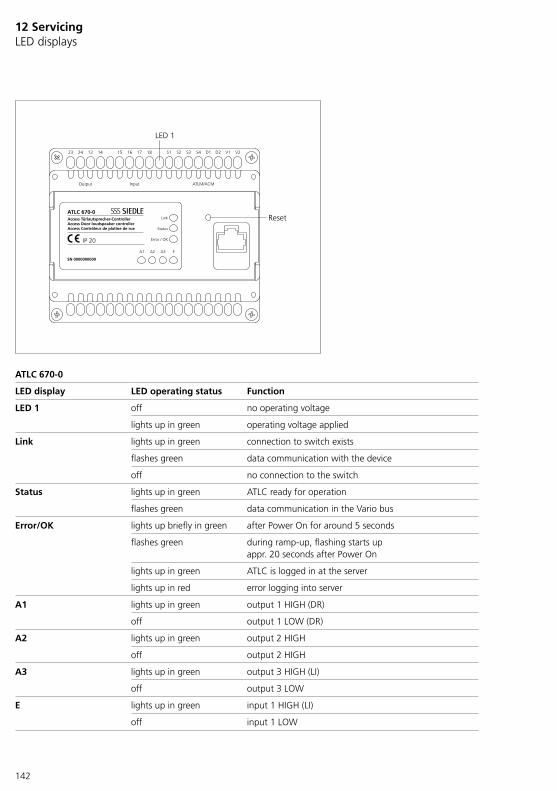
142
12 Servicing LED displays
ATLC 670-0
LED display LED operating status Function
LED 1 off no operating voltage
lights up in green operating voltage applied
Link lights up in green connection to switch exists
flashes green data communication with the device
off no connection to the switch
Status lights up in green ATLC ready for operation
flashes green data communication in the Vario bus
Error/OK lights up briefly in green after Power On for around 5 seconds
flashes green during ramp-up, flashing starts up appr. 20 seconds after Power On
lights up in green ATLC is logged in at the server
lights up in red error logging into server
A1 lights up in green output 1 HIGH (DR)
off output 1 LOW (DR)
A2 lights up in green output 2 HIGH
off output 2 HIGH
A3 lights up in green output 3 HIGH (LI)
off output 3 LOW
E lights up in green input 1 HIGH (LI)
off input 1 LOW
ATLC 670-0
SN 0000000000
IP 20
Access Türlautsprecher-ControllerAccess Door loudspeaker controllerAccess Contrôleur de platine de rue
Link
Status
Error / OK
A1 A2 A3 E
23 24 13 14 15 16 17 18 S1 S2 S3 S4 D1 D2 V1 V2
Output Input ATLM/ACM
LED 1
Reset

143
AHTV/AHFV 670-…
LED display LED operating status Function
LED 8 flashes yellow Searching for the server
off server found
LED 7 flashes yellow loading configuration from server
off export successfully completed
LED 6 flashes yellow login to server
off login successful
LED 1-8 lights up briefly in yellow after Power On for around 5 seconds
lights up in red error logging into server
off successfully logged into server
Flashes for appr. 2 mins. Software update for terminals
ATLM 67x-...
LED display LED operating status Function
LED 1 flashes 3x in green Device starts up
off Ramp up successfully completed
lights up in green Audio active
Flashes briefly 3x in green unassigned/unprogrammed call button is actuated
lights up in red At least 2 ATLMs are connected to one ATLC…! Please reduce installa-tion to 1 ATLM… per ATLC… and restart ATLC…
LED 1
LED 4
LED 5
LED 8
LED 1
LED 8
LED 1

144
12 Servicing Terminal connections and measured values
ATLC 670-0
Terminal Description Measured values
V1V2
Video signal (two-wire FBAS) appr. 40 – 200 mV AConly with active video connection
S1/S2 Loudspeaker and power supply 48 V DC (+) between S1/S2 (+) and S3/S4 (-):
appr. 42.1 - 47.4 V DC(typical: 46.2 V DC)S3/S4 Microphone and power supply
48 V DC (–)
D1D2
Vario bus +Vario bus -
appr. 230 – 270 mV DC(Typical: 250 mV DC)
13/14 Output 2 potential-free -
15/16 Input 1 potential-free * -
17/18 Input 1 electrically isolated *17 (+), 18 (–)
-
23/24 Output 1 potential AC/DC programmable: appr. 10-16 V AC, 13 V DC
* The switching input can either be used potential-free or electrically isolated. It is not intended for simul-taneous use.
ANG 600-0
Terminal Description Measured values
11 Changeover contact A3 common -
12 Changeover contact A3 N.C. contact
-
14 Changeover contact A3 N.O. contact
-
+/– Output voltage 48 V DC, 800 mA appr. 48 V DC
Specification of the changeover contact:• Contact load at least 5 V, 100 mA 10 V, 10 mA 24 V, 1 mA• Admissible switching outputs: • Motor max. 3 A bulbs max. 1300 W• Energy saving lamps max. 18 x Silvania 7 W or 12 x Osram 11 W• Fluorescent lamps uncompensated cos j 0.5 max. 800 VA Duo fluores-cent lamps max. 1200 VA• Parallel compensated fluorescent lamps max. 400 VA• Iron core transformers for low-voltage halogen lamps max. 1000 W• Electronic transformers for low-voltage halogen lamps max. 1300 W
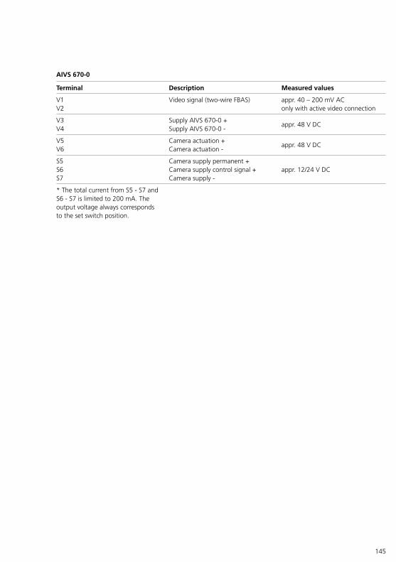
145
AIVS 670-0
Terminal Description Measured values
V1V2
Video signal (two-wire FBAS) appr. 40 – 200 mV AConly with active video connection
V3V4
Supply AIVS 670-0 +Supply AIVS 670-0 -
appr. 48 V DC
V5V6
Camera actuation +Camera actuation -
appr. 48 V DC
S5S6S7
Camera supply permanent +Camera supply control signal +Camera supply -
appr. 12/24 V DC
* The total current from S5 - S7 and S6 - S7 is limited to 200 mA. The output voltage always corresponds to the set switch position.
146
13 Glossary
3G (UMTS)Third generation mobile network standard with transfer rates of up to 42 Mbps if improved data transfer methods (HSDPA+) are used.-> UMTS, HSDPA(+)
4G (LTE-Advanced)Advanced 4th generation LTE mobile network standard (also called LTE Max). Currently transfer rates of up to 300 Mbps are offered. The maximum possible transfer rates may vary from country to country. According to the standard, transfer rates of up to 1000 Mbps are envis-aged.-> LTE-Advanced
Access controlSecurity system which controls the access to a property (plot, building, room, etc.) via a set of rules defined by the user (access for whom, when and where). Thus only authorised persons obtain (time-limited) access to the areas for which they have been approved. Siedle offers a modular access control system which can also be operated in parallel with Access via the Variobus.
Apple Push Notification Service (APNS)-> Push notification service
BandwidthParameter of signal transmission systems in telecommunications (e.g. IP-based networks) which describes and classifies the theoretical data transmission performance. The bandwidth of the transmission path (e.g. network cable) determines the maximum theoretical data trans-mission rate which can be reliably transmitted per unit of time and is the difference between an upper and lower frequency value within a frequency range in which the data transmission takes place by means of signals. The greater the bandwidth, the more information can be trans-mitted per unit of time. Bandwidth is expressed as a frequency value in units of Hertz (Hz), if necessary with unit suffixes (M for Mega = mil-lions) (e.g. 300 MHz). Colloquially, bandwidth is also used as a synonym for the data transmission rate within IP-based networks, although nor-mally the transfer rate or data rate is meant.
Cat. 5 – Category 5Class (stage) of a standardised multi-stage classification system of TP cables (twisted pair data cable) for use in telecommunications and infor-mation technology. The classification system specifies the transfer property requirements of a data cable in the relevant class and thereby forms the basic for the specification (link class) of an end-to-end data transmis-sion path with all components. The requirements on a data cable increase with the suffix (digit). Cat. 5 contains data cable specifications for a data transfer path (data cable and junc-tion boxes) of up to 90 m and data transfer rates of over 20 Mbps or operating frequencies (bandwidth) of up to 100 MHz (Megahertz) and thereby for the 100 BASE-TX (2-pair) Ethernet application in IP-based networks.-> TP – Twisted Pair
Delay (information technology)-> Latency time
147
DHCP – Dynamic Host Configuration ProtocolNetwork/communication protocol which enables the integration of any computers (clients) in an existing network based on a leading instance (server, router, etc.) without manu-ally configuring the network inter-face. Information needed for net-work traffic and data exchange, such as IP address, subnet mask, gateway, DNS and, where applicable, other settings, are automatically assigned, provided the operating system/its configuration of the computer (client) supports this.
DistributionThis is the place where several devices are switched together (con-nected). This often takes place in a distributor cabinet, although this is not mandatory. Large distribution panels can fill an entire room.
Door areaIn the door area are all devices connected to the system via an Access door loudspeaker controller ATLC 670-… This also includes cam-eras which monitor different areas.
DoormaticProgrammable function which actu-ates a contact in the ATLC 670-… with a time delay (door release).Example: The entrance doors to a doctor’s surgery can be opened directly after pressing the call button, as the door release is auto-matically triggered.
DNS – Domain Name SystemDirectory service (database) in larger networks and the Internet for con-verting domain names (e.g. www.siedle.com) into IP addresses (e.g. 10.11.12.13). DNS is automatically managed and continuously updated on the Internet by numerous decen-trally positioned servers. Without DNS, a company homepage on the Internet could only be called up by entering the IP address (if known).
DynDNS – dynamic DNS (DDNS)Service for automatically updating the associated domain entry (speci-fied domain name) in the DNS in real time after a (public) IP address is changed. In this way, a computer can always be reached under the same domain name, even if the user does not know the actual IP address. For example, a typical application is the accessibility of a computer via the Internet, which is operated on a private DSL connection with daily forced disconnection and a newly assigned IP address. DynDNS can be run as a service via various DynDNS providers.
FirewallSecurity system which can protect an individual computer, server or an entire network against unwanted network access, based on config-ured network communication rules. The firewall may be software on an end device or an independent device in the network.

148
13 Glossary
FirmwareSoftware that can be embedded in electronic devices (e.g. indoor stations) and is needed for their fundamental operation. Firmware only works with its intended device. It is only possible for the end user to change the firmware themselves when the manufacturer provides a software package which is able to carry out the software replacement on the device.
G.711Standard (recommended) for codecs used for digital audio compression of analogue audio signals with the aid of pulse code modulation (PCM) for IP telephony (VoIP) and classic landline telephony (ISDN) applica-tions. The audio codec G.711 is lossless and requires very little pro-cessing power.
GatewayNetwork-capable components (cou-pling element) which connects or disconnects networks which can be based on completely different archi-tectures and protocols.Example: KNX (bus system) is con-nected to the Access system (TCP/IP network) via a KNX gateway. In the Access system, gateways for KNX and an external connection to SIP telephony (SIP gateway and SIP provider) can be created.
H.264/MPEG-4 AVCRecommended and functionally-extensive standard for video com-pression of digitalised and high-reso-lution video sequences (e.g. HDTV).
HSDPA(+) – High Speed Downlink Packet AccessData transfer method of the 3G mobile network standard (UMTS) with standard transmission rates of up to 7.2 Mbps (HSDPA) or 42 Mbps (HSDPA+) (also called 3.5G, 3G+ or UMTS broadband). The maximum possible transfer rates may vary from country to country. According to HSDPA end device categories, transfer rates of up to 337.5 Mbps are possible.
HTTP – Hypertext Transfer ProtocolProtocol for data/file transfer of text, image, audio or video files within an IP-based network or via the Internet. The http protocol is used to transmit single frames of the MJPEG video sequence from IP cameras, for example.-> IP camera, MJPEG
Indoor stationCall station and accessory for use indoors as duplex call station for the door area (door station) outdoors. All hardware-based Access call sta-tions for indoors (AHT/V, AHF/V, AVP) are regarded as indoor stations. However, computers or smartphones which can provide a similar range of functions through the use of the rel-evant client software or app are not included in this definition.
IP cameraNetwork (video) camera which provides a retrievable video image in the digital form of a video stream via the IP protocol in an IP-based network or Internet. IP cameras can be remotely configured via network access and offer a user-dependent extended range of functions as well as security functions for convenient video surveillance. The network bandwidth required to transmit the video stream depends on the camera’s single frame resolution and frame rate as well as the video com-pression method used. To access the video stream, the relevant URL of the IP camera must be known. An URL contains the information with which the video stream of an IP camera can be reached in the network and gen-erally contains an IP address or host name, as well as further-reaching information about the video stream.
KNX standard – Konnex standardGlobally accepted bus standard (bus system) for building automa-tion, where the device control (KNX bus system) and the power supply (230 V AC) are operated separately from one another in two networks. Both networks can be installed inde-pendent from one another or in par-allel in the building. The individual components are controlled via the control network (KNW bus system) by means of a telegram which con-tains the relevant control commands. KNX is sold by various providers as a building automation solution.
149
LAN – Local Area NetworkLocal Area Network Network which connects the system components.The term LAN is used to make a rela-tive classification/distinction between wired, non-public (private) and/or locally-operated, networks and other networks.-> WAN, WLAN
Latency time (delay time)Technically-limited time difference (delayed response time) of technical devices in an IP-based network (Internet) between the initiated query and the response (answer) received by the remote station awaiting response. The following requirements apply to the Access system:• Maximum 50 ms delay in one direction (one-way delay)• Maximum 100 ms overall delay• Packet loss < 1%• Maximum 20 ms jitter (variation)In IP-based networks, an excessive latency time can result in a notice-able service delay and malfunctions through to non-availability of indi-vidual or several devices/systems.
LicencesActivated usage right on the Access server, the scope of functions of which is provided by the relevant licence. An Access user licence is required for standard operation of the Access server. The relevant application licences are included in the scope of supply of the Access system for operation of the Access indoor stations. Additional device types/functions are activated via optional application licences. For details see the Access licences chapter (For detailed information, see page 57).
LTE Advanced – Long Term Evolution AdvancedAdvanced 4th generation LTE mobile network standard (also called LTE Max). According to the standard, transfer rates of up to 1000 Mbps are envisaged. Currently transfer rates of up to 300 Mbps are offered. LTE is being continually expanded in Germany. The maximum possible transfer rates depend on method and expansion and may vary from country to country.-> 4G (LTE-Advanced)
MAC address – Media Access Control addressTwelve-character hexadecimal hard-ware address organised in pairs (e.g. 1A-2B-3C-4E-5F-66) of an internal or external network adapter/network-capable device interface (computer, router, etc.) for wireless and/or wired network connection (also called Ethernet address, Ethernet ID, air-port ID or Wi-Fi address). The MAC address can be used as a basis for automatic configuration of devices connected to an IP-based network and is used by various network proto-cols (e.g. DHCP). In theory, the MAC address of a network-capable device should be globally unique and it was regarded as a unique identifier within a network. The preset MAC address of a network adapter itself cannot be changed. However, the MAC addresses to be communicated can be changed as desired by software or created at random using existing device functions (e.g. smartphones) in order to prevent unique identifica-tion or to use replacement devices with the same ID. The MAC address also contains the manufacturer code as a six-character prefix.
150
13 Glossary
MJPEG – Motion JPEGProcess (video codec) for single frame compression of a video sequence to be transmitted, which is used on network cameras. MJPEG is a process used to compress the content of the single frames. The video stream is transmitted in JPEG-compressed single frames via the HTTP protocol.
MulticastAn information and communica-tion technology type of point-to-multipoint connection for efficiently sending data via a multicast IP address. Information is sent from the source just once, duplicated in the IP-based network and automatically forwarded to all the pre-determined recipients. This relieves the load on the sending network components (e.g. server) as the duplication and distribution of the sent informa-tion takes place via the distribution components (e.g. multicast-capable switches). All distribution compo-nents within a network must be multicast-capable. Access is multi-cast-capable.-> Unicast
NAT – Network Address TranslationNetwork address translation method for automatic replacement of address information in data packets with other information, to connect various networks (e.g. private and public IP-based network). For each established connection, the request-er’s connection information and the destination are stored so that the answer can be assigned to the right requester. In the public IP-based net-work, the private network address of the requester is not known. NAT is required in IPv4 networks due to the existing shortage of IPv4 addresses. Private networks receive just one public network address instead of several. There are two different NAT methods. NAT is also used within an IP-based network for the internal separation or connection of several private networks with different net-work address spaces.
NTP – Network Time ProtocolSynchronisation protocol which syn-chronises the time within IP-based networks and the Internet. NTP is realised via decentral and synchro-nised time servers which are located on the Internet. Without a central time server, time differences could arise between devices in IP-based networks. Significant time differ-ences can lead to malfunctions within IP-based networks.
Operating manualCurrent Access system documenta-tion including all changes. In addi-tion, responsible contact partners, regular measures for safeguarding operation and instructions for emergencies can be documented (logbook).
PABX GatewaySoftware-based SIP interface of the Access server for connecting a SIP provider account to the Access server via an IP-based network. The Access-side configuration takes place via the administration interface of the Access server. SIP provider accounts link the Access server over the Internet to the VoIP telephony connection of a VoIP provider by means of the Session Initiation Protocol (SIP). Log on as SIP user at a SIP provider with 1 speech channel (TC system, Cloud, …). In addition, you are given a central overview for configuration of the SIP provider account.-> SIP user, SIP Client
Push notification serviceService which is used on Siedle systems for signalling incoming calls (door calls, internal calls) to the Siedle app. Signals are sent in one direction only: from the sender (Siedle system) to the recipient (Siedle app) via the push notification service. For this to work, the mobile end device must be able to receive push notifications. The receipt and output of the signals is no longer dependent on the operating state of an app.
151
PoE – Power over EthernetPower over Ethernet supplies an indoor station or another PoE-capable device via the connected network cable. Network-capable devices can be decentrally and indi-vidually supplied with PoE injectors or centrally supplied via PoE-capable distribution components (e.g. switches). PoE is divided into various power classes. PoE is standardised according to IEEE 802.3… and is continually developed and improved.
QoS – Quality of ServiceProcess for determining the transfer behaviour of selected services in net-works. With QoS, different network protocols are parametrised in order to influence factors such as band-width and transport priority of a net-work protocol to ensure the required network behaviour. For example, QoS provides high transport priority and bandwidth for the telephony in an IP-based network in order to ensure that it works correctly.
RouterNetwork components which connect two or more IP-based networks with, if necessary, different network proto-cols and/or network address spaces and enable data traffic between these networks or even the Internet. A router can also be used within an IP-based network for the internal separation or connection of several private networks with different net-work address spaces. Routers come in a variety of designs with different equipment versions relating to the range of functions and the security functions.-> NAT
RTP – Real-Time Transport ProtocolProtocol for continuous and packet-based transmission of real-time sensitive multimedia data streams (audio, video, text, etc.) in IP-based networks. RTP is used with SIP to transport the audio and video streams of the call and is normally operated via the UDP protocol.-> SIP, UDP
SIP – Session Initiation ProtocolNetwork protocol for standardised control and implementation of a communication connection (session) between at least two location-independent users in IP-based net-works. SIP is used as a protocol in the Access system and IP telephony (VoIP). SIP is internationally accepted.-> VoIP, SIP Client
SIP ClientHardware or software-based applica-tion which uses the SIP standard for location-independent communica-tion with other SIP-capable applica-tions within IP-based networks. SIP clients include SIP telephones (VoIP) or VoIP apps on mobile phones, for example.
SIP TrunkTechnique (method), and software-based SIP interface of the Access server, for connecting a SIP-capable telephone system with one or more (bundled) speech channels (SIP trunk) to the Access server via an IP-based network. SIP trunks enable connection of the Siedle Access server on the network side to a SIP-capable telephone system provided by the customer. Via a trunk connec-tion, (several) bundled call numbers can be used from the Access server for telephony purposes through the IP-based telephone network. The Access-side configuration takes place via the administration interface of the Access server. To connect a SIP-capable telephone system to the Access server, the trunk connection is established based on the static IP address of the telephone system and the Access server and entirely without SIP account login data.
SIP User (SIP account)User account which has been cre-ated with a VoIP provider and contains the required access and operating data of a VoIP telephony connection of a VoIP telephone con-nection and is linked to an associ-ated call number. The login data of the user account can be created in the Access server as PABX Gateway in order to log the Access server onto the VoIP telephony connection of a VoIP provider by means of the session initiation protocol (SIP) via the Internet, and thereby be able to make telephone calls.-> SIP Client, PABX Gateway

152
13 Glossary
Storey call buttonThe storey call button (ERT) is used to call from a storey door to the indoor device. This can be connected as standard on all Access indoor stations via the right-hand R45 jack (switching input E1 – terminal 3,6) of the indoor station and addition-ally configured via the administration interface of the Access system.
SwitchCentral coupling element and distri-bution component which links indi-vidual network components to an IP-based network and is responsible for forwarding data traffic within the IP-based network (also called a net-work switch or distributor). Switches come in a variety of hardware-based designs with different equipment versions relating to the range of functions and the security functions.
TCP – Transmission Control net-work ProtocolTransport protocol for data traffic between network-capable devices (servers, computers, etc.) in IP-based networks. TCP is used for packet-based data transfer in almost all operating systems and is part of the IP protocol for the Internet. For bidi-rectional data traffic, there must be a connection between the devices.TCP includes:• Transport service• End-to-end control (reliable data transfer)• Connection management• Data flow and time control• Multiplexing connections• Error handling
Telecom socket RJ45 8/8Standardised connection unit for network cabling with two eight-pin RJ45 jacks for correct connection of Access indoor stations.The left-hand jack is used for the LAN network. The storey call button and if applicable the customer’s own existing signalling device are con-nected using the right-hand jack.
TP – Twisted PairA TP cable (TP) is a symmetrical copper cable used for data transfer, which consists of two cores (1 core pair) which are twisted around one another. In IP-based networks, cables with four core pairs are normally used. The data transfer takes place in a single direction per core pair. For a data connection 2 core pairs are required (sending and receiving). In the case of higher data transfer standards (e.g. 1000 BASE-T Ethernet) all 4 core pairs are used (2x sending and 2x receiving). TP cables come in various unshielded and shielded designs, each with different core diameters. The performance capability of a TP cable is specified by its category (e.g. Cat 5).-> Cat. 5
UDP – User Datagram ProtocolTransport protocol for data traffic between network-capable devices (servers, computers, etc.) in IP-based networks. Data transmission used in almost all operating systems and is part of the IP protocol for the Internet. For data traffic, a connec-tion is not necessary between the devices. UDP is a limited-reliability, insecure and unprotected transfer protocol, as no mechanisms are provided for this. In return, UDP uses less transport management data (overhead), thereby creating a lower additional data volume and is char-acterised by a lower latency time. In contrast to TCP, UDP has a reduced range of functions:• Transport service• Multiplexing connections• Error handling• UDP is used in voice transmission, as a low latency time is required.
UMTS – Universal Mobile Telecommunications System-> 3G (UMTS)
UnicastAn information and communication technology type of point-to-point connection for sending data from a sender to a recipient via an IP address. Information is sent from the source to the pre-defined recipient on an individual basis. Standard switches can be used for this type of data transmission. Existing networks without multicast ability do not have to be upgraded. Access is unicast-capable.-> Multicast
153
VLAN – Virtual Local Area NetworkClosed subnetwork within IP-based networks. A VLAN separates physical IP-based networks into any number of subnetworks. VLAN-capable switches ensure that data packets are only sent within this VLAN and are not forwarded to another VLAN, even though different VLANs can be connected to a shared switch or via several switches. Different methods are available for setting up a VLAN:• Port-based (old method)• Static (old method)• Tagged• Dynamic
VoIP – Voice over IPNetwork protocol for voice, data and video transmission which is used for IP/internet telephony and enables telephony in IP-based stationary and mobile networks. SIP, RTP and UDP are used for VoIP, to name a few. VoIP can only be used with suitable end devices, adapters or software clients. In addition, internal or external VoIP provision (e.g. VoIP provider) is required. Access provides an optional internal VoIP provision.
WAN – Wide Area NetworkWide area network which is designed for voice and/or data transfer over large distances. A WAN (e.g. Internet) covers a large distance and can be used without restrictions for business and private communica-tion. The term WAN serves to make a distinction between the relevant network sizes. The term WAN is used to make a relative classification/distinction between cross region and/or public IP-based networks and other networks.-> LAN, WLAN
WLAN – Wireless LANWireless local network based on radio, for communication and data transfer between network-capable devices (computer, smartphone, etc.) and, if necessary, the Internet. The data transfer rate is continually being improved with the standard IEEE 802.11…. (Gross) data rates of up to 6.9 Gbps are currently possible (IEEE 802.11ac).The term WLAN is used to make a relative classification/distinc-tion between wireless, non-public (private) and/or locally-operated, IP-based networks and other net-works.-> LAN, WAN, Wi-Fi
Wi-Fi – Wireless FidelityCertification for WLAN products based on IEEE standards for ensuring interoperability/compatibility of the various WLAN products from dif-ferent manufacturers. Wi-Fi-certified products therefore comply with the WLAN standard IEEE 802.11… This is why Wi-Fi is incorrectly used as a synonym for a wireless network (WLAN). Wi-Fi is represented by the Wi-Fi-Alliance which includes all renowned manufacturers of network-capable devices.
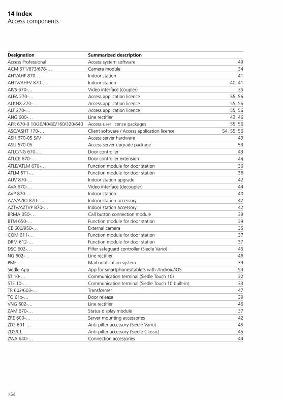
154
14 Index Access components
Designation Summarized descriptionAccess Professional Access system software 49ACM 671/673/678-… Camera module 34AHT/AHF 870-… Indoor station 41AHTV/AHFV 870-… Indoor station 40, 41AIVS 670-… Video interface (coupler) 35ALFA 270-… Access application licence 55, 56ALKNX 270-… Access application licence 55, 56ALT 270-… Access application licence 55, 56ANG 600-… Line rectifier 43, 46APR 670-0 10/20/40/80/160/320/640 Access user licence packages 55, 56ASC/ASHT 170-… Client software / Access application licence 54, 55, 56ASH 670-05 S/M Access server hardware 49ASU 670-05 Access server upgrade package 53ATLC/NG 670-… Door controller 43ATLCE 670-… Door controller extension 44ATLE/ATLM 670-… Function module for door station 36ATLM 671-… Function module for door station 36AUV 870-… Indoor station upgrade 42AVA 670-… Video interface (decoupler) 44AVP 870-… Indoor station 40AZA/AZIO 870-… Indoor station accessory 42AZTV/AZTVP 870-… Indoor station accessory 42BRMA 050-… Call button connection module 39BTM 650-… Function module for door station 39CE 600/950-… External camera 35COM 611-… Function module for door station 37DRM 612-… Function module for door station 37DSC 602-… Pilfer safeguard controller (Siedle Vario) 45NG 602-… Line rectifier 46PME-… Mail notification system 39Siedle App App for smartphones/tablets with Android/iOS 54ST 10-… Communication terminal (Siedle Touch 10) 32STE 10-… Communication terminal (Siedle Touch 10 built-in) 33TR 602/603-… Transformer 47TÖ 61x-… Door release 39VNG 602-… Line rectifier 46ZAM 670-… Status display module 37ZRE 600-… Server mounting accessories 42ZDS 601-… Anti-pilfer accessory (Siedle Vario) 45ZDS/CL Anti-pilfer accessory (Siedle Classic) 45ZWA 640-… Connection accessories 44
155
Access topics
Access cameras 34Access Certified Partners 157Access circuit diagrams 64Access custom-fit door loud-speaker circuit diagrams 100Access licences 55Access server variants 49Access system functions 8Accessory 35, 42Active/passive system expansion 44After-sales service 157Anti-pilfer controller 45App 54Application licences 56As-delivered status 140Button configuration 61Cabling for indoor devices 22Cabling in the door area 16Cabling structure/areas 21CAL (Microsoft licences) 57, 58Call buttons 39Camera connection circuit diagrams 130Cameras 23, 34Circuit diagrams – overview 64Client-Software 54Commissioning 136Commissioning functions 8Commissioning requirements 136Configuration – Access System 60Connection method 17Connection to telephone systems 15Control functions (switching/control) 8Customer support and cus-tomer advice/Siedle centres 157Digital call 20, 37, 38, 63Distribution components 43Door area 16Door controller 43Door loudspeaker 36Door stations (outdoor/indoor area) 31Doormatic 62Electrical distribution board and IT cabinet systems 4Electrical voltage 4
Electrostatic charging 4Exchanging devices 141Extension of the switching outputs/inputs 62External cameras 23, 35External device licences 57Fields of application 8Firewall – Used network ports 138Function overview 8General planning information 16Glossary 146Hardware clients 8Index for Access components 154Indoor stations 40Initial commissioning/Login 139Interfaces 8LED displays 142LED operating status 143Legal notice 6Licence purchasing 58Licences 55, 56, 57Line rectifiers 46Location of the video camera 24Maintenance contract 59Microsoft licences (CAL) 57, 58Minimum requirements – Server hardware / Virtual machine 51Network characteristics 21Network LAN 21Network security 53NTP server 11Optional Access application licences 56Performance features 8Permitted conductor material 17Pick-up range of the camera 24PoE – Power over Ethernet 20Protect your network! 5Protect your property! 5Push Notification Service (Siedle App) 13Ranges 17Registration at the administrator user interface 139Safety remarks 4Service functions 8Service requirement 141Servicing 141
Siedle App 54Siedle centres 157Siedle Classic circuit diagrams 106Siedle service 157Siedle Steel circuit diagrams 120Siedle Touch 10 32Siedle Touch 10 built-in 33Siedle Vario 31Siedle Vario circuit diagrams 68Siedle Classic 31Siedle Steel 31Space requirements in distribution boards/IT cabinets 48Specification – switching outputs / inputs 66Start process 141Status display module 37Storey call button circuit diagrams 134Supplementary functions 8Supply limits ATLC/NG 670-… 18, 19, 23Switching outputs/inputs 61, 66System components 29System conditions 52System description 8System extension 44System overview 10System structure, conductor material and range 16System update 141System upgrading 39Telephony functions 8Terminal assignment RJ45 134Terminal connections and measured values 66, 144Test period 55Time synchronisation in the Access system 11Transformers 47Update process 141Updates 137Upgrade (indoor station) 42Used network ports 138User access and passwords for the Access system 5User licences 56Video functions 8Virtualization 52Warranty 6, 141
156
15 Siedle service Customer support and customer advice/Siedle centres
Welcome to Siedle!Qualified contacts are on hand to offer a fast, professional service.By telephone, or if required we will be pleased to visit you on site.Customers and sales partners out-side of Germany should contact one of our international representatives.
The current overview broken down according to regions is located in the download area on www.siedle.com/contact
157
After-sales service
Services and information Siedle websitewww.siedle.com
Access Certified Partner near to you
www.siedle.en/acp

S. Siedle & SöhneTelefon- und Telegrafenwerke OHG
Postfach 115578113 FurtwangenBregstraße 178120 Furtwangen
Telefon +49 7723 63-0Telefax +49 7723 [email protected]
© 2016/07.20Printed in GermanyBest. Nr. 210005937-02 EN