Embed Size (px)
Citation preview

Approved Capacity Planning and Design Criteria for Establishing Approved Capacity for: 1) Surface Water And Ground Water Supply Sources, 2) Drinking Water Treatment Plants (WTPs), and 3) Source/WTP Systems
Ted Strickland, Governor Lee Fisher, Lt. Governor Chris Korleski, Director
Mar
ch 2
010

Ohio Environmental Protection Agency Division of Drinking and Ground Waters
P.O. Box 1049 Columbus, Ohio 43216-1049
www.epa.ohio.gov/ddagw
Ohio EPA is an Equal Opportunity Employer Printed on Recyled Paper

Table of Contents I. Purpose ..........................................................................................................................1 II. Background and Objectives ..........................................................................................1 III. Other Applicable References ........................................................................................2 IV. Definitions.....................................................................................................................3 V. Approved Capacity Requirements ................................................................................6 VI. Planning Criteria ...........................................................................................................8 VII. Design Criteria for Determining Component Capacity ................................................14
A. Basis-of-Design Table .........................................................................................14 B. Equivalent Maximum-Day Capacity Determination ...........................................15 C. Water-Supply Source Approved Capacity ..........................................................18
1. Surface Water Source .................................................................................18 2. Ground Water Source .................................................................................20 3. Source-Water Pumping ...............................................................................21
D. WTP Approved Capacity ....................................................................................21 1. Conventional Surface WTPs .......................................................................22 2. Surface and Ground Water Systems with Source Water Concentrations Exceeding the Finished Water Maximum Contaminant Level ...................27 3. Surface and Ground Water Systems Treating for Aesthetic-Based
Parameters ...................................................................................................27 4. Surface and Ground Water Systems Exceeding Disinfection Byproduct Maximum Contaminant Levels ...................................................................27 5. Ground Water Treatment Plants .................................................................28 6. Ground Water Precipitative-Softening Plants .............................................28 7. Ground Water Iron and/or Manganese Removal Plants .............................30 8. Chemical Feed Systems ..............................................................................30 9. Intermediate and Finished-Water Pumping ................................................31
E. Distribution Systems ...........................................................................................33 F. Example of Approved Capacity Determination ..................................................33
List of Figures 1. Example of Production Projections for a Growing Public Water System .....................8 2. Example of Maximum-Day Production Projection Exceeding Approved Capacity in Less Than Five Years ................................................................................................10 3. Example of Maximum-Day Production Projection Exceeding Approved Capacity in Less Than Ten Years .................................................................................................10 4. Example of Maximum-Day Production Projection Not Exceeding Approved
Capacity in the Next Ten Years .....................................................................................11 5. Typical Components of a Surface Water Source ...........................................................11 6. Typical Components of a Ground Water Source ...........................................................12 7. Example of the Range of Average Flow Rates Over Which a WTP Must Operate –
From When it Goes On-line to the Design Year ............................................................13 8. Illustration of Relationship Between Demands, Production and Storage .....................14 9. Illustration of Residual Stream Being Greater Than Five Percent of Desired
Approved Capacity (Simple Example) .........................................................................16

10. Illustration of Residual Stream Being Greater Than Five Percent of the Desired Approved Capacity (More Complex Example) .............................................................17
11. Example of a Surface Water Source with Several Components ....................................19 12. Example of a Ground Water Source with Several Components ....................................20 13. Example of Production Projections for a Growing Public Water System .....................33 14. Example of Clearwell Being the Limiting WTP Component in Year X Prior to the
Design Year ...................................................................................................................35
Page 1 of 38
PLANNING AND DESIGN CRITERIA FOR ESTABLISHING APPROVED CAPACITY FOR: 1) SURFACE WATER AND GROUND WATER SUPPLY SOURCES, 2) DRINKING WATER TREATMENT PLANTS (WTPs), AND 3) SOURCE/WTP SYSTEMS Issued: March 3, 2010 This document was developed through collaboration between Ohio Environmental Protection Agency, Division of Drinking and Ground Waters and the Technology Committee of the Ohio Section of the American Water Works Association. I. PURPOSE To provide, in a manner efficient and free of unnecessary delays, a framework for establishing an approved capacity for: 1) water-supply sources, 2) drinking water treatment plants, and 3) source/WTP systems. Adequate and properly designed components of both water-supply sources and WTPs are essential in fulfilling the Division’s mission. The approved capacity of water distribution systems (the third major part of a public water system) is not specifically addressed in this document due to the complex interaction and difference between “customer demands” (i.e., the rate at which most of the water exits the distribution system) and “production” (i.e., the rate at which water enters the distribution system directly from the WTP). This document addresses component capacities from the beginning of source up to the end of the WTP (i.e., it was decided that recent historical production data directly reflects the status of the water system’s existing distribution system storage, booster pumping, etc.). Therefore, certain components of the WTP addressed in this document (e.g., finished-water clearwells and finished-water pumps) that interact very closely with the water distribution system are included in determining the approved capacity of a WTP. (Section VII, E of this document provides general guidance concerning the rules governing water distribution system design.) Approved capacities of small public water systems using only ground water (such as factories, mobile home parks, office buildings, restaurants, condominiums, and the like) will be established in accordance with Ohio EPA’s “Guidelines for Design of Small Public Water Systems” (2010). II. BACKGROUND AND OBJECTIVES Objective Ohio EPA will utilize the planning and design criteria, and procedures described in this document to achieve consistency in administering provisions of the Ohio Revised Code (ORC) and the Ohio Administrative Code (OAC) in regard to the approved capacity for water-supply sources, drinking WTPs, and source/WTP systems.
Page 2 of 38
Background Ohio EPA relies heavily for plan approval on the “shall” and “must” criteria in the 2007 Edition of Recommended Standards for Water Works (RSWW), also referred to as Ten States Standards (TSS). The planning and design criteria included in this document replace the specific planning and design standards from TSS used by Ohio EPA in the past to determine the approved capacity of only WTPs. As part of the plan-approval process, the Director of Ohio EPA will establish an approved capacity in accordance with these design criteria for:
• water-supply sources, • WTPs, and • source/WTP systems (i.e., the lesser of the approved capacity for the water-supply
source and WTP). Every plan approval letter (i.e., a Director’s action letter) for water-supply sources and WTPs will state the approved capacity of both the water-supply source and WTP, and the limiting component(s) on which the approved capacity is based. The plan-approval letter will also state the approved capacity of the source/WTP system; which will be the lesser of the approved capacity for the water-supply source and WTP. Public water systems receiving a seasonal component capacity (e.g. clearwell) will also receive seasonal approved capacities, as appropriate. New approved capacities will be determined by Ohio EPA only if the public water system is requesting a “change” in its water-supply source or WTP capacity – otherwise the approved capacities from the most recent plan approval will be restated in the plan-approval letter. When plans are submitted for an upgrade (not an expansion) of a surface source/WTP system, and water-supply source capacity is unknown, the plan approval letter will state “Water-supply source approved capacity is undetermined. Note: please be advised, future plan approvals requesting a change in source/WTP approved capacity will be required to document the water-supply source approved capacity, and future plan approval letters will establish a source/WTP approved capacity of the lesser between the approved capacity of the water-supply source and the WTP.” When plans are submitted for an upgrade (not an expansion) of ground source/WTP system, the plan approval letter will state the existing water-supply source approved capacity from the most recent plan approval letter, and include the following “Note: please be advised, future plan approvals requesting a change in approved capacity will be required to document the water-supply source approved capacity.” III. OTHER APPLICABLE REFERENCES 1. Ohio EPA Plan Review Procedures for Drinking Water Facilities (Including
Appendix B); available at www.epa.ohio.gov/ddagw.

Page 3 of 38
2. 2007 Recommended Standards for Water Works (RSWW) Great Lakes Upper Mississippi River Board of State Public Health and Environmental Managers (also referred to as Ten States Standards, TSS): available at www.hes.org.
3. Guidelines for Design of Small Public Ground Water Systems, Ohio EPA, Fourth Edition, March 2010; available at www.epa.ohio.gov/ddagw.
4. Ohio Administrative Code (OAC); available at www.epa.ohio.gov/ddagw. 5. Ohio Revised Code (ORC); available at http://codes.ohio.gov/orc/6109. 6. Hydrologic Considerations for Estimation of Storage-Capacity Requirements of
Impounding and Side-Channel Reservoirs for Water Supply in Ohio – Water-Resources Investigations Report 01-4256; available from U.S. Geological Survey or Ohio Department of Natural Resources, Division of Water.
7. AWWA “Hydrogeology Field Manual”, Second edition, 2008. 8. USGS “Sustainability of Ground-Water Resources” U.S. Geological Survey Circular
1186, 1999. IV. DEFINITIONS “Approved capacity” means the allowable rate at which water may be processed by a component of a water-supply source or a WTP.
• Approved capacity of a water-supply source or WTP is based on the limiting component.
• Approved capacity of a source/WTP system is the lesser between the approved capacity of the water-supply source and WTP.
“Average-day production” means the average rate at which finished water exits the WTP (enters the distribution system) on an average production day, generally expressed in units of million gallons per day (MGD). This is the total annual volume of water leaving the WTP, in MG, divided by the 365 days; or the total volume of water produced for the days the WTP was in operation, divided by the days the WTP was in operation. “Component capacity” means the allowable rate not to be exceeded over a period of time;
• for components whose design criteria is based on supplying the average-day production, the period of time is:
o a 12-month period, or o the period during the year the component is in operation - if the
component is not operated the entire 365 days during the year; • for components whose design criteria is based on supplying the maximum-day
production, the period of time is: o a one-day period, or o the period during the day the component is in operation - if the
component is not operated the entire 24 hours during the day. “Demand” is the rate at which water exits the distribution system to supply domestic (residential), commercial, public and industrial customers, and fire flow; and also reflects the effects of accounted for and unaccounted for water losses and inaccurate meters.

Page 4 of 38
“Equivalent maximum-day capacity” means the maximum-day production a component of a water-supply source or WTP would be able to help support (based on the public water system’s projected design-year production ratios of either: a) maximum-day to average-day, or b) peak-hour to maximum-day). “Limiting component” for a water-supply source or WTP is determined by converting a component capacity to equivalent maximum-day capacity so components can be compared on a common numerical basis. “Maximum-day production” means the average rate at which finished water exits the WTP (enters the distribution system) on the largest production day in a year, generally expressed in units of MGD. “Peak-hour of treatment” means the maximum, total one-hour rate at which water enters the clearwell (exits the treatment portion of the WTP) on a given day, generally expressed in units of MGD or gpm. “Peak-hour production” means the maximum, total one-hour rate at which finished water exits the WTP (enters the distribution system) produced on a given day in a year, generally expressed in units of MGD or gpm. “Production” is the rate at which finished water exits the WTP (enters the distribution system) to satisfy customer water demands (e.g. domestic (residential), commercial, public, fire flow, and industrial), and also reflects the effects of accounted for and unaccounted for water losses and inaccurate meters. “Residual stream” means the difference over a specified period of time between WTP influent flow rate and WTP production. “Source/WTP system” means a WTP and its water-supply source(s). Public water systems with more than one WTP will be given a source/WTP system approved capacity from Ohio EPA for each source/WTP system, or a system-wide approved capacity based on an approved engineering submission. “Upgrade” of a water-supply source or WTP component is a plan approval for which no change in approved capacity is being requested. “Water distribution storage” is the volume of finished water available to supply a portion of the difference between customer water demands and WTP production. “Water-supply source” is a compilation of all water-supply source components for either a surface or ground water water-supply source. “Water-supply source component” means the individual components used to determine the approved capacity of a water-supply source. Based on an engineering submission, components can be combined to provide a larger component capacity (e.g. river, source-water pumping from the river, and off-stream storage).

Page 5 of 38
The components included in surface water-supply sources are: • A river or stream, • A natural lake, • An intake structure, • On-stream storage (e.g., a high-head dam on a river/stream to form a
reservoir), • Off-stream storage (e.g., a man-made reservoir not located in the floodway of
the river/stream that is filled by pumps or gravity from a river/stream so stored water can be conveyed by pressure or gravity to the WTP),
• Source-water pumping.
The components included in ground water-supply sources are: • An aquifer, • Wellfield, • Well pumping, • Source-water storage, • Source-water pumping.
“Water-supply source design year” means a year in the future for which a water-supply source is designed to be able to meet the: 1) Average-day production on a continuous basis, and 2) Maximum-day production on at least a one-day basis. The design year varies for each public water system and could be 5, 10, 15 or more years in the future depending on growth rate of the public water system, planned bond sales and the associated water rate increases, increased water demands, additional customers, etc. “Water treatment plant” is a compilation of all WTP components in the water treatment plant. “Water treatment plant component” means the individual components used to determine the approved capacity of the WTP.
The components included in a WTP are: • A unit-treatment process (e.g., presedimentation basin, rapid-mix/coagulation
unit, flocculation basin, sedimentation basin, filter, etc.); • An essential chemical storage-and-feed facility; • A disinfection facility (e.g., chorine, chloramines, chlorine dioxide, ozone or
UV contact unit); • WTP pumping (e.g., intermediate pumps between components within the
WTP, finished-water pumps withdrawing directly from the clearwell to convey finished water to the distribution system, etc.).
“WTP design year” means a year in the future for which a WTP is designed to be able to meet the: 1) Maximum-day production, and 2) Peak-hour production during the respective time frames. The design year varies for each public water system and could be 5, 10, 15 or more years in the future depending on growth rate of the public water system, planned bond sales and the associated water rate increases, increased water demands,

Page 6 of 38
additional customers, ability to operate the WTP on an average-day basis in the initial years when the treatment-related components are not fully loaded, etc. V. APPROVED CAPACITY REQUIREMENTS Approved capacity requirements described in this Section apply to all public water systems, except for small public water systems using only ground water (such as factories, mobile home parks, office buildings, restaurants, condominiums, and the like), which will be established in accordance with Ohio EPA’s “Guidelines for Design of Small Public Water Systems” (2010). Ohio EPA plan-approval letters will state three approved capacities:
1. Water-supply source, 2. WTP, and 3. Source/WTP system (i.e., the smaller of the Water-supply source and WTP).
The approved capacity of a water-supply source must be large enough that source water can be delivered to the WTP at a flow rate equivalent to the: 1) design-year average-day production on a continuous basis, and 2) design-year maximum-day production on at least a one-day basis. The approved capacity of the WTP must be large enough that finished water can be: 1) processed at a flow rate equivalent to the design-year maximum-day production (TSS Section 2.1), 2) disinfected at a flow rate equivalent to the design-year peak-hour of treatment rate, and 3) delivered to the distribution system at a flow rate equivalent to the design-year peak-hour production. The approved capacity of the source/WTP system must be large enough that finished water can be delivered to the distribution system at a flow rate equivalent to the design-year peak-hour production. For a public water system with more than one source/WTP system, the sum of the approved capacities of the source/WTP systems must be large enough to deliver finished water to the distribution system at a flow rate equivalent to the design-year peak-hour production. For components in which the design criteria for determining component capacity is based on supplying the average-day production, the component capacity is the allowable rate not to be exceeded over a 12-month period, or the period during the year the water-supply source or WTP component is in operation if the water-supply source and/or WTP component is not operated 365 days each year. For components in which the design criteria for determining component capacity is based on supplying the maximum-day production, the component capacity is the allowable rate not to be exceeded over a one-day period, or the period during the day the water-supply source or WTP component is in operation if the water-supply source and/or WTP component is not operated 24 hours each day.

Page 7 of 38
Any component operated at an average rate: • over a 24-hour period, or • the period during the day the component is in operation if the water-supply source
and/or WTP component is not operated 24 hours each day, or • with too many units of the component out-of-service
that exceeds the source/WTP system’s approved capacity will result in a violation of plan approval. A component can be operated at an average rate over a 24 hour period higher than the approved capacity of the source/WTP system as long as:
a) the component capacity is not exceeded, and b) the upstream or downstream component does not exceed its component capacity.
Two components: 1) a pump station, except for well pumps, and 2) a clearwell can limit the approved capacity of the source/WTP system (i.e., these components can have the smallest component capacity on an equivalent maximum-day basis), but operation of these components can not lead to a violation of plan approval. Operation of well pumps which are the limiting component in a water-supply source approved capacity that deliver water from a ground water source directly to a WTP can result in a violation of plan approval – but, operation of well pumps that deliver water from a ground water source to a source-water storage reservoir at a rate greater than the pump’s approved capacity does not result in a violation of plan approval. The component capacity of a “pump station” can be based on supplying design-year average-day, maximum-day or peak-hour production depending on the location of the pump station in the water-supply source or WTP. Operating a pump station in excess of the source/WTP system’s approved capacity does not result in a violation of plan approval – but, could result in a violation of plan approval by a component upstream or downstream of the pump station. The component capacity of a “clearwell” is based on the peak-hour of treatment rate, or the influent flow rate of treated water to the clearwell. Operating a clearwell in excess of the source/WTP system’s approved capacity does not result in a violation of plan approval – but, could result in a violation of the CT criteria defined in OAC 3745-81-74. Water Treatment Plants Operating Less Than 24 Hours Per Day WTPs must not be operated at an average process rate that exceeds the source/WTP system’s approved capacity over a 24-hour period. WTPs not operated for 24 hours each day on a regular basis must not be operated at an average process rate exceeding the source/WTP system’s approved capacity over the time period the WTP is operated during the day.
For example, the projected design-year maximum-day production to be supplied by a WTP is 1 MGD. The WTP is to be regularly operated one, 8-hour shift each day (i.e., the system’s water demands are met from water distribution storage for 16 of the 24 hours). Therefore, the approved capacity of this WTP must be at least 3 MGD:

Page 8 of 38
1 MG 24 hours X = 3 MGD 8 hours Day Another way of looking at this example is the approved capacity for a WTP is 3 MGD. The WTP is regularly operated one, 8-hour shift each day. Therefore, during the 8-hour shift this WTP must not process a volume of more than 1 MG of water:
3 MG Day 8 hours
X X = 1 MG per shift Day 24 hours shift
VI. PLANNING CRITERIA Planning criteria described in this Section only apply to public water systems serving political subdivisions as defined in ORC Section 6119.011(B) or regulated by the Public Utilities Commission of Ohio (PUCO). Expansions/upgrades of components for water-supply sources and WTPs take time to plan and implement. To ensure a public water system is prepared to continue providing an adequate quantity of quality finished-water to meet its customers’ future demands, production projections should be performed by public water systems every five years. These projections should include, at a minimum: 1) five years of historical production data; and 2) a public water system’s average-day, maximum-day and peak-hour production for five and ten years into the future. Figure 1 provides an example of production projections for average-day, maximum-day, and peak-hour production for a growing public water system.
Figure 1
FinishedWater
ProductionProjections
( MGD )
Years in the Future
Today 5 10 15 0
Pk.-hour Production
Max.-day Production
Avg.-Day Production
5 YearsAgo
Pk.-hour of Treatment

Page 9 of 38
A public water system should initiate design - or other appropriate planning activities to address approved capacity shortfalls - to expand or upgrade an existing water-supply source and/or WTP when the calculated maximum-day production, projected five years into the future, exceeds the current approved capacity of the source/WTP system. Production projections must be updated by a public water system when requesting a change in approved capacity of the source/WTP system and the updated production projections must be included with the detail plans when submitted to Ohio EPA. It is important for water-supply sources that the ratio of:
• maximum-day production to average-day production for the design year be established since some water-supply source components must deliver source water to the WTP to meet the design-year average-day production on a continuous basis, and other water-supply source components must deliver source water to the WTP to meet the design-year maximum-day production on at least a one-day basis. It is important for WTPs that the ratio of:
• peak-hour production to maximum-day production for the design year be established since some WTP components must process finished water to meet the design-year maximum-day production, and other WTP components must disinfect or deliver finished water into the distribution system to meet the design-year peak-hour production (e.g., disinfection facilities, finished-water pumps, etc.). It is highly recommended the ratio of peak-hour of treatment rate to maximum-day production also be established since WTPs processing surface water-supply sources must comply daily with CT requirements during the peak-hour of treatment. The current production ratios can be used to project the design-year ratios for existing public water systems being expanded or upgraded. Typically the ratio of maximum-day to average-day production and peak-hour to maximum-day production do not vary significantly over the period from when planning or design is initiated to the design year. However, it is recommended attention be paid to public water system changes occurring between the present day and the design year which could alter these ratios, for example, 1) a change in the customer base - i.e., domestic vs. commercial vs. industrial vs. public use, 2) addition of elevated distribution-system storage that lowers the peak-hour of treatment rate required to meet peak-hour system-wide, finished-water demands, etc. Also modifying the manner in which the water-supply source or WTP is operated, along with water distribution storage, to supply customer demands can change these ratios. These finished-water production ratios will have to be developed or estimated for new water-supply sources and/or WTPs. Figures 2, 3 and 4 illustrate the interaction between maximum-day production projections for a public water system and approved capacity of the source/WTP system. In essence, a comparison between a public water system’s maximum-day production projections and the source/WTP’s approved capacity is used to determine what actions the public water system should implement to continue providing an adequate quantity of quality finished water to meet its customers’ future demands.

Page 10 of 38
Figure 2
In Figure 2 the projected maximum-day production exceeds the approved capacity of the source/WTP system within the first five years – i.e., the public water system should start both planning and design to expand the existing water-supply source or WTP, or build new ones.
Figure 3
In Figure 3 the projected maximum-day production exceeds the approved capacity of the source/WTP system during years five through ten – i.e., the public water system should at least start planning to expand the existing water-supply source or WTP, or build new ones.
Max.- day
ProductionProjections
( MGD )
Years in the FutureToday 5 10 15
Projected Max.-day Production ExceedsAppr. Cap. in years 5 to 10 • Should at least Start Planning
0
Source/WTP System Approved Capacity
Max.-day
Production Projections
( MGD )
Years in the FutureToday 5 10 15
Projected Max.-day Production ExceedsAppr. Cap. in first 5 years• Should Start both Planning & Design
0
Source/WTP System’s Approved Capacity

Page 11 of 38
Figure 4
In Figure 4 the projected maximum-day production does not exceed the approved capacity of the source/WTP system within the next ten plus years – i.e., the public water system might want to consider starting the planning to expand the existing water-supply source or WTP, or build new ones. Figures 5 and 6 provide two (2) illustrations of the interaction among peak-hour, maximum-day and average-day production projections for a public water system, and approved capacity of the system’s water-supply source components.
FIGURE 5
Figure 5 illustrates several typical components of a surface-water source utilizing off-stream storage. Such a system might include some of the following components: The following components must be able to supply the design-year average-day production on a continuous basis:
1. River * 2. Intake structure 3. Pipeline between intake and pump station 1 4. Source-water pump station 1 5. Pipeline between pump station and off-stream reservoir
5
Max.- Day
ProductionProjections
( MGD )
Years in the FutureToday 10 15
Projected Max.-day Production doesnot Exceed Appr. Cap. for 10+ years• Might want to Start Planning
0
Source/WTP System’s
Approved Capacity

Page 12 of 38
The following components must be able to supply the design-year average-day production on a continuous basis, and the maximum-day production on at least a one-day basis:
6. Off-stream reservoir 7. Pipeline between off-stream reservoir and pump station 2 8. Source-water pump station 2 9. Pipeline between source-water pump station 2 and WTP 10. WTP (not included in analysis of water-supply source approved capacity)
* The safe yield of the river can be less than the design-year average-day production if an off-stream reservoir with adequate storage volume is provided (i.e., the river operating in concert with the reservoir becomes a single source-water component based on an engineering submission). To determine the limiting water-supply source component the various components must be compared on a common numerical basis. Therefore, each water-supply source component capacity is converted to an equivalent maximum-day capacity (see Section VII.B.) by multiplying the water-supply source component capacity by the ratio of the public water system’s projected maximum-day to average-day production.
Figure 6 illustrates a typical ground water source with the following components:
1. Ground water aquifer 2. Wells, including well pumps
As with surface-water sources, the limiting component is determined by comparing the various water-supply source components of the system on a common numerical basis. Again, each water-supply source component capacity is converted to an equivalent maximum-day capacity by multiplying the water-supply source component capacity by the ratio of the public water system’s projected maximum-day to average-day production.
Likewise, the limiting component of a WTP is determined by comparing the various WTP components on a common numerical basis – i.e., the equivalent maximum-day capacity. As with water-supply sources, the capacity for each WTP component is converted to an equivalent maximum-day capacity by: either multiplying the WTP component capacity by the ratio of the public water system’s projected maximum-day to maximum-day production (i.e., a ratio of 1.0), or dividing by the ratio of the public water system’s projected peak-hour to maximum-day production. It may be easier for WTPs (particularly those that process a surface-water source and therefore have to comply with combined, filtered-water turbidity requirements) to meet these regulatory requirements by operating at a fairly constant flow rate each day over a
2
1
FIGURE 6

Page 13 of 38
24-hour period. Figure 7 illustrates a WTP operating at a constant flow rate, and also shows the need for the WTP to be able to operate over the years of its useful life at a flow rate ranging from:
• the current, minimum-day production, to
• the future (i.e., design-year), maximum-day production. This range can be significant in a growing public water system for which the design year is more than 10 years in the future.
Figure 7
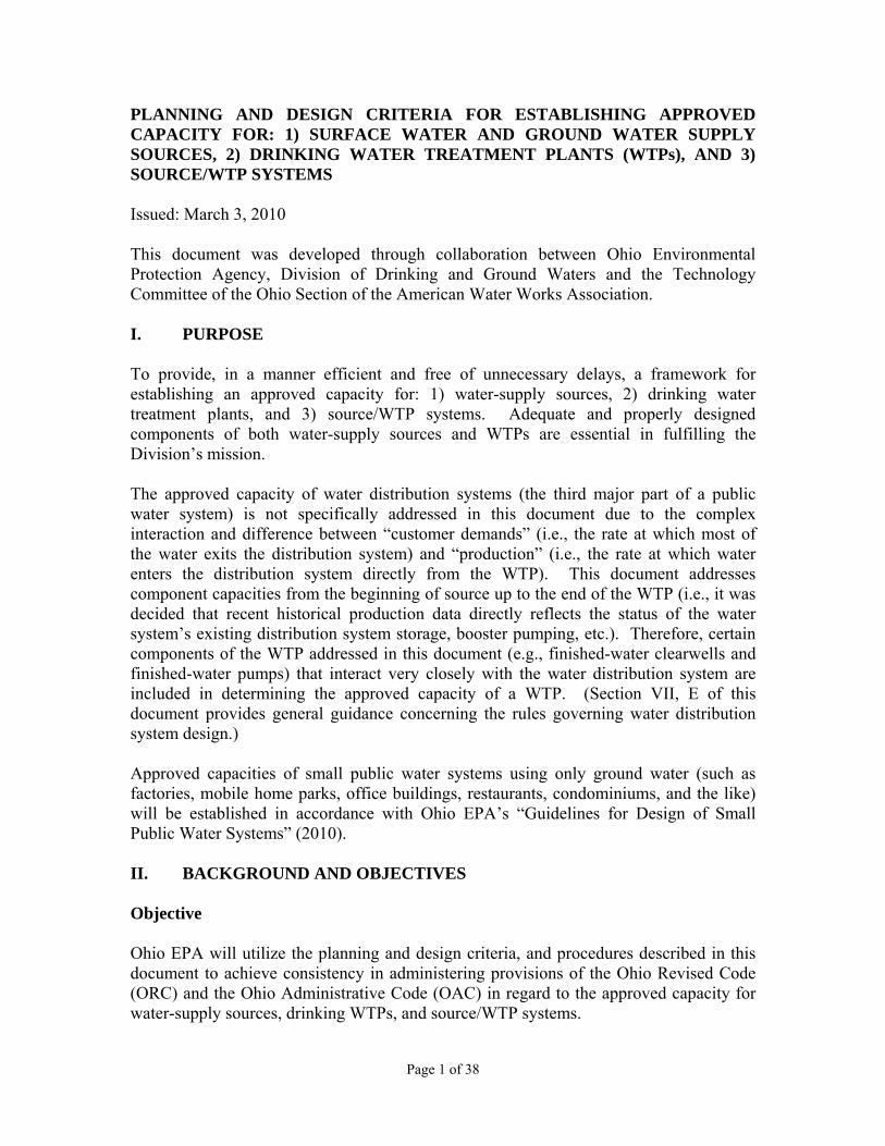
The 24-hour, diurnal water-demand curve in Figure 8 illustrates the variation between peak-hour and maximum-day finished-water demands and the relationship between the WTP and distribution-system storage in meeting these public water system customer demands. This relationship is important because: a) the approved capacity of disinfection facilities for WTPs that process surface water is determined based on meeting CT values during the design-year peak-hour of treatment, and b) the approved capacity of finished-water pumps is determined based on delivering water to the distribution system to meet the design-year peak-hour production. Figure 8 also illustrates the positive supporting role adequate distribution system storage can play in facilitating operation of the WTP on any given day at a fairly constant flow rate over the 24-hour period.
Production ( MGD )
Time of Day6 a.m. 6 p.m. 6 a.m.
Min.-day
Max.-day
Avg.-day
The WTP must be able to operate from the Current Min.-day Production, to the Future (i.e., Design year) Max.-day
Page 14 of 38
Figure 8
VII. DESIGN CRITERIA FOR DETERMINING COMPONENT CAPACITY The smaller approved capacity between the water-supply source(s) and WTP determines the approved capacity of the source/WTP system. For the overall plan-approval process and specifically the approved capacity portion of plan approval, Ohio EPA uses the applicable references listed in Section III of this document. Defined in Section VII are the design criteria for individual components, and the need for redundant treatment or submission of a contingency plan when treatment is provided for different parameters. The component capacity of each component of a Water-supply source or WTP is determined based on the required design criteria listed in this Section. A. Basis-of-Design Table A Basis-of-Design Table is required for all detail plan submittals for which the public water system is requesting a change in approved capacity for a water-supply source, WTP or source/WTP system (OAC 3745-91-06). The table must include at a minimum: 1) each component of the water-supply source and WTP, 2) number, and characteristics of component units, 3) basic design standards (i.e., any recommendations of the design engineer), 4) design criteria, 5) whether the design criteria is required or recommended, 6) component capacity (in MGD),
Flow Rate (MGD )
Time of Day
Pk.-hour Demand, or Fire Flow (MGD)
Minimum-Hour Demand ( MGD )
6 6 6
Distribution Storage being Emptied
Distribution Storage being Filled
Diurnal Demand Curve
Production

Page 15 of 38
7) flow rate (i.e., average-day production, maximum-day production, peak-hour of treatment or peak-hour production) on which the component capacity is based, and the appropriate ratio(s) for calculating the equivalent Max.-day capacity, and 8) the equivalent maximum-day capacity (in MGD), and the approved capacities (in MGD - i.e., the water-supply source and WTP component with the smallest equivalent maximum-day capacity, respectively). Example Basis-of-Design Tables (for both the Water-supply Source and WTP) are included in the Appendix for a public water system that processes surface water.
B. Equivalent Maximum-Day Capacity Determination The equivalent maximum-day capacity is calculated to compare water-supply source and WTP components on a common numerical basis to identify the limiting component that determines the approved capacity of a water-supply source or a WTP, and therefore the approved capacity of the source/WTP system (i.e., the smaller approved capacity of the water-supply source or WTP). The component capacity of some water-supply source components is determined based on the design-year average-day production and the component capacity for other components on the design-year maximum-day production. Likewise, the component capacity of some WTP components is determined based on the design-year maximum-day production and the component capacity for other WTP components on the design-year peak-hour of treatment rate or peak-hour production. The equivalent maximum-day capacity is calculated for components, whose component capacity is based on supplying the:
1. Average-day production, by multiplying the component capacity by the ratio of maximum-day to average-day production.
2. Maximum-day production, by multiplying the component capacity by the ratio of maximum-day to maximum-day production (i.e., a value of 1.0).
3. Peak-hour of treatment rate, by dividing the component capacity by the ratio of peak-hour of treatment rate to maximum-day production.
4. Peak-hour production, by dividing the component capacity by the ratio of peak-hour to maximum-day production.
Equivalent maximum-day capacity can be thought of as the maximum-day production a component would be able to help support in the design year, based on the projected ratios for maximum-day to average-day production and peak-hour to maximum-day production for the design year. Examples of equivalent maximum-day capacities are provided in this document for those components of a water-supply source or WTP for which component capacities are not determined based on meeting the design-year maximum-day production. If the total flow of residual streams exceeds 5% of the desired approved capacity of the WTP, the design of effected components for the WTP must be adjusted to account for the residual streams. This also assumes the residual streams are not recycled either partially or in full. Determining the limiting component for a water-supply source or WTP is still performed using equivalent maximum-day capacities. The equivalent maximum-day capacity for

Page 16 of 38
each component is calculated using the appropriate production projection in the design year (i.e., average-day, maximum-day or peak-hour production – or, peak-hour of treatment). However, when the residual stream(s) generated during treatment exceeds 5 percent of the desired approved capacity of the WTP, the component capacity is not calculated directly based on the projected design-year average-day or maximum-day production. Example A: The following “simple” example illustrates this concept: A WTP processing a ground water supply has a proposed approved capacity of 8.0 MGD. This WTP uses a membrane softening process with a recovery of 80% and an associated residual stream (i.e., membrane reject) of 20%. Graphically, the process is demonstrated as:
Figure 9 For this WTP the 2.0 MGD waste stream must be accounted for in the calculations for the water-supply source capacity and the water-supply source capacity must be at least 10 MGD based on the equivalent maximum day, in order to be able to satisfy the desired WTP approved capacity of 8.0 MGD. Example B: The following “more complex” example illustrates this concept in a more complete manner: The production projections in the design year for a WTP that processes surface water that is hard are:
• Average-day production = 7.50 MGD • Maximum-day production = 10.0 MGD • Peak-hour of treatment = 13.5 MGD • Peak-hour production = 15.0 MGD
8.0 MGD to distribution
2.0 MGD to waste
10 MGD source water
Page 17 of 38
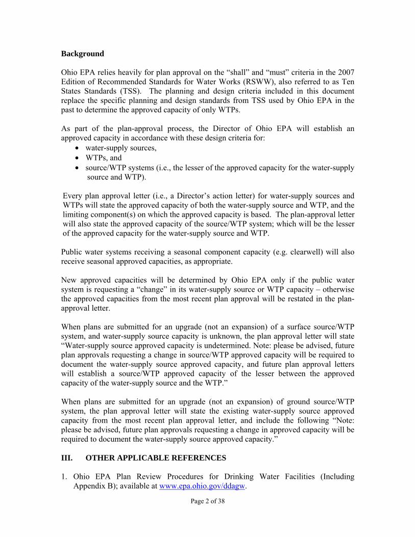
The following are the main WTP components for this public water system, and are shown in Figure 10:
• low-pressure membranes as pretreatment to both: a) prepare the water for nanofiltration, and b) remove regulated microbials associated with surface-water supplies;
• nanofiltration membranes to remove hardness from some of the water (i.e., 100 percent of the water is not processed through nanofiltration);
• clearwells to meet CT criteria for inactivating regulated microbials (i.e., as a back-up to the low-pressure membranes removing regulated microbials associated with surface-water supplies); and
• finished-water pumps to deliver water into the distribution system at the appropriate quantity and pressure.
Finished Water Clearwell Low-pressure Membranes (Pretreatment)
High-pressure Membranes (Nanofiltration for Softening)
Finished-water
Pumping Waste (backwash) Waste (concentrate)
Figure 10 The percent reject (i.e., residual stream) for the low-pressure membranes is 5%, and the percent reject for nanofiltration is 10%. The hardness of the source water is 300 mg/L (as CaCO3), and the finished-water hardness goal is 125 mg/L (again, as CaCO3). Assuming 10 mg/L of hardness (as CaCO3) exits the nanofiltration membranes, the percent of water that must be processed through nanofiltration to meet the finished-water hardness goal of 125 mg/L is: (X) 10 + (1-X) 300 1 = 125 X = 0.60 (i.e., 60% of the flow must be processed through nanofiltration) The WTP must produce 10.0 MGD of finished water over a 24-hour period (i.e., maximum-day production in the design year). Since 10% of the water is lost as reject during nanofiltration, the influent flow to the nanofiltration process has to be: (0.6) 10.0 MGD (1.1) = 6.6 MGD where: 0.6 = 60% processed through nanofiltration
1.1 = the 10% excess entering the nanofiltration process to account for the reject

Page 18 of 38
Therefore, the effluent flow rate from the low-pressure membranes has to be: 6.6 + 4.0 = 10.6 MGD where: 4.0 is the 40% of water that bypasses nanofiltration Since 5% of the water is lost as reject during low-pressure membrane filtration, the influent flow to the low-pressure membranes has to be: 10.6 MGD (1.05) = 11.1 MGD where: 1.05 = the 5% excess fed to the low-pressure membranes to account for the reject Since the ratio is 1.33 for maximum-day to average-day production for this public water system (i.e., 10.0 / 7.50 = 1.33), the water-supply source must produce on the average: 11.1 MGD divided by 1.33 = 8.35 MGD (as opposed to 7.50 MGD, the projected, average-day production). These are the flow rates, respectively, to be used to calculate the component capacities for nanofiltration and every WTP component upstream of nanofiltration - not the projected, design-year production. C. Water-Supply Source Approved Capacity
The water-supply source component with the smallest equivalent maximum-day capacity (i.e., the limiting component) determines the approved capacity of the water-supply source. The approved capacity for a combination of surface water and ground water sources must be the lesser of: a) the sum of the approved capacity of the surface water-supply source and the ground water supply-source or b) the source-water pumping approved capacity.
1. Surface Water Source Component capacity of surface water sources is based on the limiting component for the combination of stream flow, source-water storage capacity, and/or source-water pumping based on generally established hydrologic analysis methods, as determined with the largest source-water pump out-of-service. The component capacity for various components of a surface-water source is determined based on the applicable components among the following examples:
1. Rivers and Streams – i.e., the seven-day, fifty-year low flow for the stream, or extreme drought of record.
2. Natural Lakes – e.g., Methods described in USGS “Hydrologic Considerations for Estimation of Storage-Capacity Requirements of Impounding and Side-Channel Reservoirs for Water Supply in Ohio – Water-Resources Investigations Report 01-4256.”
3. Intake structure.
Page 19 of 38
4. On-stream Reservoir – e.g., Methods described in USGS document noted above. 5. Off-stream Reservoir – e.g., Methods described in USGS document noted above. 6. Source-water Pumping (with the largest unit out-of-service).
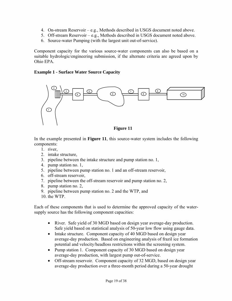
Component capacity for the various source-water components can also be based on a suitable hydrologic/engineering submission, if the alternate criteria are agreed upon by Ohio EPA. Example 1 - Surface Water Source Capacity
Figure 11
In the example presented in Figure 11, this source-water system includes the following components:
1. river, 2. intake structure, 3. pipeline between the intake structure and pump station no. 1, 4. pump station no. 1, 5. pipeline between pump station no. 1 and an off-stream reservoir, 6. off-stream reservoir, 7. pipeline between the off-stream reservoir and pump station no. 2, 8. pump station no. 2, 9. pipeline between pump station no. 2 and the WTP, and 10. the WTP.
Each of these components that is used to determine the approved capacity of the water-supply source has the following component capacities:
• River. Safe yield of 30 MGD based on design year average-day production. Safe yield based on statistical analysis of 50-year low flow using gauge data.
• Intake structure. Component capacity of 40 MGD based on design year average-day production. Based on engineering analysis of frazil ice formation potential and velocity/headloss restrictions within the screening system.
• Pump station 1. Component capacity of 30 MGD based on design year average-day production, with largest pump out-of-service.
• Off-stream reservoir. Component capacity of 32 MGD, based on design year average-day production over a three-month period during a 50-year drought

Page 20 of 38
2
1
Figure 12
(specific drought criterion selected by system; duration based on statistical characteristics of selected drought criterion).
• Pump station 2. Component capacity of 40 MGD based on design year maximum-day production with the largest pump out-of-service.
• The WTP is not included in the determination of the water-supply source approved capacity. However, peak-hour production to maximum-day production and maximum-day production to average-day production ratios are considered.
The public water system’s historic ratio of maximum-day production to average-day production is 1.4. Therefore, the above component capacities, expressed in terms of “equivalent maximum-day” capacities are: • River 30 MGD x 1.4 = 42 MGD equivalent maximum-day capacity • Intake 40 MGD x 1.4 = 56 MGD equivalent maximum-day capacity • Pump Station 1 30 MGD x 1.4 = 42 MGD equivalent maximum-day capacity • Reservoir 32 MGD x 1.4 = 45 MGD equivalent maximum-day capacity
But, it can deliver water to Pump Station 2 at a flow rate of 50 MGD on a one-day basis
• Pump Station 2 40 MGD x 1.0 = 40 MGD equivalent maximum-day capacity • WTP Not included in determining approved capacity of the water-supply
source Based on the analysis in this example, the limiting component for the water-supply source is Pump Station 2 with an equivalent maximum-day capacity of 40 MGD. 2. Ground Water Source
The approved capacity for various components of a ground water source is determined based on:
1. the “safe yield” of the aquifer (based on generally
established hydrogeologic analysis methods); or 2. the sum of the system’s wells with the largest
producing well pump out-of-service if the sum of well capacities is smaller than the safe yield of the aquifer (based on the adequate quantity determined in accordance with OAC rule 3745-9-09).
Example 2 – Ground Water Source Capacity An example of a ground water source is presented in Figure 12, the safe yield (i.e., component capacity) of the aquifer has been determined by hydrologic analysis to be 20 MGD, based on average-day withdrawal. The historic maximum-day to average-day production ratio for this

Page 21 of 38
public water system is 1.65. As a result, the equivalent maximum-day capacity of the aquifer for this system is 33 MGD (i.e. 20 MGD x 1.65). The component capacity of the wells in all of the system’s well fields (with the single largest well out-of-service) is 25 MGD based on maximum-day production. In this example, the wells are the limiting component resulting in a water-supply source equivalent maximum-day capacity of 25 MGD (i.e., 25 MGD x 1.0). However, it should be noted in the future this aquifer could support withdrawal by additional wells.
3. Source-Water Pumping The component capacity for most components is based on all units in-service.
• Source-water pumping stations pumping from a river or stream to an off-stream
reservoir – the component capacity will be taken into consideration in establishing the approved capacity for the water-supply source based on the combination of stream flow and/or source-water storage capacity, based on generally established hydrologic analysis methods.
• Source-water pumping stations pumping to an off-stream reservoir must be able to
supply at least the design-year average-day production. • Source-water pumping stations pumping directly to the WTP must be able to supply
at least the design-year maximum-day production. • The component capacity for source-water pump stations with multiple pump stations
that operate in-series is determined with the largest pump out-of-service. The component capacity for source-water pump stations that operate in-parallel is determined with the single, largest pump out-of-service. (TSS Section 6.3).
D. WTP Approved Capacity The component with the smallest equivalent maximum-day capacity (i.e., the limiting component) determines the approved capacity of the WTP. The component capacity for most components is based on all units in-service. For WTPs processing surface water-supply source(s) the approved capacity is determined with the largest filter and the largest intermediate pump(s) and/or finished-water pump(s) out-of-service. For WTPs processing surface or ground water water-supply sources to remove nitrate to comply with the maximum contaminant level (MCL) the public water system must submit a well-defined contingency plan describing the ability to comply with the MCL with the largest unit out-of-service for components crucial to treatment for nitrate removal (e.g., provide a unit-treatment process of adequate capacity, utilize blending, have in place an emergency connection with another public water system, have in place water-use restriction capabilities, have sufficient finished-water storage, etc.).

Page 22 of 38
For WTPs processing ground water water-supply sources without nitrate removal the approved capacity is determined with the largest intermediate pump and/or finished-water pump out-of-service.
The accepted design criteria for determining the component capacity of components with all units of a component in-service (i.e., those references included in Section III) are provided component-by-component on the remaining pages of this document. Design criteria listed as “required” are legal requirements adopted by Ohio EPA. Variations from the required design criteria must be approved by Ohio EPA and in some cases will be considered based on justification provided in an engineering submission. Those criteria listed as “recommended” are not legal requirements adopted by Ohio EPA, but are provided to assist with the design of WTPs. It is suggested both required and recommended design criteria for each component of a WTP be addressed in an engineering submission. The design engineer might also want to include recommended design standards.
The component capacity for various components of a WTP is determined based on the applicable design criteria in the following groupings:
1. Conventional surface WTPs 2. Surface and ground water systems with source water concentrations exceeding the
finished water maximum contaminant level 3. Surface and ground water systems treating for aesthetic-based parameters 4. Surface and ground water systems exceeding disinfection byproduct maximum
contaminant levels 5. Ground water treatment plants 6. Ground water precipitative-softening plants 7. Ground water iron and/or manganese removal plants 8. Chemical feed systems 9. Intermediate and finished-water pumping
1. Conventional Surface WTPs Presedimentation Basins Recommended criteria:
Detention time ≥ 3 hrs (TSS Section 4.1.1.d) Rapid-mix/coagulation units Required criteria:
Number of units > 2 (TSS Section 4.1.a) G value Based on an engineering submission
that justifies the design basis for the G value
Recommended criteria: Detention time < 30 sec with mixing equipment capable of
imparting a minimum velocity gradient (G) of at

Page 23 of 38
least 750 fps/ft. The design engineer should determine the appropriate G value and detention time through jar testing (TSS Section 4.1.2.a)*
*Or, as justified by an engineering submission Mechanical flocculation basins Required criteria:
Number of units > 2 (TSS Section 4.1.a) Recommended criteria:
Flow-through velocity > 0.5 fpm and < 1.5 fpm Detention time > 30 min (TSS Section 4.1.3.b)*
*Or, as justified by an engineering submission Settling basins Required criteria:
Number of units > 2 (TSS Section 4.1.a) Launder loading (weir
overflow) rate < 20,000 gpd/ft (TSS Section 4.1.4.c.1) Detention time > 4 hrs for clarification (TSS Section 4.1.4.a) Outlet Velocity < 0.5 fps entrance velocity at submerged orifices
(TSS Section 4.1.4 c.3)
Recommended criteria: Surface loading rate < 0.5 gpm/sf for clarification
< 0.75 gpm/sf for softening Flow-through velocity < 0.5 ft/min (TSS Section 4.1.4.d) Length: width Ratio > 3:1
Solids-contact clarifiers Required criteria:
Number of units > 2 (TSS Section 4.1.5) Upflow rate < 1.0 gpm/sf for clarification (TSS Section
4.1.5.13.a) < 1.75 gpm/sf for softening (TSS Section 4.1.5.13.b)
Launder loading (weir
overflow) rate < 10 gpm/ft for clarification (TSS Section 4.1.5.12.b.1) < 20 gpm/ft for softening (TSS Section 4.1.5.12.b.2) [NOTE – THIS IS AN ALTERNATIVE RATE SPECIFICALLY FOR GROUND WATER ONLY]
Page 24 of 38
Recommended criteria: Detention time
Flocculation zone > 30 min Clarification zone 2-4 hrs (TSS Section 4.1.5.9 a)
Tube-settler modules Required criteria:
Number of units > 2 (TSS Section 4.1.a) Application rate < 2 gpm/sf of cross-section (TSS Section 4.1.6.1.d)
Plate-settler modules Required criteria:
Number of units > 2 (TSS Section 4.1.6.1.e) Application rate < 0.5 gpm/sf (based on 80% of the projected
horizontal plate area)*
* Or, as justified by an engineering submission Stabilization units Recarbonation basins Required criteria: As justified by an engineering submission for plants that use precipitative softening Recommended criteria:
Detention time Total > 20 min (TSS Section 4.8.1.a.1) Mixing compartment > 3 min (TSS Section 4.8.1.a.2.a)
Diffuser submergence > 7.5 ft (TSS Section 4.8.1.a.2) Filters The accepted filtration rate for a single media sand or anthracite filter is 2.0 gallons per minute per square foot (gpm/sf) of filter area with the largest filter out-of-service. Filtration rates greater than 2.0 gpm/sf for single media sand or anthracite filter may be approved if justified by an engineering submission. Ohio EPA no longer grants public water systems using dual-media filters a ‘provisional’ filtration rate. A ‘permanent’ 4.0 gpm/sf filtration rate for approved dual-media filter will be granted to a WTP if the criteria listed below are met:
New surface WTPs with approved dual-media filters
Assign all new surface WTPs with dual-media filters that comply with TSS a 4.0 gpm/sf filtration rate in the original plan approval with no additional data collection requirements.

Page 25 of 38
Existing surface WTPs with approved dual-media filters Upon approval of a general plan submitted in accordance with OAC Chapter 3745-91, all existing surface WTPs with dual-media filters meeting the following criteria will be assigned a 4.0 gpm/sf filtration rate in plan approval with no additional data collection requirements:
• No turbidity violations of Ohio Administrative Code rule 3745-81-73 in the
last two years, • Implemented corrective action related to disinfection treatment CT violations
of Ohio Administrative Code rule 3745-81-72 (C) incurred in the last two years, and
• In accordance with Ohio Administrative Code rule 3745-7-02 the public water system must have in place one or more operator(s) of record to oversee the technical operation of the public water system or each water treatment plant.
Backwash Required criteria:
Number of sources A minimum of a primary and backup system (e.g. two pumps, tank and a pump (TSS Section 4.2.1.11.c)
Flow capacity > 15 gpm/sf for 15 minutes; (TSS Section 4.2.1.11.a for 15 gpm/sf; TSS Section 4.2.1.11.d for 15 min.) > 20 gpm/sf recommended, based on water temperature) (TSS Section 4.2.1.11.a)
Clearwells Required criteria:
Number of units > 2 (TSS Section 7.1.2.d)
Detention time ability to demonstrate 0.5-log inactivation of Giardia lamblia and 2.0-log inactivation of viruses at peak-hour of treatment, minimum clearwell level, minimum water temperature, and maximum pH value using an approved effective volume factor; seasonal ratings must be justified by an engineering submission documenting the CT requirements contained in OAC rule 3745-81-72 can be met during all seasons
Note: As noted in the Section VII, B., the approved capacity of a WTP is based on the WTP component with the smallest equivalent maximum-day capacity. The component capacity for nearly all WTP components is based on the volume of water processed and delivered to the distribution system over a 24-hour period. However, for WTPs processing a surface water-supply source the component capacity of clearwells and other disinfection components is determined based on the ability to demonstrate 0.5-log inactivation of Giardia lamblia, and 2.0-log of

Page 26 of 38
viruses, after filtration (i.e., CT capacity). In addition, the CT capacity is based on the peak-hour of treatment flow rate at which a WTP is operated. Therefore, an equivalent maximum-day capacity for clearwells and other disinfection components is determined to be compared on a common numerical basis with the component capacity of other WTP components whose component capacity is determined based on supplying the design-year maximum-day production. The ratio of the design-year peak-hour of treatment flow rate to maximum-day production is used to determine this equivalent maximum-day capacity for disinfection.
For example, a WTP processing a surface water-supply source can disinfect water (i.e., meet daily the required CT value to achieve 0.5-log inactivation of Giardia lamblia and 2.0-log of viruses) at a peak-hour of treatment rate of 9.0 MGD (i.e., clearwell influent rate), and can process water at a component capacity (i.e., can meet a maximum-day production) of 8.0 MGD. The public water system’s ratio of the design-year peak-hour production to maximum-day production is 1.5, and the peak-hour of treatment rate to maximum-day production is 1.35 (i.e., available clearwell storage allows the finished-water pumps to operate at a higher rate than the clearwell influent rate). Since the WTP must be able to disinfect water at the design-year peak-hour of treatment rate, the equivalent maximum-day capacity of disinfection (based on the peak-hour of treatment rate), for comparison with the component capacity of other WTP components, is:
9.0 MGD (Peak-hr of treatment) (Maximum-day production) X = 6.7 MGD 1.35 (Peak-hr of treatment)
Therefore, the approved capacity of this WTP is limited to 6.7 MGD by its disinfection facilities – i.e., 6.7 MGD is smaller than 8.0 MGD. In essence, at some year in the future (but before the design year is reached) when the peak-hour of treatment rate (i.e., clearwell influent flow rate) has increased to 9.0 MGD, the maximum-day production of 6.7 MGD for that year (i.e., 9.0 MGD/1.35 = 6.7 MGD) will not have exceeded the equivalent maximum-day capacity for the rest of the WTP components (i.e., 8.0 MGD). Another way of looking at this example is, a WTP can process water at a treatment rate of 8.0 MGD, and can disinfect water (i.e., meet daily the required CT value to achieve 0.5-log inactivation of Giardia lamblia and 2.0-log of viruses) at a peak-hour of treatment rate of 9.0 MGD. The public water system’s ratio of the design-year peak-hour production to maximum-day production is 1.5, and the peak-hour of treatment rate to maximum-day production is 1.35. As such, to be assigned an approved capacity of 8.0 MGD this WTP must be able to disinfect water (i.e., meet daily the required CT value to achieve 0.5-log inactivation of Giardia lamblia and 2.0-log of viruses) at a peak-hour treatment rate of 10.8 MGD:

Page 27 of 38
8.0 MGD (Maximum-day production) 1.35 (Peak-hr of treatment) X = 10.8 MGD
(Maximum-day production)
Therefore, the approved capacity of this WTP is limited by its disinfection facilities (i.e., 9.0 MGD is smaller than 10.8 MGD) – and, is actually limited to an approved capacity of 6.7 MGD since the equivalent maximum-day capacity of this disinfection facility, as illustrated in the first part of this Example, is: 9.0 MGD/1.35 = 6.7 MGD.
2. Surface and Ground Water Systems with Source Water Concentrations Exceeding the Finished Water Maximum Contaminant Level
Source-water chronic contaminant concentration less than twice the MCL For public water systems with a source-water chronic contaminant concentration less than twice the MCL, redundant treatment is required unless a contingency plan is submitted to describe how the necessary treatment unit can be repaired or replaced within 30 days (e.g., provide an additional unit-treatment process of adequate capacity to meet maximum-day production with the largest unit out of service, utilize blending, have an emergency connection in place with another public water system, have water use restriction capabilities in place, etc.). Source-water chronic contaminant concentration greater than or equal to twice the MCL For public water systems with a source-water chronic contaminant concentration greater than or equal to twice the MCL, the system must submit a well-defined contingency plan describing the ability to comply with the MCL (e.g., provide an additional treatment unit of adequate capacity to meet maximum-day production with the largest unit out of service, utilize blending, have an emergency connection in place with another public water system, have water use restriction capabilities in place, etc.). 3. Surface and Ground Water Systems Treating for Aesthetic-Based Parameters For unit-treatment processes for the removal of aesthetic-based water quality parameters, a single unit may be provided, although at least two units for each unit-treatment process are highly recommended. 4. Surface and Ground Water Systems Exceeding Disinfection Byproduct
Maximum Contaminant Levels Running annual average concentration less than twice the MCL For surface water systems with an running annual average concentration for disinfection by-products less than twice the MCL, redundant treatment (an additional unit-treatment process of adequate capacity to meet maximum-day production with the largest unit out

Page 28 of 38
of service) is required unless a contingency plan is submitted to describe how the necessary treatment unit can be repaired or replaced within 30 days (i.e., provide one of the following: a blending scheme, an emergency connection in place with another public water system, water use restriction capabilities in place, etc.) Running annual average concentration greater than or equal to twice the MCL For surface water systems treating to remove disinfection by-products when an running annual average is greater than or equal to twice the MCL, the system must submit a well-defined contingency plan describing the ability to comply with the MCL (e.g., provide an additional treatment unit of adequate capacity to meet maximum-day production with the largest unit out of service, utilize blending, have an emergency connection in place with another public water system, have water use restriction capabilities in place, etc.). 5. Ground Water Treatment Plants At least two units are required for each unit-treatment process for the removal of health-based contaminants. 6. Ground Water Precipitative-Softening Plants The accepted design parameters (e.g., launder loading (weir overflow) rate, flow-through velocity, detention time, etc.) with all unit-treatment processes in service are those listed in this section. Rapid mix/coagulation (If a coagulant is used) Recommended Criteria:
Detention time < 30 sec (TSS Section 4.4.1 which references Section 4.1.2.a)*
G value ≥ 750 fps/ft.* * Or, as justified by an engineering submission Mechanical flocculation Required Criteria:
Number of units > 2 (TSS Section 4.1.a)
Recommended Criteria: Detention time > 30 minutes (TSS Section 4.4.1 which references
Section 4.1.3.b) * Flow-through velocity > 0.5 fpm and < 1.5 fpm (TSS Section 4.4.1 which references Section 4.1.3.b)*
* Or, as justified by an engineering submission
Page 29 of 38
Settling basins Required Criteria: Number of units > 2 (TSS Section 4.1.a)
Launder loading (weir overflow) rate < 20,000 gpd/ft (TSS Section 4.4.1 which
references Section 4.1.4.c.1) Detention time > 2 hrs (TSS Section 4.4.1 which references Section
4.1.4.a) Outlet Velocity < 0.5 fps entrance velocity at submerged orifices (TSS Section 4.1.4.c.3)
Recommended criteria: Flow-through velocity < 0.5 ft/min (TSS Section 4.1.4.d)
Solids-contact clarifiers Required Criteria:
Upflow rate < 1.75 gpm/sf (TSS Section 4.4.1 which references Section 4.1.5.13.b)
Launder loading (weir overflow) rate < 20 gpm/ft (TSS Section 4.4.1 which references
Section 4.1.5.12.b.2) Recommended Criteria:
Detention time 1-2 hrs for groundwater (TSS Section 4.4.1 which references Section 4.1.5.9 b)
Catalytic fluidized bed reactors (for calcium removal only) Recommended Criteria:
Reaction zone upflow rate (at bottom of reactor) 50 to 200 gpm/sf *
Total detention time 6 to 12 min * * As justified by an engineering submission Stabilization units Recommended Criteria: As justified by an engineering submission Filters The total approved filtration capacity is based on a filtration rate for a single media sand or anthracite filter of 2.0 gpm/sf of filter area with all filters in service. WTPs utilizing a ground water-supply source with dual-media filters will be assigned a 4.0 gpm/sf filtration rate in the original plan approval with no additional data collection requirements.

Page 30 of 38
Backwash Required Criteria:
Number of sources A minimum of a primary and backup system (TSS Section 4.2.1.11.c)
Flow capacity > 15 gpm/sf for 15 minutes (TSS Section 4.2.1.11.a for 15 gpm/sf; TSS Section 4.2.1.11.d for 15 min.) > 20 gpm/sf recommended (based on water temperature, TSS Section 4.2.1.11.a)
Clearwell Required Criteria:
Detention time As determined by an engineering submission that justifies how the appropriate disinfection can be achieved. 7. Ground Water Iron and/or Manganese Removal Plants Filters The total approved filtration capacity is based on a filtration rate of 3.0 gpm/sf of filter area with all filters in service. 8. Chemical Feed Systems Essential chemicals are: Coagulant for surface water treatment
Polymer(s) if necessary to meet enhanced surface water treatment turbidity standards
Disinfectant Corrosion control chemicals where required to meet water
quality parameters for lead and copper corrosion control
Oxidant where required for removal of primary contaminants
Fluoride for public water systems required by law to maintain the required operating range of 0.8 to 1.3 mg/L
Any chemical required during a demonstration study to obtain Ohio EPA approval of an alternative technology
Chemical feeders Where a chemical feed is necessary for the protection of the
supply, such as chlorination, coagulation, or other essential processes, a standby unit or a combination of units of sufficient size to meet capacity shall be provided to replace the largest unit when out of service. Where a booster pump is part of the design of a chemical feed system and is necessary for the proper operation of the chemical feed system, a backup booster pump must be provided. (TSS Section 5.1.1.a)

Page 31 of 38
Chemical storage Required criteria:
Essential chemicals > 30 days at average dose and average-day production in the design year (TSS Section 5.1.9.a.1) * Recommended criteria: Public water systems generating sodium hypochlorite on- site should maintain a 30-day supply of salt Non-essential chemicals As justified by an engineering submission *Or, if more than one storage vessel is provided, less than 30-days storage can be justified by a contingency plan demonstrating how essential chemicals can be obtained on a consistent basis. 9. Intermediate and Finished-Water pumping Intermediate pumping components must be able to supply the maximum-day production with the largest unit out-of-service, and finished-water pumping components must be able to supply the peak-hour production with the largest unit out-of-service.
For example, the finished-water pumps for a particular WTP can deliver water into the distribution system at a rate of 18 MGD (with the largest unit out-of-service). Other components of the WTP can process water at a maximum-day treatment rate of 10 MGD. The public water system’s ratio is 1.5 for peak-hour production to maximum-day production for the design year. The equivalent maximum-day capacity of finished-water pumping, for comparison with the approved capacity of all other WTP components, is:
18 MG 1 X = 12 MGD Day 1.5
Therefore, the approved capacity of the WTP is limited to 10 MGD by the other treatment components – i.e., 10 MGD is smaller than 12 MGD. The finished water pumps are not the limiting component in determining the approved capacity of the WTP.
The component capacity of a single finished-water pump station serving multiple pressure zones must generally be determined separately for each pressure zone with the largest finished-water pump serving the pressure zone out-of-service. The combined, component capacity of multiple finished-water pump stations serving the same pressure zone must be based on the combined capacity of the various pump stations with the single largest finished-water pump out-of-service. This must be confirmed by an engineering submission that demonstrates the finished-water pump stations are mutually supporting.

Page 32 of 38
FOR EXAMPLE, a public water system has two (2) WTPs that process and provide finished water to a distribution system with three (3) pressure zones (i.e., low-, medium- and high-pressure). Each of the public water system’s WTPs has six (6) finished-water pumps that deliver water into the distribution system: WTP No. 1
1. Pump No. 1 - 5 MGD (low-pressure zone) 2. Pump No. 2 - 5 MGD (low-pressure zone) 3. Pump No. 3 - 10 MGD (low-pressure zone) 4. Pump No. 4 - 10 MGD (low-pressure zone) 5. Pump No. 5 - 10 MGD (medium-pressure zone) 6. Pump No. 6 - 15 MGD (medium-pressure zone)
WTP No. 2
7. Pump No. 7 - 10 MGD (medium-pressure zone) 8. Pump No. 8 - 10MGD (medium-pressure zone) 9. Pump No. 9 - 5 MGD (high-pressure zone) 10. Pump No. 10 - 10 MGD (high-pressure zone) 11. Pump No. 11 - 10 MGD (high-pressure zone) 12. Pump No. 12 - 15 MGD (high-pressure zone)
In WTP No. 1;
• Pumps Nos. 1, 2, 3 and 4 deliver water to the low-pressure zone in the distribution system; and
• Pumps Nos. 5 and 6 deliver water to the medium-pressure zone. In WTP No. 2:
• Pumps Nos. 7 and 8 deliver water to the medium-pressure zone in the distribution system; and
• Pumps Nos. 9, 10, 11 and 12 deliver water to the high-pressure zone. The component capacity of the finished-water pumps for a pressure zone is based on the single, largest pump from that pressure zone being out-of-service. Therefore, the component capacity of the finished-water pumps for the low-pressure zone is: 5 + 5 + 10 = 20 MGD (i.e., Pump No. 3 or 4 at 10 MGD ea. is considered to be out-of-service). The component capacity of the finished-water pumps for the medium-pressure zone is: 10 + 10 + 10 = 30 MGD (i.e., Pump No. 6 at 15 MGD is considered to be out-of-service). The component capacity of the finished-water pumps for the high-pressure zone is: 5 + 10 + 10 = 25 MGD (i.e., Pump No. 12 at 15 MGD is considered to be out-of-service).

Page 33 of 38
It should be noted this example ignores the fact there might be booster pump stations and/or pressure-reducing valves allowing flow to move among the low-, medium- and high-pressures zones. This example also ignores the fact there might be a pump(s) at either WTP that can deliver finished water to more than one pressure zone.
E. Distribution Systems
Distribution systems are not usually assigned approved capacities due to the complex interaction of customer demand, pumping, transmission and storage. OAC Rule 3745-83-01(E) states: community public water systems must maintain a minimum of 20 psig at ground level at all points in the distribution system under all conditions of flow other than conditions caused by line breaks, extreme fire flows, or other extraordinary circumstances. TSS Section 8.2.1 recommends the normal working pressure in the distribution system should be approximately 60 to 80 psig and not less than 35 psig. F. Example of Approved Capacity Determination The following example and figures demonstrate the need to convert the component capacity of each component to an equivalent maximum-day capacity for water-supply source and WTP components. Only by comparing the various components on a common numerical basis can the limiting water-supply source and WTP component be determined.
Figure 13 A public water system is requesting additional capacity to meet a projected maximum-day production of 10 MGD in the design year. Based on Figure 13:
ProductionProjections
( MGD )
DesignYear
Today0
Pk.hour Production
Max.-day Production
Avg.-day Production7.5
10.0
15.0Pk.-hour of Treatment13.5

Page 34 of 38
• The ratio of peak-hour production to maximum-day production is 1.50 (i.e., 15 MGD divided by 10 MGD = 1.50).
• The ratio of peak-hour of treatment rate to maximum-day production is 1.35 (i.e., 13.5 MGD divided by 10.0 MGD = 1.35).
• The ratio of maximum-day production to average-day production is 1.33 (i.e., 10 MGD divided by 7.5 MGD = 1.33).
The components in this public water system’s water-supply source are:
1. River, 2. Source-water pump station no. 1, 3. Off-stream storage reservoir, and 4. Source-water pump station no. 2.
The component capacities, based on design criteria, and corresponding equivalent maximum-day capacities are:
1. River - 7.5 MGD 2. Source water pump station no. 1 - 9.0 MGD 3. Off-stream storage reservoir - 8.5 MGD ( 8.5 x 1.33) = 11.3 MGD * 4. Source-water pump station no. 2 - 12.5 MGD (12.5 x 1.0 **) = 12.5 MGD
* Based on an engineering submission - the river, source-water pump station no. 1 and the off-stream storage reservoir operate as a single component (i.e., the component capacity of the water-supply source is increased since water is now supplied by both the river and off-stream storage reservoir). Another way to look at this is the component capacity of the river is based on a low-flow rate during drought conditions – and, the component capacity of the river, source-water pump station no. 1. and off-stream storage reservoir combined approaches the average flow of the river under normal conditions as the volume in the off-stream storage reservoir provided increases. In essence, water is diverted to the off-stream storage reservoir when flow rates in the river are high, and taken from the off-stream storage reservoir when flow rates in the river are low. ** Source-water pump station no. 2 has to supply water directly to the WTP so it must meet the design-year maximum-day production. Therefore, the component capacity is multiplied by the ratio of maximum-day production to maximum-day production, or 1.0).
Therefore, the combination of the river, source-water pump station no. 1 and off-stream storage reservoir is the limiting component and the approved capacity of the water-supply source is 11.3 MGD. The components in this public water system’s WTP are:
1. Rapid Mixing/Coagulation, 2. Flocculation, 3. Sedimentation, 4. Filtration, 5. Clearwells, and

Page 35 of 38
ProductionProjections
( MGD )
DesignYear
Today0
Pk-hour Production
Max.-day Production
Avg.-day Production7.5
10.0
15.0
9.3
YearX
12.5
Pk.-hour Treatment 13.5
Figure 14
6. Finished-water Pumps. The component capacities, based on design criteria, and corresponding equivalent maximum-day capacities are:
1. Rapid Mixing/Coagulation - 15.0 MGD (15.0 x 1.0) = 15.0 MGD 2. Flocculation - 12.0 MGD (12.0 x 1.0) = 12.0 MGD 3. Sedimentation - 11.5 MGD (11.5 x 1.0) = 11.5 MGD 4. Filtration - 12.5 MGD (12.5 x 1.0) = 12.5 MGD 5. Clearwells - 12.5 MGD (12.5 x 1/1.35) = 9.3 MGD 6. Finished-water Pumps - 18.0 MGD (18.0 x 1/1.5) = 12.0 MGD
Therefore, the clearwell system is the limiting component and the approved capacity of the WTP is 9.3 MGD.
Since all components are compared on a common numerical basis (i.e., the equivalent maximum-day capacity), the limiting component can be determined by simply comparing numerical values of the various components, and it is clear whether the water-supply source or WTP limits the approved capacity of the source/WTP system. Therefore, the approved capacity of the source/WTP system is 9.3 MGD (i.e., the smaller of the approved capacity of the water-supply source and WTP; 9.3 MGD is smaller than 11.3 MGD). In the design year, the clearwells could support a maximum-day production of 9.3 MGD (i.e., since the projected, design-year maximum-day production is 10 MGD, based on Figure 14 the clearwells would have to support a peak-hour of treatment rate of at least 13.5 MGD and a peak-hour production of at least 15 MGD to not be the limiting component). Another way to explain this is – if the production projections are correct, in

Page 36 of 38
Year X the maximum-day production for the public water system would have reached 9.3 MGD, and the peak-hour of treatment rate would be 12.5 MGD (i.e., 9.3 MGD multiplied by 1.35). Therefore, in Year X (prior to the design year) and beyond, the clearwells would be challenged to meet CT requirements during the peak-hour of treatment (i.e., would have approached their approved capacity). The plan-approval letter for this example must include the agreed upon basis-of-design table and would state the:
• approved capacity of the water-supply source is 11.3 MGD (using a maximum-day to average-day ratio of 1.33) based on the combination of river, source-water pump station no. 1 and off-stream storage reservoir being the limiting water-supply source component,
• approved capacity of the WTP is 9.3 MGD (using a peak-hour of treatment to maximum-day production ratio of 1.35) based on the clearwell system being the limiting WTP component, and
• approved capacity of the source/WTP system is 9.3 MGD (i.e., the smaller approved capacity of the water-supply source and WTP).
The public water system has several options to increase the component and equivalent maximum-day capacities of its clearwell system and therefore the approved capacity of the WTP:
• Increase the “C” of CT by increasing the free chlorine residual (i.e., DBPs don’t form as readily in the winter),
• Increase the “T” of CT by increasing the effective volume factor of the clearwells (e.g., install baffles),
• Increase the “T” of CT by maintaining a higher water level in the Clearwells (e.g., install VFDs on finished-water pumps),
• Decrease the “Ratio” of peak-hour of treatment to maximum-day production (e.g., install VFDs on both source-water and finished-water pumps),
• Decrease the “Ratio” of peak-hour production to maximum-day production (e.g., construct additional distribution-system storage),
• Request a “seasonal CT” approved capacity for the Clearwells (particularly if the summer, maximum-day production is significantly larger than the winter, maximum-day production)
The public water system decided to add additional baffles to the clearwells, increasing the effective volume factor from 0.4 to 0.6. Therefore, the new equivalent maximum-day capacity of the clearwells is: 9.3 MGD x 0.6 = 14.0 MGD 1 0.4 The approved capacity of the WTP is now 11.5 MGD (based on sedimentation being the limiting component), and the approved capacity of the source/WTP system is now 11.3 MGD (i.e., the approved capacity of the water-supply source is now smaller than the approved capacity of the WTP).

Page 37 of 38
Example, Basis-of-Design Table for a Water Treatment Plant (WTP). 1
Component
2
Number of Units
3
Design Standards
4
Design Criteria
5
Required/ Recommended
6 Component
Capacity (MGD)
7 Flow Basis of Component
Capacity/Ratio
8 Equivalent
Maximum-day Capacity (MGD)
rapid mixers two detention time < 30 seconds
required
15.0 maximum-day 1.0
15.0
G value of +/- 1,000 recommended 15.0 maximum-day 1.0
(1)
flocculation basins
four detention time > 30 minutes
required 12.0 maximum-day 1.0
12.0
GT value of 25 - 100
recommended 12.5 maximum-day 1.0
sedimentation basins
four detention time > 4 hours
required 11.5 maximum-day 1.0
11.5
flow-through velocity < 0.5 fpm
peak-hour treatment with all in-service
recommended 11.0 maximum-day 1.0
filters five maximum day without largest
required 12.5 maximum-day 1.0
12.5
peak-hour treatment without all in-service
recommended 15.5 peak-hour treatment 1.35 (2)
clearwells two CT for 0.5-log Giardia
required 12.5 peak-hour treatment 1.35
9.3 (3)
storage for peak-hour demand
recommended 16.0 peak-hour treatment 1.35
finished-water pump station
five pumps peak-hour production without
largest
required 18.0 peak-hour production
1.50 (4)
12.0
fire-flow demand with all in-service
recommended Un-determined
fire-flow demand
(1) Number equivalent maximum-day capacity based on design standards or recommended design criteria. Only required design criteria determine the limiting component and approved capacity.
(2) Ratio of projected, design-year peak-hour treatment to maximum-day production = 1.35.
(3) The limiting component of the WTP is the clearwells (i.e., WTP approved capacity is 9.3 MGD, and the approved capacity of the source/WTP system is 9.3 MGD [i.e., 9.3-MGD WTP is smaller than the 11.3-MGD water-supply source]).
(4) Ratio of projected, design-year peak-hour to maximum-day production = 1.50.

Page 38 of 38
Example, Basis-of-Design Table for a Water-Supply Source.
1
Component
2
Number of Units
3
Design Standards
4
Design Criteria
5
Required/ Recommended
6 Component
Capacity (MGD)
7 Flow Basis of Component
Capacity/Ratio
8 Equivalent
Maximum-day Capacity (MGD)
river one safe yield based on an engineering
submission (1)
required 7.5 average-day 1.33 (2)
10.0
source-water pump station 1
four pumps average-day without largest (3)
required 9.0 average-day 1.33
12.0
maximum-day with all in-service
recommended 12.5 maximum-day 1.0
(4)
off-stream storage reservoir
one based on an engineering
submission (6)
required 8.5 average-day 1.33
11.3 (5)
storage to assist with maximum-day
recommended 12.0 maximum-day 1.0
source-water pump station 2
five pumps maximum-day without largest
required 12.5 maximum-day 1.0
12.5
peak-hour treatment with all
in-service
recommended 16.5 peak.-hour treatment
1.35
(1) Engineering submission based on USGS, Water-Resources Investigation Report 01-4256
(2) Ratio of projected, design-year maximum-day to average-day production = 1.33.
(3) Source-water pump station 1 has to deliver source water at a rate to meet average-day production because it pumps to an off-stream storage reservoir, not directly to the WTP.
(4) Value of equivalent maximum-day capacity based on design standards or recommended design criteria. Only required design criteria determine the limiting component and approved capacity.
(5) The limiting component of the water-supply source is the combination of the river, source-water pump station 1 and off-stream storage reservoir (i.e., source-water supply approved capacity is 11.3 MGD.)
(6) An engineering submission justified the river, source-water pump station 1 and off-stream storage reservoir working closely together as a single component.