Embed Size (px)
DESCRIPTION
Molino de Laboratorio
Citation preview

PLANETARY MILL
PULVERISETTE 5 classic line
Operating instructions
Valid starting with: 05.5000/01370
Valid starting with: 05.6000/00589
Read the instructions prior to performing any task!
Translation of the original operating instructions

Version 03/2014 Index 001
Fritsch GmbHMilling and SizingIndustriestraße 8D - 55743 Idar-ObersteinTelephone: +49 (0)6784/ 70-0Fax: +49 (0)6784/ 70-11email: [email protected]: www.fritsch.com

Certifications and CE conformityFritsch GmbH has been certified by the TÜV-Zertifizierungsgemeinschafte.V.
An audit certified that Fritsch GmbH conforms to the requirements ofthe DIN EN ISO 9001:2008.
The enclosed Conformity Declaration lists the guidelines the FRITSCHinstrument conforms to, to be able to bear the CE mark.
Certification
CE Conformity
Certifications and CE conformity
- 3 -

Table of contents1 Basic structure............................................................................... 7
2 Safety information and use........................................................... 82.1 Requirements for the user..................................................... 82.2 Scope of application............................................................... 82.2.1 Operating principle............................................................. 92.2.2 Drive motor and speed regulation...................................... 92.3 Obligations of the operator................................................... 92.4 Information on hazards and symbols used in this manual. . 102.5 Device safety information.................................................... 132.6 Protective equipment.......................................................... 142.6.1 Opening the hood without mains connection.................. 142.6.2 Imbalance switch.............................................................. 152.7 Hazardous points................................................................. 172.8 Electrical safety.................................................................... 172.8.1 General information......................................................... 172.8.2 Protection against restart................................................. 172.8.3 Overload protection.......................................................... 172.8.4 Imbalance detection......................................................... 182.8.5 Operation on GFCI (Ground-Fault Circuit Interrupters).... 18
3 Technical data.............................................................................. 193.1 Dimensions.......................................................................... 193.2 Weight.................................................................................. 193.3 Operating noise.................................................................... 193.4 Voltage................................................................................. 193.5 Current consumption........................................................... 193.6 Power consumption............................................................. 203.7 Electrical fuses..................................................................... 203.8 Material................................................................................ 203.9 Final fineness....................................................................... 20
4 Installation................................................................................... 214.1 Transport............................................................................. 214.2 Unpacking............................................................................ 214.3 Setting up............................................................................. 224.4 Ambient conditions.............................................................. 234.5 Electrical connection............................................................ 234.5.1 Adjusting the mains voltage.............................................. 244.5.1.1 Adjusting the mains voltage with the rotary switch (8). 244.5.1.2 Adjusting the mains voltage in setup mode................... 254.6 Setting device specification in setup mode......................... 26
5 Initial start-up.............................................................................. 275.1 Switching on......................................................................... 27
Table of contents
- 4 -

5.2 Function check..................................................................... 27
6 Using the device........................................................................... 286.1 Choice of grinding bowls and grinding balls........................ 296.1.1 Size of the grinding balls................................................... 306.1.2 Number of balls per grinding bowl (independent of the
material quantity)............................................................. 316.1.3 Calculated weight of a ball................................................ 326.2 Filling quantities of grinding bowls...................................... 326.3 Filling the grinding bowl....................................................... 336.4 Factors with an impact on grinding..................................... 336.4.1 Running time (grinding duration)..................................... 336.4.2 Speed................................................................................ 336.4.3 Reverse mode................................................................... 336.4.4 Number and size of the balls............................................ 336.4.5 Weight of the balls (type of material)............................... 346.4.6 Dry grinding....................................................................... 346.4.7 Wet grinding (grinding in a suspension)........................... 346.5 Clamping the grinding bowls............................................... 356.5.1 Clamping with the "Safe-Lock" (5) tensioning device....... 356.5.2 Clamping the 80 ml grinding bowls................................... 376.6 Mass balance....................................................................... 376.7 Grinding duration................................................................. 376.8 Settings on the control panel............................................... 396.8.1 Setting the speed.............................................................. 396.8.2 Setting the running time................................................... 396.8.2.1 Changing the time unit in setup mode.......................... 406.9 Repetition of grinding / pause cycles................................... 416.10 Reverse mode.................................................................... 416.11 Conducting a grinding operation....................................... 416.11.1 Overload......................................................................... 426.11.2 Switching off................................................................... 426.12 Cooling the grinding bowl.................................................. 426.13 Stand-by............................................................................. 43
7 Accessories................................................................................... 447.1 Additional clamping system for grinding harmful sub-
stances or in a gas atmosphere............................................ 447.1.1 Locking the additional clamping system into place.......... 447.2 Grinding in inert gas with gassing lid................................... 487.2.1 Preparation for gassing..................................................... 487.2.2 Gassing.............................................................................. 497.2.3 Ventilate after grinding..................................................... 497.2.4 Cleaning the valves........................................................... 507.2.5 Installing valve inserts....................................................... 50
Table of contents
- 5 -

7.3 GTM - system....................................................................... 51
8 Cleaning........................................................................................ 528.1 Grinding elements................................................................ 528.2 Mill....................................................................................... 52
9 Maintenance................................................................................ 53
10 Repairs......................................................................................... 5510.1 Checklist for troubleshooting............................................. 55
11 Examples of comminution tasks.................................................. 57
12 Disposal........................................................................................ 59
13 Guarantee terms.......................................................................... 60
14 Exclusion of liability..................................................................... 62
15 Safety logbook............................................................................. 64
16 Index............................................................................................. 65
Table of contents
- 6 -

1 Basic structure
1 Hood handle2 Latch3 Hood4 Control panel5 Safe-Lock6 Bowl holder7 Lock
8 Voltage rotary switch9 Excess current protection switch10 Main switch11 Mains cennection12 Cover plate13 Ventilation grid
Basic structure
- 7 -

2 Safety information and use2.1 Requirements for the user
This operating manual is intended for persons assigned with operatingand monitoring the Fritsch PULVERISETTE 5. The operating manual andespecially its safety instructions are to be observed by all personsworking on or with this device. In addition, the applicable rules and regu-lations for accident prevention at the installation site are to be observed.Always keep the operating manual at the installation site of the PULVERI-SETTE 5.
People with health problems or under the influence of medication,drugs, alcohol or exhaustion must not operate this device.
The PULVERISETTE 5 may only be operated by authorised persons andserviced or repaired by trained specialists. All commissioning, mainte-nance and repair work may only be carried out by technically qualifiedpersonnel. Qualified personnel are persons who, because of their educa-tion, experience and training as well as their knowledge of relevantstandards, regulations, accident prevention guidelines and operatingconditions, are authorised by those responsible for the safety of themachine to carry out the required work and are able to recognize andavoid possible hazards as defined for skilled workers in IEC 364.
In order to prevent hazards to users, follow the instructions in thismanual.
Malfunctions that impair the safety of persons, the PULVERISETTE 5 orother material property must be rectified immediately. The followinginformation serves both the personal safety of operating personnel aswell as the safety of the products described and any devices connectedto them: All maintenance and repair work may only be performed bytechnically qualified personnel.
This operating manual is not a complete technical description. Only thedetails required for operation and maintaining usability are described.
Fritsch has prepared and reviewed this operating manual with thegreatest care. However, no guarantee is made for its completeness oraccuracy.
Subject to technical modifications.
2.2 Scope of applicationThe PULVERISETTE 5 classic line can be applied universally for the fast,dry or wet grinding of inorganic and organic samples for analysis, qualityinspection, material testing or mechanical alloying. During the synthesis,the PULVERISETTE 5 is used for mixing and homogenising dry samples,emulsions or suspensions.
Safety information and use
- 8 -

2.2.1 Operating principleThe grinding stock is crushed and ground by grinding balls in 2 or 4grinding bowls. The centrifugal forces from the rotation of the grindingbowls around their own axis and from the rotating support disc act onthe contents of the grinding bowl which consists of material to beground and grinding balls.
The grinding bowl and the support disc have opposite directions of rota-tion, so that the centrifugal forces alternate in the same direction and inthe opposite direction. The result is that the grinding balls run down theinside of the bowl's wall as friction effect and the grinding balls hit theopposite wall of the grinding bowl as impact effect. The impact effect isamplified by the impact of the grinding balls against each other.
The loss-free comminution, even when grinding suspensions, is ensuredby the hermetic seal between the grinding bowl and the lid.
a Rotation of the grinding bowlb Centrifugal forcec Movement of the support disc
2.2.2 Drive motor and speed regulationA maintenance-free three-phase motor operated via a frequency con-verter is used as the drive.
2.3 Obligations of the operatorBefore using the PULVERISETTE 5, this manual is to be carefully read andunderstood. The use of the PULVERISETTE 5 requires technical knowl-edge; only commercial use is permitted.
The operating personnel must be familiar with the content of the oper-ating manual. For this reason, it is very important that these personsactually receive the present operating manual. Ensure that the operatingmanual is always near the device.
The PULVERISETTE 5 may exclusively be used within the scope of applica-tions set down in this manual and within the framework of guidelinesput forth in this manual. In case of non-compliance or improper use, thecustomer assumes full liability for the functional capability of the PUL-VERISETTE 5 and for any damage or injury arising from failure to fulfil thisobligation.
Safety information and use
- 9 -

By using the PULVERISETTE 5 the customer agrees with this and recog-nizes that defects, malfunctions or errors cannot be completelyexcluded. To prevent risk of damage to persons or property or of otherdirect or indirect damage, resulting from this or other causes, the cus-tomer must implement sufficient and comprehensive safety measuresfor working with the PULVERISETTE 5.
Neither compliance with this manual nor the conditions and methodsused during installation, operation, use and maintenance of the PUL-VERISETTE 5 can be monitored by Fritsch GmbH. Improper execution ofthe installation can result in property damage and thus endanger per-sons. Therefore, we assume absolutely no responsibility or liability forloss, damage or costs that result from errors at installation, improperoperation or improper use or improper maintenance or are in any wayconnected to these.
The applicable accident prevention guidelines must be complied with.
Generally applicable legal and other obligatory regulations regardingenvironmental protection must be observed.
2.4 Information on hazards and symbols used in this manualSafety information in this manual is designated by symbols. Safety infor-mation is introduced by keywords that express the extent of the hazard.
DANGER!This symbol and keyword combination points out a directlyhazardous situation that can result in death or seriousinjury if not avoided.
WARNING!This symbol and keyword combination points out a possiblyhazardous situation that can result in death or seriousinjury if not avoided.
CAUTION!This symbol and keyword combination points out a possiblyhazardous situation that can result in slight or minor injuryif not avoided.
NOTICE!This symbol and keyword combination points out a possiblyhazardous situation that can result in property damage ifnot avoided.
Safety information
Safety information and use
- 10 -

ENVIRONMENT!This symbol and keyword combination points out a possiblyhazardous situation that can result in environmentaldamage if not avoided.
To call attention to specific hazards, the following symbols are used inthe safety information:
DANGER!This symbol and keyword combination points out a directlyhazardous situation due to electrical current. Ignoring infor-mation with this designation will result in serious or fatalinjury.
DANGER!This symbol and keyword combination designates contentsand instructions for proper use of the machine in explosiveareas or with explosive substances. Ignoring informationwith this designation will result in serious or fatal injury.
DANGER!This symbol and keyword combination designates contentsand instructions for proper use of the machine with com-bustible substances. Ignoring information with this designa-tion will result in serious or fatal injury.
WARNING!This symbol and keyword combination points out a directlyhazardous situation due to movable parts. Ignoring infor-mation with this designation can result in hand injuries.
WARNING!This symbol and keyword combination points out a directlyhazardous situation due to hot surfaces. Ignoring informa-tion with this designation can result in serious burn injuriesdue to skin contact with hot surfaces.
Special safety information
Safety information and use
- 11 -

Safety information can refer to specific, individual procedure instruc-tions. Such safety information is embedded in the procedure instructionsso that the text can be read without interruption as the procedure isbeing carried out. The keywords described above are used.
Example:
1. Loosen screw.
2.CAUTION!Risk of entrapment at the lid.
Close the lid carefully.
3. Tighten screw.
This symbol emphasises useful tips and recommendationsas wells as information for efficient operation without mal‐function.
To emphasise procedure instructions, results, lists, references and otherelements, the following designations are used in this manual:
Designation Explanation
1., 2., 3. ...
Step-by-step procedure instructions
ð Results of steps in the procedure
References to sections in this manual and rele-vant documentation
Lists without a specific order
[Button] Operating elements (e.g. push button, switch),display elements (e.g. signal lamps)
‘Display’ Screen elements (e.g. buttons, function keyassignment)
Safety information in the procedureinstructions
Tips and recommendations
Further designations
Safety information and use
- 12 -

2.5 Device safety informationn Only use original accessories and original spare parts. Failure to
observe this instruction can compromise the safety of the machine.n Safe conduct must be strictly observed during all work.n All currently applicable national and international accident preven-
tion guidelines must be complied with.
CAUTION!Wear hearing protection!If a noise level of 85 dB(A) is reached or exceeded, ear pro-tection should be worn to prevent hearing damage.
WARNING!The maximum accepted concentration (MAC) levels of therelevant safety guidelines must be observed; if necessary,ventilation must be provided or the machine must be oper-ated under an extractor hood.
DANGER!Explosion hazard!– When grinding oxidisable substances, e.g. metal or
coal, there is a risk of spontaneous combustion (dustexplosion) if the proportion of fine particles exceeds acertain percentage. When grinding these kinds of sub-stances, special safety measures must be taken and thework must be supervised by a specialist.
– The device is not explosion-protected and is not suit-able for grinding explosive materials.
n Do not remove the information signs.
NOTICE!Immediately replace damaged or illegible information signs.
n Unauthorised alteration of the device will void Fritsch's declarationof conformity to European directives and void the guarantee.
n The PULVERISETTE 5 should only be used when it is in properworking order, as intended and in a safety- and hazard-consciousmanner adhering to the operating manual. In particular, immediatelyrectify any malfunctions that could pose a safety hazard.
n If, after reading the operating manual, there are still questions orproblems, please do not hesitate to contact our specialised per-sonnel.
n Do not reuse damaged accessories.
Please observe!
Safety information and use
- 13 -

n Do not leave the Planetary Mill running for several hours withoutcooling phases. Risk of overheating!
n The mill must never be left running unsupervised. In certain oper-ating states, the vibrations may result in a shifting effect on the sur-face.
2.6 Protective equipment
Protective equipment is to be used as intended and may notbe disabled or removed.
All protective equipment is to be regularly checked forintegrity and proper functioning.
For start-up, the hood (3) has to be closed.
The hood (3) is locked:
n without mains connectionn during operation
The hood (3) can only be opened, if the mill's drive is atstandstill.
2.6.1 Opening the hood without mains connection
CAUTION!The emergency release must not be activated while themachine is running! Disconnect the machine from themains before the emergency release. Failure to observe thiswill render void the guarantee, and releases us from lia-bility for any resulting damage to the device or personalinjury.
Safety information and use
- 14 -

1. Insert the included triangular key (A) into the bore hole on thebottom side of the PULVERISETTE 5 classic line and turn it to theright.
2. Unlock the latch (2) by pressing the hood handle (1).
3. The hood (3) can now be opened.
4. The mill can only be switched on again if the hood (3) is closed andthe safety lock (7) has been enabled again by turning the trian-gular key to the right.
2.6.2 Imbalance switchThe device switches off if there is excessive imbalance. (SeeÄ Chapter 6.6 ‘Mass balance’ on page 37)
CAUTION!The imbalance switch can be disabled at your own risk. TheFritsch company will give no guarantee for damageresulting from disabling of the imbalance switch.
NOTICE!Change these settings only after all work as described inÄ Chapter 4 ‘Installation’ on page 21 has been carried out!
In the default setting of the imbalance switch, it is acti‐vated!
Activation / deactivation of the imbalance switch in setup mode:
1. Press and hold the STOP button on the front of the control panel.
Safety information and use
- 15 -

2. Switch on the device with the main switch (10) on the back side ofthe device, and release the STOP button.
3. If POWER SUPPLY is flashing, the device is in setup mode. IfPOWER SUPPLY is not flashing, repeat the procedure.
4.NOTICE!In the display above the right "-" button (x) in theTIMER field, there must be a minus sign. That acti-vates the imbalance switch and prevents a drift ofthe device and possible damage to the deviceresulting from it.
When the imbalance switch is deactivated a "1" willbe displayed in the TIMER field over the right "-"button (x)!
5. To save and end setup mode, press the STOP button.
Safety information and use
- 16 -

2.7 Hazardous points
CAUTION!– Crushing hazard when closing the hood (3).– Crushing hazard at the grinding bowl safe-lock ten-
sioning device (5).
CAUTION!Risk of splashing!During wet grinding, the high temperature may have cre-ated overpressure.
Wear protective goggles.
CAUTION!The grinding bowls can be very hot after grinding.
Wear safety gloves.
2.8 Electrical safety2.8.1 General information
n The main switch (10) separates the device from the mains on twopoles.
n Switch off the main switch (10) if the planetary mono mill is downfor a longer period of time (e.g. overnight).
2.8.2 Protection against restartIn case of power failure during operation or after switching off with themain switch (10), the hood (3) is locked. The hood lock (7) is openedwhen the power returns. For safety reasons, however, the mill does notrestart.
2.8.3 Overload protectionn In the event of an overload, the device reduces the speed in a con-
trolled manner. The REDUCED SPEED light is lit as a warning.n The device switches off if the drive motor becomes too hot.n The device switches off if the drive is blocked. (See Ä Chapter 10
‘Repairs’ on page 55)
Safety information and use
- 17 -

2.8.4 Imbalance detectionThe device switches off if there is excessive imbalance. (SeeÄ Chapter 10 ‘Repairs’ on page 55)
2.8.5 Operation on GFCI (Ground-Fault Circuit Interrupters)It is possible that the leakage currents will become marginal during oper-ation. This may trigger the earth leakage circuit breaker. These valuescan quickly be reached when all devices are added to the circuit.
Solution: Circuit without an earth leakage circuit breaker or, if possible,increase the earth leakage circuit breaker threshold.
Safety information and use
- 18 -

3 Technical data3.1 Dimensions
When the hood is open
952 x 581 x 669 mm (height x width x depth)
When the hood is closed
570 x 581 x 669 mm (height x width x depth)
3.2 WeightNet:
100 kg with 2 bowl holders
120 kg with 4 bowl holders
Gross:
approximately 140 kg with 2 bowl holders
approximately 160 kg with 4 bowl holders
3.3 Operating noiseEmissions value of workplace according to DIN EN ISO 3746:2005 is 74.9dB(A) with a grinding element made from steel and grinding stock ofsand! This value may vary depending on the type of grinding elementand sample material.
3.4 VoltageThe device can be operated in two voltage ranges:
n Single phase alternating current 100 - 120V ± 10%, and,n Single phase alternating current 200 - 240V ± 10%.
Transient overvoltage according to overvoltage category II is per-mitted.
3.5 Current consumptionDepending on the voltage range, the maximum current consumption isas follows:
n 100 - 120V® 14 An 200 - 240V® 6 A
Technical data
- 19 -

3.6 Power consumptionDepending on the voltage range, the maximum power consumption is asfollows:
n 100 - 120V® 1500Wn 200 - 240V® 1300W
3.7 Electrical fusesCircuit breaker: 16 A
Switch back on by pressing the excess current protection switch (9) onthe back of the device.
3.8 Materialn Maximum feeding size 10 mmn Maximum feeding volume 900ml divided into 4 x 500ml grinding
bowls + grinding balls or 450ml divided into 2 x 500ml grinding bowl+ grinding balls
n Achievable mean final fineness of up to d50 < 1 µm
3.9 Final finenessn Dry grinding up to d50 < 20 µm (depending on the material)n Wet grinding up to d50 < 1 µm (depending on the material)
Technical data
- 20 -

4 Installation4.1 Transport
The device is delivered on a transport pallet with a wooden cover. Werecommend using a forklift or pallet truck for transporting the packeddevice.
DANGER!Do not step under the transport pallet during transport.
WARNING!Improper lifting can lead to personal injury or propertydamage. The machine is only to be lifted with suitableequipment and by qualified personnel.
The guarantee excludes all claims for damage due to improper transport.
4.2 Unpackingn Pull out the nails that fasten the lid to the surrounding packaging.n Remove the lid.n Take out the accessories.n Pull out the nails that fasten the surrounding packaging to the trans-
port pallet.n Then lift the wooden surround over and away from the device.n The pre-perforated segments can be detached so that the foam
parts can be removed more easily.n Please store the transport packaging so that it can be reused if you
need to return the product. Fritsch GmbH accepts no liability fordamage caused by improper packaging (packaging that is not fromFritsch).
n Compare the contents of the delivery with your order.
Installation
- 21 -

Grinding bowls made of tempered steel may have recesseson the surface caused during production. They do not havean impact on grinding or the grinding results and usuallydisappear after the first grinding operation.
These recesses on the surface, if present, are within therange of the permissible production tolerances. Complaintsrelating to such grinding bowls therefore cannot beaccepted.
4.3 Setting up
DANGER!Do not step under the transport pallet during transport.
CAUTION!The weight of the planetary mill is approx. 120kg!
NOTICE!Never operate the planetary mill while it is standing on thetransport pallet!
NOTICE!Keep the air outlet on the side ventilation grate free. Risk ofoverheating!
n Lift the mill from the transport pallet.n 7 screws connect the mill to the transport pallet. Remove the
screws.n Place the mill with the transport pallet back down.n Lift the mill off the transport pallet.n Place the mill on a flat, stable surface. It is not necessary to fasten it
in place.The mill can be placed on a stable table.
n Make sure that the mill is easily accessible. There has to be sufficientspace to reach the main switch on the back side of the device.
Installation
- 22 -

4.4 Ambient conditions
WARNING!Mains voltage!– The device may only be operated indoors.– The surrounding air may not carry any electrically con-
ductive dust.– Maximum relative humidity 80% for temperatures up
to 31°C, linearly decreasing down to 50% relativehumidity at 40°C.
n The room temperature has to stay between 5 - 40°C.n Altitudes up to 2000 mn Degree of pollution 2 according to IEC 664.
4.5 Electrical connection
DANGER!Provide short-circuit protection!Risk of damage due to short-circuits.
– Make sure that the socket is connected to a mains lineprotected with a residual current circuit breaker.
DANGER!Mains voltage!Changes to the connection line may only be made by aqualified person.
CAUTION!Ignoring the values on the type plate may result in damageto the electrical and mechanical components.
Before establishing the connection, compare the voltage and currentvalues stated on the type plate with the values of the mains system to beused.
1. Plug the supplied power cord into the port (11) at the back of thedevice.
2. Then connect the device to the mains using the power cord!
Installation
- 23 -

The mains voltage has been set at the factory to that of thespecific country. The mains voltage only has to be adjustedif it deviates from the value on the type plate. If adjustmentis necessary, proceed as in Ä Chapter 4.5.1.1 ‘Adjusting themains voltage with the rotary switch (8)’ on page 24 andÄ Chapter 4.5.1.2 ‘Adjusting the mains voltage in setupmode’ on page 25.
NOTICE!Fritsch mills are speed controlled. The devices are equippedfor this with frequency converters. In order to comply withthe EMC directive, many measures must be taken to pre-vent operational transient emissions.
The possible leakage currents resulting from filtering meas-ures can trigger a conventional residual current circuitbreaker in the mains line. This is no defect!
To prevent this, special residual current circuit breakers,which are adapted for operation with frequency converters,are commercially available.
Operation without a residual current switch is possible, butmust be done in accordance with the relevant regulations.
4.5.1 Adjusting the mains voltage4.5.1.1 Adjusting the mains voltage with the rotary switch (8)
CAUTION!Only qualified personnel may change the voltage range onthe device!
CAUTION!The voltage range may only be adjusted after the mains hasbeen disconnected.
Installation
- 24 -

1. Disconnect the device from the mains!
2. The rotary switch (8) for adjusting the mains voltage is located onthe back side of the device. Rotate this switch to the requiredvoltage.
3. Connect the device to the mains.
4.5.1.2 Adjusting the mains voltage in setup mode
1. Press and hold the STOP button on the front of the control panel.
2. Switch on the device with the main switch (10) on the back side ofthe device, and release the STOP button.
3. If POWER SUPPLY is flashing, the device is in setup mode. IfPOWER SUPPLY is not flashing, repeat the procedure.
4. ROTATIONAL SPEED control panel area
Use the +/- ROTATIONAL SPEED buttons to adjust the level of themains voltage (90-260 V) to the existing mains system.
Installation
- 25 -

5. To save and end setup mode, press the STOP button.
4.6 Setting device specification in setup mode
NOTICE!"P5" must always be displayed in the REPETITIONS field.The Fritsch company will give no guarantee for damageresulting from disabling of the imbalance switch.
Installation
- 26 -

5 Initial start-upPerform initial start-up only after all work as described in Ä Chapter 4‘Installation’ on page 21 has been carried out.
5.1 Switching onn The device must be connected to the power supply if this has not
been done already.n Switch on the device with the main switch (10) on the back side of
the device.n The POWER SUPPLY lamp on the control panel lights up.
5.2 Function check
CAUTION!Only conduct the functional test at a speed of 100 1/min!
n Open the hood (3).n Take out the grinding bowl tensioning device (Safe-Lock) and trans-
port securing device (wooden block). No loose parts may remaininside the device.
n Close the hood (3).n Set the speed to 100 1/min. (See Ä Chapter 6.8.1 ‘Setting the speed’
on page 39).n Press START on the control panel.n The hood (3) is locked and the mill starts up at the preselected
speed.
Initial start-up
- 27 -

6 Using the device
DANGER!Before starting the machine, make sure that the grindingbowl has been tensioned correctly and that there are noloose parts inside the device. There is a risk of loosegrinding bowls or parts being projected. Failure to observethis will render void the guarantee, and releases us fromliability for any resulting damage to the device or personalinjury.
CAUTION!The grinding element is subject to normal wear when used.Before every grinding operation, check the wall thickness ofthe grinding bowls. In the event of severe wear, replace thegrinding bowl. If this is not done, the prevailing high centri-fugal forces during grinding may cause the grinding balls topenetrate the bowl's wall and damage the mill. Failure toobserve this will void the guarantee and release us from lia-bility for any resulting damage to the device or personalinjury.
NOTICE!During grinding, the temperatures in the grinding bowl mayget very high.
In encased grinding bowls, the inserts are glued into thecasing with a two-component construction adhesive.
The adhesive is resistant to temperatures up to approx. 140°C. Above 140 °C, the adhesive will liquefy and accumulatebelow the insert in the casing. When the adhesive coolsdown, it solidifies and pushes the casing up. That can causeirreparable damage to the insert. The grinding bowl willdefinitely be rendered unusable.
Above temperatures of 200 °C, the adhesive will bedestroyed. The same applies for encased grinding bowl lids.
V‐belt, seals, and motor require some time at the beginningbefore they can reach the optimal output and/or rotation.This means that initially a well‐filled and heavy grinding setmay be able to operate with less rotations than after anintroductory phase of approx. 1 ‐ 2 hours running time.
Using the device
- 28 -

6.1 Choice of grinding bowls and grinding balls
CAUTION!If the grinding elements used are not genuine accessories,we assume no guarantee and exclude all liability fordamage to the device or for personal injury.
The hardness and density (specific weight) of the grinding bowl andgrinding balls used must be greater than that of the material used to pre-vent excessive wear by abrasion.
Material(bowl and balls)
Main components ofthe material
Density in g/cm3
High density meanshigh impact energy!
Abrasion resistance Use for grindingstock
Agate (99.9% SiO2) 2.65 Good Soft to medium-hardsamples
Silicon nitride (90% Si3N4) 3.25 Extremely good Abrasive samples,metal-free grinding
Sintered corundum (99.7% Al2O3) 3.9 Fairly good Medium-hard,fibrous samples
Zirconium oxide (96,2% ZrO2) 5.7 Very good Fibrous, abrasivesamples
Stainless steel Bowl:
(17-19% Cr + 8-10%Ni)
Balls:
(12.5-14.5% Cr + 1%Ni)
7.8 Fairly good Medium-hard, brittlesamples
Tempered steel Bowl: (11-12% Cr)
Balls: (1.0-1.65% Cr)
7.9 Good Hard, brittle samples
Tungsten carbide (93% WC+6% Co) 14.9 Very good Hard, abrasive sam-ples
The grinding bowls and grinding balls made of zirconium oxide areresistant to acids - apart from hydrofluoric acid.
Normally choose a grinding bowl and grinding balls that are made of thesame material.
Exception: Tungsten carbide balls (<20 mm) may be temporarily (a fewminutes) combined with grinding bowls made of tempered steel.
Using the device
- 29 -
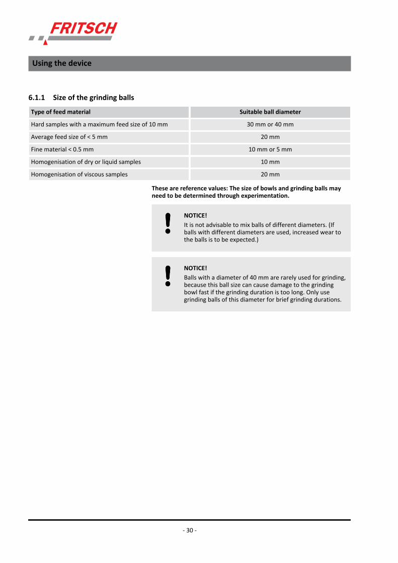
6.1.1 Size of the grinding balls
Type of feed material Suitable ball diameter
Hard samples with a maximum feed size of 10 mm 30 mm or 40 mm
Average feed size of < 5 mm 20 mm
Fine material < 0.5 mm 10 mm or 5 mm
Homogenisation of dry or liquid samples 10 mm
Homogenisation of viscous samples 20 mm
These are reference values: The size of bowls and grinding balls mayneed to be determined through experimentation.
NOTICE!It is not advisable to mix balls of different diameters. (Ifballs with different diameters are used, increased wear tothe balls is to be expected.)
NOTICE!Balls with a diameter of 40 mm are rarely used for grinding,because this ball size can cause damage to the grindingbowl fast if the grinding duration is too long. Only usegrinding balls of this diameter for brief grinding durations.
Using the device
- 30 -

6.1.2 Number of balls per grinding bowl (independent of the material quantity)A higher number of balls will reduce the grinding time and the grindingresult will have a smaller particle size distribution.
Ball diameter (mm) Grinding bowlvolume (ml)
80 250 500
5 Number of balls (pcs) 250 - 300 1200 - 1300 2000 - 2500
10 Number of balls (pcs) 25 -30 50 - 150 100 - 250
15 Number of balls (pcs) 10 45 - 50 70 - 100
20 Number of balls (pcs) 5 15 - 20 25 - 35
30 Number of balls (pcs) - 5 - 6 10
40 Number of balls (pcs) - - 4
These are reference figures: The number of balls may need to be deter-mined through experimentation.
CAUTION!When grinding with a ball size of Ø 30 mm or Ø 40 mm, donot let the device run unsupervised. The vibrations maylead to shifting.
Using the device
- 31 -

6.1.3 Calculated weight of a ball
Ball diameter in mm 5 10 15 20 30 40
Material Densityin g/cm3
Calculated weight of a ball in g
Agate 2,65 0,17 1,39 4,68 11,1 37,46 88,8
Silicon nitride 3,25 0,21 1,7 5,74 13,61 45,94 108,91
Sinteredcorundum
3,9 0,25 2,04 6,89 16,33 55,13 130,69
Zirconiumoxide
5,7 0,37 2,99 10,07 23,88 80,58 191,01
Stainless steel 7,8 0,51 4,08 13,78 32,67 110,27 261,38
Tempered steel 7,9 0,52 4,13 13,96 33,09 111,68 264,73
Tungsten car-bide
14,9 0,97 7,8 26,33 62,41 210,64 499,3
To determine the weight of the required balls, the "calculated weight ofa ball" is multiplied by the "number" of balls required.
Example: A 250 ml agate bowl is to be filled with 1221 agate balls with adiameter of 5 mm.
Calculation: 0.17g * 1221 St » 208 g
208 g of grinding balls can be weighed and inserted in the grinding bowl,thus avoiding the time required for counting the balls.
6.2 Filling quantities of grinding bowls
NOTICE!Never operate the mill without grinding stock! This can leadto grinding balls and grinding bowls getting damaged.
NOTICE!If the minimum filling quantity is fallen short of, increasedwear due to abrasion is to be expected. This can causeirreparable damage to the mill components.
Using the device
- 32 -

Grinding bowl min. sample volumes max. sample volumes
500ml 80ml 225ml
250ml 30ml 125ml
80ml 1ml 30ml
6.3 Filling the grinding bowlDo not fail to comply with the following sequence:
1. Place the grinding balls in the empty bowl.
2. Fill grinding stock onto the balls.
3. Place the seal ring on the rim of the grinding bowl.
4. Place the lid on the grinding bowl.
6.4 Factors with an impact on grinding6.4.1 Running time (grinding duration)
A longer grinding time will increase the percentage of fine material. Toreduce the grinding time, you can use a grinding bowl and grinding ballswith a higher density, and thus a higher impact energy.
6.4.2 SpeedHigher speeds shorten the grinding time and increase the share of fineparticles.
6.4.3 Reverse moden Useful for mechanical alloyingn Improvement of the homogeneity of the sample
6.4.4 Number and size of the ballsPre-grind course, hard material with large balls:
reduced percentage of fine material!
Many small balls increase the percentage of fine material duringextended running time.
Using the device
- 33 -

6.4.5 Weight of the balls (type of material)A higher mass (specific weight) of the grinding balls accelerates grinding.(see table in Ä Chapter 6.1 ‘Choice of grinding bowls and grinding balls’on page 29).
6.4.6 Dry grindingBelow a particle size of approx. 20 µm, the surface forces prevail and thematerial to be ground starts to "stick".
Additional dry comminution can be achieved by adding surface-activesubstances to the material to be ground.
Examples (maximum amount to be added in mass%)
n Stearic acid 2-3%n Aerosil (fine-particle silicic acid) 0.5-2%n Quartz sand ~ 2%n Glass powder ~ 2%
6.4.7 Wet grinding (grinding in a suspension)
DANGER!Explosion hazard! Ignition hazard!The device is not explosion-protected. If flammable liquidsare used, make sure that the heat developing in thegrinding bowl does not reach the solvent's boiling point.Program appropriate cooling phases. If the vapour pressureis too high, vapours may escape and ignite.
If it can be avoided, we recommend using non-flammableliquids or liquids with a high boiling point. The boiling pointshould be above 80 °C and above 100 °C for a long grindingduration.
During the transition to grinding in suspension, you can add a liquid aux-iliary agent with high boiling point and low vapour pressure, e.g. water,white spirits (boiling point 100 - 140°C), alcohols with a high boiling point(e.g. isopropanol)
Using the device
- 34 -

6.5 Clamping the grinding bowls6.5.1 Clamping with the "Safe-Lock" (5) tensioning device
Fritsch GmbH confirms that every Safe‐Lock clampingsystem has been manufactured and tested to our internalquality standards. Fritsch GmbH measures the clampingforce of each individual Safe‐Lock clamping system. Theclamping force must be in the range of 11.2 ‐ 11.3 kN +/‐0.2kN.
Carry out the following checks for every grinding before clamping thegrinding bowls:
n Has the rubber disc (6.1) been inserted into the grinding bowlholder? The rough side should be facing upwards!
n Check the rubber disc in the grinding bowl holder for damage:Replace the rubber disc if it has been pressed flat!
n The Teflon flat seal (for the sealing between lid and bowl) may notbe damaged or soiled.Replace heavily deformed Teflon flat seals.
n The surfaces of the lids and bowls on which the Teflon flat seals liemust be clean!
n Check the rubber disc of the pressure piece for damage!Replace rubber discs that have been pressed flat and are protrudinglaterally from the pressure piece.
Clamping
1. Position the bracket (a) of the clamping lever vertically!
2. Hang the longer projection of the Safe-Lock tensioning device ontothe cut-out of the grinding bowl holder.
Using the device
- 35 -

3. Hang the short projection of the Safe-Lock tensioning device intothe other side.
4. Push the Safe-Lock tensioning device so that the cut-out of thegrinding bowl holder sits centrally in the U-shaped cut-out of thelonger projection.
5. Pre-tension the setting screw (e) manually, then place the pro-vided torque spanner on the setting screw (e) and turn until itclicks.
6. Then press the clamping lever downwards. The Safe-Lock system isnow tensioned!
DANGER!After several minutes of grinding and in the cooling-downphases, check that the tensioning device is firmly con-nected.
If the Safe‐Lock system is correctly tensioned, the clampinglever is automatically pulled downwards by the eccentricwhen horizontal.
Using the device
- 36 -

6.5.2 Clamping the 80 ml grinding bowlsThere are two ways of clamping an 80 ml grinding bowl:
1. Place the reducer (o) (order no. 90.1120.09) into the grinding bowlholder and position the 80ml grinding bowl on it and fasten withthe Safe-Lock tensioning device.
2. Alternatively, clamp two 80 ml grinding bowls on top of oneanother.
Tensioning with the Safe‐Lock system proceeds as describedin Ä Chapter 6.5.1 ‘Clamping with the "Safe‐Lock" (5) ten‐sioning device’ on page 35.
6.6 Mass balanceLoad the laboratory planetary mill symmetrically.
Always clamp an equally heavy grinding bowl with lid and seal ring in theopposite grinding bowl holder to balance the weight!
Failing that, select an empty bowl as a counterweight. The empty bowlmay be filled with sand as an additional weight.
NOTICE!Extra weights, like "GTM" and "additional clampingsystem", have to be balanced as well.
6.7 Grinding duration
WARNING!Burn hazard!
Grinding bowls can get very hot after long grinding dura-tions. Wear protective gloves for removal after grinding orduring the grinding breaks.
Using the device
- 37 -

Depending on the application, the grinding duration should be adaptedto the development of heat in the bowls. The temperature inside thebowls is 20 - 30 °C warmer than the outer casing temperature.
CAUTION!The maximum temperature of the grinding bowl outercasing is 100 - 110 °C (agate, max. 70 - 80 °C).
The grinding duration is therefore based on the maximumbowl temperature. The grinding duration at which the tem-perature is not exceeded depends on the material, ball, andspeed. For this reason, the user should determine itthrough experimentation.
Reference value
When grinding at high speeds and with large bowls, a grinding durationof one hour (depending on the temperature) should not be exceeded.Then allow the unit to cool down for half an hour to one hour.
NOTICE!– Observe the warming up of the grinding stock.– A longer running time may require pause times for
cooling down.– Check that the tensioning device is firmly connected
when switching on again after a cooling-down phase.
NOTICE!If bowls are removed during a grinding pause, check thatthey fit correctly before the device is switched back on.
The extent to which the heating up of grinding stock needsto be observed depends on the sample used in each indi‐vidual case. Note® A longer running time may also requirea longer pause time for cooling down.
To reduce the grinding time, you can use a grinding bowl and grindingballs with a higher density, and thus a higher impact energy.
The mill can also run for several hours during low-speed operations formixing and homogenisation.
Operation with an external time switch is not possible.
Using the device
- 38 -

6.8 Settings on the control panel6.8.1 Setting the speed
n Switch on the main switch (10) on the back side of the device (I).n The green POWER SUPPLY ready status indicator lights up on the
control panel.
ROTATIONAL SPEED control panel area
Press and hold the + or - button.
The speed can be selected in steps of 10 between 50 and 400 1/min.
The actual speed is displayed during operation. The nominal speed isbriefly displayed when the + or - button is pressed.
6.8.2 Setting the running timeTIMER control panel area
Setting the grinding time
1. Press the "MILLING" button.
ð The "MILLING" button lights up
2. Press the + or - buttons to set the running time in hours (0...99)and minutes (0...59)!
Set the pause time
1. Press the "PAUSE" button.
ð The "PAUSE" button lights up.
2. Press the + or - buttons to set the pause time in hours (0...99) andminutes (0...59)!
If no pause time is required, set the pause time to 0.
Using the device
- 39 -

– If the combination minutes/seconds is set in setupmode instead of hours/minutes (see Ä Chapter 6.8.2.1‘Changing the time unit in setup mode’ on page 40), thenumbers at h indicate the minutes and at min, the sec‐onds!The factory setting of the time unit is minutes and sec‐onds. (Display: 1)
– The remaining running times and the pause times aredisplayed during operation.
– Operation with an external time switch is not possible.– For running times see Ä Chapter 6.4.1 ‘Running time
(grinding duration)’ on page 33.– Interrupt grinding by pressing the STOP button. Con‐
tinue grinding by pressing the START button. This takesinto account the previous grinding duration and thenumber of repetitions.
6.8.2.1 Changing the time unit in setup mode
1. When the device has been switched off, press and hold the STOPbutton on the front control panel.
2. Switch on the device with the main switch (10) on the back side ofthe device.
3. If POWER SUPPLY is flashing, the device is in setup mode. IfPOWER SUPPLY is not flashing, repeat the procedure.
Using the device
- 40 -

4. To perform changes, press the right "+" button (y) in the TIMERfield:
Time unit, hours and minutes ® Display: -
Time unit, hours and minutes ® Display: 1 (factory setting)
5. To save and end setup mode, press the STOP button.
6.9 Repetition of grinding / pause cyclesREPETITIONS control panel area
Press + or - button; select the number of repetitions (0..99). The numberof remaining cycles is displayed during operation.
6.10 Reverse mode®Press the REVERSE button. The button lights up.
After the selected running time expires, the mill will change its directionof rotation. For this, REPETITIONS has to indicate at least 1.
"Reverse" is selected when mixing dry samples, for example.
6.11 Conducting a grinding operationn After all the preparations described in Ä Chapter 6.1 ‘Choice of
grinding bowls and grinding balls’ on page 29 to Ä Chapter 6.10‘Reverse mode’ on page 41 have been carried out, close the hood(3).
n Press the START button on the control panel.n The hood is locked and the mill starts up.n The mill turns at the set speed (nominal speed). If the load is too
great, for example due to heavy grinding bowls, the speed is reduced(actual speed) so that the machine is not overloaded.® The "REDUCED SPEED" lamp is lit!
Using the device
- 41 -

If the mill does not start, see Ä Chapter 10 ‘Repairs’on page 55
While in operation, the hood (3) remains locked, evenduring pause times, and the fan cools the interior.
6.11.1 OverloadIf the mill is overloaded, the speed is reduced and the REDUCED SPEEDlight flashes.
The mill switches off if the overload continues for too long; seeÄ Chapter 10.1 ‘Checklist for troubleshooting’ on page 55.
6.11.2 Switching offn Press STOP on the control panel.n When the drive comes to a standstill, the hood is unlocked and can
be opened.n If the device is not in operation for a long time, switch off the main
switch (10) on the back side.
6.12 Cooling the grinding bowl
WARNING!Burn hazard!
Grinding bowls can get very hot after long grinding dura-tions. Wear protective gloves for removal after grinding orduring the grinding breaks.
n When the hood is open (3), orn In the programmed pause times with closed (locked) hood and the
fan running.
Using the device
- 42 -

6.13 Stand-byIf the mill is not in operation and the hood (3) is open, it switches to theenergy-saving stand-by mode after one hour. The STAND-BY lamp lights.
The stand-by function is not possible when the hood is closed.
Using the device
- 43 -

7 Accessories7.1 Additional clamping system for grinding harmful substances or in a gas atmosphere.
The additional clamping system is used to transport a grinding bowl filledwith inert gas or harmful substances from a glove box to the planetarymill and back again. This ensures that no harmful substances can beinhaled.
There are two ways of gassing the grinding bowls:
1. Grinding bowls with standard lids have to be filled in a glove boxwith an inert gas atmosphere and closed using the additionalclamping system. Using this procedure you can even grind haz-ardous substances!
2. Grinding bowls with gassing lids can also be closed and gassed out-side the device using the additional clamping system.
7.1.1 Locking the additional clamping system into place1. Place the grinding bowl in the grinding bowl adapter (a) of the
additional clamping system.
Accessories
- 44 -

2. Position the pressure plate (b) with the rubber disc on the bowl asshown in the picture.
3. When using grinding bowls with a volume of 80 ml, the adapterpiece (c) (90.1120.09) has to be used as well.
NOTICE!Under no circumstances may 80 ml bowls beclamped on top of one another. This can lead todamage to the bowl and its component seals.
4. Then tighten both socket-head screws (d) shown in the diagramequally with a hex key and thereby clamp the pressure platetightly. Ensure that the pressure plate is lying evenly on the bowllid.
5. Place the additional clamping system with clamped bowl in thegrinding bowl holder.
Accessories
- 45 -

6. The pressure piece has to be removed in order to use the Safe-Lock system for tensioning.
7. Position the bracket (d) vertically!
8. Hang the longer projection of the Safe-Lock tensioning device ontoone side of the mounting of the grinding bowl holder.
9. Hang the short projection of the Safe-Lock tensioning device ontothe other side.
Accessories
- 46 -

10. Ensure that the tenon joint of the threaded spindle (where thepressure piece was previously affixed) is sitting in the bore holeprovided in the pressure plate (b).
11. Push the Safe-Lock tensioning device so that the mounting of thegrinding bowl holder sits centrally in the U-shaped cut-out of thelonger projection.
12. Pre-tension the setting screw (e) manually, and screw it tight usingthe provided torque spanner. Place the torque spanner providedon the setting screw (b) and turn until it clicks.
13. Then press the clamping lever downwards.
14. Re-tighten the screws in the additional clamping system with a hexkey. The additional clamping system may be loosened due to theclamping of the Safe-Lock using the clamping lever.
DANGER!After several minutes of grinding and in the cooling-downphases, check that the tensioning devices are still firmlyconnected.
If the Safe‐Lock system is correctly tensioned, the clampinglever is automatically pulled downwards by the eccentricwhen horizontal.
Accessories
- 47 -

7.2 Grinding in inert gas with gassing lid
NOTICE!Observe imbalance offsetting! (See Ä Chapter 6.6 ‘Massbalance’ on page 37).
We carry out a worker water bath test on all gassing lids.The part to be tested is sealed, a pressure of 5.5 bar isapplied and it is immersed in a water bath. If there is a leak,bubbles will develop. The air bubbles that develop within aspecific interval are evaluated by the worker/tester.
Only gassing lids with a leak rate of <10‐4 [mbar l/s] areapproved.
When grinding in inert gas, the same conditions apply regardingclamping and composition of grinding set and balls, as apply for standardgrinding.
Two valves are screwed onto the gassing lid through which you can feedin inert gas (e.g. nitrogen) before switching on the mill. A Viton flat seal isused instead of a Teflon one.
7.2.1 Preparation for gassinga Gassing hoseb Hose clampc Couplingd Valvese Ventilation attachment
n Fill the grinding bowl with grinding balls and grinding stock. (SeeÄ Chapter 6.3 ‘Filling the grinding bowl’ on page 33)
n Attach the Viton seal and lid.n Insert the grinding bowl into the grinding bowl holder (8).n Clamp the grinding bowl in the device (See Ä Chapter 6.5.1
‘Clamping with the "Safe‐Lock" (5) tensioning device’ on page 35)
Using the additional clamping system, the following steps can also becompleted in the glove box and subsequently clamped in the PlanetaryMill:
n Connect the gassing hose (a) to the inert gas supply using the pro-vided hose clamp (b).
n Screw the ventilation attachment (e) onto one of the two valves (d).n Place the coupling (c) of the gassing hose on the free valve. When
doing so, press the lever of the coupling and push the coupling alongthe neck of the valve until it goes no further. Release the lever.
Accessories
- 48 -

Using the additional clamping system, the closed grindingbowl can also be tensioned and gassed outside of thedevice. (See Ä Chapter 7.1.1 ‘Locking the additionalclamping system into place’ on page 44)
7.2.2 Gassingn Slowly open the inert gas supply.n Press a thin object (e.g. hex key) onto the top of the ventilation
attachment (e) so that the air can escape from the grinding bowl.n The inert gas now purges the air from the grinding bowl.n The duration of purging has to be determined through experimenta-
tion.It depends on grinding bowl size, filling, and gas supply, among otherfactors.
n To end purging, close the inert gas supply and release the ventilationattachment.
n Screw off the ventilation attachment.n Remove the gassing hose. To do so, press the lever.
CAUTION!Only switch on the device when both coupling and ventila-tion attachment have been removed.
Overpressure may occur during grinding!
7.2.3 Ventilate after grinding
CAUTION!Always let the bowl cool down before ventilation. Hot gasesand sample material may escape from the bowl duringpressure equalisation, leading to serious burns.
® Use protective gloves when ventilating!
n Screw the ventilation attachment onto the valve.Each valve can be used for aerating or ventilating.
n For pressure equalisation (of the overpressure occurring because ofgrinding), carefully press on the ventilation attachment with a thinobject (e.g. hex key).
n Only now may the grinding bowl tensioning be released.
Accessories
- 49 -

7.2.4 Cleaning the valvesf Valve screwdriverg Valve insertd Valves
Both valves (d) should be cleaned after every grinding!
n Insert the thin end of the valve screwdriver (f) from above into thevalve (d) and turn anti-clockwise.
n Screw out the valve insert (g).n Depending on the soiling, clean the valve insert (g) with compressed
air, or place it in a small glass container filled with alcohol and cleanin an ultrasonic cleaner (LABORETTE 17) and then dry carefully.
n After the two valve inserts have been removed, the two valveholders can be cleaned with compressed air from above the lid.
7.2.5 Installing valve insertsn Insert the valve insert (g) into the valve (d) with the spring pointing
upwards.n With the valve screwdriver (f), screw the valve insert clockwise.
The following gassing lids for the grinding sets are available, each withtwo valves and a soft sealing ring:
Material Order number
Hardmetal tungsten carbide 250ml
50.8600.00
Tempered chrome steel 80 ml 50.8700.00
Tempered chrome steel 250 ml 50.8500.00
Tempered chrome steel 500 ml 50.8400.00
Stainless steel 80 ml 50.8800.00
Stainless steel 250 ml 50.8300.00
Stainless steel 500 ml 50.8200.00
Agate 250 ml 50.8100.00
Agate 500 ml 50.8000.00
NOTICE!The soft black sealing rings made of "Viton" can enduretemperatures of approx. 200 °C.
The valves (d) can endure temperatures of approx. 180 °Cfor one hour at most.
Accessories
- 50 -

NOTICE!The grinding parts made of agate are only designed fortemperatures of up to 100 °C. After this point, they need tobe slowly and carefully cooled down.
7.3 GTM - systemThe GTM system is available as an accessory for recording pressure andtemperatures in the grinding bowl during grinding.
Instructions are included with the GTM system.
Accessories
- 51 -

8 Cleaning
DANGER!Mains voltage!– Before beginning with cleaning work, disconnect the
mains plug and protect the device against being unin-tentionally switched back on!
– Do not allow any liquids to flow into the device.– Indicate cleaning work with warning signs.– Put safety equipment back into operation after
cleaning work.
When cleaning the entire device, adhere to the guidelines ofthe Accident Prevention Regulation (BGV A3) ‐ especiallywhen the device has been set up in a dusty environment orwhen the grinding stock processed produces dust.
8.1 Grinding elements
NOTICE!Cool grinding elements made of agate, sintered corundum,zirconium oxide and silicon nitride slowly and carefully.
Do not heat agate elements in a microwave under any cir-cumstances (heating is too fast).
They must never be exposed to thermal shocks as thiscould cause irreparable damage to the parts ® They willburst apart like in an explosion.
n Clean the grinding bowl and grinding balls each time after usingthem: Clean them, e.g., under running water using a brush and acommercially available cleaning agent.
n Half fill the grinding bowl with grinding balls, sand and water, andrun for 2 to 3 minutes (correctly tensioned) in the Planetary Mill.
n Cleaning with an ultrasonic cleaner is permitted.n For sterilisation in the heat cabinet, only heat the grinding elements
up to 100 °C.
8.2 Milln The planetary mill can be wiped down with a damp cloth when it is
switched off.
Cleaning
- 52 -

9 Maintenance
DANGER!Mains voltage– Before beginning with maintenance work, unplug the
mains plug and protect the device against being unin-tentionally switched back on again!
– Indicate maintenance work with warning signs.– Maintenance work may only be performed by special-
ised personnel.– Put safety equipment back into operation after mainte-
nance or repair work.
We recommend keeping a safety logbook Ä Chapter 15‘Safety logbook’ on page 64, where all work (maintenance,repairs......) performed on the device is entered.
– The most important element of maintenance is regularcleaning:
– When cleaning the complete device, adhere to theguidelines of the Accident Prevention Regulation (BGVA3) ‐ especially if the device has been set up in a dustyenvironment or if the processed source material pro‐duces dust.
NOTICE!Safe-lock - clamping systems might lose their tension forceover time of usage. To watch the right tension force of eachSafe-lock - clamping system Fritsch GmbH stipulates ascheduled maintenance interval of one year. Please sendback all Safe-lock - clamping systems for regular checks toFritsch GmbH. This service is liable to pay the costs.
Functional part Task or description Test Maintenance interval
Safety lock Hood lock (7) Is the closed hood (3)locked in place when themain switch is off?
If this test is failed, do notcontinue to work until thefault has been rectified.
Before each use
Rotating bearings Permanent lubrication Bearing clearance Every 2,000 h or annually
Maintenance
- 53 -

Functional part Task or description Test Maintenance interval
Drive motor Permanent lubrication Bearing clearance Every 4,000 h or annually
V-belt Motor planetary disc Check belt tension
Disconnect the device fromthe mains. Screw off thetop rear cover plate. Thebelt must not slacken bymore than 10 mm whenpushed with your thumb.
Once a year
Fan, ventilation slots (13) Grinding chamber coolingand electronics
Clean functional partswhen soiled (right and leftside of the device, as in theinterior)
Twice a year
Grinding bowl tensioningdevice, Safe-Lock (5) (Fig.1)
Rubber of the pressurepiece and rubber disc inthe grinding bowl holder
Signs of use; replace ifpressed flat and no longerelastic
After every 1,000 h
Indicated surfaces of Safe-Lock are round
Original height, 12.5 mm
Minimum height, 12 mm(y)
Safe-Lock has frequentlybeen tensioned too loosely
After every 200 h
If the height is under theminimum height, the corre-sponding part has to bereplaced.
Seal the grinding bowl Grinding bowl lid seal Replace seal if dirt haspenetrated
After every 100 h
Grinding bowl holder (8)(Fig. 2)
Keep tension
Original height, 14 mm
Minimum measurement atgrinding bowl holder, 11mm (x)
Twice a year; this minimummeasurement may have tobe checked more oftendepending on use.
If the height is under theminimum height, the corre-sponding part has to bereplaced.
Maintenance
- 54 -

10 Repairs
DANGER!Mains voltage!– Before beginning with repair work, unplug the mains
plug and protect the device against being unintention-ally switched back on.
– Indicate repair work with warning signs.– Repair work may only be performed by specialised per-
sonnel.– Put safety equipment back into operation after mainte-
nance work.
10.1 Checklist for troubleshooting
Fault description Cause Remedy
The POWER SUPPLY ready statusindicator doesn't light up
No mains connection Plug in mains plug.
Main switch (10) at 0 (OFF) Switch on main switch.
Excess current protection switchhas been triggered
Press the excess current protection switch(9) on the back of the device.
"START" button is pressed butmill does not start up
POWER SUPPLY does not light up see above
Pause time active Wait for end of pause or press "STOP".
Safety lock was opened manually Reactivate the safety lock, seeÄ Chapter 2.6 ‘Protective equipment’on page 14
Mill reduces speed automatically If REDUCED SPEED is lit: Overload Reduce load or accept automatically setspeed.
Mill stops running Switched off due to thermal over-load of the drive
Allow device to cool down and select alower speed.
Imbalance of machine too high Improve mass balance. (See Ä Chapter 6.6‘Mass balance’ on page 37).
Drive was blocked Rectify malfunction in grinding chamber.
Motor's V-belt loose or ripped Check V-belt, replace if necessary.
Speed sensor is defective Contact customer service.
The hood cannot be opened. The hood handle (1) was not prop-erly operated during opening.
Unlock the hood handle by pressing!
Repairs
- 55 -

Fault description Cause Remedy
No mains connection Plug in mains plug.
Main switch at 0 (OFF) Switch on main switch (I).
Excess current protection switchhas been triggered
Press the excess current protection switch(9) on the back of the device
Grinding stock escapes Tensioning device (5) loose Check and re-tension if necessary.
Seal ring between the bowl and lidis soiled or defective
Clean or replace seal ring.
Runs unevenly with strong vibra-tions
Bowls are imbalanced Align the bowls symmetrically (equal massesin the opposing position)
Repairs
- 56 -

11 Examples of comminution tasksMaterial
Feeding amount Material of grinding bowland balls
Grinding balls, St. x diam-eter
Result
Feed size Grinding bowl size Grinding duration Final fineness
Ruby (stone)
140 g Cr-Ni steel 6 x 30 mm 100%
12 mm 250 ml 3 min < 250 µm
Titanium dioxide TiO2 (dry and wet grinding in water)
40 g Cr-Ni steel 6 x 30 mm 100%
2 mm 250 ml 30 min < 40 µm
Titanium dioxide TiO2 (wet grinding in water)
40 g / 50 ml water Cr-Ni steel 6 x 30 mm 100%
2 mm 250 ml 60 min < 10 µm
Coal (dry and wet grinding in water)
5 g Zirconium oxide 5 x 20 mm 100%
0.5 mm 80 ml 120 min < 15 µm
Aluminium oxide / silicon oxide
100 g WC + Co 15 x 20 mm 90%
0.1 mm 250 ml 90 min < 20 µm
Ferrovanadium
70 g WC + Co 5 x 30 mm 70%
3 mm 250 ml 20 min < 100 µm
Glass
50 g Agate 15 x 20 mm 100%
4 mm 250 ml 15 min < 90 µm
Silicon carbide (dry and wet grinding in water)
15 g WC + Co 5 x 20 mm 100%
3 mm 80 ml 30 min < 150 µm
Silicon carbide (dry and wet grinding in water)
15 g / 5 ml water WC + Co 5 x 20 mm 100%
3 mm 80 ml 45 min < 71 µm
Examples of comminution tasks
- 57 -

Raw phosphate
40 g Cr steel 15 x 20 mm 100%
3 mm 250 ml 2 min < 250 µm
Manganese dioxide MnO2 (wet grinding in water)
50 g / 40 ml water WC + Co 15 x 20 mm 100%
0.1 mm 250 ml 60 min < 20 µm
Sludge (dry)
180 g Al2O3 10 x 30 mm 100%
8 mm 500 ml 30 min < 250 µm
Active carbon (wet grinding in water)
150 ml Cr-Ni steel 15 x 20 mm 100%
0.025 mm 250 ml 30 min < 5 µm
Plaster
300 g Cr steel 10 x 30 mm 100%
10 mm 500 ml 20 min < 200 µm
Protein
50 g Sintered corundum 1 6 x 30 mm 90%
20 mm 250 ml 90 min < 50 µm
Grains (barley)
100 g Sintered corundum 1 3 x 40 mm 100%
3 mm 500 ml 20 min < 150 µm
Dough products
100 g Sintered corundum 1 10 x 30 mm 100%
5 mm 500 ml 3 min < 250 µm
Sugar (wet grinding in alcohol)
200 g Agate 10 x 30 mm 100%
1 mm 500 ml 45 min < 10 µm
Examples of comminution tasks
- 58 -

12 DisposalIt is hereby confirmed that FRITSCH has implemented the directive2002/95/EC of the European Parliament and Council from 27th January2003 for the limitation of the use of certain dangerous substances inelectrical and electronic devices.
FRITSCH has registered the following categories according to the Germanelectrical and electronic equipment act, section 6, paragraph 1, clause 1and section 17, paragraphs 1 and 2:
Mills and devices for the preparation of samples have been registeredunder category 6 for electrical and electronic tools (except for large sta-tionary industrial tools).
Analytical devices have been registered under category 9, monitoringand control instruments.
It has been accepted that FRITSCH is operating only in the business-to-business area. The German registration number for FRITSCH is WEEE reg.no. DE 60198769
FRITSCH WEEE coverage
Since the registration of FRITSCH is classified for bilateral transactions,no legal recycling or disposal process is described. FRITSCH is not obligedto take back used FRITSCH devices.
FRITSCH declares it is prepared to take back used FRITSCH devices forrecycling or disposal free of charge whenever a new device is purchased.The used FRITSCH device must be delivered free of charge to a FRITSCHestablishment.
In all other cases FRITSCH takes back used FRITSCH devices for recyclingor disposal only against payment.
Disposal
- 59 -

13 Guarantee termsAs manufacturer, FRITSCH GmbH provides – above and beyond any guar-antee claims against the seller – a guaranty valid for the duration of twoyears from the date of issue of the guarantee certificate supplied withthe device.
Within this guarantee period, we shall remedy all deficiencies due tomaterial or manufacturing defects free of charge. Rectification may takethe form of either repair or replacement of the device, at our sole discre-tion. The guarantee may be redeemed in all countries in which thisFRITSCH device is sold with our authorisation.
This guarantee is subject to the condition that the device is operatedaccording to the instructions for use / operating manual and its intendeduse.
Claims against the guarantee must include presentation of the originalreceipt, stating the date of purchase and name of the dealer, togetherwith the complete device type and serial number.
For this guarantee to take effect, the answer card entitled "Securing ofGuarantee" (enclosed with the device) must be properly filled out anddespatched without delay after receipt of the device and be receivedby us within three weeks or alternatively, online registration must becarried out with the above-mentioned information.
The guarantee will not be granted in cases where:
n Damage has arisen due to normal wear and tear, especially for wearparts, such as: Crushing jaws, support walls, grinding bowls, grindingballs, sieve plates, brush strips, grinding sets, grinding disks, rotors,sieve rings, pin inserts, conversion kits, sieve inserts, bottom sieves,grinding inserts, cutting tools, sieve cassettes, sieve and measuringcell glasses.
n Repairs, adaptations or modifications were made to the device byunauthorized persons or companies.
n The device was not used in a laboratory environment and/or hasbeen used in continuous operation.
n Damage is present due to external factors (lightning, water, fire orsimilar) or improper handling.
n Damage is present that only insubstantially affects the value orproper functioning of the device.
n The device type or serial number on the device has been changed,deleted, removed or in any other way rendered illegible
n The above-mentioned documents have been changed in any way orrendered illegible.
Guarantee period
Conditions for claims against the guar-antee
Reasons for loss of the guarantee
Guarantee terms
- 60 -

This guarantee excludes any costs for transport, packaging or travel thataccrue in the event the product must be sent to us or in the event thatone of our specialist technicians is required to come to your site. Anyservicing done by persons not authorised by us and any use of parts thatare not original FRITSCH accessories and spare parts will void the guar-antee.
The guarantee period will neither extend nor will a new period of guar-antee begin in the event that a claim is placed against the guarantee.
Please provide a detailed description of the type of error or the com-plaint. If no error description is enclosed, we shall interpret the shipmentas an assignment to remedy all recognisable errors or faults, includingthose not covered by the guarantee. Errors or faults not covered by theguarantee shall in this case be rectified at cost.
We recommend reading the operating manual before contacting us oryour dealer, in order to avoid unnecessary inconvenience.
Ownership of defective parts is transferred to us with the delivery of thereplacement part; the defective part shall be returned to us at buyer'sexpense.
NOTICE!Please note that in the event that the device must bereturned, the device must be shipped in the original Fritschpackaging. Fritsch GmbH denies all liability for any damagedue to improper packaging (packaging not from Fritsch).
Any enquiries must include a reference to the serial number imprintedon the type plate.
Costs not covered by the guarantee
Further information about the guar-antee
Guarantee terms
- 61 -

14 Exclusion of liabilityBefore using the product, be sure to have read and understood thisoperating manual.
The use of the product requires technical knowledge; only commercialuse is permitted.
The product may be used exclusively within the scope of applications setdown in this operating manual and within the framework of guidelinesput forth in this operating manual and must be subject to regular main-tenance. In case of non-compliance, improper use or improper mainte-nance, the customer assumes full liability for the functional capability ofthe product and for damage or injury arising from violating these obliga-tions.
The contents of this operating manual are subject in entirety to copy-right law. This operating manual and its contents may not be copied, fur-ther distributed or stored in any form, in part or in whole, without theprior written consent of Fritsch.
This operating manual has been prepared to the best of our knowledgeand checked for accuracy at the time of printing. FRITSCH GMBHassumes no guarantee or liability whatsoever for the accuracy or com-pleteness of the contents of this operating manual, including but notlimited to the implied warranties of merchantability and fitness for a par-ticular purpose, unless liability is expressly prescribed by applicable lawsor jurisprudence.
FRITSCH GMBH expressly reserves the right to modify and/or update thisoperating manual without prior notice. The same applies to modifica-tions and improvements to the products described in this operatingmanual. It is the responsibility of the user to ensure that they have thecurrent version of this operating manual. For more information, pleasecontact your local FRITSCH GMBH distributor or Fritsch GmbH, Industri-estr. 8, D-55473 Idar-Oberstein.
Not all parts shown here are necessarily installed in the product. Thebuyer is not entitled to delivery of these parts. If interested, please con-tact your local FRITSCH GMBH distributor or Fritsch GmbH, Industriestr.8, D-55743 Idar-Oberstein.
FRITSCH GMBH takes the greatest care to ensure that the quality, relia-bility and safety of your products are continuously improved andadapted to the state of the art. The supplied products as well as thisoperating manual conform to the current state of the art when theyleave the sphere of influence of FRITSCH GMBH.
By using the product the customer agrees with this and recognizes thatdefects, malfunctions or errors cannot be completely excluded. To pre-vent risk of damage to persons or property or of other direct or indirectdamage, resulting from this or other causes, the customer must imple-ment sufficient and comprehensive safety measures for working with theproduct.
Exclusion of liability
- 62 -

Fritsch GmbH excludes any liability, warranty, or other obligation to com-pensate for damages, regardless of whether this liability, warranty, orother obligation is explicit or implicit, contractual or arising fromunlawful acts or prescribed contractually, by law, or otherwise. In noevent shall the buyer be entitled to any compensation from FritschGmbH for any special, direct, indirect, coincidental or consequentialdamage, including but not limited to lost profits, lost savings, lost salesor financial loss of any kind or for compensation of third parties, fordowntimes, for lost goodwill, for damage to or replacement of equip-ment and property, for costs or restoration of materials or goods relatedto the product or the use of our products, for other damage or injury topersons (including fatal injuries) or similar. The above exclusion of lia-bility is limited by mandatory liability as prescribed by laws or jurispru-dence. Liability for negligence is excluded in all cases.
No permission is given expressly, implicitly or otherwise for the use ofpatents, brands or other copyrights. We also assume no liability for copy-right infringements or infringements of the rights of third parties arisingfrom the use of this product.
Neither compliance with this operating manual nor the conditions andmethods used during installation, operation, use and maintenance of theproduct can be monitored by Fritsch GmbH. Improper execution of theinstallation can result in property damage and thus endanger persons.Therefore, we assume absolutely no responsibility or liability for loss,damage or costs that result from errors at installation, improper opera-tion or improper use or improper maintenance or are in any way con-nected to these.
Exclusion of liability
- 63 -

15 Safety logbookDate Maintenance / Repair Name Signature
Safety logbook
- 64 -

16 IndexAAccident prevention . . . . . . . . . . . . . . . . . . . . . . . . 8Additional clamping system . . . . . . . . . . . . . . . . . . 44Adjusting to the mains voltage . . . . . . . . . . . . . . . 24Authorised persons . . . . . . . . . . . . . . . . . . . . . . . . 8
BBasic structure . . . . . . . . . . . . . . . . . . . . . . . . . . . . 7
CClamping 80 ml bowls . . . . . . . . . . . . . . . . . . . . . . 37Clamping grinding bowl with the "Safe-Lock" ten-sioning device . . . . . . . . . . . . . . . . . . . . . . . . . . . 35Cleaning grinding elements . . . . . . . . . . . . . . . . . . 52Cleaning the mill . . . . . . . . . . . . . . . . . . . . . . . . . 52Cleaning the valves . . . . . . . . . . . . . . . . . . . . . . . . 50Conducting a grinding operation . . . . . . . . . . . . . . 41Cooling grinding bowls . . . . . . . . . . . . . . . . . . . . . 42Current consumption . . . . . . . . . . . . . . . . . . . . . . 19
DDimensions . . . . . . . . . . . . . . . . . . . . . . . . . . . . . 19Disposal . . . . . . . . . . . . . . . . . . . . . . . . . . . . . . . 59Dry grinding . . . . . . . . . . . . . . . . . . . . . . . . . . . . . 34
EElectrical connection . . . . . . . . . . . . . . . . . . . . . . 23Electrical safety . . . . . . . . . . . . . . . . . . . . . . . . . . 20Examples of comminution tasks . . . . . . . . . . . . . . . 57Exclusion of liability . . . . . . . . . . . . . . . . . . . . . . . 62Explanation of signs . . . . . . . . . . . . . . . . . . . . . . . 10Explanation of symbols . . . . . . . . . . . . . . . . . . . . . 10
FFilling grinding bowls . . . . . . . . . . . . . . . . . . . . . . 33Filling quantities of the grinding bowls . . . . . . . . . . 32Final fineness . . . . . . . . . . . . . . . . . . . . . . . . . . . . 20
GGrinding duration . . . . . . . . . . . . . . . . . . . . . . . . . 38Grinding in inert gas . . . . . . . . . . . . . . . . . . . . . . . 48GTM - system . . . . . . . . . . . . . . . . . . . . . . . . . . . 51Guarantee terms . . . . . . . . . . . . . . . . . . . . . . . . . 60
HHazardous points . . . . . . . . . . . . . . . . . . . . . . . . . 17
IImbalance detection . . . . . . . . . . . . . . . . . . . . . . . 18Initial start-up . . . . . . . . . . . . . . . . . . . . . . . . . . . 27
Installing valve inserts . . . . . . . . . . . . . . . . . . . . . 50
MMaintenance . . . . . . . . . . . . . . . . . . . . . . . . . . . . 53Mass balance . . . . . . . . . . . . . . . . . . . . . . . . . . . . 37Material . . . . . . . . . . . . . . . . . . . . . . . . . . . . . . . 20
NNumber of balls per bowl . . . . . . . . . . . . . . . . . . . 31
OOpening the hood without mains connection . . . . . 14Operating noise . . . . . . . . . . . . . . . . . . . . . . . . . . 19Operating principle . . . . . . . . . . . . . . . . . . . . . . . . 9Overload . . . . . . . . . . . . . . . . . . . . . . . . . . . . . . . 42Overload protection . . . . . . . . . . . . . . . . . . . . . . . 17
PPower consumption . . . . . . . . . . . . . . . . . . . . . . . 20Preparing gassing . . . . . . . . . . . . . . . . . . . . . . . . . 48Protection against restart . . . . . . . . . . . . . . . . . . . 17Protective equipment . . . . . . . . . . . . . . . . . . . . . . 14
RRepairs . . . . . . . . . . . . . . . . . . . . . . . . . . . . . . . . 55Repetition of grinding / pause cycles . . . . . . . . . . . 41Requirements for the user . . . . . . . . . . . . . . . . . . . 8Reverse mode . . . . . . . . . . . . . . . . . . . . . . . . 33, 41Running time . . . . . . . . . . . . . . . . . . . . . . . . . . . . 33
SSafety information . . . . . . . . . . . . . . . . . . . . . . . . 10Safety logbook . . . . . . . . . . . . . . . . . . . . . . . . . . . 64Scope of application . . . . . . . . . . . . . . . . . . . . . . . . 8Selecting the grinding balls . . . . . . . . . . . . . . . . . . 29Selecting the grinding bowl . . . . . . . . . . . . . . . . . . 29Setting the grinding duration . . . . . . . . . . . . . . . . . 39Setting the speed . . . . . . . . . . . . . . . . . . . . . . . . . 39Setting up . . . . . . . . . . . . . . . . . . . . . . . . . . . . . . 22Size of the grinding balls . . . . . . . . . . . . . . . . . . . . 30Skilled workers . . . . . . . . . . . . . . . . . . . . . . . . . . . 8Speed . . . . . . . . . . . . . . . . . . . . . . . . . . . . . . . . . 33Stand By - Mode . . . . . . . . . . . . . . . . . . . . . . . . . 43
TTroubleshooting checklist . . . . . . . . . . . . . . . . . . . 55
UUnpacking . . . . . . . . . . . . . . . . . . . . . . . . . . . . . . 21
Index
- 65 -

VVentilating after grinding . . . . . . . . . . . . . . . . . . . 49Voltage . . . . . . . . . . . . . . . . . . . . . . . . . . . . . . . . 19
WWarning information . . . . . . . . . . . . . . . . . . . . . . 10
WEEE . . . . . . . . . . . . . . . . . . . . . . . . . . . . . . . . . 59Weight . . . . . . . . . . . . . . . . . . . . . . . . . . . . . . . . 19Wet grinding . . . . . . . . . . . . . . . . . . . . . . . . . . . . 34
Index
- 66 -


© 2014
Fritsch GmbHMilling and SizingIndustriestraße 8D - 55743 Idar-ObersteinTelephone: +49 (0)6784/ 70-0Fax: +49 (0)6784/ 70-11email: [email protected]: www.fritsch.com