Embed Size (px)
Citation preview

Planeamento 1
Planeamento e Gestão de Redes
Análise de Requisitos
Manuel P. Ricardo
Faculdade de Engenharia da Universidade do Porto
Planeamento 2
♦ Book
Top-Down Network Design, Second Edition
Priscilla Oppenheimer
Cisco Press
♦ Chapters 1 to 4
♦ Credits
These slides are based on the material made available by
Priscilla Oppenheimer
on the book’s site http://www.topdownbook.com

Planeamento 3
Structured Network Design
• Set of best practices
• Layer 7 first
• Identification of
– Business/technical goals
– Groups of users/their locations
– Applications
usage, generated traffic
Application
Presentation
Session
Transport
Network
Data Link
PhysicalLayer 1
Layer 7
Layer 6
Layer 5
Layer 4
Layer 3
Layer 2

Planeamento 4
Analyze
requirements
Develop
logical
design
Develop
physical
design
Test, optimize,
and document
design
Monitor and
optimize
network
performance
Implement
and test
network
Top-Down Network Design Process

Planeamento 5Phase 1 –
Analyze Requirements
♦ Analyze company business goals
♦ Analyze network technical goals
♦ Characterize the existing network
♦ Characterize network traffic
♦ The steps addressed in this set of slides
Analyze
requirement
s
Develop
logical
design
Develop
physical
design
Test, optimize,
and document
design
Monitor and
optimize
network
performance
Implement
and test
network
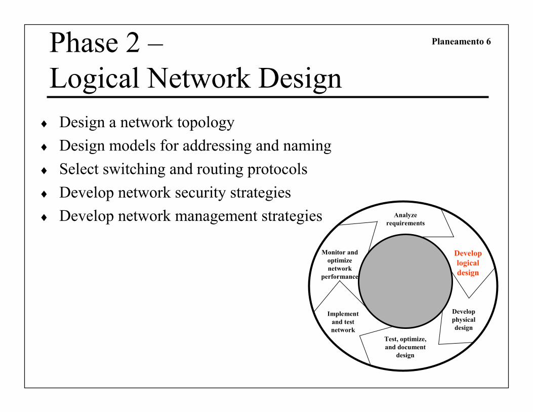
Planeamento 6Phase 2 –
Logical Network Design
♦ Design a network topology
♦ Design models for addressing and naming
♦ Select switching and routing protocols
♦ Develop network security strategies
♦ Develop network management strategies Analyze
requirements
Develop
logical
design
Develop
physical
design
Test, optimize,
and document
design
Monitor and
optimize
network
performance
Implement
and test
network

Planeamento 7Phase 3 –
Physical Network Design
♦ Select technologies and devices for the networks
Analyze
requirements
Develop
logical
design
Develop
physical
designTest, optimize,
and document
design
Monitor and
optimize
network
performance
Implement
and test
network

Planeamento 8
Phase 4 –
Testing, Optimizing, and Documenting the
Network Design
♦ Optimize the network design
♦ Document the network design
Analyze
requirements
Develop
logical
design
Develop
physical
design
Test, optimize,
and document
design
Monitor and
optimize
network
performance
Implement
and test
network
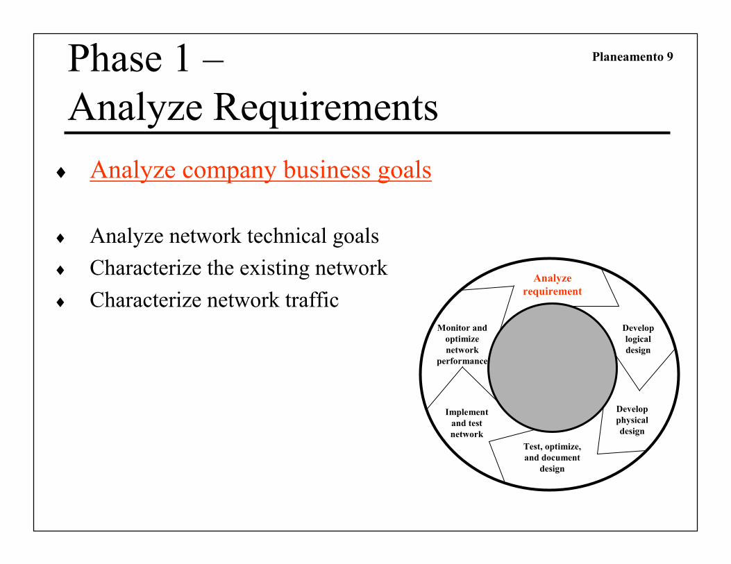
Planeamento 9Phase 1 –
Analyze Requirements
♦ Analyze company business goals
♦ Analyze network technical goals
♦ Characterize the existing network
♦ Characterize network traffic
Analyze
requirement
s
Develop
logical
design
Develop
physical
design
Test, optimize,
and document
design
Monitor and
optimize
network
performance
Implement
and test
network

Planeamento 10
Business Goals
♦ What is the new (improved) network required for?
» Help increase revenue?
» Reduce operating costs?
» Improve communications?
» Shorten product development cycle?
» Expand into worldwide markets?
» Build partnerships with other companies?
» Offer better customer support or new customer services?

Planeamento 11
The Scope of the Design
♦ Small in scope?
» E.g. Allow sales people to access network via a VPN
♦ Large in scope?
» E.g. An entire redesign of an enterprise network
♦ Use the OSI model to clarify the scope
» Support of new financial reporting application?
» Add routing?
» Wireless access?

Planeamento 12
Gather Information
♦ What applications are expected to be used?
♦ How critical are they?
» very critical, somewhat critical, not critical

Planeamento 13
Register Applications
Name of
Application
Type of
Application
New
Application?
Criticality Comments

Planeamento 14Phase 1 –
Analyze Requirements
♦ Analyze company business goals
♦ Analyze network technical goals
♦ Characterize the existing network
♦ Characterize network traffic
Analyze
requirement
s
Develop
logical
design
Develop
physical
design
Test, optimize,
and document
design
Monitor and
optimize
network
performance
Implement
and test
network

Planeamento 15
Key Technical Goals
♦ Scalability
♦ Availability
♦ Performance
♦ But also
» Security, manageability, …
Planeamento 16
Scalability
♦ Scalability refers to the ability of the network to grow
♦ Try to learn
» Number of sites to be added
» What will be needed at each of these sites
» How many users will be added
» How many more servers will be added
Planeamento 17
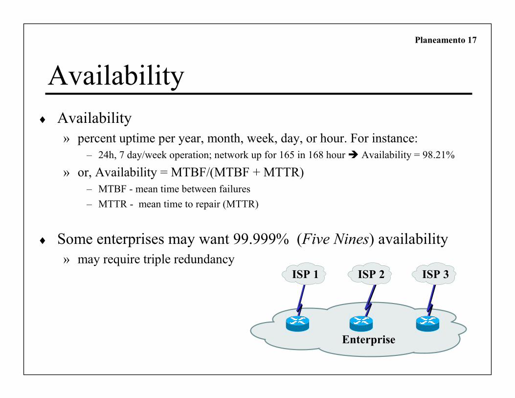
Availability
♦ Availability
» percent uptime per year, month, week, day, or hour. For instance:
– 24h, 7 day/week operation; network up for 165 in 168 hour � Availability = 98.21%
» or, Availability = MTBF/(MTBF + MTTR)
– MTBF - mean time between failures
– MTTR - mean time to repair (MTTR)
♦ Some enterprises may want 99.999% (Five Nines) availability
» may require triple redundancy
Enterprise
ISP 1 ISP 2 ISP 3

Planeamento 18
Performance
♦ Key performance factors include
» Throughput
» Delay (latency), delay variation, response time
Planeamento 19
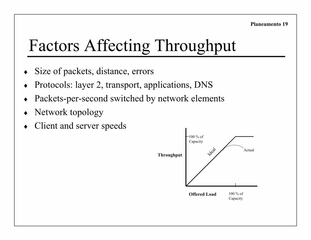
Factors Affecting Throughput
♦ Size of packets, distance, errors
♦ Protocols: layer 2, transport, applications, DNS
♦ Packets-per-second switched by network elements
♦ Network topology
♦ Client and server speeds
Offered Load
ThroughputActual
Ideal
100 % of
Capacity
100 % of
Capacity

Planeamento 20
Delay Perspectives
♦ User’s view
» Response Time– Depends on the application / equipment application is running; not just the network
– Most users expect to see something on the screen in 100 to 200 milliseconds
♦ Engineer’s view
» End-to-end delay, delay variation
» Caused by– Propagation delay
– Transmission delay
– Packet-switching delay
– Queuing delay
Planeamento 21
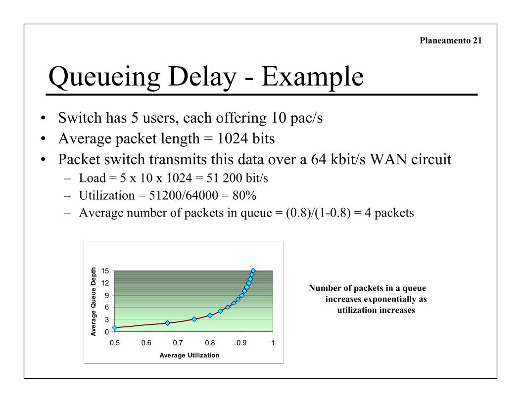
Queueing Delay - Example
• Switch has 5 users, each offering 10 pac/s
• Average packet length = 1024 bits
• Packet switch transmits this data over a 64 kbit/s WAN circuit– Load = 5 x 10 x 1024 = 51 200 bit/s
– Utilization = 51200/64000 = 80%
– Average number of packets in queue = (0.8)/(1-0.8) = 4 packets
0
3
6
9
12
15
0.5 0.6 0.7 0.8 0.9 1
Average Utilization
Average Queue Depth
Number of packets in a queue
increases exponentially as
utilization increases

Planeamento 22Network ApplicationsTechnical Requirements
Name of
Application
Cost of
Downtime
Acceptable
MTBF
Acceptable
MTTR
Throughput
Goal
Delay Must be
Less Than:
Delay
Variation
Must be Less
Than:

Planeamento 23Phase 1 –
Analyze Requirements
♦ Analyze company business goals
♦ Analyze network technical goals
♦ Characterize the existing network
♦ Characterize network traffic
Analyze
requirement
s
Develop
logical
design
Develop
physical
design
Test, optimize,
and document
design
Monitor and
optimize
network
performance
Implement
and test
network
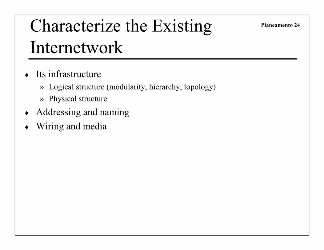
Planeamento 24Characterize the Existing
Internetwork
♦ Its infrastructure
» Logical structure (modularity, hierarchy, topology)
» Physical structure
♦ Addressing and naming
♦ Wiring and media

Planeamento 25
Get a Network Map
Gigabit
Ethernet
Eugene
Ethernet
20 users
Web/FTP server
Grants Pass
HQ
16 Mbps
Token Ring
FEP
(Front End
Processor)
IBM
MainframeT1
Medford
Fast Ethernet
50 users
Roseburg
Fast Ethernet
30 usersFrame Relay
CIR = 56 Kbps
DLCI = 5
Frame Relay
CIR = 56 Kbps
DLCI = 4
Grants Pass
HQ
Fast Ethernet
75 users
InternetT1
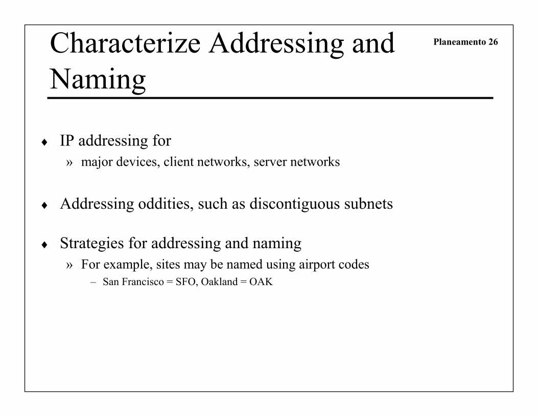
Planeamento 26Characterize Addressing and
Naming
♦ IP addressing for
» major devices, client networks, server networks
♦ Addressing oddities, such as discontiguous subnets
♦ Strategies for addressing and naming
» For example, sites may be named using airport codes
– San Francisco = SFO, Oakland = OAK

Planeamento 27
Characterize the Wiring and Media
♦ Single-mode fiber
♦ Multi-mode fiber
♦ Shielded twisted pair (STP) copper
♦ Unshielded-twisted-pair (UTP) copper
♦ Coaxial cable
♦ Microwave
♦ Laser
♦ Radio
♦ Infra-red
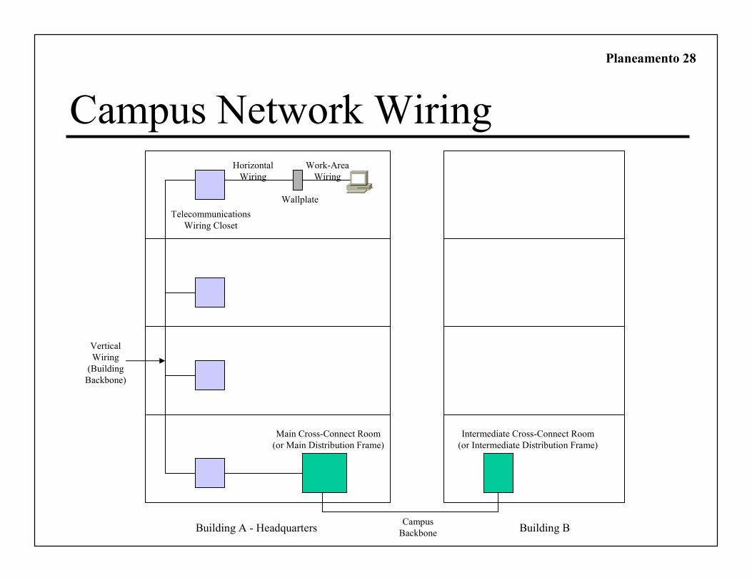
Planeamento 28
Telecommunications
Wiring Closet
Horizontal
Wiring
Work-Area
Wiring
Wallplate
Main Cross-Connect Room
(or Main Distribution Frame)
Intermediate Cross-Connect Room
(or Intermediate Distribution Frame)
Building A - Headquarters Building B
Vertical
Wiring
(Building
Backbone)
Campus
Backbone
Campus Network Wiring
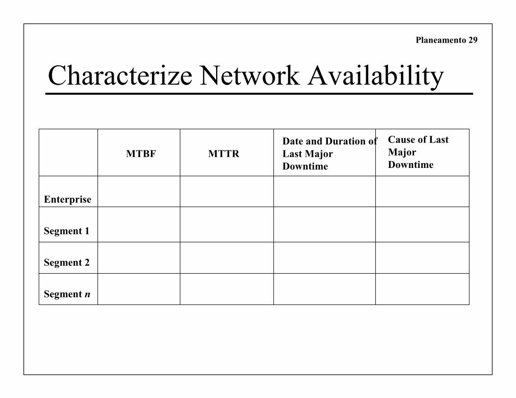
Planeamento 29
Characterize Network Availability
Enterprise
Segment 1
Segment 2
Segment n
MTBF MTTR
Date and Duration of
Last Major
Downtime
Cause of Last
Major
Downtime

Planeamento 30
Network Utilization
0 0.5 1 1.5 2 2.5 3 3.5 4 4.5
17:00:00
16:00:00
15:00:00
14:00:00
13:00:00
Tim
e
Utilization
Series1
Measure Network Utilization in
Hour Intervals
Planeamento 31
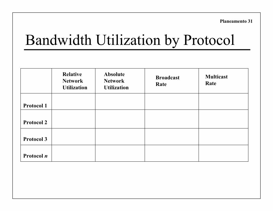
Bandwidth Utilization by Protocol
Protocol 1
Protocol 2
Protocol 3
Protocol n
Relative
Network
Utilization
Absolute
Network
Utilization
Broadcast
Rate
Multicast
Rate
Planeamento 32
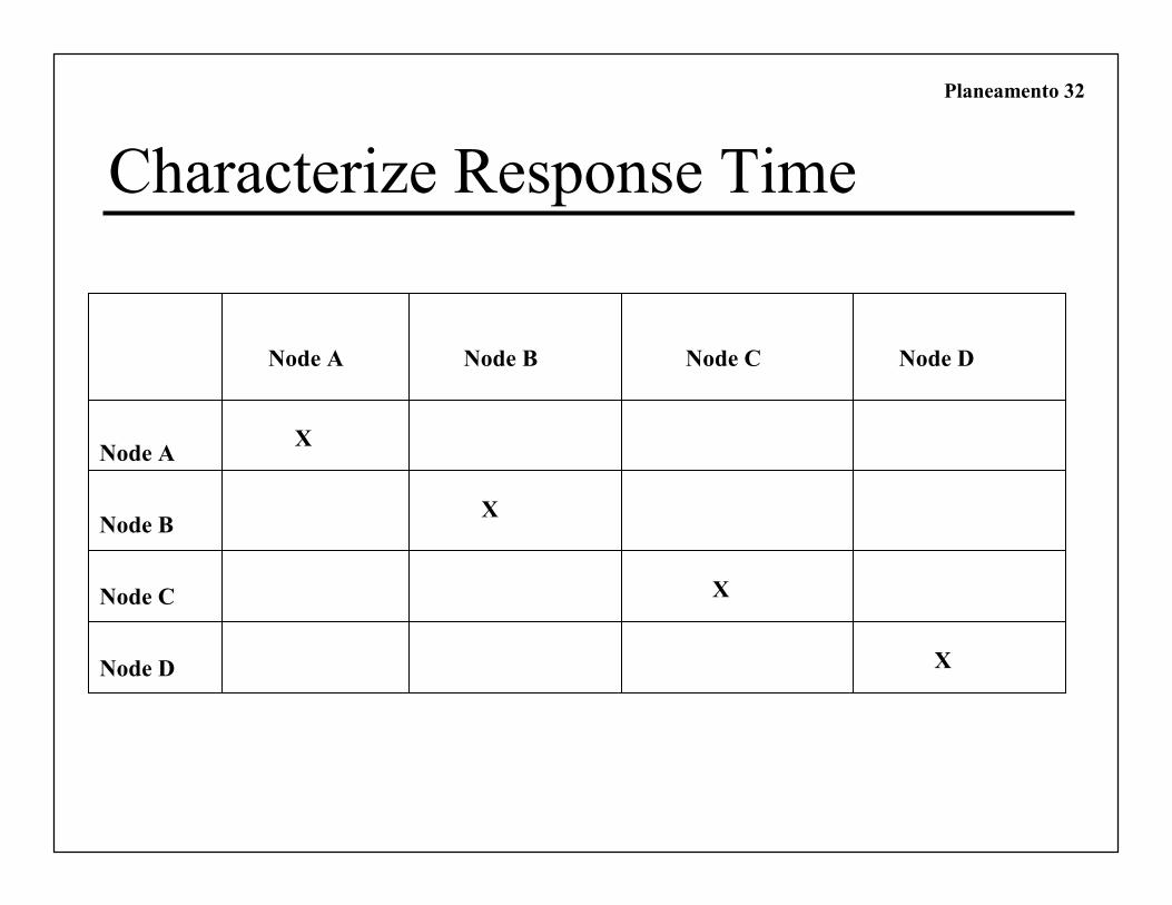
Characterize Response Time
Node A
Node B
Node C
Node D
Node A Node B Node C Node D
X
X
X
X
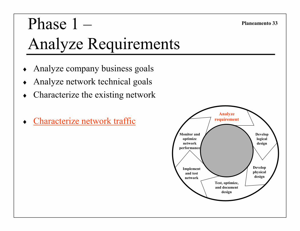
Planeamento 33Phase 1 –
Analyze Requirements
♦ Analyze company business goals
♦ Analyze network technical goals
♦ Characterize the existing network
♦ Characterize network trafficAnalyze
requirement
s
Develop
logical
design
Develop
physical
design
Test, optimize,
and document
design
Monitor and
optimize
network
performance
Implement
and test
network
Planeamento 34
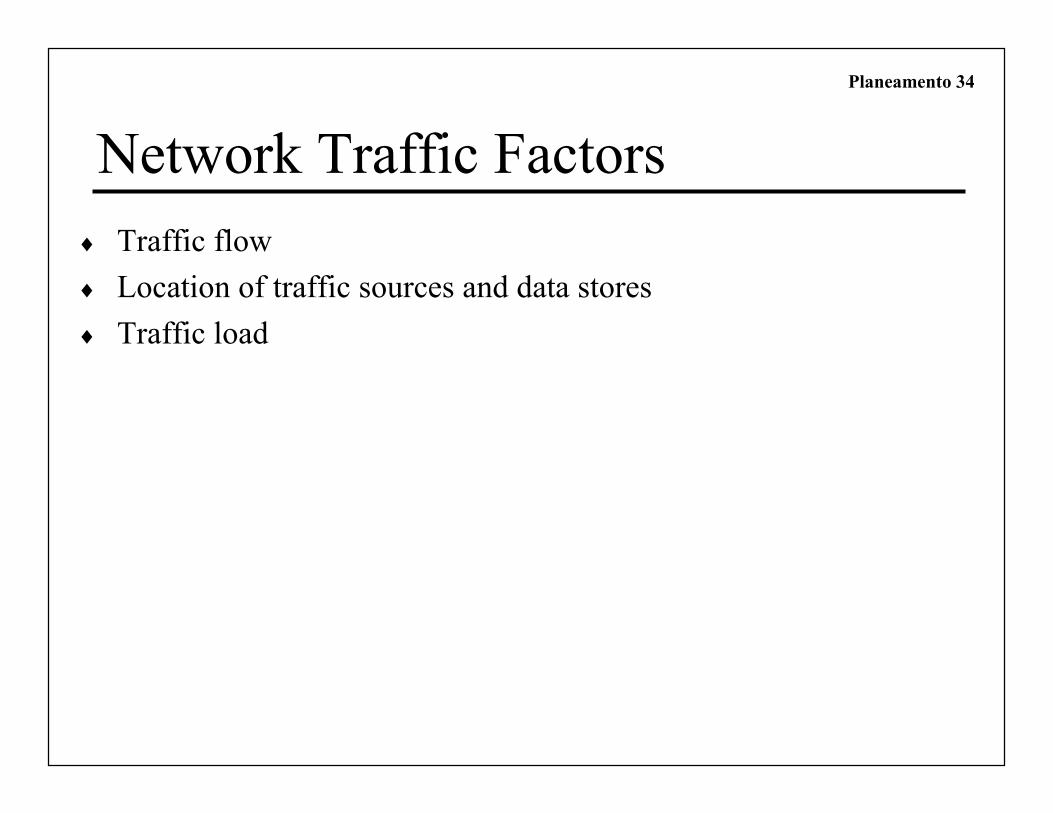
Network Traffic Factors
♦ Traffic flow
♦ Location of traffic sources and data stores
♦ Traffic load

Planeamento 35
User Communities
User
Community
Name
Size of
Community
(Number of
Users)
Location(s) of
Community
Application(s)
Used by
Community

Planeamento 36
Data Stores
Data Store Location Application(s) Used by User
Community(or
Communities)

Planeamento 37
Traffic Flow
Destination 1 Destination 2 Destination 3 Destination
MB/sec MB/sec MB/sec MB/sec
Source 1
Source 2
Source 3
Source n

Planeamento 38
Traffic Flow Example
Administration
Business and
Social Sciences
Math and
Sciences
50 PCs 25 Macs
50 PCs
50 PCs30 PCs
30 Library Patrons (PCs)
30 Macs and 60 PCs in
Computing Center
Library and Computing Center
App 1 108 Kbps
App 2 60 Kbps
App 3 192 Kbps
App 4 48 Kbps
App 7 400 Kbps
Total 808 Kbps
App 1 48 Kbps
App 2 32 Kbps
App 3 96 Kbps
App 4 24 Kbps
App 5 300 Kbps
App 6 200 Kbps
App 8 1200 Kbps
Total 1900 Kbps
App 1 30 Kbps
App 2 20 Kbps
App 3 60 Kbps
App 4 16 Kbps
Total 126 Kbps
App 2 20 Kbps
App 3 96 Kbps
App 4 24 Kbps
App 9 80 Kbps
Total 220 Kbps
Arts and
Humanities
Server Farm
10-Mbps Metro
Ethernet to Internet

Planeamento 39
Types of Traffic Flow
♦ Terminal/host
♦ Client/server
♦ Thin client
♦ Peer-to-peer
♦ Server/server
♦ Distributed computing

Planeamento 40Network Applications
Traffic Characteristics
Name of
Application
Type of
Traffic
Flow
Protocol(s)
Used by
Application
User
Communities
That Use the
Application
Data Stores
(Servers, Hosts,
and so on)
Approximate
Bandwidth
Requirements
QoS
Requirements

Planeamento 41
Collection of Tables

Planeamento 42
Register Applications
Name of
Application
Type of
Application
New
Application?
Criticality Comments
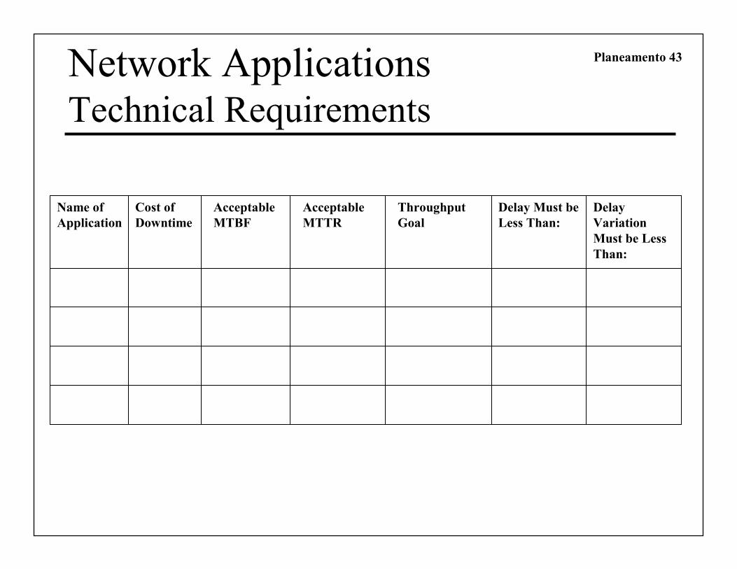
Planeamento 43Network ApplicationsTechnical Requirements
Name of
Application
Cost of
Downtime
Acceptable
MTBF
Acceptable
MTTR
Throughput
Goal
Delay Must be
Less Than:
Delay
Variation
Must be Less
Than:

Planeamento 44
Characterize Availability
Enterprise
Segment 1
Segment 2
Segment n
MTBF MTTR
Date and Duration of
Last Major
Downtime
Cause of Last
Major
Downtime

Planeamento 45
Bandwidth Utilization by Protocol
Protocol 1
Protocol 2
Protocol 3
Protocol n
Relative
Network
Utilization
Absolute
Network
Utilization
Broadcast
Rate
Multicast
Rate

Planeamento 46
Characterize Response Time
Node A
Node B
Node C
Node D
Node A Node B Node C Node D
X
X
X
X

Planeamento 47
User Communities
User
Community
Name
Size of
Community
(Number of
Users)
Location(s) of
Community
Application(s)
Used by
Community

Planeamento 48
Data Stores
Data Store Location Application(s) Used by User
Community(or
Communities)
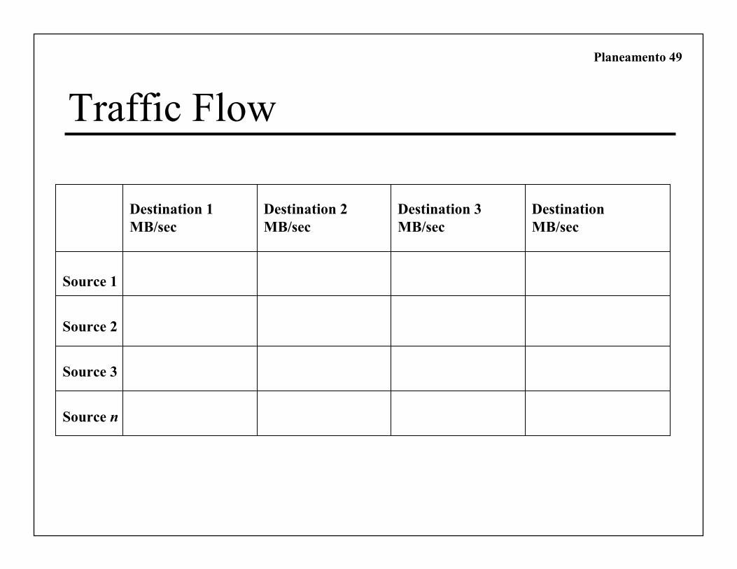
Planeamento 49
Traffic Flow
Destination 1 Destination 2 Destination 3 Destination
MB/sec MB/sec MB/sec MB/sec
Source 1
Source 2
Source 3
Source n
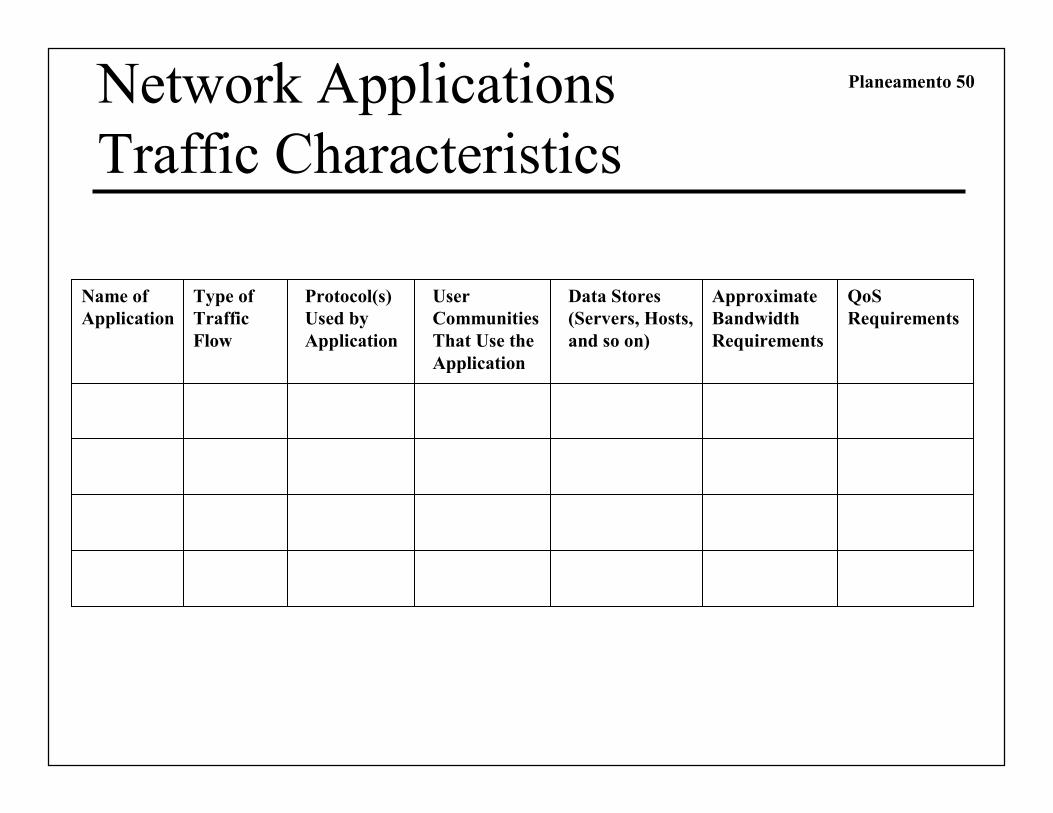
Planeamento 50Network Applications
Traffic Characteristics
Name of
Application
Type of
Traffic
Flow
Protocol(s)
Used by
Application
User
Communities
That Use the
Application
Data Stores
(Servers, Hosts,
and so on)
Approximate
Bandwidth
Requirements
QoS
Requirements