Embed Size (px)
Citation preview
Page 1 of 21
Hyperlinked Index of Topics Program Description
Sheet Layout File (not the Sheet Layout Settings dialog)
Program Access
Sheet Name Explanation
Sheet Name Selection
Plot Scale Field
Sheet Composition Settings
Sheet Layout Settings
Motif File
Model Import/Export and the Layout File
Layout Sheets Dialog (not the Layout Builder program or Sheet Layout File)
Port Shape Placement
Modify Sheets – (move Port Shapes)
Sheet Number Manager
Clip Sheets - Preparation
Process Sheets – (Sheet File Creation)
Re-Sheeting
Sheet File Information
The “Plan Sheet Cell” and “Sheet Reference File”
The Border Reference File (Send to Back) Command
For additional and complete Geopak Sheeting information
Note: Only the basic “sheeting details” (as used by the Office of Design) will be discussed here. Click the hyperlink immediately above for information on accessing complete sheeting instructions, found in the GEOPAK “Help” files.
Program Description The GEOPAK Sheeting program for P&P sheets (including Plan, Profile, and Plan & Profile type sheets) automatically places shapes (called Port Shapes) which follow selected Horizontal and/or Vertical alignments for a specified station range. The specific information that is encompassed by the Port Shapes is brought together in sheet file models as completed plan sheets ready for plotting.
Plan & Profile Geopak Sheeting Instructions
21B-4
Design Manual Chapter 21 Automation Tools Instructions Originally Issued: 03-06-09 Revised: 10-13-14
Office of Design
Chapter 21—Automation Tools Instructions Section 21B-4 Plan & Profile GEOPAK Sheeting Instructions
Page 2 of 21
Sheet Layout File (not to be confused with the Plan Sheet Layout dialog) Depending on the complexity of the project, it may be desirable to use the Sheet Layout File concept. The purpose of the Sheet Layout File is to provide a sheeting file, separate from the Design “.dsn” file, for the placement of the Plan & Profile (P&P) sheet Port Shapes. This eliminates the need to export and import any “dsn” models for the purpose of Sheet Port placement. If the Layout File is used, it becomes the source file for the creation of the Motif files discussed later in this document.
For additional information on the Sheet Layout File, see Design Manual Section 21B-2.
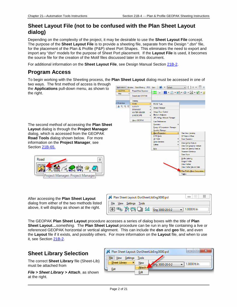
Program Access To begin working with the Sheeting process, the Plan Sheet Layout dialog must be accessed in one of two ways. The first method of access is through the Applications pull-down menu, as shown to the right.
The second method of accessing the Plan Sheet Layout dialog is through the Project Manager dialog, which is accessed from the GEOPAK Road Tools dialog shown below. For more information on the Project Manager, see Section 21B-65.
After accessing the Plan Sheet Layout dialog from either of the two methods listed above, it will display as shown at the right.
The GEOPAK Plan Sheet Layout procedure accesses a series of dialog boxes with the title of Plan Sheet Layout…something. The Plan Sheet Layout procedure can be run in any file containing a live or referenced GEOPAK horizontal or vertical alignment. This can include the dsn and geo file, and even the Layout file if it exists, and possibly others. For more information on the Layout file, and when to use it, see Section 21B-2.
Sheet Library Selection
The correct Sheet Library file (Sheet-Lib) must be attached from
File > Sheet Library > Attach, as shown at the right.
Chapter 21—Automation Tools Instructions Section 21B-4 Plan & Profile GEOPAK Sheeting Instructions
Page 3 of 21
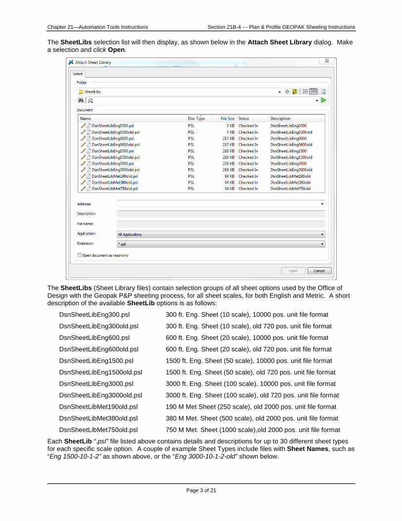
The SheetLibs selection list will then display, as shown below in the Attach Sheet Library dialog. Make a selection and click Open.
The SheetLibs (Sheet Library files) contain selection groups of all sheet options used by the Office of Design with the Geopak P&P sheeting process, for all sheet scales, for both English and Metric. A short description of the available SheetLib options is as follows:
DsnSheetLibEng300.psl 300 ft. Eng. Sheet (10 scale), 10000 pos. unit file format
DsnSheetLibEng300old.psl 300 ft. Eng. Sheet (10 scale), old 720 pos. unit file format
DsnSheetLibEng600.psl 600 ft. Eng. Sheet (20 scale), 10000 pos. unit file format
DsnSheetLibEng600old.psl 600 ft. Eng. Sheet (20 scale), old 720 pos. unit file format
DsnSheetLibEng1500.psl 1500 ft. Eng. Sheet (50 scale), 10000 pos. unit file format
DsnSheetLibEng1500old.psl 1500 ft. Eng. Sheet (50 scale), old 720 pos. unit file format
DsnSheetLibEng3000.psl 3000 ft. Eng. Sheet (100 scale), 10000 pos. unit file format
DsnSheetLibEng3000old.psl 3000 ft. Eng. Sheet (100 scale), old 720 pos. unit file format
DsnSheetLibMet190old.psl 190 M Met Sheet (250 scale), old 2000 pos. unit file format
DsnSheetLibMet380old.psl 380 M Met. Sheet (500 scale), old 2000 pos. unit file format
DsnSheetLibMet750old.psl 750 M Met. Sheet (1000 scale),old 2000 pos. unit file format
Each SheetLib “.psl” file listed above contains details and descriptions for up to 30 different sheet types for each specific scale option. A couple of example Sheet Types include files with Sheet Names, such as “Eng 1500-10-1-2” as shown above, or the “Eng 3000-10-1-2-old” shown below.
Chapter 21—Automation Tools Instructions Section 21B-4 Plan & Profile GEOPAK Sheeting Instructions
Page 4 of 21
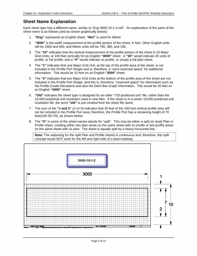
Sheet Name Explanation Each sheet type has a different name, similar to “Eng 3000-10-1-2-old”. An explanation of the parts of the sheet name is as follows (and as shown graphically below):
1. “Eng” represents an English sheet, “Met” is used for Metric
2. “3000” is the width measurement of the profile portion of the sheet, in feet. Other English units will be 1500 and 600, and Metric units will be 750, 380, and 190.
3. The “10” indicates that the vertical measurement of the profile portion of the sheet is 10 Major Grid Units, or 100 feet vertically for an English “3000” sheet. A “20” would indicate 20 units of profile, or full profile, and a “0” would indicate no profile, or simply a full plan sheet.
4. The “1” indicates that one Major Grid Unit, at the top of the profile area of the sheet, is not included in the Profile Port Shape and is, therefore, a “semi-reserved space” for additional information. This would be 10 feet on an English “3000” sheet.
5. The “2” indicates that two Major Grid Units at the bottom of the profile area of the sheet are not included in the Profile Port Shape, and this is, therefore, “reserved space” for information such as the Profile Grade Elevations and also the Ditch Bar Graph information. This would be 20 feet on an English “3000” sheet.
6. “Old” indicates the sheet type is designed for an older “720 positional unit” file, rather than the 10,000 positional unit resolution used in new files. If the sheet is in a newer 10,000 positional unit resolution file, the word “old” is just omitted from the sheet file name.
7. The sum of the “1 and 2” (1+2=3) indicates that 30 feet of the 100 foot vertical profile area will not be included in the Profile Port area; therefore, the Profile Port has a remaining height of 70 feet(100-30=70), as shown below.
8. The “S” in some of the sheet names stands for “split”. This may be either a split (or dual) Plan or Profile sheet, creating either two plan areas on the same sheet with no profile or two profile areas on the same sheet with no plan. The sheet is equally split by a heavy horizontal line.
Note: The stationing for the split Plan and Profile sheets is continuous and, therefore, this split concept would NOT work for the left and right side of a dual roadway.
Chapter 21—Automation Tools Instructions Section 21B-4 Plan & Profile GEOPAK Sheeting Instructions
Page 5 of 21
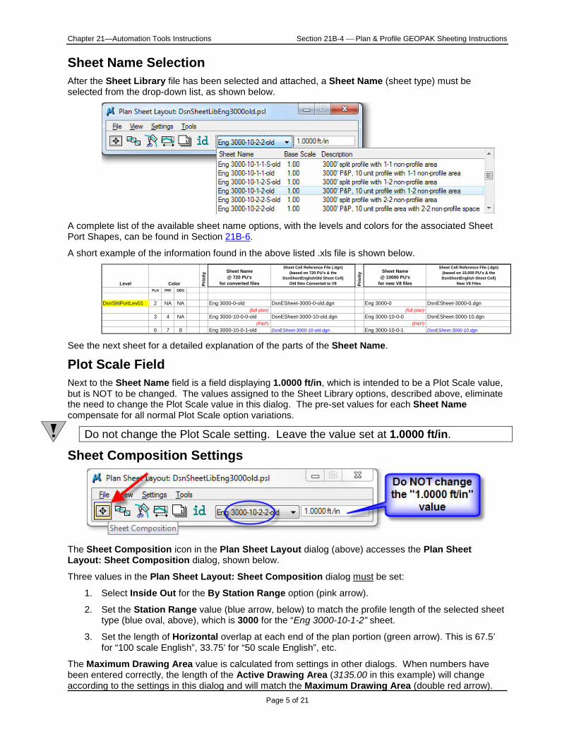
Sheet Name Selection After the Sheet Library file has been selected and attached, a Sheet Name (sheet type) must be selected from the drop-down list, as shown below.
A complete list of the available sheet name options, with the levels and colors for the associated Sheet Port Shapes, can be found in Section 21B-6.
A short example of the information found in the above listed .xls file is shown below.
See the next sheet for a detailed explanation of the parts of the Sheet Name.
Plot Scale Field Next to the Sheet Name field is a field displaying 1.0000 ft/in, which is intended to be a Plot Scale value, but is NOT to be changed. The values assigned to the Sheet Library options, described above, eliminate the need to change the Plot Scale value in this dialog. The pre-set values for each Sheet Name compensate for all normal Plot Scale option variations.
Do not change the Plot Scale setting. Leave the value set at 1.0000 ft/in.
Sheet Composition Settings
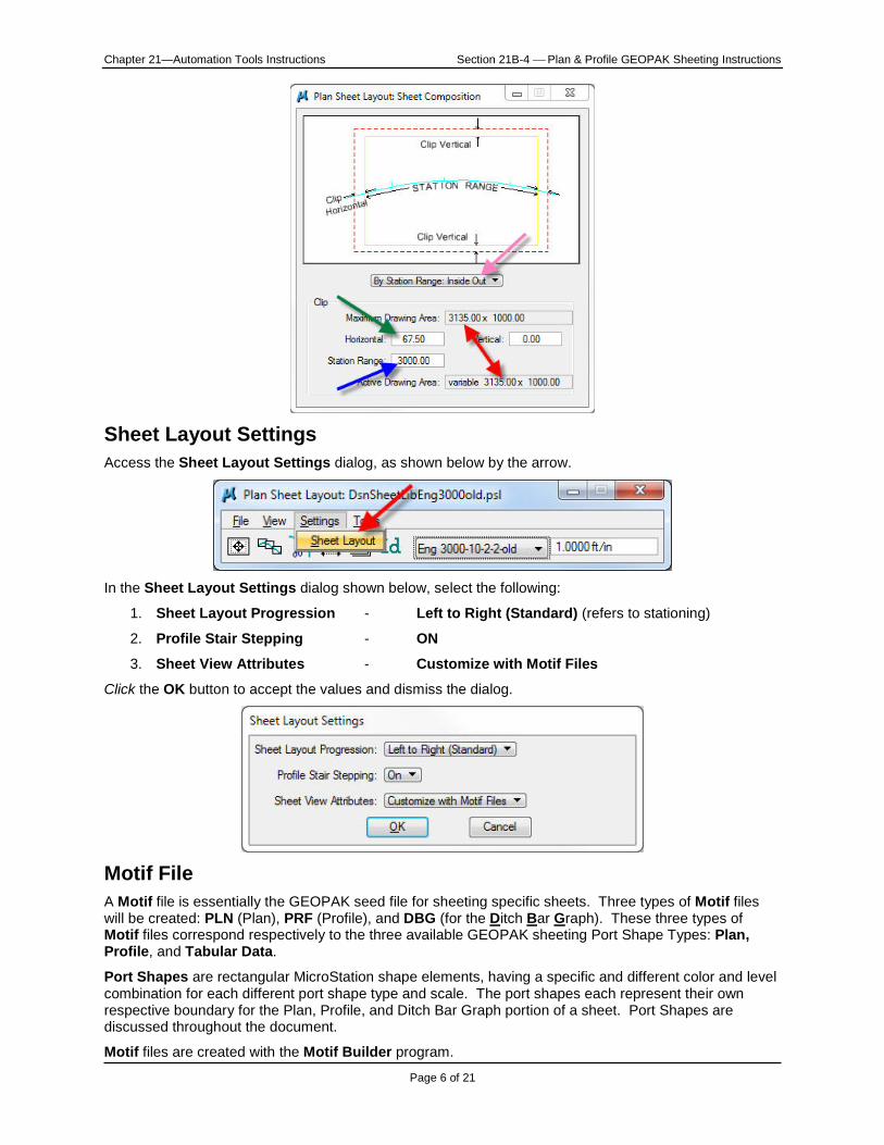
The Sheet Composition icon in the Plan Sheet Layout dialog (above) accesses the Plan Sheet Layout: Sheet Composition dialog, shown below.
Three values in the Plan Sheet Layout: Sheet Composition dialog must be set:
1. Select Inside Out for the By Station Range option (pink arrow).
2. Set the Station Range value (blue arrow, below) to match the profile length of the selected sheet type (blue oval, above), which is 3000 for the “Eng 3000-10-1-2” sheet.
3. Set the length of Horizontal overlap at each end of the plan portion (green arrow). This is 67.5’ for “100 scale English”, 33.75’ for “50 scale English”, etc.
The Maximum Drawing Area value is calculated from settings in other dialogs. When numbers have been entered correctly, the length of the Active Drawing Area (3135.00 in this example) will change according to the settings in this dialog and will match the Maximum Drawing Area (double red arrow).
Level Prio
ity
Sheet Name @ 720 PU's
for converted files
Sheet Cell Reference File (.dgn) (based on 720 PU's & the
DsnSheetEnglishOld Sheet Cell) Old files Converted to V8 Pr
ioity
Sheet Name @ 10000 PU's
for new V8 files
Sheet Cell Reference File (.dgn) (based on 10,000 PU's & the DsnSheetEnglish Sheet Cell)
New V8 Files PLN PRF DBG
DsnShtPortLev01 2 NA NA Eng 3000-0-old DsnESheet-3000-0-old.dgn Eng 3000-0 DsnESheet-3000-0.dgn(full plan) (full plan)
3 4 NA Eng 3000-10-0-0-old DsnESheet-3000-10-old.dgn Eng 3000-10-0-0 DsnESheet-3000-10.dgn(P&P) (P&P)
6 7 8 Eng 3000-10-0-1-old DsnESheet-3000-10-old.dgn Eng 3000-10-0-1 DsnESheet-3000-10.dgn
Color
Chapter 21—Automation Tools Instructions Section 21B-4 Plan & Profile GEOPAK Sheeting Instructions
Page 6 of 21
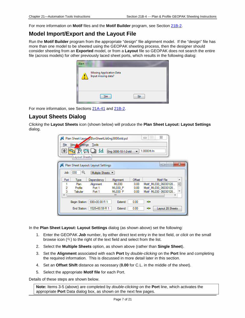
Sheet Layout Settings Access the Sheet Layout Settings dialog, as shown below by the arrow.
In the Sheet Layout Settings dialog shown below, select the following:
1. Sheet Layout Progression - Left to Right (Standard) (refers to stationing)
2. Profile Stair Stepping - ON
3. Sheet View Attributes - Customize with Motif Files
Click the OK button to accept the values and dismiss the dialog.
Motif File A Motif file is essentially the GEOPAK seed file for sheeting specific sheets. Three types of Motif files will be created: PLN (Plan), PRF (Profile), and DBG (for the Ditch Bar Graph). These three types of Motif files correspond respectively to the three available GEOPAK sheeting Port Shape Types: Plan, Profile, and Tabular Data.
Port Shapes are rectangular MicroStation shape elements, having a specific and different color and level combination for each different port shape type and scale. The port shapes each represent their own respective boundary for the Plan, Profile, and Ditch Bar Graph portion of a sheet. Port Shapes are discussed throughout the document.
Motif files are created with the Motif Builder program.
Chapter 21—Automation Tools Instructions Section 21B-4 Plan & Profile GEOPAK Sheeting Instructions
Page 7 of 21
For more information on Motif files and the Motif Builder program, see Section 21B-2.
Model Import/Export and the Layout File Run the Motif Builder program from the appropriate “design” file alignment model. If the “design” file has more than one model to be sheeted using the GEOPAK sheeting process, then the designer should consider sheeting from an Exported model, or from a Layout file so GEOPAK does not search the entire file (across models) for other previously laced sheet ports, which results in the following dialog:
For more information, see Sections 21A-41 and 21B-2.
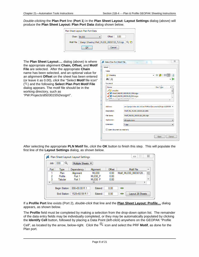
Layout Sheets Dialog Clicking the Layout Sheets icon (shown below) will produce the Plan Sheet Layout: Layout Settings dialog.
In the Plan Sheet Layout: Layout Settings dialog (as shown above) set the following:
1. Enter the GEOPAK Job number, by either direct text entry in the text field, or click on the small browse icon ( ) to the right of the text field and select from the list.
2. Select the Multiple Sheets option, as shown above (rather than Single Sheet).
3. Set the Alignment associated with each Port by double-clicking on the Port line and completing the required information. This is discussed in more detail later in this section.
4. Set an Offset Shift distance as necessary (0.00 for C.L. in the middle of the sheet).
5. Select the appropriate Motif file for each Port.
Details of these steps are shown below.
Note: Items 3-5 (above) are completed by double-clicking on the Port line, which activates the appropriate Port Data dialog box, as shown on the next few pages.
Chapter 21—Automation Tools Instructions Section 21B-4 Plan & Profile GEOPAK Sheeting Instructions
Page 8 of 21
Double-clicking the Plan Port line (Port 1) in the Plan Sheet Layout: Layout Settings dialog (above) will produce the Plan Sheet Layout: Plan Port Data dialog shown below.
The Plan Sheet Layout:… dialog (above) is where the appropriate alignment Chain, Offset, and Motif File are selected. After the appropriate Chain name has been selected, and an optional value for an alignment Offset on the sheet has been entered (or leave it as 0.00), click the “Select Motif file icon” ( ) and the following Select Plan Port Motif File dialog appears. The motif file should be in the working directory, such as “PW:Projects\85030155\Design\”.
After selecting the appropriate PLN Motif file, click the OK button to finish this step. This will populate the first line of the Layout Settings dialog, as shown below.
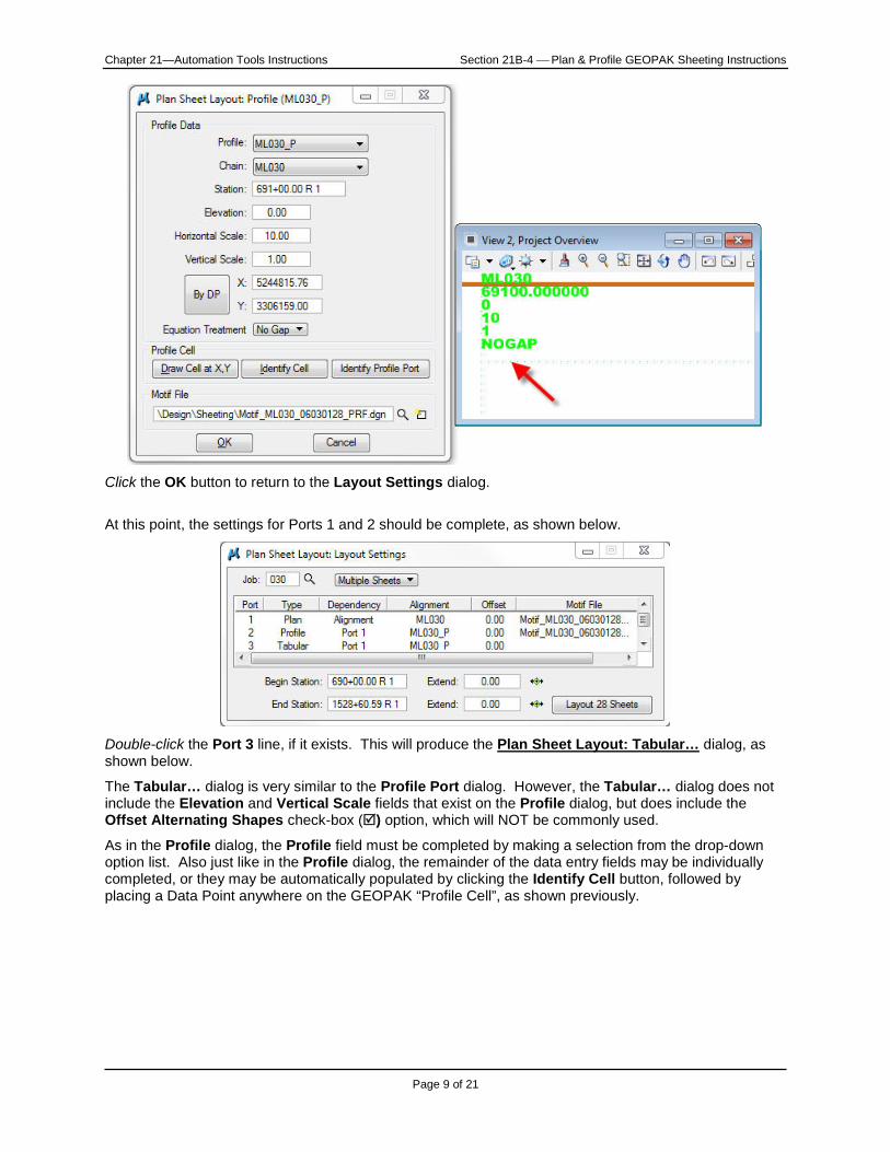
If a Profile Port line exists (Port 2), double-click that line and the Plan Sheet Layout: Profile… dialog appears, as shown below.
The Profile field must be completed by making a selection from the drop-down option list. The remainder of the data entry fields may be individually completed, or they may be automatically populated by clicking the Identify Cell button, followed by placing a Data Point (left-click) anywhere on the GEOPAK “Profile Cell”, as located by the arrow, below-right. Click the icon and select the PRF Motif, as done for the Plan port.
Chapter 21—Automation Tools Instructions Section 21B-4 Plan & Profile GEOPAK Sheeting Instructions
Page 9 of 21
Click the OK button to return to the Layout Settings dialog.
At this point, the settings for Ports 1 and 2 should be complete, as shown below.
Double-click the Port 3 line, if it exists. This will produce the Plan Sheet Layout: Tabular… dialog, as shown below.
The Tabular… dialog is very similar to the Profile Port dialog. However, the Tabular… dialog does not include the Elevation and Vertical Scale fields that exist on the Profile dialog, but does include the Offset Alternating Shapes check-box () option, which will NOT be commonly used.
As in the Profile dialog, the Profile field must be completed by making a selection from the drop-down option list. Also just like in the Profile dialog, the remainder of the data entry fields may be individually completed, or they may be automatically populated by clicking the Identify Cell button, followed by placing a Data Point anywhere on the GEOPAK “Profile Cell”, as shown previously.
Chapter 21—Automation Tools Instructions Section 21B-4 Plan & Profile GEOPAK Sheeting Instructions
Page 10 of 21
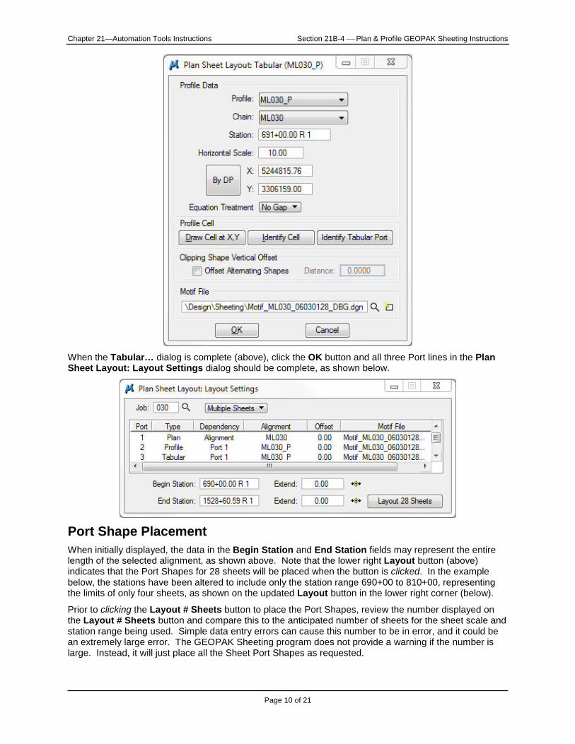
When the Tabular… dialog is complete (above), click the OK button and all three Port lines in the Plan Sheet Layout: Layout Settings dialog should be complete, as shown below.
Port Shape Placement When initially displayed, the data in the Begin Station and End Station fields may represent the entire length of the selected alignment, as shown above. Note that the lower right Layout button (above) indicates that the Port Shapes for 28 sheets will be placed when the button is clicked. In the example below, the stations have been altered to include only the station range 690+00 to 810+00, representing the limits of only four sheets, as shown on the updated Layout button in the lower right corner (below).
Prior to clicking the Layout # Sheets button to place the Port Shapes, review the number displayed on the Layout # Sheets button and compare this to the anticipated number of sheets for the sheet scale and station range being used. Simple data entry errors can cause this number to be in error, and it could be an extremely large error. The GEOPAK Sheeting program does not provide a warning if the number is large. Instead, it will just place all the Sheet Port Shapes as requested.

Chapter 21—Automation Tools Instructions Section 21B-4 Plan & Profile GEOPAK Sheeting Instructions
Page 11 of 21
When the Layout # Sheets button is clicked, the PLN, PRF, and DBG Port Shapes will automatically be placed on the alignments, similar to those shown below.
If the Port Shape placement is unsatisfactory, the shapes can be deleted and re-run as often as necessary. Use the MicroStation delete command to delete all the Port Shapes in the model that have the same color and level that correspond to the sheet type being used for this sheeting operation, then File > Compress > Design to eliminate the Port Shapes from GEOPAK memory. If any other shapes with the same color and level remain in the file, they will be located by GEOPAK and this will produce too many sheets. This will cause the Sheet Range Begin and End values to be incorrectly calculated.
Chapter 21—Automation Tools Instructions Section 21B-4 Plan & Profile GEOPAK Sheeting Instructions
Page 12 of 21
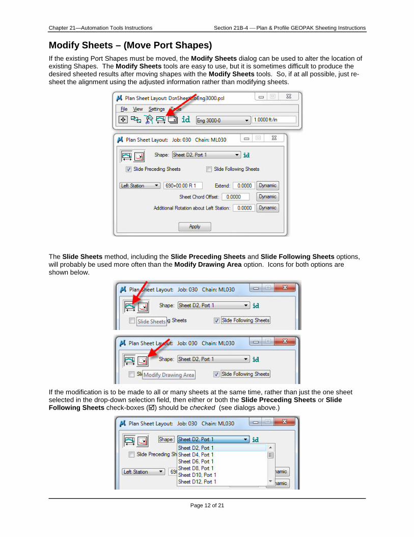
Modify Sheets – (Move Port Shapes) If the existing Port Shapes must be moved, the Modify Sheets dialog can be used to alter the location of existing Shapes. The Modify Sheets tools are easy to use, but it is sometimes difficult to produce the desired sheeted results after moving shapes with the Modify Sheets tools. So, if at all possible, just re-sheet the alignment using the adjusted information rather than modifying sheets.
The Slide Sheets method, including the Slide Preceding Sheets and Slide Following Sheets options, will probably be used more often than the Modify Drawing Area option. Icons for both options are shown below.
If the modification is to be made to all or many sheets at the same time, rather than just the one sheet selected in the drop-down selection field, then either or both the Slide Preceding Sheets or Slide Following Sheets check-boxes () should be checked (see dialogs above.)
Chapter 21—Automation Tools Instructions Section 21B-4 Plan & Profile GEOPAK Sheeting Instructions
Page 13 of 21
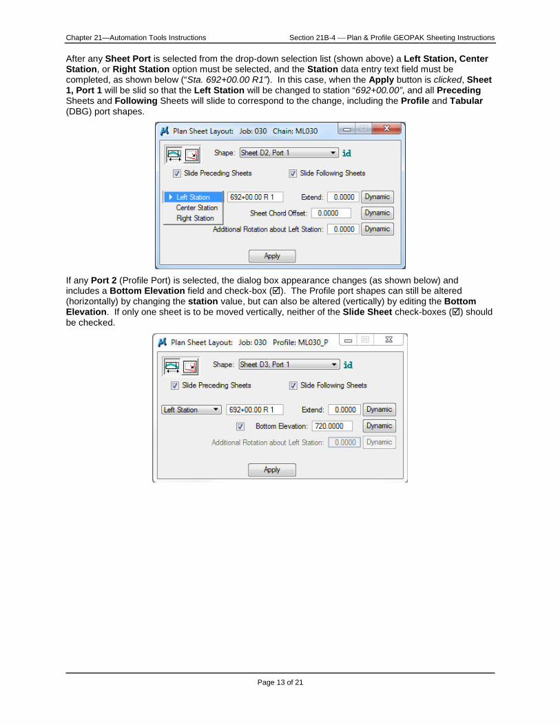
After any Sheet Port is selected from the drop-down selection list (shown above) a Left Station, Center Station, or Right Station option must be selected, and the Station data entry text field must be completed, as shown below (“Sta. 692+00.00 R1”). In this case, when the Apply button is clicked, Sheet 1, Port 1 will be slid so that the Left Station will be changed to station “692+00.00”, and all Preceding Sheets and Following Sheets will slide to correspond to the change, including the Profile and Tabular (DBG) port shapes.
If any Port 2 (Profile Port) is selected, the dialog box appearance changes (as shown below) and includes a Bottom Elevation field and check-box (). The Profile port shapes can still be altered (horizontally) by changing the station value, but can also be altered (vertically) by editing the Bottom Elevation. If only one sheet is to be moved vertically, neither of the Slide Sheet check-boxes () should be checked.
Chapter 21—Automation Tools Instructions Section 21B-4 Plan & Profile GEOPAK Sheeting Instructions
Page 14 of 21
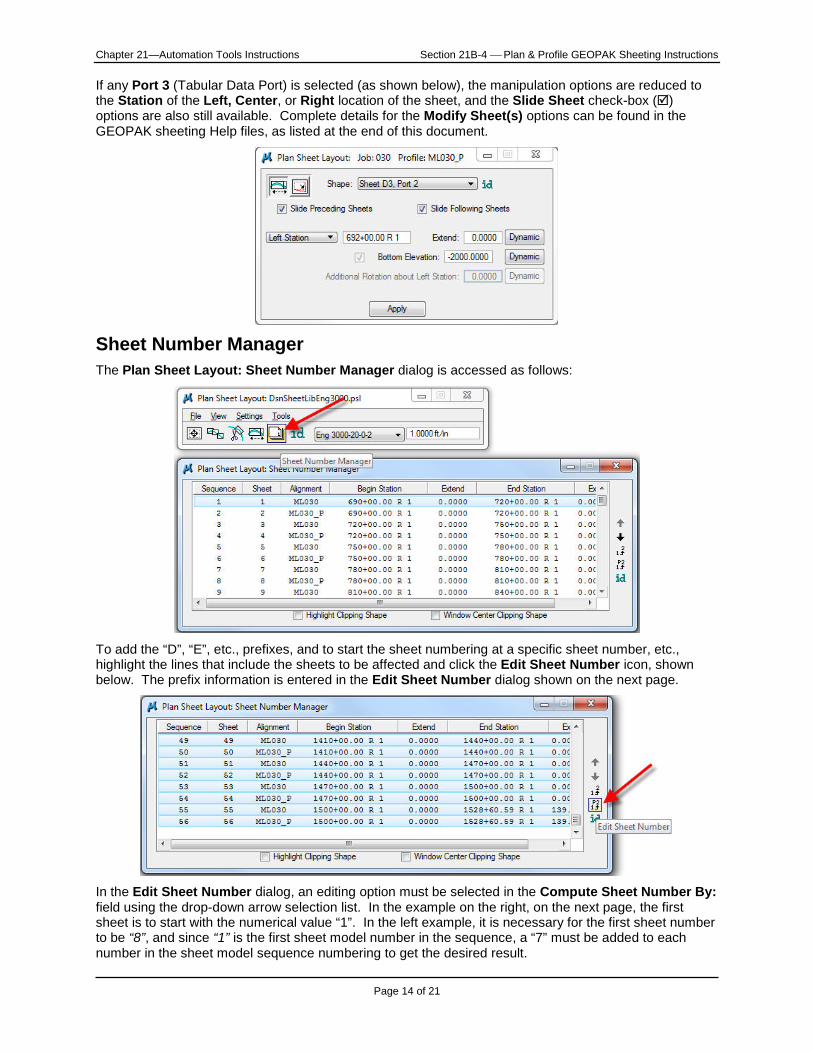
If any Port 3 (Tabular Data Port) is selected (as shown below), the manipulation options are reduced to the Station of the Left, Center, or Right location of the sheet, and the Slide Sheet check-box () options are also still available. Complete details for the Modify Sheet(s) options can be found in the GEOPAK sheeting Help files, as listed at the end of this document.
Sheet Number Manager The Plan Sheet Layout: Sheet Number Manager dialog is accessed as follows:
To add the “D”, “E”, etc., prefixes, and to start the sheet numbering at a specific sheet number, etc., highlight the lines that include the sheets to be affected and click the Edit Sheet Number icon, shown below. The prefix information is entered in the Edit Sheet Number dialog shown on the next page.
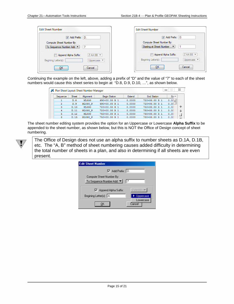
In the Edit Sheet Number dialog, an editing option must be selected in the Compute Sheet Number By: field using the drop-down arrow selection list. In the example on the right, on the next page, the first sheet is to start with the numerical value “1”. In the left example, it is necessary for the first sheet number to be “8”, and since “1” is the first sheet model number in the sequence, a “7” must be added to each number in the sheet model sequence numbering to get the desired result.
Chapter 21—Automation Tools Instructions Section 21B-4 Plan & Profile GEOPAK Sheeting Instructions
Page 15 of 21
Continuing the example on the left, above, adding a prefix of “D” and the value of “7” to each of the sheet numbers would cause this sheet series to begin at “D.8, D.9, D.10, …”, as shown below.
The sheet number editing system provides the option for an Uppercase or Lowercase Alpha Suffix to be appended to the sheet number, as shown below, but this is NOT the Office of Design concept of sheet numbering.
The Office of Design does not use an alpha suffix to number sheets as D.1A, D.1B, etc. The “A, B” method of sheet numbering causes added difficulty in determining the total number of sheets in a plan, and also in determining if all sheets are even present.
Chapter 21—Automation Tools Instructions Section 21B-4 Plan & Profile GEOPAK Sheeting Instructions
Page 16 of 21
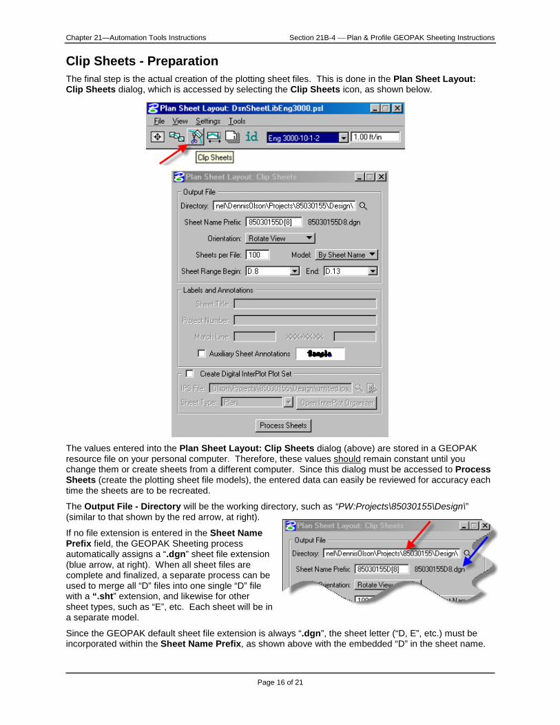
Clip Sheets - Preparation The final step is the actual creation of the plotting sheet files. This is done in the Plan Sheet Layout: Clip Sheets dialog, which is accessed by selecting the Clip Sheets icon, as shown below.
The values entered into the Plan Sheet Layout: Clip Sheets dialog (above) are stored in a GEOPAK resource file on your personal computer. Therefore, these values should remain constant until you change them or create sheets from a different computer. Since this dialog must be accessed to Process Sheets (create the plotting sheet file models), the entered data can easily be reviewed for accuracy each time the sheets are to be recreated.
The Output File - Directory will be the working directory, such as “PW:Projects\85030155\Design\” (similar to that shown by the red arrow, at right).
If no file extension is entered in the Sheet Name Prefix field, the GEOPAK Sheeting process automatically assigns a “.dgn” sheet file extension (blue arrow, at right). When all sheet files are complete and finalized, a separate process can be used to merge all “D” files into one single “D” file with a “.sht” extension, and likewise for other sheet types, such as “E”, etc. Each sheet will be in a separate model.
Since the GEOPAK default sheet file extension is always “.dgn”, the sheet letter (“D, E”, etc.) must be incorporated within the Sheet Name Prefix, as shown above with the embedded “D” in the sheet name.
Chapter 21—Automation Tools Instructions Section 21B-4 Plan & Profile GEOPAK Sheeting Instructions
Page 17 of 21
The file name (Sheet Name Prefix) will commonly be an 8-digit number (as used in the past, except without the “K” prefix) combined with “D” (for “D” sheet), and a number in square brackets, such as “[1]”. This will cause the new “D” sheet file to be named something like “85030155D1.dgn”, and the sheet models within this file will be named and incremented, beginning with the “[1]”, as “85030155D1, 85030155D2, 85030155D3”, etc. The actual sheet numbering of “D.1, D.2”, etc., is explained later. The value “[8]” (“square-bracket 8”, shown in the example on the previous page) was used because it was necessary for the first sheet number to be “D.8”. The “[8]” will cause the file to be named “85030155D8.dgn”, and the four sheet models will be named “85030155D8, 85030155D9, 85030155D10, and 85030155D11”.
As stated earlier, the GEOPAK sheeting procedure depends on the existence of a GEOPAK alignment, either horizontal or a combination of horizontal and vertical. A full plan sheet requires a horizontal alignment Chain. Both the full profile sheet and a Plan/Profile sheet require a horizontal Chain and vertical Profile alignment. Assuming all values have been set correctly, a plotting sheet file is created (or replaced) each time the Process Sheets button is clicked. For each GEOPAK Chain alignment that requires plotting sheet file(s), the Process Sheets run must be done at least one time. An additional run must be made each time the sheet scale or sheet type (sheet name) is changed within a given alignment (Chain).
Example of the scale changing within an alignment: The Main Line sheets for a Rural project are primarily 3000’ (100 scale) sheets, except through a small town near the center of the project where 1500’ (50 scale) sheets are used. This situation creates the need for 3 separate sheeting runs to be made for Main Line, including before, during, and after the small town. If the first portion has 8 sheets, and the small town has 3 sheets, the number in the square brackets should be “1” for the first section, “9” for the second section and “12” for the third. This will cause the three sheet files to be named similar to 85030155D1.dgn, …D9.dgn, and …D12.dgn. The model names in each file will also increment from the number in the square bracket, such that the model numbers in the second file will begin incrementing from “9”, and the third file will begin incrementing from “12”.
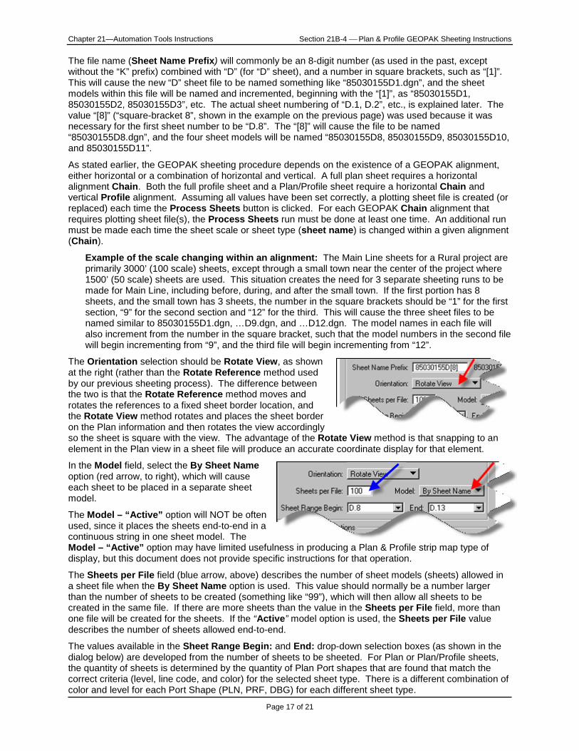
The Orientation selection should be Rotate View, as shown at the right (rather than the Rotate Reference method used by our previous sheeting process). The difference between the two is that the Rotate Reference method moves and rotates the references to a fixed sheet border location, and the Rotate View method rotates and places the sheet border on the Plan information and then rotates the view accordingly so the sheet is square with the view. The advantage of the Rotate View method is that snapping to an element in the Plan view in a sheet file will produce an accurate coordinate display for that element.
In the Model field, select the By Sheet Name option (red arrow, to right), which will cause each sheet to be placed in a separate sheet model.
The Model – “Active” option will NOT be often used, since it places the sheets end-to-end in a continuous string in one sheet model. The Model – “Active” option may have limited usefulness in producing a Plan & Profile strip map type of display, but this document does not provide specific instructions for that operation.
The Sheets per File field (blue arrow, above) describes the number of sheet models (sheets) allowed in a sheet file when the By Sheet Name option is used. This value should normally be a number larger than the number of sheets to be created (something like “99”), which will then allow all sheets to be created in the same file. If there are more sheets than the value in the Sheets per File field, more than one file will be created for the sheets. If the “Active” model option is used, the Sheets per File value describes the number of sheets allowed end-to-end.
The values available in the Sheet Range Begin: and End: drop-down selection boxes (as shown in the dialog below) are developed from the number of sheets to be sheeted. For Plan or Plan/Profile sheets, the quantity of sheets is determined by the quantity of Plan Port shapes that are found that match the correct criteria (level, line code, and color) for the selected sheet type. There is a different combination of color and level for each Port Shape (PLN, PRF, DBG) for each different sheet type.
Chapter 21—Automation Tools Instructions Section 21B-4 Plan & Profile GEOPAK Sheeting Instructions
Page 18 of 21
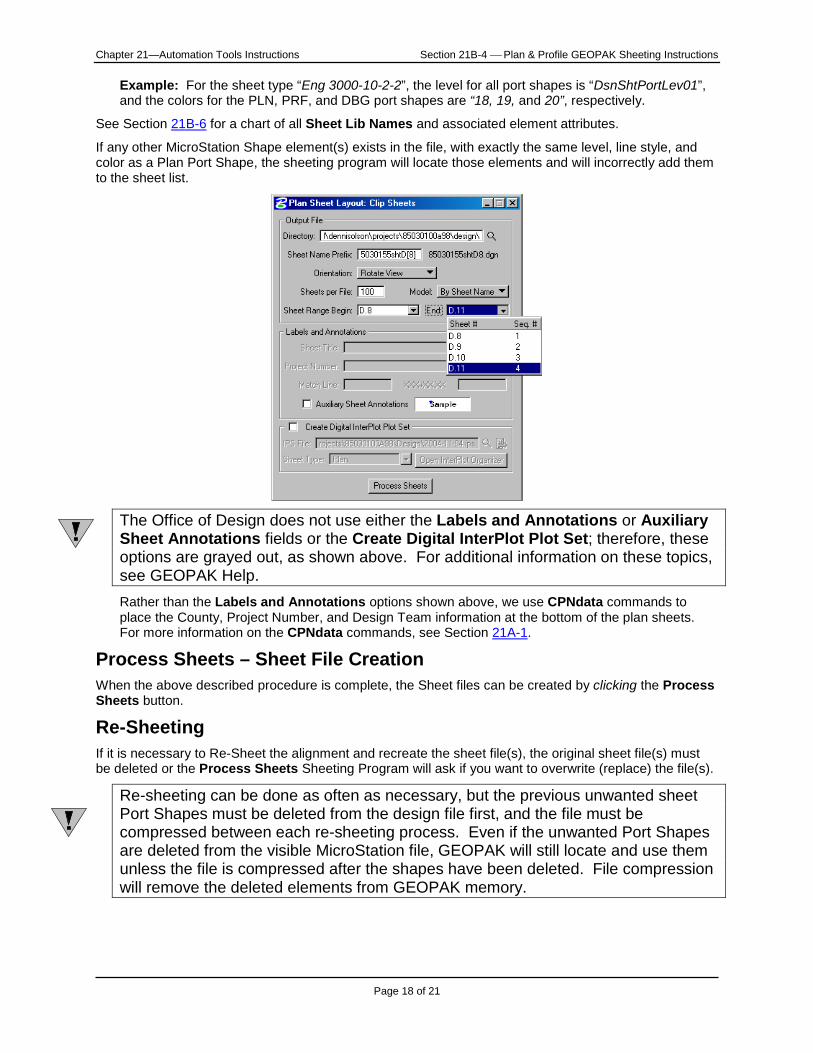
Example: For the sheet type “Eng 3000-10-2-2”, the level for all port shapes is “DsnShtPortLev01”, and the colors for the PLN, PRF, and DBG port shapes are “18, 19, and 20”, respectively.
See Section 21B-6 for a chart of all Sheet Lib Names and associated element attributes.
If any other MicroStation Shape element(s) exists in the file, with exactly the same level, line style, and color as a Plan Port Shape, the sheeting program will locate those elements and will incorrectly add them to the sheet list.
The Office of Design does not use either the Labels and Annotations or Auxiliary Sheet Annotations fields or the Create Digital InterPlot Plot Set; therefore, these options are grayed out, as shown above. For additional information on these topics, see GEOPAK Help. Rather than the Labels and Annotations options shown above, we use CPNdata commands to place the County, Project Number, and Design Team information at the bottom of the plan sheets. For more information on the CPNdata commands, see Section 21A-1.
Process Sheets – Sheet File Creation When the above described procedure is complete, the Sheet files can be created by clicking the Process Sheets button.
Re-Sheeting If it is necessary to Re-Sheet the alignment and recreate the sheet file(s), the original sheet file(s) must be deleted or the Process Sheets Sheeting Program will ask if you want to overwrite (replace) the file(s).
Re-sheeting can be done as often as necessary, but the previous unwanted sheet Port Shapes must be deleted from the design file first, and the file must be compressed between each re-sheeting process. Even if the unwanted Port Shapes are deleted from the visible MicroStation file, GEOPAK will still locate and use them unless the file is compressed after the shapes have been deleted. File compression will remove the deleted elements from GEOPAK memory.
Chapter 21—Automation Tools Instructions Section 21B-4 Plan & Profile GEOPAK Sheeting Instructions
Page 19 of 21
Sheet File information The “Plan Sheet cell” and “Sheet Reference File” Each Sheet Reference File (such as “DsnESheet-3000-10.dgn”) contains one instance of the plan sheet cell (“dsnSheetEnglish”). Each Sheet Reference File has the appropriate sheet levels turned on to produce a sheet file for a particular Sheet Name (such as “Eng 3000-10-1-2”). Part of a Sheet Name definition is the link to the correct Sheet Reference File. This link is one of the preset values for each of the defined Sheet Names. A link to a list of the Sheet Names and Sheet Reference Files is provided earlier in this document. When the Process Sheets button is used to create the plotting sheet files, the sheeting program automatically references the appropriate Sheet Reference File, based on the selected Sheet Name.
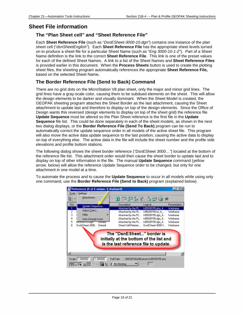
The Border Reference File (Send to Back) Command There are no grid dots on the MicroStation V8 plan sheet, only the major and minor grid lines. The grid lines have a gray-scale color, causing them to be subdued elements on the sheet. This will allow the design elements to be darker and visually dominant. When the Sheet Model is created, the GEOPAK sheeting program attaches the Sheet Border as the last attachment, causing the Sheet attachment to update last and therefore to display on top of the design elements. Since the Office of Design wants this reversed (design elements to display on top of the sheet grid) the reference file Update Sequence must be altered so the Plan Sheet reference is the first file in the Update Sequence file list. This could be done separately in each of the sheet models, as shown in the next two dialog displays, or the Border Reference File (Send To Back) program can be run to automatically correct the update sequence order in all models of the active sheet file. This program will also move the active data update sequence to the last position, causing the active data to display on top of everything else. The active data in the file will include the sheet number and the profile side elevations and profile bottom stations.
The following dialog shows the sheet border reference (“DsnESheet 3000…”) located at the bottom of the reference file list. This attachment order would then cause the sheet border to update last and to display on top of other information in the file. The manual Update Sequence command (yellow arrow, below) will allow the reference Update Sequence order to be changed, but only for one attachment in one model at a time.
To automate the process and to cause the Update Sequence to occur in all models while using only one command, use the Border Reference File (Send to Back) program (explained below).
Chapter 21—Automation Tools Instructions Section 21B-4 Plan & Profile GEOPAK Sheeting Instructions
Page 20 of 21
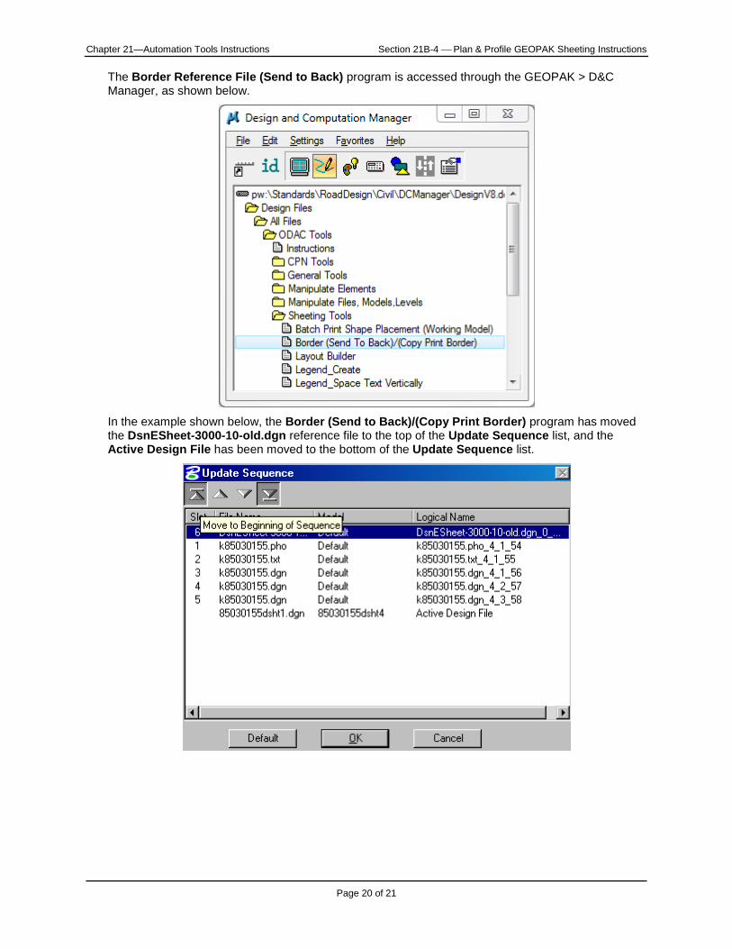
The Border Reference File (Send to Back) program is accessed through the GEOPAK > D&C Manager, as shown below.
In the example shown below, the Border (Send to Back)/(Copy Print Border) program has moved the DsnESheet-3000-10-old.dgn reference file to the top of the Update Sequence list, and the Active Design File has been moved to the bottom of the Update Sequence list.
Chapter 21—Automation Tools Instructions Section 21B-4 Plan & Profile GEOPAK Sheeting Instructions
Page 21 of 21
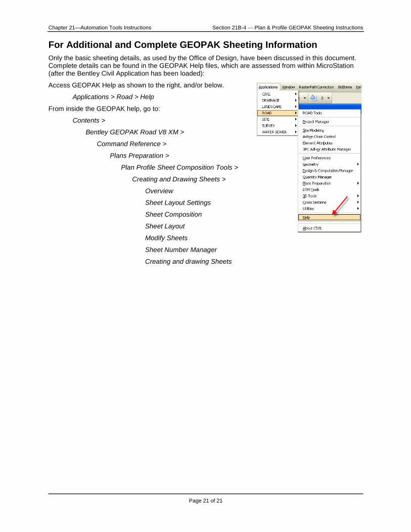
For Additional and Complete GEOPAK Sheeting Information Only the basic sheeting details, as used by the Office of Design, have been discussed in this document. Complete details can be found in the GEOPAK Help files, which are assessed from within MicroStation (after the Bentley Civil Application has been loaded):
Access GEOPAK Help as shown to the right, and/or below.
Applications > Road > Help
From inside the GEOPAK help, go to:
Contents >
Bentley GEOPAK Road V8 XM >
Command Reference >
Plans Preparation >
Plan Profile Sheet Composition Tools >
Creating and Drawing Sheets >
Overview
Sheet Layout Settings
Sheet Composition
Sheet Layout
Modify Sheets
Sheet Number Manager
Creating and drawing Sheets
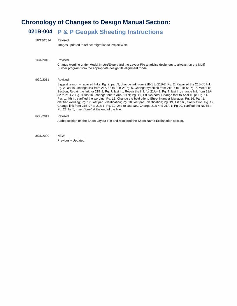
Chronology of Changes to Design Manual Section:021B-004 P & P Geopak Sheeting Instructions
10/13/2014 RevisedImages updated to reflect migration to ProjectWise.
1/31/2013 RevisedChange wording under Model Import/Export and the Layout File to advise designers to always run the Motif Builder program from the appropriate design file alignment model.
9/30/2011 RevisedBiggest reason – repaired links: Pg. 2, par. 3, change link from 21B-1 to 21B-2; Pg. 2, Repaired the 21B-65 link; Pg. 2, last ln., change link from 21A-82 to 21B-2; Pg. 5, Change hyperlink from 21B-7 to 21B-6; Pg. 7, Motif File Section, Repair the link for 21B-2; Pg. 7, last ln., Repair the link for 21A-41; Pg. 7, last ln., change link from 21A-82 to 21B-2; Pg. 8, first ln., change font to Arial 10 pt; Pg. 11, 1st two pars. Change font to Arial 10 pt; Pg. 14, Par. 1, 4th ln, clarified the wording; Pg. 15, Change the bold title to Sheet Number Manager; Pg. 16, Par. 1, clarified wording; Pg. 17, last par., clarification; Pg. 18, last par., clarification; Pg. 19, 1st par., clarification; Pg. 19, Change link from 21B-07 to 21B-6; Pg. 19, 2nd to last par., Change 21B-4 to 21A-1; Pg 20, clarified the NOTE:; Pg. 21, ln. 5, insert “one” at the end of the line.
6/30/2011 RevisedAdded section on the Sheet Layout File and relocated the Sheet Name Explanation section.
3/31/2009 NEWPreviously Updated.