Embed Size (px)
Citation preview

PIPING COMPONENTS
• Piping components are mechanical elements suitable for joining or assembly into pressure-tight fluid containing piping systems.
• Components include pipe, tubing, fittings, flanges, gaskets, bolting, valves and devices such as expansion joints, flexible joints, pressure hoses, traps, strainers, in-line portions of instruments.

PIPING NOMENCLATURE

• Header
• Branch connection
• Valve
• Flange
• Expansion joint
• Expansion loop
• Pipe support
• Reducer
• Elbow
PIPING NOMENCLATURE
PIPING SYSTEM – Branch Run
Continued...

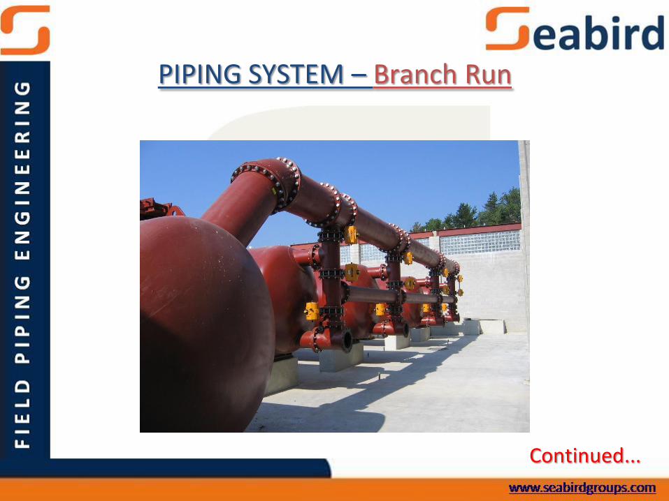
PIPE MANUFACTURING
Billet preparingvisual control
Billet chopping Billet heating
in annular furnace
Rough tubepiercing
Tube rolling in continuous mandrel mill
Mandrel removing
SEAMLESS PIPE - Manufacturing
Continued...

Tube heating in cell induction furnace
Sizing and reduction Stalk ends cutting, tubes cutting with flying shears
Tubes cooling Tubes leveling Tubes cutting in readysizes, tubes facing
Continued...
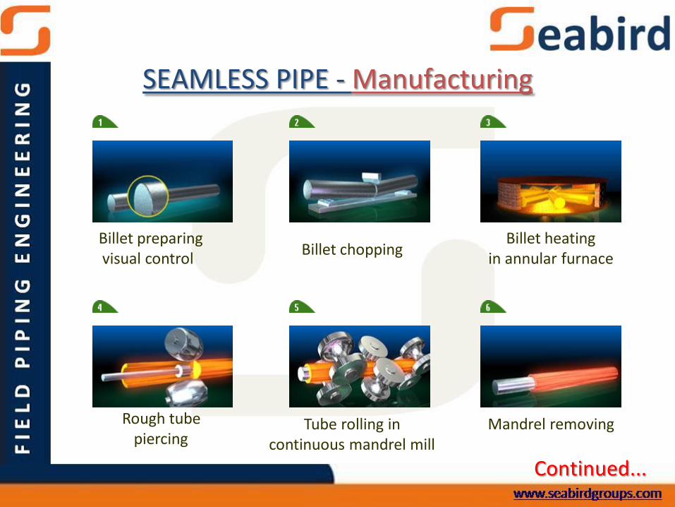
SEAMLESS PIPE - Manufacturing
Geometry measuring, mechanical tests,
chemical composition control
Tube ends sizing(by OD and ID)
Heating for quenching
Quenching in sprayer Tempering Tubes cooling
Continued...
SEAMLESS PIPE - Manufacturing

Tubes etching Ultrasonic or electromagnetic test
Hydraulic test
Sweeping-up (if required), visual control
Preservative coating Weighing, marking,packing, storing
Continued...
SEAMLESS PIPE - Manufacturing

Continued...
ERW PIPE - Manufacturing

Slitting:
HR Coils are slotted to pre-determined widths for
each and every size of pipes
Uncoiling, End Shearing And Welding:
The slotted coil is uncoiled at the entry of ERW mill
and the ends are sheared and welded one after another.
This results in a single endless strip.
Forming:
The slotted coils are initially formed into U shape
and after that into a cylindrical shape with open edges
utilizing a series of forming rolls.Continued...
ERW PIPE - Manufacturing
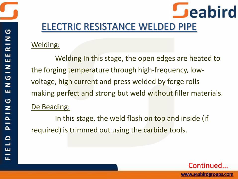
ELECTRIC RESISTANCE WELDED PIPE
Welding:
Welding In this stage, the open edges are heated to
the forging temperature through high-frequency, low-
voltage, high current and press welded by forge rolls
making perfect and strong but weld without filler materials.
De Beading:
In this stage, the weld flash on top and inside (if
required) is trimmed out using the carbide tools.
Continued...
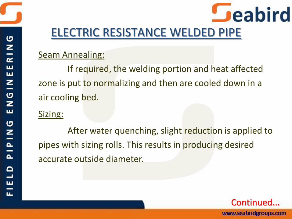
ELECTRIC RESISTANCE WELDED PIPE
Seam Annealing:
If required, the welding portion and heat affected
zone is put to normalizing and then are cooled down in a
air cooling bed.
Sizing:
After water quenching, slight reduction is applied to
pipes with sizing rolls. This results in producing desired
accurate outside diameter.
Continued...

ELECTRIC RESISTANCE WELDED PIPE
Cutting:
In cutting stage, the pipes are cut to required
lengths by flying cut off disc/saw cutter.
End Facing And Bevelling:
This is usually stage, where the pipes ends are faced
and bevelled by the end facer. All these processes are
continuous with automatic arrangements. These plain
ended tubes further go for processing as per the customer
requirements such as galvanizing, threading, black
varnishing and more.

NPS: Nominal pipe size.T – Wall ThicknessOD: Outside Diameter
PIPE CLASSIFICATION
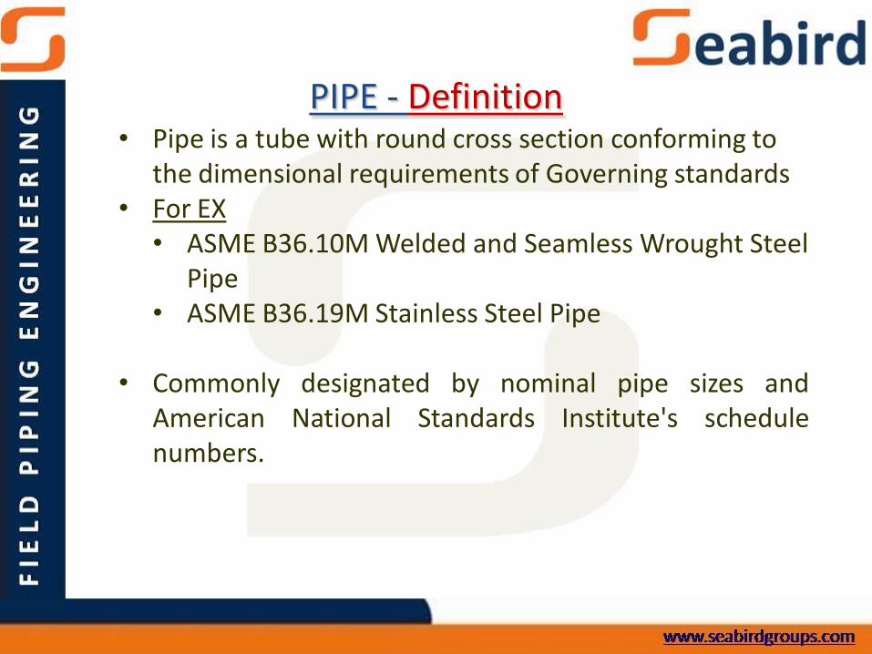
• Pipe is a tube with round cross section conforming to the dimensional requirements of Governing standards
• For EX• ASME B36.10M Welded and Seamless Wrought Steel
Pipe• ASME B36.19M Stainless Steel Pipe
• Commonly designated by nominal pipe sizes andAmerican National Standards Institute's schedulenumbers.
PIPE - Definition

• Nominal pipe size (NPS) is a dimensionless designator ofpipe size.
• It indicates standard pipe size when followed by the specificsize designation number without an inch symbol.
• NPS 12 and smaller pipe has outside diameter greater thanthe size designator
Ex: NPS 2 indicates a pipe whose Outside Diameter is2.375 in.
• NPS 14 and larger pipe is the same as the size designator ininches.
Ex: NPS 14 pipe has an Outside Diameter equal to 14in.
PIPE SIZE

PIPE SIZE
• Diameter nominal (DN) is also a dimensionless designator of
pipe size in the metric unit system, developed by ISO.
• It indicates standard pipe size when followed by the specific
size designation number.
For example, DN 50 is the equivalent designation of
NPS 2.

PIPE SIZE
NPS DN NPS DN NPS DN NPS DN
1/8 6 3 ½ 90 22 550 44 1100
¼ 8 4 100 24 600 48 1200
3/8 10 5 125 26 650 52 1300
½ 15 6 150 28 700 56 1400
¾ 20 8 200 30 750 60 1500
1 25 10 250 32 800 64 1600
1 ¼ 32 12 300 34 850 68 1700
1 ½ 40 14 350 36 900 72 1800
2 50 16 400 38 950 76 1900
2 ½ 65 18 450 40 1000 80 2000
3 80 20 500 42 1050 — —
For sizes larger than NPS
80, determine the DN
equivalent by multiplying
NPS size designation
number by 25 without a
millimetre symbol.
NPS and DN pipe size equivalents:

• In the beginning, each pipe size was produced to have onethickness, which later was termed as standard (STD)
• As the industrial requirements demanded the handling ofhigher-pressure fluids, pipes were produced having thickerwalls, which came to be known as extra strong (XS) or extraheavy (XH).
• The higher pressure requirements increased further,requiring thicker wall pipes. Accordingly, pipes weremanufactured with double extra strong (XXS) or doubleextra heavy (XXH) while the standardized outside diametersare unchanged.
PIPE THICKNESS

• With the development of stronger and corrosion-resistantpiping materials, the term schedule (SCH) was invented tospecify the various nominal wall thickness of pipe.
• Schedule numbers are5, 5s, 10, 10s, 20, 20s, 30, 40, 40s, 60, 80, 80s, 100, 120,140, 160
• The schedule numbers followed by the letter S are perASME B36.19M, and they are primarily intended for usewith stainless steel pipe.
PIPE THICKNESS

• Original pipe wall thickness designations of STD, XS,and XXS have been retained; however, theycorrespond to a certain schedule number dependingupon the nominal pipe size.
• The nominal wall thickness of NPS 10 and smallerschedule-40 pipe is same as that of Standard WallThickness pipe. Also, NPS 8 and smaller schedule-80pipe has the same wall thickness as XS pipe. (Refer Sch.Chart)
PIPE THICKNESS

PIPE THICKNESS – Schedule Chart
NPS OD S5s S10s S10 S20 S30 S40s STD S40 S60 S80s X-S S80 S100 S120 S140 S160 XX-S
1/8 10.3 - 1.24 - - - 1.73 1.73 1.73 - 2.41 2.41 2.41 - - - - -
1/4 13.7 - 1.65 - - - 2.24 2.24 2.24 - 3.02 3.02 3.02 - - - - -
3/8 17.1 - 1.65 - - - 2.31 2.31 2.31 - 3.2 3.2 3.2 - - - - -
1/2 21.3 1.65 2.11 - - - 2.77 2.77 2.77 - 3.73 3.73 3.73 - - - 4.78 7.47
3/4 26.7 1.65 2.11 - - - 2.87 2.87 2.87 - 3.91 3.91 3.91 - - - 5.56 7.82
1 33.4 1.65 2.77 - - - 3.38 3.38 3.38 - 4.55 4.55 4.55 - - - 6.35 9.09
1.25 42.2 1.65 2.77 - - - 3.56 3.56 3.56 - 4.85 4.85 4.85 - - - 6.35 9.7
1.5 48.3 1.65 2.77 - - - 3.68 3.68 3.68 - 5.08 5.08 5.08 - - - 7.14 10.2
2 60.3 1.65 2.77 - - - 3.91 3.91 3.91 - 5.54 5.54 5.54 - - - 8.74 11.1
2.5 73 2.11 3.05 - - - 5.16 5.16 5.16 - 7.01 7.01 7.01 - - - 9.52 14
3 88.9 2.11 3.05 - - - 5.49 5.49 5.49 - 7.62 7.62 7.62 - - - 11.1 15.2
3.5 102 2.11 3.05 - - - 5.74 5.74 5.74 - 8.08 8.08 8.08 - - - - -
4 114 2.11 3.05 - - - 6.02 6.02 6.02 - 8.56 8.56 8.56 - 11.1 - 13.5 17.1
5 141 2.77 3.4 - - - 6.55 6.55 6.55 - 9.53 9.53 9.53 - 12.7 - 15.9 19.1
6 168 2.77 3.4 - - - 7.11 7.11 7.11 - 1097 11 11 - 14.3 - 18.3 22
8 219 2.77 3.76 - 6.35 7.04 8.18 8.18 8.18 10.3 12.7 12.7 12.7 15.1 18.3 20.6 23 22.2
10 273 3.4 4.19 - 6.35 7.8 9.27 9.27 9.27 12.7 12.7 12.7 15.1 18.3 21.4 25.4 28.6 25.4
12 324 3.96 4.57 - 6.35 8.38 9.53 9.53 10.3 14.3 12.7 12.7 17.5 21.4 25.4 28.6 33.3 25.4
14 356 3.96 4.78 6.35 7.92 9.53 - 9.53 11.1 15.1 - 12.7 19.1 23.8 27.8 31.8 35.7 -
16 406 4.19 4.78 6.35 7.92 9.53 - 9.53 12.7 16.7 - 12.7 21.4 26.2 31 36.5 40.5 -
18 457 4.19 4.78 6.35 7.92 11.1 - 9.53 14.3 19.1 - 12.7 23.8 29.4 34.9 39.7 45.2 -
20 508 4.78 5.54 6.35 9.53 12.7 - 9.53 15.1 20.6 - 12.7 26.2 32.5 38.1 44.5 50 -
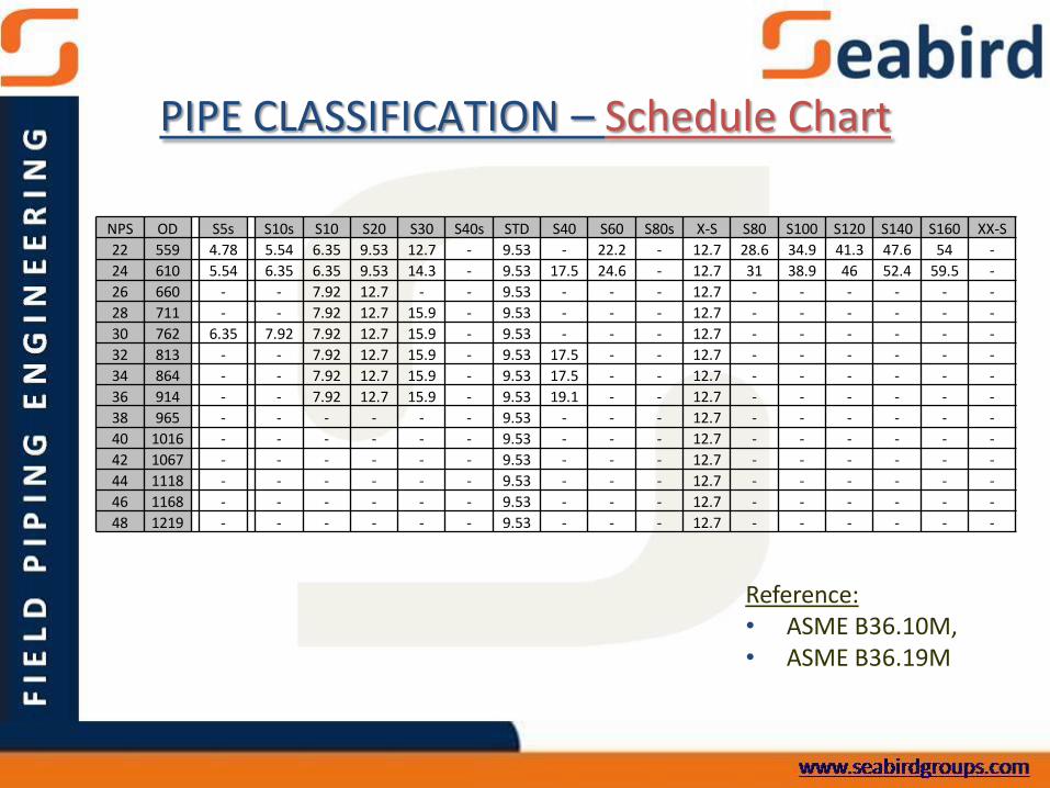
NPS OD S5s S10s S10 S20 S30 S40s STD S40 S60 S80s X-S S80 S100 S120 S140 S160 XX-S
22 559 4.78 5.54 6.35 9.53 12.7 - 9.53 - 22.2 - 12.7 28.6 34.9 41.3 47.6 54 -
24 610 5.54 6.35 6.35 9.53 14.3 - 9.53 17.5 24.6 - 12.7 31 38.9 46 52.4 59.5 -
26 660 - - 7.92 12.7 - - 9.53 - - - 12.7 - - - - - -
28 711 - - 7.92 12.7 15.9 - 9.53 - - - 12.7 - - - - - -
30 762 6.35 7.92 7.92 12.7 15.9 - 9.53 - - - 12.7 - - - - - -
32 813 - - 7.92 12.7 15.9 - 9.53 17.5 - - 12.7 - - - - - -
34 864 - - 7.92 12.7 15.9 - 9.53 17.5 - - 12.7 - - - - - -
36 914 - - 7.92 12.7 15.9 - 9.53 19.1 - - 12.7 - - - - - -
38 965 - - - - - - 9.53 - - - 12.7 - - - - - -
40 1016 - - - - - - 9.53 - - - 12.7 - - - - - -
42 1067 - - - - - - 9.53 - - - 12.7 - - - - - -
44 1118 - - - - - - 9.53 - - - 12.7 - - - - - -
46 1168 - - - - - - 9.53 - - - 12.7 - - - - - -
48 1219 - - - - - - 9.53 - - - 12.7 - - - - - -
PIPE CLASSIFICATION – Schedule Chart
Reference:• ASME B36.10M,• ASME B36.19M

Dimensions
• NPS 1/8, ¼, 3/8, ½, ¾, 1, 1 ½, 2, 3, 4, 6, 8, 10,
12, 14, 16, 18, 20, 24, 28, 30, 32, 36, 40,
44, 48 52, 56, 60
• NPS 1 ¼, 2 ½, 3 ½, 5 not used
• Pipe is supplied in
o Random length (18 to 25 ft)
o Double random length (38 to 48 ft)
PIPE SUPPLY – Dimensions

TE (Treaded End
BE (Bevel End)
PE (Plain End)
PIPE SUPPLY – Pipe End

• Line pipe grade designations come from API Spec 5Lspecification for line pipe has Grade designation A& B.
• Stronger grades have the designation X followed by thespecific Minimum Yield Strength of the pipe steelmeasured in ksi (kilo pounds per square inch)For example
API 5L X60 denotes, pipe having a minimum yieldstrength of 60ksi
PIPING MATERIAL CLASSIFICATION – API
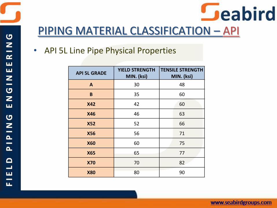
• API 5L Line Pipe Physical Properties
API 5L GRADEYIELD STRENGTH
MIN. (ksi)TENSILE STRENGTH
MIN. (ksi)
A 30 48
B 35 60
X42 42 60
X46 46 63
X52 52 66
X56 56 71
X60 60 75
X65 65 77
X70 70 82
X80 80 90
PIPING MATERIAL CLASSIFICATION – API

Tube Specify by two of
• Outside diameter
• Inside diameter
• Wall thickness
o Thousandths of inch
o Gauge number
American wire gauge
Steel wire gauge. Etc..
Tube
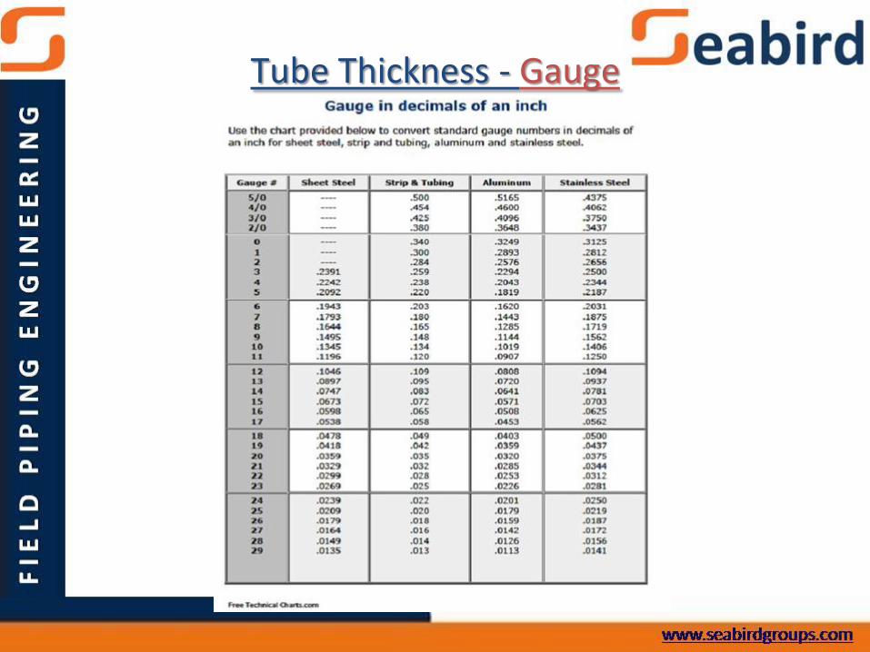
Tube Thickness - Gauge

Specification Product form Application
ASTM A53 Seamless/welded Ordinary use in gas, air, oil, water, steam
ASTM A106 Seamless High-temperature service (steam, water, gas, etc.)
ASTM A369 Forged and bored High-temperature service
ASTM A335 Seamless High-temperature service
ASTM A333 Seamless/welded Service requiring excellent fracture toughness
ASTM A671 Electric fusion-welded Low-temperature service
ASTM A672 Electric fusion-welded Moderate-temperature service
ASTM A691 Electric fusion-welded High-temperature service
ASTM A312 Seamless/welded Low- to high-temperature and corrosive service
API 5L Seamless/welded Line pipe, refinery, and transmission service
ASTM SpecSome of the commonly used American Spec & Product Form

• Branch connections may be made by welding the branch pipe or a welding outlet fitting to the run pipe
• Connections for branch pipes are made with pipe tees or stub-
ins/ stub-ons.
Reinforcement Pad:Material added in the vicinity of a branch opening to
restore the mechanical integrity of the pipe.
PIPING SYSTEM – Branch Pipe

Stub In/ Stub on:
• Welded directly in the side of the main pipe run
• Cab be reinforced
PIPING SYSTEM - Branch Connection
Stub In/ Stub on:
• Stub-in/ Stub-on can replace a reducing tee in joining branch pipes.
• A hole of the diameter of the stub-in pipe is drilled into the main pipe and the pipes are fitted together.
• The stub-in pipe and main pipe are then welded together.
• Advantage is that it avoids the cost of buying pipe fittings
• Save installation time because
– One weld is needed around the stub hole where as 3 joints are required in reducing tee
PIPING SYSTEM - Branch Connection

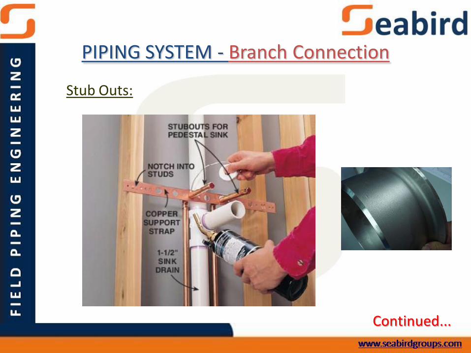
Stub Outs:
• Capped and unused pipe branch connections or stubs on pipes are called stub outs.
• They are capped until a branch pipe is attached. The branch pipe can be inserted after the pipe cap is removed.
Continued...
PIPING SYSTEM - Branch Connection
Stub Outs:
Continued...
PIPING SYSTEM - Branch Connection