Embed Size (px)
Citation preview

CHEROKEE
SERVICE MANUALCARD 1 OF 4
PA-28-140
PA-28-150
PA-28-160
PA-28-180
PA-28-235
PA-28R-180
PA-28R-200
PIPER AIRCRAFT CORPORATION
lA1(PART NUMBER 753 586)
PIPER CHEROKEE SERVICE MANUAL
AEROFICHE EXPLANATION AND REVISION STATUS
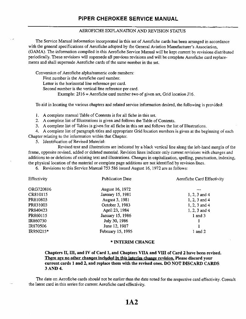
The Service Manual information incorporated in this set of Aerofiche cards has been arranged in accordancewith the general specifications of Aerofiche adopted by the General Aviation Manufacturer's Association,(GAMA). The information compiled in this Aerofiche Service Manual will be kept current by revisions distributedperiodically. These revisions will supersede all previous revisions and will be complete Aerofiche card replace-ments and shall supersede Aerofiche cards of the same number in the set.
Conversion of Aerofiche alpha/numeric code numbers:First number is the Aerofiche card number.Letter is the horizontal line reference per card.Second number is the vertical line reference per card.
Example: 2J16 = Aerofiche card number two of given set, Grid location J16.
To aid in locating the various chapters and related service information desired, the following is provided:
1. A complete manual Table of Contents is for all fiche in this set.2. A complete list of Illustrations is given and follows the Table of Contents.3. A complete list of Tables is given for all fiche in this set and follows the list of Illustrations.4. A complete list of paragraph titles and appropriate Grid location numbers is given at the beginning of each
Chapter relating to the information within that Chapter.5. Identification of Revised Material:
Revised text and illustrations are indicated by a black vertical line along the left-hand margin of theframe, opposite revised, added or deleted material. Revision lines indicate only current revisions with changes andadditions to or deletions of existing text and illustrations. Changes in capitalization, spelling, punctuation, indexing,the physical location of the material or complete page additions are not identified by revision lines.
6. Revisions to this Service Manual 753 586 issued August 16, 1972 are as follows:
Effectivity Publication Date Aerofiche Card Effectivity
ORG720816 August 16, 1972 ---CR810115 January 15, 1981 1,2, 3 and 4PR810803 August 3, 1981 1, 2, 3 and 4PR831003 October 3, 1983 1, 2, 3 and 4PR840423 April 23, 1984 1, 2, 3 and 4PR860115 January 15, 1986 1 and 3IR860730 July 30, 1986 1IR870506 June 12, 1987 1IR950215* February 15, 1995 1 and 2
* INTERIM CHANGE
Chapters II, III, and IV of Card 1, and Chapters VIIA and VIII of Card 2 have been revised.There are no other changes included in this interim change revision. Please discard yourcurrent cards 1 and 2, and replace them with the revised ones. DO NOT DISCARD CARDS3 AND 4.
The date on Aerofiche cards should not be earlier than the date noted for the respective card effectivity. Consultthe latest card in this series for current Aerofiche card effectivity.
1A2

INTRODUCTION
HANDLING
INSPECTION
TABLE OF CONTENTS
AEROFICHE CARD NO. 1
INTRODUCTION
...............
STRUCTURES
V........................ 2A8
VI...... . ........ (PA-28R)
LANDING GEAR AND
VIIA
VIII
POWER PLANT (PA-28R)
VIIIA . ........ . . .
IX .
XI
XIIIXIV
AEROFACE CARD NO. 3PLANT (PA-28R)
AEROFACE CARD NO.
NI
ACCESSORIES AND UTILITIES
1A3
AIXIIIX
1A24
IX
X
2A8
VIIIA
2K2
VIIA
IIA
IA
A
Al
4A8
II
I

1A4INTENTIONALLY LEFT BLANK

PIPER CHEROKEE SERVICE MANUAL
LIST OF ILLUSTRATIONS
Figure AeroficheGrid No.
2-1. Three View of Cherokee, PA-28-140. -150, -160, -180, Serial Nos.28-1 to 28-1760 incl., Flite Liner, Serial Nos. 28-7125174and up............................ ...................... B4
2-2. Three View of Cherokee, PA-28-140, Serial Nos.28-7225001 and up ...... ... ......... ............. B5
2-3. Three View of Cherokee, PA-28-150. -160. -180, Serial Nos.28-1761 to 28-4377 incl ............... ......... ...... 1B6
2-4. Three View of Cherokee. PA-28-180, Serial Nos. 28-4378to 28-7105244 inc .............. ............... lB7
2-5. Three View of Cherokee. PA-28-180, Serial Nos. 28-7205001to 28-7205328 incl ......................................... B8
2-6. Three View of Cherokee. PA-28-180. Serial Nos.28-7305001 and up ........................................ 1B9
2-7. Three View of Cherokee, PA-28-235. Serial Nos. 28-10000to 28-11039 incl ..................... .. ...... ............ 1B10
2-8. Three View of Cherokee, PA-28-235. Serial Nos. 28-11040to 28-7110042 incl......................................... 1B11
2-9. Three View of Cherokee, PA-28-235. Serial Nos. 28-7210001to 28-7210033 incl ......................................... 1B12
2-10. Three View of Cherokee, PA-28-235. Serial Nos.28-7310001 and up ........................................ IB13
2-11. Three View of Cherokee. PA-28R-180, -200,-180 Serial Nos. 28-30005 to 28-7130019 incl.-200 Serial Nos. 28-30482 to 28-7135238 incl ............... 1B14
2-12. Three View of Cherokee, PA-28R-200, Serial Nos.28-7235001 and up .......... .... ............ ......... IB15
2-13. Station Reference Lines. PA-28-140. -150, -160, -180. Serial Nos.28-1 to 28-1760 incl.: Flite Liner. Serial Nos. 28-7125174and up .................................................. C4
2-14. Station Reference Lines. PA-28-140, Serial Nos. 28-7225001and up .................................................. IC
2-15. Station Reference Lines, PA-28-150, -160. -180, Serial Nos.28-1761 to 28-4377 incl .................................. C6
2-16. Station Reference Lines, PA-28-180. Serial Nos. 28-4378to 28-7105244 incl ....................................... IC7
2-17. Station Reference Lines. PA-28-180. Serial Nos. 28-7205001to 28-7205328 incl ........................................ IC8
2-18. Station Reference Lines. PA-28-180, Serial Nos. 28-7305001and up. IC9
2-19. Station Reference Lines. PA-28-235. Serial Nos. 28-10000to 28-11039 incl .......... ............................ 1C10
2-20. Station Reference Lines, PA-28-235. Serial Nos. 28-11040to 28-7110042 incl ........................................ 1C11
Reissued: 1/15/81 1A51A5

PIPER CHEROKEE SERVICE MANUAL
LIST OF ILLUSTRATIONS (cont.)
Figure AeroficheGrid No.
2-21. Station Reference Lines, PA-28-235, Serial Nos. 28-7210001to 28-7210033 incl ........................................ . 1C12
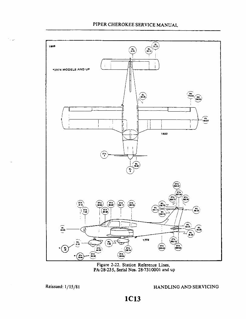
2-22. Station Reference Lines. PA-28-235, Serial Nos. 28-7310001and up .................................................. 1C13
2-23. Station Reference Lines, PA-28R-180,-200,-180 Serial Nos. 28-30005 to 28-7130019 incl.-200 Serial Nos. 28-30482 to 28-7135238 incl .................. 1C14
2-24. Station Reference Lines, PA-28R-200, Serial Nos. 28-7235001and up .................................................. IC15
2-25. Access Plates and Panels, PA-28-140 and Flite Liner. SerialNos. 28-7225001 and up as noted ........................... 1C16
2-26. Access Plates and Panels, PA-28-150, -160, -180 .... .............. C172-27. Access Plates and Panels, PA-28-235 ................. .. ......... C182-28. Access Plates and Panels, PA-28R .............................. 1C192-29. Identification of Aircraft Fluid Lines ............................ 1D72-30. Torque Wrench Formula ...................................... 1C212-31. Removing Cherrylock Rivets ................................... 1D82-32. Jacking Arrangement ......................................... 1 D92-33. Weighing Airplane ............................................. 1D102-34. Leveling Longitudinally ....................................... 1D112-35. Leveling Laterally ............................................ 1D112-36. Servicing Points, PA-28-140 ................................... 1D202-37. Servicing Points, PA-28-150,-160, -180 ....................... 1D212-38. Servicing Points, PA-28-235 ................................... 1D222-39. Servicing Points, PA-28R ..................................... 1d232-40. Main Gear Oleo Struts (Cutaway View), PA-28-140;
PA-28-150,-160,-180; PA-28-235 ........................... 1D242-41. Fuel Strainer. PA-28-140; PA-28-150, -160, -180; and PA-28R...... 1E92-42. Fuel Selector and Filter, PA-28-235 ............................ 1E92-43. Lubrication Chart (Landing Gear, Main), PA-28-140, -150,
-160, -180 and -235 ....................................... 1E172-44. Lubrication Chart (Landing Gear, Main), PA-28R-180
and -200 ............................................... E182-45. Lubrication Chart (Landing Gear, Nose), PA-28-140, -150.
-160. -180 and -235 ....................................... 1E192-46. Lubrication Chart (Landing Gear, Nose), PA-28R-180 and -200 .... 1E202-47. Lubrication Chart (Control System) ............................ I E212-48. Lubrication Chart (Control System) (cont.) ...................... 1E222-49. Lubrication Chart (Control System) (cont.) ...................... 1E232-50. Lubrication Chart (Control System) (cont.) . ..................... 1 E242-51. Lubrication Chart (Cabin Door. Baggage Door and Seat) ......... IF1
Revised: 8/3/811A6
PIPER CHEROKEE SERVICE MANUAL
LIST OF ILLUSTRATIONS (cont.)Figure Aerofiche
Grid No.
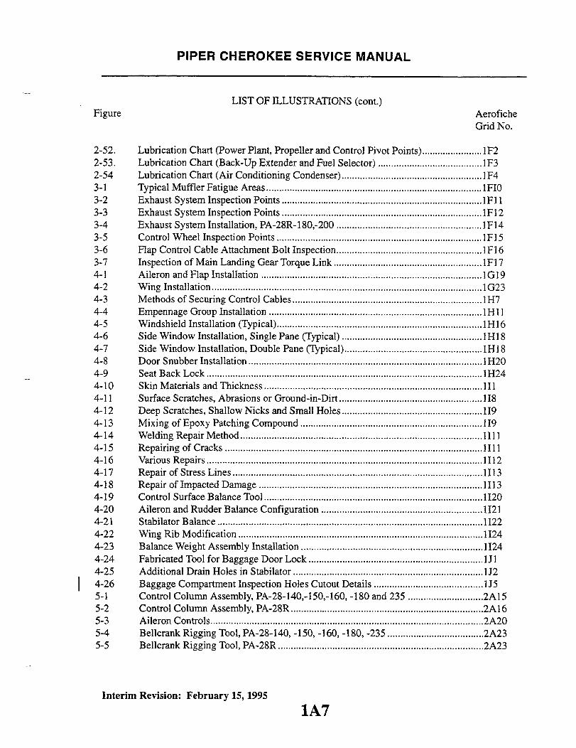
2-52. Lubrication Chart (Power Plant, Propeller and Control Pivot Points) ....................... 1F22-53. Lubrication Chart (Back-Up Extender and Fuel Selector) ........................................1F32-54 Lubrication Chart (Air Conditioning Condenser) ...................................................... F43-1 Typical Muffler Fatigue Areas . ................................................... .................... 1F103-2 Exhaust System Inspection Points ............................................................................. 1F113-3 Exhaust System Inspection Points ............................................................................. F123-4 Exhaust System Installation, PA-28R-180,-200 ........................................................ IF143-5 Control Wheel Inspection Points ...............................................................................1F153-6 Flap Control Cable Attachment Bolt Inspection........................................................ 1Fl 63-7 Inspection of Main Landing Gear Torque Link ......................................................... 1Fl 74-1 Aileron and Flap Installation ....................................................................................1G194-2 Wing Installation ..................................................................... 1G234-3 Methods of Securing Control Cables ........................................ .......... 1H74-4 Empennage Group Installation ................................................................................. 1H4-5 Windshield Installation (Typical) ............................... .......................... 1H164-6 Side Window Installation, Single Pane (Typical) ......................................................1H184-7 Side Window Installation, Double Pane (Typical) ....................................................1H184-8 Door Snubber Installation . ......................................................... 1H204-9 Seat Back Lock ........................................ ..................1H244-10 Skin Materials and Thickness .................................................................................... 1I14-11 Surface Scratches, Abrasions or Ground-in-Dirt.......................................................1I84-12 Deep Scratches, Shallow Nicks and Small Holes ................... 1................... ............. 1194-13 Mixing of Epoxy Patching Compound .................................................... 1194-14 Welding Repair Method .............................................................................................4-15 Repairing of Cracks ...................................................................................................1I114-16 Various Repairs .......................................................................................................... 1I124-17 Repair of Stress Lines ...............................................................................................1I134-18 Repair of Impacted Damage ......................................................................................1I134-19 Control Surface Balance Tool ....................................................................................1I204-20 Aileron and Rudder Balance Configuration ..............................................................1Ii214-21 Stabilator Balance ......................................................................................................11224-22 Wing Rib Modification ..............................................................................................1I244-23 Balance Weight Assembly Installation ...................................................................... 11244-24 Fabricated Tool for Baggage Door Lock ................................................................... J4-25 Additional Drain Holes in Stabilator ........................................................................1J24-26 Baggage Compartment Inspection Holes Cutout Details .......................................... J55-1 Control Column Assembly, PA-28-140,-150,-160, -180 and 235 .............................2A155-2 Control Column Assembly, PA-28R ..........................................................................2A165-3 Aileron Controls.........................................................................................................2A205-4 Bellcrank Rigging Tool, PA-28-140, -150, -160, -180, -235 .....................................2A235-5 Bellcrank Rigging Tool, PA-28R ...............................................................................2A23
Interim Revision: February 15, 1995
1A7

PIPER CHEROKEE SERVICE MANUAL
LIST OF ILLUSTRATIONS (cont.)
Figure AeroficheGrid No.
5-6. Aileron Rigging Tool ......................................... 2A245-7. Stabilator Rigging Tool ....................................... 2B35-8. Stabilator Controls ....................................... .... 2B45-9. Stabilator Trim Control (Overhead Control) ... ............. 2B85-10. Methods of Securing Trim Cables .............................. 2B105-11. Stabilator Trim Control (Floor Control) ......................... 2B185-12. Rudder and Steering Pedal Assembly ........................... 2B245-13. Rudder Controls ............................................. 2C45-14. Rudder Rigging Tool .................................... 2C55-15. Clamping Rudder Pedals ...................................... 2C55-16. Rudder and Stabilator Travel Adjustments ... ................... 2C65-17. Rudder Trim Control ......................................... 2C85-18. Flap Controls ................... ............................. 2C105-19. Flap Step Adjustment ......................................... 2C145-20. Flap Rigging Tool ............................................ 2C125-21. Fabricated Aileron Bellcrank Rigging Tool ...................... 2C155-22. Correct Method of Installing Rod End Bearings .................. 2C155-23. Fabricated Aileron and Flap Rigging Tool ....................... 2C165-24. Fabricated Stabilator Rigging Tool ............................. 2C175-25. Fabricated Rudder Rigging Tool ............................... 2C186-1. Schematic Diagram of Hydraulic System ... .............. 2D56-2. Hydraulic System Installation .................................. 2D66-3. Hydraulic Pump/Reservoir. Exploded View ...................... 2D106-4. Test and Adjustments of Hydraulic Pump ............. ............... 2D146-5. Pump Shock Mounts ......................................... 2D166-6. Checking Aligning Brackets of Gear Back-Up Extender
Actuator ................................................ 2D 176-7. Gear Back-Up Extender Actuator .............................. 2D216-8. Nose Gear Actuator Cylinder .................................. 2E26-9. End Gland Locking Device .................................... 2E46-10. Main Gear Actuating Cylinder ................................. 2E56-11. Gear Back-Up Extender Actuator Aligning Tool .................. 2E207-1. Nose Gear Oleo Strut Assembly ................................ 2F27-2. Nose Gear Installation ........................................ 2F67-3. Clamping Rudder Pedals in Neutral Position ..................... 2F87-4. Rudder Pedals at Neutral Angle .. ........................ ... 2F87-5. Main Gear Oleo Strut Assembly. PA-28-140, -150, -160
and -180 ................................................ 2F137-6. Main Gear Oleo Strut Assembly, PA-28-235 ..................... 2F157-7. Main Gear Installation ... ........................ .......... 2F197-8. Nose Wheel Assembly ......................................... 2F217-9. Main Wheel Assembly ........................................ 2F23
Revised: 4 23/84 1A81A8
PIPER CHEROKEE SERVICE MANUAL
LIST OF ILLUSTRATIONS (cont.)
Figure AeroficheGrid No.
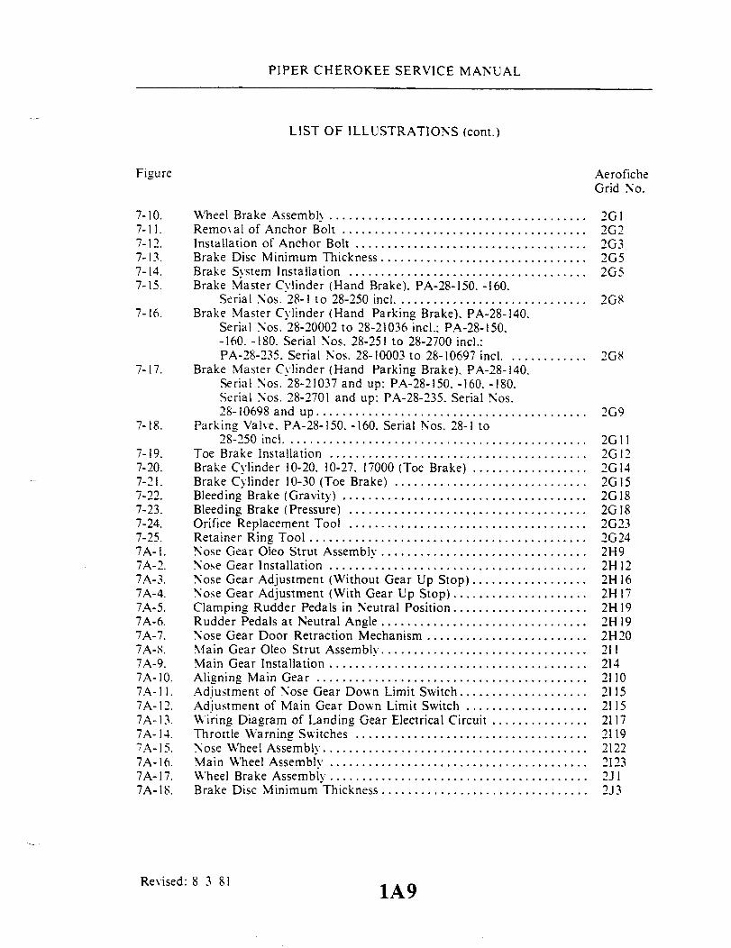
7-10. Wheel Brake Assembly ........................................ 2G17-11. Removal of Anchor Bolt ...................................... 2G27-12. Installation of Anchor Bolt .................................... 2G37-13. Brake Disc Minimum Thickness ................................ 2G57-14. Brake System Installation ..................................... 2G57-15. Brake Master Cylinder (Hand Brake). PA-28-150. -160.
Serial Nos. 28-1 to 28-250 incl ............................. 2G87-16. Brake Master Cylinder (Hand Parking Brake), PA-28-140.
Serial Nos. 28-20002 to 28-21036 incl.: PA-28-150.-160. -180. Serial Nos. 28-251 to 28-2700 incl.:PA-28-235. Serial Nos. 28-10003 to 28-10697 incl ............ 2G8
7-17. Brake Master Cylinder (Hand Parking Brake). PA-28-140.Serial Nos. 28-21037 and up: PA-28-150. -160. -180.Serial Nos. 28-2701 and up: PA-28-235. Serial Nos.28-10698 and up.......................................... 2G9
7-18. Parking Valve. PA-28-150. -160. Serial Nos. 28-1 to28-250 incl ............................................... 2G11
7-19. Toe Brake Installation ........................................ 2G127-20. Brake Cylinder 10-20. 10-27. 17000 (Toe Brake) .................. 2G147-21. Brake Cylinder 10-30 (Toe Brake) .............................. 2G 157-22. Bleeding Brake (Gravity) ...................................... 2G 187-23. Bleeding Brake (Pressure) ......... ............................ 2G 187-24. Orifice Replacement Tool ..................................... 2G237-25. Retainer Ring Tool ........................................... 2G247A-I. Nose Gear Oleo Strut Assembly ............................... . 2H97A-2. Nose Gear Installation ........................................ 2H 127A-3. Nose Gear Adjustment (Without Gear Up Stop) .................. 2H 167A-4. Nose Gear Adjustment (With Gear Up Stop) ...... ............... 2H 177A-5. Clamping Rudder Pedals in Neutral Position ..................... 2H 197A-6. Rudder Pedals at Neutral Angle ................................ 2H197A-7. Nose Gear Door Retraction Mechanism ............. .............. 2H207A-8. Main Gear Oleo Strut Assembly ............................... . 2117A-9. Main Gear Installation ....................................... 2147A-10. Aligning Main Gear .......................................... 21107A-11. Adjustment of Nose Gear Down Limit Switch .................... 21157A-12. Adjustment of Main Gear Down Limit Switch ................... 21157A-13. Wiring Diagram of Landing Gear Electrical Circuit ............... 21177A- 14. Throttle Warning Switches .................................... 21197A-15. Nose Wheel Assembly. ......................................... 21227A-16. Main Wheel Assembly ........................................ 21237A-17. Wheel Brake Assembly .................... ................... 2J17A-18. Brake Disc Minimum Thickness ................................ 2J3
Revised: 8 3 81 1A91A9

PIPER CHEROKEE SERVICE MANUAL
LIST OF ILLUSTRATIONS (cont.)
Figure AeroficheGrid No.
7A-19. Brake System Installation ..................................... 2J37A-20. Brake Master Cylinder (Hand Parking Brake) ................... 2J57A-21. Toe Brake Installation ........................................ 2J67A-22. Brake Cylinder (Toe Brake) (10-20. 10-27. 17000) ................. 2J87A-23. Brake Cylinder (Toe Brake) (10-30) ............................. 2J107A-24. Bearing Installation ........................................... 2J117A-25. Nose Gear Ser ice Tolerances. PA-28R .......................... 2J207A-26. Main Gear Service Tolerances. PA-28R ....... .................. 2J238-1. Typical Nicks and Removal Method ............................ 2K88-2. Propeller Installation (Constant Speed). PA-28-235 ............... 2K88-3. Propeller Installation ......................................... 2K98-4. Adjustment of Propeller Control. PA-28-235 ................... 2K 138-5. Propeller Governor. PA-28-235 ...... ....................... 2K 138-6. Engine Installation. PA-28-140. -150. -160. -180.
Serial Nos. 28-1 to 28-1760 ............................... 2K168-7. Engine Installation. PA-28-140. -150. -160. -180.
Serial Nos. 28-1761 and up...... ......... ............. 2K178-8. Engine Shock Mount Installation. PA-28-140.
Serial Nos. 28-25000 and up ........................... .... 2K 188-9. Engine Installation. PA-28-235 ................................. 2K228-10. Adjustment of Engine Controls ................................. 2K248-11. Carburetor. PA-28-140. -150. -160 ............................ .. 2L38-12. Carburetor. PA-28-180. -235 ................................... 2L38-13. Magneto Inspection ........................................... 2L58-14. Contact Spring Inspection ..................................... 2L68-15. Impulse Coupling ............................................ 2L68-16. Magneto Timing Marks ....................................... 2L78-17. Timing Pointer .............................................. 2L78-18. Timing Kit Installed .......................................... 2L88-19. Breaker Compartment With Cast Timing Marks .................. 2L88-20. Removing Spark Plug Frozen to Bushing ........................ 2L138-21. Ignition Switch Wiring Positions ........................... .... 2L168A-1. Propeller Installation ......................................... 3A128A-2. Typical Nicks and Removal Method ............................ 3A138A-3. Propeller Governor ........................................... 3A168A-4. Engine Installation. PA-28R-180 ............................... 3A198A-5. Engine Installation. PA-28R-200 ............................... 3A218A-6. Adjustment of Engine Controls ................................. 3B18A-7. Fuel Injector ................................................. 3B38A-8. Schematic Diagram of RSA Fuel Injection System ................ 3B48A-9. Fuel-Air Bleed Nozzle ......................................... 3B68A-10. Contact Points ............................................... 3B8
Revised: 8 3 811A10

PIPER CHEROKEE SERVICE MANUAL
LIST OF ILLUSTRATIONS (cont.)
Figure AeroficheGrid No.
8A-11 . Rotor Holding Tool Installed .................................. 3B108A-12. Timing Kit Installed ............. ..................... 3B108A-13. Aligning Timing Marks ....................................... 3B118A-14. Checking Flyweight Clearance of Impulse Coupling ............. 3B128A-15. Engine Timing Marks . ................. . ..................... 3B138A-16. Magneto Adjustment Limits . .............................. . 3B148A-17. Magneto Timing Marks . ...................................... 3B148A-18. Removing Spring From Lead Assembly . . ............ 3B168A-19. Assembly Tool . .............................................. 3B168A-20. Using Assembly Tool ......................................... 3B 178A-21. Measuring Lead Assembly Length . ............................. 3B178A-22. Cutting Metallic Braid From End of Lead ....................... 3B188A-23. Unbraiding Metallic Shielding ................................ 3B188A-24. Forming Shielding Around Ferrule ...... .......... ....... 3B198A-25. Ferrule Seating Tool .... ... ... ..... .............. 3B 198A-26. Needle ...................................................... 3B 198A-27. Measuring Wire From Top of Ferrule . . ................ 3B208A-28. Installing Grommet Over Lead Assemblies ... ............. 3B208A-29. Lead Assembly Installed in Grommet . .......................... 3B208A-30. Wire Doubled Over For Installation of Eyelet ..... ............. 3B208A-31. Removing Spark Plug Frozen to Bushing ........ .............. 3B228A-32. Ignition Switch Wiring Positions . .............................. 3B249-1. Fuel System Diagram, PA-28-140, -150, -160. -180 ... .......... . 3CII9-2. Fuel System Diagram. PA-28-235. Serial Nos. 28-10003
to 28-10719 inc ........................................... 3C129-3. Fuel System Diagram. PA-28-235. Serial Nos. 28-10720 and up.... 3C139-4. Fuel System Diagram. PA-28R................................. 3C149-5. Deleted .....................9-6. Fuel Quantity Transmitter (P N 62037-00) ......... . 3C219-7. Fuel Quantity Transmitter (P/N 68101-00) . ...................... 3C219-8. Fuel Selector and Filter. PA-28-235 . ............................ 3C249-9. Fuel Filter. PA-28-235 ...... ................... 3DI9-10. Fuel Filter Bowl and Screen. PA-28-140, -150, -160, -180
and PA-28R............................................. 3D39-11. Plunger Fuel Pump (Early). PA-28-150, -160, -180 . .......... 3D69-12. Plunger Fuel Pump (Late), PA-28-140, -150, -160. -180, -235 ....... 3D69-13. Engine Primer ............................................... 3D129-14. Fabricated Fuel Quantity Transmitter Checking Jig . .... ......... 3D1710-1. Instrument Panel, PA-28-140, Serial Nos. 28-25000 to
28-26956 incl.......................... .................. 3E410-2. Instrument Panel. PA-28-140, Serial Nos. 28-7125001 to
28-7325684 inc . .......................................... 3E5
Revised: 8/3/81 lA111All
PIPER CHEROKEE SERVICE MANUAL
LIST OF ILLUSTRATIONS (cont.)
Figure AeroficheGrid No.
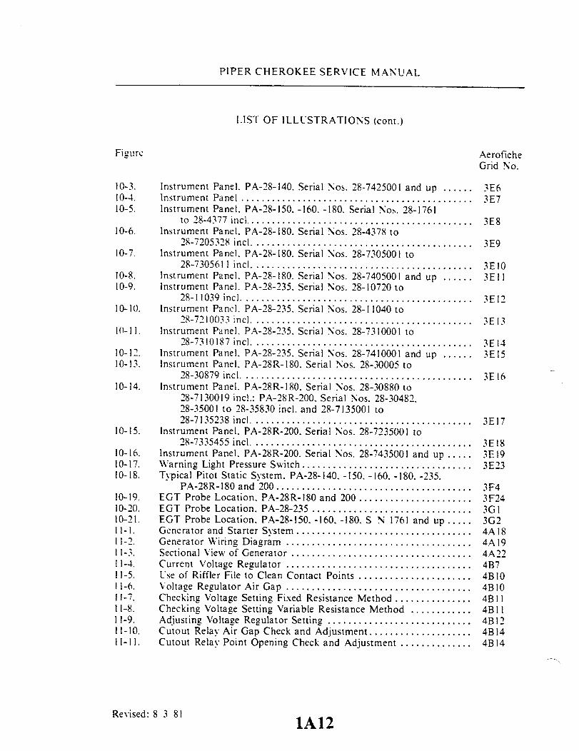
10-3. Instrument Panel. PA-28-140. Serial Nos. 28-7425001 and up ...... 3E610-4. Instrument Panel ............................................. 3E710-5. Instrument Panel. PA-28-150. -160. -180. Serial Nos. 28-1761
to 28-4377 incl ........................................... 3E810-6. Instrument Panel. PA-28-180. Serial Nos. 28-4378 to
28-7205328 incl .......................................... 3E910-7. Instrument Panel. PA-28-180. Serial Nos. 28-7305001 to
28-7305611 incl .......................................... 3E1010-8. Instrument Panel. PA-28-180. Serial Nos. 28-7405001 and up ...... 3E1110-9. Instrument Panel. PA-28-235. Serial Nos. 28-10720 to
28-11039 inc ............................................. 3E1210-10. Instrument Panel. PA-28-235. Serial Nos. 28-11040 to
28-7210033 inc ........................................... 3E1310- 11. Instrument Panel. PA-28-235. Serial Nos. 28-7310001 to
28-7310187 incl .......................................... 3E1410-12. Instrument Panel. PA-28-235. Serial Nos. 28-7410001 and up...... 3E1510-13. Instrument Panel. PA-28R-180. Serial Nos. 28-30005 to
28-30879 incl ............................................ 3E1610-14. Instrument Panel. PA-28R-180. Serial Nos. 28-30880 to
28-7130019 incl.: PA-28R-200. Serial Nos. 28-30482.28-35001 to 28-35830 incl. and 28-7135001 to28-7135238 incl .......................................... 3E17
10-15. Instrument Panel. PA-28R-200. Serial Nos. 28-7235001 to28-7335455 incl .......................................... 3E18
10-16. Instrument Panel. PA-28R-200. Serial Nos. 28-7435001 and up..... 3E1910-17. Warning Light Pressure Switch ................................. 3E2310-18. Typical Pitot Static System. PA-28-140. -150. -160. -180. -235.
PA-28R-180 and 200...................................... 3F410-19. EGT Probe Location. PA-28R-180 and 200 ...................... 3F2410-20. EGT Probe Location. PA-28-235 ............................... 3GI10-21. EGT Probe Location. PA-28-150. -160. -180. S N 1761 and up..... 3G211-1. Generator and Starter System .................................. 4A 1811-2. Generator Wiring Diagram .................................... 4A1911-3. Sectional View of Generator ................................... 4A2211-4. Current Voltage Regulator ............................. 4B711-5. Use of Riffler File to Clean Contact Points ...................... 4B1011-6. Voltage Regulator Air Gap ....................... 4B 1011-7. Checking Voltage Setting Fixed Resistance Method ............... 4B 1111-8. Checking Voltage Setting Variable Resistance Method ............ 4B I11-9. Adjusting Voltage Regulator Setting ............................ 4B 1211-10. Cutout Relay Air Gap Check and Adjustment ................... 4B14
11-11. Cutout Relay Point Opening Check and Adjustment .............. 4B14
Revised: 8 3 81 1A121A12

PIPER CHEROKEE SERVICE MANUAL
LIST OF ILLUSTRATIONS (cont.)
Figure AeroficheGrid No.
11-12. Checking Cutout Relay Closing Voltage ......................... 4B1511-13. AdJustment of Cutout Relay Closing Voltage .................. 4B1511-14. Checking Current Regulator. Load Method ...................... 4B1611-15. Checking Current Regulator. Jumper Lead Method ............... 4B1611-16. Alternator and Starter System.
PA-28-140. Serial Nos. 28-20000 to 28-24999 incl.:PA-28-150. -160. Serial Nos. 28-508 to 28-3643 incl.:PA-28-180. Serial Nos. 28-671 to 28-3643 incl.:PA-28-235. Serial Nos. 28-10002 to 28-10762 incl ............ 4B20
11-17. Alternator and Starter System.PA-28-140. Serial Nos. 28-25000 and up:PA-28-150. -160. -180. Serial Nos. 28-3644 and up:PA-28-235. Serial Nos. 10763 and up and PA-28R............ 4B21
11-18. Lamp-Bank Load .......... ................................. 4B2311-19. Checking Field Circuit ...... .................................. 4B2411-20. Testing Field Circuit .......................................... 4B2411-21. Testing Rectifiers (Positixe) .................................... 4C211-22. Testing Rectifiers (Negative) ................................... 4C311-23. C-3928 Fixtures and Adapters .................................. 4C411-24. Removing Rectifiers ..... .............................. ..... 4C411-25. Installing Rectifiers ..... ...................................... 4C511-26. Soldering Rectifier Lead ....................................... 4C611-27. Testing Stator Coils ......................................... 4C711-28. Removing End Bearing ........................................ 4C911-29. Installing End Bearing ..... ............................ .... 4C911-30. Removing Drive Pulley ....................................... 4C1011-31. Removing Drive End Bearing .................................. 4C1011-32. Removing Slip Ring ...................... .................. 4C 1111-33. Aligning Slip Ring .......................................... 4C1111-34. Installing Slip Ring ........................................... 4C1211-35. Installing Retainer ........................................... 4C1211-36. Solder Points ................................................ 4C1311-37. Installing Drive End Shield and Bearing (Typical) ................ 4C1411-38. Installing Pulley ..................... ...................... 4C 1411-39. Meter Connections for Alternator Performance Test .............. 4C1711-40. Voltage Regulator ............................................ 4C1911-41. Checking Air Gap ............................................ 4C1911-42. Voltage Regulator Fusible Wires ............................... 4C2011-43. Voltage Regulator Resistance Units ............................. 4C2011-44. No-Load Test Hookup ........................................ 4D211-45. Lock Torque Test Hookup ................................... 4D311-46. Resistance Test Hookup ....................................... 4D3
Revised: 8 3 81 1A131A13

PIPER CHEROKEE SERVICE MANUAL
LIST OF ILLUSTRATIONS (cont.)
Figure AeroficheGrid No.
11-47. Exploded View of Gear Reduction Starting Motor ................ 4D811-48. Turning Starting Motor Commutator ........................... 4D I11-49. Testing Motor Armature for Shorts ............................. 4D I11-50. Testing Motor Field for Grounds ............................. 4D I11-51. No-Load Test Hookup ..... . ....................... 4D1311-52. Stall Torque Hookup ......................................... 4D1311-53. Terminal Block ............................................ 4F511-54. For Index to these Figures, see Table XI-I, Index - Electrical 4F11thru System Schematics thru11-70. 4G1711-71. Exploded View of Alternator .................................. 4D2011-72. Removal of Slip Ring End Bearing ............................. 4D2111-73. Removal of Rectifier .......................................... 4D2111-74. Removal of Drive End Head .................................. 4D2211-75. Removal of End Head Bearing ................ .... .. ..... 4D2211-76. Testing Rotor for Ground ..................................... 4D2311-77. Testing Rotor for Shorts ..................................... 4D2311-78. Installation of Bearing ..................................... 4D2411-79. Installation of Rectifier ....................................... 4D2411-80. Terminal Assembly ........................................... 4E I11-81. Slip Ring End Bearing Assembly ............................... 4E211-82. Testing Alternator ............................................ 4E211-83. Brush Installation ............................................ 4E311-84. Internal Wiring Diagram ...................................... 4E311-85. For Index to these Figures. see Table XI-I, Index - Electrical 4G20thru System Schematics thru11-143. 4H 2411-144. Strobe Light Connections ..................................... 4E912-1. Two Year Magnesium Battery Connections ......... ......... 41312-2. Five Year, Lithium Battery Connections ... .... .................. 41412-3. Communications Components ELT Schematic ................... 411113-1. Cabin Heater. Defroster and Fresh Air System,
PA-28-140. Serial Nos. 28-2002 to 28-24999 incl..and PA-28-150, -160, -180, Serial Nos. 28-1 to28-1760 incl ............... ... .................. 4117
13-2. Cabin Heater. Defroster and Fresh Air System,PA-28-140, Serial Nos. 28-25000 and up ..................... 4118
13-3. Cabin Heater. Defroster and Fresh Air System,PA-28-150. -160, -180. Serial Nos. 28-1761 to28-2477 incl .............................................. 4119
Revised: 10 3,83 lA141A14

PIPER CHEROKEE SERVICE MANUAL
LIST OF ILLUSTRATIONS (cont.)
Figure AeroficheGrid No.
13-4. Cabin Heater. Defroster and Fresh Air System.PA-28-150. -160. -180, Serial Nos. 28-2478 to28-4377 incl.............................................. 4120
13-5. Cabin Heater. Defroster and Fresh Air System.PA-28-180. Serial Nos. 28-4378 and up ...................... 4121
13-6. Cabin Heater. Defroster and Fresh Air System.PA-28-235. Serial Nos. 28-10003 to 28-10675 incl ............ 4122
13-7. Cabin Heater. Defroster and Fresh Air System.PA-28-235. Serial Nos. 28-10676 to 28-11039 incl ............ 4123
13-8. Cabin Heater. Defroster and Fresh Air System,PA-28-235. Serial Nos. 28-11040 to 28-7210033 incl. .......... 4124
13-9. Cabin Heater. Defroster and Fresh Air System.PA-28-235. Serial Nos. 28-7310001 and up................... 4.11
13-10. Cabin Heater. Defroster and Fresh Air System.PA-28R ................................................. 4J2
13-11. Overhead Vent System . ........................................ 4.1314-1. Air Conditioning System Installation ............................ 4J714-2. Service Valves ............................................... 4J 1214-3. Test Gauge and Manifold Set .................................. 4J1314-4. Manifold Set Operation ....................................... 4J 1414-5. Leak Test Hookup ........................................... 4.11514-6. Evacuation Hookup .......................................... 4J 1714-7. Charging Stand ...... ........................................ 4J 1914-8. Charging Hookup ...................................... ...... 4J2114-9. Compressor and Fabricated Oil Dipstick .......................... 4K I14-10. Compressor and Alternator Belt Installation ..................... 4K514-11. Magnetic Clutch ............................................. 4K714-12. Condenser Air Scoop Installation ............................ 4K1114-13. Expansion Valve ............................................. 4K1314-14. Components Installation ...................................... 4K1514-15. Control Head - Diode Mounting Board, Diode Location and
Number. PA-28-140. Serial Nos. 28-7125472 to 28-7325057;PA-28-180. Serial Nos. 28-7205092 to 28-7305071;PA-28R-200. 28R-7235001 to 28R-7335057 .................. 4K16
14-16. Air Conditioning Wiring Schematic,PA-28-140. Serial Nos. 28-7125472 thru 28-7225131 incl.:PA-28-180, Serial Nos. 28-7205092 thru 28-7205144 incl........ 4K18
Revised: 10 3 83 1A15 1A15

PIPER CHEROKEE SERVICE MANUAL
LIST OF ILLUSTRATIONS (cont.)
Figure
14-17. Air Conditioning Wiring Schematic,PA-28-140. Serial Nos. 28-7225132 to 28-7225612;PA-28-180. Serial Nos. 28-7205145 to 28-7205328;PA-28R-200. Serial Nos. 28R-7235001 to 28R-7235330........
14-18. Air Conditioning Wiring Schematic,PA-28-140. Serial Nos. 28-7325001 and up:PA-28-180. Serial Nos. 28-7305001 and up:PA-28R-200. Serial Nos. 28-7335001 and up ..................
Revised: 10 3/83 1A161A16
AeroficheGrid No.
4K19
4K20

PIPER CHEROKEE SERVICE MANUAL
LIST OF TABLES
Table AeroficheGrid No.
11-I. Leading Particulars and Principal Dimensions ................. IB1611-11. Consumable Materials ......... ............................. IC311-111. Recommended Nut Torques ................................. 1C22II-IV. Deleted ........................................
1l-V. Conversion Tables .......................................... IC24II-VI. Decimal Millimeter Equivalents of Drill Sizes ........................ ID5II-VII. Maximum Distance Between Supports for Fluid Tubing ......... D6II-VIII. Hose Clamp Tightening .................................... ID6II-IX. Recommended Engine Lubricating Oils ....................... IE 15II-X. Thread Lubricants .................................... ...... 1E15II-XI. Summary of Recommended Lubricants used on PA-28
Series Aircraft ......................................... E16111-I. Inspection Report, PA-28-140. -150. -160. -180;
PA-28-235 ..................... ........................ 1F18111-11. Inspection Report. PA-28R .................................. IG3IV-I. List of Materials (Thermoplastic Repair) ...................... 117IV-II. Balancing Specifications ................................. .... 1117V-l. Control Surface Travel and Cable Tension .................... 2A 11V-ll. Cable Tension Vs. Ambient Temperature ...................... 2A13V-Ill. Troubleshooting Chart (Surface Controls) ..................... 2C19
VI-1. Leading Particulars. Hydraulic System ........................ 2D8VI-lI. Characteristics, Hydraulic Pump Motor ....................... 2D13VI-III. Hydraulic System Troubleshooting ........................... 2E9
VII-I Nose Gear Alignment Tolerances ............................. 2F9VII-II. Landing Gear Troubleshooting ............................... 2G20
VIIA-I. Landing Gear Troubleshooting ............................... 2J 12VIIA-II. PA-28R Nose Gear Service Tolerances ....................... 2J21VIIA-III. PA-28R Main Gear Service Tolerances ........................ 2J24VIII-I. Propeller Torque Limits ..................................... 2K10VIII-II. Engine Troubleshooting Chart ............................... 2L17
VIIIA-I. Engine Troubleshooting Chart ........................... .... 3CIIX-1. Transmitter/Fuel Gauge Tolerances .......................... 3C20IX-II. Fuel Quantity Transmitter Calibration Tolerances .............. 3C21IX-III. Fuel System Troubleshooting ............................... 3D15X-l. Vacuum System ............................................ 3D24X-ll. Directional Gyro Indicator .................................. 3F5
Revised: 8 3 81 1A171A17

PIPER CHEROKEE SERVICE MANUAL
LIST OF TABLES (cont.)
Table
X-lll.X-IV.X-V.X-VI.X-VII.X-VIII.X-IX.X-X.X-XI.X-XII.X-XIII.X-XIV.X-XV.X-XVI.X-XVII.
XI-I.XI-lI.XI-lll.XI-IV.XI-V.
XIV-I.XIV-II.XIV-III.XIV-IV.XIV-V.
Gyro Horizon Indicator..............Rate of Climb Indicator..............
meter ...........................Airspeed Tubes and Indicator.........Magnetic Compass ..................Manifold Pressure Indicator..........Tachometer ........................Engine Oil Pressure Gauge ...........Fuel Pressure Gauge.................Turn and Bank Indicator.............Fuel Quantity Indicators ....................................Oil Temperature Indicators ..................................Troubleshooting EGT Gauge ................................Cylinder Head Temperature Gauge ...........................Fuel Flow Gauge ......... .................................Electrical System Schematic Index............................Electrical System Troubleshooting ..........................Electrical System Component Loads ..........................Electrical Symbols..........................................Electrical Wire Coding .....................................Temperature Pressure Chart .................................Aluminum Tubing Torque...................................Compressor Oil Change .....................................Air Conditioning System Troubleshooting .....................Blower System Wire Color Codes ............................
Revised: 10 3831A18
AeroficheGrid No.
....................... 3F7
....................... 3F8
....................... 3F10
....................... 3F 12
....................... 3F14
....................... 3F15
....................... 3F 16
....................... 3F 17
....................... 3F18
....................... 3F193F203F213F233F243GI4A124E104F84F94F104.184JII4.1244K214L6

SECTION I
INTRODUCTION
AeroficheGrid No.
General .......Scope of Manual .....Description .......Wing ........Empennage .......Fuselage .......Landing Gear (Fixed) ....Landing Gear (Retractable) ....Hydraulic System (PA-28R) ....Brake System ......Engines ........Propellers . ......Fuel System .............Flight Controls .............Radio .......Cabin Heater, Defroster, and Fresh Air SystemInstrument and AutoPilot System ...
... . 1A20
... ..1A20
... . 1A20
... . 1A20
... ..1A20
... . 1A21. 1A21
.... A21
.... A21
. .. 1A211A21
.... 1A21.... . 1A21
... . 1A22
... . 1A22. .. 1A22.. 1A22
Reissued: 1/15/81 1A19
1-1.1-2.1-3.1-4.1-5.1-6.1-7.1-8.1-9.1-10.1-11.1-12.1.-13.1-14.1-15.1-16.1-17.

PIPER CHEROKEE SERVICE MANUAL
SECTION I
INTRODUCTION
WARNING
When servicing or inspecting vendor equipment installed in Piperaircraft, it is the user's responsibility to refer to the applicable vendorpublication.
1-1. GENERAL. This manual contains service and maintenance instructions for PA-28-140.-150. -160. -180. -235 and PA-28R-180 200 Cherokees. designed and manufactured asversatile airplanes in the personal and business aviation field. by the Piper AircraftCorporation . Vero Beach. Florida.
1-2. SCOPE OF MANUAL. Sections II and III comprise the service part of this manual,whereas Sections IV through XIII comprise the maintenance instructions. The serviceinstructions include ground handling, servicing and inspections. The maintenanceinstructions for each system include troubleshooting, removal and installation ofcomponents, and corrective maintenance and testing; each major system of the airplane iscovered in a separate section. Only qualified personnel should perform the operationsdescribed in this manual.
The description of the airplane included in this section is limited to generalinformation. Section II gives leading particulars and principal dimensions, while each majorsystem is described in its appropriate section of the manual. For a more detailed descriptionof the airplane, refer to the Owner's Handbook, or Pilot's Information Manual for theparticular airplane.
1-3. DESCRIPTION. The Cherokee PA-28 is a single-engine. low-wing monoplane of allmetal construction. The standard PA-28-140 is a two place. with third and fourth family seatsavailable as optional equipment. The PA-28-150. -160. -180. -235 and PA-28R-180 200 arefour place airplanes. Paragraphs 1-4 through 1-17 provide descriptions of the majorcomponents and systems.
1-4. WING. The laminar flow wing is of all-metal stressed-skin, full cantilever, low-wingdesign, consisting of two wing panels bolted to a spar box assembly in the fuselage. Thewing tips are removable. The ailerons are cable and push rod controlled and are dynamicallybalanced. The trailing edge wing flaps are manually operated.
1-5. EMPENNAGE. The empennage consists of the fin, rudder, stabilator and stabilatortrim tabs. The stabilator is dynamically balanced.
Revised: 1/15/86 INTRODUCTION
1A20
PIPER CHEROKEE SERVICE MANUAL
1-6. FUSELAGE. The fuselage consists of three basic units: The engine section, the cabinsection, and the sheet-metal tail cone.
1-7. LANDING GEAR. (Fixed) The tricycle landing gear is of the fixed type, consisting ofshock absorbing air-oil type oleo struts.
1-8. LANDING GEAR. (Retractable) The tricycle landing gear is a hydraulically operated,fully retractable unit consisting of shock absorbing air-oil type oleo struts.
1-9. HYDRAULIC SYSTEM. (PA-28R-180 200) The hydraulic system incorporates anelectrically driven pump which is controlled by a lever on the instrument panel which in turnoperates the retraction and extension of the landing gear.
1-10. BRAKE SYSTEM. The brake system operated hydraulically is controlled by a handlever connected to a single brake cylinder that operates both wheel brakes. On later models,the hand lever plus individually operated brakes and cylinder control the brakes. Dual toebrakes may be installed as optional equipment.
1-11. ENGINES. The engines installed in the PA-28 series airplanes are Avco-Lycomingdirect drive, wet sump. horizontally opposed. air cooled models. The four-cylinder enginesin the PA-28-140. -150.-160. -180 and the six-cylinder engine in the PA-28-235 are carburetorequipped while the four-cylinder engine in the PA-28-180 200 is fuel injector equipped. Theengine model. rated horsepower and other related information for each engine may be foundin Table 11-1 of Section II.
1-12. PROPELLERS. The PA-28-140. -150. -160. -180 and -235 models are equipped withan all-metal fixed pitch propeller. A constant speed propeller may be installed as optionalequipment on the PA-28-235. and is installed as standard equipment on the PA-28R-180 200.The constant speed propellers are controlled by a governor mounted on the engine. Thegovernor is in turn controlled by a lever on the power quadrant. Propeller specifications maybe found in Table 11-1 of Section 11.
1-13. FUEL SYSTEM. The fuel system on the PA-28-140. -150. -160. -180 andPA-28R-180 200 consists of two aluminum tanks in the leading edge of the wings. a strainerbowl with fuel screen. one electrical auxiliary pump and one engine driven pump. The fuelsystem for the PA-28-235 consists of two aluminum tanks in the wings plus an auxiliaryfiberglass tank in each wing tip. There also is a combination fuel selector and filter, electricalauxiliary fuel pump(s) and one engine driven pump.
Revised: 10 3 83 INTRODUCTION
1A21

PIPER CHEROKEE SERVICE MANUAL
1-14. FLIGHT CONTROLS. The flight controls are conventional equipment, consisting ofa control wheel which operates the ailerons and stabilator, and pedals which operate therudder. Duplicate controls are provided for the copilot.
1-15. RADIO. Provisions are provided for the installations of microphone and headsetjacks, loudspeaker, and panel space for radios.
1-16. CABIN HEATER. DEFROSTER AND FRESH AIR SYSTEM. Heated air for thecabin and defroster is obtained directly from the exhaust system muffler shroud. Fresh airfor the PA-28-140. PA-28-150. -160. -180. Serial Nos. 28-1 to 28-2477 incl.. and PA-28-235.Serial Nos. 28-10003 to 28-10675 incl.. is obtained through an intake located on the leftforward side of the fuselage. directing air to the forward section of the cockpit. Additionalintakes are located on each side of the fuselage. venting air to the individual seat location.On the PA-28-150. -160. -180. Serial Nos. 28-2478 and up: PA-28-235. Serial Nos. 28-10676and up. and PA-28R-180 200. fresh air is picked up from an inlet in the leading edge of eachwing. The air passed through the wings to indivually controlled outlets located just forward ofeach seat. An air ent is located in the top or bottom of the fuselage to take exhaust air fromthe cabin interior.
1-17. INSTRUMENT AND AUTOPILOT SYSTEM. Provisions for instrument installationinclude panels for engine instruments and advanced instruments, as well as for an AutopilotSystem.
Revised: 10 3 83 INTRODUCTION
1A22
1A23INTENTIONALLY LEFT BLANK

SECTION IIHANDLING AND SERVICING
Paragraph AeroficheGrid No.
2-1. Introduction ......... ........................................ 1B32-2. Dimensions .................................................. 1B32-3. Station Reference Lines ....................................... 1B32-4. Weight and Balance Data ..................................... 1B32-5. Serial Number Plate .......................................... 1C202-6. Access and Inspection Provisions ............................... 1C202-7. Tools and Test Equipment ..................................... 1C202-8. Torque Requirements ......................................... IC202-8a. Torque Wrenches ............................................. 1C212-9. Walkway. Handhold and Step ................................. C242-10. Removal of Cherrylock Rivets ................................. 1D82-11. Ground Handling ........................................... 1D9
2-12. Introduction to Ground Handling ...................... 1D92-13. Jacking ............................................. D92-14. Weighing ........................................... ID102-15. Leveling ............................................ ID102-16. Mooring............................................ 1D112-17. Locking Airplane .................................... 1D122-18. Parking ............................................ 1D122-19. Towing ............................................. D132-20. Taxiing .......................... ................ 1D13
2-21. External Power Receptacle .................................... 1D132-22. Operation of External Power Receptacle ................ ID13
2-23. Cleaning .................................................... 1D142-24. Cleaning Engine Compartment ........................ 1D142-25. Cleaning Landing Gear ............................... D 152-26. Cleaning Exterior Surfaces............................ 1D152-27. Cleaning Windshield and Windows .................... ID152-28. Cleaning Headliner, Side Panels and Seats.............. 1D162-29. Cleaning Carpets .................................... D 16
2-30. Servicing.................................................... D 162-31. Introduction to Servicing ............................. 1D16
2-32. Hydraulic System (PA-28R) ................................... 1D162-33. Servicing Hydraulic System ........................... 1D162-34. Servicing Hydraulic Pump / Reservoir ................... 1D17
Revised: 8/3/81 A241A 24
PIPER CHEROKEE SERVICE MANUAL
Paragraph
2-35. Landing Gear System ...................................2-36. Servicing Landing Gear ........................
2-37. Oleo Struts (PA-28-140. -150. -160. -180 and PA-28-235) ....2-38. Servicing Oleo Struts .............2-39. Filling Nose Gear Oleo Strut ......2-40. Filling Main Gear Oleo Strut ......2-41. Inflating Oleo Struts ..............
2-42. Oleo Struts (PA-28R) ......................2-43. Servicing Oleo Struts .............2-44. Filling Oleo Struts ................2-45. Inflating Oleo Struts ..............
2-46. Brake System .............................2-47. Servicing Brake System............2-48. Filling Brake Cylinder Reservoir....2-49. Draining Brake System............
2-50. Tires.....................................2-51. Servicing Tires ...................
2-52. Power Plant..............................2-53. Servicing Power Plant.............
2-54. Induction Air Filter . ...................2-55. Removal of Air Filter .............2-56. Service Instruction (Cleaning and Ins2-57. Installation of Air Filter ..........
pection) .........................
2-58. Propeller.2-58. Propeller ....................................................2-59. Servicing Propeller.................................2-60. Fuel System ................................................
2-61. Servicing Fuel System ................................2-62. Filling Fuel Tanks (PA-28-140. -150, -180 and
PA-28R) .......................................2-63. Filling Fuel Tanks (PA-28-235) ........................2-64. Draining Moisture From Fuel System (PA-28-140, -150,
-160. -180 and PA-28R) ......................2-65. Draining Moisture From Fuel System (PA-28-235) ....2-66. Draining Fuel System ................................2-67. Anti-Icing Fuel Additive .............................
2-68. Electrical System2-68. Electrical System .............................................2-69. Ser icing Electrical System ............................
2-70. Lubrication ..................................................2-71. Oil System (Engine) ..........................................
2-72. Servicing Oil System .................................2-73. Filling Oil Sump ....................................
Reissued: 1/15/811B1
AeroficheGrid No.
1D171D171D171D17ID18
1 D241E1
IE2IE2IE3IE4IE41E41E4IE5IE5IE5IE5IE5IE5IE51E61E71E71E7IE7IE7
IE8IE8
1E8IE8IE10IE10IEIOIE1O1E11
1E111E11IEII

PIPER CHEROKEE SERVICE MANUAL
AeroficheGrid No.
Draining Oil Sump .......... IE12Oil Screens. (Suction.) .. . ... 1E12Oil Screen. (Pressure.) ....... 1E12Oil Filter. (Full Flow.) ....... IE12Recommendations for Changing Oil . E13Lubrication Instructions . ...... 1E13Application of Oil .......... IE13Application of Grease ........ IE14Winterization Plate ......... 1E14Lubrication Chart . . . .... . 1E14
Reissued: 1/15/81
2-74.2-75.2-76.2-77.2-78.2-79.2-80.2-81.2-82.2-83.
IB2

PIPER CHEROKEE SERVICE MANUAL
SECTION II
HANDLING AND SERVICING
2-1. INTRODUCTION. This section contains routine handling and servicingprocedures that are most frequently encountered. Frequent reference to thissection will aid the individual by providing information such as the location ofvarious components, ground handling procedures, routine service proceduresand lubrication. When any system or component requires service other than theroutine procedures as outlined in this section, refer to the appropriate sectionfor that component.
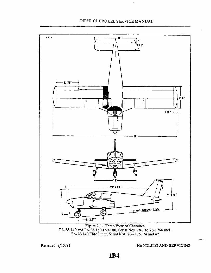
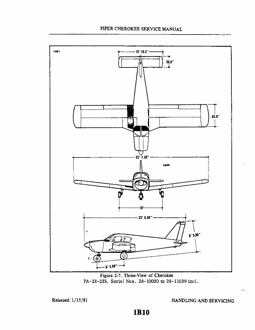
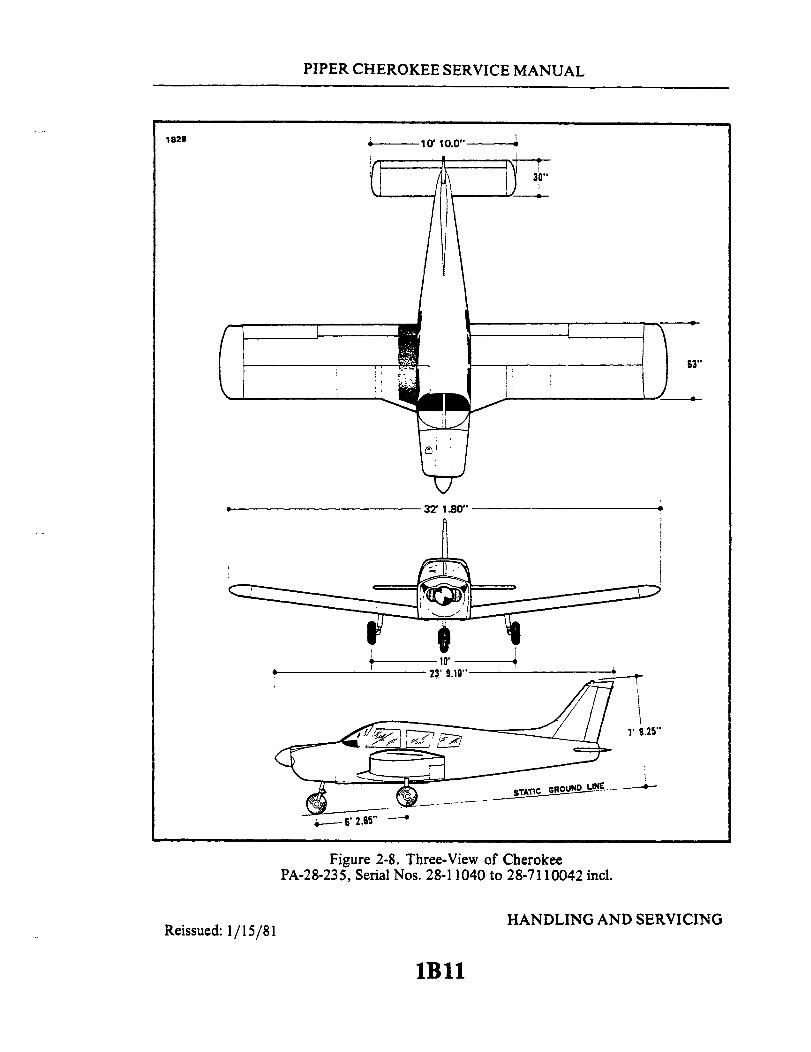
2-2. DIMENSIONS. The principal airplane dimensions are shown in Figures 2-1 through2-12 and are listed in Table II-I.
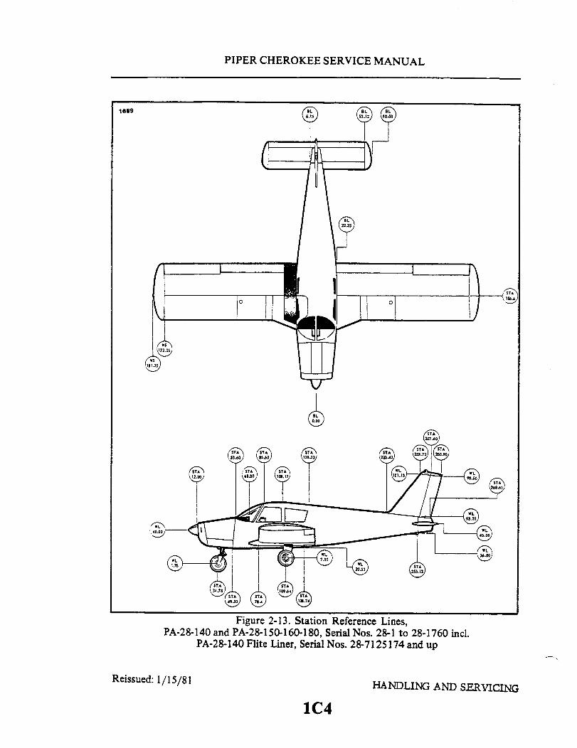
2-3. STATION REFERENCE LINES. In order to facilitate the location of vari-ous components of theairplanewhichrequiremaintenance and servicing, a methodutilizing fuselage station (Sta.), wing station or buttock line (BL), and water line(WL) designations is frequently employed in this manual. (Refer to Figures 2-13thru 2-24.) Fuselage stations, buttock lines, and water lines are reference pointsmeasured by inches in the vertical or horizontal direction from a given referenceline which indicates station locations of structural members of the airplane. Sta-tion 0 of the fuselage is 78.4 inches aheadof thewing leading edge or 49.5 inchesahead of the lower edge of the firewall; station 0 (BL) of the wing and stabilatoris the centerline of the airplane; and station 0 (WL) of the fuselage vertical stab-ilizer and rudder is 20.5 inches below the cabin floor as measured at the rearwing spar with the airplane level. The reference datum line is located 78.4 inchesahead of the wing leading edge at the intersection of the straight and tapered sec-tion.
2-4. WEIGHT AND BALANCE DATA. Whenfiguringvarious weight and balancecomputations, the empty, static and gross weight, and center of gravity of theairplane may be found in the Weight and Balance Form of the Airplane FlightManual.
HANDLING AND SERVICINGReissued: 1/15/81
1B3
PIPER CHEROKEE SERVICE MANUAL
Figure 2-1. Three-View of CherokeePA-28-140 and PA-28-150-160-180, Serial Nos. 28-1 to 28-1760 incl.
PA-28-140 Flite Liner, Serial Nos. 28-7125174 and up
Reissued: 1/15/81 HANDLING AND SERVICING
1B4
C329
63.75" -
I

PIPER CHEROKEE SERVICE MANUAL
862
*1974 MODELS AND UP
Figure 2-2. Three-View of Cherokee 140PA-28-140, Serial Nos. 28-7225001 and up
Reissued: 1/15/81 HANDLING AND SERVICING
1B5
30'

PIPER CHEROKEE SERVICE MANUAL
1694
Reissued: 1/15/81 HANDLING AND SERVICING
1B6

PIPER CHEROKEE SERVICE MANUAL
1836
Figure 2-4. Three-View of CherokeePA-28-180, Serial Nos. 28-4378 to 28-7105244 incl.
HANDLING AND SERVICINGReissued: 1/15/81
1B7

PIPER CHEROKEE SERVICE MANUAL
1732
Figure 2-5. Three-View of Cherokee PA-28-180,Serial Nos. 28-7205001 to 28-7205328 incl.
HANDLING AND SERVICINGReissued: 1/15/81 1B8

PIPER CHEROKEE SERVICE MANUAL
1724
1974 MODELS AND UP
Reissued: 1/15/81
Figure 2-6. Three-View of Cherokee PA-28-180,Serial Nos. 28-7305001 and up
HANDLING AND SERVICING
PIPER CHEROKEE SERVICE MANUAL
1691
63.0"
1840
23' 8.55"
Figure 2-7. Three-View of CherokeePA-28-235, Serial Nos. 28-10000 to 28-11039 incl.
Reissued: 1/15/81 HANDLING AND SERVICING
1BlO
PIPER CHEROKEE SERVICE MANUAL
Figure 2-8. Three-View of CherokeePA-28-235, Serial Nos. 28-11040 to 28-7110042 incl.
HANDLING AND SERVICINGReissued: 1/15/81
1Bll
182B
I

PIPER CHEROKEE SERVICE MANUAL
C330
Reissued: 1/15/81
Figure 2-9. Three-View of Cherokee PA-28-235,Serial Nos. 28-7210001 to 28-7210033 incl.
HANDLING AND SERVICING
1B12

PIPER CHEROKEE SERVICE MANUAL
Figure 2-10. Three-View of Cherokee PA-28-235,Serial Nos. 28-7310001 and up
Reissued: 1/15/81 HANDLING AND SERVICING
1B13
886
*1974 MODELS AND UP

PIPER CHEROKEE SERVICE MANUAL
1796
30'
Figure 2-11. Three-View of CherokeePA-28R-180, Serial Nos. 28-30005 to 28-7130019 incl.PA-28R-200, Serial Nos. 28-30482 to 28-7135238 incl.
Reissued: 1/15/81HANDLING AND SERVICING
1B14

PIPER CHEROKEE SERVICE MANUAL
1796
*1974 MODELS AND Up
32' 2.32"
74.00" <172.50"
Reissued: 1/15/81
Figure 2-12. Three-View of CherokeePA-28R-200, Serial Nos. 28-7235001 and up
HANDLING AND SERVICING
1B15
5' 3.0"
7° DIHEDRAL
11 .83"

PIPER CHEROKEE SERVICE MANUAL
TABLE II-I. LEADING PARTICULARS AND PRINCIPAL DIMENSIONS
PA-28-140
Avco-LycomingO-320-E2A or O-320-E3D
FAA Type CertificateRated HorsepowerRated Speed:
Full ThrottleOil, SAE NumberOil Sump CapacityFuel, Aviation Grade (Minimum Octane)Fuel, Aviation Grade (Specified Octane)Fuel, Aviation Grade (Alternate)Fuel Injector, BendixMagnetos, Scintilla:
LeftRight
Magneto TimingMagneto Point ClearanceSpark Plugs (Shielded):
Refer to the latest revision of LycomingService Instruction No. 1042.
Firing Order
Starter:Delco-Remy, 12 VoltPrestolite, 12 Volt
Alternator, Chrysler (35 AMP) 20Voltage Regulator, Chrysler
Alternator, Chrysler (60 AMP) 30Voltage Regulator, WICOOvervoltage Relay, WICO
Alternator, Prestolite (60 AMP)Voltage Regulator, WICO
Fuel Pump Drive
PROPELLER
Fixed Pitch:ManufacturerModel
Refer to Grid IC2 for foot Notes:
Revised: 10 3 83
274140 or 150
2450 RPM - 2700 RPMSee Table II-IX8 U.S. quarts80/8780/87See Note 37
Scintilla or SlickS4LN-21 or 4051S4LN-204 or 405025° BTC0.018 + 0.006
1-3-2-4
1109657MZ42042098615 or 26429962098613 or 87-87102-21 32
2642997 or 2642210X16300BX16799BALY-6422 31X16300BPlunger
SensenichM74DM
HANDLING AND SERVICING
1B16
MODEL
ENGINE
ManufacturerModel

PIPER CHEROKEE SERVICE MANUAL
TABLE II-I. LEADING PARTICULARS AND PRINCIPAL DIMENSIONS (cont)
MODEL PA-28-140
PROPELLER (cont.)
DiameterDiameter, MinimumBlade Pitch in Inches at the 75% Radius Station 9
74.0 in.72.5 in.58 thru 62 in. 2156 thru 58 in. 22
FUEL SYSTEM
Inboard (Main Fuel TanksCapacity) (each)Unusable Fuel (each)
Total CapacityTotal Unusable Fuel
Refer to Owner's Handbook, Pilot'sInformation Manual or Flight Manualfor particular airplane.
LANDING GEAR
TypeShock Strut TypeFluid Required (Struts, Hydraulic System
and Brakes)Strut Exposure (Exposure under static load):
NoseMain
Wheel TreadWheel BaseNose Wheel Travel
Wheel, NoseWheel, Main
Brake Type
Tires, NoseTires, MainTire Pressure, NoseTire Pressure, Main
ALL MODELS, CONTROL SURFACESAND CABLE TENSIONS
Refer to Grid 1C2 for foot Notes:
Revised: 10 3 83
Two25 U.S. gal.0.125 U.S. gal.50 U.S. gal.
FixedCombination Air-Oil
MIL-H-5606
3.25 + .25 in.4.50 ± .25 in.10.0 ft.6 ft. 2.65 in. 17 or 6 ft. 1.92 in. 14
REFER TO SECTION VIITABLE VII-I
Cleveland 38501, 6:00 x 6Cleveland 40-28, 6:00 x 6 14
Cleveland 40-86, 6:00 x 6 15Cleveland 30-18 14Cleveland 30-55 156:00 x 6, 4 ply rating6:00 x 6, 4 ply rating24 psi24 psi
REFER TO SECTION VTABLE V-I
HANDLING AND SERVICING
lB17

PIPER CHEROKEE SERVICE MANUAL
TABLE II-I. LEADING PARTICULARS AND PRINCIPAL DIMENSIONS (cont)
PA-28-150 PA-28-160
Avco-LycomingO-320-A2B or O-320-E2A
FAA Type CertificateRated Horsepower
Full ThrottleOil, SAE NumberOil Sump CapacityFuel, Aviation Grade (Minimum Octane)Fuel, Aviation Grade (Specified Octane)Fuel, Aviation Grade (Alternate)Fuel Injector, BendixMagnetos, Scintilla:
LeftRight
Magneto TimingMagneto Point ClearanceSpark Plugs (Shielded):
Refer to the latest revision of LycomingService Instruction No. 1042.
Firing Order
Starter:Delco-Remy, 12 VoltPrestolite, 12 Volt
Generator, Delco-Remy (35 AMP)Voltage Regulator, Delco-Remy
Alternator, Chrysler (35 AMP) 20Voltage Regulator, Chrysler
Alternator, Chrysler (60 AMP) 30Voltage Regulator, WICOOvervoltage Relay, WICO
Fuel Pump Drive
2741502700 RPMSee Table II-IX8 U.S. quarts80/8780/87See Note 37
S4LN-21S4LN-20425° BTC0.018 ± 0.006 in.
1-3-2-4
1109657MZ4204110190011187042098615 or 26429962098613 or 87-87102-21 32
2642997 or 2642210X16300BX16799B 5Plunger
Avco-LycomingO-320-B2B or O-320-D2A
2741602700 RPMSee Table II-IX8 U.S. quarts90/9690/96
S4LN-21S4LN-2025° BTC0.018 +.006 in.
1-3-2-4
1109657 or 1109511MZ4206110190011187042098615 or 26429962098613 or 87-87102-21 32
2642997 or 2642210X16300BX16799B 5Plunger
PROPELLER
Fixed Pitch:ManufacturerModel
SensenichM74DM 7 or M74DMS 8
SensenichM74DM 7 or M74DMS 8
I Refer to Grid 1C2 for foot Notes:
Revised: 10 3 83 HANDLING AND SERVICING
lB18
MODEL
ENGINE
ManufacturerModel

PIPER CHEROKEE SERVICE MANUAL
TABLE II-I. LEADING PARTICULARS AND PRINCIPAL DIMENSIONS (cont)
PA-28-150 PA-28-160
PROPELLER (cont.)
DiameterDiameter, MinimumBlade Angle 9
74.0 in.72.5 in.58 in.
74.0 in.72.5 in.60 in. - 47 in. 27
FUEL SYSTEM
Inboard (Main Fuel TanksCapacity) (each)Unusable Fuel (each)
Total CapacityTotal Unusable Fuel
Refer to Owner's Handbook, Pilot'sInformation Manual or Flight Manualfor particular airplane.
Two25 U.S. gal.0.125 U.S. gal.50 U.S. gal.
Two25 U.S. gal.0.125 U.S. gal.50 U.S. gal.
LANDING GEAR
TypeShock Strut TypeFluid Required (Struts, Hydraulic System
and Brakes)Strut Exposure (Exposure under static
load):NoseMain
Wheel TreadWheel BaseNose Wheel Travel
Wheel, NoseWheel, Main
Brake Type
Tires, NoseTires, MainTire Pressure, NoseTire Pressure, Main
FixedCombination Air-Oil
MIL-H-5606
3.25 ±.25 in.4.50 + .25 in.10.0 ft.6 ft. 2.65 in.REFER TO SECTION VII
TABLE VII-ICleveland 38501, 6:00 x 6Cleveland 40-28, 6:00 x 6 7Cleveland 40-86, 6:00 x 6 8Cleveland 30-18 7Cleveland 30-55 86:00 x 6, 4 ply rating6:00 x 6, 4 ply rating24 psi24 psi
FixedCombination Air-Oil
MIL-H-5606
3.25 + .25 in.4.50 + .25 in.10.0 ft.6 ft. 2.65 in.REFER TO SECTION VII
TABLE VII-ICleveland 38501, 6:00 x 6Cleveland 40-28, 6:00 x 6 7Cleveland 40-86, 6:00 x 6 8Cleveland 30-18 7Cleveland 30-55 86:00 x 6, 4 ply rating6:00 x 6, 4 ply rating24 psi24 psi
ALL MODELS, CONTROLAND CABLE TENSIONS
SURFACESREFER TO SECTION V
TABLE V-IREFER TO SECTION V
TABLE V-I
Refer to Grid 1C2 for foot Notes:Revised: 10 3 83 HANDLING AND SERVICING
lB19
MODEL

PIPER CHEROKEE SERVICE MANUAL
TABLE II-I. LEADING PARTICULARS AND PRINCIPAL DIMENSIONS (cont)
PA-28-180 38 PA-28-235 39
ManufacturerModel
FAA Type CertificateRated HorsepowerRated Speed:
Full ThrottleOil, SAE NumberOil Sump CapacityFuel, Aviation Grade (Minimum Octane)Fuel, Aviation Grade (Specified Octane)Fuel, Aviation Grade (Alternate)Fuel Injector, BendixMagnetos, Scintilla:
LeftRight
Magneto TimingMagneto Point ClearanceSpark Plugs (Shielded):
Refer to the latest revision of LycomingService Instruction No. 1042.
Firing Order
Starter:Delco-Remy, 12 VoltPrestolite, 12 Volt
Alternator, Chrysler (35 AMP) 20Voltage Regulator, Chrysler
Alternator, Chrysler (60 AMP) 30
Voltage Regulator, WICOOvervoltage Relay, WICO
Alternator, Prestolite (60 AMP)Voltage Regulator, WICO
Fuel Pump Drive
Avco-LycomingO-360-A3A or O-360-A4A
286180
180 @ 2700 RPMSee Table II-IX8 U.S. quarts90/9690/96
S4LN-21S4LN-20 35 or S4LN-204 3625° BTC0.018 + 0.006 in.
1-3-2-4
1109657 or 1109511MZ42062098615 or 26429962098613 or 87-87102-21 32
2642997 or 2642210X16300BX16799B 5ALY-6422 31X16300BPlunger
Avco-LycomingO-540-B2B5, 0-540-B1B5
or O-540-B4B5295235
235 @ 2575 RPMSee Table II-IX12 U.S. quarts80/8780/87See Note 37
S6LN-21S6LN-20 2 or S6LN-204 325° BTC0.018 ± 0.006 in.
1-4-5-2-3-6
1109657 or 1109511MZ42062098615 or 26429962098613 or 87-87102-21 32
2642997 or 2642210X16300BX16799B 6
Plunger
I Refer to Grid IC2 for foot Notes:
Revised: 10 3 83 HANDLING AND SERVICING
1B20
MODEL
ENGINE
PIPER CHEROKEE SERVICE MANUAL
TABLE II-I. LEADING PARTICULARS AND PRINCIPAL DIMENSIONS (cont)
MODEL PA-28-180 PA-28-235
ENGINE (cont)
PROPELLER
Fixed Pitch:ManufacturerModel
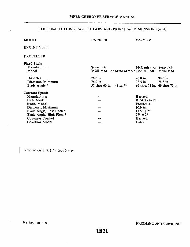
Sensenich McCauley or SensenichM76EMM 7 or M76EMMS 8 IP235PFA80 M80BMM
DiameterDiameter, MinimumBlade Angle 9
76.0 in.76.0 in.57 thru 60 in. - 48 in. 28
80.0 in.78.5 in.66 thru 71 in.
80.0 in.78.5 in.69 thru 71 in.
Constant Speed:ManufacturerHub, ModelBlade, ModelDiameter, MinimumBlade Angle, Low Pitch 9Blade Angle, High Pitch 9Governor ControlGovernor Model
HartzellHC-C2YK-1BFF8468A-480.0 in.13.5° + 2°
27° + 2°
HartzellF-4-3
Refer to Grid 1C2 for foot Notes:
Revised: 10 3 83 HANDLING AND SERVICING
1B21
I
PIPER CHEROKEE SERVICE MANUAL
TABLE II-I. LEADING PARTICULARS AND PRINCIPAL DIMENSIONS (cont)
MODEL PA-28-180 PA-28-235
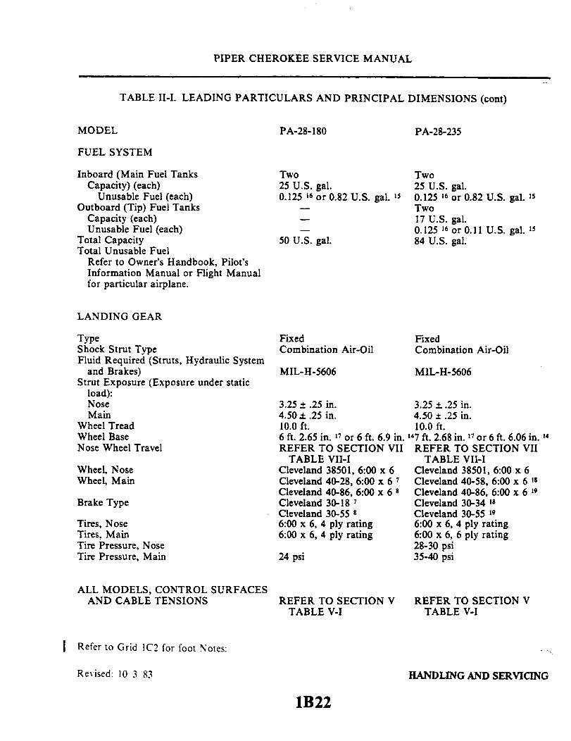
FUEL SYSTEM
Inboard (Main Fuel TanksCapacity) (each)
Unusable Fuel (each)Outboard (Tip) Fuel Tanks
Capacity (each)Unusable Fuel (each)
Total CapacityTotal Unusable Fuel
Refer to Owner's Handbook, Pilot'sInformation Manual or Flight Manualfor particular airplane.
Two25 U.S. gal.0.125 16 or 0.82 U.S. gal. 15
50 U.S. gal.
Two25 U.S. gal.0.125 16 or 0.82 U.S. gal. 15Two17 U.S. gal.0.125 16 or 0.11 U.S. gal. 15
84 U.S. gal.
LANDING GEAR
Type FixedShock Strut Type Combination Air-OilFluid Required (Struts, Hydraulic System
and Brakes) MIL-H-5606Strut Exposure (Exposure under static
load):Nose 3.25 + .25 in.Main 4.50 .25 in.
Wheel Tread 10.0 ft.Wheel Base 6 ft. 2.65 in. 17 or 6 ft. 6.9 in.Nose Wheel Travel REFER TO SECTION VII
TABLE VII-IWheel, Nose Cleveland 38501, 6:00 x 6Wheel, Main Cleveland 40-28, 6:00 x 6 7
Cleveland 40-86, 6:00 x 6 8Brake Type Cleveland 30-18 '
Cleveland 30-55 8Tires, Nose 6:00 x 6, 4 ply ratingTires, Main 6:00 x 6, 4 ply ratingTire Pressure, NoseTire Pressure, Main 24 psi
ALL MODELS, CONTROL SURFACESAND CABLE TENSIONS REFER TO SECTION V
TABLE V-I
FixedCombination Air-Oil
MIL-H-5606
3.25 ±..25 in.4.50 ± .25 in.10.0 ft.
147 ft. 2.68 in. 17 or 6 ft. 6.06 in. 14REFER TO SECTION VII
TABLE VII-ICleveland 38501, 6:00 x 6Cleveland 40-58, 6:00 x 6 18Cleveland 40-86, 6:00 x 6 19Cleveland 30-34 18Cleveland 30-55 96:00 x 6, 4 ply rating6:00 x 6, 6 ply rating28-30 psi35-40 psi
REFER TO SECTION VTABLE V-I
I Refer to Grid IC2 for foot Notes:
Revised: 10 3 83 HANDLING AND SERVICING
1B22
PIPER CHEROKEE SERVICE MANUAL
TABLE II-I. LEADING PARTICULARS AND PRINCIPAL DIMENSIONS (cont)
PA-28R- 180 PA-28R-200
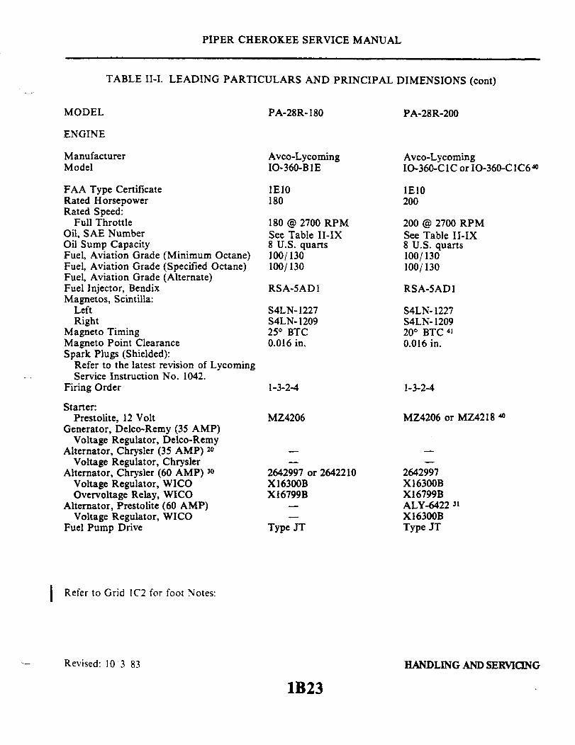
ManufacturerModel
FAA Type CertificateRated HorsepowerRated Speed:
Full ThrottleOil, SAE NumberOil Sump CapacityFuel, Aviation Grade (Minimum Octane)Fuel, Aviation Grade (Specified Octane)Fuel, Aviation Grade (Alternate)Fuel Injector, BendixMagnetos, Scintilla:
LeftRight
Magneto TimingMagneto Point ClearanceSpark Plugs (Shielded):
Refer to the latest revision of LycomingService Instruction No. 1042.
Firing Order
Starter:Prestolite, 12 Volt
Generator, Delco-Remy (35 AMP)Voltage Regulator, Delco-Remy
Alternator, Chrysler (35 AMP) 20Voltage Regulator, Chrysler
Alternator, Chrysler (60 AMP) 30Voltage Regulator, WICOOvervoltage Relay, WICO
Alternator, Prestolite (60 AMP)Voltage Regulator, WICO
Fuel Pump Drive
Avco-LycomingIO-360-B 1 E
1E10180
180 @ 2700 RPMSee Table II-IX8 U.S. quarts100/130100/130
RSA-5AD1
S4LN- 1227S4LN- 120925° BTC0.016 in.
1-3-2-4
MZ4206
2642997 or 2642210X16300BX16799B
Type JT
Avco-LycomingIO-360-C1C or IO-360-C1C6 4
1E10200
200 @ 2700 RPMSee Table II-IX8 U.S. quarts100/130100/130
RSA-5ADI
S4LN- 1227S4LN- 120920° BTC 410.016 in.
1-3-2-4
MZ4206 or MZ4218 40
2642997X16300BX16799BALY-6422 31
X16300BType JT
Refer to Grid 1C2 for foot Notes:
Revised: 103 83 HANDLING AND SERVICING
1B23
MODEL
ENGINE

PIPER CHEROKEE SERVICE MANUAL
TABLE II-I. LEADING PARTICULARS AND PRINCIPAL DIMENSIONS (cont)
PA-28R-180 PA-28R-200
PROPELLER
Constant Speed:Manufacturer
Hub, ModelBlade, ModelDiameterDiameter, Minimum
I Blade Angle, Low Pitch 9Blade Angle, High Pitch 9Governor ControlGovernor Model
HartzellHC-C2YK-IBFF7666A-076.0 in.74.014.3030°
HartzellF-2-2F-2-7
Hartzell orHC-C2YK-1BF7666A-274.072.514° ± 0.2°
29° + 2°
HartzellF-2-7
McCauley 40B2D34C21390DHA-1674.073.013.0° + 0.2°
29.8° + 0.5°
HartzellF-2-7 ( )
Refer to Grid 1C2 for foot Notes:
Revised: 4 23 84 HANDLING AND SERVICING
1B24
MODEL

PIPER CHEROKEE SERVICE MANUAL
TABLE II-I. LEADING PARTICULARS AND PRINCIPAL DIMENSIONS (cont)
PA-28R-180 PA-28R-200
FUEL SYSTEM
Inboard (Main Fuel TanksCapacity) (each)Unusable Fuel (each)
Total CapacityTotal Unusable Fuel
Refer to Owner's Handbook, Pilot'sInformation Manual or Flight Manualfor particular airplane.
Two25 U.S. gal.0.125 U.S. gal.50 U.S. gal.
Two25 U.S. gal.0.82 U.S. gal.50 U.S. gal.
LANDING GEAR
TypeShock Strut TypeFluid Required (Struts, Hydraulic System
and Brakes)Strut Exposure (Exposure under static
load):NoseMain
Wheel TreadWheel BaseNose Wheel Travel
Wheel, NoseWheel, MainBrake TypeTires, NoseTires, MainTire Pressure, NoseTire Pressure, Main
ALL MODELS, CONTROL SURFACESAND CABLE TENSIONS
Hydraulically RetractableCombination Air-Oil
MIL-H-5606
2.75 ± .25 in.2.0 ± .25 in.10 ft. 5.72 in.7 ft. 5.382 in.REFER TO SECTION VII
TABLE VII-ICleveland 40-77, 5:00 x 5Cleveland 40-84, 6:00 x 6Cleveland 30-415:00 x 5, 4 ply rating6:00 x 6, 4 ply rating30 psi27 psi
REFER TO SECTION VTABLE V-I
Hydraulically RetractableCombination Air-Oil
MIL-H-5606
2.75 + .25 in.2.0 .25 in.10 ft. 5.72 in.7 ft. 5.4 in. 17 or 7 ft. 10.6 in. 14REFER TO SECTION VII
TABLE VII-ICleveland 40-77, 5:00 x 5Cleveland 40-84, 6:00 x 6Cleveland 30-415:00 x 5, 4 ply rating6:00 x 6, 4 ply rating30 psi27 psi
REFER TO SECTION VTABLE V-I
Refer to Grid 1C2 for foot Notes:
HANDLING AND SERVICINGRevised: 10 3 83
1C1
MODEL
I

PIPER CHEROKEE SERVICE MANUAL
TABLE II-II. CONSUMABLE MATERIALS
Specification or Brand Name Manufacturer
Rain Repellant
Teflon Tape
Teflon Tape
Teflon Tape
Adhesive.Door Snubber
REPCONFSCM 50159
.003 x .50 wide -1
.003 x .50 wide -l
.003 x .25 wide -2
3MEC 1300. CScotch Grip 2210
UNELKO Corporation727 E. 110th StreetChicago Illinois 60628
Minesota Mining & Manufacturing Co.3M CenterSt. Paul, Minesota 55101
Shamban W.S. & Company713 Mitchell RoadNewbury Park, California 91320
Johnson & Johnson Inc.Permacel Division501 George StreetNew Brunswick. N.J. 08903
3-M Co.Adhesive Coatings and Sealers Div.3-M CenterSt. Paul, Minnesota 55101
PROCO Adhesive 6205-1
Reissued: 1/15/81
Protective Coatings, Inc.807 N. Fremont Ave.Tampa. Fla.
HANDLING AND SERVICING
1C3
Material
PIPER CHEROKEE SERVICE MANUAL
1689
Figure 2-13. Station Reference Lines,PA-28-140 and PA-28-150-160-180, Serial Nos. 28-1 to 28-1760 incl.
PA-28-140 Flite Liner, Serial Nos. 28-7125174 and up
Reissued: 1/15/81 HANDLING AND SERVICING
1C4
PIPER CHEROKEE SERVICE MANUAL
1761
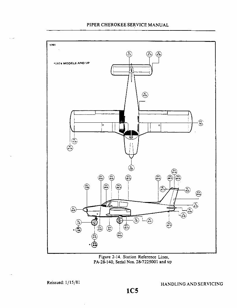
*1974 MODELS AND UP
Figure 2-14. Station Reference Lines,PA-28-140, Serial Nos. 28-7225001 and up
Reissued: 1/15/81 HANDLING AND SERVICING
1C5

PIPER CHEROKEE SERVICE MANUAL
1798
Figure 2-15. Station Reference Lines,PA-28-150-160-180, Serial Nos. 28-1761 to 28-4377 incl.
1C6
Reissued: 1/15/81 HANDLING AND SERVICING

PIPER CHEROKEE SERVICE MANUAL
Figure 2-16. Station Reference Lines,PA-28-180, Serial Nos. 28-4378 to 28-7105244 incl.
Reissued: 1/15/81 HANDLING AND SERVICING
1C7
C331
0
PIPER CHEROKEE SERVICE MANUAL
1710
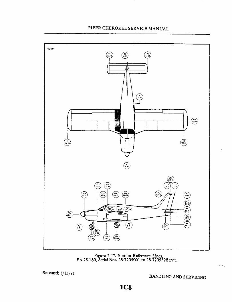
Figure 2-17. Station Reference Lines,PA-28-180, Serial Nos. 28-7205001 to 28-7205328 incl.
Reissued: 1/15/81 HANDLING AND SERVICING
1C8


PIPER CHEROKEE SERVICE MANUAL
1754
Figure 2-19. Station Reference Lines,PA-28-235, Serial Nos. 28-10000 to 28-11039 incl.
Reissued: 1/15/81 HANDLING AND SERVICING
1C10

PIPER CHEROKEE SERVICE MANUAL
1906
Figure 2-20. Station Reference Lines,PA-28-235, Serial Nos. 28-11040 to 28-7110042 incl.
Reissued: 1/15/81 HANDLING AND SERVICING
1C11
PIPER CHEROKEE SERVICE MANUAL
1908
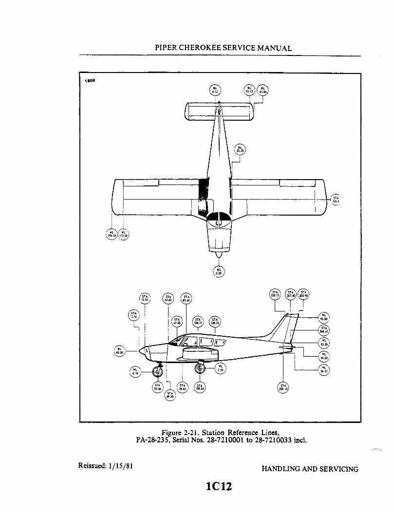
Figure 2-21. Station Reference Lines,PA-28-235, Serial Nos. 28-7210001 to 28-7210033 incl.
Reissued: 1/15/81 HANDLING AND SERVICING
1C12

PIPER CHEROKEE SERVICE MANUAL
1731
Figure 2-23. Station Reference Lines,PA-28R-180, Serial Nos. 28-30005 to 28-7130019 incl.PA-28R-200, Serial Nos. 28-30482 to 28-7135238 incl.
Reissued: 1/15/81 HANDLING AND SERVICING
1C14

PIPER CHEROKEE SERVICE MANUAL
Reissued: 1/15/81
Figure 2-24. Station Reference Lines,PA-28R-200, Serial Nos. 28-7235001 and up
HANDLING AND SERVICING
1C15
1760
PIPER CHEROKEE SERVICE MANUAL
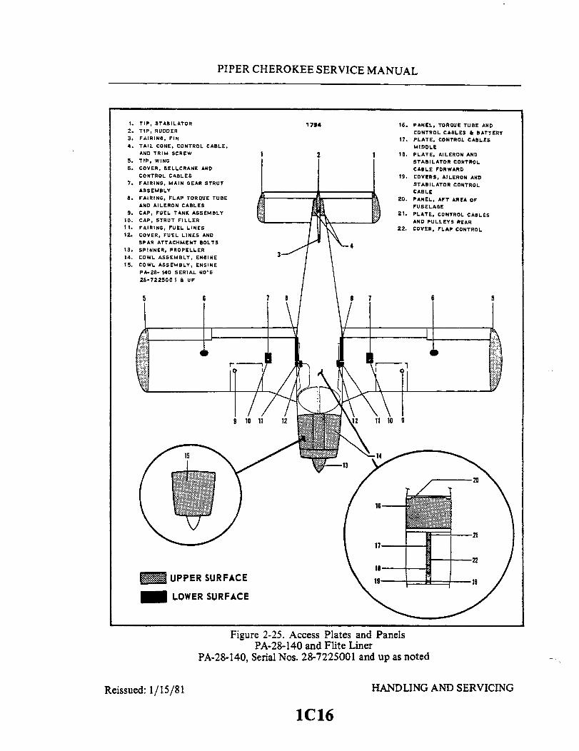
1. TIP, STABILATOR2. TIP, RUDDER3. FAIRING, FIN4. TAIL CONE, CONTROL CABLE,
AND TRIM SCREW5. TIP, WING6. COVER, BELLCRANK AND
CONTROL CABLES7. FAIRING, MAIN GEAR STRUT
ASSEMBLY8. FAIRING, FLAP TORQUE TUBE
AND AILERON CABLES
9. CAP, FUEL TANK ASSEMBLY10. CAP, STRUT FILLER11. FAIRING, FUEL LINES12. COVER, FUEL LINES AND
SPAR ATTACHMENT BOLTS13. SPINNER, PROPELLER14. COWL ASSEMBLY, ENGINE
15. COWL ASSEMBLY, ENGINE
PA-28- 140 SERIAL NO'S
26-7225001 & UP
1794
2
16. PANEL, TORQUE TUBE ANDCONTROL CABLES & BATTERY
17. PLATE, CONTROL CABLESMIDDLE
18. PLATE, AILERON ANDSTABILATOR CONTROLCABLE FORWARD
19. COVERS, AILERON ANDSTABILATOR CONTROLCABLE
20. PANEL, AFT AREA OFFUSELAGE
21. PLATE, CONTROL CABLESAND PULLEYS REAR
22. COVER, FLAP CONTROL
Figure 2-25. Access Plates and PanelsPA-28-140 and Flite Liner
PA-28-140, Serial Nos. 28-7225001 and up as noted
1C16
Reissued: 1/15/81 HANDLING AND SERVICING
PIPER CHEROKEE SERVICE MANUAL
C332
UPPER SURFACE
LOWER SURFACE
4
f
13-
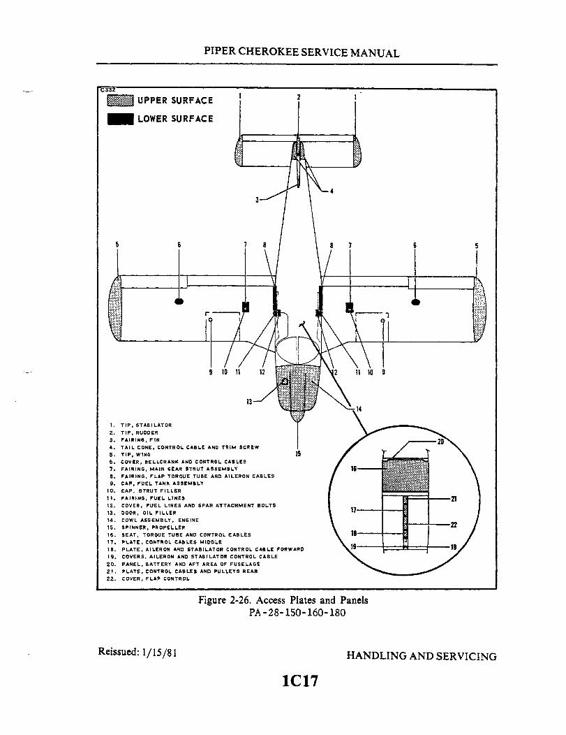
1. TIP, STABILATOR
2. TIP, RUDDER3. FAIRING, FIN4. TAIL CONE, CONTROL CABLE AND TRIM SCREW5. TIP, WING 156. COVER, BELLCRANK AND CONTROL CABLES7. FAIRING, MAIN GEAR STRUT ASSEMBLY8. FAIRING, FLAP TORQUE TUBE AND AILERON CABLES9. CAP, FUEL TANK ASSEMBLY
10. CAP, STRUT FILLER11. FAIRING, FUEL LINES12. COVER, FUEL LINES AND SPAR ATTACHMENT BOLTS13. DOOR, OIL FILLER14. COWL ASSEMBLY, ENGINE15. SPINNER, PROPELLER16. SEAT, TOROUE TUBE AND CONTROL CABLES17. PLATE, CONTROL CABLES MIDDLE
18. PLATE, AILERON AND STABILATOR CONTROL CABLE FORWARD19. COVERS, AILERON AND STABILATOR CONTROL CABLE
20. PANEL, BATTERY AND AFT AREA OF FUSELAGE21. PLATE, CONTROL CABLES AND PULLEYS REAR22. COVER, FLAP CONTROL
16
2117
18
Figure 2-26. Access Plates and PanelsPA-28-150-160-180
Reissued: 1/15/81 HANDLING AND SERVICING
1C17
5
1
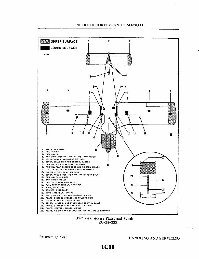
PIPER CHEROKEE SERVICE MANUAL
UPPER SURFACE 2
LOWER SURFACE
1793
4
6
14
1. TIP, STABILATOR 162. TIP, RUDDER3. FAIRING, FIN4. TAIL CONE, CONTROL CABLES AND TRIM SCREW5. COVER, TANK ATTACHMENT FITTINGS6. COVER, BELLCRANK AND CONTROL CABLES7. FAIRING, MAIN GEAR STRUT ASSEMBLY 178. FAIRING, FLAP TORQUE TUBE AND AILERON CABLES9. FUEL SELECTOR AND DRAIN VALVE ASSEMBLY
10. ELECTRIC FUEL PUMP ASSEMBLY11. COVER, FUEL LINES AND SPAR ATTACHMENT BOLTS12. FAIRING, FUEL LINES13. CAP, STRUT FILLER14. CAP, FUEL TANK ASSEMBLY15. FUEL TANK ASSEMBLY, WING TIP16. DOOR, OIL FILLER17. SPINNER, PROPELLER18. COWL ASSEMBLY, ENGINE19. SEAT, TORQUE TUBE AND CONTROL CABLES20. PLATE, CONTROL CABLES AND PULLEYS REAR21. COVER, FLAP AND TRIM CONTROL22. COVERS, AILERON AND STABILATOR CONTROL CABLE23. PANEL, BATTERY & AFT AREA OF FUSELAGE24. PLATE, CONTROL CABLES MIDDLE25. PLATE, AILERON AND STABILATOR CONTROL CABLE FORWARD
Figure 2-27. Access Plates and PanelsPA-28-235
Reissued: 1/15/81 HANDLING AND SERVICING
1C18
6
1 1

PIPER CHEROKEE SERVICE MANUAL
UPPER SURFACE
LOWER SURFACE
1752
3-
5 6 7 8
4
8 7 56
10
1. TIP, STABILATOR2. TIP, RUDDER3. FAIRING, FIN4. TAIL CONE, CONTROL CABLES & TRIM SCREW 155. TIP, WING6. COVER, BELLCRANK & CONTROL CABLES7. CAP, FUEL TANK ASSEMBLY8. COVER, GEAR ATTACHMENT FITTING9. FAIRING, FLAP TORQUE TUBE AND AILERON CABLES
10. DOOR, MAIN GEAR11. FAIRING, FUEL LINES12. COVER, FUEL LINES AND SPAR ATTACHMENT BOLTS13. DOOR, OIL FILLER14. COWL ASSEMBLY, ENGINE15. SPINNER, PROPELLER16. PLATE, AILERON AND STABILATOR CONTROL CABLE FORWARD17. PLATE, CONTROL CABLES MIDDLE18. SEAT, TORQUE TUBE AND CONTROL CABLES19. COVER, FLAP AND TRIM CONTROL20. PLATE, CONTROL CABLES AND PULLEYS REAR21. COVERS, AILERON AND STABILATOR CONTROL CABLE22. PANEL, HYDRAULIC PUMP, BATTERY & AFT AREA OF FUSELAGE
Figure 2-28. Access Plates and PanelsPA-28R
Reissued: 1/15/81 HANDLING AND SERVICING
1C19
PIPER CHEROKEE SERVICE MANUAL
2-5. SERIAL NUMBER PLATE. The serial number plate is located on the left side of thefuselage near the leading edge of the stabilator. The serial number should always be usedwhen referring to the airplane on service or warranty matters.
2-6. ACCESS AND INSPECTION PROVISIONS. The access and inspection provisionsfor the airplane are shown in Figures 2-25 thru 2-28. The component to be serviced or in-spected through each opening is identified in the illustration. All access plates and panels aresecured by either metal fasteners or screws.
CAUTION
Before entering the aft section of the fuselage, be sure theairplane is supported at the tail skid.
To enter the aft section of the fuselage, open the baggage compartment door and removethe access panel.
2-7. TOOLS AND TEST EQUIPMENT. Because of the simplicity and easy accessibilityof components, few special tools outside normal shop tools will be required. Tools that arerequired are listed in the back of the PA-28 Parts Catalog and may be fabricated to dimensionsgiven in the back of the section that pertains to a particular component.
2-8. TORQUE REQUIREMENTS. The torque values given in Table II-III are derivedfrom oil-free, cadmium-plated threads and, unless otherwise noted, are recommended for allair-frame installation procedures where torquing is required. Engine torque values are givenin the latest revision of Avco-Lycoming Service Bulletin No. 268, and propeller torque valuesare given in Section VIII or VIIIA.
Reissued: 1/15/81 HANDLING AND SERVICING
IC20

PIPER CHEROKEE SERVICE MANUAL
2-8a. TORQUE WRENCHES.
Torque wrenches should be checked daily and calibrated by means of weights and a measured lever arm tomake sure that inaccuracies are not present. Checking one torque wrench against another is not sufficient andis not recommended. Some wrenches are quite sensitive as to the way they are supported during a tighteningoperation. Any instructions furnished by the manufacturer must be followed explicitly.
When it is necessary to use a special extension or adapter wrench together with a torque wrench, a simplemathematical equation must be worked out to arrive at the correct torque reading. Following is the formula tobe used: (Refer to Figure 2-30.)
T = Torque desired at the part.A = Basic lever length from center of wrench shank to center of handle or stamped on wrench or listed for
that model wrench.B = Length of adapter extension, center of bolt to center of shank.C = Scale reading needed to obtain desired torque (T).
The formula: C= A xTA + BA+B
EXAMPLE
A bolt requires 30 foot-pounds and a 3 inch adapter (one-quarter ofa foot or .25) is needed to get at it. You want to know what scalereading it will take on a one-foot lever arm wrench to obtain the 30foot-pounds at.the bolt.
C = 30 or C 30 = 24 ft. -lbs.I + .25 .1.25
Remember, the 3 inch adapter must be projecting 3 inches straightalong the wrench axis. In general, avoid all complex assemblages oradapters and extensions of flex joints.
A933
A
T
Figure 2-30. Torque Wrench Formula
Revised: 8/3/811C21
HANDLING AND SERVICING

PIPER CHEROKEE SERVICE MANUAL
TABLE II-III RECOMMENDED NUT TORQUES (Inch-Pounds)
TORQUES: The importance of correct application can not beoveremphasized. Undertorque can result in unnecessary wear of nutsand bolts as well as the parts they are holding together. Wheninsufficient pressures are applied, uneven loads will be transmittedthroughout the assembly which may result in excessive wear orpremature failure due to fatigue. Overtorque can be equally damagingbecause of failure of a bolt or nut from overstressing the threaded areas.There are a few simple, but very important, procedures that should befollowed to assure that the correct torque is applied:
1. Calibrate the torque wrench periodically to assure accuracy;and recheck frequently.
2. Ascertain that the bolt and nut threads are clean and dry(unless otherwise specified by the manufacturer).
3. Run nut down to near contact with the washer or bearingsurface and check "friction drag torque" required to turn thenut.
4. Add the friction drag torque to the desired torquerecommended by the manufacturer, or obtain desired torqueas shown in Chart 9103. This is referred to as final torquewhich should register on the indicator or the setting for asnapover type wrench.
NOTE
For more details on torquing, refer to FAA ManualAC 43.13-1.
BOLTSSteel Tension
AN 3 thru AN 20AN 42 thru AN 49AN 73thru AN 81AN 173 thru AN 186MS 20033 thru MS 20046MS 20073MS 20074AN 509 NK9MS 24694AN 525 NK525MS 27039
NUTS
Steel Tension
AN 310AN 315AN 363AN 365NAS 1021MS 17825MS 21045MS 20365MS 20500NAS 679
Steel Shear
AN 320AN 364NAS 1022MS 17826MS 20364
COARSE THREAD SERIES
FRICTION DRAG TORQUESCOARSE AND FINE
Nut-bolt Torque Limits Torque Limitssize in-lbs in-lbs
Min. Max. Min.
FRICTION DRAG TORQUE (IN.-LBS.)
.
8 -3210 -24
1/4-205/16-18
3/8-167/16-14
1/2-139/16-125/8-113/4-107/8- 9
1 -81./8-81-1/4-8
Revised: 10/3/83
1C22HANDLING AND SERVICING
BOLT SIZE
10
1/4
5/16
18
30
60
80o 3/8
7/16
12204080
160235400500700
1.1502,2003.7005.5006.500
15255090
185255480700900
1.6003.0005.0006.5008.000100
Max
9153055
110155290420540950
1,8003.0004.0005.000
712254895
140240300420700
1.3002.2003.3004,000

PIPER CHEROKEE SERVICE MANUAL
TABLE II-111. RECOMMENDED NUT TORQUES (Inch-Pounds) (cont.)
FINE THREAD SERIES
BOLTSSteel Tension
BOLTSSteel Tension
BOLTSAluminum
AN 3 thru AN 20AN 42 thru AN 49AN 73 thru AN 81AN 173 thru AN 186MS 20033 thru MS 20046MS 20073MS 20074AN 509 NK9MS 24694AN 525 NK525MS 27039
NUTS
MS 20004 thru MS 20024NAS 144 thru NAS 158NAS 333 thru NAS 340NAS 583 thru NAS 590NAS 624 thru NAS 644NAS 1303 thru NAS 1320NAS 172NAS 174NAS 517 Steel shear bolt
NAS 464
NUTS
AN 3DD thru AN 20DDAN 173DD thru AN 186DDAN 509DDAN 525DMS 27039DMS 2469400
NUTS
Steel Tension Steel Sheer
AN 310AN 315AN 363AN 365NAS 1021MS 17825MS 21045MS 20365MS 20600NAS 679
AN 320AN 364NAS 1022MS 17826MS 20364
Steel Tension Steel Shear Alum. Tension
AN 310AN 315AN 363AN 365MS 17825MS 20365MS 21045NAS 1021NAS 679NAS 1291
AN 320AN 364NAS 1022MS 17826MS 20364
AN 365DAN 310DNAS 1021d
Nut-bolt Torque Limits Torque Limitssize in-lbs in-lbs
-3610 -32
1/4-285/16-243/8-24
7/16-201/2-20
9/16-185/8-183/4-167/8-14
1 -141-1/8-121-1/4-12
Torque Limits Torque Limitsin-lbs in-lbs
Min. Max. Min. Max. Min. Max. Min. Max.
12 15 7 920 25 12 15 25 30 15 2050 70 30 40 80 100 50 60
100 140 60 85 120 145 70 90160 190 95 110 200 250 120 150450 500 270 300 520 630 300 400480 690 290 410 770 950 450 550800 1.000 480 600 1,100 1,300 650 800
1.100 1.300 660 780 1,250 1,550 750 9502.300 2,500 1.300 1,500 2,650 3,200 1,600 1,9002,500 3,000 1.500 1.800 3,550 4,350 2,100 2,6903,700 4,500 2,200 3.300 4,500 5,500 2,700 3,3005,000 7,000 3,000 4,200 6,000 7,300 3,600 4,4009,000 11.000 5,400 6,600 11.000 13,400 6,600 8,000
Revised: 10/3/831C23
Torque Limits Torque Limitsin-lbs in-lbs
Min. Max. Min. Max.
5 10 3 610 15 5 1030 45 15 3040 65 25 4075 110 45 70
180 280 110 170280 410 160 260380 580 230 360550 670 270 420950 1,250 560 880
1,250 1,900 750 1,2001,600 2,400 ,950 1,5002,100 3,200 1.250 2,0003,900 5,600 2,300 3,650
HANDLING AND SERVICING
Alum. Shear
AN 320DAN 364DNAS 1022d

PIPER CHEROKEE SERVICE MANUAL
2-9. WALKWAY, HANDHOLD AND STEP. The walkway is made of a non-skid com-pound applied to paper and bonded to the wing surface. A fixed handhold is located on theright side of the fuselage near the rear window. A step is available as optional equipment andis installed just aft of the trailing edge of the right flap.
TABLE II-V. CONVERSION TABLES
1. These charts contain the various conversion data that may be useful when figuring capacities. lengths.temperatures. and various weights and measures from the English system values to the metric systemvalues or back again.
2. The English system is in use by England and the United States. All other countries use the metricsystem.
3. Procedure for Converting Inches to Millimeters. (Refer to Table II-V.)
A. Example: Convert 1.5 inches to millimeters.
(1) Read down inches column to 1. inches.(2) Read across top inch column to 0.5.(3) Read down and across to find millimeters (1.5 inches is 38.10 millimeters).
4. Procedure for Converting Fahrenheit (°F) and Celsius (°C) (Centigrade) Temperature. (Refe:Table II-V.)
A. Read number in middle column. if in degrees Celsius (°C). read Fahrenheit equivalent inright-hand column. If in degrees Fahrenheit (°F). read Celsius equivalent in left-hand column.
(1) 70F = 21.1°C.(2) 30°C = 86.0°F.
HANDLING AND SERVICING1C24Reissued: 1/15/81
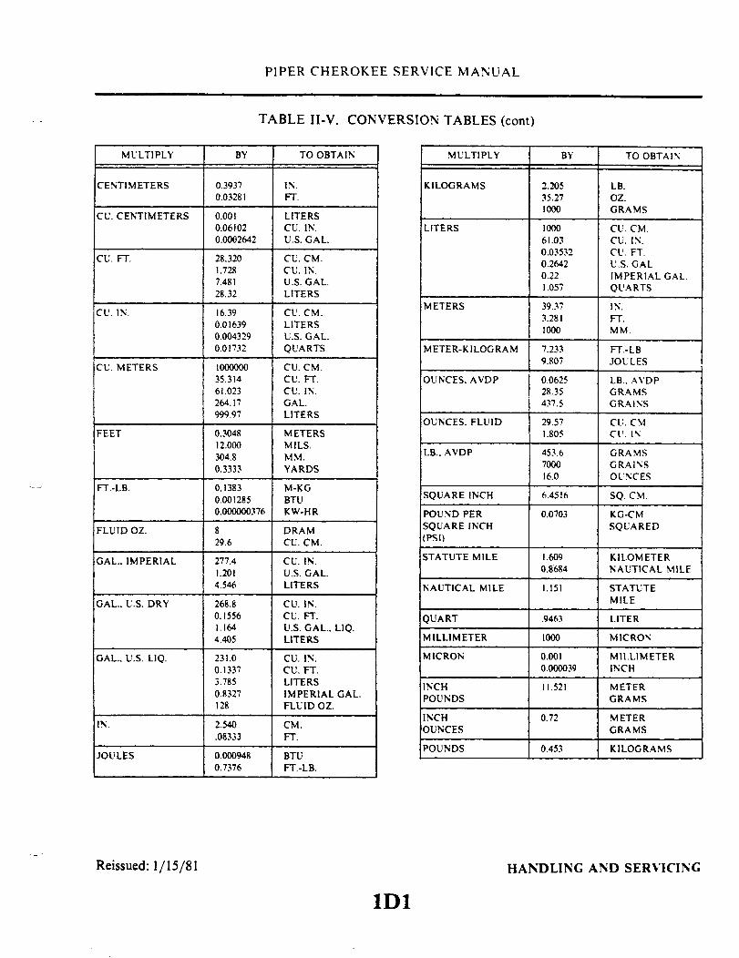
PIPER CHEROKEE SERVICE MANUAL
TABLE II-V. CONVERSION TABLES (cont)
TO OBTAIN MULTIPLY
CENTIMETERS
CU. CENTIMETERS
CU. FT.
CU. IN.
CU. METERS
FEET
FT.-LB.
FLUID OZ.
GAL.. IMPERIAL
GAL.. U.S. DRY
GAL.. U.S. LIQ.
IN.
JOULES
0.39370.03281
0.0010.061020.0002642
28.3201.7287.48128.32
16.390.016390.0043290.01732
100000035.31461.023264.17999.97
0.304812.000304.80.3333
0.13830.0012850.000000376
829.6
277.41.2014.546
268.80.15561.1644.405
231.00.13373.7850.8327128
2.540.08333
0.0009480.7376
IN.FT.
LITERSCU. IN.U.S. GAL.
CU. CM.CU. IN.U.S. GAL.LITERS
CU. CM.LITERSU.S. GAL.QUARTS
CU. CM.CU. FT.CU. IN.GAL.LITERS
METERSMILS.MM.YARDS
M-KGBTUKW-HR
DRAMCU. CM.
CU. IN.U.S. GAL.LITERS
CU. IN.CU. FT.U.S. GAL.. LIQ.LITERS
CU. IN.CU. FT.LITERSIMPERIAL GAL.FLUID OZ.
CM.FT.
BTUFT.-LB.
KILOGRAMS
LITERS
METERS
METER-KILOGRAM
OUNCES. AVDP
OUNCES. FLUID
LB.. AVDP
SQUARE INCH
POUND PERSQUARE INCH(PSI)
STATUTE MILE
NAUTICAL MILE
QUART
MILLIMETER
MICRON
INCHPOUNDS
INCHOUNCES
POUNDS
2.20535.271000
100061.030.035320.26420.221.057
39.373.2811000
7.2339.807
0.062528.35437.5
29.571.805
453.6700016.0
6.4516
0.0703
1.6090.8684
1.151
.9463
1000
0.0010.000039
11.521
0.72
0.453
LB.OZ.GRAMS
CU. CM.CU. IN.CU. FT.U.S. GALIMPERIAL GAL.QUARTS
IN.FT.MM.
FT.-LBJOULES
LB.. AVDPGRAMSGRAINS
CU. CMCU. IN
GRAMSGRAINSOUNCES
SQ. CM.
KG-CMSQUARED
KILOMETERNAUTICAL MILE
STATUTEMILE
LITER
MICRON
MILLIMETERINCH
METERGRAMS
METERGRAMS
KILOGRAMS
Reissued: 1/15/81 HANDLING AND SERVICING
1D1
MULTIPLY BY BY TO OBTAIN

PIPER CHEROKEE SERVICE MANUAL
TABLE II-V. CONVERSION TABLES (cont)
INCHES TO MILLIMETER
C328
INCHES 0.0000I
0.0000.0010.0020.0030.0040.0050.0060.0070.0080.009
0.02540.05080.07620.10160.12700.15240.17780.20320.2286
INCHES 0.000
0.000.010.020.030.040.050.060.070.080.09
0.2540.5080.7621.0161.2701.5241.7782.0322.286
0.0001 0.0002 0.0003 0.0004 0.0005MILLIMETER
0.0025 0.0050 0.0076 0.0101 0.01270.0279 0.0304 0.0330 0.0355 0.03810.0533 0.0558 0.0584 0.0609 0.06350.0787 0.0812 0.0838 0.0863 0.08890.1041 0.1066 0.1092 0.1117 0.11430.1295 0.1320 0.1346 0.1371 0.13970.1549 0.1574 0.1600 0.1625 0.16510.1803 0.1828 0.1854 0.1879 0.19050.2057 0.2082 0.2108 0.2133 0.21590.2311 0.2336 0.2362 0.2387 0.2413
0.001 0.002 0.003 0.004MILLIMETER
0.025 0.050 0.076 0.1010.279 0.304 0.330 0.3550.533 0.558 0.584 0.6090.787 0.812 0.838 0.8631.041 1.066 1.092 1.1171.295 1.320 1.346 1.3711.549 1.574 1.600 1.6251.803 1.828 1.854 1.8792.057 2.082 2.108 2.1332.311 2.336 2.362 2.387
0.1270.3810.6350.8891.1431.3971.6511.9052.1592.413
0.0006 0.0007 0.0008 0.0009
0.01520.04060.06600.09140.11680.14220.16760.19300.21840.2438
0.01770.04310.06850.09390.11930.14470.17010.19550.22090.2463
0.02030.04570.07110.09650.12190.14730.17270.19810.22350.2489
0.02280.04820.07360.09900.12440.14980.17520.20060.22600.2514
0.005 0.006 0.007 0.008 0.009
0.1520.4060.6600.9141.1681.4221.6761.9302.1842.438
0.1770.4310.6850.9391.1931.4471.7011.9552.2092.463
0.2030.4570.7110.9651.2191.4731.7271.9812.2352.489
0.2280.4820.7360.9901.2441.4981.7522.0062.2602.514
INCHES 0.00
0.00.10.20.30.40.50.60.70.80.9
2.5405.0807.620
10.16012.70015.24017.78020.32022.860
0.01
0.2542.7945.3347.874
10.41412.95415.49418.03420.57423.114
0.02 0.03 0.04 0.05MILLIMETER
0.508 0.762 0.016 1.2703.048 3.302 3.556 3.8105.588 5.842 6.096 6.3508.128 8.382 8.636 8.890
10.668 10.922 11.176 11.43013.208 13.462 13.716 13.97015.748 16.002 16.256 16.51018.288 18.542 18.796 19.05020.828 21.082 21.336 21.59023.368 23.622 23.876 24.130
0.06 0.07
1.5244.0646.6049.144
11.68414.22416.76419.30421.84424.384
1.7784.3186.8589.39811.93814.47817.01819.55822.09824.638
0.08 0.09
2.0324.5727.1129.652
12.19214.73217.27219.81222.35224.892
2.2864.8267.3669.906
12.44614.98617.52620.06622.60625.146
INCHES 0.00
I0.
I.2.3.4.5.6.7.8.9.
25.4050.8076.20
101.60127.00152.40177.80203.20228.60
0.1 0.2 0.3 0.4 0.5MILLIMETER
2.54 5.08 7.62 10.16 12.7027.94 30.48 33.02 35.56 38.1053.34 55.88 58.42 60.96 63.5078.74 81.28 83.82 86.36 88.90
104.14 106.68 109.22 111.76 114.30129.54 132.08 134.62 137.16 139.70154.94 157.48 160.02 162.56 165.10180.34 182.88 185.42 187.96 190.50205.74 208.28 210.82 213.36 215.90231.14 233.68 236.22 238.76 241.30
0.6 0.7 0.8 0 9
15.2440.6466.0491.44
116.84142.24167.64193.04218.44243.84
17.7843.1868.5893.98
119.38144.78170.18195.58220.98246.38
20.3245.7271.1296.52121.92147.32172.72198.12223.52248.92
22.8648.2673.6699.0612446149.86175.26200 66226.06251.46
Reissued: 1/15/81 HANDLING AND SERVICING
1D2

1D3INTENTIONALLY LEFT BLANK
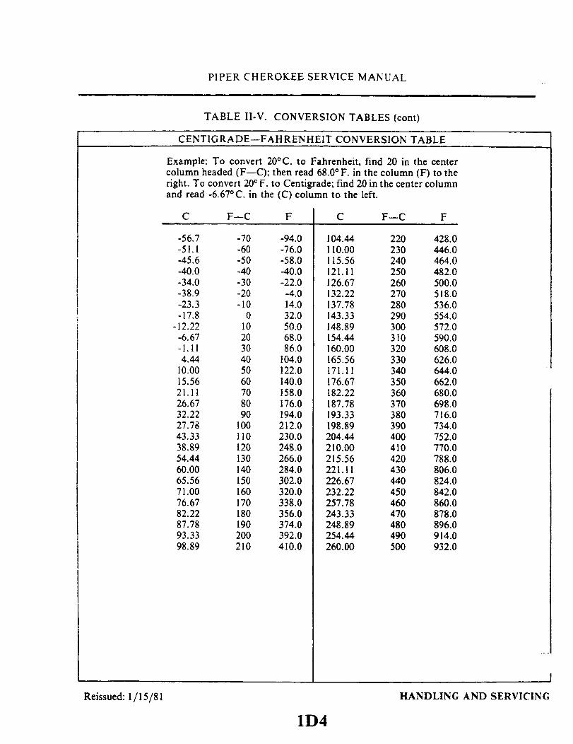
PIPER CHEROKEE SERVICE MANUAL
TABLE II-V. CONVERSION TABLES (cont)
CENTIGRADE-FAHRENHEIT CONVERSION TABLE
Example: To convert 20°C. to Fahrenheit, find 20 in the centercolumn headed (F-C); then read 68.0°F. in the column (F) to theright. To convert 20° F. to Centigrade; find 20 in the center columnand read -6.67°C. in the (C) column to the left.
C
-56.7-51.1-45.6-40.0-34.0-38.9-23.3-17.8
-12.22-6.67-1.114.44
10.0015.5621.1126.6732.2227.7843.3338.8954.4460.0065.5671.0076.6782.2287.7893.3398.89
F-C
-70-60-50-40-30-20-10
0102030405060708090
100110120130140150160170180190200210
F
-94.0-76.0-58.0-40.0-22.0-4.014.032.050.068.086.0
104.0122.0140.0158.0176.0194.0212.0230.0248.0266.0284.0302.0320.0338.0356.0374.0392.0410.0
C F-C
104.44110.00115.56121.11126.67132.22137.78143.33148.89154.44160.00165.56171.11176.67182.22187.78193.33198.89204.44210.00215.56221.11226.67232.22257.78243.33248.89254.44260.00
220230240250260270280290300310320330340350360370380390400410420430440450460470480490500
F
428.0446.0464.0482.0500.0518.0536.0554.0572.0590.0608.0626.0644.0662.0680.0698.0716.0734.0752.0770.0788.0806.0824.0842.0860.0878.0896.0914.0932.0
Reissued: 1/15/81 HANDLING AND SERVICING
1D4
I
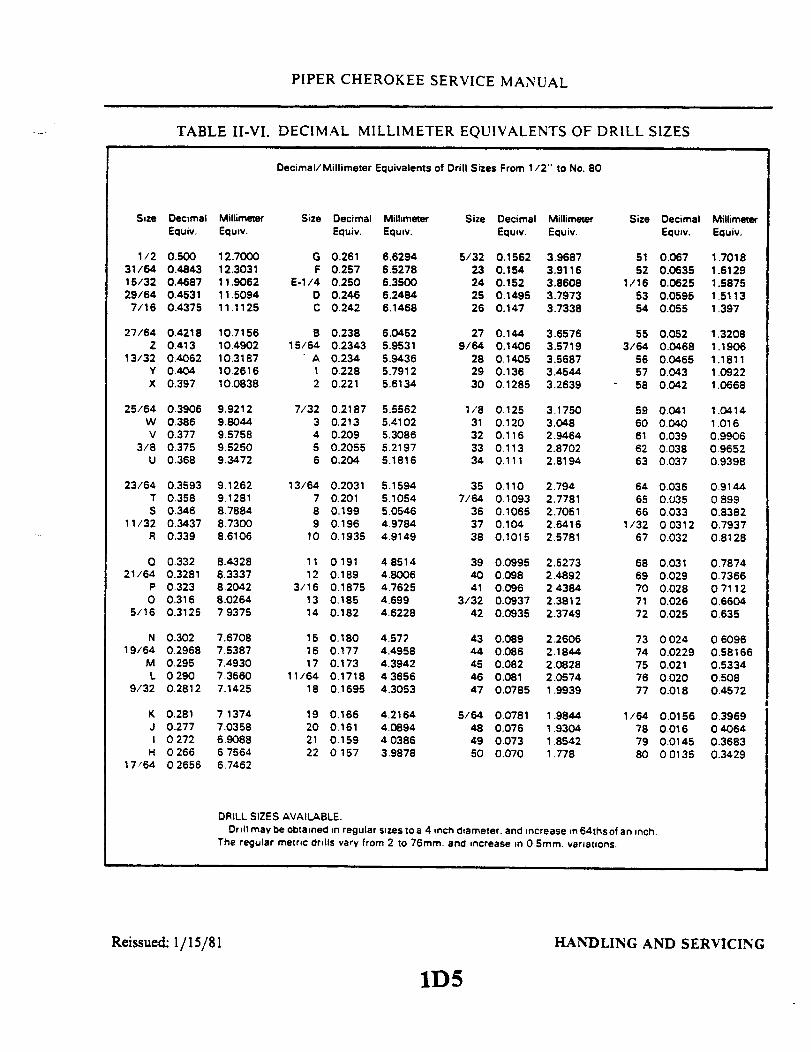
VI. DECIMAL MILLIMETER
Equivalents of Drill Sizes From 1/2" to No. 80
o o o o00000000N
LL0
z
N
E
S

PIPER CHEROKEE SERVICE MANUAL
TABLE II-VII. MAXIMUM DISTANCE BETWEEN SUPPORTS FOR FLUID TUBING
TUBE OD
(IN.)
DISTANCE BETWEEN SUPPORTS (IN.)
ALUMINUM ALLOY
1/8
3/16
1/4
5/16
3/8
1/2
5/8
3/4
1
9-1/2
12
13-1/2
15
16-1/2
19
22
24
26-1/2
STEEL
11-1/2
14
]6
18
20
23
25-1/2
27-1/2
30
TABLE II-VIII. HOSE CLAMP TIGHTENING. (INITIAL INSTALLATION)
Types of hose
Self sealing
All other hose
Types of clamps
Worm screw type
Finger-tight-plus2 complete turns
Finger-tight-plus1/4 complete Turns
All other types
Finger-tight-plus2 1/2 complete turns
Finger-tight-plus2 complete turns
If clamps do not seal at specified tightening. examine hose connection and replace parts asnecessa ry.
Reissued: 1/15/81 HANDLING AND SERVICING
1D6

PIPER CHEROKEE SERVICE MANUAL
TWO COTTON BRAIDS - IMPREGNATEDWITH SYNTHETIC COMPOUND
YELLOW SINGLE WIRE BRAID -SYNTHETIC INNER TU
A. FLAME AND AROMATIC RESISTANT HOSE
WHITE NUMEERALS, LETTERS AND STRIPE
YELLOW NUMERALS.LETTERS AND STRIPE
NON-SELF-SEALINGD. AROMATIC RESISTANT HOSE
RED
(VIEW SHOWS OPPOSITE SIDES OF HOSE)
NON-SELF-SEALING AROMATIC AND HEAT-RESISTANT HOSE
RED NUMERALS AND LETTERS
RED NUMERALS LETTERS AND STRIPE
E. SELF-SEALING AROMATICRESISTANT HOSE
C. FLAME, AROMATIC AND OIL RESISTANT HOSE
HOSE IDENTIFICATION MARKINGS
BROWN ORANGE
ELECTRICALCONDUIT
GREEN
BREATHINGOXGYEN
ORANGE ORANGE GRAY
COMPRESSED INSTRUMENTGAS AIR
RED
FUEL
ORANGE BLUE
PNEUMATIC
YELLOW
LUBRICATION
GRAY
AIRCONDITION
RED
FLUID LINE IDENTIFICATION USING TAPE AND DECALS
Reissued: 1/15/81Figure 2-29. Identification of Aircraft Fluid Lines
HANDLING AND SERVICING1D7
8362
B.
BE

PIPER CHEROKEE SERVICE MANUAL
8362
DRIFT PIN 4.
SMALLCENTER DRILL 6.
3.
Figure 2-31. Removal of Cherrylock Rivets
2-10. REMOVAL OF CHERRYLOCK RIVETS.
To remove cherrylock rivet:1. File head flat.2. Centerpunch rivet head.3. In thick material, remove the lock by driving out the rivet stem using. a tapered steel drift pin. (See
View 1.)
- NOTE -
Do not drill completely through the rivet sleeve to remove a rivet, asthis will tend to enlarge the hole.
4. In thin material, use a small center drill to provide a guide for a larger drill on top of the rivet stem.and the tapered position of the stem be drilled away to destroy the lock.
5. Remove the remainder of the locking collar out of the rivet head by prying it loose with the drift pin.(See View 3.)
6. Drill nearly through the head of the rivet. using a drill the same site as the rivet shank. (See View 4.)7. Pry off the rivet head using the drift pin. (See View 5.)8. Drive out the remaining shank with a pin having the same diameter as the rivet shank. (See View 6.)
Reissued: 1/15/81 HANDLING AND SERVICING1D8
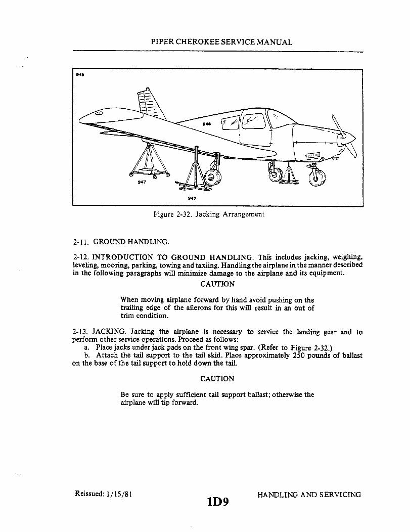
PIPER CHEROKEE SERVICE MANUAL
949
947
Figure 2-32. Jacking Arrangement
2-11. GROUND HANDLING.
2-12. INTRODUCTION TO GROUND HANDLING. This includes jacking, weighing,leveling, mooring, parking, towing and taxiing. Handling the airplane in the manner describedin the following paragraphs will minimize damage to the airplane and its equipment.
CAUTION
When moving airplane forward by hand avoid pushing on thetrailing edge of the ailerons for this will result in an out oftrim condition.
2-13. JACKING. Jacking the airplane is necessary to service the landing gear and toperform other service operations. Proceed as follows:
a. Place jacks under jack pads on the front wing spar. (Refer to Figure 2-32.)b. Attach the tail support to the tail skid. Place approximately 250 pounds of ballast
on the base of the tail support to hold down the tail.
CAUTION
Be sure to apply sufficient tail support ballast; otherwise theairplane will tip forward.
Reissued: 1/15/811D9
HANDLING AND SERVICING
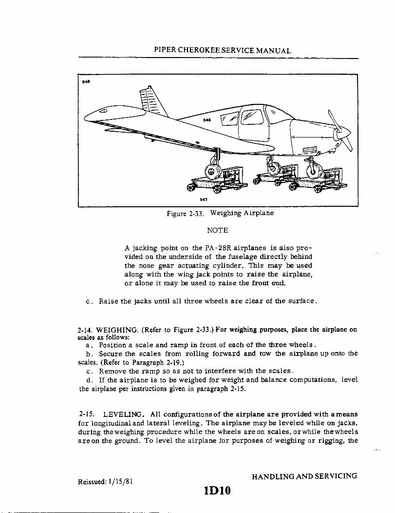
PIPER CHEROKEE SERVICE MANUAL
948
947
Figure 2-33. Weighing Airplane
NOTE
A jacking point on the PA-28R airplanes is also pro-vided on the underside of the fuselage directly behindthe nose gear actuating cylinder. This may be usedalong with the wing jack points to raise the airplane,or alone it may be used to raise the front end.
c. Raise the jacks until all three wheels are clear of the surface.
2-14. WEIGHING. (Refer to Figure 2-33.) For weighing purposes, place the airplane onscales as follows:
a. Position a scale and ramp in front of each of the three wheels.b. Secure the scales from rolling forward and tow the airplane up onto the
scales. (Refer to Paragraph 2-19.)c. Remove the ramp so as not to interfere with the scales.d. If the airplane is to be weighed for weight and balance computations, level
the airplane per instructions given in paragraph 2-15.
2-15. LEVELING. All configurationsof the airplane are provided with ameansfor longitudinal and lateral leveling. The airplane maybe leveled while on jacks,during theweighing procedure while the wheels are on scales, orwhile thewheelsare on the ground. To level the airplane for purposes of weighing or rigging, the
Reissued: 1/15/81 HANDLING AND SERVICINGReissued: 1/15/81
1Dl0
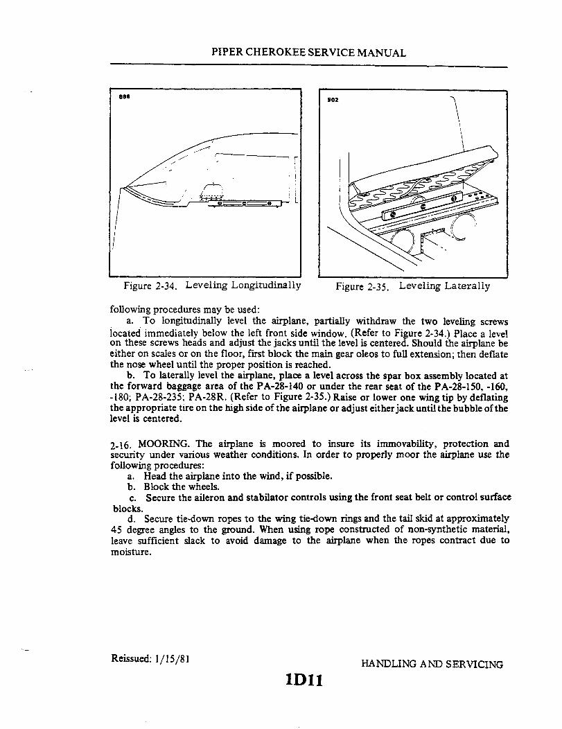
PIPER CHEROKEE SERVICE MANUAL
896 902896 902
Figure 2-34. Leveling Longitudinally Figure 2-35. Leveling Laterally
following procedures may be used:a. To longitudinally level the airplane, partially withdraw the two leveling screws
located immediately below the left front side window. (Refer to Figure 2-34.) Place a levelon these screws heads and adjust the jacks until the level is centered. Should the airplane beeither on scales or on the floor, first block the main gear oleos to full extension; then deflatethe nose wheel until the proper position is reached.
b. To laterally level the airplane, place a level across the spar box assembly located atthe forward baggage area of the PA-28-140 or under the rear seat of the PA-28-150, -160,-180; PA-28-235; PA-28R. (Refer to Figure 2-35.) Raise or lower one wing tip by deflatingthe appropriate tire on the high side of the airplane or adjust either jack until the bubble of thelevel is centered.
2-16. MOORING. The airplane is moored to insure its immovability, protection andsecurity under various weather conditions. In order to properly moor the airplane use thefollowing procedures:
a. Head the airplane into the wind, if possible.b. Block the wheels.c. Secure the aileron and stabilator controls using the front seat belt or control surface
blocks.d. Secure tie-down ropes to the wing tie-down rings and the tail skid at approximately
45 degree angles to the ground. When using rope constructed of non-synthetic material,leave sufficient slack to avoid damage to the airplane when the ropes contract due tomoisture.
Reissued: 1/15/81 HANDLING AND SERVICING
1Dl1

PIPER CHEROKEE SERVICE MANUAL
CAUTION
Use square or bowline knots. Do not use slip knots.
NOTE
Additional preparations for high winds include using tie-downropes on the landing gear forks, and securing the rudder.
e. Install pitot tube cover, if available.
2-17. LOCKING AIRPLANE. The cabin and baggage compartment doors are providedwith an outside lock. The ignition switch and cabin door require the same key while thebaggage compartment door has a different key.
2-18. PARKING. When parking the airplane, insure that it is sufficiently protected againstadverse weather conditions and presents no danger to other aircraft. When parking the air-plane for any length of time or overnight, it is recommended that it be moored as inParagraph 2-16.
a. Park the airplane headed into the wind, if possible.b. PA-28-150, -160, Serial Nos. 28-1 to 28-250 incl. Set the parking brake by pulling
back the brake lever and pulling the parking brake knob located at the left of the controlpanel. Release the brake lever while holding the knob, then release the knob. To release theparking brake, either push in the parking brake knob or pull back the brake lever.
c. PA-28-140; PA-28-150, -160, -180, Serial Nos. 28-251 and up; PA-28-235 andPA-28R. Set the parking brake by pulling back the brake lever and depressing the knobattached to the left side of the handle, then release the handle. To release the parking brake,pull back on the brake lever to disengage the catch mechanism, and allow the handle to swingforward.
NOTE
Care should be taken when setting brakes that are overheatedduring cold weather when accumulated moisture may freezethe brakes.
Reissued: 1/15/81 HANDLING AND SERVICING
1D12

PIPER CHEROKEE SERVICE MANUAL
d. The aileron and stabilator controls may be secured using the front seat belt.
2-19. TOWING. The airplane may be moved by using the nose wheel steering bar that isstowed in the baggage area of the PA-28-150, -160, -180; PA-28-235 and PA-28R, or by usingpower equipment that will not damage or cause excess strain to the nose gear steeringassembly. Towing lugs are incorporated as part of the nose gear fork of models PA-28-140;PA-28-150, -160, -180; PA-28-235 and PA-28R. On the PA-28R, the stem on the bar is insertedin the hollow of the nose wheel axle at its right side.
CAUTIONS
1. When towing with power equipment, do not turn thenose gear in either direction beyond its steering radiuslimits as this will result in damage to the nose gear andsteering mechanism.
2. Do not tow the airplane with control locks installed.3. When moving the airplane forward by hand, avoid
pushing on the trailing edge of the control surfaces as thiswill cause the control surface contour to change resultingin an out-of-trim condition.
In the event towing lines are necessary, lines (rope) should be attached to both maingear struts as high up on the tubes as possible. Lines should be long enough to clear the noseand/or tail by not less than 15 feet, and a qualified person to ride in the pilot's seat tomaintain control by use of the brakes.
2-20. TAXIING. Before attempting to taxi the airplane, ground personnel should bechecked out by a qualified pilot or other responsible person. Engine starting and shutdownprocedures should be covered as well. When it is ascertained that the propeller back blastand taxi areas are clear, apply power to start the taxi roll and perform the following checks:
a. Taxi forward a few feet and apply brakes to determine their effectiveness.b. Taxi with propeller set in low pitch, high RPM setting, where applicable.c. While taxiing, make slight turns to ascertain the effectiveness of steering.d. Observe wing clearances when taxiing near buildings or other stationary objects. If
possible, station a guide outside the airplane to observe.e. When taxiing on uneven ground, avoid holes and ruts.f. Do not operate the engine at high RPM when running-up, or taxiing, over ground
containing loose stones, gravel or any loose material that may cause damage to the propellerblades.
2-21. EXTERNAL POWER RECEPTACLE.
2-22. OPERATION OF EXTERNAL POWER RECEPTACLE. The receptacle is locatedon the left side of the nose section, just aft of the engine cowling. When used for engine startingor operation of the airplanes' other equipment, proceed as follows:
Reissued: 1/15/81 HANDLING AND SERVICINGReissued: 1/15/81
1D13
PIPER CHEROKEE SERVICE MANUAL
a. Set MASTER SWITCH to OFF.b. Ensure that the RED lead of PEP (Piper External Power) kit jumper cable is con-
nected to the POSITIVE (+) terminal of an external 12-volt battery or a power cart and thatthe BLACK lead is connected to the NEGATIVE (-) terminal of same.
NOTE
If using an external battery, and the airplanes' battery is lowor depleted, disconnect the airplane battery at the negativeterminal to prevent excessive loading of the external battery.
c. Insert the plug of the jumper cable into the receptacle.d. Set MASTER SWITCH to ON and proceed with NORMAL engine starting.e. After starting engine, set the MASTER SWITCH to OFF and remove the jumper
cable plug from the receptacle.f. Set the MASTER SWITCH to ON and check the alternator ammeter for an indication
of output.
WARNING
Do not attempt any flight without an indication of alternatoroutput.
2-23. CLEANING.
2-24. CLEANING ENGINE COMPARTMENT. Before cleaning the engine compartment,place a strip of tape on the magneto vents to prevent any solvent from entering these units.
a. Place a pan under the engine to catch waste.b. With the engine cowling removed, spray or brush the engine with solvent or a mixture
of solvent and degreaser, as desired. Brushing may be necessary where heavy grease and dirtdeposits have collected.
CAUTION
Do not spray solvent into the alternator, starter, air intake,and alternate air inlets.
c. Allow the solvent to remain on the engine from five to ten minutes; then rinse theengine clean with additional solvent and allow to dry.
CAUTION
Do not operate engine until excess solvent has evaporated orotherwise been removed.
d. Remove the protective covers from the magnetos.e. Lubricate controls, bearing surfaces, etc., per Lubrication Chart.
Reissued: 1/15/81 HANDLING AND SERVICING
1D14

PIPER CHEROKEE SERVICE MANUAL
2-25. CLEANING LANDING GEAR. Before cleaning the landing gear, place a plasticcover or similar material over the wheel and brake assembly.
a. Place a pan under the gear to catch waste.b. Spray or brush the gear area with solvent or a mixture of solvent and degreaser, as
desired. Brushing may be necessary where heavy grease and dirt deposits have collected.c. Allow the solvent to remain on the gear from five to ten minutes, then rinse the gear
with additional solvent and allow to dry.d. Remove the cover from the wheel and remove the catch pan.e. Lubricate the gear per Lubrication Chart.
2-26. CLEANING EXTERIOR SURFACES. The airplane should be washed witha mild soap and water. Harsh abrasives or detergents used on painted or plasticsurfaces couldmake scratches or cause corrosionof metal surfaces. Cover areaswhere cleaning solution could cause damage. Cover the mast of the PA-28R-180gear back-up extender. To wash the airplane, the following procedure may beused:
a. Flush away loose dirt with water.b. Apply cleaning solution with a rag, sponge or soft bristle brush.c. To remove stubborn oil and grease, use a cloth dampened with naptha.d. Where exhaust stains exist, allow solution to remain on the surface longer.e. Any good automotive wax may be used to preserve the painted surfaces.
Soft cleaning cloths or a chamois should be used to prevent scratches when clean-ing or polishing. A heavier coating of wax on the leading surfaces will reducethe abrasion problems in these areas.
2-27. CLEANING WINDSHIELD AND WINDOWS.a. Remove dirt, mud, etc. from exterior surfaces with clean water.b. Wash with mild soap and warm water or an aircraft plastic cleaner using
a soft cloth or sponge and a straight rubbing motion. Do not harshly rub sur-faces.
c. Remove oil and grease with a cloth moistened with kerosene.
NOTE
Do not use gasoline, alcohol, benzene, carbon tetra-chloride, thinner, acetone or window cleaning sprays.
d. After cleaning plastic surfaces, apply a thin coat of hard polishing wax.Rub lightly with a soft cloth. Do not use a circular motion.
Reissued: 1/15/81 HANDLING AND SERVICING
1D15
PIPER CHEROKEE SERVICE MANUAL
e. A severe scratch or mar in plastic can be removed by usingjeweler's rouge to rub out thescratch. Smooth both sides and apply wax.
f. To improve visibility through windshield and windows during flight through rain, a rainrepellant such as REPCON should be applied to the windshield and windows. The surfaces ofthe windshield and windows treated become so smooth that water beads up and readily flowsoff the surface. Apply this product in accordance with the manufacturer's instructions. (Referto Table II-II Consumable Materials, for specifications and Manufacturer's address.)
2-28. CLEANING HEADLINER, SIDE PANELS AND SEATS.a. Clean headliner, side panels and seats with a stiff bristle brush and vacuum where
necessary.b. Soiled upholstery, except leather, may be cleaned by using an approved air type
cleaner or foam upholstery cleaner. Carefully follow the manufacturer's instructions. Avoidsoaking or harsh rubbing.
CAUTION
Solvent cleaners require adequate ventilation.
c. Leather material should be cleaned with saddle soap or mild soap and water.
2-29. CLEANING CARPETS. Use a small whisk broom or vacuum to remove dirt. Forsoiled spots, use a non-inflammable dry-cleaning fluid.
2-30. SERVICING.
2-31. INTRODUCTION TO SERVICING. This includes replenishment of fuel, oil, andhydraulic fluids; the maintenance of tire pressures; and the lubrication of various items.
2-32. HYDRAULIC SYSTEM (PA-28R)
2-33. SERVICING HYDRAULIC SYSTEM. The general condition of the hydraulic pumpand landing gear actuating cylinders should be checked. Ensure that there are no leaks andthat the line fittings are tight. The cylinder rods are to be free of all dirt and grit. To clean therods use an oil soaked rag and carefully wipe them. All the hydraulic lines should also bechecked for freedom of leaks, kinks, and corrosion. Check for tightness of the attachmentfittings.
The gear back up extender actuator assembly is located beneath the rear seat and shouldbe checked to determine that it is operating properly. The diaphragm shaft may be operatedby hand to make sure that it is free to fluctuate and that the actuating arm and its components
Reissued: 1/15/81 HANDLING AND SERVICING
1D16
PIPER CHEROKEE SERVICE MANUAL
are operating freely. Check the pressure housing assembly for absence of cracks, breaks, orfatigue. Check to ensure that the hydraulic valve and fittings are free of leaks.
Repair and check procedures for the hydraulic pump, cylinders and various componentsmay be found in Section VI of this manual.
2-34. SERVICING HYDRAULIC PUMP/RESERVOIR. The fluid level of the reservoir ofthe combination pump and reservoir should be checked every 50 hours by viewing the fluidthrough the filler plug hole in the hydraulic pump. Access to the pump is through the panel atthe right rear side of the baggage compartment.
To check fluid level, remove the plug located on the forward side of the pump andascertain that fluid is visible up to the bottom of the filler plug hole. Should fluid be below thehole, add fluid, MIL-H-5606A, through the filler hole until full. Reinstall the filler plug andtighten.
NOTE
A small vent hole is located under the vent screw head. Retain1 /64 inch clearance between the screw head and the small venthole.
2-35. LANDING GEAR SYSTEM.
2-36. SERVICING LANDING GEAR. The landing gear consists of tires, brakes, oleo strutassemblies and on some models, wheel fairings. The gear should be inspected for properextension, unscored piston tubes, soundness of hydraulic fluid seals, the security and firmmechanical condition of all connection points and the absence of cracks in the fiberglassfairings. Check the brake linings for excessive wear, the brake discs for scoring and replace asnecessary. The PA-28R should be checked for proper adjustment of down locks, themechanical soundness and firm action of drag and side brace links. Minor servicing isdescribed in the following paragraphs. Detailed service and overhaul instructions are given inSections VII or VIIA.
2-37. OLEO STRUTS. (PA-28-140; PA-28-150,-160,-180 and PA-28-235.)
2-38.. SERVICING OLEO STRUTS. Air-oil struts are incorporated in each landing gearoleo to absorb the shock resulting from the impact of the wheels on the runway during landing.To obtain proper oleo action, the nose gear oleo strut must have approximately 3.25 ± .25inches of piston tube exposed, while the main gear struts require approximately 4.5 ±.50 inchesof tube exposure.
Reissued: 1/15/81 HANDLING AND SERVICING
1D17

PIPER CHEROKEE SERVICE MANUAL
CAUTION
Do not exceed the foregoing tube exposures.
These measurements are taken with the airplane setting on a level surfaceunder normal static load (empty weight of airplane plus full fuel and oil). If thestrut has less tube exposed than that prescribed, determine whether it needs airor oil by raising the airplane on jacks. With the strut extended, remove the capfrom the air valve at the top of the housing and depress the valve core to allowair to escape from the strut piston until it is fully compressed. Allow the foamfrom the air-oil mixture to settle and then determine if oil is visible up to thebottom of the filler plug hole. If oil is visible at the bottom of the hole, then allthat is required is the valve be checked for unsatisfactory conditions and air addedas described in paragraph 2-41. Should fluid be at any level below the bottom ofthe filler plug hole, the oleo should be checked for leaks, etc. and oil added asdescribed in paragraph 2-39 for the nose gear or paragraph 2-40 for the maingear. For repair procedures of the landing gear and/or oleo struts, refer toSection VII or VIIA.
WARNING
Do not release air byremovingthe strutvalve core orfiller plug. Depress the valve core pin until strutchamber pressure has diminished.
CAUTION
Dirt and foreign particles form around the filler plugsof the landing gear struts, therefore, before attempt-ing to remove these plugs, the tops of the struts shouldbe cleaned with compressed air and/orwith a dry sol-vent.
2-39. FILLING NOSE GEAR OLEO STRUT. Regardless of the amount of oil required fillthe nose gear oleo strut with hydraulic fluid (MIL-H-5606) as follows:
a. Raise the airplane on jacks until the nose wheel is completely clear of theground. (Refer to Paragraph 2-13.)
b. Place a pan under the gear to catch spillage.c. If not previously accomplished, remove the engine cowl and relieve air
Reissued: 1/15/81 HANDLING AND SERVICING
1D18

PIPER CHEROKEE SERVICE MANUAL
from the strut housing chamber by removing the cap from the air valve and depressing thevalve core.
d. There are two methods by which the strut chamber may be filled and these are asfollows:Method 1:
1. Remove the valve core from the filler plug at the top of the strut housing. Allowthe plug to remain installed.
2. Attach one end of a clear plastic hose to the valve stem of the filler plug andsubmerge the other end in a container of hydraulic fluid. Ascertain that the end of the hoseon the valve stem is tight and the fluid container is approximately equal in height to the topof the strut housing.
3. Fully compress and extend the strut thus drawing fluid from the fluid containerand expelling air from the strut chamber. By watching the fluid pass through the plastichose, it can be determined when the strut is full and no air is present in the chamber.
4. When air bubbles cease to flow through the hose, compress the strut fully andremove the hose from the valve stem.
5. With strut compressed, remove the filler plug to determine that the fluid level isvisible up to the bottom of the filler plug hole.
6. Reinstall the core in the filler plug and apply thread lubricated (Parker#6PB) tothe threads of the filler plug and install the plug in the top of the strut housing. Torque theplug to 45 foot pounds.Method 2:
1. Remove the filler plug from the top of the strut housing.2. Raise the strut piston until it is fully compressed.3. Pour fluid from a clean container through the filler opening until it reaches the
bottom of the filler plug hole.4. Install the filler plug finger tight, and extend and compress the strut two or three
times to remove any air that may be trapped in the housing.5. Remove the filler plug, raise the strut to full compression and fill with fluid if
needed.6. Apply thread lubricant (Parker #6PB) to the threads of the filler plug. Reinstall
the filler plug and torque to 45 foot pounds.e. With the airplane raised, compress and extend the gear strut several times to
ascertain that the strut actuates freely. The weight of the gear fork and wheel should extendthe strut.
f. Clean off overflow of fluid, and inflate the strut as described in Paragraph 2-41.g. Check that fluid is not leaking from around the strut piston at the bottom of the
housing.
Reissued: 1/15/81 HANDLING AND SERVICING
1D19
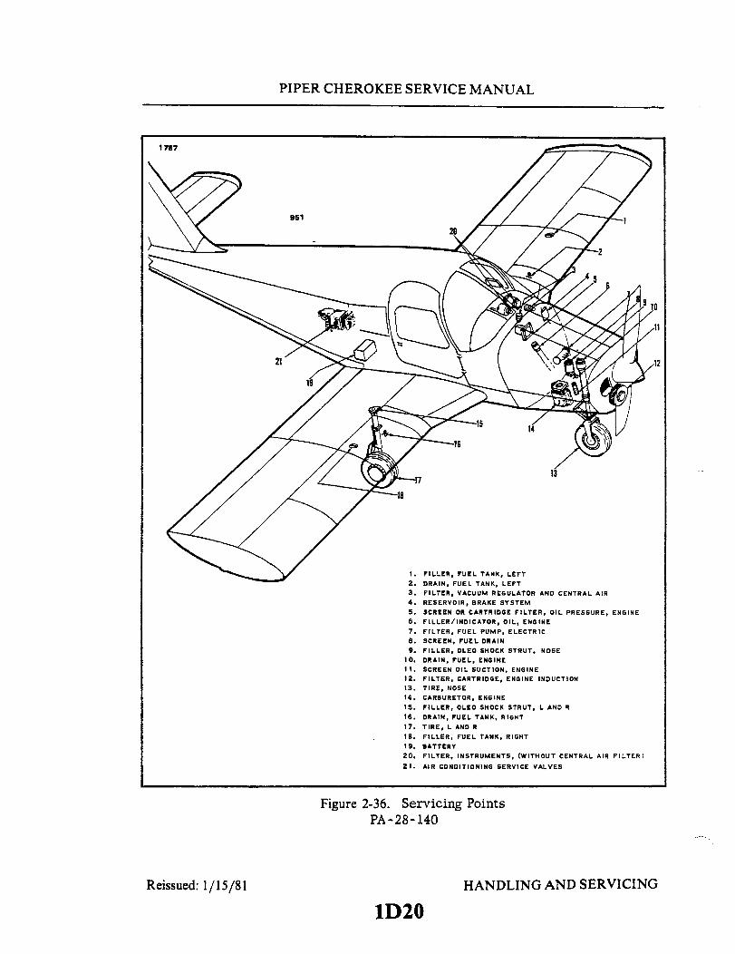
PIPER CHEROKEE SERVICE MANUAL
1757
951
1. FILLER, FUEL TANK, LEFT2. DRAIN, FUEL TANK, LEFT3. FILTER, VACUUM REGULATOR AND CENTRAL AIR4. RESERVOIR, BRAKE SYSTEM5. SCREEN OR CARTRIDGE FILTER, OIL PRESSURE, ENGINE6. FILLER/INDICATOR, OIL, ENGINE
7. FILTER, FUEL PUMP, ELECTRIC8. SCREEN, FUEL DRAIN9. FILLER, OLEO SHOCK STRUT, NOSE
10. DRAIN, FUEL, ENGINE11. SCREEN OIL SUCTION, ENGINE12. FILTER, CARTRIDGE, ENGINE INDUCTION13. TIRE, NOSE14. CARBURETOR, ENGINE15. FILLER, OLEO SHOCK STRUT, L AND R
16. DRAIN, FUEL TANK, RIGHT17. TIRE, L AND RIS. FILLER, FUEL TANK, RIGHT19. BATTERY20. FILTER, INSTRUMENTS, (WITHOUT CENTRAL AIR FILTER)
21. AIR CONDITIONING SERVICE VALVES
Figure 2-36. Servicing PointsPA-28-140
Reissued: 1/15/81 HANDLING AND SERVICING
1D20


PIPER CHEROKEE SERVICE MANUAL
1812
1. FILTER, INSTRUMENTS, (WITHOUT CENTRAL AIR FILTER)2. FILLER, TIP FUEL TANK, LEFT3. DRAIN, TIP FUEL TANK, LEFT4. FILLER, MAIN FUEL TANK, LEFT5. DRAIN, MAIN FUEL TANK, LEFT6. FILTER, VACUUM REGULATOR AND CENTRAL AIR7. RESERVOIR, BRAKE SYSTEM8. SCREEN OR CARTRIDGE FILTER, OIL PRESSURE, ENGINE9. FILLER/INDICATOR, OIL, ENGINE
10. FILLER, OLEO SHOCK STRUT, NOSE11. PROPELLER
12. TIRE, NOSE13. CARBURETOR, ENGINE14. FILTER, CARTRIDGE, ENGINE INDUCTION15. SCREEN, OIL SUCTION, ENGINE16. DRAIN, FUEL17. FILLER, OLEO SHOCK STRUT, L AND R18. DRAIN, MAIN FUEL TANK, RIGHT19. FILLER, MAIN FUEL TANK, RIGHT
20. FILLER, TIP FUEL TANK, RIGHT21. DRAIN, TIP FUEL TANK, RIGHT22. BATTERY23. FILTER, FUEL PUMP, ELECTRIC
Reissued: 1/15/81
Figure 2-38. Servicing PointsPA-28-235
HANDLING AND SERVICING
1D22

PIPER CHEROKEE SERVICE MANUAL
1811
1. FILLER, FUEL TANK, LEFT2. DRAIN, FUEL TANK, LEFT3. FILTER, VACUUM REGULATOR AND CENTRAL AIR4. RESERVOIR, BRAKE SYSTEM5. SCREEN OR CARTRIDGE FILTER, OIL PRESSURE, ENGINE6. FILLER/INDICATOR, OIL, ENGINE7. SCREEN, FUEL DRAIN8. FILTER, CARTRIDGE, ENGINE INDUCTION9. DRAIN, FUEL ENGINE
10. FILLER, OLEO SHOCK STRUT, NOSE11. PROPELLER
12. TIRE, NOSE13. INJECTOR, FUEL14. SCREEN, OIL SUCTION, ENGINE15. FILLER, OLEO SHOCK STRUT, L AND R16. DRAIN, FUEL TANK, RIGHT17. TIRE, L AND R18. FILLER, FUEL TANK, RIGHT19. PUMP/RESERVOIR, HYDRAULIC SYSTEM
20. BATTERY21. FILTER, INSTRUMENTS
Figure 2-39. Servicing PointsPA-28R
Reissued: 1/15/81 HANDLING AND SERVICING
1D23

PIPER CHEROKEE SERVICE MANUAL
2-40. FILLING MAIN GEAR OLEOSTRUT. A main gear oleo strut that ispartly full or one that has been completelyemptied may be filled with MIL-H-5606Fluid as follows:
a. Raise the airplane on jacks until thelanding gear torque link assembly hasalmost reached its full travel. (Refer toParagraph 2-13.)
b. Place a pan under the gear to catchspillage.
c. If not previously accomplished,remove the cap on top of the wing to gainaccess to the top of the strut housing, andrelieve air from the strut housing chamberby removing the cap from the air valve anddepressing the valve core.
d. Remove any one of the threetorque link bolts, and again raise theairplane until a minimum of ten inches (donot exceed twelve inches of tube exposure)of strut tube is exposed with the wheelremaining on the ground. With this amountof tube exposed, fluid will flow from themiddle chamber to the bottom chamber ofthe strut housing, insuring that the bottomchamber is filled with fluid.
NOTE
With the torque linksdisconnected, the pistontube is free to slide fromthe strut housing.
e. Fill the main gear housing by oneof two methods which are as follows:Method 1:
1. Remove the valve core from thefiller plug at the top of the strut housing.Allow the plug to remain installed.
Reissued: 1/15/81
1758
FILLER PLUGFLUID LEVEL -STRUTFULLY COMPRESSED
STRUT CHAMBER - TOP
TOP OF STRUT TUBEFULLY COMPRESSED
STRUT CHAMBERMIDDLE
TOP OFSTRUT TUBEEXTENDED 10"
STRUT CHAMBERBOTTOM
STRUT EXPOSURESTATIC LOAD
STRUT FULLY 4.50 .50COMPRESSED
STRUT EXTENSIONUNDER
STATIC LOAD
STRUT EXTENSION
STRUT EXTENDED 10"
Figure 2-40. Main Gear Oleo Struts(Cut-away View) PA-28-140;
PA-28-150, -160, -180; PA-28-235
HANDLING AND SERVICING
1D24
PIPER CHEROKEE SERVICE MANUAL
2. Attach one end of a clear plastic hose to the valve stem of the filler plug andsubmerge the other end in a container of hydraulic fluid.
3. Fully compress and extend (10 + 2-0 inches of strut tube exposed) the strutthus drawing fluid from the strut chambers. By watching the fluid pass through the plastichose, it can be determined when the strut is full and no air is present in the chambers. Thestrut must be extended to full ten inches to allow fluid to enter the bottom chamber ofstrut housing.
4. When air bubbles cease to flow through the hose, compress the strut fully andremove the hose from the valve stem.
5. With the strut fully compressed, remove the filler plug to determine that thefluid level is visible up to the bottom of the filler plug hole.
6. Reinstall the core in the filler plug and apply thread lubricant (Parker #6PB) tothe threads of the filler plug and install the plug in the top of the strut housing. Torque theplug to 45 foot pounds.Method 2:
1. Remove the filler plug from the top of the strut housing.2. Raise the strut to full compression.3. Pour fluid from a clean container through the filler opening until it is visible at
the top of the strut chamber. If the housing has been completely emptied or nearly so, allowsufficient time for the fluid to drain through the orifice from the upper chamber into themiddle chamber.
4. Lower the gear until the wheel touches the ground (10 + 2-0 inches of strutexposure) and then fully compress and extend the strut three or four times to remove anyair that may be trapped and to allow fluid to enter the bottom chamber of the housing.
5. Raise the strut to full compression and if needed, fill with fluid to the bottom ofthe filler plug.
6. Apply thread lubricant (Parker# 6PB) to the threads of the filler plug. Reinstallthe filler plug and torque to 45 foot pounds.
e. Replace the torque link bolt. Tighten bolt only tight enough to allow no side play inthe connection.
f. With the airplane raised, retract and extend the gear strut several times to ascertainthat the strut actuates freely. The weight of the gear fork and wheel should extend the strut.
g. Clean off overflow of fluid and inflate the strut as described in Paragraph 2-41.h. Check that fluid is not leaking around the strut piston at the bottom of the housing.
2-41. INFLATING OLEO STRUTS. After making certain that the oleo strut hassufficient fluid, attach a strut pump to the air valve and inflate the oleo strut. The strutshould be inflated until the correct inches of piston is exposed with normal static load(empty weight of airplane plus full fuel and oil) on the gears. (Refer to Paragraph 2-38.)Rock the airplane several times to ascertain that the gear settles back to the correct strutposition. (If a strut pump is not available, the airplane may be raised and line pressure froma high pressure air system used. Lower the airplane and while rocking it, let air from thevalve to bring the strut down to the proper extension.) Before capping the valve, check forvalve core leakage.
Reissued: 1/15/81 HANDLING AND SERVICING
1El

PIPER CHEROKEE SERVICE MANUAL
2-42. OLEO STRUTS. (PA-28R)
2-43. SERVICING OLEO STRUTS. The air-oil type oleo strut should be maintained atproper strut tube exposures for best oleo action. The nose gear strut must haveapproximately 2.75 inches of piston tube exposed, while the main gear strut requiresapproximately 2.0 inches of tube exposure. These measurements are taken with the airplanesitting on level surface under normal static load. (Empty weight of airplane plus full fuel andoil.) If the strut has less tube exposure than prescribed, determine whether it needs air or oilby rocking the airplane. If the oleo strut oscillated with short strokes (approximately oneinch) and the airplane settles to its normal position within one or two cycles after therocking force is removed, the oleo strut requires inflating. Check the valve core and fillerplug for air leaks, correct if required, and add air as described in Paragraph 2-45. If the oleostrut oscillates with long strokes (approximately three inches) and the airplane continues tooscillate after the rocking force is removed, the oleo struts require fluid. Check the oleo forindications of oil leaks, correct if required and add fluid as described in Paragraph 2-44. Forrepair procedures of the landing gear and/or oleo struts, refer to Section VIIA.
WARNING
Do not release air by removing the strut valve core or fillerplug. Depress the valve core pin until strut chamber pressurehas diminished.
CAUTION
Dirt and foreign particles form around the filler plugs of thelanding gear struts, therefore, before attempting to removethese plugs, the tops of the struts should be cleaned withcompressed air and/or with a dry solvent.
THIS SPACE INTENTIONALLY LEFT BLANK
Reissued: 1/15/81 HANDLING AND SERVICING
1E2

PIPER CHEROKEE SERVICE MANUAL
2-44. FILLING OLEO STRUTS. To fill the nose or main gear oleo strut with fluid(MIL-H-5606), whether it be the addition of a small or large amount, proceed as follows:
a. Raise the airplane on jacks. (Refer to Paragraph 2-13.)b. Place a pan under the gear to catch spillage.c. At the filler plug, relieve air pressure from the strut housing chamber by removing
the cap from the air valve and depressing the valve core.d. There are two methods by which the strut chamber may be filled and these are as
follows:Method 1:
1. Remove the valve core from the filler plug at the top of the nose gear struthousing or at the top inboard side of the main gear housing. Allow the filler plug to remaininstalled.
2. Attach one end of a clean plastic hose to the valve stem of the filler plug andsubmerge the other end in a container of hydraulic fluid.
NOTE
An air-tight connection is necessary between the plastic tubeand the valve stem. Without such a connection, a smallamount of air will be sucked into the oleo strut during eachsequence, resulting in an inordinate amount of air bubblesand a prolonged filling operation.
3. Fully compress and extend the strut thus drawing fluid from the fluid containerand expelling air from the strut chamber. By watching the fluid pass through the plastichose, it can be determined when the strut is full and no air is present in the chamber.
4. When air bubbles cease to flow through the hose, compress the strut fully andremove the hose from the valve stem.
5. With the strut compressed, remove the filler plug to determine that the fluidlevel is visible up to the bottom of the filler plug hole.
6. Reinstall the core in the filler plug and apply thread lubricant (Parker#6PB) tothe threads of the filler plug and install the plug in the top of the strut housing. Torque theplug to 45 foot pounds.
Method 2:1. Remove the filler plug from the top of the nose gear strut housing or at the top
inboard side of the main gear housing.2. Raise the strut piston tube until it is fully compressed.3. Pour fluid from a clean container through the filler opening until it reaches the
bottom of the filler plug hole. (Air pressure type oil container may be helpful.)4. Install the filler plug finger-tight and extend and compress the strut two or three
times to remove air from the housing.5. Remove the filler plug, raise the strut to full compression and fill with fluid if
needed.
Reissued: 1/15/81 HANDLING AND SERVICING
1E3

PIPER CHEROKEE SERVICE MANUAL
6. Apply thread lubricant (Parker#6PB) to the threads of the filler plug. Reinstallthe filler plug and torque -to 45 foot pounds.
e. With the airplane raised, compress and extend the gear strut several times toascertain that the strut moves freely. The weight of the gear fork and wheel should extend thestrut.
f. Clean off overflow of fluid and inflate the strut as described in Paragraph 2-45.g. Check that fluid is not leaking around the strut piston at the bottom of the housing.
2-45. INFLATING OLEO STRUTS. After making certain that an oleo strut has sufficientfluid, attach a strut pump to the air valve and inflate the oleo strut. The strut should be inflateduntil the correct inches of piston are exposed with normal static load on the gears (emptyweight of the airplane plus full fuel and oil). (Refer to Paragraph 2-43.) Rock the airplaneseveral times to ascertain that the gear settles back to the correct strut position. If a strut pumpis not available, the airplane may be raised and line pressure from a high pressure air systemused. Lower the airplane and while rocking it, let air from the valve to bring the strut down tothe proper extension. (Before capping the valve, check for tightness of the valve core, that is,no leakage.)
2-46. BRAKE SYSTEM.
2-47. SERVICING BRAKE SYSTEM. The brake system incorporates a hydraulic fluidreservoir through which the brake system is periodically serviced. Fluid is drawn from thereservoir by the brake cylinders to maintain the volume of fluid required for maximumbraking efficiency. Spongy brake pedal action is often an indication that the brake fluidreservoir is running low on fluid. Instructions for filling the reservoir are given in Paragraph2-48. When necessary to repair any of the brake system components, or to bleed the system,refer to instructions in Section VII or VIIA.
2-48. FILLING BRAKE CYLINDER RESERVOIR. The brake cylinder reservoir shouldbe filled to the level marked on reservoir, with the fluid specified in Table II-I. The reservoir,located on the left side of the fire wall in the engine compartment, should be checked at every
HANDLING AND SERVICINGReissued: 1/15/81 1E4
PIPER CHEROKEE SERVICE MANUAL
50 hour inspection and replenish as necessary. No adjustment of the brakes is necessary,though they should be checked periodically per instructions given in Section VII or VIIA.
2-49. DRAINING BRAKE SYSTEM. To drain the brake system, connect a hose to thebleeder fitting on the bottom of the cylinder and place the other end of the line in a suitablecontainer. Open the bleeder and slowly pump the hand brake lever and the desired brakepedal until fluid ceases to flow. To clean the brake system, flush with denatured alcohol.
2-50. TIRES.
2-51. SERVICING TIRES. The tires should be maintained at the pressure specified inTable II-I. When checking tire pressure, examine the tires for wear, cuts, bruises and slippageon the wheel. The tire, tube, and wheel should be properly balanced when installed with theindex mark on the tire aligned with the index mark on the tube.
2-52. POWER PLANT.
2-53. SERVICING POWER PLANT. Regularly check the engine compartment for oil andfuel leaks, chaffing of lines, loose wires and tightness of all parts. For cleaning of the enginecompartment, refer to paragraph 2-24. Maintenance instructions for the power plant may befound in Section VIII or VIIIA of this manual and in the appropriate manufacturers'manuals.
2-54. INDUCTION AIR FILTER.
2-55. REMOVAL OF AIR FILTER. (Refer to INSPECTION, SECTION III, for additionalrequirements.)
a. PA-28-140, PA-28-150, -160, -180, Serial Nos. 28-1 to 28-1760 incl. The inductionair filter is located below the spinner assembly within the nose cowling. If the airplane isequipped for night flying, a landing light will be installed within the center of the filterassembly. The filter may be removed in accordance with the following instructions:
1. Within the aft side of the nose cowl, loosen and remove the thumb screw on theback of the assembly.
2. Remove the retainer assembly. If a landing light is installed, it will be necessaryto remove the wires aft the connections on the light before removal.
Interim Revision: February 15, 1995 HANDLING AND SERVICING
1E5

PIPER CHEROKEE SERVICE MANUAL
3. Remove the filter and clean or replace in accordance with Paragraph 2-56.b. On PA-28-180, Serial Nos. 28-1761 and up, the filter is located on the right side and
midway in the engine compartment and may be removed by the following procedure:1. Remove the two nuts and washers on the cover assembly and pull off the cover.2. The filter is now free to be removed and cleaned per Paragraph 2-56.
c. On PA-28-235, Serial Nos. 28-10003 to 28-10560 incl., the air filter is located on theright side and midway in the engine compartment. For removal, refer to the following steps:
1. Loosen and remove the wing nut on the filter cover and remove cover.2. Remove the filter and clean or replace in accordance with Paragraph 2-56.
d. On PA-28-235, Serial Nos. 28-10561 and up, the air filter is located on the right side ofthe engine and in front of the fire wall. Remove the filter per the following instructions:
1. Remove the two wing nuts and remove the cover.2. The filter is now free to be removed and cleaned per Paragraph 2-56.
e. On PA-28R, the filter is located on the left side and just in front of the fire wall. Re-move by the following procedure:
1. Loosen the three studs and carefully move the cover assembly aside. Be sure not todamage or bend the alternate air cable.
2. The filter is now free for removal. Clean or replace the filter as given in Paragraph2-56.
2-56. SERVICE INSTRUCTION. (CLEANING AND INSPECTION.)a. The filter should be cleaned daily when operating in dusty conditions and if any holes
or tears are noticed, the filter should be replaced immediately. For type of replacement filter,refer to PA-28 Parts Catalog.
b. Remove the filter element and shake off loose dirt by tapping on a hard surface, beingcareful not to damage or crease the sealing ends.
CAUTION
Never wash the filter element in any liquid or soak in oil. Neverattempt to blow off dirt with compressed air.
c. The filter housing can be cleaned by wiping with a clean cloth soaked in suitable quickdrying type solvent. When the housing is dry, reinstall in accordance with Paragraph 2-56.
Reissued: 1/15/81 HANDLING AND SERVICING
1E6
PIPER CHEROKEE SERVICE MANUAL
2-57. INSTALLATION OF AIR FILTER. After cleaning and inspection, installthe filter element and cover in reverse order of removal instructions.
2-58. PROPELLER.
2-59. SERVICING PROPELLER. The spinner, back plate and propeller surfaces shouldbe cleaned and inspected frequently for freedom from nicks, scratches, corrosion and cracks.Minor nicks and scratches may be removed as found in Section VIII or VIIIA. The face of eachblade should be painted when necessary with a flat paint to retard glare. To prevent corrosion,wipe surfaces with a light oil or wax.
In addition, constant speed propellers should be inspected for absence of grease or oilleakage and freedom of rotation on the hub pilot tube. To check freedom of rotation, rock theblade back and forth through the slight freedom allowed by the pitch change mechanism.Lubricate the propeller at 100-hour intervals in accordance with the Lubrication Chart.
Additional service information for the propeller may be found in Section VII, VIII orVIIIA.
2-60. FUEL SYSTEM.
2-61. SERVICING FUEL SYSTEM.a. At intervals of 50 hours or 90 days, whichever comes first, clean the fuel screens and / or
filters as follows:1. PA-28-140; PA-28-150, -160, -180. The fuel strainer screen, located in the fuel
bowl, mounted on the lower left side of the fire wall; the screen in the electric fuel pump,located at the lower left side of the engine compartment; and the screen in the inlet side of thecarburetor.
2. PA-28-235. The screens and bowl of the fuel filter unit of the fuel selector and thescreen of the electric fuel pump(s), located in the area under the rear seat aft of the main spar;and the screen located in the inlet side of the carburetor.
3. PA-28R. The fuel strainer screen, located in the fuel bowl mounted on the lowerleft side of the fire wall; and the screen in the inlet side of the injector.
b. Remove and clean the screens in accordance with the instructions outlined in SectionIX. Additional service information is given in Section IX. Inspection intervals of the variousfuel system components is given in Section III.
Reissued: 1/15/81 HANDLING AND SERVICING
1E7

PIPER CHEROKEE SERVICE MANUAL
2-62. FILLING FUEL TANKS. (PA-28-140; PA-28-150, -160, -180 and PA-28R.) Observeall required precautions for handling gasoline. Fill the fuel tanks with the fuel as specified inTable II-I. Each fuel tank holds a maximum of 25 U.S. gallons. To obtain the standard fuelquantity of 36 U.S. gallons total, or 18 gallons per tank, the tanks are filled only to the bottomof the filler neck tube or visual indicator, each of which extend into the fuel tank about 3.50inches. To obtain the standard plus reserve quantity, the tanks are filled to the top of the fillerneck.
2-63. FILLING FUEL TANKS. (PA-28-235.) The fuel tanks of each wing are filled throughfiller necks located on the forward slope of the wings and at the wing tip. Each wing tank holds25 U.S. gallons while each tip tank holds 17 U.S. gallons. Observe all required safety pre-cautions for handling gasoline. Fill the tanks with fuel as specified on the placard adjacent tothe filler neck or as indicated in Table II-I.
2-64. DRAINING MOISTURE FROM FUEL SYSTEM. (PA-28-140, -150, -160, -180 andPA-28R.) The fuel tanks and fuel strainer should be drained daily prior to first flight and afterrefueling to avoid the accumulation of water or sediment. Each fuel tank is equipped with anindividual quick drain located at the lower inboard rear corner of the tank. The fuel strainerwith a quick drain valve (refer to Figure 2-41) is located on the lower left side of the fire wall.Drain fuel tanks and strainer per the following:
a. Drain each tank through its individual quick drain located at the lower inboard rearcorner of the tank, making sure that enough fuel has been drained to insure that all waterand sediment is removed.
b. Place a container under the fuel strainer drain. Drain the fuel strainer by opening thequick drain on the strainer.
c. Examine the contents of the container placed under the fuel strainer drain for waterand sediment and dispose of the contents.
CAUTION
When draining any amount of fuel, care should be taken toinsure that no fire hazard exists before starting engine.
2-65. DRAINING MOISTURE FROM FUEL SYSTEM. (PA-28-235.) The fuel systemshould be drained daily prior to first flight and after refueling to avoid the accumulation ofwater or sediment. Each fuel tank is equipped with an individual quick drain located at thelower inboard rear corner of the tank. The fuel strainer and a system quick drain valve (referto Figure 2-42) are located in the fuselage at the lowest point of the fuel system. It isimportant that the fuel system be drained in the following manner:
Reissued: 1/15/81 HANDLING AND SERVICING
1E8

PIPER CHEROKEE SERVICE MANUAL
A658 1673
1. BOWL 4 — 1. DRAIN LEVER 6. RIGHT MAIN TANK2. BAIL 2. LEVER ACCESS DOOR 7. LEFT MAIN TANK3. SAFETY WIRE 3. SELECTOR ROD ASSEMBLY 8. LEFT TIP TANK4. DRAIN 4 . DRAIN 9. TO FUEL PUMPS5. THUMB NUT 5. RIGHT TIP TANK
Figure 2-41. Fuel Strainer Figure 2-42. Fuel Selector and FilterPA-28-140; PA-28-150, -160, -180 PA-28-235
PA-28R
a. Drain each tank through its individual quick drain located at the lower inboard rearcorner of the tank, making sure that enough fuel has been drained to insure that all waterand sediment is removed.
b. Place a container under the fuel sump drain outlet, which is located under thefuselage.
c. Drain the fuel strainer by pressing down on the lever located on the right-hand sideof the cabin below the forward edge of the rear seat. The fuel selector must be positioned inthe following sequence: off position, left tip, left main, right main, and right tip whiledraining the strainer to insure that the fuel lines between each tank outlet and fuel strainerare drained as well as the strainer. When the fuel tanks are full, it will take approximately 11seconds to drain all the fuel in one of the lines between a tip tank and the fuel strainer andapproximately six seconds to drain all the fuel in one of the lines from a main tank to thefuel strainer. When the fuel tanks are less than full, it will take a few seconds longer.
d. Examine the contents of the container placed under the fuel sump drain outlet forwater and sediment and dispose of the contents.
CAUTION
When draining any amount of fuel, care should be taken toinsure that no fire hazard exists before starting engine.
NOTE
After using the underseat quick drain, it should be checkedfrom outside to make sure it has closed completely and is notleaking.
Reissued: 1/15/81 Reissued: 1/151 HANDLING AND SERVICING
1E9
PIPER CHEROKEE SERVICE MANUAL
2-66. DRAINING FUEL SYSTEM. Fuel may be drained from the system by opening thevalve at the inboard end of each fuel tank. Push up on the arms of the drain valve and turncounterclockwise to hold the drain in the open position. The flush type drain valve requiresthe drain cup pin to hold valve open. The remaining fuel in the system may be drained throughthe filter bowl. Any individual tank may be drained by closing the selector valve and thendraining as desired.
2-67. ANTI-ICING FUEL ADDITIVE. The operation of the aircraft is approved with ananti-icing additive in the fuel. When an anti-icing additive is used it must meet the specificationMIL-1-27686. must be uniformly blended with the fuel while refueling, must not exceed .15%by volume of the refueled quantity, and. to ensure its effectiveness, should be blended at notless than .10% by volume. One and one half liquid ozs. per ten gallon of fuel would fall withinthis range. A blender supplied by the additive manufacturer should be used. Except for theinformation contained in this section, the manufacturer's mixing or blending instructionsshould be carefully followed.
CAUTION
Assure that the additive is directed into flowing fuel stream.The additive flow should start after and stop before the fuelflow. Do not permit the concentrated additive to come incontact with the aircraft painted surfaces or the interiorsurfaces of the fuel tanks.
Some fuels have anti-icing additives preblended in the fuel atthe refinery, so no further blending should be performed.
Fuel additive cannot be used as a substitute for preflightdraining of the fuel system drains.
2-68. ELECTRICAL SYSTEM.
2-69. SERVICING ELECTRICAL SYSTEM. Servicing the electrical system involves addingdistilled water to the battery to maintain correct electrolyte level, and checking cableconnections and for any spilled electrolyte that would lead to corrosion. The security of allelectrical connections should be checked as well as the operation of all lights, generalcondition of the generator or alternator and starter. All electrical wires should be inspectedfor chafing and bare wires. For detailed information on this system, refer to Section XI ofthis manual.
Reissued: 1/15/81 HANDLING AND SERVICINGReissued: 1 /15/81
1E10

PIPER CHEROKEE SERVICE MANUAL
2-70. LUBRICATION.
2-71. OIL SYSTEM. (ENGINE.)
2-72. SERVICING OIL SYSTEM. The engine oil level should be checked before each flightand changed after each 50 hours of engine operation. During oil change, the oil screen(s)should be removed and cleaned, and when installed, the oil filter cartridge replaced.Intervals between oil changes can be increased as much as 100% on engines equipped withfull flow (cartridge type) oil filters provided the element is replaced each 50 hours ofoperation. Should fuel other than the specified octane rating for the power plant be used,refer to the latest revision of Lycoming Service Letter No. L185 for additional informationand recommended service procedures. The engine manufacturer does not recommend oils bybrand names. Use a quality brand Aviation Grade Oil of the proper season viscosity. For in-formation on the use of detergent oil, refer to paragraph 2-77 and/or the latest revision ofLycoming Service Instruction No. 1014.
CAUTION
Do not introduce any trade additive to the basic lubricantunless recommended by the engine manufacturer.
2-73. FILLING OIL SUMP. The oil sump should normally be filled with oil to the mark onthe engine dipstick. The quantity of oil required for the engines may be found in Table II-I.The specified grade of oil may be found in Table II-IX, the Lubrication Chart, or on theright cowl panel or each engine oil filler access door. To service the engine with oil, open theright cowl panel or quick release access door on top of the cowl and remove the oil filler capwith dipstick.
Reissued: 1/15/811Ell
HANDLING AND SERVICING

PIPER CHEROKEE SERVICE MANUAL
2-74. DRAINING OIL SUMP. To drain the oil sump, provide a suitable container with aminimum capacity of that required to fill the sump. Remove the engine cowl and open theoil drain valve located on the underside of the engine by pushing the arms of the drain upand turning counterclockwise. This will hold the drain in the open position. It isrecommended the engine be warmed to operating temperature to insure complete drainingof the old oil.
CAUTION
On PA-28R-200 aircraft, if an oil quick drain valve isinstalled, ascertain that it is Piper P/N 492 172. (Refer to thelatest revision of Piper Service Letter No. 534.)
2-75. OIL SCREENS. (SUCTION.) The oil suction screen, located either on the bottomaft end of the engine sump, installed horizontally, or forward of the carburetor installedvertically. To remove both types, cut the safety wire and remove the hex head plug. Thescreen should be cleaned at each oil change to remove any accumulation of sludge and toexamine for metal filings or chips. If metal particles are found in the screen, the engineshould be examined for internal damage. After cleaning and inspection, place the screeninside the recess in the hex head plug, to eliminate possible damage to the screen. Insert thescreen into the housing and when certain that the screen is properly seated, tighten andsafety the plug with MS-20995-C41 safety wire.
2-76. OIL SCREEN. (PRESSURE.) The oil pressure screen, located in a housing on theaccessory case of the engine, between the magnetos, should be cleaned at each oil change toremove any accumulation of sludge and to examine for metal filings or chips. If metalparticles are found in the screen, the engine should be examined for internal damage. Whenreinstalling the screen, it is recommended that a new gasket be used. Ascertain that thescreen fits flush with the base surface of the screen housing. Position housing on mountingpad and install attachment bolts. Torque bolts within 50 to 70 inch-pounds.
2-77. OIL FILTER. (FULL FLOW.)a. The oil filter element should be replaced after each 50 hours of engine operation;
this is accomplished by removing the lockwire from the bolt-head at the end of the filterhousing, loosening the bolt, and removing the filter assembly from the adapter.
b. Before discarding the filter element, remove the outer perforated paper cover, andusing a sharp knife, cut through the folds of the element at both ends, close to the metalcaps. Then, carefully unfold the pleated element and examine the material trapped in thefilter for evidence of internal engine damage such as chips or particles from bearings. In newor newly overhauled engines, some small particle of metallic shavings might be found; theseare generally of no consequence and should not be confused with particles produced byimpacting, abrasion or pressure. Evidence of internal engine damage found in the oil filterjustifies further examination to determine the cause.
Reissued: 1/15/81 HANDLING AND SERVICING
1E12

PIPER CHEROKEE SERVICE MANUAL
c. After the element has been replaced, tighten the attaching bolt within 15 to 18foot-pounds of torque. Lockwire the bolt through the loops on the side of the housing tothe drilled head of the thermostatic valve. Be sure the lockwire is replaced at both theattaching bolt head and the thermostatic oil cooler bypass valve.
2-78. RECOMMENDATIONS FOR CHANGING OIL. (Refer to the latest revision ofLycoming Service Instruction No. 1014 and Lycoming Service Letter No. L185.)
a. In engines that have been operating on straight mineral oil for several hundred hours,a change to additive oil should be made with a degree of caution, since the cleaning actionof some additive oils will tend to loosen sludge deposits and cause plugged oil passages.When an engine has been operating on straight mineral oil and is known to be in excessivelydirty condition, the switch to additive or compounded oil should be deferred until after theengine is overhauled.
b. When changing from straight mineral oil to compounded oil, the followingprecautionary steps should be taken:
1. Do not add additive oil to straight mineral oil. Drain the straight mineral oilfrom the engine and fill with additive oil.
2. Do not operate the engine longer than five hours before the first oil change.3. Check all oil screens for evidence of sludge or plugging and change oil every ten
hours if sludge conditions are evident. Resume normal oil drain periods after sludgeconditions improve.
2-79. LUBRICATION INSTRUCTIONS. Proper lubrication procedures are ofimmeasurable value both as a means of prolonging the service life of the airplane and as ameans of reducing the frequency of extensive and expensive repairs. The periodicapplication of recommended lubricants to their relevant bearing surfaces, as detailed in thefollowing paragraphs, together with observance of cleanliness, will insure the maximumefficiency and utmost service of all moving parts. Lubrication instruction regarding thelocations, time intervals, and type of lubricants used may be found in the Lubrication Chart.To insure the best possible results from the application of lubricants, the followingprecautions should be observed:
a. Use recommended lubricants. Where general purpose lubricating oil is specified, butunavailable, clean engine oil may be used as a satisfactory substitute.
b. Check the components to be lubricated for evidence of excessive wear and replacethem as necessary.
c. Remove all excess lubricants from components in order to prevent the collection ofdirt and sand in abrasive quantities capable of causing excessive wear or damage to bearingsurfaces.
2-80. APPLICATION OF OIL. Whenever specific instructions for lubrication ofmechanisms requiring lubrication are not available, observe the following precautions:
a. Apply oil sparingly, never more than enough to coat the bearing surfaces.b. Since the control cables are sufficiently coated by the manufacturer, additional
protection for the prevention of corrosion is unnecessary.c. Squeeze the magneto cam follower felts at regular inspection periods. If oil appears
on fingers, do not add oil. If the felt is dry, moisten with light oil.
Reissued: 1/15/81 HANDLING AND SERVICING
1E13

PIPER CHEROKEE SERVICE MANUAL
CAUTION
Be careful not to add too much oil, because the excess will bethrown off during operation and will cause pitting andburning of the magneto points.
2-81. APPLICATION GREASE. Care must be taken when lubricating bearings and bearingsurfaces with a grease gun, to insure that gun is filled with new, clean grease of the gradespecified for the particular application before applying lubricant to the grease fittings.
a. Where a reservoir is not provided around a bearing, apply the lubricant sparingly andwipe off any excess.
b. Remove wheel bearings from the wheel hub and clean thoroughly with a suitablesolvent. When repacking with grease, be sure the lubricant enters the space between therollers in the retainer ring. Do not pack the grease into the wheel hub.
c. Use extra care when greasing the constant speed propeller hub to avoid blowing theclamp gaskets. Remove one grease fitting and apply grease to the other fitting until freshgrease appears at the hole of the removed fitting.
2-82. WINTERIZATION PLATE. For winter operations there is a winterization plate kit,No. 763 828V available. When the ambient temperature is 50°F or less the plate is installed onthe inlet opening of the oil cooler plenum chamber.
When the plate is not being used it can be stowed on a bracket, provided for this purpose,located on the oil cooler plenum chamber.
2-83. LUBRICATION CHARTS. A series of lubrication charts (starting with Figure 2-43)depict numbered lubrication points and the tables therein list the component to be lubricatedalong with the type of lubricant and frequency of lubrication.
The following special instructions, Note and Cautions apply when lubricating variousitems of the aircraft.
a. Bearings and Bushings - Clean exterior with a dry type solvent before lubricating.b. Lubrication Points - Wipe all lubrication points clean of old grease, oil, dirt, etc.,
before lubricating.
THIS SPACE INTENTIONALLY LEFT BLANK
Reissued: 1/15/81HANDLING AND SERVICING
1E14

PIPER CHEROKEE SERVICE MANUAL
TABLE II-IX. RECOMMENDED ENGINE LUBRICATING OILS
Average AmbientAir Temperature
Above 60° F(16 ° C)
30 ° F to 90 ° F(-1 ° C to 32° C)
0 ° F to 70 ° F(-17 ° Cto 20° C)
Below 10° F(12 ° C)
Oil Inlet TemperaturesDesired Maximum
180° F(82° C)
180° F(82 ° C)
170 ° F(77 ° C)
160° F(71 ° C)
245 ° F(118 ° C)
2450 F(118 ° C)
225° F(107° C)
210 ° F(99 ° C)
TABLE II-X. THREAD LUBRICANTS
TYPE OF LINE TYPE OF LUBRICANT
MIL-H-5606
TT-A-580 or MIL-T-5544, Anti-Seize Compound
MIL-T-5544, Anti-Seize, Graphite Petrolatum
Landing Gear (Air Valve) 6PB Parker
MIL-G-6032, Lubricating Grease(Gasoline and Oil Resistant)
Pitot and Static TT-A-580 (JAN-A-669), Anti-Seize Compound(White Lead Base)
NOTELubricate engine fittings only with the fluid contained in the particular lines.
Reissued: 1/15/81 HANDLING AND SERVICING
1E15
AverageGrade Oil
SAE 50
SAE 40
SAE 30
SAE 20
Brakes
Freon
Fuel
Oil

PIPER CHEROKEE SERVICE MANUAL
TABLE II-XI. SUMMARY OF RECOMMENDED LUBRICANTS USEDON PA-28 SERIES AIRCRAFT
LUBRICANT
LUBRICATING OIL, GENERAL PURPOSE, LOWTEMPERATURE
LUBRICATING OIL, AIRCRAFT RECIPRO-CATING ENGINE (PISTON) GRADE ASSPECIFIEDSAE 50 ABOVE 60°F AIR TEMP.SAE 40 30 ° TO 90°F AIR TEMP.SAE 30 0 ° TO 70°F AIR TEMP.SAE 20 BELOW 10OF AIR TEMP.
HYDRAULIC FLUID PETROLEUM BASE
GREASE, AIRCRAFT AND INSTRUMENT, GEARAND ACTUATOR SCREW
GREASE, AIRCRAFT HIGH TEMPERATURE
SPECIFICATIONPREFERRED PRODUCT
AND VENDOR
MIL-L-7870
MIL-L-6082
MIL-H-5606
MI L-G-23827
TEXACO MARFAK ALLPURPOSE GREASE,MOBIL GREASE 77(OR MOBILUX EP2),SHELL ALVANIA EPGREASE 2
PARKER O-RING LUBRICANT
AERO LUBRIPLATEOR
MAG-1FLUOROCARBON RELEASE AGENT DRYLUBRICANT
GREASE - LUBRICATION GENERALPURPOSE AIRCRAFT
SILICONE, COMPOUND
GREASE, AIRCRAFT WIDE-TEMPERATURE
FISKE BROS.REFINING CO.
MS-122
MI L-G-7711
MIL-C-21567
MIL-G-81322 MOBIL GREASE 28AERO SHELL GREASE 22
Reissued: 1/15/81 HANDLING AND SERVICING
1E16
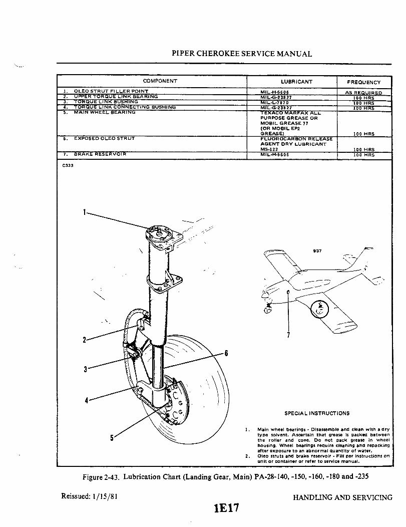
PIPER CHEROKEE SERVICE MANUAL
COMPONENT
1. OLEO STRUT FILLER POINT2. UPPER TORQUE LINK BEARING3. TORQUE LINK BUSHING4. TORQUE LINK CONNECTING BUSHING5. MAIN WHEEL BEARING
6. EXPOSED OLEO STRUT
7. BRAKE RESERVOIR
LUBRICANT
MIL-H-5606MIL-G-23827MIL-L-7870MIL-G-23827TEXACO MARFAX ALLPURPOSE GREASE ORMOBIL GREASE 77(OR MOBIL EP2GREASE)FLUOROCARBON RELEASEAGENT DRY LUBRICANTMS-122MIL-H-5606
FREQUENCY
AS REQUIRED100 HRS100 HRS100 HRS
100 HRS
100 HRS100 HRS
C333
the roller and cone. Do not pack grease in wheelhousing. Wheel bearings require cleaning and repackingafter exposure to an abnormal quantity of water.
2. Oleo struts and brake reservoir - Fill per Instructions onunit or container or refer to service manual.
Figure 2-43. Lubrication Chart (Landing Gear, Main) PA-28-140, -150, -160, -180 and -235
Reissued: 1/15/81 HANDLING AND SERVICING
1E17

0
a

PIPER CHEROKEE SERVICE MANUAL
COMPONENT
1. OLEO STRUT FILLER POINT2. STEERING BELLCRANK PIVOT POINT3. SHIMMY DAMPENER PIVOT POINT4. TORQUE LINK ASSEMBLY5. NOSE WHEEL BEARING
6. NOSE GEAR STEERING ROD END BEARINGS7. BUNGEE SEAL (1974 MODELS AND UP)
8. EXPOSED OLEO STRUT
LUBRICANT
MIL-H-S606MIL-L-7870MIL-L-7870MIL-L-7870TEXACO MARFAX ALLPURPOSE GREASE ORMOBIL GREASE 77(OR MOBIL EP2GREASE)MIL-L-7870PARKER O-RINGLUBRICANTFLUOROCARBON RELEASEAGENT DRY LUBRICANTMS-122
FREQUENCY
AS REQUIRED100 HRS100 HRS100 HRS
100 HRS100 HRS
100 HRS
100 HRS
C334
7
6
7
SPECIAL INSTRUCTIONS
Nose wheel bearings Disassemble and clean with a drytype solvent. Ascertain that grease is packed betweenthe roller and cone. Do not pack grease in wheelhousing. Wheel bearings require cleaning and repackingafter exposure to an abnormal quanity of water.Oleo struts - Fill per instructions on unit or refer toservice manual.Bungee - Lubricate springs if bungee Is disassembled.
Figure 2-45. Lubrication Chart (Landing Gear, Nose) PA-28-140, -150, -160, -180 and -235
Reissued: 1/15/811E19
HANDLING AND SERVICING

PIPER CHEROKEE SERVICE MANUAL
COMPONENT
1. NOSE GEAR STRUT HOUSING GREASE FITTING2. NOSE GEAR PIVOT POINT AND HYDRAULIC
CYLINDER ROD END3. NOSE GEAR DOOR RETRACTION MECHANISM4. NOSE GEAR DOOR HINGES5. EXPOSED OLEO STRUT
6. NOSE WHEEL BEARINGS
7. NOSE GEAR DRAG LINK ASSEMBLIES8. NOSE GEAR TORQUE LINK ASSEMBLY AND
STRUT HOUSING9. DOWNLOCK, ROLLER TENSION SPRING,
SHIMMY DAMPENER AND ALIGNING ROLLERPIVOT POINTS
10. STEERING BELL- NK PIVOT POINTS ANDROD ENDS
11. NOSE GEAR OLEO STRUT FILLER POINT12. BUNGEE SPRING (1974 MODELS AND UP)13. FIRE WALL BUNGEE SEAL (1974 MODELS AND UP)
LUBR ICANT
MIL-G-23827
MIL-L-7870MIL-L-787 0MIL-L-787 0FLUOROCARBON RELEASEAGENT DRY LUBRICANTMS-122TEXACO MARFAX ALLPURPOSE GREASE ORMOBIL MOBIL GREASE77 (OR MOBIL EP2GREASE)MIL-L-7870
MIL-G-23827
MIL-L-787 0
MIL-L-7870MIL-H-5606MIL-G-7711AERO LUBRIPLATE
FREQUENCY
100 HRS
100 HRS100 HRS100 HRS
100 HRS
100 HRS100 HRS
100 HRS
100 HRS
100 HRSAS REQUIRED
100 HRS100 HRS
1723
SPECIAL INSTRUCTIONS
1. Nose wheel bearings- Disassemble and clean with adry type solvent. Ascertain that grease Is packedbetween the roller and cone. Do not pack grease Inwheel housing. Wheel bearings require cleaning andrepacking after exposure to an abnormal quantity ofwater.
2. Oleo struts - Fill per Instructions on unit or refer toservice manual.
Figure 2-46.
Reissued: 1/15/81
Lubrication Chart (Landing Gear, Nose) PA-28R-180 and -200
HANDLING AND SERVICING
1E20
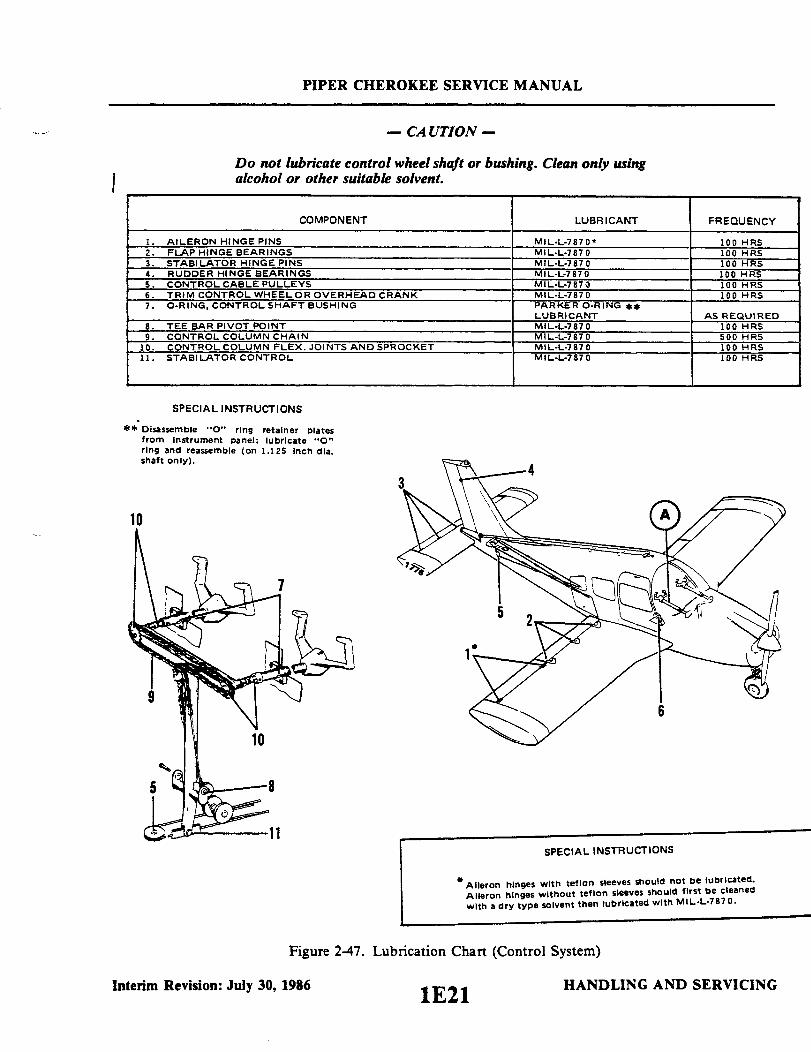
PIPER CHEROKEE SERVICE MANUAL
- CA UTION -
Do not lubricate control wheel shaft or bushing. Clean only usingalcohol or other suitable solvent.
COMPONENT
1. AILERON HINGE PINS2. FLAP HINGE BEARINGS3. STABILATOR HINGE PINS4. RUDDER HINGE BEARINGS5. CONTROL CABLE PULLEYS6. TRIM CONTROL WHEELOR OVERHEAD CRANK7. O-RING CONTROL SHAFT BUSHING
8. TEE BAR PIVOT POINT9. CONTROL COLUMN CHAIN
10. CONTROL COLUMN FLEX. JOINTS AND SPROCKET11. STABILATOR CONTROL
LUBRICANT
MIL-L-7870MIL-L-7870MIL-L-787 0MIL-L-7870MIL-L-787MIL-L-7870PARKER O-RING **LUBRICANTMIL-L-7870MIL-L-7870MIL-L-787 0MIL-L-787 0
FREQUENCY
100 HRS100 HRS100 HRS100 HRS100 HRS100 HRS
AS REQUIRED100 HRS500 HRS100 HRS100 HRS
SPECIAL INSTRUCTIONS
** Disassemble "0" ring retainer platesfrom Instrument panel; lubricate "0"ring and reassemble (on 1.125 Inch dia.shaft only).
8
11
Interim Revision: July 30, 1
SPECIAL INSTRUCTIONS
Aileron hinges with teflon sleeves should not be lubricated.Aileron hinges without teflon sleeves should first be cleanedwith a dry type solvent then lubricated with MIL-L-7870.
Figure 2-47. Lubrication Chart (Control System)
1986 1E21 HANDLING AND SERVICII1E21

LL

PIPER CHEROKEE SERVICE MANUAL
COMPONENT
1. RUDDER TUBE BEARING BLOCKS
2. TOE BRAKE CYLINDER ATTACHMENTS3. RUDDER TUBE CONNECTIONS4. BRAKE ROD ENDS
937
1608
LUBRICANT FREQUENCY
FLUOROCARBON RELEASEAGENT DRY LUBRICANTMS-122 100 HRSMIL-L-7870 100 HRSMIL-L-7870 100 HRSMIL-L-7870 100 HRS
1720
SKETCH A PA-28-140,150,-160,-180 AND -235 SKETCH A PA-28R-180 AND .200
Figure 2-49. Lubrication Chart (Control System) (cont.)
Reissued: 1/15/81 1E231E23
HANDLING AND SERVICING
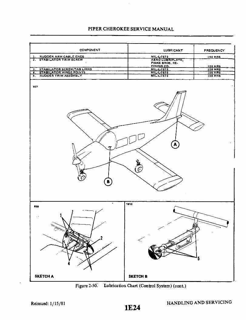
PIPER CHEROKEE SERVICE MANUAL
COMPONENT
1. RUDDER ARM CABLE ENDS2. STABILATOR TRIM SCREW
3. STABILATOR SCREW/TAB LINKS4. STABILATOR HINGE POINTS5. RUDDER TRIM ASSEMBLY
LUBRICANT
MIL-L-7870AERO LUBRIPLATE,FISKE BROS. RE-FINING CO.MIL-L-787 0MIL-L-7870MIL-L-7870
937
938
SKETCH A
Figure 2-50.
1810
SKETCH B
Lubrication Chart (Control System) (cont.)
Reissued: 1/15/811E24
HANDLING AND SERVICING
FREQUENCY
100 HRS
100 HRS100 HRS100 HRS100 HRS

PIPER CHEROKEE SERVICE MANUAL
COMPONENT
1. DOOR HINGES2. DOOR SEALS
3. DOOR LATCH MECHANISMS4. SEAT TRACK ROLLERS, STOP PINS AND REAR SEAT
LEG RETAINER (CLIP AND CAM)
LUBRICANT
MIL-L-7870FLUOROCARBON RELEASEAGENT DRY LUBRICANTMS-122MIL-L-7 870AERO LUBRIPLATE
ORMAG-1
FREQUENCY
100 HRS
50 HRS500 HRS
100 HRS
1744
SPECIAL INSTRUCTIONS
Apply fluorocarbon dry lubricant to door seals at least once amonth to prevent the seal from sticking, and improve sealingcharacteristics.
Figure 2-51. Lubrication Chart (Cabin Door, Baggage Door and Seat)
Reissued: 1/15/81 HANDLING AND SERVICING
1FI

a
ENGINE SUMP
FILTERS
0
U
,
A 0
8
0
0

PIPER CHEROKEE SERVICE MANUAL
COMPONENT
1. DIAPHRAGM SHAFT AND BUSHING
2. BACK-UP EXTENDER LINKS AND CONTROL ARMPIVOT POINTS
3. BACK-UP EXTENDER SPRING ATTACHMENT POINTS4. FUEL SELECTOR LINKAGE5. FUEL SELECTOR VALVE COVER PLATE
6. ACTUATING RODCONTACT POINTS
A103
PA-28R-180 & 200
LUBRICANT
MIL-L-7870 ABOVE20 FMIL-C-21567 BELOW20 F
MIL-L-7870MIL-L-7870MIL-L-7870
FLUOROCARBON RELEASEAGENT DRY LUBRICANTMS-122
AERO LUBRIPLATE OR MAG-1
1673
PA-28-235
5
SPECIAL INSTRUCTIONS
1. Diaphragm shaft and bushing - soft film siliconcompound (MIL-C-21567) Is recommended for usewhen operating at temperatures below 200 F.
2. Fuel selector valve - Lubricate area where detent ballmoves across cover plate (on external detent valvesonly).
Figure 2-53. Lubrication Chart (Back-Up Extender and Fuel Selector)
Reissued: 1/15/811F3
HANDLING AND SERVICING
FREQUENCY
100 HRS
100 HRS100 HRS100 HRS
100 HRS
100 HRS

PIPER CHEROKEE SERVICE MANUAL
COMPONENT
1. CONDENSER HINGE AND ACTUATORS2. CONDENSER DOOR ACTUATING TRANSMISSION
LUBRICANT
MIL-L-7870MIL-G-23827
FREQUENCY
100 HRS500 HRS
1778
SPECIAL INSTRUCTIONS
Transmission to be 1/2 full of grease. Apply grease during
assembly and lubricate transmission ball nut and screw with
MIL-G-23827 grease.
Figure 2-54. Lubrication Chart (Air Conditioning Condenser)
HANDLING AND SERVICINGReissued: 1/15/811F4

1F5INTENTIONALLY LEFT BLANK

PIPER CHEROKEE SERVICE MANUAL
SECTION m
INSPECTION
AeroficheGrid No.
Introduction ............................................................................................... 1F7Recommended Lubricants................................................................... F7Inspection Periods ..................................................................................... 1F73-4 Inspection Requirements ................................................... 1f73-5 Preflight Check..................................................................1F83-6 Overlimits Inspection ........................................................ 1F93-7 Special Inspections...........................................................1F93-8 Programmed M aintenance ...............................................1F93-9 Inspection of Exhaust System ......... . ....................... 1F93-10 Field Check of PA-28R-180, -200 Muffler Assembly ...... F133-11 Inspection of Control W heels 1F15.................................. 1F153-1 la Elevator Control Cable Inspection .................................... IF163-12 Inspection of Flap Control Cable Attachment Bolt........... F163-13 Inspection of Induction Air Inlet Duct and Alternate
Heat Duct ................................................................. F173-13a Inspection of Seals at Landing Light on Air Filter
Retaining Plate ........................................................1F173-14 Inspection of Main Landing Gear Torque Links ............... 1F17
Interim Revision: February 15, 1995
1F6
3-13-23-3
I

PIPER CHEROKEE SERVICE MANUAL
SECTION III
INSPECTION
3-1. INTRODUCTION. This section provides instructions for conducting inspections.These inspections are described in paragraphs 34 and 3-5. Repair or replacementinstructions for those components found to be unserviceable at inspection may be found inthe section covering the applicable aircraft system.
CAUTION
When working on engines, ground the magneto primarycircuit before performing any operation.
3-2. RECOMMENDED LUBRICANTS. Refer to Recommended Lubricants. Section II forLubrication Servicing Instructions.
3-3. INSPECTION PERIODS.
3-4. INSPECTION REQUIREMENTS. Required inspection procedures are listed in Table1ll-1 (PA-28-140; PA-28-150, -160. -180: PA-28-235) or ll-11 (PA-28R). The inspectionprocedure is broken down into nine major groups which are Propeller. Engine. Cabin,Fuselage and Empennage. Wing. Landing Gear, Float Group. Operational Inspection andGeneral. The first column in each group lists the inspection or procedure to be performed. Thesecond column is divided into four columns indicating the required inspection intervals of50 hours. 100 hours. 500 hours. and 1000 hours. Each inspection or operation is required ateach of the inspection intervals as indicated by a circle (O). If an item is not entirely accessibleor must be removed. refer to the applicable section of this manual for instructions on how togain access to remove the item. When performing inspections, use forms furnished by the PiperFactory Service Department. available through Piper Dealers or Distributors.
Reissued: 1/15/81 INSPECTION1F7
PIPER CHEROKEE SERVICE MANUAL
NOTE
In addition to inspection intervals required in Table III-I orIII-II, preflight check must be performed as described inParagraph 3-5.
3-5. PREFLIGHT CHECK. The airplane must be given a thorough preflight andwalk-around check. The pilot and/or mechanic must include the preflight check as a normalprocedure necessary for the safe operation of the aircraft. Refer to the Pilot's OperatingManual for a listing of items that must be checked.
THIS SPACE INTENTIONALLY LEFT BLANK
Reissued: 1/15/81 INSPECTIONINSPECTION
1F8
PIPER CHEROKEE SERVICE MANUAL
3-6. OVERLIMITS INSPECTION. If the airplane has been operated so that any of itscomponents have exceeded their maximum operational limits, check with the appropriatemanufacturer.
3-7. SPECIAL INSPECTIONS. The special inspections given in the following paragraphs,supplement the scheduled inspections as outlined in the Inspection Report, Table III-I orIII-II, to include inspection of items which are required to be examined at intervals notcompatible with airframe operating time or airframe inspection intervals. Typical of thistype are:
a. Inspection is required because of special conditions or incidents that arise, andbecause of these conditions or incidents, an immediate inspection would be required toinsure further safe flight.
b. Inspection of airframe or components on a calendar basis. This type of inspectioncould often be accomplished during the nearest scheduled inspection.
c. Specific definitive inspection on engines based strictly upon engine operating time.d. Those inspections not completely covered in other sections of this manual, but
outlined in the Inspection Report and must be explained in more detail to give a clearer andcomplete inspection.
3-8. PROGRAMMED MAINTENANCE. The programmed maintenance was designed topermit the utilization of the aircraft, by scheduling inspections through the use of a plannedinspection schedule. Programmed Maintenance schedules are available from Service Sales.
3-9. INSPECTION OF EXHAUST SYSTEM. (Refer to Figure 3-1 thru 3-3.) The entireexhaust system, including heat exchange shroud, muffler, muffler baffles, stacks and allexhaust connections must be rigidly inspected at each 100 hour inspection. The possibilityof exhaust system failure increases with use. It is recommended that the system be checkedmore carefully as the number of hours increase, therefore inspection at the 700 hour period,that the exhaust system has been in use, would be more critical than one in the 100 hourperiod. The system should also be checked carefully before winter operation when the cabinheat will be in use.
NOTE
It is recommended that all PA-28 airplanes be fitted with anew muffler at or near the 1000 hour period of which themuffler has been in use.
Reissued: 1/15/81 INSPECTION
1F9

PIPER CHEROKEE SERVICE MANUAL
A950INSPECT FOR CRACKS IN THESE AREAS
INSPECT FOR CRACKS IN THIS AREA
Figure 3-1. Typical Muffler Fatigue Areas
Removal of the tail pipe and stacks is required for inspectionof the mufflerbaffle. Remove or loosen all exhaust shields, carburetor and cabin heat muffs,shrouds, heat blankets, etc., as required to permit inspection of the completesystem. Perform the necessary cleaning operations and inspect all external sur-faces for dents, cracks and missing parts. Pay particular attention to welds,clamps, supports and support attachment lugs, slip joints, stack flanges andgaskets. Inspect internal baffle or diffusers. Any cracks, warpage or severeoxidation are cause for replacement of the muffler.
If any component is inaccessible for a thorough visual inspection, accom-plish one of the following:
a. Accomplish a submerged pressure check of the muffler and exhaust stackat 2 psi air pressure.
b. Conduct a ground test using a carbon monoxide indicator by heading theairplane into the wind, warming the engine on the ground, advancing the throttleto full static RPM with cabin heat valves open, and taking readings of the heatedairstream inside the cabin at each outlet (including rear seat heat outlet, if in-stalled). Appropriate sampling procedures applicable to the particular indicatormust be followed. If carbon monoxide concentration exceeds .005 percent or ifa dangerour reading is obtained on an indicator not calibrated in percentages,the muffler must be replaced.
Reissued: 1/15/81 INSPECTION1FlO
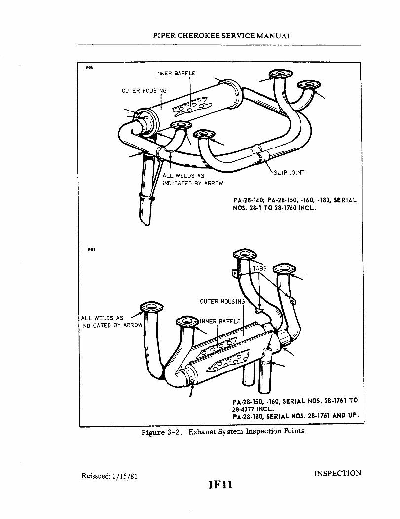
PIPER CHEROKEE SERVICE MANUAL
965
PA-28-140; PA-28-150, .160, -180, SERIALNOS. 28-1 TO 28-1760 INCL.
981
ALL WELDS ASINDICATED BY ARROW
PA-28-150, .160, SERIAL NOS. 28-1761 TO28-4377 INCL.PA-28-180, SERIAL NOS. 28-1761 AND UP.
Figure 3-2. Exhaust System Inspection Points
Reissued: 1/15/81 INSPECTION
1Fll

PIPER CHEROKEE SERVICE MANUAL
968
ALL WELDS AS INDICATEDBY ARROW
PA-28-235
1718
OUTER
INNER BAFFLE
ALL WELDS AS INDICATED BY ARROW
PA-28R
Figure 3-3 Exhaust System Inspection Points
Reissued: 1/15/81 INSPECTION
1F12

PIPER CHEROKEE SERVICE MANUAL
3-10. FIELD CHECK OF PA-28R-180 and -28R-200 MUFFLER ASSEMBLIES. (Referto Figure 3-4.)
a. Remove end clips.b. Check for any movement between the heater muff end plates and the muffler pipes in
the directions shown on Figure 3-4. If there is no movement, the muffler assembly is accept-able.
c. If there is any movement, remove the muffler assembly and inspect all parts, especial-ly for abnormal wear on muffler shroud. Rework the end plates to give a .03" min. gap afterassembly.
d. Prior to reassembly, the two top screw holes in the upper shroud assembly should beslotted as necessary to allow the screws to be installed without causing any deformations ofthe skin.
e. Install, but do not tighten, the two screws which hold the lower shroud assembly inplace.
f. Install the end strap clamps and torque them from 25 to 30 inch-pounds before in-stalling the two top screws which hold the top shroud assembly in place.
g. Tighten the two lower screws and then the two upper screws.h. Check the muffler for tightness after assembly.
Reissued: 1/15/81 INSPECTION1F13
Reissued: 1/15/81

PIPER CHEROKEE SERVICE MANUAL
3030
CHECK FOR ANY MOVEMENTOF THE END PLATES INTHESE DIRECTIONS
1. END PLATES2. END CLIPS3. END
TOP SCREWS (ADD AFTERSTRAP CLAMPS ARE TORQUED)
.03" MINIMUM GAPBETWEEN END PLATESAFTER ASSEMBLY
Figure 3-4. Exhaust System Installation, PA-28R-180, -200
Reissued: 1/15/81 INSPECTION
1F14
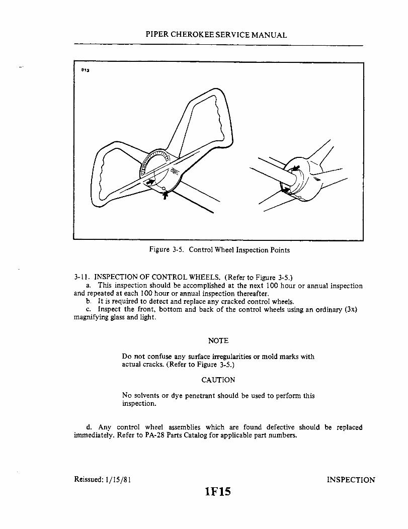
PIPER CHEROKEE SERVICE MANUAL
913
Figure 3-5. Control Wheel Inspection Points
3-11. INSPECTION OF CONTROL WHEELS. (Refer to Figure 3-5.)a. This inspection should be accomplished at the next 100 hour or annual inspection
and repeated at each 100 hour or annual inspection thereafter.b. It is required to detect and replace any cracked control wheels.c. Inspect the front, bottom and back of the control wheels using an ordinary (3x)
magnifying glass and light.
NOTE
Do not confuse any surface irregularities or mold marks withactual cracks. (Refer to Figure 3-5.)
CAUTION
No solvents or dye penetrant should be used to perform thisinspection.
d. Any control wheel assemblies which are found defective should be replacedimmediately. Refer to PA-28 Parts Catalog for applicable part numbers.
Reissued: 1/15/81 INSPECTION
1F15
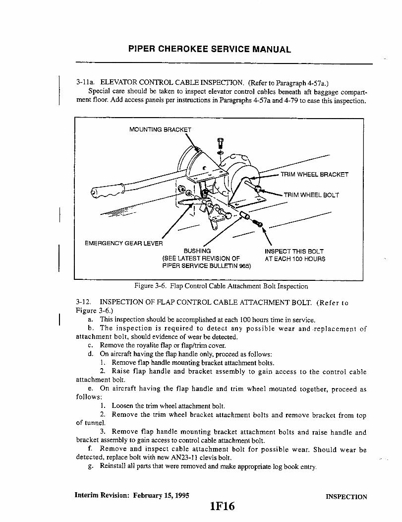
PIPER CHEROKEE SERVICE MANUAL
3-1la. ELEVATOR CONTROL CABLE INSPECTION. (Refer to Paragraph 4-57a.)Special care should be taken to inspect elevator control cables beneath aft baggage compart-
ment floor. Add access panels per instructions in Paragraphs 4-57a and 4-79 to ease this inspection.
MOUNTING BRACKET
EMERGENCY GEAR LEVERBUSHING INSPECT THIS BOLT
(SEE LATEST REVISION OF AT EACH 100 HOURSPIPER SERVICE BULLETIN 965)
Figure 3-6. Flap Control Cable Attachment Bolt Inspection
3-12. INSPECTION OF FLAP CONTROL CABLE ATTACHMENT BOLT. (Refer toFigure 3-6.)
a. This inspection should be accomplished at each 100 hours time in service.b. The inspection is required to detect any possible wear and replacement of
attachment bolt, should evidence of wear be detected.c. Remove the royalite flap or flap/trim cover.d. On aircraft having the flap handle only, proceed as follows:
1. Remove flap handle mounting bracket attachment bolts.2. Raise flap handle and bracket assembly to gain access to the control cable
attachment bolt.e. On aircraft having the flap handle and trim wheel mounted together, proceed as
follows:1. Loosen the trim wheel attachment bolt.2. Remove the trim wheel bracket attachment bolts and remove bracket from top
of tunnel.3. Remove flap handle mounting bracket attachment bolts and raise handle and
bracket assembly to gain access to control cable attachment bolt.f. Remove and inspect cable attachment bolt for possible wear. Should wear be
detected, replace bolt with new AN23-11 clevis bolt.g. Reinstall all parts that were removed and make appropriate log book entry.
Interim Revision: February 15, 1995 INSPECTION
1F16
I
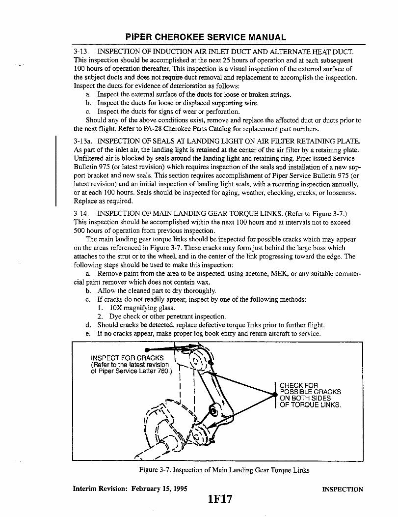
PIPER CHEROKEE SERVICE MANUAL
3-13. INSPECTION OF INDUCTION AIR INLET DUCT AND ALTERNATE HEAT DUCT.This inspection should be accomplished at the next 25 hours of operation and at each subsequent100 hours of operation thereafter. This inspection is a visual inspection of the external surface ofthe subject ducts and does not require duct removal and replacement to accomplish the inspection.Inspect the ducts for evidence of deterioration as follows:
a. Inspect the external surface of the ducts for loose or broken strings.b. Inspect the ducts for loose or displaced supporting wire.c. Inspect the ducts for signs of wear or perforation.Should any of the above conditions exist, remove and replace the affected duct or ducts prior to
the next flight. Refer to PA-28 Cherokee Parts Catalog for replacement part numbers.
3-13a. INSPECTION OF SEALS AT LANDING LIGHT ON AIR FILTER RETAINING PLATE.As part of the inlet air, the landing light is retained at the center of the air filter by a retaining plate.Unfiltered air is blocked by seals around the landing light and retaining ring. Piper issued ServiceBulletin 975 (or latest revision) which requires inspection of the seals and installation of a new sup-port bracket and new seals. This section requires accomplishment of Piper Service Bulletin 975 (orlatest revision) and an initial inspection of landing light seals, with a recurring inspection annually,or at each 100 hours. Seals should be inspected for aging, weather, checking, cracks, or looseness.Replace as required.
3-14. INSPECTION OF MAIN LANDING GEAR TORQUE LINKS. (Refer to Figure 3-7.)This inspection should be accomplished within the next 100 hours and at intervals not to exceed500 hours of operation from previous inspection.
The main landing gear torque links should be inspected for possible cracks which may appearon the areas referenced in Figure 3-7. These cracks may form just behind the large boss whichattaches to the strut or to the wheel, and in the center of the link progressing toward the edge. Thefollowing steps should be used to make this inspection:
a. Remove paint from the area to be inspected, using acetone, MEK, or any suitable commer-cial paint remover which does not contain wax.
b. Allow the cleaned part to dry thoroughly.c. If cracks do not readily appear, inspect by one of the following methods:
1. 10X magnifying glass.2. Dye check or other penetrant inspection.
d. Should cracks be detected, replace defective torque links prior to further flight.e. If no cracks appear, make proper log book entry and return aircraft to service.
INSPECT FOR CRACKS(Refer to the latest revisionof Piper Service Letter 760.)
CHECK FORPOSSIBLE CRACKSON BOTH SIDESOF TORQUE LINKS.
Figure 3-7. Inspection of Main Landing Gear Torque Links
Interim Revision: February 15, 1995 INSPECTION
1F17
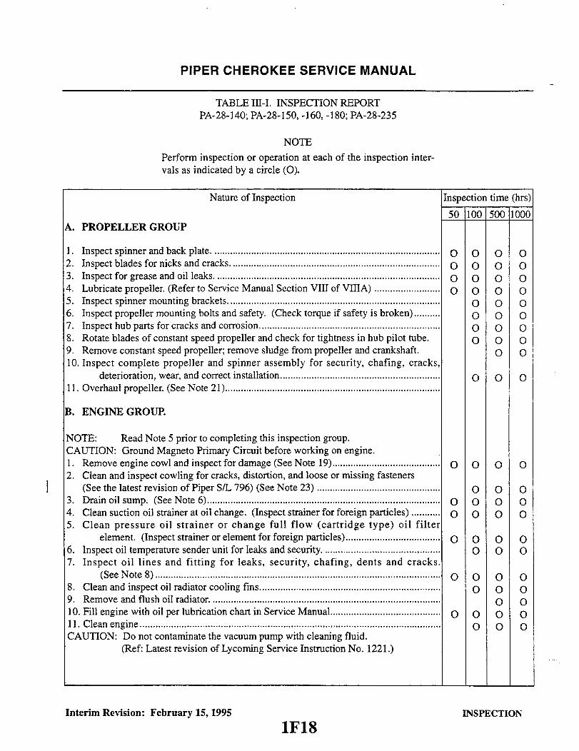
PIPER CHEROKEE SERVICE MANUAL
TABLE III-I. INSPECTION REPORTPA-28-140; PA-28-150, -160, -180; PA-28-235
NOTE
Perform inspection or operation at each of the inspection inter-vals as indicated by a circle (O).
Nature of Inspection Inspection time (hrs)
50 100 500 1000
1. Inspect spinner and back plate. .....................................................................................2. Inspect blades for nicks and cracks ...............................................................................3. Inspect for grease and oil leaks. ....................................................................................4. Lubricate propeller. (Refer to Service Manual Section VIII of VIIIA) .........................5. Inspect spinner mounting brackets ................................................................................6. Inspect propeller mounting bolts and safety. (Check torque if safety is broken)..........7. Inspect hub parts for cracks and corrosion.....................................................................8. Rotate blades of constant speed propeller and check for tightness in hub pilot tube.9. Remove constant speed propeller; remove sludge from propeller and crankshaft.10. Inspect complete propeller and spinner assembly for security, chafing, cracks,
deterioration, wear, and correct installation.............................................................11. Overhaul propeller. (See Note 21)..................................................................................
0000
0 0 00 0 00 0 00 0 00 0 00 0 00 0 00 0 0
0 0
0 0 0
B. ENGINE GROUP.
NOTE: Read Note 5 prior to completing this inspection group.CAUTION: Ground Magneto Primary Circuit before working on engine.1. Remove engine cowl and inspect for damage (See Note 19).........................................2. Clean and inspect cowling for cracks, distortion, and loose or missing fasteners
(See the latest revision of Piper S/L 796) (See Note 23) ...............................................3. Drain oil sump. (See Note 6).........................................................................................4. Clean suction oil strainer at oil change. (Inspect strainer for foreign particles) ...........5. Clean pressure oil strainer or change full flow (cartridge type) oil filter
element. (Inspect strainer or element for foreign particles)....................................6. Inspect oil temperature sender unit for leaks and security ............................................7. Inspect oil lines and fitting for leaks, security, chafing, dents and cracks.
(See N ote 8).............................................................................................................8. Clean and inspect oil radiator cooling fins.....................................................................9. Remove and flush oil radiator. .......................................................................................10. Fill engine with oil per lubrication chart in Service Manual..........................................11. C lean engine...................................................................................................................CAUTION: Do not contaminate the vacuum pump with cleaning fluid.
(Ref: Latest revision of Lycoming Service Instruction No. 1221.)
Interim Revision: February 15, 1995
0 00
00
0
0 000 000 00
0 000 00
INSPECTION
1F18
A. PROPELLER GROUP
0
00000

PIPER CHEROKEE SERVICE MANUAL
TABLE 11l-1. INSPECTION REPORT (cont)PA-28-140; PA-28-150, -160, -180; PA-28-235
Nature of Inspection
B. ENGINE GROUP (cont.)12. Inspect condition of spark plugs (Clean and adjust gap as required, adjust
per the latest revision of Lycoming Service Instruction No. 1042)(See N ote 15) ...............................................
NOTE: If fouling of spark plugs has been apparent, rotate bottom plugsto upper plugs.
13. Inspect spark plug cable leads and ceramics for corrosion and deposits ...14. Check cylinder compression (Ref: AC 43.13-lA) .......................15. Inspect cylinders for cracked or broken fins ...........................16. Inspect rocker box covers for evidence of oil leaks. If found, replace
gasket; torque cover screws 50 inch-pounds (See Note 13) ...............NOTE: Lycoming requires a Valve Inspection be made at completion of
every 400 hours of operation. (See Note 12)17. Inspect ignition harness and insulators (high tension leakage and
continuity) ........................................................18. Inspect magneto points for condition and proper clearance (Refer to
Service Manual Section VIII or VIIIA) ..............................19. Inspect magneto for oil leakage ......................................20. Inspect breaker felts for proper lubrication ............................21. Inspect distributor block for cracks, burned areas or corrosion and
height of contact springs ...........................................22. Check magnetos to engine timing ....................................23. Overhaul or replace magnetos (See Note 7)............................24. Remove air filter and tap gently to remove dirt particles (Replace
as required, refer to latest revision of Piper Service Bulletin 975, as applicable.).25. Drain carburetor and clean inlet line fuel'strainer ......................26. Inspect condition of carburetor heat air door and box (See Note 14) .....27. Inspect vent lines for evidence of fuel or oil seepage ....................28. Inspect intake seals for leaks and clamps for tightness ..................29. Inspect all air inlet duct hoses (Replace as required) ....................30. Inspect condition of flexible fuel lines ................................31. Replace flexible fuel lines (See Note 7) ................................32. Inspect fuel system for leaks (See Note 16) ............................33. Clean screens in electric fuel pump(s) and check operation
(engine and electric) ................................................34. Overhaul or replace fuel pumps (engine driven) (See Note 7) ...........35. Remove and clean fuel filter bowl and screen (Clean at least every
90 days) (PA-28-140, -150, -160, -180) ................................36. Inspect vacuum pump and lines .....................................37. Overhaul or replace vacuum pump (See Note 7) .......................38. Inspect throttle, carburetor heat, mixture and propeller governor controls
for security, travel and operating conditions (Refer to the latest revisionof Piper Service Bulletin No. 448 and Service Letter No. 747) .......
39. Inspect exhaust stacks, connections and gaskets (Refer to ServiceManual, Section III) (Replace gaskets as required) .....................
40. Inspect muffler, heat exchange and baffles (Refer to Service Manual,Section III) .......................................................
Inspection Time (hrs)
50 100 500 1000
0
000000
0
0
0
O 0 0O 0 0O 0 0
O 0 0
O 0 0
O 0 0O 0 0O 0 0
0 0O 0 0
O 0 0O 0 0O 0 0O 0 0O 0 0O O OO O O
O 0 O
O O 0
O O OO O 0
O O 0
O
0
O 0
0 0
Interim Revision: February 15, 1995 INSPECTION1F19
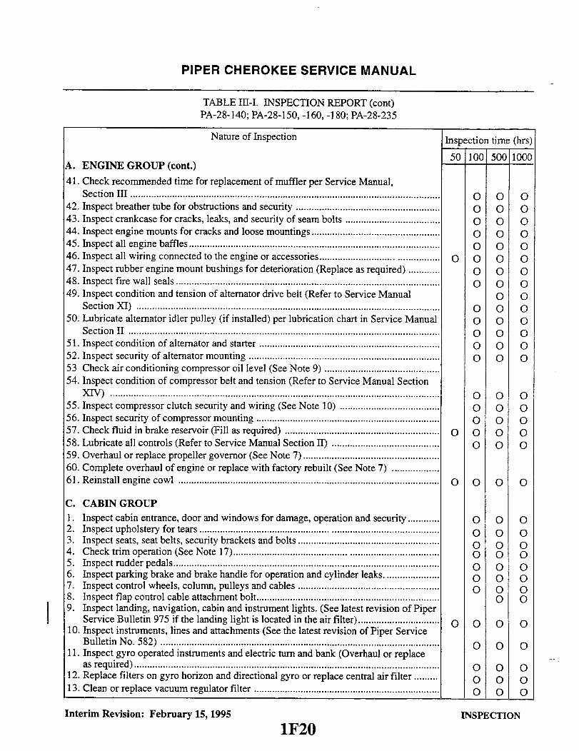
PIPER CHEROKEE SERVICE MANUAL
TABLE III-I. INSPECTION REPORT (cont)PA-28-140; PA-28-150, -160, -180; PA-28-235
Nature of Inspection
A. ENGINE GROUP (cont.)
41. Check recommended time for replacement of muffler per Service Manual,Section III ......................................................................................................................
42. Inspect breather tube for obstructions and security .......................................................43. Inspect crankcase for cracks, leaks, and security of seam bolts ....................................44. Inspect engine mounts for cracks and loose mountings.................................................45. Inspect all engine baffles ..............................................................................................46. Inspect all wiring connected to the engine or accessories.............................................47. Inspect rubber engine mount bushings for deterioration (Replace as required) ............48. Inspect fire wall seals .....................................................................................................49. Inspect condition and tension of alternator drive belt (Refer to Service Manual
Section XI) ....................................................................................................................50. Lubricate alternator idler pulley (if installed) per lubrication chart in Service Manual
Section II .......................................................................................................................51. Inspect condition of alternator and starter .....................................................................52. Inspect security of alternator mounting .........................................................................53 Check air conditioning compressor oil level (See Note 9) ............................................54. Inspect condition of compressor belt and tension (Refer to Service Manual Section
XIV) ..............................................................................................................................55. Inspect compressor clutch security and wiring (See Note 10) ......................................56. Inspect security of compressor mounting ......................................................................57. Check fluid in brake reservoir (Fill as required) ...........................................................58. Lubricate all controls (Refer to Service Manual Section II) .........................................59. Overhaul or replace propeller governor (See Note 7) ....................................................60. Complete overhaul of engine or replace with factory rebuilt (See Note 7) ..................61. Reinstall engine cowl ....................................................................................................
C. CABIN GROUP1. Inspect cabin entrance, door and windows for damage, operation and security............2. Inspect upholstery for tears ........................................ ...................................................3. Inspect seats, seat belts, security brackets and bolts ......................................................4. Check trim operation (See Note 17)...................................... ..................................5. Inspect rudder pedals......................................................................................................6. Inspect parking brake and brake handle for operation and cylinder leaks. ....................7. Inspect control wheels, column, pulleys and cables ......................................................8. Inspect flap control cable attachment bolt......................................................................9. Inspect landing, navigation, cabin and instrument lights. (See latest revision of Piper
Service Bulletin 975 if the landing light is located in the air filter)...............................10. Inspect instruments, lines and attachments (See the latest revision of Piper Service
Bulletin No. 582) ...........................................................................................................11. Inspect gyro operated instruments and electric turn and bank (Overhaul or replace
as required)................................................. ........................................ ............................12. Replace filters on gyro horizon and directional gyro or replace central air filter .........13. Clean or replace vacuum regulator filter .......................................................................
Interim Revision: February 15, 1995
1F20
Inspection time (hrs)
50 100 500 1000
0 O 0O O O
O O OO O OO O O
O O O OO O OO O O
O OO O OO O OO O oO O OO O O
O O OO O OO O O
O O O OO O O
O O O O
O O OO O0O O OO O OO O OO O OO O O
O O
O O O O
O O O
O O OO O OO O O
INSPECTION

CHEROKEE SERVICE MANUAL
TABLE III-I. INSPECTION REPORT (cont)PA-28-140; PA-28-150,-160,-180; PA-28-235
Inspection Time (hrs)Nature of Inspection
50 100 500 1000
14. Inspect altimeter (Calibrate altimeter system in accordance withFAR 91.170 if appropriate) .........................................
15. Check operation of fuel selector valve (See Note 18) ....................16. Check operation of fuel drain (PA-28-235) ............................17. Inspect condition of heater controls and ducts .........................18. Inspect condition and operation of air vents ...........................19. Inspect condition of air conditioning ducts ............................20. Remove and clean air conditioning evaporator filter ....................
O 0 0O 0 0O 0 0O 0 0o 0 0O 0 0O 0 0
D. FUSELAGE AND EMPENNAGE GROUP
1. Remove inspection plates and panels .................................2. Inspect baggage door, latch and hinges for operation and security ........3. Inspect battery, box and cables (Inspect at least every 30 days. Flush
box as required and fill battery per instructions on box) ................4. Inspect electronic installation ........................................5. Inspect bulkheads and stringers for damage ...........................6. Inspect antenna mounts and electric wiring............................7. Inspect air conditioning system for freon leaks .........................8. Check freon level in sight gauge of receiver-dehydrator (Refer to
Service Manual, Section XIV........................................9. Inspect air conditioning condenser air scoop rigging (Refer to Service
Manual, Section XIV) ..............................................10. Inspect fuel lines, valves, and gauges for damage and operation ..........11. Clean screens in fuel pumps (PA-28-235 only) .........................12. Inspect fuel valve drain lever cover for security and door for proper
operation (PA-28-235 only) .........................................13. Remove, drain and clean fuel strainer bowl and screen located in bottom
of selector valve (Drain and clean at least every 90 days) (PA-28-235).....14. Inspect security of all lines ..........................................15. Inspect vertical fin and rudder surfaces for damage .....................16. Inspect rudder hinges, horn and attachments for damage and operation ...17. Inspect rudder control stop to insure stop has not loosened and
locknut is tight ....................................................18. Inspect vertical fin attachments ......................................19. Inspect rudder hinge bolts for excess wear (Replace as required) .........20. Inspect stabilator surfaces for damage ................................21. Inspect stabilator, tab hinges, horn and attachments for damage and
operation .........................................................22. Inspect stabilator control stops to insure stop has not loosened and
locknut is tight ....................................................23. Inspect stabilator attachments (see latest Piper Service Bulletin 856) ......
O O OO O O
O
0
0
0
0
O 0 0O 0 0O 0 0O 0 0o 0 0
O 0 0
O 0 0o 0 0O 0 0
o 0 0
o 0 0O 0 0o 0 0o 0 0
0000OO
O 0O 0O O
0 0 0
O0 0 0
Revised: 8/3/81Interim Revision: 5/6/87 INSPECTION
IF21
C. CABIN GROUP (cont)

PIPER CHEROKEE SERVICE MANUAL
TABLE III-I. INSPECTION REPORT (cont)PA-28-140; PA-28-150, -160, -180; PA-28-235
Nature of Inspection Inspection time (hrs)
D. FUSELAGE AND EMPENNAGE GROUP (cont.) 50 100 5001000
24. Inspect stabilator and tab hinge bolts and bearings for excess wear (Replace asrequired) ........................................................................................................................
25. Inspect stabilator trim mechanism..................................................................................26. Inspect aileron, rudder, stabilator, stabilator trim cables, turbuckles, guides and
pulleys for safety, damage and operation (See Note 24)................................................27. Check all cable tensions (use tensiometer, see Note 20)................................................28. Clean and lubricate stabilator trim drum screw ............................................................29. Clean and lubricate all exterior needle bearings ...........................................................30. Lubricate per lubrication chart in Service Manual.........................................................31. Inspect rotating beacon for security and operation .......................................................32. Inspect security of Autopilot bridle cable clamps (See Note 11) ..................................33. Inspect all control cables, air ducts, electrical leads, lines, radio antenna leads and
attaching parts for security, routing, chafing, deterioration, wear and correctinstallation .....................................................................................................................
34. Inspect E.L.T. installation and condition of battery and antenna (See the latestrevision of Piper S/L No. 820) .......................................................................................
35. Reinstall inspection plates and panels............................................................................
0 0 00 0 00 0 00 0 00 0 0
0 0O
O O O O0 0 00 0 0
0 0 0
0 0 00 0 0
E. WING GROUP
1. Remove inspection plates and fairings ..........................................................................2. Inspect surfaces and tips for damage, loose rivets, and condition of walk-way ............3. Inspect aileron hinges and attachments .......................................................................4. Inspect aileron control stops to insure stop has not loosened and lock nut is tight........5. Inspect aileron cables, pulleys and bellcranks for damage and operation .....................6. Inspect flaps and attachments for damage and operation ..............................................7. Inspect condition of bolts used with hinges (Replace as required)................................8. Lubricate per lubrication chart in Service Manual (Section II) ....................................9. Inspect wing attachment bolts and brackets (See Note 18) ...........................................10. Inspect fuel tanks and lines for leaks, water and contamination (See Note 18).............1 . Fuel tanks marked for capacity .....................................................................................12. Fuel tanks marked for minimum octane rating ..............................................................13. Inspect fuel cell vents (See Note 18) .............................................................................14. Inspect all control cables, air ducts. electrical leads, lines and attaching parts for
security, routing, chafing, deterioration, wear and correct installation ..........................15. Reinstall inspection plates and fairings ..........................................................................
Interim Revision: February 15, 1995
OOoOOOO
0 0O
OOOO
0 00 0O O
0 00 00 00 00 00 00 0O OO O
0 0 00 0 0
INSPECTION
1F22
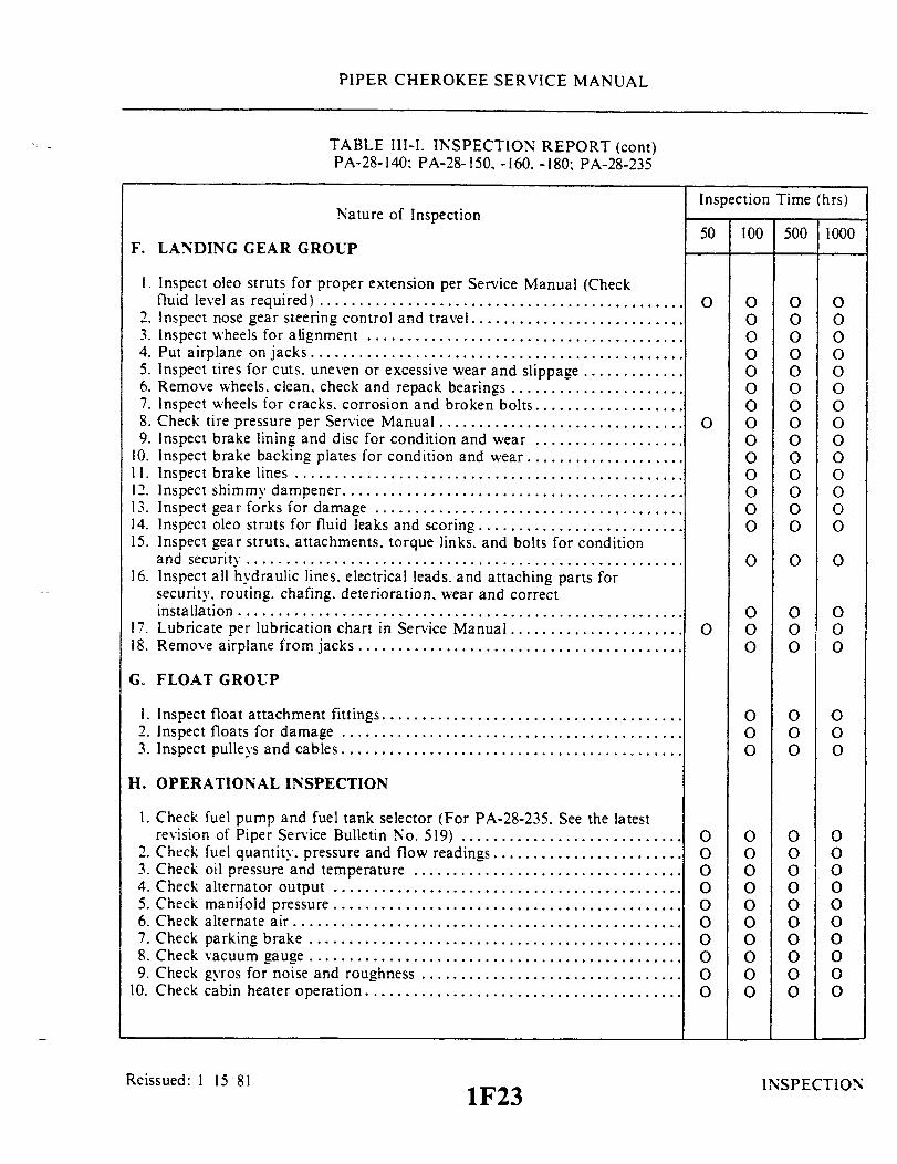
`PIPER CHEROKEE SERVICE MANUAL
TABLE 1ll-1. INSPECTION REPORT (cont)PA-28-140: PA-28-150, -160. -180; PA-28-235
Inspection Time (hrs)Nature of Inspection
50 100 500 1000F. LANDING GEAR GROUP
1. Inspect oleo struts for proper extension per Service Manual (Checkfluid level as required) ..............................................
2. Inspect nose gear steering control and travel ...........................3. Inspect wheels for alignment ........................................4. Put airplane on jacks ...............................................5. Inspect tires for cuts. uneven or excessive wear and slippage .............6. Remove wheels, clean, check and repack bearings ......................7. Inspect wheels for cracks, corrosion and broken bolts...................8. Check tire pressure per Service Manual ...............................9. Inspect brake lining and disc for condition and wear ...................
10. Inspect brake backing plates for condition and wear ....................11. Inspect brake lines .................................................12. Inspect shimmy dampener .........................................13. Inspect gear forks for damage .......................................14. Inspect oleo struts for fluid leaks and scoring ..........................15. Inspect gear struts, attachments, torque links, and bolts for condition
and security .......................................................16. Inspect all hydraulic lines, electrical leads. and attaching parts for
security, routing, chafing. deterioration. wear and correctinstallation ........................................................
17. Lubricate per lubrication chart in Service Manual......................18. Remove airplane from jacks .........................................
O
O
O
O 0 0O 0 0O 0 0O 0 0O 0 0O 0 0O 0 0O 0 0O 0 0O 0 0O O 0O 0 0O 0 0O 0 0
O 0 0
O 0 0O 0 0O 0 0
G. FLOAT GROUP
1. Inspect float attachment fittings ......................2. Inspect floats for damage ...........................3. Inspect pulleys and cables...........................
O 0 0O 0 0O 0 0
H. OPERATIONAL INSPECTION
1. Check fuel pump and fuel tank selector (For PA-28-235. See the latestrevision of Piper Service Bulletin No. 519) ............................
2. Check fuel quantity, pressure and flow readings ...... .................3. Check oil pressure and temperature ..................................4. Check alternator output ............................................5. Check manifold pressure ................... ..................6. Check alternate air.................................................7. Check parking brake ...............................................8. Check vacuum gauge ...............................................9. Check gyros for noise and roughness .................................
10. Check cabin heater operation........................................
Reissued: 1 15 81 1F231F23
0000000000
O 0 0O O O
0 0 OO 0
0 0 O0 0 O0 0 O0 0 O0 0 O0 0 O
INSPECTION
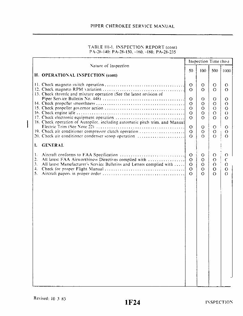
PIPER CHEROKEE SERVICE MANUAL
TABLE 111-I. INSPECTION REPORT (cont)PA-28-140: PA-28-150. -160. -180: PA-28-235
Inspection Time (hrs)Nature of Inspection
50 100 500 1000H. OPERATIONAL INSPECTION (cont)
II. Check magneto switch operation .............. .......................12. Check magneto RPM variation .....................................13. Check throttle and mixture operation (See the latest revision of
Piper Ser ice Bulletin No. 448) ......................................14. Check propeller smoothness .........................................15. Check propeller o\ ernor action .....................................16. Check engine idle ..................................................17. Check electronic equipment operation ................................18. Check operation of Autopilot including automatic pitch trim. and Manual
Electric Trim (See Note 22) .........................................19. Check air conditioner compressor clutch operation .....................20. Check air conditioner condenser scoop operation ......................
00
00000
000O
O 0 0O 0 0
O 0 0O 0 0O O OO 0 OO 0 0
O 0 0O 0 0O 0 0
I. GENERAL
1. Aircraft conforms to FAA Specification ..............................2. All latest FAA Airworthiness Directives complied with .................3. All latest Manufacturer's Service Bulletins and Letters complied with .....4. Check for proper Flight Manual .....................................5. Aircraft papers in proper order ......................................
Revised: 10 3 83 1F241F24
O O O OO O O CO O O OO O O OO O O O
INSPECTION
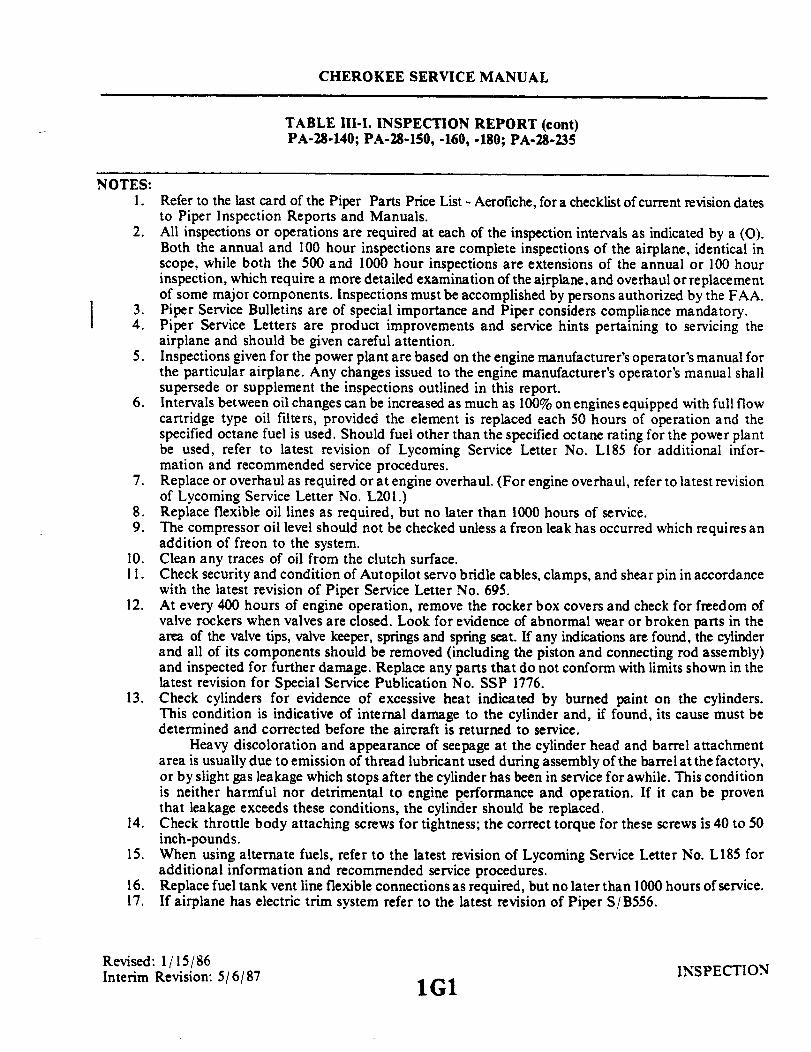
CHEROKEE SERVICE MANUAL
TABLE III-I. INSPECTION REPORT (cont)PA-28-140; PA-28-150, -160, -180; PA-28-235
NOTES:1. Refer to the last card of the Piper Parts Price List - Aerofiche, for a checklist of current revision dates
to Piper Inspection Reports and Manuals.2. All inspections or operations are required at each of the inspection intervals as indicated by a (O).
Both the annual and 100 hour inspections are complete inspections of the airplane, identical inscope, while both the 500 and 1000 hour inspections are extensions of the annual or 100 hourinspection, which require a more detailed examination of the airplane, and overhaul or replacementof some major components. Inspections must be accomplished by persons authorized by the FAA.
3. Piper Service Bulletins are of special importance and Piper considers compliance mandatory.4. Piper Service Letters are product improvements and service hints pertaining to servicing the
airplane and should be given careful attention.5. Inspections given for the power plant are based on the engine manufacturer's operator's manual for
the particular airplane. Any changes issued to the engine manufacturer's operator's manual shallsupersede or supplement the inspections outlined in this report.
6. Intervals between oil changes can be increased as much as 100% on engines equipped with full flowcartridge type oil filters, provided the element is replaced each 50 hours of operation and thespecified octane fuel is used. Should fuel other than the specified octane rating for the power plantbe used, refer to latest revision of Lycoming Service Letter No. L185 for additional infor-mation and recommended service procedures.
7. Replace or overhaul as required or at engine overhaul. (For engine overhaul, refer to latest revisionof Lycoming Service Letter No. L201.)
8. Replace flexible oil lines as required, but no later than 1000 hours of service.9. The compressor oil level should not be checked unless a freon leak has occurred which requires an
addition of freon to the system.10. Clean any traces of oil from the clutch surface.11. Check security and condition of Autopilot servo bridle cables, clamps, and shear pin in accordance
with the latest revision of Piper Service Letter No. 695.12. At every 400 hours of engine operation, remove the rocker box covers and check for freedom of
valve rockers when valves are closed. Look for evidence of abnormal wear or broken parts in thearea of the valve tips, valve keeper, springs and spring seat. If any indications are found, the cylinderand all of its components should be removed (including the piston and connecting rod assembly)and inspected for further damage. Replace any parts that do not conform with limits shown in thelatest revision for Special Service Publication No. SSP 1776.
13. Check cylinders for evidence of excessive heat indicated by burned paint on the cylinders.This condition is indicative of internal damage to the cylinder and, if found, its cause must bedetermined and corrected before the aircraft is returned to service.
Heavy discoloration and appearance of seepage at the cylinder head and barrel attachmentarea is usually due to emission of thread lubricant used during assembly of the barrel at the factory,or by slight gas leakage which stops after the cylinder has been in service for awhile. This conditionis neither harmful nor detrimental to engine performance and operation. If it can be proventhat leakage exceeds these conditions, the cylinder should be replaced.
14. Check throttle body attaching screws for tightness; the correct torque for these screws is 40 to 50inch-pounds.
15. When using alternate fuels, refer to the latest revision of Lycoming Service Letter No. L185 foradditional information and recommended service procedures.
16. Replace fuel tank vent line flexible connections as required, but no later than 1000 hours of service.17. If airplane has electric trim system refer to the latest revision of Piper S/B556.
Revised: 1/15/86Interim Revision: 5/6/87 INSPECTION1G1

PIPER CHEROKEE SERVICE MANUAL
TABLE III-I. INSPECTION REPORT (cont)PA-28-140; PA-28-150, -160, -180; PA-28-235
NOTES:18. Refer to and comply with Piper Service Bulletin No. 571 A. Replace flexible fuel tank supply hose at
time of engine overhaul.19. Refer to the latest revision of Piper Service Bulletin No. 580.20. Maintain cable tensions specified in Section V of Service Manual.21. Refer to the latest information for the particular propeller being inspected:
McCauley Service Bulletin No. 137.Hartzell Service Letter No. 61.Sensenich Propeller Bulletin No. RBHR-978 or R-14 and AD69-9-3 for PA-28-180 aircraft withLycoming 0-360-A3A engines and M76EM Sensenich propellers, built up to and including 1969.
22. Refer to Flight Manual Supplement for preflight and flight check, for intended function in all modes.23. Inspect Teflon bushing (lower to upper cowling attachment) for condition at each 100 hours. Replace
bushing on condition, but no later than 500 hours time in service. Inspect pin for condition and replaceas necessary.
24. If not already installed, add access panels, see Paragraph 4-57a. Inspect stabilator control cables, seeParagraph 3-11 a.
Interim Revision: February 15, 1995 INSPECTION
1G2

PIPER CHEROKEE SERVICE MANUAL
TABLE III-II. INSPECTION REPORTPA-28R
NOTE
Perform inspection or operation at each of the inspection inter-vals as indicated by a circle (O).
Nature of Inspection Inspection time (hrs)
50 100 500 1000A. PROPELLER GROUP
1. Inspect spinner and back plate. .....................................................................................2. Inspect blades for nicks and cracks ...............................................................................3. Inspect for grease and oil leaks. ...................................................................................4. Lubricate propeller per lubrication chart in Service Manual (Section II) ......................5. Inspect spinner mounting brackets.................................................................................6. Inspect propeller mounting bolts and safety. (Check torque if safety is broken)..........7. Inspect hub parts for cracks and corrosion.....................................................................8. Rotate blades of constant speed propeller and check for tightness in hub pilot tube.....9. Remove constant speed propeller; remove sludge from propeller and crankshaft........10. Inspect complete propeller and spinner assembly for security, chafing, cracks,
deterioration, wear, and correct installation.............................................................11. Overhaul propeller. (See Note 22)..................................................................................
OOOO
0 000 000 000 000 000 000 000 00
00
O O O
B. ENGINE GROUP.
NOTE: Read Note 5 prior to completing this inspection group.CAUTION: Ground Magneto Primary Circuit before working on engine.1. Remove engine cowl and inspect for damage................................................................2. Clean and inspect cowling for cracks, distortion, and loose or missing fasteners
(See N ote 23)..................................................................................................................3. Drain oil sump. (See Note 6).........................................................................................4. Clean suction oil strainer at oil change. (Inspect strainer for foreign particles) ...........5. Clean pressure oil strainer or change full flow (cartridge type) oil filter
element. (Inspect strainer or element for foreign particles)....................................6. Inspect oil temperature sender unit for leaks and security. ...........................................7. Inspect oil lines and fitting for leaks, security, chafing, dents and cracks.
(See Note 8) .............................................................................................................8. Clean and inspect oil radiator cooling fins.....................................................................9. Remove and flush oil radiator .......................................................................................10. Fill engine with oil per lubrication chart in Service Manual (Section II) ......................11. Clean engine ...................................................................................................................CAUTION: Do not contaminate the vacuum pump with cleaning fluid.
(Ref: Latest revision of Lycoming Service Instruction No. 1221.)
0 0 0
OO
O
O
O
Interim Revision: February 15, 1995
1G3
O
0 0 00 0 00 0 0
0 0 00 0 0
0 0 00 0 0
O O0 0 00 0 0
INSPECTION
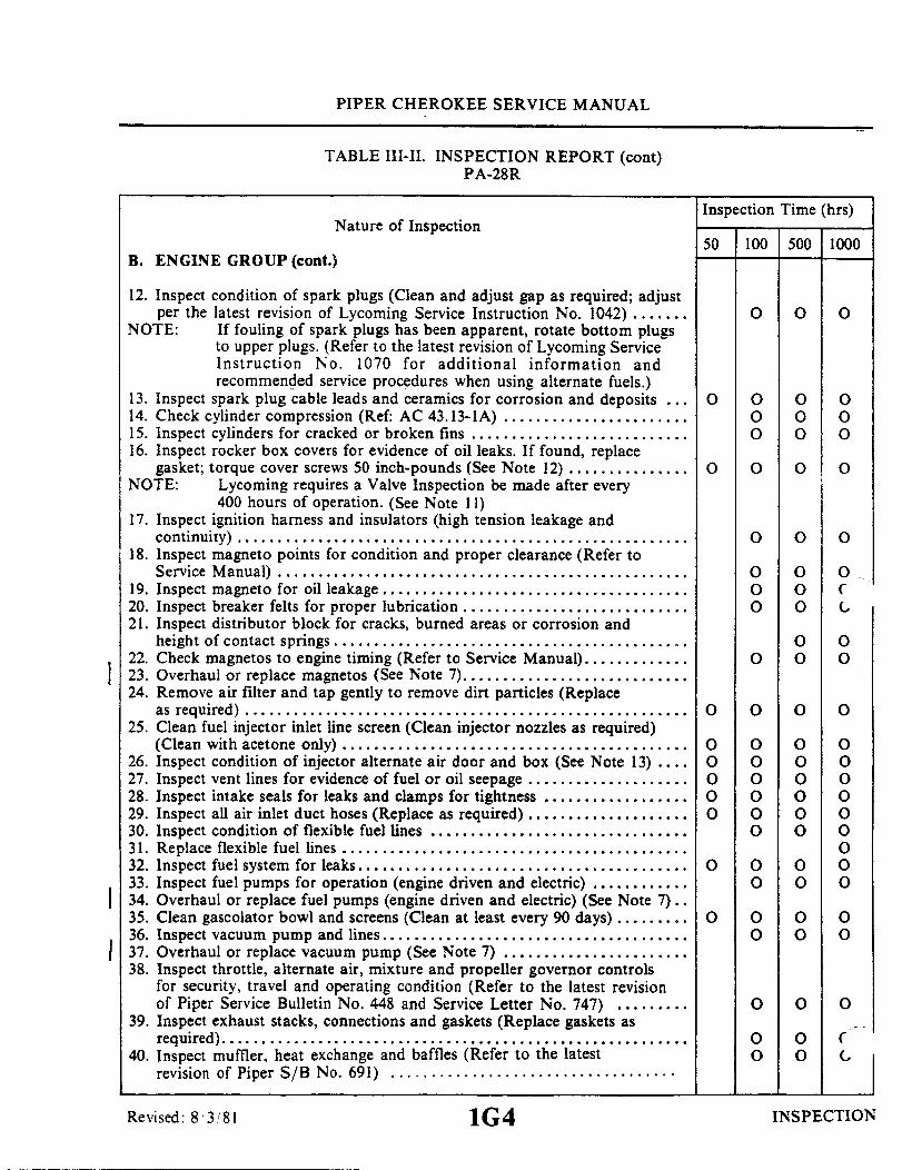
PIPER CHEROKEE SERVICE MANUAL
TABLE III-II. INSPECTION REPORT (cont)PA-28R
Nature of Inspection
B. ENGINE GROUP (cont.)
Inspection Time (hrs)
50 100 500 1000
12. Inspect condition of spark plugs (Clean and adjust gap as required; adjustper the latest revision of Lycoming Service Instruction No. 1042) .......
NOTE: If fouling of spark plugs has been apparent, rotate bottom plugsto upper plugs. (Refer to the latest revision of Lycoming ServiceInstruction No. 1070 for additional information andrecommended service procedures when using alternate fuels.)
13. Inspect spark plug cable leads and ceramics for corrosion and deposits ...14. Check cylinder compression (Ref: AC 43.13-lA) .......................15. Inspect cylinders for cracked or broken fins ...........................16. Inspect rocker box covers for evidence of oil leaks. If found, replace
gasket; torque cover screws 50 inch-pounds (See Note 12) ...............NOTE: Lycoming requires a Valve Inspection be made after every
400 hours of operation. (See Note 11)17. Inspect ignition harness and insulators (high tension leakage and
continuity) ........................................................18. Inspect magneto points for condition and proper clearance (Refer to
Service Manual) ..................................................19. Inspect magneto for oil leakage ......................................20. Inspect breaker felts for proper lubrication ............................21. Inspect distributor block for cracks, burned areas or corrosion and
height of contact springs ...........................................22. Check magnetos to engine timing (Refer to Service Manual).............23. Overhaul or replace magnetos (See Note 7)............................24. Remove air filter and tap gently to remove dirt particles (Replace
as required) .......................................................25. Clean fuel injector inlet line screen (Clean injector nozzles as required)
(Clean with acetone only) ...........................................26. Inspect condition of injector alternate air door and box (See Note 13) ....27. Inspect vent lines for evidence of fuel or oil seepage ....................28. Inspect intake seals for leaks and clamps for tightness ..................29. Inspect all air inlet duct hoses (Replace as required) ....................30. Inspect condition of flexible fuel lines ................................31. Replace flexible fuel lines ...........................................32. Inspect fuel system for leaks.........................................33. Inspect fuel pumps for operation (engine driven and electric) ............34. Overhaul or replace fuel pumps (engine driven and electric) (See Note 7)..35. Clean gascolator bowl and screens (Clean at least every 90 days) .........36. Inspect vacuum pump and lines ......................................
137. Overhaul or replace vacuum pump (See Note 7) .......................38. Inspect throttle, alternate air, mixture and propeller governor controls
for security, travel and operating condition (Refer to the latest revisionof Piper Service Bulletin No. 448 and Service Letter No. 747) .........
39. Inspect exhaust stacks, connections and gaskets (Replace gaskets asrequired) ..........................................................
40. Inspect muffler, heat exchange and baffles (Refer to the latestrevision of Piper S/B No. 691) ...................................
0 0 0
0
O
O
OOOOO
O
O
O0 0O0 0O 0 0
O 0 0
O 0 0
O 0 0O 0 CO 0 O
0 0O 0 0
O 0 0
O 0 0O 0 0O 0 0O 0 0O 0 0O 0 0
OO 0 0O 0 0
O 0 0O 0 0
O 0 0
0 0 O0 0 O
Revised: 8/3/81 1G4 INSPECTION

PIPER CHEROKEE SERVICE MANUAL
TABLE III-II. INSPECTIONPA-28 R
REPORT (cont.)
Inspection Time (hrs)Nature of Inspection
50 100 500 1000B. ENGINE GROUP (cont)
41. Inspect breather tube for obstructions and security .....................42. Inspect crankcase for cracks, leaks, and security of seam bolts ...........43. Inspect engine mounts for cracks and loose mountings ..................44. Inspect condition of all engine baffles.................................45. Inspect condition of all wiring connected to the engine or accessories .....46. Inspect rubber engine mount bushings for deterioration (Replace as
required) .........................................................47. Inspect condition of fire wall seals ...................................48. Inspect condition and tension of alternator drive belt (Refer to
Service Manual Section XI.) ........................................49. Lubricate idler pulley (if installed) per lubrication chart in
Service Manual ...................................................50. Inspect condition of alternator and starter .............................51. Inspect security of alternator mounting ...............................52. Inspect air conditioning compressor oil level (See Note 9) ...............53. Inspect condition of compressor belt and tension (Refer to Service
Manual Section XIV.) ..............................................54. Inspect compressor clutch security and wiring (See Note 10) .............55. Inspect security of compressor mounting ..............................56. Check fluid in brake reservoir (Fill as required) ........................57. Lubricate all controls per lubrication chart in Service Manual (Section 11).58. Overhaul or replace propeller governor (See Note 7) (Refer to the
latest revision of Hartzell Service Letter 61) ...........................59. Complete overhaul of engine or replace with factory rebuilt (See Note 7)..60. Reinstall engine cowl ...............................................
O 0 0O 0 0O 0 0O 0 0O 0 0
O 0 0O 0 0
O 0 0
O 0 0O 0 0O 0 0
O
0
O O OO 0 0O 0 0O 0 0O 0 0
O 0 0
C. CABIN GROUP
1. Inspect cabin entrance door and windows for damage. operation andsecurity ...........................................................
2. Inspect upholstery for tears .........................................3. Inspect seats, seat belts. security brackets and bolts .....................4. Inspect trim operation (See Note 17) .................................5. Inspect rudder pedals ...............................................6. Inspect parking brake and brake handle for operation and cylinder leaks..7. Inspect control wheels, column, pulleys and cables .....................8. Inspect flap control cable attachment bolt .............................9. Inspect landing. navigation. cabin and instrument lights.................10. Inspect instruments. lines and attachments ............................11. Inspect gyro operated instruments and electric turn and bank (Overhaul
or replace as required) ..............................................
Revised: 10 3 831G5
O
O
O O OO O OO O 0O 0 0O O O0 0 00 0 0
O OO 0 00 0 0
0 0 0INSPECTIONO O OO O O
INSPECTION
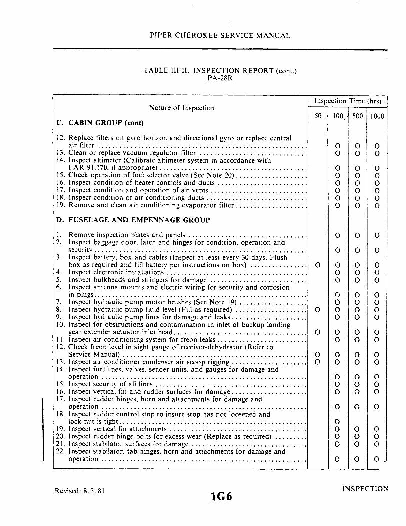
PIPER CHEROKEE SERVICE MANUAL
TABLE 111-11. INSPECTIONPA-28R
Nature of Inspection
C. CABIN GROUP (cont)
REPORT (cont.)
Inspection Time (hrs)
50 100 500 1000
12. Replace filters on gyro horizon and directional gyro or replace centralair filter ..........................................................
13. Clean or replace vacuum regulator filter ..............................14. Inspect altimeter (Calibrate altimeter system in accordance with
FAR 91.170. if appropriate) ......... ................................15. Check operation of fuel selector valve (See Note 20) ....................16. Inspect condition of heater controls and ducts .........................17. Inspect condition and operation of air vents ...........................18. Inspect condition of air conditioning ducts ...........................19. Remove and clean air conditioning evaporator filter ....................
O 0 0O 0 0
O 0 0O 0 0O 0 0O 0 0O 0 0
O 0 0
D. FUSELAGE AND EMPENNAGE GROUP
1. Remove inspection plates and panels .................................2. Inspect baggage door. latch and hinges for condition, operation and
security ...........................................................3. Inspect battery, box and cables (Inspect at least every 30 days. Flush
box as required and fill battery per instructions on box) ................4. Inspect electronic installations .......................................5. Inspect bulkheads and stringers for damage ...........................6. Inspect antenna mounts and electric wiring for security and corrosion
in plugs...........................................................7. Inspect hydraulic pump motor brushes (See Note 19) ...................8. Inspect hydraulic pump fluid level (Fill as required) ....................9. Inspect hydraulic pump lines for damage and leaks .....................10. Inspect for obstructions and contamination in inlet of backup landing
gear extender actuator inlet head.....................................11. Inspect air conditioning system for freon leaks .........................12. Check freon level in sight gauge of receiver-dehydrator (Refer to
Service Manual)...................................................13. Inspect air conditioner condenser air scoop rigging .....................14. Inspect fuel lines. valves. sender units, and gauges for damage and
operation .........................................................15. Inspect security of all lines ..........................................16. Inspect vertical fin and rudder surfaces for damage .....................17. Inspect rudder hinges. horn and attachments for damage and
operation.........................................................18. Inspect rudder control stop to insure stop has not loosened and
lock nut is tight. .................... ...............................19. Inspect vertical fin attachments ......................................20. Inspect rudder hinge bolts for excess wear (Replace as required) .........21. Inspect stabilator surfaces for damage ................................22. Inspect stabilator. tab hinges. horn and attachments for damage and
operation .........................................................
O O O
O O O
O
O
O
OO
O 0 0O 0 0O 0 0
O 0 0O 0 0O 0 0O 0 0
O 0 0O 0 0
O 0 0O 0 0
O 0 0O 0 0O 0 0
O 0 0
0000OO
0 0O O0 0
O O OO
Revised: 8 3 81 INSPECTION1G6

PIPER CHEROKEE SERVICE MANUAL
TABLE III-II. INSPECTION REPORT (cont)PA-28R
Nature of Inspection Inspection time (hrs)
D. FUSELAGE AND EMPENNAGE GROUP (cont.) 500 1000
23. Inspect stabilator control stops to insure stops have not loosened and locknut is tight.24. Inspect stabilator attachments (see latest revision of Piper Service Bulletin 856).........25. Inspect stabilator and tab hinge bolts and bearings for excess wear (Replace as
required) ........................................................................................................................26. Inspect stabilator trim mechanism..................................................................................27. Check all cable tensions (use tensiometer) (See Note 18) .............................................28. Inspect aileron, rudder, stabilator, stabilator trim cables, turnbuckles, guides and
pulleys for safety, damage and operation (See Note 24)................................................29. Clean and lubricate stabilator trim drum screw (Refer to lubrication chart in
Service Manual) .............................................................................................................30. Inspect stabilator balance weight attachments and arm for security and condition .......31. Inspect emergency locator transmitter battery for replacement date per Service
Manual (Refer to the latest revision of Piper S/L No. 820) ...........................................32. Clean and lubricate all exterior needle bearings ............................................................33. Lubricate per lubrication chart in Service Manual............................ .............................34. Inspect anti-collision light for security and operation ...................................................35. Inspect security of Autopilot bridle cable clamps..........................................................36. Inspect all control cables, air ducts, electrical leads, lines, radio antenna leads and
attaching parts for security, routing, chafing, deterioration, wear and correctinstallation ......................................................................................................................
37. Reinstall inspection plates and panels............................................................................
OO O O
0 0O0 0O0 0O
0 0O
0 00 0O
0 0oO
O Oo o0 0O0 0O
0 0O0 0O
E. WING GROUP
1. Remove inspection plates and fairings ..........................................................................2. Inspect surfaces and tips for damage, loose rivets, and condition of walk-way ............3. Inspect aileron hinges and attachments..........................................................................4. Inspect aileron control stops to insure stop has not loosened and lock nut is tight........5. Inspect aileron balance weight and arm for security and condition...............................6. Inspect aileron cables, pulleys and bellcranks for damage and operation .....................7. Inspect flaps and attachments for damage and operation ..............................................8. Inspect condition of bolts used with hinges (Replace as required)................................9. Lubricate per lubrication chart in Service Manual (Section II) .....................................10. Inspect wing attachment bolts and brackets...................................................................11. Inspect fuel tanks and lines for leaks and water (See Note 15)......................................12. Fuel tanks marked for capacity .....................................................................................13. Fuel tanks marked for minimum octane rating ..............................................................14. Inspect fuel cell vents (See Note 16) .............................................................................
Interim Revision: February 15, 1995
OOOO
0 00 00 0
0 0 00 0 00 0 0
OO0 O
0 0 00 0 00 0 00 0 00 0 0
INSPECTION
1G7

PIPER CHEROKEE SERVICE MANUAL
TABLE III-II. INSPECTION REPORT (cont)PA-28R
Inspection Time (hrs)Nature of Inspection
50 100 500 1000
15. Inspect all control cables, air ducts, electrical leads, lines and attachingparts for security, routing, chafing, deterioration, wear and correctinstallation ........................................................
16. Reinstall inspection plates and fairings ................................
F. LANDING GEAR GROUP
1. Inspect oleo struts for proper extension (N-2.75 in., M-2.0 in.) Checkfluid level as required) ..............................................
2. Inspect nose gear steering control and travel ...........................3. Inspect wheels for alignment ........................................4. Put airplane on jacks ............................................5. Inspect tires for cuts, uneven or excessive wear and slippage .............6. Remove wheels, clean, check and repack bearings ......................7. Inspect wheels for cracks, corrosion and broken bolts ...................8. Check tire pressure (N-30 psi M-27 psi) ...............................9. Inspect brake lining and disc ........................................10. Inspect brake backing plates.........................................11. Inspect brake and hydraulic lines ....................................12. Inspect shimmy dampener ...........................................13. Inspect gear forks for damage .......................................14. Inspect oleo struts for fluid leaks and scoring ..........................15. Inspect gear struts, attachments, torque links, retraction links and
bolts for condition and security ......................................16. Inspect downlock for operation and adjustment ........................17. Inspect torque link bolts and bushings (Rebush as required) .............18. Inspect drag and side brace link bolts (Replace as required) .............19. Inspect gear doors and attachments ..................................20. Inspect warning horn and light for operation ..........................21. Retract gear - check operation .......................................22. Retract gear - check doors for clearance and operation .................23. Inspect anti-retraction system ......................................24. Inspect actuating cylinders for leaks and security .......................25. Inspect all hydraulic lines, electrical leads, and attaching parts for
security. routing, chafing, deterioration, wear and correct installation(See the latest revision of Piper SL No. 808 and 810) ..................
26. Inspect position indicator switch and electrical leads for security .........27. Lubricate per lubrication chart in Service Manual (Section II) ...........28. Remove airplane from jacks .........................................
O
O
O 0 0O 0 0
O OO 0O oO 0O OO OO 0
O 0O 0O 0O 0o 0O 0
O 0
0000000O
O0000
O 0 0O 0 0
0 0O
O 0 0O 0 0
O 0 0O 0 0O 0 0O O 0
O 0 0O 0 0
O O O OO O 0
G. OPERATIONAL INSPECTION
1. Check fuel pump and fuel tank selector ...............................2. Check fuel quantity. pressure and flow readings........................
Reissued: 1 15 811G8
O O OO O O
E. WING GROUP (cont)
O
INSPECTION

PIPER CHEROKEE SERVICE MANUAL
TABLE III-11. INSPECTION REPORT (cont.)PA-28 R
Inspection Time (hrs)Nature of Inspection
50 100 500 1000G. OPERATIONAL INSPECTION (cont)
3. Check oil pressure and temperature ..................................4. Check alternator output ............................................5. Check manifold pressure ............................................6. Check alternate air ................ ..............................7. Check parking brake ...............................................8. Check vacuum gauge ...............................................9. Check gyros for noise and roughness .................................10. Check cabin heater operation ........................................11. Check magneto switch operation .....................................12. Check magneto RPM variation ......................................13. Check throttle and mixture operation (See the latest revision of
Piper Service Bulletin No. 448) ......................................14. Check propeller smoothness .........................................15. Check propeller governor action.....................................16. Check engine idle.................................................17. Check electronic equipment operation ................................18. Check operation of Autopilot. including automatic pitch trim. and
Manual Electric Trim (See Note 21.) .................................19. Check air conditioner compressor clutch operation .....................20. Check air conditioner condenser scoop operation ......................21. Check (FLY Aircraft) Landing Gear System (See Note 14) ..............
OOOOOOOOOO
OOOOO
OOO
O 0 0O 0 0O 0 0O 0 0O 0 0O 0 0O 0 0O 0 0O 0 0O 0 0
O 0 0O 0 0O 0 0O 0 0O 0 0
O 0 0O 0 0O 0 0O 0 0
H. GENERAL
1. Aircraft conforms to FAA Specification .........................2. All latest FAA Airworthiness Directives complied with ............3. All latest Manufacturers Service Bulletins and Letters complied with4. Check for proper Flight Manual ................................5. Aircraft papers in proper order .................................
Revised: 10 3 831G9
O O O oO O O OO O O OO O O OO O O O
INSPECTION

PIPER CHEROKEE SERVICE MANUAL
TABLE III-II. INSPECTION REPORT (cont)PA-28R
NOTES:1. Refer to the last card of the Piper Parts Price List - Aerofiche, for a checklist of current revision dates
to Piper Inspection Reports and Manuals.2. All inspections or operations are required at each of the inspection intervals as indicated by a (O).
Both the annual and 100 hour inspections are complete inspections of the airplane, identical inscope, while both the 500 and 1000 hour inspections are extensions of the annual or 100 hourinspections, which require a more detailed examination of the airplane, and overhaul or replacementof some major components. Inspections must be accomplished by persons authorizedby the FAA.
3. Piper Service Bulletins are of special importance and Piper considers compliance mandatory.4. Piper Service Letters are product improvements and service hints pertaining to servicing the
airplane and should be given careful attention.5. Inspections given for the power plant are based on the engine manufacturer's operator's manual for
the particular airplane. Any changes issued to the engine manufacturer's operator's manual shallsupersede or supplement the inspections outlined in this report.
6. Intervals between oil changes can be increased as much as 100% on engines equipped with full flow(cartridge type) oil filters, provided the element is replaced each 50 hours of operation. (Refer tolatest revision of Lycoming Service Instruction No. 1070, for additional information and re-commended service procedures when using alternate fuels.)
7. Replace or overhaul as required or at engine overhaul. (For engine overhaul, refer to latest revisionof Lycoming Service Instruction No. 1009.)
8. Replace flexible oil lines as required, but no later than 1000 hours.9. The compressor oil level should not be checked unless a freon leak has occurred which requires an
addition of freon to the system.10. Clean any traces of oil from the clutch surface.11. At every 400 hours of engine operation, remove the rocker box covers and check for freedom of
valve rockers when valves are closed. Look for evidence of abnormal wear or broken parts in thearea of the valve tips, valve keeper, springs and spring seat. If any indications are found, the cylinderand all of its components should be removed (including the piston and connecting rod assembly)and inspected for further damage. Replace any parts that do not conform with limits shown in thelatest revision for Lycoming Special Service Publication No. SSP1776.
12. Check cylinders for evidence of excessive heat indicated by burned paint on the cylinders.This condition is indicative of internal damage to the cylinder and, if found, its cause must bedetermined and corrected before the aircraft is returned to service.
Heavy discoloration and appearance of seepage at the cylinder head and barrel attachmentarea is usually due to emission of thread lubricant used during assembly of the barrel at the factory,or by slight gas leakage which stops after the cylinder has been in service for awhile. This conditionis neither harmful nor detrimental to engine performance and operation. If it can be proventhat leakage exceeds these conditions, the cylinder should be replaced.
13. Check throttle body attaching screws for tightness; the correct torque for these screws is 40 to 50inch-pounds.
Revised: 10/3/83Interim Revision: 5/6/87 INSPECTION

PIPER CHEROKEE SERVICE MANUAL
TABLE III-II. INSPECTION REPORT (cont)PA-28R
NOTES:14. Fly aircraft to check landing gear system in accordance with instructions given in Section VI, Paragraph
6-14, of PA-28 Service Manual 753 586. (Refer to the latest revision of Piper Service Letter No. 810.)15. Replace flexible fuel tank supply hose at time of engine overhaul.16. Replace fuel tank vent line flexible connections as required, but no later than 1000 hours of service.17. If airplane has electric trim, refer to the latest revision of Piper Service Bulletin No. 556.18. Maintain cable tensions specified in Section V of Service Manual.19. Inspect brushes every 100 hours on airplanes used for training or every 500 hours on airplanes used for
normal service. (Refer to Service Manual, Section VI.)20. Refer to latest revision of Piper Service Bulletin No. 355.21. Refer to Flight Manual Supplement for preflight and flight checks, for intended function in all modes.22. Refer to latest information for the particular propeller being inspected:
Hartzell Service Letter No. 61McCauley Service Bulletin No. 137.
23. Inspect Teflon bushing (lower to upper cowling attachment) for condition at each 100 hours. Replacebushing on condition, but no later than 500 hours time in service. Inspect pin for condition and replaceas necessary.
24. If not already installed, add access panels, see Paragraph 4-57a. Inspect stabilator control cables, seeParagraph 3-11 a.
Interim Revision: February 15, 1995 INSPECTION
1Gll

1G12INTENTIONALLY LEFT BLANK

SECTION IV
STRUCTURES
AeroficheGrid No.
4-1.4-2.4-3.4-4.
4-7.
4-10.
4-13.
4-16.4-17.
4-20.
4-23.
4-26.
4-29.4-30.
4-33.
Reissued: 1/15/81
IntroductionDescriptionWing Group .Wing Tip ..4-5.4-6.Aileron ...4-8.4-9.Wing Flap .4-11.4-12.Wing .....4-14.4-15.Empennage GrStabilator4-18.4-19.Stabilator Trim4-21.4-22.Rudder ...4-24.4-25.Vertical Fin .4-27.4-28.Fuselage AssenWindshield4-31.4-32.Side Windows4-34.4-35.
Removal of Wing Tip................... . . . . . . . . . . . . . . .... . . . . . . . . . . . .Removal of Wing Tip .................
Installation of Aileron ..................
Removal of Wing Flap ..................Installation of Wing Flap.Removal of Aileron ...................Installation of Aileron ..................
Removal of Wing . .................
Removal of Stabilator .................Installation of Stabilator ................
Trim Tab............................Removal of StabilatorTrim Tab ............Installation of Stabilator Trim Tab.
Removal of RudderInstallation of Rudder ..................Removal of Vertical Fin.............Installation of Vertical Fin............
Assembly............................Removal of Vertical Fin...........
Installation of Windshield ..... ..........Removal of Vertical Fin ................Installation of Vertical Fin .................
Removal of Side Windows ...............Installation of Side Windows ..............
1G13
................................ .... 1G15IG15IG161G161G161G17IG171G171G171G181G181G181G181G181H21H61H61H61H8IH13IH131H13IH131H131H131H141H141H141H151H151H151H15IH171H171H18

PIPER CHEROKEE SERVICE MANUAL
Paragraph AeroficheGrid No.
4-36. Door (Entrance) .......................................................................................... 1H 194-37. Removal of Door...............................................................1H194-38. Installation of Door .......................................................... 1H194-39. Adjustment of Door ..................................... 1H 194-40. Removal of Door Latch Mechanism ................................. 1H194-41. Removal and Installation of Door Seal Snubbers ............. 1H204-42. Installation of Door Latch Mechanism ............................. 1H214-43. Adjustment of Door Latch Mechanism ............................. 1H214-44. Removal of Door Lock Assembly .................................... 1H214-45. Installation of Door Lock Assembly .................................1 H214-46. Removal of Door Safety Latch ........................................ H214-47. Installation of Door Safety Latch ..................................... 1H224-48. Adjustment of Door Safety Latch ..................................... 1H22
4-49. Baggage Door ........................................................................................... H224-50. Removal of Baggage Door ................................................ H224-51. Installation of Baggage Door ........................................... 1H224-52. Removal of Baggage Door Lock Assembly ...................... 1H224-53. Installation of Baggage Door Lock Assembly .................. 1H234-54. Removal of Baggage Door Hinge ..................................... 1H234-55. Installation of Baggage Door Hinge ................................. 1H234-56. Rigging Instructions - Seat Back Lock and Release .........1H23
4-57. Structural Repairs ....................................................................................... 1134-57a. Baggage Compartment Inspection Hole and Cover Plate .......................... 134-58. Fiberglas Repairs ............................................................... 113
4-59. Fiberglas Touch-Up and Surface Repairs..........................1I34-60. Fiberglas Fracture and Patch Repairs ................................1I44-61. Thermoplastic Repairs ...................................................... 1I64-62. A.B.S. Thermoplastic Landing Gear and Strut Fairing
Repair Instructions ..................................................... 1I104-63. Safety Walk Repair.....................................................................................1I14
4-64. Surface Preparation for Liquid Safety Walk ..................... 11144-65. Product Listing for Liquid Safety Walk Compound ......... 11144-66. Application of Liquid Safety Walk Compound ................. 1I144-67. Surface Preparation for Pressure Sensitive Safety Walk...1I144-68. Application of Pressure Sensitive Safety Walk ................. 1I15
4-69. Control Surface Balancing ........................................................................ 1I164-70. Checking Control Surface Balance ................................... 11164-71. Checking Control Surface Free Play ................................. 11164-72. Balancing Equipment ........................................................ 1I184-73. Balancing Ailerons...........................................................1I184-74. Balancing Rudder..............................................................1I194-75. Balancing Stabilator ......................................................... 1I224-76. Aileron Balance Weight Modification .............................. 1I234-77. Flap Inspection and Modification ..................................... 1J14-78. Stabilator Drain Holes ..................................................... 1J1
4-79 Baggage Compartment Inspection Hole and Cover Plate .......................... 1J3
Interim Revision: February 15, 1995
1G14

PIPER CHEROKEE SERVICE MANUAL
SECTION IV
STRUCTURES
4-1. INTRODUCTION. This section explains the removal and installation procedures forthe structural surfaces of the airplane. For the removal, installation, and rigging andadjustment procedures of the controlling components of the various structural surfaces,refer to Section V.
NOTE
When torquing structural assemblies, standard torque valuesare to be used as found in Section II, Federal AeronauticsManual 18 or FAA Advisory Circular 43.13-1, unlessotherwise stated in this section.
4-2. DESCRIPTION. The PA-28 is an all metal semi-monocoque structure with an overalllength ranging from 23 feet 5.40 inches to 24 feet 7.38 inches depending on the modelinvolved. The fuselage is constructed of bulkheads, stringer and stiffeners, to which all ofthe outer skin is riveted. Windows include a single pane windshield and four to six sidewindows, again depending upon the model. All windows are single pane, the exception beingthe PA-28-235, Serial Nos. 28-10720 and up, which are equipped with double pane sidewindows. A storm window is located in the forward lower section of the left window andcan be opened inward when the latch is released. The cabin entrance door is located on theright side of the fuselage, above the wing, and is equipped with a safety latch on the top ofthe door, which can be operated from the inside or outside. A door provided for entrance tothe baggage compartment (all models except PA-28-140) is located just aft of the right wingwith a key lock installed.
Each wing panel is an all metal, full cantilever semi-monocoque type construction with aremovable wing tip. Installed in each wing ahead of the main spar is a metal fuel tank with acapacity of 25 U.S. gallons each or 50 U.S. gallons total. The PA-28-235 is equipped withfiberglass tip tanks which increases the capacity to 42 U.S. gallons per wing or 84 U.S.gallons total. Attached to each wing is an aileron, flap and main landing gear. The wings areattached to each side of the fuselage by inserting the butt ends of the main spars into a sparbox carry-through. The spar box is an integral part of the fuselage structure which provides,in effect, a continuous main spar with splices at each side of the fuselage. There are also foreand aft attachments at the front and rear spars.
Reissued: 1/15/81 1G15 STRUCTURES

PIPER CHEROKEE SERVICE MANUAL
The all metal empennage group is a full cantilever design consisting of a verticalstabilizer (fin), rudder and stabilator, all with removable tips. The stabilator has a trim tabattached that is controllable from the cockpit. The stabilator also incorporates one channelmain spar that runs the full length of the stabilator and hinges to the aft bulkhead assemblyof the fuselage. All exterior surfaces are coated with enamel or acrylic lacquer. As an optionthe airplane may be completely primed with zinc chromate.
4-3. WING GROUP.
NOTE
The major subassemblies of the wing may be removedindividually or the wing may be removed as a unit. Toremove a wing, a fuselage supporting cradle is required.
4-4. WING TIP.
4-5. REMOVAL OF WING TIP.a. PA-28-140 PA-28-150, -160, -180 and PA-28R:
1. Remove the screws holding the wing tip to the wing, being careful not to damagethe wing or wing tip.
2. Pull off the wing tip far enough to disconnect the position light wire assembly.The ground lead may be disconnected at the point of connection on the wing rib, and thepositive lead may be disconnected at the wire terminal or unscrewed from the lightassembly.
b. PA-28-235: Incorporated in each wing tip is a 17 gallon auxiliary fuel tank. Givenbelow are the steps recommended for removal of the tip:
1. Drain fuel from the tank to be removed. (Refer to Draining Fuel System,Section II.)
2. Remove the access cover from the bottom of the wing tip.3. By working through the access, disconnect the fuel line, fuel quantity
transmitting wire and position light wire. Remove the two nuts, washers and bolts whichhold the tank to the wing.
4. Carefully remove the screws from around the wing tip and remove the tipassembly.
c. Inspect the wing tip to ascertain that it is free of cracks, severe nicks and minordamage. If repair is required, refer to paragraph 4-57.
Reissued: 1/15/81 STRUCTURES1G16

PIPER CHEROKEE SERVICE MANUAL
4-6. INSTALLATION OF WING TIP.a. PA-28-140; PA-28-150, -160, -180 and PA-28R:
1. Place the wing tip in a position that the navigation light leads may be connected.Connect the ground lead to the wing rib by use of a screw and nut, and the positive lead tothe position light by connecting the wire terminals or screwing the connectors together.Insulate the wire terminals and be certain that the ground lead is free of dirt and film toinsure a good connection.
2. Insert the wing tip into position and install the screws around the tip. Usecaution to refrain from damaging the wing tip or wing. Check operation of the positionlight.
b. PA-28-235:1. Position the wing tip in place on the wing and insert the two bolts, washers and
nuts into their proper places and tighten. Replace the several screws around the tip tank andtighten. Connect the position light leads, the fuel quantity transmitting wire and the fuelline.
2. After the wing tip is installed and all connections are secured, fill the tip tankand check for fuel leaks, operation of the fuel gauge and position light. Install the accesscover to the bottom of the wing tip.
4-7. AILERON.
4-8. REMOVAL OF AILERON. (Refer to Figure 4-1.)a. Disconnect the aileron control rod at the aileron attachment point by removing the
nut, washers and bolt from the rod end bearing. To simplify installation note location ofwashers removed.
b. Remove the attaching screws, with nuts, from the hinges at the leading edge of theaileron, and remove the aileron by lowering the inboard end and swinging it forward toallow the balance arm to clear the opening in the outboard rib.
4-9. INSTALLATION OF AILERON. (Refer to Figure 4-1.)a. Install the balance arm into the opening in the outboard rib by moving the inboard
end of the aileron forward to allow the arm to be inserted through the opening. (Wheninstalling an aileron, should the balance weight assembly, P/N 66766-00, replace an earlierbalance weight assembly, P/N 65388-34 (L) or 65388-35 (R), the wing butt rib will requiremodifying per instructions in Paragraph 4-75.) Move the aileron into place and installattaching screws and nuts. Ascertain that the aileron is free to move with no interference.
b. Attach the aileron control rod with bolt, washers and nut, dividing the washers sothat the aileron is free to rotate from stop to stop without the control rod binding orrubbing on the opening in the aft spar. Be certain that the rod end bearing has no side playwhen tightening the bolt and that the rod does not contact the side of the bracket.
c. Actuate the aileron controls to insure freedom of movement.
Reissued: 1/15/81 1G17 STRUCTURES

PIPER CHEROKEE SERVICE MANUAL
4-10. WING FLAP.
4-11. REMOVAL OF WING FLAP. (Refer to Figure 4-1.)a. Extend the flaps to their fullest degree and remove the bolt and bushing from the
rod end bearing by use of an angle or offset screwdriver.b. Remove the nuts, washers, bushing and hinge bolts that hold the flap to the wing
assembly.c. Pull the flap straight back off the wing. (Refer to Paragraph 4-75 for flap inspection
and modification.)
4-12. INSTALLATION OF WING FLAP. (Refer to Figure 4-1.)a. Replace the wing flap by placing the flap onto its proper position and inserting the
hinge bolts, bushings, washers, and nuts.b. With the flap control in the full flap position, place the bushing on the outboard side
of the rod end bearing and insert and tighten the bolt.c. Operate the flap several times to be certain it is operating freely.
4-13. WING.
4-14. REMOVAL OF WING. (Refer to Figure 4-2.)a. PA-28-140; PA-28-150, -160, -180 and PA-28-235.
1. Close the fuel valve and drain the fuel from the wing to be removed. (Refer toDraining Fuel System, Section II.)
2. Drain the brake lines and reservoir. (Refer to Draining Brake System, Section II.)3. Remove the access plate at the wing butt rib and wing inspection panels. (Refer
to Access Plates and Panels, Section II.)4. Remove the front and back seats from the airplane.5. Expose the spar box and remove the cockpit side trim panel assembly that
corresponds with the wing being removed.
Reissued: 1/15/81 STRUCTURES1G18
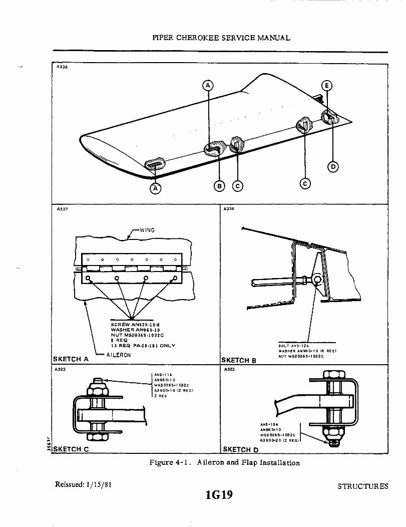
PIPER CHEROKEE SERVICE MANUAL
A339
A337 A336
WING
SCREWWASHERNUT MS8 REQ13 REQ
AILERON
AN525-10-8R AN960-1020365-1032C
PA-28-181 ONLY
AN3-11AAN960-1 0MS20365-1032C63900-19 (2 REQ)2 REQ
SKETCH BA322
SKETCH C
BOLT AN3-12AWASHER AN960-10 (6 REQ)NUT MS20365-1032C
AN3-13AAN960-10MS20365-1032C63900-20 (2 REQ)
SKETCH D
Figure 4-1. Aileron and Flap Installation
Reissued: 1/15/81 STRUCTUR ES1G19
SKETCHA322
A
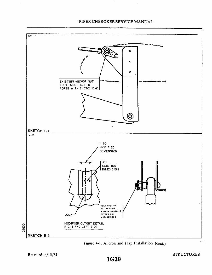
PIPER CHEROKEE SERVICE MANUAL
A321
O
O
EXISTING ANCHOR NUTTO BE MODIFIED TOAGREE WITH SKETCH E-2
1.10MODIFIEDDEMENSION
.81EXISTINGDIMENSION
NUT AN310-3WASHER AN960-10COTTER PIN
MS24665-132
MODIFIED CUTOUT DETAILRIGHT AND LEFT SIDE
SKETCH E-2
Figure 4-1. Aileron and Flap Installation (cont.)
Reissued: 1/15/81 STRUCTURES1G20
SKETCH E-1C335
.55R-

PIPER CHEROKEE SERVICE MANUAL
6. Place the airplane on jacks. (Refer to Jacking, Section II.)
NOTE
To help facilitate reinstallation of control cables, andfuel and hydraulic lines, mark cable and line ends insome identifying manner and attach a line where ap-plicable to cables before drawing them through thefuselage or wing.
7. Disconnect the aileron balance and control cables at the turnbucklesthat are located within the fuselage aft of the spar.
8. If the left wing is being removed, remove the cotter pin from the pulleybracket assembly to allow the left aileron balance cable end to pass between thepulley and bracket.
9. Disconnect the flap from the torque tube by extending the flap to itsfullest degree, and removing the bolt and bushing from the bearing at the aft endof the control rod.
10. Disconnect the fuel line at the fitting located aftof the spar at the wingbutt line.
CAUTION
To prevent damage or contaminationof fuel, hydraulicand miscellaneous lines, placea protective cover overthe line fittings and ends.
11. Remove the clamps necessary to release the electrical harness as-sembly. Disconnect the leads from the terminal strip assembly by removing thecover, and appropriate nuts and washers.
12. With the appropriate trim panel removed, disconnect the hydraulic
brake line at the fitting located within the cockpit at the leading edge of the wing.13. If the left wing is being removed, it will be necessary to disconnect
the pitot and static tubes at the elbows located within the cockpit at the wing buttline.
14. Arrange a suitable fuselage cradle and supports for both wings.15. Remove the wing jacks.16. Remove the front and rear spar nuts, washers and bolts.17. Remove the eighteen main spar bolts.18. Slowly remove the wing being certain that all electrical leads. cables
and lines are disconnected.
Reissued: 1/15/81 STRUCTURES
1G21

1G22INTENTIONALLY LEFT BLANK


PIPER CHEROKEE SERVICE MANUAL
BOLT LEGEND
NUT*MS20365-624CMS20365-624CMS20365-624CMS20365-624C
MS20365-624C
MS20365-624CMS20365-624CMS20365-624CMS20365-624CMS20365-624CMS20365-624C
MS20365-624CMS20365-624CMS20365-624CMS20365-624CMS20365-624CMS20365-624CMS20365-624C
UNDER HEAD(1) AN960-616(1) AN960-616(1) AN960-616(1) AN960-616(1) AN960-616(1) AN960-616(1) AN960-616(1) AN960-616(1) 96352-3(1) 96352-3(1) 96352-3(1) 96352-3(1) 96352-3(1) 96352-3(1) 96352-3(1) 96352-3(1) 96352-3(1) 96352-3
WASHER
UNDER NUT(1) AN960-616& (1) 96352-3(1) AN960-616&(1) 96352-3(1) AN960-616& (1) 96352-3(1) AN960-616& (1) 96352-3(2) AN960-616(2) AN960-616(2) AN960-616(2) AN960-616(1) AN960-616(2) AN960-616(2) AN960-616(2) AN960-616(1) 96352-3(1) AN960-616(2) AN960-616(2) AN960-616(2) AN960-616(1) 96352-3
*Torque Boltheads on Upper Spar Cap and Nuts on Lower Spar Cap 360-390 in-lbs
1785
SKETCH D
Figure 4-2. Wing Installation (cont.)
Reissued: 1/15/81 STRUCTURES1G24
POSITION
A-1A-2A-3
A-4
B-1B-2
B-3B4C-1C-2C-3C-4C-5D-1D-2D-3D-4D-5
BOLT*AN176-13AAN176-12AAN176-12AAN176-12AAN176-14AAN176-13AAN176-13AAN176-13AAN176-13AAN 176-13AAN176-13AAN 176-13AAN 176-13AAN 176-13AAN176-13AAN176-13AAN 175-13AAN176-13A

PIPER CHEROKEE SERVICE MANUAL
b. PA-28R:1. Close the fuel valve and drain the fuel from the wing to be removed.
(Refer to Draining Fuel System, Section II.)2. Drain the brake lines and reservoir. (Refer to Draining Brake System,
Section II. )3. Drain the hydraulic lines of the landing gear of the wing to be removed
by separating the lines and elbows at the actuating cylinder.4. Remove the access plate at the wing butt rib and wing inspection pan-
els. (Refer to Access Plates and Panels, Section II.)5. Remove the front and back seats from the airplane.6. Expose the spar box and remove the side trim cockpit panel assembly
that corresponds with the wing being removed.7. Place the airplane on jacks. (Refer to Jacking, Section II.)
NOTE
To help facilitate reinstallation of control cables, andfuel and hydraulic lines, mark cable and line ends insome identifying manner and attach a line where ap-plicable to cables before drawing them through thefuselage or wing.
8. Disconnect the aileron balance and control cables at the turnbuckles thatare located within the fuselage aft of the spar.
9. If the left wing is being removed, remove the cotter pin from the pulleybracket assembly to allow the left aileron balance cable end to pass between thepulley and bracket.
10. Disconnect the flap from the torque tube by extending the flap to itsfullest degree, and removing the bolt and bushing from the bearing at the aft endof the control rod.
11. Disconnect the fuel line at the fitting located inside of thewing, by re-moving the acces panel on the forward inboard portion of the wheel well andreaching through to the fuel line coupling.
CAUTION
To prevent damage or contamination of fuel, hydraulicand miscellaneous lines, place a protective cover overthe line fittings and ends.
12. Remove the clamps that are necessary to release the electrical harnessassembly. Disconnect the leads from the terminal strip by removing the cover,
Reissued: 1/15/81 1H1 STRUCTURES
PIPER CHEROKEE SERVICE MANUAL
and appropriate nuts and washers.13. With the appropriate trim panel removed, disconnect the hydraulic
brake line at the fitting located within the cockpit at the leading edge of the wing.14. Disconnect the landing gear hydraulic lines at the fittings aft of the spar
and within the fuselage.15. If the left wing is being removed, it will be necessary to disconnect
pitot and static tubes at the elbows located within the cockpit at thewing butt line.16. Arrange a suitable fuselage cradle and supports for both wings.17. Remove the wing jacks.18. Remove the front and rear spar nuts, washers and bolts.19. Remove the eighteen main spar bolts.20. Slowly remove the wing being certain that all electrical leads, cables
and lines are disconnected.
4-15. INSTALLATION OF WING. (Refer to Figure 4-2. )a. PA-28-140; PA-28-150, -160, -180 and PA-28-235:
NOTE
PA-28-150,-160 Serial Nos. 28-1 to 28-45 incl., 28-47 to28-54 incl., 28-56, 28-57, 28-61 to 28-77 incl., 28-79 to28-84 incl., 28-86 to 28-89 incl., 28-92, 28-93 and 28-94.
The subject airplanes indicated by the above serial numbers were equippedat the factory with wing panel assemblies having a wasHout of 0
° , (P/N 62010-41L W and P/N 62010-42 R W).
All airplanes not indicated in the above serial number listing are equippedwith wing panels modified to 20of washout, (P/N 62015-04 L W and P/N 62015-03R W).
During the service life of the subject airplanes there may be occasion toreplace one or bothof thewingpanels having 0° washout. Undernocircumstancesshould one twisted and one nontwisted wing be used on the same airplane. If aninterchange of salvaged nontwisted wing panels is made in the field, the stallcharacteristics shall be tested to the requirement of Civil Air Regulation 3.120by an authorized representative of Piper Aircraft Corporation or the FederalAviation Administration. Since the number of airplanes equipped with 0°washoutwing panels is relatively small, this type wing assembly will not be available forreplacement. All replacement wing panels, when required, will be furnishedhaving the 20 washout.
1. Ascertain that the fuselage is positioned solidly on a support cradle.2. Place the wing in position for installation, with the spar end a few inches
Reissued: 1/15/81 STRUCTURES
1H2

PIPER CHEROKEE SERVICE MANUAL
from the side of the fuselage and set on trestles.3. Prepare the various lines, control cables, etc. for inserting into the
wing or fuselage when the wing is slid into place.4. Slide the wing into position on the fuselage.5. Install the eighteen main spar bolts in accordance with the bolt legend.
NOTE
When replacing a wing assembly, ascertain the wingbutt clearance is maintained. (Refer to Sketch A,Figure 4-2.)
6. Install the bolt, washers and nut that attaches the front spar with thefuselage fitting. A minimum of one washer is required under the nut, then addwashers as needed to leave a maximum of one and one-half threads visible or aminimum of the bolt chamfer exposed.
7. Insert the number of washers required between the forward face of thewing fitting and aft face of the fuselage fitting. The maximum number of washersallowedis one AN960C-516Land one AN960C-516. It is also acceptable to havethe faces of the fittings against each other. After the required washers are in-serted between the plates, install the bolt and check to insure that no threads arebearing on the forward plate prior to installing the nut. Use the shortest boltwhich will leave 0.580 of an inch minimum from the fitting to the end of the bolt.Add washers, AN960-516, as required, (minimum of one), to leave a maximumof one andone-half visible thread, or minimum of the bolt chamfer exposed afterthe nut is torqued.
8. Torque the eighteen main spar bolt nuts or bolt heads 360 to 390 inch-pounds. Becertain that the bolts, nuts and washers are installed in accordance with the bolt legend. Theforward spar attachment bolt should be torqued, in accordance with the chart ofrecommended torque requirements given in Section II. Torque the rear spar attachment boltfrom 200 to 225 inch-pounds.
9. Install the wing jacks and the tail support to the tail skid with approxi-mately 250 pounds of ballast on the base of the tail support. Remove the fuselagecradle and wing supports.
10. If the left wing was removed, it is necessary that the pitot and statictubes to be connected at the elbows located within the cockpit at thewing butt line.On occasion, one tube may be painted red, denoting the pitot tube. Replace orinstall clamps where found necessary. In the event that a heated pitot is installed,the plus lead must be connected at the fuselage.
11. Connect the hydraulic brake line onto the fitting located within the cock-pit at the leading edge of the wing.
12. Connect the leads to the appropriate posts on the terminal strip and
STRUCTURESReissued: 1/15/81Reissued: 1/15/81
STRUCTURES
PIPER CHEROKEE SERVICE MANUAL
install the washers and nuts. (For assistance in connecting the electrical lead,refer to the Electrical Schematics in Section VI.) Place the clamps along theelectrical harness to secure it in position and install the terminal strip dust cover.
13. Remove the cap from the fuel line and connect it at the fitting locatedaft of the spar at the wing butt line.
14. Connect the aileron balance and control cables at the turnbuckles thatare located within the fuselage aft of the spar. After the left balance cable hasbeen inserted through the bracket assembly and connected, install a cotter pincable guard into the hold that is provided in the bracket assembly.
15. Connect the flap by placing the flap handle in the full flap position, placethe bushing on the outside of the rod end bearing and insert and tighten bolt.
16. Check the rigging and control cable tension of the ailerons and flaps.(Refer to Rigging and Adjustment of Ailerons, and Rigging and Adjustment ofFlaps, Section V.)
17. Service and refill the brake system with hydraulic fluid in accordancewith Servicing Brake System, Section II. Bleed the system as given in Section VIIand check for fluid leaks.
18. Service and fill the fuel system in accordance with Servicing FuelSystem, Section II. Open the fuel valve and.check far leaks and flow.
19. Check the operation of all electrical equipment, and pitot and staticsystem.
20. Remove the airplane from the jacks.21. Tnstall the cockpit trim panel assembly, spar box carpet, the front and
back seats, and wing butt rubber molding.22. Replace all the access plates and panels on the wing involved.
b. PA-28R:1. Ascertain that the fuselage is positioned solidly on a support cradle.2. Place the wing in position for installation, with the spar end a few inches
from the side of the fuselage and set on trestles.3. Prepare the various lines, control cables, etc. for inserting into the
wing or fuselage when the wing is eased into place.4. Slide the wing into position of the fuselage.5. Install the eighteen main spar bolts in accordance with the bolt legend.6. Install the bolt, washers, and nut that attaches the front spar and fuse-
lage fitting. A minimum of one washer is required under the nut, then add wash-ers as needed to leave a maximum of one and one-half threads visible or a mini-mum of the bolt chamfer exposed-
7. Insert the number of washers required between the forward face of thewing fitting and aft face of the fuselage fitting. The maximum number of washersallowed is one ofAN960C-516Land oneAN960C-516. It is also acceptable to havethe faces of the fitting against each other. After the required washers are in-serted between the plates, install the bolt and check to insure that no threads are
Reissued: 1/15/81 ' 1H4 STRUCTURES
PIPER CHEROKEE SERVICE MANUAL
bearing on the forward plate prior to installing the nut. Use the shortest boltwhich will leave 0.580 of an inch minimum from the fitting to the end of the bolt.Add washers, AN960-516, as required, (minimum of one), to leave a maximumof one and one-half visible threads, or minimum of the bolt chamfer exposedafter the nut is torqued.
8. Torque the eighteen main spar bolts to 360 inch pounds. Be certain thatthe bolts, nuts and washers are installed in accordance with the bolt legend. Theforward spar attachment bolt should be torqued in accordance with the chart ofrecommended torque requirements given in Section II. Torque the rear spar at-tachment bolt from 200 to 225 pounds.
9. Install the wing jacks and the tail support to the tail skid with approxi-mately 250 pounds of ballast on the base of the tail support. Removethefuselagecradle and wing supports.
10. If the left wing was removed, it is necessary that the pitot and statictubes be connected at the elbows located within the cockpit at the wing butt line.On occasion, one tube may be painted red, denoting the pitot tube. Replace orinstall clamps where found necessary.
11. Connect the hydraulic brake line onto the fitting locatedwithin the cock-pit at the leading edge of the wing, and the landing gear hydraulic lines at the fit-tings within the fuselage aft of the spar.
12. Connect the leads to the appropriate posts on the terminal strip andinstall the washers and nuts. (For assistance in connecting the electrical leads,refer to the electrical schematics in Section XI.) Place the clamps along theelectrical harness to secure it in position and install the terminal strip dust cover.
13. Connect the fuel line at the fitting located inside of the wing, by reach-ing through the access panel on the forward inboard portion of the wheel well.
14. Connect the aileron balance and control cables at the turnbuckles thatare located within the fuselage aft of the spar. After the left balance cable hasbeen inserted through the bracket assembly and connected, install a cotter pincable guard into the hole that is provided in the bracket assembly.
15. Connect the flap by placing the flap handle in the full flap position, placethe bushing on the outside of the rod end bearing, and insert and tighten bolt.
16. Check the rigging and control cable tension of the ailerons and flaps.(Refer to Rigging and Adjustment of Ailerons, and Rigging and Adjustment ofFlaps, Section V.)
17. Service and refill the brake system with hydraulic fluid in accordancewith Servicing Brake System, Section II. Bleed the system as given in SectionVII and check for fluid leaks.
18. Check the fluid level of the landing gear hydraulic system and fill inaccordance with Servicing Hydraulic Pump/Reservoir, Section II. With the air-plane setting on jacks, operate the gear through several retraction and extensioncycles to be certain that there are no hydraulic leaks. Bleed the hydraulic sys-
Reissued: 1/15/81
_ _ - - -- - -- - - -- -_
1H5 STRUCTURES
PIPER CHEROKEE SERVICE MANUAL
tern in accordance with Section VI.19. Service and fill the fuel system in accordance with Servicing Fuel
System, Section II. Open the fuel valve and check for leaks and flow.20. Check the operation of all electrical equipment, pitot and static sys-
tem s.21. Remove the airplane from jacks.22. Install the cockpit trim panel assembly, spar box carpet, the front
and back seats and wing root rubber.23. Replace all the access plates and panels on the wing involved.
4-16. EMPENNAGE GROUP.
4-17. STABILATOR.
4-18. REMOVAL OF STABILATOR. (Refer to Figure 4-4.)
NOTE
Before entering the aft portion of the fuselage, attacha stand to the tail skid for support; and with the use ofa heavy pad, protect the inside of the fuselage. Becertain to distribute weight on top of the bulkheads soas not to damage the fuselage skin.
NOTE
Should it be necessary to move the rudder to its ex-treme left or right for clearance, do so with the use ofthe rudder pedals or toe bar.
a. PA-28-150,-160,-180, Serial Nos. 28-1 to 28-2171 incl. and PA-28-235,Serial Nos. 28-10003 to 28-10605 incl. (The exception being those airplanes withPiper Kit No. 756 930 or 756 896, Stabilator Trim Modification, installed. Air-planes with either kit installed, refer to step b.)
1. Remove the access panel to the aft section of the fuselage located at theback wall of the baggage compartment.
2. Install cable blocks, as illustrated in Figure 4-3, on the stabilator trimcontrol cable at the first set of pulleys forward of the cable turnbuckle to preventthe forward portion of the cable from unwrapping.
Reissued: 1/15/81 1H6 STRUCTURES

PIPER CHEROKEE SERVICE MANUAL
982
Figure 4-3. Methods of Securing Control Cables
3. Disconnect the trim cable at the turnbuckle withinthe aft section of thefuselage.
4. Relieve tension from the stabilator control cables by loosening one ofthe cable turnbuckles in the aft section of the fuselage.
5. Disconnect the stabilator control cables from the stabilator balance armby removing cotter pins, nuts, washers, bushings and clevis bolts.
6. Remove the screws from around the upper and lower tail cone fairingassembly and remove the fairings separately.
7. Disconnect trim indicator cable at trim screw and trim tab control armfrom the trunnion or screw link by removing nut, washers, bushings and bolt.
8. Disconnect the trim assembly from the aft bulkhead of the fuselage byremoving the attaching nuts, washers and bolts of the horizontal and diagonalsupport brackets.
9. Move the trim assembly up through the tail cone fairing cutout in thestabilator, allowing cable to draw out, and tape it to the tail cone out of the way.
10. Remove the stabilator by disconnecting the stabilator at its hinge pointsby removing attaching nuts, washers and bolts.
b. PA-28-140; PA-28-150, -160, -180, Serial Nos. 28-2171 and up; PA-28-235, SerialNos. 28-10606 and up; and PA-28R:
1. Remove the screws from around the upper and lower tail cone fairingassembly and remove the fairing separately.
Issued: 1/15/81 STRUCTURES1H7Reissued: 1/15/81
Reissued: 1/15/81

PIPER CHEROKEE SERVICE MANUAL
2. Block the trim cable at the barrel of the trim screw assembly to preventthe cable from unwrapping.
3. Remove the access panel to the aft section of the fuselage located at theback wall of the baggage compartment.
4. Install cable blocks, as illustrated in Figure 4-3, on the stabilator trimcontrol cable at the first set of pulleys forward of the cable turnbuckles to preventthe forward cable from unwrapping.
5. Disconnect the trim cables at the turnbuckles within the aft section ofthe fuselage.
6. Relieve tension from the stabilator control cables by loosening one ofthe cable turnbuckles in the aft section of the fuselage.
7. Disconnect the stabilator control cables from the stabilator balance armby removing cotter pins, nuts, washers, bushings and clevis bolts.
8. Disconnect the trim indicator cable (overhead trim only) and the tabcontrol arm connecting links from the trim screw by removing nut, washers,bushings and bolts.
9. Disconnect the trim assembly from the aft bulkhead of the fuselage byremoving the attaching nuts, washers and bolts of the horizontal and diagonalsupport brackets.
10. Move the trim assembly up through the tail cone fairing cutout in thestabilator and remove, with cable, from the airplane.
11. Remove the stabilatorby disconnectingthe stabilator at its hinge pointsby removing attaching nuts, washers and bolts.
4-19. INSTALLATION OF STABILATOR. (Refer to Figure 4-4.)
NOTE
A clearance of .25 + .06 of an inch between the stabi-lator and the side of the fuselage and .18 of an inchminimum between all parts of the stabilator and thetail cone assembly must be maintained throughout thestabilator travel. Use a proper washer combinationon the stabilator hinges to attain the necessary toler-ances.
a. PA-28-150,-160,-180, Serial Nos. 28-1 to 28-2171 incl. and PA-28-235,Serial Nos. 28-10003 to 28-10605 incl. (The exception being those airplanes withPiper Kit No. 756 930 or 756 896, Stabilator Trim Modification, installed. Air-planes with either kit installed, refer to step b.)
1. Insert the stabilator in position and install attaching hinge bolts, washersand nuts.
Reissued: 1/15/81 1H8 STRUCTURES

PIPER CHEROKEE SERVICE MANUAL
2. Move the trim assembly through the cutout in the stabilator and attach thebrackets of the assembly to the aft bulkhead with bolts, washers and nuts. Draw the trimcable around the idler pulley and trim drum, and insert the cable end into the fuselage.
3. Attach the stabilator control cables to the stabilator balance arm with clevisbolts, bushings, washers, nuts and cotter pins.
4. Connect the fore and aft end of the trim cable at the turnbuckle within the aftsection of the fuselage.
5. Remove the cable blocks from the trim control cable.6. Set stabilator control cable tension and check rigging and adjustment according
to Rigging and Adjustment of Stabilator, Section V.7. Set stabilator trim control cable tension and check rigging and adjustment
according to instructions in Section V. During this procedure, connect the trim indicatorcable and tab control arm to the trim screw trunnion or links with bolt, washers, bushingsand nut. Insure that the tab attachment bolt head is on the side next to the trim indicatorcable to insure no interference with indicator cable.
8. Remove the pad from the aft section of the fuselage and replace the accesspanel.
9. Install the tail cone fairing and remove tail stand.b. PA-28-140; PA-28-150, -160, -180, Serial Nos. 28-2171 and up; PA-28-235, Serial
Nos. 28-10606 and up; and PA-28R:1. Insert the stabilator in position and install attaching hinge bolts, washers and
nuts.2. Move the trim assembly through the cutout in the stabilator and attach the
brackets of the assembly to the aft bulkhead with bolts, washers and nuts. Insert the trimcable ends into the fuselage.
3. Attach the stabilator control cables to the stabilator balance arm with clevisbolts, bushings, washers, nuts and cotter pins.
4. Connect the ends of the fore and aft trim cables at the turnbuckles within theaft section of the fuselage.
5. Remove the cable block from the trim control cable within the fuselage.6. Set stabilator control cable tension and check rigging and adjustment according
to Rigging and Adjustment of Stabilator, Section V.7. Remove the cable blocks from the trim cable at the barrel of the trim screw
assembly.8. Set stabilator trim control cable tension and check rigging and adjustment
according to instructions in Section V. During this procedure, connect the trim indicatorcable (overhead trim only) and the tab control arm to the trim screw, with the connectinglinks of the control arm, with bolt, bushings, washers and nut. Insure that the tabattachment bolt head is on the side next to the trim indicator cable to insure no interferencewith indicator cable.
9. Remove the pad from the aft section of the fuselage and replace the accesspanel.
10. Install the tail cone fairing and remove tail stand.
Reissued: 1/15/81 1H9 STRUCTURES

1H10INTENTIONALLY LEFT BLANK

PIPER CHEROKEE SERVICE MANUAL
SKETCH A 908
SKETCH B 908
868907
SKETCH C
BOLT AN3-11NUT AN310-3
SKETCH D
Figure 4-4. Empennage Group Installation
1H11Reissued: 1/15/81 STRUCTURES
C3351791
Al16
SKETCH F
SKETCH E A109
BOLT AN3-5AWASHER AN960-10L4 REQ.

PIPER CHEROKEE SERVICE MANUAL
4-20. STABILATOR TRIM TAB.
4-21. REMOVAL OF STABILATOR TRIM TAB. (Refer to Figure 4-4.)a. Disconnect the stabilator trim control rod by removing the bolts that attach the
control rod to the stabilator trim tab.b. Remove the stabilator trim hinge pins by cutting one end of the wire pins and
removing.c. The stabilator trim tab can now be removed.
4-22. INSTALLATION OF STABILATOR TRIM TAB. (Refer to Figure 4-4.)a. Place the trim tab in position on the aft end of the stabilator.b. Insert new pins and secure by bending the end to a 45 degree angle.c. Install the control rod and attach with the four bolts and washers.
4-23. RUDDER.
4-24. REMOVAL OF RUDDER.a. Remove the screws from around the upper tail cone fairing assembly and remove the
fairing.b. Remove the rudder tip by removing the attaching screws and disconnect the tail
position light wire at the quick disconnect located at the tip of the rudder. Open the accesspanel in the rear of the baggage compartment to gain access to the aft section of thefusleage.
c. Relieve the cable tension from the rudder control system by loosening one of thecable turnbuckles in the aft section of the fuselage.
d. Disconnect the two control cables from the rudder horn by removing the cotterpins, nuts, washers, bushings and bolts.
e. Remove the cotter pins, nuts, washers and bolts from the upper and lower rudderhinge pivot points.
f. Pull the rudder up and aft from the vertical fin.
4-25. INSTALLATION OF RUDDER. (Refer to Figure 4-4.)a. Place the rudder in position and install the hinge bolts, washers, nuts and cotter pins.
Issued: 1/15/81 1H13 STRUCTURES

PIPER CHEROKEE SERVICE MANUAL
NOTE
Use any washer combination of the hinge assembly tosuit best the centering and operation of the rudder.
b. Connect the tail position light electrical lead at the quick disconnect andcover the connector with an insulating sleeve. Tie both ends of the sleeve withnumber six electrical lacing twine.
c. Connect the control cables to the rudder horn with bolts, washers, nuts andcotter pins.
d. Check the rudder in accordance with Rigging and Adjustment of Rudder,Section V.
e. Install the upper tail cone fairing and rudder tip and secure with the attach-ment screws. Secure the access panel to the aft section of fuselage.
4-26. VERTICAL FIN.
4-27. REMOVAL OF VERTICAL FIN.a. Remove the screws from the upper and lower tail cone fairing, the fin tip
cover and the fairing at the forward base of the fin.b. Remove the rudder per instructions given in Paragraph 4-24.c. Disconnect the leads from the antenna terminals (optional) and attach a line
to the leads to assist in reinstallation.d. Disconnect the wire antenna (optional) that attaches to the leading edge of
the fin.e. Disconnect the positive lead to the rotating beacon (optional) and attach a
line prior to removal. Disconnect the ground lead by removing the attachmentscrew.
f. Remove the stabilator trim assembly and aft trim cable in accordance withRemoval of Stabilator Trim Assembly (Aft), Section V.
g. Remove the bolt and washer that attaches the leading edge of the fin to thefuselage.
h. Remove the nuts, washers and bolts that secure the fin spar to the aft bulk-head and remove the vertical fin.
4-28. INSTALLATION OF VERTICAL FIN.a. Insert the vertical fin into position and install the bolts, washers and nuts
that secure the fin spar to the aft bulkhead.b. Install the bolt and washer that attaches the leading edge of the fin to the
Reissued: 1/15/81 STRUCTURES1H14

PIPER CHEROKEE SERVICE MANUAL
fuselage.c. Install the stabilator trim assembly and aft trim cable per instructions
given in Installation of Stabilator Trim Assembly, Section V.d. Install the rudder per paragraph 4-25.e. Pull the electrical and antenna leads through the vertical fin with the line
that was attached.f. Connect the antenna leads to the proper terminals and secure with washers
and nuts.g. Connect the electrical leads at the disconnects and insulate.h. Rig and adjust the rudder and trim control cables as given in Section V.i . Check the operation of the radios and electrical lights.j . Replace all fairings and access plates, and secure with attaching screws.
4-29. FUSELAGE ASSEMBLY.
4-30. WINDSHIELD.
4-31. REMOVAL OF WINDSHIELD.a. Remove the collar molding from around the bottom of the windshield and the
trim strip from between the windshield halves by removing the attaching screws.b. Remove the windshield by raising the lower portion of the windshield and
carefully pulling it out and downward to release the top and side edges.
NOTE
A damaged windshield should be saved since it can beused as a pattern for drilling required holes in the newwindshield.
c. Clean the old tape and sealer from the windshield channels, strips and di-vider post.
4-32. INSTALLATION OF WINDSHIELD. (Refer to Figure 4-5.)a. Be certain that thenew windshield outside contours are the same as that of
the old windshield. It may be found that it is necessary to cut or grind the newwindshield to acquire the proper dimensions.
b. Apply black vinyl plastic tape around the outer edges of the entire wind-shield.
Reissued: 1/15/81 STRUCTURES
1H15
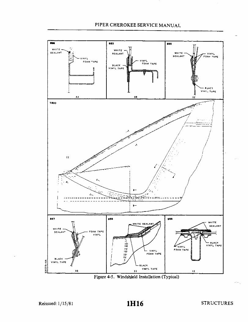
PIPER CHEROKEE SERVICE MANUAL
390 963 955
WHITE WHITE
SEALANT SEALANT WHITE
:I VINYL
BLACK
1800
WHITESEALANT
BLACKVINYL TAPE
Reissued: 1/15/81
898 966WHITE
SEALANT
VINYL
BLACKVINYL TAPE
BLACKVINYL TAPE
Figure 4-5. Windshield Installation (Typical)
1H16
F.F
STRUCTURES
VINYLFOAM TAPE
- BLACK
PIPER CHEROKEE SERVICE MANUAL
c. Apply Behr-Manningvinyl foam tape number 560 or equivalent over the plas-tic tape, completely around the edges of the windshield.
d. Apply Behr-Manning sealant number PRC 5000 or equivalent under the edgeof the moldings and trim strips.
e. Place the windshield in position for installation and slide the windshield aftand up into place, using caution not to dislocate the tape around the edges. Allowclearance between the two windshields at the divider post for expansion.
f . Lay sealant at the bottom and center (inboard) of the windshield in the hol-low between the outside edge and channel.
g. Lay a small amount of sealant under the center trim strip, install and se-cure.
h. Lay black vinyl tape on the underside of the collar molding, install and se-cure.
i . Seal with sealant any areas around windshield that mayallow water to pen-etrate past the windshield.
j . Remove excess exposed sealer to tape.
4-33. SIDE WINDOWS.
4-34. REMOVAL OF SIDE WINDOWS. PA-28 airplanes are equipped witha sin-
gle pane side windows, the exception being the PA-28-235, Serial Nos. 28-10720 to28-7210033 inclusive, which are installed with double pane side windows. For removal ofboth types of windows, the following instructions may be used:
a. Single Panel.1. Remove the retainer molding from around the window by removing the
attachment screws.2. Carefully remove the window from the frame.
NOTE
A damaged window should be saved to provide a patternfor shaping the new window.
3. Remove excess tape and sealer from the window frame and molding.b. Double Pane.
1. Remove the trim and retainer moldings from around the window by re-moving the attachment screws.
2. Carefully remove the window from the frame.
Issued: 9 1 68 1H17 STRUCTURES1H17

PIPER CHEROKEE SERVICE MANUAL
C337
INNER PANE(LIGHT GAUGE)
OUTER PANE(HEAVY GAUGE)
WHITE SEALANT
ADHESIVE SPONGERUBBER
Figure 4-6. Side Window Installation,Single Pane (Typical)
Figure 4-7. Side Window Installation,Double Pane (Typical)
NOTE
A damagedwindow should be saved to provide a patternfor shaping the new window.
3. Remove excess tape and sealer from the window frame.
4-35. INSTALLATION OF SIDE WINDOWS.a. Single Pane. (Refer to Figure 4-6.)
1. Cut or grind the new window to the same dimension as the window re-moved.
2. Apply Behr-Manning vinyl foam tape number 560 or equivalent, on bothsides of the window around the outer edges.
3. Apply Behr-ManningSealant number PRC 5000 or equivalent, completelyaround the outer surface of the windows at all attachment flanges.
4. Insert the window in the frame and install the retainer moldings.5. Secure the molding with attachment screws and tighten until the vinyl
foam tape is 25% compressed by the retainers.6. Remove the excess exposed sealer and tape.
b. Double Pane. (Refer to Figure 4-7.)1. Cut or grind the new window to the same dimension as the window re-
moved.2. Apply Raybestos R-15 black #565C sponge rubber adhesive or equiva-
Reissued: 1/15/81 1H18 STRUCTUR 1H18
980
WHITE SEALANT
VINYL FOAM TAPE
Reissued: 1/15/81 ES
PIPER CHEROKEE SERVICE MANUAL
lent, between the edges of the outer (heavy gauge) and inner (light gauge) windows, prior toinstallation.
3. Apply Behr-Manning sealant number PRC 5000 or equivalent, completelyaround the outer surface of the attachment flanges.
4. Insert the window assembly in the frame and install the retainer moldings.5. Secure the window and retainer moldings in position by installing the
attachment screws.6. Install the trim moldings and attachment screws.7. Remove the excess exposed sealer from around the window.
4-36. DOOR (ENTRANCE).
4-37. REMOVAL OF DOOR.a. Remove the clevis bolt, washer and bushing from the door holder assembly.b. Remove cotter pins, clevis pins and washers from serrated door hinges.c. Remove the door from the airplane.
4-38. INSTALLATION OF DOOR.a. Insert the door into position and install the washers, clevis bolts and cotter pins on
the door hinges.b. For adjustment of door, refer to Paragraph 4-39.c. Hook up and install the clevis bolt, bushing and washer into the door holder
assembly.
4-39. ADJUSTMENT OF DOOR.a. To acquire the proper vertical adjustment of the door, insert the necessary washer
combination between the cabin door hinge and fuselage bracket assembly.b. Additional adjustments may be made by tapping out the serrated door hinge,
bushings and rotating them to obtain the hinge centerline location that will provide properdoor fit.
c. To insure long life of door seals and improve sealing characteristics, it isrecommended they be lubricated with a fluorocarbon or similar dry lubricant in a spray can.
4-40. REMOVAL OF DOOR LATCH MECHANISMa. Remove the door latch mechanism by removing the door trim upholstery and the
screws that attach the latch plate and latch mechanism to the door.b. Disconnect the latch pull rod from the inside door handle.c. Remove the complete latch mechanism.
Reissued: 1/15/81 STRUCTUR ES
1H19

PIPER CHEROKEE SERVICE MANUAL
4-41. REMOVAL AND INSTALLATION OF DOOR SEAL SNUBBERS. (Refer to Figure 4-8.)
A. To remove old seals use a thinner, such as toluol. that won't affect the painted surface, and strip offthe old seal.
B. Install the door seal as follows:1. If the surface has just been painted. allow to dry for a minimum of 2 hours before installing the
seal.2. Wipe the surface clean with a cleaner solvent. such as DuPont Prep-Sol 3919S.
-NOTE -
Refer to the List of Consumable Materials for types ofappropriate neoprene adhesive.
3. Make sure both the seal and surface are 65° to 100°F.4. Adhesive should only be applied to that area to be covered by the seal. If necessary. tape off the
affected area. The adhesive can be thinned as required with toluol. Apply adhesive in a continuous coat of.002to .010 of an inch thick.
5. Apply a continuous coat of adhesive of the same thickness to the seal.6. With the adhesive applied to the mating surface and seal. allow them to cure 30 to 60 min. apart
before bonding them in place.7. With reference to Figure 4-8, make sure the seal is properly aligned before allowing the
surfaces to come in contact. The seal should not be stretched or pulled such that the cross section of the seal isreduced or distorted. Make sure the door closes properly and that an airtight seal is produced.
8. After positioning the seal. apply pressure to remove air bubbles and assure firm contact.
B95SDO NOT STRETCH SNUBBERAROUND CORNERS (TYP)
ORIENT SNUBBER FLATWITH THIS SURFACE
FIGURE 1VIEW LOOKING INBOARD
R.H. SIDE
ADHESIVE
CI-
SECTION C-C
Figure 4-8. Door Snubber Installation
Reissued: 1/15/81
STRIKER PLATE
STRUCTURES1H20

PIPER CHEROKEE SERVICE MANUAL
4-42. INSTALLATION OF DOOR LATCH MECHANISM.a. Place the latch assembly into position on the door.b. Connect the latch pull rod to the inside door handle.c. Replace the screws that attach the latch plate and mechanism to the door.
Install the door trim upholstery and secure with screws.
4-43. ADJUSTMENT OF DOOR LATCH MECHANISM. To adjust the door latch,loosen the screws on the striker plate, make necessary adjustment, and retightenthe screws.
4-44. REMOVAL OF DOOR LOCK ASSEMBLY.a. Remove the door trim upholstery by removing the attachment screws.b. Loosen the nut on the lock assemblyand remove the lock by turning it side-
ways.
4-45. INSTALLATION OF DOOR LOCK ASSEMBLY.a. Install the lock in the door by turning it sideways and placing it through the
opening provided.b. Replace the nut on the back of the lock assembly and tighten.c. Replace the door trim upholstery and secure with the attachment screws.
4-46. REMOVAL OF DOOR SAFETY LATCH.a. PA-28-150, -160,-180 Serial Nos. 28-1 to 28-990 incl:
1. Remove the latch assembly by removing the two knobs and the smalltrim plate at the aft end of the latch.
2. Remove the two screws from the inside trim plate and remove the plate.3. Remove the latch assembly from the door.
b. PA-28-140; PA-28-150, -160, -180, Serial Nos. 28-991 and up; PA-28-235 andPA-28R:
1. Remove the two handles and the five screws holding the pan on the insideof the door.
2. Remove the pane and pull the latch assembly through the openingon thedoor.
STRUCTURESReissued: 1/15/81
1H21

PIPER CHEROKEE SERVICE MANUAL
4-47. INSTALLATION OF DOOR SAFETY LATCHa. PA-28-150, -160, -180 Serial Nos. 28-1 to 28-990 incl:
1. Place the latch assembly into position for installation.2. Install the small trim plate on the aft end of the door and on the inside
of the door. Secure in place with the attachment screws.3. Replace the knobs and tighten. Check latch for proper operation and
that the knobs are free of rubbing on the trim panels.b. PA-28-140; PA-28-150,-160,-180 Serial Nos. 28-991 and up; PA-28-235
and PA-28R:1. Place the latch assembly into position for installation.2. Replace the pan and install the five screws and handles.3. Check the latch assembly for operation and be certain that it is free of
rubbing on the trim panels.
4-48. ADJUSTMENT OF DOOR SAFETY LATCH. (PA-28-140; PA-28-150,-160,-180,Serial Nos. 28-991 and up; PA-28-235 and PA-28R.)
a. To adjust the door safety latch remove the two screws from latch plate foundat the top of the door opening.
b. Remove the plate and turn the loop assembly in or out to make necessaryadjustments.
c. Replace the latch plate and secure with the two attachment screws.
4-49. BAGGAGE DOOR.
4-50. REMOVAL OF BAGGAGE DOOR. With the dooropen removethehinge pinfrom the hinge and remove the door.
4-51. INSTALLATION OF BAGGAGE DOOR. Place the door in position so thatthe hinge halves are properly matched and install the hinge pin. It will not benecessary to replace the hinge pin with a new pin if it is free of bends and wear.
4-52. REMOVAL OF BAGGAGE DOOR LOCK ASSEMBLY.a. With the door open remove the nut from the back of the lock assembly by
use of a special made wrench. (This tool may be fabricated from the dimensionsgiven in Figure 4-24.)
b. Remove the lock assembly through the front of the door.
Reissued: 1/15/81 STRUCTURES
1H22

PIPER CHEROKEE SERVICE MANUAL
4-53. INSTALLATION OF BAGGAGE DOOR LOCK ASSEMBLY.a. Place the lock into position for installation.b. Install the nut on the lock assembly and tighten with the use of a special wrench.
4-54. REMOVAL OF BAGGAGE DOOR HINGE.a. Remove the door from the airplane as described in Removal of Baggage Door,
Paragraph 4-49.b. Remove the hinge half from the airplane or door by drilling out the rivets and
removing the hinge.
4-55. INSTALLATION OF BAGGAGE DOOR HINGE.a. Place the hinge halves together and install the hinge pin.b. Install the door into the closed position and drill the two end rivet holes and install
the rivets.c. Operate the door and check for proper fit and installation. Drill the remaining holes
and install the rivets.
4-56. RIGGING INSTRUCTIONS - SEAT BACK LOCK AND RELEASE. (Refer to Figure4-9.)
a. Loosen screws (1 and 2) and ascertain that clamps (3 and 4) are in a relaxedcondition. (Push-pull cable (6) is able to move within the clamps.)
b. Place a straightedge along the lower surface of bushing (5) of the seat back release.c. Adjust the push-pull cable (6) by raising or lowering it until the lower surface of the
stop assembly (7) is parallel to the straightedge.d. Secure the push-pull cable in this position by tightening screws (1 and 2) on clamps
(3 and 4). The stop (7) should be lubricated and free to swivel without excessive play.e. Push on seat back with stop assembly (7) in an engaged position to check
engagement. Rotate the seat back release handle and check for disengagement of seat back.
STRUCTURESReissued: 1/15/81
1H23

`PIPER CHEROKEE SERVICE MANUAL
A282
SCREWSCREWCLAMPCLAMPBUSHINGCABLESTOP ASSY.
STRAIGHTEDGE
STOP SHOULD BE LUBRICATED AND FREETO SWIVEL WITHOUT EXCESSIVE PLAY
Figure 4-9. Seat Back Lock
1H24 STRUCTURESReissued: 1/15/81
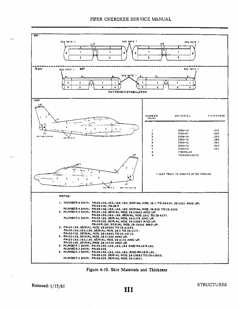
0
o
a
0

PIPER CHEROKEE SERVICE MANUAL
LEFT, BOTTOM C33B
SEE NOTE 5 1 2
3
SEE NOTE 4
SEE NOTE 6
SEE NOTE 6
2
PA-28-140,-150,-160,-180 AND 23
3,4 SEE NOTE 3
6 7 5
235
LEFT, TOP
5
8
SEE NOTE 5
LEFT, BOTTOM
7
SEE NOTE 4 1
PA-2 8 R ONLY
4
31,2
5
LEFT, TOP
5 6 7
5
Figure 4-10. Skin Materials and Thickness (cont.)
Reissued: 1/15/81 STRUCTURES112
SEE NOTE 3
2
3 5
5
13
4
5
6 3
3
3
8
3
5
I I
3
PIPER CHEROKEE SERVICE MANUAL
4-57. STRUCTURAL REPAIRS. Structural repair methods used may be made in accordancewith the regulations set forth in Federal Aeronautics Manual 18 or FAA Advisory Circular43.13-1A. To assist in making repairs, Figure 4-10 identifies the type and thickness of skinstructure used. Never make a skin replacement or patch from a material thinner than the originalskin. Original material and thickness is recommended and must result in a surface which is asstrong as, or stronger than, the original skin. However, flexibility must be retained so that thesurrounding areas will not receive extra stress.
When making major structural repairs, other than using factory manufactured parts, it isrecommended the manufacturer be contacted. No major alterations are recommended withoutcontacting the manufacturer.
4-57a. BAGGAGE COMPARTMENT INSPECTION HOLE AND COVER PLATE.If baggage compartment inspection holes are not already installed, see Paragraph 4-79 forinstallation details.
4-58. FIBERGLAS REPAIRS. The repair procedure in this manual will describe the methodsfor repair of fiberglas reinforced structures. Paragraph 4-59 describes Fiberglas Touch-Up andSurface Repairs such as blisters, open seams, delamination, cavities, small holes and minordamages that have not harmed the fiberglas cloth material. Paragraph 4-60 describes FiberglasFracture and Patch Repairs as puncture, breaks and holes that have penetrated through the structureand damaged the fiberglas cloth. A repair kit, part number 756 729 will furnish necessary materialfor such repairs, is available through Piper Aircraft Dealers.
NOTE
Very carefully follow resin and catalyst mixing instruc-tions furnished with repair kit.
4-59. FIBERGLAS TOUCH-UP AND SURFACE REPAIRS.a. Remove wax, oil and dirt from around the damaged area with acetone, Methylethylketone
or equivalent and remove paint to gel coat.b. The damaged area may be scraped with a fine blade knife or a power drill with a burr
attachment to roughen the bottom and sides of the damaged area. Feather the edge surrounding thescratch or cavity. Do not undercut the edge. (If the scratch or cavity is shallow and penetrates onlythe surface coat, continue to step h.)
c. Pour a small amount of resin into ajar lid or on a piece of cardboard, just enough to fill thearea being worked on. Mix an equal amount of milled fiberglas with the resin, using a putty knifeor stick. Add catalyst, according to kit instruction, to the resin and mix thoroughly. A hypodermicneedle may be used to inject gel into small cavities not requiring fiberglas millings mixed with thegel.
Interim Revision: February 15, 1995 STRUCTURES
113

PIPER CHEROKEE SERVICE MANUAL
d. Work the mixture of resin, fibers and catalyst into the damaged area, usingthe sharp point of a putty knife or stick to press it into the bottom of the hole andto puncture any air bubbles which may be present. Fill the scratch or hole abovethe surrounding undamaged area about 1/16 inch.
e. Lay a piece of cellophane or waxed paper over the repair to cut off air andstart the cure of gel mixture.
f. Allow the gel to cure 10 to 15 minutes until it feels rubbery to the touch.Remove the cellophane and trim flush with the surface, using a sharp razor bladeor knife. Replace the cellophane and allow to cure completely for 30 minutes toan hour. The patch will shrink slightly below the structure surface as it cures.(If wax paper is used, ascertain wax is removed from surface.)
g. Rough up the bottom and edges of the holewith the electric burr attachmentor rough sand paper. Feather hole into surrounding gel coat, do not undercut.
h. Pour out a small amount of resin, add catalyst and mix thoroughly, usinga cutting motion rather than stirring. Use no fibers.
i . Using the tip of a putty knife or finger tips, fill the hole at about 1/16 inchabove the surrounding surface with the gel coat mixture.
j . Lay a piece of cellophane over the patch to start the curing process. Re-peat step f, trimming patch when partially cured.
k. After trimming the patch, immediately place another small amount of gelcoat on one edge of the patch and cover with cellophane. Then, using a squeegeeor the back of a razor blade, squeegee level wtih area surrounding the patch,leave the cellophane onpatch for one or two hours or overnight, for complete cure.
1 . After repair has cured for 24 hours, sand patched the area using a sandingblock with fine wet sandpaper. Finish by priming, again sanding and applyingcolor coat.
4-60. FIBERGLAS FRACTURE AND PATCH REPAIRS.a. Remove wax, oil and dirt from around damaged area with acetone, methyl-
ethylketone or equivalent.b. Using a key hole saw, electric saber saw, or sharp knife cut away ragged
edges. Cut back to sound material.c. Remove paint three inches back from around damaged area.d. Working inside the structure, bevel the edges to approximately a 30 degree
angle and rough-sand the hole and the area around it, using 80-grit dry paper.Feather back for about two inches all around the hole. This roughens the surfacefor strong bond with patch.
e. Cover a piece of cardboard or metal with cellophane. Tape it to the out-side of the structure covering the hole completely. The cellophane should facetoward the inside of the structure. If the repair is on a sharp contour or shaped
Reissued: 1/15/81 114 STRUCTURES

PIPER CHEROKEE SERVICE MANUAL
area, a sheet of aluminum formed to a similar contour may be placed over thearea. The aluminum should also be covered with cellophane.
f . Prepare a patch of fiberglas matand cloth to cover an area two inches largerthan the hole.
g. Mix a small amount of resin and catalyst, enough to be used for one stepata time, according to kit instructions.
h. Thoroughlywetmat andcloth withcatalyzedresin. Daub resin on mat first,and then on cloth. Mat should be applied against structures surface with cloth ontop. Both pieces may be wet out on cellophane and applied as a sandwich. Enoughfiberglas cloth and mat reinforcements should be used to at least replace theamount of reinforcements removed in order to maintain the original strength. Ifdamage occurred as a stress crack, an extra layer or two of cloth may be usedto strengthen area.
i. Lay patch over hole on inside of structure, cover with cellophane, andsqueegee from center to edges to remove all air bubbles and assure adhesionaround edge of hole. Air bubbles will show white in the patch and they should allbe worked out to the edge. Remove excess resin before it gels on the part. Al-low patch to cure completely.
j . Remove cardboard or aluminum sheet from outside of hole and rough-sandthe patch and edge of hole. Feather edge of hole about two inches into undamagedarea.
k. Mask area around hole with tape and paper to protect surface. Cut a pieceof fiberglas mat about one inch larger than the hole and one or more pieces offiberglas cloth two inches larger than the hole. Brush catalyzed resin over hole,lay mat over hole and wet out with catalyzed resin. Use a daubing action withbrush. Then apply additional layer or layers of fiberglas cloth to build up patchto the surface of structure. Wet out each layer thoroughly with resin.
1 . With a squeegee or broad knife, work out all air bubbles in the patch. Workfrom center to edge, pressing patch firmly against the structure. Allow patch tocure for 15 to 20 minutes.
m. As soon as the patch begins to set up, but while still rubbery, take a sharpknife and cut away extra cloth and mat. Cut on outside edge of feathering. Stripcut edges of structure. Do this before cure is complete, to save extra sanding.Allow patch to cure overnight.
n. Using dry 80 grit sandpaper on a power sander or sanding block, smoothpatch and blend with surrounding surface. Should air pockets appear while sand-ing, puncture and fill with catalyzed resin. A hypodermic needle may be used tofill cavities. Let cure and resand.
o. Mix catalyzed resin and work into patch with fingers. Smooth carefully andwork into any crevices.
p. Cover with cellophane and squeegee smooth. Allow to cure completely be-fore removing cellophane. Let cure and resand.
Reissued: 1/15/81 115 STRUCTURES

PIPER CHEROKEE SERVICE MANUAL
q. Brush or spray a coat of catalyzed resin to seal patch. Sand patch, finish by priming,again sanding and applying color coat.
NOTE
Brush and hands may be cleaned in solvents such as acetoneor methylethylketone. If solvents are not available, a strongsolution of detergent and water may be used.
4-61. THERMOPLASTIC REPAIRS. The following procedure will assist in making fieldrepairs to items made of thermoplastic which are used throughout the airplane. A list ofmaterial needed to perform these repairs is given along with suggested suppliers of thematerial. Common safety precautions should be observed when handling some of thematerials and tools used while making these repairs.
a. Surface Preparation:1. Surface dirt and paint if applied must be removed from the item being repaired.
Household cleaners have proven most effective in removing surface dirt.2. Preliminary cleaning of the damaged area with perchlorethylene or VM&P
Naptha will generally insure a good bond between epoxy compounds and thermoplastic.b. Surface Scratches, Abrasion or Ground-in-Dirt: (Refer to Figure 4-11.)
1. Shallow scratches and abraded surfaces are usually repaired by following direc-tions on containers of conventional automotive buffing and rubbing compounds.
2. If large dirt particles are embedded in thermoplastic parts, they can be removedwith a hot air gun capable of supplying heat in the temperature range of 300° to 400° F. Usecare not to overheat the material. Hold the nozzle of the gun about 1/4 of an inch away fromthe surface and apply heat with a circular motion until the area is sufficiently soft to removethe dirt particles.
3. The thermoplastic will return to its original shape upon cooling.c. Deep Scratches, Shallow Nicks and Small Holes: (Less than 1 inch in diameter.)
(Refer to Figure 4-12.)1. Solvent cements will fit virtually any of these applications. If the area to be re-
paired is very small, it may be quicker to make a satisfactory cement by dissolving thermo-plastic material of the same type being repaired in solvent until the desired paste-like con-sistency is achieved.
2. This mixture is then applied to the damaged area. Upon solvent evaporation, thehard durable solids remaining can easily be shaped to the desired contour by filing or sanding.
3. Solvent adhesives are not recommended for highly stressed areas, on thin walledparts or for patching holes greater than 1/4 inch in diameter.
4. For larger damages an epoxy patching compound is recommended. This typematerial is a two part, fast curing, easy sanding commercially available compound.
5. Adhesion can be increased by roughing the bonding surface with sandpaper andby utilizing as much surface area for the bond as possible.
6. The patching compound is mixed in equal portions on a hard flat surface using afigure eight motion. The damaged area is cleaned with perchlorethylene or VM&P Napthaprior to applying the compound. (Refer to Figure 4-13.)
7. A mechanical sander can be used after the compound is cured, providing thesander is kept in constant motion to prevent heat buildup.
Reissued: 1/15/81 STRUCTURES
116
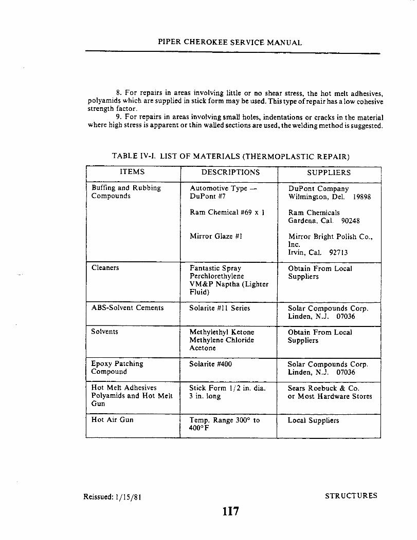
PIPER CHEROKEE SERVICE MANUAL
8. For repairs in areas involving little or no shear stress, the hot melt adhesives,polyamids which are supplied in stick form may be used. This type of repair has a low cohesivestrength factor.
9. For repairs in areas involving small holes, indentations or cracks in the materialwhere high stress is apparent or thin walled sections are used, the welding method is suggested.
TABLE IV-I. LIST OF MATERIALS (THERMOPLASTIC REPAIR)
DESCRIPTIONS SUPPLIERS
Buffing and RubbingCompounds
Automotive Type -DuPont #7
DuPont CompanyWilmington, Del. 19898
Ram Chemical #69 x 1
Mirror Glaze #1
Fantastic SprayPerchlorethyleneVM&P Naptha (LighterFluid)
Ram ChemicalsGardena, Cal. 90248
Mirror Bright Polish Co.,Inc.Irvin, Cal. 92713
Obtain From LocalSuppliers
ABS-Solvent Cements Solarite #11 Series Solar Compounds Corp.Linden, N.J. 07036
Methylethyl KetoneMethylene ChlorideAcetone
Obtain From LocalSuppliers
Epoxy PatchingCompound
Hot Melt AdhesivesPolyamids and Hot MeltGun
Hot Air Gun
Solarite #400
Stick Form 1/2 in. dia.3 in. long
Temp. Range 300° to400° F
Solar Compounds Corp.Linden, N.J. 07036
Sears Roebuck & Co.or Most Hardware Stores
Local Suppliers
Reissued: 1/15/81 STRUCTURES
117
ITEMS
Cleaners
Solvents
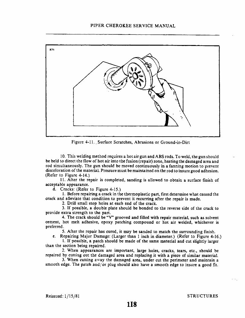
PIPER CHEROKEE SERVICE MANUAL
871
Figure 4-11., Surface Scratches, Abrasions or Ground-in-Dirt
10. This welding method requires a hot air gun and ABS rods. To weld, the gun shouldbe held to direct the flow of hot air into the fusion (repair) zone, heating the damaged area androd simultaneously. The gun should be moved continuously in a fanning motion to preventdiscoloration of the material. Pressure must be maintained on the rod to insure good adhesion.(Refer to Figure 4-14.)
11. After the repair is completed, sanding is allowed to obtain a surface finish ofacceptable appearance.
d. Cracks: (Refer to Figure 4-15.)1. Before repairing a crack in the thermoplastic part, first determine what caused the
crack and alleviate that condition to prevent it recurring after the repair is made.2. Drill small stop holes at each end of the crack.3. If possible, a double plate should be bonded to the reverse side of the crack to
provide extra strength to the part.4. The crack should be "V" grooved and filled with repair material, such as solvent
cement, hot melt adhesive, epoxy patching compound or hot air welded, whichever ispreferred.
5. After the repair has cured, it may be sanded to match the surrounding finish.e. Repairing Major Damage: (Larger than 1 inch in diameter.) (Refer to Figure 4-16.)
1. If possible, a patch should be made of the same material and cut slightly largerthan the section being repaired.
2. When appearances are important, large holes, cracks, tears, etc., should berepaired by cutting out the damaged area and replacing it with a piece of similar material.
3. When cutting away the damaged area, under cut the perimeter and maintain asmooth edge. The patch and/or plug should also have a smooth edge to insure a good fit.
Reissued: 1/15/81 STRUCTURES
118

PIPER CHEROKEE SERVICE MANUAL
871
Figure 4-12. Deep Scratches, Shallow Nicks and Small Holes
826
THOROUGHLY MIXUSING FIGURE EIGHT
MOTION.
Figure 4-13. Mixing of Epoxy Patching Compound
Reissued: 1/15/81 119 STRUCTURES

PIPER CHEROKEE SERVICE MANUAL
4. Coat the patch with solvent adhesive and firmly attach it over the damaged area.5. Let the patch dry for approximately one hour before any additional work is
performed.6. The hole, etc., is then filled with the repair material. A slight overfilling of the
repair material is suggested to allow for sanding and finishing after the repair has cured. Ifpatching compound is used the repair should be made in layers, not exceeding a 1/2 inch inthickness at a time, thus allowing the compound to cure and insuring a good solid buildup ofsuccessive layers as required.
f. Stress Lines: (Refer to Figure 4-17.)1. Stress lines produce a whitened appearance in a localized area and generally
emanate from the severe bending or impacting of the material. (Refer to Figure 4-18.)2. To restore the material to its original condition and color, use a hot air gun or
similar heating device and carefully apply heat to the affected area. Do not overheat thematerial.
g. Painting the Repair:1. An important factor in obtaining a quality paint finish is the proper preparation
of the repair and surrounding area before applying any paint.2. It is recommended that parts be cleaned prior to painting with a commercial
cleaner or a solution made from one-fourth cup of detergent mixed with one gallon of water.3. The paint used for coating thermoplastic can be either lacquers or enamels de-
pending on which is preferred by the repair facility or customer. (See NOTE.)
NOTE
It is extremely important that solvent formulations be con-sidered when selecting a paint, because not all lacquers orenamels can be used satisfactorily on thermoplastics. Somesolvents used in the paints can significantly affect and degradethe plastic properties.
4. Another important matter to consider is that hard, brittle coatings that are usuallybest for abrasion resistance should not be used in areas which incur high stress, flexing orimpact. Such coating may crack, thus creating a weak area.
4-62. A.B.S. THERMOPLASTIC LANDING GEAR WHEELS AND STRUT FAIRINGREPAIR INSTRUCTIONS. Instructions covering the wheel and strut fairing is containedin a special Wheel and Strut Fairing Repair Instruction Manual, P/N 761 708V. This manualis obtainable from Vero Beach Service and Sales Department, Piper Aircraft Corporation,Vero Beach, Florida 32960.
Reissued: 1/15/81 STRUCTURES1110

PIPER CHEROKEE SERVICE MANUAL
B70
Figure 4-14. Welding Repair Method
827
HOLES
Figure 4-15. Repairing of Cracks
1I11
DOUBLER PLATE TO
I
Revised: 10 3 83 STRUCTURES

PIPER CHEROKEE SERVICE MANUAL
831
830
828
DAMAGED AREA
Figure 4-16. Various Repairs
STRUCTURES
I
1112

PIPER CHEROKEE SERVICE MANUAL
827
STRESSLINES
Figure 4-17. Repair of Stress Lines
829
PROFILE VIEW INDICATINGDAMAGED AREA
Figure 4-18. Repair of Impacted Damage
1113 STRUCTURESRevised: 10 3 83
PIPER CHEROKEE SERVICE MANUAL
4-63. SAFETY WALK REPAIR.
4-64. SURFACE PREPARATION FOR LIQUID SAFETY WALK.a. Clean all surfaces with a suitable cleaning solvent to remove dirt, grease and oils.
Solvents may be applied by dipping, spraying or mopping.b. Insure that no moisture remains on the surface by wiping with a clean cloth.c. Outline the area to which the liquid safety walk compound is to be applied, and
mask adjacent surfaces.
NOTE
Newly painted surfaces, shall be allowed to dry for 2.5 hoursminimum prior to the application of the safety walk.
4-65. PRODUCT LISTING FOR LIQUID SAFETY WALK COMPOUND.a. Suggested Solvents:
Safety Solvent per MIL-S-18718Sherwin Williams Lacquer Thinner R7KC 120Glidden Thinner No. 207
b. Safety Walk Material:Walkway Compound and matting nonslip(included in Piper Part No. 179872.)
4-66. APPLICATION OF LIQUID SAFETY WALK COMPOUND. Liquid safety walkcompound shall be applied in an area, free of moisture for a period of 24 hours minimumafter application. Do not apply when surface to be coated is below 50 ° F. Apply liquidsafety walk compound as follows:
a. Mix and thin the liquid safety walk compound in accordance with themanufacturer's instructions on the container.
b. Coat the specified surfaces with a smooth, unbroken film of the liquid safety walkcompound. A nap type roller or a stiff brush is recommended, using fore and aft strokes.
c. Allow the coating to dry for 15 minutes to one hour before recoating or touch-up; ifrequired after application of the initial coating.
d. After recoating or touch-up, if done, allow the coating to dry for 15 minutes to onehour before removing masking.
NOTE
The coated surface shall not be walked on for six hoursminimum after application of final coating.
4-67. SURFACE PREPARATION FOR PRESSURE SENSITIVE SAFETY WALK. Theareas to which the pressure sensitive safety walk is to be installed must be free from allcontaminates and no moisture present. If liquid safety walk is installed the area must beprepared as follows:
a. Area must be masked off to protect painted surfaces.b. Apply suitable stripper MEK Federal Spec. TT-M-261, U.S. Rubber No. 3339 to
wingwalk compound. As compound softens remove by using putty knife or other suitabletool.
c. Area must be clean and dry prior to painting.d. Prime and paint area.
Reissued: 1/15/81 STRUCTURE1114
PIPER CHEROKEE SERVICE MANUAL
NOTE
Newly painted surfaces, shall be allowed to dry for 2.5 hoursminimum prior to the application of the safety walk.
4-68. APPLICATION OF PRESSURE SENSITIVE SAFETY WALK. (Kit 763 848V)Wipe area with a clean dry cloth to insure that no moisture remains on surface. Do notapply when surface temperature is below 500 F. Apply pressure sensitive safety walk asfollows:
a. Peel back the full width of the protective liner approximately 2 inches from theleading edge of the safety walk.
b. Apply the safety walk to the wing area, begin at the leading edge, insure properalignment and position from wing lap.
c. Remove the remaining protective liner as the safety walk is being applied from frontto back of wing area.
d. Roll firmly with a long handled cylindrical brush in both lengthwise directions.Make sure all edges adhere to the wing skin.
e. Install and rivet leading edge retainer.
Reissued: 1/15/81
1I15
PIPER CHEROKEE SERVICE MANUAL
4-69. CONTROL SURFACE BALANCING.
4-70. CHECKING CONTROL SURFACE BALANCE. The movable control surfaces have
been statically balanced at the time of installation at the factory and normally should notrequire rebalancing. Where possible the control surfaces were set with the balance weight onthe heavy side of the limits, to permit limited repair or paint touch-up without adjusting thebalance weight. It should be noted however, that spare control surfaces are deliveredunpainted and the static balance will not necessarily fall within the limits provided, this ismore pronounced on the stabilators and rudders. The completed control surface, including
paint, should be within the limits given in Table IV-II. If the surface is not to be painted, thebalance weight will probably require adjustment. All replacement control surfaces, or
surfaces that have been repainted or repaired, should be rebalanced according to theprocedures given in Paragraphs 4-69 thru 4-75. The static balance of the surfaces must be asspecified in Table IV-II.
Before balancing any control surface, it must be complete including tip, trim/servo tabsand tab actuating arms or push rods with bearings as applicable, and all optional equipmentwhich is mounted on or in the control surface when it is flown, including paint, positionlights and wiring, static wicks, scuff boots, etc.
If optional equipment is added or removed after balancing, the control surface must be
rebalanced. During balancing, trim/servo tabs must be maintained in their neutral positions.
4-71 CHECKING CONTROL SURFACES FREE PLAY. The following checks arerecommended before balancing to ascertain the amount of "free play" in the stabilator,stabilator trim tab and aileron:
a. Stabilator: Check the stabilator for any "free play" at its attachment points by
grasping each half near the tip and gently trying to move it up and down, fore and aft, and
in and out. No play is allowed.b. Stabilator Trim Tab: Set the stabilator trim tab in neutral position. This neutral
position is determined with the airplane properly rigged per instructions given in Section Vof this Service Manual and the trim indicator at its neutral position. Obtain a straightedgelong enough to extend from the ground up to a few inches above the trim tab trailing edge.Place the straightedge next to the trim tab inboard (center) trailing edge, secure the
stabilator in neutral and grasping the tab, gently move it up and down, mark the limit of tabfree play on the straightedge. The overall travel (free play) must not exceed 0.15 of an inch.The use of a dial indicator and fixed stand is recommended.
c. Aileron: Set the aileron in its neutral position and secure. Obtain a straightedge long
enough to extend from the ground up to a few inches above the aileron trailing edge. Place
the straightedge next to the aileron trailing edge and gently move the aileron up and down,mark the limit of travel (free play) on the straightedge. The overall travel (free play) must
not exceed 0.24 of an inch. Should free play exceed the limit stated make necessary repairs
as required to eliminate excessive free play. Grasp the aileron and move it spanwise(inboard/outboard) to insure maximum end play of .035 of an inch is not exceeded.
Reissued: 1/15/81 STRUCTURES
1116

PIPER CHEROKEE SERVICE MANUAL
TABLE IV-II. BALANCING SPECIFICATIONS
Maximum Limits - Flight Conditions
STATIC BALANCE LIMITS (INCH-POUNDS)
SERIAL NOS.MODEL EFFECTED
HEAVY SIDELEADING EDGE
HEAVY SIDETRAILING EDGE
S PA-28-140T PA-28-140A PA-28-150B PA-28-160I PA-28-180LA PA-28-180TO PA-28-180R PA-28R-180/200S PA-28R-200
PA-28R-200PA-28-235
PA-28-235PA-28-235
R PA-28-140U PA-28-140D PA-28-150D PA-28-160E PA-28-180R PA-28-180S PA-28-180
PA-28R-180PA-28R-200PA-28R-200PA-28R-200PA-28-235PA-28-235PA-28-235
A PA-28-140I PA-28-150L PA-28-160E PA-28-180R PA-28R-180
PA-28R-200N PA-28-235
Revised: 10/3/83
THRU 28-732561428-7425001 AND UPALLALLNON-STRETCHEDSTABILATORSTRETCHED STABILATOR7305001 TO 730560128-7405001 AND UPTO 7235000STRETCHED STABILATOR7235001 TO 733544628R-7435001 AND UPNON-STRETCHEDSTABILATOR7310001 TO 731017628-7410001 AND UP
UP TO 28-732561428-7425001 AND UPALLALLTHRU 73050007305001 TO 73056117435001 AND UPTHRU 7235000THRU 72350007235001 TO 73354557435001 AND UPTHRU 7310000731001 TO 7310187741001 AND UP
ALLALLALLALLALLALLALL
STRUCTURES
1117
SURFACE
00000
+5+5-5
-5-5
-5+5+5
0O000000000000
TOTOTOTOTO
TOTOTO
TOTO
TOTOTO
TOTOTOTOTOTOTOTOTOTOTOTOTOTO
-30-30-30-30-30
-40-40-14
-40-40
-14-40-40
-20.9-13-20.9-20.9-20.9-25.0-13-15-15-14-13-15-14-14
0000
+2+2+2
-17-17-17-17-15-15-20
I
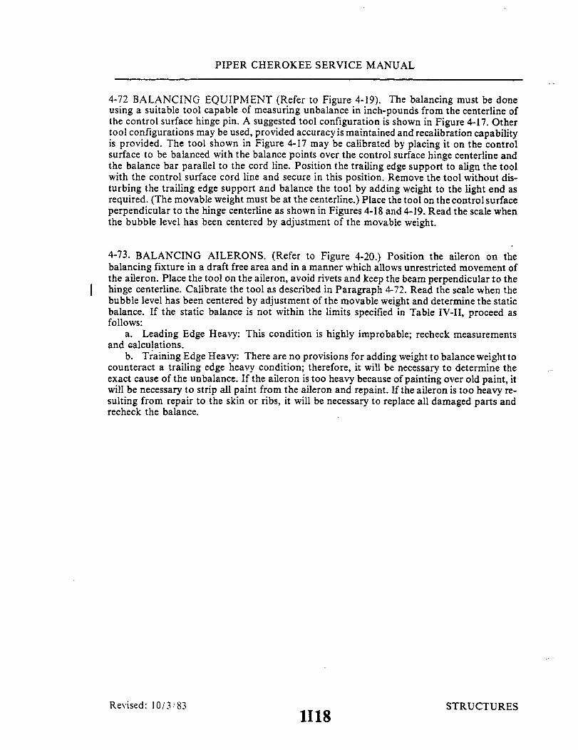
PIPER CHEROKEE SERVICE MANUAL
4-72 BALANCING EQUIPMENT (Refer to Figure 4-19). The balancing must be doneusing a suitable tool capable of measuring unbalance in inch-pounds from the centerline ofthe control surface hinge pin. A suggested tool configuration is shown in Figure 4-17. Othertool configurations may be used, provided accuracy is maintained and recalibration capabilityis provided. The tool shown in Figure 4-17 may be calibrated by placing it on the controlsurface to be balanced with the balance points over the control surface hinge centerline andthe balance bar parallel to the cord line. Position the trailing edge support to align the toolwith the control surface cord line and secure in this position. Remove the tool without dis-turbing the trailing edge support and balance the tool by adding weight to the light end asrequired. (The movable weight must be at the centerline.) Place the tool on the control surfaceperpendicular to the hinge centerline as shown in Figures 4-18 and 4-19. Read the scale whenthe bubble level has been centered by adjustment of the movable weight.
4-73. BALANCING AILERONS. (Refer to Figure 4-20.) Position the aileron on thebalancing fixture in a draft free area and in a manner which allows unrestricted movement ofthe aileron. Place the tool on the aileron, avoid rivets and keep the beam perpendicular to thehinge centerline. Calibrate the tool as described in Paragraph 4-72. Read the scale when thebubble level has been centered by adjustment of the movable weight and determine the staticbalance. If the static balance is not within the limits specified in Table IV-II, proceed asfollows:
a. Leading Edge Heavy: This condition is highly improbable; recheck measurementsand calculations.
b. Training Edge Heavy: There are no provisions for adding weight to balance weight tocounteract a trailing edge heavy condition; therefore, it will be necessary to determine theexact cause of the unbalance. If the aileron is too heavy because of painting over old paint, itwill be necessary to strip all paint from the aileron and repaint. If the aileron is too heavy re-sulting from repair to the skin or ribs, it will be necessary to replace all damaged parts andrecheck the balance.
Revised: 10/3/83 STRUCTURES1118

PIPER CHEROKEE SERVICE MANUAL
4-74. BALANCING RUDDER. (Refer to Figure 4-20.)To balance the rudder, theassembly must be complete including the tip assembly with all attaching screws and the posi-tion light wiring. Place the complete assembly horizontally on knife edge supports in a draft-free area in a manner that allows unrestricted movement. Place the tool on the rudder withthe beam perpendicular to the hinge centerline. Calibrate the tool as described in Para-graph 4-72. Read the scale when the bubble level has been centered by adjustment of themovable weight and determine the static balance limit. If the static balance is not within thelimits given in Table IV-II, proceed as follows:
a. Nose Heavy: This condition is highly improbable; recheck calculations andmeasurements.
b. Nose Light: In this case, the mass balance weight is too light or the rudder is tooheavy because of painting; it will be necessary to strip the paint and repaint. If the rudder is tooheavy as a result of repairs, the repair must be removed and the damaged parts replaced.
STRUCTURESRevised: 10 3 83 1I19
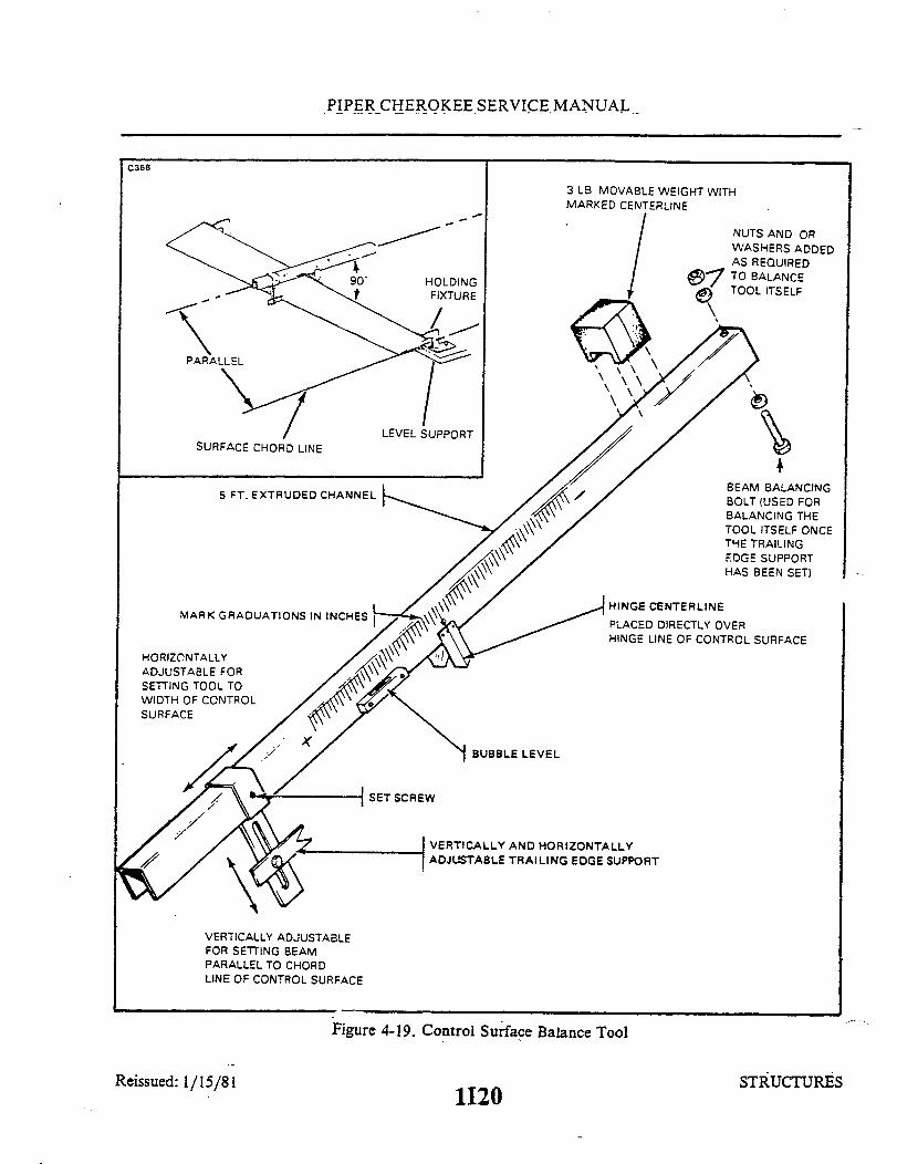
PIPER CHEROKEE SERVICE MANUAL
C368
3 LB MOVABLE WEIGHT WITH
SURFACE CHORD LINE
5 FT. EXTRUDED CHANNEL
MARK GRADUATIONS IN INCHES
HORIZONTALLYADJUSTABLE FORSETTING TOOL TOWIDTH OF CONTROLSURFACE
SET SCR
NUTS AND ORWASHERS ADDEDAS REQUIREDTO BALANCETOOL ITSELF
BEAM BALANCINGBOLT (USED FORBALANCING THETOOL ITSELF ONCETHE TRAILINGEDGE SUPPORTHAS BEEN SET)
HINGE CENTERLINE
PLACED DIRECTLY OVERHINGE LINE OF CONTROL SURFACE
BUBBLE LEVEL
EW
VERTICALLY AND HORIZONTALLYADJUSTABLE TRAILING EDGE SUPPORT
VERTICALLY ADJUSTABLEFOR SETTING BEAMPARALLEL TO CHORDLINE OF CONTROL SURFACE
Figure 4-19. Control Surface Balance Tool
Reissued: 1/15/81 STRUCTURES1I20
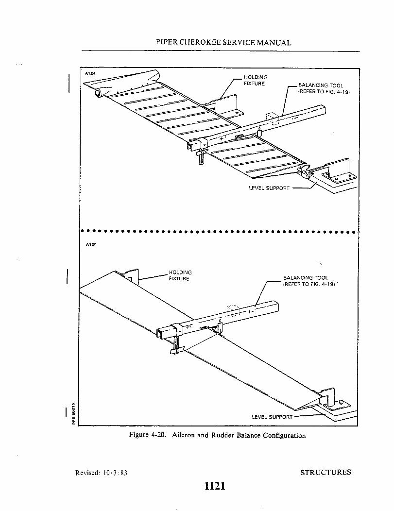
PIPER CHEROKEE SERVICE MANUAL
A12r
HOLDINGFIXTURE BALANCING TOOL
(REFER TO FIG. 4-19)
LEVEL SUPPORT
Figure 4-20. Aileron and Rudder Balance Configuration
STRUCTURESRevised: 10/3/83
1121

PIPER CHEROKEE SERVICE MANUAL
NOTE
The 1974 and up models of the PA-28-140 and PA-28-180, allPA-28-235, PA-28R-180 and PA-28R-200 have a non-adjustable mass balance weight molded in the nose of therudder tip. All rudders should be maintained within thestatic balance weights provided in Table IV-II.
4-75. BALANCING STABILATOR. (Refer to Figure 4-21.) To balance the stabilator, theassembly must be complete including the trim tab, the tab push rod and end bearing,stabilator tips and all attaching screws. Before balancing, tape the trim tab in neutral positionwith a small piece of tape. Place the complete assembly on the knife edge supports in a draft-free area in a manner that allows unrestricted movement. Place the tool on the stabilator withthe beam perpendicular to the hinge centerline. Do not place the tool on the trim tab. Calibratethe tool as described in Paragraph 4-72 Read the scale when the bubble level has been centeredby adjustment of the movable weight and determine the static balance limit. If the staticbalance is not within the limits given in Table IV-II, proceed as follows:
a. If the stabilator is out of limits on the leading edge heavy side, remove balance platesfrom the mass balance weight until the static balance is within limits. Do not attempt toadjust the stabilator tip balance weight.
b. If the stabilator is out of limits on the trailing edge heavy side, add balance plates tothe mass balance weight until the static balance is within limits.
0
Figure 4-21. Stabilator Balance
Revised: 10/3/83 1122 STRUCTURES

PIPER CHEROKEE SERVICE MANUAL
4-76. AILERON BALANCE WEIGHT MODIFICATION. (PA-28-140, Serial Nos.28-20002 to 28-25547 incl.; PA-28-150,-160, -180, SerialNos. 28-1 to 28-5339 incl.; PA-28-235,Serial Nos. 28-10003 to 28-11235 incl.; PA-28R-180, Serial Nos. 28-30005 to 28-31119 incl.)To facilitate the use of new aileron balance weight assembly (P/N 66766-00) on above statedairplanes, it will be necessary to modify the balance weight cutout in the wing rib. (Refer toFigure 4-22.)The hole pattern in the new balance weight bracket is the same as the old bracketwith the exception of two holes. When replacing the old bracket with the new one, it is per-missible to use the new bracket as a hole template to drill the two new holes at their properlocation. To install the balance weight assembly, the following procedure may be used:
a. Remove the aileron per Paragraph 4-8.b. Remove the old balance weight by drilling out the rivets from around the perimeter
of the bracket.c. Modify the wing end rib, balance arm hole as shown in Figure 4-21.d. Using the new bracket as a template, drill the two new holes in the rib. (Refer to
Figure 4-22.)e. Place six cherry lock rivets, CR22494-2, in the holes within the bracket and set the
rivets.f. Replace the six rivets around the perimeter of the bracket with MS20470AD 3-3,
and set.g. Prior to installation, paint metal parts where necessary.h. Install the aileron per Paragraph 4-9.
Reissued: 1/15/81 STRUCTURES
1123

PIPER CHEROKEE SERVICE MANUAL
969
.50R.
Figure 4-22. Wing Rib Modification
885.
RIVETS - MS20470AD3-3
Figure 4-23. Balance Weight Assembly Installation
Reissued: 1/15/81 STRUCTURES
1124

PIPER CHEROKEE SERVICE MANUAL
888
1.25"
.44"
.88"
.19"
1.75"
Figure 4-24. Fabricated Tool for Baggage Door Lock
4-77. FLAP INSPECTION AND MODIFICATION. (Refer to Figure 4-1.) Inspectthe aft flap attaching point for security. If it is found secure, no modification isrequired. If the clevis bolt appears to be working loose from the anchor nut, theattachment point should be modified in accordancewith the following instructions.
a. Remove the clevis bolt and related parts from the inboard flap hinge at-taching point.
b. The skin on the flap must be modified in accordance with Figure 4-1.c. Remove the existing anchor nuts from the inboard flap hinge.d. Install a new clevis bolt and related parts and secure with castellated nuts
and cotter pins.
4-78. STABILATOR DRAIN HOLES. In order to prevent thewater or ice in the stabilator when the aircraft is parked, itthat drain holes be added in accordance with Figure 4-25.
Reissued: 1/15/81
accumulation ofis recommended
STRUCTURES
1J1

PIPER CHEROKEE SERVICE MANUAL
1.13
43.20
.191 HOLE(4 PLACES)
EDGE OF LEADINGEDGE OF SKIN
STABILATOR(BOTTOM VIEW)
Figure 4-25. Additional Drain Holes in Stabilator
J2
924
Reissued: 1/15/81 STRUCTURES
FWDFWD.

PIPER CHEROKEE SERVICE MANUAL
4-79. BAGGAGE COMPARTMENT INSPECTION HOLE AND COVER PLATE.(See latest revision of Piper Service Bulletin 977.)
a. General.Airplanes manufactured before 1979 may not have had control cable inspection access
holes in the baggage compartment floor. The following is a method of fabricating inspectionaccess holes in the floor of the baggage compartment, if desired.
b. Baggage Compartment Inspection Holes Fabrication Procedure. (Refer to Figure 4-26.)While Figure 4-26 shows the hole in the left side of the baggage compartment, a
similar hole is also cut out in the right side baggage compartment floor. Installation willrequire two each inspection access covers, Piper P/N 62109-00.
1. Layout cut lines
(a) Gain access to baggage compartment.(b) Carefully remove:
(1) Right side baggage compartment Royalite plastic close out panel.(2) Rear close out panel.(3) Carpeting from baggage compartment floor.
(c) Determine and mark a reference center line running through baggagecompartment. Refer to Figure 4-26 for measurements.
(d) Measure two points 14.99 inches each side of the reference centerline. Joiningthese two points will form the centerlines of each inspection hole.
(e) Measure two points on each side of each centerline of both holes at distances of8.48 inches and 10.98 inches from the aft edge of the baggage compartmentfloor.
(f) Connect the two 8.48" points and the two 10.98" points so that the resulting linescross the centerline of each hole.
(g) Using the intersection of the lines constructed in step (f) with each hole's center-line as the center, scribe an arc having a radius of 2.00"
(h) Draw a line (four lines total) tangent to each side of the arcs constructed on step (g).(i) There should now be two ovals, like the one in Figure 4-26, laid out on each side
of the baggage compartment floor.
2. Cutting the holes.
- CAUTION-
Baggage compartment flooring is made of 0.025inch thick aluminum. Use care when cuttingthrough flooring so as not to damage cables andwiring routed below the floor.
(a) Drill a 1/4 inch hole inside of, and adjacent to, one of the scribed lines layed outfor each hole.
(b) Using a 1/8 inch router bit, cut out the two inspection holes by following the lineslayed out on each side of the baggage compartment floor.
(c) Deburr each cut edge using a file or emery wheel.
Interim Revision: February 15, 1995 STRUCTURES
1J3

PIPER CHEROKEE SERVICE MANUAL
3. Installing covers.
(a) Lay one of the 62109-00 covers over one of the inspection holes. Using thescrew holes in the cover, scribe the position for the screw holes on the baggagecompartment floor.
(b) Drill a 0.120 inch hole in baggage compartment floor at each position layed outin step (a).
(c) Attach cover to flooring with No.8 X 0.38 corrosion resistant steel sheet metalscrews.
(d) Repeat steps (a) through (c) on remaining hole.
4. Install baggage compartment rear and side close out panels.5. Install baggage compartment floor carpet.
Interim Revision: February 15, 1995 STRUCTURES
1J4

PIPER CHEROKEE SERVICE MANUAL
21.80"
0 0
14.99" —
2.28" RTYP
2.00" Ro TYP;M
0
0.120" HOLETHRUN0.8 X 38 CRES TR USS
RECESSED HEAD SHEETMETAL SCREWS (16 REQD
10.98"
8.48"
AFT'V
19.11"
Figure 4-26. Baggage Compartment Inspection Holes Cutout Details
Interim Revision: February 15, 1995 STRUCTURES
1J5

PIPER CHEROKEE SERVICE MANUAL
1J6 THRU 1L24INTENTIONALLY LEFT BLANK
1J6
CHEROKEE
SERVICE MANUALCARD 2 OF 4
PA-28-140
PA-28-150
PA-28-160
PA-28-180
PA-28-235
PA-28R-180
PA-28R-200
PIPER AIRCRAFT CORPORATION
(PART NUMBER 753 586) 2A1

TABLE OF CONTENTS AIX
AEROFICHE CARD NO. 1 IIIX
INTRODUCTION ...................... . 1A19 IIX
II HANDLING AND SERVICING........ IXMODIFICATION
IV . . . . . . . . . . . . . X
IV .................... AEROFICHE CARD NO. 2 1G13
V .......... SURFACE CONTROLS .. VIIIAHYDRAULIC SYSTEM (PA-28R)
VII .. .............. LANDING GEAR AND BRAKE SYSTEM. IIIA
VIIA..... . LANDING GEAR AND BRAKE SYSTEM (PA-28R) VIIA
VIII . ..... POWER PLANT (PA-28) 2K2
VIII .. . . . . . . . (POWER PLANT (PA-28) IA
VIIIA ............. .. A
FUEL SYSTEM
X 3D18
X . . . .INSTRUMENTS . . . . . . . . 3D18
XI ELETRICAL AEROFICHE CARD NO. 4 4A8
XII . ELECTRONICS . . . . . . . . 411
XIII HEATING AND VENTILATING
ACCESSORIES AND UTILITIES

PIPER CHEROKEE SERVICE MANUAL
LIST OF ILLUSTRATIONS (cont)
Figure AeroficheGrid No.
5-1. Control Column Assembly, PA-28-140, -150, -160,-180 and -235 ............................................ 2A 15
5-2. Control Column Assembly, PA-28R ................... ......... 2A 165-3. Aileron Controls .................................. .......... 2A205-4. Bellcrank Rigging Tool. PA-28-140, -150, -160, -180, -235 .......... 2A235-5. Bellcrank Rigging Tool. PA-28R ............................... 2A235-6. Aileron Rigging Tool ........................................... 2A245-7. Stabilator Rigging Tool ....................................... 2B35-8. Stabilator Controls ........................................... 2B45-9. Stabilator Trim Control (Overhead Control) ..................... 2B85-10. Methods of Securing Trim Cables ............................... 2B10.5-11. Stabilator Trim Control (Floor Control). ... ......... ........ 2B185-12. Rudder and Steering Pedal Assembly ........................... 2B245-13. Rudder Controls ............. ...... . .. . . ... ...... . 2C45-14. Rudder Rigging Tool ............................ ........ 2C55-15. Clamping Rudder Pedals ...................................... 2C55-16. Rudder and Stabilator Travel Adjustments ...................... 2C65-17. Rudder Trim Control ......................................... 2C85-18. Flap Controls........... ........ ........... 2C105-19. Flap Step Adjustment ................... 2C125-20. Flap Rigging Tool ............................................ 2C145-21. Fabricated Aileron Bellcrank Rigging Tool ...................... 2C155-22. Correct Method of Installing Rod End Bearings .................. 2C155-23. Fabricated Aileron and Flap Rigging Tool ....................... 2C165-24. Fabricated Stabilator Rigging Tool ............................. 2C175-25. Fabricated Rudder Rigging Tool ............................... 2C186-1. Schematic Diagram of Hydraulic System ........................ 2D56-2. Hydraulic System Installation .................................. 2D66-3. Hydraulic Pump/Reservoir, Exploded View ..................... 2D106-4. Test and Adjustments of Hydraulic Pump ....................... 2D146-5. Pump Shock Mounts ......................................... 2D166-6. Checking Aligning Brackets of Gear Back-Up Extender
Actuator ............................................... 2D17 2D 176-7. Gear Back-Up Extender Actuator .............................. 2D216-8. Nose Gear Actuator Cylinder .................................. 2E26-9. End Gland Locking Device .................................... 2E46-10. Main Gear Actuating Cylinder ................................. 2E56-11. Gear Back-Up Extender Actuator Aligning Tool.................. 2E20
Revised: 4 23 S4 2A4 2A4
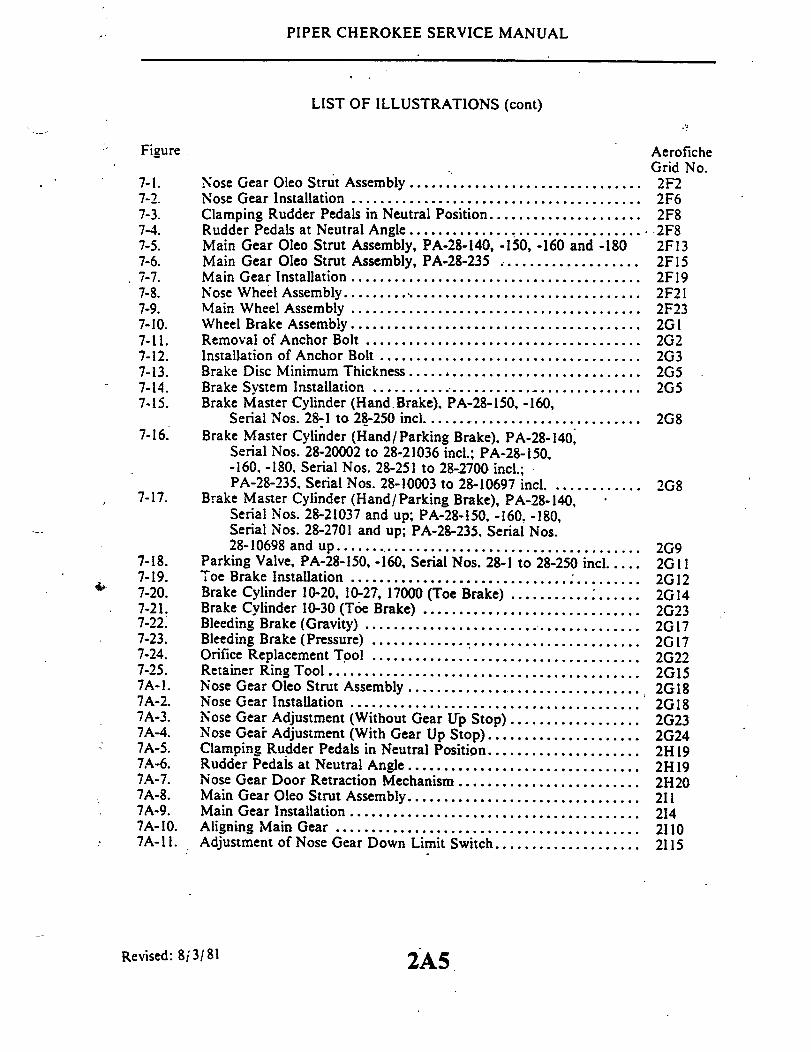
PIPER CHEROKEE SERVICE MANUAL
LIST OF ILLUSTRATIONS (cont)
Figure AeroficheGrid No.
7-1. Nose Gear Oleo Strut Assembly ................................ 2F27-2. Nose Gear Installation ................................... . 2F67-3. Clamping Rudder Pedals in Neutral Position ..................... 2F87-4. Rudder Pedals at Neutral Angle ................................. 2F87-5. Main Gear Oleo Strut Assembly, PA-28-140, -150, -160 and -180 2F137-6. Main Gear Oleo Strut Assembly, PA-28-235 ................... 2F157-7. Main Gear Installation ...................................... 2F197-8. Nose Wheel Assembly........................................... 2F217-9. Main Wheel Assembly ........................................ 2F237-10. Wheel Brake Assembly ........................................ 2GI7-11. Removal of Anchor Bolt ..................................... 2G27-12. Installation of Anchor Bolt .................................... 2G37-13. Brake Disc Minimum Thickness .......................... . 2G57-14. Brake System Installation ..................................... 2G57-15. Brake Master Cylinder (Hand.Brake), PA-28-150, -160,
Serial Nos. 28-1 to 28-250 incl ............................... 2G87-16. Brake Master Cylinder (Hand/Parking Brake), PA-28-140.
Serial Nos. 28-20002 to 28-21036 incl.; PA-28-150,-160, -180, Serial Nos. 28-251 to 28-2700 incl.;PA-28-235, Serial Nos. 28-10003 to 28-10697 incl .. .......... 2G8
7-17. Brake Master Cylinder (Hand/Parking Brake), PA-28-140,Serial Nos. 28-21037 and up; PA-28-150, -160, -180,Serial Nos. 28-2701 and up; PA-28-235, Serial Nos.28-10698 and up......................................... 2G9
7-18. Parking Valve, PA-28-150, -160, Serial Nos. 28-1 to 28-250 incl .... 2G117-19. Toe Brake Installation ........................................ 2G127-20. Brake Cylinder 10-20, 10-27, 17000 (Toe Brake) ................ 2G 147-21. Brake Cylinder 10-30 (Toe Brake) .............................. 2G237-22. Bleeding Brake (Gravity) ...................................... 2G177-23. Bleeding Brake (Pressure) ..................................... 2G177-24. Orifice Replacement Tool ..................................... 2G227-25. Retainer Ring Tool ........................................... 2G157A-1. Nose Gear Oleo Strut Assembly ................................ 2G187A-2. Nose Gear Installation ........................................ 2G187A-3. Nose Gear Adjustment (Without Gear Up Stop) ................. 2237A-4. Nose Gear Adjustment (With Gear Up Stop).................... 2G247A-5. Clamping Rudder Pedals in Neutral Position ..................... 2H197A-6. Rudder Pedals at Neutral Angle................................ 2H197A-7. Nose Gear Door Retraction Mechanism ......................... 2H207A-8. Main Gear Oleo Strut Assembly.............................. 2117A-9. Main Gear Installation ........... ........................ 2147A-10. Aligning Main Gear .......................................... 21107A-11. Adjustment of Nose Gear Down Limit Switch .................... 2115
Revised: 8/3/81 2A5

PIPER CHEROKEE SERVICE MANUAL
LIST OF ILLUSTRATIONS (cont)
Figure AeroficheGrid No.
7A-12. Adjustment of Main Gear Down Limit Switch ................... 21157A-13. Wiring Diagram of Landing Gear Electrical Circuit ................ 21177A-14. Throttle Warning Switches .................................... 21197A-15. Nose Wheel Assembly................ ... .............. 21227A-16. Main Wheel Assembly ........................................ 21237A-17. Wheel Brake Assembly ................. ....................... 2J I7A-18. Brake Disc Minimum Thickness ................................ 2J37A-19. Brake System Installation ..................................... 2J37A-20. Brake Master Cylinder (Hand/ Parking Brake) ................... 2J57A-21. Toe Brake Installation ......................................... 2J67A-22. Brake Cylinder (Toe Brake) (10-20, 10-27. 17000) ................. 2J87A-23. Brake Cylinder (Toe Brake) (10-30) ............................. 2J 10'7A-24. Bearing Installation ................... ..... ................. 2J117A-25. Nose Gear Service Tolerances, PA-28R .......................... 2J207A-26. Main Gear Service Tolerances. PA-28R ......................... 2J238-1. Typical Nicks and Removal Method ........................... 2K88-2. Propeller Installation (Constant Speed) PA-28-235 ......... 2K88-3. Propeller Installation .......................... 2K98-4. Adjustment of Propeller Control (PA-28-235) . . . ........ . 2K138-5. Propeller Governor (PA-28-235) ..................... 2K 138-6. Engine Installation (PA-28-140,-150.-160.-180:
Serial Nos. 28-1 to 28-1760) . . . ............... 2K168-7. Engine Installation (PA-28-140. -150, -160. -180
Serial Nos. 28-1761 and up) .................... 2K178-8. Engine Shock Mount Installation (PA-28-140.
Serial Nos. 28-25000 and up) ................... 2K188-9. Engine Installation(PA-28-235) .................. 2K228-10. Adjustment of Engine Controls .......... .......... 2K248-11. Carburetor (PA-28-140, -150. -160) ................... 2L38-12. Carburetor (PA-28-180. -181.-235) ................... 2L38-13. Magneto Inspection ............... ............ 2L58-14. Contact Spring Inspection ......... ............... 2L6
8-15. Impulse Coupling ......... .................. 2L68-16. Magneto Timing Marks . ...... . ...... ........ 2L78-17. Timing Pointer ................................ 2L78-18. Timing Kit Installed . ........................... 2L88-19. Breaker Compartment with Cast Timing Marks . .......... . 2L88-20. Removing Spark Plug Frozen to Bushing ................. 2L13
Revised: 8/3/81 2A6

PIPER CHEROKEE SERVICE MANUAL
LIST OF TABLESAeroficheGrid No.
Control Surface Travel and Cable Tension .......... .... 2A11Cable Tension vs. Ambient Temperature ................... . 2A13Troubleshooting Chart (Surface Controls) .............. 2C19Leading Particulars. Hydraulic System ................. 2D8Characteristics. Hydraulic Pump Motor .................... . 2D13Hydraulic System Troubleshooting ................... 2E9Nose Gear Alignment Tolerances .................... 2F9Landing Gear Troubleshooting ................... ... 2G20Landing Gear Troubleshooting ..................... 2J 12PA-28R Nose Gear Service Tolerances ................ 2J21PA-28R Main Gear Service Tolerances ................ 2J24Propeller Torque Limits ............. .......... 2K 10Engine Troubleshooting Chart ..................... 2L17
Revised: 8/3/81 2A7
Table
V-l.V-II.V-Ill.
VI-IVI-II.VI-III.
VII-.VII-II.
VIIA-I.VIIA-II.VIIA-III.VIII-I.VIII-II.

SECTION VSURFACE CONTROLS
Paragraph AeroficheGrid No.
5-1. Introduction ..................... ........................... 2A105-2. Description ..................... .......................... 2A105-3. Standard Procedures .......................................... 2A 145-4. Control Column Assembly .................................. 2A17
5-5. Removal of Control Column Assembly ................. 2A 175-6. Installation of Control Column Assembly ............... 2A 18
5-7. Aileron Controls ............................................. 2A195-8. Removal of Aileron Control Cables ................... 2A195-9. Installation of Aileron Control Cables .................. 2A215-10. Removal of Aileron Bellcrank Assembly ................ 2A225-11. Installation of Aileron Bellcrank Assembly .............. 2A225-12. Rigging and Adjustment of Aileron Controls ............ 2A235-13. Adjustment of Aileron Trim.. ....................... 2B2
5-14. Stabilator Controls ........................................... 2B25-15. Removal of Stabilator Control Cables .................. 2B25-16. Installation of Stabilator Control Cables ................ 2B35-17. Rigging and Adjustment of Stabilator Controls.......... 2B5
5-18. Stabilator Trim Controls (Overhead Trim) . ...................... 2B75-19. Removal of Stabilator Trim Assembly (Forward) ........ 2B75-20. Installation of Stabilator Trim Assembly (Forward) ...... 2B95-21. Removal of Stabilator Trim Controls (Aft) ............. 2B95-22. Installation of Stabilator Trim Controls (Aft) ........... 2B 125-23. Rigging and Adjustment of Stabilator Trim
(Overhead Control) ............ ............... 2B155-24. Stabilator Trim Controls (Floor Trim) ......... . ....... 2B 17
5-25. Removal of Stabilator Trim Assembly (Forward) ........ 2B 175-26. Installation of Stabilator Trim Assembly (Forward) ...... 2B 19
Reissued: 1/15/81
2A8

5-27.5-28.
5-29.
Removal of Stabilator Trim Assembly (Aft)Installation of Stabilator Trim Assembly
(Aft) . . . . . . . . . . . .Rigging and Adjustment of Stabilator Trim
(Floor Control) . ....Rudder and Steering Pedal Assembly .. .....5-31. Removal of Rudder and Steering Pedal
Assembly .. ........5-32. Installation of Rudder and Steering Pedal
Assembly ...........Rudder Controls . ...............5-34. Removal of Rudder Control Cables5-35. Installation of Rudder Control Cables5-36. Rigging and Adjustment of Rudder ControlsRudder Trim Controls ...... . . . . .5-38. Removal of Rudder Trim Controls . .5-39. Installation of Rudder Trim Controls .5-40. Rigging and Adjustment of Rudder Trim
Controls ............Wing Flap Controls . . . ...........5-42. Removal of Wing Flap Controls . ..5-43. Installation of Wing Flap Controls . .5-44. Rigging and Adjustment of Wing Flaps .
Reissued: 1/15/81 2A9
AeroficheGrid No.
5-30.
5-33.
5-37.
5-41.
2B20
2B21
2B222B23
2B23
2C12C22C22C32C52C72C72C7
2C82C82C82Cll2C12

PIPER CHEROKEE SERVICE MANUAL
SECTION VSURFACE CONTROLS
5-1. INTRODUCTION. This section contains removal, installation, rigging, adjustmentand trim procedures for ailerons, flaps (less trim), stabilator and rudder flight control surfaces.Also included are similar procedures for the control column and rudder and steering pedalassembly. For removal, installation, and repair of structural surfaces of the airplane, refer toSection IV.
5-2. DESCRIPTION. The PA-28 is controlled in flight by the use of three stand-ard primary control surfaces, consisting of the ailerons, stabilator and rudder.Operation of these controls is through the movement of the dual control columnsand dual rudder pedals. The individual surfaces are connected to their controlcomponents through the use of cables and push-pull tubes. Provision for direc-tional and longitudinal trim control is provided by an adjustable trim mechanismfor the rudder and stabilator. The flaps on the PA-28 are mechanically operatedand can be positioned in four locations of 0, 10, 25 and 40 degrees.
The aileron controls consist of two-control wheels connected by torquetubes to sprockets on each end of the horizontal control column. A chain is wrap-ped around the sprockets and around a double sprocket on the vertical post of thecontrol column. The chain is connected to the primary aileron control cablewhich is routed through the center of the fuselage to the main spar and out throughthe wings to a bellcrank in each wing. A balance cable is also connected to thebellcrank. As the control wheels are moved, the control cables move the bell-cranks and actuate push-pull rods to move the ailerons.
The stabilator controls are also connected to the control column. Fromthe connecting point, cables are routed around a series of pulleys down under thefloor and aft to the tail section of the airplane. The aft end of the cables connectto the stabilator balance arm which in turn is connected to the stabilator. Whenthe control wheels are moved forward or aft, the cables move the balance armup and down rotating the stabilator on its hinge points.
The rudder is controlled by the pilot's and co-pilot's rudder pedals. Cablesare connected to both sides of the rudder pedal assembly and are routed aftthrough the bottom of the fuselage to the rudder horn. When one rudder pedal ispushed, the cables move in opposite directions turning the rudder horn and rud-der. The wing flap system is operated by a lever located between the front seats.
Reissued: 1/15/81 SURFACE CONTROLS2A10

PIPER CHEROKEE SERVICE MANUAL
TABLE V-l CONTROL SURFACE TRAVEL AND CABLE TENSIONC34 0
Aileron
A 30° + 2UP ALLMODELS
AILERON CHORD LINE
B 15° + 2ODN ALL MODELS
C 0 ° 53' UP ALL MODELSPREVIOUS TO 1973
0° + 2UP 1973 MODELSAND UP
Maximum free play for aileron is 0.24 of an inch.measured at trailing edge (up/down movement).
Maximum free play spanwise is .035 (inboard/outboard movement).
Refer to Section IV, Paragraph 4-70.
RudderA 27 ± 2 L ALL MODELS
B 27 + 2° R ALL MODELS
C340
1681
C340
Flap
C340A 25 + 2 ALL MODELS
B 100 ± 2° ALL MODELS
C 0 53'UP
O° + 1 UP
ALL MODELSPREVIOUS TO 19731973 MODELSAND UP
D 40 + 2 ALL MODELS
FLAP CHORD LINEA
WING CHORD LINE
2All SURFACE CONTROLSRevised: 10/3/83
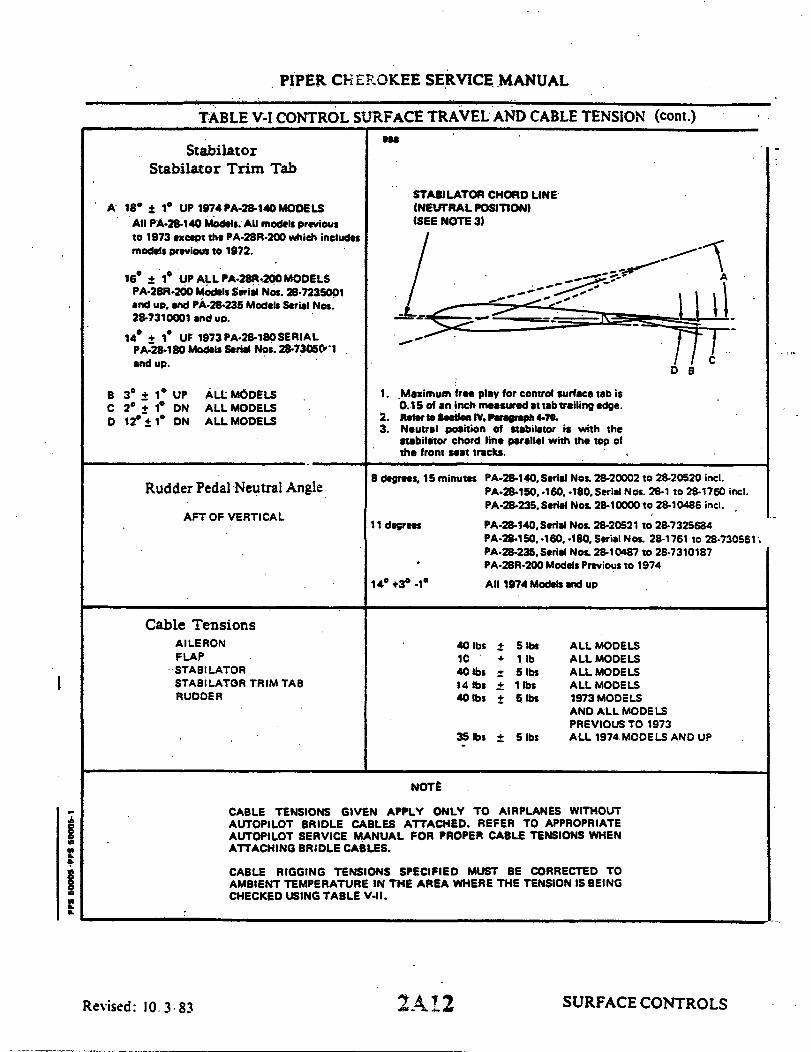
PIPER CHEROKEE SERVICE MANUAL
TABLE V-I CONTROL SURFACE TRAVEL AND CABLE TENSION (cont.)
StabilatorStabilator Trim Tab
A 18' 11 UP 1974 PA-28-140 MODELSAll PA-28-140 Models. All models previousto 1973 except the PA-28R-200 which includesmodels previous to 1972.
16 ± 1 UP ALL PA-28R-200 MODELSPA-28R-200 Models Serial Nos. 28-7235001and up end PA-28-235 Models Serial Nos.28-7310001 and up.
14 ± 1 UF 1973PA-28-180SERIALPA-28-180 Models Serial Nos. 28-73050'1and up.
B 3° ± 1* UPC 2* + 1° DND 12° 1* DN
ALL MODELSALL MODELSALL MODELS
Rudder Pedal Neutral Angle
AFT OF VERTICAL
STABILATOR CHORD LINE(NEUTRAL POSITION)(SEE NOTE 3)
1. Maximum free play for control surface tab is0.15 of an inch measured it tab trailing edge.
2. Refer to Section IV, Paragraph 4-70.3. Neutral position of stabilator is with the
stabilator chord line parallel with the top ofthe front seat tracks.
8 degrees, 15 minutes PA-28-140, Serial Nos. 28-20002 to 28-20520 incl.PA-28-150, -160. -180. Serial Nos. 28-1 to 28-1760 incl.PA-28-235. Seriel Nos. 28-10000 to 28-10486 incl.
11 degrees
14 +3 .-1
Cable TensionsAILERONFLAPSTABILATORSTABILATOR TRIM TABRUDDER
PA-28-140, Serial Nos. 28-20521 to 28-7325684PA-28-150, -160.-180. Serial Nos. 28-1761 to 28-730561PA-28-235, Serial Nos. 28-10487 to 28-7310187PA-28R-200 Models Previous to 1974
All 1974 Models and up
40 lbs ±10
40 lbs14 lbs ±40 lbs ±
5 lbs1 lb5 1bs1 lbs5 lbs
35 bs ± 5 lbs
ALL MODELSALL MODELSALL MODELSALL MODELS1973 MODELSAND ALL MODELSPREVIOUS TO 1973ALL 1974 MODELS AND UP
NOTE
CABLE TENSIONS GIVEN APPLY ONLY TO AIRPLANES WITHOUTAUTOPILOT BRIDLE CABLES ATTACHED. REFER TO APPROPRIATEAUTOPILOT SERVICE MANUAL FOR PROPER CABLE TENSIONS WHENATTACHING BRIDLE CABLES.
CABLE RIGGING TENSIONS SPECIFIED MUST BE CORRECTED TOAMBIENT TEMPERATURE IN THE AREA WHERE THE TENSION IS BEINGCHECKED USING TABLE V-II.
SURFACE CONTROLS2A12
I
Revised: 10.3.83
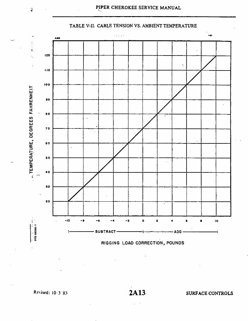
PIPER CHEROKEE SERVICE MANUAL
TABLE V-II. CABLE TENSION VS. AMBIENT TEMPERATURE
A99
120
110
100
90
80
70
60
50
40
30
20
-10 -8 -6 -4 -2 0 2 4 6 10
I SUBTRACT I ADD
RIGGING LOAD CORRECTION, POUNDS
2A13
z
LL
UJ
Revised: 10 3 83 SURFACE CONTROLS

PIPER CHEROKEE SERVICE MANUAL
For a visual description of the various control systems, refer to the illustrated figures.throughout this section.
5-3. STANDARD PROCEDURES. The following tips may be helpful in the removal,installation and rigging of the various assemblies:
a. It is recommended, though not always necessary to level and place the airplane onjacks during rigging and adjustment.
b. Remove turnbuckle barrels from cable ends before withdrawing the cables throughthe structures.
c. Tie a cord to the cable end before withdrawing the cable through the structures tofacilitate reinstallation of cable.
d. Turnbuckle stations are given at their neutral positions.e. When referring to marking cable end, etc., before disconnecting a felt marking.pen
may be used.f. Assemble and adjust the turnbuckles so that each terminal is screwed an
approximately equal distance into the barrel. Do not turn the terminals in such a mannerthat will put a permanent "twist" into the cables.
g. Cable tensions should be taken with the appropriate control surface in its neutralposition.
h. After completion of each adjustment, check the turnbuckles to be sure not morethan three terminal threads are visible outside the barrel. Install the locking clips, and checkfor proper installation by trying to remove the clips using fingers only. Both locking clipsmay be installed in opposite holes. Locking clips which have been installed and removedmust be scrapped and not reused. Turnbuckles may be safetied in accordance with AdvisoryCircular 43.13-1A Chapter 4, Section 2.
i. When push rods or rod ends are provided with an inspection hole, the screw must bescrewed in far enough to pass the inspection hole. This can be determined visually or byfeel, inserting a piece of wire into the inspection hole. If no hole is provided, there must be aminimum of .375 of an inch thread engagement.
j. After completion of adjustments, each jam nut must be tightened securely (Refer toFigure 5-22 for proper installation method).
NOTECable rigging tensions specified must be corrected to ambienttemperature in the area where the tension is being checked,using Table V-II.
k. When normal operation requires movement between any of the components beingclamped together, the bolt (screw) -nut shall be tightened as required to insure intended normaloperation of the assembly, without reference to Table II-II.
1. Unless otherwise specified, when castellated nuts are used with a cotter pin on movingjoints, the nut shall not be torqued to the Table II-II values. Nuts shall be tightened to removelooseness in the joint and then the cotter pin installed.
SURFACE CONTROLS2A14Reissued: 1 /15 / 81

0


PIPER CHEROKEE SERVICE MANUAL
54. CONTROL COLUMN ASSEMBLY.
5-5. REMOVAL OF CONTROL COLUMN ASSEMBLY. (Refer to Figure 5-1 or 5-2.)a. To remove either control wheel (1) with tube (2), the following procedure may be
used:1. Separate the control wheel tube (2) from the flexible joint (4) that is located on
either side of the tee bar assembly (5) by removing the nut, washer and bolt (3). Pull thetube from the flexible joint.
2. If removing the left control tube, slide the stop (6) from the tube.3. Should wires for the various Autopilot systems be installed in the control tube,
disconnect them at the quick disconnect terminals behind the instrument panel. Draw thewires back into the tube and out through the forward end of the tube.
4. Remove the control wheel assembly from the instrument panel.b. The tee bar (5) with assembled parts may be removed from the airplane by the
following procedure:1. Remove the access panel or door to the aft section of the fuselage.2. Relieve cable tension from the stabilator control cables (11) at one of the
stabilator cable turnbuckles in the aft section of the fuselage.3. Relieve tension from the aileron control cables (12) and chains (7 and 8)
and at the turnbuckle (9) that connects the chains at the top of the tee bar (5).4. Disconnect the control chains from the control cables where the chains
and cables join by removing the cotter pins, nuts, bolts and bushings (10).5. Remove the tunnel cover by the following procedure:
(a) PA-28-140; PA-28-1-50, -160, -180; and PA-28R:Remove the rudder trim control knob and trim cover attaching screws. Roll backthe carpet from the tunnel and remove the tunnel plate that is located just aft ofthe tee bar assembly, by removing the plate attaching screws.
(b) PA-28-235:Remove the fuel selector and rudder trim covers by removing the knobs and theattaching screws. Disconnect the fuel indicator control lever from the fuel se-lector torque tube by removing the attaching pin located at the bottom of the lever.Remove the tunnel plate, located just aft of the tee bar, by laying back enoughtunnel carpet to remove the plate attaching screws..
6. Remove the two aileron control cable pulleys (13)attached to the lowersection of the tee bar by removing the pulley attaching bolt (14).
7. Disconnect the stabilator controls (11) from the lower end of the tee barassembly.
8. Disconnect the necessary controls, such as the mixture control, throttlecontrol, etc., that will allow the tee bar assembly to be removed.
9. Remove the tee bar assembly by removing the attaching bolts (15) withwashers and nuts, which are through each side of the floor tunnel, and lifting itup and out through the right side of the cabin.
SURFACE CONTROLSReissued: 1 /15/81 2A17

PIPER CHEROKEE SERVICE MANUAL
5-6. INSTALLATION OF CONTROL COLUMN ASSEMBLY.(Refer to Figure 5-1 or 5-2.)
a. The tee bar assembly may be installed in the airplane by the following pro-cedure:
1. Swing the tee bar assembly into place from the right side of the cabinand secure with attaching bolts (15), washers and nuts inserted in through eachside of the floor tunnel.
2. Connect the stabilator controls (11) to the lower end of the tee bar withbolt, washer, nut and cotter pin (16). Allow the cable ends free to rotate.
3. Place the aileron control cables (12) around the pulleys (13) that attach to thelower section of the tee bar (5), position pulleys and secure with bolt, washers and nut (14).
4. Install the control wheel per step b.5. Place the control wheels in neutral (centered) position and install the aileron
control chains (7 and 8) on the control wheel sprockets (17 and 18) and idler crossoversprockets (19 and 21). This turnbuckle (9) must be centered between the two control wheelsprockets.
6. Loosen the connecting bolts (22) of the idler sprockets (i9 nd 21) to allow thechain to fit snug around the control wheel sprockets and over the idler sprockets.
7. Connect the aileron control cables (12) to the ends of the chains (7 and 8) withbolts, bushings, nuts and cotter pins (10).
8. Adjust the chain turnbuckle (9) between the two control wheel sprockets toallow the control wheels to be neutral and obtain proper cable tension as given in Table V-I.It may be necessary, in order to have both control wheels neutral, to set the chainturnbuckle to neutralize the wheels and then set cable tension with the turnbuckles locatedunder the floor panel aft of the main spar as instructed in paragraph 5-12. Before safetyingthe tumbuckle, check that when the ailerons are neutral, the control wheels will be neutraland the chain turnbuckle centered. Also, the aileron bellcranks should contact their stopsbefore the control wheel hits its stop. Maintain .030 to .040 clearance between sprocket pinand adjustable stop bolts on models having adjustable aileron tee bar stops.
9. Set stabilator cable tension with the turnbuckle in the aft section of the fuselageand instructions given in paragraph 5-17. Check safety of all turnbuckles upon completionof adjustments.
10. Tighten the connecting bolts (22) of the idler sprockets (19 and 21).1 1. Install the floor tunnel plate trim covers by the following procedure:
(a) PA-28-140; PA-28-150, -160, -180; and PA-28R: Place the tunnel plate intoposition for installation and secure with the appropriate screws. Roll thecarpet into place and install the rudder trim cover and knob.
(b) PA-28-235: Install the floor tunnel plate and secure with the appropriatescrews. Fasten the tunnel carpet into place and install the fuel selector leveron the selector torque tube and secure with a clevis pin and cotter pin.Replace the fuel selector and rudder trim knob.
b. Either control wheel assembly may be installed by the following procedure:1. Insert the control wheel tube through the instrument panel.2. Should wires for the various Autopilot systems need to be installed in the
control tube, route them through the hole in the forward side of the tube and out of thesmall hole in the forward side. Position the rudder grommet in the hole in the side of thetube.
3. On the left control tube install the stop (6).
SURFACE CONTROLSReissued: 1/15/81
2A18
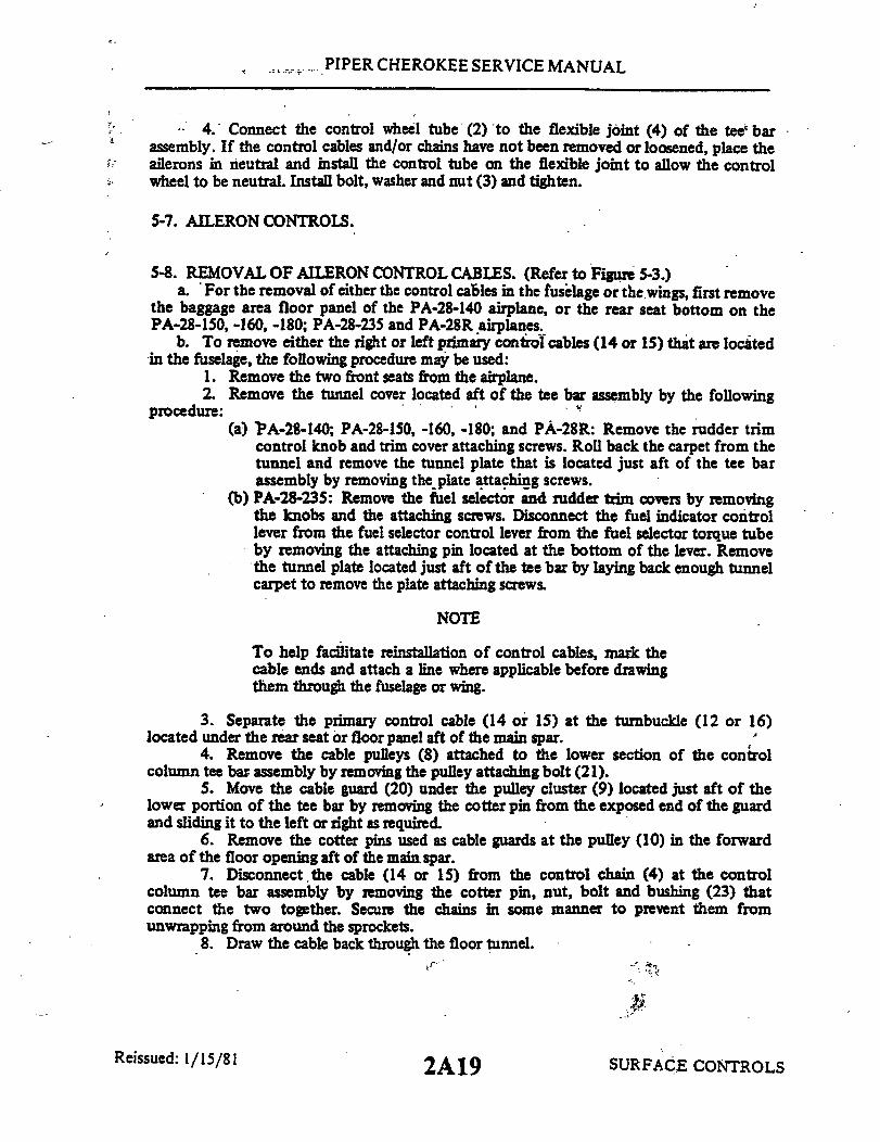
PIPER CHEROKEE SERVICE MANUAL
4. Connect the control wheel tube (2) to the flexible joint (4) of the tee barassembly. If the control cables and/or chains have not been removed or loosened, place theailerons in neutral and install the control tube on the flexible joint to allow the controlwheel to be neutral. Install bolt, washer and nut (3) and tighten.
5-7. AILERON CONTROLS.
5-8. REMOVAL OF AILERON CONTROL CABLES. (Refer to Figure 5-3.)a. For the removal of either the control cables in the fuselage or thewings, first remove
the baggage area floor panel of the PA-28-140 airplane, or the rear seat bottom on thePA-28-150, -160, -180; PA-28-235 and PA-28R airplanes.
b. To remove either the right or left primary control cables (14 or 15) that are locatedin the fuselage, the following procedure may be used:
1. Remove the two front seats from the airplane.2. Remove the tunnel cover located aft of the tee bar assembly by the following
procedure:(a) PA-28-140; PA-28-150, -160, -180; and PA-28R: Remove the rudder trim
control knob and trim cover attaching screws. Roll back the carpet from thetunnel and remove the tunnel plate that is located just aft of the tee barassembly by removing the plate attaching screws.
(b) PA-28-235: Remove the fuel selector and rudder trim covers by removingthe knobs and the attaching screws. Disconnect the fuel indicator controllever from the fuel selector control lever from the fuel selector torque tubeby removing the attaching pin located at the bottom of the lever. Removethe tunnel plate located just aft of the tee bar by laying back enough tunnelcarpet to remove the plate attaching screws.
NOTE
To help facilitate reinstallation of control cables, mark thecable ends and attach a line where applicable before drawingthem through the fuselage or wing.
3. Separate the primary control cable (14 or 15) at the turnbuckle (12 or 16)located under the rear seat or floor panel aft of the main spar.
4. Remove the cable pulleys (8) attached to the lower section of the controlcolumn tee bar assembly by removing the pulley attaching bolt (21).
5. Move the cable guard (20) under the pulley cluster (9) located just aft of thelower portion of the tee bar by removing the cotter pin from the exposed end of the guardand sliding it to the left or right as required.
6. Remove the cotter pins used as cable guards at the pulley (10) in the forwardarea of the floor opening aft of the main spar.
7. Disconnect the cable (14 or 15) from the control chain (4) at the controlcolumn tee bar assembly by removing the cotter pin, nut, bolt and bushing (23) thatconnect the two together. Secure the chains in some manner to prevent them fromunwrapping from around the sprockets.
8. Draw the cable back through the floor tunnel.
Reissued: 1/15/81 SURFACE CONTROLS2A19

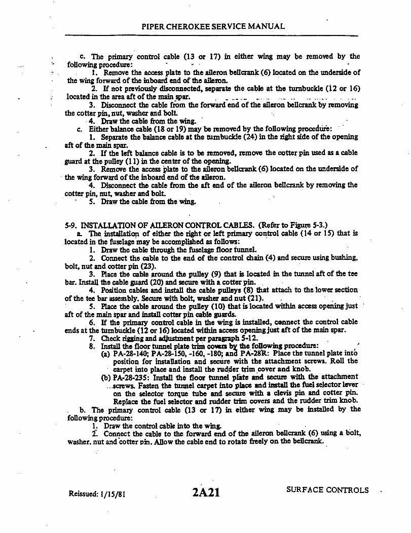
PIPER CHEROKEE SERVICE MANUAL
c. The primary control cable (13 or 17) in either wing may be removed by thefollowing procedure:
1. Remove the access plate to the aileron bellcrank (6) located on the underside ofthe wing forward of the inboard end of the aileron.
2. If not previously disconnected, separate the cable at the turnbuckle (12 or 16)located in the area aft of the main spar.
3. Disconnect the cable from the forward end of the aileron bellcrank by removingthe cotter pin, nut, washer and bolt.
4. Draw the cable from the wingc. Either balance cable (18 or 19) may be removed by the following procedure:
1. Separate the balance cable at the turnbuckle (24) in the right side of the openingaft of the main spar.
2. If the left balance cable is to be removed, remove the cotter pin used as a cableguard at the pulley (11) in the center of the opening.
3. Remove the access plate to the aileron bellcrank (6) located on the underside ofthe wing forward of the inboard end of the aileron.
4. Disconnect the cable from the aft end of the aileron bellcrank by removing thecotter pin, nut, washer and bolt.
5. Draw the cable from the wing.
5-9. INSTALLATION OF AILERON CONTROL CABLES. (Refer to Figure 5-3.)a. The installation of either the right or left primary control cable (14 or 15) that is
located in the fuselage may be accomplished as follows:1. Draw the cable through the fuselage floor funnel.2. Connect the cable to the end of the control chain (4) and secure using bushing,
bolt, nut and cotter pin (23).3. Place the cable around the pulley (9) that is located in the tunnel aft of the tee
bar. Install the cable guard (20) and secure with a cotter pin.4. Position cables and install the cable pulleys (8) that attach to the lower section
of the tee bar assembly. Secure with bolt, washer and nut (21).5. Place the cable around the pulley (10) that is located within access opening just
aft of the main spar and install cotter pin cable guards.6. If the primary control cable in the wing is installed, connect the control cable
ends at the tumbuckle (12 or 16) located within access opening just aft of the main spar.7. Check rigging and adjustment per pargraph 5-12.8. Install the floor tunnel plate trim cowers by the following procedure:
(a) PA-28-140; PA-28-150, -160, -180; and PA-28R: Place the tunnel plate intoposition for installation and secure with the attachment screws. Roll thecarpet into place and install the rudder trim cover and knob.
(b) PA-28-235: Install the floor tunnel plate and secure with the attachment..screws. Fasten the tunnel carpet into place and install the fuel selector leveron the selector torque tube and secure with a clevis pin and cotter pin.Replace the fuel selector and rudder trim covers and the rudder trim knob.
b. The primary control cable (13 or 17) in either wing may be installed by thefollowing procedure:
1. Draw the control cable into the wing.2. Connect the cable to the forward end of the aileron bellcrank (6) using a bolt,
washer, nut and cotter pin. Allow the cable end to rotate freely on the bellcrank.
SURFACE CONTROLSReissued: 1/15/81 2A21

PIPER CHEROKEE SERVICE MANUAL
3. If the primary control cable in the fuselage is installed, connect the ends at theturnbuckle (12 or 16) located under the rear seat aft of the main spar.
4. Check rigging and adjustment per paragraph 5-12.5. Install the access plate on the underside of the wing.
c. Either balance cable (18 or 19) may be installed by the following procedure:1. Draw the cable into the wing.2. Connect the cable to the aft end of the aileron bellcrank (6) using a bolt, washer,
nut and cotter pin. Allow the cable end to rotate freely on the bellcrank.3. Connect the balance cable ends at the turnbuckle (24) that is located under the
rear seat aft of the main spar.4. If the left cable was removed, install the cotter pin cable guard at the pulley (10)
located within the fuselage, aft of the main spar.5. Check rigging and adjustment per paragraph 5-12.6. Install the access plate on the underside of the wing.
d. Replace the rear seat bottom or floor panel and the two front seats.
5-10: REMOVAL OF AILERON BELLCRANK ASSEMBLY (Refer to Figure 5-3.)a. Remove the baggage area floor panel of PA-28-140 airplanes or the bottom half of
the rear seat of the PA-28-150, -160, -180; PA-28-235 and PA-28R airplanes.b. Remove the access plate to the aileron bellcrank (6) located on the underside of the
wing, forward of the inboard end of the aileron.c. Relieve tension from the aileron control cables by loosening the balance cable
turnbuckle (24) located in the opening aft of the main spar.d. Disconnect the primary (13 or 17) and balance (18 or 19) control cables from the
bellcrank assembly by removing cotter pins, nuts, washers and bolts.e. Disconnect the aileron control rod (7) at the aft or forward end, as desired, by
removing the cotter pin, nut, washer and bolt.f. Remove the nut, pivot bolt (25) and washers that secure the bellcrank. The nut is
visible from the underside of the wing.g. Remove the bellcrank from within the wing.
5-11. INSTALLATION OF AILERON BELLCRANK ASSEMBLY. (Refer to Figure 5-3.)a. Ascertain that the bellcrank pivot bushing (26) is lubricated and install in the torque
tube portion of the bellcrank (6).b. Place the bellcrank in position in the wing with a washer located between each end
of the torque tube and the mounting brackets.c. Install the bellcrank pivot bolt (25) with the head up. Install a washer and nut on
the bolt, and torque nut within 20 to 25 inch-pounds. Check that the bellcrank rotatesfreely with little up-down play.
d. Install and adjust control rod (7) and check aileron travel per paragraph 5-12.e. Connect the ends of the primary (13 or 17) and balance (18 or 19) control cables to
the bellcrank using bolts, washers, nuts and cotter pins. Allow the cable ends to rotate freelyon the bellcrank.
f. Tighten the control cables at the balance cable turnbuckle (24) in the floor openingaft of the main spar. Check cable tension per paragraph 5-12.
g. Install the access plate on the underside of the wing and replace the floor panel orrear seat bottom.
SURFACE CONTROLS2A22Reissued: 1/15/ 81

PIPER CHEROKEE SERVICE MANUAL
I Refer to Figure 5-21 for tool fabrication
Figure 5-4. Bellcrank Rigging ToolPA-28-140, -150, -160, -180, -235
Refer to Figure 5-21 for tool fabrication
Figure 5-5. Bellcrank Rigging ToolPA-28R
5-12. RIGGING AND ADJUSTMENT OF AILERON CONTROLS. (Refer to Figures 5-4thru 5-6.)
NOTE
Flap adjustment must be complete before starting aileronadjustment.
a. To check and adjust the rigging of the aileron controls, first set the right and leftaileron bellcranks at neutral position. (Ascertain that the control chains have been rigged perparagraph 5-6.) This may be accomplished by the following procedure:
1. Place tee bar in full forward position. Maintain in this position by use of asuitable tool or by placing weights on aft side of stabilator if stabilator cables have beenpreviously tensioned.
2. Remove the access plate to each aileron bellcrank located on the underside of thewing. forward of the inboard end of the aileron by removing the plate attaching screws.
3. Affix a bellcrank rigging tool, as shown in Figures 5-4 or 5-5. between theforward arm of each bellcrank and the adjacent rib. (This tool may be fabricated to dimensionsgiven in Figure 5-21.) The slotted end of the tool fits on the arm forward of. and adjacent to, theprimary control cable end. The other end of the tool is positioned so that the side of the toolcontacts the aft side of the bellcrank stop. The bellcrank must be moved to allow a snug fit ofthe tool between the bellcrank arm and rib. To do so. it may be necessary to loosen a primarycontrol cable or the balance cable. Neutral position of the bellcranks may also be found bylocating the centers of the forward and aft cable connection holes an equal distance from theadjacent inboard wing rib.
SURFACE CONTROLS
1652 2054
2A23Revised: 10 3 83
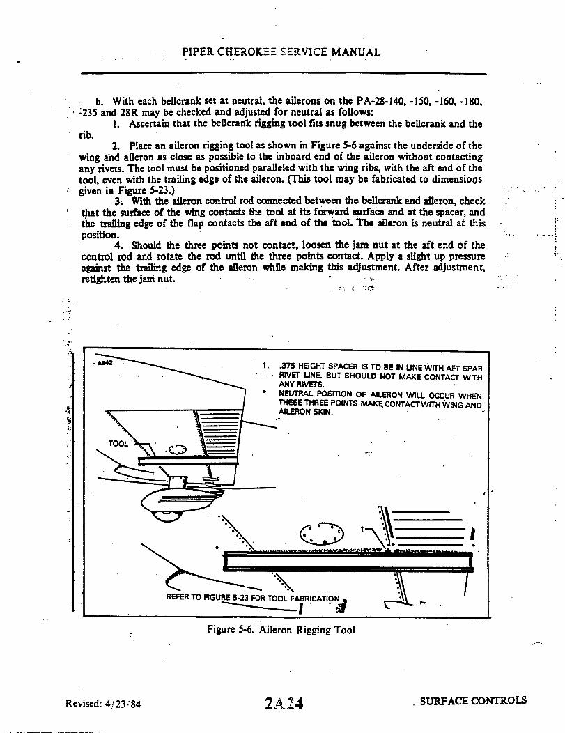
PIPER CHEROKEE SERVICE MANUAL
b. With each bellcrank set at neutral, the ailerons on the PA-28-140, -150, -160, -180,-235 and 28R may be checked and adjusted for neutral as follows:
1. Ascertain that the bellcrank rigging tool fits snug between the bellcrank and therib.
2. Place an aileron rigging tool as shown in Figure 5-6 against the underside of thewing and aileron as close as possible to the inboard end of the aileron without contactingany rivets. The tool must be positioned paralleled with the wing ribs, with the aft end of thetool, even with the trailing edge of the aileron. (This tool may be fabricated to dimensionsgiven in Figure 5-23.)
3. With the aileron control rod connected between the bellcrank and aileron, checkthat the surface of the wing contacts the tool at its forward surface and at the spacer, andthe trailing edge of the flap contacts the aft end of the tool. The aileron is neutral at thisposition.
4. Should the three points not contact, loosen the jam nut at the aft end of thecontrol rod and rotate the rod until the three points contact. Apply a slight up pressureagainst the trailing edge of the aileron while making this adjustment. After adjustment,retighten the jam nut.
.375 HEIGHT SPACER IS TO BE IN LINE WITH AFT SPARRIVET LINE. BUT SHOULD NOT MAKE CONTACT WITHANY RIVETS.NEUTRAL POSITION OF AILERON WILL OCCUR WHENTHESE THREE POINTS MAKE CONTACTWITH WING ANDAILERON SKIN.
REFER TO FIGURE 5-23 FOR TOOL FABRICATION
Figure 5-6. Aileron Rigging Tool
2A24
I
SURFACE CONTROLSRevised: 4/23 84

PIPER CHEROKEE SERVICE MANUAL
c. Adjust primary and balance cable tension as given in Table V-I by the followingprocedure:
1. Remove the two front seats, if desired, and the baggage area floor panel of thePA-28-140 airplanes or the bottom of the rear seat of the PA-28-150, -160, -180; PA-28-235and PA-28R airplanes to facilitate in the necessary operation.
2. Loosen the connecting bolts of the idler cross-over sprockets at the control teebar to allow the chain to fit snug around the control wheel sprockets, and- over the idlersprockets.
3. Ascertain that both bellcranks are at neutral position.4. Adjust the turnbuckles, located in the access opening just aft of the main spar,
of the primary and balance cables to their proper cable tension and maintain neutral-centerposition of the control wheels. To obtain neutral position of both control wheels, it mayalso be necessary to adjust the roller chain turnbuckle located between the control wheelsprockets. During adjustment, obtain a little more tension on the primary control cables tohold the bellcranks in neutral against the rigging tools, finishing with even tension on allcables.
5. Tighten the bolts to secure the idler cross-over sprockets.6. Remove the aileron bellcrank rigging tool from each wing.
d. Check the ailerons for correct travel from neutral perdimensions given in Table V-I,by the following procedure:
1. Center the bubble of a protractor over the surface of an aileron at neutralposition and note the reading.
2. Move the aileron full up and down, checking the degree of travel for each direction.The degree of travel on the protractor is determined by taking the difference between theprotractor reading at neutral and up, and neutral and down. The bubble must be centered ateach reading. When measuring down travel from the neutral position, maintain a light uppressure at the center of the aft edge of the aileron. When measuring up travel from theneutral position, maintain a light down pressure at the center of the aft edge of the aileron;just sufficient to remove the slack between the bellcrank and the aileron.
3. Should the travel not be correct, the travel may be set by rotating the bellcrankstops in or out. Stops are located in the wing attached to the rib that is adjacent to theaileron bellcrank.
4. Repeat this procedure for the other aileron.e. Check to insure that the left aileron up and right aileron down stops are contacted
simultaneously and vice versa. Adjust stops as required.f. Check the bellcrank stops to assure that the bellcrank contact is made
simultaneously, but still have cushion before contacting the control wheel stops. Maintain.030 to .040 clearance between sprocket pin and adjustable stop bolts on models havingadjustable tee bar stops.
g. Check complete system for operation and safety of turnbuckles, bolts, etc.h. Install access plates and panels.
SURFACE CONTROLS2B1Reissued: 1/15/81
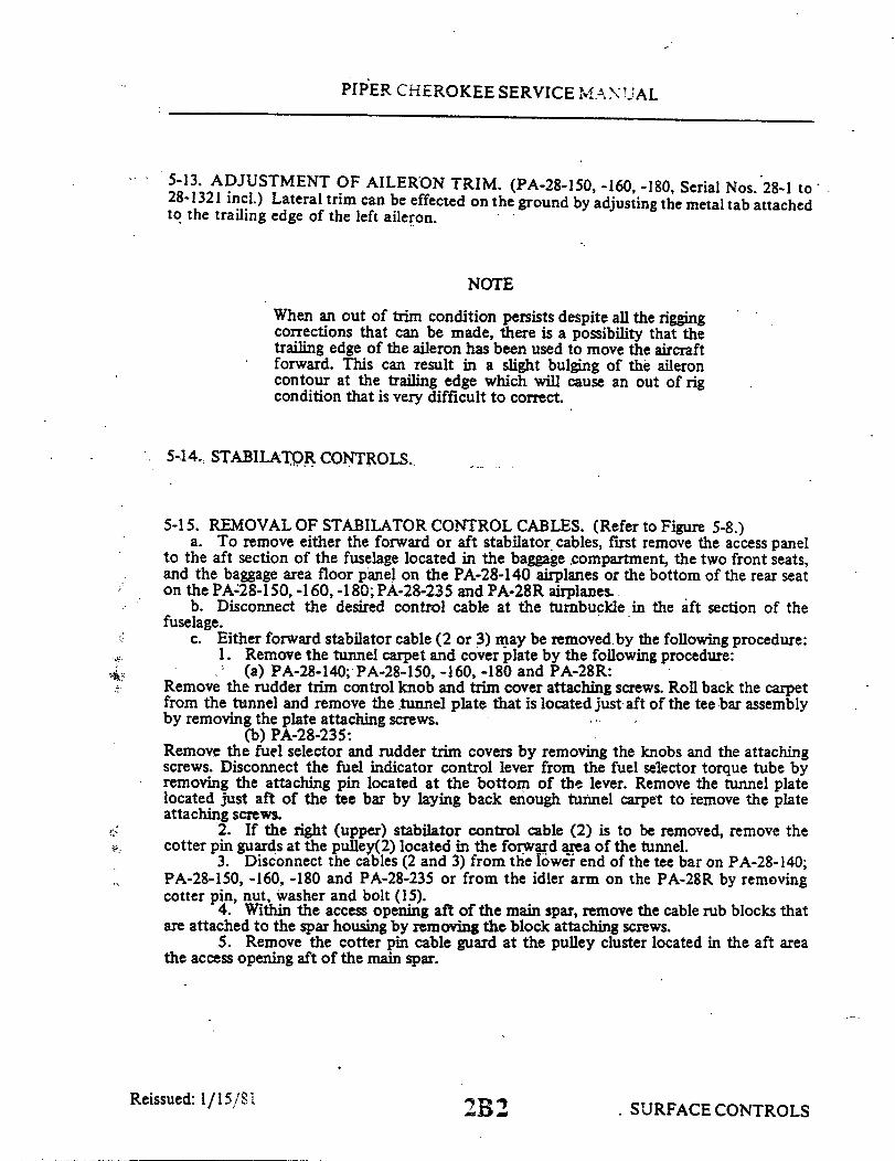
PIPER CHEROKEE SERVICE MANUAL
5-13. ADJUSTMENT OF AILERON TRIM. (PA-28-150, -160, -180, Serial Nos. 28-1 to'28-1321 incl.) Lateral trim can be effected on the ground by adjusting the metal tab attachedto the trailing edge of the left aileron.
NOTE
When an out of trim condition persists despite all the riggingcorrections that can be made, there is a possibility that thetrailing edge of the aileron has been used to move the aircraftforward. This can result in a slight bulging of the aileroncontour at the trailing edge which will cause an out of rigcondition that is very difficult to correct.
5-14. STABILATOR CONTROLS.
5-15. REMOVAL OF STABILATOR CONTROL CABLES. (Refer to Figure 5-8.)a. To remove either the forward or aft stabilator cables, first remove the access panel
to the aft section of the fuselage located in the baggage compartment, the two front seats,and the baggage area floor panel on the PA-28-140 airplanes or the bottom of the rear seaton the PA-28-150, -160, -180; PA-28-235 and PA-28R airplanes.
b. Disconnect the desired control cable at the turnbuckle in the aft section of thefuselage.
c. Either forward stabilator cable (2 or 3) may be removed by the following procedure:1. Remove the tunnel carpet and cover plate by the following procedure:
(a) PA-28-140; PA-28-150, -160, -180 and PA-28R:Remove the rudder trim control knob and trim cover attaching screws. Roll back the carpetfrom the tunnel and remove the tunnel plate that is located just aft of the tee bar assemblyby removing the plate attaching screws.
(b) PA-28-235:Remove the fuel selector and rudder trim covers by removing the knobs and the attachingscrews. Disconnect the fuel indicator control lever from the fuel selector torque tube byremoving the attaching pin located at the bottom of the lever. Remove the tunnel platelocated just aft of the tee bar by laying back enough tunnel carpet to remove the plateattaching screws.
2. If the right (upper) stabilator control cable (2) is to be removed, remove thecotter pin guards at the pulley(2) located in the forward area of the tunnel.
3. Disconnect the cables (2 and 3) from the lower end of the tee bar on PA-28-140;PA-28-150, -160, -180 and PA-28-235 or from the idler arm on the PA-28R by removingcotter pin, nut, washer and bolt (15).
4. Within the access opening aft of the main spar, remove the cable rub blocks thatare attached to the spar housing by removing the block attaching screws.
5. Remove the cotter pin cable guard at the pulley cluster located in the aft areathe access opening aft of the main spar.
Reissued: 1/15/81.SURFACE CONTROLS2B2
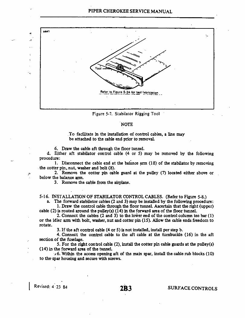
PIPER CHEROKEE SERVICE MANUAL
A641
Refer to Figure 5-24 for tool fabrication
Figure 5-7. Stabilator Rigging Tool
NOTE
To facilitate in the installation of control cables, a line maybe attached to the cable end prior to removal.
6. Draw the cable aft through the floor tunnel.d. Either aft stabilator control cable (4 or 5) may be removed by the following
procedure:1. Disconnect the cable end at the balance arm (18) of the stabilator by removing
the cotter pin, nut, washer and bolt (8).2. Remove the cotter pin cable guard at the pulley (7) located either above or
below the balance arm.3. Remove the cable from the airplane.
5-16. INSTALLATION OF STABILATOR CONTROL CABLES. (Refer to Figure 5-8.)a. The forward stabilator cables (2 and 3) may be installed by the following procedure:
1. Draw the control cable through the floor tunnel. Ascertain that the right (upper)cable (2) is routed around the pulley(s) (14) in the forward area of the floor tunnel.
2. Connect the cables (2 and 3) to the lower end of the control column tee bar (1)or the idler arm with bolt, washer, nut and cotter pin (15). Allow the cable ends freedom torotate.
3. If the aft control cable (4 or 5) is not installed, install per step b.4. Connect the control cable to the aft cable at the turnbuckle (16) in the aft
section of the fuselage.5. For the right control cable (2), install the cotter pin cable guards at the pulley(s)
(14) in the forward area of the tunnel.6. Within the access opening aft of the main spar, install the cable rub blocks (10)
to the spar housing and secure with screws.
Revised: 4 23 84 2B3 SURFACE CONTROL S

0
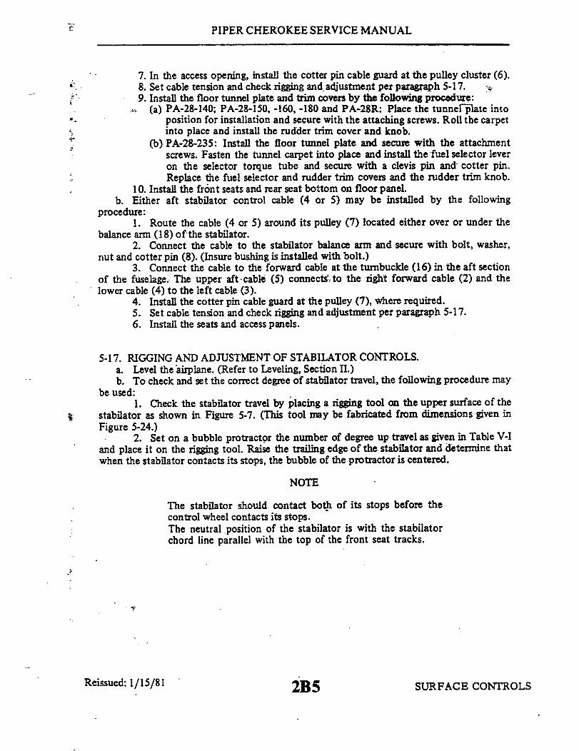
PIPER CHEROKEE SERVICE MANUAL
7. In the access opening, install the cotter pin cable guard at the pulley cluster (6).8. Set cable tension and check rigging and adjustment per paragraph 5-17.9. Install the floor tunnel plate and trim covers by the following procedure:
(a) PA-28-140; PA-28-150, -160, -180 and PA-28R: Place the tunnel plate intoposition for installation and secure with the attaching screws. Roll the carpetinto place and install the rudder trim cover and knob.
(b) PA-28-235: Install the floor tunnel plate and secure with the attachmentscrews. Fasten the tunnel carpet into place and install the fuel selector leveron the selector torque tube and secure with a clevis pin and cotter pin.Replace the fuel selector and rudder trim covers and the rudder trim knob.
10. Install the front seats and rear seat bottom on floor panel.b. Either aft stabilator control cable (4 or 5) may be installed by the following
procedure:1. Route the cable (4 or 5) around its pulley (7) located either over or under the
balance arm (18) of the stabilator.2. Connect the cable to the stabilator balance arm and secure with bolt, washer,
nut and cotter pin (8). (Insure bushing is installed with bolt.)3. Connect the cable to the forward cable at the turnbuckle (16) in the aft section
of the fuselage. The upper aft cable (5) connects to the right forward cable (2) and thelower cable (4) to the left cable (3).
4. Install the cotter pin cable guard at the pulley (7), where required.5. Set cable tension and check rigging and adjustment per paragraph 5-17.6. Install the seats and access panels.
5-17.a.b.
RIGGING AND ADJUSTMENT OF STABILATOR CONTROLS.Level the airplane. (Refer to Leveling, Section II.)To check and set the correct degree of stabilator travel, the following procedure may
be used:1. Check the stabilator travel by placing a rigging tool on the upper surface of the
stabilator as shown in Figure 5-7. (This tool may be fabricated from dimensions given inFigure 5-24.)
2. Set on a bubble protractor the number of degree up travel as given in Table V-Iand place it on the rigging tool. Raise the trailing edge of the stabilator and determine thatwhen the stabilator contacts its stops, the bubble of the protractor is centered.
NOTE
The stabilator should contact both of its stops before thecontrol wheel contacts its stops.The neutral position of the stabilator is with the stabilatorchord line parallel with the top of the front seat tracks.
Reissued: 1/15/81 SURFACE CONTROLS2B5
PIPER CHEROKEE SERVICE MANUAL
3. Set on the protractor the number of degrees down travel as given inTable V-I and again place it on the rigging tool. Lower the trailing edge of thestabilator and determine that when it contacts its stops, the bubble of the pro-tractor is centered.
4. Should the stabilator travel be incorrect in either the up or down posi-tion, remove the tail cone fairing by removing the attaching screws and with theuse of the rigging tool and bubble protractor turn the stops located at each stabi-lator hinge in or out (Refer to Figure 5-16. )to obtain the correct degree of travel
5. Ascertain that the lock nuts of the stop screws are secure and reinstallthe tail cone fairing.
c. To check and set stabilator control cable tension, the following proceduremay be used:
1. Ascertain that the stabilator travel is correct.2. Remove the access panel to the aft section of the fuselage.3. Secure the control column in the near forward position. Allow one-
quarter inch between the column and the stop bumper4. Check each control cable for the correct tension as given in Table V-I.5. Should tension be incorrect, loosenthe turnbuckle of the lower cable in
the aft section of the fuselage and adjust the turnbuckle of the upper cable to ob-tain correct tension. Cable tension should be obtained with the control wheel atthe one-quarter inch dimension from the stop and the stabilator contacting itsstop.
6. Check safety of all turnbuckles and bolts.7. With the tension of the upper, cable correct and the control wheel still
forward, adjust the turnbuckle of the lower cable to obtain correct tension.8. Check the full travel of the control wheel with relation to the full travel
of the stabilator to determine that the stabilator contacts its stops before thecontrol wheel contacts its stops. With the control wheel in the fore and aft posi-tions, the travel distance from the point where the stabilator contacts its stopsand the control wheel contacts its stops should be approximately equal. Readjustturnbuckles if incorrect.
9. Reinstall access panels.d. Remove the airplane from jacks.
Reissued: 1/15/81 SURFACE CONTROLS2B6

PIPER CHEROKEE SERVICE MANUAL
5-18. STABILATOR TRIM CONTROLS. (OVERHEAD TRIM.)
NOTE
If the airplane involved is equipped with a single sta-bilator trim cable (one turnbuckle),it will be necessaryto follow the combined instructions for removal of bothforward and aft cables.
5-19. REMOVAL OF STABILATOR TRIM ASSEMBLY. (FORWARD. )-(Refer to Figure 5-9.)
a. Rotate the stabilator trim crank to bring the indicator to full aft (extremenose high) position to facilitate removal of the trim indicator from the panel.
b. Remove the spring clip from the stabilator trim crank handle and removethe handle.
c. Remove the headliner trim panel (light panel) from around the trim crankassembly by the following procedure:
1. Remove the attaching screws that secure the panel.2. Disconnect the light wires at the quick disconnects.
NOTE
It is recommended that the wires be marked for iden-tification before removal.
3. Remove the panel.d. Remove the access panel at the aft wall of the baggage compartment to gain
entry to the aft section of the fuselage.e. Install a cable block on the aft trim control cables, as shown in Figure 5-10.f. Disconnect the stabilator trim cable(s) at the turnbuckle(s) located in the
aft section of the fuselage.g. Remove the cable guard pins from the pulleys located at stations 108.16
and 138.33. Station 138.33 is accessible through the zipper on the aft area ofthe headliner.
h. Remove the clevis pin cable guard from the trim crank assembly.
NOTE
To facilitate installation, it is recommended that aline be attached to the cable end prior to removal.
SURFACE CONTROLS2B7Reissued: 1/15/81
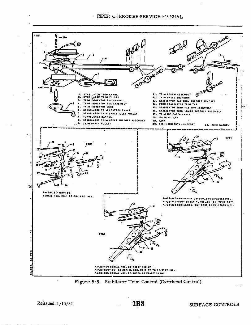
PIPER CHEROKEE SERVICE MANUAL
1761
1. STABILATOR TRIM CRANK2. STABILATOR TRIM PULLEY3. TRIM INDICATOR TEE SPRING4. TRIM INDICATOR TEE ASSEMBLY5. TRIM INDICATOR WIRE6. STABILATOR TRIM CONTROL CABLE7. STABILATOR TRIM CABLE IDLER PULLEY8. TURNBUCKLE BARREL9. STABILATOR TRIM UPPER SUPPORT ASSEMBLY10. TRIM SHAFT PULLEY
PA-20-150-160-180SERIAL NOS. 2B-1 TO 2B-1410 INCL.
PA-28-140 SERIAL NOS. 2-20002 TO 28-20656 INCL.PA2-2-140-160-10 SERIAL NOS. 28-141 TO 21-2 171PA-28-235 SERIAL NOS. 21-10003 TO 28-10605 INCL.
1751
PA-2B-140 SERIAL NOS. 28-20657 AND UPPA-2-150-160-180 SERIAL NOS. 28-2172 TO 28-9377 INCL.PA-28-235 SERIAL NOS. 28-1060 TO 28-10719 INCL.
Figure 5-9. Stabilator Trim Control (Overhead Control)
2B8
T
Reissued: 1/15/81 SURFACE CONTROLS

PIPER CHEROKEE SERVICE MANUAL
i. Remove the cable from the airplane.j. The trim crank and pulley assembly may be removed by removing the
mounting bracket attaching screws.
5-20. INSTALLATION OF STABILATOR TRIM ASSEMBLY. (FORWARD.)(Refer to Figure 5-9.)
a. If the trim crank and pulley assembly has been removed, install assemblyand secure with attachment screws.
b. Install the forward stabilator trim cable using the following procedure:1. Attach a line to the right end of the control cable and pull the cable for-
ward to the crank assembly.2. Route the cable clockwise (as view from the underside) around and into
the top groove of the crank pulley, and on to the left side of the idler pulley.3. From around the idler pulley, route the cable around and in the bottom
groove of the crank pulley.4. With the use of a line attached to the cable end, pull the cable through
to the turnbuckle located in the aft section of the fuselage.c. Attach the cable ends together and install guard pins in the pulley assem-
blies.d. Insert the guard pin in the trim bracket assembly and safety with a cotter
pin.e. Actuate the trim crank fore and aft several times to seat the cables into
the pulleys.f. Rig and adjust in accordance with paragraph 5-23.g. Replace all the access plates and panels.h. Install the headliner trim panel by connecting the electrical leads and in-
stalling attaching screws.i . Replace the trim handle and secure with the snap ring.
5-21. REMOVAL OF STABILATOR TRIM CONTROLS. (AFT.)(Refer to Figure 5-9.)
a. PA-28-150,-160,-180, Serial Nos. 28-1 to 28-1410 incl. (The exceptionbeing airplanes with Piper Kit No. 756 930 Stabilator Trim Modifications install-ed. Airplanes with this kit installed, refer to step c.)
1. Remove the tail cone fairing by removing attaching screws.2. Remove the access panel located at the aft wall of the baggage compart-
ment to allow access to the aft section of the fuselage.3. To remove the trim control cable, proceed as follows:
(a) Disconnect the cable at the turnbuckle (8) in the aft section of thefuselage.
SURFACE CONTROLS2B9Reissued: 1/15/81

PIPER CHEROKEE SERVICE MANUAL
A977
Figure 5-10. Methods of Securing Trim Cables
(b) Remove the cable guard pin from the pulleys located within the fuse-lage at station 228.30.
(c) Remove the cable guard from the top support brace of the trimmechanism located just aft of the trim screw pulley.
(d) Remove the cotter pin cable guard at the idler pulley (18) which isattached to the aft side of the rearward most bulkhead of the fuselage.
(e) Draw the cable aft around the trim screw pulley (10) and then for-ward.
(f) Removethe forward portion of the cable as givenin paragraph5-19.4. The trim mechanism may be disassembled and removed from the aft
bulkhead of the fuselage as follows:(a) Disconnect the trim tab control arm (15) from its support bracket
by removing nuts, washers, bushings and bolts.(b) Disconnect the trim indicator cable (17) from the trim screw trun-
nion (12) by removing attaching nut, washer and screw. Remove the cotter pincable guard at the cable pulley (10) located directly below the trunnion.
(c) Remove the trim mechanism assembly (11) by removing the nut,washer and bolt at each support brace (20) attachment point, and at the aft mostfuselage bulkhead.
(d) Disassemble the trim mechanism by removing the cotter pin, washerand nut located at each end of shaft assembly, and pulling the supports withwashers from the shaft.
(e) Disassemble the shaft by removing the roll pins from the desiredcomponent.
SURFACE CONTROLSReissued: 1/15/81 2B10

PIPER CHEROKEE SERVICE MANUAL
b. PA-28-140, Serial Nos. 28-20002 to 28-20656 incl; PA-28-150, -160, -180,Serial Nos. 28-1411 to 28-2171 incl. and PA-28-235, Serial Nos. 28-10603 to28-10605 incl. (The exception being those airplanes with Piper Kit No. 756 896Stabilator Trim Modification installed. Airplanes with this kit installed, referto step c.)
1. Remove the tail cone fairing by removing attaching screws.2. Remove the access panel located at the aft wall of the baggage compart-
ment to allow access to the aft section of the fuselage.3. To remove the trim control cable, proceed as follows:
(a) Disconnect the cable at the turnbuckle (8) in the aft section of thefuselage.
(b) Remove the cable guard pin from the pulleys located within thefuselage at station 228.30.
(c) Disconnect the links (19), located between the trim screw (11) andcontrol arm (15) at the trim screw, by removing nut, washers, bushing and bolt.
(d) Remove the cotter pin that extends through the top of the trim screwand the cable guard pin located just aft of the trim barrel (10).
(e) Remove the cotter pin cable guard at the idler pulleys which areattached to the aft side of the rearward most bulkhead.
(f) Turn the screw down and out from the underside of the barrel.(g) Remove the snap ring, washer and thrust washer from the bottom
of the barrel.(h) Disconnect the diagonal and horizontal trim assembly support ribs
from one another by removing their four attaching nuts, washers and bolts.(i) Loosen the bolts where the horizontal ribs attach to the fuselage
bulkhead, raise the aft end of the ribs, and move the barrel (21) aft far enoughto unwrap the trim cable from around the barrel and idler pulleys (18).
(j) Remove the forward portion of the cable (6) as given in paragraph5-19.
4. The horizontal and diagonal support ribs may be removed by removingthe cotter pin cable guard at the trim indicator cable pulley located on the diagonalrib, and removing the attaching nuts, washers and bolts that secure the ribs tothe aft bulkhead.
c. PA-28-140, Serial Nos. 28-20657 and up; PA-28-150,-160,-180, SerialNos. 28-2172 to 28-9377 incl. and PA-28-235, Serial Nos. 28-10606 to 28-10719incl.
1. Remove the tail cone fairing by removing attaching screws.2. Remove the access panel located at the aft wall of the baggage compart-
ment to allow access to the aft section of the fuselage.3. To remove the trim control cable, proceed as follows:
(a) Block the first set of pulleys forward of the cable turnbuckles (8) inthe aft section of the fuselage by the method shown in Figure 5-10.
SURFACE CONTROLS2B11Reissued: 1/15/81

PIPER CHEROKEE SERVICE MANUAL
(b) Remove the cable guard pin from the pulleys located withinthe fuse-lage at station 228.30.
(c) Disconnect the links (19), located between the trim screw (11) andcontrol arm (15) at the trim screw by removing nut, washers and bolt.
(d) Remove the cotter pin that extends through the top of the trim screwand the cable guard pin located just aft of the trim barrel (21).
(e) Turn the screw down and out from the underside of the barrel.(f) Remove the snap ring, washer and thrust washer from the bottom
of the barrel.(g) Disconnect the diagonal and horizontal (20) trim assembly support
ribs from one another by removing their four attaching nuts, washers and bolts.(h) Loosen the attaching bolts where the horizontal ribs attach to the
fuselage bulkhead, raise the aft end of the ribs and remove the barrel with cable.Draw the cable from the fuselage.
4. The horizontal and diagonal support ribs may be removed by removingthe cotter pin cable guard at the trim indicator cable pulley located on the diago-nal rib, and removing the attachment nuts, washers and bolts that secure the ribsto the aft bulkhead.
d. The trim indicator cable(17) may be removed from the aft area of the fuse-lage by disconnecting the cable from the trim screw trunnion or at the lower endof the trim screw (11), removing the cotter pin cable guard at the pulley locatedbelow the trim screw and disconnecting the cable from the indicator wire.
5-22. INSTALLATION OF STABILATOR TRIM CONTROLS. (AFT.)(Refer to Figure 5-9.)
a. PA-28-150,-160, -180, Serial Nos. 28-1 to 28-1410' incl. (The exceptionbeing airplanes with Piper Kit No. 756 930, Stabilator Trim Modification, in-stalled. Airplanes with this kit installed, refer to step c.)
1 The trim mechanism may be assembled and attached to the aft bulkheadof the fuselage as follows:
(a) Assemble the trunnion (12), stops and pulley (10) in the trim shaftand secure with roll pins.
(b) Assemble the trim mechanism by placing an AN960-516L washerfollowed by a support on each end of the shaft assembly (11). Install washers andnuts, check freedom of rotation of the shaft with no end play and then secure nutswith cotter pins.
(c) Align the attachment hole of each support brace with those of theaft bulkhead, install bolts and secure with washers and nuts.
(d) Draw the trim cable and attach the end to the trim screw trunnion,and secure with bolts, nut and washer. With the cable placed around the pulleylocated directly below, the trunnion, install the cotter pin cable guard at the pulley.
SURFACE CONTROLSReissued: 1/15/81 2B12

PIPER CHEROKEE SERVICE MANUAL
2. The trim control cable may be installed by the following procedure:(a) Install the forward portion of the cable as givenin paragraph 5-20.(b) With the forward portion installed, route the long length (the long
length should be the left end of the cable) aft, counterclockwise around to the topgroove of the trim pulley (10), around the idler pulley (18), back around the bot-tom groove of the trim pulley and forward to the inside of the fuselage.
(c) Draw the cable end forward and connect it with its mating end withinthe fuselage.
(d) Ascertain that the cable is seated in the groove of each pulley, andinstall the cotter pin cable guards at the pulleys located within the fuselage atstation 228.30 and at idler pulley at the aft fuselage bulkhead.
(e) Install the cable guard at the top support brace located just aftthe trim screw pulley.
3. The trim indicator cable may be installed by attaching one end to thetrim screw trunnion. (Refer to Figure 5-9 for correct location.) Loop the cablearound the pulley below the trim screw; Install the cotter pin cable guard at thepulley. Attach other end of the cable to the indicator wire, and at the same timemake adjustments given in paragraph 5-23.
4. Set cable tension and check rigging and adjustment per paragraph 5-23.Check safety of turnbuckle.
5. Install tail cone fairing and secure with screws.6. Install the access panel to the aft section of the fuselage.
b. PA-28-140, Serial Nos. 28-20002 to 28-20656 incl; PA-28-150, -160, -180,Serial Nos. 28-1411 to 28-2171 incl. and PA-28-235, Serial Nos. 28-10003 to28-10605 incl. (The exception being those airplanes with Piper Kit No. 756 896,Stabilator Trim Modification, installed. Airplanes with this kit installed, referto step c.)
1. Ascertain that the trim barrel bushings are lubricated and installed inthe rib plate and clip.
2. Attach the horizontal (20) and diagonal support ribs to the aft bulkheadof the fuselage with bolts, washers and nuts. Start nuts only a few threads so asto allow ribs to hang loose. Do not connect the ribs at this time.
3. Install the forward portion of the cable as given in paragraph 5-20.4. Wrap the trim cable around the barrel(21)and idler pulley (18). To do
this, hold the barrel next to the aft end of the support braces and wrap, bringingthe end of the long length(The long length should be the left end of the cable.) aftto the left side of the trim barrel, around the bottom groove of the idler pulley,then continuing to wrap in this direction until all grooves are filled.
5. Install the trim barrel (21) in the bushing between the horizontal anddiagonal ribs, and then attach the ribs, securing with bolts, washers and nuts.Tighten bolts where the ribs attach to the aft bulkhead.
SURFACE CONTROLS2B13Reissued: 1/15/81

PIPER CHEROKEE SERVICE MANUAL
6. Install the thrust washer, washer and snap ring on lower end of thebarrel.
7. Install the trim screw in the barrel and secure each end with a cotterpin through the screw.
8. Draw the cable end forward and connect it with its mating end withinthe fuselage.
9. Ascertain that the cable is seated in the groove of each pulley and in-stall the cotter pin cable guards at the pulleys located within the fuselage at sta-tion 228.30 and at the idler pulley at the aft fuselage bulkhead.
10. Set cable tension and check rigging and adjustment per paragraph 5-17.Check safety of turnbuckle.
11. The trim indicator cable may be installed by attaching one end to thelower end of the trim screw (Refer to Figure 5-9 for correct location.) and loop-ing the cable around the pulley below thetrim screw. Install the cotter pin cableguard at the pulley. Attach other end of the cable to the indicator wire, and atthe same time make adjustments given in paragraph 23.
12. Install tail cone fairing and secure with screws.13. Install access panel to the aft section of the fuselage.
c. PA-28-140, Serial Nos. 28-20657 and up; PA-28-150,-160,-180, Serial No.28-2172 to 28-9377 incl. and PA-28-235, Serial Nos. 28-10606 to 28-10719 incl.
1. Ascertain that the trim barrel bushings are lubricated and installed inthe rib plate and clip.
2. Attach the horizontal (20) and diagonal support ribs to the aft bulkheadof the fuselage with bolts, washers and nuts. Start nuts only a few threads so asto allow ribs to hang loose. Do not connect the ribs at this time.
3. Wrap the trim barrel (21). To do this, first lay the center (as meas-ured equally from each end to the center of the cable) of the trim cable in the slotof the barrel. Bring the upper cable through the diagonal slot in the flange at theupper end of the barrel and wrap down in a counterclockwise direction. Bring thelower cable through the diagonal slot in the lower end of the barrel and wrap upin a clockwise direction. Wrap the cable as evenlyas possible to obtain 23 wrapson the barrel as viewed from the side opposite the slot and with the cables extend-ing out from the slotted side.
4. Block both cables by clamping them between two pieces of wood laid nextto the wraps to prevent them from unwrapping. (Refer to Figure 5-10.)
5. Install the barrel in the bushings between the horizontal and diagonalribs, and then attach rib securing with bolts, washers and nuts. Tighten boltswhere the ribs attach to the aft bulkhead.
6. Install the thrust washer, washer and snap ring on the lower end of thebarrel.
7. Install the trim screw (11) in the barrel and secure each end with a cot-ter pin through the screw.
SURFACE CONTROLSReissued: l/15/81 2B14

PIPER CHEROKEE SERVICE MANUAL
8. Route the cable ends into the fuselage and attach the ends to the matingend of the forward cable.
9. Remove the blocks holding the forward cable tight and the aft cables atthe barrel.
10. Set cable tension and check rigging and adjustment per paragraph 5-23.Check safety of turnbuckles.
11. The trim indicator cable may be installed by attaching one end to thelower end of the trim screw (Refer to Figure 5-9 for correct location.) and loop-ingthe cable around the pulley below the trim screw. Install the cotter pin cableguard at the pulley. Attach other end of the cable to the indicator wire, and atthe same time make adjustments given in paragraph 5-23.
12. Install tail cone fairing and secure with screws.13. Install the access panel to the aft section of the fuselage.
5-23. RIGGING AND ADJUSTMENT OF STABILATOR TRIM.(OVERHEAD CONTROL.)
a. PA-28-150, -160, -180, Serial Nos. 28-1 to 28-1410 incl. (The exceptionbeing those airplanes with Piper Kit No. 756 930, Stabilator Trim Modification,installed. Airplanes with this kit installed, refer to step b.) (Refer to Figure5-9.)
1. Level the airplane. (Refer to Leveling, Section II.)2. Check for proper stabilator trim cable tension as given in Table V-I.
If the cables were disconnected, rotate control crank (1) several times to allowthe cables to seat and recheck tension.
3. Position the stabilator against its down stop. Ascertain that the stab-ilator travel is correctly set according to Table V-I.
4. Turn the trim crank until the aft end of the turnbuckle of the right trimcable is positioned approximately one-half inch forward of the double pulley clus-ter at the top of the rear bulkhead at station 228.3.
5. Check that the trim screw trunnion (12) is turned down until it contactsthe top of the lower screw stop of the trim assembly If the trunnion is not con-tacting the stop, and the fork (14) between the trim support bracket (13) and thetrim control arm (15) is not disconnected, -disconnect the arm from the tab byremoving the connecting bolts. With the turnbuckle still at the one-half dimen-sion from the pulley, turn the screw down until the trunnion contacts the stop.
6. With the stabilator positioned against its down stop, adjust the trimactuating arm until the trailing edge of the tab aligns with the trailing edge of thestabilator. Adjust by loosening the jam nut on the fork of the control arm andturning the fork in or out as required.
7. Connect the control arm to the tab and secure with bolts.
SURFACE CONTROLS2B15Reissued: 1/15/81

PIPER CHEROKEE SERVICE MANUAL
8. Move the stabilator to the neutral position and secure. To find neutral,place a rigging tool on the upper surface of the stabilator as shown in Figure 5-8.Zero a bubble protractor, set it on the rigging tool and tilt the stabilator untilthe bubble is centered.
9. Turn the trim crank until the trailing edge of the tab aligns with thetrailing edge of the stabilator.
10. Check the bubble of the protractor over the neutral tab and then checktab travels as given in Table V-I. The degree of travel on the protractor is de-termined by taking the difference between the protractor reading at neutral andup, and neutral and down. The bubble must be centered at each reading with theairplane level.
11. To obtain correct travels, if incorrect, adjust by disconnecing the ac-tuating arm and turning it in or out as required. Reconnect the arm to the tab.
12. Secure the jam nut against the fork.13. Turn the trim wheel to full travel and check for turnbuckle clearance
and location of tab indicator.b. PA-28-140;PA-28-150, -160, -180, Serial Nos. 28-1411 to 28-4377 incl. and
PA-28-235, Serial Nos. 28-10003 to 28-10719 incl. (Refer to Figure 5-9.)1. Level the airplane. (Refer to Leveling, Section II.)2. Check for proper stabilator trim cable tension as given in Table V- .
If the cables were disconnected, rotate control crank (1) several times to allowthe cables to seat and recheck tension.
3. Position the stabilator against its down stop. Ascertain that the stabi-lator travel is correctly set according to Table V-I.
4. Turn the trim crank until the aft end of the turnbuckle of the right trimcable is positioned approximately one-half inchforward of the double pulley clus-ter at the top of the rear bulkhead at station 228.3.
5. Check that the trim screw is turned down until the cotter pin stop in thetop of the screw is contacting the plate (9) on the horizontal support rib (20) ofthe trim assembly. If the stop is not contacting the plate, and the links betweenthe screw (11) and the trim control arm (15) are not disconnected, disconnect thetwo by removing the connecting nut, washer and bolt. With the turnbuckle stillat the one-half dimension from the pulley, turn the screw down until the pin con-tacts the plate.
6. Withthe stabilator positioned against its down stop, adjust thetrim ac-tuating arm until the trailing edge of the tab aligns with the trailing edge of thestabilator. Adjust by loosening the jam nut on the end bearing of the control armand turning the bearing in or out as required.
7. Connect the links to the control arm and secure with bolt, washers andnut.
Reissued: 1/15/81SURFACE CONTROLS2B16
PIPER CHEROKEE SERVICE MANUAL
8. Move the stabilator to the neutral position and secure. To find neutral,place a rigging tool on the upper surface of the stabilator as shown in Figure5-8. Zero a bubble protractor, set it on the rigging tool and tilt the stabilatoruntil the bubble is centered.
9. Turn the trim crank until trailing edge of the tab aligns with the trail-ing edge of the stabilator.
10. Check the bubble of the protractor over the neutral tab and then checktab travels as given in Table V-I. The degree of travel on the protractor is de-termined by taking the difference between the protractor reading at neutral andup, and neutral and down. The bubble must be centered at each reading with theairplane level.
11. To obtain correct travels, if incorreci, adjust by disconnecting the linksat the actuating arm rod end and turning the end in or out as required. Reconnectlinks to rod end.
12. Secure the jam nut on the actuating arm rod end.13. Turn the trim wheel to full travel and check for turnbuckle clearance
and location of tab indicator.
5-24. STABILATOR TRIM CONTROLS. (FLOOR TRIM.)
5-25. REMOVAL OF STABILATOR TRIM ASSEMBLY. (FORWARD.)(Refer to Figure 5-11.)
a. To remove the trim control wheel assembly and/or the trim control cables,first remove the panel to the aft section of the airplane.
b. If the aft trim cable (12) is not to be removed, block the cables atthe pulleys(13) inthe upper aft section of the fuselage to prevent them from unwrappingfromthe trim drum. (Refer to Figure 5-10.)
c. Loosen the cables if the trim control wheel (1) is to be removed or discon-nect if the cables are also to be removed. Do this at the trim cable turnbuckles(10 and 11) in the aft section of the fuselage.
d. The control wheel (1) with drum (3) may be removed by the following pro-cedure:
1. Remove the control wheel cover by removing the cover attaching screws.2. The wheel assembly may be removed from its mounting brackets by
removing nut, washer and bolt (7) that secures the wheel between the brackets.Draw the wheel from the brackets. Use caution not to damage trim indicatorwire (2).
3. Unwrap the left cable (9) from the drum.4.. The wheel and drum are joined by a push fit, separate these two items
with their center bushing and unwrap the right cable (8).
SURFACE CONTROLSReissued: 1/15/81 2B17

PIPER CHEROKEE SERVICE MANUAL
C339
28
9
CONTROL WHEEL TRIMINDICATOR TRIM POSITIONDRUM, TRIM CABLEMOUNTING BRACKET
CLEVIS PIN, WASHER & COTTER PINPULLEY CLUSTER
BOLT, BUSHING, WASHER & NUTCABLE, RIGHT FORWARDCABLE, LEFT FORWARDTURNBUCKLE, RICHTTURNBUCKLE, LEFTCABLE, AFTPULLEY CLUSTERBOLT, BUSHING, WASHER (3) & NUTGUARD-BOLT, BUSHING, WASHER & NUTRIB, HORIZONTAL SUPPORTPLATE, RIBGUARD
19. BUSHING, BARREL20. BARREL, TRIM21. CLIP, DIAGONAL RIB22. RIB, DIAGONAL SUPPORT23. SCREW, TRIM24. BOLT, WASHER (2) & NUT25. LINK26. ROD END
27. JAM NUT
28. ARM, TRIM CONTROL29. BUSHING BARREL30. WASHER, THRUST31. WASHER, SPACER32. SNAP RING33. PULLEY CLUSTER34. PULLEY CLUSTER35. BOLT, WASHER & NUT36. GUARD, CABLE37. RUB BLOCK
Figure 5-11. Stabilator Trim Control (Floor Control)
Reissued: 1/15/81 2B18 SURFACE CONTROLS
1.2.3.4.5
6.
9.
10..11.12.13.
a 1415.1617.18.

PIPER CHEROKEE SERVICE MANUAL
5. Tie the cables forward to prevent them from slipping back into the floortunnel.
e. The trim control cables (8 and 9) may be removed by the following proce-dure:
1 . Remove the rear seat bottom or floor panel, whichever applies, and thefront seats, if desired.
2. Unfasten the carpet from the aft portion of the floor tunnel and lay itforward.
3. Remove the tunnel cover located between the trim control wheel and thespar cover by removing attaching screws.
4. Remove the cable pulleys (6) located in the tunnel by removing the cotterpin, washer and clevis pin (5).
5. Remove the cable rub blocks (37) located on the aft side of the main sparby removing the block attaching screws.
6. Remove the cable guard pin (36) at the pulley cluster (34) located justaft of the wing flap torque tube at station 127.25.
7. If installed, remove the cable pulleys (33) within the aft section of thefuselage at station 156.5 by removing nut, washer, bushing and bolt.
8. With the cables disconnected from the trim control wheel, draw thecable(s) through the floor tunnel.
5-26. INSTALLATION OF STABILATOR TRIM ASSEMBLY. (FORWARD.)(Refer to Figure 5-11.)
a. The trim control wheel with drum may be installed by the following proce-dure:
1. Wrapthe right trim cable on the trim drum byinsertingthe swaged ballof the cable in the slot provided in the side (right side) of the drum that mateswith the control wheel, and looking at this side, wrap the drum with three wrapsof the cable in a clockwise direction.
2. Attach the control wheel to the cable drum by aligning the long lug ofthe drum with the long slot of the wheel and pushing the two pieces together.
3. Wrap the left trim cable on the drum by inserting the swaged ball of thecable in the slot provided in the flanged side (left side) of the drum and lookingat this side, wrap the drum with three wraps of the cable in a clockwise direction.
4. Lubricate and install the bushing in the control wheel and drum.5. Alignthe controlcables andpositionthe control wheel assembly between
its mounting brackets. Ascertain that the end of the trim indicator wire is posi-tioned in the spiraled slot of the drum withno bind on the end. Install the retainerbolt from the left side and install washer and nut.
6. Install the cover over the control wheel and secure with screws, unlessthe control cables have yet to be installed.
SURFACE CONTROLS2B19Reissued: 1/15/81

PIPER CHEROKEE SERVICE MANUAL
... b. The trim control cables may be installed by the following procedure:1. Draw the cable(s) through the floor tunnel.2. Wrap the cable drum and install the trim control wheel as given in
step a.3. Position the cable pulleys on their mounting bracket within the floor
tunnel and install the clevis pin, washer and cotter pin.4. Connect the cable to the aft cable at the turnbuckle in the aft section of
the fuselage. Install aft cable if not installed.5. If previously installed, install the pulleys in the aft lower section of the
fuselage at station 156.5 forward of the cable turnbuckles.6. Install the cable guard atthe underside of the pulleys located just aft of
the flap torque tube at station 127.25 and secure.7.. Install the cable rub blocks located on the aft side of the main spar
housing and secure with screws.8. Remove the blocks that secure the aft trim cable and check that the
cables are seated on their pulleys.c. Set cable tension and check rigging and adjustment per paragraph 5-29.
Check safety of all turnbuckles.d. Install the tunnel cover on the tunnel and secure with screws.e. Install the carpet over the floor tunnel.f. Install the cover over the trim control wheel and secure with screws and
special washers.g. Install the floor panel and seat belt attachments aft of the main spar and
secure panel with screws.h. Install the panel to the aft section of the airplane and the seats.
5-27. REMOVAL OF STABILATOR TRIM ASSEMBLY. (AFT.)(Refer to Figure 5-11.)
a. Remove the access panel to the aft section of the fuselage.b. Block the trim cables at the first set of pulleys (33) forward of the cable
turnbuckles (10 and 11) in the aft section of the fuselage by a method shown inFigure 5-10.
c. Disconnect the cable (12) at the turnbuckles (10 and 11) in the aft sectionof the fuselage.
d. Remove the tail cone by removing its attaching screws.e. Disconnect the link (25) between the trim screw (23) and the trim control
arm (28) by removing the nut, washer and bolt (24) that connects the link to thescrew.
f. Remove the cotter pin from the top of the screw (23), and turn the screwdown and out of the barrel (20).
SURFACE CONTROLS2B20Reissued: 1/15/81

PIPER CHEROKEE SERVICE MANUAL
g. Remove the snap ring (32), washer (31) and thrust washer (30) from thebottom of the barrel.
h. Disconnect the diagonal rib (22) from the horizontal rib (16) that supportsthe trim assembly by removing the four attaching nuts, washers and bolts.
i. Draw the trim cable (12) from the fuselage.
5-28. INSTALLATION OF STABILATOR TRIM ASSEMBLY. (AFT.)(Refer to Figure 5-11.)
a. Wrap the trim barrel (20) by first laying the center (as measured equallyfrom each end to the center of the cable) of the trim cable (12) in the slot of thebarrel. Bring the upper cable through the diagonal slot in the flange at the upperend of the barrel and wrap down in a counterclockwise direction. Bring the lowercable through the diagonal slot in the lower end of the barrel and wrap up in aclockwise direction. Wrap the cable as evenly as possible to obtain 23 wraps onthe barrel as viewed from the side opposite the slot and with the cables extendingout from the slotted side.
b. Block both cables by clamping them between two pieces of wood laid next tothe wraps to prevent them from unwrapping.
c. Ascertain that the barrel bushings (19 and 29) are installed in the rib plate(17) and clip (21).
d. Lubricate the bushings and install the trim barrel (20) in the bushings be-tween the two support ribs. Attach the bottom diagonal rib (22) to horizontal rib(16) and secure with bolt, washers and nuts.
e. Install the thrust washer (30), washer (31) and snap ring (32) on the lowerend of the barrel.
f. Install the trim screw (23) in the barrel (20) and secure each end with acotter pin through the screw.
g. Route the cables into the fuselage and attach the ends to the forward trimcables (8 and 9).
h. Remove the blocks that are holding the forward cables tight and aft cablesat the barrel.
i. Set cable tension and check rigging and adjustment per paragraph 5-29.Check safety of all turnbuckles.
j. Install the tail cone and secure with screws.k. Install the access panel to the aft section of the fuselage.
SURFACE CONTROLSReissued: 1/15/81 2B21

PIPER CHEROKEE SERVICE MANUAL
5-29. RIGGING AND ADJUSTMENT OF STABILATOR TRIM. (FLOORCONTROL.) PA-28-180, Serial Nos. 28-4378 and up; PA-28-235, Serial Nos. 28-10720 andup; and PA-28R. (Refer to Figure 5-11.)
a. Level the airplane. (Refer to Leveling, Section II.)b. Check for proper stabilator trim cable tension as given in Table V-I. If
cables were disconnected, rotate control wheel several times to allow the cablesto seat and recheck tension.
c. Secure the stabilator in neutral position. To find neutral, place a riggingtool onthe upper surface of the stabilator as shownin Figure 5-7. Zero a bubbleprotractor, set it on the rigging tool and tilt the stabilator until the bubble is cen-tered.
d. With the stabilator centered, turn the trim wheel (1) until the aft end of theturnbuckle (10) of the right trim cable (8) is approximately two inches forward ofthe double pulleys (13) at the top of the rear bulkhead at station 228.3.
e. Check that the trim screw (23) is turned down until the cotter pin stop inthe top of the screw is contacting the plate (17) on the horizontal support rib (16)of the trim assembly. If the stop is not contacting the plate, the links (25) be-tween the screw (23) and the trim control arm (28) are not disconnected, discon-nect the two by removing the connecting nut, washers and bolt (24). With theturnbuckle still at the two inch dimension from the pulley, turn the screw downuntil the pin contacts the plate.
f. Check the rod end (26) on the tab actuating arm (28) for approximately sixthreads forward of the jam nut (27).
g. Connect the links to the trim screw and secure with bolt, washers and nut.h. Turn the trim control wheel until the trim tab streamlines with the neutral
stabilator.i. Check the bubble of the protractor over the neutral tab and then check tab
travels as given in Table V-I. The degree of travel on the protractor is deter-mined by taking the difference between the protractor reading at neutral and up,and neutral and down. The bubble must be centered at each reading with the air-plane level.
j. To obtain correct travels, if incorrect, adjust by disconnecting the links(25) at the actuating arm rod end (26) and turning the end in or out as required.Reconnect links to rod end.
k. Secure the jam nut (27) on the actuating arm rod end.1. Turn the trim wheel to full travel and check for turnbuckle clearance and
location of tab indicator.
Reissued: 1/15/81 SURFACE CONTROLS2B22
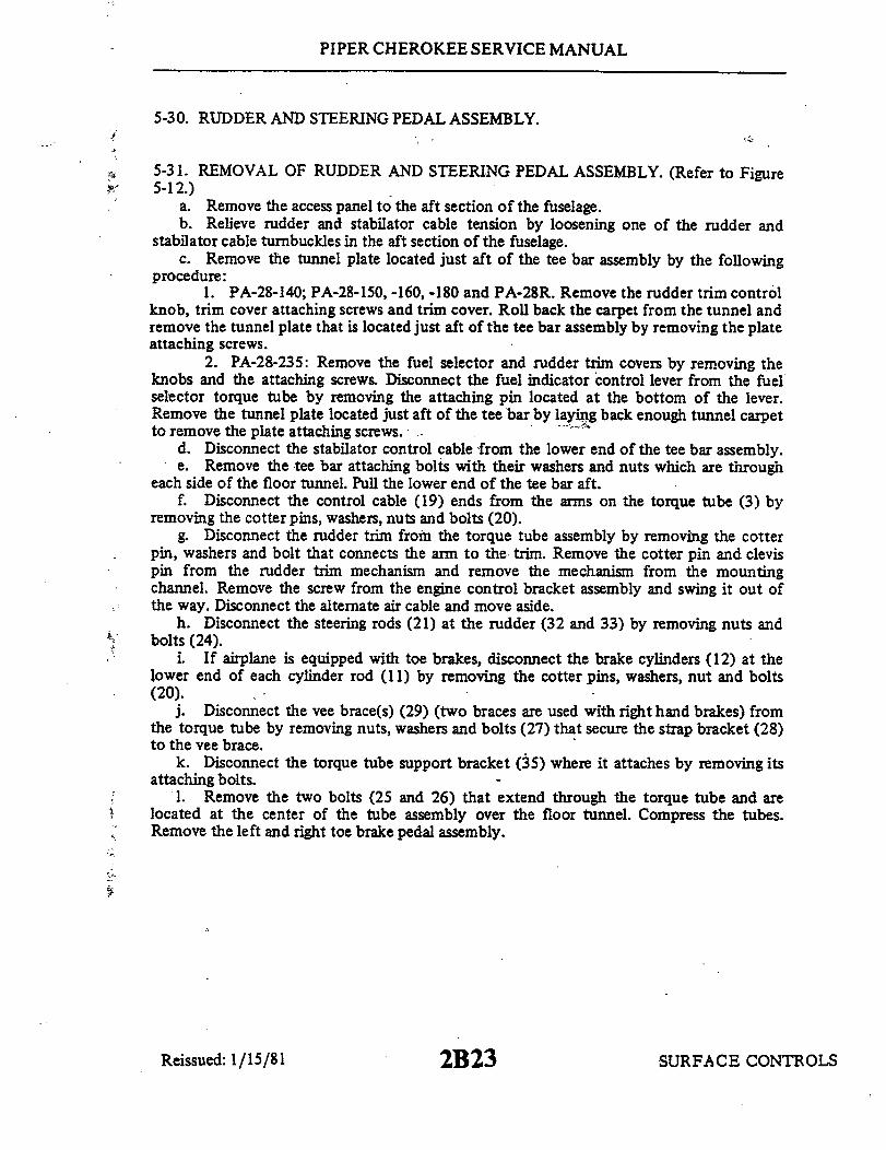
PIPER CHEROKEE SERVICE MANUAL
5-30. RUDDER AND STEERING PEDAL ASSEMBLY.
5-31. REMOVAL OF RUDDER AND STEERING PEDAL ASSEMBLY. (Refer to Figure5-12.)
a. Remove the access panel to the aft section of the fuselage.b. Relieve rudder and stabilator cable tension by loosening one of the rudder and
stabilator cable turnbuckles in the aft section of the fuselage.c. Remove the tunnel plate located just aft of the tee bar assembly by the following
procedure:1. PA-28-140; PA-28-150, -160, -180 and PA-28R. Remove the rudder trim control
knob, trim cover attaching screws and trim cover. Roll back the carpet from the tunnel andremove the tunnel plate that is located just aft of the tee bar assembly by removing the plateattaching screws.
2. PA-28-235: Remove the fuel selector and rudder trim covers by removing theknobs and the attaching screws. Disconnect the fuel indicator control lever from the fuelselector torque tube by removing the attaching pin located at the bottom of the lever.Remove the tunnel plate located just aft of the tee bar by laying back enough tunnel carpetto remove the plate attaching screws. -
d. Disconnect the stabilator control cable from the lower end of the tee bar assembly.e. Remove the tee bar attaching bolts with their washers and nuts which are through
each side of the floor tunnel. Pull the lower end of the tee bar aft.f. Disconnect the control cable (19) ends from the arms on the torque tube (3) by
removing the cotter pins, washers, nuts and bolts (20).g. Disconnect the rudder trim from the torque tube assembly by removing the cotter
pin, washers and bolt that connects the arm to the trim. Remove the cotter pin and clevispin from the rudder trim mechanism and remove the mechanism from the mountingchannel. Remove the screw from the engine control bracket assembly and swing it out ofthe way. Disconnect the alternate air cable and move aside.
h. Disconnect the steering rods (21) at the rudder (32 and 33) by removing nuts andbolts (24).
i If airplane is equipped with toe brakes, disconnect the brake cylinders (12) at thelower end of each cylinder rod (11) by removing the cotter pins, washers, nut and bolts(20).
j. Disconnect the vee brace(s) (29) (two braces are used with right hand brakes) fromthe torque tube by removing nuts, washers and bolts (27) that secure the strap bracket (28)to the vee brace.
k. Disconnect the torque tube support bracket (35) where it attaches by removing itsattaching bolts.
1. Remove the two bolts (25 and 26) that extend through the torque tube and arelocated at the center of the tube assembly over the floor tunnel. Compress the tubes.Remove the left and right toe brake pedal assembly.
SURFACE CONTROLSReissued: 1/15/81 2B23

PIPER CHEROKEE SERVICE MANUAL
1608
14
TUBE, L. OUTERTUBE, L. CENTERTUBE, R. CENTERTUBE, R. OUTERPLATE
BOLT & NUTSUPPORT BLOCK, UPPERSUPPORT BLOCK, LOWERWASHER, SPACERARM, IDLERROD, BRAKE CYLINDERBRAKE CYLINDERCLEVIS PIN & COTTER PINTUBE, RUDDER CONTROLCLEVIS RODCLEVIS PIN & COTTER PIN
17. ROD END18. JAM NUT19. CONTROL CABLE, RUDDER20. BOLT, WASHER, NUT & COTTER PIN21. ROD, NOSE WHEEL STEERING22. JAM NUT
23. ROD END, STEERING24. BOLT & NUT25. BOLT, WASHER & NUT26. BOLT, WASHER & NUT27. BOLT, WASHER & NUT28. BRACKET29. VEE BRACE -30. CLEVIS PIN · COTTER PIN31. RUDDER PEDAL, L. OUTER32. RUDDER PEDAL, L. INNER33. RUDDER PEDAL, R INNER34. RUDDER PEDAL, R. OUTER35. BRACKET, TUBE SUPPORT
N
Figure 5-12. Rudder and Steering Pedal Assembly
Reissued: 1/15/81 2B24 SURFACE CONTROLS
2.3.4.5.6.7.8.9.
10.1I.
12.
13.14.15.16.

PIPER CHEROKEE SERVICE MANUAL
m. Disconnect the torque tube support blocks (7 and 8) from their support brackets oneach side of the fuselage by removing the attaching nuts, washers and bolts (6).
n. Remove the trim side panels,if desired.o. Rotate the rudder pedal bar assembly toward the cabin door far enough to pull the
right pedal bar out. Rotate the remaining assembly to the left and remove the assemblyfrom the aircraft. Note the spacers and washers (9) on each end and between the supportblocks.
5-32. INSTALLATION OF RUDDER AND STEERING PEDAL ASSEMBLY. (Refer toFigure 5-12.)
a. Assemble the torque tube assembly (1, 2, 3 and 4) as shown in Figure 5-12. Do notat this time install the two bolts (25 and 26) through the center of the tube assembly.
b. Place the upper support blocks (7) on the ends of the torque tube assembly. Notethat a washer (9) is required on each end of the tube.
c. Position the support blocks (7 and 8) on their mounting brackets at each side of thefuselage and secure with bolts, washers and nuts. Note that a bushing is required in the boltholes of the upper support block, a plate on top of the upper block, between the upper andlower blocks and under the block mounting bracket.
d. Align the bolt holes in the center area of the torque tube assembly, install bolts,washers and nuts (25 and 26) and tighten.
e. Position the torque tube support bracket (35) on the floor tunnel and secure withbolts.
f. Position the vee brace(s) (29) on the torque tube, install the strap bracket (28)around the torque tube and brace and secure with bolts, washers and nuts (27).
g. Check that the rod end (17) on the clevis rod (15) is adjusted to give a dimension of7.94 inches between hole centers.
h. Connect the ends of the brake cylinder rods (11) and clevis rods (15) to the idlerarms (10) and secure with clevis and cotter pins (13).
i. Connect the steering rods (21) to the rudder pedals (32 and 33) and secure withbolts and nuts (24). Check steering rod adjustment per Alignment of Nose Gear, Section VIIor VIIA.
j. Connect the rudder trim to the arm of the torque tube and secure with bolt, washer,nut and cotter pin. A thin washer is installed under the nut which is tightened only fingertight.
k. Connect the ends of the rudder control cables (19) to the arms provided on thetorque tube and secure with bolts, washers, nuts and cotter pins (20). Allow the ends free torotate.
1. Swing the tee bar into place and secure with attachment bolts, washers and nuts(15). Insert bolts through each side of the floor tunnel. (See Figure 5-1 or 5-2.)
SURFACE CONTROLS2CIReissued: 1/15/81
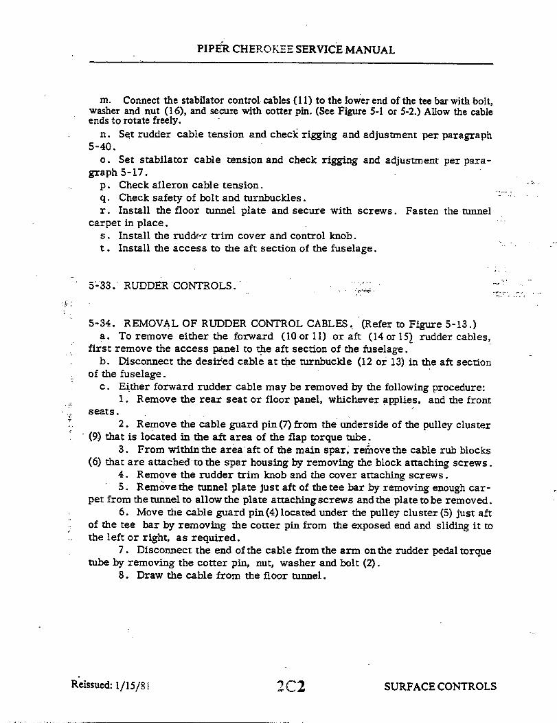
PIPER CHEROKEE SERVICE MANUAL
m. Connect the stabilator control cables (11) to the lower end of the tee bar with bolt,washer and nut (16), and secure with cotter pin. (See Figure 5-1 or 5-2.) Allow the cableends to rotate freely.
n. Set rudder cable tension and check rigging and adjustment per paragraph5-40.
o. Set stabilator cable tension and check rigging and adjustment per para-graph 5-17.
p. Check aileron cable tension.q. Check safety of bolt and turnbuckles.r. Install the floor tunnel plate and secure with screws. Fasten the tunnel
carpet in place.s. Install the rudder trim cover and control knob.t. Install the access to the aft section of the fuselage.
5-33. RUDDER CONTROLS.
5-34. REMOVAL OF RUDDER CONTROL CABLES. (Refer to Figure 5-13.)a. To remove either the forward (10 or 11) or aft (14 or 15) rudder cables,
first remove the access panel to the aft section of the fuselage.b. Disconnect the desired cable at the turnbuckle (12 or 13) in the aft section
of the fuselage.c. Either forward rudder cable may be removed by the following procedure:
1. Remove the rear seat or floor panel, whichever applies, and the frontseats.
2. Remove the cable guard pin(7) from the underside of the pulley cluster(9) that is located in the aft area of the flap torque tube.
3. From within the area aft of the main spar, remove the cable rub blocks(6) that are attached to the spar housing by removing the block attaching screws.
4. Remove the rudder trim knob and the cover attaching screws.5. Remove the tunnel plate just aft of the tee bar by removing enough car-
pet from the tunnel to allow the plate attaching screws and the plate to be removed.6. Move the cable guard pin (4) located under the pulley cluster (5) just aft
of the tee bar by removing the cotter pin from the exposed end and sliding it tothe left or right, as required.
7. Disconnect the end of the cable from the arm on the rudder pedal torquetube by removing the cotter pin, nut, washer and bolt (2).
8. Draw the cable from the floor tunnel.
SURFACE CONTROLS2C2Reissued: 1/15/81

PIPER CHEROKEE SERVICE MANUAL
d. The aft rudder control cables may be removed by the following procedure:1. Remove the tail cone fairing by removing its attaching screws.2. Disconnect the cable (14 or 15) from the rudder horn (17) by removing
cotter pin, nut, washer and bolt (16).6. 3. Draw the cable through the fuselage.
5-35. INSTALLATION OF RUDDER CONTROL CABLES. (Refer to Figure 5-13.)a. The forward rudder control cables may be installed by the following pro-
cedure:1. Draw the control cable through the floor tunnel.2. Connect the end of the cable to the arm on the rudder pedal torque tube
by installing bolt, washer, nut and cotter pin (2). Allow the cable end free torotate on the arm.
3. Connect the cable to the aft control cable at the turnbuckle (12 or 13) inthe aft section of the fuselage. If the aft control cables are not installed, installat this time per step b. Ascertain that each cable is in the groove of its pulley.
4. Move the cable guard (4) into position, that is located in the forwardarea of the tunnel, under the pulley cluster (5) and secure with cotter pin.
5. Within the area aft of the main spar, install the cable guard blocks (6)onto the spar housing and secure with screws.
6. Install the cable guard (7) under the pulley cluster (9) located just aftof the flap torque tube.
7. Set cable tension and check rigging and adjustment per paragraph 5-36.8. Install the forward tunnel plate aft of the tee bar and secure with screws.9. Put the floor carpet in place and secure.
10. (PA-28-235.) Place the fuel selector lever on the selector torque tubeand secure with pin and cotter pin.
11. Install the lower and upper selector covers and secure with screws.12. Install the rear seat or floor panel and install the seats.
b. The aft rudder control cables may be installed by the following procedure:1. Position the control cable in the fuselage.2. Connect the end of the cable (14 or 15) to the rudder horn (17) with bolt,
washer, nut and cotter pin (16). Allow the cable end free to rotate.3. Connect the other cable end to forward control cable (10 or 11) at the
turnbuckle (12 or 13) in the aft section of the fuselage.4. Set cable tension and check rigging and adjustmentper paragraph 5-36.5. Install tail cone fairing and secure with screws.
c. Install the access panel to the aft section of the fuselage.
SURFACE CONTROLS2C3Reissued: 1/15/81

PIPER CHEROKEE SERVICE MANUAL
1690
11
1. RUDDER & STEERING PEDAL ASSY.2. BOLT, WASHER, NUT & COTTER PIN3. BOLT, BUSHINGS, WASHER & NUT4. GUARD PIN, CABLE5. PULLEY CLUSTER6. RUB BLOCKS7. GUARD PIN, CABLE8. BOLT, BUSHINGS, WASHER & NUT9. PULLEY CLUSTER
10. CABLE, RIGHT FORWARD11. CABLE, LEFT FORWARD12. TURNBUCKLE, LEFT13. TURNBUCKLE, RIGHT14. CABLE, RIGHT AFT15. CABLE, LEFT AFT16. BOLT, BUSHING, WASHER & NUT17. HORN RUDDER
Figure 5-13. Rudder Controls
SURFACE CONTROLS2C4Reissued: 1/15/81

PIPER CHEROKEE SERVICE MANUAL
Refer to Figure 5-25 for tool fabrication
Figure 5-14. Rudder Rigging Tool Figure 5-15. Clamping Rudder Pedals
5-36. RIGGING AND ADJUSTMENT OF RUDDER CONTROLS.a. To check and set the correct degree of rudder travel, the following proce-
dure may be used:1. Check the rudder travel by swinging the rudder until it contacts its stop.
If the control cables are connected, use the rudder pedals to swing the rudder.2. With the rudder against its stop, place a rigging tool against the side of
the rudder and vertical stabilizer as shown in Figure 5-14. (Ascertain that thetool is not contacting any rivets.) If no gap exists between the rigging tool andthe surface of the rudder and vertical stabilizer, the rudder stop for one direc-tion of travel is correct as required in Table V-I. (This tool may be fabricatedfrom dimensions given in Figure 5-23.)
3. Swing the rudder in the other direction and check travel as directed instep 2.
4. Should the rudder travel be incorrect showing a gap between the tooland any part of the control surfaces, the tail cone fairing should be removed andthe stops reset to obtain correct rudder travel. (Refer to Figure 5-16.)
b. To set cable tension and alignment of the rudder, the following proceduremay be used:
1. Remove the access panel to the aft section of the fuselage.2. Ascertain that thenose gearsteeringhasbeen alignedand rudderpedals
set fore and aft according to Alignment of Nose Landing Gear, Section VII or VIIA.3. Clamp the rudder pedals to align in a lateral position as shown in Fig-
ure 5-15.4. Adjust the turnbuckles in the aft section of the fuselage to obtain proper
cable tension as given in Table V-I and to allow the rudder to align at neutral
SURFACE CONTROLS2C5Revised: 103 83

PIPER CHEROKEE SERVICE MANUAL
1. RUDDER TRAVEL ADJUSTMENT2. STABILATOR TRAVEL ADJUSTMENT
Figure 5-16. Rudder and Stabilator Travel Adjustments
position. Adjust cables evenly to prevent undue strain on aircraft components. Neutralposition can be determined by standing behind the airplane and sighting the rudder with thevertical stabilizer or the center of the trim screw.
5. Check safety of turnbuckles.c. On fixed landing gears check that when the rudder contacts its stop, the clearance
between the nose wheel stops and the nose wheel horn is between..06 and . 12 of an inch. A moreaccurate check can be made with the weight off the nose wheel. Adjust the stops according toAlignment of Nose Landing Gear. Section VII.
d. On 1974 models adjust the rudder pedal stops by pushing on the pilot's left rudderpedal until the rudder stop is contacted. Adjust the pedal stop (on the fire wall) to provide 0.060to 0. 120 of an inch clearance. Repeat the procedure with the copilot's right rudder pedal. Donot push rudder harder than necessary to avoid cable stretch.
e. Install the tail cone fairing and the access panel to the aft section of the fuselage.
Reissued: 1/15/81 2C6 SURFACE CONTROLS
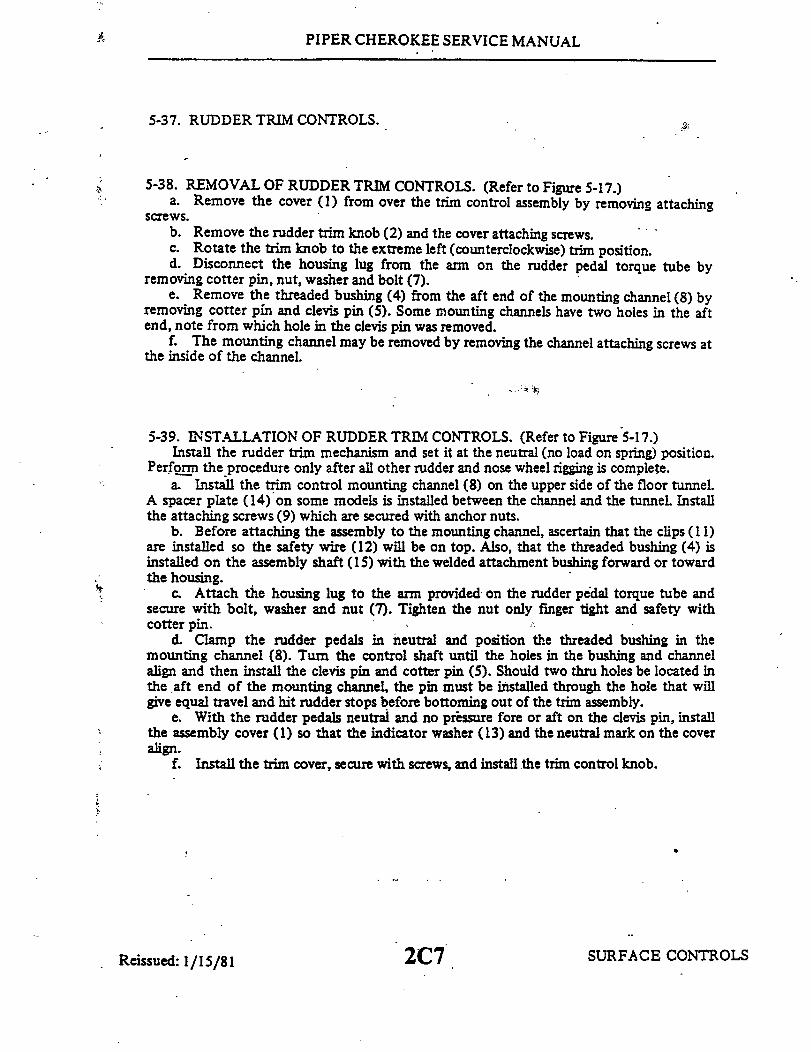
PIPER CHEROKEE SERVICE MANUAL
5-37. RUDDER TRIM CONTROLS.
5-38. REMOVAL OF RUDDER TRIM CONTROLS. (Refer to Figure 5-17.)a. Remove the cover (1) from over the trim control assembly by removing attaching
screws.b. Remove the rudder trim knob (2) and the cover attaching screws.c. Rotate the trim knob to the extreme left (counterclockwise) trim position.d. Disconnect the housing lug from the arm on the rudder pedal torque tube by
removing cotter pin, nut, washer and bolt (7).e. Remove the threaded bushing (4) from the aft end of the mounting channel (8) by
removing cotter pin and clevis pin (5). Some mounting channels have two holes in the aftend, note from which hole in the clevis pin was removed.
f. The mounting channel may be removed by removing the channel attaching screws atthe inside of the channel.
5-39. INSTALLATION OF RUDDER TRIM CONTROLS. (Refer to Figure 5-17.)Install the rudder trim mechanism and set it at the neutral (no load on spring) position.
Perform the procedure only after all other rudder and nose wheel rigging is complete.a. Install the trim control mounting channel (8) on the upper side of the floor tunnel.
A spacer plate (14) on some models is installed between the channel and the tunnel. Installthe attaching screws (9) which are secured with anchor nuts.
b. Before attaching the assembly to the mounting channel, ascertain that the clips (1 1)are installed so the safety wire (12) will be on top. Also, that the threaded bushing (4) isinstalled on the assembly shaft (15) with the welded attachment bushing forward or towardthe housing.
c. Attach the housing lug to the arm provided on the rudder pedal torque tube andsecure with bolt, washer and nut (7). Tighten the nut only finger tight and safety withcotter pin.
d. Clamp the rudder pedals in neutral and position the threaded bushing in themounting channel (8). Turn the control shaft until the holes in the bushing and channelalign and then install the clevis pin and cotter pin (5). Should two thru holes be located inthe aft end of the mounting channel, the pin must be installed through the hole that willgive equal travel and hit rudder stops before bottoming out of the trim assembly.
e. With the rudder pedals neutral and no pressure fore or aft on the clevis pin, installthe assembly cover (1) so that the indicator washer (13) and the neutral mark on the coveralign.
f. Install the trim cover, secure with screws, and install the trim control knob.
Reissued: 1/15/81 2C7 SURFACE CONTROLS

PIPER CHEROKEE SERVICE MANUAL
1660
.25 must be held when trim assemblyInstalled with rudder pedals In neutral position.
1. COVER2. RUDDER TRIM XNOS3. LOCK SCREW
. BUSHING5. CLEVIS PIN6. HOUSING, CONTROL SHAFT8. BOLT ASSEMBLY9. CHANNEL, MOUNTING9. SCREW
10. SCREW11. CLIPS12. SAFETY WIRE13. WASHER, INOICATOR14. SPACER PLATE
15. SHAFT, CONTROL
Figure 5-17. Rudder Trim Control
5-40. RIGGING AND ADJUSTMENT OF RUDDER TRIM CONTROLS. Perform theseprocedures only after all other rudder and nose wheel rigging is complete. No adjustmentsare necessary other than those required during installation of the assembly in the airplane asgiven in paragraph 5-39.
5-41. WING FLAP CONTROLS.
5-42. REMOVAL OF WING FLAP CONTROLS. (Refer to Figure 5-18.)a. The flap torque tube assembly may be removed by the following procedure:
1. Remove the access plate located between the underside of the aft section of eachwing and the fuselage by removing attaching screws.
2. Remove the two front seats and the bottom half of the rear seat or floor panel,whichever applies.
3. Disconnect the left and right flap control tubes (rods) (4) at the flaps byremoving the nuts, washers and bolts (2) or at the torque tube cranks (arms) (11) by
ed: 1/15/81 SURFACE CONTR(Reissued:

PIPER CHEROKEE SERVICE MANUAL
removing the bolts (12) and washers from the inner side of each crank. It will be necessayto remove bolt through a hole in the side skin of the fuselage located over the torque tubewith the flap handle moved to its 40 degree position.
4. With the flap handle (29), fully extend the flaps and disconnect the flap tensionspring (22) at the spar or the aft end of the control cable (23), as desired.
5. Grasp the flap handle, release the plunger (33) and allow the flap to return tothe retracted position. Use caution as forward pressure will be on the handle with thetension spring disconnected.
6. Disconnect the flap return spring (32) at the spar or return chain (30), asdesired.
7. Disconnect the control cable from the chain (20) by removing cotter pin, nutand clevis bolt (21).
8. Remove the tube support blocks (16 and 31) by removing the block attachingbolts (15).
9. Remove the nuts, washers and bolts (10) securing the right and left cranks ( 1)and stop fittings (13) on the torque tube.
10. From between each wing and the fuselage, remove the cranks from the torquetube.
11. Disconnect one bearing block (7) from its mounting brackets (6) by removingnuts, washers and bolts (5).
12. Slide the tube from the bearing block still attached to its brackets; raise the endand lift it from the floor opening.
b. The flap control cable (23) may be removed by the following procedure:1. If the front seats and bottom of the rear seat have not been removed, remove the
seats.2. Disconnect the flap tension spring (22) from the cable, if not previously
disconnected, by extending the flaps to relieve spring tension.3. Retract the flap. Use caution as forward pressure will be on the handle with the
spring disconnected.4. Disconnect the cable from the chain (20) by removing cotter pin, nut, clevis pin
and bushing (21).5. Remove the flap handle bracket and cover.6. Lift the aft section of the tunnel carpet far enough to remove the screws
securing the tunnel cover that is between the flap handle and the spar cover. Remove thecover.
7. Remove the cotter pin cable guard from the flap cable pulley (24) located insidethe floor tunnel just ahead of the spar housing.
8. Remove the cable rub blocks located in the floor opening on the aft side of thespar housing by removing the attaching screws.
9. Disconnect the cable turnbuckle (25) at the flap handle by removing cotter pin,nut and bolt (26). Check clevis bolt (26) for wear. Replace bolt if any wear is evident.
SURFACE CONTROLS2C9Reissued: 1/15/81

`PIPER CHEROKEE SERVICE MANUAL
1707
19-
1. BRACKET, ROD ATTACHENT2. BOLT, WASHER S NUT3. JAM NUT4. ROD, FLAP CONTROL
5. BOLT, BEARING BLOCK ATTACHMENT6. BRACKET, BEARING BLOCK7. BLOCK, BEARING
8. NUT, LOCK9. SCREW, FLAP ADJUSTMENT
10. BOLT, WASHER & NUT11. CRANK (ARM), TORQUE TUBE
12. BOLT, WASHER & BUSHING13. FITTING, TORQUE TUBE STOP14. TUBE, TORQUE
15. BOLT, WASHER & NUT16. BLOCK, BEARING17. SPROCKET, TENSION SPRING18. BOLT, WASHER & NUT19. BRACKET, BEARING BLOCK20. CHAIN, TENSION SPRING21. CLEVIS BOLT, BUSHING NUT &22. SPRING, TENSION
23.24.25.26.27.28.29.30.31.
COTTER PIN 32.33.
CABLE, FLAP CONTROLPULLEYTURNBUCKLECLEVIS BOLT, NUT & COTTER PINBOLT, BUSHING, WASHER & NUTBRACKET, FLAP HANDLEHANDLE, FLAPCHAIN, RETURN SPRINGBLOCK, BEARINGSPRING, RETURNBUTTON, FLAP RELEASE
Reissued: 1/15/81
Figure 5-18. Flap Controls
2C10 SURFACE CONTROLS

PIPER CHEROKEE SERVICE MANUAL
c. Remove the flap handle (29)and bracket (28)by disconnecting the cable turn-buckle from the handle and removing the bolts securing the bracket to thefloortunnel.
5-43. INSTALLATION OF WING FLAP CONTROLS. (Refer to Figure 5-18.)a. The flap torque tube assembly may be installed by the following procedure:
1. Install the chain sprocket (17) with chain (20 and 30) on the torque tube(14) and secure with bolts, washers and nuts (18).
2. Slide the tube stop fittings (13) on their respective ends of the torquetube.
3. Ascertain that one bearing block fitting (7) is installed between its at-tachment brackets (6).
4. Slide the other bearing block over its respective end of the torque tube.5. Position the torque tube by placing the end with the bearing block on it
between the mounting bracket and sliding the other end into the previously attach-ed bearing block.
6. Position the remaining bearing block and secure with bolts, washersand nuts (5).
7. Push the torque tube cranks (arms) (11) on each end of the torque tubeand slide the stop fitting (13) in place. Align the bolt hole of the crank and stopfitting with the holes in the torque tube and install bolts. The holes in the stopfitting are longated to allow the stop fitting to be pushed against the bearing blocks(7) thus allowing no side play of the assembly. Tighten the bolt assemblies (10)on the stop fittings.
8. Install the tube support blocks (16 and 31) on their support brackets (19)and secure with bolts (15).
9. Connect. the flap return spring (32) to the return chain (30) and/or atthe spar housing.
10. Connect the control cable end to the tension chain (20) and secure withbushing, clevis bolt, nut and cotter pin.
11. Pull the flap handle full back and connect the tension spring (22). Re-lease the flap handle to the forward position.
12. Connect the flap control tube (4) to the flap and/or torque tube crank (11)and secure. The bolt (12) and bushing that connects the control tube to the crankis installed through a hole in the side of the fuselage located over the torque tube.
b. To install the flap handle (29) with bracket (28), place the assembly on thefloor tunnel and secure with bolts.
c. The flap control cable (23) may be installed by the following procedure:1. Attach the cable and turnbuckle (25) to the flap handle arm and secure
with clevis bolt, nut and cotter pin (26). Ascertain that the turnbuckle endis freeto rotate on the arm.
Reissued: 1/15/81 SURFACE CONTROLS2Cll

PIPER CHEROKEE SERVICE MANUAL
Figure 5-19. Flap Step Adjustment
2. Route the cable through the tunnel and spar housing.3. Install the cable rub blocks on the aft side of the spar housing and
secure with screws.4. Install cotter pin cable guard over pulley (24) located just ahead of the
spar housing in the floor tunnel.5. Attach the cable end to the tension chain(20) and secure with bushings,
clevis bolt, nut and cotter pin. If the chain is not installed because of the torquetube assembly being removed, install the assembly as given in step c.
6. Pull the flap handle (29) full back and connect the tension spring (22) tothe cable end.
d. Install the tunnel cover and secure with screws. Also, the tunnel carpetand bracket cover.
e. Install and secure the seats.
5-44. RIGGING AND ADJUSTMENT OF WING FLAPS.a. Place the flap handle in the full forward position.b. If not previously removed, remove the bottom half of the rear seat.c. To adjust the flap up stop and step lock, loosen the jam nut of the right
torque tube stop screw, located in the floor opening along the outer end of theflap torque tube, and turn the stop screw to obtain approximately .60 of an inchbetween the stop fitting and the bearing block as measured along the top side ofthe screw. (Refer to Figure 5-19.) It may be necessary to loosen the adjust-ment screw of the left stop.
SURFACE CONTROLSRevised: 4 23 84 2C1 2
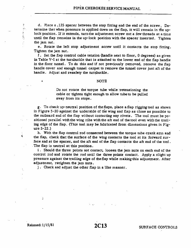
PIPER CHEROKEE SERVICE MANUAL
d. Place a .125 spacer between the stop fitting and the end of the screw. De-termine that when pressure is applied down on the flap, it will remain in the up-lock position. If it extends, turnthe adjustment screw out a few threads at a timeuntil the flap remains in the up-lock position with the spacer inserted. Tightenthe jam nut.
e. Rotate the left stop adjustment screw until it contacts the stop fitting.Tighten the jam nut.
f. Set the flap control cable tension (handle next to floor, 0 degrees) as givenin Table V-I at the turnbuckle that is attached to the lower end of the flap handlein the floor tunnel. To do this and if not previously removed, remove the flaphandle cover and enough tunnel carpet to remove the tunnel cover just aft of thehandle. Adjust and resafety the turnbuckle.
NOTE
Do not rotate the torque tube while."retensioning thecable or tighten tight enough to allow tube to be pulledaway from its stops.
g. To check up-neutral position of the flaps, place a flap rigging tool as shownin Figure 5-20 against the underside of the wing and flap as close as possible tothe outboard end of the flap without contacting any rivets. The tool must be po-sitioned parallel with the wing ribs with the aft end of the tool even with the trail-ing edge of the flap. (This tool may be fabricated from dimensions given in Fig-ure 5-22.)
h. With the flap control rod connected between the torque tube crank arm andthe flap, check that the surface of the wing contacts the tool at its forward sur-face and at the spacer, and the aft end of the flap contacts the aft end of the tool.The flap is neutral at this position.
i. Should the three points not contact, loosen the jam nuts on each end of thecontrol rod and rotate the rod until the three points contact. Apply a slight uppressure against the trailing edge of the flap while making this adjustment. Afteradjustment, retighten the jam nuts.
j . Check and adjust the other flap in a like manner.
Reissued: 1/15/81 SURFACE CONTROLS2C13
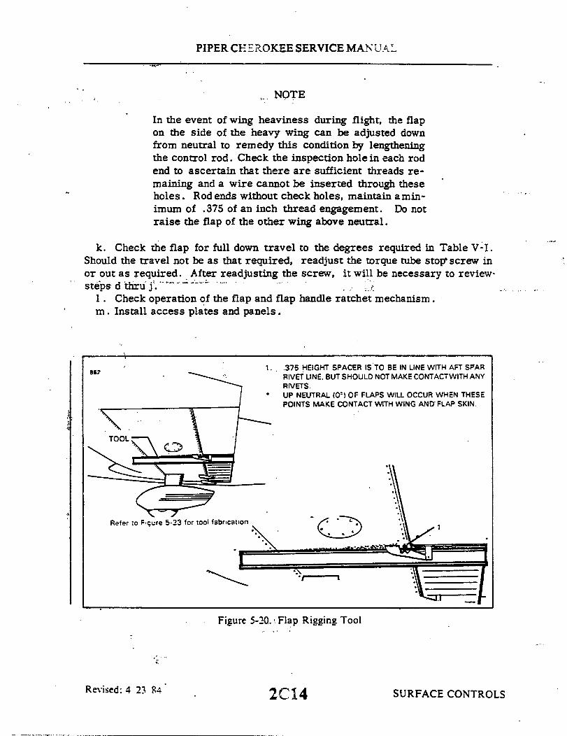
PIPER CHEROKEE SERVICE MANUAL
NOTE
In the event of wing heaviness during flight, the flapon the side of the heavy wing can be adjusted downfrom neutral to remedy this condition by lengtheningthe control rod. Check the inspection hole in each rodend to ascertain that there are sufficient threads re-maining and a wire cannot be inserted through theseholes. Rod ends without check holes, maintain a min-imum of .375 of an inch thread engagement. Do notraise the flap of the other wing above neutral.
k. Check the flap for full down travel to the degrees required in Table V-I.Should the travel not be as that required, readjust the torque tube stop screw inor out as required. After readjusting the screw, it will be necessary to review-steps d thru j.
1. Check operation of the flap and flap handle ratchet mechanism.m. Install access plates and panels.
857
.TOOL:
1. 375 HEIGHT SPACER IS TO BE IN LINE WITH AFT SPARRIVET LINE. BUT SHOULD NOT MAKE CONTACTWITH ANYRIVETS.UP NEUTRAL (0) OF FLAPS WILL OCCUR WHEN THESEPOINTS MAKE CONTACT WITH WING AND FLAP SKIN.
Refer to Figure 5-23 for tool fabrication
Figure 5-20. Flap Rigging Tool
2C14Revised: 4 23 84 SURFACE CONTROLS
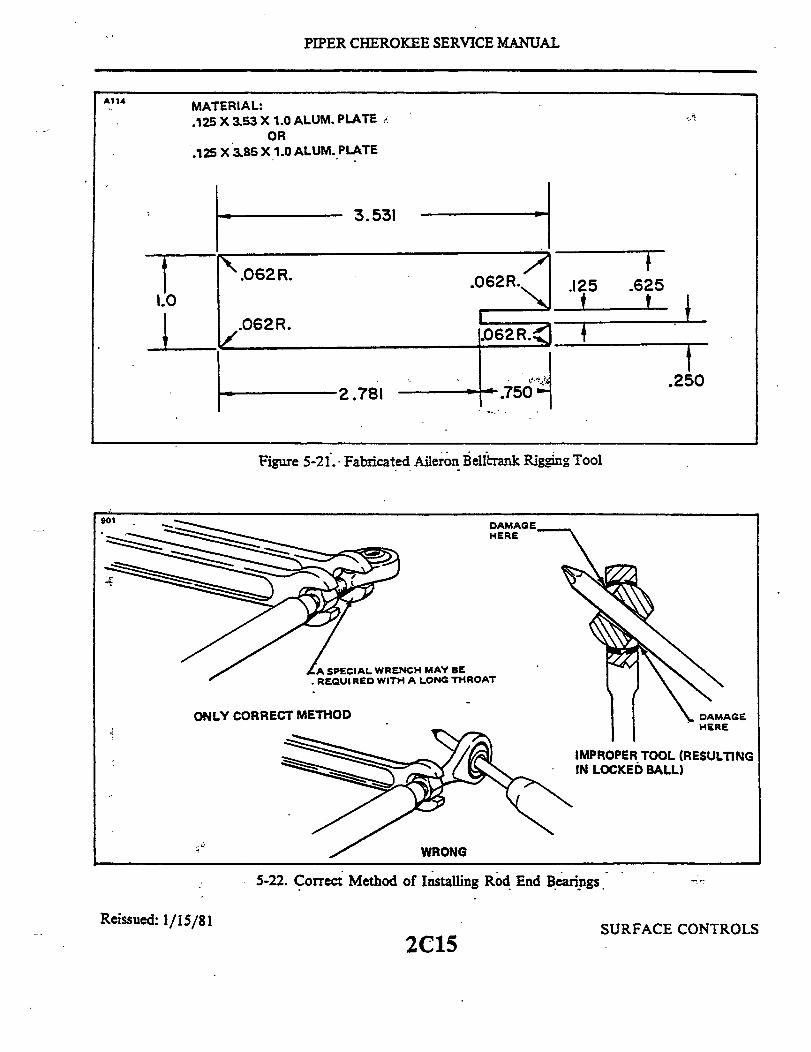
PIPER CHEROKEE SERVICE MANUAL
MATERIAL:.125 X 3.53 X 1.0 ALUM. PLATE
OR.125 X 3.85 X 1.0 ALUM. PLATE
3.531
.062R.
.062R.
.125
2.781
.625
2
Figure 5-21.- Fabricated Aileron Bellcrank Rigging Tool
901
HERE
ONLY CORRECT METHODHERE
IMPROPER TOOL (RESULTINGIN LOCKED BALL)
5-22. Correct Method of Installing Rod End Bearings
Reissued: 1/15/81
2C15SURFACE CONTROLS
A114

PIPER CHEROKEE SERVICE MANUAL
A115
SEE NOTE 1
.375
.187
13.250
4.0
31.50
SEE NOTE 2
NOTES1. DRILL AND TAP TO 10-32NF. AN-3 BOLT, JAM NUT AND
INTERNAL STAR WASHER. MAY BE USED FOR SPACEROR AN-3 BOLT WITH HEAD FILED TO REQUIRED LENGTH.
2. SPAR STOCK MAY BE USED IN PLACE OF ALUM. BARSTOCK.
.375
.750
MATERIAL:: .750 X 31.50 X 4.00 ALUM. BAR OR
.750 X 31.5 X .750 ALUM. BAR (MIN.)
Revised: 4'23 84
Figure 5-23. Fabricated Aileron and Flap Rigging Tool
2C16 SURFACE CONTROLS
I

PIPER CHEROKEE SERVICE MANUAL
932
MATERIAL:1.0 X 23.19 X 3.82 ALUM. BAR
SURFACE PARALLEL TO BASE LINE
STABILATOR CONTOUR
.803, 1.121 1.39, 1.60 . / 25 SET BACK
2224.03
BASE LINE
20.00
18.03 15.03
Figure 5-24. Fabricated Stabilator Rigging Tool
2C17
SE LINE
1.10
.94
1.53
1.00
EDGE
Reissued: 1/15/81 SURFACE CONTROLS
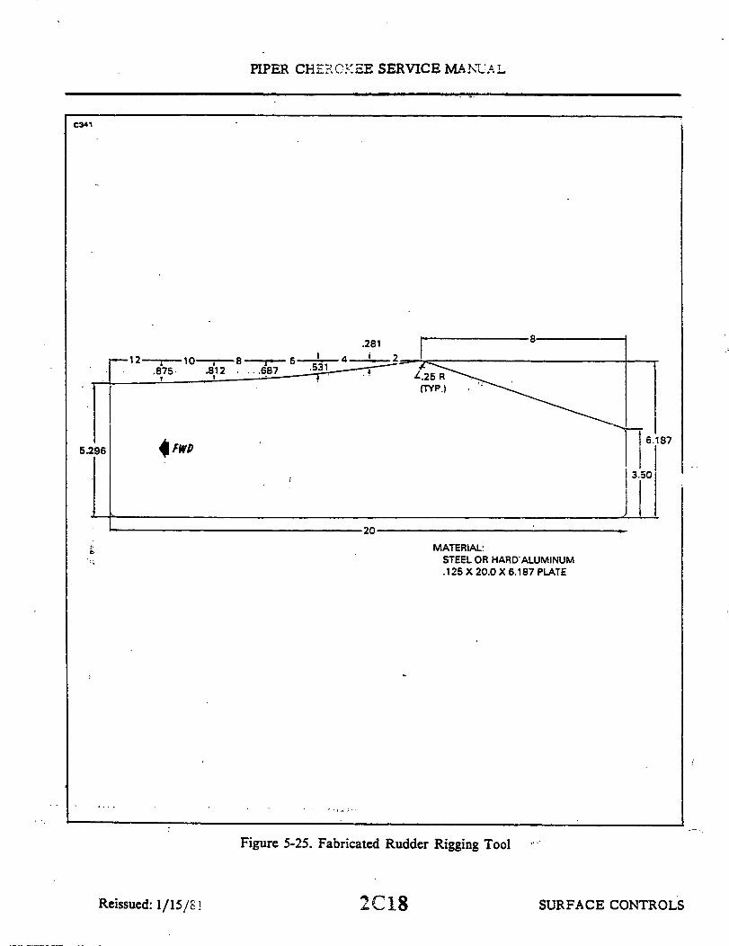
PIPER CHEROKEE SERVICE MANUA L
C341
.281 8
20
MATERIAL:STEEL OR HARD ALUMINUM.125 X 20.0 X 6.187 PLATE
Figure 5-25. Fabricated Rudder Rigging Tool
2C18
5.2
I
SURFACE CONTROLSReissued: 1/15/81
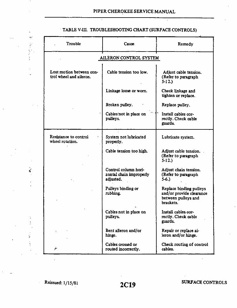
PIPER CHEROKEE SERVICE MANUAL
TABLE V-III. TROUBLESHOOTING CHART (SURFACE CONTROLS)
Trouble Cause Remedy
AILERON CONTROL SYSTEM
Lost motion between con-trol wheel and aileron.
Cable tension too low. Adjust cable tension.(Refer to paragraph5-12.)
Linkage loose or worn.
Broken pulley.
Cables'not in place onpulleys.
Check linkage andtighten or replace.
Replace pulley.
Install cables cor-rectly. Check cableguards.
Resistance to controlwheel rotation.
System not lubricatedproperly.
Lubricate system.
Cable tension too high.
Control column hori-zontal chain improperlyadjusted.
Pulleys binding orrubbing.
Cables not in place onpulleys.
Bent aileron and/orhinge.
Cables crossed orrouted incorrectly.
Reissued: 1/15/81 2C19
Adjust cable tension.(Refer to paragraph5-12.)
Adjust chain tension.(Refer to paragraph5-6.)
Replace binding pulleysand/or provide clearancebetween pulleys andbrackets.
Install cables cor-rectly. Check cableguards.
Repair or replace ai-leron and/or hinge.
Check routing of controlcables.
SURFACE CONTROLS

PIPER CHEROKEE SERVICE MANUAL
TABLE V-III. TROUBLESHOOTING CHART (SURFACE CONTROLS) (cont.)
Trouble Cause Remedy
AILERON CONTROL SYSTEM (cont.)
Control wheels notsynchronized.
Control wheels not hori-zontal when aileronsare neutral.
Incorrect ailerontravel.
Incorrect controlcolumn rigging.
Incorrect rigging ofaileron system.
Aileron control rodsnot adjusted properly.
Rig in accordance withparagraph 5-6.
Rig in accordance withparagraph 5-12.
Adjust in accordancewith paragraph 5-12.
Aileron bellcrank stopsnot adjusted properly.
Adjust in accordancewith paragraph 5-12.
Correct aileron travelcannot be obtained byadjusting bellcrankstops.
Control wheel stopsbefore controlsurfaces reach fulltravel.
Incorrect rigging ofaileron cables, controlwheel and control rod.
Incorrect riggingbetween control wheeland control cables.
Rig in accordance withparagraph 5-12.
Rig in accordance withparagraph 5-12.
STRUCTURES2C20Reissued: 1/15/81 1

PIPER CHEROKEE SERVICE MANUAL
TABLE V-III. TROUBLESHOOTING CHART (SURFACE CONTROLS) (cont.)
Trouble Cause Remedy
STABILATOR CONTROL SYSTEM
Lost motion between Cable tension too low. Adjust cable tensionntrol wheel and stabi- per paragraph 5-17.or.
Linkage loose or worn. Check linkage andtighten or replace.
Broken pulley. Replace pulley.
Cables not in place Install cables cor-on pulleys. rectly.
Resistance to stabilator System not lubricated Lubricate system.ntrol movement. properly.
Cable tension too high. Adjust cable tensionper paragraph 5-17.
Binding control column. Adjust and lubricateper paragraph 5-6.
Pulleys binding or Replace binding pulleyrubbing. and/or provide clearane
Cables not in place onpulleys.
Cables crossed or -routed incorrectly.
Bent stabilator hinge.
Stabilator stopsincorrectly adjusted.
Incorrect stabilatortravel.
between pulleys andbrackets.
Install cables cor-rectly.
Check routing of controlcables.
Repair or replacestabilator hinge.
Adjust stop screws perparagraph 5-17.
SURFACE CONTROLS
Lost
lat
Re
2C21Reissued: 1/15/81
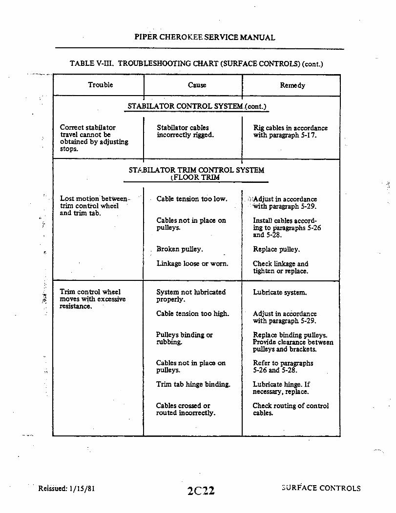
PIPER CHEROKEE SERVICE MANUAL
TABLE V-III. TROUBLESHOOTING CHART (SURFACE CONTROLS) (cont.)
Trouble Cause Remedy
STABILATOR CONTROL SYSTEM-(cont.)
Correct stabilatortravel cannot beobtained by adjustingstops.
Stabilator cablesincorrectly rigged.
Rig cables in accordancewith paragraph 5-17.
STABILATOR TRIM CONTROL SYSTEM(FLOOR TRIM
Lost motion between -trim control wheeland trim tab.
Cable tension too low.
Cables not in place onpulleys.
Adjust in accordancewith paragraph 5-29.
Install cables accord-ing to paragraphs 5-26and 5-28.
Broken pulley.
Linkage loose or worn.
Replace pulley.
Check linkage andtighten or replace.
Trim control wheelmoves with excessiveresistance.
System not lubricatedproperly.
Cable tension too high.
Lubricate system.
Adjust in accordancewith paragraph 5-29.
Pulleys binding orrubbing.
Cables not in place onpulleys.
Trim tab hinge binding.
Cables crossed orrouted incorrectly.
Replace binding pulleys.Provide clearance betweenpulleys and brackets.
Refer to paragraphs5-26 and 5-28.
Lubricate hinge. Ifnecessary, replace.
Check routing of controlcables.
SURFACE CONTROLS2C22
...
Reissued: 1/15/81
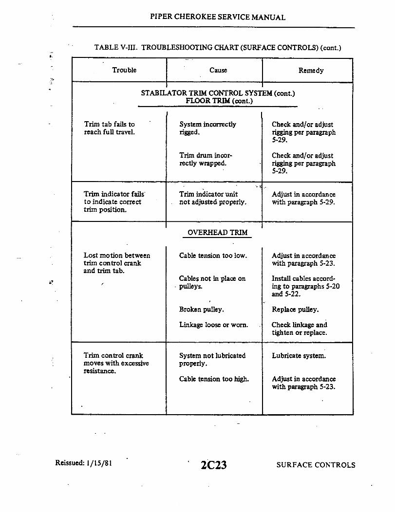
PIPER CHEROKEE SERVICE MANUAL
TABLE V-III. TROUBLESHOOTING CHART (SURFACE CONTROLS) (cont.)
Trouble Cause Remedy
STABILATOR TRIM CONTROL SYSTEM (cont.)FLOOR TRIM (cont.)
Trim tab fails toreach full travel.
System incorrectlyrigged.
Check and/or adjustrigging per paragraph5-29.
Trim drum incor-rectly wrapped.
Check and/or adjustrigging per paragraph5-29.
Trim indicator failsto indicate correcttrim position.
Trim indicator unitnot adjusted properly.
Adjust in accordancewith paragraph 5-29.
OVERHEAD TRIM
Lost motion betweentrim control crankand trim tab.
Cable tension too low.
Cables not in place onpulleys.
Adjust in accordancewith paragraph 5-23.
Install cables accord-ing to paragraphs 5-20and 5-22.
Broken pulley.
Linkage loose or worn.
Replace pulley.
Check linkage andtighten or replace.
Trim control crankmoves with excessiveresistance.
System not lubricatedproperly.
Cable tension too high.
Lubricate system.
Adjust in accordancewith paragraph 5-23.
SURFACE CONTROLS2C23Reissued: 1/15/81

PIPER CHEROKEE SERVICE MANUAL
TABLE V-III. TROUBLESHOOTING CHART (SURFACE CONTROLS) (cont.)
Trouble Cause Remedy
STABILATOR TRIM CONTROL SYSTEM (cont.)OVERHEAD TRIM (cont)
Trim control crankmoves with excessiveresistance. (cont.)
Pulleys binding orrubbing.
Replace binding pulleys.Provide clearance betweenpulleys and brackets.
Cables not in place onpulleys.
. Trim tab hinge binding.
Cables crossed orrouted incorrectly.
Refer to paragraphs5-20 and 5-22.
Lubricate hinge. Ifnecessary, replace.
Check routing of controlcables.
Trim tab fails toreach full travel.
System incorrectlyrigged.
Check and/or adjustrigging per paragraph5-23.
Trim drum incor-rectly wrapped.
Check and/or adjustrigging per paragraph5-23.
Trim indicator failsto indicate correcttrim position.
Trim indicator unitnot adjusted properly.
Adjust in accordancewith paragraph 5-23.
SURFACE CONTROLS2C24Reissued: 1/15/81

PIPER CHEROKEE SERVICE MANUAL
TABLE V-III. TROUBLESHOOTING CHART (SURFACE CONTROLS) (cont.)
Trouble Cause Remedy
RUDDER CONTROL SYSTEM
Lost motion betweenrudder pedals andrudder.
Cable tension too low.
Linkage loose or worn.
Adjust cable tensionper paragraph 5-36.
Check linkage andtighten or replace.
Broken pulley. Replace pulley.
Bolts attaching rudder Tighten bellcrank bolts.to bellcrank are loose.
Excessive resistanceto rudder pedalmovement.
System not lubricatedproperly.
Rudder pedal torquetube bearing in needof lubrication.
Lubricate system.
Lubricate torque tubebearings.
Cable tension too high.
Pulleys binding orrubbing.
Cables not in place onpulleys.
Cables crossed orrouted incorrectly.
Adjust cable tensionper paragraph 5-36.
Replace binding pulleysand/or provide clearancebetween pulleys andbrackets.
Install cables cor-rectly. Check cableguards.
Check routing of controlcables.
Rudder pedals notneutral when rudderis streamlined.
Rudder cablesincorrectly rigged.
Rig in accordance withparagraph 5-36.
Reissued: 1/15/81SURFACE CONTROLS2D1

PIPER CHEROKEE SERVICE MANUAL
TABLE V-III. TROUBLESHOOTING CHART (SURFACE CONTROLS) (cont.)
Trouble Cause Remedy
RUDDER CONTROL SYSTEM (cont.)
Incorrect ruddertravel.
Rudder bellcrank stopincorrectly adjusted.
Rig in accordance withparagraph 5-36.
Nose wheel contactsstops before rudder.
Rig in accordance withparagraph 3-36.
RUDDER TRIM CONTROL SYSTEM
Trim control knobmoves with excessiveresistance.
System not lubricatedproperly.
Lubricate system.
FLAP CONTROL SYSTEM
Flaps fail to extendor retract.
Flaps not synchro-nized or fail tomove evenly whenretracted.
Control cable brokenor disconnected.
Incorrect riggingof system.
Replace or reconnectcontrol cable. (Referto paragraph 5-43.)
Adjust flaps per in-structions in paragraph5-44.
SURFACE CONTROLS2D2Reissued: 1/15/81
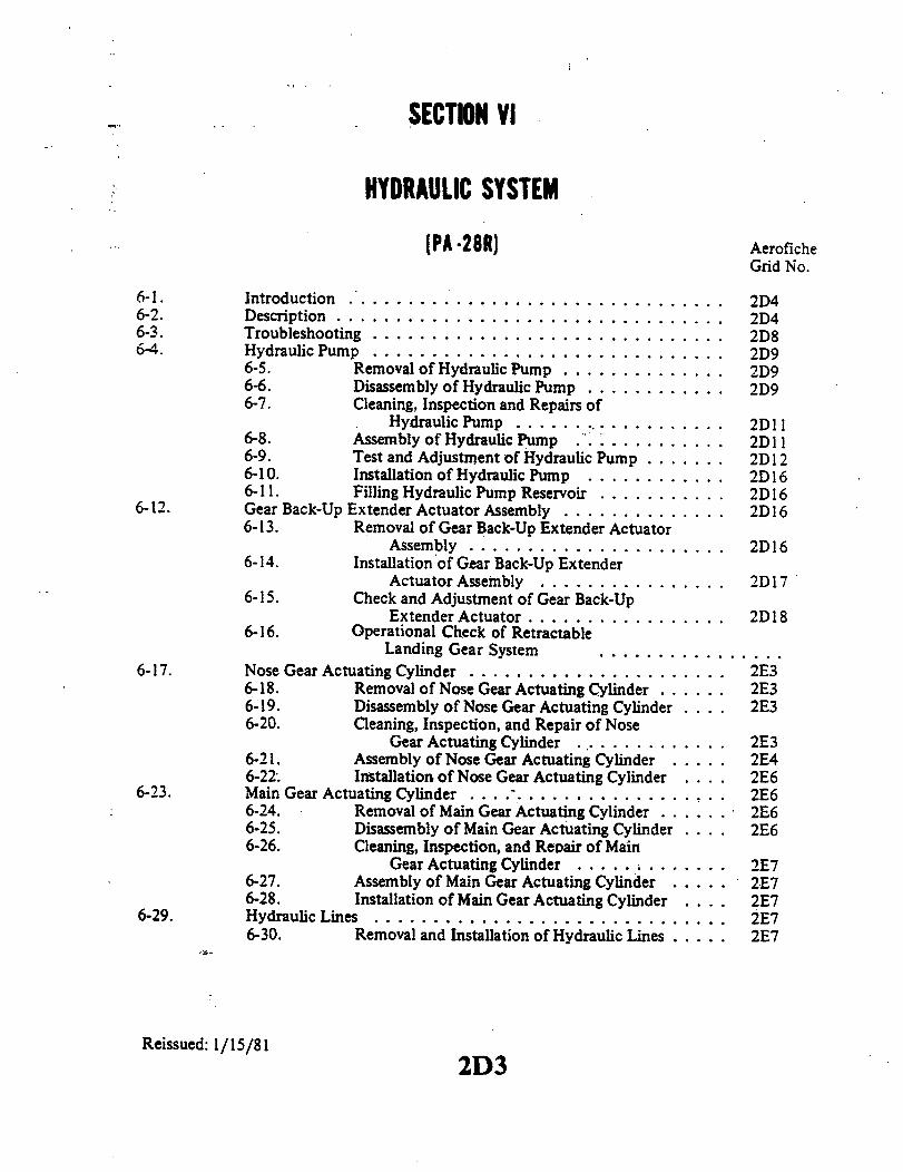
SECTION VI
HYDRAULIC SYSTEM
(PA -28R) AeroficheGrid No.
6-1. Introduction ................................ 2D46-2. Description ................................. 2D46-3. Troubleshooting ............................. 2D86-4. Hydraulic Pump ............................. 2D9
6-5. Removal of Hydraulic Pump .............. 2D96-6. Disassembly of Hydraulic Pump ............ 2D96-7. Cleaning, Inspection and Repairs of
Hydraulic Pump.................. 2D116-8. Assembly of Hydraulic Pump ... .......... 2D 116-9. Test and Adjustment of Hydraulic Pump ....... 2D126-10. Installation of Hydraulic Pump ............ 2D166-11. Filling Hydraulic Pump Reservoir ........... 2D16
6-12. Gear Back-Up Extender Actuator Assembly .............. 2D166-13. Removal of Gear Back-Up Extender Actuator
Assembly ...................... 2D166-14. Installation of Gear Back-Up Extender
Actuator Assembly ................ 2D176-15. Check and Adjustment of Gear Back-Up
Extender Actuator................. 2D186-16. Operational Check of Retractable
Landing Gear System ................6-17. Nose Gear Actuating Cylinder . . . .................. 2E3
6-18. Removal of Nose Gear Actuating Cylinder ...... 2E36-19. Disassembly of Nose Gear Actuating Cylinder .... 2E36-20. Cleaning, Inspection, and Repair of Nose
Gear Actuating Cylinder ... . .......... 2E36-21. Assembly of Nose Gear Actuating Cylinder ..... 2E46-22. Installation of Nose Gear Actuating Cylinder ... 2E6
6-23. Main Gear Actuating Cylinder ..................... 2E66-24. Removal of Main Gear Actuating Cylinder ...... 2E66-25. Disassembly of Main Gear Actuating Cylinder .... 2E66-26. Cleaning, Inspection, and Repair of Main
Gear Actuating Cylinder ............ 2E76-27. Assembly of Main Gear Actuating Cylinder ..... 2E76-28. Installation of Main Gear Actuating Cylinder .... 2E7
6-29. Hydraulic Lines .............................. 2E76-30. Removal and Installation of Hydraulic Lines ..... 2E7
Reissued: 1/15/812D3

PIPER CHEROKEE SERVICE MANUAL
SECTION VI
HYDRAULIC SYSTEMPA-28R
6-1. INTRODUCTION.. The PA-28R hydraulic system components coveredin this section consist of the combination hydraulic pump and reservoir, gearback-up extender actuator assembly, actuating cylinders and hydraulic lines.The brake system, although hydraulically operated, is not included inthis sectionas it has its own hydraulic system independent of the gear retraction system.The brake system along with the landing gearand components is covered in Sec-tion VIIA.
This section provides -instructions for remedying difficulties which mayarise in the operation of the hydraulic system. The instructions are organizedso that the mechanic can refer to: Description of the System, for a basic under-standing of the system; Troubleshooting, for a methodical approach in locatingdifficulty; Corrective Maintenance, for the removal, repair and installation ofcomponents; and Adjustments and Checks, for the operation of the repaired sys-tem.
CAUTION
Prior to starting anyinvestigation of the hydraulic sys -tem, place the airplane on jacks. (Refer to Jacking,Section II.)
6-2. DESCRIPTION. Hydraulic fluid is supplied to the landing gear actuating cylinders byan electrically powered, reversible hydraulic pump located aft of the baggage compartmentat right side of station 156.00. A reservoir is also an integral part of the pump. The pump iscontrolled by a selector handle on the instrument panel to the left of the control quadrant.As the handle is selected to either the up or down position, the pump directs fluid through asingle line to a manifold and from that manifold to each individual actuating cylinder. Asfluid pressure increases at one side of a cylinder piston, fluid at the other side is directedback through another manifold to the pump. The two manifolds and their connecting linesserve either as pressure or return passages depending on the rotation of pump to retract orextend the gear.
On the manifold through which pressure fluid passed during gear retraction
HYDRAULIC SYSTEM2D4Reissued: 1/15/81

PIPER CHEROKEE SERVICE MANUAL
HYDRAULIC PUMP RESERVOIRFILTER
THEWRMAL RELIEF
SHUTTLESWITCH
MANUAL FREE FALLEMERGENCY EXTEND
CYLINDER
GEAR DOWN SNUBBERORIFICE
AUTORMATIC GEAR DOWN &EMERGENCY FREE FALLGEAR VALVE. HYDAULIC CYLINDER
ON FUSELAGE SIDE
SENSING CHAMBER
I
Reissued: 1/15/81
Figure 6-1. Schematic Diagram of Hydraulic System
2D5 HYDRAULIC SYSTEM
LOW PRESSURE

PIPER CHEROKEE SERVICE MANUAL
1. PUMP/RESERVOIR2. ACTUATING CYLINDER, RIGHT3. MANIFOLD, GEAR DOWN4. MANIFOLD, GEAR UP
. PRESSURE SWITCH6. GEAR BACK-UP EXTENDER ACTUATOR7. MAST, ACK-UP EXTENDER
8. ACTUATING CYLINDER, LEFT9. LEVER, EMERGENCY EXTENDER
10. ACTUATING CYLINDER NOSE11. FITTING, RESTRICTOR
Figure 6-2. Hydraulic System Installation
HYDRAULIC SYSTEM2D6
1817
Reissued: 1/15/81
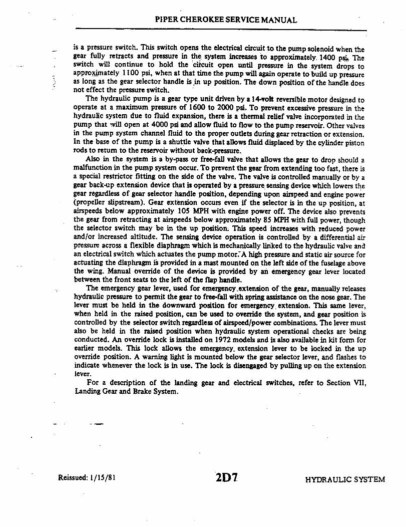
PIPER CHEROKEE SERVICE MANUAL
is a pressure switch. This switch opens the electrical circuit to the pump solenoid when thegear fully retracts and pressure in the system increases to approximately 1400 psi Theswitch will continue to hold the circuit open until pressure in the system drops toapproximately 1100 psi, when at that time the pump will again operate to build up pressureas long as the gear selector handle is in up position. The down position of the handle doesnot effect the pressure switch.
The hydraulic pump is a gear type unit driven by a 14-volt reversible motor designed tooperate at a maximum pressure of 1600 to 2000 psi. To prevent excessive pressure in thehydraulic system due to fluid expansion, there is a thermal relief valve incorporated in thepump that vill open at 4000 psi and allow fluid to flow to the pump reservoir. Other valvesin the pump system channel fluid to the proper outlets during gear retraction or extension.In the base of the pump is a shuttle valve that allows fluid displaced by the cylinder pistonrods to return to the reservoir without back-pressure.
Also in the system is a by-pass or free-fall valve that allows the gear to drop should amalfunction in the pump system occur. To prevent the gear from extending too fast, there isa special restrictor fitting on the side of the valve. The valve is controlled manually or by agear back-up extension device that is operated by a pressure sensing device which lowers thegear regardless of gear selector handle position, depending upon airspeed and engine power(propeller slipstream). Gear extension occurs even if the selector is in the up position, atairspeeds below approximately 105 MPH with engine power off. The device also preventsthe gear from retracting at airspeeds below approximately 85 MPH with full power, thoughthe selector switch may be in the up position. This speed increases with reduced powerand/or increased altitude. The sensing device operation is controlled by a differential airpressure across a flexible diaphragm which is mechanically linked to the hydraulic valve andan electrical switch which actuates the pump motor.A high pressure and static air source foractuating the diaphragm is provided in a mast mounted on the left side of the fuselage abovethe wing. Manual override of the device is provided by an emergency gear lever locatedbetween the front seats to the left of the flap handle.
The emergency gear lever, used for emergency extension of the gear, manually releaseshydraulic pressure to permit the gear to free-fall with spring assistance on the nose gear. Thelever must be held in the downward position for emergency. extension. This same lever,when held in the raised position, can be used to override the system, and gear position iscontrolled by the selector switch regardless of airspeed/power combinations. The lever mustalso be held in the raised position when hydraulic system operational checks are beingconducted. An override lock is installed on 1972 models and is also available in kit form forearlier models. This lock allows the emergency extension lever to be locked in the upoverride position. A warning light is mounted below the gear selector lever, and flashes toindicate whenever the lock is in use. The lock is disengaged by pulling up on the extensionlever.
For a description of the landing gear and electrical switches, refer to Section VII,Landing Gear and Brake System.
HYDRAULIC SYSTEMReissued: 1/15/81 2D7

PIPER CHEROKEE SERVICE MANUAL
TABLE VI-I. LEADING PARTICULARS, HYDRAULIC SYSTEM
Hydraulic PumpHigh Pressure 1600 to 2000 psiLow Pressure 650 ± 150 psiFlow Rate @ 1000 psi 45 cu. in. per min.High Pressure Control 1600 to 2000 psiThermal Relief 4000 psiHydraulic Fluid MIL-H-5606
Pressure SwitchOpen (OFF) Pressure 1100 ± 100 psiClose (ON) Pressure 400 ± 200 psi below opening pressure
6-3. TROUBLESHOOTING Malfunctions
6-3. TROUBLESHOOTING. Malfunctions of the hydraulic systemwill result infailure of the landing gear to operate properly. When trouble arises, jack up theairplane (Refer to Jacking, Section II.) and then proceed to determine the extentof the trouble. Generally, hydraulic system troubles fall into two types, troublesinvolving the hydraulic supplying system and troubles in the landing gear hydrau -lic system. Table VI-III at the back of this section, lists the troubles which maybe encountered and their probable cause, and suggests a remedy for the troubleinvolved. A hydraulic system. operational check may be conducted using Figures6-1 or .6-2. When the trouble has been recognized, the first step in trouble-shooting is isolating the cause. Hydraulic system troubles are not always trace-able to one cause. It is possible that a malfunction may be the result of morethan one difficulty within the system. Starting first with the most obvious andmost probable reasons for the trouble, check each possibility in turn and, byprocess of elimination, isolate the troubles.
NOTE
If it is found that the hydraulic pump is at fault and re-quires disassembly, itis recommended that it be over-hauled by a recommended overhaul shop. However, ifthis cannot be achieved, minor repairs of the pumpsuch as replacement of gaskets and motor components,and pressure checks with adjustments maybe accom-plished in accordance with instructions given in para-graphs 6-6 thru 6-9.
Reissued: 1/15/81 2D8 HYDRAULIC SYSTEM

PIPER CHEROKEE SERVICE MANUAL
6-4. HYDRAULIC PUMP.
6-5. REMOVAL OF HYDRAULIC PUMP. The hydraulic pump with reservoir incor-porated is located in the aft section of the fuselage. Access to the pump is through the accesspanel in the aft wall of the baggage compartment.
a. Disconnect the pump electrical leads from the pump solenoid relays and the groundwire from the battery shelf.
b. Disconnect the hydraulic lines from the pump. Cap the line ends to prevent contamina-tion.
c. Remove the pump by removing the pump attaching bolts.
6-6. DISASSEMBLY OF HYDRAULIC PUMP. (RefertoFigure6-3.) Afterthehydraulicpump has been removed from the airplane, cap or plug all ports and clean the exterior of thepump with a dry type solvent to remove accumulated dust or dirt. To disassemble any one ofthe three main components of the pump, proceed as follows:
a. The base (16) of the pump may be removed from the case (15) as follows:1. Cut the safety wire and remove the bolts (17) with washers that secure the base
to the pump case.2. The shuttle valve within the base should be removed for cleaning purposes only.
To remove the valve, cut safety wire. Remove plug with spring and valve.
NOTE
The shuttle valve and'pump base are matched, lapped parts.Should it be necessary to replace, replace as an assembly only.
b. Pump Motor: The pump motor may be removed from the pump and disassembled asfollows:
1. Remove thru bolts (4) from head (1) of motor. Using a knife cut the seal coatingbetween the motor head and case.
2. Lift the head up from the case approximately .50 of an inch, this will allow in-spection of brushes (3) without the. brushes unseating from the commutator. (Refer to Para-graph 6-7 for brush inspection.) The brush leads are secured to the head assembly.
3. Raise the head assembly (1) off the armature (8) and note the small thrust ball (7)located between the end of the armature (8) and motor head. Do not misplace this bearing.
4. Draw the armature from the motor frame (9). Note the number of thrust washers(11) mounted on the drive end of the armature shaft.
5. Remove the motor frame from the pump reservoir (13.)
Reissued: 1/15/81 2D9 HYDRAULIC SYSTEM
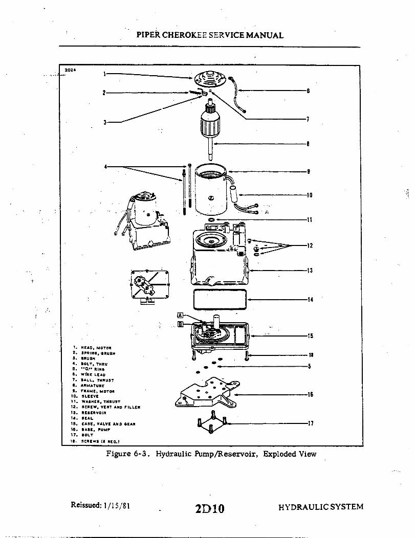
PIPER CHEROKEE SERVICE MANUAL
2 6
7
1. HEAD, MOTOR2. SPRING,BRUSH3. BRUSH4. BOLT, THRU
5. "0." RING6. WIRE LEAD7. BALL THRUST8. ARMATURE9. FRAME, MOTOR
10. SLEEVE11 . WASHER, THRUST12. SCREW, VENT AND FILLER13. RESERVOIR14. SEAL
15. CASE, VALVE AND SEAR16. BASE, PUMP17. BOLT
18. SCREWS (8 REQ.)
*
9
10
11
13
14
15
18
5
16
17
Figure 6-3. Hydraulic Pump/Reservoir, Exploded View
1/15/81 2D10 HYDRAUL2D10 2D10
2024
Reissued: IC SYSTEM
PIPER CHEROKEE SERVICE MANUAL
c. The valve body and gear case assembly (15) may be separated from the reservoir(13) as follows:
1. Remove the screws from the flange of the body and separate the two assemblies.2. The pump gears and valves should be removed for cleaning purposes only. To
remove cap securing gears, remove cap attaching bolts. There are two valve springs thatshould be positively identified with their valve cavities. Otherwise, it will be necessary toreadjust each valve for proper operating pressure.
6-7. CLEANING, INSPECTION AND REPAIRS OF HYDRAULIC PUMP.a. Discard all old O-rings.b. Remove cap or plugs and clean all parts with a dry type cleaning solvent and dry
thoroughly.
NOTE
The conditions at repair require cleanliness, carefulness andproper handling of parts. Ensure that foreign materials areprevented from entering the system and that no parts aredamaged.
c. Inspect pump components for scratches, scores, chips, cracks and wear.d. Inspect motor for worn brushes (minimum of.218 brush remains between the braided
wire and commutator end), excess commutator wear and excess bearing wear.
6-8. ASSEMBLY OF HYDRAULIC PUMP. (Refer to Figure 6-3.)a. The pump motor may be assembled and installed on the pump reservoir assembly as
follows:1. Position the motor frame (9) on the reservoir (13). Note the aligning marks on
the frame and reservoir.2. Place thrush washers ( 1), of the same amount removed, on the drive end of the
armature (8).3. Lubricate the entire length of the armature shaft, on the drive end, with a light
grease to protect the O-ring seal from damage and insert the end of the shaft in the reservoir.4. Saturate the felt oiling pad around the-commutator end bearing with SAE20 oil.
Allow excess oil to drain off before assembling motor.5. Insert the thrust ball(7) in the bearing of the head assembly (1). To hold the ball
in position, place a small amount of light grease inside the bearing.
HYDRAULIC SYSTEM2D11Reissued: 1/15/81
PIPER CHEROKEE SERVICE MANUAL
6. Place head assembly on frame and allow brushes to extend over commutator.Remove the string securing the brushes in the holders. Push head assembly on frame andinsure proper indexing of head and frame assemblies. Secure in place with thru bolts (4).
7. Check freedom of rotation and end play (thrust) of the armature withinthe assembly. A minimum of .005 of an inch end play is allowable. Should thisbe incorrect, adjust by adding or removing thrust washers (11) on drive end ofarmature shaft, as required.
b. The valve body and gear case assembly (15) may be assembled to the res-ervoir (13) as follows:
1. If removed, place the pump gears in the gear case and install cover.Install cover attaching bolts and secure.
2. Lubricate the reservoir seal ring(14) with hydraulic fluid (MIL-H-5606)and place it in the recess provided in the case (15).
3. Position the valve body and gear case assembly (15) with the reservoir(13). Care should be taken when lining upthe armature drive with the pump gear.Do not run the motor to do this.
4. Ascertain that the seal ring is properly positioned and install attachingscrews. Tighten the screws so that with the motor connected to a 14-volt sourceand with an ammeter in the circuit, the current drawn does not exceed 12-amp-eres.
c. The base of the pump may be attached to the pump as follows:1. With the pump in the up-side down position, lubricate "O" ring seals,
and install inthe recesses providedinthe valve body andgear case assembly (15).2. Install attaching bolts with washers and torque to 70 inch pounds.3. Safety attaching bolts with MS20995-C32 wire.
d. Conduct motor operational check not to exceed 10 seconds running time.
6-9. TEST AND ADJUSTMENT OF HYDRAULIC PUMP. (Refer to Figure 6-4.)a. Test Equipment:
1. Hydraulicpump and mounting base.2. Pressure gauge (0 to 1000 psi).3. Pressure gauge (0 to 3000 psi).4. Hoses with fittings to connect between base and gauges.5. Power supply (14VDC).6. Ammeter (0 to 100 amps).7. Fuse or circuit protector (100 amp).
b. Test and Adjustment:1. Connect a 0 to 1000 psi gauge to the low pressure port (port No. 3) of
the pump base. (The low pressure port, No. 3, is located nearest to the pipeplug installed in the base.)
2. Connect a 0 to 3000 psi gauge to the high pressure port (port No. 1) ofthe pump base. (The high pressure port, No. 1, is located farthest from the pipeplug installed in the base.)
HYDRAULIC SYSTEM2D12Reissued: 1/15/81
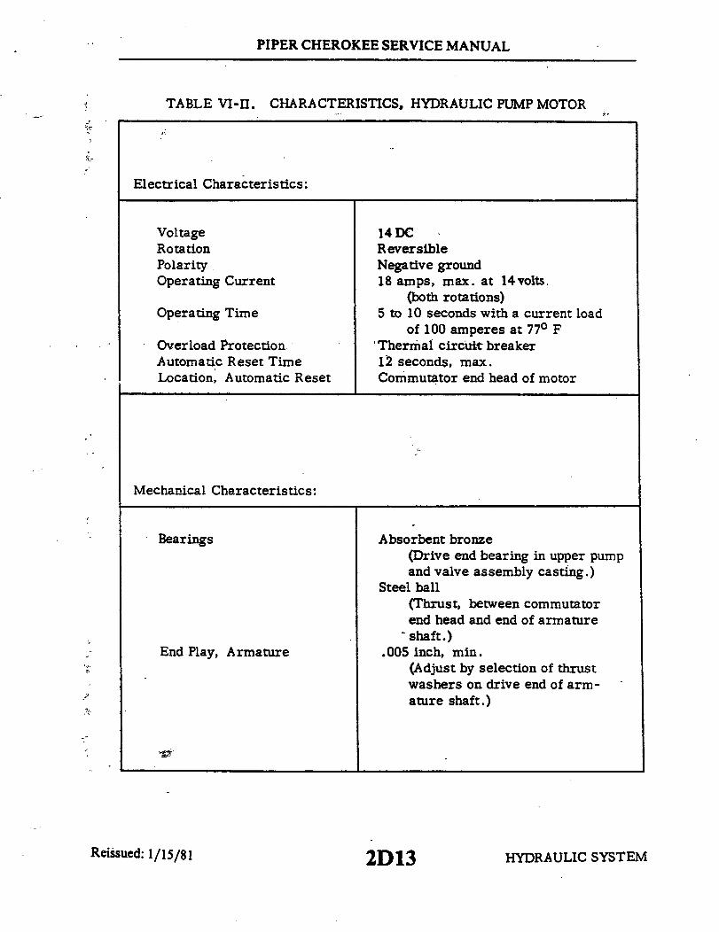
PIPER CHEROKEE SERVICE MANUAL
TABLE VI-II. CHARACTERISTICS, HYDRAULIC PUMP MOTOR
Electrical Characteristics:
VoltageRotationPolarityOperating Current
Operating Time
Overload ProtectionAutomatic Reset TimeLocation, Automatic Reset
14DCReversibleNegative ground18 amps, max. at 14volts
(both rotations)5 to 10 seconds with a current load
of 100 amperes at 77° F'Thermal circuit breaker12 seconds, max.Commutator end head of motor
Mechanical Characteristics:
Bearings
End Play, Armature
Absorbent bronze(Drive end bearing in upper pumpand valve assembly casting.)
Steel ball(Thrust, between commutatorend head and end of armature
- shaft.).005 inch, min.
(Adjust by selection of thrustwashers on drive end of arm-ature shaft.)
HYDRAULIC SYSTEM2D13Reissued: 1/15/81

PIPER CHEROKEE SERVICE MANUAL
922
GROUND- BLACK
HIGH PRESSLOW PRESS.
- 14 V. D. C.
Reissued: 1/15/81
Figure 6-4. Test and Adiustments of Hydraulic Pump
2D14 HYDRAULIC SYSTEM

PIPER CHEROKEE SERVICE MANUAL
3. Connect the black lead of the pump motor to the negative terminal ofthe DC power supply.
- 4. Fill the pump reservoir and bleed all air from the attached lines. (Linesmay be bled by alternately connecting the blue electrical lead and green lead to.the positive terminal of the power supply until all air is exhausted.)
5. Connect the blue lead to the positive terminal of the power supply. Pumpshould operate and the high pressure gauge should indicate between 1600 to 2000psi. (Should the pressure be incorrect, adjust valve "A", Figure 6-3, in pumpreservoir.)
6. Disconnect the blue lead, and the high pressure reading should not dropmore than 300psi in five minutes. High pressure may not be selected until afterfive minutes.
7. Connect the green lead to the positive terminal of the power supply.Pump should operate in reverse, dropping the high pressure gauge to zero andthe low pressure gauge should indicate between 500 to 800 psi. When the greenlead is disconnected, both pressure gauges should indicate zero psi. (Should thepressure of 500 to 800 psi be incorrect, adjust valve "B", Figure 6-3, in pumpreservoir.)
NOTE
During test steps 5 thru 7, there should not be anyexternal leakage.
8. Should it be necessary to check the pump motor, first connect the am-meter in the electrical circuit with the positive terminal of the meter to the blacklead and the negative terminal of the meter to negative terminal of the DC powersupply.
9. Connect the blue lead to the positive terminal of the power supply. Withthe high pressure indication within the 1600 to 2000 psi range on the pressuregauge, the ammeter should read between 35 to 60 amperes. Disconnect the elec-trical lead.
10. Connect the green lead to the positive terminal of the power supply.With the high pressure indication within the 500 to 800 psi range, the ammetershould read between 15 to 35 amperes.
NOTE
In the event that any of the various tests do not per-form satisfactorily, the pump assembly should beoverhauled or replaced.
Reissued: 1/15/81 HYDRAULIC SYSTEM2D15Reissued: 1/15/81

PIPER CHEROKEE SERVICE MANUAL
11. Connect the green lead to the.power supply to drop pressures beforedisconnecting the hydraulic lines.
36-10. INSTALLATION OF HYDRAULICPUMP.
a. Install the rubber shock mountsthrough the mounting holes of the pump.Insert a bushing through the holes of eachshock mount.
b. Position the pump on its mountingflange. Install mounting bolt with washerand tighten. (Refer to Figure 6-5.)
c. Connect the hydraulic lines to thepump.
2 WASHER 5. BUSHINGd. Connect the pump electrical leads. 3. SHOCK MOUNT 6. BUSHING
Green wire to outboard relay, blue wire to 4 PUMP BASE 7. SHELF
inboard relay and black wire to ground onbattery shelf. Figure 6-5. Pump Shock Mounts
e. Check fluid level in pump. Fill per instructions given in Section II.f. With the airplane on jacks, operate the pump to purge the hydraulic system of air,
and check for leaks. After operation, recheck fluid level.
6-11. FILLING HYDRAULIC PUMP RESERVOIR. To check fluid level, remove the pluglocated on the forward side of the pump and ascertain that fluid is visible up to the bottomof the filler plug hole. Should fluid be below the hole, add fluid, MIL-H-5606A, through thefiller hole until full. Reinstall the filler plug and tighten.
NOTE
A small vent hole is located under the vent screw head.Retain 1/64 inch clearance between the screw head and thesmall vent hole.
6-12. GEAR BACK-UP EXTENDER ACTUATOR ASSEMBLY.
6-13. REMOVAL OF GEAR BACK-UP EXTENDER ACTUATOR ASSEMBLY. (Refer toFigure 6-6.) The back-up extender actuator is located under the rear seat. To reach theactuator, remove the rear seats.
a. Disconnect the actuator electrical leads at-the quick disconnect terminals.b. On early installations disconnect the manual override control rod (30) at the
actuator control arm (19) by removing cotter pin, washer, and clevis pin (1). On laterinstallations the control rod (30) is not connected to the actuator arm (19).
c. Disconnect the pressure (13) and static (11) hoses from the elbows (12) of thediaphragm housing (10) by releasing clamps and sliding the hoses from their elbows. Thehoses should be tagged for ease of reassembly.
d. Place a shop cloth under the actuator hydraulic valve (25) to absorb fluid, and thendisconnect the hydraulic lines (5) and (25) from the elbows (4) and (27) of the hydraulicvalve (25). Cover the lines to prevent contamination.
Reissued: 1/15/81 HYDRAULIC SYSTEM2D16
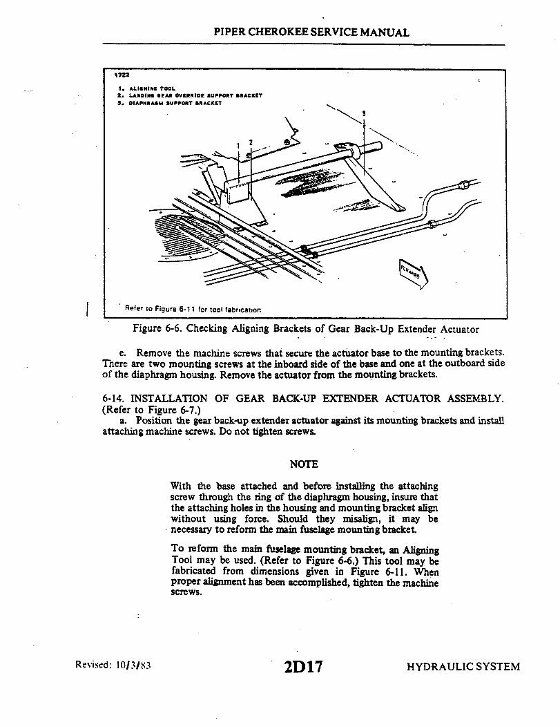
PIPER CHEROKEE SERVICE MANUAL
1722
1. ALIGNING TOOL2. LANDING GEAR OVERRIDE SUPPORT BRACKET3. DIAPHRAGM SUPPORT BRACKET
Refer to Figure 6-11 for tool fabrication
Figure 6-6. Checking Aligning Brackets of Gear Back-Up Extender Actuator
e. Remove the machine screws that secure the actuator base to the mounting brackets.There are two mounting screws at the inboard side of the base and one at the outboard sideof the diaphragm housing. Remove the actuator from the mounting brackets.
6-14. INSTALLATION OF GEAR BACK-UP EXTENDER ACTUATOR ASSEMBLY.(Refer to Figure 6-7.)
a. Position the gear back-up extender actuator against its mounting brackets and installattaching machine screws. Do not tighten screws.
NOTE
With the base attached and before installing the attachingscrew through the ring of the diaphragm housing, insure thatthe attaching holes in the housing and mounting bracket alignwithout using force. Should they misalign, it may benecessary to reform the main fuselage mounting bracket.
To reform the main fuselage mounting bracket, an AligningTool may be used. (Refer to Figure 6-6.) This tool may befabricated from dimensions given in Figure 6-11. Whenproper alignment has been accomplished, tighten the machinescrews.
Revised: 10/3/83 HYDRAULIC SYSTEM
I
2D17

PIPER CHEROKEE SERVICE MANUAL
b. On early installations connect the manual control push rod (30) to the actuatorcontrol arm (19) using clevis pin (1). Place a washer over end of clevis pin and secure withcotter pin.
c. Move the actuator on its mounting brackets to allow the manual control push rod tohave maximum clearance from the left stabilator cable and center in the fairlead on the aftface of the main spar box. Check system for sufficient travel and freedom of movement ofcontrols. Tighten actuator attaching screws.
NOTE
Care should be used when attaching the forward hose (13) tothe diaphragm assembly (10) so that no strain is placed onthe teflon bushing (15) and diaphragm shaft (16), thuscausing friction in movement.
d. Connect the hydraulic lines (5) and (26) to the elbows (4) and (27) of the actuatorhydraulic valve (25).
NOTE
A special fitting (27) with a restriction orifice of .063 of aninch is installed in the side of the hydraulic valve (25). Donot mistake this for a standard AN fitting.
e. Connect the pressure (13) and static (11) hoses to the elbows (12) of the diaphragmhousing (10). Secure hoses with clamps.
f. Connect the actuator electrical leads terminal to their mating terminals and insulate.Refer to the electrical schematic for hookup.
g. Check the actuator adjustments as given in paragraph 6-15.h. Install the rear seat.
6-15. CHECK AND ADJUSTMENT OF GEAR BACK-UP EXTENDERACTUATOR. (Refer to Figure 6-7.)
a. If diaphragm failure is suspected note the following:1. If the landing gear retracts or extends at too high an airspeed or will not retract
at all unless the back-up extender is placed in the override position, then the diaphragm ispossibly defective.
2. If it is determined that the diaphragm is defective, then remove the back-upextender per instructions given in Paragraph 6-13 and install, Piper Kit No. 761 138V,Back-Up Gear Extender Diaphragm Replacement. Instructions for installing the diaphragmare included in the kit.
3. Following completion of Replacement Kit, reinstall the extender unit in theaircraft and functionally test and adjust as outlined below and in Paragraph 6-16.
Reissued: 1/15/81 HYDRAULIC SYSTEM2D18

PIPER CHEROKEE SERVICE MANUAL
b. Adjustment of the gear back-up extender actuator is preset to allow the hydraulicvalve (25) of the actuator to open when the airspeed is reduced below 105 MPH with theengine power OFF. This adjustment is accomplished by setting the tension of springs (24)on the actuator with adjustment screw (2).
NOTE
The airspeed at which the hydraulic valve of the actuatoropens was preset at the factory under ideal conditions. Therecould be some variations at different altitudes andatmosphere conditions.
CAUTION
The micro switch (21) on all units, and eccentric bolt (35) onlater units must not be adjusted. These components are set atthe factory under specific conditions, with the use of specialset-up equipment.
NOTE
This adjustment will require two persons, a qualified pilotand a mechanic to set the actuator adjustment screw (2).
1. Remove the bottom of the rear seat.2. The pivot screw (20) should be torqued 8 to 10 inch-pounds.3. Loosen the jam nut (28) of the adjustment screw (2).4. Ascertain that the electrical switch (21) will actuate with the use of the
emergency gear extension lever.5. Fly the airplane (refer to Owner's Handbook). Should the spring tension be out
of adjustment very much, it may be necessary to assist gear retraction with the use of theemergency gear extension lever moved to the up override position.
6. Loosen the adjustment screw (2) by turning counterclockwise until spring (24)tension is free.
WARNING
While making adjustments, do not lay tools in area under seatwhich may interfere with control of the airplane.
7. With the airplane at a safe altitude, slow the airplane to a glide of 110 MPH withthe gear selector handle up and the throttle reduced to power OFF. (Gear warning light andhorn will indicate when power is reduced.) At 110 MPH, slow the airplane at a rate of one(1) MPH per second until 105 MPH is obtained, hold the airplane at this speed.
HYDRAULIC SYSTEMReissued: 1/15/81 2D19

INTENTIONALLY LEFT BLANK
2D20

4~L
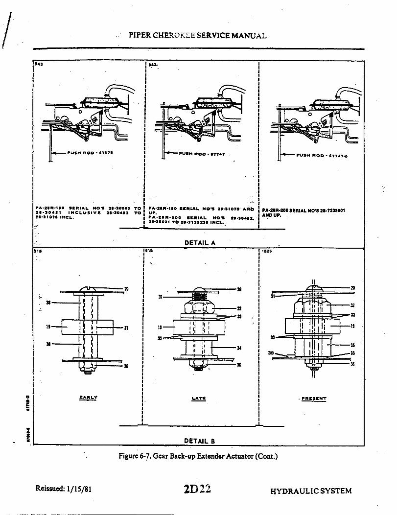
PIPER CHEROKEE SERVICE MANUAL
943
PA-21R-110 SERIAL NOS 21-30000 TO28-31078 INCL. 24-30483 TO28-31078 INCL.
EAR.LY
943.
PA-28R-200 SERIAL NOS 28-1073 ANDUP.PA-28R-200 SERIAL NO'S 28-30482.28-33001 TO 28-7232238 INCL.
DETAIL A
I
IIIIII
826826826
LATE
PA-28R-200 SERIAL NO'S 28-7235001AND UP.
826
PRESENT
DETAIL B
Reissued: 1/15/81
Figure 6-7. Gear Back-up Extender Actuator (Cont.)
2D 22 HYDRAULIC SYSTEM
PIPER CHEROKEE SERVICE MANUAL
NOTE
On later installations, adjustment of the nut (32) may benecessary to increase or decrease the spread between the gearup and gear down actuation speeds. To expand the spreadbetween these speeds, loosen the nut. Tighten the nut tobring the airspeeds closer together. Whenever the nut isadjusted, it may be necessary to readjust the tension on thesprings (24) and to repeat the nut adjustment procedure. Ifthe eccentric bolt (35) is installed on the unit being adjusted,CAUTION should be observed so as not to disturb itsposition in relation to the rest of the unit.
8. With the glide established, turn the adjustment screw (2) clockwise until the geardrops. (First indication of gear dropping will be that the yellow intransit light comes ON.)
9. Climb again to a safe altitude and check that the gear drops at the correctairspeed.
10. Land the airplane and tighten the adjustment screw jam nut (28).c. - To check adjustment of electrical switch, the following procedure may be used:
1. Place the airplane on jacks. (Refer to Jacking, Section II.)2. Move the mixture control back to idle cut-off and the throttle to full forward to
prevent gear warning horn from sounding during adjustment.3. Ascertain that the actuator tension springs are properly adjusted according to
Step a.4. Retract the landing gear hydro electrically by turning the master switch ON,
raising the emergency gear extension lever and moving the gear selector handle to the upposition. The emergency gear extension lever must be retained in the up position to keepthe gear up.
5. Check for proper switch operation by the following procedure:(a) Turn master switch ON and move gear selector handle to the up position.
Pump should not operate.(b) Move the emergency gear extension lever to the up override position. Pump
should operate and gear should retract.(c) With selector lever up, slowly lower emergency gear extension lever to allow
gear to drop to down position. The pump should not operate at any timeduring extension.
(d) Turn master switch OFF.6. Check gear operation in the normal manner with the use of the gear selector
handle. The emergency extension lever must be held in the up override position.7. Ascertain that gear is down and locked and remove airplane from jacks. Then
flight check the retractable landing gear system. (Refer to Paragraph 6-16.)
HYDRAULIC SYSTEM2D23Reissued: 1/15/81

PIPER CHEROKEE SERVICE MANUAL
6-16. OPERATIONAL CHECK OF RETRACTABLE LANDING GEAR SYSTEM.a. Maximum Gear Extend: Place the gear selector in the down position at 150 MPH
(130 Kts). In approximately 5 to 10 seconds the three green gear lights should be onindicating that the gear is down and locked.
b. Minimum Gear Retract: Allow approximately 8 seconds for the pressure in thehydraulic system to normalize between gear extension and retraction. Place the selectorswitch in the UP position at 125 MPH (109 Kts). In approximately 5 to 10 seconds all thegear indicating lights should be out, indicating that the gear is fully retracted.
c. Override Gear Down and Up:1. Down: Establish a normal glide at approximately 120 MPH (104 Kts), with
power at idle. Slowly move the override lever down, while observing the ammeter toconfirm that the hydraulic pump does not start. The gear should go down and lock. Movethe gear selector switch down. Release the override lever. The gear should remain down.
2. Up: Set maximum climb power. Maintain approximately 70 MPH (61 Kts) forapproximately 15 seconds. Move the gear selector switch to the up position. The gear shouldnot retract. Pull the override lever up. The gear should retract. Allow the airspeed toincrease to at least 120 MPH (109 Kts). Release the override lever and the gear shouldremain up.
INTENTIONALLY LEFT BLANK
HYDRAULIC SYSTEMReissued: 1/15/81 2D24
PIPER CHEROKEE SERVICE MANUAL
d. Gear "Back-Up" Down and Up:1. Gear Down: Set power at idle. Glide the aircraft at 120 MPH (109 Kts).
Decrease the airspeed at the rate of 1 MPH (1 Kt) per second. The gear should start downbetween. 100 and 110 MPH (87 to 96 Kts). Place the gear selector switch down, after thegear is down and locked.for 2. Gear Up: Set maximum climb power. Maintain approximately 70 MPH (61 Kts)for approximately 15 seconds. Move the gear selector up. The gear should stay down andlocked. Increase the airspeed at the rate of 1 MPH (1 Kt) per second. The gear should beginto retract between 80 and 90 MPH (70 and 78 Kts) at zero density altitude. The speed atwhich the gear starts up will increase 1.5 MPH (1.3 Kts) for each 1000' increase of densityaltitude.
3. Manual Override Up Latch: With the gear up, the aircraft in normal flightconfiguration, select up on the gear override lever. Engage the up latch. The amber up latchwarning light, below the gear selector switch, should be flashing. Gradually slow the aircraftbelow the auto gear extend speed and observe that the gear stays fully retracted. Disengagethe up latch. The flashing amber warning light should stay out.
e. Gear Indicator Lights:1. The green lights indicate when the corresponding gear is in the down and locked
position. Turn landing light switch on and off- observe ammeter for indication.2. The amber light indicates when the gear is in an intermediate position, neither
fully up nor down.3. The Red gear warning light will indicate an unsafe condition. It will indicate
when the throttle setting is less than 14 ± 2 inches of manifold pressure while the gear is notdown and locked. It will also indicate when the gear is down and locked while the selector isin the UP position, except at full throttle.
f. The Gear Warning Horn: It will sound whenever the red gear warning light is on.g. Micro Switch Check:
1. The forward throttle micro switch is checked by moving the throttle fullforward while the gear is down and the gear selector switch is in the up position. The hornshould stop sounding and the red light should go out. Retard the throttle slightly and thehorn and light should come on.
2. The aft throttle micro switch setting is-checked as follows: with the gear up,reduce the throttle at a normal rate. The gear warning horn and the red light should comeon at 14 inches of manifold pressure ± 2".
HYDRAULIC SYSTEM2E1

PIPER CHEROKEE SERVICE MANUAL
1706
4SYNCRO DEVICESCYLINDER
EARLY
1. SNAP RING2. END GLAND3. BACK-UP RING4. "0" RING5. "0" RING6. PISTON7. BODY, CYLINDER
8. "O" RING9. SAFETY WIRE
GAR-KENYONCYLINDER
LATER
Figure 6-8. Nose Gear Actuating Cylinder
Reissued: 1/15/81 2E2 HYDRAULIC SYSTEM

PIPER CHEROKEE SERVICE MANUAL
6-17. NOSE GEAR ACTUATING CYLINDER.
6-18. REMOVAL OF NOSE GEAR ACTUATING CYLINDER.a. Place the airplane on jacks. (Refer to Jacking, Section II.)b. Disconnect the hydraulic lines from the actuating cylinder and cover the open line
ends to prevent contamination.c. Disconnect the cylinder operating rod end from the downlock hook by removing
attachment nut and bolt.d. Disconnect the cylinder from its attachment fitting by removing nut and bolt.e. Remove the cylinder from the wheel well.
6-19. DISASSEMBLY OF NOSE GEAR ACTUATING CYLINDER. (Refer to Figure 6-8.)a. With the cylinder removed from the airplane, remove the fitting from the piston rod
(6) end of the cylinder (7). Mark the position of the fitting to facilitate reinstallation.b. On Syncro Devices nose gear actuating cylinders remove the snap ring (1) from the
annular slot in the end of the housing. On Gar-Kenyon nose gear actuating cylinder removesafety wire (9) and unscrew end gland(2).
c. On Syncro Devices Assemblies pull the piston (6) with end gland (2) from thecylinder housing. On Gar-Kenyon Assemblies remove piston (6) after unscrewing end gland(2).
6-20. CLEANING, INSPECTION, AND REPAIR OF NOSE GEAR ACTUATINGCYLINDER.
a. Clean the cylinder parts with a suitable dry type solvent and dry thoroughly.b. Inspect the cylinder assembly for the following:
1. Interior walls of the cylinder and exterior surfaces of the piston for scratchesburrs, corrosion, etc.
2. Threaded areas for damage.3. Rod end fitting and swivel fitting of cylinder for wear and corrosion.
c. Repairs to the cylinder and limited to polishing out small scratches, burrs, etc. andreplacing parts.
HYDRAULIC SYSTEM2E3Reissued: 1/15/81

PIPER CHEROKEE SERVICE MANUAL
BEARING END
Figure 6-9. End Gland Locking Device
6-21. ASSEMBLY OF NOSE GEAR ACTUATING.CYLINDER. (Refer to Figure 6-8.)a. Install "O" ring (5) on the exterior of the end gland (2).b. Install 'O" ring (4) in the interior of the end gland. The Syncro Devices Assemblies
also includes a ring back-up (3) with the "O" ring (4)c. Install "O" ring (8) on the body of the piston assembly.d. Lubricate the areas around the "O" rings with hydraulic fluid, slide the end gland on
the piston rod and the piston into the cylinder housing (7).e. Secure the end gland in the cylinder by installing the snap ring ( 1) in the annular slot
in the Syncro Devices cylinder. The end gland on the Gar-Kenyon cylinder is secured bythreading gland into cylinder body (7) and securing with safety wire (9).
f. Install restrictor fitting in the piston rod end of the cylinder.g Check smoothness of operation of the piston.
HYDRAULIC SYSTEMReissued: 1/15/81

PIPER CHEROKEE SERVICE MANUAL
1767
N'• \
1 END GLAND2. BACK-UP RING3 "O" RING4. RETAINER RING5. "O" RING
6. PISTON7. CYLINDER BODY
8. "0" RING9. CLEVIS10. BEARING
Figure 6-10. Main Gear Actuating Cylinder
Issued: 1/15/81 2E5 HYDRAULIC SYSTEMReissued:
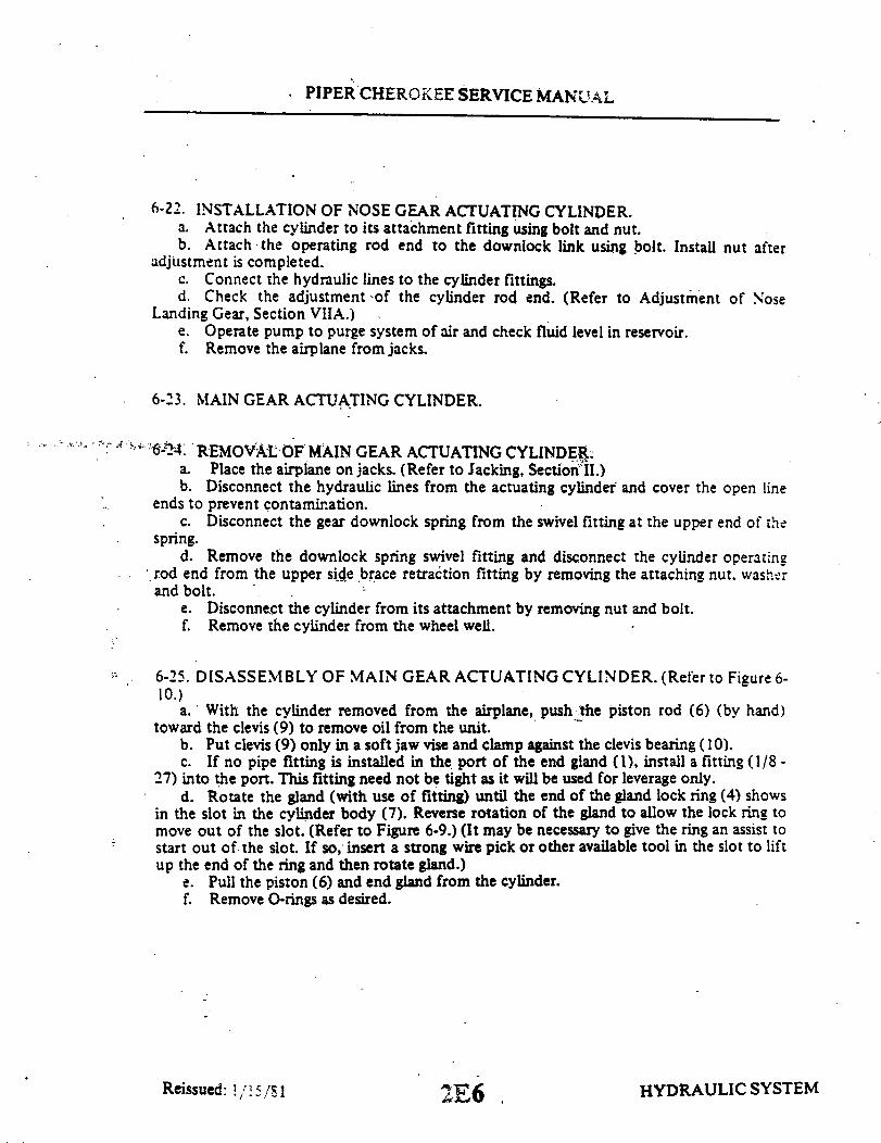
PIPER CHEROKEE SERVICE MANUAL
6-22. INSTALLATION OF NOSE GEAR ACTUATING CYLINDER.a. Attach the cylinder to its attachment fitting using bolt and nut.b. Attach the operating rod end to the downlock link using bolt. Install nut after
adjustment is completed.c. Connect the hydraulic lines to the cylinder fittings.d. Check the adjustment of the cylinder rod end. (Refer to Adjustment of Nose
Landing Gear, Section VIIA.)e. Operate pump to purge system of air and check fluid level in reservoir.f. Remove the airplane from jacks.
6-23. MAIN GEAR ACTUATING CYLINDER.
REMOVAL OF MAIN GEAR ACTUATING CYLINDER.a. Place the airplane on jacks. (Refer to Jacking, Section II.)b. Disconnect the hydraulic lines from the actuating cylinder and cover the open line
ends to prevent contamination.c. Disconnect the gear downlock spring from the swivel fitting at the upper end of the
spring.d. Remove the downlock spring swivel fitting and disconnect the cylinder operating
rod end from the upper side brace retraction fitting by removing the attaching nut. washerand bolt.
e. Disconnect the cylinder from its attachment by removing nut and bolt.f. Remove the cylinder from the wheel well.
6-25. DISASSEMBLY OF MAIN GEAR ACTUATING CYLINDER. (Refer to Figure 6-10.)
a. With the cylinder removed from the airplane, push the piston rod (6) (by hand)toward the clevis (9) to remove oil from the unit.
b. Put clevis (9) only in a soft jaw vise and clamp against the clevis bearing (10).c. If no pipe fitting is installed in the port of the end gland (1), install a fitting (1/8 -
27) into the port. This fitting need not be tight as it will be used for leverage only.d. Rotate the gland (with use of fitting) until the end of the gland lock ring (4) shows
in the slot in the cylinder body (7). Reverse rotation of the gland to allow the lock ring tomove out of the slot. (Refer to Figure 6-9.) (It may be necessary to give the ring an assist tostart out of the slot. If so, insert a strong wire pick or other available tool in the slot to liftup the end of the ring and then rotate gland.)
e. Pull the piston (6) and end gland from the cylinder.f. Remove O-rings as desired.
HYDRAULIC SYSTEM2E6Reissued: 1/15/81
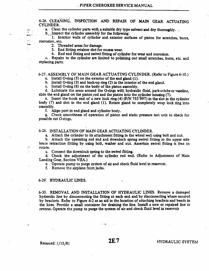
PIPER CHEROKEE SERVICE MANUAL
6-26. CLEANING, INSPECTION AND REPAIR OF MAIN GEAR ACTUATINGCYLINDER.
a. Clean the cylinder parts with, a suitable dry type solvent and dry thoroughly.b. Inspect the cylinder assembly for the following:
1. Interior walls of cylinder and exterior surfaces of piston for scratches, burrs,corrosion, etc.
2. Threaded areas for damage.3. End fitting retainer slot for excess wear.4. Rod end fitting and swivel fitting of cylinder for wear and corrosion.
c. Repairs to the cylinder are limited to polishing out small scratches, burrs, etc. andreplacing parts.
6-27. ASSEMBLY OF MAIN GEAR ACTUATING CYLINDER. (Refer to Figure 6-10.)a. Install O-ring (5) on the exterior of the end gland (1).b. Install O-ring (3) and back-up ring (2) in the interior of the end gland.c. Install O-ring (8) on the body of the piston assembly.d. Lubricate the areas around the O-rings with hydraulic fluid, park-o-lube or vaseline,
slide the end gland on the piston rod and the piston into the cylinder housing (7).e. Insert the hook end of a new lock ring (4) (P/N 755 997) in the slot in the cylinder
body (7) and slot in the end gland (1). Rotate gland to completely wrap lock ring intoassembly.
f. Align port in end gland and cylinder body.g. Check smoothness of operation of piston and static pressure test unit to check for
possible cut O-rings.
6-28. INSTALLATION OF MAIN GEAR ACTUATING CYLINDER.a. Attach the cylinder to its attachment fitting in the wheel well using bolt and nut.b. Attach the operating rod end and downlock spring swivel fitting to the upper side
brace retraction fitting by using bolt, washer and nut. Ascertain swivel fitting is free torotate.
c. Connect the downlock spring to the swivel fitting.d. Check the adjustment of the cylinder rod end. (Refer to Adjustment of Main
Landing Gear, Section VIIA.)e. Operate pump to purge system of air and check fluid level in reservoir.f. Remove the airplane from jacks.
6-29. HYDRAULIC LINES.
6-30. REMOVAL AND INSTALLATION OF HYDRAULIC LINES. Remove a damagedhydraulic line by disconnecting the fitting at each end and by disconnecting where securedby brackets. Refer to Figure 6-2 as an aid in the location of attaching brackets and bends inthe lines. Provide a small container for draining the line. Install a new or repaired line inreverse. Operate the pump to purge the system of air and check fluid level in reservoir
HYDRAULIC SYSTEMReissued: 1/15/81 2E7

INTENTIONALLY LEFT BLANK
2E8

PIPER CHEROKEE SERVICE MANUAL
TABLE VI-III. HYDRAULIC SYSTEM TROUBLESHOOTING
Trouble Cause Remedy
Landing gear retractionsystem fails to operate.
Landing gear actuatorcircuit breaker open.
Reset circuit breakerand determine causefor open circuitbreaker.
Landing gear selectorcircuit breaker open.
Landing gear actuatorcircuit wires broken.
Landing gear selectorcircuit wires broken.
Safety (squat) switchout of adjustment.
Squat switch inoper-ative.
Pressure switchinoperative.
Pump retractionsolenoid inoper-ative (inboardsolenoid).
Reset circuit breakerand determine causefor open circuitbreaker.
Check wiring.
Check wiring.
Readjust switch (RefertoAdjustment of SafetySwitch, Section VIIA.)
Replace switch.
Replace switch.
Replace solenoid.
HYDRAULIC SYSTEM2E9Reissued: 1/15/81

PIPER CHEROKEE SERVICE MANUAL
TABLE VI-Ill. HYDRAULIC SYSTEM TROUBLESHOOTING (cont)
.Trouble Cause Remedy
NOTE
If the retracting solenoid of the pump can be heard toactuate when operating the gear selector switch, it maybe assumed that the gear control circuit is operatingproperly andchecked.
the actuator circuit should be further
Landing gear retractionsystem fails to oper-ate (cont.)
Gear selector switchground incomplete.
Check ground.
Gear selector switchinoperative.
Hydraulic pump groundincomplete.
Hydraulic pump inop-erative.
Auxiliary extenderswitch inoperative.
Hydraulic fluid Inreservoir belowoperating level.
Battery low or dead.
Replace switch.
Check ground.
Replace or overhaulpump.
Replace unit..
Fill reservoir withhydraulic fluid.
Check condition ofbattery.
HYDRAULIC SYSTEM
I
Reissued: 1/15/81 2E10

PIPER CHEROKEE SERVICE MANUAL
TABLE VI-III. HYDRAULIC SYSTEM TROUBLESHOOTING (cont)
Trouble Cause Remedy
Landing gear retractionsystem fails to oper-ate (cont.).
Pressure head airpassage obstructed. *
Clear obstruction.
Pressure head hoseoff.*
Split or hole in dia-phragm of auxiliaryextender. *
Reconnect hose.
Replace diaphragm.Refer to the latestrevision of Piper ServiceLetter No. 810.
*Can be checked byusing override.
Landing gear exten-sion system fails tooperate.
Landing gear actuatorcircuit breaker open.
Reset circuit breakerand determine causefor open circuitbreaker.
Landing gear selectorcircuit breaker open.
Landing gear actuatorcircuit wires broken.
Landing gear selectorcircuit wires broken.
Reset circuit breakerand determine causefor open circuitbreaker.
Check wiring.
Check wiring.
Reissued: 1/15/81 HYDRAULIC SYSTEM2Ell
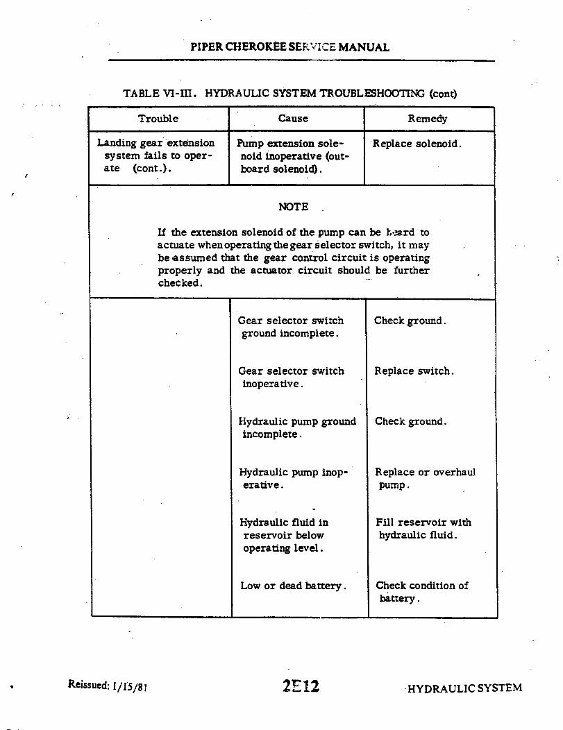
PIPER CHEROKEE SERVICE MANUAL
TABLE VI-III. HYDRAULIC SYSTEM TROUBLESHOOTING (cont)
Trouble Cause Remedy
Landing gear extensionsystem fails to oper-ate (cont.).
Pump extension sole-noid inoperative (out-board solenoid).
Replace solenoid.
NOTE
If the extension solenoid of the pump can be heard toactuate when operating the gear selector switch, it maybe assumed that the gear control circuit is operatingproperly and the actuator circuit should be furtherchecked.
Gear selector switchground incomplete.
Gear selector switchinoperative.
Hydraulic pump groundincomplete.
Hydraulic pump inop-erative.
Hydraulic fluid inreservoir belowoperating level.
Low or dead battery.
Check ground.
Replace switch.
Check ground.
Replace or overhaulpump.
Fill reservoir withhydraulic fluid.
Check condition ofbattery.
Reissued: 1/15/81 HYDRAULIC SYSTEM2E12

PIPER CHEROKEE SERVICE MANUAL
TABLE VI-III. HYDRAULIC SYSTEM TROUBLESHOOTING (cont)
Trouble Cause Remedy
Landing gear retractionextremely slow.
Hydraulic fluid in res-ervoir below operatinglevel.
Fill reservoir withhydraulic fluid.
Restriction in hydrauliclines.
Shuttle valve sticking inpump base.
Isolate and check hy-draulic lines.
Check cause.
Pump stops during gearretraction.
Landing gear actuatorcircuit breaker opens.
Reset circuit breakerand determine causefor overload.
Landing gear selectorcircuit breaker opens.
Pressure switch out ofadjustment.
Mechanical restrictionor obstruction in hyd-raulic system to allowpressure to build upand shut off pump be-fore gear has retracted.
Shuttle valve sticking inpump base.
Reset circuit breakerand determine causefor overload.
Remove and readjust orreplace switch.
Place airplane on jacksand run retractioncheck. Isolate anddetermine cause.
Check cause.
Pump stops during gearextension.
Landing gear actuatorcircuit breaker opens.
Reset circuit breakerand determine causefor overload.
Landing gear selectorcircuit breaker opens.
Reset circuit breakerand determine causefor overload.
HYDRAULIC SYSTEMReissued: 1/15/81 2E13

PIPER CHEROKEE SERVICE MANUAL
TABLE VI-III. HYDRAULIC SYSTEM TROUBLESHOOTING (cont)
Trouble Cause Remedy
Pump fails to shut offthough gear has fullyretracted.
Pressure switch inop-erative.
Replace switch.
Pressure switch out ofadjustment.
Pump retraction sole-noid sticking (inboardsolenoid).
Internal leakage ofsystem.
Replace switch.
Replace solenoid.
Check back-up exten-sion unit valve forinternal leakage.
Check gear actuatingcylinders for internalleakage.
Check for internal dam-age to hydraulic pump.
External leakage ofsystem.
Check back-up exten-sion unit valve forexternal leakage.
Check gear actuatingcylinders for externalleakage.
HYDRAULIC SYSTEM2E14Reissued: 1/15/81
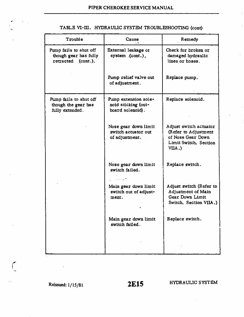
PIPER CHEROKEE SERVICE MANUAL
TABLE VI-III. HYDRAULIC SYSTEM TROUBLESHOOTING (cont)
Trouble Cause Remedy
Pump fails to shut offthough gear has fullyretracted (cont.).
External leakage ofsystem .(cont.).
Check for broken ordamaged hydrauliclines or hoses.
Pump relief valve outof adjustment.
Replace pump.
Pump fails to shut offthough the gear hasfully extended.
Pump extension sole-noid sticking (out-board solenoid).
Replace solenoid.
Nose gear down limitswitch actuator outof adjustment.
Nose gear down limitswitch failed.
Main gear down limitswitch out of adjust-ment.
Main gear down limitswitch failed.
Adjust switch actuator(Refer to Adjustmentof Nose Gear DownLimit Switch, SectionVIIA.)
Replace switch.
Adjust switch (Refer toAdjustment of MainGear Down LimitSwitch, Section VIIA.)
Replace switch.
HYDRAULIC SYSTEMReissued: 1/15/81 2E15
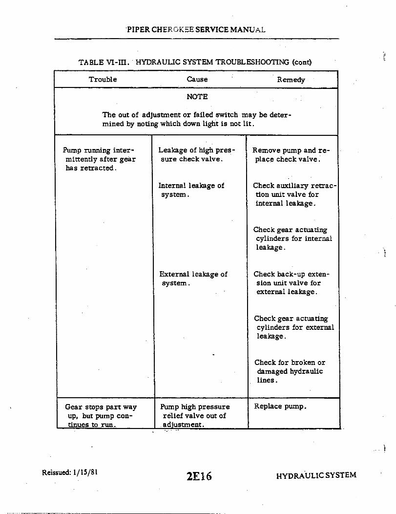
PIPER CHEROKEE SERVICE MANUAL
TABLE VI-III. HYDRAULIC SYSTEM TROUBLESHOOTING (cont)
Trouble Cause Remedy
NOTE
The out of adjustment or failed switch may be deter-mined by noting which down light is not lit.
Pump running inter-mittently after gearhas retracted.
Leakage of high pres-sure check valve.
Remove pump and re-place check valve.
Internal leakage ofsystem.
Check auxiliary retrac-tion unit valve forinternal leakage.
Check gear actuatingcylinders for internalleakage.
External leakage ofsystem.
Check back-up exten-sion unit valve forexternal leakage.
Check gear actuatingcylinders for externalleakage.
Check for broken ordamaged hydrauliclines.
Gear stops part wayup, but pump con-tinues to run.
Pump high pressurerelief valve out ofadjustment.
Replace pump.
Reissued: 1/15/81 HYDRAULIC SYSTEM2E16

PIPER CHEROKEE SERVICE MANUAL
TABLE VI-III. HYDRAULIC SYSTEM TROUBLESHOOTING (cont)
Trouble Cause Remedy
Gear stops part way up,but pump continues torun (cont.).
Internal leakage ofsystem.
Check back-up exten-sion unit valve forinternal leakage.
Check gear actuatingcylinders for internalleakage.
Check for broken ordamaged hydrauliclines.
Hydraulic fluid inreservoir belowoperating level.
Fill reservoir withhydraulic fluid.
All gears fail tofree fall.
Gear free falls atair speeds abovethat required.
Back-up extension unitvalve fails to open.
Back-up extender unithydraulic valve failsto close.
Check unit and valveand replace.
Check extender unitspring adjustment.
Check hydraulic valvefor sticking open.
Check extender unitdiaphragm for damage.
Check for restriction inair pressure and staticlines.
Reissued: 1/15/81 HYDRAULIC SYSTEM2E17

PIPER CHEROKEE SERVICE MANUAL
TABLE VI-III. HYDRAULIC SYSTEM TROUBLESHOOTING (cont)
Trouble Cause Remedy
Landing gear fails tooperate at requiredspeeds. (Gear up at85 mph , gear downat 105 mph.)
Manual control rodbetween over-ridelever (manual ex-truder) and rearseat rubbing orchafing on spar webwhere rod passesbeneath the spar.
Form the rod to allowclearance through fullfore and aft travel.
Friction or tightconnection at any ofthe attachment points(pivot points) of theover-ride lever oractuator arm.
Binding of diaphragmshaft caused by buildup of sand or dirt.
Clean, free and lub-ricate all pivot points.
Clean all moving parts.
Landing gear will notretract after selectingup at an airspeed aboveactuator speed. (Also,upon trying to over-rideit is found that only witha steady pressure canthe over-ride be activ-ated. After gear doesretract and the over-ride lever (manualextruder) is relaxed(approximately 11 to15 seconds.) the gearwill fall free.
Restriction in pres-sure head of gearback-up extenderactuator.
2E18
Disconnect hoses atback-up extender andclean out hoses andhead.
HYDRAULIC SYSTEMReissued: 1/15/81

PIPER CHEROKEE SERVICE MANUAL
TABLE VI-III. HYDRAULIC SYSTEM TROUBLESHOOTING (cont)
Trouble Cause Remedy
With gear selector downand three green lightson, in transit lightcomes on or inter-mittently on.
With gear selector downand three green lightson, pump motor circuitbreaker opens.
With in transit light on,pump operates on andoff.
With in transit light on,pump motor circuitbreaker opens.
Shorted gear upsolenoid.
Shorted gear upsolenoid.
Shorted gear downsolenoid.
Shorted gear downsolenoid.
Replace solenoid.
Replace solenoid.
Replace solenoid.
Replace solenoid.
HYDRAULIC SYSTEMReissued: 1/15/81 2E19

PIPER CHEROKEE SERVICE MANUAL
A659
ALLEN SET-SCREW .25
MATERIAL: Steel
Figure 6-11. Gear Back-up Extender Actuator Aligning Tool
Reissued: 1/15/81 HYDRAULIC SYSTEM2E20

INTENTIONALLY LEFT BLANK
2E21
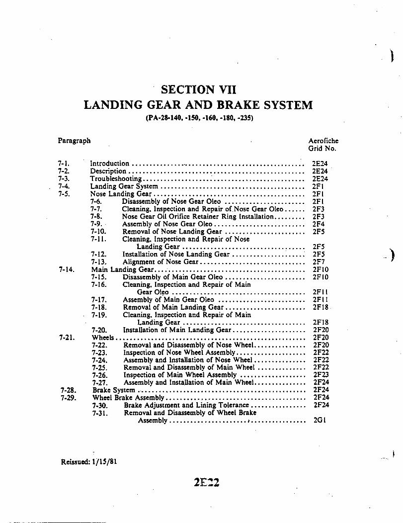
SECTION VIILANDING GEAR AND BRAKE SYSTEM
(PA-28-140, -150, -160, -180, -235)
Paragraph AeroficheGrid No.
7-1. Introduction .................................................. 2E247-2. Description .................................................. 2E247-3. Troubleshooting ............... 2E247-4. Landing Gear System ......................................... 2F17-5. Nose Landing Gear ........................................... 2F1
7-6. Disassembly of Nose Gear Oleo ....................... 2FI7-7. Cleaning. Inspection and Repair of Nose Gear Oleo ...... 2F37-8. Nose Gear Oil Orifice Retainer Ring Installation ......... 2F37-9. Assembly of Nose Gear Oleo .......................... 2F47-10. Removal of Nose Landing Gear ....................... 2F57-11. Cleaning, Inspection and Repair of Nose
Landing Gear ........................ 2F57-12. Installation of Nose Landing Gear ..................... 2F57-13. Alignment of Nose Gear .............................. 2F7
7-14. Main Landing Gear .......................................... 2F107-15. Disassembly of Main Gear Oleo ....................... 2F107-16. Cleaning, Inspection and Repair of Main
Gear Oleo ...................................... 2F117-17. Assembly of Main Gear Oleo ......................... 2F117-18. Removal of Main Landing Gear ....................... 2F187-19. Cleaning, Inspection and Repair of Main
Landing Gear ........................ 2F187-20. Installation of Main Landing Gear ..................... 2F20
7-21. Wheels ...................................................... 2F207-22. Removal and Disassembly of Nose Wheel ............... 2F207-23. Inspection of Nose Wheel Assembly .................... 2F227-24. Assembly and Installation of Nose Wheel ............... 2F227-25. Removal and Disassembly of Main Wheel .............. 2F227-26. Inspection of Main Wheel Assembly ................... 2F237-27. Assembly and Installation of Main Wheel ............... 2F24
7-28. Brake System .............................. ............. 2F247-29. Wheel Brake Assembly ........................................ 2F24
7-30. Brake Adjustment and Lining Tolerance ................ 2F247-31. Removal and Disassembly of Wheel Brake
Assembly ...................... ................ 2G1
Reissued: 1/15/81
2E22
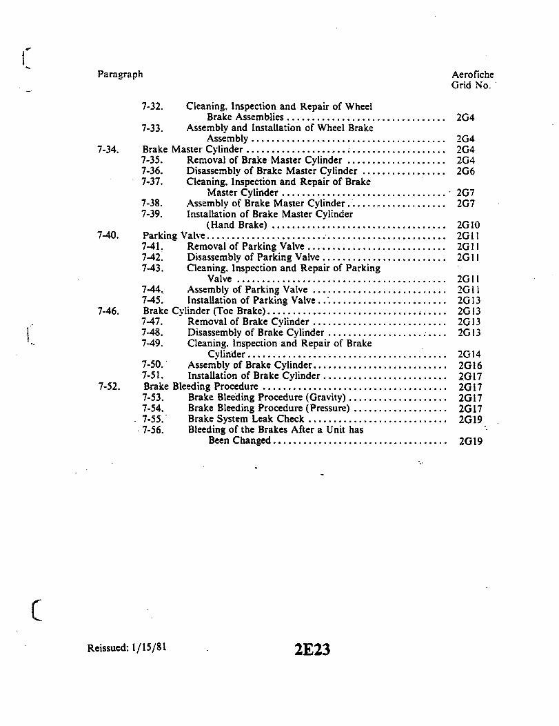
Paragraph AeroficheGrid No.
7-32. Cleaning, Inspection and Repair of WheelBrake Assemblies ................................ 2G4
7-33. Assembly and Installation of Wheel BrakeAssembly....................................... 2G4
7-34. Brake Master Cylinder ........................................ 2G47-35. Removal of Brake Master Cylinder .................... 2G47-36. Disassembly of Brake Master Cylinder ................. 2G67-37. Cleaning. Inspection and Repair of Brake
Master Cylinder................................. 2G77-38. Assembly of Brake Master Cylinder ................... 2G77-39. Installation of Brake Master Cylinder
(Hand Brake) ................................... 2G107-40. Parking Valve ................................................ 2G11
7-41. Removal of Parking Valve ............................ 2G 117-42. Disassembly of Parking Valve ......................... 2G117-43. Cleaning. Inspection and Repair of Parking
Valve .......................................... 2G117-44. Assembly of Parking Valve ........................... 2G117-45. Installation of Parking Valve.......................... 2G13
7-46. Brake Cylinder (Toe Brake) .............................. ..... 2G137-47. Removal of Brake Cylinder ........................... 2G137-48. Disassembly of Brake Cylinder ........................ 2G137-49. Cleaning, Inspection and Repair of Brake
Cylinder........................................ 2G147-50. Assembly of Brake Cylinder ........................... 2G167-51. Installation of Brake Cylinder ......................... 2G17
7-52. Brake Bleeding Procedure ..................................... 2G177-53. Brake Bleeding Procedure (Gravity) .................... 2G177-54. Brake Bleeding Procedure (Pressure) ................... 2G177-55. Brake System Leak Check ............................ 2G197-56. Bleeding of the Brakes After a Unit has
Been Changed................................... 2G19
Reissued: 1/15/81 2E23

PIPER CHEROKEE SERVICE MANUAL
SECTION VII
LANDING GEAR AND BRAKE SYSTEMPA-28-140, -150, -160, -180 and -235
7-1. INTRODUCTION. In this section are instructions for the removal, disassembly,inspection, overhaul and installation of the various landing gear and brake systemcomponents used on the alignment of the nose gear, and the repair and service of the brakesystem.
7-2. DESCRIPTION. The landing gear incorporated on the PA-28-140, -150, -160, -180 and-235 airplanes is a fixed tricycle type, fitted with three 600 x 6 wheels. The landing gearstruts are of the air-oil type. The nose gear, steerable through a wide arc, enables a shortturning radius in each direction. (For turning arc of each airplane by serial number, refer toTable VII-I.) To aid in nose wheel and rudder centering and to provide rudder trim there is aspring device attached to the rudder pedal torque tube assembly. A shimmy dampener isalso incorporated in the nose wheel steering mechanism. Bungee springs are alsoincorporated on the push rods of later models. (1974 models and up) These springs makelighter and smoother ground steering possible.
The two main wheels are equipped with a single disc hydraulic brake assembly which isactuated by a hand lever connected to a cylinder located below and behind the center of theinstrument panel, or by individual cylinders attached to each rudder pedal. The hand leveralso doubles as a parking brake and may be operated by pulling back on the handle andpulling out the parking brake tee handle, holding it until the hand lever is released orpushing in on the button at the side of the handle. To disengage the parking brake, eitherpush in on the tee handle or pull back on the hand brake handle. A brake fluid reservoir isinstalled on the left forward face of the engine firewall.
7-3. TROUBLESHOOTING. Troubles peculiar to the landing gear are listed in Table VII-II,at the back of this section, along with their probable causes and suggested remedies. Whentroubleshooting the landing gear system, it may be found that it is necessary to place theairplane on jacks. If so, refer to Jacking, Section II.
LANDING GEAR AND BRAKE SYSTEM2E24

PIPER CHEROKEE SERVICE MANUAL
7-4. LANDING GEAR SYSTEM.
7-5. NOSE LANDING GEAR.
7-6. DISASSEMBLY OF NOSE GEAR OLEO. (Refer to Figure 7-1.) The nosegear oleo strut assembly maybe removed and disassembled from the strut hous-ing with the gear removed from or installed on the airplane.
a. Remove the lower engine cowling by the following procedure:1. Release the cowl fasteners, two on each side and remove the top cowl.2. Disconnect the electrical lead to the landing light at the quick disconnect
at the inside of the bottom cowl.3. Remove the bottom cowl attaching screws from around its aft end and
remove cowl.b. Place airplane on jacks. (Refer to Jacking, Section II.)c. Place a drip pan under the nose gear to catch spillage.d. To remove air from the strut, depress the air valve core pin found at the
top of the strut assembly. After the pressure in the strut chamber has dimin-ished, remove the valve core pin, and attach a small hose to the air valve, anddrain the fluid by slowly compressing the piston tube. If it is desirable to ex-tract more fluid from the strut chamber, remove the filler plug, insert the si-phon hose and drain fluid from the upper area of the housing.
e. To remove the strut assembly from the strut housing (4), cut the safetywire at the top of the housing that secures the steering horn attaching bolt to thetube retainer nut. Then remove the steering horn attaching bolt and the flat headpin, thus relieving the steering horn from the top of the strut housing.
f. Loosen the strut assembly retainer nut (1) that secures the strut assemblyin the strut housing. At the same time, slide the strut assembly out through thebottom of the strut housing. Remove the nut (1) and washer (2) from the top ofthe strut housing after the assembly is removed.
NOTE
The strut assembly may fit tight inside of the housing.It may be necessary to tap the top of the fork with aplastic mallet.
g. If desired, remove the top and bottom bearing (3 and 5) from the struthousing. The bearings are compressed slightly into place, and light tapping maybe needed to free them.
Reissued: 1/15/81 2F1 LANDING GEAR AND BRAKE SYSTEM

PIPER CHEROKEE SERVICE MANUAL
1768
18
RING ,RETAINER
1973 PA-28-180 AND PA-28-235 SERIAL NOS. AND UP
NUT, RETAINER2. WASHER
3. BEARING, TOP4. STRUT HOUSING5. BEARING, BOTTOM6. CAP, VALVE7. PLUG, FILLER8. TUBE METERING9. CYLINDER
10. RING, RETAINER11. SNAP RING
12. BEARING13. "0" RING, PACKING14. "0" RING OR QUAD RING15. WASHER, CACK-UP
17. WIPER STRIP17. TUBE, PISTON18. "0" RING19. PLUG, PISTON TUBE
Figure 7-1. Nose Gear Oleo Strut Assembly
Reissued: 1/15/81 LANDING GEAR AND BRAKE SYSTEM2F2

PIPER CHEROKEE SERVICE MANUAL-
h. To remove the piston tube and fork assembly (17) from the cylinder (9), proceed asfollows:
1. Separate the upper and lower torque links by removing the connecting nut,washer and bolt.
2. Compress the piston tube and fork assembly slightly and remove the retainerring (10) from the annular slot in the bottom of the cylinder tube. Then remove piston tubeand fork assembly by sliding out from the bottom of the cylinder tube.
i. To remove the bearing assembly from the piston tube, release the snap ring (11)from the top of the piston tube and slide bearing assembly off the end.
1. If desired, carefully remove the wiper strip (16), back-up washer (15) and quadring or "O" ring (14) from the inside of the bearing sleeve, and also the "0" ring gasket (13)from the outside of the bearing sleeve.
j. To remove the piston tube plug (19) with "O" ring (18) located in the lower end ofthe tube, the following procedure may be used:
1. Remove the nose wheel from the fork as described in paragraph 7-22.2. Loosen and remove the bolt, washer and nut that extends through the piston
tube and block assembly.3. Push the plug through the top of the piston tube by use of a rod inserted
through the bottom of the tube.
7-7. CLEANING, INSPECTION AND REPAIR OF NOSE GEAR OLEO.a. Clean all parts with a suitable dry type cleaning solvent.b. Inspect the landing gear oleo assembly component for the following:
1. Cylinder tube assembly for corrosion, scratches, nicks and excessive wear.2. Lock rings for cracks, burrs, wear.3. Fork assembly for corrosion, scratches, nicks, and misalignment.4. Link assembly for elongated holes, cracks, corrosion, scratches, nicks and
straightness.5. General condition of air valve.
c. Repair of the oleo is limited to smoothing out minor scratches, nicks and dents andreplacement of parts.
7-8. NOSE GEAR OIL ORIFICE RETAINER RING INSTALLATION. (Refer to Figures7-1 and 7-22.)
a. With the piston tube (17) and fork removed from the cylinder (9), ascertain that alltraces of the old retainer ring (10) are removed from the metering tube (8).
b. A tool can be fabricated to simplify the installation of the new retainer ring. (Referto Figure 7-22.)
c. With the use of the fabricated tool, position the new retainer ring on the end of thetool with the locating stud.
d. Insert the tool into the cylinder (9), with the centering stud positioned into the holein the base of the metering tube (8).
e. Hold the tool tightly against the metering tube and slide the sleeve of the tooltowards the metering tube. This will move the new retainer ring (10) over the end of themetering tube and position itself into the groove of the metering tube (8).
2F3 LANDING GEAR AND BRAKE SYSTEMReissued: 1/15/81

PIPER CHEROKEE SERVICE MANUAL
7-9. ASSEMBLY OF NOSE GEAR OLEO. (Refer to Figure 7-1.)a. Ascertain that all parts are cleaned and inspected.b. To install the piston tube plug, proceed as follows:
1. Lubricate thetube plug(19) and "O" ring(18) with hydraulic fluid (MIL-H-5606) and install the "O" ring on the plug.
2. Lubricate the inside wall of the piston tube, and insert the plug into thetop of the tube, pushing it to the fork end.
3. Align the bolt holes of the fork, tube and plug; install the bolt, washerand nut.
c. Carefully install in the bearing sleeve the quad ring (14), back-up washer(15) and the wiper strip (16). Slide the "O" ring (13) in place on the outside ofthe sleeve.
d. Lubricate the bearing assembly and carefully install it on the piston tube(17).
e. Position the snap ring (11) on the upper end of the piston tube.f. Insert the piston tube with bearing assembly in the cylinder tube (9). Secure
it with the retainer ring (10) in the annular slot at the bottom of the tube.g. Connect the torque links on the tube and fork securing them with a bolt,
washer and nut. Tighten the nuts only tight enough to retard side play, but stillallowing the links to rotate freely.
h. Ascertain that the upper and lower bearings (3 and 5) are installed in thestrut housing. Bearings are a press fit with the grooves in the inner and outerraces in the up position.
i. Position washer (2) and strut assembly retainer nut (1) on top of the struthousing. Insert the strut assembly up through the washer until it contacts the nut.Tighten the nut to a snug fit.
j. To install the steering horn assembly, insert the flat head pin through theside of the horn and top of the strut assembly. When it protrudes through theother side of the steering horn, install the washer and secure with a cotter pin.
k. Install the steering horn attaching bolt through the top of the horn into thestrut assembly. Do not tighten bolt at this time. If a space appears between thesteering horn plate and the top of the strut assembly, it will then be necessaryto install spacer washer(s), (AN960-416L), between the horn and strut. Thentighten the bolt and safety the bolt to the strut assembly retainer nut (1) withMS20995C40 wire.
1. Compress and extend the strut several times to ascertain that the strut willoperate freely. The weight of the gear wheel and fork should allow the strut toextend.
m. Service the oleo strut with fluid and air. (Refer to Oleo Struts, Section II.)n. Check the gear for alignment. (Refer to Alignment of Nose Landing Gear,
Paragraph 7-12.)
Reissued: 1/15/81LANDING GEAR AND BRAKE SYSTEM2F4

PIPER CHEROKEE SERVICE MANUAL
7-10. REMOVAL OF NOSE LANDING GEAR. (Refer to Figure 7-2.)a. Remove the engine cowling by the following procedure:
1. Release the fasteners, two on each side and two at the top of the cowl.2. Lift the aft end of the top cowl and then slide it forward to release the
two stud type front fasteners. Remove the top cowl.3. Disconnect the electrical lead to the landinglightat the quick disconnect
at the right inside of the bottom cowl.4. Remove the bottom cowl attaching screws from around its aft end and
remove the cowl.b. Remove the propeller. (Refer to Removal of Propeller, Section VIII.)c. Place the airplane on jacks. (Refer to Jacking, Section II.)d. Remove the engine. (Refer to Removal of Engine, Section VIII.)e. Disconnect the two steering rods (lland4) at the nose gear horn assembly
(3) by removing the cotter pins, nuts, washers and bolts.f. Disconnect the oil lines, vacuum lines, fuel lines, hoses and wires which
are secured to the mount with clamps and Koroseal lacing. Mark all wires andlines for identification and reinstallation.
g. Remove the nose gear and engine mount by removing the five bolts (16)which attach the mount to the firewall.
7-11. CLEANING, INSPECTION AND REPAIR OF NOSE LANDING GEAR.a. Clean all parts with a suitable dry type cleaning solvent.b. Inspect the nose gear assembly for the following:
1. Bolts, bearings and bushings for excess wear, corrosion and damage.2. Strut housing and torque links for cracks, bends or misalignment.
c. The shimmy dampener requires no service other than routine inspection.In case of damage or malfunction, the dampener should be replaced rather thanrepaired.
d. Repair to the landing gear is limited to reconditioning of parts, such asreplacing bearings and bushings, smoothing out minor nicks and scratches, re-painting of areas where paint has chipped or peeled and replacement of parts.
7-12. INSTALLATION OF NOSE LANDING GEAR. (Refer to Figure 7-2.)a. Install the nose gear and engine mount assembly to the firewall with bolts,
washers and nuts. Torque nuts as specified in Torque Requirements, Section IIof this manual.
b. Attach the two steering rods (11 and 4) to the nose gear steering horn (3)with bolts, washers and nuts (1).
Reissued: 1/15/81 2F5 LANDING GEAR AND BRAKESYSTEM
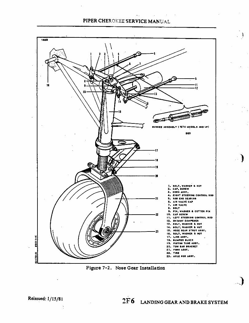
PIPER CHEROKEE SERVICE MANUAL
1829
BUNGEE ASSEMBLY (1974 MODELS AND UP)
983
18
19
20
1. BOLT, WASHER & NUT2. CAP, SCREW3. HORN ASSY.4. RIGHT STEERING CONTROL ROD
21 5. ROD END BEARING6. AIR VALVE CAP7. AIR VALVE8. BOLT9. PIN, WASHER & COTTER PIN
22 10. CAP SCREW11. LEFT STEERING CONTROL ROD
12. SHIMMY DAMPENER13. BOLT, WASHER & NUT
14. BOLT, WASHER & NUT
23 19. NOSE GEAR STRUT ASSY.18. BOLT, WASHER & NUT
17. LINK ASSY.18. BUMPER BLOCK19 . PISTON TUBE ASSY.20. TOW BAR BRACKET21. FORK ASSY.22. TIRE23. AXLE ROD ASSY.
Figure 7-2. Nose Gear Installation
Reissued: 1/15/81 2F6 LANDING GEAR AND BRAKE SYSTEM
16

PIPER CHEROKEE SERVICE MANUAL
c. If removed, connect the shimmy dampener(12)to the steering horn with bolts,washers and nuts(l4).A spacer bushing and cotter pin are required at the body attachmentpoint.
d. Install the engine and connect controls. (Refer to Installation of Engine, SectionVIII.)
e. Attach hoses, wires and cables to engine mount tubing, securing with clamps andKoroseal lacing where required.
f. Check the alignment of the nose gear per paragraph 7-12.g. Remove the airplane from the jacks.h. Install the propeller, (Refer to Installation of Propeller, Section VIII.) and engine
cowling.
7-13. ALIGNMENT OF NOSE GEAR. On 1974 models the nose wheel steering has beenmodified by the addition of the bungee steering system. This new system will require somedifferent adjustment procedures which are included with the regular instructions.
a. Place the airplane on a smooth level floor that will accomodate the striking of achalk line.
b. Place the airplane on jacks. (Refer to Jacking, Section II.)c. Level the airplane laterally and longitudinally. (Refer to Leveling, Section II.)d. From the center of the tail skid, extend a plumb bob and mark the contact point on
the floor.e. Extend a chalk line from the mark on the floor below the tail skid to a point
approximately three feet forward of the nose wheel. Allow the line to pass under the wheelat the center line of the tire. Snap the chalk line.
f. Ascertain that the rudder is properly rigged and the rudder cable tension is correct.(Refer to Rigging of Rudder, Section V.)
g. Clamp the rudder pedals to align in a lateral position. (Refer to Figure 7-3.)h. Ascertain that the nose wheel is in alignment with the longitudinal axis of the
airplane or chalk line.i. On airplanes prior to 1974 models adjust the rod end bearings of each steering
control rod to align the nose wheel with the chalk line and bring the rudder pedals into theirneutral angle fore and aft. (Refer to Table VII-I for neutral angle.) Do not attempt to makethe adjustments by means of one rod end, divide the adjustment between rod ends. Place abubble protractor against a pedal steering tube to check this angle.
j. On 1974 models install the steering bungee assemblies between the steering horn andrudder pedals without any load on the bungees. Adjust the rod ends to obtain this no loadcondition, and connect the bungees to the steering horn.
NOTE
Check that the rod ends have sufficient thread engagement,by use of the check holes in the rods or a minimum ofthree-eights of an inch thread engagement.
k. On 1974 models ascertain that the rudder pedal stops are adjusted in accordancewith instructions given in Rigging and Adjustment of Rudder, Section V.
2F7 LANDING GEAR AND BRAKE SYSTEMReissued: 1/15/81

PIPER CHEROKEE SERVICE MANUAL
1641
See Table VII-1 For Rudder Pedal Neutral Angle
Figure 7-3. Clamping Rudder Figure 7-4. Rudder PedalsPedals in Neutral Position at Neutral Angle
L To check the nose gear steering for its maximum right and left travel, mark on eachside of the nose wheel an angle line from the center line and wheel pivot point. (Refer toTable VII-I for nose wheel turning angle of the particular model being serviced.) Turn thewheel to its maximum travel in both directions to check for allowable travel. Should travelbe exceeded in one direction and not enough in the other direction, check for possibledamage to the gear fork or torque links,
m. When the wheel is turned to its extreme right or left travel, there should be .06 to.12 of an inch clearance between the nose wheel steering stops. This is due to the stops onthe rudder making contact ahead of the nose gear stops. Prior to checking and/or makingthis adjustment, ascertain that the rudder travel is correct per Rigging and Adjustment ofRudder, Section V.
n. Adjust the shimmy dampener by turning the nose wheel against its stops andadjusting the rod end of the dampener for adequate travel to both directions.
o. Remove the aircraft from jacks.
NOTE
When the nose wheel fairing is removed, centering springsshould be installed for proper nose wheel centering. Refer tothe latest revision of Piper Service Bulletin No. 291 for moreinformation.
LANDING GEAR AND BRAKE SYSTEM2F8Reissued: 1/15/81

PIPER CHEROKEE SERVICE MANUAL
TABLE VII-I. NOSE GEAR ALIGNMENT TOLERANCES
Rudder Pedal Neutral Angle (Aft of Vertical)
8 degrees, 15 minutes
11 degrees
14 degrees + 3. -
1. PA-28-140,Serial Nos. 28-20002 to 28-20520 incl.
2. PA-28-150,-160,-180,Serial Nos. 28-1 to 28-1760 incl.
3. PA-28-235,Serial Nos. 28-10000 to 28-10486 incl.
1. PA-28-140,Serial Nos. 28-20521 to 28-7325684
2. PA-28-150. -160, -180,Serial Nos. 28-1760 to 28-7305611
3. PA-28-235.Serial Nos. 28-10487 to 28-7310187
4. PA-28R-200. Models Previous to 19745. PA-28R-180, Serial Nos. 28R-713001 and up
All 1974 Models and up
Nose Wheel Travel
30 degrees left,30 degrees right
22 degrees left,22 degrees right
.
+ 1°
- 1 °
1. PA-28-140,Serial Nos. 28-20002 to 28-21845 incl;28-21847 to 28-21929 incl; 28-21931 to28-21934 incl.
2. PA-28-150,-160,-180,Serial Nos. 28-1 to 28-3377 incl.
3. All PA-28R-200 Models4. All 1974 Models and up
1. PA-28-140,Serial Nos. 28-21846, 28-21930, 28-21935to 28-7325684
2. PA-28-150,-160,-180,Serial Nos. 28-3378 to 28-7305611
3. PA-28-235 Models up to Serial No.28-7310187
LANDING GEAR AND BRAKE SYSTEM2F9Revised: 10'3;'83
PIPER CHEROKEE SERVICE MANUAL
7-14. MAIN LANDING GEAR.
7-15. DISASSEMBLY OF MAIN GEAR OLEO. (Refer to Figure 7-5 or 7-6.) The main gearaxle (19) and piston tube assembly (18) may be removed from the cylinder housing (9) withthe gear removed from or installed on the airplane. On some airplanes the meteringcomponents of the gear that are located in the top of the housing may be removed, but onlywith the gear removed from the airplane. (Refer to Paragraph 7-17 for Removal of Gear.)
a. Place the airplane on jacks. (Refer to Jacking, Section II.)b. Place a drip pan under the main gear to catch spillage.c. The gear axle and piston tube assembly may be removed by the following
procedure:1. Remove the air from the oleo chamber by depressing the air valve core pin found
in the inspection hole on top of the wing. After the pressure in the oleo chamber hasdiminished, remove the valve core pin, attach a small hose to the air valve, and drain the fluid by slowly compressing the piston tube. If it is desirable to extract more fluid from thechamber, remove the filler plug, insert a siphon hose and drain fluid from the upper area ofthe housing.
2. Disconnect the flexible brake line at the elbow on the brake assembly.3. Disconnect the torque link assembly by removing any one of the three cotter
pins, nuts, washers and bolts. Note arrangement of the components for reinstallation.Carefully slide the piston tube from the cylinder housing.
4. The scraper ring (15) located inside the lower end of the cylinder housing maybe removed by first removing the retainer ring (17), spacer ring (16) and then the scraperring.
5. The "O" ring seal (14) located just before the scraper ring may be removed byusing a curved wire or spoon shaped tool and inserting it under the ring.
d. The cylinder head, and in some airplanes the orifice assembly, may be removed bythe following procedure:
1. Cut safety wire and remove the bolts that secure the cylinder head (4) in the topof the housing. Remove the assembly from the housing.
2. If "O" ring was used with cylin4er head (4), remove and discard. If "0" ring wasnot used with cylinder head (4), remove all traces of sealant from around the cylinder head(4) and top of housing.
3. If, when removed, the cylinder head is equipped with a metering tube (6), thisindicates that the orifice assembly (8) may be removed. (Those assemblies without ametering tube, the metering device is cast into the housing.)
4. The orifice assembly may be removed from within the housing by rotating itcounterclockwise out of the housing with the use of a .50 x .125 stud type spanner wrench(Refer to Figure 7-21). Do not remove orifice unless it necessitates replacement.
Reissued: 1/15/81 2FI0 LANDING GEAR AND BRAKE SYSTEM

PIPER CHEROKEE SERVICE MANUAL
7-16. CLEANING, INSPECTION AND REPAIR OF MAIN GEAR OLEO.a. Clean all parts with a suitable dry type cleaning solvent.b. Inspect the landing gear oleo components for the following:
1. Bearing surfaces of housing for excess wear, corrosion, scratches and overalldamage.
2. Retaining ing for cracks,-burrs, etc.3. Cylinder tube for corrosion, scratches, nicks, excessive wear and misalignment.4. Air valve for operation and general condition.5. Orifice plate for hole restriction.
c. Repair of the oleo is limited to smoothing out minor scratches, nicks and dents, andreplacement of parts.
7-17. ASSEMBLY OF MAIN GEAR OLEO. (Refer to Figure 7-5 or 7-6.)a. Install the orifice assembly, if removed, by the following procedure:
1. Lubricate with hydraulic fluid (MIL-H-5606) and install an "O" ring (7) in theannular slot in the metering orifice (8).
2. Insert the orifice through the opening in the top of the gear housing and turn itinto the threaded hole web. Tighten the orifice with the use of a stud type spanner wrench.
3. Lubricate and install an "O" ring or apply a thin layer of PermatexForma-Gasket No. 6 Sealant, directly underneath the flange of the cylinder head (4).
NOTE
/({~~ ~~On models without the groove for the "O" ring, applyPermatex Forma-Gasket #6 Sealant beneath the flange of thecylinder head (4).
4. Insert The tube of the metering assembly through the opening in the top of thehousing and into the orifice. Use caution not to cut or dislodge the "0" ring slot in theorifice.
5. Secure the metering tube assembly with bolts and safety with MS20995-C32wire..
b. Assemble the- components of the piston tube (18) on the tube by placing, in order,the retainer ring (17), spacer ring (16) and scraper ring (15). Insert an "O" ring (14) into theannular slot in the bottom of the housing.
c. Lubricate the wall of the piston and carefully insert it into the housing being carefulnot to damage or dislocate the "0O" ring in the housing.
d. Ascertain that the bushings are installed in the upper and lower torque links andthen install links. At cable end of each link, install with the use of brake line bracket,bearing washers, bolt, washer, nut and cotter pin. Do not over tighten causing binding ordamage to the link. At the connection point of the upper and lower links, attach with the
. use of brake line brackets, spacer washers, grease bolt, washers, nut and cotter pins. Installwashers (AN960-816L) under the head of the bolt to allow a firm sliding fit between thetwo links.
e. Slide the scraper and spacer rings into place and secure with the retainer ring in theannular slot in the bottom of the housing.
(
LANDING GEAR AND BRAKE SYSTEMReissued: 1/15/81 2Fll

INTENTIONALLY LEFT BLANK
2F 1 2
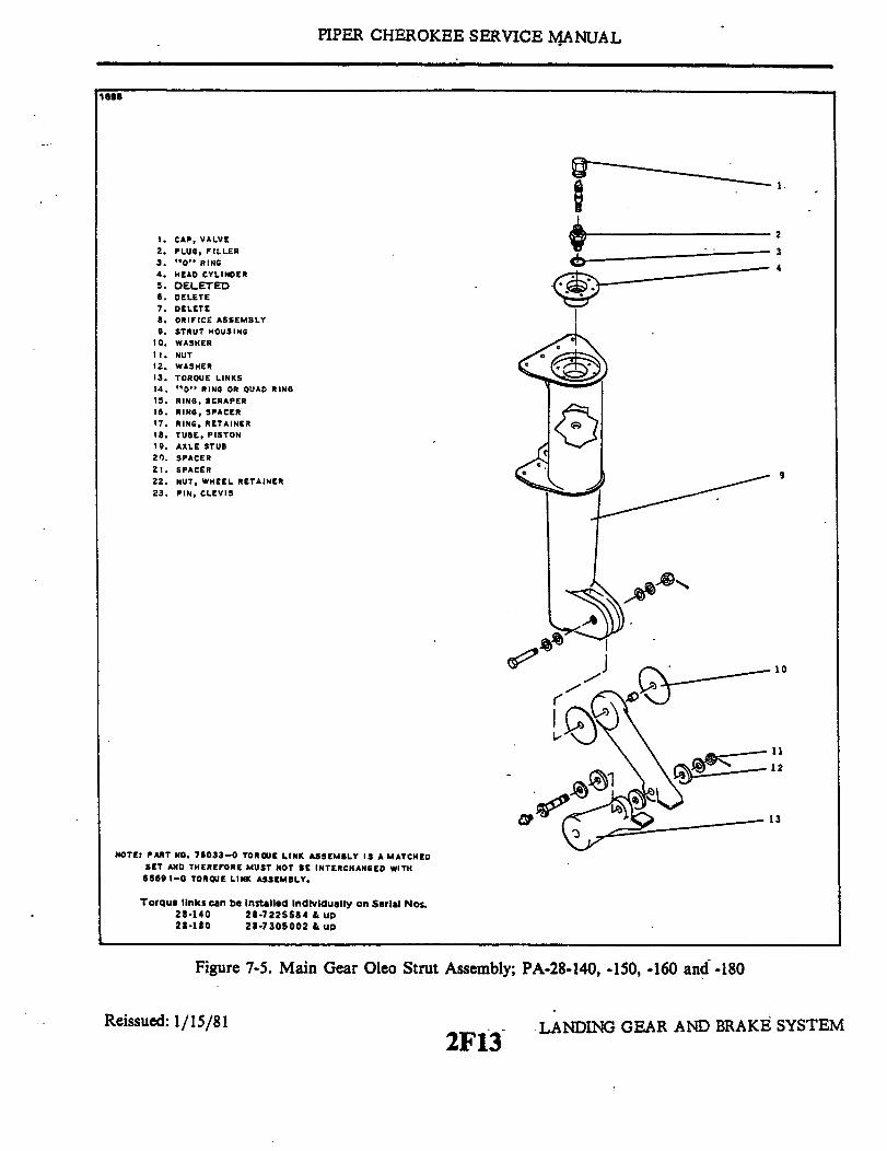
PIPER CHEROKEE SERVICE MANUAL
1898
1.
1. CAP, VALVE2. PLUG, FILLER3. "O" RING4. HEAD CYLINDER5. DELETED6. DELETE7. DELETE8. ORIFICE ASSEMBLY9. STRUT HOUSING
10. WASHER
11. NUT12. WASHER13. TORQUE LINKS14. "O" RING OR QUAD RING
15. RING, SCRAPER16. RING, SPACER17. RING, RETAINER18. TUBE, PISTON
19. AXLE STUB20. SPACER21. SPACER22. NUT, WHEEL RETAINER
23. PIN, CLEVIS
NOTE: PART NO. 78033-0 TORQUE LINK ASSEMBLY IS A MATCHED
SET AND THEREFORE MUST NOT BE INTERCHANGED WITH
6569 -0 TORQUE LINK ASSEMBLY.
2
3
4
9
10
11
12
13
Torque links can be installed individually on Serial Nos.28-140 28-7225584 & up28-180 28-7305002 & up
Figure 7-5. Main Gear Oleo Strut Assembly; PA-28-140, -150, -160 and -180
Reissued: 1/15/812F13
LANDING GEAR AND BRAKE SYSTEM

PIPER CHEROKEE SERVICE MANUAL
1698
SEE NOTE
Figure 7-5. Main Gear Oleo Strut Assembly; PA-28-140, -150, -160 and -180 (cont.)
1/15/81 2F14 LANDING GEAR AND BRAKEReissued: SYSTEM

PIPER CHEROKEE SERVICE MANUAL
1699
NOTE: PART NO. 78033-0 TORQUE LINK ASSEMBLY IS A MATCHED
SET AND THEREFORE MUST NOT BE INTERCHANGED WITH65691-0 TORQUE LINK ASSEMBLY.
Torque links can be installed Individually on Serial Nos.28-235 28-7310003 & UP
2
1. CAP, VALVE2. PLUG, FILLER3. "0" RING4. HEAD CYLINDER5. DELETED6 TUBE, METERING7. "0" RING8. ORIFICE ASSEMBLY /9. SRUT HOUSING
10. WASHER12 . NUT
12. WASHER13 TORQUE LINKS14. "O" RING OR QUAD RING15 RING, SCRAPER \16. RING SPACER17 RING RETAINER17. TUBE, PISTON
19 AXLE STUB
20. SPACER21. SPACER22 NUT, WHEEL RETAINER
23 PIN, CLEVIS
Figure 7-6. Main Gear Oleo Strut Assembly, PA-28-235
Reissued: 1/15/81 2F15 LANDING GEAR AND BRAKE SYSTEM

PIPER CHEROKEE SERVICE MANUAL
1999
1
234
6
78
9
13
SEE NOTE
Figure 7-6. Main Gear Oleo Strut Assembly, PA-28-235 (cont.)
Reissued: 1/15/812F 16 LANDING GEAR AND BRAKE SYSTEM

INTENTIONALLY LEFT BLANK
2F17

PIPER CHEROKEE SERVICE MANUAL
f. Install the hydraulic brake line.g. If removed, install the landing gear as described in paragraph 7-19.h. Service the oleo strut as given in Oleo Struts, Section II.i. Actuate the gear several times by hand to be certain it operates freely.
NOTE
Links should be loose enough to allow free action of the gear.but also resist side play. To eliminate side play shim washers63311-03 (.005) may be used as required. Maximum sideplay .005 /.007.
j . Remove the drip pan and slowly lower the airplane from the jacks.k. If necessary, bleed brakes by instructions given in paragraph 7-51.
7-18. REMOVAL OF MAIN LANDING GEAR. (Refer to Figure 7-7.)a. Place the airplane on jacks. (Refer to Jacking, Section II.)b. Place a drip pan under the main gear to catch spillage.c. If desired, remove the air from the oleo chamber by depressing the air
valve core pin found in the inspection hole ontop of the wing. After the pressurein the oleo chamber has diminished, remove the valve core pin and attach a smallhose to the air valve and drain the fluid by slowly compressing the piston tube.If it is desirable to extract more fluid from the chamber, remove the filler plug,insert the siphon hose and drain fluid from the upper area of the housing.
d. Remove the fairing from around the cylinder housing and the access platelocated on the bottom of the wing and to the rear of the housing by removing at-taching screws.
e. Unhook the hydraulic brake line inside the wing assembly. This is acces-sible through the access plate. Cap the line by use of a threaded cap or wrappingwith plastic.
f. Remove the top four bolts by holding them with a slotted screwdriver andturning the nut with the appropriate wrench. Remove the remaining six by useof a wrench. Carefully remove the gear assembly from the wing.
7-19.. CLEANING, INSPECTION AND REPAIR OF MAIN LANDING GEAR.a. Clean all parts with a suitable dry type cleaning solvent.b. Inspect the gear components for excessive wear, corrosion and damage.
Check the cylinder housing and torque links for cracks, nicks and misalignment.c. Repair of the landing gear is limited to reconditioning of parts, replace-
ment of parts, smoothing out minor nicks and scratches and repainting areaswhere paint has chipped or peeled.
Revised: 10/3/83
LANDING GEAR AND BRAKE SYSTEM2F18
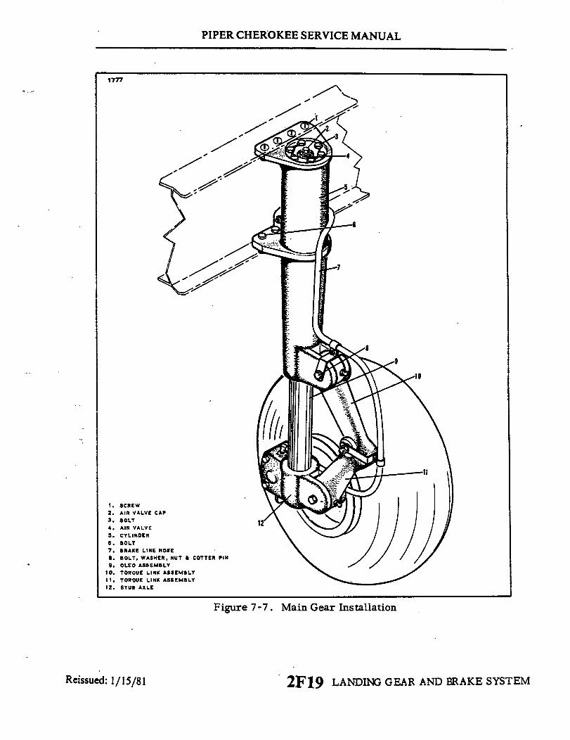
PIPER CHEROKEE SERVICE MANUAL
1777
100
1. SCREW2. AIR VALVE CAP3. BOLT4. AIR VALVE5. CYLINDER6. BOLT7. BRAKE LINE HOSE8. BOLT, WASHER, NUT & COTTER PIN9. OLEO ASSEMBLY
10. TORQUE LINK ASSEMBLY11. TOROUE LINK ASSEMBLY12. STUB AXLE
Figure 7-7. Main Gear Installation
Reissued: 1/15/81 2F19 LANDING GEAR AND BRAKE SYSTEM
,/
PIPER CHEROKEE SERVICE MANUAL
7-20..INSTALLATION OF MAIN LANDING GEAR. (Refer to Figure 7-7.)a. The main landing gear assembly may be installed on the wing by the follow-
ing procedure:1. Position the gear up in the wing through the access opening and secure
with bolts, washers and nuts.2. Reconnect the brake line at the point of disconnection.
b. Service the oleo strut per Oleo Struts, Section II.c. Service the brake system. (Refer to Brake System, Section II.)d. Install the access plate to the bottom of the wing and the oleo housing fair-
ing to the gear.e. Slide the drip pan from under the gear and remove the airplane from the
jacks.
7-21. WHEELS.
7-22. REMOVAL AND DISASSEMBLY OF NOSE WHEEL. (Refer to Figure 7-8.)a. Jack the airplane enough to raise the nose wheel clear of the ground. (Refer
to Jacking, Section II.)b. If wheel fairing is installed, remove four bolts, two on each side, and the
small plate on top held by metal screws. Slide fairing up on the gear until thewheel is removed.
c. Remove wheel by the following procedure:1. Remove the nut and washer from one end of the axle rod and slide out
the rod and axle plugs.2. Lightly tap the axle tube out from the center of the wheel assembly by
use of an object of near equal diameter.
NOTE
Be certain not to damage the axle tube end in any way.This will make removal and installation extremelydifficult.
3. Remove the spacer tubes and the wheel assembly.4. Slide down wheel fairing and remove by turning it sideways.
2F20 LANDING GEAR AND BRAKE SYSTEMReissued: 1/15/81

PIPER CHEROKEE SERVICE MANUAL
/
2
//
1J
as, 3 -I
1. WHEEL HALF2. WHEEL HALF3. WASHER4. WHEEL THROUGH BOLT5. NUT6. SEAL RETAINER SCREW7. SNAP RING
S. SEAL RETAINERS9. GREASE SEAL
10. BEARING CONESII. BEARING CUP
Figure 7-8. Nose Wheel Assembly
d. The wheel halves (1 and 2) may be separated by first deflating the tire.With the tire sufficiently deflated, remove the wheel through bolts (4). Pull thewheel halves from the tire by removing the wheel half opposite the valve stemfirst and then the other half.
e. The wheel bearing assemblies (10 and 11) maybe removed from each wheelhalf by first removing the three screws (6) or snap ring (7) which hold in thegrease seal (9) and seal retainers (8), and then the bearing cones (10). The bear-ing cup (11) should be removed by tapping out evenly from the inside.
sued: 1/15/81 2F21 LANDING GEAR AND BRAKE S
/
1695
9.
11
Reise SYSTEM

PIPER CHEROKEE SERVICE MANUAL
7-23. INSPECTION OF NOSE WHEEL ASSEMBLY.a. Visually check all parts for cracks, distortion, defects and excess wear.b. Check tie bolts for looseness or failure.c. Check internal diameter of felt grease seals. Replace the felt grease seal if surface
is hard or gritty.d. Check tire for cuts, internal bruises and deterioration.e. Check bearing cones and cups for wear and pitting and relubricate.f. Replace any wheel casting having visible cracks.
7-24. ASSEMBLY AND INSTALLATION OF NOSE WHEEL. (Refer to Figure 7-8.)a. Ascertain that the bearing cup (11) for each wheel half (I and 2) is properly
installed. Install the tire with tube on the wheel half with the valve stem hole and thenjoin the two wheel halves. Install the through bolts (4) with the washers (3) and nuts (5) tothe valve stem side, torque nuts to 90 inch pounds and inflate tire. (Refer to Table II-I,Section II for tire pressure.)
b. Lubricate the bearing cones (10) and install the cones and grease seal assembly (8and 9). Secure with the same three screws (6) or snap ring (7).
c. Replace the wheel fairing by turning sideways and slipping it up over the forkassembly.
d. Place the spacer tubes one on each side of the wheel and install unit in fork. Alignand slide the axle tube through the spacer tubes and wheel assembly. Reinstall the axleplugs and rod with washer and nut. Tighten the nuts until no side play is felt, yet allowingthe wheel to rotate freely.
e. Turn fairing so it will fall into place and reinstall it with the four bolts and screwsin the small plate.
7-25. REMOVAL AND DISASSEMBLY OF MAIN WHEEL. (Refer to Figure 7-9.)a. Place the airplane on jacks. (Refer to Jacking, Section II.)b. To remove the main wheel, remove the two cap bolts that join the brake cylinder
housing and the lining back plate assemblies. Remove the back plate from between brakedisc and wheel.
c. Remove the dust cover, the cotter pin and flat head pin that safeties the wheel nut,and the wheel nut. Slide the wheel from the axle.
d. The wheel halves (1 and 2) may be separated by first deflating the tire. With the tiredeflated, remove the wheel through bolts (16). Pull the wheel halves from the tire byremoving the inner half from the tire first, and then the outer half. The brake disc can beremoved at this time.
Revised: 10/3/83 LANDING GEAR AND2F22 BRAKE SYSTEM
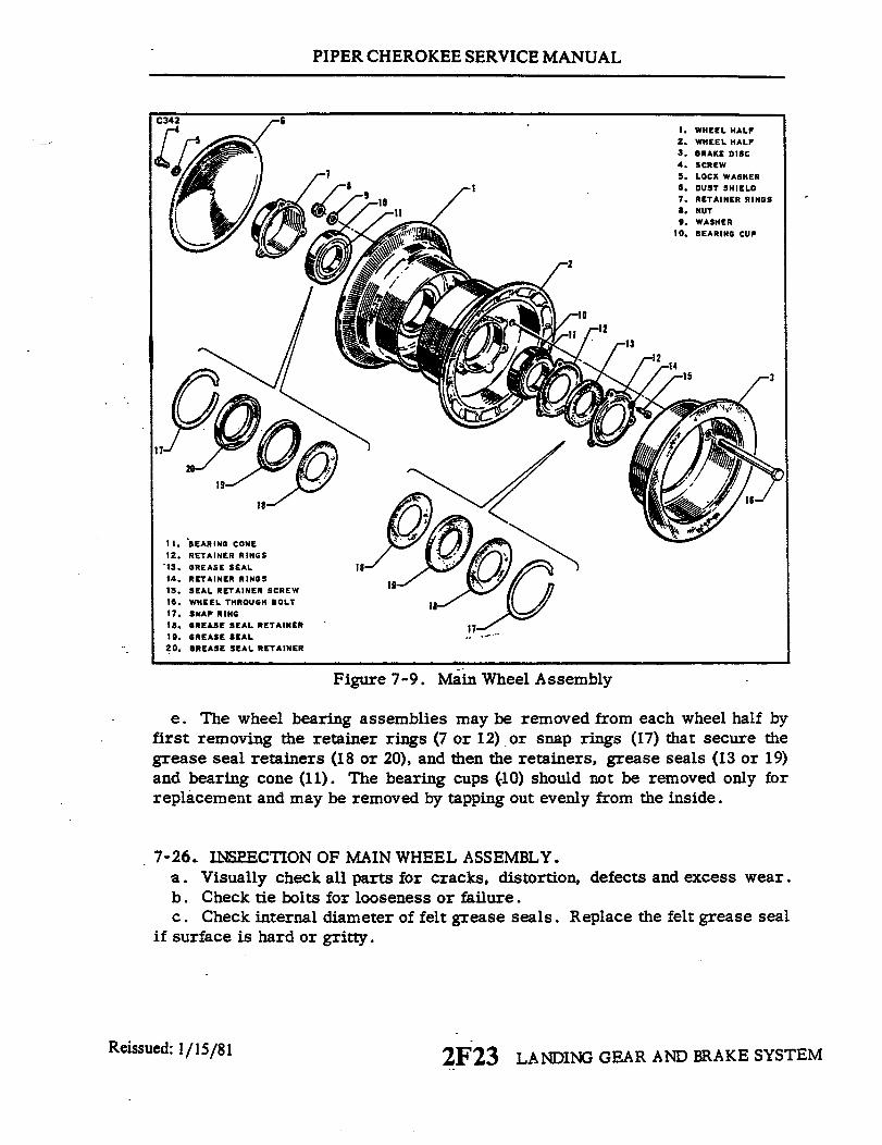
PIPER CHEROKEE SERVICE MANUAL
1. WHEEL HALF2. WHEEL HALF3. BRAKE DISC4. SCREW5. LOCK WASHER6. DUST SHIELD7. RETAINER RINGS8. NUT9. WASHER
10. BEARING CUP
/'
I · 13
18
11.
12.13.14.15.I5.16.17.18.19.20.
BEARING CONERETAINER RINGSGREASE SEALRETAINER RINGSSEAL RETAINER SCREWWHEEL THROUGH BOLTSNAP RINGGREASE SEAL RETAINERGREASE SEALGREASE SEAL RETAINER
Figure 7-9. Main Wheel Assembly
e. The wheel bearing assemblies may be removed from each wheel half byfirst removing the retainer rings (7 or 12) or snap rings (17) that secure thegrease seal retainers (18 or 20), and then the retainers, grease seals (13 or 19)and bearing cone (II). The bearing cups (10) should not be removed only forreplacement and may be removed by tapping out evenly from the inside.
7-26. INSPECTION OF MAIN WHEEL ASSEMBLY.a. Visually check all parts for cracks, distortion, defects and excess wear.b. Check tie bolts for looseness or failure.c. Check internal diameter of felt grease seals. Replace the felt grease seal
if surface is hard or gritty.
Reissued: 1/15/81 2F23 LANDING GEAR AND BRAKE SYSTEM
/�l

PIPER CHEROKEE SERVICE MANUAL
d. Check tire for cuts, internal bruises and deterioration.e. Check bearing cones and cups for wear and pitting and relubricate.f. Replace any wheel casting having visible cracks.
7-27. ASSEMBLY AND INSTALLATION OF MAIN WHEEL. (Refer to Figure 7-9.)a. Ascertain that the bearing cup (10) for each wheel is properly installed. Install
the tire with tube on the outer wheel half and then join the two wheel halves. Position thebrake disc (3) in the inner wheel half and install the through bolts with the nuts on thevalve stem side. Torque wheel nuts to 150 inch,pounds and inflate tire. (Refer to Table 11-1.Section II for tire pressure.)
b. Lubricate the bearing cones (I ) and install the cones, grease seals (13 and 19) andseal retainer rings (18 or 20). Secure with retainer rings (14) or snap ring (17).
c. Slide the wheel on the axle and secure with retainer nut. Tighten the nut to allowno side play. yet allow the wheel to rotate freely. Safety the nut with a flat head pin. washerand cotter pin. Reinstall the dust cover.
d. Position the brake lining back plates between the wheel and brake disc and thebrake cylinder on the torque plate. Insert the spacer blocks between the back plates andcylinder, and install the four bolts to secure the assembly. If the brake line was disconnected.reconnect the line and bleed the brakes per paragraph 7-52.
7-28. BRAKE SYSTEM.
7-29. WHEEL BRAKE ASSEMBLY.
7-30. BRAKE ADJUSTMENT AND LINING TOLERANCE. No adjustment of thebrake lining clearance is necessary as they are self-adjusting. Inspection of the lining isnecessary, and it may be inspected visually while installed on the airplane. The linings areof the riveted type and should be replaced if the thickness of any one segment becomesworn below .099 of an inch or unevenly worn.
LANDING GEAR ANDRevised: 10/3/83 2F24 BRAKE SYSTEM
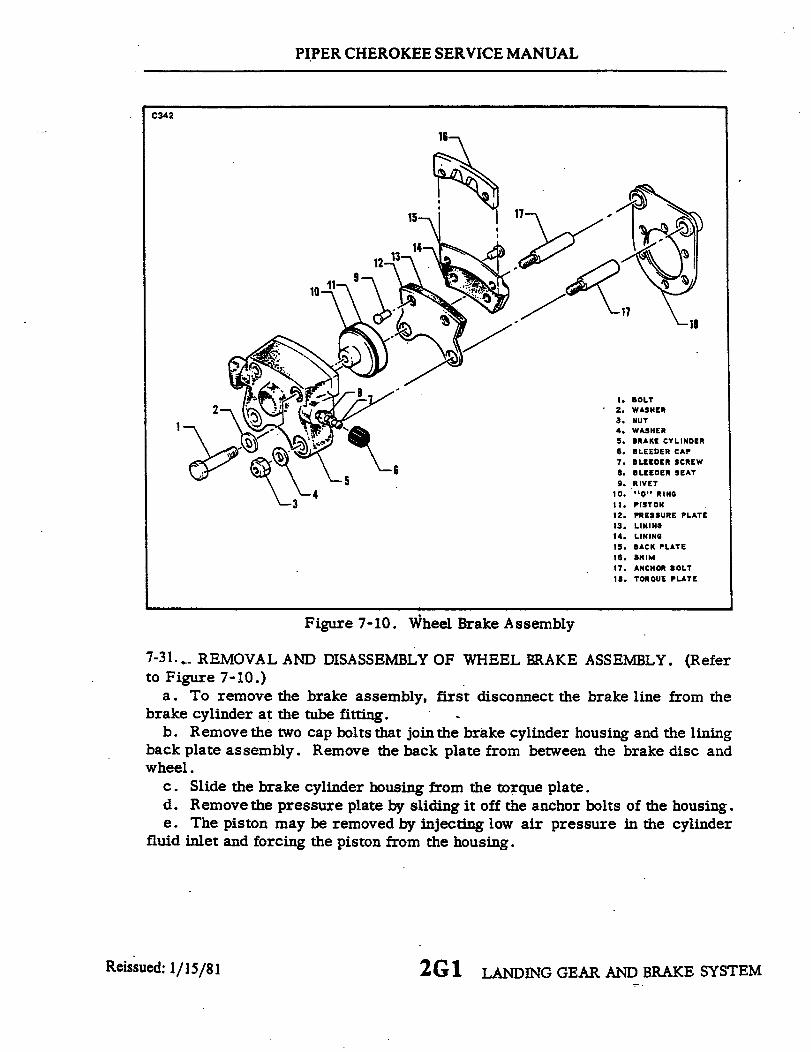
PIPER CHEROKEE SERVICE MANUAL
C342
2-
4
18
1. BOLT2. WASHER3. NUT4. WASHER5. BRAKE CYLINDER6. BLEEDER CAP7. BLEEDER SCREW
8. BLEEDER SEAT9. RIVET
10. "O" RING11. PISTON12. PRESSURE PLATE13. LINING14. LINING15. BACK PLATE16. SHIM17. ANCHOR BOLT18. TORQUE PLATE
Figure 7-10. Wheel Brake Assembly
7-31. REMOVAL AND DISASSEMBLY OF WHEEL BRAKE ASSEMBLY. (Referto Figure 7-10.)
a. To remove the brake assembly, first disconnect the brake line from thebrake cylinder at the tube fitting.
b. Remove the two cap bolts that jointhe brake cylinder housing and the liningback plate assembly. Remove the back plate from between the brake disc andwheel.
c. Slide the brake cylinder housing from the torque plate.d. Remove the pressure plate by sliding it off the anchor bolts of the housing.e. The piston may be removed by injecting low air pressure in the cylinder
fluid inlet and forcing the piston from the housing.
Reissued: 1/15/81 2G1 LANDING GEAR AND BRAKE SYSTEM
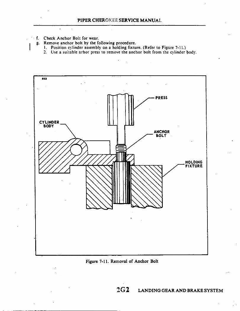
PIPER CHEROKEE SERVICE MANUAL
f. Check Anchor Bolt for wear.g. Remove anchor bolt by the following procedure.
1. Position cylinder assembly on a holding fixture. (Refer to Figure 7-11.)2. Use a suitable arbor press to remove the anchor bolt from the cylinder body.
923
PRESS
CYLINDERBODY
Figure 7-11. Removal of Anchor Bolt
LANDING GEAR AND BRAKE SYSTEM2G2

PIPER CHEROKEE SERVICE MANUAL
h. Install Anchor Bolt by the following procedure.1. Support Anchor Bolt in a holding fixture. (Refer to Figure 7-12. Step A.)2. Align cylinder body over anchor bolt. (Refer to Figure 7-12. Step B.)3. Use a suitable arbor press and apply pressure on the spot face directly over the
anchor bolt hole. (Refer to Figure 7-12. Step C).
A122
STEP A
PRESS
HOLDINGFIXTURE
ANCHORBOLT
HOLDINGFIXTURE
CYLINDERBODY
HOLDINGFIXTURE
STEP B
CYLINDERBODY
STEP C
Figure 7-12. Installation of Anchor Bolt
2G3 LANDING GEAR AND BRAKE SYSTEMRevised: 10/'3/83
PIPER CHEROKEE SERVICE MANUAL
7-32. CLEANING, INSPECTION AND REPAIR OF WHEEL BRAKE ASSEMBLIES.a. Clean the assembly with a suitable solvent and dry thoroughly.b. Check the wall of the cylinder housing and piston for scratches, burrs, corrosion,
etc., that may damage "O" rings.c. Check the general condition of the brake bleeder screw and lines.d. Check the brake disc for grooves, scratches or pits. Minimum service thickness of
Disc 164-5 used on Wheel Assembly 40-28 is .157. Minimum dimension for Disc 164-9 usedon Wheel Assembly 40-58 is .227. Minimum thickness of Disc 164-20 used on WheelAssembly 40-86B is .205. (Refer to Figure 7-13.) A single groove or isolated grooves up to.031 of an inch deep would not necessitate replacement. but a grooving of the entire surfacewould reduce lining life and should be replaced. Should it be necessary to remove the wheeldisc. refer to paragraph 7-25.
e. Lining may be removed from the backing plates by drilling or punching out the oldrivets, and installing a new set using the proper rivets and a rivet set that will properly stakethe lining and form a correct flare of the rivet. (A rivet setting kit is available through PiperDealers under part number 754 165.)
7-33; ASSEMBLY AND INSTALLATION OF WHEEL BRAKE ASSEMBLY. (Refer toFigure 7-10.)
a. Lubricate the piston "O" ring with fluid MIL-H-5606 and install on piston. Slide thepiston in cylinder housing until flush with surface of housing.
b. Slide the lining pressure plate onto the anchor bolts of the housing.c. Slide the cylinder housing assembly on the torque plate of the gear.d. Position the lining back plate between the wheel and brake disc. Install the two bolts
to secure the assembly.e. Connect the brake line to the brake cylinder housing.f. Bleed the brake system as described in paragraph 7-52.
7-34. BRAKE MASTER CYLINDER. (Hand Parking Brake.)
7-35. REMOVAL OF BRAKE MASTER CYLINDER. (Hand Brake.) (Refer to Figure7-14.)
a. To remove the brake master cylinder (8), first disconnect the inlet supply line (13)from the fitting at the top of the cylinder and allow fluid to drain from the reservoir andline into a suitable container.
b. Disconnect the pressure line from the fitting on the cylinder and allow fluid to drainfrom the cylinder line.
c. Disconnect the end of the cylinder rod from the brake handle (6) by removing thecotter pin that safeties the connecting clevis pin (12). Remove the clevis pin and spacerwashers.
d. Disconnect the base of the cylinder from its mounting bracket by removing theattaching bolt assembly (11).
LANDING GEAR AND BRAKE SYSTEM2G4Revised: 10/3/83

PIPER CHEROKEE SERVICE MANUAL
C343
- MINIMUM THICKNESS
- MEASURE 2DISC THICK
!,, MM
MINIMUMTHICKNESS
.157
.227
.205
WHEELASSEMBLIES
40-2840-5840-86
OR 3 POINTS TO GET AVERAGENESS
Figure 7-13. Brake Disc Minimum Thickness
1786
1. BRAKE RESERVOIR2. RIGHT BRAKE AND RUDDER PEDAL3. LEFT BRAKE AND RUDDER PEDAL4. RIGHT BRAKE CYLINDER
5. LEFT BRAKE CYLINDER6. BRAKE HANDLE7. HANDLE RELEASE BUTTON
8. MASTER CYLINDER ASSEMBLY9. TORQUE TUBE
10. RUDDER PEDAL PADSII. BOLT ASSEMBLY12. CLIVIS PIN13. LINE, INLET
Revised: 10/3/83
Figure 7-14. Brake System Installation
2G5 LANDING GEAR AND BRAKE SYSTEM
.
I,

PIPER CHEROKEE SERVICE MANUAL
e. The handle assembly may be removed by removing the attaching bolt assembly thatsecures the handle to its mounting bracket.
7-36. DISASSEMBLY OF BRAKE MASTER CYLINDER.a. PA-28-150. -160. Serial Nos. 28-1 to 28-250 incl. (Refer to Figure 7-15.)
1. Remove the cylinder from its mounting bracket as per Paragraph 7-35.2. To disassemble the cylinder, first remove the piston rod assembly by removing
the retainer ring (2) from the annular slot at the rod end of the cylinder. Draw the pistonrod assembly from the cylinder. Remove the spring (13) from the cylinder.
3. The piston rod assembly may be disassembled by first removing the clevis endfrom the piston rod (6) and then sliding off the brake cylinder cap (3).
4. Remove the roll pin (8) from the bushing (7) thus releasing the piston head andO-rings (9 and 11).
b. PA-28-140. Serial Nos. 28-20002 to 28-21036 incl: PA-28-150. -160. -180 SerialNos. 28-251 to 28-2700 incl: PA-28-235. Serial Nos. 28-10003 to 28-10679 incl. (Refer toFigure 7-16.)
1. Remove the cylinder from the airplane per Paragraph 7-35.2. Cut the safety wire and remove screw (10) that secures the plug (1) in the end of
the cylinder (9).3. Remove the plug (1) and piston assembly from the cylinder by pulling the
cylinder actuator shaft (4) from the cylinder.4. Remove the spring (8) from within the cylinder.5. Remove the roll pin (7) from the cylinder actuator piston (5) and pull off the
piston.c. PA-28-140. Serial Nos. 28-21037 and up: PA-28-150. -160. -180. Serial Nos. 28-2701
and up: PA-28-235. Serial Nos. 28-10698 and up. (Refer to Figure 7-17.)1. Remove the cylinder from its mounting bracket as per Paragraph 7-35.2. To disassemble the cylinder, first remove the piston rod assembly by removing
the snap ring (11) from the annular slot at the rod end of the cylinder. Draw the piston rodassembly from the cylinder.
3. The piston rod assembly may be disassembled by first removing the small snapring (2) securing the retainer bushing (3), spring (4), piston (6), seal (7), gland (9), and, ifdesired, the large retainer spring (13).
4. Remove the O-rings from the piston and gland.
2 G 6 LANDING GEAR AND BRAKE SYSTEMRevised: 10/3/83
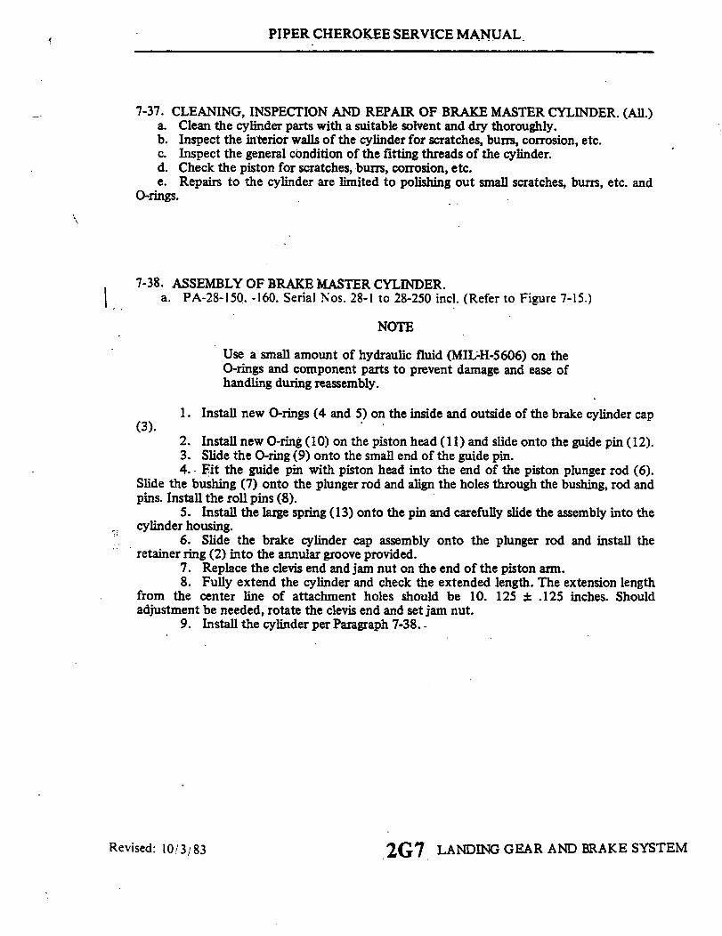
PIPER CHEROKEE SERVICE MANUAL
7-37. CLEANING, INSPECTION AND REPAIR OF BRAKE MASTER CYLINDER. (All.)a. Clean the cylinder parts with a suitable solvent and dry thoroughly.b. Inspect the interior walls of the cylinder for scratches, burrs, corrosion, etc.c. Inspect the general condition of the fitting threads of the cylinder.d. Check the piston for scratches, burrs, corrosion, etc.e. Repairs to the cylinder are limited to polishing out small scratches, burrs, etc. and
O-rings.
7-38. ASSEMBLY OF BRAKE MASTER CYLINDER.a. PA-28-150. -160. Serial Nos. 28-1 to 28-250 incl. (Refer to Figure 7-15.)
NOTE
Use a small amount of hydraulic fluid (MIL-H-5606) on theO-rings and component parts to prevent damage and ease ofhandling during reassembly.
1. Install new O-rings (4 and 5) on the inside and outside of the brake cylinder cap(3).
2. Install new O-ring (10) on the piston head (11) and slide onto the guide pin (12).3. Slide the O-ring (9) onto the small end of the guide pin.4. Fit the guide pin with piston head into the end of the piston plunger rod (6).
Slide the bushing (7) onto the plunger rod and align the holes through the bushing, rod andpins. Install the roll pins (8).
5. Install the large spring (13) onto the pin and carefully slide the assembly into thecylinder housing.
6. Slide the brake cylinder cap assembly onto the plunger rod and install theretainer ring (2) into the annular groove provided.
7. Replace the clevis end and jam nut on the end of the piston arm.8. Fully extend the cylinder and check the extended length. The extension length
from the center line of attachment holes should be 10. 125 + .125 inches. Shouldadjustment be needed, rotate the clevis end and set jam nut.
9. Install the cylinder per Paragraph 7-38. -
Revised: 10/3/83 2G7 LANDING GEAR AND BRAKE SYSTEM

PIPER CHEROKEE SERVICE MANUAL
REFER TO FIGURE 7-18
Figure 7-15. Brake Master CylinderPA-28-150, -160, Serial Nos. 28-1
1. CYLINDER2. RETAINER RING3. BRAKE CYLINDER CAP4. "O" RING5. "O" RING6. ROD7. BUSHING8. ROLL PIN9. "0" RING
10. "O" RING11. PISTON HEAD12. PIN13. SPRING14. PARKING VALVE
(Hand Brake)to 28-250 incl.
1. CYLINDER ACTUATOR PLUG A6002. "0" RING3. "0" RING4. CYLINDER ACTUATOR SHAFT5. CYLINDER ACTUATOR PISTON6. PISTON7. ROLL PIN8. SPRING9. CYLINDER
10. SCREW
9
Figure 7-16. Brake Master Cylinder (Hand/Parking Brake)PA-28-140, Serial Nos. 28-20002 to 28-21036 incl;
PA-28-150, -160,-180, Serial Nos. 28-251 to 28-2700 incl;PA-28-235, Serial Nos. 28-10003 to 28-10697 incl.
Revised: 10/3;83 2G8 LANDING GEAR AND BRAKE SYSTEM
A601

PIPER CHEROKEE SERVICE MANUAL
A349
889
1 HOUSING2 SNAP RING3 BUSHING. RETAINER4 SPRING5. O-RING
6 PISTON7 DYNA SEAL8. O-RING9. GLAND PACKIN
10. O-RING
12 13 14 15
11 SNAP RING12 ROD. PISTON13 SPRING. RETAINING
G 14. ROLL PIN15 WASHER
Figure 7-17. Brake Master Cylinder. (Hand/Parking Brake)PA-28-140, Serial Nos. 28-21037 and up;
PA-28-150, -160, -180, Serial Nos. 28-2701 and up;PA-28-235, Serial Nos. 28-10698 and up
b. PA-28-140. Serial Nos. 28-20002 to 28-21037; PA-28-150, -160, -180, Serial Nos. 28-251 to28-2700 inch PA-28-235, Serial Nos. 28-10003 to 28-10697 incl. (Refer to Figure 7-16.)
NOTE
Use a small amount of hydraulic fluid (MIL-H-5606) on the "0"rings and component parts to prevent damage and ease of handlingduring reassembly.
pin (7).
1. Install the new "0" rings (2 and 3) on the cylinder plug (1).2. Install the cylinder actuator piston (5) on the actuator shaft (4) and secure with the roll
3. Install a new "0" ring (6) on the actuator pin.4. Place the spring (8) into the cylinder housing, and carefully slide the actuator and shaft
assembly into the housing.
2G9 LANDING GEAR AND BRAKE SYSTEM
COUNTER BORE.562 DIA. .0625 DEEP
.75
Revised: 10/3/83

PIPER CHEROKEE SERVICE MANUAL
5. Install the plug assembly (1)on the shaft and install the screw through the housing.6. Safety the screw with MS20995-C40 wire.7. -Install the cylinder per Paragraph 7-38.
c. PA-28-140. Serial Nos. 28-21037 and up: PA-28-150. -160. -180. Serial Nos. 28-28-2701 and up: PA-28-235. Serial Nos. 28-10698 and up. (Refer to Figure 7-17.)
NOTE
Use a small amount of hydraulic fluid (MIL-H-5606) on the"0" ring and component parts to prevent damage and ease ofhandling during reassembly.
1. Install new "O" ring on the inside and outside of the packing gland (9) and onthe outside of the piston (6). (When installing teflon "O" ring (5) on piston, it is recommendedthat it be installed with the use of a cone placed against the piston. The cone may be con-structed of plastic or metal with dimensions shown in Figure 7-17.)
2. To assemble the piston rod assembly, install on the rod (12), in order, the rollpins (14), return spring retainer washer (15), retaining spring (13), packing gland (9) with"0" rings (10), seal (7), piston (6) with "0" ring, spring (4) and retainer bushing (3). Securethese pieces with snap ring (2) on the end of the rod.
3. Insert the piston rod assembly in the housing (1) and secure packing gland withsnap ring ( 1).
4. Install the cylinder per Paragraph 7-39.
7-39. INSTALLATION OF BRAKE MASTER CYLINDER. (Hand Brake.) (Referto Figure 7-14.)
a. Install the brake handle assembly between its mounting bracket and secure withbolt, washers, nut and cotter pin. Washers should be placed on each side of the handle,between the bracket, and under the nut.
b. Place the cylinder (8) between the mounting bracket and secure the base end withbolt, washers, nut and cotter pin. This, too, should have washers placed on each side of thecylinder and under the nut.
c. Connect the rod end of the cylinder to the brake handle with a clevis pin and thinwashers. Safety the clevis with a cotter pin.
d. Connect the pressure line to the fitting at the bottom of the cylinder.e. Connect the inlet supply line (13) to the fitting at the top of the cylinder and secure
with spring clamp.f. Bleed the brake system per Paragraph 7-51.
Revised: 10/3/83 LANDING GEAR AND BRAKE SYSTEM2G10

PIPER CHEROKEE SERVICE MANUAL
7-40. PARKING VALVE. (PA-28-150,-160, Serial Nos. 28-1 to 28-250 incl.)
7-41. REMOVAL OF PARKINGVALVE.
a. Remove the brake master cylin-der as given in paragraph 7-35.
b. Remove the parking valve fromthe cylinder by turning the elbow from
END FITTING the cylinder housing.2. RING3. "0" RING4. RING. STOP
5. BODY 7-42. DISASSEMBLY OF PARKING6. PISTON
VALVE. (Refer to Figure 7-18. )Figure 7-18. Parking Valve a. Remove the end fitting (1) from
PA-28-150, -160 the valve body (5).Serial Nos. 28-1 to 28-250 incl. b. Pushthe piston(6)out through the
body. Ascertainthat the endof the pis-ton that connects to the link is free from damage or burrs that could- cause thebody piston wall to become scratched or galled as the piston is pushed through.
c. Remove "O" ring packings from the end fitting and piston.
7-43. CLEANING, INSPECTION AND REPAIR OF PARKING VALVE.a. Clean the valve-components in a suitable dry type cleaning solvent.b. Inspect the valve for the following:
1. Check that the friction surfaces of the valve body and stem are freefrom nicks, dents and burrs.
2. Check that the stop on the piston is secure and undamaged.3. Check that the threaded surfaces of the body and end fitting are not
stripped or cross-threaded.c. Repair to the valve is limited to reconditioning of parts, such as smoothing
out minor nicks and scratches, and the replacement of "O" ring packings.
7-44. ASSEMBLY OF PARKING VALVE. (Refer to Figure 7-18. )a. Install "O" ring packings (3) on the piston (6) and install piston in the valve
body (5). Lubricate "O" rings with hydraulic fluid before installing piston.b. Install "O" ring packing (2) on end fitting (1) and install end fitting in the
valve body.
Revised: 1013/83 2Gll LANDING GEAR AND BRAKE SYSTEM

1. SPRING CLIP2. TOE BRAKE PEDAL3. ARM, TRIM CONTROL ATTACHMENT4. CLEVIS PIN, WASHER & COTTER PIN5. CLEVIS ASSEMBLY6. CLEVIS PIN7. ARM, IDLER8. JAM NUT 16
PIPER CHEROKEE SERVICE MANUAL
1884
9. CLEVIS PIN, WASHER & COTTER PIN10. CLEVIS PIN, WASHER & COTTER PIN11. SPRING, RETURN12. BRACKET13. BRACE ASSEMBLY14. CYLINDER ASSEMBLY, HYDRAULIC15. TUBE ASSEMBLY, LEFT16. CLEVIS PIN & COTTER PIN17. HOSE ASSEMBLY - FLEXIBLE18. TUBE ASSEMBLY, RIGHT19. PEDAL PADS
Figure 7-19. Toe Brake Installation
2G12 LANDING GEAR AND BRAKE SYSTEMReissued: 1/15/81

PIPER CHEROKEE SERVICE MANUAL
7-45. INSTALLATION OF PARKING VALVE.a. Install the parking valve onto the cylinder housing by turning the elbow into the
threaded housing.b. Install the brake master cylinder as given in Paragraph 7-39.
7-46. BRAKE CYLINDER. (Toe Brake.)
7-47. REMOVAL OF BRAKE CYLINDER. (Refer to Figure 7-19.)a. Disconnect the upper and lower lines from the cylinder (14) to be removed and cap
the lines to prevent fluid leakage or drain the fluid from the brake reservoir and mastercylinder.
b. Remove the cylinder from its attachment fittings by first removing cotter pins thatsafety the cylinder attaching pins (4 and 16) and then removing the pins.
7-48. DISASSEMBLY OF BRAKE CYLINDER.a. Cleveland cylinder number 10-20. (Refer to Figure 7-20.)
1. Remove the cylinder from its mounting bracket as per Paragraph 7-47.2. To disassemble the cylinder, first remove the piston rod assembly by unscrewing
the packing gland (9) from the cylinder.3. The piston rod assembly may be disassembled by first removing the small snap
ring (2) securing the retainer bushing (3) and then removing the bushing, spring (4), piston (5),seal (7), gland (9), and, if desired, the large return spring.
4. Remove the O-rings from the piston and packing gland.b. Cleveland cylinder number 10-27. (Refer to Figure 7-20.)
1. Remove the cylinder from its mounting bracket per Paragraph 7-47.2. To disassemble the cylinder, first remove the piston rod assembly by removing the
snap ring (10) from the annular slot in the cylinder housing (1). Draw the piston rod assemblyfrom the cylinder.
3. The piston rod assembly may be disassembled by first removing the roll pin (12)and then the piston assembly (3), seal (5), packing gland (7).
4. Remove the O-rings from the piston and packing gland.c. Cleveland cylinder number 10-30. (Refer to Figure 7-21.)
1. Remove the cylinder from its mounting bracket per Paragraph 7-47.2. To disassemble the cylinder, first remove the piston rod assembly by removing the
reta ning ring from the annular slot in the cylinder housing (1). Draw the piston rod assemblyfrom the cylinder.
3. The piston rod assembly may be disassembled by first removing the retaininging (2), sleeve (3), spring (4), and then the piston assembly, O-ring (5), and gland (8), and, ifdesired, the return spring (13).
4. Remove the O-rings from the piston and packing gland.d. Gar-Kenyon cylinder number 17000. (Refer to Figure 7-20.)
1. Remove the cylinder from its mounting bracket as per Paragraph 7-47.2. To disassemble the cylinder, first remove the piston rod assembly by unscrewing
the fitting (8) from the cylinder.3. The piston rod assembly may be disassembled by first removing the retaining
ring (2) securing the sleeve (3) and then removing the spring (4), piston (6), seal (7), fitting (8),and, if desired, the large return spring (11).
4. Remove the O-rings from the piston and fitting.
Revised: 10/3/83 LANDING GEAR AND BRAKE SYSTEM2G13

PIPER CHEROKEE SERVICE MANUAL
10-20
14
12
10
7
1. HYDRAULIC 4CYLINDER
2. SNAP RING3. BUSHING4. SPRING5. PISTON6. "0" RING7. DYNA-SEAL
WASHER8. "O" RING9. PACKING GLAND
10. "O" RING11. PISTON ROD12. SPRING13. DELETED14. WASHER15. ROLL PIN
10-27 17000
12
87
6
1. HYDRAULICCYLINDER 3
2. SPRING3. PISTON 24. "O" RING5. SEAL WASHER6. "O" RING7. PACKING GLAND8. "O" RING9. WIPER WASHER
10. RETAINING RING 111. SPRING12. ROLL PIN13. PISTON ROD14. WASHER15. ROLL PIN
1. HOUSING2. RETAINING RING3. SLEEVE4. SPRING5. "O" RING6.. PISTON7. SEAL8. FITTING9. "O" RING
10. "O" RING11. SPRING12. PISTON ROD13. WASHER14. ROLL PIN
Figure 7-20. Brake Cylinder (Toe Brake)
7-49. CLEANING, INSPECTION AND REPAIR OF BRAKE CYLINDER.a. Clean the cylinder parts with a suitable solvent and dry thoroughly.b. Inspect the interior walls of the cylinder for scratches, burrs, corrosion,
etc.c. Inspect the general condition of the fitting threads of the cylinder.d. Check the piston and valve for scratches, burrs, corrosion, etc.e. Repairs to the cylinder are limited to polishing out small scratches, burrs,
etc. and replacing valve, washer, seal, and "O" rings.
2G14 LANDING GEAR AND BRAKE SYSTEM
C344
11
14
13
12
113 10
8
.5
Reissued: 1/15/81
4
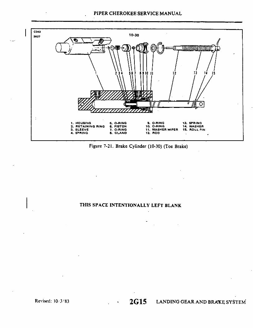
PIPER CHEROKEE SERVICE MANUAL
10-30
1. HOUSING2. RETAINING RING3. SLEEVE4. SPRING
Revised: 10/3/83
5. O-RING6. PISTON7. O-RING8. GLAND
9. O-RING10. O-RING11. WASHER WIPER12. ROD
13. SPRING14. WASHER15. ROLL PIN
Figure 7-21. Brake Cylinder (10-30) (Toe Brake)
THIS SPACE INTENTIONALLY LEFT BLANK
2G15 LANDING GEAR AND BRAKE SYSTEM
C343
2637I
I
PIPER CHEROKEE SERVICE MANUAL
7-50. ASSEMBLY OF BRAKE CYLINDER.a. Cleveland cylinder number 10-20. (Refer to Figure 7-20.)
NOTE
Use a small amount of hydraulic fluid (MIL-H-5606) on the"O" ring and component parts to prevent damage and ease ofhandling during reassembly.
1. Install new "O" rings on the inside and outside of the packing gland (9) and onthe outside of the piston (5).
2. To assemble the piston rod assembly, install on the rod (11), in order, the rollpin (15), return spring retainer washer (14), return spring (12), packing gland (9) with "O"rings, seal (7), piston (5) with "0" ring, spring (4) and retainer bushing (3). Secure thesepieces with the small ring (2) on the end ofthe rod.
3. Insert the piston rod assembly in the cylinder (1) and secure packing (9).4. Install the cylinder per paragraph 7-51.
b. Cleveland cylinder number 10-27. (Refer to Figure 7-20.)1. Install new "0" rings on the inside and outside of the packing gland (7) and on
the outside of the piston (3). (Refer to above note.)2. To assemble the piston rod assembly, install on the rod (13), in order, the roll
pin (15), washer (14), spring (11), washer (9), packing gland (7), seal (5), piston assembly(3) and spring (2).
3. Insert the piston rod assembly in the cylinder (1) and secure with the snap ring(10).
4. Install the cylinder per paragraph 7-51.c. Cleveland cylinder number 10-30. (Refer to Figure 7-21.)
1. Install new O-rings on the inside and outside of the packing gland (7) and on theoutside of the piston (3).
2. To assemble the piston rod assembly, install on the rod (12), in order, the roll pin(14), washer (13), spring (11), washer (9), packing gland (7) with O-rings, seal (5), pistonassembly (3) with O-ring, spring (2), and roll pin (15).
3. Insert the piston rod assembly in the cylinder (1) and secure with the retainingring (10).
4. Install the cylinder per paragraph 7-51.d. Gar-Kenyon cylinder number 17000. (Refer to Figure 7-20.)
1. Install new O-rings on the inside and outside of the fitting (8) and on the outsideof the piston (6). (Refer to above note.)
2. To assemble the piston rod assembly; install on the rod (12), in order, the rollpin (14), return spring retainer washer (13), return spring ( 11), fitting (8) with O-rings, seal (7),piston (6) with O-ring, spring (4) and sleeve (3). Secure these pieces with the retaining ring (2)on the end of the rod.
3. Insert the piston rod assembly in the cylinder (1) and secure fitting (8).4. Install the cylinder per paragraph 7-51.
LANDING GEAR AND BRAKE SYSTEM2G16Reissued: 1/15/81
PIPER CHEROKEE SERVICE MANUAL
7-51. INSTALLATION OF BRAKE CYLINDER. (Refer to Figure 7-19.)a. Position the cylinder (14) at its mounting points and attach with clevis pins. Safety
the pins with cotter pins.b. Connect the brake lines to the cylinder fittings.c. Bleed the brakes per paragraph 7-52.
7-52. BLEEDING BRAKES.
7-53. BRAKE BLEEDING PROCEDURE (Gravity). (Refer to Figure 7-22.)a. Attach a clean, clear plastic tube to the brake bleeder of the right landing gear.
Extend the free end of the tube to a container partially filled with hydraulic fluid(MIL-H-5606). Determine that the end of the tube is submerged in the fluid. Open thebleeder 1/2 to 1 turn.
b. Fill the brake fluid reservoir located on the firewall with hydraulic fluid.c. Check to determine the right hand toe brake pedal(s) in the cockpit have been
pulled full aft.d. Pull the hand brake handle and slowly pump the master cylinder approximately 50
times or until hydraulic fluid is observed passing through the plastic tube at the brakebleeder.
NOTE
Fluid level in the reservoir must be maintained to prevent airfrom entering the system.
e. Pump right brake cylinder very slowly approximately 12 times. This will purge airfrom the toe brake cylinder system. Watch for any air forced through the clear plastic tubeduring this operation to insure air has been forced from the toe brake system.
f. Pump the hand brake an additional 25 times or until no air is observed through theclear plastic tube.
g. Tighten brake bleeder and remove the plastic tube.h. Repeat steps a through f to the left main landing gear.
7-54. BRAKE BLEEDING PROCEDURE (Pressure). (Refer to Figure 7-23.)a. Place a clean, clear plastic tube on the vent fitting on top of the brake fluid
reservoir. Extend the free end of the tube to a container partially filled with hydraulic fluid(MIL-H-5606). Be certain the end of the tube is submerged in the fluid.
b. Attach another clear plastic tube to the brake bleeder of the right landing gear.Connect the free end of this tube to the pressure source. Open the bleeder 1 to 2 turns andpressure fill the system with fluid.
c. With fluid continually flowing through the system, SLOWLY and simultaneouslyactuate the hand brake and toe brake pedal, of the side being bled, several times to purgethe cylinders of air. On dual brake installations, both pedals for the brake being bled mustbe actuated.
LANDING GEAR AND BRAKE SYSTEM2G17Reissued: 1/15/81
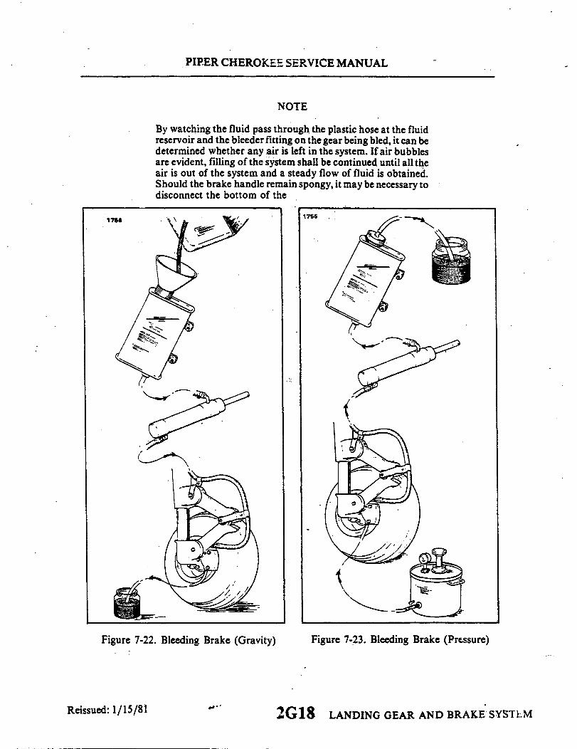
PIPER CHEROKEE SERVICE MANUAL
NOTE
By watching the fluid pass through the plastic hose at the fluidreservoir and the bleeder fitting on the gear being bled, it can bedetermined whether any air is left in the system. If air bubblesare evident, filling of the system shall be continued until all theair is out of the system and a steady flow of fluid is obtained.Should the brake handle remain spongy, it may be necessary todisconnect the bottom of the
1756
Figure 7-22. Bleeding Brake (Gravity) Figure 7-23. Bleeding Brake (Pressure)
2G18 LANDING GEAR AND BRAKE SYSTEM
1756
Reissued: 1/15/81

PIPER CHEROKEE SERVICE MANUAL
toe brake cylinders (next to the pedal) and rotating thecylinder horizontally or even above horizontal and by use ofthe hand brake alone, purge the air from the system.
d. Close the open bleeder fitting to which the pressure hose is attached. Do not removethe tube from the fluid reservoir until both brakes have been bled. Check the brakes on theside being bled for proper pedal pressure. Replace cap on bleeder fitting.
NOTE
It may be necessary to remove any trapped air in the top ofthe wheel brake unit by applying pressure to the system withthe brake hand lever and slowly opening the bleeder andrelease the hand lever.
e. Repeat steps b through d to the left main landing gear.f. Drain excess fluid from the reservoir to fluid level with a syringe.
7-55. BRAKE SYSTEM LEAK CHECK. Pull for a good, firm hand brake and lock parkingbrake mechanism. Allow system to stand for approximately 10 minutes, then -by grippingthe park brake handle it should not be able to be pulled aft further than the original set.Should the handle be able to be pulled towards the panel and feel spongy, a leak is presentat some point in the system. This leak may appear at any one of the connections throughoutthe system or internally in the master brake cylinder or wheel brake assemblies.
7-56. BLEEDING OF THE BRAKES AFTER A UNIT HAS BEEN CHANGED.a. Actuate the hand brake handle until some pressure builds up in the system. At this
time, crack the attaching B nuts at any of the hose connections of the replaced unit. Most ofthe handle sponge feeling should be displaced by this action.
b. Actuate the master cylinder and the toe brake cylinder of the side unit was changedand bleed fluid through the brake assembly on the wheel by pumping pressure and crackingbleeder until pressure drops.
CAUTION
Do not allow pressure to bleed off before closing bleeders,for this will allow air to enter the system. Repeat thepumping and bleeding approximately 10 or more times oruntil all the air is released from the system. During allbleeding, fluid level of the reservoir must be maintained.
Reissued: 1/15/81LANDING GEAR AND BRAKE SYSTEM2G19
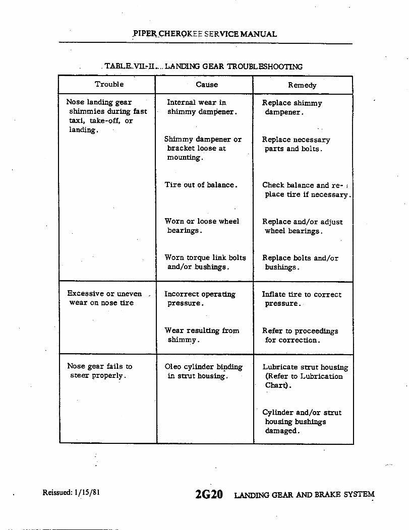
PIPER CHEROKEE SERVICE MANUAL
TABLE VIL-II.. LANDING GEAR TROUBLESHOOTING
Trouble Cause Remedy
Nose landing gearshimmies during fasttaxi, take-off, orlanding.
Excessive or unevenwear on nose tire
Internal wear inshimmy dampener.
Shimmy dampener orbracket loose atmounting.
Tire out of balance.
Worn or loose wheelbearings.
Worn torque link boltsand/or bushings.
Incorrect operatingpressure.
Replace shimmydampener.
Replace necessaryparts and bolts.
Check balance and re-place tire if necessary.
Replace and/or adjustwheel bearings.
Replace bolts and/orbushings.
Inflate tire to correctpressure.
Wear resulting fromshimmy.
Refer to proceedingsfor correction.
Nose gear fails tosteer properly.
Oleo cylinder bindingin strut housing.
Lubricate strut housing(Refer to LubricationChart).
Cylinder and/or struthousing bushingsdamaged.
Reissued: 1/15/81 2G20 LANDING GEAR AND BRAKE SYSTEM

PIPER CHEROKEE SERVICE MANUAL
TABLE VII-II. LANDING GEAR TROUBLESHOOTING (cont)
Trouble Cause Remedy
Nose gear fails tosteer properly (cont).
One brake dragging. Determine cause andcorrect.
Steering bellcrank looseon attachment plate.
Steering bellcrank bear-ing and/or bolt worn.
Shimmy dampenergalling or binding.
Readjust and tighten.
Replace bearing and/orbolt.
Replace.
Main landing shimmiesduring fast taxi, take-off, or landing.
Tire out of balance. Check balance and re-place tire if necessary.
Worn or loose wheelbearings.
Worn torque link boltsand/or bushings.
Replace and/or adjustwheel bearings.
Replace bolts and/orbushings.
Excessive or unevenwear on main tires.
Incorrect operatingpressure.
Inflate tire to correctpressure.
Wheel out of alignment(toe in or out).
Check wheel alignment.
Reissued: 1/15/812G21 LANDING GEAR AND BRAKE SYSTEM
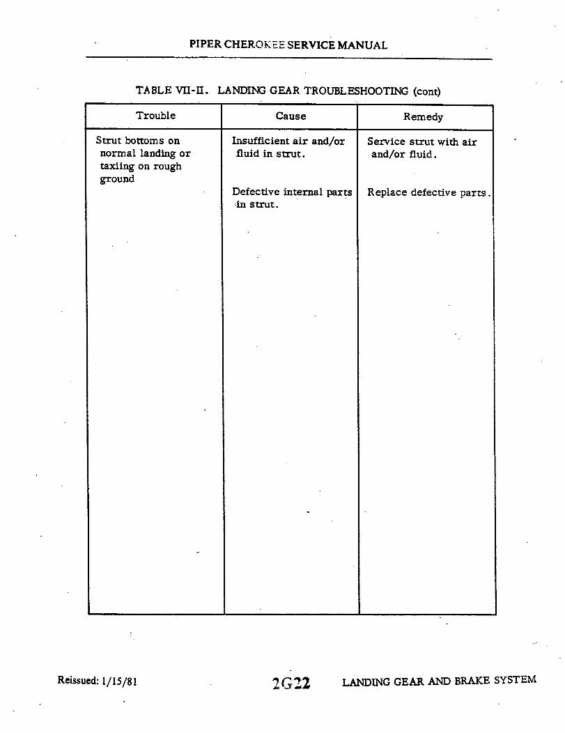
PIPER CHEROKEE SERVICE MANUAL
TABLE VII-II. LANDING GEAR TROUBLESHOOTING (cont)
Trouble Cause Remedy
Strut bottoms onnormal landing ortaxiing on roughground
Insufficient air and/orfluid in strut.
Service strut with airand/or fluid.
Defective internal parts Replace defective parts.in strut.
LANDING GEAR AND BRAKE SYSTEM2G22Reissued: 1/15/81
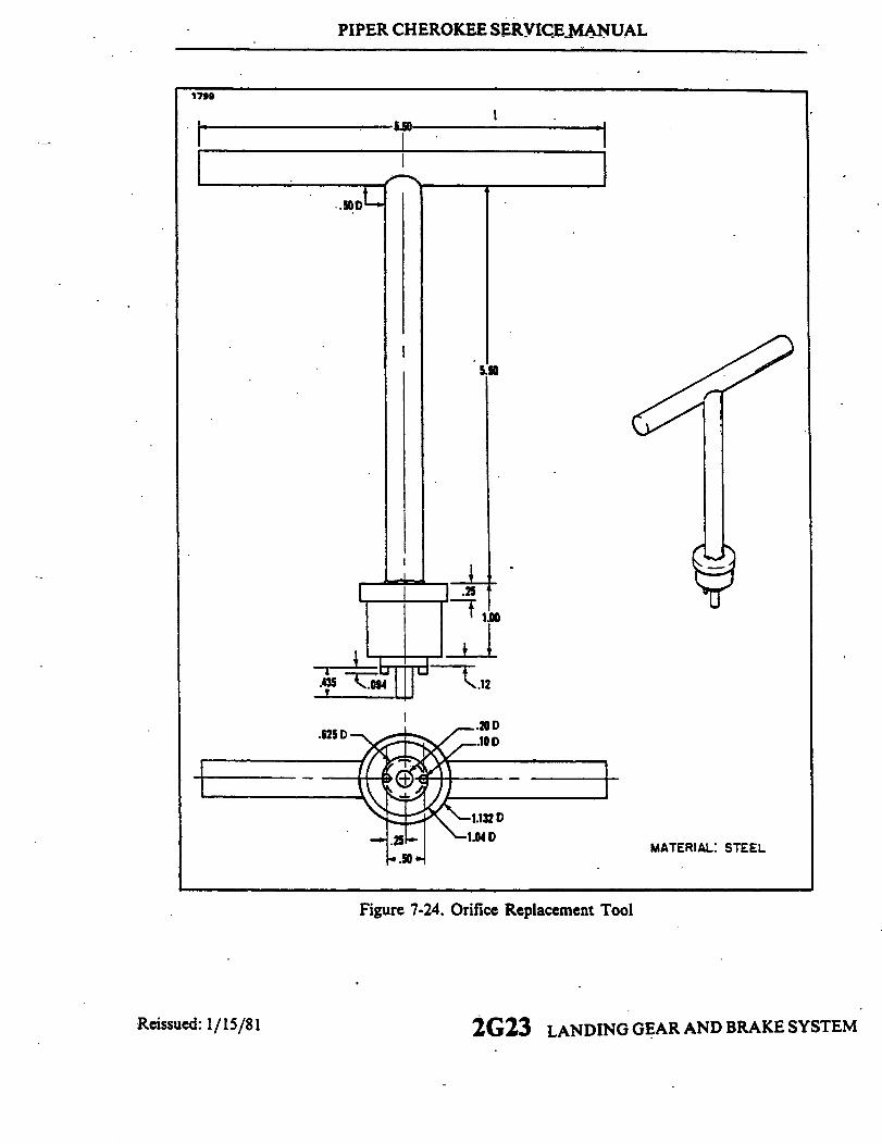
PIPER CHEROKEE SERVICE MANUAL
I
MATERIAL: STEEL
Figure 7-24. Orifice Replacement Tool
Reissued: 1/15/81 2G23 LANDING GEAR AND BRAKE SYSTEM
I

PIPER CHEROKEE SERVICE MANUAL
904
HANDLE .50 DIA.
4.00 3
WELD
.125
7.50
Reissued: 1/15/81
Figure 7-25. Retainer Ring Tool
2 G 24 LANDING GEAR AND BRAKE SYSTEM

SECTION VIIALANDING GEAR AND BRAKE SYSTEM
(PA-28R)
Paragraph AeroficheGrid No.
7A- . Introduction ............................................... 2H47A-2. Description ............................................... 2H47A-3. Troubleshooting .......................... 2H67A-4. Landing Gear System ......................................... 2H67A-5. Nose Landing Gear ........................................... 2H6
7A-6. Disassembly of Nose Gear Oleo ....................... 2H67A-7. Cleaning, Inspection and Repair of Nose Gear Oleo ...... 2H77A-8. Assembly of Nose Gear Oleo ........................... 2H77A-9. Removal of Nose Landing Gear ...................... . 2H 0.7A-10. Cleaning, Inspection.and Repair of Nose Landing
Gear............................................. -2H 137A- 11. Installation of Nose Landing Gear ..................... 2H 147A-12. Adjustment of Nose Landing Gear (Without
Gear Up Stop) .................................. 2H167A-13. Adjustment of Nose Landing Gear (With Gear
Up Stop) ....................................... 2H177A-14. Alignment of Nose Landing Gear ...................... 2H187A-15. Removal of Nose Gear Door Assembly ................. 2H 197A-16. Cleaning, Inspection and Repair of Nose Gear
Door Assembly .................................. 2H217A-17. Installation of Nose Gear Door Assembly ............... 2H217A-18. Adjustment of Nose Gear Doors ....................... 2H22
7A- 19. Main Landing Gear System.... ............................... 2H227A-20. Disassembly of Main Gear Oleo ....................... 2H227A-21. Cleaning, Inspection and Repair of Main
Gear Oleo ...................................... 2H237A-22. Assembly of Main Gear Oleo .......................... 2H237A-23. Removal of Main Landing Gear ........................ 2137A-24. Cleaning, Inspection and Repair of Main
Landing Gear .................................. 2167A-25. Installation of Main Landing Gear .... ................. 2177A-26. Adjustment of Main Landing Gear ...................... 2187A-27. Alignment of Main Landing Gear ...................... 2III7A-28. Removal of Main Gear Door Assembly ................ 21137A-29. Cleaning, Inspection and Repair of Main
Gear Door Assembly ............................. 2I137A-30. Installation of Main Gear Door Assembly .............. 2I137A-31. Adjustment of Main Gear Door Assembly .............. 2I14
Revised: 10/3/83 2H1
Paragraph AeroficheGrid No.
7A-32. Landing Gear Limit Switches .................................. 21147A-33. Adjustment of Nose Gear Up Limit Switch ............. 21147A-34. Adjustment of Nose Gear Down Limit Switch ........... 21157A-35. Adjustment of Main Gear Up Limit Switch ............. 21167A-36. Adjustment of Main Gear Down Limit Switch .......... 21167A-37. Adjustment of Landing Gear Safety Switch
(Squat Switch) ............................. .... 21187A-38. Adjustment of Gear Back-Up Extender Actuator
Switch ........................................ 21187A-39. Landing Gear Warning Switches (Throttle Switches) .............. 2118
7A-40. Landing Gear Up/Power Reduced Warning Switch ...... 21187A-41. Removal of Landing Gear Up/Power Reduced
Warning Switch ................... .............. 21187A-42. Installation of Landing Gear Up/Power Reduced
Warning Switch .......... ..................... 21187A-43. Adjustment of Landing Gear Up/Power Reduced
Warning Switch .................................. 21197A-44. Gear Down/ Selector Handle Up Warning Switch ........ 21207A-45. Removal of Gear Down/Selector Handle Up
Warning Switch ................................. 21207A-46. Installation of Gear Down/Selector Handle Up
Warning Switch .............................. 21207A-47. Adjustment of Gear Down/Selector Handle Up
Warning Switch ................................. 21207A-48. Wheels ....................................................... 2121
7A-49. Removal and Disassembly of Nose Wheel ............... 21217A-50. Inspection of Nose Wheel Assembly. ................... 2127A-51. Assembly and Installation of Nose Wheel ............... 21217A-52. Removal and Disassembly of Main Wheel .............. 21237A-53. Inspection of Main Wheel Assembly ................... 21247A-54. Assembly and Installation of Main Wheel ............... 2124
7A-55. Brake System ................................................ 21247A-56. Wheel Brake Assembly ........................................ 2124
7A-57. Brake Adjustment and Lining Tolerance ................ 21247A-58. Removal and Disassembly of Wheel Brake
Assembly ....................................... 2J7A-59. Cleaning, Inspection and Repair ofWheel
Brake Assemblies ................................ 2J27A-60. Assembly and Installation of Wheel Brake
Assembly ....................................... 2J2
Revised: 8/3/81 2H2

Paragraph AeroficheGrid No.
7A-61. Brake Master Cylinder (Hand Parking Brake) .................... 2J27A-62. Removal of Brake Master Cylinder .................... 2J27A-63. Disassembly of Brake Master Cylinder ................. 2J47A-64. Cleaning, Inspection and Repair of Brake
Master Cylinder ................................ 2J47A-65. Assembly of Brake Master Cylinder .................... 2J47A-66. Installation of Brake Master Cylinder ............ ...... 2J5
7A-67. Brake Cylinder (Toe Brake) ............................... 2J77A-68. Removal of Brake Cylinder ........................... 2J77A-69. Disassembly of Brake Cylinder ........................ 2J77A-70. Cleaning, Inspection and Repair of Brake
Cylinder ........................................ 2J87A-71. Assembly of Brake Cylinder ...................... .... 2J97A-72. Installation of Brake Cylinder ......................... 2J10
7A-73. Bleeding Procedure ................................ ........... 2J107A-74. Bearing Replacement ........................................ 2107A-75. Nose Gear Service Tolerances ................................... 2J207A-76. Main Gear Service Tolerances .................................. 2J23
Revised: 10/3/83 2H3
PIPER CHEROKEE SERVICE MANUAL
SECTION VIIA
LANDING GEAR AND BRAKE SYSTEMPA-28R
7A-1, INTRODUCTION. In this section are instructions for the overhaul, inspection andadjustment of the various components of the PA-28R landing gear and brake system. Alsoincluded are adjustments for the electrical limit, safety and warning switches, and the hydraulicfunction of the brakes. Information on the hydraulic system for raising and lowering thelanding gear is covered in Section VI.
7A-2. DESCRIPTION. The PA-28R airplane is equipped with a retractable, tricycle, air-oil,strut-type landing gear which is-hydraulically operated by an electrically powered reversiblepump. A selector handle on the instrument panel to the left of the control quadrant is used toselect gear UP or DOWN positions.
Gear positions are indicated by three green lights located below the selector lever for geardown and locked, and a yellow light located at the top of the instrument panel for intransitpositions. There is no light to indicate the gear has fully retracted other than all lights are out.As the landing gear swings to the down position and each downlock hook moves into itslocked position, a switch at each hook actuates the switch to the NO (Normally Open) circuitto indicate by a green light that the individual gear is safely down and locked. The activationof all three downlock switches will also shut the hydraulic pump off. As the instrument lightsare turned on, the green lights will dim. When the gear begins to retract and the downlock hookdisengages, the down limit switch actuates the switch to the NC circuit, and in series with theNC circuit of the up limit switch, allows the intransit light to come on. The intransit light willremain on until the gear is up and all up limit switches are actuated to their NO (NormallyOpen) circuit.
To the left of the yellow intransit light is a red warning light which operatessimultaneously in conjunction with the warning horn, and they have a twofold purpose.Their primary purpose is to give warning when power is reduced below approximately 14inches of manifold pressure and the landing gear has not reached the down and lockedposition. This circuit is controlled by the three paralleling down limit switches connected inseries with a throttle switch (Switch "A") located in the control quadrant. The secondaryfunction of the warning light and horn is to give warning when the gear selector handle is upand while the airplane is on the ground or airspeed is below that required to close thehydraulic valve and the pump switch of the backup gear extender unit. When the airplane issetting on the ground, the warning circuit is controlled through the NO side of the safetyswitch (squat switch) located on the left gear and the up position of the selector lever.Should the airplane be raised from the ground, such as in flight, far enough to move thesafety switch to its NC position, then current is directed in series through the hydraulicpressure switch, the pump switch (providing airspeed has actuated the switch to its NOposition), throttle switch (Switch "B") and the up positioned selector lever. Throttle switch"B" is located forward of the instrument panel directly below the arm of the throttle lever.
Reissued: 1/15/81 2H4 LANDING GEAR AND BRAKE SYSTEM
PIPER CHEROKEE SERVICE MANUAL
The up limit, safety, throttle, pressure and selector switch, and pump solenoids are allprotected by the landing gear control and warning circuit protector. (Refer to Figure7A-13.)
Each landing gear is retracted and extended by a single hydraulic cylinder attached tothe drag link assembly of the nose gear and the side brace link assembly of the main gears.As the gears retract, doors partially enclose each gear through mechanical linkage. The gearsare held in their up position by hydraulic pressure alone on the cylinder. There are nouplocks and loss of hydraulic pressure will allow the gears to drop. It is preferred that thegears be extended and retracted with the use of the gear selector handle; however in theevent of hydraulic loss or electrical failure, they can be lowered by pushing down on theemergency extension lever between the pilot seats or they will drop themselves shouldarispeed drop below approximately 105 MPH, engine power off. In either instant thehydraulic valve of the back-up extender unit opens to allow hydraulic pressure to neutralizebetween each side of the cylinder pistons The emergency extension lever can also be usedto manually overcome system malfunctions or to meet special pilot needs such as, adeliberate wheels up landing - needed for emergency landings on water, or during variousflight maneuvers where airpseed and power settings would normally allow the gear toextend. It also permits gear retraction after take-off at speeds lower than those normallypermitted by the automatic system. When using the manual extension lever the gear positionis controlled by the selector switch, regardless of airspeed/power combinations. An overridelock mechanism is installed on 1972 models and is also available in Kit form for earliermodels, which allows the pilot to lock the extension lever in the up override position, thusbypassing the automatic portion of the system. A flashing warning light is mounted belowthe gear selector lever to indicate whenever the lock is in use. The lock is disengaged bypulling up on the extension lever. To assist the nose gear to extend under these conditionsare two springs attached to the nose gear. The main gears require no assist springs. Once thegears are down and the downlock hooks engage, a spring maintains each hook in the lockedposition until hydraulic pressure again releases it. A further description of the hydraulicsystem and the gear back-up extender unit may be found in Section VI, Hydraulic System.
The nose gear is steerable through a 60 degree arc by the use of the rudder pedals. Asthe gear retracts, however, the steering linkage becomes separated from the gear so thatrudder pedal action with the gear retracted is not impeded by the nose gear operation. Ashimmy dampener is also incorporated in the nose wheel steering mechanism. Bungees arealso incorporated on the push rods of later models. (1974 models and up) These springsmake lighter and smoother ground steering possible.
The two main wheels are equipped with self-adjusting single disc hydraulic brakeassemblies. On models previous to 1974 models, these brake assemblies are actuated byindividual toe brake cylinders mounted on the pilot's (optional on the copilot's) rudder.pedals and a handle connected to a brake cylinder located below and forward of the centerof the instrument panel. On 1974 models and up, these toe brakes are standard on both thepilot's and copilot's rudder pedals. A parking brake is incorporated with the handle, andmay be used by pulling back on the handle and pushing forward on the button to the left ofthe handle. To release the hand brake, pull aft on the handle and allow it to swing forward.Hydraulic fluid for the cylinders is supplied by a reservoir installed on the left forward sideof the fire wall.
Reissued: 1/15/81 LANDING GEAR AND BRAKE SYSTEM2H5
PIPER CHEROKEE SERVICE MANUAL
7A-3. TROUBLESHOOTING. Mechanical and electrical switchtroubles peculiarto the landing gear system are listed in Table VIIA-I at the back of this section.When troubleshooting, first eliminate hydraulic malfunctions as listed in SectionVI. Then proceed to switch malfunctions and last to the mechanical operation ofthe gear itself, both of which are listed in this section. Always place the airplaneon jacks before attempting any troubleshooting of the gear. To operate the gear,the emergency gear lever must be maintained in the up override position.
7A-4. LANDING GEAR SYSTEM.
7A-5. NOSE LANDING GEAR.
7A-6. DISASSEMBLY OF NOSE GEAR OLEO. (Referto Figure 7A-1.) The nosegear oleo assembly may be removed and disassembled from the gear oleo hous-ing with the gear removed from or installed on the airplane.
a. Place the airplane on jacks. (Referto Jacking, Section II.)b. Place a drip pan under the nose gear to catch spillage.c. Remove air and fluid from the oleo strut. Depress the air valve core pin
until strut chamber pressure has diminished, remove the filler plug and with asmall hose siphon as much hydraulic fluid from the strut as possible.
d. To remove the complete cylinder and fork assembly from the oleo housing(21), cut safety wire (2) at the top of the unit and remove cap bolts (1) that attachsteering arm (11) and aligner guide bracket (12) to the top of the oleo cylinder (23).
e. Disconnect the shimmydampener by removing each cotter pin, nut, washerand bolt that connects the dampener to the oleo cylinder (23) and housing.
f. Release and remove the snap ring (17) and washer(s) (43), if installed atthe top of the housing (21), and pullthe complete cylinder and fork assembly fromthe bottom of the housing. The upper and lower housing bushings (20 and 22)should remain pressed in the housing.
g. To remove the piston tube (39) and fork (42) from the cylinder (23), firstseparate the upper and lower torque links (24 and 26) by removing the link con-necting bolt assembly (25) and then separate the two links. Note spacer washerbetween the two links.
h. Compress the piston tube (39), reach up along the tube and release the snapring (38) from the annular slot at the bottom of the oleo housing.
Reissued: 1/15/81 LANDING GEAR AND BRAKE SYSTEM2H6
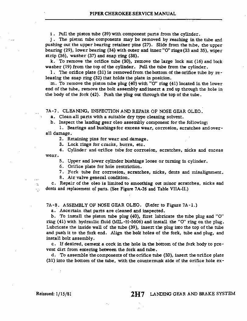
PIPER CHEROKEE SERVICE MANUAL
i . Pull the piston tube (39) with component parts from the cylinder.j . The piston tube components may be removed by reaching in the tube and
pushing out the upper bearing retainer pins (27). Slide from the tube, the upperbearing (29), lower bearing (34) with outer and inner "O" rings (33 and 35), wiperstrip (36), washer (37) and snap ring (38).
k. To remove the orifice tube (30), remove the large lock nut (16) and lockwasher (19) from the top of the cylinder. Pull the tube from the cylinder.
1. The orifice plate (31) is removed from the bottom of the orifice tube by re-leasing the snap ring (32) that holds the plate in position.
m. To remove the piston tube plug (40) with "O" ring (41) located in the lowerend of the tube, remove the bolt assembly and insert a rod up through the hole inthe body of the fork (42). Push the plug out through the top of the tube.
7A-7. CLEANING, INSPECTION AND REPAIR OF NOSE GEAR OLEO.a. Cleanall parts with a suitable dry type cleaning solvent.b. Inspect the landing gear oleo assembly component for the following:
1. Bearings and bushings for excess wear, corrosion, scratches and over-all damage.
2. Retaining pins for wear and damage.3. Lock rings for cracks, burrs, etc.4. Cylinder and orifice tube for corrosion, scratches, nicks and excess
wear.5. Upper and lower cylinder bushings loose or turning in cylinder.6. Orifice plate for hole restriction.7. Fork tube for corrosion, scratches, nicks, dents and misalignment.8. Air valve general condition.
c. Repair of the oleo is limited to smoothing out minor scratches, nicks anddents and replacement of parts. (See Figure 7A-26 and Table VIIA-II.)
7A-8. ASSEMBLY OF NOSE GEAR OLEO. (Refer to Figure 7A-1.)a. Ascertain that parts are cleaned and inspected.b. To install the piston tube plug (40), first lubricate the tube plug and "0"
ring (41) with hydraulic fluid (MIL-H-5606) and install the "0" ring on the plug.Lubricate the inside wall of the tube (39), insert the plug into the top of the tubeand push it to the fork end. Align the bolt holes of the fork, tube and plug, andinstall bolt assembly.
c. If desired, cement a cork in the hole in the bottom of the fork body to pre-vent dirt from entering between the fork and tube.
d. To assemble the components of the orifice tube (30), insert the orifice plate(31) into the bottom of the tube, with the countersunk side of the orifice hole ex-
2H7 LANDING GEAR AND BRAKE SYSTEMReissued: 1/15/81

PIPER CHEROKEE SERVICE MANUAL
1714
121314
2. CAP BOLTS AND WASHERS
3. SUPPORT FITTING 22
4. RUSHING SUPPORT FITTING
5. BUSHING 236. BOLT, WASHERS, NUT AND COTTER PIN
7. BOLT, WASHERS, NUT AND COTTER PIN8. AXLE3
9 CAP BOLTI. BUSHING, ROLLER FITTING
11. ARM, STEERING
12. BRACKET ALIGNER 2413. CAP, AIR VALVE
14. CORE, AIR VALVE 2515. BODY, AIR VALVE
16. NUT, ORIFICE TUBE 2617. SNAP RING18. ROLL PIN19. WASHER, STOP
20. BUSHING, UPPER \21. HOUSING, STRUT22. BUSHING, LOWER
23. OLEO CYLINDER
24. LINK, UPPER TORQUE25. BOLT, WASHER, BUSHINGS, NUT AND COTTER PIN
26. LINK, LOWER TORQUE27. PIN, BEARING RETAINING
28. "O" RING29. BEARING, UPPER TUBE30. TUBE, ORIFICE31. PLATE, ORIFICE32. SNAP RING
33. "O" RING34. BEARING, LOWER TUBE
35. "O" RING
36. WIPER STRIP37. WASHER36. SNAP RING39. TUBE, PISTON40. PISTON TUBE PLUG41. "O" RING42. PORK43. WASHER
Figure 7A-1. Nose Gear Oleo Strut Assembly
Reissued: 1/15/81 2H8 LANDING GEAR AND BRAKE SYSTEMReissued: 1/15/81 2H8

PIPER CHEROKEE SERVICE MANUAL
1716
27
293031
3839
4041
42
1736
Reissued: 1/15/81
Figure 7A-I. Nose Gear Oleo Strut Assembly (cont)
2H9 LANDING GEAR AND BRAKE SYSTEM
1733
101112131415161718191943
20
21
22
23
24
25
26
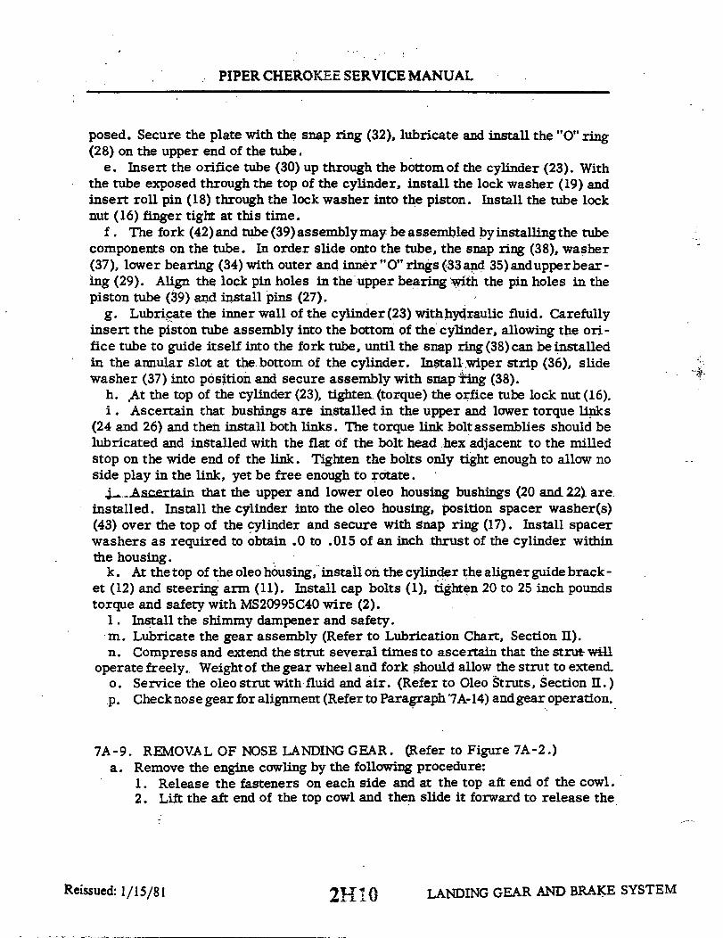
PIPER CHEROKEE SERVICE MANUAL
posed. Secure the plate with the snap ring (32), lubricate and install the "O" ring(28) on the upper end of the tube.
e. Insert the orifice tube (30) up through the bottom of the cylinder (23). Withthe tube exposed through the top of the cylinder, install the lock washer (19) andinsert roll pin (18) through the lock washer into the piston. Install the tube locknut (16) finger tight at this time.
f. The fork (42)and tube (39)assemblymay be assembled byinstallingthe tubecomponents on the tube. In order slide onto the tube, the snap ring (38), washer(37), lower bearing (34) with outer and inner "O" rings (33and 35)andupperbear-ing (29). Align the lock pin holes in the upper bearing with the pin holes in thepiston tube (39) and install pins (27).
g. Lubricate the inner wall of the cylinder(23) withhydraulic fluid. Carefullyinsert the piston tube assembly into the bottom of the cylinder, allowing the ori-fice tube to guide itself into the fork tube, until the snap ring (38) can be installedin the annular slot at the bottom of the cylinder. Install wiper strip (36), slidewasher (37) into position and secure assembly with snap ing (38).
h. At the top of the cylinder (23), tighten (torque) the orfice tube lock nut (16).i. Ascertain that bushings are installed in the upper and lower torque links
(24 and 26) and then install both links. The torque link bolt assemblies should belubricated and installed with the flat of the bolt head hex adjacent to the milledstop on the wide end of the link. Tighten the bolts only tight enough to allow noside play in the link, yet be free enough to rotate.
j. Ascertain that the upper and lower oleo housing bushings (20 and 22) are.installed. Install the cylinder into the oleo housing, position spacer washer(s)(43) over the top of the cylinder and secure with snap ring (17). Install spacerwashers as required to obtain .0 to .015 of an inch thrust of the cylinder withinthe housing.
k. At the top of the oleo housing, install on the cylinder the aligner guide brack-et (12) and steering arm (11). Install cap bolts (1), tighten 20 to 25 inch poundstorque and safety with MS20995C40 wire (2).
l. Install the shimmy dampener and safety.m. Lubricate the gear assembly (Refer to Lubrication Chart, Section II).n. Compress and extend the strut several times to ascertain that the strut will
operate freely. Weight of the gear wheel and fork should allow the strut to extend.o. Service the oleo strut with fluid and air. (Refer to Oleo Struts, Section II.)p. Checknosegearfor alignment (Referto Paragraph '7A-14) andgear operation.
7A-9. REMOVAL OF NOSE LANDING GEAR. (Refer to Figure 7A-2.)a. Remove the engine cowling by the following procedure:
1. Release the fasteners on each side and at the top aft end of the cowl.2. Lift the aft end of the top cowl and then slide it forward to release the
Reissued: 1/15/81 LANDING GEAR AND BRAKE SYSTEM2H10
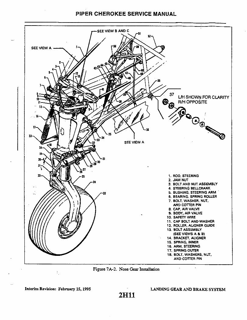
PIPER CHEROKEE SERVICE MANUAL
SEE VIEW A
FOR CLARITY
SEE VIEW A
1. ROD, STEERING2. JAM NUT3. BOLT AND NUT ASSEMBLY4. STEERING BELLCRANK5. BUSHING. STEERING ARM6. BEARING, SPRING ROLLER7. BOLT, WASHER, NUT,
AND COTTER PIN8. CAP, AIR VALVE9. BODY, AIR VALVE
10. SAFETY WIRE11. CAP BOLT AND WASHER12. ROLLER, ALIGNER GUIDE13. BOLT ASSEMBLY
(SEE VIEWS A & B)14. BRACKET, ALIGNER15. SPRING, INNER16. ARM, STEERING17. SPRING OUTER18. BOLT, WASHERS, NUT,
AND COTTER PIN
Figure 7A-2. Nose Gear Installation
Interim Revision: February 15, 1995
2H11LANDING GEAR AND BRAKE SYSTEM
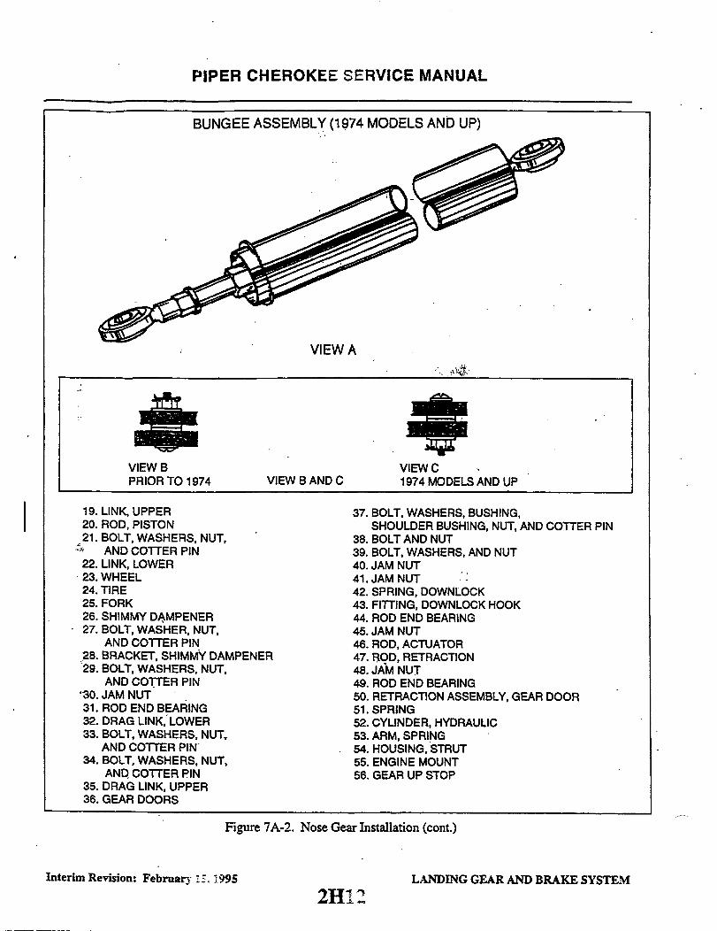
PIPER CHEROKEE SERVICE MANUAL
BUNGEE ASSEMBLY (1974 MODELS AND UP)
VIEW A
VIEW BPRIOR TO 1974 VIEW B AND C
VIEW C1974 MODELS AND UP
19. LINK, UPPER20. ROD, PISTON21. BOLT, WASHERS, NUT,
AND COTTER PIN22. LINK, LOWER23. WHEEL24. TIRE25. FORK26. SHIMMY DAMPENER27. BOLT, WASHER, NUT,
AND COTTER PIN28. BRACKET, SHIMMY DAMPENER29. BOLT, WASHERS, NUT,
AND COTTER PIN30. JAM NUT31. ROD END BEARING32. DRAG LINK, LOWER33. BOLT, WASHERS, NUT,
AND COTTER PIN34. BOLT, WASHERS, NUT,
AND COTTER PIN35. DRAG LINK, UPPER36. GEAR DOORS
37. BOLT, WASHERS, BUSHING,SHOULDER BUSHING, NUT, AND COTTER PIN
38. BOLT AND NUT39. BOLT, WASHERS, AND NUT40. JAM NUT41.JAM NUT42. SPRING, DOWNLOCK43. FITTING, DOWNLOCK HOOK44. ROD END BEARING45. JAM NUT46. ROD, ACTUATOR47. ROD, RETRACTION48. JAM NUT49. ROD END BEARING50. RETRACTION ASSEMBLY, GEAR DOOR51. SPRING52. CYLINDER, HYDRAULIC53. ARM, SPRING54. HOUSING, STRUT55. ENGINE MOUNT56. GEAR UP STOP
Figure 7A-2. Nose Gear Installation (cont.)
Interim Revision: February 15. 1995 LANDING GEAR AND BRAKE SYSTEM
2H12

PIPER CHEROKEE SERVICE MANUAL
two stud type front fasteners. Remove the top cowl.3. Disconnect the electrical lead to the landing light at the quick discon-
nect at the left inside of the bottom cowl.4. Disconnect the nose landing gear door control rods at each door by re-
moving the connecting bolts with nuts and washers... Remove the bottom cowl support screws, two located at.the side of each
gear door hinge.6. Remove the bottom cowl attaching screws from around its aft end and
remove cowl.b. Place the airplane on jacks. (Refer to Jacking; Section II.)c. Disconnect the two gear tension springs (15 and 17) from the spring arm
(53) that is attached to the right side of the strut housing (54).d. Retract nose gear slightly to remove the gear from its downlocked position.e. To remove the upper and lower drag links (32 and 35), the following pro-
cedure may be used:1. Disconnect the rod end (44) of the hydraulic cylinder (52) from the down-
lock fitting (43) by removing nut and bolt that connects these two units.2. Retract the gear and disconnect the gear downlock spring (42) from the
upper drag link (35).3. Remove the gear tension spring arm (53) from the right side of the oleo
housing (54) and lower drag link (32) by removing the cotter pin, nut and washerfrom the bolt (29) that connects the drag link to the housing. Slide the arm andspacer washer from the bolt.
4. Remove the cotter pins, washers and nuts from the bolts that secure theupper drag link (35) to the engine mount (55).
5. Slide the attachment bolts from the upper and lower drag links and re-move the links.
f. With the lower drag link (32) disconnected from the gear oleo housing (54),the housing may be removed by removing cotter pins, nuts, washers, and bolts(7 and 33) at the attachment points on each side of the housing at the engine mount.
g. The steering bellcrank (4) may be removed by removing the nut and bolt (3)at the steering rod, and the bolt assembly (13) with bushing at the bellcrank pivot point.
7A-10. CLEANING, INSPECTION AND REPAIR OF NOSE LANDING GEARa. Clean all parts with a suitable dry type cleaning solvent.b. Inspect the gear components for the following unfavorable conditions:
1. Bolts, bearings and bushings for excess wear, corrosion and damage.2. Gear housing, drag links, torque links, and tension spring arm for
cracks, bends or misalignment.3. Downlock hook for excess wear of the hook and bearing surfaces.4. Downlock rollerbearing for freedom of movement and excessive wobble.
LANDING GEAR AND BRAKE SYSTEMReissued: 1/15/81 2H13
PIPER CHEROKEE SERVICE MANUAL
c. Inspect the gear tension and downlock hook springs for the following:1. Excess wear or corrosion, especially around the hook portion of the springs. A
spring should be rejected if wear or corrosion exceeds one-quarter the diameter of thespring. Clean away all corrosion and repaint.
2. Check the gear tension springs for load tensions below minimum allowabletolerances. The minimum allowable tension of the inner spring is 37 pounds pull at 13.75inches and the outer is 60 pounds pull at 13.75 inches. Measurement is taken from the innerside of each hook. If it is found that either spring should be rejected, replace both springs.
3. Check the gear downlock hook spring for load tension below minimumallowable tolerance. The minimum tension of the spring is 10.5 pounds pull at 4.5 inches.Measurement is also taken from the inner side of each hook.
d. Check the general condition of each limit switch and its actuator, and wiring forfraying, poor connections or conditions that may lead to failures.
e. Check drag link through center travel by attaching the upper and lower drag links,setting them on a surface table, and ascertaining that when the stop surfaces of the two linkstouch, linkage is not less than .062 to .125 nor more than .125 to .250 of an inch throughcenter. Should the distance exceed the required through center travel and bolt and bushingare tight, replace one or both drag links.
f. The shimmy dampener requires no service other than routine inspection. In case ofdamage or malfunction, the dampener should be replaced rather than repaired.
g. Repair to the landing gear is limited to reconditioning of parts such as replacingbearings and bushings, smoothing out minor nicks and scratches, repainting of areas wherepaint has chipped or peeled and replacement of parts.
7A-11. INSTALLATION OF NOSE LANDING GEAR. (Refer to Figure 7A-2.)
NOTE
When assembling any units of the landing gear; lubricatebearings, bushings, and friction surfaces with the properlubricant as described in Section II.
a. Attach the steering bellcrank (4) with bushing to its mounting plate on the enginemount (55) securing with the bolt assembly (13). Align the steering bellcrank (4) and thesteering arm bushings (5) by positioning the spacer washers as shown in Figure 7A-2.Connect the steering rods (1) to the bellcrank (4) and install bolt and nut assemblies (3).The adjustment, fore and aft of the bellcrank, may be made after the gear has been installedand rigged and adjusted.
b. To install the gear housing assembly, position the gear so that the bolt attachmentpoints on the housing (54) align with the attachment points on the engine mount (55).Install pivot bolts, washers and nuts (7 and 33). Tighten the nuts to a snug fit, yet allowingthe gear to swing free, and safety.
LANDING GEAR AND BRAKE SYSTEMReissued: 1/15/81 2H14

PIPER CHEROKEE SERVICE MANUAL
c. The drag links (32 and 35) and gear tension spring arm (53) may be installed by thefollowing procedure:
1. Ascertain that the upper and lower links (32 and 35) are assembled with thedownlock hook attached, and the through travel of the links checked according toparagraph 7A-10.
2. Position the link assembly to allow the bolt holes in the links to align with thebolt holes in the gear housing and the engine mount. Install the link attachment bolts.
3. Install nuts and washers on the upper link (35) attachment bolts. Tighten thenuts to allow the links to rotate freely and safety.
4. Check alignment of the downlock hook to determine if it grips the roller bearingso as not to contact the bolt head, the bearing attachment block or washer. If the downlockhook is inboard, or it contacts the bolt head, shim between the bearing and the bearingattachment block with washer AN960-1OL, not to exceed three. The bearing must be free torotate, therefore, it may be necessary to replace the bearing retaining bolt with longer bolt,AN23-36A, depending on the number of washers used. Should the downlock hook beonboard, or in contact with the bearing attachment block, add one washer, P/N 62833-40of P/N 62833-41 between the engine mount (55) and upper drag link (35). Washer, P/N6283341, is to be tried first.
5. Install the gear tension spring arm (53) on the drag link bolt (29) on the rightside of the gear oleo housing (54), secure and safety. A washer is installed on the boltbetween the lower drag link and the arm.
d. Retract and extend the landing gear several times to ascertain smoothness ofoperation. Also check that the drag link assembly falls into the through center-lockedposition.
e. Retract the gear and connect the gear downlock spring (42) between the downlockhook (43) and the upper drag link (35).
f. Extend the gear and connect the two gear tension springs (15 and 17) between theattachment point on the oleo housing (54) and the spring arm (53).
g. Ascertain that the landing gear is lubricated per Lubrication Chart, Section II.h. Check adjustment of the gear per paragraph 7A-12 or 7A-13.i. Install engine cowling. (The cowl support jacks located at each forward side of the
nose gear door hinges are adjusted down to contact the cowl surface after attaching screwsare secure.)
j. Retract landing gear and check door operation as per paragraph 7A-18.k. Check the alignment of the nose gear per paragraph 7A-14.1. Remove the airplane from jacks.
Reissued: 1/15/81 LANDING GEAR AND BRAKE SYSTEM2H15

PIPER CHEROKEE SERVICE MANUAL
1. STEERIN BELLCRANK 5. JAM NUT . SHIMMY DAMPENER
2. CROSS-OVER TUBE 6. ROD END BEARING 10. STRUT HOUSING
3. STEERING ROD 7. OLT ASSEMBLY 11. SPRING
4. ACTUATOR ROD, CYLINDER 8. DOWNLOCK HOOK
Figure 7A-3. Nose Gear Adjustment (Without Gear Up. Stop)
7A-12. ADJUSTMENT OF NOSE LANDING GEAR (Without GearUp Stop). (Refer.to Figure 7A-3.)
a. Place the airplane on jacks. (Refer to Jacking, Section II. )b. With the gear extended, disconnect the nose gear door retraction rods from
each door by removing the rod attaching bolts. If desired, the lower engine cowlmay be removed to facilitate easier access for adjustments.
c. Retract the landing gear hydro-electrically by turning the master switchon, raising the emergency gear extension lever and moving the gear selector han -dle to the up position. Retain the emergency extension lever in the up overrideposition.
d. Clearance between the strut housing (10) and the cross-over tube (2) wherethe steering bellcrank (1) attaches should be 0. 015 ± 0. 003 of an inch with thepiston of the actuator cylinder bottomed. Should this dimension be incorrect andit will require more than 0. 010 of an inch to bring the housing to the correctclearance, then block the gear in the up position, disconnect the piston rod endbearing from the downlock by removing the attaching bolt, loosen the jam nut onthe end bearing to obtain correct adjustment. Reinstall attaching bolt and safety.When adjustment requires less than 0. 010 of an inch, the rod end bearing need
2H16 LANDING GEAR AND BRAKE SYSTEMReissued: 1/15/81

PIPER CHEROKEE SERVICE MANUAL
1823
2
12
1. STEERING BELLCRANK2. STEERING ROD3. UPPER DRAG LINK4. GEAR UP STOP
5. JAM NUT6. ACTUATOR ROD, CYLINDER7. JAM NUT8. ROD END BEARING
9. BOLT ASSEMBLY10. DOWNLOCK HOOK11. SHIMMY DAMPENER12. STRUT HOUSING
Figure 7A-4. Nose Gear Adjustment (With Gear Up Stop).
not be disconnected and therefore all that will be required is to loosen the jamnut, place a wrench on the flat at the end of the piston rod and turn to obtain thecorrect adjustment.
e. Check rod end bearing for adequate thread engagement and tighten jam nut.f. With gear extended, adjust shimmy dampener by turningnose wheelagainst
stops and adjusting rod end for adequate travel for both extremes.g. Remove the airplane from jacks.
7A-13. ADJUSTMENT OF NOSE LANDING GEAR (With Gear Up Stop). (Referto Figure 7A-4.) The gear up stop (4) is located just above the gear door re-traction roller near the lower aft end of the engine.
a. Remove the engine cowl. For removal instructions, refer to paragraph.7A-9, step a.
b. Place the airplane on jacks. (Refer to Jacking, Section II.)c. Retract the landing gear hydro-electrically by turning the master switch
on, raising the emergency gear extension lever and moving the gear selectorhandle to the UP position. Retain the emergency extension lever in the UP Over-ride position.
2H17 LANDING GEAR AND BRAKE SYSTEM
*
Reissued: 1 / 15/81

PIPER CHEROKEE SERVICE MANUAL
d. Check the adjustment of the gear up stop by placing a carpenters squarewith the longest end along the bottom of the fuselage, and the shortest end run-ning up through the centerline of the wheel axle. Measure up along the squarefrom the bottom of the fuselage 6.25 ± .25 inches, to determine if the center ofthe wheel axle meets this measurement. If this measurement is incorrect, ex-tend the gear, loosen the jam nut (5) on the gear up stop, and make the requiredadjustment by turning the stop.
e. Check the adjustment of the hydraulic cylinder by extending the gear andremoving the nut and bolt (9) from the rod end bearing (8). Loosen the jam nutthat secures the rod end bearing and turn the rod end approximately one threadin past the safety hole on the cylinder rod (6).
f. Hook -up cylinder rod end bearing and retract gear. Recheck all adjustmentsand retighten the jam nut on the gear up stop. When the gear is fully retracted,the upper drag link (3) should be firmly against the gear up stop. Extend the gear.
g. Adjust shimmy dampener by turningnose wheel against stops and adjustingthe rod end of the dampener for adequate travel to both extremes.
h. Install engine cowling, retract landing gear and check door per paragraph7A-18.
i. Remove the airplane from jacks.
7A-14. ALIGNMENT OF NOSE LANDING GEAR. On 1974 models the nose wheelsteering has been modified by the addition of the bungee system. This will require somedifferent adjustment procedures which are included with the regular instructions below.
a. Place the airplane on a smooth level floor that will accommodate the striking of achalk line.
b. Ascertain that the nose gear is properly adjusted as given in Paragraph 7A-12 or7A-13.
c. With the landing gear in the down-locked position, weight proportionally on thenose gear and the nose wheel facing forward, adjust the steering bellcrank. The bellcrank isattached at the lower front of the engine mount directly aft of the gear housing and may beadjusted by loosening its attachment bolt and sliding the bellcrank fore and aft until it clearseach steering arm rollers by .03 of an inch. Retighten the attachment bolt.
d. Place the airplane on jacks. (Refer to Jacking, Section II.)e. Level the airplane laterally and longitudinally. (Refer to Leveling, Section II.)f. From the center point of the tail skid, extend a plumb bob and mark the contact
point on the floor.g. Extend a chalk line from the mark on the floor below the tail skid to a point
approximately three feet forward of the nose wheel. Allow the line to pass under the wheelat the center line of the tire. Snap the chalk line.
h. Clamp the rudder pedals to align then in a lateral position. Ascertain that the rudderpedals are in there neutral position. (Refer to Figure 7A-6 and Table VII-I.)
Reissued: 1/15/81 LANDING GEAR AND BRAKE SYSTEM2H18
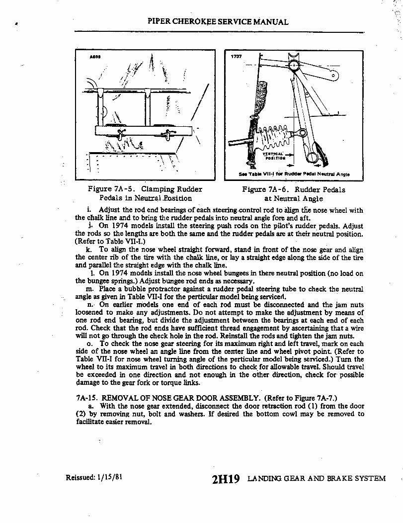
PIPER CHEROKEE SERVICE MANUAL
A599 1737
See Table VII-I for Rudder Pedal Neutral Angle
Figure 7A-5. Clamping Rudder Figure 7A-6. Rudder PedalsPedals in Neutral Position at Neutral Angle
i. Adjust the rod end bearings of each steering control rod to align the nose wheel withthe chalk line and to bring the rudder pedals into neutral angle fore and aft.
j. On 1974 models install the steering push rods on the pilot's rudder pedals. Adjustthe rods so the lengths are both the same and the rudder pedals are at their neutral position.(Refer to Table VII-I.)
k. To align the nose wheel straight forward, stand in front of the nose gear and alignthe center rib of the tire with the chalk line, or lay a straight edge along the side of the tireand parallel the straight edge with the chalk line.
1. On 1974 models install the nose wheel bungees in there neutral position (no load onthe bungee springs.) Adjust bungee rod ends as necessary.
m. Place a bubble protractor against a rudder pedal steering tube to check the neutralangle as given in Table VII-I for the perticular model being serviced.
n. On earlier models one end of each rod must be disconnected and the jam nutsloosened to make any adjustments. Do not attempt to make the adjustment by means ofone rod end bearing, but divide the adjustment between the bearings at each end of eachrod. Check that the rod ends have sufficient thread engagement by ascertaining that a wirewill not go through the check hole in the rod. Reinstall the rods and tighten the jam nuts.
o. To check the nose gear steering for its maximum right and left travel, mark on eachside of the nose wheel an angle line from the center line and wheel pivot point. (Refer toTable VII-I for nose wheel turning angle of the perticular model being serviced.) Turn thewheel to its maximum travel in both directions to check for allowable travel. Should travelbe exceeded in one direction and not enough in the other direction, check for possibledamage to the gear fork or torque links.
7A-15. REMOVAL OF NOSE GEAR DOOR ASSEMBLY. (Refer to Figure 7A-7.)a. With the nose gear extended, disconnect the door retraction rod (1) from the door
(2) by removing nut, bolt and washers. If desired the bottom cowl may be removed tofacilitate easier removal.
Reissued: 1/15/81 2H19 LANDING GEAR AND BRAKE SYSTEM

PIPER CHEROKEE SERVICE MANUAL
1730
1. ROD, DOOR RETRACTION2. DOOR, GEAR3. SPRING, TENSION4. SELLCRANK ASSEMBLY5 ROLLER ASSEMBLY6. ROLLER
7. THREADED LINK, ROLLER8. COTTER PIN9. GEAR UP STOP
Reissued: 1/15/81
Figure 7A-7. Nose Gear Door Retraction Mechanism
2H20 LANDING GEAR AND BRAKE SYSTEM

PIPER CHEROKEE SERVICE MANUAL
b. To remove the door(s) from the cowl, bend the end of the hinge pin straightand from the other end pull out the pin.
c. The bellcrank assembly (4) of the door retraction mechanism may be re-moved by removing the attached hardware, disconnecting the door down tensionspring (3) and removing the cotter pins (8) at each end of the pivot tube. Slidethe insulating sleeve and bushing tube from the bellcrank.
d. The roller assembly (5) of the mechanism may be removed by removing theattached hardware and pivot bolt with insulator.
7A-16. CLEANING, INSPECTION AND REPAIR OF NOSE GEAR DOOR ASSEM-BLY.
a. Clean all parts with a suitable cleaning solvent.b. Inspect doors for cracks or damage, loose or damaged hinges and brackets.c. Inspect door retraction rods for damage and rod end bearing for corrosion.d. Check the door tension spring for wear and tension below minimum allow-
able tolerance. Reject spring if load tension is below 8.0 pounds pull at 4.75 in-ches.
e. Check general condition of bellcrank and roller assembly.f . Repairs to the doors may be replacement of hinges, repair of fiberglass
and painting.g. Repairs to the retraction mechanism is limited to replacement of parts,
and sanding and painting.
7A-17. INSTALLATION OF NOSE GEAR DOOR ASSEMBLY. (Refer to Figure7A-7.)
a. The roller assembly (5) of the retraction mechanism may be installed byfirst assembling the roller (6), threaded link (7) and rollerlinks (5), and thenin-stalling this assembly on its mountingbracket. Ascertain that an insulator sleeveis installed with the attachment bolt and link bolt.
b. The bellcrank assembly (4) of the retraction mechanism may be installedby positioning the bellcrank between its mounting bushing and inserting the in-sulator sleeve and bushing tube. Install a cotter pin through each attachmentbushing and the pivot tube. New tubes will require a .070 hole drilled througheach end to facilitate a cotter pin. Use the existing hole in the mounting bushingsas a guide. Do not connect link between roller assembly and bellcrank until timeof door adjustment.
c. Install the gear door(s) by positioning the hinge halves of the door and cowl,and inserting the hinge pin. It is recommended a new pin be used. Bend the endof the pin to secure in place.
d. Install the cowl and adjust doors as given in paragraph 7A-18.
2H21 LANDING GEAR AND BRAKE SYSTEMReissued: 1/15/81
PIPER CHEROKEE SERVICE MANUAL
7A-18. ADJUSTMENT .OF NOSE GEAR DOORSa.. Place the airplane on jacks. (Refer to Jacking, Section II.)b. Adjust the door retraction rods so thatthe gear will swing throughthe door
opening with a . 12 .06 of an inch clearance between the gear and door at theirclosest point. This can best be done with the nose gear down, tension springsdisconnected and operating the nose gear manually.
c. With door clearance adjusted, adjust the link between the roller assemblyand bellcrank assembly so thatthe doors will pull uptightly when gear is full up.Over-tightening may result in door buckling, however if the link is too loose,doors will gap in flight.
d. Check all rod ends for adequatethreadengagement, for safetyandtightnessof jam nuts.
e. Remove the airplane from jacks .
7A -19. MAINLANDING GEAR SYSTEM.
7A-.20 ... DISASSEMBLY OF MAIN GEAR OLEO. (Refer to Figure 7A.-8) Themain gear oleo assembly may be removed and disassembled from the gear oleohousing with the gear removed from or installed on the airplane.
a. Place the airplane on jacks. (Refer to Jacking, Section II.)b. Place a drip pan under the main gear to catch spillage.c. Remove the air and fluid from the oleo. To do this, depress the air valve
core pin until strut pressure has diminished, remove the filler plug and with asmall hose siphon as much hydraulic fluid from the strut as possible.
.d. D isconnect the brake. line. at the jint located in the wheel well.,e. To remove piston tube 25) assembly from oleo housing (11), remove the
upper and lower torque link connecting bolt assembly (3) and separate the links.Note number and thickness of spacer washer(s) between the two links (15 and 16).
f. Compress the piston tube (25), reach up along the tube and release the snapring (24) from the annualar slot at the bottom of the oleo housing.
g. Pull the piston tube(25) with component parts from the cylinder housing.h. The piston tube (25) components may be removed by reaching in the tube
and pushing out the upper bearing (18) retainer pins (17). Slide off the upper bear-ing(18), 'lower bearing (20) with "O" rings (19 and 21), wiper (22), washer (23)and' snap ring (24).
i. To remove the orifice tube (12) from the oleo housing, remove the lock nut(6) and washer (7) from the top of the housing. Draw the tube with "O" ring (9)and retainer (8) from the housing.
j. The orifice plate (13) is removed from the bottom of the orifice tube (12)by releasing the snap ring (14) that holds the plate in position.
Reissued: 1/15/81 2H22 LANDING GEAR AND BRAKE SYSTEM

PIPER CHEROKEE SERVICE MANUAL
k. To remove the piston tube plug (26) with "0" ring (27) located in the lower end ofthe tube, remove the bolt assembly and insert a rod up through the hole in the body of thefork (28), pushing the plug out through the top of the tube.
7A-21. CLEANING, INSPECTION AND REPAIR OF MAIN GEAR OLEO.a. Clean all parts with a suitable dry type cleaning solvent.b. Inspect the landing gear oleo assembly component for the following:
1. Bearings and bushings for excess wear, corrosion, scratches and overall damage.2. Retaining pins for wear and damage.3. Lock rings for cracks, burrs, etc.4. Cylinder and orifice tube for corrosion, scratches, nicks and excess wear.5. Orifice plate for hole restriction.6. Fork tube for corrosion, scratches, nicks, dents and misalignment.7. Air valve general condition.
c. Repair of the oleo is limited to smoothing out minor scratches, nicks and dents andreplacement of parts. (See Figure 7A-26 and Table VIIA-III for bearing replacement.)
7A-22. ASSEMBLY OF MAIN GEAR OLEO. (Refer to Figure 7A-8.)a. Ascertain that all parts are cleaned and inspected.b. To install the piston tube plug (26), first lubricate the plug "O" ring (27) with
hydraulic fluid (MIL-H-5606) and install it on the plug. Lubricate the inside wall of thetube. Insert the plug into the top of the tube (25) and push it to the fork end. Align the boltholes of the fork, tube and plug, and install bolt assembly.
c. If desired, cement a cork in the hole in the bottom of the fork body to prevent dirtfrom entering between the fork and tube.
d. To assemble the components of the orifice tube (12) insert the orifice plate (13)into the bottom of the tube and secure with snap ring (14).
e. To install the tube (12) in the oleo housing (11), insert the tube up through thehousing. With the end of the tube exposed through the top of the housing, install the "O"ring (9), retainer (8), washer (7), and lock nut (6). Tighten lock nut only finger tight at thistime.
f. Assemble the components of the piston tube (25) on the tube by placing, in order,the snap ring (24), washer (23), lower bearing (20) with outer and inner "0" rings (19 and21) and upper bearing (18). Align the two .125 diameter holes and the lock pin holes withthe corresponding holes in the piston tube (25) and install pins (17) without force. Theouter surface of the pins must not protrude beyond the outer diameter of the bearing (18).
g. Lubricate the wall of the cylinder oleo housing (11) and tube (25), and carefullyinsert the tube assembly into the housing, guiding the orifice tube (12) into the piston tubeuntil the snap ring (24) can be installed in the annular slot at the lower end of the housing.Install the wiper strip (22); slide the washer (23) into position and secure the assembly withsnap ring (24).
Reissued: 1/15/81 LANDING GEAR AND BRAKE SYSTEM2H23

INTENTIONALLY LEFT BLANK
Reissued: 1/15/81 2H24
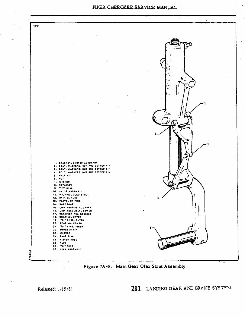
PIPER CHEROKEE SERVICE MANUAL
1711
. BRACKET SWITCH ACTUATOR2. BOLT WASHERS, NUT AND COTTER PIN3. BOLT, WASHERS NUT AND COTTER PIN
4. BOLT WASHERS, NUT AND COTTER PIN5. AXLE NUT6. NUT7. WASHER
8. RETAINER9. "C" RINS
10. VALVE ASSEMBLY11 . HOUSING OLEO STRUT12. ORIFICE TUBE13. PLATE ORIFICE14. SNAP RING15. LINK ASSEMBLY. UPPER
16. LINK ASSEMBLY, LOWER17. RETAINER PIN, BEARING18. BEARING UPPER19. "0" RING, OUTER20. BEARING. LOWER21. "O" RING, INNER22. WIPER STRIP23. WASHER24. SNAP RING
25. PISTON TUBE26. PLUG27. "O" RING22. FORK ASSEMBLY
3
Figure 7A-8. Main Gear Oleo Strut Assembly
211 LANDING GEAR AND BRAKE SYSTEMReissued: 1/15/81
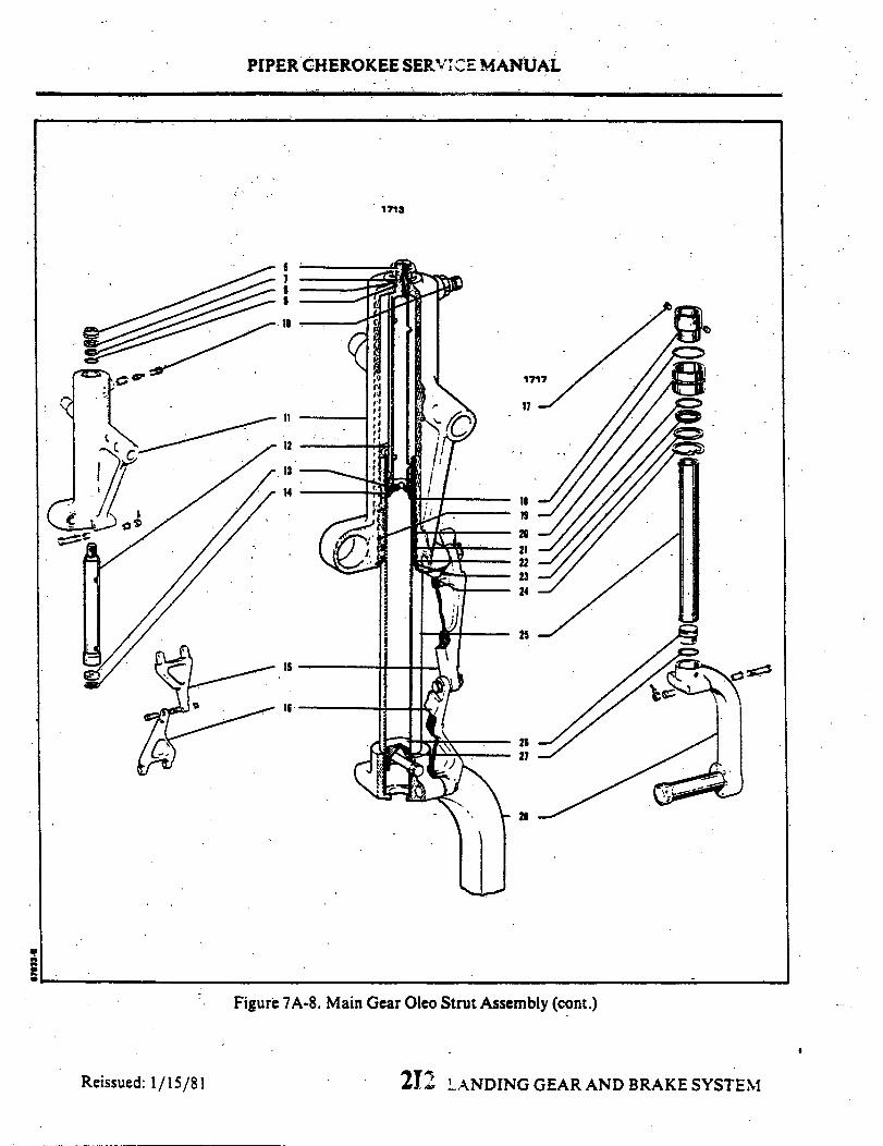
PIPER CHEROKEE SERVICE MANUAL
1713
1717
17
19s19s
20
2324
25
2627
21
Figure 7A-8. Main Gear Oleo Strut Assembly (cont.)
212 LANDING GEAR AND BRAKE SYSTEMReissued: 1/15/81
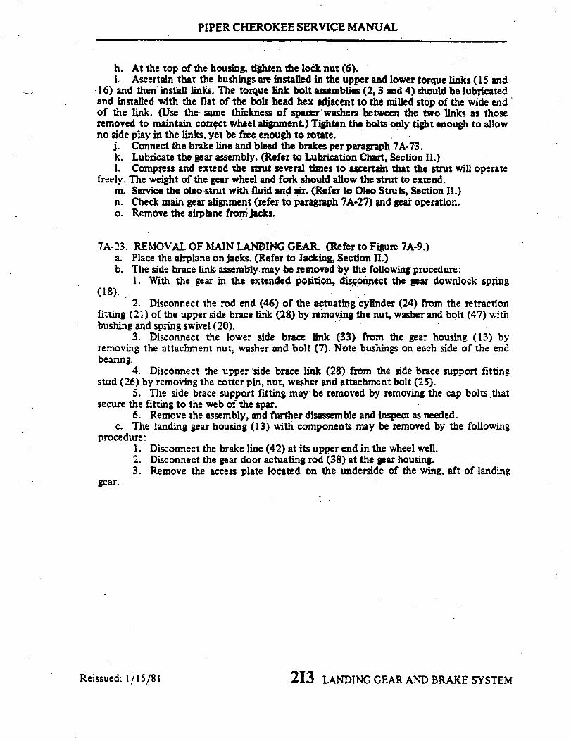
PIPER CHEROKEE SERVICE MANUAL
h. At the top of the housing, tighten the lock nut (6).i. Ascertain that the bushings are installed in the upper and lower torque links ( 1 and
16) and then install links. The torque link bolt assemblies (2, 3 and 4) should be lubricatedand installed with the flat of the bolt head hex adjacent to the milled stop of the wide endof the link. (Use the same thickness of spacer washers between the two links as thoseremoved to maintain correct wheel alignment.) Tighten the bolts only tight enough to allowno side play in the links, yet be free enough to rotate.
j. Connect the brake line and bleed the brakes per paragraph 7A-73.k. Lubricate the gear assembly. (Refer to Lubrication Chart, Section II.)1. Compress and extend the strut several times to ascertain that the strut will operate
freely. The weight of the gear wheel and fork should allow the strut to extend.m. Service the oleo strut with fluid and air. (Refer to Oleo Struts, Section II.)n. Check main gear alignment (refer to paragraph 7A-27) and gear operation.o. Remove the airplane from jacks.
7A-23. REMOVAL OF MAIN LANDING GEAR. (Refer to Figure 7A-9.)a. Place the airplane on jacks. (Refer to Jacking, Section II.)b. The side brace link assembly may be removed by the following procedure:
1. With the gear in the extended position, disconnect the gear downlock spring(18).
2. Disconnect the rod end (46) of the actuating cylinder (24) from the retractionfitting (21) of the upper side brace link (28) by removing the nut, washer and bolt (47) withbushing and spring swivel (20).
3. Disconnect the lower side brace link (33) from the gear housing (13) byremoving the attachment nut, washer and bolt (7). Note bushings on each side of the endbearing.
4. Disconnect the upper side brace link (28) from the side brace support fittingstud (26) by removing the cotter pin, nut, washer and attachment bolt (25).
5. The side brace support fitting may be removed by removing the cap bolts thatsecure the fitting to the web of the spar.
6. Remove the assembly, and further disassemble and inspect as needed.c. The landing gear housing (13) with components may be removed by the following
procedure:1. Disconnect the brake line (42) at its upper end in the wheel well.2. Disconnect the gear door actuating rod (38) at the gear housing.3. Remove the access plate located on the underside of the wing, aft of landing
gear.
213 LANDING GEAR AND BRAKE SYSTEMReissued: 1/15/81

PIPER CHEROKEE SERVICE MANUAL
A
NOTEIt may have been necessary to use specallanding gear attachment hardware duringassembly of the aircraft due tomanufacturing tolerances. Therfore,special attention should be given whenremoving hardware to inspect and insurethe same diameter hardware is used uponreassembly. Standard AN4 or AN5 boltsare replaced by alternate oversized boltsNAS3004 or NAS3005 respectivelywhen oversized hardware is required.
Figure 7A-9. Main Gear Installation
Reissued: 1/15/81 214 LANDING GEAR AND BRAKE SYSTEM
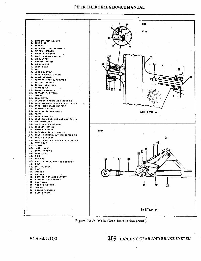
PIPER CHEROKEE SERVICE MANUAL
1. SUPPORT FITTING. AFT2. SNAP RING3. BEARING4. RETAINER, TUBE ASSEMBL5. FITTING GREASE6. HINGE, GEAR DOOR7. BOLT, WASHERS AND NUT8. LINK, UPPER
9. WASHER, SPACER10. LINK, LOWER11. DOOR,GEAR12. NUT13. HOUSING, STRUt14. PLUG. HYDRAULIC FLUID
15. VALVE ASSEMBLY16. SUPPORT FITTINGS, FORWARD
17. FITTING. GREASE
18. SPRING, DOWNLOCK19. TURNBUCKLE20. SWIVEL ASSEMBLY
21. RETRACTICN FITTING22. JAM NUT23. ROD,`PISTON24. CYLINDER, HYDRAULIC ACTUATING25. BOLT, WASHERS, NUT AND COTTER PIN26. STUD, SIDE BRACE SUPPORT27. SUPPORT BRAKE-28. LINK, UPPER SIDE BRACE SKETCH A29. PLATE30. HOOK, DOWNLOCK31. BOLT, WASHERS, NUT AND COTTER PIN32. PIN, DOWNLOCK33. LINK, LOWER SIDE BRACE
34. BRACKET, SPRING35. SWITCH. SAFETY 173436. ACTUATOR, SAFETY SWITCH37. BOLT, WASHERS. NUT AND COTTER PIN38. ROD, GEAR DOOR 2139 . BOLT, WASHERS. NUT AND COTTER PIN40. FORK GEAR41. CLAMP 19
42. HOSE. BRAKE43. BRAKE HOUSING
44J. BRAKE DISC 5845. TIRE
46. ROD END 56 57 33. BOLT, WASHER. NUT AND BUSHING
e. BOLT49. SHIM WASHER50. BOLT51. WASHER
52. WASHER53. BEARING, FORWARD SUPPORT54. BEARING, AFT SUPPORT55. SNAP RING56. ROD END BEARING 31 2857. JAM NUT
58. BRACKET, SWITCH59. CLIP, SAFETY
SKETCH B
Figure 7A-9. Main Gear Installation (cont.)
Reissued: 1/15/81 215 LANDING GEAR AND BRAKE SYSTEM

PIPER CHEROKEE SERV CE MANUAL
4. If not previously disconnected, disconnect the lower side brace link (33)from the gear housing.
5. Disconnect the forward support fitting (16) of the housing (13) from theweb of the main spar by removing the fitting attachment bolts.
6. Remove the retainer tube (4) in the aft support fitting (1) that supportsthe aft arm of the housing by reaching through the access opening on the undersideof the wing, through the hole in the web and removing the bolt (48) that securesthe tube in the housing. Insert a hook through the bolt hole in the tube, and slideit aft from the support fitting. Remove the tube from the wing. Note the numberof spacer washers (52) between the arm and support fitting (1).
7. Allow the gear to drop down removing it from the wing.8. The aft support fitting (1) may be removed by holding the nuts, reach-
ing through the access opening, and removing the fitting attachment bolts.9. The forward support fitting (16) may be removed from the arm of the
housing by removing the bolt and washer from the base side of the fitting. Slidethe fitting from the arm. Remove the washer (52) from the arm.
d. Either bearing (53 or 54) installed in the support fittings may be removedby removing the snap rings (2) that hold the bearing in the housing. Push thebearing from the housing.
7A-24. CLEANING, INSPECTION AND REPAIR OF MAIN LANDING GEAR.a. Clean all parts with a suitable dry type cleaning solvent.b. Inspect the gear components for the following unfavorable conditions:
1. Bolts, bearing and bushings for excess wear, corrosion and damage.2. Gear housing, side brace links, torque links and attachment plates for
cracks, bends or misalignment.3. Downlock hook for excessive wear of the bearing surfaces.
c. Inspect the gear downlock spring for the following:1. Excessive wear or corrosion, especially around the hook portion of the
spring. A spring should be rejected if wear or corrosion exceeds one-quarterthe diameter of the spring. Clean away all corrosion and repaint.
2. Check the spring for load tensions below minimumallowable tolerance.The minimum tension of the spring is 48 pounds pull at 7.9 inches. Measurement is takenfrom the inner side of each hook.
d. Check the general condition of each limit switch and its actuator, and wir-ing for fraying, poor connections or conditions that may lead to failures.
e. Check side brace link through centertravel byattaching the upper and lowerlinks, setting them on a surface table, and ascertaining that when the stop sur-faces of the two links touch, linkage is not less than .062 nor more than . 125 ofan inch through center. Should the distance exceed the required through centertravel and bolt and bushings are tight, replace one or both links.
216 LANDING GEAR AND BRAKE SYSTEMReissued: 1/15/81

PIPER CHEROKEE SERVICE MANUAL
f. With the side brace links assembled and checked, ascertain that when thestop surfaces of the two links contact, the clearance between each downlock hookand the flat of the downlock pin is not less than 0.010 of an inch. Should clear-ance be less than that required, the hook only may be filed not to exceed a gapof more than 0.025 of an inch. The maximum allowable clearance between eachhook and the downlock pin that are service worn is 0.055 of an inch. Shouldclearance be more than 0.055 of an inch, replace the pin, check clearance andthen if still beyond tolerance, replace hooks. The gap between each hook shouldbe equal.
g. Repair of the landing gear is limited to reconditioning of parts such asreplacing components, bearings and bushings, smoothing out minor nicks andscratches and repainting areas where paint has chipped or peeled.
7A-25. INSTALLATION OF MAIN LANDING GEAR. (Refer to Figure 7A-9.)
NOTE
When assembling components of the landing gear, lu-bricate bearings, bushings and friction surfaces withproper lubricant as described in Section II.
a. Insert a gear support bearing (53 or 54) in each support fitting (1 or 16)and secure with snap rings (2). Check bearing (53) for excess end play, shim asnecessary with shim washers (49) (P/N 62833-44).
b. The gear housing may be installed in the wheel well of the wing by the fol-lowing procedure:
1. Place a spacer washer (52) and then the forward support fitting (16) onthe forward arm of the housing. Ascertain that the barrel nut (55) is positionedin the arm and insert the attachment bolt through washer (51) and the fitting intothe arm. Tighten bolt and ascertain that the bearing is free to rotate.
2. Position the aft support fitting (1) at its attachment point in the wheelwell and secure with bolts, washers and nuts. Install the nuts and washers byreaching through the access hole on the underside of the wing.
3. With the retainer tube (4) for the aft arm of the housing in hand, reachup through the access opening and insert the tube into the support fitting (1)through the hole in the web.
4. Position the gear housing up in the wheel well and install the forwardsupport fitting (16) bolts and washers. (One each AN960-416 and AN960-416Lwasher per bolt.)
5. Push the retainer tube into the arm of the housingand secure with bolt.
2I7 LANDING GEAR AND BRAKE SYSTEMReissued: 1/15/81

PIPER CHEROKEE SERVICE MANUAL
6. Check that the gear rotates freely in its support fitings and recheckthrust.
7. Connect the brake line to its mating line in the wheel well and bleedbrakes as given in paragraph 7A-73.
c. The gear side brace link assembly may be installed by the following pro-cedure:
1.' Position the link support bracket (27) with swivel stud (26) installed atits attachment point on the web of the spar and secure with bolts and washers.
NOTE
When installing a new wing, it will be necessary toback drill two (2) holes 0.250 inch and countersink100° x .499 through the spar cap. (Screw head shouldbe flush with spar). Use hole in the support bracketas a guide in the drilling.
2. Ascertain that the upper and lower links(28 and 33)are assembled withdownlock hook (30), retraction fitting (21), etc. attached, and the through travelof the links and downlock hook clearance checked according to paragraph 7A-24.
3. Attach the upper link to the swivel stud of the support fitting and secure.with bolt, bushing, washer, nut and cotter pin.
4. The actuating cylinder rod end bearing (46) and lower side brace link(33) may be attached respectively to the retraction fitting (21) and gear housingduring the adjustment of the landing gear.
d. A scertain that the landing gear is lubricated per Lubrication Chart.e. Check adjustment of the landing gear per paragraph 7A-26.f. Check alignment of the wheel per paragraph.7A-27_g. Install the access plate on the underside of the wingand remove the airplane
from jacks.
7A-26. ADJUSTMENT OF MAIN LANDING GEAR.- a.. Place the airplane on jacks. (Refer to Jacking, Section II.)
b. Level the airplane laterally and longitudinally. (Refer to Leveling, Section II.)c. Disconnect the gear door actuating rods at either the door or the housing,
as desired, by removing the rod attachment bolt. Secure the door out of the way.
Reissued: 1/15/81 LANDING GEAR AND BRAKE SYSTEM218

PIPER CHEROKEE SERVICE MANUAL
d. Adjust the gear oleo housing to obtain a vertical position with the airplanelevel (90 degrees to horizontal). To do this, set 90 degrees on a bubble protrac-tor, place the protractoralong the side of the gear piston tube and adjust the endbearing of the lower side brace link allowing thebubble of the protractor to centerwhen the end bearing isconnected tothe gear housing. This shouldallow anangleof 83 degrees between the gear housing and the spar cap of the wing. Place a bush-ing on each side of the end bearing and secure with bolt, washer and nut.
e. Check that the rod end has sufficient thread engagement in the end bearing,align the flat sides of the bearing casting with the flat side of the bearing andtighten the jam nut.
f. Adjust the turnbuckle of the downlock mechanism by first ascertaining thatthe gear is down and locked, and then move the retraction fitting outboard untilit contacts the stop slot of the side brace link. Hold the fitting in this positionand turn the turnbuckle barreluntil the downlock hooks make contact with the lockpin. Safety the turnbuckle.
g. For easier adjustment of the downlock limit switch, it may be set at thistime as given in paragraph 7A-36.
h. Retract and extend the gear manually several times to ascertain that theside brace link falls through center, the downlock hook falls into position andthere is no binding of the gear assembly.
i. The gear should beadjustedin the upposition to allow the gear fork topresslightly into the rubber bumper pad on the wing. The adjustment may be accom-plished as follows:
NOTE
If it requires less than .025 of an inch to move thegear into the correct adjustment, steps 2 and 6 thru8 need only be followed.
1. Ascertain that the rod end bearing of the actuating cylinder is discon-nected from the retraction fitting.
2. Actuate the hydraulic system to bring the hydraulic cylinder to the upposition by turning the master switch on, raising the emergency gear extensionlever and moving the gear selector handle to the up position. Retain the emer-gency extension lever in the up override position. The piston of the cylindershould be bottomed.
3. Raise the gear by pushing up onthe retraction fitting, thus disengagingthe hooks, and pushing up on the pivot point at the bottom of the side brace linksto bring the links out of the locked position. Raise the gear until the fork presseslightly into the rubber pad. Retain the gear in this position.
219 LANDING GEAR AND BRAKE SYSTEMReissued: 1/15/81

PIPER CHEROKEE SERVICE MANUAL
Figure A -10. Aligning Main Gear
Reissued: 1/15/81 2110 LANDING GEAR AND BRAKE SYSTEM
.
RIVETBRACKET
SKETCH B

PIPER CHEROKEE SERVICE MANUAL.
4. Loosen the jam nut on the piston rod of the actuating cylinder and turnthe rod end bearing in or out to allow a slip fit of the attachment bolt.
5. Install with the attachment bolt, bushing, spring swivel and secure withwasher and nut. Install the gear downlock spring.
6. Whenthe gear is towithin .125 of aninch ofcorrect adjustment, the rodend need not be disconnected and therefore all that will be required is to loosenthe jam nut, place a wrench on the flat at the endof the piston rod and turn to ob-tain correct adjustment.
7. Check the rod end bearing for adequate thread engagement and tightenjam nut.
8. If the downlock limit switch is properlyadjusted, retract and extend thegear hydro-electrically to ascertain that the gear operates properly.
7A-27. ALIGNMENT OF MAIN LANDING GEAR.a. Place a straightedge no less than twelve feet long across the front of both
main landing gear wheels. Butt the straightedge against the tire at the hub levelof the landing gear wheels. Jack the airplane up just high enough to obtain a sixand one-half inch dimension between the centerline of the strut piston and the.centerline of the center pivot bolt of the gear torque links. (Refer to Figure 7A - 10.)Devise a support to hold the straightedge in this position.
b. Set a square against the straightedge and check to see if its outstanding legbears on the front and rear side of the brake disc. (It may be necessary to re-move the brake assembly to have clear access to the disc.) (Refer to Figure7A-10.) If it touches both forward and rear flange, the landing gear is correctlyaligned. The toe-in for the main landing gear wheels is 0 ± 1/2 degrees.
NOTE
A carpenter's square, because of its especially longlegs, is recommended for checking main landing gearwheel alignment.
c. If the square contacts the rear side of the disc, leaving a gapbetween it andthe front flange, the wheel is toed-out. If a gap appears at the rear flange, thewheel is toed-in.
d. To rectify the toe-in or toe-out condition, remove the bolt connecting theupper and lower torque links and remove or add spacerwashers to move the wheelin the desired direction. Refer to the chart on the following page.
2111 LANDING GEAR AND BRAKE SYSTEMReissued: 1/15/81
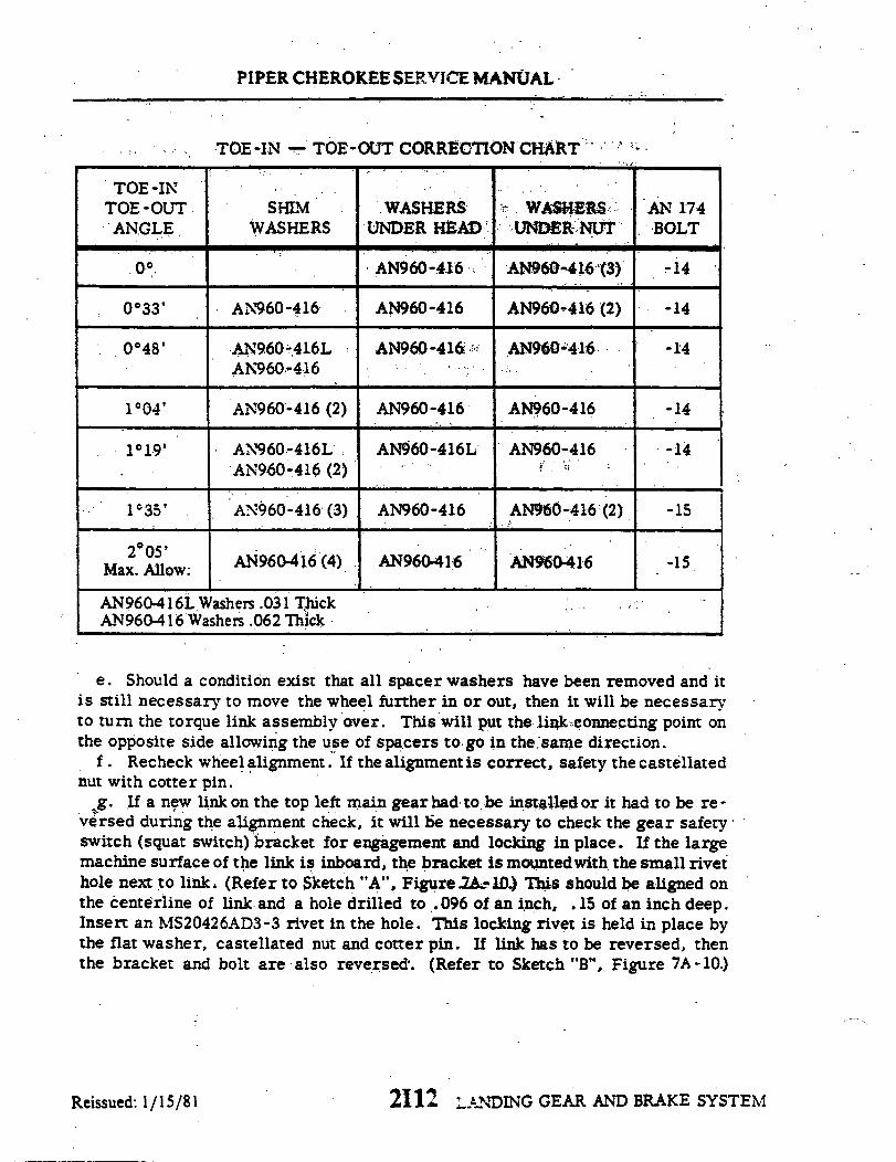
PIPER CHEROKEE SERVICE MANUAL
TOE-IN - TOE-OUT CORRECTION CHART
TOE-INTOE -OUTANGLE
SHIMWASHERS
. .
WASHERS WASHERSUNDER HEAD UNDER NUT
.
AN960-416
AN960-416
AN960-416LAN960-416
AN960-416
AN960-416
AN960-416 -(3)
AN960-416 (2)
AN960-416
1°04 '
1°19 '
1°35 '
2°05'Max. Allow
AN960-416 (2)
AN960 -416LAN960-416 (2)
AN960-416 (3)
AN960-416 (4)
AN960-416 AN960-416
AN960-416L AN960-416
AN960-416 AN960-416 (2)
AN960-416 AN960-416
AN960-416L Washers .031 ThickAN960-416 Washers .062 Thick
e. Should a condition exist that all spacer washers have been removed and itis still necessary to move the wheel further in or out, then it will be necessaryto turn the torque link assembly over. This will put the link connecting point onthe opposite side allowing the use of spacers to go in the same direction.
f. Recheck wheel alignment. If the alignment is correct, safety the castellatednut with cotter pin.
g. If a new link on the top left main gear had to be installed or it had to be re -versed during the alignment check, it will bie necessary to check the gear safetyswitch (squat switch) bracket for engagement and locking in place. If the largemachine surface of the link is inboard, the bracket is mountedwith the small rivethole next to link. (Refer to Sketch "A", Figure 7A-10) This should be aligned onthe centerline of link and a hole drilled to .096 of an inch, .15 of an inch deep.Insert an MS20426AD3-3 rivet in the hole. This locking rivet is held in place bythe flat washer, castellated nut and cotter pin. If link has to be reversed, thenthe bracket and bolt are-also reversed. (Refer to Sketch "B", Figure 7A-10.)
2112 LANDING GEAR AND BRAKE SYSTEM
0
0033 '
0048 '
AN' 174BOLT
-14
-14
-14
-14
-14
-15
-15
Reissued: 1/15/81

PIPER CHEROKEE SERVICE MANUAL
h. Check adjustment of landing gear safety switch (squat switch) per paragraph7A-37.
7A-28. REMOVAL OF MAIN GEAR DOOR ASSEMBLY,a. With the landing gear extended, disconnect the door retraction rod from the
door by removing nut, washers and bolt.b. Remove the door from the wing panel bybending the door hinge pin straight
and from the other end pulling out the pin.c. The door retraction rod may be removed from the gear housing by cutting
the safety wire and removing the attachment bolt and washer. Note the numberof washers between rod end bearing and housing.
7A-29. CLEANING, INSPECTION AND REPAIR OF MAIN GEAR DOOR ASSEM-BLY.
a. Clean the door and retraction rod with a suitable cleaning solvent.b. Inspect the door for cracks or damage, loose or damaged hinges and brackets.c. Inspect the door retraction rod and end bearing for damage and corrosion.d. Repairs to a door may be replacement of hinge, repair of fiberglass and
painting.
7A-30. INSTALLATION OF MAIN GEAR DOOR ASSEMBLY.a. Install the door by positioning the hinge halves of the door and wing, and in-
serting the hinge pin. It is recommended a new pin be used. Bend the end of thepin to secure in place.
b. Install the door retraction rod bypositioningthe rod at its attachment pointsat the door and strut housing. At the door attachment, thin washers are insertedat each side of the rod end bearing and it is secured with bolt, washer and nut.At the strut housing, place washers between rod end bearing and housing not toexceed . 12 of an inch to obtain proper clearance and secure with bolt. Safety boltwith MS20995C41 wire.
c. Check that the all around clearance between the door and the wing skin isnot less than .032 of an inch.
2I13 LANDING GEAR AND BRAKE SYSTEMReissued: 1/15/81

PIPER CHEROKEE SERVICE MANUAL
7A-31. ADJUSTMENT OF MAIN GEAR DOOR ASSEMBLY.a. Place the airplane on jacks. (Refer to Jacking. Section II.)b. Ascertain that the main gear is properly adjusted for gear up as given in paragraph
7A-26.c. Adjust the retraction rod end at the door so that the, door will pull up tightly when
the gear is full up. Over-tightening may result in door buckling: however if the door is tooloose, it will gap in flight.
d. Check all rod ends for adequate thread engagement. for safety and tightness ofjam nuts.
e. Remove the airplane from jacks.
7A-32. LANDING GEAR LIMIT SWITCHES.
NOTE
All adjustments of the limit switches should be made withthe airplane on jacks. (Refer to Jacking. Section II.)
NOTE
Do not bend the actuator springs mounted on the limitswitches.
7A-33. ADJUSTMENT OF NOSE GEAR UP LIMIT SWITCH. The gear up limit switch ismounted on a bracket on the engine mount above the point where the-right side of the upperdrag link attaches to the engine mount.
a. To facilitate adjustment of the limit switch. disconnect the gear doors or remove thebottom cowl. as desired.
b. Retract the landing gear hydro-electrically by turning the master switch on.raising the emergency gear extension lever and moving the gear selector handle to the upposition. Retain the emergency extension lever in the up position and turn the master switchoff.
c.' Block the nose gear in, the up position and then slowly release the emergencyextension lever. This will relieve hydraulic pressure and the main gears will drop.
d. Rig the nose gear up limit switch so that the switch activates when the nose gear iswithin .12 of an inch of the full up position per rigging instructions given in paragraphs7A-12 or 7A-13.
2114 LANDING GEAR AND BRAKE SYSTEMRevised: 4 23 84

PIPER CHEROKEE SERVICE MANUAL
_A127
Figure 7A- 11. Adjustment of NoseGear Down Limit Switch
Figure 7A-12. Adjustment of MainGear Down Limit Switch
e. Loosen the attachment screws of the switch and rotate the switch towardthe actuator tang until it is heard to actuate. Retighten the attachment screwsof the switch.
f. Manually move the gear up and down only as far as necessary to ascertainthat the switch actuates at the correct position. Remove the block from underthe gear and allow it to slowly extend.
g. Retract the gear hydro-electrically and ascertain that the yellow transitlight will go out when the gear has retracted and the pump has shut off.
7A-34. ADJUSTMENT OF NOSE GEAR DOWN LIMIT SWITCH. The gear downlimit switch is mounted on the horizontal support tube of the engine mount thatruns between the right attachment points of the gear housing and upper drag link.
a. Ascertain that the gear is down and locked.b. The down limit switch should actuate only after the leading edge of the down-
lock hook, when moving to the locked position, has passed the downlock rollerby .06 of an inch. Refer to Figure 7A-11.) Position the hook at this locationin relation to the roller bymoving the actuator piston manually toward the up po-sition. The downlock spring may be disconnected, if desired.
c. Loosen the attachment screws of the actuator located on the downlock hookand move it toward the switch until it is heard to actuate. Retighten the actuatorscrews.
d. Manually move the hook from the locked to the unlocked position and ascer-
2I15 LANDING GEAR AND BRAKE SYSTEMReissued: 1/15/81
PIPER CHEROKEE SERVICE MANUAL
tain that the switch actuates at the correct location of the hook,e. Retract and extend the gar hydro-electrically by turning the master switch
on, raising the emergency gear extension lever and moving thegear selector han-dle to the up position. As the gear begins to retract the green light below the se-lector should go out and the yellow transit light at the top of the instrument panelshould come on.
7A -35. ADJUSTMENT OF MAIN GEAR UP LIMIT SWITCH.A gear up limit switch is located in each wheel well above the gear door
hinge. There is no adjustment of these switches other than check that the gear,when retracting, will actuate the switch within .88 of an inch of full up. Switchoperation turns the yellow transit light out.
.7A-36. ADJUSTMENT OF MAIN GEAR DOWN LIMIT SWITCH. A gear .downlimit switch is mounted on a bracket which is attached to the lower drag link ofeach main gear. The switch should be adjusted to allow it to actuate thus turningon the green indicator light within the cockpit when the downlock hook has enteredthe locked position and is within .025 to .035 of an inch of contacting the down-lock pin. (Refer to Figure 7A-12.) Adjustment of the switch may be as follows:
a. Ascertain that the main gear downlock is properly adjusted as describedin paragraph 7A-26.
b. Raise the airplane on jacks. (Refer to Jacing, Section II.)c. Ascertain that the landing gear is down and pressure is relieved from the
hydraulic system. To relieve pressure, hold down the emergency extender lever.d. Raise the downlock hook assembly and place a .030 of an inch feeler gauge
between the horizontal surface of the hook that is next to the switch (The surfacethat contacts the downlock pin.) and the rounded surface of the pin. Lower thehook and allow it to rest on the feeler gauge.
e. Loosen the attaching screws of the switch and, while pushing up on thecenter of the link assembly, rotate the switch toward the hook until it is heardto actuate. Retighten the attaching screws of the switch.
f. Manually move the hook assembly up from the pin until the hook nearly dis-engages from the pin. Then, with pressure against the bottom of the link assem-bly, move back to ascertain that the switch actuates within .025 to .035 of aninch of full lock.
g. Retract and extend the gear hydro-electrically by turningthe master switchon, raising the emergency gear extension lever and moving the gear selectorhandle to the up position. As the gear begins to retract, the green light belowthe selector should go out and the yellow transit light at the top of the instrumentpanel should come on.
2I16 LANDING GEAR AND BRAKE SYSTEMReissued: 1/ 15/81
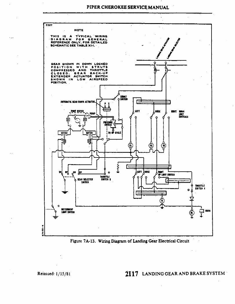
u
)
i*IN
3
aG
Ou
o
.1O
.
6oo
'
.
PIPER CHEROKEE SERVICE MANUAL
7A-37. ADJUSTMENT OF LANDING GEAR SAFETY SWITCH (SQUAT SWITCH).The landing gear safety switch, located on the left main gear housing is adjustedso that the switch is actuated within the last quarter of an inch of gear extension.
a. Compress the strut until 7.875 inches is obtained between the top of the gearfork and the bottom of the gear housing. Hold the gear at this measurement.
b. Adjust the switch down until it actuates at this point. Secure the switch.c. Extend and then compress the strut to ascertain thatthe switch will actuate
within the last quarter of an inch of oleo extension.
7A-38. ADJUSTMENT OF GEAR BACK-UP EXTENDER ACTUATOR SWITCH.The back-up gear extender actuator switch is mounted on the extender unit locatedunder the bottom section of the rear seat. Inasmuch as the switch is a componentof the back-up extender, instructions for the adjustment of the switch will befound with the adjustment instructions for the extender as found in Section VI.
7A-39. LANDING GEAR WARNING SWITCHES (THROTTLE SWITCHES).
7A-40. LANDING GEAR UP/POWER REDUCED WARNING SWITCH. The gearup/power reduced warning switch (Switch "A") is within the control quadrant be-low the throttle control lever. (Refer to Figure 7A-14.) This switch will actuatethe warning horn and red light simultaneously when the landing gear is not downand locked, and the throttle is reduced to and below 14 inches of manifold pressure.
7A-41. REMOVAL OF LANDING GEAR UP/POWER REDUCED WARNINGSWITCH.
a. Loosen the quadrant cover by removing the cover attaching screws fromeach side and at the bottom of the cover.
b. Pull the cover aft enough to remove the screws that secure the reinforcingclip to the top underside of the cover. Remove the cover.
c. Remove the switch from its mounting bracket by removing the switch at-taching screws.
d. Disconnect the electrical leads from the switch.
7A-42. INSTALLATION OF LANDING GEAR UP/POWER REDUCED WARNINGSWITCH.
a. Connect the electrical leads to the switch.b. Position the switch with actuator follower against its mounting bracket and
LANDING GEAR AND BRAKE SYSTEMReissued: 1/15/81 2118
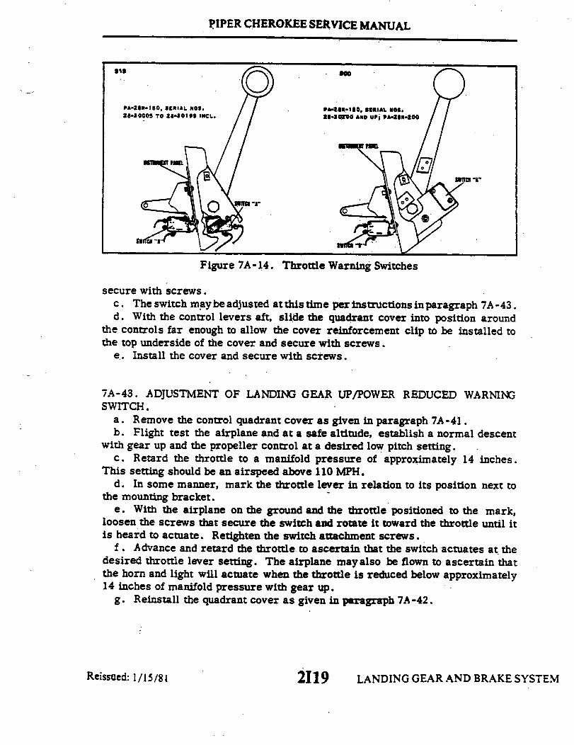
PIPER CHEROKEE SERVICE MANUAL
PA-20R-180, SERIAL NOS. P .28-0005 TO 28-30199 INCL.
Figure 7A-14. Throttle Warning Switches
secure with screws.c. The switch may be adjusted at this time per instructions in paragraph 7A-43.d. With the control levers aft, slide the quadrant cover into position around
the controls far enough to allow the cover reinforcement clip to be installed tothe top underside of the cover and secure with screws.
e. Install the cover and secure with screws.
7A-43. ADJUSTMENT OF LANDING GEAR UP/POWER REDUCED WARNINGSWITCH.
a. Remove the control quadrant cover as given in paragraph 7A-41.b. Flight test the airplane and at a safe altitude, establish a normal descent
with gear up and the propeller control at a desired low pitch setting.c. Retard the throttle to a manifold pressure of approximately 14 inches.
This setting should be an airspeed above 110 MPH.d. In some manner, mark the throttle lever in relation to its position next to
the mounting bracket.e. With the airplane on the ground and the throttle positioned to the mark,
loosen the screws that secure the switch and rotate it toward the throttle until itis heard to actuate. Retighten the switch attachment screws.
f. Advance and retard the throttle to ascertain that the switch actuates at thedesired throttle lever setting. The airplane mayalso be flown to ascertain thatthe horn and light will actuate when the throttle is reduced below approximately14 inches of manifold pressure with gear up.
g. Reinstall the quadrant cover as given in paragraph 7A-42.
LANDING GEAR AND BRAKE SYSTEM2119Reissued: 1/15/81
PIPER CHEROKEE SERVICE MANUAL
7A-44. GEAR DOWN/SELECTOR HANDLE UPWARNING SWITCH. The geardown/selector handle up warning switch (Switch "B") is located directly forwardof the instrument panel, below the arm of the throttle control lever. (Refer toFigure 7A-14.) This switch will actuate the gear warning horn and light simul-taneously when the gear selector handle is at the up position and the airplane ison the ground or airspeed is below that required to close the hydraulic valve andthe pump switch of the back-up gear extender. The latter applies except at fullthrottle.
7A -45. REMOVAL OF GEAR DOWN/SELECTOR HANDLE UPWARNING SWITCH.a. Remove the switch from its mounting bracket by removing the switch attach-
ment screws.b. Disconnect the electrical leads from the switch.
NOTE
The switch with mounting bracket may be removed byremoving the control quadrant cover and removing thetwo screws that secure the bracket.
7A-46. INSTALLATION OF GEAR DOWN/SELECTOR HANDLE UP WARNINGSWITCH.
a. Connect the electrical leads tothe switch. Leads attach to terminals C andNC.
b. Position the switch against its mounting bracket and secure with attachmentbolts.
c. Adjust the switch as given in paragraph 7A-47.
7A-47-. ADJUSTMENT OF GEAR DOWN/SELECTOR HANDLE UP WARNINGSWITCH.
a. Loosen the quadrant cover by removing the cover attachment screws fromeach side and at the bottom of the cover.
b. Pull the cover aft far enough to remove the screws that secure the reinforc -ing clip to the top underside of the cover. Remove the cover.
c. Position the throttle control lever. 25 of an inch from its full forward stop.d. Loosen the switch bracket attachment screw from the quadrant side and
move the bracket with switch toward the arm of the control lever until the switchactuates. Tighten the attachment screws.
e. Move aft and then forward to ascertain that the switch actuates at the .25
2120 LANDING GEAR AND BRAKE SYSTEMReissued: 1/15/81
PIPER CHEROKEE SERVICE MANUAL
of an inch dimension the throttle lever should still move approximately .125 ofan inch before it stops.
f. Reinstall the quadrant cover.
7A-48. WHEELS.
7A-49. REMOVAL AND DISASSEMBLY OF NOSE WHEEL. (RefertoFigure7A-15.)
a. Jack the airplane enough to raise the nosewheelclearof the ground. (Referto Jacking, Section II. )
b. To remove the nose wheel, first remove the cotter pin and washer that se-cures the safety clevis pin of the wheel nut. Next remove the clevis pin, wheelnut and then slide the wheel from the axle.
c. The wheel halves (7 and 10) may be separated by first deflating the tire.With the tire sufficiently deflated, remove the wheel through bolts (18). Pull thewheel halves from the tire by removing the wheel half opposite the valve stemfirst and then the other half.
d. The wheel bearing assemblies may be removed from each wheel half by firstremoving the snap rings (1 or 16) that secure the grease seal retainers, and thenthe retainers, grease seals (4 or 13) and bearing cones (6 or 12). The bearingcups (5 or 11) should be removed by tapping out evenly from the inside.
7A -50. INSPECTION OF NOSE WHEEL ASSEMBLY.a. Visually check all parts for cracks, distortion, defects and excess wear.b. Check tie bolts for looseness or failure.c. Check internal diameter of felt grease seals. Replace the felt grease seal
if surface is hard or gritty.d. Check tire for cuts, internal bruises and deterioration.e. Check bearing cones and cups for wear and pitting and relubricate.f. Replace any wheel casting having visible cracks.
7A-51. ASSEMBLY AND INSTALLATION OF NOSE WHEEL. (Refer to Figure7A-15.)
a. Ascertain that the bearing cup (5 or 11) for each wheel half (7 and 10) isproperly installed. Install the tire with tube on the wheel half with the valve stemhole and then join the two wheel halves. Install the through bolts (18)with thewashers (9 and 17) and nuts (8) to the valve stem side.
2121 LANDING GEAR AND BRAKE SYSTEMReissued: 1/15/81
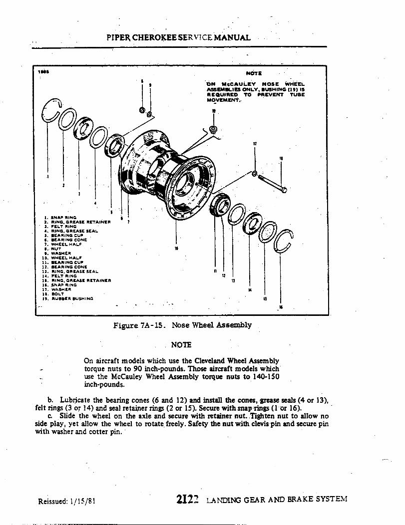
PIPER CHEROKEE SERVICE MANUAL
I sea. I
3
1. SNAP RING2. RING. GREASE RETAINER3. FELT RING4. RING, GREASE SEAL5. BEARING CUP6. BEARING CONE7. WHEEL HALF8. NUT9. WASHER
10. WHEEL HALF11. BEARING CUP12. BEARING CONE13. RING, GREASE SEAL14. FELT RING15. RING. GREASE RETAINER16. SNAP RING17. WASHER18. BOLT19. RUBBER BUSHING
NOTE
ON McCAULEY NOSE WHEELASSEMBIES ONLY, BUSHING (19) ISREQUIRED TO PREVENT TUBEMOVEMENT.
19
II
10
1112
13
14
15
Figure 7A-15. Nose Wheel Assembly
NOTE
On aircraft models which use the Cleveland Wheel Assemblytorque nuts to 90 inch-pounds. Those aircraft models whichuse the McCauley Wheel Assembly torque nuts to 140-150inch-pounds.
b. Lubricate the bearing cones (6 and 12) and install the cones, grease seals (4 or 13),felt rings (3 or 14) and seal retainer rings (2 or 15). Secure with snap rings (lor 16).
c. Slide the wheel on the axle and secure with retainer nut. Tighten nut to allow noside play, yet allow the wheel to rotate freely. Safety the nut with clevis pin and secure pinwith washer and cotter pin.
2122 LANDING GEAR AND BRAKE SYSTEM
4
7
Reissued: 1/15/81
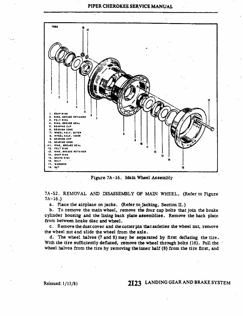
PIPER CHEROKEE SERVICE MANUAL
1893
SNAP RING
2. RING, GREASE RETAINER
3. FELT, RING4. RING, GREASE SEAL
6. BEARING CONE7; WHEEL HALF, OUTER8. WHEEL HALF, INNER9. BEARING CUP
10. BEARING CONE
11. RING, GREASE SEAL12. FELT RING13. RING, GREASE RETAINER 1214. SNAP RING 13
15. BRAKE DISC 1416. BOLT17. WASHERS18. NUT
Figure 7A-16. Main Wheel Assembly
7A-52. REMOVAL AND DISASSEMBLY OF MAIN WHEEL. (Refer to Figure7A-16.)
a. Place the airplane on jacks. (Refer to Jacking, Section II.)b. To remove the main wheel, remove the four cap bolts that join the brake
cylinder housing and the lining back plate assemblies. Remove the back platefrom between brake disc and wheel.
c. Remove the dust cover and the cotter pin that safeties the wheel nut, removethe wheel nut and slide the wheel from the axle.
d. The wheel halves (7 and 8) may be separated by first deflating the tire.With the tire sufficiently deflated, remove the wheel through bolts (16). Pull thewheel halves from the tire by removing the inner half (8) from the tire first, and
Reissued: 1/15/81 2123 LANDING GEAR AND BRAKE SYSTEM

PIPER CHEROKEE SERVICE MANUAL
then the outer half.e. The wheel bearing assemblies may be removed from each wheel half by
first removing the snap rings (1 or 14) that secure the grease seal retainers (2or 13), and then the retainers, grease seals (4 or 11) and bearing cones (6 or 10).The bearing cups (5 or 9) should not be removed only for replacement and may beremoved by tapping out evenly from the inside.
7A-53. INSPECTION OF MAIN WHEELASSEMBLY. The inspection of the mainwheel is the same as that given for the nose wheel, paragraph 7A-50.
7A-54. ASSEMBLY AND INSTALLATION OF MAIN WHEEL. (Refer to Figure7A- 16)
a. Ascertain that the bearing cup(5 or 9) foreach wheel is properly installed.Install the tire with tube on the outer'wheel half (7) and then join the two wheelhalves. Position the brake disc (15) in the inner wheel half and install the throughbolts with the nuts on the valve stem side. Torque wheel nuts to 150 inch poundsand inflate tire.
b. Lubricate the bearing cones (6 or 10) and install the cones, grease seals(4 or 11), seal retainer rings (2 or 13) and felt rings (3 or 12). Secure with snaprings (1 or 14).
c. Slide the wheel on the axle and secure with retainer nut. Tighten the nutto allow no side play, yet allow the wheel to rotate freely. Safety the nut with acotter pin and install dust cover.
d. Position the brake lining back plates between the wheel and brake disc andthe brake cylinder on the torque plate. Insert the spacer blocksbetween the backplates and cylinder, and install the four bolts to secure the assembly. If the brakeline was disconnected, reconnect the line and bleed the brakes.
7A-55. BRAKE SYSTEM.
7A-56. WHEEL BRAKE ASSEMBLY.
7A -57. BRAKE ADJUSTMENT AND LINING TOLERANCE. No adjustment of thebrake lining clearance is necessary as they are self adjusting. Inspection of thelining is necessary, and it may be inspected visually while installed on the air-plane. The linings are of the riveted type and should be replaced if the thicknessof any one segment becomes worn below .097 of an inch or unevenly worn.
2124 LANDING GEAR AND BRAKE SYSTEMReissued: 1/15/81
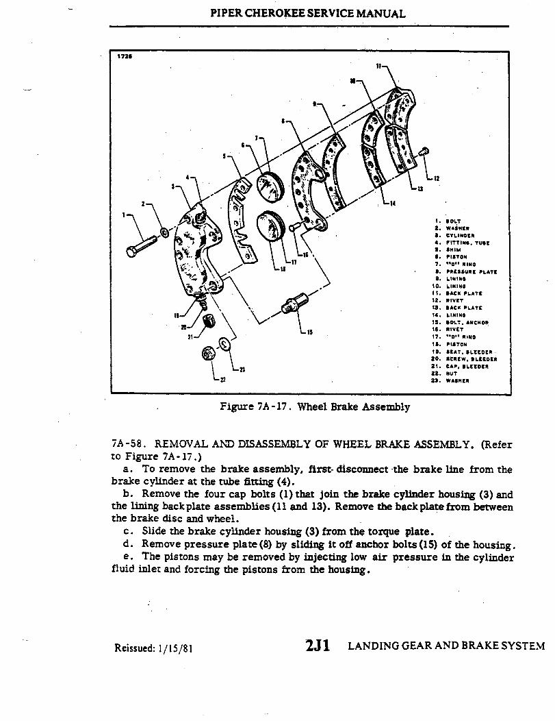
PIPER CHEROKEE SERVICE MANUAL
1726
.2. WASHER3. CYLINDER
5. SHIM
6. PISTON
Figure7A-17. Whee LINING11. BACK PLATE12. RIVET
13. BACK PLATE
the lining backplate assemblies (11 and 13). Remove the backplate 14. LINING15. BOLT ANCHOR
17. "O" RING
18. PISTON19.SEAT, BLEEDER
21. CAP, BLEEDER
22 22. NUT
a. To remove the brake assembly, first- disconnect the brake line from thebrake cylinder at the tube fitting (4).
b. Remove the four cap bolts (1) that join the brake cylinder housing (3) andthe lining back plate assemblies (1 and 13). Remove the back plate from betweenthe brake disc and wheel.
c. Slide the brake cylinder housing (3) from the torque plate.d. Remove pressure plate (8) by sliding it off anchor bolts (15) of the housing.e. The pistons may be removed by injecting low air pressure in the cylinder
fluid inlet and forcing the pistons from the housing.
2J 1 LANDING GEAR AND BRAKE SYSTEMReissued: 1/15/81

PIPER CHEROKEE SERVICE MANUAL
7A-59. CLEANING, INSPECTION AND REPAIR OF WHEEL BRAKE ASSEMBLIES.a. Clean the assembly with a suitable solvent and dry thoroughly.b. Check the walls of the cylinder housing and pistons for scratches, burrs, corrosion,
etc., that may damage "O" rings.c. Check the genera condition of the brake bleeder screw andlines.d. Check the brake disc for grooves. scratches, pits or coning. Coning beyond .015 in
either direction would because.for replacement. The minimum dimension of Disc 164-19used on Wheel Assembly 40-84 is .227. and Disc 164-20 used on Wheel Assembly 40-86B is.205 (Referto Figure 7A-18.) A single groove or isolated grooves up to .031 of an inch deepwould not necessitate replacement, but a grooving of the entire surface would reduce lininglife.braking applications to remove it. A heavier coating of rust may require removal of the discso that it may be wire-brushed and then sanded with 220 grit sandpaper.
e. Lining may be removed from the backing plates by drilling or punching out the oldrivets, and installing a new set using the proper rivets and a rivet set that will properly stakethe lining and form a correct flair of the rivet..
f. After replacing brake linings, condition them by performing a minimum of six lightpedal effort braking applications from 25 to 40 MPH, allowing the brake discs to partiallycool between stops.
7A-60. ASSEMBLY AND INSTALLATION OF WHEEL BRAKE ASSEMBLY. (Refer toFigure 7A-17.)
a. Lubricate the piston "O" rings (7 and 17) with fluid MIL-H-5606 and install onpistons (6 and 18). Slide the pistons in cylinder housing until flush with surface of housing.
b. Slide the lining pressure plate (8) onto the anchor bolts(15) of the housing.c. Slide the cylinder housing assembly on the torque plate of the gear.d. Position the lining back plates (11 and 13) between the wheel and brake disc. Insert
the shim blocks (5) between the back plates and cylinder, and install the four bolts to securethe assembly.
e. Connect the brake line to the brake cylinder housing.f. Bleed the brake system as described in paragraph 7A-73.
7A-61. BRAKE MASTER CYLINDER (Hand Parking Brake).
7A-62. REMOVAL OF BRAKE MASTER CYLINDER. (Refer to Figure 7A 19.)a. To remove the brake master cylinder (8) first disconnect the inlet supply line (13)
from the fitting at the top of the cylinder and allow fluid to drain from the reservoir andline into a suitable container.
b. Disconnect the pressure line from the fitting at the bottom of the cylinder and allowfluid to drain from the cylinder line.
c. Disconnect the end of the cylinder rod from the brake handle (6) by removing thecotter pin that safeties the connecting clevis pin (12). Remove the clevis pin and spacerwashers.
d. Disconnect the base of the cylinder from its mounting bracket by removing theattachment bolt assembly (11).
Revised: 10 3 83 2J2 LANDING GEAR AND BRAKE SYSTEEM

PIPER CHEROKEE SERVICE MANUAL
MINIMUM THICKNESS
MEASURE 2 ORDISC THICKNES
MINIMUMTHICKNESS
227205
WHEEL ASSEMBLY
40-8440-86B
3 POINTS TO GET AVERAGESS
Figure 7A-18. Brake Disc Minimum Thickness
1739
7/
10-
Revised: 10 3 83
1.BRAKE RESERVED
2. RIGHT BRAKE AND RUDDER
3. LEFT BRAKE AND RUDDER PEGS
4. RIGHT BRAKE CLINDER5. LEFT BRAKE CYLINDER6. BRKE HANDLE7. HANDLE RELEASE BUTTON8. MASTER CLINDER ASSEMBLY
10. RUDDER PEDAL PADS11. BOLT ASSEMBLY12. CLEVIS PIN13. LINE. INLET
Figure 7A-19. Brake System Installation
2J3 LANDING GEAR AND BRAKE SYSTEM
C343
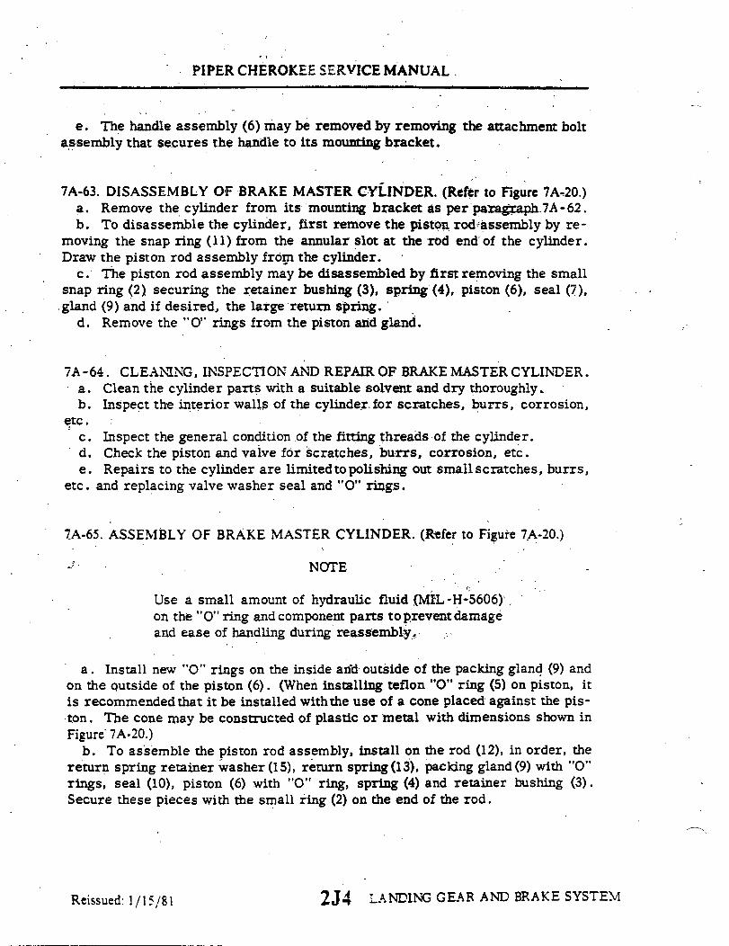
PIPER CHEROKEE SERVICE MANUAL
e. The handle assembly (6) may be removed by removing the attachment boltassembly that secures the handle to its mounting bracket.
7A-63. DISASSEMBLY OF BRAKE MASTER CYLINDER. (Refer to Figure 7A-20.)a. Remove the cylinder from its mounting bracket as per paragraph 7A-62.b. To disassemble the cylinder, first remove the piston rod assembly by re-
moving the snap ring (11) from the annular slot at the rod end of the cylinder.Draw the piston rod assembly from the cylinder.
c. The piston rod assembly may be disassembled by first removing the smallsnap ring (2) securing the retainer bushing (3), spring (4), piston (6), seal (7),gland (9) and if desired, the large return spring.
d. Remove the "O" rings from the piston and gland.
7A -64. CLEANING, INSPECTION AND REPAIR OF BRAKE MASTER CYLINDER.a. Clean the cylinder parts with a suitable solvent and dry thoroughly.b. Inspect the interior walls of the cylinder, for scratches, burrs, corrosion,
etc.c. Inspect the general condition of the fitting threads of the cylinder.d. Check the piston and valve for scratches, burrs, corrosion, etc.e. Repairs to the cylinder are limitedtopolishing out smallscratches, burrs,
etc. and replacing valve washer seal and "O" rings.
7A-65. ASSEMBLY OF BRAKE MASTER CYLINDER. (Refer to Figure 7A-20.)
NOTE
Use a small amount of hydraulic fluid (MIL-H-5606)on the "O" ring and component parts to prevent damageand ease of handling during reassembly.
a. Install new "O" rings on the inside and outside of the packing gland (9) andon the outside of the piston (6). (When installing teflon "O" ring (5) on piston, itis recommended that it be installed withthe use of a cone placed against the pis-ton. The cone may be constructed of plastic or metal with dimensions shown inFigure 7A-20.)
b. To assemble the piston rod assembly, install on the rod (12), in order, thereturn spring retainer washer (15), return spring(13), packing gland (9) with "O"rings, seal (10), piston (6) with "O" ring, spring (4) and retainer bushing (3).Secure these pieces with the small ring (2) on the end of the rod.
2J4 LANDING GEAR AND BRAKE SYSTEMReissued: 1/15/81

PIPER CHEROKEE SERVICE MANUAL
A349
889
COUNTER BORE562 DIA 0625 DEEP
312 745
19375
1 HOUSING 62 SNAP RING 73 BUSHING RETAINER 84 SPRING 95 O RING 10
0 11 12 13 14 15
PISTONDYNA SEALO-RINGGLAND. PACKINGO-RING
11 SNAP RING12 ROD PISTON13 SRING RETAINING14 ROLL PIN15 WASHER
Figure 7A-20. Brake Master Cylinder (Hand Parking Brake)
c. Insert the piston rod assembly in the cylinder (1) and secure packing gland with snap ring (11).d. Install the cylinder per Paragraph 7A-67.
A-66. INSTALLATION OF BRAKE MASTER CYLINDER. (Refer to Figure 7A-19.)a. Install the brake handle assembly between its mounting bracket and secure with bolt. washers. nut
and cotter pin. Washers should be placed on each side of the handle, between the bracket. and under the nut.b. Place the cylinder (8) between the mounting bracket and secure the base end with bolt, washers.
nut and cotter pin. This too should have washers placed on each side of the cylinder and under the nut.c. Connect the rod end of the cylinder to the brake handle with a clevis pin and thin washers. Safety
the clevis with a cotter pin.d. Connect the pressure line to the fitting at the bottom of the cylinder.e. Connect the inlet supply line (13) to the fitting at the top of the cylinder and secure with spring
clamp.f. Bleed the brake system per Paragraph 7A-73.
2J5 LANDING GEAR AND BRAKE SYSTEM
.
Reissued: 1/15/81
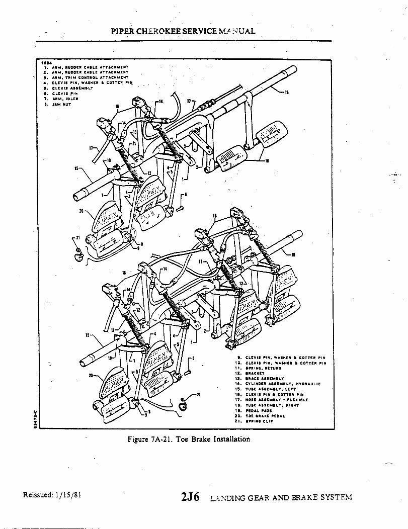
PIPER CHEROKEE SERVICE MAN UAL
16841. ARM, RUDDER CABLE ATTACHMENT
2. ARM, RUDDER CABLE ATTACHMENT3. ARM, TRIM CONTROL ATTACHMENT
4. CLEVIS PIN, WASHER & COTTER PIN
5. CLEVIS ASSEMBLY6. CLEVIS PIN7. ARM, IDLER8. JAM NUT
1.1
Figure 7A-21. Toe Brake Installation
Reissued: 1/15/81 2J6 LANDING GEAR AND BRAKE SYSTEM

PIPER CHEROKEE SERVICE MANUAL
7A-67. BRAKE CYLINDER (Toe Brake).
7A-68. REMOVAL OF BRAKE CYLINDER. (Refer to Figure 7A-21.)a. Disconnect the upper and lower lines from the cylinder (14) to be removed and cap
the lines to prevent fluid leakage or drain the fluid from the brake reservoir and mastercylinder.
b. Remove the cylinder from its attachment fittings by first removing cotter pins thatsafety the cylinder attaching pins (16) and then removing the pins.
7A-69. DISASSEMBLY OF BRAKE CYLINDER.a. Cleveland cylinder number 10-20. (Refer to Figure 7A-22.)
1. Remove the cylinder from its mounting bracket as per paragraph 7A-68.2. To disassemble the cylinder, first remove the piston rod assembly by unscrewing
the packing gland (9) from the cylinder. Draw the piston rod assembly from the cylinder.3. The piston rod assembly may be disassembled by first removing the small snap
ring (2) securing the retainer bushing (3) and then removing the bushing, spring (4), piston(5), seal (7), gland (9). and, if desired, the large return spring (12).
4. Remove the "O" rings from the piston and gland.b. Cleveland cylinder number 10-27. (Refer to Figure 7A-22.)
1. Remove the cylinder from its mounting bracket per paragraph 7A-68.2. To disassemble the cylinder, first remove the piston rod assembly by removing
the snap ring (10) from the annular slot in the cylinder housing (1). Draw the piston rodassembly from the cylinder.
3. The piston rod assembly may be disassembled by first removing the roll pin (12)and then the piston assembly (3), seal (5). and packing gland (7).
4. Remove the O-rings from the piston and packing gland.c. Cleveland cylinder number 10-30. (Refer to Figure 7A-23.)
1. Remove the cylinder from its mounting bracket per Paragraph 7A-68.2. To disassemble the cylinder, first remove the piston rod assembly by removing the
retaining ring from the annular slot in the cylinder housing (1). Draw the piston rod assemblyfrom the cylinder.
3. The piston rod assembly may be disassembled by first removing the retainingring (2), sleeve (3), spring (4), and then the piston assembly, O-ring (5), and gland (8), and, ifdesired, the return spring (13).
4. Remove the O-rings from the piston and packing gland.d. Gar-Kenyon cylinder number 17000. (Refer to Figure 7A-22.)
1. Remove the cylinder from its mounting bracket as per Paragraph 7A-68.2. To disassemble the cylinder, first remove the piston rod assembly by unscrewing
the fitting (8) from the cylinder.3. The piston rod assembly may be disassembled by first removing the retaining
ring (2) securing the sleeve (3) and then removing the spring (4), piston (6), seal (7), fitting (8),and, if desired, the large return spring (11).
4. Remove the O-rings from the piston and fitting.
LANDING GEAR AND BRAKE SYSTEM2J7Reissued: 1/15/81
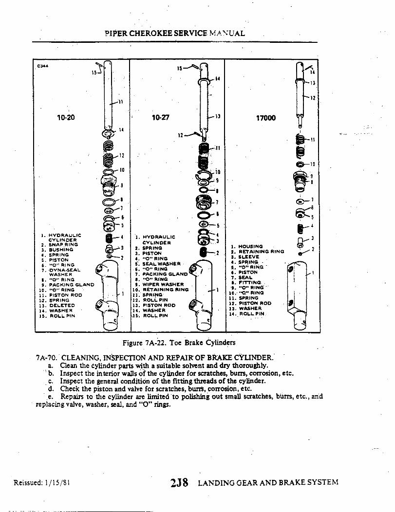
PIPER CHEROKEE SERVICE MANUAL
10-20
1. HYDRAULICCYLINDER
2. SNAP RING3. BUSHING4. SPRING5. PISTON6. "O" RING7. DYNA-SEAL
WASHER8. "O" RING9. PACKING GLAND
10. "O" RING11. PISTON ROD12. SPRING13. DELETED14. WASHER15. ROLL PIN
10-27 13
11
10
6. "O" RING5
4 1. HYDRAULIC
3 2. SPRING3. PISTON 24. "O" RING5. SEAL WASHER6. "O" RING7. PACKING GLAND8. "O" RING
9. WIPER WASHER10. RETAINING RING 1
1 11. SPRING12. ROLL PIN13. PISTON ROD14. WASHER15. ROLL PIN
17000
1. HOUSING2. RETAINING RING3. SLEEVE4. SPRING5. "O" RING6. PISTON7. SEAL8. FITTING9. "O" RING
10. "O" RING11. SPRING12. PISTON ROD13. WASHER14. ROLL PIN
Figure 7A-22. Toe Brake Cylinders
7A-70. CLEANING, INSPECTION AND REPAIR OF BRAKE CYLINDER.a. Clean the cylinder parts with a suitable solvent and dry thoroughly.b. Inspect the interior walls of the cylinder for scratches, burrs, corrosion, etc.c. Inspect the general condition of the fitting threads of the cylinder.d. Check the piston and valve for scratches, burrs, corrosion, etc.e. Repairs to the cylinder are limited to polishing out small scratches, burrs, etc., and
replacing valve, washer, seal, and "0" rings.
2J 8 LANDING GEAR AND BRAKE SYSTEM
C344
14
13
12
10
8
5
3
21
15
Reissued: 1/15/81
1 4

PIPER CHEROKEE SERVICE MANUAL
7A-71. ASSEMBLY OF BRAKE CYLINDER.a. Cleveland cylinder number 10-20. (Refer to Figure 7A-22.)
NOTEUse a small amount of hydraulic fluid (MIL-H-5606) on the"O" ring and component parts to prevent damage and ease ofhandling during reassembly.
1. Install new "O" rings on the inside and outside of the packing gland (9) and onthe outside of the piston (5).
2. To assemble the piston rod assembly, install on the rod (11), in order, the rollpin (15), return spring retainer washer (14), return spring (12), packing gland (9) with "O"rings, seal (7), piston (5) with "O" ring, spring (4) and retainer bushing (3). Secure thesepieces with the small ring (2) on the end of the rod.
3. Insert the piston rod assembly in the cylinder (1) and secure packing (9).4. Install the cylinder per paragraph 7A-72.
b. Cleveland cylinder number 10-27. (Refer to Figure 7A-22.)
NOTE
Use a small amount of hydraulic fluid (MIL-H-5606) on the"O" ring and component parts to prevent damage and ease ofhandling during reassembly.
1. Install new "O" rings on the inside and outside of the packing gland (7) and onthe outside of the piston (3).
2. To assemble the piston rod assembly, install on the rod (13), in order, the rollpin (15), washer (14), spring (11), washer (9), packing gland (7), seal (5), piston assembly(3) and spring (2), and roll pin (12).
3. Insert the piston rod assembly in the cylinder (1) and secure with the snap ring(10).
4. Install the cylinder per paragraph 7A-72.c. Cleveland cylinder number 10-30. (Refer to Figure 7A-23.)
1. Install new O-rings on the inside and outside of the packing gland (7) and on theoutside of the piston (3).
2. To assemble the piston rod assembly, install on the rod (12), in order, the rollpin (14), washer (13), spring (11), washer (9), packing gland (7) with O-rings, seal (5), pistonassembly (3) with O-ring, spring (2), and roll pin (15).
3. Insert the piston rod assembly in the cylinder (1) and secure with the retainingring (10).
4. Install the cylinder per Paragraph 7A:72.d. Gar-Kenyon cylinder number 17000. (Refer to Figure 7A-22.)
1. Install new O-rings on the inside and outside of the fitting (8) and on the outsideof the piston (6). (Refer to above note.)
2. To assemble the piston rod assembly, install on the rod (12), in order, the rollpin (14), return spring retainer washer (13), return spring (11), fitting (8) with O-rings, seal (7),piston (6) with O-ring, spring (4) and sleeve (3). Secure these pieces with the retaining ring (2)on the end of the rod.
3. Insert the piston rod assembly in the cylinder (1) and secure fitting (8).4. Install the cylinder per Paragraph 7A-72.
LANDING GEAR AND BRAKE SYSTEM2J9Reissued: 1/15/81

PIPER CHEROKEE SERVICE MANUAL
7A-72. INSTALLATION OF BRAKE CYLINDER. (Referto Figure 7A-21.)a. Position the cylinder (14) at its mounting points and attach with clevis pin. Safety
the pins with cotter pins. (See 16, Figure 7A-21.)b. Connect the brake lines to the cylinder fittings.c. Bleed the brakes per Paragraph 7A-73.
7A-73. BLEEDING PROCEDURE. When it becomes necessary to bleed the brake system,refer to Section VII, paragraphs 7-52 through 7-55.
7A-74. BEARING REPLACEMENT. (Refer to Figure 7A-25.) When it becomes necessaryto replace a bearing in any link attachment housing, follow instructions listed below:
a. Remove bearings being replaced.
NOTE
An individual bearing can be removed and replaced only ifexisting boss includes the .089 grease hole (noted inillustration). If existing boss does not include the .089 greasehole, both bearings on a boss must be removed and the .089grease hole added before installing the new bearings.
C343
1. HOUSING2. RETAINING RING3. SLEEVE .4.. SPRING
Figure 7A-23. Brake Cylinder(10-30) (Toe Brake)
Revised: 10 3 83 2J 10 LANDING GEAR AND BRAKE SYSTEM
5. O-RING 9. O-RING 13. SPRING6. PISTON 10. O-RING 14. WASHER7. O-RING 11. WASHER WIPER 15. ROLL PIN8. GLAND 12. ROD

PIPER CHEROKEE SERVICE MANUAL
b. Addition of the grease hole is accomplished by drilling a .089 hole centered on theboss as shown in the illustration. After drilling hole, deburr any rough edges and clean outany shavings that accumulate inside the boss hole.
c. Press fit new bearing(s) P/N 67026-07 tight against boss and line ream bearing(s) to.3 1 dimension.
d. The .089 grease holes will require a needle type adapter on the grease gun nozzle.
1738
.089 Grease Hole
Boss
Bearing - 67026-07 (press fit) (2Line Ream .314
Boss
.089 Grease HoleTypical Bearing Installation
Req.)
Nose Gear Assembly Main Gear Assembly
Figure 7A-24. Bearing Installation
2J 11 LANDING GEAR AND BRAKE SYSTEMReissued: 1/15/81

PIPER CHEROKEE SERVICE MANUAL
TABLE VILA-I. LANDING GEAR TROUBLESHOOTING
Trouble
Yellow transit light outwhile gear is in tran-sit.
Cause
Indicator lamp burnedout.
Remedy
Replace lamp.
Indicator light groundincomplete.
Indicator light circuitwire broken.
Indicator light circuitbreaker open.
Check ground circuit.
Check wiring.
Reset circuit breakerand determine causefor open circuitbreaker.
Yellow transit light onthough gear has re-tracted.
One or more up limitswitches failed.
Isolate and replaceswitch.
Nose gear up limitswitch out of ad-justment.
Main gear not re-tracting far enoughto actuate switch.
Check gear up adjust-ment and readjust uplimit switch.
Check gear up adjust-ment.
Yellow transit light onthough gear is downand locked.
One or more down limitswitches failed.
Isolate and replaceswitch.
Nose gear down limitswitch out of adjust-ment.
Readjust down limitswitch.
2J12 LANDING GEAR AND BRAKE SYSTEMReissued: 1/15/81

PIPER CHEROkEE SERVICE MANUAL
TABLE VIIA -I.
Trouble
LANDING GEAR TROUBLESHOOTING(cont)
Cause Remedy
Yellow transit light onthough gear is downand locked. (cont)
Main gear down limitswitch out of adjust-ment.
Readjust down limitswitch.
NOTE
The out of adjustment or failed switch may be deter-mined by noting which down light is not lit.
Yellow transit lightoperates on and offafter gear has re-tracted.
Light circuit wireloose.
Check wiring.
Hydraulic systemlosing pressure.
Gear up switch out ofadjustment.
Refer to HydraulicSystem Section VI..
Check gear up adjust-ment and then switchadjustment.
Yellow transit light outand one green geardown light out thoughgear is down and locked.
Lamp burned out.
Gear down limit switchfailed.
Replace lamp.
Replace switch.
NOTE
Ascertain navigationlights are off (daytime).
Light circuit wirebroken.
Check wiring.
2J13 LANDING GEAR AND BRAKE SYSTEMReissued: 1/15/81
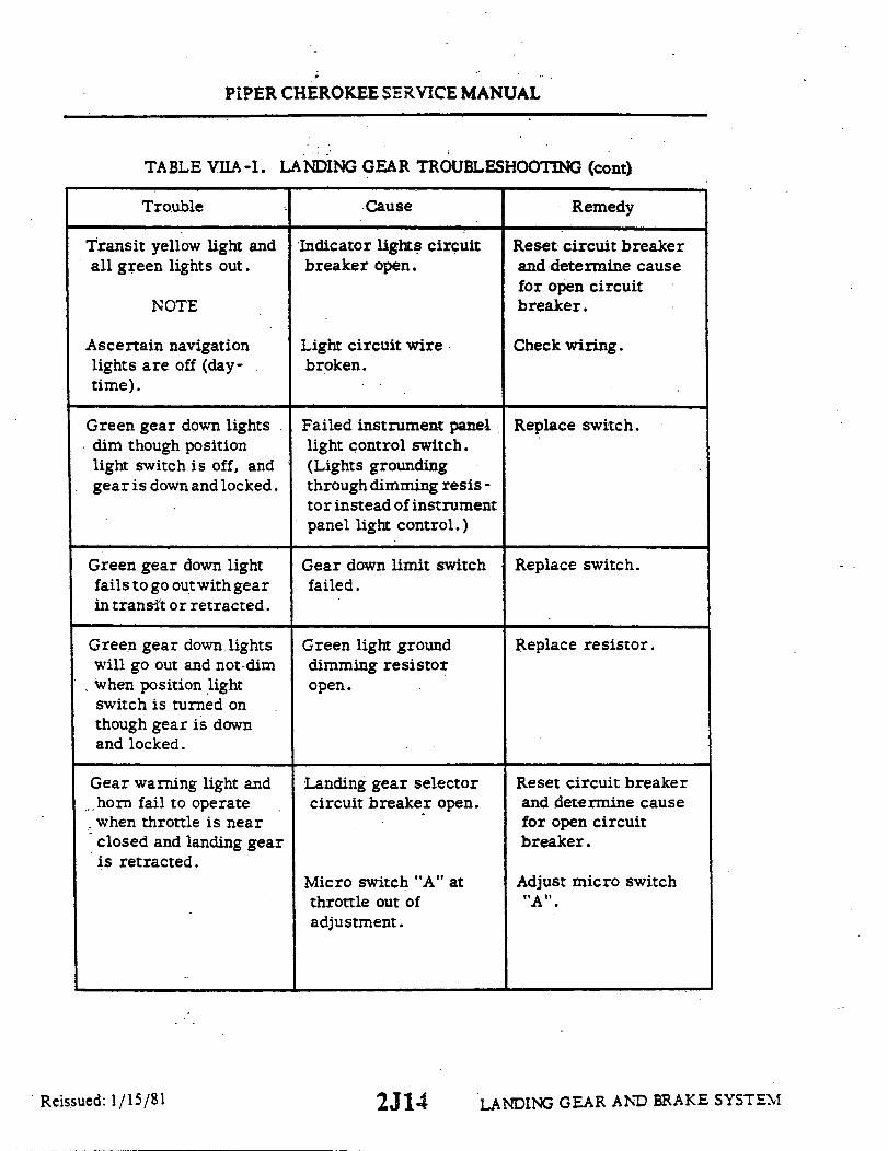
PIPER CHEROKEE SERVICE MANUAL
TABLE VIIA-I. LANDING GEAR TROUBLESHOOTING (cont)
Trouble
Transit yellow light andall green lights out.
Cause
Indicator lights circuitbreaker open.
NOTE
Ascertain navigationlights are off (day-time).
Light circuit wirebroken.
Remedy
Reset circuit breakerand determine causefor open circuitbreaker.
Check wiring.
Green gear down lightsdim though positionlight switch is off, andgear is down and locked.
Green gear down lightfails to go outwith gearin transit or retracted.
Green gear down lightswill go out and not dimwhen position lightswitch is turned onthough gear is downand locked.
Gear warning light andhorn fail to operatewhen throttle is nearclosed and landing gearis retracted.
Failed instrument panellight control switch.(Lights groundingthrough dimming resis -tor instead of instrumentpanel light control.)
Gear down limit switchfailed.
Green light grounddimming resistoropen.
Landing gear selectorcircuit breaker open.
Micro switch "A" atthrottle out ofadjustment.
Replace switch.
Replace switch.
Replace resistor.
Reset circuit breakerand determine causefor open circuitbreaker.
Adjust micro switch"A".
LANDING GEAR AND BRAKE SYSTEMReissued: 1/15/81 2J14
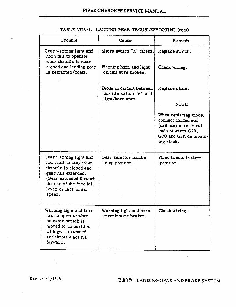
PIPER CHEROKEE SERVICE MANUAL
TABLE VIIA-I. LANDING GEAR TROUBLESHOOTING (cont)
Trouble Cause Remedy
Gear warning light andhorn fail to operatewhen throttle is nearclosed and landing gearis retracted (cont).
Micro switch "A" failed.
Warning horn and lightcircuit wire broken.
Replace switch.
Check wiring.
Diode in circuit betweenthrottle switch "A" andlight/horn open.
Replace diode.
NOTE
When replacing diode,connect banded end(cathode) to terminalends of wires G2R,G2Q and G2K on mount-ing block.
Gear warning light andhorn fail to stop whenthrottle is closed andgear has extended.(Gear extended throughthe use of the free falllever or lack of airspeed.
Warning light and hornfail to operate whenselector switch ismoved to up positionwith gear extendedand throttle not fullforward.
Gear selector handlein up position.
Warning light and horncircuit wire broken.
Place handle in downposition.
Check wiring.
Reissued: 1/15/81 2J15 LANDING GEAR AND BRAKE SYSTEM

PIPER CHEROKEE SERVICE MANUAL
TABLE VIIA-I. LANDING GEAR TROUBLESHOOTING (cont)
Trouble Cause Remedy
Above condition onground.
Above condition inthe air.
Warning light and hornfail to shut off at fullthrottle. Gear selec-tor at up position andgear extended.
Hydraulic pump shutsoff, but gear yellow,in transit, light re-mains on.
Landing gear doorsfail to completelyclose.
Defective safety (squat)switch.
Pressure switch open.
Throttle micro swich"B" out of adjustment.
Throttle micro switch"B" failed.
Gear not fully retracted.
Landing gear not re-tracting completely.
Replace switch.
Replace switch.
Adjust switch.
Replace switch.
Determine cause andremedy.
Check adjustment oflanding gear.
Door retraction rodsout of adjustment.
Check adjustment doorretraction rods.
Nose landing gearshimmies during fasttaxi, take-off, orlanding.
Internal wear in shimmydampener.
Shimmy dampener orbracket loose atmounting.
Replace shimmydampener.
Replace necessaryparts and bolts.
2J16 . LANDING GEAR AND BRAKE SYSTEMReissued: 1/15/81

PIPER CHEROKEE SERVICE MANUAL.
TABLE VIIA-I. LANDING GEAR TROUBLESHOOTING (cont)
Trouble Cause Remedy
Nose landing gearshimmies during fasttaxi, take-off, orlanding (cont).
Tire out of balance.
Worn or loose wheelbearings.
Check balance and re-place tire if necessary.
Replace and/or adjustwheel bearings.
Worn torque link boltsand/or bushings.
Replace bolts and/orbushings.
Excessive or unevenwear on nose tire.
Incorrect operatingpressure.
Inflate tire to correctpressure.
Wear resulting fromshimmy.
Refer to proceedingsfor correction.
Nose gear fails tosteer properly.
Oleo cylinder bindingin strut housing.
Lubricate strut housing(Refer to LubricationChart).
Cylinder and/or struthousing bushingsdamaged.
One brake dragging.
Steering arm rollersheared at top ofstrut.
Determine cause andcorrect.
Replace defectiveroller.
2J17 LANDING GEAR AND BRAKE SYSTEMReissued: 1/15/81

PIPER CHEROKEE SERVICE MANUAL
TABLE VIIA-I. LANDING GEAR TROUBLESHOOTING (cont)
Trouble Cause Remedy
Nose gear fails tosteer properly (cont).
Steering bellcrank looseon attachment plate.
Readjust and tighten.
Steering bellcrank bear-ing and/or bolt worn.
Shimmy dampenergalling or binding.
Replace bearing and/orbolt.
Replace.
Nose gear fails tostraighten whenlanding gear extends.
Steering arm rollersheared at top ofstrut.
Replace defectiveroller.
Incorrect rigging ofnose gear steering.,
Check nose gear steer-ing adjustment.
Nose gear fails tostraighten whenlanding gear retracts.
Main landing shimmiesduring fast taxi, take-off, or landing.
Centering guide rollersheared.
Damaged guide.
Tire out of balance.
Worn or loose wheelbearings.
Replace roller.
Replace guide.
Check balance and re-place tire if necessary.
Replace and/or adjustwheel bearings.
Worn torque link boltsand/or bushings.
Replace bolts and/orbushings.
2J18 LANDING GEAR AND BRAKE SYSTEMReissued: 1/15/81
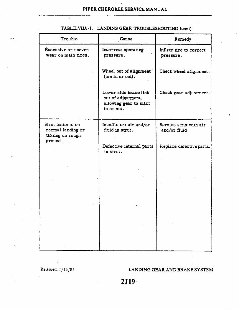
PIPER CHEROKEE SERVICE MANUAL.
TABLE VIIA-I.
Trouble
LANDING GEAR TROUBLESHOOTING (cont)
Cause Remedy
Excessive or unevenwear on main tires.
Incorrect operatingpressure.
Inflate tire to correctpressure.
Wheel out of alignment(toe in or out).
Lower side brace linkout of adjustment,allowing gear to slantin or out.
Check wheel alignment.
Check gear adjustment.
Strut bottoms onnormal landing ortaxiing on roughground.
Insufficient air and/orfluid in strut.
Defective internal partsin strut.
Service strut with airand/or fluid.
Replace defective parts.
Reissued: 1/15/81 LANDING GEAR AND BRAKE SYSTEM
2J19

PIPER CHEROKEE SERVICE MANUAL
7A-75. NOSE GEAR SERVICE TOLERANCES.
1770
24.2
7-8
11-12
13-14
1915-16 17
19
20-21
1922-23 19
19
25 1.2 1.2
6
18
5
9-10
11-12
3.4
Figure 7A-25. Nose Gear Service Tolerances, PA-28R
2J20. LANDING GEAR AND BRAKE SYSTEMRevised: 10 383

pue 6L80
Buuo!
dn
s
S3
0
LL
6
L
9
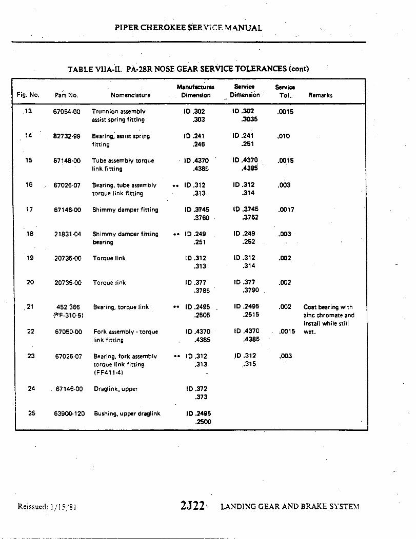
OO
pue (
06
u
6u
SS
6
8
LL
9
91S
L
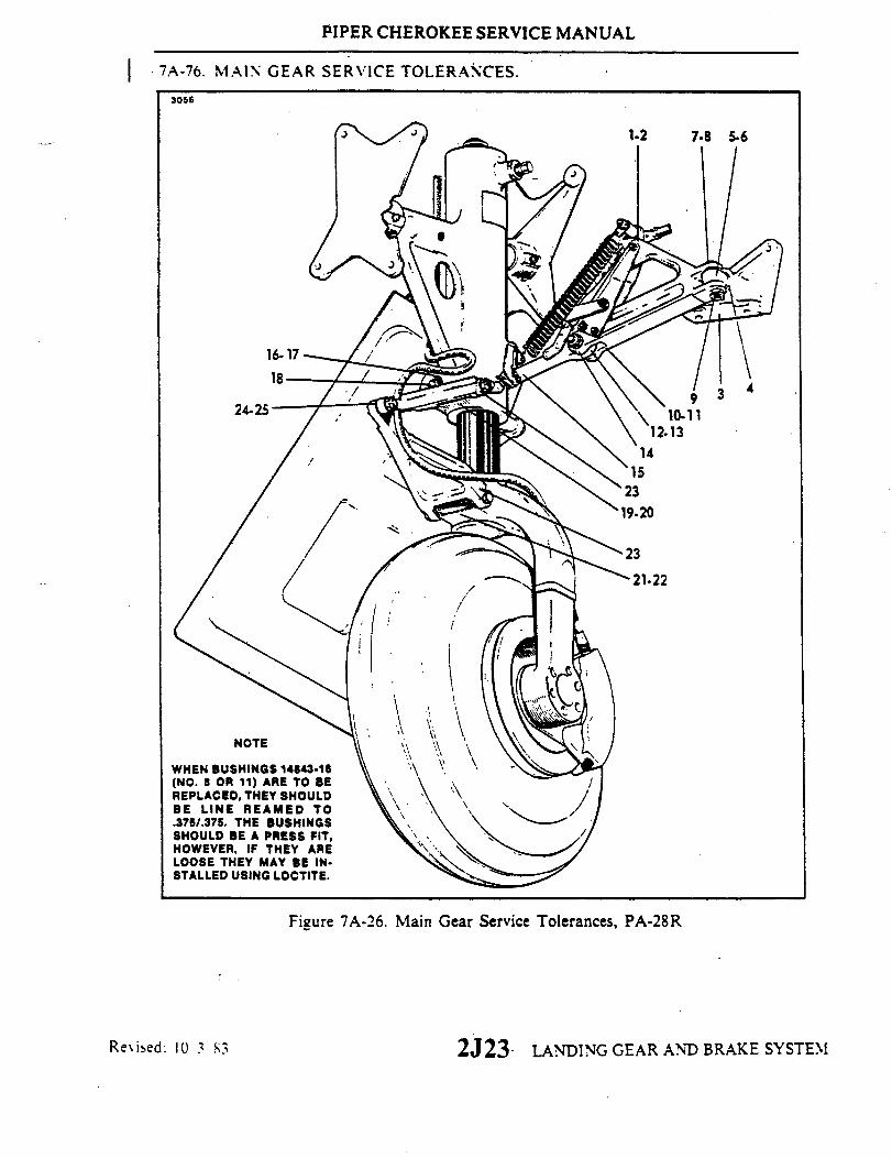
PIPER CHEROKEE SERVICE MANUAL
7A-76. MAIN GEAR SERVICE TOLERANCES.
3056
NOTE
WHEN BUSHINGS 14843-16(NO. 8 OR 11) ARE TO BEREPLACED, THEY SHOULDBE LINE REAMED TO.376/.375. THE BUSHINGSSHOULD BE A PRESS FIT,HOWEVER, IF THEY ARELOOSE THEY MAY BE IN-STALLED USING LOCTITE.
Figure 7A-26. Main Gear Service Tolerances, PA-28R
LANDING GEAR AND BRAKE SYSTEM
I
Revised: 10 3 83 2J23

9
9
9L
0
s
18
00
a
06
06
06
S9
6
SOS
6
99!
uo
(
(
(
(S
(
Z SZ
00-
00
00
68`
Z-S
'
Z
LL
6
8
L
9
.
N '6!d
S33MOi

(
000
(
OLE OLAlq
uo
O O
ap
86 66 uo
ap
a
(
09
OO
O-9
(
6L
8L
9L
18/

SECTION VIIIPOWER PLANT
(PA-28-140, -150, -160, -180, -235)
Paragraph AeroficheGrid No.
8-1. Introduction ...............................................................................................2K48-2. Description ..... .............................................................................. 2K48-3. Standard Practices- Engine.........................................................................2K68-4. Troubleshooting......................................................................................... 2K68-5. Propeller ...................................................................................................2K7
8-6. Removal of Propeller (Fixed Pitch) ..................................2K78-7. Cleaning. Inspection and Repair of Propeller ...................2K78-8. Installation of Propeller (Fixed Pitch) ...............................2K78-9. Removal of Propeller (Constant Speed) ...........................2K108-10. Cleaning, Inspection and Repair of Propeller
(Constant Speed) ........................................................2K 08-11. Installing Propeller (Constant Speed) ...............................2K118-12. Blade Track ......................................................................2K11
8-13. Propeller Governor .................................................................................. 2K 128-14. Removal of Propeller Governor ........................................2K 128-15. Installation of Propeller Governor ....................................2K 28-16. Rigging and Adjustment of Propeller Governor
(PA-28-235) ................................................................2K 28-17. Engine.........................................................................................................K14
8-17a. Removal of Engine Cowlings ........................................2K 148-17b. Installation of Engine Cowlings ........................................2K 48-17c. Installation of Bushings and Pins for Fiberglas Type
Cowlings ...................................................................2K148-18. Removal of Engine (PA-28-140, -150, -160, -180)...........2K 48-19. Installation of Engine (PA-28-140, -150, -160, -180) .......2K158-20. Installation of Engine Shock Mounts
(PA-28-140, Serial Nos. 28-2500 and up) ..................2K198-21. Removal of Engine (PA-28-235).......................................2K208-22. Installation of Engine (PA-28-235) ...................................2K21
8-23. Installation of Oil Cooler............................................................................2K238-24. Adjustment of Throttle and Mixture Controls............................................2K 38-25. Adjustment of Throttle and Mixture Controls............................................2K248-26. Carburetor..................................................................................................2L2
8-27. Carburetor Maintenance ....................................................2L28-28 Throttle Arm .....................................................................2L28-29. Adjustment of Idle Mixture...............................................2L28-30. Adjustment of Idle Speed..................................................2L4
8-31. Magneto (Bendix) ......................................................................................2L48-32. Inspection of Magnetos .....................................................2L48-33. Removal of Magnetos .......................................................2L68-34. Timing Procedure..............................................................2L78-35. Installation and Timing Procedure ...................................2L9
Interim Revision: February 15, 1995
2K2

Paragraph AeroficheGrid No.
8-36. Magneto (Slick) ..................... ......................... 2L18-37. Harness Assembly ..................................... . 2L II
8-38. Inspection of Harness ................................ 2L 118-39. Removal of Harness ................................. 2L 11`8-40. Installation of Harness ............................... 2L12
8-41. Spark Plugs ....................................... 2L128-42. Removal of Spark Plugs .............................. 2L128-43. Inspection and Cleaning of Spark Plugs ................ 2L 148-44. Installation of Spark Plugs ............................ 2L14
8-45. Lubrication System ........................................... 2L148-46. Oil Pressure Relief Valve ............................. 2L14
8-47. Switching ................................................... 2L158-48. Removal of Ignition Switch ........................... 2L158-49. Installation of Ignition Switch ......................... 2L 15
Revised: 83 81 2K3
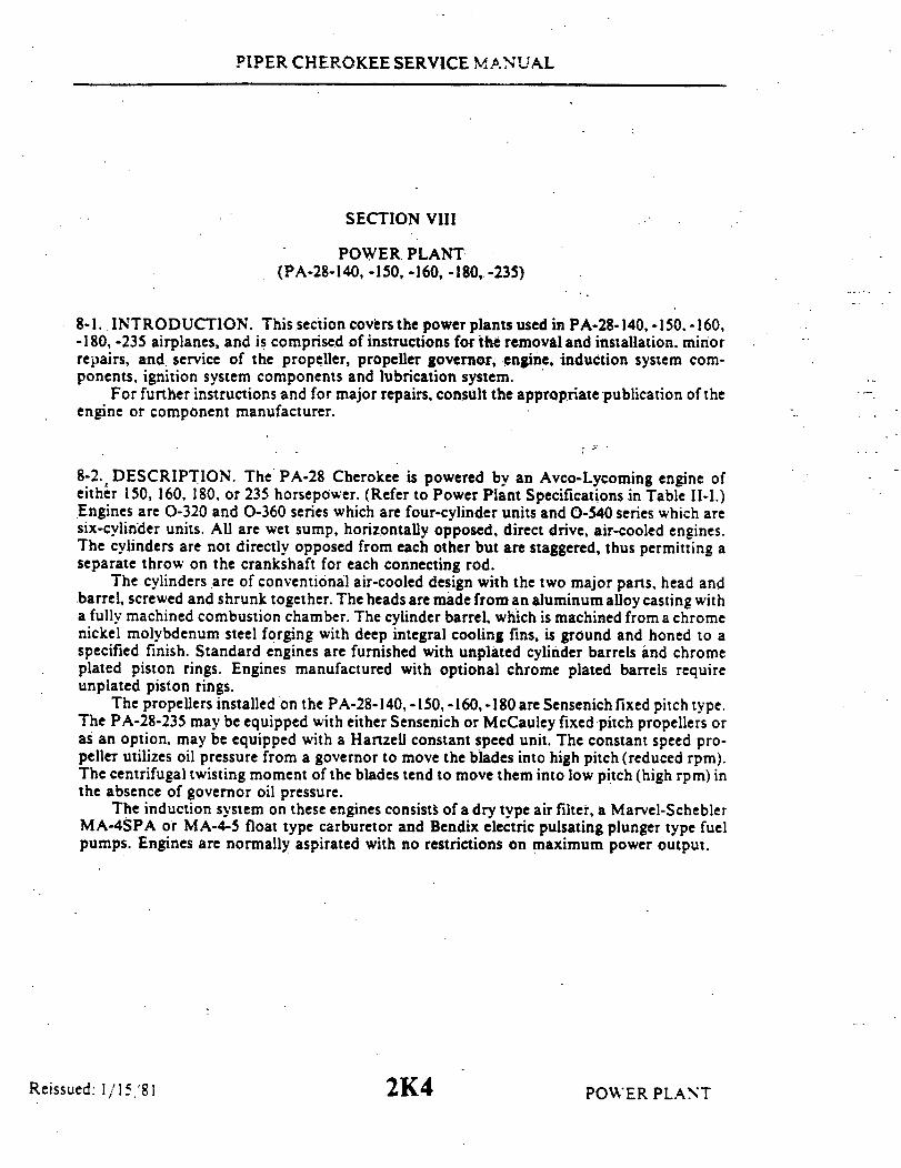
PIPER CHEROKEE SERVICE MANUAL
SECTION VIII
POWER PLANT(PA-28-140,-150,-160,-180,-235)
8-1. INTRODUCTION. This section covers the power plants used in PA-28-140, -150. -160,-180, -235 airplanes, and is comprised of instructions for the removal and installation, minorrepairs, and service of the propeller, propeller governor, engine, induction system com-ponents, ignition system components and lubrication system.
For further instructions and for major repairs, consult the appropriate publication of theengine or component manufacturer.
8-2. DESCRIPTION. The PA-28 Cherokee is powered by an Avco-Lycoming engine ofeither 150, 160, 180, or 235 horsepower. (Refer to Power Plant Specifications in Table II-I.)Engines are 0-320 and 0-360 series which are four-cylinder units and 0-540 series which aresix-cylinder units. All are wet sump, horizontally opposed, direct drive, air-cooled engines.The cylinders are not directly opposed from each other but are staggered, thus permitting aseparate throw on the crankshaft for each connecting rod.
The cylinders are of conventional air-cooled design with the two major parts, head andbarrel, screwed and shrunk together. The heads are made from an aluminum alloy casting witha fully machined combustion chamber. The cylinder barrel, which is machined from a chromenickel molybdenum steel forging with deep integral cooling fins, is ground and honed to aspecified finish. Standard engines are furnished with unplated cylinder barrels and chromeplated piston rings. Engines manufactured with optional chrome plated barrels requireunplated piston rings.
The propellers installed on the PA-28-140, -150,-160,-180 are Sensenich fixed pitch type.The PA-28-235 may be equipped with either Sensenich or McCauley fixed pitch propellers oras an option, may be equipped with a Hartzell constant speed unit. The constant speed pro-peller utilizes oil pressure from a governor to move the blades into high pitch (reduced rpm).The centrifugal twisting moment of the blades tend to move them into low pitch (high rpm) inthe absence of governor oil pressure.
The induction system on these engines consists of a dry type air filter, a Marvel-ScheblerMA-4SPA or MA-4-5 float type carburetor and Bendix electric pulsating plunger type fuelpumps. Engines are normally aspirated with no restrictions on maximum power output.
Reissued: 1/15/81 2K4 POWER PLANT

PIPER CHEROKEE SERVICE MANUAL
The magnetos used on these engines may be either Bendix-Scintilla S-20 or S-200 seriesor Slick 4000 series. The Bendix series magnetos are installed with their associatedcomponents. This magneto system consists of two single contact magnetos with the leftmagneto incorporating an impulse coupling to aid in starting. These are serviceable units.The Slick series magnetos are installed with their associated components. Refer to the latestrevision of Lycoming Service Letter No. SL-L177 for Slick exchange policy. These magnetosare non-serviceable, sealed units.
In addition to the previously mentioned components, each engine is furnished with astarter, 35 ampere or 60 ampere output, 14-volt electrical system, shielded ignition, vacuumpump drive and fuel pump. The exhaust system is stainless steel with a large muffler or twosmall mufflers and a shroud is provided to supply heat for both the cabin and carburetor.
The lubrication system is of the pressure wet sump type. The oil pump, which is locatedin the accessory housing, draws oil through a drilled passage leading from the oil suctionscreen located in the sump. The oil from the pump then enters a drilled passage in theaccessory housing, which feeds the oil to a threaded connection on the rear face of theaccessory housing, where a flexible line leads the oil to the external oil cooler. Pressure oilfrom the cooler returns to a second threaded connection on the accessory housing fromwhich point a drilled passage conducts oil to the oil pressure screen or filter. In the eventthat cold oil or an obstruction should restrict the oil flow to the cooler, an oil bypass valveis provided to pass the oil directly from the oil pump to the oil pressure screen or filter.
The oil pressure screen or filter element, located on the accessory housing is provided asa means to filter from the oil any solid particles that may have passed through the suctionscreen in the sump. After being filtered in the pressure screen or filter, the oil is fed througha drilled passage to the oil pressure relief valve, located in the upper right side of thecrankcase in front of the accessory housing.
This relief valve regulates the engine oil pressure by allowing excessive oil to return tothe sump, while the balance of the pressure oil is fed to the main oil gallery in the right halfof the crankcase. Residual oil is returned by gravity to the sump where, after passingthrough a screen, it is again circulated through the engine.
Reissued: 1/15/81 2K5 POWER PLANT

PIPER CHEROKEE SERVICE MANUAL
8-3. STANDARD PRACTICES-ENGINE. The following suggestions should be appliedwherever they are needed when working on the power plant.
a. To insure proper reinstallation and/or assembly, tag and mark all parts, clips, andbrackets as to their location prior to their removal and/ or disassembly.
b. During removal of various tubes or engine parts,,inspect then for indications ofscoring, burning or other undesirable conditions. To facilitate reinstallation. observe thelocation of each part during removal. Tag any unserviceable part and or units forinvestigation and possible repair.
c. Extreme care must be taken to prevent foreign matter from entering the engine, suchas lockwire. washers. nuts, dirt, dust, etc. This precaution applies whenever work is done onthe engine, either on or off the aircraft. Suitable protective caps, plugs, and covers must be usedto protect all openings as they are exposed.
NOTE
Dust caps used to protect open lines must always be installedOVER the tube ends and NOT IN the tube ends. Flow throughthe lines may be blocked off if lines are inadvertently installedwith dust caps in the tube ends.
d. Should any items be dropped into the engine, the assembly process must stop and theitem removed. even though this may require considerable time and labor. Insure that all partsare thoroughly clean before assembling.
e. Never reuse any lockwire, lockwashers, tablocks, tabwashers or cotter pins. Alllockwire and cotter pins must fit snugly in holes drilled in studs and bolts for locking purposes.Cotter pins should be installed so the head fits into the castellation of the nut. and unlessotherwise specified, bend one end of the pin back over the stud or bolt and the other end downflat against the nut. Use only corrosion resistant steel lockwire and/ or cotter pins. Bushingplugs shall be lockwired to the assembly base or case. Do-not lockwire the plugto the bushing.
f. All gaskets, packings and rubber parts must be replaced with new items of the sametype at reassembly. Insure the new nonmetallic parts being installed show no sign of havingdeteriorated in storage.
g. When installing engine parts which require the use of a hammer to facilitate assemblyor installation, use only a plastic or rawhide hammer.
h. Anti-seize lubrication should be applied to all loose-fit spline drives which areexternal to the engine and have no other means of lubrication. For certain assemblyprocedures, molybdenum disulfide in either paste or powdered form mixed with engine oil orgrease may be used.
CAUTION
Ensure that Anti-seize compounds are applied in thin evencoats, and that excess compound is completely removed toavoid contamination of adjacent parts.
i. Temporary marking methods are those markings which will ensure identificationduring ordinary handling, storage and final assembly of parts.
8-4. TROUBLESHOOTING. Troubles peculiar to the power plant are listed in Table VIII-I,at the back of this section, along with their probable causes and suggested remedies. Whentroubleshooting the engine, ground the magneto primary circuit before performing anychecks on the engine.
2K6 POWER PLANT2K6Reissued: 1/15/81

PIPER CHEROKEE SERVICE MANUAL
8-5. PROPELLER.
8-6. REMOVAL OF PROPELLER. (Fixed Pitch.)a. Insure master and magneto switches are off.b. Move fuel selector to off position and place mixture control in idle cut-off.c. Note the position of each component to facilitate reinstallation.d. Remove the screws attaching the spinner assembly and remove the spinner.e. Remove the safety wire that secures the six attaching bolts and remove the
bolts. The propeller is now free to be removed.
8-7. CLEANING, INSPECTION AND REPAIR OF PROPELLER. (Fixed Pitch.)a. Clean the spinner, back plate and propeller surfaces with a non-corrosive
solvent, and inspect for nicks, scratches, corrosion and cracks.b. Nicks in the leading edges of the blades should be filed out and all edges
rounded, as cracks sometimes start from such places. Use fine emery cloth forfinishing. (Refer to Figure 8-1 for propeller blade care.) A propeller with severenicks, scratches, corrosion or cracks should be returned to a propeller overhaulshop or the manufacturer for inspection and repair.
c. Each blade face should be sanded lightly and painted, when necessary, witha flat black paint to retard glare. A light application of oil or wax may be appliedto the surfaces to prevent corrosion.
8-8. INSTALLATION OF PROPELLER. (Fixed Pitch.)a. Insure magneto switch is OFF.b. Place the generator or alternator drive belt in the groove of the starter
ring gear and position the starter gear on the flange of the crankshaft. Ascertainthat the stamped "O" on the gear is aligned with the "O" on the crankshaft flange.
c. Install the propeller spinner backplate or bulkhead on the starter ring gear.d. Rotate crankshaft until the top center (TC) mark on the starter gear and the
crankcase parting flange or the index mark on starter housing are aligned.e. Install propeller with tips pointing at the two and eight o'clock position.f. Install and tighten each propeller bolt, with washer, finger tight. Use a
torque wrench for final tightening and tighten in sequence so that all bolts arepulled down evenly. Torque three-eights inch bolts to 280 to 300 inch-poundsor one-half inch bolts to 720 to 780 inch-pounds (60 to 65 foot-pounds).
g. Check the propeller blade track as given in paragraph 8-12.h. Safety the propeller mounting bolts with MS20995-C41 wire.i . Install the spinner and tighten cap bolts to a torque of 35 to 40 inch-pounds.j. Adjust generator or alternator drive belt as given in Checking Generator
and Alternator Belt Tension, Section XI.
POWER PLANT2K7Reissued: 1/15/81
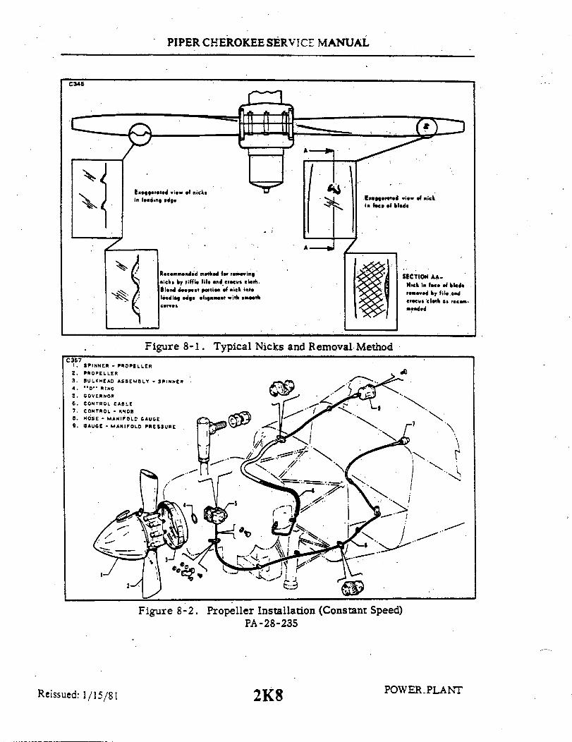
PIPER CHEROKEE SERVICE MANUAL
C345
Exagerated view of nicksin leading edge
Figure 8-1.
Exagerated view of nickin face of bladsd
SECTION AA-Nick in face of blade
0 removed by file andereci cloth as recom-mended
Typical Nicks and Removal Method
SPINNER - PROPELLERPROPELLERBULKHEAD ASSEMBLY - SPINNER"O" RINGGOVERNOR
CONTROL CABLECONTROL - KNOBHOSE - MANIFOLD GAUGEGAUGE - MANIFOLD PRESSURE
Figure 8-2. Propeller Installation (Constant Speed)PA-28-235
Reissued: 1/15/81 POWER PLANT2K8
Recommended method for removingnicks by riffle file and crocus cloth.Blend deepest portion of nick intoleading edge alignment with smoothcurves
C3671.2.3.4.5.
6.7.8.9.
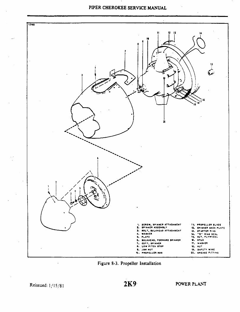
PIPER CHEROKEE SERVICE MANUAL
1740
14
10S
I
15
'15
20
4.
1. SCREW, SPINNER ATTACHMENT2. SPINNER ASSEMBL3. BOLT, BULKHEAD ATTACHMENT4. WASHER5. PLATE
6. BULKHEAD, FORWARD SPINNER7. CUFF, SPINNER8. Low PITCH STOP9. JAM NUT
10. PROPELLER HUB
11. PROPELLER BLADE12. SPINNER BACK PLATE13. STARTER RING14. "" RING SEAL15. NUT, FLYWHEEL16. STUD17. WASHER18. NUT19. SAFETY WIRE
20. GREASE FITTING
Figure 8-3. Propeller Installation
2K9 POWER PLANTReissued: 1/15/81

PIPER CHEROKEE SERVICE MANUAL
TABLE VIII-I. PROPELLER TORQUE LIMITS
DESCRIPTION REQUIRED TORQUE
Propeller Mounting Nuts - 55-65 Foot Pounds(1 )
Forward Bulkhead Attachment Bolts 30-35 Inch Pounds
Spinner Attachment Screws 20-25 Inch Pounds(1) Fixed Pitch and constant Speed.
8-9. REMOVAL OF PROPELLER. (Constant Speed.)a. Insure that the master and magneto switches are off.b. Move fuel selector to off position.c. Place the mixture control in idle cut-off.d. Note position of each component to facilitate reinstallation.e. Remove the screws from around the spinner assembly and remove spinner.f. Remove the safety wire from the six propeller mounting nuts on studs and remove
studs.g. Place a drip pan under the propeller to catch oil spillage, then remove the propeller.
8-10. CLEANING. INSPECTION AND REPAIR OF PROPELLER. (Constant Speed.)a; Check for oil and grease leaks.b. Clean the spinner, propeller hub interior and exterior, and blades with a
non-corrosive solvent.c. Inspect the hub parts for cracks.d. Steel hub parts should not be permitted to rust. Use aluminum paint to touch up, if
necessary, or replate during overhaul.e. Check all visible parts for wear and safety.f. Check blades to determine whether they turn freely on the hub pivot tube. This can
be done by rocking the blades back and forth through the slight freedom allowed by thepitch change mechanism. If they appear tight and are properly lubricated, the pitch changemechanism should be removed so that each blade can be checked individually. If blades aretight, the propeller should be disassembled.
g. Inspect blades for damage or cracks. Nicks in leading edges of blades should be filedout and all edges rounded, as cracks sometimes start from such places. Use fine emery clothfor finishing. (Refer to Figure 8-1 for propeller blade care.) Each blade face should besanded lightly and painted, when necessary, with a flat black paint to retard glare. A lightapplication of oil or wax may be applied to the surfaces to prevent corrosion.
h. It is recommended that for severe damage, internal repairs and replacement of parts,the propeller should be referred to the Hartzell Factory or an authorized Service Station.
i. Grease blade hub through zerk fittings. Remove one of the two fittings for eachpropeller blade, alternate the next time. Apply grease through the zerk fitting until freshgrease appears at the fitting hole of the removed fitting. Care should be taken to avoidblowing out hub gaskets.
j. Check condition of the propeller mounting nuts on studs.
Reissued: 1/15/81 POWER PLANT2K10
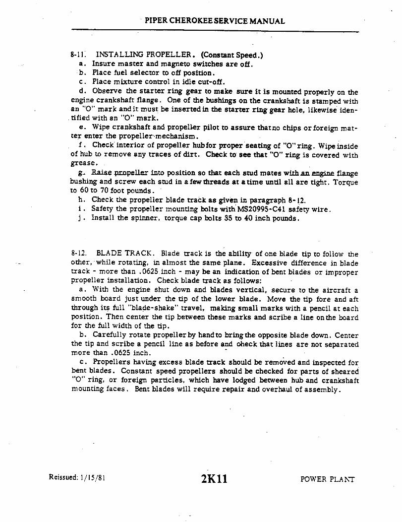
PIPER CHEROKEE SERVICE MANUAL
8-11. INSTALLING PROPELLER. (Constant Speed.)a. Insure master and magneto switches are off.b. Place fuel selector to off position.c. Place mixture control in idle cut-off.d. Observe the starter ring gear to make sure it is mounted properly on the
engine crankshaft flange. One of the bushings on the crankshaft is stamped withan "O" mark and it must be inserted in the starter ring gear hole, likewise iden-tified with an "O" mark.
e. Wipe crankshaft and propeller pilot to assure thatno chips or foreign mat-ter enter the propellermechanism.
f. Check interior of propeller hubfor proper seating of "O" ring. Wipe insideof hub to remove any traces of dirt. Check to see that "O" ring is covered withgrease.
g Raise propeller into position so that each stud mates with an engine flangebushing and screw each stud in a few threads at a time until all are tight. Torqueto 60 to 70 foot pounds.
h. Check the propeller blade track as given in paragraph 8-12.i . Safety the propeller mounting bolts with MS20995-C41 safety wire.j . Install the spinner, torque cap bolts 35 to 40 inch pounds.
8-12. BLADE TRACK. Blade track is the ability of one blade tip to follow theother, while rotating, in almost the same plane. Excessive difference in bladetrack - more than .0625 inch - may be an indication of bent blades or improperpropeller installation. Check blade track as follows:
a. With the engine shut down and blades vertical, secure to the aircraft asmooth board just under the tip of the lower blade. Move the tip fore and aftthrough its full "blade-shake" travel, making small marks with a pencil at eachposition. Then center the tip between these marks and scribe a line onthe boardfor the full width of the tip.
b. Carefully rotate propeller by hand to bring the opposite blade down. Centerthe tip and scribe a pencil line as before and check that lines are not separatedmore than .0625 inch.
c. Propellers having excess blade track should be removed and inspected forbent blades. Constant speed propellers should be checked for parts of sheared"O" ring, or foreign particles, which have lodged between hub and crankshaftmounting faces. Bent blades will require repair and overhaul of assembly.
Reissued: 1/15/81 POWER PLANT2K11

PIPER CHEROKEE SERVICE MANUAL
8-13. PROPELLER GOVERNOR. (PA-28-235.)
8-14. REMOVAL OF PROPELLER GOVERNOR.a. Remove the upper engine cowl.b. Disconnect the control cable end from the governor control arm.c. Remove the governor mounting stud nuts. It will be:necessary to raise the
governor as the nuts are being removed before the nuts can be completely re-moved.
d. Remove the mounting gasket. If the governor is to be removed for a con-siderable length of time and another unit not substituted, it is advisable to coverthe mounting pad to prevent damage caused by foreign matter.
8-15. INSTALLATION OF PROPELLER GOVERNOR.a. Clean the mounting pad thoroughly, making very certain that there are no
foreign particles in the recess around the drive shaft.b. Place the governor mounting gasket in position with the raised portion of
the screen facing away from the engine,c. Align the splines on the governor shaft with the engine drive and slide the
governor into position.d. With the governor in position, raise the governor enough to install washers
and start mounting nuts. Torque nuts even.e. Connect the control cable end to the governor control arm. The ball stud
is installed in the inner hole of the control arm.f. Adjust governor control per paragraph 8-16.g. Install engine cowl.
8-16. RIGGING AND ADJUSTMENT OF PROPELLER GOVERNOR. (PA-28-235.)(Refer to Figure 8-5.)
a. Start engine, park 90° to wind direction and warm in normal manner.b. To check high RPM, low pitch setting, move the propeller control all the
way forward. At this position, the governor speed control arm (1) should beagainst the high RPM fine adjusting screw (2). With the throttle full forward,observe engine RPM, which should be 2575 RPM with high RPM properly adjusted.
c. Should engine RPM not be as required, the high RPM setting should be ad-justed as follows:
1. Shut down the engine and remove the upper engine cowl.2. Adjustthe governor by means ofthefine adjustmentscrew for 2575 RPM.
To do this, loosen the high RPM fine adjustment screw locknut and turn the screwin a clockwise direction to decrease engine speed or in a counterclockwise direc-tion to increase engine speed.
Reissued: 1/15/81 2K12 POWERPLANT1/15/81Reis

PIPER CHEROKEE SERVICE MANUAL
O90
.K2 TS .125
Figure 8-4. Adjustment of Propeller Control (PA-28-235)
NOTE
One revolution of the fine adjustment screw.will in-crease or decrease the engine speed approximately20 RPM.
3. Reinstall upper engine cowl and repeat step b to ascertain proper RPM
C308
1. CONTROL ARM2. RPM ADJUSTMENT SCREW3. LOCK NUT4. CONTROL WHEEL5. BOLT ASSEMBLY
Figure 8-5. Propeller Governor(PA-28-235)
setting.4. After setting the proper high
RPM adjustment, run the self-lockingnut on the fine adjustment screw againstthe base projection to lock.
5. Ascertain that the governorcontrol arm is adjusted to the properangle on the control wheel (4) as shownin Figure 8-5.
d. With the high RPM adjustmentcomplete, the control system should beadjusted so that the governor controlarm will contact the high RPM stop.On airplanes with Serial Nos. 28-10166to 28-11039 incl., the cockpit knobshould be .062 to .125 of an inch fromits full forward stop. Airplanes withSerial Nos. 28-11040 and up, the cockpit
Reissued: 1/15/81 POWER PLANT
960
2K13

PIPER CHEROKEE SERVICE MANUAL
control lever should be .031 to .062 of an inch from its full forward stop. (Refer to Figure 8-4.) Toadjust the control travel, disconnect the control cable end from the control arm, loosen the cablejam nut and rotate the end to obtain the desired level clearance. Reconnect the cable end and tightenjam nut.
e. It is usually only necessary to adjust the high RPM setting of the governor control system,as the action automatically takes care of the positive high pitch setting.8-17. ENGINE.
8-17a. REMOVAL OF ENGINE COWLINGS.a. Release cowling fasteners or attachment screws, depending on the type installed.b. Disconnect all electrical leads.c. Remove cowlings. (Move upper cowling up and forward, drop lower cowling down.)
8-17b. INSTALLATION OF ENGINE COWLINGS.a. Position cowlings in place. (Bottom cowling first, insert locator pins of upper cowling and
lower into place.)b. Connect electrical leads.c. Secure fasteners or attachment screws, depending on the type of cowling installed.
8-17c. INSTALLATION OF BUSHINGS AND PINS FOR FIBERGLAS TYPE COWLINGS.a. With cowlings removed, locate bushings on lower cowling. (See Figure 8-7.)b. Using snap ring pliers, remove snap ring and old bushing.c. Install new bushing and new snap ring.
NOTEBushings should be inspected each 100 hours andshould be replaced upon condition, but no later than500 hours time in service.
d. Locate pins in upper cowling.
NOTEIt should not be necessary to replace the pins unlessbushing in lower cowling has worn enough to allowdamage to the pin. Any noticeable notching or cut-ting of the pin requires replacement.
e. If it is necessary to remove the pins, appropriate tools should be used to remove the fiber-glas resin from around the pin and plate assembly. (A template or adequate measurements shouldbe made to assure proper alignment of the new pin and plate assembly.)
f. Remove pin and plate assemblyg. To install new pin and plate assembly it will be necessary to prepare the fiberglas surface to
accept the new plate. (See Paragraph 4-58, FIBERGLAS REPAIRS.)1. Clean area as required, and roughen.2. Prepare cowling surface by applying resin. Do not allow to harden.3. Install plate and pin.4. Lay in a layer ofresin impregnated fiberglas cloth over the plate and surrounding fiber-
glas. (Use template or measurements from step e to assure alignment.) Allow to cure.8-18. REMOVAL OF ENGINE. (PA-28-140, -150, -160, -180) (Refer to Figure 8-6 or 8-7.)
a. Turn off all electrical switches in the cockpit and then disconnect the bat-tery ground wire at the battery.
b. Move the fuel selector lever in the cockpit to the OFF position.c. Remove ihe engine cowlings per Paragraph 8-17a. Be certain that-all electrical leads
are disconnected prior to removal of the cowling.d. Remove the propeller per paragraph 8-6.e. Disconnect the starter positive and ground leads at the starter, and their
attachment clamps.
Interim Revision: February 15, 1995 POWER PLANT
2K14
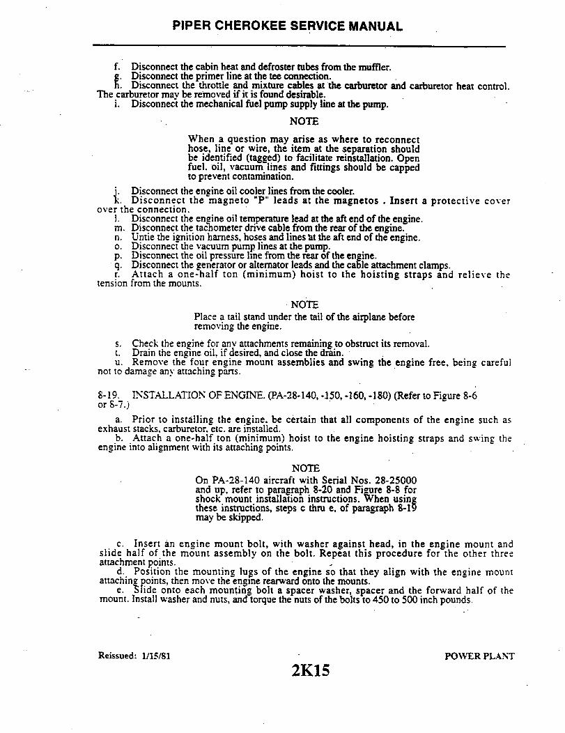
PIPER CHEROKEE SERVICE MANUAL
f. Disconnect the cabin heat and defroster tubes from the muffler.g. Disconnect the primer line at the tee connection.
h. Disconnect the throttle and mixture cables at the carburetor and carburetor heat control.The carburetor may be removed if it is found desirable.
i. Disconnect the mechanical fuel pump supply line at the pump.
NOTE
When a question may arise as where to reconnecthose, line or wire, the item at the separation shouldbe identified (tagged) to facilitate reinstallation. Openfuel. oil, vacuum lines and fittings should be cappedto prevent contamination.
j. Disconnect the engine oil cooler lines from the cooler.k.Disconnect the magneto "P" leads at the magnetos . Insert a protective cover
over the connection.l. Disconnect the engine oil temperature lead at the aft end of the engine.m. Disconnect the tachometer drive cable from the rear of the engine.n. Untie the ignition harness, hoses and lines at the aft end of the engine.o. Disconnect the vacuum pump lines at the pump.p. Disconnect the oil pressure line from the rear of the engine.q. Disconnect the generator or alternator leads and the cable attachment clamps.r. Attach a one-half ton (minimum) hoist to the hoisting straps and relieve the
tension from the mounts.
NOTEPlace a tail stand under the tail of the airplane beforeremoving the engine.
s. Check the eneine for any attachments remaining to obstruct its removal.t. Drain the engine oil, if desired, and close the drain.u. Remove the four engine mount assemblies and swing the engine free, being careful
not to damage any attaching parts.
8-19. INSTALLATION OF ENGINE. (PA-28-140, -150, -160, -180) (Refer to Figure 8-6or 8-7.)
a. Prior to installing the engine, be certain that all components of the engine such asexhaust stacks, carburetor, etc. are installed.
b. Attach a one-half ton (minimum) hoist to the engine hoisting straps and swing theengine into alignment with its attaching points.
NOTEOn PA-28-140 aircraft with Serial Nos. 28-25000and up, refer to paragraph 8-20 and Figure 8-8 forshock mount installation instructions. When usingthese instructions, steps c thru e, of paragraph 8-19may be skipped.
c. Insert an engine mount bolt, with washer against head, in the engine mount andslide half of the mount assembly on the bolt. Repeat this procedure for the other threeattachment points.
d. Position the mounting lugs of the engine so that they align with the engine mountattaching points, then move the engine rearward onto the mounts.
e. Slide onto each mounting bolt a spacer washer, spacer and the forward half of themount. Install washer and nuts, and torque the nuts of the bolts to 450 to 500 inch pounds.
Reissued: 1/15/81 POWER PLANT
2K15

PIPER CHEROKEE SERVICE MANUAL
C3101. ENGINE AND NOSE GEAR MOUNT
2. THROTTLE CONTROL3. CARBURATOR HEAT CONTROL4. MIXTURE CONTROL5. TACHOMETER HAET6. OIL COOLER LINES7. OIL COOLER8. BAFFLING9. TOP COWL
10. PROPELLER11. SPINNER MOUNTING PLATE12. SPINNER ASSEMBLY13. LANDING LIGHT
14. PAPER AIR FILTER15. LANDING LIGHT - AIR FILTER
ATTACHMENT BOLT
16. HEATER SHROUD
Figure 8-6. Engine Installation (PA-28-140, -150, -160, -180;Serial Nos. 28-1 to 28-1760.)
Reissued: 1/15/81 2K16
8
12
13
15
POWER PLANT

PIPER CHEROKEE SERVICE MANUAL
1. ENGINE AND NOSE GEAR MOUNT2. THROTTLE CONTROL3. CARBURETOR HEAT CONTROL4. MIXTURE CONTROL5. TACHOMETER SHAFT6. ENGINE SHOCK MOUNT7. OIL COOLER8. BAFFLING9. TOP COWL
10. BOTTOM COWL11. SPINNER MOUNTING PLATE12. PROPELLER13. SPINNER SUPPORT PLATE14. SPINNER15. HEATER AND MUFFLER ASSEMBLY16. AIR FILTER17. FRESH AIR INTAKE18. POWER PLANT ASSEMBLY19. PLATE ASSEMBLY, BUSHING,
RETAINING RING, WASHERS, NUTSNOTE: A maximum of (3) AN960-616washers can be used to permit a max. of2.5 threads exposed on the bolt. Torqueto 230/240 inch-pounds.
Figure 8-7. Engine Installation(PA-28-140, -150. -160, -180, Serial Nos. 28-1761 and up)
Interim Revision: February 15, 1995 POWER PLANT
2K17

PIPER CHEROKEE SERVICE MANUAL
138
SECTION A-A
SECTION C-C
BOLTWASHER
SHOCK MOUNTSPACER
ENGINE MOUNT
SHOCK MOUNT
ENGINE MOUNTING LUG
TORQUE - 450-500 IN. LBS.
SPACER WASHER
SECTION B-B..
SECTION D-D
Figure. 8-8. Engine Shock Mount Installation (PA-28-140, Serial Nos. 28-25000 and up)
Reissued: 1/15/81 POWER PLANT2K18 POWER PLANT
I

PIPER CHEROKEE SERVICE MANUAL
f. Connect the generator or alternator leads and secure cables with clamps.g. Connect the oil pressure line, tachometer drive cable, oil temperature lead and the
engine vent tube to the aft end of the engine.h. Connect the vacuum pump line at the pump.i. Secure the ignition harness, hoses and lines at the aft end of the engine using
koroseal lacing.j. Connect both lines to the oil cooler.k. Connect the mechanical fuel pump supply line at the pump.1. Connect the magneto "P" leads to the magnetos.m. Connect the throttle, mixture and carburetor heat cables at the engine
components.n. Connect the cabin heat and defroster tubes to the muffler.o. Connect the starter positive and ground leads at the starter and secure with
attachment clamps.p. Be certain that the magneto switches are OFF 'and install the propeller per
paragraph 8-8.q. Install the proper grade and amount of engine oil. Refer to Lubrication Chart,
Section II.r. Connect the battery ground wire at the battery.s. Open the throttle and fuel valve completely. Turn on the electric fuel pump and
check the fuel line for leaks.t. Install the engine cowlings and remove the tail stand.
NOTE
To avoid a possible high speed bearing failure resulting from alack of lubrication during initial starts, refer to the latestrevision of Avco-Lycoming Service Instruction No. 1241 forinformation on pre-oiling the engine.
u. Perform an engine operational check. Refer to the engine manufacturer'sappropriate operator's manual.
8-20. INSTALLATION OF ENGINE SHOCK MOUNTS. (PA-28-140, Serial Nos. 28-2500and up.) (Refer to Figure 8-8.)
a. Assemble the engine shock mounts on the engine mount as shown in Figure 8-8.Note the position of each mount carefully. The upper right and lower left mounts are thesame, as are the upper left and lower right.
b. Swing the engine into place, positioning the engine mounting lugs so they align.with the engine mount attachment points.
c. Position the shock mount bolts through the'mounting lugs and secure with nuts.Torque the nuts progressively, following a circular sequence until a torque value of 450-500inch pounds is reached.
Reissued: 1/15/81r2K19
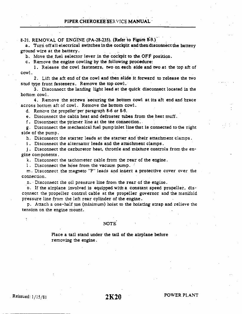
PIPER CHEROKEESERVICE MANUAL
8-21. REMOVAL OF ENGINE (PA-28-235). (Refer to Figure 8-9.)a. Turn off all electrical switches in the cockpit and then disconnect the battery
ground wire at the battery.b. Move the fuel selector lever in the cockpit to the OFF position.c. Remove the engine cowling by the following procedure:
1. Release the cowl fasteners, two on each side and two at the top aft ofcowl.
2. Lift the aft end of the cowl and then slide it forward to release the twostud type front fasteners. Remove the top cowl.
3. Disconnect the landing light lead at the quick disconnect located in thebottom cowl.
4. Remove the screws securing the bottom cowl at its aft end and braceacross bottom aft of cowl. Remove the bottom cowl.
d. Remove the propeller per paragraph 8-6 or 8-9.e. Disconnect the cabin heat and defroster tubes from the heat muff.f. Disconnect the primer line at the tee connection.g. Disconnect the mechanical fuel pump inlet line that is connected to the right
side of the pump.h. Disconnect the starter leads at the starter and their attachment clamps.i . Disconnect the alternator leads and the attachment clamps.j . Disconnect the carburetor heat, throttle and mixture controls from the en-
gine components.k. Disconnect the tachometer cable from the rear of the engine.1. Disconnect the hose from the vacuum pump.m. Disconnect the magneto "P" leads and insert a protective cover over the
connection.n. Disconnect the oil pressure line from the rear of the engine.o. If the airplane involved is equipped with a constant speed propeller, dis-
connect the propeller control cable at the propeller governor and the manifoldpressure line from the left rear cylinder of the engine.
p. Attach a one-half ton (minimum) hoist to the hoisting strap and relieve thetension on the engine mount.
NOTE
Place a tail stand under the tail of the airplane beforeremoving the engine.
Reissued: 1/15/81 2K20 POWER PLANT

PIPER CHEROKEE SERVICE MANUAL
q. Check the engine for any attachments remaining to obstruct its removal.r. Drain the engine oil, if desired, and then close the drain.s. Remove the four engine mount assemblies and swingthe engine free, being
careful not to damage any attaching parts.
8-22. INSTALLATION OF ENGINE (PA-28-235). (Refer to Figure 8-9.)a. Attach a one-half ton (minimum) hoist to the engine hoisting straps and
swing the engine into alignment with its attaching points on the mounts.b. Insert an engine mount bolt through the hole of a mount attachment point
(A washer is installed next to the head of the bolt.) and slide a half of the shockmount assembly on the bolt. Repeat for the other three mounts.
c. Position the mounting lugs of the engine so that they align with the enginemount attaching points, then move the engine rearward onto the mounts.
d. Slide onto each mounting bolt a spacerwasher, spacer and the forward halfof mount. Install the washer and nut, and torque the nuts to 450 to 500 inch pounds.
e. If the airplane involved is equipped with a constant speed propeller, connectthe propeller control cable at the propeller governor and the manifold pressureline to the left rear cylinder of the engine.
f. Connect the oil pressure line to the aft end of the engine.g. Remove the protective cover from the magneto "P" leads and connect the
leads to the magnetos.h. Connect the hose to the vacuum pump.i. Connect the tachometer cable to the rear of the engine.j. Connect the carburetor heat, throttle and mixture controls to the engine
components.k. Connect the alternator leads and secure with the attachment clamps.1. Connect the starter leads at the starter and secure with the attachment
clamps.m. Connect the mechanical fuel pump inlet line that is connected to the right
side of the pump.n. Connect the primer line at the tee connection.o. Connect the cabin heat line and defroster tubes at the heat muff.p. Be certain that the magneto switches-are OFF and install the propeller per
paragraph 8-9 or 8-13.q. Install the proper grade and amount of engine oil. Refer to Lubrication
Chart, Section II.
Reissued: 1/15/81 POWER PLANT2K21

PIPER CHEROKEE SERVICE MANUAL
1. ENGINE MOUNT ASSEMBLY2. CARBURATOR HEAT CONTROL CABLE3. MIXTURE CONTROL CABLE4. TACHOMETER SHAFT5. OIL RADIATOR HOSE6. OIL RADIATOR7. ENGINE BAFFLES8. TOP COWL ASSEMBLY9. PROPELLER ASSEMBLY
NOTE: A maximum of (3) AN960416 17washers can be used to permit a max. of2.5 threads exposed on the bolt. Torqueto 230/240 Inch-pounds.
10. SPINNER BULKHEAD ASSEMBLY11. PROPELLER SPINNER ASSEMBLY12. CARBURETOR AIR FILTER ASSEMBLY13. CABIN HEAT BOX14. MUFFLER ASSEMBLY15. CARBURETOR HEAT SHROUD16. OIL DRAIN VALVE
17. BOTTOM COWL ASSEMBLY
Figure 8-9. Engine Installation (PA-28-235)
Reissued: 1/15/81 2K22
1120
POWER PLANT
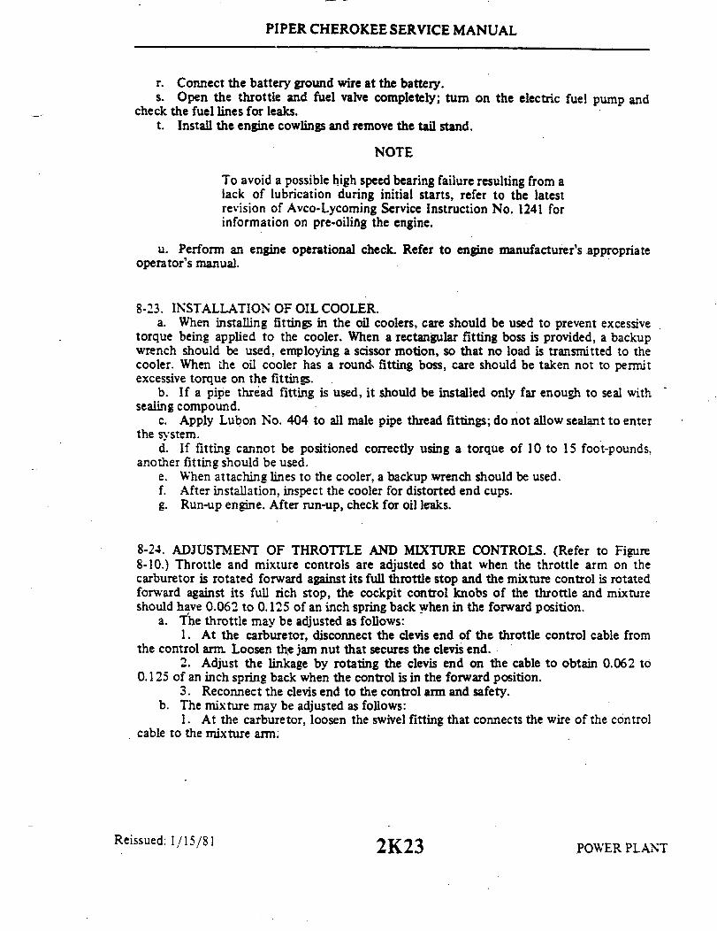
PIPER CHEROKEE SERVICE MANUAL
r. Connect the battery ground wire at the battery.s. Open the throttle and fuel valve completely; turn on the electric fuel pump and
check the fuel lines for leaks.t. Install the engine cowlings and remove the tail stand.
NOTE
To avoid a possible high speed bearing failure resulting from alack of lubrication during initial starts, refer to the latestrevision of Avco-Lycoming Service Instruction No. 1241 forinformation on pre-oiling the engine.
u. Perform an engine operational check. Refer to engine manufacturer's appropriateoperator's manual.
8-23. INSTALLATION OF OIL COOLER.a. When installing fittings in the oil coolers, care should be used to prevent excessive
torque being applied to the cooler. When a rectangular fitting boss is provided, a backupwrench should be used, employing a scissor motion, so that no load is transmitted to thecooler. When the oil cooler has a rounds fitting boss, care should be taken not to permitexcessive torque on the fittings.
b. If a pipe thread fitting is used, it should be installed only far enough to seal withsealing compound.
c. Apply Lubon No. 404 to all male pipe thread fittings; do not allow sealant to enterthe system.
d. If fitting cannot be positioned correctly using a torque of 10 to 15 foot-pounds.another fitting should be used.
e. When attaching lines to the cooler, a backup wrench should be used.f. After installation, inspect the cooler for distorted end cups.g. Run-up engine. After run-up, check for oil leaks.
8-24. ADJUSTMENT OF THROTTLE AND MIXTURE CONTROLS. (Refer to Figure8-10.) Throttle and mixture controls are adjusted so that when the throttle arm on thecarburetor is rotated forward against its full throttle stop and the mixture control is rotatedforward against its full rich stop, the cockpit control knobs of the throttle and mixtureshould have 0.062 to 0.125 of an inch spring back when in the forward position.
a. The throttle may be adjusted as follows:1. At the carburetor, disconnect the clevis end of the throttle control cable from
the control arm. Loosen the jam nut that secures the clevis end.2. Adjust the linkage by rotating the clevis end on the cable to obtain 0.062 to
0.125 of an inch spring back when the control is in the forward position.3. Reconnect the clevis end to the control arm and safety.
b. The mixture may be adjusted as follows:1. At the carburetor, loosen the swivel fitting that connects the wire of the control
cable to the mixture arm.
Reissued: 1/15/81POWER PLANT2K23

PIPER CHEROKEE SERVICE MANUAL
OLD A/C 890 NEW A/C
0.062 TO 0.125 0.010 TO 0.030
Figure 8-10. Adjustment of Engine Controls
2. Reposition the fitting on the wire to obtain .062 to .125 of an inch spring backbetween the knob and plate when the mixture control arm isagainst its stop.
3. Tighten the swivel fitting and safety. The control wire should be straighted toalign with the control cable casing after tightening the swivel fitting.
c. Check security of cable casing attachments.d. Pull throttle and mixture knobs in cockpit full aft to ascertain that the idle screw
contacts its stop and the mixture control arm contacts its lean position.
8-25 ADJUSTMENT OF THROTTLE AND MIXTURE CONTROLS. (PA-28-140,Serial Nos. 28-25000 and up; PA-28-180, Serial Nos. 28-4378 and up; PA-28-235, Serial Nos.28-11040 and up.) (Refer to Figure 8-10.) Throttle and mixture controls are adjusted so thatwhen the throttle arm on the carburetor is rotated forward against its full throttle stop and themixture control is rotated forward against its full rich stop, the cockpit control levers of thethrottle and mixture should have 0.010 to 0.030 of an inch spring back when in the forwardposition.
a. The throttle may be adjusted as follows:1. For PA-28-140 aircraft, S/N 28-25001 thru 28-7225373 with Kit 760 780
installed, ascertain that there is some cushion at the throttle control handle in the cockpitwith the throttle completely closed. Check that the bearing on the carburetor end of thecontrol cable has the proper thread engagement by use of the inspection hole. Tighten thejam nut against the rod end of the bearing.
2. For aircraft other than those listed in Step 1, proceed as follows:(a) At the carburetor, disconnect the clevis end of the throttle control cable
from the control arm. Loosen the jam nut that secures the clevis end.(b) Adjust the linkage by rotating the clevis end on the cable to obtain 0.010 to
0.030 of an inch spring back on instrument stop when in full throttleposition.
Reissued: 1/15/81 2K24 POWER PLANT

PIPER CHEROKEE SERVICE MANUAL
(c) Reconnect the clevis end to the control arm and safety.b. The mixture may be adjusted as follows:
1. At the carburetor, disconnect the clevis end of the mixture control cable fromthe control arm. Loosen the jam nut that secures.the clevis end.
2. Adjust the linkage by rotating the clevis end on the cable to obtain 0.010 to0.030 of an inch spring back on the instrument panel stop when in full rich position.
3. On aircraft equipped with air conditioning systems, a micro switch is locatedbelow the throttle control which is set to actuate in the full open position. With the throttlecontrol adjusted to obtain a clearance of .010 to .030, adjust the micro switch to actuate atthis point also.
4. Reconnect the clevis end to the control arm and safety.c. Check security of cable casing attachment.d. Pull throttle and mixture levers in cockpit full aft to ascertain that the idle screw
contacts its stop and the mixture control arm contacts its lean position. On 1975 modelsand up, a mixture control lock is incorporated in the quadrant cover which prevents themixture control from being moved to the idle cutoff position inadvertently. The lock mustbe depressed before the control can be moved completely aft. Ascertain that the lockoperates freely without any tendency to bind or hang up.
THIS SPACE INTENTIONALLY LEFT BLANK
Reissued 1 /15 /01 2L1POWER PLANTReissued 1/15/81

PIPER CHEROKEE SERVICE MANUAL
8-26. CARBURETOR.
8-27. CARBURETOR MAINTENANCE. In general, little attention is required betweencarburetor overhauls. However, it is recommended that the following items be checkedduring recommended inspection periods of the engine.
a. Check tightness and safety of all nuts and screws which fasten the carburetor to theengine.
b. Check all fuel lines for tightness and evidence of leakage.c. Check throttle and mixture control rods and levers for travel, tightness and safety.d. Clean the fuel inlet screen. (Refer to Figure 8-11 or 8-12.)e. Remove the plug at the aft position of the carburetor and drain any accumulation of
foreign matter.f. Check carburetor air box for wear and full travel of heat door.g. Check the adjustment of the idle mixture and idle speed. (Refer to paragraphs 8-29
and 8-30.)
8-28. THROTTLE ARM.a. Remove screw securing the throttle arm to the carburetor. Do not remove the
throttle arm.b. Remove and discard lock tab.c. Examine the screw to determine if there is a hole through the head of the screw. If
not, drill a 1/16 inch diameter hole through the head of the screw.d. Reinstall the screw; torque to 20 to 28 inch-pounds.
NOTE
Be sure the torque handle is correctly calibrated to insure theattaching screw is neither under nor over tightened.
e. Using .032 inch diameter safety wire, first tie the wire to the idle stop lever and thencontinue as shown in Figures 8-11 and 8-12.
f. Depending upon the carburetor model, the sequence and direction of tying mayvary; however, the idle stop arm, throttle arm, and attaching screws must all be tiedtogether.
8-29. ADJUSTMENT OF IDLE MIXTURE. (Refer to Figures 8-11 and 8-12.)a. After performing the standard engine starting procedure, operate the engine for at
least two minutes between 800 to 1200 RPM to insure proper engine warmup.
Reissued: 1/15/81 2L2 POWER PLANT

PIPER CHEROKEE SERVICE MANUAL
2573
TIGHTEN THROTTLE ARM SCREW(8) TO 20 - 28 IN. LBS. TORQUE
Figure 8-11. Carburetor Figure 8-12. Carburetor(PA-28-140, -150, -160) (PA-28-180, -235)
WARNING
When performing engine warm-up indoors, provide a barrierabout the engine to prevent serious injury. Also provideadequate means of ventilating the work area.
b. Draw back on the cockpit throttle control lever to obtain a reading ofapproximately 550 RPM on the tachometer.
c. Turn the idle mixture adjusting screw (1) located near the rear of the carburetor,clockwise, leaning the fuel mixture. Continue to do this until the engine begins to runroughly, at which time the engine speed will decrease.
d. Turn the screw counterclockwise until the engine runs smoothly again. Continue toturn the screw in the same direction until the engine begins to run roughly once more. Atthis point, the fuel mixture will be too rich and engine speed will decrease again.
e. Now advance the screw to a midway position between the lean and rich fuelmixture; the RPM of the engine will reach a maximum speed for idle mixture settings.
Reissued: 1/15/81
C3451
2L3 POWER PLANT
PIPER CHEROKEE SERVICE MANUAL
8-30. ADJUSTMENT OF IDLE SPEED.a. Pull back the cockpit throttle control until it is completely aft and in the closed
position: Observe the engine speed on the tachometer.b. Adjust idle adjustment screw to obtain from 550 to 650 RPM.Rotate the screw
clockwise to increase the speed of the engine; counterclockwise to decrease the enginespeed. The screw is located on the throttle arm.
NOTE
One complete revolution of the carburetor idle screwprovides a variation of approximately 100 RPM in idlingspeed.
8-31. MAGNETO. (Bendix.)
CAUTION
Ascertain that the primary circuits of both enginesare grounded before working on the engine.
8-32. INSPECTION OF MAGNETOS. (Refer to Figure 8-12.) At time of engine inspectionor when a magneto has been removed from the engine, the following checks may be per-formed.
1. Inspect distributor block contact springs. Top of spring must not bemore than .422 inches below, top of tower as shown in Figure 8-14. If broken orcorroded, they should be replaced.
2. Inspect oil felt washer, It should be saturated with oil. If dry, checkfor worn bushing. If O.K., add No. 30 oil.
3. Inspect distributor block for cracks or burned areas. The wax coatingon the block should not be removed. Do not use solvents.
4. Look for excess oil in breaker compartment. If present, it may meana bad oil seal or oil seal bushing at drive end. Check manufacturer's overhaulprocedure.
5. Look for frayed insulation or broken wire strands in leads in back ofmagneto. See that terminals are secure. Be sure wires are properly positioned.
6. Inspect capacitor visually. If possible, test for leakage, capacity andseries resistance. Remember, an electrical failure of an aircraft capacitor israre.
7. Adjustment of breakers must be correct for proper internal timing ofmagneto. (Refer to paragraph 8-34.)
8. Check if breaker cam is clean and smooth; if cam screw is. tight (25 in.
POWER PLANT2L4Reissued: 1/15/81

PIPER CHEROKEE SERVICE MANUAL
A851
15
21
4 9
CONTACT SPRING 13
CONTACT SPRING 5. LEAD WIRE 9. IMPULSE COUPLING2 RETAINNG RING 6 CAPACITOR 10. FLYWEIGHTS 13. CONTACT SPRING3 DISTRIBUTOR BLOCK 7 BREAKER ASSEMBLY 11. DELETED 14. INSULATOR4 BREAKER COMPARTMENT 8 BREAKER CAM 12 LEAD CIRCUIT 15. VENT PLUG
Figure 8-13. Magneto Inspection (Bendix)
lbs.). If new points are installed, blot a little oil on cam.9. Inspect impulse coupling (-21 and -204 magneto) flyweights for excessive
looseness on the axles. Design couplings having .927 inch thick body should bechecked with 1/8 inch drill. Couplings with .974 inch thick body are checked witha No. 18 drill. If drill fits between cam and flyweight, the fit is too loose andcoupling should be replaced. (Refer to Figure 8- 15.)
10. Check impulse coupling for excess wear on the contact edges of bodyand flyweights.
-11. Checkthat the impulse couplingflyweight axle rivets are tight and thereare no cracks in body.
12. Look at the lead conduits. A few broken strands won't hurt, but if theinsulation looks tired, you may be in for trouble. The special high temperaturecoating, used on light-weight harnesses, is provided chiefly for vibration resist-ance and mechanical protection. The integrity of the harness is not sacrificed ifsmall areas of the braid show peeling or flaking of this coating.
13. Check the springs for breaks, corrosion, or deformation. If possible,check continuity from block with tester or light.
14. Check insulators for cracks, breaks, or evidence of "old age". Be surethey are clean.
15. Timing and ventilator plugs. Ventilator has drilled holes and should bein lowest hole in magneto to serve also as drain for excess water or oil. Solidplug is used in other hole or in location exposed to rain or water.
Reissued: 1/15/81 POWER PLANT.2L5

PIPER CHEROKEE SERVICE MANUAL
A825 0.422 MAX. C326
MEASURE BODYTHICKNESS HERE
Figure 8-14. Contact Spring Inspection Figure 8-15. Impulse Coupling
8-33. REMOVAL OF MAGNETOS. Before removing the magneto, make suremagneto switches are OFF.
a. Remove the harness assembly terminal plate-from the magneto.
WARNING
The magneto is not internally grounded; when theground lead is disconnected, the magneto is hot. Re-moving the harness assembly terminal plate first andinstalling them last, minimizes the danger of startingthe engine accidentally when the ground lead is re-moved from the magneto.
b. Disconnect the ground lead at the magneto.c. Remove the nuts and washers and draw the magneto from the engine.
NOTE
The magneto service instructions in this manual areto cover minor repairs and timing. For further re-pairs and adjustments of the magnetos, it is recom-mended that the latest revision of the magneto manufacturer'sservice instructions be followed.
Reissued: 1/15/81 POWER PLANT2L6
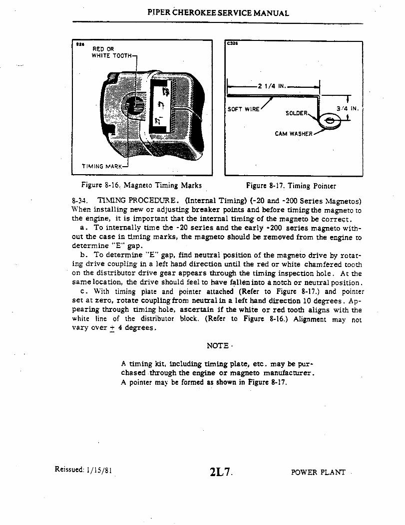
PIPER CHEROKEE SERVICE MANUAL
826 C326RED ORWHITE TOOTH
2 1/4 IN.
SOFT WIRE 3/ 4IN.SOLDER
CAM WASHER
TIMING MARK-
Figure 8-16. Magneto Timing Marks Figure 8-17. Timing Pointer
8-34. TIMING PROCEDURE. (Internal Timing) (-20 and -200 Series Magnetos)When installing new or adjusting breaker points and before timing the magneto tothe engine, it is important that the internal timing of the magneto be correct.
a. To internally time the -20 series and the early -200 series magneto with-out the case in timing marks, the magneto should be removed from the engine todetermine "E" gap.
b. To determine "E" gap, find neutral position of the magneto drive by rotat-ing drive coupling in a left hand direction until the red or white chamfered toothon the distributor drive gear appears through the timing inspection hole. At thesame location, the drive should feel to have fallen into a notch or neutral position.
c. With timing plate and pointer attached (Refer to Figure 8-17.) and pointerset at zero, rotate couplingfrom neutralin a left hand direction 10 degrees. Ap-pearing through timing hole, ascertain if the white or red tooth aligns with thewhite line of the distributor block. (Refer to Figure 8-16.) Alignment may notvary over + 4 degrees.
NOTE-
A timing kit, including timing plate, etc. may be pur-chased through the engine or magneto manufacturer.A pointer may be formed as shown in Figure 8-17.
Reissued: 1/15/81 POWER PLANT2L7.

PIPER CHEROKEE SERVICE MANUAL
C326 C326
HOUSING CENTER MARK HOUSING CENTER MARK
~30 30 TIMING LINE
NUMBER OF DEGREES RETARD
Figure 8-18. Timing Kit Installed Figure 8-19. Breaker Compartmentwith Cast Timing Marks
d. Using the alignment of the gear marked with the white line of the distribu-tor block as a reference, adjust breaker points to open at this point. Turn themagneto drive until the cam follower is on high point of the cam lobe. Measurecontact clearance, it must be .018 inch + .006 with the "E" gap set 10 degrees+ 4 degrees. If breaker points do not come within tolerances, they should be re-placed.
NOTE
A pointer can also be made by wrapping a piece of softwire tightly around the head of cam securing screw andbending it to extend over timing marks.
e. If magneto is type which has "cast in" timing marks (-200 series, see Fig-ure 8-19), main breaker may be adjusted with magneto on engine as follows: turnengine crankshaft until notch in cam is aligned with mark at top of breaker com -partment. Set wire pointer in center of the "E" gap boss at the side of breakercompartment. Connect timing light across main breaker. Adjust main breakercontacts to open at this point. Turn engine crankshaft until cam follower is onthe high point of the cam lobe. Measure contact clearance. It must be .018 +.006. If necessary, readjust breaker and recheck to be sure that contacts willopen within "E" gap tolerance + 4 degrees. (Width of "E" gap boss.)
Reissued: 1/15/81 2L8. POWER PLANT
PIPER CHEROKEE SERVICE MANUAL
CAUTION
If cam screw was removed, be sure to replace flatwasher, lock washer and screw. Torque to 25 inchpounds.
f. With internal timing checked, the magneto may be timed to the engine.(Refer to paragraph 8-35.)
8.35. INSTALLATION AND TIMING PROCEDURE. (Timing Magneto to Engine).The magnetos can be installed and timed to the engine by the following procedure:
NOTE
Ascertain that the breakers are correct for proper in-ternal timing of magnetos.
a. Remove the top spark plug from No. one cylinder. Place the thumb of onehand over the spark plug hole and rotate the crankshaft in direction of normal ro-tation until the compression stroke is reached. The compression stroke is indi-cated by a positive pressure inside the cylinder tending to lift the thumb off thespark plug hole. In this position both valves of No. one cylinder are closed. Turnthe crankshaft opposite to its normal direction of rotation until it is approximately35 degrees BTC on the compression stroke of No. one cylinder. Rotate the crank-shaft in its normal direction of rotation until the 25 degrees mark on the startergear and the crankcase parting flange or the index on the front of the starterhousing are aligned.
b. Rotate the magneto gear on the right magneto until the chamfered tooth onthe distributor gear inside the magneto aligns with the white pointer as seenthrough the window in the magneto cover. Without allowing the gear to turn fromthis position, assemble the magneto and gasket. Secure magneto in place withwashers and nuts; tighten the nuts only finger tight.
c. Fasten ground wire on electric timing light to any unpainted metallic por-tion of the engine, and one of the positive wires of the timing light to a suitableterminal connected to the ground terminal connection of the right magneto. Turnengine crankshaft several degrees from BTC in directionopposite to that of nor-mal rotation.
Reissued: 1/15/81 2L9 POWER PLANT
PIPER CHEROKEE SERVICE MANUAL
d. Turn on the switch of the timing light. Turn the crankshaft very slowly indirection of normal rotation until the timing mark on the front face of the ringgear support aligns with the drilled hole in the starter, at which point the lightshould go on, (on battery operated models). If not, turn the magneto in its mount-ing flange slots and repeat the procedure until the light goes on at 25 degrees be-fore top dead center. Tighten the two mounting nuts and replace magneto inspec-tion plug.
e. Install the impulse coupling magneto adapter and gasket on the left magnetomounting pad of the accessory housing.
CAUTION
The impulse coupling magneto can be used only on theleft side of the engine (as viewed from rear).
f. Remove inspection plug, depress pawl on impulse coupling shaft and turnimpulse coupling on left magneto until the white beveled tooth (or middle tooth, iftiming gear has three beveled teeth) aligns with the timing pointer. Without al-lowing the magneto gear to turn from this position, assemble the left magneto tothe accessory housing and secure with washers and nuts. Tighten nuts only fingertight.
g. Connect the other positive wire of the timing light to a suitable terminalconnection of the left magneto and time the magneto in the same manner as de-scribed for the right magneto.
h. After both magnetos have been timed, leave the timing light wires connectedand recheckmagneto timing as previously described to make sure that both mag-netos are set to fire together. If timing is correct, both timing lights will go onsimultaneously when the 25 degree mark aligns with the centerline of the crank-case. If the breaker points open too early, loosen the mounting nuts and rotatethe magneto clockwise. If the breaker points open too late, rotate the magnetocounterclockwise. Remove timing light and ignition timing pointer, and replacetiming inspection plug in magneto.
i. After the magnetos have been properly timed, clean the breaker points toremove any trace of oil or dirt. Replace breaker cover and lock the retainingscrews together with lockwire.
Reissued: 1/15/81 POWER PLANT2L10
PIPER CHEROKEE SERVICE MANUAL
NOTE
The crankshaft should not be rotated more than 10 degreesin direction opposite normal rotation as the pawl on theimpulse coupling will engage with the stop pin and latetiming will be indicated through the impulse couplingmechanism. If this should happen, rotate crankshaft innormal direction until sharp click is heard; this will indicatethat the impulse coupling has passed through fiing position.Turn crankshaft in direction opposite normal rotation toapproximately 35 degrees BTC and proceed with timingcheck.
8-36. MAGNETO. (Slick.)a. For service information concerning these magnetos refer to the latest revisions of
Lycoming Service Letter No. L177 and Lycoming Service Instruction No. 1189.
8-37. HARNESS ASSEMBLY
8-38. INSPECTION OF HARNESS.a. Check lead assemblies for nicks, cuts, mutilated braiding, badly worn section or any
other evidence of physical damage. Inspect spark plug sleeves for chafing or tears anddamaged or stripped threads on coupling nuts. Check compression spring to see if it isbroken or distorted. Inspect grommet for tears. Check all mounting brackets and clamps tosee that they are secure and not cracked.
b. Using an ohmmeter, buzzer, or other suitable low voltage device, check each lead forcontinuity. If continuity does not exist, wire is broken and must be replaced.
c. Minor repair of the harness assembly, such as replacement of contact springs, springretainer assemblies, insulating sleeves or of one lead assembly, can be accomplished with theharness assembly mounted on the engine. However, should repair require replacement ofmore than one lead assembly or of a cable outlet plate, the harness should be removed fromthe engine and sent to an overhaul shop.
8-39. REMOVAL OF HARNESS.a. Disconnect the clamps that secure the wires to the engine and accessories.b. Loosen the coupling nuts at the spark plugs and remove the insulators from the
spark plug barrel well. Use caution when withdrawing the insulator not to damage theinsulator spring.
c. Place a guard over the harness insulators.
Reissued: 1/15/81 POWER PLANT2L11

PIPER CHEROKEE SERVICE MANUAL
d. Remove the harness assembly terminal plate from the magneto.e. Remove the engine baffle plate that receives the harness assembly.f. Remove the harness from the airplane.
8-40. INSTALLATION OF HARNESS. Before installing harness on magneto,check mating surfaces for cleanliness. Spray entire face of grommet with a lightcoat of Plastic Mold Spray, SM-O-O-TH Silicone Spray or equivalent. This willprevent harness grommet from sticking to magneto distributor block.
a. Place the harness terminal plate on the magneto and tighten nuts around theplate alternately to seat cover squarely on magneto. Torque nuts to 18 to 22 inchpounds.
b. Route ignition wires to their respective cylinders.c. Clamp the harness assembly in position and replace the engine baffle plate.d. Connect the leads to the spark plugs.
8-41. SPARK PLUGS.
8-42. REMOVAL OF SPARK PLUGS.a. Loosen the coupling nut onthe harness lead and remove the terminal insu-
lator from the spark plug barrel well.
NOTE
When withdrawing the ignition cable lead connectionfrom the plug, care must be taken to pull the leadstraight out and in line with the center line of the plugbarrel; otherwise, a side load will be applied whichfrequently results in damage to the barrel insulatorand connector. If the lead cannot be removed easily inthis manner, the resisting contact between the neo-prene collar and the barrel insulator will be broken bya rotary twisting of the collar. Avoid undue distortionof the collar and possible side loading of the barrelinsulator.
b. Remove the spark plug from the engine. Inthe course of engine operation,carbon and other combustion products will be deposited on the end of the sparkplug and will penetrate the lower threads to some degree. As a result, greatertorque is frequently required for removing a plug than for its installation. Ac-
Reissued: 1/15/81 2L12 POWER PLANT
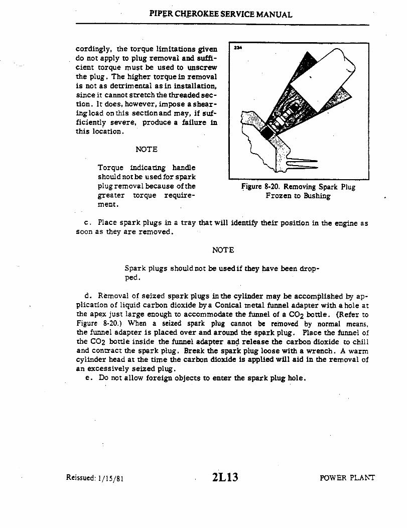
PIPER CHEROKEE SERVICE MANUAL
cordingly, the torque limitations given 234
do not apply to plug removal and suffi-cient torque must be used to unscrewthe plug. The higher torque in removalis not as detrimental as in installation,since it cannot stretch the threaded sec-tion. It does, however, impose a shear-ing load on this section and may, if suf-ficiently severe, produce a failure inthis location.
NOTE
Torque indicating handleshould not be used for sparkplug removal because of the Figure 8-20. Removing Spark Pluggreater torque require- Frozen to Bushingment.
c. Place spark plugs in a tray that will identify their position in the engine assoon as they are removed.
NOTE
Spark plugs should not be used if they have been drop-ped.
d. Removal of seized spark plugs inthe cylinder may be accomplished by ap-plication of liquid carbon dioxide by a Conical metal funnel adapter with a hole atthe apex just large enough to accommodate the funnel of a CO2 bottle. (Refer toFigure 8-20.) When a seized spark plug cannot be removed by normal means,the funnel adapter is placed over and around the spark plug. Place the funnel ofthe CO2 bottle inside the funnel adapter and release the carbon dioxide to chilland contract the spark plug. Break the spark plug loose with a wrench. A warmcylinder head at the time the carbon dioxide is applied will aid in the removal ofan excessively seized plug.
e. Do not allow foreign objects to enter the spark plug hole.
Reissued: 1/15/81 2L13 POWER PLANT

PIPER CHEROKEE SERVICE MANUAL
8-43. INSPECTION AND CLEANING OF SPARK PLUG.a. Visually inspect each spark plug for the following non-repairable defects:
1. Severely damaged shell or shield threads nicked up, stripped or cross-threaded.
2. Badly battered or rounded shell hexagons.3. Out-of-round or damaged shielding barrel.4. Chipped, cracked, or broken ceramic insulator portions.5. Badly eroded electrodes worn to approximately 50% of original size.
b. Clean the sparkplug as required, removing carbon and foreign deposits.c. Test the spark plug both electrically and for resistance.d. Set the electrode gap at .015 to .018 of an inch or if a smoother operation
at idle speed and reduced magneto drop-off is desired, set at .018 to .022 of aninch. However, with wide gap setting the plugs must be serviced at more fre-quent intervals. Fine wire platinum or iridium electrodes should be set at .015to .018 of an inch only.
8-44. INSTALLATION OF SPARK PLUGS. Before installing spark plugs, ascer-tain that the threads within the cylinder are clean and not damaged.
a. Apply anti-seize compound sparingly on the threads and install gasket andspark plugs. Torque 360 to 420 inch pounds.
CAUTION
Make certainthe deep socketis properly seated on thespark plug hexagon as damage to the plug could resultif the wrench is cocked to one side when pressure isapplied.
b. Carefully insert the terminal insulator in the spark plug and tighten thecoupling nut.
8-45. LUBRICATION SYSTEM.
8-46. OIL PRESSURE RELIEF VALVE. Subject engines may be equipped witheither an adjustable or non-adjustable oil pressure relief valve. A brief descrip-tion of both types follows:
a. Non-adjustable Oil Pressure Relief Valve - The valve is notadjustable; how-ever, the pressure can be controlled by the addition of a maximum of three STD-425 washers under the cap to increase pressure or the use of a spacer (Lycoming
Reissued: 1/15/81 POWER PLANT2L14

PIPER CHEROKEE SERVICE MANUAL
P N 73629 or 73630) to decrease pressure. Particles of metal or otherforeign matter lodged be-tween the ball and seat will result in a drop in oil pressure. It is advisable, therefore, to dis-assemble. inspect, and clean the valve if excessive pressure fluctuations are noted. The oil pres-sure relief valve is not to be mistaken for the oil cooler by-pass valve, whose function is to per-mit pressure oil to by-pass the oil cooler in case of an obstruction.
b. Adjustable Oil Pressure Relief Valve - The adjustable oil pressure relief valve enablesthe operator to maintain engine oil pressure within the specified limits (refer to the enginemanufacturer's appropriate manual). The valve is located above and to the rear of No. 3cylinder. If the pressure under normal operating conditions should consistently exceed 90psi.. or run less than 60 psi.. adjust the valve as follows:
With the engine thoroughly warmed up and running at a maximum of 2200 RPM.observe the reading on the oil pressure gauge. If the pressure is above 90 psi.. stop engine.loosen the adjusting lock nut: and back off the adjusting screw one or two full turns. Tightenlock nut and retest. If pressure is too low. turn adjusting screw further into the relief valve plug.thereby increasing the tension on the relief valve spring. When the valve has been satisfactorilyadjusted. tighten the lock nut and lockwire the crown nut to the drilled ear projecting from thevalve mounting boss.
8-47. SWITCHING.
8-48. REMOVAL OF IGNITION SWITCH.a. Insure the ignition switch is in the off position.b. Gain access to and disconnect the power lead (+) from the battery.c. Remove the ignition switch retaining nut from the switch on the forward side of the
instrument panel and withdraw the switch from the panel.d. Mark the wires and note their position on the switch. then disconnect the wires.
8-49. INSTALLATION OF IGNITION SWITCH. (Refer to Figure 8-21.)a. Attach wires to the switch as shown in Figure 8-21.b. Position the ignition switch in the instrument panel and secure with retaining nut.c. Connect the power lead (-) to the battery and reinstall any access covers previously
removed.
POWER PLANT2L15Revised: 8 3 81
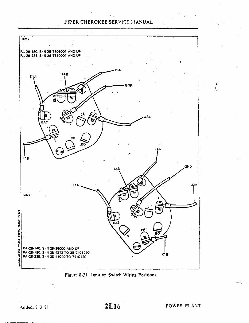
PIPER CHEROKEE SERVICE MANUAL
C216
PA-28-180..S/N 28-7505001 AND UPPA-28-235. S/N 28-7510001 AND UP
J2A
K1B
GND
C236
PA-28-140. S/N 28-25000 AND UPPA-28-180. S/N 28-4378 TO 28-7405290PA-28-235, S/N 28-11040 TO 7410120 B
Figure 8-21. Ignition Switch Wiring Positions
Added: 8 3 81 2L16 POWER PLANT
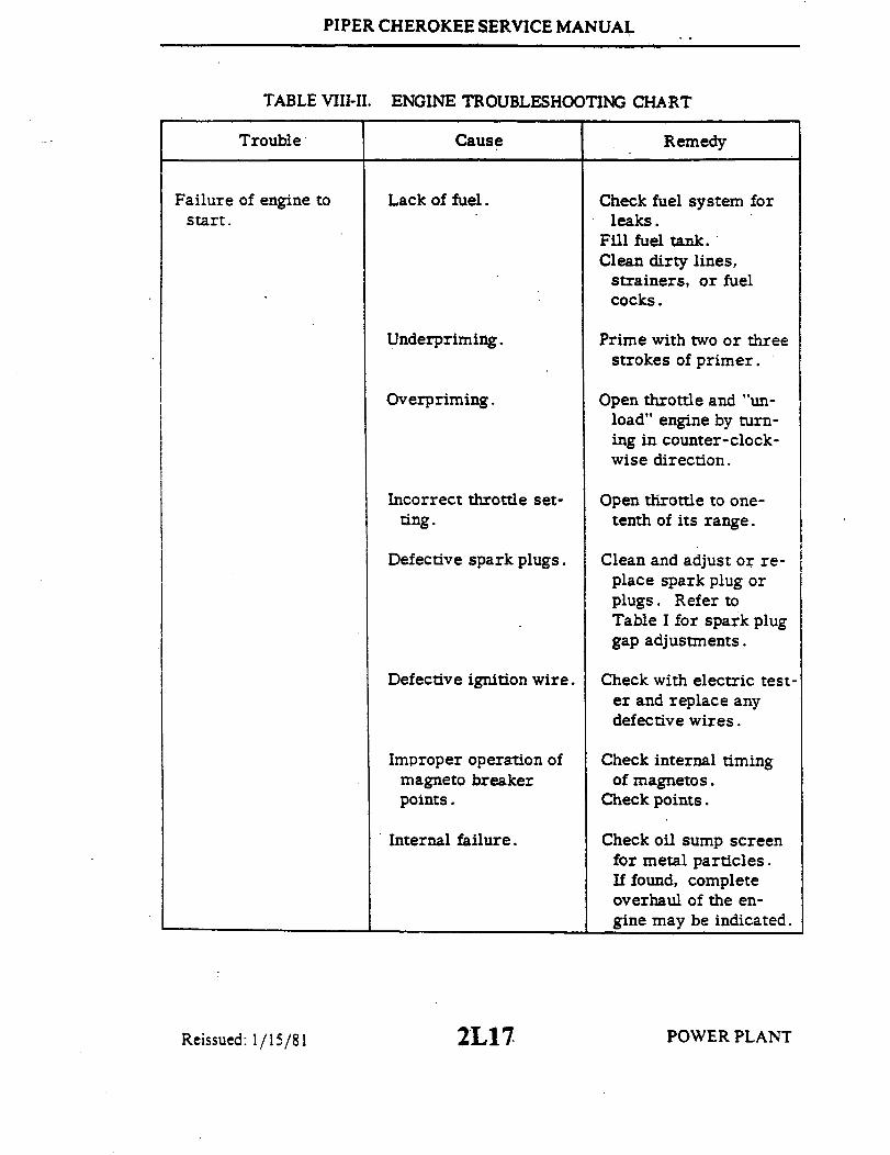
PIPER CHEROKEE SERVICE MANUAL
TABLE VIII-I.
Trouble
ENGINE TROUBLESHOOTING CHART
Cause Remedy
Failure of engine tostart.
Lack of fuel. Check fuel system forleaks.
Fill fuel tank.Clean dirty lines,
strainers, or fuelcocks.
Underpriming.
Overpriming.
Incorrect throttle set-ting.
Defective spark plugs.
Defective ignition wire.
Improper operation ofmagneto breakerpoints.
Internal failure.
Prime with two or threestrokes of primer.
Open throttle and "un-load" engine by turn-ing in counter-clock-wise direction.
Open throttle to one-tenth of its range.
Clean and adjust or re-place spark plug orplugs. Refer toTable I for spark pluggap adjustments.
Check with electric test-er and replace anydefective wires.
Check internal timingof magnetos.
Check points.
Check oil sump screenfor metal particles.If found, completeoverhaul of the en-gine may be indicated.
POWER PLANTReissued: 1/15/81 2L17

PIPER CHEROKEE SERVICE MANUAL
TABLE VIII-II.
Trouble
ENGINE TROUBLESHOOTING CHART (cont)
Cause Remedy
Failure of engineto start. (cont)
Improper switch wiringfor left magnetostarting.
Reverse magneto switchwires.
Magnetized impulsecoupling - left mag-neto only.
Frozen spark plugelectrodes.
Mixture control in idlecut-off.
Shorted ignition switchor loose ground.
Demagnetize impulsecouplings.
Replace spark plugs ordry out removedplugs.
Open mixture control.
Check and replace orrepair.
Failure of engine toidle properly.
Incorrect carburetoridle adjustment.
Adjust throttle stop toobtain correct idle.
Idle mixture.
Leak in the inductionsystem.
Low cylinder com-pression.
Adjust mixture. Referto engine manufac-turer's handbook forproper procedure.
Tighten all connectionsin the induction sys-tem. Replace anyparts that are defec-tive.
Check cylinder com-pression.
Reissued: 1/15/81 POWER PLANT2L18
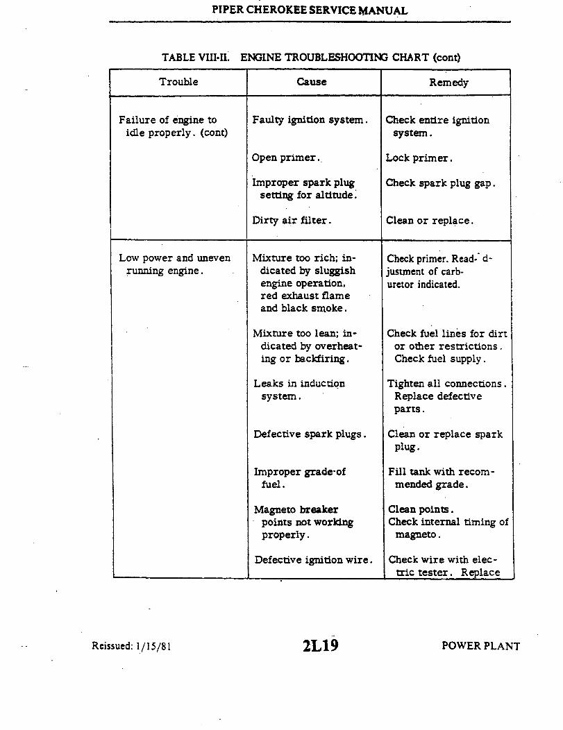
PIPER CHEROKEE SERVICE MANUAL
TABLE VII-II.
Trouble
ENGINE TROUBLESHOOTING CHART (cont)
Cause Remedy
Failure of engine toidle properly. (cont)
Faulty ignition system. Check entire ignitionsystem.
Open primer..
Improper spark plugsetting for altitude.
Dirty air filter.
Lock primer.
Check spark plug gap.
Clean or replace.
Low power and unevenrunning engine.
Mixture too rich; in-dicated by sluggishengine operation,red exhaust flameand black smoke.
Check primer. Read- d-justment of carb-uretor indicated.
Mixture too lean; in-dicated by overheat-ing or backfiring.
Leaks in inductionsystem.
Defective spark plugs.
Improper grade-offuel.
Magneto breakerpoints not workingproperly.
Defective ignition wire.
Check fuel lines for dirtor other restrictions.Check fuel supply.
Tighten all connections.Replace defectiveparts.
Clean or replace sparkplug.
Fill tank with recom-mended grade.
Clean points.Check internal timing of
magneto.
Check wire with elec-tric tester. Replace
POWER PLANTReissued: 1/15/81 2L19

PIPER CHEROKEE SERVICE MANUAL
TABLE VIII-II. ENGINE TROUBLESHOOTING CHART (cont)
Trouble Cause Remedy
Low power and unevenrunning engine. (cont)
Defective spark plugterminal connectors.
Restriction in exhaustsystem.
Improper ignition tim-ing.
defective wire.
Replace connectors onspark plug wire.
Check for loose mufflerbaffles.
Check magnetos fortrimming andsynchronization.
Failure of engine todevelop full power.
Throttle lever out ofadjustment.
Adjust throttle lever.
Leak in inductionsystem.
Restriction in carb-uretor air scoop.
Improper fuel.
Faulty ignition.
Tighten all connections,and replace defectiveparts.
Examine air scoop andremove restriction.
Fill tank with recom-mended fuel.
Tighten all connections.
Check system. Checkignition timing.
Reissued: 1/15/81 2L20 POWER PLANT

PIPER CHEROKEE SERVICE MANUAL
TABLE VIII-II.
Trouble
ENGINE TROUBLESHOOTING CHART (cont)
Cause Remedy
Rough running engine.
Low oil pressure.
Cracked engine mounts.
Unbalanced propeller.
Bent propeller blades.
Defective mounting.
Lead deposit on sparkplug.
Malfunctioning engine.
Insufficient oil.
Dirty oil screens.
Defective pressuregauge.
Air lock or dirt inrelief valve.
Leak in suction line orpressure line.
High oil temperature.
Repair or replace enginemount.
Remove propeller andhave it checked forbalance.
Check propeller fortrack.
Install new mountingbushings.
Clean or replace plugs.
Check entire engine.
Check oil supply.
Remove and clean oilscreens.
Replace gauge.
Remove and clean oilpressure relief valve.
Check gasket betweenaccessory housingcrankcase.
See "High Oil Temper-ature" in TroubleColumn.
Reissued: 1/15/81 POWER PLANT2L21
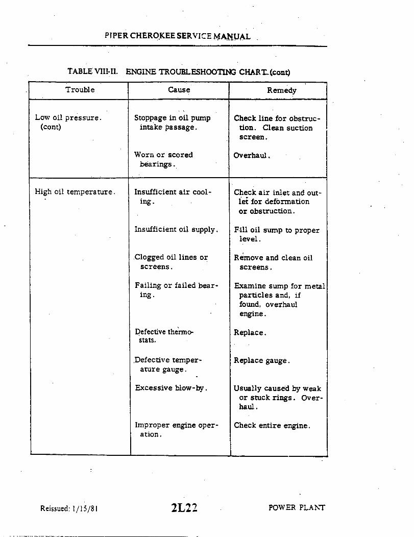
PIPER CHEROKEE SERVICE MANUAL
TABLE VIII-II.
Trouble
ENGINE TROUBLESHOOTING CHART(cont)
Cause Remedy
Low oil pressure.(cont)
Stoppage in oil pumpintake passage.
Check line for obstruc-tion. Clean suctionscreen.
Worn or scoredbearings.
High oil temperature. Insufficient air cool-ing.
Check air inlet and out-let for deformationor obstruction.
Insufficient oil supply.
Clogged oil lines orscreens.
Failing or failed bear-ing.
Defective thermo-stats.
Defective temper-ature gauge.
Excessive blow-by.
Improper engine oper-ation.
Fill oil sump to properlevel.
Remove and clean oilscreens.
Examine sump for metalparticles and, iffound, overhaulengine.
Replace.
Replace gauge.
Usually caused by weakor stuck rings. Over-haul.
Check entire engine.
POWER PLANTReissued: 1/15/81
Overhaul.
2L22

CHEROKEE
SERVICE MANUALCARD 3 OF 4
PA-28-140
PA-28-150
PA-28-160
PA-28-180
PA-28-235
PA-28R-180
PA-28R-200
PIPER AIRCRAFT CORPORATION
(PART NUMBER 753 586) 3A1

PIPER CHEROKEE SERVICE MANUAL
AEROFICHE EXPLANATION AND REVISION STATUS
The Service Manual information incorporated in this set of Aerofiche cards has been arranged inaccordance with the general specifications of Aerofiche adopted by the General Aviation Manufacturer'sAssociation, (GAMA). The information compiled in this Aerofiche Service Manual will be kept current byrevisions distributed periodically. These revisions will supersede all previous revisions and will be completeAerofiche card replacements and shall supersede Aerofiche cards of the same number in the set.
Conversion of Aerofiche alpha/numeric code numbers:First number is the Aerofiche card number.Letter is the horizontal line reference per card.Second number is the vertical line reference per card.
Example: 2J16 = Aerofiche card number two of given set, Grid location J16.
To aid in locating the various chapters and related service information desired, the following is provided:
1. A complete manual Table of Contents is for all fiche in this set.2. A complete list of Illustrations is given and follows the Table of Contents.3. A complete list of Tables is given for all fiche in this set and follows the list of Illustrations.4. A complete list of paragraph titles and appropriate Grid location numbers is given at the beginning of
each Chapter relating to the information within that Chapter.5. Identification of Revised Material:
Revised text and illustrations are indicated by a black vertical line along the left-hand margin ofthe frame, opposite revised, added or deleted material. Revision lines indicate only current revisionswith changes and additions to or deletions of existing text and illustrations. Changes in capitalization,spelling, punctuation, indexing, the physical location of the material or complete page additions arenot identified by revision lines.
6. Revisions to this Service Manual 753 586 issued August 16, 1972 are as follows:
Effectivity Publication Date Aerofiche Card Effectivity
ORG720816 August 16, 1972 -CR810115 January 15, 1981 1, 2, 3 and 4PR810803 August 3, 1981 1, 2, 3 and 4PR831003 October 3, 1983 1, 2, 3 and 4PR840423 April 23, 1984 1, 2, 3 and 4PR860115 January 15, 1986 1 and 3IR860730 July 30, 1986 1IR870506* June 12,1987 1
This publication contains material revised as of January 15, 1986 (with two interim revisions effective July30, 1986 and May 6, 1987).
* INTERIM CHANGE
Revisions appear in Table III-I and Table III-II of card 1.There are no other changes included in this maintenancemanual. Please discard your current card 1 and replace it withthis revised one. DO NOT DISCARD CARDS 2, 3, or 4.
The date on Aerofiche cards should not be earlier than the date noted for the respective card effectivity.Consult the latest card in this series for current Aerofiche card effectivity.
3A2

NIIV
33
S3
. . . . . . . . . . .
L'ON O
S
8V
8
8
AIXIIIX
IIX
IX
X
X
VIIIA
III
VIIA
IIA
IA
A
Al
II
I
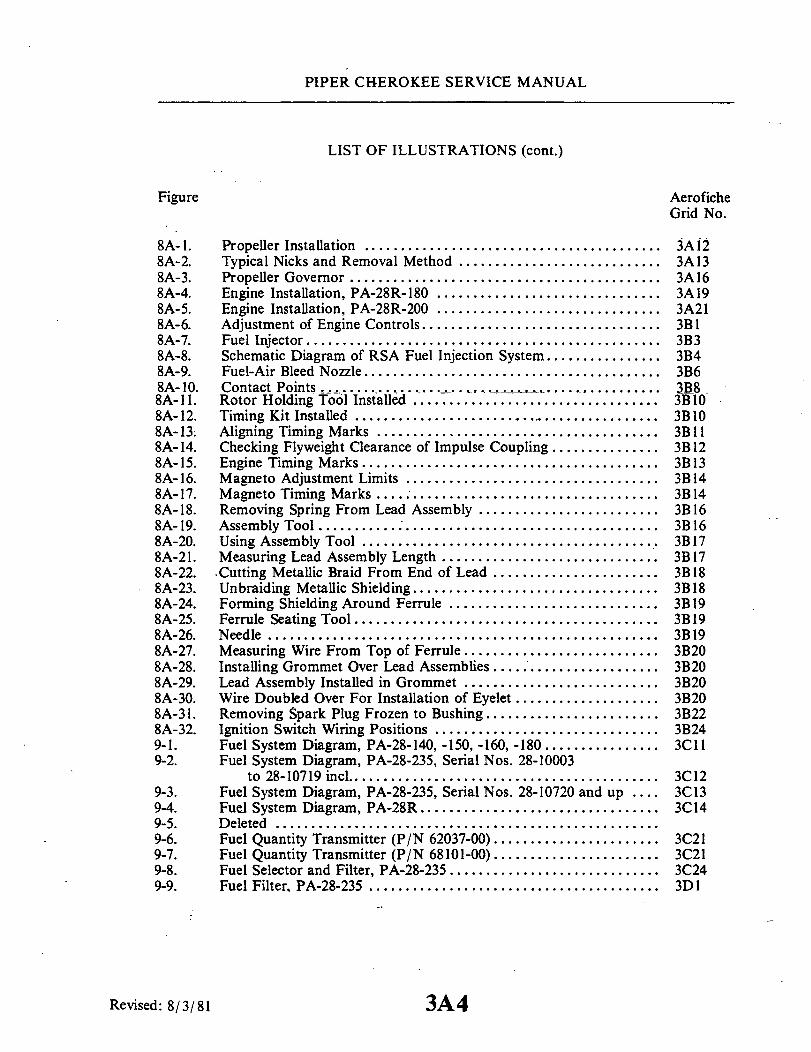
PIPER CHEROKEE SERVICE MANUAL
LIST OF ILLUSTRATIONS (cont.)
Figure AeroficheGrid No.
8A-1. Propeller Installation ........................................ 3A128A-2. Typical Nicks and Removal Method ............................ 3A138A-3. Propeller Governor ........................................... 3A168A-4. Engine Installation, PA-28R-180 ............................... 3A198A-5. Engine Installation, PA-28R-200 ............................... 3A218A-6. Adjustment of Engine Controls ................................. 3BI8A-7. Fuel Injector ................................................. 3B38A-8. Schematic Diagram of RSA Fuel Injection System ................ 3B48A-9. Fuel-Air Bleed Nozzle ......................................... 3B68A-10. Contact Points .......... ... ....... .......... ........... 3B88A-11. Rotor Holding Tool Installed .... .............................. 3B108A- 12. Timing Kit Installed .......................................... 3B108A-13. Aligning Timing Marks ....................................... 3B 118A-14. Checking Flyweight Clearance of Impulse Coupling ............... 3B 128A-15. Engine Timing Marks ..................... ................... 3B 138A- 16. Magneto Adjustment Limits ................................... 3B 148A-17. Magneto Timing Marks ........................ ............... 3B148A-18. Removing Spring From Lead Assembly ......................... 3B168A-19. Assembly Tool ............................................... 3B168A-20. Using Assembly Tool ...................................... . 3B 178A-21. Measuring Lead Assembly Length .............................. 3B 178A-22. Cutting Metallic Braid From End of Lead ....................... 3B 188A-23. Unbraiding Metallic Shielding .................................. 3B 188A-24. Forming Shielding Around Ferrule ............................. 3B198A-25. Ferrule Seating Tool .......................................... 3B198A-26. Needle ...................................................... 3B198A-27. Measuring Wire From Top of Ferrule ........................... 3B208A-28. Installing Grommet Over Lead Assemblies ....................... 3B208A-29. Lead Assembly Installed in Grommet ........................... 3B208A-30. Wire Doubled Over For Installation of Eyelet .................... 3B208A-31. Removing Spark Plug Frozen to Bushing ........................ 3B228A-32. Ignition Switch Wiring Positions ...................... ......... 3B249-1. Fuel System Diagram, PA-28-140, -150, -160, -180 ................ 3C119-2. Fuel System Diagram, PA-28-235, Serial Nos. 28-10003
to 28-10719 incl ........................................... 3C129-3. Fuel System Diagram, PA-28-235, Serial Nos. 28-10720 and up .... 3C139-4. Fuel System Diagram, PA-28R ................................. 3C149-5. Deleted .....................................................9-6. Fuel Quantity Transmitter (P/N 62037-00) ....................... 3C219-7. Fuel Quantity Transmitter (P/N 68101-00) ....................... 3C219-8. Fuel Selector and Filter, PA-28-235 ............................. 3C249-9. Fuel Filter, PA-28-235 ........................................ 3D I
Revised: 8/3/81 3A4

PIPER CHEROKEE SERVICE MANUAL
LIST OF ILLUSTRATIONS (cont.)
Fuel Filter Bowl and Screen (PA-28-140, -150, -160, -180and PA-28R) ..............................
Plunger Fuel Pump (Early), PA-28-150, -160, -180 ..........Plunger Fuel Pump (Late), PA-28-140, -150, -160, -180,
-235 . . . . . . . . . . . . . . . . . . . . . . . . . . . . . . .Engine Primer ...............................Fabricated Fuel Quantity Transmitter Checking Jig ..........Instrument Panel, PA-28-140, Serial Nos. 28-25000 to
28-26956 incl. ............................Instrument Panel, PA-28-140, Serial Nos. 28-7125001 to
28-7325684 incl ...........................Instrument Panel, PA-28-140, Serial Nos. 28-7425001
and up .. ... ... .. . ... . .. ... ... ... ... . .. .Instrument Panel ..............................Instrument Panel, PA-28-150, -160, -180, Serial Nos.
28-1761 to 28-4377 incl .......Instrument Panel, PA-28-180, Serial Nos.
28-7205328 incl . ..........Instrument Panel, PA-28-180, Serial Nos.
28-7305611 incl . ..........Instrument Panel, PA-28-180, Serial Nos.Instrument Panel, PA-28-235, Serial Nos.
28-11039 incl..............Instrument Panel, PA-28-235, Serial Nos.
28-7210033 incl . ..........Instrument Panel, PA-28-235, Serial Nos.
28-7310187 incl . ..........Instrument Panel. PA-28-235, Serial Nos.
284378 to
28-7305001 to
28-7405001 and up ...28-10720 to. . . . . . . . . . . . . . . .
28-11040 to· .. . .. . . . . . . . . ..
28-7310001 to
28-7410001 and up ....Instrument Panel, PA-28R-180, Serial Nos. 28-30005 to
28-30879 incl.............................Instrument Panel, PA-28R-180, Serial Nos. 28-30880 to
28-7130019 incl.; PA-28R-200, Serial Nos. 28-30482,28-35001 to 28-35830 incl. and 28-7135001 to28-7135238 incl . ..........................
Instrument Panel, PA-28R-200, Serial Nos. 28-7235001 to28-7335455 incl . ..........................
Instrument Panel. PA-28R-200. Serial Nos. 28-7435001 and up . . .Warning Light Pressure Switch ......................Typical Pitot Static System, PA-28-140,-150,-160, -180,-235,
PA-28R-180 and 200 .........................EGT Probe Location (PA-28R-180 and 200) ....................EGT Probe Location (PA-28-235) .............................EGT Probe Location (PA-28-150/ 160/180) S/N 1761 and up . ...
AeroficheGrid No.
3D33D6
3D63D123D17
3E4
3E5
3E63E7
3E8
3E9
3E103E11
3E12
3E13
3E143E15
3E16
3E17
3E183E193E23
3F43 F243G13G2
Reissued: 1/15/81
Figure
9-10.
9-11.9-12.
9-13.9-14.10-1.
10-2.
10-3.
10-4.10-5.
10-6.
10-7..
10-8.10-9.
10-10.
10-11.
10-12.10-13.
10-14.
10-15.
10-16.10-17.10-18.
10-19.10-20.10-21.
3A5

PIPER CHEROKEE SERVICE MANUAL
LIST OF TABLES
Table
VIIIA-IIIA-I. Engine Troubleshooting Chart ...........IX-I. Transmitter/Fuel Gauge Tolerances ........IX-II. Fuel Quantity Transmitter Calibration TolerancesIX-III. Fuel System Troubleshooting .....X-I. Vacuum System ...................X-II. Directional Gyro Indicator .............X-III. Gyro Horizon Indicator ...............X-IV. Rate of Climb Indicator ...............X-V. Altimeter ...........X-VI. Airspeed Tubes and Indicator .....X-VII. Magnetic Compass ........... ......X-VIII. Manifold Pressure Indicator ............X-IX. Tachometer......................X-X. Engine Oil Pressure Gauge ......X-XI. Fuel Pressure Gauge .................X-XII. Turn and Bank Indicator ..............X-XIII. Fuel Quantity Indicators ... ...... .....X-XIV. Oil Temperature Indicators ...... ......X-XV. Troubleshooting EGT Gauge ............X-XVI. Cylinder Head Temperature Gauge ...X-XVII. Fuel Flow Gauge .................
AeroficheGrid No.
. ... . .. . .. 3C1
. .. . . .. . .. . 3C20
. . .. . . . ... . 3C21
. ... .. . . .. . 3D 15
. ... . . . ... . 3D24
. . .. ... ... . 3F5
. ... .. . ... . 3F7
. ... . .. . .. . 3F8
. . .. . .. .. .. 3F10
. ... .. . .. .. 3F12
. ... .. . .. . . 3F 14
. .. . . .. ... . 3F15
. ... .. . . .. . 3F 16
. ... . . . ... . 3F17
. .. . . .. ... . 3F18
. ... . . . ... . 3F19
. ... ... ... . 3F20
. . .. .. . .. . . 3F21
. . .. . .. ... . 3F23. .. .. . ... .. 3G 3... . .. . .... 3G4
Reissued: 1/15/81 3A6

3A7INTENTIONALLY LEFT BLANK

PIPER CHEROKEE SERVICE MANUAL
SECTION VIIIAPOWER PLANT
(PA-28R)
Paragraph AeroficheGrid No.
8A-1. Introduction ................................................. 3A108A-2. Description ............................................... 3A108A-3. Troubleshooting .............................................. 3A108A-4. Propeller .................................................... 3A11
8A-5. Removal of Propeller ................................ 3A118A-6. Cleaning, Inspection and Repair of Propeller ............ 3A118A-7. Installing Propeller .................................. 3A138A-8. Blade Track ......................................... 3A14
8A-9. Propeller Governor ........................................... 3A148A-10. Removal of Propeller Governor ....................... 3A148A- 11. Installation of Propeller Governor ..................... 3A148A-12. Rigging and Adjustment of Propeller Governor.......... 3A15
8A-13. Engine ...................................................... 3A168A-14. Removal of Engine ................. .............. 3A168A-15. Installation of Engine ................................ 3A17
8A-16. Installation of Oil Cooler ..................................... 3A248A-17. Adjustment of Throttle and Mixture Controls .................... 3B 18A-18. Induction Air Filter. .......................................... 3B28A-19. Alternate Air Door ........................................... 3B28A-20. Fuel Injector ................................................ 3B3
8A-21. Fuel Injector Maintenance ............................ 3B38A-22. Adjustment of Idle Speed and Mixture .......................... 3B58A-23. Fuel Air Bleed Nozzle ......................................... 3B6
8A-24. Removal of Fuel-Air Bleed Nozzle ..................... 3B68A-25. Cleaning and Inspection of Fuel-Air Bleed
Nozzle ........................................ 3B68A-26. Installation of Fuel-Air Bleed Nozzle ................... 3B6
8A-27. Ignition System Maintenance .................................. 3B78A-28. Magneto .................................................... 3B7
8A-29. Inspection of Magneto ............................... 3B78A-30. -Removal of Magneto ................................. 3B98A-31. Timing Procedure (Internal Timing) .................... 3B98A-32. Installation and Timing Procedure (Timing
Magneto to Engine) .............................. 3B 12
Reissued: 1/15/81 3A8
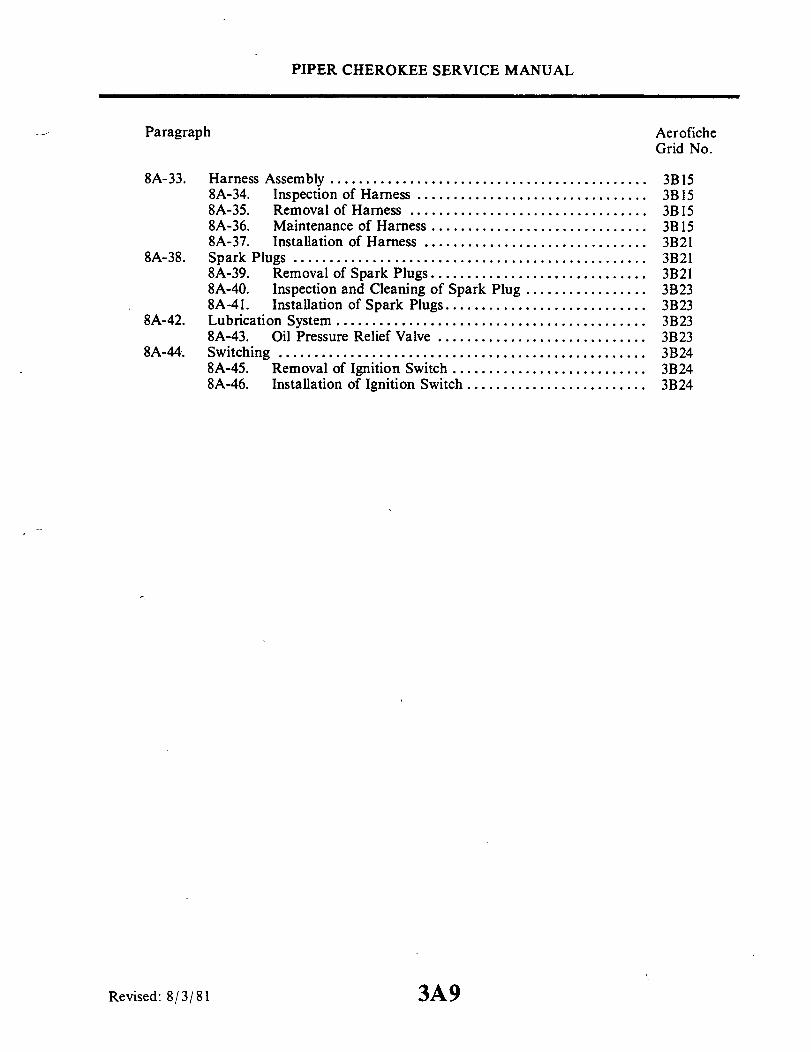
PIPER CHEROKEE SERVICE MANUAL
Paragraph AeroficheGrid No.
8A-33. Harness Assembly ............................................ 3B 158A-34. Inspection of Harness ................................ 3B 158A-35. Removal of Harness ................................. 3B158A-36. Maintenance of Harness .............................. 3B158A-37. Installation of Harness ...................... ......... 3B21
8A-38. Spark Plugs ................................................. 3B218A-39. Removal of Spark Plugs .............................. 3B218A-40. Inspection and Cleaning of Spark Plug ................. 3B238A-41. Installation of Spark Plugs ............................ 3B23
8A-42. Lubrication System ........................................... 3B238A-43. Oil Pressure Relief Valve ............................. 3B23
8A-44. Switching ............................... .................... 3B248A-45. Removal of Ignition Switch ..... ...................... 3B248A-46. Installation of Ignition Switch ......................... 3B24
Revised: 8/3/81 3A9

PIPER CHEROKEE SERVICE MANUAL
SECTION VIIIA
POWER PLANT(PA-28R)
8A-1. INTRODUCTION. This section covers the power plant used in PA-28R-180 airplanesand is comprised of instructions for the removal, minor repair, service and installation of thepropeller, propeller governor, engine, induction system, fuel injector, fuel air bleed nozzle,ignition system and lubrication system.
For further instructions on major repairs, consult the appropriate publication of theengine or component manufacturer.
8A-2. DESCRIPTION. The PA-28R-180 is powered by an Avco-Lycoming IO-360-B1Eengine of 180 horsepower and the PA-28R-200 is powered by an Avco-LycomingIO-360-C1C engine of 200 horsepower. (Refer to Power Plant Specifications in Table II-I.)The engines are furnished with starters, 60 ampere, 14-volt alternators, voltage regulators,shielded ignition systems, vacuum pump drive, fuel pump, fuel injector and dry paper typeinduction air filter. An alternate air door that will open automatically in the event of airstoppage through the filter or may be operated manually with the use of a control in thecockpit is provided in the induction system.
The exhaust system is constructed of stainless steel, directing gases inboard to a mufflerlocated directly under the engine. The large muffler with a heater shroud provides heat forboth the cabin and defrosting.
The engines are provided with a constant speed propeller controlled by a governormounted on the engine supplying oil through the propeller shaft at various pressures.
Service of both engines is identical and wherever there is any difference in serviceinstructions it will be so noted.
8A-3. TROUBLESHOOTING. Troubles peculiar to the power plant are listed in TableVIIIA-I along with their probable causes and suggested remedies. When troubleshooting theengine, ground the magneto primary circuit before performing any checks of the engine.
POWER PLANTReissued: 1/15/81 3A10

PIPER CHEROKEE SERVICE MANUAL
8A-4. PROPELLER.
8A-5. REMOVAL OF PROPELLER.a. Insure master and magneto switches are off.b. Move fuel selector to off position.c. Place mixture control in idle cut-off.d. Note position of components to facilitate reinstallation.e. Remove screws from the spinner assembly and remove spinner.f. Remove the-safety wire from the six propeller mounting nuts on studs and
remove studs.g. Place a drip pan under propeller to catch oil spillage, remove propeller.
8A-6. CLEANING, INSPECTION AND REPAIR OF PROPELLER.a. Check for oil and grease leaks.b. Clean the spinner, propeller hub interior and exterior, and blades with a
non-corrosive solvent.c. Inspect the hub parts for cracks.d. Steel hub parts should not be permitted to rust. Use aluminum paint to
touch up if found necessary.e. Check all visible parts for wear and safety.f. Check blades to determine whether they turn freely on the hub pivot tube.
This can be done by rocking the blades back and forth through the slight freedomallowed by the pitch change mechanism. If they appear tight and are properlylubricated, the pitch change mechanism should be removed so that -each blade canbe checked individually. If blades are tight, the propeller should be disassem-bled.
g. Inspect blades for damage or cracks. Nicks in leading edges of bladesshould be filed out and all edges rounded, as cracks sometimes start from suchplaces. Use fine emery cloth for finishing. Refer to Figure 8A-2 for propellerblade care.
h. It is recommended that for severe damage, internal repairs and replace-ment of parts, the propeller should be referredto the Hartzell Factory or ServiceStation.
i. Grease blade hub through zerk fittings. Remove one of the two fittings foreach propeller blade, alternate the next time. Apply grease through the zerk fit-ting until fresh grease appears at the fitting hole of the removed fitting. Careshould be taken to avoid blowing out hub gaskets.
j . Checkconditionof propeller mounting nuts on studs,
Reissued: 1/15/81 POWER PLANT3All

PIPER CHEROKEE SERVICE MANUAL
1801
1. LOW PITCH STOP2. JAM NUT3. PROPELLER HUB4. SPINNER5. PROPELLER BLADE6. SPINNER BACK PLATE7. STARTER RING8. "O" RING SEAL9. GREASE FITTING
10. WASHERII. NUT12. SAFETY WIRE13. STUD14. NUT, FLYWHEEL
Figure 8A-1. Propeller Installation
3A12Reissued: 1/15/81 POWER PLANT
\14

PIPER CHEROKEE SERVICE MANUAL
C345
Exaggerated view of nicksin leading edge.
Recommended method for removingnicks by riffle file and crocus cloth.Blend deepest portion of nick intoleading edge alignment with smoothcurves.
A
Exaggeratein face of blade
A
I view of nickblade
SECTION AA-Nick in face of blade
removed by file andcrocus cloth as recom-mended
Figure 8A-2 Typical Nicks and Removal Method
8A-7. INSTALLING PROPELLER.a. Insure master and magneto switches are off.b. Place fuel selector to off position.c. Place mixture control in idle cut-off.d. Observe the starter ring gear to make sure it is mounted properly on the
engine crankshaft flange. One of the bushings on the crankshaft is stamped withan "O" mark and it must be inserted in the starter ring gear hole, likewise iden-tified with an "O" mark.
e. Wipe crankshaftand propeller pilot to assure that no chips or foreign mat-ter enter the propeller mechanism.
f. Check interior of propeller hub for proper seating of "O" ring. Wipe in-side of hub to remove any traces of dirt. Check to see that "O" ring is coveredwith grease.
g. Raise propeller into position so that each stud mates with an engine flange.bushing, and screw each stud in a few turns at a time until all are tight. Torqueto 55 to 65 foot pounds.
h. Check the propeller blade track as given in paragraph 8A-8.
Revised: 10/3/83 3A13 POWER PLANT
PIPER CHEROKEE SERVICE MANUAL
i. Safety the propeller mounting bolts with MS20995-C41 safety wire.j. Install the spinner, torque cap bolts 35 to 40 inch pounds.
8A-8. BLADE TRACK. Blade track is the ability of one blade tip to follow theother, while rotating, in almost the same plane. Excessive difference in bladetrack - more than .0625 inch - may be an indication of bent blades or improperpropeller installation. Check blade track as follows:
a. With the engine shut down and blades vertical, secure to the aircraft asmooth board just under the tip of the lower blade. Move the tip fore and aftthrough its full "blade-shake" travel, making small marks with a pencil at eachposition. Then center the tip between these marks and scribe a line on the boardfor the full width of the tip.
b. Carefully rotatepropeller by hand to bring the opposite blade down. Centerthe tip and scribe a pencil line as before and check that lines are not separatedmore than .0625 inch.
c. Propellers having excess blade track should be removed and inspected forbent blades, or for parts of sheared "O" ring, or foreign particles, which havelodged between hub and crankshaft mounting faces. Bent blades will require re-pair and overhaul of assembly.
8A-9. PROPELLER GOVERNOR.
8A-10. REMOVAL OF PROPELLER GOVERNOR.a. Remove the upper engine cowl.b. Disconnect the control cable end from the governor control arm.c. Remove the governor mounting stud nuts. It will be necessary to raise the
governor as the nuts are being removed before the nuts can be completely re-moved.
d. Remove the mounting gasket. If the governor is to be removed for a con-siderable length of time and another unit not substituted, it is advisable to coverthe mounting pad to prevent damage caused by foreign matter.
8A-11. INSTALLATION OF PROPELLER GOVERNOR.a. Clean the mounting pad thoroughly, making very certain that there are no
foreign particles in the recess around the drive shaft.b. Place the governor mounting gasket in position with the raised portion of
the screen facing away from the engine.c. Align the splines on the governor shaft with the engine drive and slide the
Reissued: 1/15/81 POWER PLANT3A14

PIPER CHEROKEE SERVICE MANUAL
governor into position.d. With the governor in position, raise the governor enough to install wash-
ers and start mounting nuts. Torque nuts even.e. Connect the control cable end to the governor control arm. The ball stud
is installed in the inner hole of the control arm.f. Adjust governor control per paragraph 8A-12.g. Install engine cowl.
8A-12. RIGGING AND ADJUSTMENT OF PROPELLER GOVERNOR. (Refer toFigure 8A-3.)
a. Start engine, park 90° to wind direction and warm in normal manner.b. To check high RPM, low pitch setting, move the propeller control all the
way forward. At this position the governor speed control arm (1) should be againstthe high RPM fine adjusting screw (2). With the throttle full forward, observeengine RPM, which should be 2700 RPM with high RPM properly adjusted.
c. Should engine RPM not be as required, the high RPM setting should be ad-justed as follows:
1. Shut down the engine and remove the upper engine cowl.2. Adjust the governor by means of the fine adjustment screw (2) for 2700
RPM. To do this, loosen the high RPM fine adjustment screw lock nut and turnthe screw in a clockwise direction to decrease engine speed or in a counterclock-wise direction to increase engine speed.
NOTE
One revolution of the fine adjustment screw will in-crease or decreasethe engine speedapproximately 20RPM.
3. Reinstall upper engine cowl and repeat step b to ascertain proper RPMsetting.
4. After setting the proper high RPM adjustment, run the self-locking nuton the fine adjustment screw against the base projection to lock.
5. Ascertain that the governor control arm (1) is adjusted to the properangle on the control wheel (4) as shown in Figure 8A-3.
d. With the high RPM adjustment complete, the control system should be ad-justed so that the governor control arm will contact the high RPM stop when thecockpit control knob is .032 to .047 of an inch from its full forward stop. To ad-just the control knob travel, disconnect the control cable end from the controlarm, loosen the cable end jam nut and rotate the end to obtain the desired levelclearance. Reconnect the cable end and tighten jam nut.
Reissued: 1/15/81 POWER PLANT3A15

PIPER CHEROKEE SERVICE MANUAL
e. It is usually only necessary to ad- A617
just the high RPM (low pitch) setting ofthe governor control system, as the ac- 5 5 / 3tion automatically takes care of the pos-itive low RPM (high pitch) setting.
8A-13. ENGINE.
8A -14. REMOVAL OF ENGINE.a. Turn off all electrical switches
in the cockpit and then disconnect the 1 . CONTROL ARM2. RPM ADJUSTMENT SCREWbattery ground wire at the battery. 3. LOCK NUT
b. Move the fuel selector lever in 4. CONTROL WHEEL5. BOLT ASSEMBLY
the cockpit to "OFF".c. Remove the engine cowlingby the Figure 8A -3. Propeller Governor
following procedure:1. Release the cowl fasteners, two on each side of the cowl.2. Lift the aft end of the cowl and then slide it forward to release the two
stud type front fasteners. Remove the top cowl.3. Disconnect thelanding light lead at the quickdisconnect at the left rear
side of the bottom cowl.4. Disconnect the nose gear door rods by removing the nuts, washers, and
bolts.5. Remove the screws securing the bottom cowl at its aft end. Remove the
bottom cowl.d. Remove the propeller. (Refer to Paragraph 8A-5.)e. Disconnect the starter positive and ground leads at the starter, and their
attachment clamps.f. Disconnect thegovernor control cable at the governor and cable attachment
clamps.g. Disconnect the heater hose at the muffler.h. Disconnect the throttle and mixture cables at the injector. (The injector
may be removed if desired.)d.i . Remove the air filter box by removing the bolts that secure the box to its
attachment clamps. The cover may remain attached to the alternate air doorcontrol cable.
j. Disconnect the fuel pump supply line at the left side of the pump. Discon-nect the pump vent line.
Reissued: 1/15/81 POWER PLANT3A16

PIPER CHEROKEE SERVICE MANUAL
NOTE
Where a question may arise as where to reconnecthose, line or wire, the item at the separation shouldbe identified (tagged) to facilitate reinstallation. Openfuel, oil, vacuum lines and fittings should be coveredto prevent contamination.
k. Disconnect both lines from the oil cooler.1. Disconnect the magneto "P" leads at the magnetos.
m. Disconnect the engine vent tube at the engine.n. Disconnect the engine oil temperature lead at the aft end of the engine.o. Disconnect the tachmeter drive cable at the engine.p. Untie the ignition harness, hoses and lines at the aft end of the engine.q. Disconnect the vacuum pump lines at pump and remove fittings from pump.r. Disconnect the oil pressure line at the engine.s. Disconnect the static and fuel flow line at the right rear engine baffle.t. Disconnect the manifold pressure line at the right rear side of the engine.u. Disconnect the injector line at the flow divider.v. Disconnect the alternator leads and the cable attachment clamps.w. Attach a one-half ton (minimum) hoist to the hoisting straps and relieve the
tension from the engine mounts.
NOTE
Place a tail stand under the tail of the airplane beforeremoving the engine.
x. Check the engine for any attachments remaining to obstruct its removal.y. Drain the engine oil, if desired, and then close drain.z. Remove the four engine mount assemblies and swing the engine free, being
careful not to damage any attaching parts.
8A-15. INSTALLATION OF ENGINE.a. Attach a one-half ton (minimum) hoist to the engine hoisting straps and
swing the engine into alignment with its attaching points.b. Insert an engine mount bolt, with washer against head, in the engine mount
and slide half of the mount assembly on the bolt. Repeat this procedure for theother three attachment points. (Refer to Figure 8A-4.)
c. Position the mounting lugs of the engine so that they align with the enginemount attaching points, then move the engine rearward onto the mounts.
Reissued: 1/15/81 POWER PLANT3A17

3A18INTENTIONALLY LEFT BLANK

PIPER CHEROKEE SERVICE MANUAL
1727
NOTE: A maximum of (3)AN960-616 washers can beused to permit a maximum of2.5 threads exposed on thebolt. Torque to 230/240inch-pounds.
3 4 5 6 7 8 9 10 11
Section A-A
1. AIR FILTER BOX2. BAFFLE ASSEMBLY, LEFT3. MAGNETO, LEFT4. OIL TEMPERATURE LEAD5. VACUUM PUMP6. TACHOMETER CABLE7. ENGINE MOUNT ASSEMBLY8. MAGNETO, RIGHT
9. SHOCK MOUNT (SEE SKETCH A)10. FLOW DIVIDER11. OIL FILLER12. LIFTING STRAP13. STARTER RING GEAR14. OIL FILTER15. PROPELLER GOVERNOR16. INJECTOR INLET HOSE
17. FUEL INJECTOR18. OIL COOLER INLET HOSE (180 ONLY)
19. MANIFOLD PRESSURE LINE
20. BAFFLE ASSEMBLY, RIGHT
21. SPARK PLUGS22. INJECTOR NOZZLE23. INTAKE TUBE
24. EXHAUST STACK
25. BOLT26. WASHER27. SPACER28. SHOCK MOUNT (SILVER CODING)29. SHOCK MOUNT (GOLD CODING)30. ENGINE MOUNT ASSEMBLY31. ENGINE .
Figure 8A-4.- Engine Installation (PA-28R-180)
3A19
I
Reissued: 1/15/81 POWER PLANT

PIPER CHEROKEE SERVICE MANUAL
C311
NOTE
REFER TO PIPER SERVICE LET-TER NO. 910 ON OIL QUICKDRAIN INSTALLATION
VIEW AA VIEW BB
Figure 8A-4. Engine Installation (PA-28R-180) (cont.)
POWER PLANTRevised: 10/3/83
SKETCH A
3A20

PIPER CHEROKEE SERVICE MANUAL
17051. STARTER RING GEAR
2. FLOW DIVIDER3. LIFTING STRAP4. SHOCK MOUNT (SEE SKETCK A)5. INJECTOR NOZZLE6. OIL FILTER7. BAFFLE ASSEMBLY, RIGHT8. TACHOMETER CABLE9. VACUUM PUMP
10. MAGNETO, RIGHT11. OIL FILLER12. MANIFOLD PRESSURE LINE
13. PROPELLER GOVERNOR14. ENGINE MOUNT ASSEMBLY15. EXHAUST STACK16. SPARK PLUG
17. INTAKE TUBE18. BAFFLE ASSEMBLY, LEFT19. MAGNETO, LEFT
20. AIR FILTER BOX
21. FUEL PUMP22. FUEL INJECTOR23. OIL TEMPERTURE LEAD24. INJECTOR INLET HOSE
25. BOLT26. WASHER
27. SPACER28. SHOCK MOUNT (SILVER CODING)29. SHOCK MOUNT (GOLD CODING)30. ENGINE MOUNT ASSEMBLY31. ENGINE
NOTE: A maximum of (3) AN960616washers can be used to permit a max. of25 threads exposed on the bolt. Torqueto 230/240 inch-pounds.
Figure 8A-5. Engine Installation (PA-28R-200)
3A21Reissued: 1/15/81 POWER PLANT
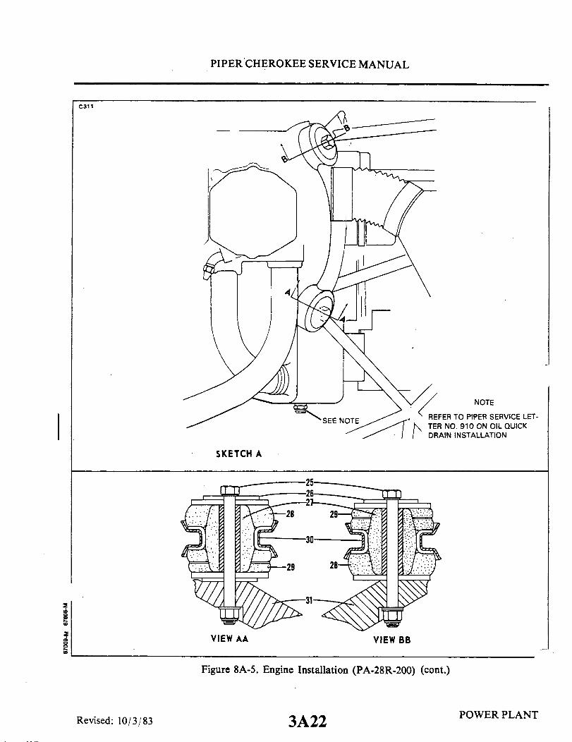
PIPER CHEROKEE SERVICE MANUAL
C311
NOTE
REFER TO PIPER SERVICE LET-TER NO. 910 ON OIL QUICKDRAIN INSTALLATION
SKETCH A
VIEW AA VIEW BB
Figure 8A-5. Engine Installation (PA-28R-200) (cont.)
Revised: 10/3/83POWER PLANT3A22
2
I
PIPER CHEROKEE SERVICE MANUAL
d. Slide onto each mounting bolt a spacer washer, spacer and the forward half of themount. Install washer and nut, and torque the nuts of the bolts to 450 to 500 inch pounds.
e. Connect the alternator leads and secure cable with clamps.f. Connect the injector line to the flow divider.g. Connect the manifold pressure line at the right rear side of the engine.h. Connect the static and fuel flow line at the right rear engine baffle.i. Connect the oil pressure line.j. Install the line fitting in the vacuum pump and install lines.k. Connect the tachometer drive cable.1. Connect the oil temperature lead.m. Connect the engine vent tube.n. Connect the oil cooler.o. Connect the magneto "P" leads. Check that magneto switch is "OFF."p. Connect the fuel pump supply and vent line.q. Install the injector.r. Connect the throttle and mixture cables to the injector. Check adjustment of the
control by referring to paragraph 8A-17.s. Connect the heater hose to the muffler.t Install the air filter box, filter and box cover. Check adjustment of the alternate air
door by referring to Paragraph 8A-19.u. Connect the governor control cable and secure with clamps.v. Connect the starter positive and ground leads and secure cables with clamps.w. Secure the ignition harness, lines, hoses, wires, etc. that may be loose.x. Install the propeller. (Refer to Figure 8A-8.)y. Install the cowling by attaching the bottom cowl to the firewall and then installing
the top. Connect the electrical lead to the landing light.z. Connect the gear door retraction rods and secure with bolts, washers and nut.aa. Install the proper grade and amount of engine oil.ab. Turn on the fuel valve; open the throttle full and turn on the electric fuel pump.
Check the fuel lines for leaks.
NOTE
To avoid a possible high speed bearing failure resulting from alack of lubrication during initial starts, refer to the latestrevision of Avco-Lycoming Service Instruction No. 1241 forinformation on pre-oiling the engine.
ac. Perform an engine operational check.
POWER PLANTReissued: 1/15/81 3A23
PIPER CHEROKEE SERVICE MANUAL
8A-16. INSTALLATION OF OIL COOLER.a. When installing fittings in the oil coolers, care should be used to prevent excessive
torque being applied to the cooler. When a rectangular fitting boss is provided, a backupwrench should be used, employing a scissor motion, so that no load is transmitted to thecooler. When the oil cooler has a round fitting boss, care should be taken not to permitexcessive torque on the fittings.
b. If a pipe thread fitting is used, it should be installed only far enough to seal withsealing compound.
c. Apply Lubon No. 404 to all male pipe thread fittings; do not allow sealant to enterthe system.
d. If fitting cannot be positioned correctly using a torque of 10 to 15 foot-pounds,another fitting should be used.
e. When attaching lines to the cooler, a backup wrench should be used.f. After installation, inspect the cooler for distorted end cups.g. Run-up engine. After run-up, check for oil leaks.
THIS SPACE INTENTIONALLY LEFT BLANK
POWER PLANTReissued: 1/15/81 3A24

PIPER CHEROKEE SERVICE MANUAL
890
COCKPITCONTROLS
0.010 TO 0.030
STOP
Figure 8A-6. Adjustment of Engine Controls
8A-17. ADJUSTMENT OF THROTTLE AND MIXTURE CONTROLS. (Refer to Figure8A-6.) Throttle and mixture controls are adjusted so that when the throttle arm on thecarburetor is rotated forward against its full throttle stop and the mixture control is rotatedforward against its full rich stop, the cockpit control levers of the throttle and mixtureshould have 0.010 to 0.030 of an inch spring back on instrument panel stop when in fullthrottle or full rich position.
a. The throttle may be adjusted as follows:1. At the carburetor, disconnect the clevis end of the throttle control cable from
the control arm. Loosen the jam nut that secures the clevis end.2. Adjust the linkage by rotating the clevis end on the cable to obtain 0.010 to
0.030 of an inch spring back on instrument panel stop when in full throttle position.3. On PA-28R aircraft equipped with air conditioning systems, a micro switch is
located below the throttle control which is set to actuate in the full open position. With thethrottle control adjusted to obtain a clearance of .010 to .030, adjust the micro switch toactuate at this point also.
4. Reconnect the clevis end to the control arm and safety.b. The mixture may be adjusted as follows:
1. At the carburetor, disconnect the clevis end of the mixture control cable fromthe control arm. Loosen the jam nut that secures the clevis end.
2. Adjust the linkage by rotating the clevis end on the cable to obtain 0.010 to0.030 of an inch spring back on the instrument panel stop when in full rich position.
3. Reconnect the clevis end to the control arm and safety.c. Check security of cable casing attachments.
Reissued: 1/15/81 POWER PLANT3B1

PIPER CHEROKEE SERVICE MANUAL
d. Pull the throttle and mixture levers in the cockpit full aft to ascertain that the idlescrew contacts its stop and the mixture control arm contacts its lean position. On 1975models and up, a mixture control lock is incorporated in the quadrant cover which preventsthe mixture control from being moved to the idle cutoff position inadvertently. The lockmust be depressed before the control can be moved completely aft. Ascertain that the lockoperates freely without any tendency to bind or hang up.
8A-18. INDUCTION AIR FILTER.a. The filter should be cleaned daily when operating in dusty conditions. If any holes
or tears are noticed, the filter must be replaced immediately.b. Remove the filter element and shake off loose dirt by rapping on a hard flat surface,
being careful not to damage or crease the sealing ends.
CAUTION
Never wash the filter element in any liquid or soak it in oil.Never attempt to blow off dirt with compressed air.
c. The filter housing can be cleaned by wiping with a clean cloth soaked in a suitabledry type solvent. When the housing is dry, reinstall and seal the filter element.
8A-19. ALTERNATE AIR DOOR. The alternate air door is located in the cover of thefilter box to provide a source of air to the engine should there be an air stoppage throughthe filter system. The following should be checked during inspection:
a. Check that air door seals are tight and hinge is secure.b. Ascertain that the spring tension of the door is tight enough to allow the door to
remain closed at full engine RPM, yet should there be an air stoppage, it will be drawn open.c. Actuate the door by pushing in on it with the fingers to determine that it is not
sticking or binding.d. Check the cockpit control cable for free travel.e. Check that when the control lever in the cockpit is in the open position, the cable is
adjusted to allow approximately .0625 to .125 of an inch between the actuating arm rollerand the door when fully closed.
POWER PLANT3B2Reissued: 1/15/81

PIPER CHEROKEE SERVICE MANUAL
A616
3
1. THROTTLE ARM2. IDLE MIXTURE ADJUSTMENT3. IDLE SPEED ADJUSTMENT4. FUEL SCREEN5. MIXTURE ARM
Figure 8A-7. Fuel Injector
8A-20. FUEL INJECTOR.
8A-21. FUEL INJECTOR MAINTENANCE.a. In general, little attention is required between injector overhauls. However, it is
recommended that the following items be checked during periodic inspection of the engine.1. Check tightness and lock of all nuts and screws which fasten the injector to the
engine, torquing all nuts to 135-150 inch-pounds.2. Seat the pal type locknuts and finger tighten them against the plain nuts. After
this has been done tighten the locknuts an additional 1/3 to 1/2 turn.3. Check all fuel lines for tightenss and evidence of leakage. A slight fuel stain
adjacent to the air bleed nozzles is not cause for concern.4. Check throttle and mixture control rod ends and levers for tightness and lock.5. Remove and clean the injector inlet strainer at the first 25 hours of operation
and each 50 hour inspection thereafter. Check the screen for distortion or openings in thestrainer. Replace for either of these conditions. Clean screen assembly in solvent and drywith compressed air. Damaged strainer "O"rings should be replaced. To install the screenassembly, place the gasket on the screen assembly and install the assembly in the throttlebody and tighten to 35-40 inch-pounds torque.
Reissued: 1/15/81 3B3 POWER PLANT

PIPER CHEROKEE SERVICE MANUAL
C348
1/8 INCH O.D. STAINLESSSTEEL LINE
NOZZLE(ONE PER CYLINDER)
FLOW DIVIDER VALVE
FUEL INLET STRAINER
SECTION- AA
IDLE VALVE LEVERCONNECTED TOTHROTTLE LEVERLINKAGE
MANUAL MIXTURECONTROL AND IDLECUT-OFF LEVER
CONSTANT HEADIDLE SPRING
CONSTANT EFFORTSPRINGAIR DIAPHRAGM
FUEL DIAPHRAGMBALL SERVO VALVE
I
It
' IDLE SPEEDADJUSTMENT
. ' I- -
IMPACT TUBE
AIR INLETI
Figure 8A-8. Schematic Diagram of RSA Fuel Injection System
3B4
\\
\\\\
\\\\\\
Reissued: 1/15/81 POWER PLANT

PIPER CHEROKEE SERVICE MANUAL
8A-22. ADJUSTMENT OF IDLE SPEED AND MIXTURE.a. Start the engine and warm up in the usual manner until oil and cylinder head
temperatures are normal.b. Check magnetos. If the "mag-drop" is normal, proceed with idle adjustment.c. Set throttle stop screw so that the engine idles at 550-600 RPM. If the RPM changes
appreciable after making the mixture adjustment during the succeeding steps, readajust theidle speed to the desired RPM.
d. When the idling speed has been stabilized, move the cockpit mixture control leverwith a smooth, steady pull toward the "Idle-Cut-Off" position and observe the tachometerfor any change during the leaning process. Caution must be excerised to return the mixturecontrol to the "Full Rich" position before the RPM can drop to a point where the enginecuts out. An increase of more than 10 RPM while "leaning out" indicates an excessively richidle mixture. An immediate decrease in RPM (if not preceded by a momentary increase)indicates the idle mixture is too lean.
e. If the above indicates that the idle adjustment is too rich or too lean, turn the idlemixture adjustment in the direction required for correction, and check this new position byrepeating the above procedure. Make additional adjustments as necessary until a checkresults in a momentary pick-up of approximately 5 (never more than 10) RPM. Each timethe adjustment is changed, the engine should be run up to 2000 RPM to clear the enginebefore proceeding with the RPM check. Make final adjustment of the idle speed adjustmentto obtain the desired idling RPM with closed throttle. The above method aims at a settingthat will obtain maximum RPM with minimum manifold pressure. In case the setting doesnot remain stable, check the idle linkage; any looseness in this linkage would cause erraticidling. In all cases, allowance should be made for the effect of weather conditions and fieldaltitude upon idling adjustment.
THIS SPACE INTENTIONALLY LEFT BLANK
Reissued: 1/15/81 3B5 POWER PLANT
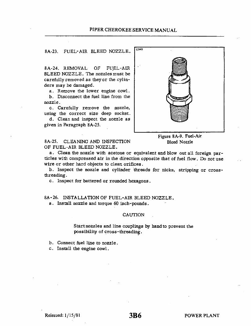
PIPER CHEROKEE SERVICE MANUAL
8A-23. FUEL-AIR BLEED NOZZLE.
8A-24. REMOVAL OF FUEL-AIRBLEED NOZZLE. The nozzles must becarefully removed as they or the cylin-ders may be damaged.
a. Remove the lower engine cowl.b. Disconnect the fuel line from the
nozzle.c. Carefully remove the nozzle,
using the correct size deep socket.d. Clean and inspect the nozzle as
given in Paragraph 8A-25.
Figure 8A-9. Fuel-Air8A-25. CLEANING AND INSPECTION Bleed NozzleOF FUEL-AIR BLEED NOZZLE.
a. Clean the nozzle with acetone or equivalent and blow out all foreign par-ticles with compressed air in the direction opposite that of fuel flow. Do not usewire or other hard objects to clean orifices.
b. Inspect the nozzle and cylinder threads for nicks, stripping or cross-threading.
c. Inspect for battered or rounded hexagons.
8A-26. INSTALLATION OF FUEL-AIR BLEED NOZZLE.a. Install nozzle and torque 60 inch-pounds.
CAUTION
Startnozzles and line couplings by handto prevent thepossibility of cross-threading.
b. Connect fuel line to nozzle.c. Install the engine cowl.
Reissued: 1/15/81 3B6 POWER PLANT

PIPER CHEROKEE SERVICE MANUAL
8A-27. IGNITION SYSTEM MAINTENANCE.
8A-28. MAGNETO.
CAUTION
Ascertain that the primary circuit of both magnetosis grounded before working on the engine.
8A-29. INSPECTION OF MAGNETO.a. After the first 25 hour and 50. hour periods, and periodically thereafter,
the contact assemblies should be checked. Examine the points for excessivewear or burning. Points which have deep pits or excessively burned areas shouldbe discarded. Examine the cam follower felt for proper lubrication. If neces-sary, points can be cleaned by using any hard finished paper. Clean breakercompartment with dry cloth.
b. If engine operating troubles develop which appear to be caused by the igni-tion system, it is advisable to check the spark plugs and wiringfirst beforework-ing on the magnetos.
c. Should the trouble appear definitely associated with the magneto, the mosteffective measure is to install a replacement magneto which is known to be insatisfactory condition and send the suspected unit to the overhaul shop for testand repair.
d. Should this not be possible, a visual inspection may disclose the source oftrouble. Remove the harness outlet plate from the magneto. Inspect for thepresence of moisture and foreign matter on the rubber grommet and high tensionoutlet side of the distributor block. Check height of block contact springs, (0.422maximum from top of the block tower to the spring). Also check for broken leadsor damaged insulation. If either is present, remove magneto and replace withone known to be in satisfactory condition.
e. Remove the breaker cover and harness securing screws and nuts, and sep-arate cover from magneto housing. Check contact assemblies to see that camfollower is securely riveted to its spring. Examine the contact points for ex-cessive wear or burning. Figure 8A-10 shown how the average contact point willlook when surfaces are separated for inspection. Desired contact surfaces havea dull gray, sand-blasted (almost rough) or frosted appearance, over the areawhere electrical contact is made. This means that points are worn in and matedto each other, thereby providing the best possible electrical contact and highestefficiency of performance.
f . Minor irregularities or roughness of point surfaces are not harmful (Refer
Reissued: 1/15/81 3B7 POWER PLANT
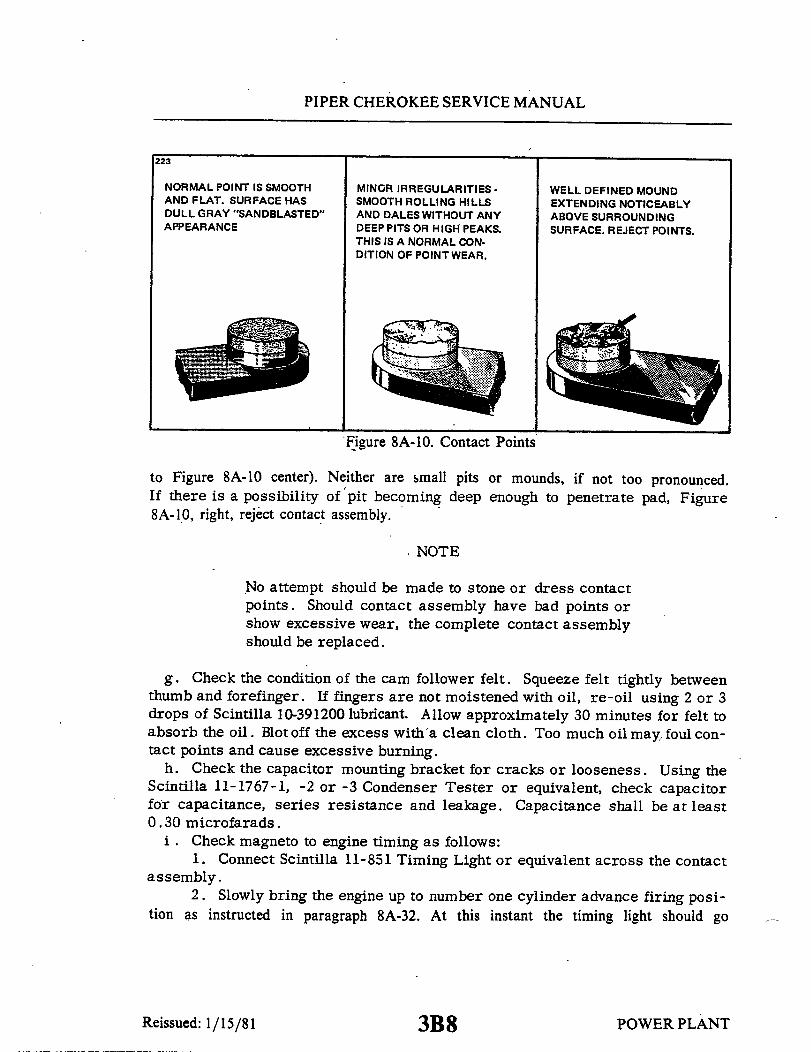
PIPER CHEROKEE SERVICE MANUAL
223
NORMAL POINT IS SMOOTH MINOR IRREGULARITIES - WELL DEFINED MOUNDAND FLAT. SURFACE HAS SMOOTH ROLLING HILLS EXTENDING NOTICEABLYDULL GRAY "SANDBLASTED" AND DALES WITHOUT ANY ABOVE SURROUNDINGAPPEARANCE DEEP PITS OR HIGH PEAKS. SURFACE. REJECT POINTS.
THIS IS A NORMAL CON-DITION OF POINTWEAR.
Figure 8A-10. Contact Points
to Figure 8A-10 center). Neither are small pits or mounds, if not too pronounced.If there is a possibility of pit becoming deep enough to penetrate pad, Figure8A-10, right, reject contact assembly.
NOTE
No attempt should be made to stone or dress contactpoints. Should contact assembly have bad points orshow excessive wear, the complete contact assemblyshould be replaced.
g. Check the condition of the cam follower felt. Squeeze felt tightly betweenthumb and forefinger. If fingers are not moistened with oil, re-oil using 2 or 3drops of Scintilla 10-391200 lubricant. Allow approximately 30 minutes for felt toabsorb the oil. Blot off the excess with a clean cloth. Too much oil may, foul con-tact points and cause excessive burning.
h. Check the capacitor mounting bracket for cracks or looseness. Using theScintilla 11-1767-1, -2 or -3 Condenser Tester or equivalent, check capacitorfor capacitance, series resistance and leakage. Capacitance shall be at least0.30 microfarads.
i . Check magneto to engine timing as follows:1. Connect Scintilla 11-851 Timing Light or equivalent across the contact
assembly.2. Slowly bring the engine up to number one cylinder advance firing posi-
tion as instructed in paragraph 8A-32. At this instant the timing light should go
POWER PLANT3B8Reissued: 1/15/81
PIPER CHEROKEE SERVICE MANUAL
out. If it does, the magneto is properly timed to the engine. If the timing lightdoes not go out, removal of the magneto for internal timing check and inspectionis recommended.
NOTE
The magneto service instructions in this manual areto cover minor repairs and timing. For further re-pairs and adjustments of the magneto, it is recom-mended that the manufacturer's recommended serv-ice instructions be followed.
8A-30.. REMOVAL OF MAGNETO. Before removing the magneto, make suremagneto switches are off.
a. Remove the harness assembly terminal plate from the magneto.
WARNING
The magneto is not internally grounded; when the groundlead is disconnected, the magneto is hot. Removingthe harness assembly terminal plate first and instal-ling them last minimizes the danger of starting theengine accidentally when the ground lead is removedfrom the magneto.
b. Disconnect the ground lead at the magneto.c. Remove the nuts and washers and draw the magneto from the engine.
8A-31.. TIMING PROCEDURE (Internal Timing).a. Remove the cover to the contact(s), distributor block, etc.b. To internally time the contact assembly of the single-breaker magnetos,
proceed as follows:1. Loosen the nut securing the drive plate to the magneto shaft sufficiently
in order to install the Scintilla 11-8465 Rotor Holding Tool under the nut and flatwasher as shown in Figure 8A-11. Tighten the nut securely.
2. Remove the timing inspection plug from the top of the magneto. Turnrotating magneto to proper neutral position. This position is determined by lo-cating keyways on drive end of magnet shaft at 12 o'clock with respect to nameplate on housing. Tighten adjusting knob of 11-8465 Rotor Holding Tool untilpressure is applied on housing flange preventing magnet from turning.
Reissued: 1/15/81POWER PLANT3B9
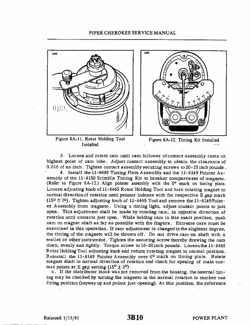
PIPER CHEROKEE SERVICE MANUAL
230 226
Figure 8A-11. Rotor Holding Tool Figure 8A-12. Timing Kit InstalledInstalled
3. Loosen and rotate cam until cam follower of contact assembly rests onhighest point of cam lobe. Adjust contact assembly to obtain the clearance of0.016 of an inch. Tighten contact assembly securing screws to 20-25 inch pounds.
4. Install the 11-8693 Timing Plate Assembly and the 11-8149 Pointer As-sembly of the 11-8150 Scintilla Timing Kit to breaker compartment of magneto.(Refer to Figure 8A-12.) Align pointer assembly with the 0° mark on timing plate.Loosen adjusting knob of 11-8465 Rotor Holding Tool and turn rotating magnet innormal direction of rotation until pointer indexes with the respective E gap mark(150 ± 20). Tighten adjusting knob of 11-8465 Tool and remove the 11-8149Point-er Assembly from magneto. Using a timing light, adjust contact points to justopen. This adjustment shall be made by rotating cam, in opposite direction ofrotation until contacts just open. While holding cam in this exact position, pushcam on magnet shaft as far as possible with the fingers. Extreme care must beexercised in this operation. If cam adjustment is changed in the slightest degree,the timing of the magneto will be thrown off. Do not drive cam on shaft with amallet or other instrument. Tighten the securing screw thereby drawing the camdown, evenly and tightly. Torque screw to 16-20 inch pounds. Loosenthe 11-8465Rotor Holding Tool adjusting knob and return rotating magnet to neutral position.Reinstall the 11-8149 Pointer Assembly over 0° mark on timing plate. Rotatemagnet shaft in normal direction of rotation and check for opening of main con-tact points at E gap setting (15 + 2).
c. If the distributor block was not removed from the housing, the internal tim-ing may be checked by turning the magneto in the normal rotation to number onefiring position (keyway up and points just opening). At this position, the reference
Reissued: 1/15/81 POWER PLANT3B10

PIPER CHEROKEE SERVICE MANUAL
226 line on the distributor block should lineup between the L and LB marks on thegear. On single contact magnetos theline should favor the L mark, if possible.
d. If the distributor block was re-moved from the housing, the distrib-utor gear alignment and internal checkmay be accomplished as followed:
1. Turn rotating magnet in di-rection of rotation until it is located infiring position (keyway up and pointsjust opening). Tighten adjusting knobof 11-8465 Rotor Holding Tool Applya light coating of Bendix Grease P/N10-27165 to teeth of distributor gear,if needed. The large distributor gearincorporates four timing makrs, Land
Figure 8A-13. Aligning Timing Marks LB for left hand rotation and R and RBfor right hand rotation.
2. With distributor gear assembled to block, turn gear until raised rib onblock lines up between the L and LB marks. Assemble block and gear into hous-ing, meshing the distributor gears together. The rib should favor the L mark,if possible, (Refer to Figure 8A-13.)
3. Secure distributor block to housing with studs and washers. Tightenstuds finger tight. Loosen the 11-8465 Rotor HoldingTool and turn rotating mag-net in reverse direction of rotation until timing light indicates contact assemblyhad just opened and check to make certain timing marks align within toleranceindicated above. Tighten block securing studs, first to 4-8 inch pounds torqueand then final torque to 20 inch pounds.
4. Insert the tip of your small finger through timing hole in housing andagainst large distributor gear teeth. Rockdistributor gear back and forth slightly.There must be perceptible backlash between teeth of large and small gears. Thischeck should be made at three different points, 120° apart on gear. If backlashis not evident, replace large distributor gear.
5. Install the breaker cover and complete reassembly of the magneto. Re-fer to the manufacturer's publications for complete disassembly and reassemblyprocedures.
e. On the magneto employing the impulse coupling, check clearance betweeneach flyweight and each stop pin as follows:
1. Bend the end of a stiff piece of wire into a right angle 1/8 inch long (max-imum).
2. Hold magneto as shown in Figure 8A-14. Pull heel of flyweight outward
POWER PLANTReissued: 1/15/81 3B11

PIPER CHEROKEE SERVICE MANUAL
with the hooked wire and make certain A626
that feeler gauge of 0.010 inch mini-mum thickness will pass between stoppin and the highestpoint of the flyweight. 0.10 A
NOTE
A true and accurate checkof the clearance betweenflyweight and stop pin.canonly be obtained by pullingthe flyweight outward asdescribed above. Do notattempt the check by push-ing in on flyweight at point"A"
f. Install and time magneto, re-moved from engine, in accordance withparagraph 8A-32.
g. Secure external switch leads tothe breaker cover terminals. Connect Figure 8A-14. Checking Flyweightharness assembly to the magneto. Clearance of Impulse Coupling
8A-32. INSTALLATION AND TIMING PROCEDURE. (Timing Magneto to En-gine.) Although only the left magneto is equipped with an impulse coupling, thetiming procedure, in the following paragraphs, is the same for both magnetos.
a. Remove the spark plug from No. 1 cylinder and place a thumb over thespark plug hole. Rotate the crankshaft in direction of normal rotation until thecompression stroke is reached, this is indicated by a positive pressure insidethe cylinder tending to push the thumb off the spark plug hole. Continue rotatingthe crankshaft in direction of normal rotation until the advance timing mark (20)on the front face of the starter ring gear is in exactalignment with the small holelocated at the two o'clock position on the front face of the starter housing. (Referto Figure 8A-15.)
POWER PLANTReissued: 1/15/81 3B12

PIPER CHEROKEE SERVICE MANUAL
228 Refer to the latest revisionof Lycoming Service
Bulletin No. 380
Figure 8A-15. Engine Timing Marks
NOTE
The advance timingmarkonthe top face of the starterring gear is marked at both20° and 25 BTC. Use onlythe 20° BTC mark when tim -ingthe magnetos to the en-gine.
NOTE
If the crankshaft is acci-dently turned in the direc-tion opposite normal rota-tion, repeat the above pro-cedure as accumulatedbacklashwill make the finaltiming incorrect.
b. At this point, the engine is ready for assembly of the magnetos. Removethe inspection plugs from both magnetos and turn the drive shafts in direction ofnormal rotation (counterclockwise facing the coupling), until the first paintedchamfered tooth on the distributor gear is aligned in the center of the inspectionwindow. (Refer to Figure 8A-16.) Being sure that the gear does not move fromthis position, install gaskets and magnetos on the engine. Secure with washersand nuts; tighten only finger tight.
NOTE
The magnetos are held in placebyclampswhichallowsthem to be timed in several positions. Since all po-sitions will not give the required clearance betweenmagneto and engine mount, the magnetos must be in-stalled from the horizontal position to 20° above thehorizontal as shown in Figure 8A-16. Improper in-stallation of magnetos could cause damage or failure.
NOTE
In order to turn the shaft on an impulse coupling magne-to, depress pawl on the impulse couplingwith the finger.
POWER PLANTReissued: 1/15/81 3B13

PIPER CHEROKEE SERVICE MANUAL
897 229RED ORWHITE TOOTH
TIMING MARK
Figure 8A-16. Magneto Adjustment Figure 8A-17. Magneto Timing MarksLimits
c. Using a battery powered timing light, attach the positive lead to a suitableterminal connected to the ground terminal of the magneto and the negative lead toany unpainted portion of the engine. Rotate the magneto in its mounting flange toa point where the light comes on, then slowly turn it in the opposite direction un-til the light goes out. Bring the magneto back slowly until the light just comeson. Repeat this with the second magneto.
NOTE
AC timinglights operate in the reverse manner as de-scribed above, the light goes out when the breakerpoints open.
d, After both magnetos have been timed, check, as described below, to as-certain that both magnetos are set to fire together.
e. Backoff the crankshaft a few degrees, the timinglights shouldgo out. Bringthe crankshaft slowly back in direction of normal rotation until the timing markand the hole in the starter housing are in alignment. At this point, both lightsshould go on simultaneously. Tighten nuts to specified torque.
f . After magnetos have been properly timed, replace breaker cover and secure.g. Install the ground lead and the retard spark lead on the left magneto.h. Place the harness terminal plate on the magneto and tighten nut around the
plate alternately to seat cover squarely on magneto. Torque nuts to 18 to 22 inchpounds.
Reissued: 1/15/81 POWER PLANT3B14
PIPER CHEROKEE SERVICE MANUAL
8A-33. HARNESS ASSEMBLY.
8A-34. INSPECTION OF HARNESS.a. Check lead assemblies for nicks, cuts, mutilated braiding, badlyworn sec-
tion or any other evidence of physical damage. Inspect spark plug sleeves forchafing or tears and damaged or stripped threads on coupling nuts. Check com-pression spring to see if it is broken or distorted. Inspect grommet for tears.Check all mounting brackets and clamps to see that they are secure and not cracked.
b. Using an ohmmeter, buzzer, or other suitable low voltage device, checkeach lead for continuity. If continuity does not exist, wire is broken and must bereplaced.
c. For electrical test of harness assembly, use a high voltage, directcurrenttester such as the TAKK Model 86 or 86A or an equivalent direct current highvoltage tester capable of delivering a test potential of 10, 000 volts. Connectground lead to high voltage tester to outer shielding braid of a single lead. Con-nect plug terminal. Turn tester "ON" and apply 10, 000 volts. The insulationresistance should be 100 megohms minimum. Proceed to check other leads ofharness in same manner.
d. Minor repair of the harness assembly, such as replacement of contactsprings, spring retainer assemblies, insulating sleeves or of one lead assembly,can be accomplished with the harness assembly mounted on the engine. However,should repair require replacement of more than one lead assembly or of a cableoutlet plate, the harness should be removed from the engine and sent to anover-haul shop.
8A-35. REMOVAL OF HARNESS.a. Disconnect the clamps that secure the wires to the engine and accessories.b. Loosen the coupling nuts at the sparkplugs andremove the insulators from
the spark plug barrel well. Use caution when withdrawing the insulator not todamage the insulator spring.
c. Place a guard over the harness insulators.d. Remove the harness assembly terminal plate from the magneto.e. Remove the harness from the airplane.
8A-36. MAINTENANCE OF HARNESS.a. To replace contact springs, spring retainer assemblies or insulating sleeves,
proceed as follows:1. Using a Scintilla 11-7073 Needle or a mechanical pencil with the lead
retracted, hook the end of the contact spring as shown in Figure 8A-18.
Reissued: 1/15/81 3B15 POWER PLANT

PIPER CHEROKEE SERVICE MANUAL
2. Using the needle or pencil,unscrew the spring.
3. Slide insulating sleeve andspring retainer assembly off end of leadassembly.
4. Replace defective componentand reassemble as follows:
(a) Fabricate a tool as shownin Figure 8A-19 for instal-ling the insulating sleevesover cable terminals.
(b) Push the tool thru insula-ting sleeve and spring re-tainer assembly as shownin Figure 8A-20. Screwthe cable terminal into thetool.
230
Figure 8A-18. Removing SpringFrom Lead Assembly
(c) Work insulating sleeve and spring retainer assembly into positionover the cable and unscrew the tool. Install contact spring on cableterminal.
NOTE
It may be necessary to lubricate cable and insulatingsleeve with a thin film of MC 200 (200, 000 centistokes)or commercial grade alcohol to facilitate assembly.
C 346
BRAZE
2-1/2 IN.
DRILL NO. 47 1/4 IN. DEEPTAP 3-48
BLEND O.D. TO I.D.POLISH O.D.
12.000 IN.
MAT: NO. 30 DRILL ROD OR EQUIVALENT
Figure 8A-19. Assembly Tool
Reissued: 1/15/81 POWER PLANT3B16
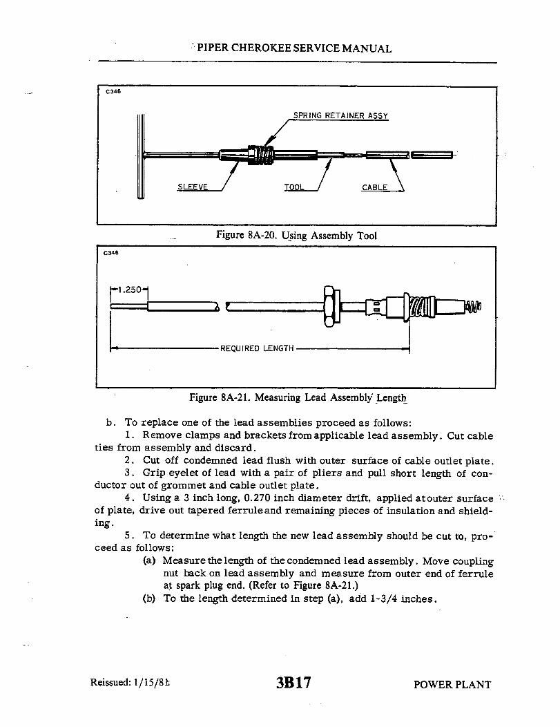
PIPER CHEROKEE SERVICE MANUAL
C346
SPRING RETAINER ASSY
SLEEVE TOOL CABLE
Figure 8A-20. Using Assembly Tool
C346
REQUIRED LENGTH
Figure 8A-21. Measuring Lead Assembly Length
b. To replace one of the lead assemblies proceed as follows:1. Remove clamps and brackets from applicable lead assembly. Cut cable
ties from assembly and discard.2. Cut off condemned lead flush with outer surface of cable outlet plate.3. Grip eyelet of lead with a pair of pliers and pull short length of con-
ductor out of grommet and cable outlet plate.4. Using a 3 inch long, 0.270 inch diameter drift, applied atouter surface
of plate, drive out tapered ferrule and remaining pieces of insulation and shield-ing.
5. To determine what length the new lead assembly should be cut to, pro-ceed as follows:
(a) Measure the length of the condemned lead assembly. Move couplingnut back on lead assembly and measure from outer end of ferruleat spark plug end. (Refer to Figure 8A-21.)
(b) To the length determined in step (a), add 1-3/4 inches.
Reissued: 1/15/81 3B17 POWER PLANTI
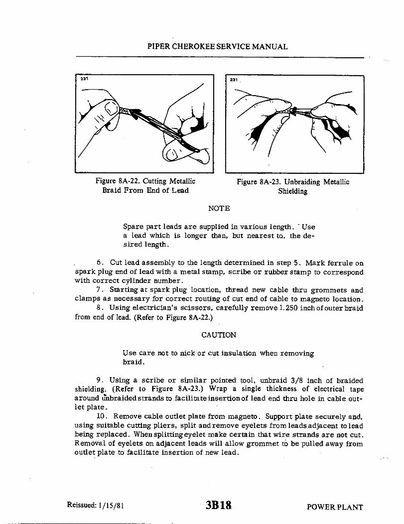
PIPER CHEROKEE SERVICE MANUAL
231 231
Figure 8A-22. Cutting Metallic Figure 8A-23. Unbraiding MetallicBraid From End of Lead Shielding
NOTE
Spare part leads are supplied in various length. Usea lead which is longer than, but nearest to, the de-sired length.
6. Cut lead assembly to the length determined in step 5. Mark ferrule onspark plug end of lead with a metal stamp, scribe or rubber stamp to correspondwith correct cylinder number.
7. Starting at spark plug location, thread new cable thru grommets andclamps as necessary for correct routing of cut end of cable to magneto location.
8. Using electrician's scissors, carefully remove 1.250 inch of outer braidfrom end of lead. (Refer to Figure 8A-22.)
CAUTION
Use care not to nick or cut insulation when removingbraid.
9. Using a scribe or similar pointed tool, unbraid 3/8 inch of braidedshielding. (Refer to Figure 8A-23.) Wrap a single thickness of electrical tapearound unbraided strands to facilitate insertionof lead end thru hole in cable out-let plate.
10. Remove cable outlet plate from magneto. Support plate securely and,using suitable cutting pliers, split and remove eyelets from leads adjacent to leadbeing replaced. When splitting eyelet make certain that wire strands are not cut.Removal of eyelets on adjacent leads will allow grommet to be pulled away fromoutlet plate to facilitate insertion of new lead.
Reissued: 1/15/81 POWER PLANT3B18

PIPER CHEROKEE SERVICE MANUAL
C347
UNBRAIDED SHIELDING POSITION OF
RED COATING FERRULE UNDERSHIELDING
- 3/8"
Figure 8A-24. Forming Shielding Around Ferrule
11. Pass the taped end of new lead through hole in outlet plate. Removeelectrical tape from lead and install tapered end of ferrule under the unbraidedstrands of shielding. Form strands of shielding evenlyas shown in Figure '8A-24 and pull lead assembly back through cable outlet plateuntil ferrule binds in the outlet well. Position the Scintilla 11-7074 Ferrule Seat-ing Tool (Figure 8A-25) over the wire and firmly seat the ferrule by tapping theseating tool with a hammer or by using an arbor press.
12. Measure 1/2 inch from tapered ferrule and strip remaining insulationfrom wire. (Refer to Figure 8A-27.)
13. Insert Scintilla 11-7073 Needle (Figure 8A-26) thru small hole grom-met and over stripped end of wire. (Refer to Figure 8A-28.) Slide grommet downneedle until it seats tightly against the tapered ferrule.
C347
2.031
0.370 0.095 DIA
0.047 SPHERICAL RAD 0.047 DIA2 PLACES
MATERIAL- BRASS
Figure 8A-25. Ferrule Seating Tool Figure 8A-26. Needle
POWER PLANT
C347
2.750
2.375
Reissued: 1/15/81 3B19

PIPER CHEROKEE SERVICE MANUAL
232
1-7073 NEEDLE232
Figure 8A-27. Measuring Wire FromTop of Ferrule
Figure 8A-28. Installing GrommetOver Lead Assemblies
14. Cut wire 3/8 inch from top of grommet outlet (Refer to Figure 8A-28).Double wire over as shown in A of Figure 8A-30. Slide eyelet over doubled wireuntil it is firmly seated in recess of grommet outlet.
15. Using the "AB" groove of Scintilla 11-4152 Crimping Tool, or equiva-lent, crimp eyelet to wire. Approximately 1/32 of an inch of wire should extendfrom end of eyelet after crimping. (Refer to B of Figure 8A-30.)
233
Figure 8A-29. Lead AssemblInstalled in Grommet
233
A
Assembly Figure 8A-30. Wire Doubled OverFor Installation of Eyelet
POWER PLANT
0.50
Reissued: 1/15/813B20
PIPER CHEROKEE SERVICE MANUAL
NOTE
If the crimping tool is not available, a satisfactoryconnection can be made by soldering with Kester Flux709 or equivalent and a non-corrosive solder. Aftersoldering, clean solder joints using denatured alcohol.
16. Install clamps and calbe ties as necessary to secure lead to the engine.
8A-37. INSTALLATION OF HARNESS. Before installing harness on magneto,check mating surfaces for cleanliness. Spray entire face of grommet with a lightcoat of Plastic Mold Spray, SM-O-O-TH Silicone Spray or equivalent. This willprevent harness grommet from sticking to magneto distributor block.
a. Placetheharness terminal plate on the magneto and tighten nuts around theplate alternately to seat cover squarely on magneto. Torque nuts to 18 to 22 inchpounds.
b. Route ignition wires to their respective cylinders.c. Clamp the harness assembly in position.d. Connect the leads to the spark plugs.
8A-38. SPARK PLUGS.
8A-39. REMOVAL OF SPARK PLUGS.a. Loosen the coupling nut on the harness lead and remove the terminal in-
sulator from the spark plug barrel well.
NOTE
When withdrawing the ignition cable lead connectionfrom the plug, care must be taken to pull the leadstraight out and in line with the center line of the plugbarrel; otherwise a side load will be applied, whichfrequently results in damage to the barrel insulatorand connector. If the lead cannot be removed easilyin this manner, the resistingcontact between the neo-prene collar and the barrel insulator will be brokenby a rotary twisting of the collar. Avoid undue dis-tortion of the collar and possible side loading of thebarrel insulator.
Reissued: 1/15/81 POWER PLANT3B21

PIPER CHEROKEE SERVICE MANUAL
b. Remove the spark plug from the engine. In the course of engine operation,carbon and other combustion products will be deposited on the end of the sparkplug and will penetrate the lower threads to some degree. As a result, greatertorque is frequently required for removing a plug than for its installation. Ac-cordingly, the torque limitations given do not apply to plug removal and sufficienttorque must be used to unscrew the plug. The higher torque in removal is not asdetrimental as in installation, since it cannot stretch the threaded section. Itdoes, however, impose a shearing load on this section and may, if sufficientlysevere, produce a failure in this location.
NOTE
Torque indicating handle should not be used for sparkplug removal because of the greater torque require-ment.
c. Place spark plugs in a tray that will identify their position in the engine assoon as they are removed.
NOTE
Spark plugs should not be used if they have been dropped.
d. Removalof seized spark plugs inthe cylinder may be accomplished byapplication of liquid carbon dioxide bya Conical metal funnel adapter with ahole at the apex just large enough toaccommodate the funnel of a CO2 bottle.(Refer to Figure 8A-31.) When a seizedsparkplug cannot be removed by normalmeans, the funnel adapter is placed overand around the spark plug. Place thefunnel of the CO2 bottle inside the funneladapter and release the carbon dioxideto chill and contract the spark plug.Break the sparkplug loose witha wrench.A warm cylinder head at the time thecarbon dioxide is appliedwill aidin theremoval of an excessively seized plug.
e. Do not allow foreign objects toenter the spark plug hole.
234
Figure 8A-31. Removing Spark PlugFrozen to Bushing
Reissued: 1/15/81 POWER PLANT3B22

PIPER CHEROKEE SERVICE MANUAL
8A-40.. INSPECTION AND CLEANING OF SPARK PLUG.a. Visually inspect each spark plug for the following non-repairable defects:
1. Severely damaged shellor shield threads nicked up, stripped or cross-threaded.
2. Badly battered or rounded shell hexagons.3. Out-of-round or damaged shielding barrel.4. Chipped, cracked or broken ceramic insulator protions.5. Badly eroded electrodes worn to approximately 50% of original size.
b. Clean the spark plug as required, removing carbon and foreign deposits.c. Set the electrode gap at .015 to .018 inches.d. Test the spark plug both electrically and for resistance.
8A-41. INSTALLATION OF SPARK PLUGS. Before installing spark plugs, as-certain that the threads within the cylinder are clean and not damaged.
a. Apply anti-seize compound sparingly on the threads and install gasket andspark plugs. Torque 360 to 420 inch pounds.
CAUTION
Make certain the deep socket is properly seated on thespark plug hexagon as damage to the plug could resultif the wrench is cocked to one side when pressure isapplied.
b. Carefully insert the terminal insulator in the spark plug and tighten thecoupling unit.
8A-42. LUBRICATION SYSTEM.
8A-43. OIL PRESSURE RELIEF VALVE.The function of the oil pressure relief valve, which is located between the
upper right engine mounting lug and No. 3 cylinder, is to maintain engine oilpressure within specified limits by withdrawing a portion of the oil from the cir-culating system and returning the oil to the sump should the pressure becomeexcessive. This valve is not adjustable; however, particles of metal or otherforeign matter lodged between ball and seat will result in a drop in oil pressure.It it advisable, therefore, to disassemble, inspect and clean the relief valve ifexcessive pressure fluctuations are noted.
The oil pressure relief valve is by no means to be confused with the oil
3B23Reissued: 1/15/81 POWER PLANT

PIPER CHEROKEE SERVICE MANUAL
cooler by-pass which is located on the oil pressure screen housing mounting pad. The solepurpose of the by-pass valve is to serve as a safety measure, permitting pressure oil to by-passthe oil cooler entirely in case of an obstruction within the cooler.
8A-44. SWITCHING.
8A-45. REMOVING IGNITION SWITCH.a. Insure the ignition switch is in the OFF position.b. Gain access to and disconnect the power lead (+) from the battery.c. Remove the ignition switch retaining nut from the switch on the forward side of the
instrument panel and withdraw the switch from the panel.d. Mark the wires and note their position on the switch, then disconnect the wires.
8A-46. INSTALLATION OF IGNITION SWITCH. (Refer to Figure 8A-32.)a. Attach wires to the switch as shown in Figure 8A-32.b. Position the ignition switch in the instrument panel and secure with retaining nut.c. Connect the power lead (+) to the battery and reinstall any access covers previously
removed.
.C236 J1A
TAB
K1A GND
J2A
BAT
PR K1B
PA-28R-180, S/N 28R-30005 TO 28-7130019PA-28R-200, S/N 28R-30482, 28R-35001 TO 28R-7435331
Figure 8A-32. Ignition Switch Wiring Positions
POWER PLANTRevised: 8/3/81 3B24

PIPER CHEROKEE SERVICE MANUAL
TABLE VIIIA-I. ENGINE TROUBLESHOOTING
Trouble Cause
Failure of engine tostart.
Lack of fuel. Check fuel system forleaks. Fill fuel tank.
Clean dirty lines, strain-ers or fuel valves.
Check fuel selectorvalvefor proper tank.
Check fuel pressure withelectric boost pump ON.
Check mixture controlknob for full rich.
Overpriming.
Incorrect throttlesetting.
Defective spark plugs.
Defective ignition wire.
Defective battery.
Improper operation ofmagneto breaker.
Lack of sufficient fuelflow.
Open throttle and "unload"engine by engagingstarter. Mixture inidle-cut-off.
Open throttle to one-eight of its range.
Clean and adjust or re-place spark plugs.
Check with electric test-er and replace defectivewires.
Replace with chargedbattery.
Clean points. Check in-ternal timing of mag-netos.
Disconnect fuel line atfuel injector and checkfuel flow.
Reissued: 1/15/81 POWER PLANT
Remedy
3C1

PIPER CHEROKEE SERVICE MANUAL
TABLE VIIIA-I. ENGINE TROUBLESHOOTING
Trouble Cause
Failure of engine tostart. (cont.)
Failure of engine toidle properly.
Internal failure.
Incorrect idle mixture.
Leak in the inductionsystem.
Check oil screens formetal particles. Iffound, complete over-haul of engine may beindicated.
Adjust mixture.
Tighten all connectionsin the induction sys-tem. Replace any partsthat are defective.
Incorrect idle adjust-ment.
Uneven cylinder com-pression.
Faulty ingition system.
Insufficient fuel pres-sure.
Adjust throttle stop toobtain correct idle.
Check condition of pis-ton rings and valveseats.
Check entire ignitionsystem.
Adjust fuel pressure.
Low power and uneven Mixture too rich; indi-cated by sluggish en-gine operation, red ex-haust flame at night.Extreme cases indi-cated by black smokefrom exhaust.
Readjustment of fuel in-jector by authorizedpersonnel is indicated.
Reissued: 1/15/81
(cont.)
Remedy
3C2 POWER PLANT
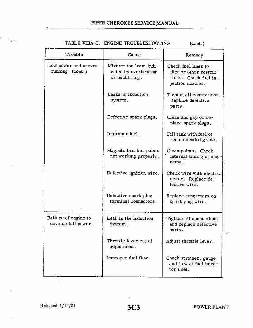
PIPER CHEROKEE SERVICE MANUAL
TABLE VIIIA-I. ENGINE TROUBLESHOOTING
Trouble Cause
Low power and unevenrunning. (cont.)
Mixture too lean; indi-cated by overheatingor backfiring.
Check fuel lines fordirt or other restric-tions. Check fuel in-jection nozzles.
Leaks in inductionsystem.
Defective spark plugs.
Improper fuel.
Magneto breaker pointsnot working properly.
Defective ignition wire.
Defective spark plugterminal connectors.
Tighten all connections.Replace defectiveparts.
Clean and gap or re-place spark plugs.
Fill tank with fuel ofrecommended grade.
Clean points. Checkinternal timing of mag-netos.
Check wire with electrictester. Replace de-fective wire.
Replace connectors onspark plug wire.
Failure of engine todevelop full power.
Leak in the inductionsystem.
Throttle lever out ofadjustment.
Improper fuel flow.
Tighten all connectionsand replace defectiveparts.
Adjust throttle lever.
Check strainer, gaugeand flow at fuel injec-tor inlet.
Reissued: 1/15/81 3C3
(cont.)
Remedy
POWER PLANT
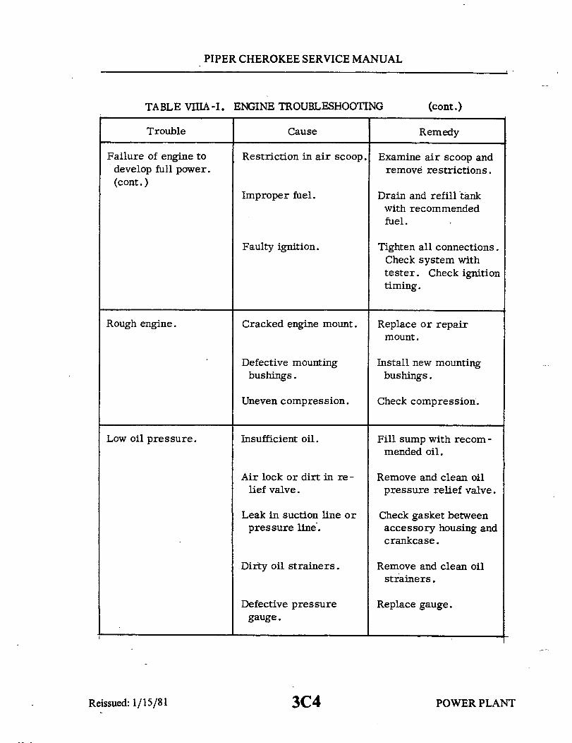
PIPER CHEROKEE SERVICE MANUAL
TABLE VIIIA-I. ENGINE TROUBLESHOOTING
Trouble Cause
Failure of engine todevelop full power.(cont.)
Restriction in air scoop.
Improper fuel.
Faulty ignition.
Examine air scoop andremove restrictions.
Drain and refill tankwith recommendedfuel.
Tighten all connections.Check system withtester. Check ignitiontiming.
Rough engine. Cracked engine mount.
Defective mountingbushings.
Uneven compression.
Replace or repairmount.
Install new mountingbushings.
Check compression.
Low oil pressure. Insufficient oil. Fill sump with recom-mended oil.
Air lock or dirt in re-lief valve.
Leak in suction line orpressure line.
Dirty oil strainers.
Defective pressuregauge.
Remove and clean oilpressure relief valve.
Check gasket betweenaccessory housing andcrankcase.
Remove and clean oilstrainers.
Replace gauge.
Reissued: 1/15/81
(cont.)
Remedy
3C4 POWER PLANT

PIPER CHEROKEE SERVICE MANUAL
TABLE VIIIA-I.
Trouble
ENGINE TROUBLESHOOTING
Cause
Low oil pressure.(cont. )
Stoppage in oil pumpintake passage.
Check line for obstruc-tion. Clean suctionstrainer.
High oil temperature. See "High Oil Temper-ature" in "Trouble"column.
High oil temperature. Insufficient air cooling. Check air inlet and out-let for deformation orobstruction.
Insufficient oil supply.
Low grade of oil.
Clogged oil lines orstrainers.
Excessive blow-by.
Failing or failedbearing.
Defective temperaturegauge.
Fill oil sump to properlevel with specified oil.
Replace with oil con-forming to specifica-tions.
Remove and clean oilstrainers.
Usually caused by wornor stuck rings.
Examine sump formetal particles. Iffound, overhaul of en-gine is indicated.
Replace gauge.
Excessive oil consump-tion.
Low grade of oil. Fill tank with oil con-forming to specifica-tions.
Reissued: 1/15/81 3C5
(cont.)
Remedy
POWER PLANT
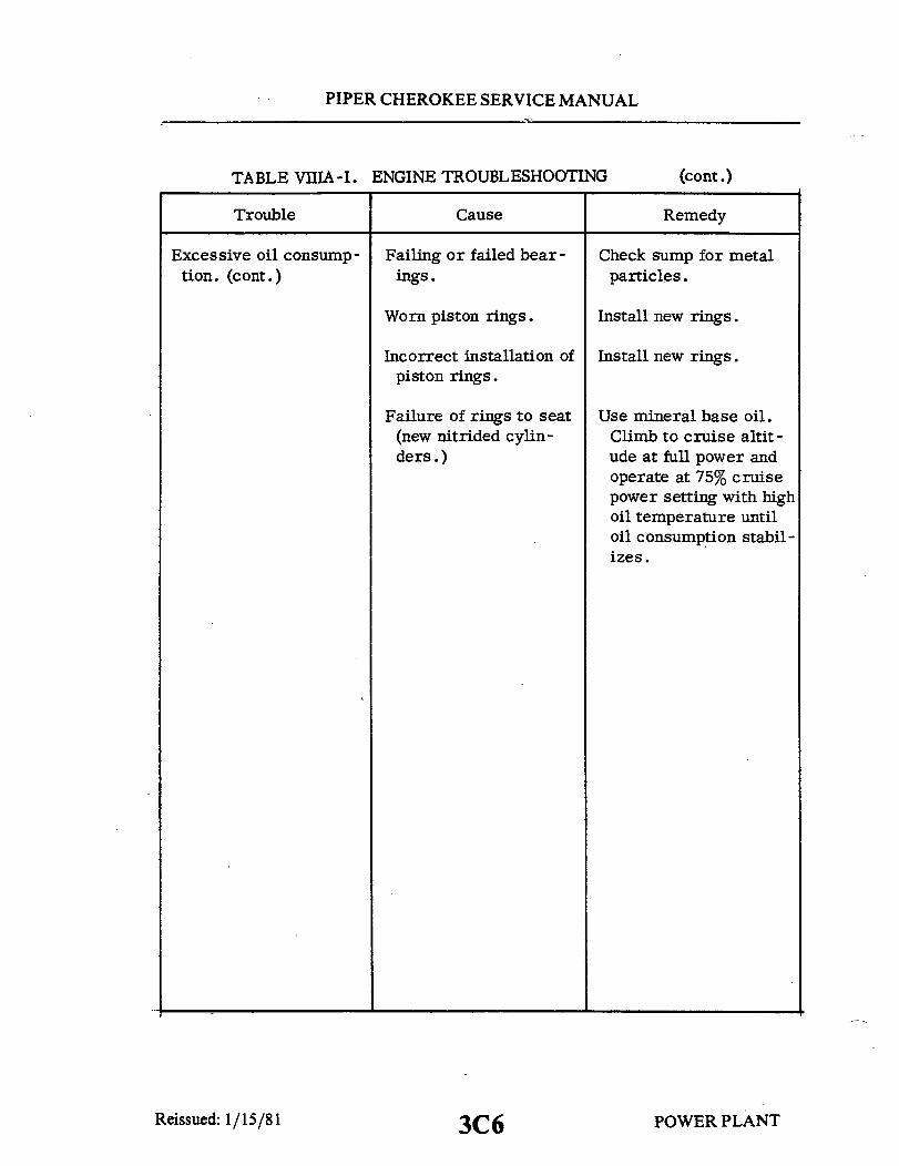
PIPER CHEROKEE SERVICE MANUAL
TABLE VIIIA-I. ENGINE TROUBLESHOOTING
Trouble Cause
Excessive oil consump- Failing or failed bear-tion. (cont.) ings.
Worn piston rings.
Incorrect installation ofpiston rings.
Failure of rings to seat(new nitrided cylin-ders. )
Check sump for metalparticles.
Install new rings.
Install new rings.
Use mineral base oil.Climb to cruise altit-ude at full power andoperate at 75% cruisepower setting with highoil temperature untiloil consumption stabil-izes.
POWER PLANT3C6
(cont.)
Remedy
Reissued: 1/15/81

3C7INTENTIONALLY LEFT BLANK

SECTION IXFUEL SYSTEM
Paragraph AeroficheGrid No.
9-1. Introduction ................................................. 3C109-2. Description .................................................. 3C109-3. Troubleshooting .............................................. 3C179-4. Main Fuel Tanks (PA-28-140, -150, -160, -180, -235
and PA-28R) ............................................ 3C179-5. Removal of Main Fuel Tanks .................. ...... 3C179-6. Inspection and Repair of Main Fuel Tank .............. 3C179-7. Installation of Main Fuel Tank ........................ 3C18
9-8. Tip Fuel Tanks (PA-28-235) ................................... 3C189-9. Removal of Tip Tank ............................. ... 3C18
9-10. Fuel Tank Repair (Fiberglas) ................ .................. 3C189-11. Installation of Tip Tank ......................... ... .. 3C19
9-12. Fuel Quantity Transmitter Unit ................................ 3C199-13. Removal of Fuel Quantity Transmitter Unit ............. 3C199-14. Installation of Fuel Quantity Transmitter Unit .......... 3C199-15. Fuel Quantity Transmitter/Gauge Check ............... 3C199-16. Check and Adjustment of Fuel Quantity
Transmitter Unit ................................ 3C209-17. Fuel Valves .................................................. 3C22
9-18. Fuel Shutoff Valve (PA-28-140, -150, -160,-180, and PA-28R) ............................... 3C22.
9-19. Removal of Fuel Shutoff Valve ........................ 3C229-20. Disassembly of Fuel Shutoff Valve ..................... 3C229-21. Cleaning, Inspection and Repair of Fuel
Shutoff Valve................................... 3C229-22. Assembly of Fuel Shutoff Valve ....................... 3C239-23. Installation of Shutoff Valve .......................... 3C23
9-24. Fuel Selector Valve and Filter (PA-28-235) .......... ............ 3C239-25. Fuel Selector Valve Operation......................... 3C239-26. Removal of Fuel Selector Valve and Filter .............. 3C239-27.. Port Repair of 1H26-4 Fuel Selector ................... 3C249-28. Cleaning Filter Assembly ............................. 3D19-29. Installation of Fuel Selector and Filter Valve............ 3D2
9-30. Fuel Filter Bowl and Screen (PA-28-140, -150, -160,-180, and PA-28R) ....................... 3D3
9-31. Removal of Fuel Filter Bowl and Housing .............. 3D39-32. Installation of Fuel Filter Bowl and Screen ............. 3D39-33. Cleaning and Inspection of Filter Bowl Screens.......... 3D4
Reissued: 1/15/81 3C8

PIPER CHEROKEE SERVICE MANUAL
Paragraph AeroficheGrid No.
9-34. Electric Fuel Pumps .......................................... 3D49-35. Plunger Fuel Pumps (PA-28-140, -150, -160, -180, and -235) ....... 3D4
9-36. Removal of Fuel Pumps .............................. 3D49-37. Disassembly of Fuel Pump ........................... 3D59-38. Cleaning, Inspection and Repair of Fuel Pump .......... 3D79-39. Resistance Check (Plunger Type Pump) ................ 3D79-40. Assembly of Fuel Pump .............................. 3D79-41. Adjustment of Electric Fuel Pump (Bench Test) ......... 3D89-42. Adjustment of Electric Fuel Pump (In Airplane)......... 3D89-43. Installation of Fuel Pumps ............................ 3D9
9-44. Rotary Fuel Pumps (Weldon) (PA-28R) .. .................. 3D 109-45. Removal of Fuel Pump .............................. 3D109-46. Disassembly, Repair and Assembly of Fuel Pump ....... 3D109-47. Adjustment of Electric Fuel Pump (Bench Test) ......... 3D119-48. Adjustment of Electric Fuel Pump (In Airplane) ......... 3D 119-49. Installation of Fuel Pump ............................ 3D12
9-50. Engine Primer Pump ........................................ 3D129-51. Removal of Engine Primer ......... ................. 3D 129-52. Disassembly, Cleaning and Assembly of Engine
Primer ......................................... 3D 129-53. Installation of Engine Primer Pump .................... 3D13
9-54. Primer Jets .................................................. 3D139-55. Cleaning Fuel System ......................................... 3D1 3
Reissued: 1/15/81 3C9
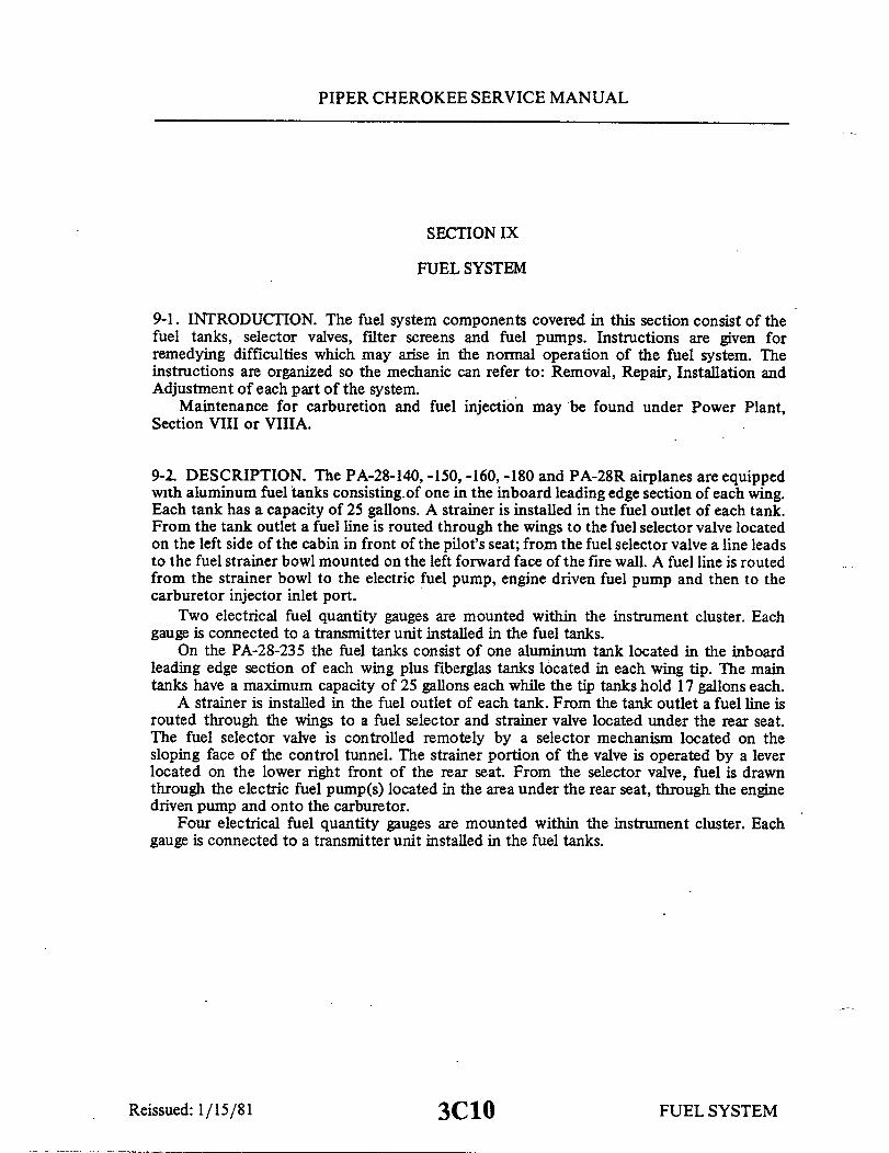
PIPER CHEROKEE SERVICE MANUAL
SECTION IX
FUEL SYSTEM
9-1. INTRODUCTION. The fuel system components covered in this section consist of thefuel tanks, selector valves, filter screens and fuel pumps. Instructions are given forremedying difficulties which may arise in the normal operation of the fuel system. Theinstructions are organized so the mechanic can refer to: Removal, Repair, Installation andAdjustment of each part of the system.
Maintenance for carburetion and fuel injection may be found under Power Plant,Section VIII or VIIIA.
9-2. DESCRIPTION. The PA-28-140, -150, -160, -180 and PA-28R airplanes are equippedwith aluminum fuel tanks consisting of one in the inboard leading edge section of each wing.Each tank has a capacity of 25 gallons. A strainer is installed in the fuel outlet of each tank.From the tank outlet a fuel line is routed through the wings to the fuel selector valve locatedon the left side of the cabin in front of the pilot's seat; from the fuel selector valve a line leadsto the fuel strainer bowl mounted on the left forward face of the fire wall. A fuel line is routedfrom the strainer bowl to the electric fuel pump, engine driven fuel pump and then to thecarburetor injector inlet port.
Two electrical fuel quantity gauges are mounted within the instrument cluster. Eachgauge is connected to a transmitter unit installed in the fuel tanks.
On the PA-28-235 the fuel tanks consist of one aluminum tank located in the inboardleading edge section of each wing plus fiberglas tanks located in each wing tip. The maintanks have a maximum capacity of 25 gallons each while the tip tanks hold 17 gallons each.
A strainer is installed in the fuel outlet of each tank. From the tank outlet a fuel line isrouted through the wings to a fuel selector and strainer valve located under the rear seat.The fuel selector valve is controlled remotely by a selector mechanism located on thesloping face of the control tunnel. The strainer portion of the valve is operated by a leverlocated on the lower right front of the rear seat. From the selector valve, fuel is drawnthrough the electric fuel pump(s) located in the area under the rear seat, through the enginedriven pump and onto the carburetor.
Four electrical fuel quantity gauges are mounted within the instrument cluster. Eachgauge is connected to a transmitter unit installed in the fuel tanks.
Reissued: 1/15/81 FUEL SYSTEM3C10

PIPER CHEROKEE SERVICE MANUAL
1787
FUEL QUANTITY GAUGES
FUEL TANK SELECTOR VALVE
FUEL TANK SELECTOR VALVE
FUEL STRAINERRIGHT MAIN TANK LEFT MAIN TANK
PRIMER
FUEL PRESSURE GAUGE
CARBURETOR
-ENGINE FUEL PUMP
ELECTRIC FUEL PUMP
Figure 9-1. Fuel System Diagram (PA-28-140, -150, -160, -180)
Reissued: 1/15/813C11 FUEL SYSTEM

PIPER CHEROKEE SERVICE MANUAL
1780
CARBURETOR
THROTTLEMIXTURE
FUEL SELECTOR CONTROL
ENGINE FUEL PUMP
LEFT TIP TANK LEFT MAIN TANK RIGHT MAIN TANK
FUEL PUMPS
FUEL QUANTITY GAUGES
Figure 9-2. Fuel System Diagram(PA-28-235, Serial Nos. 28-10003 to 28-10719 incl.)
Reissued: 1/15/81
RIGHT TIP TANK
FUEL SYSTEM3C12

PIPER CHEROKEE SERVICE MA NUA L
1771
CARBURETOR
ENGINE
FUEL SELECTOR CONTROL
RIGHT MAIN TANK RIGHT TIP TANK
ELECTRIC FUEL PUMP
FUEL QUANTITY GAUGES
Figure 9-3. Fuel System Diagram(PA-28-235, Serial Nos. 28-10720 and up)
Reissued: 1/15/81 3C13
LEFT TIP TANK LEFT MAIN TANK
FUEL SYSTEM

PIPER CHEROKEE SERVICE MANUAL
FUEL QUANTITYGAUGE
RIGHT TANK
UDRAIN
FUEL PRESSUREGAUGE
FUEL QUANTITYGAUGE
FUELSELECTOR
LEFT TANK
UDRAIN
GASCOLATOR
FUEL FLOWGAUGE
VENT
FLOW
ELECTRIC FUEL PUMP
ENGINE DRIVEN FUEL PUMP
FUEL INJECTOR
Figure 9-4. Fuel System Diagram (PA-28R)
Reissued: 1/15/81
C350
FUEL SYSTEM3C14

3C15INTENTIONALLY LEFT BLANK

3C16INTENTIONALLY LEFT BLANK

PIPER CHEROKEE SERVICE MANUAL
9-3. TROUBLESHOOTING. Troubles peculiar to the PA-28 fuel system are listed in TableIX-III along with their probable causes and suggested remedies. When troubleshooting,check from the power supply to the items affected. If no trouble is found by this method,the trouble probably exists inside individual pieces of equipment; they may then beremoved from the airplane and an identical unit or units, tested and known to be good,installed in their place.
9-4. MAIN FUEL TANKS. (PA-28-140, -150, -160, -180, -235 and PA-28R.)
9-5. REMOVAL OF MAIN FUEL TANKS.a. Drain the fuel from the fuel tank. (Refer to Draining Fuel System, Section II.)b. Remove the screws from around the perimeter of the tank assembly.c. Disconnect fuel line attached to tank.d. Pull the tank away from the wing assembly far enough to gain access for removal of
the sender wire.e. The tank is now free to be removed.
9-6. INSPECTION AND REPAIR OF MAIN FUEL TANK. The entire interior of the maintanks should be inspected for peeling of small areas of the sloshing compound. Indicationsare that in the majority of cases the peeling is started just inside the filler neck as a result ofthe metal nozzle of the gas filler hose nicking the compound. The following items arerecommended:
a. The entire interior of the main tanks should be inspected with the tanks drained.This is accomplished with a mirror and inspection light through the filler neck. Small scrapesin the film adjacent to the filler neck may be disregarded provided there is no indication ofpeeling.
b. If peeling has occurred and separated material is found, the main tank should beremoved and resloshed in accordance with the instructions included with each can ofRandolph Sloshing Sealer 802, Piper part number 757 572v. (Approved under Mil. Spec.MIL-L-6047B.) One gallon of sloshing compound is required per tank. After sloshing thetank, apply 1.5 lbs. air pressure and using a soap and water solution, check for leaks.
c. After resloshing, reinspect as above at intervals of 100 hours. These inspections maybe discontinued after the second inspection if no peeling is discovered.
Reissued: 1/15/81 3C17 FUEL SYSTEM

PIPER CHEROKEE SERVICE MANUAL
NOTE
The fuel tank should be replaced if the tank is damaged tothe extent it cannot be repaired by the above method.
9-7. INSTALLATION OF MAIN FUEL TANK.a. Slide the main tank partly into position and connect the sender wire.b. Slide the tank completely into place and secure with screws around its perimeter.c. Connect fuel line on inboard side of tank. The flexible hose from the fuel tank must
not be twisted during installation on applicable models.d. Fill the fuel tank and check for leaks, unrestricted fuel flow and proper sender
indications on the quantity gauge.
9-8. TIP FUEL TANKS (PA-28-235).
9-9. REMOVAL OF TIP TANK.a. Drain the fuel from the tank to be removed. (Refer to Draining Fuel System,
Section II.)b. Remove the access cover from the bottom of the wing tip.c. By working through the access, disconnect the fuel line, fuel quantity transmitting
wire and position light wire. Remove the two nuts, washers and bolts which hold the tank tothe wing.
d. Carefully remove the screws from around the wing tip and remove the tip assembly.
9-10. FUEL TANK REPAIR. (Fiberglas). The wing tip tanks are constructed of fiberglas.Minor repair of the tank can be accomplished with the use of Fiberglas Repair Kit No.756 729. This kit along with instructions is obtained from Piper Dealers or Distributors.Additional fiberglas repairs may be found in Section IV of the Manual.
Reissued: 1/15/81 FUEL SYSTEM3C18

PIPER CHEROKEE SERVICE MANUAL
9-11. INSTALLATION OF TIP TANK.a. Position the wing tip in place on the wing and insert the two bolts, washers and
nuts on their proper places and tighten. Replace the several screws around the tip tank andtighten. Connect the position light leads, the fuel quantity transmitting wire and the fuel line.
b. After the wing tip is installed and all connections are secured, fill the tip tank andcheck for fuel leaks, operation of the fuel gauge and position light.
c. Install the access cover to the bottom of the wing tip.
9-12. FUEL QUANTITY TRANSMITTER UNIT.
9-13. REMOVAL OF FUEL QUANTITY TRANSMITTER UNIT.a. Remove the fuel tank. (Refer to Paragraph 9-5 or 9-9.)b. Disconnect the transmitter wire from the connection post.c. Cut the safety wire which secures the five attaching screws.d. Remove the five screws or bolts and remove the unit.
9-14. INSTALLATION OF FUEL QUANTITY TRANSMITTER UNIT.a. Position the transmitter and gasket to the fuel tank and secure with machine screws
or bolts and washers. Torque bolts to 25 inch pounds. (Tip tank installation, install groundwire under head of mounting screw.)
b. Safety the machine screws with MS20995-C32 wire.c. Install the fuel tank. (Refer to Paragraph 9-7 or 9-10.)
9-15. FUEL QUANTITY TRANSMITTER/GAUGE CHECK. Fuel quantity trans-mitter unit and gauge may be checked, while installed in the airplane, by the followingprocedure:
a. Turn the fuel selector valve off.b. Completely drain the fuel tank that relates to the gauge to be checked. (Refer to
Draining Fuel System, Section II.)c. Level the airplane longitudinally and laterally.
NOTE
The electrical system should supply 14-volts to the gauge.
Revised: 10/3/83 FUEL SYSTEM3C19

PIPER CHEROKEE SERVICE MANUAL
TABLE IX-I. TRANSMITTER/FUEL GAUGE TOLERANCES
MAIN TANK TIP TANK
Actual Fuel in Gauge Reading Actual Fuel in Gauge ReadingTank (U. S. Gal) (U. S. Gal) Tank (U. S. Gal) (U. S. Gal)
Full 22 to Full* Full 15 to Full*20 17 to 24 10 7 to 1215 12 to 17 5 3 to 710 7 to 12 0 0 to-25 2to 60 0 to -2 *Plus one needle width
d. Turn the master switch on and observe the fuel quantity gauge. It shouldread empty. Refer to Table IX-I for tolerances that are permitted between thefuel gauge reading and the actual fuel in the tank.
e. Add fuel to the tank in the amount of five U. S. gallon increments until thetank is full and observe the gauge readings.
NOTE
It will bepermissible to adjust the float assembly toobtain specified tolerances. This adjustment may beaccomplished per instructions given in Paragraph 9-16.
9-16. CHECK AND ADJUSTMENT OF FUEL QUANTITY TRANSMITTER UNIT.(Refer to Figure 9-6 or 9-7.)
a. If not previously removed, remove the transmitter unit to be checked fromthe fuel tank. (Refer to Paragraph 9-13.)
b. Check and adjust the transmitter unit float position by using the followingprocedure:
1. Fasten the unit to a fabricated checking jig with washers and nuts. (Thisjig may be fabricated from dimensions given in Figure 9-14.)
2. Ascertain that with the float arm down against the mechanical stop onthe transmitter, the float is just touching (The float may be to .18 of aninch abovebase the base of the jig. Should the float not be touching the base or the float armis not against the bottom stop, adjust the arm of float assembly, P/N 62037-00,by bending it at the location as indicated in Figure 9-6 orthe arm stop of floatassembly, P/N 68101-00, by bending it where shown in Figure 9-7. (On rubbertype floats, the entire surface of the float must be horizontal with the base of jig.
FUEL SYSTEMReissued: 1/15/81 3C20
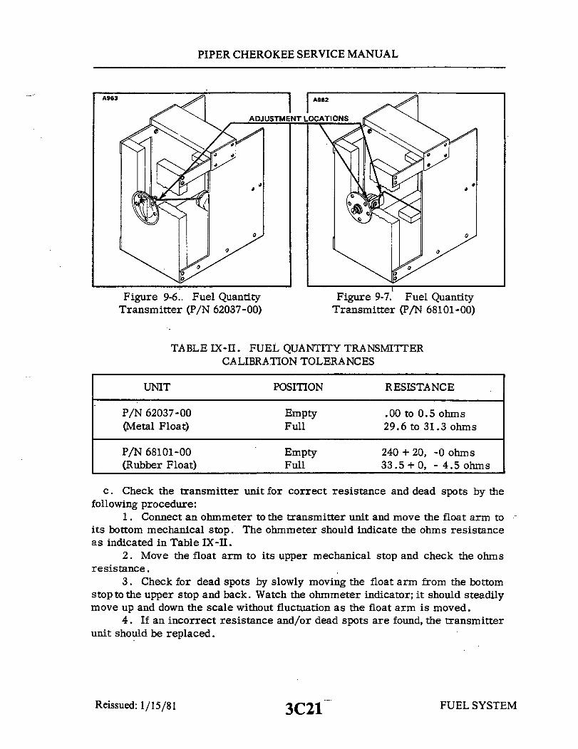
PIPER CHEROKEE SERVICE MANUAL
I I AADJUSTMENT LOCATIONS
Figure 9-6. Fuel QuantityTransmitter (P/N 62037-00)
Figure 9-7. Fuel QuantityTransmitter (P/N 68101-00)
TABLE IX-II. FUEL QUANTITY TRANSMITTERCALIBRATION TOLERANCES
UNIT
P/N 62037-00(Metal Float)
P/N 68101-00(Rubber Float)
POSITION
EmptyFull
EmptyFull
RESISTANCE
.00 to 0.5 ohms29.6 to 31.3 ohms
240 + 20, -0 ohms33.5 + 0, - 4.5 ohms
c. Check the transmitter unit for correct resistance and dead spots by thefollowing procedure:
1. Connect an ohmmeter to the transmitter unit and move the float arm toits bottom mechanical stop. The ohmmeter should indicate the ohms resistanceas indicated in Table IX-II.
2. Move the float arm to its upper mechanical stop and check the ohmsresistance.
3. Check for dead spots by slowly moving the float arm from the bottomstop to the upper stop and back. Watch the ohmmeter indicator; it should steadilymove up and down the scale without fluctuation as the float arm is moved.
4. If an incorrect resistance and/or dead spots are found, the transmitterunit should be replaced.
Reissued: 1/15/81 3C21 FUEL SYSTEM
A963

PIPER CHEROKEE SERVICE MANUAL
9-17. FUEL VALVES.
9-18. FUEL SHUTOFF VALVE. (PA-28-140, -150, -160, -180 and PA-28R.)
9-19. REMOVAL OF FUEL SHUTOFF VALVE.a. Remove two screws holding the fuel valve placard plate and the screw holding the
fuel shutoff valve handle.b. Remove fuel shutoff valve handle and placard plate.c. Disconnect right and left fuel inlet lines from fuel valve assembly.d. Disconnect fuel outlet line from fuel valve assembly.e. Remove fuel valve assembly by removing attaching screws.
9-20. DISASSEMBLY OF FUEL SHUTOFF VALVE. Aircraft equipped with fuel selectorvalve P/N 11383-04, must be disassembled according to the latest revision of Piper ServiceBulletin No. 355. Disassembly of other fuel selector valves is not recommended.
9-21. CLEANING, INSPECTION AND REPAIR OF FUEL SHUTOFF VALVE. Aircraftequipped with fuel selector valve P/N 11383-04, must be cleaned, inspected, and repairedaccording to the latest revision of Piper Service Bulletin No. 355. No cleaning, inspection, orrepair is recommended for other fuel selector valves.
THIS SPACE INTENTIONALLY LEFT BLANK
FUEL SYSTEMReissued: 1/15/813C22

PIPER CHEROKEE SERVICE MANUAL
9-22. ASSEMBLY OF FUEL SHUTOFF VALVE. Aircraft equipped with fuel selectorvalve P/N 11383-04 must be assembled according to the latest revision of Piper Service Bul-letin No. 355.
9-23. INSTALLATION OF SHUTOFF VALVE.a. Secure the valve to the bulkhead attachment plate with attaching screws.b. Connect the fuel lines to the valve.c. Install the fuel valve placard with attaching screws.d. Install the valve control handle with attaching screw.
9-24. FUEL SELECTOR VALVE AND FILTER. (PA-28-235.)
9-25. FUEL SELECTOR VALVE OPERATION. When the fuel selector handle is not in apositive selector detent position, more than one fuel port will be open at the same time. Itshould be ascertained that the fuel selector is positioned in a detent, which can be easily feltwhen moving the handle through its various positions.
9-26. REMOVAL OF FUEL SELECTOR VALVE AND FILTER.a. Drain fuel from tanks. (Refer to Draining Fuel System, Section II.)b. Remove rear seats, seat belt attachments and floor panel just aft of the main spar by
removing the floor attachment screws. Lift the panel and remove.c. Remove plate from bottom of the fuselage which covers fuel selector.d. Disconnect the fuel lines and selector linkage from valve assembly.e. Remove the four mounting screws which hold the fuel selector in place and remove
the selector assembly.
THIS SPACE INTENTIONALLY LEFT BLANK
Reissued: 1/15/81 3C23 FUEL SYSTEM

PIPER CHEROKEE SERVICE MANUAL
827 EXTERNAL DETENT 926
10
3
1 H28-4 VALVES ONLY
1. PLATE, QUICK DRAIN2. SHAFT, QUICK DRAIN3. SLEEVE
4 BALL, HANDLE
7 5. VALVE HANDLE6. BALL7. FILTER8. SPECIAL "O" RING9. SPRING
10. SNAP RING
Figure 9-8. Fuel Selector and Filter (PA-28-235)
9-27. PORT REPAIR OF 1H264 FUEL SELECTOR. (Refer to Figure 9-8.) Thefollowing information is for the 1 H26-4 valves only, and the PA-28 parts catalog should beused to order replacement parts.
a. Remove and discard the snap ring (10), spring (9), ball (6) and "O" ring (8) from thevalve port.
b. Replace parts removed in Step a with new parts.
NOTE
Use only special "O" ring provided by service spares and usecare not to push "O" ring into center of valve housing.
c. Pressure check valve with 10 +5 -0 psi of air applied at outlet port. No bubblesshould be observed when valve is held with the four inlet ports pointing up and gasolineplaced in each port.
d. Rotate the fuel selector through its full cycle of tank positions to insure properoperation.
e. Reinstall fittings with new "O" rings in each inlet port and reinstall the valve intothe airplane in accordance with Paragraph 9-29;,
Reissued: 1/15/81 3C24 FUEL SYSTER

PIPER CHEROKEE SERVICE MANUAL
METALLIC FILTER ASSEMBLY
1715
*
-
1. FILTER2. SPRING3. RETAINER WASHER4. BOWL NYLON FILTER ASSEMBLY
Figure 9-9. Fuel Filter (PA-28-235)
9-28. CLEANING FILTER ASSEMBLY.a. Remove the access panel to the filter bowl on the bottom of the fuselage.b. Remove fuel strainer bowl.c. Remove filter disc assembly from center stem by compressing filter retainer spring
and removing filter retainer washer. (Refer to Figure 9-9.)d. Inspect bowl gasket and replace if necessary.e. Filter discs may be cleaned as follows:
1. Plug open ends of filter disc center with stoppers to prevent dirt from entering.2. Wash metallic filter disc in acetone, gasoline, carbon tetrachloride,
trichlorethylene (permachor) or Bendix cleaner. Wash nylon filter disc with soap and water.
CAUTION
Do not use acetone, methylethylketone, etc., to clean nylonfilter discs.
3. Remove stubborn deposits from filter disc with a soft bristle brush.4. Rinse all traces of soap solution. Drain or blow dry and remove stoppers.
f. Replace the filter disc if damage is evident.g. Reinstall filter disc assembly and strainer bowl.
FUEL SYSTEM3D1Revised: 10/3/83

PIPER CHEROKEE SERVICE MANUAL
9-29. .INSTALLATION OF FUEL SELECTOR AND FILTER VALVE.a. Position the valve inside the airplane just aft of the main spar.b. Secure the valve with machine screws, washers and self-locking nuts.c. Connect the fuel lines.d. Rig fuel selector valve linkage to insure that selector handle engages left indent
position when it is against the safety stop on console cover.e. Fill the fuel tanks and check all connections for leaks.f. Install the rear seat.g. Install the access plate to the bottom of the fuselage with attaching screws .
NOTE
When installing the fuel selector valve, it is recommended thecomplete fuel system and tanks be drained and flushed toascertain no contamination is present. (Refer to paragraph9-55.)
Reissued: 1/15/81 3D2 FUEL SYSTEM

PIPER CHEROKEE SERVICE MANUAL
A640
1. BODY2. SCREEN3. GASKET4. STRAINER 30WL
5. BAIL WIRE6. BAIL ASSEMBLY7. SAFETY WIRE8. DRAIN VALVE
Figure 9-10. Fuel Filter Bowl and Screen(PA-28-140, -150, -160, -180 and PA-28R)
9-30. FUEL FILTER BOWL AND SCREEN. (PA-28-140, -150, -160, -180 and PA-28R.)(Refer to Figure 9-10.)
9-31.. REMOVAL OF FUEL FILTER BOWL AND HOUSING.a. Ascertain that the fuel shutoff is in the off position.b. Remove the engine cowlings by releasing the cowl fasteners or the attach-
ing screws, depending on the type installed. Be certain that all electrical leadsare disconnected prior to removal of the cowl.
c. Disconnect the fuel lines from the filter bowl housing.d. Cut the safety wire, loosen the bail nut, move the bail wire to the side and
remove the bowl.e. Remove the housing of the filter bowl by spreading the ends of the bail wire
allowing the housing to be lifted from the bracket.
9-32. INSTALLATION OF FUEL FILTER BOWL AND SCREEN.a. Position the top of the filter bowl to the bracket and connect the fuel lines.b. Spread the bail wire ends and insert them through the holes in the side of
the mounting bracket and the top of the filter bowl.c. Position the bowl and bail wire, and tighten the bail nut.d. Safety the bail nut and the bail wire assembly.e. Install the engine cowling.
Reissued: 1/15/81 3D3 FUEL SYSTEM
PIPER CHEROKEE SERVICE MANUAL
9-33. CLEANING AND INSPECTION OF FILTER BOWL SCREEN.a. Follow steps a, b and d of paragraph 9-31 for removal of the filter bowl.
b. Remove the gasket and screen from the filter housing.c. Clean the screen and bowl with acetone or a suitable dry type solvent. If damaged,
replace screen.d. Replace the screen followed by a new gasket.e. Position the bowl and bail wire, and tighten the bail nut.f. Safety the bail nut and the bail wire assembly.
9-34. ELECTRIC FUEL PUMPS.
9-35. PLUNGER FUEL PUMPS. (PA-28-140, -150, -160, -180 and -235.)
9-36. REMOVAL OF FUEL PUMPS.a. On the PA-28-140, -150, -160, and -180, the fuel pump may be removed by the
following procedure:1. Remove the cowlings by releasing the cowl fasteners or the attaching screws,
depending on the type installed. Be certain all electrical leads are disconnected prior toremoval.
2. Ascertain that the fuel shutoff valve is in the off position.3. Disconnect the fuel pump electrical leads.4. Disconnect the fuel lines from the inlet and outlet sides of the pump.5. Remove the nuts and bolts securing the pump to its mounting bracket and
remove the fuel pump.b. On the PA-28-235, the electric fuel pump(s) may be removed by the following
procedure:1. Ascertain the fuel selector is in the off position.2. Remove the fuel drain placard cover from the front of the rear seat by removing
the attaching screws.3. Remove the bottom portion of the rear seat by unsnapping it across the front
and lifting the seat pulling it forward at the same time.4. Remove the pump cover located in the left side of the floor opening.5. Disconnect the electrical lead from the pump.6. Disconnect the inlet and oulet lines from the pump.7. Remove the pump by removing the pump attaching bolts.
Reissued: 1/15/81 FUEL SYSTEM
3D4

PIPER CHEROKEE SERVICE MANUAL
9-37. DISASSEMBLY OF FUEL PUMP. The following procedure is given for disassemblyof the fuel pump. Repair of the pump is limited to the fuel reservoir area only, since theelectrical system is sealed. For cleaning and servicing purposes, refer to the appropriateinstructions covering the particular type pump being serviced:
a. Early Type Pump: (Refer to Figure 9-11.)1. Cut the safety wire and remove the bottom cover, gasket and filter
screen from the pump.
NOTE
If the screen does not come out, use caution removingit from the pump housing so as not to damage it.
2. Remove the three screws securing the plunger spring cup inside thepump. Remove the cup and gasket.
3. Pull the plunger spring and plunger assembly from the pump with fingers.
CAUTION
Do not remove the buffer spring and valve from theplunger assembly.
b. Late Type Pump: (Refer to Figure 9-12.)1. Cut the safety wire and remove the bottom cover, gasket, magnet and
filter screen from the pump.
NOTE
If the screen does not come out use caution removingit from the pump housing so as not to damage it.
2. Remove the retainer spring from the plunger tube using thin nose pliersto spread and remove the ends of the retainer from the tube.
3. Remove the washer, "O" ring seal, cup valve, plunger assembly fromthe pump.
FUELSYSTEMReissued: 1/15/81 3D5
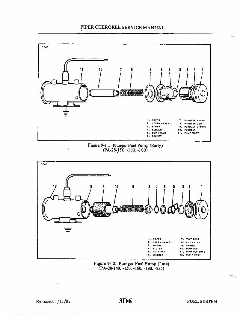
PIPER CHEROKEE SERVICE MANUAL
C349
7 9
. COVER2. COVER GASKET3. SCREW4. SCREEN5. CUP VALVE6. GASKET
7. PLUNGER VALVE8. PLUNGER CUP9. PLUNGER SPRING
10. PLUNGER11. PUMP BODY
Figure 9-11. Plunger Fuel Pump (Early)(PA-28-150, -160, -180)
C349
9 8 7 6 5 3 2 1
1. COVER2. COVER GASKET3. MAGNET4. FILTER5. RETAINER6. WASHER
7. "O" RING8. CUP VALVE9. SPRING
10. PLUNGER11. PLUNGER TUBE12. PUMP BODY
Figure 9-12. Plunger Fuel Pump (Late)(PA-28-140, -150, -160, -180, -235)
Reissued: 1/15/81 3D6 FUEL SYSTEM
PIPER CHEROKEE SERVICE MANUAL
CAUTION
Do not remove the buffer spring and valve from theplunger assembly.
Do not tamper with seal at center of mounting bracketat side of pump as it retains the dry gas which sur-rounds the electric system in the upper portion of thepump.
9-38. CLEANING, INSPECTION AND REPAIR OF FUEL PUMP.a. Clean all parts with acetone or a suitable dry type solvent. If plunger
assembly does not come clean or there are any rough spots, polish gently withcrocus cloth.
b. Inspect the pump for the following:1. Check the filter screen for damage or distortion.2. Gently touch the cup valve and check for freedom of movement. Do not
disassemble.3. Shake the plunger assembly and listen for clicks to indicate valve action.4. On the late model pumps, check the condition of the "O" ring.5. Check the condition of the cover gasket and plunger spring cup gasket.
c. Repair of the pump is limited to replacementof parts found defective duringinspection.
9-39. RESISTANCE CHECK (PLUNGER TYPE PUMP). To check the resistanceof the pump, connect an ohmmeter to the lead wire of the pump and the pumpbody. A reading of 4.87 to 6.4 ohms for a 12-volt pump should be obtained.
9-40. ASSEMBLY OF FUEL PUMP.a. Later Type Pump: (Refer to Figure 9-11.)
1. Insert the plunger assembly (10) in the tube with the buffer spring endfirst. Check fit by slowly raising and lowering the plunger to stick. If a clickcannot be heard, the interrupter assembly is not functioning properly in whichcase the pump should be replaced.
2. Install the component parts in the following order: Cup valve, "O" ringseal, and washer. Install the retainer spring securing the components inside thepump housing.
3. Place the cover gasket and magnet in the bottom cover with the filterscrew.
Reissued: 1/15/81 3D7 FUEL SYSTEM

PIPER CHEROKEE SERVICE MANUAL
4. Carefully guide the screen around the plunger spring cup. The screenmust fit snugly at both ends. Do not pinch or distort the screw. Draw the bottomcover tight with a wrench and safety.
b. Early Type Pump: (Refer to Figure 9-12.)1. Insert the plunger spring assembly (10) in the tube with the buffer spring
end first. Check fit by slowly raising and lowering the plunger in the tube. Itshould move fully without any tendency to stick. If a click cannot be heard, theinterrupter assembly is not functioning properly in which case the pump shouldbe replaced.
2. Install the plunger spring cup gasket (use a new one) and the plungerspring cup. Draw the screws reasonably tight, but do not over tighten them. Besure the cup is not cocked to prevent the plunger from binding in the tube.
3. Place the filter screen around the bottom cover magnet.4. Carefully guide the screen around the plunger spring cup. The screen
must fit snugly at both ends. Do not pinch or distort the screen. Draw the bottomcover tight with a wrench and safety.
9-41. ADJUSTMENT OF ELECTRIC FUEL PUMP (BENCH TEST).a. Ascertain that the pump is sufficiently lubricated to prevent damage if run
dry for a period greater than five minutes.b. Connect the electrical lead of one pump to a 14-volt DC power source.c. Using a suitable container with the proper octane fuel, connect a fuel line
from a container to the inlet side of the pump.d. Connect another line from the outlet side of the pump to a pressure gauge
and by-pass valve and back to the container.e. Run the pump with the by-pass valve open until a steady flow of fuel is ob-
tained. Then close the by-pass valve and check the pressure gauge for the properreading of 4 to 4.75 psi maximum, no flow.
f. Repeat steps b through e for the second fuel pump.g. If the proper pressure is not obtained, the plunger spring may be replaced
or it may be necessary to replace the complete pump assembly.
9-42. ADJUSTMENT OF ELECTRIC FUEL PUMP (IN AIRPLANE).a. With the access panel removed and the fuel selector in the OFF position,
remove the fuel line from the outlet end of the pump.b. Connect a test line with a by-pass valve and pressure gauge to the outlet
end of the pump to be checked.c. Place a container below the pumpto catch any fuel from the test line during
the adjustment of the pump.
Reissued: 1/15/81 FUEL SYSTEM3D8
PIPER CHEROKEE SERVICE MANUAL
d. Disconnect the electrical lead to the pump that is not being checked.e. Turn the fuel selector on, open the by-pass valve on the test line and start
the pump.f. When a steady flow of fuel is obtained, close the by-pass valve and check
the reading on the pressure gauge. It should read 4 to 4.75 psi maximum, noflow. Do not keep by-pass valve closed for more than one minute during pumpoperation and adjustment.
g. Repeat steps b through f for the other pump.h. If the proper pressure is not obtained, the plunger spring may be replaced
or it may be necessary to replace the complete pump assembly.i. Reconnect the original fuel line to the pump. Open fuel selector and run
the pump to check for any fuel leaks.j . Shut off the pump, close the fuel selector and replace and secure the access
panel.
9-43. INSTALLATION OF FUEL PUMPS.a. Install the fuel pump on PA-28-140, -150, -160, and -180 airplanes by the following
procedure:
1. Position the fuel pump tothe engine mount frame and secure with bolts,washers and nuts.
2. Connect the fuel lines to the pump.3. Connect the electrical leads to the pump.4. Turn the fuel shutoff on and operate the fuel pump. Check all fuel line
fittings for leakage.5. Install the cowling.
b. Install the fuel pump(s)on PA-28-235 airplanes by the following procedure:1. Position the fuel pump(s) behind the main spar and secure with bolts,
washers and nuts.2. Connect the inlet and outlet lines to the pump.3. Connect the electrical leads to the pump.4. Turn the fuel selector on and operate the pump(s). Check all fuel line
fittings for leakage.5. Install the pump cover with attaching screws.6. Install the bottom section of the rear seat.7. Install the fuel drain cover with attaching screws.
Reissued: 1/15/81 FUEL SYSTEM3D9

PIPER CHEROKEE SERVICE MANUAL
9-44. ROTARY FUEL PUMPS (WELDON) (PA-28R).
9-45. REMOVAL OF FUEL PUMP.
a. Remove the engine cowling from the aircraft.b. Ensure the fuel shutoff valve is in the off position.c. Disconnect the electrical leads from the pump.d. Disconnect the fuel lines from the pump.e. Remove the cap screws, washers, and plate.f. Remove the fuel pump from the airplane.
9-46. REPAIR OF FUEL PUMP.
-CAUTION -
Overhauling fuel pump is not recommendedbecause of special tools needed. If overhaulingis necessary, the pump should be returned to:
The Weldon Tool Company300 Woodhill RoadCleveland, Ohio 44104
However, some repairs may be accomplished as follows:a. Replacing the shaft seal.
1. Remove the pump end assembly from the motor by removing the four machine screws.2. Pry the shaft seal loose from the insert.3. Check the shaft for burrs, scratches or any defects which might cause the seal to wear.Any defect would be cause for pump replacement.4. Replace the seal on the shaft and press into place.5. Install the pump end assembly to the motor in its original position. Install the four machinescrews and safety.
b. Repairing the relief valve.1. Remove the adjusting screw from the pump end assembly. Do not change the positionof the jam nut.2. Remove the valve plunger and spring.3. Inspect the valve seat, plunger and spring for condition and wear. If the valve seat isdamaged, replace the pump.4. Install the plunger, spring, and adjusting screw to the pump.5. Adjust the pump pressure as described in paragraph 9-47 or 9-48.
c. Replacing fitting O-rings.
- WARNING -
If O-rings are defective or if inlet fitting is notproperly installed, air will be drawn into fuel line,causing engine to run lean or stop running. Installnew O-rings whenever fuel pump is removed forservice.
1. Remove inlet and outlet fittings.2. Remove O-rings. Inspect chamfered O-rings seat for nicks.
Reissued: 1/15/86 FUEL SYSTEM3D10

PIPER CHEROKEE SERVICE MANUAL
3. Install new O-rings.
- CAUTION -
Seal all pipe threads with Lubon #404. Do not applyto the first two threads or sealant may enter fuelsystem.
4. Replace fittings. Torque to 230-360 in.-lb.
9-47. ADJUSTMENT OF ELECTRIC FUEL PUMP (BENCH TEST).a. Ensure that the pump is sufficeintly lubricated to prevent damage.b. Connect the electric leads to a 14-volt DC power source.c. Using an approved container with the proper octane fuel, connect a fuel line
from the container to the inlet fitting.d. Connect another line from the pump outlet to a pressure gauge and by-pass valve
and back to the container.e. Run the pump with the by-pass valve open until a steady flow of fuel is ob-
tained.f. Close the by-pass valve and check the pressure gauge for a proper reading of 26
to 29 psi, no flow. Do not keep the by-pass valve closed for more than one minuteduring pump operation and adjustment.
g. Loosen the locknut and turn the adjusting scre until there is a reading of 29 psimaximu, no flow, on the gauge. Repeat steps e, f, and g until the proper pressureis obtained.
h. Disconnect the power source from the pump and lock the adjustment screw withthe locknut. Remove the fuel lines from the pump.
9-48. ADJUSTMENT OF ELECTRIC FUEL PUMP (IN AIRPLANE).a. With the access panel removed and the fuel selector valve in the OFF position,
remove the fuel line from the outlet end of the pump.b. Connect a test line with a by-pass valve and pressure gauge to pump outlet.c. Place a container below the pump to catch any fuel from the test line.d. Turn the fuel selector valve on, open the by-pass valve on the test line, and start
the pump.e. When fuel flow becomes steady, clsoe the by-pass valve and check the reading
on the pressure gauge. The gauge should read 26 to 29 psi, no flow. Do not keepthe by-pass valve closed for more than one minute during pump operation andadjustment.
f. Loosen locknut on adjusting screw and turn the screw to obtain the properpressure of 29 psi maximum, no flow. Repeat this step until adjustment iscomplete. Lock adjusting screw with locknut.
g. turn off fuel pump and close fuel selector valve. Remove the test line from thepump.
h. connect the original fuel lines to the pump. Open fuel selector valve and runthe pump to check for any fuel leaks.
i. Shut off the pump, close the fuel selector valve and replace access panel.
Revised: 1/15/86 3D11 FUEL SYSTEM

PIPER CHEROKEE SERVICE MANUAL
9-49. INSTALLATION OF FUELPUMP.
a. Place fuel pump inside coverassembly and secure with cap
screws, washers and plate. -
WARNING -
If O-rings are defective or if inlet fittingis not properly installed, air will bedrawn into fuel line, cuasing engine torun very lean or stop running. Installnew O-rings whenever fuel pump isremoved for service.
b. Inspect chamfered O-ring seatfor nicks.c. Install new O-rings betweenthe fittings and the pump.d. Connect fittings to fuel pump.Torque to 230-360 in.-lb.e. Connect fuel lines to fuel pumpfittings.f. Connect the electrical leads tothe pump.g. Turn the fuel selector valve onand operate the fuel pump. Checkthe line fittings for leakage.h. Install the cowling.
9-50. ENGINE PRIMER PUMP.
C349
1. CHECK BALL2. BALL SPRING3. RETAINER SCREW4. "O" RINGS5. CYLINDER6. SEALING SPRING7. PISTON
8. STOP PIN9. PUMP HANDLE
10. FACE NUTII. WASHER12. LOCK NUT13. SEALING PIN
Figure 9-13. Engine Primer
9-51. REMOVAL OF ENGINE PRIMER (Refer to Figure 9-13).a. Disconnect the fuel lines from the primer behind the instrument panel.b. Loosen the locknut (12) from behind the panel.c. Unscrew the knurled face nut (10), withdraw the pump handle (9) and piston (7)
from the cylinder (5).d. Remove the remaining portion of the primer.
9-52. DISASSEMBLY, CLENAING, AND ASSEMBLY OF ENGINE PRIMER(Refer to Figure 9-13).
a. The primer may be disassembled after removal by removing the screws (3), springs(2), and check balls (1) from the end of the cylinder housing.
b. Clean the primer parts with acetone or a dry type solvent.c. Install new O-rings to the piston (7) and lubricate with light motor oil.d. Install the balls (1), springs (2), and screws (3) to the cylinder housing.e. Insert the pump handle (9) and piston (7) into the cylinder (5), finger tighten the
knurled face nut (10).f. Immerse the pump in gasoline and operate several times to ensure proper operation.
Revised: 1/15/86 FUEL SYSTEM3D12
PIPER CHEROKEE SERVICE MANUAL
9-53. INSTALLATION OF ENGINE PRIMER PUMP. (Refer to Figure 9-13.)a. Remove the pump handle (9) and piston (7) by unscrewing the knurled face
nut (10), if previously installed.b. Insert the cylinder assembly through the back side of the panel.c. Insert the piston into the cylinder (5) and tighten the knurled face nut.d. Position the primer and tighten the locknut (12) on the cylinder behind the
panel.e. Connect the fuel lines to the primer.f. Disconnect the primer line inside the engine compartment. Operate the
pump to ascertain proper operation.
9-54. PRIME JETS.a. To remove the prime jets, disconnect the supply line from each jet. With
a deep socket and light pressure, remove the jet from the cylinder.b. To clean the jet, soak in a carbon remover solution long enough to loosen
any dirt and blow clean with air pressure. Do not use sharp objects or wirebrush to clean the jet tube.
c. Install the jet finger tight to assure that the threads are not crossed andthen torque 60 inch-pounds. Align and install the fuel supply lines, tighten to asnug fit.
NOTE
Should further fuel stoppage of the primer systemexist, check the supply lines for stoppage, bent orcollapsed walls.
9-55. CLEANING FUEL SYSTEM.a. To flush the fuel tanks and selector valve, disconnect the fuel line at the
carburetor or injector.b. Select a fuel tank, turn on the electric fuel pump and flush fuel through the
system until it is determined there is no dirt and foreign matter inthe fuel valveor tank. During this operation, agitation of the fuel within the tank will help pickup and remove any dirt.
c. Repeat this procedure for each tank.d. When all tanks are flushed, clean all filters.
Reissued: 1/15/81 FUEL SYSTEM3D13

3D14INTENTIONALLY LEFT BLANK

PIPER CHEROKEE SERVICE MANUAL
TABLE IX-III. FUEL SYSTEM TROUBLESHOOTING
Trouble Cause Remedy
Failure of fuel to flow. Blockage in fuel line. Flush fuel system.
Blockage of cap vent.
Failure of mechanicalor electrical fuel pump.
Failure of fuel selectorto be in proper position.
Damage of fuelselector valve.
Check and clean venthole in cap.
Check and replace ifnecessary.
Check position ofselector and adjustif required.
Replace fuel valve.
Fuel gauge fails tooperate.
Broken wire.
Gauge inoperative.
Check and repair.
Replace.
Float partially orcompletely filledwith fuel.
Circuit breaker openor fuse blown.
Incomplete ground.
Float and arm assem-bly of fuel transmitterin wing sticking.
Replace float.
Check and reset orreplace.
Check ground connec-tions at fuel trans-mitter in wings.
Check fuel transmitterin wings and repair orreplace.
Reissued: 1/15/81 FUEL SYSTEM3D15

PIPER CHEROKEE SERVICE MANUAL
TABLE IX-III. FUEL SYSTEM TROUBLESHOOTING (cont)
Trouble
Fuel gauge indicates fullwhen tanks are not full.
No fuel pressure indica-tion.
Pressure low orpressure surges.
Cause
Complete ground ontransmitter wire.
Fuel valve stuck.
No fuel in tanks.
Defective fuel pump.
Air leak in intakelines.
Defective gauge.
Failure of fuelselector to be inproper position.
Remedy
Check ground connec-tions at fuel trans-mitting in wings.
Check valve.
Check fuel level and fill.
Check pump for pres-sure build up. Checkdiaphragm and reliefvalves in engine pump.Check for obstructionsin electric pump. Checkby-pass valve. Airleak in intake lines.
Check O-rings fordamage and inlet fittingfor proper installation.
Replace gauge.
Check position of selec-tor and adjust if requir-ed.
Unidentified leak.Obstruction in inletside of pump.
Trace lines and locateobstruction.
Faulty by-pass valve.
Fuel valve leaks. Faulty diaphragm. Replace or rebuild pump.
Fuel line damagedor improperlyinstalled.
Worn "O" rings.
Locate and repair ortighten.
Replace "O" rings orvalve.
Revised: 1/15/86
Replace.
FUEL SYSTEM3D16

PIPER CHEROKEE SERVICE MANUAL
.219"
.188" HOLE3 REQ. (T.M.M.P.)
R
9.938"
2 WOOD SCREWSEVENLY SPACED
MATERIAL LIST2-8.75 x9.938x.1251.8.75 x 6 x .75 RICH1.8.75 x 6 x 1 RICHLITE1- 1.50 x 6 x .50 RICHLITE1 2.50 x 6.25 x .50
I 2. 1.625 x x 2.50 x .125 2024-T3 ALUM.
26 WOOD SCREWS
2024-T3 ALUM.LITE, MASONITE OR HARDWOODLITE, MASONITE OR HARDWOODCHLITEMASONITE OR HARDWOOD.50 RICHLITE,MASONITE OR HARDWOOD125 2024-T3 ALUM.
6 WOOD SCREWSEVENLY SPACED
i
. "1Figure 9-14. Fabricated Fuel Quantity Transmitter Checking Jig
d: 1/15/81 3D17 FUELSYS
C351
I
I
t
Reissud: 1/15/81 TEM

SECTION XINSTRUMENTS
Paragraph AeroficheGrid No.
10-1. General ..................................................... 3D2210-2. Non-Electrical Instruments .................................... 3D2210-3. Vacuum System .............................................. 3D22
10-4. Vacuum System Service Tips .......................... 3D2210-5. Troubleshooting ..................................... 3D24
10-6. Suction Gauge ............................................... 3E2110-7. General ............................................ 3E2110-8. Troubleshooting ..................................... 3E21
10-9. Vacuum Regulator Valve ...................................... 3E2110-10. General ............................................ 3E2110-11. Troubleshooting ..................... ........... 3E2110-12. Adjustment of Vacuum Regulator Valve
(Without Vacuum Warning Lights) ................ 3E2110-13. Adjustment of Vacuum Regulator Valve
(With Vacuum Warning Lights) ................... 3E2210-14. Adjustment of Vacuum Warning Light Pressure
Switch ........................................ 3E2210-15. Adjustment of Vacuum Turn and Bank Indicator
Regulator Valve................................. 3E2410-16. Removal and Replacement of Regulator Valve .......... 3E24
10-17. Vacuum Pump ............................................... 3E2410-18. General ............................................ 3E2410-19. Troubleshooting ..................................... 3F110-20. Removal of Vacuum Pump ........................... 3F110-21. Replacing Pump Fittings ............................. 3F110-22. Installation of Vacuum Pump ......................... 3F210-23. Instrument Air System ............................... 3F2
10-24. Directional Gyro ............................................. 3F310-25. General . .. .................................. 3F310-26. Troubleshooting ..................................... 3F510-27. Removal and Replacement ............................ 3F6
10-28. Gyro Horizon ................................................ 3F610-29. General ............................................ 3F610-30. Troubleshooting ..................................... 3F710-31. Removal and Replacement ............................ 3F8
Reissued: 1/15/81 3D18
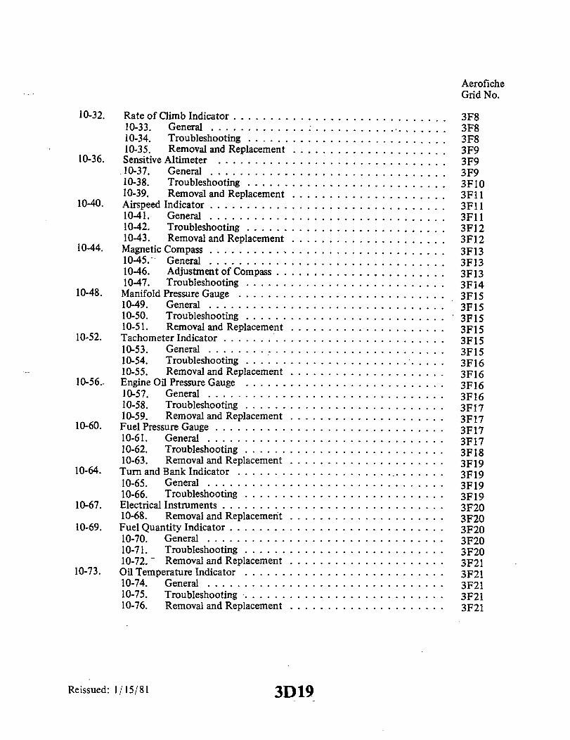
10-32. Rate of Climb Indicator .........10-33. General ............10-34. Troubleshooting .......10-35. Removal and Replacement
10-36. Sensitive Altimeter .....10-37. General ............10-38. Troubleshooting .......10-39. Removal and Replacement
10-40. Airspeed Indicator ............10-41. General ......10-42. Troubleshooting .......1043. Removal and Replacement
10-44. Magnetic Compass ........... .10-45. General ............10-46. Adjustment of Compass . . .10-47. Troubleshooting .......
10-48. Manifold Pressure Gauge ....10-49. General ............10-50. Troubleshooting .......10-51. Removal and Replacement
10-52. Tachometer Indicator . .........10-53. General ............10-54. Troubleshooting .......10-55. Removal and Replacement
10-56.. Engine Oil Pressure Gauge .......10-57. General ............10-58. Troubleshooting .......10-59. Removal and Replacement
10-60. Fuel Pressure Gauge ...........10-61. General ............10-62. Troubleshooting .......10-63. Removal and Replacement
10-64. Turn and Bank Indicator ....10-65. General ............10-66. Troubleshooting .......
10-67. Electrical Instruments ..........10-68. Removal and Replacement
10-69. Fuel Quantity Indicator .........10-70. General ............10-71. Troubleshooting .......10-72. - Removal and Replacement
10-73. Oil Temperature Indicator ...10-74. General ............10-75. Troubleshooting ......10-76. Removal and Replacement
Reissued: 1/15/81 3D19
AeroficheGrid No.
..................... 3F8........... ....... 3F8
...................... 3F8
...................... 3F9
...................... 3F9
...................... 3F9.................... 3F10.................... . ..3F11.................... . .3F11.................... . .3F11.................... . .3F12.................... . .3F12.................... . .3F13.................... . .3F13.................... . .3F13.................... . .3F14.................... 3F15.................... .. 3F15.................... ..3F15
..................... 3F15
.................... . .3F15
.................... . .3F15.................... 3F16
.................... 33F16.................... 3F16...................... 3F16.................... 3F17............. ........ 3F17.................... 3F17...................... 3F17.................... 3F18..................... 3F19..................... 3F19.................... 3F19.................... 3F19.................... 3F20............ ......... 3F20........... .......... 3F20..................... 3F20................. ..... 3F20
.................... 3F21...................... 3F21.............. ....... . 3F21................ ...... 3F21............... ....... 3F21

AeroficheGrid No.
10-77. Ammeter ..................................... 3F2110-78. General ............................... . 3F2110-79. Troubleshooting ........................... 3F2110-80. Removal and Replacement ..................... 3F21
10-81. Removal and Replacement of Face Mounted Instruments ........ . 3F2110-82. General ............................... . 3F22
10-83. Removal and Replacement of Cluster Mounted Instruments ........ 3F2210-84. General ............................... . 3F22
10-85. Exhaust Gas Temperature Gauge (Alcor) . ........ ..... .... . 3F2210-86. General .............................. ........... . 3F22
10-87. Cleaning and Inspection ............................ . 3F2310-88. Troubleshooting .......................... . 3F23
10-89. Cylinder Head Temperature Gauge ..................... . 3G310-90. General ................................ 3G310-91. Troubleshooting .......................... . 3G310-92. Removal and Replacement .................... . 3G3
10-93. Fuel Flow Gauge ................................. 3G310-94. General .............................. ........... . 3G310-95. Troubleshooting .......................... . 3G410-96. Removal and Replacement .................... . 3G4
10-97. Piper AutoControl System .......................... . 3G410-98. Annunciator Panel ............. ................... 3G4
10-99. General ................................ 3G410-100. Troubleshooting . . . . . . . . . . . . . . . . . . . ........ 3G410-101. Removal and Replacement ..................... 3G4
Reissued: 1/15/81 3D20

3D21INTENTIONALLY LEFT BLANK

PIPER CHEROKEE SERVICE MANUAL
SECTION X
INSTRUMENTS
10-1. GENERAL. The instrumentation in the Cherokee is designed to give a quick andactual indication of the attitude, performance and condition of the airplane. Maintenance,other than described in these sections, shall be done by the instrument manufacturer or anauthorized repair station.
The two types of instruments have been classified in this section as non-electrical andelectrical. The first part of this section will pertain to maintenance and troubleshooting ofall the instruments and their systems which depend on non-electrical sources for theiroperation. The remaining portion of this section is directed to maintenance andtroubleshooting of all the electrically operated instruments.
10-2. NON-ELECTRICAL INSTRUMENTS.
10-3. VACUUM SYSTEM.
10-4. VACUUM SYSTEM SERVICE TIPS. The following information is intended toacquaint field service personnel with a means to diagnose vacuum system service symptomson those components which are serviced by removal and replacement. These items includehoses, clamps, gyro filters, vacuum regulating valves and vacuum gauges.
a. Hoses and Clamps:1. These items should be examined periodically and inspected carefully whenever
engine maintenance activities cause hose disconnections to be made at the pump, regulatingvalve, gyros and/or vacuum gauge.
2. The ends of the hoses should be examined for rubber separation and slivers ofrubber on the inside diameter of the hoses. These slivers can and do become detached. Ifthis happens, the vacuum pump suck these loose particles and eventually ingest them. Thiscan cause premature pump service.
3. Hose clamps and fittings should be replaced when broken, damaged or corroded.
CAUTION
When replacing any of the threaded fittings, DO NOT USEPIPE DOPE or any other anti-seize tape or compound. TheAIRBORNE fittings are all cadmium plated to avoid the needfor any other anti-seize materials. The reason for this cautionis to protect the pump from ingesting any foreign materialsthat could cause premature service.
Reissued: 1/15/81 3D22 INSTRUMENTS

PIPER CHEROKEE SERVICE MANUAL
b. Vacuum Gauges:1. Vacuum gauges seldom require service and usually are replaced when
malfunctions occur.
NOTE
Vacuum gauge failure in a properly operating vacuum systemdoes not impair safety of flight.
2. If the vacuum gauge malfunctions in a manner to cause an incorrect reading innormal cruise conditions, the gauge must be checked by comparing the reading with a gaugeof known accuracy. If the gauge is indicating correct values and the system vacuum level isnot in accordance with the specified vacuum, then and only then should the regulator bereset.
3. Visual examination of the gauge performance should cover the following steps:(a) With engine stopped and no vacuum applied to the gauge, its pointer should
rest against the internal stop in the 9 o'clock position. Any otherdisplacement from this position suggests need for replacement.
(b) A slight overshoot during engine startup, not to exceed half an inch (1/2")of mercury, is normal and is not cause to replace gauge.
(c) With engine operating at normal cruise RPM, the gauge should read from 4.9inches to 5.1 inches of mercury (vacuum).
(d) At 1200 RPM, the vacuum gauge reading should be more than four inches ofmercury.
c. Gyro Filters:1. Gyro filters must be serviced on a scheduled basis, not to exceed 100 hours, or
sooner as condition indicates.
NOTE
Several gyro filter systems have been used on various aircraft,depending on when the aircraft was built.
2. The oldest aircraft installations generally did not have central filters. Theydepended on the small cloth or paper disc-type filters built into the instruments themselves.This type of filter requires frequent replacement for proper gyro operation.
3. The later system installation employed a large central filter which eliminated thefrequent replacement of the small internal filters in the gyros.
4. The latest system installation employs a large central filter and differentialvacuum gauge that continuously monitors the filter condition while indicating vacuumreadings.
NOTE
In the aircraft systems described in items (2) and (3) above,failure to replace filters would cause a slight increase invacuum gauge readings. The AIRBORNE regulator willautomatically adjust to the flow changes that result whendirty filters are allowed to remain in the system.
Reissued: 1/15/81 INSTRUMENTS3D23
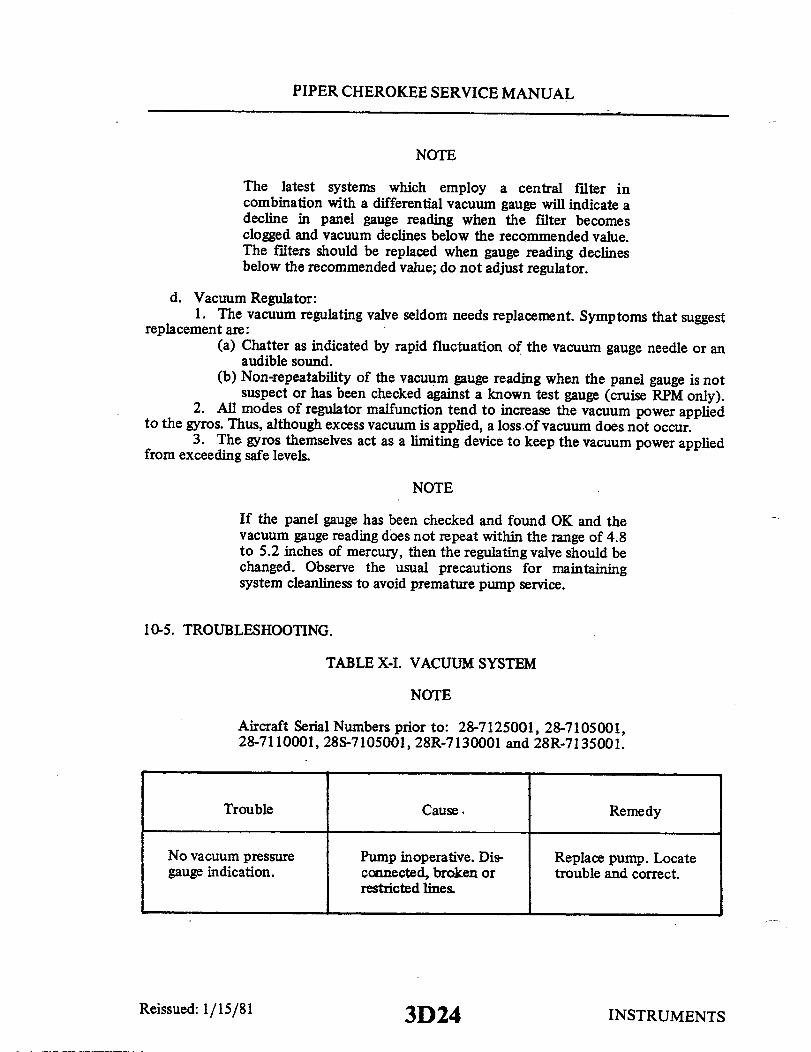
PIPER CHEROKEE SERVICE MANUAL
NOTE
The latest systems which employ a central filter incombination with a differential vacuum gauge will indicate adecline in panel gauge reading when the filter becomesclogged and vacuum declines below the recommended value.The filters should be replaced when gauge reading declinesbelow the recommended value; do not adjust regulator.
d. Vacuum Regulator:1. The vacuum regulating valve seldom needs replacement. Symptoms that suggest
replacement are:(a) Chatter as indicated by rapid fluctuation of the vacuum gauge needle or an
audible sound.(b) Non-repeatability of the vacuum gauge reading when the panel gauge is not
suspect or has been checked against a known test gauge (cruise RPM only).2. All modes of regulator malfunction tend to increase the vacuum power applied
to the gyros. Thus, although excess vacuum is applied, a loss of vacuum does not occur.3. The gyros themselves act as a limiting device to keep the vacuum power applied
from exceeding safe levels.
NOTE
If the panel gauge has been checked and found OK and thevacuum gauge reading does not repeat within the range of 4.8to 5.2 inches of mercury, then the regulating valve should bechanged. Observe the usual precautions for maintainingsystem cleanliness to avoid premature pump service.
10-5. TROUBLESHOOTING.
TABLE X-I. VACUUM SYSTEM
NOTE
Aircraft Serial Numbers prior to: 28-7125001, 28-7105001,28-7110001, 28S-7105001, 28R-7130001 and 28R-7135001.
Trouble Cause. Remedy
No vacuum pressure Pump inoperative. Dis- Replace pump. Locategauge indication. connected, broken or trouble and correct.
restricted lines
INSTRUMENTS3D24Reissued: 1/15/81

PIPER CHEROKEE SERVICE MANUAL
TABLE X-I. VACUUM SYSTEM (cont)
Cause
No vacuum gauge indica-tion at instrument.
No vacuum gauge indica-tion at either instru-ment or source.
Hose from instrument togauge leaking or re-stricted.
Faulty gauge. Mal-functioning, regulatorvalve, or vacuum pump.
Check all lines andconnections.
Check operation ofinstrument. If oper-ation is normal, re-place gauge. If instru-ments are inoperative,check operation ofvacuum pump or regulatorvalve.
Vacuum lines restrictedor broken.
Check system.
Low vacuum systempressure.
Vacuum regulator valveincorrectly adjusted.
Leaking of the systemlines or fittings.
Malfunctioning pump.
Overboard line fromvacuum pump restricted.Sealing plugs loose ingyros.
Adjust regulator valvesin accordance withAdjustments of thissection.
Check all lines andfittings.
Replace pump.
Replace line.
Normal pressure indica-tion, but sluggishoperation of instru-ments.
Instruments air filterelements dirty.
Remove and clean orreplace.
Line restricted be-tween gyro and filter.
Check all lines andfittings.
Reissued: 1/15/81
Trouble Remedy
3E INSTRUMENTS

PIPER CHEROKEE SERVICE MANUAL
TABLE X-I. VACUUM SYSTEM (cont)
Cause
High system pressure.
No
Vacuum regulator valveincorrectly adjusted.
Vacuum regulator valvesticking or dirtyscreen.
Faulty gauge.
Adjust in accordancewith Adjustments ofthis section.
Clean and check opera-tion of regulatorvalve.
Replace gauge.
Aircraft Serial Numbers: 28-7125001, 28-7105001, 28-7110001, 28S-7105001,28R-7130001, 28R-7135001 and above.
acuum gauge indica- Filter clogged or I Clean or replace filter.tion at instrument. dirty.
No vacuum gauge indica-tion at instrument orsource.
Low vacuum systempressure.
Line from gyro tofilter restricted.
Faulty gauge mal-functioning pump.
Filter dirty.
Check line.
Replace gauge.Replace pump.
Clean or replace filter.
Vacuum regulator valveincorrectly adjusted.
Line from gyros tofilter restricted.
Line from pump to gyrosleaking.
Adjust regulator valvein accordance withAdjustments in thissection.
Repair line.
Check all lines andfittings.
Normal pressure indica-but sluggish operationof instruments.
Faulty instrument. Replace instrument.
INSTRUMENTSReissued: 1/15/81
Trouble Remedy
3E2

PIPER CHEROKEE SERVICE MANUAL
TABLE X-I. VACUUM SYSTEM (cont)
Cause
High system pressure. Vacuum regulator in-correctly adjusted.
Adjust regulator.
Vacuum regulatorsticking or dirtyscreen.
Clean and check opera-tion of regulator.
Regulator cannot beadjusted to producecorrect pressure.
Vacuum correct onground but will notmaintain pressure ataltitude.
Lines leaking.
Vacuum pump mal-functioning.
Vacuum pump mal-functioning.
Check lines and fittings.
Replace pump.
Replace pump.
Regulator sticky. Clean regulator.
Vacuum correct butpilot reports pressureerratic or showscomplete loss inflight.
Pressure can only bemaintained at fullthrottle on ground.
Regulator sticky.
Oil in pump due toleaky engine sealor cleaning fluidblown into pumpwhile cleaning engine.
Leak in system.
Clean regulator.
Replace pump.
Repair or replacelines.
Worn pump.
Stuck regulator.
Replace pump.
Clean or replaceregulator.
Reissued: 1/15/81
Trouble Remedy
3E3 INSTRUMENTS

PIPER CHEROKEE SERVICE MANUAL
POH
1. STALL WARNING INDICATOR2. CLOCK3. TURN INDICATOR4. AIRSPEED INDICATOR5. DIRECTIONAL GYRO6. ATTITUDE GYRO7. PLACARD8. VERTICAL SPEED INDICATOR9. ALTIMETER
10. PLACARD11. MARKER BEACON LIGHTS12. OMNI AND GLIDE SLOPE INDICATORS13. TRANSMITTER SELECTOR SWITCH14. VHF TRANSCEIVERSIS. ADF RECEIVER16. DME RECEIVER17. SUCTION GAUGE18. CIGAR LIGHTER
19. PHONE JACKS20. AUTOCONTROL III AUTOPILOT21. OMNI COUPLER22. PITCH CONTROL23. MAGNETO SWITCHES & STARTER24. INSTRUMENT CLUSTER25. RPM CRUISE CHART26. CHECK LISTS27. TACHOMETER28. ENGINE PRIMER29. THROTTLE QUADRANT30. THROTTLE QUADRANT FRICTION LOCK31. CARBURETOR HEAT CONTROL32. AMMETER33. SWITCH PANEL34. CIRCUIT BREAKER PANEL35. HEAT AND DEFROST CONTROLS
Figure 10-1. Instrument Panel, PA-28-140, SerialNos. 28-25000 to 28-26956 incl.
3E4Reissued: 1/15/81 INSTRUMENTS

-


PIPER CHEROKEE SERVICE MANUAL
1. COMPASS2. AIRSPEED INDICATOR
3. DIRECTIONAL GYRO INDICATOR. GYRO HORIZON INDICATOR
5. AUTONAV RADIO6. SUPERHOMER RADIO7. TACHOMETER
8. VACUUM GAUGE9. INSTRUMENT CLUSTER
10. TURN AND BANK INDICATOR11. CLOCK12. STALL WARNING LIGHT13. ALTIMETER INDICATOR14. RATE OF CLIMB INDICATOR
4 5 6 7
14 13 12 11 10
Figure 10-4. Instrument Panel
Reissued: 1/15/81
5 6 7
L8
12 11 9
-
1
8
I
•
3
3E7 INSTRUMENTS
a
I

PIPER CHEROKEE SERVICE MANUAL
18 17 16 15 14 13 12 11 10
1. COMPASS2. AIRSPEED INDICATOR3. DIRECTIONAL GYRO4. GYRO HORIZON5. MARKER BEACON RECEIVER CONTROL6. OMNI AND GLIDE SLOPE INDICATORS
7. ADF RECEIVER AND INDICATOR8. TACHOMETER9. VACUUM INDICATOR
10. COMMUNICATIONS AND NAVIGATION TRANSCEIVERS11. ENGINE AND FUEL SYSTEM INSTRUMENT CLUSTER12. OME CONTROL AND INDICATOR
Figure 10-5. Instrument Panel, PA-28-150, -160, -180Serial Nos. 28-1761 to 28-4377 incl.
3E8
13. AUTOCONTROL II AUTOPILOT14. STALL WARNING LIGHT15. TURN AND BANK INDICATOR16. ALTIMETER17. VERTICAL SPEED INDICATOR18. CLOCK
Reissued: 1/15/8J INSTRUMENTS

PIPER CHEROKEE SERVICE MANUAL
C353
1. STALL WARNING LIGHT2. CLOCK3. TURN AND BANK INDICATOR4. AIRSPEED INDICATOR5. DIRECTIONAL GYRO6. ATTITUDE GYRO7. HI-LO VACUUM WARNING LIGHT8. VERTICAL SPEED INDICATOR9. ALTIMETER
10. PLACARD11. MARKER BEACON RECEIVER CONTROL
12. OMNI AND GLIDE SLOPE INDICATORS13. TRANSMITTER SELECTOR SWITCH14. COMMUNICATIONS AND NAVIGATION TRANSCEIVERS15. ADF RECEIVER AND INDICATOR16. DME CONTROL AND INDICATOR17. CIGAR LIGHTER18. HEAT AND DEFROST CONTROLS19. AUTOCONTROL III AUTOPILOT20. ENGINE INSTRUMENT CLUSTER21. OMNI-COUPLER22. MAGNETO SWITCHES AND STARTER
Figure 10-6. Instrument Panel, PA-28-180,Serial Nos. 284378 to 28-7205328 incl.
3E9
23. FUEL SYSTEM CLUSTER24. TAKE-OFF AND LANDING CHECK LIST25. TACHOMETER26. ENGINE PRIMER27. THROTTLE QUADRANT28. THROTTLE QUADRANT FRICTION KNOB29. CARBURETOR HEAT CONTROL30. EXHAUST GAS TEMPERATURE GAUGE31. SWITCH PANEL32. CIRCUIT BREAKER PANEL
INSTRUMENTSReissued: 1/15/81

i


PIPER CHEROKEE SERVICE MANUAL
976
CLOCKCOMPASSALTIMETERAIRSPEEDTURN AND BANK INDICATORDIRECTIONAL GYRO INDICATORSTALL WARNING LIGHTGYRO HORIZON INDICATOROMNI INDICATORMARKER BEACONRADIO ADFRADIODISTANCE/SPEED INDICATORMANIFOLD PRESSUREINSTRUMENT CLUSTERTACHOMETER
17. SUCTION GAUGE18. RADIO19. MIXTURE CONTROL20. AUTOFLITE21. PROPELLER CONTROL22. THROTTLE CONTROL23. AUDIO SELECTOR24._CARBURETOR HEAT25. ROTATING BEACON26. LANDING LIGHT27. NAV AND INST. LIGHTS28. FUEL PUMP29. VERTICAL SPEED30. STARTER31. MASTER SWITCH32. PRIMER
- WHEN CONSTANT SPEED PROPELLER IS INSTALLED.
Figure 10-9. Instrument Panel, PA-28-235, Serial Nos. 28-10720 to 28-11039 incl.
Reissued: 1/15/81 3E12 INSTRUMENTS
1.
2.3.4.5.6.7.8.9.
10.11.12.13.14.15.16.
INSTRUMENTS

PIPER CHEROKEE SERVICE MANUAL
1825
23.24.
25.26.27.
28.29.30.31.32.
1. STALL WARNING LIGHT2. CLOCK3. TURN AND BANK INDICATOR4. AIRSPEED INDICATOR5. DIRECTIONAL GYRO6. GYRO HORIZON7. VERTICAL SPEED INDICATOR8. ALTIMETER9. MARKER BEACON RECEIVER CONTROL
10. OMNI AND GLIDE SLOPE INDICATORSII. TRANSMITTER SELECTOR SWITCH12. COMMUNICATIONS AND NAVIGATION TRANSCEIVERS13. ADF RECEIVER AND INDICATOR14. DME CONTROL AND INDICATOR15. CIGAR LIGHTER16. VACUUM INDICATOR17. HEAT AND DEFROST CONTROLS18. AUTOCONTROL III AUTOPILOT19. ENGINE INSTRUMENT CLUSTER20. OMNI-COUPLER21. MAGNETO SWITCHES AND STARTER22. FUEL SYSTEM CLUSTER
MANIFOLD PRESSURE INDICATORTAKE-OFF AND LANDING CHECK LISTSTACHOMETERENGINE PRIMERTHROTTLE QUADRANTTHROTTLE QUADRANT FRICTION KNOBCARBURETOR HEAT CONTROLEXHAUST GAS TEMPERATURE GAUGESWITCH PANELCIRCUIT BREAKER PANEL
-WHEN CONSTANT SPEED PROPELLER IS INSTALLED.
Figure 10-10. Instrument Panel, PA-28-235Serial Nos. 28-11040 to 28-7210033 incl.
Reissued: 1/15/81 3E13 INSTRUMENTS

ZZ
__
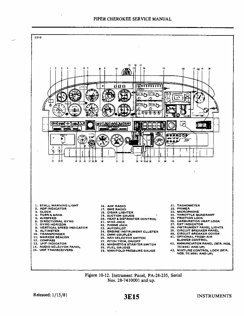
.

PIPER CHEROKEE SERVICE MANUAL
1831
1. STALL WARNING LIGHT2. CLOCK3. TURN AND BANK INDICATOR4. AIRSPEED INDICATOR5. DIRECTIONAL GYRO6. ATTITUDE GYRO7. HI-LO VACUUM WARNING LIGHT8. VERTICAL SPEED INDICATOR -9. ALTIMETER
10. GEAR UP WARNING LIGHT11. GEAR IN TRANSIT LIGHT12. MARKER BEACON RECEIVER CONTROL13. OMNI AND GLIDE SLOPE INDICATORS14. COMMUNICATIONS AND NAVIGATION TRANSCEIVERS15. ADF RECEIVER AND INDICATOR16. DME CONTROL AND INDICATOR17. CIGAR LIGHTER18. HEAT AND DEFROST CONTROLS19. AUTOCONTROL III AUTOPILOT20. ENGINE INSTRUMENT CLUSTER21. OMNI-COUPLER22. MAGNETO SWITCHES AND STARTER
23. FUEL SYSTEM CLUSTER24. MANIFOLD PRESSURE - FUEL FLOW INDICATOR25. TACHOMETER26. LANDING GEAR CONTROL HANDLE27. LANDING GEAR INDICATOR LIGHTS28. THROTTLE QUADRANT29. ALTERNATE AIR CONTROL30. MIXTURE MONITOR31. SWITCH PANEL32. CIRCUIT BREAKER PANEL
Reissued: 1/15/81
Figure 10-13. Instrument PanelPA-28R-180, Serial Nos. 28-30005 to 28-30879 incl.
3E16 INSTRUMENTS
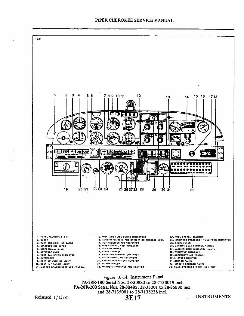
PIPER CHEROKEE SERVICE MANUAL
1831
1. STALL WARNING LIGHT2. CLOCK3. TURN AND BANK INDICATOR4. AIRSPEED INDICATOR5. DIRECTIONAL GYRO6. ATTITUDE GYRO7. VERTICAL SPEED INDICATOR8. ALTIMETER9. GEAR UP WARNING LIGHT
10. GEAR IN TRANSIT LIGHT11. MARKER BEACON RECEIVER CONTROL
12. OMNI AND GLIDE SLOPE INDICATORS13. COMMUNICATIONS AND NAVIGATION TRANSCEIVERS14. ADF RECEIVER AND INDICATOR
15. DME CONTROL AND INDICATOR16. SUCTION GAUGE17. CIGAR LIGHTER18. HEAT AND DEFROST CONTROLS19. AUTOCONTROL III AUTOPILOT20. ENGINE INSTRUMENT CLUSTER21. OMNI-COUPLER22. MAGNETO SWITCHES AND STARTER
23. FUEL SYSTEM CLUSTER24. MANIFOLD PRESSURE - FUEL FLOW INDICATOR25. TACHOMETER26. LANDING GEAR CONTROL HANDLE27. LANDING GEAR INDICATOR LIGHTS28. THROTTLE QUADRANT29. ALTERNATE AIR CONTROL30. MIXTURE MONITOR31. SWITCH PANEL32. CIRCUIT BREAKER PANEL33. GEAR OVERRIDE WARNING LIGHT
Figure 10-14. Instrument PanelPA-28R-180 Serial Nos. 28-30880 to 28-7130019 incl.
PA-28R-200 Serial Nos. 28-30482, 28-35001 to 28-35830 incl.and 28-7135001 to 28-7135238 incl.
3E17 INSTRUMENTSReissued: 1/15/81
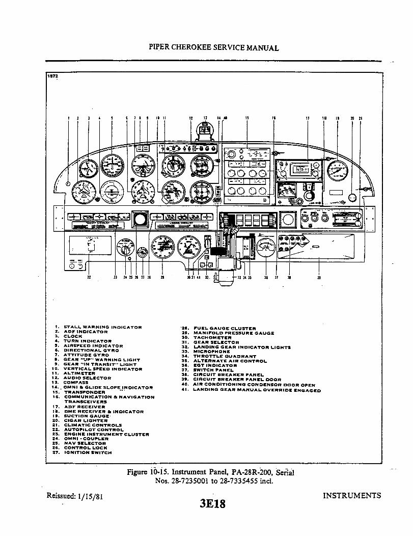

0
.

3E20INTENTIONALLY LEFT BLANK

PIPER CHEROKEE SERVICE MANUAL
10-6. SUCTION GAUGE.
10-7. GENERAL. The suction gauge is mounted in the right side of the instrument panelabove the glove compartment. This gauge is calibrated in inches of mercury and indicatesthe amount of vacuum created by the engine driven vacuum pump. The suction gaugeinstalled in "71" models have a direct pressure line and a vent line. Therefore, these aircraftindicate the differential pressure or actual pressure being applied to the gyro instruments. Asthe system filter becomes clogged or lines obstructed, the gauge will show a decrease inpressure. Do not reset the regulator until the filter and lines have been checked.
10-8. TROUBLESHOOTING. For troubleshooting of this instrument, refer to Table X-I ofthis section.
10-9. VACUUM REGULATOR VALVE.
10-10. GENERAL. One vacuum regulator valve is incorporated in the system to controlvacuum pressure to the gyro instruments. The regulator valve is located under theinstrument panel. Access to the valve for maintenance and adjustment is gained from belowthe instrument panel.
10-11. TROUBLESHOOTING. For troubleshooting of the vacuum regulator refer to TableX-I.
10-12. ADJUSTMENTS OF VACUUM REGULATOR VALVE. (Without Vacuum WarningLights)
a. Loosen the locking nut or remove the protective cap from the valve, depending onwhich type is installed.
NOTEDo not attempt adjustment of this valve with the engine inoperation, without a qualified pilot or other responsibleperson at the controls.
b. Start the engine, after allowing time for warm-up, run the engine at medium RPM.c. With the engine running at medium RPM, the suction gauge should indicate 5.0
inches of mercury ± .1 inches of mercury. If the pressure reading fails to fall within thisrange, shut down the engine and adjust the regulator valve by moving the valve adjustmentscrew clockwise to increase the pressure, and counter-clockwise to decrease the pressure.Start the engine and repeat the check. With engine running at medium RPM, the suctiongauge should indicate 5.0 inches of mercury ± .1 inches of mercury. If the airplane is notequipped with a suction gauge, it will be necessary to connect a gauge by removing the plugfrom the back of the artificial horizon, and attaching a temporary gauge.
d. Restart the engine and repeat the check.
INSTRUMENTS3E21Reissued: 1/15/81

PIPER CHEROKEE SERVICE MANUAL
e. After the system pressure has been adjusted to these recommended settings,remove the gauge and install the plug, replace the protective cap or retighten the locknut,whichever applies to the type of valve installed.
10-13. ADJUSTMENT OF VACUUM REGULATOR VALVE (PA-28-180, Serial Nos.28-4378 to 28-5227; PA-28R-180, Serial Nos. 28R-30005 to 28R-30878) (With VacuumWarning Lights).
a. Remove the plug from the back of the artificial horizon and install an appropriateAN fitting that will accommodate a small hose from a suction gauge.
b. Locate the valve adjustment screw on the bottom of the regulator and loosen theregulator screw jam nut.
NOTE
Do not attempt adjustment of this valve with the enginein operation, without a qualified pilot or otherresponsible person at the controls.
c. Start the engine, allow time for warm-up, and operate at a medium RPM.d. With the engine operating at medium RPM, the suction gauge should indicate 5.0
± .1 inches of mercury. If pressure reading fails to fall within this range, shut-down theengine and adjust the regulator valve by moving the adjustment screw clockwise to increasethe pressure and counterclockwise to decrease the pressure.
e. Restart the engine and repeat the check.f. After the system pressure has been adjusted to this recommended setting,
retighten the regulator screw jam nut, remove the suction gauge, hose and fitting. Replacethe plug into the back of the artificial horizon.
10-14. ADJUSTMENT OF VACUUM WARNING LIGHT PRESSURE SWITCH(PA-28-180, Serial Nos. 28-4378 to 28-5227; PA-28R-180, Serial Nos. 28R-30005 to28R-30878). The vacuum warning light switch should allow the low vacuum light toactuate when the suction has decreased to or below 4.25 ± .2 inches of mercury, and thehigh vacuum light with suction in excess of 5.2 + .2 -.0 inches of mercury. To check andadjust the operation of the vacuum warning switch, the following procedure may be used:
a. Remove the plug from the back of the artificial horizon and install an appropriateAN fitting that will accommodate a small hose from-a suction gauge.
b. Start the engine, allow time for warm-up and operate at a medium RPM.
NOTE
Do not attempt adjustment of any system in thisairplane with the engine in operation, without aqualified pilot or other responsible person at thecontrols.
c. Reduce RPM until low vacuum is indicated by the light, and determine if theswitch has actuated the light at 4.25 .2. Adjust by the following procedure:
INSTRUMENTS3E22Reissued: 1/15/81

PIPER CHEROKEE SERVICE MANUAL
976 LOW ADJUSTMENTCLOCKWISE - INCREASESLOW SETTING
BLACK
WHITE
YELLOWHIGH ADJUSTMENTCLOCKWISE - DECREASES
HIGH SETTING
Figure 10-17. Warning Light Pressure Switch
1. Increase RPM to a high setting, then decrease to 4.25 inches of mercury.2. Adjust switch to activate the low vacuum light at this setting by locating the
vacuum switch in the back of the directional gyro. Directly in the center of the switch is asmall adjustment screw which by turning clockwise will increase the low setting and turningcounterclockwise will decrease the low setting. (Refer to Figure 10-17.)
3. After making adjustment, recheck the vacuum switch by increasing to a highRPM and again decreasing to a setting of 4.25. If the light does not actuate at 4.25 ± .2inches of mercury, repeat steps 2 and 3. After proper adjustments have been made, shutdown the engine.
d. To adjust the high vacuum light, locate the valve adjustment screw on the bottom ofthe regulator and loosen the regulator jam nut.
e. Start the engine and set the throttle at 1400 to 1600 RPM. While reading the suctiongauge, turn valve adjustment screw of the vacuum regulator clockwise to increase thesuction. At 5.2 + .2 -.0 the high vacuum light, if adjusted properly, should light. Ifadjustment is proper, proceed to step g.
f. With high vacuum light not operating correctly, shut down engine and adjust by thefollowing procedure:
1. Adjustment of the high vacuum light necessitates the removal of the vacuumwarning light pressure switch. This switch, which is located in the back of the directionalgyro, has three wires that have to be disconnected and then the switch will turn from theinstrument. The adjustment screw for the switch is found inside the neck of the 1/8 NPTfitting that threads into the directional gyro. Turning this adjustment screw clockwise willdecrease the high setting and counterclockwise will increase the high setting.
2. After making the necessary adjustments, reinstall the vacuum switch into theinstrument and replace the wires in accordance with the Electrical System Schematic asfound in Section XI.
INSTRUMENTS3E23Reissued: 1/15/81
PIPER CHEROKEE SERVICE MANUAL
3. Recheck the high vacuum light by restarting the engine and increasing theRPM. Determine if the high light indicates high vacuum at 5.2 +.2 - 0. If further adjustmentis necessary, return to step f. After proper adjustment to the high vacuum light has beenmade, shut down the engine.
g. Readjust the vacuum regulator by setting throttle at a medium RPM. At this settingthe suction gauge should read from 4.6 to 5.2. To prevent intermittent actuation of thewarning light due to closeness of the pressure settings of the light pressure switch and thevacuum regulator, it should be determined that the regulator is set 0.2 inches of mercuryless than that of the pressure switch as long as vacuum is within the required range. Makenecessary adjustments by turning clockwise to increase the suction and counterclockwise todecrease the suction. Then tighten the jam nut on the regulator valve adjustment screw andremove the vacuum gauge and fitting from the back of the artificial horizon. Reinstall theplug into the artificial horizon.
10-15. ADJUSTMENT OF VACUUM TURN AND BANK INDICATOR REGULATORVALVE.
a. To adjust the turn and bank indicator, remove the plug found in the back of theinstrument and install the proper AN fitting that will accommodate a small hose from asuction gauge.
NOTE
Do not attempt adjustment of any system in this airplane,with the engine in operation, without a qualified pilot orother responsible person at the controls.
b. Start the engine and operate at a medium RPM with the suction gauge indicating 5.0with central air filter. If adjustment is necessary, refer to Paragraph 10-12 or 10-13.
c. With the suction gauge reading within the stated range, the gauge attached to theturn and bank should indicate 2.0 inches of mercury. If adjustment is necessary, turning theadjustment screw, found in the valve assembly at the back of the instrument, clockwise willdecrease the suction and counterclockwise will increase the suction. After the properreading is acquired, shut down the engine, remove the gauge, hose and fitting from the turnand bank and install the plug.
10-16. REMOVAL AND REPLACEMENT OF REGULATOR VALVE.a. To remove the regulator valve, disconnect the three lines and remove the mounting
nut. Remove the valve from the airplane.b. Replace regulator in reverse order given for removal. Check complete vacuum system
for proper operation.
10-17. VACUUM PUMP.
10-18. GENERAL. The vacuum pump is of the rotary vane, positive displacement type. Thisunit consists essentially of an aluminum housing containing a tempered sleeve in which an off-set rotor, with moving blades is incorporated. This assembly is driven by means of a couplingmated to the engine driven gear assembly. The pump is mounted on the accessory section ofthe engine.
Reissued: 1/15/81 3E24 INSTRUMENTS

PIPER CHEROKEE SERVICE MANUAL
10-19. TROUBLESHOOTING. For troubleshooting of the pumps, refer to Table X-I ofthis section.
10-20. REMOVAL OF VACUUM PUMP.a. Remove the top portion of the engine cowling. (Refer to Section VIII.)b. Loosen the hose clamp and remove the hose from the pump fitting.c. Remove the four retaining nuts, lock washers and plain washers used to secure the
pump to the engine; then remove the pump.
10-21. REPLACING PUMP FITTINGS.a. Before installing any fittings on the pump, check for any external damage. A pump
that has been damaged or dropped should not be installed.b. When a vise is used to hold the pump while installing fittings, suitable caution must
be exercised to avoid pump damage. The square mounting flange must be held between softwood blocks and only at right angles to the vise jaws. Use only enough vise pressure to holdthe pump firmly.
CAUTION
DO NOT apply vise pressure to the outside diameter oroverall length of the pump.
c. The ports of the AIRBORNE pump have been treated with a dry film lubricant andthe AIRBORNE fittings are cadmium plated thus eliminating any need for thread lubricants.If thread lubricant is required, use a powdered moly-sulfide or graphite in dry form or in anevaporating vehicle; or employ a silicone spray. Apply sparingly to external threads offittings only.
CAUTION
DO NOT use pipe tape, thread dope, hydrocarbon oil orgrease, as these can contaminate the pump and causemalfunction.
d. With the pump properly secured in the vise, insert fittings in ports and hand tightenfirmly.
e. Using a wrench, tighten each fitting from one-half to two additional turns.
INSTRUMENTS3F1Reissued: 1/15/81

PIPER CHEROKEE SERVICE MANUAL
10-22. INSTALLATION OF VACUUM PUMP.a. Place the pump gasket in its proper place and align the spline on the pump drive
with the spline on the engine drive assembly.
CAUTION
The only pump mounting gasket authorized and approved foruse on the Airborne vacuum pump is the Airborne gasketB3-1-2, Piper part number 751 859. Use of any other gasketmay result in oil seepage or leakage at the mounting surface.
b. Secure the pump to the engine with four plain washers, lock washers and retainingnuts. Torque the nuts 40 to 50 inch-pounds.
c. Connect the hoses to the pump and secure with hose clamps.d. Reinstall the engine cowling.
10-23. INSTRUMENT AIR SYSTEM. (Refer to Figure 10-18.) The instrument air systemconsists of a pitot air system and a static air system. The system supplies both pitot and staticpressure for the airspeed indicator, altimeter and vertical speed indicator. Refer to Figure 10-18 for PA-28-140, -150, -160, -180 -235, PA-28R-180 and -200 system layout.
Pitot air system consists of a pitot mast located on the underside of the left wing, withits related plumbing. Impact air pressure entering the pitot is transmitted from the pitotinlet through hose and tubing routed in the wing to the airspeed indicator on the instrumentpanel. A partially or completely blocked pitot head will give erratic or zero readings on theinstruments.
Static air system consists of a static port located on the bottom of the pitot mast. Thestatic port is directly connected to the airspeed indicator, altimeter and rate of climbindicator on the instrument panel by means of hose and tubing routed through the wingalong with the pitot line. An alternate static air source is located below the instrument panelin front of the pilot. The alternate static source is part of the standard system and has ashutoff valve which closes the port when it is not needed. A placard giving instructions foruse is located on the instrument panel.
INSTRUMENTS3F2Reissued: 1/15/81

PIPER CHEROKEE SERVICE MANUAL
10-24. DIRECTIONAL GYRO.
10-25. GENERAL. The directional gyro is a flight instrument incorporating an air drivengyro stabilized in the vertical plane. The gyro is rotated at high speed by lowering thepressure in the air tight case and simultaneously allowing atmospheric air pressure to enterthe instrument against the gyro buckets. Due to gyroscopic inertia, the spin axis continuesto point in the same direction even though the aircraft yaws to the right or left. This relativemotion between the gyro and the instrument case is shown on the instrument dial which issimilar to a compass card. The dial, when set to agree with the airplane magnetic compass,provides a positive indication free from swing and turning error. However, the directionalgyro has no sense of direction and must be set to the magnetic compass, since the magneticcompass is subject to errors due to magnetic fields, electric instruments, etc. The directionalgyro is only accurate for the heading it has been set for. If the gyro is set on 270° , forinstance, and the aircraft is turned to some other heading, there can be a large error betweenthe gyro and the magnetic compass due to the error in compass compensation. This willappear as gyro precession. The gyro should only be checked to the heading on which it wasfirst set. Due to internal friction, spin axis error, air turbulence and airflow, the gyro shouldbe set at least every 15 minutes for accurate operation, whether it has drifted or not.
INSTRUMENTSReissued: 1/15/81 3F3
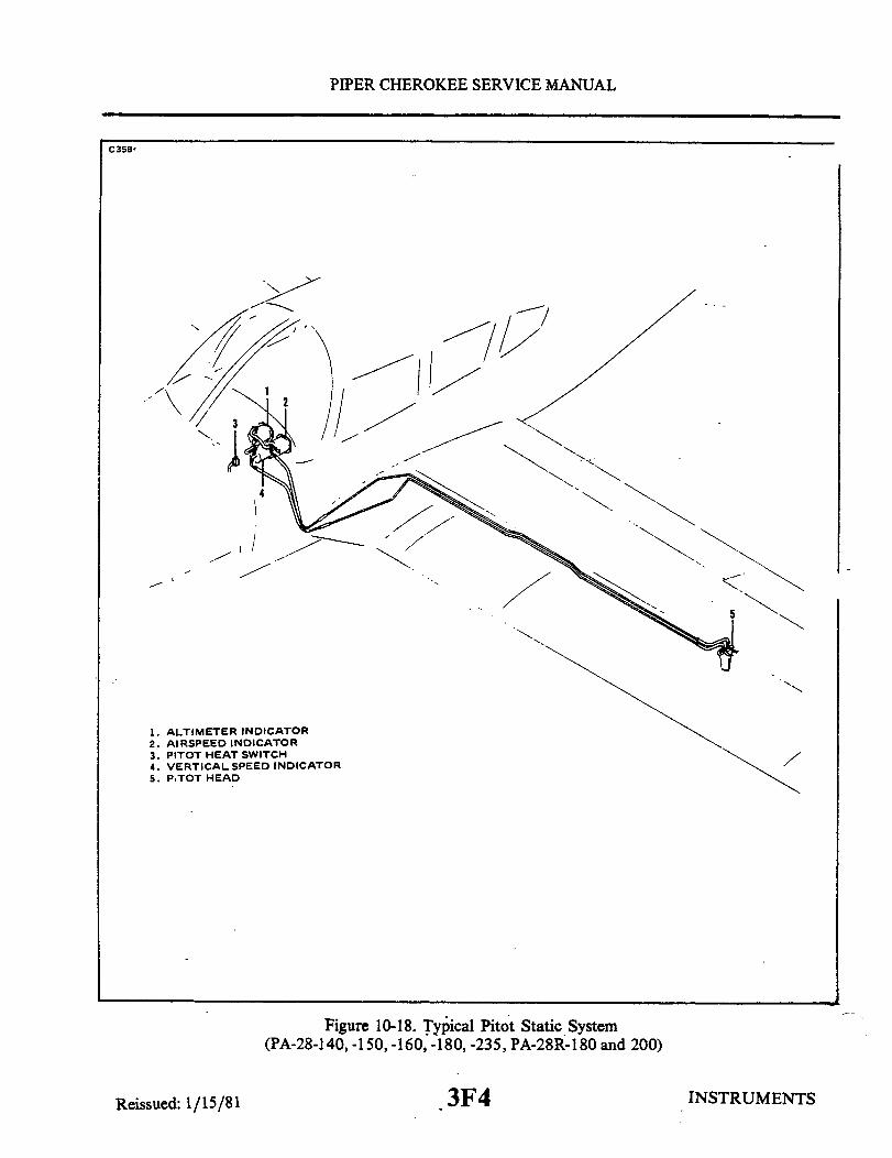
PIPER CHEROKEE SERVICE MANUAL
C358
5
1. ALTIMETER INDICATOR2. AIRSPEED INDICATOR3. PITOT HEAT SWITCH4. VERTICAL SPEED INDICATOR5. PITOT HEAD
Figure 10-18. Typical Pitot Static System(PA-28-140, -150, -160, -180, -235, PA-28R-180 and 200)
INSTRUMENTSReissued: 1/15/81 3F4
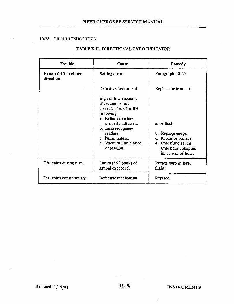
PIPER CHEROKEE SERVICE MANUAL
10-26. TROUBLESHOOTING.
TABLE X-II. DIRECTIONAL GYRO INDICATOR
Trouble Cause
Excess drift in eitherdirection.
Setting error. Paragraph 10-25.
Defective instrument.
High or low vacuum.If vacuum is notcorrect, check for thefollowing:a. Relief valve im-
properly adjusted.b. Incorrect gauge
reading.c. Pump failure.d. Vacuum line kinked
or leaking.
Replace instrument.
a. Adjust.
b. Replace gauge.c. Repair or replace.d. Check and repair.
Check for collapsedinner wall of hose.
Dial spins during turn. Limits (55 ° bank) ofgimbal exceeded.
Recage gyro in levelflight.
Dial spins continuously. Defective mechanism.
Reissued: 1/15/81
Remedy
Replace.
3F5 INSTRUMENTS

PIPER CHEROKEE SERVICE MANUAL
10-27. REMOVAL AND REPLACEMENT. The following procedure pertains to aircrafthaving the Edo-Aire Air Driven Gyro installation. For installations other than Edo-Aire referto Paragraph 10-81 of this section.
NOTEPermit no oil, grease, pipe compound or any foreign materialto enter parts prior to installation of fittings. Make sure that allair lines are clean and free of foreign particles and/or residuebefore connecting lines to gyro. Do not use thread lube onfittings or in parts.
The use of teflon tape on fitting threads is recommended and should be installed as follows:a. Lay teflon tape on threads keeping one thread visible from the end of the fitting. Hold in
place and wrap in the direction of the threads.b. Apply sufficient tension while winding to assure that tape conforms to thread grooves.
One full wrap plus 1/2" overlap is sufficient.c. After completing wrap, maintain tension and tear tape by pulling in direction of wrap.
Do not cut tape.d. Press tape well into threads.e. Screw fitting into part being careful not to exceed touque requirements noted on decal
on the cover of the gyro. (Refer to Table, II-II .Consumable Materials, for specificationsand Manufacturer's address.)
10-28. GYRO HORIZON.
10-29. GENERAL. The gyro horizon is essentially an air driven gyroscope rotating in ahorizontal plane and is operated by the same principal as the directional gyro. Due to thegyroscopic inertia, the spin axis continues to point in the vertical direction, providing aconstant visual reference to the attitude of the airplane relative to pitch and roll axis. A baracross the face of the indicator represents the horizon and aligning the miniature airplane tothe horizon bar simulates the alignment of the airplane to the actual horizon. Any deviationsimulates the deviation of the airplane from the true horizon. The gyro horizon is markedfor different degrees of bank.
Reissued: 1/15/81 3F6 INSTRUMENTS
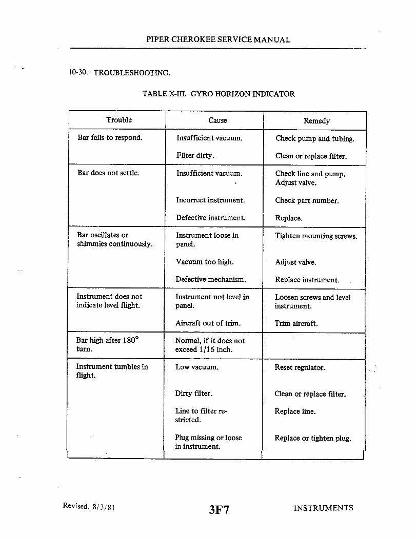
PIPER CHEROKEE SERVICE MANUAL
10-30. TROUBLESHOOTING.
TABLE X-III. GYRO HORIZON INDICATOR
Trouble
Bar fails to respond.
Bar does not settle.
Bar oscillates orshimmies continuously.
Instrument does notindicate level flight.
Bar high after 180°
turn.
Instrument tumbles inflight.
Cause
Insufficient vacuum.
Filter dirty.
Insufficient vacuum.
Incorrect instrument.
Defective instrument.
Instrument loose inpanel.
Vacuum too high.
Defective mechanism.
Instrument not level inpanel.
Aircraft out of trim.
Normal, if it does notexceed 1/16 inch.
Low vacuum.
Remedy
Check pump and tubing.
Clean or replace filter.
Check line and pump.Adjust valve.
Check part number.
Replace.
Tighten mounting screws.
Adjust valve.
Replace instrument.
Loosen screws and levelinstrument.
Trim aircraft.
Reset regulator.
Dirty filter.
Line to filter re-stricted.
Plug missing or loosein instrument.
Clean or replace filter.
Replace line.
Replace or tighten plug.
I
Revised: 8/3/81 INSTRUMENTS3F7
I I
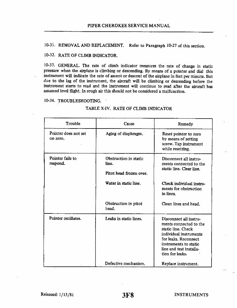
PIPER CHEROKEE SERVICE MANUAL
10-31. REMOVAL AND REPLACEMENT. Refer to Paragraph 10-27 of this section.
10-32. RATE OF CLIMB INDICATOR.
10-33. GENERAL. The rate of climb indicator measures the rate of change in staticpressure when the airplane is climbing or descending. By means of a pointer and dial thisinstrument will indicate the rate of ascent or descent of the airplane in feet per minute. Butdue to the lag of the instrument, the aircraft will be climbing or descending before theinstrument starts to read and the instrument will continue to read after the aircraft hasassumed level flight. In rough air this should not be considered a malfunction.
10-34. TROUBLESHOOTING.
Trouble
TABLE X-IV. RATE OF CLIMB INDICATOR
Cause Remedy
Pointer does not seton zero.
Pointer fails torespond.
Pointer oscillates.
Aging of diaphragm.
Obstruction in staticline.
Pitot head frozen over.
Water in static line.
Obstruction in pitothead.
Leaks in static lines.
Reset pointer to zeroby means of settingscrew. Tap instrumentwhile resetting.
Disconnect all instru-ments connected to thestatic line. Clear line.
Check individual instru-ments for obstructionin lines.
Clean lines and head.
Disconnect all instru-ments connected to thestatic line. Checkindividual instrumentsfor leaks. Reconnectinstruments to staticline and test installa-tion for leaks.
Defective mechanism. Replace instrument.
INSTRUMENTS3F8Reissued: 1/15/81

PIPER CHEROKEE SERVICE MANUAL
TABLE X-IV. RATE OF CLIMB INDICATOR (cont)
Trouble Cause Remedy
Rate of climb indi-cates when aircraftis banked.
Pointer has to beset before everyflight.
Pointer cannot be resetto zero.
Instrument reads verylow during climb ordescent.
Water in static line.
Temperature compen-sator inoperative.
Diaphragm distorted.
Case of instrumentbroken or leaking.
Disconnect static linesand blow out lines fromcockpit out to pitothead.
Replace instrument.
Replace instrument.
Replace instrument.
NOTE
When any connections in the static system are opened forchecking, system must be rechecked per F.A.R. 23.1325.
10-35. REMOVAL AND REPLACEMENT. Refer to Paragraph 10-81 of this section.
10-36. SENSITIVE ALTIMETER.
10-37. GENERAL. The altimeter indicates pressure altitude in feet above sea level. Theindicator has three pointers and a dial scale; the long pointer is read in hundreds of feet, themiddle pointer in thousandths of feet and the short pointer in ten thousandth of feet. Abarometric pressure window is located on the right side of the indicator dial and is set bythe knob located on the lower left corner of the instrument. The altimeter consists of asealed diaphragm that is connected to the pointers through a mechanical linkage. Theinstrument case is vented to the static air system and as static air pressure decreases, thediaphragm expands, causing the pointers to move through the mechanical linkage.
Reissued: 1/15/81 3F9 INSTRUMENTS
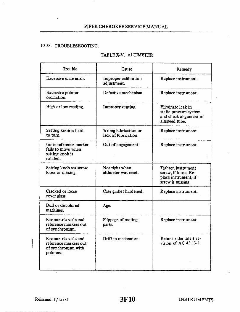
PIPER CHEROKEE SERVICE MANUAL
10-38. TROUBLESHOOTING.
TABLE X-V. ALTIMETER
Trouble Cause
Excessive scale error.
Excessive pointeroscillation.
High or low reading.
Setting knob is hardto turn.
Inner reference markerfails to move whensetting knob isrotated.
Setting knob set screwloose or missing.
Cracked or loosecover glass.
Dull or discoloredmarkings.
Barometric scale andreference markers outof synchronism.
Barometric scale andreference markers outof synchronism withpointers.
Improper calibrationadjustment.
Defective mechanism.
Improper venting.
Wrong lubrication orlack of lubrication.
Out of engagement.
Not tight whenaltimeter was reset.
Case gasket hardened.
Age.
Slippage of matingparts.
Drift in mechanism.
Replace instrument.
Replace instrument.
Eliminate leak instatic pressure systemand check alignment ofairspeed tube.
Replace instrument.
Replace instrument.
Tighten instrumentscrew, if loose. Re-place instrument, ifscrew is missing.
Replace instrument.
Replace instrument.
Refer to the latest re-vision of AC 43.13-1.
Reissued: 1/15/81
Remedy
INSTRUMENTS3F10
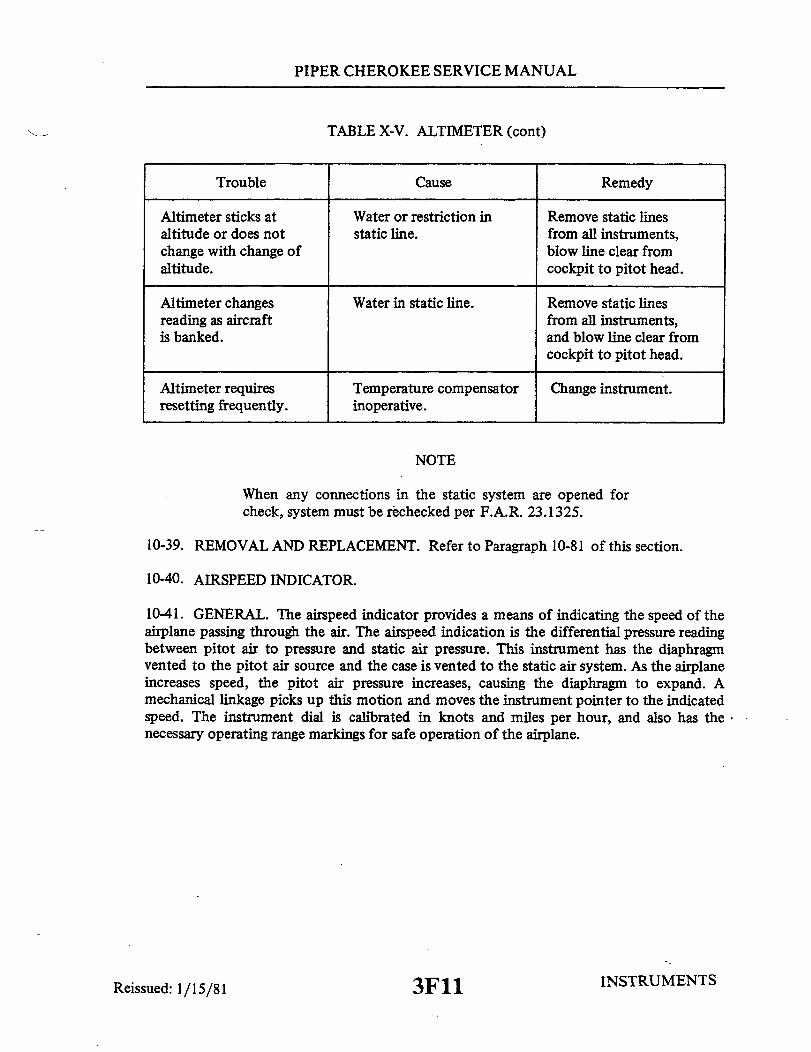
PIPER CHEROKEE SERVICE MANUAL
TABLE X-V. ALTIMETER (cont)
Cause
Altimeter sticks ataltitude or does notchange with change ofaltitude.
Altimeter changesreading as aircraftis banked.
Altimeter requiresresetting frequently.
Water or restriction instatic line.
Water in static line.
Temperature compensatorinoperative.
Remove static linesfrom all instruments,blow line clear fromcockpit to pitot head.
Remove static linesfrom all instruments,and blow line clear fromcockpit to pitot head.
Change instrument.
NOTE
When any connections in the static system are opened forcheck, system must be rechecked per F.A.R. 23.1325.
10-39. REMOVAL AND REPLACEMENT. Refer to Paragraph 10-81 of this section.
10-40. AIRSPEED INDICATOR.
10-41. GENERAL. The airspeed indicator provides a means of indicating the speed of theairplane passing through the air. The airspeed indication is the differential pressure readingbetween pitot air to pressure and static air pressure. This instrument has the diaphragmvented to the pitot air source and the case is vented to the static air system. As the airplaneincreases speed, the pitot air pressure increases, causing the diaphragm to expand. Amechanical linkage picks up this motion and moves the instrument pointer to the indicatedspeed. The instrument dial is calibrated in knots and miles per hour, and also has thenecessary operating range markings for safe operation of the airplane.
INSTRUMENTSReissued: 1/15/81
Trouble Remedy
3F11
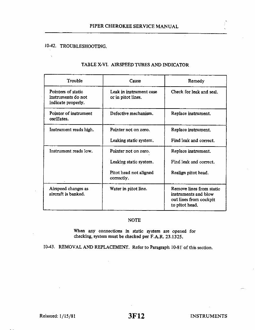
PIPER CHEROKEE SERVICE MANUAL
10-42. TROUBLESHOOTING.
TABLE X-VI. AIRSPEED TUBES AND INDICATOR
Trouble
Pointers of staticinstruments do notindicate properly.
Pointer of instrumentoscillates.
Instrument reads high.
Instrument reads low.
Airspeed changes asaircraft is banked.
Cause
Leak in instrument caseor in pitot lines.
Defective mechanism.
Pointer not on zero.
Leaking static system.
Pointer not on zero.
Leaking static system.
Pitot head not alignedcorrectly.
Water in pitot line.
Remedy
Check for leak and seal.
Replace instrument.
Replace instrument.
Find leak and correct.
Replace instrument.
Find leak and correct.
Realign pitot head.
Remove lines from staticinstruments and blowout lines from cockpitto pitot head.
NOTE
When any connections in static system are opened forchecking, system must be checked per F.A.R. 23.1325.
10-43. REMOVAL AND REPLACEMENT. Refer to Paragraph 10-81 of this section.
Reissued: 1/15/81 INSTRUMENTS3F12
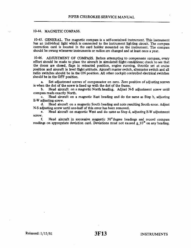
PIPER CHEROKEE SERVICE MANUAL
10-44. MAGNETIC COMPASS.
10-45. GENERAL. The magnetic compass is a self-contained instrument. This instrumenthas an individual light which is connected to the instrument lighting circuit. The compasscorrection card is located in the card holder mounted on the instrument. The compassshould be swung whenever instruments or radios are changed and at least once a year.
10-46. ADJUSTMENT OF COMPASS. Before attempting to compensate compass, everyeffort should be made to place the aircraft in simulated flight conditions; check to see thatthe doors are closed, flaps in retracted position, engine running, throttle set at cruiseposition and aircraft in level flight attitude. Aircraft master switch, alternator switch and allradio switches should be in the ON position. All other cockpit controlled electrical switchesshould be in the OFF position.
a. Set adjustment screws of compensator on zero. Zero position of adjusting screwsis when the dot of the screw is lined up with the dot of the frame.
b. Head aircraft on a magnetic North heading. Adjust N-S adjustment screw untilcompass reads exactly North.
c. Head aircraft on a magnetic East heading and do the same as Step b, adjustingE-W adjusting screw.
d. Head aircraft on a magnetic South heading and note resulting South error. AdjustN-S adjusting screw until one-half of this error has been removed.
e. Head aircraft on magnetic West and do same as Step d, adjusting E-W adjustmentscrew.
f. Head aircraft in successive. magnetic 30 degree headings and record compassreadings on appropriate deviation card. Deviations must not exceed ± 10° on any heading.
INSTRUMENTSReissued: 1/15/81 3F13
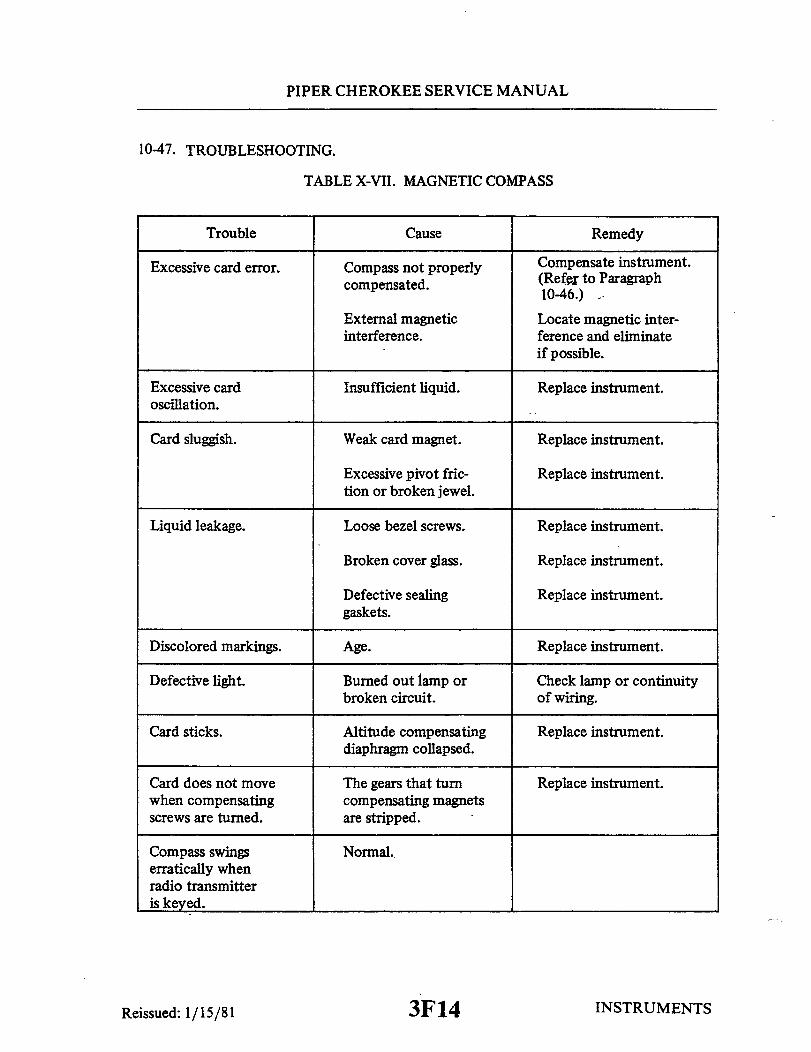
PIPER CHEROKEE SERVICE MANUAL
10-47. TROUBLESHOOTING.
TABLE X-VII. MAGNETIC COMPASS
Trouble Cause
Excessive card error. Compass not properlycompensated.
External magneticinterference.
Excessive cardoscillation.
Card sluggish.
Insufficient liquid.
Weak card magnet.
Compensate instrument.(Refer to Paragraph10-46.)
Locate magnetic inter-ference and eliminateif possible.
Replace instrument.
Replace instrument.
Excessive pivot fric-tion or broken jewel.
Replace instrument.
Liquid leakage. Loose bezel screws. Replace instrument.
Broken cover glass.
Defective sealinggaskets.
Discolored markings. Age.
Replace instrument.
Replace instrument.
Replace instrument.
Defective light.
Card sticks.
Card does not movewhen compensatingscrews are turned.
Burned out lamp orbroken circuit.
Altitude compensatingdiaphragm collapsed.
The gears that turncompensating magnetsare stripped.
Check lamp or continuityof wiring.
Replace instrument.
Replace instrument.
Compass swingserratically whenradio transmitteris keyed.
Normal.
INSTRUMENTSReissued: 1/15/81
Remedy
3F14

PIPER CHEROKEE SERVICE MANUAL
10-48. MANIFOLD PRESSURE GAUGE.
10-49. GENERAL. The manifold pressure gauge is a vapor proof, absolute pressure typeinstrument. Pressure from the intake manifold of the engine is transmitted to the instrumentthrough a line. A pointer indicates the manifold pressure available at the engine in inches ofmercury.
10-50. TROUBLESHOOTING.
TABLE X-VIII. MANIFOLD PRESSURE INDICATOR
Trouble Cause Remedy
Excessive error at ex-isting barometric pressure.
Excessive error whenengine is running.
Sluggish or jerkypointer movement.
Pointer shifted.
Line leaking.
Defective instrument.
Replace instruments.
Tighten line connections.
Replace instrument.
Dull or discoloredmarking.
Age. Replace instrument.
Incorrect reading. Moisture or oil inline.
Disconnect lines andblow out.
10-51. REMOVAL AND REPLACEMENT. (Refer to Paragraph 10-81 of this section.)
10-52. TACHOMETER INDICATOR.
10-53. GENERAL. The tachometer is connected to the engine accessory by a flexible cableand provides an indication of crankshaft speed in revolutions per minute. The instrumenthas a recording mechanism for recording the time that the engine is in actual operation.
NOTE
On PA-28-180 aircraft Serial Nos. 28-1761 to 28-3555,28-3557 to 28-3572 and 28-3574 to 28-3626. The aircrafttachometer must be placarded to show a red ARC between2150 and 2350 RPM in accordance with the latest revision ofPiper Service Letter No. 526.Propeller Limits: avoid continuous operation between 2150and 2350 RPM.
Reissued: 1/15/81 INSTRUMENTS3F15

PIPER CHEROKEE SERVICE MANUAL
10-54. TROUBLESHOOTING.
TABLE X-IX. TACHOMETER
Trouble Cause
No reading on indica-tor, either permanentor intermittent.
Broken shaft. Replace instrument.
Loose cable connections. Tighten cable.
Pointer oscillatesexcessively.
Rough spot on, orsharp bend in shaft.
Repair or replace.
Excessive friction ininstrument.
Replace instrument.
Indicator changes inclimb.
Pointer goes all theway to stop, morenoticeable in coldweather.
Pointer jumps at idle.
Tachometer cable breaks.
Excessive clearance inspeed cup.
Excessive lubricant ininstruments.
Speed cup hitting ro-tating magnet.
Cable bent too sharply.
Replace instrument.
Replace instruments.
Replace instrument.
Reroute cable.
10-55. REMOVAL AND REPLACEMENT. Refer to Paragraph 10-81 of this section.
10-56. ENGINE OIL PRESSURE GAUGE.
10-57. GENERAL. The oil pressure gauge is mounted in the cluster on the instrumentpanel. This gauge will indicate the amount of oil pressure available at the pressurized engineoil passage.
Reissued: 1/15/81
Remedy
INSTRUMENTS3F16

PIPER CHEROKEE SERVICE MANUAL
10-58. TROUBLESHOOTING.
TABLE X-X. ENGINE OIL PRESSURE GAUGE
Trouble Cause
Excessive error atzero.
Excessive scale error.
Excessive pointeroscillation.
Sluggish operation ofpointer or pressurefails to build up.
Pointer loose on shaft.Overpressure orseasoning of bourdontube.
Improper calibrationadjustment.
Air in line or roughengine relief.
Engine relief valveopen.
Replace instrument.
Replace instrument.
Disconnect line andfill with light oil.Check for leaks. Iftrouble persists, cleanand adjust relief valve.
Clean and check.
10-59. REMOVAL AND REPLACEMENT. Refer to Paragraph 10-83 of this section.
10-60. FUEL PRESSURE GAUGE.
10-61. GENERAL. The fuel pressure gauge instrument is mounted in the cluster on theinstrument panel. This gauge is connected to the fuel system at the carburetor fuel inletfitting.
Reissued: 1/15/81
Remedy
INSTRUMENTS3F17
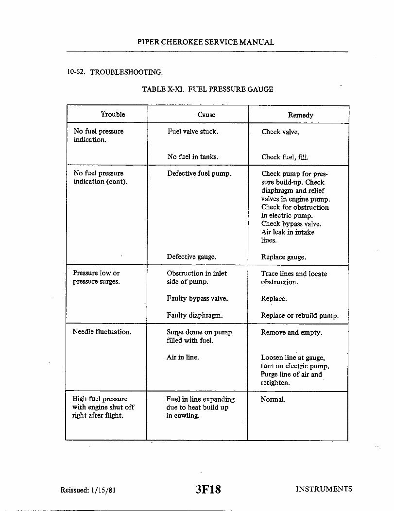
PIPER CHEROKEE SERVICE MANUAL
10-62. TROUBLESHOOTING.
TABLE X-XI. FUEL PRESSURE GAUGE
Trouble Cause
No fuel pressureindication.
Fuel valve stuck. Check valve.
No fuel in tanks. Check fuel, fill.
No fuel pressureindication (cont).
Defective fuel pump. Check pump for pres-sure build-up. Checkdiaphragm and reliefvalves in engine pump.Check for obstructionin electric pump.Check bypass valve.Air leak in intakelines.
Defective gauge. Replace gauge.
Pressure low orpressure surges.
Obstruction in inletside of pump.
Trace lines and locateobstruction.
Faulty bypass valve.
Faulty diaphragm. Replace or rebuild pump.
Needle fluctuation. Surge dome on pumpfilled with fuel.
Remove and empty.
Loosen line at gauge,turn on electric pump.Purge line of air andretighten.
High fuel pressurewith engine shut offright after flight.
Fuel in line expandingdue to heat build upin cowling.
Reissued: 1/15/81
Remedy
Replace.
Air in line.
Normal.
INSTRUMENTS3F18

PIPER CHEROKEE SERVICE MANUAL
10-63. REMOVAL AND REPLACEMENT. Refer to Paragraph 10-79 of this section.
10-64. TURN AND BANK INDICATOR.
10-65. GENERAL. The turn and bank indicator can be either vacuum driven or electric.The turn portion of the indicator is a gyroscope, while the bank portion of the indicator is aball sealed in a curved glass tube filled with damping fluid. There are two styles of this unit.The first is the old style with a vertical needle in the center of the dial. This instrumentreads only the rate of turn, and unless the aircraft is turning, the needle will not moveregardless of bank angle. The other style is the turn coordinator which indicates both therate of turn and rate of roll. With this indicator, if the aircraft is rolled right and left rapidly,the indicator will move, indicating a turn, but if the aircraft is held in a bank, and rudder isapplied, the indicator will come back to zero indicating no turn.
10-66. TROUBLESHOOTING.
TABLE X-XII. TURN AND BANK INDIATOR
Trouble
Pointer fails torespond.
Incorrect sensitivity.
Incorrect turn rate(vacuum style).
Incorrect turn rate(electric).
Cause
Foreign matter lodged ininstrument.
Out of calibration.
High or low vacuum.
Filter dirty.
Out of calibration.
Remedy
Replace instrument.
Replace instrument.
Check vacuum and adjust.
Replace filter.
Replace instrument.
Aircraft not incoordinated turn.
Center ball in turn.
Ball sticky.
Ball not in centerwhen aircraft iscorrectly trimmed.
Instrument will notrun (electric).
Flat spot on ball.
Instrument not levelin panel.
No power to instrument.
Instrument malfunction.
Replace instrument.
Level instrument.
Check circuit and repair.
Replace instrument.
INSTRUMENTS3F19Reissued: 1/15/81

PIPER CHEROKEE SERVICE MANUAL
10-67. ELECTRICAL INSTRUMENTS.
10-68. REMOVAL AND REPLACEMENT. Refer to Paragraph 10-81 of this section.
10-69. FUEL QUANTITY INDICATOR.
10-70. GENERAL. The two fuel quantity gauges are mounted in the cluster on theinstrument panel. These instruments are calibrated in fractional divisions of one fourth, onehalf, three fourths and full. A transmitter unit is installed in each fuel cell. This unitcontains a resistance strip and a movable control arm. The position of this arm is controlledby a float in the fuel cell and this position is transmitted electrically to the indicator gaugeto show the amount of fuel in the cell.
10-71. TROUBLESHOOTING.
TABLE X-XIII. FUEL QUANTITY INDICATORS
Trouble Cause Remedy
Fuel gauge fails toindicate.
Broken wiring. Check and repair.
Gauge not operating.
Blown fuse. Replace fuse.
Fuel gauge indicatesempty when tanks arefull.
Fuel gauge indicatesfull with tanks empty.
Incomplete ground.
Incomplete ground.
Check ground connectionsat fuel transmitter inwings.
Check ground at instru-ment.
Float arm stuck. Replace fuel transmitter.
Fuel gauge indicatesincorrectly.
Intermittent ground. Check ground at trans-mitter and instrument.
Float arm sticky. Replace fuel transmitter.
INSTRUMENTS3F20
Replace.
Reissued: 1/15/81

PIPER CHEROKEE SERVICE MANUAL
10-72. REMOVAL AND REPLACEMENT. Refer to Paragraph 10-83 of this section.
10-73. OIL TEMPERATURE INDICATOR.
10-74. GENERAL. The oil temperature indicator is mounted in the instrument cluster onthe instrument panel. This instrument will provide a temperature indication of the engine oilin degrees Fahrenheit. The instrument has a temperature bulb located in the oil screenassembly, on the engine accessory section.
10-75. TROUBLESHOOTING.
TABLE X-XIV. OIL TEMPERATURE INDICATORS
Trouble Cause Remedy
Instrument fails toshow any reading.
Excessive scale error.
Pointer fails to moveas engine is warmed up.
Broken or damaged bulb.Wiring open.
Improper calibrationadjustment.
Broken or damaged bulbor open wiring.
Check engine unit andwiring to instrument.
Repair or replace.
Check engine unit andwiring.
Dull or discoloredmarking.
Age. Replace instrument.
10-76. REMOVAL AND REPLACEMENT. Refer to Paragraph 10-83 of this section.
10-77. AMMETER.
10-78. GENERAL. The ammeter is mounted in the instrument cluster located on theinstrument panel. This instrument measures the output of the alternator into the entireelectrical system including the battery charging demand.
10-79. TROUBLESHOOTING. Refer to Section XI. (Alternator Section)
10-80. REMOVAL AND REPLACEMENT. Refer to Paragraph 10-83 of this section.
10-81. REMOVAL AND REPLACEMENT OF FACE MOUNTED INSTRUMENTS.
INSTRUMENTSReissued: 1/15/81 3F21

PIPER CHEROKEE SERVICE MANUAL
10-82. GENERAL. Since all instruments are mounted in a similar manner, a description ofa typical removal and installation is provided as a guide for the removal and installation ofthe instruments. Special care should be taken when any operation pertaining to theinstruments is performed.
a. Remove the face panel by removing the screws from around the perimeter of thepanel.
b. With the face panel removed, the mounting screws for the individual instrumentswill be exposed. Remove the connections to the instrument prior to removing the mountingscrews of the instrument to be removed.
NOTE
Tag instrument connections for ease of installation.
c. Installation of the instruments will be completed by reversing the removalinstructions. After the installation is completed and before replacing the instrument facepanel, check all components for security and clearance of the control column.
10-83. REMOVAL AND REPLACEMENT OF CLUSTER MOUNTED INSTRUMENTS.
10-84. GENERAL. A cluster, located on the instrument panel, contains six individualinstruments. Removal of these instruments can be accomplished by the following procedure.
a. Remove the face panel by removing the screws from around the perimeter of thepanel.
b. With the face panel removed, the clear plastic cover on the cluster assembly will beexposed. Remove the cover and cluster by removing the six mounting screws.
c. Remove the connection to the individual instrument to be removed and remove theinstrument from the cluster assembly.
d. Replace the instruments by reversing the removal instructions. Check allmountings and connections for security.
10-85. EXHAUST GAS TEMPERATURE GAUGE. (ALCOR)
10-86.. GENERAL. This instrument, which is commonly referred to as EGT, is used to aidthe pilot in selecting the economical fuel-air mixture for cruising flight at a power setting of75% or less. It is a sensing device to monitor the fuel-air mixture leaving the enginecylinders. This gauge is adjustable. If it is found defective after checking withtroubleshooting chart it should be replaced. If the leads to the gauge are defective in anyway they should be replaced. When replacing leads, it is very important to use the sametype and length of wire as the resistance of the leads is critical for the proper operation ofthis gauge.
INSTRUMENTS3F22Reissued: 1/15/81

PIPER CHEROKEE SERVICE MANUAL
10-87. CLEANING AND INSPECTION. Unless mechanical damage is evident, brokenglass, bent or broken pointer, or broken case, the following checks should be performedbefore removing the instrument.
a. Remove the probe from the exhaust stack and check for a broken weld (at tipend) or a burnt off end. The measured resistance of probe should be .8 ohms. Clean theconnections with steel wool before reassembly.
b. Disconnect the lead wires at the instrument and measure. Resistance with the leadwires connected to probe should be 3.3 ohms. Clean connections with steel wool beforereassembly.
c. With the leads connected to instrument, heat probe with propane torch to dullred. The meter should read up to the fourth graduation or approximately 1500 ° F. Beforemaking this check, make sure that the adjustment screw, located at the rear of theinstrument case, is in the center of its travel. If this screw has been turned to either end offull travel, it will shut the instrument off and no indication will be shown on the pointer. Ifmeter still does not read, replace it.
CAUTION
Do not connect ohmmeter across meter. It will burn outthe movement of the meter.
10-88. TROUBLESHOOTING.
TABLE X-XV. EXHAUST GAS TEMPERATURE GAUGE (ALCOR)
Trouble Cause Remedy
Gauge inoperative. Defective gauge, probeor wiring.
Check probe and leadwires for chafing,breaks or shortingbetween wires and/ormetal structure.
Adjusting potentio-meter turned off scale.
Reset potentiometer.
Fluctuating reading. Loose, frayed or brokenelectrical leads orfaulty connections.
Clean and tightenconnections. Repairor replace defectiveleads.
INSTRUMENTS3F23Reissued: 1/15/81

PIPER CHEROKEE SERVICE MANUAL
C314
PROBE (SEE NOTE)
LEFT SIDE VIEW
NOTE.129 HOLE IN NO. 2 CYLINDER EXHAUSTSTACK. REFER TO TOP VIEW FOR CORRECTLOCATION.
Figure 10-19. EGT PROBE LOCATION (PA-28R-180 and 200)
5/81 3F24 INSTRUMENTSReissued: 1/15/81

PIPER CHEROKEE SERVICE MANUAL
C316
ENGINE CENTERLINE
45°
TOP VIEW
EGT
2.00
NOTE.129 HOLE IN NO. 2 CYLINDER EXHAUSTSTACK. REFER TO TOP VIEW FOR CORRECTLOCATION.
Figure 10-20. EGT PROBE LOCATION (PA-28-235)
3G1Reissued: 1/15/81 INSTRUMENTS

PIPER CHEROKEE SERVICE MANUAL
C3158152
ENGINE CENTERLINE
TOP VIEW
EGT PROBE (SEE NOTE)
LEFT SIDE VIEW
NOTE.129 HOLE IN NO. 4 CYLINDER EXHAUSTSTACK IN LINE WITH CENTERLINE OF ENGINE.
Figure 10-21. EGT PROBE LOCATION (PA-28-150/160/180) (S/N 1761 and up)
/15/81 3G2 INSTRUTRUMENTSReissued: 1/15/81

PIPER CHEROKEE SERVICE MANUAL
10-89. CYLINDER HEAD TEMPERATURE GAUGE.
10-90. GENERAL. The cylinder head temperature gauge is in the instrument cluster on theinstrument panel. This instrument measures the cylinder head temperature using a senderlocated in a cylinder head. The head location is determined by the engine manufacturer. It isan electrical instrument and is wired through the instruments circuit breaker.
10-91. TROUBLESHOOTING.
TABLE X-XVI. CYLINDER HEAD TEMPERATURE GAUGE
Trouble Cause Remedy
Instrument shows noindication.
Power supply wirebroken.
Repair wire.
Defective instrument. Replace instrument.
Master switch off.
Instrument goes allthe way to upper stop.
Wire broken betweensender and gauge.
Repair wire.
Defective sender. Replace sender.
10-92. REMOVAL AND REPLACEMENT. Refer to Paragraph 10-83 of this section.
10-93. FUEL FLOW GAUGE.
10-94. GENERAL.The fuel flow gauge is a non-electric pressure gauge mounted in thebottom half of the manifold pressure gauge. This gauge is located in the lower portion of theinstrument panel.
This instrument measures flow by reading the pressure drop across a fixed orificelocated in the fuel divider. When a constant fuel pressure is being supplied by the enginedriven pump, one can put a fixed orifice in the fuel divider head and measure the pressuredrop downstream of the orifice against a constant static pressure. This resultant pressure canbe calibrated in gallons per hour flow. The constant static pressure is supplied by a vent linerunning to the engine compartment. The vent line to the engine compartment automaticallycompensates the instrument for altitude.
INSTRUMENTS3G3Reissued: 1/15/81

PIPER CHEROKEE SERVICE MANUAL
10-95.. TROUBLESHOOTING.
TABLE X-XVII. FUEL FLOW GAUGE
Trouble Cause
Pointer oscillates. Air in fuel line.
Gauge reads low ataltitude.
Pointer does not returnto zero.
Vent line restricted.
Fuel in diaphragm ofgauge.
Check line and fittings.
Replace gauge.
10-96. REMOVAL AND REPLACEMENT. Refer to Paragraph 10-81 of this section.
10-97. PIPER AUTOCONTROL SYSTEM. (See AutoControl Service Manual)
10-98. ANNUNCIATOR PANEL.
10-99. GENERAL. The annunciator panel consists of three amber lights and a push-buttontest switch located on the upper left center portion of the instrument panel. (Refer toFigure 10-4b.) The panel monitors alternator output, oil pressure and the vacuum system.The ALT warning light will illuminate when alternator output is zero; the VAC light whenthe pressure difference is below 3.5 in. Hg, and the OIL light when the oil pressure is below35 psi. A test button is included to check the operation of the lights. This installation isavailable on 1975 models and up. (Refer to Section XI for service information.)
10-100.TROUBLESHOOTING. (Refer to Table XI-I.)
10-101. REMOVAL AND REPLACEMENT. (Refer to paragraph 10-81.)
Reissued: 1/15/81
Remedy
Purge line.
INSTRUMENTS3G4

3G5 THRU 3L24INTENTIONALLY LEFT BLANK
CHEROKEE
SERVICE MANUALCARD 4 OF 4
PA-28-140
PA-28-150
PA-28-160
PA-28-180
PA-28-235
PA-28R-180
PA-28R-200
PIPER AIRCRAFT CORPORATION
(PART NUMBER 753 586) 4A1

PIPER CHEROKEE SERVICE MANUAL
AEROFICHE EXPLANATION AND REVISION STATUS
The Service Manual information incorporated in this set of Aerofiche cards has been arranged inaccordance with the general specifications of Aerofiche adopted by the General Aviation Manufacturer'sAssociation, (GAMA). The information compiled in this Aerofiche Service Manual will be kept current byrevisions distributed periodically. These revisions will supersede all previous revisions and will be completeAerofiche card replacements and shall supersede Aerofiche cards of the same number in the set.
Conversion of Aerofiche alpha/numeric code numbers:First number is the Aerofiche card number.Letter is the horizontal line reference per card.Second number is the vertical line reference per card.
Example: 2J16 = Aerofiche card number two of given set, Grid location J16.
To aid in locating the various chapters and related service information desired, the following is provided:
1. A complete manual Table of Contents is for all fiche in this set.2. A complete list of Illustrations is given and follows the Table of Contents.3. A complete list of Tables is given for all fiche in this set and follows the list of Illustrations.4. A complete list of paragraph titles and appropriate Grid location numbers is given at the beginning of
each Chapter relating to the information within that Chapter.5. Identification of Revised Material:
Revised text and illustrations are indicated by a black vertical line along the left-hand margin ofthe frame, opposite revised, added or deleted material. Revision lines indicate only current revisionswith changes and additions to or deletions of existing text and illustrations. Changes in capitalization,spelling, punctuation, indexing, the physical location of the material or complete page additions arenot identified by revision lines.
6. Revisions to this Service Manual 753 586 issued August 16, 1972 are as follows:
Effectivity Publication Date Aerofiche Card Effectivity
ORG720816 August 16, 1972CR810115 January 15, 1981 1, 2, 3 and 4PR810803 August 3, 1981 1, 2, 3 and 4PR831003 October 3, 1983 1, 2, 3 and 4PR840423 April 23, 1984 1, 2, 3 and 4PR860115 January 15, 1986 1 and 3IR860730 July 30, 1986 1IR870506* June 12,1987 1
This publication contains material revised as of January 15, 1986 (with two interim revisions effective July30, 1986 and May 6, 1987).
* INTERIM CHANGERevisions appear in Table III-I and Table III-I of card 1.There are no other changes included in this maintenancemanual. Please discard your current card 1 and replace it withthis revised one. DO NOT DISCARD CARDS 2 3, or 4.
The date on Aerofiche cards should not be earlier than the date noted for the respective card effectivity.Consult the latest card in this series for current Aerofiche card effectivity.
4A2

8V
8
8313
8
8V
Z'ON
S9
6 N
'ON
S
AIXIIIX
IIX
IX
X
XI
VIIIA
IIIAVIIA
IIAIA
A
A
III
I
I

PIPER CHEROKEE SERVICE MANUAL
LIST OF ILLUSTRATIONSFigure1 1-1. Generator and Starter System .........................11-2. Generator Wiring Diagram .............11-3. Sectional View of Generator .............1-4. Current/Voltage Regulator .............11-5. Use of Riffler File to Clean Contact Points ..................11-6. Voltage Regulator Air Gap ..........................11-7. Checking Voltage Setting Fixed Resistance Method .............11-8. Checking Voltage Setting Variable Resistance Method .....11-9. Adjusting Voltage Regulator Setting ..... .....1 -10. Cutout Relay Air Gap Check and Adjustment ................11-11. Cutout Relay Point Opening Check and Adjustment ............11-12. Checking Cutout Relay Closing Voltage ...................11-13. Adjustment of Cutout Relay Closing Voltage ................11-14. Checking Current Regulator, Load Method ..................11-15. Checking Current Regulator, Jumper Lead Method .............11-16. Alternator and Starter System,
PA-28-140, Serial Nos. 28-20000 to 28-24999 incl.:PA-28-150, -160. Serial Nos. 28-508 to 28-3643 incl.:PA-28-180, Serial Nos. 28-671 to 28-3643 incl.;PA-28-235, Serial Nos. 28-10002 to 28-10762 incl. ...........
11-17. Alternator and Starter System,PA-28-140, Serial Nos. 28-25000 and up;PA-28-150. -160, -180, Serial Nos. 28-3644 and up;PA-28-235 Serial Nos. 10763 and up and PA-28R ........ ..
11-18.11-19.11-20.11-21.11-22.11-23.11-24.11-25.11-26.11-27.11-28.11-29.11-30.11-31.11-32.11-33.11-34.11-35.11-36.11-37.11-38.11-39.
Lamp-Bank Load ................................Checking Field Circuit .............................Testing Field Circuit ...............................Testing Rectifiers (Positive) ..........................Testing Rectifiers (Negative) ..........................C-3928 Fixtures and Adapters ........................Removing Rectifiers ...............................Installing Rectifiers ...............................Soldering Rectifier Lead ............................Testing Stator Coils ...............................Removing End Bearing .............................Installing End Bearing ..............................Removing Drive Pulley .............................Removing Drive End Bearing ..........................Removing Slip Ring . ............................Aligning Slip Ring ................................Installing Slip Ring ...............................Installing Retainer ................................Solder Points ...................................Installing Drive End Shield and Bearing (Typical) ..............Installing Pulley .................................Meter Connections for Alternator Performance Test ............
AeroficheGrid No.
4A184A194A224B74B104B104B114B114B124B144B144B154B154B164B16
4B20
4B214B234B244B244C24C34C44C44C54C64C74C94C94C104C104C114C114C124C124C134C144C144C17
4A4
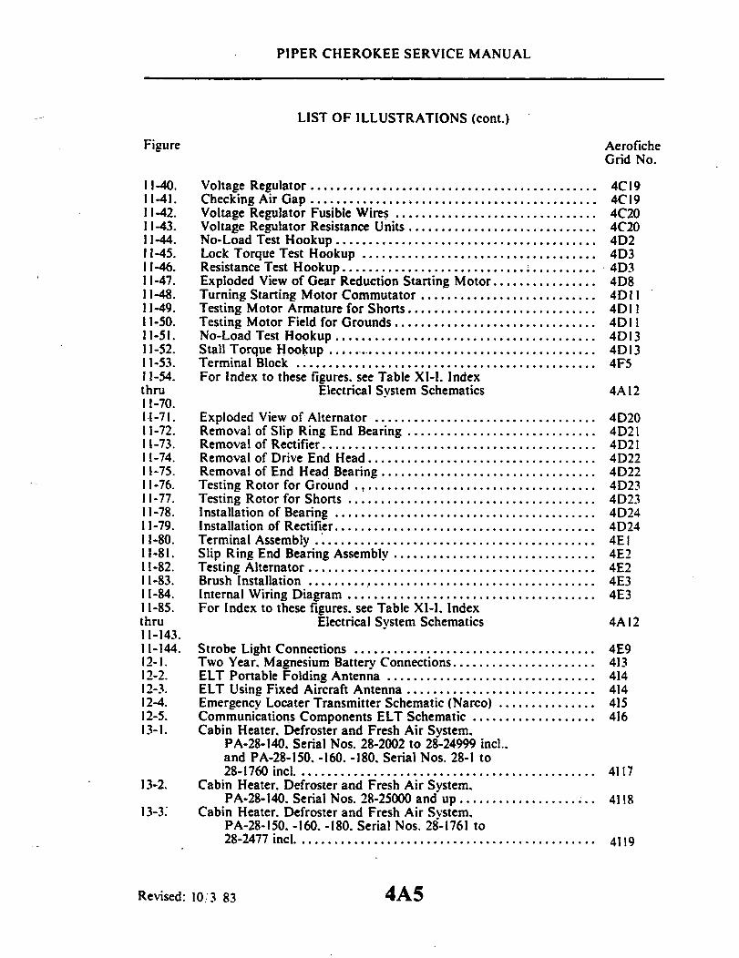
PIPER CHEROKEE SERVICE MANUAL
LIST OF ILLUSTRATIONS (cont.)
Figure AeroficheGrid No.
11-40. Voltage Regulator ...................................... ...... 4C1911-41. Checking Air Gap .................... ....................... 4C1911-42. Voltage Regulator Fusible Wires ............................... 4C2011-43. Voltage Regulator Resistance Units ............................. 4C2011-44. No-Load Test Hookup ........................................ 4D211-45. Lock Torque Test Hookup ........... ...................... 4D311-46. Resistance Test Hookup ............................. .......... 4D311-47. Exploded View of Gear Reduction Starting Motor ................ 4D811-48. Turning Starting Motor Commutator ........................... 4D1111-49. Testing Motor Armature for Shorts ................... .......... 4D1111-50. Testing Motor Field for Grounds ............................... 4D1111-51. No-Load Test Hookup ........................................ 4D1311-52. Stall Torque Hookup .......................................... 4D1311-53. Terminal Block ............................................. 4F511-54. For Index to these figures. see Table XI-I. Indexthru Electrical System Schematics 4A 1211-70.11-71. Exploded View of Alternator .................................. 4D2011-72. Removal of Slip Ring End Bearing ............................. 4D2111-73. Removal of Rectifier .......................................... 4D2111-74. Removal of Drive End Head ................................... 4D2211-75. Removal of End Head Bearing ................................. 4D2211-76. Testing Rotor for Ground ..................................... 4D2311-77. Testing Rotor for Shorts ...................................... 4D2311-78. Installation of Bearing ...................................... .. 4D2411-79. Installation of Rectifier ........................................ 4D2411-80. Terminal Assembly ........................................... 4E I11-81. Slip Ring End Bearing Assembly ....................... ........ 4E211-82. Testing Alternator ............................................ 4E211-83. Brush Installation ........................................... 4E311-84. Internal Wiring Diagram ...................................... 4E311-85. For Index to these figures. see Table XI-I. Indexthru Electrical System Schematics 4A 1211-143.11-144. Strobe Light Connections ..................................... 4E912-1. Two Year. Magnesium Battery Connections ...................... 41312-2. ELT Portable Folding Antenna ................................ 41412-3. ELT Using Fixed Aircraft Antenna ............................. 41412-4. Emergency Locater Transmitter Schematic (Narco) ............... 41512-5. Communications Components ELT Schematic ................... 41613-1. Cabin Heater. Defroster and Fresh Air System.
PA-28-140. Serial Nos. 28-2002 to 28-24999 incl..and PA-28-150. -160. -180. Serial Nos. 28-1 to28-1760 incl ........................................... 4117
13-2. Cabin Heater. Defroster and Fresh Air System.PA-28-140. Serial Nos. 28-25000 and up ..................... 4118
13-3. Cabin Heater. Defroster and Fresh Air System.PA-28-150. -160. -180. Serial Nos. 28-1761 to28-2477 inc .............................................. 4119
Revised: 10/3 83 4A5
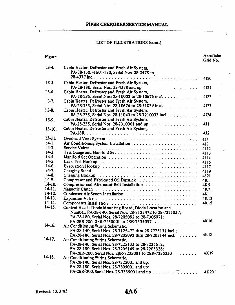
PIPER CHEROKEE SERVICE MANUAL
LIST OF ILLUSTRATIONS (cont.)
AeroficheGrid No.
13-4. Cabin Heater, Defroster and Fresh Air System,PA-28-150, -160, -180, Serial Nos. 28-2478 to28-4377 incl ............. ....................... 4120
13-5. Cabin Heater, Defroster and Fresh Air System,PA-28-180, Serial Nos. 28-4378 and up ........ 4121
13-6. Cabin Heater, Defroster and Fresh Air System.PA-28-235. Serial Nos. 28-10003 to 28-10675 incl. ............ 4122
13-7. Cabin Heater, Defroster and Fresh Air System.PA-28-235, Serial Nos. 28-10676 to 28-1 1039 incl. ........... 4123
13-8. Cabin Heater. Defroster and Fresh Air System.PA-28-235, Serial Nos. 28-1 1040 to 28-7210033 incl. ........... 4124
13-9. Cabin Heater. Defroster and Fresh Air System.PA-28-235, Serial Nos. 28-7310001 and up ............... 4JI
13-10. Cabin Heater, Defroster and Fresh Air System.PA-28R. ................................... 4J2
13-11.14-1.14-2.14-3.14-4.14-5.14-6.14-7.14-8.14-9.14-10.14-11.14-12.14-13.14-14.
Overhead Vent System ............Air Conditioning System Installation ....Service Valves .................Test Gauge and Manifold Set .........Manifold Set Operation ............Leak Test Hookup ...............Evacuation Hookup ..............Charging Stand .................Charging Hookup ....... ........Compressor and Fabricated Oil Dipstick . .Compressor and Alternator Belt InstallationMagnetic Clutch ................Condenser Air Scoop Installation ......Expansion Valve ................Components Installation ...........
14-15. Control Head - Diode Mounting Board, Diode Location andNumber, PA-28-140, Serial Nos. 28-7125472 to 28-7325057;PA-28-180, Serial Nos. 28-7205092 to 28-7305071;PA-28R-200. 28R-7235001 to 28R-7335057 ..............
14-16. Air Conditioning Wiring Schematic.PA-28-140, Serial Nos. 28-7125472 thru 28-7225131 incl.;PA-28-180, Serial Nos. 28-7205092 thru 28-7205 44 incl ......
14-17. Air Conditioning Wiring Schematic,PA-28-140, Serial Nos. 28-7225132 to 28-7225612;PA-28-180, Serial Nos. 28-7205145 to 28-7205328;PA-28R-200, Serial Nos. 28R-7235001 to 28R-7235330 .......
14-18. Air Conditioning Wiring Schematic,PA-28-140, Serial Nos. 28-7325001 and up;PA-28-180, Serial Nos. 28-7305001 and up;PA-28R-200, Serial Nos. 28-7335001 and up ..............
.............. ....... ;4J3
................. 4J74J7
................. . . 4J12
........ ·......... . . 4J13................. U 4J14................. 4J15................. .......4J17................... 4J19................. 4J21................. .. 4K1. ................ . 4K5.... .. ............ 4K7................. ..4K11................. ..4K13................. 4K15
4K16
4K18
4K19
4K20
Revised: 10/3/83
Figure
4A6
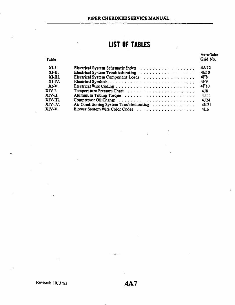
PIPER CHEROKEE SERVICE MANUAL
LIST OF TABLESAeroficheGrid No.
Electrical System Schematic Index ..................Electrical System Troubleshooting ..................Electrical System Component Loads .................Electrical Symbols ............................Electrical Wire Coding ..........................Temperature Pressure Chart .......................Aluminum Tubing Torque .......................Compressor Oil Change .........................Air Conditioning System Troubleshooting ..............Blower System Wire Color Codes ...................
4A124E104F84F94F104J84J114J244K214L6
Revised: 10/3/83 4A7
Table
XI-I.XI-II.XI-III.XI-IV.XI-V.
XIV-I.XIV-II.XIV-III.XIV-IV.XIV-V.

SECTION XI
ELECTRICAL SYSTEM
AeroficheGrid No.
Introduction ...................................Description ........................ ... ..Troubleshooting .................................Generator System (Delco-Remy) .......................11-5. Description of Generator System .................11-6. Checking Generator System ...................11-7. Adjustments, Tests and Maintenance of
Generator System ........................11-8. Test and Maintenance of Generator (Delco-Remy) .......11-9. Inspection of Generator .......................11-10. Shunt Generator Output ......................11-11. Check Defective Generators ....................11-12. No Output .........................11-13. Unsteady or Low Output . .. .................. ..11-14. Excessive Output ..........................11-15. Noisy Generator ...........................11-16. Disassembly, Repair and Reassembly ...............11-17. Field Coil Removal ............11-18. Inspection and Repair of Parts ...................11-19. Field Coil Service .............11-20. Armature Service ..........................11-21. Polarizing Generator .........................11-22. Generator Service Test Specifications (Delco-Remy) ......
r (Delco-Remy)Description of Regulator .......Cutout Relay ..............Voltage Regulator ...........Current Regulator ...........Resistances ..............Temperature Compensation .....Regulator Polarity ...........Regulator Maintenance ........Maintenance Instructions .......Cleaning Contact Points ........Regulator Checks and AdjustmentsVoltage Regulator ...........
11-23. Regulator11-24.11-25.11-26.11-27.11-28.11-29.11-30.11-31.11-32.11-33.11-34.11-35.
Revised: 10/3/83
11-1.11-2.11-3.11-4.
4A174A174A174A204A204A20
4A214A224A224A234A244A244B14B24B24B34B34B34B34B44B44B5
................ 4B6
................ 4B6·..... ........... 4B6............... 4B7............... 4B8............... 4B8............... 4B9............... 4B9........... .... ..4B9
............... 4B9............... .4B10............... 4B11............ 4B11
............
4A8
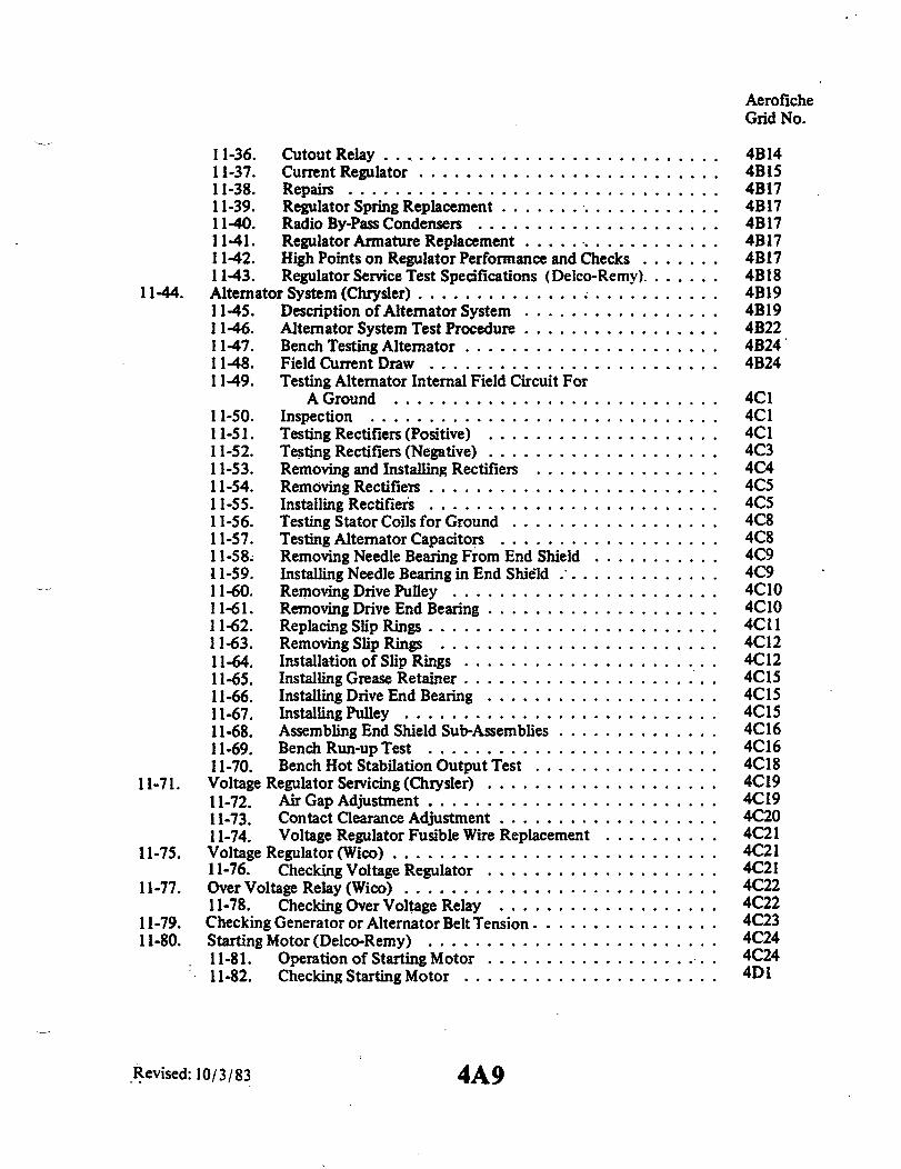
11-36.11-37.11-38.11-39.11-40.11-41.11-42.11-43.
Cutout Relay ...........................Current Regulator ..........................Repairs ................................Regulator Spring Replacement ... .............Radio By-Pass Condensers .....................Regulator Armature Replacement .... ............High Points on Regulator Performance and Checks .......Regulator Service Test Specifications (Delco-Remy) ......
11-44. Alternator System (Chrysler) .........................11-45. Description of Alternator System .................11-46. Alternator System Test Procedure .................11-47. Bench Testing Alternator ......................11-48. Field Current Draw .........................11-49. Testing Alternator Internal Field Circuit For
A Ground ............................11-50. Inspection ..............................11-51. Testing Rectifiers (Positive) ....................11-52. Testing Rectifiers (Negative) ....................11-53. Removing and Installing Rectifiers ................11-54. Removing Rectifiers .........................11-55. Installing Rectifiers .........................11-56. Testing Stator Coils for Ground ..................11-57. Testing Alternator Capacitors ...................11-58. Removing Needle Bearing From End Shield ...........11-59. Installing Needle Bearing in End Shield ..............11-60. Removing Drive Pulley .......................11-61. Removing Drive End Bearing ....................11-62. Replacing Slip Rings .........................11-63. Removing Slip Rings ........................11-64. Installation of Slip Rings ......................11-65. Installing Grease Retainer ......................11-66. Installing Drive End Bearing ....................11-67. Installing Pulley ...........................11-68. Assembling End Shield Sub-Assemblies ..............11-69. Bench Run-up Test .........................11-70. Bench Hot Stabilation Output Test ................
11-71. Voltage Regulator Servicing (Chrysler) ....................11-72. Air Gap Adjustment .........................11-73. Contact Clearance Adjustment ...................11-74. Voltage Regulator Fusible Wire Replacement
11-75. Voltage Regulator (Wico) ..................11-76. Checking Voltage Regulator ..........
11-77. Over Voltage Relay (Wico) .................11-78. Checking Over Voltage Relay .........
11-79. Checking Generator or Alternator Belt Tension .....11-80. Starting Motor (Delco-Remy) ...............
11-81. Operation of Starting Motor ..........11-82. Checking Starting Motor ............
Revised: 10/3/83
AeroficheGrid No.
4B144B154B174B174B174B174B174B184B194B194B224B244B24
4C14C14C14C34C44C54C54C84C84C94C94C104C104C114C124C124C154C154C154C164C164C184C194C194C204C214C214C214C224C224C234C244C244D1
. . . . . . . .
. . . . . . . .
. . . . . . . .
. . . . . . . .
. . . . . . . .
. . . . . . . .
. . . . . . . .
. . . . . . . .
. . . . . . . .
4A9
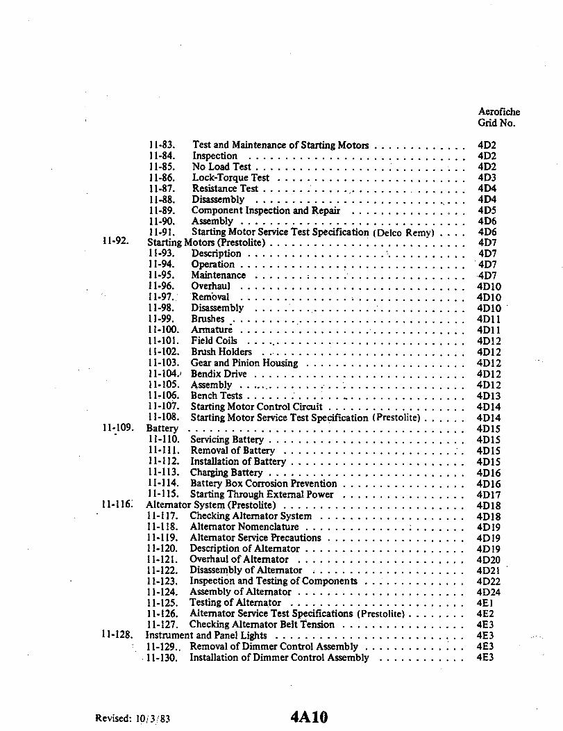
AeroficheGrid No.
11-83. Test and Maintenance of Starting Motors . ............ 4D211-84. Inspection ............. ................. 4D211-85. No Load Test ................... .......... 4D211-86. Lock-Torque Test ...... .............. ..... . 4D311-87. Resistance Test .......... .... ..... . 4D411-88. Disassembly .............................. 4D411-89. Component Inspection and Repair . ............... 4D511-90. Assembly ............................... 4D611-91. Starting Motor Service Test Specification (Delco Remy) .... 4D6
11-92. Starting Motors (Prestolite) ..... ..................... . 4D711-93. Description .............................. 4D711-94. Operation ............................... 4D711-95. Maintenance ........... ........... 4D711-96. Overhaul ............................... 4D1011-97. Removal ....... ........................ 4D1011-98. Disassembly ............... . .. ..... 4D1011-99. Brushes ................... ... ...... ... 4D1111-100. Armature .... ........................ 4D1111-101. Field Coils ... ............. ........... 4D1211-102. Brush Holders ...................... ........ 4D1211-103. Gear and Pinion Housing ...................... 4D1211-104. Bendix Drive .................. ....... 4D1211-105. Assembly ................ ................ 4D1211-106. Bench Tests ....... 4D1311-107. Starting Motor Control Circuit . ........... 4D1411-108. Starting Motor Service Test Specification (Prestolite) ...... 4D14
11-109. Battery ..... ................................. 4D1511-110. Servicing Battery ........................... 4D1511-111. Removal of Battery ......................... 4D1511-112. Installation of Battery ................... ..... 4D1511-113. Charging Battery ................................ 4D1611-114. Battery Box Corrosion Prevention . ................... 4D1611-115. Starting Through External Power . ................... 4D17
11-116 Alternator System (Prestolite) ........ .............. 4D1811-117. Checking Alternator System .................... 4D1811-118. Alternator Nomenclature ........ . 4D1911-119. Alternator Service Precautions . ................. . 4D1911-120. Description of Alternator ......... ............. 4D 1911-121. Overhaul of Alternator .......... ............ . 4D2011-122. Disassembly of Alternator . ....... ........ .... 4D2111-123. Inspection and Testing of Components ......... .... 4D2211-124. Assembly of Alternator ....................... 4D2411-125. Testing of Alternator ........................ 4E111-126. Alternator Service Test Specifications (Prestolite) ....... . 4E211-127. Checking Alternator Belt Tension . .................... 4E3
11-128. Instrument and Panel Lights ......... ....... . . . 4E311-129.. Removal of Dimmer Control Assembly ... ............ 4E311-130. Installation of Dimmer Control Assembly ............ 4E3
Revised: 10/3/83 4A10

AeroficheGrid No.
11-131. Annunciator Panel ................................ 4E411-132. Description .............................. 4E411-133. Removal of Oil Pressure Sensor .................. 4E411-134. Installation of Oil Pressure Sensor ................. 4E411-135. Removal of Vacuum Sensor . ............... . 4E411-136. Installation of Vacuum Sensor ................... 4E5
11-137. Anti-Collision Light (Rotating Beacon) ................... 4E511-138. Removal .......................... 4E511-139. Installation ............................. 4E5
11-140. Anti-Collision Light (Strobe) .......................... 4E511-141. Description ................ 4E511-142. Removal of Wing Tip Strobe Light ................ 4E511-143. Installation of Wing Tip Strobe Light .............. 4E611-144. Removal of Fin Tip Strobe Light . ...... ... 4E611-145. Installation of Fin Tip Strobe Light . .......... 4E611-146. Removal of Strobe Power Supply . ........... 4E611-147. Installation of Strobe Power Supply ......... ....... 4E711-148. Troubleshooting Procedure . ............ 4E7
Reissued: 1/15/81 4A11

TABLE XI-I. INDEX - ELECTRICAL SYSTEM SCHEMATICS
AeroficheSystem Figure Grid No.
Electrical System Schematic, PA-28-140, Serial Nos. 28-20000 to28-24999 incl ............................................. 11-54 4F11
Electrical System Schematic, PA-28-140, Serial Nos. 28-25000 to28-7325052 incl ........................................... 11-55 4F13
Electrical System Schematic, PA-28-150, -160, Serial Nos. 28-1to 28-507 incl. ........................................... 11-56 4F15
Electrical System Schematic, PA-28-150, -160, Serial Nos. 28-508to 28-670 incl. ........................................... 11-57 4F17
Electrical System Schematic, PA-28-150, -160, -180, Serial Nos.28-671 to 28-1760 incl. ................ ............... 11-58 4F19
Electrical System Schematic, PA-28-150, -160, -180, Serial Nos.28-1761 to 28-3643 incl ...................................... 11-59 4F21
Electrical System Schematic, PA-28-150, -160,-180, Serial Nos.28-3644 to 28-4377 incl ................................... 11-60 4F23
Electrical System Schematic, PA-28-180, Serial Nos. 28-4378to 28-5227 incl .......................................... 11-61 4GI
Electrical System Schematic, PA-28-180, Serial Nos. 28-5228to 28-7305063 incl. ....................................... 11-62 4G3
Electrical System Schematic, PA-28-235, Serial Nos. 28-10003to 28-10719 incl. ......................................... 11-63 4G5
Electrical System Schematic, PA-28-235, Serial Nos. 28-10720to 28-10762 incl. ......................................... 11-64 4G7
Electrical System Schematic, PA-28-235, Serial Nos. 28-10763to 28-11039 incl. ........................................ 11-65 4G9
Electrical System Schematic, PA-28-235, Serial Nos. 28-11040to 28-7310038 incl. ....................................... 11-66 4G11
Electrical System Schematic, PA-28R-180, Serial Nos. 28-30005to 28-30879 incl. ......................................... 11-67 4G13
Electrical System Schematic, PA-28R-180, -200, Serial Nos.28-30880 to 28-7335054 incl ............................... 11-68 4G15
Landing Gear Back-up Actuator Override Mechanism ........... 11-69 4G17Landing Gear Back-up Actuator Override Mechanism .......... 11-70 4G 17
See Note on Grid No..................................... 4G19A/C Air Blower, PA-28-140, Serial Nos. 28-7425001 & up;
PA-28R-200, Serial Nos. 28-7435001 & up;PA-28-235, Serial Nos. 28-7410001 & up;PA-28-180, Serial Nos. 28-7405001 & up .................... 11-107 4H10
Alternator, Starter, Cabin Light, Cigar Lighter andExternal Power Receptacle, PA-28-140, Serial Nos. 28-25000to 28-7325052 incl. ..................................... 11-85
Alternator, Starter, Cabin Light, Cigar Lighter andExternal Power Receptacle, PA-28-140, Serial Nos.28-7325053 to 28-7425454 incl. ........................... 11-86
Reissued: 1/15/81 4A12

I
4
.
oo
00
60
I00

~~~
.


TABLE XI-I. INDEX - ELECTRICAL SYSTEM SCHEMATICS (cont)
AeroficheSystem Figure Grid No.
Stall Warning, PA-28-140, Serial Nos. 28-7625001 & up;PA-28R-200, Serial Nos. 28-7635001 & up; PA-28-235, Serial Nos.28-7610001 & up ......................................... 11-138 4H23
Turn & Bank, PA-28-140, Serial Nos. 28-7325053 & up ......... 11-121 4H 14Turn & Bank, PA-28-180, Serial Nos. 28-7405001 & up;
PA-28-235, Serial Nos. 28-7410001 & up ........ ............ 11-122 4H 14Turn & Bank, PA-28R-200, Serial Nos. 28-7335055 & up........ 11-123 4H 14
Reissued: 1/15/81 4A16

PIPER CHEROKEE SERVICE MANUAL
SECTION XI
ELECTRICAL SYSTEM
11-1. INTRODUCTION. This section contains instructions for correcting difficulties whichmay arise in the operation of the electrical system in PA-28 series airplanes. It includes ageneral description and function of each part of the system along with test and adjustmentsof the various components. This does not include any electronics installations such asAutopilot or radios. For Autopilot Service Information, refer to Section XII of this manual.Radio Service and Repairs may be found in the appropriate radio manufacturer's manuals.
11-2. DESCRIPTION. The electrical system is a 14-volt, direct current, single wire,negative ground system. All electrical equipment is grounded to the metal structure of theairplane, therefore, the structure takes the place of the second wire. A 12-volt battery isincorporated in the system to furnish power for starting and as a reserve power source incase of generator or alternator failure. The battery and generator or alternator are bothconnected to the bus bar, from which all electrical equipment is powered, with theexception of the starter which receives its power from the load side of the battery. Themaster switch controls the battery relay and field circuit. The master switch must be onbefore any electrical equipment will operate. The airplane can be equipped with standardnavigation lights, rotating beacon and one landing light located in the nose cowl.
11-3. TROUBLESHOOTING. Troubles peculiar to the electrical system are listed in TableXI-I at the back of this section along with their probable causes and suggested remedies. Thewiring diagrams included at the end of this section will give physical breakdown of thedifferent electrical circuits used in this airplane.
After the trouble has been corrected, check the entire electrical system for security andoperation of its components.
WARNING
All checks and adjustments of the generator or alternatorand/or its components should be made with the enginestopped. Therefore, to complete some checks or adjustments,it will be necessary to remove these units from the airplaneand place on a test stand.
ELECTRICAL SYSTEM4A17Reissued: 1/15/81
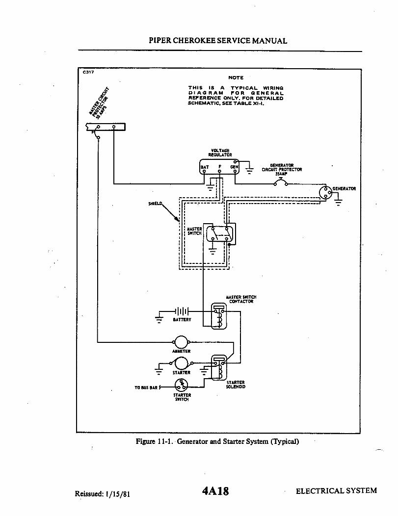
PIPER CHEROKEE SERVICE MANUAL
NOTE
THIS IS A TYPICAL WIRINGDIAGRAM FOR GENERALREFERENCE ONLY. FOR DETAILEDSCHEMATIC, SEE TABLE XI-I.
VOLTAGEREGULATOR
BAT F GENERATORT CIRCUIT PROTECTOR
35AMP
T
- -
SHIE
iMASTER
I
MASTER SWITCH. .CONTACTOR
_ BATTERY
AMMETER
TO BUS BAR SELINOID
STARTERSWITCH
Figure 11-1. Generator and Starter System (Typical)
4A18 ELECTRICAL SYSTEMSTEMReissued: 1/15/81
C317

PIPER CHEROKEE SERVICE MANUAL
NOTE
THIS IS A TYPICAL WIRINGDIAGRAM FOR GENERALREFERENCE ONLY. FOR DETAILEDSCHEMATIC, SEE TABLE XI-I.
REGULATOR
I II
F
BATTERY
LOAD
GENERATOR
Figure 11-2. Generator Wiring Diagram (Typical)
4A19
A143
BAT. GEN.
A
"A"
Reissued: 1/15/81 ELECTRICAL SYSTEM
PIPER CHEROKEE SERVICE MANUAL
11-4. GENERATOR SYSTEM .(Delco-Remy.)
11-5. DESCRIPTION OF GENERATOR SYSTEM. The generator is of the twobrush, shunt type and is controlled by a regulator operating on the principal ofinserting resistance into the generator field circuit to cause a reduction of gen-erator voltage and current output. With each generator is the regulator assem-bly, composed of a voltage regulatorand current regulator, to prevent overload-ing of the battery and electrical circuits. Also with the regulator is a reversecurrent cutout to prevent the generator from beingmotorized by the battery whenthe generator output drops below the battery voltage. Field current between theregulator and generator maybe broken through the use of the master switch. Thegenerator is located on the front lower right side of the engine and utilizes a beltdrive from the engine crankshaft. The generator voltage regulator is located onthe engine firewall. The best assurance of obtaining maximum service from thegenerator with minimum trouble is to follow a regular inspection and maintenanceprocedure.
11-6. CHECKING GENERATOR SYSTEM. Inanalyzingcomplaints of generator-regulator operation, any of several basic conditions may be found.
a. Fully Charged Battery and Low Charging Rate: This indicates normalgen-erator-regulator operation. Regulator settingmay be checked as outlined inpara-graph 11-23.
b. Fully Charged Batteryand a HighChargingRate: This indicatesthatthevolt-age regulator is not reducing the generator output as it should. A high chargingrate to a fully charged battery will damage the battery and the accompanying highvoltage is very injurious to all electrical units.
This operating condition may result from:1. Improper voltage regulator setting.2. Defective voltage regulator unit.3. Grounded generator fieldcircuit (in eithergenerator, regulatoror wir-
ing).4. Poor ground connection at regulator.5. High temperature which reduces the resistance of the battery to charge
so that it will accept a high charging rate even though the voltage regulator set-ting is normal.
If the trouble is not due to high temperature, determine the cause of troublebydisconnecting the lead from the regulator "F" terminal with the generator op-erating at medium speed. If the output remains high, the generator field i s ground -ed either in the generator or in the wiring harness. If the output drops off, theregulatoris at fault, and it should be checked for a high voltage settingorgrounds.
ELECTRICAL SYSTEMReissued: 1/15/81 4A20
PIPER CHEROKEE SERVICE MANUAL
c. Low Battery and High Charging Rate: This is normal generator-regulatoraction. Regulator settings may be checked as outlined in paragraph 11-23.
d. Low Battery and Low or No Charging Rate: This condition could be due to:1. Loose connections, frayed or damaged wires.2. Defective battery.3. High circuit resistance.4. Low regulator setting.5. Oxidized regulator contact points.6. Defects within the generator.If the condition is not caused by loose connections, frayed or damaged wires,
proceed as follows to locate cause of trouble.To determine whether the generator or regulator is at fault, momentarily
ground the "F" terminal of the regulator and increase generator speed. If theoutput does not increase, the generator is probably at fault and it should be check -ed as outlined in paragraph 11-8. If the generator output increases, the troubleis due to:
1. A low voltage (or current) regulator setting.2. Oxidized regulator contactpointswhich insert excessive resistance into
the generator field circuit so that output remains low.3. Generator field circuit open within the regulator at the connections or
in the regulator wiring.e. Burned Resistances, Windings or Contacts: These result from open circuit
operation or high resistance in the charging circuit. Where burned resistances,windings or contacts are found, always check wiring before installing a new reg-ulator. Otherwise the new regulator may also fail in the same way.
f. Burned Relay Contact Points: This is due to reversed generator polarity.Generator polarity must be corrected as explained in paragraph 11-21 after anychecks of the regulator or generator or after disconnecting and reconnecting leads.
11-7. ADJUSTMENTS, TESTS AND MAINTENANCE OF GENERATOR SYSTEM.The best assurance of obtaining maximum service from generators with
minimum trouble is to follow a regular inspection and maintenance procedure.Periodic lubrication where required, inspection of the brushes and commutatorand checking of the brush spring tension are essentials in the inspection proce-dure. In addition, disassembly and thorough overhauling of the generator at pe-riodic intervals are desirable as a safeguard against failures from accummula-tions of dust and grease and normal wear of parts. This is particularly desir-able on installations where maintenance of operating schedules is of special im-portance. In addition to the generator itself, the external circuits between thegenerator, regulator and battery must be kept in good condition since defectivewiring or loose or corroded connections will prevent normal generator and reg-
ELECTRICAL SYSTEMReissued: 1/15/81 4A21
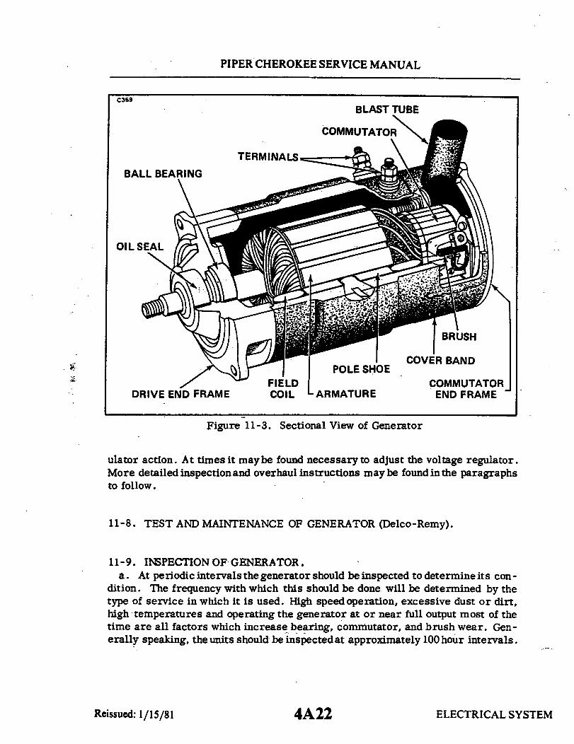
PIPER CHEROKEE SERVICE MANUAL
BLAST TUBE
COMMUTATOR
TERMINALS
01
DRIVE END FRAME
IFIELDCOIL
COMMUTATOREND FRAME
Figure 11-3. Sectional View of Generator
ulator action. At times it maybe found necessary to adjust the voltage regulator.More detailed inspection and overhaul instructions may be found in the paragraphsto follow.
11-8. TEST AND MAINTENANCE OF GENERATOR (Delco-Remy).
11-9. INSPECTION OF GENERATOR.a. At periodic intervals the generator should be inspected to determine its con-
dition. The frequency with which this should be done will be determined by thetype of service in which it is used. High speed operation, excessive dust or dirt,high temperatures and operating the generator at or near full output most of thetime are all factors which increase bearing, commutator, and brush wear. Gen-erally speaking, the units should be inspected at approximately 100 hour intervals.
ELECTRICAL SYSTEM
C359
4A22Reissued: 1/15/81
PIPER CHEROKEE SERVICE MANUAL
The inspection procedure follows.b. First inspect the terminals, external connections and wiring, mounting,
pulley and belt. Then remove the cover band so that the commutator, brushesand internal connections can be inspected. If the commutator is dirty it may becleaned with a strip of No. 00 sandpaper. Never use emery cloth to clean thecommutator.
c. The sandpaper may be used byholding it against the commutatorwith a woodstick while the generator is rotated, moving it backand forth across the commu-tator. Gum and dirt will be sanded off in a few seconds. All dust should be blownfrom the generator after the commutator has been cleaned. A brush seating stonecan also be used to clean the commutator.
d. If the commutator is rough, out of round, or has high mica, the generatormust be removed and disassembled so that the armature can be turned down in alathe and the mica undercut.
e. If the brushes are worn down to less than half their original length, theyshould be replaced. Compare the old brush with anewone todetermine how muchit is worn. New brushes should be seated to make sure that they are in good con-tact with the commutator. A convenient tool for seating brushes is a brush seat -ing or bedding stone. This is a soft abrasive material which, when held againsta revolving commutator, disintegrates so that particles are carried under thebrushes and wear their contacting faces to the contour of the commutator in a fewseconds. All dust should be blown fromthegeneratorafter the brushes are seated.
f. The brush spring tension must be correct since excessive tension will causerapid brush and commutator wear, while low tension causes arcing and burningof the brushes and commutator. Brush springtension can be checked with a springgauge hooked on the brusharm or brush attaching screw. Correction can be madeby bending the brush spring as required. If the brush spring shows evidence ofoverheating (blued or burned), do not attempt to readjust it, but install a newspring. Overheating will cause a spring to lose its temper.
g. The belt should bechecked to make sure that it is in good condition and hascorrect tension. Low belt tensionwill permit belt slippagewith a resulting rapidbelt wear and low or erratic generator output. Excessive belt tension will causerapid belt and bearing wear. Check the tension of a new belt 25 hours after in-stallation. Proper adjustment is given in paragraph 11-79.
11-10. SHUNT GENERATOR OUTPUT. Themaximumoutputofshuntgeneratorsis determined by the current setting of the current regulator with which the shuntgenerator is used. Checking of this setting is discussed in the applicable regula-tor bulletin.
ELECTRICAL SYSTEMReissued: 1/15/81 4A23
PIPER CHEROKEE SERVICE MANUAL
11-11. CHECKING DEFECTIVE GENERATORS. If the generator-regulator sys-tem does not perform according to specifications (generator does not producerated output or produces excessive output), and the trouble has been isolated inthe generator itself by following the procedure outlined in paragraph 11-6, thegenerator may be checked further as follows to determine the location of troublein the generator.
11-12 NO OUTPUT.a. If the generator will not produce any output, remove the cover band and
check the commutator, brushes and internal connections. Sticking brushes, adirty or gummycommutator (Refer to paragraph 11-20.)orpoor connections mayprevent the generator from producing any output. Thrown solder on the coverband indicates that the generator has been overloaded (allowed to produce exces-sive output) so it has overheated and melted the solder at the commutator riserbars. Solder thrown out often leads to an open circuit and burned commutatorbars. If the brushes are satisfactorily seated and are making good contact withthe commutator, and the cause of trouble is not apparent, use a set of test pointsand a test lamp as follows to locate the trouble (leads must be disconnected fromgenerator terminals).
b. Raise the grounded brush from the commutator and insulate with a piece ofcardboard. Check for grounds with test points from the generator main brush tothe generator frame. If the lamp lights, it indicates that the generator is inter-nally grounded. Location of the ground can be found by raising and insulating allbrushes from the commutator and checking the brush holders, armature, com-mutator and field separately. Repair or replace defective parts as required.(Refer to paragraph 11-18.)
NOTE
If a grounded field is found, check the regulator con-tact points, since a grounded field may have permit-ted an excessive field current which will have burnedthe regulator contact points. Burned regulator pointsshould be cleaned or replaced as required.
c. If the generator is not grounded, check the field for an open circuit with atest lamp. The lamp should light when one test point is placed on the field ter-minal or grounded field lead and the other is placed on the brush holder to whichthe field is connected. If it does not light, the circuit is open. If the open is dueto a broken lead or bad connection, it can be repaired, but if the open is insideone of the field coils, it must be replaced.
Reissued: 1/15/81 ELECTRICAL SYSTEM4A24

PIPER CHEROKEE SERVICE MANUAL
d. If the field is not open, check for a short circuit in the field by connectinga battery of the specified voltage and an ammeter in series with the field circuit.Proceed with care, since a shorted field may draw excessive current which mightdamage the ammeter. If the field is not within specification, new field coils willbe required. (Refer to Paragraph 11-16.)
NOTE
If a shorted field is found, check the regulator contactpoints, since a shorted field may have permitted ex-cessive field current whichwould have caused the reg-ulator contact points to burn. Clean or replace pointsas required.
e. If the trouble has not yet been located, check the armature for open andshort circuits. Open circuits in the armatureareusually obvious, since the opencircuited commutator bars will arc every time they pass under the generatorbrushes so that they will soon become burned. If the bars are not too badly burn-ed and the open circuit can be repaired, the armature can usually be saved. Inaddition to repairing the armature, generator output must be brought down tospecifications to prevent overloading by readjustment of the regulator.
f. Short circuits in the armature are located by use of a growler. The ar-mature is placed in the growler and slowly rotated (while a thin strip of steel suchas a hacksaw blade is held above the armature core). The steel strip will vibrateabove the area of the armature core in which short circuited armature coils arelocated. If the short circuit is obvious, it can often be repaired so that the ar-mature can be saved.
11-13. UNSTEADY OR LOW OUTPUT. If the generator produces a low or un-steady output, the following factors should be considered:
a. A loose drive belt will slip and cause a low or unsteady output.b. Brushes which stick in their holders, or low brushspring tension will pre-
vent good contact between the brushes and commutator so that output will be lowand unsteady. This will also cause arcing and burning of the brushes and com-mutator.
c. If the commutator is dirty, out of round, or has high mica, generator out-put is apt to be low and unsteady. The remedy here is to turn the commutatordown in a lathe and undercut the mica. Burned commutator bars may indicate anopen circuit condition in the armature as already stated above. (Refer to Para-graph 11-12.)
ELECTRICAL SYSTEMReissued: 1/15/81 4B1

PIPER CHEROKEE SERVICE MANUAL
11-14. EXCESSIVE OUTPUT.a. When a generator produces excessive output on an application, the proce-
dure for determining whether the trouble is in the generator, regulator, or else-where is outlined in paragraph 11-6. If the generator output remains high, evenwith the "F" terminal lead disconnected, then the trouble is in the generator it-self, and it must be further analyzed to locate the source of trouble.
b. In the systemwhich has thegenerator fieldcircuit groundedexternally, ac-cidental internal grounding of the field circuit would prevent normal regulation sothat excessive output might be produced by the generator. On this type of unit,an internally grounded field which would cause excessive output may be locatedby use of test points connected between the "F" terminal and thegenerator frame.Leads should be disconnected from the "F" terminal and the brush to which thefield lead is connected inside the generator should be raised from the commu-tator before this test is made. If the lamp lights, the field is internallygrounded..If the field has.become grounded because the insulation on a field lead has wornaway, repair can be made by reinsulating the lead. It is also possible to makerepair where the ground has occurred at the pole shoes by removing the field coilsand reinsulating and reinstalling them. A ground at the "F" terminal stud can berepaired by installing new insulating washers or bushings.
NOTE
If battery temperature is excessive, battery over-charge is apt to occur, even though regulator settingsare normal. Under this condition, it is permissibleto reduce the voltage regulator setting as explained inthe applicable bulletin pertaining to the regulator usedon the application.
11-15. NOISY GENERATOR. Noise emanating from agenerator may be causedby a loose mounting, drive pulley, or gear; worn or dirty bearings: or improp-erly seated brushes. Dirty bearings may sometimes be saved by cleaning andrelubrication, but worn bearings should be replaced. Brushes can be seated asexplained in paragraph 11-9. If the brush holder is bent, it may be difficult toreseat the brush so that it will function properly without excessive noise. Sucha brush holder will require replacement.
ELECTRICAL SYSTEM4B2Reissued: 1/15/81

PIPER CHEROKEE SERVICE MANUAL
11-16. DISASSEMBLY, REPAIR AND REASSEMBLY. Normally, disassemblyshould proceed only so far as is necessary to make repair or replacement of thedefective parts. For example, the field coils should be checked for opens, shorts,or grounds before being removed from the field frame. They should be removedonly if they require repair or replacement.
11-17. FIELD COIL REMOVAL. Fieldcoilscanbe removedfromthefieldframemost easily by use of a pole shoe screw driver. It is also advisable to use a poleshoe spreader, since this prevents distortion of the field frame. The pole shoescrew driver permits easy loosening and removal of the pole shoe screws so thatthe pole shoes and field coils can be taken out of the field frame. The pole shoesc rew driver and spreader should be used on reassembly of the field frame. Ca re -ful reassembly is necessary to prevent shorting orgrounding of the field coils asthe pole shoes are tightened into place.
11-18. INSPECTION AND REPAIR OF PARTS. The armature or field should notbe cleaned in any degreasing tank or by use of degreasing compounds, since thismight damage insulation so that a short or ground would subsequently develop.Sealed ball bearings do not require cleaning or relubrication. Other generatorparts should be cleaned and carefully inspected for wear and other damage. Anydefective parts should be repaired or replaced. On reassembly all soldered elec -trical connections should be made with rosin flux. Acid flux must never be usedon electrical connections.
11-19. FIELD COIL SERVICE.a. The field coils should be checked for grounds, opens or shorts as already
explained in paragraph 11-12.b. Grounded field coils may sometimes be repaired by removing them so they
can be reinsulated. Care must be used to avoid excessive bulkiness when ap-plying new insulation, since this might cause the pole shoe to cut through andcause another ground when the coils are reinstalled.
c. Usually if a field coil is open or shorted internally it will require replace-ment, since it is difficult to repair such a defect.
d. To remove or replace field coils in the field frame, the use of a pole shoespreader and screw driver is recommended.
Reissued: 1/15/81 ELECTRICAL SYSTEM
4B3

PIPER CHEROKEE SERVICE MANUAL
11-20. ARMATURE SERVICE.a. The armature should be checked for opens, shorts and grounds as explained
in followingparagraphs. If the armature commutator is worn, dirty, out of round,or has high mica, the armature should be put in a lathe so the commutator can beturned down and the mica undercut. The mica should be undercut .031 of an inchand the slots cleaned out carefully to remove any trace of dirt or copper dust. Asa final step in this procedure, the commutator should be sanded lightly with No.00 sandpaper to remove any slight burrs that might be left as a result of the un-dercutting procedure.
b. Open circuited armatures can often be saved when the open is obvious andrepairable. The most likely place an open will occur is at the commutator riserbars. This usually results from overloading of the generator which causes over-heating and melting of the solder. Repair can be effected by resoldering the leadsin the riser bars (usingrosin flux) and turning down the commutator in a lathe toremove the burned spot and then undercutting the mica as explained in the pre-vious paragraph. In some heavy-duty armatures, the leads are welded into theriser bars and these cannot be repaired by resoldering.
c. Short circuits in the armature are located by use of a growler. When thearmature is revolved in the growler, with a steel strip such as a hacksaw bladeheld above it, the blade will vibrate above the area of the armature core in whichthe short is located. Copper or brush dust in the slots between the commutatorbars sometimes causes shorts between bars which can be eliminated by cleaningout the slots. Shorts at cross-overs of the coils at the core endcan often be elim-inated by bending wires slightly and reinsulating the exposed bare wire.
d. Grounds in the armature are detectedby use of atest lamp and test points.If the lamp lights when one test point is placed on the commutator with the otherpoint on the core or shaft, the armature is grounded. Grounds occur as a resultof insulation failure, which is often brought on by overloading and consequentoverheating of the generator. Repairs can sometimes be made if grounds are atcore ends (where coils come out of slots) by placing insulating strips betweencore and coil which has grounded.
11-21. POLARIZING GENERATOR. After a generator has been repaired andreinstalled or at any time after a generator has been tested, it must be repolar-ized to make sure that it has the correct polarity with respect to the battery it isto charge. Failure to repolarize the generator may result in burned relay con-tact points, a run-down battery and possibly serious damage to the generator it-self. The procedure to follow in correcting generator polarity depends upon thegenerator-regulatorwiringcircuits; that is, whether the generator field is inter-nally grounded or is grounded through the regulator. (Refer to paragraph 11-30. )
ELECTRICAL SYSTEM4B4Reissued: 1/15/81

PIPER CHEROKEE SERVICE MANUAL
11-22. GENERATOR SERVICE TEST SPECIFICATIONS. Delco-Remy specifi-cations for 14 volt generators installed on PA -28 series airplanes are as follows:
Generator 1101900
Delco-Remy,Ref, Service Bulletin 1G-150
Brush Spring Tension 24 oz.
Field Current (80° F)Amps 1.62 to 1.72Volts 12
Cold OutputAmps 35Volts 14.0Approx. RPM 3100
COLD OUTPUT: Cold output data applies to generators at 80 degrees F,and with brushes well seated. Variations in temperature and brush seatingas well as the condition of the generator may cause deviations of 100 RPMor more from rated speed.HOT OUTPUT: Hot output is maximum output as controlled bycurrent reg-ulator.
ELECTRICAL SYSTEMReissued: 1/15/81 4B5
PIPER CHEROKEE SERVICE MANUAL
11-23. REGULATOR.
11-24. DESCRIPTION OF REGULATOR. The regulator shown in Figure 11-4consists of a cutout relay, a voltage regulator and a current regulator unit. Thecutout relaycloses the generator to batterycircuit when the generator voltage issufficient to charge the battery, and it opens the circuit when the generator slowsdown or stops. The voltage regulator unit is a voltage-limiting device that pre-vents the system voltage from exceeding a specified maximum and thus protectsthe battery and other voltage-sensitive equipment. The current regulator unit isa current-limiting device that limits the generator output so as not to exceed itsrated maximum.
11-25. CUTOUT RELAY.a. The cutout relay (Refer to Figure 11-4.) has twowindings, a series winding
of a few turns of heavy wire and a shunt winding of many turns of fine wire (shownin dashed lines). The shunt winding is connected across the generator so thatgenerator voltage is impressed upon it at all times. The series winding is con-nected in series with the charging circuit so that all generator output passesthrough it. The relay core and windings are assembled into a frame. A flat steelarmature is attached to the frame by a flexible hinge so that it is centered justabove the stationary contact points. When the generator is not operating, the ar-mature contact points are held away from the stationary points by the tension ofa flat spring riveted on the side of the armature.
b. When the generator voltage builds up a value great enough to charge thebattery, the magnetism induced by the relay windings is sufficient to pull the ar-mature toward the core so that the contact points close. This completes the cir-cuit between the generator and battery. The current which flows from the gen-erator to the battery passes through the series winding in a direction to add to themagnetism holding the armature down and the contact points closed.
c. When the generator slows down or stops, current begins to flow from thebattery to the generator.
d. This reverse flow of current through the series winding causes a reversalof the series winding magnetic field. The magnetic field of the shunt winding doesnot reverse. Therefore, instead of helping each other, the two windings nowoppose so that the resultant magnetic field becomes insufficient to hold the arm-ature down. The flat spring pulls the armature away from the core so that thepoints separate; this opens the circuit between the generator and battery.
ELECTRICAL SYSTEMReissued: 1/15/81 4B6

PIPER CHEROKEE SERVICE MANUAL
11-26. VOLTAGE REGULATOR.a. The voltage regulator (Refer to
Figure 11-4.) has two windings assem-bled on a single core, a shunt windingconsisting of many turns of fine wire(shown in dashed lines) which is shunt-ed across the generator, and a serieswinding of a few turns of relativelyheavy wire which is connected in serieswith the generator field circuit whenthe regulator contact points are closed.
b. The windings and core are as-sembled into a frame. A flat steelarmature is attached to the frame by aflexible hinge so that it is just abovethe end of the core. The armaturecontains a contact point which is just
C360
CURRENTREGULATOR
/ VOLTAGE__ REGULATOR
CUTOUTRELAY
BATTERY GENERATOR FIELDTERMINAL TERMINAL TERMINAL
Figure 11-4. Current/VoltageRegulator
beneath a stationary contact point. When the voltage regulator is not operating,the tension of a spiral spring holds the armature away from the core so that thepoints are in contact and the generator field circuit is completed to ground throughthem.
c. When the generator voltage reaches the value for which the voltage regu-lator is adjusted, the magnetic field produced by the two windings (shunt and se-ries) overcomes the armature spring tension and pulls the armature down so thatthe contact points separate. This inserts resistance into the generator field cir-cuit so that the generator field current and voltage are reduced. Reduction of thegenerator voltage reduces the magnetic field of the regulator shunt winding. Also,opening the regulator points opens the regulator series winding circuit sothat itsmagnetic field collapses completely. The consequence is that the magnetic fieldis reduced sufficiently to allow the spiral spring to pull the armature away fromthe core so that the contact points again close. This directly grounds the gener-ator so that generator voltage and output increase. The above cycle of actionagain takes place and the cycle continues at a rate of 50 to 200 times a second,regulating the voltage to a predetermined value. With the voltage thus limited,the generator supplies varying amounts of current to meet the varying states ofbattery charge and electrical load.
ELECTRICAL SYSTEMReissued: 1/15/81 4B7

PIPER CHEROKEE SERVICE MANUAL
11-27. CURRENT REGULATORa. The current regulator (Refer to Figure 11-4.) has a series winding of a few
turns of heavy wire which carries all generator output. The winding core is as-sembled into a frame. Aflat steel armature is attached to the frame by a flexiblehinge so that it is just above the core. The armature has a contact pointwhich isjust below a stationary contact point. When the current regulator is not operating,the tension of a spiral spring holds the armature away from the core so that thepoints are in contact. In this position the generator field circuit is completed toground through the current regulator contact points in series with the voltage reg-ulator contact points.
b. When the load demands are heavy, as for example, when electrical devicesare turned on and the battery is in adischargedcondition, thevoltage may not in-crease to a value sufficient to cause the voltage regulator to operate. Consequen-tly, generator output will continue to increase until the generator reaches ratedmaximum current. This is the current value for which the current regulator isset. Therefore, when the generator reaches rated output, this output, flowingthrough the current regulator winding, creates sufficient magnetism to pull thecurrent regulator armature down and open the contact points. With the pointsopen, resistance is inserted into the generator field circuit so that the generatoroutput is reduced.
c. As soon as the generator output starts to fall off, the magnetic field of thecurrent regulator winding is reduced, the spiral spring tension pulls the arma-ture up, the contact points close and directly connect the generator field to ground.Output increases and the above cycle is repeated. The cycle continues to takeplace while the current regulator is in operation 50 to 200 times a second, pre-venting the generator from exceeding its rated maximum. When the electricalload is reduced (electrical devices turned off or battery comes up to charge), thenthe voltage increases so that the voltage regulator begins to operate and tapersthe generator output down. This prevents the current regulator from operating.Either the voltage regulator or the current regulator operates at any one time -the two do not operate at the same time.
11-28. RESISTANCES. The current and voltage regulator circuits use a commonresistor which is inserted in the field circuit when either the current or voltageregulator operates. A second resistor* is connected between the regulator fieldterminal and the cutout relay frame, which places it in parallel with the generatorfield coils. The sudden reduction in field current occurring when the current orvoltage regulator contact points open, is accompanied by a surge of induced volt-age in the field coils as the strength of the magnetic field changes. These surges
ELECTRICAL SYSTEM4B8Reissued: 1/15/81

PIPER CHEROKEE SERVICE MANUAL
are partially dissipated by the two resistors, thus preventing excessive arcing atthe contact points.*(The second resistor is not present on all regulators. Many aircraft regulatorshave this resistor omitted.)
11-29. TEMPERATURE COMPENSATION. Voltage regulators are compensatedfor temperature by means of a bimetal thermostatic hinge on the armature. Thiscauses the regulator to regulate at a higher voltage when cold which partly com-pensates for the fact that a higher voltage is required to charge a cold battery.Many current regulators also have a bimetal thermostatic hinge on the armature.This permits a somewhat highergenerator output when the unit is cold, but causesthe output to drop off as temperature increases.
11-30. REGULATOR POLARITY. Some regulators are designed for use withnegative grounded systems, while other regulators are designed for use with po-sitive grounded systems. Usingthe wrong polarity regulator on an installation willcause the regulator contact points to pit badlyand give short life. As a safeguardagainst installation of the wrong polarity regulator, all regulators of this typehave the model number and the polarity clearly stamped on the end of the regu-lator base. (Refer to paragraph 11-32, step e. )
11-31. REGULATOR MAINTENANCE.
11-32. MAINTENANCE INSTRUCTIONS.a. Mechanical checks and adjustments (air gaps, point opening) must be made
with battery disconnected and regulator preferably off the aircraft.
CAUTION
The cutout relay contact points must never be closedby hand with the battery connected to the regulator.This would cause a high current to flow through theunits which would seriously damage them.
b. Electrical checks and adjustments may be made either on or off the air-plane. The regulator must always be operated with the type generator for whichit is designed.
c. The regulator must be mounted in the operating position when electrical
ELECTRICAL SYSTEM4B9Reissued: 1/15/81

PIPER CHEROKEE SERVICE MANUAL
C359 C159
FILE AIR GAP(CHECK WITH POINT
JUST TOUCHING)
CONTACTTO CLEAN CONTACT POINTS MOUNTING SCREWS
(LOOSEN UPPER CONTACT (LOOSEN TO SET AIR GAP)BRACKET MOUNTING SCREWS)
Figure 11-5. Use of Riffler File Figure 11-6. Voltage Regulatorto Clean Contact Points Air Gap
settings are checked and adjusted and it must be at operating temperature.d. Specified generator speeds for testing and adjusting.
1. Voltage Regulator(a) Operating speed
2. Current Regulator(a) All generators must be operated at a speed sufficient to producecurrent in excess of specified setting.(b) Voltage of the generator must be kept high enough to insure suffi-cient current output, but below the operating voltage of the voltage reg-ulator unit.
e. After any tests oradjustments thegenerator on the airplane must be polar-ized after leads are connected, but before the engine is started, as follows:
After reconnecting leads, momentarily connect a jumper lead between the."GEN" and "BAT" terminals of the regulator. This allows a momentary surgeof current to flow through the generator which correctly polarizes it. Failure todo this may result in severe damage to the equipment since reversed polaritycauses vibration, arcing and burning of the relay contact points.
11-33. CLEANING CONTACT POINTS. The contact points of a regulator willnot operate indefinitely without some attention. It has been found that a greatmajority of all regulator trouble can be eliminated by a simple cleaning of thecontact points, plus some possible readjustment. The flat points should be clean-ed with a spoon or riffler file. On negative grounded regulators which have the
ELECTRICAL SYSTEMReissued: 1/15/81 4B10

PIPER CHEROKEE SERVICE MANUAL
C318
Figure 11-7. Checking Voltage Figure 11-8. Checking VoltageSetting Fixed Resistance Method Setting Variable Resistance Method
flat contact point on the regulator armatures, loosen the contact bracket mount-ing screws so that the bracket can be tilted to one side. A flat file cannot be usedsuccessfully to clean the flat contact points since it will not touch the center ofthe flat point where point wear is most apt to occur. Never use emery cloth orsandpaper to clean the contact points. Remove all the oxides from the contactpoints but note that it is not necessary to remove any cavity that may have devel-oped.
11-34. REGULATOR CHECKS AND ADJUSTMENTS.
11-35. VOLTAGE REGULATOR. Two checks and adjustments are required onthe voltage regulator; air gap and voltage setting.
a. Air Gap: To check air gap, push armature down until the contact points arejust touchingand then measure air gap. (Refer to Figure 11-6.) Adjust by loosen-ing the contact mounting screws and raising or lowering contact bracket as re-quired. Be sure the points are lined up and tighten screws after adjustment.
b. Voltage Setting: There are two ways to check the voltage setting; the fixedresistance method and the variable resistance method. (Refer to Figures 11-7and 11-8.)
1. Fixed Resistance Method:(a) Connect a fixed resistance between the battery terminal and groundas shown in Figure .11-7 after disconnecting the battery lead from the
Reissued: 1/15/81 ELECTRICAL SYSTEM4B11

PIPER CHEROKEE SERVICE MANUAL
battery terminal of the regu-lator. The resistance must
ADJUSTING SCREW( TURN TO ADJUST SETTING) be 1-1/2 ohms for 14volt
units. It must be capable ofcarrying 10 amperes withoutany change of resistance withtemperature changes .(b) Connect avoltmeterfromregulator "BAT" terminal toground.
(c) Place the thermometerwithin 1/4 inch of regulatorcover to measure regulatorambient temperature.(d) Operate generator atspecified speed for 15 minutes
Figure 11-9. Adjusting Voltage with regulator cover in placeRegulator Setting to bring the voltage regulator
to operating temperature.(e) Cycle the generator:
Method 1: Move voltmeter lead from "BAT" to "GEN" terminal ofregulator. Retard generator speed until generator voltage is re-duced to 4-volts. Move voltmeter lead back to "BAT" terminal ofregulator. Bring generator back to specified speed and note voltagesetting.Method 2: Connect a variable resistance into the field circuit as inFigure 11-7. Turn out all resistance. Operate generator at spec-ified speed. Slowly increase (turn in) resistance until generatorvoltage is reduced to 4-volts. Turn out all resistance again andnote voltage setting (with voltmeter connected as in Figure-II-7).Regulator cover must be in place.
(f) Note the thermometer reading and select the Normal Range of Volt-age for this temperature as listed in specifications paragraph 11-43.(g) Note the voltmeter reading with regulator cover in place.(h) To adjust voltage setting, turn adjusting screw. (Refer to Figure11-9.) Turn clockwise toincrease setting andcounterclockwise to de-crease setting.
ELECTRICAL SYSTEM
C36
Reissued: 1/15/81 4B12

PIPER CHEROKEE SERVICE MANUAL
CAUTION
If adjusting screw is turned down (clockwise) beyondrange, spring support may not return when screw isbacked off. In such case, turn screw counterclock-wise until there is ample clearance between screw headand spring support. Then bend spring supportup care-fully until it touches the screw head. Final setting ofthe unit should always be made by increasing springtension, never by reducing it. If setting is too high,adjust unit below required value and then raise to ex-act settingby increasingthe spring tension. After eachadjustment and before taking reading, replace the reg-ulator cover and cycle the generator.
2. Variable Resistance Method:(a) Connect ammeter and 1/4-ohm variable resistor in series with thebattery as shown in Figure 11-8.
NOTE
It is very important that the variable resistance beconnected at the "BAT" terminal as shown in Figure11-7 rather than at the "GEN" terminal even thoughthese terminals are in the same circuit. An examin-ation of the wiring diagram, Figure 11-2, will showthat regulation begins at the point where the shuntwindings are connected to the series circuit. Anysmall resistance added to the circuit between the gen-erator and this point will simply be offset by a rise ingenerator voltage without affecting the output shown atthe ammeter.
(b) Connect voltmeter between "BAT" terminal and ground.(c) Place thermometer within 1/4 inch of regulator cover to measureregulator ambient temperature.(d) Operate generator at specified speed. Adjust variable resistor un-til current flow is 8 to 10-amperes. If less current than is requiredabove is flowing, it will be necessary to turn on airplane lights to per-mit increased generator output. Variable resistance can then be usedto decrease current flow to the required amount.
Allow generator to operate at this speed and current flow for 15
ELECTRICAL SYSTEM4B13Reissued: 1/15/81

PIPER CHEROKEE SERVICE MANUAL
AIR GAP C360 UPPER ARMATURE STOPAIR GAP (BEND TO ADJUST
ADJUSTING SCREWS(LOOS TO SET AIR GAP)
POINT OPENING
Figure 11-10. Cutout Relay Air Gap Figure-11-11. Cutout Relay PointCheck and Adjustment Opening Check and Adjustment
minutes with regulator cover in place in order to bring the voltage reg-ulator to operating temperature.(e) Cycle the generator by either method listed in "Fixed ResistanceMethod" of "Voltage Setting" procedure.(f) Note the thermometer reading and select the "Normal Range" ofvoltage for this temperature as listed in specifications paragraph 11-43.(g) Note the voltmeter reading with regulator cover in place.(h) Adjustvoltage regulator as requiredasdescribed in step(h) of"Fix-ed Resistance Method of "Voltage Setting Procedure." In using the vari -able resistance method, it is necessary to readjust the variable resis-tance after each voltage adjustment to assure that 8 to 10 amperes areflowing. Cycle generator after each adjustment before reading voltageregulator setting with cover in place.
11-36. CUTOUT RELAY. The cutout relay requires three checks and adjust-ments: air gap, point opening and closing voltage. The air gap and point open-ing adjustments must be made with the battery disconnected.
a. Air Gap: Place fingers on armature directly above core and move armaturedown until points just close and then measureairgap between armature and centerof core. (Refer to Figure 11-12.) On multiple contact point relays, make surethat all points close simultaneously. If they do not, bend spring finger so theydo. To adjust air gap, loosen two screws at the back of relay and raise or lowerthe armature as required. Tighten screws after adjustment.
Reissued: 1/15/81 ELECTRICAL SYSTEM4B14

PIPER CHEROKEE SERVICE MANUAL
ADJUSTING SCEW
Figure 11-12. Checking Cutout Relay Figure 11-13. Adjustment ofClosing Voltage Cutout Relay Closing Voltage
b. Point Opening. Check point opening and adjust by bending the upper arma-ture stop. (Refer to Figure 11-11.)
c. Closing Voltage: Connect regulator to proper generator and battery. Con-nect voltmeter between the regulator "GEN" terminal and ground. (Refer to Fig-ure 11-12.).
Method 1: Slowly increase generator speed and note relay closing voltage.Decrease generator speed and make sure the cutout relay points open.Method 2: Make connections as in step c; but, in addition, add a variableresistor connected into the field circuit. (Refer to Figure 11-12.) Use a25-ohm 25-watt resistor. Operate generator at medium speed with vari-able resistance turned all in. Slowly decrease (turn out) the resistance un-til cutout relay points close. Note closing voltage. With cover in place,slowly increase (turn in) resistance to make sure points open.
d. Adjust closingvoltage by turning adjusting screw. (Refer to Figure 11-13.)Turn screw clockwise to increase setting and counterclockwise to decrease set-ting.
11-37. CURRENT REGULATOR. Two checks and adjustments are required onthe current regulator. air gap and current setting.
a. Air Gap: Check and adjust in exactly the same manner as for the voltageregulator.
b. Current Setting: Current regulator setting on current regulators havingtemperature compensation should be checked by the following method:
4B15 ELECTRICAL SYSTEMReissued: 1/15/81

PIPER CHEROKEE SERVICE MANUAL
C321 C321
REGULATOR CONNECT TO REGULATOR
Figure 11-14. Checking Current Figure 11-15. Checking Current
1. Load Method:(a) Connect ammeter into charging circuit as in Figure 11-14.(b) Turn on all accessory load (lights, radio, etc. ) and connect an ad-ditional load across the battery (such as a carbon pile or band of lights)so as to drop the system voltage approximately one volt below the volt-age regulator setting.(c) Operate generator at specified speed for 15 minutes with cover inplace. (This establishes operating temperature; see steps (c) and (d)in paragraph 11-32.) If current regulator is not temperature-compen-
..sated, disregard 15 minute warm-up period.(d) Cycle generator and note current setting.(e) Adjust in same manner as described for voltage regulator. (Referto Figure 11-9.))
2. Jumper Lead Method: (Use onlyforcurrent regulators without temper-ature compensation.)(a) Connect ammeter into charging circuit as in Figure 11-15.(b) Connect jumper lead ac ross voltage regulator points as in Figure11-15.(c) Turn on all lights and access ories or load battery as in (b) und erLoad Method:(d) Operate generator at specified speed and note current setting.(e) Adjust in same manner as described for thevoltage regulator. (Re-fer to Figure 11-9.))fer to Figure 11-9.))
ELECTRICAL SYSTEMReissued: 1/15/81 4B16

PIPER CHEROKEE SERVICE MANUAL
11-38. REPAIRS.
11-39. REGULATOR SPRING REPLACEMENT. If it becomes necessary to re-place the spiral spring on either the current or voltage regulator unit, the newspring should first be hooked on the lower spring support and then stretched upuntil it can be hooked at the upper end. Stretch the spring only by means of ascrew driver blade inserted between the turns (or in a similar manner). Do notpry the spring into place as this is likely to bend the spring support. After in-stalling a new spring, readjust the unit setting as already described.
11-40. RADIO BY-PASS CONDENSERS. The installation of radio by-pass con-densers on the field terminal of the regulator or generator will cause the regula-tor contact points to burn and oxidize so that generator output will be reduced anda run down battery will result. If a condenser is found connected to either of theseterminals, disconnect the condenser and clean the regulator contact points as pre -viously explained.
11-41. REGULATOR ARMATURE REPLACEMENT. The armature may be re-placed by drilling out the two rivets attaching the armature to the regulator frame.Support the frame to avoid bending. Center-punch the rivet heads and drill outwith a 3/32 inch drill. Attach the new armature with screws, lockwashers andnuts supplied with the service armature. Assemble screws down so that they willnot ground against cover.
11-42. HIGH POINTS ON REGULATOR PERFORMANCE AND CHECKS.a. The voltage regulator unit limits the voltage of the circuit, thus protecting
the battery, distributor points, lights and other accessories from high voltage.b. The current regulator unit provides protection to the generator, preventing
it from exceeding its maximum rated output.c. Never set the current regulator above the maximum specified output of the
generator.d. Many of the regulators are designed to be used with a positive grounded
battery while others are designed to be used with a negative grounded batteryonly. Never attempt to use the wrong polarity regulator on an application.
e. The majority of reported regulator troubles arise from dirty or oxidizedcontact points which cause a reduced generator output. Clean the contact pointswith a spoon or riffler file. Never use emery cloth or sandpaper to clean points.
f . Always make sure that the rubber gasket is in place between the cover and
ELECTRICAL SYSTEMReissued: 1/15/81 4B17
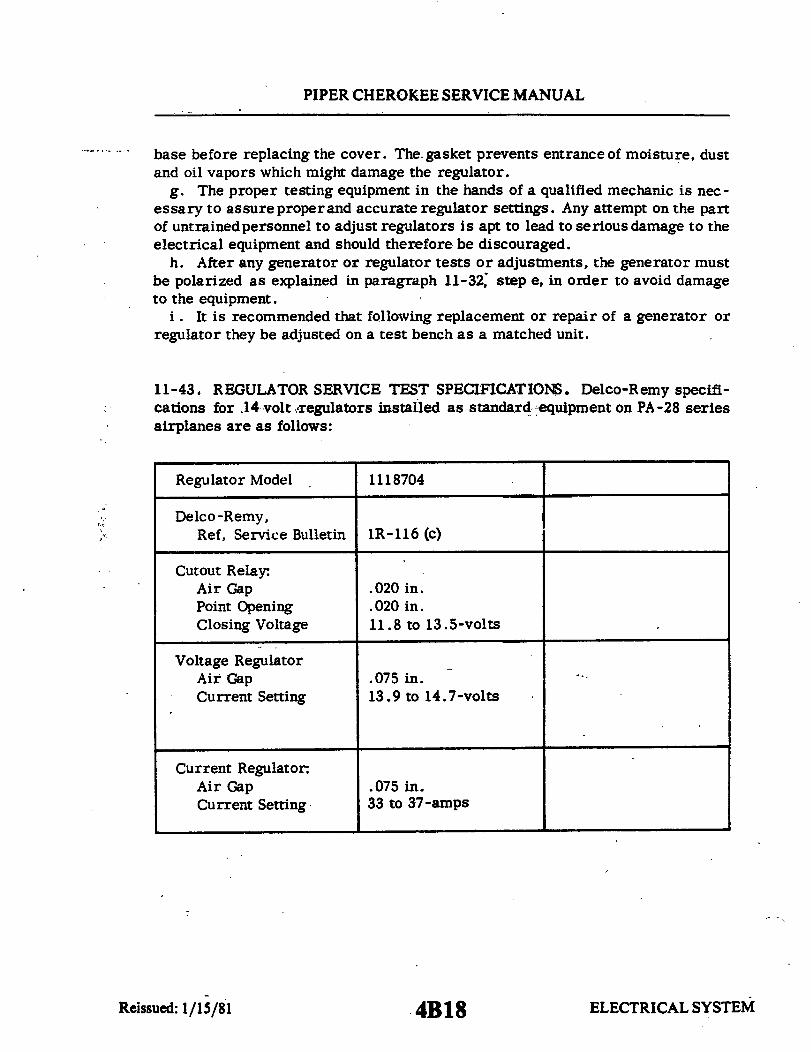
PIPER CHEROKEE SERVICE MANUAL
base before replacing the cover. The. gasket prevents entrance of moisture, dustand oil vapors which might damage the regulator.
g. The proper testing equipment in the hands of a qualified mechanic is nec-essary to assure proper and accurate regulator settings. Any attempt on the partof untrained personnel to adjust regulators is apt to lead to serious damage to theelectrical equipment and should therefore be discouraged.
h. After any generator or regulator tests or adjustments, the generator mustbe polarized as explained in paragraph 11-32, step e, in order to avoid damageto the equipment.
i. It is recommended that following replacement or repair of a generator orregulator they be adjusted on a test bench as a matched unit.
11-43. REGULATOR SERVICE TEST SPECIFICATIOS. Delco-Remy specifi-cations for .14 volt regulators installed as standard equipment on PA-28 seriesairplanes are as follows:
Regulator Model 1118704
Delco -Remy,Ref, Service Bulletin
Cutout Relay:Air GapPoint OpeningClosing Voltage
Voltage RegulatorAir GapCurrent Setting
Current Regulator:Air GapCurrent Setting
1R-116 (c)
.020 in.
.020 in.11.8 to 13.5-volts
.075 in.13.9 to 14.7-volts
.075 in.33 to 37-amps
ELECTRICAL SYSTEMReissued: 1/15/81 4B18

PIPER CHEROKEE SERVICE MANUAL
11-44. ALTERNATOR SYSTEM (Chrysler).
11-45. DESCRIPTION OF ALTERNATOR SYSTEM. The electrical power is supplied byone 12-volt battery and a 14-volt direct current 37 or 60 ampere alternator. The alternatoris located on the front lower right side of the engine and utilizes a belt drive from the enginecrankshaft. Many advantages both in operation and maintenance are derived from thissystem. The main advantage is that full electrical power output is available regardless ofengine RPM.
The alternator has no armature or commutator and only a small pair of carbon brushes,which make contact with a pair of copper slip rings. The rotating member of the alternator,known as the rotor, is actually the field windings. The rotor draws only 1/13th (37 amp) or1/20th (60 amp) of the current output. Therefore, there is very little friction and negligiblewear and heat in this area. The alternating current is converted to direct current by diodespressed into the end bell housing of the alternator. The diodes are highly reliable solid-statedevices, but are easily damaged if current flow is reversed through them.
The alternator system does not require a reverse current relay, because of the high backresistance of the diodes and the inability of the alternator to draw current or motorize. Acurrent regulator is unnecessary because the windings have been designed to limit themaximum current available. Therefore, the voltage regulator is the only control needed.
An additional latching circuit is used to help keep the master solenoid closed when thebattery voltage is low and the engine starter is being operated. This circuit routes voltagefrom the alternator to the master solenoid coil, thus holding the master solenoid in theclosed position and allowing the starter to function. This circuit will also supply somevoltage to the battery. A diode is placed into this circuit to prevent the reverse flow ofcurrent from the battery to the alternator.
The circuit breaker panel contains a 5 ampere circuit breaker marked ALT FIELD. Ifthe field circuit breaker trips, it will result in a complete shutdown of power from thegenerating system. After a one or two minute cool-down period, the breaker can be resetmanually. If tripping reoccurs and holding the breaker down will not prevent continualtripping, then a short exists in the alternator field.
Unlike previous systems, the ammeter does not indicate battery discharge, but displaysthe load in amperes placed on the generating system. With all electrical equipment off(except master) the ammeter will indicate the amount of charging current demanded by thebattery. This amount will vary, depending on the percentage of charge in the battery at thetime. As the battery becomes charged, the amount of current displayed on the ammeter willreduce to approximately two amperes. The amount of current shown on the ammeter willtell immediately whether or not the alternator system is operating normally, if the followingprinciples are kept in mind.
ELECTRICAL SYSTEMReissued: 1/15/81 4B19

PIPER CHEROKEE SERVICE MANUAL
C319
NOTE
THIS IS A TYPICAL WIRINGDIAGRAM FOR GENERALREFERENCE ONLY. FOR DETAILEDSCHEMATIC, SEE TABLE XI-I.
AMMETER
VOLTAGE REGULATOR
6—
ALTERNATOR SOURCE - POWERRELAY ENERGIZING CIRCUIT
PA-28-140, Serial Nos. 28-20000 to 28-24999 incl.;PA-28-150, -160, Serial Nos. 28-508 to 28-3643 incl.;PA-28-180, Serial Nos. 28-671 to 28-3643 incl.;PA-28-235, Serial Nos. 28-10002 to 28-10762 incl.
Figure 11-16. Early Alternator and Starter Systems (Typical)
4B20 ELE(ELECTRICAL SYSTEMReissued: 1/15/81
II
ALTERNATOR
l

PIPER CHEROKEE SERVICE MANUAL
C320
NOTE
THIS IS A TYPICAL WIRINGDIAGRAM FOR GENERALREFERENCE ONLY. FOR DETAILEDSCHEMATIC, SEE TABLE XI-I.
RADIO
ALTERNATOR
ALTERNATOR SOURCE - POWE
RELAY ENERGIZING CIRCUIT PA-28-140, Serial Nos. 28-25000 and up;PA-28-150, -160, -180, Serial Nos. 28-3644 and up;PA-28-235, Serial Nos. 10763 and up and PA-28R.
Figure 11-17. Later Alternator and Starter Systems (Typical)
4B21 ELECTRICAL SYSTEMReissued: 1/15/81 ELECTRICAL SYSTEM
I
SYSTEMReissued: 1/15/81
PIPER CHEROKEE SERVICE MANUAL
NOTE
The amount of current shown on the ammeter is theload in amperes that is demanded by the electricalsystem from the alternator. As a check, take for ex-ample a condition where the battery is demanding 10-amperes charging current, then switch on the landinglight. Note the value in amperes placarded on thepanel for the landing light fuse (10-amps) and multiplythis by 80 per cent, you will arrive at a current of 8-amperes. This is the approximate current drawn bythe light. Therefore, when the light is switched on,there will be an increase of current from 10 to 18-amperes displayed on the ammeter. As each unit ofelectrical equipment is switched on, the currents willadd up and the total, including the battery, will appearon the ammeter.
Using the example that the airplane's maximum continuous load with allequipment on is approximately 30-amperes for the 37-ampere alternator or 48-amperes for the 60-ampere alternator. This approximate 30 or 48-ampere value,plus approximately two amperes for a fully charged battery, will appear contin-uously under these flight conditions. If the ammeter reading were to go muchbelow this value, under the aforementioned conditions, trouble with the generatingsystem would be indicated and corrective action should be taken by switching offthe least essential equipment.
11-46. ALTERNATOR SYSTEM TEST PROCEDURE.a. Start engine and set throttle for 1000.to 1200 RPM.b. Switch on the following loads and observe the ammeter output increase as
indicated:1. Rotating beacon - 3 to 6 amps.2. Navigation and instrument lights (bright position) - 4 to 6 amps.3. Landing light - 7 to 9 amps.4. Mark 12 radio - 4 to 6 amps each. If alternator does not meet above
indications, refer to troubleshooting chart. (Follow troubleshooting procedureoutlined on chart in a step-by-step fashion checking each cause and isolationprocedure under a given trouble before proceeding with the following cause andisolation procedure.)
ELECTRICAL SYSTEMReissued: 1/15/81 4B22
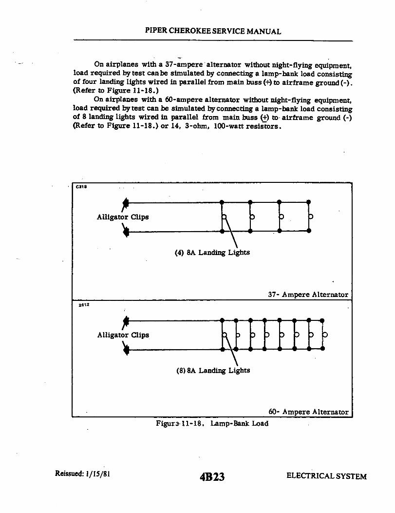
PIPER CHEROKEE SERVICE MANUAL
On airplanes with a 37-ampere alternator without night-flying equipment,load required by test can be simulated by connecting a lamp-bank load consistingof four landing lights wired in parallel from main buss (+) to airframe ground (-).(Refer to Figure 11-18.)
On airplanes with a 60-ampere alternator without night-flying equipment,load required by test can be simulated by connecting a lamp-bank load consistingof 8 landing lights wired in parallel from main buss (±) to airframe ground (-)(Refer to Figure 11-18.) or 14, 3-ohm, 100-watt resistors.
C31
Alligator Clips
(4) 8A Landing Lights
37- Ampere Alternator2612
Alligator Clips
(8) 8A Landing Lights
60- Ampere Alternator
Figure 11-18. Lamp-Bank Load
ELECTRICAL SYSTEM4B23Reissued: 1/15/81

PIPER CHEROKEE SERVICE MANUAL
11-47. BENCH TESTING ALTERNATOR.
11-48. FIELD CURRENT DRAW. Connect a test ammeter in series between a12-volt battery positive post and the alternator field terminal. (Refer to Figure11-19.) Connect a jumper wire to a machined surface on one of the alternator endshields (ground) and to the negative battery post. The reason for connecting tothe machined surface is to ensure a good electrical connection. The end shieldsare treated to oppose corrosion. The material used to treat the end shields isnot a good electrical conductor.
Observe the ammeter to determine the current flowing through the rotorcoil and connected circuit and record the amount. Slowly rotate the rotor withthe pulley while watching the meter. The current will be a little less while ro-tating the rotor than when stationary. However, if the slip rings are clean andthe brushes are making good contact, the reading should be fairly even. A slightfluctuation will be normal due to variation in turning speed when operated by hand.
The current draw should not be less than 2.3-amperes nor more than 2.7-amperes. A reading of less than 2.3-amperes indicates high resistance due topoorly soldered coil leads at the slip rings, dirty, oily slip rings or poor brushcontact. A reading higher than 2.7-amperes indicates shorted coil windings.
C322 C322
Firure 11-19.. Checking Field Circuit Figure 11-20 -Testing Field Circuit
ELECTRICAL SYSTEMReissued: 1/15/81 4B24
PIPER CHEROKEE SERVICE MANUAL
11-49. TESTING ALTERNATOR INTERNAL FIELD CIRCUIT FOR A GROUND.To test the alternator internal field circuit for a short circuit to ground, proceedas follows:
a. Remove the ground brush and using a 110-volt test lamp, place one testprobe to a machined surface at one of the alternator end shields. (Refer to Fig-ure 11-20.) The test lamp should not light.
If the test lamp lights, carefully observe the order in which the parts wereinstalled as you remove the insulated brush assembly. Remove the three throughbolts. Then, separate the two end shield assemblies. Touch one of the test lampprobes to one of the slip rings and the remaining test probe to the rotor shaft.The lamp should notlight. If the lamp lights, the rotor assembly is grounded andrequires replacement.
If the test lamp does not light, the ground condition was in the insulatedbrush assembly and the parts were either assembled wrong or damaged and shortcircuiting through to ground. Inspect the brush holder and insulatedwasher. Re-place if damaged. The stack of parts attaching the insulated brush holder assem-bly to the end shield must always be installed in the proper sequence as follows:Insulated brush holder, "FLD" terminal, insulating washer, lockwasher and at-taching screw.
11-50. INSPECTION. Inspect the condition of the alternator components payingspecial attention to the condition of the slip rings for indications of oil, beingburnt or worn. Inspect brushes for signs of sticking in holder or shield and forwear.
Inspect the bearing surface of the rotor shaft and the roller bearings atthe rectifier end. Rotate the rotor in the drive end shield to feel for roughnessin the drive end bearing. Inspect the grease retainer, if so equipped, on latealternators. Inspect the rectifier leads especially at connections for a good sol-der joint, also inspect insulation. Rectifier/stator lead must be pushed down in-to the slots that are cast into the end shield and cemented with MoPar Cement#2299314.
11-51. TESTING RECTIFIERS (POSITIVE.)(Refer to Figure 11-21.) Special test box toolC-3829 has been developed to test the diode rectifiers without opening the "Y" connectionas is necessary where the test lamp method is used.
Due to the short leads at the "Y" connection it is quite difficult to separate andreconnect them properly. This tool C-3829 will save much time and is accurate.
Insulate alternator from metal bench and plug tester tool C-3829 into a 110 voltsupply. Connect the alligator clip of tool C-3829 to the alternator "BAT" terminal andtouch the bare metal of each of the positive case rectifier lead wires in the heat sink at therectifiers.
ELECTRICAL SYSTEM4C1Reissued: 1/15/81
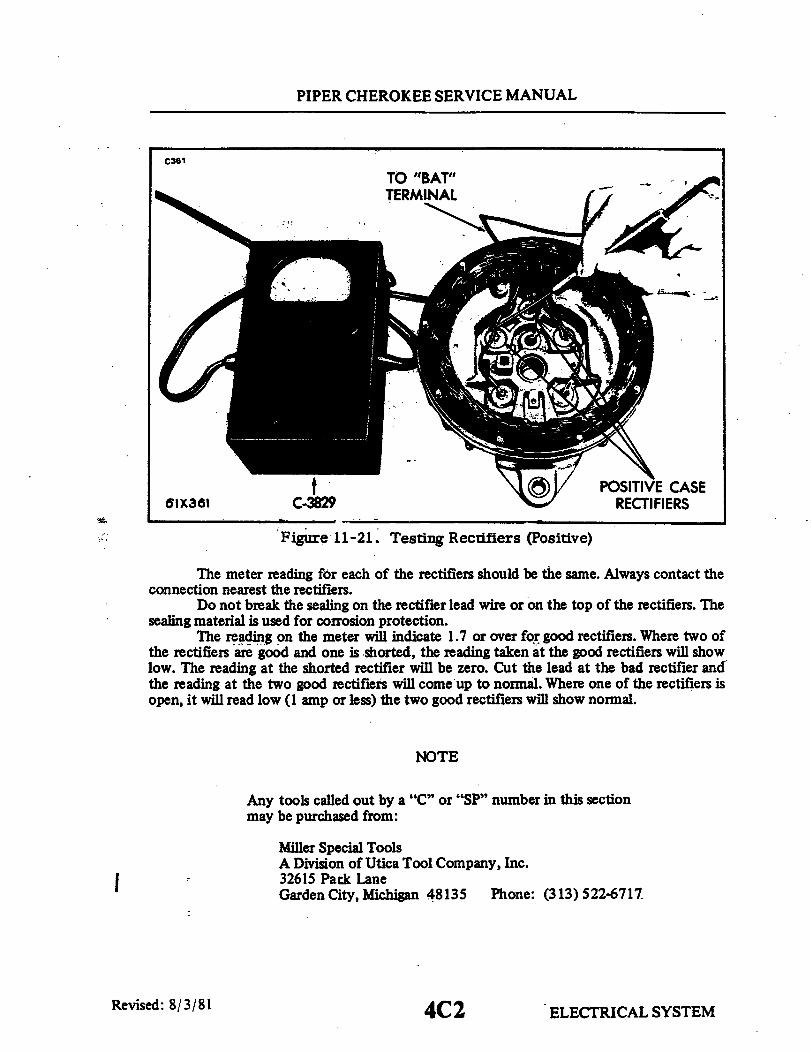
PIPER CHEROKEE SERVICE MANUAL
C361
TO "BAT"TERMINAL
POSITIVE CASE61X361 C-3829 RECTIFIERS
Figure 11-21. Testing Rectifiers (Positive)
The meter reading for each of the rectifiers should be the same. Always contact theconnection nearest the rectifiers.
Do not break the sealing on the rectifier lead wire or on the top of the rectifiers. Thesealing material is used for corrosion protection.
The reading on the meter will indicate 1.7 or over for good rectifiers. Where two ofthe rectifiers are good and one is shorted, the reading taken at the good rectifiers will showlow. The reading at the shorted rectifier will be zero. Cut the lead at the bad rectifier andthe reading at the two good rectifiers will come up to normal. Where one of the rectifiers isopen, it will read low (1 amp or less) the two good rectifiers will show normal.
NOTE
Any tools called out by a "C" or "SP" number in this sectionmay be purchased from:
Miller Special ToolsA Division of Utica Tool Company, Inc.32615 Park LaneGarden City, Michigan 48135 Phone: (313) 522-6717
Revised: 8/3/81 4C2 ELECTRICAL SYSTEM
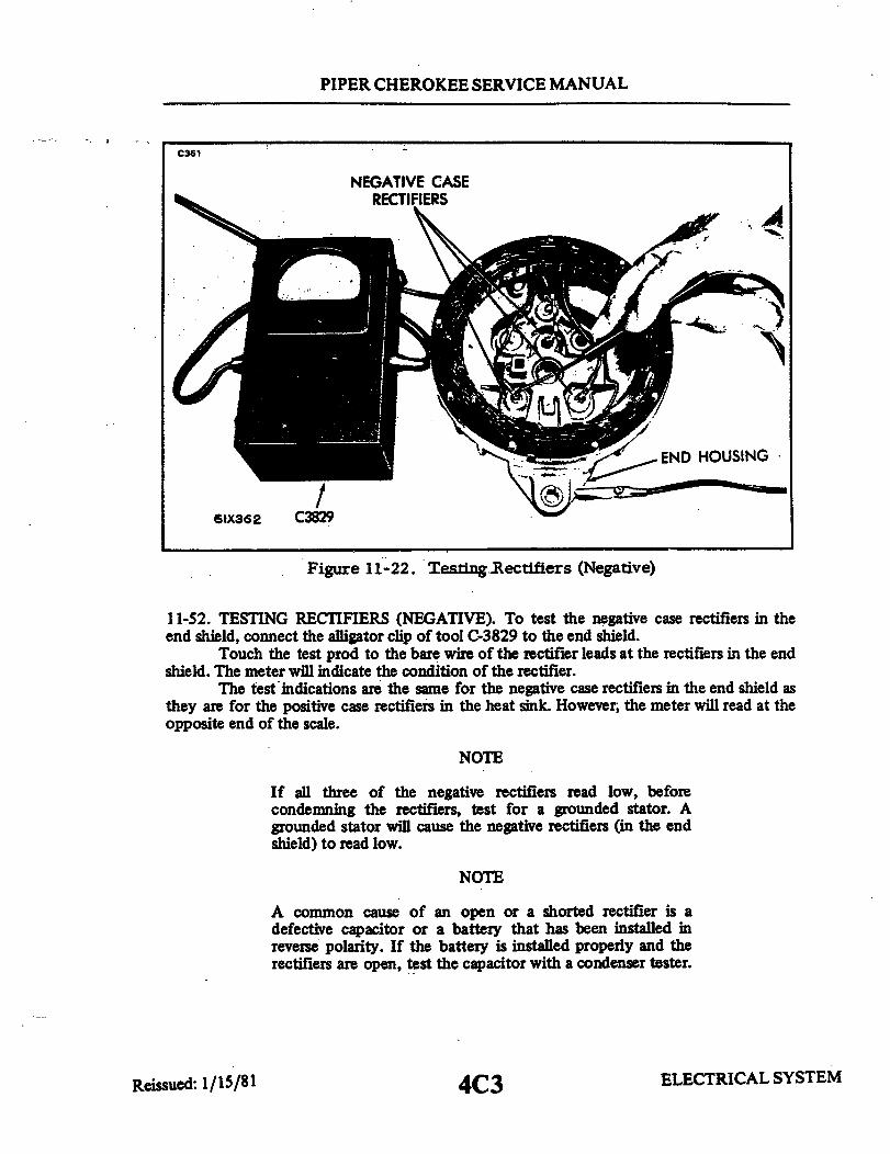
PIPER CHEROKEE SERVICE MANUAL
C361
NEGATIVE CASERECTIFIERS
61X362 C3829
END HOUSING
Figure 11-22. Testing Rectifiers (Negative)
11-52. TESTING RECTIFIERS (NEGATIVE). To test the negative case rectifiers in theend shield, connect the alligator clip of tool C-3829 to the end shield.
Touch the test prod to the bare wire of the rectifier leads at the rectifiers in the endshield. The meter will indicate the condition of the rectifier.
The test indications are the same for the negative case rectifiers in the end shield asthey are for the positive case rectifiers in the heat sink. However, the meter will read at theopposite end of the scale.
NOTE
If all three of the negative rectifiers read low, beforecondemning the rectifiers, test for a grounded stator. Agrounded stator will cause the negative rectifiers (in the endshield) to read low.
NOTE
A common cause of an open or a shorted rectifier is adefective capacitor or a battery that has been installed inreverse polarity. If the battery is installed properly and therectifiers are open, test the capacitor with a condenser tester.
ELECTRICAL SYSTEMReissued: 1/15/81 4C3

PIPER CHEROKEE SERVICE MANUAL
C362 C362
FIXTURE
C.3928 FIXTURE AND ADAPTERS
C
REMOVING
Figure 11-23. C-3928 Fixtures Figure 11-24. Removing Rectifiersand Adapters
11-53. REMOVING AND INSTALLING RECTIFIERS. The use of proper toolsfor the removal and installation of rectifiers cannot be over emphasized. A spe-cial tool kit has been developed to remove and replace new rectifiers withoutdamage.
NOTE
Only new rectifiers should be installed. It is not rec-ommended to reinstall rectifiers once they have beenremoved.
The tool kitcan beused on all Chrysler built alternators. A press is not requiredwhen using the C-3928 tool kit for removing or installing rectifiers. Three dioderectifiers are pressed into the heat sink and three in the end shields.
The new tool consists of a clamp type fixture with special adapters. Thistool makes it unnecessary to use a press.
The tool assembly consists of the following components:C-3928 - Fixutre and Adapters
SP-3821 - Removing AdapterSP-3818 - Installing AdapterSP-3820 - Installing Support
Reissued: 1/15/81 4C4 ELECTRICAL SYSTEMEM

PIPER CHEROKEE SERVICE MANUAL
11-54. REMOVING RECTIFIERS.After cutting the lead from the mal-functioning rectifier, position the fix-ture with the rectifier to be removedover the fixture anvil.
Position the removing adapterSP-3821 around the rectifier. Rotatethe threaded screw clockwise. As thescrew approaches the removing adap-ter, guide its shank into the hole in theend of the screw.
Just before the downward motionof the screw bottoms, recheck the a-dapter to be sure it is in the properposition. Then continue to rotate thescrew until the rectifier is free of theend shield or heat sink.
Reverse the screw by rotatingit counter-clockwise. Remove adapterand old rectifier.
Remove the end shield assemblyinstalling support on the fixture anvil.
C362
FIXTURE
INSTALLINGSUPPORT
Figure 11-25. Installing Rectifiers
from the fixture and position SP-3820
11-55. INSTALLING RECTIFIERS. Start the new rectifier as squarely as pos-sible into the hole the old rectifier was removed from after first checking to besure it is of the proper polarity. The negative rectifiers are marked with blacknumerals and the positive with red.
Reposition the end shield in the fixture, locating the hole over the install-ing support.
With the installing adapter SP-3818 positioned on the rectifier, rotate thescrew clockwise.
Guide the shank of the adapter into the screw. Continue to move the screwdownward until just before bottoming.
CAUTION
Check carefully to be certain that the adapter is posi-tioned properly over the rectifier and the rectifier isstarted squarely in the hole.
ELECTRICAL SYSTEM4C5Reissued: 1/15/81

PIPER CHEROKEE SERVICE MANUAL
C362
Figure 11-26. Soldering Rectifier Lead
Rotate the screw clockwise pressing the rectifier in place until it bottoms.When the rectifier bottoms, it can easily be felt. Remove the end shield assem-bly from the fixture and inspect to see that rectifier is installed properly.
NOTE STATOR LEADRECTIFIER LEADClean all wire 11-26 before Soldering. Form the rectifier Leadlead around the connector, being very careful not toRotate the screwclockwise pressing the rectifier in place until it bottoms.heting, grip the rectifier bottoms, itea be felt. Remove the end shield assem-bly from the fixture and inspect to see that rectifier is installed properly.NOTEClean all wires before soldering. Form the rectifierlead around the connector, being very careful not tocrack the seal. To protect the rectifier from over-heating, grip the rectifier lead between the rectifierand the point being soldered with a pair of long nosepliers. The pliers absorb heat to protect the recti-fier. Under no circumstances use acid flux or acidcore solder. Use rosin core solder only. The soldermust be hot enough to flow and form a positive con-
ELECTRICAL SYSTEMReissued: 1/15/81 4C6

PIPER CHEROKEE SERVICE MANUAL
C363
WOOD
110-VOLT BULB
Figure 11-27. Testing Stator Coils
nection. Cold solder joints will break open. A goodsolder connection will be smooth while a poor solderjoint (cold) will be rough and pitted.
NOTE
After soldering, to quickly cool the soldered connec-tion, touch a dampened cloth against it. This will aidin forming a solid joint.
With the rectifier properly installed, test to ensure that the rectifier has not beendamaged while installing. If the lead wires have been pulled away from the end shield, rece-ment them.
ELECTRICAL SYSTEM
WOOD
Reissued: 1/15/81 4C7

PIPER CHEROKEE SERVICE MANUAL
11-56. TESTING STATOR COILS FOR GROUND. The stator coils are insulatedfrom the core. A break in the insulation allowing the bare wire to touch the corewill ground the coil and result in no output.
To test the stator for aground (end shields separated), lift the stator awayfrom the end shieldand place wooden blocks approximately .50 inch thick betweenthe stator and the shield to keep them separated.
Using a 110volt test lamp, place one test probe on the core and the othertest probe to one of the rectifier leads, making certain to have good electricalconnections at both test probes. The lamp should not light. If the lamp lights,it is an indication that the coil windings are grounded to the core and a replace-ment of the stator is required.
11-57. TESTING ALTERNATOR CAPACITORS. Capacitors are used in connec-tion with alternators to suppress any transient peak.voltage that may occur. Itis essential therefore, to test the capacitor when servicing the alternator.
This is especially true where diode rectifiers test open or short circuited.The capacitor is connected to the inner end of the alternator "BAT" term-
inal screw and to the inner surface of the rectifier end shield (ground).
NOTE
On some early models, the capacitorwas installed onthe outside.
Connect the capacitor tester to the alternator "BAT" terminal screw andthe disconnected ground lead.
CAUTION
Do not allow the tester probes or clips to touch the endshield or the rectifier leads while the test is in pro-gress or damage to the rectifiers may occur.
Specified capacity for alternator capacitors of the early models is as follows:Internally mounted .158 MFD (min.)Very early external mount .5 MFD (min.)
The specified capacity for later built alternators (capacitor part of ter-minal screw) is .5 ± .1 MFD (min.).
Replace capacitors with low capacity, shorted or with high series resist-ance.
ELECTRICAL SYSTEM4C8Reissued: 1/15/81
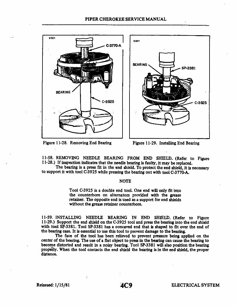
PIPER CHEROKEE SERVICE MANUAL
C321C321
C-3770-A
B SP-3381
BEARING
C-3925 C-3925
Figure 11-28. Removing End Bearing Figure 11-29. Installing End Bearing
11-58. REMOVING NEEDLE BEARING FROM END SHIELD. (Refer to Figure11-28.) If inspection indicates that the needle bearing is faulty, it may be replaced.
The bearing is a press fit in the end shield. To protect the end shield, it is necessaryto support it with tool C-3925 while pressing the bearing out with tool C-3770-A.
NOTE
Tool C-3925 is a double end tool. One end will only fit intothe counterbore on alternators provided with the greaseretainer. The opposite end is used as a support for end shieldswithout the grease retainer counterbore.
11-59. INSTALLING NEEDLE BEARING IN END SHIELD. (Refer to Figure11-29.) Support the end shield on the C-3925 tool and press the bearing into the end shieldwith tool SP-3381. Tool SP-3381 has a concaved end that is shaped to fit over the end ofthe bearing case. It is essential to use this tool to prevent damage to the bearing.
The face of the tool has been relieved to prevent pressure being applied on thecenter of the bearing. The use of a flat object to press in the bearing can cause the bearing tobecome distorted and result in a noisy bearing. Tool SP-3381 will also position the bearingproperly. When the tool contacts the end shield the bearing is in the end shield, the properdistance.
ELECTRICAL SYSTEM4C9Reissued: 1/15/81

PIPER CHEROKEE SERVICE MANUAL
C323 C323
C-4068 TOOLTOOL
BEARINGRETAINER
Figure 11-30. Removing Drive Pulley Figure 11-31. RemovingDrive End Bearing
NOTE
New bearings are prelubricated, additional lubrication is notrequired and should not be used.
11-60. REMOVING DRIVE PULLEY. The drive pulley is an interference fit on the rotorshaft. The pulley is removed with puller C-4068. The use of this puller set to remove thepulley will prevent damage to the pulley.
11-61. REMOVING DRIVE END BEARING. The drive end bearing is an interference fiton the rotor shaft. It is also retained in the end shield by a retainer. The retainer on theearly production alternators was attached to the end shield by three stud nuts and washers.
All late retainers are of spring steel construction and three integral fingers snap overa shoulder on the end shield.
Remove the drive end shield from the bearing by removing either the three retainingnuts from the retainer studs or by unsnapping the spring retainer fingers with a screwdriver.The end shield may then be removed by tapping on the end of the rotor shaft with a softhammer while holding the end shield.
Remove the drive end bearing from the rotor shaft with puller C-4068 and specialadapters as follows:
a. Position the center screw of tool C-4068 on the rotor shaft.b. Place the thin lower end of the adapters SP-3375 under the bearing equally spaced
ELECTRICAL SYSTEM4C10Reissued: 1/15/81

PIPER CHEROKEE SERVICE MANUAL
C322 C322
SLIP RING
GUIDE WIRE
GUIDE WIRESOLDEREDTO LEAD
OLD SLIP RING
CUT WITH CHISEL
Figure 11-32. Removing Slip Ring Figure 11-33. Aligning Slip Ring
and the upper end of the adapters around the center screw.c. Hold adapters and center screw in position with the tool sleeve.
CAUTION
Tool sleeve must bottom on bearing, otherwise adapters maybe damaged.
d. Turning the center screw while holding the outer body of the tool will withdraw thebearing from the shaft.
11-62. REPLACING SLIP RINGS. Slip rings that are damaged may be replaced. Two sizesare available. The early rotor shaft was smooth and the slip rings were pressed on and thering cemented to the rotor fan. Later rotor shafts were knurled and the slip rings werepressed on the knurled surface of the shaft
The early slip rings have a smaller inside diameter and must be pressed on thesmooth rotor shafts ONLY.
The later slip rings have a larger inside diameter and must be pressed on the knurledshaft ONLY.
There is also another difference in the rotor shafts installed on the late alternators.This shaft has a grease retainer and an insulator. The retainer is pressed on over the insulatorahead of the slip rings. These rotors are not interchangeable with rotors used on alternatorswithout the counterbore in the rectifier end shield.
ELECTRICAL SYSTEMReissued: 1/15/81 4C11

PIPER CHEROKEE SERVICE MANUAL
C324
Figure 11-34. Installing Slip Ring Figure 11-35. Installing Retainer
11-63. REMOVING SLIP RINGS. (Refer to Figure 11-32.)a. Unsolder the rotor coil (field) leads from the solder lugs.b. If the rotor has a grease retainer (installed on all late production alternators), remove
it with a pair of diagonal pliers.c. Cut through the copper of both slip rings at opposite points (180° apart) with a
chisel.d. Break the insulator and remove the ring.e. Clean away any dirt and all particles of the old ring.f. Scrape the face of the fan to be sure it is smooth.g. Clean the shaft surface on the area that contacts the inner diameter of the ring and
also the ends of the rotor coil leads.
11-64. INSTALLATION OF SLIP RINGS. (Refer to Figure 11-35.) There are two typesof slip rings which can be installed. The following instructions will describe each type.
a. Old Style:1. Obtain a three inch long piece of bar wire (approx. 18 gauge) and scrape one
end (about 0.19 of an inch) clean and tin this area with rosin core solder.2. Lap the tinned end of the wire over the field coil lead to the insulated ring and
solder the two together. (Refer to Figure 11-33.)
ELECTRICAL SYSTEM
C324
IGREASERETAINER
Reissued: 1/15/81 4C12
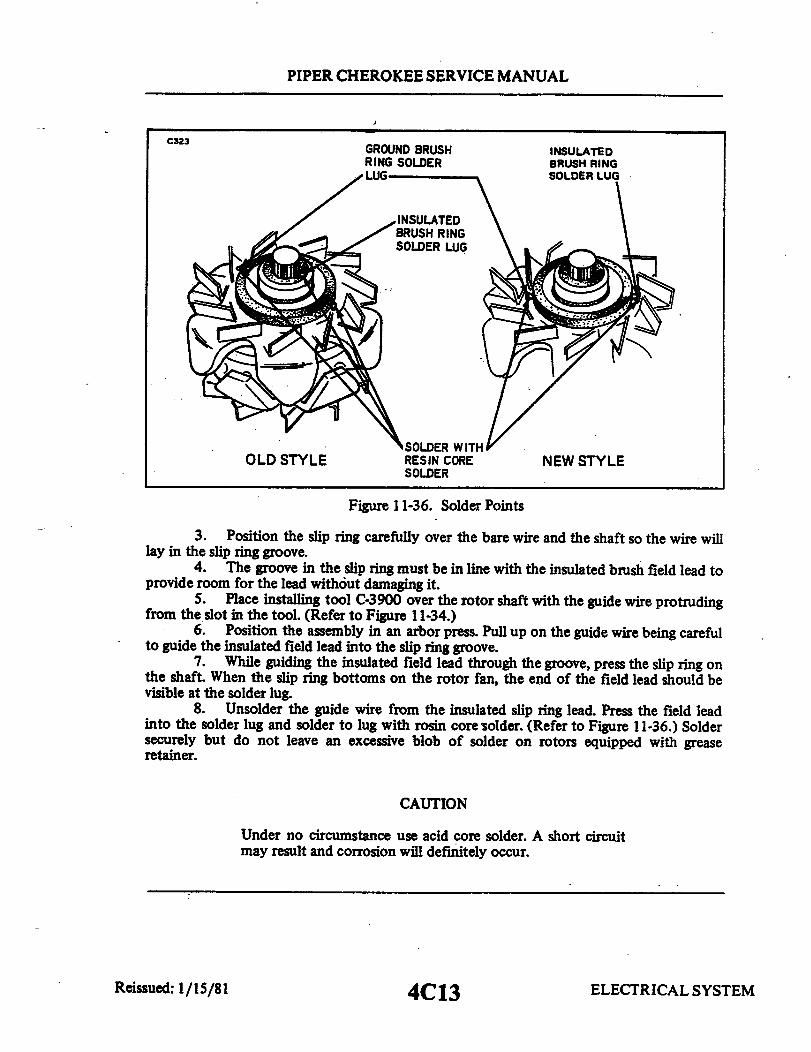
PIPER CHEROKEE SERVICE MANUAL
C323GROUND BRUSHRING SOLDER
INSULATED
SOLDER WITHOLD STYLE RESIN CORE NEW STYLE
SOLDER
Figure 11-36. Solder Points
3. Position the slip ring carefully over the bare wire and the shaft so the wire willlay in the slip ring groove.
4. The groove in the slip ring must be in line with the insulated brush field lead toprovide room for the lead without damaging it.
5. Place installing tool C-3900 over the rotor shaft with the guide wire protrudingfrom the slot in the tool. (Refer to Figure 11-34.)
6. Position the assembly in an arbor press. Pull up on the guide wire being carefulto guide the insulated field lead into the slip ring groove.
7. While guiding the insulated field lead through the groove, press the slip ring onthe shaft. When the slip ring bottoms on the rotor fan, the end of the field lead should bevisible at the solder lug.
8. Unsolder the guide wire from the insulated slip ring lead. Press the field leadinto the solder lug and solder to lug with rosin core solder. (Refer to Figure 11-36.) Soldersecurely but do not leave an excessive blob of solder on rotors equipped with greaseretainer.
CAUTION
Under no circumstance use acid core solder. A short circuitmay result and corrosion will definitely occur.
ELECTRICAL SYSTEMReissued: 1/15/81 4C13

PIPER CHEROKEE SERVICE MANUAL
C325 C325
DRIVE ENDPRESSING TOOL SHIELD PULLEYC-3858
BEARINGRETAINER
DRIVE ENDSHIELD ROTOR ROTOR
SHAFT
Figure 11-37. Installing Driver End Figure 11-38. Installing PulleyShield and Bearing (Typical)
9. Coil the ground brush ring field lead around the solder lug and solder with rosincore solder.
10. Test slip rings for ground with 110-volt test lamp by touching one test probe torotor pole shoe and remaining probe to slip rings. Test lamp should not light. If lamp lights,slip rings are shorted to ground, possibly due to grounding insulated field lead wheninstalling slip ring. If rotor is not grounded, lightly clean slip ring surface with -00-sandpaperand assemble alternator.
b. New Style (Refer to Figure 11-36):1. Position the slip ring on the rotor shaft so the solder lugs align with the rotor
coil leads.2. Place assembly tool C-3900 over rotor shaft and slip ring.3. Position assembly in an arbor press and press the slip ring on the shaft until it
bottoms on the rotor fan.4. Coil the insulated brush slip ring lead around the solder lug and solder securely
with rosin core solder.5. Coil the ground brush ring field lead around the solder lug located 180° from
the slip ring lug and solder with rosin core solder.6. Test the slip rings for ground with 110 volt test lamp as outlined in step a-10.
ELECTRICAL SYSTEMReissued: 1/15/81 4C14

PIPER CHEROKEE SERVICE MANUAL
11-65. INSTALLING GREASE RETAINER. If the solder connection where the rotor fieldcoil lead is soldered to the insulated brush ring lug has a sharp point or if the blob of solderis excessive, smooth with a scraper or file before installing the grease retainer insulator. Ifsmooth, place fibre insulator on shaft and press the retainer (cupped side to end of shaft) onthe shaft with tool C-3921 in an arbor press.
11-66. INSTALLING DRIVE END BEARING. Insert the sealed drive end bearing in thedrive end shield and install the bearing retainer. Install the washers and nuts to hold thebearing in place on all early production. Snap the spring steel retainer fingers in place on alllater production models.
If the rotor and its components require no service, position the bearing and the driveend shield assembly on the rotor shaft and while supporting the parts on the end of therotor shaft, press the bearing and end shield assembly in position on the rotor shaft using anarbor press and tool C-3858.
CAUTION
Make sure that the bearing is installed squarely at the start;otherwise, damage to the bearing will result. Press the bearingon the rotor shaft until the bearing contacts the shoulder onthe rotor shaft.
11-67. INSTALLING PULLEY. Install pulley on the rotor shaft using an arbor pressbefore the rectifier end shield is assembled to the drive end shield.
THIS SPACE INTENTIONALLY LEFT BLANK
Reissued: 1/15/81 ELECTRICAL SYSTEM4C15
PIPER CHEROKEE SERVICE MANUAL
WARNING
Do not press pulley on with a vise. Use a press.
The shaft must be the support while the pulley is pressed on with the pres-sure being applied to the pulley hub.
NOTE
Do not exceed 6800 pounds pressure. Press the pul-ley on the rotor shaft until the pulley contacts the in-ner face of the drive end bearing.
11-68. ASSEMBLING END SHIELD SUB-ASSEMBLIES. Position the rotor anddrive end shield assembly on the rectifier end shield. Align the through bolt holesthrough the drive end shield, stator and the rectifier end shield.
Compress stator and both end shields by hand and install the through bolts.Install the insulated brush and holder, terminal, insulating washer, lock-
washer and terminal attaching screw. Install the ground brush and attachingscrew.
Rotate the pulley slowly by hand to be sure that the rotor fans do not hit therectifiers and stator connectors.
After installing the alternator on the engine, always test the complete charg-ing system to be certain it is functioning properly.
NOTE
New through bolt locking tabs should be installed ateach alternator disassembly. Torque through boltsevenly to 25 inch pounds and bend both ears of thelocking tabs against bolt head. Check proper belttension.
11-69. BENCH RUN-UP TEST. This test is to be performed at room ambientconditions and consists of four checks which are to be made quickly to avoid heat-ing of the windings. These are as follows:
NOTE
For test c and d external field excitation may be used.
ELECTRICAL SYSTEM4C16Reissued: 1/15/81

PIPER CHEROKEE SERVICE MANUAL
C324 OUTPUTAMPERES
OUTPUTTERMINAL
FIELDAMPERES
VARIABLEOUTPUT LOAD
TEST VOLTAGETEST FIELDALTERNATOR TERMINAL
GROUND
Figure. 11-39. Meter Connections for AlternatorPerformance Test
but must be removed and self excitation used to obtainoutput amperes. (Refer to Figure 11-39 for meterconnections.)
a. 37-Ampere Alternator:1. With the alternator at rest, apply 15-volts between the alternator bat-
tery terminal and ground with polarity such that the rectifiers will block currentflow (positive of supply to positive of the alternator). Monitor rectifier reversecurrent which shall be not more than 1 milliampere.
2. With the alternator at rest, apply 15-volts to the field circuit and mon-itor field current. This shall be between the limits of 3.0-amperes minimumand 3.5-amperes maximum.
3. Drive the alternator at 1500 RPM with an electrical load connected tothe alternator. Adjust the load to obtain 15-volts. Net output(not including fieldcurrent) shall be not less than 19.0-amperes.
4. Drive the alternator at 2500 RPM with an electrical load connected tothe alternator. Adjust the load to obtain 15-volts. Net output(not including fieldcurrent) shall be not less than 32.0-amperes.
ELECTRICAL SYSTEMReissued: 1/15/81 4C17

PIPER CHEROKEE SERVICE MANUAL
b. 60-Ampere Alternator:1. With the alternator at rest, supply 15-volts between the alternator bat-
tery terminal and ground with polarity such that the rectifiers will block currentflow (positive of supply to positive of the alternator). Monitor rectifier reversecurrent which shall be not more than 1 milliampere.
2. With the alternator at rest, apply 15-volts to the field circuit and mon-itor field current. This shall be betweenthe limits of 3.3-amperes minimum and3.6-amperes maximum.
3. Drive the alternator at 1500 RPM with an electrical load connected tothe alternator. Adjust the load to obtain 15-volts. Net output(not including fieldcurrent) shall be not less than 26.5-amperes.
4. Drive the alternator at 2500 RPM with an electrical load connected tothe alternator. Adjust the load to obtain 15-volts. Net output (not including fieldcurrent) shall be not less than 49.0-amperes.
11-70. BENCH HOT STABILATION OUTPUT TEST. To determine the hot stabi-lized output, the alternator must be driven with a suitable driving mechanism.During this test, the following shall be monitored: (Refer to Figure 11-39 formeter connections.)
a. Alternator output voltage.b. Alternator output current.c. Field current.d. Alternator rpm.
Drive the alternator at sufficient rpm to obtain 14-volts at the alternatorbattery terminal. Alternator shall be self excited, otherwise no external loadshall be applied. An external D.C. power source may be used to polarize thefield but must be removed as soon as the alternator is self sustaining. Maintain14-volts at no load by adjusting rpm for a period of 15 minutes, at which time re-cord the above specified data.
Apply an electrical load to the alternator and increase speed so as to ob-tain 5-amperes output (not including field exictation) at 14-volts. Maintain thiscondition for 15 minutes by adjusting the rpm. At the end of this period recordthe above specified data.
Maintain output voltage at 14-volts and vary the load in 5-ampere intervals.At each 5-amp interval allow a 15 minute stabilization period maintaining outputby varying rpm. Record the required data at each interval. Continue this pro-cedure through the maximum output (approximately 10, 000 rpm).
ELECTRICAL SYSTEMReissued: 1/15/81, 4C18

PIPER CHEROKEE SERVICE MANUAL
C363 C363
UPPER CONTACT
SPING
CONTACT SPRING CONTACT POINTS
ADJUSTING
61X232 SPRING ANGER2x 105
Figure 11-40. Voltage Regulator Figure 11-41. Checking Air Gap
11-71. VOLTAGE REGULATOR SERVICING. (Chrysler.)
11-72. AIR GAP ADJUSTMENT. (Regulator removed.) The mostaccurate meth-od of measuring the air gap between the lower side of the armature and the top ofthe core is to use a volt test lamp.
a. Connect one lead from the test lamp to a 12-volt battery positive post andthe remaining lead to the regulator "IGN" terminal.
b. Connect a jumper wire from the battery negative post to the regulator"Field" terminal.
c. Insert a .048 inch gauge betweenthe armature and the core at the hinge sideof the stop.
d. Press the armature (not the contact reed) down against the gauge. The testlamp light should dim.
e. Insert a .052 inch gauge and when the armature is pressed down the lampshould not dim.
f. If an adjustment is required, loosen the adjustable bracket retaining screwand raise or lower the support as required to bring the air gap to specificationsand retighten retaining screw.
ELECTRICAL SYSTEM4C19Reissued: 1/15/81
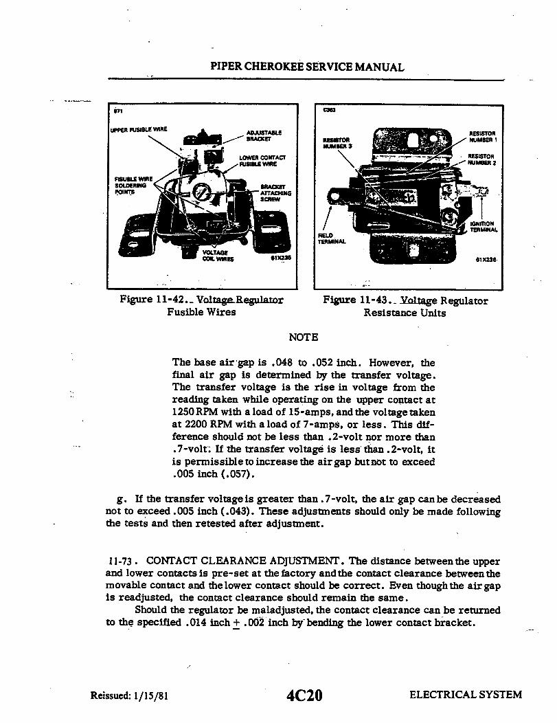
PIPER CHEROKEE SERVICE MANUAL
971 c363
UPPER FUSIBLE WIRE ADJUSTABLE RESISTORBRACKET RESISTOR NUMBER 1
LOWER CONTACT RESISTOR
FISUBLE WIRESOLDERING
TERMINAL
VOLTAGECOIL WIRES 61x236 61X236
Figure 11-42._ Voltage Regulator Figure 11-43. Voltage RegulatorFusible Wires Resistance Units
NOTE
The base air gap is .048 to .052 inch. However, thefinal air gap is determined by the transfer voltage.The transfer voltage is the rise in voltage from thereading taken while operating on the upper contact at1250 RPM with a load of 15-amps, and the voltage takenat 2200 RPM with a load of 7-amps, or less. This dif-ference should not be less than .2-volt nor more than.7-volt. If the transfer voltage is less than .2-volt, itis permissible to increase the air gap but not to exceed.005 inch (.057).
g. If the transfer voltage is greater than .7-volt, the air gap can be decreasednot to exceed .005 inch (.043). These adjustments should only be made followingthe tests and then retested after adjustment.
11-73. CONTACT CLEARANCE ADJUSTMENT. The distance betweenthe upperand lower contacts is pre-set at the factory and the contact clearance between themovable contact and the lower contact should be correct. Even though the air gapis readjusted, the contact clearance should remain the same.
Should the regulator be maladjusted, the contact clearance can be returnedto the specified .014 inch + .002 inch by bending the lower contact bracket.
issued: 1/15/81 4C20 ELECTRICAL SYSTEMReiSSUED : 1/15/81

PIPER CHEROKEE SERVICE MANUAL
11-74. VOLTAGE REGULATOR FUSIBLE WIRE REPLACEMENT.a. Cut fuse wire above solder connection at the base and unwind wire at top
bracket.
CAUTION
If an attempt is made to unsolder the old fuse, the verysmall wire from voltage coil may be damaged.
b. Tin end of fuse wire. (Use resin core solder only.)c. Holding tinned end of new fuse wire into recessed rivet at base of regulator
and against old piece of fuse wire that remains, cause a drop of solder fromsoldering iron to fall on these parts. Allow solder to cool sufficiently for fusewires to make a good solder joint.
d. Pull new fuse wire up enough to remove slack and wrap it around the brack-et. Solder coiled wire to the bracket and cut off surplus fuse wire.
(The original fuse wire is machine wound on the upper bracket. Replace-ment fuse should be soldered to the bracket to ensure a good electrical contact.)
11-75. VOLTAGE REGULATOR. (Wico.)
11-76. CHECKING VOLTAGE REGULATOR. Theregulator is a fully transistor-ized unit in which all of the components are encapsulated in epoxy, which makesfield repair of the unit impractical, and if it does not meet the specifications, itmust be replaced. The regulator may be tested by the following procedure:
a. Be sure that the battery is fully charged and in good condition.b. Check the alternator according to the manufacturer's instructions, to deter-
mine if it is functioning properly. This test must be done with the regulator outof the circuit. After completing this test, reconnect the regulator into the circuit.
c. Use a good quality accurate voltmeter with at least a 15-volt scale.d. Connect the positive voltmeter lead to the red wireat the regulator harness
connector, or terminal block. Connect the negative voltmeter lead to the regula-tor housing. (Note) Do not connect the voltmeter across the battery, because theregulator is designed to compensate for resistance contained within the wiringharness.
e. With the alternator turning at sufficient rpm to produce a half load condition,or approximately 25-amperes output, the voltmeter should read between 13.6and14.3 volts. The ambient temperatures surrounding the voltage regulator shouldbe between 50°F. to 100°F. while this test is being made.
f. The voltage regulator heat sink, or case, is the ground connection for the
ELECTRICAL SYSTEMReissued: 1/15/81 4C21

PIPER CHEROKEE SERVICE MANUAL
electronic circuit. Therefore, if this unit is tested on the bench it is most im-portant that a wire, No. 14, be connected between the regulator case and the al-ternator. If the regulator does not regulate between 13.6 and 14.4-volts, one ofthe following conditions may exist:
1. Regulates, but out of specification. The regulator is out of calibrationand must be replaced.
2. The voltmeter continues to read battery voltage.a. Poor or open connections within the wiring harness.b. The regulator is "open."
3. Voltage continues to rise.a. Regulator housing not grounded.b. Regulator shorted, must be replaced.
g. These are some of the things to look for in case of failure:
1. Poor or loose connections.2. Poor ground on the regulator housing.3. Shorted alternator windings.4. A grounded yellow wire (This will cause instantaneous failure.)5. Disconnecting the regulator while the circuit energized.6. Open circuit operation of the alternator (The battery disconnected.)
11-77.. OVER VOLTAGE RELAY. (Wico.)
11-78. CHECKING OVER VOLTAGE RELAY. The relay may be tested with theuse of a good quality, accurate voltmeter, with a scale of at least 20-volts and asuitable power supply, with an output of at least 20-volts, or sufficient batterieswith a voltage divider to regulate voltage. The test equipment may be connectedby the following procedure:
a. B+ is connected to "Bat" of the over-voltage control.b. B- is connected to the frame of the over-voltage control.c. Be sure both connections are secure, and connected to a clean, bright sur-
face.d. Connect the positive lead of thevoltmeter to the "Bat" terminal of the over-
voltage control.e. Connect the negative lead of the voltmeter to the frame of the over-voltage
control.f. The over-voltage control is set to operate between 16.2-volts to 17 .3-volts..
By adjusting the voltage, anaudible "click" may be heard when the relay operates.g. If the over-voltage control does not operate between 16.2 and 17.3-volts,
it must be replaced.
ELECTRICAL SYSTEM4C22Reissued: 1/15/81

PIPER CHEROKEE SERVICE MANUAL
11-79. CHECKING GENERATOR OR ALTERNATOR BELT TENSION. If properlyinstalled and checked periodically, the generator or alternator drive belt will give very sat-isfactory service. However, an improperly tensioned belt will wear rapidly and may slip andreduce unit output. Consequently, a belt should be checked for proper tension at the time ofinstallation, again after 25 hours of operation and each 100 hours thereafter.
The method of checking belt tension is simple and requires little time for accom-plishment. This method of checking belt tension consists of measuring torque required toslip the belt at the pulley on the generator or alternator, and is accomplished as follows:
a. Apply a torque indicating wrench to the nut that secures the pulley to the generatoror alternator and turn the pulley in a clockwise direction. Observe the torque shown on thewrench at the instant the pulley slips.
b. Check the torque indicated in Step a with the torque specified in the following chart.Adjust the belt tension accordingly.
BELT BELT BELT SLIP TORQUETYPE WIDTH IN. CONDITION FOOT POUNDS
RUBBER .375 NEW 11-13RUBBER .375 USED 7-9RUBBER .500 NEW 13-15RUBBER .500 USED 9-11PLASTIC .328 NEW 11-13PLASTIC .328 USED 7-9
11-80. STARTING MOTOR (Delco-Remy.)
11-81. OPERATION OF STARTING MOTOR. When the starting motor switch is closed.the armature begins to rotate. The drive pinion, being a loose fit on the drive sleeve locatedon the armature shaft, does not pick up speed as fast as the armature. Therefore, the drivepinion, having internally matched splines with respect to the splined drive sleeve, movesendwise on the shaft and into mesh with the flywheel. As the pinion hits the pinion stop, itbegins to rotate with the armature and cranks the engine.
When the engine starts, the flywheel begins to spin the pinion faster than the armature.Again, because of the splined action of the pinion and drive sleeve assembly, the pinion backsout of mesh with the flywheel ring gear protecting the armature from excessive speeds.
Some Bendix drives incorporate a small anti-drift spring between the drive pinion stopwhich prevents the pinion from drifting into mesh when the engine is running. Others use asmall anti-drift pin and spring inside the pinion which provides enough friction to keep thepinion from drifting into mesh.
Never operate the motor for more than 30 seconds without pausing for two minutesto allow it to cool.
ELECTRICAL SYSTEM4C23Revised: 10/3/83

THIS PAGE INTENTIONALLY LEFT BLANK
4C24

PIPER CHEROKEE SERVICE MANUAL
11-82. CHECKING STARTING MOTOR. Several checks, both visual and elec-trical, should be made in a defective cranking circuit to isolate trouble beforeremoving any unit. Many times a component is removed from the airplane onlyto find it is not defective after reliable tests. Therefore, before removing a unitin a defective cranking system, the following checks should be made:
a. Determine the condition of the battery.
NOTE
If a solderless terminal on an aluminum cable is loose, cor-roded or otherwise unsatisfactory, it is recommended that thecomplete cable assembly be replaced instead of replacing orrepairing the solderless terminal.
Should replacement of the complete assembly not be prac-tical, it is permissible to replace the aluminum cable assemblywith a copper cable assembly which is two sizes smaller (ex.:an AL-1 aluminum cable assembly is replaced with an AN-3copper cable assembly).
The new cable should be installed in accordance with AC-43-13-2A.
b. Inspect the wiring for frayed insulation or other damage. Replace anywir-ing that is damaged. Inspect all connections to the starting motor solenoidswitch, starting switch or any other control switch, and battery, including allground connections. Clean and tighten all connections and wiring as required.The engine manufacturer specifies allowable voltage drop in the cranking circuit.For this information, refer to the manufacturer's shop manual.
c. Inspect starting and solenoid switches to determine their condition. Con-nect a jumper lead around any switch or solenoid suspected of being defective.If the system functions properlyusing this method, repair or replace the bypassedunit.
d. If specified battery voltage can be measured at the motor terminal of thestarting motor, allowing for some voltage drop in the circuit and the engine isknown to be functioning properly, remove the motor and follow the test proce-dures outlined below.
ELECTRICAL SYSTEM4D1Reissued: 1/15/81

PIPER CHEROKEE SERVICE MANUAL
C325 11-83. TESTAND MAINTENANCE OFSTARTING MOTORS.
BATTERY 11-84. INSPECTION. With the start-_^ ing motor removed from the engine, the
I pinion should be checked for freedomof operation by turning it on the screwshaft. The armature should be check-ed for freedom of operation by turningthe pinion. Tight, dirty, or worn bear-ings, bentarmature shaft, or loose poleshoe screw will cause the armature todrag and it will not turn freely. If thearmature does not turn freely, the mo-
Figure 11-44. No-Load Test Hookup tor should be disassembled immedi-ately. However, if the armature does
operate freely, the motor should be given electrical tests before disassembly.
11-85. NO LOAD TEST. (Refer to Figure 11-44.) Connect the starting motorin series with a fully charged battery of the specified voltage, an ammeter ca-pable of reading several hundred amperes, and a variable resistance. Also con-nect a voltmeter as illustrated, from the motor terminal to the motor frame. AnRPM indicator is necessary to measure armature speed. Obtain the specifiedvoltage by varying the resistance unit. Then read the current draw and the ar-mature speed and compare these readings with the values listed in paragraph11-91. Interpret the test results as follows:
a. Rated current draw and no -load speed indicate normal condition of the crank -ing motor.
b. Low free speed and high current draw indicate:1. Too much friction - tight, dirty, or worn bearings, bentarmature shaft
or loose pole shoes allowing armature to drag.2. Shorted armature. This can be furtherchecked on a growler after dis-
assembly.c. Failure to operate with high current draw indicates:
1. A direct ground in the terminal or fields.2. "Frozen" bearings (this should have been determined by turning the ar-
mature by hand).d. Failure to operate with no current draw indicates:
1. Open field circuit. This can be checked after disassembly by inspec-ting internal connections and tracing circuit with a test lamp.
ELECTRICAL SYSTEM4D2Reissued: 1/15/81

PIPER CHEROKEE SERVICE MANUAL
C325 C325
I
Figure 11-45. Lock-Torque Figure 11-46 ResistanceTest Hookup Test Hookup
2. Open armature coils. Inspect the commutator for badly burned barsafter disassembly.
3. Broken brush springs, worn brushes, high insulation between the com-mutator bars orothercauseswhich wouldpreventgood contact betweenthe brush-es and commutator.
e. Low no-load speed and low current draw indicate high internal resistancedue to poorconnections, defective leads, dirtycommutatorand causes listed understep d.
f. High free speed and high current draw indicate shorted fields. If shortedfields are suspected, replace the field coil assemblyand check for improved per-formance .
11-86. LOCK-TORQUE TEST. (Refer to Figure 11-45.) The lock-torque testrequires the equipment illustrated. A variable resistance with a high currentcapacity should be used. The cranking motor should be securely mounted and abrake arm hooked to the drive pinion. Use extreme caution during this test tomake sure the end of the brake arm does not slip off the pinion when current isapplied. When specified current is applied, the torque can be computed from thereading on the scale. A one foot brake arm will directly indicate pound-feet.Compare the pound-feet of torque as read on the scale with that listed in para-graph 11-91. If the torque is low, the motor must be disassembled for furthertests and repair.
ELECTRICAL SYSTEM4D3Reissued: 1/15/81
PIPER CHEROKEE SERVICE MANUAL
11-87. RESISTANCE TEST. (Refer to Figure.11-46.) This test requires equip-ment similar to the lock-torque test, with the exception that the pinion is lockedsecurely so it cannot rotate. When the specified voltage is applied, the currentshould fall in a range as indicated in paragraph 11-91. A high current indicatesgrounded or shorted conductors, and a low current indicates excessive resistance.
11-88. DISASSEMBLY. If the motor does not perform in accordance with pub-lished specifications, it may need to be disassembled for further testing of thecomponents. Normally the cranking motor should be disassembled only so faras is necessary to make repair or replacement of the defective parts. As a pre -caution, it is suggested that safety glasses be worn when disassembling or as-sembling the cranking motor. Following are general instructions for disassem-bling a typical Bendix drive starting motor.
a. Remove the cover band, if present, and detach the field coil leads from thebrush holders.
b. If gear reduction, remove the drive housing and reduction housing.c. Remove the bolts attaching the drive housing and commutator end frame to
the field frame assembly. Discard the tang lock washers.d. Separate the commutator end frame, armature assembly, field frame and
drive housing.e. Remove and disassemble the drive from the armature shaft by first iden-
tifying the type Bendix drive and then following one of the guides below:1. Standard Bendix Drive: Remove the head spring screw and slip it off
the armature shaft.2. Folo-Thru-Bendix Drive: Push in the outer anchor plate so the pilot
screw or pin can be removed.
CAUTION
Do not disassemble this drive, service is by completereplacement.
NOTE
Some Folo-Thru drives use a rubber cushion in placeof a drive spring. To remove from shaft, screw pin-ion out to drive position, then force pin from shaftthrough screw sleeve holes.
Reissued: 1/15/81 4D4 ELECTRICAL SYSTEM

PIPER CHEROKEE SERVICE MANUAL
11-89. COMPONENT INSPECTION AND REPAIR.a. Brushes and Brush Holders: Inspect thebrushes for wear. If they areworn
down to one-half their original length, when compared with a new brush, theyshould be replaced. Make sure the brush holders are clean and the brushes arenot binding in the holders. The full brush surface should ride on the commutatorwith proper spring tension (Refer to paragraph 11-91.) to give good, firm con-tact. Brush leads and screws should be tight and clean.
b. Armature: The armature should be checked for short circuits, opens andgrounds:
1. Short circuits are located by rotating the armature in a growler with asteel strip such as a hacksaw blade held on the armature. The steel strip willvibrate on the area of the short circuit. Shorts between bars are sometimes pro-duced by brush dust or copper between the bars. Undercutting the insulation willeliminate these shorts.
2. Opens: Inspect the points where the conductors are joined to the com-mutator for loose connections. Poor connections cause arcing and burning of thecommutator. If the bars are not badly burned, resolder the leads in the riserbars and turn the commutator down in a lathe. Then undercut the insulation be-tween the commutator bars .031 of an inch.
3. Grounds in the armature can be detected by the use of a test lamp andprods. If the lamp lights when one test prod is placed on the commutator and theother test prod on the armature core or shaft, the armature is grounded. If thecommutator is worn, dirty, out of round, or has high insulation, the commutatorshould be turned down and undercut as previously described.
c. Field Coils: The field coils should be checked for grounds and opens usinga test lamp.
1. Grounds: Disconnect field coil ground connections. Connect one testprod to the field frame and the other to the field connector. If the lamp lights,the field coils are grounded and must be repaired or replaced.
2. Opens: Connect test lamp prods to ends of field coils. If lamp does notlight, the field coils are open.
If the field coils need to be removed for repair or replacement, a pole shoespreader and pole shoe screw driver should be used. Care should be exercisedin replacing the field coils to prevent grounding or shorting them as they are tight-ened into place. Where the pole shoe has a long lip on one side, it should be as-sembled in the direction of armature rotation.
ELECTRICAL SYSTEMReissued: 1/15/81 4D5

PIPER CHEROKEE SERVICE MANUAL
11-90. ASSEMBLY. To reassemble the motorfollowthedisassemblyproceduresin reverse. Install new tang lock washers where removed.
CAUTION
If Folo-Thru drive is manually rotated to locked posi-tion, do not attempt to force it in a reverse direction.Proceed to install with pinion meshing with flywheel.When engine starts, the drive will return to the de-meshed position.
11-91. STARTING MOTOR SERVICE TEST SPECIFICATIONS. Delco-Remyspecifications for 12-volt starting motors installed as standard equipment onPA-28 series airplanes are as follows:
Motor Model 1109657 1109657
Delco-Remy, Ref,Service Bulletin IM- 110 M-110
Minimum Brush Tension 24 oz. 24 oz.
No-Load TestVolts 10.6 10.6Min. Amps 48Max. Amps 80 80Min. RPM 5800 3000Max. RPM 8200
Lock TestAmps - 300Torque (ft.-lbs.) 18.0Approx. Volts -7.3
Resistance TestVolts 4.0Min. Amps 365Max. Amps 420
ELECTRICAL SYSTEMReissued: 1/15/81 4D6

PIPER CHEROKEE SERVICE MANUAL
11-92. STARTING MOTORS .Prestolite.)
11-93. DESCRIPTION. The gear reduction starting motor consists of six majorcomponents: The Commutator End Head Assembly, The Armature, The Frameand Field Assembly, theGear Housing, The Pinion Housing, and The Bendix DriveAssembly. Refer to Figure 11-47.
11-94. OPERATION. When the starting circuit is energized, battery current isapplied to the starting motor terminal. Current flows through the field coils,creating a strong magnetic field. At the same time, current flows through thebrushes to the commutator, through the armature windings to ground. The mag-netic force created in the armature combined with that created in the field wind-ings begins to turn the armature.
The gear cut on the drive end of the armature shaft extends through the gearhousing, where it is supported bya roller bearing. The gear mates with the teethof the reduction gear that drives the bendix shaft. The shaft is keyed to the re-duction gear. The Bendix drive is held in position on the shaft by a "spirol" pin.The shaft is supported in the gear housing by a closed end roller bearing and inthe pinion housing by a graphitized bronze bearing.
When the armature turns the reduction gear, the Bendix drive pinion mesheswith the flywheel ring gear by inertia and action of the screw threads within theBendix sleeve. A detent pin engages in a notch in the screw threads which pre-vents demeshing if the engine fails to start when the starting circuit is de-ener-gized.
When the engine reaches a predetermined speed, centrifugal action forcesthe detent pin out of the notch in the screw shaft and allows the pinion to demeshfrom the flywheel.
11-95. MAINTENANCE. The starting circuit should be inspected at regularintervals, the frequency of which should be determined by the amount of serviceand the conditions under which the vehicle is operated. It is recommended thatsuch inspection be made at each 100 hours and include the following:
a. The battery should be checked with a hydrometer to be sure if is fullycharged and filled to the proper level with approved water. A load test shouldbe made to determine battery condition. If dirt and corrosion have accumulatedon the battery, it should be cleaned with a solution of baking soda and water. Besure none of the solution enters the battery cells.
b. The starting circuit wiring should be inspected to be sure that all connec-tions are clean and tight and that the insulation is sound. A voltage loss test
ELECTRICAL SYSTEM4D7Reissued: 1/15/81

PIPER CHEROKEE SERVICE MANUAL
374
-THRUST WASHER PKG.
Figure 11-47. Exploded View of Gear Reduction Starting Motor
should be made to locate any high-resistanceconnections that would affect start-ing motor efficiency. This test is made with a low-reading voltmeter while crank-ing the engine or at approximately 100 amperes, and the following limits shouldbe used:
NOTE
If a solderless terminal on an aluminum cable is loose, cor-roded or otherwise unsatisfactory, it is recommended that thecomplete cable assembly be replaced instead of replacing orrepairing the solderless terminal.
Should replacement of the complete assembly not be prac-tical, it is permissible to replace the aluminum cable assemblywith a copper cable assembly which is two sizes smaller (ex.:an AL-1 aluminum cable assembly is replaced with an AN-3copper cable assembly).
The new cable should be installed in accordance with AC-43-13-2A.
ELECTRICAL SYSTEM4D8Reissued: 1/15/81
PIPER CHEROKEE SERVICE MANUAL
. Voltage loss from insulated battery post to starting motor terminal -
0.3-volt maximum.2. Voltage loss from battery ground post to starter frame - 0.1-volt
maximum.
NOTE
If voltage loss is greater than the above limits, add-
itional tests should be made over each part of the cir-
cuit to locate the high-resistance connections.
THIS SPACE INTENTIONALLY LEFT BLANK
4D9 ELECTRICAL SYSTEMReissued: 1/15/81
PIPER CHEROKEE SERVICE MANUAL
c. No lubrication is required on the starting motor except at the time of over-haul. Then lubricate the entire shaft under Bendix Drive, fill grooves in arma-ture shaft at drive end and pack gear box with 1.3 to 2.0 ounces of Lithium SoapBase Grease #1925 Molytex "O" or equivalent.
d. The starting motor should be operated for a few seconds with the ignitionswitch off to make sure that the pinion engages properly and that it turns freelywithout bindingor excessive noise. Then the engine should be started two or threetimes to see that the pinion disengages properly when the engine is turned off.
11-96. OVERHAUL. If during the above inspection any indication of startingmotor difficulty is noted, the starting motor should be removed from the enginefor cleaning and repair.
11-97. REMOVAL. To remove the starting motor from the engine, first dis-connect the ground cable from the battery post to prevent short circuiting. Dis-connect the lead from the starting motor terminal, then take out the mountingbolts. The motor can then be lifted off and taken to the bench for overhaul.
11-98. DISASSEMBLY.a. Remove the frame screws from the commutator end head and pull end head
and armature from frame. Lift the brushes and lock in elevated position withbrush springs. Use a puller to remove the end head from the armature. Use aspecial bearing puller to remove the sealed ball bearing from the armature shaft.
b. Remove the frame screws that secure the gear housing to the frame. Re-move bolts and nuts holding the gear housing to the pinion housing and separatethe two units. Pull Bendix shaft from pinion housing. Do not lose the steel spacerthat is located on the pinion end of the shaft. Remove reduction gear, woodruffkey and steel spacer from shaft.
c. Turn the Bendix pinion until it locks in the extended position. Locate "spi-rol" pin and use a punch to remove. Slide drive assembly off the shaft. Do notattempt to disassemble the drive and do not dip it in cleaning solvent.
d. To remove the roller bearings from the gear housing, use an arbor pressand the correct bearing arbor. DO NOT HAMMER OUT. Each part should becleaned and inspected for excessive wear or damage. Bearings should be checkedfor proper clearance and evidence of roughness orgalling. Oil and dirt should beremoved from insulation and the condition of the insulation checked.
ELECTRICAL SYSTEM4D10Reissued: 1/15/81
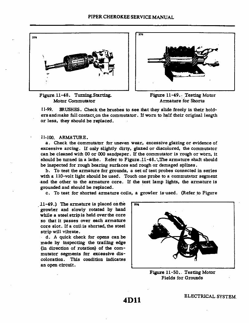
PIPER CHEROKEE SERVICE MANUAL
376375
Figure 11-48. Turning Starting Figure 11-49. Testing MotorMotor Commutator Armature for Shorts
11-99. BRUSHES. Check the brushes to see that they slide freely in their hold-ersandmake full contacton the commutator. If worn to half their original lengthor less, they should be replaced.
11-100. ARMATURE.a. Check the commutator for uneven wear, excessive glazing or evidence of
excessive arcing. If only slightly dirty, glazed or discolored, the commutatorcan be cleaned with 00 or 000 sandpaper. If the commutator is rough or worn, itshould be turned in a lathe. Refer to Figure.11-48. The armature shaft shouldbe inspected for rough bearing surfaces and rough or damaged splines.
b. To test the armature for grounds, a set of test probes connected in serieswith a 110-volt light should be used. Touch one probe to a commutator segmentand the other to the armature core. If the test lamp lights, the armature isgrounded and should be replaced.
c. To test for shorted armature coils, a growler is used. (Refer to Figure
11-49.) The armature is placed onthe 376o,growler and slowly rotated by handwhile a steel stripis held over the coreso that it passes over each armaturecore slot. If a coil is shorted, the steelstrip will vibrate.
d. A quick check for opens can bemade by inspecting the trailing edge(in direction of rotation) of the com-mutator segments for excessive dis-coloration. This condition indicatesan open circuit.
Figure 11-50. Testing MotorFields for Grounds
ELECTRICAL SYSTEM4D11

PIPER CHEROKEE SERVICE MANUAL
11-101. FIELD COILS.a. Check the field coils for grounds (Refer to Figure 11-50) by placing one
testprobe on the frame and the other on the starter terminal. Be sure the brushesare not accidentally touching the frame. If the lamp lights, the fields are ground-ed. Repair or replace.
b. Inspect all connections to make sure they are clean and tight and inspectinsulation for deterioration.
11-102. BRUSH HOLDERS.a. To test brush holders, touch one test probe to the brush plate and the other
to each brush holder.b. The test lamp should light when the grounded brush holders are touched and
should not light when the insulated brush holders are touched.
11-103. GEAR AND PINION HOUSING. Inspect housings for cracks and bearingsfor excessive wear. Remove rust, paint or grease from mounting surfaces.
11-104. BENDIX DRIVE.The Bendix Drive should be wiped clean with a dry cloth.The pinion should turn smoothly in one direction and should lock in the other di-rection. Replace drive if it fails to check as above or if the pinion teeth are ex-cessively worn or damaged.
11-105. ASSEMBLY.a. When assembling the starting motor, always use an arbor press and the
proper bearing arbor for installing graphitized bronze and roller bearings. TheBendix shaft should have a thin film of Lubriplate #777 or equivalent on the Bendixportion of the shaft. End play should be .005 to .050 of an inch.
b. New brushes should be properly seated when installing by wrapping a stripof 00 sandpaper around the commutator (with the sanding side out) 1-1/4 to 1-1/2times maximum. Drop brushes on sandpaper covered commutator and turn thearmature slowly in the direction of rotation. Dust should be blown out of the motorafter sanding.
NOTE
The spring tension is 32 to 40 ounces with new brushes.This tension is measured with the scale hooked under thebrush spring near the brush and the reading is taken atright angles to the line of force exerted by the brush spring.
ELECTRICAL SYSTEMReissued: 1/15/81 4D12

PIPER CHEROKEE SERVICE MANUAL
377 378
Figure 11-51. No-Load Figure 11-52. Stall-TorqueTest Hook-up Hook-up
c. Check the position of the pinion to be sure the unit will mesh properly withthe flywheel ring gear. See specifications for unit for correct dimensions. Referto paragraph 11-108.
11-106. BENCH TESTS.a. After the starting motor is reassembled, it should be tested to see that the
no-load currentat a certain voltage is within specifications as given in paragraph11-108. To make this test, connect as shown in Figure 11-51. If current is toohigh, check the bearing alignment and end play to make sure there is no bindingor interference. Two or three sharp raps on the frame with a rawhide hammerwill often help to align the bearings and free the armature.
b. If no difficulty is indicated in the above test, a stall torque test may be madeto see if the starting motor is producing its rated cranking power. Make testconnections as shown in Figure 11-52.
c. If torque and current are not within specifications, check the seating of thebrushes and internal connections for high resistance. If these checks are madeand found to be in good order, replace frame and field assembly and reteststarter.
Reissued: 1/15/81 ELECTRICAL SYSTEM4D13

PIPER CHEROKEE SERVICE MANUAL
11-107. STARTING MOTOR CONTROL CIRCUIT.a. Inspect the control circuit wiring between the battery, solenoid and manual starting
switches for breaks, poor connections and faulty insulation. Tighten all connections andmake sure solenoid is firmly mounted and makes a good ground connection.
b. Check the voltage loss across the switch contacts during normal starting. If loss is inexcess of 0.2 volts per 100 amperes, the solenoid should be replaced.
c. If solenoid fails to operate when the manual starting switch is turned on or if it failsto release when the manual starting switch is released, it should be removed and tested tospecifications. If either opening or closing voltages are not to specifications, replace thesolenoid.
11-108. STARTING MOTOR SERVICE TEST SPECIFICATIONS. Prestolite specificationsfor 12-volt starting motors installed as standard equipment on PA-28 series airplanes are asfollows:
Motor Model MZ-4204 or MZ-4206
Min. Brush Tension 32 oz.Max. Brush Tension 40 oz.
No-Load Test (77° F)Volt 10Max. Amps 75Min. R.P.M. 2000
Stall TorqueAmps 560Min. Toruqe, Ft. lbs. 38.0Approx. volts 4.0
Pinion Position*Drive at rest 1.748 in. - 1.855 in.Drive extended 2.388 in. - 2.495 in.
*This dimension is measured from the centerline ofthe mounting hole nearest the drive end head to theedge of the pinion.
Reissued: 1/15/81 ELECTRICAL SYSTEM4D14
PIPER CHEROKEE SERVICE MANUAL
11-109. BATTERY.
11-110. SERVICING BATTERY. Access to the battery is through the aft side of thebaggage compartment (PA-28-150, -160, -180 and PA-28R-180, -200) or the access panellocated in the baggage compartment floor (PA-28-140). It is enclosed in a protective boxwith a vent system and a drain. The vents allow fresh air to enter the box and draw offfumes that may accumulate due to the charging process of the battery. The drain is clampedoff and should be opened occasionally to drain any accumulation of liquid or duringcleaning of the box. The battery should be checked for fluid level but must not be filledabove the baffle plates. A hydrometer check should be performed to determine the percentof charge in the battery. All connections must be clean and tight.
NOTE
If a solderless terminal on an aluminum cable is loose, cor-roded or otherwise unsatisfactory, it is recommended that thecomplete cable assembly be replaced instead of replacing orrepairing the solderless terminal.
Should replacement of the complete assembly not be prac-tical, it is permissible to replace the aluminum cable assemblywith a copper cable assembly which is two sizes smaller (ex.:an AL-I aluminum cable assembly is replaced with an AN-3copper cable assembly).
The new cable should be installed in accordance with AC-43-13-2A.
11-111. REMOVAL OF BATTERY.a. Remove the access panel to the aft section of the fuselage (PA-28-150, -160, -180 and
PA-28R-180, -200) or the floor panel located aft of the main spar (PA-28-140).b. Remove battery box cover.c. Disconnect the battery cables.
NOTE
Always remove the ground cable first and install last toprevent accidental short circuiting or arcing.
*d. Lift the battery from the box.
11-112. INSTALLATION OF BATTERY.a. Ascertain that the battery and battery box have been cleaned and are free of acid.b. Install the battery in box.c. Connect the positive lead to the positive battery terminal and secure.d. Connect the ground cable to the negative battery terminal and secure.e. Install the battery box cover and secure with wing nuts.f. Install access panel.
Reissued: 1/15/81 ELECTRICAL SYSTEM
4D15
PIPER CHEROKEE SERVICE MANUAL
11-113. CHARGING BATTERY. If the battery is notup to normalcharge, removethe battery and recharge starting with a charging rate of 4-amps and finishing with2-amps. A fast charge is not recommended.
HYDROMETER READING AND BATTERY CHARGE PER CENT
Hydrometer Reading Per cent of Charge
1280 1001250 751220 501190 251160 Very little useful capacity1130 or below discharged
11-114. BATTERY BOX CORROSION PREVENTION. The battery should be checked forspilled electrolyte or corrosion at least each 50 hour inspection or at least every 30 days,whichever comes first. Should this be found in the box, on the terminals or around thebattery, the battery should be removed and both the box and battery cleaned by thefollowing procedure:
a. Remove the box drain cap from the under side of the fuselage and drain off anyelectrolyte that may have overflowed into the box.
b. Clean the battery and the box. Corrosion effects may be neutralized by applying asolution of baking soda and water mixed to a consistency of thin cream. The application ofthis mixture should be applied until all bubbling action has ceased.
CAUTION
Do not allow soda solution to enter battery.
c. Rinse the battery and box with clean water and dry.d. As necessary, paint the metal battery box with an acid resistant paint. Allow paint
to dry thoroughly.e. Place the cap over the battery box drain.f. Reinstall the battery.
Reissued: 1/15/81ELECTRICAL SYSTEM4D16

PIPER CHEROKEE SERVICE MANUAL
11-115. STARTING THROUGH EXTERNAL POWER RECEPTACLE WITHAIRPLANE'S BATTERY NEARLY DEPLETED.
a. When using a 12-volt battery for external power starting and the airplane's battery isnearly depleted, the following procedure should be used:
1. Disconnect the airplane's battery at the negative terminal to prevent excessiveloading of the external starting battery.
2. Check that all of the airplane's electrical equipment is turned OFF.3. Connect the external battery to the external power receptacle; turn master
switch ON and start engine using normal starting procedure.4. Turn master switch OFF; remove external battery, and then reconnect the
battery at the negative terminal.5. Turn master switch ON.
When starting with a power cart and the airplane's battery is nearly depleted, theprocedure in step a need not be followed. The capacity of a power cart is sufficient to startan aircraft with a low battery.
THIS SPACE INTENTIONALLY LEFT BLANK
ELECTRICAL SYSTEMReissued: 1/15/81 4D17

PIPER CHEROKEE SERVICE MANUAL
11-116. ALTERNATOR SYSTEM (RRESTOLITE).
11-117. CHECKING ALTERNATOR SYSTEM. With all electrical equipment off (exceptmaster switch) the ammeter will indicate the amount of charging current demanded by thebattery. This amount will vary, depending on the percentage of charge in the battery at thetime. As the battery becomes charged, the amount of current displayed on the ammeter willreduce to approximately two amperes. The amount of current shown on the ammeter willtell immediately whether or not the alternator system is operating normally, if the followingprinciples are kept in mind.
NOTE
The amount of current shown on the ammeter is the load inamperes that is demanded by the electrical system from thealternator. As a check, take for example a condition wherethe battery is demanding 10 amperes charging current, thenswitch on the landing light. Note the value in amperesplacarded on the circuit breaker panel for the landing lightcircuit breaker (10 amps) and multiply this by 80 percent,you will arrive at a current of 8 amperes. This is theapproximate current drawn by the light. Therefore, when thelight is switched on, there will be an increase of current from10 to 18 amperes displayed on the ammeter. As each unit ofelectrical equipment is switched on, the current will add upand the total, including the battery, will appear on theammeter.
Using the example that the airplane's maximum continuous load with all equipment on isapproximately 48 amperes for the 60-ampere alternator. This approximate 48-ampere value,plus approximately two amperes for a fully charged battery, will appear continuously underthese flight conditions. If the ammeter reading were to go much below this value, under theaforementioned conditions, trouble with the alternator system would be indicated andcorrective action should be taken by switching off the least essential equipment.
The following test procedure could be helpful in locating faulty components:a. Ascertain that the airplane is positioned so that the prop blast will not interfere with
other operations going on near by. Start engine and set throttle for 1000 to 1200 RPM.b. Switch on the following loads and observe the ammeter output increase as indicated.
1. Rotating beacon - 3 to 6 amps.2. Navigation and instrument lights (bright position) - 4 to 6 amps.3. Landing light - 7 to 9 amps.
If alternator does not meet above indications, refer to troubleshooting chart. Followtroubleshooting procedure outlined on the chart in a step by step fashion checking eachcause and isolation procedure under a given trouble before proceeding to the next.
On airplanes without night-flying equipment, load required by test can be simulated byconnecting a lamp-bank load consisting of 8 landing lights wired in parallel from main bus(+) to airframe ground (-) (Refer to Figure 11-18) or 3 ohm, 100 watt resistors.
ELECTRICAL SYSTEMReissued: 1/15/81 4D18

PIPER CHEROKEE SERVICE MANUAL
11-118. ALTERNATOR NOMENCLATURE.a. Bearings: These units have a sealed ball bearing at the drive end and a two-piece
roller bearing at the slip ring end. The inner race is pressed onto the rotor shaft and the restof the bearing is in the slip ring end head. When the unit is assembled, the inner race alignswith the bearing. When the bearing is replaced, the new inner race must be installed on therotor shaft.
b. Lubrication: The slip ring end bearing should be lubricated whenever the alternatoris disassembled. The bearing should be thoroughly cleaned and repacked with Shell AlvaniaNo. 2 or an equivalent bearing lubricant. The cavity behind the bearing should be packedone-third to one-half full with the same lubricant.
c. Brushes: These units have a separate brush holder assembly that is installed after thealternator has been assembled. The brush holder has a small hole that intersects the brushcavities. Use a pin or a piece of wire, as shown in Figure 11-83 to hold the brushes in theholder during assembly. Remove the pin after the brush holder retaining screws have beentightened. Make a continuity check to be sure the brushes are seated against the slip rings.
d. Drive Pulley: Torque the drive pulley retaining nut to 35 foot pounds.
11-119. ALTERNATOR SERVICE PRECAUTIONS. Since the alternator and regulator aredesigned for use on only one polarity system, the following precautions must be observedwhen testing or servicing the electrical system. Failure to observe these precautions willresult in serious damage to the electrical equipment.
a. Disconnect the battery before connecting or disconnecting test instruments (exceptvoltmeter) or before removing or replacing any unit or wiring. Accidental grounding orshorting at the regulator, alternator, ammeter or accessories, will cause severe damage to theunits and/or wiring.
b. The alternator must not be operated on open circuit with the rotor windingenergized.
c. Do not attempt to polarize the alternator. No polarization is required. Any attemptto do so may result in damage to the alternator, regulator or circuits.
d. Grounding of the alternator output terminal may damage the alternator and/orcircuit and components.
e. Reversed battery connections may damage the rectifiers, wiring or othercomponents of the charging system. Battery polarity should be checked with a voltmeterbefore connecting the battery. Most aircraft are negative ground.
f. If a booster battery or fast charger is used, its polarity must be connected correctlyto prevent damage to the electrical system components.
11-120. DESCRIPTION OF ALTERNATOR. (Refer to Figure 11-71.)The principal components of the alternator are the brush holder assembly (1), the slip
ring end head (2), the rectifiers (3), the stator (4), the rotor (5) and the drive end head (6).a. The brush and holder assembly contains two brushes, two brush springs, a brush
holder and insulator. One brush is connected to a terminal stud and is insulated fromground. The other brush is connected to ground thru the brush holder. The brush andholder assembly can easily be removed for inspection or brush replacement purposes.
Reissued: 1/15/81 ELECTRICAL SYSTEM4D19
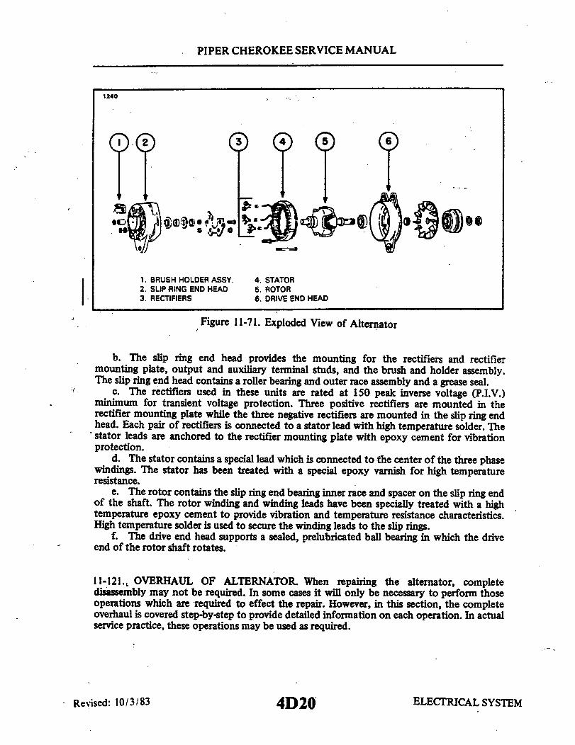
PIPER CHEROKEE SERVICE MANUAL
1240
1. BRUSH HOLDER ASSY. 4.STATOR2. SLIP RING END HEAD 5. ROTOR3. RECTIFIERS 6. DRIVE END HEAD
Figure 11-71. Exploded View of Alternator
b. The slip ring end head provides the mounting for the rectifiers and rectifiermounting plate, output and auxiliary terminal studs, and the brush and holder assembly.The slip ring end head contains a roller bearing and outer race assembly and a grease seal.
c. The rectifiers used in these units are rated at 150 peak inverse voltage (P.I.V.)minimum for transient voltage protection. Three positive rectifiers are mounted in therectifier mounting plate while the three negative rectifiers are mounted in the slip ring endhead. Each pair of rectifiers is connected to a stator lead with high temperature solder. Thestator leads are anchored to the rectifier mounting plate with epoxy cement for vibrationprotection.
d. The stator contains a special lead which is connected to the center of the three phasewindings. The stator has been treated with a special epoxy varnish for high temperatureresistance.
e. The rotor contains the slip ring end bearing inner race and spacer on the slip ring endof the shaft. The rotor winding and winding leads have been specially treated with a hightemperature epoxy cement to provide vibration and temperature resistance characteristics.High temperature solder is used to secure the winding leads to the slip rings.
f. The drive end head supports a sealed, prelubricated ball bearing in which the driveend of the rotor shaft rotates.
11-121., OVERHAUL OF ALTERNATOR. When repairing the alternator, completedisassembly may not be required. In some cases it will only be necessary to perform thoseoperations which are required to effect the repair. However, in this section, the completeoverhaul is covered step-by-step to provide detailed information on each operation. In actualservice practice, these operations may be used as required.
ELECTRICAL SYSTEMRevised: 10/3/83 4D20

PIPER CHEROKEE SERVICE MANUAL
362 361
Figure 11-72. Removal of Slip Ring Figure 11-73. Removal of RectifierEnd Bearing
11-122. DISASSEMBLY OF ALTERNATOR.a. Remove the two Number 10-24 screws holding the brush holder assembly in the slip
ring end head. Remove the brush and holder assembly from the end head.b. Remove the safety wire from the through bolts. Hold the pulley with a strap wrench
and remove the pulley nut. The pulley must be removed with a puller. Remove the fan,woodruff key and spacer from the shaft.
c. Remove the four through bolts and tap the drive end head lightly to separate thedrive end head and rotor, as a unit, from the stator and slip ring end head.
d. Remove the nuts, lock washers, flat washers and insulators from the output andauxiliary terminal studs. Note carefully the correct assembly of the insulator washers andbushings. Using the special tools shown in Figure 11-73, support the end head and press outthe three negative rectifiers. The end head can now be separated from the stator assembly.
e. To remove the slip ring end bearing and grease seal, it will be necessary to have ahook type or impact type bearing puller as shown in Figure 11-72. Do not remove thebearing unless replacement is necessary.
NOTE
The inner race of the slip ring end bearing is pressed onto therotor shaft. When bearing replacement is necessary, alwaysreplace the complete bearing assembly, including the innerrace.
ELECTRICAL SYSTEM4D21Revised: 8/3/81

PIPER CHEROKEE SERVICE MANUAL
363 364
Figure 11-74. Removal of Drive End Head Figure 11-75. Removal of End Head Bearing
f. To remove the drive end head from the rotor shaft, use a puller that grips on thebearing retainer plate as shown in Figure 11-74. Do not attempt to remove by supportingthe end head and pressing on the shaft, as this may result in distortion of the end head orstripping of the retainer plate screws. Remove the three retainer plate screws and press thebearing out of the end head. (Refer to Figure 11-75.)
11-123. INSPECTION AND TESTING OF COMPONENTS. Upon completion of thedisassembly, all parts should be cleaned and visually inspected for cracks, wear or distortionand any signs of overheating or mechanical interference.
a. Rotor: The rotor should be tested for grounded or shorted windings. The groundtest can be made with test probes, connected in series with a 110 volt test lamp, anohmmeter or any type of continuity tester. (Refer to Figure 11-76.) There must not be anycontinuity between the slip rings and the rotor shaft or poles. To test for shorted turns inthe rotor winding, connect a voltmeter, ammeter and rheostat as shown in Figure 11-77, oruse an ohmmeter. Rotor current draw and resistance are listed in the Alternator Service TestSpecifications paragraph. Excessive current draw or a low ohmmeter reading indicatesshorted windings. No current draw or an infinite ohmmeter reading would indicate an openwinding.
b. Rectifiers: A diode rectifier tester will detect and pinpoint open or shortedrectifiers without going through the operation of disconnecting the stator leads. However, ifa tester is not available, test probes and a No. 57 bulb, connected in series with a 12 voltbattery, can be used in the following manner. Touch one test probe to a rectifier heat sinkand the other test probe to a lead from one of the rectifiers in that heat sink. Then reversethe position of the leads. The test bulb should light in one direction and not light in the
ELECTRICAL SYSTEMRevised: 8/3/81 4D22

PIPER CHEROKEE SERVICE MANUAL
365A 365B
RHEOSTAT
AMMETER
Figure 11-76. Testing Rotor for Ground Figure 11-77. Testing Rotor for Shorts
other direction. If the test bulb lights in both directions, one or more of the rectifiers in thatheat sink is shorted. To pinpoint the defective rectifier, the stator leads must bedisconnected and the above test repeated on each rectifier. Open rectifiers can only bedetected, when using the test bulb, by disconnecting the stator leads. The test bulb will failto light in either direction if the rectifier is open.
c. Stator: The stator can be tested for open or grounded windings with a 12 volt testbulb, described in the rectifier section, or an ohmmeter, in the following manner. Separatethe stator from the slip ring end head just far enough to insert a fold of rags or blocks ofwood. In other words, insulate the stator from the end head. To test for grounded windings,touch one test bulb or ohmmeter probe to the auxiliary terminal or any stator lead, and theother test bulb or ohmmeter probe to the stator frame. If the test bulb lights, or theohmmeter indicates continuity, the stator is grounded. To test for open windings, connectone test probe to the auxiliary terminal or the stator winding center connection and toucheach of the three stator leads. The test bulb must light, or the ohmmeter must showcontinuity. Due to the low resistance in the stator windings, shorted windings are almostimpossible to locate. However, shorted stator windings will usually cause the alternator to"growl" or be noisy during operation and will usually show some signs of overheating. If allother electrical checks are normal and alternator fails to supply its rated output, the statorshould be replaced to determine whether or not it is the faulty component.
d. Bearings and Seals: Whenever the alternator is overhauled, new bearings and oil orgrease seals are recommended, even though the bearings and seals appear to be in goodcondition. A faulty seal can cause an alternator to fail within a very short period of time.
ELECTRICAL SYSTEM4D23Reissued: 1/15/81

PIPER CHEROKEE SERVICE MANUAL
366 367
Figure 11-78. Installation of Bearing Figure 11-79. Installation of Rectifier
11-124. ASSEMBLY OF ALTERNATOR.a. Press the ball bearing into the drive end head using a flat block approximately two
inch square so that the pressure is exerted on the outer race of the bearing. Install theretainer plate. With the snap ring and retainer cup in place on the rotor shaft, use a tool thatfits over the shaft and against the inner bearing race, and press until the inner bearing race isagainst the snap ring retainer cup. (Refer to Figure 11-78.)
b. Carefully install the rectifiers in the slip ring end head or rectifier mounting plate bysupporting the unit and using the special tools illustrated in Figure 11-79.
CAUTION
Use an arbor press, do not hammer. Reconnect the statorleads to the rectifiers. When soldering these connections, usepliers as a heat dam on the lead between the solder joint andthe rectifier. Too much heat will damage the rectifiers.
c. Reassemble the rectifier mounting plate studs and insulators, making sure they are inthe correct order. (Refer to Figure 11-80.)
d. After the slip ring end head is completely assembled, the stator and rectifier leadsmust be secured to the rectifier mounting plate with epoxy. Make sure the stator leads arepositioned so that they do not interfere with the rotor.
e. Install the slip ring end bearing and oil seal. Make sure the lip of the oil seal istoward the bearing. Stake the seal in place. Correct assembly of bearing, seal, inner race andspacer as shown in Figure 11-81.
ELECTRICAL SYSTEMRevised: 8/3/81 4D24

PIPER CHEROKEE SERVICE MANUAL
368
NUTLOCKWASHER
FLATWASHERFIBERWASHER
END HEAD
INSULATORRECTIFIER MOUNTING PLATE
TERMINAL STUD
OUTPUT (+)TERMINALAUXILIARY TERMINAL
TERMINAL PRESTOLITE ONLY
Figure 11-80. Terminal Assembly
f. Assemble the alternator and install the through bolts. Spin the rotor to make surethere is no mechanical interference. Torque the through bolts to 30 to 35 inch pounds.Safety wire should be installed after the unit has been bench tested for output. Installspacer, woodruff key, fan, pulley, lock washer and nut. Torque the nut to 35 foot pounds,using a strap wrench to hold the pulley.
g. Install the brush and holder assembly and retaining screws. Spin the rotor and checkfor interference between the brush holder and rotor. Check between the field terminal andground with an ohmmeter. The ohmmeter must indicate the amount of rotor resistancelisted with paragraph 11-125, Alternator Service Test Specifications.
11-125. TESTING OF ALTERNATOR.a. Wiring connections for bench testing the alternator are shown in Figure 11-82. Refer
to the individual specification pages for output test figures. Adjust the carbon pile ifnecessary, to obtain the specified voltage.
b. After bench testing the alternator, install the safety wire and install the alternator onthe engine.
NOTE
Always refer to the wiring diagram (Refer to Figure 11-55)when installing the alternator or testing the alternator.
ELECTRICAL SYSTEM4E1Revised: 10/3/83
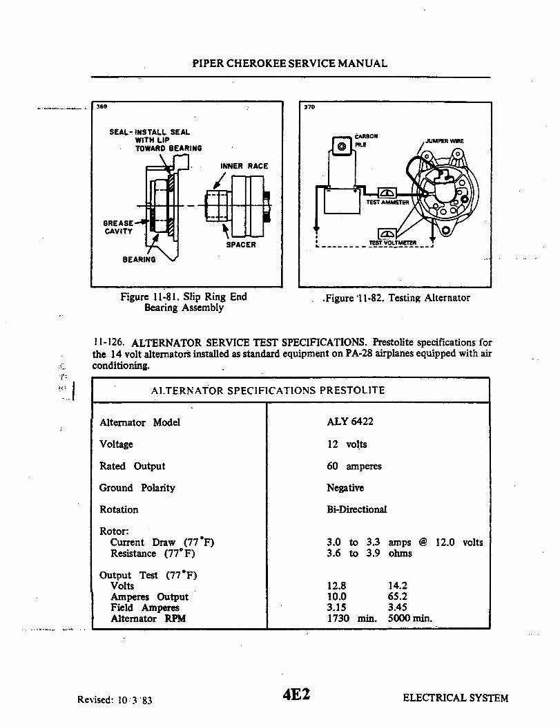
PIPER CHEROKEE SERVICE MANUAL
369 370
SEAL-INSTALL SEALWITH LIPTOWARD BEARING
INNER RACE
SPACER
Figure 11-81. Slip Ring EndBearing Assembly
.Figure 11-82. Testing Alternator
11-126. ALTERNATOR SERVICE TEST SPECIFICATIONS. Prestolite specifications forthe 14 volt alternators installed as standard equipment on PA-28 airplanes equipped with airconditioning.
ALTERNATOR SPECIFICATIONS PRESTOLITE
Alternator Model
Voltage
ALY 6422
12 volts
Rated Output 60 amperes
Ground Polarity
Rotation
Negative
Bi-Directional
Rotor:Current Draw (77 F)Resistance (77 F)
3.0 to 3.3 amps @ 12.0 volts3.6 to 3.9 ohms
Output Test (77 F)VoltsAmperes OutputField AmperesAlternator RPM
ELECTRICAL SYSTEM
12.810.03.151730
14.265.23.455000 min.min.
4E2Revised: 10/3/83

PIPER CHEROKEE SERVICE MANUAL
371 C326
PIN
END IVIEW SIDE VIEW
Figure 11-83. Brush Installation Figure 11-84. Internal Wiring Diagram
11-127. CHECKING ALTERNATOR BELT TENSION. See paragraph 11-79, CheckingGenerator and Alternator Belt Tension. For aircraft with airconditioning installed, seeparagraph 14-22, Section XIV, Replacement of compressor and/or Alternator Drive Belts.
11-128., INSTRUMENT AND PANEL LIGHTS. The instrument and panel lights arebroken up into three groups; Lower Panel Light, Upper Panel Lights, and Compass Light.The instrument lights are controlled by a 5 amp circuit breaker through a transistorizeddimmer. The dimmer control is located in the middle of the instrument panel just above thepedestal. In earlier model airplanes there is one control knob connected to a varible resistorthat controls the intensity of the instrument lights. On 1974 model aircraft there is a secondcontrol knob connected to a varible resistor which controls the light intensity for all theavionic equipment. It may be necessary to gain access to the Dimmer Control Assembly; ifso follow the instructions given below.
11-129. REMOVAL OF DIMMER CONTROL ASSEMBLY.a. Access to the Dimmer Control Assembly is from beneath the instrument panel.b. Disconnect the electrical connection from the assembly.c. Remove the two screws securing the assembly to the instrument panel.d. Remove assembly from the airplane.
11-130. INSTALLATION OF DIMMER CONTROL ASSEMBLY.a. Position the assembly in the instrument panel with the control knobs inserted into
their appropriate slots.b. Secure, the assembly to the instrument panel with the two screws previously
removed.c. Connect the electrical connection to the assembly.d. Check operation of Dimmer Control Assembly.
ELECTRICAL SYSTEMRevised: 8/3/81 4E3

PIPER CHEROKEE SERVICE MANUAL
11-131. ANNUNCIATOR PANEL.
11-132. DESCRIPTION. The annunciator panel is a small cluster of lights which warn ofmalfunctions in the various circuits or systems. A malfunction is identified by theillumination of an individual warning light There are three amber waning lights and apush-button test switch. (Refer to Figure 10-8.) Power is supplied from the bus barthrough a 5 amp fuse located behind the switch panel
The VAC warning light is controlled by a vacuum sensor switch located at the firewalland is attached to the vacuum regulator. The sensor switch will activate when thedifferential pressure is below 3.5 in. Hg.
The OIL warning light is controlled by an oil pressure sensor switch incorporated in theoil line to the oil pressure gauge and is located at the firewall The sensor switch will activatewhen the oil pressure is below 35 psi.
The ALT warning light is illuminated by current flowing from the bus bar to thealternator circuit. (Refer to Figure 11-125.) This condition exists when the alternator is notoperating properly and the output is zero. During normal operation, the alternator warningcircuit is also supplied with power from the top diode terminal This current flows through a5 amp fuse, located near the diode heat sink, to the resistor and diode creating a no-flowcondition which does not allow the warning light to light.
The test button is used to check the operation of the lights when the engine is running.The lights will work when the engine is not running with the master switch turned on.
NOTE
Oil pressure sensor and vacuum sensor switches are similar inlooks and size. Insure correct unit is to be installed per PartsCatalog part number and description.
11-133. REMOVAL OF OIL PRESSURE SENSOR. Access to the sensor unit is gained byreaching up under the instrument panel. Removal is accomplished by the following:
a. Disconnect the two electrical leads.b. Unscrew the sensor unit from the bulkhead fitting.c. Catch spillage and cover hole to prevent foreign matter from entering oil line.
11-134. INSTALLATION OF OIL PRESSURE SENSOR.a. Seal sensor unit pipe threads with thread sealant tape (3M-Teflon No. 48 x 1/4").b. Screw the sensor unit into the bulkhead fitting.c. Reconnect the two electrical leads.d. Perform operational check.
11-135. REMOVAL OF VACUUM SENSOR. Access to the sensor unit is gained byreaching up under the instrument panel to the vacuum regulator. Removal is accomplishedby the following:
a. Disconnect the two electrical leads.b. Unscrew the sensor unit from the vacuum regulator.c. Cover hole to prevent foreign matter from entering regulator.
ELECTRICAL SYSTEMRevised: 8/3/81 4E4

PIPER CHEROKEE SERVICE MANUAL
11-136. INSTALLATION OF VACUUM SENSOR.a. Screw sensor unit into vacuum regulator.b. Reconnect the two electrical leads.c. Perform operational check.
11-137. ANTI-COLLISION LIGHT (ROTATING BEACON).
11-138. REMOVAL.a. Loosen screw securing clamp around rotating beacon lens. Remove clamp and lens.b. Remove light bulb from bayonet socket.
NOTE
To remove complete rotating beacon assembly, removescrews securing it to rudder tip. Next pull rotating beaconassembly out and disconnect the electrical leads. Take noteof their placement to facilitate reinstallation. Rotatingbeacon assembly can now be removed.
11-139. INSTALLATION.a. Install light bulb in bayonet socket.b. Replace lens and clamp and secure by tightening screw on clamps.
11-140. ANTI-COLLISION (STROBE).
11-141. DESCRIPTION. The lights are located on each wing tip in the same assembly withthe navigation lights on the fin tip. They are rated to flash at approximately 50 times aminute. There is just one power supply for all three lights.
11-142. REMOVAL OF WING TIP STROBE LIGHT.a. Remove the screw securing the navigation light cover and remove cover.b. Remove the three screws securing navigation light bracket assembly and pull out.c. Remove the strobe lamp by cutting the wires on the lamp beneath the mounting
bracket.d. Remove the defective lamp.e. Remove and discard the plug with the cut wires from its electrical socket.
ELECTRICAL SYSTEMRevised: 8/3/81 4E5

PIPER CHEROKEE SERVICE MANUAL
11-143. INSTALLATION OF WING TIP STROBE LIGHT.a. Route the wires from the new lamp down through the hole in the navigation light
bracket.b. Insert the wire terminals in the plastic plug supplied with the new lamp. Wire
according to the schematic diagram located in the back of this section.c. Position strobe lamp on navigation light bracket.d. Secure navigation light assembly and bracket with appropriate screws.e. Install navigation light cover and secure with appropriate screw.
11-144. REMOVAL OF FIN TIP STROBE LIGHT.a. Remove clamp securing lens to mounting plate on fin tip.b. Remove lens from strobe light assembly.c. Remove screws securing fin tip to fin.d. Lift up fin tip and disconnect electrical plug.e. Pull strobe light assembly out of fin tip, electrical plug will pull up through hole in
middle of mounting plate.
11-145. INSTALLATION OF FIN TIP STROBE LIGHT.a. Insert new electrical plug down through hole in mounting plate and position strobe
light assembly in place.b. Position lens in place.c. Secure lens to mounting plate by the clamp previously removed.d. Reconnect electrical plugs underneath fin tip.e. Replace fin tip and secure with appropriate screws.
11-146. REMOVAL OF STROBE POWER SUPPLY. The strobe power supply is in the aftsection of the fuselage.
a. Remove access panel to the aft section of the fuselage in the rear baggagecompartment to gain access to power supply.
b. To remove power supply disconnect the electrical plugs. (One to four plugsdepending on installation. Make note of the placement of the plugs to facilitatereinstallation.)
c. Disconnect the other electrical leads.
NOTE
Make note of the placement of the leads to facilitate reinstallation.
d. Remove the four screws securing power supply to the fuselage. Power supply cannow be removed.
ELECTRICAL SYSTEMRevised: 8/3/81 4E6

PIPER CHEROKEE SERVICE MANUAL
11-147.: INSTALLATION OF STROBE POWER SUPPLY. (Refer to Figure 11-143.)a. Position the power supply in place and secure with the four screws previously
removed.b. Reconnect the electrical leads in their proper place.c. Reconnect the electrical plugs previously removed in their proper place.d. Replace access panel in rear baggage compartment.
11-148. TROUBLESHOOTING PROCEDURE. The strobe light functions as a condenserdischarge system. A condenser in the power supply is charged to approximately 450-voltsDC then discharged across the Xenon flash tube at intervals of approximately 50 flashes perminute. The condenser is parallel across the Xenon flash tube which is designated to holdoff the 450-volts DC applied until the flash tube is triggered by an external pulse. This pulseis generated by a solid state timing circuit in the power supply.
When troubleshooting the strobe light system, it must first be determined if the troubleis in the flash tube or the power supply. Replacement of the flash tube will confirm if thetube is defective. A normally operating power supply will emit an audible tone of 1 to 1.5KHZ. If there is no sound emitted, check the system according to the following instructions.When troubleshooting the system, utilize the appropriate schematic at the back of thissection.
a. Ascertain the input voltage at the power supply is 14-volts.
CAUTION
When disconnecting and connecting the power supply inputconnections, do not get the connections reversed. Reversedpolarity of the input voltage for just an instant willpermanently damage the power supply. The reversed polaritydestroys a protective diode in the power supply, causingself-destruction from overheating of the power supply. Thisdamage is sometimes not immediately apparent, but willcause failure of the system in time.
b. Check for malfunction in interconnecting cables.1. Ascertain Pins 1 and 3 of interconnecting cable are not reversed.2. Using an ohmmeter, check continuity between Pin I and 3 of interconnecting
cable. If a reading is obtained on the meter, the cable is shorted and should be replaced.
NOTE
A short of the type described in Steps 1 and 2 will not causepermanent damage to the power supply, but the system willbe inoperative if such a short exists. Avoid any connectionbetween Pins 1 and 3 of the interconnecting cable as this willdischarge the condenser in the power supply and destroy thetrigger circuits.
ELECTRICAL SYSTEM4E7Revised: 8/3/81

PIPER CHEROKEE SERVICE MANUAL
CAUTION
When disconnecting the power supply, allow five minutes ofbleed down time prior to handling the unit.
c. Check interconnecting cables for shorts.1. Disconnect the output cables from the power supply outlets.2. The following continuity checks can be made with an ohmmeter.3. Check for continuity between the connectors of each interconnecting cable by
checking from Pin 1 to Pin 1, Pin 2 to Pin 2, and Pin 3 to Pin 3. When making these checksif no continuity exists, the cable is broken and should be replaced.
4. Check continuity between Pins 1 and 2, 1 and 3, 2 and 3 of the interconnectingcable. If continuity exists between any of these connections, the cable is shorted and shouldbe replaced.
d. Check the tube socket assembly for shorts.1. Disconnect the tube socket assembly of the anti-collision light from the
interconnecting cable.2. The following continuity checks can be made with an ohmmeter.3. Check for continuity between Pin I of AMP connector to Pin 1 of tube socket.
Pin 2 of AMP connector to Pins 6 and 7 of tube socket and Pin 3 of AMP connector to Pin 4of tube socket. When making these tests, if no continuity exists, the tube socket assembly isbroken and should be replaced.
ELECTRICAL SYSTEMReissued: 1/15/81 4E8

PIPER CHEROKEE SERVICE MANUAL
901
BLACK
SPLIT SWITCH
OFF OFF
FIN WING
AN TI
BLACK (WITH SHIELD)
VIEW A WHITE
4
TO LEFT WING TIP(SEE VIEW A)
TO FIN TIP(SEE VIEW A)
TO RIGHTWING TIP(SEE VIEW A)
REFER TO FIGURE 11-139 FOR SCHEMATIC 28-140, 180,235, AND 28R-180 & 28R-200
Figure 11-144. Strobe Light Connections
Reissued: 1/15/81 ELECTRICAL SYSTEM
L4B
4E9
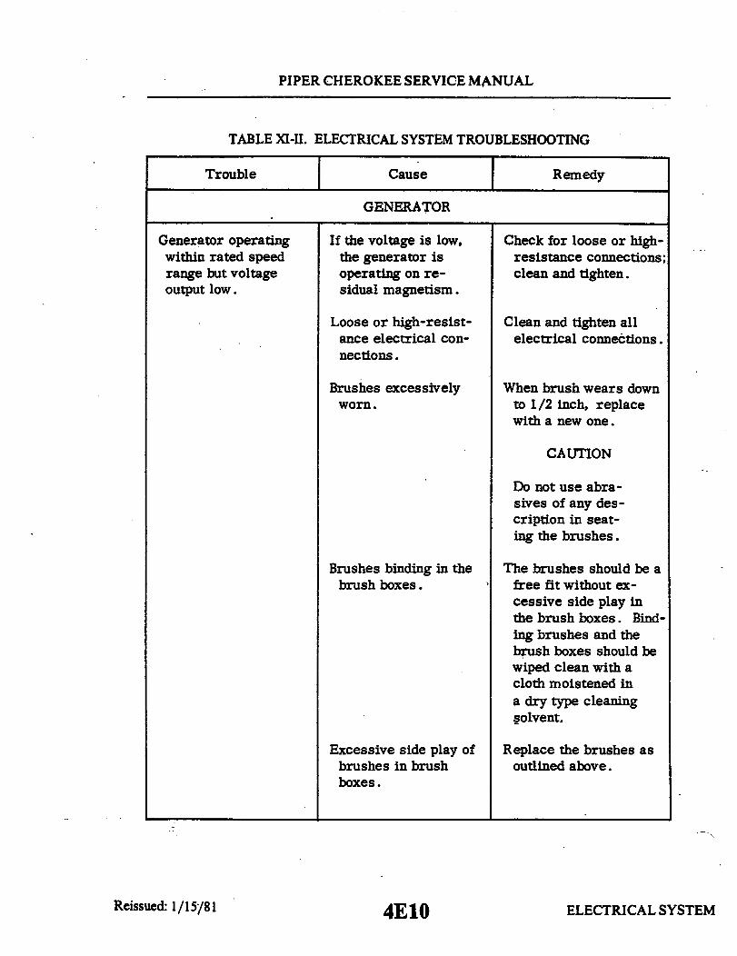
PIPER CHEROKEE SERVICE MANUAL
TABLE XI-II. ELECTRICAL SYSTEM TROUBLESHOOTING
Trouble Cause Remedy
GENERATOR
Generator operatingwithin rated speedrange but voltageoutput low.
If the voltage is low,the generator isoperating on re-sidual magnetism.
Check for loose or high-resistance connections;clean and tighten.
Loose or high-resist-ance electrical con-nections.
Brushes excessivelyworn.
Clean and tighten allelectrical connections.
When brush wears downto 1/2 inch, replacewith a new one.
CAUTION
Do not use abra-sives of any des-cription in seat-ing the brushes.
Brushes binding in thebrush boxes.
Excessive side play ofbrushes in brushboxes.
The brushes should be afree fit without ex-cessive side play inthe brush boxes. Bind-ing brushes and thebrush boxes should bewiped clean with acloth moistened ina dry type cleaningsolvent.
Replace the brushes asoutlined above.
Reissued: 1/15/81 ELECTRICAL SYSTEM
I
4E1O

PIPER CHEROKEE SERVICE MANUAL
TABLE XI-II. ELECTRICAL SYSTEM TROUBLESHOOTING (cont.)
Trouble I Cause Remedy
GENERATOR (cont)
Generator operatingwithin rated speedrange but voltage out-put low. (cont)
Brushes not properlyseated.
Low brush springtension.
Reseat brushes as out-lined above.
Brush spring shouldbear centrally on thetop of the brushes, in-suring full brush con-tact with the face ofthe commutators
Dirty commutator.
Scored or pitted com-mutator.
Shorted or open arm-ature coils.
Improper operation ofthe voltage regulator.
Clean the commutatorwith a cloth moistenedin a dry type cleaningsolvent.
Turn down commutatoror replace armature.
Replace generator orarmature.
Adjust regulator.
Generator operatingwithin rated speedrange but voltmeterindicates zero.
Wiring not properlyconnected.
Grounded or openfield coil assembly.
See electrical systemwiring diagram.
Remove the generatorand replace with oneknown to be in goodcondition.
ELECTRICAL SYSTEMReissued: 1/15/81 4Ell

PIPER CHEROKEE SERVICE MANUAL
TABLE XI-II. ELECTRICAL SYSTEM TROUBLESHOOTING (cont.)
Trouble Cause Remedy
GENERATOR (cont)
Generator operatingwithin rated speedrange, but voltageoutput is erratic.
Excessive sparking atgenerator brushes.
Generator operatingwithin rated speedrange but system am-meter reads off scale.
System ammeter fluc-tuates excessivelywhen indicating ratedload.
Unstable operation ofthe voltage regulator.Same as "Generatoroperating within ratedspeed range but volt-age output "low",above.
Same as "Generatoroperating within ratedspeed range but volt-age output low, above.
Generator field mag-netized in the wrongdirection.
Generating system isoverloaded.
Improper operation ofgenerator reverse-current relay.
Replace voltage reg-ulator. Use remedyunder "Generatoroperating within ratedspeed range but volt-age output low", above.
Use remedy under"Generator operatingwithin rated speedrange but voltageoutput low", above.
Flash field with ajumper wire on reg-ulator between gen-erator and battery.
Check the system forabnormal loads.
Readjust to operateproperly.
Loose connections. Tighten connections.
Burned-out systemammeter or line fuse.
Burned-out systemammeter or line fuse.
Discharged battery.
Defective wiring.
Replace with a fullycharged battery.
Replace all defectivewiring.
ELECTRICAL SYSTEM
I I
Reissued: 1/15/81 4E12

PIPER CHEROKEE SERVICE MANUAL
TABLE Xl-II. ELECTRICAL SYSTEM TROUBLESHOOTING (cont.)
Trouble I Cause Remedy
ALTERNATOR
Zero output indicatedon ammeter regard-less of RPM (refer toalternator system testprocedure).
Open field circuit. With master switchturned on, check forbattery voltage fromairplane's main bussthrough entire fieldcircuit to alternatorfield terminal. Mea-sure voltage fromground (-) to the follow-ing points (+) in se-quence: buss bar, out-put circuit breaker (40A)(60A), field circuitbreaker (5A), fieldterminals of masterswitch, voltage regu-lator and alternatorfield terminal.
Interruption of voltagethrough any of thesepoints isolates the faultycomponent or wirewhich must be replaced.(See wiring schematic. )
Open output circuit. With master switchturned on, check forbattery voltage fromairplane's main bussthrough entire outputcircuit to alternatorbattery post. Measurevoltage from ground (-)to the following points(+) in sequence: buss
ELECTRICAL SYSTEM4E13
I
Reissued: 1/15/81

PIPER CHEROKEE SERVICE MANUAL
TABLE XI-II ELECTRICAL SYSTEM TROUBLESHOOTING (cont.)
Trouble Cause Remedy
ALTERNATOR (cont)
Zero output indicated onammeter regardless ofRPM (refer to alterna-tor system test proce-dure) (cont)
Open output circuit.(cont)
bar, output circuitbreaker, ammeter,and alternator batterypost.
Interruption of voltagethrough any of thesepoints isolates thefaulty component orwire which must bereplaced. (See wiringschematic. )
Open field winding inalternator.
Disconnect field termi-nal of alternator fromfield wiring and checkfor continuity from fieldterminal to ground withohmeter (20-100 ohms)depending on brushcontact resistance.(Pull propeller slowlyby hand turning alter-nator rotor through360° of travel.)
CAUTION
Turn magneto switch tooff before turning prop.
If resistance is high,check brushes forspring tension and ex-cessive wear and re-place if necessary. Ifbrushes are okay and
ELECTRICAL SYSTEM
I
Reissued: 1/15/81 4E14

PIPER CHEROKEE SERVICE MANUAL
TABLE XI-II. ELECTRICAL SYSTEM TROUBLESHOOTING (cont.)
Trouble Cause Remedy
ALTERNATOR (cont)
Zero output indicated onammeter regardless ofRPM (refer to alterna-tor system test proce-dure) (cont)
Output indicated onammeter does notmeet minimum valuesspecified in alternatorsystem test procedure.
Open output circuit.(cont)
Faulty voltage regu-lator.
field reads open, re-place alternator
Start engine, turn onload (Ref. alternatortest procedure), setthrottle at 2300 RPM.Check voltage at bussbar (convenient checkpoint, remove cigarlighter and check fromcenter contact (+) toground (-). Voltageshould be 13.5 voltsminimum. If voltageis below this value,replace regulator.
High resistance con-nections in field oroutput circuit.
Check visually for loosebinding posts at thevarious junction pointsin system, alternatorbattery post, lugs onammeter, connectionsat voltage regulator,circuit breaker, etc.,(See wiring schematic. )Examine crimped ter-minal ends for signs ofdeterioration at crimpor strands of brokenwire at crimp. Tightenany loose binding posts.
ELECTRICAL SYSTEM4E15Reissued: 1/15/81
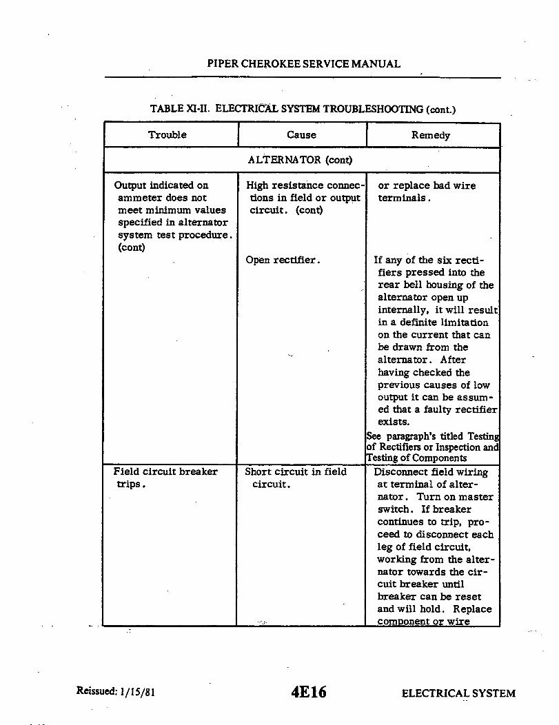
PIPER CHEROKEE SERVICE MANUAL
TABLE XI-II. ELECTRICAL SYSTEM TROUBLESHOOTING (cont.)
Trouble I Cause Remedy
ALTERNATOR (cont)
Output indicated onammeter does notmeet minimum valuesspecified in alternatorsystem test procedure.(cont)
Field circuit breakertrips.
High resistance connec- or replace bad wiretions in field or output terminals.circuit. (cont)
Open rectifier. If any of the six recti-fiers pressed into therear bell housing of thealternator open upinternally, it will resultin a definite limitationon the current that canbe drawn from thealternator. Afterhaving checked theprevious causes of lowoutput it can be assum-ed that a faulty rectifierexists.
See paragraph's titled Testingof Rectifiers or Inspection andTesting of Components
Short circuit in field Disconnect field wiringcircuit. at terminal of alter-
nator. Turn on masterswitch. If breakercontinues to trip, pro-ceed to disconnect eachleg of field circuit,working from the alter-nator towards the cir-cuit breaker untilbreaker can be resetand will hold. Replacecomponent or wire
ELECTRICAL SYSTEM
I
Reissued: 1/15/81 4E16

PIPER CHEROKEE SERVICE MANUAL
TABLE XI-I. ELECTRICAL SYSTEM TROUBLESHOOTING (cont.)
Trouble I Cause Remedy
ALTERNATOR (cont)
Field circuit breakertrips. (cont)
Short circuit in fieldcircuit. (cont)
which was isolated asdefective. (See wiringschematic. )
Short circuit in fieldwinding of alternator.
Disconnect field wiringat terminal of alter-nator. Turn on masterswitch. Reset breakerand if breaker fails toretrip, this isolatesshort circuit to field ofalternator itself. Checkbrush holders forshorting against frame.If there are no obvioussigns of a physicalshort circuit at fieldterminal or brushholder, replace alter-nator. (Note: Inter-mittent short circuit.)
Internal short circuitingof the field can occurat various positions ofthe rotor, therefore,reconnect field, resetbreaker, pull propellerslowly by hand turningalternator rotor through360° of travel. Observecircuit breaker forsigns of tripping.
ELECTRICAL SYSTEMReissued: 1/15/81 4E17

PIPER CHEROKEE SERVICE MANUAL
TABLE XI-II. ELECTRICAL SYSTEM TROUBLESHOOTING (cont.)
Trouble Cause Remedy
ALTERNATOR (cont)
Field circuit breakertrips. (cont)
Output circuit breakertrips.
Short circuit in fieldwinding of alternator.(cont)
Short circuit in outputcircuit..
CAUTION
Turn magneto switch tooff before turning pro-peller .
Disconnect wiring atbattery post of alter-nator. Turn on masterswitch. Reset breakerand if breaker continuesto trip, proceed to dis-connect each leg of out-put circuit, workingfrom the alternatortowards the circuitbreaker until breakercan be reset and willhold. Replace com-ponent or wire whichwas isolated as defec-tive. (See schematic. ).
Shorted alternatordiode.
Battery installed withreversed polarity.
Disconnect wiring atbattery post of alter-nator. Turn on masterswitch. Reset breakerand if breaker fails toretrip, this isolatesshort circuit to alter-nator. Replace alter-nator.
Remove battery andreinstall with correctpolarity.
Reissued: 1/15/81 ELECTRICAL SYSTEM4E18

PIPER CHEROKEE SERVICE MANUAL
TABLE XI-II. ELECTRICAL SYSTEM TROUBLESHOOTING (cont.)
Trouble Cause I Remedy
ALTERNATOR (cont)
Output circuit breakertrips. (cont)
Battery charged back-wards.
Remove battery. Con-nect load such as land-ing light lamp or simi-lar load and dischargebattery. Rechargewith correct polarityand test each cell forsigns of damage due toreversed charging.
NOTE
This type of conditioncan only occur in acase where a dis-charged battery hasbeen removed from theairplane and put on acharger with thepolarity reversed.This reversal inpolarity cannot occurin the airplane due toany fault in the alter-nator system.
Excessive ammeterfluctuation.
Excessive resistancein field circuit.
Check all connectionsand wire terminals infield circuit for de-terioration such asloose binding posts,broken wire strands atterminals, etc. Tightenall connections andreplace faulty term-inals
ELECTRICAL SYSTEM
I
Reissued: 1/15/814E19

PIPER CHEROKEE SERVICE MANUAL
TABLE XI-II. ELECTRICAL SYSTEM TROUBLESHOOTING (cont.)
Trouble Cause Remedy
ALTERNATOR (cont)
Excessive ammeterfluctuation. (cont)
High field circuitresistance.
If problem persists,jump across terminalsof the following com-ponents one at a timeuntil the faulty unitis isolated.a. Field 5 amp (al-
ternator) circuitprotector.
b. Alternator halfof master switch.
c. Overvoltage relay.
Defective voltageregulator.
Replace voltage regu-lator.
ELECTRICAL SYSTEM4E20Reissued: 1/15/81
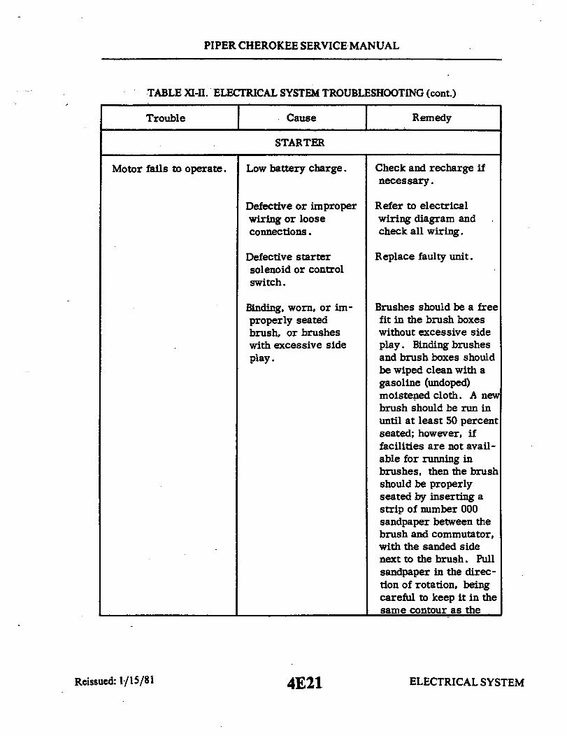
PIPER CHEROKEE SERVICE MANUAL
TABLE XI-II. ELECTRICAL SYSTEM TROUBLESHOOTING (cont.)
Trouble Cause
STARTERI Remedy
Motor fails to operate. Low battery charge. Check and recharge ifnecessary.
Defective or improperwiring or looseconnections.
Defective startersolenoid or controlswitch.
Binding, worn, or im-properly seatedbrush, or brusheswith excessive sideplay.
Refer to electricalwiring diagram andcheck all wiring.
Replace faulty unit.
Brushes should be a freefit in the brush boxeswithout excessive sideplay. Binding brushesand brush boxes shouldbe wiped clean with agasoline (undoped)moistened cloth. A newbrush should be run inuntil at least 50 percentseated; however, iffacilities are not avail-able for running inbrushes, then the brushshould be properlyseated by inserting astrip of number 000sandpaper between thebrush and commutator,with the sanded sidenext to the brush. Pullsandpaper in the direc-tion of rotation, beingcareful to keep it in thesame contour as the
ELECTRICAL SYSTEMReissued: 1./15/81 4E21

PIPER CHEROKEE SERVICE MANUAL
TABLE XI-II. ELECTRICAL SYSTEM TROUBLESHOOTING (cont.)
Trouble Cause I Remedy
STARTER (cont)
Motor fails to operate.(cont)
Binding, worn, or im-properly seatedbrush, or brusheswith excessive sideplay. (cont)
commutator.
CAUTION
Do not use coarsesandpaper or emerycloth. After seating,clean thoroughly toremove all sand andmetal particles toprevent excessivewear. Keep motorbearing free fromsand or metal particles.
Dirty commutator.
Shorted, grounded,or open armature.
Grounded or openfield circuit.
If commutator is roughor dirty, smooth andpolish with number 0000sandpaper. If too roughand pitted, remove andturn down. Blow outall particles.
Remove and replace withan armature known tobe in good condition.
Test, repair if possibleor replace with a newpart.
Low motor and crank-ing speed.
Worn, rough, or im-properly lubricatedmotor or startergearing.
Disassemble, clean, in-spect, and relubricate,replacing ball bearingsif worn.
ELECTRICAL SYSTEM4E22Reissued: 1/15/81

PIPER CHEROKEE SERVICE MANUAL
TABLE XI-II. ELECTRICAL SYSTEM TROUBLESHOOTING (cont.)
Trouble Cause I Remedy
STARTER (cont)
Low motor and crank-ing speed. (cont)
Excessive arcing ofmotor brushes.
Same electrical causesas listed under "Motorfails to operate".
Binding, worn, or im-properly seated brushor brushes with ex-cessive side play.
Same remedies listedfor these troubles.
See information abovedealing with thistrouble.
Dirty commutator,rough, pitted, orscored.
Clean as outlined above.
Excessive wear andarcing of motorbrushes.
Rough or scoredcommutator.
Armature assemblynot concentric.
Remove and turn com-mutator down on a lathe.
Reface commutator.
ELECTRICAL SYSTEM4E23
I
Reissued: 1/15/81
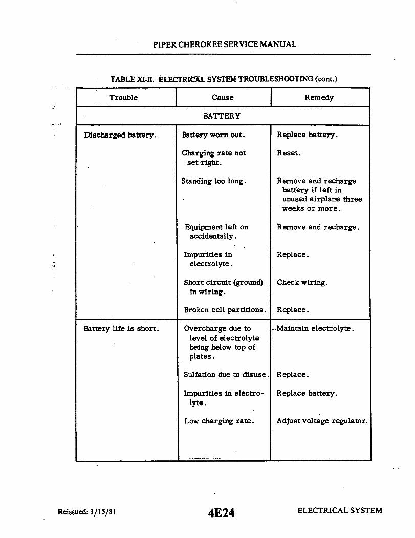
PIPER CHEROKEE SERVICE MANUAL
TABLE XI-II. ELECTRICAL SYSTEM TROUBLESHOOTING (cont.)
Trouble Cause Remedy
BATTERY
scharged battery. Battery worn out. Replace battery.
Charging rate not Reset.set right.
Standing too long. Remove and recharge
Battery life is short.
Equipment left onaccidentally.
Impurities inelectrolyte.
Short circuit (ground)in wiring.
Broken cell partitions.
Overcharge due tolevel of electrolytebeing below top ofplates.
Sulfation due to disuse.
Impurities in electro-lyte.
Low charging rate.
chargebattery if left inunused airplane threeweeks or more.
Remove and recharge.
Replace.
Check wiring.
Replace.
Maintain electrolyte.
Replace.
Replace battery.
Adjust voltage regulator.
ELECTRICAL SYSTEM4E24
Discharged battery.
Reissued: 1/15/81

PIPER CHEROKEE SERVICE MANUAL
TABLE XI-II. ELECTRICAL SYSTEM TROUBLESHOOTING (cont.)
Trouble Cause Remedy
BATTERY (cont)
Cracked cell jars. Hold-down bracketloose.
Replace battery andtighten.
Frozen battery.
Compound on top ofbattery melts.
Electrolyte runs outof vent plugs.
Excessive corrosioninside container.
Charging rate toohigh.
Too much water addedto battery and charg-ing rate too high.
Spillage from over-filling.
Vent lines leaking orclogged.
Charging rate too high.
Reduce charging rate byadjusting voltage regu-lator or replace tran-sistorized regulator.
Drain and keep at properlevel and adjust voltageregulator.
Use care in addingwater.
Repair or clean.
Adjust voltage regulator.
Battery freezes. Discharged battery.
Water added andbattery not chargedimmediately.
Always recharge batteryfor 1/2 hour followingaddition of water infreezing weather.
Leaking battery jar.
Battery polarityreversed.
Connected backwardson airplane orcharger.
Battery should be slowlydischarged completelyand then chargedcorrectly and tested.
Reissued: 1/15/81 ELECTRICAL SYSTEM4F1
Replace.
Replace.
Frozen. Replace.
I

PIPER CHEROKEE SERVICE MANUAL
Batterexces
TABLE XI-II. ELECTRICAL SYSTEM TROUBLESHOOTING (cont.)
Trouble Cause Remedy
BATTERY (cont)
y consumes Charging rate too high Correct chargiexcessive water. (if in all cells).
Cracked jar (one cell Replace batteryonly).
ELECTRICAL SYSTEM
ng rate.
attery.
4F2Reissued: 1/15/81
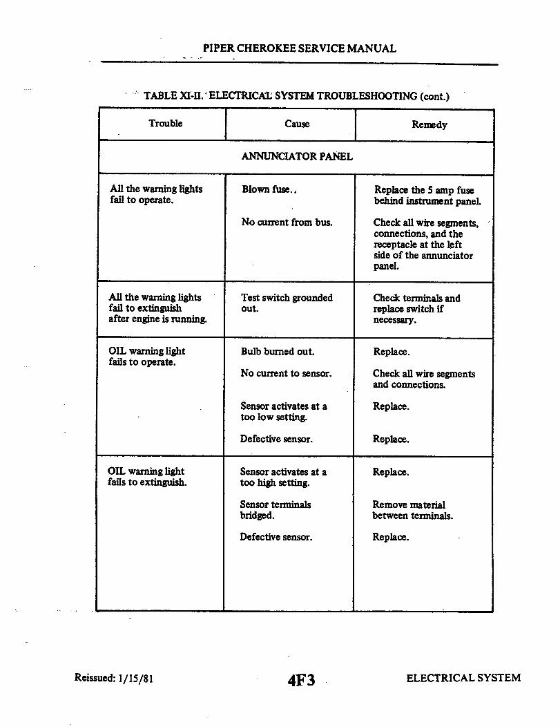
PIPER CHEROKEE SERVICE MANUAL
TABLE XI-II. ELECTRICAL SYSTEM TROUBLESHOOTING (cont.)
Trouble Cause Remedy
ANNUNCIATOR PANEL
All the warning lightsfail to operate.
Blown fuse., Replace the 5 amp fusebehind instrument panel.
No current from bus. Check all wire segments,connections, and thereceptacle at the leftside of the annunciatorpanel.
All the warning lightsfail to extinguishafter engine is running.
OIL warning lightfails to operate.
Test switch groundedout.
Bulb burned out.
No current to sensor.
Sensor activates at atoo low setting.
Defective sensor.
Check terminals andreplace switch ifnecessary.
Replace.
Check all wire segmentsand connections.
Replace.
Replace.
OIL warning lightfails to extinguish.
Sensor activates at atoo high setting.
Sensor terminalsbridged.
Defective sensor.
Replace.
Remove materialbetween terminals.
Replace.
ELECTRICAL SYSTEM4F3Reissued: 1/15/81

PIPER CHEROKEE SERVICE MANUAL
TABLE XI-II. ELECTRICAL SYSTEM TROUBLESHOOTING (cont.)
Trouble Cause Remedy
ANNUNCIATOR PANEL (cont.)
VAC warning light failsto operate.
Bulb burned out.
No current to sensor.
Sensor activates at atoo low setting.
Defective sensor.
Replace.
Check all wire segmentsand connections.
Replace.
Replace.
VAC warning light failsto extinguish.
ALT warning light failsto operate.
ALT warning light failsto extinguish.
Sensor activates at atoo high setting.
Sensor terminalsbridged.
Defective sensor.
Bulb burned out.
No current from busto resistor.
Blown fuse.
Replace.
Remove materialbetween terminals.
Replace.
Replace.
Check all wire segmentsand connections.
Replace 5 amp fusenear the diode heatsink.
No current from thefuse to the resistor.
Check all wire segmentsand connections.
Test switch fails toactivate warning lights.
Bad switch orconnections.
Check wires and replaceswitch if necessary.
ELECTRICAL SYSTEM4F4Reissued: 1/15/81

PIPER CHEROKEE SERVICE MANUAL
NOTE: TERMINAL 12 AS SHOWN USEDON PA-21 R MODELS TO SERIALNOS. 28R-7335055 INCLUSIVE.
12
4
012
FIB
FIC
L4E
L45
06B
Q7B
012
LIG
Q4B 10Q4B
Q3A
74E
PA-28-140 SERIAL NOS. 28-25000 TO28-7425454 INCLUSIVE.PA-28-180 SERIAL NOS. 28-4378 TO28-7405290 INCLUSIVE.
3
PA-28-235 SERIAL NOS. 28-11040 TO28-7410120 INCLUSIVE.
PA-28R-180 (ALL) PA-28R-200SERIAL NOS. TO 28R-7435331INCLUSIVE.
Figure 11-53. Terminal Block
4F5 ELECTRICAL SYSTEMReissued: 1/15/81

PIPER CHEROKEE SERVICE MANUAL
2
34 4
5 5
6 6
7 7
8 8
9 9
10 10
UPPER PANEL
2
4 4
6 6
LOWER PANEL
PA-28-235 SERIAL NOS. 28-10003 TO 28-11039 INCLUSIVE.
PA-28-140 SERIAL NOS.28-20002 TO 28-24999 INCLUSIVEPA-28-150, PA-28-160 AND PA-28-130SERIAL NOS. 28-1411 TO 2-4377INCLUSIVE.
PA-28-150, PA-28-160, ANDPA-28-180 SERIAL NOS.28-1 TO 2-14 10 INCLUSIVE.
Figure 11-53. Terminal Block (cont.)
ELECTRICAL SYSTEM4F6.Reissued: 1/15/81
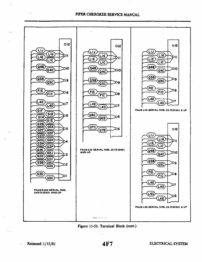
PIPER CHEROKEE SERVICE MANUAL
012
PA-28-235 SERIAL NOS. 28-7510001AND UP
PA-28-140 SERIAL NOS. 28-7525001 & UP
012
PA-28-180 SERIAL NOS. 28-7505001 & UP
Figure 11-53. Terminal Block (cont.)
ELECTRICAL SYSTEM
012 012
PA-28 R-200 SERIAL NOS.28 R-7535001 AND UP
Reissued: 1/15/81 4F7

PIPER CHEROKEE SERVICE MANUAL
TABLE XI-III. ELECTRICAL SYSTEM COMPONENT LOADS
-DUTY CYCLECONT. INMT.
EQUIPMENT LOAD PA-28-(AMPS) 140 *180 235 PA-28R
Anti-Collision Light(2) Grimes D7080A-3-12
Grimes 40-0101-XX-12Whelen WRML-12Whelen Red StrobeWhelen Red/White Strobe
Position LightsX Landing Lights
Instrument Light(s)Red FloodPanel
X Reading LightDome
X Fuel PumpPulsating (Carb)Rotary (Fuel Inj't)
Engine GagesElec. Turn & BankPitot Heat
X Cigar LighterMaster Solenoid
X Starter SolenoidX Landing Gear
Pump (Circuit breaker)Solenoid
X Gear Down LightsX AutoPilot (Avg)
Radio (See Mfg's InstallationManual)
Each 6.03.53.53.43.84.08.0
(Max)1.02.4
XX X X XX X X
OPT OPT OPT OPTOPT OPT OPT OPT
X X X XX X X X
X X XX X
0.6 X X X
.5 X X X6.0
Approx 1.0 X X X0.5 X X X13.2 X X X17.08.0 X X X0.8 X X X10.0 X X X
25.00.8
Total 0.30.6
*Also 150 & 160
ELECTRICAL SYSTEM4F8
X
X
X
XXX
X
XX
X
XXX
XXXX
XXX
Reissued: 1/15/81
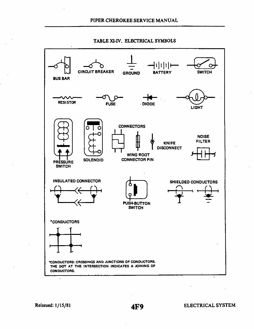
PIPER CHEROKEE SERVICE MANUAL
TABLE XI-IV. ELECTRICAL SYMBOLS
BUS BAR
CIRCUIT BREAKER
RESISTOR FUSE
GROUNDBATTERY SWITCHBATTERY SWITCH
DIODEDIODELIGHT
PRESSURE SOLENOID CONNECTOR PINSWITCH
INSULATED CONNECTOR
NNECTORS
WING ROOTCONNECTOR PIN
KNIFEDISCONNECT
NOISEFILTER
SHIELDED CONDUCTORS
USH-BUTTONSWITCH
*CONDUCTORS
•CONDUCTORS: CROSSINGS AND JUNCTIONS OF CONDUCTORS.THE DOT AT THE INTERSECTION INDICATES A JOINING OFCONDUCTORS.
Reissued: 1/15/81 4F9 ELECTRICAL SYSTEM
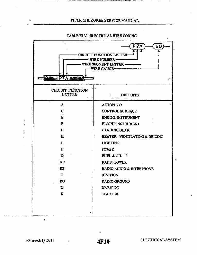
PIPER CHEROKEE SERVICE MANUAL
TABLE XI-V. "ELECTRICAL WIRE CODING
WIRE NUMBERWIRE SEGMENT LETTER
I WIRE GAUGE
P7A
CIRCUIT FUNCTIONLETTER CIRCUITS
A AUTOPILOT
C CONTROL SURFACE
E ENGINE INSTRUMENT
F FLIGHT INSTRUMENT
G LANDING GEAR
H HEATER - VENTILATING & DEICING
L LIGHTING
P POWER
Q FUEL & OIL
RP RADIO POWER
RZ RADIO AUDIO & INTERPHONE
J IGNITION
RG RADIO GROUND
W WARNING
K STARTER
ELECTRICAL SYSTEM4F10
.~~Y , ~ . . .A. _ = =
Reissued: 1/15/81

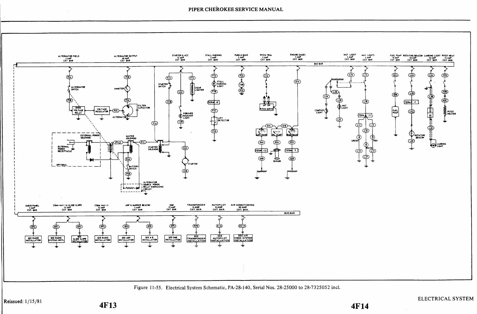
PIPER CHEROKEE SERVICE MANUAL
Figure 11-55. Electrical System Schematic, PA-28-140, Serial Nos. 28-25000 to 28-7325052 incl.
Reissued: 1/15/81
4F13 4F14ELECTRICAL SYSTEM
I
I
I
I
I

PIPER CHEROKEE SERVICE MANUAL
o
Figure 11-56. Electrical System Schematic, PA-28-150, -160, Serial Nos. 28-1 to 28-507 incl.
Reissued: 1/15/81
4F15 4F16ELECTRICAL SYSTEM

O~-
E3II-r-
'
WHY IIi- B<•—— I T\ , —
1am
z l
C0\0u
n

PIPER CHEROKEE SERVICE MANUAL
EXTERNALPOWERRECEPTACLE
OPTIONAL
ALTERNATOR
CAPACITOR
VOLTAGEREGULATOR
RADIO INTERFERENCEFILTER ASSY
Figure 11-58.
o0
STARTER10 AMPFUSE
LIFT INDICATOR
SEE RADIO
DOME LIGHTSWITCH
Electrical System Schematic, PA-28-150, -160, -180, Serial Nos. 28-671 to 28-1760 incl.
Reissued: 1/15/81 4F19 4F20ELECTRICAL SYSTEM
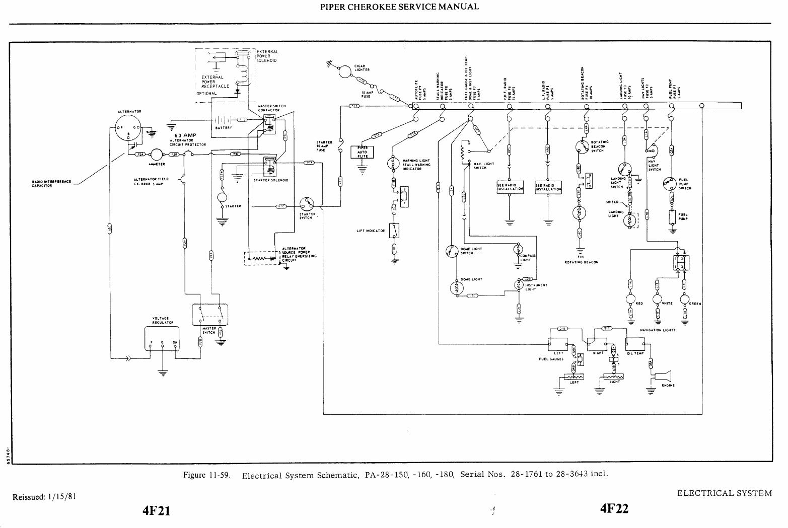
0m
0
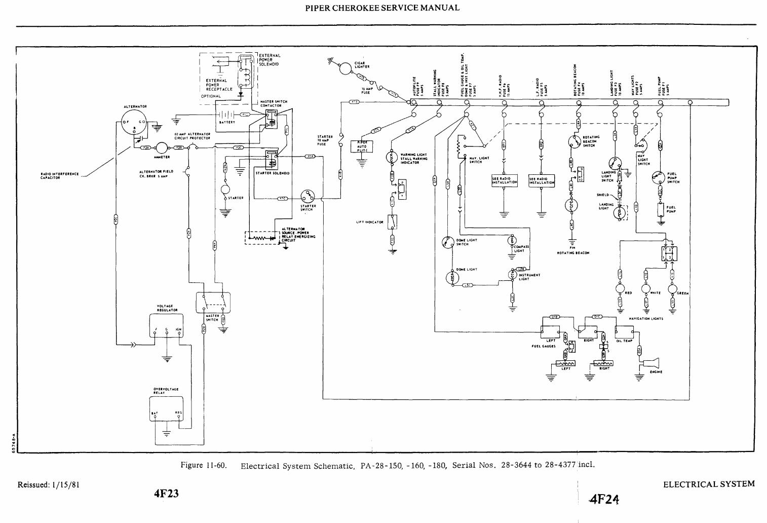
PIPER CHEROKEE SERVICE MANUAL
Figure 11-60.
Reissued: 1/15/814F23
Electrical System Schematic, PA-28-150, -160, -180, Serial Nos. 28-3644 to 28-4377 incl.
ELECTRICAL SYSTEM
4F24
I
SEE RADIO
0
I
x
~

w
0
U
z z
III
O
o -0
Z
0
Ioo
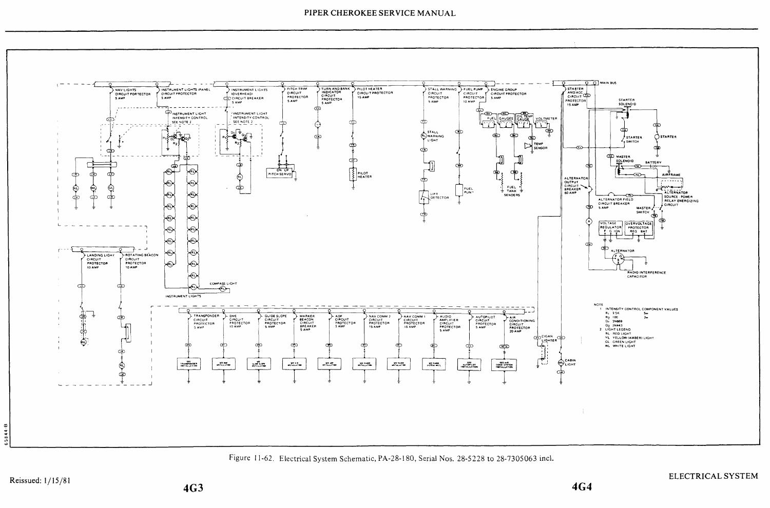
PIPER CHEROKEE SERVICE MANUAL
Figure 11-62. Electrical System Schematic, PA-28-180, Serial Nos. 28-5228 to 28-7305063 incl.
4G4Reissued: 1/15/81
4G3ELECTRICAL SYSTEM

PIPER CHEROKEE SERVICE MANUAL
S EE T N OT L°T
Figure 11-63. Electrical System Schematic, PA-28-235, Serial Nos. 28-10003 to 28-10719 incl.
Reissued: 1/15/814G5 4G6
ELECTRICAL SYSTEM


U
0z
rI
I
o
II
z
I

t
--3 -1.I...O-_ _ _-_- - - - - - - -- - - -- - - - - -- <1 8s l s^—6 — ^—6—0 I-
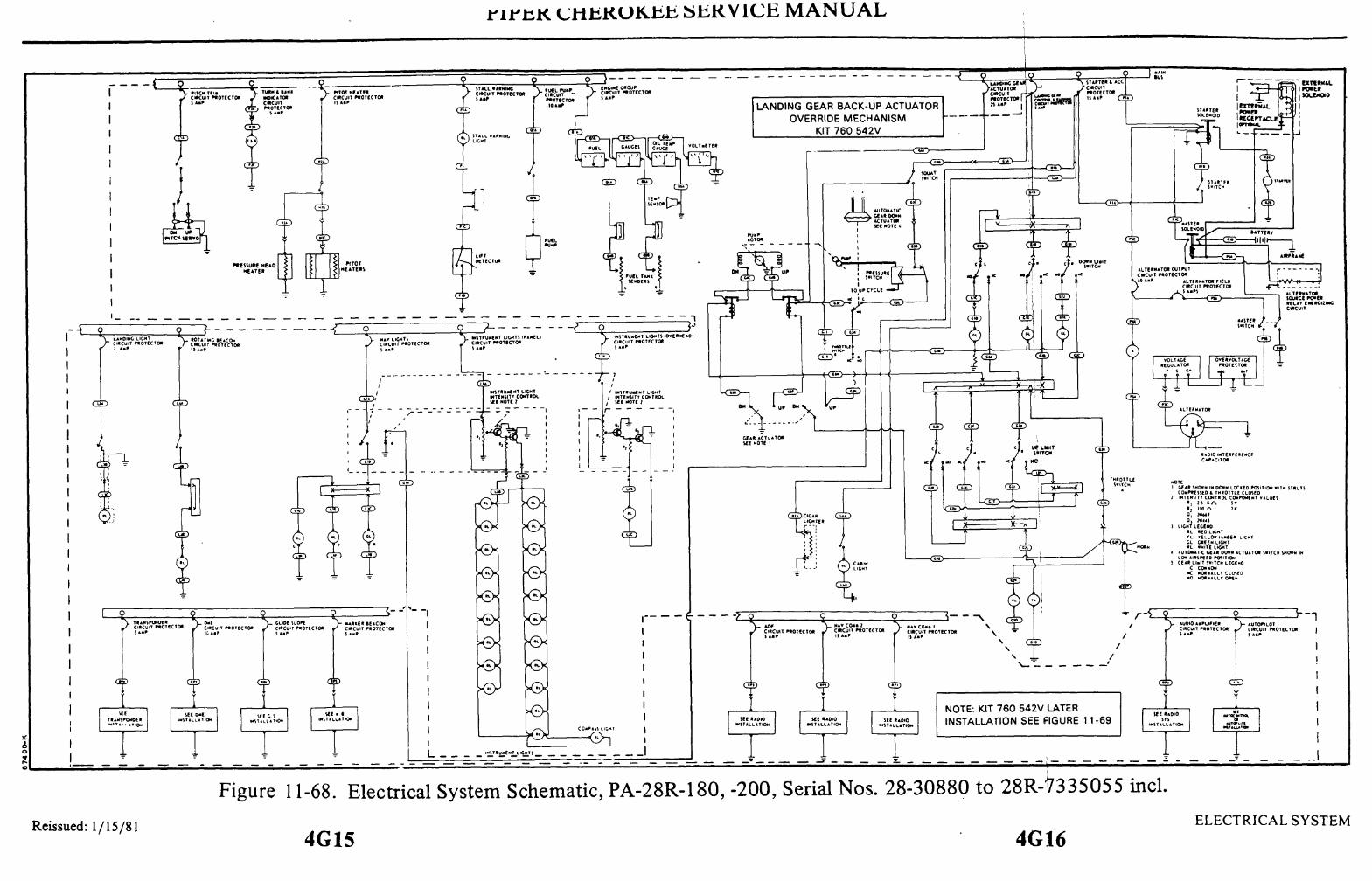
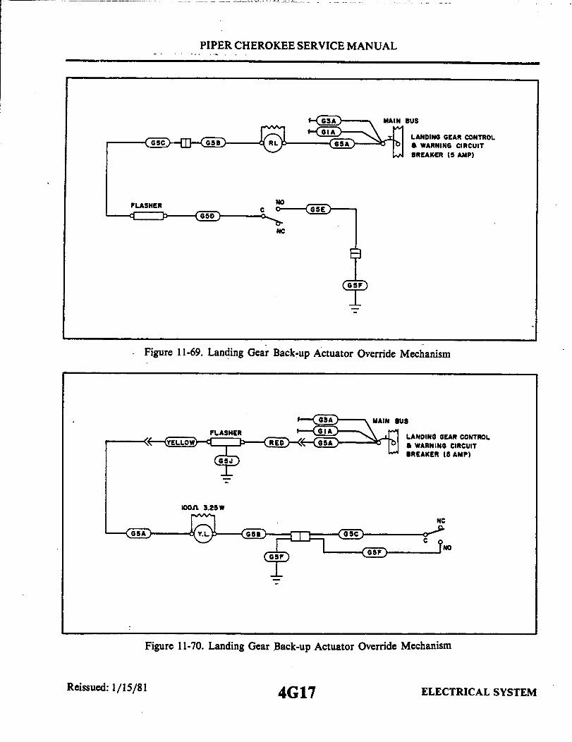
PIPER CHEROKEE SERVICE MANUAL
6 — MAIN BUS
G I\-_-'_ o LANDING GEAR CONTROLGC6c)—-- -(11—osB —--c( R^ '"J'—CCSAD—[^ a6 WARNING CIRCUIT
BREAKER (5 AMP)
FLASHER G
NC
Figure 11-69. Landing Gear Back-up Actuator Override Mechanism
FLASHER
NC
Figure 11-70. Landing Gear Back-up Actuator Override Mechanism
1 4G17 ELECIReissued: ~41/1/7RC LSSE
MAIN BUS
"1 LANDING GEAR CONTROLJ WARNING CIRCUITBREAKER (S AMP)
----_L-�iL� ICIY
Reissued: 1/15/8 TRICAL SYSTEM

4G18INTENTIONALLY LEFT BLANK
PIPER CHEROKEE SERVICE MANUAL
NOTE
Figures 11-71 thru 11-84 have been used for illustrations in thecontext of Section XI. See List of Illustrations for index tothese figures.
ELECTRICAL SYSTEMReissued: 1/15/81 4G19
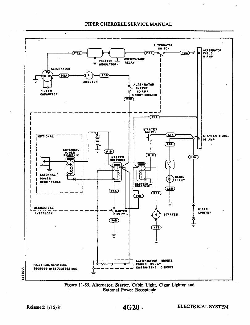
PIPER CHEROKEE SERVICE MANUAL
ALTERNATOR
ALTERNATOROUTPUT
C
I
I I
I EXTERNAL
I I EXTERNALPOWER
I RECEPTACLE
I I
MECHANICAL
INTERLOCK
PA-28-140, Serial Nos.28-25000 to 28-7325052 Incl.
STARTER
\ STARTER & ACC.15 AMP
HIA
CIGARLIGHTER
ALTERNATOR SOURCEPOWER RELAYENERGIZING CIRCUIT
Figure 11-85. Alternator, Starter, Cabin Light, Cigar Lighter andExternal Power Receptacle
ELECTRICAL SYSTEM4G20
AMMETER
FILTERCAPACITOR
I
III
II
Reissued: 1/15/81
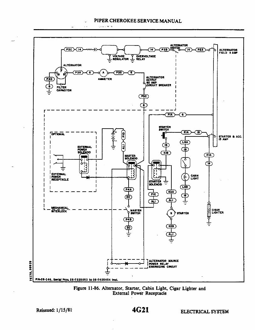
PIPER CHEROKEE SERVICE MANUAL
ALTERNATORFIELD 5 AMP
EXTERNAL
EXTERNALPOWERRECEPTACLE
L MECHANICALINTERLOCK
PA-28-140, Serial Nos. 28-7325053 to 28-7425454 Incl.
b STARTER & ACC.IS AMP
HIA
CIGARLIGHTER
ALTERNATOR SOURCEPOWER RELAYENERGIZING CIRCUIT
Figure 11-86. Alternator, Starter, Cabin Light, Cigar Lighter andExternal Power Receptacle
4G21 ELECTRICAL
ALTERNATORAMMETER OUTPUT
AMPCIRCUIT BREAKER
FILTERCAPACITOR
I
Reissued: 1/15/81 ELECTRICAL SYSTEM
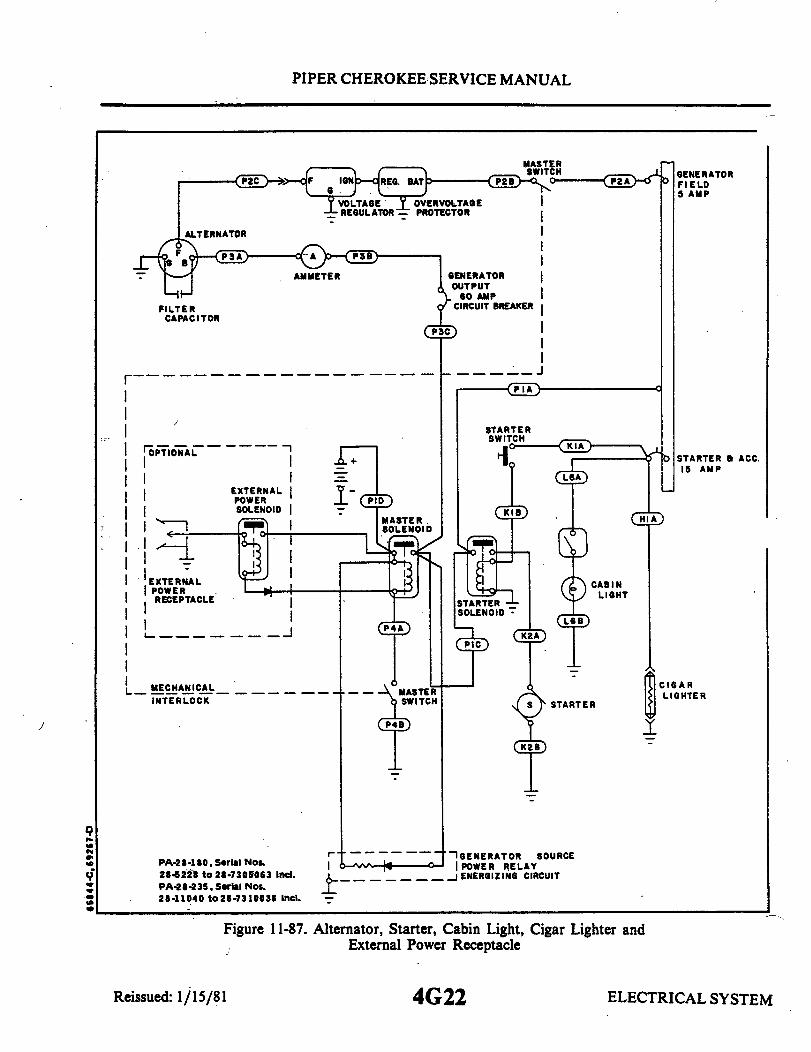
PIPER CHEROKEE SERVICE MANUAL
AMMETER
FILTERCAPACITOR
OPTIONAL
EXTERNALPOWERSOLENOID
EXTERNALPOWERRECEPTACLE
I
MECHANICAL _INTERLOCK
PA-28-180 Serial Nos.28-5228 to 28-7305063 Incl.PA-28-235, Serial Nos.28-11040 to 28-7310038 Incl.
Figure 11-87.
Reissued: 1/15/81
GENERATORFIELD5 AMP
STARTER & ACC.15 AMP
HIA
CIGARLIGHTER
IGENERATOR SOURCEPOWER RELAYENERGIZING CIRCUIT
Alternator, Starter, Cabin Light, Cigar Lighter andExternal Power Receptacle
4G22 ELECTRICAL SYSTEM
9

PIPER CHEROKEE SERVICE MANUAL
MASTER
GENERATORFIELD 5 AMP
C
OPTIONAL
EXTERNALPOWERSOLENOID
IEXTERNALPOWERRECEPTACLE
MECHANICALINTERLOCK
PA-28-235,Seral Nos.28-7310039 to 28-7310187 Incl.
Figure 11-88. Alternato
STARTER & ACC.15 AMP
HIA
CIGARLIGHTER
GENERATOR SOURCEPOWER RELAYENERGIZING CIRCUIT
r, Starter, Cabin Light, CigarExternal Power Receptacle
4G23
Lighter and
I
Reissued: 1/15/81 ELECTRICAL SYSTEM

PIPER CHEROKEE SERVICE MANUAL
FILTERCAPACITOR
OPTIONAL
EXTERNALPOWERSOLENOID
EXTERNALIPOWER
RECEPTACLE
MECHANICALINTERLOCK
PA28-180, Serial Nos. 28-730064 to28-7405290 Incl.PA-28R-200, Serial Nos. 28-7335055 to28-7435331 Incl.PA28-28-235,Serial Nos. 28-7410001 to28-7410120 Incl.
Figure 11-89.
ALTERNATORFIELD 5 AMP
STARTER &ACCESSORY15 AMP
CIGARLIGHTER
ALTERNATOR SOURCEPOWER RELAYENERGIZING CIRCUIT
Alternator, Starter, Cabin Light, Cigar Lighter andExternal Power Receptacle
ELECTRICAL SYSTEM4G24Reissued: 1/15/81

PIPER CHEROKEE SERVICE MANUAL
NOTES -I. GEAR SHOWN IN LOCKED DOWN
POSITION WITH STRUTS COMPRESSEDAND THROTTLE CLOSED.
LANDINGGEARACTUATOR25 AMPS
LANDING GEARCONTROL a WARNING5 AMP
2. AUTOMATIC GEAR DOWN ACTUATORSWITCH SHOWN IN LOW AIRSPEED POSITION.
3.
SWITCH
THROTTLESWITCH
"A"
PA-28R-200,Serial Nos. 28-7335055 to 28-7335455 Incl.
Figure 11-90. Landing Gear
4H1Reissued: 1/15/81 ELECTRICAL SYSTEM.

PIPER CHEROKEE SERVICE MANUAL
CONTROLWARNING
TERMINAL 5 AMP
NOTE :I EAR SHOWN IN LOCKED DOWN
POSITION WITH STRUT COMPRESSEDAND THROTTLE CLOSED.
AUTOMATIC GEAR DOWN ACTUATIONSWITCH SHOWN IN LOW AIRSPEEDPOSITION.
3. LEGEND:RL- RED LIGHTYL- YELLOW LIGHTGL- GREEN LIGHTC- COMMONNC- NORMALLY CLOSEDNO- NORMALLY OPEN
PA-28R-200, Serial Nos.28-7435001 to28-7435331 Incl.
Figure 11-91. Landing Gear
Reissued: 1/15/81 4H2 ELECTRICAL SYSTEM

PIPER CHEROKEE SERVICE MANUAL
AUDIO
SEE
SYSTEM:
PA-28-140, Serll Nos. 28-732505
PANEL COMM/NAV I
AMP 15 AMP
RADIO SEE RADIO
S INSTL. INSTALLATION
ADF & MARKER BEACON
AMP
SEE ADF SEE
INSTALLATION INSTALLATION
3 to 28-7425454 Incl.
a GLIDE SLOPE COMM/NAV II
15AMP
SEE GLIDE SLOPE SEE RADIO
INSTALLION INSTALLION
M.B.INSTALLATION
DME
10 AMP
SEE DME
INSTALLATION
Figure 11-92. Avionics
TRANSPONDER DME GLIDE SLOPE
5 AMP 10 AMP 5 AMP
RPB RP7 RP6
SEE SEE SEE G/STRANSPONDER DME INSTALLATIONINSTALLATION INSTALLATION INSTALLATION
_
MARKER BEACON
5 AMP
RP5
SEE M/9INSTALLATION
ADF NAV COMM II NAV COMM I AUDIO AMPLIFIER AUTOPI
5 AMP 15 AMP 15 AMP 5 AMP
RP3 RP2 RPI RP4
SEE RADIO SEE RADIO SEE RADIO SEE RADIO RADIO SEESYSTEM AUTO PILOT
INSTALLATION INSTALLATION INSTALLATION SYSTEM INSTALLATIONINSTALLATION INSTALLA
_ _
PA-28-180 Serial Nos.28-7305064 to28-7305611 Incl. PA-2R-200.Serial Nos. 2-7335055 to28-7335455 Incl.PA-28-35,Serial Nos.28-7310039 to 28-7310187 Incl.
Figure 11-93. Avionics
4H3
LOT
5 AMP
PILOTINSTALLATION
ELECTRICAL SYSTEMReissued: 1/15/81

PIPER CHEROKEE SERVICE MANUAL
AUDIO PANEL
5AMP
SEE RADIOSYSTEMSINSTALLATION
COMM/NAV I a GLIDE SLOPE
15 AMP
SEERADIOINSTALLATION
SEEGLIDE SLOPEINSTALLATION
COMM / NAV II
15 AMP
I
SEERADIOINSTALLATION
ADF & MARKER BEACON DME TRANSPONDER
AMP 10 AMP 5 AMP
SEE SEE SEE SEEADF MARKER DME TRANSPONDERINSTALLATION INSTALLATION INSTALLATION INSTALLAT ION
PA-28-180, Serial Nos. 28-7405001 to 28-7405290 Incl.PA-28-235, Serial Nos. 28-7410001 to 28-7410120 Incl.
AUTO PILOT
5 AMP
YSEEAUTOPILOTINSTALLATION
Figure 11-94. Avionics
ADF
5 AMP
Y
TRANSPONDER
I5 AMP
SEETRANSPONDERINSTALLATION
NAV-COMM II
15 AMP
DME
10 AMP
NAV-COMM I
15 AMP
YSEE EE SEERADIO RADIO RADICINSTALL ATION INSTALLATION INSTALLATION
PA-28R-200, Serial Nos. 28-7435001 to 28-7435331 Incl.
INSTALLATION
GLIDE SLOPE
5 AMP
SEEG/SINSTALLATION
AUDIO AMPLIFIER
5 AMP
SEERADIO SYSTEMINSTALLATION
MARKER BEACON
5 AMP
SEEM/SINSTALLATION
AUTO PILOT
AMP
SEE AUTO CONTROLOR AUTO FLITEINSTALLATION
Figure 11-95. Avionics
4H4 ELECTRICAL SYSTEMReissued: 1/15/81

PIPER CHEROKEE SERVICE MANUAL
ENGINEGAUGES
5 AMP
RIGHTTANK
PA-28-140, Serial Nos. 28-7325053 to 2-7425454 Incl.PA-28-180, Serial Nos. 28-7405001 to 28-7405290 Inl.PA-2R-200, Serial Nos 28-7435001 to 2-7435331 ncl.
Figure 11-96. Engine Gauges
ENGINEGROUP5 AMP
FUEL TANKSENDERS
PA-28-180, Serial Nos. 28-7305064 to 2-7305611 Incl.PA-28R-200, Serial Nos. 2-7335055 to 2-7335455 incl.
Figure 11-97. Engine Gauges
Reissued: 1/15/81 4H54H5 ELECTRICAL SYSTEM
LEFTTANK
Rei ELECTRICAL SYSTEM

PIPER CHEROKEE SERVICE MANUAL
PA-28-235, Serial Nos. 28-7310039 to 28-7410120 Inl.
Figure 11-98. Engine Gauges
INSTRUMENTLIGHTS
5 AMPNAV LIGHT
SWITCH
I
INSTRUMENTLIGHT
PA-28-140, Serial Nos. 28-7325053 to 28-7325684 Incl.
Figure 11-99. Instrument Lights
Reissued: 1/15/81 4H6 ELECTRICAL SYSTEM
COMPASSLIGHT
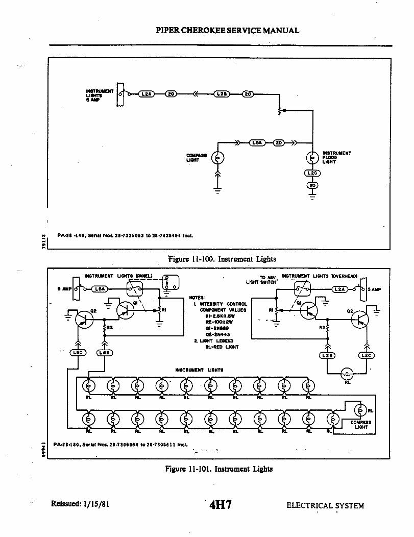
PIPER CHEROKEE SERVICE MANUAL
INSTRUMENTLIGHTS5 AMP
COMPASSLIGHT
PA-28-140, Serial Nos. 28-7325053 to 28-7425454 Inl.
Figure 11-100. Instrument Lights
PA-28-180, Serial Nos.28-7305064 to28-7305611 incl.
Figure 11-101. Instrument Lights
Reissued: 1/15/81 4H7 ELECTRICAL SYSTEM
INSTRUMENTFLOODLIGHT

PIPER CHEROKEE SERVICE MANUAL
PANEL LIGHTS LOWER PANEL LIGHTS
UPPER PANEL LIGHTS
PA-28-10, Serial Nos. 2-74050001 to 28-7405290 incl.
Figure 11-102. Instrument Lights
INSTRUMENT LIGHTS (PANEL) INSTRUMENT LIGHTS (OVERHEAD)TO LANDING GEAR TO NAV
LIGHT SWITCH LIGHT SWITCHINSTRUMENT LIGHTINTENSITY CONTROL
NOTES:1. INTENSITY CONTROL
RI COMPONENT VALUES RIQ2 RI-2.5K.5W Q2
R2-100K 2WQI- 2N669QZ-2N443 R2
R2 2. LIGHT LEGENDRL- RED LIGHT
PA-28R-200.Serial Nos.28-7335055 to 28-7335455 Incl.
Figure 11-103. Instrument Lights
Reissued: 1/15/81 4H8 ELECTRICAL SYSTEM
5 AMP
RL
INSTRUMENT

PIPER CHEROKEE SERVICE MANUAL
INSTRUMENTLOWER PANEL LIGHTS
COMPASSLIGHT
INSTRUMENT
PA-28R-200, Serial Nos. 28-7435001 to 28-7435331 Incl.
. Figure 11-104. Instrument Lights
PA-28-235 Serial Nos. 28-7310039 to 28-7310187 Incl.
Figure 11-105. Instrument Lights
Reissued: 1/15/81
4H9ELECTRICAL SYSTEM
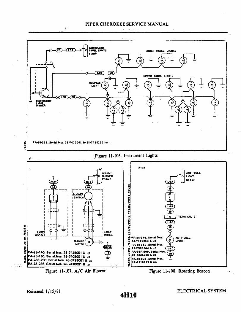
PIPER CHEROKEE SERVICE MANUAL
PA-28-235,Serial Nos.28-7410001 to 28-7410120 incl.
Figure 11-106. Instrument Lights
PA-28-140, Serial Nos. 28-7425001 & upPA-28-180, Serial Nos. 28-7405001 & upPA-28R-200, Serial Nos. 28-7435001 & upPA-28-235, Serial Nos. 28-7410001 & up
A132
PA-28-140. Serial Nos.28-7325053 & upPA-28-180, Serial NO.28-7305064 & up (PA-28R-200. Serial Nos.28-7335055 & upPA-28-235, Serial Nos.28-7310039 & up
Figure 11-107. A/C Air Blower
Reissued: 1/15/81 4H10
Figure 11-108. Rotating Beacon
ELECTRICAL SYSTEM
ANTI-COLL.LIGHT10 AMP
TERMINAL 7
ANTI-COLL.LIGHT
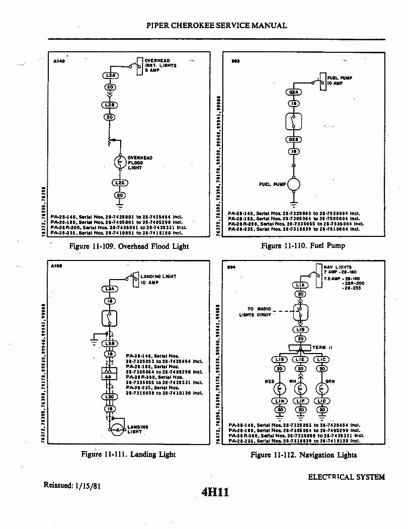
0

PIPER CHEROKEE SERVICE
Figure 11-113. Pitch Trim
g
Figure 11-114. Pitch
cc
n
U
00
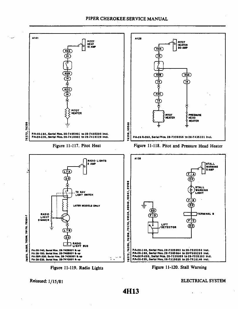
a
z
u
.
cc c
18. Pitot and Pressure Head Heat
oo
Figure 11-118. Pitot and Pressure
C
&C
00
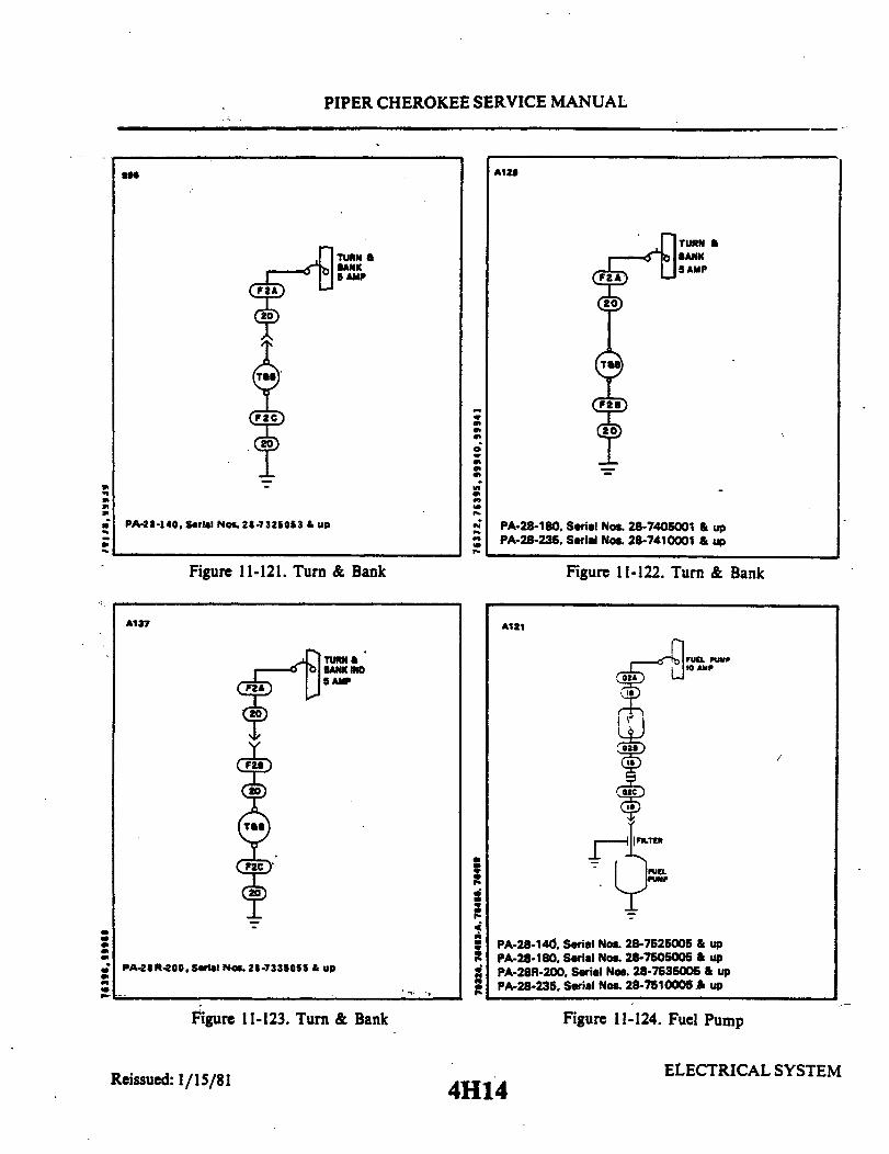
PIPER CHEROKEE SERVICE MANUAL
A129
TURN aBANK5 AMP
PA-28-140, Serial Nos. 28-7325053 & up
Figure 11-121. Turn & Bank
A137
PA-28R-200,Serial Nos. 28-7335055 & up
Figure 11-123. Turn & Bank
TURN &
5 AMP
20
PA-28-180. Serial Nos. 28-7405001 & upPA-28-235, Serial Nos. 28-7410001 & up
Figure 11-122. Turn & Bank
A121
PA-28-140. Serial Nos. 28-7525005 & upPA-28-180, Serial Nos. 28-7505005 & upPA-28R-200, Serial Nos. 28-7535005 & upPA-28-235, Serial Nos. 28-7510005 & up
Figure 11-124. Fuel Pump
ELECTRICAL SYSTEMReissued: 1/15/81 4H14
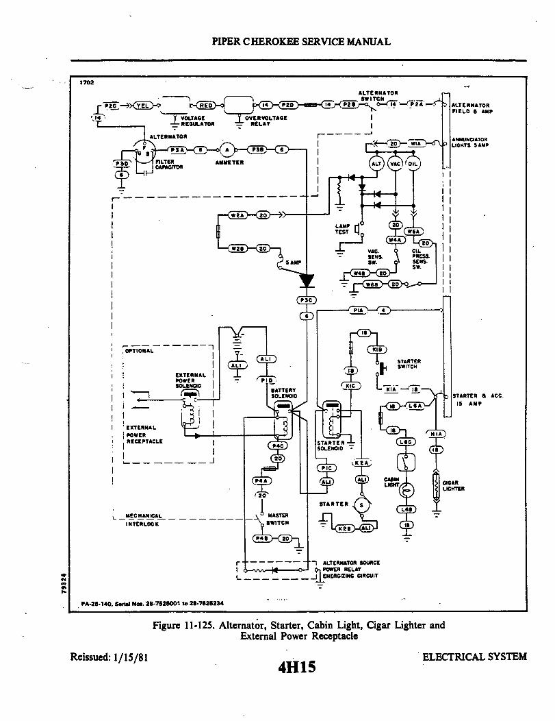
PIPER CHEROKEE SERVICE MANUAL
1702
ALTERNATORSWITCH
ALTERNATOR _
I II
I II II II II II II II
OPTIONAL
EXTERNALPOWER
EXTERNAL
POWERRECEPTACLEI
I
STARTER & ACC.15 AMP
CIGARLIGHTER
MECHANICALINTERLOCK
r - ALTERNATOR SOURCEPOWER RELAYENERGIZING CIRCUIT
PA-28-140. Serial Nos. 28-7525001 to 28-7625234
Reissued: 1/15/81
Figure 11-125. Alternator, Starter, Cabin Light, CigarExternal Power Receptacle
4H15
Lighter and
ELECTRICAL SYSTEM
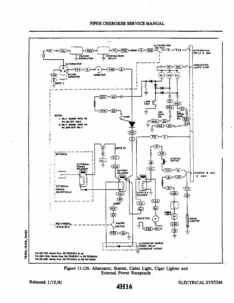
PIPER CHEROKEE SERVICE MANUAL
ALTERNATOR
EXTERNALPOWERSOLENOID
EXTERNAL
POWERRECEPTACLE
MECHANICAL
INTERLOCK
PA-28-180. Serial Nos. 28-7505001 & upPA-28R-200. Serial Nos. 28-7535001 to 28-7635545PA-28-235. Serial Nos. 28-7510001 to 28-7610206
STARTER a ACC.15 AMP
ALTERNATOR SOURCEPOWER RELAY
ENERGIZING CIRCUIT
Figure 11-126. Alternator, Starter, Cabin Light, Cigar Lighter andExternal Power Receptacle.
Reissued: 1/15/814H16
ELECTRICAL SYSTEM
I

PIPER CHEROKEE SERVICE MANUAL
1704
AUTOMATICLANDING GEAR GEAR DOWNACTUATOR ACTUATORas AMP (NOTE 3)
PA-28R-200, Serial Nos. 28-7535001 & up
Figure 11-127. Landing Gear
Reissued: 1/15/81 ELECTRICAL SYSTEM
4H17

PIPER CHEROKEE SERVICE MANUAL
AUDIO PANEL
AMP
RP4
SEE RADIOSYSTEMSINSTALLATION
ADF & MARKER BEACON
5 AMP
SEEADFINSTALLATION
ON
SEE MARKERSEE MARKERBEACONINSTALLATION
COMM/NAV I & GLIDE SLOPE
10 AMP
SEERADIOINSTALLATION
DME
10 AMP
SEEDMEINSTALLATION
SEEGLIDE SLOPEINSTALLATION
TRANSPONDER
TRANSPONDER
SEETRANSPONDERINSTALLATION
PA-28-140, Serial Nos. 28-7525001 & upPA-28-180, Serial Nos. 28-7505001 & upPA-28-235, Serial Nos. 28-7510001 & up
Figure 11-128. Avionics
AUDIO PANEL
5 AMP
SEE RADIOSYSTEMSINSTALLATION
ADF
5 AMP
SEEADFINSTALLATION
MARKER BEACON
AMP
SEE MARKERBEACONINSTALLATION
COM/NAVI
AMP
RPI
SEERADIOINSTALLATION
DME
AMP
SEEDMEINSTALLATION
GLIDE SLOPE
AMP
SEEGLIDE SLOPEINSTALLATION
TRANSPONDER
SEETRANSPONDERINSTALLATION
PA-2 R-200, Serial No. 28-7535001 & up Figure 11-129. Avionics
4H18
1701COMM/NAV II
AMP
RP2
SEERADIOINSTALLATION
AUTOPILOT
-5AMP
SEEAUTOPILOTINSTALLATION
I
COMM/NAV II
AMP
RP2
SEERADIOINSTALLATION
AUTOPILOT
5 AMP
SEEAUTOPILOTINSTALLATION
Reissued: 1/15/81 ELECTRICAL SYSTEM
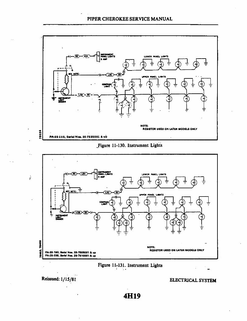
PIPER CHEROKEE SERVICE MANUAL
NOTE:RESISTOR USED ON LATER MODELS ONLY
PA-28-140, Serial No. 28-7525001 & up
Figure 11-130. Instrument Lights
PA-28-180, Serial Nos. 28-7505001 & upPA-28-235, Serial Nos. 28-7510001 & up
NOTE:RESISTOR USED ON LATER MODELS ONLY
Figure 11-131. Instrument Lights
Reissued: 1/15/81 ELECTRICAL SYSTEM
4H19
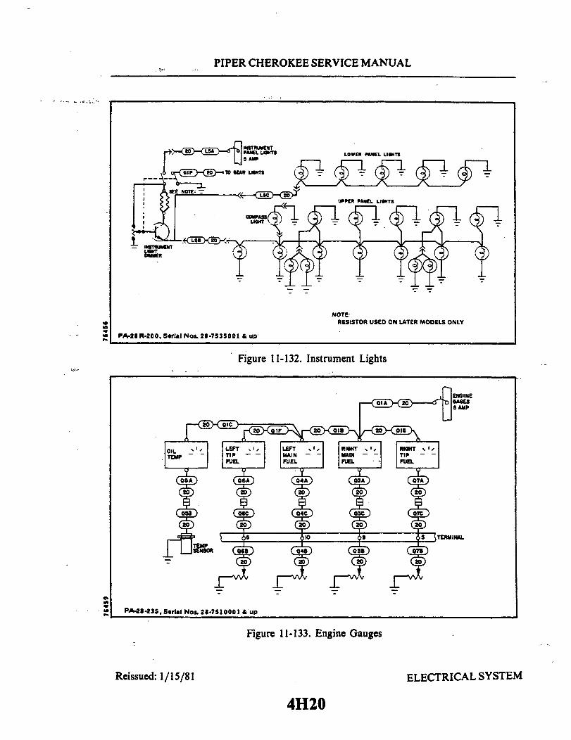
PIPER CHEROKEE SERVICE MANUAL
NOTE:RESISTOR USED ON LATER MODELS ONLY
PA-28R-200, Serial Nos. 28-7535001 & up
Figure 11-132. Instrument Lights
PA-28-235,Serial Nos.28-7510001 & up
Figure 11-133. Engine Gauges
Reissued: 1/15/81 ELECTRICAL SYSTEM
4H20

PIPER CHEROKEE SERVICE MANUAL
PA-28-140, Serial Nos. 28-7525001 & upPA-28-180, Serial Nos. 28-7505001 & up
Figure 11-134. Engine Gauges
A130
PA-28 R-200, Seral No. 28-7535001 &up
Figure 11-135. Engine Gauges
Reissued: 1/15/81 ELECTRICAL SYSTEM
4H21
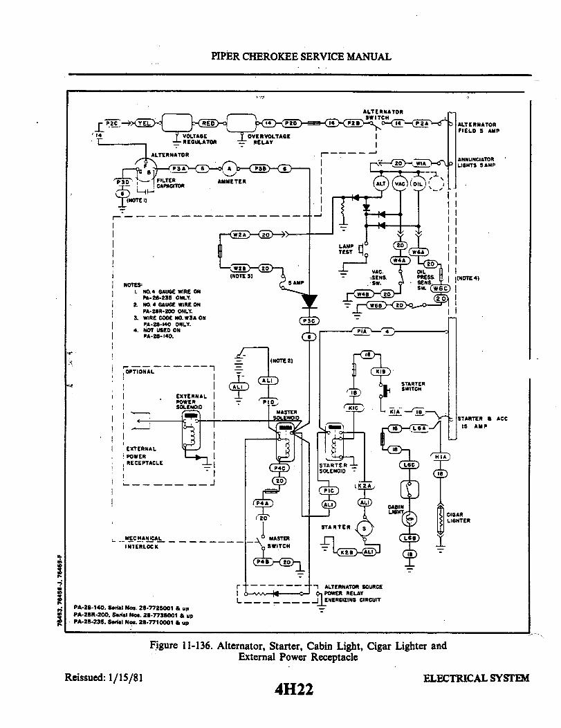
PIPER CHEROKEE SERVICE MANUAL
ANNUNCIATORLIGHTS 5 AMP
P3D AMMETER
(NOTE 1)
NOTES
L NO.4 GAUGE WIRE ONPA-28-235 ONLY.
2. NO. 4 GAUGE WIRE ONPA-28R-200 ONLY.
. WIRE CODE NO. W3A ONPA-2-140 ONLY.
4. NOT USED ONPA-2- 140.
(NOTE 2)
OPTIONAL A L
EXTERNALPOWERSOLENOID
MASTERSOLENOID
EXTERNALPOWERRECEPTACLE STARTER
·
MECHANICAL
INTERLOCK
I I
(NOTE 4)
0
STARTER & ACC15 AMP
CIGARLIGHTER
PA-28-140, Serial Nos. 28-7725001 & upPA-28R-200. Serial Nos. 28-7735001 & upPA-28-235, Serial Nos. 28-7710001 & up
ALTERNATOR SOURCEPOWER RELAY
ENERGIZING CIRCUIT
Figure 11-136. Alternator, Starter, Cabin Light, Cigar Lighter andExternal Power Receptacle
Reissued: 1/15/814H22
ELECTRICAL SYSTEM

PIPER CHEROKEE SERVICE MANUAL
A11S
I
I
PA-28-140, Serial Nos. 28-7525001 & upPA-28-180, Serial Nos. 28-7505001 & upPA-28-235, Serial Nos. 28-7510001 & up
Figure 11-137. Pitot Heat
PA-28-140. Serial Nos. 28-7625001 upPA-28R-200, Serial Nos.28-7635001 & upPA-28-235, Serial Nos. 28-7610001 & up
Figure 11-138. Stall Warning
PA-28-235
FIN STROBEANTI-COLLISION
10AMP
2668 PA-2B-140, Serial Nos. 28-7525001 & upPA-25-180, Serial Nos. 28-750001 & upPA-28R-200, Serial Nos. 28-7535001 upPA-28-235, Serial Nos. 28-7510001 & up
Figure 11-139. Fin Strobe Anti-CollisionLight
Figure 11-140. Navigation Lights
Reissued: 1/15/81 ELECTRICAL SYSTEM
4H23
A133
SWITCH
7 AMP28-180
7.5 AMP28-14028 R-20028-235
TERMINAL II

PIPER CHEROKEE SERVICE MANUAL
A119OVERHEADINST. LIGHTS5 AMP
iPA-28-140, Serial Nos. 28-7525001 & upPA 28-l80,Serial Nos. 28-7505001 & upPA-28R-200, Serial Nos. 28-7535001 & upPA-28-235, Serial Nos. 28-7510001 & up
Figure 11-141. Overhead Flood Light
A1 3
PA-28-140, Serial Nos. 28-7525001 & upPA-28-180, Serial Nos. 28-7505001 & upPA-28R-200, Serial Nos. 28-7358001 & upPA-28-235. Serial Nos. 28-7510001 & up
Figure 11-142. Landing Light
ANTI COLLISIONLIGHTS15 AMP
PA-2 R-200. Serial Nos. 28-7535001 & up
Figure 11-143. Pitot and PressureHead Heater
Reissued: 1/15/81
7
BEACONANTI COL.LIGHT
PA-28-235
Figure 11-144. Anti-Collision Light
ELECTRICAL SYSTEM
4H24
A120
I

PIPER CHEROKEE SERVICE MANUAL
SECTION XIIELECTRONICS
AeroficheGrid No.
Introduction ................................................Emergency Locator Transmitter (Garrett Mfg. Ltd.) ..............Description ..................................................Battery Removal and Installation (2 Year Magnesium) ............Battery Removal and Installation (NARCO) .....................Testing Emergency Locator Transmitter .........................Pilot's Remote Switch.........................................Testing Pilot's Remote Switch..................................Inadvertent Activation ........................................Emergency Locator Transmitter (Communications
Components Corp.) .........................................Description .................................................Battery Removal and Installation ...............................Pilot's Remote Switch ........................................Testing Emergency Locator Transmitter .........................Testing Pilot's Remote Switch..................................Inadvertent Activation ........................................Autoflight - General ..........................................Non-Piper A.F.C.S. Equipment Contacts ........................Piper A.F.C.S. Equipment.....................................
Revised: 10/3/83 ELECTRONICS411
12-1.12-2.12-3.12-4.12-5.12-6.12-7.12-8.12-9.12-10.
12-11.12-12.12-13.12-14.12-15.12-16.12-17.12-18.12-19.
412412412412415417418418419
4110411041104111411141114111411241124113
PIPER CHEROKEE SERVICE MANUAL
SECTION XII
ELECTRONICS
12-1. INTRODUCTION. This section of the manual contains information necessary toperform operational checks of the Emergency Locator Transmitter (ELT), with and withouta pilot's remote switch. Included are the appropriate removal and installation instructions tofacilitate battery replacement.
12-2. EMERGENCY LOCATOR TRANSMITTER (GARRETT MFG. LTD.).
12-3. DESCRIPTION. The electrical power for the ELT is totally supplied by its ownself-contained battery. The magnesium batteries used on early models have a service life offour years. The lithium batteries used on later models have a service life of ten years.However, to comply with FAA regulations, magnesium batteries must be replaced every 2years and lithium batteries must be replaced at 5 year intervals. If the transmitter has beenused in an emergency situation during this 2 or 5 year period or it has more than one hourof accumulated test time, the battery must be replaced according to FAA regulations. Toreplace the battery pack in the transmitter, it is necessary to remove the transmitter fromthe aircraft. (Refer to Paragraph 12-4 or 12-5.)
12-4. BATTERY REMOVAL AND INSTALLATION. (2 year, magnesium battery, refer toFigure 12-1.) The ELT is located on mounting brackets on the right side of the fuselage aftofsta. 228.30.
a. Remove the access plate on the right side of the fuselage aft of sta. 228.30.b. Set the ON/ARM/OFF switch on the transmitter to the OFF position.c. Disconnect the antenna coax from the transmitter.d. Disconnect the harness to the pilot's remote switch.e. Remove the rear mounting bracket by pulling the plastic knob out. Remove the
transmitter from the airplane.f. Remove the two long or four short screws securing the transmitter plain end cap.
Remove the plain end cap.g. Disconnect the battery connector from the board terminals.h. Withdraw the battery pack from the transmitter case.i Before installing the new battery pack, check the replacement date printed on the
battery. Transfer this date onto the outside of the ELT.j. Slide the new battery pack, plain end first, into transmitter. It may be necessary to
rotate the battery slightly to get it seated properly in the transmitter case and to achieve.correct orientation of the battery connector.
k. Connect the battery connector to board terminals.1. Insure O-ring is fitted in plain end cap and correctly seated.
Reissued: 1/15/81 ELECTRONICS4I2

PIPER CHEROKEE SERVICE MANUAL
BATTERYCONNECTOR LONG
SCREWS
PLAINENDCAP
Figure 12-1. Two Year, Magnesium Battery Connections
NOTE
Red ELT's have no O-ring; replace end cap using fresh RTVsilicone rubber compound.
m. Refit end cap and secure with the screws previously removed.
NOTE
Do not overtighten the end cap screws.
n. Place transmitter into its mounting bracket; replace rearpushing plastic knob into place.
o. Connect the pilot's remote switch harness to the transmitter.p. Connect the antenna coax to the transmitter.
mounting bracket by
NOTE
Before installing access plate ascertain that transmitter switchis in the ARM position. It may also be advisable to test theunit operation before installing the access panel (Refer toParagraph 12-6.)
q. Install the access plate on the right side of the fuselage aft of sta. 228.30. Make anentry in the aircraft logbook, including the new battery run out date.
NOTE
Inspect the external whip antenna for any damage. Avoidbending the whip. Any sharply bent or kinked whip shouldbe replaced. Antenna damage may cause structural failure ofwhip inflight.
ELECTRONICSReissued: 1/15/81
413
278

PIPER CHEROKEE SERVICE MANUAL
NOTCH PIN PORTABLESTOP ANTENNA
OPERATIVEBUT STORED
VIEWA
LATCH
VIEWB
PULL TAB
ANTENNAPOPS OUTOFCHANNEL
AND DOWN
ANTENNAEXTENSIONTAB
SET
ON-OFF-ARMSWITCH
TO"ON"
PINSTOP
TO EXTEND TO FULL LENGTHVIEW
C
Figure 12-2. ELT Portable Folding Antenna (Narco)
CONTACT
PORTABLEANTENNACONTACTFINGER
NOTCH FOR
ANDLE RELEASE
PORTABLE ANTENNA BLADENOT
MAKING CONTACT
FIXED ANTENNA'SCABLE CONNECTOR ANDCONTACT SEPARATOR
TO REMOTE SWITCH
Figure 12-3. ELT Using Fixed Aircraft Antenna (Narco)
Reissued: 1/15/81 ELECTRONICS
414
B965
B965
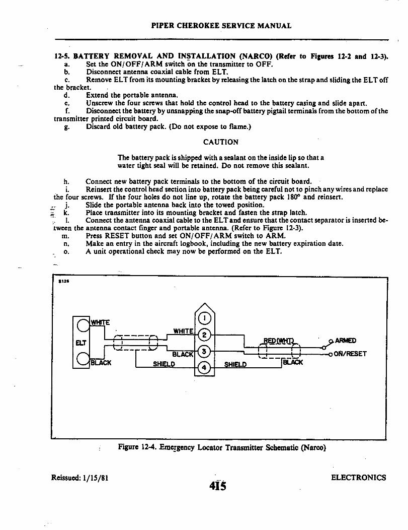
PIPER CHEROKEE SERVICE MANUAL
12-5. BATTERY REMOVAL AND INSTALLATION (NARCO) (Refer to Figures 12-2 and 12-3).a. Set the ON/OFF/ARM switch on the transmitter to OFF.b. Disconnect antenna coaxial cable from ELT.c. Remove ELT from its mounting bracket by releasing the latch on the strap and sliding the ELT off
the bracket.d. Extend the portable antenna.e. Unscrew the four screws that hold the control head to the battery casing and slide apart.f. Disconnect the battery by unsnapping the snap-off battery pigtail terminals from the bottom of the
transmitter printed circuit board.g. Discard old battery pack. (Do not expose to flame.)
CAUTION
The battery pack is shipped with a sealant on the inside lip so that awater tight seal will be retained. Do not remove this sealant.
h. Connect new battery pack terminals to the bottom of the circuit board.i. Reinsert the control head section into battery pack being careful not to pinch any wires and replace
the four screws. If the four holes do not line up, rotate the battery pack 180 and reinsert.j. Slide the portable antenna back into the towed position.k. Place transmitter into its mounting bracket and fasten the strap latch.l. Connect the antenna coaxial cable to the ELT and ensure that the contact separator is inserted be-
tween the antenna contact finger and portable antenna. (Refer to Figure 12-3).m. Press RESET button and set ON/OFF/ARM switch to ARM.n. Make an entry in the aircraft logbook, including the new battery expiration date.o. A unit operational check may now be performed on the ELT.
B126
WHITE
BLACK
SHIELD SHIELD
I
Figure 12-4. Emergency Locator Transmitter Schematic (Narco)
Reissued: 1/15/81 ELECTRONICS4I5
ELT
BLACK
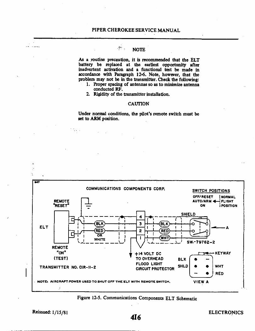
PIPER CHEROKEE SERVICE MANUAL
NOTE
As a routine precaution, it is recommended that the ELTbattery be replaced at the earliest opportunity afterinadvertent activation and a functional test be made inaccordance with Paragraph 12-6. Note, however, that theproblem may not be in the transmitter. Check the following:
1. Proper spacing of antennas so as to minimize antennaconducted RF.
2. Rigidity of the transmitter installation.
CAUTION
Under normal conditions, the pilot's remote switch must beset to ARM position.
347
COMMUNICATIONS COMPONENTS CORP.
REMOTI"RESET"
ELT
E
BLK
WHITE
REMOTE"ON"
(TEST)
TRANSMITTER NO. CIR-II-2
+14 VOLT DCTO OVERHEADFLOOD LIGHTCIRCUIT PROTECTOR
NOTE: AIRCRAFT POWER USED TO SHUT OFF THE ELT WITH REMOTE SWITCH.
SWITCH POSITIONSOFF/RESET NORMALAUTO/ARM FLIGHT
ON POSITION
SHIELD
SW.-79762-2
KEYWAY
BLK
SHLD WHT
RED
VIEW A
Figure 12-5. Communications Components ELT Schematic
Reissued: 1/15/81 ELECTRONICS416

PIPER CHEROKEE SERVICE MANUAL
12-6. TESTING EMERGENCY LOCATOR TRANSMITTER. The transmitter operates onthe emergency frequencies of 121.5 and 243 MHz; both of these frequencies are monitoredby the various FAA installations. Before performing any operational test of the ELT, thefollowing precautions should be observed:
CAUTION
Testing of an ELT should be conducted in a screen room ormetal enclosure to ensure that electromagnetic energy is notradiated during testing. If a shielded enclosure is notavailable, testing may be performed in accordance with thefollowing procedures:
1. Test should be no longer than three audio sweeps.2. If the antenna is removed, a dummy load should be
substituted during the test.3. Test should be conducted only within the time period
made up of the first five minutes after any hour.4. If the operational tests must be made at a time not
included within the first five minutes after the hour,the test should be coordinated with the closest FAATower or Flight Service Station.
Consult FAA Advisory Circular AC 20-81 for detailedinformation concerning above caution.
a. Remove the access plate on the right side of the fuselage aft of sta. 228.30.b. Tune the aircraft communications receiver to 121.5 MHz and switch the receiver
ON; deactivate the squelch, and turn the receiver volume up until a slight background noiseis heard.
NOTE
If the aircraft is not fitted with a communications receiver,request that the tower listen for your test.
c. On the transmitter, set the ON/ARM/OFF switch to the ON position. Keep theswitch in this position for only a few seconds; then set to the OFF position. Return to theARM position.
NOTE
The test transmission should have been picked up by theaircraft communications receiver and/or control tower.During cold weather, there may be a slight delay beforetransmission occurs.
d. A transmitter which is functioning properly should emit a characteristic downwardswept tone.
e. When the test is completed, ascertain the transmitter ON/ARM/OFF switch is in theARM position.
Reissued: 1/15/81 ELECTRONICS417

PIPER CHEROKEE SERVICE MANUAL
f. Place the access panel on the right side of the fuselage aft of sta. 228.30.
WARNING
Whenever the unit is checked by moving the transmitterON/ARM/OFF switch from the ARM to the ON position, itmust then be moved to the OFF position before reverting tothe ARM position again.
CAUTION
Under normal conditions, the transmitter switch must be setto arm.
12-7. PILOT'S REMOTE SWITCH. A pilot's remote switch, located on the left side panel,is provided to allow the transmitter to be controlled from inside the cabin. The switch islocked into each position. To move the switch, the toggle-must be pulled out and moved tothe new desired position, On early models the pilot's remote switch is placarded "ON,""ARM," "OFF/RESET." If the pilot's remote switch has been placed in the "ON" positionfor any reason, the "OFF/RESET" position must be selected for one second before theswitch is placed in the "ARM" position. On later models the pilot's remote switch isplacarded "ON/RESET" and "ARM (NORMAL POSITION)." The switch is normally left inthe down or "ARM" position. To turn the transmitter off, move the switch to the"ON/RESET" position for one second then return it to the "ARM" position. To actuate thetransmitter for tests or other reasons, move the switch upward to the "ON/RESET"position and leave it in that position as long as transmission is desired.
CAUTION
Under normal conditions the switch must be set to ARM.
12-8. TESTING PILOT'S REMOTE SWITCH. Before performing any operational test ofthe pilot's remote switch, the following precautions should be observed:
CAUTION
The transmitter operates on the emergency frequencies of121.5 and 243 MHz; both of these frequencies are monitoredby the various FAA installations. Permission should beobtained from the FAA/FCC Representative (or otherapplicable Authority) prior to testing. Keep your testtransmission to a minimal duration.
a. Tune the aircraft communications receiver to 121.5 MHz and switch the receiverON; deactivate the squelch, and turn the receiver volume up until a slight background noiseis heard.
Reissued: 1/15/81 ELECTRONICS4I8
PIPER CHEROKEE SERVICE MANUAL
NOTE
If the aircraft is not fitted with a communications receiver,request that the tower listen for your test.
b. Set the pilot's remote switch to the ON position. Hold the switch in this position foronly a few seconds.
NOTE
The test transmission should have been picked up by theaircraft communications receiver and/or control tower.During cold weather there may be a slight delay beforetransmission occurs.
c. Set the pilot's remote switch to the RESET position for one second; then select theARM position.
12-9. INADVERTENT ACTIVATION.a. In the event the ELT is inadvertently activated in aircraft without a pilot's remote
switch, the ELT will have to be reset by gaining access to the ELT. (Refer to Paragraphs12-4 or 12-5.) Put the ON/ARM/OFF switch in the OFF position. To reset for automaticoperation, return switch to the ARM position. (See Note.)
b. In aircraft with a pilot's remote switch, if the ELT is inadvertently activated, set thepilot's remote switch to the RESET position; then return it to the ARM position. (SeeNote.)
NOTE
As a routine precaution, it is recommended that the ELTbattery be replaced at the earliest opportunity afterinadvertent activation and a functional test be made inaccordance with Paragraph 12-6. Note, however, that theproblem may not be in the transmitter. Check the following:
1. Proper spacing of antennas so as to minimize antennaconducted RF.
2. Rigidity of the transmitter installation.
CAUTION
Under normal conditions,the pilot's remote switch must beset to ARM position.
Reissued: 1/15/81 ELECTRONICS4I9
PIPER CHEROKEE SERVICE MANUAL
12-10. EMERGENCY LOCATOR TRANSMITER (COMMUNICATIONS COMPONENTSCORP.).
12-11. DESCRIPTION. The electrical power for the ELT transmissions is totally suppliedby its own self-contained battery. However, aircraft power is required to shut offtransmitter with the remote switch. For portable use, the ELT can be easily removed fromits mounting in the aircraft. The battery must also be replaced if the transmitter has been usedin an emergency situation or if accumulated test time exceeds one hour. The replacement dateis marked on the transmitter label.
12-12. BATTERY REMOVAL AND INSTALLATION. The ELT is located on the rightside of the airplane tail section, ahead of the stabilator.
a. Remove the access plate on the right side of fuselage aft of sta. 228.30.b. Rotate the ON/ARM/OFF switch to the OFF position.c. Disconnect the antenna coax cable (twist left, then pull outwards).d. Disconnect the harness to the pilot's remote switch.e. Remove the forward mounting bracket by pulling the black plastic knob .out.
Remove the transmitter from the airplane.f. Remove the six Phillips-head screws securing the transmitter cover. Remove the
cover.g. Lift out the old battery pack.h. Copy the expiration date on the battery into the space provided on the external
ELT name and date plate.i Disconnect and replace with a new battery pack. The nylon battery connector is a
friction fit and is easily removed by pulling on the exposed end.j. Insert transmitter into airplane and fit into place. Replace mounting bracket by
pushing the black plastic knob into place.k. Reconnect the pilot's remote switch harness and the antenna coax cable to the
transmitter.L Set the ON/ARM/OFF switch to the ARM position.m. Reinstall the access plate previously removed.
NOTE
It may be advisable to test the unit operation beforeinstalling the access plate. (See Paragraph 12-6.)
NOTE
Inspect the external whip antenna for any damage. Avoidbending the whip. Any sharply bent or kinked whip shouldbe replaced. Antenna damage may cause structural failure ofwhip in flight.
Reissued: 1 /15/81I ELECTRONICS4I10

PIPER CHEROKEE SERVICE MANUAL
12-13. PILOT'S REMOTE SWITCH. A pilot's remote switch, located on the left side panel,is provided to allow the transmitter to be controlled from inside the cabin. The pilot'sremote switch is placarded ON, AUTO/ARM and OFF/RESET. The switch is normally leftin the AUTO/ARM position. To turn the transmitter off, move the switch momentarily tothe OFF/RESET position. The aircraft master switch must be ON to turn the transmitterOFF. To actuate the transmitter for tests or in the event the automatic feature was nottriggered by impact, move the switch upward to the ON position and leave it in thatposition as long as transmission is desired.
12-14. TESTING EMERGENCY LOCATOR TRANSMITTER. (Testing done the same asnoted in Paragraph 12-6.)
12-15. TESTING PILOTS REMOTE SWITCH. Before performing any operational test ofthe pilot's remote switch, the same precautions noted in Paragraph 12-6 must be observed.
a. Tune the aircraft communications receiver to 121.5 MHz and switch the receiverON, deactivate the squelch, and turn the receiver volume up until a slight background noiseis heard.
NOTE
If the aircraft is not fitted with a communications receiver,request that the tower listen for your test.
b. Set the pilot's remote switch to the ON position. Hold the switch in this position foronly a few seconds.
NOTE
The test transmission should have been picked up by theaircraft communications receiver and/or control tower.During cold weather there may be a slight delay beforetransmission occurs.
c. Set the pilot's remote switch to the momentary OFF,RESET position. The switch isspring loaded to automatically return to the ARM position.
12-16. INADVERTENT ACTIVATION. The remote switch allows the pilot to turn off thetransmitter inadvertently activated by impact or improper switch selection. The pilot simplyselects the momentary OFFRESET position. The transmitter shuts off and the springloaded switch automatically returns to the ARM position. The aircraft master switch mustbe ON to turn transmitter OFF with the remote switch. Stopping inadvertent activation atthe transmitter itself is accomplished in the following manner:
a. Improper switch selection is corrected by rotating the switch to the OFF positionand then to the ARM position.
b. If the transmitter is inadvertently activated through impact, deactivate by pushing inon the OFF/ARM/ON switch.
Reissued: 1/15/81 ELECTRONICS4111
PIPER CHEROKEE SERVICE MANUAL
12-17. AUTOFLIGHT. GENERAL. Due to the wide variety of A.F.C.S. (AutomatedFlight Control System) options, it is mandatory to follow the service literature published bythe individual manufacturer of the A.F.C.S. equipment installed in any particular airplane.This includes mechanical service such as: adjusting, bridle cable tension, servo removal andinstallation, servo clutch adjustments, etc.
12-18. NON-PIPER A.F.C.S. EQUIPMENT CONTACS. Refer to the following list ofAutoPilot/Flight Director manufacturers to obtain service direction parts support, andservice literature.
Bendix Avionics Division2100 N.W. 62nd StreetFort Lauderdale, Fla. 33310(305) 776-4100/TWX 5109559884
Collins General Aviation DivisionRockwell InternationalCedar Rapids, Iowa, 52406(319) 395-3625 Telex: 464-421
Edo Corporation - Avionics DivisionBox 610Municipal AirportMineral Wells. Texas 76067(817) 325-2517 Telex: 76067
King Radio Corporation400 North Rodgers RoadOlathe. Kansas. 66061(913) 782-0400 Telex: 4-2299-Kingrad
Sperry Flight Systems/Avionics Div.8500 Balboa Blvd.P.O. Box 9028VanNuys, CA. 91409(213) 894-8111 Telex: 65-1367
Global Navigation2144 Michelson DriveIrvine, CA 92715(714) 851-0119
Added: 10/3/83 ELECTRONICS4112

PIPER CHEROKEE SERVICE MANUAL
12-19. PIPER A.F.C.S. EQUIPMENT. In the case of early models, Piper AutoPilotequipment bears the Piper name, and the appropriate Piper AutoPilot/Flight DirectorService Manual shall be used.
NOTE
If a Roll Axis - only AutoPilot is installed, or if no AutoPilotis installed, consult the Piper Pitch Trim Service Manual -753 771 for manual electric pitch trim service information.
The following is a complete listing of Piper A.F.C.S. equipment service literature. It isimperative to correctly identify the AutoPilot system by "faceplate" model name, in orderto consult the appropriate service manual. Each manual identifies the revision level andrevision status as called out on the Master Parts Price List - Aerofiche published monthlyby Piper. Consult the aircraft's parts catalog for replacement parts.
NAME PIPER PART NO.
AutoControl I/II & AltiMatic I/IIAutoControl III & AltiMatic III and IIIBAutoControl IIIB & AltiMatic IIIB-1AltiMatic IIICAltiMatic V and V-IAltiMatic V F/D and V F/D-IAltiMatic X F.D./A.P./ & X A.PAutoFliteAutoFlite IIPiper Pitch Trim (Manual-Electric)
753 798753 723761 502761 602761 525761 526761 668753 720761 481757 771
Added: 10/3/83 ELECTRONICS4113

SECTION XIII
HEATING AND VENTILATING
AeroficheGrid No.
Introduction ................................Description ... .....................Heater Maintenance ............................Overhead Vent System ..........................
Revised: 10/3/83
4114
13-1.13-2.13-3.13-4.
4115411541164116
PIPER CHEROKEE SERVICE MANUAL
SECTION XIII
HEATING AND VENTILATING SYSTEM
13-1. INTRODUCTION. Because of the simplicity of the heating and ventilatingsystem installed on the PA-28, the operation and maintenance instructions of thecomponents are contained in paragraph 13-3. A pictorial description of thesesystems may be found in Figure 13-1 thru 13-6.
13-2. DESCRIPTION. Heat forthe cabinofthe Cherokee is provided bya hot airheater installed on the exhaust manifold. Fresh air enters the engine compart-ment through the nose cowling, passes over the engine and is vented to the heatermuff through a flexible hose located on the bafflingat the rear of the engine. Theair is then heated and vented into the cabin area through a valve which can becontrolled from the instrument panel. When the valve is completely closed off,the heated air is vented back into the engine compartment. The heater outlet inthe cabin is located between the two front seats. Control for the heater systemis located on the right panel, below the instruments. The windshield is kept clearof frost, ice and etc. by a defroster system which operates from the heater muff,but has an individual control.
Fresh air for the PA-28-140; PA-28-150, -160, -180, Serial Nos. 28-1 to 28-2477 incl., andPA-28-235, Serial Nos. 28-10000 to 28-10675 incl. is obtained through an intake located onthe left forward side of the fuselage, directing air to the forward section of the cockpit. Addi-tional intakes are located on each side of the fuselage, venting air to the individual seat loca-tion. On the PA-28-150, -160, -180, Serial Nos. 28-2478 and up; PA-28-235, Serial Nos.28-10676 and up; PA-28R, fresh air is picked up from an inlet in the leading edge of each wing.The air passes through the wings to individually controlled outlets located just forward ofeach seat. An air vent is located in the top or bottom of the fuselage depending on the modelinvolved, to take exhaust air from the cabin interior.
Reissued: 1/15/81 Reissued: 1/15/81
4I15
PIPER CHEROKEE SERVICE MANUAL
13-3. HEATER MAINTENANCE.If the exhaust manifold should become defective,carbon monoxide fumes may be discharged into the cabin area, therefore it is imperativethat the exhaust manifold be inspected regularly. Refer to Section III, paragraph 3-9 forinspection of exhaust systems. The heater muff must be removed in order to inspect themanifold assembly. Check the operation of the push-pull controls to insure the valve doorsfunction properly. When the controls are pulled out, the door should be completely open topermit full air flow. When the controls are pushed in, the valves should close off all airpassage and vent the air into the engine compartment. Refer to Figures 13-1 thru 13-9 foran illustration of the heater system,
13-4. OVERHEAD VENT SYSTEM. (Optional 1974 Models and up.) "NOT AVAILABLEWITH AIR CONDITIONING."
The overhead vent system utilizes the same ducting as that of the air conditioningsystem. (Refer to Figure 13-10.) Air enters an inlet at the top of the fin and is ductedthrough the vent system. Small louvers control the flow of air into the cabin. This ventsystem may also be equipped with a blower (optional). This blower, mounted aft of theclose-out panel underneath the top of the fuselage, will force air through the overhead ventsystem whenever desired.
Reissued: 1/15/81 HEATING AND VENTILATING SYSTEM
4116

PIPER CHEROKEE SERVICE MANUAL
C364
. DEFROSTER AIR OUTLET
DEFROSTER CONTROL3. FRESH AIR CONTROL
. HEATER CONTROL. FRESH AIR INLET. HEATER OUTLET
7. FRESH AIR INLET8. CABIN HEAT CONTROL BOX
. FLEXIBLE HOSE10. DEFROSTER CONTROL BOX
Figure 13-1. Cabin Heater, Defroster and Fresh Air SystemPA-28-140, Serial Nos. 28-20002 to 28-24999 incl. and
PA-28-150, -160, -180, Serial Nos. 28-1 to 28-1760 incl.
Reissued: l/15/81 HEATING AND VENTILATING
4117

PIPER CHEROKEE SERVICE MANUAL
1747
FRESH AIR
CABIN HEAT
Figure 13-2. Cabin Heater,PA-28-140, Serial
Reissued 1/15/814
Defroster and Fresh Air SystemNos. 28-25000 and up
I18HEATING AND VENTILATING SYSTEM.
1. FRESH AIR CONTROL 4. DEFROSTER AIR OUTLET
2. DEFROSTER CONTROL 5. FRESH AIR INLET
3. HEATER CONTROL 6. CABIN EXHAUST OUTLET

PIPER CHEROKEE SERVICE MANUAL
1826
Figure 13-3. Cabin Heater, Defroster and Fresh Air SystemPA-28-150, -160, -180, Serial Nos. 28-1761 to 28-2477 incl.
Reissued: 1/15/814119
HEATING AND VENTILATING SYSTEM

PIPER CHEROKEE SERVICE MANUAL
1797
.
FRESH AIR
CABIN HEAT
1. FRESH AIR CONTROL 4. DEFROSTER AIR OUTLET
2. DEFROSTER CONTROL 5. FRESH AIR INLET3. HEATER CONTROL 3. CABIN EXHAUST OUTLET
Figure 13-4. Cabin Heater, Defroster and Fresh Air SystemPA-28-150, -160, -180, Serial Nos. 28-2478 to 28-4377 incl.
Reissed: 1/15/114120
HEATING AND VENTILATING SYSTEM

PIPER CHEROKEE SERVICE MANUAL
1748
Reissued: 1/15/81
FRESH AIR 1. FRESH AIR CONTROL2. DEFROSTER CONTROL
CABIN HEAT 3. HEATER CONTROLFigure
4. DEFROSTER AIR OUTLET
5. FRESH AIR INLET6. CABIN EXHAUST OUTLET
Figure 13-5. Cabin Heater, Defroster and Fresh Air SystemPA-28-180, Serial Nos. 28-4378 and up
HEATING AND VENTILATING SYSTEM4I21

/
PIPER CHEROKEE SERVICE MANUAL
C365
__
/ I
/1-
1.2.3.4.5.6.
FRESH AIR INLET, HEATERDEFROSTER OUTLETFRESH AIR INLET, CABINCABIN HEAT OUTLETCABIN AIR AND HEAT CONTROLSCABIN AIR EXHAUST OUTLET
Figure 13-6. Cabin Heater, Defroster and Fresh Air SystemPA-28-235, Serial Nos. 28-10003 to 28-10675 incl.
Reissued: 1/15/81 HEATING AND VENTILATING SYSTEM4122
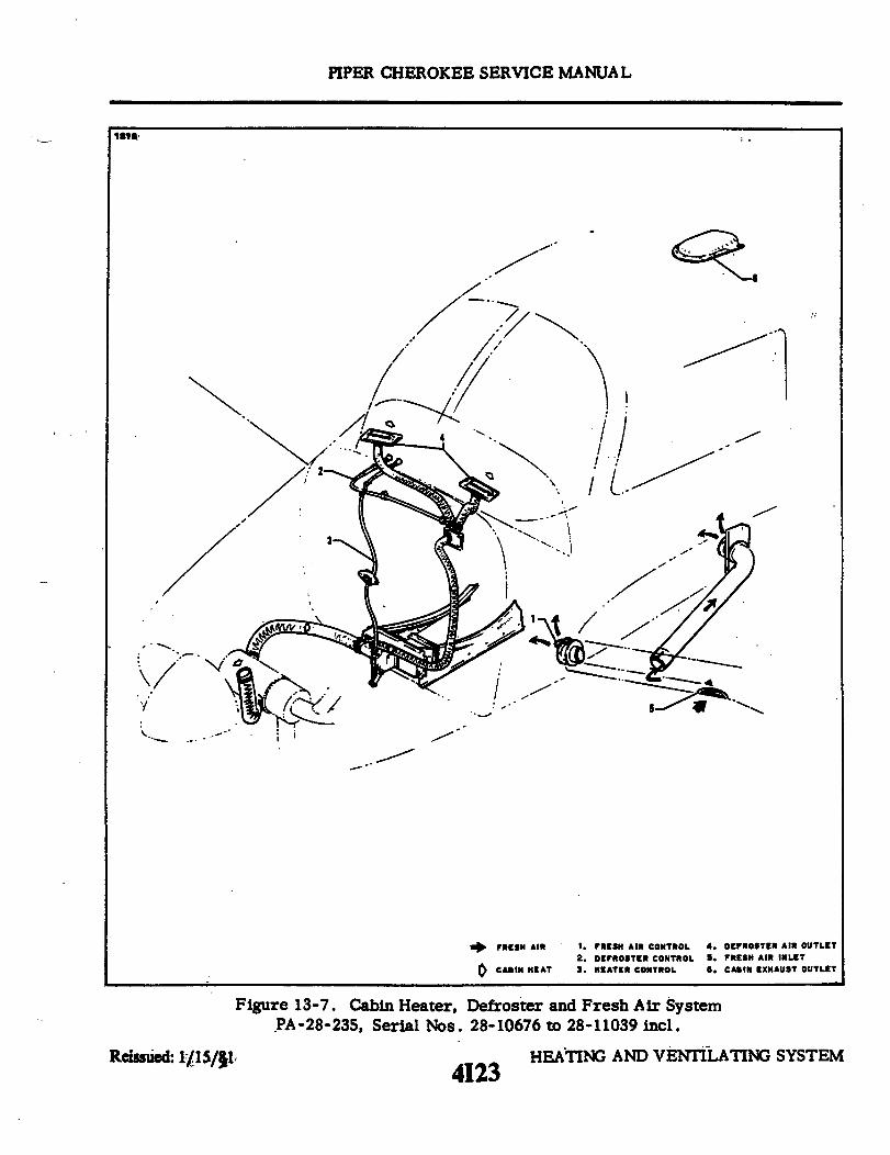
PIPER CHEROKEE SERVICE MANUAL
1816
FRESH AIR
CABIN HEAT
Figure 13-7. Cabin Heater,PA-28-235, Serial Nos.
Reissued: l/15/81
Defroster and Fresh Air System28-10676 to 28-11039 incl.
4123HEATING AND VENTILATING SYSTEM
1. FRESH AIR CONTROL 4. DEFROSTER AIR OUTLET2. DEFROSTER CONTROL 5. FRESH AIR INLET3. HEATER CONTROL 6. CAIN EXHAUST OUTLET
-

PIPER CHEROKEE SERVICE MANUAL
1587
FRESH AIR
CABIN HEAT
1. FRESH AIR CONTROL 4. DEFROSTER AIR OUTLET
2. DEFROSTER CONTROL 5. FRESH AIR INLET
3. HEATER CONTROL 6. CABIN EXHAUST OUTLET
Figure 13-8. Cabin Heater, Defroster and Fresh Air SystemPA-28-235, Serial Nos. 28-11040 and up
HEATING AND VENTILATING SYSTEMReissued: 1/15/814124
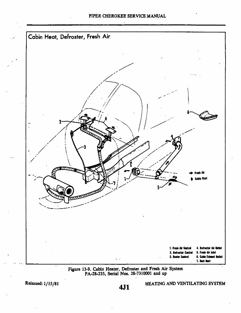
PIPER CHEROKEE SERVICE MANUAL
Cabin Heat, Defroster, Fresh Air
/
Fresh Air
Cabin Heat
1. Fr Air Control 4. Defroster Air Outlet2. Defroster Control 5. Fresh Air Inlet3. Heater Control 6. Cabin Exhaust Outlet
7. Heat Duct
Figure 13-9. Cabin Heater, Defroster and Fresh Air SystemPA-28-235, Serial Nos. 28-7310001 and up
Reissued: 1/15/814J1
HEATING AND VENTILATING SYSTEM
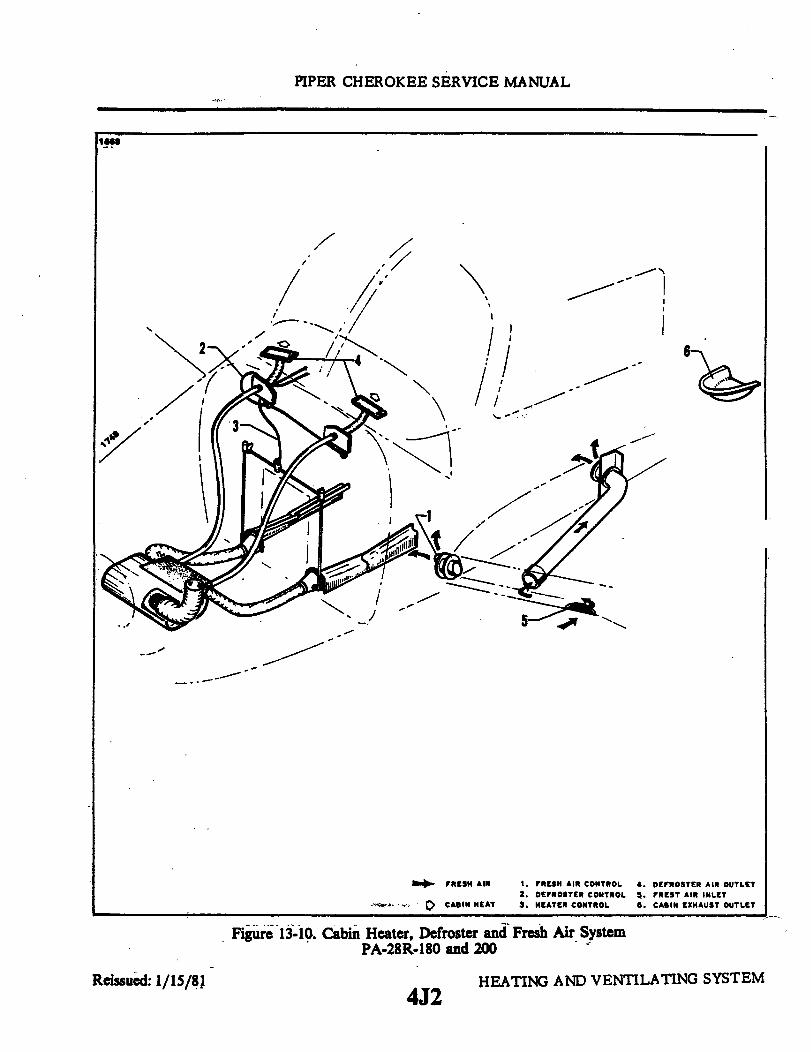
PIPER CHEROKEE SERVICE MANUAL
1669
FRESH AIR
CABIN HEAT
1. FRESH AIR CONTROL 4. DEFROSTER AIR OUTLET2. DEFROSTER CONTROL 5. FREST AIR INLET3. HEATER CONTROL 6. CABIN EXHAUST OUTLET
Figure 13-10. Cabin Heater, Defroster and Fresh Air SystemPA-28R-180 and 200
Reissued: 1/15/8 24J2
HEATING AND VENTILATING SYSTEM

S
I
SECTION XIV
ACCESSORIES AND UTILITIES
AeroficheGrid No.
Air Conditioning Installation ....................Description ..............................Air Conditioning System Operation ................Malfunction Detection .......................Special Servicing Procedures ....................Service Valves ............................Service Valve Replacement .....................Test Gauge and Manifold Set . ...................Checking the System for Leaks ..................Leak Check - Method I .......................Leak Check - Method II .......................Discharging ..............................Evacuating the System .......................Charging the System .........................With a Charging Stand .....................Using the Airplane Compressor to Charge the System ......Addition of Partial Charge to System ...............Compressor Service .........................Compressor Removal ........................Compressor Installation .......................Checking Compressor Oil ......................Replacement of Compressor and/or Alternator Drive Belts . . .Adjustment of Drive Belt Tension .................Magnetic Clutch ...........................Magnetic Clutch Removal ......................Magnetic Clutch Installation ....................Refrigerant Lines and Routing ...................Receiver-Dehydrator ............Receiver-Dehydrator Removal ...................Receiver-Dehydrator Installation .................Condenser ..............................Condenser Assembly Removal ................ : .Condenser Installation .......................Condenser Door Actuator .....................Condenser Assembly Rigging Instructions ............Expansion Valve ...........................Expansion Valve Removal .....................Expansion Valve Installation ....................
... 4J6
... 4J64J6
... 4J64J9
... 4J10.. 4J12
.... 4J12.4J13
·... 4J13... 4J15... 4J16
. 4J16·... 4J17
.. 4J18
. 4J19
... 4J20.... 4J21
. 4J22
... 4J23... 4J23
4J24... 4K1· . . 4K3
4K34K74K74K84K84K94K94K94K9
.. 4K94K104K104K124K134K134K13
Revised: 10/3/83
4J4
14-1.14-2.14-3.14-4.14-5.14-6.14-7.14-8.14-9.14-10.14-11.14-12.14-13.14-14.14-15.14-16.14-17.14-18.14-19.14-20.14-21.14-22.14-23.14-24.14-25.14-26.14-27.14-28.14-29.14-30.14-31.14-32.14-33.14-34.14-35.14-36.14-37.14-38.
Evaporator Assembly ...........................Evaporator Assembly Removal......................Evaporator Assembly Installation ...................Pressure Relief Switch (Ranco) .....................Electrical Installation ...........................Adjustment of Throttle Switch .....................Fuse Replacement (Ser No. PA-28-140, 28-7125472 to
28-7325057, PA-28-180, 28-7205092 to 28-7305071,PA-28R-180, 28R-7235001 to 28R-7335057.) ..........
Fuse Replacement (Ser Nos. PA-28-140, 28-7325058 and up,PA-28-180, 28-7305072 and up, PA-28R-200,28R-7335058 and up.) ........................
Shoulder- Harness Inertia Reel Adjustment ..............Overhead Vent Blower ..........................Description ................................Removal of Blower Assembly ......................Disassembly of Blower Assembly ....................Reassembly of Blower Assembly .....................Installation of Blower Assembly .....................
Revised: 10/3/83
4J5
AeroficheGrid No.
14-39.14-40.14-41.14-42.14-43.14-44.14-45.
14-46.
14-47.14-48.14-49.14-50.14-51.14-52.14-53.
4K144K144K144K154K164K16
4K17
4K174L44L44L44L44L44L54L5

PIPER CHEROKEE SERVICE MANUAL
SECTION XIV
ACCESSORIES AND UTILITIES
14-1. AIR CONDITIONING INSTALLATION.
14-2. DESCRIPTION. This installation consists of a compressor with its special bracketry,an evaporator, a condenser, a receiver-dehydrator, circulating fan, thermal expansion valve,and related plumbing.
The evaporator filters, dehumidifies and cools the air. The evaporator is mounted in afabricated housing along with the receiver-dehydrator, circulating fan, thermal expansionvalve and related plumbing. This housing is located at the rear of the cabin, aft of thebaggage area. The compressor is a two cylinder, piston type compressor which is supportedby special bracketry at the front of the engine. A V-belt connected to the engine ring geardrives the compressor through a magnetic clutch. The condenser is installed on a hingemounted door that is located on the bottom portion of the fuselage tail section. Thecondenser door is hinge mounted to allow extension into the airstream during systemoperation. The condenser door is electrically activated to provide the following positions,(system on - fully extended or system off - fully retracted).
The system is protected by a Ranco type pressure switch which automatically controlsthe condenser maximum head pressure by temporarily de-clutching the compressor in theevent the pressure becomes excessively high. The controls are located on the aircraftinstrument panel adjacent to the heater and defroster levers, and consist of an AirConditioning control, a fan control to govern the cold air velocity, and a temperaturecontrol.
The system design is such that there is no increase in drag to the aircraft during itstake-off flight conditions. During maximum power demands the compressor is de-clutchedand the condenser door is automatically retracted.
14-3. AIR CONDITIONING SYSTEM OPERATION.The air conditioning system in this aircraft is a recirculating, independent unit. It filters,
dehumidifies.and cools the air as it cycles through the evaporator. The unit is operated fromcontrols mounted on the right side of the instrument panel. The air conditioning masterswitch has three positions on early models: "FAN only, OFF and AIR COND" and a twoposition ON-OFF switch on later models. When the "AIR COND" position is selected thecompressor clutch engages, the condenser scoop opens and the circulating fan is turned on.The temperature is controlled by a thermostat operated by the temperature control selector.A three position fan swithc (LOW-MED-HIGH) operates the blower. The fan may beoperated to circulate air without using the air conditioning unit
The air conditioning system uses Refrigerant 12 as the refrigerant. The refrigerant entersthe compressor as a vapor. The Compressor pressurized the heat-laden vapor until itspressure and heat reach a point much hotter than the outside air. The compressor thenpumps the vapor to the condenser where it cools and changes to a liquid. The liquid thenpasses to the receiver-dehydrator. Its function is to filter, remove any moisture and insure asteady flow of liquid refrigerant into the evap rator through the expansion valve. Theexpansion valve is a temperature controlled metering valve which regulates the flow of theliquid refrigerant to the evaporator. The evaporator absorbs the heat from the air passingover the coils. From the evaporator the refrigerant vapor returns to the compressor wherethe cycle is repeated.
Reissued: 1/15/81 ACCESSORIES AND UTILITIES
4J6

0~~~~~~~~~~~~~~~~~~~~~~~~~~~~~~~~b 4U


PIPER CHEROKEE SERVICE MANUAL
NOTE
A table at the end of these instructions will assist in locatingand correcting malfunctions which may arise in this system.
NOTE
The air conditioning system should be operated at least oncea month to prevent sticking valves and keep the systemlubricated.
144. MALFUNCTION DETECTION. The detection of system malfunction largelydepends on the mechanic's ability to interpret the gauge pressure readings into systemproblems. A system operating normally will have a low side gauge pressure reading that willcorrespond with the temperature of the refrigerant evaporating in the evaporator, allowingfor a few degrees temperature rise due to loss in the tube walls and fins. The high side willhave a gauge pressure that will correspond with the temperature of the refrigerantcondensing in the condenser, allowing for a few degrees temperature drop due to loss in thetube walls and fins.
Any deviation from that which is normal indicates a malfunction within the system dueto a faulty control device, obstruction, defective part, or improper installation.
Detection of system malfunction is made easier with the knowledge that thetemperature and pressure of Refrigerant 12 is in close proximity between the pressures oftwenty and eighty pounds per square inch (psi). A glance at the temperature-pressure chartwill show that there is only a slight variation between the temperature and pressure of therefrigerant in the lower range.
It is correct to assume that for every pound of pressure added to the low side, atemperature increase of about one degree Fahrenheit takes place. For instance, a pressure of23.8 on the chart indicates a temperature of 24° F. A change of pressure of almost onepound to 24.6 psi gives us a temperature increase to 25 ° F.
NOTE
For each 1,000 feet of elevation above sea level, the gaugereadings will be about one inch of mercury or 1/2 psi higherthan the chart indicates.
It must be pointed out that the actual temperature of the air passing over the coils ofthe evaporator will be several degrees warmer allowing for a temperature rise caused by theloss in the fins and tubing of the evaporator.
The importance of a seasonal check up of the air conditioning system should be broughtto the attention of the customer whenever possible. A thorough check of the systemperformed in a methodical manner will reveal trouble the customer is often not aware of.
Reissued: 1/15/81 ACCESSORIES AND UTILITIES
4J9

PIPER CHEROKEE SERVICE MANUAL
Locating and repairing the trouble early will usually result in savings to the customer both intime and additional troubles that too often result from neglect.
A Performance Test of the system is the only positive way in which the complete systemcan be checked for efficient operation. The air conditioning system should be given this testbefore work is begun on the system whenever possible, however, if the system is completelyinoperative, repairs must be performed before the system can be properly tested. The testcan uncover further work that must be performed before the system is brought to its fulloperating efficiency. The Performance Test should always be performed after repair workhas been done and before the aircraft is released to the customer. The servicemanperforming this test carefully will insure that the repairs have been properly performed andthat the system will operate satisfactorily.
The Performance Test when properly performed includes a thorough examination of theoutside of the system as well as the inside. Many related parts are overlooked because it isfelt they are of no bearing on the operating efficiency of the unit. For this reason, athorough visual inspection of the complete system should be performed, followed by anoperating inspection of the system.
14-5. SPECIAL SERVICING PROCEDURES. The air conditioning system should beserviced by a qualified shop with trained personnel. The following procedures andprecautions should be observed.
The efficiency of this system depends upon the pressure-temperature relationship ofpure refrigerant. As long as the system contains only pure refrigerant plus a specifiedamount of compressor oil (which is mixed with the refrigerant), it is considered to bechemically stable. Foreign materials within the system will affect the chemical stability,contaminate the system, and decrease its efficiency.
I. GENERAL REFRIGERATION SYSTEM PROCEDURES.A. REFRIGERANT SAFETY PRECAUTIONS.
1. Refrigerant 12 (commonly known as R-12 or "Freon" 12) is odorless andcolorless in either the liquid or gaseous state. R-12 for charging refrigerationsystems is supplied in pressurized containers (approx. 70 psi at 700F) inliquid form. Since this material is essentially inert at room temperatures thedangers are primarily associated with the pressure and the refrigerationeffects of the release and subsequent evaporation of this pressurized liquid.
2. Wear suitable eye protection when handling R-12 due to the possibility offreezing of the eye if contacted by escaping liquid refrigerant. If liquid R-12does strike the eye, the following actions should be taken:a. DO NOT RUB THE EYE.b. Splash large quantities of cool water into the eye to raise the
temperature.c. Tape on an eye patch to avoid the possibility of dirt entering the eye.d. Rush to a physician or hospital for immediate professional aid.e. DO NOT ATTEMPT TO TREAT IT YOURSELF.
3. If liquid R-12 strikes the skin frostbite can occur. Treat with cool water andprotect with petroleum jelly.
4. Do not discharge large quantities of R-12 into closed rooms. It may displacemost of the air in the room and this could cause oxygen starvation. GaseousR-l 2 is heavier than air and flows to the bottom of a container.
Reissued: 1/15/81 ACCESSORIES AND UTILITIES
4J10

PIPER CHEROKEE SERVICE MANUAL
5. Do not discharge R-12 into an open flame or onto a very hot surface(500°F+). Poisonous phosgene gas is generated by the action of the heat onthe refrigerant.
6. Do not apply direct flame or other high heat source to a R-12 container dueto the high pressures which will result. If any heating is done to R-12containers the container pressure should be monitored and kept below 150psi.
B. SYSTEM SERVICING PRECAUTIONS.1. Systems should be discharged slowly to prevent the escape of liquid
refrigerant and the loss of the lubricating oil.2. Systems should not be left open to the atmosphere when discharged.
Moisture and other contamination may enter and damage open systems.3. Never introduce anything but pure refrigerant and refrigerant oil into a
system.4. Keep refrigerant oil containers tightly sealed and clean to prevent absorption
of moisture or other contamination.5. Use only approved refrigeration oil in the compressor. If any doubt exists
about the cleanliness of the compressor oil, replace it with new oil.6. Never reuse oil removed from the system. Discard it.7. When Loctite Refrigerant Sealant has been used on a joint it must be heated
to 400°F prior to disassembly. Loctite must be used to seal any pipe threadsin the system lines.
8. Replace the receiver-dehydrator assembly on any system which has beenoperating with a leak allowing air to enter the system. If areceiver-dehydrator is left open to the atmosphere it should be replaced dueto the loss of effectiveness of the drying compound it contains.
NOTE
A very strong acid (HCL) is formed when R-12 comes incontact with moisture.
A new receiver-dehydrator should be opened and connected to the systemonly when ready to charge the system with refrigerant.
9. Recommended torque values must be used on all flare fitting and O-ringjoints. See Table XIV-II.
TABLE XIV-II. ALUMINUM TUBING TORQUE
Metal Tube Thread and Fitting Alum. TubingO.D. Size Torque
1/4 7/16 5-7 ft. Ibs.3/8 5/8 11-13 ft. lbs.1/2 3/4 15-20 ft. lbs.5/8 7/8 21-27 ft. lbs.3/4 1-1/16 28-33 ft. lbs.
Reissued: 1/15/81 ACCESSORIES AND UTILITIES
4J11

PIPER CHEROKEE SERVICE MANUAL
914
COMPRESSOR VALVE (SCHRADER CHARGING) INLINE SERVICE VALVE (SCHRADER)
Figure 14-2. Service Valves
14-6. SERVICE VALVES. The purpose of the service valve is to service the airconditioning system. (Testing, Bleeding, Evacuating and Charging). This aircraft is equippedwith service valves mounted in the suction and discharge lines of the evaporator assembly.These valves are the "2" position type Schrader valves. All normal air conditioning serviceshould be performed at the evaporator assembly mounted valves.
NOTE
Service valves are also located on the compressor. However,use of these valves in servicing is not recommended.
NOTE
If a Schrader service valve is not serviceable, the coreassembly must be replaced.
14-7. SERVICE VALVE REPLACEMENT. The valves on the compressor are sealed with agasket placed in the valve port boss. Lubricate the gasket with refrigerant oil of the typeused in the compressor, place the valves with the tube fitting facing aft and secure with .312bolts, torque to 15-23 inch pounds.
NOTE
Whenever the air conditioning refrigerant lines or system isopened for any reason, the lines and fittings should becapped and sealed immediately to prevent dirt and othercontaminants from entering the system. (It is not advisable toput a plug into the hoses or fittings.)
Reissued: 1/15/81 ACCESSORIES AND UTILITIES
4J12
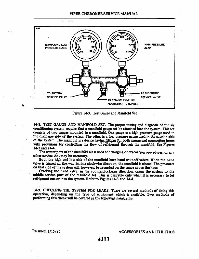
PIPER CHEROKEE SERVICE MANUAL
408
COMPOUND LOWPRESSURE GAGE
C
TO SUCTIONSERVICE VALVE
HIGH PRESSUREGAGE
TO DISCHARGESERVICE VALVE
TO VACUUM PUMP ORREFRIGERANT CYLINDER
Figure 14-3. Test Gauge and Manifold Set
14-8. TEST GAUGE AND MANIFOLD SET. The proper testing and diagnosis of the airconditioning system require that a manifold gauge set be attached into the system. This setconsists of two gauges mounted to a manifold. One gauge is a high pressure gauge used inthe discharge side of the system. The other is a low pressure gauge used in the suction sideof the system. The manifold is a device having fittings for both gauges and connection hoseswith provisions for controlling the flow of refrigerant through the manifold. See Figures14-3 and 144.
The center port of the manifold set is used for charging or evacuation procedures, or anyother service that may be necessary.
Both the high and low side of the manifold have hand shut-off valves. When the handvalve is turned all the way in, in a clockwise direction, the manifold is closed. The pressureson that side of the system will, however, be recorded on the gauge above the hose.
Cracking the hand valve, in the counterclockwise direction, opens the system to themiddle service port of the manifold set. This is desirable only when it is necessary to letrefrigerant out or into the system. Refer to Figures 14-3 and 14-4.
14-9. CHECKING THE SYSTEM FOR LEAKS. There are several methods of doing thisoperation, depending on the type of equipment which is available. Two methods ofperforming this check will be covered in the following paragraphs.
Reissued: 1/15/81 ACCESSORIES AND UTILITIES
4J13

PIPER CHEROKEE SERVICE MANUAL
1257
DIAGRAM A
DIAGRAM B
DIAGRAM C
DIAGRAM D
Figure 14-4.Manifold Set Operation
Reissued: 1/15/81 ACCESSORIES AND UTILITIES
4J14

PIPER CHEROKEE SERVICE MANUAL
COMPOUNDGAGE 50 P.S.I. PRESSURE GAGE
SCHRADER VALVE
CLOSED
L H SCHRADER VALVE
MANI FOLDGAGE SET
REFRIGERANTCONTAINER
OPEN TO 50 P.S.I. EVAPORATOR ASS'YTHEN CLOSE
Figure 14-5. Leak Test Hookup
NOTE
Evacuate system prior to leak check.
14-10. LEAK CHECK - METHOD I.a. Connect the manifold gauge set into the system and determine if there is any
refrigerant in the system. A minimum of 50 psi refrigerant pressure in the system is neededfor leak detection. (Refer to Figure 14-5.)
b. Purge the hoses of air by allowing some refrigerant to escape from the connectionsat the service valves. Then tighten connections at the service valve.
c. Close the low side manifold valve and open the high side manifold valve.d. Open the refrigerant container service valve and allow the pressure at the low side
gauge to reach 50 psi at which time close the high side manifold valve.e. Close the refrigerant container service valve and remove the hose if no leaks are
evident.f. It is advisable to use an electronic leak detector to check this system instead of an
open flame leak detector due to the possible presence of gasoline fumes in the engine area.g. If any leaks are found, purge the system of refrigerant, make the necessary repairs
and check the compressor oil.h. Add oil, if required, (refer to Paragraph 14-21 and Table XIV-II) then repeat steps a
thru e.i. If no further leaks are found, the system may be evacuated and charged. Refer to
Paragraphs 14-13 and 14-14.
Reissued: 1/15/81 ACCESSORIES AND UTILITIES
4J15
PIPER CHEROKEE SERVICE MANUAL
14-11. LEAK CHECK - METHOD II.a. Remove the access panel at the rear of the cabin to gain access to the service valves.b. Remove the protective cap on the high pressure Schrader valve fitting and connect a
charging hose with a shut-off valve arrangement to the fitting. The charging hose must havea Schrader fitting or adapter to fit the valve.
c. Connect the other end of the charging hose to a small cylinder of refrigerant andpurge the hose by allowing a slight amount of refrigerant gas to escape from the Schradervalve fitting.
d. The cylinder of refrigerant should be placed upright in a container of warm (125°Fmax. water on a small scale.)
e. Allow approximately 1/2 pound of refrigerant to enter the system by opening thevalve on the charging hose and observing the weight change on the scale.
f. Using an electronic leak detector, check all joints and repair any leaks.g. After completion of repair of any leaks, proceed to check the system in accordance
with one of the methods outlined for any other leaks.h. If no further repair is required on the system, it is now ready to evacuate in
accordance with paragraph 14-13.
14-12. DISCHARGING. (Required only if system contains refrigerant.)
NOTE
Applies to Kent Moore J23500 or similar charging station.Refer to Figure 14-7.
a. Close all valves on charging station.b. Connect red high pressure charging line to high pressure Schrader valve at the
evaporator fitting.c. Open valve 8 (high pressure control) on charging station one turn.d.. Hold end of blue low pressure charging line in a shop rag and slowly open valve 2
(low pressure control) on charging station allowing refrigerant to exhaust from system intoshop rag.
CAUTION
Refrigerant can cause freezing of skin. Be particularly carefulnot to allow contact with the eyes.
Do not allow refrigerant to escape too rapidly, as excessiveoil may be carried out of system. When hissing stops, systemis empty and valve should be closed if no further work isplanned.
Reissued: 1/15/81 ACCESSORIES AND UTILITIES
4J16

PIPER CHEROKEE SERVICE MANUAL
988
COMPOUND GAGEPULL 26 TO 28INCHES VACUUM
PRESSURE GAGE
VACUUM PUMP
NOTE: OPEN BOTH SERVICE VALVES
(COUNTERCLOCKWISE) ONE TURNEVAPORATOR ASS'Y
Figure 14-6. Evacuation Hookup
14-13. EVACUATING THE SYSTEM. If the system has been operated in a dischargedcondition or anytime the system has been open to atmospheric pressure, thereceiver-dehydrator must be replaced and the system evacuated to remove any trapped airand moisture which has entered it. A vacuum pump capable of pulling 29 inches of mercuryor better should be used. As we lower the pressure in the air conditioning system, we lowerthe boiling temperature of the water (moisture) that may be present. Then we are able topull this water, in the form of vapor, out of the system. The following table demonstates theeffectiveness of moisture removal under a given vacuum.
System Vacuum Temperature F.
COMPOUND GAUGEREADING IN INCHESOF MERCURY VACUUM
27.9928.8929.4029.7129.8229.88
100806040200
NOTE
For each 1,000 feet of elevation above sea level, thecompound gauge reading will be about one inch lower,numerically.
Reissued: 1/15/81 ACCESSORIES AND UTILITIES
4J17
ACCESSORIES AND UTILITIES
SCHRADERVALVE
Reissued:1/15/81

PIPER CHEROKEE SERVICE MANUAL
The following steps should be ofhelp-when performing this operation.a. Remove access panel at the rear of the cabin to gain access to the Schrader service
valves.
CAUTION
Ascertain that all system pressure is released beforeattempting the evacuation. (Refer to Paragraph 14-5.)
b. Connect the manifold gauge set to the airplane service valves. (Refer to Figure 14-6.)c. The high and low manifold hand valves should be in the closed position. (Refer to
Figures 14-3 and 14-4.) .d. Connect the center manifold hose to the inlet of the vacuum pump.
NOTE
Make sure the exhaust port on the vacuum pump is open toavoid damage to the vacuum pump.
e. Start the vacuum pump and open the low side manifold hand valve. Observe thecompound, low pressure gauge needle, it should show a slight vacuum.
f. Continue to operate the vacuum pump until 26 to 28 inches of vacuum is attainedon the low pressure gauge, then extend the operation for another 25 minutes.
g. If the system cannot maintain 26 to 28 inches of vacuum, close both manifold handvalves and observe the compound gauge.
h. Should the compound gauge show a loss of vacuum, there is a leak in the systemwhich must be repaired before continuing with evacuation.
i If no leaks are evident, reopen both manifold hand valves and continue theevacuation for another 30 minutes.
j. Close both manifold hand valves, stop vacuum pump and disconnect center manifoldhose from the vacuum pump.
k. Proceed to charge the system in accordance with Paragraph 14-14.
NOTE
The system should be charged as soon as it has been evacuated.
14-14. CHARGING THE SYSTEM. When the system is completely evacuated inaccordance with instructions given in paragraph 14-13, one of the following proceduresshould be used to charge the system.
Reissued: 1/15/81 ACCESSORIES AND UTILITIES
4J18

PIPER CHEROKEE SERVICE MANUAL
. CYLINDER PRESSURE GAUGE. ICOMPOUND SAUSE
8. VALVE. LOW PRiESURE CONTROL 14. VALVE, VACUUM CONTROL 2 9S. CHARSIN CYLINDOR 2S. lReACET 3 1A7. SIlT LASS IS. CYLINDER BAE VALVES. HlIN PRESSURE «AUSE _ 2 2—
I. VALVE. HIGH PCRESSURE CONTROL 11. VALVE, REPRI. CONTROL 5 _ 2to. CHARIN LINE HOSE HOLDER 13. BRACKET
14. LOW PRESSURE CHARIINS LINE 14IS. HIlG PRESSURE CHARNIN LINE — =IS. HEATIMN ELEMENT PLUS 1517. VACUUM PuMP 7 2 S. OIL FILL LOCATION3. NECK AEMLY 16 21
20. REFRISERANT DRUM SUPPORT2 L» RIEFRIERANT DRUM VALVE IL VACUUM PUMP VALVE2. VACUUM PUMP EXHAUS OT POT1724. TOP CYLINDER VALVE
. REPRIERAKT DRUM 22236. WEE STRAP 23 T2. IRERIOERNAT DRUM REOUCER
2. CHARIN CYLINDER HOSE 312a. VACUUM PUMP INTAKE HOSESO. VACUUM PUMP SWITCH
41. VACUUM PUMP POWER CORD
Figure 14-7. Charging Stand
14-15. WITH A CHARGING STAND. This is the preferred method of charging the system.
NOTE
The following instructions apply to Kent Moore. J23500charging stand. (Refer to Figure 14-7.)
a. With the system discharged and evacuated, proceed to hook-up the charging stand.(Refer to Figure 14-8.)
b. Fill the charging cylinder by opening the valve (8) at the base of the charging cylinderand filling the sight glass with two pounds of liquid refrigerant.
c. As refrigerant stops filling the sight glass, open the valve (24) at the top of the gaugeneck assembly intermittently to relieve head pressure and allow refrigerant to continue fillingthe sight glass to the required amount.
d. When refrigerant reaches the required level in the sight glass, close both the valve (8) atthe base of the cylinder and the valve (21) at the bottom of refrigerant tank. Be sure the topvalve (24) is fully closed.
NOTE
If bubbling occurs in sight glass, reopen the cylinder basevalve (8) momentarily to equalize drum and cylinder pressure.
Reissued: 1/15/81 ACCESSORIES AND UTILITIES4J19

PIPER CHEROKEE SERVICE MANUAL
e. Connect the heating element plug to a 110-volt outlet.f. Turn cylinder sight glass to match pressure reading on cylinder pressure gauge (1). This
scale should be used during entire charging operation.g. Close valve (3) (low pressure control), fully open valve ( 11) (refrigerant control) and
allow all the liquid refrigerant contained in the charging cylinder to enter high side of aircraftsystem.
h. When the full charge of refrigerant has entered the system, close valve (11) (refrigerantcontrol) and valve (10) (high pressure control).
i. After completion of charging, close all valves on the charging stand. Disconnect thehigh and low pressure charging lines from the aircraft system. (A small amount of refrigerantremaining in the lines will escape.) Replace lines on holder of charging stand to keep air anddirt out of lines. Open the valve (24) at the top of cylinder to relieve any remaining pressure,then reclose the valve.
j. Reinstall protective caps of Schrader valves and any access panels previously removed.
14-16. USING THE AIRPLANE COMPRESSOR TO CHARGE THE SYSTEM. Thismethod is the least desirable due to the requirement of operating the airplane's engine to runthe compressor.
CAUTION
Ascertain that the area around the airplane is clear and aqualified person is at the controls of the airplane.
a. With the system evacuated as outlined in Paragraph 14-13, connect the refrigerantcharging hose to the manifold (refer to Figure 14-8) and purge the charging hose of air.
b. Place the refrigerant container on a scale to observe the amount of refrigerantentering the system. Open the high pressure valve and add as much refrigerant as possible.
c. Close the high pressure valve, start the engine and operate it at 900 to 1000 RPM.d. Operate the air conditioner and set controls to maximum cooling.e. -Open-the low pressure valve and complete charging the system.f. Close the low pressure valve after two pounds of refrigerant has been added to the
system.g. With the system still operating, observe the sight glass in the top of the receiver-
dehydrator by removing the plastic plug.h. The sight glass should be clear of any bubbles or foam. If bubbles or foam are seen
passing through the sight glass, it is an indication of a low refrigerant charge in the systemand more refrigerant is required. This check should be made with OAT of 70° F or higherand with the air conditioner operating.
i. If more refrigerant must be added to the system, open the low pressure valve andincrease engine speed to 2000 RPM and observe the sight glass. After the sight glass hascleared, close the low pressure valve and observe the pressure gauges. At 1000 RPM thegauge pressure should be 15 to 20 psi on the low side and 150 to 200 on the high side.
Reissued: 1/15/81 ACCESSORIES AND UTILITIES
4J20

PIPER CHEROKEE SERVICE MANUAL
DISCHARGE U
SUCTION LINE
COMPRESSOR
CONDENSE
OPTIONAL METHOD
COIL FITTING
EVAPORATOR
THIS END OF HOSEMUST HAVE DEVICETO DEPRESSSCHRADER VALVE
CHARGINGSTAND
PREFERRED METHOD
Figure 14-8. Charging Hookup
NOTE
Suspect leaks or an inaccurate scale if two pounds ofrefrigerant does not fill the system.
j. Shut off the air conditioning system and airplane engine. Then, remove the charginglines from the Schrader valves with care due to the refrigerant remaining in the hose.
NOTE
A shop cloth should be used to divert escaping refrigerantwhen disconnecting the charging hose from the Schradervalve. Recap the valve.
14-17. ADDITION OF PARTIAL CHARGE TO SYSTEM. It is possible to top off thissystem with refrigerant by the following method.
a. Remove the access panel at the rear of the cabin.
Reissued: 1/15/81 ACCESSORIES AND UTILITIES
4J21
I

PIPER CHEROKEE SERVICE MANUAL
b. Connect a charging hose-di:a refrigerant cylinder and also to the Schrader valvefitting on the suction line. (Refer to Figure 14-8.)
c. Purge the charging hose by allowing a small amount of refrigerant gas to escape atthe Schrader valve fitting.
d. Start the engine and operate at 1000 RPM and turn the air conditioner on maximumcool.
e. Remove the plastic plug from the sight glass in the top of the receiver-dehydrator.f. With a low refrigerant charge in the system, bubbles will be seen passing thru the
sight glass when the system is operating.g. Open the valve on the refrigerant cylinder.h. Allow refrigerant to flow into the system until the bubbles disappear from the sight
glass.i. Close the refrigerant valve and check to see that the sight glass remains clear during
system operation.j. When the sight glass stays clear of bubbles, add an additional 1/4 pound of
refrigerant to the system. (Engine should be operating at 1000 RPM).
NOTE
This should be done with OAT at 700 F, or higher, with theair conditioner operating.
k. Shut off the air conditioner and engine. Remove the charging hose from theSchrader valve with care due to refrigerant remaining in the line.
1. Replace the access panels.
14-18. COMPRESSOR SERVICE. It is not advisable to service the compressor in the field.It should be done by a qualified shop which has the special equipment and trained personnelrequired to properly service the unit.
Maintenance to this unit and its related components is limited to the replacement ofworn drive belt and magnetic clutch. Any other service requires removal of the compressorfrom the system.
NOTE
An important factor in air conditioning servicing iscleanliness and care should be exercised to prevent dirt orforeign material from entering the system. All hose andtubing ends should be capped immediately. Any lubricationrequired in the assembly of the components should berefrigerant oil of the type used in the compressor.
Reissued: 1/15/81 ACCESSORIES AND UTILITIES
4J22

PIPER CHEROKEE SERVICE MANUAL
14-19. COMPRESSOR REMOVAL. (The removal of the compressor requires a completesystem discharge.) See Paragraph 14-12.
a. Be certain the circuit protector is off for the air conditioning system.b. Remove the engine cowling and right front baffles.c. Disconnect the electrical leads to the magnetic clutch on the compressor.d. Depressurize the air conditioning system.e. Remove the suction and discharge lines from the service valves on the compressor.
NOTE
All open lines should be capped immediately to prevent dirtand moisture from entering the system.
f. Loosen the bolt securing the compressor idler pulley to release the belt tension andremove belt from compressor pulley. (Do not force belt over the pulleys.)
g. Support the compressor and remove, the 6 bolts securing the compressor to theengine mounting brackets.
14-20. COMPRESSOR INSTALLATION.a. Place the compressor to the mounting brackets. Install the six bolts and
progressively torque to 14-17 ft. pounds. (Safety all bolts with .032 safety wire.)b. Check the oil level in the compressor in, accordance with instructions given in
paragraph 14-21.c. Place drive belt over clutch pulley and adjust the alignment of the pulleys and belt in
accordance with instructions given in paragraph 14-22.
CAUTION
Do not force the belt into the pulley sheavie.If necessary,remove the idler assembly.
d. Connect the discharge and suction lines to their respective service valve fittings.e. Evacuate and charge the system per paragraphs 14-13 and 14-14.
Reissued: 1/15/81 ACCESSORIES AND UTILITIESRessued: 11584234J23
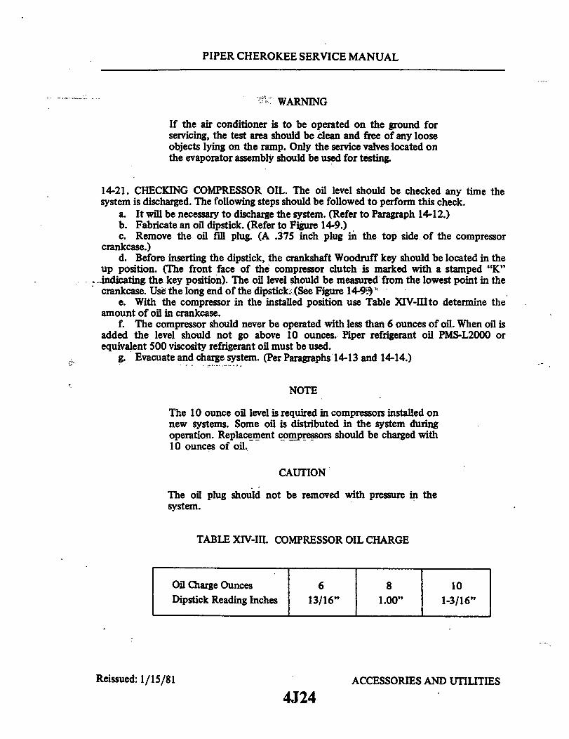
PIPER CHEROKEE SERVICE MANUAL
WARNING
If the air conditioner is to be operated on the ground forservicing, the test area should be clean and free of any looseobjects lying on the ramp. Only the service valves located onthe evaporator assembly should be used for testing.
14-21. CHECKING COMPRESSOR OIL. The oil level should be checked any time thesystem is discharged. The following steps should be followed to perform this check.
a. It will be necessary to discharge the system. (Refer to Paragraph 14-12.)b. Fabricate an oil dipstick. (Refer to Figure 14-9.)c. Remove the oil fill plug. (A .375 inch plug in the top side of the compressor
crankcase.)d. Before inserting the dipstick, the crankshaft Woodruff key should be located in the
up position. (The front face of the compressor clutch is marked with a stamped "K"ndicating the key position). The oil level should be measured from the lowest point in thecrankcase. Use the long end of the dipstick. (See Figure 14-9.)
e. With the compressor in the installed position use Table XlV-III to determine theamount of oil in crankcase.
f. The compressor should never be operated with less than 6 ounces of oil. When oil isadded the level should not go above 10 ounces. Piper refrigerant oil PMS-L2000 orequivalent 500 viscosity refrigerant oil must be used.
g. Evacuate and charge system. (Per Paragraphs 14-13 and 14-14.)
NOTE
The 10 ounce oil level is required in compressors installed onnew systems. Some oil is distributed in the system duringoperation. Replacement compressors should be charged with10 ounces of oil.
CAUTION
The oil plug should not be removed with pressure in thesystem.
TABLE XIV-III. COMPRESSOR OIL CHARGE
Oil Charge Ounces 6 8 10Dipstick Reading Inches 13/16" 1.00" 1-3/16"
Reissued: 1/15/81 ACCESSORIES AND UTILITIES
4J24
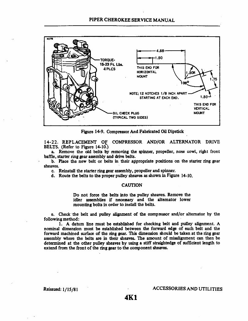
PIPER CHEROKEE SERVICE MANUAL
4078
TORQUE-15-23 Ft. Lbs.
4PLCS
4.68
1.50
THIS END FORHORIZONTALMOUNT
NOTE; 12 NOTCHES 1/8 INCH APARTSTARTING AT EACH END. 1.50
THIS END FORVERTICALMOUNTOIL CHECK PLUG
(TYPICAL TWO SIDES)
Figure 14-9. Compressor And Fabricated Oil Dipstick
14-22. REPLACEMENT OF COMPRESSOR AND/OR ALTERNATOR DRIVEBELTS. (Refer to Figure 14-10.)
a. Remove the old belts by removing the spinner, propeller, nose cowl, right frontbaffle, starter ring gear assembly and drive belts.
b. Place the new belt or belts in their appropriate positions on the starter ring gearsheaves.
c. Reinstall the starter ring gear assembly, propeller and spinner.d. Route the belts to the proper pulley sheaves as shown in Figure 14-10.
CAUTION
Do not force the belts into the pulley sheaves. Remove theidler assemblies if necessary and the alternator lowermounting bolts in order to install the belts.
e. Check the belt and pulley alignment of the compressor and/or alternator by thefollowing method:
1. A datum line must be established for checking belt and pulley alignment. Anominal dimension must be established between the forward edge of each belt and theforward machined surface of the ring gear. This dimension should be taken at the ring gearassembly where the belts are in their sheaves. The amount of misalignment can then bedetermined at the other pulley sheaves by using a stiff straightedge of sufficient length toextend from the front of the ring gear to the component sheaves.
Reissued: 1/15/81 ACCESSORIES AND UTILITIES
4K1

PIPER CHEROKEE SERVICE MANUAL
NOTE
Insure adequate ring gear surface contact to provide a solidbase for the straightedge.
2. Obtain a basic measurement from the top of the ring gear by measuring thewidth of the starter ring gear plus the dimension from the forward machined surface of thering gear to the forward edge of the compressor or alternator (on early installations) drivebelt. (Refer to Figure 14-10.)
3. The check and adjustments of the compressor and/or alternator drive beltsrequire different procedures; refer to following appropriate instructions:
f. Compressor Belt Alignment: (Refer to Figure 14-10.)1. Place the straightedge against the right forward side of the ring gear and measure
belt alignment at compressor sheave (Point-B).2. Measure belt alignment at the compressor idler pulley (Point-A). The belt
misalignment at Point-A should be half the misalignment of Point-B and the dimension atthe top of the ring gear and in the same direction fore and aft.
3. If at Point-A nominal misalignment is not within + .030 of an inch as obtainedfrom Step 2, add or remove shims as required. Belt alignment should be made as close tonominal as shims will allow.
4. On earlier installations, insure that there is a positive clearance between the jamnut on the idler pulley shoulder bolt and the face of the mounting bracket. Refer toparagraph 14-23 for belt tension adjustment. No jam nut is used on newer idler pulleybracket.
g. Alternator Belt Alignment - Early Installations: (Refer to Figure 14-10.) On earlyinstallations there are no provisions for shimming the alternator and/or the alternator idlerpulley in the forward direction, On later installations shims can be transferred as requiredfrom forward or aft of the alternator mounting lugs to achieve alignment. If shimming isrequired, insure that the alternator mounting bolts are of adequate length. For presentinstallations which incorporate the new bracket assembly, P/N 79584-02, proceed to step h.Older installations must still follow steps 1 thru 5 until the new bracket is used:
1. Place the straightedge against the left forward side of the ring gear and measurebelt alignment at the alternator pulley sheave (Point-C).
2. If at Point-C nominal misalignment is not within + .025 of an inch, add orremove shims as required between the alternator mounting bracket and the alternatormounting lugs. (Refer to Figure 14-10.) On later installations, transfer shims as requiredfrom forward or aft of the alternator mounting lugs to achieve alignment.
3. On later installations, measure belt alignment at the alternator idler pulleysheave (Point-D). The belt misalignment at Point-D should be halfway between themisalignment of Point-C and the dimension at the top of the ring gear and in the samedirection fore and aft. Earlier models provide no means of shimming at the alternator idlerpulley, and therefore need not comply with this paragraph.
4. Alternator Pulley Skew: (Refer to Figure 14-10.) The face of the alternatorpulley must be parallel to the starter ring gear. If skew (misalignment) is in excess of .015 ofan inch, loosen the alternator attachment bolts and adjust the alternator to the minimumskew. Tighten the mounting bolts and safety the support bracket bolt if not alreadysafetied.
Reissued: 1/15/81 ACCESSORIES AND UTILITIES
4K2

PIPER CHEROKEE SERVICE MANUAL
5. The belt alignment at the alternator pulley should be made as close as possible tothe nominal alignment, and pulley skew is to be held within this alignment. Refer toparagraph 14-23 for belt tension adjustment.
h. Alternator Belt Alignment - Present Installation: (Refer to Figure 14-10.)1. With the alternator belt installed, align the idler pulley in the belt plane by
adding or removing shims, P/N 62833-82 as required. Refer to paragraph 14-23 for belttension adjustment.
14-23. ADJUSTMENT OF DRIVE BELT TENSION. The adjustment of the compressorand/or alternator drive belts is very important to obtain long belt life and proper componentoperation.
a. Adjust new compressor belt to 120 pounds span tension and new alternator belt to90-100 pounds span tension. Use a calibrated belt tension gauge.
NOTE
The higher tension specified for a new belt isto compensatefor the initial stretch that takes place as soon as it isoperated. These higher tension values should not be appliedto belts which previously have been used. See tensions notedbelow for used belts.
b. Install the right front engine baffle and secure the engine cowling if previouslyremoved.
c. Run the engine for a 15 minute period at 1200 RPM.
WARNING
If the air conditioner is to be operated on the ground forservicing, the test area should be clean and free of any looseobjects lying on the ramp. Only the service valves located onthe evaporator assembly should be used for testing.
d. Shut down engine and recheck both belt tensions. If compressor belt tension falls aslow as 60 pounds, retension to 80 pounds. If alternator belt tension falls below 50 pounds,retension to 70 pounds.
e. This tension check should be made at every 100 hours or annual inspection,whichever occurs first.
f. Check all idler and bracket bolts for safety and replace engine cowling.
Reissued: 1/15/81 ACCESSORIES AND UTILITIES
4K3

4K4INTENTIONALLY LEFT BLANK

PIPER CHEROKEE SERVICE MANUAL
903
NOMINAL DIMENSION FORCOMPRESSOR BELT ALIGNMENT
NOMINAL DIMENSION FORALTERNATOR BELT ALIGNMENT
MISALIGNMENTDIMENSION
CHECK
MISALIGNMENTDIMENSION
CHECK
DATUM LINE
(FORWARD SURFACE OF RING GEAR)
PRESENT INSTL. INSURECLEARANCEAND
DATUM LINE
(FORWARD SURFACE OF RING GEAR)
URE THERE IS POSITIVECLEARANCE BETWEEN JAM NUT
MOUNTING BRACKET.
REMOVE SHIMS (P/NAS REQUIRED FOR
COMPRESSOR BELT
1.2.3.4.5.6.7.8.9.
10.11.12.13.14..15.16.17.
RING GEARCOMPRESSOR IDLER PULLEYCOMPRESSORCOMPRESSORALTERNATORRING GEARCOMPRESSOR BELTCOMPRESSOR IDLER SHEAVECOMPRESSOR SHEAVERING GEAR SHEAVEALTERNATOR BELTALTERNATOR SHEAVEALTERNATOR IDLER SHEAVERING GEARALTERNATOR SUPPORT BRACKETALTERNATORALTERNATOR MOUNTING BRACKET
VIEW A
Figure 14-10. Compressor and Alternator Belt Installation
Reissued: 1/15/814K5
ACCESSORIES AND UTILITIES
941
ADD OR62833-83)PROPERALIGNMENT.

PIPER CHEROKEE SERVICE MANUAL
LATER INSTL. 917
STRAIGHT EDGE
SAFETY WIRE TO
FWD
TO ESTABLISH ALTERNATORPULLEY AND RING GEARPARALLEL ALIGNMENT, MEASUREFROM STRAIGHT EDGE TO FACE OFPULLEY (AT TWO PLACES), POINT
"C", and RELATIVEBELT-PULLEY CONTACT.
,14EDGE
FWD
POINT "A"
A
POINT "B"
ADD SHIMS (P/N 62833-41) ASREQUIRED FOR PROPERALTERNATOR BELT ALIGNMENT.
PRESENT INSTL.BRACKET ASSY. P/N 79584-2
ADD OR REMOVE SHIMS P/N 62833-82AS REQUIRED TO ALIGN IDLER INBELT PLANE
911
"C"
-12
POINT "D"
Figure 14-10. Compressor and Alternator Belt Installation (cont.)
Reissued: 1/15/814K6
ACCESSORIES AND UTILITIES
918
936
VIEW A-A................................ . . . ................................................ .

PIPER CHEROKEE SERVICE MANUAL
413
1. CAPSCREW2. ROTOR PULLEY AS'Y3. CAPSCREWS AND LOCK WASERS4. FIELD ASSY5. COMPRESSOR
Figure 14-11. Magnetic Clutch
14-24. MAGNETIC CLUTCH.
14-25. MAGNETIC CLUTCH REMOVAL. (Refer to Figure 14-11.)a. Remove the self-locking capscrew and washer (1) from the compressor shaft.b. Insert a 5/8 - 11 UNC-2B bolt in the threaded portion of the hub and tighten. The
pressure exerted by the bolt on the end of the compressor crankshaft will force off the rotorpulley assembly (2) without damage to the clutch or compressor.
CAUTION
Do not use a wheel puller on the outer flange of the pulley.This can damage the pulley grooves or clutch bearings.
c. Remove the four bolts securing the field assembly against the compressor bosses andremove the bolts, washers and field assembly.
Reissued: 1/15/81 ACCESSORIES AND UTILITIES
4K7
PIPER CHEROKEE SERVICE MANUAL
14-26. MAGNETIC CLUTCH INSTALLATION. (Refer to Figure 14-11.)a. Position the field assembly(4) against the compressor bosses, with the electrical
leads to the cylinder side of the compressor.b. Secure the field assembly (4) with four capscrews and lockwashers (3), do not
torque at this time.c. Connect the electrical lead from the field assembly.
NOTE
The compressor shaft must be clean and free from burrs.
d. Slide the pulley assembly (2) over the field assembly and onto the crankshaft, nowtorque the field assembly 85 to 120 inch pounds. Then secure pulley assembly with washerand new self-locking capscrew (1). Torque the capscrew to 180 to 240 inch pounds.
'NOTE
If the clutch is not engaged while tightening the cap screw,insert a spanner into the holes provided in the armature face.
e. Spin the pulley by hand to check for any interference between the field (4) androtor pulley assemblies (2). A rubbing noise can be heard as the pulley rotates if there isinterference. The rotor pulley assembly must be removed and the mounting of the fieldassembly adjusted until the interference is eliminated.
14-27. REFRIGERANT LINES AND ROUTING.The refrigerant lines in this aircraft are flexible high pressure hoses and should be
handled accordingly. The hoses in the power plant area are routed so as to providemaximum protection from heat and abrasion. They couple at the firewall to hoses routedthrough the two inboard, external hat section on the bottom of the fuselage, up thru thefloor to the condenser and evaporator in the tail cone. The discharge is in the right hatsection and the suction in the left.
NOTE
Before any of the hose couplings are uncoupled, the systemmust be completely discharged. (See Paragraph 14-12.)
Reissued: 1/15/81 ACCESSORIES AND UTILITIES
4K8
PIPER CHEROKEE SERVICE MANUAL
14-28. RECEIVER-DEHYDRATOR.
14-29. RECEIVER-DEHYDRATOR REMOVAL. This unit is mounted on the inboard sideof the evaporator assembly housing.
a. Discharge the system of all refrigerant. (See Paragraph 14-12.)b. Uncouple the refrigerant lines at the receiver-dehydrator. (See Paragraph 14-5, B-7.)c. Remove the clamp attaching the unit to the evaporator housing.
NOTE
This part is not serviceable, it must be replaced. Thereceiver-dehydrator should be replaced when the system hasbeen operated without a charge or is left open.
14-30. RECEIVER-DEHYDRATOR INSTALLATION.a. Slip the mounting bracket around the receiver and put it in place on the evaporator
housing with the tube fitting on top. Align the fittings to the proper line before securing themounting bracket.
NOTE
Torque the fittings (See Table XIV-I).
b. Evacuate and recharge the system in accordance with paragraph 14-13 and 14-14.
14-31. CONDENSER. The condenser is mounted in a frame assembly located in thebottom of the fuselage between stations 156.00 and 191.00.
14-32. CONDENSER ASSEMBLY REMOVAL.a. Discharge the system. (See Paragraph 14-5 and 14-12.)b. Remove access panel from the aft bulkhead of cabin.c. Remove the forward cover panel.d. Uncouple the suction and discharge hoses at the condenser fitting. (See Paragraph
14-5, B-7). Remove the hose clamps holding the hoses to the condenser frame.e. Remove the AN-3 bolts from the upper ends of the side hinges and rod ends.f. Support the condenser assembly and remove the bolt attaching the actuating rod to
the condenser assembly.
Reissued: 1/15/81 ACCESSORIES AND UTILITIES
4K9
PIPER CHEROKEE SERVICE MANUAL
g. Lower the aft end of the assembly on the piano hinge at the forward end ofassembly.
h. Remove the eight screws attaching the piano hinge to the condenser frame assemblyand remove from aircraft.
i. To remove condenser core from assembly, remove the screws in the side mountingframe.
14-33. CONDENSER INSTALLATION.a. Install the condenser core to the frame assembly with the hose fittings forward and
up.b. Place the condenser and frame assembly to the fuselage frame mounting bracket and
insert the (8) screws into the piano hinge.c. Attach the side hinges and actuating rod and rig per Paragraph 14-35.d. Seal and couple the hose fittings (seal with Loctite refrigerant sealant applied to
flanges only).e. Adjust the condenser in accordance with Paragraph 14-35.f. Seal all around forward cover panel (and aft cover panel if removed) with Permagum
Bead No. 576 purchased from Prestolite Engineering Company. (See Figure 14-12.)
WARNING
Whenever it is necessary to remove and replace the cabin rearpanel, it should be replaced and sealed in the original mannerto prevent exhaust gases from entering the cabin. Afterremoving and replacing the rear panel, conduct a carbonmonoxide test on ground and in flight with and without theair conditioner operating. Presence of CO shall not exceed 1part in 20,000.
14-34. CONDENSER DOOR ACTUATOR. The actuator is on a bracket mounted betweentwo bulkheads in the tail cone. It is coupled to the condenser assembly through a bellcrankmounted to a bracket on the bulkhead aft of the condenser. The actuator travel iscontrolled by two limit switches. On early installations the down switch is located on theinboard bellcrank support and the up switch on the condenser frame. On later installationsboth the up and down switches are located on the actuator. Refer to Figure 14-12 for theswitch locations of the particular installation.
Reissued: 1/15/81 ACCESSORIES AND UTILITIES
4K10

PIPER CHEROKEE SERVICE MANUAL
ACTUATING TRANSMISSION ASSY.BELLCRANK ASSY. (CONDENSER)PUSH ROD ASSY.
BELLCRANK ASSY. (MECHANISM)OPEN LIMIT SWITCHCLOSED LIMIT IWITCHCONDENSERCONDENSER DOORPUSH ROD
5 + .50
Seal all around forward and aft covers withPermagum Bead No. 576 purchased from PrestollteEngineering Company.
REAR AND SIDES
Early Installation - Detail A
SEAL ALL AROUND FORWARD AND-AFT COVERS WITH PERMAGUM BEAD NO. 57617SS PURCHASED FROM PRESTOUTE ENGINEERING COMPANY.
10
Present Installation- Detail B
LIMIT SWITCH
44
ACTUATING TRANSMISSION ASSY.2. BELLCRANK ASSY. (CONDENSER)3. PUSH ROD ASY.4. BELLCRANK ASSY. (MECHANISM)S. OPEN LIMIT SWITCH
6. CLOSED LIMIT SWITCH7. CONDENSER8. CONDENSER DOOR9. PUSH ROD
10. TRANSMISSION MOTOR ASSY.
.12
.22 NOM. CLEARANCEPRIOR TO PRELOAD
Figure 14-12. Condenser Air Scoop Installation
Reissued: 1/15/81 ACCESSORIES AND UTILITIES
4Kll
1.2.3.4.5.6.7.8.10.
1831
I

PIPER CHEROKEE SERVICE MANUAL
14-35. CONDENSER ASSEMBLY RIGGING INSTRUCTIONS. (Refer to :Figure 14-12.)The condenser assembly is actual. by an electric motor through bellcranks, push rods
and limit switches.
NOTE
There are two installations of this system. The first or earlyinstallation had the limit switches located as shown in Figure14-12, Detail A. The second or present installation has thelimit switches located as shown in Figure 14-12, Detail B.The instructions covering the adjustment of the limitswitches will be covered in separate steps.
It is necessary for the condenser door to fit flush with the fuselage skin, and withincreased force along the forward edge. The following steps will help accomplish this..requirement:
Early Installations: (Refer to Figure 14-12, Detail A.).a. With actuator fully extended, adjust push rod (3) to open the condenser door (8)
five inches ± .5 when measured from the leading edge of the door to the fuselage skin.Adjust the open limit switch (5) to actuate when the door is approximately .25 of an inchbefore the fully open position.
b. Adjust the push rods (9) so that a vertically measured gap of .062 of an inch existsalong the trailing edge of the door at the instant the forward edge becomes flush withfuselage.
c. When the above adjustments have been completed, assure that the door actuatorassembly (1) is fully retracted and that the door is held upward with sufficient force to closethe trailing edge gap. While maintaining these conditions, adjust push rod (3) so that theupper edge of hole in rod end bearing is tangent to lower edge of hole in bellcrank (2).Adjust the closed limit switch (6) to shut off motor once this fit has been obtained.
d. Cyclethe assembly several times to be certain it operates properly without bindingor misalignment.
Present Installations: (Refer to Figure 14-12, Detail B.)a. Adjust open limit switch (5) to open the condenser door (8) 5.00 + .50 inches when
measured from the leading edge of the door to the fuselage skin.b. Adjust the push rods (9) so that a vertically measured gap of .16 of an inch exists
along the trailing edge of the door at the instant the forward edge of the door becomes flushwith the fuselage skin.
c. With the door fully closed adjust the "CLOSED" (6) limit switch so that theactuator (1) travels an additional .12 of an inch after the door is fully closed, this isnecessary to preload the mechanism. Refer to Figure 14-12, Detail B - View AA.
d. Cycle the assembly several times to be certain it operates properly without binding.
Reissued: 1/15/81 ACCESSORIES AND UTILITIES
4K12

PIPER CHEROKEE SERVICE MANUAL
TO EVAPORATOR32612 TO EVAPORATOR
FROM RECEIVERDEHYDRATOR
VALVE ASS'Y
CAPILLARY COIL
Figure 14-13. Expansion Valve
14-36. EXPANSION VALVE. (See Figure 14-13.)
14-37. EXPANSION VALVE REMOVAL. The expansion valve is located in the evaporatorassembly between the receiver drier and the evaporator inlet. The capillary coil is attachedto the evaporator outlet line.
a. Remove the necessary access panels and discharge system.b. Remove the capillary coil from the outlet line. (Do not kink the capillary tube.)c. Uncouple all related tube fittings. (See Paragraph 14-5, B-7.)
NOTE
If this part is not serviceable, it must be replaced with a newpart.
14-38. EXPANSION VALVE INSTALLATION.a. Install the expansion valve in the inlet line of the evaporator core by coupling the
related fittings. (Seal all couplings with sealant applied to tube flanges only.) Torque fittingsper Table XIV-I.
b. Secure the capillary coil to the evaporator outlet line.c. Evacuate and charge the system. (See Paragraphs 14-13 and 14-14.) Check for leaks.
(See Paragraph 14-9.)d. -Replace access panels.
Reissued: 1/15/81 ACCESSORIES AND UTILITIES
4K13

PIPER CHEROKEE SERVICE MANUAL
14-39. EVAPORATOR ASSEMBLY. The evaporator assembly consists of the evaporatorcore, receiver-dehydrator, expansion valve, circulating fan and pressure switch together withnecessary housing and plumbing. The housing is fabricated of Cycolac type material. Thecondensed moisture is dumped overboard through a hose clamped to a fitting on the bottomof the evaporator housing.
14-40. EVAPORATOR ASSEMBLY REMOVAL. The evaporator assembly is locatedbehind the cabin rear panel, attached to the mounting panel with 12 screws and washers anda bracket securing the back to the mounting panel.
a. Remove air conditioning filter Cover, filter and rear access panels.
NOTE
Discharge the system before disassembling.
b. Uncouple the liquid line from the inlet side of the receiver-dehydrator and thesuction line from the evaporator core outlet. (See Paragraph 14-5, B-7.)
c. Disconnect the related electrical wires.d. Remove flexible air duct from housing outlet.-Remove drain hose from housing.e. Remove temperature probe from evaporator housing.f. Remove the screws attaching the support bracket and evaporator housing to the
mounting panel. Remove the assembly through the access hole in the bulkhead.
14-41. EVAPORATOR ASSEMBLY INSTALLATION.a. Cement gasket in place on the flanges of the evaporator housing and attach the large
end of the mounting gasket to the back of the housing.b. Install the housing through the access hole with the air duct outlet on top. Mate the
mounting flanges to the mating surface of the mounting panel and insert the screws. (Do nottighten at this time.)
c. Line up the mounting bracket with mating holes in mounting panel, insert screwsand tighten. Tighten screws in the flange at this time. Be certain gasket is in place. Theflange must have an air tight seal.
d. Couple the suction and discharge lines to their respective fittings (apply Loctiterefrigerant sealant to tube flanges only).
e. Evacuate and charge system. (See Paragraphs 14-13 and 14-14.)f. Check for leaks (see Paragraph 14-9) if no leaks are detected. Seal and install access
panel on evaporator housing.h. Couple flexible air duct and drain tube.i. Make and check electrical connections. (Refer to Figure 14-14.)j. Check operation of blower and refrigerant systems.k. Install rear bulkhead panels. Be certain to seal. (See NOTE.)
Reissued: 1/15/81 ACCESSORIES AND UTILITIES
4K14
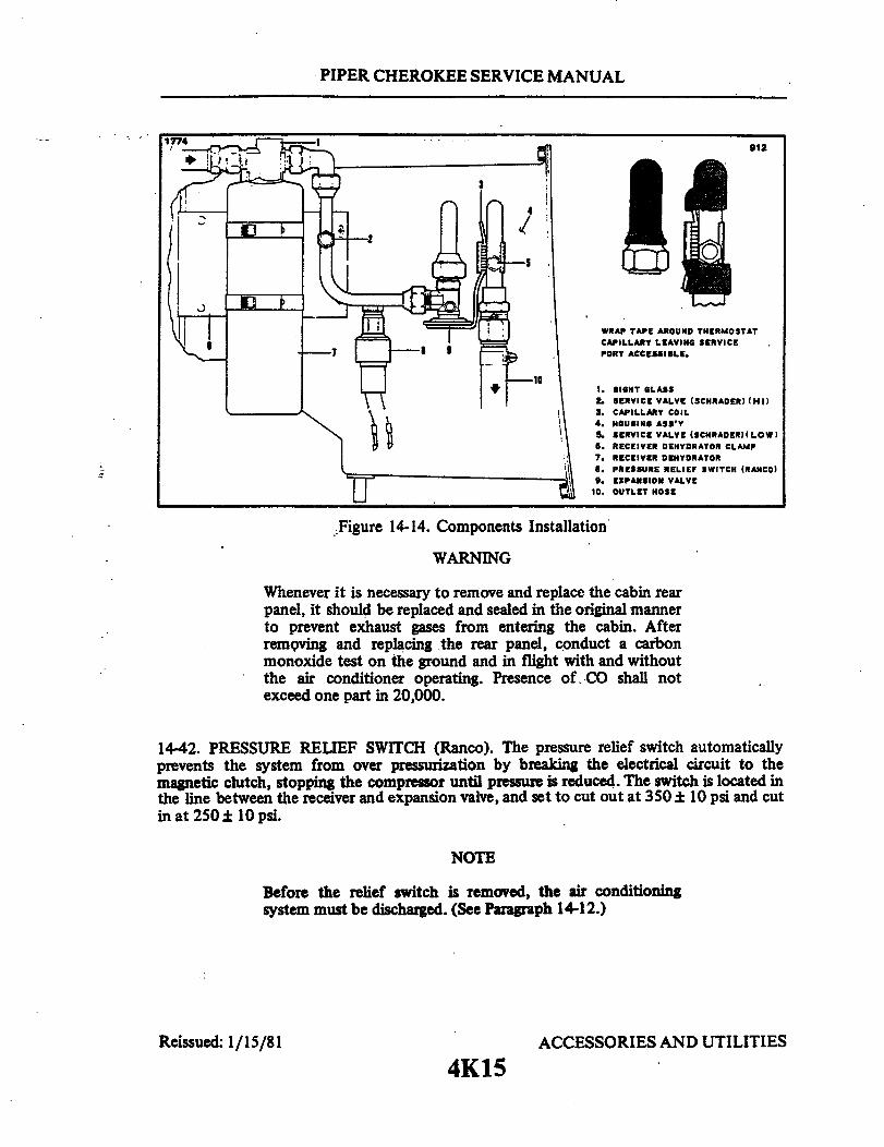
PIPER CHEROKEE SERVICE MANUAL
1774912
WRAP TAPE AROUND THERMOSTATCAPILLARY LEAVING SERVICEPORT ACCESSIBLE.
1. SIGHT GLASS2 SERVICE VALVE (SCHRADER) (HI)
3. CAPILLARY COIL4. HOUSING ASS'Y
. SERVICE VALVE (SCHRADER)(LOW)6. RECEIVER DEHYDRATOR CLAMP7. RECEIVER DEHYDRATOR
. PRESSURE RELIEF SWITCH (RANCO)9. EXPANSION VALVE
10. OUTLET HOSE
Figure 14-14. Components Installation
WARNING
Whenever it is necessary to remove and replace the cabin rearpanel, it should be replaced and sealed in the original mannerto prevent exhaust gases from entering the cabin. Afterremoving and replacing the rear panel, conduct a carbonmonoxide test on the ground and in flight with and withoutthe air conditioner operating. Presence of .CO shall notexceed one part in 20,000.
14-42. PRESSURE RELIEF SWITCH (Ranco). The pressure relief switch automaticallyprevents the system from over pressurization by breaking the electrical circuit to themagnetic clutch, stopping the compressor until pressure is reduced. The switch is located inthe line between the receiver and expansion valve, and set to cut out at 350 ± 10 psi and cutin at 250 ± 10 psi.
NOTE
Before the relief switch is removed, the air conditioningsystem must be discharged. (See Paragraph 14-12.)
Reissued: 1/15/81 ACCESSORIES AND UTILITIES
4K15
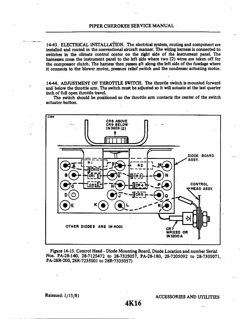
PIPER CHEROKEE SERVICE MANUAL
1443. ELECTRICAL INSTALLATION. The electrical system, routing and component areinstalled and routed in the conventional aircraft manner. The wiring harness is connected toswitches in the climate control center on the right side of the instrument panel. Theharnesses cross the instrument panel to the left side where two (2) wires are taken off forthe compressor clutch. The harness then passes aft along the left side of the fuselage whereit connects to the blower motor, pressure relief switch and the condenser actuating motor.
14-44. ADJUSTMENT OF THROTTLE SWITCH. The throttle switch is mounted forwardand below the throttle arm. The switch must be adjusted so it will actuate at the last quarterinch of full open throttle travel.
The switch should be positioned so the throttle arm contacts the center of the switchactuator button.
C366
CR8 ABOVECR9 BELOW1N3659 (2)
DIODE BOARD
R2 ASSY.
CONTROL
OTHER DIODES ARE IN 4001 CR7
MR1120 ORIN 1200 A
Figure 14-15. Control Head - Diode Mounting Board, Diode Location and number SerialNos. PA-28-140, 28-7125472 to 28-7325057, PA-28-180, 28-7205092 to 28-7305071,PA-28R-200, 28R-7235001 to 28R-7335057)
Reissued: 1/15/81 ACCESSORIES AND UTILITIES
4K16
PIPER CHEROKEE SERVICE MANUAL
14-45. FUSE REPLACEMENT (Refer to Figure 14-15.) (Serial Nos. PA-28-140,28-7125472 to 28-7325057, PA-28-180, 28-7205092 to 28-7305071, PA-28R-200,28R-7235001 to 28R-7335057.) There are two fuses located behind the air conditioningsystem control panel. A 25 amp circuit breaker mounted in the circuit breaker panelprotects the complete air conditioning electrical system.
14-46. FUSE REPLACEMENT (Serial Nos. PA-28-140, 28-7325058 and up, PA-28-180,28-7305072 and up, PA-28R-200, 28R-7335058 and up.) There are three fuses locatedbehind the air conditioning system control panel. A 20 amp circuit breaker mounted in thecircuit breaker panel protects the complete air conditioning electrical system.
NOTE
The Control Head will be replaced when needed with newparts used in the Air Conditioning Control SystemModification Kit installed in the PA-28-140, Serial Numbers28-7325058 and up, the PA-28-180, Serial Numbers28-7305072 and up, and the PA-28R-200, Serial Numbers28R-7335058 and up.
THIS SPACE INTENTIONALLY LEFT BLANK
Reissued: 1/15/81 ACCESSORIES AND UTILITIES
4K17
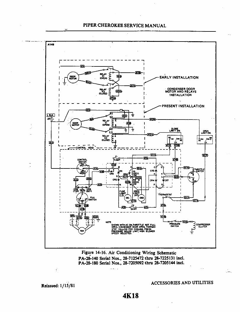
PIPER CHEROKEE SERVICE MANUAL
A145
RELAYEARLY INSTALLATION
RELAY CONDENSER DOORK2 MOTOR AND RELAYS
(CLOSE) INSTALLATION
PRESENT INSTALLATION
NOTESHOWN WITH AC ON,THROTTLE NOT FULLOPEN, CONDENSER DOOR OPEN. THERMO-STAT CALLING FOR COOING. FREONPRESSURE BELOW LIMIT. HIGH BLOWERSPEED SELECTED.
Figure 14-16. Air Conditioning Wiring SchematicPA-28-140 Serial Nos., 28-7125472 thru 28-7225131 incl.PA-28-180 Serial Nos., 28-7205092 thru 28-7205144 incl.
ACCESSORIES AND UTILITIESReissued: 1/15/81
4K18
I
I
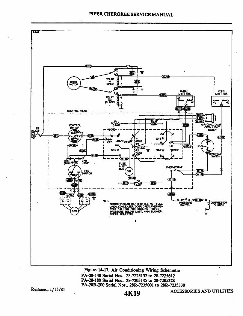
PIPER CHEROKEE SERVICE MANUAL
A146
CLOSE
CONTROL HEAD
CONTROL
.
NOTE:SHOWN WITH AC ON,THROTTLE NOT FULLOPEN, CONDENSER DOOR OPEN,THERMO-STAT CALLING FOR COOLING, FREONPRESSURE BELOW LIMIT, HIGH BLOWERSPEED SELECTED.
Reissued: 1/15/81
Figure 14-17. Air Conditioning Wiring SchematicPA-28-140 Serial Nos., 28-7225132 to 28-7225612PA-28-180 Serial Nos., 28-7205145 to 28-7205328PA-28R-200 Serial Nos., 28R-7235001 to 28R-7235330
4K19 ACCESSORIES AND UTILITIES

PIPER CHEROKEE SERVICE MANUAL
NO. COMPONENT
F1 FuseF2 FuseF3 FuseK1 Relay (Door Open)K2 Relay (Door Close)K3 Relay (Logic)S2 Air Cond. ON-OFF Sw.S3 Throttle Sw.S4 Door Open Limit Sw.S5 Pressure SwitchS6 ThermostatS7 Door Close Umit Sw.
SHOWN WITH AIR CONDITIONINGTHROTTLE NOT WIDE OPENPOSITION, FREON PRESSIING FOR COOLING, AND C
LOCATION
Instrument PanelInstrument PanelInstrument PanelRear of CabinRear of CabinIntrument PanelInstrument PanelThrottle Quadrnt R.Transmission AssyRear of CabinIntrument PanelTransmission Assy
LATER
5A F3
S2 COND.
ON SW.
OPEN4 3 RELAY 2
CONDITIONING FAN SWITCH IN OFF POSITION, MOTOREN, AIR CONDITIONING SWITCH IN ONURE BELOW LIMIT, THERMOSTAT CALL-ONDENSER DOOR CLOSED.
Figure 14-18. Air Conditioning Wiring SchematicPA-28-140 Serial Nos., 28-7325001 and upPA-28-180 Serial Nos., 28-7305001 and upPA-28R-200 Serial Nos., 28-7335001 and up
Reissued: 1/15/814K20
1700
NC
5 4
K2
THERMOSTAT
COMPRESSORCLUTCH
ACCESSORIES AND UTILITIES
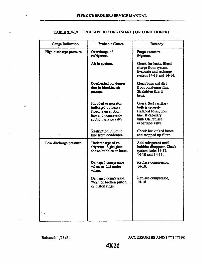
PIPER CHEROKEE SERVICE MANUAL
TABLE XIV-IV. TROUBLESHOOTING CHART (AIR CONDITIONER)
Gauge Indication Probable Causes
High discharge pressure. Overcharge ofrefrigerant.
Purge excess re-frigerant.
Air in system.
Overheated condenserdue to blocking airpassage.
Flooded evaporatorindicated by heavyfrosting on suctionline and compressorsuction service valve.
Restriction in liquidline from condenser.
Check for leaks. Bleedcharge from system.Evacuate and rechargesystem 14-13 and 14-14.
Clean bugs and dirtfrom condenser fins.Straighten fins ifbent.
Check that capillarybulb is securelyclamped to suctionline. If capillarybulb OK replaceexpansion valve.
Check for kinked hosesand stopped up filter.
Low discharge pressure. Undercharge of re-frigerant. Sight glassshows bubbles or foam.
Add refrigerant untilbubbles disappear. Checksystem leaks 14-17,14-10 and 14-11.
Damaged compressorvalves or dirt undervalves.
Damaged compressor.Worn or broken pistonor piston rings.
Reissued: 1/15/81
Replace compressor,14-18.
Replace compressor,14-18.
ACCESSORIES AND UTILITIES
4K21
Remedy
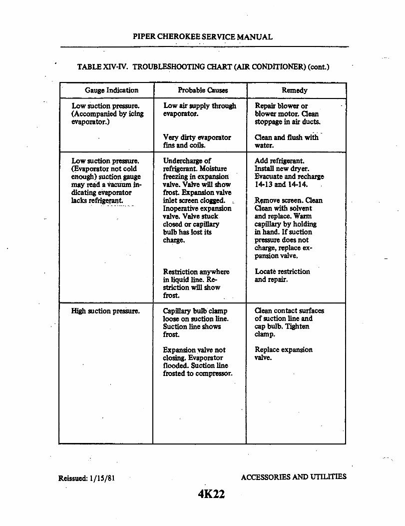
PIPER CHEROKEE SERVICE MANUAL
TABLE XIV-IV. TROUBLESHOOTING CHART (AIR CONDITIONER) (cont.)
Gauge Indication Probable Causes
Low suction pressure.(Accompanied by icingevaporator.)
Low air supply throughevaporator.
Very dirty evaporatorfins and coils.
Repair blower orblower motor. Cleanstoppage in air ducts.
Clean and flush withwater.
Low suction pressure.(Evaporator not coldenough) suction gaugemay read a vacuum in-dicating evaporatorlacks refrigerant
Undercharge ofrefrigerant. Moisturefreezing in expansionvalve. Valve will showfrost. Expansion valveinlet screen clogged.Inoperative expansionvalve. Valve stuckclosed or capillarybulb has lost itscharge.
Add refrigerant.Install new dryer.Evacuate and recharge14-13 and 14-14.
Remove screen. CleanClean with solventand replace. Warmcapillary by holdingin hand. If suctionpressure does notcharge, replace ex-pansion valve.
Restriction anywherein liquid line. Re-striction will showfrost.
Locate restrictionand repair.
High suction pressure. Capillary bulb clamploose on suction line.Suction line showsfrost.
Clean contact surfacesof suction line andcap bulb. Tightenclamp.
Expansion valve notclosing. Evaporatorflooded. Suction linefrosted to compressor.
Reissued: 1/15/81
Replace expansionvalve.
ACCESSORIES AND UTILITIES
4K22
Remedy

PIPER CHEROKEE SERVICE MANUAL
TABLE XIV-IV. TROUBLESHOOTING CHART (AIR CONDITIONER) (cont.)
Gauge Indication
High suction pressure.(cont.)
Probable Causes
Compressor drive beltslipping.
Remedy
Adjust belt tension,14-23.
Magnetic clutchslipping
Leaking or brokencompressor valves.
Cause
Check electricalcircuit for correctvoltage to clutchcoil. Clean clutchsurfaces of oil.
Replace compressor.
Remedy
Door will not closewhen air conditionerswitch is in OFFposition.
System produces nocooling.
Faulty relay "K-2." Replace relay.
Electrical.
Blown fuse incontrol head.
Open circuit breaker.
Broken or disconnectedelectrical wire.
Broken or disconnectedground wire.
Clutch coil burned outor disconnected.
Replace fuse.
Reset circuit breaker.
Check all terminalsfor loose connections;check wiring for hiddenbreaks.
Check ground wire toto see if loose, broken,or disconnected.
Check current flow toclutch, replace ifinoperative.
Reissued: 1/15/81 ACCESSORIES AND UTILITIES
4K23
Trouble

PIPER CHEROKEE SERVICE MANUAL
TABLE XIV-IV. TROUBLESHOOTING CHART (AIR CONDITIONER) (cont.)
Trouble Cause Remedy
Electrical. (cont.)
Thermostat sensingelement defective.
Blower motor dis-connected or burnedout.
Mechanical
Loose or broken drivebelt.
Compressor partiallyor completely frozen.
Expansion valve stuckin open position.
Refrigeration
Broken refrigerantline.
Leak in system.
Reissued: 1/15/81
Check thermostat andcabin comfort controlpanel.
Check current flowto blower motor.Repair or replace ifinoperative.
Replace drive beltsand/or tighten tospecifications. 14-22and 14-23.
Remove compressor forservice or replacement,14-18.
Replace expansionvalve, 14-35.
Examine all lines forevidence of breakageby external stress orrubbing wear.
Evacuate system, applystatic charge, leaktest system, and repairleak as necessary,14-13 and 14-9.
ACCESSORIES AND UTILITIES
4K24
System produces nono cooling. (cont.)

PIPER CHEROKEE SERVICE MANUAL
TABLE XIV-IV. TROUBLESHOOTING CHART (AIR CONDITIONER) (cont.)
Trouble Cause Remedy
System produces nocooling. (cont)
Compressor shaft sealleaking.
Replace compressor,14-18.
Clogged screen orscreens in receiverdehydrator or expansionvalve; plugged hose orcoil.
Repair as necessary.
System will not producesufficient cooling.
Electrical
Blower motor sluggishin operation.
Remove blower motorfor service or re-placement.
Mechanical
Compressor clutchslipping.
Obstructed blowerpassage.
Insufficient aircirculation overcondenser coils;fins clogged withdirt or bugs.
Reissued: 1/15/81
Remove clutch assemblyfor service or replace-ment, 14-24.
Examine entire passagefor obstruction. Correctas necessary.
Clean condenser coils.
ACCESSORIES AND UTILITIES
4L1
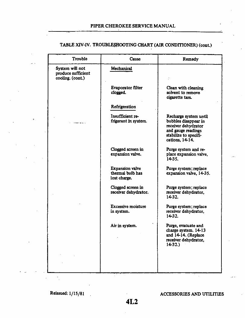
PIPER CHEROKEE SERVICE MANUAL
TABLE XIV-IV. TROUBLESHOOTING CHART (AIR CONDITIONER) (cont.)
Trouble
System will notproduce sufficientcooling. (cont.)
Cause Remedy
Mechanical
Evaporator filterclogged.
Refrigeration
Insufficient re-frigerant in system.
Clogged screen inexpansion valve.
Expansion valvethermal bulb haslost charge.
Clogged screen inreceiver dehydrator.
Excessive moisturein system.
Air in system.
Reissued: 1/15/81
Clean with cleaningsolvent to removecigarette tars.
Recharge system untilbubbles disappear inreceiver dehydratorand gauge readingsstabilize to specifi-cations, 14-14.
Purge system and re-place expansion valve,14-35.
Purge system; replaceexpansion valve, 14-35.
Purge system; replacereceiver dehydrator,14-32.
Purge system; replacereceiver dehydrator,14-32.
Purge, evacuate andcharge system. 14-13and 14-14. (Replacereceiver dehydrator,14-32.)
ACCESSORIES AND UTILITIES
4L2

PIPER CHEROKEE SERVICE MANUAL
TABLE XIV-IV. TROUBLESHOOTING CHART (AIR CONDITIONER) (cont.)
Trouble Cause Remedy
Excessively noisysystem
Electrical
Defective winding orimproper connectionin compressor clutchcoil.
Replace or repairas necessary, 14-24.
Mechanical
Loose or excessivelyworn drive belts.
Noisy clutch.
Compressor noisy.
Compressor oil levellow.
Refrigeration
Excessive charge insystem.
Low charge in system.
Excessive moisture insystem.
Reissued: 1/15/81
Tighten or replace asrequired. 14-22 and14-23.
Remove clutch forservice or replace-ment as necessary,14-24.
Check mountings andrepair; remove com-pressor for serviceor replacement, 14-18.
Fill with correctamount of specifiedoil, 14-21.
Discharge excess freonuntil high pressuregauge drops withinspecifications.
Check system forleaks; charge system,14-9 and 14-14.
Replace dehydrator;purge, evacuate, andcharge system, 14-32,14-13 and 14-14.
ACCESSORIES AND UTILITIES
4L3
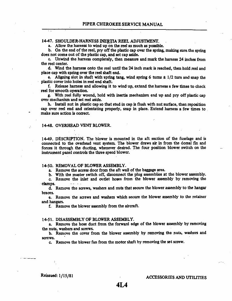
PIPER CHEROKEE SERVICE MANUAL
14-47. SHOULDER-HARNESS INERTIA REEL ADJUSTMENT.a. Allow the harness to wind up on the reel as much as possible.b. On the end of the reel, pry off the plastic cap over the spring, making sure the spring
does not come out of the plastic cap, and set cap aside.c. Unwind the harness completely, then measure and mark the harness 24 inches from
the reel center.d. Wind the harness onto the reel until the 24 inch mark is reached, then hold reel and
place cap with spring over the reel shaft end.e. Aligning slot in shaft with spring tang, wind spring 6 turns ± 1/2 turn and snap the
plastic cover into holes in reel end shaft.f. Release harness and allowing it to wind up, extend the harness a few times to check
reel for smooth operation.g. With reel fully wound, hold with inertia mechanism end up and pry off plastic cap
over mechanism and set reel aside.h. Install nut in plastic cap so that stud in cap is flush with nut surface, then reposition
cap over reel end and orientating properly, snap in place. Extend harness a few times tomake sure action is correct.
14-48. OVERHEAD VENT BLOWER.
1449. DESCRIPTION. The blower is mounted in the aft section of the fuselage and isconnected to the overhead vent system. The blower draws air in from the dorsal fin andforces it through the ducting, whenever desired. The four position blower switch on theinstrument panel controls the three speed blower.
14-50. REMOVAL OF BLOWER ASSEMBLY.a. Remove the access door from the aft wall of the baggage area.b. With the master switch off, disconnect the plug assemblies at the blower assembly.c. Remove the inlet and outlet hoses from the blower assembly by removing the
clamps.d. Remove the screws, washers and nuts that secure the blower assembly to the hangar
braces.e. Remove the screws and washers which secure the blower assembly to the retainer
and hangars.f. Remove the blower assembly from the aircraft.
14-51. DISASSEMBLY OF BLOWER ASSEMBLY.a. Remove the hose duct from the forward edge of the blower assembly by removing
the nuts, washers and screws.b. Remove the cover from the blower assembly by removing the nuts, washers and
screws.c. Remove the blower fan from the motor shaft by removing the set screw.
Reissued: 1/15/81 ACCESSORIES AND UTILITIES
4L4
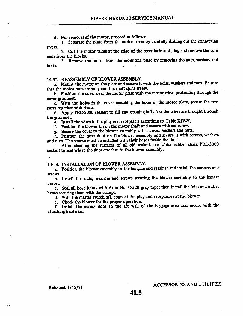
PIPER CHEROKEE SERVICE MANUAL
d. For removal of the motor, proceed as follows:1. Separate the plate from the motor cover by carefully drilling out the connecting
rivets.2. Cut the motor wires at the edge of the receptacle and plug and remove the wire
ends from the blocks.3. Remove the motor from the mounting plate by removing the nuts, washers and
bolts.
14-52. REASSEMBLY OF BLOWER ASSEMBLY.a. Mount the motor on the plate and secure it with the bolts, washers and nuts. Be sure
that the motor nuts are snug and the shaft spins freely.b. Position the cover over the motor plate with the motor wires protruding through the
cover grommet.c. With the holes in the cover matching the holes in the motor plate, secure the two
parts together with rivets.d. Apply PRC-5000 sealant to fill any opening left after the wires are brought through
the grommet.e. Install the wires in the plug and receptacle according to Table XIV-V.f. Position the blower fin on the motor shaft and secure with set screw.g. Secure the cover to the blower assembly with screws, washers and nuts.h. Position the hose duct on the blower assembly and secure it with screws, washers
and nuts. The screws must be installed with their heads inside the duct.i. After cleaning the surfaces of all old sealant, use white rubber chalk PRC-5000
sealant to seal where the duct attaches to the blower assembly.
14-53. INSTALLATION OF BLOWER ASSEMBLY.a. Position the blower assembly in the hangars and retainer and install the washers and
screws.b. Install the nuts, washers and screws securing the blower assembly to the hangar
braces.c. Seal all hose joints with Arno No. C-520 grap tape; then install the inlet and outlet
hoses securing them with the clamps.d. With the master switch off, connect the plug and receptacles at the blower.e. Check the blower for the proper operation.f. Install the access door to the aft wall of the baggage area and secure with the
attaching hardware.
Reissued: 1/15/81 ACCESSORIES AND UTILITIES
4L5

PIPER CHEROKEE SERVICE MANUAL
TABLE XIV-V. BLOWER SYSTEM WIRE COLOR CODES
MOTOR WIRES AIRCRAFTWIRES
15920-01Pin. GeneralNos. Industries
E362QSinger
Controls
F0018075FALeece-Neville
Aircraft PinHarness Nos.
Ground
Low Speed
I00.
Medium Speed g
High Speed 8C2
2 Brown
1 Red
2 Black
I Yellow
NOTEPin number 1 is at the pointed side of the plug and receptacle.Wire color codes for YY75062 ESB-Universal ElectricCompany are same as E 362Q Singer Control color code listedabove.
Reissued: 1/15/81 ACCESSORIES AND UTILITIES
4L6
Brown
Yellow
Red
N · Orange
Black
Yellow
Red
Orange
AC26A
Black
White
Red
.22 .
I 01 o
2
1 _

4L7
4L7 THRU 4L24INTENTIONALLY LEFT BLANK