Embed Size (px)
Citation preview

Pipelaying – example from Ormen Lange

Date: 2004-01-16 • Page: 2
Development concept

Date: 2004-01-16 • Page: 3
Ormen Lange bottom topography

Date: 2004-01-16 • Page: 4
Pipeline routing
NShelf (-250m)
Development area (-900m)

Date: 2004-01-16 • Page: 5
Free spans – Early routing
10000 15000 20000 25000 300000 5000-900
-800
-700
-600
-500
-400
-300
-200
Wat
er D
epth
KP
Route 2000Route B

Date: 2004-01-16 • Page: 6
Early route alternative – Distribution of free spans
0.5
5.5
10.5
15.5
20.5
40 140 240 340 440
Span Length [m]
Span
Hei
ght [
m]
Typicalmaximum
Date: 2004-01-16 • Page: 7
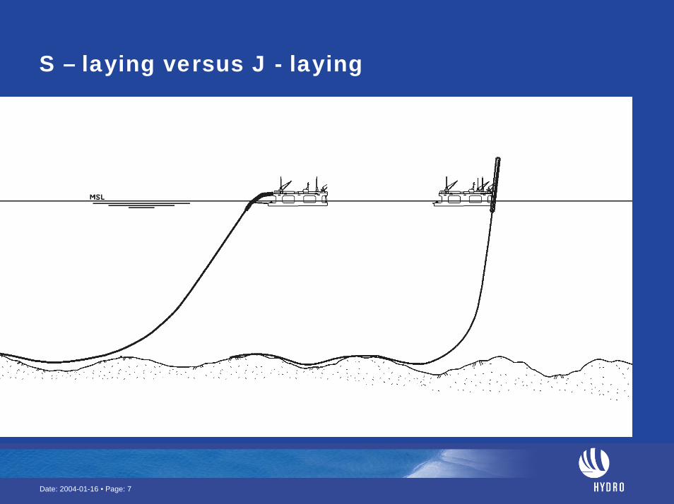
S – laying versus J - laying

Date: 2004-01-16 • Page: 8
Critical length – a fatigue issue
Critical Length
Critical length depends upon natural frequencies and current velocity:LengthDiameterSupport conditionsFatigue capacity

Date: 2004-01-16 • Page: 9
Vortex induced vibrations (VIV) of free spanning pipelines
Induced by current.Simplistic estimation toolsDetermines maximum length of free spans.
FatiguePuts severe constraints on pipeline routingCost driver: Intervention work in deep water.Ormen Lange:
Pioneer project. Basis for improved future methods

Date: 2004-01-16 • Page: 10
Span rectification several options
-1000
-900-800
-700
-600
-500
-400
-300
-200
-100
0
0 5000 10000 15000 20000 25000
Length [m]
Dep
th [m
]
Submerged floating pipelineRocksupports
(Pre/Post dumping) Dredging/Trenching

Date: 2004-01-16 • Page: 11
SHORT versus LONG FREE SPANS
SHORT SPAN L/D ≈ 100
• BEAM BEHAVIOUR GOVERNING
• SINGLE HALF WAVE MODE
• EXISTING DNV - G14
LONG SPAN
L/D ≈ 200
• CABLE DOMINATED BEHAVIOUR
• MULTIPLE MODE EXCITATION
• NOT COVERED BY EXISTING DNV - G14

Date: 2004-01-16 • Page: 12
Cable, beam and sag effect on 1st natural frequency, Large sag, high axial stiffness
Eq 2:
f1,CF = ⎟⎟⎠
⎞⎜⎜⎝
⎛⋅++
effeff
E
e
eff
Nk
LNP
mN
L
20
2
41
21 δπ
(Hz)
Cable Beam Sag
cablelarge sag
cablesmall sag
0 50 100 150 200 250 300 350 4000
0.1
0.2
0.3
0.4
0.5
0.6
0.7
0.8
0.9
1
L/D
f 1 (1/s
ec)
Equation 2 w/o beam effect
Sagging cable (Triantafyllou)Cable w/o sag Equation 2
Equation 2 w/o sag effect FEM values, IL FEM values, CF

Date: 2004-01-16 • Page: 13
Reliability analysis & RP-F105IL vibration controls fatigue life.
Single (idealized) span length can be increased from 40 – 60 m to 80 – 110m (Shortest in slide area, longest in development area)

Date: 2004-01-16 • Page: 14
Shoulder contact force. Soft versus stiff soil

Date: 2004-01-16 • Page: 15
Improved routing & intervention workShorter spans with short shoulders. I.e. interaction between spans.Max. allowable length of a span depends upon neighbouring spans and shoulder properties (stiffness & geometry)Improved current and soil information

Date: 2004-01-16 • Page: 16
DNV-RP-F105 Span interaction

Date: 2004-01-16 • Page: 17
S – laying versus J - laying
Date: 2004-01-16 • Page: 18
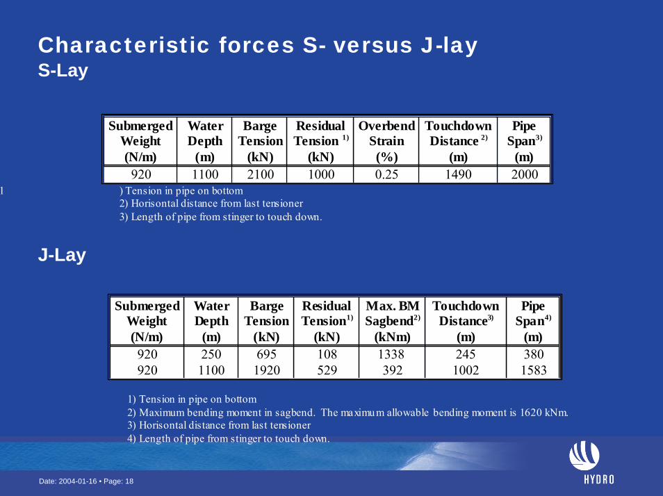
Characteristic forces S- versus J-layS-Lay
200014900.25100021001100920
PipeSpan3)
(m)
TouchdownDistance 2)
(m)
OverbendStrain
(%)
ResidualTension 1)
(kN)
BargeTension
(kN)
WaterDepth
(m)
SubmergedWeight(N/m)
1 ) Tension in pipe on bottom2) Horisontal distance from last tensioner3) Length of pipe from stinger to touch down.
J-Lay
15831002392529192011009203802451338 108695250920
PipeSpan4)
(m)
TouchdownDistance3)
(m)
Max. BMSagbend2)
(kNm)
ResidualTension1)
(kN)
BargeTension
(kN)
WaterDepth
(m)
SubmergedWeight(N/m)
1) Tension in pipe on bottom2) Maximum bending moment in sagbend. The maximum allowable bending moment is 1620 kNm.3) Horisontal distance from last tensioner4) Length of pipe from stinger to touch down.

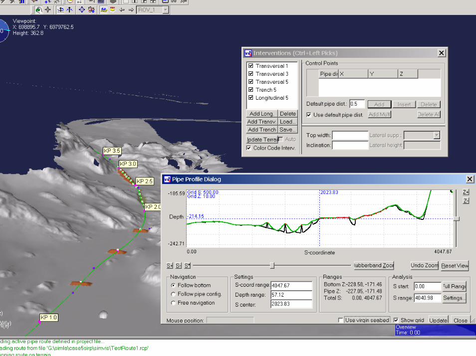
Simulation of marine operationsPipelaying

Date: 2004-01-16 • Page: 20
Simulator for complex marine operations
High level architecture (HLA) / Run -Time Infrastructure (RTI)
Terrain module
ROV control and visualization
RIFLEXcables and risers
SIMOvessel INC. DP
SIMLAPipelayingFree spans
SIMULATOR CONTROL Visualization
GL view

Date: 2004-01-16 • Page: 21
Pipe Laying
Date: 2004-01-16 • Page: 22

Date: 2004-01-16 • Page: 23
Gravel supports in BjørnsundetBasis for laying analysis

Date: 2004-01-16 • Page: 24
Virtual ROV picture

Date: 2004-01-16 • Page: 25
Rock installation