Embed Size (px)
Citation preview

Drainage (10-1-2013)
PIPE CULVERT PLACEMENT
Overview Roadway has created features for pipes for plan, profile, & 3d views. A Civil Cell has been created for Box Culvert placement. The steps below show how to place pipes and culverts.
Prerequisites 1) Corridor placed on roadway that intended drainage is being placed on. 2) Create a Drainage.dgn file, reference your existing terrain, make active, & open the default-3d
model in view 5. 3) Reference in the DGN containing your roadway corridor, both Default model to View 1 &
Default-3d model to View 5.
Placing a Pipe 1) Place the Horizontal Alignment.
Length doesn’t matter at this time, just make sure it’s initially at or outside your construction limits.

2) Open a profile view of the Pipe alignment.
3) Choose the Vertical command “Profile from Surface”.
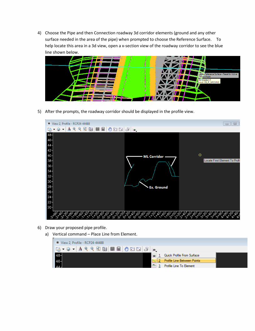
4) Choose the Pipe and then Connection roadway 3d corridor elements (ground and any other surface needed in the area of the pipe) when prompted to choose the Reference Surface. To help locate this area in a 3d view, open a x-section view of the roadway corridor to see the blue line shown below.
5) After the prompts, the roadway corridor should be displayed in the profile view.
6) Draw your proposed pipe profile. a) Vertical command – Place Line from Element.

b) Trim the pipe profile length back to take Flared End Sections into consideration if they are present.
c) If the profile is not as long as the Horizontal Pipe drawn, find out what station the profile ends at and then change the ending station of the Horizontal Pipe to match the profile.

d) Set the profile active.
e) 3d Pipe is drawn when the profile is set active.
f) You can use the Vertical command “Profile from Surface” to choose more surfaces of your corridor to check for height of cover.

Placing a Box Culvert 1) Place the Horizontal Alignment.
Length doesn’t matter at this time, just make sure it’s initially at or outside your construction limits.
2) Follow steps 2-6d for profile creation. You should have an active profile for the Box Culvert CL that looks similar to below and the horizontal length should have been modified to match the vertical length.

3) Copy parallel partial your roadway alignment, 0’ offset, a distance of +/- 100’ from the intersection of the Box Culvert CL. This element will need to be placed on
4) Choose the Place Civil Cell command.
5) Choose the Box Culvert cell.

6) Choose the Construction element copied on top of the road alignment.
7) Choose the Box Culvert CL.
8) Follow remaining prompts to place Box. You can see 2d & 3d views of the box below.

9) The box is default 6’x6’ withy associated thicknesses. Make any adjustments needed as shown below.
a) Select the 2 lines below to modify box width.
b) Go to properties on the Working_BOX_TOP* elements to modify height.
c) You’ll need to modify the profile of the line below on each side of the box to adjust the Wing Wall height.

d) Wing Wall skew can be adjusted as shown below.
e) “W” height can be modified by opening the profile view of the line below.

Finished product in a Microstation Transparent view.