Embed Size (px)
Citation preview

M u l t ip h a s e F l o w Characteristics of G a s S p a r g e d H y drocy clo ne F lotation D e in k in g
J . D . M iller, A. Das and D. Lelinski J. W. Chamblee D ep t, o f M etallurgical Engineering R & D Engineer 412 W m . Browning Building Kamyr Inc.U niversity o f Utah 1 Ridge CenterSalt Lake City, U T 84112 Glens Falls, NY 12801
A B STR A C T
A new high-efficiency technology has been developed for flo ta tion deinking of various wastepaper grades. The GSC™ gas sparged hydrocyclone is a centrifugal device that operates at consistencies of 1 to 3 percent and uses conventional flotation chemistry.
Research and development efforts have continued in order to b e tte r understand the fluid mechanics involved in successful a ir-sparged hydrocyclone flotation deinking. X-ray com puted tomography measurements have helped to describe the m ultiphase fluid flow in the hydrocyclone, particularly w ith respect to particle segregation in the swirl flow. This m easurem ent technique has also been used to evaluate the characteristics o f the froth phase.
A dditionally , bubble size distributions generated during operation o f the hydrocyclone have been measured using a special photographic technique. The results of these research efforts w ill be presented and discussed.
INTRODUCTION
T h e air-sparged hydrocyclone (ASH) is distinguished by its h ig h specific capacity for fine particle flotation in a centrifugal field. For example, it is now evident that the ASH has a specific capacity of at least 100 times that of conventional flo tation equipment. During the 1980s, small, 2-inch diam eter ASH units were tested for a large number o f m ineral commodities, and design modifications were made as necessary (1). The air-sparged hydrocyclone has shown prom ising potential for the flotation of copper porphyry ore, low -grade placer gold and auriferous pyrite ores, various industrial minerals, and fme coal cleaning. Development efforts have been extended to other countries, including A ustralia , Brazil, Canada, Chile, Israel, Japan, M exico, N etherlands, Poland, and South Africa.
O ne o f the promising applications has been found to be the u se o f the ASH for fine coal flotation. As a result o f this
pioneering research, the effectiveness o f the ASH for fine coal flotation has been demonstrated for a number o f U.S. and Canadian coals, and plant-site evaluation of large- diameter units is in progress. Testing o f the first 15-inch air-sparged hydrocyclone (A SH - 15C) began in October 1992 at the Homer City Coal Preparation Plant and preliminary results indicate that effective separations will be possible for fine coal cleaning,
Also during the last few years, attention has been given to applications of air-sparged hydrocyclone flotation technology outside the mineral industry, including the pulp and paper industry and the food industiy, as well as its possible utilization to solve environmental problems (oil spills, soil remediation, hazardous waste, etc .). The most significant development, however, was the construction in 1991 of a wastepaper recycling pulp mill which uses air-sparged hydrocyclone technology for deinking flotation. The plant, which began operation in June 1992, employs a 3 stage flotation system using twenty 6-inch ASH units to produce 120 ADT/day of recycled market pulp (2, 3).
In addition to these efforts to commercialize the ASH technology, fundamental research has been on-going, and currently x-ray computed tomography studies of the time- averaged multiphase flow characteristics are being supported by NSF and DOE. As a result o f these x-ray CT studies, a better appreciation of the influence of system variables on the nature of the segregated flow is being developed. In addition, high-speed photography and high-speed video techniques are being used to examine the nature of bubble formation in the swirl flow o f the ASH and the corresponding bubble size distributions. O n this basis, it is expected that these fundamental measurements w ill help to establish design features and operating conditions for even more efficient flotation separations.
PRINCIPLES AND DESIGN FEATURES
The basic concept from which high-capacity air-sparged hydrocyclone flotation evolved was the notion that fine hydrophobic particles are difficult to float because they have insufficient inertia to penetrate/rupture the bubble film and establish a stable attachment w ith the bubble. In this regard, i f the fine particles’ inertia could be increased by placing it in a centrifugal force field, more effective flotation of fme particles could be realized. Such a centrifugal force field is found for the fluid flow in hydrocyclone separators. A number of designs for the air-sparged hydrocyclone were tested in the early eighties, and as a result a preferred design, a vertically oriented, cylindrical cyclone with a tangential feed entry at the top, was established (4). A schematic drawing of such an air-sparged hydrocyclone is
1993 Engineering Conference / 417

presented in Figure 1. The ASH unit consists of two concentric right-vertical tubes, a conventional cyclone header at the top, and a froth pedestal at the bottom. The inner tube is a porous wall through which air is injected. The outer nonporous tube simply serves as an air jacket to provide for even distribution of air through the porous inner tube. The slurry is fed tangentially through the conventional cyclone header to develop a swirl flow of a certain thickness in the radial direction (called the swirl layer thickness) adjacent to the porous wall, leaving an air core centered on the axis of the air-sparged hydrocyclone. The swirl flow thus created shears the injected air to produce a high concentration of small bubbles. In wastepaper flotation, hydrophobic ink particles in a pulp suspension collide with these air bubbles, and after attachment, lose some of their tangential velocity, and are transported radially into a froth phase which forms at the surface of the air core on the cyclone axis. The froth phase is stabilized and constrained by the froth pedestal at the underflow and thus moves towards the vortex finder of the cyclone header and is discharged as an overflow reject stream. Hydrophilic
Rejects
Ink And Other Lightweights
Stock
Stock In
Accepts
Figure 1. (ASH).
Perspective o f the air-sparged hydrocyclone
particles including pulp fibers generally remain centrifuged at the porous tube wall and are accepted through the annu lar underflow opening created between the inner porous tube wall and the froth pedestal (5).
The design features of the ASH improve the floatability o f fine ink particles in two ways. First, a significant cen trifu gal force field is developed, the magnitude o f which is determined by the slurry feed rate and the cyclone diam eter. This centrifugal force field results in increased inertia o f fine ink particles and hence facilitates their attachment to a ir bubbles. Secondly, the high-speed swirl flow creates a significant shear force at the porous wall, which shears the air injected through the porous tube into numerous small a ir bubbles, thus increasing the rate of flotation of fine h y d ro phobic ink particles. Further, these small air bubbles are directed in the radial direction, orthogonal to the motion o f the hydrophobic ink particles in the swirl flow. As a result, the probability of collision o f air bubbles with hydrophobic ink particles is significantly increased, and effective flotation of these fine ink particles can be achieved for residence times that approach the intrinsic bubble/particle attachment times. Consequently, a specific flotation capacity o n the order o f 30 tpd/ft3 o f cyclone volume is realized, at least 100 times the specific capacity o f conventional mechanical o r column flotation cells.
MULTIPHASE FLOW CHARACTERISTICS BY X-RAY COMPUTED TOMOGRAPHY
During the past few years research efforts have been m ade to examine time-averaged multiphase flow in air-sparged hydrocyclone flotation by x-ray computed tomography. In x-ray CT an x-ray beam o f intensity I„ is incident on an object and emerges with an intensity I. The measurement quantity (I/Io) is equal to the summation of the x-ray attenuation coefficients of the material at each point along the incident line. Total attenuations are measured along all rays through an object from several directions around the object, and the image is reconstructed from these intensity data using a reconstruction algorithm. The computer softw are according to this specific algorithm, manipulates the m easured projections and produces a two-dimensional map o f x-ray attenuation coefficients (CT numbers) o f the irradiated cross sections. The attenuation coefficients are correlated with density by calibrating the CT machine with objects o f known density and obtaining a correlation equation that relates attenuation coefficients and thus CT numbers w ith density. In such a fashion, then quantitative x-ray CT measurements are possible and a two-dimensional density map of the object under investigation is established (6, 7 ) .
Already, preliminary results using a quartz (120 microns)
% / TAPPI Proceedings

suspension as a model system have clarified certain aspects o f the flow and provided valuable information on the geometric characteristics of the air core, the froth phase and the swirl layer. The narrow size quartz system was selected to facilitate the contrast between the froth phase and swirl layer and thus allow for x-ray CT analysis. Generally, these preliminary results substantiate previous inferences regarding the nature o f multiphase flow during ASH flotation.
A reconstructed CT image and the corresponding time- averaged radial density profile is presented in Figure 2. Darker regions in the image identify the regions o f higher density, During ASH flotation, three regions, namely, the air core, the froth phase and the swirl layer, can be identified as indicated in the radial density profile shown in Figure 3. A transition region between the froth phase and the swirl layer as had been suggested previously is not well defined, but the possibility of its existence should not be neglected.
Flow Geometry
The geometric features of the multiphase flow can be summarized in more detail by referring to Figures 3-5, which for each figure shows three cross sectional scans at the top, middle and bottom o f the ASH (experimental details are provided in the caption). Actually, 11 scans were taken for each experiment.
O f course, the tangential velocity decreases from top to bottom because of the swirl decay. Thus, the centrifugal force is maximum at the top and minimum at the bottom. This feature is generally reflected in the air core dimension. Examination of the images presented in Figure 3, shows that the air core radius is greater at the top o f the ASH than that at the bottom. At the top the air core radius is 9.1 mm and decreases to 7.2 mm at the bottom. Investigation of all CT image data reveals that in most cases the shape of the air
core is conical. Observations regarding air core radius have been summarized in Table 1. For 5% solids in the feed (feed density 1.032 g/cc), the air core radius at the top was observed to decrease with an increase in A*, the dimension- less ratio o f the overflow opening area (vortex finder diameter) to the underflow opening area (annular opening created by froth pedestal). In this way the magnitude of A* is changed mechanically and does not depend on flow conditions. It is clear from Table 1 that the air core volume is a maximum for the smallest A* value considered (A* = 0.74).
High percent solids in the feed slurry is characterized by a smaller air core and the conical shape is no longer well defined. Instead, the air core takes on a cylindrical shape as is evident from the data presented in Table 1. With 15% solids (feed density = 1.104 g/cc), the air core radius varied from 2.2 to 7 ,0 mm depending on experimental conditions. Without any collector addition, the air core radius at the top decreased from 5.1 mm to 2.2 mm as A* increased from 0.74 to 1.00; again indicating that the air core volume is greatest for the smallest A* value under consideration. When collector was added, the air core radius remained approximately the same for all three A* values which suggests that the air hold up is comparable in these three cases. This is easily seen from the images presented in Figure 5.
Air Flow Distribution
In view of the results discussed in the previous section, it appears from the analysis of the air core dimensions that the axial air flow distribution is not uniform during flotation. This analysis is supported by the variation in density and thickness of the swirl layer as can be seen in Figures 3, 4 and 5. It is evident from these figures that the thickness of the swirl layer is smaller at the top than that at the bottom.
Distance From Center (mm)
Figure 2. A reconstructed CT image at the top of the ASH and the corresponding radial density profile.
1993 Engineering Conference / 419

1.40
1.20
o ’ 1-00O3 0.80
~ o.aoV)c<D 0.40
QE
' 0.20 - f
0.00 ............ ,........ I i , | jo 10 20 30
Distance From Center (mm)
Figure 3. CT images and radial density profiles for quartz (100 x 200 mesh)suspension at the top, middle and bottom of the ASH-2C for 5 %solids (feed density = 1.032), 800 g/t collector and A* = 1.00.
? / TAPPI Proceedings

o
toc
1.40
1,20 -
1.00 1 ........... *\. f \
| 1 0.80 - f 'l J o.eo L /\ ' 1 M - /
0.40 - /0.20 - /
L0.00 L.. i , i ,
o 10 20 30
Distance From Center (mm)
Figure 4. CT images and corresponding radial density profiles for quartz (100 x 200mesh) suspension at the top, middle and bottom of the ASH-2C for15% solids (feed density = 1.104), no collector and A* = 0.85.
1993 Engineering Conference / 421

1 .4 0
1.40
1.20
'o ' 1.00o
3 0.80
> .■»-* 0.60Cf)tz© 0.40
O0.20
0.00
Distance From Center (mm)
^ 5 and corresPondlng radial density profiles for qiiartz (100x200solids ( ' f r ^ S10n 8t the t0p’ middle and bottom of the ASH-2C for 15%solids (feed density = 1.104), 800 g/t collector and A* = 1 00
/ TAPPI Proceedings

Table 1. Radius of the air core at different locations for quartz (120microns) suspension under various experimental conditions.
Air Core Radius
Solids(%)
A* Collector(g/ton)
Top(mm)
Middle(mm)
Bottom(mm)
5 0.74 0 12.0 11.0 8.05 0.85 0 8.7 8.0 7.05 1.00 0 6.2 7.5 6.0
5 0.74 800 13.3 9.1 8.55 0.85 800 9.5 8.7 8.05 1.00 800 9.1 8.6 7.2
15 0.74 0 5.1 4.0 5.115 0.85 0 4.9 4.1 5 .215 1.00 0 2.2 2.6 2.5
15 0.74 800 5.0 4.1 5.115 0.85 800 7.0 6.4 4.915 1.00 800 5.0 4.3 5.1
Further the density o f the swirl layer is greatest at the top of the ASH. The swirl layer, because o f the higher centrifugal force, is in a compact state at the top, resulting in a higher density (lower hold up o f air) whereas the swirl layer is expanded at the bottom and is of a lower density due to greater hold up of air. I t is believed that these results are indicative of a greater air flow through the bottom o f the ASH. Such an interpretation can be rationalized by the fact that the resistance to air flow at the bottom will be less due to the reduction in the tangential velocity component o f the swirl flow and thus a reduced centrifugal force. In this regard, multiple air chambers have been used to shift the air flow distribution patterns when necessary.
Particle Hydrophobicity
Since the quartz particles (-100 + 200 mesh) are naturally hydrophilic, the solid split to the overflow (OF) rejects is negligible (about 0 .5 % o f the feed solids; at 5 % solids in the feed and a feed density o f 1.032). In the absence of collecto r addition, essentially all o f the quartz is found in the underflow (UF) accepts. For 5 % solids in the feed slurry and no collector, the water split to the OF rejects was observed to increase with an increase in A*. Experimental data regarding solids and water split to the OF rejects for various experimental conditions are summarized in Table 2. Notice that with the addition o f 800 g collector (amine) per ton of quartz, the quartz particles become hydrophobic. Excellent ASH flotation takes place as is evident from Table
2. F o r 5% solids in the feed the solids split to OF rejects was found to increase from 68.4% to 85.6% and finally to 94.2% with an increase in A* from 0.74 to 0.85 and finally to 1.00 respectively. The radial density profiles with collector addition are presented in Figure 3 for 5% solids. A higher density for the froth phase indicates that hydrophobic quartz particles were transported into the froth phase. Near the top, the density o f the froth phase increases gradually from the air core to the swirl layer which is estimated to be about 6 mm in thickness, whereas at the bottom, the froth phase is narrow (about 5 mm) and the density rises abruptly indicating that the froth phase near the bottom is depleted o f the hydrophobic quartz particles. These results clearly show that froth transport to the vortex finder is excellent a t A* = 1.00. However, for smaller A* values (0.74 and 0.85) some hydrophobic quartz particles are found in the UF accef t stream.
W hen n/) collector was added, the solids split to the OF reject sjream with 15% solids in the feed slurry was in the range 6f 1-3% for different values of A*. The water split to the/O F rejects was 20.63, 26.95 and 36.22% for A* values of 0.74, 0.85 and 1.00 respectively as can be seen from Table 2. The addition o f collector (800 g amine per ton o f quartz) resulted in substantial flotation and transport o f hydrophobic quartz particles to the overflow rejects. The solids split to the OF rejects was found to be 15.5%, 50.9% and 97.3 % for A* values o f0 .7 4 ,0 .8 5 and 1.00 respectively. I t is evident that higher A* values improve quartz flotation.
1993 Engineering Conference / 423
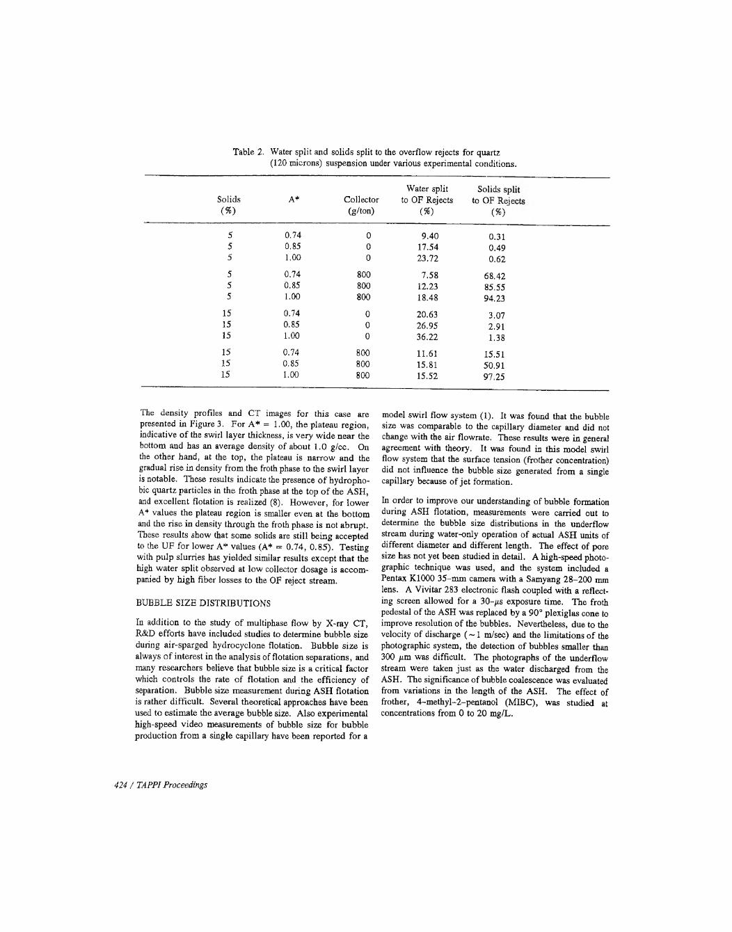
Table 2. Water split and solids split to the overflow rejects for quartz(120 microns) suspension under various experimental conditions.
Solids(% )
A* Collector(g/ton)
Water split to OF Rejects
(%)
Solids spl to OF Reje
(%)
5 0.74 0 9.40 0.315 0.85 0 17.54 0.495 1.00 0 23.72 0.62
5 0.74 800 7.58 68.425 0.85 800 12.23 85.555 1.00 800 18.48 94.23
15 0.74 0 20.63 3.0715 0.85 0 26.95 2.9115 1.00 0 36.22 1.38
15 0.74 800 11.61 15.5115 0.85 800 15.81 50.9115 1.00 800 15.52 97.25
The density profiles and CT images for this case are presented in Figure 3. For A * = 1.00, the plateau region, indicative o f the swirl layer thickness, is very w ide near the bottom and has an average density of about 1.0 g/cc. On the other hand, at the top, the plateau is narrow and the gradual rise in density from the froth phase to the swirl layer is notable. These results indicate the presence o f hydrophobic quartz particles in the froth phase at the top o f the ASH, and excellent flotation is realized (8). However, for lower A* values the plateau region is smaller even at the bottom and the rise in density through the froth phase is not abrupt. These results show that some solids are still being accepted to the U F fo r lower A* values (A* = 0.74, 0 .85). Testing with pulp slurries has yielded similar results except that the high w ater split observed at low collector dosage is accom panied by high fiber losses to the OF reject stream.
BUBBLE SIZE DISTRIBUTIONS
In addition to the study o f multiphase flow by X-ray CT, R&D efforts have included studies to determine bubble size during air-sparged hydrocyclone flotation. Bubble size is always o f interest in the analysis of flotation separations, and many researchers believe that bubble size is a critical factor which controls the rate o f flotation and the efficiency of separation. Bubble size measurement during ASH flotation is rather difficult. Several theoretical approaches have been used to estim ate the average bubble size. Also experimental high-speed video measurements of bubble size for bubble production from a single capillary have been reported for a
model swirl flow system (1). It was found that the bubble size was comparable to the capillary diameter and did not change with the air flowrate. These results were in general agreement with theory. It was found in this model swirl flow system that the surface tension (frother concentration) did not influence the bubble size generated from a single capillary because o f je t formation.
In order to improve our understanding of bubble formation during ASH flotation, measurements were carried out to determine the bubble size distributions in the underflow stream during water-only operation o f actual ASH units of different diameter and different length. The effect o f pore size has not yet been studied in detail. A high-speed photographic technique was used, and the system included a Pentax K1000 35-m m camera w ith a Samyang 28-200 mm lens. A Vivitar 283 electronic flash coupled with a reflecting screen allowed for a 30-^s exposure time. The froth pedestal o f the ASH was replaced by a 90° plexiglas cone to improve resolution o f the bubbles. Nevertheless, due to the velocity o f discharge ( ~ 1 m/sec) and the limitations o f the photographic system, the detection of bubbles smaller than 300 /xm was difficult. The photographs o f the underflow stream were taken ju s t as the water discharged from the ASH. The significance of bubble coalescence was evaluated from variations in the length o f the ASH. The effect of frother, 4-m ethyl-2-pentanol (MIBC), was studied at concentrations from 0 to 20 mg/L.
424 / TAPPI Proceedings

Typical air bubble size distributions for different frother concentrations are presented in Figure 6. When the frother concentration increases the size distribution becomes narrower and shifts towards smaller average bubble diameters. These results confirm earlier predictions for bubble generation from a porous wall under significant shear (9). In the absence of frother the distribution shows a characteristic contribution from both large and small bubbles. I t is believed that the large bubbles were formed by coalescence, and that the fine bubbles are, in part, the satellite bubbles released during the formation and/or coalescence process.
The concentration o f frother had the most pronounced effect on the average bubble size as calculated from each size distribution. See Figure 7. The average bubble size dropped from almost 1000 fim to below 500 /xm with an increase in frother concentration for 0 ppm to 20 ppm. Such a change in the bubble size was not observed during the swirl flow study of bubble formation from a single capillary.It may be that the major role of the frother is to prevent coalescence o f bubbles as they form at adjacent pores on the porous tube wall. Also it was observed that with an increase in frother concentration the bubble concentration in the underflow accepts increased, presumably due to smaller bubble diameters and greater retention in the swirl layer.
ASH Diameter
The average diameter o f bubbles generated in the 15-cm ASH-6C unit was approximately 25% larger than in the5-cm ASH-2C unit when frother was absent, as is evident from the data presented in Figure 7. With an increase in MIBC concentration the bubble size decreased in both ASH units, and the difference in the average bubble size dim inished. For example, for the 5-cm unit (47 cm in length, Q = 2) the average bubble size dropped from 780 /im at 0 ppm MIBC to 420 /xm at 20 ppm MIBC, whereas fo r the 15-cm unit (117 cm in length, Q* = 2) the average bubble size dropped from 890 fiva at 0 ppm MIBC to 440 /xm at 20 ppm MIBC. At higher frother concentration the bubble size is almost independent o f ASH diameter, and from one perspective this might be attributed to the fact that as the bubbles become smaller the thickness of the effective hydrodynamic boundary layer for the swirl flow is no longer o f significance. In the absence of frother the bubble size is sufficiently large that the bubble extends beyond the effective boundary layer into the shear flow. In this way, the shear velocity which, o f course, is greater for the 5-cm A SH -2C unit leads to smaller bubbles for the 5-cm ASH-2C unit in the absence of frother. On the other hand in the presence o f sufficient frother bubble release occurs at a smaller size in the boundary layer due to a reduced surface tension, and the
Frother Concentration boundary layer thickness (ASH diameter), under these circumstances, does not significantly influence bubble size. In addition the presence o f frother tends to stabilize these smaller bubbles and prevent coalescence. Of course, the effect of frother is of considerable significance and quite different from the results reported for single capillary experiments.
ASH Length (L)
The data presented in Figure 7 indicate that the length of the ASH unit has no influence on the measured bubble size for both 5-cm and 15-cm ASH units. These results suggest that coalescence after formation is not significant and that the measured bubble size in the underflow is probably close to the bubble size in the swirl layer.
Dimensionless Flow rate Ratio (Q )
Of equal importance from these results is the observation that the bubble size distribution is independent of the dimensionless flowrate (Q* = air flowrate/water flowrate) for both the 5-cm A SH -2C unit and the 15-cm ASH-6C unit for all concentrations o f M IBC as shown in Figure 8. Strictly speaking, the w ater flowrate remained constant (at 70 1pm for the 5-cm A SH -2C unit and at 700 1pm for the 15-cm ASH-6C unit), and only the air flowrate was changed. The lack of influence o f air flowrate on bubble size was already predicted for air-sparged hydrocyclone flotation, and regarding bubble generation from orifices, these findings support the findings from previous research for orifice air velocities exceeding 0.1 m/s (10).
Discussion
The experimental results from bubble size measurements can be discussed in terms of frother stabilization of bubbles formed at individual pores and the effective thickness o f the hydrodynamic boundary layer relative to bubble size. Such an analysis has been discussed in preceding sections.
On the other hand, it may be imagined that air is injected as numerous small je ts o f air, perhaps 1 mm in length, emanating from active pores typically 50 /xm in diameter. The air jets are broken, and the bubbles thus formed are accelerated through the swirl flow due to their buoyancy and the centrifugal force field. The bubble size might then be expected to be controlled more by the size of the turbulent eddies rather than by the pore size o f the porous tube.
Finally, it should be remembered that measurement of bubble sizes o f less than 100 /xm was not possible with the equipment used, and further research must be undertaken with an improved photographic system.
1993 Engineering Conference / 425

Proceedings

Babb
le Siz
e [u
m]
Bubb
le Siz
e [u
m]
Bubb
le Siz
e [u
m]
5cm ASH Unit 15cm ASH Unit
Figure 7. Average bubble size in the underflow as a function of MIBCconcentration for 5-cm ASH and 15-cm ASH units of different lengths (L) and different dimensionless flowrate ratios (Q*).
5cm ASH Unit 15cm ASH Unit
Figure 8. Average bubble size in the underflow as a function of the dimensionless flowrate ratio (Q*) for 5-cm ASH and 15-cm ASH units of different lengths (L) and for different MIBC concentrations.
1993 Engineering Conference /

Progress continues to be made in the development o f air- sparged hydrocyclone (ASH) flotation technology. Significant strides have been made in the commercialization of the ASH technology, while R&D efforts have added to our understanding of this complex flotation phenomenon. In addition to defining flow geometry, it appears that x-ray CT measurements will provide very useful density profile information regarding phase distribution, particularly with respect to the recovery of hydrophobic particles. Other R&D activities include efforts to measure bubble size distributions by photography using a high-speed flash.
ACKNOWLEDGEMENTS
Appreciation is given to K. Argyle and K. Cundick for assistance in the preparation of this paper. Support for fundamental study of air-sparged hydrocyclone flotation is being provided by NSF, CTS-9000406, and DOE, DEFG- 2290PC9Q311, and is gratefully acknowledged.
SUMMARY AND CONCLUSIONS 7. Miller, J. D., Lin, C. L., and Cortes, A. B., 1991, “An Improved X-Ray CT Reconstruction Algorithm Suitable for Quantitative Analysis in Industry Applications,” Review of Progress in Quantitative NDE, Proceedings of the 17th Annual Conference, July, 1990, La Jolla, CA; Vol. 10A, ed. by D. O. Thompson and D. E. Chimenti, Plenum, New York, pp. 459-467.
8. Miller, J. D., and Das, A., 1992, “X-Ray CT Analysis of Multiphase Flow during ASH Flotation, ” to be published.
9. Miller, J. D., Upadrashta, K. R, Kinneberg, D. J., and Gopalakrishnan, S., 1985. “Fluid-flowphenomena in the air- sparged hydrocyclone,” XV Int. Mineral Proc. Cong., pp. 87-99, Cannes, July 2-9.
10. Saxena, S. C., Patel, D., Smith, D. N., and Reuther, J. A., 1988, “An assessment of experimental techniques for the measurement of bubble size in a bubble slurry reactor as applied to indirect coal liquefaction,” Chem. Eng. Comm., pp. 87-127, vol. 63.
REFERENCES
1. Miller, J. D. and Ye, Y., 1989, “Froth characteristics in air-sparged hydrocyclone flotation,” Mineral Proc. & Extr. Metallurgy Rev., pp. 307-329, vol. 5.
2. Chamblee, J. W., and Greenwood, B. F., 1991, “Evaluation of High Throughput High Consistency Deinking Technology,” TAPPI Pulping Conference, Nov. 4-7.
3. Chamblee, J. W., and Plattner, G., 1992, “Gas Sparged Cyclone Flotation Processes,” TAPPI Pulping Conference, Boston, Nov. 1-6.
4. Miller, J. D. and Kinneberg D. J., 1984, “Fast flotation in an air-sparged hydrocyclone, ” Proc. ofM lNTEK 50, pp. 373-383, South Africa, vol. 1, March, 1984.
5. Yu, Q., Ye, Y., and Miller, J, D., “Dispersion and aggregation of newspaper pul pfor fiber recovery by deinking with air-sparged hydrocyclone flotation,” Proceedings o f the Engineering Foundation Conference on Dispersion and Aggregation: Fundamentals and Applications, Palm Coast, Florida, March 1992.
6 . Miller, J. D ., Lin, C. L ., and Cortes, A. B., 1990, “Review of X-Ray Computed Tomography and Its Applications in Mineral Processing,” Mineral Processing and Extractive Metallurgy Review, Vol. 7, pp. 1-18.
428 / TAPPI Proceedings