Embed Size (px)
Citation preview

PIONEER N.A., INC.
PIONEER TOOL HOLDING SOLUTIONS 2019 CATALOG
www.PioneerNA.com

Dual Contact Holder Standard Holder
Dual Contact Spindle
Standard Spindle
No Gap Small Gap
Large GapSmall Gap
www.pioneerNA.com | 847.593.6000 | [email protected] 145
Large or Small, PIONEER Rotary has a cost effective solution for your application
PIONEER brings an Installation and Service department SECOND TO NONE
PIONEER brings an Installation and Service department second to none, with over 20 years experience in full rotary table 4th and 5th Axis installations as well as repair and service on many popular brands.
· Full Turnkey Installations on many Fanuc based controls including Fanuc 0i, 16i, 18i, 21i series and more.
· Guaranteed Compatibility - We only install OEM Motors & Controllers to guarantee 100% compatibility with the machine control.
PIONEER EDM Thanks to excellent water protection by patented auto air purging and optional corrosion protection plating or paint, JNC and TNT models are available as most affordable EDM rotary and indexing solution. JNC Models JNC140 / JNC170 / JNC200 / JNC250
· Available in 5.5 / 6.7 / 7.9 / 9.8 inch table diameter
· Submersible with standard Auto Air Purging System (PAT)
· Optional stainless face plate with commutator block
· Optional nickel plating for better corrosion protection TNT models TNT100 / TNT170
· Available in 3.9 / 6.7 inch table diameter
· Submersible with standard Auto Air Purging System (PAT)
· Optional stainless face plate with commutator block
· Optional rust preventative paint for better corrosion protection
What is Dual Contact Dual Contact spindle gageline is ground to a controlled dimension to the taper of the spindle and tool holder. Standard spindles have a 0.078”/0.125” gap from the back of the tool holder flange to the spindle face. Dual contact reduces the gap to microns.
How is Dual Contact Effective If enough side pressure (radial load) is applied to a milling tool it will cause the tool taper to disengage from the spindle, causing the tool to dog tail, effecting assembly runout and rigidity. Dual Contact uses the face of the spindle for additional support creating a higher displacement pressure point allowing the machine to operate at a higher radial load. The amount of pressure is dependent on the draw bar system in the machine. Lower draw bar pressure machines will see a greater improvement in side load applications than higher machines.
Verify Machine Spindle warrantee and Machine Tool manufacturers recommendation when using standard tooling in Dual Contact Spindles. Standard tooling can wear dual contact spindle tapers causing dual contact tooling to lock on the face before locking on the taper requiring a spindle repair to regain taper & face lockup. The reverse is also true, Dual Contact tooling used in standard spindles can wear the taper of the dual contact tool holder and cause lock up issues over time when used in dual contact spindles.
PIONEER DUAL CONTACT

AC
C
Dri
ll C
hu
cks
Test
Bar
s
TG C
OLL
ET
CH
UC
K
QC
Tap
SM
SH
ELL
MIL
L
AD
AP
TER
S
EM E
ND
MIL
L
AD
AP
TER
S
ER C
OLL
ET
CH
UC
KS
MC
MIL
L
CH
UC
KS
SHR
INK
FIT
SX
CO
LLET
CH
UC
KS
MX
VX
MIN
I
CH
UC
KS
BC
MIL
L
CH
UC
KS
Ro
tary
Ind
exer
s
1 www.PioneerNA.com | 847.593.6000 | [email protected]
Mill Chucks & Non-Pull Out BC—Page 6
Super Collet Chucks & Collets SX—Page 26
Mini Chucks & Collets MX & VX—Page 14
Mill Chuck & Collets
MC—Page 62
Shrink Fit Adapters & Machines SD—Page 44
Collet Chucks & Collets ER—Page 72
Collet Chucks & Collets
TG—Page 130
End Mill Adapters EM—Page 100
Shell Mill Adapters SM—Page 58
Drill Chucks, Test Bars MISC—Page 132
Tap Holders & Adapters QC—Page 122
Wrenches, Fixtures, Retention Knobs ACC—Page 134
Rotary Indexers, EDM Indexers RT—Page 144
For the most current offering and additional
information please visit our web site:
http://www.pioneerna.com

PIO
NEE
R P
rem
ium
To
ol H
old
ing
2 www.PioneerNA.com | 847.593.6000 | [email protected]
BC Mill Chucks—6 SD Shrink Fit Holders—44 MC Mill Chucks—62
VX Collet Chucks—14 SX Collet Chucks—26 ER Collet Chucks—72 MX Collet Chucks—20
EM End Mills—100 SM Shell Mills—112 TG Collet Chucks—130
Test Bars—133 Retention Knobs—134 Locking Fixtures—142 Shrink Machines—60
OTHER PRODUCTS
PERFORMANCE MILLING
Drill Chucks—132

AC
C
Dri
ll C
hu
cks
Test
Bar
s
TG C
OLL
ET
CH
UC
K
QC
Tap
SM
SH
ELL
MIL
L
AD
AP
TER
S
EM E
ND
MIL
L
AD
AP
TER
S
ER C
OLL
ET
CH
UC
KS
MC
MIL
L
CH
UC
KS
SHR
INK
FIT
SX
CO
LLET
CH
UC
KS
MX
VX
MIN
I
CH
UC
KS
BC
MIL
L
CH
UC
KS
Ro
tary
Ind
exer
s
3 www.PioneerNA.com | 847.593.6000 | [email protected]
SX Collet Chucks—26 SD Shrink Fit Holders—44 VX Collet Chucks—14 MX Collet Chucks—20
ER Collet Chucks—72 TG Collet Chucks—130
PT Precision Sync Tap—84 QC Tapping—122 ER Collet Chucks—72
Rotary Wipers—141 Rotary Indexers—144 EDM Indexers—158
OTHER PRODUCTS
PERFORMANCE DRILLING
PERFORMANCE TAPPING

PIO
NEE
R P
rem
ium
To
ol H
old
ing
4 www.PioneerNA.com | 847.593.6000 | [email protected]
Causes of Unbalance
1. Flaws in the base material
2. Poor tolerances during fabrication
3. Out of roundness
4. Improper placement of through holes
5. Any machining performed on the tool holder that diminishes the absolute
concentricity about the rotational axis contributes to unbalance
6. Asymmetrical tool holder design
7. Out of balance cutting tools (variable helix, variable pitch)
8. Deformation from over tightening retention knobs, coolant tube, screws or collet nuts.
Balanced Tooling
In todays manufacturing balance in more important than ever. Spindle
speeds are increasing, cutting tools are designed to run a greater RPM’s.
Understanding balance is key to spindle and cutting tool life.
Any assembly running over 5,000 RPM will require some form of balance
compensation. The higher the speed, the finer the balance requirement.
Effective Balance
There is an understanding that needs to be corrected in the industry. If I purchased balanced holders my “tools” are balanced.
Machine tool companies state in warranties the “tooling” must be balanced. Tooling referring to the assembly not just 1 piece.
Consider a wheel on your automobile. The tool holder is the rim, the cutting tool is the tire. When you purchase tires they always
balance the wheel once the tire is assembled and you have to re-balance as the tire wears. The same is true for tooling.
If I balance only the holder then add the weight of the accessories need to use that tool holder, most likely my center of gravity has
moved and I am no longer in balance. Anyone who has been around balancing machines knows that any change in weight usually
takes the assembly out of balance. Remember we are talking about measuring grams per mm, a very small amount can affect a tool at
15,000 RPM.
Consider the other argument, I take my balanced tooling then put the cutter into a side load with cutting forces against 1 side of the
cutting tool, am I still balanced? The machine spindle warranty requires fine balance but the application creates an unbalanced condi-
tion. How critical is the fine balance?
Cutting Tool Geometry
Consider variable pitch / variable helix cutting tools. They create less vibration and better finish because the design is not symmetrical,
1 flue it thicker than the others. If it is not symmetrical is it balanced? If yes what is the certified balance grade and RPM?
We know that balancing all individual components for a higher than required speed does not mean the assembly will be balanced.
There are still tolerances and weight distribution issues to consider.
The center of gravity
Tool holder manufactures cannot pre-balance collet chucks for example and guarantee results due to the unknown size, length and
preset projection of the cutting tool. If I pre-balance for a 1/2” solid carbide end mill x 4” and a 6” is used, the weight has increased
and also the distance that weight was placed from the face of the chuck moving the center of gravity. What if I pre-balance for 1/2”
and a 1/8 is used? 1” is used? This is why it is impossible for any tool holder company to guarantee balance unless the tool is
assembled and balanced prior to usage.

AC
C
Dri
ll C
hu
cks
Test
Bar
s
TG C
OLL
ET
CH
UC
K
QC
Tap
SM
SH
ELL
MIL
L
AD
AP
TER
S
EM E
ND
MIL
L
AD
AP
TER
S
ER C
OLL
ET
CH
UC
KS
MC
MIL
L
CH
UC
KS
SHR
INK
FIT
SX
CO
LLET
CH
UC
KS
MX
VX
MIN
I
CH
UC
KS
BC
MIL
L
CH
UC
KS
Ro
tary
Ind
exer
s
5 www.PioneerNA.com | 847.593.6000 | [email protected]
Assy Weight
LBS
3 3.25 2.7 2.32 2.03 1.8 1.62 1.48 1.35 1.25 1.08
2 2.17 1.8 1.55 1.35 1.2 1.08 0.98 0.9 0.83 0.72
1.5 1.62 1.35 1.16 1.01 0.9 0.81 0.74 0.68 0.62 0.54
1 1.08 0.9 0.77 0.68 0.6 0.54 0.49 0.45 0.42 0.36
10000 12000 14000 16000 18000 20000 22000 24000 26000 30000
RPM
gr-mm by Holder Weight & Application RPM (U) (numbers in red are outside the balance machine limits)
Balance Machine Limits
An issue that presents in modern manufacturing today is the balance requirements compared to the balance machine limits. Balancing machines today have
a sensitivity of +/-0.5 gr-mm or total of 1 gr-mm. This means the total assembly weight must be high enough for the machine to sense to allow accurate bal-
ance of the assembly or in other words, the machine cannot guarantee results under 1 gr-mm.
In the chart below we show how the lighter weight assemblies can only be certified to certain RPM’s due to the available limits of the balancing machine. This
is also why it is important on light tooling like HSK32E, BT30, etc… are balanced as an assembly for high speed applications. If the cutting tool is not present
the weight is reduced causing a lower than desired
actual balance.
The balancing machine manufactures who sell tool holders state “balanced to G2.5 @ 25,000 RPM or >/= 1 gr-mm” on their holder products.
Balance Correction
Once we assemble our “balanced” components depending on the weight and length of the
components there is a shift in the Mass Axis of the holder. To correct any movement or error we
need to determine how much correction is required.
Balance Calculations
The industry uses ANSI S2.19-1989 balancing grade system to determine the “G” rating to use for machine spindles and tooling.
To make this correction you need to know the following:
• U = Maximum allowable unbalance in gr-mm
• W = Total weight of the assembly in kilograms (kg)
• G = Required “G” rating
• RPM = The operating speed for this assembly
Applied with a 9549 constant you use the following formula to
calculate your allowable unbalance.
U = (G x 9549 x W) / RPM
Calculation of “G” 2.5 for a #40 Taper ER16 Assembly with a weight of
2.75 lbs (1.247 kg) at 8,000 and 20,000 rpm a general expression for
G2.5 works out to the following:
U = (2.5 x 9549 x 1.247) / RPM
Solving these expressions for 8,000 rpm and 20,000 rpm range shows:
Unbalance for G 2.5 at 8,000 rpm = 3.72 gr-mm
Unbalance for G 2.5 at 20,000 rpm = 1.49 gr-mm
If our assembly checks within the gr-mm for the operating RPM no
correction is required.
63
50
40
30
25
20
15
12.5
10
8
6.3
5
4
3
2.5
2
1.5
1
0.5
0.4
0.3
0.2
0.1
2000 5000 10000 15000 20000 25000 30000
Max. Operating Speed (RPM)
Allo
wab
le Im
bal
ance
(U
)
The above chart is a representation only due to size limits of the catalog page, use the shown formula for all calculations.

PIO
NEE
R P
rem
ium
To
ol H
old
ing
6 www.PioneerNA.com | 847.593.6000 | [email protected]
Bearingless Mill Chuck Design Features
UN-LOCKED
POSITION
LOCKED
POSITION
Taper & Face Contact
Sliding Taper
Locking Ring
Clamping Section Coolant Seal Section
Compression Channels
Taper Locking Ring Threaded Locking Collar
Thrust Bearings
O-Ring Seal
Chuck Body
BC Mill Chuck Premium Performance
• 0.0002” TIR Guaranteed @ 50mm (2”)
• Eliminating wear components & easy to clean
• Solid Shoulder Design prevents over tightening
• Smaller OD than Traditional Mill Chucks
• Sealed bore design for high pressure applications
• Over 400 ft/lbs of radial torque on 1.25” Carbide
Shanks
• Unlike materials & mass dampen cutting harmonics
• Designed for Performance Milling with Neutral to 30°
flute geometry, not designed for hi-helix applications

AC
C
Dri
ll C
hu
cks
Test
Bar
s
TG C
OLL
ET
CH
UC
K
QC
Tap
SM
SH
ELL
MIL
L
AD
AP
TER
S
EM E
ND
MIL
L
AD
AP
TER
S
ER C
OLL
ET
CH
UC
KS
MC
MIL
L
CH
UC
KS
SHR
INK
FIT
SX
CO
LLET
CH
UC
KS
MX
VX
MIN
I
CH
UC
KS
BC
MIL
L
CH
UC
KS
Ro
tary
Ind
exer
s
7 www.PioneerNA.com | 847.593.6000 | [email protected]
The NP Milling System provides a cost effective solution to
prevent cutter pull out. Designed to work with any standard
Weldon flat, the system can be adapted to other flat styles
and radial grooves.
Pioneer modifies a standard BC Mill Chuck by
EDM, allowing for quick delivery and special
configurations in under a week.
The result is a 100% Non-Pull out holder with all
the vibration dampening of a Mill Chuck for
improved cutter performance.
Combined with the BC Chucks vibration
dampening and you have a cost effective
performance combination.
Non Pull Out For Volume & High Feed Milling
BC
How to assemble Non-Pull Out
Insert the End
mill, orientate the
flat to the
cross hole
Insert the
Hardened
Dowel Pin
Grease Taper &
Assemble the
Lock Nut,
Hand Tight
Adjust and Tighten the
Preset Screw until tight
against the Dowel Pin
Tighten the Lock
Nut in a Locking
Fixture

PIO
NEE
R P
rem
ium
To
ol H
old
ing
8 www.PioneerNA.com | 847.593.6000 | [email protected]
P-134 P-138
L1
L2 - Tool Enters
øD øA
DBT30 & DBT40 Bearing-less Mill Chucks
Features
• 5 µm - 0.0002” Runout @ 2 x Cutter Shank Dia.
• Works in both Standard and Dual Contact Spindles
• Designed for Tool Shanks w/ ISO h6 Class Tolerance
• Sealed by Design for High Pressure Coolant
• Balanced for use @ 20,000 RPM
Optional (Order Separately):
• Torque Wrench
• Nylon Screw Seal for short tool shanks
• DIN-B Flange Coolant
• Jet-Blast Coolant Ports (for Solid Tooling)
• Fine Trim Balance (Sample cutter required for balance compensation)
• For Non-Pull Out add –NP to the part number
Dual Contact Spindle
Part Number
A
Bore D
L1
Projection
L2
Tool Enters
Coolant Seal Depth
(Min. Shank Length)
Optional
Preset Screw
Optional
Torque Wrench
Head
Grease &
Torque
DBT30-BC050-0268 0.5000 1.38 2.68 2.36 1.38 ASC-12-30 TWSQ050-S38 100 ft/lbs
DBT30-BC062-0268 0.6250 1.50 2.68 2.36 1.38 ASC-12-30 TWSQ050-S38 120 ft/lbs
DBT30-BC075-0295 0.7500 1.73 2.95 2.72 1.62 ASC-12-30 TWSQ050-S45 120 ft/lbs
DBT30-BCM12-0268 12mm 1.38 2.68 2.36 1.38 ASC-12-30 TWSQ050-S38 100 ft/lbs
DBT30-BCM16-0268 16mm 1.50 2.68 2.36 1.38 ASC-12-30 TWSQ050-S38 100 ft/lbs
DBT30-BCM20-0295 20mm 1.73 2.95 2.72 1.62 ASC-12-30 TWSQ050-S45 120 ft/lbs
Dual Contact Spindle
Part Number
A
Bore D
L1
Projection
L2
Tool Enters
Coolant Seal Depth
(Min. Shank Length)
Optional
Preset Screw
Optional
Torque Wrench
Head
Grease &
Torque
DBT40-BC050-0284 0.5000 1.38 2.84 2.36 1.38 ASC-12-30 TWSQ050-S38 100 ft/lbs
DBT40-BC062-0287 0.6250 1.50 2.87 2.36 1.38 ASC-12-30 TWSQ050-S38 120 ft/lbs
DBT40-BC075-0315 0.7500 1.73 3.15 2.72 1.62 ASC-12-30 TWSQ050-S45 120 ft/lbs
DBT40-BC100-0331 1.0000 2.12 3.31 3.00 1.65 ASC-12-30 TWSQ050-S55 140 ft/lbs
DBT40-BC125-0401 1.2500 2.56 4.01 3.00 2.05 ASC-12-30 TWSQ050-S65 140 ft/lbs
Note: BC Holders do “work in”. Meaning the first couple of uses will require additional tightening torque.
BC
MIL
L C
HU
CKS

AC
C
Dri
ll C
hu
cks
Test
Bar
s
TG C
OLL
ET
CH
UC
K
QC
Tap
SM
SH
ELL
MIL
L
AD
AP
TER
S
EM E
ND
MIL
L
AD
AP
TER
S
ER C
OLL
ET
CH
UC
KS
MC
MIL
L
CH
UC
KS
SHR
INK
FIT
SX
CO
LLET
CH
UC
KS
MX
VX
MIN
I
CH
UC
KS
BC
MIL
L
CH
UC
KS
Ro
tary
Ind
exer
s
9 www.PioneerNA.com | 847.593.6000 | [email protected]
P-134 P-138
L1
L2 - Tool Enters
øD øA
CAT40 & DCAT40 Bearing-less Mill Chucks
Features
• 5 µm - 0.0002” Runout @ 2 x Cutter Shank Dia.
• Works in both Standard and Dual Contact Spindles
• Designed for Tool Shanks w/ ISO h6 Class Tolerance
• Sealed by Design for High Pressure Coolant
• Balanced for use @ 20,000 RPM
Optional (Order Separately):
• Torque Wrench
• Nylon Screw Seal for short tool shanks
• DIN-B Flange Coolant
• Jet-Blast Coolant Ports (for Solid Tooling)
• Fine Trim Balance (Sample cutter required for balance compensation)
• For Non-Pull Out add –NP to the part number
* No ANSI Safety Area - will not function in umbrella style tool changers
Dual Contact Spindle
Part Number
Standard Spindle
Part Number
A
Bore D
L1
Projection
L2
Tool Enters
Coolant Seal Depth
(Min. Shank Length)
Optional
Preset Screw
Optional Torque
Wrench Head
Grease &
Torque
DCAT40-BC037-0256 0.3750 1.38 2.56 2.36 1.38 ASC-12-30 TWSQ050-S38 100 ft/lbs
DCAT40-BC050-0256 CAT40-BC050-0256 0.5000 1.38 2.56 2.36 1.38 ASC-12-30 TWSQ050-S38 100 ft/lbs
CAT40-BC050-0400 0.5000 1.38 4.00 2.36 1.38 ASC-12-30 TWSQ050-S38 100 ft/lbs
DCAT40-BC062-0256 CAT40-BC062-0256 0.6250 1.50 2.56 2.36 1.38 ASC-12-30 TWSQ050-S38 120 ft/lbs
DCAT40-BC075-0283 CAT40-BC075-0283 0.7500 1.73 2.83 2.72 1.62 ASC-12-30 TWSQ050-S45 120 ft/lbs
DCAT40-BC100-0300 CAT40-BC100-0300 1.0000 2.12 3.00 3.00 1.65 ASC-12-30 TWSQ050-S55 140 ft/lbs
DCAT40-BC125-0350 * CAT40-BC125-0350 * 1.2500 2.56 3.50 3.00 2.05 ASC-12-30 TWSQ050-S65 140 ft/lbs
DCAT40-BCM12-0256 12mm 1.38 2.56 2.36 1.38 ASC-12-30 TWSQ050-S38 100 ft/lbs
DCAT40-BCM16-0256 16mm 1.50 2.56 2.36 1.38 ASC-12-30 TWSQ050-S38 120 ft/lbs
DCAT40-BCM20-0283 20mm 1.73 2.83 2.72 1.62 ASC-12-30 TWSQ050-S45 120 ft/lbs
DCAT40-BCM25-0300 25mm 2.12 3.00 3.00 1.65 ASC-12-30 TWSQ050-S55 140 ft/lbs
DCAT40-BCM32-0350 * 32mm 2.56 3.50 3.00 2.05 ASC-12-30 TWSQ050-S65 140 ft/lbs
Note: BC Holders do “work in”. Meaning the first couple of uses will require additional tightening torque.
BC

PIO
NEE
R P
rem
ium
To
ol H
old
ing
10 www.PioneerNA.com | 847.593.6000 | [email protected]
P-134 P-138
Dual Contact Spindle
Part Number
Standard Spindle
Part Number
A
Bore D
L1
Projection
L2
Tool Enters
Coolant Seal Depth
(Min. Shank Length)
Optional
Preset Screw
Optional Torque
Wrench Head
Grease &
Torque
DCAT50-BC050-0256 CAT50-BC050-0256 0.5000 1.38 2.56 2.36 1.38 ASC-12-30 TWSQ050-S38 100 ft/lbs
DCAT50-BC062-0256 CAT50-BC062-0256 0.6250 1.50 2.56 2.36 1.38 ASC-12-30 TWSQ050-S38 120 ft/lbs
DCAT50-BC075-0283 CAT50-BC075-0283 0.7500 1.73 2.83 2.72 1.62 ASC-12-30 TWSQ050-S45 120 ft/lbs
DCAT50-BC100-0300 CAT50-BC100-0300 1.0000 2.12 3.00 3.00 1.65 ASC-12-30 TWSQ050-S55 140 ft/lbs
DCAT50-BC100-0600 1.0000 2.12 6.00 3.00 1.65 ASC-12-30 TWSQ050-S55 140 ft/lbs
DCAT50-BC125-0350 CAT50-BC125-0350 1.2500 2.56 3.50 3.00 2.05 ASC-12-30 TWSQ050-S65 140 ft/lbs
CAT50-BC200-0450 2.0000 3.78 4.50 3.54 2.20 - TWSQ075-S96 150 ft/lbs
DCAT50-BCM12-0256 12mm 1.38 2.56 2.36 1.38 ASC-12-30 TWSQ050-S38 100 ft/lbs
DCAT50-BCM16-0256 16mm 1.50 2.56 2.36 1.38 ASC-12-30 TWSQ050-S38 120 ft/lbs
DCAT50-BCM20-0283 20mm 1.73 2.83 2.72 1.62 ASC-12-30 TWSQ050-S45 120 ft/lbs
DCAT50-BCM25-0300 25mm 2.12 3.00 3.00 1.65 ASC-12-30 TWSQ050-S55 140 ft/lbs
DCAT50-BCM32-0350 32mm 2.56 3.50 3.00 2.05 ASC-12-30 TWSQ050-S65 140 ft/lbs
Note: BC Holders do “work in”. Meaning the first couple of uses will require additional tightening torque.
BC
MIL
L C
HU
CKS
CAT50 & DCAT50 Bearing-less Mill Chucks
Features
• 5 µm - 0.0002” Runout @ 2 x Cutter Shank Dia.
• Works in both Standard and Dual Contact Spindles
• Designed for Tool Shanks w/ ISO h6 Class Tolerance
• Sealed by Design for High Pressure Coolant
• Balanced for use @ 20,000 RPM
Optional (Order Separately):
• Torque Wrench
• Nylon Screw Seal for short tool shanks
• DIN-B Flange Coolant
• Jet-Blast Coolant Ports (for Solid Tooling)
• Fine Trim Balance (Sample cutter required for balance compensa-tion)
• For Non-Pull Out add –NP to the part number
L1
L2 - Tool Enters
øD øA

AC
C
Dri
ll C
hu
cks
Test
Bar
s
TG C
OLL
ET
CH
UC
K
QC
Tap
SM
SH
ELL
MIL
L
AD
AP
TER
S
EM E
ND
MIL
L
AD
AP
TER
S
ER C
OLL
ET
CH
UC
KS
MC
MIL
L
CH
UC
KS
SHR
INK
FIT
SX
CO
LLET
CH
UC
KS
MX
VX
MIN
I
CH
UC
KS
BC
MIL
L
CH
UC
KS
Ro
tary
Ind
exer
s
11 www.PioneerNA.com | 847.593.6000 | [email protected]
HSK063A Bearing-less Mill Chucks
Features
• 5 µm - 0.0002” Runout @ 2” out
• Designed for Tool Shanks w/ ISO h6 Class Tolerance
• Sealed by Design for High Pressure Coolant
• Balanced for use @ 20,000 RPM
Optional (Order Separately):
• Torque Wrench
• Nylon Screw Seal for short tool shanks
• Jet-Blast Coolant Ports for Solid Tooling
• Finer Balance
(Sample cutter required for balance compensation)
• For Non-Pull Out add –NP to the part number
HSK063 A/C Spindle
Part Number
Non Pull Out
Optional
A
Bore
B
Max.
Tool Enters
D L
Projection
Coolant Seal Depth
(Min. Shank Length)
Optional
Preset Screw
Optional Torque
Wrench Head
Grease &
Torque
HSK063A-BC050-0362 -NP 0.5000 2.36 1.38 3.62 1.38 ASC-12-30 TWSQ050-S38 100 ft/lbs
HSK063A-BC062-0362 -NP 0.6250 2.36 1.50 3.62 1.38 ASC-12-30 TWSQ050-S38 120 ft/lbs
HSK063A-BC075-0311 Not Available 0.7500 2.16 1.73 3.11 1.62 - TWSQ050-S45 120 ft/lbs
HSK063A-BC075-0394 -NP 0.7500 2.16 1.73 3.94 1.62 ASC-12-30 TWSQ050-S45 120 ft/lbs
HSK063A-BC100-0394 -NP 1.0000 2.96 2.12 3.94 1.65 ASC-12-30 TWSQ050-S55 140 ft/lbs
HSK063A-BC125-0394 Not Available 1.2500 3.00 2.56 3.94 2.05 - TWSQ050-S65 140 ft/lbs
HSK063A-BC125-0472 -NP 1.2500 3.00 2.56 4.72 2.05 ASC-12-30 TWSQ050-S65 140 ft/lbs
P-138 P-137 Note: BC Holders do “work in”. Meaning the first couple of uses will require additional tightening torque.
BC
L1
L2 - Tool Enters
øD øA

PIO
NEE
R P
rem
ium
To
ol H
old
ing
12 www.PioneerNA.com | 847.593.6000 | [email protected]
HSK100A Bearingless Mill Chucks
Features
• 5 µm - 0.0002” Runout @ 2” out
• Designed for Tool Shanks w/ ISO h6 Class Tolerance
• Sealed by Design for High Pressure Coolant
• Balanced for use @ 20,000 RPM
Optional (Order Separately):
• Torque Wrench
• Nylon Screw Seal for short tool shanks
• Jet-Blast Coolant Ports for Solid Tooling
• Finer Balance
(Sample cutter required for balance compensation)
• For Non-Pull Out add –NP to the part number
HSK 100 A/C Spindle
Part Number
Non Pull Out
Optional
A
Bore
B
Max.
Tool Enters
D L
Projection
Coolant Seal Depth
(Min. Shank Length)
Optional
Preset Screw
Optional Torque
Wrench Head
Grease &
Torque
HSK100A-BC050-0392 -NP 0.5000 2.36 1.38 3.94 1.38 ASC-12-30 TWSQ050-S38 100 ft/lbs
HSK100A-BC062-0392 -NP 0.6250 2.36 1.50 3.94 1.38 ASC-12-30 TWSQ050-S38 120 ft/lbs
HSK100A-BC075-0394 Not Available 0.7500 2.16 1.73 3.11 1.62 - TWSQ050-S45 120 ft/lbs
HSK100A-BC075-0472 -NP 0.7500 2.16 1.73 4.72 1.62 ASC-12-30 TWSQ050-S45 120 ft/lbs
HSK100A-BC100-0394 Not Available 1.0000 2.96 2.12 3.94 1.65 - TWSQ050-S55 140 ft/lbs
HSK100A-BC100-0472 -NP 1.0000 2.96 2.12 4.72 1.65 ASC-12-30 TWSQ050-S55 140 ft/lbs
HSK100A-BC125-0512 -NP 1.2500 3.00 2.56 5.12 2.05 - TWSQ050-S65 140 ft/lbs
P-138 P-137 Note: BC Holders do “work in”. Meaning the first couple of uses will require additional tightening torque.
BC
MIL
L C
HU
CKS
L1
L2 - Tool Enters
øD øA

AC
C
Dri
ll C
hu
cks
Test
Bar
s
TG C
OLL
ET
CH
UC
K
QC
Tap
SM
SH
ELL
MIL
L
AD
AP
TER
S
EM E
ND
MIL
L
AD
AP
TER
S
ER C
OLL
ET
CH
UC
KS
MC
MIL
L
CH
UC
KS
SHR
INK
FIT
SX
CO
LLET
CH
UC
KS
MX
VX
MIN
I
CH
UC
KS
BC
MIL
L
CH
UC
KS
Ro
tary
Ind
exer
s
13 www.PioneerNA.com | 847.593.6000 | [email protected]
Non-Pull Out Replacement Parts
Holder Size Dowel Pin Preset Screw
BC050 DP03X08
SCW-ASC-12-30
BC062 DP03X10
BC075 / BCM20 DP03X12
BC100 / BCM25 DP03X16
BC125 / BCM32 DP03X20
BC Replacement Nuts
Holder Size Nut
BC050 NUT BC050
BC062 NUT BC062
BC075 / BCM20 NUT BC075
BC100 / BCM25 NUT BC100
BC125 / BCM32 NUT BC125
Weldon Flat Information
Shank
L
W X
V Max Ø
Min Ø
(ISO h6) Min Max Max Min
Inch
0.3750 0.3746 1.563 0.641 0.125 0.282 0.333 0.325
0.5000 0.4996 1.781 0.616 0.125 0.332 0.458 0.440
0.6250 0.6246 1.906 0.581 0.125 0.402 0.583 0.560
0.7500 0.7495 2.031 0.554 0.125 0.457 0.695 0.675
0.8750 0.8745 2.031 0.554 0.125 0.457 0.820 0.810
1.0000 0.9995 2.281 0.524 0.125 0.517 0.945 0.925
1.2500 1.2494 2.281 0.524 0.125 0.517 1.176 1.156
1.5000 1.4994 2.688 0.524 0.125 0.517 1.426 1.406
2.0000 1.9993 3.250 0.431 0.125 0.702 1.920 1.900
Metric
16.000 15.989 48 19.0 10.0 10.2 14.2 13.8
20.000 19.987 50 19.5 11.0 11.2 18.2 17.8
25.000 24.987 56 26.0 12.0 12.2 23.0 22.6
32.000 31.984 60 29.0 14.0 14.2 30.0 29.6
Industry standard Weldon Flat Information. Non-Pull Out Pin location can be set to match your cutter if
different from information provided below.
L
V
W
X Ø h6
Remove the lock nut from the BC holder assembly,
wipe off any dirt or existing grease from taper and
inside the lock nut.
Apply grease
to taper.
Re-Assemble
lock nut.
Tighten lock nut until it stops or approx.
1mm (0.040”) of the chuck body protrudes out from
the face of the lock nut with a torque wrench set to
specified settings, see chart.
Body protruding
approx. 1mm
(0.040) from the
lock nut at full
torque.
BC Setup and Tightening Information
BC

PIO
NEE
R P
rem
ium
To
ol H
old
ing
14 www.PioneerNA.com | 847.593.6000 | [email protected]
MX & VX 3 Micron Chuck
Clamping Range : 0.125” - 0.500”
ISO h6 Tool Shanks Required
Simply the Best Finish & Tool Life in a Cost Effective Milling System
Hands Down Winner in any Finish Milling Application!
Designed for Finish Milling
Once you pre-load the collet into the VX holder, repeat-
ability is less than 0.0001” Tool to Tool due to the cross
pin design which prevents twisting on the collet while
tightening.
Collet Class Max. TIR
MX 0.00012” @ 4D
Collet TIR
Unbeatable T.I.R. - 3µm @ 4D or better!
Coolant Thru for
High Pressure or Jet-Blast
Collets are sealed by design for high
pressure coolant or air. Jet-Blast is avail-
able for coolant around solid tools.
Reduced Harmonic Design
Unlike materials, taper nose and
draw bar design provide superior
vibration dampening over Slim Nose
Shrink holders and extensions.
When you “have to” use Extensions
No one wants to use extensions but when
you have to, use an extension that has the
Best TIR in the industry.
Guaranteed 3µm @ 4D, no extension runs
better.
Coolant Thru for High Pressure with a
Jet-Blast option for solid tools.
Compact Design
The MX and VX system are compact to provide maximum nose clearance for hard to reach applications.
We have redesigned the nose ends for additional clearance:
VX06 = 0.500 (Previously 0.625) VX08 = 0.787 (Previously 0.870) VX12 = 1.000 (Previously 1.180)
MX
/ V
X M
INI C
HU
CKS

AC
C
Dri
ll C
hu
cks
Test
Bar
s
TG C
OLL
ET
CH
UC
K
QC
Tap
SM
SH
ELL
MIL
L
AD
AP
TER
S
EM E
ND
MIL
L
AD
AP
TER
S
ER C
OLL
ET
CH
UC
KS
MC
MIL
L
CH
UC
KS
SHR
INK
FIT
SX
CO
LLET
CH
UC
KS
MX
VX
MIN
I
CH
UC
KS
BC
MIL
L
CH
UC
KS
Ro
tary
Ind
exer
s
15 www.PioneerNA.com | 847.593.6000 | [email protected]
How MX Works
How VX Works
VX is a front locking collar design utilizing a pin spanner wrench to tighten. This allows for increased locking pressure
over MX up to 5X the holding power.
The front locking mechanism requires the collet to be threaded into the holder before the collar can be locked.
Coolant thru center draw bolt accessed from the retention knob end of the holder draws the collet into the pocket and
tightens the collet. Please note the retention knob must have a 6mm or larger coolant hole for the 5mm wrench to clear
or the knob will have to be removed to change cutting tools.
Design uses a T-Handle Hex wrench to tighten which limits the maximum gripping force, MX is designed for finishing only.
VX
/ M
X

PIO
NEE
R P
rem
ium
To
ol H
old
ing
16 www.PioneerNA.com | 847.593.6000 | [email protected]
Dual Contact Spindle
Part Number
Collet
Range D
L1
Projection L2 Collet Wrench
Locking
Torque Max.
Standard Spindle
Part Number
CAT40
DCAT40-VX06-0394 0.079 - 0.250 0.50
3.94 1.48 MX06
45-48 PIN 30 ft/lbs
CAT40-VX06-0394
DCAT40-VX06-0591 5.91 CAT40-VX06-0591
DCAT40-VX08-0350 0.125 - 0.394 0.787
3.50 1.21 MX08
CAT40-VX08-0350
DCAT40-VX08-0591 5.91 CAT40-VX08-0591
DCAT40-VX12-0394 0.157 - 0.500 1.00
3.94 2.03 MX12
CAT40-VX12-0394
DCAT40-VX12-0591 5.91 CAT40-VX12-0591
CAT50
DCAT50-VX08-0413 0.125 - 0.394 0.787
4.13 1.21 MX08
CAT50-VX08-0413
DCAT50-VX08-0654 6.54 CAT50-VX08-0654
DCAT50-VX12-0457 0.157 - 0.500 1.00
4.57 2.03 MX12
CAT50-VX12-0457
DCAT50-VX12-0654 6.54 CAT50-VX12-0654
L1
L2
øD
CAT & DCAT VX Mini Chuck
Features
• 3 µm - 0.0001” Runout @ 4X Diameter
• Front Locking System
• Coolant Thru
• Dynamically Pre-Balanced G2.5 @ 25,000 RPM or < 1gmm
Optional (Order Separately):
• Wrench
• Torque Wrench
• Collets, STD and Jet-Blast
• DIN-B Flange Coolant
• Fine Trim Balance (Sample cutter required for balance compensation)
P-24 P-138 P-134
VX
MIN
I CH
UC
KS

AC
C
Dri
ll C
hu
cks
Test
Bar
s
TG C
OLL
ET
CH
UC
K
QC
Tap
SM
SH
ELL
MIL
L
AD
AP
TER
S
EM E
ND
MIL
L
AD
AP
TER
S
ER C
OLL
ET
CH
UC
KS
MC
MIL
L
CH
UC
KS
SHR
INK
FIT
SX
CO
LLET
CH
UC
KS
MX
VX
MIN
I
CH
UC
KS
BC
MIL
L
CH
UC
KS
Ro
tary
Ind
exer
s
17 www.PioneerNA.com | 847.593.6000 | [email protected]
L
L2
øD
Dual Contact Spindle
Part Number
Collet
Range D
L1
Projection L2 Collet Wrench
Locking
Torque Max.
BT30 DBT30-VX06-090 0.079 - 0.250 0.50 3.54 1.37 MX06
45-48 PIN 30 ft/lbs
DBT30-VX08-092 0.125 - 0.394 0.787 3.62 1.21 MX08
BT40
DBT40-VX06-100 0.079 - 0.250 0.50
3.94 1.48 MX06
DBT40-VX06-150 5.91
DBT40-VX08-100 0.125 - 0.394 0.787
3.94 1.21 MX08
DBT40-VX08-150 5.91
DBT40-VX12-110 0.157 - 0.500 1.00
4.33 2.03 MX12
DBT40-VX12-150 5.91
P-24 P-138 P-134
Dual Contact DBT VX Mini Chuck
Features
• 3 µm - 0.0001” Runout @ 4X Diameter
• Front Locking System
• Coolant Thru
• Dynamically Pre-Balanced G2.5 @ 25,000 RPM or < 1gmm
Optional (Order Separately):
• Wrench
• Torque Wrench
• Collets
• DIN-B Flange Coolant
• Fine Trim Balance (Sample cutter required for balance compensation)
VX

PIO
NEE
R P
rem
ium
To
ol H
old
ing
18 www.PioneerNA.com | 847.593.6000 | [email protected]
HSK VX Mini Chuck+
Features
• 3 µm - 0.0001” Runout @ 4X Diameter
• Front Locking System
• Coolant Thru
• Dynamically Pre-Balanced G2.5 @ 25,000 RPM or < 1gmm
Optional (Order Separately):
• Wrench
• Torque Wrench
• Collets, STD and Jet-Blast
• Fine Trim Balance (Sample cutter required for balance compensation)
L1
L2
øD
P-24 P-138 P-137
Part Number Collet Range D L1
Projection L2 Collet Wrench
Locking
Torque Max.
HSK63A
HSK063A-VX06-105 0.079 - 0.250 0.500
4.13 1.48 MX06
45-48 PIN 30 ft/lbs
HSK063A-VX06-150 5.91
HSK063A-VX08-105 0.125 - 0.394 0.787
4.13 1.21 MX08
HSK063A-VX08-150 5.91
HSK063A-VX12-115 0.157 - 0.500 1.000
4.53 2.03 MX12
HSK063A-VX12-150 5.91
HSK100A
HSK100A-VX06-110 0.079 - 0.250 0.500
4.33 1.48 MX06
HSK100A-VX06-150 5.91
HSK100A-VX08-110 0.125 - 0.394 0.787
4.33 1.21 MX08
HSK100A-VX08-150 5.91
HSK100A-VX12-120 0.157 - 0.500 1.000
4.53 MX12 2.03
HSK100A-VX12-165 6.49
VX
MIN
I CH
UC
KS

AC
C
Dri
ll C
hu
cks
Test
Bar
s
TG C
OLL
ET
CH
UC
K
QC
Tap
SM
SH
ELL
MIL
L
AD
AP
TER
S
EM E
ND
MIL
L
AD
AP
TER
S
ER C
OLL
ET
CH
UC
KS
MC
MIL
L
CH
UC
KS
SHR
INK
FIT
SX
CO
LLET
CH
UC
KS
MX
VX
MIN
I
CH
UC
KS
BC
MIL
L
CH
UC
KS
Ro
tary
Ind
exer
s
19 www.PioneerNA.com | 847.593.6000 | [email protected]
Turn locking collar
counter-clockwise
until it stops.
Insert collet
and turn clockwise.
Use Flat Screw Driver
if required.
Turn collet until it stops or reach-
es 1/8” from the face of the
chuck. Assemble loose,
Do not tighten!
Thread gap is required for proper
function.
Insert cutter, while holding the
cutter hand tighten the locking
collar clockwise until the collet
holds the tool.
Tighten locking collar to
50 ft/lbs Maximum
(70 ft/lbs on 1/2” & 12mm tools)
Do not over tighten or tool can
jam or cause excessive TIR!
1/8”
VX Assembly & Tightening Instructions
The instructions below are a basic procedure. Always use proper safety equipment when working with any machine tool component.
VX

PIO
NEE
R P
rem
ium
To
ol H
old
ing
20 www.PioneerNA.com | 847.593.6000 | [email protected]
Dual Contact Spindle
Part Number
Collet
Range D
L1
Projection L2 Collet Wrench
Locking
Torque Max.
Standard Spindle
Part Number
CAT40
DCAT40-MX06-085 0.079 - 0.250 0.50
3.35 1.42 MX06
MXW05 20 ft/lbs
CAT40-MX06-085
DCAT40-MX06-150 5.91 CAT40-MX06-150
DCAT40-MX08-085
0.125 - 0.394 0.787
3.35
1.42 MX08
CAT40-MX08-085
DCAT40-MX08-120 4.72 CAT40-MX08-120
DCAT40-MX08-150 5.91 CAT40-MX08-150
DCAT40-MX12-090 0.157 - 0.500 1.00
3.54 1.38 MX12
CAT40-MX12-090
DCAT40-MX12-120 4.72 CAT40-MX12-120
CAT50
DCAT50-MX08-110 0.125 - 0.394 0.787
4.33 1.42 MX08
CAT50-MX08-110
DCAT50-MX08-165 6.50 CAT50-MX08-165
DCAT50-MX12-105 0.157 - 0.500 1.00
4.13 1.38 MX12
CAT50-MX12-105
DCAT50-MX12-165 6.50 CAT50-MX12-165
L1
L2
øD
Dual Contact DCAT MX - Mini Chuck
Features
• 3 µm - 0.0001” Runout @ 4X Diameter
• Rear Draw Bolt Locking System
• Coolant Thru
• Dynamically Pre-Balanced G2.5 @ 25,000 RPM or < 1gmm
Optional (Order Separately):
• Wrench
• Torque Wrench
• Collets, STD and Jet-Blast
• DIN-B Flange Coolant
• Fine Trim Balance (Sample cutter required for balance compensation)
P-24 P-138 P-134
MX
MIN
I CH
UC
KS

AC
C
Dri
ll C
hu
cks
Test
Bar
s
TG C
OLL
ET
CH
UC
K
QC
Tap
SM
SH
ELL
MIL
L
AD
AP
TER
S
EM E
ND
MIL
L
AD
AP
TER
S
ER C
OLL
ET
CH
UC
KS
MC
MIL
L
CH
UC
KS
SHR
INK
FIT
SX
CO
LLET
CH
UC
KS
MX
VX
MIN
I
CH
UC
KS
BC
MIL
L
CH
UC
KS
Ro
tary
Ind
exer
s
21 www.PioneerNA.com | 847.593.6000 | [email protected]
Dual Contact Spindle
Part Number
Collet
Range D
L1
Projection L2 Collet Wrench
Locking
Torque Max.
Standard Spindle
Part Number
BT30
DBT30-MX06-090 0.079 - 0.250 0.500 3.54 1.42 MX06
MXW05 20 ft/lbs
BT30-MX06-090
DBT30-MX08-090 0.125 - 0.394 0.787 3.54 1.42 MX08 BT30-MX08-090
DBT30-MX12-105 0.157 - 0.500 1.000 4.13 1.38 MX12 BT30-MX12-105
BT40
DBT40-MX06-085 0.079 - 0.250 0.500
3.35 1.42 MX06
DBT40-MX06-150 5.91
DBT40-MX08-085 0.125 - 0.394 0.787 3.35 1.42 MX08
DBT40-MX12-090 0.157 - 0.500 1.000 3.54 1.38 MX12
L1
L2
øD
P-24 P-138 P-134
Dual Contact DBT MX - Mini Chuck
Features
• 3 µm - 0.0001” Runout @ 4X Diameter
• Rear Draw Bolt Locking System
• Coolant Thru
• Dynamically Pre-Balanced G2.5 @ 25,000 RPM or < 1gmm
Optional (Order Separately):
• Wrench
• Torque Wrench
• Collets, STD and Jet-Blast
• DIN-B Flange Coolant
• Fine Trim Balance (Sample cutter required for balance compensation)
MX

PIO
NEE
R P
rem
ium
To
ol H
old
ing
22 www.PioneerNA.com | 847.593.6000 | [email protected]
Part
Number
Collet
Range D
L1
Projection L2 Collet Wrench
Locking
Torque Max.
HSK063A-MX06-100 0.079 - 0.250 0.500 3.94 1.42 MX06
MXW05 20 ft/lbs HSK063A-MX08-100 0.125 - 0.394 0.787 3.94 1.42 MX08
HSK063A-MX12-110 0.157 - 0.500 1.000 4.33 1.54 MX12
HSK MX - Mini Chuck
Features
• 3 µm - 0.0001” Runout @ 4X Diameter
• Rear Draw Bolt Locking System
• Coolant Thru
• Dynamically Pre-Balanced G2.5 @ 25,000 RPM or < 1gmm
Optional (Order Separately):
• Wrench
• Torque Wrench
• Collets, STD and Jet-Blast
• Fine Trim Balance (Sample cutter required for balance compensation)
MX Straight Shank Extensions
Features
• 3 µm - 0.0001” Runout @ 4X Diameter
• Rear Draw Bolt Locking System
• Coolant Thru
Optional (Order Separately):
• Wrench
• Torque Wrench
• Collets, STD and Jet-Blast
P-84 P-138
Part
Number
Collet
Range D L Collet Wrench
Locking
Torque Max.
S050-MX06-0400 0.079 - 0.250 0.5000
4.00 MX06
MXW05 20 ft/lbs
S050-MX06-0600 6.00
S075-MX08-0600
0.125 - 0.394 0.7500
6.00
MX08 S075-MX08-0800 8.00
S075-MX08-1000 10.00
S100-MX12-0600 0.157 - 0.500 1.0000
6.00 MX12
S100-MX12-0800 8.00
L1
L2
øD
L
øD
MX
MIN
I CH
UC
KS
P-24 P-138 P-137

AC
C
Dri
ll C
hu
cks
Test
Bar
s
TG C
OLL
ET
CH
UC
K
QC
Tap
SM
SH
ELL
MIL
L
AD
AP
TER
S
EM E
ND
MIL
L
AD
AP
TER
S
ER C
OLL
ET
CH
UC
KS
MC
MIL
L
CH
UC
KS
SHR
INK
FIT
SX
CO
LLET
CH
UC
KS
MX
VX
MIN
I
CH
UC
KS
BC
MIL
L
CH
UC
KS
Ro
tary
Ind
exer
s
23 www.PioneerNA.com | 847.593.6000 | [email protected]
Holder # Locking Bolt # Bolt Hex Jam Screw #
BT30-MX06-090 MX/MXCS M06X056C HEX5 5mm JAM-NUT BT30
BT30-MX08-090 MX/MXCS M08X060-10.0 HEX5 5mm JAM-NUT BT30
BT30-MX12-105 MX/MXCS M10X025-13.0 HEX5 5mm JAM-NUT BT30-FM*
BT40-MX06-085 MX/MXCS M06X056C HEX5 5mm JAM-NUT BT40
BT40-MX06-150 MX/MXCS M06X091C HEX5 5mm JAM-NUT BT40X60
BT40-MX08-085 MX/MXCS M08X060-13.0 HEX5 5mm JAM-NUT BT40
BT40-MX08-120 MX/MXCS M08X090-13.0 HEX5 5mm JAM-NUT BT40
BT40-MX08-150 MX/MXCS M08X120-13.0 HEX5 5mm JAM-NUT BT40
BT40-MX12-090 MX/MXCS M10X060-13.0 HEX5 5mm JAM-NUT BT40
BT40-MX12-120 MX/MXCS M10X090-13.0 HEX5 5mm JAM-NUT BT40
CAT40-MX06-085 MX/MXCS M06X056C HEX5 5mm JAM-NUT CAT40
CAT40-MX06-120 MX/MXCS M06X091C HEX5 5mm JAM-NUT CAT40X30
CAT40-MX06-150 MX/MXCS M06X091C HEX5 5mm JAM-NUT CAT40X60
CAT40-MX08-085 MX/MXCS M08X060-13.0 HEX5 5mm JAM-NUT CAT40
CAT40-MX08-120 MX/MXCS M08X090-13.0 HEX5 5mm JAM-NUT CAT40
CAT40-MX08-150 N MX/MXCS M08X124-13.0 HEX5 5mm JAM-NUT CAT40
CAT40-MX08-150 P MX/MXCS M08X124-13.0 HEX5 5mm JAM-NUT CAT40
CAT40-MX12-090 MX/MXCS M10X060-13.0 HEX5 5mm JAM-NUT CAT40
CAT40-MX12-120 MX/MXCS M10X090-13.0 HEX5 5mm JAM-NUT CAT40
CAT50-MX08-110 MX/MXCS M08X090-13.0 HEX5 5mm JAM-NUT CAT50
CAT50-MX08-165 MX/MXCS M08X120-13.0 HEX5 5mm JAM-NUT CAT50
CAT50-MX08-225 D MX/MXCS M08X120-13.0 HEX5 5mm JAM-NUT CAT50
CAT50-MX08-225 P MX/MXCS M08X190-13.0 HEX5 5mm JAM-NUT CAT50
CAT50-MX12-105 MX/MXCS M10X090-13.0 HEX5 5mm JAM-NUT CAT50
CAT50-MX12-120 MX/MXCS M10X120-13.0 HEX5 5mm JAM-NUT CAT50
CAT50-MX12-165 D MX/MXCS M10X120-13.0 HEX5 5mm JAM-NUT CAT50
CAT50-MX12-165 P MX/MXCS M10X090-13.0 HEX5 5mm JAM-NUT CAT50
HSK63A-MX06-100 MX/MXCS M06X035C HEX5 5mm JAM-NUT BT40
HSK63A-MX08-100 MX/MXCS M08X020-13.0 HEX5 5mm JAM-NUT BT40
HSK63A-MX12-110 MX/MXCS M10X025-13.0 HEX5 5mm JAM-NUT BT40
S050-MX06-0400 MX/MXCS M06X064C HEX5 5mm JAM-NUT S050
S050-MX06-0600 MX/MXCS M06X115C HEX5 5mm JAM-NUT S050
S075-MX08-0600 MX/MXCS M08X090-10.0 HEX5 5mm JAM-NUT BT30
S075-MX08-0800 MX/MXCS M08X120-10.0 HEX5 5mm JAM-NUT BT30
S075-MX08-1000 MX/MXCS M08X171-10.0 HEX5 5mm JAM-NUT BT30
S100-MX12-0600 MX/MXCS M10X090-13.0 HEX5 5mm JAM-NUT BT40
S100-MX12-0800 MX/MXCS M10X120-13.0 HEX5 5mm JAM-NUT BT40
Jam Screw Locking Bolt
MX
MX - Mini Chuck Replacement Parts
• Select replacement Locking Bolt by Holder #
• Replacement Locking Bolts are coolant thru
• * –FM series is front mounting, requires special assembly tool

PIO
NEE
R P
rem
ium
To
ol H
old
ing
24 www.PioneerNA.com | 847.593.6000 | [email protected]
MX06 Collets
MX08 Collets MX12 Collets
Tool Shank
h6 MX06
Tool Shank
Enters Depth
1/8 0.1250 MX06-0125 0.81—0.94
5/32 0.1563 MX06-0156
0.83— 0.94 3/16 0.1875 MX06-0187
7/32 0.2188 MX06-0218
1/4 0.2500 MX06-0250 0.85—0.94
2.0 0.0787 MX06-M020
0.81—0.94 2.5 0.0984 MX06-M025
3.0 0.1181 MX06-M030
3.5 0.1378 MX06-M035
4.0 0.1575 MX06-M040
0.83— 0.94 4.5 0.1772 MX06-M045
5.0 0.1969 MX06-M050
5.5 0.2165 MX06-M055 0.85—0.94
6.0 0.2362 MX06-M060
MX Coolant Collets
Features
• 3µm - 0.0001” Runout @ 4X Diameter
• Seals up to 1,500 PSI Coolant
• Fits MX & VX Collet Chucks
• On-Size Type “A” Collets for h6 tolerance cutting tools
• Cutting tools must be fully inserted for sealed applications
Optional (Order Separately):
• Jet-Blast Coolant Ports
Tool Shank
h6 MX12
Tool Shank
Enters Depth
1/8 0.1250 MX12-0125 0.75—1.61
3/16 0.1875 MX12-0187 0.87—1.61
1/4 0.2500 MX12-0250 1.06—1.61
5/16 0.3125 MX12-0312 1.56—1.61
3/8 0.3750 MX12-0375 1.56—1.65
7/16 0.4375 MX12-0437
1/2 0.5000 MX12-0500 1.61—1.74
3.0 0.1181 MX12-M030 0.75—1.61
4.0 0.1575 MX12-M040 0.83—1.61
5.0 0.1969 MX12-M050 0.95—1.61
6.0 0.2362 MX12-M060 1.06—1.61
8.0 0.3150 MX12-M080 1.56—1.61
10.0 0.3937 MX12-M100 1.56—1.65
12.0 0.4724 MX12-M120
Tool Shank
h6 MX08
Tool Shank
Enters Depth
1/8 0.125 MX08-0125 0.75—1.42
5/32 0.1563 MX08-0156
3/16 0.1875 MX08-0187 0.87—1.42
1/4 0.25 MX08-0250 0.98—1.18
5/16 0.3125 MX08-0312
3/8 0.375 MX08-0375 1.14—1.18
3.0 0.1181 MX08-M030 0.75—1.42
4.0 0.1575 MX08-M040 0.83—1.42
5.0 0.1969 MX08-M050 0.87—1.42
6.0 0.2362 MX08-M060 0.98—1.42
7.0 0.2756 MX08-M070
1.14—1.18 8.0 0.315 MX08-M080
9.0 0.3543 MX08-M090
10.0 0.3937 MX08-M100
MX
MIN
I CH
UC
KS

AC
C
Dri
ll C
hu
cks
Test
Bar
s
TG C
OLL
ET
CH
UC
K
QC
Tap
SM
SH
ELL
MIL
L
AD
AP
TER
S
EM E
ND
MIL
L
AD
AP
TER
S
ER C
OLL
ET
CH
UC
KS
MC
MIL
L
CH
UC
KS
SHR
INK
FIT
SX
CO
LLET
CH
UC
KS
MX
VX
MIN
I
CH
UC
KS
BC
MIL
L
CH
UC
KS
Ro
tary
Ind
exer
s
25 www.PioneerNA.com | 847.593.6000 | [email protected]
Part
Number
Collet
Size Pieces Includes
MX06-MSET-7 MX06 7 3.0, 3.5, 4.0, 4.5, 5.0, 5.5, 6.0
MX06-ISET-5 MX06 5 1/8, 5/32, 3/16, 7/32, 1/4
MX08-MSET-8 MX08 8 3.0, 4.0, 5.0, 6.0, 7.0, 8.0, 9.0, 10.0
MX08-ISET-6 MX08 6 1/8, 5/32, 3/16, 1/4, 5/16, 3/8
MX12-MSET-7 MX12 7 3.0, 4.0, 5.0, 6.0, 8.0, 10.0, 12.0
MX12-ISET-7 MX12 7 1/8, 3/16, 1/4, 5/16, 3/8, 7/16, 1/2
MX Jet-Blast Collets
Features
• 3µm - 0.0001” Runout @ 4X Diameter
• Jet-Blast for Coolant Around Solid Tools
• Fits MX & VX Collet Chucks
• Designed for h6 tolerance cutting tools
• Coolant ports are 2 ports
Additional holes can be added as an up charge
• To Order, add –J to the end of the MX Collet number
MX Collet Trays
Features
• Collet Tray includes positions for Inch and Metric collets.
• Steel Construction with Sizes Laser marked
Part Number Amount of
Collets
MX06 TRAY 14
MX08 TRAY 14
MX12 TRAY 14
MX Collet Sets
Features
• 3 µm - 0.0001” or Better
• Includes Collet Tray
Note: Collet Tray includes positions for Inch and Metric collets,
will not be filled unless all sizes are ordered
Jet-Blast
Optional 4 Port shown
1/2 Moon Jet-Blast, only used
when collet wall is too thin for full
diameter Jet-Blast holes.
VX
/ M
X

PIO
NEE
R P
rem
ium
To
ol H
old
ing
26 www.PioneerNA.com | 847.593.6000 | [email protected]
Clamping Range : 0.031” - 1.000” Collet Range : 0.020” (0.5mm)
SX-P 3 Micron Chuck
Ultimate Precision Collet Chuck
Designed for Drilling & Finish Milling For the best tool life and superior finish.
T.I.R. - 3µm @ 4D, Second to None!
• All SX-P Collets are
hand inspected and checked
3 times for guaranteed
performance
• Standard 5µm Grade Available
• Inch & Metric Sizes
Collet Class Max. TIR
SX 0.00020” @ 4D
SX-P 0.00012” @ 4D
Collet TIR
Smaller Nose for Tight Applications
SX holders are designed to provide additional
clearance for close wall applications.
The SX25M has been re-designed to provide additional
clearance. SX25M provides the same clearance as ER32
but with a tool capacity up to 1”.
Holder Max. Cutting Tool Nose Ø
SX06 0.250” (6mm) 0.77”
SX06M 0.250” (6mm) 0.63”
SX10 0.375” (10mm) 1.08”
SX10M 0.375” (10mm) 0.87”
SX16 0.625” (16mm) 1.58”
SX25M 1.000” (25mm) 1.97”
Reduced Harmonic Design
When gage-lines are aligned, SX16 sits
deeper in the chuck with less overhang and
more shank support than ER32.
The Flat Locking Surface eliminates any
influence from the locking nut for con-
sistency on every tool change.
High Pressure Coolant Caps
SX Coolant Caps supply up to 1,000 psi coolant seal. The threaded
cap design when properly
tightened has no effect on the
TIR of the assembly, even at 30D!
Jet-Blast also available for solid
cutting tools.
10X 10X
2XØ
4XØ
0.00011”
(3µm) TIR
0.0002”
(5µm) TIR
0.0004”
(10µm) TIR
0.0003”
(8µm) TIR
0.0005”
(13µm) TIR
0.0020”
(51µm) TIR
SX10-P SX10 ER16
3 Micron Provides Results Shown below a 1/4” at 10X. Worst Case Runout Shown with each
collet at maximum TIR.
SX C
OLL
ET C
HU
CK
S

AC
C
Dri
ll C
hu
cks
Test
Bar
s
TG C
OLL
ET
CH
UC
K
QC
Tap
SM
SH
ELL
MIL
L
AD
AP
TER
S
EM E
ND
MIL
L
AD
AP
TER
S
ER C
OLL
ET
CH
UC
KS
MC
MIL
L
CH
UC
KS
SHR
INK
FIT
SX
CO
LLET
CH
UC
KS
MX
VX
MIN
I
CH
UC
KS
BC
MIL
L
CH
UC
KS
Ro
tary
Ind
exer
s
27 www.PioneerNA.com | 847.593.6000 | [email protected]
Insert SX25-NP Collet into
the SXN25M Nut
Insert cutting tool into the
collet, cutter flat orientation to
the pin hole as shown
Use safety gloves if required
Fully insert cutter
into the collet
Insert Pin into the Pin Hole
Note: if cutting tool flat is
not in the correct orienta-
tion the pin will not insert,
rotate cutter if needed to
align the pin to the flat
Once the pin is fully inserted pull
out on the cutting tool so the
back of the flat is tight
against the pin
Use safety gloves if required
Insert the preset screw
finger tight against the
back of the cutting
tool to hold the cutter in
place and eliminate gap
and movement
SX25 Non-Pull Out Assembly - How does it work!
For Hi-Feed Milling Applications
SX25 Non-Pull Out Collets
Non Pull out collets are developed for hi-feed titanium and
aluminum applications with a cutter helix of 45° or greater to
prevent cutter pull out.
The Pioneer design utilizes a standard hardened 62Rc 3mm
dowel pin to provide contact across the flat and superior sheer
strength. The preset screw is used to hold the cutter in
position, preventing any movement while being locked into
the tool holder.
The modification is performed at our location in Chicago, the
pin location can be adjusted to fit any flat or groove position
within the collet bore behind the nut. Special configurations available upon request.
Assemble into the collet chuck, torque to 85 ft/lbs, you are ready to go!
3mm Hardened Dowel Pin locks
against flat or in radial groove
Preset screw finger tightened to hold
assembly while locking into chuck
PART NUMBER BORE
SX25-0375NP 0.3750
SX25-0500NP 0.5000
SX25-0625NP 0.6250
SX25-0750NP 0.7500
SX25-0875NP 0.8750
SX25-M120NP 12MM
SX25-M160NP 16MM
SX25-M200NP 20MM
SX

PIO
NEE
R P
rem
ium
To
ol H
old
ing
28 www.PioneerNA.com | 847.593.6000 | [email protected]
SX Mini Collet Chuck Extensions
Features
• 3 µm - 0.0001” Runout Taper to Taper
• Coolant Thru Body
Optional (Order Separately):
• Wrench
• Torque Wrench
• Collets
• 0.005mm (0.0002”) Standard
• 0.003mm (0.0001”) Ultra Precision
• Sealed (Select Sizes)
• Jet-Blast (Select Sizes)
L
øB øD
L1 L2
Part
Number
Collet
Type B D L L1 L2 Set Screw Wrench Nut Type
S050-SX06M-0552 SX06 0.63 0.500 6.58 5.52 1.07 ASC-SX06-SS ERW-11M SX-Mini
S075-SX10M-0640 SX10 0.87 0.750 7.87 6.40 1.47 ASC-ER16-SS ERW-16M SX-Mini
P-40 P-138
SX C
OLL
ET C
HU
CK
S

AC
C
Dri
ll C
hu
cks
Test
Bar
s
TG C
OLL
ET
CH
UC
K
QC
Tap
SM
SH
ELL
MIL
L
AD
AP
TER
S
EM E
ND
MIL
L
AD
AP
TER
S
ER C
OLL
ET
CH
UC
KS
MC
MIL
L
CH
UC
KS
SHR
INK
FIT
SX
CO
LLET
CH
UC
KS
MX
VX
MIN
I
CH
UC
KS
BC
MIL
L
CH
UC
KS
Ro
tary
Ind
exer
s
29 www.PioneerNA.com | 847.593.6000 | [email protected]
Dual Contact Spindle
Part Number
Flange
Coolant D
L1
Projection L2
Max.
Preset Collet Nut Wrench
Standard Spindle
Part Number
DCAT40-SX06M-0250-D Included 0.63
2.50 1.56 2.12 SX06 SXN-06M ERW-11M
DCAT40-SX06M-0400-D 4.00 2.42 CAT40-SX06M-0400-D
DCAT40-SX10M-0250-D Included 0.87
2.50 1.56 2.70 SX10 SXN-10M ERW-16M
CAT40-SX10M-0250-D
DCAT40-SX10M-0400-D 4.00 2.42 CAT40-SX10M-0400-D
P-40 P-138 P-134
Dual Contact DCAT40 SX Mini Collet Chucks
Features
• 3 µm - 0.0001” Runout Taper to Taper
• Coolant Thru Body
• Dynamically Pre-Balanced G2.5 @ 25,000 RPM or < 1gmm
• DIN AD/B Flange Coolant Included (remove plugs for thru flange coolant)
Optional (Order Separately):
• Wrench
• Torque Wrench
• Collets
• 0.005mm (0.0002”) Standard
• 0.003mm (0.0001”) Ultra Precision
• Sealed (Select Sizes)
• Jet-Blast (Select Sizes)
• Fine Trim Balance (Sample cutter required for balance compensation)
L1
L2
øD
SX

PIO
NEE
R P
rem
ium
To
ol H
old
ing
30 www.PioneerNA.com | 847.593.6000 | [email protected]
P-40 P-138 P-134
CAT40 & DCAT40 SX Collet Chucks
Features
• 3 µm - 0.0001” Runout Taper to Taper
• Coolant Thru Body
• Dynamically Pre-Balanced G2.5 @ 25,000 RPM or <1gmm
• DIN AD/B Flange Coolant Included (Select Models, remove plugs for thru flange coolant)
Optional (Order Separately):
• Wrench
• Torque Wrench
• Collets
• 0.005mm (0.0002”) Standard
• 0.003mm (0.0001”) Ultra Precision
• Sealed (Select Sizes)
• Jet-Blast (Select Sizes)
• DIN-B Coolant (Select models)
• Fine Trim Balance (Sample cutter required for balance compensation)
Max
Capacity
Dual Contact Spindle
Part Number Style
Flange
Coolant A B ØD
L
Projection
L2
Max. Preset Collet Nut Wrench
Standard Spindle
Part Number
0.250
DCAT40-SX06-0250-D 1 Included - 1.63
0.77
2.50
2.16 SX06 SXN-06 SXW-06
DCAT40-SX06-0354-D 2
Optional
Add –D
- 1.97 3.54 CAT40-SX06-0354
DCAT40-SX06-0472-D 4 Ø32 2.36 4.72 CAT40-SX06-0472
DCAT40-SX06-0591-D 4 Ø32 2.36 5.91 CAT40-SX06-0591
0.394
DCAT40-SX10-0250-D 1 Included - 1.63
1.08
2.50
2.81 SX10 SXN-10 SXW-10
DCAT40-SX10-0354 2
Optional
Add –D
- 1.97 3.54 CAT40-SX10-0354
DCAT40-SX10-0472 4 Ø32 2.76 4.72 CAT40-SX10-0472
DCAT40-SX10-0591 4 Ø32 2.76 5.91 CAT40-SX10-0591
DCAT40-SX10-0800 3 2.67° 2.76 8.00
0.630
DCAT40-SX16-0250-D 1 Included - 1.63
1.58
2.50 3.12
SX16 SXN-16 SXW-16
DCAT40-SX16-0354 2
Optional
Add –D
- 2.12 3.54 3.03 CAT40-SX16-0354
DCAT40-SX16-0472 2 - 3.30 4.72 2.95 CAT40-SX16-0472
DCAT40-SX16-0591 2 - 4.48 5.91 2.95 CAT40-SX16-0591
DCAT40-SX16-0800 2 - 5.66 8.00 2.63
1.000
DCAT40-SX25M-0175-D** 1 Included
- 1.00
1.97
1.75 3.25
SX25 SXN-25M 50-55 HOOK
CAT40-SX25M-0175-D**
DCAT40-SX25M-0250-D 1 - 1.75 2.50 2.62
DCAT40-SX25M-0354 2
Optional
Add –D
- 2.79 3.54 3.20 CAT40-SX25M-0354
DCAT40-SX25M-0472 2 - 3.97 4.72 3.68 CAT40-SX25M-0472
DCAT40-SX25M-0591 2 - 5.15 5.91 3.68 CAT40-SX25M-0591
DCAT40-SX25M-0800 2 - 7.25 8.00 3.68
** Nut Diameter is larger than ANSI B5.50 Safety Area, may not function in Umbrella Style Tool Changers
Style - 3 L1
L2
ØD
A°
Style - 2 L1
L2
ØD
Style - 1 L1
L2
ØD
L3
Style - 4 L1
L2
ØD
ØA L3
SX C
OLL
ET C
HU
CK
S

AC
C
Dri
ll C
hu
cks
Test
Bar
s
TG C
OLL
ET
CH
UC
K
QC
Tap
SM
SH
ELL
MIL
L
AD
AP
TER
S
EM E
ND
MIL
L
AD
AP
TER
S
ER C
OLL
ET
CH
UC
KS
MC
MIL
L
CH
UC
KS
SHR
INK
FIT
SX
CO
LLET
CH
UC
KS
MX
VX
MIN
I
CH
UC
KS
BC
MIL
L
CH
UC
KS
Ro
tary
Ind
exer
s
31 www.PioneerNA.com | 847.593.6000 | [email protected]
Max
Capacity
Standard Spindle
Part Number Style
Flange
Coolant A B D
L
Projection
L2
Max. Preset Collet Nut Wrench
Dual Contact Spindle
Part Number
0.250
CAT50-SX06-0413 1
Optional
Add –D
-
2.36 0.77
4.13 2.11
SX06 SXN-06 SXW-06
DCAT50-SX06-0413
CAT50-SX06-0531 4 Ø32mm 5.31 2.11 DCAT50-SX06-0531
CAT50-SX06-0650 4 Ø32mm 6.50 2.11 DCAT50-SX06-0650
4 Ø30mm 8.00 1.37 DCAT50-SX06-0800
0.394
CAT50-SX10-0413 1
Optional
Add –D
- 2.36
1.08
4.13 3.05
SX10 SXN-10 SXW-10
DCAT50-SX10-0413
CAT50-SX10-0531 4 Ø32mm 2.95 5.31 3.05 DCAT50-SX10-0531
CAT50-SX10-0650 4 Ø32mm 2.95 6.50 2.71 DCAT50-SX10-0650
4 Ø40mm 2.95 8.00 2.71 DCAT50-SX10-0800
0.630
CAT50-SX16-0413 1
Optional
Add –D
- 2.56
1.58
4.13
3.15 SX16 SXN-16 SXW-16
DCAT50-SX16-0413
CAT50-SX16-0531 1 - 3.54 5.31 DCAT50-SX16-0531
CAT50-SX16-0650 3 8.27° 3.54 6.50 DCAT50-SX16-0650
3 3.88° 3.54 8.00 DCAT50-SX16-0800
1.000
CAT50-SX25M-0413 1
Optional
Add –D
- 2.56
1.97
4.13 3.87
SX25 SXN-25M 50-55 HOOK
DCAT50-SX25M-0413
CAT50-SX25M-0531 1 - 3.74 5.31 3.87 DCAT50-SX25M-0531
CAT50-SX25M-0650 1 - 4.92 6.50 3.80 DCAT50-SX25M-0650
CAT50-SX25M-0800 1 - 6.10 8.00 3.87 DCAT50-SX25M-0800
SX
P-40 P-138 P-134
CAT50 & DCAT50 SX Collet Chucks
Features
• 3 µm - 0.0001” Runout Taper to Taper
• Coolant Thru Body
• Dynamically Pre-Balanced G2.5 @ 25,000 RPM or <1gmm
Optional (Order Separately):
• Wrench
• Torque Wrench
• Collets
• 0.005mm (0.0002”) Standard
• 0.003mm (0.0001”) Ultra Precision
• Sealed (Select Sizes)
• Jet-Blast (Select Sizes)
• DIN-B Coolant
• Fine Trim Balance (Sample cutter required for balance compensation)
Style - 3 L1
L2
ØD
A°
Style - 2 L1
L2
ØD
Style - 1 L1
L2
ØD
L3
Style - 4 L1
L2
ØD
ØA L3

PIO
NEE
R P
rem
ium
To
ol H
old
ing
32 www.PioneerNA.com | 847.593.6000 | [email protected]
Dual Contact Spindle
Part Number D
L1
Projection L2
L3
Max. Preset Collet Nut Wrench
Standard Spindle
Part Number
DBT30-SX06-060 0.77
2.36 1.30 2.15 SX06 SXN-06 SXW-06
BT30-SX06-060
DBT30-SX06–090 3.54 2.20 2.15 BT30-SX06–090
DBT30-SX10–060 1.08
2.36 1.38 2.30 SX10 SXN-10 SXW-10
BT30-SX10–060
DBT30-SX10-090 3.54 2.56 2.40 BT30-SX10-090
DBT30-SX16–060 1.58
2.36 1.46 2.30 SX16 SXN-16 SXW-16
BT30-SX16–060
DBT30-SX16-090 3.54 2.64 3.03** BT30-SX16-090
DBT30-SX25M–070 1.97 2.76 2.68 2.42 SX25 SXN-25 50-55 HOOK BT30-SX25M–070
BT30 & DBT30 SX Collet Chucks
Features
• 3 µm - 0.0001” Runout Taper to Taper
• Coolant Thru Body
• Dynamically Pre-Balanced G2.5 @ 25,000 RPM or <1gmm
Optional (Order Separately):
• Wrench
• Torque Wrench
• Collets
• 0.005mm (0.0002”) Standard
• 0.003mm (0.0001”) Ultra Precision
• Sealed (Select Sizes)
• Jet-Blast (Select Sizes)
• Fine Trim Balance (Sample cutter required for balance compensation)
P-40 P-138 P-134
** 10MM Tool Shanks & Smaller
L1
L2
øD
L3
SX C
OLL
ET C
HU
CK
S

AC
C
Dri
ll C
hu
cks
Test
Bar
s
TG C
OLL
ET
CH
UC
K
QC
Tap
SM
SH
ELL
MIL
L
AD
AP
TER
S
EM E
ND
MIL
L
AD
AP
TER
S
ER C
OLL
ET
CH
UC
KS
MC
MIL
L
CH
UC
KS
SHR
INK
FIT
SX
CO
LLET
CH
UC
KS
MX
VX
MIN
I
CH
UC
KS
BC
MIL
L
CH
UC
KS
Ro
tary
Ind
exer
s
33 www.PioneerNA.com | 847.593.6000 | [email protected]
BT40 & DBT40 SX Collet Chucks
Features
• 3 µm - 0.0001” Runout Taper to Taper
• Coolant Thru Body
• Dynamically Pre-Balanced G2.5 @ 25,000 RPM or <1gmm
Optional (Order Separately):
• Wrench
• Torque Wrench
• Collets
• 0.005mm (0.0002”) Standard
• 0.003mm (0.0001”) Ultra Precision
• Sealed (Select Sizes)
• Jet-Blast (Select Sizes)
• DIN-B Coolant
• Fine Trim Balance (Sample cutter required for balance compensation)
Dual Contact Spindle
Part Number
Standard Spindle
Part Number
Dual Contact
Available Style L2 D
L1
Projection
L3
Max. Preset Collet Nut Wrench
DBT40-SX06-090 Y 1 2.36
0.77
3.54 2.16
SX06 SXN-06 SXW-06 DBT40-SX06-120 Y 2 2.36 4.72 2.00
DBT40-SX06-150 Y 2 2.36 5.91 2.00
DBT40-SX10-060 BT40-SX10-060 Y 1 1.18
1.08
2.36 2.20
SX10 SXN-10 SXW-10 DBT40-SX10-090 BT40-SX10-090 Y 1 2.36 3.54 2.76
DBT40-SX10-120 BT40-SX10-120 Y 2 2.76 4.72 2.56
DBT40-SX10-150 Y 2 2.87 5.91 2.76
DBT40-SX16-090 BT40-SX16-090 Y 1 2.28
1.58
3.54 2.92
SX16 SXN-16 SXW-16 DBT40-SX16-120 BT40-SX16-120 Y 1 3.46 4.72 3.00
DBT40-SX16-150 BT40-SX16-150 Y 1 4.64 5.91 3.00
DBT40-SX16-180 Y 1 5.82 7.09 3.00
DBT40-SX25M-090 Y 1 2.40 1.97
3.54 3.16 SX25 SXN-25M 50-55 HOOK
DBT40-SX25M-120 Y 1 2.40 4.72 3.16
P-40 P-138 P-134
SX
STYLE - 2 L1
L2
øD
L3
L1
L2
øD
L3
STYLE - 1

PIO
NEE
R P
rem
ium
To
ol H
old
ing
34 www.PioneerNA.com | 847.593.6000 | [email protected]
Part
Number Style A D
L
Projection L2
L3
Max. Preset Collet Nut Wrench
HSK063A-SX06-100 1 -
0.77
3.94 1.97
1.73 SX06 SXN-06 SXW-06 HSK063A-SX06-120 2 3° 4.72 2.36
HSK063A-SX06-150 3 Ø32 5.91 2.36
HSK063A-SX10-105 1 -
1.08
4.13 2.91 1.65
SX10 SXN-10 SXW-10 HSK063A-SX10-120 2 3° 4.72 2.36 1.89
HSK063A-SX10-150 3 Ø32 5.91 2.76 1.89
HSK063A-SX16-120 1 - 1.58
4.72 3.50 2.44 SX16 SXN-16 SXW-16
HSK063A-SX16-150 1 - 5.91 4.68 2.83
HSK063A-SX25M-090 1 - 1.97
3.54 2.52 2.44 SX25 SXN-25M 50-55 HOOK
HSK063A-SX25M-135 1 - 5.31 4.29 2.89
HSK063A SX Collet Chucks
Features
• 3 µm - 0.0001” Runout Taper to Taper
• Coolant Thru Body
• Dynamically Pre-Balanced G2.5 @ 25,000 RPM or <1gmm
Optional (Order Separately):
• Wrench
• Torque Wrench
• Collets
• 0.005mm (0.0002”) Standard
• 0.003mm (0.0001”) Ultra Precision
• Sealed (Select Sizes)
• Jet-Blast (Select Sizes)
• Fine Trim Balance (Sample cutter required for balance compensation)
P-40 P-138 P-137
L1
L2
ØD
L3
STYLE 1
A°
L1
L2
ØD
L3
STYLE 2
ØA
L1
L2
ØD
L3
STYLE 3
SX C
OLL
ET C
HU
CK
S

AC
C
Dri
ll C
hu
cks
Test
Bar
s
TG C
OLL
ET
CH
UC
K
QC
Tap
SM
SH
ELL
MIL
L
AD
AP
TER
S
EM E
ND
MIL
L
AD
AP
TER
S
ER C
OLL
ET
CH
UC
KS
MC
MIL
L
CH
UC
KS
SHR
INK
FIT
SX
CO
LLET
CH
UC
KS
MX
VX
MIN
I
CH
UC
KS
BC
MIL
L
CH
UC
KS
Ro
tary
Ind
exer
s
35 www.PioneerNA.com | 847.593.6000 | [email protected]
Part
Number Style D
L1
Projection L2
L3
Max. Preset Collet Nut Wrench
HSK100A-SX10-105 1 1.08
4.13 2.83 1.65 SX10 SXN-10 SXW-10
HSK100A-SX10-150 3 5.91 2.76
HSK100A-SX16-120 1
1.58
4.72 3.54
2.44 SX16 SXN-16 SXW-16 HSK100A-SX16-150 1 5.91 4.68
HSK100A-SX16-200 1 7.87 4.50
HSK100A-SX25M-095 1
1.97
3.74 2.60 2.44
SX25 SXN-25M 50-55 HOOK HSK100A-SX25M-135 1 5.31 4.17 2.89
HSK100A-SX25M-200 1 7.87 6.73 2.89
SX
HSK100A SX Collet Chucks
Features
• 3 µm - 0.0001” Runout Taper to Taper
• Coolant Thru Body
• Dynamically Pre-Balanced G2.5 @ 25,000 RPM or <1gmm
Optional (Order Separately):
• Wrench
• Torque Wrench
• Collets
• 0.005mm (0.0002”) Standard
• 0.003mm (0.0001”) Ultra Precision
• Sealed (Select Sizes)
• Jet-Blast (Select Sizes)
• Fine Trim Balance (Sample cutter required for balance compensation)
P-40 P-138 P-137
L1
L2
ØD
L3
STYLE 1
A°
L1
L2
ØD
L3
STYLE 2
ØA
L1
L2
ØD
L3
STYLE 3

PIO
NEE
R P
rem
ium
To
ol H
old
ing
36 www.PioneerNA.com | 847.593.6000 | [email protected]
Nut
Part Number Description
Wrench
Part Number Thread Max. Torque O.D. Hex
SXN-06M SX06 Mini Nut ERW-11M M13 x 0.75 9 ft/lbs 0.63 -
SXN-10M SX10 Mini Nut ERW-16M M19 x 1.0 13 ft/lbs 0.87 -
SXN-06H SX06 Hex Nut SXW-06H M15.5 x 1.0 22 ft/lbs 0.77 18mm
SXN-10H SX10 Hex Nut SXW-10H M21.5 x 1.0 41 ft/lbs 1.08 25.4mm
SXN-16S SX16 Spanner Nut SXW-16S M32 x 1.5 55 ft/lbs 1.58 -
SXN-25S SX25 Spanner Nut 50-55 HOOK M45 x 1.5 85 ft/lbs 2.17 -
SXN-25M SX25 Mini Spanner Nut 50-55 HOOK M45 x 1.5 85 ft/lbs 1.97 -
SXN-25MB SX25 Mini Bearing Spanner Nut 50-55 HOOK M45 x 1.5 120 ft/lbs 1.97 -
SX Collet Nuts
Preset Screws
• Solid Standard Screw
• Nylon Coolant Screw w/ O-Ring Optional
Screw Part
Number Description
Coolant
Hole O-Ring Thread
Length
mm Wrench
ASC-8-24 SX06 Nylon Coolant Preset Screw 1.5 6mm OD x 1.0mm M8 x 1.25 24 2.0mm Hex
ASC-12-30 SX10 Nylon Coolant Preset Screw 2.5 10mm OD x 1.5mm M12 x 1.75 30 2.5mm & 5.0mm Hex
ASC-18-33 SX16 Nylon Coolant Preset Screw 3.0 14mm OD x 2.0mm M18 x 1.5 33 5.0mm Hex
ASC-25-30 SX25 Nylon Coolant Preset Screw 4.0 17mm OD x 2.0mm M25 x 2.0 30 4.0mm & 8.0mm Hex
ASC-28-34 SX25 Nylon Coolant Preset Screw 4.0 17mm OD x 2.0mm M28 x 2.0 34 4.0mm & 8.0mm Hex
SX C
OLL
ET C
HU
CK
S

AC
C
Dri
ll C
hu
cks
Test
Bar
s
TG C
OLL
ET
CH
UC
K
QC
Tap
SM
SH
ELL
MIL
L
AD
AP
TER
S
EM E
ND
MIL
L
AD
AP
TER
S
ER C
OLL
ET
CH
UC
KS
MC
MIL
L
CH
UC
KS
SHR
INK
FIT
SX
CO
LLET
CH
UC
KS
MX
VX
MIN
I
CH
UC
KS
BC
MIL
L
CH
UC
KS
Ro
tary
Ind
exer
s
37 www.PioneerNA.com | 847.593.6000 | [email protected]
SX Collet Assembly Tool
• Tool is required for assembly and removal of the SX collets from the nut.
NUT SERIES PART NUMBER
SXN-06H & M SXR-06
SXN-10H SXR-10
SXN-10M SXR-10M
SXN-16S SXR-16
SXN-25S SXR-25
SX Collet Assembly Instructions
Set the small end of the collet
remover on the taper
Push down on the collet remov-
er until the slots collapse
Flip the collet over on
the tail end Set the collet nut on the collet
Push down on the collet
remover, the collet will expand
into the nut
SX

PIO
NEE
R P
rem
ium
To
ol H
old
ing
38 www.PioneerNA.com | 847.593.6000 | [email protected]
Thread Coolant Cap into SX nut, do not tighten,
assemble the collet.
Insert cutting tool with the seal engaged on the round
part of the shank, tighten cap.
SX Coolant Cap Nuts
Coolant Nut
Part Number Description Type
Nut Wrench
Part Number Thread
Coolant Cap
Wrench
Tightening
Torque
SXCN-06 SX06 Coolant Cap Nut Hex SXW-06 M15.5 X 1.0 22 ft/lbs
SXW-CC SXCN-10 SX10 Coolant Cap Nut Hex SXW-10 M21.5 X 1.0 41 ft/lbs
SXCN-16 SX16 Coolant Cap Nut Spanner SXW-16 M32 X 1.5 55 ft/lbs
SXCN-25 SX25 Coolant Cap Nut Spanner 50-55 HOOK M45 X 1.5 85 ft/lbs
SX06 SX10 SX16 SX25 Inch Shank MM
1/8 0.1250 SXC06-0125 SXC10-0125 SXC16-0125 3.175
3/16 0.1875 SXC06-0187 SXC10-0187 SXC16-0187 SXC25-0187 4.763
1/4 0.2500 SXC06-0250 SXC10-0250 SXC16-0250 SXC25-0250 6.350
5/16 0.3125 SXC10-0312 SXC16-0312 SXC25-0312 7.938
3/8 0.3750 SXC10-0375 SXC16-0375 SXC25-0375 9.525
7/16 0.4375 SXC16-0437 SXC25-0437 11.113
1/2 0.5000 SXC16-0500 SXC25-0500 12.700
9/16 0.5625 SXC16-0562 SXC25-0562 14.288
5/8 0.6250 SXC16-0625 SXC25-0625 15.875
3/4 0.7500 SXC25-0750 19.050
7/8 0.8750 SXC25-0875 22.225
1 1.0000 SXC25-1000 25.400
SX Coolant Caps - Inch
Features
• O-ring seal for pressures up to 1500 PSI
• Prevents chips, dust & swarf from entering the holder
• Requires Coolant Cap Nut (See Above)
• Jet Blast for Non-Coolant Cutting Tools Available
• Order by adding a “J” to the end of the part number
SX Coolant Cap System
Seals Collet Chucks for Air/Coolant Thru applications and prevents dirt, chips & swarf from entering the slots of the collet.
What do you need?
• 1 SX Collet Chuck
• 1 SX Collet
• 1 SX Coolant Cap Nut
• 1 SX Coolant Cap
SX C
OLL
ET C
HU
CK
S

AC
C
Dri
ll C
hu
cks
Test
Bar
s
TG C
OLL
ET
CH
UC
K
QC
Tap
SM
SH
ELL
MIL
L
AD
AP
TER
S
EM E
ND
MIL
L
AD
AP
TER
S
ER C
OLL
ET
CH
UC
KS
MC
MIL
L
CH
UC
KS
SHR
INK
FIT
SX
CO
LLET
CH
UC
KS
MX
VX
MIN
I
CH
UC
KS
BC
MIL
L
CH
UC
KS
Ro
tary
Ind
exer
s
39 www.PioneerNA.com | 847.593.6000 | [email protected]
SX Coolant Caps - Metric
Features
• O-ring seal for pressures up to 1500 PSI
• Prevents chips, dust & swarf from entering the holder
• Requires Coolant Cap Nut (See Previous Page)
• Jet Blast for Non-Coolant Cutting Tools Available
• Order by adding a “J” to the end of the part number
MM Inch SX06 SX10 SX16 SX25
1.0 0.039 SXC06-M010 SXC10-M010
1.5 0.059 SXC06-M015 SXC10-M015
2.0 0.079 SXC06-M020 SXC10-M020
2.5 0.098 SXC06-M025 SXC10-M025
3.0 0.118 SXC06-M030 SXC10-M030 SXC16-M030 SXC25-M030
3.5 0.138 SXC06-M035 SXC10-M035 SXC16-M035 SXC25-M035
4.0 0.157 SXC06-M040 SXC10-M040 SXC16-M040 SXC25-M040
4.5 0.177 SXC06-M045 SXC10-M045 SXC16-M045 SXC25-M045
5.0 0.197 SXC06-M050 SXC10-M050 SXC16-M050 SXC25-M050
5.5 0.217 SXC06-M055 SXC10-M055 SXC16-M055 SXC25-M055
6.0 0.236 SXC06-M060 SXC10-M060 SXC16-M060 SXC25-M060
6.5 0.256 SXC10-M065 SXC16-M065 SXC25-M065
7.0 0.276 SXC10-M070 SXC16-M070 SXC25-M070
7.5 0.295 SXC10-M075 SXC16-M075 SXC25-M075
8.0 0.315 SXC10-M080 SXC16-M080 SXC25-M080
8.5 0.335 SXC10-M085 SXC16-M085 SXC25-M085
9.0 0.354 SXC10-M090 SXC16-M090 SXC25-M090
9.5 0.374 SXC10-M095 SXC16-M095 SXC25-M095
10.0 0.394 SXC10-M100 SXC16-M100 SXC25-M100
10.5 0.413 SXC16-M105 SXC25-M105
11.0 0.433 SXC16-M110 SXC25-M110
11.5 0.453 SXC16-M115 SXC25-M115
12.0 0.472 SXC16-M120 SXC25-M120
12.5 0.492 SXC16-M125 SXC25-M125
13.0 0.512 SXC16-M130 SXC25-M130
13.5 0.531 SXC16-M135 SXC25-M135
14.0 0.551 SXC16-M140 SXC25-M140
14.5 0.571 SXC16-M145 SXC25-M145
15.0 0.591 SXC16-M150 SXC25-M150
15.5 0.610 SXC16-M155 SXC25-M155
16.0 0.630 SXC16-M160 SXC25-M160
16.5 0.650 SXC25-M165
17.0 0.669 SXC25-M170
17.5 0.689 SXC25-M175
18.0 0.709 SXC25-M180
18.5 0.728 SXC25-M185
19.0 0.748 SXC25-M190
19.5 0.768 SXC25-M195
20.0 0.787 SXC25-M200
20.5 0.807 SXC25-M205
21.0 0.827 SXC25-M210
21.5 0.846 SXC25-M215
22.0 0.866 SXC25-M220
22.5 0.886 SXC25-M225
23.0 0.906 SXC25-M230
23.5 0.925 SXC25-M235
24.0 0.945 SXC25-M240
24.5 0.965 SXC25-M245
25.0 0.984 SXC25-M250
SX

PIO
NEE
R P
rem
ium
To
ol H
old
ing
40 www.PioneerNA.com | 847.593.6000 | [email protected]
SX Collet Sets
Features
• 5 µm - 0.0002” or Better
• Includes Collet Tray
Note: Collet Tray includes positions for Inch and Metric collets,
will not be filled unless all sizes are ordered
SX Collet Trays
Features
• Collet Tray includes positions for Inch and Metric collets.
• Steel Construction with Sizes Laser marked
Part Number Chuck
Size Pieces Range Increments Collapse Includes Tray
Metric
SX06-MSET-07 SX06 7 3.0mm - 6.0mm 0.5mm 0.5mm SX06 TRAY
SX10-MSET-15 SX10 15 3.0mm - 10.0mm 0.5mm 0.5mm SX10 TRAY
SX10-MSET-08 SX10 8 3.0mm - 10.0mm 1.0mm 0.5mm SX10 TRAY
SX16-MSET-27 SX16 27 3.0mm - 16.0mm 0.5mm 0.5mm SX16 TRAY
SX16-MSET-14 SX25 14 3.0mm - 16.0mm 1.0mm 0.5mm SX16 TRAY
SX25-MSET-19 SX25 19 16.0mm - 25.0mm 0.5mm 0.5mm SX25 TRAY
SX25-MSET-10 SX25 10 16.0mm - 25.0mm 1.0mm 0.5mm SX25 TRAY
SX25-MSET-45 SX25 45 3.0mm - 25.0mm 0.5mm 0.5mm SX25 TRAY
SX25-MSET-23 SX25 23 3.0mm - 25.0mm 1.0mm 0.5mm SX25 TRAY
Inch
SX06-iSET-05 SX06 5 1/8 - 1/4" 1/32 " 0.02" SX06 TRAY
SX10-iSET-09 SX10 9 1/8 - 3/8" 1/32 " 0.02" SX10 TRAY
SX10-iSET-05 SX10 5 1/8 - 3/8" 1/16 " 0.02" SX10 TRAY
SX16-iSET-17 SX16 17 1/8 - 5/8" 1/32 " 0.02" SX16 TRAY
SX16-iSET-09 SX16 9 1/8 - 5/8" 1/16 " 0.02" SX16 TRAY
SX25-iSET-29 SX25 29 1/8 - 1" 1/32 " 0.02" SX25 TRAY
SX25-iSET-15 SX25 15 1/8 - 1" 1/16 " 0.02" SX25 TRAY
SX25-iSET-08 SX25 8 1/8 - 1" 1/8 " 0.02" SX25 TRAY
Part Number Amount of Collets
SX06 TRAY 23
SX10 TRAY 30
SX16 TRAY 44
SX25 TRAY 76
SX C
OLL
ET C
HU
CK
S

AC
C
Dri
ll C
hu
cks
Test
Bar
s
TG C
OLL
ET
CH
UC
K
QC
Tap
SM
SH
ELL
MIL
L
AD
AP
TER
S
EM E
ND
MIL
L
AD
AP
TER
S
ER C
OLL
ET
CH
UC
KS
MC
MIL
L
CH
UC
KS
SHR
INK
FIT
SX
CO
LLET
CH
UC
KS
MX
VX
MIN
I
CH
UC
KS
BC
MIL
L
CH
UC
KS
Ro
tary
Ind
exer
s
41 www.PioneerNA.com | 847.593.6000 | [email protected]
SX10 Inch Precision Ultra Precision Sealed—ON SIZE
Inch 5 Micron @ 4D 3 Micron @ 4D 5 Micron @ 4D
SX10 SX10-P SX06-S
1/8 0.1250 SX10-0125 SX10-0125-P SX10-0125-S
5/32 0.1563 SX10-0156 SX10-0156-P SX10-0156-S
3/16 0.1875 SX10-0187 SX10-0187-P SX10-0187-S
7/32 0.2188 SX10-0218 SX10-0218-P SX10-0218-S
1/4 0.2500 SX10-0250 SX10-0250-P SX10-0250-S
9/32 0.2813 SX10-0281 SX10-0281-P SX10-0281-S
5/16 0.3125 SX10-0312 SX10-0312-P SX10-0312-S
11/32 0.3438 SX10-0343 SX10-0343-P SX10-0343-S
3/8 0.3750 SX10-0375 SX10-0375-P SX10-0375-S
SX06 Inch Precision Ultra Precision Sealed—ON SIZE
Inch 5 Micron @ 4D 3 Micron @ 4D 5 Micron @ 4D
SX06 SX06-P SX06-S
1/8 0.1250 SX06-0125 SX06-0125-P SX06-0125-S
5/32 0.1563 SX06-0156 SX06-0156-P SX06-0156-S
3/16 0.1875 SX06-0187 SX06-0187-P SX06-0187-S
7/32 0.2188 SX06-0218 SX06-0218-P SX06-0218-S
1/4 0.2500 SX06-0250 SX06-0250-P SX06-0250-S
SX Collets
Features
• 5µm - 0.0002” T.I.R. @ 4X tool diameter 3µm - 0.0001” T.I.R. @ 4X tool diameter—Add “P” to the collet part number (Hand Inspected from Inventory) -S Sealed Collets - 5µm - 0.0002” T.I.R. @ 4X tool diameter
• Flat ground shoulder guarantees the collet to be seated correctly for optimal
repeatability.
• Up to 0.020” (0.5mm) Collapse Range 3mm (1/8, 0.1250”) & Larger >3mm for use ON-Size -P Collets for use ON-Size -S Sealed Collets for use ON-Size
SX
SX06 Metric Precision Ultra Precision Sealed—ON SIZE
MM 5 Micron @ 4D 3 Micron @ 4D 5 Micron @ 4D MM in
INCH SX06 SX06-P SX06-S
0.80 0.0315 SX06-M008
1.00 0.0394 SX06-M010
1.25 0.0492 SX06-M0125
1.50 0.0591 SX06-M015
1.75 0.0689 SX06-M0175
2.00 0.0787 SX06-M020
2.25 0.0886 SX06-M0225
2.50 0.0984 SX06-M025
2.75 0.1083 SX06-M0275
3.00 0.1181 SX06-M030 SX06-M030-P SX06-M030 –S
3.50 0.1378 SX06-M035 SX06-M035-P
4.00 0.1575 SX06-M040 SX06-M040-P SX06-M040-S
4.50 0.1772 SX06-M045 SX06-M045-P
5.00 0.1969 SX06-M050 SX06-M050-P SX06-M050-S
5.50 0.2165 SX06-M055 SX06-M055-P
6.00 0.2362 SX06-M060 SX06-M060-P SX06-M060-S
SX10 Metric Precision Ultra Precision Sealed—ON SIZE
MM 5 Micron @ 4D 3 Micron @ 4D 5 Micron @ 4D MM in
INCH SX10 SX10-P SX06-S
2.00 0.0787 SX10-M020
2.25 0.0886 SX10-M0225
2.50 0.0984 SX10-M025
2.75 0.1083 SX10-M0275
3.00 0.1181 SX10-M030 SX10-M030-P SX10-M030-S
3.50 0.1378 SX10-M035 SX10-M035-P
4.00 0.1575 SX10-M040 SX10-M040-P SX10-M040-S
4.50 0.1772 SX10-M045 SX10-M045-P
5.00 0.1969 SX10-M050 SX10-M050-P SX10-M050-S
5.50 0.2165 SX10-M055 SX10-M055-P
6.00 0.2362 SX10-M060 SX10-M060-P SX10-M060-S
6.50 0.2559 SX10-M065 SX10-M065-P
7.00 0.2756 SX10-M070 SX10-M070-P SX10-M070-S
7.50 0.2953 SX10-M075 SX10-M075-P
8.00 0.3150 SX10-M080 SX10-M080-P SX10-M080-S
8.50 0.3346 SX10-M085 SX10-M085-P
9.00 0.3543 SX10-M090 SX10-M090-P SX10-M090-S
9.50 0.3740 SX10-M095 SX10-M095-P
10.00 0.3937 SX10-M100 SX10-M100-P SX10-M100-S
SX06 Collets
SX10 Collets

PIO
NEE
R P
rem
ium
To
ol H
old
ing
42 www.PioneerNA.com | 847.593.6000 | [email protected]
SX16 Collets
Features
• 5µm - 0.0002” T.I.R. @ 4X tool diameter 3µm - 0.0001” T.I.R. @ 4X tool diameter—Add “P” to the collet part number (Hand Inspected from Inventory)
• Flat ground shoulder guarantees the collet to be seated correctly for optimal
repeatability.
• Up to 0.020” (0.5mm) Collapse Range 3mm (1/8, 0.1250”) & Larger
P Collets for use ON-Size
SX16 Metric Precision Ultra Precision
MM 5 Micron @ 4D 3 Micron @ 4D MM in
INCH SX16 SX16-P
3.00 0.1181 SX16-M030 SX16-M030P
3.50 0.1378 SX16-M035 SX16-M035P
4.00 0.1575 SX16-M040 SX16-M040P
4.50 0.1772 SX16-M045 SX16-M045P
5.00 0.1969 SX16-M050 SX16-M050P
5.50 0.2165 SX16-M055 SX16-M055P
6.00 0.2362 SX16-M060 SX16-M060P
6.50 0.2559 SX16-M065 SX16-M065P
7.00 0.2756 SX16-M070 SX16-M070P
7.50 0.2953 SX16-M075 SX16-M075P
8.00 0.3150 SX16-M080 SX16-M080P
8.50 0.3346 SX16-M085 SX16-M085P
9.00 0.3543 SX16-M090 SX16-M090P
9.50 0.3740 SX16-M095 SX16-M095P
10.00 0.3937 SX16-M100 SX16-M100P
10.50 0.4134 SX16-M105 SX16-M105P
11.00 0.4331 SX16-M110 SX16-M110P
11.50 0.4528 SX16-M115 SX16-M115P
12.00 0.4724 SX16-M120 SX16-M120P
12.50 0.4921 SX16-M125 SX16-M125P
13.00 0.5118 SX16-M130 SX16-M130P
13.50 0.5315 SX16-M135 SX16-M135P
14.00 0.5512 SX16-M140 SX16-M140P
14.50 0.5709 SX16-M145 SX16-M145P
15.00 0.5906 SX16-M150 SX16-M150P
15.50 0.6102 SX16-M155 SX16-M155P
16.00 0.6299 SX16-M160 SX16-M160P
SX16 Inch Precision Ultra Precision
5 Micron @ 4D 3 Micron @ 4D Inch
SX16 SX16-P
1/8 0.1250 SX16-0125 SX16-0125P
5/32 0.1563 SX16-0156 SX16-0156P
3/16 0.1875 SX16-0187 SX16-0187P
7/32 0.2188 SX16-0218 SX16-0218P
1/4 0.2500 SX16-0250 SX16-0250P
9/32 0.2813 SX16-0281 SX16-0281P
5/16 0.3125 SX16-0312 SX16-0312P
11/32 0.3438 SX16-0343 SX16-0343P
3/8 0.3750 SX16-0375 SX16-0375P
13/32 0.4063 SX16-0406 SX16-0406P
7/16 0.4375 SX16-0437 SX16-0437P
15/32 0.4688 SX16-0468 SX16-0468P
1/2 0.5000 SX16-0500 SX16-0500P
17/32 0.5313 SX16-0531 SX16-0531P
9/16 0.5625 SX16-0562 SX16-0562P
19/32 0.5938 SX16-0593 SX16-0593P
5/8 0.6250 SX16-0625 SX16-0625P
SX C
OLL
ET C
HU
CK
S

AC
C
Dri
ll C
hu
cks
Test
Bar
s
TG C
OLL
ET
CH
UC
K
QC
Tap
SM
SH
ELL
MIL
L
AD
AP
TER
S
EM E
ND
MIL
L
AD
AP
TER
S
ER C
OLL
ET
CH
UC
KS
MC
MIL
L
CH
UC
KS
SHR
INK
FIT
SX
CO
LLET
CH
UC
KS
MX
VX
MIN
I
CH
UC
KS
BC
MIL
L
CH
UC
KS
Ro
tary
Ind
exer
s
43 www.PioneerNA.com | 847.593.6000 | [email protected]
SX25 Metric Precision Ultra Precision
MM 5 Micron @ 4D 3 Micron @ 4D MM in
INCH SX25 SX25-P
3.0 0.1181 SX25-M030 SX25-M030P
3.5 0.1378 SX25-M035 SX25-M035P
4.0 0.1575 SX25-M040 SX25-M040P
4.5 0.1772 SX25-M045 SX25-M045P
5.0 0.1969 SX25-M050 SX25-M050P
5.5 0.2165 SX25-M055 SX25-M055P
6.0 0.2362 SX25-M060 SX25-M060P
6.5 0.2559 SX25-M065 SX25-M065P
7.0 0.2756 SX25-M070 SX25-M070P
7.5 0.2953 SX25-M075 SX25-M075P
8.0 0.3150 SX25-M080 SX25-M080P
8.5 0.3346 SX25-M085 SX25-M085P
9.0 0.3543 SX25-M090 SX25-M090P
9.5 0.3740 SX25-M095 SX25-M095P
10.0 0.3937 SX25-M100 SX25-M100P
10.5 0.4134 SX25-M105 SX25-M105P
11.0 0.4331 SX25-M110 SX25-M110P
11.5 0.4528 SX25-M115 SX25-M115P
12.0 0.4724 SX25-M120 SX25-M120P
12.5 0.4921 SX25-M125 SX25-M125P
13.0 0.5118 SX25-M130 SX25-M130P
13.5 0.5315 SX25-M135 SX25-M135P
14.0 0.5512 SX25-M140 SX25-M140P
14.5 0.5709 SX25-M145 SX25-M145P
15.0 0.5906 SX25-M150 SX25-M150P
15.5 0.6102 SX25-M155 SX25-M155P
16.0 0.6299 SX25-M160 SX25-M160P
16.5 0.6496 SX25-M165 SX25-M165P
17.0 0.6693 SX25-M170 SX25-M170P
17.5 0.6890 SX25-M175 SX25-M175P
18.0 0.7087 SX25-M180 SX25-M180P
18.5 0.7283 SX25-M185 SX25-M185P
19.0 0.7480 SX25-M190 SX25-M190P
19.5 0.7677 SX25-M195 SX25-M195P
20.0 0.7874 SX25-M200 SX25-M200P
20.5 0.8071 SX25-M205 SX25-M205P
21.0 0.8268 SX25-M210 SX25-M210P
21.5 0.8465 SX25-M215 SX25-M215P
22.0 0.8661 SX25-M220 SX25-M220P
22.5 0.8858 SX25-M225 SX25-M225P
23.0 0.9055 SX25-M230 SX25-M230P
23.5 0.9252 SX25-M235 SX25-M235P
24.0 0.9449 SX25-M240 SX25-M240P
24.5 0.9646 SX25-M245 SX25-M245P
25.0 0.9843 SX25-M250 SX25-M250P
SX25 Collets
Features
• 5µm - 0.0002” T.I.R. @ 4X tool diameter 3µm - 0.0001” T.I.R. @ 4X tool diameter—Add “P” to the collet part number (Hand Inspected from Inventory)
• Flat ground shoulder guarantees the collet to be seated correctly for optimal
repeatability.
• Up to 0.020” (0.5mm) Collapse Range 3mm (1/8, 0.1250”) & Larger
P Collets for use ON-Size SX
SX25 Inch Precision Ultra Precision
5 Micron @ 4D 3 Micron @ 4D Inch
SX25 SX25-P
1/8 0.1250 SX25-0125 SX25-0125P
5/32 0.1563 SX25-0156 SX25-0156P
3/16 0.1875 SX25-0187 SX25-0187P
7/32 0.2188 SX25-0218 SX25-0218P
1/4 0.2500 SX25-0250 SX25-0250P
9/32 0.2813 SX25-0281 SX25-0281P
5/16 0.3125 SX25-0312 SX25-0312P
11/32 0.3438 SX25-0343 SX25-0343P
3/8 0.3750 SX25-0375 SX25-0375P
13/32 0.4063 SX25-0406 SX25-0406P
7/16 0.4375 SX25-0437 SX25-0437P
15/32 0.4688 SX25-0469 SX25-0469P
1/2 0.5000 SX25-0500 SX25-0500P
17/32 0.5313 SX25-0531 SX25-0531P
9/16 0.5625 SX25-0562 SX25-0562P
19/32 0.5938 SX25-0593 SX25-0593P
5/8 0.6250 SX25-0625 SX25-0625P
21/32 0.6563 SX25-0656 SX25-0656P
11/16 0.6875 SX25-0687 SX25-0687P
23/32 0.7188 SX25-0718 SX25-0718P
3/4 0.7500 SX25-0750 SX25-0750P
25/32 0.7813 SX25-0781 SX25-0781P
13/16 0.8125 SX25-0812 SX25-0812P
27/32 0.8438 SX25-0843 SX25-0843P
7/8 0.8750 SX25-0875 SX25-0875P
29/32 0.9063 SX25-0906 SX25-0906P
15/16 0.9375 SX25-0937 SX25-0937P
31/32 0.9688 SX25-0968 SX25-0968P
1 1.0000 SX25-1000 SX25-1000P

PIO
NEE
R P
rem
ium
To
ol H
old
ing
44 www.PioneerNA.com | 847.593.6000 | [email protected]
Highest Quality - Designed to Last PIONEER Shrink Fit is manufactured from ISO-40CrMoV5 Tool Steel, Double Tem-
pered at 1050°F to withstand up to 10,000 tool changes.
All holders are 100% inspected on Air/Electronic gaging and the ID is ground for a
maximum of 3 microns (0.0001”) Runout (TIR) in the Bore.
Dynamically Balanced PIONEER Tapered Shrink Fit Holders are Dynamically
Balanced for G2.5 @ 25,000 RPM or < 1 gmm’s
Jet-Blast Options to fit YOUR Application
We at Pioneer have invested in an
EDM Drilling machine which allow
us to customize Jet-Blast coolant
holes to your application.
Every Jet-Blast Holder or collet
comes with 2 ports standard.
Depending on style and type we
have the ability of adding as many
holes as your coolant volume can
support without losing pressure.
2 - Port Jet-Blast Same tool shot with
a High Speed
Shutter
Any standard Shrink can be modified from stock.
Adding a “J” to the end of the part number will
provide you with 2 coolant ports. Need additional
ports? Add “J 6-Port” to the part number for addi-
tional 4 ports (additional fees will apply).
Premium Shrink Fit Performance
0.0001” TIR Guaranteed @ Bore
Manufactured from ISO-40CrMoV5 (H13) Material, Heat Treated for Opti-
mum Elasticity and Tool Life
Tolerance and Ground for as close to 10,000 lbs of pull out force or higher
(cutter shank finish may effect results)
Designed for Performance Milling with Neutral flute
geometry, not designed for hi-helix applications
For Carbide Cutting Tools with h6 shank tolerance
Dynamically Balanced for G2.5 @ 25,000 RPM
or < 1 gmm’s
SHR
INK
FIT

AC
C
Dri
ll C
hu
cks
Test
Bar
s
TG C
OLL
ET
CH
UC
K
QC
Tap
SM
SH
ELL
MIL
L
AD
AP
TER
S
EM E
ND
MIL
L
AD
AP
TER
S
ER C
OLL
ET
CH
UC
KS
MC
MIL
L
CH
UC
KS
SHR
INK
FIT
SX
CO
LLET
CH
UC
KS
MX
VX
MIN
I
CH
UC
KS
BC
MIL
L
CH
UC
KS
Ro
tary
Ind
exer
s
45 www.PioneerNA.com | 847.593.6000 | [email protected]
SHR
INK
EZ Shrink Unit
#EZ-SHRINK-EZ3K
1/8-3/4 Capacity
(1-1/4 with Optional Coil)
220V, 20A Single Phase Power
3kw Output
For tools with up to a 12.50 Projection
1 Year Limited Warranty
30 Second Cycle Time
EZ Cooling Unit
#EZ-COOL-EZ3W-KIT
Water Cooling with Shop Coolant
(Water Based)
Separate Cooling, cool 1st tool while
heating the 2nd
110V, 16A
1 Year Limited Warranty
30 Second Cycle Time
What’s Included in the Package:
(2) EZ-Base
Tool Holder Base
EZ-COOL-EXT
Cooling Extension
EZ-GLOVE
Safety Gloves
EZ-ROUND-TRAY
Cutter Storage Tray
(5) Shrink Fit Holders Pick any 5 standard length holders listed on the back page.
*Optional 1-1/4 Heating Coil
EZ-SHRINK-EZ3K COIL 32MM
Required for 1” and 1-1/4” Holders
EZ Shrink Pack Complete Shrink Fit Heating & Water Cooling System

PIO
NEE
R P
rem
ium
To
ol H
old
ing
46 www.PioneerNA.com | 847.593.6000 | [email protected]
Standard Spindle
Part Number
D1
Bore D2 D3
L1
Projection L2
L3
Max
Tool Enters
Dual Contact Spindle
Part Number
Preset
Screw
CAT40-SD012-080 0.1250 0.39 0.77 3.15 2.28 4.57 DCAT40-SD012-080 -
CAT40-SD012-160 0.1250 0.39 0.77 6.30 5.43 7.73 DCAT40-SD012-160 -
CAT40-SD018-080 0.1875 0.39 0.77 3.15 2.28 4.57 DCAT40-SD018-080 -
CAT40-SD018-160 0.1875 0.39 0.77 6.30 5.43 7.73 DCAT40-SD018-160 -
CAT40-SD025-080 0.2500 0.83 1.06 3.15 2.28 1.54 DCAT40-SD025-080 SCW-ASC-05-23
CAT40-SD025-160 0.2500 0.83 1.06 6.30 5.43 1.54 DCAT40-SD025-160 SCW-ASC-05-23
CAT40-SD031-080 0.3125 0.83 1.06 3.15 2.28 1.54 SCW-ASC-06-23
CAT40-SD031-160 0.3125 0.83 1.06 6.30 5.43 1.54 SCW-ASC-06-23
CAT40-SD037-080 0.3750 0.94 1.26 3.15 2.28 1.73 DCAT40-SD037-080 SCW-ASC-08-23
CAT40-SD037-160 0.3750 0.94 1.26 6.30 5.43 1.73 DCAT40-SD037-160 SCW-ASC-08-23
CAT40-SD043-080 0.4375 0.94 1.26 3.15 2.28 1.73 SCW-ASC-08-23
CAT40-SD043-160 0.4375 0.94 1.26 6.30 5.43 1.73 SCW-ASC-08-23
CAT40-SD050-080 0.5000 0.94 1.26 3.15 2.28 1.97 DCAT40-SD050-080 SCW-ASC-10-23
CAT40-SD050-160 0.5000 0.94 1.26 6.30 5.43 1.97 DCAT40-SD050-160 SCW-ASC-10-23
CAT40-SD062-080 0.6250 1.06 1.34 3.15 2.28 2.09 DCAT40-SD062-080 SCW-ASC-12-23
CAT40-SD062-160 0.6250 1.06 1.34 6.30 5.43 2.09 SCW-ASC-12-23
CAT40-SD075-080 0.7500 1.30 1.65 3.15 2.28 2.09 DCAT40-SD075-080 SCW-ASC-12-23
CAT40-SD075-160 0.7500 1.30 1.65 6.30 5.43 2.09 DCAT40-SD075-160 SCW-ASC-12-23
CAT40-SD100-100 1.0000 1.73 2.09 3.94 3.07 2.28 DCAT40-SD100-100 SCW-ASC-16-23
CAT40-SD100-160 1.0000 1.73 2.09 6.30 5.43 2.28 SCW-ASC-16-23
CAT40-SD125-100 1.2500 1.73 2.09 3.94 3.07 2.28 SCW-ASC-16-23
CAT40-SD125-160 1.2500 1.73 2.09 6.30 5.43 2.28 SCW-ASC-16-23
P-134
CAT40 Shrink Fit - Inch
Features
• 3 µm - 0.0001” Runout Taper to Bore
• Manufactured from ISO-40CrMoV5 (H13) Material, Heat Treated for Optimum Elasticity and Tool Life
• Coolant Thru the Center
• Tapers are ground better than AT3 for optimal T.I.R.
• Dynamically Balanced for G2.5 @ 25,000 RPM or < 1 gmm
• Preset Screw included for 1/4” & larger for positive stop
• Designed for Carbide Cutting Tools with h6 shank tolerance
Optional (Order Separately):
• Jet-Blast Coolant Ports - Add “-J”
• DIN-B Coolant - Add “-D”
• Fine Trim Balance (Sample cutter required for balance compensation)
SHR
INK
FIT
L1
L2
L3
øD3
øD2
øD1
4.5°

AC
C
Dri
ll C
hu
cks
Test
Bar
s
TG C
OLL
ET
CH
UC
K
QC
Tap
SM
SH
ELL
MIL
L
AD
AP
TER
S
EM E
ND
MIL
L
AD
AP
TER
S
ER C
OLL
ET
CH
UC
KS
MC
MIL
L
CH
UC
KS
SHR
INK
FIT
SX
CO
LLET
CH
UC
KS
MX
VX
MIN
I
CH
UC
KS
BC
MIL
L
CH
UC
KS
Ro
tary
Ind
exer
s
47 www.PioneerNA.com | 847.593.6000 | [email protected]
Part Number D1
Bore D2 D3
L1
Projection L2
L3
Max
Tool Enters
Style Preset
Screw
CAT40-SDM03-080 3.000 0.39 0.75 3.15 2.28 4.57 1 -
CAT40-SDM03-160 3.000 0.39 0.75 6.30 5.43 7.73 3 -
CAT40-SDM04-080 4.000 0.39 0.75 3.15 2.28 4.57 1 -
CAT40-SDM04-160 4.000 0.39 0.75 6.30 5.43 7.73 3 -
CAT40-SDM06-080 6.000 0.83 1.06 3.15 2.28 1.54 1 SCW-ASC-05-23
CAT40-SDM06-160 6.000 0.83 1.06 6.30 5.43 1.54 2 SCW-ASC-05-23
CAT40-SDM08-080 8.000 0.83 1.06 3.15 2.28 1.54 1 SCW-ASC-06-23
CAT40-SDM08-160 8.000 0.83 1.06 6.30 5.43 1.54 1 SCW-ASC-06-23
CAT40-SDM10-080 10.000 0.94 1.26 3.15 2.28 1.73 1 SCW-ASC-08-23
CAT40-SDM10-160 10.000 0.94 1.26 6.30 5.43 1.73 1 SCW-ASC-08-23
CAT40-SDM12-080 12.000 0.94 1.26 3.15 2.28 1.97 1 SCW-ASC-10-23
CAT40-SDM12-160 12.000 0.94 1.26 6.30 5.43 1.97 1 SCW-ASC-10-23
CAT40-SDM16-080 16.000 1.06 1.34 3.15 2.28 1.97 1 SCW-ASC-12-23
CAT40-SDM16-160 16.000 1.06 1.34 6.30 5.43 1.97 1 SCW-ASC-12-23
CAT40-SDM20-080 20.000 1.30 1.65 3.15 2.28 2.17 1 SCW-ASC-12-23
CAT40-SDM20-160 20.000 1.30 1.65 6.30 5.43 2.17 1 SCW-ASC-12-23
CAT40-SDM25-100 25.000 1.73 2.09 3.94 3.07 2.28 1 SCW-ASC-16-23
CAT40-SDM32-100 32.000 1.73 2.09 3.94 3.07 2.28 1 SCW-ASC-16-23
P-134
L1
L2
L3
øD3
øD2
øD1
4.5°
Style – 1
L1
L2
L3
øD3
øD2
øD1
4.5°
Style – 3
SHR
INK
CAT40 Shrink Fit - Metric
Features
• 3 µm - 0.0001” Runout Taper to Bore
• Manufactured from ISO-40CrMoV5 (H13) Material, Heat Treated for Optimum Elasticity and Tool Life
• Coolant Thru the Center
• Tapers are ground better than AT3 for optimal T.I.R.
• Dynamically Balanced for G2.5 @ 25,000 RPM or < 1 gmm
• Preset Screw included for 1/4” & larger for positive stop
• Designed for Carbide Cutting Tools with h6 shank tolerance
Optional (Order Separately):
• Jet-Blast Coolant Ports - Add “J”
• DIN-B Coolant - Add “D”
• Fine Trim Balance (Sample cutter required for balance compensation)

PIO
NEE
R P
rem
ium
To
ol H
old
ing
48 www.PioneerNA.com | 847.593.6000 | [email protected]
Part Number D1
Bore D2 D3
L1
Projection L2
L3
Max
Tool Enters
Preset
Screw Style
CAT50-SD025-080 0.2500 0.83 1.06 3.15 2.32 1.46 SCW-ASC-05-23 1
CAT50-SD025-160 0.2500 0.83 1.06 6.30 2.76 1.46 SCW-ASC-05-23 2
CAT50-SD031-080 0.3125 0.83 1.06 3.15 2.32 1.46 SCW-ASC-06-23 1
CAT50-SD031-160 0.3125 0.83 1.06 6.30 2.76 1.46 SCW-ASC-06-23 2
CAT50-SD037-080 0.3750 0.94 1.24 3.15 2.32 1.65 SCW-ASC-08-23 1
CAT50-SD037-160 0.3750 0.94 1.26 6.30 2.76 1.65 SCW-ASC-08-23 2
CAT50-SD050-080 0.5000 0.94 1.24 3.15 2.32 1.65 SCW-ASC-10-23 1
CAT50-SD050-160 0.5000 0.94 1.26 6.30 2.76 1.65 SCW-ASC-10-23 2
CAT50-SD062-080 0.6250 1.06 1.34 3.15 2.32 2.01 SCW-ASC-12-23 1
CAT50-SD062-160 0.6250 1.06 1.34 6.30 2.76 2.01 SCW-ASC-12-23 2
CAT50-SD075-080 0.7500 1.30 1.61 3.15 2.32 2.09 SCW-ASC-12-23 1
CAT50-SD075-160 0.7500 1.30 1.61 6.30 3.35 2.09 SCW-ASC-12-23 2
CAT50-SD100-100 1.0000 1.73 2.09 3.94 3.11 2.32 SCW-ASC-16-23 1
CAT50-SD100-160 1.0000 1.73 2.09 6.30 3.35 2.32 SCW-ASC-16-23 2
CAT50-SD125-100 1.2500 1.73 2.09 3.94 3.11 2.48 SCW-ASC-16-23 1
CAT50-SD125-160 1.2500 1.73 2.09 6.30 3.35 2.48 SCW-ASC-16-23 2
SHR
INK
FIT
P-134
CAT50 Shrink Fit - Inch
Features
• 3 µm - 0.0001” Runout Taper to Bore
• Manufactured from ISO-40CrMoV5 (H13) Material, Heat Treated for Optimum Elasticity and Tool Life
• Coolant Thru the Center
• Tapers are ground better than AT3 for optimal T.I.R.
• Dynamically Balanced for G2.5 @ 25,000 RPM or < 1 gmm
• Preset Screw included for 1/4” & larger for positive stop
• Designed for Carbide Cutting Tools with h6 shank tolerance
Optional (Order Separately):
• Jet-Blast Coolant Ports - Add “-J”
• DIN-B Coolant - Add “-D”
• Fine Trim Balance (Sample cutter required for balance compensation)
L1
L2
L3
øD3
øD2
øD1
4.5°
Style – 1
L1
L2
L3
øD3
øD2
øD1
4.5°
Style – 2

AC
C
Dri
ll C
hu
cks
Test
Bar
s
TG C
OLL
ET
CH
UC
K
QC
Tap
SM
SH
ELL
MIL
L
AD
AP
TER
S
EM E
ND
MIL
L
AD
AP
TER
S
ER C
OLL
ET
CH
UC
KS
MC
MIL
L
CH
UC
KS
SHR
INK
FIT
SX
CO
LLET
CH
UC
KS
MX
VX
MIN
I
CH
UC
KS
BC
MIL
L
CH
UC
KS
Ro
tary
Ind
exer
s
49 www.PioneerNA.com | 847.593.6000 | [email protected]
Part Number D1
Bore D2 D3
L1
Projection L2
L3
Max
Tool Enters
Preset
Screw Style
CAT50-SDM06-080 6 21 27 80 59 37 SCW-ASC-05-23 1
CAT50-SDM06-160 6 21 27 160 70 37 SCW-ASC-05-23 2
CAT50-SDM08-080 8 21 27 80 59 37 SCW-ASC-06-23 1
CAT50-SDM08-160 8 21 27 160 70 37 SCW-ASC-06-23 2
CAT50-SDM10-080 10 24 32 80 59 42 SCW-ASC-08-23 1
CAT50-SDM10-160 10 24 32 160 70 42 SCW-ASC-08-23 2
CAT50-SDM12-080 12 24 32 80 59 48 SCW-ASC-10-23 1
CAT50-SDM12-160 12 24 32 160 70 48 SCW-ASC-10-23 2
CAT50-SDM16-080 16 27 34 80 59 51 SCW-ASC-12-23 1
CAT50-SDM16-160 16 27 34 160 70 51 SCW-ASC-12-23 2
CAT50-SDM20-080 20 33 42 80 59 53 SCW-ASC-12-23 1
CAT50-SDM20-160 20 33 42 160 70 53 SCW-ASC-12-23 2
CAT50-SDM25-100 25 44 53 100 79 59 SCW-ASC-16-23 1
CAT50-SDM25-160 25 44 53 160 85 59 SCW-ASC-16-23 2
CAT50-SDM32-100 32 44 53 100 79 63 SCW-ASC-16-23 1
CAT50-SDM32-160 32 44 53 160 85 63 SCW-ASC-16-23 2
SHR
INK
P-134
CAT50 Shrink Fit - Metric
Features
• 3 µm - 0.0001” Runout Taper to Bore
• Manufactured from ISO-40CrMoV5 (H13) Material, Heat Treated for Optimum Elasticity and Tool Life
• Coolant Thru the Center
• Tapers are ground better than AT3 for optimal T.I.R.
• Dynamically Balanced for G2.5 @ 25,000 RPM or < 1 gmm
• Preset Screw included for 1/4” & larger for positive stop
• Designed for Carbide Cutting Tools with h6 shank tolerance
Optional (Order Separately):
• Jet-Blast Coolant Ports - Add “J”
• DIN-B Coolant - Add “D”
• Fine Trim Balance (Sample cutter required for balance compensation)
L1
L2
L3
øD3
øD2
øD1
4.5°
Style – 1
L1
L2
L3
øD3
øD2
øD1
4.5°
Style – 2

PIO
NEE
R P
rem
ium
To
ol H
old
ing
50 www.PioneerNA.com | 847.593.6000 | [email protected]
Part Number D1
Bore D2 D3
L1
Projection L2
L3
Max
Tool Enters
Preset
Screw
HSK063A-SD012-080 0.1250 0.39 0.71 3.15 2.02 2.28 -
HSK063A-SD012-160 0.1250 0.39 0.75 6.30 5.16 5.43 -
HSK063A-SD018-080 0.1875 0.39 0.71 3.15 2.02 2.28 -
HSK063A-SD018-160 0.1875 0.39 0.75 6.30 5.16 5.43 -
HSK063A-SD025-080 0.2500 0.83 1.06 3.15 2.02 1.54 SCW-ASC-05-23
HSK063A-SD025-160 0.2500 0.83 1.06 6.30 5.16 1.54 SCW-ASC-05-23
HSK063A-SD037-085 0.3750 0.94 1.06 3.35 2.21 1.73 SCW-ASC-08-23
HSK063A-SD037-160 0.3750 0.94 1.06 6.30 5.16 1.73 SCW-ASC-08-23
HSK063A-SD050-090 0.5000 0.94 1.26 3.54 2.41 1.97 SCW-ASC-10-23
HSK063A-SD050-160 0.5000 0.94 1.26 6.30 5.16 1.97 SCW-ASC-10-23
HSK063A-SD062-095 0.6250 1.06 1.34 3.74 2.61 1.97 SCW-ASC-12-23
HSK063A-SD062-160 0.6250 1.06 1.34 6.30 5.16 1.97 SCW-ASC-12-23
HSK063A-SD075-100 0.7500 1.30 1.65 3.94 2.80 2.05 SCW-ASC-12-23
HSK063A-SD075-160 0.7500 1.30 1.65 6.30 5.16 2.05 SCW-ASC-12-23
HSK063A-SD100-115 1.0000 1.73 2.09 4.53 3.50 2.28 SCW-ASC-16-23
HSK063A-SD100-160 1.0000 1.73 2.09 6.30 5.16 2.28 SCW-ASC-16-23
HSK063A-SD125-120 1.2500 1.73 2.09 4.72 3.70 2.40 SCW-ASC-16-23
HSK063A-SD125-160 1.2500 1.73 2.09 6.30 5.16 2.40 SCW-ASC-16-23
P-137
SHR
INK
FIT
HSK063A Shrink Fit - Inch
Features
• 3 µm - 0.0001” Runout Taper to Bore
• Manufactured from ISO-40CrMoV5 (H13) Material, Heat Treated for Optimum Elasticity and Tool Life
• Coolant Thru the Center
• Dynamically Balanced for G2.5 @ 25,000 RPM or < 1 gmm
• Preset Screw included for 1/4” & larger for positive stop
• Designed for Carbide Cutting Tools with h6 shank tolerance
Optional (Order Separately):
• Jet-Blast Coolant Ports - Add “-J”
• Fine Trim Balance (Sample cutter required for balance compensation)
L1
L2
L3
øD3
øD2
øD1
4.5°

AC
C
Dri
ll C
hu
cks
Test
Bar
s
TG C
OLL
ET
CH
UC
K
QC
Tap
SM
SH
ELL
MIL
L
AD
AP
TER
S
EM E
ND
MIL
L
AD
AP
TER
S
ER C
OLL
ET
CH
UC
KS
MC
MIL
L
CH
UC
KS
SHR
INK
FIT
SX
CO
LLET
CH
UC
KS
MX
VX
MIN
I
CH
UC
KS
BC
MIL
L
CH
UC
KS
Ro
tary
Ind
exer
s
51 www.PioneerNA.com | 847.593.6000 | [email protected]
Part Number D1
Bore D2 D3
L1
Projection L2
L3
Max
Tool Enters
Preset
Screw
HSK063A-SDM03-080 3.000 0.39 0.71 3.15 2.02 2.28 -
HSK063A-SDM03-160 3.000 0.39 0.75 6.30 5.16 5.43 -
HSK063A-SDM04-080 4.000 0.39 0.71 3.15 2.02 2.28 -
HSK063A-SDM04-160 4.000 0.39 0.75 6.30 5.16 5.43 -
HSK063A-SDM06-080 6.000 0.83 1.06 3.15 2.02 1.54 SCW-ASC-05-23
HSK063A-SDM06-160 6.000 0.83 1.06 6.30 5.16 1.54 SCW-ASC-05-23
HSK063A-SDM08-080 8.000 0.83 1.06 3.15 2.02 1.54 SCW-ASC-06-23
HSK063A-SDM08-160 8.000 0.83 1.06 6.30 5.16 1.54 SCW-ASC-06-23
HSK063A-SDM10-085 10.000 0.94 1.26 3.35 2.21 1.73 SCW-ASC-08-23
HSK063A-SDM10-160 10.000 0.94 1.26 6.30 5.16 1.73 SCW-ASC-08-23
HSK063A-SDM12-090 12.000 0.94 1.26 3.54 2.41 1.97 SCW-ASC-10-23
HSK063A-SDM12-160 12.000 0.94 1.26 6.30 5.16 1.97 SCW-ASC-10-23
HSK063A-SDM16-095 16.000 1.06 1.34 3.74 2.61 1.97 SCW-ASC-12-23
HSK063A-SDM16-160 16.000 1.06 1.34 6.30 5.16 1.97 SCW-ASC-12-23
HSK063A-SDM20-100 20.000 1.30 1.65 3.94 2.80 2.17 SCW-ASC-12-23
HSK063A-SDM20-160 20.000 1.30 1.65 6.30 5.16 2.17 SCW-ASC-12-23
HSK063A-SDM25-115 25.000 1.73 2.09 4.53 3.50 2.40 SCW-ASC-16-23
HSK063A-SDM25-160 25.000 1.73 2.09 6.30 5.16 2.40 SCW-ASC-16-23
Note: 120mm, 130mm & 200mm in normally in stock in Germany
SHR
INK
P-137
HSK063A Shrink Fit - Metric
Features
• 3 µm - 0.0001” Runout Taper to Bore
• Manufactured from ISO-40CrMoV5 (H13) Material, Heat Treated for Optimum Elasticity and Tool Life
• Coolant Thru the Center
• Dynamically Balanced for G2.5 @ 25,000 RPM or < 1 gmm
• Preset Screw included for 1/4” & larger for positive stop
• Designed for Carbide Cutting Tools with h6 shank tolerance
Optional (Order Separately):
• Jet-Blast Coolant Ports - Add “-J”
• Fine Trim Balance (Sample cutter required for balance compensation)
L1
L2
L3
øD3
øD2
øD1
4.5°

PIO
NEE
R P
rem
ium
To
ol H
old
ing
52 www.PioneerNA.com | 847.593.6000 | [email protected]
L1
L2
L3
øD3
øD2
øD1
4.5°
Part Number D1
Bore D2 D3
L1
Projection L2
L3
Max
Tool Enters
Preset
Screw Style
HSK100A-SD025-085 0.2500 0.83 1.06 3.35 1.91 1.46 SCW-ASC-05-23 1
HSK100A-SD025-160 0.2500 0.83 1.06 6.30 2.40 1.46 SCW-ASC-05-23 2
HSK100A-SD031-085 0.3125 0.83 1.06 3.35 1.91 1.46 SCW-ASC-06-23 1
HSK100A-SD031-160 0.3125 0.83 1.06 6.30 2.40 1.46 SCW-ASC-06-23 2
HSK100A-SD037-090 0.3750 0.94 1.24 3.54 2.20 1.65 SCW-ASC-08-23 1
HSK100A-SD037-160 0.3750 0.94 1.26 6.30 2.40 1.65 SCW-ASC-08-23 2
HSK100A-SD050-095 0.5000 0.94 1.26 3.74 2.40 1.89 SCW-ASC-10-23 1
HSK100A-SD050-160 0.5000 0.94 1.26 6.30 2.40 1.89 SCW-ASC-10-23 2
HSK100A-SD062-100 0.6250 1.06 1.34 3.94 2.60 2.01 SCW-ASC-12-23 1
HSK100A-SD062-160 0.6250 1.06 1.34 6.30 2.40 2.01 SCW-ASC-12-23 2
HSK100A-SD075-105 0.7500 1.30 1.61 4.13 2.80 2.09 SCW-ASC-12-23 1
HSK100A-SD075-160 0.7500 1.30 1.61 6.30 2.99 2.09 SCW-ASC-12-23 2
HSK100A-SD100-115 1.0000 1.73 2.09 4.53 3.19 2.32 SCW-ASC-16-23 1
HSK100A-SD100-160 1.0000 1.73 2.09 6.30 4.57 2.32 SCW-ASC-16-23 2
HSK100A-SD125-120 1.2500 1.73 2.09 4.72 3.39 2.48 SCW-ASC-16-23 1
HSK100A-SD125-160 1.2500 1.73 2.09 6.30 4.57 2.48 SCW-ASC-16-23 2
SHR
INK
FIT
P-137
HSK100A Shrink Fit - Inch
Features
• 3 µm - 0.0001” Runout Taper to Bore
• Manufactured from ISO-40CrMoV5 (H13) Material, Heat Treated for Optimum Elasticity and Tool Life
• Coolant Thru the Center
• Dynamically Balanced for G2.5 @ 25,000 RPM or < 1 gmm
• Preset Screw included for 1/4” & larger for positive stop
• Designed for Carbide Cutting Tools with h6 shank tolerance
Optional (Order Separately):
• Jet-Blast Coolant Ports - Add “-J”
• Fine Trim Balance (Sample cutter required for balance compensation)
Style – 1
L1
L2
L3
øD3
øD2
øD1
4.5°
Style – 2

AC
C
Dri
ll C
hu
cks
Test
Bar
s
TG C
OLL
ET
CH
UC
K
QC
Tap
SM
SH
ELL
MIL
L
AD
AP
TER
S
EM E
ND
MIL
L
AD
AP
TER
S
ER C
OLL
ET
CH
UC
KS
MC
MIL
L
CH
UC
KS
SHR
INK
FIT
SX
CO
LLET
CH
UC
KS
MX
VX
MIN
I
CH
UC
KS
BC
MIL
L
CH
UC
KS
Ro
tary
Ind
exer
s
53 www.PioneerNA.com | 847.593.6000 | [email protected]
Part Number D1
Bore D2 D3
L1
Projection L2
L3
Max
Tool Enters
Preset
Screw Style
HSK100A-SDM06-085 6 21 27 85 51 37 SCW-ASC-05-23 1
HSK100A-SDM06-160 6 21 27 160 126 37 SCW-ASC-05-23 2
HSK100A-SDM08-085 8 21 27 85 51 37 SCW-ASC-06-23 1
HSK100A-SDM08-160 8 21 27 160 126 37 SCW-ASC-06-23 2
HSK100A-SDM10-090 10 24 32 90 56 42 SCW-ASC-08-23 1
HSK100A-SDM10-160 10 24 32 160 126 42 SCW-ASC-08-23 2
HSK100A-SDM12-095 12 24 32 95 61 48 SCW-ASC-10-23 1
HSK100A-SDM12-160 12 24 32 160 126 48 SCW-ASC-10-23 2
HSK100A-SDM16-100 16 27 34 100 66 51 SCW-ASC-12-23 1
HSK100A-SDM16-160 16 27 34 160 126 51 SCW-ASC-12-23 2
HSK100A-SDM20-105 20 33 42 105 71 53 SCW-ASC-12-23 1
HSK100A-SDM20-160 20 33 42 160 126 53 SCW-ASC-12-23 2
HSK100A-SDM25-115 25 44 53 115 81 59 SCW-ASC-16-23 1
HSK100A-SDM25-160 25 44 53 160 126 59 SCW-ASC-16-23 2
HSK100A-SDM32-120 32 44 53 120 86 63 SCW-ASC-16-23 1
HSK100A-SDM32-160 32 44 53 160 126 63 SCW-ASC-16-23 2
Note: 130mm & 200mm normally in stock in Germany
SHR
INK
P-137
HSK100A Shrink Fit - Metric
Features
• 3 µm - 0.0001” Runout Taper to Bore
• Manufactured from ISO-40CrMoV5 (H13) Material, Heat Treated for Optimum Elasticity and Tool Life
• Coolant Thru the Center
• Dynamically Balanced for G2.5 @ 25,000 RPM or < 1 gmm
• Preset Screw included for 1/4” & larger for positive stop
• Designed for Carbide Cutting Tools with h6 shank tolerance
Optional (Order Separately):
• Jet-Blast Coolant Ports - Add “-J”
• Fine Trim Balance (Sample cutter required for balance compensation)
L1
L2
L3
øD3
øD2
øD1
4.5°
Style – 1
L1
L2
L3
øD3
øD2
øD1
4.5°
Style – 2

PIO
NEE
R P
rem
ium
To
ol H
old
ing
54 www.PioneerNA.com | 847.593.6000 | [email protected]
P-134
L1
L2
L3
øD3 øD2
øD1
4.5°
Part Number D1
Bore D2 D3
L1
Projection L2
L3
Max
Tool Enters
Preset
Screw
BT40-SD012-090 0.1250 0.39 0.77 3.54 2.28 4.57 -
BT40-SD012-160 0.1250 0.39 0.77 6.30 5.43 7.73 -
BT40-SD018-090 0.1875 0.39 0.77 3.54 2.28 4.57 -
BT40-SD018-160 0.1875 0.39 0.77 6.30 5.43 7.73 -
BT40-SD025-090 0.2500 0.83 1.06 3.54 2.28 1.54 SCW-ASC-05-23
BT40-SD025-160 0.2500 0.83 1.06 6.30 5.43 1.54 SCW-ASC-05-23
BT40-SD031-090 0.3125 0.83 1.06 3.54 2.28 1.54 SCW-ASC-06-23
BT40-SD031-160 0.3125 0.83 1.06 6.30 5.43 1.54 SCW-ASC-06-23
BT40-SD037-090 0.3750 0.94 1.26 3.54 2.28 1.73 SCW-ASC-08-23
BT40-SD037-160 0.3750 0.94 1.26 6.30 5.43 1.73 SCW-ASC-08-23
BT40-SD050-090 0.5000 0.94 1.26 3.54 2.28 1.97 SCW-ASC-10-23
BT40-SD050-160 0.5000 0.94 1.26 6.30 5.43 1.97 SCW-ASC-10-23
BT40-SD062-090 0.6250 1.06 1.34 3.54 2.28 2.09 SCW-ASC-12-23
BT40-SD062-160 0.6250 1.06 1.34 6.30 5.43 2.09 SCW-ASC-12-23
BT40-SD075-090 0.7500 1.30 1.65 3.54 2.28 2.09 SCW-ASC-12-23
BT40-SD075-160 0.7500 1.30 1.65 6.30 5.43 2.09 SCW-ASC-12-23
BT40-SD100-100 1.0000 1.73 2.09 3.94 3.07 2.28 SCW-ASC-16-23
BT40-SD100-160 1.0000 1.73 2.09 6.30 5.43 2.28 SCW-ASC-16-23
BT40-SD125-100 1.2500 1.73 2.09 3.94 3.07 2.28 SCW-ASC-16-23
BT40-SD125-160 1.2500 1.73 2.09 6.30 5.43 2.28 SCW-ASC-16-23
SHR
INK
FIT
BT40 Shrink Fit - Inch
Features
• 3 µm - 0.0001” Runout Taper to Bore
• Manufactured from ISO-40CrMoV5 (H13) Material, Heat Treated for Optimum Elasticity and Tool Life
• Coolant Thru the Center
• Tapers are ground better than AT3 for optimal T.I.R.
• Dynamically Balanced for G2.5 @ 25,000 RPM or < 1 gmm
• Preset Screw included for 1/4” & larger for positive stop
• Designed for Carbide Cutting Tools with h6 shank tolerance
Optional (Order Separately):
• Jet-Blast Coolant Ports - Add “-J”
• DIN-B Coolant - Add “-D”
• Fine Trim Balance (Sample cutter required for balance compensation)

AC
C
Dri
ll C
hu
cks
Test
Bar
s
TG C
OLL
ET
CH
UC
K
QC
Tap
SM
SH
ELL
MIL
L
AD
AP
TER
S
EM E
ND
MIL
L
AD
AP
TER
S
ER C
OLL
ET
CH
UC
KS
MC
MIL
L
CH
UC
KS
SHR
INK
FIT
SX
CO
LLET
CH
UC
KS
MX
VX
MIN
I
CH
UC
KS
BC
MIL
L
CH
UC
KS
Ro
tary
Ind
exer
s
55 www.PioneerNA.com | 847.593.6000 | [email protected]
P-134
Part Number D1
Bore D2 D3
L1
Projection L2
L3
Max
Tool Enters
Preset
Screw
BT40-SDM03-090 3.000 0.39 0.75 3.54 2.28 4.57 -
BT40-SDM03-160 3.000 0.39 0.75 6.30 5.43 7.73 -
BT40-SDM04-090 4.000 0.39 0.75 3.54 2.28 4.57 -
BT40-SDM04-160 4.000 0.39 0.75 6.30 5.43 7.73 -
BT40-SDM06-090 6.000 0.83 1.06 3.54 2.28 1.54 SCW-ASC-05-23
BT40-SDM06-160 6.000 0.83 1.06 6.30 5.43 1.54 SCW-ASC-05-23
BT40-SDM08-090 8.000 0.83 1.06 3.54 2.28 1.54 SCW-ASC-06-23
BT40-SDM08-160 8.000 0.83 1.06 6.30 5.43 1.54 SCW-ASC-06-23
BT40-SDM10-090 10.000 0.94 1.26 3.54 2.28 1.73 SCW-ASC-08-23
BT40-SDM10-160 10.000 0.94 1.26 6.30 5.43 1.73 SCW-ASC-08-23
BT40-SDM12-090 12.000 0.94 1.26 3.54 2.28 1.97 SCW-ASC-10-23
BT40-SDM12-160 12.000 0.94 1.26 6.30 5.43 1.97 SCW-ASC-10-23
BT40-SDM16-090 16.000 1.06 1.34 3.54 2.28 1.97 SCW-ASC-12-23
BT40-SDM16-160 16.000 1.06 1.34 6.30 5.43 1.97 SCW-ASC-12-23
BT40-SDM20-090 20.000 1.30 1.65 3.54 2.28 2.17 SCW-ASC-12-23
BT40-SDM20-160 20.000 1.30 1.65 6.30 5.43 2.17 SCW-ASC-12-23
SHR
INK
P-134
BT40 Shrink Fit - Metric
Features
• 3 µm - 0.0001” Runout Taper to Bore
• Manufactured from ISO-40CrMoV5 (H13) Material, Heat Treated for Optimum Elasticity and Tool Life
• Coolant Thru the Center
• Tapers are ground better than AT3 for optimal T.I.R.
• Dynamically Balanced for G2.5 @ 25,000 RPM or < 1 gmm
• Preset Screw included for 1/4” & larger for positive stop
• Designed for Carbide Cutting Tools with h6 shank tolerance
Optional (Order Separately):
• Jet-Blast Coolant Ports - Add “J”
• DIN-B Coolant - Add “D”
• Fine Trim Balance (Sample cutter required for balance compensation)
L1
L2
L3
øD3 øD2
øD1
4.5°

PIO
NEE
R P
rem
ium
To
ol H
old
ing
56 www.PioneerNA.com | 847.593.6000 | [email protected]
Dual Contact Spindle
Part Number
D1
Bore D2 D3
L1
Projection L2
L3
Max
Tool Enters
Preset
Screw
DBT30-SD012-080 0.1250 0.39 0.77 3.15 2.17 3.72 -
DBT30-SD018-080 0.1875 0.39 0.77 3.15 2.17 3.72 -
DBT30-SD025-080 0.2500 0.83 1.06 3.15 2.17 1.54 SCW-ASC-05-23
DBT30-SD031-080 0.3125 0.83 1.06 3.15 2.17 1.54 SCW-ASC-06-23
DBT30-SD037-080 0.3750 0.94 1.26 3.15 2.17 1.73 SCW-ASC-08-23
DBT30-SD050-080 0.5000 0.94 1.26 3.15 2.17 1.97 SCW-ASC-10-23
DBT30-SD062-080 0.6250 1.06 1.34 3.15 2.17 2.09 SCW-ASC-12-23
DBT30-SD075-090 0.7500 1.30 1.65 3.54 2.56 2.09 SCW-ASC-12-23
SHR
INK
FIT
P-134
DBT30 Dual Contact Shrink Fit - Inch
Features
• 3 µm - 0.0001” Runout Taper to Bore
• Manufactured from ISO-40CrMoV5 (H13) Material, Heat Treated for Optimum Elasticity and Tool Life
• Coolant Thru the Center
• Tapers are ground better than AT3 for optimal T.I.R.
• Dynamically Balanced for G2.5 @ 25,000 RPM or < 1 gmm
• Preset Screw included for 1/4” & larger for positive stop
• Designed for Carbide Cutting Tools with h6 shank tolerance
Optional (Order Separately):
• Jet-Blast Coolant Ports - Add “J”
• Fine Trim Balance (Sample cutter required for balance compensation)
L1
L2
L3
øD3 øD2
øD1
4.5°

AC
C
Dri
ll C
hu
cks
Test
Bar
s
TG C
OLL
ET
CH
UC
K
QC
Tap
SM
SH
ELL
MIL
L
AD
AP
TER
S
EM E
ND
MIL
L
AD
AP
TER
S
ER C
OLL
ET
CH
UC
KS
MC
MIL
L
CH
UC
KS
SHR
INK
FIT
SX
CO
LLET
CH
UC
KS
MX
VX
MIN
I
CH
UC
KS
BC
MIL
L
CH
UC
KS
Ro
tary
Ind
exer
s
57 www.PioneerNA.com | 847.593.6000 | [email protected]
SD - Shrink Fit Extensions - Metric
Features:
• 3 µm - 0.0001” Runout
• Coolant Thru the Center
• Close Center to clear fixtures or part walls
• Manufactured from ISO-40CrMoV5 (H13) Material,
Heat Treated for Optimum Elasticity and Tool Life
• Designed for Carbide Cutting Tools with h6 shank tolerance
Optional (Order Separately):
• Jet-Blast Coolant Ports - Add “J”
Note: Due to the thin wall Jet-Blast Ports may be into the bore of the extension.
Part
Number
D1
Shank mm
D2
Bore mm
D3
Nose mm
L1
Length mm
L2
Nose mm
A
Angle
S12-SD03-160 12 3 8 160 25.4 4.5°
S12-SD04-160 12 4 8 160 25.4 4.5°
S16-SD03-160 16 3 10 160 38.1 4.5°
S16-SD04-160 16 4 10 160 38.1 4.5°
S16-SD05-160 16 5 10 160 38.1 4.5°
S16-SN06-140 16 6 9 140 67 3°
S16-SD06-160 16 6 10 160 38.1 4.5°
S20-SD06-160 20 6 14 160 38.1 4.5°
S20-SD06-300 20 6 14 300 38.1 4.5°
S20-SD08-160 20 8 14 160 38.1 4.5°
S20-SD08-300 20 8 14 300 38.1 4.5°
S25-SD10-160 25 10 20 160 31.8 4.5°
S25-SD10-300 25 10 20 300 31.8 4.5°
S25-SD12-160 25 12 20 160 31.8 4.5°
S25-SD12-300 25 12 20 300 31.8 4.5°
S25-SD14-160 25 14 20 160 31.8 4.5°
S25-SD16-160 25 16 22 160 19.1 4.5°
S25-SD16-300 25 16 22 300 19.1 4.5°
øD1 øD2
øD3
L2
L1
A°
SHR
INK

PIO
NEE
R P
rem
ium
To
ol H
old
ing
58 www.PioneerNA.com | 847.593.6000 | [email protected]
L1
øD1
A2°
øD2
øD3
L2
L3
A1°
SD - Shrink Fit Extensions - Inch
Features:
• 3 µm - 0.0001” Runout
• Coolant Thru the Center
• Close Center to clear fixtures or part walls
• Manufactured from ISO-40CrMoV5 (H13) Material,
Heat Treated for Optimum Elasticity and Tool Life
• Designed for Carbide Cutting Tools with h6 shank tolerance
Optional (Order Separately):
• Jet-Blast Coolant Ports - Add “J”
Note: Due to the thin wall Jet-Blast Ports may be into the bore of the extension.
Part
Number D1 D2 D3 L1 L2 L3 A1 A2
S075-SD025-0415 0.7500 0.2500 0.49 4.15 1.38 0.87 3.0° 9.4°
S075-SD031-0415 0.7500 0.3125 0.55 4.15 1.38 0.87 3.0° 6.1°
S075-SD037-0415 0.7500 0.3750 0.61 4.15 - 1.37 3.0° -
S100-SD025-0800 1.0000 0.2500 0.49 8.00 2.17 1.65 3.0° 17.9°
S100-SD031–0800 1.0000 0.3125 0.55 8.00 2.17 1.65 3.0° 14.9°
S100-SD037–0800 1.0000 0.3750 0.61 8.00 2.17 1.65 3.0° 11.8°
S100-SD050–0800 1.0000 0.5000 0.81 8.00 1.71 1.43 2.5° 6.5°
SHR
INK
FIT

AC
C
Dri
ll C
hu
cks
Test
Bar
s
TG C
OLL
ET
CH
UC
K
QC
Tap
SM
SH
ELL
MIL
L
AD
AP
TER
S
EM E
ND
MIL
L
AD
AP
TER
S
ER C
OLL
ET
CH
UC
KS
MC
MIL
L
CH
UC
KS
SHR
INK
FIT
SX
CO
LLET
CH
UC
KS
MX
VX
MIN
I
CH
UC
KS
BC
MIL
L
CH
UC
KS
Ro
tary
Ind
exer
s
59 www.PioneerNA.com | 847.593.6000 | [email protected]
L1
øD1
A2°
øD2
øD3
L2
L3 A1°
SN - Shrink Fit Slim Nose Extensions
Features:
• 3 µm - 0.0001” Runout
• Coolant Thru the Center
• Close Center to clear fixtures or part walls
• Manufactured from ISO-40CrMoV5 (H13) Material,
Heat Treated for Optimum Elasticity and Tool Life
• Designed for Carbide Cutting Tools with h6 shank tolerance
Optional (Order Separately):
• Jet-Blast Coolant Ports - Add “J”
Note: Due to the thin wall Jet-Blast Ports may be into the bore of the extension.
Part
Number D1 D2 D3 L1 L2 L3 A1 A2
S037-SN012-0315 0.3750
0.1250 0.24
3.15 1.40 -
2.8°
- S037-SN018-0315 0.1875 0.31 1.5°
S050-SN025–0315 0.5000 0.2500 0.37 2.8°
S075-SN012–0800
0.7500
0.1250 0.24 8.00 4.46 3.95 3.0° 5.4°
S075-SN018–0800 0.1875 0.31 8.00 4.46 - 2.9° -
S075-SN025-0433 0.2500 0.37 4.33 1.38 25.6 3.0° 20.2°
S075-SN025–0800 0.2500 0.37 8.00 4.46 - 2.5° -
S075-SN031-0433 0.3125 0.43 4.33 1.38 1.00 3.0° 16.1°
S075-SN037-0433 0.3750 0.49 4.33 1.38 1.00 3.0° 11.8°
S100-SN037–0800
1.0000
0.3750 0.49 8.00 4.33 3.82 3.0° 6.0°
S100-SN050-0610 0.5000 0.62 6.10 2.00 1.63 2.9° 16.1°
S100-SN050-0800 0.5000 0.62 8.00 4.33 3.82 2.0° 6.0°
Part
Number
D1
mm
D2
mm
D3
mm
L1
mm L2 L3 A1 A2
S10-SN04-080 10 4 8 80 - 35 1.5° -
S16-SN06-140 16 6 10 140 - 67 3° -
S20-SN06-200 20 6 10 200 - 113 2.5° -
S25-SN10-200 25 10 12.1 200 110 97 3° 6°
SHR
INK

PIO
NEE
R P
rem
ium
To
ol H
old
ing
60 www.PioneerNA.com | 847.593.6000 | [email protected]
SECONDS
EZ-SHRINK-EZ3K-KIT
3kw, 1/8-3/4 Capacity, 220V, 20A Single Phase
User adjustable settings.
Includes: • EZ Shrink Machine • Optional 32mm Coil for tooling up to 1-1/4” • (2) Bases • (1) Cutting Tool Tray • (1) Pair of Gloves • 12”W x 17.5”D x 31”H
•Max tool projection over cutter is 12.5” from holder gage line with base installed , base height is 6.5”.
EZ-COOL-EZ3W-KIT
2 Station, 110V, 16A
Includes: • EZ Cooling Machine • (1) Hose Kit • (1) Cooling Adapter • 16.5”W x 21.88”D x 23”H • Coolant Tank Capacity = 5 Gallons • Anti-Rust additive recommended
Proper cooling is the key to preventing over heating of the tool holders and long life of the H13 tool steel. EZ Cool units uses your shop coolant to returns the
holder to a safe to handle temperature in 30 seconds.
EZ Shrink Machine is a 3kw, 30 second unit that functions with 1/8-3/4 (3mm-20mm) cutter shanks (carbide only).
Pre-programmed and user adjustable EZ Shrink is simple and effective.
Part Number Includes
EZ-SHRINK-EZ3K Machine Only
EZ-SHRINK-EZ3K-KIT-40 Machine, (2) Base-T40, Gloves, Tool Tray
EZ-SHRINK-EZ3K-KIT-50 Machine, (2) Base-T50, Gloves, Tool Tray
EZ-SHRINK-EZ3K-KIT-63A Machine, (2) Base-HSK63A, Gloves, Tool Tray
EZ-SHRINK-EZ3K-KIT-100A Machine, (2) Base-HSK100A, Gloves, Tool Tray
Part Number Includes
EZ-COOL-EZ3W Unit Only
EZ-COOL-EZ3W-KIT Base, Adapter & Hose
EZ-COOL-ADAPTER Cooling Adapter to fit Base
EZ-COOL-HOSE Hose & 2 Hose Clamps
SHR
INK
FIT

AC
C
Dri
ll C
hu
cks
Test
Bar
s
TG C
OLL
ET
CH
UC
K
QC
Tap
SM
SH
ELL
MIL
L
AD
AP
TER
S
EM E
ND
MIL
L
AD
AP
TER
S
ER C
OLL
ET
CH
UC
KS
MC
MIL
L
CH
UC
KS
SHR
INK
FIT
SX
CO
LLET
CH
UC
KS
MX
VX
MIN
I
CH
UC
KS
BC
MIL
L
CH
UC
KS
Ro
tary
Ind
exer
s
61 www.PioneerNA.com | 847.593.6000 | [email protected]
EZ-BASE
Tapered Shank Bases
For use with EZ3K & EZ3W
Base Height = 6.5”
EZ-BASE-S
Straight Shank Adapters
EZ-ROUND-TRAY is required to locate any
EZ-BASE-S*** (Order Separately)
EZ-COOL-EXT
Spacer to increase height for extended
length holders in the EZ-COOL-EZ3W
EZ-ROUND-TRAY
For storage of the cutting tools
EZ-GLOVE
Safety Gloves
Part Number Shank Size
EZ-BASE-S037 3/8"
EZ-BASE-S050 1/2"
EZ-BASE-S075 3/4"
EZ-BASE-S100 1"
EZ-BASE-S10 10mm
EZ-BASE-S12 12mm
EZ-BASE-S16 16mm
EZ-BASE-S20 20mm
EZ-BASE-S25 25mm
EZ-BASE-S32 32mm
Part Number Shank Size
EZ-BASE-T30 BT30, CAT30, ISO30, SK30
EZ-BASE-T40 BT40, CAT40, ISO40, SK40
EZ-BASE-T50 BT50, CAT50, ISO50, SK50
EZ-BASE-HSK032A HSK32A, C & E
EZ-BASE-HSK040A HSK40A, C, E, HSK50F
EZ-BASE-HSK050A HSK50A, C, E, HSK63F
EZ-BASE-HSK063A HSK63A, C, E, HSK80F
EZ-BASE-HSK100A HSK100A, C, E
Part Number Description
EZ-COOL-EXT Extension for Longer Tools
Part Number Description
EZ-ROUND-TRAY Cutting Tool Holder
Part Number Description
EZ-GLOVE Protective Gloves
EZ-TABLE • Dimensions: 48" W x 24" D x 39" H
• Polyurethane coated solid wooden top (48" x 24" x 1.5" thick)
• 2 solid steel drawers with ball bearing sliders; 4 wheels (2 locking)
• Steel frame in graphite finish
Part Number Size
EZ-TABLE 48" W x 24" D x 39" H
EZ3K-32MM-COIL
Increases Capacity to 32mm (1-1/4”)
For 1/2”-1/1/4 Tool Shanks
See manual for installation and programming
Part Number Description
EZ-SHRINK-EZ3K COIL 32MM 12MM-32MM Expansion Coil SH
RIN
K

PIO
NEE
R P
rem
ium
To
ol H
old
ing
62 www.PioneerNA.com | 847.593.6000 | [email protected]
Ultimate Precision 0.0002” @ 100mm Runout at the end of the 1-1/4” tool 4” from the chuck face is
within 0.0002” TIR, that is 8” from the spindle!
Ultra-low Temperature Treatment Sub-zero temperature treatment at –100ºC to remove the
residual austenite from the holder which provides increased
durability and long lasting performance.
MC Mill Chuck—Best in Class
• 0.0002” TIR Guaranteed @ 4D or up to 100mm
• 5X the driving torque than ER on nominal sizes, over 600 ft/lbs of
radial torque on 1.25” Carbide shanks
• 20% Higher grip force than competitive models
• Unlike materials & bearings & mass dampen cutting harmonics
• Designed for Performance Milling with Neutral flute
geometry, not designed for hi-helix applications
• Reducing sleeves down to 1/8”
Note: Using reducing sleeves also reduces holding power by 6X
MIL
L C
HU
CK
S

AC
C
Dri
ll C
hu
cks
Test
Bar
s
TG C
OLL
ET
CH
UC
K
QC
Tap
SM
SH
ELL
MIL
L
AD
AP
TER
S
EM E
ND
MIL
L
AD
AP
TER
S
ER C
OLL
ET
CH
UC
KS
MC
MIL
L
CH
UC
KS
SHR
INK
FIT
SX
CO
LLET
CH
UC
KS
MX
VX
MIN
I
CH
UC
KS
BC
MIL
L
CH
UC
KS
Ro
tary
Ind
exer
s
63 www.PioneerNA.com | 847.593.6000 | [email protected]
Coolant Cap Sealing System for MC Collets
Pioneer Coolant Cap Seals create a positive seal against the face
of the Mill Chuck body and the shank of the cutting tool. The sys-
tem utilizes a standard MC collet, a coolant cap that matches the
collet ID, and a coolant cap nut.
• Low Cost - Uses standard MC collets
• Replaceable Seals - Utilizes standard O-rings for
easy low cost replacement
• Works with all MC Collets, will not fit BC Mill Chucks.
MC Coolant Cap
Nut Part
Number
Collet
Size
Cap Part
Number Available Sizes
MCN075 MC075 MCC075- 1/8, 3/16, 1/4, 5/16, 3/8, 7/16, 1/2, 9/16, 5/8
MCN100 MC100 MCC100- 1/8, 3/16, 1/4, 5/16, 3/8, 7/16, 1/2, 9/16, 5/8, 3/4, 7/8
MCN125 MC125 MCC125- 1/8, 3/16, 1/4, 5/16, 3/8, 7/16, 1/2, 9/16, 5/8, 3/4, 7/8, 1”
MCN075 MC075 MCC075- 6, 8, 10, 12, 14, 16
MCN100 MC100 MCC100- 6, 8, 10, 12, 14, 16, 18, 20
MCN125 MC125 MCC125- 6, 8, 10, 12, 14, 16, 18, 20, 22, 25
1. MC Collet, MCN Nut & MCC Cap Required, Cap must
match cutter shank diameter. 2. Insert a cutting tool into the MCC Cap. 3. Insert the MC collet into the MCN Nut.
4. Insert the cutting tool into the collet, thread the MCC Cap
into the MCN Nut. 5. Tighten Cap. 6. Insert the assembly into the Mill Chuck & Tighten fully.
• Works with all MC Collets, will not fit BC Mill Chucks
• Requires (1) MCN Nut and (1) MCC Cap
• Order Cap to match MC Collet ID Size M
ILL
CH
UC
K

PIO
NEE
R P
rem
ium
To
ol H
old
ing
64 www.PioneerNA.com | 847.593.6000 | [email protected]
L
B - Tool Enters
øD øA
CAT40 Mill Chucks
Features
• 5 µm - 0.0002” Runout @ 4 x Cutter Shank Dia.
• Designed for Tool Shanks w/ ISO h6 Class Tolerance
• Pre-Balanced for use @ 20,000 RPM
Optional (Order Separately):
• Wrench
• Nylon Screw Seal for short tool shanks
• DIN-B Flange Coolant
• Fine Trim Balance (Sample cutter required for balance compensation)
* No ANSI Safety Area - will not function in umbrella style tool changers
Part
Number
A
Bore
B
Max. Tool
Enters
D L
Projection
Preset
Screw Collet Wrench
CAT40-MC075-0276
0.7500 2.76 2.09
2.76
ASC-16-40 MC075 50-55 HOOK CAT40-MC075-0335 3.35
CAT40-MC075-0472 4.72
CAT40-MC075-0591 5.91
CAT40-MC100-0335
1.0000 2.91 2.44
3.35
ASC-16-40 MC100 58-65 HOOK CAT40-MC100-0374 3.74
CAT40-MC100-0413 4.13
CAT40-MC100-0591 5.91
CAT40-MC125-0354 *
1.2500 3.07 2.76
3.54
ASC-16-40 MC125 65-70 HOOK CAT40-MC125-0413 4.13
CAT40-MC125-0472 4.72
CAT40-MC125-0591 5.91
P-70 P-134 P-138
MIL
L C
HU
CK
S

AC
C
Dri
ll C
hu
cks
Test
Bar
s
TG C
OLL
ET
CH
UC
K
QC
Tap
SM
SH
ELL
MIL
L
AD
AP
TER
S
EM E
ND
MIL
L
AD
AP
TER
S
ER C
OLL
ET
CH
UC
KS
MC
MIL
L
CH
UC
KS
SHR
INK
FIT
SX
CO
LLET
CH
UC
KS
MX
VX
MIN
I
CH
UC
KS
BC
MIL
L
CH
UC
KS
Ro
tary
Ind
exer
s
65 www.PioneerNA.com | 847.593.6000 | [email protected]
Part
Number
A
Bore
B
Max. Tool
Enters
D L
Projection
Preset
Screw Collet Wrench
CAT50-MC075-0354
0.7500 2.76 2.09
3.54
ASC-16-40 MC075 50-55 HOOK CAT50-MC075-0413 4.13
CAT50-MC075-0531 5.31
CAT50-MC075-0650 6.50
CAT50-MC100-0315
1.0000 2.95 2.44
3.15
ASC-16-40 MC100 58-65 HOOK
CAT50-MC100-0354 3.54
CAT50-MC100-0413 4.13
CAT50-MC100-0531 5.31
CAT50-MC100-0650 6.50
CAT50-MC125-0354
1.2500 3.23 2.76
3.54
ASC-16-40 MC125 65-70 HOOK CAT50-MC125-0413 4.13
CAT50-MC125-0531 5.31
CAT50-MC125-0650 6.50
P-70 P-134 P-138
MIL
L C
HU
CK
CAT50 Mill Chucks
Features
• 5 µm - 0.0002” Runout @ 4 x Cutter Shank Dia.
• Designed for Tool Shanks w/ ISO h6 Class Tolerance
• Pre-Balanced for use @ 15,000 RPM
Optional (Order Separately):
• Wrench
• Nylon Screw Seal for short tool shanks
• DIN-B Flange Coolant
• Fine Trim Balance (Sample cutter required for balance compensation)
L
B - Tool Enters
øD øA

PIO
NEE
R P
rem
ium
To
ol H
old
ing
66 www.PioneerNA.com | 847.593.6000 | [email protected]
Part
Number
A
Bore
B
Max. Tool
Enters
D L
Projection
Preset
Screw Collet Wrench
BT30-MC075-0315 0.7500
2.76 2.09
3.15
ASC-12-30 MC075
50-55 HOOK BT30-MC075-0335 3.35
BT30-MC20-080 20mm 3.15 MC20
L
B - Tool Enters
øD
øA
BT30 Mill Chucks
Features
• 5 µm - 0.0002” Runout @ 4 x Cutter Shank Dia.
• Designed for Tool Shanks w/ ISO h6 Class Tolerance
• Pre-Balanced for use @ 20,000 RPM
Optional (Order Separately):
• Wrench
• Nylon Screw Seal for short tool shanks
• DIN-B Flange Coolant
• Fine Trim Balance (Sample cutter required for balance compensation)
P-70 P-134 P-138
MIL
L C
HU
CK
S

AC
C
Dri
ll C
hu
cks
Test
Bar
s
TG C
OLL
ET
CH
UC
K
QC
Tap
SM
SH
ELL
MIL
L
AD
AP
TER
S
EM E
ND
MIL
L
AD
AP
TER
S
ER C
OLL
ET
CH
UC
KS
MC
MIL
L
CH
UC
KS
SHR
INK
FIT
SX
CO
LLET
CH
UC
KS
MX
VX
MIN
I
CH
UC
KS
BC
MIL
L
CH
UC
KS
Ro
tary
Ind
exer
s
67 www.PioneerNA.com | 847.593.6000 | [email protected]
Part
Number
A
Bore
B
Max. Tool
Enters
D L
Projection
Preset
Screw Collet Wrench
BT40-MC075-0295 0.7500 2.76 2.09
2.95 ASC-16-40 MC075 50-55 HOOK
BT40-MC075-0472 4.72
BT40-MC100-0315
1.0000 2.91 2.44
3.15
ASC-16-40 MC100 58-65 HOOK BT40-MC100-0335 3.35
BT40-MC100-0472 4.72
BT40-MC125-0335
1.2500 3.07 2.76
3.35
ASC-16-40 MC125 65-70 HOOK BT40-MC125-0354 3.54
BT40-MC125-0472 4.72
P-70 P-134 P-138
MIL
L C
HU
CK
BT40 Mill Chucks
Features
• 5 µm - 0.0002” Runout @ 4 x Cutter Shank Dia.
• Designed for Tool Shanks w/ ISO h6 Class Tolerance
• Pre-Balanced for use @ 20,000 RPM
Optional (Order Separately):
• Wrench
• Nylon Screw Seal for short tool shanks
• DIN-B Flange Coolant
• Fine Trim Balance (Sample cutter required for balance compensa-tion)
L
B - Tool Enters
øD
øA

PIO
NEE
R P
rem
ium
To
ol H
old
ing
68 www.PioneerNA.com | 847.593.6000 | [email protected]
HSK-A Mill Chuck
Features
• 5 µm - 0.0002” Runout @ 4 x Cutter Shank Dia.
• Designed for Tool Shanks w/ ISO h6 Class Tolerance
• Pre-Balanced for use @ 20,000 RPM
Optional (Order Separately):
• Wrench
• Nylon Screw Seal for short tool shanks
• Fine Trim Balance (Sample cutter required for balance compensation)
L
B - Tool Enters
øD
øA
Part
Number
A
Bore
B
Max. Tool
Enters
D L
Projection
Preset
Screw Collet Wrench
3/4 HSK063A-MC075-0374 0.7500 2.36 2.09 3.74 - MC075 50-55 HOOK
3/4 HSK063A-MC075-0433 0.7500 2.36 2.09 4.33 ASC-16-18 MC075 50-55 HOOK
1" HSK063A-MC100-0394 1.0000 2.40 2.44 3.94 - MC100 58-65 HOOK
1" HSK063A-MC100-0472 1.0000 2.40 2.44 4.72 ASC-16-18 MC100 58-65 HOOK
1-1/4 HSK063A-MC125-0394 1.2500 2.99 2.76 3.94 - MC125 65-70 HOOK
1-1/4 HSK063A-MC125-0472 1.2500 2.99 2.76 4.72 ASC-16-18 MC125 65-70 HOOK
20mm HSK063A-MC20-110 20.000 2.36 2.09 4.33 ASC-16-18 MC20 50-55 HOOK
32mm HSK063A-MC32-120 32.000 2.99 2.76 4.72 ASC-16-18 MC32 65-70 HOOK
P-70 P-137 P-138
Part
Number
A
Bore
B
Max. Tool
Enters
D L
Projection
Preset
Screw Collet Wrench
3/4 HSK100A-MC075-0453 0.7500 2.52 2.09 4.53 ASC-16-18 MC075 50-55 HOOK
1" HSK100A-MC100-0512 1.0000 2.40 2.44 5.12 ASC-16-18 MC100 58-65 HOOK
1-1/4 HSK100A-MC125-0531 1.2500 3.07 2.76 5.31 ASC-16-18 MC125 65-70 HOOK
20mm HSK100A-MC20-115 20.000 2.52 2.09 4.53 ASC-16-18 MC20 50-55 HOOK
32mm HSK100A-MC32-135 32.000 3.07 2.76 5.31 ASC-16-18 MC32 65-70 HOOK
HSK63A
HSK100A
MIL
L C
HU
CK
S

AC
C
Dri
ll C
hu
cks
Test
Bar
s
TG C
OLL
ET
CH
UC
K
QC
Tap
SM
SH
ELL
MIL
L
AD
AP
TER
S
EM E
ND
MIL
L
AD
AP
TER
S
ER C
OLL
ET
CH
UC
KS
MC
MIL
L
CH
UC
KS
SHR
INK
FIT
SX
CO
LLET
CH
UC
KS
MX
VX
MIN
I
CH
UC
KS
BC
MIL
L
CH
UC
KS
Ro
tary
Ind
exer
s
69 www.PioneerNA.com | 847.593.6000 | [email protected]
Mill Chuck Operation
1. Cutting tools must have an ISO shank tolerance of h6 (0 / -0.0005”).
2. It is strongly recommended that the cutting tools have a straight cylindrical shanks to optimize performance.
Reducing sleeves (collets) should not be used if possible because holding power is reduced 2-6X using reducing
sleeves. Mill Chucks are designed for direct drive without a reducing sleeve (collet). For best performance keep
flats on the cutting tools to a minimum.
3. Clean the ID of the Chuck, ID and OD of the Collet and the OD of the tool shank
4. Firmly hold the mill chuck with a tool fixture. Insert the collet or cutter shank into the ID of the MC Chuck, for
proper holding the round part of the cutting shank must engage the complete bore depth. When using reducing
sleeves (collets)
verify the round portion of the cutting tool shank enters the complete length of the collet bore.
5. Tighten the nut using the proper wrench. Tighten the nut all the way down until
the O-ring located at the bottom of the nut touches the flange of the body.
Note: The nut hitting the shoulder will cause additional TIR. See Step 6.
6. Back off 1/8 - 1/4 turn for semi-finishing and finishing applications, TIR is restored the holder is back to where it
was ground.
7. DO NOT tighten the mill chuck without a cutting tool shank inserted. This may cause damage to the mill chuck,
or loss of performance.
8. DO NOT tighten past the O-ring touching the body. Over tightening does not
increase pressure and damages the bearings in the nut.
9. When changing tools and storing mill chucks it is important to loosen the mill chuck nut completely and disen-
gage the nut until is spins freely. This allows the bearing to return to the home position.
10. If there is noticeable corrosion or wear on the mill chuck ID, taper of the shank, or excessive unsmooth feeling
when tightening or loosening the mill chuck nut, please stop using the mill chuck and contact your local service
center.
Due to the tolerance variance of the cutter shanks and pressure required a tightening torque value is not supplied.
The procedure above if followed will allow the holder to operate for many years without issue.
O-ring
MIL
L C
HU
CK

PIO
NEE
R P
rem
ium
To
ol H
old
ing
70 www.PioneerNA.com | 847.593.6000 | [email protected]
MC Collets are Straight Sleeves that allow you to expand the capabilities of your Mill Chuck.
• Collets Ground 3µm - 0.0001” Runout OD to ID
• Interchangeable with most competitive models
• On Size
Designed for h6 tolerance cutting tool shanks
Note: Mill Chuck Collets reduce the grip force of the Mill Chuck. Use caution to prevent cutter
slip / pull out.
MC075 Cutter
Shank Size
1/8 0.1250 MC075-0125
3/16 0.1875 MC075-0187
1/4 0.2500 MC075-0250
5/16 0.3125 MC075-0312
3/8 0.3750 MC075-0375
7/16 0.4375 MC075-0437
1/2 0.5000 MC075-0500
9/16 0.5625 MC075-0562
5/8 0.6250 MC075-0625
6mm 0.2362 MC075-M060
8mm 0.3150 MC075-M080
10mm 0.3937 MC075-M100
12mm 0.4724 MC075-M120
14mm 0.5512 MC075-M140
16mm 0.6299 MC075-M160
Cutter
Shank Size MC100
1/8 0.1250 MC100-0125
3/16 0.1875 MC100-0187
1/4 0.2500 MC100-0250
5/16 0.3125 MC100-0312
3/8 0.3750 MC100-0375
7/16 0.4375 MC100-0437
1/2 0.5000 MC100-0500
9/16 0.5625 MC100-0562
5/8 0.6250 MC100-0625
3/4 0.7500 MC100-0750
7/8 0.8750 MC100-0875
6mm 0.2362 MC100-M060
8mm 0.3150 MC100-M080
10mm 0.3937 MC100-M100
12mm 0.4724 MC100-M120
16mm 0.6299 MC100-M160
20mm 0.7874 MC100-M200
Cutter
Shank Size MC125
1/8 0.1250 MC125-0125
3/16 0.1875 MC125-0187
1/4 0.2500 MC125-0250
5/16 0.3125 MC125-0312
3/8 0.3750 MC125-0375
7/16 0.4375 MC125-0437
1/2 0.5000 MC125-0500
9/16 0.5625 MC125-0562
5/8 0.6250 MC125-0625
3/4 0.7500 MC125-0750
7/8 0.8750 MC125-0875
1 1.0000 MC125-1000
6mm 0.2362 MC125-M060
8mm 0.3150 MC125-M080
10mm 0.3937 MC125-M100
12mm 0.4724 MC125-M120
16mm 0.6299 MC125-M160
18mm 0.7087 MC125-M180
20mm 0.7874 MC125-M200
22mm 0.8661 MC125-M220
25mm 0.9843 MC125-M250
MC - Milling Chuck Collets M
ILL
CH
UC
KS

AC
C
Dri
ll C
hu
cks
Test
Bar
s
TG C
OLL
ET
CH
UC
K
QC
Tap
SM
SH
ELL
MIL
L
AD
AP
TER
S
EM E
ND
MIL
L
AD
AP
TER
S
ER C
OLL
ET
CH
UC
KS
MC
MIL
L
CH
UC
KS
SHR
INK
FIT
SX
CO
LLET
CH
UC
KS
MX
VX
MIN
I
CH
UC
KS
BC
MIL
L
CH
UC
KS
Ro
tary
Ind
exer
s
71 www.PioneerNA.com | 847.593.6000 | [email protected]
Part
Number
Collet
Size Pieces Includes
MC075-ISET MC075 9 1/8, 3/16, 1/4, 5/16, 3/8, 7/16, 1/2, 9/16, 5/8
MC100-ISET MC100 11 1/8, 3/16, 1/4, 5/16, 3/8, 7/16, 1/2, 9/16, 5/8, 3/4, 7/8
MC125-ISET MC125 12 1/8, 3/16, 1/4, 5/16, 3/8, 7/16, 1/2, 9/16, 5/8, 3/4, 7/8, 1”
Collet Sets MC Collets are Straight Sleeves that allow you to expand the capabilities of
your Mill Chuck.
• Interchangeable with most competitive models
• Designed for h6 tolerance cutting tool shanks
• Collet Tray Included
Preset Screws
• Nylon Coolant Screw w/ O-Ring Standard
Part
Number Description Hole O-Ring Thread Length Wrench
ASC-16-40 MC20, 25, 32, 075, 100 & 125 Nylon Coolant 2.50 11mm OD x 2.0mm M16 x 2.00 40 2.5mm & 5.0mm Hex
ASC-12-30 BT30 - MC20 & MC075 Nylon Coolant 2.50 10mm OD x 1.5mm M12 x 1.75 30 2.5mm & 5.0mm Hex
ASC-16-18 HSK - MC20, 25, 32, 075, 100 & 125 Nylon Coolant 2.50 11mm OD x 2.0mm M16 x 2.00 18 2.5mm & 5.0mm Hex
MIL
L C
HU
CK

PIO
NEE
R P
rem
ium
To
ol H
old
ing
72 www.PioneerNA.com | 847.593.6000 | [email protected]
ID Chip Hole
Standard Features
Dynamic Balance Compensation
Sealed or Jet-Blast Coolant Cap
Seal Collets or ER Coolant Caps provide a coolant seal up to 1,500
PSI. Coolant Caps prevent chips & debris from entering the collet
and chuck. Available in a Jet-Blast model for directional coolant
into the cutter flutes.
True Dynamic Balance
PIONEER ER holder bodies and collet nuts are
individually dynamically balanced, not in sets,
for maximum flexibility and balance compensation.
Dynamic Balance
Compensation
Performance ER System
Clamping Range : 0.020” - 1.000”
Holders Ground 0.0001” TIR or Less
All Holders Dynamically Balanced,
Nuts also Dynamically Balanced Individually,
not Paired to the Holder
Coolant Thru with Coolant Collets Available
or Coolant Cap System
Collet Options down to 2 Micron TIR Guaranteed!
Holders Meet & Exceed all DIN Standards
ID Chip Hole Standard
Mini Holders for Tight Applications
ER Mini holders are designed to provide additional
clearance for close wall applications.
Available in ER11M & ER16M in CAT40 & BT30.
ER08M, ER11M, ER16M & ER20M in Straight Extensions.
ER C
OLL
ET C
HU
CK
S

AC
C
Dri
ll C
hu
cks
Test
Bar
s
TG C
OLL
ET
CH
UC
K
QC
Tap
SM
SH
ELL
MIL
L
AD
AP
TER
S
EM E
ND
MIL
L
AD
AP
TER
S
ER C
OLL
ET
CH
UC
KS
MC
MIL
L
CH
UC
KS
SHR
INK
FIT
SX
CO
LLET
CH
UC
KS
MX
VX
MIN
I
CH
UC
KS
BC
MIL
L
CH
UC
KS
Ro
tary
Ind
exer
s
73 www.PioneerNA.com | 847.593.6000 | [email protected]
Double your grip force without increasing your locking pressure.
High Performance Bearing Nuts
Part
Number Diameter
Locking
Torque ft/lbs
Std
Wrench #
Torque
Wrench Head #
NUT ERN16B 32 [1.26"] 40 WRENCH 30-32 HOOK WRENCH TWSQ050-S32
NUT ERN20B 36 [1.42"] 60 WRENCH 34-38 HOOK WRENCH TWSQ050-S38
NUT ERN25B 43 [1.69"] 75 WRENCH 40-42 HOOK WRENCH TWSQ050-S40
NUT ERN32B 51 [2.01"] 100 WRENCH 50-55 HOOK WRENCH TWSQ050-S55
NUT ERN40B 63 [2.48"] 125 WRENCH 58-65 HOOK WRENCH TWSQ050-S65
Available sizes & specifications
Bearing transfers torque more efficiently with ER collets allowing
higher grip forces without increasing locking torque.
For best performance use ER collets with our bearing nuts!
Note: Cutter size, material and finish may effect results. Recommend on-size collets when available.
ER32 standard nut locked at 100 ft/lbs using a 1/2” carbide test arbor, the arbor
slips at 60 ft/lbs of radial torque, using a Pioneer Bearing Nut the arbor slipped at
130 ft/lbs of radial toque. The average improvement on ER16 thru ER40 was
75% to 125% increase in radial holding power.
50 60 60 60
140
90110 100
130
250
0
50
100
150
200
250
300
ER16 ER20 ER25 ER32 ER40
Radial Slip Torque on 1/2" Carbide Arbor
STD Nut Bearing Nut
ER

PIO
NEE
R P
rem
ium
To
ol H
old
ing
74 www.PioneerNA.com | 847.593.6000 | [email protected]
CAT40 ER32 Stub Collet Chucks
Features
• 3 µm - 0.0001” Runout Taper to Taper
• Coolant Thru Body
• Dynamically Pre-Balanced G6.3 @ 20,000 RPM or <1gmm
Optional (Order Separately):
• Wrench
• Torque Wrench
• Collets
• 0.010mm (0.0004”) Standard
• 0.005mm (0.0002”) Ultra Precision
• Sealed
• Jet-Blast
• Fine Trim Balance (Sample cutter required for balance compensation)
P-86 P-138 P-134
Part
Number Range D
L1
Projection L2 Nut Wrench
CAT40-ER32-0106 .039-.787 32mm
Hex 1.06 0.31 ERN-32H-EXT DAW-180
ER C
OLL
ET C
HU
CK
S
L1
L2
D

AC
C
Dri
ll C
hu
cks
Test
Bar
s
TG C
OLL
ET
CH
UC
K
QC
Tap
SM
SH
ELL
MIL
L
AD
AP
TER
S
EM E
ND
MIL
L
AD
AP
TER
S
ER C
OLL
ET
CH
UC
KS
MC
MIL
L
CH
UC
KS
SHR
INK
FIT
SX
CO
LLET
CH
UC
KS
MX
VX
MIN
I
CH
UC
KS
BC
MIL
L
CH
UC
KS
Ro
tary
Ind
exer
s
75 www.PioneerNA.com | 847.593.6000 | [email protected]
CAT40 ER Mini Collet Chucks
Features
• 3 µm - 0.0001” Runout Taper to Taper
• Coolant Thru Body
• Dynamically Pre-Balanced G6.3 @ 20,000 RPM or <1gmm
Optional (Order Separately):
• Wrench
• Torque Wrench
• Collets
• 0.010mm (0.0004”) Standard
• 0.005mm (0.0002”) Ultra Precision
• Sealed
• Jet-Blast
• Fine Trim Balance (Sample cutter required for balance compensation)
Part
Number Range D
L1
Projection L2 Screw Nut Wrench
CAT40-ER11M-0250
.019-.276 0.63
2.50 1.56
ASC-ER11 ERN-11M ERW-11M CAT40-ER11M-0400 4.00 2.42
CAT40-ER11M-0600 6.00 4.42
CAT40-ER11M-0800 8.00 6.42
CAT40-ER16M-0250
.019-.394 0.87
2.50 1.56
ASC-ER16 ERN-16M ERW-16M CAT40-ER16M-0400 4.00 2.42
CAT40-ER16M-0600 6.00 4.42
CAT40-ER16M-0800 8.00 6.42
P-86 P-138 P-134
L1
L2
ØD
ER

PIO
NEE
R P
rem
ium
To
ol H
old
ing
76 www.PioneerNA.com | 847.593.6000 | [email protected]
Standard Spindle
Part Number Range D
L1
Projection L2 Screw Nut Wrench Style
Dual Contact Spindle
Part Number
CAT40-ER11H-0250
.019-.276 0.79
2.50 0.92
ASC-ER11 ERN-11H ERW-11H
1
CAT40-ER11H-0400 4.00 2.50 1
CAT40-ER11H-0600 6.00 1.83 2
CAT40-ER16H-0250
.019-.394 1.10
2.50 1.55
ASC-ER16 ERN-16H ERW-16H
1 DCAT40-ER16H-0250
CAT40-ER16H-0400 4.00 2.42 1 DCAT40-ER16H-0400
CAT40-ER16H-0600 6.00 4.42 1 DCAT40-ER16H-0600
CAT40-ER16H-0800 8.00 6.42 1 DCAT40-ER16H-0800
CAT40-ER20H-0250
.019-.512 1.33
2.50 1.63
ASC-ER20 ERN-20H ERW-20H
1 DCAT40-ER20H-0250
CAT40-ER20H-0400 4.00 2.50 1 DCAT40-ER20H-0400
CAT40-ER20H-0600 6.00 4.60 1 DCAT40-ER20H-0600
CAT40-ER20H-0800 8.00 6.60 1 DCAT40-ER20H-0800
CAT40-ER25-0250
.019-.630 1.65
2.50 1.73
ASC-ER25 ERN-25 ERW-25E
1 DCAT40-ER25-0250
CAT40-ER25-0400 4.00 2.58 1 DCAT40-ER25-0400
CAT40-ER25-0600 6.00 4.60 1 DCAT40-ER25-0600
CAT40-ER25-0800 8.00 6.60 1 DCAT40-ER25-0800
CAT40-ER32-0250
.039-.787 1.96
2.50 1.73
ASC-ER32 ERN-32 ERW-32E
1 DCAT40-ER32-0250
CAT40-ER32-0400 4.00 3.23 1 DCAT40-ER32-0400
CAT40-ER32-0600 6.00 5.23 1 DCAT40-ER32-0600
CAT40-ER32-0800 8.00 7.25 1 DCAT40-ER32-0800
CAT40-ER40-0250
.079-1.024 2.48
2.50 1.75
ASC-ER40 ERN-40 ERW-40E
1 DCAT40-ER40-0250
CAT40-ER40-0400 4.00 3.25 1 DCAT40-ER40-0400
CAT40-ER40-0600 6.00 5.25 1
CAT40 & DCAT40 ER Collet Chucks
Features
• 3 µm - 0.0001” Runout Taper to Taper
• Coolant Thru Body
• Dynamically Pre-Balanced G6.3 @ 20,000 RPM or <1gmm
Optional (Order Separately):
• Wrench
• Torque Wrench
• Collets
• 0.010mm (0.0004”) Standard
• 0.005mm (0.0002”) Ultra Precision
• Sealed (Select Sizes)
• Jet-Blast (Select Sizes)
• DIN-B Coolant (Select models)
• Fine Trim Balance (Sample cutter required for balance compensation)
P-86 P-138 P-134
Style - 2 L1
L2
D
Style - 1 L1
L2
D
ER C
OLL
ET C
HU
CK
S

AC
C
Dri
ll C
hu
cks
Test
Bar
s
TG C
OLL
ET
CH
UC
K
QC
Tap
SM
SH
ELL
MIL
L
AD
AP
TER
S
EM E
ND
MIL
L
AD
AP
TER
S
ER C
OLL
ET
CH
UC
KS
MC
MIL
L
CH
UC
KS
SHR
INK
FIT
SX
CO
LLET
CH
UC
KS
MX
VX
MIN
I
CH
UC
KS
BC
MIL
L
CH
UC
KS
Ro
tary
Ind
exer
s
77 www.PioneerNA.com | 847.593.6000 | [email protected]
CAT50 & DCAT50 ER Collet Chucks
Features
• 3 µm - 0.0001” Runout Taper to Taper
• Coolant Thru Body
• Dynamically Pre-Balanced G6.3 @ 15,000 RPM or <1gmm
Optional (Order Separately):
• Wrench
• Torque Wrench
• Collets
• 0.010mm (0.0004”) Standard
• 0.005mm (0.0002”) Ultra Precision
• Sealed (Select Sizes)
• Jet-Blast (Select Sizes)
• DIN-B Coolant (Select models)
• Fine Trim Balance (Sample cutter required for balance compensation)
P-86 P-138 P-134
Dual Contact Spindle
Part Number Range L2 D
L1
Projection Screw Nut Wrench Style
Standard Spindle
Part Number
.019-.394
1.55
1.10
2.50
ASC-ER16 ERN-16H ERW-16H
1 CAT50-ER16H-0250
DCAT50-ER16H-0400 2.42 4.00 1 CAT50-ER16H-0400
DCAT50-ER16H-0600 2.39 6.00 2 CAT50-ER16H-0600
DCAT50-ER16H-0800 2.39 8.00 2 CAT50-ER16H-0800
DCAT50-ER16H-1000 2.39 10.00 2 CAT50-ER16H-1000
DCAT50-ER16H-1200 CAT50-ER16H-1200 2.39 12.00 2
DCAT50-ER16H-1500 2.39 15.00 2 CAT50-ER16H-1500
.019-.512 1.33 ASC-ER20 ERN-20H ERW-20H
CAT50-ER20H-0250 1.55 2.50 1
DCAT50-ER20H-0400 2.42 4.00 1 CAT50-ER20H-0400
DCAT50-ER20H-0600 2.42 6.00 2 CAT50-ER20H-0600
DCAT50-ER20H-0800 2.42 8.00 2 CAT50-ER20H-0800
DCAT50-ER20H-1500 CAT50-ER20H-1500 3.40 15.00 2
.019-.630 1.65 ASC-ER25 ERN-25 ERW-25E
CAT50-ER25-0250 1.55 2.50 1
DCAT50-ER25-0400 2.42 4.00 1 CAT50-ER25-0400
DCAT50-ER25-0600 4.42 6.00 1 CAT50-ER25-0600
DCAT50-ER25-0800 2.44 8.00 2 CAT50-ER25-0800
CAT50-ER25-1500 3.42 15.00 2
.039-.787 1.96 ASC-ER32 ERN-32 ERW-32E
CAT50-ER32-0250 1.71 2.50 1
DCAT50-ER32-0400 2.50 4.00 1 CAT50-ER32-0400
3.50 5.00 1 CAT50-ER32-0500
DCAT50-ER32-0600 4.50 6.00 1 CAT50-ER32-0600
DCAT50-ER32-0800 6.50 8.00 1 CAT50-ER32-0800
DCAT50-ER32-1000 4.45 10.00 2 CAT50-ER32-1000
DCAT50-ER32-1200 CAT50-ER32-1200 4.45 12.00 2
DCAT50-ER32-1500 4.45 15.00 2 CAT50-ER32-1500
DCAT50-ER40-0400
.079-1.024
2.54
2.48
4.00
ASC-ER40 ERN-40 ERW-40E
1 CAT50-ER40-0400
CAT50-ER40-0500 5.00 1
DCAT50-ER40-0600 4.54 6.00 1 CAT50-ER40-0600
DCAT50-ER40-0800 6.54 8.00 1 CAT50-ER40-0800
ER
Style - 2 L1
L2
D
Style - 1 L1
L2
D

PIO
NEE
R P
rem
ium
To
ol H
old
ing
78 www.PioneerNA.com | 847.593.6000 | [email protected]
BT30 & Dual Contact DBT30 ER Collet Chucks
Features
• 3 µm - 0.0001” Runout Taper to Taper
• Coolant Thru Body
• Dynamically Pre-Balanced G6.3 @ 20,000 RPM or <1gmm
Optional (Order Separately):
• Wrench
• Torque Wrench
• Collets
• 0.010mm (0.0004”) Standard
• 0.005mm (0.0002”) Ultra Precision
• Sealed (Select Sizes)
• Jet-Blast (Select Sizes)
• Fine Trim Balance (Sample cutter required for balance compensation)
P-86 P-138 P-134
Dual Contact Spindle
Part Number
Standard Spindle
Part Number Range D
L1
Projection L2 Screw Nut Wrench
DBT30-ER11H-060 BT30-ER11H-060 .019-.276 0.74
2.36 1.46 ASC-ER11 ERN-11H ERW-11H
DBT30-ER11H-100 BT30-ER11H-100 3.94 2.95
DBT30-ER16H-060 BT30-ER16H-060 .019-.394 1.10
2.36 1.46 ASC-ER16 ERN-16H ERW-16H
DBT30-ER16H-100 BT30-ER16H-100 3.94 3.03
DBT30-ER20H-060 BT30-ER20H-060 .019-.512 1.33
2.36 1.46 ASC-ER20 ERN-20H ERW-20H
DBT30-ER20H-100 BT30-ER20H-100 3.94 3.03
DBT30-ER25-060 BT30-ER25-060 .019-.630 1.65
2.36 1.54 ASC-ER25 ERN-25 ERW-25E
DBT30-ER25-100 BT30-ER25-100 3.94 3.11
DBT30-ER32-060 BT30-ER32-060 .039-.787 1.96
2.36 1.54 ASC-ER32 ERN-32 ERW-32E
DBT30-ER32-100 3.94 1.54
ER C
OLL
ET C
HU
CK
S
L1
L2
D
Part
Number Range D
L1
Projection L2 Screw Nut Wrench
BT30-ER11M-060 .019-.276 0.63
2.36 1.46 ASC-ER11 ERN-11M ERW-11M
BT30-ER11M-100 3.94 2.95
BT30-ER16M-070 .019-.394 0.87
2.76 1.86 ASC-ER16 ERN-16M ERW-16M
BT30-ER16M-100 3.94 3.03
BT30 MINI NUT
BT30 STD NUT

AC
C
Dri
ll C
hu
cks
Test
Bar
s
TG C
OLL
ET
CH
UC
K
QC
Tap
SM
SH
ELL
MIL
L
AD
AP
TER
S
EM E
ND
MIL
L
AD
AP
TER
S
ER C
OLL
ET
CH
UC
KS
MC
MIL
L
CH
UC
KS
SHR
INK
FIT
SX
CO
LLET
CH
UC
KS
MX
VX
MIN
I
CH
UC
KS
BC
MIL
L
CH
UC
KS
Ro
tary
Ind
exer
s
79 www.PioneerNA.com | 847.593.6000 | [email protected]
BT40 & DBT40 ER Collet Chucks Features
• 3 µm - 0.0001” Runout Taper to Taper
• Coolant Thru Body
• Dynamically Pre-Balanced G6.3 @ 20,000 RPM or <1gmm
Optional (Order Separately):
• Wrench
• Torque Wrench
• Collets
• 0.010mm (0.0004”) Standard
• 0.005mm (0.0002”) Ultra Precision
• Sealed (Select Sizes)
• Jet-Blast (Select Sizes)
• DIN-B Coolant (Select models)
• Fine Trim Balance (Sample cutter required for balance compensation)
Standard Spindle
Part Number Range D
L1
Projection L2 Screw Nut Wrench Style
Dual Contact Spindle
Part Number
BT40-ER11H-060
.019-.276 0.74
2.36 1.18
ASC-ER11 ERN-11H ERW-11H
1
BT40-ER11H-100 3.94 2.75 1
BT40-ER11H-150 5.91 1.57 1 DBT40-ER11H-150
BT40-ER16H-060
.019-.394 1.10
2.36 1.18
ASC-ER16 ERN-16H ERW-16H
1 DBT40-ER16H-060
BT40-ER16H-100 3.94 2.75 1 DBT40-ER16H-100
BT40-ER16H-160 6.30 5.11 2 DBT40-ER16H-160
BT40-ER20H-070
.019-.512 1.33
2.76 1.57
ASC-ER20 ERN-20H ERW-20H
1 DBT40-ER20H-070
BT40-ER20H-100 3.94 2.75 1 DBT40-ER20H-100
BT40-ER20H-160 6.30 5.11 1
BT40-ER25-060
.019-.630 1.65
2.36 1.26
ASC-ER25 ERN-25 ERW-25E
1
BT40-ER25-100 3.94 2.83 1
BT40-ER25-160 6.30 5.19 1
.039-.787 1.96 ASC-ER32 ERN-32 ERW-32E
DBT40-ER32-060 2.36 1.30 1
BT40-ER32-075 2.95 1.88 1
BT40-ER32-100 3.94 2.87 1 DBT40-ER32-100
BT40-ER32-160 6.30 5.23 1
BT40-ER40-080 .079-1.024 2.48
3.15 2.04 ASC-ER40 ERN-40 ERW-40E
1 DBT40-ER40-080
BT40-ER40-160 6.30 4.40 1
P-86 P-138 P-134
L1
L2
D
Style - 1
Style - 2 L1
L2
D
ER

PIO
NEE
R P
rem
ium
To
ol H
old
ing
80 www.PioneerNA.com | 847.593.6000 | [email protected]
HSK063A ER Collet Chucks
Features
• 3 µm - 0.0001” Runout Taper to Taper
• Coolant Thru Body
• Dynamically Pre-Balanced G6.3 @ 20,000 RPM or <1gmm
Optional (Order Separately):
• Wrench
• Torque Wrench
• Collets
• 0.010mm (0.0004”) Standard
• 0.005mm (0.0002”) Ultra Precision
• Sealed (Select Sizes)
• Jet-Blast (Select Sizes)
• Fine Trim Balance (Sample cutter required for balance compensation)
Part
Number Style A D
Max.
Tool Enters
L1
Projection L2 Screw Nut Wrench
HSK063A-ER16H-100 1 - 1.10
2.00 3.94 2.79 ASC-ER16 ERN-16H ERW-16H
HSK063A-ER16H-160 2 5° 3.05 6.30 2.36
HSK063A-ER20H-100 1 - 1.33
1.87 3.94 2.65 ASC-ER20 ERN-20H ERW-20H
HSK063A-ER20H-160 1 - 2.89 6.30 5.08
HSK063A-ER25-100 1 - 1.65
2.20 3.94 2.72 ASC-ER25 ERN-25 ERW-25E
HSK063A-ER25-160 1 - 3.90 6.30 5.08
HSK063A-ER32-100 1 - 1.96
2.17 3.94 2.83 ASC-ER32 ERN-32 ERW-32E
HSK063A-ER32-160 1 - 4.33 6.30 5.20
HSK063A-ER40-120 1 - 2.48
2.83 4.72 3.70 ASC-ER40 ERN-40 ERW-40E
HSK063A-ER40-160 1 - 4.02 6.30 5.20
P-86 P-138 P-137
D
L2
L1 Style 1
L1
L2
D
Style 2 A
ER C
OLL
ET C
HU
CK
S

AC
C
Dri
ll C
hu
cks
Test
Bar
s
TG C
OLL
ET
CH
UC
K
QC
Tap
SM
SH
ELL
MIL
L
AD
AP
TER
S
EM E
ND
MIL
L
AD
AP
TER
S
ER C
OLL
ET
CH
UC
KS
MC
MIL
L
CH
UC
KS
SHR
INK
FIT
SX
CO
LLET
CH
UC
KS
MX
VX
MIN
I
CH
UC
KS
BC
MIL
L
CH
UC
KS
Ro
tary
Ind
exer
s
81 www.PioneerNA.com | 847.593.6000 | [email protected]
HSK100A ER Collet Chucks
Features
• 3 µm - 0.0001” Runout Taper to Taper
• Coolant Thru Body
• Dynamically Pre-Balanced G6.3 @ 15,000 RPM or <1gmm
Optional (Order Separately):
• Wrench
• Torque Wrench
• Collets
• 0.010mm (0.0004”) Standard
• 0.005mm (0.0002”) Ultra Precision
• Sealed (Select Sizes)
• Jet-Blast (Select Sizes)
• Fine Trim Balance (Sample cutter required for balance compensation)
P-86 P-138 P-137
Part
Number Style A D
Max.
Tool Enters
L1
Projection L2 Screw Nut Wrench
HSK100A-ER16H-100 1 - 1.10
2.80 3.94 2.20 ASC-ER16 ERN-16H ERW-16H
HSK100A-ER16H-160 2 6° 5.17 6.30 2.76
HSK100A-ER25-100 1 - 1.65
2.63 3.94 2.20 ASC-ER25 ERN-25 ERW-25E
HSK100A-ER25-160 2 3° 2.95 6.30 3.35
HSK100A-ER32-100 1 - 1.96
2.67 3.94 2.20 ASC-ER32 ERN-32 ERW-32E
HSK100A-ER32-160 2 3° 3.22 6.30 3.39
HSK100A-ER40-100 1 - 2.48
3.46 3.94 3.35 ASC-ER40 ERN-40 ERW-40E
HSK100A-ER40-160 2 4° 3.78 6.30 3.48
ER
D
L2
L1 Style 1
L1
L2
D
Style 2 A

PIO
NEE
R P
rem
ium
To
ol H
old
ing
82 www.PioneerNA.com | 847.593.6000 | [email protected]
D1
L2
L1
D2
L3
Part
Number
Collet
Type D1 D2 L1 L2 L3
Preset
Screw
Max Tool
Dia. Wrench
Nut
Type
Coolant
Thru
Optional
1/8 Hole
S037-ER08M-0394 ER8 0.3750 0.47 4.88 3.94 0.94 N/A 0.19 ERW-08M Mini N -C
S050-ER11M-0552 ER11 0.5000 0.63 6.56 5.51 1.04 N/A 0.29 ERW-11M Mini Y
S050-ER16M-0552 ER16 0.5000 0.87 6.97 5.51 1.46 N/A 0.26 ERW-16M Mini Y
S062-ER11M-0552 ER11 0.6250 0.63 6.24 5.51 0.73 N/A 0.29 ERW-11M Mini N -C
S075-ER16M-0552 ER16 0.7500 0.87 6.50 5.51 0.98 ASC-ER16 0.38 ERW-16M Mini Y
S100-ER20M-0552 ER20 1.0000 1.10 6.61 5.51 1.10 ASC-ER20 0.50 ERW-20M Mini Y
Part
Number
Collet
Type D1 D2 L1 L2 L3
Preset
Screw
Max Tool
Dia. Wrench
Nut
Type
Coolant
Thru
Optional
1/8 Hole
S050-ER11H-0552 ER11 0.5000 0.75 6.87 5.51 0.85 N/A 0.28 ERW-11H Hex N -C
S062-ER11H-0552 ER11 0.6250 0.75 6.87 5.51 0.85 N/A 0.28 ERW-11H Hex N -C
S062-ER16H-0236 ER16 0.6250 1.10 3.74 2.36 1.38 N/A 0.28 ERW-16H Hex N -C
S075-ER16H-0197 ER16 0.7500 1.10 3.35 1.97 1.38 ASC-ER16 0.38 ERW-16H Hex Y
S075-ER16H-0394 ER16 0.7500 1.10 5.32 3.94 1.38 ASC-ER16 0.38 ERW-16H Hex Y
S075-ER16H-0552 ER16 0.7500 1.10 6.89 5.51 1.38 ASC-ER16 0.38 ERW-16H Hex Y
S075-ER20H-0250 ER20 0.7500 1.34 3.94 2.50 1.50 ASC-ER16 0.38 ERW-20H Hex Y
S100-ER20H-0552 ER20 1.0000 1.34 7.11 5.51 1.59 ASC-ER20 0.50 ERW-20H Hex Y
S100-ER25-0197 ER25 1.0000 1.65 3.98 1.97 2.01 ASC-ER25 0.63 ERW-25E Spanner Y
S100-ER32-0197 ER32 1.0000 1.97 4.00 1.97 2.03 ASC-ER25 0.63 ERW-32E Spanner Y
S125-ER32-0236 ER32 1.2500 1.97 4.39 2.36 2.03 ASC-ER32 0.75 ERW-32E Spanner Y
S125-ER32-0552 ER32 1.2500 1.97 7.54 5.51 2.03 ASC-ER32 0.75 ERW-32E Spanner Y
S100-ER40-0197 ER40 1.0000 2.48 4.53 1.97 2.56 ASC-ER16 0.38 ERW-40E Spanner Y
Mill ER Mini Nut Straight Shank
Mill ER Standard Nut Straight Shank
Features
• 3 µm - 0.0001” Runout Taper to Taper
• Coolant Thru Body (see chart)
Optional (Order Separately):
• Wrench
• Torque Wrench
• Collets
L1
D2 D1
L2 L3
Features
• 3 µm - 0.0001” Runout Taper to Taper
• Coolant Thru Body (see chart)
Optional (Order Separately):
• Wrench
• Torque Wrench
• Collets
P-86 P-138
P-86 P-138
ER C
OLL
ET C
HU
CK
S

AC
C
Dri
ll C
hu
cks
Test
Bar
s
TG C
OLL
ET
CH
UC
K
QC
Tap
SM
SH
ELL
MIL
L
AD
AP
TER
S
EM E
ND
MIL
L
AD
AP
TER
S
ER C
OLL
ET
CH
UC
KS
MC
MIL
L
CH
UC
KS
SHR
INK
FIT
SX
CO
LLET
CH
UC
KS
MX
VX
MIN
I
CH
UC
KS
BC
MIL
L
CH
UC
KS
Ro
tary
Ind
exer
s
83 www.PioneerNA.com | 847.593.6000 | [email protected]
Features
• 3 µm - 0.0001” Runout Taper to Taper
• Coolant Thru Body (see chart)
• Includes 1/4” Pipe Threads
Optional (Order Separately):
• Wrench
• Torque Wrench
• Collets
Part
Number
Collet
Type D1 D2 L1 L2 L3
ID
Thread Wrench Nut Type
O-Ring
Shank Seal
S125-ER25-0236NC ER25 1.2500 1.65 3.82 2.36 1.46 11/16-16 ERW-25E E -Spanner AS-024
S125-ER32-0236NC ER32 1.2500 1.97 4.06 2.36 1.69 15/16-16 ERW-32E E -Spanner AS-024
S125-ER40-0236NC ER40 1.2500 2.48 4.72 2.36 2.36 15/16-16 ERW-40E E -Spanner AS-024
S150-ER32-0315NC ER32 1.5000 1.97 4.65 3.15 1.50 15/16-16 ERW-32E E -Spanner AS-028
S150-ER40-0295NC ER40 1.5000 2.48 5.31 2.95 2.36 1 1/8-16 ERW-40E E -Spanner AS-028
Part
Number
Collet
Type D1 D2 L1 L2 L3 Wrench
Nut
Type
S075-ER11M-0173DE ER11 0.7500 0.63 2.68 1.73 0.47 ERW-11M Mini
S075-ER11M-0256DE ER11 0.7500 0.63 3.50 2.56 0.47 ERW-11M Mini
S075-ER11M-0303DE ER11 0.7500 0.63 3.98 3.03 0.47 ERW-11M Mini
S075-ER11M-0392DE ER11 0.7500 0.63 4.86 3.92 0.47 ERW-11M Mini
Lathe Coolant Thru Straight Shank
Lathe ER Straight Shank
Swiss Double Ended Collet Holder
L1
D2
D1
L2
T
Part
Number
Collet
Type D1 D2 L1 L2 T- Thread
Set
Screw
Max Tool
Dia. Wrench
Nut
Type
S075-ER16M-0342C ER16 0.7500 0.87 4.34 3.42
1/4" NPT
ASC-ER16 0.38 ERW-16M Mini
S100-ER20M-0331C ER20 1.0000 1.10 4.38 3.31 ASC-ER20 0.50 ERW-20M Mini
S125-ER32-0236C ER32 1.2500 1.97 4.52 2.36 ASC-ER32 0.75 ERW-32E E -Spanner
L1
D2 D1
L2 L3
Features
• 3 µm - 0.0001” Runout Taper to Taper
• Coolant Thru Body (see chart)
Optional (Order Separately):
• Wrench
• Torque Wrench
• Collets
L1
D2 D1
L2 L3
Features
• 3 µm - 0.0001” Runout Taper to Taper
• Coolant Thru Body (see chart)
• Includes O-Ring Shank Seal
Optional (Order Separately):
• Wrench
• Torque Wrench
• Collets
P-86 P-138
P-86 P-138
P-86 P-138
ER

PIO
NEE
R P
rem
ium
To
ol H
old
ing
84 www.PioneerNA.com | 847.593.6000 | [email protected]
Precision Sync ER Tapping System Reduce Tap Wear and Extend your Tap Life
• Compensates for synchronization errors in the tap cycle
• Minimal length compensation in both Tension and Compression compensates for small pitch differences between the spindle and tap reducing friction on the tap flanks
• Increases tap life at least 30%
• For tapping speeds up to 15,000 RPM’s
• For use in Left or Right hand applications
• Coolant Thru, for use up to 1,500 PSI
• Compact Design with Modular Shank options to fit many machine spindles
Coolant Thru Tapping with Precision Sync The holder is designed for coolant thru the center. To see the tap shank use a coolant cap matching the tap shank size to create the seal.
Required (each sold separately)
• Holder
• Coolant Cap Nut (page 28)
• Coolant Cap (page 28-29)
• Tap Collet (page 26-27)
Please note the coolant tap shank must be long enough for the coolant deal to make contact on the full round diameter, tap flutes cannot enter the cap.
ER C
OLL
ET C
HU
CK
S
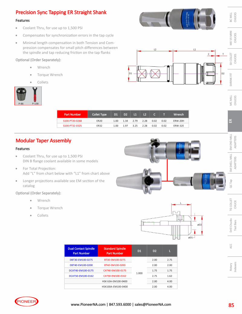
AC
C
Dri
ll C
hu
cks
Test
Bar
s
TG C
OLL
ET
CH
UC
K
QC
Tap
SM
SH
ELL
MIL
L
AD
AP
TER
S
EM E
ND
MIL
L
AD
AP
TER
S
ER C
OLL
ET
CH
UC
KS
MC
MIL
L
CH
UC
KS
SHR
INK
FIT
SX
CO
LLET
CH
UC
KS
MX
VX
MIN
I
CH
UC
KS
BC
MIL
L
CH
UC
KS
Ro
tary
Ind
exer
s
85 www.PioneerNA.com | 847.593.6000 | [email protected]
Precision Sync Tapping ER Straight Shank
Features
• Coolant Thru, for use up to 1,500 PSI
• Compensates for synchronization errors in the tap cycle
• Minimal length compensation in both Tension and Com-pression compensates for small pitch differences between the spindle and tap reducing friction on the tap flanks
Optional (Order Separately):
• Wrench
• Torque Wrench
• Collets
P-86 P-138
L1
D2 D1
L2
C T
Part Number Collet Type D1 D2 L1 L2 C T Wrench
S100-PT20-0268 ER20 1.00 1.34 2.79 2.28 0.02 0.02 ERW-20H
S100-PT32-0325 ER32 1.00 1.97 3.25 2.28 0.02 0.02 ERW-32E
Dual Contact Spindle
Part Number
Standard Spindle
Part Number D1 D2 L
DBT30-EM100-0275 BT30-EM100-0275
1.000
2.00 2.75
DBT40-EM100-0200 BT40-EM100-0200 2.00 2.00
DCAT40-EM100-0175 CAT40-EM100-0175 1.75 1.75
DCAT50-EM100-0162 CAT50-EM100-0162 2.75 1.62
HSK 63A-EM100-0400 2.00 4.00
HSK100A-EM100-0400 2.00 4.00
øD1
øD2
L
Modular Taper Assembly
Features
• Coolant Thru, for use up to 1,500 PSI DIN B flange coolant available in some models
• For Total Projection: Add “L” from chart below with “L1” from chart above
• Longer projections available see EM section of the catalog
Optional (Order Separately):
• Wrench
• Torque Wrench
• Collets
ER

PIO
NEE
R P
rem
ium
To
ol H
old
ing
86 www.PioneerNA.com | 847.593.6000 | [email protected]
ER Collets
Optimize your work in many ways:
Pioneer has updated our collet offering to meet the
high demands of precision cutting tools and
high performance applications.
ER collets are now offered in standard, sealed by design
and tap collets.
• Pioneer standard collets come in General Purpose and
new Stainless Steel Ultra Precision. The stainless steel
collets are made from 420 Stainless and hardened to
Rc45.
• Pioneer Sealed collets are sealed by alternating slots.
The cutting tool shank must make full contact with the collet bore to create a seal.
This design allows for the highest coolant pressures without damage to the collet.
• Pioneer Tap Collets are available in ANSI and DIN configurations with a square
punched into the ID for positive drive.
ER C
OLL
ET C
HU
CK
S
Stainless Steel Precision Collets
Pioneer Stainless Steel Collets are only available in a
5 micron (0.0002”) TIR @ 3D.
The picture to the right is a standard ER collet and a
Stainless Steel Collet that were submerged in Chicago tap
water for 3 months. The stainless collet showed no
corrosion anywhere compared to the standard collet.
420 Stainless is a 12% Chromium high carbon material
which provides high hardenability and superior corrosion resistance. 420 Stainless allows
us to harden the collets to Rc45, similar hardness as most standard ER collets in the
market today.
Available in ER11-ER32 in select sizes.

AC
C
Dri
ll C
hu
cks
Test
Bar
s
TG C
OLL
ET
CH
UC
K
QC
Tap
SM
SH
ELL
MIL
L
AD
AP
TER
S
EM E
ND
MIL
L
AD
AP
TER
S
ER C
OLL
ET
CH
UC
KS
MC
MIL
L
CH
UC
KS
SHR
INK
FIT
SX
CO
LLET
CH
UC
KS
MX
VX
MIN
I
CH
UC
KS
BC
MIL
L
CH
UC
KS
Ro
tary
Ind
exer
s
87 www.PioneerNA.com | 847.593.6000 | [email protected]
ER08 Precision Collets
Features
• Standard 15 Microns @ 2D (0.0006” @ 2D)
ER08 Metric General Purpose
15 Micron @ 2D
Metric Metric ER08
Max Min
3.0 2.5 ER08-M030
3.5 3.0 ER08-M035
4.0 3.5 ER08-M040
4.5 4.0 ER08-M045
5.0 4.5 ER08-M050
ER08 Collet Sets General Purpose
15 Micron @ 2D
QTY Sizes Incr. ER08
5 3.0 - 5.0mm 0.5mm Tray ER08 MSET 5PCS
ER08
ER11 Precision Collets
Features
• Standard 10 Microns @ 2D (0.0004” @ 2D)
• Stainless Steel
ER-UP Precision 5 Microns @ 3D (0.0002” @ 3D)
ER11 Metric General Purpose Ultra-Precision
10 Micron @ 2D 5 Micron @ 3D
Metric Metric ER11
ER11UP
Stainless Steel Max Min
3.0 2.5 ER11-M030 ER11-M030UP
3.5 3.0 ER11-M035 ER11-M035UP
4.0 3.5 ER11-M040 ER11-M040 UP
4.5 4.0 ER11-M045 ER11-M045 UP
5.0 4.5 ER11-M050 ER11-M050UP
5.5 5.0 ER11-M055 ER11-M055UP
6.0 5.5 ER11-M060 ER11-M060UP
6.5 6.0 ER11-M065 ER11-M065UP
7.0 6.5 ER11-M070 ER11-M070UP
ER11 Inch General Purpose Ultra-Precision
10 Micron @ 2D 5 Micron @ 3D
Inch Inch ER11
ER11UP
Stainless Steel Max Min
0.1250 0.1053 ER11-0125 ER11-0125UP
0.1563 0.1366 ER11-0156
0.1875 0.1678 ER11-0187 ER11-0187UP
0.2188 0.1991 ER11-0218
0.2500 0.2303 ER11-0250 ER11-0250UP
ER11 Collet Sets General Purpose Ultra Precision
10 Micron @ 2D 5 Micron @ 3D
QTY Sizes Incr. ER11 ER11UP
Stainless Steel
5 1/8-1/4 1/32 ER11 ISET 5PCS
9 3.0-7.0mm 0.5mm ER11 MSET 9PCS
9 1.0-7.0mm 0.5mm ER11 MSET UP 5UM - 9PCS
ER11 ER11***UP
Stainless Steel
ER

PIO
NEE
R P
rem
ium
To
ol H
old
ing
88 www.PioneerNA.com | 847.593.6000 | [email protected]
ER16 Precision Collets
Features
• Standard 10 Microns @ 2D (0.0004” @ 2D)
• Stainless Steel
ER-UP Precision 5 Microns @ 3D (0.0002” @ 3D)
ER16 Metric General Purpose Ultra-Precision
10 Micron @ 2D 5 Micron @ 3D
Metric Metric ER16
ER16UP
Stainless Steel Max Min
3.0 2.0 ER16-M030 ER16-M030UP
3.5 2.5 ER16-M035 ER16-M035UP
4.0 3.0 ER16-M040 ER16-M040UP
5.0 4.0 ER16-M050 ER16-M050UP
6.0 5.0 ER16-M060 ER16-M060UP
7.0 6.0 ER16-M070 ER16-M070UP
8.0 7.0 ER16-M080 ER16-M080UP
9.0 8.0 ER16-M090 ER16-M090UP
10.0 9.0 ER16-M100 ER16-M100UP
ER16 Inch General Purpose Ultra-Precision
10 Micron @ 2D 5 Micron @ 3D
Inch Inch ER16
ER16UP
Stainless Steel Max Min
0.1250 0.0856 ER16-0125 ER16-0125UP
0.1563 0.1169 ER16-0156
0.1875 0.1481 ER16-0187 ER16-0187UP
0.2188 0.1794 ER16-0218
0.2500 0.2106 ER16-0250 ER16-0250UP
0.2813 0.2419 ER16-0281
0.3125 0.2731 ER16-0312 ER16-0312UP
0.3438 0.3044 ER16-0344
0.3750 0.3356 ER16-0375 ER16-0375UP
0.4063 0.3669 ER16-0406
ER16 Collet Sets General Purpose Ultra-Precision
10 Micron @ 2D 5 Micron @ 3D
QTY Sizes Incr. ER16 ER16UP
Stainless Steel
9 1/8-3/8 1/32 ER16 ISET 9PCS
5 1/8-3/8 1/16 ER16 ISET UP 5UM - 5PCS
8 3.0-10.0mm 1mm ER16 MSET 8PCS
8 3.0-10.0mm 1mm ER16 MSET UP 5UM - 8PCS
ER16 ER16***UP
ER C
OLL
ET C
HU
CK
S

AC
C
Dri
ll C
hu
cks
Test
Bar
s
TG C
OLL
ET
CH
UC
K
QC
Tap
SM
SH
ELL
MIL
L
AD
AP
TER
S
EM E
ND
MIL
L
AD
AP
TER
S
ER C
OLL
ET
CH
UC
KS
MC
MIL
L
CH
UC
KS
SHR
INK
FIT
SX
CO
LLET
CH
UC
KS
MX
VX
MIN
I
CH
UC
KS
BC
MIL
L
CH
UC
KS
Ro
tary
Ind
exer
s
89 www.PioneerNA.com | 847.593.6000 | [email protected]
ER20 Precision Collets
Features
• Standard 10 Microns @ 2D (0.0004” @ 2D)
• Stainless Steel
ERUP Precision 5 Microns @ 3D (0.0002” @ 3D)
ER20 Metric General Purpose Ultra-Precision
10 Micron @ 2D 5 Micron @ 3D
Metric Metric ER20
ER20UP
Stainless Steel Max Min
3.0 2.0 ER20-M030 ER20-M030UP
3.5 2.5 ER20-M035 ER20-M035UP
4.0 3.0 ER20-M040 ER20-M040UP
5.0 4.0 ER20-M050 ER20-M050UP
6.0 5.0 ER20-M060 ER20-M060UP
7.0 6.0 ER20-M070 ER20-M070UP
8.0 7.0 ER20-M080 ER20-M080UP
9.0 8.0 ER20-M090 ER20-M090UP
10.0 9.0 ER20-M100 ER20-M100UP
11.0 10.0 ER20-M110 ER20-M110UP
12.0 11.0 ER20-M120 ER20-M120UP
13.0 12.0 ER20-M130 ER20-M130UP
ER20 Inch General Purpose Ultra-Precision
10 Micron @ 2D 5 Micron @ 3D
Inch Inch ER20
ER20UP
Stainless Steel Max Min
0.1250 0.0856 ER20-0125 ER20-0125UP
0.1563 0.1169 ER20-0156
0.1875 0.1481 ER20-0187 ER20-0187UP
0.2188 0.1794 ER20-0218
0.2500 0.2106 ER20-0250 ER20-0250UP
0.2813 0.2419 ER20-0281
0.3125 0.2731 ER20-0312 ER20-0312UP
0.3438 0.3044 ER20-0344
0.3750 0.3356 ER20-0375 ER20-0375UP
0.4063 0.3669 ER20-0406
0.4375 0.3981 ER20-0438 ER20-0438UP
0.4688 0.4294 ER20-0469
0.5000 0.4606 ER20-0500 ER20-0500UP
ER20 Collet Sets General Purpose Ultra-Precision
10 Micron @ 2D 5 Micron @ 3D
QTY Sizes ER20 ER20UP
Stainless Steel Incr.
12 5/32-1/2 ER20 ISET 12PCS 1/32
7 1/8-1/2 ER20 ISET UP 5UM - 7PCS 1/16
11 3-13mm ER20 MSET 11PCS 1mm
11 3-13mm ER20 MSET UP 5UM - 11PCS 1mm
ER20 ER20***UP
* Items stocked in Germany
ER

PIO
NEE
R P
rem
ium
To
ol H
old
ing
90 www.PioneerNA.com | 847.593.6000 | [email protected]
ER25 Precision Collets
Features
• Standard 10 Microns @ 2D (0.0004” @ 2D)
• Stainless Steel
ER-UP Precision 5 Microns @ 3D (0.0002” @ 3D)
ER25 Metric General Purpose Ultra-Precision
10 Micron @ 2D 5 Micron @ 3D
Metric Metric ER25
ER25UP
Stainless Steel Max Min
3.0 2.5 ER25-M030 ER25-M030UP
3.5 3.0 ER25-M035 ER25-M035UP
4.0 3.5 ER25-M040 ER25-M040UP
5.0 4.5 ER25-M050 ER25-M050UP
6.0 5.5 ER25-M060 ER25-M060UP
7.0 6.5 ER25-M070 ER25-M070UP
8.0 7.5 ER25-M080 ER25-M080UP
9.0 8.5 ER25-M090 ER25-M090UP
10.0 9.5 ER25-M100 ER25-M100UP
11.0 10.5 ER25-M110 ER25-M110UP
12.0 11.5 ER25-M120 ER25-M120UP
13.0 12.5 ER25-M130 ER25-M130UP
14.0 13.5 ER25-M140 ER25-M140UP
15.0 14.5 ER25-M150 ER25-M150UP
16.0 15.5 ER25-M160 ER25-M160UP
ER25 Inch General Purpose Ultra-Precision
10 Micron @ 2D 5 Micron @ 3D
Inch Inch ER25
ER25UP
Stainless Steel Max Min
0.1250 0.1053 ER25-0125 ER25-0125UP
0.1563 0.1366 ER25-0156
0.1875 0.1678 ER25-0187 ER25-0187UP
0.2188 0.1991 ER25-0218
0.2500 0.2303 ER25-0250 ER25-0250UP
0.2813 0.2616 ER25-0281
0.3125 0.2928 ER25-0312 ER25-0312UP
0.3438 0.3241 ER25-0344
0.3750 0.3553 ER25-0375 ER25-0375UP
0.4063 0.3866 ER25-0406
0.4375 0.4178 ER25-0438 ER25-0438UP
0.4688 0.4491 ER25-0469
0.5000 0.4803 ER25-0500 ER25-0500UP
0.5313 0.5116 ER25-0531
0.5625 0.5428 ER25-0563 ER25-0563UP
0.5938 0.5741 ER25-0594
0.6250 0.6053 ER25-0625 ER25-0625UP
ER25 Collet Sets General Purpose Ultra-Precision
10 Micron @ 2D 5 Micron @ 3D
QTY Sizes Incr. ER25 ER25UP
Stainless Steel
15 3/16-5/8 1/32 ER25 ISET 15PCS
9 1/8-5/8 1/16 ER25 ISET UP 5UM - 9PCS
14 3.0-16.0mm 1mm ER25 MSET 14PCS
15 3.0-16.0mm 1mm ER25 MSET UP 5UM - 14PCS
ER25 ER25***UP
ER C
OLL
ET C
HU
CK
S

AC
C
Dri
ll C
hu
cks
Test
Bar
s
TG C
OLL
ET
CH
UC
K
QC
Tap
SM
SH
ELL
MIL
L
AD
AP
TER
S
EM E
ND
MIL
L
AD
AP
TER
S
ER C
OLL
ET
CH
UC
KS
MC
MIL
L
CH
UC
KS
SHR
INK
FIT
SX
CO
LLET
CH
UC
KS
MX
VX
MIN
I
CH
UC
KS
BC
MIL
L
CH
UC
KS
Ro
tary
Ind
exer
s
91 www.PioneerNA.com | 847.593.6000 | [email protected]
ER32 Precision Collets
Features
• Standard 10 Microns @ 2D (0.0004” @ 2D)
• Stainless Steel
ER-UP Precision 5 Microns @ 3D (0.0002” @ 3D)
ER32 Metric General Purpose Ultra-Precision
10 Micron @ 2D 5 Micron @ 3D
Metric Metric ER32
ER32UP
Stainless Steel Max Min
3.0 2.0 ER32-M030 ER32-M030UP
3.5 2.5 ER32-M035 ER32-M035UP
4.0 3.0 ER32-M040 ER32-M040UP
5.0 4.0 ER32-M050 ER32-M050UP
6.0 5.0 ER32-M060 ER32-M060UP
7.0 6.0 ER32-M070 ER32-M070UP
8.0 7.0 ER32-M080 ER32-M080UP
9.0 8.0 ER32-M090 ER32-M090UP
10.0 9.0 ER32-M100 ER32-M100UP
11.0 10.0 ER32-M110 ER32-M110UP
12.0 11.0 ER32-M120 ER32-M120UP
13.0 12.0 ER32-M130 ER32-M130UP
14.0 13.0 ER32-M140 ER32-M140UP
15.0 14.0 ER32-M150 ER32-M150UP
16.0 15.0 ER32-M160 ER32-M160UP
17.0 16.0 ER32-M170 ER32-M170UP
18.0 17.0 ER32-M180 ER32-M180UP
19.0 18.0 ER32-M190 ER32-M190UP
20.0 19.0 ER32-M200 ER32-M200UP
ER32 Inch General Purpose Ultra-Precision
10 Micron @ 2D 5 Micron @ 3D
Inch Inch ER32
ER32UP
Stainless Steel Max Min
0.1250 0.0856 ER32-0125 ER32-0125UP
0.1563 0.1169 ER32-0156
0.1875 0.1481 ER32-0187 ER32-0187UP
0.2188 0.1794 ER32-0218
0.2500 0.2106 ER32-0250 ER32-0250UP
0.2813 0.2419 ER32-0281
0.3125 0.2731 ER32-0312 ER32-0312UP
0.3438 0.3044 ER32-0344
0.3750 0.3356 ER32-0375 ER32-0375UP
0.4063 0.3669 ER32-0406
0.4375 0.3981 ER32-0438 ER32-0438UP
0.4688 0.4294 ER32-0469
0.5000 0.4606 ER32-0500 ER32-0500UP
0.5313 0.4919 ER32-0531
0.5625 0.5231 ER32-0563 ER32-0563UP
0.5938 0.5544 ER32-0594
0.6250 0.5856 ER32-0625 ER32-0625UP
0.6563 0.6169 ER32-0656
0.6875 0.6481 ER32-0688 ER32-0688UP
0.7188 0.6794 ER32-0719
0.7500 0.7106 ER32-0750 ER32-0750UP
ER32 Collet Sets General Purpose Ultra-Precision
10 Micron @ 2D 5 Micron @ 3D
QTY Sizes Incr. ER32 ER32UP
Stainless Steel
10 1/8-5/8 +3/4 1/16 ER32 ISET 10PCS
11 1/8-3/4 1/16 ER32 ISET 11PCS
18 7/32-3/4 1/32 ER32 ISET 18PCS
12 1/8-3/4 1/16 ER32 ISET UP 5UM - 11PCS
18 3-20mm 1mm ER32 MSET 18PCS
18 3-20mm 1mm ER32 MSET UP 5UM - 18PCS
ER32 ER32***UP
ER

PIO
NEE
R P
rem
ium
To
ol H
old
ing
92 www.PioneerNA.com | 847.593.6000 | [email protected]
ER40 Precision Collets
Features
• Standard 10 Microns @ 2D (0.0004” @ 2D)
ER40 Metric General Purpose
10 Micron @ 2D
Metric Metric ER40
Max Min
3.0 3.0 ER40-M030
3.5 3.5 ER40-M035
4.0 3.0 ER40-M040
5.0 4.0 ER40-M050
6.0 5.0 ER40-M060
7.0 6.0 ER40-M070
8.0 7.0 ER40-M080
9.0 8.0 ER40-M090
10.0 9.0 ER40-M100
11.0 10.0 ER40-M110
12.0 11.0 ER40-M120
13.0 12.0 ER40-M130
14.0 13.0 ER40-M140
15.0 14.0 ER40-M150
16.0 15.0 ER40-M160
17.0 16.0 ER40-M170
18.0 17.0 ER40-M180
19.0 18.0 ER40-M190
20.0 19.0 ER40-M200
21.0 20.0 ER40-M210
22.0 21.0 ER40-M220
23.0 22.0 ER40-M230
24.0 23.0 ER40-M240
25.0 24.0 ER40-M250
26.0 25.0 ER40-M260
ER40 Inch General Purpose
10 Micron @ 2D
Inch Inch ER40
Max Min
0.1250 0.0856 ER40-0125
0.1563 0.1169 ER40-0156
0.1875 0.1481 ER40-0187
0.2188 0.1794 ER40-0218
0.2500 0.2106 ER40-0250
0.2813 0.2419 ER40-0281
0.3125 0.2731 ER40-0312
0.3438 0.3044 ER40-0344
0.3750 0.3356 ER40-0375
0.4063 0.3669 ER40-0406
0.4375 0.3981 ER40-0438
0.4688 0.4294 ER40-0469
0.5000 0.4606 ER40-0500
0.5313 0.4919 ER40-0531
0.5625 0.5231 ER40-0563
0.5938 0.5544 ER40-0594
0.6250 0.5856 ER40-0625
0.6563 0.6169 ER40-0656
0.6875 0.6481 ER40-0688
0.7188 0.6794 ER40-0719
0.7500 0.7106 ER40-0750
0.7813 0.7419 ER40-0781
0.8125 0.7731 ER40-0813
0.8438 0.8044 ER40-0844
0.8750 0.8356 ER40-0875
0.9063 0.8669 ER40-0906
0.9375 0.8981 ER40-0938
0.9688 0.9294 ER40-0969
1.0000 0.9606 ER40-1000
ER40 Collet Sets General Purpose
10 Micron @ 2D
QTY Sizes Incr. ER40
13 1/8-3/4 in 1/16 + 7/8 + 1 Tray ER40 ISET 13PCS
15 1/8-1 1/16 Tray ER40 ISET 15PCS
29 1/8-1 1/32 Tray ER40 ISET 29PCS
23 4-26mm 1mm Tray ER40 MSET 23PCS
ER40
ER C
OLL
ET C
HU
CK
S

AC
C
Dri
ll C
hu
cks
Test
Bar
s
TG C
OLL
ET
CH
UC
K
QC
Tap
SM
SH
ELL
MIL
L
AD
AP
TER
S
EM E
ND
MIL
L
AD
AP
TER
S
ER C
OLL
ET
CH
UC
KS
MC
MIL
L
CH
UC
KS
SHR
INK
FIT
SX
CO
LLET
CH
UC
KS
MX
VX
MIN
I
CH
UC
KS
BC
MIL
L
CH
UC
KS
Ro
tary
Ind
exer
s
93 www.PioneerNA.com | 847.593.6000 | [email protected]
ER
Collet Nuts
Nut
Part Number Description
Wrench
Part Number Collet Retainer Ø D Thread
Max.
Torque
ERN-08M ER 8 Mini Nut WRENCH ERW-8M Compression 0.472 / 12mm M10 x 0.75 6 ft/lbs
ERN-11H ER 11 Nut -Hex WRENCH ERW-11H Eccentric 0.787 / 20mm M14 x 0.75 18 ft/lbs
ERN-11M ER 11 Mini Nut WRENCH ERW-11M Eccentric 0.630 / 16mm M13 x 0.75 9 ft/lbs
ERN-16B ER 16 Nut - E Type WRENCH 30-32 HOOK Compression 1.260 / 32mm M22 x 1.5 40 ft/lbs
ERN-16H ER 16 Nut -Hex WRENCH ERW-16H Eccentric 1.102 / 28mm M22 x 1.5 40 ft/lbs
ERN-16E ER 16 Nut - E Type WRENCH ERW-16E Eccentric 1.260 / 32mm M22 x 1.5 40 ft/lbs
ERN-16M ER 16 Mini Nut WRENCH ERW-16M Eccentric 0.866 / 22mm M19 x 1.0 13 ft/lbs
ERN-20B ER 20 Nut - E Type WRENCH 34-38 HOOK Compression 1.380 / 35mm M25 x 1.5 60 ft/lbs
ERN-20H ER 20 Nut -Hex WRENCH ERW-20H Eccentric 1.338 / 34mm M25 x 1.5 60 ft/lbs
ERN-20E ER 20 Nut - E Type WRENCH ERW-20E Eccentric 1.380 / 35mm M25 x 1.5 60 ft/lbs
ERN-20M ER 20 Mini Nut WRENCH ERW-20M Eccentric 1.102 / 28mm M24 x 1.0 17 ft/lbs
ERN-25B ER 25 Nut - E Type WRENCH 40-42 HOOK Compression 1.654 / 42mm M32 x 1.5 75 ft/lbs
ERN-25E ER 25 Nut - E Type WRENCH ERW-25E Eccentric 1.654 / 42mm M32 x 1.5 75 ft/lbs
ERN-32B ER 32 Nut - E Type WRENCH 50-55 HOOK Compression 1.969 / 50mm M40 x 1.5 100 ft/lbs
ERN-32E ER 32 Nut - E Type WRENCH ERW-32E Eccentric 1.969 / 50mm M40 x 1.5 100 ft/lbs
ERN-32H-EXT ER 32 Ext Nut—Hex WRENCH DAW180 Compression M40 M40 100 ft/lbs
ERN-40B ER 40 Nut - E Type WRENCH 58-65 HOOK Compression 2.480 / 63mm M50 x 1.5 125 ft/lbs
ERN-40E ER 40 Nut - E Type WRENCH ERW-40E Eccentric 2.480 / 63mm M50 x 1.5 125 ft/lbs
Hex Style Mini Type
Pioneer replacement ER nuts exceed industry standard for fit, finish and balance.
ER nuts are in 4 styles, Mini, Hex, E Type & RD Type.
• Hex Nuts are standard for ER11, ER16 & ER20. Smaller diameter than E-Type with standard chuck threads.
Hex nuts are machined with an eccentric for easy collet installation and removal.
• E-Type or castle type use the 4 prong wrench or spanner wrench, standard on ER25, ER32 & ER40.
E-Type nuts are machined with an eccentric for easy collet installation and removal.
• -EXT are external threaded nuts for stub length holders. Due to the constraints of the design collets must be
“snapped” into the nut. Tap and Sealed Collets are difficult to install and remove.
• Mini nuts are designed for reduced threaded Mini Chucks. Mini nuts use a special E type wrench. Mini’s are not interchangeable with Hex or E-Type. Mini nuts are a compression type nut, must be pressed onto the collet for the nut to extract the collet from the chuck. Note: Mini Nuts do not function well with some sealed and tap collets due to the limited space to tip the collet for removal. Some small ID, tap and sealed collets are difficult to compress causing issues in installation and removal.
E Type
ØD
Collet Retainer Type
Hex, E-Type & RD
Eccentric Design
Mini Compression Design
Note: ER Nuts are built to DIN standards. Per DIN tolerances the collet may or many not be retained by an eccentric style nut.
If the collet is not retained into an eccentric style nut are not defective but a result of the DIN tolerances.
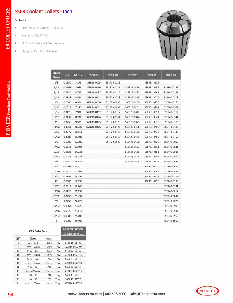
PIO
NEE
R P
rem
ium
To
ol H
old
ing
94 www.PioneerNA.com | 847.593.6000 | [email protected]
SSER Coolant Collets - Inch
Features
• High Pressure Coolant - 1,500 PSI
• Standard .0004” T.I.R.
• On Size Collets - Will Not Collapse
• Designed for h6 Tool Shanks
Cutter
Shank Inch Metric SSER 16 SSER 20 SSER 25 SSER 32 SSER 40
1/8 0.1250 3.175 SSER16-0125 SSER20-0125 SSER32-0125
5/32 0.1563 3.969 SSER16-0156 SSER20-0156 SSER25-0156 SSER32-0156 SSER40-0156
3/16 0.1880 4.775 SSER16-0187 SSER20-0187 SSER25-0187 SSER32-0187 SSER40-0187
7/32 0.2188 5.558 SSER16-0218 SSER20-0218 SSER25-0218 SSER32-0219 SSER40-0218
1/4 0.2500 6.350 SSER16-0250 SSER20-0250 SSER25-0250 SSER32-0250 SSER40-0250
9/32 0.2813 7.145 SSER16-0281 SSER20-0281 SSER25-0281 SSER32-0281 SSER40-0281
5/16 0.3125 7.938 SSER16-0312 SSER20-0312 SSER25-0312 SSER32-0312 SSER40-0312
11/32 0.3437 8.730 SSER16-0344 SSER20-0344 SSER25-0344 SSER32-0344 SSER40-0344
3/8 0.3750 9.525 SSER16-0375 SSER20-0375 SSER25-0375 SSER32-0375 SSER40-0375
13/32 0.4063 10.320 SSER16-0406 SSER20-0406 SSER25-0406 SSER32-0406 SSER40-0406
7/16 0.4375 11.113 SSER20-0438 SSER25-0438 SSER32-0438 SSER40-0438
15/32 0.4688 11.908 SSER20-0469 SSER25-0469 SSER32-0469 SSER40-0469
1/2 0.5000 12.700 SSER20-0500 SSER25-0500 SSER32-0500 SSER40-0500
17/32 0.5313 13.495 SSER25-0531 SSER32-0531 SSER40-0531
9/16 0.5625 14.288 SSER25-0563 SSER32-0563 SSER40-0563
19/32 0.5938 15.083 SSER25-0594 SSER32-0594 SSER40-0594
5/8 0.6250 15.875 SSER25-0625 SSER32-0625 SSER40-0625
21/32 0.6563 16.670 SSER32-0656 SSER40-0656
11/16 0.6875 17.463 SSER32-0688 SSER40-0688
23/32 0.7188 18.258 SSER32-0719 SSER40-0719
3/4 0.7500 19.050 SSER32-0750 SSER40-0750
25/32 0.7813 19.845 SSER40-0781
13/16 0.8125 20.638 SSER40-0812
27/32 0.8438 21.433 SSER40-0844
7/8 0.8750 22.225 SSER40-0875
29/32 0.9063 23.020 SSER40-0906
15/16 0.9375 23.813 SSER40-0937
31/32 0.9688 24.608 SSER40-0969
1 1.0000 25.400 SSER40-1000
SSER Collet Sets General Purpose
10 Micron @ 2D
QTY Sizes Incr.
9 1/8—3/8 1/32 Tray SSER16 ISET09
7 4mm—10mm 1mm Tray SSER16 MSET07
12 5/32—1/2 1/32 Tray SSER20 ISET12
10 4mm—13mm 1mm Tray SSER20 MSET10
16 5/32—5/8 1/32 Tray SSER25 ISET16
13 4mm—16mm 1mm Tray SSER25 MSET13
18 7/32—3/4 1/32 Tray SSER32 ISET18
17 4mm-20mm 1mm Tray SSER32 MSET17
13 1/4—1” 1/16 Tray SSER40 ISET13
25 1/4—1” 1/32 Tray SSER40 ISET25
21 6mm—26mm 1mm Tray SSER40 MSET21
ER C
OLL
ET C
HU
CK
S

AC
C
Dri
ll C
hu
cks
Test
Bar
s
TG C
OLL
ET
CH
UC
K
QC
Tap
SM
SH
ELL
MIL
L
AD
AP
TER
S
EM E
ND
MIL
L
AD
AP
TER
S
ER C
OLL
ET
CH
UC
KS
MC
MIL
L
CH
UC
KS
SHR
INK
FIT
SX
CO
LLET
CH
UC
KS
MX
VX
MIN
I
CH
UC
KS
BC
MIL
L
CH
UC
KS
Ro
tary
Ind
exer
s
95 www.PioneerNA.com | 847.593.6000 | [email protected]
Cutter
Shank
Tool
Size Inch SSER 16 SSER 20 SSER 25 SSER 32 SSER 40
3.0 0.1181 SSER16-M030 SSER20-M030 SSER25-M030 SSER32-M030
4.0 0.1575 SSER16-M040 SSER20-M040 SSER25-M040 SSER32-M040
5.0 0.1969 SSER16-M050 SSER20-M050 SSER25-M050 SSER32-M050
6.0 0.2362 SSER16-M060 SSER20-M060 SSER25-M060 SSER32-M060 SSER40-M060
7.0 0.2756 SSER16-M070 SSER20-M070 SSER25-M070 SSER32-M070 SSER40-M070
8.0 0.3150 SSER16-M080 SSER20-M080 SSER25-M080 SSER32-M080 SSER40-M080
9.0 0.3543 SSER16-M090 SSER20-M090 SSER25-M090 SSER32-M090 SSER40-M090
10.0 0.3937 SSER16-M100 SSER20-M100 SSER25-M100 SSER32-M100 SSER40-M100
11.0 0.4331 SSER20-M110 SSER25-M110 SSER32-M110 SSER40-M110
12.0 0.4724 SSER20-M120 SSER25-M120 SSER32-M120 SSER40-M120
13.0 0.5118 SSER20-M130 SSER25-M130 SSER32-M130 SSER40-M130
14.0 0.5512 SSER25-M140 SSER32-M140 SSER40-M140
15.0 0.5906 SSER25-M150 SSER32-M150 SSER40-M150
16.0 0.6299 SSER25-M160 SSER32-M160 SSER40-M160
17.0 0.6693 SSER32-M170 SSER40-M170
18.0 0.7087 SSER32-M180 SSER40-M180
19.0 0.7480 SSER32-M190 SSER40-M190
20.0 0.7874 SSER32-M200 SSER40-M200
21.0 0.8268 SSER40-M210
22.0 0.8661 SSER40-M220
23.0 0.9055 SSER40-M230
24.0 0.9449 SSER40-M240
25.0 0.9843 SSER40-M250
26.0 1.0236 SSER40-M260
SSER Coolant Collets - Metric
Features
• High Pressure Coolant - 1,500 PSI
• Standard .0004” T.I.R.
• On Size Collets - Will Not Collapse
• Designed for h6 Tool Shanks
Jet-Blast SSER Coolant ER Collets
Features:
• High Pressure Coolant - 1,500 PSI
• Standard .0004” T.I.R.
• Designed for h6 Tool Shanks
• Add J to any SSER collet part number
Coolant thru standard collet slots create a loss in pressure and flow control, allowing coolant to fly everywhere. The Jet-Blast option for SSER forces the coolant into the Jet-Blast Ports maintaining pressure and directing the coolant down the flutes of the cutting tool.
ER

PIO
NEE
R P
rem
ium
To
ol H
old
ing
96 www.PioneerNA.com | 847.593.6000 | [email protected]
ER Rigid Tap Collets - ANSI
Features
Special design locks tap flats into the collet slots preventing the tap
from spinning inside the collet.
• ANSI Shank and Square Standard
øShank Square Tap Size TER16U TER20U TER25U TER32U TER40U
0.141 0.110 #6 TER16U-141 TER20U-141 TER25U-141 TER32U-141 TER40U-141
0.168 0.131 #8 TER16U-168 TER20U-168 TER25U-168 TER32U-168 TER40U-168
0.194 0.152 #10 TER16U-194 TER20U-194 TER25U-194 TER32U-194 TER40U-194
0.220 0.165 #12 TER16U-220 TER20U-220 TER25U-220 TER32U-220 TER40U-220
0.255 0.191 1/4" TER16U-255 TER20U-255 TER25U-255 TER32U-255 TER40U-255
0.318 0.238 5/16" TER16U-318 TER20U-318 TER25U-318 TER32U-318 TER40U-318
0.323 0.242 7/16" TER16U-323 TER20U-323 TER25U-323 TER32U-323 TER40U-323
0.367 0.275 1/2" TER16U-367 TER20U-367 TER25U-367 TER32U-367 TER40U-367
0.381 0.286 3/8" TER16U-381 TER20U-381 TER25U-381 TER32U-381 TER40U-381
0.429 0.322 9/16" TER25U-429 TER32U-429 TER40U-429
0.437 0.328 1/8" NPT TER25U-437 TER32U-437 TER40U-437
0.480 0.360 5/8" TER25U-480 TER32U-480 TER40U-480
0.542 0.406 11/16" TER32U-542 TER40U-542
0.562 0.421 1/4" NPT TER32U-562 TER40U-562
0.590 0.442 3/4" TER32U-590 TER40U-590
0.652 0.489 13/16" TER32U-652 TER40U-652
0.687 0.515 1/2" NPT TER40U-687
0.697 0.523 7/8" TER40U-697
0.700 0.531 3/8" NPT TER40U-700
0.760 0.570 15/16" TER40U-760
0.800 0.600 1" TER40U-800
øShank Square
Note:
Due to Multiple Standards for Metric Taps, the actual shank and square must
be supplied to verify compatibility.
TER ANSI Collet Sets Part Number
QTY Sizes
9 0.141—0.381 Tray TER16U- SET9
9 0.141—0.381 Tray TER20U- SET9
12 0.141—0.480 Tray TER25U- SET12
16 0.141—0.652 Tray TER32U- SET16
21 0.141—0.800 Tray TER40U- SET21
ER C
OLL
ET C
HU
CK
S

AC
C
Dri
ll C
hu
cks
Test
Bar
s
TG C
OLL
ET
CH
UC
K
QC
Tap
SM
SH
ELL
MIL
L
AD
AP
TER
S
EM E
ND
MIL
L
AD
AP
TER
S
ER C
OLL
ET
CH
UC
KS
MC
MIL
L
CH
UC
KS
SHR
INK
FIT
SX
CO
LLET
CH
UC
KS
MX
VX
MIN
I
CH
UC
KS
BC
MIL
L
CH
UC
KS
Ro
tary
Ind
exer
s
97 www.PioneerNA.com | 847.593.6000 | [email protected]
ER Rigid Tap Collets - DIN
Features
Special design locks tap flats into the collet slots preventing the tap
from spinning inside the collet.
• DIN Shank and Square Standard
øShank Inch Square Inch TER16D TER20D TER25D TER32D TER40D
3.5 0.138 2.7 0.106 TER16D-035 TER25D-035
4.0 0.157 3.0 0.118 TER16D-040 TER20D-040 TER25D-040
4.5 0.177 3.4 0.134 TER16D-045 TER20D-045 TER25D-045 TER32D-045
5.5 0.217 4.3 0.169 TER16D-055 TER20D-055 TER25D-055 TER32D-055
6.0 0.236 4.9 0.193 TER16D-060 TER20D-060 TER25D-060 TER32D-060 TER40D-060
7.0 0.276 5.5 0.217 TER16D-070 TER20D-070 TER25D-070 TER32D-070 TER40D-070
8.0 0.315 6.2 0.244 TER16D-080 TER20D-080 TER25D-080 TER32D-080 TER40D-080
9.0 0.354 7.0 0.276 TER16D-090 TER20D-090 TER25D-090 TER32D-090 TER40D-090
10.0 0.394 8.0 0.315 TER16D-100 TER20D-100 TER25D-100 TER32D-100 TER40D-100
11.0 0.433 9.0 0.354 TER25D-110 TER32D-110 TER40D-110
12.0 0.472 9.0 0.354 TER25D-120 TER32D-120 TER40D-120
14.0 0.551 11.0 0.433 TER25D-140 TER32D-140 TER40D-140
16.0 0.630 12.0 0.472 TER25D-160 TER32D-160 TER40D-160
18.0 0.709 14.5 0.571 TER32D-180 TER40D-180
20.0 0.787 16.0 0.630 TER32D-200 TER40D-200
22.0 0.866 18.0 0.709 TER40D-220
øShank Square
Note:
Due to Multiple Standards for Metric Taps, the actual shank and square must
be supplied to verify compatibility.
ER

PIO
NEE
R P
rem
ium
To
ol H
old
ing
98 www.PioneerNA.com | 847.593.6000 | [email protected]
ER Coolant Cap Collet Nuts
Features
• For coolant pressures up to 1,500 PSI.
• Fits standard ER collet chucks.
• Jet-Blast Caps Available Upon Request
• Uses SX Coolant Caps below and on the following page.
• Designed for use with standard ER collets
Nut
Part Number Description
Coolant
Cap
Wrench
Part Number Thread
Max.
Torque
Nut
Diameter
ERN11-CC ER 11 Nut - Hex SXC06 ERW-11H M14 x 0.75 18 ft/lbs Max 0.787 / 20mm
ERN16-CC ER 16 Nut - Hex SXC10 ERW-16H M22 x 1.50 40 ft/lbs Max 1.102 / 28mm
ERN20-CC ER 20 Nut - Hex SXC16 ERW-20H M25 x 1.50 60 ft/lbs Max 1.338 / 34mm
ERN25-CC ER 25 Nut - E Type SXC16 ERW-25 M32 x 1.50 75 ft/lbs Max 1.654 / 42mm
ERN32-CC ER 32 Nut - E Type SXC25 ERW-32 M40 x 1.50 100 ft/lbs Max 1.969 / 50mm
ERN40-CC ER 40 Nut - E Type SXC25 ERW-40 M50 x 1.50 125 ft/lbs Max 2.480 / 63mm
Thread Coolant Cap into ER nut, snug with wrench after the collet has been
assembled.
Insert cutting tool with the seal engaged on the
round part of the shank
ER Coolant Caps - Inch
Features
• O-ring seal for pressures up to 1500 PSI
• Prevents chips, dust & swarf from entering the holder
• Seal range +0 / -.50mm ( +0 / -.020” )
• Requires Coolant Cap Nut (See Previous Page)
• Jet Slot Available, Order by adding a “J” to the end of the Cap part number
ER11 ER 16 ER 20 ER 25 ER 32 ER 40 Inch Shank
1/8 0.1250 SXC06-0125 SXC10-0125 SXC16-0125 SXC16-0125 SXC25-0125 SXC25-0125
3/16 0.1875 SXC06-0187 SXC10-0187 SXC16-0187 SXC16-0187 SXC25-0187 SXC25-0187
1/4 0.2500 SXC06-0250 SXC10-0250 SXC16-0250 SXC16-0250 SXC25-0250 SXC25-0250
5/16 0.3125 SXC10-0312 SXC16-0312 SXC16-0312 SXC25-0312 SXC25-0312
3/8 0.3750 SXC10-0375 SXC16-0375 SXC16-0375 SXC25-0375 SXC25-0375
7/16 0.4375 SXC16-0437 SXC16-0437 SXC25-0437 SXC25-0437
1/2 0.5000 SXC16-0500 SXC16-0500 SXC25-0500 SXC25-0500
9/16 0.5625 SXC16-0562 SXC25-0562 SXC25-0562
5/8 0.6250 SXC16-0625 SXC25-0625 SXC25-0625
3/4 0.7500 SXC25-0750 SXC25-0750
7/8 0.8750 SXC25-0875
1" 1.0000 SXC25-M254
w/ Jet-Blast Option
ER C
OLL
ET C
HU
CK
S

AC
C
Dri
ll C
hu
cks
Test
Bar
s
TG C
OLL
ET
CH
UC
K
QC
Tap
SM
SH
ELL
MIL
L
AD
AP
TER
S
EM E
ND
MIL
L
AD
AP
TER
S
ER C
OLL
ET
CH
UC
KS
MC
MIL
L
CH
UC
KS
SHR
INK
FIT
SX
CO
LLET
CH
UC
KS
MX
VX
MIN
I
CH
UC
KS
BC
MIL
L
CH
UC
KS
Ro
tary
Ind
exer
s
99 www.PioneerNA.com | 847.593.6000 | [email protected]
ER Coolant Caps - Metric
Features
• O-ring seal for pressures up to 1500 PSI
• Prevents chips, dust & swarf from entering the holder
• Seal range +0 / -.50mm ( +0 / -.020” )
• Requires Coolant Cap Nut (See Previous Page)
• Jet Slot Available, Order by adding a “J” to the end of the Cap part number
Range Inch
Shank ER 16 ER 20 ER 25 ER 32 ER 40 ER11
1.0 - 0.7mm 1/32 SXC10-M010 SXC06-M010
1.5 - 1.2mm 3/64 SXC10-M015 SXC06-M015
2.0 - 1.5mm 1/16 SXC10-M020 SXC06-M020
2.5 - 2.0mm 3/32 SXC10-M025 SXC06-M025
3.0 - 2.5mm 7/64 SXC10-M030 SXC16-M030 SXC16-M030 SXC25-M030 SXC25-M030 SXC06-M030
3.5 - 3.0mm 1/8" SXC10-M035 SXC16-M035 SXC16-M035 SXC25-M035 SXC25-M035 SXC06-M035
4.0 - 3.5mm 5/32" SXC10-M040 SXC16-M040 SXC16-M040 SXC25-M040 SXC25-M040 SXC06-M040
4.5 - 4.0mm 11/64" SXC10-M045 SXC16-M045 SXC16-M045 SXC25-M045 SXC25-M045 SXC06-M045
5.0 - 4.5mm 3/16" SXC10-M050 SXC16-M050 SXC16-M050 SXC25-M050 SXC25-M050 SXC06-M050
5.5 - 5.0mm 13/64" SXC10-M055 SXC16-M055 SXC16-M055 SXC25-M055 SXC25-M055 SXC06-M055
6.0 - 5.5mm 7/32" SXC10-M060 SXC16-M060 SXC16-M060 SXC25-M060 SXC25-M060 SXC06-M060
6.5 - 6.0mm 1/4" SXC10-M065 SXC16-M065 SXC16-M065 SXC25-M065 SXC25-M065
7.0 - 6.5mm 17/64" SXC10-M070 SXC16-M070 SXC16-M070 SXC25-M070 SXC25-M070
7.5 - 7.0mm 9/32" SXC10-M075 SXC16-M075 SXC16-M075 SXC25-M075 SXC25-M075
8.0 - 7.5mm 5/16" SXC10-M080 SXC16-M080 SXC16-M080 SXC25-M080 SXC25-M080
8.5 - 8.0mm 21/64" SXC10-M085 SXC16-M085 SXC16-M085 SXC25-M085 SXC25-M085
9.0 - 8.5mm 11/32" SXC10-M090 SXC16-M090 SXC16-M090 SXC25-M090 SXC25-M090
9.5 - 9.0mm 3/8" SXC10-M095 SXC16-M095 SXC16-M095 SXC25-M095 SXC25-M095
10.0 - 9.5mm 25/64" SXC10-M100 SXC16-M100 SXC16-M100 SXC25-M100 SXC25-M100
10.5 - 10.0mm 13/32" SXC16-M105 SXC16-M105 SXC25-M105 SXC25-M105
11.0 - 10.5mm 27/64" SXC16-M110 SXC16-M110 SXC25-M110 SXC25-M110
11.5 - 11.0mm 7/16" SXC16-M115 SXC16-M115 SXC25-M115 SXC25-M115
12.0 - 11.5mm 15/32" SXC16-M120 SXC16-M120 SXC25-M120 SXC25-M120
12.5 - 12.0mm 31/64" SXC16-M125 SXC16-M125 SXC25-M125 SXC25-M125
13.0 - 12.5mm 1/2" SXC16-M130 SXC16-M130 SXC25-M130 SXC25-M130
13.5 - 13.0mm 17/32" SXC16-M135 SXC25-M135 SXC25-M135
14.0 - 13.5mm 35/64" SXC16-M140 SXC25-M140 SXC25-M140
14.5 - 14.0mm 9/16" SXC16-M145 SXC25-M145 SXC25-M145
15.0 - 14.5mm 37/64" SXC16-M150 SXC25-M150 SXC25-M150
15.5 - 15.0mm 19/32" SXC16-M155 SXC25-M155 SXC25-M155
16.0 - 15.5mm 5/8" SXC16-M160 SXC25-M160 SXC25-M160
16.5 - 16.0mm 41/64" SXC25-M165 SXC25-M165
17.0 - 16.5mm 21/32" SXC25-M170 SXC25-M170
17.5 - 17.0mm 11/16" SXC25-M175 SXC25-M175
18.0 - 17.5mm 45/64" SXC25-M180 SXC25-M180
18.5 - 18.0mm 23/32" SXC25-M185 SXC25-M185
19.0 - 18.5mm 3/4" SXC25-M190 SXC25-M190
19.5 - 19.0mm 49/64" SXC25-M195 SXC25-M195
20.0 - 19.5mm 25/32" SXC25-M200 SXC25-M200
20.5 - 20.0mm 51/64" SXC25-M205
21.0 - 20.5mm 13/16" SXC25-M210
21.5 - 21.0mm 27/32" SXC25-M215
22.0 - 21.5mm 55/64" SXC25-M220
22.5 - 22.0mm 7/8" SXC25-M225
23.0 - 22.5mm 29/32" SXC25-M230
23.5 - 23.0mm 59/64" SXC25-M235
24.0 - 23.5mm 15/16" SXC25-M240
24.5 - 24.0mm 61/64" SXC25-M245
25.0 - 24.5mm 31/32" SXC25-M250
25.4 - 25.0mm 1" SXC25-M254
ER

PIO
NEE
R P
rem
ium
To
ol H
old
ing
100 www.PioneerNA.com | 847.593.6000 | [email protected]
≤ 3µm (0.0001”) T.I.R.
You lose 10% of cutter life for every 0.0001” of T.I.R.
PIONEER Premium
T.I.R. = 0.0001”
“Better” T.I.R.=0.0002”
Air Gap
Cutting Tool Tool Holder T.I.R. = Total Indicator Reading
Centerline Deviation
Others T.I.R. = 0.0005”
ID Chip Hole
Dynamic Balance Compensation
Standard Features
Building the Best EM in the Industry!
• 3 µm - 0.0001” Bore Runout Standard
• H5 Bore Tolerance Standard
• Coolant Thru Center Standard
• Dynamically Balanced Body for use @ 20,000 RPM’s
(CAT50 @ 15,000)
• ID Chip Hole Standard
• Jet-Blast available on all projections
END
MIL
L A
DA
PTER
S

AC
C
Dri
ll C
hu
cks
Test
Bar
s
TG C
OLL
ET
CH
UC
K
QC
Tap
SM
SH
ELL
MIL
L
AD
AP
TER
S
EM E
ND
MIL
L
AD
AP
TER
S
ER C
OLL
ET
CH
UC
KS
MC
MIL
L
CH
UC
KS
SHR
INK
FIT
SX
CO
LLET
CH
UC
KS
MX
VX
MIN
I
CH
UC
KS
BC
MIL
L
CH
UC
KS
Ro
tary
Ind
exer
s
101 www.PioneerNA.com | 847.593.6000 | [email protected]
Jet-Blast Coolant Option
Jet-Blast Coolant Ports allow coolant to go around solid cutting tools and deliver
coolant at the top of the cutting flutes.
The coolant ports are EDM beside the bore of the end mill holder intersecting
the relief behind the ground bore. Coolant is fed from the center or from DIN-B
Flange Coolant into the relief and around the cutting tool.
Jet-Blast is available in all holders with a 10” projection or shorter. Longer pro-
jections are a factory build and available upon request.
END
MIL
L

PIO
NEE
R P
rem
ium
To
ol H
old
ing
102 www.PioneerNA.com | 847.593.6000 | [email protected]
Standard Spindle
Part Number
A
Bore D E
L
Projection L2
L3
Max. Tool
Enters
Screw
Number Style
Dual Contact Spindle
Part Number
1/8
CAT40-EM012-0175
0.1250 0.69 0.19
1.75 0.80 3.32
3
1
CAT40-EM012-0250 2.50 0.92 4.07 2
CAT40-EM012-0400 4.00 2.42 5.57 2
CAT40-EM012-0500 5.00 1.57 6.57 3
CAT40-EM012-0600 6.00 1.57 7.57 3
3/16
CAT40-EM018-0175
0.1875 0.69 0.44
1.75 0.88 3.32
3
1
CAT40-EM018-0250 2.50 0.92 4.07 2
CAT40-EM018-0400 4.00 2.42 5.57 2
CAT40-EM018-0600 6.00 2.50 7.57 3
1/4
CAT40-EM025-0175
0.2500 0.44
1.75 0.80 3.32
4
1
0.78
CAT40-EM025-0250 2.50 0.92 4.07 2
CAT40-EM025-0400 4.00 2.42 5.57 2
CAT40-EM025-0500 5.00 2.50 6.57 3
CAT40-EM025-0600 6.00 2.50 7.57 3
CAT40-EM025-0900 9.00 2.50 10.57 3
5/16
CAT40-EM031-0175
0.3125 0.88 0.44
1.75 0.88 3.32
4
1
CAT40-EM031-0250 2.50 0.92 4.07 2
CAT40-EM031-0400 4.00 2.42 5.57 2
CAT40-EM031-0600 6.00 3.00 7.57 3
3/8
CAT40-EM037-0175
0.3750 1.00 0.75
1.75 0.88 4.07
5
1
CAT40-EM037-0250 2.50 1.00 4.07 2 DCAT40-EM037-0250
CAT40-EM037-0400 4.00 2.50 5.57 2 DCAT40-EM037-0400
CAT40-EM037-0450 4.50 1.00 6.07 3
CAT40-EM037-0500 5.00 1.00 6.57 3
CAT40-EM037-0600 6.00 2.50 7.57 3 DCAT40-EM037-0600
CAT40-EM037-0900 9.00 2.50 10.57 3
7/16 CAT40-EM043-0250 0.4375 1.25 0.75 2.50 1.00 4.07 5 2
1/2
CAT40-EM050-0175
0.5000
1.75
0.88
1.75 0.96 3.07
6
1 DCAT40-EM050-0175
CAT40-EM050-0250 1.25 2.50 1.00 3.07 2 DCAT40-EM050-0250
CAT40-EM050-0262 1.25 2.62 1.12 3.07 2
CAT40-EM050-0400 1.25 4.00 2.58 3.07 2 DCAT40-EM050-0400
CAT40-EM050-0462 1.25 4.62 3.20 3.07 2
CAT40-EM050-0500 1.25 5.00 3.50 3.07 2
CAT40-EM050-0600 1.25 6.00 3.00 3.07 3 DCAT40-EM050-0600
CAT40-EM050-0900 1.25 9.00 3.00 3.07 3
Style - 1
L1
øD
E
øA
L3 Tool Enters
Style - 2 L
øD
F
L2
E
øA
L3 Tool Enters
Style - 3 L
øD
L2
E
øA L3 Tool Enters
CAT40 & DCAT40 End Mill Adapters Features
• 3 µm - 0.0001” Bore Runout
• H5 Bore Tolerance or better
• Coolant Thru
• Pre-Balanced for use @ 20,000 RPM
Optional (Order Separately):
• Jet-Blast (add “J” to the part number)
• DIN-B Coolant (Select models)
P-134
END
MIL
L A
DA
PTER
S

AC
C
Dri
ll C
hu
cks
Test
Bar
s
TG C
OLL
ET
CH
UC
K
QC
Tap
SM
SH
ELL
MIL
L
AD
AP
TER
S
EM E
ND
MIL
L
AD
AP
TER
S
ER C
OLL
ET
CH
UC
KS
MC
MIL
L
CH
UC
KS
SHR
INK
FIT
SX
CO
LLET
CH
UC
KS
MX
VX
MIN
I
CH
UC
KS
BC
MIL
L
CH
UC
KS
Ro
tary
Ind
exer
s
103 www.PioneerNA.com | 847.593.6000 | [email protected]
** No DIN AD+B Option Available - No ANSI Safety Area due to bore size - Will not tool change in Heavy Duty or Umbrella style tool changers & Alarm
Standard Spindle
Part Number
A
Bore D E F
L
Projection L2
L3
Max. Tool
Enters
Screw
Number Style
Dual Contact Spindle
Part Number
5/8
CAT40-EM062-0175
0.6250
1.75
0.94 -
1.75 0.95 3.25
7
1 DCAT40-EM062-0175
CAT40-EM062-0250 1.50 2.50 1.70 3.62 2 DCAT40-EM062-0250
CAT40-EM062-0300 1.50 3.00 1.50 3.50 2
CAT40-EM062-0400 1.50 4.00 2.50 3.50 2 DCAT40-EM062-0400
CAT40-EM062-0500 1.50 5.00 3.50 3.50 2
CAT40-EM062-0600 1.50 6.00 4.50 3.50 2 DCAT40-EM062-0600
3/4
CAT40-EM075-0175
0.7500 1.75 1.00 -
1.75 0.95 3.23
8
1 DCAT40-EM075-0175
CAT40-EM075-0250 2.50 1.70 3.94 2 DCAT40-EM075-0250
CAT40-EM075-0300 3.00 2.20 3.94 2
CAT40-EM075-0350 3.50 2.70 3.94 2
CAT40-EM075-0400 4.00 3.20 3.94 2 DCAT40-EM075-0400
CAT40-EM075-0500 5.00 4.20 3.94 2
CAT40-EM075-0600 6.00 5.20 3.94 2 DCAT40-EM075-0600
CAT40-EM075-0900 9.00 8.20 3.94 2
7/8
CAT40-EM087-0175
0.8750
1.75
1.00
- 1.75 0.95 2.38
8
1
CAT40-EM087-0350 1.75 0.81 3.50 2.70 4.25 2
CAT40-EM087-0600 1.88 0.81 6.00 5.24 4.25 2
1
CAT40-EM100-0175
1.0000
1.75
1.12
- 1.75 0.95 2.38 9 1 DCAT40-EM100-0175
CAT40-EM100-0300 2.00 1.00 3.00 2.24 3.15 9 & 10 2 DCAT40-EM100-0300
CAT40-EM100-0400 2.00 1.00 4.00 3.24 4.50 (2) 10 2 DCAT40-EM100-0400
CAT40-EM100-0500 2.00 1.00 5.00 4.24 4.50 (2) 10 2
CAT40-EM100-0600 2.00 1.00 6.00 5.24 4.50 (2) 10 2
CAT40-EM100-0900 2.00 1.00 9.00 8.24 4.50 (2) 10 2
1 1/4
CAT40-EM125-0200**
1.2500
2.25**
1.12
- 2.00 1.20 2.38 9 1 DCAT40-EM125-0200**
CAT40-EM125-0400 2.50 1.00 4.00 3.24 3.54 (2) 11 2 DCAT40-EM125-0400
CAT40-EM125-0425 2.50 1.00 4.25 3.49 3.54 (2) 11 2
CAT40-EM125-0600 2.50 1.00 6.00 5.24 3.54 (2) 11 2 DCAT40-EM125-0600
1 1/2
CAT40-EM150-0400
1.5000 1.12
1.00 4.00 3.24 2.52 (2) 11 2
2.62
DCAT40-EM150-0400
CAT40-EM150-0462 1.00 4.62 3.86 2.52 (2) 11 2 DCAT40-EM150-0462
CAT40-EM150-0600 1.00 6.00 5.24 3.15 (2) 11 2
CAT40 & DCAT40 End Mill Adapters Features
• 3 µm - 0.0001” Bore Runout
• H5 Bore Tolerance or better
• Coolant Thru
• Pre-Balanced for use @ 20,000 RPM
Optional (Order Separately):
• Jet-Blast (add “J” to the part number)
• DIN-B Coolant (Select models)
P-134
END
MIL
L
Style - 1
L1
øD
E
øA
L3 Tool Enters
Style - 2 L
øD
F
L2
E
øA
L3 Tool Enters
Style - 3 L
øD
L2
E
øA L3 Tool Enters

PIO
NEE
R P
rem
ium
To
ol H
old
ing
104 www.PioneerNA.com | 847.593.6000 | [email protected]
Standard Spindle
Part Number
A
Bore D E F
L
Projection L2
L3
Max. Tool
Enters
Screw
Number Style
Dual Contact Spindle
Part Number
1/8 CAT50-EM012-0250
0.1250 0.69 0.19 - 2.50 0.92 4.75
3 2
CAT50-EM012-0531 5.31 1.57 7.56 3
3/16 CAT50-EM018-0250
0.1875 0.69 0.44 - 2.50 0.92 4.75
3 2
CAT50-EM018-0531 5.31 1.57 7.56 3
1/4
CAT50-EM025-0250
0.2500 0.79 0.44 -
2.50 0.92 4.75
4
2
CAT50-EM025-0400 4.00 2.42 6.25 2
CAT50-EM025-0531 5.31 1.57 7.56 3
CAT50-EM025-0600 6.00 1.57 8.25 3
5/16
CAT50-EM031-0250
0.3125 0.88 0.44 -
2.50 1.00 4.75
4
2
CAT50-EM031-0400 4.00 2.42 6.25 2
CAT50-EM031-0531 5.31 1.57 7.56 3
CAT50-EM031-0600 6.00 1.57 8.25 3
3/8
CAT50-EM037-0250
0.3750 1.00 0.75 -
2.50 1.00 4.75
5
2
CAT50-EM037-0300 3.00 1.42 5.25 2
CAT50-EM037-0400 4.00 2.42 6.25 2
CAT50-EM037-0450 4.50 2.92 6.75 2
CAT50-EM037-0600 6.00 3.00 8.25 3
CAT50-EM037-0650 6.50 3.00 8.75 3
CAT50-EM037-0800 8.00 3.00 10.25 3
CAT50-EM037-1000 10.00 3.00 12.25 3 DCAT50-EM037-1000
CAT50-EM037-1200 12.00 3.00 14.25 3
CAT50-EM037-1500 15.00 3.00 17.25 3
7/16
CAT50-EM043-0262
0.4375 1.25 0.88 -
2.62 1.12 4.87
5
2
CAT50-EM043-0400 4.00 2.42 6.25 2
CAT50-EM043-0600 6.00 1.96 8.25 3
1/2
CAT50-EM050-0262
0.5000 1.25 0.88 -
2.62 1.20 4.87
6
2
CAT50-EM050-0300 3.00 1.42 5.25 2
CAT50-EM050-0400 4.00 2.42 6.25 2 DCAT50-EM050-0400
CAT50-EM050-0462 4.62 3.04 6.87 2
CAT50-EM050-0600 6.00 3.13 8.25 3 DCAT50-EM050-0600
CAT50-EM050-0662 6.62 3.13 8.87 3
CAT50-EM050-0800 8.00 3.13 10.25 3 DCAT50-EM050-0800
CAT50-EM050-1000 10.00 3.13 12.25 3
CAT50-EM050-1200 12.00 3.13 14.25 3 DCAT50-EM050-1200
CAT50-EM050-1500 15.00 3.13 17.25 3 DCAT50-EM050-1500
9/16 CAT50-EM056-0262 0.5625 1.50 0.88 - 2.62 1.12 4.87 6 2
5/8
CAT50-EM062-0300
0.6250 1.50 0.94 -
3.00 1.50 5.25 2
7
CAT50-EM062-0375 3.75 2.25 6.00 2
CAT50-EM062-0400 4.00 2.50 6.25 2 DCAT50-EM062-0400
CAT50 & DCAT50 End Mill Adapters Features
• 3 µm - 0.0001” Bore Runout
• H5 Bore Tolerance or better
• Coolant Thru
• Pre-Balanced for use @ 15,000 RPM
Optional (Order Separately):
• Jet-Blast (add “J” to the part number)
• DIN-B Coolant (Select models)
P-134
END
MIL
L A
DA
PTER
S
Style - 1
L1
øD
E
øA
L3 Tool Enters
Style - 2 L
øD
F
L2
E
øA
L3 Tool Enters
Style - 3 L
øD
L2
E
øA L3 Tool Enters

AC
C
Dri
ll C
hu
cks
Test
Bar
s
TG C
OLL
ET
CH
UC
K
QC
Tap
SM
SH
ELL
MIL
L
AD
AP
TER
S
EM E
ND
MIL
L
AD
AP
TER
S
ER C
OLL
ET
CH
UC
KS
MC
MIL
L
CH
UC
KS
SHR
INK
FIT
SX
CO
LLET
CH
UC
KS
MX
VX
MIN
I
CH
UC
KS
BC
MIL
L
CH
UC
KS
Ro
tary
Ind
exer
s
105 www.PioneerNA.com | 847.593.6000 | [email protected]
Dual Contact Spindle
Part Number
Standard Spindle
Part Number
A
Bore D E F
L
Projection L2
L3
Max. Tool
Enters
Screw
Number Style
5/8 DCAT50-EM062-0600 CAT50-EM062-0600
0.6250 1.50 0.94 - 6.00 4.42 8.25
7 2
DCAT50-EM062-0775 CAT50-EM062-0775 7.75 4.25 10.00 3
3/4
CAT50-EM075-0175
0.7500 1.75 1.00 -
1.75 0.25 2.76
8
1
DCAT50-EM075-0300 CAT50-EM075-0300 3.00 1.50 3.86 2
CAT50-EM075-0375 3.75 2.25 4.00 2
DCAT50-EM075-0400 CAT50-EM075-0400 4.00 2.50 3.94 2
CAT50-EM075-0575 5.75 4.17 3.94 2
DCAT50-EM075-0600 CAT50-EM075-0600 6.00 1.96 3.94 3
DCAT50-EM075-0800 CAT50-EM075-0800 8.00 1.96 3.94 3
DCAT50-EM075-1000 CAT50-EM075-1000 10.00 1.96 3.94 3
DCAT50-EM075-1200 CAT50-EM075-1200 12.00 1.96 3.94 3
DCAT50-EM075-1500 CAT50-EM075-1500 15.00 1.96 N/A 3
7/8
CAT50-EM087-0350
0.8750 1.88 1.00 0.81
3.50 2.00 4.19
8
2
CAT50-EM087-0600 6.00 4.42 4.06 2
CAT50-EM087-0775 7.75 6.17 4.06 2
1
CAT50-EM100-0162
1.0000
2.75 1.12 - 1.62 0.62 2.50 10 1
CAT50-EM100-0300
2.00
1.12 - 3.00 1.50 4.44 10 2
DCAT50-EM100-0400 CAT50-EM100-0400 1.12 1.00 4.00 2.54 4.44 (2) 10 2
DCAT50-EM100-0600 CAT50-EM100-0600 1.12 1.00 6.00 4.50 4.44 (2) 10 2
DCAT50-EM100-0800 CAT50-EM100-0800 1.12 1.00 8.00 6.50 4.44 (2) 10 2
DCAT50-EM100-1000 CAT50-EM100-1000 1.12 1.00 10.00 4.50 4.44 (2) 10 3
DCAT50-EM100-1200 1.12 1.00 12.00 4.50 4.44 (2) 10 3
1 1/4
CAT50-EM125-0200
1.2500
2.75 1.50 - 2.00 1.20 3.50 11 1
CAT50-EM125-0300 1.12 1.00 3.00 2.20 3.50 (2) 11 1
DCAT50-EM125-0400 CAT50-EM125-0400
2.50
1.12 1.00 4.00 2.58 3.35 (2) 11 2
DCAT50-EM125-0600 CAT50-EM125-0600 1.12 1.00 6.00 4.58 3.35 (2) 11 2
DCAT50-EM125-0800 CAT50-EM125-0800 1.12 1.00 8.00 6.58 3.35 (2) 11 2
DCAT50-EM125-1000 CAT50-EM125-1000 1.12 1.00 10.00 8.58 3.35 (2) 11 2
1 1/2
CAT50-EM150-0225
1.5000 2.75
1.50 - 2.25 1.45 2.44 11 1
DCAT50-EM150-0400 CAT50-EM150-0400 1.12 1.00 4.00 3.20 4.50 (2) 11 2
DCAT50-EM150-0600 CAT50-EM150-0600 1.12 1.00 6.00 5.20 4.50 (2) 11 2
DCAT50-EM150-0800 CAT50-EM150-0800 1.12 1.00 8.00 7.20 4.50 (2) 11 2
DCAT50-EM150-1000 CAT50-EM150-1000 1.12 1.00 10.00 9.20 4.50 (2) 11 2
2
CAT50-EM200-0362 **
2.0000 3.75 1.41 1.50
3.62 2.82 3.66 12 & 13 2
DCAT50-EM200-0562 CAT50-EM200-0562 5.62 4.86 4.13 (2) 13 2
CAT50-EM200-0800 8.00 7.24 4.13 (2) 13 2
CAT50-EM200-1000 10.00 9.24 4.13 (2) 13 2
2 1/2 DCAT50-EM250-0650 CAT50-EM250-0650 2.5000 4.00 1.50 1.56 6.50 5.74 4.00 (2) 13 2
** No DIN AD+B Option Available - No ANSI Safety Area due to bore size. Check Tool Change Clearance prior to ordering.
END
MIL
L
CAT50 & DCAT50 End Mill Adapters Features
• 3 µm - 0.0001” Bore Runout
• H5 Bore Tolerance or better
• Coolant Thru
• Pre-Balanced for use @ 15,000 RPM
Optional (Order Separately):
• Jet-Blast (add “J” to the part number)
• DIN-B Coolant (Select models)
P-134
Style - 1
L1
øD
E
øA
L3 Tool Enters
Style - 2 L
øD
F
L2
E
øA
L3 Tool Enters
Style - 3 L
øD
L2
E
øA L3 Tool Enters

PIO
NEE
R P
rem
ium
To
ol H
old
ing
106 www.PioneerNA.com | 847.593.6000 | [email protected]
Part
Number
A
Bore D E F
L
Projection L2
L3
Max. Tool
Enters
Style Screw #
CAT40-EMM06-0250 6mm 0.78 0.38 - 2.50 0.93 4.06 2 4
CAT40-EMM08-0250 8mm 0.88 0.44 - 2.50 1.00 4.06 2 4
CAT40-EMM10-0250 10mm 1.00 0.75 - 2.50 1.00 4.06 2 5
CAT40-EMM12-0250 12mm 1.25 0.87 - 2.50 1.00 4.06 2 6
CAT40-EMM14-0250 14mm 1.50 0.87 - 2.50 1.73 3.50 2 6
CAT40-EMM16-0250 16mm 1.50 0.94 - 2.50 1.73 3.94 2 7
CAT40-EMM18-0250 18mm 1.75 0.94 - 2.50 1.73 3.94 2 8
CAT40-EMM20-0250 20mm 1.75 1.00 - 2.50 1.73 3.94 2 8
CAT40-EMM25-0300 25mm 2.00 0.94 0.98 3.00 2.25 3.15 2 (2) 10
CAT40-EMM32-0400 32mm 2.50 0.94 1.10 4.00 2.25 3.54 2 (2) 11
Standard Spindle
Part Number
A
Bore D E F
L
Projection L2
L3
Max. Tool
Enters
Style Screw # Dual Contact Spindle
Part Number
CAT50-EMM06-0400 6mm 0.78 0.38 - 4.00 2.43 6.25 2 4
CAT50-EMM08-0400 8mm 0.88 0.44 - 4.00 2.43 6.25 2 4
CAT50-EMM10-0400 10mm 1.00 0.75 - 4.00 2.43 6.25 2 5
CAT50-EMM12-0400 12mm 1.25 0.87 - 4.00 2.43 6.25 2 6
CAT50-EMM14-0400 14mm 1.50 0.87 - 4.00 2.50 6.25 2 6
CAT50-EMM16-0400 16mm 1.50 0.94 - 4.00 2.50 6.25 2 7
CAT50-EMM18-0400 18mm 1.75 0.94 - 4.00 2.50 6.25 2 8
CAT50-EMM20-0400 20mm 1.75 1 - 4.00 2.5 6.25 2 8
CAT50-EMM25-0400 25mm 2.00 0.94 0.98 4.00 2.50 4.45 2 (2) 10 DCAT50-EMM25-0400
CAT50-EMM32-0400 32mm 2.50 0.94 1.10 4.00 2.50 3.35 2 (2) 11 DCAT50-EMM32-0400
CAT40
CAT50
CAT End Mill Adapters—Metric Features
• 3 µm - 0.0001” Bore Runout
• H5 Bore Tolerance or better
• Coolant Thru
• Pre-Balanced for use @ 20,000 RPM (CAT50 @ 15,000 RPM)
Optional (Order Separately):
• Jet-Blast (add “J” to the part number)
• DIN-B Coolant (Select models)
P-134
END
MIL
L A
DA
PTER
S
Style - 2 L
øD
F
L2
E
øA
L3 Tool Enters

AC
C
Dri
ll C
hu
cks
Test
Bar
s
TG C
OLL
ET
CH
UC
K
QC
Tap
SM
SH
ELL
MIL
L
AD
AP
TER
S
EM E
ND
MIL
L
AD
AP
TER
S
ER C
OLL
ET
CH
UC
KS
MC
MIL
L
CH
UC
KS
SHR
INK
FIT
SX
CO
LLET
CH
UC
KS
MX
VX
MIN
I
CH
UC
KS
BC
MIL
L
CH
UC
KS
Ro
tary
Ind
exer
s
107 www.PioneerNA.com | 847.593.6000 | [email protected]
Part
Number
A
Bore D E F
L
Projection L2
L3 Max.
Tool Enters
Screw
Number Style
HSK063A-EM012-0250 0.1250 0.69 0.19 - 2.50 1.28 1.63 3 1
HSK063A-EM018-0250 0.1875 0.69 0.44 - 2.50 1.28 1.63 3 1
HSK063A-EM025-0250 0.2500 0.78 0.44 - 2.50 1.28 1.63 4 1
HSK063A-EM031-0250 0.3125 0.88 0.44 - 2.50 1.28 1.63 4 1
HSK063A-EM037-0250 0.3750 1.00 0.75 - 2.50 1.28 1.50 5 1
HSK063A-EM050-0315 0.5000 1.25 0.88 - 3.15 1.93 2.10 6 1
HSK063A-EM062-0315 0.6250 1.50 0.94 - 3.15 1.93 2.10 7 1
HSK063A-EM075-0315 0.7500 1.75 1.00 - 3.15 2.08 1.97 8 1
HSK063A-EM100-0400 1.0000 2.00 1.12 1.00 4.00 2.94 2.95 (2) 10 1
HSK063A-EM125-0435 1.2500 2.50 1.12 1.00 4.35 3.32 3.23 (2) 11 1
HSK End Mill Adapters
Features
• 3 µm - 0.0001” Bore Runout
• H5 Bore Tolerance or better
• Coolant Thru
• Pre-Balanced for use @ 20,000 RPM (HSK100A @ 15,000 RPM)
Optional (Order Separately):
• Jet-Blast (add “J” to the part number)
P-137
END
MIL
L
Part Number
A Bore
D E F L
Projection L2
L3 Max. Tool Enters
Screw Number
Style
HSK100A-EM037-0400 0.3750 1.00 0.75 -
4.00 2.85 3.37 5
1
HSK100A-EM037-0600 6.00 3.00 5.37 2
HSK100A-EM050-0400
0.5000 1.25 0.88 -
4.00 2.85 2.56
6
1
HSK100A-EM050-0600 6.00 3.13 3.07 2
HSK100A-EM050-0800 8.00 3.13 3.07 2
HSK100A-EM062-0400 0.6250 1.50 0.94 -
4.00 2.85 2.56 7
1
HSK100A-EM062-0600 6.00 4.85 3.50 1
HSK100A-EM075-0400
0.7500 1.75 1.00 -
4.00 2.85 2.56
8
1
HSK100A-EM075-0600 6.00 1.97 4.00 2
HSK100A-EM075-0800 8.00 1.97 4.00 2
HSK100A-EM100-0400
1.0000 2.00 1.12 1.00
4.00 2.85 2.70
(2) 10
1
HSK100A-EM100-0600 6.00 4.85 4.50 1
HSK100A-EM100-0800 8.00 6.85 4.50 1
HSK100A-EM125-0400
1.2500 2.50 1.12 1.00
4.00 2.85 2.81
(2) 11
1
HSK100A-EM125-0600 6.00 4.85 3.23 1
HSK100A-EM125-0800 8.00 6.85 3.23 1
HSK100A-EM150-0450 1.5000 2.75 1.12 1.00
4.50 3.35 3.26 1 (2) 11
HSK100A-EM150-0600 6.00 5.35 3.26 1
HSK100A-EM200-0550 2.0000 3.75 1.41 1.50 5.50 4.35 4.13 (2) 13 1
HSK063A
HSK100A
L
øD
F
L2
E
øA L3 Tool Enters
Style - 1
L
øD
L2
E
øA L3 Tool Enters
Style - 2

PIO
NEE
R P
rem
ium
To
ol H
old
ing
108 www.PioneerNA.com | 847.593.6000 | [email protected]
Standard Spindle
Part Number
A
Bore D E F
L
Projection L2
L3
Max. Tool
Enters
Screw
Number
Dual Contact Spindle
Part Number
1/8 BT30-EM012-0236
0.1250 0.69 0.38 - 2.36 1.37 3.32
3 DBT30-EM012-0236
BT30-EM012-0400 4.00 3.00 4.96 DBT30-EM012-0400
3/16 BT30-EM018-0236
0.1875 0.69 0.50 - 2.36 1.37 3.32
4 DBT30-EM018-0236
BT30-EM018-0400 4.00 3.00 4.96 DBT30-EM018-0400
1/4 BT30-EM025-0236
0.2500 0.78 0.38 - 2.36 1.37 3.32
4 DBT30-EM025-0236
BT30-EM025-0400 4.00 3.00 4.96 DBT30-EM025-0400
5/16 BT30-EM031-0236
0.3125 0.88 0.60 - 2.36 1.37 3.32
4-BT30 DBT30-EM031-0236
BT30-EM031-0400 4.00 3.00 2.96
3/8 BT30-EM037-0236
0.3750 1.00 0.75 - 2.36 1.37 2.36
5 DBT30-EM037-0236
BT30-EM037-0400 4.00 3.00 2.36 DBT30-EM037-0400
1/2 BT30-EM050-0236
0.5000 1.25 0.88 - 2.36 1.37 2.56
6 DBT30-EM050-0236
BT30-EM050-0400 4.00 3.00 2.56 DBT30-EM050-0400
5/8 BT30-EM062-0236
0.6250 1.50 0.94 - 2.36 1.37 2.25
7 DBT30-EM062-0236
BT30-EM062-0400 4.00 3.00 2.25
3/4 BT30-EM075-0236
0.7500 1.75 1.00 - 2.36 1.57 2.56
8 DBT30-EM075-0236
BT30-EM075-0400 4.00 3.21 2.56 DBT30-EM075-0400
7/8 BT30-EM087-0354 0.8750 1.75 1.00 0.81 3.54 2.75 3.15 (2) 8 DBT30-EM087-0354
1 BT30-EM100-0275 1.0000 2.00 1.12 - 2.75 1.96 2.50 10 DBT30-EM100-0275
L
øD
F
L2
E
øA
L3 Tool Enters
BT30 End Mill Adapters
Features
• 3 µm - 0.0001” Bore Runout
• H5 Bore Tolerance or better
• Coolant Thru
• Pre-Balanced for use @ 20,000 RPM
Optional (Order Separately):
• Jet-Blast (add “J” to the part number)
P-134
END
MIL
L A
DA
PTER
S

AC
C
Dri
ll C
hu
cks
Test
Bar
s
TG C
OLL
ET
CH
UC
K
QC
Tap
SM
SH
ELL
MIL
L
AD
AP
TER
S
EM E
ND
MIL
L
AD
AP
TER
S
ER C
OLL
ET
CH
UC
KS
MC
MIL
L
CH
UC
KS
SHR
INK
FIT
SX
CO
LLET
CH
UC
KS
MX
VX
MIN
I
CH
UC
KS
BC
MIL
L
CH
UC
KS
Ro
tary
Ind
exer
s
109 www.PioneerNA.com | 847.593.6000 | [email protected]
Dual Contact Spindle
Part Number
Standard Spindle
Part Number
A
Bore D E F
L
Projection L2
L3
Max. Tool
Enters
Screw
Number
1/8 BT40-EM012-0250
0.1250 0.69 0.19 - 2.50 1.31 3.89
3 BT40-EM012-0400 4.00 1.00 5.39
3/16 BT40-EM018-0250
0.1875 0.69 0.44 - 2.50 1.31 3.89
4 BT40-EM018-0400 4.00 2.81 5.39
1/4
BT40-EM025-0250
0.2500 0.78 0.44 -
2.50 1.31 3.89
4 BT40-EM025-0400 4.00 2.81 5.39
BT40-EM025-0600 6.00 2.50 7.39
5/16 BT40-EM031-0250
0.3125 0.88 0.44 - 2.50 1.31 3.89
4 BT40-EM031-0400 4.00 2.81 5.41
3/8
DBT40-EM037-0250 BT40-EM037-0250
0.3750 1.00 0.75 -
2.50 1.31 3.89
5 DBT40-EM037-0400 BT40-EM037-0400 4.00 2.81 5.39
BT40-EM037-0600 6.00 2.50 7.39
1/2 0.5000 1.25 0.88 - 6
DBT40-EM050-0250 BT40-EM050-0250 2.50 1.31 2.56
DBT40-EM050-0400 BT40-EM050-0400 4.00 2.81 2.56
DBT40-EM050-0600 BT40-EM050-0600 6.00 2.50 2.56
5/8
DBT40-EM062-0250 BT40-EM062-0250
0.6250 1.50 0.94 -
2.50 1.31 3.50
7 DBT40-EM062-0400 BT40-EM062-0400 4.00 2.81 3.50
DBT40-EM062-0600 BT40-EM062-0600 6.00 4.81 3.50
3/4
BT40-EM075-0175
0.7500 1.75 1.00 -
1.75 0.56 2.38
8 DBT40-EM075-0250 BT40-EM075-0250 2.50 1.31 2.38
DBT40-EM075-0400 BT40-EM075-0400 4.00 2.81 4.00
DBT40-EM075-0600 BT40-EM075-0600 6.00 4.81 4.00
7/8 BT40-EM087-0335
0.8750 1.88 1.00 0.81 3.35 2.28 4.18
8 BT40-EM087-0500 5.00 3.93 4.18
1
DBT40-EM100-0200 BT40-EM100-0200
1.0000 2.00 1.12
- 2.00 0.97 2.38 10
BT40-EM100-0300 - 3.00 1.97 3.15 10
DBT40-EM100-0400 BT40-EM100-0400 1.00 4.00 2.97 4.44 (2) 10
BT40-EM100-0600 1.00 6.00 4.97 4.44 (2) 10
1 1/4
DBT40-EM125-0200 BT40-EM125-0200
1.2500 2.25 1.12
- 2.00 0.97 2.36 9
DBT40-EM125-0356 BT40-EM125-0356 1.00 3.56 2.57 3.54 (2) 11
DBT40-EM125-0600 BT40-EM125-0600 1.12 6.00 5.00 3.54 (2) 11
1 1/2 DBT40-EM150-0433 BT40-EM150-0433 1.5000 2.62 1.12 1.00 4.33 3.34 2.52 (2) 11
P-134
BT40 End Mill Adapters
Features
• 3 µm - 0.0001” Bore Runout
• H5 Bore Tolerance or better
• Coolant Thru
• Pre-Balanced for use @ 20,000 RPM
Optional (Order Separately):
• Jet-Blast (add “J” to the part number)
• DIN-B Coolant (Select models)
END
MIL
L
L
øD
F
L2
E
øA
L3 Tool Enters

PIO
NEE
R P
rem
ium
To
ol H
old
ing
110 www.PioneerNA.com | 847.593.6000 | [email protected]
Part
Number A D1 D2 E
L
Length L2
L3
Max. Tool
Enters
Screw
Number
1/8 S075-EM012-0600 0.1250 0.50
0.7500
0.19
6.00
2.00
6.00
1
3/16 S075-EM018-0600 0.1875 0.56 0.44 2.00 2
1/4 S075-EM025-0600 0.2500 0.75 0.59 - 4
5/16 S075-EM031-0600 0.3125 0.75 0.44 - 4
3/8 S100-EM037-0600 0.3750 1.00 0.75 - 5 1.0000
1/2 S100-EM050-0600 0.5000 1.00 0.39 & 0.98 - (2) 4
Straight Shank End Mill Adapters
Features
• 3 µm - 0.0001” Bore Runout
• H5 Bore Tolerance or better
• Coolant Thru
Optional (Order Separately):
• Jet-Blast (add “J” to the part number) L
øD1
L2
E
øA L3
øD2
END
MIL
L A
DA
PTER
S

AC
C
Dri
ll C
hu
cks
Test
Bar
s
TG C
OLL
ET
CH
UC
K
QC
Tap
SM
SH
ELL
MIL
L
AD
AP
TER
S
EM E
ND
MIL
L
AD
AP
TER
S
ER C
OLL
ET
CH
UC
KS
MC
MIL
L
CH
UC
KS
SHR
INK
FIT
SX
CO
LLET
CH
UC
KS
MX
VX
MIN
I
CH
UC
KS
BC
MIL
L
CH
UC
KS
Ro
tary
Ind
exer
s
111 www.PioneerNA.com | 847.593.6000 | [email protected]
Screw
Number
Part
Number
End Mill
Bore Size Thread
OD
Screw Length Hex
Max.
Torque ft/lbs
1 SCW-EM01 1/8 #6-32 0.14 0.19 1/16 1
2 SCW-EM02 3/16 #8-32 0.16 0.19 5/64 2
3 SCW-EM03 1/8 #10-32 0.19 0.25 3/32 3
4 SCW-EM04 3/16, 1/4, 5/16, 6mm, 8mm 1/4-28 0.25 0.25 1/8 4
4-BT30 SCW-EM04-BT30 BT30-EM031, 5/16 5/16-24 0.31 0.31 1/8 6
5 SCW-EM05 3/8, 7/16, 10mm 3/8-24 0.38 0.31 3/16 12
6 SCW-EM06 1/2, 12mm, 14mm 7/16-20 0.44 0.37 7/32 17
7 SCW-EM07 5/8, 16mm, 18mm 9/16-18 0.56 0.50 9/32 31
8 SCW-EM08 3/4, 7/8, 20mm 5/8-18 0.63 0.50 5/16 48
9 SCW-EM09 1", 1-1/4 STUB, 25mm 3/4-16 0.75 0.37 3/8 69
10 SCW-EM10 1", 1-1/4, 1-1/2, 25mm 3/4-16 0.75 0.50 3/8 69
11 SCW-EM11 1", 1-1/4, 1-1/2, 32mm 3/4-16 0.75 0.62 3/8 69
12 SCW-EM12 2", 2-1/2 1"-14 1.00 0.47 1/2 125
13 SCW-EM13 2", 2-1/2 1"-14 1.00 0.87 1/2 125
Control Point End Mill Adapter Screws
• Ground control point for angular locking
• Use holder part number to verify screw size and length
END
MIL
L

PIO
NEE
R P
rem
ium
To
ol H
old
ing
112 www.PioneerNA.com | 847.593.6000 | [email protected]
ID Chip Hole
Dynamic Balance Compensation
Standard Features
Shell Mill with more standard features!
• Body - Prepped for Coolant Thru, FX or Coolant Screw Req’d
• Body Dynamically Balanced
• ID Chip Hole Standard
• Standard & Extended Lengths up to 15”
• Replaceable Keys
Optional
• FX High Volume Coolant System for Ported Cutter Bodies
Shown body mounted with Shell Mill and Inserts not included.
SHEL
L M
ILL
AD
APT
ERS

AC
C
Dri
ll C
hu
cks
Test
Bar
s
TG C
OLL
ET
CH
UC
K
QC
Tap
SM
SH
ELL
MIL
L
AD
AP
TER
S
EM E
ND
MIL
L
AD
AP
TER
S
ER C
OLL
ET
CH
UC
KS
MC
MIL
L
CH
UC
KS
SHR
INK
FIT
SX
CO
LLET
CH
UC
KS
MX
VX
MIN
I
CH
UC
KS
BC
MIL
L
CH
UC
KS
Ro
tary
Ind
exer
s
113 www.PioneerNA.com | 847.593.6000 | [email protected]
Coolant Flow
FX Coolant Port System
• Designed for cutter bodies with coolant ports to each insert from the mounting pilot.
• 400%+ Increase in coolant volume for faster chip evacuation in high feed milling applications.
Note: Some cutter manufacturer’s supply a modified cutter mounting screw with coolant ports.
Use that screw in concert with the FX Coolant System for increased coolant volume.
FX - High Volume Coolant System
Shown body mounted with Shell Mill and Inserts not included.
Did your cutter company supply a coolant screw?
Use our standard holder for coolant through the modified screw - or - use
our FX model for additional coolant flow!
The standard model is designed for non-coolant and
coolant screw applications. For ported cutters,
coolant holes to the insert from the pilot of the holder, the FX model is re-
quired.
SHEL
L M
ILL

PIO
NEE
R P
rem
ium
To
ol H
old
ing
114 www.PioneerNA.com | 847.593.6000 | [email protected]
Dual Contact Spindle
Part Number
Standard Spindle
Part Number
A
Pilot D H
L
Projection
Drive Key
Size
Drive Key
Number
Mounting
Screw
Thread
Mounting
Screw#
DBT30-SM050-0119 BT30-SM050-0119
0.50 1.38 0.57
1.19
0.250 DK-SM050 1/4-28 SCW-SM050 DBT30-SM050-0200 2.00
DBT30-SM050-0400 4.00
DBT30-SM075-0119 BT30-SM075-0119
0.75 1.75 0.69
1.19
0.312 DK-SM075 3/8-24 SCW-SM075 DBT30-SM075-0200 2.00
DBT30-SM075-0400 4.00
DBT30-SM100-0119 BT30-SM100-0119 1.00 1.97 0.69 1.19 0.375 DK-SM100 1/2-20 SCW-SM100
BT30 & DBT30 Shell Mill Adapters
Features
• 3 µm - 0.0001” Bore Runout • H5 Bore Tolerance or better • Coolant Thru Body • Pre-Balanced for use @ 20,000 RPM
Optional (Order Separately):
• FX Coolant (add “F” to the part number)
P-134
L
øD
H
øA
SHEL
L M
ILL
AD
APT
ERS

AC
C
Dri
ll C
hu
cks
Test
Bar
s
TG C
OLL
ET
CH
UC
K
QC
Tap
SM
SH
ELL
MIL
L
AD
AP
TER
S
EM E
ND
MIL
L
AD
AP
TER
S
ER C
OLL
ET
CH
UC
KS
MC
MIL
L
CH
UC
KS
SHR
INK
FIT
SX
CO
LLET
CH
UC
KS
MX
VX
MIN
I
CH
UC
KS
BC
MIL
L
CH
UC
KS
Ro
tary
Ind
exer
s
115 www.PioneerNA.com | 847.593.6000 | [email protected]
Dual Contact Spindle
Part Number
Standard Spindle
Part Number
A
Pilot D H
L
Projection
Drive Key
Size
Drive Key
Number
Mounting
Screw
Thread
Mounting
Screw#
DBT40-SM075-0175 BT40-SM075-0175 0.75 1.75 0.69
1.75 0.312 DK-SM075 3/8-24 SCW-SM075
DBT40-SM075-0400 BT40-SM075-0400 4.00
DBT40-SM100-0175 BT40-SM100-0175 1.00 1.97 0.69
1.75 0.375 DK-SM100 1/2-20 SCW-SM100
DBT40-SM100-0400 BT40-SM100-0400 4.00
DBT40-SM125-0200 BT40-SM125-0200 1.25 2.87 0.69
2.00 0.500 DK-SM125 5/8-18 SCW-SM125
BT40-SM125-0400 4.00
DBT40-SM150-0200 BT40-SM150-0200 1.50 3.82 0.94 2.00 0.625 DK-SM150 3/4-16 SCW-SM150
BT40 & DBT40 Shell Mill Adapters
Features
• 3 µm - 0.0001” Bore Runout • H5 Bore Tolerance or better • Coolant Thru Body • Pre-Balanced for use @ 20,000 RPM
Optional (Order Separately):
• FX Coolant (add “F” to the part number)
• DIN-B Coolant (Select models)
P-134
SHEL
L M
ILL
L
øD
H
øA

PIO
NEE
R P
rem
ium
To
ol H
old
ing
116 www.PioneerNA.com | 847.593.6000 | [email protected]
Standard Spindle
Part Number
A
Pilot D H
L
Projection
Drive Key
Size
Drive Key
Number
Mounting
Screw
Thread
Mounting
Screw#
Dual Contact Spindle
Part Number
CAT40-SM050-0175
0.500 1.38 0.57
1.75
0.250 DK-SM050 1/4-28 SCW-SM050
DCAT40-SM050-0175
CAT40-SM050-0400 4.00 DCAT40-SM050-0400
CAT40-SM050-0600 6.00 DCAT40-SM050-0600
CAT40-SM050-0900 9.00
CAT40-SM075-0175
0.750 1.75 0.69
1.75
0.312 DK-SM075 3/8-24 SCW-SM075
DCAT40-SM075-0175
CAT40-SM075-0400 4.00 DCAT40-SM075-0400
CAT40-SM075-0600 6.00 DCAT40-SM075-0600
CAT40-SM075-0800 8.00 DCAT40-SM075-0800
CAT40-SM075-0900 9.00 DCAT40-SM075-0900
CAT40-SM100-0200
1.000 1.97 0.69
2.00
0.375 DK-SM100 1/2-20 SCW-SM100
DCAT40-SM100-0200
CAT40-SM100-0400 4.00 DCAT40-SM100-0400
CAT40-SM100-0600 6.00 DCAT40-SM100-0600
CAT40-SM100-0800 8.00 DCAT40-SM100-0800
CAT40-SM125-0225 1.250 2.87 0.69 2.25 0.500 DK-SM125 5/8-18 SCW-SM125 DCAT40-SM125-0225
CAT40-SM150-0240 1.500 3.82 0.94 2.40 0.625 DK-SM150 3/4-16 SCW-SM150 DCAT40-SM150-0240
CAT40-SM200-0240 2.000 4.37 0.94 2.40 0.750 DK-SM200 1"-14 SCW-SM200 DCAT40-SM200-0240
L
øD
H
øA
P-134
CAT40 & DCAT40 Shell Mill Adapters
Features
• 3 µm - 0.0001” Bore Runout • H5 Bore Tolerance or better • Coolant Thru Body • Pre-Balanced for use @ 20,000 RPM
Optional (Order Separately):
• FX Coolant (add “F” to the part number)
• DIN-B Coolant (Select models)
SHEL
L M
ILL
AD
APT
ERS

AC
C
Dri
ll C
hu
cks
Test
Bar
s
TG C
OLL
ET
CH
UC
K
QC
Tap
SM
SH
ELL
MIL
L
AD
AP
TER
S
EM E
ND
MIL
L
AD
AP
TER
S
ER C
OLL
ET
CH
UC
KS
MC
MIL
L
CH
UC
KS
SHR
INK
FIT
SX
CO
LLET
CH
UC
KS
MX
VX
MIN
I
CH
UC
KS
BC
MIL
L
CH
UC
KS
Ro
tary
Ind
exer
s
117 www.PioneerNA.com | 847.593.6000 | [email protected]
CAT50 & DCAT50 Shell Mill Adapters
Features
• 3 µm - 0.0001” Bore Runout • H5 Bore Tolerance or better • Coolant Thru Body • Pre-Balanced for use @ 20,000 RPM
Optional (Order Separately):
• FX Coolant (add “F” to the part number)
• DIN-B Coolant (Select models)
P-134
Dual Contact Spindle
Part Number
Standard Spindle
Part Number
A
Pilot D H
L
Projection
Drive Key
Size
Drive Key
Number
Mounting
Screw
Thread
Mounting
Screw#
DCAT50-SM075-0150 CAT50-SM075-0150
0.75 1.75 0.69
1.50
0.312 DK-SM075 3/8-24 SCW-SM075
DCAT50-SM075-0350 CAT50-SM075-0350 3.50
DCAT50-SM075-0550 CAT50-SM075-0550 5.50
DCAT50-SM075-0800 CAT50-SM075-0800 8.00
DCAT50-SM075-1000F** CAT50-SM075-1000F** 10.00
DCAT50-SM075-1200F** CAT50-SM075-1200F** 12.00
DCAT50-SM075-1500F** CAT50-SM075-1500F**
DCAT50-SM100-0200 CAT50-SM100-0200
1.00 1.97 0.69
2.00
0.375 DK-SM100 1/2-20 SCW-SM100
DCAT50-SM100-0400 CAT50-SM100-0400 4.00
DCAT50-SM100-0600 CAT50-SM100-0600 6.00
DCAT50-SM100-0800 CAT50-SM100-0800 8.00
DCAT50-SM100-1000F** CAT50-SM100-1000F** 10.00
DCAT50-SM100-1200F** CAT50-SM100-1200F** 12.00
CAT50-SM100-1500F** 15.00
DCAT50-SM125-0150 CAT50-SM125-0150
1.25 2.75 0.69
1.50
0.500 DK-SM125 5/8-18 SCW-SM125
DCAT50-SM125-0350 CAT50-SM125-0350 3.50
DCAT50-SM125-0550 CAT50-SM125-0550 5.50
DCAT50-SM125-0800 CAT50-SM125-0800 8.00
CAT50-SM125-1000F**
DCAT50-SM125-1200F** CAT50-SM125-1200F** 12.00
CAT50-SM125-1500F** 15.00
DCAT50-SM150-0240 CAT50-SM150-0240
1.50 3.82 0.94
2.40
0.625
DK-SM150-C
3/4-16 SCW-SM150 DCAT50-SM150-0400 CAT50-SM150-0400 4.00 DK-SM150
DCAT50-SM150-0600 CAT50-SM150-0600 6.00 DK-SM150
DCAT50-SM150-0800 CAT50-SM150-0800 8.00 DK-SM150
DCAT50-SM200-0240 CAT50-SM200-0240 2.00 4.37 0.94
2.40 0.750 DK-SM200 1”-14 SCW-SM200
DCAT50-SM200-0400 CAT50-SM200-0400 4.00
** Stocked in “FX” Coolant Style Only
SHEL
L M
ILL
L
øD
H
øA

PIO
NEE
R P
rem
ium
To
ol H
old
ing
118 www.PioneerNA.com | 847.593.6000 | [email protected]
HSK 63A Shell Mill Adapters
Features
• 3 µm - 0.0001” Bore Runout • H5 Bore Tolerance or better • Coolant Thru Body • Pre-Balanced for use @ 20,000 RPM
Optional (Order Separately):
• FX Coolant (add “F” to the part number)
Part
Number
A
Pilot D H
L
Projection
Drive Key
Size
Drive Key
Number
Mounting
Screw
Thread
Mounting
Screw#
HSK063A-SM050-0177
0.500 1.38 0.57
1.77
0.250 DK-SM050 1/4-28 SCW-SM050 HSK063A-SM050-0394 3.94
HSK063A-SM050-0630 6.30
HSK063A-SM050-0800 8.00
HSK063A-SM075-0177
0.75 1.71 0.69
1.77
0.312 DK-SM075 3/8-24 SCW-SM075 HSK063A-SM075-0394 3.94
HSK063A-SM075-0630 6.30
HSK063A-SM075-0800 8.00
HSK063A-SM100-0197
1.00 1.97 0.69
1.97
0.375 DK-SM100 1/2-20 SCW-SM100 HSK063A-SM100-0394 3.94
HSK063A-SM100-0630 6.30
HSK063A-SM100-0800 8.00
HSK063A-SM125-0236 1.25 2.75 0.69
2.36 0.500 DK-SM125 5/8-18 SCW-SM125
HSK063A-SM125-0394 3.94
HSK063A-SM150-0236 1.50 3.78 0.94 2.36 0.625 DK-SM150 3/4-16 SCW-SM150
L
øD
H
øA
P-137
SHEL
L M
ILL
AD
APT
ERS

AC
C
Dri
ll C
hu
cks
Test
Bar
s
TG C
OLL
ET
CH
UC
K
QC
Tap
SM
SH
ELL
MIL
L
AD
AP
TER
S
EM E
ND
MIL
L
AD
AP
TER
S
ER C
OLL
ET
CH
UC
KS
MC
MIL
L
CH
UC
KS
SHR
INK
FIT
SX
CO
LLET
CH
UC
KS
MX
VX
MIN
I
CH
UC
KS
BC
MIL
L
CH
UC
KS
Ro
tary
Ind
exer
s
119 www.PioneerNA.com | 847.593.6000 | [email protected]
HSK 100A Shell Mill Adapters
Features
• 3 µm - 0.0001” Bore Runout • H5 Bore Tolerance or better • Coolant Thru Body • Pre-Balanced for use @ 15,000 RPM
Optional (Order Separately):
• FX Coolant (add “F” to the part number)
Part
Number
A
Pilot D H
L
Projection
Drive Key
Size
Drive Key
Number
Mounting
Screw
Thread
Mounting
Screw#
HSK100A-SM075-0225
0.75 1.71 0.69
2.25
0.312 DK-SM075 3/8-24 SCW-SM075
HSK100A-SM075-0350 3.50
HSK100A-SM075-0550 5.50
HSK100A-SM075-0800 8.00
HSK100A-SM075-1000 10.00
HSK100A-SM075-1200 12.00
HSK100A-SM075-1500 15.00
HSK100A-SM100-0225
1.00 1.97 0.69
2.25
0.375 DK-SM100 1/2-20 SCW-SM100
HSK100A-SM100-0400 4.00
HSK100A-SM100-0600 6.00
HSK100A-SM100-0800 8.00
HSK100A-SM100-1000 10.00
HSK100A-SM100-1200 12.00
HSK100A-SM100-1500 15.00
HSK100A-SM125-0250
1.25 2.75 0.69
2.50
0.500 DK-SM125 5/8-18 SCW-SM125 HSK100A-SM125-0350 3.50
HSK100A-SM125-0550 5.50
HSK100A-SM125-0800 8.00
HSK100A-SM150-0250
1.50 3.78 0.94
2.50
0.625 DK-SM150 3/4-16 SCW-SM150 HSK100A-SM150-0400 4.00
HSK100A-SM150-0600 6.00
HSK100A-SM150-0800 8.00
HSK100A-SM200-0250 2.00 4.37 0.94
2.50 0.750 DK-SM200 1”-14 SCW-SM200
HSK100A-SM200-0400 4.00
P-137
SHEL
L M
ILL
L
øD
H
øA

PIO
NEE
R P
rem
ium
To
ol H
old
ing
120 www.PioneerNA.com | 847.593.6000 | [email protected]
Shell Mill
Pilot
Mount Screw
Number
T
Thread (UNF) D
H
Hex L1 L2 L3
Maximum
Tightening
Torque
1/2 SCW-SM050 1/4-28 0.62 0.25 0.91 0.63 0.28 14 ft/lbs
1/2 SCW-SM050-SM 1/4-28 0.38 0.25 1.00 0.75 0.25 14 ft/lbs
3/4 SCW-SM075 3/8-24 0.87 0.31 1.26 0.79 0.31 45 ft/lbs
3/4 SCW-SM075-SM 3/8-24 0.56 0.31 1.38 1.00 0.38 45 ft/lbs
1 SCW-SM100 1/2-20 1.18 0.38 1.69 1.26 0.43 60 ft/lbs
1 SCW-SM100-SM 1/2-20 0.75 0.38 2.00 1.50 0.50 60 ft/lbs
1-1/4 SCW-SM125 5/8-18 1.50 0.50 2.05 1.57 0.47 70 ft/lbs
1-1/2 SCW-SM150 3/4-16 1.89 0.63 2.36 1.81 0.55 75 ft/lbs
2" SCW-SM200 1"-14 2.48 0.83 2.52 1.97 0.55 80 ft/lbs
Shell Mill Screws
Replacement screw for catalog holders
Note:
Coolant Screws not available.
• Coolant flow from a modified screw does not feed full volume
to the inserts
• Modifying the screw weakens the screw causing
damage to the cutter and machine tool
FX Holders are available for coolant cutter applications
L1
øD
L2
L3
H
T
SHEL
L M
ILL
AD
APT
ERS

AC
C
Dri
ll C
hu
cks
Test
Bar
s
TG C
OLL
ET
CH
UC
K
QC
Tap
SM
SH
ELL
MIL
L
AD
AP
TER
S
EM E
ND
MIL
L
AD
AP
TER
S
ER C
OLL
ET
CH
UC
KS
MC
MIL
L
CH
UC
KS
SHR
INK
FIT
SX
CO
LLET
CH
UC
KS
MX
VX
MIN
I
CH
UC
KS
BC
MIL
L
CH
UC
KS
Ro
tary
Ind
exer
s
121 www.PioneerNA.com | 847.593.6000 | [email protected]
Shell Mill Drive Keys
Kit includes
• (2) Drive Keys
• (2) Mounting Screws
Shell Mill Pilot Drive Key
Number
Drive Key
Size Specifications
1/2 DK-SM050 0.250
3/4 DK-SM075 0.312
1" DK-SM100 0.375
1" DK-SM100-B 0.375 Fits BT30-SM100-0119
1-1/4 DK-SM125 0.500
1-1/2 DK-SM150 0.625
1-1/2 DK-SM150-C 0.625 Fits CAT50-SM150-0240
2" DK-SM200 0.750
SHEL
L M
ILL

PIO
NEE
R P
rem
ium
To
ol H
old
ing
122 www.PioneerNA.com | 847.593.6000 | [email protected]
Pioneer Quick Change Tapping Options
Pioneer offers Rigid, Length Compensating and Tap ER for fully Synchronized tapping
applications. Our adapters are manufactured by the company who invented the system
so there is never a compatibility problem.
What holder should I use?
In CNC applications where the hole is being drilled in the same setup, it comes down to
the machine tool to determine which holder is best for you.
Rigid Tapping
When rigid tapping in a fully synchronized system ER Tap collets provide zero movement
with no axial play. While Quick Change RT & RA are called “rigid” they still have some
movement in the Quick Change connection which can cause some issues.
RT holders do have a hole thru the center for coolant, it is not sealed but works well with
the appropriate adapter. Most RA adapters allow coolant to the back of the tap , the
exception is some of the pipe adapters have a stop plug that needs to be modified. This
is not a sealed system but fluid dynamics apply, if the outlet coolant hole is larger than
the inlet coolant hole there is no issue. Leakage occurs when the outlet coolant hole is
smaller than the inlet causing back pressure. This back pressure will leak out of the
mechanism.
Roll Form
It is recommended to use ER Tap Collets for Roll Form Tapping. Quick change does not
perform well with Roll Form applications.
Length Compensating
In applications where there is backlash in the machine or timing to pitch issues, Tension and Compression holders will
compensate to allow the tap to cut freely without pressure from the machine tool.
Programming should be 95-98% of Pitch of in-feed, 100% of Pitch on reverse. This will allow the tap to pull out on the springs of
the holder while tapping the hole and spring back when exiting the hole to prevent thread pulling and double cutting.
Rigid Adapters vs Torque Control
Torque control adapters have a user adjustable clutch. The clutch is set for mild steel from the factory.
Torque control adapters will clutch if the there is hard spots in the material, the drilled hole is not deep
enough or the tap has become dull and is not cutting properly. Due to the sensitivity of the clutch the
adapter will clutch before the tap is fully dull.
In CNC machine tools we recommend RA Rigid Adapters with TC Tension and Compression holders due
to the drilled hole being controlled by the same setup. However there is always a chance of tap
breakage if the tap becomes to dull in a RA Adapter.
QC
TA
PP
ING

AC
C
Dri
ll C
hu
cks
Test
Bar
s
TG C
OLL
ET
CH
UC
K
QC
Tap
SM
SH
ELL
MIL
L
AD
AP
TER
S
EM E
ND
MIL
L
AD
AP
TER
S
ER C
OLL
ET
CH
UC
KS
MC
MIL
L
CH
UC
KS
SHR
INK
FIT
SX
CO
LLET
CH
UC
KS
MX
VX
MIN
I
CH
UC
KS
BC
MIL
L
CH
UC
KS
Ro
tary
Ind
exer
s
123 www.PioneerNA.com | 847.593.6000 | [email protected]
Size Part
Number Capacity D1 D2 L
1 S100-RT1-0158 #6 - 9/16 1.34 1.000 1.57
2 S100-RT2-0237 5/16 - 7/8 1.93 1.000 2.36
3 S125-RT3-0375 9/16 - 1-3/8 2.89 1.250 3.74
L
øD1 øD2 h6
RT - Straight Shank
Features:
• Flats for Lathe Applications
• Compatible with industry standards
Size Part
Number Capacity D1 D2 L
T
TENSION
C
COMP.
1 S100-TC1-0158 #6 - 9/16 1.42 1.000 1.58 0.30 0.30
2 S100-TC2-0256 5/16 - 7/8 2.09 1.000 2.36 0.49 0.49
3 S125-TC3-0504 9/16 - 1-3/8 3.07 1.250 3.94 0.79 0.79
L
øD1 øD2 h6
C
T
TC - Straight Shank
Features:
• Non Coolant
• Flats for Lathe Applications
• Compatible with industry standards
• TC Holders are not designed for Coolant Thru
QC
TA
P

PIO
NEE
R P
rem
ium
To
ol H
old
ing
124 www.PioneerNA.com | 847.593.6000 | [email protected]
RT - Rigid QC Tap Holders
Features
• Body - Coolant Thru Center
• For use with RA Adapters Only!
Size Dual Contact Spindle
Part Number
Standard Spindle
Part Number
2 Piece
Design Capacity A D
L
Projection
1 CAT40-RT1-72 #6-9/16 0.75 1.34 2.83
1 DCAT40-RT1-0332 CAT40-RT1-0332 Y #6-9/16 0.75 1.34 3.32
2 CAT40-RT2-91 5/16-7/8 1.22 1.93 3.58
2 DCAT40-RT2-0411 CAT40-RT2-0411 Y 5/16-7/8 1.22 1.93 4.11
3 CAT40-RT3-130 9/16-1-3/8 1.89 2.89 5.12
3 DCAT40-RT3-0574 DCAT40-RT3-0574 Y 9/16-1-3/8 1.89 2.89 5.74
1 CAT50-RT1-72 #6-9/16 0.75 1.34 2.83
1 DCAT50-RT1-0557 CAT50-RT1-0557 Y #6-9/16 0.75 1.34 5.57
2 CAT50-RT2-91 5/16-7/8 1.22 1.93 3.58
2 DCAT50-RT2-0636 CAT50-RT2-0636 Y 5/16-7/8 1.22 1.93 6.36
3 CAT50-RT3-130 9/16-1-3/8 1.89 2.89 5.12
3 DCAT50-RT3-0774 CAT50-RT3-0774 Y 9/16-1-3/8 1.89 2.89 7.74
1 DBT30-RT1-0432 BT30-RT1-0432 Y #6-9/16 0.75 1.34 4.32
2 DBT30-RT2-0511 BT30-RT2-0511 Y 5/16-7/8 1.22 1.93 5.11
1 BT40-RT1-72 #6-9/16 0.75 1.34 2.83
1 DBT40-RT1-0357 BT40-RT1-0357 Y #6-9/16 0.75 1.34 3.57
2 BT40-RT2-91 5/16-7/8 1.22 1.93 3.58
2 DBT40-RT2-0436 BT40-RT2-0436 Y 5/16-7/8 1.22 1.93 4.36
1 HSK 63A-RT1-65 #6-9/16 0.75 1.34 2.56
2 HSK 63A-RT2-98 5/16-7/8 1.22 1.93 3.86
L
øD
øA
P-134
RT holders work best in rigid cut tap applications with synchronized speed and feed to match the tap’s exact pitch.
For roll form taps it is recommended to use TER collets and ER holders.
QC
TA
PP
ING

AC
C
Dri
ll C
hu
cks
Test
Bar
s
TG C
OLL
ET
CH
UC
K
QC
Tap
SM
SH
ELL
MIL
L
AD
AP
TER
S
EM E
ND
MIL
L
AD
AP
TER
S
ER C
OLL
ET
CH
UC
KS
MC
MIL
L
CH
UC
KS
SHR
INK
FIT
SX
CO
LLET
CH
UC
KS
MX
VX
MIN
I
CH
UC
KS
BC
MIL
L
CH
UC
KS
Ro
tary
Ind
exer
s
125 www.PioneerNA.com | 847.593.6000 | [email protected]
L
øD
øA
C
T
Size Standard Spindle
Part Number Capacity A D L
T
Tension
C
Comp.
Dual Contact Spindle
Part Number
2 Piece
Design
1 CAT40-TC1-59 #6-9/16 0.75 1.42 2.32 0.30 0.30
1 DCAT40-TC1-0333 CAT40-TC1-0333 #6-9/16 0.75 1.42 3.33 0.30 0.30 Y
2 CAT40-TC2-97 5/16-7/8 1.22 2.09 3.82 0.49 0.49
2 DCAT40-TC2-0411 CAT40-TC2-0411 5/16-7/8 1.22 2.09 4.11 0.49 0.49 Y
3 CAT40-TC3-149 9/16-1-3/8 1.89 3.07 5.87 0.79 0.79
3 DCAT40-TC3-0594 CAT40-TC3-0594 9/16-1-3/8 1.89 3.07 5.94 0.79 0.79 Y
1 CAT50-TC1-59 #6-9/16 0.75 1.42 2.32 0.30 0.30
1 DCAT50-TC1-0558 CAT50-TC1-0558 #6-9/16 0.75 1.42 5.58 0.30 0.30 Y
2 CAT50-TC2-97 5/16-7/8 1.22 2.09 3.82 0.49 0.49
2 DCAT50-TC2-0636 CAT50-TC2-0636 5/16-7/8 1.22 2.09 6.36 0.49 0.49 Y
3 CAT50-TC3-141 9/16-1-3/8 1.89 3.07 5.55 0.79 0.79
3 DCAT50-TC3-0794 CAT50-TC3-0794 9/16-1-3/8 1.89 3.07 7.94 0.79 0.79 Y
1 DBT30-TC1-0433 BT30-TC1-0433 #6-9/16 0.75 1.42 4.33 0.30 0.30 Y
2 DBT30-TC2-0511 BT30-TC2-0511 5/16-7/8 1.22 2.09 5.11 0.49 0.49 Y
1 BT40-TC1-67 #6-9/16 0.75 1.42 2.64 0.30 0.30
1 DBT40-TC1-0358 BT40-TC1-0358 #6-9/16 0.75 1.42 3.58 0.30 0.30 Y
2 BT40-TC2-94 5/16-7/8 1.22 2.09 3.70 0.49 0.49
2 DBT40-TC2-0436 BT40-TC2-0436 5/16-7/8 1.22 2.09 4.36 0.49 0.49 Y
1 HSK 63A-TC1-102 #6-9/16 0.75 1.42 4.02 0.30 0.30
2 HSK 63A-TC2-137 5/16-7/8 1.22 2.09 5.39 0.49 0.49
TC - Tension & Compression Holders
• Features
• Tension and Compression Stroke for improved tap life
• Pressure Point Mechanism to increase the cutting pressure
and ensure a positive start
• Size 3 includes pull to release system to prevent damage
from over stroke
• TC Holders are not designed for Coolant Thru
• For use with both RA and TC adapters
• TC for machines with limited “Z” control
• 2 Piece Design is assembled Straight Shank Tap Holder with
End Mill Adapter
P-134
QC
TA
P

PIO
NEE
R P
rem
ium
To
ol H
old
ing
126 www.PioneerNA.com | 847.593.6000 | [email protected]
RA - Rigid QC Tap Adapters
Features:
• Direct Drive for Rigid Tapping
• Bilz Quick Change Compatible
• Push to load / release system for quick tool change
Recommended for use in both RT & TC Tap Holders
ANSI
Tap Size
ANSI
Metric Shank
Shank
MM Square
Square
MM SIZE 1 SIZE 2 SIZE 3
#0 - #6 M1.6 0.141 3.58 0.110 2.79 RA1U-0141
#8 M4 0.168 4.27 0.131 3.33 RA1U-0168
#10 M4.5, M5 0.194 4.93 0.152 3.86 RA1U-0194
#12 0.220 5.59 0.165 4.19 RA1U-0220
M6, M8 0.236 6.00 0.193 4.90 RA1D-M060X049
1/4 M6, M6.3 0.255 6.48 0.191 4.85 RA1U-0255
M7, M9, M10 0.276 7.00 0.217 5.50 RA1D-M070X055
1/8 PIPE SS 0.313 7.95 0.234 5.94 RA1U-0313
M11 0.315 8.00 0.236 6.00 RA1J-M080X060
M8, M11 0.315 8.00 0.244 6.20 RA1D-M080X062
5/16 M7, M8 0.318 8.08 0.238 6.05 RA1U-0318 RA2U-0318
3/8 M10 0.381 9.68 0.286 7.26 RA1U-0381 RA2U-0381
7/16 0.323 8.20 0.242 6.15 RA1U-0323 RA2U-0323
M9, M12 0.354 9.00 0.276 7.00 RA1D-M090X070
1/2 M12, M12.5 0.367 9.32 0.275 6.99 RA1U-0367 RA2U-0367
9/16 M14 0.429 10.90 0.322 8.18 RA1U-0429 RA2U-0429 RA3U-0429
1/8 PIPE LS 0.438 11.13 0.328 8.33 RA1U-0438 RA2U-0438
M16 0.472 12.00 0.354 9.00 RA2D-M120X090
5/8 M16 0.480 12.19 0.360 9.14 RA2U-0480 RA3U-0480
11/16 M18 0.542 13.77 0.406 10.31 RA2U-0542 RA3U-0542
1/4 PIPE 0.563 14.30 0.421 10.69 RA2U-0563
3/4 0.590 14.99 0.442 11.23 RA2U-0590 RA3U-0590
13/16 M20 0.652 16.56 0.489 12.42 RA2U-0652 RA3U-0652
1/2 PIPE 0.688 17.48 0.515 13.08 RA2U-0688 RA3U-0688
7/8 M22 0.697 17.70 0.523 13.28 RA2U-0697 RA3U-0697
3/8 PIPE 0.700 17.78 0.531 13.49 RA2U-0700 RA3U-0700
15/16 M24 0.760 19.30 0.570 14.48 RA3U-0760
1" M25 0.800 20.32 0.600 15.24 RA3U-0800
1-1/16 - 1-1/8 M27 0.896 22.76 0.672 17.07 RA3U-0896
3/4 PIPE 0.906 23.01 0.679 17.25 RA3U-0906
1-3/16 - 1-1/4 M30 1.021 25.93 0.766 19.46 RA3U-1021
1-5/16 - 1-3/8 M33 1.108 28.14 0.831 21.11 RA3U-1108
1" PIPE 1.125 28.58 0.843 21.41 RA3U-1125
øShank Square
Note:
Due to Multiple Standards for Metric Taps, the actual shank and square must
be supplied to verify compatibility.
QC
TA
PP
ING

AC
C
Dri
ll C
hu
cks
Test
Bar
s
TG C
OLL
ET
CH
UC
K
QC
Tap
SM
SH
ELL
MIL
L
AD
AP
TER
S
EM E
ND
MIL
L
AD
AP
TER
S
ER C
OLL
ET
CH
UC
KS
MC
MIL
L
CH
UC
KS
SHR
INK
FIT
SX
CO
LLET
CH
UC
KS
MX
VX
MIN
I
CH
UC
KS
BC
MIL
L
CH
UC
KS
Ro
tary
Ind
exer
s
127 www.PioneerNA.com | 847.593.6000 | [email protected]
QC
TA
P
TC holders are length compensating holders, this allows the tap to start late without causing damage to the tap, holder or
machine tool. TC holders are recommended for use with RA adapters unless it is a bottom tapping operation and Z length is
not controlled, TC adapters provide a clutch so if the adapter hits bottom the unit will clutch allowing the spindle to contin-
ue without damage. Note: There is trial and testing to achieve the proper torque setting on a TC adapter. Adapters come
set from the factory for mild steel. Adapter must be set for material hardness and quality of the tap, dull taps require
additional pressure to start.
When running TC holders in a machining center it is recommended to set the feed rate 95-98% of the pitch of the tap on in
stroke and 100% of pitch on out stroke. This allows the tap to pull out on the holder springs while cutting preventing spindle
pressure pushing on the tap. On reverse the tap will “spring” back to help prevent pulled or damage to the first thread.
For roll form taps it is recommended to use TER collets and ER holders.

PIO
NEE
R P
rem
ium
To
ol H
old
ing
128 www.PioneerNA.com | 847.593.6000 | [email protected]
ER Tap Collets QC Tap Adapters Shank Square ANSI
TER Collet RA Rigid MM Inch MM Inch ANSI Inch ANSI Metric
TER (16, 20, 25, 32, 40)U -141 RA1U-0141 3.58 0.141 2.79 0.11 #0 - #6 M1.6 - M3.5
TER (16, 20, 25, 32, 40)U -168 RA1U-0168 4.27 0.168 3.33 0.131 #8 M4
TER (16, 20, 25, 32, 40)U -194 RA1U-0194 4.93 0.194 3.86 0.152 #10 M4.5 - M5
TER (16, 20, 25, 32, 40)U -220 RA1U-0220 5.59 0.22 4.19 0.165 #12
TER (16, 20, 25, 32, 40)U -255 RA1U-0255 6.48 0.255 4.85 0.191 #14 & 1/4" M6 - M6.3
RA1U-0313 7.95 0.313 5.94 0.234 1/16"P & 1/8"P-SS
TER (16, 20, 25, 32, 40)U -318 RA (1, 2) U-0318 8.08 0.318 6.05 0.238 5/16" M7 - M8
TER (16, 20, 25, 32, 40)U -323 RA (1, 2) U-0323 8.2 0.323 6.15 0.242 7/16"
TER (16, 20, 25, 32, 40)U -367 RA (1, 2) U-0367 9.32 0.367 6.99 0.275 1/2" M12 - M12.5
TER (16, 20, 25, 32, 40)U -381 RA (1, 2) U-0381 9.68 0.381 7.26 0.286 3/8" M10
TER (25, 32, 40)U -429 RA (1, 2, 3) U-0429 10.9 0.429 8.18 0.322 9/16" M14
TER (25, 32, 40)U -437 RA (1, 2) U-0438 11.13 0.438 8.33 0.328 1/8" P-LS
TER (25, 32, 40)U -480 RA (2, 3) U-0480 12.19 0.48 9.14 0.36 5/8" M16
TER (32, 40)U -542 RA (2, 3) U-0542 13.77 0.542 10.31 0.406 11/16" M18
TER (32, 40)U -562 RA2U-0563 14.3 0.563 10.69 0.421 1/4" P
TER (32, 40)U -590 RA (2, 3) U-0590 14.99 0.59 11.23 0.442 3/4"
TER (32, 40)U -652 RA (2, 3) U-0652 16.56 0.652 12.42 0.489 13/16" M20
TER40U -687 RA (2, 3) U-0688 17.48 0.688 13.08 0.515 1/2" P
TER40U -697 RA (2, 3) U-0697 17.7 0.697 13.28 0.523 7/8" M22
TER40U -700 RA (2, 3) U-0700 17.78 0.7 13.49 0.531 3/8" P
TER40U -760 RA3U-0760 19.3 0.76 14.48 0.57 15/16" M24
TER40U -800 RA3U-0800 20.32 0.8 15.24 0.6 1" M25
RA3U-0896 22.76 0.896 17.07 0.672 1-1/16" & 1-1/8" M27
RA3U-0906 23.01 0.906 17.25 0.679 3/4" P
RA3U-1021 25.93 1.021 19.46 0.766 1-3/16" & 1-1/4" M30
RA3U-1108 28.14 1.108 21.11 0.831 1-5/16" & 1-3/8" M33
RA3U-1125 28.58 1.125 21.41 0.843 1" P
ANSI Tap Shank and Square Information
Information from ANSI/ASME B94.9-1987
øShank Square
Note:
Due to Multiple Standards for Metric Taps, the actual shank and square must
be supplied to verify compatibility.
QC
TA
PP
ING

AC
C
Dri
ll C
hu
cks
Test
Bar
s
TG C
OLL
ET
CH
UC
K
QC
Tap
SM
SH
ELL
MIL
L
AD
AP
TER
S
EM E
ND
MIL
L
AD
AP
TER
S
ER C
OLL
ET
CH
UC
KS
MC
MIL
L
CH
UC
KS
SHR
INK
FIT
SX
CO
LLET
CH
UC
KS
MX
VX
MIN
I
CH
UC
KS
BC
MIL
L
CH
UC
KS
Ro
tary
Ind
exer
s
129 www.PioneerNA.com | 847.593.6000 | [email protected]
ER Tap Collets QC Tap Adapters Shank Square DIN
TER Collet RA Rigid MM Inch MM Inch DIN 352 DIN 371 DIN 374 DIN 376
TER (16, 25)D -035 3.50 0.138 2.70 0.106 M3 M3 M4.5 - 5 M4.5 - 5
TER (16, 20, 25)D -040 4.00 0.157 3.00 0.118 M3.5 M3.5
TER (16, 20, 25, 32)D -045 4.50 0.177 3.40 0.134 M4 M4 M6 M6
TER (16, 20, 25, 32)D -055 5.50 0.217 4.30 0.169 M7 M7
TER (16, 20, 25, 32, 40)D -060 RA1D-M060X049 6.00 0.236 4.90 0.193 M4.5 - M6 M5 & M6 M8 M8
TER (16, 20, 25, 32, 40)D -070 RA1D-M070X055 7.00 0.276 5.50 0.217 M7 M9 - M10 M9 - M10
TER (16, 20, 25, 32, 40)D -080 RA1D-M080X062 8.00 0.315 6.20 0.244 M8 M11 M11
TER (16, 20, 25, 32, 40)D -090 RA1D-M090X070 9.00 0.354 7.00 0.276 M12 M9 M12 M12
TER (16, 20, 25, 32, 40)D -100 RA1D-M100X080 10.00 0.394 8.00 0.315 M10
TER (25, 32, 40)D -110 11.00 0.433 9.00 0.354 M14 M14 M14
TER (25, 32, 40)D -120 RA2D-M120X090 12.00 0.472 9.00 0.354 M16 M16 M16
TER (25, 32, 40)D -140 14.00 0.551 11.00 0.433 M18 M18 M18
TER (25, 32, 40)D -160 16.00 0.630 12.00 0.472 M20 M20 M20
TER (32, 40)D -180 18.00 0.709 14.50 0.571 M22 & M24 M22 & M24 M22 & M24
TER (32, 40)D -200 20.00 0.787 16.00 0.630 M27 M27 M27
TER 40D -220 22.00 0.866 18.00 0.709 M30 M30 M30
DIN Tap Shank and Square Information
Information from DIN 352, 371, 374, 376
øShank Square
Note:
Due to Multiple Standards for Metric Taps, the actual shank and square must
be supplied to verify compatibility.
QC
TA
P

PIO
NEE
R P
rem
ium
To
ol H
old
ing
130 www.PioneerNA.com | 847.593.6000 | [email protected]
L
øD
TG - Collet Chuck
Features
• 3 µm - 0.0001” Runout Taper to Taper
• Coolant Thru Body
• Dynamically Pre-Balanced @ 20,000 RPM (CAT50 @ 15,000 RPM)
Optional (Order Separately):
• Wrench
• Torque Wrench
• Collets
• DIN-B Coolant (Select models)
Part
Number Range D
L
Projection Collet Screw Nut Wrench
BT40 BT40-TG100-0300 .094 - 1.00 2.48 3.00 TG100 ASC-ER40 TGN100 58-65 HOOK
CAT40 CAT40-TG100-0300
.094 - 1.00 2.48 3.00
TG100 ASC-ER40 TGN100 58-65 HOOK CAT40-TG100-0550 5.50
CAT50
CAT50-TG100-0350
.094 - 1.00 2.48
3.50
TG100 ASC-ER40 TGN100 58-65 HOOK CAT50-TG100-0550 5.50
CAT50-TG100-0750 7.50
Collet Nuts Nut
Part Number Description
Nut
Diameter
Wrench
Part Number
Coolant
Cap Thread
Max.
Torque
TGN-100 TG100 Spanner Nut 2.48 / 63mm 58-65 HOOK - 1 7/8-12 Acme 75 ft/lbs Max
P-131 P-134 P-138
TG C
OLL
ET C
HU
CKS

AC
C
Dri
ll C
hu
cks
Test
Bar
s
TG C
OLL
ET
CH
UC
K
QC
Tap
SM
SH
ELL
MIL
L
AD
AP
TER
S
EM E
ND
MIL
L
AD
AP
TER
S
ER C
OLL
ET
CH
UC
KS
MC
MIL
L
CH
UC
KS
SHR
INK
FIT
SX
CO
LLET
CH
UC
KS
MX
VX
MIN
I
CH
UC
KS
BC
MIL
L
CH
UC
KS
Ro
tary
Ind
exer
s
131 www.PioneerNA.com | 847.593.6000 | [email protected]
TG C
HU
CK
S
Part
Number
Collet
Size Pieces Range Increments
TG100-SET15 TG100 15 1/8-1" 1/16
TG100-SET21 TG100 21 3/8-1" 1/32
TG100-SET30 TG100 30 3/32-1" 1/32
TG100-SET41 TG100 41 3/8-1" 1/64
TG100-SET59 TG100 59 3/32-1" 1/64
Collet Sets
Nominal
Tool
Tool
Max
Tool
Min TG100
Nominal
Tool
Tool
Max
Tool
Min TG100
Nominal
Tool
Tool
Max
Tool
Min TG100
3/32 0.0938 0.0781 TG100-0094 13/32 0.4063 0.3906 TG100-0406 23/32 0.7188 0.7031 TG100-0719
7/64 0.1094 0.0938 TG100-0109 27/64 0.4219 0.4063 TG100-0422 47/64 0.7344 0.7188 TG100-0734
1/8 0.1250 0.1094 TG100-0125 7/16 0.4375 0.4219 TG100-0438 3/4 0.7500 0.7344 TG100-0750
9/64 0.1406 0.1250 TG100-0141 29/64 0.4531 0.4375 TG100-0453 49/64 0.7656 0.7500 TG100-0766
5/32 0.1563 0.1406 TG100-0156 15/32 0.4688 0.4531 TG100-0469 25/32 0.7813 0.7656 TG100-0781
11/64 0.1719 0.1563 TG100-0172 31/64 0.4844 0.4688 TG100-0484 51/64 0.7969 0.7813 TG100-0797
3/16 0.1875 0.1719 TG100-0188 1/2 0.5000 0.4844 TG100-0500 13/16 0.8125 0.7969 TG100-0813
13/64 0.2031 0.1875 TG100-0203 33/64 0.5156 0.5000 TG100-0516 53/64 0.8281 0.8125 TG100-0828
7/32 0.2188 0.2031 TG100-0219 17/32 0.5313 0.5156 TG100-0531 27/32 0.8438 0.8281 TG100-0844
15/64 0.2344 0.2188 TG100-0234 35/64 0.5469 0.5313 TG100-0547 55/64 0.8594 0.8438 TG100-0859
1/4 0.2500 0.2344 TG100-0250 9/16 0.5625 0.5469 TG100-0563 7/8 0.8750 0.8594 TG100-0875
17/64 0.2656 0.2500 TG100-0266 37/64 0.5781 0.5625 TG100-0578 57/64 0.8906 0.8750 TG100-0891
9/32 0.2813 0.2656 TG100-0281 19/32 0.5938 0.5781 TG100-0594 29/32 0.9063 0.8906 TG100-0906
19/64 0.2969 0.2813 TG100-0297 39/64 0.6094 0.5938 TG100-0609 59/64 0.9219 0.9063 TG100-0922
5/16 0.3125 0.2969 TG100-0313 5/8 0.6250 0.6094 TG100-0625 15/16 0.9375 0.9219 TG100-0938
21/64 0.3281 0.3125 TG100-0328 41/64 0.6406 0.6250 TG100-0641 61/64 0.9531 0.9375 TG100-0953
11/32 0.3438 0.3281 TG100-0344 21/32 0.6563 0.6406 TG100-0656 31/32 0.9688 0.9531 TG100-0969
23/64 0.3594 0.3438 TG100-0359 43/64 0.6719 0.6563 TG100-0672 63/64 0.9844 0.9688 TG100-0984
3/8 0.3750 0.3594 TG100-0375 11/16 0.6875 0.6719 TG100-0688 1 1.0000 0.9844 TG100-1000
25/64 0.3906 0.3750 TG100-0391 45/64 0.7031 0.6875 TG100-0703
TG100 Inch Collets
Features:
• Standard .0004” T.I.R.
• Collapse Range: .020
We use only the best material and a Swiss grinding technique that ensures
accuracy on each grind.

PIO
NEE
R P
rem
ium
To
ol H
old
ing
132 www.PioneerNA.com | 847.593.6000 | [email protected]
Part
Number Range D
L
Projection Wrench
CAT40-DC050-0413
0.04 - 0.50
4.13 DCW13
1.96
CAT50-DC050-0394 3.94 DCW13
BT30-DC13-105 4.13 DCW13-BT30
BT40-DC13-110 4.33 DCW13
HSK 63A-DC13-155 6.10 DCW13
L
øD
DC - Drill Chuck
Features:
• Non Coolant
• Keyless w/ slots for spanner wrench (sold separately)
P-134
DR
ILL
CH
UC
KS
& T
EST
BA
RS

AC
C
Dri
ll C
hu
cks
Test
Bar
s
TG C
OLL
ET
CH
UC
K
QC
Tap
SM
SH
ELL
MIL
L
AD
AP
TER
S
EM E
ND
MIL
L
AD
AP
TER
S
ER C
OLL
ET
CH
UC
KS
MC
MIL
L
CH
UC
KS
SHR
INK
FIT
SX
CO
LLET
CH
UC
KS
MX
VX
MIN
I
CH
UC
KS
BC
MIL
L
CH
UC
KS
Ro
tary
Ind
exer
s
133 www.PioneerNA.com | 847.593.6000 | [email protected]
Part
Number D
L
Projection Spindle
DBT30-TB32-200 32mm 200mm STD & Dual Contact BT30
DBT40-TB40-300 40mm 300mm STD & Dual Contact BT40
CAT40-TB150-1000 STD CAT40 1.50 10.00
DCAT40-TB150-1000 1.50 10.00 STD & Dual Contact CAT40
CAT50-TB200-1200 STD CAT50 2.00 12.00
DCAT50-TB200-1200 2.00 12.00 STD & Dual Contact CAT50
HSK63A-TB150-1000 1.50 10.00 HSK63A & C
HSK100A-TB50-320 50mm 320mm HSK100A & C
P-134
L
øD
TB - Test Bar
Features
• Concentric to Taper within 3µm (0.0001”) TIR
• Hardened & Normalized for consistency
• 100% Individually inspected with
Certification Sheet included
• Wood Box Included
• Laser Marked with Actual Diameter and Length
Dri
ll C
hu
cks
Test
Bar
s

PIO
NEE
R P
rem
ium
To
ol H
old
ing
134 www.PioneerNA.com | 847.593.6000 | [email protected]
Part
Number
A
Angle
D1
Head
D2
Neck
D3
Pilot
L1
OAL
L2
Proj.
L3
Pull
Loc.
L4
Flange
H
Hole
F
Flats
T
Thread
Socket
Wrench Notes O-Ring
BT30
HPS- 16
45
0.433
0.276
0.492 1.693 0.906 0.709 0.197
-
13mm M12 TWS-M13
MAS P30T-1 -
HPS- 16C-FA 0.315 0.157 MAS P30T-1 FANUC Yes ꝉ
HPS– 16C 0.276 0.098 MAS P30T-1 -
HPS- 17
60
0.276 - MAS P30T-2 -
HPS– 17C-BR 0.295 0.098 MAS P30T-2 Brother Yes ꝉ
HPS– 17C 0.276 0.098 MAS P30T-2 -
BT40
HPS- 1 45 0.591 0.394
0.669
2.362 1.378 1.102 0.236 -
19mm M16 TWS-M19
MAS P40T-1 -
HPS– 1C 0.236 0.157* MAS P40T-1 Yes ꝉ
HPS-806 -1 75 0.748 0.551 2.126 1.142 0.906 0.276 0.236 JIS B6339 Yes ꝉ
HPS-G51 45 0.740 0.490 1.736 0.752 0.552 0.118 0.276 Coolant Yes ꝉ
HPS-O8 90 0.591 0.394 2.362 1.378 1.102 0.236 - MAS P40T-3 -
L1
L2
Aº
L3
T
ØH
ØD2
ØD3
ØD1
F L4
O-RING
ꝉ O-Ring added to Pilot, adheres to machine company changes, remove O-Ring if not required
BT - Retention Knobs
Features
• Manufactured to the Industry Standards or machine builders specifications.
• Grind Finish to adhere to machine builder recommendations
• Coolant Knobs include O-ring on the thread side pilot diameter to adhere to builder recommendations
Note: It is critical that the correct retention knob is used with each machining center. Please verify all dimensions prior to ordering. Machine specifications will be located in your machine manual or contact the machine manufacturer.
RET
ENTI
ON
KN
OB
S
Examples of Coolant Thru Retention Knobs
All of the knobs shown below the manufacturers listed at JMTBA MAS403 Modified.
Please verify which coolant thru knob you require prior to ordering or spindle damage may occur.

AC
C
Dri
ll C
hu
cks
Test
Bar
s
TG C
OLL
ET
CH
UC
K
QC
Tap
SM
SH
ELL
MIL
L
AD
AP
TER
S
EM E
ND
MIL
L
AD
AP
TER
S
ER C
OLL
ET
CH
UC
KS
MC
MIL
L
CH
UC
KS
SHR
INK
FIT
SX
CO
LLET
CH
UC
KS
MX
VX
MIN
I
CH
UC
KS
BC
MIL
L
CH
UC
KS
Ro
tary
Ind
exer
s
135 www.PioneerNA.com | 847.593.6000 | [email protected]
Part
Number
A
Angle
D1
Head
D2
Neck
D3
Pilot
L1
OAL
L2
Proj.
L3
Pull
Loc.
L4
Flange
H
Hole
Pilot
O-Ring
F
Flats
T
Thread
Socket
Wrench Notes
CAT40
HPS- 72 45 0.591 0.394 0.641 2.250 1.266 0.990 0.236 - -
19mm
5/8-11
TWS-M19
MAS P40T-1
HPS- 72C 45 0.591 0.394 0.641 2.250 1.266 0.990 0.118 0.157 Yes ꝉ MAS P40T-1 w/ 3mm Flange
HPS- 26 60 0.591 0.394 0.630 2.252 1.268 0.992 0.236 - - MAS P40T-2
HPS- 26C 60 0.591 0.394 0.641 2.252 1.268 0.992 0.236 0.157 Yes ꝉ MAS P40T-2
HPS-806U-1 75 0.748 0.551 0.641 2.000 1.024 0.787 0.276 0.236 Yes ꝉ JIS B6339
HPS-806U-2 75 0.748 0.551 0.641 2.000 1.024 0.787 0.157 0.236 Yes ꝉ JIS B6339 Matsuura w/4mm Flange
HPS-C40-DIN-C 75 0.748 0.551 0.641 2.010 1.024 0.787 0.157 0.276 Yes ꝉ DIN 69872
HPS-C40-MORI-CO 75 0.748 0.551 0.641 2.015 1.029 0.793 0.236 0.276 Yes ꝉ Mori O-Ring OD & ID
HPS-D72 45 0.740 0.490 0.641 1.624 0.640 0.440 0.118 0.291 Yes ꝉ
0.750 TWS-075
ANSI B5.50
HPS-B64-1 45 0.740 0.490 0.641 1.624 0.640 0.440 0.118 0.157 Yes ꝉ Okuma Coolant Thru
HPS-G60 45 0.740 0.490 0.641 1.624 0.640 0.440 0.118 - - Okuma Non Coolant
HPS-O14 90 0.591 0.394 - 2.244 1.260 0.984 0.236 - - 17mm TWS-M17
MAS P40T-3 Mori-Seiki
HPS-O14C 90 0.591 0.394 0.641 2.244 1.260 0.984 0.236 0.157 Yes ꝉ MAS P40T-3 Coolant
CAT50
HPS- 54 45 0.906 0.669 1.031 3.354 1.780 1.386 0.402 0.236 Yes ꝉ
30mm
1”-8
TWS-M30
MAS P50T-1
HPS- 63 60 0.906 0.669 1.024 3.248 1.772 1.378 0.394 - - MAS P50T-2
HPS-B61 60 0.906 0.669 1.024 3.248 1.772 1.378 0.394 0.236 Yes ꝉ MAS P50T-2 Coolant
HPS-D92 45 1.140 0.820 1.031 2.580 1.000 0.700 0.210 0.457 Yes ꝉ 1.250 TWS-125 ANSI B5.50
HPS-G43 45 1.140 0.820 1.031 2.303 1.000 0.700 0.197 0.394 Yes ꝉ 1.187 TWS-118 Mazak 16mm C’Bore in Face
HPS-C50-MAZAK-C 45 1.140 0.820 1.031 2.303 1.000 0.700 0.197 0.394 Yes ꝉ 1.187 TWS-118 Mazak
HPS-O19 90 0.906 0.669 - 3.346 1.780 1.386 0.394 - -
30mm TWS-M30
MAS P50T-3 Mori-Seiki
HPS-O19C 90 0.906 0.669 1.031 3.346 1.780 1.386 0.394 0.250 Yes ꝉ MAS P50T-3 Coolant
HPS-711-45 75 1.102 0.827 1.031 2.913 1.338 0.984 0.197 0.468 Yes ꝉ JIS B6339
AC
C
CAT - Retention Knobs
Features
• Manufactured to the Industry Standards or machine builders specifications.
• Grind Finish to adhere to machine builder recommendations
• Coolant Knobs include O-ring on the thread side pilot diameter to adhere to builder recommendations
Note: It is critical that the correct retention knob is used with each machining center. Please verify all dimensions prior to ordering. Machine specifications will be located in your machine manual or contact the machine manufacturer.
L1
L2
Aº
L3
T
ØH
ØD2
ØD3
ØD1
F L4
O-RING HPS-C40-MORI-CO
ꝉ O-Ring added to Pilot, adheres to machine company changes, remove O-Ring if not required

PIO
NEE
R P
rem
ium
To
ol H
old
ing
136 www.PioneerNA.com | 847.593.6000 | [email protected]
RET
ENTI
ON
KN
OB
S TWS - Retention Knobs Sockets
Features
• Fits HPS Retention Knobs on the previous page
• May not fit other manufacturers designs & styles
• Uses standard torque wrench fractional drive
• Use Machine Tool Manufacturer’s recommended tightening torque
Part
Number
Retention Knob
Flats
Torque Wrench
Drive
Socket
Length
Socket
Diameter
TWS-075 0.750 1/2 1.15 1.30
TWS-125 1.250 1/2 1.56 1.93
TWS-118 1.187 1/2 1.56 1.93
TWS-M13 13mm 3/8 1.40 0.98
TWS-M17 17mm 1/2 1.74 1.30
TWS-M19 19mm 1/2 1.74 1.30
TWS-M30 30mm 1/2 2.24 1.97
Retention Knob Tightening Torque
To avoid any warranty and safety issues always use the machine tool manufacturer’s
specifications.
Traditional locking torque for Retention Knobs are as follows:
• 30 Taper = 36-40 ft/lbs
• 40 Taper = 76-85 ft/lbs
• 50 Taper = 100-110 ft/lbs
Depending on the material, heat treat and wall thickness of the tool holder the above torque specifications can expand the tool
holder taper at the small end causing uneven spindle wear and cutting tool runout. Many companies have started using a lighter
torque number to reduce or eliminate the expansion. Many machine tool manufacturers do not recommend this lighter system.
Check with your machine tool manufacturer for recommending operational torque.

AC
C
Dri
ll C
hu
cks
Test
Bar
s
TG C
OLL
ET
CH
UC
K
QC
Tap
SM
SH
ELL
MIL
L
AD
AP
TER
S
EM E
ND
MIL
L
AD
AP
TER
S
ER C
OLL
ET
CH
UC
KS
MC
MIL
L
CH
UC
KS
SHR
INK
FIT
SX
CO
LLET
CH
UC
KS
MX
VX
MIN
I
CH
UC
KS
BC
MIL
L
CH
UC
KS
Ro
tary
Ind
exer
s
137 www.PioneerNA.com | 847.593.6000 | [email protected]
Torque Wrench
Recommended settings to be 10% below maximum torque to prevent over tightening.
Note: It is recommended to calibrate the wrench to manufacturer’s specifications and re-calibrate as
recommended. Over torque will cause damage to the tool holder (and collet if applicable).
Part Number Type Drive Sq. Torque Range
TWSQ025 Click & Reversible 1/4 (0.25) 20-200 in/lbs (+/- 4%)
TWSQ037 Click & Reversible 3/8 (0.37) 5-80 ft/lbs (+/-4%)
TWSQ050 Click & Reversible 1/2 (0.50) 30-150 ft/lbs (+/-4%)
AC
C
• Fits HSK Form A Shanks
• Double Seal Design per DIN standard
Replacement O-Rings listed, CS= Cross Section
HSK Coolant Tubes
Part
Number Description
Inner
O-Ring
Outer
O-Ring Wrench
TUBE-063A HSK 63A Coolant Tube 10mm ID x 2mm CS 10.8mm ID x 2.4mm CS WRENCH HSK63A COOLNT TUBE
TUBE-100A HSK 100A Coolant Tube 15mm ID x 3mm CS 15mm ID x 3mm CS WRENCH HSK100 COOLNT TUBE

PIO
NEE
R P
rem
ium
To
ol H
old
ing
138 www.PioneerNA.com | 847.593.6000 | [email protected]
Hook Spanner
Wrenches
Nut
Size Metric Type Works On Part Number Drive
Torque Wrench
Head #
1.26 32 Hook Spanner ERN16, ERN16B WRENCH 30-32 HOOK 0.500 TWSQ050-S32
1.38 35.1 Hook Spanner BC037, BC050, ERN20B WRENCH 34-38 HOOK 0.500 TWSQ050-S38
1.50 38.1 Hook Spanner BC062 WRENCH 40-42 HOOK 0.500 TWSQ050-S38
1.58 40.1 Hook Spanner SXN16 WRENCH 40-42 HOOK 0.500 TWSQ050-S40
1.73 43.9 Hook Spanner BC075, BCM20 WRENCH 45-48 HOOK 0.500 TWSQ050-S45
1.75 44.5 Hook Spanner VX WRENCH 45-48 PIN 0.500 TWSQ050-S45
1.75 44.5 Hook Spanner DC050-BT30 WRENCH 45-48 HOOK
1.89 48.0 Hook Spanner DC050 WRENCH 45-48 HOOK
1.97 50.0 Hook Spanner TG075, ER32B WRENCH 50-55 HOOK 0.500 TWSQ050-S55
1.98 50.3 Hook Spanner SXN25M WRENCH 50-55 HOOK 0.500 TWSQ050-S55
2.09 53.1 Hook Spanner MC075 WRENCH 50-55 HOOK 0.500 TWSQ050-S55
2.12 53.8 Hook Spanner BC100, BCM25 WRENCH 50-55 HOOK 0.500 TWSQ050-S55
2.17 55.1 Hook Spanner SXN25 WRENCH 50-55 HOOK 0.500 TWSQ050-S55
2.44 62.0 Hook Spanner MC100 WRENCH 58-65 HOOK 0.500 TWSQ050-S65
2.48 63.0 Hook Spanner TG100 WRENCH 58-65 HOOK 0.500 TWSQ050-S65
2.56 65.0 Hook Spanner BC125, BCM32 WRENCH 58-65 HOOK 0.500 TWSQ050-S65
2.76 70.1 Hook Spanner MC125 WRENCH 65-70 HOOK 0.500 TWSQ050-S70
3.19 81.0 Hook Spanner BC150 WRENCH 80-85 HOOK
3.23 82.0 Hook Spanner TG150 WRENCH 80-85 HOOK
3.78 96.0 Hook Spanner BC200 WRENCH 92-100 HOOK 0.750 TWSQ075-S96
Nut
Size Metric Type Works On Part Number
0.07 1.9 PIN SPANNER COOLANT CAP WRENCH SXW-CC
Nut
Size Metric Type Works On Part Number
0.20 5.0 Hex (Allen) MX WRENCH MXW05
For Torque Values see page 140
WR
ENC
HES

AC
C
Dri
ll C
hu
cks
Test
Bar
s
TG C
OLL
ET
CH
UC
K
QC
Tap
SM
SH
ELL
MIL
L
AD
AP
TER
S
EM E
ND
MIL
L
AD
AP
TER
S
ER C
OLL
ET
CH
UC
KS
MC
MIL
L
CH
UC
KS
SHR
INK
FIT
SX
CO
LLET
CH
UC
KS
MX
VX
MIN
I
CH
UC
KS
BC
MIL
L
CH
UC
KS
Ro
tary
Ind
exer
s
139 www.PioneerNA.com | 847.593.6000 | [email protected]
Wrenches
E Type
Hex
Mini E Type
Nut
Size Metric Type Works On Part Number Drive
Torque Wrench
Head #
1.26 32.0 E Type ERN16 WRENCH ERW-16 E 0.500 TWSQ050-S32
1.38 35.0 E Type ERN20 WRENCH ERW-20 E 0.500 TWSQ050-S38
1.65 42.0 E Type ERN25 WRENCH ERW-25 E 0.500 TWSQ050-ER25E
1.97 50.0 E Type ERN32 WRENCH ERW-32 E 0.500 TWSQ050-ER32E
2.48 63.0 E Type ERN40 WRENCH ERW-40 E 0.500 TWSQ050-ER40E
Nut
Size Metric Type Works On Part Number Drive
Torque Wrench
Head #
0.50 12.7 Hex (Open End) DA300 WRENCH DAW300
0.67 17.0 Hex (Open End) ER11H WRENCH ERW-11 HEX 0.375 TWSQ037-H17
0.71 18.0 Hex (Open End) SXN06 WRENCH SXW-06 H 0.375 TWSQ037-H18
0.75 19.0 Hex (Open End) DA200 WRENCH DAW200
0.94 24.0 Hex (Open End) DA100 WRENCH DAW100
0.98 25.0 Hex (Open End) ER16H WRENCH ERW-16 HEX 0.500 TWSQ050-H254
1.00 25.4 Hex (Open End) SXN10 WRENCH SXW-10 H 0.500 TWSQ050-H254
1.18 30.0 Hex (Open End) ER20H WRENCH ERW-20 HEX 0.500 TWSQ050-H30
1.26 32.0 Hex (Open End) DA180, ER32H-EXT WRENCH DAW180 TWSQ050-H318
Nut
Size Metric Type Works On Part Number Drive
Torque Wrench
Head #
0.47 12.0 Mini E ER08 WRENCH ERW- 8M
0.63 16.0 Mini E SX06M, ER11M WRENCH ERW-11 M 0.250 TWSQ025-ER11M
0.87 22.1 Mini E SX10M, ER16M WRENCH ERW-16 M 0.250 TWSQ025-ER16M
1.10 28.0 Mini E ER20M WRENCH ERW-20 M
For Torque Values see page 140
For Torque Values see page 140
For Torque Values see page 140
AC
C.

PIO
NEE
R P
rem
ium
To
ol H
old
ing
140 www.PioneerNA.com | 847.593.6000 | [email protected]
Collet Chuck Tightening Torque
Collet Nut Description Wrench Type Wrench # Torque Wrench Head Max. Torque Max. Nm
BC037 BC037 MILL CHUCK NUT Spanner WRENCH TWSQ050-S38 100 ft/lbs 135 Nm
BC050 BC050 MILL CHUCK NUT Spanner WRENCH TWSQ050-S38 100 ft/lbs 135 Nm
BC062 BC062 MILL CHUCK NUT Spanner WRENCH TWSQ050-S38 120 ft/lbs 163 Nm
BC075 BC075 MILL CHUCK NUT Spanner WRENCH TWSQ050-S45 120 ft/lbs 163 Nm
BC100 BC100 MILL CHUCK NUT Spanner WRENCH TWSQ050-S55 140 ft/lbs 190 Nm
BC125 BC125 MILL CHUCK NUT Spanner WRENCH TWSQ050-S65 140 ft/lbs 190 Nm
SXN-06M SX06 Nut - Mini E Type Wrench Mini E WRENCH ERW-11 M WRENCH TWSQ025-ER11M 108 in/lbs 12 Nm
SXN-10M SX10 Nut - Mini E Type Wrench Mini E WRENCH ERW-16 M WRENCH TWSQ025-ER16M 156 in/lbs 17 Nm
SXN-25M SX25 Nut - Mini Spanner Wrench Spanner WRENCH 50-55 HOOK WRENCH TWSQ050-S55 85 ft/lbs 115 Nm
SXN-25MB SX25 Bearing Nut - Mini Spanner Spanner WRENCH 50-55 HOOK WRENCH TWSQ050-S55 120 ft/lbs 162 Nm
SXN-06H SX06 Nut -Hex Wrench Hex WRENCH SXW-06 H WRENCH TWSQ037-H18 22 ft/lbs 29 Nm
SXN-10H SX10 Nut -Hex Wrench Hex WRENCH SXW-10 H WRENCH TWSQ050-H254 41 ft/lbs 55 Nm
SXN-16S SX16 Nut - Spanner Wrench Spanner WRENCH SXW-16 S WRENCH TWSQ050-S40 55 ft/lbs 74 Nm
SXN-25S SX25 Nut - Spanner Wrench Spanner WRENCH 50-55 HOOK WRENCH TWSQ050-S55 85 ft/lbs 115 Nm
VX - All VX12 - Pin Spanner Wrench Pin Spanner WRENCH 45-48 PIN WRENCH TWSQ050-S45 30 ft/lbs 94 Nm
ERN-08M ER08 Nut - Mini E Type Wrench Mini E WRENCH ERW- 8 M 48 in/lbs 5 Nm
ERN-11M ER11 Nut - Mini E Type Wrench Mini E WRENCH ERW-11 M WRENCH TWSQ025-ER11M 108 in/lbs 12 Nm
ERN-16M ER16 Nut - Mini E Type Wrench Mini E WRENCH ERW-16 M WRENCH TWSQ025-ER16M 156 in/lbs 17 Nm
ERN-20M ER20 Nut - Mini E Type Wrench Mini E WRENCH ERW-20 M 17 ft/lbs 23 Nm
ERN-11H ER11 Nut -Hex Wrench Hex WRENCH ERW-11 HEX WRENCH TWSQ037-H17 18 ft/lbs 24 Nm
ERN-16H ER16 Nut -Hex Wrench Hex WRENCH ERW-16 HEX WRENCH TWSQ050-H254 40 ft/lbs 54 Nm
ERN-20H ER20 Nut -Hex Wrench Hex WRENCH ERW-20 HEX WRENCH TWSQ050-H30 60 ft/lbs 81 Nm
ERN-16B ER16 Nut - Spanner Wrench Spanner WRENCH 30-32 HOOK WRENCH TWSQ050-S32 40 ft/lbs 54 Nm
ERN-20B ER20 Nut - Spanner Wrench Spanner WRENCH 34-38 HOOK WRENCH TWSQ050-S38 60 ft/lbs 81 Nm
ERN-25B ER25 Nut - Spanner Wrench Spanner WRENCH 40-42 HOOK WRENCH TWSQ050-S40 75 ft/lbs 101 Nm
ERN-32B ER32 Nut - Spanner Wrench Spanner WRENCH 50-55 HOOK WRENCH TWSQ050-S55 100 ft/lbs 135 Nm
ERN-40B ER40 Nut - Spanner Wrench Spanner WRENCH 58-65 HOOK WRENCH TWSQ050-S65 125 ft/lbs 169 Nm
ERN-32H-EXT ER32 Ext Thread Nut - Hex Wrench Hex WRENCH DAW180 WRENCH TWSQ050-H32 100 ft/lbs 135 Nm
ERN-16E ER16 Nut - E Type Wrench E Type WRENCH ERW-16 E 40 ft/lbs 54 Nm
ERN-20E ER20 Nut - E Type Wrench E Type WRENCH ERW-20 E 60 ft/lbs 81 Nm
ERN-25E ER25 Nut - E Type Wrench E Type WRENCH ERW-25 E WRENCH TWSQ050-ER25E 75 ft/lbs 101 Nm
ERN-32E ER32 Nut - E Type Wrench E Type WRENCH ERW-32 E WRENCH TWSQ050-ER32E 100 ft/lbs 135 Nm
ERN-40E ER40 Nut - E Type Wrench E Type WRENCH ERW-40 E WRENCH TWSQ050-ER40E 125 ft/lbs 169 Nm
TGN-075 TG075 Nut - Spanner Wrench Spanner WRENCH 50-55 HOOK WRENCH TWSQ050-S55 55 ft/lbs 74 Nm
TGN-100 TG100 Nut - Spanner Wrench Spanner WRENCH 58-65 HOOK WRENCH TWSQ050-S65 75 ft/lbs 101 Nm
TGN-150 TG150 Nut - Spanner Wrench Spanner WRENCH 80-85 HOOK 100 ft/lbs 135 Nm
DAN-300 DA300 Nut - Mini Hex Mini Hex WRENCH DAW300 20 ft/lbs 27 Nm
DAN-200 DA200 Nut - Mini Hex Mini Hex WRENCH DAW200 25 ft/lbs 33 Nm
DAN-100 DA100 Nut - Mini Hex Mini Hex WRENCH DAW100 35 ft/lbs 47 Nm
DAN-180 DA180 Nut - Mini Hex Mini Hex WRENCH DAW180 40 ft/lbs 54 Nm
Below values are Maximum, do not over torque or damage to the chuck or collet may occur. Calibrate
your torque wrench on a regular bases, use wrench manufacturer’s speciation.
If any distortion is observed in the collet slots, back off the torque until the collet is restored to normal.
TIG
HTE
NIN
G T
OR
QU
E

AC
C
Dri
ll C
hu
cks
Test
Bar
s
TG C
OLL
ET
CH
UC
K
QC
Tap
SM
SH
ELL
MIL
L
AD
AP
TER
S
EM E
ND
MIL
L
AD
AP
TER
S
ER C
OLL
ET
CH
UC
KS
MC
MIL
L
CH
UC
KS
SHR
INK
FIT
SX
CO
LLET
CH
UC
KS
MX
VX
MIN
I
CH
UC
KS
BC
MIL
L
CH
UC
KS
Ro
tary
Ind
exer
s
141 www.PioneerNA.com | 847.593.6000 | [email protected]
ROTARY WIPER makes it possible to view the production/machining process clearly within
the machine enclosure. The window will get dirty from oils, coolants and chips.
By installing ROTARY WIPER, even large amount of coolants, etc., will not prevent an operator from being
able to observe set-ups and production runs of all sorts.
• Improved Visible Area
• Less Air Consumption & Lower Noise Level
• Easier Maintenance Work
• Improved Sealing Performance against Coolant (For Tape Fitting Type)
• Special chemically treated glass provides long life from chips and debris
• Low Profile for tight installation areas
Type Mounting Ø6mm Air Cable
(Ø10mm Conduit)
RW-V2-25 Bolt Fitting Type Ø6mm x 8.2 ft (2.5M)
RW-V2-50 Bolt Fitting Type Ø6mm x 16.4 ft (5.0M)
RW-V2-T25 Tape Fitting Type Ø6mm x 8.2 ft (2.5M)
RW-V2-T50 Tape Fitting Type Ø6mm x 16.4 ft (5.0M)
Rotary Wiper is available in 2 different mountings, Bolt & Tape.
Bolt mountings require 8 mounting screw holes in the win-
dows. Tape on uses a high end adhesive with the only require-
ment is a clean window.
Tape Fitting Bolt Fitting Air Cable
Version 2 Refined Design
This air driven rotary window does not require special wiring like competitive models. Installation could not be more simple:
1. Choose your mount type (Bolt or Tape)
2. Install in machine per provided instructions
3. Run Air Cable to the machine control side air bank
4. Attached Air Cable to your Rotary Wiper
Done!
If RW window was to become damaged, easy removal of the 4 screws from the center hub makes window replacement easy.
AC
C

PIO
NEE
R P
rem
ium
To
ol H
old
ing
142 www.PioneerNA.com | 847.593.6000 | [email protected]
2 Position Locking Fixtures
• Bolts to Workbench
• Easy Access to Retention Knob
Part Number Shank
TLD-BT30 BT30 / DBT30*
TLD-BT40 BT40 / DBT40*
TLD-CAT40 CAT40 / DCAT40*
TLD-CAT50 CAT50 / DCAT50*
* Dual Contact only function in the Vertical Position
FIX
TUR
ES
Bearing Type Locking Fixtures
• Bolts to Workbench
• Friction Locking, no drive slots required
Part Number Shank
TL-BT30 BT30 / DBT30
TL-HSK063 BT40 / DBT40 / CAT40 / DCAT40 / HSK063 A/E/F
TL-HSK100 HSK100 A/E/F
TL-CAT50 CAT50 / DCAT50
Friction Bearing System,
locks in both directions.
HSK063 Shown HSK100 Shown

AC
C
Dri
ll C
hu
cks
Test
Bar
s
TG C
OLL
ET
CH
UC
K
QC
Tap
SM
SH
ELL
MIL
L
AD
AP
TER
S
EM E
ND
MIL
L
AD
AP
TER
S
ER C
OLL
ET
CH
UC
KS
MC
MIL
L
CH
UC
KS
SHR
INK
FIT
SX
CO
LLET
CH
UC
KS
MX
VX
MIN
I
CH
UC
KS
BC
MIL
L
CH
UC
KS
Ro
tary
Ind
exer
s
143 www.PioneerNA.com | 847.593.6000 | [email protected]
Part
Number Shank
TB-BT30 HEAD BT30 / DBT30 JMTBA MAS403
TB-BT40 HEAD BT40 / DBT40 JMTBA MAS403
TB-CAT40 HEAD CAT40, DCAT40, ISO7388-40, DIN69871-40
TB-CAT50 HEAD CAT50, DCAT50, ISO7388-50, DIN69871-50
TB-HSK32A HEAD DIN69893 HSK32-A
TB-HSK40A HEAD DIN69893 HSK40-A
TB-HSK50A HEAD DIN69893 HSK50-A
TB-HSK63A HEAD DIN69893 HSK63-A
TB-HSK100A HEAD DIN69893 HSK100-A
Part
Number Description
TB-BASE (1) Base Required
Base includes Mounting Bolts & Hex Wrench
Note:
PIONEER Tool Block Base will accept competitor’s
Head Assemblies. Some versions of the competitor’s bases will not
accept PIONEER Tool Block Heads. An alteration or conversion bolt is
required on the competitor’s base.
Please contact PIONEER customer service for more information.
PIONEER’s Flexible, Indexable Tool Block
with Interchangeable Heads!
The system is designed to prevent injury and allow the operator to move the
holder into the best position for manipulation. 8 locking positions
(45° apart) with auto lock provides the easiest and safest way of
changing cutters and retention knobs. Interchangeable with heads from
competitive systems, Tool Block is a must for all tool rooms.
Version 3 includes 1 piece body and 45° positions!
Order Tool Block Head and Base Separately!
Assemble Tool Block Head to Base
by rotating the Push Knob on the
back of the Base
Push in on the Push Knob to
unlock the head from the base
Rotate the knob to the
desired location, the head will lock
in 90 degree increments
The tool holder will snap in
automatically.
Optional: Assemble Tool Block
Head to the Base by rotating the
Push Knob on the back of the Base,
Snug tighten with
supplied 8mm Wrench
Tool Block Head Tool Block Base
AC
C
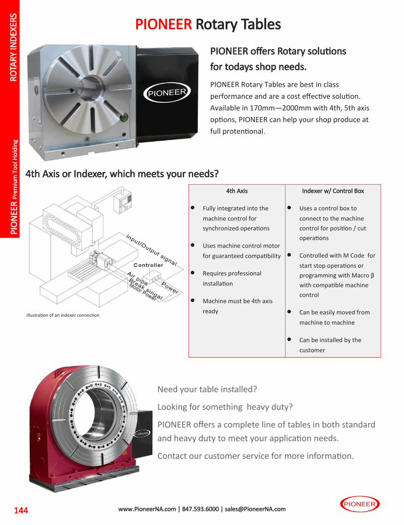
PIO
NEE
R P
rem
ium
To
ol H
old
ing
144 www.PioneerNA.com | 847.593.6000 | [email protected]
PIONEER Rotary Tables
4th Axis
• Fully integrated into the
machine control for
synchronized operations
• Uses machine control motor
for guaranteed compatibility
• Requires professional
installation
• Machine must be 4th axis
ready
Indexer w/ Control Box
• Uses a control box to
connect to the machine
control for position / cut
operations
• Controlled with M Code for
start stop operations or
programming with Macro β
with compatible machine
control
• Can be easily moved from
machine to machine
• Can be installed by the
customer
4th Axis or Indexer, which meets your needs?
Illustration of an indexer connection
PIONEER offers Rotary solutions
for todays shop needs.
PIONEER Rotary Tables are best in class
performance and are a cost effective solution.
Available in 170mm—2000mm with 4th, 5th axis
options, PIONEER can help your shop produce at
full protentional.
Need your table installed?
Looking for something heavy duty?
PIONEER offers a complete line of tables in both standard
and heavy duty to meet your application needs.
Contact our customer service for more information.
RO
TAR
Y IN
DEX
ERS

AC
C
Dri
ll C
hu
cks
Test
Bar
s
TG C
OLL
ET
CH
UC
K
QC
Tap
SM
SH
ELL
MIL
L
AD
AP
TER
S
EM E
ND
MIL
L
AD
AP
TER
S
ER C
OLL
ET
CH
UC
KS
MC
MIL
L
CH
UC
KS
SHR
INK
FIT
SX
CO
LLET
CH
UC
KS
MX
VX
MIN
I
CH
UC
KS
BC
MIL
L
CH
UC
KS
Ro
tary
Ind
exer
s
145 www.PioneerNA.com | 847.593.6000 | [email protected]
PIONEER put the highest level of technology and engineering together to
build the CNC Rotary Tables that have the power to perform.
Durable and Rigid Dual-Lead Gear System All PIONEER tables use a combination of case hardened special alloy dual-lead screw that has a larger shaft diameter
and special high tensile strength brass worm wheel that ensures exceptional wear resistance and long durability for
the life of the gear system.
RO
TAR
Y
IND
EXER
S

PIO
NEE
R P
rem
ium
To
ol H
old
ing
146 www.PioneerNA.com | 847.593.6000 | [email protected]
Specifications
*Photo shows generic image of the product and
may be different from actual product.
AX4-171R-IDX Table, Controller, Motor & Cable Set
EZX-310 Control
• 15 sets of program, 90 steps for each program
• 0.001° degree minimum increment
• Macro β Functionality
• Power, feedback, M-signal, and power supply cable included
• RS232C capable
• 14”W x 10.5”H x 12.5”D
AX4-171R Inch Metric Table Dia. 6.69 170 mm
Center height 6.30 160 mm
Through hole 1.38 35 mm
Accuracy +/- 12.5 sec
Max. weight limit (V) 165 lbs 75 kg
Max. weight limit (H) 330 lbs 150 kg
Brake system Pneumatic
Brake torque 181 ft-lbs 245 N-m
Max. rpm 33.3 rpm
Gear ratio 1/90
Position Vertical/Horizontal
Weight 185 lbs 84 kg
Motor Delta ECMA-E11310RS
RO
TAR
Y IN
DEX
ERS

AC
C
Dri
ll C
hu
cks
Test
Bar
s
TG C
OLL
ET
CH
UC
K
QC
Tap
SM
SH
ELL
MIL
L
AD
AP
TER
S
EM E
ND
MIL
L
AD
AP
TER
S
ER C
OLL
ET
CH
UC
KS
MC
MIL
L
CH
UC
KS
SHR
INK
FIT
SX
CO
LLET
CH
UC
KS
MX
VX
MIN
I
CH
UC
KS
BC
MIL
L
CH
UC
KS
Ro
tary
Ind
exer
s
147 www.PioneerNA.com | 847.593.6000 | [email protected]
AX4-171R-IDX Accessories
Hand Controller
#MPG-1
6” 3 Jaw Scroll Chuck w/ Adapter Plate
#SC-6 SCROLL CHUCK & #SC-6 ADP-170
5C Manual Chuck w/ Adapter Plate
#ACSU-5C MANUAL CHUCK & #SC-6-M5C-ADP-170
Manual Tail Stock
#TS-A160 TAILSTOCK
Pneumatic / Hydraulic Tail Stock
#TS-A160 (P/H) TAILSTOCK
Pneumatic / Hydraulic Side Table
#TS-A200S (P/H) TAILSTOCK
160mm Center Height, 200mm Face Plate
5C Air Chuck Kit
#DACC-170-KIT
RO
TAR
Y
IND
EXER
S

PIO
NEE
R P
rem
ium
To
ol H
old
ing
148 www.PioneerNA.com | 847.593.6000 | [email protected]
Specifications
*Photo shows generic image of the product and
may be different from actual product.
AX4-200R-IDX Table, Controller, Motor & Cable Set
EZX-310 Control
• 15 sets of program, 90 steps for each program
• 0.001° degree minimum increment
• Macro β Functionality
• Power, feedback, M-signal, and power supply cable included
• RS232C capable
• 14”W x 10.5”H x 12.5”D
AX4-200R Inch Metric Table Dia. 7.87 200 mm
Center height 6.30 160 mm
Through hole 1.38 35 mm
Accuracy +/- 12.5 sec
Max. weight limit (V) 220 lbs 100 kg
Max. weight limit (H) 440 lbs 200 kg
Brake system Pneumatic Standard
Air Brake torque 181 ft-lbs 245 Nm
*Optional Hyd Brake torque 351 ft-lbs 490 Nm
Max. rpm 22.2 rpm
Gear ratio 1/90
Position Vertical/Horizontal
Weight 185 lbs 84 kg
Motor Delta ECMA-E11310RS
* Must be ordered Hydraulic, additional booster required.
RO
TAR
Y IN
DEX
ERS

AC
C
Dri
ll C
hu
cks
Test
Bar
s
TG C
OLL
ET
CH
UC
K
QC
Tap
SM
SH
ELL
MIL
L
AD
AP
TER
S
EM E
ND
MIL
L
AD
AP
TER
S
ER C
OLL
ET
CH
UC
KS
MC
MIL
L
CH
UC
KS
SHR
INK
FIT
SX
CO
LLET
CH
UC
KS
MX
VX
MIN
I
CH
UC
KS
BC
MIL
L
CH
UC
KS
Ro
tary
Ind
exer
s
149 www.PioneerNA.com | 847.593.6000 | [email protected]
AX4-200R-IDX Accessories
Hand Controller
#MPG-1
8” 3 Jaw Scroll Chuck w/ Adapter Plate
#SC-8 SCROLL CHUCK & #SC-8-ADP-200
5C Manual Chuck w/ Adapter Plate
#ACSU-5C MANUAL CHUCK & #SC-8-M5C-ADP-200
Manual Tail Stock
#TS-A160 TAILSTOCK
Pneumatic / Hydraulic Tail Stock
#TS-A160 (P/H) TAILSTOCK
Pneumatic / Hydraulic Side Table
#TS-A200S (P/H) TAILSTOCK
160mm Center Height, 200mm Face Plate
5C Air Chuck Kit
#DACC-200-KIT
RO
TAR
Y
IND
EXER
S

PIO
NEE
R P
rem
ium
To
ol H
old
ing
150 www.PioneerNA.com | 847.593.6000 | [email protected]
Specifications
*Photo shows generic image of the product and
may be different from actual product.
AX4-250R-IDX Table, Controller, Motor & Cable Set
AX4-250R Inch Metric Table Dia. 9.84 250 mm
Center height 7.28 185 mm
Through hole 2.76 70 mm
Accuracy +/- 10 sec
Max. weight limit (V) 275 lbs 125 kg
Max. weight limit (H) 660 lbs 300 kg
Brake system Pneumatic Standard
Air Brake torque 340 ft-lbs 461 Nm
*Optional Hyd Brake torque 679 ft-lbs 921 Nm
Max. rpm 22.2 rpm
Gear ratio 1/90
Position Vertical/Horizontal
Weight 275 lbs 124 kg
Motor Delta ECMA-E11315RS
EZX-315 Control
• 15 sets of program, 90 steps for each program
• 0.001° degree minimum increment
• Macro β Functionality
• Power, feedback, M-signal, and power supply cable included
• RS232C capable
• 14”W x 10.5”H x 12.5”D
* Must be ordered Hydraulic, additional booster required.
RO
TAR
Y IN
DEX
ERS

AC
C
Dri
ll C
hu
cks
Test
Bar
s
TG C
OLL
ET
CH
UC
K
QC
Tap
SM
SH
ELL
MIL
L
AD
AP
TER
S
EM E
ND
MIL
L
AD
AP
TER
S
ER C
OLL
ET
CH
UC
KS
MC
MIL
L
CH
UC
KS
SHR
INK
FIT
SX
CO
LLET
CH
UC
KS
MX
VX
MIN
I
CH
UC
KS
BC
MIL
L
CH
UC
KS
Ro
tary
Ind
exer
s
151 www.PioneerNA.com | 847.593.6000 | [email protected]
AX4-250R-IDX Accessories
Hand Controller
#MPG-1
10” 3 Jaw Scroll Chuck w/ Adapter Plate
#SC-10 SCROLL CHUCK & #SC-10-ADP-250
5C Manual Chuck w/ Adapter Plate
#ACSU-5C MANUAL CHUCK & #SC-10-M5C-ADP-250
Manual Tail Stock
#TS-B185 TAILSTOCK
Pneumatic / Hydraulic Tail Stock
#TS-B185 (P/H) TAILSTOCK
Pneumatic / Hydraulic Side Table
#TS-A251S (P/H) TAILSTOCK
185mm Center Height, 250mm Face Plate
5C Air Chuck Kit
#DACC-200-KIT
RO
TAR
Y
IND
EXER
S

PIO
NEE
R P
rem
ium
To
ol H
old
ing
152 www.PioneerNA.com | 847.593.6000 | [email protected]
Specifications
*Photo shows generic image of the product and
may be different from actual product.
AX4-320R-IDX Table, Controller, Motor & Cable Set
Hydraulic Booster Required
AX4-320R Inch Metric Table Dia. 12.6 320 mm
Center height 8.27 210 mm
Through hole 4.33 110 mm
Accuracy +/- 10 sec
Max. weight limit (V) 330 lbs 150 kg
Max. weight limit (H) 770 lbs 350 kg
Brake system Hydraulic
Brake torque Hyd 1,025 ft-lbs 1,398 Nm
Max. rpm 22.2 rpm
Gear ratio 1/90
Position Vertical/Horizontal
Weight 463 lbs 210 kg
Motor Delta ECMA-E11830RS
Hyd. Booster Quote on Demand
EZX-830 Control
• 15 sets of program, 90 steps for each program
• 0.001° degree minimum increment
• Macro β Functionality
• Power, feedback, M-signal, and power supply cable included
• RS232C capable
• 14”W x 10.5”H x 12.5”D
RO
TAR
Y IN
DEX
ERS

AC
C
Dri
ll C
hu
cks
Test
Bar
s
TG C
OLL
ET
CH
UC
K
QC
Tap
SM
SH
ELL
MIL
L
AD
AP
TER
S
EM E
ND
MIL
L
AD
AP
TER
S
ER C
OLL
ET
CH
UC
KS
MC
MIL
L
CH
UC
KS
SHR
INK
FIT
SX
CO
LLET
CH
UC
KS
MX
VX
MIN
I
CH
UC
KS
BC
MIL
L
CH
UC
KS
Ro
tary
Ind
exer
s
153 www.PioneerNA.com | 847.593.6000 | [email protected]
AX4-320R-IDX Accessories
Hand Controller
#MPG-1
12” 3 Jaw Scroll Chuck w/ Adapter Plate
#SC-12 SCROLL CHUCK & #SC-12-ADP-320
Manual Tail Stock
#TS-B210 TAILSTOCK
Pneumatic / Hydraulic Tail Stock
#TS-B210 (P/H) TAILSTOCK
Pneumatic / Hydraulic Side Table
#TS-A320S (P/H) TAILSTOCK
185mm Center Height, 250mm Face Plate
RO
TAR
Y
IND
EXER
S

PIO
NEE
R P
rem
ium
To
ol H
old
ing
154 www.PioneerNA.com | 847.593.6000 | [email protected]
Specifications
*Photo shows generic image of the product and
may be different from actual product.
AX4-400R-IDX Table, Controller, Motor & Cable Set
Hydraulic Booster Required
EZX-830 Control
• 15 sets of program, 90 steps for each program
• 0.001° degree minimum increment
• Macro β Functionality
• Power, feedback, M-signal, and power supply cable included
• RS232C capable
• 14”W x 10.5”H x 12.5”D
AX4-400R Inch Metric Table Dia. 15.75 400 mm
Center height 9.84 250 mm
Through hole 5.91 150 mm
Accuracy +/- 7.5 sec
Max. weight limit (V) 660 lbs 300 kg
Max. weight limit (H) 1,100 lbs 500 kg
Brake system Hydrualic
Hyd brake torque 1,330 ft-lbs 1,803 Nm
Max. rpm 22.2 rpm
Gear ratio 1/90
Position Vertical/Horizontal
Weight 616 lbs 280 kg
Motor Delta ECMA-E11830RS
Hyd. Booster Quote on Demand
RO
TAR
Y IN
DEX
ERS

AC
C
Dri
ll C
hu
cks
Test
Bar
s
TG C
OLL
ET
CH
UC
K
QC
Tap
SM
SH
ELL
MIL
L
AD
AP
TER
S
EM E
ND
MIL
L
AD
AP
TER
S
ER C
OLL
ET
CH
UC
KS
MC
MIL
L
CH
UC
KS
SHR
INK
FIT
SX
CO
LLET
CH
UC
KS
MX
VX
MIN
I
CH
UC
KS
BC
MIL
L
CH
UC
KS
Ro
tary
Ind
exer
s
155 www.PioneerNA.com | 847.593.6000 | [email protected]
AX4-400R-IDX Accessories
Hand Controller
#MPG-1
Manual Tail Stock
#TS-B250 TAILSTOCK
Pneumatic / Hydraulic Tail Stock
#TS-B250 (P/H) TAILSTOCK R
OTA
RY
IND
EXER
S

PIO
NEE
R P
rem
ium
To
ol H
old
ing
156 www.PioneerNA.com | 847.593.6000 | [email protected]
Specifications
*Photo shows generic image of the product and
may be different from actual product.
AX4-500R-IDX Table, Controller, Motor & Cable Set
Hydraulic Booster Required
EZX-830 Control
• 15 sets of program, 90 steps for each program
• 0.001° degree minimum increment
• Macro β Functionality
• Power, feedback, M-signal, and power supply cable included
• RS232C capable
• 14”W x 10.5”H x 12.5”D
AX4-500R Inch Metric Table Dia. 19.68 500 mm
Center height 12.2 300 mm
Through hole 7.09 180 mm
Accuracy +/- 7.5 sec
Max. weight limit (V) 770 lbs 400 kg
Max. weight limit (H) 1,320 lbs 800 kg
Brake system Hydualic
Hyd brake torque 1,807 ft-lbs 6,680 Nm
Max. rpm 16.7 rpm
Gear ratio 1/120
Position Vertical/Horizontal
Weight 836 lbs 380 kg
Motor Delta ECMA-E11830RS
Hyd. Booster Quote on Demand
RO
TAR
Y IN
DEX
ERS

AC
C
Dri
ll C
hu
cks
Test
Bar
s
TG C
OLL
ET
CH
UC
K
QC
Tap
SM
SH
ELL
MIL
L
AD
AP
TER
S
EM E
ND
MIL
L
AD
AP
TER
S
ER C
OLL
ET
CH
UC
KS
MC
MIL
L
CH
UC
KS
SHR
INK
FIT
SX
CO
LLET
CH
UC
KS
MX
VX
MIN
I
CH
UC
KS
BC
MIL
L
CH
UC
KS
Ro
tary
Ind
exer
s
157 www.PioneerNA.com | 847.593.6000 | [email protected]
AX4-500R-IDX Accessories
Hand Controller
#MPG-1
Manual Tail Stock
#TS-C310 TAILSTOCK
Pneumatic / Hydraulic Tail Stock
#TS-C310 (P/H) TAILSTOCK R
OTA
RY
IND
EXER
S

PIO
NEE
R P
rem
ium
To
ol H
old
ing
158 www.PioneerNA.com | 847.593.6000 | [email protected]
PIONEER EDM Rotary Tables
4th Axis
• Fully integrated into the
machine control for
synchronized operations
• Uses machine control motor
for guaranteed compatibility
• Requires professional
installation
• Machine must be 4th axis
ready
Indexer w/ Control Box
• Uses a control box to
connect to the machine
control for position / cut
operations
• Controlled with M Code for
start stop operations or
programming with Macro β
with compatible machine
control
• Can be easily moved from
machine to machine
• Can be installed by the
customer
4th Axis or Indexer, which meets your needs?
Illustration of an indexer connection
PIONEER EDM tables are fully sealed
with positive air pressure and check
valve system.
PIONEER EDM Rotary Tables are best in class
performance and are a cost effective solution.
Available in 140mm—250mm with 4th, 5th axis
options, PIONEER can supply an EDM option to
meet your needs.
Pioneer EDM Rotary are available in 2 configurations, EDW for Wire, EDS for Sinker machines.
EDW Wire:
• Stainless Steel Faceplate
• Communicator block to ground the face plate
• Nickel plating
• High Performance Seals
• Stainless Steel Screws
EDS Sinker:
• Stainless Steel Faceplate
• Optional Nickel plating
• High Performance Seals
• Stainless Steel Screws
RO
TAR
Y IN
DEX
ERS

AC
C
Dri
ll C
hu
cks
Test
Bar
s
TG C
OLL
ET
CH
UC
K
QC
Tap
SM
SH
ELL
MIL
L
AD
AP
TER
S
EM E
ND
MIL
L
AD
AP
TER
S
ER C
OLL
ET
CH
UC
KS
MC
MIL
L
CH
UC
KS
SHR
INK
FIT
SX
CO
LLET
CH
UC
KS
MX
VX
MIN
I
CH
UC
KS
BC
MIL
L
CH
UC
KS
Ro
tary
Ind
exer
s
159 www.PioneerNA.com | 847.593.6000 | [email protected]
Specifications
JNC140R-AC5-10-EDW EDW configuration for Wire EDM applications. Table, Controller, Motor & Cable Set
*Photo shows generic image of the product and may be
different from actual product.
Stainless Steel Face Plate & Communicator Block not shown
JNC140 Inch Metric Table Dia. 5.51 140 mm
Center height 4.33 110 mm
Through hole 1.10 28 mm
Accuracy Within 40 sec. cumulatively
Repeatability Within 4 sec.
Max. load horizontal 880 lbs 4,000 N
Max. load vertical 440 lbs 2,000 N
Brake system Pneumatic
Brake torque 89 ft-lbs 120 N-m
Max. rpm 41.6 rpm
Gear ratio 1/72
Position Vertical/Horizontal
Weight 60 lbs 27 kg
Motor Fanuc Beta0.5/1is size
AC5-10 control • 10,000 block capacity, Bi-directional
• 0.0001° degree minimum increment
• Power, feedback, M-signal, and power supply cable included.
• RS232C capable
• W 10.25” x H 8” x D9”
RO
TAR
Y
IND
EXER
S

www.pioneerNA.com | 847.593.6000 | [email protected]
JET-BLAST Coolant Options
Jet-Blast has been proven over the last 10 years to double tool life in
many applications by blasting the chips out of the cut allowing the
cutting tool to cut free increasing efficiency and life.
Jet-Blast is a modification we perform at Pioneer by adding coolant
ports to holders in stock. The amount of coolant ports and sizes are
dependent on the customer and application. Pioneer will EDM in
2 ports standard, additional ports at a per hole fee.
Jet-Blast can be applied to all tool holders 10” and shorter from
inventory, all sealed collets and coolant caps.
Coolant Volume, Pressure and RPM will determine the
effectiveness of the Jet-Blast system.
Examples

www.pioneerNA.com | 847.593.6000 | [email protected] 145
Large or Small, PIONEER Rotary has a cost effective solution for your application
PIONEER brings an Installation and Service department SECOND TO NONE
PIONEER brings an Installation and Service department second to none, with over 20 years experience in full rotary table 4th and 5th Axis installations as well as repair and service on many popular brands.
· Full Turnkey Installations on many Fanuc based controls including Fanuc 0i, 16i, 18i, 21i series and more.
· Guaranteed Compatibility - We only install OEM Motors & Controllers to guarantee 100% compatibility with the machine control.
PIONEER EDM Thanks to excellent water protection by patented auto air purging and optional corrosion protection plating or paint, JNC and TNT models are available as most affordable EDM rotary and indexing solution. JNC Models JNC140 / JNC170 / JNC200 / JNC250
· Available in 5.5 / 6.7 / 7.9 / 9.8 inch table diameter
· Submersible with standard Auto Air Purging System (PAT)
· Optional stainless face plate with commutator block
· Optional nickel plating for better corrosion protection TNT models TNT100 / TNT170
· Available in 3.9 / 6.7 inch table diameter
· Submersible with standard Auto Air Purging System (PAT)
· Optional stainless face plate with commutator block
· Optional rust preventative paint for better corrosion protection

The PIONEER Group
Pioneer N.A., Inc.
641 Fargo Ave.
Elk Grove Village, IL 60007
USA
T: 847-593-6000
F: 800-930-6436
www.PioneerNA.com
THD GmbH
Spiesheimer Weg 19
D-55286 Worrstadt
Germany
T: +49-(0)67-329-3790
F: +49-(0)67-329-3792-9
www.thdgmbh.com
Pioneer Trading Company
1-88-2 Okawa Akanabe
Gifu City, 500-8282
Japan
T: +81-(0)58-274-0341
F: +81-(0)58-273-7102
www.goptc.jp
Also available through Pioneer NA:
Rotary Tables & Indexers
• Pioneer Rotary
• Yukiwa Rotary
Pioneer Machine Tool
Air & Diaphragm Chucks
Pioneer
Trading
Compa-
ny
Catalog P2019 - $9.95USD
Pioneer NA 2019