Embed Size (px)
Citation preview

TABLE OF CONTENTS
CHAPTER 6 oTHER dEvEloPmEnT CodES
PineRiversPlan
PART 3 ASSESSmEnT CRITERIA FoR oPERATIonAl WoRKS ...............................................................................................6-270
Division 1 Preliminary ................................................................................6-270
Division 2 Urban Residential Subdivision Works Design Code .............6-271
Division 3 Park Residential Subdivision Works Design Code ...............6-302
Division 4 Rural Residential Subdivision Works Design Code ..............6-326
Division 5 Industrial Subdivision Works Design Code ...........................6-347
Division 6 Commercial Subdivision Works Design Code .......................6-375
Division 7 Rural Subdivision Works Design Code ..................................6-403
Division 8 Access Easement Subdivision Works Design Code .............6-418
Histori
c Vers
ion
PineRive
rsPlan

CHAPTER 6, PART 3, DIVISION 1 - PRELIMINARY
CHAPTER 6, PART 3 - ASSESSMENT CRITERIA FOR OPERATIONAL WORKS Effective from 15 December 2006 6-270
PineRiversPlan
chapter 6 - Other DeVeLOpMeNt cODeS
Part 3 assessment CrIterIa FOr OPeratIOnaL WOrKs
Division 1 Preliminary1.1 Codes for Operational Work Development
The provisions of this part comprise the following codes:–
(1) Urban Residential Subdivision Works Design Code;
(2) Park Residential Subdivision Works Design Code;
(3) Rural Residential Subdivision Works Design Code;
(4) Industrial Subdivision Works Design Code;
(5) Commercial Subdivision Works Design Code;
(6) Rural Subdivision Works Design Code; and
(7) Access Easement Subdivision Works Design Code.
Histori
c Vers
ion
PineRive
rsPlan

CHAPTER 6, PART 3, DIVISION 2 - URBAN RESIDENTIAL SUBDIVISION WORKS DESIGN CODE
PineRiversPlan
CHAPTER 6, PART 3 - ASSESSMENT CRITERIA FOR OPERATIONAL WORKS Effective from 15 December 2006 6-271
Division 2 Urban Residential Subdivision Works Design Code2.1 Overall Outcome
To create urban subdivision development that:-(1) provides safe, convenient and attractive urban residential neighbourhoods;(2) ensures that sites are managed during construction to minimise adverse impacts to the
environment and on the health and amenity of residents and premises;(3) ensures that sites are managed during construction to minimise adverse traffic impacts to
existing roads;(4) ensures that earthworks design and construction is suitable for the intended use of the land
and that adverse impacts to the environment and on the health and amenity of residents is minimised;
(5) have road networks that are designed and constructed to provide an optimum combination of safety, amenity, convenience, economy and environment for residents, road and street users, and the community generally;
(6) have stormwater management systems that are designed and constructed to provide an optimum combination of safety, amenity, convenience, economy and environment for residents and the community generally;
(7) have stormwater management systems that are designed and constructed to collect and convey stormwater from a catchment to its receiving waters with minimal nuisance, danger or damage, and at a development and environmental cost which is acceptable to the community as a whole;
(8) provide for the convenience and safety of pedestrians and vehicular traffic during frequent or nuisance stormwater flows;
(9) limits flooding of public and private property, both within the catchment and downstream, to ensure that flood inundation occurs on rare occasions only;
(10) ensures a reasonable level of pedestrian and vehicular traffic safety and accessibility during storm events;
(11) minimises pollutant inflows to the receiving waters and controls scour and depositional effects;
(12) controls and temporarily detains within each catchment as much incident rainfall and runoff as possible to reduce the impact of urbanisation;
(13) adequately protects people, the natural environment and the built environment from stormwater runoff flows at an acceptable level of risk;
(14) integrates stormwater management solutions with other uses and the natural environment;(15) provides safe, convenient and legible networks for walking and cycling to points of attraction
and beyond the development while preserving maximum visual amenity;(16) ensures that opportunities exist for choice in the mode of transport and to provide for cost-
effective and energy efficient public transport services that are accessible and convenient to the community;
(17) ensures, where appropriate, as many existing trees are retained as possible to keep the original character of the land and provide shelter and food for endemic flora and fauna;
(18) provides for urban residential lots that are adequately serviced with sewerage, water supply, electricity, street lighting and communications services in a timely, cost effective, coordinated and efficient manner that supports sustainable development practices, and is in accordance with the desired character of the locality;
(19) ensures that the water supply and sewerage service provision complies with the relevant State Guidelines for design;
(20) minimises the impact on residential amenity due to provision of water supply and sewerage infrastructure;
(21) ensures all sewerage, water supply, electricity, street lighting and communications services that require relocation and/or alterations as a result of urban residential development are carried out in a timely, cost effective, coordinated and efficient manner; and
(22) reduces the level of fire risk associated with building in areas which are assessed to have a medium to high bushfire hazard.
2.2 Compliance with the Urban Residential Subdivision Works Design CodeThis code applies to all operational works relating to development or reconfiguring of urban residential land, but specifically excludes applications for access easements to a road, subdivision by lease and boundary relocations or realignments.
Histori
c Vers
ion
PineRive
rsPlan

CHAPTER 6, PART 3, DIVISION 2 - URBAN RESIDENTIAL SUBDIVISION WORKS DESIGN CODE
PineRiversPlan
CHAPTER 6, PART 3 - ASSESSMENT CRITERIA FOR OPERATIONAL WORKS Effective from 15 December 2006 6-272
The application of the various specific outcomes will depend upon the size or scale of the proposed development. Some specific outcomes will not apply due to a particular design element not being part of the proposal (e.g. new road). In other instances it may be impractical to apply some specific outcomes, particularly for small infill developments.
2.3 Development RequirementsThe following are the design elements relevant to urban residential subdivision works:-(2.3.1) Managing Impacts During Construction(2.3.2) Earthworks(2.3.3) Road Networks (excludes State-controlled roads)(2.3.4) Stormwater Management(2.3.5) Pedestrian and Cyclist Facilities(2.3.6) Public Transport(2.3.7) Public Open Space(2.3.8) Utilities
(2.3.8a) Water Supply(2.3.8b) Sewerage(2.3.8c) Recycled Water(2.3.8d) Electricity(2.3.8e) Street Lighting(2.3.8f) Telecommunications(2.3.8g) Alterations and Relocations(2.3.8h) As Constructed Information
(2.3.9) Bushfire Hazard
Histori
c Vers
ion
PineRive
rsPlan

CHA
PTER 6, PA
RT 3, DIVIS
ION
2 - UR
BA
N R
ESID
ENTIA
L SU
BD
IVISIO
N W
OR
KS DES
IGN
COD
E
PineRiversPlan
CHA
PTER 6, PA
RT 3 - ASS
ESSM
ENT CR
ITERIA
FOR
OPER
ATION
AL W
OR
KS Effective from
15 Decem
ber 2006 6-273
Specific Outcomes for Assessable Development Probable Solutions
2.3.1 Managing Impacts During ConstructionSO 1 All development sites minimise, as far as possible, any adverse impact to the natural environment caused by erosion, siltation, incineration of cleared vegetation and rubbish.
PS 1 The development works incorporate temporary stormwater runoff, erosion and sediment controls and trash traps designed in accordance with Council’s Planning Scheme Policy PSP28 Civil Infrastructure Design, Part 2, Section 4.2.0 and 4.11.4, and Subdivisions Section Technical Note No. 6. The measures are adjusted on-site to maximise their effectiveness.Stormwater runoff, erosion and sediment controls are constructed prior to commencement of any clearing works wherever possible.All environmentally significant areas to be retained with the development are clearly delineated and fenced prior to development works commencing.
SO 2 All development works are carried out at times which minimise noise impacts to residents.
PS 2 All development works are carried out within the following times, unless otherwise approved in writing by Council’s engineer:-(1) Monday to Friday (other than public holidays) between 7am and 6pm on the same day; and(2) Saturday (other than public holidays) between 7 am and 12 noon on the same day.No work is carried out on Sundays and public holidays.Variations to the above working hours may be approved if Council’s engineer considers that the work is unlikely to cause significant inconvenience or disruption to the public, or the work is unlikely to cause annoyance or inconvenience to occupants of adjacent properties.
SO 3 All development works are managed to minimise dust and siltation nuisance to residents.
PS 3 During construction, dust suppression measures (such as watering of the site) are implemented to protect nearby premises from dust pollution.
SO 4 All development works avoid the redirection of stormwater runoff where potential impacts to residents may occur.
PS 4 Temporary construction works do not pond or concentrate stormwater runoff in adjoining properties.Temporary construction works do not create nuisance or annoyance to adjoining premises as a result of altering the stormwater runoff pattern exiting the site.
SO 5 Construction traffic does not adversely impact on the amenity of existing residents.
PS 5 Construction traffic to and from the site uses the highest classification streets or roads where a choice of access routes is available.Where significant volumes of material are approved to enter or leave the site, a haul route is approved by Council.All materials associated with the development that are dropped, deposited or spilled on streets giving access to the site are removed and the streets are cleaned as soon as practicable after the event. Any damaged areas are repaired and reinstated to their previous condition.Where works are carried out on existing roads, a traffic control plan is prepared in accordance with the Manual of Uniform Traffic Control Devices. All traffic control measures are properly erected and maintained during the works.Any access road to the site that has been affected by any material dropped, deposited or spilled on the road as a result of the construction processes associated with the site is cleaned and restored to its original condition.
SO 6 Construction traffic is controlled to ensure all traffic movements to and from the site are safe.
PS 6 All traffic movements to and from the site frontage are carried out in a safe manner. Traffic controls are used where site access is approved directly onto a Major Road.
SO 7 All clearing works are carefully undertaken to ensure the clearing is limited to the area of the approved infrastructure works, buildings areas and other areas approved in the development permit.
PS 7 Areas of significant vegetation, proposed park and open space areas and other areas of vegetation or individual trees designated to be retained with the development are temporarily fenced and flagged.
Histori
c Vers
ion
PineRive
rsPlan
CHA
PTER 6, PA
RT 3, DIVIS
ION
2 - UR
BA
N R
ESID
ENTIA
L SU
BD
IVISIO
N W
OR
KS DES
IGN
COD
E
PineRiversPlan
CHA
PTER 6, PA
RT 3 - ASS
ESSM
ENT CR
ITERIA
FOR
OPER
ATION
AL W
OR
KS Effective from
15 Decem
ber 2006 6-274
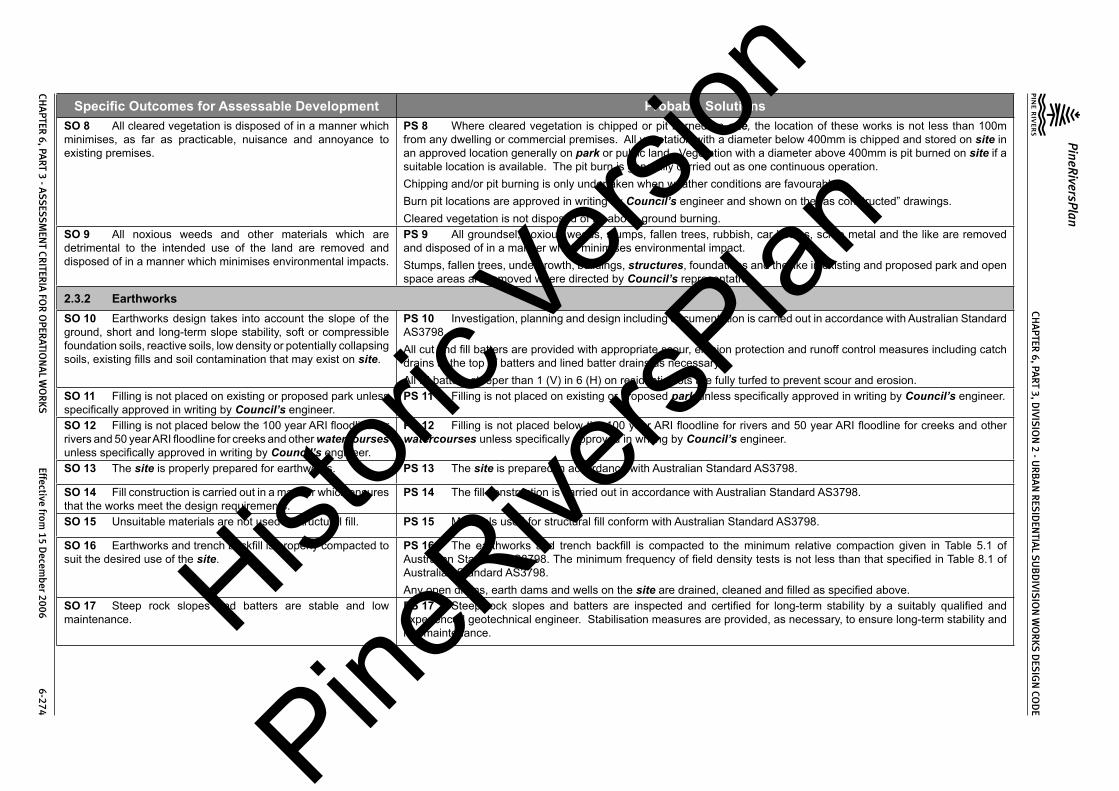
Specific Outcomes for Assessable Development Probable SolutionsSO 8 All cleared vegetation is disposed of in a manner which minimises, as far as practicable, nuisance and annoyance to existing premises.
PS 8 Where cleared vegetation is chipped or pit burned on site, the location of these works is not less than 100m from any dwelling or commercial premises. All vegetation with a diameter below 400mm is chipped and stored on site in an approved location generally on park or public land. Vegetation with a diameter above 400mm is pit burned on site if a suitable location is available. The pit burn is generally carried out as one continuous operation.Chipping and/or pit burning is only undertaken when weather conditions are favourable.Burn pit locations are approved in writing by Council’s engineer and shown on the “as constructed” drawings.Cleared vegetation is not disposed of by above ground burning.
SO 9 All noxious weeds and other materials which are detrimental to the intended use of the land are removed and disposed of in a manner which minimises environmental impacts.
PS 9 All groundsel, noxious weeds, stumps, fallen trees, rubbish, car bodies, scrap metal and the like are removed and disposed of in a manner which minimises environmental impact.Stumps, fallen trees, undergrowth, buildings, structures, foundations and the like in existing and proposed park and open space areas are removed where directed by Council’s representative.
2.3.2 EarthworksSO 10 Earthworks design takes into account the slope of the ground, short and long-term slope stability, soft or compressible foundation soils, reactive soils, low density or potentially collapsing soils, existing fills and soil contamination that may exist on site.
PS 10 Investigation, planning and design including documentation is carried out in accordance with Australian Standard AS3798.All cut and fill batters are provided with appropriate scour, erosion protection and runoff control measures including catch drains at the top of batters and lined batter drains as necessary.All fill batters steeper than 1 (V) in 6 (H) on residential lots are fully turfed to prevent scour and erosion.
SO 11 Filling is not placed on existing or proposed park unless specifically approved in writing by Council’s engineer.
PS 11 Filling is not placed on existing or proposed park unless specifically approved in writing by Council’s engineer.
SO 12 Filling is not placed below the 100 year ARI floodline for rivers and 50 year ARI floodline for creeks and other watercourses unless specifically approved in writing by Council’s engineer.
PS 12 Filling is not placed below the 100 year ARI floodline for rivers and 50 year ARI floodline for creeks and other watercourses unless specifically approved in writing by Council’s engineer.
SO 13 The site is properly prepared for earthworks. PS 13 The site is prepared in accordance with Australian Standard AS3798.
SO 14 Fill construction is carried out in a manner which ensures that the works meet the design requirements.
PS 14 The fill construction is carried out in accordance with Australian Standard AS3798.
SO 15 Unsuitable materials are not used in structural fill. PS 15 Materials used for structural fill conform with Australian Standard AS3798.
SO 16 Earthworks and trench backfill is properly compacted to suit the desired use of the site.
PS 16 The earthworks and trench backfill is compacted to the minimum relative compaction given in Table 5.1 of Australian Standard AS3798. The minimum frequency of field density tests is not less than that specified in Table 8.1 of Australian Standard AS3798.Any open drains, earth dams and wells on the site are drained, cleaned and filled as specified above.
SO 17 Steep rock slopes and batters are stable and low maintenance.
PS 17 Steep rock slopes and batters are inspected and certified for long-term stability by a suitably qualified and experienced geotechnical engineer. Stabilisation measures are provided, as necessary, to ensure long-term stability and low maintenance.Histori
c Vers
ion
PineRive
rsPlan

CHA
PTER 6, PA
RT 3, DIVIS
ION
2 - UR
BA
N R
ESID
ENTIA
L SU
BD
IVISIO
N W
OR
KS DES
IGN
COD
E
PineRiversPlan
CHA
PTER 6, PA
RT 3 - ASS
ESSM
ENT CR
ITERIA
FOR
OPER
ATION
AL W
OR
KS Effective from
15 Decem
ber 2006 6-275
Specific Outcomes for Assessable Development Probable SolutionsSO 18 Allotment earthworks for building platforms is designed and constructed to minimise the visual impact of the cut and fill works and effects on the amenity of the future dwelling occupiers.
PS 18 Allotment earthworks is minimised to retain, as far as practicable, the natural land form.Allotment earthworks carried out for building platforms are designed and constructed in order that the finished surface along side and rear boundaries conforms with Figure 5.1.
Figure 5.1 – Cross Section Perpendicular to BoundarySO 19 “As constructed” information including test certificates for material quality (if required) and compaction is provided after completion of the subdivision works.
PS 19 “As constructed” information including test certificates for material quality (if required) and compaction is provided after completion of the subdivision works.
2.3.3 Road Networks (excludes State-controlled roads)SO 20 The road design and construction has a clear structure and component streets conform to their function in the network.
PS 20 to PS 23 The Residential Streets conform to the following:-Histori
c Vers
ion
PineRive
rsPlan

CHA
PTER 6, PA
RT 3, DIVIS
ION
2 - UR
BA
N R
ESID
ENTIA
L SU
BD
IVISIO
N W
OR
KS DES
IGN
COD
E
PineRiversPlan
CHA
PTER 6, PA
RT 3 - ASS
ESSM
ENT CR
ITERIA
FOR
OPER
ATION
AL W
OR
KS Effective from
15 Decem
ber 2006 6-276
Specific Outcomes for Assessable Development Probable SolutionsSO 21 The road design and construction has clear physical distinctions between each type of street. The distinctions are to be based on function, legibility, convenience, traffic volumes, vehicle speeds, public safety and amenity.SO 22 The road design and construction accommodates the following primary functions:-(1) access to residences;(2) car parking for visitors;(3) social and activity space;(4) stormwater drainage paths
(minor and major storms);(5) public transport on Collector Streets;(6) utility services location; and(7) setting and approach (streetscape and landscape) for
adjoining residences.SO 23 The road design and construction accommodates adequate verge and carriageway width for the primary functions listed in specific outcomes above.
Design Issue Access Place (1) Access Street (1) Collector Street Trunk Collector Street
Traffic Catchment (maximum)
20 lots 50 lots (2) 300 lots (2)(3) 900 lots (2)
Design Speed (maximum)
40km/h 40km/h 40km/h 60km/h
Carriageway Lanes 2 (4) 2 3 2Carriageway Width 6m 6m 7.5m 9mVerge Width (minimum)
3.5m (5)(6) 3.5m (5)(6) 3.5m (5)(6) 5.0m (6)
Reserve Width (minimum)
15m 15m 18m 24m (7)
Footpaths/Cyclepaths not required (8) where >40 lots served (8)
one side (8) both sides (8)
Parking 0.5 space per lot (9) 0.5 space per lot (9) 0.5 space per lot (9) 0.5 space per lot (9)
Grade (minimum - maximum)
0.4% - 16% (10) 0.4% - 16% (10) 0.4% - 12% (11) 0.4% - 12% (11)
Notes:1. Difference is in subdivision layout only, not in street design.2. Based on 10 vpd per single detached dwelling residential lot.3. Absolute maximum 350 lots.4. Single lane with Council approval, maximum 12 lots.5. Greater width required to verge with water main (refer to Standard Drawing 8-10011).6. Greater width required where cyclepaths provided.7. Greater width required at intersections.8. Footpath or cyclepaths may be required in accordance with network design.9. A car park is required within 25m of every residential lot.10. 20% absolute maximum grade may be permitted under special circumstances.11. 16% absolute maximum grade may be permitted under special circumstances.The detailed design of Residential Streets conforms with Council’s Planning Scheme Policy PSP28 Civil Infrastructure Design:-
Road Design Issue Planning Scheme Policy PSP28 Civil Infrastructure Design Reference
Traffic Volume Part 1 Sect 2.2.0Traffic Speed Part 1 Sect 2..30Parking Part 1 Sect 2.4.0
Histori
c Vers
ion
PineRive
rsPlan

CHA
PTER 6, PA
RT 3, DIVIS
ION
2 - UR
BA
N R
ESID
ENTIA
L SU
BD
IVISIO
N W
OR
KS DES
IGN
COD
E
PineRiversPlan
CHA
PTER 6, PA
RT 3 - ASS
ESSM
ENT CR
ITERIA
FOR
OPER
ATION
AL W
OR
KS Effective from
15 Decem
ber 2006 6-277
Specific Outcomes for Assessable Development Probable SolutionsProvision for Passing Part 1 Sect 2.5.0Carriageway Width Part 1 Sect 2.6.0Street Classification Part 1 Sect 2.7.0Verge Part 1 Sect 2.8.0Street Reserve Width Part 1 Sect 2.9.0Geometric Design Part 1 Sect 2.10.0Intersections Part 1 Sect 2.11.0 & 6.16.0Manoeuvring Areas Part 1 Sect 2.12.0Speed Control Devices Part 1 Sect 2.13.0Roundabouts Part 1 DG 01Landscape Construction on Road Reserves, Parks and Drainage Reserves Part 1 DG 03Local Area Traffic Management Part 1 DG 05Signs and Road Marking Part 1 Sect 6.7.0Footpaths Part 1 Sect 6.4.0Bikeways Part 1 Sect 6.5.0Service Conduits Part 1 Sect 6.8.0Subsoil Drainage Part 1 Sect 6.9.0Safety Barriers Part 1 Sect 6.10.0Guide Posts Part 1 Sect 6.11.0Bridge and Culvert Widths Part 1 Sect 6.12.0Street and Pathway Lighting Part 1 Sect 6.13.0Park Barriers Part 1 Sect 6.14.0Retaining Walls Part 1 Sect 6.15.0The Major Roads conform to the following:-
Design Issue Sub-Arterial Arterial Major Arterial FreewayTraffic Volume (typical) 12,000vpd 30,000vpd as required as requiredDesign Speed (minimum)
80km/h 100km/h 100km/h 100km/h
Carriageway Lanes 2 4 4 or more 4 or moreCarriageway Width 10m(kerbed) (1) 2 x 8.5m (kerbed) (1) as required by design as required by
designVerge Width (minimum) 7.5m 8.5m as required by design as required by
design
Histori
c Vers
ion
PineRive
rsPlan

CHA
PTER 6, PA
RT 3, DIVIS
ION
2 - UR
BA
N R
ESID
ENTIA
L SU
BD
IVISIO
N W
OR
KS DES
IGN
COD
E
PineRiversPlan
CHA
PTER 6, PA
RT 3 - ASS
ESSM
ENT CR
ITERIA
FOR
OPER
ATION
AL W
OR
KS Effective from
15 Decem
ber 2006 6-278
Specific Outcomes for Assessable Development Probable SolutionsReserve Width (minimum)
25m (2) 40m (2) as required by design as required by design
Footpaths/Cyclepaths both sides (3) both sides (3) not required not requiredGrade (minimum - maximum)
0.4% - 7% (4) 0.4% - 6% (4) as required by design as required by design
Notes:-1. Does not include cyclelanes.2. Greater width required at intersections.3. Cyclepaths may be required in accordance with network design.4. Steeper grades may be permitted under special circumstances.The detailed design of Major Roads conforms with Council’s Planning Scheme Policy PSP28 Civil Infrastructure Design:-
Road Design Issue Planning Scheme Policy PSP28 Civil Infrastructure Design Reference
Design Philosophy Part 1 Sect 3.2.0Classification of Major Urban Roads Part 1 Sect 3.3.0Freeways Part 1 Sect 3.4.0Arterial Roads Part 1 Sect 3.5.0Sub-Arterial Roads Part 1 Sect 3.6.0Intersections Part 1 Sect 3.7.0 & 6.16.0Traffic Volume and Capacity Part 1 Sect 3.8.0Design Speed Part 1 Sect 3.9.0Cross Section Elements Part 1 Sect 3.10.0Geometric Design Part 1 Sect 3.11.0Bus Stops Part 1 Sect 3.12.0Pedestrian and Cyclist Facilities Part 1 Sect 3.13.0Aesthetics and Appurtenances Part 1 Sect 3.14.0Services Streets Part 1 Sect 3.15.0Roundabouts Part 1 DG 01Signs and Road Markings Part 1 Sect 6.7.0Footpaths Part 1 Sect 6.4.0Bikeways Part 1 Sect 6.5.0Service Conduits Part 1 Sect 6.8.0Subsoil Drainage Part 1 Sect 6.9.0
Histori
c Vers
ion
PineRive
rsPlan
CHA
PTER 6, PA
RT 3, DIVIS
ION
2 - UR
BA
N R
ESID
ENTIA
L SU
BD
IVISIO
N W
OR
KS DES
IGN
COD
E
PineRiversPlan
CHA
PTER 6, PA
RT 3 - ASS
ESSM
ENT CR
ITERIA
FOR
OPER
ATION
AL W
OR
KS Effective from
15 Decem
ber 2006 6-279
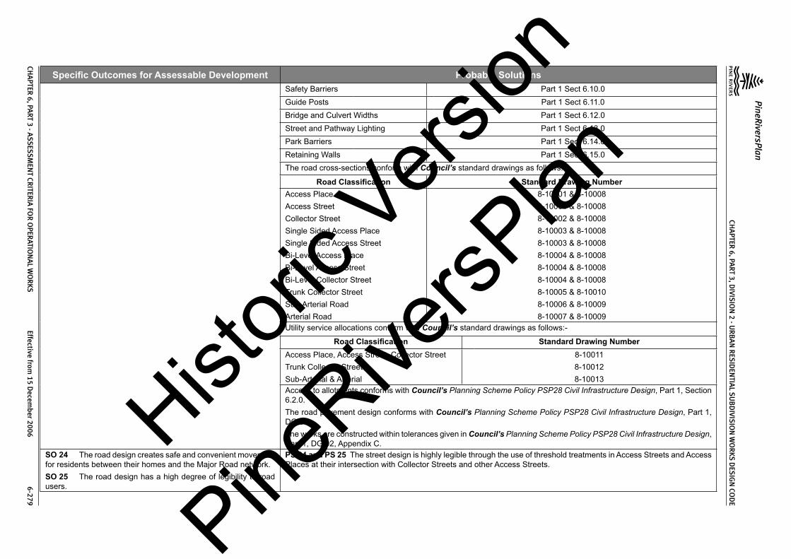
Specific Outcomes for Assessable Development Probable SolutionsSafety Barriers Part 1 Sect 6.10.0Guide Posts Part 1 Sect 6.11.0Bridge and Culvert Widths Part 1 Sect 6.12.0Street and Pathway Lighting Part 1 Sect 6.13.0Park Barriers Part 1 Sect 6.14.0Retaining Walls Part 1 Sect 6.15.0The road cross-sections conform with Council’s standard drawings as follows:-
Road Classification Standard Drawing NumberAccess PlaceAccess StreetCollector StreetSingle Sided Access PlaceSingle Sided Access StreetBi-Level Access PlaceBi-Level Access StreetBi-Level Collector StreetTrunk Collector StreetSub-Arterial RoadArterial Road
8-10001 & 8-100088-10001 & 8-100088-10002 & 8-100088-10003 & 8-100088-10003 & 8-100088-10004 & 8-100088-10004 & 8-100088-10004 & 8-100088-10005 & 8-100108-10006 & 8-100098-10007 & 8-10009
Utility service allocations conform with Council’s standard drawings as follows:-
Road Classification Standard Drawing NumberAccess Place, Access Street, Collector StreetTrunk Collector StreetSub-Arterial & Arterial
8-100118-100128-10013
Access to allotments conforms with Council’s Planning Scheme Policy PSP28 Civil Infrastructure Design, Part 1, Section 6.2.0.The road pavement design conforms with Council’s Planning Scheme Policy PSP28 Civil Infrastructure Design, Part 1, DG 06.The works are constructed within tolerances given in Council’s Planning Scheme Policy PSP28 Civil Infrastructure Design, Part 1, DG 02, Appendix C.
SO 24 The road design creates safe and convenient movement for residents between their homes and the Major Road network.SO 25 The road design has a high degree of legibility to road users.
PS 24 and PS 25 The street design is highly legible through the use of threshold treatments in Access Streets and Access Places at their intersection with Collector Streets and other Access Streets.
Histori
c Vers
ion
PineRive
rsPlan

CHA
PTER 6, PA
RT 3, DIVIS
ION
2 - UR
BA
N R
ESID
ENTIA
L SU
BD
IVISIO
N W
OR
KS DES
IGN
COD
E
PineRiversPlan
CHA
PTER 6, PA
RT 3 - ASS
ESSM
ENT CR
ITERIA
FOR
OPER
ATION
AL W
OR
KS Effective from
15 Decem
ber 2006 6-280
Specific Outcomes for Assessable Development Probable SolutionsSO 26 The road design provides more than one access route (at all stages of development) for residential areas containing a significant number of residential lots.
PS 26 The residential area is served by more than one access route to the Major Road system when the number of residential lots exceeds 100 (absolute maximum allowed is 150 lots).
SO 27 Intersections along residential streets and Major Roads are safe and convenient.
PS 27 Intersection spacing (centreline – centreline) along a through road conforms with the following:-
Intersecting Road
Location
Through Road
Access Street & Collector Street
Trunk Collector
Street
Sub- Arterial Road (1)
Arterial Road
Major Arterial Road
On same side of through road
60m 100m 300m 500m 1000m
On opposite sides of the through road
40m 60m 300m 500m 1000m
Notes:-1. In the case of Sub-Arterial Roads, existing landholdings may require intersections at a lesser spacing. In such
cases the following absolute minimum spacing is used, but all turns access may not be permitted (i.e. left in/left out only):
Intersections on same side 100m
Intersections on opposite sides:• left-right stagger• right-left stagger
100m30m
The detailed design of street and road intersections conforms to the following sections of Council’s Planning Scheme Policy PSP28 Civil Infrastructure Design:-
Road Classification Planning Scheme Policy PSP28 Civil Infrastructure Design Reference
Residential StreetsMajor RoadsRoundaboutsLocal Area Traffic Management
Part 1 Sect 2.11.0 & Sect 6.16.0Part 1 Sect 3.7.0 & Sect 6.16.0
Part 1 DG 01 Part 1 DG 05
SO 28 The alignment and geometry of roads that form identified bus routes allows for efficient and unimpeded movement of buses without facilitating high traffic speeds.
PS 28 Bus routes have a minimum road width of 20m and carriageway width of 9.5m. The maximum grade of the bus route is 12%.The detailed design of bus routes and associated facilities conforms with Council’s Planning Scheme Policy PSP28 Civil Infrastructure Design.Histori
c Vers
ion
PineRive
rsPlan

CHA
PTER 6, PA
RT 3, DIVIS
ION
2 - UR
BA
N R
ESID
ENTIA
L SU
BD
IVISIO
N W
OR
KS DES
IGN
COD
E
PineRiversPlan
CHA
PTER 6, PA
RT 3 - ASS
ESSM
ENT CR
ITERIA
FOR
OPER
ATION
AL W
OR
KS Effective from
15 Decem
ber 2006 6-281
Specific Outcomes for Assessable Development Probable SolutionsSO 29 The road design facilitates walking and cycling within the neighbourhood and to local activity centres.
PS 29 All pathways have 1.2m wide (minimum) reinforced concrete paths linking up with:-(1) any existing concrete footpaths/cyclepaths within 20m of the pathway;(2) any proposed concrete footpath/cyclepath in the development within 20m of the pathway;(3) the kerb and channel by way of a kerb ramp; and(4) where there is no kerb and channel, the carriageway.Kerb ramps are provided at all kerb and channelled intersections.
SO 30 All new Council controlled roads are fully constructed to Council’s Planning Scheme Policy PSP28 Civil Infrastructure Design standards.
PS 30 All new Council controlled roads are fully constructed to Council’s Planning Scheme Policy PSP28 Civil Infrastructure Design standards.
SO 31 All Council controlled frontage roads are constructed to Council’s Planning Scheme Policy PSP28 Civil Infrastructure Design standards.
PS 31 All Council controlled frontage roads are constructed with Council’s Planning Scheme Policy PSP28 Civil Infrastructure Design standards as follows:-
Situation Minimum Construction (1)
Frontage road unconstructed or gravel road only
For Access Place and Access Street: full carriageway and verges.For Collector Street and Trunk Collector Street: verge adjoining new lots, carriageway (including near side kerb and channel) to a minimum sealed width of 6m plus 1.5m wide (full depth pavement) gravel shoulder and table drainage to the opposite side.For Major Roads: verge adjoining new lots, carriageway (including near side kerb and channel) to a minimum sealed width of 7m plus 1.5m wide (full depth pavement) gravel shoulder and table drainage to the opposite side.
Frontage road sealed (2) but not constructed to Council’s Planning Scheme Policy PSP28 Civil Infrastructure Design standard
For Access Place and Access Street: reconstruction of full carriageway and verges.For Collector Street and Trunk Collector Street: reconstruction of verge adjoining new lots and carriageway (including near side kerb and channel) to a minimum sealed width of 6m plus 1.5m wide (full depth pavement) gravel shoulder and table drainage to the opposite side. The works match into the remaining existing works wherever possible.For Major Roads: verge adjoining new lots and carriageway (including near side kerb and channel) to a minimum sealed width of 7m plus 1.5m wide (full depth pavement) gravel shoulder and table drainage to the opposite side. The works match into the remaining existing works wherever possible.
Frontage road (2) partially constructed to Council’s Planning Scheme Policy PSP28 Civil Infrastructure Design standard
For Access Place and Access Street: construction of all remaining carriageway and verges.For Collector Street and Trunk Collector Street: verge adjoining new lots and carriageway (including near side kerb and channel) to join existing works. In any event the minimum sealed width to be constructed is 6m plus 1.5m wide (full depth pavement) gravel shoulder and table drainage to the opposite side where necessary. The works match into the existing works.For Major Roads: verge adjoining new lots and carriageway (including near side kerb and channel) to join existing works. In any event the minimum sealed width is 7m plus 1.5m wide (full depth pavement) gravel shoulder and table drainage to the opposite side where necessary. The works match into the existing works.
Histori
c Vers
ion
PineRive
rsPlan

CHA
PTER 6, PA
RT 3, DIVIS
ION
2 - UR
BA
N R
ESID
ENTIA
L SU
BD
IVISIO
N W
OR
KS DES
IGN
COD
E
PineRiversPlan
CHA
PTER 6, PA
RT 3 - ASS
ESSM
ENT CR
ITERIA
FOR
OPER
ATION
AL W
OR
KS Effective from
15 Decem
ber 2006 6-282
Specific Outcomes for Assessable Development Probable SolutionsNotes:-1. Construction includes all associated works (services, streetlighting and linemarking).2. Testingof theexistingpavement iscarriedout toconfirmwhether theexistingworksmeetCouncil’s Planning
Scheme Policy PSP28 Civil Infrastructure Design standard. SO 32 Sealed and flood free road access during minor storms is available to the site from the nearest Major Road.
PS 32 Roads or streets giving access to the development from the nearest Major Road are sealed to a minimum width of 6.0 metres. These access roads or streets have minor drainage systems which conform with Council’s Planning Scheme Policy PSP28 Civil Infrastructure Design, Part 2, Section 4.7.0.
SO 33 Existing street car parking is retained, wherever practicable, at new road intersections with existing Collector Streets or existing Major Roads.
PS 33 No solution provided.
SO 34 Vehicular access to existing lots is retained, wherever practicable, at new road intersections with existing Collector Streets or existing Major Roads.
PS 34 No solution provided.
SO 35 The road network design takes into account::-(1) streetscapes that may be created or already exist;(2) protection of topography and vegetation;(3) opportunities for views and vistas; and(4) protection of natural drainage and open space systems.
PS 35 No solution provided.
SO 36 The existing road network is upgraded, where necessary, to cater for the traffic impact from the development.
PS 36 New intersections onto existing roads are designed to accommodate traffic volumes and traffic movements ten years hence. Detailed design is in accordance with Council’s Planning Scheme Policy PSP28 Civil Infrastructure Design, Part 1.Existing intersections external to the site are upgraded as necessary to accommodate increased traffic from the development. Detailed design is in accordance with Council’s Planning Scheme Policy PSP28 Civil Infrastructure Design, Part 1.
SO 37 As constructed information, including test certificates for material quality (if required) and compaction, is provided after completion of the subdivision works.
PS 37 As constructed information including test certificates for material quality (if required) and compaction is provided after completion of the subdivision works.
Histori
c Vers
ion
PineRive
rsPlan

CHA
PTER 6, PA
RT 3, DIVIS
ION
2 - UR
BA
N R
ESID
ENTIA
L SU
BD
IVISIO
N W
OR
KS DES
IGN
COD
E
PineRiversPlan
CHA
PTER 6, PA
RT 3 - ASS
ESSM
ENT CR
ITERIA
FOR
OPER
ATION
AL W
OR
KS Effective from
15 Decem
ber 2006 6-283
Specific Outcomes for Assessable Development Probable Solutions
2.3.4 Stormwater ManagementSO 38 The major drainage system has the capacity to safely convey stormwater flows for the 100 year ARI storm event.SO 39 Overland flow paths conveying stormwater flows for the 100 year ARI storm event (and greater) do not pass through or encroach upon residential lots unless the lot contains an area not less than 2000m2 which has not less than 750mm freeboard to the 100 year ARI (fully developed catchment) storm flood level.
PS 38 and PS 39 The roads, drainage pathways, drainage features and waterways safely convey the stormwater flows for the 100 year ARI storm event (ultimate development catchment characteristics upstream) without allowing the flows to encroach upon private lots.Overland flow paths (for any storm event) from roads and public open space areas do not pass through residential lots. Drainage pathways are provided to accommodate overland flows from roads and public open space areas.The major drainage system has a minimum design ARI of 100 years (ultimate development catchment characteristics upstream).Carriageways generally have kerb and channel (except where table or swale drains are approved). Catchpits and kerb turnouts are located to ensure the longitudinal flow in the channel does not exceed the following requirements for the Major Storm (100 year ARI):-
Location
Major Storm - Maximum Flow Width and DepthMajor Roads Minor Roads
Where floor levels of adjacent buildings are above road level (kerb and channeled crowned road)
(a) Total flow contained within road reserve; and
(b) Freeboard ≥250mm to floor level of adjacent buildings; and
(c) Maximum depth of flow of 300mm
(a) Total flow contained within road reserve; and
(b) Freeboard ≥250mm to floor level of adjacent buildings; and
(c) Maximum flow depth 300mmWhere floor levels of adjacent buildings are below road level or < 300mm above top of kerb (kerb and channeled crowned road)(a) ≥100mm fall on verge towards kerb;(b) < 100mm fall on verge towards kerb.
(a) 50mm above top of kerb;(b) Top of kerb
(a) 50mm above top of kerb;(b) Top of kerb
Roads without kerb and channel – table or swale drains used for longitudinal drainage
(a) Total flow contained within road reserve; and
(b) Flows do not encroach upon driving lanes; and
(c) Freeboard ≥250mm to floor level of adjacent buildings; and
(d) Maximum depth of flow in drain of 300mm
(a) Total flow contained within road reserve; and
(b) Flows do not encroach upon driving lanes; and
(c) Freeboard ≥250mm to floor level of adjacent buildings; and
(d) Maximum depth of flow in drain of 300mmHist
oric V
ersion
PineRive
rsPlan

CHA
PTER 6, PA
RT 3, DIVIS
ION
2 - UR
BA
N R
ESID
ENTIA
L SU
BD
IVISIO
N W
OR
KS DES
IGN
COD
E
PineRiversPlan
CHA
PTER 6, PA
RT 3 - ASS
ESSM
ENT CR
ITERIA
FOR
OPER
ATION
AL W
OR
KS Effective from
15 Decem
ber 2006 6-284
Specific Outcomes for Assessable Development Probable SolutionsNotes:1. Widths are measured from channel invert for kerb and channel and from kerb face for kerb only.2. Refer Council’s Planning Scheme Policy PSP28 Civil Infrastructure Design, Part 2, Section 4 for detailed design
requirements.The flow velocity in all unlined or soft faced open drains is kept within acceptable limits for the type of material or lining and condition of the channel (refer QUDM Table 8.03).Detailed design of the major drainage system conforms with Council’s Planning Scheme Policy PSP28 Civil Infrastructure Design, Part 2, Section 4.The total major flow is contained within the road.Residential lots have the following minimum development levels:
Location of Residential Lot Minimum Development Level Minimum Area at Development Level
Adjacent Existing Natural Watercourse
The greater of:• Q100ultimate plus 750mm; or
• the highest recorded flood level plus 750mm.
• For lots > 2000m2 min. area is 2000m2
• For lots up to 2000m2 min. area is the whole lot
Adjacent Engineered Channels The greater of:• Q100ultimate for a maintained channel
plus 500mm; or• Q100ultimate for an unmaintained
channel plus 250mm.
• For lots > 2000m2 min. area is 2000m2
• For lots up to 2000m2 min. area is the whole lot
Adjacent Road Drainage The greater of:• Q100ultimate plus 250mm; or
• Q100ultimate plus 150mm using blocked catchpits or inlets.
• For lots > 2000m2 min. area is 2000m2
• For lots up to 2000m2 min. area is the whole lot
Adjacent Overland Flow Paths The greater of:• Q100ultimate for a maintained flow path
plus 250mm; or• Q100ultimate for an unmaintained flow
path plus 150mm.
• For lots > 2000m2 min. area is 2000m2
• For lots up to 2000m2 min. area is the whole lot
Detention basins are designed in accordance with Council’s Planning Scheme Policy PSP28 Civil Infrastructure Design Part 2, Section 4.8.0.Open channels are designed in accordance with Council’s Planning Scheme Policy PSP28 Civil Infrastructure Design Part 2, Section 4.9.0.
Histori
c Vers
ion
PineRive
rsPlan

CHA
PTER 6, PA
RT 3, DIVIS
ION
2 - UR
BA
N R
ESID
ENTIA
L SU
BD
IVISIO
N W
OR
KS DES
IGN
COD
E
PineRiversPlan
CHA
PTER 6, PA
RT 3 - ASS
ESSM
ENT CR
ITERIA
FOR
OPER
ATION
AL W
OR
KS Effective from
15 Decem
ber 2006 6-285
Specific Outcomes for Assessable Development Probable SolutionsSO 40 The minor stormwater drainage system has the capacity to convey stormwater flows from frequent storm events whilst ensuring pedestrian and vehicular traffic movements are safe and convenient.
PS 40 The minor drainage system through the site has a minimum design ARI of 5 years (ultimate development catchment characteristics upstream).Carriageways generally have kerb and channel (except where swale drains are approved by Council’s engineer). Catchpits are located to ensure the longitudinal flow in the channel does not exceed the following requirements for the minor storm:-
Location Minor Storm - Maximum Flow Width
Major Roads Minor Roads
Design ARI (years) 10 5
Normal situation – kerb and channel crowned road
Parking Lane width (usually 2.5m) or breakdown lane width
Full pavement width with zero depth at crown
Normal situation – no kerb and channel, crowned road
Contained within the table drain Contained within the table drain
Normal situation – one way crossfall road
Parking Lane width (usually 2.5m) or breakdown lane width
To high side of road pavement but not above top of kerb on low side
Where parking lane may be replaced by a through, acceleration, deceleration or turn lane
1m Not applicable
Where road falls towards median 1m Not applicable
Pedestrian crossing or bus stops 0.45m 0.45m
Intersection kerb returns (including entrances to shopping centres and other major developments)
1m 1m
Notes:-1. Widths are measured from channel invert for kerb and channel and from kerb face for kerb only.2. Refer Council’s Planning Scheme Policy PSP28 Civil Infrastructure Design, Part 2, Section 4 for detailed design
requirements.The product of depth by average velocity in the channel (longitudinal drainage) does not exceed 0.6m2/s except where there is a danger of pedestrians being swept away and drowned where the value is limited to 0.4m2/s.The pipelines are located on a 1.5m nominal alignment measured from the invert of kerb and channel towards the road centreline and are not located under kerb and channel.Pipelines from sag points in the road are taken through drainage reserves, pathways or park and open space to an approved discharge point.Gully inlets (catchpits) allow for blockage by reducing the theoretical capacity of the inlet as follows:-
Condition Inlet Type Percentage of Theoretical Capacity AllowedSag Side Entry 80%
Grated 50%
Histori
c Vers
ion
PineRive
rsPlan

CHA
PTER 6, PA
RT 3, DIVIS
ION
2 - UR
BA
N R
ESID
ENTIA
L SU
BD
IVISIO
N W
OR
KS DES
IGN
COD
E
PineRiversPlan
CHA
PTER 6, PA
RT 3 - ASS
ESSM
ENT CR
ITERIA
FOR
OPER
ATION
AL W
OR
KS Effective from
15 Decem
ber 2006 6-286
Specific Outcomes for Assessable Development Probable SolutionsCombination Capacity of kerb opening assuming grate is fully blocked
Continuous Grade Side Entry 80%Grated – Longitudinal Bars 60%Grated – Transverse Bars (with or without longitudinal bars)
50%
Combination 70% - 90% of capacity of kerb opening plus grate (depending upon length of backstone)
Gully inlets and manholes have the following minimum freeboard for the minor storm event:-Situation Minimum freeboard requirements
Gully inlet on gradeGully inlet in sagField inletManhole or junction structure
150mm below invert of kerb and channel150mm below invert of kerb and channel150mm below top of grate or lip of inlet150mm below top of lid
Roof and allotment (interallotment – QUDM level 3) drainage, including bunds, is provided to all lots that have a gradient less than 1 in 100 (for the whole of the allotment) to the road. The interallotment drainage system has a minimum design storm ARI of 5 years. Interallotment drainlines are generally placed in the allotment they directly serve and located centrally in the easement or 1m from the centreline of an adjacent sewer.Field inlet pits with bunding are provided at the lowest point of each residential lot where the lot drains one or more properties or where an interallotment drainage system is provided.Roofwater connections are provided as follows:-
Lot Area Minimum Pipe connections provided for each lot to pits or kerb and channel via approved adaptors
Up to 450m2 1 x 100mm diameter or equivalent> 450m2 2 x 100mm diameter or equivalentDrowned outlets are not used.Stormwater drainage infrastructure through or within private land is protected by easements in favour of Council. Minimum easement widths are as follows:
Pipe Diameter Minimum Easement Width (excluding access requirements)
Stormwater Pipe up to 825mm diameter 3m
Stormwater Pipe up to 825mm diameter with Sewer Pipe up to 225mm diameter
4m
Stormwater Pipe greater than 825mm diameter Easement boundary to be 1m clear of outside wall of pipe and clear of pits
Detailed design of the minor drainage system conforms with Council’s Planning Scheme Policy PSP28 Civil Infrastructure Design, Part 2, Section 4.Stormwater drainage reticulation and cross drainage conforms with the following standard drawings:-
Histori
c Vers
ion
PineRive
rsPlan

CHA
PTER 6, PA
RT 3, DIVIS
ION
2 - UR
BA
N R
ESID
ENTIA
L SU
BD
IVISIO
N W
OR
KS DES
IGN
COD
E
PineRiversPlan
CHA
PTER 6, PA
RT 3 - ASS
ESSM
ENT CR
ITERIA
FOR
OPER
ATION
AL W
OR
KS Effective from
15 Decem
ber 2006 6-287
Specific Outcomes for Assessable Development Probable Solutions
Item Standard Drawing Numbers
Road CatchpitsField InletsCircular ManholesBedding and Backfill to Pipes and CulvertsSecurity Grates to Stormwater Outlets
8-30001 to 8-30003, 8-300368-30004
8-3006-8-30008, 8-30010, 8-300118-30013 & 8-30014
8-30025SO 41 Road cross drainage ensures that roads remain trafficable during major and minor storm events without flooding or impacting upon residential properties or other premises.
PS 41 Road cross drainage is provided to satisfy the following requirements:
Road Classification Major Storm Minor Storm*
Major Road Trafficable for flows from the 100 year ARI storm:-• Maximum depth 200mm; and• DgVave < 0.4
For the 50 year ARI storm:-• Flows and flood levels do not encroach upon the driving lanes;• Minimum pipe system freeboards are maintained.
Minor Road Trafficable for flows from the 100 year ARI storm:-• Maximum depth 200mm; and• DgVave < 0.4
For the 10 year ARI storm:-• Flows and flood levels do not encroach upon the driving lanes;• Minimum pipe system freeboards are maintained.
* 50 year ARI for Major Roads; 10 year ARI for Minor RoadsDetailed design of culverts and bridges conforms with Council’s Planning Scheme Policy PSP28 Civil Infrastructure Design, Part 2, Section 4.12.2 and 4.12.3 and Austroads Waterways Design Guidelines.Where there is potential for blockage by stream debris due to the nature of the catchment the cross drainage is constructed using box culverts or a bridge structure.Afflux from the cross drainage does not flood or reduce the required Q100 freeboard to residential properties or other premises.
SO 42 Where the catchment at a lot boundary exceeds 2,000m2, a stormwater system is provided to protect the downstream property during major storm events.
PS 42 Where the catchment at a lot boundary exceeds 2,000m2 an underground stormwater system, including inlets, bunds and junction pits, is provided with a design storm ARI of 100 years.Stormwater drainage infrastructure through or within private land is protected by easements in favour of Council.The detailed design conforms with Council’s Planning Scheme Policy PSP28 Civil Infrastructure Design, Part 2, Section 4.Histori
c Vers
ion
PineRive
rsPlan
CHA
PTER 6, PA
RT 3, DIVIS
ION
2 - UR
BA
N R
ESID
ENTIA
L SU
BD
IVISIO
N W
OR
KS DES
IGN
COD
E
PineRiversPlan
CHA
PTER 6, PA
RT 3 - ASS
ESSM
ENT CR
ITERIA
FOR
OPER
ATION
AL W
OR
KS Effective from
15 Decem
ber 2006 6-288
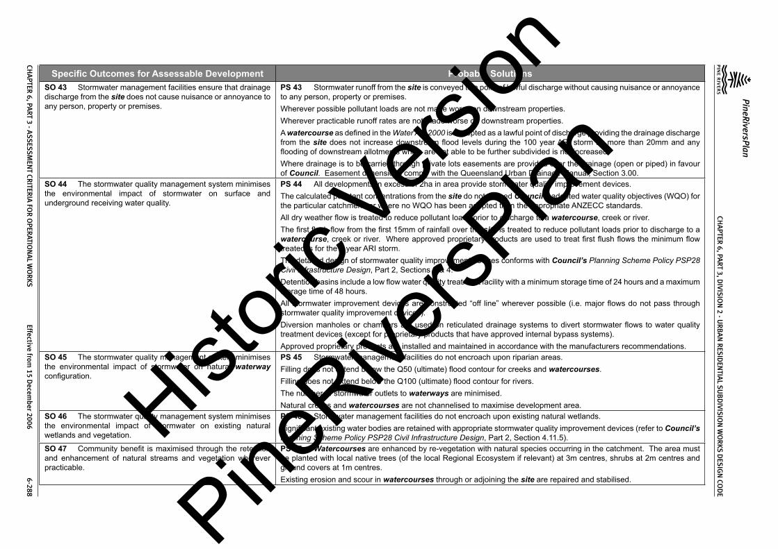
Specific Outcomes for Assessable Development Probable SolutionsSO 43 Stormwater management facilities ensure that drainage discharge from the site does not cause nuisance or annoyance to any person, property or premises.
PS 43 Stormwater runoff from the site is conveyed to a point of lawful discharge without causing nuisance or annoyance to any person, property or premises.Wherever possible pollutant loads are not made worse on downstream properties.Wherever practicable runoff rates are not made worse on downstream properties.A watercourse as defined in the Water Act 2000 is accepted as a lawful point of discharge providing the drainage discharge from the site does not increase downstream flood levels during the 100 year ARI storm by more than 20mm and any flooding of downstream allotments which are not able to be further subdivided is not increased.Where drainage is to be carried through private lots easements are provided over the drainage (open or piped) in favour of Council. Easement dimensions comply with the Queensland Urban Drainage Manual, Section 3.00.
SO 44 The stormwater quality management system minimises the environmental impact of stormwater on surface and underground receiving water quality.
PS 44 All developments in excess of 2ha in area provide stormwater quality improvement devices.The calculated pollutant concentrations from the site do not exceed Council’s adopted water quality objectives (WQO) for the particular catchment, or where no WQO has been adopted then the appropriate ANZECC standards.All dry weather flow is treated to reduce pollutant loads prior to discharge to a watercourse, creek or river.The first flush flow from the first 15mm of rainfall over the site is treated to reduce pollutant loads prior to discharge to a watercourse, creek or river. Where approved proprietary products are used to treat first flush flows the minimum flow treated is for the 1 year ARI storm.The detailed design of stormwater quality improvement devices conforms with Council’s Planning Scheme Policy PSP28 Civil Infrastructure Design, Part 2, Sections 3 & 4.Detention basins include a low flow water quality treatment facility with a minimum storage time of 24 hours and a maximum storage time of 48 hours.All stormwater improvement devices are constructed “off line” wherever possible (i.e. major flows do not pass through stormwater quality improvement devices).Diversion manholes or chambers are used on reticulated drainage systems to divert stormwater flows to water quality treatment devices (except for proprietary products that have approved internal bypass systems).Approved proprietary products are installed and maintained in accordance with the manufacturers recommendations.
SO 45 The stormwater quality management system minimises the environmental impact of stormwater on natural waterway configuration.
PS 45 Stormwater management facilities do not encroach upon riparian areas.Filling does not extend below the Q50 (ultimate) flood contour for creeks and watercourses.Filling does not extend below the Q100 (ultimate) flood contour for rivers.The number of stormwater outlets to waterways are minimised.Natural creeks and watercourses are not channelised to maximise development area.
SO 46 The stormwater quality management system minimises the environmental impact of stormwater on existing natural wetlands and vegetation.
PS 46 Stormwater management facilities do not encroach upon existing natural wetlands.Significant existing water bodies are retained with appropriate stormwater quality improvement devices (refer to Council’s Planning Scheme Policy PSP28 Civil Infrastructure Design, Part 2, Section 4.11.5).
SO 47 Community benefit is maximised through the retention and enhancement of natural streams and vegetation wherever practicable.
PS 47 Watercourses are enhanced by re-vegetation with natural species occurring in the catchment. The area must be planted with local native trees (of the local Regional Ecosystem if relevant) at 3m centres, shrubs at 2m centres and ground covers at 1m centres.Existing erosion and scour in watercourses through or adjoining the site are repaired and stabilised.
Histori
c Vers
ion
PineRive
rsPlan

CHA
PTER 6, PA
RT 3, DIVIS
ION
2 - UR
BA
N R
ESID
ENTIA
L SU
BD
IVISIO
N W
OR
KS DES
IGN
COD
E
PineRiversPlan
CHA
PTER 6, PA
RT 3 - ASS
ESSM
ENT CR
ITERIA
FOR
OPER
ATION
AL W
OR
KS Effective from
15 Decem
ber 2006 6-289
Specific Outcomes for Assessable Development Probable SolutionsSO 48 Areas constructed as detention basins are adaptable for passive recreation wherever practicable.
PS 48 Large dry detention basins are designed to accommodate passive recreation. The basin includes a low flow drainage system with capacity to carry 3mm/hr rainfall in the catchment. The basin floor is sloped at not less than 1(V) to 100(H) towards its perimeter drains.
SO 49 “As constructed” information including test certificates for material quality (if required) and compaction is provided after completion of the subdivision works.
PS 49 As constructed information including test certificates for material quality (if required) and compaction is provided after completion of the subdivision works.
2.3.5 Pedestrian and Cyclist FacilitiesSO 50 The pedestrian and bikeway design is designed to provide for safe, attractive and convenient movement of cyclists between each residential precinct and major attractions such as schools, shops, sporting facilities, bus routes (existing and planned) and railway stations.
PS 50 Footpaths are provided in the following instances:-Location Footpath Requirement
Access Place Nil (1)
Access Street One side only where the traffic catchment exceeds 40 lots, otherwise nil.
Collector Street One side onlyTrunk Collector Both sidesMajor Roads Both sides
Adjacent pedestrian traffic generators such as schools, shopping centres, etc.
To suit pedestrian movements
Along pathways The full length of the pathway and linking to any footpath within 20m, the kerb and channel by way of a kerb ramp or to the
carriageway where no kerb and channel exists.Notes:1. Footpaths may be required for network planning considerations.Footpaths are designed to conform with the following:-
Issue RequirementWidth 1.2m minimum for Access Place, Access Street and Collector Street;
1.5m one side and 2m other side for Trunk Collector, Sub Arterial and Arterial;1.5m minimum elsewhere except for dual use pedestrian/cycle paths where minimum width is 2m
Location Refer relevant standard drawing for road classification. Meandering of the path is desirable to create visual interest.
Clearance to Properties 0.8m for Access Place, Access Street and Collector Street;1m for Trunk Collector, Sub-Arterial & Arterial.
Clearance to Kerbline 1.5m for Access Place, Access Street and Collector Street;2.5m for Trunk Collector, Sub-Arterial & Arterial.
Pathway Construction Refer Standard Drawing No. 8-10036
Histori
c Vers
ion
PineRive
rsPlan

CHA
PTER 6, PA
RT 3, DIVIS
ION
2 - UR
BA
N R
ESID
ENTIA
L SU
BD
IVISIO
N W
OR
KS DES
IGN
COD
E
PineRiversPlan
CHA
PTER 6, PA
RT 3 - ASS
ESSM
ENT CR
ITERIA
FOR
OPER
ATION
AL W
OR
KS Effective from
15 Decem
ber 2006 6-290
Specific Outcomes for Assessable Development Probable SolutionsGrades Along roads - as per maximum grade for classification of road;
Pathway reserves and open space – 10% desirable maximum.Crossfall 2.5% (1 in 40) minimum;
5% (1 in 20) maximum.Crossing Points Refer Planning Scheme Policy PSP28 Civil Infrastructure Design, Part 1, Section 6.4.7
& 6.4.8Crossing Points for combined bicycle/footway use
Refer Standard Drawing No. 8-203
Chicanes are provided at the ends of all pathways to roads (refer Standard Drawing Nos. 8-60033, 8-60034 & 8-60036).Bike/footway terminations at Collector Streets or higher classification roads conform to Standard Drawing No. 8-60034.Bike/footway direct road crossings conform with Standard Drawing No. 8-60035.Detailed design of the footpaths conforms with Council’s Planning Scheme Policy PSP28 Civil Infrastructure Design, Part 1, Section 6.4.0.Bikeways are provided within and adjacent the site as indicated in Council’s Bikeways Plan or adopted local area plan.Detailed design of the bikeways conforms with Council’s Planning Scheme Policy PSP28 Civil Infrastructure Design, Part 1, Section 6.5.0.
SO 51 As constructed information is provided after completion of the subdivision works.
PS 51 As constructed information is provided after completion of the subdivision works.
2.3.6 Public TransportSO 52 The road design provides for potential bus routes including safe convenient stops and, where necessary, bus turnaround areas.SO 53 The road design caters for the extension of existing and future public transport routes to provide sufficient services that are convenient and accessible to the community.
PS 52 and PS 53 Bus routes are design to conform with the following:-Design Issue Requirement
Reserve width 20m minimumCarriageway width 9.5m minimumGrade 12% general maximum;
16% absolute maximum over short distancesSpeed control by street alignment onlyDesign vehicle coach (tourist bus)Turning single movement turns onlyBus stops are provided at 400m maximum spacing and integrated with the street and pedestrian network. Fully indented bus bays are provided for Trunk Collector Streets, Sub-Arterial and Arterial Roads with detailed design conforming with Planning Scheme Policy PSP28 Civil Infrastructure Design, Part 1, Section 3.12.2. Bus stops on Collector Streets generally provide a level area not less than 2m wide between the kerb and the footpath. For higher passenger demand bus stops on Collector Streets a bus shelter is provided on a level concrete slab (not less than 3m in width) between the kerb and the footpath.The road design provides for extension of existing and future public transport routes.
Histori
c Vers
ion
PineRive
rsPlan

CHA
PTER 6, PA
RT 3, DIVIS
ION
2 - UR
BA
N R
ESID
ENTIA
L SU
BD
IVISIO
N W
OR
KS DES
IGN
COD
E
PineRiversPlan
CHA
PTER 6, PA
RT 3 - ASS
ESSM
ENT CR
ITERIA
FOR
OPER
ATION
AL W
OR
KS Effective from
15 Decem
ber 2006 6-291
Specific Outcomes for Assessable Development Probable SolutionsSO 54 “As constructed” information including test certificates for material quality (if required) and compaction is provided after completion of the subdivision works.
PS 54 “As constructed” information including test certificates for material quality (if required) and compaction is provided after completion of the subdivision works.
2.3.7 Public Open SpaceSO 55 Public open space has barriers to its road frontage to prevent access by unauthorised vehicles.
PS 55 The public open space is provided with log barriers designed along their road frontage in accordance with Council’s Planning Scheme Policy PSP28 Civil Infrastructure Design, Part 1, Section 6.14.0 and Standard Drawing No. 8-70003.
SO 56 Public open space provides for recreational, environmental and stormwater management needs.
PS 56 No solution provided.
SO 57 Public open space that is intended to be used for local neighbourhood park includes a sufficiently level area that is suitable for non-organised recreation and passive relaxation including small children’s playgrounds and appropriate landscaping.
PS 57 Public open space that is intended to be used for local neighbourhood park contains one area, constructed if necessary, not less than 15m x 15m with a slope less than 5%.
SO 58 As constructed information including test certificates for material quality (if required) is provided after completion of the subdivision works.
PS 58 As constructed information including test certificates for material quality (if required) is provided after completion of the subdivision works.
2.3.8 UtilitiesSO 59 Development only occurs in locations where there are adequate services and capacity for the desired use.
PS 59 The design of water supply infrastructure including water mains, pumping stations, pressure mains and associated works complies with the relevant Queensland Government Department’s Guidelines for Planning and Design of Urban Water Supply Schemes, Council’s Standard Drawings and Council’s Planning Scheme Policy PSP28 Civil Infrastructure Design, Part 3. The design of water supply infrastructure includes all works internal and any works external required to ensure that all new and existing lots maintain adequate water supply at all times.The design of sewerage infrastructure including sewer mains, pumping stations, pressure mains and associated works complies with the relevant Queensland Government Department’s Guidelines for Planning and Design of Sewerage Schemes, Council’s Standard Drawings and Council’s Planning Scheme Policy PSP28 Civil Infrastructure Design, Part 4. The design of sewerage infrastructure includes all works internal and any works external required to ensure that all new and existing lots are provided with a service at all times within the capacity of the system.The design of the electrical reticulation is in accordance with ENERGEX Specification URD Underground Residential Distribution.
2.3.8(a) Water SupplySO 60 Where lots are intended to be provided with water supply the design and construction of the associated infrastructure and connections are provided in a safe, cost-effective, coordinated and efficient manner that supports sustainable development practices.SO 61 Water supply infrastructure is easily controlled and accessed for maintenance and repair.
PS 60 and PS 61 Staged construction of water supply infrastructure is designed so that each stage is self supporting at the completion of construction of that stage.Water supply infrastructure materials and construction complies with Council’s Planning Scheme Policy PSP28 Civil Infrastructure Design, Part 3, Section 4.The minimum water main size is 100mm diameter.Water mains are provided along one side of all residential streets (minimum) to the boundaries of the development site.Water mains are provided on both sides of all Major Roads and divided roads.Water mains are located within service corridors shown on the following standard drawings:
Histori
c Vers
ion
PineRive
rsPlan

CHA
PTER 6, PA
RT 3, DIVIS
ION
2 - UR
BA
N R
ESID
ENTIA
L SU
BD
IVISIO
N W
OR
KS DES
IGN
COD
E
PineRiversPlan
CHA
PTER 6, PA
RT 3 - ASS
ESSM
ENT CR
ITERIA
FOR
OPER
ATION
AL W
OR
KS Effective from
15 Decem
ber 2006 6-292
Specific Outcomes for Assessable Development Probable SolutionsStreet Classification Standard Drawing No.
Access Place, Access Street & Collector StreetTrunk Collector StreetSub Arterial & Arterial
8-100118-100128-10013
In special circumstances (e.g. infill development where existing services are on Council’s previous service allocations – refer Standard Drawing 8-0049), the services are placed on an alternative alignment.Service connections are not made to water mains 250mm diameter and above.Fire hydrants are provided at intervals (measured within the road reserve) not exceeding 80m, at high points (for air release) and at the ends of mains (use a duckfoot bend).Scours are provided at all low points, generally discharging into drainage structures.Fittings and valves at road intersections are contained in the verge and are 500mm clear of the back of the kerb.The water supply system is designed to limit the static head to 80m maximum. Where approved by Council’s engineer, pressure reducing valves are designed and installed to limit the static head to 80m maximum.Water supply infrastructure is contained within roads or other public reserves. In exceptional circumstances Council may accept water mains through private land providing an appropriate easement, not less than 3m wide, is registered in Council’s favour. The water main is constructed centrally within the easement.Sufficient valves are provided, generally on street corners, to limit the area of any shut-off to within the following:-(1) 40 lots or premises for 100mm and 150mm mains; and(2) 50 lots or premises for 225mm mains.Valves in the shut-off area are limited to a maximum of six.Water supply infrastructure is designed and constructed in accordance with the following standard drawings:-
Item Standard Drawing No.Hydrant & Valve InstallationsPavement Markers & DelineatorsHydrant, Valve & Mains Marker PostsThrust Block DetailsAir Valve Installation DetailsAir Valve SizingScour OutletsTrench DetailsSection Valve Pits & Interconnection PitsPressure Reducing Valve PitsPressure Gauge InstallationsOfftakes from MainsProperty Service Conduits
8-400028-400038-400048-400068-400078-400088-400098-400108-40011
8-40012 & 8-400138-400148-400158-40016
Histori
c Vers
ion
PineRive
rsPlan

CHA
PTER 6, PA
RT 3, DIVIS
ION
2 - UR
BA
N R
ESID
ENTIA
L SU
BD
IVISIO
N W
OR
KS DES
IGN
COD
E
PineRiversPlan
CHA
PTER 6, PA
RT 3 - ASS
ESSM
ENT CR
ITERIA
FOR
OPER
ATION
AL W
OR
KS Effective from
15 Decem
ber 2006 6-293
Specific Outcomes for Assessable Development Probable SolutionsService tappings are constructed using ductile iron pre-tapped fittings for every lot. For pipe diameters where re-tapped fittings are not manufactured, conventional tapping bands are used.Water supply conduits are provided for across road house connections for the full width of the carriageway and concrete footpaths.Water supply conduits are provided for the full length of the accessway to rear allotments.Kerb marker plates are provided to indicate the location of property service conduits.Concrete thrust blocks are provided at all locations where there is unbalanced hydraulic load including all bends (horizontal and vertical), tees, angle branches, crosses, dead ends and reducers. Thrust blocks are contained within the service allocation.Water mains are provided with the following cover:Main Diameter
(mm)Cover
Verges & Accessway Urban Road Carriageway(1) State Controlled Roads
100 – 200 600 Greater of 750 or pavement thickness + 150 1200225 – 375 750 Greater of 900 or pavement thickness + 150 1200>375 1000 Greater of 1000 or pavement thickness + 150 1200Notes:-1. Where Council’s Engineer approves a reduced cover the watermain is constructed of ductile iron pipe (minimum
class K9).Water mains are not laid under stormwater pipes, sewerage mains or electricity conduits.For water mains 300mm diameter and larger subsoil drains are provided from low points preferably draining to stormwater drainage structures.Water mains maintain the following minimum clearances to existing and future services:-(1) horizontally where the water main runs along the adjacent service for >1m:– 800mm;(2) horizontally where the water main runs along the adjacent services for <1m:- 150mm;(3) vertically :- 150mm.Connection to Council’s water supply system is not provided until adequate water supply can be maintained at all times and the new mains are disinfected and watertight. Tests certificates (not older than 10 days at the time of connection) are provided to confirm the new mains have been satisfactorily disinfected prior to connection to Council’s water supply system. The mains are pressure tested and test certificates are provided to confirm that the new mains are watertight prior to connection to Council’s water supply system.
SO 62 Water mains provides multiple flow routes for fire fighting and water quality issues.
PS 62 Water mains are constructed with the maximum number of cross connections, including connections through all pathways.
SO 63 The water supply system for the proposed development is planned to conform with Council’s broad infrastructure plan for the water supply zone.
PS 63 The water supply system for the proposed development aligns with Council’s broad infrastructure plan for the water supply zone.
Histori
c Vers
ion
PineRive
rsPlan

CHA
PTER 6, PA
RT 3, DIVIS
ION
2 - UR
BA
N R
ESID
ENTIA
L SU
BD
IVISIO
N W
OR
KS DES
IGN
COD
E
PineRiversPlan
CHA
PTER 6, PA
RT 3 - ASS
ESSM
ENT CR
ITERIA
FOR
OPER
ATION
AL W
OR
KS Effective from
15 Decem
ber 2006 6-294
Specific Outcomes for Assessable Development Probable Solutions
2.3.8(b) SewerageSO 64 Where lots are intended to be provided with reticulated sewerage the design and construction of the associated infrastructure and connections are provided in a safe, cost-effective, coordinated and efficient manner that supports sustainable development practices.
PS 64 Staged construction of sewerage infrastructure is designed so that each stage is self supporting and properly served at the completion of construction of that stage.Sewerage infrastructure design complies with Council’s Planning Scheme Policy PSP28 Civil Infrastructure Design, Part 4. For normal sewer reticulation design the following parameters are used:-
Item Design ValueResidential occupancy rate per connection 3.29 equivalent persons (EP)
Average Dry Weather Flow (ADWF) 250 litres/EP/day
Maximum Possible Flow (C1)• Sewers serving < 1,000 EP• Sewers serving >23,000 EP
• 5 times ADWF
• 3 times ADWF
Infiltration Allowance (IA) 250 litres/EP/day
Maximum Design Flow (MDF) Maximum Possible Flow + Infiltration Allowance (C1 + IA)
Sewerage infrastructure materials and construction complies with Council’s Planning Scheme Policy PSP28 Civil Infrastructure Design, Part 4, Section 4.The sewerage system through the site has sufficient capacity to convey the ultimate flows from all upstream properties when they are fully developed.Sewer pipes are sized in accordance with AS2200. The minimum flow velocity in any sewer is 0.6m/s based on ADWF. Sewers are designed to carry MDF at a depth not exceeding ¾ of the pipe diameter.The minimum sewer main size is 150mm diameter.Sewers are designed and constructed to serve the entire area of each lot.House drains are graded (around the perimeter of the building envelope) at 1 in 40 with a minimum cover of 600mm except for control allotments where a grade of 1 in 60 with a minimum cover of 400mm is used.Sewers are designed to extend to the boundaries of the site in order to serve all upstream areas within the catchment.In flat areas, sewers are designed to serve properties on both sides of the sewer.Sewers are designed to follow the land’s natural fall as far as possible.The minimum grade on sewer mains for residential lots is as follows:-Histori
c Vers
ion
PineRive
rsPlan

CHA
PTER 6, PA
RT 3, DIVIS
ION
2 - UR
BA
N R
ESID
ENTIA
L SU
BD
IVISIO
N W
OR
KS DES
IGN
COD
E
PineRiversPlan
CHA
PTER 6, PA
RT 3 - ASS
ESSM
ENT CR
ITERIA
FOR
OPER
ATION
AL W
OR
KS Effective from
15 Decem
ber 2006 6-295
Specific Outcomes for Assessable Development Probable SolutionsSewer Diameter (mm) Minimum Grade(1)
150225300375450525600675750
1 in 80 for first 6 lots, 1 in 150 thereafter1 in 2901 in 4201 in 5701 in 7301 in 9001 in 10001 in 12001 in 1500
Notes:-1. Sewers are designed on steeper grades where possible.The minimum drop through a manhole is the greater of 40mm or the difference between downstream and upstream pipe diameters.Steep sewers on grades exceeding 1 in 15 are provided with concrete stops (refer Standard Drawing No. 8-50008) at the following spacing:-
Pipe Diameter (mm)
General Maximum Grade
Maximum Spacing of Concrete Stops (m)VC Pipe Other than VC Pipe
150 1 in 6 2 6225 1 in 10 2 6
300 or greater 1 in 15 2 6Sewers steeper than 1 in 4 are only approved by Council’s engineer in special circumstances and providing the manufacturer’s recommended maximum flow velocity is not exceeded. No sewer has a grade steeper than 1 in 3.Sewer mains are provided with the following cover:-
Location Minimum Cover (mm)House connection branches in lots 600Sewer mains in lots:-• front of lot• elsewhere in the lot
• greater of 250 below invert of kerb and channel or 600 below future driveway(1)
• 600
Sewer mains in road verges 900Sewer mains under road pavements 1200Notes:-1. Determine using driveway access as per Standard Drawing No. 8-10008.The minimum clearance between the sewer and adjacent services/pipes is 300mm. Where Council’s engineer has approved a reduced clearance for a sewer crossing another service the crossing sewer is constructed using a full length (5.5m) of Class 12 DICL pipe.
Histori
c Vers
ion
PineRive
rsPlan

CHA
PTER 6, PA
RT 3, DIVIS
ION
2 - UR
BA
N R
ESID
ENTIA
L SU
BD
IVISIO
N W
OR
KS DES
IGN
COD
E
PineRiversPlan
CHA
PTER 6, PA
RT 3 - ASS
ESSM
ENT CR
ITERIA
FOR
OPER
ATION
AL W
OR
KS Effective from
15 Decem
ber 2006 6-296
Specific Outcomes for Assessable Development Probable SolutionsHouse connections are only made to sewers where the depth to invert does not exceed 3m. A shallower second main is provided for house connections where the sewer depth (to invert) exceeds 3m.Flexible sewer pipes are only used for sewers less than 4.5m deep.Sewer and/or allotment drainage lines are located on no more than 2 boundaries of a residential lot.Sewer mains are not located along the side boundary of lots that are less than 19m wide at any point.Where the finished surface slope of a residential lot exceeds 1 in 10, the sewer main depth is increased to allow for future site earthworks.Trunk sewer mains of 300mm diameter and greater are not located in residential lots.Existing on-site sewerage systems that are made redundant by the development, are demolished or removed from the site.Sewer manholes are provided at the following locations:-(1) changes in direction;(2) changes of grade;(3) intersections of sewers;(4) changes of sewer diameter;(5) changes of sewer pipe material;(6) ends of sewer lines, except where the line section does not exceed 30m in length and no more than 2 house connections
are made to the line.Manhole spacing (centre to centre) does not exceed 90m for sewer lines up to 450mm diameter and 120m for greater than 450mm diameter.Type 1 manholes are used for sewer lines up to 375mm diameter and up to 6m sewer depth.Precast manholes are not used where:-(1) the sewer line receives pumped flows;(2) the sewer line is >375mm diameter;(3) the manhole depth exceeds 6m;(4) saturated ground conditions are likely; and(5) the manhole is located near a creek bank which is likely to be susceptible to erosion.The top of the manhole ring is at the following finished levels:-(1) 600mm above ground in unmaintained areas;(2) 100mm above finished surface level in maintained open space and private lots;(3) 25mm above finished surface level in road verges; and(4) flush with carriageway surface, trafficable areas and concrete paths.Where possible, the top of manholes are above the 20 year ARI flood level.
Histori
c Vers
ion
PineRive
rsPlan

CHA
PTER 6, PA
RT 3, DIVIS
ION
2 - UR
BA
N R
ESID
ENTIA
L SU
BD
IVISIO
N W
OR
KS DES
IGN
COD
E
PineRiversPlan
CHA
PTER 6, PA
RT 3 - ASS
ESSM
ENT CR
ITERIA
FOR
OPER
ATION
AL W
OR
KS Effective from
15 Decem
ber 2006 6-297
Specific Outcomes for Assessable Development Probable SolutionsBolt down manhole covers are used near creek banks, in flood prone areas (i.e. below 20 year ARI flood level) in parks and reserves and public open space.Control manholes at pump stations are within 10m distance of the station except where approved otherwise by Council’s engineer.Where practicable, sewer lines are located within lots on the following alignments:-(1) 1.5m from the front and rear lot boundary; and(2) 1m from the side lot boundary.In special circumstances Council’s engineer may approve alternative sewer alignments outside the building envelope.Sewer lines do not cross lot boundaries at acute angles.Where inter-allotment drainage is provided the sewer line is located between the drainage line and the lot boundary. The house connection branch extends 1m beyond the drainage line.All parks and reserves are provided with a sewerage connection unless approved otherwise by Council’s engineer.Manholes are located 1m upstream of lot boundaries except where the total fall across the lot along the sewer line exceeds 2m. Where the total fall across the lot along the sewer line exceeds 2m the manhole is located 1m downstream of the lot boundary.Manholes do not straddle lot boundaries.The angle between incoming sewer lines and outlet sewer lines is 60o or greater.A maximum of three (3) inlet sewers or house connection inlets are made to any manhole.House connections are made to manholes where ever practicable.House connection branches (other than to manholes) are located between 1m and 1.2m upstream of lot boundaries at the lowest part of the lot.House connection branch inverts are not deeper than 1m. In special circumstances Council’s engineer may approve a greater depth (up to 1.5m) to control the whole lot.The maximum length of house connection branch from a sewer in an adjoining lot is 5m. with the branch extending a minimum of 1m into the lot being served.The top of the sewage pump station is 100mm above the 20 year ARI flood level.The bottom of the switchboard for the sewage pump station is 300mm above the 100 year ARI flood level.The sewage pump station is contained within a secure fenced compound.The sewage pump station is provided with appropriate ventilation.The sewage pump station is provided with a water service including a reduced pressure zone valve.Appropriate measures are provided to prevent sewage from becoming septic where the detention time exceeds six (6) hours.Sewage pumps are the non-clogging submersible type pump.Flow meters are provided on the discharge line from the pump station.Telemetry is provided to the sewage pump station.Flow meters and telemetry equipment is housed in weatherproof enclosures.
Histori
c Vers
ion
PineRive
rsPlan

CHA
PTER 6, PA
RT 3, DIVIS
ION
2 - UR
BA
N R
ESID
ENTIA
L SU
BD
IVISIO
N W
OR
KS DES
IGN
COD
E
PineRiversPlan
CHA
PTER 6, PA
RT 3 - ASS
ESSM
ENT CR
ITERIA
FOR
OPER
ATION
AL W
OR
KS Effective from
15 Decem
ber 2006 6-298
Specific Outcomes for Assessable Development Probable SolutionsThe potential for sewage overflows from sewage pump stations is minimised using appropriately designed overflow storage or other means approved by Council’s engineer.The number and length of pressure mains is minimised as far as practicable.Sewer pressure mains are located in road verges of the opposite side to water supply mains.Sewer pressure mains have the following cover:-(1) 1200mm under carriageways;(2) 1000mm elsewhere.Sewer pressure mains are not laid within 1.5m of parallel potable water supply mains. In special circumstances Council’s engineer may approve a lesser separation providing the sewer pressure main obvert is 500mm below the water supply main.Sewer pressure mains have section valves at not greater than 500m spacing.Scour valves are located at all low points in the pressure main.Vents are provided to all high points in the pressure main.Odour and corrosion control measures are provided, as necessary, to pressure mains.Pressure mains discharge into vented discharge manholes whose immediate downstream line does not have any house connection branches.Maintenance vehicle access is provided to the sewage pump station in accordance with the following:-
Item RequirementDesign Vehicles (a) Medium Rigid Vehicle
(b) Articulated Tanker when oxygen injection is usedAccess Track Maximum Grade (a) 1 in 10 for gravel access;
(b) 1 in 6 for sealed accessAccess Track Minimum Width 3.5m
Access Track Drainage (a) No inundation in 5 year ARI storm;(b) Trafficable in 10 year ARI storm
Surfacing (a) Minor pump station with access grade < 1 in 10 – gravel surface(1);(b) Minor pump station with access grade >1 in 10 – sealed;(c) Major pump stations – sealed.
Pavement Design (a) Minor pump station - as per DG 06 using 2.3 x 10³ ESAs;(b) Major pump station - as per DG 06 using 4.5 x 10³ ESAs
Pump Maintenance (a) Level area adjacent pump well for a crane truck;(b) Vent pole, switchboard and other equipment clear of working area of crane
truck.
Histori
c Vers
ion
PineRive
rsPlan

CHA
PTER 6, PA
RT 3, DIVIS
ION
2 - UR
BA
N R
ESID
ENTIA
L SU
BD
IVISIO
N W
OR
KS DES
IGN
COD
E
PineRiversPlan
CHA
PTER 6, PA
RT 3 - ASS
ESSM
ENT CR
ITERIA
FOR
OPER
ATION
AL W
OR
KS Effective from
15 Decem
ber 2006 6-299
Specific Outcomes for Assessable Development Probable SolutionsNotes:1. Where the access is adjacent to residential properties or Council’s engineer considers that the amenity of nearby
residents may be affected by dust the access is sealed.Sewerage infrastructure is designed and constructed in accordance with the following standard drawings:-
Item Standard Drawing No.Sewer Manholes 8-50002, 8-50003, 8-50004, 8-50006 & 8-50007
Sewer Pipelines 8-50008
House Connection Branches 8-50009
Sewage Pump Stations 8-50015, 8-50016, 8-50017, 8-50018, 8-50019, 8-50021, 8-50023, 8-50024, 8-50025, 8-50026, 8-50040, 8-50041, 8-50042, 8-50043, 8-50050, 8-50051, 8-50052, 8-50053, 8-50100, 8-50101, 8-50102, 8-50103, 8-50110, 8-50111, 8-50112, 8-50113, 8-50120,
8-50121, 8-50122, 8-50123, 8-50140 & 8-50141Sewer Valves 8-50027
Sewer Rising Mains 8-50028, 8-50029
Connection to Council’s sewerage system is not provided until the new mains are clean and watertight. The mains and manholes are vacuum tested and test certificates are provided to confirm that the new mains and manholes are watertight.
SO 65 Adequate buffers are provided between sewerage transportation and treatment facilities and dwellings to protect residential amenity and health.
PS 65 Sewage pump stations are no closer than 100m to the nearest existing or future residential lot. In special circumstances Council’s engineer may approve a lesser buffer distance.
SO 66 The sewerage transportation system for the proposed development is planned to conform with Council’s broad infrastructure plan for the catchment.
PS 66 The sewerage transportation system conforms with Council’s infrastructure plan for the sewerage scheme.
2.3.8(c) Recycled WaterSO 67 Where Council plans to supply recycled water, developments make provision for these future recycled water supply systems.
PS 67 An appropriate service corridor is provided for future recycled water supply.
2.3.8(d) ElectricitySO 68 Where lots are intended to be provided with reticulated electricity the service is underground with design and construction of the associated infrastructure and connections being provided in a safe, cost-effective, coordinated and efficient manner that supports sustainable development practices.
PS 68 Underground electrical reticulation is provided in residential developments.Crossings of existing roads are bored. In special circumstances Council’s engineer may approve other methods including trenched construction.Road crossing are not at acute angles to the road centreline.Electrical crossings occur at alternate common lot boundaries to water service crossings.Electrical crossings are within the area defined as an intersection under State Legislation or are diagonally across intersections to enable 11kV cables to be installed without joints.Pillars are provided at all entry points to private property and located at side boundaries of the lot.Pillars are located on alternate common lot boundaries to water meters and hydrants.
Histori
c Vers
ion
PineRive
rsPlan

CHA
PTER 6, PA
RT 3, DIVIS
ION
2 - UR
BA
N R
ESID
ENTIA
L SU
BD
IVISIO
N W
OR
KS DES
IGN
COD
E
PineRiversPlan
CHA
PTER 6, PA
RT 3 - ASS
ESSM
ENT CR
ITERIA
FOR
OPER
ATION
AL W
OR
KS Effective from
15 Decem
ber 2006 6-300
Specific Outcomes for Assessable Development Probable Solutions
2.3.8(e) Street Lighting – (excludes State-controlled roads)SO 69 All roads are provided with street lighting which is designed and constructed to provide a safe, cost-effective, coordinated and efficient system that supports sustainable development practices.
PS 69 All works are designed and constructed to AS1158, Public Lighting Code, 1986, Austroads Guide to Traffic Engineering Practice – Part 12, Roadway Lighting, 1988 and ENERGEX standards and approval.Street lighting poles and luminaries are standard ENERGEX patterns under Rate 1 Tariff in roads and Rate 2 Tariff in other than roads.
Street light poles are located on standard alignments in accordance with the following standard drawings:
Street Classification Standard Drawing No.Access Place, Access Street & Collector StreetTrunk CollectorSub Arterial & Arterial
8-100118-100128-10013
Street lights are generally located opposite common lot boundaries and are positioned to minimise conflicts with vehicle movements.Street lights are located to minimise the risk of damage from errant vehicles at intersections, bends and speed control devices and by oversize vehicles which must necessarily leave the carriageway to manoeuvre in turn around areas, speed control devices and some intersections.Street light pole that are in vulnerable locations (e.g. small islands or roundabouts) use frangible type poles.Colour consistency is maintained as far as practicable.Lighting designs are prepared in accordance with the Lighting Category specified below:-
Road Classification Lighting CategoryArterial A2Sub Arterial A3Trunk Collector B1(1)
Collector B2Access Street, Access Place B2Pathways between residential lots B2General pathways in open space areas C3(2)
Commuter Links C2(2)
Other locations Subject to individual assessmentNote:1. Use A3 where pedestrian /cyclist volumes are higher.2. Lighting standard may vary to suit local conditions.3. TheaboveclassificationalsoappliestoCommunityTitleDevelopments.4. Power supply to pathway lighting is underground.5. Pathway lighting is Rate 2 Tariff.
Histori
c Vers
ion
PineRive
rsPlan

CHA
PTER 6, PA
RT 3, DIVIS
ION
2 - UR
BA
N R
ESID
ENTIA
L SU
BD
IVISIO
N W
OR
KS DES
IGN
COD
E
PineRiversPlan
CHA
PTER 6, PA
RT 3 - ASS
ESSM
ENT CR
ITERIA
FOR
OPER
ATION
AL W
OR
KS Effective from
15 Decem
ber 2006 6-301
Specific Outcomes for Assessable Development Probable SolutionsA light is provided to each end of pathways (may be street light), at every bend or change of alignment and at every obstruction or hazard (e.g. bridge, stairway, etc).Pedestrian underpasses or tunnels are lit in accordance with the relevant standard.Crossing points of pathways across roads or streets are lit in accordance with the relevant street standard.In addition to the through street lighting above, additional special lighting is provided, as necessary, at the following locations:(1) intersections;(2) roundabouts;(3) sharp bends;(4) traffic control devices;(5) pedestrian crossings;(6) cul de sac turn around areas; and(7) bridges.
2.3.8(f) TelecommunicationsSO 70 All lots are able to be provided with a telecommunications service which is designed to give a safe, cost effective, coordinated and efficient system that supports sustainable development practices.
PS 70 Application for telecommunications reticulation is made and pre-provisioning confirmation is received prior to subdivision works commencing.Telecommunications reticulation (i.e. conduits and pits) is installed in accordance with Telstra standards and a provisioning confirmation is provided for the works.
2.3.8(g) Alterations and RelocationsSO 71 Any alteration or relocation in connection with or arising from the development to any service, installation, plant, equipment or other item belonging to or under the control of the telecommunications authority, electricity authorities, the Council or other person engaged in the provision of public utility services, is carried out prior to the approval of the plan of subdivision.
PS 71 No solution provided.
2.3.8(h) As Constructed InformationSO 72 “As constructed” information including test certificates for material quality (if required) and compaction is provided after completion of the subdivision works.
PS 72 “As constructed” information including test certificates for material quality (if required) and compaction is provided to the relevant authority upon completion of the subdivision works
2.3.9 Bushfire HazardSO 73 All lots are provided with a safe and secure water supply for fire fighting and protection.
PS 73 All lots have adequate reticulated water supply in accordance with Council’s standards.Histori
c Vers
ion
PineRive
rsPlan
CHAPTER 6, PART 3, DIVISION 3 - PARK RESIDENTIAL SUBDIVISION WORKS DESIGN CODE
PineRiversPlan
CHAPTER 6, PART 3 - ASSESSMENT CRITERIA FOR OPERATIONAL WORKS Effective from 15 December 2006 6-302
Division 3 Park Residential Subdivision Works Design Code3.1 Overall Outcome
To create park residential subdivision development that:-(1) Provides safe, convenient and attractive park residential neighbourhoods;(2) Provides residential lots that have a high degree of amenity;(3) Ensures that sites are managed during construction to minimise adverse impacts to the
environment and on the health and amenity of residents and premises;(4) Ensures that sites are managed during construction to minimise adverse traffic impacts to
existing roads;(5) Ensures that earthworks design and construction is suitable for the intended use of the land
and that adverse impacts to the environment and on the health and amenity of residents is minimised;
(6) Have road networks that are designed and constructed to provide an optimum combination of safety, amenity, convenience, economy and environment for residents, road and street users, and the community generally;
(7) Have stormwater management systems that are designed and constructed to provide an optimum combination of safety, amenity, convenience, economy and environment for residents and the community generally;
(8) Have stormwater management systems that are designed and constructed to collect and convey stormwater from a catchment to its receiving waters with minimal nuisance, danger or damage, and at a development and environmental cost which is acceptable to the community as a whole;
(9) Provide for the convenience and safety of pedestrians and vehicular traffic during frequent or nuisance stormwater flows;
(10) Ensures a reasonable level of pedestrian and vehicular traffic safety and accessibility during storm events;
(11) Minimises pollutant inflows to the receiving waters, and controls scour and depositional effects;
(12) Adequately protects people, the natural environment and the built environment from stormwater runoff flows at an acceptable level of risk;
(13) Integrates stormwater management solutions with other uses and the natural environment;(14) Provides public open space that meets user requirements for outdoor recreational and social
activities and for landscaping that contributes to the identity, environmental health and safety of the community;
(15) Ensures that tree plantings are selected and located appropriately as well as being planted and maintained to be long lasting and low maintenance;
(16) Provides for park residential lots that are adequately serviced with water supply, electricity, street lighting and communications services in a timely, cost effective, coordinated and efficient manner that supports sustainable development practices, and is in accordance with the desired character of the locality;
(17) Ensures that the water supply service provision complies with the relevant State Guidelines for design;
(18) Ensures all water supply, electricity, street lighting and communications services that require relocation and/or alterations as a result of park residential development are carried out in a timely, cost effective, coordinated and efficient manner; and
(19) Reduces the level of fire risk associated with building in areas which are assessed to have a medium to high bushfire hazard;
3.2 Compliance with the Park Residential Subdivision Works Design CodeThis code applies to all operational works relating to development or reconfiguring of park residential land, but specifically excludes applications for access easements to a road, subdivision by lease and boundary relocations or realignments.
The application of the various specific outcomes will depend upon the size or scale of the proposed development. Some specific outcomes will not apply due to a particular design element not being part of the proposal (e.g. new road). In other instances it may be impractical to apply some specific outcomes, particularly for small infill developments.
Histori
c Vers
ion
PineRive
rsPlan

CHAPTER 6, PART 3, DIVISION 3 - PARK RESIDENTIAL SUBDIVISION WORKS DESIGN CODE
PineRiversPlan
CHAPTER 6, PART 3 - ASSESSMENT CRITERIA FOR OPERATIONAL WORKS Effective from 15 December 2006 6-303
3.3 Development RequirementsThe following are the design elements relevant to Park Residential Subdivision Works:-(3.3.1) Managing Impacts During Construction(3.3.2) Earthworks(3.3.3) Road Networks (excludes State-controlled Roads)(3.3.4) Stormwater Management(3.3.5) Pedestrian & Cyclist Facilities(3.3.6) Recreation Trails(3.3.7) Public Transport(3.3.8) Public Open Space(3.3.9) Utilities
(3.3.9a) Water Supply(3.3.9b) Recycled Water(3.3.9c) Electricity(3.3.9d) Street Lighting(3.3.9e) Telecommunications(3.3.9f) Alterations and Relocations(3.3.9g) As Constructed Information
(3.3.10) Bushfire Hazard
Histori
c Vers
ion
PineRive
rsPlan

CHA
PTER 6, PA
RT 3, DIVIS
ION
3 - PAR
K RES
IDEN
TIAL S
UB
DIVIS
ION
WO
RKS D
ESIG
N CO
DE
PineRiversPlan
CHA
PTER 6, PA
RT 3 - ASS
ESSM
ENT CR
ITERIA
FOR
OPER
ATION
AL W
OR
KS Effective from
15 Decem
ber 2006 6-304
Specific Outcomes for Assessable Development Probable Solutions
3.3.1 Managing Impacts During ConstructionSO 1 All development sites minimise, as far as possible, any adverse impact to the natural environment caused by erosion, siltation, incineration of cleared vegetation and rubbish.
PS 1 The development works incorporate temporary stormwater runoff, erosion and sediment controls and trash traps designed in accordance with Council’s Planning Scheme Policy PSP28 Civil Infrastructure Design, Part 2, Section 4.2.0 and 4.11.4, and Subdivisions Section Technical Note No. 6. The measures are adjusted on-site to maximise their effectiveness.Stormwater runoff, erosion and sediment controls are constructed prior to commencement of any clearing works wherever possible.All environmentally significant areas to be retained with the development are clearly delineated and fenced prior to development works commencing.
SO 2 All development works are carried out at times which minimise noise impacts to residents.
PS 2 All development works are carried out within the following times, unless otherwise approved in writing by Council’s engineer:-(1) Monday to Friday (other than public holidays) between 7am and 6pm on the same day; and(2) Saturday (other than public holidays) between 7 am and 12 noon on the same day.No work is carried out on Sundays and public holidays.Variations to the above working hours may be approved if Council’s engineer considers that the work is unlikely to cause significant inconvenience or disruption to the public, or the work is unlikely to cause annoyance or inconvenience to occupants of adjacent properties.
SO 3 All development works are managed to minimise dust and siltation nuisance to residents.
PS 3 During construction, dust suppression measures (such as watering of the site) are implemented to protect nearby premises from dust pollution.
SO 4 All development works avoid the redirection of stormwater runoff where potential impacts to residents may occur.
PS 4 Temporary construction works do not pond or concentrate stormwater runoff in adjoining properties.Temporary construction works do not create nuisance or annoyance to adjoining premises as a result of altering the stormwater runoff pattern exiting the site.
SO 5 Construction traffic does not adversely impact on the amenity of existing residents.
PS 5 Construction traffic to and from the site uses the highest classification streets or roads where a choice of access routes is available.Where significant volumes of material are approved to enter or leave the site, a haul route is approved by Council. All materials associated with the development that are dropped, deposited or spilled on streets giving access to the site are removed and the streets are cleaned as soon as practicable after the event. Any damaged areas are repaired and reinstated to their previous condition.Where works are carried out on existing roads a traffic control plan is prepared in accordance with the Manual of Uniform Traffic Control Devices. All traffic control measures are properly erected and maintained during the works.Any access road to the site that has been affected by any material dropped, deposited or spilled on the road as a result of the construction processes associated with the site is cleaned and restored to its original condition.
SO 6 Construction traffic is controlled to ensure all traffic movements to and from the site are safe.
PS 6 All traffic movements to and from the site frontage are carried out in a safe manner. Traffic controls are used where site access is approved directly onto a Major Road.
SO 7 All clearing works are carefully undertaken to ensure the clearing is limited to the area of the approved infrastructure works, buildings areas and other areas approved in the development permit.
PS 7 Areas of significant vegetation, proposed park and open space areas and other areas of vegetation or individual trees designated to be retained with the development are temporarily fenced and flagged.
Histori
c Vers
ion
PineRive
rsPlan

CHA
PTER 6, PA
RT 3, DIVIS
ION
3 - PAR
K RES
IDEN
TIAL S
UB
DIVIS
ION
WO
RKS D
ESIG
N CO
DE
PineRiversPlan
CHA
PTER 6, PA
RT 3 - ASS
ESSM
ENT CR
ITERIA
FOR
OPER
ATION
AL W
OR
KS Effective from
15 Decem
ber 2006 6-305
Specific Outcomes for Assessable Development Probable SolutionsSO 8 All cleared vegetation is disposed of in a manner which minimises, as far as practicable, nuisance and annoyance to existing premises.
PS 8 Where cleared vegetation is chipped or pit burned on site the location of these works is not less than 100m from any dwelling or commercial premises. All vegetation with a diameter below 400mm is chipped and stored on site in an approved location generally on Park or public land. Vegetation with a diameter above 400mm is pit burned on site if a suitable location is available. The pit burn is generally carried out as one continuous operation.Chipping and/or pit burning is only undertaken when weather conditions are favourable.Burn pit locations are approved in writing by Council’s engineer and shown on the “as constructed” drawings.Cleared vegetation is not disposed of by above ground burning.
SO 9 All noxious weeds and other materials which are detrimental to the intended use of the land are removed and disposed of in a manner which minimises environmental impacts.
PS 9 All groundsel, noxious weeds, stumps, fallen trees, rubbish, car bodies, scrap metal and the like are removed and disposed of in a manner which minimises environmental impact.Stumps, fallen trees, undergrowth, buildings, structures, foundations and the like in existing and proposed park and open space areas are removed where directed by Council’s representative.
3.3.2 EarthworksSO 10 Earthworks design takes into account the slope of the ground, short and long-term slope stability, soft or compressible foundation soils, reactive soils, low density or potentially collapsing soils, existing fills and soil contamination that may exist on site.
PS 10 Investigation, planning and design including documentation is carried out in accordance with Australian Standard AS3798.All cut and fill batters are provided with appropriate scour, erosion protection and runoff control measures including catch drains at the top of batters and lined batter drains as necessary.All fill batters steeper than 1 (V) in 6 (H) in residential lots are fully turfed to prevent scour and erosion.
SO 11 Filling is not placed on existing or proposed park unless specifically approved in writing by Council’s engineer.
PS 11 Filling is not placed on existing or proposed park unless specifically approved in writing by Council’s engineer.
SO 12 Filling is not placed below the 100 year ARI floodline for rivers and 50 year ARI floodline for creeks and other watercourses unless specifically approved in writing by Council’s engineer
PS 12 Filling is not placed below the 100 year ARI floodline for rivers and 50 year ARI floodline for creeks and other watercourses unless specifically approved in writing by Council’s engineer.
SO 13 The site is properly prepared for earthworks. PS 13 The site is prepared in accordance with Australian Standard AS3798.
SO 14 Fill construction is carried out in a manner which ensures that the works meet the design requirements.
PS 14 The fill construction is carried out in accordance with Australian Standard AS3798.
SO 15 Unsuitable materials are not used in structural fill. PS 15 Materials used for structural fill conform with Australian Standard AS3798.
SO 16 Earthworks and trench backfill is properly compacted to suit the desired use of the site.
PS 16 The earthworks and trench backfill is compacted to the minimum relative compaction given in Table 5.1 of Australian Standard AS3798. The minimum frequency of Any open drains, earth dams and wells on the site are drained, cleaned and filled as specified above.
SO 17 Steep rock slopes and batters are stable and low maintenance.
PS 17 Steep rock slopes and batters are inspected and certified for long-term stability by a suitably qualified and experienced geotechnical engineer. Stabilisation measures are provided, as necessary, to ensure long-term stability and low maintenance.
SO 18 “As constructed” information including test certificates for material quality (if required) and compaction is provided after completion of the subdivision works.
PS 18 “As constructed” information including test certificates for material quality (if required) and compaction is provided after completion of the subdivision works.
Histori
c Vers
ion
PineRive
rsPlan

CHA
PTER 6, PA
RT 3, DIVIS
ION
3 - PAR
K RES
IDEN
TIAL S
UB
DIVIS
ION
WO
RKS D
ESIG
N CO
DE
PineRiversPlan
CHA
PTER 6, PA
RT 3 - ASS
ESSM
ENT CR
ITERIA
FOR
OPER
ATION
AL W
OR
KS Effective from
15 Decem
ber 2006 6-306
Specific Outcomes for Assessable Development Probable Solutions
3.3.3 Road Networks (excludes State-controlled roads)SO 19 The road design and construction has a clear structure and component streets conform to their function in the network.SO 20 The road design and construction has clear physical distinctions between each type of street. The distinctions are to be based on function, legibility, convenience, traffic volumes, vehicle speeds, public safety and amenity.SO 21 The road design and construction accommodates the following primary functions:-(1) access to residences;(2) car parking for visitors;(3) social and activity space;(4) stormwater drainage paths (minor and major storms);(5) public transport on Collector Streets;(6) utility services location; and(7) setting and approach (streetscape and landscape) for
adjoining residences.SO 22 The road design and construction accommodates adequate verge and carriageway width for the primary functions listed in specific outcomes above.
PS 19 to PS 22 The Residential Streets conform to the following:-
Design Issue Access Place (1) Access Street (1) Collector StreetTraffic Catchment (maximum) 50 lots (1) 100 lots 350 lots (2)
Street Length (maximum) 900m 1200m (3) 1200m (3)
Design Speed (maximum) 45km/h 60 km/h 60km/hCarriageway Lanes 2 (4) 2 2Carriageway Width 6m (4) 7m 8mVerge Width (minimum) 5m 5m 5mRoad Width (minimum) 20m 20m 25mParking no provision (5) no provision no provisionFootpaths/recreational trails as required (6) as required (6) as required (6)
Grade (minimum - maximum) 0.4% - 16% (7) 0.4% - 16% 0.4% - 12% (8)
Notes:1. Theoretical limit only. Maximum length controls in most cases.2. May be increased by widening road reserve.3. Maximum street lengths are inter-dependant. Essential criterion is maximum total travel time 180 seconds.4. Single lane, 3.5m width, with Council approval only, maximum 12 lots.5. Parking bays may be required at cul-de-sac heads.6. As required by Council’s network planning .7. 20% absolute maximum grade under special circumstances.8. 16% absolute maximum grade under special circumstances.
The detailed design of Residential Streets conforms with Council’s Planning Scheme Policy PSP28 Civil Infrastructure Design, viz::-
Road Design Issue Planning Scheme Policy PSP28 Civil Infrastructure Design Reference
Traffic Volume Part 1 Sect 5.2.4Traffic Speed Part 1 Sect 5.2.3Parking Part 1 Sect 5.2.5Carriageway Width Part 1 Sect 5.2.6.2Street Classification Part 1 Sect 5.2.9Verge Part 1 Sect 5.2.7Street Reserve Width Part 1 Sect 5.2.8
Histori
c Vers
ion
PineRive
rsPlan

CHA
PTER 6, PA
RT 3, DIVIS
ION
3 - PAR
K RES
IDEN
TIAL S
UB
DIVIS
ION
WO
RKS D
ESIG
N CO
DE
PineRiversPlan
CHA
PTER 6, PA
RT 3 - ASS
ESSM
ENT CR
ITERIA
FOR
OPER
ATION
AL W
OR
KS Effective from
15 Decem
ber 2006 6-307
Specific Outcomes for Assessable Development Probable SolutionsGeometric Design Part 1 Sect 5.2.10.2Intersections Part 1 Sect 5.2.10.3Manoeuvring Areas Part 1 Sect 5.2.10.4Speed Control Devices Part 1 Sect 5.2.10.5Roundabouts Part 1 DG 01Landscape Construction on Road Reserves, Parks and Drainage Reserves
Part 1 DG 03
Local Area Traffic Management Part 1 DG 05Signs and Road Marking Part 1 Sect 6.7.0Footpaths Part 1 Sect 6.4.0Recreational Trails Part 1 Sect 6.6.0Service Conduits Part 1 Sect 6.8.0Subsoil Drainage Part 1 Sect 6.9.0Safety Barriers Part 1 Sect 6.10.0Guide Posts Part 1 Sect 6.11.0Bridge and Culvert Widths Part 1 Sect 6.12.0Street and Pathway Lighting Part 1 Sect 6.13.0Park Barriers Part 1 Sect 6.14.0Retaining Walls Part 1 Sect 6.15.0The Major Roads conform to the following:
Design Issue Urban Sub-Arterial Urban Arterial Rural Sub-Arterial Rural ArterialTraffic Volume (typical) 12,000 vpd 30,000 vpd 12,000 vpd 30,000 vpdDesign Speed (minimum) 8km/h 100km/h 80km/h 100km/hCarriageway Lanes 2 4 2 4Carriageway Width 10m (kerbed) (1) 2 x 8.5m (kerbed) (1) 7m 2 x 7mVerge Width (minimum) 7.5m 8.5m 7m 7mReserve Width (minimum)
25m (2) 40m (2) 26m 40m
Footpaths/Cyclepaths both sides (3) both sides (3) as required as requiredGrade (minimum – maximum)
0.4% - 7% (4) 0.4% - 6% (4) 0.4% - 8% 0.4% - 6%Hist
oric V
ersion
PineRive
rsPlan
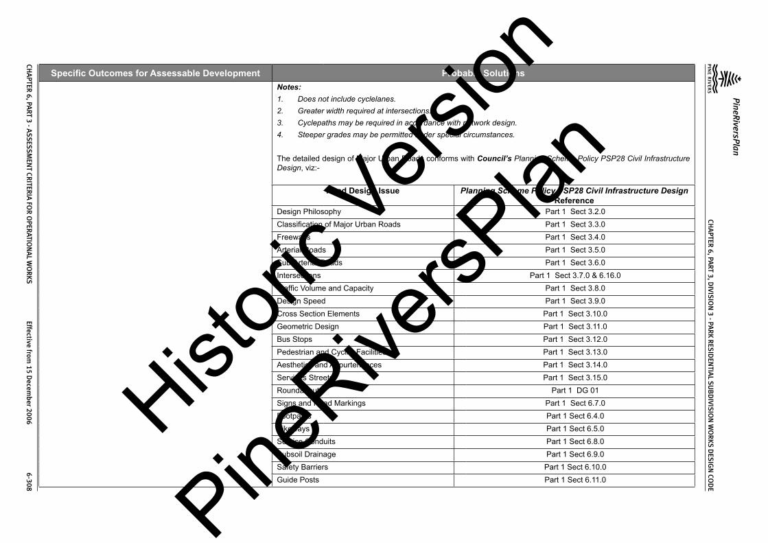
CHA
PTER 6, PA
RT 3, DIVIS
ION
3 - PAR
K RES
IDEN
TIAL S
UB
DIVIS
ION
WO
RKS D
ESIG
N CO
DE
PineRiversPlan
CHA
PTER 6, PA
RT 3 - ASS
ESSM
ENT CR
ITERIA
FOR
OPER
ATION
AL W
OR
KS Effective from
15 Decem
ber 2006 6-308
Specific Outcomes for Assessable Development Probable SolutionsNotes:1. Does not include cyclelanes.2. Greater width required at intersections.3. Cyclepaths may be required in accordance with network design.4. Steeper grades may be permitted under special circumstances.
The detailed design of Major Urban Roads conforms with Council’s Planning Scheme Policy PSP28 Civil Infrastructure Design, viz:-
Road Design Issue Planning Scheme Policy PSP28 Civil Infrastructure Design Reference
Design Philosophy Part 1 Sect 3.2.0Classification of Major Urban Roads Part 1 Sect 3.3.0Freeways Part 1 Sect 3.4.0Arterial Roads Part 1 Sect 3.5.0Sub-Arterial Roads Part 1 Sect 3.6.0Intersections Part 1 Sect 3.7.0 & 6.16.0Traffic Volume and Capacity Part 1 Sect 3.8.0Design Speed Part 1 Sect 3.9.0Cross Section Elements Part 1 Sect 3.10.0Geometric Design Part 1 Sect 3.11.0Bus Stops Part 1 Sect 3.12.0Pedestrian and Cyclist Facilities Part 1 Sect 3.13.0Aesthetics and Appurtenances Part 1 Sect 3.14.0Services Streets Part 1 Sect 3.15.0Roundabouts Part 1 DG 01Signs and Road Markings Part 1 Sect 6.7.0Footpaths Part 1 Sect 6.4.0Bikeways Part 1 Sect 6.5.0Service Conduits Part 1 Sect 6.8.0Subsoil Drainage Part 1 Sect 6.9.0Safety Barriers Part 1 Sect 6.10.0Guide Posts Part 1 Sect 6.11.0
Histori
c Vers
ion
PineRive
rsPlan

CHA
PTER 6, PA
RT 3, DIVIS
ION
3 - PAR
K RES
IDEN
TIAL S
UB
DIVIS
ION
WO
RKS D
ESIG
N CO
DE
PineRiversPlan
CHA
PTER 6, PA
RT 3 - ASS
ESSM
ENT CR
ITERIA
FOR
OPER
ATION
AL W
OR
KS Effective from
15 Decem
ber 2006 6-309
Specific Outcomes for Assessable Development Probable SolutionsBridge and Culvert Widths Part 1 Sect 6.12.0Street and Pathway Lighting Part 1 Sect 6.13.0Park Barriers Part 1 Sect 6.14.0Retaining Walls Part 1 Sect 6.15.0The detailed design of Major Rural Roads conforms with Council’s Planning Scheme Policy PSP28 Civil Infrastructure Design, viz:-
Road Design Issue Planning Scheme Policy PSP28 Civil Infrastructure Design Reference
Design Philosophy Part 1 Sect 5.3.2Design Speed Part 1 Sect 5.3.4Traffic Volume & Capacity Part 1 Sect 5.3.5Cross Section Elements Part 1 Sect 5.3.6Geometric Design Part 1 Sect 5.3.7Intersections Part 1 Sect 5.3.8The road cross-sections conform with Council’s standard drawings as follows:-
Road Classification Standard Drawing NumberAccess Place 8-10017 & 8-10020Access Street 8-10018 & 8-10020Collector Street 8-10019 & 8-10020Urban Sub-Arterial Road 8-10006 & 8-10009Urban Arterial Road 8-10007 & 8-10009Rural Sub-Arterial 8-10023 & 8-1002Rural Arterial 8-10024 & 8-1002Utility service allocations conform to Council’s standard drawings as follows:
Road Classification Standard Drawing NumberAccess Place, Access Street, Collector Street 8-10027Urban Sub-Arterial & Arterial 8-10013Rural Sub-Arterial & Arterial 8-10028Histori
c Vers
ion
PineRive
rsPlan

CHA
PTER 6, PA
RT 3, DIVIS
ION
3 - PAR
K RES
IDEN
TIAL S
UB
DIVIS
ION
WO
RKS D
ESIG
N CO
DE
PineRiversPlan
CHA
PTER 6, PA
RT 3 - ASS
ESSM
ENT CR
ITERIA
FOR
OPER
ATION
AL W
OR
KS Effective from
15 Decem
ber 2006 6-310
Specific Outcomes for Assessable Development Probable SolutionsRoad designs incorporate retention of existing significant trees where ever practicable.Road designs minimise the heights of cut and fill of road formation to less than 2m where ever practicable.New roads are located to minimise the heights of cut and fill of road formation to less than 2m where ever possible.Road designs minimise the amount of filling and extent of filling in or adjacent existing natural gullies, waterways, existing public open space areas and proposed public open space areas.Access to allotments conforms to Council’s Planning Scheme Policy PSP28 Civil Infrastructure Design, Part 1, Section 6.2.0.The road pavement design conforms to Council’s Planning Scheme Policy PSP28 Civil Infrastructure Design, Part 1, DG 06.The works are constructed within tolerances given in Council’s Planning Scheme Policy PSP28 Civil Infrastructure Design, Part 1, DG 02, Appendix C.
SO 23 The road design creates safe, convenient movement for residents between their homes and the Major Road network.SO 24 The road design has a high degree of “legibility” to road users.
PS 23 and PS 24 The street design is highly legible through the use of different carriageway widths in Access Streets, Access Places and Collector Streets.
SO 25 The road design provides more than one access route (at all stages of development) for residential areas containing a significant number of residential lots.
PS 25 The residential area is served by more than one access route to the Major Road system when the number of residential lots exceeds 100 (absolute maximum allowed is 150 lots).
SO 26 Intersections along residential streets are safe and convenient.
PS 26 Intersection spacing conforms with the following:
Intersecting Road
Location
Through Road
Access Street & Collector Street
Urban Sub- Arterial Road (1)
Urban Arterial Road
Rural Sub- Arterial Road (1)
Rural Arterial Road
On same side of through road
100m 300m 500m 300m 500m
On opposite sides of the through road
100m 300m 500m 300m 500m
Notes:1. In the case of Sub-Arterial Roads, existing landholdings may require intersections at a lesser spacing. In such cases
the following absolute minimum spacing is used, but all turns access may not be permitted (i.e. left in/left out only):-Intersections on same side 100mIntersections on opposite sides:-• left-right stagger• right-left stagger
100m30m
Histori
c Vers
ion
PineRive
rsPlan

CHA
PTER 6, PA
RT 3, DIVIS
ION
3 - PAR
K RES
IDEN
TIAL S
UB
DIVIS
ION
WO
RKS D
ESIG
N CO
DE
PineRiversPlan
CHA
PTER 6, PA
RT 3 - ASS
ESSM
ENT CR
ITERIA
FOR
OPER
ATION
AL W
OR
KS Effective from
15 Decem
ber 2006 6-311
Specific Outcomes for Assessable Development Probable SolutionsThe detailed design of street and road intersections conforms to the following sections of Council’s Planning Scheme Policy PSP28 Civil Infrastructure Design:
Road Classification Planning Scheme Policy PSP28 Civil Infrastructure Design Reference
Residential Streets Part 1 Sect 2.11.0 & Sect 6.16.0
Major Roads Part 1 Sect 3.7.0 & Sect 6.16.0
Roundabouts Part 1 DG 01
Local Area Traffic Management Part 1 DG 05
SO 27 The alignment and geometry of roads that form identified bus routes allows for efficient and unimpeded movement of buses without facilitating high traffic speeds.
PS 27 Bus routes have a minimum carriageway width of 9.5m. The maximum grade of the bus route is 12%.The detailed design of bus routes and associated facilities conforms with Council’s Planning Scheme Policy PSP28 Civil Infrastructure Design.
SO 28 The road design facilitates recreational trail activities within the neighbourhood and to local activity centres.
PS 28 All recreational trails are designed and constructed in accordance with Planning Scheme Policy PSP28 Civil Infrastructure Design, Part 1, Section 6.6.
SO 29 All new Council controlled roads are fully constructed to Council’s Planning Scheme Policy PSP28 Civil Infrastructure Design standards.
PS 29 All new Council controlled roads are fully constructed to Council’s Planning Scheme Policy PSP28 Civil Infrastructure Design standards.
SO 30 All Council controlled frontage roads are constructed to Council’s Planning Scheme Policy PSP28 Civil Infrastructure Design standards.
PS 30 All Council controlled frontage roads are constructed to Council’s Planning Scheme Policy PSP28 Civil Infrastructure Design standards as follows:
Situation Minimum Construction(1)
Frontage road unconstructed or gravel road only
For Access Place and Access Street: full carriageway and verges.For Collector Street: verge adjoining new lots, carriageway to a minimum sealed width of 6m plus 1.5m wide (full depth pavement) gravel shoulder and table drainage to the opposite side.For Major Roads: verge adjoining new lots, carriageway to a minimum sealed width of 7m plus 1.5m wide (full depth pavement) gravel shoulder and table drainage to the opposite side.
Frontage road sealed(2) but not constructed to Council’s Planning Scheme Policy PSP28 Civil Infrastructure Design standard
For Access Place and Access Street: reconstruction of full carriageway and verges.For Collector Street: reconstruction of verge adjoining new lots and carriageway to a minimum sealed width of 6m plus 1.5m wide (full depth pavement) gravel shoulder and table drainage to the opposite side. The works match into the remaining existing works wherever possible.For Major Roads: verge adjoining new lots and carriageway to a minimum sealed width of 7m plus 1.5m wide (full depth pavement) gravel shoulder and table drainage to the opposite side. The works match into the remaining existing works wherever possible.
Histori
c Vers
ion
PineRive
rsPlan

CHA
PTER 6, PA
RT 3, DIVIS
ION
3 - PAR
K RES
IDEN
TIAL S
UB
DIVIS
ION
WO
RKS D
ESIG
N CO
DE
PineRiversPlan
CHA
PTER 6, PA
RT 3 - ASS
ESSM
ENT CR
ITERIA
FOR
OPER
ATION
AL W
OR
KS Effective from
15 Decem
ber 2006 6-312
Specific Outcomes for Assessable Development Probable SolutionsFrontage road(2) partially constructed to Council’s Planning Scheme Policy PSP28 Civil Infrastructure Design standard
For Access Place and Access Street: construction of all remaining carriageway and verges.For Collector Street: verge adjoining new lots and carriageway to join existing works. In any event the minimum sealed width to be constructed is 6m plus 1.5m wide (full depth pavement) gravel shoulder and table drainage to the opposite side where necessary. The works match into the existing works.For Major Roads: verge adjoining new lots and carriageway to join existing works. In any event the minimum sealed width is 7m plus 1.5m wide (full depth pavement) gravel shoulder and table drainage to the opposite side where necessary. The works match into the existing works.
Notes:1. Construction includes all associated works (services, streetlighting and linemarking)2. Testing of the existing pavement is carried out to confirmwhether the existingworksmeetCouncil’s Planning
Scheme Policy PSP28 Civil Infrastructure Design standard.SO 31 Sealed and flood free road access during minor storms is available to the site from the nearest Major Road.
PS 31 Roads or streets giving access to the development from the nearest Major Road are sealed to a minimum width of 5.5m. These access roads or streets have drainage systems that conform to Council’s Planning Scheme Policy PSP28 Civil Infrastructure Design, Part 2, Section 4.7.0.
SO 32 Vehicular access to existing lots is retained, wherever possible, at new road intersections with existing Collector Streets or existing Major Roads.
PS 32 No solution provided.
SO 33 The road network design takes into account:(1) streetscapes that may be created or already exist;(2) protection of topography and vegetation;(3) opportunities for views and vistas; and(4) protection of natural drainage and open space systems.
PS 33 Road designs incorporate retention of existing significant trees where ever practicable.Road designs minimise the heights of cut and fill of road formation to less than 2m where ever practicable.New roads are located to minimise the heights of cut and fill of road formation to less than 2m where ever possible.Road designs minimise the amount of filling and extent of filling in or adjacent existing natural gullies, waterways, existing public open space areas and proposed public open space areas.
SO 34 The existing road network is upgraded where necessary to cater for the traffic impact from the development.
PS 34 Solutions will need to be determined by traffic studies and adapted to suit the particular site constraints and features.New intersections onto existing roads are designed to accommodate traffic volumes and traffic movements ten years hence. Detailed design is in accordance with Council’s Planning Scheme Policy PSP28 Civil Infrastructure Design, Part 1.Existing intersections external to the site are upgraded as necessary to accommodate increased traffic from the development. Detailed design is in accordance with Council’s Planning Scheme Policy PSP28 Civil Infrastructure Design, Part 1.
SO 35 “As constructed” information including test certificates for material quality (if required) and compaction is provided upon completion of the subdivision works.
PS 35 “As constructed” information including test certificates for material quality (if required) and compaction is provided upon completion of the subdivision works.Histori
c Vers
ion
PineRive
rsPlan

CHA
PTER 6, PA
RT 3, DIVIS
ION
3 - PAR
K RES
IDEN
TIAL S
UB
DIVIS
ION
WO
RKS D
ESIG
N CO
DE
PineRiversPlan
CHA
PTER 6, PA
RT 3 - ASS
ESSM
ENT CR
ITERIA
FOR
OPER
ATION
AL W
OR
KS Effective from
15 Decem
ber 2006 6-313
Specific Outcomes for Assessable Development Probable Solutions
3.3.4 Stormwater ManagementSO 36 The major drainage system has the capacity to safely convey stormwater flows for the 100 year ARI storm event.
PS 36 The roads, drainage pathways, drainage features and waterways safely convey the stormwater flows for the 100 year ARI storm event (ultimate development catchment characteristics upstream).The major drainage system has a minimum design ARI of 100 years (ultimate development catchment characteristics upstream).Carriageways generally have kerb and channel (except where table or swale drains are approved). Catchpits and kerb turnouts are located to ensure the longitudinal flow in the channel does not exceed the following requirements for the Major Storm (100 year ARI):-
LocationMajor Storm - Maximum Flow Width and DepthMajor Roads Minor Roads
Where floor levels of adjacent buildings are above road level (kerb and channeled crowned road)
(a) Total flow contained within road reserve; and
(b) Freeboard ≥250mm to floor level of adjacent buildings; and
(c) Maximum depth of flow of 300mm.
(a) Total flow contained within road reserve; and
(b) Freeboard ≥250mm to floor level of adjacent buildings; and
(c) Maximum flow depth 300mm.Where floor levels of adjacent buildings are below road level or < 300mm above top of kerb (kerb and channeled crowned road)(a) ≥100mm fall on verge towards kerb;(b) <100mm fall on verge towards kerb.
(a) 50mm above top of kerb;(b) Top of kerb.
(a) 50mm above top of kerb;(b) Top of kerb.
Roads without kerb and channel – table or swale drains used for longitudinal drainage
(a) Total flow contained within road reserve; and
(b) Flows do not encroach upon driving lanes; and
(c) Freeboard ≥250mm to floor level of adjacent buildings; and
(d) Maximum depth of flow in drain of 300mm.
(a) Total flow contained within road reserve; and
(b) Flows do not encroach upon driving lanes; and
(c) Freeboard ≥250mm to floor level of adjacent buildings; and
(d) Maximum depth of flow in drain of 300mm.
Notes:1. Widths are measured from channel invert for kerb and channel and from kerb face for kerb only.2. Refer Council’s Planning Scheme Policy PSP28 Civil Infrastructure Design, Part 2, Section 4 for detailed design
requirements.The product of depth by average velocity in the channel does not exceed 0.6m2/s except where there is a danger of pedestrians being swept away and drowned where the value is limited to 0.4m2/s.Detailed design of the major drainage system conforms to Council’s Planning Scheme Policy PSP28 Civil Infrastructure Design, Part 2, Section 4.
Histori
c Vers
ion
PineRive
rsPlan

CHA
PTER 6, PA
RT 3, DIVIS
ION
3 - PAR
K RES
IDEN
TIAL S
UB
DIVIS
ION
WO
RKS D
ESIG
N CO
DE
PineRiversPlan
CHA
PTER 6, PA
RT 3 - ASS
ESSM
ENT CR
ITERIA
FOR
OPER
ATION
AL W
OR
KS Effective from
15 Decem
ber 2006 6-314
Specific Outcomes for Assessable Development Probable SolutionsResidential lots have the following minimum development levels:-
Location of Residential Lot Minimum Development Level Minimum Area at Development Level
Adjacent Existing Natural Watercourse
The greater of:• Q100ultimate plus 750mm; or• the highest recorded flood level
plus 750mm.
1500m2 minimum area
Adjacent Engineered Channels The greater of:• Q100ultimate plus 500mm for a
maintained channel; or• Q100ultimate plus 250mm for an
unmaintained channel.
1500m2 minimum area
Adjacent Road Drainage The greater of:• Q100ultimate plus 250mm; or• Q100ultimate plus 150mm using
blocked catchpits or inlets.
1500m2 minimum area
Adjacent Overland Flow Paths The greater of:• Q100ultimate plus 250mm for a
maintained flow path; or• Q100ultimate plus 150mm for an
unmaintained flow path.
1500m2 minimum area
Detention basins are designed in accordance with Council’s Planning Scheme Policy PSP28 Civil Infrastructure Design Part 2, Section 4.8.0.Open channels are designed in accordance with Council’s Planning Scheme Policy PSP28 Civil Infrastructure Design Part 2, Section 4.9.0.
SO 37 The minor stormwater drainage system has the capacity to convey stormwater flows from frequent storm events whilst ensuring pedestrian and vehicular traffic movements are safe and convenient.
PS 37 The minor drainage system has a minimum design ARI of 5 years (ultimate development catchment characteristics upstream).Carriageways generally have kerb and channel (except where swale drains are approved by Council’s engineer). Catchpits and kerb turnouts are located to ensure the longitudinal flow in the channel does not exceed the following requirements for the minor storm:-Histori
c Vers
ion
PineRive
rsPlan
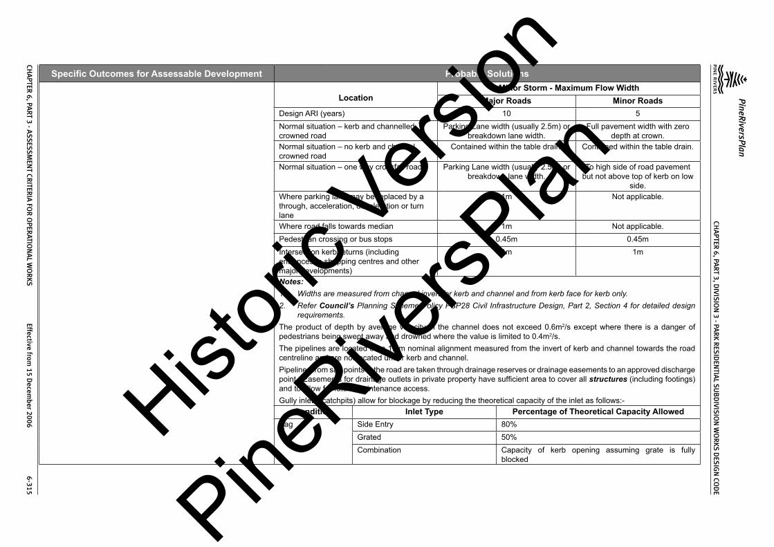
CHA
PTER 6, PA
RT 3, DIVIS
ION
3 - PAR
K RES
IDEN
TIAL S
UB
DIVIS
ION
WO
RKS D
ESIG
N CO
DE
PineRiversPlan
CHA
PTER 6, PA
RT 3 - ASS
ESSM
ENT CR
ITERIA
FOR
OPER
ATION
AL W
OR
KS Effective from
15 Decem
ber 2006 6-315
Specific Outcomes for Assessable Development Probable Solutions
LocationMinor Storm - Maximum Flow Width
Major Roads Minor RoadsDesign ARI (years) 10 5Normal situation – kerb and channelled crowned road
Parking Lane width (usually 2.5m) or breakdown lane width.
Full pavement width with zero depth at crown.
Normal situation – no kerb and channel crowned road
Contained within the table drain. Contained within the table drain.
Normal situation – one way crossfall road Parking Lane width (usually 2.5m) or breakdown lane width.
To high side of road pavement but not above top of kerb on low
side.Where parking lane may be replaced by a through, acceleration, deceleration or turn lane
1m Not applicable.
Where road falls towards median 1m Not applicable.Pedestrian crossing or bus stops 0.45m 0.45mIntersection kerb returns (including entrances to shopping centres and other major developments)
1m 1m
Notes:1. Widths are measured from channel invert for kerb and channel and from kerb face for kerb only.2. Refer Council’s Planning Scheme Policy PSP28 Civil Infrastructure Design, Part 2, Section 4 for detailed design
requirements.The product of depth by average velocity in the channel does not exceed 0.6m2/s except where there is a danger of pedestrians being swept away and drowned where the value is limited to 0.4m2/s.The pipelines are located on a 1.5m nominal alignment measured from the invert of kerb and channel towards the road centreline and are not located under kerb and channel.Pipelines from sag points in the road are taken through drainage reserves or drainage easements to an approved discharge point. Easements for drainage outlets in private property have sufficient area to cover all structures (including footings) and to allow for future maintenance access.Gully inlets (catchpits) allow for blockage by reducing the theoretical capacity of the inlet as follows:-
Condition Inlet Type Percentage of Theoretical Capacity AllowedSag Side Entry 80%
Grated 50%Combination Capacity of kerb opening assuming grate is fully
blocked
Histori
c Vers
ion
PineRive
rsPlan

CHA
PTER 6, PA
RT 3, DIVIS
ION
3 - PAR
K RES
IDEN
TIAL S
UB
DIVIS
ION
WO
RKS D
ESIG
N CO
DE
PineRiversPlan
CHA
PTER 6, PA
RT 3 - ASS
ESSM
ENT CR
ITERIA
FOR
OPER
ATION
AL W
OR
KS Effective from
15 Decem
ber 2006 6-316
Specific Outcomes for Assessable Development Probable SolutionsContinuous Grade Side Entry 80%
Grated – Longitudinal Bars 60%Grated – Transverse Bars (with or without longitudinal bars)
50%
Combination 70% - 90% of capacity of kerb opening plus grate (depending upon length of backstone)
Gully inlets and manholes have the following minimum freeboard for the minor storm event:
Situation Minimum freeboard requirementsGully inlet on grade 150mm below invert of kerb and channelGully inlet in sag 150mm below invert of kerb and channelField inlet 150mm below top of grate or lip of inletManhole or junction structure 150mm below top of lidStormwater drainage infrastructure through or within private land is protected by easements in favour of Council. Minimum easement widths are as follows:-
Pipe Diameter Minimum Easement Width (excluding access requirements)Stormwater Pipe up to 825mm diameter 3mStormwater Pipe up to 825mm diameter with Sewer Pipe up to 225mm diameter
4m
Stormwater Pipe greater than 825mm diameter
Easement boundary to be 1m clear of outside wall of pipe and clear of pits.
Structures at the end of headwalls 3m beyond and to one side of works. Easement is to be extended to include 2-wheel drive vehicular access to the road.
Detailed design of the minor drainage system conforms to Council’s Planning Scheme Policy PSP28 Civil Infrastructure Design, Part 2, Section 4.Stormwater drainage reticulation and cross drainage conforms to the following standard drawings:-
Item Standard Drawings NumbersRoad Catchpits 8-30001 to 8-30003, 8-30036Field Inlets 8-30004Circular Manholes 8-30006 to 8-30008, 8-30010, 8-30011Bedding and Backfill to Pipes and Culverts 8-30013 & 8-30014Wingwalls, Headwalls and Aprons to pipe Culverts 8-30015 to 8 - 30018Wingwalls, Headwalls, Aprons, Bases and crown unit hold downs to Box Culverts
8-30019 to 8-30024Hist
oric V
ersion
PineRive
rsPlan

CHA
PTER 6, PA
RT 3, DIVIS
ION
3 - PAR
K RES
IDEN
TIAL S
UB
DIVIS
ION
WO
RKS D
ESIG
N CO
DE
PineRiversPlan
CHA
PTER 6, PA
RT 3 - ASS
ESSM
ENT CR
ITERIA
FOR
OPER
ATION
AL W
OR
KS Effective from
15 Decem
ber 2006 6-317
Specific Outcomes for Assessable Development Probable SolutionsSO 38 Road cross drainage ensures that roads remain trafficable during major storm events without flooding or impacting upon residential properties or other premises.
PS 38 Road cross drainage is provided to satisfy the following requirements:-
Road Classification Major Storm Minor Storm*Major Road Trafficable for flows from the 100 year
ARI storm:-• Maximum depth 200mm; and• DgVave < 0.4
For the 50 year ARI storm:-• Flows and flood levels do not
encroach upon the driving lanes;
• Minimum pipe system freeboards are maintained.
Minor Road Trafficable for flows from the 100 year ARI storm:-
• Maximum depth 200mm; and• DgVave < 0.4
For the 10 year ARI storm:-• Flows and flood levels do not
encroach upon the driving lanes;
• Minimum pipe system freeboards are maintained.
* 50 year ARI for Major Roads; 10 year ARI for Minor RoadsRoads remain trafficable during major storm events. Detailed design of culverts and bridges conforms with Council’s Planning Scheme Policy PSP28 Civil Infrastructure Design, Part 2, Section 4.12.2 and 4.12.3 and Austroads Waterways Design Guidelines.Where there is potential for blockage by stream debris due to the nature of the catchment the cross drainage is constructed using box culverts or a bridge structure.Afflux from the cross drainage does not flood or reduce the required Q100 freeboard to residential properties or other premises.Where the Minor Road provides access for less than 15 allotments then, in exceptional circumstances where a structure conforming with the above requirements cannot be reasonably required, the absolute minimum minor storm design flow is for the 2 year ARI storm with the structure designed as a floodway with a maximum duration of inundation during the major storm of 6 hours.All floodways where the depth of flow at any point on the carriageway exceeds 200mm have appropriate signage and flood markers provided.
SO 39 Stormwater management facilities ensure that drainage discharge from the site does not cause nuisance or annoyance to any person, property or premises.
PS 39 Stormwater runoff from the site is conveyed to a point of lawful discharge without causing nuisance or annoyance to any person, property or premises.Runoff rates and pollutant loads are not made worse by runoff from the site. A watercourse as defined in the Water Act 2000 is accepted as a lawful point of discharge providing the drainage discharge from the site does not increase downstream flood levels during the 100 year ARI storm and any flooding of downstream allotments which are not able to be further subdivided is not increased.
SO 40 The stormwater quality management system minimises the environmental impact of stormwater on surface and underground receiving water quality.
PS 40 All developments in excess of 5 ha provide stormwater quality improvement devices.The calculated pollutant concentrations from the site do not exceed Council’s adopted water quality objectives (WQO) for the particular catchment, or where no WQO has been adopted then the appropriate ANZECC standards.All dry weather flow is treated to reduce pollutant loads prior to discharge to a watercourse, creek or river.
Histori
c Vers
ion
PineRive
rsPlan

CHA
PTER 6, PA
RT 3, DIVIS
ION
3 - PAR
K RES
IDEN
TIAL S
UB
DIVIS
ION
WO
RKS D
ESIG
N CO
DE
PineRiversPlan
CHA
PTER 6, PA
RT 3 - ASS
ESSM
ENT CR
ITERIA
FOR
OPER
ATION
AL W
OR
KS Effective from
15 Decem
ber 2006 6-318
Specific Outcomes for Assessable Development Probable SolutionsThe first flush flow from the first 15mm of rainfall over the site is treated to reduce pollutant loads prior to discharge to a watercourse, creek or river.The detailed design of stormwater quality improvement devices conforms to Council’s Planning Scheme Policy PSP28 Civil Infrastructure Design, Part 2, Sections 3 & 4.Approved proprietary products are installed and maintained in accordance with the manufacturer’s recommendations.
SO 41 The stormwater quality management system minimises the environmental impact of stormwater on natural waterway configuration.
PS 41 Stormwater management facilities do not encroach upon riparian areas.Filling does not extend below the Q50 (ultimate) flood contour for creeks and watercourses.Filling does not extend below the Q100 (ultimate) flood contour for rivers.The number of stormwater outlets to waterways are minimised.Natural creeks and watercourses are not channelised to maximise development area.
SO 42 The stormwater quality management system minimises the environmental impact of stormwater on existing natural wetlands and vegetation.
PS 42 Stormwater management facilities do not encroach upon existing natural wetlands.Significant existing water bodies are retained with appropriate stormwater quality improvement devices (refer Council’s Planning Scheme Policy PSP28 Civil Infrastructure Design, Part 2, Section 4.11.5).
SO 43 Community benefit is maximised through the retention and enhancement of natural streams and vegetation wherever practicable.
PS 43 Watercourses are enhanced by re-vegetation with natural species occurring in the catchment. The area must be planted with local native trees (of the local Regional Ecosystem if relevant) at 3m centres, shrubs at 2m centres and ground covers at 1m centres.Existing erosion and scour in watercourses through or adjoining the site are repaired and stabilised.
SO 44 Areas constructed as detention basins within public lands are adaptable for passive recreation wherever practicable.
PS 44 Large dry detention basins are designed to accommodate passive recreation. The basin includes a low flow drainage system with the capacity to carry 3mm/hr rainfall in the catchment. The basin floor is sloped at not less than 1(V) to 100(H) towards its perimeter drains.
SO 45 “As constructed” information including test certificates for material quality (if required) and compaction is provided upon completion of the subdivision works.
PS 45 “As constructed” information including test certificates for material quality (if required) and compaction is provided upon completion of the subdivision works.
3.3.5 Pedestrian and Cyclist FacilitiesSO 46 The pedestrian and bikeway design provides for safe, attractive and convenient movement of pedestrian and cyclists between each residential precinct and major attractions such as schools, shops, sporting facilities, bus routes (existing and planned) and railway stations.
PS 46 Footpaths are provided in the following instances:-
Location Footpath RequirementAccess Place, Access Street & Collector Street To suit pedestrian movements
Major Urban Roads Both sides
Major Rural Roads To suit pedestrian movements
Adjacent pedestrian traffic generators such as schools, shopping centres, etc.
To suit pedestrian movements
Along pathways The full length of the pathway and linking to any footpath within 20m, the kerb and channel by way of a kerb ramp or to the carriageway where no kerb and channel exists.
Histori
c Vers
ion
PineRive
rsPlan

CHA
PTER 6, PA
RT 3, DIVIS
ION
3 - PAR
K RES
IDEN
TIAL S
UB
DIVIS
ION
WO
RKS D
ESIG
N CO
DE
PineRiversPlan
CHA
PTER 6, PA
RT 3 - ASS
ESSM
ENT CR
ITERIA
FOR
OPER
ATION
AL W
OR
KS Effective from
15 Decem
ber 2006 6-319
Specific Outcomes for Assessable Development Probable SolutionsFootpaths are designed to conform with the following:-
Issue RequirementWidth 1.2m minimum for low usage; 1.5m minimum elsewhere except for dual use pedestrian/
cycle paths where minimum width is 2.0mLocation Refer relevant standard drawing for road classification. Meandering of the path is desirable
to create visual interest.Clearance to Properties 0.8m for Collector Street;
1m for Sub-Arterial and Arterial.Clearance to Kerbline 1.5m for Access Place, Access Street and Collector Street;
2.5m Sub-Arterial and Arterial.Grades Along roads - as per maximum grade for classification of road;
Pathway reserves and open space – 10% desirable maximum.Crossfall 2.5% (1 in 40) minimum;
5% (1 in 20) maximum.Crossing Points Refer Planning Scheme Policy PSP28 Civil Infrastructure Design, Part 1, Section 6.4.7 &
6.4.8Chicanes are provided at the ends of all pathways to roads (refer Standard Drawing Nos. 8-60033, 8-60034 & 8-60036).Bike/footway terminations at Collector Streets or higher classification roads conform to Standard Drawing No. 8-60034.Bike/footway direct road crossings conform to Standard Drawing No. 8-60045.Detailed design of the footpaths conforms to Council’s Planning Scheme Policy PSP28 Civil Infrastructure Design, Part 1, Section 6.4.0.Bikeways are provided within and adjacent the site as indicated in Council’s Bikeways Plan or adopted local area plan. Detailed design of the bikeways conforms with Council’s Planning Scheme Policy PSP28 Civil Infrastructure Design, Part 1, Section 6.5.0.
SO 47 “As constructed” information is provided upon completion of the subdivision works.
PS 47 “As constructed” information is provided upon completion of the subdivision works.
Histori
c Vers
ion
PineRive
rsPlan

CHA
PTER 6, PA
RT 3, DIVIS
ION
3 - PAR
K RES
IDEN
TIAL S
UB
DIVIS
ION
WO
RKS D
ESIG
N CO
DE
PineRiversPlan
CHA
PTER 6, PA
RT 3 - ASS
ESSM
ENT CR
ITERIA
FOR
OPER
ATION
AL W
OR
KS Effective from
15 Decem
ber 2006 6-320
Specific Outcomes for Assessable Development Probable Solutions
3.3.6 Recreational TrailsSO 48 The recreational trail design provides for safe, attractive and convenient movement of pedestrians and horse riders on circular routes or links to recreational areas and attractions such as tourist facilities (natural and built), schools, shops and sporting facilities.
PS 48 Recreational trails are provided in accordance with Council’s Recreational Trails Plan.Trails are designed to conform to the following:
Issue RequirementTrail type:-1. Network Trails2. Informal Trails
1. Formed and surfaced with 50mm minimum compacted gravel pavement2. Formed and grassed.
Grades Desirable maximum: 20 %Absolute Maximum: 25%
Formation width Minimum width: 2mCrossfall 1(V) in 30(H) minimum; 1(V) in 10(H) maximum.Clearances Horizontal: 3m; Vertical: 3m Drainage Drainage works sufficient to provide reasonable all-weather usability and to minimise
potential for erosion damage. Typically low flow pipes (375mm diam. min), rock fords or bridges at larger crossings. Longitudinal earth or rock lined table drains as necessary.
Post and rail fencing is located at the ends of off road trails to minimise access by motor vehicles.Recreational trail direct road crossings conform to Standard Drawing No. 8-60045.
SO 49 As constructed information is provided upon completion of the subdivision works.
PS 49 As constructed information is provided upon completion of the subdivision works.
3.3.7 Public TransportSO 50 The road design provides for potential bus routes including safe convenient stops and, where necessary, bus turnaround areas.SO 51 The road design caters for the extension of existing and future public transport routes to provide sufficient services that are convenient and accessible to the community.
PS 50 and PS 51 Bus routes are design to conform with the following:
Issue RequirementCarriageway width 8.0m minimum
Grade 12% general maximum;16% absolute maximum over short distances
Speed control by street alignment only
Design Vehicle Coach (tourist bus)
Turning Single movement turns only
Fully indented bus bays are provided for Sub-Arterial and Arterial Roads with detailed design conforming with Planning Scheme Policy PSP28 Civil Infrastructure Design, Part 1, Section 3.12.2.The road design provides for extension of existing and future public transport routes.
Histori
c Vers
ion
PineRive
rsPlan

CHA
PTER 6, PA
RT 3, DIVIS
ION
3 - PAR
K RES
IDEN
TIAL S
UB
DIVIS
ION
WO
RKS D
ESIG
N CO
DE
PineRiversPlan
CHA
PTER 6, PA
RT 3 - ASS
ESSM
ENT CR
ITERIA
FOR
OPER
ATION
AL W
OR
KS Effective from
15 Decem
ber 2006 6-321
Specific Outcomes for Assessable Development Probable SolutionsSO 52 As constructed information including test certificates for material quality (if required) and compaction is provided upon completion of the subdivision works.
PS 52 As constructed information including test certificates for material quality (if required) and compaction is provided upon completion of the subdivision works.
3.3.8 Public Open SpaceSO 53 Public open space has barriers to its road frontage to prevent access by unauthorised vehicles.
PS 53 The public open space is provided with log barrier fence (or similar) along the road frontage in accordance with Council’s Planning Scheme Policy PSP28 Civil Infrastructure Design, Part 1, Section 6.14.0 and Standard Drawing No. 8-70003.
SO 54 Public open space that is intended to be used for local neighbourhood park includes sufficiently a level area that is suitable for non-organised recreation and passive relaxation.
PS 54 Public open space that is intended to be used for local neighbourhood park contains one area, constructed if necessary, not less than 15m x 15m with a slope less than 5%.
SO 55 As constructed information including test certificates for material quality (if required) is provided upon completion of the subdivision works.
PS 55 As constructed information including test certificates for material quality (if required) is provided upon completion of the subdivision works.
3.3.9 UtilitiesSO 56 Development only occurs in locations where there are adequate services and capacity for the desired use.
PS 56 The design of water supply infrastructure including water mains, pumping stations, pressure mains and associated works complies with the relevant Queensland Government Department’s Guidelines for Planning and Design of Urban Water Supply Schemes, Council’s Standard Drawings and Council’s Planning Scheme Policy PSP28 Civil Infrastructure Design, Part 3. The design of water supply infrastructure includes all Works Internal and any Works External required to ensure that all new and existing lots maintain adequate water supply at all times.The design of the electrical reticulation is in accordance with ENERGEX Specification URD Underground Residential Distribution.
3.3.9(a) Water SupplySO 57 Where lots are intended to be provided with water supply, the design and construction of the associated infrastructure and connections are provided in a safe, cost-effective, coordinated and efficient manner that supports sustainable development practices.SO 58 Water supply infrastructure is easily controlled and accessed for maintenance and repair.
PS 57 and PS 58 Staged construction of water supply infrastructure is designed so that each stage is self supporting at the completion of construction of that stage.Water supply infrastructure materials and construction complies with Council’s Planning Scheme Policy PSP28 Civil Infrastructure Design, Part 3, Section 4.The minimum water main size is 100mm diameter.Water mains are provided along one side of all residential streets (minimum) to the boundaries of the development site.Water mains are provided on both sides of all Major Roads and divided roads.Water mains are located within service corridors shown on the following standard drawings:-
Street Classification Standard Drawing No.
Access Place, Access Street and Collector Street 8-10027
Urban Sub Arterial and Arterial 8-10013
Rural Sub Arterial and Arterial 8-10028
Histori
c Vers
ion
PineRive
rsPlan

CHA
PTER 6, PA
RT 3, DIVIS
ION
3 - PAR
K RES
IDEN
TIAL S
UB
DIVIS
ION
WO
RKS D
ESIG
N CO
DE
PineRiversPlan
CHA
PTER 6, PA
RT 3 - ASS
ESSM
ENT CR
ITERIA
FOR
OPER
ATION
AL W
OR
KS Effective from
15 Decem
ber 2006 6-322
Specific Outcomes for Assessable Development Probable SolutionsIn special circumstances (e.g. infill development where existing services are on Council’s previous service allocations – refer Standard Drawing 8-0049), the services are placed on an alternative alignment.Service connections are not made to water mains 250mm diameter and above.Fire hydrants are provided at intervals (measured within the road reserve) not exceeding 80m, at high points (for air release) and at the ends of mains (use a duckfoot bend).Scours are provided at all low points, generally discharging into drainage structures.Fittings and valves at road intersections are contained in the verge and are 500mm clear of the back of the kerb.The water supply system is designed to limit the static head to 80m maximum. Where approved by Council’s engineer, pressure reducing valves are designed and installed to limit the static head to 80m maximum.Water supply infrastructure is contained within roads or other public reserves. In exceptional circumstances Council may accept water mains through private land providing an appropriate easement, not less than 3m wide, is registered in Council’s favour. The water main is constructed centrally within the easement.Sufficient valves are provided, generally on street corners, to limit the area of any shut-off to within the following:-(1) 40 lots or premises for 100mm and 150mm mains; and(2) 50 lots or premises for 225mm mains.Valves in the shut-off area are limited to a maximum of six.Water supply infrastructure is designed and constructed in accordance with the following standard drawings:-
Item Standard Drawing No.Hydrant and Valve Installations 8-40002Pavement Markers and Delineators 8-40003Hydrant, Valve and Mains Marker Posts 8-40004Thrust Block Details 8-40006Air Valve Installation Details 8-40007Air Valve Sizing 8-40008Scour Outlets 8-40009Trench Details 8-40010Section Valve Pits and Interconnection Pits 8-40011Pressure Reducing Valve Pits 8-40012 & 8-40013Pressure Gauge Installations 8-40014Offtakes from Mains 8-40015Property Service Conduits 8-40016
Histori
c Vers
ion
PineRive
rsPlan

CHA
PTER 6, PA
RT 3, DIVIS
ION
3 - PAR
K RES
IDEN
TIAL S
UB
DIVIS
ION
WO
RKS D
ESIG
N CO
DE
PineRiversPlan
CHA
PTER 6, PA
RT 3 - ASS
ESSM
ENT CR
ITERIA
FOR
OPER
ATION
AL W
OR
KS Effective from
15 Decem
ber 2006 6-323
Specific Outcomes for Assessable Development Probable SolutionsService tappings are constructed using ductile iron pre-tapped fittings. For pipe diameters where re-tapped fittings are not manufactured conventional tapping bands are used.Water supply conduits are provided for the full length of the accessway to rear allotments.Kerb marker plates are provided to indicate the location of property service conduits.Concrete thrust blocks are provided at all locations where there is unbalanced hydraulic load including all bends (horizontal and vertical), tees, angle branches, crosses, dead ends and reducers. Thrust blocks are contained within the service allocation.Water mains are provided with the following cover:-
Main Diameter
(mm)
Cover
Verges & Accessway
Council-controlled Road Carriageway(1) State-controlled Roads
100 – 200 600 Greater of 750 or pavement thickness + 150 1200
225 – 375 750 Greater of 900 or pavement thickness + 150 1200
>375 1000 Greater of 1000 or pavement thickness + 150 1200
Notes:1. Where Council’s Engineer approves a reduced cover the watermain is constructed of ductile iron pipe (minimum
Class K9).Water mains are not laid under stormwater pipes or electricity conduits.For water mains 300mm diameter and larger, subsoil drains are provided from low points preferably draining to stormwater drainage structures.Water mains maintain the following minimum clearances to existing and future services:(1) horizontally where the water main runs along the adjacent service for > 1m:- 800mm;(2) horizontally where the water main runs along the adjacent services for < 1m:- 150mm;(3) vertically:- 150mm.Connection to Council’s water supply system is not provided until adequate water supply can be maintained at all times and the new mains are disinfected and watertight. Tests certificates are provided to confirm the new mains have been satisfactorily disinfected within 10 days of the connection to Council’s water supply system. The mains are pressure tested and test certificates are provided to confirm that the new mains are watertight.
SO 59 Water mains should provide multiple flow routes for fire fighting and water quality issues.
PS 59 Water mains are constructed with the maximum number of cross connections, including connections through all pathways.
SO 60 The water supply system for the proposed development is planned to conform to Council’s broad infrastructure plan for the water supply zone.
PS 60 The water supply system for the proposed development aligns with Council’s broad infrastructure plan for the water supply zone.
Histori
c Vers
ion
PineRive
rsPlan

CHA
PTER 6, PA
RT 3, DIVIS
ION
3 - PAR
K RES
IDEN
TIAL S
UB
DIVIS
ION
WO
RKS D
ESIG
N CO
DE
PineRiversPlan
CHA
PTER 6, PA
RT 3 - ASS
ESSM
ENT CR
ITERIA
FOR
OPER
ATION
AL W
OR
KS Effective from
15 Decem
ber 2006 6-324
Specific Outcomes for Assessable Development Probable Solutions
3.3.9(b) Recycled WaterSO 61 Where Council plans to supply recycled water, developments make provision for these future recycled water supply systems.
PS61 An appropriate service corridor is provided for future recycled water supply.
3.3.9(c) ElectricitySO 62 Where lots are intended to be provided with reticulated electricity the service is underground with design and construction of the associated infrastructure and connections being provided in a safe, cost-effective, coordinated and efficient manner that supports sustainable development practices.
PS 62 Electrical reticulation is provided in residential developments.Underground crossings of existing roads are bored. In special circumstances Council’s engineer may approve other methods including trenched construction.Road crossing are not at acute angles to the road centreline.Electrical crossings are within the area defined as an intersection under State Legislation or are diagonally across intersections to enable 11kV cables to be installed without joints.
3.3.9(d) Street Lighting - (excludes State-controlled roads)SO 63 All roads are provided with street lighting which is designed and constructed to provide a safe, cost-effective, coordinated and efficient system that supports sustainable development practices.
PS 63 All works are designed and constructed to AS1158, Public Lighting Code, 1986, Austroads Guide to Traffic Engineering Practice – Part 12, Roadway Lighting, 1988 and ENERGEX standards and approval.Street lighting poles and luminaries are standard ENERGEX patterns under Rate 1 Tariff in roads and Rate 2 Tariff in other than roads.Street light poles are located on standard alignments in accordance with the following standard drawings:-
Street Classification Standard Drawing No.Access Place, Access Street & Collector Street 8-10027Urban Sub Arterial & Arterial 8-10013Rural Sub Arterial & Arterial 8-10028Street lights are generally located opposite common lot boundaries and are positioned to minimise conflicts with vehicle movements.Street lights are located to minimise the risk of damage from errant vehicles at intersections, bends and speed control devices and by oversize vehicles which must necessarily leave the carriageway to manoeuvre in turn around areas, speed control devices and some intersections.Street light pole that are in vulnerable locations (e.g. small islands or roundabouts) use frangible type poles.Colour consistency is maintained as far as practicable.Lighting designs are prepared in accordance with the Lighting Category specified below:
Road Classification Lighting CategoryUrban Arterial A2Urban Sub Arterial A3Rural Sub Arterial & Arterial Nil(1)
Collector B2(2)
Histori
c Vers
ion
PineRive
rsPlan

CHA
PTER 6, PA
RT 3, DIVIS
ION
3 - PAR
K RES
IDEN
TIAL S
UB
DIVIS
ION
WO
RKS D
ESIG
N CO
DE
PineRiversPlan
CHA
PTER 6, PA
RT 3 - ASS
ESSM
ENT CR
ITERIA
FOR
OPER
ATION
AL W
OR
KS Effective from
15 Decem
ber 2006 6-325
Specific Outcomes for Assessable Development Probable SolutionsAccess Street, Access Place B2(2)
Pathways between residential lots NilGeneral pathways in open space areas NilOther locations Subject to individual assessmentNote:1. Special lighting at traffic hazards (intersections, roundabouts, sharp bends, traffic control devices, pedestrian
crossings, ends of cul de sacs and bridges) may be required if electricity reticulation is available.2. Lightingat traffichazards (intersections, roundabouts,sharpbends, trafficcontroldevices,pedestriancrossings,
endsofculdesacs&bridges)andateveryfifth(5th)pole(notincludingintersections).3. Theaboveclassificationalsoappliestocommunitytitleddevelopments.Pedestrian underpasses or tunnels are lit in accordance with the relevant standard.
3.3.9(e) TelecommunicationsSO 64 All lots are able to be provided with a telecommunications service which is designed to give a safe, cost effective, coordinated and efficient system that supports sustainable development practices.
PS 64 Application for telecommunications reticulation is made and pre-provisioning confirmation is received prior to subdivision works commencing.Telecommunications reticulation (i.e. conduits & pits) is installed in accordance with Telstra standards and a provisioning confirmation is provided for the works.
3.3.9(f) Alterations and RelocationsSO 65 Any alteration or relocation in connection with or arising from the development to any service, installation, plant, equipment or other item belonging to or under the control of the telecommunications authority, electricity authorities, the Council or other person engaged in the provision of public utility services, is carried out at no cost to Council prior to the approval of the plan of subdivision.
PS 65 Any alteration or relocation in connection with or arising from the development to any service, installation, plant, equipment or other item belonging to or under the control of the telecommunications authority, electricity authorities, the Council or other person engaged in the provision of public utility services has been carried out at no cost to Council prior to the approval of the plan of subdivision.
3.3.9(g) As Constructed InformationSO 66 “As constructed” information including test certificates for material quality (if required) and compaction are provided upon completion of the subdivision works.
PS 66 “As constructed” information including test certificates for material quality (if required) and compaction is provided to the relevant authority upon completion of the subdivision works
3.3.10 Bushfire HazardSO 67 All lots are provided with a safe and secure water supply for fire fighting and protection.
PS 67 All lots have adequate reticulated water supply in accordance with Council’s standards.Histori
c Vers
ion
PineRive
rsPlan

CHAPTER 6, PART 3, DIVISION 4 - RURAL RESIDENTIAL SUBDIVISION WORKS DESIGN CODE
PineRiversPlan
CHAPTER 6, PART 3 - ASSESSMENT CRITERIA FOR OPERATIONAL WORKS Effective from 15 December 2006 6-326
Division 4 Rural Residential Subdivision Works Design Code4.1 Overall Outcome
To create rural residential subdivision development that:(1) provides safe, convenient and attractive rural residential neighbourhoods;(2) provides residential lots that have a high degree of amenity;(3) ensures that sites are managed during construction to minimise adverse impacts to the
environment and on the health and amenity of residents and premises;(4) ensures that sites are managed during construction to minimise adverse traffic impacts to
existing roads;(5) ensures that earthworks design and construction is suitable for the intended use of the land
and that adverse impacts to the environment and on the health and amenity of residents is minimised;
(6) have road networks that are designed and constructed to provide an optimum combination of safety, amenity, convenience, economy and environment for residents, road and street users, and the community generally;
(7) have stormwater management systems that are designed and constructed to provide an optimum combination of safety, amenity, convenience, economy and environment for residents and the community generally;
(8) have stormwater management systems that are designed and constructed to collect and convey stormwater from a catchment to its receiving waters with minimal nuisance, danger or damage, and at a development and environmental cost which is acceptable to the community as a whole.
(9) provide for the convenience and safety of pedestrians and vehicular traffic during frequent or nuisance stormwater flows;
(10) ensures a reasonable level of pedestrian and vehicular traffic safety and accessibility during storm events;
(11) minimises pollutant inflows to the receiving waters and controls scour and depositional effects;
(12) adequately protects people, the natural environment and the built environment from stormwater runoff flows at an acceptable level of risk;
(13) integrates stormwater management solutions with other uses and the natural environment;(14) provides public open space that meets user requirements for outdoor recreational and social
activities and for landscaping that contributes to the identity, environmental health and safety of the community;
(15) ensures, where appropriate, as many existing trees are retained as possible to keep the original character of the land and provide shelter and food for endemic flora and fauna.
(16) ensures that tree plantings are selected and located appropriately as well as being planted and maintained to be long lasting and low maintenance;
(17) provides for rural residential lots that are adequately serviced with electricity, street lighting and communications services in a timely, cost effective, coordinated and efficient manner that supports sustainable development practices, and is in accordance with the desired character of the locality;
(18) ensures all electricity, street lighting and communications services that require relocation and/or alterations as a result of rural residential development are carried out in a timely, cost effective, coordinated and efficient manner; and
(19) reduces the level of fire risk associated with building in areas which are assessed to have a medium to high bushfire hazard.
4.2 Compliance with the Rural Residential Subdivision Works Design CodeThis code applies to all operational works relating to development or reconfiguring of rural residential land, but specifically excludes applications for access easements to a road, subdivision by lease and boundary relocations or realignments.
The application of the various specific outcomes will depend upon the size or scale of the proposed development. Some specific outcomes will not apply due to a particular design element not being part of the proposal (e.g. new road). In other instances it may be impractical to apply some specific outcomes, particularly for small infill developments.
Histori
c Vers
ion
PineRive
rsPlan

CHAPTER 6, PART 3, DIVISION 4 - RURAL RESIDENTIAL SUBDIVISION WORKS DESIGN CODE
PineRiversPlan
CHAPTER 6, PART 3 - ASSESSMENT CRITERIA FOR OPERATIONAL WORKS Effective from 15 December 2006 6-327
4.3 Development RequirementsThe following are the design elements relevant to rural residential subdivision works:-(4.3.1) Managing Impacts During Construction(4.3.2) Earthworks(4.3.3) Road Networks (excludes State-controlled Roads)(4.3.4) Stormwater Management(4.3.5) Pedestrian & Cyclist Facilities(4.3.6) Recreational Trails(4.3.7) Public Transport(4.3.8) Public Open Space(4.3.9) Utilities
(4.3.9a) Electricity(4.3.9b) Street Lighting(4.3.9c) Telecommunications(4.3.9d) Alterations and Relocations(4.3.9e) As Constructed Information
Histori
c Vers
ion
PineRive
rsPlan

CHA
PTER 6, PA
RT 3, DIVIS
ION
4 - RU
RA
L RES
IDEN
TIAL S
UB
DIVIS
ION
WO
RKS D
ESIG
N CO
DE
PineRiversPlan
CHA
PTER 6, PA
RT 3 - ASS
ESSM
ENT CR
ITERIA
FOR
OPER
ATION
AL W
OR
KS Effective from
15 Decem
ber 2006 6-328
Specific Outcomes for Assessable Development Probable Solutions
4.3.1 Managing Impacts During ConstructionSO 1 All development sites minimise, as far as possible, any adverse impact to the natural environment caused by erosion, siltation, incineration of cleared vegetation and rubbish.
PS 1 The development works incorporate temporary stormwater runoff, erosion and sediment controls and trash traps designed in accordance with Council’s Planning Scheme Policy PSP28 Civil Infrastructure Design, Part 2, Section 4.2.0 and 4.11.4, and Subdivisions Section Technical Note No. 6. The measures are adjusted on-site to maximise their effectiveness.Stormwater runoff, erosion and sediment controls are constructed prior to commencement of any clearing works wherever possible.All environmentally significant areas to be retained with the development are clearly delineated and fenced prior to development works commencing.
SO 2 All development works are carried out at times which minimise noise impacts to residents.
PS 2 All development works are carried out within the following times, unless otherwise approved in writing by Council’s engineer:-(1) Monday to Friday (other than public holidays) between 7am and 6pm on the same day; and(2) Saturday (other than public holidays) between 7am and 12 noon on the same day.No work is carried out on Sundays and public holidays.Variations to the above working hours may be approved if Council’s engineer considers that the work is unlikely to cause significant inconvenience or disruption to the public, or the work is unlikely to cause annoyance or inconvenience to occupants of adjacent properties.
SO 3 All development works are managed to minimise dust and siltation nuisance to residents.
PS 3 During construction, dust suppression measures (such as watering of the site) are implemented to protect nearby premises from dust pollution.
SO 4 All development works avoid the redirection of stormwater runoff where potential impacts to residents may occur.
PS 4 Temporary construction works do not pond or concentrate stormwater runoff in adjoining properties.Temporary construction works do not create nuisance or annoyance to adjoining premises as a result of altering the stormwater runoff pattern exiting the site.
SO 5 Construction traffic does not adversely impact on the amenity of existing residents.
PS 5 Construction traffic to and from the site uses the highest classification streets or roads where a choice of access routes is available.Where significant volumes of material are approved to enter or leave the site a haul route is approved by Council.All materials associated with the development that are dropped, deposited or spilled on streets giving access to the site are removed and the streets are cleaned as soon as practicable after the event. Any damaged areas are repaired and reinstated to their previous condition.Where works are carried out on existing roads a traffic control plan is prepared in accordance with the Manual of Uniform Traffic Control Devices. All traffic control measures are properly erected and maintained during the works.Any access road to the site that has been affected by any material dropped, deposited or spilled on the road as a result of the construction processes associated with the site is cleaned and restored to its original condition.
SO 6 Construction traffic is controlled to ensure all traffic movements to and from the site are safe.
PS 6 All traffic movements to and from the site frontage are carried out in a safe manner. Traffic controls are used where site access is approved directly onto a Major Road.
SO 7 All clearing works are carefully undertaken to ensure the clearing is limited to the area of the approved infrastructure works, buildings areas and other areas approved in the development permit.
PS 7 Areas of significant vegetation, proposed park and open space areas and other areas of vegetation or individual trees designated to be retained with the development are temporarily fenced and flagged.
Histori
c Vers
ion
PineRive
rsPlan

CHA
PTER 6, PA
RT 3, DIVIS
ION
4 - RU
RA
L RES
IDEN
TIAL S
UB
DIVIS
ION
WO
RKS D
ESIG
N CO
DE
PineRiversPlan
CHA
PTER 6, PA
RT 3 - ASS
ESSM
ENT CR
ITERIA
FOR
OPER
ATION
AL W
OR
KS Effective from
15 Decem
ber 2006 6-329
Specific Outcomes for Assessable Development Probable SolutionsSO 8 All cleared vegetation is disposed of in a manner which minimises, as far as practicable, nuisance and annoyance to existing premises.
PS 8 Where cleared vegetation is chipped or pit burned on site the location of these works is not less than 100m from any dwelling or commercial premises. All vegetation with a diameter below 400mm is chipped and stored on site in an approved location generally on park or public land. Vegetation with a diameter above 400mm is pit burned on site if a suitable location is available. The pit burn is generally carried out as one continuous operation.Chipping and/or pit burning is only undertaken when weather conditions are favourable.Burn pit locations are approved in writing by Council’s engineer and shown on the “as constructed” drawings.Cleared vegetation is not disposed of by above ground burning unless the proposed burn site is at least 250m from the nearest dwelling or workplace building.
SO 9 All noxious weeds and other materials which are detrimental to the intended use of the land are removed and disposed of in a manner which minimises environmental impacts.
PS 9 All groundsel, noxious weeds, stumps, fallen trees, rubbish, car bodies, scrap metal and the like are removed and disposed of in a manner which minimises environmental impact.Stumps, fallen trees, undergrowth, buildings, structures, foundations and the like in existing and proposed park and open space areas are removed where directed by Council’s representative.
4.3.2 EarthworksSO 10 Earthworks design takes into account the slope of the ground, short and long-term slope stability, soft or compressible foundation soils, reactive soils, low density or potentially collapsing soils, existing fills and soil contamination that may exist on site.
PS 10 Investigation, planning and design including documentation is carried out in accordance with Australian Standard AS3798.All cut and fill batters are provided with appropriate scour, erosion protection and runoff control measures including catch drains at the top of batters and lined batter drains as necessary.All fill batters steeper than 1 (V) in 6 (H) in residential lots are fully turfed to prevent scour and erosion.
SO 11 Filling is not placed on existing or proposed Park unless specifically approved in writing by Council’s engineer
PS 11 Filling is not placed on existing or proposed park unless specifically approved in writing by Council’s engineer.
SO 12 Filling is not placed below the 100 year ARI floodline for rivers and 50 year ARI floodline for creeks and other watercourses unless specifically approved in writing by Council’s engineer.
PS 12 Filling is not placed below the 100 year ARI floodline for rivers and 50 year ARI floodline for creeks and other watercourses unless specifically approved in writing by Council’s engineer.
SO 13 The site is properly prepared for earthworks. PS 13 The site is prepared in accordance with Australian Standard AS3798.
SO 14 Fill construction is carried out in a manner which ensures that the works meet the design requirements.
PS 14 The fill construction is carried out in accordance with Australian Standard AS3798.
SO 15 Unsuitable materials are not used in structural fill. PS 15 Materials used for structural fill conform with Australian Standard AS3798.
SO 16 Earthworks and trench backfill is properly compacted to suit the desired use of the site.
PS 16 The earthworks and trench backfill is compacted to the minimum relative compaction given in Table 5.1 of Australian Standard AS3798. The minimum frequency of field density tests is not less than that specified in Table 8.1 of Australian Standard AS3798.Any open drains, earth dams and wells on the site are drained, cleaned and filled as specified above.
SO 17 Steep rock slopes and batters are stable and low maintenance.
PS 17 Steep rock slopes and batters are inspected and certified for long-term stability by a suitably qualified and experienced geotechnical engineer. Stabilisation measures are provided, as necessary, to ensure long-term stability and low maintenance.
SO 18 As constructed information including test certificates for material quality (if required) and compaction is provided after completion of the subdivision works.
PS 18 As constructed information including test certificates for material quality (if required) and compaction is provided after completion of the subdivision works.
Histori
c Vers
ion
PineRive
rsPlan

CHA
PTER 6, PA
RT 3, DIVIS
ION
4 - RU
RA
L RES
IDEN
TIAL S
UB
DIVIS
ION
WO
RKS D
ESIG
N CO
DE
PineRiversPlan
CHA
PTER 6, PA
RT 3 - ASS
ESSM
ENT CR
ITERIA
FOR
OPER
ATION
AL W
OR
KS Effective from
15 Decem
ber 2006 6-330
Specific Outcomes for Assessable Development Probable Solutions
4.3.3 Road Networks (excludes State-controlled roads)SO 19 The road design and construction has a clear structure and component streets conform to their function in the network.SO 20 The road design and construction has clear physical distinctions between each type of street. The distinctions are to be based on function, legibility, convenience, traffic volumes, vehicle speeds, public safety and amenity.SO 21 The road design and construction accommodates the following primary functions:-(1) access routes to residences;(2) car parking for visitors;(3) social and activity space;(4) stormwater drainage paths (minor and major storms);(5) public transport on Collector Streets;(6) utility services location; and(7) setting and approach (streetscape and landscape) for adjoining residences.SO 22 The road design and construction accommodates adequate verge and carriageway width for the primary functions listed in specific outcomes above.
PS 19 to PS 22. The Residential Streets conform to the following:Design Issue Access Place (1) Access Street (1) Collector Street
Traffic Catchment (maximum) 50 lots (1) 100 lots 350 lots (2)
Street Length (maximum) 900m 1200m (3) 1200m (3)
Design Speed (maximum) 45km/h 60km/h 60km/hCarriageway Lanes 2 (4) 2 2Carriageway Width 6m (4) 7m 8mVerge Width (minimum) 5m 5m 5mRoad Width (minimum) 20m 20m 25mParking no provision (5) no provision no provisionFootpath/recreational trails as required (6) as required (6) as required (6)
Grade (minimum - maximum) 0.4% - 16% (7) 0.4% - 16% 0.4% - 12% (8)
Notes:1. Theoretical limit only. Maximum length controls in most cases.2. May be increased by widening road reserve.3. Maximum street lengths are inter-dependant. Essential criterion is maximum total travel time 180 seconds.4. Single lane, 3.5 metres width, with Council approval only, maximum 12 lots.5. Parking bays may be required at cul-de-sac heads.6. As required by Council’s network planning .7. 20% absolute maximum grade under special circumstances.8. 16% absolute maximum grade under special circumstances.The detailed design of Residential Streets conforms with Council’s Planning Scheme Policy PSP28 Civil Infrastructure Design viz:
Road Design Issue Planning Scheme Policy PSP28 Civil Infrastructure Design Reference
Traffic Volume Part 1 Sect 5.2.4Traffic Speed Part 1 Sect 5.2.3Parking Part 1 Sect 5.2.5Carriageway Width Part 1 Sect 5.2.6.2Street Classification Part 1 Sect 5.2.9Verge Part 1 Sect 5.2.7Street Reserve Width Part 1 Sect 5.2.8Geometric Design Part 1 Sect 5.2.10.2Intersections Part 1 Sect 5.2.10.3
Histori
c Vers
ion
PineRive
rsPlan

CHA
PTER 6, PA
RT 3, DIVIS
ION
4 - RU
RA
L RES
IDEN
TIAL S
UB
DIVIS
ION
WO
RKS D
ESIG
N CO
DE
PineRiversPlan
CHA
PTER 6, PA
RT 3 - ASS
ESSM
ENT CR
ITERIA
FOR
OPER
ATION
AL W
OR
KS Effective from
15 Decem
ber 2006 6-331
Specific Outcomes for Assessable Development Probable SolutionsManoeuvring Areas Part 1 Sect 5.2.10.4Speed Control Devices Part 1 Sect 5.2.10.5Roundabouts Part 1 DG 01Landscape Construction on Road Reserves, Parks and Drainage Reserves
Part 1 DG 03
Local Area Traffic Management Part 1 DG 05Signs and Road Marking Part 1 Sect 6.7.0Footpaths Part 1 Sect 6.4.0Recreational Trails Part 1 Sect 6.6.0Service Conduits Part 1 Sect 6.8.0Subsoil Drainage Part 1 Sect 6.9.0Safety Barriers Part 1 Sect 6.10.0Guide Posts Part 1 Sect 6.11.0Bridge and Culvert Widths Part 1 Sect 6.12.0Street and Pathway Lighting Part 1 Sect 6.13.0Park Barriers Part 1 Sect 6.14.0Retaining Walls Part 1 Sect 6.15.0The Major Roads conform to the following:-
Design Issue Urban Sub-Arterial Urban Arterial Rural Sub-Arterial Rural ArterialTraffic Volume (typical) 12,000 vpd 30,000 vpd 12,000 vpd 30,000 vpdDesign Speed (minimum) 80km/h 100km/h 80km/h 100km/hCarriageway Lanes 2 4 2 4Carriageway Width 10m (kerbed) (1) 2 x 8.5m (kerbed) (1) 7m 2 x 7mVerge Width (minimum) 7.5m 8.5m 7m 7mReserve Width (minimum) 25m (2) 40m (2) 26m 40mFootpaths/Cyclepaths both sides (3) both sides (3) as required as requiredGrade (minimum – maximum)
0.4% - 7% (4) 0.4% - 6% (4) 0.4% - 8% 0.4% - 6%Histori
c Vers
ion
PineRive
rsPlan

CHA
PTER 6, PA
RT 3, DIVIS
ION
4 - RU
RA
L RES
IDEN
TIAL S
UB
DIVIS
ION
WO
RKS D
ESIG
N CO
DE
PineRiversPlan
CHA
PTER 6, PA
RT 3 - ASS
ESSM
ENT CR
ITERIA
FOR
OPER
ATION
AL W
OR
KS Effective from
15 Decem
ber 2006 6-332
Specific Outcomes for Assessable Development Probable SolutionsNotes:1. Does not include cyclelanes.2. Greater width required at intersections.3. Cyclepaths may be required in accordance with network design.4. Steeper grades may be permitted under special circumstances.
The detailed design of Major Urban Roads conforms with Council’s Planning Scheme Policy PSP28 Civil Infrastructure Design, viz:-
Road Design Issue Planning Scheme Policy PSP28 Civil Infrastructure Design Reference
Design Philosophy Part 1 Sect 3.2.0Classification of Major Urban Roads Part 1 Sect 3.3.0Freeways Part 1 Sect 3.4.0Arterial Roads Part 1 Sect 3.5.0Sub-Arterial Roads Part 1 Sect 3.6.0Intersections Part 1 Sect 3.7.0 & 6.16.0Traffic Volume and Capacity Part 1 Sect 3.8.0Design Speed Part 1 Sect 3.9.0Cross Section Elements Part 1 Sect 3.10.0Geometric Design Part 1 Sect 3.11.0Bus Stops Part 1 Sect 3.12.0Pedestrian and Cyclist Facilities Part 1 Sect 3.13.0Aesthetics and Appurtenances Part 1 Sect 3.14.0Services Streets Part 1 Sect 3.15.0Roundabouts Part 1 DG 01Signs and Road Markings Part 1 Sect 6.7.0Footpaths Part 1 Sect 6.4.0Bikeways Part 1 Sect 6.5.0Service Conduits Part 1 Sect 6.8.0Subsoil Drainage Part 1 Sect 6.9.0Safety Barriers Part 1 Sect 6.10.0Guide Posts Part 1 Sect 6.11.0Bridge and Culvert Widths Part 1 Sect 6.12.0
Histori
c Vers
ion
PineRive
rsPlan

CHA
PTER 6, PA
RT 3, DIVIS
ION
4 - RU
RA
L RES
IDEN
TIAL S
UB
DIVIS
ION
WO
RKS D
ESIG
N CO
DE
PineRiversPlan
CHA
PTER 6, PA
RT 3 - ASS
ESSM
ENT CR
ITERIA
FOR
OPER
ATION
AL W
OR
KS Effective from
15 Decem
ber 2006 6-333
Specific Outcomes for Assessable Development Probable SolutionsStreet and Pathway Lighting Part 1 Sect 6.13.0Park Barriers Part 1 Sect 6.14.0Retaining Walls Part 1 Sect 6.15.0The detailed design of Major Rural Roads conforms with Council’s Planning Scheme Policy PSP28 Civil Infrastructure Design, viz:-
Road Design Issue Planning Scheme Policy PSP28 Civil Infrastructure Design Reference
Design Philosophy Part 1 Sect 5.3.2Design Speed Part 1 Sect 5.3.4Traffic Volume and Capacity Part 1 Sect 5.3.5Cross Section Elements Part 1 Sect 5.3.6Geometric Design Part 1 Sect 5.3.7Intersections Part 1 Sect 5.3.8The road cross-sections conform with Council’s standard drawings as follows:-
Road Classification Standard Drawing NumberAccess Place 8-10017 & 8-10020Access Street 8-10018 & 8-10020Collector Street 8-10019 & 8-10020Urban Sub-Arterial Road 8-10006 & 8-10009Urban Arterial Road 8-10007 & 8-10009Rural Sub-Arterial 8-10023 & 8-1002Rural Arterial 8-10024 & 8-1002Utility service allocations conform to Council’s standard drawings as follows:-
Road Classification Standard Drawing NumberAccess Place, Access Street, Collector Street 8-10027Urban Sub-Arterial & Arterial 8-10013Rural Sub-Arterial & Arterial 8-10028Road designs incorporate retention of existing significant trees where ever practicable.Road designs minimise the heights of cut and fill of road formation to less than 2m where ever practicable.New roads are located to minimise the heights of cut and fill of road formation to less than 2m where ever possible.Road designs minimise the amount of filling and extent of filling in or adjacent existing natural gullies, waterways, existing public open space areas and proposed public open space areas.Access to allotments conforms to Council’s Planning Scheme Policy PSP28 Civil Infrastructure Design, Part 1, Section 6.2.0.
Histori
c Vers
ion
PineRive
rsPlan

CHA
PTER 6, PA
RT 3, DIVIS
ION
4 - RU
RA
L RES
IDEN
TIAL S
UB
DIVIS
ION
WO
RKS D
ESIG
N CO
DE
PineRiversPlan
CHA
PTER 6, PA
RT 3 - ASS
ESSM
ENT CR
ITERIA
FOR
OPER
ATION
AL W
OR
KS Effective from
15 Decem
ber 2006 6-334
Specific Outcomes for Assessable Development Probable SolutionsThe road pavement design conforms to Council’s Planning Scheme Policy PSP28 Civil Infrastructure Design, Part 1, DG 06.The works are constructed within tolerances given in Council’s Planning Scheme Policy PSP28 Civil Infrastructure Design, Part 1, DG 02, Appendix C.
SO 23 The road design creates safe, convenient movement for residents between their homes and the Major Road network.SO 24 The road design has a high degree of “legibility” to road users.
PS 23 and PS 24 The combination of road length and grade for new Residential Streets conforms with the following chart:-
Figure 1Notes:1. It is recognised that special circumstances may arise where it may be acceptable to allow grades and/or lengths of
grade. Special circumstances may include:• where comparatively short lengths of grade lead to significant reductions in environmental impact and/or costs;• where absolute numbers of heavy vehicles are low; and• on local roads where the cost of achieving the higher standard cannot be justified in terms of the traffic volumes using the road.
2. Existing roads may fall into this area in which case special design is required.On Collector Roads and Major Roads where grades greater than 10% are combined with significant changes in horizontal alignment, (particularly where the maximum speed difference between successive horizontal geometric elements exceeds 6%), then additional lane or shoulder width and/or curve widening is provided as necessary.The street design is highly legible through the use of different carriageway widths in Access Streets, Access Places and Collector Streets.
Histori
c Vers
ion
PineRive
rsPlan
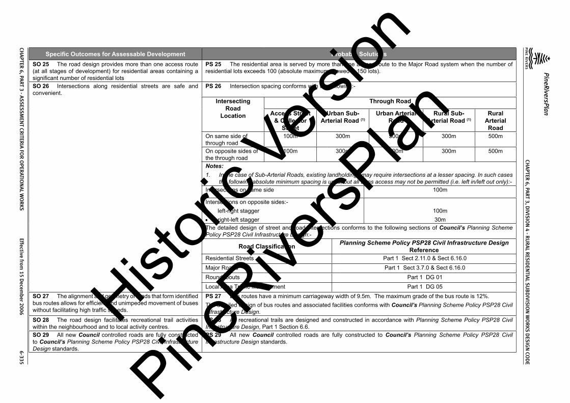
CHA
PTER 6, PA
RT 3, DIVIS
ION
4 - RU
RA
L RES
IDEN
TIAL S
UB
DIVIS
ION
WO
RKS D
ESIG
N CO
DE
PineRiversPlan
CHA
PTER 6, PA
RT 3 - ASS
ESSM
ENT CR
ITERIA
FOR
OPER
ATION
AL W
OR
KS Effective from
15 Decem
ber 2006 6-335
Specific Outcomes for Assessable Development Probable SolutionsSO 25 The road design provides more than one access route (at all stages of development) for residential areas containing a significant number of residential lots
PS 25 The residential area is served by more than one access route to the Major Road system when the number of residential lots exceeds 100 (absolute maximum allowed is 150 lots).
SO 26 Intersections along residential streets are safe and convenient.
PS 26 Intersection spacing conforms with the following:-
Intersecting Road
Location
Through Road
Access Street & Collector
Street
Urban Sub- Arterial Road (1)
Urban Arterial Road
Rural Sub- Arterial Road (1)
Rural Arterial Road
On same side of through road
100m 300m 500m 300m 500m
On opposite sides of the through road
100m 300m 500m 300m 500m
Notes:1. In the case of Sub-Arterial Roads, existing landholdings may require intersections at a lesser spacing. In such cases
the following absolute minimum spacing is used, but all turns access may not be permitted (i.e. left in/left out only):-Intersections on same side 100m
Intersections on opposite sides:-• left-right stagger• right-left stagger
100m30m
The detailed design of street and road intersections conforms to the following sections of Council’s Planning Scheme Policy PSP28 Civil Infrastructure Design:-
Road Classification Planning Scheme Policy PSP28 Civil Infrastructure Design Reference
Residential Streets Part 1 Sect 2.11.0 & Sect 6.16.0Major Roads Part 1 Sect 3.7.0 & Sect 6.16.0Roundabouts Part 1 DG 01Local Area Traffic Management Part 1 DG 05
SO 27 The alignment and geometry of roads that form identified bus routes allows for efficient and unimpeded movement of buses without facilitating high traffic speeds.
PS 27 Bus routes have a minimum carriageway width of 9.5m. The maximum grade of the bus route is 12%.The detailed design of bus routes and associated facilities conforms with Council’s Planning Scheme Policy PSP28 Civil Infrastructure Design.
SO 28 The road design facilitates recreational trail activities within the neighbourhood and to local activity centres.
PS 28 All recreational trails are designed and constructed in accordance with Planning Scheme Policy PSP28 Civil Infrastructure Design, Part 1 Section 6.6.
SO 29 All new Council controlled roads are fully constructed to Council’s Planning Scheme Policy PSP28 Civil Infrastructure Design standards.
PS 29 All new Council controlled roads are fully constructed to Council’s Planning Scheme Policy PSP28 Civil Infrastructure Design standards.
Histori
c Vers
ion
PineRive
rsPlan

CHA
PTER 6, PA
RT 3, DIVIS
ION
4 - RU
RA
L RES
IDEN
TIAL S
UB
DIVIS
ION
WO
RKS D
ESIG
N CO
DE
PineRiversPlan
CHA
PTER 6, PA
RT 3 - ASS
ESSM
ENT CR
ITERIA
FOR
OPER
ATION
AL W
OR
KS Effective from
15 Decem
ber 2006 6-336
Specific Outcomes for Assessable Development Probable SolutionsSO 30 All Council controlled frontage roads are constructed to Council’s Planning Scheme Policy PSP28 Civil Infrastructure Design standards.
PS 30 All Council controlled frontage roads are constructed to Council’s Planning Scheme Policy PSP28 Civil Infrastructure Design standards as follows:-
Situation Minimum Construction(1)
Frontage road unconstructed or gravel road only
For Access Place and Access Street: full carriageway and verges.For Collector Street: verge adjoining new lots, carriageway to a minimum sealed width of 6m plus 1.5m wide (full depth pavement) gravel shoulder and table drainage to the opposite side.For Major Roads: verge adjoining new lots, carriageway to a minimum sealed width of 7m plus 1.5m wide (full depth pavement) gravel shoulder and table drainage to the opposite side.
Frontage road sealed(2) but not constructed to Council’s Planning Scheme Policy PSP28 Civil Infrastructure Design standard
For Access Place and Access Street: reconstruction of full carriageway and verges.For Collector Street: reconstruction of verge adjoining new lots and carriageway to a minimum sealed width of 6m plus 1.5m wide (full depth pavement) gravel shoulder and table drainage to the opposite side. The works match into the remaining existing works wherever possible.For Major Roads: verge adjoining new lots and carriageway to a minimum sealed width of 7m plus 1.5m wide (full depth pavement) gravel shoulder and table drainage to the opposite side. The works match into the remaining existing works wherever possible.
Frontage road(2) partially constructed to Council’s Planning Scheme Policy PSP28 Civil Infrastructure Design standard
For Access Place and Access Street: construction of all remaining carriageway and verges.For Collector Street: verge adjoining new lots and carriageway to join existing works. In any event the minimum sealed width to be constructed is 6m plus 1.5m wide (full depth pavement) gravel shoulder and table drainage to the opposite side where necessary. The works match into the existing works.For Major Roads: verge adjoining new lots and carriageway to join existing works. In any event the minimum sealed width is 7m plus 1.5m wide (full depth pavement) gravel shoulder and table drainage to the opposite side where necessary. The works match into the existing works.
Notes:1. Construction includes all associated works (services, streetlighting and linemarking).2. Testing of the existing pavement is carried out to confirm whether the existing works meet Council’s Planning
Scheme Policy PSP28 Civil Infrastructure Design standards.SO 31 Sealed and flood free road access during minor storms is available to the site from the nearest Major Road.
PS 31 Roads or streets giving access to the development from the nearest Major Road are sealed to a minimum width of 5.5m. These access roads or streets have drainage systems that conform to Council’s Planning Scheme Policy PSP28 Civil Infrastructure Design, Part 2, Section 4.7.0.
Histori
c Vers
ion
PineRive
rsPlan

CHA
PTER 6, PA
RT 3, DIVIS
ION
4 - RU
RA
L RES
IDEN
TIAL S
UB
DIVIS
ION
WO
RKS D
ESIG
N CO
DE
PineRiversPlan
CHA
PTER 6, PA
RT 3 - ASS
ESSM
ENT CR
ITERIA
FOR
OPER
ATION
AL W
OR
KS Effective from
15 Decem
ber 2006 6-337
Specific Outcomes for Assessable Development Probable SolutionsSO 32 The road network design takes into account:-(1) streetscapes that may be created or already exist;(2) protection of topography and vegetation;(3) opportunities for views and vistas; and(4) protection of natural drainage and open space systems.
PS 32 Road designs incorporate retention of existing significant trees where ever practicable.Road designs minimise the heights of cut and fill of road formation to less than 2m where ever practicable.New roads are located to minimise the heights of cut and fill of road formation to less than 2m where ever possible.Road designs minimise the amount of filling and extent of filling in or adjacent existing natural gullies, waterways, existing public open space areas and proposed public open space areas.
SO 33 The existing road network is upgraded where necessary to cater for the traffic impact from the development.
PS 33 Solutions will need to be determined by traffic studies and adapted to suit the particular site constraints and features.New intersections onto existing roads are designed to accommodate traffic volumes and traffic movements ten years hence. Detailed design is in accordance with Council’s Planning Scheme Policy PSP28 Civil Infrastructure Design, Part 1.Existing intersections external to the site are upgraded as necessary to accommodate increased traffic from the development. Detailed design is in accordance with Council’s Planning Scheme Policy PSP28 Civil Infrastructure Design, Part 1.
SO 34 “As constructed” information including test certificates for material quality (if required) and compaction is provided upon completion of the subdivision works.
PS 34 “As constructed” information including test certificates for material quality (if required) and compaction is provided upon completion of the subdivision works.
4.3.4 Stormwater ManagementSO 35 The major drainage system has the capacity to safely convey stormwater flows for the 100 year ARI storm event.
PS 35 The roads, drainage pathways, drainage features and waterways safely convey the stormwater flows for the 100 year ARI storm event (ultimate development catchment characteristics upstream).The major drainage system has a minimum design ARI of 100 years (ultimate development catchment characteristics upstream).Carriageways generally have kerb and channel (except where table or swale drains are approved). Catchpits and kerb turnouts are located to ensure the longitudinal flow in the channel does not exceed the following criteria for the major storm (100 year ARI):-
Location
Major Storm - Maximum Flow Width and DepthMajor Roads Minor Roads
Where floor levels of adjacent buildings are above road level (kerb and channeled crowned road)
(a) Total flow contained within road reserve; and
(b) Freeboard ≥250mm to floor level of adjacent buildings; and
(c) Maximum depth of flow of 300mm
(a) Total flow contained within road reserve; and
(b) Freeboard ≥250mm to floor level of adjacent buildings; and
(c) Maximum flow depth 300mmWhere floor levels of adjacent buildings are below road level or < 300mm above top of kerb (kerb and channeled crowned road)(a) ≥100mm fall on verge towards
kerb;(b) < 100mm fall on verge towards
kerb.
(a) 50mm above top of kerb;
(b) Top of kerb
(a) 50mm above top of kerb;
(b) Top of kerb
Histori
c Vers
ion
PineRive
rsPlan

CHA
PTER 6, PA
RT 3, DIVIS
ION
4 - RU
RA
L RES
IDEN
TIAL S
UB
DIVIS
ION
WO
RKS D
ESIG
N CO
DE
PineRiversPlan
CHA
PTER 6, PA
RT 3 - ASS
ESSM
ENT CR
ITERIA
FOR
OPER
ATION
AL W
OR
KS Effective from
15 Decem
ber 2006 6-338
Specific Outcomes for Assessable Development Probable SolutionsRoads without kerb and channel – table or swale drains used for longitudinal drainage
(a) Total flow contained within road reserve; and
(b) Flows do not encroach upon driving lanes; and
(c) Freeboard ≥250mm to floor level of adjacent buildings; and
(d) Maximum depth of flow in drain of 300mm
(a) Total flow contained within road reserve; and
(b) Flows do not encroach upon driving lanes; and
(c) Freeboard ≥250mm to floor level of adjacent buildings; and
(d) Maximum depth of flow in drain of 300mm
Notes:1. Widths are measured from channel invert for kerb and channel and from kerb face for kerb only.2. Refer Council’s Planning Scheme Policy PSP28 Civil Infrastructure Design, Part 2, Section 4 for detailed design
requirements.The product of depth by average velocity in the channel does not exceed 0.6m2/s except where there is a danger of pedestrians being swept away and drowned where the value is limited to 0.4m2/s.Detailed design of the major drainage system conforms to Council’s Planning Scheme Policy PSP28 Civil Infrastructure Design, Part 2, Section 4.Residential lots have the following minimum development levels:
Location of Residential Lot Minimum Development Level Minimum Area at Development Level
Adjacent Existing Natural Watercourse The greater of:• Q100ultimate plus 750mm; or• the highest recorded flood level plus
750mm.
1500m2 minimum area
Adjacent Engineered Channels The greater of:• Q100ultimate plus 500mm for a
maintained channel; or• Q100ultimate plus 250mm for an
unmaintained channel.
1500m2 minimum area
Road Drainage The greater of:• Q100ultimate plus 250mm; or• Q100ultimate plus 150mm using
blocked catchpits or inlets.
1500m2 minimum area
Overland Flow Paths The greater of:• Q100ultimate plus 250mm for a
maintained flow path; or• Q100ultimate plus 150mm for an
unmaintained flow path.
1500m2 minimum areaHistori
c Vers
ion
PineRive
rsPlan

CHA
PTER 6, PA
RT 3, DIVIS
ION
4 - RU
RA
L RES
IDEN
TIAL S
UB
DIVIS
ION
WO
RKS D
ESIG
N CO
DE
PineRiversPlan
CHA
PTER 6, PA
RT 3 - ASS
ESSM
ENT CR
ITERIA
FOR
OPER
ATION
AL W
OR
KS Effective from
15 Decem
ber 2006 6-339
Specific Outcomes for Assessable Development Probable SolutionsDetention basins are designed in accordance with Council’s Planning Scheme Policy PSP28 Civil Infrastructure Design, Part 2, Section 4.8.0.Open channels are designed in accordance with Council’s Planning Scheme Policy PSP28 Civil Infrastructure Design, Part 2, Section 4.9.0.
SO 36 The minor stormwater drainage system has the capacity to convey stormwater flows from frequent storm events whilst ensuring pedestrian and vehicular traffic movements are safe and convenient.
PS 36 The minor drainage system has a minimum design ARI of 5 years (ultimate development catchment characteristics upstream).Carriageways generally have kerb and channel (except where swale drains are approved by Council’s engineer). Catchpits and kerb turnouts are located to ensure the longitudinal flow in the channel does not exceed the following criteria for the minor storm:
Location
Minor Storm - Maximum Flow WidthMajor Roads Minor Roads
Design ARI (years) 10 5
Normal situation – kerb and channeled crowned road
Parking Lane width (usually 2.5m) or breakdown lane width.
Full pavement width with zero depth at crown.
Normal situation – no kerb and channel, crowned road
Contained within the table drain. Contained within the table drain.
Normal situation – one way crossfall road
Parking Lane width (usually 2.5m) or breakdown lane width.
To high side of road pavement but not above top of kerb on low side.
Where parking lane may be replaced by a through, acceleration, deceleration or turn lane
1m Not applicable.
Where road falls towards median 1m Not applicable.Pedestrian crossing or bus stops 0.45m 0.45mIntersection kerb returns (including entrances to shopping centres and other major developments)
1m 1m
Notes:1. Widths are measured from channel invert for kerb and channel and from kerb face for kerb only.2. Refer to Council’s Planning Scheme Policy PSP28 Civil Infrastructure Design, Part 2, Section 4 for detailed design
requirements.The product of depth by average velocity in the channel does not exceed 0.6m2/s except where there is a danger of pedestrians being swept away and drowned where the value is limited to 0.4m2/s.The pipelines are located on a 1.5m nominal alignment measured from the invert of kerb and channel towards the road centreline and are not located under kerb and channel.Pipelines from sag points in the road are taken through drainage reserves or drainage easements to an approved discharge point. Easements for drainage outlets in private property have sufficient area to cover all structures (including footings) and to allow for future maintenance access.Gully inlets (catchpits) allow for blockage by reducing the theoretical capacity of the inlet as follows:-
Histori
c Vers
ion
PineRive
rsPlan

CHA
PTER 6, PA
RT 3, DIVIS
ION
4 - RU
RA
L RES
IDEN
TIAL S
UB
DIVIS
ION
WO
RKS D
ESIG
N CO
DE
PineRiversPlan
CHA
PTER 6, PA
RT 3 - ASS
ESSM
ENT CR
ITERIA
FOR
OPER
ATION
AL W
OR
KS Effective from
15 Decem
ber 2006 6-340
Specific Outcomes for Assessable Development Probable SolutionsCondition Inlet Type Percentage of Theoretical Capacity Allowed
Sag Side Entry 80%Grated 50%Combination Capacity of kerb opening assuming grate is fully
blockedContinuous Grade Side Entry 80%
Grated – Longitudinal Bars 60%Grated – Transverse Bars (with or without longitudinal bars)
50%
Combination 70% - 90% of capacity of kerb opening plus grate (depending upon length of backstone)
Gully inlets and manholes have the following minimum freeboard for the minor storm event:-
Situation Minimum freeboard requirementsGully inlet on grade 150mm below invert of kerb and channelGully inlet in sag 150mm below invert of kerb and channelField Inlet 150mm below top of grate or lip of inletManhole or junction structure 150mm below top of lidStormwater drainage infrastructure through or within private land is protected by easements in favour of Council. Minimum easement widths are as follows:-
Pipe Diameter Minimum Easement Width (excluding access requirements)
Stormwater pipe up to 825mm diameter 3mStormwater pipe up to 825mm diameter with Sewer pipe up to 225mm diameter
4m
Stormwater pipe greater than 825mm diameter Easement boundary to be 1m clear of outside wall of pipe and clear of pits.
Structures at the end of headwalls 3m beyond and to one side of works. Easement is to be extended to include 2-wheel drive vehicular access to the road.
Detailed design of the minor drainage system conforms to Council’s Planning Scheme Policy PSP28 Civil Infrastructure Design, Part 2, Section 4.Stormwater drainage reticulation and cross drainage conforms to the following standard drawings:-
Item Standard Drawings NumbersRoad Catchpits 8-30001 to 8-30003, 8-30036Field Inlets 8-30004Circular Manholes 8-30006 to 8-30008, 8-30010, 8-30011Bedding and Backfill to Pipes and Culverts 8-30013 & 8-30014
Histori
c Vers
ion
PineRive
rsPlan

CHA
PTER 6, PA
RT 3, DIVIS
ION
4 - RU
RA
L RES
IDEN
TIAL S
UB
DIVIS
ION
WO
RKS D
ESIG
N CO
DE
PineRiversPlan
CHA
PTER 6, PA
RT 3 - ASS
ESSM
ENT CR
ITERIA
FOR
OPER
ATION
AL W
OR
KS Effective from
15 Decem
ber 2006 6-341
Specific Outcomes for Assessable Development Probable SolutionsWingwalls, Headwalls and Aprons to pipe Culverts 8-30015 to 8 - 30018Wingwalls, Headwalls, Aprons, Bases and crown unit hold downs to Box Culverts
8-30019 to 8-30024
SO 37 Road cross drainage ensures that roads remain trafficable during major storm events without flooding or impacting upon residential properties or other premises.
PS 37 Road cross drainage is provided to satisfy the following requirements:-Road
ClassificationMajor Storm Minor Storm*
Major Road Trafficable for flows from the 100 year ARI storm:-(a) Maximum depth 200mm; and(b) DgVave < 0.4
For the 50 year ARI storm:-(a) Flows and flood levels do not encroach
upon the driving lanes;(b) Minimum pipe system freeboards are
maintained.Minor Road Trafficable for flows from the 100 year ARI
storm:-(c) Maximum depth 200mm; and(c) DgVave < 0.4
For the 10 year ARI storm:-(a) Flows and flood levels do not encroach
upon the driving lanes;(b) Minimum pipe system freeboards are
maintained.
* 50 year ARI for Major Roads; 10 year ARI for Minor Roads
Roads remain trafficable during major storm events. Detailed design of culverts and bridges conforms with Council’s Planning Scheme Policy PSP28 Civil Infrastructure Design, Part 2, Section 4.12.2 and 4.12.3 and Austroads Waterways Design Guidelines.Where there is potential for blockage by stream debris due to the nature of the catchment the cross drainage is constructed using box culverts or a bridge structure.Afflux from the cross drainage does not flood or reduce the required Q100 freeboard to residential properties or other premises.Where the Minor Road provides access for less than 15 allotments then, in exceptional circumstances where a structure conforming with the above requirements cannot be reasonably required, the absolute minimum minor storm design flow is for the 2 year ARI storm with the structure designed as a floodway with a maximum duration of inundation during the Major Storm of 6 hours.All floodways where the depth of flow at any point on the carriageway exceeds 200mm have appropriate signage and flood markers provided.
SO 38 Stormwater management facilities ensure that drainage discharge from the site does not cause nuisance or annoyance to any person, property or premises.
PS 38 Stormwater runoff from the site is conveyed to a point of lawful discharge without causing nuisance or annoyance to any person, property or premises.Runoff rates and pollutant loads are not made worse by runoff from the site.A watercourse as defined in the Water Act 2000 is accepted as a lawful point of discharge providing the drainage discharge from the site does not increase downstream flood levels during the 100 year ARI storm and any flooding of downstream allotments which are not able to be further subdivided is not increased.
Histori
c Vers
ion
PineRive
rsPlan

CHA
PTER 6, PA
RT 3, DIVIS
ION
4 - RU
RA
L RES
IDEN
TIAL S
UB
DIVIS
ION
WO
RKS D
ESIG
N CO
DE
PineRiversPlan
CHA
PTER 6, PA
RT 3 - ASS
ESSM
ENT CR
ITERIA
FOR
OPER
ATION
AL W
OR
KS Effective from
15 Decem
ber 2006 6-342
Specific Outcomes for Assessable Development Probable SolutionsSO 39 The stormwater quality management system minimises the environmental impact of stormwater on surface and underground receiving water quality.
PS 39 All developments in excess of 5ha provide stormwater quality improvement devices.The calculated pollutant concentrations from the site do not exceed Council’s adopted water quality objectives (WQO) for the particular catchment or, where no WQO has been adopted, then the appropriate ANZECC standards.All dry weather flow is treated to reduce pollutant loads prior to discharge to a watercourse, creek or river.The first flush flow from the first 15mm of rainfall over the site is treated to reduce pollutant loads prior to discharge to a watercourse, creek or river.The detailed design of stormwater quality improvement devices conforms to Council’s Planning Scheme Policy PSP28 Civil Infrastructure Design, Part 2, Sections 3 & 4.Approved proprietary products are installed and maintained in accordance with the manufacturer’s recommendations.
SO 40 The stormwater quality management system minimises the environmental impact of stormwater on natural waterway configuration
PS 40 Stormwater management facilities do not encroach upon riparian areas.Filling does not extend below the Q50 (ultimate) flood contour for creeks and watercourses.Filling does not extend below the Q100 (ultimate) flood contour for rivers.The number of stormwater outlets to waterways are minimised.Natural creeks and watercourses are not channelised to maximise development area.
SO 41 The stormwater quality management system minimises the environmental impact of stormwater on existing natural wetlands and vegetation.
PS 41 Stormwater management facilities do not encroach upon existing natural wetlands.Significant existing water bodies are retained with appropriate stormwater quality improvement devices (refer to Council’s Planning Scheme Policy PSP28 Civil Infrastructure Design, Part 2, Section 4.11.5).
SO 42 Community benefit is maximised through the retention and enhancement of natural streams and vegetation wherever practicable
PS 42 Watercourses are enhanced by re-vegetation with natural species occurring in the catchment. The area must be planted with local native trees (of the local Regional Ecosystem if relevant) at 3m centres, shrubs at 2m centres and ground covers at 1m centres.Existing erosion and scour in watercourses through or adjoining the site are repaired and stabilised.
SO 43 Areas constructed as detention basins within public lands are adaptable for passive recreation wherever practicable.
PS 43 Large dry detention basins are designed to accommodate passive recreation. The basin includes a low flow drainage system with the capacity to carry 3mm/hr rainfall in the catchment. The basin floor is sloped at not less than 1(V) to 100(H) towards its perimeter drains.
SO 44 “As constructed” information including test certificates for material quality (if required) and compaction is provided upon completion of the subdivision works.
PS 44 “As constructed” information including test certificates for material quality (if required) and compaction is provided upon completion of the subdivision works.
4.3.5 Pedestrian and Cyclist FacilitiesSO 45 The pedestrian and bikeway paths are designed to provide for safe, attractive and convenient movement of pedestrian and cyclists between each residential precinct and major attractions such as schools, shops, sporting facilities, bus routes (existing and planned) and railway stations.
PS 45 Footpaths are provided in the following instances:-
Location Footpath RequirementAccess Place, Access Street & Collector Street To suit pedestrian movementsMajor Rural Roads To suit pedestrian movementsAdjacent pedestrian traffic generators such as schools, shopping centres, etc.
To suit pedestrian movements
Along pathways The full length of the pathway and linking to any footpath within 20m, the kerb and channel by way of a kerb ramp or to the carriageway where no kerb and channel exists.
Histori
c Vers
ion
PineRive
rsPlan

CHA
PTER 6, PA
RT 3, DIVIS
ION
4 - RU
RA
L RES
IDEN
TIAL S
UB
DIVIS
ION
WO
RKS D
ESIG
N CO
DE
PineRiversPlan
CHA
PTER 6, PA
RT 3 - ASS
ESSM
ENT CR
ITERIA
FOR
OPER
ATION
AL W
OR
KS Effective from
15 Decem
ber 2006 6-343
Specific Outcomes for Assessable Development Probable SolutionsFootpaths are designed to conform with the following:-
Issue RequirementWidth 1.2m minimum for low usage; 1.5m minimum elsewhere except for dual use pedestrian/
cycle paths where minimum width is 2mLocation Refer relevant standard drawing for road classification. Meandering of the path is desirable
to create visual interest.Clearance to Properties 0.8m for Collector Street
1m for Sub-Arterial and ArterialClearance to Kerbline 1.5m for Access Place, Access Street & Collector Street
2.5m Sub-Arterial and ArterialGrades Along roads - as per maximum grade for classification of road
Pathway reserves and open space – 10% desirable maximumCrossfall 2.5% (1 in 40) minimum
5% (1 in 20) maximumCrossing Points Refer to Planning Scheme Policy PSP28 Civil Infrastructure Design, Part 1, Section 6.4.7
& 6.4.8Chicanes or vehicle barriers are provided at the ends of all pathways to roads.Detailed design of the footpaths conforms to Council’s Planning Scheme Policy PSP28 Civil Infrastructure Design, Part 1, Section 6.4.0.
SO 46 “As constructed” information is provided upon completion of the subdivision works.
PS 46 “As constructed” information is provided upon completion of the subdivision works.
4.3.6 Recreational TrailsSO 47 Recreational trails are designed to provide for safe, attractive and convenient movement of pedestrians and horse riders on circular routes or links to recreational areas and attractions such as tourist facilities (natural and built), schools, shops and sporting facilities.
PS 47 Recreational trails are provided in accordance with Council’s Recreational Trails Plan.Trails are designed to conform to the following:-
Issue RequirementTrail Type:-1. Network Trails2. Informal Trails
1. Formed and surfaced with 50 mm minimum compacted gravel pavement..2. Formed and grassed.
Grades Desirable maximum: 20 %Absolute Maximum: 25%
Formation width Minimum width: 2mCrossfall 1(V) in 30(H) minimum; 1(V) in 10(H) maximum.Clearances Horizontal: 3m; Vertical: 3m Drainage Drainage works sufficient to provide reasonable all-weather useability and to minimise
potential for erosion damage. Typically low flow pipes (375mm diam. min), rock fords or bridges at larger crossings. Longitudinal earth or rock lined table drains as necessary.
Histori
c Vers
ion
PineRive
rsPlan

CHA
PTER 6, PA
RT 3, DIVIS
ION
4 - RU
RA
L RES
IDEN
TIAL S
UB
DIVIS
ION
WO
RKS D
ESIG
N CO
DE
PineRiversPlan
CHA
PTER 6, PA
RT 3 - ASS
ESSM
ENT CR
ITERIA
FOR
OPER
ATION
AL W
OR
KS Effective from
15 Decem
ber 2006 6-344
Specific Outcomes for Assessable Development Probable SolutionsPost and rail fencing is located at the ends of off road trails to minimise access by motor vehicles.Recreational trail direct road crossings conform to Standard Drawing No. 8-60045.
SO 48 As constructed information is provided upon completion of the subdivision works.
PS 48 As constructed information is provided upon completion of the subdivision works.
4.3.7 Public TransportSO 49 The road design provides for potential bus routes including safe convenient stops and, where necessary, bus turnaround areas.SO 50 The road design caters for the extension of existing and future public transport routes to provide sufficient services that are convenient and accessible to the community.
PS 49 and PS 50 Bus routes are design to conform with the following:Issue Requirement
Carriageway Width 8.0m minimumGrade 12% general maximum
16% absolute maximum over short distancesSpeed Control Generally by street alignment onlyDesign Vehicle Coach (tourist bus)Turning Single movement turns onlyFully indented bus bays are provided for Sub-Arterial and Arterial Roads with detailed design conforming with Planning Scheme Policy PSP28 Civil Infrastructure Design, Part 1, Section 3.12.2.The road design provides for extension of existing and future public transport routes.
SO 51 “As constructed” information including test certificates for material quality (if required) and compaction is provided upon completion of the subdivision works.
PS 51 “As constructed” information including test certificates for material quality (if required) and compaction is provided upon completion of the subdivision works.
4.3.8 Public Open SpaceSO 52 Public open space has barriers to its road frontage to prevent access by unauthorised vehicles.
PS 52 The public open space is provided with log barrier fence (or similar) along the road frontage in accordance with Council’s Planning Scheme Policy PSP28 Civil Infrastructure Design, Part 1, Section 6.14.0 and Standard Drawing No. 8-70003.
SO 53 Public open space that is intended to be used for local neighbourhood park includes sufficiently level areas that are suitable for non-organised recreation and passive relaxation.
PS 53 Public open space that is intended to be used for local neighbourhood park contains one area, constructed if necessary, not less than 15m x 15m with a slope less than 5%.
SO 54 “As constructed” information including test certificates for material quality (if required) is provided upon completion of the subdivision works.
PS 54 “As constructed” information including test certificates for material quality (if required) is provided upon completion of the subdivision works.
4.3.9 UtilitiesSO 55 Development only occurs in locations where there are adequate services and capacity for the desired use.
PS 55 The design of the electrical reticulation is in accordance with ENERGEX Specification URD Underground Residential Distribution.Histori
c Vers
ion
PineRive
rsPlan

CHA
PTER 6, PA
RT 3, DIVIS
ION
4 - RU
RA
L RES
IDEN
TIAL S
UB
DIVIS
ION
WO
RKS D
ESIG
N CO
DE
PineRiversPlan
CHA
PTER 6, PA
RT 3 - ASS
ESSM
ENT CR
ITERIA
FOR
OPER
ATION
AL W
OR
KS Effective from
15 Decem
ber 2006 6-345
Specific Outcomes for Assessable Development Probable Solutions
4.3.9(a) ElectricitySO 56 Where lots are intended to be provided with reticulated electricity the service is underground with design and construction of the associated infrastructure and connections being provided in a safe, cost-effective, coordinated and efficient manner that supports sustainable development practices.
PS 56 Electrical reticulation is provided in residential developments.Underground crossings of existing roads are bored. In special circumstances Council’s engineer may approve other methods including trenched construction.Road crossing are not at acute angles to the road centreline.Electrical crossings are within the area defined as an intersection under State Legislation or are diagonally across intersections to enable 11kV cables to be installed without joints.
4.3.9(b) Street Lighting – (excludes State-controlled roads)SO 57 All roads are provided with street lighting which is designed and constructed to provide a safe, cost-effective, coordinated and efficient system that supports sustainable development practices.
PS 57 All works are designed and constructed to AS1158, Public Lighting Code, 1986, Austroads Guide to Traffic Engineering Practice – Part 12, Roadway Lighting, 1988 and ENERGEX standards and approval.Street lighting poles and luminaries are standard ENERGEX patterns under Rate 1 Tariff in roads and Rate 2 Tariff in other than roads.Street light poles are located on standard alignments in accordance with the following Standard Drawings:-
Street Classification Standard Drawing No.Access Place, Access Street and Collector Street 8-10027Urban Sub Arterial and Arterial 8-10013Rural Sub Arterial and Arterial 8-10028Street lights are generally located opposite common lot boundaries and are positioned to minimise conflicts with vehicle movements.Street lights are located to minimise the risk of damage from errant vehicles at intersections, bends and speed control devices and by oversize vehicles which must necessarily leave the carriageway to manoeuvre in turn around areas, speed control devices and some intersections.Street light poles that are in vulnerable locations (e.g. small islands or roundabouts) use frangible type poles.Colour consistency is maintained as far as practicable.Lighting designs are prepared in accordance with the Lighting Category specified below:-
Road Classification Lighting CategoryUrban Arterial A2Urban Sub Arterial A3Rural Sub Arterial and Arterial Nil(1)
Collector B2(2)
Access Street, Access Place B2(2)
Pathways between residential lots NilGeneral pathways in open space areas NilOther locations Subject to individual assessment
Histori
c Vers
ion
PineRive
rsPlan

CHA
PTER 6, PA
RT 3, DIVIS
ION
4 - RU
RA
L RES
IDEN
TIAL S
UB
DIVIS
ION
WO
RKS D
ESIG
N CO
DE
PineRiversPlan
CHA
PTER 6, PA
RT 3 - ASS
ESSM
ENT CR
ITERIA
FOR
OPER
ATION
AL W
OR
KS Effective from
15 Decem
ber 2006 6-346
Specific Outcomes for Assessable Development Probable SolutionsNote:1. Special lighting at traffic hazards (intersections, roundabouts, sharp bends, traffic control devices, pedestrian
crossings, ends of cul de sacs and bridges) may be required if electricity reticulation is available.2. Lighting at traffic hazards (intersections, roundabouts, sharp bends, traffic control devices, pedestrian crossings,
ends of cul de sacs and bridges) and at every (5th) pole (not including intersections)..3. The above classification also applies to community titled developments.
4.3.9(c) TelecommunicationsSO 58 All lots are able to be provided with a telecommunications service which is designed to give a safe, cost effective, coordinated and efficient system that supports sustainable development practices.
PS 58 Application for telecommunications reticulation is made and pre-provisioning confirmation is received prior to subdivision works commencing.Telecommunications reticulation (i.e. conduits and pits) is installed in accordance with Telstra standards and a provisioning confirmation is provided for the works.
4.3.9(d) Alterations and RelocationsSO 59 Any alteration or relocation in connection with or arising from the development to any service, installation, plant, equipment or other item belonging to or under the control of the telecommunications authority, electricity authorities, the Council or other person engaged in the provision of public utility services is carried out prior to the approval of the plan of subdivision.
PS 59 No solution provided.
4.3.9(e) As Constructed InformationSO 60 “As constructed” information including test certificates for material quality (if required) and compaction is provided upon completion of the subdivision works.
PS 60 “As constructed” information including test certificates for material quality (if required) and compaction is provided to the relevant authority upon completion of the subdivision works.
Histori
c Vers
ion
PineRive
rsPlan

CHAPTER 6, PART 3, DIVISION 5 - INDUSTRIAL SUBDIVISION WORKS DESIGN CODE
PineRiversPlan
CHAPTER 6, PART 3 - ASSESSMENT CRITERIA FOR OPERATIONAL WORKS Effective from 15 December 2006 6-347
Division 5 Industrial Subdivision Works Design Code5.1 Overall Outcome
To create industrial subdivision development that:-(1) Provides safe, functional, convenient and attractive industrial areas;(2) Ensures that sites are managed during construction to minimise adverse impacts to the
environment and on the health and amenity of residents and premises;(3) Ensures that sites are managed during construction to minimise adverse traffic impacts to
existing roads;(4) Ensure that earthworks design and construction is suitable for the intended use of the land
and that adverse impacts to the environment and on the health and amenity of residents is minimised;
(5) To design and construct road networks which provide an optimum combination of Safety, Amenity, Convenience, Economy and Environment for residents, road and street users, and the community generally;
(6) To design and construct stormwater management systems which provide an optimum combination of Safety, Amenity, Convenience, Economy and Environment for residents and the community generally;
(7) To collect and convey stormwater from a catchment to its receiving waters with minimal nuisance, danger or damage, and at a development and environmental cost which is acceptable to the community as a whole;
(8) Provides for the convenience and safety for pedestrians and vehicular traffic during frequent or nuisance stormwater flows;
(9) Limits flooding of public and private property, both within the catchment and downstream, to ensure that flood inundation occurs on rare occasions only;
(10) Ensures a reasonable level of pedestrian and vehicular traffic safety and accessibility;(11) To minimise pollutant inflows to the receiving waters, and controls scour and depositional
effects;(12) Controls and temporarily detains within each catchment as much incident rainfall and runoff
as possible and reduces the impact of urbanisation;(13) Adequately protects people, the natural environment and the built environment at an acceptable
level of risk;(14) Integrates stormwater management solutions with other uses and the natural environment;(15) Provides safe, convenient and legible networks for walking and cycling to points of attraction
and beyond the development while preserving maximum visual amenity;(16) Ensures that opportunities exist for choice in the mode of transport and provides for cost-
effective and energy efficient public transport services that are accessible and convenient to the community;
(17) Provides public open space that meets user requirements for outdoor recreational and social activities and for landscaping that contributes to the identity, environmental health and safety of the community;
(18) Ensures, where appropriate, as many existing trees are retained as possible to keep the original character of the land and provide shelter and food for endemic flora and fauna;
(19) Ensures that tree plantings are selected and located appropriately as well as being planted and maintained to be long lasting and low maintenance;
(20) Provides for industrial lots that are adequately serviced with sewerage, water supply, electricity, street lighting and communications services in a timely, cost effective, coordinated and efficient manner that supports sustainable development practices, and is in accordance with the desired character of the locality;
(21) Ensures that the water supply and sewerage service provision complies with the relevant state guidelines for design;
(22) Minimises the impact on amenity due to provision of water supply and sewerage infrastructure;
(23) Ensures that all sewerage, water supply, electricity, street lighting and communications services that require relocation and/or alterations as a result of industrial development are carried out in a timely, cost effective, coordinated and efficient manner;
(24) Provides the design requirements for all types of industrial lots within the Shire; and(25) to provide designers with the relevant specific outcomes and, where possible, probable
solutions to achieve the design overall outcomes associated with the various elements of subdivision works design.
Histori
c Vers
ion
PineRive
rsPlan

CHAPTER 6, PART 3, DIVISION 5 - INDUSTRIAL SUBDIVISION WORKS DESIGN CODE
PineRiversPlan
CHAPTER 6, PART 3 - ASSESSMENT CRITERIA FOR OPERATIONAL WORKS Effective from 15 December 2006 6-348
5.2 Compliance with the Industrial Subdivision Works Design CodeThis code applies to all operational works relating to development or reconfiguring of industrial land in the Service Industry and General Industry zones, but specifically excludes applications for access easements to a road, subdivision by lease and boundary relocations or realignments.
The application of the various specific outcomes will depend upon the size or scale of the proposed development. Some specific outcomes will not apply due to a particular design element not being part of the proposal (e.g. new road). In other instances it may be impractical to apply some specific outcomes, particularly for small infill developments.
5.3 Development RequirementsThe development requirements of this code relate to the following elements:-(5.3.1) Managing Impacts During Construction(5.3.2) Earthworks(5.3.3) Road Networks (excludes State-controlled Roads)(5.3.4) Stormwater Management(5.3.5) Pedestrian & Cyclist Facilities(5.3.6) Public Transport(5.3.7) Public Open Space(5.3.8) Utilities
(5.3.8a) Water Supply(5.3.8b) Sewerage(5.3.8c) Recycled Water(5.3.8d) Electricity(5.3.8e) Street Lighting(5.3.8f) Telecommunications(5.3.8g) Alterations and Relocations(5.3.8h) As Constructed Information
Histori
c Vers
ion
PineRive
rsPlan

CHA
PTER 6, PA
RT 3, DIVIS
ION
5 - IND
US
TRIA
L SU
BD
IVISIO
N W
OR
KS DES
IGN
COD
E
PineRiversPlan
CHA
PTER 6, PA
RT 3 - ASS
ESSM
ENT CR
ITERIA
FOR
OPER
ATION
AL W
OR
KS Effective from
15 Decem
ber 2006 6-349
Specific Outcomes for Assessable Development Probable Solutions
5.3.1 Managing Impacts During ConstructionSO 1 All development sites minimise, as far as possible, any adverse impact to the natural environment caused by erosion, siltation, incineration of cleared vegetation and rubbish.
PS 1 The development works incorporate temporary stormwater runoff, erosion and sediment controls and trash traps designed in accordance with Council’s Planning Scheme Policy PSP28 Civil Infrastructure Design, Part 2, Section 4.2.0 and 4.11.4, and Subdivisions Section Technical Note No. 6. The measures are adjusted on-site to maximise their effectiveness.Stormwater runoff, erosion and sediment controls are constructed prior to commencement of any clearing works wherever possible.All environmentally significant areas to be retained with the development are clearly delineated and fenced prior to development works commencing.
SO 2 All development works are carried out at times which minimise noise impacts to residents.
PS 2 All development works are carried out within the following times, unless otherwise approved in writing by Council’s engineer:-(1) Monday to Friday (other than public holidays) between 7am and 6pm on the same day; and(2) Saturday (other than public holidays) between 7am and 12 noon on the same day.No work is carried out on Sundays and public holidays.Variations to the above working hours may be approved if Council’s engineer considers that the work is unlikely to cause significant inconvenience or disruption to the public, or the work is unlikely to cause annoyance or inconvenience to occupants of adjacent properties.
SO 3 All development works are managed to minimise dust and siltation nuisance to residents and other premises.
PS 3 During construction, dust suppression measures (such as watering of the site) are implemented to protect nearby premises from dust pollution.
SO 4 All development works avoid the redirection of stormwater runoff where potential impacts to residents and other premises may occur.
PS 4 Temporary construction works do not pond or concentrate stormwater runoff in adjoining properties.Temporary construction works do not create nuisance or annoyance to adjoining premises as a result of altering the stormwater runoff pattern exiting the site.
SO 5 Construction traffic does not adversely impact on the amenity of existing residents.
PS 5 Construction traffic to and from the site uses the highest classification streets or roads where a choice of access routes is available.Where significant volumes of material are approved to enter or leave the site, a haul route is approved by Council.All materials associated with the development that are dropped, deposited or spilled on streets giving access to the site are removed and the streets are cleaned as soon as practicable after the event. Any damaged areas are repaired and reinstated to their previous condition.Where works are carried out on existing roads a traffic control plan is prepared in accordance with the Manual of Uniform Traffic Control Devices. All traffic control measures are properly erected and maintained during the works.Any access road to the site that has been affected by any material dropped, deposited or spilled on the road as a result of the construction processes associated with the site is cleaned and restored to its original condition.
SO 6 Construction traffic is controlled to ensure all traffic movements to and from the site are safe.
PS 6 All traffic movements to and from the site frontage are carried out in a safe manner. Traffic controls are used where site access is approved directly onto a Major Road.
SO 7 All clearing works are carefully undertaken to ensure the clearing is limited to the area of the approved infrastructure works, buildings areas and other areas approved in the development permit.
PS 7 Areas of significant vegetation, proposed park and open space areas and other areas of vegetation or individual trees designated to be retained with the development are temporarily fenced and flagged.
Histori
c Vers
ion
PineRive
rsPlan
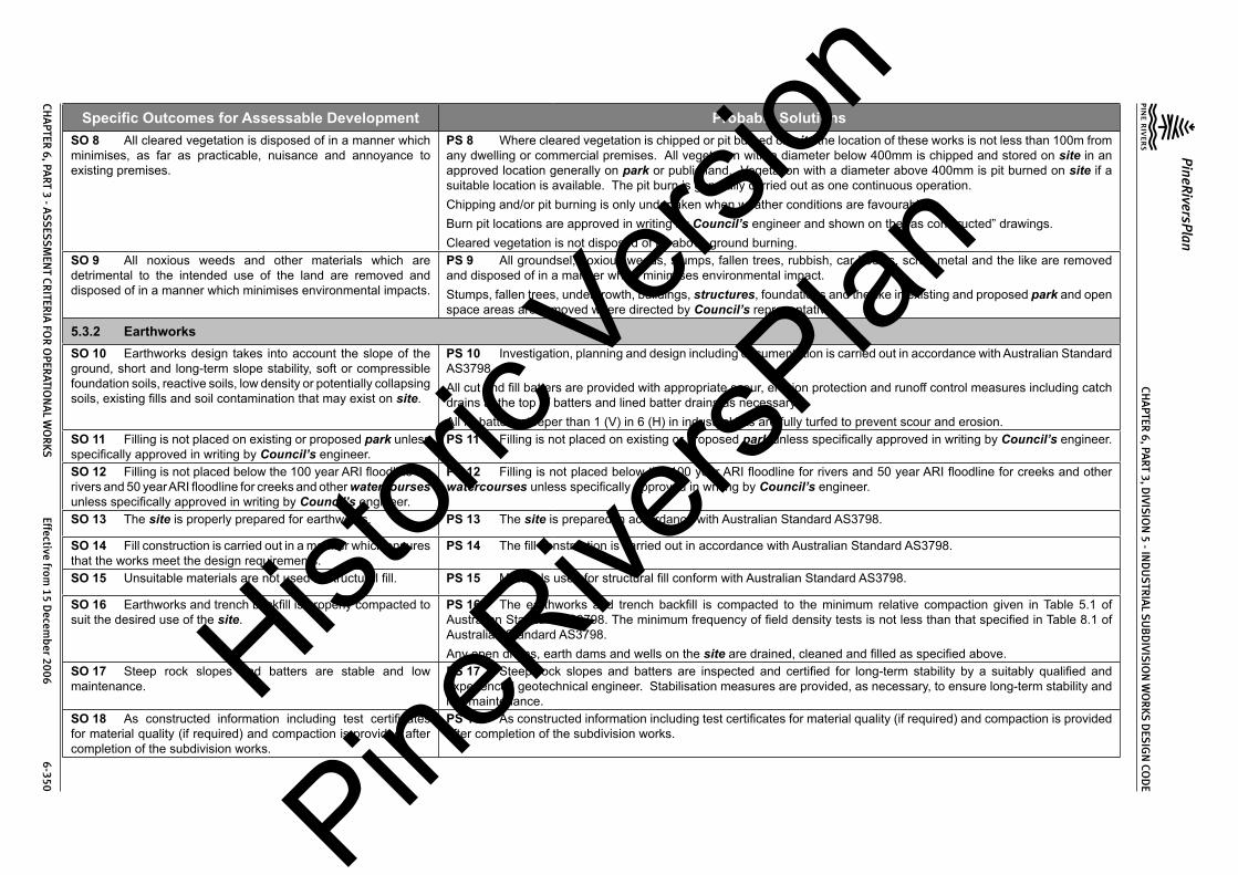
CHA
PTER 6, PA
RT 3, DIVIS
ION
5 - IND
US
TRIA
L SU
BD
IVISIO
N W
OR
KS DES
IGN
COD
E
PineRiversPlan
CHA
PTER 6, PA
RT 3 - ASS
ESSM
ENT CR
ITERIA
FOR
OPER
ATION
AL W
OR
KS Effective from
15 Decem
ber 2006 6-350
Specific Outcomes for Assessable Development Probable SolutionsSO 8 All cleared vegetation is disposed of in a manner which minimises, as far as practicable, nuisance and annoyance to existing premises.
PS 8 Where cleared vegetation is chipped or pit burned on site the location of these works is not less than 100m from any dwelling or commercial premises. All vegetation with a diameter below 400mm is chipped and stored on site in an approved location generally on park or public land. Vegetation with a diameter above 400mm is pit burned on site if a suitable location is available. The pit burn is generally carried out as one continuous operation.Chipping and/or pit burning is only undertaken when weather conditions are favourable.Burn pit locations are approved in writing by Council’s engineer and shown on the “as constructed” drawings.Cleared vegetation is not disposed of by above ground burning.
SO 9 All noxious weeds and other materials which are detrimental to the intended use of the land are removed and disposed of in a manner which minimises environmental impacts.
PS 9 All groundsel, noxious weeds, stumps, fallen trees, rubbish, car bodies, scrap metal and the like are removed and disposed of in a manner which minimises environmental impact.Stumps, fallen trees, undergrowth, buildings, structures, foundations and the like in existing and proposed park and open space areas are removed where directed by Council’s representative.
5.3.2 EarthworksSO 10 Earthworks design takes into account the slope of the ground, short and long-term slope stability, soft or compressible foundation soils, reactive soils, low density or potentially collapsing soils, existing fills and soil contamination that may exist on site.
PS 10 Investigation, planning and design including documentation is carried out in accordance with Australian Standard AS3798.All cut and fill batters are provided with appropriate scour, erosion protection and runoff control measures including catch drains at the top of batters and lined batter drains as necessary.All fill batters steeper than 1 (V) in 6 (H) in industrial lots are fully turfed to prevent scour and erosion.
SO 11 Filling is not placed on existing or proposed park unless specifically approved in writing by Council’s engineer.
PS 11 Filling is not placed on existing or proposed park unless specifically approved in writing by Council’s engineer.
SO 12 Filling is not placed below the 100 year ARI floodline for rivers and 50 year ARI floodline for creeks and other watercourses unless specifically approved in writing by Council’s engineer.
PS 12 Filling is not placed below the 100 year ARI floodline for rivers and 50 year ARI floodline for creeks and other watercourses unless specifically approved in writing by Council’s engineer.
SO 13 The site is properly prepared for earthworks. PS 13 The site is prepared in accordance with Australian Standard AS3798.
SO 14 Fill construction is carried out in a manner which ensures that the works meet the design requirements.
PS 14 The fill construction is carried out in accordance with Australian Standard AS3798.
SO 15 Unsuitable materials are not used in structural fill. PS 15 Materials used for structural fill conform with Australian Standard AS3798.
SO 16 Earthworks and trench backfill is properly compacted to suit the desired use of the site.
PS 16 The earthworks and trench backfill is compacted to the minimum relative compaction given in Table 5.1 of Australian Standard AS3798. The minimum frequency of field density tests is not less than that specified in Table 8.1 of Australian Standard AS3798.Any open drains, earth dams and wells on the site are drained, cleaned and filled as specified above.
SO 17 Steep rock slopes and batters are stable and low maintenance.
PS 17 Steep rock slopes and batters are inspected and certified for long-term stability by a suitably qualified and experienced geotechnical engineer. Stabilisation measures are provided, as necessary, to ensure long-term stability and low maintenance.
SO 18 As constructed information including test certificates for material quality (if required) and compaction is provided after completion of the subdivision works.
PS 18 As constructed information including test certificates for material quality (if required) and compaction is provided after completion of the subdivision works.
Histori
c Vers
ion
PineRive
rsPlan

CHA
PTER 6, PA
RT 3, DIVIS
ION
5 - IND
US
TRIA
L SU
BD
IVISIO
N W
OR
KS DES
IGN
COD
E
PineRiversPlan
CHA
PTER 6, PA
RT 3 - ASS
ESSM
ENT CR
ITERIA
FOR
OPER
ATION
AL W
OR
KS Effective from
15 Decem
ber 2006 6-351
Specific Outcomes for Assessable Development Probable Solutions
5.3.3 Road Networks (excludes State-controlled roads)SO 19 The road design and construction has a clear structure and component streets conform to their function in the network.SO 20 The road design and construction has clear physical distinctions between each type of street based on function, legibility, convenience, traffic volumes, vehicle speeds, public safety and amenity.SO 21 The road design and construction accommodates the following primary functions:-(1) access to lots;(2) on street car parking;(3) stormwater drainage paths (minor and major storms);(4) public transport on Collector Roads and Major Roads;(5) utility services location; and(6) setting and approach (streetscape and landscape).SO 22 The road design and construction accommodates adequate verge and carriageway width for the primary functions listed in specific outcomes above.
PS 19 to PS 22 The Industrial Roads conform to the following:-
Design Issue Access Road Collector RoadMaximum. Traffic Catchment 8 ha 30 haMinimum. Design Speed 40km/h 60km/hTotal Carriageway Width 12m 14mMinimum. Verge Width 4m 4mMinimum. Reserve Width 20m 24mMaximum. Grade 6% (desirable)
10% (absolute)6.0% (desirable)
8% (absolute)Min. Grade 0.4% 0.4%The detailed design of Industrial Roads conforms with Council’s Planning Scheme Policy PSP28 Civil Infrastructure Design, viz:
Road Design Issue Planning Scheme Policy PSP28 Civil Infrastructure Design Reference
Design Speed Part 1 Sect 4.5.0Traffic Volume and Capacity Part 1 Sect 4.6.0Parking Part 1 Sect 4.7.0Carriageway Design Part 1 Sect 4.8.0Verge Part 1 Sect 4.9.0Road Reserve Part 1 Sect 4.10.0Geometric Design Part 1 Sect 4.11.0Intersections Part 1 Sect 4.12.0 & 6.16.0Manoeuvring Areas Part 1 Sect 4.13.0Roundabouts Part 1 DG 01Landscape Construction on Road Reserves, Parks and Drainage Reserves
Part 1 DG 03
Signs and Road Marking Part 1 Sect 6.7.0Footpaths Part 1 Sect 6.4.0Bikeways Part 1 Sect 6.5.0Service Conduits Part 1 Sect 6.8.0Subsoil Drainage Part 1 Sect 6.9.0Safety Barriers Part 1 Sect 6.10.0Guide Posts Part 1 Sect 6.11.0
Histori
c Vers
ion
PineRive
rsPlan

CHA
PTER 6, PA
RT 3, DIVIS
ION
5 - IND
US
TRIA
L SU
BD
IVISIO
N W
OR
KS DES
IGN
COD
E
PineRiversPlan
CHA
PTER 6, PA
RT 3 - ASS
ESSM
ENT CR
ITERIA
FOR
OPER
ATION
AL W
OR
KS Effective from
15 Decem
ber 2006 6-352
Specific Outcomes for Assessable Development Probable SolutionsBridge and Culvert Widths Part 1 Sect 6.12.0Street and Pathway Lighting Part 1 Sect 6.13.0Park Barriers Part 1 Sect 6.14.0Retaining Walls Part 1 Sect 6.15.0Major Roads conform to the following:-
Design Issue Sub-Arterial ArterialTraffic Volume (typical) 12,000 vpd 30,000 vpdDesign Speed (minimum) 80km/h 100km/hCarriageway Lanes 2 4Carriageway Width 10m (kerbed)(1) 2 x 8.5 m (kerbed)(1)
Verge Width (minimum) 7.5m 8.5mReserve Width (minimum) 25m (2) 40m (2)
Footpaths/Cyclepaths Both sides (3) Both sides (3)
Maximum Grade 7% 6%Minimum Grade 0.4% 0.4%Notes:1. Does not include cycle lanes.2. Greater width required at intersections.3. Cyclepaths may be required in accordance with network design.The detailed design of Major Roads conforms with Council’s Planning Scheme Policy PSP28 Civil Infrastructure Design, viz:
Road Design Issue Planning Scheme Policy PSP28 Civil Infrastructure Design Reference
Design Philosophy Part 1 Sect 3.2.0Classification of Major Urban Roads Part 1 Sect 3.3.0Freeways Part 1 Sect 3.4.0Arterial Roads Part 1 Sect 3.5.0Sub-Arterial Roads Part 1 Sect 3.6.0Intersections Part 1 Sect 3.7.0 & 6.16.0Traffic Volume and Capacity Part 1 Sect 3.8.0Design Speed Part 1 Sect 3.9.0Cross Section Elements Part 1 Sect 3.10.0Geometric Design Part 1 Sect 3.11.0
Histori
c Vers
ion
PineRive
rsPlan

CHA
PTER 6, PA
RT 3, DIVIS
ION
5 - IND
US
TRIA
L SU
BD
IVISIO
N W
OR
KS DES
IGN
COD
E
PineRiversPlan
CHA
PTER 6, PA
RT 3 - ASS
ESSM
ENT CR
ITERIA
FOR
OPER
ATION
AL W
OR
KS Effective from
15 Decem
ber 2006 6-353
Specific Outcomes for Assessable Development Probable SolutionsBus Stops Part 1 Sect 3.12.0Pedestrian and Cyclist Facilities Part 1 Sect 3.13.0Aesthetics and Appurtenances Part 1 Sect 3.14.0Services Streets Part 1 Sect 3.15.0Roundabouts Part 1 DG 01Signs and Road Markings Part 1 Sect 6.7.0Footpaths Part 1 Sect 6.4.0Bikeways Part 1 Sect 6.5.0Service Conduits Part 1 Sect 6.8.0Subsoil Drainage Part 1 Sect 6.9.0Safety Barriers Part 1 Sect 6.10.0Guide Posts Part 1 Sect 6.11.0Bridge and Culvert Widths Part 1 Sect 6.12.0Street and Pathway Lighting Part 1 Sect 6.13.0Park Barriers Part 1 Sect 6.14.0Retaining Walls Part 1 Sect 6.15.0The road cross-sections conform with Council’s standard drawings as follows:
Road Classification Standard Drawing NumberAccess Road 8-10014Collector Road 8-10015Sub-Arterial Road 8-10006 & 8-10009Arterial Road 8-10007 & 8-10009Utility service allocations conform with Council’s standard drawings as follows:-
Road Classification Standard Drawing NumberAccess Road and Collector Road 8-10016Sub-Arterial and Arterial 8-10013Access to allotments conforms with Council’s Planning Scheme Policy PSP28 Civil Infrastructure Design, Part 1, Section 6.2.0.The road pavement design conforms with Council’s Planning Scheme Policy PSP28 Civil Infrastructure Design, Part 1, DG 06.The works are constructed within tolerances given in Council’s Planning Scheme Policy PSP28 Civil Infrastructure Design, Part 1, DG 02, Appendix C.
Histori
c Vers
ion
PineRive
rsPlan

CHA
PTER 6, PA
RT 3, DIVIS
ION
5 - IND
US
TRIA
L SU
BD
IVISIO
N W
OR
KS DES
IGN
COD
E
PineRiversPlan
CHA
PTER 6, PA
RT 3 - ASS
ESSM
ENT CR
ITERIA
FOR
OPER
ATION
AL W
OR
KS Effective from
15 Decem
ber 2006 6-354
Specific Outcomes for Assessable Development Probable SolutionsSO 23 The road design provides more than one access route (at all stages of development) for industrial areas containing a significant number of lots.
PS 23 The industrial area is served by more than one access route to the Major Road system when the number of industrial lots exceeds 100 (absolute maximum allowed is 150 lots).
SO 24 Intersections along Industrial Roads and Major Roads are safe and convenient.
PS 24 Intersection spacing (centreline – centreline) along a through road conforms with the following:-
Intersecting Road
Location
Through RoadAccess Road Collector Road Sub-Arterial Road
(1)Arterial Road
On same side of through road
60m 100m 300m 500m
On opposite side of through road, left – right stagger
60m 150m 300m 50om
On opposite side of through road, right – left stagger
40m 60m 300m 500m
Notes:-1. In the case of Sub-Arterial Roads, existing landholdings may require intersection at a lesser spacing. In such cases
the following absolute minimum spacing is used, but all turns access may not be permitted (i.e. left in/left out only):Intersections on same side 100 mIntersections on opposite sides:-• left – right stagger• right – left stagger
100m30m
The detailed design of street and road intersections conforms with the following sections of Council’s Planning Scheme Policy PSP28 Civil Infrastructure Design:
Road Classification Planning Scheme Policy PSP28 Civil Infrastructure Design Reference
Industrial Roads Part 1 Sect 4.12.0 & Sect 6.16.0Major Roads Part 1 Sect 3.7.0 & Sect 6.16.0Roundabouts Part 1 DG 01
SO 25 The road design facilitates walking and cycling within the area and to local facilities and public transport routes and stops.
PS 25 All pathways have 1.2m wide (minimum) reinforced concrete paths linking up with:(1) any existing concrete footpaths/cyclepaths within 20m of the pathway;(2) any proposed concrete footpath/cyclepath in the development within 20m of the pathway;(3) the kerb and channel by way of a kerb ramp; and(4) where there is no kerb and channel, the carriageway.Kerb ramps are provided at all kerb and channelled intersections.
SO 26 All new Council controlled roads are fully constructed to Council’s Planning Scheme Policy PSP28 Civil Infrastructure Design standards.
PS 26 All new Council controlled roads are fully constructed to Council’s Planning Scheme Policy PSP28 Civil Infrastructure Design standards.
Histori
c Vers
ion
PineRive
rsPlan

CHA
PTER 6, PA
RT 3, DIVIS
ION
5 - IND
US
TRIA
L SU
BD
IVISIO
N W
OR
KS DES
IGN
COD
E
PineRiversPlan
CHA
PTER 6, PA
RT 3 - ASS
ESSM
ENT CR
ITERIA
FOR
OPER
ATION
AL W
OR
KS Effective from
15 Decem
ber 2006 6-355
Specific Outcomes for Assessable Development Probable SolutionsSO 27 All Council controlled frontage roads are constructed to Council’s Planning Scheme Policy PSP28 Civil Infrastructure Design standards.
PS 27 All Council controlled frontage roads are fully constructed to Council’s Planning Scheme Policy PSP28 Civil Infrastructure Design standards as follows:-
Situation Minimum Construction (1)
Where the existing frontage road is unconstructed or a gravel road only:
For Access Roads the full carriageway and verges are provided (including all associated works);For Collector Roads the verge adjoining the new lots, carriageway (including near side kerb and channel) to a minimum sealed width of 9.5m plus 1.2m wide (full depth pavement) gravel shoulder and table drainage to the opposite side is provided (including all associated works).For Major Roads the verge adjoining the new lots, carriageway (including near side kerb and channel) to a minimum sealed width of 9.5m plus 2m wide (full depth pavement) gravel shoulder and table drainage to the opposite side is provided (including all associated works).
Where the existing frontage road is sealed but not constructed to Council’s Planning Scheme Policy PSP28 Civil Infrastructure Design standard (2):
For Access Roads the full carriageway and verges is reconstructed (including all associated works);For Collector Roads the verge adjoining the new lots, carriageway (including near side kerb and channel) to a minimum sealed width of 9.5m plus 1.2m wide (full depth pavement) gravel shoulder and table drainage to the opposite side is reconstructed (including all associated works). The works match into the remaining works wherever possible.For Major Roads the verge adjoining the new lots, carriageway (including near side kerb and channel) to a minimum sealed width of 9.5m plus 2m wide (full depth pavement) gravel shoulder and table drainage to the opposite side is reconstructed (including all associated works). The works match into the remaining works wherever possible.
Where the existing frontage road is partially constructed to Council’s Planning Scheme Policy PSP28 Civil Infrastructure Design standard (2):
For Access Roads construction of the full carriageway and verges is completed (including all associated works);For Collector Roads the verge adjoining the new lots, carriageway (including near side kerb and channel) to a minimum sealed width of 9.5m plus 1.2m wide (full depth pavement) gravel shoulder and table drainage to the opposite side is reconstructed (including all associated works). The works match into the remaining works wherever possible.for Major Roads the verge adjoining the new lots, carriageway (including near side kerb and channel) to a minimum sealed width of 9.5m plus 2m wide (full depth pavement) gravel shoulder and table drainage to the opposite side is reconstructed (including all associated works). The works match into the remaining works wherever possible.
Notes:1. Construction includes all associated works (services, streetlighting and linemarking).2. Testing of the existing pavement is carried out to confirmwhether the existingworksmeetCouncil’s Planning
Scheme Policy PSP28 Civil Infrastructure Design standard.
Histori
c Vers
ion
PineRive
rsPlan

CHA
PTER 6, PA
RT 3, DIVIS
ION
5 - IND
US
TRIA
L SU
BD
IVISIO
N W
OR
KS DES
IGN
COD
E
PineRiversPlan
CHA
PTER 6, PA
RT 3 - ASS
ESSM
ENT CR
ITERIA
FOR
OPER
ATION
AL W
OR
KS Effective from
15 Decem
ber 2006 6-356
Specific Outcomes for Assessable Development Probable SolutionsSO 28 Sealed and flood free road access during minor storms is available to the site from the nearest Major Road.
PS 28 Roads giving access to the development from the nearest Major Road are sealed to a minimum width of 7m. These access roads or streets have minor drainage systems which conform with Council’s Planning Scheme Policy PSP28 Civil Infrastructure Design, Part 2, Section 4.7.0.
SO 29 The existing road network is upgraded where necessary to cater for the traffic impact from the development.
PS 29 New intersections onto existing roads are designed to accommodate traffic volumes and traffic movements ten years hence. Detailed design is in accordance with Council’s Planning Scheme Policy PSP28 Civil Infrastructure Design, Part 1.Existing intersections external to the site are upgraded as necessary to accommodate increased traffic from the development. Detailed design is in accordance with Council’s Planning Scheme Policy PSP28 Civil Infrastructure Design, Part 1.
SO 30 As constructed information including test certificates for material quality (if required) and compaction is provided after completion of the subdivision works.
PS 30 As constructed information including test certificates for material quality (if required) and compaction is provided after completion of the subdivision works.
5.3.4 Stormwater ManagementSO 31 The major drainage system has the capacity to safely convey stormwater flows for the 100 year ARI storm event.SO 32 Overland flow paths conveying stormwater flows for the 100 year ARI storm event (and greater) do not pass through or encroach upon industrial lots.
PS 31 and PS 32 The roads, drainage pathways, drainage features and waterways safely convey the stormwater flows for the 100 year ARI storm event (ultimate development catchment characteristics upstream) without allowing the flows to encroach upon private lots.Overland flow paths (for any storm event) from roads and public open space areas do not pass through industrial lots. Drainage pathways are provided to accommodate overland flows from roads and public open space areas.The major drainage system has a minimum design ARI of 100 years (ultimate development catchment characteristics upstream).All carriageways have kerb and channel.Catchpits are located to ensure the longitudinal flow in the channel does not exceed the following requirements for the major storm (100 year ARI):-
LocationMajor Storm - Maximum Flow Width and DepthMajor Roads Minor Roads
Where floor levels of adjacent buildings are above road level (kerb and channelled crowned road)
(a) Total flow contained within road reserve; and
(b) Freeboard ≥250mm to floor level of adjacent buildings; and
(c) Maximum depth of flow of 300mm
(a) Total flow contained within road reserve; and
(b) Freeboard ≥250mm to floor level of adjacent buildings; and
(c) Maximum flow depth 300mmWhere floor levels of adjacent buildings are below road level or < 300mm above top of kerb (kerb and channelled crowned road)(a) ≥100mm fall on verge towards
kerb;(b) < 100mm fall on verge towards
kerb.
(a) 50mm above top of kerb;
(b) Top of kerb
(a) 50mm above top of kerb;
(b) Top of kerb
Histori
c Vers
ion
PineRive
rsPlan

CHA
PTER 6, PA
RT 3, DIVIS
ION
5 - IND
US
TRIA
L SU
BD
IVISIO
N W
OR
KS DES
IGN
COD
E
PineRiversPlan
CHA
PTER 6, PA
RT 3 - ASS
ESSM
ENT CR
ITERIA
FOR
OPER
ATION
AL W
OR
KS Effective from
15 Decem
ber 2006 6-357
Specific Outcomes for Assessable Development Probable SolutionsRoads without kerb and channel – table or swale drains used for longitudinal drainage
(a) Total flow contained within road reserve; and
(b) Flows do not encroach upon driving lanes; and
(c) Freeboard ≥250mm to floor level of adjacent buildings; and
(d) Maximum depth of flow in drain of 300mm
(a) Total flow contained within road reserve; and
(b) Flows do not encroach upon driving lanes; and
(c) Freeboard ≥250mm to floor level of adjacent buildings; and
(d) Maximum depth of flow in drain of 300mm
Notes:1. Widths are measured from channel invert for kerb and channel and from kerb face for kerb only.2. Refer to Council’s Planning Scheme Policy PSP28 Civil Infrastructure Design, Part 2, Section 4 for detailed design
requirements.Detailed design of the major drainage system conforms with Council’s Planning Scheme Policy PSP28 Civil Infrastructure Design, Part 2, Section 4.The total major flow is contained within the road.Industrial lots have the following minimum development levels:-
Location Minimum Development Level Minimum Area at Development Level
Adjacent Existing Natural Watercourse The greater of:-(a) Q100ultimate plus 750mm; or(b) the highest recorded flood level
plus 750mm.
(a) For lots > 4000m2 min. area is 4000m2
(b) For lots up to 4000m2 min. area is the whole lot
Adjacent Engineered Channels The greater of:-(a) Q100ultimate for a maintained channel
plus 500mm; or(b) Q100ultimate for an unmaintained
channel plus 250mm.
(a) For lots > 4000m2 min. area is 4000m2
(b) For lots up to 4000m2 min. area is the whole lot
Adjacent Road Drainage The greater of:(a) Q100ultimate plus 250mm; or(b) Q100ultimate plus 150mm using
blocked catchpits or inlets.
(a) For lots > 4000m2 min. area is 4000m2
(b) For lots up to 4000m2 min. area is the whole lot
Adjacent Overland Flow Paths The greater of:(a) Q100ultimate for a maintained flow
path plus 250mm; or(b) Q100ultimate for an unmaintained flow
path plus 150mm.
(a) For lots > 4000m2 min. area is 4000m2
(b) For lots up to 4000m2 min. area is the whole lot
Histori
c Vers
ion
PineRive
rsPlan

CHA
PTER 6, PA
RT 3, DIVIS
ION
5 - IND
US
TRIA
L SU
BD
IVISIO
N W
OR
KS DES
IGN
COD
E
PineRiversPlan
CHA
PTER 6, PA
RT 3 - ASS
ESSM
ENT CR
ITERIA
FOR
OPER
ATION
AL W
OR
KS Effective from
15 Decem
ber 2006 6-358
Specific Outcomes for Assessable Development Probable SolutionsDetention basins are designed in accordance with Council’s Planning Scheme Policy PSP28 Civil Infrastructure Design, Part 2, Section 4.8.0.Open channels are designed in accordance with Council’s Planning Scheme Policy PSP28 Civil Infrastructure Design, Part 2, Section 4.9.0.
SO 33 The minor stormwater drainage system has the capacity to convey stormwater flows from frequent storm events whilst ensuring pedestrian and vehicular traffic movements are safe and convenient.
PS 33 The minor drainage system through the site has a minimum design ARI of 5 years (ultimate development catchment characteristics upstream).All carriageways have kerb and channelCatchpits are located to ensure the flow in the channel does not exceed the following requirements for the minor storm:-
Location
Maximum Flow WidthMajor Roads Minor Roads
Design ARI (years) 10 5Normal situation – kerb and channelled crowned road
Parking lane width (usually 2.5m) or breakdown lane width
Full pavement width with zero depth at crown
Normal situation – no kerb and channel, crowned road
Contained within the table drain Contained within the table drain
Normal situation – one way crossfall road
Parking lane width (usually 2.5m) or breakdown lane width
To high side of road pavement but not above top of kerb on low side
Where parking lane may be replaced by a through, acceleration, deceleration or turn lane
1m Not applicable
Where road falls towards median 1m Not applicablePedestrian crossing or bus stops 0.45m 0.45mIntersection kerb returns (including entrances to shopping centres and other major developments)
1m 1m
Notes:1. Widths are measured from channel invert for kerb and channel and from kerb face for kerb only.2. Refer to Council’s Planning Scheme Policy PSP28 Civil Infrastructure Design, Part 2, Section 4 for detailed
design requirements.The product of depth by average velocity in the channel (longitudinal drainage) does not exceed 0.6m2/s except where there is a danger of pedestrians being swept away and drowned where the value is limited to 0.4m2/s.The pipelines are located on a 1.5m nominal alignment measured from the invert of kerb and channel towards the road centreline and are not located under kerb and channel.Pipelines from sag points in the road are taken through drainage reserves, pathways or park and open space to an approved discharge point.Gully inlets (catchpits) allow for blockage by reducing the theoretical capacity of the inlet as follows:-
Histori
c Vers
ion
PineRive
rsPlan

CHA
PTER 6, PA
RT 3, DIVIS
ION
5 - IND
US
TRIA
L SU
BD
IVISIO
N W
OR
KS DES
IGN
COD
E
PineRiversPlan
CHA
PTER 6, PA
RT 3 - ASS
ESSM
ENT CR
ITERIA
FOR
OPER
ATION
AL W
OR
KS Effective from
15 Decem
ber 2006 6-359
Specific Outcomes for Assessable Development Probable SolutionsCondition Inlet Type Percentage of Theoretical Capacity Allowed
Sag Side Entry 80%Grated 50%Combination Capacity of kerb opening assuming grate is fully
blockedContinuous Grade Side Entry 80%
Grated – Longitudinal Bars 60%Grated – Transverse Bars (with or without longitudinal bars)
50%
Combination 70% - 90% of capacity of kerb opening plus grate (depending upon length of backstone)
Gully inlets and manholes have the following minimum freeboard for the minor storm event:-
Situation Minimum freeboard requirementsGully inlet on grade 150mm below invert of kerb and channelGully inlet in sag 150mm below invert of kerb and channelField inlet 150mm below top of grate or lip of inletManhole or junction structure 150mm below top of lidRoof and allotment (QUDM level IV) drainage is provided. The site pipe drainage system is connected to the Council’s underground drainage system.The roof and allotment drainage system has a minimum design storm ARI of 5 years.Drowned outlets are not used.Stormwater drainage infrastructure through or within private land is protected by easements in favour of Council. Minimum easement widths are as follows:Pipe Diameter Minimum Easement Width (excluding access requirements)Stormwater pipe up to 825mm diameter 3mStormwater pipe up to 825mm diameter with sewer pipe up to 225mm diameter
4m
Stormwater pipe greater than 825mm diameter Easement boundary to be 1m clear of outside wall of pipe and clear of pits.
Detailed design of the minor drainage system conforms with Council’s Planning Scheme Policy PSP28 Civil Infrastructure Design, Part 2, Section 4.Stormwater drainage reticulation and cross drainage conforms with the following standard drawings:-
Item Standard Drawing NumbersRoad Catchpits 8-30001 to 8-30003, 8-30036Field Inlets 8-30004
Histori
c Vers
ion
PineRive
rsPlan

CHA
PTER 6, PA
RT 3, DIVIS
ION
5 - IND
US
TRIA
L SU
BD
IVISIO
N W
OR
KS DES
IGN
COD
E
PineRiversPlan
CHA
PTER 6, PA
RT 3 - ASS
ESSM
ENT CR
ITERIA
FOR
OPER
ATION
AL W
OR
KS Effective from
15 Decem
ber 2006 6-360
Specific Outcomes for Assessable Development Probable SolutionsCircular Manholes 8-3006-8-30008, 8-30010, 8-30011Bedding and Backfill to Pipes and Culverts 8-30013 & 8-30014Security Grates to Stormwater Outlets 8-30025
SO 34 Road cross drainage ensures that roads remain trafficable during major and minor storm events without flooding or impacting upon industrial properties or other premises.
PS 34 Road cross drainage is provided to satisfy the following requirements:-
Road Classification Major Storm Minor Storm(1)
Major Road Trafficable for flows from the 100 year ARI storm:-(a) Maximum depth 200mm; and
(b) DgVave < 0.4
For the 50 year ARI storm:-(a) Flows and flood levels do not
encroach upon the driving lanes;
(b) Minimum pipe system freeboards are maintained.
Minor Road Trafficable for flows from the 100 year ARI storm:-(a) Maximum depth 200mm; and(b) DgVave < 0.4
For the 10 year ARI storm:-(a) Flows and flood levels do not
encroach upon the driving lanes;
(b) Minimum pipe system freeboards are maintained.
Notes:1. 50 year ARI for Major Roads; 10 year ARI for Minor Roads
Roads remain trafficable during major storm (100 year ARI) events. Detailed design of culverts and bridges conforms with Council’s Planning Scheme Policy PSP28 Civil Infrastructure Design, Part 2, Section 4.12.2 and 4.12.3 and Austroads Waterways Design Guidelines.Where there is potential for blockage by stream debris due to the nature of the catchment the cross drainage is constructed using box culverts or a bridge structure.Afflux from the cross drainage does not flood or reduce the required Q100 freeboard to industrial properties or other premises.
SO 35 Stormwater management facilities ensure that drainage discharge from the site does not cause nuisance or annoyance to any person, property or premises.
PS 35 Stormwater runoff from the site is conveyed to a point of lawful discharge without causing nuisance or annoyance to any person, property or premises.Wherever possible pollutant loads are not made worse on downstream properties.Wherever practicable runoff rates are not made worse on downstream properties.A watercourse as defined in the Water Act 2000 is accepted as a lawful point of discharge providing the drainage discharge from the site does not increase downstream flood levels during the 100 year ARI storm by more than 20mm and any flooding of downstream allotments which are not able to be further subdivided is not increased.Where drainage is to be carried through private lots easements are provided over the drainage (open or piped) in favour of Council). Easement dimensions comply with the Queensland Urban Drainage Manual, Section 3.00.
Histori
c Vers
ion
PineRive
rsPlan

CHA
PTER 6, PA
RT 3, DIVIS
ION
5 - IND
US
TRIA
L SU
BD
IVISIO
N W
OR
KS DES
IGN
COD
E
PineRiversPlan
CHA
PTER 6, PA
RT 3 - ASS
ESSM
ENT CR
ITERIA
FOR
OPER
ATION
AL W
OR
KS Effective from
15 Decem
ber 2006 6-361
Specific Outcomes for Assessable Development Probable SolutionsSO 36 The stormwater quality management system minimises the environmental impact of stormwater on surface and underground receiving water quality.
PS 36 All developments in excess of 2ha provide stormwater quality improvement devices.The calculated pollutant concentrations from the site do not exceed Council’s adopted water quality objectives (WQO) for the particular catchment, or where no WQO has been adopted then the appropriate ANZECC standards.All dry weather flow is treated to reduce pollutant loads prior to discharge to a watercourse, creek or river.The first flush flow from the first 15mm of rainfall over the site is treated to reduce pollutant loads prior to discharge to a watercourse, creek or river. Where approved proprietary products are used to treat first flush flows the minimum flow treated is for the 3 month ARI storm.The detailed design of stormwater quality improvement devices conforms with Council’s Planning Scheme Policy PSP28 Civil Infrastructure Design, Part 2, Sections 3 & 4.Detention basins include a low flow water quality treatment facility with a minimum storage time of 24 hours and a maximum storage time of 48 hours.All stormwater improvement devices are constructed “off line” wherever possible (i.e. major flows do not pass through stormwater quality improvement devices).Diversion manholes or chambers are used on reticulated drainage systems to divert stormwater flows to water quality treatment devices (except for proprietary products that have approved internal bypass systems).Approved proprietary products are installed and maintained in accordance with the manufacturers recommendations.
SO 37 The stormwater quality management system minimises the environmental impact of stormwater on natural waterway configuration.
PS 37 Stormwater management facilities do not encroach upon riparian areas.Filling does not extend below the Q50 (ultimate) flood contour for creeks and watercourses.Filling does not extend below the Q100 (ultimate) flood contour for rivers.The number of stormwater outlets to waterways are minimised.Natural creeks and watercourses are not channelised to maximise development area.
SO 38 The stormwater quality management system minimises the environmental impact of stormwater on existing natural wetlands and vegetation.
PS 38 Stormwater management facilities do not encroach upon existing natural wetlands.Significant existing water bodies are retained with appropriate stormwater quality improvement devices (refer to Council’s Planning Scheme Policy PSP28 Civil Infrastructure Design, Part 2, Section 4.11.5).
SO 39 Community benefit is maximised through the retention and enhancement of natural streams and vegetation wherever practicable.
PS 39 Watercourses are enhanced by re-vegetation with natural species occurring in the catchment. The area must be planted with local native trees (of the local Regional Ecosystem if relevant) at 3m centres, shrubs at 2m centres and ground covers at 1m centres.Existing erosion and scour in watercourses through or adjoining the site are repaired and stabilised.
SO 40 Areas constructed as detention basins are adaptable for passive recreation wherever practicable.
PS 40 Large dry detention basins are designed to accommodate passive recreation. The basin includes a low flow drainage system with capacity to carry 3mm/hr rainfall in the catchment. The basin floor is sloped at not less than 1(V) to 100(H) towards its perimeter drains
SO 41 “As constructed” information including test certificates for material quality (if required) and compaction is provided after completion of the subdivision works.
PS 41 “As constructed” information including test certificates for material quality (if required) and compaction is provided after completion of the subdivision works.Histori
c Vers
ion
PineRive
rsPlan
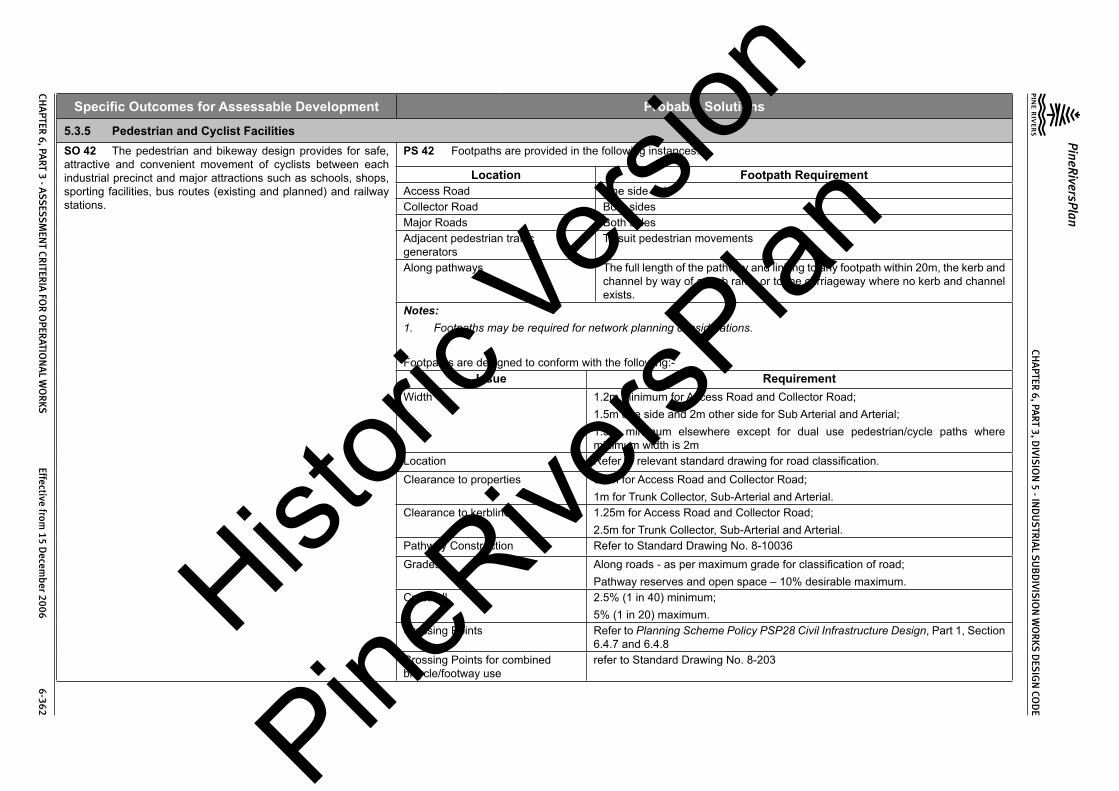
CHA
PTER 6, PA
RT 3, DIVIS
ION
5 - IND
US
TRIA
L SU
BD
IVISIO
N W
OR
KS DES
IGN
COD
E
PineRiversPlan
CHA
PTER 6, PA
RT 3 - ASS
ESSM
ENT CR
ITERIA
FOR
OPER
ATION
AL W
OR
KS Effective from
15 Decem
ber 2006 6-362
Specific Outcomes for Assessable Development Probable Solutions
5.3.5 Pedestrian and Cyclist FacilitiesSO 42 The pedestrian and bikeway design provides for safe, attractive and convenient movement of cyclists between each industrial precinct and major attractions such as schools, shops, sporting facilities, bus routes (existing and planned) and railway stations.
PS 42 Footpaths are provided in the following instances:
Location Footpath RequirementAccess Road One side onlyCollector Road Both sidesMajor Roads Both sidesAdjacent pedestrian traffic generators
To suit pedestrian movements
Along pathways The full length of the pathway and linking to any footpath within 20m, the kerb and channel by way of a kerb ramp or to the carriageway where no kerb and channel exists.
Notes:1. Footpaths may be required for network planning considerations.
Footpaths are designed to conform with the following:-Issue Requirement
Width 1.2m minimum for Access Road and Collector Road;1.5m one side and 2m other side for Sub Arterial and Arterial;1.5m minimum elsewhere except for dual use pedestrian/cycle paths where minimum width is 2m
Location Refer to relevant standard drawing for road classification.Clearance to properties 0.8m for Access Road and Collector Road;
1m for Trunk Collector, Sub-Arterial and Arterial.Clearance to kerbline 1.25m for Access Road and Collector Road;
2.5m for Trunk Collector, Sub-Arterial and Arterial.Pathway Construction Refer to Standard Drawing No. 8-10036Grades Along roads - as per maximum grade for classification of road;
Pathway reserves and open space – 10% desirable maximum.Crossfall 2.5% (1 in 40) minimum;
5% (1 in 20) maximum.Crossing Points Refer to Planning Scheme Policy PSP28 Civil Infrastructure Design, Part 1, Section
6.4.7 and 6.4.8Crossing Points for combined bicycle/footway use
refer to Standard Drawing No. 8-203
Histori
c Vers
ion
PineRive
rsPlan

CHA
PTER 6, PA
RT 3, DIVIS
ION
5 - IND
US
TRIA
L SU
BD
IVISIO
N W
OR
KS DES
IGN
COD
E
PineRiversPlan
CHA
PTER 6, PA
RT 3 - ASS
ESSM
ENT CR
ITERIA
FOR
OPER
ATION
AL W
OR
KS Effective from
15 Decem
ber 2006 6-363
Specific Outcomes for Assessable Development Probable SolutionsChicanes are provided at the ends of all pathways to roads (refer Standard Drawing Nos. 8-60033, 8-60034 & 8-60036).Bike/footway terminations at Collector Roads or higher classification roads conform with Standard Drawing No. 8-60034.Bike/footway direct road crossings conform with Standard Drawing No. 8-60035.Detailed design of the footpaths conforms with Council’s Planning Scheme Policy PSP28 Civil Infrastructure Design, Part 1, Section 6.4.0.Bikeways are provided within and adjacent the site as indicated in Council’s Bikeways Plan or adopted local area plan. Detailed design of the bikeways conforms with Council’s Planning Scheme Policy PSP28 Civil Infrastructure Design, Part 1, Section 6.5.0.
SO 43 As constructed information is provided after completion of the subdivision works.
PS 43 As constructed information is provided after completion of the subdivision works.
5.3.6 Public TransportSO 44 The road design provides for potential bus routes including safe convenient stops and, where necessary, bus turnaround areas.
PS 44 Bus routes are designed to conform with the following:-
Issue RequirementReserve width 20m minimumCarriageway width 11m minimumGrade 12% general maximum;
16% absolute maximum over short distancesSpeed control by street alignment onlyDesign vehicle Coach (tourist bus)Turning Single movement turns onlyBus stops are provided at 400m maximum spacing and integrated with the street and pedestrian network. Fully indented bus bays are provided on Sub-Arterial and Arterial Roads with detailed design conforming with Planning Scheme Policy PSP28 Civil Infrastructure Design, Part 1, Section 3.12.2.
SO 45 The road design caters for the extension of existing and future public transport routes to provide sufficient services that are convenient and accessible to the community.
PS 45 The road design provides for extension of existing and future public transport routes.
SO 46 As constructed information including test certificates for material quality (if required) and compaction is provided after completion of the subdivision works.
PS 46 As constructed information including test certificates for material quality (if required) and compaction is provided after completion of the subdivision works.
5.3.7 Public Open SpaceSO 47 Public open space has barriers to its road frontage to prevent access by unauthorised vehicles.
PS 47 The public open space is provided with log barriers designed along their road frontage in accordance with Council’s Planning Scheme Policy PSP28 Civil Infrastructure Design, Part 1, Section 6.14.0 and Standard Drawing No. 8-70003.
SO 48 Public open space that is intended to be used for local neighbourhood park includes a sufficiently level area that is suitable for non-organised recreation and passive relaxation including small children’s playgrounds and appropriate landscaping.
PS 48 Public open space that is intended to be used for local neighbourhood park contains one area, constructed if necessary, not less than 15m x 15m with a slope less than 5%.
Histori
c Vers
ion
PineRive
rsPlan

CHA
PTER 6, PA
RT 3, DIVIS
ION
5 - IND
US
TRIA
L SU
BD
IVISIO
N W
OR
KS DES
IGN
COD
E
PineRiversPlan
CHA
PTER 6, PA
RT 3 - ASS
ESSM
ENT CR
ITERIA
FOR
OPER
ATION
AL W
OR
KS Effective from
15 Decem
ber 2006 6-364
Specific Outcomes for Assessable Development Probable SolutionsSO 49 As constructed information including test certificates for material quality (if required) is provided after completion of the subdivision works.
PS 49 As constructed information including test certificates for material quality (if required) is provided after completion of the subdivision works.
5.3.8 UtilitiesSO 50 Development only occurs in locations where there are adequate services and capacity for the desired use.
PS 50 The design of water supply infrastructure including water mains, pumping stations, pressure mains and associated works complies with the relevant Queensland Government Department’s Guidelines for Planning and Design of Urban Water Supply Schemes, Council’s Standard Drawings and Council’s Planning Scheme Policy PSP28 Civil Infrastructure Design, Part 3. The design of water supply infrastructure includes all works internal and any works external required to ensure that all new and existing lots maintain adequate water supply at all times.The design of sewerage infrastructure including sewer mains, pumping stations, pressure mains and associated works complies with the relevant Queensland Government Department’s Guidelines for Planning and Design of Sewerage Schemes, Council’s standard drawings and Council’s Planning Scheme Policy PSP28 Civil Infrastructure Design, Part 4. The design of sewerage infrastructure includes all works internal and any works external required to ensure that all new and existing lots are provided with a service at all times within the capacity of the system.The design of the electrical reticulation is in accordance with ENERGEX Specification URD Underground Residential Distribution.
5.3.8(a) Water SupplySO 51 Where lots are intended to be provided with water supply the design and construction of the associated infrastructure and connections is provided in a safe, cost-effective, coordinated and efficient manner that supports sustainable development practices.
PS 51 Staged construction of water supply infrastructure is designed so that each stage is self supporting at the completion of construction of that stage.Water supply infrastructure materials and construction complies with Council’s Planning Scheme Policy PSP28 Civil Infrastructure Design, Part 3, Section 4.The minimum water main size is 100mm diameter.
SO 52 Water supply infrastructure is easily controlled and accessed for maintenance and repair.
PS 52 Water mains are provided along one side of all industrial streets (minimum) to the boundaries of the development site.Water mains are provided on both sides of all Major Roads and divided roads.Water mains are located within service corridors shown on the following standard drawings:-
Street Classification Standard Drawing No.Access Road and Collector Road 8-10016Sub Arterial and Arterial 8-10013In special circumstances (e.g. infill development where existing services are on Council’s previous service allocations – refer to Standard Drawing 8-0049), the services are placed on an alternative alignment.Service connections are not made to water mains 250mm diameter and above.Fire hydrants are provided at intervals (measured within the road reserve) not exceeding 80m, at high points (for air release) and at the ends of mains (use a duckfoot bend).Scours are provided at all low points, generally discharging into drainage structures.Fittings and valves at road intersections are contained in the verge and are 500mm clear of the back of the kerb.The water supply system is designed to limit the static head to 80m maximum. Where approved by Council’s engineer, pressure reducing valves are designed and installed to limit the static head to 80m maximum.
Histori
c Vers
ion
PineRive
rsPlan

CHA
PTER 6, PA
RT 3, DIVIS
ION
5 - IND
US
TRIA
L SU
BD
IVISIO
N W
OR
KS DES
IGN
COD
E
PineRiversPlan
CHA
PTER 6, PA
RT 3 - ASS
ESSM
ENT CR
ITERIA
FOR
OPER
ATION
AL W
OR
KS Effective from
15 Decem
ber 2006 6-365
Specific Outcomes for Assessable Development Probable SolutionsWater supply infrastructure is contained within roads or other public reserves. In exceptional circumstances Council may accept water mains through private land providing an appropriate easement, not less than 3m wide, is registered in Council’s favour. The water main is constructed centrally within the easement.Sufficient valves are provided, generally on street corners, to limit the area of any shut-off to within the following:-• 40 lots or premises for 100mm and 150mm mains; and• 50 lots or premises for 225mm mains.• Valves in the shut-off area are limited to a maximum of six.Water supply infrastructure is designed and constructed in accordance with the following standard drawings:-
Item Standard Drawing No.Hydrant and Valve Installations 8-40002Pavement Markers and Delineators 8-40003Hydrant, Valve and Mains Marker Posts 8-40004Thrust Block Details 8-40006Air Valve Installation Details 8-40007Air Valve Sizing 8-40008Scour Outlets 8-40009Trench Details 8-40010Section Valve Pits and Interconnection Pits 8-40011Pressure Reducing Valve Pits 8-40012 & 8-40013Pressure Gauge Installations 8-40014Offtakes from Mains 8-40015Property Service Conduits 8-40016Service tappings are constructed using ductile iron pre-tapped fittings for every lot. For pipe diameters where re-tapped fittings are not manufactured, conventional tapping bands are used.Water supply conduits are provided for across road house connections for the full width of the carriageway and concrete footpaths.Water supply conduits are provided for the full length of the accessway to rear allotments.Kerb marker plates are provided to indicate the location of property service conduits.Concrete thrust blocks are provided at all locations where there is unbalanced hydraulic load including all bends (horizontal and vertical), tees, angle branches, crosses, dead ends and reducers. Thrust blocks are contained within the service allocation.Histori
c Vers
ion
PineRive
rsPlan

CHA
PTER 6, PA
RT 3, DIVIS
ION
5 - IND
US
TRIA
L SU
BD
IVISIO
N W
OR
KS DES
IGN
COD
E
PineRiversPlan
CHA
PTER 6, PA
RT 3 - ASS
ESSM
ENT CR
ITERIA
FOR
OPER
ATION
AL W
OR
KS Effective from
15 Decem
ber 2006 6-366
Specific Outcomes for Assessable Development Probable SolutionsWater mains are provided with the following cover:-
Main Diameter (mm)
CoverVerges & Accessway Urban Road Carriageway(1) State controlled
Roads100 – 200 600 Greater of 750 or pavement
thickness + 1501200
225 – 375 750 Greater of 900 or pavement thickness + 150
1200
>375 1000 Greater of 1000 or pavement thickness + 150
1200
Notes:1. Where Council’s Engineer approves a reduced cover, the water main is constructed of ductile iron pipe (minimum
Class K9).Water mains are not laid under stormwater pipes, sewerage mains or electricity conduits.For water mains 300mm diameter and larger subsoil drains are provided from low points preferably draining to stormwater drainage structures.Water mains maintain the following minimum clearances to existing and future services:(1) horizontally where the water main runs along the adjacent service for > 1m:– 800mm;(2) horizontally where the water main runs along the adjacent services for < 1m:- 150mm;(3) vertically:- 150mm.Connection to Council’s water supply system is not provided until adequate water supply can be maintained at all times and the new mains are disinfected and watertight. Tests certificates (not older than 10 days at the time of connection) are provided to confirm the new mains have been satisfactorily disinfected prior to connection to Council’s water supply system. The mains are pressure tested and test certificates are provided to confirm that the new mains are watertight prior to connection to Council’s water supply system.
SO 53 Water mains provides multiple flow routes for fire fighting and water quality issues.
PS 53 Water mains are constructed with the maximum number of cross connections, including connections through all pathways.
SO 54 The water supply system for the proposed development is planned to conform with Council’s broad infrastructure plan for the water supply zone.
PS 54 The water supply system for the proposed development aligns with Council’s broad infrastructure plan for the water supply zone.
5.3.8(b) SewerageSO 55 Where lots are intended to be provided with reticulated sewerage the design and construction of the associated infrastructure and connections is provided in a safe, cost-effective, coordinated and efficient manner that supports sustainable development practices.
PS 55 Staged construction of sewerage infrastructure is designed so that each stage is self supporting and properly served at the completion of construction of that stage.Sewerage infrastructure design complies with Council’s Planning Scheme Policy PSP28 Civil Infrastructure Design, Part 4.
Histori
c Vers
ion
PineRive
rsPlan

CHA
PTER 6, PA
RT 3, DIVIS
ION
5 - IND
US
TRIA
L SU
BD
IVISIO
N W
OR
KS DES
IGN
COD
E
PineRiversPlan
CHA
PTER 6, PA
RT 3 - ASS
ESSM
ENT CR
ITERIA
FOR
OPER
ATION
AL W
OR
KS Effective from
15 Decem
ber 2006 6-367
Specific Outcomes for Assessable Development Probable SolutionsFor normal sewer reticulation design the following parameters are used:-
Item Design ValueDemand 15 equivalent tenements per hectare.Occupancy rate per tenement 3.29 equivalent persons (EP)Average Dry Weather Flow (ADWF) 250 litres/EP/dayMaximum Possible Flow (C1)(a) sewers serving < 1,000 EP(b) sewers serving >23,000 EP
(a) 5 times ADWF(b) 3 times ADWF
Infiltration Allowance (IA) 250 litres/EP/dayMaximum Design Flow (MDF) Maximum Possible Flow + Infiltration Allowance (C1 + IA)Sewerage infrastructure materials and construction complies with Council’s Planning Scheme Policy PSP28 Civil Infrastructure Design, Part 4, Section 4.The sewerage system through the site has sufficient capacity to convey the ultimate flows from all upstream properties when they are fully developed.Sewer pipes are sized in accordance with AS2200. The minimum flow velocity in any sewer is 0.6m/s based on ADWF. Sewers are designed to carry MDF at a depth not exceeding ¾ of the pipe diameter.The minimum sewer main size is 150mm diameter.Sewers are designed and constructed to serve the entire area of each lot.House drains are graded (around the perimeter of the building envelope) at 1 in 40 with a minimum cover of 600mm except for control allotments where a grade of 1 in 60 with a minimum cover of 400mm is used.Sewers are designed to extend to the boundaries of the site in order to serve all upstream areas within the catchment.In flat areas, sewers are designed to serve properties on both sides of the sewer.Sewers are designed to follow the land’s natural fall as far as possible.The minimum grade on sewer mains for lots is as follows:
Sewer Diameter (mm) Minimum Grade(1)
150 1 in 100 for first 3 lots, 1 in 150 thereafter225 1 in 290300 1 in 420375 1 in 570450 1 in 730525 1 in 900600 1 in 1000675 1 in 1200750 1 in 1500
Histori
c Vers
ion
PineRive
rsPlan

CHA
PTER 6, PA
RT 3, DIVIS
ION
5 - IND
US
TRIA
L SU
BD
IVISIO
N W
OR
KS DES
IGN
COD
E
PineRiversPlan
CHA
PTER 6, PA
RT 3 - ASS
ESSM
ENT CR
ITERIA
FOR
OPER
ATION
AL W
OR
KS Effective from
15 Decem
ber 2006 6-368
Specific Outcomes for Assessable Development Probable SolutionsNotes:1. Sewers are designed on steeper grades where possible.The minimum drop through a manhole is the greater of 40mm or the difference between downstream and upstream pipe diameters.
Steep sewers on grades exceeding 1 in 15 are provided with concrete stops (refer to Standard Drawing No. 8-50008) at the following spacing:-Pipe Diameter
(mm)General
Maximum Grade
Maximum Spacing of Concrete Stops (m)VC Pipe Other than VC Pipe
150 1 in 6 2 6225 1 in 10 2 6300 or greater 1 in 15 2 6Sewers steeper than 1 in 4 are only approved by Council’s engineer in special circumstances and providing the manufacturer’s recommended maximum flow velocity is not exceeded. No sewer has a grade steeper than 1 in 3.Sewer mains are provided with the following cover:
Location Minimum Cover (mm)House connection branches in lots 600
Sewer mains in lots:(a) front of lot
(b) elsewhere in the lot
(a) greater of 250 below invert of kerb and channel or 600 below future driveway(1)
(b) 600Sewer mains in road verges 900Sewer mains under road pavements 1200
Notes:1. Determine using driveway access as per Standard Drawing No. 8-10008.The minimum clearance between the sewer and adjacent services/pipes is 300mm. Where Council’s engineer has approved a reduced clearance for a sewer crossing another service, the crossing sewer is constructed using a full length (5.5m) of Class 12 DICL pipe.
House connections are only made to sewers where the depth to invert does not exceed 3m. A shallower second main is provided for house connections where the sewer depth (to invert) exceeds 3m.Vitrified clay pipes (Class 4) are only used for sewers in industrial areas.Sewer and/or roof and allotment drainage lines are located on no more than 2 boundaries of a lot.Sewer mains are not located along the side boundary of lots that are less than 19m wide at any point.
Histori
c Vers
ion
PineRive
rsPlan

CHA
PTER 6, PA
RT 3, DIVIS
ION
5 - IND
US
TRIA
L SU
BD
IVISIO
N W
OR
KS DES
IGN
COD
E
PineRiversPlan
CHA
PTER 6, PA
RT 3 - ASS
ESSM
ENT CR
ITERIA
FOR
OPER
ATION
AL W
OR
KS Effective from
15 Decem
ber 2006 6-369
Specific Outcomes for Assessable Development Probable SolutionsWhere the finished surface slope of a lot exceeds 1 in 10, the sewer main depth is increased to allow for future site earthworks.Sewer mains are located along the front or rear boundary of the lot in order to maximise access to the infrastructure.Trunk sewer mains of 300mm diameter and greater are not located in lots.Existing on-site sewerage systems that are made redundant by the development are demolished or removed from the site.Sewer manholes are provided at the following locations:-(1) changes in direction;(2) changes of grade;(3) intersections of sewers;(4) changes of sewer diameter;(5) changes of sewer pipe material; and(6) ends of sewer lines, except where the line section does not exceed 30m in length and no more than 2 house connections are made to the line.Manhole spacing (centre to centre) does not exceed 90m for sewer lines up to 450mm diameter and 120m for greater than 450mm diameter.Type 1 manholes are used for sewer lines up to 375mm diameter and up to 6m sewer depth.Precast manholes are not used where:-(1) the sewer line receives pumped flows;(2) the sewer line is > 375mm diameter;(3) the manhole depth exceeds 6m;(4) saturated ground conditions are likely; or(5) the manhole is located near a creek bank which is likely to be susceptible to erosion.The top of the manhole ring is at the following finished levels:-(1) 600mm above ground in unmaintained areas;(2) 100mm above finished surface level in maintained open space and private lots;(3) 25mm above finished surface level in road verges; and(4) flush with carriageway surface, trafficable areas and concrete paths.Where possible, the top of manholes are above the 20 year ARI flood level.Bolt down manhole covers are used near creek banks, in flood prone areas (i.e. below 20 year ARI flood level) in parks and reserves and public open space.Control manholes at pump stations are within 10m distance of the station except where approved otherwise by Council’s engineer.Wherever practicable, sewer lines are located within lots on a 1.5m alignment from the front boundary. In special circumstances only, the following alternative alignments within the lots are used:(1) 1.5m rear lot boundary; and(2) 1m from the side lot boundary.
Histori
c Vers
ion
PineRive
rsPlan

CHA
PTER 6, PA
RT 3, DIVIS
ION
5 - IND
US
TRIA
L SU
BD
IVISIO
N W
OR
KS DES
IGN
COD
E
PineRiversPlan
CHA
PTER 6, PA
RT 3 - ASS
ESSM
ENT CR
ITERIA
FOR
OPER
ATION
AL W
OR
KS Effective from
15 Decem
ber 2006 6-370
Specific Outcomes for Assessable Development Probable SolutionsIn special circumstances Council’s engineer may approve alternative sewer alignments outside the building envelope.Sewer lines do not cross lot boundaries at acute angles.Where inter-allotment drainage is provided, the sewer line is located between the drainage line and the lot boundary. The house connection branch extends 1m beyond the drainage line.All parks and reserves are provided with a sewerage connection unless approved otherwise by Council’s engineer.Manholes are located 1m upstream of lot boundaries except where the total fall across the lot along the sewer line exceeds 2m. Where the total fall across the lot along the sewer line exceeds 2m, the manhole is located 1m downstream of the lot boundary.Manholes do not straddle lot boundaries.The angle between incoming sewer lines and outlet sewer lines is 60o or greater.A maximum of three (3) inlet sewers or house connection inlets are made to any manhole.House connections are made to manholes where ever practicable.House connection branches (other than to manholes) are located between 1m and 1.2m upstream of lot boundaries at the lowest part of the lot.House connection branch inverts are not deeper than 1m. In special circumstances Council’s engineer may approve a greater depth (up to 1.5m) to control the whole lot.The maximum length of house connection branch from a sewer in an adjoining lot is 5m. with the branch extending a minimum of 1m into the lot being served.The top of the sewage pump station is 100mm above the 20 year ARI flood level.The bottom of the switchboard for the sewage pump station is 300mm above the 100 year ARI flood level.The sewage pump station is contained within a secure fenced compound.The sewage pump station is provided with appropriate ventilation.The sewage pump station is provided with a water service including a reduced pressure zone valve.Appropriate measures are provided to prevent sewage from becoming septic where the detention time exceeds six (6) hours.Sewage pumps are the non-clogging submersible type pump.Flow meters are provided on the discharge line from the pump station.Telemetry is provided to the sewage pump station.Flow meters and telemetry equipment is housed in weatherproof enclosures.The potential for sewage overflows from sewage pump stations is minimised using appropriately designed overflow storage or other means approved by Council’s engineer.The number and length of pressure mains is minimised as far as practicable.Sewer pressure mains are located in road verges of the opposite side to water supply mains.Sewer pressure mains have the following cover:(1) 1200mm under carriageways;(2) 1000mm elsewhere.
Histori
c Vers
ion
PineRive
rsPlan

CHA
PTER 6, PA
RT 3, DIVIS
ION
5 - IND
US
TRIA
L SU
BD
IVISIO
N W
OR
KS DES
IGN
COD
E
PineRiversPlan
CHA
PTER 6, PA
RT 3 - ASS
ESSM
ENT CR
ITERIA
FOR
OPER
ATION
AL W
OR
KS Effective from
15 Decem
ber 2006 6-371
Specific Outcomes for Assessable Development Probable SolutionsSewer pressure mains are not laid within 1.5m of parallel potable water supply mains. In special circumstances Council’s engineer may approve a lesser separation providing the sewer pressure main obvert is 500mm below the water supply main.Sewer pressure mains have section valves at not greater than 500m spacing.Scour valves are located at all low points in the pressure main.Vents are provided to all high points in the pressure main.Odour and corrosion control measures are provided, as necessary, to pressure mains.Pressure mains discharge into vented discharge manholes whose immediate downstream line does not have any house connection branches.Maintenance vehicle access is provided to the sewage pump station in accordance with the following:-
Item RequirementDesign Vehicles (a) Medium Rigid Vehicle
(b) Articulated Tanker when oxygen injection is usedAccess Track Maximum Grade (a) 1 in 10 for gravel access;
(b) 1 in 6 for sealed accessAccess Track Minimum Width 3.5mAccess Track Drainage (a) No inundation in 5 year ARI storm;
(b) Trafficable in 10 year ARI stormSurfacing (a) Minor pump station with access grade < 1 in 10 – gravel surface(1);
(b) Minor pump station with access grade >1 in 10 – sealed;(c) Major pump stations – sealed.
Pavement Design (a) Minor pump station - as per DG 06 using 2.3 x 10³ ESAs;(b) Major pump station - as per DG 06 using 4.5 x 10³ ESAs
Pump Maintenance (a) Level area adjacent pump well for a crane truck;(b) Vent pole, switchboard and other equipment clear of working area of crane truck.
Notes:-1. Where the access is adjacent to residential properties or Council’s engineer considers that the amenity of nearby
residents may be affected by dust, the access is sealed.Sewerage infrastructure is designed and constructed in accordance with the following standard drawings:
Item Standard Drawing No.Sewer Manholes 8-50002, 8-50003, 8-50004, 8-50006 & 8-50007Sewer Pipelines 8-50008House Connection Branches 8-50009Sewage Pump Stations 8-50015, 8-50016, 8-50017, 8-50018, 8-50019, 8-50021, 8-50023, 8-50024,
8-50025, 8-50026, 8-50040, 8-50041, 8-50042, 8-50043, 8-50050, 8-50051, 8-50052, 8-50053, 8-50100, 8-50101, 8-50102, 8-50103, 8-50110, 8-50111, 8-
50112, 8-50113, 8-50120, 8-50121, 8-50122, 8-50123, 8-50140 & 8-50141
Histori
c Vers
ion
PineRive
rsPlan

CHA
PTER 6, PA
RT 3, DIVIS
ION
5 - IND
US
TRIA
L SU
BD
IVISIO
N W
OR
KS DES
IGN
COD
E
PineRiversPlan
CHA
PTER 6, PA
RT 3 - ASS
ESSM
ENT CR
ITERIA
FOR
OPER
ATION
AL W
OR
KS Effective from
15 Decem
ber 2006 6-372
Specific Outcomes for Assessable Development Probable SolutionsSewer Valves 8-50027Sewer Rising Mains 8-50028, 8-50029Connection to Council’s sewerage system is not provided until the new mains are clean and watertight. The mains and manholes are vacuum tested and test certificates are provided to confirm that the new mains and manholes are watertight.
SO 56 Adequate buffers are provided between sewerage transportation and treatment facilities and dwellings to protect residential amenity and health.
PS 56 Sewage pump stations are no closer than 100m to the nearest existing or future residential lot. In special circumstances Council’s engineer may approve a lesser buffer distance.
SO 57 The sewerage transportation system for the proposed development is planned to conform with Council’s broad infrastructure plan for the catchment.
PS 57 The sewerage transportation system conforms with Council’s infrastructure plan for the sewerage scheme.
5.3.8(c) Recycled WaterSO 58 Where Council plans to supply recycled water, developments make provision for these future recycled water supply systems.
PS 58 An appropriate service corridor is provided for future recycled water supply.
5.3.8(d) ElectricitySO 59 Where lots are intended to be provided with reticulated electricity the service is underground with design and construction of the associated infrastructure and connections being provided in a safe, cost-effective, coordinated and efficient manner that supports sustainable development practices.
PS 59 Underground electrical reticulation is provided in industrial developments.Crossings of existing roads are bored. In special circumstances, Council’s engineer may approve other methods including trenched construction.Road crossing are not at acute angles to the road centreline.Electrical crossings occur at alternate common lot boundaries to water service crossings.Electrical crossings are within the area defined as an intersection under State Legislation or are diagonally across intersections to enable 11kV cables to be installed without joints.Pillars are provided at all entry points to private property and located at side boundaries of the lot.Pillars are located on alternate common lot boundaries to water meters and hydrants.
5.3.8(e) Street Lighting – (excludes State-controlled roads)SO 60 All roads are provided with street lighting which is designed and constructed to provide a safe, cost-effective, coordinated and efficient system that supports sustainable development practices.
PS 60 All works are designed and constructed to AS1158, Public Lighting Code, 1986, Austroads Guide to Traffic Engineering Practice – Part 12, Roadway Lighting, 1988 and ENERGEX standards and approval.Street lighting poles and luminaries are standard ENERGEX patterns under Rate 1 Tariff in roads and Rate 2 Tariff in other than roads.Street light poles are located on standard alignments in accordance with the following standard drawings:-
Street Classification Standard Drawing No.Access Road and Collector Road 8-10016Sub Arterial and Arterial 8-10013Street lights are generally located opposite common lot boundaries and are positioned to minimise conflicts with vehicle movements.
Histori
c Vers
ion
PineRive
rsPlan

CHA
PTER 6, PA
RT 3, DIVIS
ION
5 - IND
US
TRIA
L SU
BD
IVISIO
N W
OR
KS DES
IGN
COD
E
PineRiversPlan
CHA
PTER 6, PA
RT 3 - ASS
ESSM
ENT CR
ITERIA
FOR
OPER
ATION
AL W
OR
KS Effective from
15 Decem
ber 2006 6-373
Specific Outcomes for Assessable Development Probable SolutionsStreet lights are located to minimise the risk of damage from errant vehicles at intersections, bends and speed control devices and by oversize vehicles which must necessarily leave the carriageway to manoeuvre in turn around areas, speed control devices and some intersections.Street light poles that are in vulnerable locations (e.g. small islands or roundabouts) use frangible type poles.Colour consistency is maintained as far as practicable.Lighting designs are prepared in accordance with the Lighting Category specified below:
Road Classification Lighting CategoryArterial A2Sub Arterial A3Collector Road B2(1)
Access Road B2Pathways between lots B2General pathways in open space areas C3(2)
Commuter Links C2(2)
Other locations Subject to individual assessmentNotes:1. A higher category may be appropriate where a Collector Road is a through road or where there are land uses such
as retailing or entertainment.2. Lighting standard may vary to suit local conditions.3. Theaboveclassificationalsoappliestocommunitytitledevelopments.4. Power supply to pathway lighting is underground.5. Pathway lighting is Rate 2 Tariff.A light is provided to each end of pathways (may be street light), at every bend or change of alignment and at every obstruction or hazard (e.g. bridge, stairway, etc).Pedestrian underpasses or tunnels are lit in accordance with the relevant standard.Crossing points of pathways across roads or streets are lit in accordance with the relevant street standard.In addition to the “through” street lighting above, additional special lighting is provided, as necessary, at the following locations:-(1) intersections;(2) roundabouts;(3) sharp bends;(4) traffic control devices;(5) pedestrian crossings;(6) cul de sac turn around areas; and(7) bridges.
Histori
c Vers
ion
PineRive
rsPlan

CHA
PTER 6, PA
RT 3, DIVIS
ION
5 - IND
US
TRIA
L SU
BD
IVISIO
N W
OR
KS DES
IGN
COD
E
PineRiversPlan
CHA
PTER 6, PA
RT 3 - ASS
ESSM
ENT CR
ITERIA
FOR
OPER
ATION
AL W
OR
KS Effective from
15 Decem
ber 2006 6-374
Specific Outcomes for Assessable Development Probable Solutions
5.3.8(f) TelecommunicationsSO 61 All lots are able to be provided with a telecommunications service which is designed to give a safe, cost effective, coordinated and efficient system that supports sustainable development practices.
PS 61 Application for telecommunications reticulation is made and pre-provisioning confirmation is received prior to subdivision works commencing.Telecommunications reticulation (i.e. conduits and pits) is installed in accordance with Telstra standards and a provisioning confirmation is provided for the works.
5.3.8(g) Alterations and RelocationsSO 62 Any alteration or relocation in connection with or arising from the development to any service, installation, plant, equipment or other item belonging to or under the control of the telecommunications authority, electricity authorities, the Council or other person engaged in the provision of public utility services, is carried out prior to the approval of the plan of subdivision.
PS 62 No solution provided.
5.3.8(h) As Constructed InformationSO 63 As constructed information including test certificates for material quality (if required) and compaction is provided after completion of the subdivision works.
PS 63 As constructed information including test certificates for material quality (if required) and compaction is provided to the relevant authority upon completion of the subdivision works
Histori
c Vers
ion
PineRive
rsPlan

CHAPTER 6, PART 3, DIVISION 6 - COMMERCIAL SUBDIVISION WORKS DESIGN CODE
PineRiversPlan
CHAPTER 6, PART 3 - ASSESSMENT CRITERIA FOR OPERATIONAL WORKS Effective from 15 December 2006 6-375
Division 6 Commercial Subdivision Works Design Code6.1 Overall Outcome
To create commercial subdivision development that:-(1) Provides safe, functional, convenient and attractive commercial areas;(2) Ensures that sites are managed during construction to minimise adverse impacts to the
environment and on the health and amenity of residents and premises;(3) Ensures that sites are managed during construction to minimise adverse traffic impacts to
existing roads;(4) Ensures that earthworks design and construction is suitable for the intended use of the land
and that adverse impacts to the environment and on the health and amenity of residents is minimised;
(5) To design and construct road networks which provide an optimum combination of Safety, Amenity, Convenience, Economy and Environment for residents, road and street users, and the community generally;
(6) To design and construct stormwater management systems which provide an optimum combination of Safety, Amenity, Convenience, Economy and Environment for residents and the community generally;
(7) To collect and convey stormwater from a catchment to its receiving waters with minimal nuisance, danger or damage, and at a development and environmental cost which is acceptable to the community as a whole;
(8) Provides for the convenience and safety for pedestrians and vehicular traffic during frequent or nuisance stormwater flows;
(9) Limits flooding of public and private property, both within the catchment and downstream, to ensure that flood inundation occurs on rare occasions only;
(10) Ensures a reasonable level of pedestrian and vehicular traffic safety and accessibility;(11) Minimises pollutant inflows to the receiving waters, and controls scour and depositional
effects;(12) Controls and temporarily detain within each catchment as much incident rainfall and runoff as
possible and to reduce the impact of urbanisation;(13) Adequately protects people, the natural environment and the built environment at an acceptable
level of risk;(14) Integrates stormwater management solutions with other uses and the natural environment;(15) Provides safe, convenient and legible networks for walking and cycling to points of attraction
and beyond the development while preserving maximum visual amenity;(16) Ensures that opportunities exist for choice in the mode of transport and provides for cost-
effective and energy efficient public transport services that are accessible and convenient to the community;
(17) Provides public open space that meets user requirements for outdoor recreational and social activities and for landscaping that contributes to the identity, environmental health and safety of the community;
(18) Ensures, where appropriate, as many existing trees are retained as possible to keep the original character of the land and provide shelter and food for endemic flora and fauna;
(19) Provides for commercial lots that are adequately serviced with sewerage, water supply, electricity, street lighting and communications services in a timely, cost effective, coordinated and efficient manner that supports sustainable development practices, and is in accordance with the desired character of the locality;
(20) Ensures that the water supply and sewerage service provision complies with the relevant state guidelines for design;
(21) Minimises the impact on amenity due to provision of water supply and sewerage infrastructure;
(22) Ensures that all sewerage, water supply, electricity, street lighting and communications services that require relocation and/or alterations as a result of commercial development are carried out in a timely, cost effective, coordinated and efficient manner;
(23) Provides the design requirements for all types of commercial lots within the Shire; and(24) Provides designers with the relevant specific outcomes and where possible, probable solutions
to achieve the design overall outcomes associated with the various elements of subdivision works design.
Histori
c Vers
ion
PineRive
rsPlan

CHAPTER 6, PART 3, DIVISION 6 - COMMERCIAL SUBDIVISION WORKS DESIGN CODE
PineRiversPlan
CHAPTER 6, PART 3 - ASSESSMENT CRITERIA FOR OPERATIONAL WORKS Effective from 15 December 2006 6-376
6.2 Compliance with the Commercial Subdivision Works Design CodeThis code applies to all operational works relating to development or reconfiguring of commercial land, but specifically excludes applications for access easements to a road, subdivision by lease and boundary relocations or realignments.
The application of the various specific outcomes will depend upon the size or scale of the proposed development. Some specific outcomes will not apply due to a particular design element not being part of the proposal (e.g. new road). In other instances it may be impractical to apply some specific outcomes, particularly for small infill developments.
6.3 Development RequirementsThe following are the design Elements relevant to commercial subdivision:(6.3.1) Managing Impacts During Construction(6.3.2) Earthworks(6.3.3) Road Networks (excludes State-controlled Roads)(6.3.4) Stormwater Management(6.3.5) Pedestrian & Cyclist Facilities(6.3.6) Public Transport(6.3.7) Public Open Space(6.3.8) Utilities
(6.3.8a) Water Supply(6.3.8b) Sewerage(6.3.8c) Recycled Water(6.3.8d) Electricity(6.3.8e) Street Lighting(6.3.8f) Telecommunications(6.3.8g) Alterations and Relocations(6.3.8h) As Constructed Information
Histori
c Vers
ion
PineRive
rsPlan

CHA
PTER 6, PA
RT 3, DIVIS
ION
6 - COM
MER
CIAL S
UB
DIVIS
ION
WO
RKS D
ESIG
N CO
DE
PineRiversPlan
CHA
PTER 6, PA
RT 3 - ASS
ESSM
ENT CR
ITERIA
FOR
OPER
ATION
AL W
OR
KS Effective from
15 Decem
ber 2006 6-377
Specific Outcomes for Assessable Development Probable Solutions
6.3.1 Managing Impacts During ConstructionSO 1 All development sites minimise as far as possible any adverse impact to the natural environment caused by erosion, siltation, incineration of cleared vegetation and rubbish.
PS 1 The development works incorporate temporary stormwater runoff, erosion and sediment controls and trash traps designed in accordance with Council’s Planning Scheme Policy PSP28 Civil Infrastructure Design, Part 2, Section 4.2.0 and 4.11.4, and Subdivisions Section Technical Note No. 6. The measures are adjusted on-site to maximise their effectiveness.Stormwater runoff, erosion and sediment controls are constructed prior to commencement of any clearing works wherever possible.All environmentally significant areas to be retained with the development are clearly delineated and fenced prior to development works commencing.
SO 2 All development works are carried out at times which minimise noise impacts to residents and other premises.
PS 2 All development works are carried out within the following times, unless otherwise approved in writing by Council’s engineer:(1) Monday to Friday (other than public holidays) between 7am and 6pm on the same day; and(2) Saturday (other than public holidays) between 7am and 12noon on the same day.No work is carried out on Sundays and public holidays.Variations to the above working hours may be approved if Council’s engineer considers that the work is unlikely to cause significant inconvenience or disruption to the public, or the work is unlikely to cause annoyance or inconvenience to occupants of adjacent properties.
SO 3 All development works are managed to minimise dust and siltation nuisance to residents and other premises.
PS 3 During construction, dust suppression measures (such as watering of the site) are implemented to protect nearby premises from dust pollution.
SO 4 All development works avoid the redirection of stormwater runoff where potential impacts to residents and other premises may occur.
PS 4 Temporary construction works do not pond or concentrate stormwater runoff in adjoining properties.Temporary construction works do not create nuisance or annoyance to adjoining premises as a result of altering the stormwater runoff pattern exiting the site.
SO 5 Construction traffic does not adversely impact on the amenity of existing residents and other premises.
PS 5 Construction traffic to and from the site uses the highest classification streets or roads where a choice of access routes is available.Where significant volumes of material are approved to enter or leave the site, a haul route is approved by Council.All materials associated with the development that are dropped, deposited or spilled on streets giving access to the site are removed and the streets are cleaned as soon as practicable after the event. Any damaged areas are repaired and reinstated to their previous condition.Where works are carried out on existing roads a traffic control plan is prepared in accordance with the Manual of Uniform Traffic Control Devices. All traffic control measures are properly erected and maintained during the works.Any access road to the site that has been affected by any material dropped, deposited or spilled on the road as a result of the construction processes associated with the site is cleaned and restored to its original condition.
SO 6 Construction traffic are controlled to ensure all traffic movements to and from the site are safe.
PS 6 All traffic movements to and from the site frontage are carried out in a safe manner. Traffic controls are used where site access is approved directly onto a Major Road.
SO 7 All clearing works are carefully undertaken to ensure the clearing is limited to the area of the approved infrastructure works, buildings areas and other areas approved in the development permit.
PS 7 Areas of significant vegetation, proposed park and open space areas and other areas of vegetation or individual trees designated to be retained with the development are temporarily fenced and flagged.
Histori
c Vers
ion
PineRive
rsPlan

CHA
PTER 6, PA
RT 3, DIVIS
ION
6 - COM
MER
CIAL S
UB
DIVIS
ION
WO
RKS D
ESIG
N CO
DE
PineRiversPlan
CHA
PTER 6, PA
RT 3 - ASS
ESSM
ENT CR
ITERIA
FOR
OPER
ATION
AL W
OR
KS Effective from
15 Decem
ber 2006 6-378
Specific Outcomes for Assessable Development Probable SolutionsSO 8 All cleared vegetation is disposed of in a manner which minimises, as far as practicable, nuisance and annoyance to existing premises.
PS 8 Where cleared vegetation is chipped or pit burned on site the location of these works is not less than 100m from any dwelling or commercial premises. All vegetation with a diameter below 400mm is chipped and stored on site in an approved location generally on park or public land. Vegetation with a diameter above 400mm is pit burned on site if a suitable location is available. The pit burn is generally carried out as one continuous operation.Chipping and/or pit burning is only undertaken when weather conditions are favourable.Burn pit locations are approved in writing by Council’s engineer and shown on the “as constructed” drawings.Cleared vegetation is not disposed of by above ground burning.
SO 9 All noxious weeds and other materials which are detrimental to the intended use of the land are removed and disposed of in a manner which minimises environmental impacts.
PS 9 All groundsel, noxious weeds, stumps, fallen trees, rubbish, car bodies, scrap metal and the like are removed and disposed of in a manner which minimises environmental impact.Stumps, fallen trees, undergrowth, buildings, structures, foundations and the like in existing and proposed park and open space areas are removed where directed by Council’s representative.
6.3.2 EarthworksSO 10 Earthworks design takes into account the slope of the ground, short and long-term slope stability, soft or compressible foundation soils, reactive soils, low density or potentially collapsing soils, existing fills and soil contamination that may exist on site.
PS 10 Investigation, planning and design including documentation is carried out in accordance with Australian Standard AS3798.All cut and fill batters are provided with appropriate scour, erosion protection and runoff control measures including catch drains at the top of batters and lined batter drains as necessary.All fill batters steeper than 1 (V) in 6 (H) in commercial lots are fully turfed to prevent scour and erosion.
SO 11 Filling is not placed on existing or proposed park unless specifically approved in writing by Council’s engineer.
PS 11 Filling is not placed on existing or proposed park unless specifically approved in writing by Council’s engineer.
SO 12 Filling is not placed below the 100 year ARI floodline for rivers and 50 year ARI floodline for creeks and other watercourses unless specifically approved in writing by Council’s engineer.
PS 12 Filling is not placed below the 100 year ARI floodline for rivers and 50 year ARI floodline for creeks and other watercourses unless specifically approved in writing by Council’s engineer.
SO 13 The site is properly prepared for earthworks. PS 13 The site is prepared in accordance with Australian Standard AS3798.
SO 14 Fill construction is carried out in a manner which ensures that the works meet the design requirements.
PS 14 The fill construction is carried out in accordance with Australian Standard AS3798.
SO 15 Unsuitable materials are not used in structural fill. PS 15 Materials used for structural fill conform with Australian Standard AS3798.
SO 16 Earthworks and trench backfill is properly compacted to suit the desired use of the site.
PS 16 The earthworks and trench backfill is compacted to the minimum relative compaction given in Table 5.1 of Australian Standard AS3798. The minimum frequency of field density tests is not less than that specified in Table 8.1 of Australian Standard AS3798.Any open drains, earth dams and wells on the site are drained, cleaned and filled as specified above.
SO 17 Steep rock slopes and batters are stable and low maintenance.
PS 17 Steep rock slopes and batters are inspected and certified for long-term stability by a suitably qualified and experienced geotechnical engineer. Stabilisation measures are provided, as necessary, to ensure long-term stability and low maintenance.
SO 18 As constructed information including test certificates for material quality (if required) and compaction is provided after completion of the subdivision works.
PS 18 As constructed information including test certificates for material quality (if required) and compaction is provided after completion of the subdivision works.
Histori
c Vers
ion
PineRive
rsPlan

CHA
PTER 6, PA
RT 3, DIVIS
ION
6 - COM
MER
CIAL S
UB
DIVIS
ION
WO
RKS D
ESIG
N CO
DE
PineRiversPlan
CHA
PTER 6, PA
RT 3 - ASS
ESSM
ENT CR
ITERIA
FOR
OPER
ATION
AL W
OR
KS Effective from
15 Decem
ber 2006 6-379
Specific Outcomes for Assessable Development Probable Solutions
6.3.3 Road Networks (excludes State-controlled Roads)SO 19 The road design and construction has a clear structure and component streets conform to their function in the network.SO 20 The road design and construction has clear physical distinctions between each type of street based on function, legibility, convenience, traffic volumes, vehicle speeds, public safety and amenity.SO 21 The road design and construction is integrated with the site design and accommodate the following primary functions:(1) access to lots;(2) on street car parking;(3) stormwater drainage paths (minor and major storms);(4) public transport on Collector Roads and Major Roads;(5) utility services location; and(6) setting and approach (streetscape and landscape).
PS 19 to PS 21 The Commercial Roads conform to the following:-Design Issue Collector Road Trunk Collector Road Major Road
Maximum Traffic Volume for Direct Frontage Access
3500 vpd 9000 vpd May not suitable (1)
Design Speed 40km/h (max.) 60km/h (max.) 60km/hMinimum verge Width 4.275m (2) (3) 5.5m (3) 7.5mMinimum Parking Lane Width (includes provision for cycles)
4.2m (4) 4.2m (4) 4.2m (4)
Minimum Through Lane Width 3.5 m 3.5 m 3.5mMinimum Median Widths:-(a) providing for sheltered turn lane(b) providing for pedestrian refuge(c) providing for traffic signals or
lighting poles(d) providing for small signs
(a) 6m(b) 2.5m(c) 2m
(d) 1.5m
(a) 6m(b) 2.5m(c) 2m
(d) 1.5m
(a) 6m(b) 2.5m(c) 2m
(d) 1.5mMinimum Road Reserve Width 15.4m plus verge and
median requirements15.4m plus verge and median requirements
15.4m plus verge and median requirements
Footpaths/Cyclepaths 1.5m wide (both sides) (5) 1.5m wide (both sides) (5) 2m wide (both sides) (5)
Maximum Grade 12% 12% 6.0%Minimum Grade 0.4% 0.4% 0.4%Notes:1. SubjecttoappropriatedesignforMajorDevelopments.Fortrafficvolumesexceeding12,000vpd,serviceroadsare
provided.Forminorinfilldevelopmentsfrontage,accessmaybepermittedwherethereisnoreasonablealternativeavailable.
2. CollectorStreetcontainwatermainsinbothsidesandthereforerequireaminimumvergewidthof4.275m.3. Greaterwidthisrequiredatbusbays.4. Allowsforparkingandcycling.5. Greaterwidthswillberequiredforcyclepaths–refertoCouncil’sBikewaysPlan.The roads accommodate appropriate corridors for all public utilities in accordance with Council’s standards.The road design is integrated with the site design.The detailed design of Commercial Roads conforms with Council’s Planning Scheme Policy PSP28 Civil Infrastructure Design, viz:
Histori
c Vers
ion
PineRive
rsPlan

CHA
PTER 6, PA
RT 3, DIVIS
ION
6 - COM
MER
CIAL S
UB
DIVIS
ION
WO
RKS D
ESIG
N CO
DE
PineRiversPlan
CHA
PTER 6, PA
RT 3 - ASS
ESSM
ENT CR
ITERIA
FOR
OPER
ATION
AL W
OR
KS Effective from
15 Decem
ber 2006 6-380
Specific Outcomes for Assessable Development Probable SolutionsRoad Design Issue Planning Scheme Policy PSP28 Civil Infrastructure Design
Reference – Collector & Trunk Collector RoadsGeometric Design Part 1 Sect 2.10.0Intersections Part 1 Sect 2.11.0 & 6.16.0Manoeuvring Areas Part 1 Sect 2.12.0Roundabouts Part 1 DG 01Landscape Construction on Road Reserves, Parks and Drainage Reserves
Part 1 DG 03
Signs and Road Marking Part 1 Sect 6.7.0Footpaths Part 1 Sect 6.4.0Bikeways Part 1 Sect 6.5.0Service Conduits Part 1 Sect 6.8.0Subsoil Drainage Part 1 Sect 6.9.0Safety Barriers Part 1 Sect 6.10.0Guide Posts Part 1 Sect 6.11.0Bridge and Culvert Widths Part 1 Sect 6.12.0Street and Pathway Lighting Part 1 Sect 6.13.0Park Barriers Part 1 Sect 6.14.0Retaining Walls Part 1 Sect 6.15.0Major Roads conform to the following:
Issue Sub-Arterial ArterialTraffic Volume (typical) 12,000 vpd 30,000 vpdDesign Speed (minimum) 80km/h 100km/hCarriageway Lanes 2 4Carriageway Width 10m (kerbed)(1) 2 x 8.5 m (kerbed)(1)
Verge Width (minimum.) 7.5m 8.5 mReserve Width (minimum) 25m (2) 40m (2)
Footpaths/Cyclepaths Both sides (3) Both sides (3)
Maximum Grade 7% 6%Minimum Grade 0.4% 0.4%Notes:1. Does not include cycle lanes.2. Greaterwidthrequiredatintersections.3. Cyclepathsmayberequiredinaccordancewithnetworkdesign.
Histori
c Vers
ion
PineRive
rsPlan

CHA
PTER 6, PA
RT 3, DIVIS
ION
6 - COM
MER
CIAL S
UB
DIVIS
ION
WO
RKS D
ESIG
N CO
DE
PineRiversPlan
CHA
PTER 6, PA
RT 3 - ASS
ESSM
ENT CR
ITERIA
FOR
OPER
ATION
AL W
OR
KS Effective from
15 Decem
ber 2006 6-381
Specific Outcomes for Assessable Development Probable SolutionsThe detailed design of Major Roads conforms with Council’s Planning Scheme Policy PSP28 Civil Infrastructure Design, viz:
Road Design Issue Planning Scheme Policy PSP28 Civil Infrastructure Design Reference
Design Philosophy Part 1 Sect 3.2.0Classification of Major Urban Roads Part 1 Sect 3.3.0Freeways Part 1 Sect 3.4.0Arterial Roads Part 1 Sect 3.5.0Sub-Arterial Roads Part 1 Sect 3.6.0Intersections Part 1 Sect 3.7.0 & 6.16.0Traffic Volume and Capacity Part 1 Sect 3.8.0Design Speed Part 1 Sect 3.9.0Cross Section Elements Part 1 Sect 3.10.0Geometric Design Part 1 Sect 3.11.0Bus Stops Part 1 Sect 3.12.0Pedestrian and Cyclist Facilities Part 1 Sect 3.13.0Aesthetics and Appurtenances Part 1 Sect 3.14.0Services Streets Part 1 Sect 3.15.0Roundabouts Part 1 DG 01Signs and Road Markings Part 1 Sect 6.7.0Footpaths Part 1 Sect 6.4.0Bikeways Part 1 Sect 6.5.0Service Conduits Part 1 Sect 6.8.0Subsoil Drainage Part 1 Sect 6.9.0Safety Barriers Part 1 Sect 6.10.0Guide Posts Part 1 Sect 6.11.0Bridge and Culvert Widths Part 1 Sect 6.12.0Street and Pathway Lighting Part 1 Sect 6.13.0Park Barriers Part 1 Sect 6.14.0Retaining Walls Part 1 Sect 6.15.0
Histori
c Vers
ion
PineRive
rsPlan

CHA
PTER 6, PA
RT 3, DIVIS
ION
6 - COM
MER
CIAL S
UB
DIVIS
ION
WO
RKS D
ESIG
N CO
DE
PineRiversPlan
CHA
PTER 6, PA
RT 3 - ASS
ESSM
ENT CR
ITERIA
FOR
OPER
ATION
AL W
OR
KS Effective from
15 Decem
ber 2006 6-382
Specific Outcomes for Assessable Development Probable SolutionsThe road cross-sections conform with Council’s standard drawings as follows:-
Road Classification Standard Drawing NumberCollector Street 8-10014 & 8-10008 modified to suit additional elements (parking lanes, bus bays and
medians as required)Trunk Collector Street 8-10015 & 8-10010 modified to suit additional elements (parking lanes, bus bays and
medians as required)Sub-Arterial Road 8-10006 & 8-10009 modified to suit additional elements (service streets or parking
lanes, bus bays and medians as required)Arterial Road 8-10007 & 8-10009 modified to suit additional elements (service streets or parking
lanes, bus bays and medians as required)Utility service allocations conform with Council’s standard drawings as follows:
Road Classification Standard Drawing NumberCollector Street 8-10011Trunk Collector Street 8-10012Sub-Arterial & Arterial 8-10013Access to allotments conforms with Council’s Planning Scheme Policy PSP28 Civil Infrastructure Design, Part 1, Section 6.2.0.The road pavement design conforms with Council’s Planning Scheme Policy PSP28 Civil Infrastructure Design, Part 1, DG 06.The works are constructed within tolerances given in Council’s Planning Scheme Policy PSP28 Civil Infrastructure Design, Part 1, DG 02, Appendix C.
SO 22 Intersections along Commercial Roads and Major Roads are safe and convenient.
PS 22 Intersection spacing (centreline – centreline) along a through road conforms with the following:-Intersecting
Road Location
Through RoadAccess Street & Collector Street
Trunk Collector Street
Sub-Arterial Road (1)
Arterial Road
On same side of through road
60m 100m 300m 500m
On opposite side of through road
40m 60m 300m 500m
Notes:1. InthecaseofSub-ArterialRoads,existinglandholdingsmayrequireintersectionatalesserspacing.Insuchcases
thefollowingabsoluteminimumspacingisused,butallturnsaccessmaynotbepermitted(ieleftin/leftoutonly):Intersections on same side 100mIntersections on opposite sides:• left – right stagger• right – left stagger
100m30m
Histori
c Vers
ion
PineRive
rsPlan
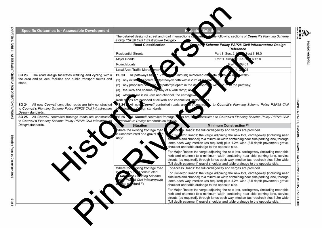
CHA
PTER 6, PA
RT 3, DIVIS
ION
6 - COM
MER
CIAL S
UB
DIVIS
ION
WO
RKS D
ESIG
N CO
DE
PineRiversPlan
CHA
PTER 6, PA
RT 3 - ASS
ESSM
ENT CR
ITERIA
FOR
OPER
ATION
AL W
OR
KS Effective from
15 Decem
ber 2006 6-383
Specific Outcomes for Assessable Development Probable SolutionsThe detailed design of street and road intersections conforms with the following sections of Council’s Planning Scheme Policy PSP28 Civil Infrastructure Design:-
Road Classification Planning Scheme Policy PSP28 Civil Infrastructure Design Reference
Residential Streets Part 1 Sect 2.11.0 & Sect 6.16.0Major Roads Part 1 Sect 3.7.0 & Sect 6.16.0Roundabouts Part 1 DG 01Local Area Traffic Management Part 1 DG 05
SO 23 The road design facilitates walking and cycling within the area and to local facilities and public transport routes and stops.
PS 23 All pathways have 1.2m wide (minimum) reinforced concrete paths linking up with:-(1) any existing concrete footpath/cyclepath within 20m of the pathway;(2) any proposed concrete footpath/cyclepath in the development within 20m of the pathway;(3) the kerb and channel by way of a kerb ramp; and(4) where there is no kerb and channel, the carriageway.Kerb ramps are provided at all kerb and channelled intersections.
SO 24 All new Council controlled roads are fully constructed to Council’s Planning Scheme Policy PSP28 Civil Infrastructure Design standards.
PS 24 All new Council controlled roads are fully constructed to Council’s Planning Scheme Policy PSP28 Civil Infrastructure Design standards.
SO 25 All Council controlled frontage roads are constructed to Council’s Planning Scheme Policy PSP28 Civil Infrastructure Design standards.
PS 25 All Council controlled frontage roads are fully constructed to Council’s Planning Scheme Policy PSP28 Civil Infrastructure Design standards as follows:
Situation Minimum Construction (1)
Where the existing frontage road is unconstructed or a gravel road only:-
For Access Roads: the full carriageway and verges are provided.For Collector Roads: the verge adjoining the new lots, carriageway (including near side kerb and channel) to a minimum width containing near side parking lane, through lanes each way, median (as required) plus 1.2m wide (full depth pavement) gravel shoulder and table drainage to the opposite side.For Major Roads: the verge adjoining the new lots, carriageway (including near side kerb and channel) to a minimum width containing near side parking lane, service streets (as required), through lanes each way, median (as required) plus 1.2m wide (full depth pavement) gravel shoulder and table drainage to the opposite side.
Where the existing frontage road is sealed but not constructed to Council’s Planning Scheme Policy PSP28 Civil Infrastructure Design standard (2):
For Access Roads: the full carriageway and verges are provided.For Collector Roads: the verge adjoining the new lots, carriageway (including near side kerb and channel) to a minimum width containing near side parking lane, through lanes each way, median (as required) plus 1.2m wide (full depth pavement) gravel shoulder and table drainage to the opposite side.For Major Roads: the verge adjoining the new lots, carriageway (including near side kerb and channel) to a minimum width containing near side parking lane, service streets (as required), through lanes each way, median (as required) plus 1.2m wide (full depth pavement) gravel shoulder and table drainage to the opposite side.
Histori
c Vers
ion
PineRive
rsPlan

CHA
PTER 6, PA
RT 3, DIVIS
ION
6 - COM
MER
CIAL S
UB
DIVIS
ION
WO
RKS D
ESIG
N CO
DE
PineRiversPlan
CHA
PTER 6, PA
RT 3 - ASS
ESSM
ENT CR
ITERIA
FOR
OPER
ATION
AL W
OR
KS Effective from
15 Decem
ber 2006 6-384
Specific Outcomes for Assessable Development Probable SolutionsWhere the existing frontage road is partially constructed to Council’s Planning Scheme Policy PSP28 Civil Infrastructure Design standard (2):
For Access Roads: construction of the full carriageway and verges is completed.For Collector Roads and Trunk Collector Streets: complete the verge adjoining the new lots, carriageway (including near side kerb and channel) to a minimum width containing near side parking lane, through lanes each way, median (as required) plus 1.2m wide (full depth pavement) gravel shoulder and table drainage to the opposite side. The works match into the existing works.For Major Roads: complete the verge adjoining the new lots, carriageway (including near side kerb and channel) to a minimum width containing near side parking lane, service streets (as required), through lanes each way, median (as required) plus 1.2m wide (full depth pavement) gravel shoulder and table drainage to the opposite side. The works match into the existing works.
Notes:1. Constructionincludesallassociatedworks(services,streetlightingandlinemarking).2. Testingof theexistingpavement is carriedout to confirmwhether theexistingworksmeetCouncil’s Planning
Scheme Policy PSP28 Civil Infrastructure Design standard.SO 26 Sealed and flood free road access during minor storms is available to the site from the nearest Major Road.
PS 26 Roads giving access to the development from the nearest Major Road are sealed to a minimum width of 7m. These access roads or streets have minor drainage systems (10 year ARI design storm) which conform with Council’s Planning Scheme Policy PSP28 Civil Infrastructure Design, Part 2, Section 4.7.0.
SO 27 The existing road network is upgraded where necessary to cater for the traffic impact from the development.
PS 27 New intersections onto existing roads are designed to accommodate traffic volumes and traffic movements 10 years hence. Detailed design is in accordance with Council’s Planning Scheme Policy PSP28 Civil Infrastructure Design, Part 1.Existing intersections external to the site are upgraded as necessary to accommodate increased traffic from the development. Detailed design is in accordance with Council’s Planning Scheme Policy PSP28 Civil Infrastructure Design, Part 1.
SO 28 As constructed information including test certificates for material quality (if required) and compaction is provided after completion of the subdivision works.
PS 28 As constructed information including test certificates for material quality (if required) and compaction is provided after completion of the subdivision works.
6.3.4 Stormwater ManagementSO 29 The major drainage system has the capacity to safely convey stormwater flows for the 100 year ARI storm event.SO 30 Overland flow paths conveying stormwater flows for the 100 year ARI storm event (and greater) do not pass through or encroach upon commercial lots.
PS 29 and PS 30 The roads, drainage pathways, drainage features and waterways safely convey the stormwater flows for the 100 year ARI storm event (ultimate development catchment characteristics upstream) without allowing the flows to encroach upon private lots.Overland flow paths (for any storm event) from roads and public open space areas do not pass through commercial lots. Drainage pathways are provided to accommodate overland flows from roads and public open space areas.The major drainage system has a minimum design ARI of 100 years (ultimate development catchment characteristics upstream).All carriageways have kerb and channel.Catchpits are located to ensure the longitudinal flow in the channel does not exceed the following requirements for the major storm (100 year ARI):-
Histori
c Vers
ion
PineRive
rsPlan

CHA
PTER 6, PA
RT 3, DIVIS
ION
6 - COM
MER
CIAL S
UB
DIVIS
ION
WO
RKS D
ESIG
N CO
DE
PineRiversPlan
CHA
PTER 6, PA
RT 3 - ASS
ESSM
ENT CR
ITERIA
FOR
OPER
ATION
AL W
OR
KS Effective from
15 Decem
ber 2006 6-385
Specific Outcomes for Assessable Development Probable SolutionsLocation Major Storm - Maximum Flow Width and Depth
Major Roads Minor RoadsWhere floor levels of adjacent buildings are above road level (kerb and channelled crowned road)
(a) Total flow contained within road reserve; and
(b) Freeboard ≥250mm to floor level of adjacent buildings; and
(c) Maximum depth of flow of 300mm
(a) Total flow contained within road reserve; and
(b) Freeboard ≥250mm to floor level of adjacent buildings; and
(c) Maximum flow depth 300mmWhere floor levels of adjacent buildings are below road level or < 300mm above top of kerb (kerb and channelled crowned road)(a) ≥100mm fall on verge towards
kerb;(b) <100mm fall on verge towards
kerb.
(a) 50mm above top of kerb;
(b) Top of kerb
(a) 50mm above top of kerb;
(b) Top of kerb
Roads without kerb and channel – table or swale drains used for longitudinal drainage
(a) Total flow contained within road reserve; and
(b) Flows do not encroach upon driving lanes; and
(c) Freeboard ≥250mm to floor level of adjacent buildings; and
(d) Maximum depth of flow in drain of 300mm
(a) Total flow contained within road reserve; and
(b) Flows do not encroach upon driving lanes; and
(c) Freeboard ≥250mm to floor level of adjacent buildings; and
(d) Maximum depth of flow in drain of 300mm
Notes:1. Widthsaremeasuredfromchannelinvertforkerbandchannelandfromkerbfaceforkerbonly.2. RefertoCouncil’sPlanningSchemePolicyPSP28CivilInfrastructureDesign,Part2,Section4fordetaileddesign
requirements.Detailed design of the major drainage system conforms with Council’s Planning Scheme Policy PSP28 Civil Infrastructure Design, Part 2, Section 4.The total major flow is contained within the road.Commercial lots have the following minimum development levels:-
Location Minimum Development Level Minimum Area at Development Level
Adjacent Existing Natural Watercourse
The greater of:-(a) Q100ultimate plus 750mm; or
(b) the highest recorded flood level plus 750mm.
(a) For lots > 2000m2 minimum area is 2000m2
(b) For lots up to 2000m2 minimum area is the whole lot
Histori
c Vers
ion
PineRive
rsPlan

CHA
PTER 6, PA
RT 3, DIVIS
ION
6 - COM
MER
CIAL S
UB
DIVIS
ION
WO
RKS D
ESIG
N CO
DE
PineRiversPlan
CHA
PTER 6, PA
RT 3 - ASS
ESSM
ENT CR
ITERIA
FOR
OPER
ATION
AL W
OR
KS Effective from
15 Decem
ber 2006 6-386
Specific Outcomes for Assessable Development Probable SolutionsAdjacent Engineered Channels The greater of:-
(a) Q100ultimate for a maintained channel plus 500mm; or
(b) Q100ultimate for an unmaintained channel plus 250mm.
(a) For lots > 2000m2 minimum area is 2000m2
(b) For lots up to 4000m2 minimum area is the whole lot
Road Drainage The greater of:-(a) Q100ultimate plus 250mm; or(b) Q100ultimate plus 150mm using blocked
catchpits or inlets.
(a) For lots > 2000m2 minimum area is 2000m2
(b) For lots up to 4000m2 minimum area is the whole lot
Overland Flow Paths The greater of:-(a) Q100ultimate for a maintained flow path
plus 250mm; or(b) Q100ultimate for an unmaintained flow path
plus 150mm.
(a) For lots > 2000m2 minimum area is 2000m2
(b) For lots up to 4000m2 minimum area is the whole lot
Detention basins are designed in accordance with Council’s Planning Scheme Policy PSP28 Civil Infrastructure Design Part 2, Section 4.8.0.Open channels are designed in accordance with Council’s Planning Scheme Policy PSP28 Civil Infrastructure Design Part 2, Section 4.9.0.
SO 31 The minor stormwater drainage system has the capacity to convey stormwater flows from frequent storm events whilst ensuring pedestrian and vehicular traffic movements are safe and convenient.
PS 31 The minor drainage system through the site has a minimum design ARI of 10 years (ultimate development catchment characteristics upstream).All carriageways have kerb and channel.Catchpits are located to ensure the flow in the channel does not exceed the following requirements for the minor storm:-
LocationMinor Storm - Maximum Flow Width
Major Roads Minor RoadsDesign ARI (years) 10 10Normal situation – kerb and channelled crowned road
Parking Lane width (usually 2.5m) or breakdown lane width.
Full pavement width with zero depth at crown.
Normal situation – no kerb and channel, crowned road
Contained within the table drain. Contained within the table drain.
Normal situation – one way crossfall road
Parking Lane width (usually 2.5m) or breakdown lane width.
To high side of road pavement but not above top of kerb on low side.
Where parking lane may be replaced by a through, acceleration, deceleration or turn lane
1m Not applicable
Where road falls towards median 1m Not applicablePedestrian crossing or bus stops 0.45m 0.45mIntersection kerb returns (including entrances to shopping centres and other major developments)
1m 1m
Histori
c Vers
ion
PineRive
rsPlan

CHA
PTER 6, PA
RT 3, DIVIS
ION
6 - COM
MER
CIAL S
UB
DIVIS
ION
WO
RKS D
ESIG
N CO
DE
PineRiversPlan
CHA
PTER 6, PA
RT 3 - ASS
ESSM
ENT CR
ITERIA
FOR
OPER
ATION
AL W
OR
KS Effective from
15 Decem
ber 2006 6-387
Specific Outcomes for Assessable Development Probable SolutionsNotes:1. Widthsaremeasuredfromchannelinvertforkerbandchannelandfromkerbfaceforkerbonly.2. ReferCouncil’sPlanningSchemePolicyPSP28CivilInfrastructureDesign,Part2,Section4fordetaileddesign
requirements.The product of depth by average velocity in the channel (longitudinal drainage) does not exceed 0.6m2/s except where there is a danger of pedestrians being swept away and drowned where the value is limited to 0.4m2/s.The pipelines are located on a 1.5m nominal alignment measured from the invert of kerb and channel towards the road centreline and are not located under kerb and channel.Pipelines from sag points in the road are taken through drainage reserves, pathways or park and open space to an approved discharge point.Gully inlets (catchpits) allow for blockage by reducing the theoretical capacity of the inlet as follows:-
Condition Inlet Type Percentage of Theoretical Capacity AllowedSag Side Entry 80%
Grated 50%Combination Capacity of kerb opening assuming grate is fully blocked
Continuous Grade Side Entry 80%Grated – Longitudinal Bars 60%Grated – Transverse Bars
(with or without longitudinal bars)50%
Combination 70% - 90% of capacity of kerb opening plus grate (depending upon length of backstone)
Gully inlets and manholes have the following minimum freeboard for the minor storm event:-
Situation Minimum freeboard requirementsGully inlet on grade 150mm below invert of kerb and channelGully inlet in sag 150mm below invert of kerb and channelField inlet 150mm below top of grate or lip of inletManhole or junction structure 150mm below top of lidRoof and allotment (QUDM level V) drainage is provided. The site pipe drainage system is connected to the Council’s underground drainage system.The roof and allotment drainage system has a minimum design storm ARI of 10 years.Drowned outlets are not used.Stormwater drainage infrastructure through or within private land is protected by easements in favour of Council. Minimum easement widths are as follows:-
Pipe Diameter Minimum Easement Width (excluding access requirements)Stormwater pipe up to 825mm diameter 3m
Histori
c Vers
ion
PineRive
rsPlan

CHA
PTER 6, PA
RT 3, DIVIS
ION
6 - COM
MER
CIAL S
UB
DIVIS
ION
WO
RKS D
ESIG
N CO
DE
PineRiversPlan
CHA
PTER 6, PA
RT 3 - ASS
ESSM
ENT CR
ITERIA
FOR
OPER
ATION
AL W
OR
KS Effective from
15 Decem
ber 2006 6-388
Specific Outcomes for Assessable Development Probable SolutionsStormwater pipe up to 825mm diameter with Sewer pipe up to 225mm diameter
4m
Stormwater pipe greater than 825mm diameter Easement boundary to be 1m clear of outside wall of pipe and clear of pits.
Detailed design of the minor drainage system conforms with Council’s Planning Scheme Policy PSP28 Civil Infrastructure Design, Part 2, Section 4.Stormwater drainage reticulation and cross drainage conforms with the following standard drawings:-
Item Standard Drawing NumbersRoad Catchpits 8-30001 to 8-30003, 8-30036Field Inlets 8-30004Circular Manholes 8-3006-8-30008, 8-30010, 8-30011Bedding and Backfill to Pipes and Culverts 8-30013 & 8-30014Security Grates to Stormwater Outlets 8-30025
SO 32 Road cross drainage ensures that roads remain trafficable during major and minor storm events without flooding or impacting upon commercial properties or other premises.
PS 32 Road cross drainage is provided to satisfy the following requirements:-Road
ClassificationMajor Storm Minor Storm1
Major Road Trafficable for flows from the 100 year ARI storm:(a) Maximum depth 200mm; and
(b) DgVave < 0.4
For the 50 year ARI storm:
(a) Flows and flood levels do not encroach upon the driving lanes;
(b) Minimum pipe system freeboards are maintained.
Minor Road Trafficable for flows from the 100 year ARI storm:(a) Maximum depth 200mm; and
(b) DgVave < 0.4
For the 10 year ARI storm:
(a) Flows and flood levels do not encroach upon the driving lanes;
(b) Minimum pipe system freeboards are maintained.
Notes:1. 50yearARIforMajorRoads;10yearARIforMinorRoadsRoads remain trafficable during major storm (100 year ARI) events. Detailed design of culverts and bridges conforms with Council’s Planning Scheme Policy PSP28 Civil Infrastructure Design, Part 2, Section 4.12.2 and 4.12.3 and Austroads Waterways Design Guidelines.Where there is potential for blockage by stream debris due to the nature of the catchment the cross drainage is constructed using box culverts or a bridge structure.Afflux from the cross drainage does not flood or reduce the required Q100 freeboard to commercial properties or other premises.
Histori
c Vers
ion
PineRive
rsPlan

CHA
PTER 6, PA
RT 3, DIVIS
ION
6 - COM
MER
CIAL S
UB
DIVIS
ION
WO
RKS D
ESIG
N CO
DE
PineRiversPlan
CHA
PTER 6, PA
RT 3 - ASS
ESSM
ENT CR
ITERIA
FOR
OPER
ATION
AL W
OR
KS Effective from
15 Decem
ber 2006 6-389
Specific Outcomes for Assessable Development Probable SolutionsSO 33 Stormwater management facilities ensure that drainage discharge from the site does not cause nuisance or annoyance to any person, property or premises.
PS 33 Stormwater runoff from the site is conveyed to a point of lawful discharge without causing nuisance or annoyance to any person, property or premises.Wherever possible pollutant loads are not made worse on downstream properties.Wherever practicable runoff rates are not made worse on downstream properties.A watercourse as defined in the WaterAct 2000 is accepted as a lawful point of discharge providing the drainage discharge from the site does not increase downstream flood levels during the 100 year ARI storm by more than 20mm and any flooding of downstream allotments which are not able to be further subdivided is not increased.Where drainage is to be carried through private lots easements are provided over the drainage (open or piped) in favour of Council. Easement dimensions comply with the Queensland Urban Drainage Manual, Section 3.00.
SO 34 The stormwater quality management system minimises the environmental impact of stormwater on surface and underground receiving water quality.
PS 34 All developments in excess of 2ha provide stormwater quality improvement devices.The calculated pollutant concentrations from the site do not exceed Council’s adopted water quality objectives (WQO) for the particular catchment or, where no WQO has been adopted, then the appropriate ANZECC standards.All dry weather flow is treated to reduce pollutant loads prior to discharge to a watercourse, creek or river.The first flush flow from the first 15mm of rainfall over the site is treated to reduce pollutant loads prior to discharge to a watercourse, creek or river. Where approved proprietary products are used to treat first flush flows the minimum flow treated is for the 3 month ARI storm.The detailed design of stormwater quality improvement devices conforms with Council’s Planning Scheme Policy PSP28 Civil Infrastructure Design, Part 2, Sections 3 & 4.Detention basins include a low flow water quality treatment facility with a minimum storage time of 24 hours and a maximum storage time of 48 hours.All stormwater improvement devices are constructed “off line” wherever possible (i.e. major flows do not pass through stormwater quality improvement devices).Diversion manholes or chambers are used on reticulated drainage systems to divert stormwater flows to water quality treatment devices (except for proprietary products that have approved internal bypass systems).Approved proprietary products are installed and maintained in accordance with the manufacturers recommendations.
SO 35 The stormwater quality management system minimises the environmental impact of stormwater on natural waterway configuration.
PS 35 Stormwater management facilities do not encroach upon riparian areas.Filling does not extend below the Q50 (ultimate) flood contour for creeks and watercourses.Filling does not extend below the Q100 (ultimate) flood contour for rivers.The number of stormwater outlets to waterways are minimised.Natural creeks and watercourses are not channelised to maximise development area.
SO 36 The stormwater quality management system minimises the environmental impact of stormwater on existing natural wetlands and vegetation.
PS 36 Stormwater management facilities do not encroach upon existing natural wetlands.Significant existing water bodies are retained with appropriate stormwater quality improvement devices (refer Council’s Planning Scheme Policy PSP28 Civil Infrastructure Design, Part 2, Section 4.11.5).
SO 37 Community benefit is maximised through the retention and enhancement of natural streams and vegetation wherever practicable.
PS 37 Watercourses are enhanced by re-vegetation with natural species occurring in the catchment. The area must be planted with local native trees (of the local Regional Ecosystem if relevant) at 3m centres, shrubs at 2m centres and ground covers at 1m centres.Existing erosion and scour in watercourses through or adjoining the site are repaired and stabilised.
Histori
c Vers
ion
PineRive
rsPlan
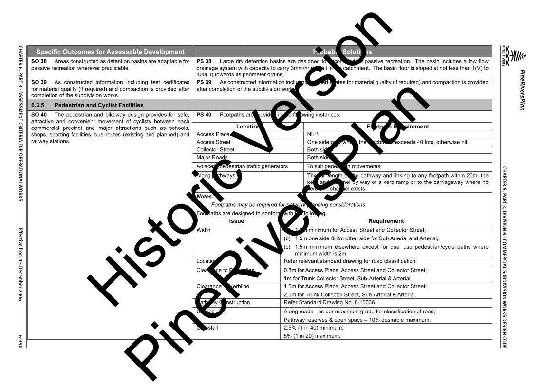
CHA
PTER 6, PA
RT 3, DIVIS
ION
6 - COM
MER
CIAL S
UB
DIVIS
ION
WO
RKS D
ESIG
N CO
DE
PineRiversPlan
CHA
PTER 6, PA
RT 3 - ASS
ESSM
ENT CR
ITERIA
FOR
OPER
ATION
AL W
OR
KS Effective from
15 Decem
ber 2006 6-390
Specific Outcomes for Assessable Development Probable SolutionsSO 38 Areas constructed as detention basins are adaptable for passive recreation wherever practicable.
PS 38 Large dry detention basins are designed to accommodate passive recreation. The basin includes a low flow drainage system with capacity to carry 3mm/hr rainfall in the catchment. The basin floor is sloped at not less than 1(V) to 100(H) towards its perimeter drains.
SO 39 As constructed information including test certificates for material quality (if required) and compaction is provided after completion of the subdivision works.
PS 39 As constructed information including test certificates for material quality (if required) and compaction is provided after completion of the subdivision works.
6.3.5 Pedestrian and Cyclist FacilitiesSO 40 The pedestrian and bikeway design provides for safe, attractive and convenient movement of cyclists between each commercial precinct and major attractions such as schools, shops, sporting facilities, bus routes (existing and planned) and railway stations.
PS 40 Footpaths are provided in the following instances:
Location Footpath RequirementAccess Place Nil (1)
Access Street One side only where the catchment exceeds 40 lots, otherwise nil.Collector Street Both sidesMajor Roads Both sidesAdjacent pedestrian traffic generators To suit pedestrian movementsAlong pathways The full length of the pathway and linking to any footpath within 20m, the
kerb and channel by way of a kerb ramp or to the carriageway where no kerb and channel exists.
Notes:1. Footpathsmayberequiredfornetworkplanningconsiderations.Footpaths are designed to conform with the following:
Issue RequirementWidth (a) 1.2m minimum for Access Street and Collector Street;
(b) 1.5m one side & 2m other side for Sub Arterial and Arterial;(c) 1.5m minimum elsewhere except for dual use pedestrian/cycle paths where
minimum width is 2mLocation Refer relevant standard drawing for road classification.Clearance to Properties 0.8m for Access Place, Access Street and Collector Street;
1m for Trunk Collector Street, Sub-Arterial & Arterial.Clearance to Kerbline 1.5m for Access Place, Access Street and Collector Street;
2.5m for Trunk Collector Street, Sub-Arterial & Arterial.Pathway Construction Refer Standard Drawing No. 8-10036Grades Along roads - as per maximum grade for classification of road;
Pathway reserves & open space – 10% desirable maximum.Crossfall 2.5% (1 in 40) minimum;
5% (1 in 20) maximum.
Histori
c Vers
ion
PineRive
rsPlan

CHA
PTER 6, PA
RT 3, DIVIS
ION
6 - COM
MER
CIAL S
UB
DIVIS
ION
WO
RKS D
ESIG
N CO
DE
PineRiversPlan
CHA
PTER 6, PA
RT 3 - ASS
ESSM
ENT CR
ITERIA
FOR
OPER
ATION
AL W
OR
KS Effective from
15 Decem
ber 2006 6-391
Specific Outcomes for Assessable Development Probable SolutionsCrossing Points Refer to Planning Scheme Policy PSP28 Civil Infrastructure Design, Part 1, Section
6.4.7 & 6.4.8Crossing Points for combined bicycle/footway use
Refer to Standard Drawing No. 8-203
Chicanes are provided at the ends of all pathways to roads (refer to Standard Drawing Nos. 8-60033, 8-60034 & 8-60036).Bike/footway terminations at Collector Roads or higher classification roads conform with Standard Drawing No. 8-60034.Bike/footway direct road crossings conform with Standard Drawing No. 8-60035.Detailed design of the footpaths conforms with Council’s Planning Scheme Policy PSP28 Civil Infrastructure Design, Part 1, Section 6.4.0.Bikeways are provided within and adjacent the site as indicated in Council’s Bikeways Plan or adopted local area plan. Detailed design of the bikeways conforms with Council’s Planning Scheme Policy PSP28 Civil Infrastructure Design, Part 1, Section 6.5.0.
SO 41 As constructed information is provided after completion of the subdivision works.
PS 41 As constructed information is provided after completion of the subdivision works.
6.3.6 Public TransportSO 42 The road design provides for potential bus routes including safe convenient stops and, where necessary, bus turnaround areas.
PS 42 Bus routes are designed to conform with the following:-
Issue RequirementReserve Width 20m minimumCarriageway Width 11m minimumGrade 12% general maximum;
16% absolute maximum over short distancesSpeed Control by street alignment onlyDesign Vehicle Coach (tourist bus)Turning Single movement turns onlyBus stops are provided at 400m maximum spacing and integrated with the street and pedestrian network. Fully indented bus bays are provided on Collector, Trunk Collector, Sub-Arterial and Arterial Roads with detailed design conforming with Planning Scheme Policy PSP28 Civil Infrastructure Design, Part 1, Section 3.12.2. Bus stops on Collector Roads generally provide a level area not less than 2m wide between the kerb and the footpath. For higher passenger demand bus stops on Collector Roads a bus shelter is provided on a level concrete slab (not less than 3m in width) between the kerb and the footpath.
SO 43 The road design caters for the extension of existing and future public transport routes to provide sufficient services that are convenient and accessible to the community.
PS 43 The road design provides for extension of existing and future public transport routes.
SO 44 As constructed information including test certificates for material quality (if required) and compaction is provided after completion of the subdivision works.
PS 44 As constructed information including test certificates for material quality (if required) and compaction is provided after completion of the subdivision works.
Histori
c Vers
ion
PineRive
rsPlan

CHA
PTER 6, PA
RT 3, DIVIS
ION
6 - COM
MER
CIAL S
UB
DIVIS
ION
WO
RKS D
ESIG
N CO
DE
PineRiversPlan
CHA
PTER 6, PA
RT 3 - ASS
ESSM
ENT CR
ITERIA
FOR
OPER
ATION
AL W
OR
KS Effective from
15 Decem
ber 2006 6-392
Specific Outcomes for Assessable Development Probable Solutions
6.3.7 Public Open SpaceSO 45 Public open space has barriers to its road frontage to prevent damage by unauthorised vehicles.
PS 45 The public open space is provided with log barriers designed along their road frontage in accordance with Council’s Planning Scheme Policy PSP28 Civil Infrastructure Design, Part 1, Section 6.14.0 and Standard Drawing No. 8-70003.
SO 46 Public open space provides for recreational, environmental and stormwater management needs.
PS 46 No solution provided. Solutions will need to be adapted to suit the particular site constraints and features.
SO 47 Public open space that is intended to be used for local neighbourhood park includes a sufficiently level area that is suitable for non-organised recreation and passive relaxation including small children’s playgrounds and appropriate landscaping.
PS 47 Public open space that is intended to be used for local neighbourhood park contains one area, constructed if necessary, not less than 15m x 15m with a slope less than 5%.
SO 48 As constructed information including test certificates for material quality (if required) is provided after completion of the subdivision works.
PS 48 As constructed information including test certificates for material quality (if required) is provided after completion of the subdivision works.
6.3.8 UtilitiesSO 49 Development only occurs in locations where there are adequate services and capacity for the desired use.
PS 49 The design of water supply infrastructure including water mains, pumping stations, pressure mains and associated works complies with the relevant Queensland Government Department’s Guidelines for Planning and Design of Urban Water Supply Schemes, Council’s Standard Drawings and Council’s Planning Scheme Policy PSP28 Civil Infrastructure Design, Part 3. The design of water supply infrastructure includes all works internal and any works external required to ensure that all new and existing lots maintain adequate water supply at all times.The design of sewerage infrastructure including sewer mains, pumping stations, pressure mains and associated works complies with the relevant Queensland Government Department’s Guidelines for Planning andDesign of SewerageSchemes, Council’s Standard Drawings and Council’s Planning Scheme Policy PSP28 Civil Infrastructure Design, Part 4. The design of sewerage infrastructure includes all works internal and any works external required to ensure that all new and existing lots are provided with a service at all times within the capacity of the system.The design of the electrical reticulation is in accordance with ENERGEX Specification URD UndergroundResidentialDistribution.
6.3.8(a) Water SupplySO 50 Where lots are intended to be provided with water supply the design and construction of the associated infrastructure and connections is provided in a safe, cost-effective, coordinated and efficient manner that supports sustainable development practices.
PS 50 Staged construction of water supply infrastructure is designed so that each stage is self supporting at the completion of construction of that stage.Water supply infrastructure materials and construction complies with Council’s Planning Scheme Policy PSP28 Civil Infrastructure Design, Part 3, Section 4.The minimum water main size is 100mm diameter.
SO 51 Water supply infrastructure is easily controlled and accessed for maintenance and repair.
PS 51 Water mains are provided along both sides of all commercial streets to the boundaries of the development site.Water mains are provided on both sides of all Major Roads and divided roads.
Histori
c Vers
ion
PineRive
rsPlan

CHA
PTER 6, PA
RT 3, DIVIS
ION
6 - COM
MER
CIAL S
UB
DIVIS
ION
WO
RKS D
ESIG
N CO
DE
PineRiversPlan
CHA
PTER 6, PA
RT 3 - ASS
ESSM
ENT CR
ITERIA
FOR
OPER
ATION
AL W
OR
KS Effective from
15 Decem
ber 2006 6-393
Specific Outcomes for Assessable Development Probable SolutionsWater mains are located within service corridors shown on the following Standard Drawings:
Street Classification Standard Drawing No.Access Road & Collector Road 8-10016Sub Arterial & Arterial 8-10013In special circumstances (e.g. infill development where existing services are on Council’s previous service allocations – refer to Standard Drawing 8-0049), the services are placed on an alternative alignment.Service connections are not made to water mains 250mm diameter and above.Fire hydrants are provided at intervals (measured within the road reserve) not exceeding 80m, at high points (for air release) and at the ends of mains (use a duckfoot bend).Scours are provided at all low points, generally discharging into drainage structures.Fittings and valves at road intersections are contained in the verge and are 500mm clear of the back of the kerb.The water supply system is designed to limit the static head to 80m maximum. Where approved by Council’s engineer, pressure reducing valves are designed and installed to limit the static head to 80m maximum.Water supply infrastructure is contained within roads or other public reserves. In exceptional circumstances Council may accept water mains through private land providing an appropriate easement, not less than 3m wide, is registered in Council’s favour. The water main is constructed centrally within the easement.Sufficient valves are provided, generally on street corners, to limit the area of any shut-off to within the following:40 lots or premises for 100mm and 150mm mains; and50 lots or premises for 225mm mains.Valves in the shut-off area are limited to a maximum of 6.Water supply infrastructure is designed and constructed in accordance with the following standard drawings:-
Item Standard Drawing No.Hydrant and Valve Installations 8-40002Pavement Markers & Delineators 8-40003Hydrant, Valve and Mains Marker Posts 8-40004Thrust Block Details 8-40006Air Valve Installation Details 8-40007Air Valve Sizing 8-40008Scour Outlets 8-40009Trench Details 8-40010Section Valve Pits and Interconnection Pits 8-40011Pressure Reducing Valve Pits 8-40012 & 8-40013Pressure Gauge Installations 8-40014Offtakes from Mains 8-40015Property Service Conduits 8-40016
Histori
c Vers
ion
PineRive
rsPlan

CHA
PTER 6, PA
RT 3, DIVIS
ION
6 - COM
MER
CIAL S
UB
DIVIS
ION
WO
RKS D
ESIG
N CO
DE
PineRiversPlan
CHA
PTER 6, PA
RT 3 - ASS
ESSM
ENT CR
ITERIA
FOR
OPER
ATION
AL W
OR
KS Effective from
15 Decem
ber 2006 6-394
Specific Outcomes for Assessable Development Probable SolutionsService tappings are constructed using ductile iron pre-tapped fittings for every lot. For pipe diameters where re-tapped fittings are not manufactured conventional tapping bands are used.Water supply conduits are provided for across road house connections for the full width of the carriageway and concrete footpaths.Water supply conduits are provided for the full length of the accessway to rear allotments.Kerb marker plates are provided to indicate the location of property service conduits.Concrete thrust blocks are provided at all locations where there is unbalanced hydraulic load including all bends (horizontal and vertical), tees, angle branches, crosses, dead ends and reducers. Thrust blocks are contained within the service allocation.Water mains are provided with the following cover:
Main Diameter
(mm)
CoverVerges & Accessway Commercial Road Carriageway(1) State-controlled
Roads100 – 200 600 Greater of 750 or pavement thickness + 150 1200225 – 375 750 Greater of 900 or pavement thickness + 150 1200
>375 1000 Greater of 1000 or pavement thickness + 150 1200Notes:1. Where Council’sEngineerapprovesareducedcover,thewatermainisconstructedofductileironpipe(minimum
ClassK9).Water mains are not laid under stormwater pipes, sewerage mains or electricity conduits.For water mains 300mm diameter and larger subsoil drains are provided from low points preferably draining to stormwater drainage structures.Water mains maintain the following minimum clearances to existing and future services:-(1) horizontally where the water main runs along the adjacent service for > 1m:– 800mm;(2) horizontally where the water main runs along the adjacent services for < 1m:- 150mm;(3) vertically:- 150mm.Connection to Council’s water supply system is not provided until adequate water supply can be maintained at all times and the new mains are disinfected and watertight. Tests certificates (not older than 10 days at the time of connection) are provided to confirm the new mains have been satisfactorily disinfected prior to connection to Council’s water supply system. The mains are pressure tested and test certificates are provided to confirm that the new mains are watertight prior to connection to Council’s water supply system.
SO 52 Water mains provides multiple flow routes for fire fighting and water quality issues.
PS 52 Water mains are constructed with the maximum number of cross connections, including connections through all pathways.
SO 53 The water supply system for the proposed development is planned to conform with Council’s broad infrastructure plan for the water supply zone.
PS 53 The water supply system for the proposed development aligns with Council’s broad infrastructure plan for the water supply zone.
Histori
c Vers
ion
PineRive
rsPlan

CHA
PTER 6, PA
RT 3, DIVIS
ION
6 - COM
MER
CIAL S
UB
DIVIS
ION
WO
RKS D
ESIG
N CO
DE
PineRiversPlan
CHA
PTER 6, PA
RT 3 - ASS
ESSM
ENT CR
ITERIA
FOR
OPER
ATION
AL W
OR
KS Effective from
15 Decem
ber 2006 6-395
Specific Outcomes for Assessable Development Probable Solutions
6.3.8(b) SewerageSO 54 Where lots are intended to be provided with reticulated sewerage the design and construction of the associated infrastructure and connections is provided in a safe, cost-effective, coordinated and efficient manner that supports sustainable development practices.
PS 54 Staged construction of sewerage infrastructure is designed so that each stage is self supporting and properly served at the completion of construction of that stage.Sewerage infrastructure design complies with Council’s Planning Scheme Policy PSP28 Civil Infrastructure Design, Part 4.For normal sewer reticulation design the following parameters are used:-
Item Design ValueDemand 15 equivalent tenements per hectare.Occupancy rate per tenement 3.29 equivalent persons (EP)Average Dry Weather Flow (ADWF) 250 litres/EP/dayMaximum Possible Flow (C1)(a) Sewers serving < 1,000 EP(b) Sewers serving >23,000 EP
(a) 5 times ADWF(b) 3 times ADWF
Infiltration Allowance (IA) 250 litres/EP/dayMaximum design flow (MDF) Maximum Possible Flow + Infiltration Allowance (C1 + IA)Sewerage infrastructure materials and construction complies with Council’s Planning Scheme Policy PSP28 Civil Infrastructure Design, Part 4, Section 4.The sewerage system through the site has sufficient capacity to convey the ultimate flows from all upstream properties when they are fully developed.Sewer pipes are sized in accordance with AS2200. The minimum flow velocity in any sewer is 0.6m/s based on ADWF. Sewers are designed to carry MDF at a depth not exceeding ¾ of the pipe diameter.The minimum sewer main size is 150mm diameter.Sewers are designed and constructed to serve the entire area of each lot.House drains are graded (around the perimeter of the building envelope) at 1 in 40 with a minimum cover of 600mm except for control allotments where a grade of 1 in 60 with a minimum cover of 400mm is used.Sewers are designed to extend to the boundaries of the site in order to serve all upstream areas within the catchment.In flat areas, sewers are designed to serve properties on both sides of the sewer.Sewers are designed to follow the land’s natural fall as far as possible.The minimum grade on sewer mains for lots is as follows:
Sewer Diameter (mm) Minimum Grade(1)
150 1 in 80 for first 6 lots, 1 in 150 thereafter225 1 in 290300 1 in 420375 1 in 570450 1 in 730
Histori
c Vers
ion
PineRive
rsPlan

CHA
PTER 6, PA
RT 3, DIVIS
ION
6 - COM
MER
CIAL S
UB
DIVIS
ION
WO
RKS D
ESIG
N CO
DE
PineRiversPlan
CHA
PTER 6, PA
RT 3 - ASS
ESSM
ENT CR
ITERIA
FOR
OPER
ATION
AL W
OR
KS Effective from
15 Decem
ber 2006 6-396
Specific Outcomes for Assessable Development Probable Solutions525 1 in 900600 1 in 1000675 1 in 1200750 1 in 1500
Notes:1. Sewersaredesignedonsteepergradeswherepossible.The minimum drop through a manhole is the greater of 40mm or the difference between downstream and upstream pipe diameters.Steep sewers on grades exceeding 1 in 15 are provided with concrete stops (refer to Standard Drawing No. 8-50008) at the following spacing:-
Pipe Diameter (mm)
General Maximum Grade
Maximum Spacing of Concrete Stops (m)VC Pipe Other than VC Pipe
150 1 in 6 2 6225 1 in 10 2 6
300 or greater 1 in 15 2 6Sewers steeper than 1 in 4 are only approved by Council’s engineer in special circumstances and providing the manufacturer’s recommended maximum flow velocity is not exceeded. No sewer has a grade steeper than 1 in 3.Sewer mains are provided with the following cover:
Location Minimum Cover (mm)House connection branches in lots 600Sewer mains in lots:(a) front of lot
(b) elsewhere in the lot
(a) greater of 250 below invert of kerb and channel or 600 below future driveway(1)
(b) 600Sewer mains in road verges 900Sewer mains under road pavements 1200Notes:1. DetermineusingdrivewayaccessasperStandardDrawingNo.8-10008.The minimum clearance between the sewer and adjacent services/pipes is 300mm. Where Council’s engineer has approved a reduced clearance for a sewer crossing, another service the crossing sewer is constructed using a full length (5.5m) of Class 12 DICL pipe.House connections are only made to sewers where the depth to invert does not exceed 3m. A shallower second main is provided for house connections where the sewer depth (to invert) exceeds 3m.
Histori
c Vers
ion
PineRive
rsPlan

CHA
PTER 6, PA
RT 3, DIVIS
ION
6 - COM
MER
CIAL S
UB
DIVIS
ION
WO
RKS D
ESIG
N CO
DE
PineRiversPlan
CHA
PTER 6, PA
RT 3 - ASS
ESSM
ENT CR
ITERIA
FOR
OPER
ATION
AL W
OR
KS Effective from
15 Decem
ber 2006 6-397
Specific Outcomes for Assessable Development Probable SolutionsApproved flexible pipes are only used for sewers less than 6m deep.Sewer and/or roof and allotment drainage lines are located on no more than 2 boundaries of a lot.Sewer mains are not located along the side boundary of lots that are less than 19m wide at any point.Where the finished surface slope of a lot exceeds 1 in 10 the sewer main depth is increased to allow for future site earthworks.Sewer mains are located along the front or rear boundary of the lot in order to maximise access to the infrastructure.Trunk sewer mains of 300mm diameter and greater are not located in lots.Existing on-site sewerage systems that are made redundant by the development are demolished or removed from the site.Sewer manholes are provided at the following locations:-(1) changes in direction;(2) changes of grade;(3) intersections of sewers;(4) changes of sewer diameter;(5) changes of sewer pipe material;(6) ends of sewer lines, except where the line section does not exceed 30m in length and no more than 2 house
connections are made to the line.Manhole spacing (centre to centre) does not exceed 90m for sewer lines up to 450mm diameter and 120m for greater than 450mm diameter.Type 1 manholes are used for sewer lines up to 375mm diameter and up to 6m sewer depth.Precast manholes are not used where:-(1) the sewer line receives pumped flows;(2) the sewer line is > 375mm diameter;(3) the manhole depth exceeds 6m;(4) saturated ground conditions are likely; or(5) the manhole is located near a creek bank which is likely to be susceptible to erosion.The top of the manhole ring is at the following finished levels:-(1) 600mm above ground in unmaintained areas;(2) 100mm above finished surface level in maintained open space and private lots;(3) 25mm above finished surface level in road verges; and(4) flush with carriageway surface, trafficable areas and concrete paths.Where possible, the top of manholes are above the 20 year ARI flood level.Bolt down manhole covers are used near creek banks, in flood prone areas (i.e. below 20 year ARI flood level) in parks and reserves and public open space.Control manholes at pump stations are within 10m distance of the station except where approved otherwise by Council’s engineer.
Histori
c Vers
ion
PineRive
rsPlan

CHA
PTER 6, PA
RT 3, DIVIS
ION
6 - COM
MER
CIAL S
UB
DIVIS
ION
WO
RKS D
ESIG
N CO
DE
PineRiversPlan
CHA
PTER 6, PA
RT 3 - ASS
ESSM
ENT CR
ITERIA
FOR
OPER
ATION
AL W
OR
KS Effective from
15 Decem
ber 2006 6-398
Specific Outcomes for Assessable Development Probable SolutionsWherever practicable, sewer lines are located within lots on a 1.5m alignment from the front boundary. In special circumstances only, the following alternative alignments within the lots are used:(1) 1.5m rear lot boundary; and(2) 1m from the side lot boundary.In special circumstances, Council’s engineer may approve alternative sewer alignments outside the building envelope.Sewer lines do not cross lot boundaries at acute angles.Where inter-allotment drainage is provided the sewer line is located between the drainage line and the lot boundary. The house connection branch extends 1m beyond the drainage line.All parks and reserves are provided with a sewerage connection unless approved otherwise by Council’s engineer.Manholes are located 1m upstream of lot boundaries except where the total fall across the lot along the sewer line exceeds 2m. Where the total fall across the lot along the sewer line exceeds 2m, the manhole is located 1m downstream of the lot boundary.Manholes do not straddle lot boundaries.The angle between incoming sewer lines and outlet sewer lines is 60o or greater.A maximum of three (3) inlet sewers or house connection inlets are made to any manhole.House connections are made to manholes where ever practicable.House connection branches (other than to manholes) are located between 1m and 1.2m upstream of lot boundaries at the lowest part of the lot.House connection branch inverts are not deeper than 1m. In special circumstances Council’s engineer may approve a greater depth (up to 1.5m) to control the whole lot.The maximum length of house connection branch from a sewer in an adjoining lot is 5m. with the branch extending a minimum of 1m into the lot being served.The top of the sewage pump station is 100mm above the 20 year ARI flood level.The bottom of the switchboard for the sewage pump station is 300mm above the 100 year ARI flood level.The sewage pump station is contained within a secure fenced compound.The sewage pump station is provided with appropriate ventilation.The sewage pump station is provided with a water service including a reduced pressure zone valve.Appropriate measures are provided to prevent sewage from becoming septic where the detention time exceeds six (6) hours.Sewage pumps are the non-clogging submersible type pump.Flow meters are provided on the discharge line from the pump station.Telemetry is provided to the sewage pump station.Flow meters and telemetry equipment is housed in weatherproof enclosures.The potential for sewage overflows from sewage pump stations is minimised using appropriately designed overflow storage or other means approved by Council’s engineer.The number and length of pressure mains is minimised as far as practicable.
Histori
c Vers
ion
PineRive
rsPlan

CHA
PTER 6, PA
RT 3, DIVIS
ION
6 - COM
MER
CIAL S
UB
DIVIS
ION
WO
RKS D
ESIG
N CO
DE
PineRiversPlan
CHA
PTER 6, PA
RT 3 - ASS
ESSM
ENT CR
ITERIA
FOR
OPER
ATION
AL W
OR
KS Effective from
15 Decem
ber 2006 6-399
Specific Outcomes for Assessable Development Probable SolutionsSewer pressure mains are located in road verges of the opposite side to water supply mains.Sewer pressure mains have the following cover:-(1) 1200mm under carriageways;(2) 1000mm elsewhere.Sewer pressure mains are not laid within 1.5m of parallel potable water supply mains. In special circumstances Council’s engineer may approve a lesser separation providing the sewer pressure main obvert is 500mm below the water supply main.Sewer pressure mains have section valves at not greater than 500m spacing.Scour valves are located at all low points in the pressure main.Vents are provided to all high points in the pressure main.Odour and corrosion control measures are provided, as necessary, to pressure mains.
Pressure mains discharge into vented discharge manholes whose immediate downstream line does not have any house connection branches.Maintenance vehicle access is provided to the sewage pump station in accordance with the following:-
Item RequirementDesign Vehicles (a) Medium rigid vehicle
(b) Articulated Tanker when oxygen injection is usedAccess Track Maximum Grade (a) 1 in 10 for gravel access;
(b) 1 in 6 for sealed accessAccess Track Minimum Width 3.5mAccess Track Drainage (a) No inundation in 5 year ARI storm;
(b) Trafficable in 10 year ARI stormSurfacing (a) Minor pump station with access grade < 1 in 10 – gravel surface(1);
(b) Minor pump station with access grade >1 in 10 – sealed;(c) Major pump stations – sealed.
Pavement Design (a) Minor pump station - as per DG 06 using 2.3 x 10³ ESAs;(b) Major pump station - as per DG 06 using 4.5 x 10³ ESAs
Pump Maintenance (a) Level area adjacent pump well for a crane truck;(b) Vent pole, switchboard and other equipment clear of working area of
crane truck.Notes:1. Where the access is adjacent to residential properties or Council’s engineer considers that the amenity of nearby
residentsmaybeaffectedbydust,theaccessissealed.
Histori
c Vers
ion
PineRive
rsPlan

CHA
PTER 6, PA
RT 3, DIVIS
ION
6 - COM
MER
CIAL S
UB
DIVIS
ION
WO
RKS D
ESIG
N CO
DE
PineRiversPlan
CHA
PTER 6, PA
RT 3 - ASS
ESSM
ENT CR
ITERIA
FOR
OPER
ATION
AL W
OR
KS Effective from
15 Decem
ber 2006 6-400
Specific Outcomes for Assessable Development Probable SolutionsSewerage infrastructure is designed and constructed in accordance with the following standard drawings:-
Item Standard Drawing No.Sewer Manholes 8-50002, 8-50003, 8-50004, 8-50006 & 8-50007Sewer Pipelines 8-50008House Connection Branches 8-50009Sewage Pump Stations 8-50015, 8-50016, 8-50017, 8-50018, 8-50019, 8-50021, 8-50023, 8-50024,
8-50025, 8-50026, 8-50040, 8-50041, 8-50042, 8-50043, 8-50050, 8-50051, 8-50052, 8-50053, 8-50100, 8-50101, 8-50102, 8-50103, 8-50110, 8-50111, 8-50112, 8-50113, 8-50120, 8-50121, 8-50122, 8-50123, 8-50140 & 8-50141
Sewer Valves 8-50027Sewer Rising Mains 8-50028, 8-50029Connection to Council’s sewerage system is not provided until the new mains are clean and watertight. The mains and manholes are vacuum tested and test certificates are provided to confirm that the new mains and manholes are watertight.
SO 55 Adequate buffers are provided between sewerage transportation and treatment facilities and dwellings to protect residential amenity and health.
PS 55 Sewage Pump Stations are no closer than 100m to the nearest existing or future residential lot. In special circumstances Council’s engineer may approve a lesser buffer distance.
SO 56 The sewerage transportation system for the proposed development is planned to conform with Council’s broad infrastructure plan for the catchment.
PS 56 The sewerage transportation system conforms with Council’s infrastructure plan for the sewerage scheme.
6.3.8(c) Recycled WaterSO 57 Where Council plans to supply recycled water, developments make provision for these future recycled water supply systems.
PS 57 An appropriate service corridor is provided for future recycled water supply.
6.3.8(d) ElectricitySO 58 Where lots are intended to be provided with reticulated electricity the service is underground with design and construction of the associated infrastructure and connections being provided in a safe, cost-effective, coordinated and efficient manner that supports sustainable development practices.
PS 58 Underground electrical reticulation is provided in commercial developments.Crossings of existing roads are bored. In special circumstances, Council’s engineer may approve other methods including trenched construction.Road crossing are not at acute angles to the road centreline.Electrical crossings occur at alternate common lot boundaries to water service crossings.Electrical crossings are within the area defined as an intersection under State Legislation or are diagonally across intersections to enable 11kV cables to be installed without joints.Pillars are provided at all entry points to private property and located at side boundaries of the lot.Pillars are located on alternate common lot boundaries to water meters and hydrants.
Histori
c Vers
ion
PineRive
rsPlan

CHA
PTER 6, PA
RT 3, DIVIS
ION
6 - COM
MER
CIAL S
UB
DIVIS
ION
WO
RKS D
ESIG
N CO
DE
PineRiversPlan
CHA
PTER 6, PA
RT 3 - ASS
ESSM
ENT CR
ITERIA
FOR
OPER
ATION
AL W
OR
KS Effective from
15 Decem
ber 2006 6-401
Specific Outcomes for Assessable Development Probable Solutions
6.3.8(e) Street Lighting – (excludes State-controlled roads)SO 59 All roads are provided with street lighting which is designed and constructed to provide a safe, cost-effective, coordinated and efficient system that supports sustainable development practices.
PS 59 All works are designed and constructed to AS1158, Public Lighting Code, 1986, Austroads Guide to Traffic Engineering Practice – Part 12, Roadway Lighting, 1988 and ENERGEX standards and approval.Street lighting poles and luminaries are standard ENERGEX patterns under Rate 1 Tariff in roads and Rate 2 Tariff in other than roads.Street light poles are located on standard alignments in accordance with the following standard drawings:-
Street Classification Standard Drawing No.Access Road & Collector Road 8-10016Sub Arterial & Arterial 8-10013Street lights are generally located opposite common lot boundaries and are positioned to minimise conflicts with vehicle movements.Street lights are located to minimise the risk of damage from errant vehicles at intersections, bends and speed control devices and by oversize vehicles which must necessarily leave the carriageway to manoeuvre in turn around areas, speed control devices and some intersections.Street light poles that are in vulnerable locations (e.g. small islands or roundabouts) use frangible type poles.Colour consistency is maintained as far as practicable.Lighting designs are prepared in accordance with the lighting category specified below:-
Road Classification Lighting CategoryArterial A2Sub Arterial A3Collector Road B2(1)
Access Road B2Pathways between lots B2General pathways in open space areas C3(2)
Commuter Links C2(2)
Other locations Subject to individual assessmentNotes:1. AhighercategorymaybeappropriatewhereaCollectorRoadisathroughroadorwheretherearelandusessuch
as retailing or entertainment.2. Lighting standard may vary to suit local conditions.3. Theaboveclassificationalsoappliestocommunitytitledevelopments.4. Powersupplytopathwaylightingisunderground.5. PathwaylightingisRate2Tariff.A light is provided to each end of pathways (may be street light), at every bend or change of alignment and at every obstruction or hazard (e.g. bridge, stairway, etc).Pedestrian underpasses or tunnels are lit in accordance with the relevant standard.
Histori
c Vers
ion
PineRive
rsPlan

CHA
PTER 6, PA
RT 3, DIVIS
ION
6 - COM
MER
CIAL S
UB
DIVIS
ION
WO
RKS D
ESIG
N CO
DE
PineRiversPlan
CHA
PTER 6, PA
RT 3 - ASS
ESSM
ENT CR
ITERIA
FOR
OPER
ATION
AL W
OR
KS Effective from
15 Decem
ber 2006 6-402
Specific Outcomes for Assessable Development Probable SolutionsCrossing points of pathways across roads or streets are lit in accordance with the relevant street standard.In addition to the “through” street lighting above, additional special lighting is provided, as necessary, at the following locations:(1) Intersections;(2) Roundabouts;(3) Sharp bends;(4) Traffic control devices;(5) Pedestrian crossings;(6) Cul de sac turn around areas; and(7) Bridges.
6.3.8(f) TelecommunicationsSO 60 All lots are able to be provided with a telecommunications service which is designed to give a safe, cost effective, coordinated and efficient system that supports sustainable development practices.
PS 60 Application for telecommunications reticulation is made and pre-provisioning confirmation is received prior to subdivision works commencing.Telecommunications reticulation (i.e. conduits and pits) is installed in accordance with Telstra standards and a provisioning confirmation is provided for the works.One 50mm nominal diameter telecommunications conduit is provided on each side on the road in addition to those provided for or by Telstra.
6.3.8(g) Alterations and RelocationsSO 61 Any alteration or relocation in connection with or arising from the development to any service, installation, plant, equipment or other item belonging to or under the control of the telecommunications authority, electricity authorities, the Council or other person engaged in the provision of public utility services, is carried out at no cost to Council prior to the approval of the plan of subdivision.
PS 61 Any alteration or relocation in connection with or arising from the development to any service, installation, plant, equipment or other item belonging to or under the control of the telecommunications authority, electricity authorities, the Council or other person engaged in the provision of public utility services, has been carried out at no cost to Council prior to the approval of the plan of subdivision.
6.3.8(h) As Constructed InformationSO 62 “As constructed” information including test certificates for material quality (if required) and compaction is provided after completion of the subdivision works.
PS 62 “As constructed” information including test certificates for material quality (if required) and compaction is provided to the relevant authority upon completion of the subdivision worksHistori
c Vers
ion
PineRive
rsPlan

CHAPTER 6, PART 3, DIVISION 7 - RURAL SUBDIVISION WORKS DESIGN CODE
PineRiversPlan
CHAPTER 6, PART 3 - ASSESSMENT CRITERIA FOR OPERATIONAL WORKS Effective from 15 December 2006 6-403
Division 7 Rural Subdivision Works Design Code7.1 Overall Outcome
To create rural subdivision development that:-(1) Provides safe, convenient and attractive rural areas;(2) Provides lots that meet user requirements;(3) Ensures that sites are managed during construction to minimise adverse impacts to the
environment and on the health and amenity of residents and premises;(4) Ensures that sites are managed during construction to minimise adverse traffic impacts to
existing roads;(5) Ensures that earthworks design and construction is suitable for the intended use of the land
and that adverse impacts to the environment and on the health and amenity of residents is minimised;
(6) Have road networks that are designed and constructed to provide an optimum combination of safety, amenity, convenience, economy and environment for residents, road and street users, and the community generally;
(7) Have stormwater management systems that are designed and constructed to provide an optimum combination of safety, amenity, convenience, economy and environment for residents and the community generally;
(8) Have stormwater management systems that are designed and constructed to collect and convey stormwater from a catchment to its receiving waters with minimal nuisance, danger or damage, and at a development and environmental cost which is acceptable to the community as a whole;
(9) Provides for the convenience and safety of pedestrians and vehicular traffic during frequent or nuisance stormwater flows;
(10) Ensures a reasonable level of pedestrian and vehicular traffic safety and accessibility during storm events;
(11) Minimises pollutant inflows to the receiving waters and controls scour and depositional effects;
(12) Adequately protects people, the natural environment and the built environment from stormwater runoff flows at an acceptable level of risk;
(13) Integrates stormwater management solutions with other uses and the natural environment;(14) Provides public open space that meets user requirements for outdoor recreational and social
activities and for landscaping that contributes to the identity, environmental health and safety of the community;
(15) Ensures, where appropriate, as many existing trees are retained as possible to keep the original character of the land and provide shelter and food for endemic flora and fauna;
(16) Provides for rural lots that are adequately serviced with electricity, street lighting (if required) and communications services in a timely, cost effective, coordinated and efficient manner that supports sustainable development practices, and is in accordance with the desired character of the locality;
(17) Ensures all electricity, street lighting and communication services that require relocation and/or alterations as a result of rural development are carried out in a timely, cost effective, coordinated and efficient manner; and
(18) Reduces the level of fire risk associated with building in areas which are assessed to have a medium to high bushfire hazard.
7.2 Compliance with the Rural Subdivision Works Design CodeThis code applies to all operational works relating to development or reconfiguring of rural land, but specifically excludes applications for access easements to a road, subdivision by lease and boundary relocations or realignments.The application of the various specific outcomes will depend upon the size or scale of the proposed development. Some specific outcomes will not apply due to a particular design element not being part of the proposal (e.g. new road). In other instances it may be impractical to apply some specific outcomes, particularly for small infill developments.
7.3 Development RequirementsThe following are the design elements relevant to rural subdivision works:-(7.3.1) Managing Impacts During Construction(7.3.2) Earthworks(7.3.3) Road Networks (excludes State-controlled Roads)(7.3.4) Stormwater Management
Histori
c Vers
ion
PineRive
rsPlan

CHAPTER 6, PART 3, DIVISION 7 - RURAL SUBDIVISION WORKS DESIGN CODE
PineRiversPlan
CHAPTER 6, PART 3 - ASSESSMENT CRITERIA FOR OPERATIONAL WORKS Effective from 15 December 2006 6-404
(7.3.5) Recreational Trails(7.3.6) Public Transport (7.3.7) Public Open Space(7.3.8) Utilities
(7.3.8a) Electricity(7.3.8b) Street Lighting(7.3.8c) Telecommunications(7.3.8d) Alterations and Relocations(7.3.8e) As Constructed Information
Histori
c Vers
ion
PineRive
rsPlan

CHA
PTER 6, PA
RT 3, DIVIS
ION
7 - RU
RA
L SU
BD
IVISIO
N W
OR
KS DES
IGN
COD
E
PineRiversPlan
CHA
PTER 6, PA
RT 3 - ASS
ESSM
ENT CR
ITERIA
FOR
OPER
ATION
AL W
OR
KS Effective from
15 Decem
ber 2006 6-405
Specific Outcomes for Assessable Development Probable Solutions
7.3.1 Managing Impacts During ConstructionSO 1 All development sites minimise, as far as possible, any adverse impact to the natural environment caused by erosion, siltation, incineration of cleared vegetation and rubbish.
PS 1 The development works incorporate temporary stormwater runoff, erosion and sediment controls and trash traps designed in accordance with Council’s Planning Scheme Policy PSP28 Civil Infrastructure Design, Part 2, Section 4.2.0 and 4.11.4, and Subdivisions Section Technical Note No. 6. The measures are adjusted on-site to maximise their effectiveness.Stormwater runoff, erosion and sediment controls are constructed prior to commencement of any clearing works wherever possible.All environmentally significant areas to be retained with the development are clearly delineated and fenced prior to development works commencing.
SO 2 All development works are carried out at times which minimise noise impacts to residents.
PS 2 All development works are carried out within the following times, unless otherwise approved in writing by Council’s engineer:(1) Monday to Friday (other than public holidays) between 7am and 6pm on the same day; and(2) Saturday (other than public holidays) between 7am and 12noon on the same day.No work is carried out on Sundays and public holidays.Variations to the above working hours may be approved if Council’s engineer considers that the work is unlikely to cause significant inconvenience or disruption to the public, or the work is unlikely to cause annoyance or inconvenience to occupants of adjacent properties.
SO 3 All development works are managed to minimise dust and siltation nuisance to residents.
PS 3 During construction, dust suppression measures (such as watering of the site) are implemented to protect nearby premises from dust pollution.
SO 4 All development works avoid the redirection of stormwater runoff where potential impacts to residents or premises may occur.
PS 4 Temporary construction works do not pond or concentrate stormwater runoff in adjoining properties.Temporary construction works do not create nuisance or annoyance to adjoining premises as a result of altering the stormwater runoff pattern exiting the site.
SO 5 Construction traffic does not adversely impact on the amenity of existing residents.
PS 5 Construction traffic to and from the site uses the highest classification streets or roads where a choice of access routes is available.Where significant volumes of material are approved to enter or leave the site, a haul route is approved by Council. All materials associated with the development that are dropped, deposited or spilled on streets giving access to the site are removed and the streets are cleaned as soon as practicable after the event. Any damaged areas are repaired and reinstated to their previous condition.Where works are carried out on existing roads a traffic control plan is prepared in accordance with the Manual of Uniform Traffic Control Devices. All traffic control measures are properly erected and maintained during the works.Any access road to the site that has been affected by any material dropped, deposited or spilled on the road as a result of the construction processes associated with the site is cleaned and restored to its original condition.
SO 6 Construction traffic is controlled to ensure all traffic movements to and from the site are safe.
PS 6 All traffic movements to and from the site frontage are carried out in a safe manner. Traffic controls are used where site access is approved directly onto a Major Road.
SO 7 All clearing works are carefully undertaken to ensure the clearing is limited to the area of the approved infrastructure works, buildings areas and other areas approved in the development permit.
PS 7 Areas of significant vegetation, proposed park and open space areas and other areas of vegetation or individual trees designated to be retained with the development are temporarily fenced and flagged.
Histori
c Vers
ion
PineRive
rsPlan
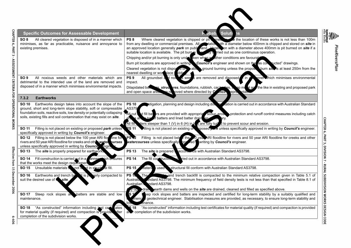
CHA
PTER 6, PA
RT 3, DIVIS
ION
7 - RU
RA
L SU
BD
IVISIO
N W
OR
KS DES
IGN
COD
E
PineRiversPlan
CHA
PTER 6, PA
RT 3 - ASS
ESSM
ENT CR
ITERIA
FOR
OPER
ATION
AL W
OR
KS Effective from
15 Decem
ber 2006 6-406
Specific Outcomes for Assessable Development Probable SolutionsSO 8 All cleared vegetation is disposed of in a manner which minimises, as far as practicable, nuisance and annoyance to existing premises.
PS 8 Where cleared vegetation is chipped or pit burned on site the location of these works is not less than 100m from any dwelling or commercial premises. All vegetation with a diameter below 400mm is chipped and stored on site in an approved location generally park on public land. Vegetation with a diameter above 400mm is pit burned on site if a suitable location is available. The pit burn is generally carried out as one continuous operation.Chipping and/or pit burning is only undertaken when weather conditions are favourable.Burn pit locations are approved in writing by Council’s engineer and shown on the “as constructed” drawings.Cleared vegetation is not disposed of by above ground burning unless the proposed burn site is at least 250m from the nearest dwelling or workplace building.
SO 9 All noxious weeds and other materials which are detrimental to the intended use of the land are removed and disposed of in a manner which minimises environmental impacts.
PS 9 All groundsel and noxious weeds are removed and disposed of in a manner which minimises environmental impact.Dilapidated buildings, structures, foundations, rubbish, car bodies, scrap metal and the like in existing and proposed park and open space areas are removed where directed by Council’s representative.
7.3.2 EarthworksSO 10 Earthworks design takes into account the slope of the ground, short and long-term slope stability, soft or compressible foundation soils, reactive soils, low density or potentially collapsing soils, existing fills and soil contamination that may exist on site.
PS 10 Investigation, planning and design including documentation is carried out in accordance with Australian Standard AS3798.All cut and fill batters are provided with appropriate scour, erosion protection and runoff control measures including catch drains at the top of batters and lined batter drains as necessary.All fill batters steeper than 1 (V) in 6 (H) in lots are fully turfed to prevent scour and erosion.
SO 11 Filling is not placed on existing or proposed park unless specifically approved in writing by Council’s engineer.
PS 11 Filling is not placed on existing or proposed park unless specifically approved in writing by Council’s engineer.
SO 12 Filling is not placed below the 100 year ARI floodline for rivers and 50 year ARI floodline for creeks and other watercourses unless specifically approved in writing by Council’s engineer.
PS 12 Filling is not placed below the 100 year ARI floodline for rivers and 50 year ARI floodline for creeks and other watercourses unless specifically approved in writing by Council’s engineer.
SO 13 The site is properly prepared for earthworks. PS 13 The site is prepared in accordance with Australian Standard AS3798.
SO 14 Fill construction is carried out in a manner which ensures that the works meet the design requirements.
PS 14 The fill construction is carried out in accordance with Australian Standard AS3798.
SO 15 Unsuitable materials are not used in structural fill. PS 15 Materials used for structural fill conform with Australian Standard AS3798.
SO 16 Earthworks and trench backfill is properly compacted to suit the desired use of the site.
PS 16 The earthworks and trench backfill is compacted to the minimum relative compaction given in Table 5.1 of Australian Standard AS3798. The minimum frequency of field density tests is not less than that specified in Table 8.1 of Australian Standard AS3798.Any open drains, earth dams and wells on the site are drained, cleaned and filled as specified above.
SO 17 Steep rock slopes and batters are stable and low maintenance.
PS 17 Steep rock slopes and batters are inspected and certified for long-term stability by a suitably qualified and experienced geotechnical engineer. Stabilisation measures are provided, as necessary, to ensure long-term stability and low maintenance.
SO 18 “As constructed” information including test certificates for material quality (if required) and compaction is provided after completion of the subdivision works.
PS 18 “As constructed” information including test certificates for material quality (if required) and compaction is provided after completion of the subdivision works.
Histori
c Vers
ion
PineRive
rsPlan

CHA
PTER 6, PA
RT 3, DIVIS
ION
7 - RU
RA
L SU
BD
IVISIO
N W
OR
KS DES
IGN
COD
E
PineRiversPlan
CHA
PTER 6, PA
RT 3 - ASS
ESSM
ENT CR
ITERIA
FOR
OPER
ATION
AL W
OR
KS Effective from
15 Decem
ber 2006 6-407
Specific Outcomes for Assessable Development Probable Solutions
7.3.3 Road Networks (excludes State-controlled Roads)SO 19 The road design and construction has a clear structure and component streets conform to their function in the network.SO 20 The road design and construction has clear physical distinctions between each type of street. The distinctions are to be based on function, legibility, convenience, traffic volumes, vehicle speeds, public safety and amenity.SO 21 The road design and construction accommodates the following primary functions:-(1) Access to properties and premises;(2) Social and activity space;(3) Utility services location; and(4) Setting and approach (streetscape and landscape) for
adjoining residences.SO 22 The road design and construction accommodates adequate verge and carriageway width for the primary functions listed in specific outcomes above.
PS 19 to PS 22 The Rural Roads conform to the following:
Issue Rural Access Road Rural Collector RoadTraffic Catchment (maximum) 15 lots 100 lotsDesign Speed (minimum) (1) 60km/h 60km/hCarriageway Lanes 1 2Carriageway Width 3.5m 6mFormation Width (minimum) 8.5m 9mReserve Width (minimum) 20m 20mGrade (minimum - maximum) 0.4% - 10% (2) 0.4% - 10% (2)
Notes:1. In rugged topography or constrained situations, a lower design speed may be approved with the absolute minimum
design speed not less than 20km/h below those given in the table.2. Grades over 10% must be used with caution due to problems related to slow climbing speeds and potentially high
downhill speeds.The detailed design of Rural roads conforms with Council’s Planning Scheme Policy PSP28 Civil Infrastructure Design, viz:
Road Design Issue Planning Scheme Policy PSP28 Civil Infrastructure Design Reference
Traffic Volume & Capacity Part 1 Sect 5.3.5Design Speed Part 1 Sect 5.3.4Drainage Method Part 1 Sect 5.3.6.2Carriageway and Shoulder Width Part 1 Sect 5.3.6.3Medians, Islands and Auxiliary Lanes Part 1 Sect 5.3.6.4Crossfalls Part 1 Sect 5.3.6.5Batter Slopes and Clearance from Earthworks Part 1 Sect 5.3.6.6 - 7Reserve Width Part 1 Sect 5.3.6.11Geometric Design Part 1 Sect 5.3.7Intersections Part 1 Sect 5.3.8Roundabouts Part 1 DG 01Landscape Construction on Road Reserves, Parks and Drainage Reserves
Part 1 DG 03
Signs and Road Marking Part 1 Sect 6.7.0Footpaths Part 1 Sect 6.4.0
Histori
c Vers
ion
PineRive
rsPlan

CHA
PTER 6, PA
RT 3, DIVIS
ION
7 - RU
RA
L SU
BD
IVISIO
N W
OR
KS DES
IGN
COD
E
PineRiversPlan
CHA
PTER 6, PA
RT 3 - ASS
ESSM
ENT CR
ITERIA
FOR
OPER
ATION
AL W
OR
KS Effective from
15 Decem
ber 2006 6-408
Specific Outcomes for Assessable Development Probable SolutionsRecreational Trails Part 1 Sect 6.6.0Service Conduits Part 1 Sect 6.8.0Subsoil Drainage Part 1 Sect 6.9.0Safety Barriers Part 1 Sect 6.10.0Guide Posts Part 1 Sect 6.11.0Bridge and Culvert Widths Part 1 Sect 6.12.0Street and Pathway Lighting Part 1 Sect 6.13.0Park Barriers Part 1 Sect 6.14.0Retaining Walls Part 1 Sect 6.15.0The Major Roads conform to the following:
Issue Sub-Arterial ArterialTraffic Volume (typical) 12,000 vpd 30,000 vpdDesign Speed (minimum)(1) 80km/h 100km/hCarriageway Lanes 2 4Reserve Width (minimum) 26m 40mMaximum Grade 8% (2) 6% (2)
Notes:1. In rugged topography, or constrained situations, a lower design speed may be approved with the absolute minimum
Design Speed not less than 20 km/h below those given in the table.2. Grades over 10% must be used with caution due to problems related to slow climbing speeds and potentially high
downhill speeds.The detailed design of Major Rural Roads conforms with Council’s Planning Scheme Policy PSP28 Civil Infrastructure Design, viz:
Road Design Issue Planning Scheme Policy PSP28 Civil Infrastructure Design Reference
Design Speed Part 1 Sect 5.3.4Traffic Volume and Capacity Part 1 Sect 5.3.5Cross Section Elements Part 1 Sect 5.3.6Geometric Design Part 1 Sect 5.3.7Intersections Part 1 Sect 5.3.8Histori
c Vers
ion
PineRive
rsPlan

CHA
PTER 6, PA
RT 3, DIVIS
ION
7 - RU
RA
L SU
BD
IVISIO
N W
OR
KS DES
IGN
COD
E
PineRiversPlan
CHA
PTER 6, PA
RT 3 - ASS
ESSM
ENT CR
ITERIA
FOR
OPER
ATION
AL W
OR
KS Effective from
15 Decem
ber 2006 6-409
Specific Outcomes for Assessable Development Probable SolutionsThe road cross-sections conform with Council’s standard drawings as follows:-
Road Classification Standard Drawing NumberAccess Road 8-10021 & 8-10025Collector Road 8-10022 & 8-10025Rural Sub-Arterial 8-10023 & 8-10026Rural Arterial 8-10024 & 8-10026Utility service allocations conform to Council’s standard drawings as follows:-
Road Classification Standard Drawing NumberAccess Road, Collector Road 8-10028Rural Sub-Arterial and Arterial 8-10028Road designs incorporate retention of existing significant trees, where ever practicable.Road designs minimise the heights of cut and fill of road formation to less than 2m where ever practicable.New roads are located to minimise the heights of cut and fill of road formation to less than 2m, where ever possible.Road designs minimise the amount of filling and extent of filling in or adjacent existing natural gullies, waterways, existing public open space areas and proposed public open space areas.Access to allotments conforms to Council’s Planning Scheme Policy PSP28 Civil Infrastructure Design, Part 1, Section 6.2.0.The road pavement design conforms to Council’s Planning Scheme Policy PSP28 Civil Infrastructure Design, Part 1, DG 06.The works are constructed within tolerances given in Council’s Planning Scheme Policy PSP28 Civil Infrastructure Design, Part 1, DG 02, Appendix C.
SO 23 The road design creates safe, convenient movement for residents between their homes and the Major Road network.
PS 23 The combination of road length and grade for new Rural roads conforms with the following chart:
Figure 1
Histori
c Vers
ion
PineRive
rsPlan

CHA
PTER 6, PA
RT 3, DIVIS
ION
7 - RU
RA
L SU
BD
IVISIO
N W
OR
KS DES
IGN
COD
E
PineRiversPlan
CHA
PTER 6, PA
RT 3 - ASS
ESSM
ENT CR
ITERIA
FOR
OPER
ATION
AL W
OR
KS Effective from
15 Decem
ber 2006 6-410
Specific Outcomes for Assessable Development Probable SolutionsNotes:1. It is recognised that special circumstances may arise where it may be acceptable to allow grades and/or lengths of
grade. Special circumstances may include:(a) Where comparatively short lengths of grade lead to significant reductions in environmental impact and/or costs;(b) Where absolute numbers of heavy vehicles are low; and(c) On local roads where the cost of achieving the higher standard cannot be justified in terms of the traffic volumes using the road.
2. Existing roads may fall into this area, in which case special design is required.On Collector Roads and Major Roads where grades greater than 10% are combined with significant changes in horizontal alignment (particularly where the maximum speed difference between successive horizontal geometric elements exceeds 6%), then additional lane or shoulder width and/or curve widening is provided as necessary.
SO 24 Intersections along streets are safe and convenient. PS 24 Intersection spacing (centreline – centreline) along a through road conforms with the following:
Intersecting Road
Location
Through RoadAccess Road Collector Road Rural Sub- Arterial Road (1) Rural Arterial
RoadOn same side of through road
100m 100m 300m 500m
On opposite sides of the through road
100m 100m 300m 500m
Notes:1. In the case of Sub-Arterial Roads, existing landholdings may require intersections at a lesser spacing. In such cases
the following absolute minimum spacing is used but all turns access may not be permitted (i.e. left in/left out only):-Intersections on same side 100mIntersections on opposite sides:-(1) left-right stagger(2) right-left stagger
100m30m
The detailed design of street and road intersections conforms to the following sections of Council’s Planning Scheme Policy PSP28 Civil Infrastructure Design:-
Road Classification Planning Scheme Policy PSP28 Civil Infrastructure Design Reference
Rural Roads Part 1 Sect 5.3.8 & Sect 6.16.0Major Roads Part 1 Sect 5.3.8 & Sect 6.16.0Roundabouts Part 1 DG 01Local Area Traffic Management Part 1 DG 05
Histori
c Vers
ion
PineRive
rsPlan

CHA
PTER 6, PA
RT 3, DIVIS
ION
7 - RU
RA
L SU
BD
IVISIO
N W
OR
KS DES
IGN
COD
E
PineRiversPlan
CHA
PTER 6, PA
RT 3 - ASS
ESSM
ENT CR
ITERIA
FOR
OPER
ATION
AL W
OR
KS Effective from
15 Decem
ber 2006 6-411
Specific Outcomes for Assessable Development Probable SolutionsSO 25 All new Council controlled roads are fully constructed to Council’s Planning Scheme Policy PSP28 Civil Infrastructure Design standards.
PS 25 All new Council controlled roads are fully constructed to Council’s Planning Scheme Policy PSP28 Civil Infrastructure Design standards.
SO 26 All Council controlled frontage roads are constructed to Council’s Planning Scheme Policy PSP28 Civil Infrastructure Design standards.
PS 26 All Council controlled frontage roads are constructed to Council’s Planning Scheme Policy PSP28 Civil Infrastructure Design standards as follows:-
Situation Minimum Construction(1)
Frontage road unconstructed or gravel road only
For Access Place and Access Street: full carriageway and verges.For Collector Street: verge adjoining new lots, carriageway to a minimum sealed width of 6m plus 1.5m wide (full depth pavement) gravel shoulder and table drainage to the opposite side.For Major Roads: verge adjoining new lots, carriageway to a minimum sealed width of 7m plus 1.5m wide (full depth pavement) gravel shoulder and table drainage to the opposite side.
Frontage road sealed(2) but not constructed to Council’s Planning Scheme Policy PSP28 Civil Infrastructure Design standard
For Access Place and Access Street: reconstruction of full carriageway and verges.For Collector Street: reconstruction of verge adjoining new lots and carriageway to a minimum sealed width of 6m plus 1.5m wide (full depth pavement) gravel shoulder and table drainage to the opposite side. The works match into the remaining existing works wherever possible.For Major Roads: verge adjoining new lots and carriageway to a minimum sealed width of 7m plus 1.5m wide (full depth pavement) gravel shoulder and table drainage to the opposite side. The works match into the remaining existing works wherever possible.
Frontage road(2) partially constructed to Council’s Planning Scheme Policy PSP28 Civil Infrastructure Design standard
For Access Place and Access Street: construction of all remaining carriageway and verges.For Collector Street: verge adjoining new lots and carriageway to join existing works. In any event the minimum sealed width to be constructed is 6m plus 1.5m wide (full depth pavement) gravel shoulder and table drainage to the opposite side where necessary. The works match into the existing works.For Major Roads: verge adjoining new lots and carriageway to join existing works. In any event the minimum sealed width is 7m plus 1.5m wide (full depth pavement) gravel shoulder and table drainage to the opposite side where necessary. The works match into the existing works.
Notes:1. Construction includes all associated works (services, streetlighting and linemarking)2. Testing of the existing pavement is carried out to confirm whether the existing works meet Council’s Planning
Scheme Policy PSP28 Civil Infrastructure Design standard.SO 27 Safe, constructed and flood free road access (during minor storms) is available to the site from the nearest Major Road.
PS 27 Roads or streets giving access to the development from the nearest Major Road are safe and constructed to a minimum pavement gravel width of 5.5m. These access roads or streets have minor drainage systems (5 year ARI) and cross drainage (5 year ARI) that conform to Council’s Planning Scheme Policy PSP28 Civil Infrastructure Design, Part 2, Section 4.7.0.
Histori
c Vers
ion
PineRive
rsPlan
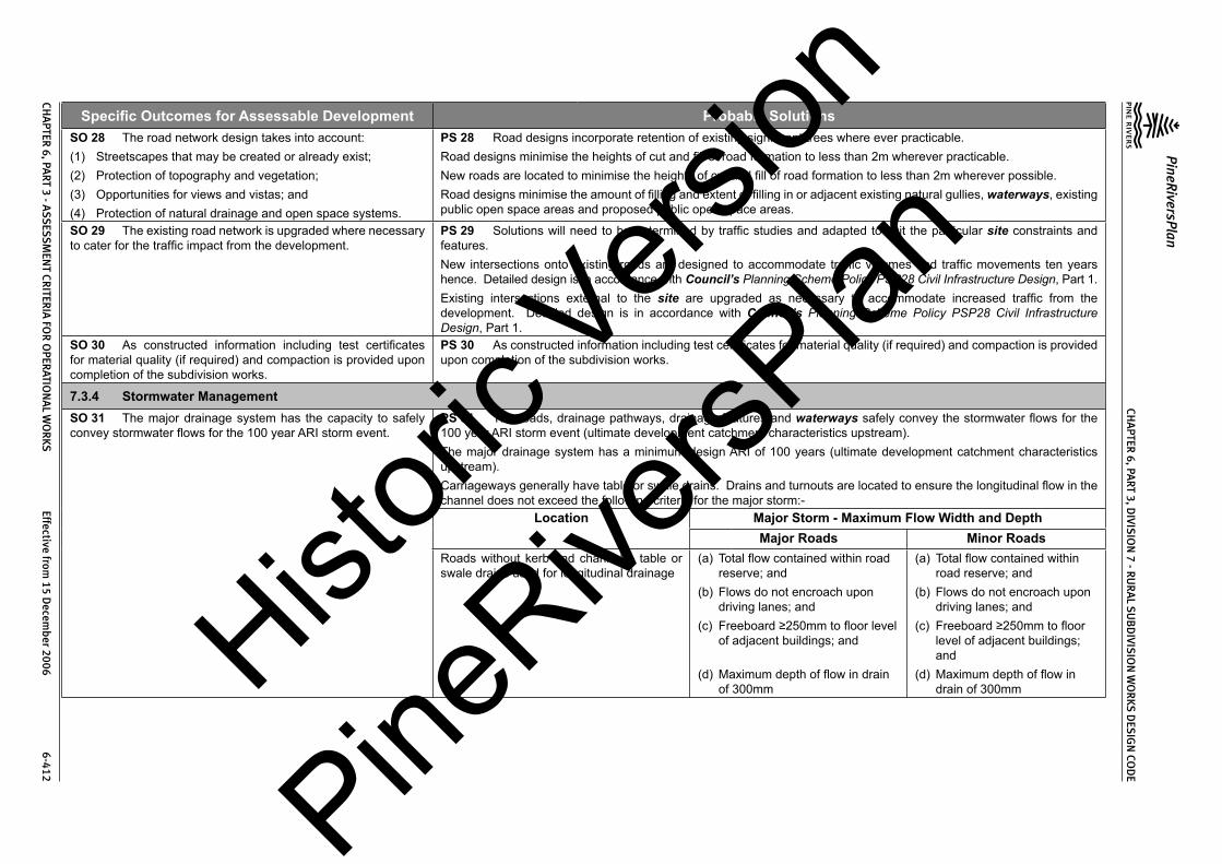
CHA
PTER 6, PA
RT 3, DIVIS
ION
7 - RU
RA
L SU
BD
IVISIO
N W
OR
KS DES
IGN
COD
E
PineRiversPlan
CHA
PTER 6, PA
RT 3 - ASS
ESSM
ENT CR
ITERIA
FOR
OPER
ATION
AL W
OR
KS Effective from
15 Decem
ber 2006 6-412
Specific Outcomes for Assessable Development Probable SolutionsSO 28 The road network design takes into account:(1) Streetscapes that may be created or already exist;(2) Protection of topography and vegetation;(3) Opportunities for views and vistas; and(4) Protection of natural drainage and open space systems.
PS 28 Road designs incorporate retention of existing significant trees where ever practicable.Road designs minimise the heights of cut and fill of road formation to less than 2m wherever practicable.New roads are located to minimise the heights of cut and fill of road formation to less than 2m wherever possible.Road designs minimise the amount of filling and extent of filling in or adjacent existing natural gullies, waterways, existing public open space areas and proposed public open space areas.
SO 29 The existing road network is upgraded where necessary to cater for the traffic impact from the development.
PS 29 Solutions will need to be determined by traffic studies and adapted to suit the particular site constraints and features.New intersections onto existing roads are designed to accommodate traffic volumes and traffic movements ten years hence. Detailed design is in accordance with Council’s Planning Scheme Policy PSP28 Civil Infrastructure Design, Part 1.Existing intersections external to the site are upgraded as necessary to accommodate increased traffic from the development. Detailed design is in accordance with Council’s Planning Scheme Policy PSP28 Civil Infrastructure Design, Part 1.
SO 30 As constructed information including test certificates for material quality (if required) and compaction is provided upon completion of the subdivision works.
PS 30 As constructed information including test certificates for material quality (if required) and compaction is provided upon completion of the subdivision works.
7.3.4 Stormwater ManagementSO 31 The major drainage system has the capacity to safely convey stormwater flows for the 100 year ARI storm event.
PS 31 The roads, drainage pathways, drainage features and waterways safely convey the stormwater flows for the 100 year ARI storm event (ultimate development catchment characteristics upstream).The major drainage system has a minimum design ARI of 100 years (ultimate development catchment characteristics upstream).Carriageways generally have table or swale drains. Drains and turnouts are located to ensure the longitudinal flow in the channel does not exceed the following criteria for the major storm:-
Location Major Storm - Maximum Flow Width and DepthMajor Roads Minor Roads
Roads without kerb and channel – table or swale drains used for longitudinal drainage
(a) Total flow contained within road reserve; and
(b) Flows do not encroach upon driving lanes; and
(c) Freeboard ≥250mm to floor level of adjacent buildings; and
(d) Maximum depth of flow in drain of 300mm
(a) Total flow contained within road reserve; and
(b) Flows do not encroach upon driving lanes; and
(c) Freeboard ≥250mm to floor level of adjacent buildings; and
(d) Maximum depth of flow in drain of 300mmHist
oric V
ersion
PineRive
rsPlan

CHA
PTER 6, PA
RT 3, DIVIS
ION
7 - RU
RA
L SU
BD
IVISIO
N W
OR
KS DES
IGN
COD
E
PineRiversPlan
CHA
PTER 6, PA
RT 3 - ASS
ESSM
ENT CR
ITERIA
FOR
OPER
ATION
AL W
OR
KS Effective from
15 Decem
ber 2006 6-413
Specific Outcomes for Assessable Development Probable SolutionsKerb and channelled crowned road - where floor levels of adjacent buildings are above road level
(a) Total flow contained within road reserve; and
(b) Freeboard ≥250mm to floor level of adjacent buildings; and
(c) Maximum depth of flow of 300mm
(a) Total flow contained within road reserve; and
(b) Freeboard ≥250mm to floor level of adjacent buildings; and
(c) Maximum flow depth 300mmKerb and channelled crowned road - where floor levels of adjacent buildings are below road level or < 300mm above top of kerb (a) ≥100mm fall on verge towards kerb;(b) < 100mm fall on verge towards kerb.
(a) 50mm above top of kerb;(b) Top of kerb
(a) 50mm above top of kerb;(b) Top of kerb
Notes:1. Widths are measured from channel invert for kerb and channel and from kerb face for kerb only.2. Refer to Council’s Planning Scheme Policy PSP28 Civil Infrastructure Design, Part 2, Section 4 for detailed
design requirements.The flow velocity in all unlined or soft faced open drains is kept within acceptable limits for the type of material or lining and condition of the channel (refer to QUDM Table 8.03).The product of depth by average velocity in the concrete channel (longitudinal drainage) does not exceed 0.6m2/s except where there is a danger of pedestrians being swept away and drowned where the value is limited to 0.4m2/s.Detailed design of the major drainage system conforms to Council’s Planning Scheme Policy PSP28 Civil Infrastructure Design, Part 2, Section 4.Rural lots have one area satisfying the following minimum development levels:-
Location of Rural Lot Minimum Development Level Minimum Area at Development Level
Adjacent Existing Natural Watercourse
The greater of:-(a) Q100ultimate plus 750mm; or(b) the highest recorded flood level plus
750mm.
1500m2 min. area
Adjacent Engineered Channels The greater of:-(a) Q100ultimate plus 500mm for a
maintained channel; or(b) Q100ultimate plus 250mm for an
unmaintained channel.
1500m2 min. area
Road Drainage The greater of:-(a) Q100ultimate plus 250mm; or(b) Q100ultimate plus 150mm using blocked
catchpits or inlets.
1500m2 min. areaHistori
c Vers
ion
PineRive
rsPlan

CHA
PTER 6, PA
RT 3, DIVIS
ION
7 - RU
RA
L SU
BD
IVISIO
N W
OR
KS DES
IGN
COD
E
PineRiversPlan
CHA
PTER 6, PA
RT 3 - ASS
ESSM
ENT CR
ITERIA
FOR
OPER
ATION
AL W
OR
KS Effective from
15 Decem
ber 2006 6-414
Specific Outcomes for Assessable Development Probable SolutionsOverland Flow Paths The greater of:-
(a) Q100ultimate plus 250mm for a maintained flow path; or
(b) Q100ultimate plus 150mm for an unmaintained flow path.
1500m2 min. area
Open channels are designed in accordance with Council’s Planning Scheme Policy PSP28 Civil Infrastructure Design, Part 2, Section 4.9.0.
SO 32 The minor stormwater drainage system has the capacity to convey stormwater flows from frequent storm events whilst ensuring pedestrian and vehicular traffic movements are safe and convenient.
PS 32 The minor drainage system has a minimum design ARI of 5 years (ultimate development catchment characteristics upstream).Carriageways generally have table or swale drains and turnouts located to ensure the longitudinal flow is fully contained within the channel for the minor storm. Table drain outlets contain energy dissipaters and flow spreaders to control erosion and scour. Table drain outlets are located such that they do not direct flows towards certified building areas or existing structures or site works that could be adversely affected by overland flows.
SO 33 Road cross drainage ensures that roads remain trafficable during major storm events without flooding or impacting upon building areas or other premises.
PS 33 Road cross drainage is provided to satisfy the following requirements:-
Road Classification Major Storm Minor Storm(1)
Major Road Trafficable for flows from the 100 year ARI storm:-(a) Maximum depth 200mm; and(b) DgVave < 0.4
For the 50 year ARI storm:-(a) Flows and flood levels do not encroach
upon the driving lanes;(b) Minimum pipe system freeboards are
maintained.Minor Road Trafficable for flows from the 100 year ARI
storm:-(a) Maximum depth 200mm; and(b) DgVave < 0.4
For the 10 year ARI storm:-(a) Flows and flood levels do not encroach
upon the driving lanes;(b) Minimum pipe system freeboards are
maintained.Notes:1. 50 year ARI for Major Roads; 10 year ARI for Minor Roads
Roads remain trafficable during major storm events. Detailed design of culverts and bridges conforms with Council’s Planning Scheme Policy PSP28 Civil Infrastructure Design, Part 2, Section 4.12.2 and 4.12.3 and Austroads Waterways Design Guidelines.Where there is potential for blockage by stream debris due to the nature of the catchment the cross drainage is constructed using box culverts or a bridge structure.Afflux from the cross drainage does not flood or reduce the required Q100 freeboard to existing building areas or other premises.Where the Minor Road provides access for less than 15 allotments then, in exceptional circumstances where a structure conforming with the above requirements cannot be reasonably required, the absolute minimum minor storm design flow is for the 2 year ARI storm with the structure designed as a floodway with a maximum duration of inundation during the major storm of 6 hours.All floodways, where the depth of flow at any point on the carriageway exceeds 200mm, have appropriate signage and flood markers provided.
Histori
c Vers
ion
PineRive
rsPlan
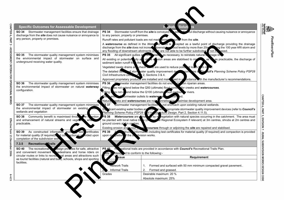
CHA
PTER 6, PA
RT 3, DIVIS
ION
7 - RU
RA
L SU
BD
IVISIO
N W
OR
KS DES
IGN
COD
E
PineRiversPlan
CHA
PTER 6, PA
RT 3 - ASS
ESSM
ENT CR
ITERIA
FOR
OPER
ATION
AL W
OR
KS Effective from
15 Decem
ber 2006 6-415
Specific Outcomes for Assessable Development Probable SolutionsSO 34 Stormwater management facilities ensure that drainage discharge from the site does not cause nuisance or annoyance to any person, property or premises.
PS 34 Stormwater runoff from the site is conveyed to a point of lawful discharge without causing nuisance or annoyance to any person, property or premises.Runoff rates and pollutant loads are not made worse by runoff from the site.A watercourse as defined in the Water Act 2000 is accepted as a lawful point of discharge providing the drainage discharge from the site does not increase downstream flood levels by more than 20mm during the 100 year ARI storm and any flooding of downstream allotments which are not able to be further subdivided is not increased.
SO 35 The stormwater quality management system minimises the environmental impact of stormwater on surface and underground receiving water quality.
PS 35 All significant gullies are revegetated, as necessary, to reinstate natural drainage lines.All existing or potential gully and slope erosion areas are stabilised to minimise, as far as practicable, the discharge of sediment laden runoff from the site.Vegetated swale drains and check dams are used to reduce pollutant loads from roads.The detailed design of stormwater quality improvement devices conforms to Council’s Planning Scheme Policy PSP28 Civil Infrastructure Design, Part 2, Sections 3 & 4.Approved proprietary products are installed and maintained in accordance with the manufacturer’s recommendations.
SO 36 The stormwater quality management system minimises the environmental impact of stormwater on natural waterway configuration.
PS 36 Stormwater management facilities do not encroach upon riparian areas.Filling does not extend below the Q50 (ultimate) flood contour for creeks and watercourses.Filling does not extend below the Q100 (ultimate) flood contour for rivers.The number of stormwater outlets to waterways are minimised.Natural creeks and watercourses are not channelised to maximise development area.
SO 37 The stormwater quality management system minimises the environmental impact of stormwater on existing natural wetlands and vegetation
PS 37 Stormwater management facilities do not encroach upon existing natural wetlands.Significant existing water bodies are retained with appropriate stormwater quality improvement devices (refer to Council’s Planning Scheme Policy PSP28 Civil Infrastructure Design, Part 2, Section 4.11.5).
SO 38 Community benefit is maximised through the retention and enhancement of natural streams and vegetation wherever practicable.
PS 38 Watercourses are enhanced by re-vegetation with natural species occurring in the catchment. The area must be planted with local native trees (of the local Regional Ecosystem if relevant) at 3m centres, shrubs at 2m centres and ground covers at 1m centres.Existing erosion and scour in watercourses through or adjoining the site are repaired and stabilised.
SO 39 As constructed information including test certificates for material quality (if required) and compaction is provided upon completion of the subdivision works.
PS 39 As constructed information including test certificates for material quality (if required) and compaction is provided upon completion of the subdivision works.
7.3.5 Recreational TrailsSO 40 The recreational trail design provides for safe, attractive and convenient movement of pedestrians and horse riders on circular routes or links to recreational areas and attractions such as tourist facilities (natural and built), schools, shops and sporting facilities.
PS 40 Recreational trails are provided in accordance with Council’s Recreational Trails Plan.Trails are designed to conform to the following:-
Issue RequirementTrail type 1. Network Trails2. Informal Trails
1. Formed and surfaced with 50 mm minimum compacted gravel pavement..2. Formed and grassed.
Grades Desirable maximum: 20 %Absolute maximum: 25%
Histori
c Vers
ion
PineRive
rsPlan

CHA
PTER 6, PA
RT 3, DIVIS
ION
7 - RU
RA
L SU
BD
IVISIO
N W
OR
KS DES
IGN
COD
E
PineRiversPlan
CHA
PTER 6, PA
RT 3 - ASS
ESSM
ENT CR
ITERIA
FOR
OPER
ATION
AL W
OR
KS Effective from
15 Decem
ber 2006 6-416
Specific Outcomes for Assessable Development Probable SolutionsFormation width Minimum width: 2mCrossfall 1(V) in 30(H) minimum; 1(V) in 10(H) maximum.Clearances Horizontal: 3m; Vertical: 3m Drainage Drainage works sufficient to provide reasonable all-weather useability and to minimise
potential for erosion damage.Typically low flow pipes (375mm diameter minimum), rock fords or bridges at larger crossings. Longitudinal earth or rock lined table drains as necessary.
Post and rail fencing is located at the ends of off road trails to minimise access by motor vehicles.Recreational trail direct road crossings conform to Standard Drawing No. 8-60045.
SO 41 As constructed information is provided upon completion of the subdivision works.
PS 41 As constructed information is provided upon completion of the subdivision works.
7.3.6 Public TransportSO 42 The road design provides for the extension of existing bus routes and/or potential bus routes including safe convenient stops and, where necessary, bus turnaround areas.
PS 42 Bus stops are provided at selected locations. These stops accommodate bus clear of the through traffic lanes. Piped crossovers to the table drains are provided for passengers at the bus stop. Bus stops have adequate safe sight distance to approaching vehicles for the bus re-entering the driving lane from the bus stop.
SO 43 “As constructed” information including test certificates for material quality (if required) and compaction is provided upon completion of the subdivision works.
PS 43 “As constructed” information including test certificates for material quality (if required) and compaction is provided upon completion of the subdivision works.
7.3.7 Public Open SpaceSO 44 Public open space provides for recreational, environmental and stormwater management needs.
PS 44 No solution provided.
SO 45 “As constructed” information including test certificates for material quality (if required) is provided upon completion of the subdivision works.
PS 45 “As constructed” information including test certificates for material quality (if required) is provided upon completion of the subdivision works.
7.3.8 UtilitiesSO 46 Development only occurs in locations where there are adequate services and capacity for the desired use.
PS 46 The design of the electrical reticulation is in accordance with ENERGEX specifications.
7.3.8(a) ElectricitySO 47 Where lots are intended to be provided with reticulated electricity the service is underground with design and construction of the associated infrastructure and connections being provided in a safe, cost-effective, coordinated and efficient manner that supports sustainable development practices.
PS 47 Electrical reticulation is provided in rural developments.Underground crossings of existing roads are bored. In special circumstances, Council’s engineer may approve other methods including trenched construction.Road crossing are not at acute angles to the road centreline.Electrical crossings are within the area defined as an intersection under State legislation or are diagonally across intersections to enable 11kV cables to be installed without joints.
Histori
c Vers
ion
PineRive
rsPlan

CHA
PTER 6, PA
RT 3, DIVIS
ION
7 - RU
RA
L SU
BD
IVISIO
N W
OR
KS DES
IGN
COD
E
PineRiversPlan
CHA
PTER 6, PA
RT 3 - ASS
ESSM
ENT CR
ITERIA
FOR
OPER
ATION
AL W
OR
KS Effective from
15 Decem
ber 2006 6-417
Specific Outcomes for Assessable Development Probable Solutions7.3.8(b) Street Lighting – (excludes State-controlled roads)SO 48 Street lighting is provided where a strong need has been identified to light a traffic hazard.
PS 48 Street lighting is provided where a strong need has been identified to light a traffic hazard such as a dip, causeway or intersection. All works are designed and constructed to AS1158, Public Lighting Code, 1986, Austroads Guide to Traffic Engineering Practice – Part 12, Roadway Lighting, 1988 and ENERGEX standards and approval.
7.3.8(c) TelecommunicationsSO 49 All lots are able to be provided with a telecommunications service which is designed to give a safe, cost effective, coordinated and efficient system that supports sustainable development practices.
PS 49 Application for telecommunications reticulation is made and pre-provisioning confirmation is received prior to subdivision works commencing.Telecommunications reticulation is installed in accordance with Telstra standards and a provisioning confirmation is provided for the works.
7.3.8(d) Alterations and RelocationsSO 50 Any alteration or relocation in connection with or arising from the development to any service, installation, plant, equipment or other item belonging to or under the control of the telecommunications authority, electricity authorities, the Council or other person engaged in the provision of public utility services, is carried out prior to the approval of the plan of subdivision.
PS 50 No solution provided.
7.3.8(e) As Constructed InformationSO 51 As constructed information including test certificates for material quality (if required) and compaction is provided upon completion of the subdivision works.
PS 51 As constructed information including test certificates for material quality (if required) and compaction is provided to the relevant authority upon completion of the subdivision works.
Histori
c Vers
ion
PineRive
rsPlan

CHAPTER 6, PART 3, DIVISION 8 - ACCESS EASEMENT SUBDIVISION WORKS DESIGN CODE
PineRiversPlan
CHAPTER 6, PART 3 - ASSESSMENT CRITERIA FOR OPERATIONAL WORKS Effective from 15 December 2006 6-418
Division 8 Access Easement Subdivision Works Design Code8.1 Access Easement Subdivision Works Design Code
The overall outcomes are the purpose of this code.
The overall outcomes sought by the Access Easement Design Code are the following:(1) Access easements to a road include properly constructed driveways;(2) Access easements to a road have safe access points onto the road;(3) Access easements to a road minimise impacts on the amenity of adjacent residents;(4) Access easements to a road minimise impacts on existing infrastructure; and (5) Access easements to a road minimise impacts on the environment.
8.2 Compliance with the Access Easement Subdivision Works Design CodeDevelopment that is consistent with the specific outcomes in Section 8.3 complies with the Access Easement Design Code.
Histori
c Vers
ion
PineRive
rsPlan

CHA
PTER 6, PA
RT 3, DIVIS
ION
8 - ACCESS EA
SEM
ENT S
UB
DIVIS
ION
WO
RKS D
ESIG
N CO
DE
PineRiversPlan
CHA
PTER 6, PA
RT 3 - ASS
ESSM
ENT CR
ITERIA
FOR
OPER
ATION
AL W
OR
KS Effective from
15 Decem
ber 2006 6-419
8.3 Development Requirements
Specific Outcomes for Assessable Development Probable SolutionsSO 1 Access easements contain a driveway constructed to suit the user’s needs.
PS 1.1 Driveways are constructed within access easements to carry a design loading of 2.3 x 10³ E.S.A for each lot entitled to use the driveway.PS 1.2 The driveway width is a minimum of 3m.PS 1.3 Urban driveways are 3m wide fully sealed gravel pavements, reinforced concrete slabs or interlocking concrete pavers over a gravel pavement.PS 1.4 Non-urban residential driveways are 3m wide fully sealed gravel pavements.PS 1.5 Rural driveways are 3m wide gravel pavements with sections that are greater than 10% slope being sealed (2 coat bitumen or 25mm thick asphalt) as well as a 30m length either end of the 10% sloped section.PS 1.6 The driveway is not inundated in the runoff from the 5 year ARI storm (fully developed catchment conditions).PS 1.7 The driveway is trafficable in the runoff from the 10 year ARI (fully developed catchment conditions).PS 1.8 The driveway has a general maximum longitudinal grade of 16%. In special circumstances, such as difficult terrain the absolute maximum grade is 20% for a distance not exceeding 60m.PS 1.9 Effective drainage control is provided to prevent scouring and erosion of the works.
SO 2 The access point onto the road is located with appropriate grading, verge cross section and safe sight distance for accessing vehicles, through traffic and pedestrians on the verge.
PS 2.1 The driveway construction across the verge conforms with the relevant standard verge cross-section for the classification of the road.PS 2.2 The sight distance available between a vehicle leaving the lot at the driveway access point and a vehicle approaching on the frontage road is equal to the Safe Intersection Sight Distance (determined appropriate for the classification of the frontage road – refer to Austroads Guide to Traffic Engineering Practice – Part 5, Intersections at Grade).
SO 3 Any alteration or relocation in connection with or arising from the development to any service, installation, plant, equipment or other item belonging to or under the control of the telecommunications authority, electricity authorities, the Council or other person engaged in the provision of public utility services, is carried out prior to the approval of the plan of subdivision.
PS 3 No solution provided.
SO 4 Clearing of existing vegetation for construction of the driveway is minimised as far as practicable.
PS 4 The driveway is located in existing cleared areas.
SO 5 Stormwater runoff from disturbed areas (earthworks or clearing) is controlled to minimise environmental impacts.
PS 5 All areas disturbed for clearing or earthworks for the driveway constructed have suitable erosion, sedimentation and drainage controls in place. These devices are modified, as necessary, during construction to ensure their ongoing effectiveness.
SO 6 The driveway includes adequate permanent stormwater runoff control and drainage to minimise, as far as possible, erosion and scour.
PS 6.1 Table drains are lined with appropriate materials in relation to the flow velocity.PS 6.2 Steep table drains are avoided. However, where steep table drains are used these contain “check dams” at appropriate spacing to reduce flow velocities to acceptable levels.PS 6.3 The flow velocity in all unlined or soft faced open drains is kept within acceptable limits for the type of material or lining and condition of the channel (refer QUDM Table 8.03).PS 6.4 Drain outlets include appropriate energy dissipaters and flow spreaders to minimise erosion and scour.PS 6.5 Drain outlets are located so as not to create nuisance or annoyance to adjoining properties.
SO 7 The easement covers all works associated with the access.
PS 7 The easement covers all driveway construction including cut and fill batters, drainage works and utility services.
Histori
c Vers
ion
PineRive
rsPlan