Embed Size (px)
Citation preview

E
Pilot Operated Safety Valves
Series 810 – Pop ActionSeries 820 – Modulate Action
The-Safety-Valve.com
HighEfficiencyHighEfficiency
CATALOGHigh EfficiencyEdition 05.2012 / 1.0000777.5666
20537 Hamburg, Wendenstr. 133-13520506 Hamburg, P.O. Box 26 16 51
Fon +49 (40) 251 65-100Fax +49 (40) 251 65-500
LESER GmbH & Co. KG E-Mail: [email protected]
The-Safety-Valve.com
LESER LLCCharlotte (NC), [email protected]
LESER UKBristol, Great [email protected]
LESER S.A.R.L.Toulouse, [email protected]
André Ramseyer AGFlamatt, [email protected]
Hong Kong LESERShenzen, [email protected]
LESER PolskaPoznan, [email protected]
LESER LLP [email protected]
FAINGER LESER ValvesMumbai, [email protected]
LESER Office Middle East [email protected]
LESER LTDA. Rio de Janeiro, [email protected]
LESER representatives
LESER stock and local assembly
LESER worldwideLESER worldwide

LESER Safety Valves for every industrial application
Product RangeProduct Range
Compact Performance
High Performance
API
Clean Service
H2SO4
HNO3
NH3
HCL
Critical Service
Modulate Action
Best Availability
High EfficiencyHigh Efficiency
Series 810 – Pop Action
Type 811
Series 820 – Modulate Action
Type 821
Furt
her
Info
rmat
ion
04/10
ClaimsClaimsIf there is any claim related to LESER products or services (e.g. safety valves, damaged shipments, etc.) please contact:
Ralf Lemke Fon: +49 (4871) 27-122Fax: +49 (4871) 27-298E-Mail: [email protected]
SeminarsSeminarsLESER offers the following standard seminars:
Seminar 1: Basics of safety valves technologySeminar 2: Maintenance and repair of safety valvesSeminar 3: Maintenance and repair of pilot operated safety valvesSeminar 4: Sizing and calculation of safety valves – basics / advanced
LESER offers these seminars also in English and on the spot. Further details concerning content and dates of the seminar as well as applications forms can be found at www.leser.com
Please send the registration form to:Diana SadowskiFon: +49 40 25165-147Fax: +49 40 [email protected]
StockStockTo compete successfully in today‘s global market it is most important to meet the customer requirements. Therefore it is indispensible to have a stock. For questions or support please do not hesitate to contact your Area Sales Manager use www.leser.com/partners
LESER test lab servicesLESER test lab servicesLESERs test lab is one of the biggest worldwide. It is the first and only air and water test lab outside the US which is not only certified by TÜV but also certified by ASME.
You are welcome to use the LESER test lab for your tests.Please send your request to:
Martin Wesenberg Fon: +49 40 25165-141Fax: +49 40 [email protected]
Further InformationFurther InformationCustomer Service

Product RangeProduct Range
TYPE 811
TYPE 821
TYPE 811
TYPE 821
LESER Type 811 Pop Action pilot-operated safety valves are non-flowing, which minimizes the flow of media through the pilot for decreased emissions and extended valve life. Set pressure is not affected by back pressure. Features: • Set pressures: 36 – 1480 psig, 2.5 – 63 barg
• Sizes: 1" x 2" up to 8" x 10" (DN 25 – DN 200) with API Standard Orifices and Extra (full-bore) Orifices
• Adjustable blowdown of 3 – 7%• Complete stainless steel construction of pilot valve• Certified for air / gas service (ASME Section VIII,
DIN EN ISO 4126, AD 2000-Merkblatt) Soft seal sealings or metal-to-metal sealing
LESER Type 821 Modulate Action pilot-operated safety valves open in proportion to system overpressure to decrease product loss, reduce emissions and limit noise. Set pressure is not affected by back pressure. The modulate action pilot control can be vented to the outlet of the main valve for additional safety. Features: • Set pressures: 36 – 1480 psig, 2.5 – 63 barg
• Sizes: 1" x 2" up to 8" x 10" (DN 25 – DN 200) with API Standard Orifices and Extra (full-bore) Orifices
• Typical blowdown max. 7%• Complete stainless steel construction of pilot valve• Certified for air, gas, steam and liquid service (ASME
Section VIII) and air, gas, steam and liquid service (DIN EN ISO 4126, AD 2000-Merkblatt)
Soft seal sealings or metal-to-metal sealings
OptionsOptions

How to Find the Right Product Group
Valve FinderValve Finder
No
No
No
No
No
Critical Service
Clean Service
Best Availability
Med
ium
-co
ntro
lled
Cha
nge-
over
val
ve
Bur
stin
g d
isc
Sp
ring
load
ed
Saf
ety
Valv
es
High operating to set pressure ratio, high backpressure
or low total height?
Clean Service application?
Critical Service / highly corrosive application?
API specified application?
Additional components beyond safety valves
Steam, gas and liquid application with low capacity in relation
to valve size?
High Performance
API
Compact Performance
Modulate Action
High EfficiencyHigh Efficiency
Orifice ≥ F
Yes
Yes
Yes
Yes
Yes
Yes
Orifice ≤ F
Required Orifice letter?
00/01

00/02
Contents Contents
Chapter/Page
General
Valve Finder 00/01
LESER Type Chapter/Page
Sizing & Selection
How to Construct the Article Number 02/01
How to Construct the Remaining Order Code 02/02
Reference: Identifying the Flange Pressure Rating (ASME) 02/03
Reference: Identifying the Article Number, Series 810 02/05
Reference: Identifying the Article Number, Series 820 02/07
Reference: Application range Soft seal disc / Metal disc 02/09
Reference: • Option Codes for Connections acc. to DIN EN 1092 • Option Codes for Connections acc. to JIS B2220
02/1102/12
Reference: Option Codes for Flange Facings 02/13
Reference: Available Accessories 02/14
Reference: Soft Seal Material – Main Valve and Pilot 02/15
Reference: Option Codes for Documentation 02/16
Product Data
Dimensions and Weights (Metric Units) 03/01
Dimensions and Weights (US Units) 03/03
Screw Dimensions (Metric Units) 03/05
Screw Dimensions (US Units) 03/07
Capacities (ASME VIII) • Metric Units • US Units
[Steam, Air, Water][Steam, Air, Water]
03/0903/15
Further Information
Operating Concepts in Comparison 04/01
LESER Effective Orifice (LEO) 04/03
LESER Valve Sizes for Orifice Letters 04/05
Operating Characteristic Curves of LESER Safety Valve 04/07
Customer Service 04/09
LESER Type Chapter/Page
Product Description
Series 810 and 820 Overview 01/01
Series 810 and 820 Specification and Approvals 01/02
Good Reasons for the LESER Pilot Operated Safety Valve 01/03
Applications • Functional Areas • Examples • Sour Gas Applications (NACE)
01/0501/0601/07
Design Features 01/08
Seat Designs: API Standard and Extra Orifices 01/09
Components 01/10
Accessories • Overview • Field Test Connector, Pilot Supply Filter • Manual Blowdown, Remote Sensing, Sealing Accesories, NACE requirements
01/1101/1201/13
• Operating Cycle 01/14
Series 810 – Pop Action • Features • Operating Cycle
01/1501/16
Series 820 – Modulate Action • Features • Diaphragm or Piston Design • Operating Cycle
01/1701/1801/19
Materials • Series 810, 820: Main Valve • Series 810: Pilot Action Valve • Series 820: Modulate Action Valve • Series 810, 820: Manifold block
01/2101/2301/25 01/27
Pilot-operated safety valve Series 810 – Pop Action pilot valve Series 820 – Modulate Action pilot valve
01/01
Series 810 and 820 Overview
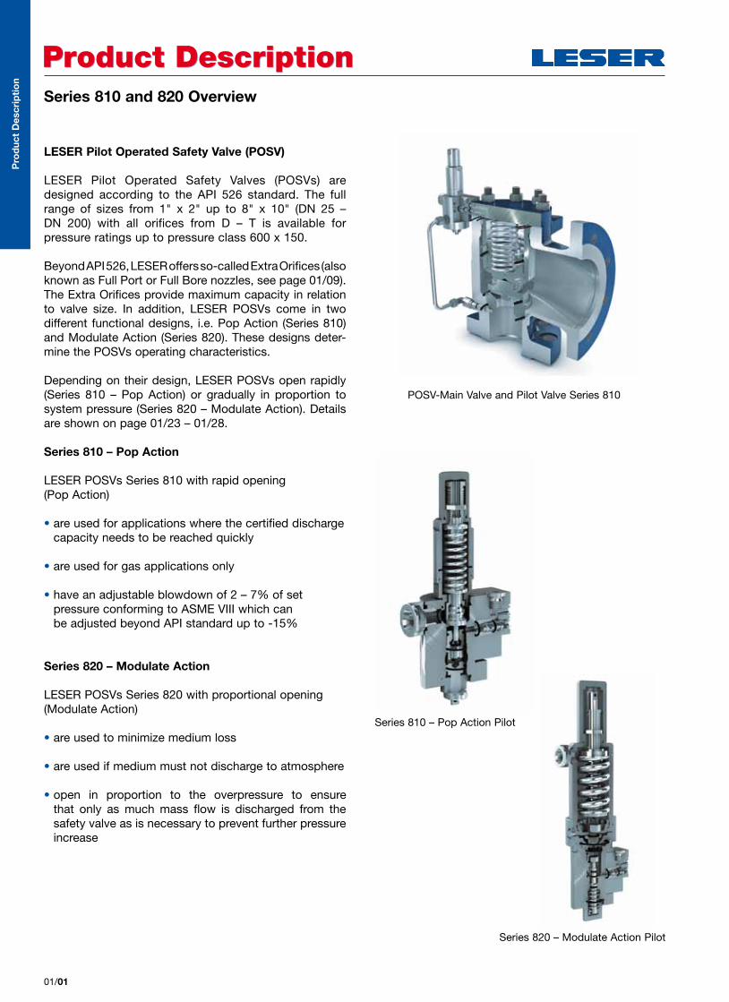
LESER Pilot Operated Safety Valve (POSV)
LESER Pilot Operated Safety Valves (POSVs) are designed according to the API 526 standard. The full range of sizes from 1" x 2" up to 8" x 10" (DN 25 – DN 200) with all orifices from D – T is available for pressure ratings up to pressure class 600 x 150.
Beyond API 526, LESER offers so-called Extra Orifices (also known as Full Port or Full Bore nozzles, see page 01/09). The Extra Orifices provide maximum capacity in relation to valve size. In addition, LESER POSVs come in two different functional designs, i.e. Pop Action (Series 810) and Modulate Action (Series 820). These designs deter-mine the POSVs operating characteristics.
Depending on their design, LESER POSVs open rapidly (Series 810 – Pop Action) or gradually in proportion to system pressure (Series 820 – Modulate Action). Details are shown on page 01/23 – 01/28.
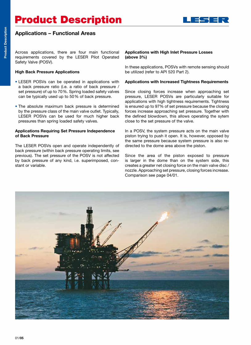
Series 810 – Pop Action
LESER POSVs Series 810 with rapid opening (Pop Action)
• are used for applications where the certified discharge capacity needs to be reached quickly
• are used for gas applications only
• have an adjustable blowdown of 2 – 7% of set pressure conforming to ASME VIII which can be adjusted beyond API standard up to -15%
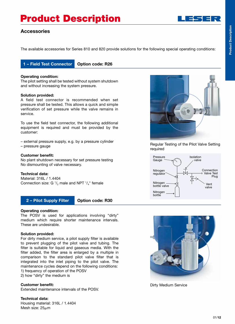
Series 820 – Modulate Action
LESER POSVs Series 820 with proportional opening (Modulate Action)
• are used to minimize medium loss
• are used if medium must not discharge to atmosphere
• open in proportion to the overpressure to ensure that only as much mass flow is discharged from the safety valve as is necessary to prevent further pressure increase
Product DescriptionProduct Description
POSV-Main Valve and Pilot Valve Series 810
Series 810 – Pop Action Pilot
Series 820 – Modulate Action Pilot
Pro
duc
t D
escr
ipti
on

Pro
duc
t D
escr
ipti
on
Series 810 and 820 Specifications and Approvals
The LESER Pilot Operated Safety Valve (POSV) comprises the POSV main valve and a pilot valve based on either the Pop Action (Series 810) or the Modulate Action (Series 820) designs. The table below shows their common and their specific features.
Specification at a glance
Product DescriptionProduct Description
1) The possible flange pressure ratings depend on the size of the valve. Refer to page 02/11 to verify the correct option codes and availability of DIN EN and JIS flange ratings.
LESER Pilot Operated Safety Valve (Main Valve and Pilot Valve)Common features for Series 810 and 820
Flange pressure rating1) acc. to ASME B16.5 CL150 – CL 600acc. to DIN EN 1092-1 PN 10 – PN 63
Materialsacc. to ASME B16.5 WCB, LCB, CF8M
acc. to DIN EN 1092-1 1.0619, 1.4408
Pressure range acc. to ASME B16.5 36 – 1480 psig
acc. to DIN EN 1092-1 2.5 – 63 bar
Sizeacc. to ASME B16.5 1" to 8"
acc. to DIN EN 1092-1 DN 25 – DN 200
Temperatureacc. to ASME B16.5 -49 °F – 392 °F
acc. to DIN EN 1092-1 -45 °C – 200 °C
Orifice systemAPI Standard Orifice 1 D 2 – 8 T 10
Extra Orifice 1 G 2 – 8 T+ 10
Specific features of Series 810 and Series 820Series 810 820Type 811 821Pilot action type Pop Action Modulate ActionFull Open (overpressure) 1% max. 10%
Blowdown 3 to 7% adjustable (adjustable also beyond API standard from 2 up to 15%) max. 7% fixed
Application Gas Steam, gases and liquids
01/02
POSV Approvals
Additional Approval Information for Series 810 and 820 POSVs
Approvals for Canada, China and Russia are also available.
LESER Pilot Operated Safety Valves can be used world-wide, as they comply with the following inter national codes and standards:
• USA: UV-Stamp acc. to ASME Section VIII Division 1, National Board certified capacities for steam, gases and liquids
• European Community: CE marking as per Pressure Equipment Directive 97/23/EC and EN ISO 4126-4
• Germany: VdTUEV approval as per Pressure Equipment Directive, EN ISO 4126-4, VdTUEV – Merkblatt SV 100/1
The design, manufacture and marking of LESER’s Pilot Operated Safety Valves also complies with the following regulations:
ASME PTC 25, ASME-Code Sec. II, ASME B16.34 and ASME B16.5, API Std. 527, API RP 576, EN ISO 4126-7, EN 12266-1/-2, EN 1092 part I and II
Series 810 Series 820 USA Coefficient of discharge K
ASME Sec. VIII Div. 1
Steam Approval No. Not approved M37280Coefficient of discharge K Not approved 0.82
GasApproval No. M37268
Coefficient of discharge K 0.82 0.82
LiquidApproval No. Not approved M37268
Coefficient of discharge K Not approved 0.689 European Community Coefficient of discharge Kdr
DIN EN ISO 4126-4Approval No. 07 202 1321 Z 0038/9/01
S/G G: 0.82 S/G: 0.82L Not approved 0.690
Germany Coefficient of discharge w
AD 2000-Merkblatt A2Approval No. TÜV SV 10-1126
S/G G: 0.82 S/G: 0.82L Not approved 0.69

01/03
Product DescriptionProduct DescriptionGood Reasons for the LESER Pilot Operated Safety Valve
Pilot operated safety valves have been a proven tech-nology for many decades especially in ASME oriented regions. However, some of the older designs show potential for improvement in areas like external tubing, capacity and delivery times. Based on customer feed back and extended research and using Computational Fluid
Dynamics (CFD), Rapid Prototyping and one of the most modern factories for safety valves, LESER has developed the latest POSV on the market. The new LESER POSV offers unique benefits for both users and assemblers /maintenance personnel that are listed below.
Feature Benefit for userBenefit for
assembler / maintenance
Design
Tubing between pilot valve and main valve integrated into top plate
• Less risk of damage to tubing
• Resistant against vibration
• No freezing
• Less tubing for easy removal of top plate
• Tubing between inlet and pilot remains accessible for easy cleaning
Backflow preventer integrated into manifold block as a standard component
• Easy ordering, no extra cost
• Less risk of damage to backflow preventer
• No need for machining to retrofit backflow preventer
Integral cast support brackets
• Compensation of reactiveforces (high pressures)
• Easy handling during installation
Pilot valve manufactured completely from stainless steel
Less corrosion for higher operation reliability
NACE conversion only requires exchange of spring
All medium-wetted parts in tubing and pilot valve are either stainless steel or nickel-coated
Corrosion resistance
Pro
duc
t D
escr
ipti
on

01/04
Product DescriptionProduct Description
Feature Benefit for userBenefit for
assembler / maintenance
High capacity / small size
EXTRA ORIFICE
Higher capacity for same valve size with Extra Orifice types. For details see page 01/09
Smaller valve sizes possible Small footprint in system
-20
%
OthersLESER POSV
20% less space requirement than typical competitive designs
Space-saving system designs possible
Small footprint in system
Modular system
Pop Action and ModulateAction pilot valves can beexchanged without tubingmodification
Easy later upgrade Less spare parts stock required. Easy conversion between Pop Action and Modulate Action pilot valve
LESER service
Sizing with VALVESTAR Comprehensive documenta-tion in multiple languages
4 weeks
delivery time
Four weeks delivery ex works for most types
Quick availability
Manufactured in Germany Consistently high manufacturing quality
VALVESTAR®P
rod
uct
Des
crip
tio
n
Applications – Functional Areas
Across applications, there are four main functional requirements covered by the LESER Pilot Operated Safety Valve (POSV).
High Back Pressure Applications
• LESER POSVs can be operated in applications with a back pressure ratio (i.e. a ratio of back pressure / set pressure) of up to 70%. Spring loaded safety valves can be typically used up to 50% of back pressure.
• The absolute maximum back pressure is determined by the pressure class of the main valve outlet. Typically, LESER POSVs can be used for much higher back pressures than spring loaded safety valves.
Applications Requiring Set Pressure Independence of Back Pressure
The LESER POSVs open and operate independently of back pressure (within back pressure operating limits, see previous). The set pressure of the POSV is not affected by back pressure of any kind, i.e. superimposed, con-stant or variable.
Applications with High Inlet Pressure Losses (above 3%)
In these applications, POSVs with remote sensing should be utilized (refer to API 520 Part 2).
Applications with Increased Tightness Requirements
Since closing forces increase when approaching set pressure, LESER POSVs are particularly suitable for applications with high tightness requirements. Tightness is ensured up to 97% of set pressure because the closing forces increase approaching set pressure. Together with the defined blowdown, this allows operating the sytem close to the set pressure of the valve.
In a POSV, the system pressure acts on the main valve piston trying to push it open. It is, however, opposed by the same pressure because system pressure is also re-directed to the dome area above the piston.
Since the area of the piston exposed to pressure is larger in the dome than on the system side, this creates a greater net closing force on the main valve disc / nozzle. Approaching set pressure, closing forces increase. Comparison see page 04/01.
Product DescriptionProduct Description
01/05
Pro
duc
t D
escr
ipti
on

Product DescriptionProduct Description
01/06
Applications – Examples
Compressors in Gas Main Systems Pressure relief devices in these applications must allow for high operating pressures in relation to set pressure, which are required for efficient gas transport. Additionally, compressor vibrations put through requirements on the tightness of the safety valve.
LESER Series 810 and 820 POSVs offer an ideal solution for these conditions because:
• they enable highest possible operating pressure to set pressure ratios facilitating maximum energy density of transport medium
• they are not susceptible to leakage caused by com-pressor vibration as are spring loaded safety valvess
Downstream Oil and Gas Industry Long pipings to the flare systems and common blow-down are frequently used in refineries. Both conditions lead to high back pressure of 50% of set pressure or more.
LESER Series 810 and 820 POSVs are used in these applications because:
• they offer high back pressure to set pressure ratios• they operate reliably independent of back pressure
Upstream Oil and Gas Industry Offshore platforms have especially high tightness require-ments to avoid leakage. Furthermore, the weight and size of the safety valves should be minimized due to space limitations on the platform.
LESER Series 810 and 820 POSVs are ideal for the up -stream oil and gas industry because of:
• their high tightness up to set pressure• their bonnetless design which allows lower weight and
lower valve height
Pumps in All IndustriesSystems with positive displacement pumps are protect-ed by safety valves. The medium is often discharged to the suction side of the pump which creates back pres-sure.
LESER Series 810 and 820 POSVs are used because:
• they operate independently of back pressure• they allow high back pressure to set pressure ratios
Because of their suitability for high back pressure and high tightness applications, LESER Pilot Operated Safety Valves (POSVs) are used in a number of industrial areas including the following: P
rod
uct
Des
crip
tio
n

Product DescriptionProduct Description
01/07
Sour Gas Applications (NACE)
LESER Pilot Operated Safety Valves (POSVs) are available for sour gas (H2S) service.
Regulatory Requirements
The material requirements for hydrogen sulfide (H2S) service (sour gas service) are specified in the NACE standards, MR0175/ISO 15156 (Upstream processes), and MR0103 (Downstream processes). Since the body of
the pilot valve is manufactured from stainless steel, only the spring in the pilot valve of the Series 810 Pop Action POSV and the dome spring in the main valve need to be replaced for compliance with NACE MR0175 standard.
Standard MR0175/ISO 15156 MR0103
Application Upstream processes Downstream processes (Refineries)
Content
Petroleum and natural gas industries – Materials for use in H2S-containing
environments in oil and gas production
Materials resistant to Sulfide Stress Cracking in Corrosive Petroleum Refining environments
– Rigid requirements for materials resistant to SSC for petroleum production, drilling, gathering, flow line equipment and field processing facilities to be used in H2S bearing hydrocarbon service
– Provides a standard set of requirements for materials used in sour petroleum refinery equipment
– Applies to upstream processes (gas production and treatment)
– Applies to downstream (e.g. refining and gas processing) environments (broader range of sour environments)
MaterialCarbon Steel 22 HRC max. and more stringent welding
requirementNo base metal hardness requirements on P-No. 1 Group 1 or 2 (WCB, A105 forgings, LCB)
Austenitic Stainless Steel (316 SS)
Maximum hardness of 22 HRC Maximum hardness of 22 HRCNo temperature limitations
The following parts of the LESER POSV are affected by NACE sour gas standards requirements. Parts with a check mark are compliant with the relevant standard (Option code R70).
959
6
8
1
7
5
54
1
42
1 Body 5 Nozzle 6 Piston 7 Disc 8 Piston guide 9 Top plate
59 Dome spring Inconel®
Main Valve NACE-compliant materials
1 Pilot body 42 Return spring N/A 54 Spring Inconel® Not affected
Pilot Valve Series 810 Series 820
To achieve NACE International conformity for Series 810, only the spring needs to be manufactured in Inconel® material. Spring (54) of Series 820 is not affected by the medium and therefore does not need to be exchanged. Return spring (42) is manufactured in Inconel® material as a standard material. To order the NACE compliant LESER POSV, please select option code R70.
Pro
duc
t D
escr
ipti
on
Pilot Series 810 Pilot Series 820

Product DescriptionProduct Description
01/08
Design Features
The following sections discuss the specific design and functional features of LESER's Pilot Operated Safety Valves (POSV) Series 810 und 820 which enable their application benefits. These benefits include:
• API 526 design ensuring standard valve sizes, dimen-sions and capacities for easy exchangeability in plants designed according to API standards
• API 526 product range with valve sizes from 1" to 8", orifice D to T, and pressure ratings up to Class 600
• Additional Extra Orifices allowing to use a smaller valve size for a given orifice letter or capacity
• Flange connections according to ASME, EN and JIS available, which guarantee worldwide suitability
• Tubing between main valve and pilot valve integrated into top plate
• One design and spring (single trim) for gas and liquid applications reduces the number of spare parts and ensures low cost maintenance
• Body materials WCB, CF8M, LCB, 1.069, 1.4408 available from stock. Further materials on request.
• Back pressure independent design allows external back pressure up to 70% of set pressure in most applications
• Metal discs or o-ring discs for a wide spectrum of applications
• NACE compliant materials enable NACE applications with minimal need for parts exchange as well as short delivery times
• Backflow preventer included as a standard feature – for details see page 01/10
• Easy-to-repair “top loader” design. This means the valve seat is a single part and can be installed from the top without the need to remove the entire POSV from the plant.
In addition, the Series 820 – Modulate Action POSV is available in a diaphragm or piston design depending on the operating pressure range. For details on these designs, see “Diaphragm or Piston Design” in the sec-tion on the Series 820 – Modulate Action POSV see page 01/25.
Pro
duc
t D
escr
ipti
on

Product DescriptionProduct Description
LWN 487.71-E01/09
Seat Designs: API Standard Orifices and Extra Orifices
API Standard Orifice
Extra Orifice
The main valve of the LESER POSV Series 810 and 820 comes in a variety of orifices. These orifices are obtained by varying the diameter of the main valve nozzle (see illustrations below). For each nominal valve size, LESER offers several orifices which are in accordance with the API orifice system. These are termed API Standard Orifices. In addition, for each nominal valve size a full
bore nozzle is also available where the orifice is beyond the API orifice system. LESER refers to this orifice as an Extra Orifice. With an Extra Orifice, the customer often has the choice to use a smaller valve size for a required orifice and capacity (for details see page 03/09). See below for design details and illustrations regarding the Standard and Extra Orifices.
In the POSV, nominal valve sizes correspond to standard API and Extra Orifices as shown in the following table. Extra Orifice letters followed by a plus (+) sign, e.g. “K+”, mean that these valves offer at least 25% more capacity than specified in API 526. For capacity values for Standard and Extra Orifices see the capacity tables on page 03/09.
Below are the details of the different nozzle designs for API Standard and Extra Orifices:
The API Standard Orifice ensures that the safety valve is in accordance with the API 526 orifice system.
The maximum drilling of the main valve seat (full bore) allows to discharge the maximum capacity in relation to the nominal valve size.
Full bore safety valves comply with API 526 except for their orifice, so their orifice is identified by a Extra Orifice letter.
DNI+O 25 x 50 40 x 50 40 x 80 50 x 80 80 x 100 100 x 150 150 x 200 200 x 250
Valve size 1" x 2" 11/2" x 2" 11/2" x 3" 2" x 3" 3" x 4" 4" x 6" 6" x 8" 8" x 10"
API Standard Orifice acc.
to API 526D E F D E F G G H G H J J K L L M N P Q R T
Extra Orifice G H J K+ N+ P+ R+ T+
Pro
duc
t D
escr
ipti
on
API Standard Orifice
Extra Orifice

Product DescriptionProduct DescriptionComponents
The LESER Pilot Operated Safety Valve (POSV) consists of four main components in its standard configuration:
• the main valve, which serves to protect the pressurized equipment
• the pilot valve, which controls the opening and closing of the main valve
• the tubing is identical for both POSV Series, i.e. 810 and 820
• the manifold block with integrated backflow preventer (standard feature)
The backflow preventer prevents an unwanted open-ing of the main valve, which would cause backflow of medium from the outlet into the protected system. This problem can occur when there is back pressure that exceeds the inlet pressure (or insufficient pressure at the inlet), resulting in a net force acting on the valve piston in the opening direction, such as e.g. in a process running under vacuum.
01/10
Pro
duc
t D
escr
ipti
on
Backflow Preventer Included in standard configuration
POSV Main valve, pilot valve, tubing and manifold block
Manifold block
Pilot valve
Tubing
Main valve

Product DescriptionProduct DescriptionAccessories
For both series of the LESER Pilot Operated Safety Valve (POSV) the following accessories are available. The accessories allow the adaptation of your safety valve to various special operating conditions.
01/11
Overview Maximum configuration
Pro
duc
t D
escr
ipti
on
Manual blowdownOption code R24Option code R27
Field test connectorOption code R26
4
*
3
Pilot supply filterOption code R30
Remote sensingOption code R28
Backflow preventer(standard feature)
2
1
Product DescriptionProduct Description
Operating condition:The POSV is used for applications involving “dirty” medium which require shorter maintenance intervals. These are undesirable.
Solution provided:For dirty medium service, a pilot supply filter is available to prevent plugging of the pilot valve and tubing. The filter is suitable for liquid and gaseous media. With the filter added, the filter area is enlarged by a multiple in comparison to the standard pilot valve filter that is integrated into the inlet piping to the pilot valve. The maintenance cycles depend on the following conditions:1) frequency of operation of the POSV2) how “dirty” the medium is
Customer benefit:Extended maintenance intervals of the POSV.
Technical data:Housing material: 316L / 1.4404Mesh size: 25m
Operating condition:The pilot setting shall be tested without system shutdown and without increasing the system pressure.
Solution provided:A field test connector is recommended when set pressure shall be tested. This allows a quick and simple verification of set pressure while the valve remains in service.
To use the field test connector, the following additional equipment is required and must be provided by the customer:
– external pressure supply, e.g. by a pressure cylinder– pressure gauge
Customer benefit:No plant shutdown necessary for set pressure testingNo dismounting of valve necessary.
Technical data:Material: 316L / 1.4404 Connection size: G 1/2 male and NPT 1/4" female
The available accessories for Series 810 and 820 provide solutions for the following special operating conditions:
Regular Testing of the Pilot Valve Setting required
Dirty Medium Service
Accessories
01/12
1 – Field Test Connector Option code: R26
2 – Pilot Supply Filter Option code: R30
Pro
duc
t D
escr
ipti
on
Pressure Gauge
Isolation valve
Vent valve
Connection Valve Test
Plug
Nitrogen regulator
Nitrogen bottle valve
Nitrogen bottle

Product DescriptionProduct DescriptionAccessories
Operating condition:The lifting of the piston shall be tested without switching of the pilot valve. To achieve a piston lift the dome volume must be released manually and refilling of the dome must be avoided. The testing of the piston may be required when the medium tends to block the piston. Manual blowdown cannot be used for set pressure testing.
Solution provided:The manual blowdown allows lifting of the main valve by bypassing the pilot valve. Thus, the piston dome pres-sure can be discharged: 1) to atmosphere (Option Code R27) or 2) to the main valve outlet (Option Code R24)Customer benefit:No plant shutdown necessary to test valve liftingNo dismounting of the safety valve necessary for testing purposes
LESER offers two different types of discs for different applications to achieve optimum tightness:
For material details see page 01/24.
Operating condition:Due to an unfavourable position or length of the inlet pipe excessive pressure loss may occur. This can lead to chat-tering of the safety valve especially with Pop Action POSVs and the safety valve cannot discharge as much medium as required. This may also damage the safety valve.
Solution provided:The pilot valve pressure pick up is piped to a location which is remote from the main valve. The pilot will oper-ate independently of a possible pressure loss in the inlet pipe. The tapping point must be chosen so as to avoid pressure loss resulting from flow influences.
LESER supplies the plug at the main valve and the fitting (NPT 3/8") for the customer remote sensing pipe to the pilot.
The pipe itself and its welding to the system must be pro-vided by the customer. Parameters determining the maxi-mum length of the inlet pipe are the pipe diameter, the static height of the medium and the viscosity of the medium.
Customer benefit:No reworking of inlet pipe necessary in case of high inlet pressure drop.
O-RingStandard application
Metal discHigh tempertaure and high pressure
01/13
3 – Manual Blowdown Option code: R27 (blowdown to atmosphere), R24 (blowdown to main valve outlet)
4 – Remote Sensing Option code: R28
5 – Sealing Accessories Option codes: see page 02/15 6 – NACE requirements Option code: R70
Valve Lifting Test without Actuation of Pilot Valve required
Inlet pressure drop
Pro
duc
t D
escr
ipti
on

Product DescriptionProduct DescriptionOperating Cycle
LESER Pilot Operated Safety Valve (POSV) is controlled by process medium. To achieve this, the system pressure is applied to the pilot valve (= control component for the main valve) via the pressure pickup. The pilot valve then uses the dome above the main valve piston to control the opening and closing of the main valve.
While there are specific differences between the Series 810 – Pop Action POSV and the Series 820 – Modulate Action POSV, the basic operation of a LESER POSV can be described as follows. During operation, the POSV goes through these basic operating states:
1. Below set pressure: normal operationDuring normal operation, the system pressure is picked up at the main valve inlet and routed to the dome (see illustration). Since the dome area is larger than the area of the main valve seat, the closing force is greater than the opening force. This keeps the main valve tightly closed.
2. At set pressure: actuating state At set pressure, the pilot valve actuates. The medium is no longer routed to the dome (see illustration). This prevents a further rise in dome pressure. Also, the dome is vented. As a result, the closing force ceases as a pre-condition for the system overpressure to push the main valve open.
3. Main valve openingThe main valve opens. Depending on the design of the pilot valve, this opening is either rapid and complete (Pop Action) or gradual and partial following system pressure (Modulate Action).
4. At closing pressure: refilling the domeIf system pressure drops to closing pressure, the pilot valve actuates and again routes the medium to the dome. The pressure in the dome builds up and the main valve recloses either rapid and complete (Pop Action) or gradual and partial following system pressure (Modulate Action).
Operating states of the POSV
01/14
Pro
duc
t D
escr
ipti
on
1.
2.
3.
4.

Product DescriptionProduct DescriptionSeries 810 – Pop Action Features
The Series 810 – Pop Action Pilot Operated Safety Valve (POSV) is characterized by rapid opening, or pop action. When set pressure is reached, the dome of the main valve is vented quickly and completely and the main valve opens just as quickly and completely. The medium from the dome is discharged to atmosphere. The Pop Action POSV is used mainly for gas applications.
Product Features
Robust and insensitive to vibrations. The robust con-nection of the pilot valve (= control valve for the main valve) to the main valve and the reduced exposed piping guarantee safe operation even if there are vibrations in the system.
Easy spring replacement. The spring is easily accessible. This allows simple replacement of the spring, saving time and costs. In order to replace the spring only the top sec-tion of the bonnet needs to be removed. Other functional parts or soft goods do not have to be disassembled and therefore do not need to be replaced.
Easy blowdown setting within the requirements of codes and standards. LESER sets the blowdown in the range of 3 – 7%, which conforms to codes and stand-ards. This setting can easily be adjusted. Other testing devices are not required.
A large pressure range of 2.5 – 102 bar (36 – 1480 psig) ensures that the Series 810 Pop Action POSV can be used for a wide variety of applications.
Easy material replacement. The complete pilot valve is machined from bar material in 1.4404 / 316L. Hence, the pop action pilot valve can be made from customized materials easily within short lead time. Materials see page 01/23.
Series 810 Pop Action Pilot Valve
01/15
Pro
duc
t D
escr
ipti
on

Product DescriptionProduct DescriptionSeries 810 – Pop Action Operating Cycle
1. Below set pressure: normal operation – feeding seat open, exhaust seat closed
The system pressure is routed to the top side of the main valve piston via the pressure pickup, the pilot valve and the dome of the main valve (see illustration). Since the pressure contact surface is larger on the top side than on the underside of the piston, there is always a stronger net force acting on the top side. The main valve is kept tightly closed.
2. At set pressure: feeding seat opening, exhaust seat closing
When set pressure is reached, the pilot valve opens the exhaust seat and closes the feeding seat. This releases the dome pressure. The release of dome pressure is a pre-condition for the opening of the main valve by system pressure.
3. At and above set pressure (+ max. 1%): pop openingAt set pressure, the main valve opens abruptly and completely feeding seat closed, exhaust seat open (Pop Action) (see bottom chart). The medium is channelled from the dome to atmosphere (see illustration on right).
4. At closing pressure: feeding seat open, exhaust seat closed
When the system pressure drops to closing pressure, the pilot valve actuates and again channels the system pressure to the dome of the main valve. Here, the sys-tem pressure builds up, the main valve recloses. The closing stage (blowdown) can be adjusted from at least 3% (when pressure loss at the inlet is low) to max. 15% blowdown difference.
Opening Characteristic with Overpressure and Blowdown Difference: Series 810 Pop Action
01/16
1 2
4 3
Set pressure Pressure
Lift
Pro
duc
t D
escr
ipti
on
1
2 3
4
1 – Below set pressure: normal operation2 – At set pressure3 – Pop opening4 – At closing pressure – blowdown
Operating states Series 810

Product DescriptionProduct DescriptionSeries 820 – Modulate Action Features
01/17
The pilot valve in the Series 820 – Modulate Action Pilot Operated Safety Valve (POSV) does not open the main valve abruptly after reaching set pressure (pop action), but in modulating to the system overpressure (modulate action). Above set pressure, only as much mass flow is discharged as is needed to prevent a further pressure increase. This avoids an unnecessary loss of medium.
The LESER Modulate Action POSV is suitable for liquid as well as for steam and gas applications.
Product Features
The LESER Series 820 – Modulate Action POSV has the same design related benefits as the Series 810 – Pop Action POSV. This means that it can be manufactured and delivered without any problems in special materials. It is robust, spare replacement is uncomplicated and it has a large pressure range of 2.5 – 102 bar (36 – 1480 psig). Furthermore, it offers the following specific benefits:
Suitability for media that are harmful to health / environment. The Series 820 – Modulate Action POSV releases the medium from the dome into the main valve outlet and not into the atmosphere like the Pop Action POSV. Since back pressure can occur here, the Modulate Action pilot valve has a back pressure compensating design.
Same performance, full lift. The LESER Series 820 – Modulate Action POSV has the same discharge capacity and the same lift when completely open as the Series 810 – Pop Action POSV.
Series 820 Modulate Action Pilot Valve
(Diaphragm design)
Pro
duc
t D
escr
ipti
on
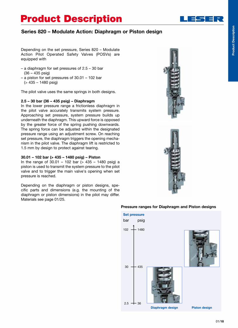
Product DescriptionProduct DescriptionSeries 820 – Modulate Action: Diaphragm or Piston design
Depending on the set pressure, Series 820 – Modulate Action Pilot Operated Safety Valves (POSVs) are equipped with
– a diaphragm for set pressures of 2.5 – 30 bar (36 – 435 psig)
– a piston for set pressures of 30.01 – 102 bar (> 435 – 1480 psig)
The pilot valve uses the same springs in both designs.
2.5 – 30 bar (36 – 435 psig) – DiaphragmIn the lower pressure range a frictionless diaphragm in the pilot valve accurately transmits system pressure. Approaching set pressure, system pressure builds up underneath the diaphragm. This upward force is opposed by the greater force of the spring pushing downwards. The spring force can be adjusted within the designated pressure range using an adjustment screw. On reaching set pressure, the diaphragm triggers the opening mecha-nism in the pilot valve. The diaphragm lift is restricted to 1.5 mm by design to protect against tearing.
30.01 – 102 bar (> 435 – 1480 psig) – Piston In the range of 30.01 – 102 bar (> 435 – 1480 psig) a piston is used to transmit the system pressure to the pilot valve and to trigger the main valve's opening when set pressure is reached.
Depending on the diaphragm or piston designs, spe-cific parts and dimensions (e.g. the mounting of the diaphragm or piston dimensions) in the pilot may differ. Materials see page 01/25.
01/18
Pro
duc
t D
escr
ipti
on
Pressure ranges for Diaphragm and Piston designs
Diaphragm design Piston design
Set pressure
bar psig
102
30
2.5
1480
435
36

Product DescriptionProduct DescriptionSeries 820 – Modulate Action Operating Cycle
1. Below set pressure: normal operation – feeding seat open, exhaust seat closed
The system pressure is routed to the dome, keeping the main valve tightly closed (see illustration).
1a. Near set pressure: feeding seat closed, exhaust seat closed (not shown)
Shortly before set pressure is reached, the pilot valve closes the dome feeding seat. This keeps the dome pres-sure stable. A stable dome volume is the pre-condition which allows the rising system pressure to push the main valve open at set pressure.
2. At set pressure (+ max. 1%): feeding seat closed, exhaust seat open
With a further slight pressure increase, set pressure is reached and the pilot valve opens the dome exhaust seat. The dome volume is discharged and the main valve opens.
The operating cycles of the Series 820 – Modulate Action and the Series 810 – Pop Action POSV differ at two points: shortly before set pressure is reached (see below, 1 and after reaching set pressure. At this second point actual modulation takes place in the Series 820 – Modulate Action POSV. Modulation means that above
set pressure the pilot valve will open the main valve in proportion to overpressure. Thus, there may only be a partial lift of the main valve. This ensures that only as much medium is discharged as is required for pressure reduction. Any unnecessary medium loss is avoided.
01/19
1
2
Opening Characteristic with Overpressure and Blowdown Difference: Series 820 – Modulate Action vs. Spring Loaded Safety Valve
21
34
93% 98% 100% 110%Pressure
Lift
Blowdown2% – 7%
Set pressure
LESER spring- loaded safety valve for com parison only
Pilot-operated safety valve Series 820
1 – Below set pressure: normal operation2 – At set pressure3 – Modulate opening4 – At closing pressure – blowdown
Pro
duc
t D
escr
ipti
on
Operating states Series 820

Series 820 – Modulate Action Operating Cycle
3. Modulate opening: feeding seat closed or open, exhaust seat closed or open
At this point, modulation takes place. This means that if overpressure remains within the modulating range of 93 – 110% of set pressure, the pilot valve will again close the dome exhaust seat. This stops discharge from the dome and keeps the main valve piston unchanged at the achieved lift. The achieved lift will always be enough to ensure pressure reduction, but not more than is required. During blow-off this intermediate state with a stable dome volume and main valve lift can occur repeatedly and at different pressure levels. To change the lift, there can also be partial opening movements with the exhaust seat opened, or closing movements with the feeding seat opened. Modulation ensures that only as much medium is discharged as is necessary to prevent the overpressure from exceeding the modulating range (see chart page 01/19).
4. At closing pressure: full closing – feeding seat open, exhaust seat closed
When system pressure drops below the modulating range to reach blowdown pressure , the pilot returns to its first state (with feeding seat open and exhaust seat closed). The main valve closes completely.
Product DescriptionProduct Description
01/20
4
Pro
duc
t D
escr
ipti
on
3

Product DescriptionProduct DescriptionMaterials Series 810, 820 Main Valve
01/21
Below is a schematic drawing of the parts layout for the LESER POSV main valve including both the Standard and Extra Orifice designs. For the related parts listing, see opposite page. P
rod
uct
Des
crip
tio
n
55 Stud
56 Nut
60 O-ring, inner top plate seal
67 O-ring, outer top plate seal
59 Dome spring
8 Piston guide
6 Piston, complete
6.2 Piston top
6.5 Guide ring
6.3 O-ring, piston
6.4 Backup ring
6.1 Piston body
6.5 Guide ring
6.6 Allen head screw
7 O-ring disc, complete
7.1 O-ring disc
7.2 Disc retainer
7.4 Nut
5 Nozzle
4 Fitting
62 Backup ring
63 O-ring, pitot tube
61 O-ring, seat seal
3 Tube
2 Pitot tube
1 Body
58 Screw
9 Top plate

Materials Series 810, 820 Main Valve
Product DescriptionProduct Description
01/22
Materials
Item Component Type 8112 / 8212 Type 8114 / 8214 Type 8113 / 8213
1 Body1.0619 1.4408
SA 216 WCB SA 351 CF8M SA 352 LCB
2 Pitot tube1.4404 1.4404 1.4404316L 316L 316L
3 Tube1.4404 1.4404 1.4404316L 316L 316L
4 Fitting1.4404 1.4404 1.4404316L 316L 316L
5 Nozzle1.4404 1.4404 1.4404316L 316L 316L
6 Piston, complete
1.4404 1.4404 1.4404316L 316L 316L
6.1 Piston body1.4404 1.4404 1.4404316L 316L 316L
6.2 Piston top1.4404 1.4404 1.4404316L 316L 316L
6.4 Backup ringPTFE PTFE PTFEPTFE PTFE PTFE
6.5 Guide ringPTFE with carbon PTFE with carbon PTFE with carbonPTFE with carbon PTFE with carbon PTFE with carbon
6.6 Allen head screwA4-70 A4-70 A4-70
Stainless steel Stainless steel Stainless steel
7 O-ring disc, complete
1.4404 1.4404 1.4404316L 316L 316L
7.1 O-ring disc1.4404 1.4404 1.4404316L 316L 316L
7.2 Disc retainer1.4404 1.4404 1.4404316L 316L 316L
7.4 NutA4-70 A4-70 A4-70
Stainless steel Stainless steel Stainless steel
8 Piston guide1.4404 1.4404 1.4404316L 316L 316L
9 Top plate1.0460 1.4404 1.406SA 105 316L SA105
55 Stud1.7225 1.4401 1.7225B7M B8M B7M
56 Nut1.7225 1.4401 1.7225
2H 8M 2HM
58 ScrewA4-70 A4-70 A4-70
Stainless steel Stainless steel Stainless steel
59 Dome spring1.4310 1.4310 1.4310
Stainless steel Stainless steel Stainless steel
62 Backup ringPTFE PTFE PTFEPTFE PTFE PTFE
Option code
6.3, 6.4, 7.3, 60, 61, 63,
67
O-ring1)
* Viton® (FKM – Fluorocarbon)
R05 Buna-EP® (EPDM – Ethylene-Propylene-Dine)
R06 Kalrez® (FFKM – Perfluor)
Pro
duc
t D
escr
ipti
on
Please notice:
– Modifications reserved by LESER.– LESER can upgrade materials without notice.– Every part can be replaced by other material acc. to customer specification.
1) For further soft seal materials refer to page 02/15

Product DescriptionProduct DescriptionMaterials Series 810Pop Action Pilot Valve
Below is a schematic drawing of the parts layout for the LESER Series 810 – Pop Action pilot valve.For the related parts listing, see opposite page.
01/23
40 Cap
18 Adjusting screw
19 Lock nut
54 Spring
9 Bonnet
17 Spring plate (lower)
11 Piston guide
10 Bonnet, base part
2 Guide
31 O-ring, seat seal
13 Seat, exhaust (upper)
14 Seat, exhaust (lower)
35 Gasket
15 Plunger
5 Seat, feeding
30 O-ring, seat seal
7 Disc, feeding (upper)
8 Disc, feeding (lower)
1 Body
32 O-ring, piston seal
20 Nut
12 Adjusting screw
21 Counter nut
16 Spring plate (upper)
Pro
duc
t D
escr
ipti
on
Bug screen 64
Please notice:
– Modifications reserved by LESER.– LESER can upgrade materials without notice.– Every part can be replaced by other material acc. to customer specification.

Materials Series 810 Pop Action Pilot Valve
Product DescriptionProduct Description
01/24
Materials
Item Component Standard NACE
1 Body1.4404 1.4404
SA 479 316L SA 479 316L
2 Guide1.4404 1.4404
316L 316L
5 Seat, feeding1.4404 1.4404
316L 316L
7 Disc, feeding (upper)1.4404 1.4404
316L 316L
8 Disc, feeding (lower)1.4404 1.4404
316L 316L
9 Bonnet1.4404 1.4404
SA 479 316L SA 479 316L
10 Bonnet, base part1.4404 1.4404
SA 479 316L SA 479 316L
11 Piston guide1.4404 1.4404
316L 316L
12 Adjusting screw1.4404 1.4404
316L 316L
13 Seat, exhaust (upper)1.4404 1.4404
316L 316L
14 Seat, exhaust (lower)1.4404 1.4404
316L 316L
15 Plunger1.4404 1.4404
316L 316L
16 Spring plate (upper)1.4404 1.4404
316L 316L
17 Spring plate (lower)1.4404 1.4404
316L 316L
18 Adjusting screw1.4404 1.4404
316L 316L
19 Lock nut1.4404 1.4404
316L 316L
20 Nut1.4404 1.4404
316L 316L
21 Counter nut1.4404 1.4404
316L 316L
26 Piston1.4404 1.4404
316L 316L
35 GasketPTFE PTFE
40 Cap1.4404 1.4404
316L 316L
54 Spring1.4310 2.4669
Stainless steel INCONEL X750
64 Bug screenPlastic Plastic
Plastic Plastic
Option code
30, 31, 32 O-ring1)
* Viton® (FKM – Fluorocarbon)
R05 Buna-EP® (EPDM – Ethylene-Propylene-Dine)
R06 Kalrez® (FFKM – Perfluor)
Pro
duc
t D
escr
ipti
on
1) For further soft seal materials refer to page 02/15
Product DescriptionProduct Description
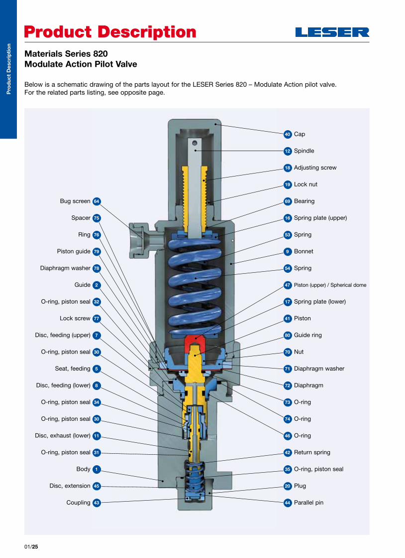
01/25
Materials Series 820Modulate Action Pilot Valve
Below is a schematic drawing of the parts layout for the LESER Series 820 – Modulate Action pilot valve.For the related parts listing, see opposite page.
40 Cap
12 Spindle
18 Adjusting screw
69 Bearing
16 Spring plate (upper)
53 Spring
9 Bonnet
54 Spring
47 Piston (upper) / Spherical dome
O-ring, piston seal 30
17 Spring plate (lower)
41 Piston
80 Guide ring
Spacer 75
Bug screen 64
Ring 76
Piston guide 79
Diaphragm washer 78
Guide 2
O-ring, piston seal 32
70 Nut
Disc, feeding (upper) 7
Lock screw 77
71 Diaphragm washerSeat, feeding 5
72 DiaphragmDisc, feeding (lower) 8
73 O-ringO-ring, piston seal 34
74 O-ringO-ring, piston seal 30
46 O-ringDisc, exhaust (lower) 11
O-ring, piston seal 31
35 O-ring, piston seal
42 Return spring
Body 1
44 Parallel pin
20 Plug
Coupling 43
Disc, extension 45
19 Lock nut
Pro
duc
t D
escr
ipti
on
Product DescriptionProduct Description
01/26
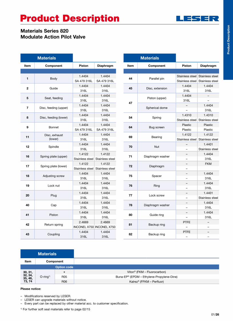
Materials Series 820Modulate Action Pilot Valve
Materials
Item Component Piston Diaphragm
1 Body1.4404 1.4404
SA 479 316L SA 479 316L
2 Guide1.4404 1.4404
316L 316L
5 Seat, feeding1.4404 1.4404
316L 316L
7 Disc, feeding (upper)1.4404 1.4404
316L 316L
8 Disc, feeding (lower)1.4404 1.4404
316L 316L
9 Bonnet1.4404 1.4404
SA 479 316L SA 479 316L
11Disc, exhaust
(lower)1.4404 1.4404
316L 316L
12 Spindle1.4404 1.4404
316L 316L
16 Spring plate (upper)1.4122 1.4122
Stainless steel Stainless steel
17 Spring plate (lower)1.4122 1.4122
Stainless steel Stainless steel
18 Adjusting screw1.4404 1.4404
316L 316L
19 Lock nut1.4404 1.4404
316L 316L
20 Plug1.4404 1.4404
316L 316L
40 Cap1.4404 1.4404
316L 316L
41 Piston1.4404 1.4404
316L 316L
42 Return spring2.4669 2.4669
INCONEL X750 INCONEL X750
43 Coupling1.4404 1.4404
316L 316L
Materials
Item Component Piston Diaphragm
44 Parallel pin Stainless steel Stainless steel
Stainless steel Stainless steel
45 Disc, extension1.4404 1.4404
316L 316L
47
Piston (upper)1.4404 –
316L –
Spherical dome– 1.4404
– 316L
54 Spring1.4310 1.4310
Stainless steel Stainless steel
64 Bug screenPlastic Plastic
Plastic Plastic
69 Bearing1.4122 1.4122
Stainless steel Stainless steel
70 Nut– 1.4401
– Stainless steel
71 Diaphragm washer– 1.4404
– 316L
72 Diaphragm– FKM
–
75 Spacer– 1.4404
– 316L
76 Ring– 1.4404
– 316L
77 Lock screw– 1.4401
– Stainless steel
78 Diaphragm washer– 1.4404
– 316L
80 Guide ring– 1.4404
– 316L
81 Backup ringPTFE –
– –
82 Backup ringPTFE –
– –
Pro
duc
t D
escr
ipti
on
Please notice:
– Modifications reserved by LESER.– LESER can upgrade materials without notice.– Every part can be replaced by other material acc. to customer specification.
1) For further soft seal materials refer to page 02/15
Materials
Item Component
Option code
30, 31, 32, 34, 35, 46, 73, 74
O-ring1)* Viton® (FKM – Fluorocarbon)
R05 Buna-EP® (EPDM – Ethylene-Propylene-Dine)
R06 Kalrez® (FFKM – Perfluor)

Product DescriptionProduct DescriptionMaterials Series 810, 820 Manifold block
Below is a schematic drawing of the parts layout for the Manifold block.For the related parts listing, see opposite page.
24.8 Gasket
24.6 O-ring
24.3 Piston
24.7 Lock screw
24.7 Lock screw
24.4 O-ring (Outlet)
24.4 O-ring (Outlet)
24.8 Gasket
24.1 Manifold block
Pro
duc
t D
escr
ipti
on
01/27
Bushing 24.2
O-ring 24.5
O-ring (Exhaust Series 820) 24.6
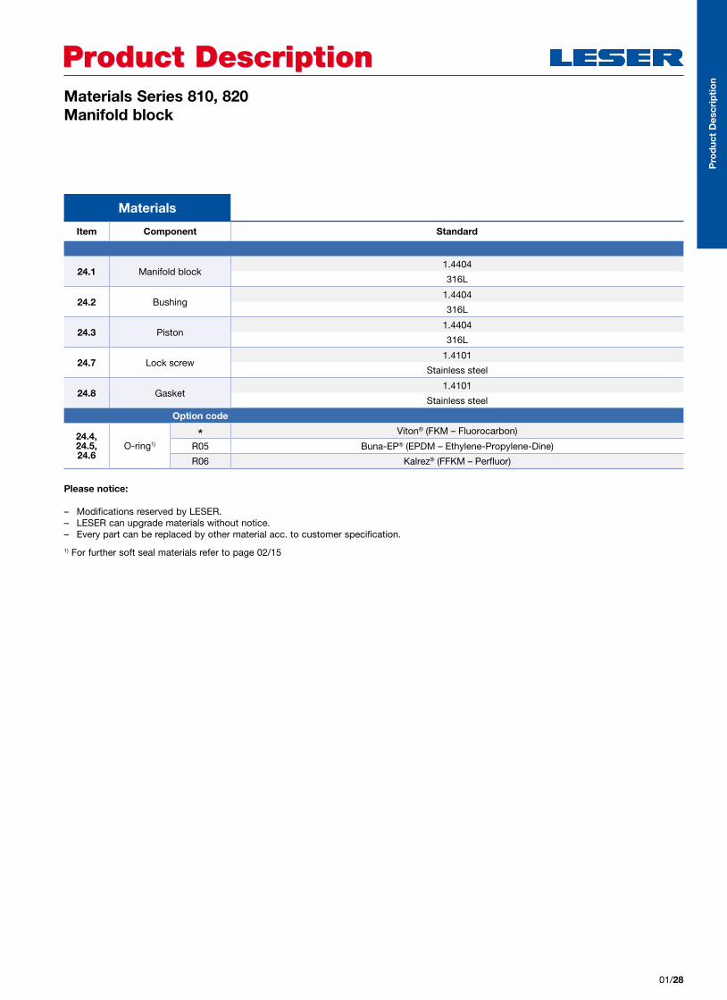
Materials Series 810, 820 Manifold block
Product DescriptionProduct Description
01/28
Materials
Item Component Standard
24.1 Manifold block1.4404
316L
24.2 Bushing1.4404
316L
24.3 Piston1.4404
316L
24.7 Lock screw1.4101
Stainless steel
24.8 Gasket1.4101
Stainless steel
Option code
24.4, 24.5, 24.6
O-ring1)* Viton® (FKM – Fluorocarbon)
R05 Buna-EP® (EPDM – Ethylene-Propylene-Dine)
R06 Kalrez® (FFKM – Perfluor)
Pro
duc
t D
escr
ipti
on
Please notice:
– Modifications reserved by LESER.– LESER can upgrade materials without notice.– Every part can be replaced by other material acc. to customer specification.
1) For further soft seal materials refer to page 02/15

Sizing and SelectionSizing and Selection
22 Material code2 – WCB / 1.06193 – LCB4 – CF8M / 1.4408
2
11 Type 811 – Pop Action821 – Modulate Action
See page 01/08 811
Article number
Type Material code Valve code
811 2 .0010
02/01
How to Construct the Article Number
LESER combines the steps of Sizing and Selection into one process. This means when you make the technical specifications for your LESER product you construct the order code for your order at the same time. The sizing also can be done with VALVESTAR®.
The article number is the most important part of the order code. The steps you follow in order to construct the article number for your LESER POSV are summarized.
On the following page, the steps for constructing the remainder of the order code are outlined. Note that these two overview pages only show sample data. The actual data for sizing and selection of your LESER POSV can be found on the pages indicated below under “Reference”.
StepSelectable Code /
ExplanationReference Example
33 Flange pressure rating
As a prerequisite, you need to know the operating pres-sure and operating tempera-ture of the application.
Then select the flange pressure rating from the selection chart indicated on the right.
For selection charts see page 02/03
-49
51
151
251
351
0 500 1000 1500 2000
p [psig]
p [bar]
T [
°F
]
T [
°C
]
-45
-10
25
60
95
130
165
2000 25 50 75 100 125
150 300 600
44Valve code
As a prerequisite, you need to know the connection sizes and the required orifice letter of your application. Alternatively, you can identify your orifice using LESER's VALVESTAR® software pro-gram or by using the dischar-ge capacity tables indicated on the right.
Based on the flange pressure rating, the connection size and the orifice you select the last three digits of your order code from the selection charts indicated on the right.
For discharge capacities see page 03/09
This example:Flange pressure range 150 x 150 Connection size: 1" x 2"Orifice: D .0010
Siz
ing
and
Sel
ecti
on
Valve size 1 x 2Standard Orifice acc. to API 526 D E F
Extra Orifice G
Body material: WCB 1.0619
Flange class
Art.-No.
150 x 150 8112. 0010 0020 0030 1820
300 x 150 8112. 0220 0230 0240 1900
600 x 150 8112. 0640 0650 0660 2060

Sizing and SelectionSizing and Selection
02/02
55 Set Pressure Here you indicate the pressure in gauge units
Application range 5 barg
99Code and Medium
3 1
1 2
.
See page 02/16 3.1
1 Code 1. ASME Section VIII2. CE / VdTUEV3. ASME Section VIII
+ CE / VdTUEV
2 Medium .1 Gases.2 Liquids.3 Steam .0 Steam / Gases /
Liquids (valid only for CE / VdTUEV)
Serie 810 certified only for steam and gases
77 Options Accessories for main valve and pilot valve
For accessories see page 02/14 For the standard
configuration see page 01/11
R27
66 Connections Option codes for dimensions and facings.
See page 02/11 and 02/13
H45H51
88 DocumentationSelect your required docu mentation, e.g. LESER Certificate for Global Application or material test certificates for individual parts
For required documentation see page 04/16
H01 L23
Order code
Set pressure Connections Options Documentation Code und Medium
5 barg H45 H51 R27 H01 L23 3.1
How to Construct the Order Code
Following the steps below, the remaining order code is constructed using the same basic procedure as for the article number.
Siz
ing
and
Sel
ecti
on

Sizing and SelectionSizing and Selection
02/03
Reference: Identifying the Flange Pressure Rating (ASME)
-49
51
151
251
351
0 500 1000 1500 2000
p [psig]
p [bar]
T [
°F
]
T [
°C
]
-29-10
25
60
95
130
165
2000 25 50 75 100 125
150 300 600
Body material: WCB
-49
51
151
251
351
0 500 1000 1500 2000-45
-10
25
60
95
130
165
2000 25 50 75 100 125
150 300 600
p [psig]
p [bar]
T [
°F
]
T [
°C
]
Body material: CF8M
-49
51
151
251
351
0 500 1000 1500 2000-45
-10
25
60
95
130
165
2000 25 50 75 100 125
150 300 600
p [psig]
p [bar]
T [
°F
]
T [
°C
]
Body material: LCB
Inlet flange rating class:
Inlet flange rating class:
Inlet flange rating class:
The following selection charts help you identify the flange pressure rating of your LESER safety valve based on the operating pressure and operating temperature of your plant depending on the required body material.
The flange pressure rating is shown inside the color-coded fields of each chart. For the numerical selection tables see opposite page.
33
Siz
ing
and
Sel
ecti
on

Sizing and SelectionSizing and Selection
02/04
Reference: Identifying the Flange Pressure Rating (ASME)33
Temperature range
T [°C] -29 38 93 149 204
T [°F] -20 100 200 300 400
Inlet flange rating class
Pressure range [psig]
150 285 285 260 230 200
300 740 740 680 655 635
600 1480 1480 1360 1310 1265
Body material: WCB
Temperature range
T [°C] -29 38 93 149 204
T [°F] -20 100 200 300 400
Inlet flange rating class
Pressure range [psig]
150 265 265 255 230 200
300 695 695 660 640 615
600 1395 1395 1320 1275 1230
Body material: LCB
Temperature range
T [°C] -29 38 93 149 204
T [°F] -20 100 200 300 400
Inlet flange rating class
Pressure range [psig]
150 275 275 235 215 195
300 720 720 620 560 515
600 1440 1440 1240 1120 1025
Body material: CF8M
Siz
ing
and
Sel
ecti
on

Sizing and SelectionSizing and Selection
02/05
In the selection charts below you identify the article number based on your flange pressure rating (“flange class”), connection size (“valve size”) and orifice. If you
specified the Extra Orifice (or “Full bore” orifice) for your nozzle design, refer to row “Extra Orifice”, otherwise use row “API Standard Orifice acc. to API 526”.
Series 810 – Pop Action, API Standard Orifice and Extra OrificeAll Connection Sizes, Orifice D – K+, by Flange Pressure Rating
Reference: Identifying the Valve Code, Series 810, Orifice D – K+44
DN I+O 25 x 50 40 x 50 40 x 80 50 x 80Valve size 1" x 2" 11/2" x 2" 11/2" x 3" 2" x 3"
API Standard Orifice acc. to API 526 D E F D E F G H G H J
Extra Orifice G H J K+
Body material: WCB 1.0619
Flange class Art.-No.
150 x 150 8112. 0010 0020 0030 1820 0040 0050 0060 1830 0070 0080 1840 0090 0100 0110 1850
300 x 150 8112. 0220 0230 0240 1900 0250 0260 0270 1910 0280 0290 1920 0300 0310 0320 1930
600 x 150 8112. 0640 0650 0660 2060 0670 0680 0690 2070 0700 0710 2080 0720 0730 0740 2090
Body material: CF8M 1.4408
Flange class Art.-No.
150 x 150 8114. 0010 0020 0030 1820 0040 0050 0060 1830 0070 0080 1840 0090 0100 0110 1850
300 x 150 8114. 0220 0230 0240 1900 0250 0260 0270 1910 0280 0290 1920 0300 0310 0320 1930
600 x 150 8114. 0640 0650 0660 2060 0670 0680 0690 2070 0700 0710 2080 0720 0730 0740 2090
Body material: LCB
Flange class Art.-No.
150 x 150 8113. 0010 0020 0030 1820 0040 0050 0060 1830 0070 0080 1840 0090 0100 0110 1850
300 x 150 8113. 0220 0230 0240 1900 0250 0260 0270 1910 0280 0290 1920 0300 0310 0320 1930
600 x 150 8113. 0640 0650 0660 2060 0670 0680 0690 2070 0700 0710 2080 0720 0730 0740 2090
Siz
ing
and
Sel
ecti
on

Sizing and SelectionSizing and Selection
02/06
In the selection charts below you identify the article number based on your flange pressure rating (“flange class”), connection size (“valve size”) and orifice. If you
specified the Extra Orifice (or “Full bore” orifice) for your nozzle design, refer to row “Extra Orifice”, otherwise use row “API Standard Orifice acc. to API 526”.
Series 810 – Pop Action, API Standard Orifice and Extra OrificeAll Connection Sizes, Orifice J – T+, by Flange Pressure Rating
Reference: Identifying the Valve Code, Series 810, Orifice J – T+ 44
DN I+O 80 x 100 100 x 150 150 x 200 200 x 250Valve size 3" x 4" 4" x 6" 6" x 8" 8" x 10"
API Standard Orifice acc. to API 526 J K L L M N P Q R T
Extra Orifice N+ P+ R+ T+
Body material: WCB 1.0619
Flange class Art.-No.
150 x 150 8112. 0120 0130 0140 1860 0150 0160 0170 0180 1870 0190 0200 1880 0210 1890
300 x 150 8112. 0330 0340 0350 1940 0360 0370 0380 0390 1950 0400 0410 1960 0420 1970
600 x 150 8112. 0750 0760 0770 2100 0780 0790 0800 0810 2110 0820 0830 2120 0840 2130
Body material: CF8M 1.4408
Flange class Art.-No.
150 x 150 8114. 0120 0130 0140 1860 0150 0160 0170 0180 1870 0190 0200 1880 0210 1890
300 x 150 8114. 0330 0340 0350 1940 0360 0370 0380 0390 1950 0400 0410 1960 0420 1970
600 x 150 8114. 0750 0760 0770 2100 0780 0790 0800 0810 2110 0820 0830 2120 0840 2130
Body material: LCB
Flange class Art.-No.
150 x 150 8113. 0120 0130 0140 1860 0150 0160 0170 0180 1870 0190 0200 1880 0210 1890
300 x 150 8113. 0330 0340 0350 1940 0360 0370 0380 0390 1950 0400 0410 1960 0420 1970
600 x 150 8113. 0750 0760 0770 2100 0780 0790 0800 0810 2110 0820 0830 2120 0840 2130S
izin
g a
nd S
elec
tio
n

Sizing and SelectionSizing and Selection
02/07
DN I+O 25 x 50 40 x 50 40 x 80 50 x 80Valve size 1" x 2" 11/2" x 2" 11/2" x 3" 2" x 3"
API Standard Orifice acc. to API 526 D E F D E F G H G H J
Extra Orifice G H J K+
Body material: WCB 1.0619
Flange class Art.-No.
150 x 150 8212. 0010 0020 0030 1820 0040 0050 0060 1830 0070 0080 1840 0090 0100 0110 1850
300 x 150 8212. 0220 0230 0240 1900 0250 0260 0270 1910 0280 0290 1920 0300 0310 0320 1930
600 x 150 8212. 0640 0650 0660 2060 0670 0680 0690 2070 0700 0710 2080 0720 0730 0740 2090
Body material: CF8M 1.4408
Flange class Art.-No.
150 x 150 8214. 0010 0020 0030 1820 0040 0050 0060 1830 0070 0080 1840 0090 0100 0110 1850
300 x 150 8214. 0220 0230 0240 1900 0250 0260 0270 1910 0280 0290 1920 0300 0310 0320 1930
600 x 150 8214. 0640 0650 0660 2060 0670 0680 0690 2070 0700 0710 2080 0720 0730 0740 2090
Body material: LCB
Flange class Art.-No.
150 x 150 8213. 0010 0020 0030 1820 0040 0050 0060 1830 0070 0080 1840 0090 0100 0110 1850
300 x 150 8213. 0220 0230 0240 1900 0250 0260 0270 1910 0280 0290 1920 0300 0310 0320 1930
600 x 150 8213. 0640 0650 0660 2060 0670 0680 0690 2070 0700 0710 2080 0720 0730 0740 2090
In the selection charts below you identify the article number based on your flange pressure rating (“flange class”), connection size (“valve size”) and orifice. If you
specified the Extra Orifice (or “Full bore” orifice) for your nozzle design, refer to row “Extra Orifice”, otherwise use row “API Standard Orifice acc. to API 526”.
Series 820 – Modulate Action, API Standard Orifice and Extra OrificeAll Connection Sizes, Orifice D – K+, by Flange Pressure Rating
Reference: Identifying the Valve Code, Series 820, Orifice D – K+44
Siz
ing
and
Sel
ecti
on

Sizing and SelectionSizing and Selection
02/08
DN I+O 80 x 100 100 x 150 150 x 200 200 x 250Valve size 3" x 4" 4" x 6" 6" x 8" 8" x 10"
API Standard Orifice acc. to API 526 J K L L M N P Q R T
Extra Orifice N+ P+ R+ T+
Body material: WCB 1.0619
Flange class Art.-No.
150 x 150 8212. 0120 0130 0140 1860 0150 0160 0170 0180 1870 0190 0200 1880 0210 1890
300 x 150 8212. 0330 0340 0350 1940 0360 0370 0380 0390 1950 0400 0410 1960 0420 1970
600 x 150 8212. 0750 0760 0770 2100 0780 0790 0800 0810 2110 0820 0830 2120 0840 2130
Body material: CF8M 1.4408
Flange class Art.-No.
150 x 150 8214. 0120 0130 0140 1860 0150 0160 0170 0180 1870 0190 0200 1880 0210 1890
300 x 150 8214. 0330 0340 0350 1940 0360 0370 0380 0390 1950 0400 0410 1960 0420 1970
600 x 150 8214. 0750 0760 0770 2100 0780 0790 0800 0810 2110 0820 0830 2120 0840 2130
Body material: LCB
Flange class Art.-No.
150 x 150 8213. 0120 0130 0140 1860 0150 0160 0170 0180 1870 0190 0200 1880 0210 1890
300 x 150 8213. 0330 0340 0350 1940 0360 0370 0380 0390 1950 0400 0410 1960 0420 1970
600 x 150 8213. 0750 0760 0770 2100 0780 0790 0800 0810 2110 0820 0830 2120 0840 2130
In the selection charts below you identify the article number based on your flange pressure rating (“flange class”), connection size (“valve size”) and orifice. If you
specified the Extra Orifice (or “Full bore” orifice) for your nozzle design, refer to row “Extra Orifice”, otherwise use row “API Standard Orifice acc. to API 526”.
Series 820 – Modulate Action, API Standard Orifice and Extra OrificeAll Connection Sizes, Orifice J – T+, by Flange Pressure Rating
Reference: Identifying the Valve Code, Series 820, Orifice J – T+ 44
Siz
ing
and
Sel
ecti
on

Sizing and SelectionSizing and Selection
02/09
DN I+O 25 x 50 40 x 50 40 x 80 50 x 80Valve size 1" x 2" 11/2" x 2" 11/2" x 3" 2" x 3"
API Standard Orifice acc. to API 526 D E F D E F G H G H J
Extra Orifice G H J K+
Set pressure
p [bar] [psig]
from 2.5 36
to 19.7 286
to 27.6 387
to 41.3 599
to 102 1480
For soft seal material options, please refer to page 02/15.The chart above refers to ambient temperature conditions. For sealing materials at other temperatures, please ask LESER.
Metal to metal disc
Different sealing designs are used for different pressure ranges to ensure maximum tightness. Generally, at lower pressures, soft sealings are used, at higher pressures
metal-to-metal sealings are used. The following chart shows which sealing is used as a standard.
Reference: Application range of soft seal disc and metal to metal disc at ambient temperature
55
Siz
ing
and
Sel
ecti
on
Application range
Soft seal disc

Sizing and SelectionSizing and Selection
02/10
For soft seal material options, please refer to page 02/15.The chart above refers to ambient temperature conditions. For sealing materials at other temperatures, please ask LESER.
Different sealing designs are used for different pressure ranges to ensure maximum tightness. Generally, at lower pressures, soft sealings are used, at higher pressures
metal-to-metal sealings are used. The following chart shows which sealing is used as a standard.
Reference: Application range of soft seal disc and metal to metal disc at ambient temperature
55
Siz
ing
and
Sel
ecti
on
DN I+O 80 x 100 100 x 150 150 x 200 200 x 250Valve size 3" x 4" 4" x 6" 6" x 8" 8" x 10"
API Standard Orifice acc. to API 526 J K L L M N P Q R T
Extra Orifice N+ P+ R+ T+
p [bar] [psig]
from 2.5 36
to 19.7 286
to 27.6 387
to 41.3 599
to 102 1480
Application range
Soft seal disc
Metal to metal disc

Sizing and SelectionSizing and Selection
02/11
DN I+O 25 x 50 40 x 50 40 x 80 50 x 80
Valve size 1" x 2" 11/2" x 2" 11/2" x 3" 2" x 3"
API Standard Orifice acc. to API 526 D E F D E F G H G H J
Extra Orifice G H J K+
Inlet Outlet
Art.-No.Flange rating class
Option code
Flange rating class
Option code
PN 10 H44 PN 10 H50
8112.8212.8114.8214.8113.8213.
0220 0230 0240 1900 0040 0050 0060 1830 0070 0080 1840 0090 0100 0110 1850
PN 16 H45 PN 16 H51 0220 0230 0240 1900 0040 0050 0060 1830 0070 0080 1840 0090 0100 0110 1850
PN 25 H46PN 10 H50 0220 0230 0240 1900 0250 0260 0270 1910 0280 0290 1920 0300 0310 0320 1930
PN 16 H51 0220 0230 0240 1900 0250 0260 0270 1910 0280 0290 1920 0300 0310 0320 1930
PN 40 H47PN 10 H50 0220 0230 0240 1900 0250 0260 0270 1910 0280 0290 1920 0300 0310 0320 1930
PN 16 H51 0220 0230 0240 1900 0250 0260 0270 1910 0280 0290 1920 0300 0310 0320 1930
PN 63 H10PN 10 H50 – – – – – – – – – – – 0720 0730 0740 2090
PN 16 H51 – – – – – – – – – – – 0720 0730 0740 2090
As a standard, the Types 811 and 821 are equipped with flanges according to ASME B 16.5. Flanges according to DIN EN 1092 can be specified with the option codes below. Use the right half of the selection table to deter-
mine if an article number exists for your required combi-nation of pressure classes. Then use the left half of the same table to establish the two option codes (inlet/outlet) for that combination.
Flange dimensions of LESER Type 811, 821 may exceed flange dimensions as mentioned in ASME / ANSI B 16.5, DIN EN 1092 and JIS B 2220. The exceedance is in accordance e.g. with API Standard 526 Sec. 2.4.
For flange facings, please see page 02/13.
Reference: Option Codes for Connections acc. to DIN EN 109266
Option Codes for Inlet/Outlet DIN Connections with DIN EN 1092-1 Flange Facings (through PN Pressure Class 63 and Orifice K+)
DN I+O 80 x 100 100 x 150 150 x 200 200 x 250
Valve size 3" x 4" 4" x 6" 6" x 8" 8" x 10"
API Standard Orifice acc. to API 526 J K L L M N P Q R T
Extra Orifice N+ P+ R+ T+
Inlet Outlet
Art.-No.Flange rating class
Option code
Flange rating class
Option code
PN 10 H44 PN 10 H50
8112.8212.8114.8214.8113.8213.
0120 0130 0140 1860 0150 0160 0170 0180 1870 0190 0200 1880 0210 1890
PN 16 H45 PN 16 H51 0120 0130 0140 1860 0150 0160 0170 0180 1870 0190 0200 1880 0210 1890
PN 25 H46PN 10 H50 0330 0340 0350 1940 0360 0370 0380 0390 1950 0400 0410 1960 0420 1970
PN 16 H51 0330 0340 0350 1940 0360 0370 0380 0390 1950 0400 0410 1960 0420 1970
PN 40 H47PN 10 H50 0330 0340 0350 1940 0360 0370 0380 0390 1950 0400 0410 1960 0420 1970
PN 16 H51 0330 0340 0350 1940 0360 0370 0380 0390 1950 0400 0410 1960 0420 1970
PN 63 H10PN 10 H50 0750 0760 0770 2100 0780 0790 0800 0810 2110 0820 0830 2120 0840 2130
PN 16 H51 0750 0760 0770 2100 0780 0790 0800 0810 2110 0820 0830 2120 0840 2130
Siz
ing
and
Sel
ecti
on

Sizing and SelectionSizing and Selection
02/12
DN I+O 80 x 100 100 x 150 150 x 200 200 x 250
Valve size 3" x 4" 4" x 6" 6" x 8" 8" x 10"
API Standard Orifice acc. to API 526 J K L L M N P Q R T
Extra Orifice N+ P+ R+ T+
Inlet Outlet
Art.-No.Flange rating class
Option code
Flange rating class
Option code
10K 16K
R53R54
10K R49
8112.8212.8114.8214.8113.8213.
0330 0340 0350 1940 0360 0370 0380 0390 1950 0400 0410 1960 0420 1970
16K R50 0330 0340 0350 1940 0360 0370 0380 0390 1950 0400 0410 1960 0420 1970
20K R5510K R49 0330 0340 0350 1940 0360 0370 0380 0390 1950 0400 0410 1960 0420 1970
16K R50 0330 0340 0350 1940 0360 0370 0380 0390 1950 0400 0410 1960 0420 1970
30K R5610K R49 0330 0340 0350 1940 0360 0370 0380 0390 1950 0400 0410 1960 0420 1970
16K R50 0750 0760 0770 2100 0780 0790 0800 0810 2110 0820 0830 2120 0840 2130
40K R57 10K R49 0750 0760 0770 2100 0780 0790 0800 0810 2110 0820 0830 2120 0840 2130
63K R60 16K R50 – – – – 0780 0790 0800 0810 2110 0820 0830 2120 0840 2130
Flange dimensions of LESER Type 811, 821 may exceed flange dimensions as mentioned in ASME / ANSI B 16.5, DIN EN 1092 and JIS B 2220. The exceedance is in accordance e.g. with API Standard 526 Sec. 2.4.
For flange facings, please see page 02/13.
As a standard, the Types 811 and 821 are equipped with flanges according to ASME B 16.5. Flanges according to JIS can be specified with the option codes below. Use the right half of the selection table to determine if
an article number exists for your required combination of pressure classes. Then use the left half of the same table to establish the two option codes (inlet/outlet) for that combination.
Reference: Option Codes for Connections acc. to JIS B222066
DN I+O 25 x 50 40 x 50 40 x 80 50 x 80
Valve size 1" x 2" 11/2" x 2" 11/2" x 3" 2" x 3"
API Standard Orifice acc. to API 526 D E F D E F G H G H J
Extra Orifice G H J K+
Inlet Outlet
Art.-No.Flange rating class
Option code
Flange rating class
Option code
10K 16K
R53R54
10K R49
8112.8212.8114.8214.8113.8213.
0220 0230 0240 1900 0250 0260 0270 1910 0280 0290 1920 0300 0310 0320 1930
16K R50 0220 0230 0240 1900 0250 0260 0270 1910 0280 0290 1920 0300 0310 0320 1930
20K R5510K R49 0220 0230 0240 1900 0250 0260 0270 1910 0280 0290 1920 0300 0310 0320 1930
16K R50 0220 0230 0240 1900 0250 0260 0270 1910 0280 0290 1920 0300 0310 0320 1930
30K R5610K R49 0220 0230 0240 1900 0250 0260 0270 1910 0280 0290 1920 0300 0310 0320 1930
16K R50 0220 0230 0240 1900 0250 0260 0270 1910 0280 0290 1920 0300 0310 0320 1930
40K R57 10K R49 0640 0650 0660 2060 0670 0680 0690 2070 0700 0710 2080 0720 0730 0740 2090
63K R60 16K R50 – – – – – – – – – – – – – – –
Option Codes for Inlet/Outlet JIS Connections with JIS Flange Facings (through 63K and Orifice K+)
Siz
ing
and
Sel
ecti
on

02/13
Siz
ing
and
Sel
ecti
on
Sizing and SelectionSizing and Selection
Reference: Option Codes for Flange Facings66The following table shows the various specifications for flange facings according to ASME B16.5 or DIN EN.
Acc. to DIN EN 1092
Flange facingInlet Outlet Note
PN 10 – PN 40 PN 10 – PN 40 (Rz-data according to DIN EN 1092 in µm)
Raised faceForm B1 * * Facing: Rz = 12.5 – 50Form B2 L36 L38 Facing: Rz = 3.2 – 12.5
Ste
el fl
ange
s on
ly
Tongue face C1) H94 H92Groove face D1) H93 H91Male face E H96 H98Female face F H97 H99O-ring male face G J01 J02O-ring female face H J03 J04
Flange facings
1) LESER manufactures the groove at flanged valves by milling. If you require a turned surface in the bottom of the groove according to DIN 2512 and/or DIN EN 1092-1 an additional option code is necessary: “S01: bottom of the groove turned.” Groove and tongue for PN160 flanges refer to DIN2512/ WI 3313.32.
2) Smooth finish is not defined in the effective standards.
Note: Flange drillings and facings meet always the requirements of mentioned flange standards. Flange thickness and outer diameter may vary from flange standard.
Acc. to ASME B16.5
Smooth Finish2) Serrated Finish RTJ-groove
Inlet Outlet Inlet OutletInlet Outlet
DN / NPS CL150 CL300 CL600 CL150
Type Inlet Outlet Option code Option code Option code
811, 821 All All L52 L53 * * H62 H63

Sizing and SelectionSizing and Selection
02/14
Reference: Available Accessories77
Remote SensingR28
Soft sealing POSV completeO-ring disc, Piston guide, Seat, Tubing, CoverR05: EPDMR06: FFKMR04: FKM (Standard = *)
Field test connectionR26
Blowdownadjusted to fixed value (for type 811 only)R44
Drain holeJ19: G1/2
R48: NPT 1/2"
Pilot lifting deviceR25
Pilot test gagR33
Backflow preventer (Standard)
Prevents return flow of the medium from the discharge into the system to be secured
Set pressure testing with external test medium
Mechanical lifting of pilot for verification of POSV operation
Filter to prevent plugging of the pilot
Blocking of operation in case of required hydrostatic testing of vessel
Actual operating pressure sensed to pilot. No influence of inlet pressure losses, stable function of POSV
Functional test of main valve piston
Blowdown adjusted: Closing pressure difference as a fixed value between 2 – 15%. Standard adjustment between 3 – 7%
Manual blowdownR27 to atmosphereR24 into main valve outlet
Pilot supply filterR30
NACE sour gas applicationR70MR0175/ISO 15156
Main valve discR71 metal sealing
Specify one or more of the following option codes to order the required accessories for your LESER POSV.
Siz
ing
and
Sel
ecti
on

02/15
Siz
ing
and
Sel
ecti
on
Sizing and SelectionSizing and Selection
Use the option codes in this table to order the required soft sealing material for your LESER POSV main valve.
1) The code letters will be stamped on the disc.2) Pressure and temperature service must be considered in any case.
Chemical resistance and the temperature limits ddepend on O-ring manufacturer information. LESER can not take any warranty.
* Standard
Soft seal (Complete valve)
ASTM 1418 Abbrevation
Commercial name
Code letter1)
Option code
Tmin Tmax Application2)
[°C] [°F] [°C] [°F]
Soft Seal Disc (O-Ring), Main Valve
FKM Viton® (Fluorocarbon) L * -15 5 200 392
High temperature service (no superheated steam), mineral oil and grease, silicone oil and grease, vegetable and animal grease and oil, ozone, FDA compliant compound available on request
EPDMBuna-EP
(Ethylene- Propylene-Dine)
D R05 -45 -49 150 302
Hot water and superheated steam up to 150 °C, 302 °F, some organic and inorganic acids, silicone oil and grease, FDA compliant
FFKM Kalrez®
(Perfluor) C R06 0 32 200 392Nearly all chemicals, standard compound isKalrez® 6375 with steam resistance, FDA compliant compound available on request
Other than listed X
For other materials please contact
your local representive or [email protected]
Reference: Selecting Soft Seal Material – Main Valve and Pilot77

Sizing and SelectionSizing and Selection
02/16
Siz
ing
and
Sel
ecti
on
Reference: Option Codes for Documentation88The option codes you specify here are used by LESER in order to supply the documentation you need on your product (step 8) and for manufacturing and marking purposes, e.g. for markings on the product (step 9).
Inspections, TestsOption code
DIN EN 10204-3.2: TUEV-NordTUEV-Nord Certificate for test pressure
M33
LESER CGA (Certificate for Global Application)– Inspection certificate 3.1 acc. to DIN EN 10204– Declaration of conformity acc. to PED 97/23/EC
H03
Applicable Code Code Medium Code
ASME Section VIII 1 Gases 1CE / VdTUEV 2 Liquids 2
ASME Section VIII + CE / VdTUEV 3 Steam 3
Steam / Gases / Liquids (applies only to CE / VdTUEV)
0
Component Option code
Main valve
Body H01Disc L23Nozzle/Seat L59Studs N07Nuts N08Piston R75Cover R76Piston Guide R77Pilot valve
Spring L60Pilot Body R78Pilot Bonnet R79Manifold R84Accessories
Pilot supply filter R89
Material Test Certificate
TestPMI Test N55 (Disc), N56 (Seat / nozzle), N57 (Body / inlet body)
Option codes Applicable
Reference: Selection of Code and Medium99
This code is specified as a combination of two digits separated by a dot, e.g. “1.1” for ASME as a code and gas as a medium.

Dimensions and Weights – Series 810 and 820
Product DataProduct Data
03/01
DN I+O 25 x 50 40 x 50 40 x 80 50 x 80
Valve size 1" x 2" 11/2" x 2" 11/2" x 3" 2" x 3"
API Standard orifice acc. to API 526 D E F D E F G H G H J
Extra Orifice G H J K+
d0 [mm] 11 14.7 18.4 23 11 14.7 18.4 29 23.6 29.4 35.7 23.6 29.4 38 48
A0 [mm2] 95.0 169.7 265.9 415.5 95.0 169.7 265.9 660.5 437.4 678.9 1001 437.4 678.9 1134.1 1809.6
Flange class 150 x 150
a 105 105 105 105 124 124 124 124 130 130 130 137 137 137 137b 114 114 114 114 121 121 121 121 124 124 124 124 124 124 124
H Series 810 330 330 330 330 359 359 359 359 370 370 370 386 386 386 386H Series 820 456 456 456 456 485 485 485 485 496 496 496 512 512 512 512
S1 20 20 20 20 31 31 31 31 31 31 31 36 36 36 36S2 24 24 24 24 24 24 24 24 29 29 29 29 29 29 29A 143 143 143 143 152 152 152 152 160 160 160 179 179 179 179B – – – – – – – – – – – – – – –C 14 14 14 14 14 14 14 14 14 14 14 14 14 14 14D 182 182 182 182 186 186 186 186 200 200 200 209 209 209 209E 283 283 283 283 296 296 296 296 304 304 304 311 311 311 311m 22,5 22,5 22,5 22,5 27 27 27 27 31 31 31 37 37 37 37
Flange class 300 x 150
a 111 111 111 111 124 124 124 124 130 130 130 137 137 137 137b 114 114 114 114 121 121 121 121 124 124 124 124 124 124 124
H Series 810 336 336 336 336 359 359 359 359 370 370 370 386 386 386 386H Series 820 462 462 462 462 485 485 485 485 496 496 496 512 512 512 512
S1 26 26 26 26 31 31 31 31 31 31 31 36 36 36 36S2 24 24 24 24 24 24 24 24 29 29 29 29 29 29 29A 143 143 143 143 152 152 152 152 160 160 160 179 179 179 179B – – – – – – – – – – – – – – –C 14 14 14 14 14 14 14 14 14 14 14 14 14 14 14D 182 182 182 182 186 186 186 186 200 200 200 209 209 209 209E 283 283 283 283 296 296 296 296 304 304 304 311 311 311 311m 19,5 19,5 19,5 19,5 24 24 24 24 28 28 28 34 34 34 34
Flange class 600 x 150
a 111 111 111 111 124 124 124 124 130 130 130 137 137 137 137b 114 114 114 114 121 121 121 121 124 124 124 124 124 124 124
H Series 810 336 336 336 336 359 359 359 359 370 370 370 386 386 386 386H Series 820 462 462 462 462 485 485 485 485 496 496 496 512 512 512 512
S1 26 26 26 26 31 31 31 31 31 31 31 36 36 36 36S2 24 24 24 24 24 24 24 24 29 29 29 29 29 29 29A 143 143 143 143 152 152 152 152 160 160 160 179 179 179 179B – – – – – – – – – – – – – – –C 14 14 14 14 14 14 14 14 14 14 14 14 14 14 14D 182 182 182 182 186 186 186 186 200 200 200 209 209 209 209E 283 283 283 283 296 296 296 296 304 304 304 311 311 311 311m 22,5 22,5 22,5 22,5 27 27 27 27 31 31 31 37 37 37 37
Metric Units Orifice D – K+
d0 = Actual discharge diameter [mm]A0 = Actual discharge area [mm2] a = Center to face [mm]b = Center to face [mm]H = Heights [mm]S1 = Inlet flange thicknes [mm]S2 = Outlet flange thickness [mm]
A = Bracket [mm]B = Bracket [mm]C = Hole diameter [mm]D = Total width [mm]E = Total length [mm]m = Weight [kg]
Pro
duc
t D
ata

Dimensions and Weights – Series 810 and 820
Product DataProduct Data
03/02
A D
B
C
H
a
bE
S1
S2
DN I+O 80 x 100 100 x 150 150 x 200 200 x 250
Valve size 3" x 4" 4" x 6" 6" x 8" 8" x 10"
API Standard orifice acc. to API 526 J K L L M N P Q R T
Extra Orifice N+ P+ R+ T+
d0 [mm] 38 45 56 75 56 63 69 83 95 110 133 142 168 180
A0 [mm2] 1134.1 1590.4 2463.0 4417.9 2463.0 3117.3 3739.3 5410.6 7088.2 9503.3 13892.9 15836.8 22167.0 25446.9
Flange class 150 x 150
a 156 156 156 156 197 197 197 197 197 240 240 240 276 276b 162 162 162 162 210 210 210 210 210 241 241 241 279 279
H Series 810 428 428 428 428 481 481 481 481 481 580 580 580 683 683H Series 820 554 554 554 554 607 607 607 607 607 706 706 706 809 809
S1 36 36 36 36 49 49 49 49 49 52 52 52 45 45S2 29 29 29 29 30 30 30 30 30 47 47 47 35 35A 223 223 223 223 249 249 249 249 249 320 320 320 356 356B 110 110 110 110 110 110 110 110 110 160 160 160 160 160C 18 18 18 18 18 18 18 18 18 18 18 18 18 18D 259 259 259 259 305 305 305 305 305 381 381 381 430 430E 370 370 370 370 432 432 432 432 432 528 528 528 561 561m 59 59 59 59 89 89 89 89 89 195 195 195 263 263
Flange class 300 x 150
a 156 156 156 156 197 197 197 197 197 240 240 240 276 276b 162 162 162 162 210 210 210 210 210 241 241 241 279 279
H Series 810 428 428 428 428 481 481 481 481 481 580 580 580 683 683H Series 820 554 554 554 554 607 607 607 607 607 706 706 706 809 809
S1 36 36 36 36 49 49 49 49 49 52 52 52 45 45S2 29 29 29 29 30 30 30 30 30 47 47 47 35 35A 223 223 223 223 249 249 249 249 249 320 320 320 356 356B 110 110 110 110 110 110 110 110 110 160 160 160 160 160C 18 18 18 18 18 18 18 18 18 18 18 18 18 18D 259 259 259 259 305 305 305 305 305 381 381 381 430 430E 370 370 370 370 432 432 432 432 432 528 528 528 561 561m 59 59 59 59 89 89 89 89 89 195 195 195 263 263
Flange class 600 x 150
a 162 162 162 162 197 197 197 197 197 246 246 246 297 297b 162 162 162 162 210 210 210 210 210 241 241 241 279 279
H Series 810 434 434 434 434 481 481 481 481 481 586 586 586 689 689H Series 820 560 560 560 560 607 607 607 607 607 712 712 712 815 815
S1 42 42 42 42 49 49 49 49 49 58 58 58 66 66S2 29 29 29 29 30 30 30 30 30 47 47 47 35 35A 223 223 223 223 249 249 249 249 249 320 320 320 356 356B 110 110 110 110 110 110 110 110 110 160 160 160 160 160C 18 18 18 18 18 18 18 18 18 18 18 18 18 18D 259 259 259 259 305 305 305 305 305 381 381 381 430 430E 370 370 370 370 432 432 432 432 432 528 528 528 561 561m 59 59 59 59 89 89 89 89 89 195 195 195 263 263
Metric Units Orifice J – T+
Pro
duc
t D
ata

Dimensions and Weights – Series 810 and 820
Product DataProduct Data
DN I+O 25 x 50 40 x 50 40 x 80 50 x 80
Valve size 1" x 2" 11/2" x 2" 11/2" x 3" 2" x 3"
API Standard orifice acc. to API 526 D E F D E F G H G H J
Extra Orifice G H J K+
d0 [inch] 0.433 0.579 0.724 0.906 0.433 0.579 0.724 1.142 0.929 1.157 1.406 0.929 1.157 1.496 1.890
A0 [inch2] 0.147 0.264 0.412 0.643 0.147 0.264 0.412 1.025 0.677 1.052 1.552 0.677 1.052 1.758 2.806
Flange class 150 x 150
a 41/8 41/8 41/8 41/8 47/8 47/8 47/8 47/8 51/8 51/8 51/8 53/8 53/8 53/8 53/8
b 41/2 41/2 41/2 41/2 43/4 43/4 43/4 43/4 47/8 47/8 47/8 47/8 47/8 47/8 47/8
H Series 810 13 13 13 13 144/32 144/32 144/32 144/32 145/8 145/8 145/8 156/32 156/32 156/32 156/32
H Series 820 18 18 18 18 191/8 191/8 191/8 191/8 195/8 195/8 195/8 206/32 206/32 206/32 206/32
S125/32
25/3225/32
25/32 17/32 17/32 17/32 17/32 17/32 17/32 17/32 113/32 113/32 113/32 113/32
S230/32
30/3230/32
30/3230/32
30/3230/32
30/32 15/32 15/32 15/32 15/32 15/32 15/32 15/32
A 55/8 55/8 55/8 55/8 6 6 6 6 65/16 65/16 65/16 71/16 71/16 71/16 71/16
B – – – – – – – – – – – – – – –C 9/16
9/169/16
9/169/16
9/169/16
9/169/16
9/169/16
9/169/16
9/169/16
D 73/16 73/16 73/16 73/16 75/16 75/16 75/16 75/16 714/16 714/16 714/16 84/16 84/16 84/16 84/16
E 11 5/32 11 5/32 11 5/32 11 5/32 11 21/32 11 21/32 11 21/32 11 21/32 1131/32 1131/32 1131/32 12 1/4 12 1/4 12 1/4 12 1/4
m 49.6 49.6 49.6 49.6 59.5 59.5 59.5 59.5 68.3 68.3 68.3 81.6 81.6 81.6 81.6
Flange class 300 x 150
a 43/8 43/8 43/8 43/8 47/8 47/8 47/8 47/8 51/8 51/8 51/8 53/8 53/8 53/8 53/8
b 41/2 41/2 41/2 41/2 43/4 43/4 43/4 43/4 47/8 47/8 47/8 47/8 47/8 47/8 47/8
H Series 810 137/32 137/32 137/32 137/32 144/32 144/32 144/32 144/32 145/8 145/8 145/8 156/32 156/32 156/32 156/32
H Series 820 182/8 182/8 182/8 182/8 191/8 191/8 191/8 191/8 195/8 195/8 195/8 206/32 206/32 206/32 206/32
S1 11/32 11/32 11/32 11/32 17/32 17/32 17/32 17/32 17/32 17/32 17/32 113/32 113/32 113/32 113/32
S230/32
30/3230/32
30/3230/32
30/3230/32
30/32 15/32 15/32 15/32 15/32 15/32 15/32 15/32
A 55/8 55/8 55/8 55/8 6 6 6 6 65/16 65/16 65/16 71/16 71/16 71/16 71/16
B – – – – – – – – – – – – – – –C 9/16
9/169/16
9/169/16
9/169/16
9/169/16
9/169/16
9/169/16
9/169/16
D 73/16 73/16 73/16 73/16 75/16 75/16 75/16 75/16 714/16 714/16 714/16 84/16 84/16 84/16 84/16
E 11 5/32 11 5/32 11 5/32 11 5/32 11 21/32 11 21/32 11 21/32 11 21/32 1131/32 1131/32 1131/32 12 1/4 12 1/4 12 1/4 12 1/4
m 49.6 49.6 49.6 49.6 59.5 59.5 59.5 59.5 68.3 68.3 68.3 81.6 81.6 81.6 81.6
Flange class 600 x 150
a 43/8 43/8 43/8 43/8 47/8 47/8 47/8 47/8 51/8 51/8 51/8 53/8 53/8 53/8 53/8
b 41/2 41/2 41/2 41/2 43/4 43/4 43/4 43/4 47/8 47/8 47/8 47/8 47/8 47/8 47/8
H Series 810 137/32 137/32 137/32 137/32 144/32 144/32 144/32 144/32 145/8 145/8 145/8 156/32 156/32 156/32 156/32
H Series 820 182/8 182/8 182/8 182/8 191/8 191/8 191/8 191/8 195/8 195/8 195/8 206/32 206/32 206/32 206/32
S1 11/32 11/32 11/32 11/32 17/32 17/32 17/32 17/32 17/32 17/32 17/32 113/32 113/32 113/32 113/32
S230/32
30/3230/32
30/3230/32
30/3230/32
30/32 15/32 15/32 15/32 15/32 15/32 15/32 15/32
A 55/8 55/8 55/8 55/8 6 6 6 6 65/16 65/16 65/16 71/16 71/16 71/16 71/16
B – – – – – – – – – – – – – – –C 9/16
9/169/16
9/169/16
9/169/16
9/169/16
9/169/16
9/169/16
9/169/16
D 73/16 73/16 73/16 73/16 75/16 75/16 75/16 75/16 714/16 714/16 714/16 84/16 84/16 84/16 84/16
E 11 5/32 11 5/32 11 5/32 11 5/32 11 21/32 11 21/32 11 21/32 11 21/32 1131/32 1131/32 1131/32 12 1/4 12 1/4 12 1/4 12 1/4
m 49.6 49.6 49.6 49.6 59.5 59.5 59.5 59.5 68.3 68.3 68.3 81.6 81.6 81.6 81.6
US Units Orifice D – K+
d0 = Actual discharge diameter [inch]A0 = Actual discharge area [inch2] a = Center to face [inch]b = Center to face [inch]H = Heights [inch]S1 = Inlet flange thicknes [inch]S2 = Outlet flange thickness [inch]
A = Bracket [inch]B = Bracket [inch]C = Hole diameter [inch]D = Total width [inch]E = Total length [inch]m = Weight [lb]
03/03
Pro
duc
t D
ata

Dimensions and Weights – Series 810 and 820
Product DataProduct Data
DN I+O 80 x 100 100 x 150 150 x 200 200 x 250
Valve size 3" x 4" 4" x 6" 6" x 8" 8" x 10"
API Standard orifice acc. to API 526 J K L L M N P Q R T
Extra Orifice N+ P+ R+ T+
d0 [inch2] 1.496 1.772 2.205 2.953 2.205 2.480 2.717 3.268 3.740 4.331 5.236 5.591 6.614 7.087
A0 [inch2] 1.758 2.465 3.818 6.848 3.818 4.832 5.796 8.386 10.987 14.730 21.534 24.547 34.359 39.443
Flange class 150 x 150
a 61/8 61/8 61/8 61/8 73/4 73/4 73/4 73/4 73/4 97/16 97/16 97/16 107/8 107/8
b 63/8 63/8 63/8 63/8 81/4 81/4 81/4 81/4 81/4 91/2 91/2 91/2 11 11H Series 810 1627/32 1627/32 1627/32 1627/32 1815/16 1815/16 1815/16 1815/16 1815/16 2227/32 2227/32 2227/32 262/8 262/8
H Series 820 2114/16 2114/16 2114/16 2114/16 2315/16 2315/16 2315/16 2315/16 2315/16 2713/16 2713/16 2713/16 315/16 315/16
S1 17/16 17/16 17/16 17/16 115/16 115/16 115/16 115/16 115/16 22/32 22/32 22/32 112/16 112/16
S2 12/16 12/16 12/16 12/16 13/16 13/16 13/16 13/16 13/16 127/32 127/32 127/32 16/16 16/16
A 825/32 825/32 825/32 825/32 913/16 913/16 913/16 913/16 913/16 1219/32 1219/32 1219/32 141/32 141/32
B 411/32 411/32 411/32 411/32 411/32 411/32 411/32 411/32 411/32 65/16 65/16 65/16 65/16 65/16
C 23/3223/32
23/3223/32
23/3223/32
23/3223/32
23/3223/32
23/3223/32
23/3223/32
D 106/32 106/32 106/32 106/32 12 12 12 12 12 15 15 15 1630/32 1630/32
E 14 9/16 14 9/16 14 9/16 14 9/16 17 17 17 17 17 20 25/32 20 25/32 20 25/32 22 3/32 22 3/32
m 130.1 130.1 130.1 130.1 196.2 196.2 196.2 196.2 196.2 429.9 429.9 429.9 579.8 579.8
Flange class 300 x 150
a 61/8 61/8 61/8 61/8 73/4 73/4 73/4 73/4 73/4 97/16 97/16 97/16 107/8 107/8
b 63/8 63/8 63/8 63/8 81/4 81/4 81/4 81/4 81/4 91/2 91/2 91/2 11 11H Series 810 1627/32 1627/32 1627/32 1627/32 1815/16 1815/16 1815/16 1815/16 1815/16 2227/32 2227/32 2227/32 267/8 267/8
H Series 820 2114/16 2114/16 2114/16 2114/16 2315/16 2315/16 2315/16 2315/16 2315/16 2713/16 2713/16 2713/16 3114/16 3114/16
S1 17/16 17/16 17/16 17/16 115/16 115/16 115/16 115/16 115/16 22/32 22/32 22/32 112/16 112/16
S2 12/16 12/16 12/16 12/16 13/16 13/16 13/16 13/16 13/16 127/32 127/32 127/32 16/16 16/16
A 825/32 825/32 825/32 825/32 913/16 913/16 913/16 913/16 913/16 1219/32 1219/32 1219/32 141/32 141/32
B 411/32 411/32 411/32 411/32 411/32 411/32 411/32 411/32 411/32 65/16 65/16 65/16 65/16 65/16
C 23/3223/32
23/3223/32
23/3223/32
23/3223/32
23/3223/32
23/3223/32
23/3223/32
D 106/32 106/32 106/32 106/32 12 12 12 12 12 15 15 15 1630/32 1630/32
E 14 9/16 14 9/16 14 9/16 14 9/16 17 17 17 17 17 20 25/32 20 25/32 20 25/32 22 3/32 22 3/32
m 130.1 130.1 130.1 130.1 196.2 196.2 196.2 196.2 196.2 429.9 429.9 429.9 579.8 579.8
Flange class 600 x 150
a 63/8 63/8 63/8 63/8 73/4 73/4 73/4 73/4 73/4 911/16 911/16 911/16 1111/16 1111/16
b 63/8 63/8 63/8 63/8 81/4 81/4 81/4 81/4 81/4 91/2 91/2 91/2 11 11H Series 810 173/32 173/32 173/32 173/32 1815/16 1815/16 1815/16 1815/16 1815/16 232/32 232/32 232/32 271/8 271/8
H Series 820 221/16 221/16 221/16 221/16 2315/16 2315/16 2315/16 2315/16 2315/16 281/16 281/16 281/16 322/16 322/16
S1 110/16 110/16 110/16 110/16 115/16 115/16 115/16 115/16 115/16 29/32 29/32 29/32 210/16 210/16
S2 12/16 12/16 12/16 12/16 13/16 13/16 13/16 13/16 13/16 127/32 127/32 127/32 16/16 16/16
A 825/32 825/32 825/32 825/32 913/16 913/16 913/16 913/16 913/16 1219/32 1219/32 1219/32 141/32 141/32
B 411/32 411/32 411/32 411/32 411/32 411/32 411/32 411/32 411/32 65/16 65/16 65/16 65/16 65/16
C 23/3223/32
23/3223/32
23/3223/32
23/3223/32
23/3223/32
23/3223/32
23/3223/32
D 106/32 106/32 106/32 106/32 12 12 12 12 12 15 15 15 1630/32 1630/32
E 14 9/16 14 9/16 14 9/16 14 9/16 17 17 17 17 17 20 25/32 20 25/32 20 25/32 22 3/32 22 3/32
m 130.1 130.1 130.1 130.1 196.2 196.2 196.2 196.2 196.2 429.9 429.9 429.9 579.8 579.8
US Units Orifice J – T+
A D
B
C
H
a
bE
S1
S2
03/04
Pro
duc
t D
ata

Product DataProduct Data
03/05
Screw Dimensions acc. to DIN EN 1092-1
The flange thickness of the inlet and outlet flanges of the Pilot Operated Safety Valve (POSV) may differ from the standard. Therefore stud-bolts for the flange connec-tions may also be longer than stated in DIN EN 1092-1. To simplify the calculation of the correct bolt length, the
quantity and sizes of the stud-bolts and nuts for the inlet and outlet flange connections are given below. The listed screw dimensions are rounded to standard dimensions. The connection flanges are based on the DIN EN 1092-1 standard.
DN I+O 25 x 50 40 x 50 40 x 80 50 x 80
Size 1" x 2" 11/2" x 2" 11/2" x 3" 2" x 3"
API Standard orifice acc. to API 526 D E F D E F G H G H J
Extra Orifice G H J K+
d0 [mm] 11 14,7 18,4 23 11 14,7 18,4 29 23,6 29,4 35,7 23,6 29,4 38 48
A0 [mm2] 95 170 266 415 95 170 266 661 437 679 1001 437 679 1134 1810
Flange Class 150 x 150
Inle
t
Qty Hexagon screws
PN 10 –
PN 16
4 4 4 4 4 4 4 4 4 4 4 4 4 4 4
Nuts 4 4 4 4 4 4 4 4 4 4 4 4 4 4 4
Hexagon screw diameter nut size [mm] M12 M12 M12 M12 M16 M16 M16 M16 M16 M16 M16 M16 M16 M16 M16
Scr
ew
dim Raised face flange type
[mm]65 65 65 65 80 80 80 80 80 80 80 85 85 85 85
Out
let Q
ty Hexagon screws
PN 10 –
PN 16
4 4 4 4 4 4 4 4 8 8 8 8 8 8 8
Nuts 4 4 4 4 4 4 4 4 8 8 8 8 8 8 8
Hexagon screw diameter nut size [mm] M16 M16 M16 M16 M16 M16 M16 M16 M16 M16 M16 M16 M16 M16 M16
Scr
ew
dim Raised face flange type
[mm]75 75 75 75 75 75 75 75 80 80 80 80 80 80 80
Flange class 300 x 150
Inle
t
Qty Hexagon screws
PN 25 –
PN 40
4 4 4 4 4 4 4 4 4 4 4 4 4 4 4
Nuts 4 4 4 4 4 4 4 4 4 4 4 4 4 4 4
Hexagon screw diameter nut size [mm] M12 M12 M12 M12 M16 M16 M16 M16 M16 M16 M16 M16 M16 M16 M16
Scr
ew
dim Raised face flange type
[mm]65 65 65 65 80 80 80 80 80 80 80 85 85 85 85
Out
let Q
ty Hexagon screws
PN 10 –
PN 16
4 4 4 4 4 4 4 4 8 8 8 8 8 8 8
Nuts 4 4 4 4 4 4 4 4 8 8 8 8 8 8 8
Hexagon screw diameter nut size [mm] M16 M16 M16 M16 M16 M16 M16 M16 M16 M16 M16 M16 M16 M16 M16
Scr
ew
dim Raised face flange type
[mm]75 75 75 75 75 75 75 75 80 80 80 80 80 80 80
Flange class 600 x 150
Inle
t
Qty Hexagon screws
PN 36
4 4 4 4 4 4 4 4 4 4 4 4 4 4 4
Nuts 4 4 4 4 4 4 4 4 4 4 4 4 4 4 4
Hexagon screw diameter nut size [mm] M12 M12 M16 M16 M16 M16 M16 M16 M16 M20 M20 M20 M20 M20 M20
Scr
ew
dim Raised face flange type
[mm]65 65 80 80 80 80 80 80 80 100 100 100 100 110 110
Out
let Q
ty Hexagon screws
PN 10 –
PN 16
4 4 4 4 4 4 8 8 8 8 8 8 8 8 8
Nuts 4 4 4 4 4 4 8 8 8 8 8 8 8 8 8
Hexagon screw diameter nut size [mm] M16 M16 M16 M16 M16 M16 M16 M16 M16 M16 M16 M16 M16 M16 M16
Scr
ew
dim Raised face flange type
[mm]75 75 75 75 75 75 80 80 80 80 80 80 80 80 80
Metric Units Orifice D – K+
Pro
duc
t D
ata
Outlet
Inlet
S

Product DataProduct Data
03/06
Screw Dimensions acc. to DIN EN 1092-1
DN I+O 80 x 100 100 x 150 150 x 200 200 x 250
Size 3" x 4" 4" x 6" 6" x 8" 8" x 10"
API Standard orifice acc. to API 526 J K L L M N P Q R T
Extra Orifice N+ P+ R+ T+
d0 [mm] 38 45 56 75 56 63 69 83 95 110 133 142 168 180
A0 [mm2] 1134 1590 2463 4418 2463 3117 3739 5411 7088 9503 13893 15837 22167 25447
Flange Class 150 x 150
Inle
t
Qty Hexagon screws
PN 10 –
PN 16
8 8 8 8 8 8 8 8 8 8 8 8 12 12
Nuts 8 8 8 8 8 8 8 8 8 8 8 8 12 12
Hexagon screw diameter nut size [mm] M16 M16 M16 M16 M16 M16 M16 M16 M16 M20 M20 M20 M20 M20
Scr
ew
dim Raised face flange type
[mm]90 90 90 90 100 100 100 100 100 120 120 120 130 130
Out
let Q
ty Hexagon screws PN 10 –
PN 16
8 8 8 8 8 8 8 8 8 12 12 12 12 12
Nuts 8 8 8 8 8 8 8 8 8 12 12 12 12 12
Hexagon screw diameter nut size [mm]PN 10 M16 M16 M16 M16 M20 M20 M20 M20 M20 M20 M20 M20 M20 M20
PN 16 M16 M16 M16 M16 M20 M20 M20 M20 M20 M20 M20 M20 M24 M24
Scr
ew
dim Raised face flange type
[mm]PN 10 80 80 80 80 90 90 90 90 90 110 110 110 100 100
PN 16 80 80 80 80 90 90 90 90 90 110 110 110 110 110
Flange class 300 x 150
Inle
t
Qty Hexagon screws PN 25
– PN 40
8 8 8 8 8 8 8 8 8 8 8 8 12 12
Nuts 8 8 8 8 8 8 8 8 8 8 8 8 12 12
Hexagon screw diameter nut size [mm]PN 25 M16 M16 M16 M16 M20 M20 M20 M20 M20 M24 M24 M24 M24 M24
PN 40 M16 M16 M16 M16 M20 M20 M20 M20 M20 M24 M24 M24 M24 M24
Scr
ew
dim Raised face flange type
[mm]PN 25 95 95 95 95 110 110 110 110 110 130 130 130 140 140
PN 40 95 95 95 95 110 110 110 110 110 130 130 130 150 150
Out
let Q
ty Hexagon screws PN 10 –
PN 16
8 8 8 8 8 8 8 8 8 8 8 8 8 8
Nuts 8 8 8 8 8 8 8 8 8 8 8 8 8 8
Hexagon screw diameter nut size [mm]PN 10 M16 M16 M16 M16 M20 M20 M20 M20 M20 M20 M20 M20 M20 M20
PN 16 M16 M16 M16 M16 M20 M20 M20 M20 M20 M20 M20 M20 M24 M24
Scr
ew
dim Raised face flange type
[mm]PN 10 80 80 80 80 90 90 90 90 90 110 110 110 100 100
PN 16 80 80 80 80 90 90 90 90 90 110 110 110 110 110
Flange class 600 x 150
Inle
t
Qty Hexagon screws
PN 63
8 8 8 8 8 8 8 8 8 8 8 8 12 12
Nuts 8 8 8 8 8 8 8 8 8 8 8 8 12 12
Hexagon screw diameter nut size [mm] M20 M20 M20 M20 M24 M24 M24 M24 M24 M30 M30 M30 M33 M33
Scr
ew
dim Raised face flange type [mm]
110 110 110 110 120 120 120 120 120 100 100 100 100 110
Out
let
Qty Hexagon screws PN 10
– PN 16
8 8 8 8 8 8 8 8 8 8 8 8 8 8
Nuts 8 8 8 8 8 8 8 8 8 8 8 8 8 8
Hexagon screw diameter nut size [mm]PN10 M16 M16 M16 M16 M20 M20 M20 M20 M20 M20 M20 M20 M20 M20
PN16 M16 M16 M16 M16 M20 M20 M20 M20 M20 M20 M20 M20 M24 M24
Scr
ew
dim Raised face flange type
[mm]PN10 80 80 80 80 90 90 90 90 90 110 110 110 100 100
PN16 80 80 80 80 90 90 90 90 90 110 110 110 110 110
Metric Units Orifice J – T+
Pro
duc
t D
ata

Product DataProduct Data
03/07
Screw Dimensions acc. to ASME B16.5
The flange thickness of the inlet and outlet flanges of the Pilot Operated Safety Valve (POSV) may differ from the standard. Therefore stud-bolts for the flange con-nections may also be longer than stated in ASME B16.5. To simplify the calculation of the correct bolt length, the
quantity and sizes of the stud-bolts and nuts for the inlet and outlet flange connections are given below. The listed screw dimensions are rounded to standard dimensions. The connection flanges are based on the ASME B16.5 standard.
DN I+O 25 x 50 40 x 50 40 x 80 50 x 80
Size 1" x 2" 11/2" x 2" 11/2" x 3" 2" x 3"
API Standard orifice acc. to API 526 D E F D E F G H G H J
Extra Orifice G H J K+
d0 [inch] 0.433 0.579 0.724 0.906 0.433 0.579 0.724 1.142 0.929 1.157 1.406 0.929 1.157 1.496 1.890
A0 [inch2] 0.147 0.264 0.412 0.643 0.147 0.264 0.412 1.025 0.677 1.052 1.552 0.677 1.052 1.758 2.806
Flange class 150 x 150
Inle
t
Qty Stud bolts 4 4 4 4 4 4 4 4 4 4 4 4 4 4 4
Nuts 8 8 8 8 8 8 8 8 8 8 8 8 8 8 8
Stud bolt diameter nut size [inch] 1/21/2
1/21/2
1/21/2
1/21/2
1/21/2
1/25/8
5/85/8
5/8
Bol
t d
im
Raised face flange type [inch] 31/4 31/4 31/4 31/4 31/2 31/2 31/2 31/2 31/2 31/2 31/2 4 4 4 4
Ring type joint flange [inch] 31/4 31/4 31/4 31/4 31/2 31/2 31/2 31/2 31/2 31/2 31/2 41/4 41/4 41/4 41/4
Out
let Q
ty Stud bolts 4 4 4 4 4 4 4 4 4 4 4 4 4 4 4
Nuts 8 8 8 8 8 8 8 8 8 8 8 8 8 8 8
Bolt size [inch] 5/85/8
5/85/8
5/85/8
5/85/8
5/85/8
5/85/8
5/85/8
5/8
Bol
t d
im
Raised face flange type [inch] 33/4 33/4 33/4 33/4 33/4 33/4 33/4 33/4 4 4 4 4 4 4 4
Ring type joint flange [inch] 4 4 4 4 4 4 4 4 41/4 41/4 41/4 41/4 41/4 41/4 41/4
Flange class 300 x 150
Inle
t
Qty Stud bolts 4 4 4 4 4 4 4 4 4 4 4 8 8 8 8
Nuts 8 8 8 8 8 8 8 8 8 8 8 16 16 16 16
Bolt size [inch] 5/85/8
5/85/8
3/43/4
3/43/4
3/43/4
3/45/8
5/85/8
5/8
Bol
t d
im
Raised face flange type [inch] 33/4 33/4 33/4 33/4 41/4 41/4 41/4 41/4 41/4 41/4 41/4 41/4 41/4 41/4 41/4
Ring joint flange [inch] 33/4 33/4 33/4 33/4 41/2 41/2 41/2 41/2 41/2 41/2 41/2 41/4 41/4 41/4 41/4
Out
let Q
ty Stud bolts 4 4 4 4 4 4 4 4 4 4 4 4 4 4 4
Nuts 8 8 8 8 8 8 8 8 8 8 8 8 8 8 8
Bolt size [inch] 5/85/8
5/85/8
5/85/8
5/85/8
5/85/8
5/85/8
5/85/8
5/8
Bol
t d
im
Raised face flange type [inch] 33/4 33/4 33/4 33/4 33/4 33/4 33/4 33/4 4 4 4 4 4 4 4
Ring type joint flange [inch] 4 4 4 4 4 4 4 4 41/4 41/4 41/4 41/4 41/4 41/4 41/4
Flange class 600 x 150
Inle
t
Qty Stud bolts 4 4 4 4 4 4 4 4 4 4 4 8 8 8 8
Nuts 8 8 8 8 8 8 8 8 8 8 8 16 16 16 16
Bolt size [inch] 5/85/8
5/85/8
3/43/4
3/43/4
3/43/4
3/45/8
5/85/8
5/8
Bol
t d
im
Raised face flange type [inch] 4 4 4 4 43/4 43/4 43/4 43/4 43/4 43/4 43/4 41/2 41/2 41/2 41/2
Ring type joint flange [inch] 4 4 4 4 43/4 43/4 43/4 43/4 43/4 43/4 43/4 43/4 43/4 43/4 43/4
Out
let Q
ty Stud bolts 4 4 4 4 4 4 4 4 4 4 4 4 4 4 4
Nuts 8 8 8 8 8 8 8 8 8 8 8 8 8 8 8
Bolt size [inch] 5/85/8
5/85/8
5/85/8
5/85/8
5/85/8
5/85/8
5/85/8
5/8
Bol
t d
im
Raised face flange type [inch] 33/4 33/4 33/4 33/4 33/4 33/4 33/4 33/4 4 4 4 4 4 4 4
Ring type joint flange [inch] 4 4 4 4 4 4 4 4 41/4 41/4 41/4 41/4 41/4 41/4 41/4
US Units Orifice D – K+
Pro
duc
t D
ata
Outlet
Inlet
S

Product DataProduct Data
03/08
Screw Dimensions acc. to ASME B16.5
DN I+O 80 x 100 100 x 150 150 x 200 200 x 250
Size 3" x 4" 4" x 6" 6" x 8" 8" x 10"
API Standard orifice acc. to API 526 J K L L M N P Q R T
Extra Orifice N+ P+ R+ T+
d0 [inch] 1.496 1.772 2.205 2.953 2.205 2.480 2.717 3.268 3.740 4.331 5.236 5.591 6.614 7.087
A0 [inch2] 1.758 2.465 3.818 6.848 3.818 4.832 5.796 8.386 10.987 14.730 21.534 24.547 34.359 39.443
Flange class 150 x 150
Inle
t
Qty Stud bolts 4 4 4 4 8 8 8 8 8 8 8 8 8 8
Nuts 8 8 8 8 16 16 16 16 16 16 16 16 16 16
Stud bolt diameter nut size [inch] 5/85/8
5/85/8
5/85/8
5/85/8
5/83/4
3/43/4
3/43/4
Bol
t d
im
Raised face flange type [inch] 41/2 41/2 41/2 41/2 43/4 43/4 43/4 43/4 43/4 51/2 51/2 51/2 6 6
Ring type joint flange [inch] 43/4 43/4 43/4 43/4 5 5 5 5 5 53/4 53/4 53/4 61/4 61/4
Out
let Q
ty Stud bolts 8 8 8 8 8 8 8 8 8 8 8 8 12 12
Nuts 16 16 16 16 16 16 16 16 16 16 16 16 24 24
Bolt size [inch] 5/85/8
5/85/8
3/43/4
3/43/4
3/43/4
3/43/4
7/87/8
Bol
t d
im
Raised face flange type [inch] 4 4 4 4 41/2 41/2 41/2 41/2 41/2 51/4 51/4 51/4 51/4 51/4
Ring type joint flange [inch] 41/4 41/4 41/4 41/4 43/4 43/4 43/4 43/4 43/4 51/2 51/2 51/2 51/2 51/2
Flange class 300 x 150
Inle
t
Qty Stud bolts 8 8 8 8 8 8 8 8 8 12 12 12 12 12
Nuts 16 16 16 16 16 16 16 16 16 24 24 24 24 24
Bolt size [inch] 3/43/4
3/43/4
3/43/4
3/43/4
3/43/4
3/43/4
7/87/8
Bol
t d
im
Raised face flange type [inch] 5 5 5 5 51/2 51/2 51/2 51/2 51/2 6 6 6 7 7
Ring type joint flange [inch] 51/2 51/2 51/2 51/2 53/4 53/4 53/4 53/4 53/4 61/4 61/4 61/4 71/4 71/4
Out
let Q
ty Stud bolts 8 8 8 8 8 8 8 8 8 8 8 8 12 12
Nuts 16 16 16 16 16 16 16 16 16 16 16 16 24 24
Bolt size [inch] 5/85/8
5/85/8
3/43/4
3/43/4
3/43/4
3/43/4
7/87/8
Bol
t d
im
Raised face flange type [inch] 4 4 4 4 41/2 41/2 41/2 41/2 41/2 51/4 51/4 51/4 51/4 51/4
Ring type joint flange [inch] 41/4 41/4 41/4 41/4 43/4 43/4 43/4 43/4 43/4 51/2 51/2 51/2 51/2 51/2
Flange class 600 x 150
Inle
t
Qty Stud bolts 8 8 8 8 8 8 8 8 8 8 8 8 12 12
Nuts 16 16 16 16 16 16 16 16 16 24 24 24 24 24
Bolt size [inch] 3/43/4
3/43/4
7/87/8
7/87/8
7/8 1 1 1 11/8 11/8
Bol
t d
im
Raised face flange type [inch] 51/2 51/2 51/2 51/2 61/4 61/4 61/4 61/4 61/4 71/2 71/2 71/2 81/2 81/2
Ring type joint flange [inch] 51/2 51/2 51/2 51/2 61/2 61/2 61/2 61/2 61/2 71/2 71/2 71/2 81/2 81/2
Out
let Q
ty Stud bolts 8 8 8 8 8 8 8 8 8 8 8 8 12 12
Nuts 16 16 16 16 16 16 16 16 16 16 16 16 24 24
Bolt size [inch] 5/85/8
5/85/8
3/43/4
3/43/4
3/43/4
3/43/4
7/87/8
Bol
t d
im
Raised face flange type [inch] 4 4 4 4 41/2 41/2 41/2 41/2 41/2 51/4 51/4 51/4 51/4 51/4
Ring type joint flange [inch] 41/4 41/4 41/4 41/4 43/4 43/4 43/4 43/4 43/4 51/2 51/2 51/2 51/2 51/2
US Units Orifice J – T+
Pro
duc
t D
ata

Product DataProduct DataCapacities – Steam
API Standard Orifice acc. to API 526 D E F G H J K
Extra Orifice G H J K+
d0 [mm] 11 14,7 18,4 23 23,6 29 29,4 35,7 38 45 48
A0 [mm2] 95 169,7 265,9 415,5 437,4 660,5 678,9 1001 1134,1 1590,4 1809,6
Set pressure [bar] Capacity [kg/h]
2.5 164 293 460 718 756 1138 1174 1725 1961 2750 3119
3 187 335 525 820 863 1303 1339 1975 2237 3138 3570
4 234 417 654 1021 1075 1623 1668 2460 2787 3909 4447
5 279 499 782 1221 1286 1942 1996 2943 3334 4676 5320
6 325 580 909 1421 1496 2259 2322 3423 3879 5439 6189
7 371 662 1037 1620 1705 2575 2647 3903 4422 6201 7055
8 416 743 1164 1818 1914 2891 2971 4381 4963 6960 7919
9 461 824 1290 2016 2123 3205 3295 4858 5504 7718 8782
10 506 904 1417 2214 2331 3520 3618 5334 6044 8475 9643
12 597 1066 1670 2609 2747 4148 4263 6286 7122 9987 11363
14 687 1227 1922 3003 3162 4775 4908 7236 8198 11497 13081
16 777 1388 2175 3398 3577 5402 5552 8186 9275 13007 14799
18 867 1549 2427 3792 3993 6029 6197 9137 10352 14518 16518
20 958 1711 2680 4187 4409 6657 6842 10089 11430 16029 18238
22 1048 1872 2933 4583 4825 7286 7488 11041 12510 17543 19960
24 1139 2034 3187 4979 5242 7916 8136 11996 13591 19060 21686
26 1230 2196 3441 5376 5660 8547 8784 12952 14675 20579 23415
28 1321 2359 3695 5774 6079 9179 9434 13911 15761 22102 25147
30 1412 2521 3951 6173 6499 9813 10086 14872 16850 23629 26885
32 1503 2685 4207 6573 6920 10449 10739 15835 17941 25160 28627
34 1595 2849 4463 6974 7342 11087 11395 16802 19036 26696 30374
36 1687 3013 4721 7376 7766 11727 12052 17771 20135 28236 32126
38 1780 3178 4979 7780 8191 12368 12712 18744 21237 29781 33885
40 1872 3343 5238 8185 8618 13013 13374 19720 22343 31332 35649
50 2341 4180 6550 10234 10775 16269 16721 24655 27935 39174 44572
60 2819 5035 7889 12326 12977 19596 20140 29696 33646 47184 53685
70 3310 5910 9260 14469 15234 23003 23642 34860 39496 55387 63019
80 3813 6810 10670 16671 17552 26504 27240 40165 45507 63817 72610
90 4333 7738 12123 18943 19944 30115 30951 45638 51708 72512 82503
100 4871 8699 13630 21297 22422 33857 34798 51309 58133 81523 92755
Calculation of the capacity for saturated steamacc. to AD 2000-Merkblatt A2 based on set pressure plus 10% overpressure at 0° C and 1013 mbar. Capacities at 1 bar (14.5 psig) and lower are based on 0.1 bar (1.45 psig) overpressure.
Metric Units AD 2000-Merkblatt A2 [kg/h]
03/09
Pro
duc
t D
ata
LEOS/G = LESER Effective Orifice steam/gas please refer to page 04/03.

Product DataProduct Data
API Standard Orifice acc. to API 526 L M N P Q R T
Extra Orifice N+ P+ R+ T+
d0 [mm] 56 63 69 75 83 95 110 133 142 168 180
A0 [mm2] 2463 3117,3 3739,3 4417,9 5410,6 7088,2 9503,3 13892,9 15836,8 22167 25446,9
Set pressure [bar] Capacity [kg/h]
2.5 4259 5390 6444 7614 9355 12216 16378 23943 27294 38203 43856
3 4859 6150 7377 8716 10674 13984 18748 27408 31243 43731 50201
4 6053 7661 9190 10858 13298 17421 23356 34144 38922 54480 62541
5 7241 9164 10993 12988 15907 20839 27939 40844 46559 65169 74811
6 8424 10661 12789 15110 18505 24243 32502 47515 54164 75814 87031
7 9603 12154 14579 17224 21095 27636 37052 54166 61745 86425 99213
8 10779 13642 16364 19334 23679 31020 41590 60800 69307 97011 111364
9 11953 15128 18147 21440 26258 34399 46119 67422 76855 107576 123493
10 13125 16612 19926 23542 28833 37773 50642 74034 84393 118127 135605
12 15466 19575 23481 27742 33976 44510 59676 87240 99446 139197 159792
14 17805 22535 27031 31937 39113 51241 68699 100432 114484 160245 183955
16 20143 25494 30581 36131 44250 57970 77721 113620 129518 181289 208113
18 22482 28454 34132 40326 49388 64701 86747 126815 144559 202342 232280
20 24824 31418 37687 44526 54532 71440 95780 140022 159613 223414 256470
22 27168 34385 41246 48731 59682 78187 104826 153246 174688 244514 280692
24 29517 37357 44812 52944 64841 84945 113888 166493 189788 265650 304956
26 31870 40335 48384 57165 70010 91717 122967 179766 204919 286829 329268
28 34228 43320 51965 61395 75191 98505 132068 193070 220084 308056 353636
30 36593 46313 55555 65636 80386 105310 141191 206407 235287 329337 378065
32 38964 49314 59154 69889 85594 112133 150339 219781 250533 350676 402562
34 41342 52323 62764 74155 90818 118977 159515 233195 265823 372078 427130
36 43727 55343 66386 78433 96058 125842 168719 246650 281161 393547 451776
38 46121 58372 70019 82726 101316 132729 177953 260150 296549 415087 476503
40 48522 61411 73665 87034 106591 139641 187219 273696 311991 436701 501315
50 60667 76782 92103 108818 133270 174592 234079 342200 390079 546003 626789
60 73071 92480 110934 131066 160518 210288 281937 412164 469833 657635 754938
70 85775 108559 130222 153854 188427 246850 330957 483827 551523 771978 886200
80 98830 125082 150041 177270 217105 284420 381328 557463 635462 889470 1021076
90 112296 142124 170484 201423 246685 323172 433283 633417 722043 1010660 1160197
100 126250 159785 191670 226453 277339 363331 487125 712129 811768 1136250 1304369
Metric Units AD 2000-Merkblatt A2 [kg/h]
03/10
Pro
duc
t D
ata

Product DataProduct Data
03/11
Capacities – Air
API Standard Orifice acc. to API 526 D E F G H J K
Extra Orifice G H J K+
d0 [mm] 11 14.7 18.4 23 23.6 29 29.4 35.7 38 45 48
A0 [mm2] 95.0 169.7 265.9 415.5 437.4 660.5 678.9 1001 1134.1 1590.4 1809.6
Set pressure [bar] Capacity [mn3/h]
2.5 211 376 589 921 969 1459 1505 2211 2513 3525 3997
3 241 431 675 1055 1111 1678 1724 2543 2881 4040 4597
4 303 541 848 1325 1395 2106 2164 3191 3615 5070 5769
5 365 651 1020 1594 1678 2534 2604 3840 4350 6100 6941
6 426 761 1192 1863 1961 2961 3044 4488 5085 7131 8113
7 488 871 1364 2132 2245 3389 3484 5136 5820 8161 9285
8 549 981 1537 2401 2528 3817 3923 5785 6554 9191 10458
9 611 1091 1709 2670 2811 4245 4363 6433 7289 10222 11630
10 672 1201 1881 2939 3095 4673 4803 7082 8024 11252 12802
12 795 1421 2226 3478 3661 5529 5682 8379 9493 13313 15147
14 919 1640 2570 4016 4228 6385 6562 9675 10962 15373 17491
16 1042 1860 2915 4554 4795 7240 7441 10972 12432 17434 19836
18 1165 2080 3259 5093 5362 8096 8321 12269 13901 19494 22180
20 1288 2300 3604 5631 5928 8952 9201 13566 15370 21555 24525
22 1411 2520 3948 6169 6495 9808 10080 14863 16840 23615 26869
24 1534 2740 4293 6707 7062 10663 10960 16160 18309 25676 29214
26 1657 2960 4637 7246 7629 11519 11839 17457 19779 27737 31558
28 1780 3180 4982 7784 8195 12375 12719 18754 21248 29797 33903
30 1904 3400 5326 8322 8762 13231 13598 20051 22717 31858 36247
32 2027 3619 5671 8861 9329 14087 14478 21347 24187 33918 38591
34 2150 3839 6015 9399 9896 14942 15357 22644 25656 35979 40936
36 2273 4059 6360 9937 10462 15798 16237 23941 27125 38039 43280
38 2396 4279 6704 10476 11029 16654 17116 25238 28595 40100 45625
40 2519 4499 7049 11014 11596 17510 17996 26535 30064 42161 47969
50 3135 5598 8771 13705 14430 21789 22394 33019 37411 52464 59692
60 3750 6698 10494 16397 17263 26067 26791 39504 44758 62766 71414
70 4366 7797 12216 19088 20097 30346 31189 45988 52105 73069 83137
80 4982 8897 13939 21780 22931 34625 35587 52473 59452 83372 94859
90 5597 9996 15662 24471 25765 38904 39985 58957 66798 93675 106581
100 6213 11096 17384 27163 28598 43183 44382 65441 74145 103978 118304
Calculation of the capacity for air acc. to AD 2000-Merkblatt A2 based on set pressure plus 10% overpressure at 0° C and 1013 mbar. Capacities at 1 bar (14.5 psig) and lower are based on 0.1 bar (1.45 psig) overpressure.
Metric Units AD 2000-Merkblatt A2 [mn³/h]
Pro
duc
t D
ata
LEOS/G = LESER Effective Orifice steam/gas please refer to page 04/03.

Product DataProduct Data
03/12
API Standard Orifice acc. to API 526 L M N P Q R T
Extra Orifice N+ P+ R+ T+
d0 [mm] 56 63 69 75 83 95 110 133 142 168 180
A0 [mm2] 2463.0 3117.3 3739.3 4417.9 5410.6 7088.2 9503.3 13892.9 15836.8 22167.0 25446.9
Set pressure [bar] Capacity [mn3/h]
2.5 5459 6909 8260 9759 11991 15658 20993 30690 34984 48968 56213
3 6256 7918 9498 11222 13744 18005 24140 35290 40227 56307 64638
4 7852 9938 11921 14084 17249 22597 30296 44290 50487 70667 81123
5 9447 11957 14343 16946 20754 27189 36452 53290 60746 85027 97608
6 11043 13976 16765 19808 24259 31780 42609 62290 71005 99387 114092
7 12639 15996 19188 22670 27764 36372 48765 71289 81264 113747 130577
8 14234 18015 21610 25532 31269 40964 54921 80289 91523 128107 147062
9 15830 20034 24032 28393 34774 45556 61077 89289 101782 142467 163546
10 17425 22054 26455 31255 38279 50147 67234 98289 112041 156827 180031
12 20616 26093 31299 36979 45289 59331 79546 116289 132560 185547 213000
14 23807 30131 36144 42703 52299 68515 91859 134289 153078 214267 245969
16 26999 34170 40988 48427 59309 77698 104172 152288 173596 242987 278939
18 30190 38209 45833 54151 66319 86882 116484 170288 194115 271706 311908
20 33381 42247 50678 59875 73329 96065 128797 188288 214633 300426 344877
22 36572 46286 55522 65598 80339 105249 141109 206288 235151 329146 377846
24 39763 50325 60367 71322 87349 114432 153422 224288 255669 357866 410816
26 42954 54364 65212 77046 94359 123616 165735 242287 276188 386586 443785
28 46145 58402 70056 82770 101369 132800 178047 260287 296706 415306 476754
30 49336 62441 74901 88494 108379 141983 190360 278287 317224 444026 509724
32 52527 66480 79746 94217 115389 151167 202672 296287 337743 472746 542693
34 55718 70519 84590 99941 122399 160350 214985 314287 358261 501466 575662
36 58909 74557 89435 105665 129409 169534 227297 332286 378779 530185 608631
38 62101 78596 94280 111389 136419 178717 239610 350286 399297 558905 641601
40 65292 82635 99124 117113 143429 187901 251923 368286 419816 587625 674570
50 81247 102828 123348 145732 178480 233819 313486 458285 522407 731225 839416
60 97203 123022 147571 174351 213530 279737 375049 548284 624998 874824 1004262
70 113158 143216 171794 202970 248580 325655 436612 638283 727590 1018424 1169109
80 129114 163409 196017 231589 283630 371572 498175 728282 830181 1162023 1333955
90 145069 183603 220241 260209 318680 417490 559738 818281 932773 1305623 1498801
100 161025 203797 244464 288828 353731 463408 621301 908280 1035364 1449222 1663648
Metric Units AD 2000-Merkblatt A2 [mn³/h]
Pro
duc
t D
ata

Product DataProduct Data
03/13
Capacities – Water
API Standard Orifice acc. to API 526 D E F G H J K
Extra Orifice G H J K+
d0 [mm] 11 14.7 18.4 23 23.6 29 29.4 35.7 38 45 48
A0 [mm2] 95.0 169.7 265.9 415.5 437.4 660.5 678.9 1001 1134.1 1590.4 1809.6
Set pressure [bar] Capacity [103kg/h]
2.5 5.53 9.88 15.5 24.2 25.5 38.4 39.5 58.3 66.0 92.6 105
3 6.06 10.8 17.0 26.5 27.9 42.1 43.3 63.8 72.3 101 115
4 7.00 12.5 19.6 30.6 32.2 48.6 50.0 73.7 83.5 117 133
5 7.82 14.0 21.9 34.2 36.0 54.4 55.9 82.4 93.3 131 149
6 8.57 15.3 24.0 37.5 39.4 59.6 61.2 90.3 102 143 163
7 9.25 16.5 25.9 40.5 42.6 64.3 66.1 97.5 110 155 176
8 9.89 17.7 27.7 43.3 45.5 68.8 70.7 104 118 166 188
9 10.5 18.7 29.4 45.9 48.3 72.9 75.0 111 125 176 200
10 11.1 19.8 31.0 48.4 50.9 76.9 79.0 117 132 185 211
12 12.1 21.6 33.9 53.0 55.8 84.2 86.6 128 145 203 231
14 13.1 23.4 36.6 57.2 60.2 91.0 93.5 138 156 219 249
16 14.0 25.0 39.2 61.2 64.4 97.3 100 147 167 234 266
18 14.8 26.5 41.5 64.9 68.3 103 106 156 177 248 283
20 15.6 27.9 43.8 68.4 72.0 109 112 165 187 262 298
22 16.4 29.3 45.9 71.7 75.5 114 117 173 196 275 312
24 17.1 30.6 47.9 74.9 78.9 119 122 181 205 287 326
26 17.8 31.9 49.9 78.0 82.1 124 127 188 213 299 340
28 18.5 33.1 51.8 80.9 85.2 129 132 195 221 310 352
30 19.2 34.2 53.6 83.8 88.2 133 137 202 229 321 365
32 19.8 35.3 55.4 86.5 91.1 138 141 208 236 331 377
34 20.4 36.4 57.1 89.2 93.9 142 146 215 243 341 388
36 21.0 37.5 58.7 91.8 96.6 146 150 221 250 351 400
38 21.6 38.5 60.3 94.3 99.3 150 154 227 257 361 411
40 22.1 39.5 61.9 96.7 102 154 158 233 264 370 421
50 24.7 44.2 69.2 108 114 172 177 261 295 414 471
60 27.1 48.4 75.8 118 125 188 194 285 323 453 516
70 29.3 52.3 81.9 128 135 203 209 308 349 490 557
80 31.3 55.9 87.5 137 144 217 224 330 373 524 596
90 33.2 59.3 92.9 145 153 231 237 350 396 555 632
100 35.0 62.5 97.9 153 161 243 250 368 417 585 666
Calculation of the capacity for water acc. to AD 2000-Merkblatt A2 based on set pressure plus 10% overpressure at 20° C (68° F). Capacities at 1 bar (14.5 psig) and lower are based on 0.1 bar (1.45 psig) overpressure.
Metric Units AD 2000-Merkblatt A2 [10³ kg/h]
Pro
duc
t D
ata
LEOL = LESER Effective Orifice liquids please refer to page 04/04.

Product DataProduct Data
03/14
API Standard Orifice acc. to API 526 L M N P Q R T
Extra Orifice N+ P+ R+ T+
d0 [mm] 56 63 69 75 83 95 110 133 142 168 180
A0 [mm2] 2463.0 3117.3 3739.3 4417.9 5410.6 7088.2 9503.3 13892.9 15836.8 22167.0 25446.9
Set pressure [bar] Capacity [103kg/h]
2.5 143 181 218 257 315 413 553 809 922 1290 1481
3 157 199 238 282 345 452 606 886 1010 1413 1622
4 181 229 275 325 398 522 700 1023 1166 1632 1873
5 203 257 308 364 445 583 782 1143 1303 1824 2094
6 222 281 337 398 488 639 857 1253 1428 1999 2294
7 240 304 364 430 527 690 925 1353 1542 2159 2478
8 256 325 389 460 563 738 989 1446 1649 2308 2649
9 272 344 413 488 597 783 1049 1534 1749 2448 2810
10 287 363 435 514 630 825 1106 1617 1843 2580 2962
12 314 397 477 563 690 904 1212 1771 2019 2826 3245
14 339 429 515 608 745 976 1309 1913 2181 3053 3505
16 363 459 551 650 797 1044 1399 2046 2332 3264 3747
18 385 487 584 690 845 1107 1484 2170 2473 3462 3974
20 405 513 616 727 891 1167 1564 2287 2607 3649 4189
22 425 538 646 763 934 1224 1641 2399 2734 3827 4393
24 444 562 674 797 976 1278 1714 2505 2856 3997 4589
26 462 585 702 829 1016 1330 1784 2608 2972 4160 4776
28 480 607 728 860 1054 1381 1851 2706 3085 4318 4956
30 497 628 754 891 1091 1429 1916 2801 3193 4469 5130
32 513 649 779 920 1127 1476 1979 2893 3298 4616 5299
34 529 669 803 948 1161 1521 2040 2982 3399 4758 5462
36 544 688 826 976 1195 1565 2099 3068 3498 4896 5620
38 559 707 848 1002 1228 1608 2156 3152 3593 5030 5774
40 573 726 870 1028 1260 1650 2212 3234 3687 5160 5924
50 641 811 973 1150 1408 1845 2473 3616 4122 5770 6623
60 702 889 1066 1260 1543 2021 2710 3961 4515 6320 7255
70 759 960 1152 1361 1666 2183 2927 4278 4877 6827 7837
80 811 1026 1231 1454 1781 2334 3129 4574 5214 7298 8378
90 860 1089 1306 1543 1889 2475 3319 4851 5530 7741 8886
100 907 1147 1376 1626 1992 2609 3498 5114 5829 8159 9367
Metric Units AD 2000-Merkblatt A2 [10³ kg/h]
Pro
duc
t D
ata

Product DataProduct DataCapacities – Steam – for Series 820 only
API Standard Orifice acc. to API 526 D E F G H J K
Extra Orifice G H J K+
d0 [inch] 0.433 0.579 0.724 0.906 0.929 1.142 1.157 1.406 1.496 1.772 1.890
A0 [inch2] 0.147 0.263 0.412 0.644 0.678 1.024 1.052 1.552 1.758 2.465 2.805
Set pressure [psig] Capacity [lb/h]
35 331 591 926 1447 1523 2300 2364 3485 3949 5538 6301
40 365 652 1022 1596 1681 2538 2608 3846 4357 6110 6952
50 434 774 1213 1895 1996 3013 3097 4567 5174 7256 8255
60 502 896 1405 2195 2311 3489 3586 5287 5990 8401 9558
70 570 1019 1596 2494 2626 3965 4075 6008 6807 9546 10861
80 639 1141 1787 2793 2940 4440 4563 6729 7624 10691 12164
90 707 1263 1979 3092 3255 4916 5052 7449 8440 11836 13467
100 776 1385 2170 3391 3570 5391 5541 8170 9257 12981 14770
120 913 1630 2553 3989 4200 6342 6519 9612 10890 15272 17376
140 1049 1874 2936 4588 4830 7294 7496 11053 12523 17562 19982
160 1186 2118 3319 5186 5460 8245 8474 12495 14156 19852 22587
180 1323 2363 3702 5784 6090 9196 9451 13936 15790 22143 25193
200 1460 2607 4085 6383 6720 10147 10429 15377 17423 24433 27799
220 1597 2852 4468 6981 7350 11098 11407 16819 19056 26723 30405
240 1734 3096 4851 7579 7980 12050 12384 18260 20689 29013 33011
260 1870 3340 5234 8178 8610 13001 13362 19702 22322 31304 35617
280 2007 3585 5617 8776 9240 13952 14339 21143 23955 33594 38223
300 2144 3829 6000 9374 9870 14903 15317 22585 25589 35884 40828
320 2281 4074 6382 9973 10500 15854 16295 24026 27222 38175 43434
340 2418 4318 6765 10571 11130 16805 17272 25468 28855 40465 46040
360 2555 4562 7148 11169 11759 17757 18250 26909 30488 42755 48646
380 2692 4807 7531 11767 12389 18708 19227 28351 32121 45045 51252
400 2828 5051 7914 12366 13019 19659 20205 29792 33755 47336 53858
420 2965 5296 8297 12964 13649 20610 21183 31234 35388 49626 56463
440 3102 5540 8680 13562 14279 21561 22160 32675 37021 51916 59069
460 3239 5784 9063 14161 14909 22513 23138 34116 38654 54207 61675
480 3376 6029 9446 14759 15539 23464 24115 35558 40287 56497 64281
500 3513 6273 9829 15357 16169 24415 25093 36999 41920 58787 66887
600 4197 7495 11743 18349 19319 29171 29981 44207 50086 70239 79916
700 4881 8717 13658 21340 22468 33927 34869 51414 58252 81690 92945
800 5566 9939 15572 24332 25618 38683 39757 58621 66418 93142 105975
900 6250 11161 17487 27323 28768 43438 44645 65829 74584 104593 119004
1000 6934 12383 19402 30315 31917 48194 49533 73036 82750 116045 132033
1100 7618 13605 21316 33306 35067 52950 54421 80243 90916 127496 145062
1200 8303 14827 23231 36298 38216 57706 59309 87451 99082 138948 158091
1300 8987 16049 25145 39289 41366 62462 64197 94658 107248 150399 171121
1400 9657 17247 27022 42222 44453 67124 68988 101722 115251 161623 183892
1480 10254 18313 28692 44831 47201 71272 73252 108010 122375 171613 195258
Capacities for saturated steam according to ASME Section VIII (UV), based on set pressure plus 10% overpressure.Capacities at 2.07 bar (30 psig) and below are based on 0.207 bar (3 psig) overpressure.
US Units ASME Section VIII [lb/h]
03/15
Pro
duc
t D
ata
LEOS/G = LESER Effective Orifice steam/gas please refer to page 04/03.

Product DataProduct Data
API Standard Orifice acc. to API 526 L M N P Q R T
Extra Orifice N+ P+ R+ T+
d0 [inch] 2.205 2.480 2.717 2.953 3.268 3.740 4.331 5.236 5.591 6.614 7.087
A0 [inch2] 3.818 4.832 5.796 6.848 8.386 10.987 14.730 21.534 24.547 34.359 39.443
Set pressure [psig] Capacity [lb/h]
35 8576 10854 13020 15383 18840 24681 33091 48375 55144 77186 88607
40 9463 11977 14366 16974 20788 27233 36512 53377 60845 85167 97768
50 11236 14221 17059 20155 24684 32337 43355 63380 72248 101128 116090
60 13010 16466 19751 23336 28579 37441 50197 73384 83651 117088 134413
70 14783 18710 22444 26517 32475 42544 57040 83387 95054 133049 152735
80 16557 20955 25136 29697 36371 47648 63883 93390 106457 149010 171057
90 18330 23199 27828 32878 40267 52752 70725 103393 117860 164971 189380
100 20104 25444 30521 36059 44162 57855 77568 113396 129263 180932 207702
120 23650 29932 35905 42421 51954 68063 91253 133403 152068 212853 244347
140 27197 34421 41290 48783 59745 78270 104938 153409 174874 244775 280992
160 30744 38910 46675 55145 67537 88477 118623 173416 197680 276696 317636
180 34291 43399 52060 61507 75328 98685 132309 193422 220485 308618 354281
200 37838 47888 57444 67869 83120 108892 145994 213428 243291 340540 390926
220 41385 52377 62829 74231 90911 119099 159679 233435 266097 372461 427570
240 44931 56866 68214 80593 98703 129307 173364 253441 288902 404383 464215
260 48478 61355 73599 86955 106495 139514 187049 273448 311708 436304 500860
280 52025 65844 78983 93317 114286 149722 200735 293454 334514 468226 537504
300 55572 70333 84368 99679 122078 159929 214420 313461 357319 500148 574149
320 59119 74822 89753 106041 129869 170136 228105 333467 380125 532069 610794
340 62666 79311 95137 112403 137661 180344 241790 353473 402931 563991 647439
360 66213 83800 100522 118764 145452 190551 255476 373480 425736 595913 684083
380 69759 88289 105907 125126 153244 200758 269161 393486 448542 627834 720728
400 73306 92778 111292 131488 161035 210966 282846 413493 471348 659756 757373
420 76853 97267 116676 137850 168827 221173 296531 433499 494153 691677 794017
440 80400 101756 122061 144212 176618 231380 310216 453506 516959 723599 830662
460 83947 106245 127446 150574 184410 241588 323902 473512 539765 755521 867307
480 87494 110734 132831 156936 192201 251795 337587 493518 562570 787442 903951
500 91040 115223 138215 163298 199993 262002 351272 513525 585376 819364 940596
600 108775 137668 165139 195108 238950 313039 419698 613557 699404 978972 1123820
700 126509 160113 192063 226917 277908 364076 488124 713589 813433 1138580 1307043
800 144243 182558 218986 258727 316866 415113 556550 813621 927461 1298188 1490267
900 161977 205003 245910 290537 355823 466150 624976 913653 1041489 1457796 1673490
1000 179712 227447 272834 322346 394781 517186 693402 1013686 1155518 1617404 1856714
1100 197446 249892 299757 354156 433739 568223 761828 1113718 1269546 1777012 2039937
1200 215180 272337 326681 385965 472696 619260 830255 1213750 1383575 1936620 2223161
1300 232914 294782 353605 417775 511654 670297 898681 1313782 1497603 2096228 2406384
1400 250297 316782 379995 448954 549839 720322 965750 1411830 1609370 2252671 2585974
1480 265768 336362 403482 476704 583824 764844 1025442 1499095 1708845 2391908 2745813
US Units ASME Section VIII [lb/h]
03/16
Pro
duc
t D
ata

Product DataProduct Data
03/17
Capacities – Air
API Standard Orifice acc. to API 526 D E F G H J K
Extra Orifice G H J K+
d0 [inch] 0.433 0.579 0.724 0.906 0.929 1.142 1.157 1.406 1.496 1.772 1.890
A0 [inch2] 0.147 0.263 0.412 0.644 0.678 1.024 1.052 1.552 1.758 2.465 2.805
Set pressure [psig] Capacity [S. C. F. M.]
35 118 210 329 514 541 818 840 1239 1404 1969 2240
40 130 232 363 567 597 902 927 1367 1549 2172 2471
50 154 275 431 674 709 1071 1101 1623 1839 2579 2934
60 178 319 499 780 821 1240 1275 1879 2129 2986 3398
70 203 362 567 886 933 1409 1448 2136 2420 3393 3861
80 227 406 635 993 1045 1578 1622 2392 2710 3800 4324
90 251 449 703 1099 1157 1747 1796 2648 3000 4207 4787
100 276 492 771 1205 1269 1916 1970 2904 3290 4614 5250
120 324 579 908 1418 1493 2255 2317 3417 3871 5429 6176
140 373 666 1044 1631 1717 2593 2665 3929 4452 6243 7103
160 422 753 1180 1843 1941 2931 3012 4441 5032 7057 8029
180 470 840 1316 2056 2165 3269 3360 4954 5613 7871 8955
200 519 927 1452 2269 2389 3607 3707 5466 6193 8685 9882
220 568 1014 1588 2481 2613 3945 4055 5979 6774 9499 10808
240 616 1101 1724 2694 2837 4283 4402 6491 7354 10313 11734
260 665 1187 1860 2907 3060 4621 4750 7003 7935 11127 12660
280 714 1274 1996 3120 3284 4959 5097 7516 8515 11941 13587
300 762 1361 2133 3332 3508 5297 5445 8028 9096 12756 14513
320 811 1448 2269 3545 3732 5636 5792 8540 9676 13570 15439
340 859 1535 2405 3758 3956 5974 6140 9053 10257 14384 16366
360 908 1622 2541 3970 4180 6312 6487 9565 10837 15198 17292
380 957 1709 2677 4183 4404 6650 6835 10078 11418 16012 18218
400 1005 1796 2813 4396 4628 6988 7182 10590 11998 16826 19144
420 1054 1882 2949 4608 4852 7326 7530 11102 12579 17640 20071
440 1103 1969 3085 4821 5076 7664 7877 11615 13160 18454 20997
460 1151 2056 3221 5034 5300 8002 8225 12127 13740 19268 21923
480 1200 2143 3358 5246 5524 8340 8572 12640 14321 20083 22849
500 1249 2230 3494 5459 5747 8679 8920 13152 14901 20897 23776
600 1492 2664 4174 6522 6867 10369 10657 15714 17804 24967 28407
700 1735 3099 4855 7586 7987 12060 12395 18276 20706 29038 33039
800 1978 3533 5535 8649 9106 13750 14132 20838 23609 33108 37670
900 2222 3967 6216 9712 10226 15441 15870 23400 26512 37179 42301
1000 2465 4402 6897 10776 11345 17131 17607 25962 29414 41249 46933
1100 2708 4836 7577 11839 12465 18822 19345 28523 32317 45320 51564
1200 2951 5271 8258 12903 13584 20512 21082 31085 35220 49391 56196
1300 3194 5705 8938 13966 14704 22203 22820 33647 38122 53461 60827
1400 3438 6139 9619 15029 15824 23893 24557 36209 41025 57532 65458
1480 3632 6487 10163 15880 16719 25246 25947 38259 43347 60788 69163
Capacities for air according to ASME Section VIII (UV), based on set pressure plus 10 % overpressure at 16 °C (60 °F). Capacities at 2.07 bar (30 psig) and below are based on 0.207 bar (3 psig) overpressure.
US Units ASME Section VIII [S. C. F. M.]
Pro
duc
t D
ata
LEOS/G = LESER Effective Orifice steam/gas please refer to page 04/03.

Product DataProduct Data
03/18
API Standard Orifice acc. to API 526 L M N P Q R T
Extra Orifice N+ P+ R+ T+
d0 [inch] 2.205 2.480 2.717 2.953 3.268 3.740 4.331 5.236 5.591 6.614 7.087
A0 [inch2] 3.818 4.832 5.796 6.848 8.386 10.987 14.730 21.534 24.547 34.359 39.443
Set pressure [psig] Capacity [S. C. F. M.]
35 3049 3858 4628 5468 6697 8773 11763 17196 19602 27437 31496
40 3364 4257 5107 6033 7389 9680 12979 18974 21628 30274 34753
50 3994 5055 6064 7164 8774 11495 15411 22529 25682 35947 41266
60 4625 5853 7021 8295 10159 13309 17843 26085 29735 41621 47779
70 5255 6651 7978 9426 11544 15123 20276 29641 33788 47294 54292
80 5885 7449 8935 10556 12928 16937 22708 33197 37841 52967 60804
90 6516 8246 9892 11687 14313 18751 25140 36752 41895 58641 67317
100 7146 9044 10849 12818 15698 20565 27572 40308 45948 64314 73830
120 8407 10640 12763 15079 18468 24194 32437 47420 54055 75661 86856
140 9668 12236 14677 17341 21237 27822 37302 54531 62161 87008 99882
160 10928 13831 16591 19602 24007 31450 42166 61643 70268 98355 112908
180 12189 15427 18505 21863 26776 35079 47031 68754 78374 109702 125933
200 13450 17023 20419 24125 29546 38707 51895 75866 86481 121049 138959
220 14711 18618 22333 26386 32316 42335 56760 82977 94587 132396 151985
240 15971 20214 24247 28648 35085 45964 61624 90089 102694 143743 165011
260 17232 21810 26162 30909 37855 49592 66489 97200 110800 155090 178037
280 18493 23405 28076 33171 40624 53220 71354 104312 118907 166437 191063
300 19754 25001 29990 35432 43394 56849 76218 111423 127014 177784 204088
320 21015 26596 31904 37693 46164 60477 81083 118535 135120 189131 217114
340 22275 28192 33818 39955 48933 64105 85947 125646 143227 200477 230140
360 23536 29788 35732 42216 51703 67734 90812 132758 151333 211824 243166
380 24797 31383 37646 44478 54472 71362 95676 139870 159440 223171 256192
400 26058 32979 39560 46739 57242 74990 100541 146981 167546 234518 269217
420 27318 34575 41474 49001 60012 78619 105406 154093 175653 245865 282243
440 28579 36170 43388 51262 62781 82247 110270 161204 183759 257212 295269
460 29840 37766 45302 53523 65551 85875 115135 168316 191866 268559 308295
480 31101 39362 47216 55785 68320 89504 119999 175427 199973 279906 321321
500 32361 40957 49130 58046 71090 93132 124864 182539 208079 291253 334346
600 38665 48936 58701 69353 84938 111274 149187 218096 248612 347988 399476
700 44969 56914 68271 80661 98786 129415 173510 253654 289145 404722 464605
800 51273 64892 77841 91968 112634 147557 197833 289212 329677 461457 529734
900 57577 72871 87412 103275 126482 165699 222155 324769 370210 518191 594863
1000 63881 80849 96982 114582 140330 183840 246478 360327 410743 574926 659992
1100 70185 88827 106552 125889 154178 201982 270801 395885 451276 631661 725121
1200 76488 96806 116123 137196 168026 220124 295124 431442 491809 688395 790250
1300 82792 104784 125693 148503 181874 238265 319447 467000 532341 745130 855379
1400 89096 112762 135264 159810 195722 256407 343770 502558 572874 801865 920508
1480 94139 119145 142920 168856 206800 270920 363228 531004 605300 847252 972611
US Units ASME Section VIII [S. C. F. M.]
Pro
duc
t D
ata

Product DataProduct Data
03/19
Capacities – Water
API Standard Orifice acc. to API 526 D E F G H J K
Extra Orifice G H J K+
d0 [inch] 0.433 0.579 0.724 0.906 0.929 1.142 1.157 1.406 1.496 1.772 1.890
A0 [inch2] 0.147 0.263 0.412 0.644 0.678 1.024 1.052 1.552 1.758 2.465 2.805
Set pressure [psig] Capacity [US-G.P.M.]
35 23.9 42.7 67.0 105 110 166 171 252 286 400 456
40 25.6 45.7 71.6 112 118 178 183 269 305 428 487
50 28.6 51.1 80.0 125 132 199 204 301 341 479 545
60 31.3 56.0 87.7 137 144 218 224 330 374 524 597
70 33.8 60.4 94.7 148 156 235 242 356 404 566 644
80 36.2 64.6 101 158 167 251 258 381 432 605 689
90 38.4 68.5 107 168 177 267 274 404 458 642 731
100 40.4 72.2 113 177 186 281 289 426 483 677 770
120 44.3 79.1 124 194 204 308 317 467 529 742 844
140 47.9 85.5 134 209 220 333 342 504 571 801 911
160 51.2 91.4 143 224 236 356 365 539 611 856 974
180 54.3 96.9 152 237 250 377 388 572 648 908 1033
200 57.2 102 160 250 263 398 409 603 683 957 1089
220 60.0 107 168 262 276 417 429 632 716 1004 1142
240 62.7 112 175 274 288 436 448 660 748 1049 1193
260 65.2 116 182 285 300 453 466 687 778 1092 1242
280 67.7 121 189 296 312 470 484 713 808 1133 1289
300 70.1 125 196 306 322 487 500 738 836 1173 1334
320 72.4 129 202 316 333 503 517 762 864 1211 1378
340 74.6 133 209 326 343 518 533 786 890 1248 1420
360 76.7 137 215 336 353 533 548 808 916 1284 1461
380 78.9 141 221 345 363 548 563 831 941 1320 1501
400 80.9 144 226 354 372 562 578 852 965 1354 1540
420 82.9 148 232 362 382 576 592 873 989 1387 1578
440 84.8 152 237 371 391 590 606 894 1013 1420 1616
460 86.8 155 243 379 399 603 620 914 1035 1452 1652
480 88.6 158 248 387 408 616 633 933 1058 1483 1687
500 90.4 162 253 395 416 629 646 953 1079 1514 1722
600 99.1 177 277 433 456 689 708 1044 1182 1658 1887
700 107 191 299 468 493 744 764 1127 1277 1791 2038
800 114 204 320 500 527 795 817 1205 1365 1915 2178
900 121 217 340 531 559 843 867 1278 1448 2031 2311
1000 128 228 358 559 589 889 914 1347 1526 2141 2436
1100 134 240 375 587 618 932 958 1413 1601 2245 2555
1200 140 250 392 613 645 974 1001 1476 1672 2345 2668
1300 146 260 408 638 671 1014 1042 1536 1740 2441 2777
1400 151 270 423 662 697 1052 1081 1594 1806 2533 2882
1480 156 278 435 680 716 1082 1112 1639 1857 2604 2963
Capacities for water according to ASME Section VIII (UV), based on set pressure plus 10 % overpressure at 21 °C (70 °F). Capacities at 2.07 bar (30 psig) and below are based on 0.207 bar (3 psig) overpressure.
US Units ASME Section VIII [US-G.P.M]
Pro
duc
t D
ata
LEOL = LESER Effective Orifice liquids please refer to page 04/04.

Product DataProduct Data
03/20
API Standard Orifice acc. to API 526 L M N P Q R T
Extra Orifice N+ P+ R+ T+
d0 [inch] 2.205 2.480 2.717 2.953 3.268 3.740 4.331 5.236 5.591 6.614 7.087
A0 [inch2] 3.818 4.832 5.796 6.848 8.386 10.987 14.730 21.534 24.547 34.359 39.443
Set pressure [psig] Capacity [US-G.P.M.]
35 620 785 942 1112 1362 1785 2393 3498 3988 5582 6408
40 663 839 1007 1189 1457 1908 2558 3740 4263 5967 6850
50 741 938 1125 1330 1628 2133 2860 4181 4766 6672 7659
60 812 1028 1233 1457 1784 2337 3133 4580 5221 7308 8390
70 877 1110 1332 1573 1927 2524 3384 4947 5640 7894 9062
80 938 1187 1424 1682 2060 2698 3618 5289 6029 8439 9688
90 995 1259 1510 1784 2185 2862 3837 5610 6395 8951 10275
100 1048 1327 1592 1880 2303 3017 4045 5913 6741 9435 10831
120 1148 1453 1743 2060 2523 3305 4431 6478 7384 10336 11865
140 1240 1570 1883 2225 2725 3570 4786 6997 7976 11164 12816
160 1326 1678 2013 2379 2913 3816 5117 7480 8526 11935 13700
180 1407 1780 2135 2523 3090 4048 5427 7934 9044 12659 14531
200 1483 1876 2251 2659 3257 4267 5720 8363 9533 13343 15318
220 1555 1968 2361 2789 3416 4475 6000 8771 9998 13995 16065
240 1624 2055 2466 2913 3568 4674 6266 9161 10443 14617 16779
260 1690 2139 2566 3032 3713 4865 6522 9535 10869 15214 17465
280 1754 2220 2663 3146 3854 5048 6768 9895 11279 15788 18124
300 1816 2298 2757 3257 3989 5226 7006 10242 11675 16342 18760
320 1875 2373 2847 3364 4120 5397 7236 10578 12058 16878 19375
340 1933 2447 2935 3467 4246 5563 7459 10904 12429 17397 19972
360 1989 2517 3020 3568 4370 5724 7675 11220 12790 17902 20551
380 2044 2586 3103 3666 4489 5881 7885 11527 13140 18392 21114
400 2097 2654 3183 3761 4606 6034 8090 11827 13481 18870 21662
420 2148 2719 3262 3854 4720 6183 8290 12119 13814 19336 22197
440 2199 2783 3339 3944 4831 6329 8485 12404 14139 19791 22720
460 2248 2846 3414 4033 4939 6471 8675 12683 14457 20236 23230
480 2297 2907 3487 4120 5046 6610 8862 12955 14768 20671 23730
500 2344 2967 3559 4205 5150 6746 9045 13223 15073 21098 24219
600 2568 3250 3899 4606 5641 7390 9908 14485 16511 23111 26531
700 2774 3510 4211 4975 6093 7982 10702 15645 17834 24963 28656
800 2965 3753 4502 5318 6514 8533 11441 16725 19066 26686 30635
900 3145 3980 4775 5641 6909 9051 12135 17740 20222 28305 32493
1000 3315 4196 5033 5946 7283 9541 12791 18700 21316 29836 34251
1100 3477 4401 5279 6236 7638 10006 13416 19612 22356 31293 35923
1200 3632 4596 5513 6514 7978 10451 14012 20484 23350 32684 37520
1300 3780 4784 5738 6780 8303 10878 14584 21321 24304 34019 39052
1400 3923 4964 5955 7036 8617 11289 15135 22126 25221 35303 40526
1480 4033 5104 6123 7234 8860 11607 15561 22749 25932 36298 41668
US Units ASME Section VIII [US-G.P.M]
Pro
duc
t D
ata

Further InformationFurther InformationOperating Concepts in Comparison
Based on the operating concept, the LESER product range can be broadly divided into:
– Spring loaded safety valves (Series 526, 441, 459) – Safety valves with added control capabilities
(Series 700, 810, 820)
Since control improves efficiency, LESER has named the products providing added control the High Efficiency group. The High Efficiency group includes:
– Pilot Operated Safety Valves (POSVs) – Supplementary Loading System (SLS)
The following table summarizes the different operating concepts across the LESER product range.
These safety valve products differ in their design and functional characteristics. They each have their specific benefits and applications.
LESER High Efficiency product group Other LESER product groups
ProductsLESER POSV (Series 810, 820)
Pilot Operated Safety ValveLESER SLS (Series 700)
Supplemetary Loading SystemLESER SLSV (Series 526, 441, 459)
Spring Loaded Safety Valves
Operating concepts
In the POSV, a pilot valve actuates the main valve based on the pres-sure sensed at the inlet.
SLS are systems which use external compressed air to control and sup-port the action of a spring loaded safety valve.
SLSV operated by a spring force.
Closing force
F [N]
Clo
sing
forc
e
Pset
p [bar/psig]
F [N]
Clo
sing
forc
e
Pset
p [bar/psig]
Net spring force
Compressed air
F [N]
Clo
sing
forc
e
Pset
p [bar/psig]
In a POSV, the system pressure acts on the main valve piston trying to push it open. It is, however, opposed by the same pressure because system pressure is also re-directed to the dome area above the piston.
Since the area of the piston exposed to pressure is larger in the dome than on the system side, this creates a greater net closing force on the main valve disc / nozzle. Approaching set pressure, closing forces increase.
The SLS uses external compressed air and an actuator to apply con-stant pressure on the main valve in addition to the spring force. This ensures seat tightness up to set pressure.
Without supplementary loading, the safety valve works like a standard spring loaded safety valve.
When system pressure approaches set pressure, the net closing force of the disc / nozzle decreases.
At set pressure, the closing force is equal to the opening force created by system pressure.
04/01
Furt
her
Info
rmat
ion

Further InformationFurther Information
04/02
Operating Concepts in Comparison
LESER offers a large variety of types, materials and options to suit any application.
The overview below presents these features and benefits with a focus on the High Efficiency product group.
LESER High Efficiency product group Other LESER product groups
FeatureProduct
LESER POSV (Series 810, 820) Pilot Operated Safety Valve
LESER SLS (Series 700)Supplemetary Loading System
LESER SLSV (Series 526, 441, 459) Spring Loaded Safety Valves
Typical applications
Gas transmission (compressors) Pulp and paper Chemical and petrochemical plants
Oil and gas: upstream, downstream (refineries, storage vessels)
Drum and superheater in sugar beet plants
Compressors
Pulp and paper Pumps
Pumps
Seat tightness
Tight up to 97% of set pressure Tight up to set pressure Tight up to 90% of set pressure
Relieving and reseating close to set pressure
Relieving and reseating close to set pressure
Complies with API 527 Complies with API 527
Full open (overpressure)
min.: 1% min.: 1% min.: 5%
max.: 10% max.: 1% max.: 10%
Blowdown min.: 2% min.: 3% min.: 7%
max.: 15% max.: 3% max.: 20%
Opening characteristic
Pop action: complete valve opening within 1% overpressure
Modulate action: proportional opening up to 10% overpressure
Complete valve opening within 1% overpressure
Full lift valve: complete opening within 5% overpressure
Other valve types: proportional opening up to 10% overpressure
Back pressure ratio
Up to 70% possible > 50% possible Up to 50% possible
Absolute back pressure depending on flange rating of outlet flange
Absolute back pressuredepending on outlet flange rating and on design (conventional or bellows)
Absolute back pressuredepending on design (conventional or bellows) and on outlet flange rating
Investment and installation costs
Low Moderate Low
Control capability
Control capability with no supplementary energy needed
Control capability for multiple safety valves
No control capability, no need for supplementary energy
DesignSmall structural size Actuator and control unit Simple and sturdy design
Low weight
Dirty serviceSensitive to dirty medium Insensitive to dirty medium Insensitive to dirty medium
Requires clean instrument air
Temperature-49 to 392 °F (ASME) Suitable for hot steam applications
(with condensate separator protecting control unit from medium)
Suitable for hot steam applications-45 to 200 °C (DIN)
Approvals World wide approvals Approval acc. to PED World wide approvals
Control line Single pressure sensing to pilotTriple redundancy control lines for high operating safety
No control line needed
Exchangability/ Retrofitting
API dimensions for easy exchangeability (API 526)
Existing valves can be retrofittedAPI dimensions for easy exchangeability (API 526)
Valve size1" to 8" 1" to 16" 1" to 16"
DN 25 to DN 200 DN 25 to DN 400 DN 25 to DN 400
Set pressure
36 psig to 1480 psig (acc. to ASME B16.5) Depending on the pressure range
of the safety vavle
1.5 psig to 4350 psig
2.5 bar to 63 bar (acc. to DIN EN 1092-1)
0.1 bar to 300 bar Furt
her
Info
rmat
ion

Further InformationFurther InformationLESER Effective Orifice (LEO)
04/03
• The LESER Effective Orifice (LEO) is used to compare the effective orifice A0 API stated in API 526 with the actuel A0 of the LESER safety valve.
• The LEO is calculated according to the following formula:
LEOS/G [inch2] = A0 [inch2] · (K
)0,975
• This table applies only for LESER safety valves with ASME approval to steams and gases.
• The appropriate Kdr / w-values you can take from the table.
• EO means Extra Orifice (see page 01/09)
Furt
her
Info
rmat
ion
LEOS/G LESER Effective Orifice (for steam, gas and vapor)
Orifice acc. to API 526
LESER series
DN Size d0 [inch] d0 [mm] Kdr / wvalue
LEOS/G
[inch2]% of next
higher orifice% of next
lower orifice
D 0,110 100,0% 100,0%
811, 821 25 1" 0.433 11,0 0,820 0,124 63,2% 112,6%
811, 821 32 11/2" 0.433 11,0 0,820 0,124 63,2% 112,6%
E 0,196 100,0% 100,0%
811, 821 25 1" 0.579 14,7 0,820 0,221 63,2% 112,6%
811, 821 32 11/2" 0.579 14,7 0,820 0,221 63,2% 112,6%
F 0,307 100,0% 100,0%
811, 821 25 1" 0.724 18,4 0,820 0,347 68,9% 112,9%
811, 821 32 11/2" 0.724 18,4 0,820 0,347 68,9% 112,9%
G 0,503 100,0% 100,0%
811, 821 32 11/2" 0.929 23,6 0,820 0,570 72,6% 113,4%
811, 821 50 2" 0.929 23,6 0,820 0,570 72,6% 113,4%
811, 821 EO 25 1" 0.906 23,0 0,820 0,542 69,0% 107,7%
H 0,785 100,0% 100,0%
811, 821 40 11/2" 1.157 29,4 0,820 0,885 68,8% 112,7%
811, 821 50 2" 1.157 29,4 0,820 0,885 68,8% 112,7%
811, 821 EO 32 11/2" x 2" 1.142 29,0 0,820 0,861 66,9% 109,7%
J 1,287 100,0% 100,0%
811, 821 50 2" 1.496 38,0 0,820 1,478 80,4% 114,9%
811, 821 80 3" 1.496 38,0 0,820 1,478 80,4% 114,9%
811, 821 EO 32 11/2" x 3" 1.406 35,7 0,820 1,305 71,0% 101,4%
K 1,838 100,0% 100,0%
811, 821 80 3" 1.772 45,0 0,820 2,073 72,7% 112,8%
811, 821 EO 50 2" 1.890 48,0 0,820 2,359 82,7% 128,3%
L 2,853 100,0% 100,0%
811, 821 80 3" 2.205 56,0 0,820 3,211 89,2% 112,5%
811, 821 EO 100 4" 2.205 56,0 0,820 3,211 89,2% 112,5%
M 3,600 100,0% 100,0%
811, 821 100 4" 2.480 63,0 0,820 4,064 93,6% 112,9%
N 4,340 100,0% 100,0%
811, 821 100 4" 2.717 69,0 0,820 4,874 76,4% 112,3%
811, 821 EO 80 3" 2.953 75,0 0,820 5,759 90,3% 132,7%
P 6,380 100,0% 100,0%
811, 821 100 4" 3.268 83,0 0,820 7,053 63,8% 110,6%
811, 821 EO 100 4" 3.740 95,0 0,820 9,240 83,6% 144,8%
Q 11,050 100,0% 100,0%
811, 821 150 6" 4.331 110,0 0,820 12,388 77,4% 112,1%
R 16,000 100,0% 100,0%
811, 821 150 6" 5.236 133,0 0,820 18,111 69,7% 113,2%
811, 821 EO 150 6" 5.591 142,0 0,820 20,645 79,4% 129,0%
T 26,000 100,0% 100,0%
811, 821 200 8" 6.614 168,0 0,820 28,897 96,3% 111,1%
811, 821 EO 200 8" 7.087 180,0 0,820 33,172 110,6% 127,6%

Further InformationFurther InformationLESER Effective Orifice (LEO)
04/04
• The LESER Effective Orifice (LEO) is used to compare the effective orifice A0 API stated in API 526 with the actuel A0 of the LESER safety valve.
• The LEO is calculated according to the following formula:
LEOL [inch2] = A0 [inch2] · (K
)0,650
• This table applies only for LESER safety valves with ASME approval to liquids.
• T he appropriate Kdr / w-values you can take from the table.
• EO means Extra Orifice (see page 01/09)
Furt
her
Info
rmat
ion
LEOL LESER Effective Orifice (for liquids)
Orifice acc. to API 526
LESER series
DN Size d0 [inch] d0 [mm] Kdr / wvalue
LEOL
[inch2]% of next
higher orifice% of next
lower orifice
D 0,110 100,0% 100,0%
811, 821 25 1" 0.433 11,0 0,689 0,156 79,7% 141,9%
811, 821 32 11/2" 0.433 11,0 0,689 0,156 79,7% 141,9%
E 0,196 100,0% 100,0%
811, 821 25 1" 0.579 14,7 0,689 0,279 90,8% 142,3%
811, 821 32 11/2" 0.579 14,7 0,689 0,279 90,8% 142,3%
F 0,307 100,0% 100,0%
811, 821 25 1" 0.724 18,4 0,689 0,437 86,9% 142,3%
811, 821 32 11/2" 0.724 18,4 0,689 0,437 86,9% 142,3%
G 0,503 100,0% 100,0%
811, 821 32 11/2" 0.929 23,6 0,689 0,719 91,6% 142,9%
811, 821 50 2" 0.929 23,6 0,689 0,719 91,6% 142,9%
811, 821 EO 25 1" 0.906 23,0 0,689 0,683 87,0% 135,7%
H 0,785 100,0% 100,0%
811, 821 40 11/2" 1.157 29,4 0,689 1,115 86,7% 142,1%
811, 821 50 2" 1.157 29,4 0,689 1,115 86,7% 142,1%
811, 821 EO 32 11/2" x 2" 1.142 29,0 0,689 1,085 84,3% 138,2%
J 1,287 100,0% 100,0%
811, 821 50 2" 1.496 38,0 0,689 1,863 101,4% 144,8%
811, 821 80 3" 1.496 38,0 0,689 1,863 101,4% 144,8%
811, 821 EO 32 11/2" x 3" 1.406 35,7 0,689 1,815 98,7% 141,0%
K 1,838 100,0% 100,0%
811, 821 80 3" 1.772 45,0 0,689 2,613 91,6% 142,2%
L 2,853 100,0% 100,0%
811, 821 80 3" 2.205 56,0 0,689 4,047 112,4% 141,8%
811, 821 100 4" 2.205 56,0 0,689 4,047 112,4% 141,8%
811, 821 EO 50 2" 1.890 48,0 0,689 2,973 82,6% 104,2%
M 3,600 100,0% 100,0%
811, 821 100 4" 2.480 63,0 0,689 5,122 118,0% 142,3%
N 4,340 100,0% 100,0%
811, 821 100 4" 2.717 69,0 0,689 6,144 96,3% 141,6%
P 6,380 100,0% 100,0%
811, 821 100 4" 3.268 83,0 0,689 8,890 80,4% 139,3%
811, 821 EO 80 3" 2.953 75,0 0,689 7,259 65,7% 113,8%
Q 11,050 100,0% 100,0%
811, 821 100 6" 4.331 110,0 0,689 15,614 97,6% 141,3%
811, 821 EO 100 4" 3.740 95,0 0,689 11,646 72,8% 105,4%
R 16,000 100,0% 100,0%
811, 821 150 6" 5.236 133,0 0,689 22,826 87,8% 142,7%
811, 821 EO 150 6" 5.591 142,0 0,689 26,020 86,7% 100,1%
T 26,000 100,0% 100,0%
811, 821 200 8" 6.614 168,0 0,689 36,421 121,4% 140,1%
811, 821 EO 200 8" 7.087 180,0 0,689 41,809 139,4% 160,8%
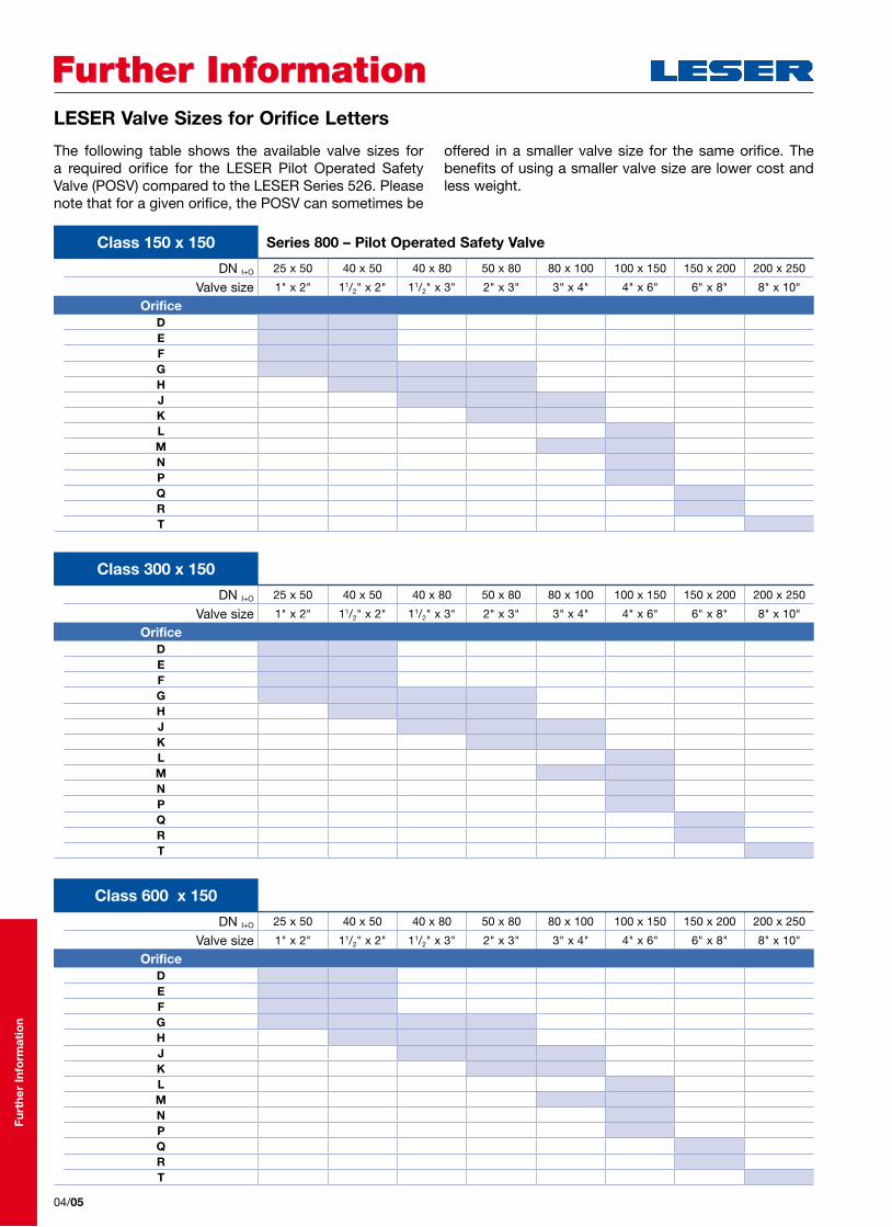
Further InformationFurther InformationLESER Valve Sizes for Orifice Letters
04/05
The following table shows the available valve sizes for a required orifice for the LESER Pilot Operated Safety Valve (POSV) compared to the LESER Series 526. Please note that for a given orifice, the POSV can sometimes be
offered in a smaller valve size for the same orifice. The benefits of using a smaller valve size are lower cost and less weight.
DN I+O 25 x 50 40 x 50 40 x 80 50 x 80 80 x 100 100 x 150 150 x 200 200 x 250
Valve size 1" x 2" 11/2" x 2" 11/2" x 3" 2" x 3" 3" x 4" 4" x 6" 6" x 8" 8" x 10"
OrificeDEFGHJKLMNPQRT
Class 150 x 150 Series 800 – Pilot Operated Safety Valve
DN I+O 25 x 50 40 x 50 40 x 80 50 x 80 80 x 100 100 x 150 150 x 200 200 x 250
Valve size 1" x 2" 11/2" x 2" 11/2" x 3" 2" x 3" 3" x 4" 4" x 6" 6" x 8" 8" x 10"
OrificeDEFGHJKLMNPQRT
Class 300 x 150
DN I+O 25 x 50 40 x 50 40 x 80 50 x 80 80 x 100 100 x 150 150 x 200 200 x 250
Valve size 1" x 2" 11/2" x 2" 11/2" x 3" 2" x 3" 3" x 4" 4" x 6" 6" x 8" 8" x 10"
OrificeDEFGHJKLMNPQRT
Class 600 x 150
Furt
her
Info
rmat
ion

Further InformationFurther InformationLESER Valve Sizes for Orifice Letters
04/06
DN I+O 25 x 50 40 x 50 40 x 80 50 x 80 80 x 100 100 x 150 150 x 200 150 x 250 200 x 250
Valve size 1" x 2" 11/2" x 2" 11/2" x 3" 2" x 3" 3" x 4" 4" x 6" 6" x 8" 6" x 10" 8" x 10"
OrificeDEFGHJKLMNPQRT
Class 150 x 150 Series 526 – Spring Loaded Safety Valve
DN I+O 25 x 50 40 x 50 40 x 80 50 x 80 80 x 100 100 x 150 150 x 200 150 x 250 200 x 250
Valve size 1" x 2" 11/2" x 2" 11/2" x 3" 2" x 3" 3" x 4" 4" x 6" 6" x 8" 6" x 10" 8" x 10"
OrificeDEFGHJKLMNPQRT
Class 300 x 150
DN I+O 25 x 50 40 x 50 40 x 80 50 x 80 80 x 100 100 x 150 150 x 200 150 x 250 200 x 250
Valve size 1" x 2" 11/2" x 2" 11/2" x 3" 2" x 3" 3" x 4" 4" x 6" 6" x 8" 6" x 10" 8" x 10"
OrificeDEFGHJKLMNPQRT
Class 600 x 150
Furt
her
Info
rmat
ion
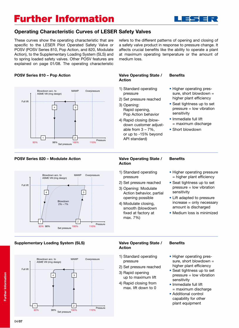
POSV Series 810 – Pop Action
POSV Series 820 – Modulate Action
Supplementary Loading System (SLS)
Valve Operating State /Action
Valve Operating State /Action
Valve Operating State /Action
Benefits
Benefits
Benefits
1 2
34
OverpressureMAWP
93% 98% 100% 110%Pressure
Set pressure
Blowdown acc. toASME VIII (ring design)
Full lift
Full lift
OverpressureMAWPBlowdown acc. toASME VIII (ring design)
1 2
34
93% 98% 100% 110%Pressure
Set pressure
Blowdown2% – 7%
1 2
34
Full lift
OverpressureMAWPBlowdown acc. toASME VIII (ring design)
93% 98% 100% 110%Pressure
Set pressure
Further InformationFurther Information
04/07
Operating Characteristic Curves of LESER Safety Valves
These curves show the operating characteristic that are specific to the LESER Pilot Operated Safety Valve or POSV (POSV Series 810, Pop Action, and 820, Modulate Action), to the Supplementary Loading System (SLS) and to spring loaded safety valves. Other POSV features are explained on page 01/08. The operating characteristic
refers to the different patterns of opening and closing of a safety valve product in response to pressure change. It affects crucial benefits like the ability to operate a plant at maximum operating temperature or the amount of medium loss.
1) Standard operating pressure
2) Set pressure reached
3) Opening: Rapid opening, Pop Action behavior
4) Rapid closing (blow-down customer adjust-able from 3 – 7%, or up to -15% beyond API standard)
1) Standard operating pressure
2) Set pressure reached
3) Opening: Modulate Action behavior, partial opening possible
4) Modulate closing, smooth (blowdown fixed at factory at max. 7%)
1) Standard operating pressure
2) Set pressure reached
3) Rapid opening up to maximum lift
4) Rapid closing from max. lift down to 0
• Higher operating pres-sure, short blowdown = higher plant efficiency
• Seat tightness up to set pressure = low vibration sensitivity
• Immediate full lift = maximum discharge
• Short blowdown
• Higher operating pressure = higher plant efficiency
• Seat tightness up to set pressure = low vibration sensitivity
• Lift adapted to pressure increase = only necessary amount is discharged
• Medium loss is minimized
• Higher operating pres-sure, short blowdown = higher plant efficiency
• Seat tightness up to set pressure = low vibration sensitivity
• Immediate full lift = maximum discharge
• Additional control capability for other plant equipment
Furt
her
Info
rmat
ion

Spring loaded safety valve: Valve set at first audible discharge (LESER setting)
Spring loaded safety valve: Valve set at pop
Valve Operating State /Action
Valve Operating State /Action
Benefits
Benefits
12
4 3
OverpressureMAWPBlowdown acc. toASME VIII (ring design)
Set pressurePressure93% 110%100%
Full lift
Lift
4
1
2
4
3
OverpressureMAWPBlowdown acc. toASME VIII (ring design)
Set pressurePressure93% 110%100%
Full lift
Lift
Further InformationFurther Information
04/08
Operating Characteristic Curves of LESER Safety Valves
1) Standard operating pressure (usually less than 90%)
2) Set pressure reached, first audible discharge
3) Rapid opening after popping point
4) Rapid closing with proper reseating (typical blowdown ring design 7%)
1) Standard operating pressure (usually less than 90%)
2) Set pressure reached, with pop action up to commonly 70% of max. lift
3) Pressure increase to reach max. lift
4) Rapid closing with proper reseating (typical blowdown ring design 7%)
• Cost efficient
• Low medium loss and low risk of valve damage when testing set pressure
• Cost efficient
Furt
her
Info
rmat
ion

Furt
her
Info
rmat
ion
04/09
CatalogueCatalogueLESER catalogues provide you with all product-related information you need:
• High Performance• Compact Performance • API • Clean Service
Series 441, 458Series 437, 459Series 526Series 48X
• Critical Service • Modulate Action• High Efficiency• Best Availability
Series 447, 546Series 429, 433Series 810, 820 Series 310, KUB
For quick access to all LESER catalogues please use the download portal atwww.leser.com or order the LESER Digital Library which includes all catalogues in different languages as pdf-files.
For ordering the LESER Digital Library or printed catalogues please contact:Fax: +49 40 251 65-500 E-Mail: [email protected]
VALVESTAR®VALVESTAR®
VALVESTAR® 7, the sizing program for safety valves developed by LESER, supports all leading worldwide codes and standards in 15 languages.
Please use the following contacts for:
CD Order: [email protected] sizing with VALVESTAR Web: www.valvestar.comFurther information and updates: www.valvestar.com
OntimeOntimeAt the ontime service you receive information about your order concerning:
• Delivery dates • Consignment and delivery records • Partial deliveries • Reducing delivery times
Your order number is required.
Simone PinkertFon: +49 (4871) 27-137 Fax: +49 (40) 25 165-537E-Mail: [email protected]
CertificatesCertificatesIf any material test report is missing please visit www.leser.com/certificates or contact [email protected]
www.leser.com/certificates E-Mail: [email protected]
LESER GmbH & Co. KG20537 Hamburg, Wendenstr. 133-13520506 Hamburg, P.O. Box 26 16 51
Fon +49 (40) 251 65-100Fax +49 (40) 251 65-500
E-Mail: [email protected]
VALVESTAR®VALVESTAR®
The-Safety-Valve.com
Further InformationFurther InformationCustomer Service

LESER Safety Valves for every industrial application
Product RangeProduct Range
Compact Performance
High Performance
API
Clean Service
H2SO4
HNO3
NH3
HCL
Critical Service
Modulate Action
Best Availability
High EfficiencyHigh Efficiency
Series 810 – Pop Action
Type 811
Series 820 – Modulate Action
Type 821
Furt
her
Info
rmat
ion
04/10
ClaimsClaimsIf there is any claim related to LESER products or services (e.g. safety valves, damaged shipments, etc.) please contact:
Ralf Lemke Fon: +49 (4871) 27-122Fax: +49 (4871) 27-298E-Mail: [email protected]
SeminarsSeminarsLESER offers the following standard seminars:
Seminar 1: Basics of safety valves technologySeminar 2: Maintenance and repair of safety valvesSeminar 3: Maintenance and repair of pilot operated safety valvesSeminar 4: Sizing and calculation of safety valves – basics / advanced
LESER offers these seminars also in English and on the spot. Further details concerning content and dates of the seminar as well as applications forms can be found at www.leser.com
Please send the registration form to:Diana SadowskiFon: +49 40 25165-147Fax: +49 40 [email protected]
StockStockTo compete successfully in today‘s global market it is most important to meet the customer requirements. Therefore it is indispensible to have a stock. For questions or support please do not hesitate to contact your Area Sales Manager use www.leser.com/partners
LESER test lab servicesLESER test lab servicesLESERs test lab is one of the biggest worldwide. It is the first and only air and water test lab outside the US which is not only certified by TÜV but also certified by ASME.
You are welcome to use the LESER test lab for your tests.Please send your request to:
Martin Wesenberg Fon: +49 40 25165-141Fax: +49 40 [email protected]
Further InformationFurther InformationCustomer Service

E
Pilot Operated Safety Valves
Series 810 – Pop ActionSeries 820 – Modulate Action
The-Safety-Valve.com
HighEfficiencyHighEfficiency
CATALOGHigh EfficiencyEdition 05.2012 / 1.0000777.5666
20537 Hamburg, Wendenstr. 133-13520506 Hamburg, P.O. Box 26 16 51
Fon +49 (40) 251 65-100Fax +49 (40) 251 65-500
LESER GmbH & Co. KG E-Mail: [email protected]
The-Safety-Valve.com
LESER LLCCharlotte (NC), [email protected]
LESER UKBristol, Great [email protected]
LESER S.A.R.L.Toulouse, [email protected]
André Ramseyer AGFlamatt, [email protected]
Hong Kong LESERShenzen, [email protected]
LESER PolskaPoznan, [email protected]
LESER LLP [email protected]
FAINGER LESER ValvesMumbai, [email protected]
LESER Office Middle East [email protected]
LESER LTDA. Rio de Janeiro, [email protected]
LESER representatives
LESER stock and local assembly
LESER worldwideLESER worldwide