Embed Size (px)
Citation preview

N601GE POH, v1.6L – 18 May 2014 page 1 of 27
N601GE
Zodiac 601XL, SN 6-6753 Corvair 3.0L Motor, Sensenich 63x44 Prop
Pilot Operating Handbook

N601GE POH, v1.6L – 18 May 2014 page 2 of 27
TABLE OF CONTENTS
Section 1 – Airplane and Systems Description Section 2 – Operating Limitations Section 3 – Weight and Balance Information Section 4 – Emergency Procedures Section 5 – Normal Procedures Section 6 – Flight Characteristics and Performance Section 7 – Required Placards & Markings Section 8 – Maintenance Information Section 9 – Other Information Section 10 – Revision History

N601GE POH, v1.6L – 18 May 2014 page 3 of 27
Section 1 – Airplane and Systems Description ENGINE A modified Chevrolet Corvair engine is installed in this aircraft. This is a normally-aspirated, direct-drive, 6-cylinder, air-cooled engine, with redundant ignition sources driving single plugs per cylinder. This engine uses specially modified 92 mm Volkswagen cylinders and custom-made dished-top pistons giving a compression ratio of ~8.4:1 and a displacement of 3000 cc or 183 c.i. It has an approximate rating of this engine is 115 HP at 3300 rpm maximum and 105 HP at 3000 RPM continuous. The long block was built up by Mark Petniunas from Falcon Machine, www.falconmachine.net. The engine has been converted for flight use following the methods described in Corvair Flight Engines for use in Experimental Aircraft, by William Wynne and was installed very similarly to the methods described in Corvair/601 Firewall Forward Installation Manual, also by William Wynne. When questions about the engine come up that are not directly addressed in this POH, the answers will likely be found in one of those books. The engine includes a Dan Weseman 5th bearing. See www.fly5thbearing.com. The construction manuals, as well as many of the conversion parts and lots of additional information, are available from www.flycorvair.com, Mr. Wynne’s website. FUEL SYSTEM The fuel system consist of two 15 gallon wing tanks with float sensors, a console-mounted tank selector valve, primary and alternate fuel pumps, a fuel pressure sensor, a fuel flow sensor and the MA3-SPA carburetor. The carburetor has an accelerator pump to prime the engine for starting; there is no separate engine primer system. The fuel flow sensor uses regular aircraft power, but the fuel pressure sensor gets 5VDC power from the avionics voltage regulator. If that regulator fails or is bypassed, the fuel pressure indication will be unreliable and should be ignored. The primary and alternate fuel pumps are identical, however the primary pump is protected by an oil pressure switch which prevents pump operation below ~5 psi oil pressure. This prevents fuel dumping in a crash situation where the pilot is unable to turn off the fuel pump or main power. Therefore the primary fuel pump should be selected for normal flight operations, but the alternate pump must be used for engine start. The float sensors in the tanks are limited in range to the last 6 gallons in each tank. From 0-6 gallons, they are fairly accurate. The sensors were calibrated using the MGL Ultra EFIS as follows:

N601GE POH, v1.6L – 18 May 2014 page 4 of 27
Right Tank EFIS Cal Left Tank EFIS cal True Left True Cal 0 250 0 250 0 272 1 195 3 128 1 208 2 164 6 83 2 156 3 140 12 82 3 128 4 124 18 81 4 112 5 112 24 80 5 100 6 100 30 79 6 83 7 88 6.5 83
The right tank quantity is displayed on the #2 tank indicator. The #1 indicator displays computed fuel quantity for the complete aircraft based on fuel used, as determined by the fuel flow sensor. The sensor has been calibrated over many test flights and a value of XXXXXX counts was found to give accurate indications. In normal usage, the total fuel is entered in the EFIS prior to flight, and the fuel totalizer computes both fuel used and fuel remaining. The #1 gauge is the primary indicator. The #2 gauge only shows accurate indications for the last 6-7 gallons in the right tank. Normal operation is to switch between tanks using the selector valve at 3 or 5 gallon increments, starting with the fullest tank (or left tank if both are equal). In case of a low fuel condition, the correct procedure is the finish the fuel from the left tank first, so that the final few gallons are correctly indicated on the #2 indicator. The normal fuel for this engine is 100LL grade aviation fuel. When using straight 100LL, a lead scavenger such as Decalin RunUp or TCP should also be used consistently to prevent lead fouling on the exhaust valves. Alternate fuels are 93 and higher octane motor fuels or AVGAS/MOGAS mixtures. The fuel system is alcohol-capable, but care should be exercised as alcohol both absorbs water and increases susceptibility to vapor lock. It is acceptable to mix auto fuel and 100LL in the one tank. When mixed 3:1 with 100LL, 91 octane motor fuel is OK. OIL SYSTEM The oil system is a single wet sump system with a nominal capacity of 5 quarts. A high-capacity oil pump is used to account for the additional needs of the 5th bearing. The specified oil is Shell Rotella T 15W-40 (non-synthetic). Other non-full-synthetic oils which meet the API CJ-4 specification can be used if Rotella T is unavailable. It is important that the oil have sufficent ZDDP for the Corvair engine. For example, Chevron Delo 400 LE 15W-40 and Conoco Kendall Super-D XA 15W-40 are acceptable if a small amount of ZDDP is added. Full synthetic oils should be avoided. The oil change interval is 25-40 hours depending on operating conditions and usage. The standard oil filter is the K&N model HP-1008. The Mobil M1-108 or Fram TG6607 are acceptable alternatives. IGNITION SYSTEM The ignition system consists of a identical primary and alternate coils feeding a modified dual-points distributor through a coil joiner device. Only one coil may be powered at a time using the

N601GE POH, v1.6L – 18 May 2014 page 5 of 27
ignition switch on the instrument panel. The distributor has one set of primary electronic points and one set of alternate mechanical points, and fires single spark plugs in each cylinder. Details of the ignition system design can be found the Wynne Corvair Installation Manual. The specified spark plug for this engine is the AC Delco R44F, with a gap of 0.035-0.040 inches. Alternate equivalent (but not hotter) plugs may be used, including the NGK BR6HS. Maximum ignition advance should be set on both sides to 32° BTDC. Normal operation is to start the engine using the alternate ignition and to switch to the primary ignition during engine run up. In this way, both sets are confirmed to be working before flight. CARBURETOR & CABIN HEAT Carburetor heat should be used for any extended in-flight operation at low power settings, below 2000 RPM, whenever ambient conditions are conducive to carburetor icing. This includes any time temperatures are below 75° with significant humidity. When ground conditions are conducive to carburetor icing, the carb heat should be use for a few minutes before takeoff. A heat muff around the right side exhaust can provide cabin heat through a control valve at the bottom center of the firewall, or carburetor heat if the carb heat control is pulled, closing the airbox inlet door. Note: Using the carburetor heat will significantly reduce available engine power. The system is set up so that the normal flow (carb heat off) is from the airbox, through the heat muff and either overboard at the firewall bottom center or into the cabin as cabin heat. When the carb heat control is pulled and the inlet door closes, the flow reverses, going from ambient or cabin air, through the heat muff into the airbox. While it is not possible to have both carburetor and cabin heat working at the same time, but it is not necessary to shut off the cabin heat before pulling the carb heat control. The reversing operation is automatic. ELECTRICAL SYSTEM This aircraft is electrically dependent. There is no mechanical fuel pump and the ignition system requires power to operate. Power is provided by an 18A permanent magnet alternator and two PC-680 SLA-type batteries, one under the passenger seat and one on the left side of the firewall. Alternator power is regulated by voltage regulator attached to the fuselage under the right side of the avionics area, and is controlled by an alternator switch at the left of the instrument panel. On the right side of the panel is the large manual battery selector switch. Only the battery under passenger seat can be used to start the engine. This is selected by moving the battery to the START position. Attempting to start the engine on the backup battery will usually blow the back-up battery in-line fuse (Requires removing panel top cover to replace!) After the engine is started and the alternator switch is turned on, the battery switch should be moved to the FLIGHT position, which connects both batteries to the system. In the event the starting battery should fail, it can be disconnected and the backup battery can be selected by changing the battery switch to RTB (return to base).
N601GE POH, v1.6L – 18 May 2014 page 6 of 27
Should the voltage regulator or alternator fail, a warning light will illuminate at the upper left of the instrument panel. In this situation, reduce electrical loads as much as possible and land as conditions permit. The largest loads are the pitot heat, the landing light, the transponder, and the strobes. With these off and both batteries fully charged, you should have at least 2 full hours of flight time before the engine will fail. Power to the EFIS, gyros, encoder and backup airspeed/altimeter is provided by a car-computer-type voltage regulator (Carnetix P1290) which provides very clean 12V power even during engine start. In addition, this regulator provides 5V power to the fuel pressure sensor. Power to the regulator is controlled by a switch on the panel. If this regulator should fail, all equipment except the fuel pressure sensor can be powered by moving the switch down to the BYPASS position. FLIGHT CONTROLS This aircraft has cable-operated ailerons, elevator and rudder. Cable tension on the elevators and ailerons should be checked regularly at 25-30 lbs. The ailerons have counter-balance weights and spades added to reduce roll control forces. The roll forces may be trimmed out using an electrically operated trim tab on the left aileron. The pitch forces may be trimmed out using an electrically operated trim tab on the left side of the elevator. The “coolie hat” switch on the pilot’s stick and the two rocker switches on the center panel operate identically, but only one should be used at a time. Because of the large available CG range, a 2” fiberglass extension has been added to the elevator trim tab. This allows trimming out the elevator forces for full flaps when flying solo. There are simply-hinged wing flaps which are electrically actuated and use a control tube-pin and slot arrangement. The flap actuator has built in stops which are not adjustable. Maximum operating speed with ½ flaps is 90 MIAS and with full flaps is 80 MIAS. Actuating the flaps creates a significant pitching moment which the pilot must control and/or trim out. PROPELLER A wood Sensenich propeller, type W64ZKL47S, SN AJ1354, was installed on 24 November 2010, at 256 tach hours. When the original engine was replaced with the current 3.0L version, the propeller was re-pitched by Gary Hertzler (Hertzler Propeller) to match. The propeller is now a 63” diameter x 44” pitch. The propeller bolts should be torqued to 17-18 ft-lbs not less often than every 3 months or 50 hours, whichever comes first. Static RPM for this prop is 2725. You may see a small drop in RPM during the first part of the takeoff roll, then a steady increase.

N601GE POH, v1.6L – 18 May 2014 page 7 of 27
Section 2 – Operating Limitations DESIGN AIRSPEEDS & AIRSPEED LIMITS
Speed MIAS MCAS Remarks VS – No-Flap Stall Speed at Maximum Takeoff Weight 57 Stall speeds will be as much as 7
mph lower at lighter weights. VS1 – ½-Flap Stall Speed at Maximum Takeoff Weight 55 Stall speeds will be as much as 7
mph lower at lighter weights. VS0 – Full-Flap Stall Speed at Maximum Takeoff Weight 52 Stall speeds will be as much as 7
mph lower at lighter weights. VFE – Maximum Speed With Full Flaps Extended 80 Do not exceed this speed with full
flaps extended VF2 – Maximum Speed With ½ Flaps Extended 90 Use with caution as flaps are not
marked VX – Speed for Best Angle of Climb 72 Gives highest feet per mile
VY – Speed for Best Rate of Climb 74 Gives highest feet per minute
VBG – Speed for Best Glide 70 Gives highest L/D, maximum glide
distance. VMD – Speed for Minimum Descent Rate 68 Gives maximum air time.
VA – Design Maneuvering Speed 103 Do not make abrupt or full control
movements above this speed VC – Design Cruising Speed 124 Do not exceed this speed except in
smooth air and with caution VNE - Never Exceed Speed 160 Do not exceed this speed in any
case or condition. CROSSWIND LIMITS Maximum demonstrated crosswind component is 15 knots. Use extreme caution with any winds above 30 knots as the plane will be difficult to control and keep on the ground. SERVICE CEILING Maximum service ceiling is 17,500 feet. PROHIBITED MANEUVERS
Intentional spins are prohibited. Aerobatics are prohibited.
TYPES OF OPERATIONS When appropriately equipped according to the FARs, this airplane may be operated Day and Night, VFR and IFR. Flight into known or forecast icing conditions is prohibited.
N601GE POH, v1.6L – 18 May 2014 page 8 of 27
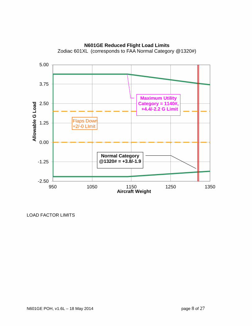
LOAD FACTOR LIMITS
-2.50
-1.25
0.00
1.25
2.50
3.75
5.00
950 1050 1150 1250 1350
Allo
wab
le G
Loa
d
Aircraft Weight
N601GE Reduced Flight Load Limits Zodiac 601XL (corresponds to FAA Normal Category @1320#)
Maximum Utility Category = 1140#, +4.4/-2.2 G Limit
Normal Category @1320# = +3.8/-1.9
Flaps Down +2/-0 LImit
N601GE POH, v1.6L – 18 May 2014 page 9 of 27
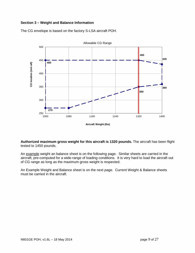
Section 3 – Weight and Balance Information
The CG envelope is based on the factory S-LSA aircraft POH.
Authorized maximum gross weight for this aircraft is 1320 pounds. The aircraft has been flight tested to 1450 pounds. An example weight an balance sheet is on the following page. Similar sheets are carried in the aircraft, pre-computed for a wide-range of loading conditions. It is very hard to load the aircraft out of CG range as long as the maximum gross weight is respected. An Example Weight and Balance sheet is on the next page. Current Weight & Balance sheets must be carried in the aircraft.
350 360
435 450
450
270 250
300
350
400
450
500
1000 1080 1160 1240 1320 1400
CG
loca
tion
(mm
aft)
Aircraft Weight (lbs)
Allowable CG Range

N601GE POH, v1.6L – 18 May 2014 page 10 of 27
N601GE Weight & Balance
18-May-14
Zodiac 601XL S/N 6-6753
Datum line is plumb from wing leading edge.
Amain = 33 measured
Maximum takeoff weight is 1320 lbs.
Atail = 4160.5 measured
MAC= 1500 mm
Weight Arm Moment
Right Main 363 33 11979
Left Main 357 33 11781
Max Gross X-Country
Tailwheel 42 4160.5 174741
#2 Battery 15 -400 -6000
Added Fairings 10 1500 15000
Spar Modifications 6 0 0
additional equipment 0
Empty CG Location
Total Empty 793 207501
262
Pilot 195 700 136500
Passenger 125 700 87500
Baggage 27 1600 43200
Full Fuel 180 180 32400
Takeoff CG Location
Takeoff Weight 1320 507101
384
Fuel Burned -156 180 -28080
Landing CG Location
Landing Weight 1164 479021
412
level @longeron

N601GE POH, v1.6L – 18 May 2014 page 11 of 27
Section 4 – Emergency Procedures In all cases – Maintain aircraft control. Analyze the situation and take appropriate action. Land as conditions permit. Engine Fire During Start
1. Starter – CONTINUE CRANKING If engine starts:
2. RPM – 1500 momentarily 3. Engine - SHUTDOWN
If engine does not start: 4. Battery Switch – OFF 5. Fuel Selector Switch – OFF 6. Mixture – IDLE CUT-OFF 7. Abandon aircraft and fight fire.
Engine Failure During Takeoff
If tail is up 1. Apply brakes and aft stick carefully to avoid nose-over 2. If flaps are down and conditions permit, raise flaps. 3. Steer with pedals and brakes until tail is down
If/when tail is down: 1. Stick aft to keep tail down. 2. Steer with pedals and brakes. 3. Brakes – Apply smoothly as required 4. Engine - SHUTDOWN
Engine Failure Soon After Takeoff
1. Lower nose to maintain 70 MIAS. 2. Select landing area. 3. If time permits, lower flaps to full. 4. Land as slowly as possible without stalling.
Alternator or Voltage Regulator Failure in Flight
1. Alternator switch - OFF. 2. Battery switch - FLIGHT. 3. Reduce electrical load as much as possible.
Avionics Regulator Failure in Flight
1. Regulator swtich to BYPASS. 2. Fuel pressure indication will be unreliable..

N601GE POH, v1.6L – 18 May 2014 page 12 of 27
Engine Failure in Flight 1. Establish speed for best glide, ~70 MIAS 2. Ignition and Fuel switches – ALTERNATE 3. Fuel Selector – OTHER TANK 4. Carb Heat - PULL
If engine will restart: 5. Land as soon as practical
If engine does not restart: 5. Select landing area. 6. Starter may be used to extend glide. 7. Power Off Landing
Engine Fire in Flight
1. Cabin Heat – OFF 2. Fuel Pumps & Ignitions – OFF 3. Throttle - CLOSED 4. Mixture – IDLE CUT-OFF 5. Fuel Selector – OFF 5. Select landing area. 6. Starter may be used to extend glide. 7. Power Off Landing
Electrical Fire in Flight
1. Alternator – OFF 2. Regulator – BYPASS 3. Air vents - OPEN 4. Electrical equipment – OFF as possible 5. Fire extinguisher – As required 6. Land as soon as practical
Power Off Landing
1. When committed to land: > Seat Belts & Shoulder Harness - SECURE > Battery Switch – OFF > Fuel Selector Valve – OFF > Mixture – IDLE CUT-OFF
2. Flaps – Full when landing is assured 3. Touchdown at lowest possible speed without stalling (Using starter to get propeller horizontal will reduce chances of a nose-over.)

N601GE POH, v1.6L – 18 May 2014 page 13 of 27
Spin Recovery 1. Determine direction of spin 2. Reduce throttle to idle 3. Rudder – Full opposite spin direction 4. Aileron – Full opposite spin direction 5. Elevator – Full forward 6. When rotation stops
> Neutralize rudder and ailerons > If flaps were extended, Flaps – Up > Elevator to recover from dive. Avoid overstressing airframe.
7. Return to controlled flight. Trim Failure or Runaway Trim
1. Slow to 70 MIAS to lower control forces 2. Try other trim switches 3. Be prepared for high control forces, especially during landing. 4. Depending on trim condition, flaps or no-flaps may be best.

N601GE POH, v1.6L – 18 May 2014 page 14 of 27
Section 5 – Normal Procedures PREFLIGHT CHECK
1. Check condition of canopy. Unlock and open canopy
2. Cockpit check
a. All switches and avionics – OFF
b. Remove control lock and check controls free
c. Battery switch – RTB
d. Regulator – BYPASS
e. EFIS – Operating
f. Check beacon and strobes
g. Flaps – DOWN
h. For planned IFR or night flight:
i. Check pitot heat
ii. Check nav and landing lights
iii. Install and connect night LED panel power supply if needed.
i. Battery switch – OFF
N601GE POH, v1.6L – 18 May 2014 page 15 of 27
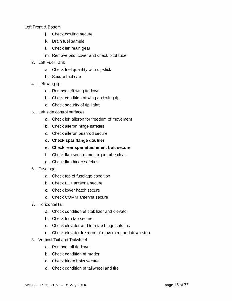
Left Front & Bottom
j. Check cowling secure
k. Drain fuel sample
l. Check left main gear
m. Remove pitot cover and check pitot tube
3. Left Fuel Tank
a. Check fuel quantity with dipstick
b. Secure fuel cap
4. Left wing tip
a. Remove left wing tiedown
b. Check condition of wing and wing tip
c. Check security of tip lights
5. Left side control surfaces
a. Check left aileron for freedom of movement
b. Check aileron hinge safeties
c. Check aileron pushrod secure
d. Check spar flange doubler e. Check rear spar attachment bolt secure f. Check flap secure and torque tube clear
g. Check flap hinge safeties
6. Fuselage
a. Check top of fuselage condition
b. Check ELT antenna secure
c. Check lower hatch secure
d. Check COMM antenna secure
7. Horizontal tail
a. Check condition of stabilizer and elevator
b. Check trim tab secure
c. Check elevator and trim tab hinge safeties
d. Check elevator freedom of movement and down stop
8. Vertical Tail and Tailwheel
a. Remove tail tiedown
b. Check condition of rudder
c. Check hinge bolts secure
d. Check condition of tailwheel and tire

N601GE POH, v1.6L – 18 May 2014 page 16 of 27
e. Check tailwheel actuating connections
9. Right side control surfaces
a. Check right aileron for freedom of movement
b. Check aileron hinge safeties
c. Check aileron pushrod secure
d. Check spar flange doubler e. Check rear spar attachment bolt secure f. Check flap secure and torque tube clear
g. Check flap hinge safeties
10. Right wing tip
a. Remove right wing tiedown
b. Check condition of wing and wing tip
c. Check security of tip lights
11. Landing light
a. Check condition and security of cover
b. Visually check landing light mounting secure
12. Right Front & Bottom
a. Drain fuel sample
b. Check right main gear
13. Engine
a. Check condition of cowling
b. Open right side top cowling
c. Check security of all wiring and hoses
d. Check oil quantity 5 quarts
e. Check condition of baffling
f. Secure cowling
14. Propeller
a. Check propeller secure
b. Check condition of both blades
15. Nose
a. Check nosebowl condition
b. Check spinner secure
c. Remove cowl plugs if installed
d. Check air inlets clear and no foreign objects inside

N601GE POH, v1.6L – 18 May 2014 page 17 of 27
CHECKLISTS Before Starting Engine
Seat Belt / Shoulder Harness: Buckled Brakes: Set Control Lock: Removed Controls: Free & correct Lights: Off Avionics: Off Canopy: Closed Starting Engine
Battery Switch: Start Anti-collision Light: Day or Night Regulator: On EFIS : Alive and working Ignition & Fuel Pump: Alternate Fuel Selector: Fullest Tank Mixture: Full rich Carburetor Heat: Off Clear Propellor Starter Switch: Start Throttle: Prime as needed, then ¼” Open Oil Pressure: Up within 15 secs Throttle: 700-800 RPM Mixture: Set Battery Switch: Run Avionics: Comm & GPS On Transponder: Standby Engine Runup
Ignition & Fuel Pump: Primary Battery Switch: RTB, then Run Mixture: Set Throttle: 1700 rpm Engine Instruments: Checked and normal Carburetor Heat: Check for minimum drop of 25 rpm. Throttle: Idle
Before Takeoff
Flaps: Check operation, then Set Trim: Set for takeoff GPS: Initialize as required Mixture: Set Carburetor Heat: Off Controls: Free & clear Flight Instruments: Checked Engine Instruments: Normal
- - Before Taking Active - - Canopy: Closed and Locked Transponder: On with Mode C Lights: As Desired
N601GE POH, v1.6L – 18 May 2014 page 18 of 27
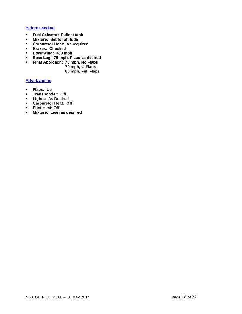
Before Landing
Fuel Selector: Fullest tank Mixture: Set for altitude Carburetor Heat: As required Brakes: Checked Downwind: <80 mph Base Leg: 75 mph, Flaps as desired Final Approach: 75 mph, No Flaps 70 mph, ½ Flaps 65 mph, Full Flaps After Landing Flaps: Up Transponder: Off Lights: As Desired Carburetor Heat: Off Pitot Heat: Off Mixture: Lean as desrired
N601GE POH, v1.6L – 18 May 2014 page 19 of 27
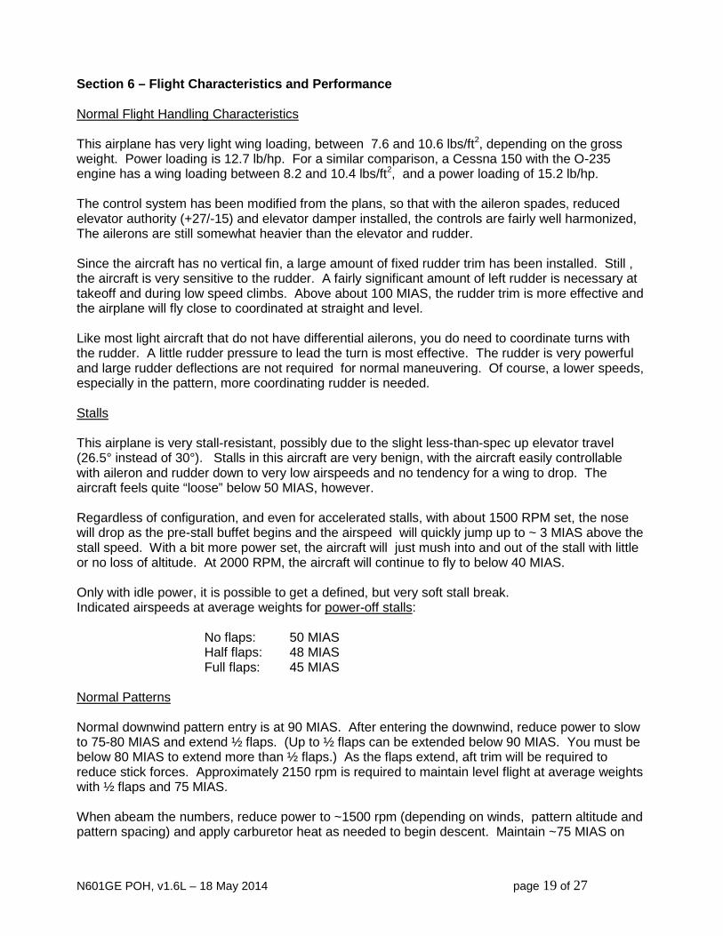
Section 6 – Flight Characteristics and Performance Normal Flight Handling Characteristics This airplane has very light wing loading, between 7.6 and 10.6 lbs/ft2, depending on the gross weight. Power loading is 12.7 lb/hp. For a similar comparison, a Cessna 150 with the O-235 engine has a wing loading between 8.2 and 10.4 lbs/ft2, and a power loading of 15.2 lb/hp. The control system has been modified from the plans, so that with the aileron spades, reduced elevator authority (+27/-15) and elevator damper installed, the controls are fairly well harmonized, The ailerons are still somewhat heavier than the elevator and rudder. Since the aircraft has no vertical fin, a large amount of fixed rudder trim has been installed. Still , the aircraft is very sensitive to the rudder. A fairly significant amount of left rudder is necessary at takeoff and during low speed climbs. Above about 100 MIAS, the rudder trim is more effective and the airplane will fly close to coordinated at straight and level. Like most light aircraft that do not have differential ailerons, you do need to coordinate turns with the rudder. A little rudder pressure to lead the turn is most effective. The rudder is very powerful and large rudder deflections are not required for normal maneuvering. Of course, a lower speeds, especially in the pattern, more coordinating rudder is needed. Stalls This airplane is very stall-resistant, possibly due to the slight less-than-spec up elevator travel (26.5° instead of 30°). Stalls in this aircraft are very benign, with the aircraft easily controllable with aileron and rudder down to very low airspeeds and no tendency for a wing to drop. The aircraft feels quite “loose” below 50 MIAS, however. Regardless of configuration, and even for accelerated stalls, with about 1500 RPM set, the nose will drop as the pre-stall buffet begins and the airspeed will quickly jump up to ~ 3 MIAS above the stall speed. With a bit more power set, the aircraft will just mush into and out of the stall with little or no loss of altitude. At 2000 RPM, the aircraft will continue to fly to below 40 MIAS. Only with idle power, it is possible to get a defined, but very soft stall break. Indicated airspeeds at average weights for power-off stalls:
No flaps: 50 MIAS Half flaps: 48 MIAS Full flaps: 45 MIAS
Normal Patterns Normal downwind pattern entry is at 90 MIAS. After entering the downwind, reduce power to slow to 75-80 MIAS and extend ½ flaps. (Up to ½ flaps can be extended below 90 MIAS. You must be below 80 MIAS to extend more than ½ flaps.) As the flaps extend, aft trim will be required to reduce stick forces. Approximately 2150 rpm is required to maintain level flight at average weights with ½ flaps and 75 MIAS. When abeam the numbers, reduce power to ~1500 rpm (depending on winds, pattern altitude and pattern spacing) and apply carburetor heat as needed to begin descent. Maintain ~75 MIAS on

N601GE POH, v1.6L – 18 May 2014 page 20 of 27
base. Reducing power below 1500 rpm can give very high sink rates. The airplane is very pitch sensitive to power changes and reducing power will require more aft stick pressure. Turning final, you can reduce airspeed to ~70 MIAS, ±3 MIAS depending on weight. At light weights, this will require full aft trim. As noted above, sink rate is very power sensitive and slipping is rarely required to adjust position. However, the up to ½ rudder can be used to slip the aircraft and further increase the sink if required. Do not exceed ½ rudder deflection for slipping on final, as the rudder is extremely powerful and unrecoverable sink rates may occur. Crossing the threshold, or at about 5 feet altitude, reduce power slightly to about 1300 rpm. Holding the aircraft off the runway is very easy and you may choose to either wheel land or 3-point the plane. Beware of high elevator sensitivity if your airspeed is higher than desired. For wheel landings, you will still need make a fairly large pitch change while flying the aircraft onto the wheels. This plane does not fly onto the wheels in a flat attitude like some others. For 3-point landings, just establish the 3-point attitude and the aircraft will slowly settle onto the runway. After touchdown, smoothly reduce the power to idle and brake as necessary. For touch & go landings or go-arounds, close the carburetor heat, raise the flaps and smoothly apply power while trimming forward. It requires a lot of forward trim to transition from approach to climbing flight, approximately a 5-count of continuous application at the stick hat switch. Be careful to not change the aileron trim at the same time. Crosswind Landings The rudder is very powerful and crosswind landings are straightforward up to 15 knots of steady crosswind component. Normal crosswind technique is to fly wing low on final and wheel-land the aircraft on the upwind wheel first. The plane is very controllable down to below 50 MIAS, so that the downwind wheel can be gently lowered to the runway and then the tail lowered while maintaining runway alignment. After the downwind wheel is on the runway, differential brakes can be used to maintain alignment if necessary. Cruise Performance with Sensenich 63x44 Propeller The following tested data are approximate and will change as modifications are made to the airframe and the engine ages. These data are valid as of March, 2013. Note that indicated and true airspeeds are in MPH. At density altitude of 7500’, leaned to peak power: MIAS Fuel Flow MTAS RPM MPG 86 3.4 96 2400 27.4 94 3.6 105 2500 28.3 97 3.8 108 2600 27.0 106 4.7 118 2800 24.1 115 5.2 128 3000 23.7

N601GE POH, v1.6L – 18 May 2014 page 21 of 27
Section 7 – Required Placards & Markings External
1. In accordance with 14 CFR 45.23, the word “EXPERIMENTAL” must be displayed in letters at least 2” high at each entrance to the cabin. Currently, this is displayed in relief in the wing walk.
2. Warning: In accordance with 14 CFR 45.29, this aircraft displays 3” tall registration marks
on the vertical tail. These markings may not be acceptable for flights into foreign airspace. Internal
1. The following warning must be clearly displayed in the cabin and visible from the passenger seat:
THIS AIRCRAFT IS AMATEUR BUILT AND DOES NOT COMPLY WITH FEDERAL SAFETY REGULATIONS FOR STANDARD AIRCRAFT.
2. The electronic flight information system (EFIS) of this aircraft does not display “red line”, “green arc” or “white arc” airspeeds. Therefore a placard is required adjacent to the EFIS which displays at least the following speeds: VS0, VFE, VA and VNE.

N601GE POH, v1.6L – 18 May 2014 page 22 of 27
Section 8 – Maintenance Information Inspection Date ___________
N601GE, Zodiac 601XL, 6-6753 Condition Inspection Checklist
Airframe Hours: ________ Engine Hours / SMOH: ________/________ PROPELLER GROUP (Sensenich Wood Propeller)
1. Inspect blades and hub for damage and corrosion ............................................... _______
2. Inspect spinner and back plate for damage and corrosion ................................... _______
3. Re-torque prop bolts to 17 ft-lbs and re-safety ..................................................... _______
ENGINE GROUP (Corvair Engine)
1. Warm up engine, check for fuel and oil leaks ....................................................... _______
2. Perform cylinder compression checks (set TDC before removing plug!) .............. _______
#1 ________ #2 ________ #3 ________ #4 ________ #5 ________ #6 ________
3. Check distributor cap and rotor condition, and check timing ................................ _______
4. Drain and replace engine oil with 5 qts Rotella T 15W-40 or equivalent ............... _______
5. Replace oil filter with K&N filter HP-1008 or equivalent ........................................ _______
6. Check fuel filter element, replace if necessary ..................................................... _______
7. Check spark plugs. Replace worn plugs with AC R44F gapped @0.038” ............ _______
8. Inspect L & R exhaust manifolds .......................................................................... _______
9. Inspect motor mount and fuselage attachment bolts ............................................ _______
10. Inspect urethane engine mount bushings............................................................. _______
11. Inspect condition, security and proper operation of throttle and mixture controls.. _______
12. Drain carburetor, clean strainer and float bowl ..................................................... _______
13. Inspect inlet airbox for leaks and cracks .............................................................. _______
14. Clean and service inlet air filter ............................................................................ _______
15. Inspect cowling for damage and loose rivets ........................................................ _______
16. Inspect firewall for damage and check pass-through seals .................................. _______
17. Inspect cabin heat box for cracks or other damage .............................................. _______
18. Check starter and alternator mounts for security and damage ............................. _______
19. Check condition of all fuel lines and connections ................................................. _______
20. Check condition and security of grounding strap .................................................. _______
21. Inspect all wiring for condition, security, damage, etc........................................... _______
22. Run engine and check:
a. No oil or fuel leaks
N601GE POH, v1.6L – 18 May 2014 page 23 of 27
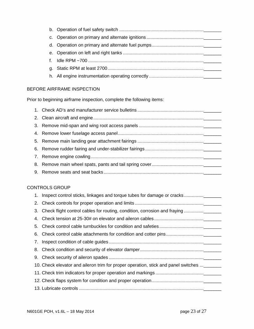
b. Operation of fuel safety switch ................................................................. _______
c. Operation on primary and alternate ignitions ............................................ _______
d. Operation on primary and alternate fuel pumps ........................................ _______
e. Operation on left and right tanks .............................................................. _______
f. Idle RPM ~700 ......................................................................................... _______
g. Static RPM at least 2700 .......................................................................... _______
h. All engine instrumentation operating correctly .......................................... _______
BEFORE AIRFRAME INSPECTION Prior to beginning airframe inspection, complete the following items:
1. Check AD’s and manufacturer service bulletins ................................................... _______
2. Clean aircraft and engine ..................................................................................... _______
3. Remove mid-span and wing root access panels .................................................. _______
4. Remove lower fuselage access panel .................................................................. _______
5. Remove main landing gear attachment fairings ................................................... _______
6. Remove rudder fairing and under-stabilizer fairings ............................................. _______
7. Remove engine cowling ....................................................................................... _______
8. Remove main wheel spats, pants and tail spring cover ........................................ _______
9. Remove seats and seat backs ............................................................................. _______
CONTROLS GROUP
1. Inspect control sticks, linkages and torque tubes for damage or cracks ............... _______
2. Check controls for proper operation and limits ..................................................... _______
3. Check flight control cables for routing, condition, corrosion and fraying ............... _______
4. Check tension at 25-30# on elevator and aileron cables ...................................... _______
5. Check control cable turnbuckles for condition and safeties .................................. _______
6. Check control cable attachments for condition and cotter pins ............................. _______
7. Inspect condition of cable guides ......................................................................... _______
8. Check condition and security of elevator damper ................................................. _______
9. Check security of aileron spades ......................................................................... _______
10. Check elevator and aileron trim for proper operation, stick and panel switches ... _______
11. Check trim indicators for proper operation and markings ..................................... _______
12. Check flaps system for condition and proper operation ........................................ _______
13. Lubricate controls ................................................................................................ _______
N601GE POH, v1.6L – 18 May 2014 page 24 of 27
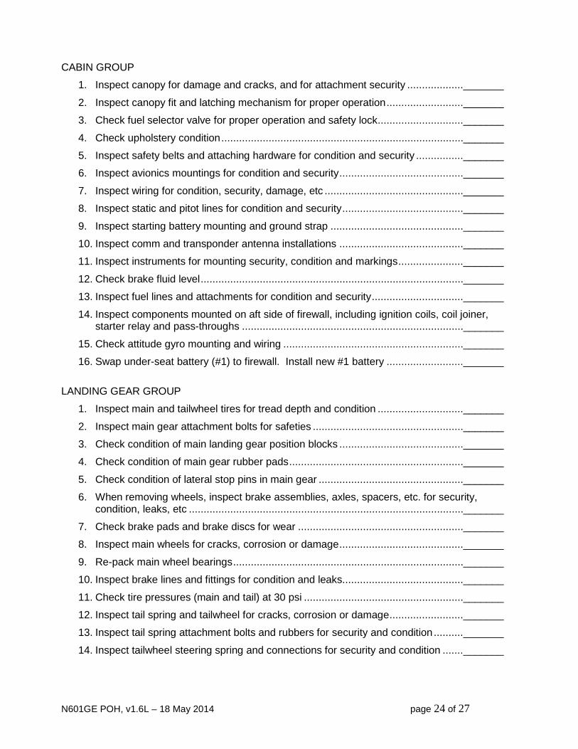
CABIN GROUP
1. Inspect canopy for damage and cracks, and for attachment security ................... _______
2. Inspect canopy fit and latching mechanism for proper operation .......................... _______
3. Check fuel selector valve for proper operation and safety lock ............................. _______
4. Check upholstery condition .................................................................................. _______
5. Inspect safety belts and attaching hardware for condition and security ................ _______
6. Inspect avionics mountings for condition and security .......................................... _______
7. Inspect wiring for condition, security, damage, etc ............................................... _______
8. Inspect static and pitot lines for condition and security ......................................... _______
9. Inspect starting battery mounting and ground strap ............................................. _______
10. Inspect comm and transponder antenna installations .......................................... _______
11. Inspect instruments for mounting security, condition and markings ...................... _______
12. Check brake fluid level ......................................................................................... _______
13. Inspect fuel lines and attachments for condition and security ............................... _______
14. Inspect components mounted on aft side of firewall, including ignition coils, coil joiner, starter relay and pass-throughs ........................................................................... _______
15. Check attitude gyro mounting and wiring ............................................................. _______
16. Swap under-seat battery (#1) to firewall. Install new #1 battery .......................... _______
LANDING GEAR GROUP
1. Inspect main and tailwheel tires for tread depth and condition ............................. _______
2. Inspect main gear attachment bolts for safeties ................................................... _______
3. Check condition of main landing gear position blocks .......................................... _______
4. Check condition of main gear rubber pads ........................................................... _______
5. Check condition of lateral stop pins in main gear ................................................. _______
6. When removing wheels, inspect brake assemblies, axles, spacers, etc. for security, condition, leaks, etc ............................................................................................. _______
7. Check brake pads and brake discs for wear ........................................................ _______
8. Inspect main wheels for cracks, corrosion or damage .......................................... _______
9. Re-pack main wheel bearings .............................................................................. _______
10. Inspect brake lines and fittings for condition and leaks......................................... _______
11. Check tire pressures (main and tail) at 30 psi ...................................................... _______
12. Inspect tail spring and tailwheel for cracks, corrosion or damage ......................... _______
13. Inspect tail spring attachment bolts and rubbers for security and condition .......... _______
14. Inspect tailwheel steering spring and connections for security and condition ....... _______

N601GE POH, v1.6L – 18 May 2014 page 25 of 27
WING GROUP
1. Check main spar bolts for security. Re-torque if necessary .................................. _______
2. Check rear spar bolt for security. Re-torque if necessary ..................................... _______
3. Inspect surfaces of ailerons and flaps for cracks, working rivets or damage ........ _______
4. Inspect rear spar reinforcement straps at aileron pushrod holes for cracks .......... _______
5. Inspect root moldings for security and condition................................................... _______
6. Inspect aileron and flap hinge pins for corrosion, wear, safeties .......................... _______
7. Inspect aileron bellcranks, stops, and cable ends ................................................ _______
8. Inspect lower rivets on main spar for any indication of working ............................ _______
9. Lubricate aileron bellcranks ................................................................................. _______
10. Lubricate aileron and flap hinges ......................................................................... _______
11. Inspect landing light for lens condition and mounting condition ............................ _______
12. Check landing light operation ............................................................................... _______
13. Check wingtip strobes and position lights for security and proper operation ......... _______
14. Check wing tanks sump drains for water and leaks .............................................. _______
15. Drain tanks and check tank fuel filter screen. Reinstall ....................................... _______
16. Check condition and security of in-wing fuel lines ................................................ _______
17. Inspect fuel tank filler caps for condition and markings ........................................ _______
18. Check pitot heat operation ................................................................................... _______
19. Check proper operation of fuel quantity indicating system ................................... _______
FUSELAGE GROUP
1. Inspect outer fuselage skin for cracks, loose rivets, damage, etc ......................... _______
2. Inspect internal fuselage structure for cracks, loose rivets, damage, etc .............. _______
3. Inspect all electrical wiring for condition, security, routing, etc. ............................. _______
4. Check magnetometer mounting and wiring .......................................................... _______
5. Inspect condition of static lines ............................................................................ _______
6. Inspect condition and mounting security of backup battery .................................. _______
7. Inspect ELT antenna for connection and mounting .............................................. _______
8. Inspect beacon drivers and beacon for condition ................................................. _______

N601GE POH, v1.6L – 18 May 2014 page 26 of 27
EMPENNAGE GROUP
1. Inspect rudder, stabilizer and elevator skins for cracks, loose rivets and damage _______
2. Inspect elevator trim tab control horn and wiring .................................................. _______
3. Check elevator and trim tab hinge pins for corrosion, wear, safeties .................... _______
4. Lubricate elevator and trim tab hinges ................................................................. _______
5. Inspect elevator down stop .................................................................................. _______
6. Inspect rudder bearings and bolts for security and wear ...................................... _______
7. Lubricate rudder bearings .................................................................................... _______
8. Check security of elevator trim wiring and connector ........................................... _______
9. Inspect control cable attachments and check cotter pins ..................................... _______
POST-INSPECTION
10. Re-install mid-span and wing root access panels ................................................. _______
11. Re-install lower fuselage access panel ................................................................ _______
12. Re-install main landing gear fuselage fairings ...................................................... _______
13. Re-install rudder fairing and under-stabilizer fairings ........................................... _______
14. Re-install engine cowling ..................................................................................... _______
15. Re-install spinner ................................................................................................. _______
16. Re-install main wheel pants and tail spring cover ................................................. _______
17. Re-install seats and seat backs ........................................................................... _______
18. Clean aircraft ...................................................................................................... _______
RETURN TO SERVICE
This aircraft’s condition has been inspected in accordance with this checklist and found airworthy for return to service. All logbooks have been updated.
SIGNED:_______________________________________ DATE:__________________
TITLE:_________________________________________

N601GE POH, v1.6L – 18 May 2014 page 27 of 27
Section 9 – Other Information
Section 10 – Revision History V1.0: 24 Nov 08 Initial release with airworthiness inspection V1.2: 23 Dec 09 Adjusted flight load limits, maximum zero fuel weight and maximum gross
weight. Updated weight and balance calculations accordingly. Added additional detail to stall and cruise operations sections. Added additional detail to condition inspection checklist, including checks for structural integrity. Added additional placard for RPM avoidance range.
V1.3: 09 Aug 11 Added Weseman 5th bearing and Sensenich 64x47 wood propeller, with removed the RPM avoidance range and eliminated requirements to fly extra conservatively to minimize G loads. Added some additional oil and oil filter options.
V1.4: 21 Oct 12 Added ignition timing and spark plug gap specifications. Replaced perfor- mance section with numbers for Sensenich propeller. V1.5: 16 Apr 14 Various small changes to account for change from previous 3.1L engine to
new 3.0L engine, including optional use high-octane auto fuel. V1.6L: 16 Apr 14 Formatting and editorial clean-up.


