Embed Size (px)
Citation preview

Page | 1 Date of Issue: 12 March 2012 Revision: 1.2
Pilot Operating Handbook &
FLIGHT TRAINING SUPPLEMENT
The Airplane Factory SLING
THE AIRPLANE FACTORY (Pty) Ltd. HANGAR 7 TEDDERFIELD AIR PARK, JHB SOUTH, EIKENHOF, 1872, SOUTH AFRICA
PO BOX 308, EIKENHOF, 1872, SOUTH AFRICA Phone: +27 11 024 4304
Information: [email protected]
The Airplane Factory, Inc
3401 Airport Drive, Torrance, CA, 90505 Phone: 310-721-9190

Airplane Factory SLING LSA Pilot Operating Handbook
Page | 2 Date of Issue: 12 March 2012 Revision: 1.2
Aircraft model : Airplane Factory Sling LSA Manufacturer : The Airplane Factory (Pty) Ltd Aircraft serial Number : _________________________ Date of construction : _________________________ Registration : _________________________ Airworthiness category : Light Sport Aircraft (LSA) Issue date of POH : 12 March 2012
This airplane must be operated in compliance with information and limitations contained herein. This pilot’s
operating handbook must be available on board of the airplane at all times.
Airplane Factory SLING LSA Pilot Operating Handbook
Page | 3 Date of Issue: 12 March 2012 Revision: 1.2
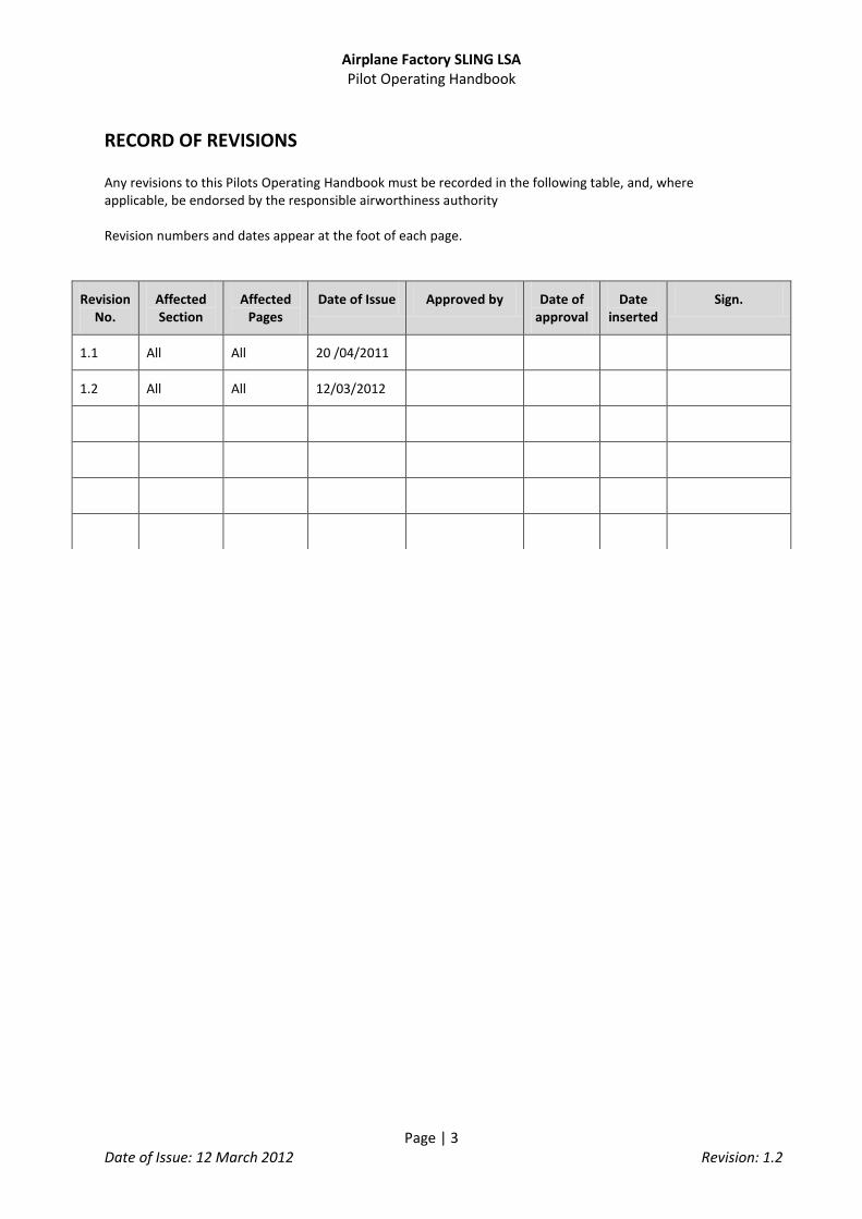
RECORD OF REVISIONS Any revisions to this Pilots Operating Handbook must be recorded in the following table, and, where applicable, be endorsed by the responsible airworthiness authority Revision numbers and dates appear at the foot of each page.
Revision No.
Affected Section
Affected Pages
Date of Issue Approved by Date of approval
Date inserted
Sign.
1.1 All All 20 /04/2011
1.2 All All 12/03/2012
Airplane Factory SLING LSA Pilot Operating Handbook
Page | 4 Date of Issue: 12 March 2012 Revision: 1.2
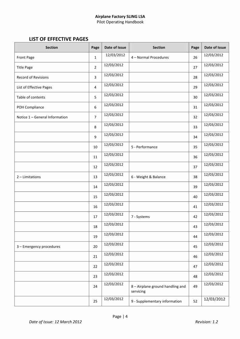
LIST OF EFFECTIVE PAGES
Section Page Date of Issue Section Page Date of Issue
Front Page 1 12/03/2012
4 – Normal Procedures 26 12/03/2012
Title Page 2 12/03/2012
27 12/03/2012
Record of Revisions 3 12/03/2012
28 12/03/2012
List of Effective Pages 4 12/03/2012
29 12/03/2012
Table of contents 5 12/03/2012
30 12/03/2012
POH Compliance 6 12/03/2012
31 12/03/2012
Notice 1 – General Information 7 12/03/2012
32 12/03/2012
8 12/03/2012
33 12/03/2012
9 12/03/2012
34 12/03/2012
10 12/03/2012
5 - Performance 35 12/03/2012
11 12/03/2012
36 12/03/2012
12 12/03/2012
37 12/03/2012
2 – Limitations 13 12/03/2012
6 - Weight & Balance 38 12/03/2012
14 12/03/2012
39 12/03/2012
15 12/03/2012
40 12/03/2012
16 12/03/2012
41 12/03/2012
17 12/03/2012
7 - Systems 42 12/03/2012
18 12/03/2012
43 12/03/2012
19 12/03/2012
44 12/03/2012
3 – Emergency procedures 20 12/03/2012
45 12/03/2012
21 12/03/2012
46 12/03/2012
22 12/03/2012
47 12/03/2012
23 12/03/2012
48 12/03/2012
24 12/03/2012
8 – Airplane ground handling and servicing
49 12/03/2012
25 12/03/2012
9 - Supplementary information 52 12/03/2012

Airplane Factory SLING LSA Pilot Operating Handbook
Page | 5 Date of Issue: 12 March 2012 Revision: 1.2
TABLE OF CONTENTS
1. GENERAL INFORMATION ................................................................................................................ 8 2. LIMITATIONS ................................................................................................................................. 14 3. EMERGENCY PROCEDURES ........................................................................................................... 24 4. NORMAL PROCEDURES ................................................................................................................. 30 5. PERFORMANCE ............................................................................................................................. 38 6. WEIGHT AND BALANCE ................................................................................................................. 41 7. SYSTEMS ........................................................................................................................................ 45 8. AIRPLANE GROUND HANDLING AND SERVICING .......................................................................... 52 9. SUPPLEMENTARY INFORMATION ................................................................................................. 55

Airplane Factory SLING LSA Pilot Operating Handbook
Page | 6 Date of Issue: 12 March 2012 Revision: 1.2
POH Compliance Notice
ASTM Standards used for the design, construction, and continued airworthiness:
ASTM F2279 ASTM F2295 ASTM F2245
Quality Assurance Records are stored both with the original manufacturer in South Africa and with its US Distributor at the below addresses.
THE AIRPLANE FACTORY
HANGAR 7 TEDDERFIELD AIR PARK, JHB SOUTH, EIKENHOF, 1872, SOUTH AFRICA PO BOX 308, EIKENHOF, 1872, SOUTH AFRICA
Phone: +27 11 024 4304 [email protected]
The Airplane Factory USA 3401 Airport Drive, Torrance, CA, 90505
Phone: 310-721-9190 [email protected]

Airplane Factory SLING LSA Pilot Operating Handbook
Page | 7 Date of Issue: 12 March 2012 Revision: 1.2
Continued Operational Safety Monitoring
Manufacturer Responsibilities
The Airplane Factory has a procedure in place to monitor the safety of the fleet and to alert pilots of any potential safety issues. The owner of a Light Sport Aircraft is responsible for making sure they receive pertinent safety information and complying with bulletins. The owner of a Light Sport Aircraft is also
responsible for alerting the manufacturer of any potential safety of flight issues.
Report a Safety of Flight Issue
Please contact our US Distribution Center to report any maintenance, service or safety issues.
Service/Maintenance/Safety issues: [email protected]
Or, fill out a safety/service form on our website: www.airplanefactory.com
Sign up to receive safety notices
Method for Owner/Operator to obtain the latest Safety of Flight Information
Please sign up on our website for continued safety/service updates:
www.airplanefactory.com, or
Call 310-721-9190, and we’ll sign you up
In addition, all updates will be posted to our website
Detailed Owner/Operator Responsibilities
Each owner/operator of a LSA shall read and comply with the maintenance and continued
airworthiness information and instructions provided by the manufacturer.
Each owner/operator of a LSA shall be responsible for providing the manufacturer with current
contact information where the manufacturer may send the owner/operator supplemental
notification bulletins.
The owner/operator or a LSA shall be responsible for notifying the manufacturer of any safety of
flight issue or significant service difficulty upon discovery.
The owner/operator of a LSA shall be responsible for complying with all manufacturer issued
notices of corrective action and for complying with all applicable aviation authority regulations in
regard to maintaining the airworthiness of the LSA.
An owner of a LSA shall ensure that any needed corrective action be completed as specified in a
notice, or by the next scheduled annual inspection.
Should an owner/operator not comply with any mandatory service requirements, the LSA shall be
considered not in compliance with applicable ASTM standards and may be subject to regulatory
action by the presiding aviation authority (FAA).

Airplane Factory SLING LSA Pilot Operating Handbook
Page | 8 Date of Issue: 12 March 2012 Revision: 1.2
1. GENERAL INFORMATION
1.1 Introduction to airplane
The Airplane Factory Sling is a two seat, single engine, tricycle gear aluminum aircraft with a conventional low wing design. The aircraft is based upon the FAA Light Sport Aircraft (LSA) category according to ASTM Standards F2245, F2279 and F2295. In this configuration the Sling is known as the Sling LSA. The Sling is intended chiefly for recreational and cross-country flying. It is not intended for aerobatic operation. It is considered to be suitable for use as a trainer. This Pilot Operating Handbook has been prepared to provide pilots with information for the safe and efficient operation of the Sling.
1.2 Warnings, cautions and notes
The following definitions apply to warnings, cautions and notes in the Pilot Operating Handbook. Means that non-observation of the corresponding procedure leads to an immediate or important degradation of flight safety. Means that non-observation of the corresponding procedure leads to a minor or possible long term degradation of flight safety. Draws attention to any special item not directly related to safety but which is important or unusual.
1.3 Descriptive data for the Airplane Factory Sling LSA
The Sling LSA is a single-engine, all metal, low-wing monoplane of semi-monocoque construction with two side-by-side seats. The airplane is equipped with a fixed tricycle gear and a steerable nose wheel.
WARNING
CAUTION
NOTE

Airplane Factory SLING LSA Pilot Operating Handbook
Page | 9 Date of Issue: 12 March 2012 Revision: 1.2
1.4 Aircraft layout – Measurements in Millimeters

Airplane Factory SLING LSA Pilot Operating Handbook
Page | 10 Date of Issue: 12 March 2012 Revision: 1.2
WING Wing span: 30.07 ft. (9.165 m) Mean Aerodynamic Chord: 4.39 ft. (1.339 m) Wing surface area: 127.5 ft
2 (11.845 m
2)
Wing loading: 10.37 lbs/ft2 (50.65 kg/m
2)
Aspect ratio: 7.04 Taper ratio: 1.375 Dihedral: 5
o
FUSELAGE
Fuselage length: 18.93 ft. (5.77 m) Overall length: 21.9 ft. (6.675 m) Overall width: 3.77 ft. (1.15 m) Overall height: 8.2 ft. (2.5 m)
EMPENNAGE
Horizontal stabilizer span: 9.27 ft. (2.825 m) Horizontal stabilizer surface area: 10.33 ft
2 (0.96 m
2)
Elevator surface area: 10.98 ft2 (1.02 m
2)
Horizontal stabilizer angle of incidence -3o
Vertical stabilizer span: 4.82 ft. (1.47 m) Vertical stabilizer surface area: 5.7 ft
2 (0.53 m
2)
Rudder surface area: 6.35 ft2 (0.59 m
2)
LANDING GEAR
Wheel track: 6.4 ft. (1.95 m) Wheel base: 4.63 ft. (1.41 m) Wheel hubs and brakes: Main gear tires: 15 X 6.00 - 6, 6 ply Nose gear tires: 5.00 - 5, 6 ply
CONTROL SURFACE TRAVEL LIMITS
Ailerons: 22o up and down (±3°)
Elevator: 28o up and 20
o down (± 2°)
Trim tab: 20o up and 25
o down (± 3°)
Rudder: 25o left and right (± 2°)
Flaps: 0o to 32
o down (± 3°)

Airplane Factory SLING LSA Pilot Operating Handbook
Page | 11 Date of Issue: 12 March 2012 Revision: 1.2
ENGINE Manufacturer: Bombardier-Rotax GmbH Model: 912 ULS Type: 4 cylinder horizontally opposed with overall displacement 1352cc, mixed
cooling (water-cooled heads and air-cooled cylinders), twin carburetors, and integrated reduction gearbox with torque damper
Maximum power: 98.5 hp (73.5 kW) @ 5800 RPM (max 5 mins.) 92.5 hp (69 kW) @ 5500 RPM (max continuous) PROPELLER
Manufacturer: Warp drive Model: 70 inch 3 blade composite (70RWT3) No of blades: 3 Diameter: 70 inches (1.78 m) Type: Composite FUEL Fuel grade: 91 (AKI Index) Octane MOGAS or 100LL AVGAS Fuel tanks: 2 wing tanks integrated within wing’s leading edge, equipped with finger
strainers outlet and drain fittings Capacity of each tank: 19.8 Gallons (75 Liters) Total capacity: 39.6 Gallons (150 Liters) Total usable fuel: 38.6 Gallons (146 Liters) OIL SYSTEM Oil system type: Forced, with external oil reservoir Oil: Automotive grade API “SF” or “SG” type oil preferably synthetic or semi-
synthetic Oil capacity: 2.6 Quarts (2.5 Liters) COOLING Cooling system: Mixed air and liquid pressurized closed circuit system Coolant: Antifreeze liquid (type BASF Glysanthin Anticorrosion or equivalent) and
water mixture Capacity: 3.2 Quarts (3 Liters) MAXIMUM WEIGHTS Maximum take-off weight: 1,320 Lbs. (600 kg) Maximum landing weight: 1,320 Lbs. (600 kg) Maximum baggage weight: 77 Lbs. (35 kg)

Airplane Factory SLING LSA Pilot Operating Handbook
Page | 12 Date of Issue: 12 March 2012 Revision: 1.2
STANDARD WEIGHTS Standard empty weight: 794 Lbs. (360 kg) SPECIFIC LOADINGS Wing loading: 10.37 lbs/ft
2 (50.65 kg/m
2)
Power loading: 13.23 lbs/hp (6.00 kg/hp)
TERMINOLOGY AND SYMBOLS General airspeed terminology and symbols
KCAS Calibrated Airspeed, being the indicated airspeed corrected for position and instrument error, expressed in knots
KIAS Indicated Airspeed, being the speed shown on the airspeed indicator, expressed in knots
KTAS True Airspeed, being the airspeed, expressed in knots, relative to undisturbed air, and which is KCAS corrected for altitude and temperature
VA Maneuvering airspeed
VFE Maximum Flap Extended Speed, being the highest speed permissible with wing flaps in a prescribed extended position
VNO Maximum Structural Cruising Speed, being the speed that should not be exceeded except in smooth air, and then only with caution
VNE Never Exceed Speed, being the speed that may not be exceeded at any time
VS Stall Speed
VSO Stall Speed in Landing Configuration (i.e. - with wing flaps in extended position)
VS1 Stall speed with wing flaps in retracted position
VX Best Angle of Climb Speed, being the speed which results in the greatest altitude gain in a given horizontal distance (i.e. - highest climb angle)
VY Best Rate of Climb Speed, being the speed which results in the greatest altitude gain in a given time
VR Rotation Speed, being the speed at which the aircraft should be rotated about the pitch axis during take-off
VLO Lift Off Speed, being the speed at which the aircraft generally lifts off from the ground during take-off
VOBS Obstacle Speed, being the speed at which the aircraft flies over a 50 ft (15 m) obstacle during take-off and landing, properly executed

Airplane Factory SLING LSA Pilot Operating Handbook
Page | 13 Date of Issue: 12 March 2012 Revision: 1.2
Meteorological terminology
OAT Outside Air Temperature, being the free air static temperature expressed in degrees Fahrenheit (°F)or Celsius (°C)
Ts Standard Temperature, being 59 °F (15 °C) at sea level pressure altitude and decreased by
3.5 °F (2 °C) for each 1,000 ft. of altitude
Hp Pressure Altitude, being the altitude read from an altimeter when the barometric scale has been set to 29.92 “Hg (1013 mb)
Engine terminology
RPM Revolutions per Minute, being the number of revolutions per minute of the engine crank, being 2.4286 times the number of revolutions performed by the propeller per minute pursuant to the reduction gearbox mounted between engine and propeller
Airplane performance and flight planning terminology
Crosswind Velocity
is the velocity of the crosswind component for which adequate control of the airplane during takeoff and landing can be guaranteed
Usable fuel Is the fuel available for flight planning
G is the acceleration due to gravity
TOR Is the take off distance measured from actual start to wheel lift off point
TOD Is the take off distance measured from the actual start to clearance of a 15m obstacle
GR Is the distance measured during landing from actual touchdown to the stopping point
LD Is the distance measured during landing from clearance of a 15m obstacle to the stopping point
S/R Is the specific range, being the distance, in nautical miles, which can be expected of the aircraft at a specific power setting and/or flight configuration per kilo of fuel used
Weight and balance terminology
Datum Reference datum is an imaginary vertical plane from which all horizontal distances are measured for balance purposes. (In the Sling this plane runs through the center point of the flat front face of the propeller flange of the Rotax 912 engine)
Arm Is the horizontal distance from the reference datum to the center of gravity of an item
Moment Is the product of the weight of an item multiplied by its arm
CG Center of Gravity, being the point at which the airplane, or equipment, would balance if suspended. Its distance from the reference datum is found by dividing the total moment by the total weight of the airplane
Empty weight
Is the weight of the airplane with engine fluids and oil at operating levels
Maximum Take-off Weight
Is the maximum weight approved for the start of the take-off run
Maximum Landing Weight
Is the maximum weight approved for the landing touch down
Tare Is the weight of chocks, blocks, stands, etc. used when weighing an airplane and included in the scale reading. Tare is deducted from the scale reading to obtain the actual (or net) airplane weight

Airplane Factory SLING LSA Pilot Operating Handbook
Page | 14 Date of Issue: 12 March 2012 Revision: 1.2
2. LIMITATIONS 2.1 Introduction This section includes operating limitations, instrument markings and basic placards necessary for the safe operation of the Airplane Factory Sling LSA, its engine, systems and equipment.
2.2 Airspeed limitations
SPEED KIAS REMARKS
VNE Never exceed speed 135 Never exceed this speed in any operation
VNO Maximum structural cruising speed
120 Never exceed this speed unless in smooth air, and then only with caution
VH Maximum speed in level flight
118 The aircraft will not exceed this speed at MTOW in level flight
VA Maneuvering speed 91 Do not make full or abrupt control movements above this speed as this may cause stress in excess of limit load factor (*Note: Maneuvering Speed quoted is at gross weight. VA decreases with a decrease in weight)
VFE Maximum flap extended speed
85 Never exceed this speed unless the flaps are fully retracted
VS1 Stall speed in Specific Configuration
45 At maximum takeoff weight in the most forward CG configuration the aircraft will stall if flown slower than this speed
VS0 Stall Speed in Landing Config.
40 The aircraft will stall at this speed in straight flight when at maximum gross weight with the power at idle and full flaps.
2.3 Airspeed indicator markings
MARKING KIAS SIGNIFICANCE
White arc 40-85 Positive Flap Operating Range (lower limit is VSO at maximum weight, and upper limit is the maximum speed permissible with flaps deployed)
Green arc 45-120 Normal Operating Range (lower limit is VS1 at maximum weight and most forward CG with flaps retracted and upper limit is maximum structural speed VNO)
Yellow arc 120-135 Maneuvers must be conducted with caution and only in smooth air
Red line 135 Maximum speed for all operations
2.4 Crosswind and wind limitation (demonstrated) Maximum permitted cross wind velocity for take-off and landing 15 kts
2.5 Service ceiling Service ceiling 12,000 ft

Airplane Factory SLING LSA Pilot Operating Handbook
Page | 15 Date of Issue: 12 March 2012 Revision: 1.2
2.6 Load factor
Maximum positive limit load factor + 4g Maximum negative limit load factor - 2g Maximum positive load factor with flaps +2g
Maximum negative load factor with flaps -1g 2.7 Weights
Maximum take-off weight 1,320 Lbs. (600 kg) Maximum landing weight 1,320 Lbs. (600 kg) Maximum baggage weight 77 Lbs. (35 kg)
2.8 Center of gravity range Datum Center of front face of propeller flange without spacer Reference for leveling Center fuselage upper channel surface with canopy open Forward limit -64.37 in. (-1.635 m) (20% MAC) Rear limit -69.76 in. (-1.772 m) (30.3% MAC)
2.9 Prohibited maneuvers The Sling LSA is approved for normal maneuvers including the following:
Steep turns not exceeding 60° bank
Lazy eights
Chandelles
Stalls (except whip stalls)
WARNING Aerobatics and intentional spins are
prohibited
WARNING It is the pilot’s responsibility to ensure that the airplane is properly loaded. Refer to section 6
for information on weight and balance
WARNING Limit load factor would be exceeded by
moving flight controls abruptly to their limits at a speed above VA (91 KIAS – maneuvering
speed)

Airplane Factory SLING LSA Pilot Operating Handbook
Page | 16 Date of Issue: 12 March 2012 Revision: 1.2
2.10 Flight crew
Minimum crew for flight is one pilot seated on the left side. 2.11 Passengers Only one passenger is allowed on board the aircraft in addition to the pilot.
2.12 Kinds of operation The Sling LSA, in standard configuration, is approved only for day VFR operation. Additional packages for Day/Night VFR and IFR are required for operations in those respective environments where approved by regulation. Minimum equipment required is as follows-
Altimeter
Airspeed indicator
Compass
Fuel gauges
Oil pressure indicator
Oil temperature indicator
Cylinder head temperature indicator
Outside air temperature indicator
Tachometer
Chronometer
First aid kit
Fire extinguisher
Emergency Locator Transmitter
2.13 Engine operating speeds and limits
Engine Model: ROTAX 912 ULS
Engine Manufacturer: Bombardier-Rotax GMBH
Po
wer
Max take-off 98.6 hp (73.5 kW)
at 5800 rpm, max. 5 min.
Max continuous 92.5 hp (69 kW)
at 5500 rpm
Cruising 71 hp (53 kW)
at 4800 rpm

Airplane Factory SLING LSA Pilot Operating Handbook
Page | 17 Date of Issue: 12 March 2012 Revision: 1.2
Engi
ne
RP
M
Max take-off 5800 rpm, max. 5 min.
Max continuous 5500 rpm
Cruising 4600 rpm to 5400 rpm
Idling ~ 1400 – 1650 RPM
Cyl
ind
er h
ead
tem
per
atu
re Minimum - N/A
Maximum 302 °F (150 °C)
Optimum 167 – 230 °F (75 – 110 °C)
Oil
tem
per
atu
re Minimum 122 °F (50 °C)
Maximum 284 °F (140 °C)
Optimum 194 – 230 °F (90 – 110 °C)
Oil
pre
ssu
re
Minimum 12 psi (0.8 bar) – below 3500 rpm
Maximum 102 psi (7 bar) – cold engine starting
Optimum 29 – 73 psi (2 – 5 bar) – above 3500 rpm
Instruments reflecting engine parameters should in each case be marked to reflect the minimum and maximum figures
2.14 Other limitations
No smoking is allowed on board of the aircraft.
2.15 Flight in rain When flying in the rain no additional steps are required. Aircraft qualities and performance are not substantially changed. However, VMC should be maintained.
WARNING Intentional flights under icing conditions are
prohibited!

Airplane Factory SLING LSA Pilot Operating Handbook
Page | 18 Date of Issue: 12 March 2012 Revision: 1.2
2.16 Limitation placards The following limitation warning placards must be placed in plain view of the aircraft. In a place visible to pilot and passenger -
FASTEN SEATBELTS
PASSENGER WARNING THIS AIRCRAFT WAS MANUFACTURED IN ACCORDANCE
WITH LIGHT SPORT AIRCRAFT AIRWORTHINESS STANDARDS AND DOES NOT CONFORM TO STANDARD
CATEGORY AIRWORTHINESS REQUIREMENTS
NO INTENTIONAL SPINS

Airplane Factory SLING LSA Pilot Operating Handbook
Page | 19 Date of Issue: 12 March 2012 Revision: 1.2
On the baggage space separator channel -
MAX BAGGAGE WEIGHT – 77 Lbs / 35 Kgs
EMERGENCY BALLISTIC CHUTE
REMOVE LOCKING PIN BEFORE FLIGHT PULL HANDLE TO FIRE
Airplane Factory SLING LSA Pilot Operating Handbook
Page | 20 Date of Issue: 12 March 2012 Revision: 1.2
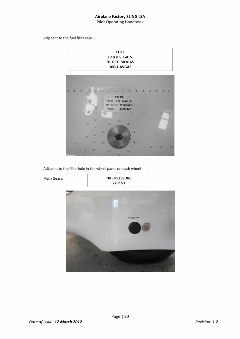
Adjacent to the fuel filler caps -
Adjacent to the filler hole in the wheel pants on each wheel - Main Gears:
FUEL 19.8 U.S. GALS. 91 OCT. MOGAS
100LL AVGAS
TIRE PRESSURE 22 P.S.I

Airplane Factory SLING LSA Pilot Operating Handbook
Page | 21 Date of Issue: 12 March 2012 Revision: 1.2
Nose Gear:
On the inboard upper wing flap surface -
NO STEP
TIRE PRESSURE 20 P.S.I

Airplane Factory SLING LSA Pilot Operating Handbook
Page | 22 Date of Issue: 12 March 2012 Revision: 1.2
On the exterior of the fuselage adjacent to the entrance to the cockpit - Light Sport – Both Passenger and PIC Side
When Ballistic Parachute is installed: On the exterior of the fuselage adjacent to the egress point of the Parachute Recovery System -
LIGHT-SPORT
WARNING This aircraft is equipped with a ballistically-
deployed emergency parachute system
DANGER EXPLOSIVE EGRESS Rocket Deployed Parachute Egress Area
STAY CLEAR

Airplane Factory SLING LSA Pilot Operating Handbook
Page | 23 Date of Issue: 12 March 2012 Revision: 1.2
On the Parachute Rocket Body inside the Rocket housing -
On a fireproof metal plate attached to the exterior of the fuselage aft of the cockpit -
The airplane must be placarded to show the identity of:
All fuses/circuit breakers
Magneto switches
Choke
Starter
Trim : Nose up and down
Flaps : Up and Down
AIRCRAFT IDENTIFICATION BUILDER: THE AIRPLANE FACTORY (Pty) Ltd
MODEL: SLING SERIAL NO: xxx
MADE IN SOUTH AFRICA
DANGER EXPLOSIVE ROCKET

Airplane Factory SLING LSA Pilot Operating Handbook
Page | 24 Date of Issue: 12 March 2012 Revision: 1.2
3. EMERGENCY PROCEDURES
3.1 Introduction
This section provides checklists and amplified procedures for coping with various emergencies that may arise. Emergencies caused by aircraft or engine malfunction are extremely rare if proper pre-flight inspections and maintenance are practiced. However, should an emergency arise, the basic guidelines described in this section should be considered and applied as necessary to correct the problem. In case of emergency the pilot should remember the following priorities – 1 Keep control of and continue flying the aircraft 2 Analyze the situation 3 Apply applicable procedures 4 Inform air traffic control of the situation if time and conditions permit it
3.2 Engine related emergencies
3.2.1 Engine failure during take-off run 1. Throttle - Reduce to idle 2. Magneto - Switch off 3. Brakes - Apply as needed 4. Magnetos: - Off 5. Alternator and master switches - Off With airplane under control – 6. Fuel selector valve - Off 7. Electric fuel pump - Off
3.2.2 Engine failure immediately after take-off 1. Speed - Check 2. Find a suitable place on the ground to land safely. The landing should be planned straight
ahead with only small changes in direction not exceeding 45 degrees to either side 3. Flaps - As needed (plan to land as slowly as possible) 4. Throttle - As needed At touch down 5. Magneto - Switch off 6. Fuel selector valve - Switch off 4. Electric fuel pump - Off

Airplane Factory SLING LSA Pilot Operating Handbook
Page | 25 Date of Issue: 12 March 2012 Revision: 1.2
3.2.3 Engine irregularities in flight
3.2.3.1 Irregular engine rpm
1. Check throttle position 2. Check engine gauges 3. Check fuel quantity gauge 4. Turn electric fuel pump on 5. Check fuel selector valve and change if required If engine continues to run irregularly 6. Land as soon as possible
3.2.3.2 Low fuel pressure (2.2 psi (0.15 bar) or less)
1. Check fuel quantity indicator 2. Switch electric fuel pump on 3. Check that fuel selector is correctly set If fuel pressure remains low 4. Decease throttle setting if viable to do so If fuel pressure remains low 5. Land as soon as possible
3.2.3.3 Low oil pressure (12 psi (0.8 bar) or less)
1. Check oil temperature If oil temperature is high or increasing 2. Set throttle to a setting which gives an aircraft speed of 70 KIAS (most efficient speed) If oil pressure remains low or temperature remains high or increasing 3. Land as soon as possible and remain vigilant for impending engine fault
3.2.4 In-flight engine restarting
1. Electric fuel pump - On 2. Fuel selector - Ensure on 3. Throttle - Set to middle position 4. Master and alternator switches - Check on
NOTE If one fuel tank is empty ensure that fuel selector is set to
fullest tank

Airplane Factory SLING LSA Pilot Operating Handbook
Page | 26 Date of Issue: 12 March 2012 Revision: 1.2
5. Magnetos - Check on 6. Starter - Switch on If engine should fail to restart 8. Apply forced landing without engine power procedure
3.3 Smoke and fire
3.3.1 Fire on ground at engine starting
1. Starter - Release Immediately 2. Fuel selector - Close 3. Throttle - Set to Idle 4. Magnetos - Switch off 5. Collect the fire extinguisher from luggage compartment if possible 6. Leave the airplane 7. Extinguish fire by fire extinguisher or call fire department if necessary
3.3.2 Fire on ground with engine running 1. Heating - Close 2. Fuel selector - Close 3. Throttle - Full power 4. Magnetos - Switch off 5. Collect the fire extinguisher from luggage compartment if possible 6. Leave the airplane 7. Extinguish fire by fire extinguisher or call fire department if necessary
3.3.3 Fire during take-off
1. Speed - 70 knots 2. Heating - Close 3. Fuel selector - Close 4. Throttle - Set to Idle if appropriate 5. Magnetos - Switch off 6. Land and stop the airplane 7. Collect the fire extinguisher from luggage compartment if possible 8. Leave the airplane 9. Extinguish fire by fire extinguisher or call fire department if necessary
3.3.4 Fire in flight 1. Heating - Close 2. Fuel selector - Close 4. Throttle - Full power 5. Magnetos - Switch off after the fuel in carburetors is consumed and
engine shut down 6. Choose an area - Heading to the nearest airport or choose emergency
landing area 7. Emergency landing - Perform according to 6.5.1

Airplane Factory SLING LSA Pilot Operating Handbook
Page | 27 Date of Issue: 12 March 2012 Revision: 1.2
8. Leave the airplane 9. Extinguish fire by fire extinguisher or call fire department if necessary
3.3.5 Fire in the cockpit 1. Master switch - Switch off 2. Heating - Close 3. Use the fire extinguisher
3.4 Landing Emergencies
Emergency landings are generally carried out in the case of engine failure and the engine cannot be re-started. Other reasons for an emergency landing may arise, however.
3.4.1 Engine-off emergency landing
1. Speed - Apply best glide speed of 70 KIAS 2. Trim - Trim for best glide speed 3. Landing location - Locate most suitable landing location, free of obstacles
and preferably into wind 4. Safety harness - Tighten 5. Engine restart - If time permits and if appropriate attempt to identify
reason for engine failure and attempt restart 6. Flaps - Extend as needed 7. Safety harness - Tighten 8. Communications - Report your location to third parties if possible 9. Passenger - Brief passenger Immediately before touchdown- 10. Fuel selector - Shut off 11. Magnetos - Switch off 12. Master and alternator switches - Switch off 13. Electric fuel pump - Switch off
3.4.2 Precautionary landing A precautionary landing is generally carried out in the cases where the pilot may be disorientated, the aircraft has no fuel reserve or possibly in bad weather conditions. 1. Choose landing area, determine wind direction
NOTE Estimated time to pump fuel out of
carburetors is 30 seconds
WARNING Do not attempt to re-start the engine!

Airplane Factory SLING LSA Pilot Operating Handbook
Page | 28 Date of Issue: 12 March 2012 Revision: 1.2
2. Report your intention to land and land area location if a COMM is installed in the airplane 3. Perform low-altitude passage into wind over the right-hand side of the chosen area with flaps extended as needed and thoroughly inspect the landing area. 4. Perform circle pattern. 5. Perform approach at increased idling with flaps fully extended. 6. Reduce power to idle when flying over the runway threshold and touch-down at the very beginning of the chosen area. 7. After stopping the airplane switch off all switches, shut off the fuel selector, lock the airplane and look for assistance.
3.4.3 Landing with a flat tire 1. If the main landing gear is damaged, perform touch-down at the lowest practicable speed with aircraft slightly banked towards good tire. Keep flat tire off the ground just above or very lightly on the ground until minimum speed possible, while maintaining directional stability during landing run. 2. If the nose wheel is damaged perform touch-down at the lowest practicable speed and hold the nose wheel above the ground by means of the elevator control as long as possible.
3.5 Recovery from unintentional spin The aircraft is unlikely to enter an unintentional spin unless extreme inputs are used. Unintentional spin recovery technique: 1. Throttle - Idle 2. Lateral control - Ailerons neutralized 3. Rudder pedals - Full rudder in direction opposite to spin 4. Rudder pedals - Neutralize rudder immediately when rotation stops 5. Longitudinal control - Neutralize stick or push forward if necessary to lower
nose, then recover from dive ensuring VNE and G limitations are not exceeded
3.6 Other emergencies
3.6.1 Vibration If any forced aircraft vibrations appear: 1. Set engine speed to such power rating where the vibrations are lowest.
NOTE Watch the chosen area steadily during
precautionary landing.
WARNING Intentional spins are prohibited!

Airplane Factory SLING LSA Pilot Operating Handbook
Page | 29 Date of Issue: 12 March 2012 Revision: 1.2
2. Land on the nearest airfield or to perform a precautionary landing according to 6.5.2.
3.6.2 Carburetor icing Carburetor icing is evidenced through a decrease in engine power and an increase of engine temperatures. To recover the engine power, the following procedure is recommended: 1. Speed - 75 knots 2. Throttle - Set to 1/3
rd power
3. If possible, leave the icing area 4. Increase the engine power gradually up to cruise conditions after 1 – 2 minutes. If you fail to recover the engine power, land on the nearest airfield (if possible) or depending on the circumstances, perform a precautionary landing according to 6.5.2.

Airplane Factory SLING LSA Pilot Operating Handbook
Page | 30 Date of Issue: 12 March 2012 Revision: 1.2
4. NORMAL PROCEDURES
This section provides checklists and recommended procedures for normal operation of the aircraft.
4.1 Pre-flight check
Carry out the pre-flight inspection every day prior to the first fight. Pre-flight inspections must also be performed after any accident, incident, maintenance activity, assembly of any aircraft component or similar. Incomplete or careless inspection can cause an accident. Carry out the inspection following the instructions in the Inspection Check List. Inspection Check List 1. Cabin - Magnetos - OFF - Master switch - ON - Fuel level indicator - Check fuel quantity - Flaps - Move to full down position - Master switch - OFF - Avionics - Check condition - Control System - Visual inspection, free movement up to stops,
check function - Canopy - Attachment condition, clean - Cockpit - Check for loose objects - Fire extinguisher - Check present and valid - Documentation - Check present and valid
2. Nose Section and Nose Gear - Engine cowling condition - Check - Propeller and spinner condition - Check - Air intakes - Check - Radiators - Check - Engine mount and exhaust manifold condition - Check - Oil and coolant quantity check - Check - Visual inspection of the fuel and electrical system - Check - Engine checks as per manual - Complete - Other actions according to the engine manual - Parachute cover - If fitted check sealed and secure - Tire - Condition, inflation, wear - Wheel - Security, general condition - Chocks and tie-down ropes - Remove - Suspension - Check and test
NOTE The word “condition” in the instructions means a visual inspection of
surface for damage deformations, scratching, chafing, corrosion or other damages, which may lead to flight safety degradation.

Airplane Factory SLING LSA Pilot Operating Handbook
Page | 31 Date of Issue: 12 March 2012 Revision: 1.2
3. Right Fuselage
- Surface condition - Check - Cowling attachment - Check - Wing/fuselage fairings - Check - Empennage fairings - Check - Antennae - Check condition and security
4. Right Wing and Main Gear
- Wheel fairing - Security, cracks, tire condition, inflation, wear - Service condition - Check - Leading edge condition - Check - Wheel and brakes - Fluid leaks, security, general condition - Wheel strut - Condition, cracks - Fuel vent (underside) - Unobstructed - Wing trailing edge - Check condition - Aileron - Freedom of movement, attachment, surface condition - Aileron hinges, control horn, bolts, pushrod - Secure, condition - Flap hinges, control horn, bolts, pushrod - Secure, condition - Wing tip - Check condition - Strobe/Nav light and lens - Check for cracks and condition
5. Empennage
- Tie-down rope - Removed - Horizontal and vertical stabilizers - Check condition - Elevator and tab - Condition and movement - Rudder - Condition and movement - Hinges, control horn, bolts, pushrod - Condition and secure
6. Left Fuselage
- Surface condition - Check - Cowling attachment - Check - Wing/fuselage fairings - Check - Empennage fairings - Check - Antennae - Check condition and security
7. Left Wing
- Wheel fairing - Security, cracks, tire condition, inflation, wear - Service condition - Check - Leading edge condition - Check - Wheel and brakes - Fluid leaks, security, general condition - Wheel strut - Condition, cracks - Wing trailing edge - Check condition - Aileron - Freedom of movement, attachment, surface condition - Aileron hinges, control horn, bolts, pushrod - Secure, condition - Flap hinges, control horn, bolts, pushrod - Secure, condition - Wing tip - Check condition - Strobe/Nav light and lens - Check for cracks and condition - Pitot tube - Security and clear

Airplane Factory SLING LSA Pilot Operating Handbook
Page | 32 Date of Issue: 12 March 2012 Revision: 1.2
4.2 Engine starting
4.2.1 Before starting engine
1. Pre-flight inspection - Completed 2. Emergency equipment - On board 3. Passengers - Briefed 4. Seats, seatbelt and harnesses - Adjust and secure 5. Brakes - On
4.2.2 Engine starting 1. Master switch - On 2. Backup battery - On check MGL Voyager on and backup battery
voltage 3. Fuel selector - Select fuller tank 4. Magnetos - On 5. Choke (cold engine) - Pull to open and gradually release after engine
start 6. Throttle - Closed if choke used, cracked just open if not 7. Propeller area - Clear of people and obstructions 8. Starter - Hold activated to start engine 9. MGL Voyager switch - On and check battery charging 10. Avionics main switch - On 11. Warm engine - 2000 rpm for 2 minutes, then 2500 rpm until oil
temp is 120 °F (50 °C)
** Starter mat be operated continuously for a maximum of 10 seconds. Thereafter a cool down period of 2 minutes is required. Failure to comply with this limitation will result in starter motor damage.
WARNING Physically check the fuel level before each take-off to
make sure you have sufficient fuel for the planned flight.
CAUTION In case of long-term parking it is recommended to turn the
engine several times (Magnetos OFF!) by turning the propeller. Always handle by palm the blade area i.e. do not grasp only the
blade edge. It will facilitate engine starting.

Airplane Factory SLING LSA Pilot Operating Handbook
Page | 33 Date of Issue: 12 March 2012 Revision: 1.2
4.2.3 Engine warm up, engine check Prior to engine check block the main wheels using chocks or ensure that the brake is firmly on. Initially warm up the engine to 2000 rpm for approx. 2 minutes, then continue to 2500 rpm until the oil temperature reaches 120 °F (50 °C). The warm up period depends on ambient air temperature. Check both Magneto circuits at 4000 rpm for Rotax 912 ULS. The engine speed drop when either Magneto is switched off should not be over 300 rpm. The maximum engine speed drop difference between circuits A and B should be 120 rpm. Set maximum power for verification of maximum speed with given propeller and engine parameters (temperatures and pressures). Check acceleration from idling to maximum power. If necessary, cool the engine at 3000 rpm before shutdown.
4.3 Taxiing
1. Flaps - Up 2. Taxi light - On 3. Brakes - Off (Carefully check stop brake valve is off) 4. Controls - Neutral position, or as required for wind 5. Power and brakes - As required 6. Fuel selector - Switch tank 7. Brakes - Check 8. Instruments - Check
CAUTION The starter should be activated for a maximum of 10 sec., followed by 2 min. pause for engine cooling. As soon as engine runs, adjust throttle to achieve smooth running at approx. 2500 rpm. Check the oil pressure, which should increase within 10 sec. Increase the engine speed after the oil pressure has reached 29 psi (2 bars) and is steady. To avoid shock loading, start the engine with the throttle lever set for idling or 10% open at maximum, then wait 3 sec to reach constant engine speed before new acceleration. Only one magneto should be switched on (off) during Magneto check.
NOTE Only one magneto should be switched on (off) during
magneto check
CAUTION The engine check should be performed with the aircraft heading upwind and not on a loose terrain (the propeller may suck grit
which can damage the leading edges of blades).

Airplane Factory SLING LSA Pilot Operating Handbook
Page | 34 Date of Issue: 12 March 2012 Revision: 1.2
Apply power and brakes as needed. Apply brakes to control movement on ground. Taxi with usual procedures and precautions when wind velocity exceeds 15 knots.
4.4 Normal take-off
4.4.1 Before take-off
1. Controls - Test full and free movement, directions 2. Trim - Set neutral position 3. Choke - Check off 4. Propeller pitch (if applicable) - Full fine 5. Flaps - As required, 12 degrees recommended for best take-off
roll and initial climb 6. Fuel quantity - Confirm 7. Fuel selector - Both (but fuller tank if one tank near empty) 8. Electric Fuel pump - Test 9. Fuses - All in 10. Instruments - Check all 11. Switches - Check, as required 12. Power and Magnetos - Check mags at 3,800 rpm, max diff 50 rpm, max drop
150 rpm 13. Engine parameters - Temperatures, pressures, current/voltage 14. Canopy - Closed and latched 15. Safety harnesses - On and tight
4.4.2 Take-off 1. Take-off power - Throttle fully forward (max. 5800 rpm for 5 minutes) 2. Engine speed - Check rpm (propeller specific) 3. Instruments within limits - Check 4. Nose wheel unstuck - 40 KIAS 5. Airplane lift-off - 48 KIAS 6. Wing flaps - Retract when speed of 70 KIAS is reached, at altitude of
minimum 300 ft 7. Transit to climb 8. Climb with flaps at 70 knots. Best rate of climb without flaps is 75 knots
4.5 Climb 1. Throttle - Max. take-off power 5800 rpm (for max. 5 minutes) - Max. cont. power 5500 rpm 2. Airspeed - VX = 65 KIAS - VY = 72 KIAS - Cruise climb = 75 to 90 KIAS 3. Trim - Trim the airplane
WARNING Take-off is prohibited if:
The engine is running unsteadily
The engine instrument values are beyond operational limits
The crosswind velocity exceeds permitted limits (see 3.6)

Airplane Factory SLING LSA Pilot Operating Handbook
Page | 35 Date of Issue: 12 March 2012 Revision: 1.2
4. Instruments - Check - Oil temperature and pressure - Cylinder temperature within limits 5. Brakes - Apply to stop wheel rotation
Best angle of climb speed (VX): 65 knots Best rate of climb speed (VY): 72 knots
4.6 Cruise
Refer to section 5, for recommended cruising figures
4.7 Descent Optimum glide speed - 70 KIAS
4.8 Approach Approach speed
Long finals - 65 KIAS Short finals - 60 KIAS
1. Throttle - As needed 2. Wing flaps - Extend as needed 3. Trim - As needed
CAUTION If the cylinder head temperature or oil temperature approach their limits,
reduce the climb angle to increase airspeed and thus fulfill the limits.
CAUTION It is not advisable to reduce the engine throttle control lever to minimum on final approach and
when descending from very high altitude. In such cases the engine becomes over-cooled and a loss of power may occur. Descent at increased idle (approx. 3000 rpm), speed between 65-76 knots (75-
87 mph, 120-140 km/h) and check that the engine instruments indicate values within permitted limits.
WARNING The fuel lift pipe in the fuel tank is situated adjacent to the lower inside wall of the tank. The aircraft should at no time be subjected to a sustained side slip towards a near empty fuel tank (i.e. - right wing down) as, despite the baffling, this may have the consequence that the fuel runs towards the outer edge of the tank exposing the fuel lift pipe to suck air, thereby starving the engine of fuel leading to engine failure. This poses a particular
threat when at low altitude, typically prior to landing.

Airplane Factory SLING LSA Pilot Operating Handbook
Page | 36 Date of Issue: 12 March 2012 Revision: 1.2
4.9 Normal landing
4.9.1 Before landing
1. Throttle - As needed 2. Airspeed - 60 KIAS 3. Wing flaps - Extend as needed 4. Trim - As needed
4.9.2 Landing
1. Throttle - Idle 2. Controls - Flare to minimum flying speed 3. Touch-down on main wheels 3. Apply brakes - As needed (after the nose wheel touch-down)
4.9.3 After landing 1. Engine speed - Set as required for taxiing 2. Wing flaps - Retract
4.9.4 Engine shutdown
1. Engine speed - Idle 2. Instruments - Engine instruments within limits 3. Avionics - Switch off 4. Magnetos - Switch off 5. Circuit breakers - Switch off 6. Master switch - Switch off 7. Switch box - Turn key to switch off 8. Fuel selector - Off
4.10 Short field take-off and landing procedures Not considered necessary. Ordinary short field procedures may be used if the pilot deems it appropriate.
4.11 Balked landing procedures 1. Throttle - Full power (max. 5800 rpm) 2. Pitch for Vx - 65 KIAS 3. Wing flaps - Extend as needed 4. Trim - Adjust as needed
CAUTION Rapid engine cooling should be avoided during operation. This happens above all during aircraft descent, taxiing, low engine rpm or at engine shutdown immediately after landing. Under normal conditions the engine temperatures stabilize during descent, taxiing and at values suitable to stop engine by switching the Magnetos off. If necessary, cool the engine at 2500 – 2750 rpm to stabilize the temperatures prior to engine shut down.

Airplane Factory SLING LSA Pilot Operating Handbook
Page | 37 Date of Issue: 12 March 2012 Revision: 1.2
5. Wing Flaps - retract to 50% as soon as possible and retract fully at height of 300 ft after reaching 70 knots
6. Trim - Adjust 7. Repeat Pattern
4.12 Aircraft parking and tie-down 1. Site - Park the aircraft on as level an area as possible 2. Magneto check - OFF 3. Master switch check - OFF 4. Fuel selector - OFF 6. Parking brake - Use as necessary 7. Canopy - Close, lock as necessary 8. Secure the airplane
NOTE It is recommended to use parking brake (if installed) for short-time parking
only, between flights during a flight day. After ending the flight day or at low temperatures of ambient air, do not use parking brake, but use the wheel
chocks instead.
NOTE Use anchor eyes on the wings and fuselage rear section to fix the airplane. Move control stick forward and fix it together with the rudder pedals. Make sure that
the cockpit canopy is properly closed and locked.

Airplane Factory SLING LSA Pilot Operating Handbook
Page | 38 Date of Issue: 12 March 2012 Revision: 1.2
5. PERFORMANCE
The presented data has been computed from actual flight tests with the aircraft and engine in good conditions and using average piloting techniques.
If not stated otherwise, the performance stated in this section is valid for maximum take-off weight 1,320 lbs. (600 kg) and under ISA conditions.
The performance shown in this section is valid for aircraft fitted with a ROTAX 912 ULS 73.5kW (98.6 hp) engine.
5.1 Take-off and landing distance
Take-off distances:
RWY Take-off run distance
Take-off distance over 50 ft (15 m)
obstacle
Concrete 394 ft. (120 m) 755 ft. (230 m)
Grass 459 ft. (140 m) 820 ft. (250 m)
Landing distances:
RWY Landing run distance (braked)
Landing distance over 50 ft. obstacle
Concrete 230 ft. (70 m) 656 ft. (200 m)
Grass 230 ft. (70 m) 656 ft. (200 m)
5.2 Rate of climb
Conditions: Max. continuous Power: 5500 rpm Weight: 1,320 lbs (600kg)
Best rate of climb speed IAS
Rate of climb
KIAS fpm
0 ft ISA 72 900
3,000 ft ISA 72 700
6,000 ft ISA 72 520
9,000 ft ISA 72 430

Airplane Factory SLING LSA Pilot Operating Handbook
Page | 39 Date of Issue: 12 March 2012 Revision: 1.2
5.3 Cruise speeds
Altitude [ft. ISA]
Engine speed [rpm]
KIAS
100
4500 75
4800 90
5000 98
5300 102
5500 106
3,000
4500 72
4800 87
5000 94
5300 100
5500 104
6,000
4500 65
4800 80
5000 90
5300 98
5500 101
9,000
4500 55
4800 70
5000 80
5300 88
5500 91
5.4 Fuel consumption
Altitude [ft. ISA] 3,000
Fuel quantity [Gallons] [Liters ]
39.6 150
Engine speed [rpm] 4500 4800 5000 5300 5500
Fuel consumption
[GPH] [l/hr]
3.4 13
4 15
4.2 16
4.8 18
5.3 20
Airspeed [KIAS] 72 87 94 100 104
Endurance [hh:mm] 11:30 10:00 09:22 08:20 07:30
Range [NM] 828 870 881 833 780
Airplane Factory SLING LSA Pilot Operating Handbook
Page | 40 Date of Issue: 12 March 2012 Revision: 1.2
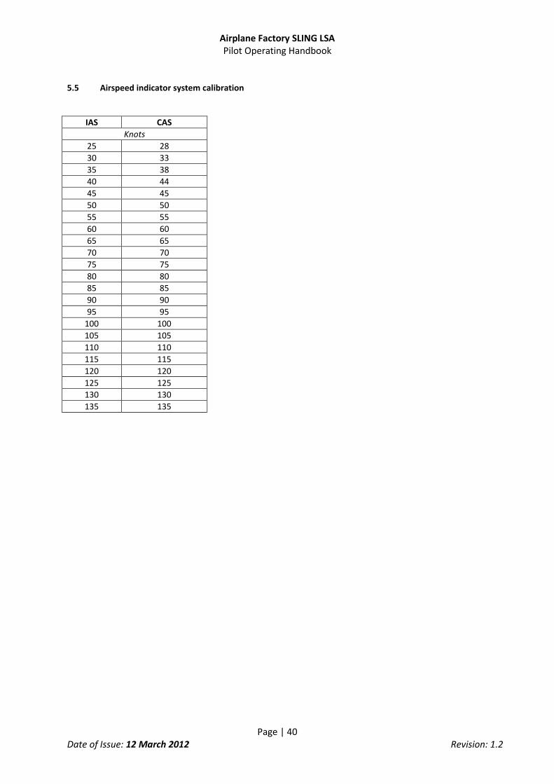
5.5 Airspeed indicator system calibration
IAS CAS
Knots
25 28
30 33
35 38
40 44
45 45
50 50
55 55
60 60
65 65
70 70
75 75
80 80
85 85
90 90
95 95
100 100
105 105
110 110
115 115
120 120
125 125
130 130
135 135

Airplane Factory SLING LSA Pilot Operating Handbook
Page | 41 Date of Issue: 12 March 2012 Revision: 1.2
6. WEIGHT AND BALANCE
This section contains weight and balance records and the payload range for the safe operation of the Sling.
6.1 Standard Installed Equipment List
MGL Avionics Voyager EFIS EGT, CHT, OT, OP, RPM, Fuel Level, Fuel Press., Fuel Flow, Man. Press FT-60 Red Cube Fuel Flow Transducer
3 1/8” Backup Instruments ASI, Alt
2 ¼” Compass, Slip/Skid MGL Avionics V6 VHF Radio/Intercom Ray Allan electric trim system on elevator (T2-10A-TS) Transmotec electric flap actuator DLA-12-20-A-100-POT-IP65 Internal Red LED Cabin Light
6.2 Center of gravity (CG) range and determination

Airplane Factory SLING LSA Pilot Operating Handbook
Page | 42 Date of Issue: 12 March 2012 Revision: 1.2
Operating CG range -64.37 inches (-1,635mm) to -69.76 inches (-1,772mm) from reference datum (20 to 30.3% of MAC – Leading edge of MAC is -53.78 inches (-1,366mm), MAC is 52.72 inches (1,339mm)
Determination of CG Weight and balance report lists:
Empty CG check
Forward CG check
Rear CG check
Blank CG form %MAC (metric) (mm) = (Total moment arm + 1366) x 100 Total weight (- 1339) %MAC (US) (inches) = (Total moment arm + 53.78) x 100 Total weight (- 52.72)
6.3 Empty CG Check
Item Weight
Lbs. (kg)
Arm
Inches (mm)
Moment
(weight x arm)
Air
craf
t Em
pty
CG
Right Main Wheel WR = LR= -77.13” (-1959mm)
Left Main Wheel WL = LL= -77.13” (-1959mm)
Nose Wheel WN = LN= -21.57” (-548mm)
Computed CG empty
Empty weight:
WE – …………..kg
CG = ……….. mm
(…………% MAC)
Aircraft moment :
Maximum take-off weight is 1,320 Lbs. (600 kg)

Airplane Factory SLING LSA Pilot Operating Handbook
Page | 43 Date of Issue: 12 March 2012 Revision: 1.2
6.4 Forward CG check
WEIGHT
Lbs. (kg)
ARM
Inches (mm)
MOMENT
(weight x arm)
PILOT 77.13 “ (1959 mm)
PASSENGER 77.13” (1959 mm)
FRONT BAGGAGE 98.74” (2508 mm)
REAR BAGGAGE 114.02” (2896 mm)
FUEL TANKS 59.49” (1511 mm)
ADD EMPTY VALUES 906 65.08” (1653 mm) 58,962
TOTAL
Take-Off Weight WT = MT =
PILOT CG = % MAC
6.5 Rear CG check
WEIGHT
Lbs. (kg)
ARM
Inches (mm)
MOMENT
(weight x arm)
PILOT 77.13 “ (1959 mm)
PASSENGER 77.13” (1959 mm)
FRONT BAGGAGE 98.74” (2508 mm)
REAR BAGGAGE 114.02” (2896 mm)
FUEL TANKS 59.49” (1511 mm)
ADD EMPTY VALUES 906 65.08” (1653 mm) 58,962
TOTAL WT = MT =
Take-Off Weight kg CG = % MAC

Airplane Factory SLING LSA Pilot Operating Handbook
Page | 44 Date of Issue: 12 March 2012 Revision: 1.2
6.6 Blank CG form for use
WEIGHT
Lbs. (kg)
ARM
Inches (mm)
MOMENT
(weight x arm)
PILOT 77.13 “ (1959 mm)
PASSENGER 77.13” (1959 mm)
FRONT BAGGAGE 98.74” (2508 mm)
REAR BAGGAGE 114.02” (2896 mm)
FUEL TANKS 59.49” (1511 mm)
ADD EMPTY VALUES 906 65.08” (1653 mm) 58,962
TOTAL WT = MT =
Take-Off Weight CG = % MAC

Airplane Factory SLING LSA Pilot Operating Handbook
Page | 45 Date of Issue: 12 March 2012 Revision: 1.2
7. SYSTEMS
7.1 Airframe
The airplane has an all-metal construction with single curvature stressed aluminum skins riveted to stiffeners. Construction is of 6061-T6 aluminum sheet metal riveted to aluminum angles with high quality blind rivets. This high strength aluminum alloy construction provides long life and low maintenance costs thanks to its durability and corrosion resistant characteristics. The wing has a high lift airfoil (NACA 4415) and is equipped with semi-slotted fowler type flaps.
7.2 Control system The airplane is equipped with dual stick controls and dual rudder pedals which control rudder and steer the nose wheel. Braking is controlled on both main wheels with a hand actuator situated in the center console. Elevator trim is electrically controlled by buttons on the control stick. Wing flaps are electrically controlled by a rocker switch located on the instrument panel or control stick, according to owner choice.
7.3 Landing gear The landing gear is a tricycle landing gear with a steel sprung steerable nose wheel. The main landing gear uses a single continuous fiberglass spring section.
7.4 Brake
The aircraft braking system is a single hydraulic system acting on both wheels of the main landing gear through disk brakes. An intercept valve acts as a parking brake by stopping pressure relief. For braking to be operational the brake intercept valve must be off and the brake lever activated. The arrangement is apparent in the diagram below-
Brake system

Airplane Factory SLING LSA Pilot Operating Handbook
Page | 46 Date of Issue: 12 March 2012 Revision: 1.2
7.5 Safety and safety harness The aircraft has side-by-side seating. Four point safety belts are provided for each seat. Seats can be adjusted backwards and forwards for comfort with forward movement slightly raising the seat height.
7.6 Baggage compartment The baggage compartment comprises two sections positioned behind the seats and is designed to carry up to 77 lbs (35 kg) in total. The baggage compartment comprises a narrow, slightly lowered front section and a higher, larger back section. 77 lbs (35 kg) of luggage may be loaded in the front section and 55 lbs (25 kg) in the back section, subject to a total maximum baggage weight of 77 lbs (35 kg). Regardless of the manner in which baggage is loaded, it is the obligation of the pilot to ensure that the aircraft CG is within the permissible limits. All baggage must be properly secured.
7.7 Canopy The airplane is equipped with a sliding canopy mechanism. External access to the cabin is from either side. Latching mechanism is provided inside the cabin at the top centre of the roll-over bar. Please ensure that the canopy is latched and that the mechanism is securely locked into position before operating the aircraft.
7.8 Pitot – static system A pitot-static tube is located below the left wing. Pressure distribution to the instruments is through flexible plastic hoses. The tube incorporates a second inlet for measurement of angle of attack. Keep the pitot head clean to ensure proper functioning of the system. Ensure that pitot tube cover is removed prior to flight.
Pitot and static system
NOTE Prior to each flight, ensure that the seat belts are firmly
secured to the airframe, and that the belts are not damaged. Adjust the buckle so that it assumes a central position
relative to the body. Ensure that the seat slider is locked firmly in place.

Airplane Factory SLING LSA Pilot Operating Handbook
Page | 47 Date of Issue: 12 March 2012 Revision: 1.2
7.9 Cockpit
1 Master switch 18 Slip indicator
2 Magneto switches left and right 19 MGL V10 radio
3 Generator light 20 Engine choke control knob
4 Analogue airspeed indicator 21 Cabin heat control knob
5 Analogue altimeter 22 Main fuse (25A)
6 Analogue VSI 23 Instruments fuse (10A)
7 MGL Voyager switch 24 Radio fuse (5A)
8 Backup battery switch 25 MGL Voyager fuse (3A)
9 Electric fuel pump switch 26 Trim motor fuse (1A)
10 Taxi light switch 27 12V power socket and flap motor fuse (5A)
11 Landing light switch 28 Fuel pump fuse (5A)
12 Avionics switch 29 12V power source socket
13 Flap deployment switch
14 Fuel selector valve
15 MGL Voyager
16 MGL Voyager warning light
17 Magnetic compass

Airplane Factory SLING LSA Pilot Operating Handbook
Page | 48 Date of Issue: 12 March 2012 Revision: 1.2
7.10 Instruments and Avionics
MGL Voyager is a multifunction “glass cockpit” instrument and incorporates – o ASI o VSI o ALT o Compass o Artificial Horizon o Turn co-coordinator o G meter o Clock/timer o Comprehensive mapping and navigation software and data o GPS o Stopwatch o Autopilot if fitted to servos o Full engine monitoring and management capacity including –
RPM indicator CHT indicators EGT indicators Oil temperature indicator Oil pressure indicator Fuel level indicators Fuel flow indicator Tachometer Flight time recorder Charge current indicator Voltmeter
See MGL Voyager operations manual for operating details.
7.11 Miscellaneous equipment The following additional equipment and systems can be used in the aircraft-
Ray Allen elevator trim control motor in elevator with PTT on both control sticks
Kuntzleman wing tip nav lights with red, green and white LED
Kuntzleman strobe light under tail
Kuntzleman wing leading edge LED landing and taxi lights on left wing
Hand actuated hydraulic brakes on main wheels with actuator in center console
Park brake mechanism operated by brake fluid shutoff valve in center console
7.12 Minimum instruments and equipment list for VFR flights:
Altimeter
Airspeed indicator
Compass
Fuel gauges
Oil pressure indicator
Oil temperature indicator
Cylinder head temperature indicator
Outside air temperature indicator
Tachometer
Clock

Airplane Factory SLING LSA Pilot Operating Handbook
Page | 49 Date of Issue: 12 March 2012 Revision: 1.2
First aid kit
Fire extinguisher
7.13 Powerplant The Rotax 912 ULS engine is a 4-stroke, 4 cylinder, horizontally opposed, spark Ignition engine with one central camshaft-push-rod-OHV. The engine features liquid cooled cylinder heads with ram air cooled cylinders. It uses dry sump forced lubrication and has a dual contactless capacitor discharge magneto type ignition system. The magneto system will contine to operate in the event of a battery or generator failure. The engine is fitted with an electric starter, AC generator and mechanical fuel pump. A backup electrical fuel pump is fitted. Prop drive via reduction gear with integrated shock absorber.
7.14 Coolant Coolant type Either water-free propylene glycol coolant concentrate or the conventional glycol/water coolant mixture can be used (refer to ROTAX engine Operator’s Manual – section 10.2.1 and Installation Manual – section 11.6.1 and 11.6.2).
Coolant liquid volume Coolant volume is approximately 2.64 Quarts (0.7 Gal) (2.5 Liters)
7.15 Throttle and Choke Engine power is controlled by means of a hand operated throttle situated in the center console. A choke lever is positioned in the center of the instrument panel. Both levers are mechanically connected by cable to activators on the carburetors. Springs are added to the throttle push rods to ensure that the engine will go to full power if the linkages fail.
7.16 Carburetor pre-heating/anti-ice A Skydrive, anti-ice, warming mechanism is fitted to the carburetor intake housings to prevent icing.
7.17 Electrical System Battery The battery is mounted on the engine side of the firewall. Master switch
WARNING The coolant concentrate (propylene glycol) may not be mixed
with conventional (glycol/water) coolant or with additives! Non observance can lead to damage to the cooling system and
engine.

Airplane Factory SLING LSA Pilot Operating Handbook
Page | 50 Date of Issue: 12 March 2012 Revision: 1.2
The master switch connects the electrical system to the 12 Volt battery and charger/coils, controlled by the regulator. See the Rotax engine Installation manual for engine electrical system details.
Magneto Switches Both Magneto switches should be in the “ON” position to operate the engine.
General
The electrical system also incorporates a generator light found on the upper left side of the instrument panel. The light will light up if there is a generator failure or a failure of the regulator/rectifier, with consequent overvoltage sensor shutoff.
NOTE The engine ignition system is independent of the power source and will operate even with
master switch and/or any circuit breaker/s off.
NOTE All switches or engine controls are “up” or “push forward” for operation, except the choke and brake actuator which are “pull” for “on”. Optional equipment, switches and/or fuses are subject to change or installed as requested. See Aircraft Equipment List and Photo and Description of Equipment and
Controls in the Cockpit.

Airplane Factory SLING LSA Pilot Operating Handbook
Page | 51 Date of Issue: 12 March 2012 Revision: 1.2
7.18 Propeller
The propeller is a Warp Drive 70 inch composite ground adjustable three blade propeller. 7.19 Fuel system
Volume of wing tanks: 19.8 Gallons (75 Liters) per wing (max 19.3 Gallons Usable) The tanks are equipped with a vent outlet and finger screen. A drain valve is located in the lowest point of the tanks. Tank outlets lead to a fuel selector valve situated on the central console in the cockpit. The system appears from the diagram below.
Fuel system
NOTE For technical data refer to documentation supplied by the propeller
manufacturer.
WARNING The fuel lift pipe in the fuel tank is situated adjacent to the lower inside wall of the tank.
The aircraft should at no time be subjected to a sustained side slip towards the near empty fuel tank (e.g. - the right tank, right wing down) as, despite the baffling, this may have the consequence that the fuel runs towards the outer edge of the tank exposing
the fuel lift pipe to suck air, thereby starving the engine of fuel leasing to engine failure. This poses a particular threat when at low altitude, typically prior to landing.

Airplane Factory SLING LSA Pilot Operating Handbook
Page | 52 Date of Issue: 12 March 2012 Revision: 1.2
8. AIRPLANE GROUND HANDLING AND SERVICING
This section contains factory-recommended procedures for proper ground handling and servicing of the airplane. It also identifies certain inspection and maintenance requirements, which should be followed at all times. Full details for servicing and maintenance appear from the aircraft maintenance manual.
8.1 Servicing fuel, oil and coolant
See appropriate chapters in the ROTAX engine Maintenance and Operator’s manuals and Sling Aircraft Maintenance Manual.
8.2 Towing and tie-down instructions
8.2.1 Towing
If you wish to move the aircraft on the ground other than under its own power, it is best to pull the aircraft forwards or push it backwards by hand holding one or more propeller blades close to the spinner. The rear fuselage may be pushed down directly above a bulkhead or the horizontal stabilizer may be pressed down close to the root directly over the front spar at the point where it attaches to a rib in order to lift the nose of the aircraft for maneuvering purposes. It is best to press down on both points at once to spread the load. It is also acceptable to push the aircraft carefully backwards by putting pressure on the wing leading edges close to the root directly on a nose rib, or on the horizontal stabilizer leading edge next to the root over a rib.
8.2.2 Tie-down The airplane should be tied down when parked outside a hangar. The tie-down is necessary to protect the airplane against possible damage caused by wind and gusts. For this reason the aircraft is equipped with tie-down eyes located on the lower surfaces of the wings and one under the tail. Tie-down procedure: 1. Check: Fuel Selector shut off, Circuit breakers and Master switch switched off. 2. Fix the joystick (using for example a. safety harness). 3. Close air vent. 4. Close and lock canopy. 5. Tie-down the aircraft to the ground by means of a tie-down rope passed through the tie-down eyes located on the lower surfaces of the wings and below the rear fuselage.
CAUTION Avoid excessive pressure at the airplane airframe – especially at or
near control surfaces. The skins are very thin and minimum pressure should be placed on them. Maintain all safety
precautions, especially in the propeller area.
NOTE In the case of long term parking, especially during winter, it is
recommended to cover the cockpit canopy or possibly the whole aircraft by means of a suitable airplane cover attached to the
airframe.

Airplane Factory SLING LSA Pilot Operating Handbook
Page | 53 Date of Issue: 12 March 2012 Revision: 1.2
8.3 Parking It is advisable to park the airplane inside a hangar or alternatively inside any other suitable space (garage) with stable temperature, good ventilation, low humidity and a dust-free environment. When parking for a long time, cover the cockpit canopy and possibly the whole airplane by means of a suitable airplane cover.
8.4 Jacking Since the empty weight of the aircraft is relatively low, two people are usually able to lift the aircraft. It is possible to lift the aircraft in the following manner:
By pushing the fuselage rear section down above a bulkhead, the fuselage front section may be raised and then supported under the firewall. The same effect can be achieved by pressing down on the horizontal stabilizer as described under “towing”.
By lifting the rear fuselage under a bulkhead the rear fuselage may be raised and then supported under that bulkhead. The support should comprise a large, flat surface area to avoid damage to the under fuselage skin. The wings should also be gently supported to prevent the aircraft from rolling.
To lift a wing, push from underneath the wing only at the main spar area and again using a support that has a large surface area. Do not lift up a wing by handling the wing tip.
A single wheel can be lifted by jacking carefully under the end of the wheel strut.
8.5 Road transport The aircraft may be transported after loading on a suitable car trailer. It is necessary to remove the wings before road transport. The aircraft and dismantled wings should be attached securely to protect these parts against possible damage.
8.6 Cleaning and care Use efficient cleaning detergents to clean the aircraft surface. Oil spots on the aircraft surface (except the canopy!) may be cleaned with fuel. The canopy may only be cleaned by washing it with a sufficient quantity of lukewarm water and an adequate quantity of detergents. Use either a soft, clean cloth sponge. Then use suitable polishers to clean the canopy. Upholstery and covers may be removed from the cockpit, brushed and eventually washed in lukewarm water with an adequate quantity of detergents. Dry the upholstery thoroughly before insertion into the cockpit.
CAUTION Never clean the canopy under “dry” conditions and never use fuel
or chemical solvents
CAUTION In the case of long term parking, cover the canopy to protect the
cockpit interior from direct sunshine.

Airplane Factory SLING LSA Pilot Operating Handbook
Page | 54 Date of Issue: 12 March 2012 Revision: 1.2
8.7 Assembly and Disassembly
Refer to the Sling Maintenance Manual for assembly and disassembly instructions.
8.8 Aircraft inspection periods Periods of overall checks and contingent maintenance depend upon operating conditions and overall condition of the airplane. Inspections and revisions should be carried out in the following periods, at least: after the first 25 flight hours thereafter, at 50 flight hours thereafter after every 100 flight hours, or annually, whichever comes sooner. Refer to the Engine Operator’s Manual for engine maintenance. Maintain the propeller according to its manual. Comprehensive airplane maintenance procedures are set out in the airplane Maintenance Manual.
8.9 Aircraft modifications and repairs It is recommended that you contact the airplane manufacturer prior to making any modifications to the aircraft to ensure that the airworthiness of the aircraft is not affected. Always use only the original spare parts produced by the airplane (or engine/propeller) manufacturer, as the case may be. If the aircraft weight is affected by a modification, a new mass and balance exercise is necessary. This should be completed comprehensively and new figures should be recorded in all relevant documentation.

Airplane Factory SLING LSA Pilot Operating Handbook
Page | 55 Date of Issue: 12 March 2012 Revision: 1.2
9. SUPPLEMENTARY INFORMATION
This section contains the appropriate supplements necessary to safely and efficiently operate the aircraft when equipped with various optional systems and equipment not provided with the standard airplane.
9.5 List of inserted supplements
Date Suppl. No. Title of inserted supplement
01/11/10 01/2010 Rotax 912 ULS engine
01/11/10 02/2010 Magnum 601 Ballistic Parachute recovery system
01/11/10 03/2010 Warp Drive Composite Propeller