Embed Size (px)
Citation preview

FLOW CONTROLS
D
Petroleum base oils
Synthetic fluids
Water containing fluids
Use fluids equivalent to ISO VG 32 or VG 46.Use phosphate ester or polyol ester fluid. When phosphate ester fluid is used, prefix "F-" to the model number because the special seals (fluororubber) are required to be used.Use water-glycol fluid.
FHG FHCG
T P
A
O M
BA
O M
B
T P
FG
FCG
Up to 21 MPa (3050 PSI), 500 L /m in (132 U.S.GPM)
No.1
FLOW CONTROL (AND CHECK) VALVESPub. EC-0301
-01/02/03/06/10 (1/8,1/4,3/8,3/4,1-1/4)FG FCG
PILOT OPERATED FLOW CONTROL (AND CHECK) VALVES
-02/03/06/10 (1/4,3/8,3/4,1-1/4)FHG FHCG
Sub-plate Mounting
Flow Control and Check Valves ...... Page 2These valves are pressure and temperature compen-sating type valves and maintain a constant flow rate independent of change in system pressure (load) and temperature (viscosity of the fluid). They control flow rate of the hydraulic circuit and eventually control speed of the actuator precisely. Valves with an integral check valve allow a controlled flow and reverse free flow. Repeated resetting can be made easily with a digital readout.
Pilot Operated Flow Control and Check Valves ......................... Page 14Flow control of these valves is continuously made by a hydraulically operated pilot piston mechanism which controls opening area of the orifice of the valve. With the use of these valves, shockless operation either in acceleration or deceleration can be obtained. With the compensator for the pressure and temperature, stable flow control can be obtained regardless of the changes in the pressure (load) and temperature (oil viscosity).
Hydraulic Fluids
Recommended Viscosity and Oil Temperatures2 Viscosity ranging between 15 - 400 mm /s (77 - 1800 SSU).
Oil temperatures between -15/+70°C (5 - 158°F). Use hydraulic fluids which satisfy the recommended viscosity and oil temperatures given above.Control of ContaminationDue caution must be paid to maintaining control over contamination of the hydraulic fluids which may otherwise lead to breakdowns and shorten the life of the valves. Please maintain the degree of contamination within NAS 1638-Grade 12. Use 25 µm or finer line filter.
Fluid TypesAny type of hydraulic fluids listed in the table below can be used.
Note: For use with hy draulic fluids other than those listed above, please consult y our Yuken representatives in advance.

FLOW CONTROLS
Specifications / Model Number Designation / Others
Special Seals for Phosphate Ester Ty pe Fluids (Om it if not required)
F: F:Flow Control Valves
-11Design
Num ber
∗Design
Standards
Refer to
F- FC -01 -8Max. Metred Flow Capacity
L /m in (U.S.GPM)Valve Size
01
Special Seals Series Num ber
Model Number Designation
4 8
: :
4 (1.06) 8 (2.1)
0.02 (.005) {0.04 (.011)} 14 (2030)
21 (3050)
FC:Flow Control and Check Valves
GTy pe of
Mounting
G:Sub-plate Mounting
02030610
30 : 30 (7.9)125 : 125 (33)250 : 250 (66)500 : 500 (132)
11
30303030
-NPres. Com pensator Stroke Adjustm ent
N:Applicable only for Pres. Com pensator Stroke Adjustm ent (Option - Om it if not required)
FG/FCG-01 FG/FCG-02 FG/FCG-03 FG/FCG-06 FG/FCG-10
Model Num bersMPa (PSI)
8 (2.1)
30 (7.9)
125 (33)
250 (66)
500 (132)
The figures in the brace are for pressures above 7 MPa (1020 PSI).
4 8-01- -∗-11∗FG
FCG
-02-30-∗-30∗FG FCG
-03-125-∗-30∗FG FCG
-06-250-∗-30∗FG FCG
-10-500-∗-30∗FG FCG
Max. Operating Pressure
L /m in (U.S.GPM)
Max. Metred Flow Capacity
L /m in (U.S.GPM)
Min. Metred Flow Capacity
kg (lbs.)
Approx. Mass
0.05 (.013)
0.2 (.053)
2 (.53)
4 (1.06)
1.3 (2.9)
3.8 (8.4)
7.9 (17.4)
23 (50.7)
52 (115)
M5 55 Lg. M8 50 Lg. M10 75 Lg. M16 130 Lg. M20 160 Lg.
×××××
4 4 4 4 4
No.10-24 UNC 2-1/4 Lg. 5/16-18 UNC 2 Lg. 3/8-16 UNC 3 Lg. 5/8-11 UNC 5 Lg. 3/4-10 UNC 6-1/2 Lg.
×××××
Valve Model Num bers
Socket Head Cap ScrewJapanese Std. "JIS" & European Design Std. N. Am erican Design Std.
Qty .
Graphic Sym bols
FG
FCG
No.2
Flow Control (and Check) Valves
Specifications
Design Standards: None 90
Japanese Standard "JIS" and European Design Standard N. Am erican Design Standard
........... ...............
-01/02/03/06/10FG FCGSub-plate Mounting
Attachment
Option
Can reduce jumping at the start of the actuator.
Mounting Bolts
Pres. compensator stroke adjustment
FLOW CONTROLS
Sub-plate / Instructions
D2.3 (5.1) 2.3 (5.1) 3.1 (6.8) 3.9 (8.6) 3.9 (8.6)
5.7 (12.6) 5.7 (12.6)
12.5 (27.6) 16 (35.3) 16 (35.3)
Valve Model
Num bers
-01FG FCG
-02FG FCG
-03FG FCG
-06FG FCG
-10FG FCG
Japanese Standard "JIS"Sub-plate
Model No.Thread
Size
European Design Std.Sub-plate
Model No.Sub-plate
Model No.
N. Am erican Design Std. Approx. Mass
kg (lbs.)
FGM-01X-10
FGM-02-20 FGM-02X-20 FGM-02Y-20 FGM-03-20 FGM-03X-20 FGM-03Y-20 FGM-03Z-20 FGM-06X-20 FGM-06Y-20 FGM-06Z-20
FGM-10Y-20
Rc 1/4
Rc 1/4 Rc 3/8 Rc 1/2 Rc 3/8 Rc 1/2 Rc 3/4 Rc 1 Rc 1
Rc 1-1/4 Rc 1-1/2
1-1/2, 2
FGM-01X-1080
FGM-02-2080 FGM-02X-2080 FGM-02Y-2080 FGM-03-2080 FGM-03X-2080 FGM-03Y-2080 FGM-03Z-2080 FGM-06X-2080 FGM-06Y-2080 FGM-06Z-2080
FGM-10Y-20
1/4 BSP.F
1/4 BSP.F 3/8 BSP.F 1/2 BSP.F 3/8 BSP.F 1/2 BSP.F 3/4 BSP.F 1 BSP.F 1 BSP.F
1-1/4 BSP.F 1-1/2 BSP.F
1-1/2, 2
FGM-01X-1090
FGM-02-2090 FGM-02X-2090 FGM-02Y-2090 FGM-03-2090 FGM-03X-2090 FGM-03Y-2090 FGM-03Z-2090 FGM-06X-2090 FGM-06Y-2090 FGM-06Z-2090
FGM-10Y-2090
1/4 NPT
1/4 NPT 3/8 NPT 1/2 NPT 3/8 NPT 1/2 NPT 3/4 NPT 1 NPT 1 NPT
1-1/4 NPT 1-1/2 NPT
1-1/2, 2
0.8 (1.8)
37 (81.6)
Thread Size
Thread Size
Sub-plate
Sub-plates are available. Specify the sub-plate m odel num ber from the table above. W hen sub-plates are not used, the m ounting surface should have a good m achined finish.
FGM-10Y is special ty pe sub-plate to be used with pipe flange. W hen ordering FGM-10Y, specify pipe flange kit in addition to FGM-10Y referring to F3 pipe flange kits Catalogue (No. Pub. EC-3001).
Instructions
The minimum differential pressure between inlet and outlet port is required to obtain the optimum pressure com-pensation. It varies according to the flow rate to be set. For details, please refer to the performance curves.
Min. required pressure difference
Check valve pressure drops vary with flow rates. If models with check valves are used, see free flow pressure drop characteristics.
Free f low
Loosen the locking screw and turn the flow adjustment dial clockwise for increase, and anti-clockwise for decrease. The dial makes about 4 revolutions from zero to full flow and the valve opening is indicated on the revolution indicator. (Refer to characteristics of "Metred Flow vs. Dial Position"). After flow adjustments, tighten the locking screw.
Flow adjustment[F∗G-01]
Loosen the locking screw and turn the flow adjustment handle clockwise for increase, and anti-clockwise for decrease. Open condition is indicated in digital-scale in built-in revolution indicator (Refer to the characteristics of "Metred Flow vs. Dial Position"). After flow adjustments, tighten the locking screw.
[F∗G-02, 03, 06, 10]
To carry out flow adjustments by as small degree as 2 L/min (.53 U.S.GPM) or less, be sure to use a line filter of 10 µm or finer and install it near the valve inlet.
Line filter
Flow Control (and Check) Valves -01/02/03/06/10FG FCG
No.3
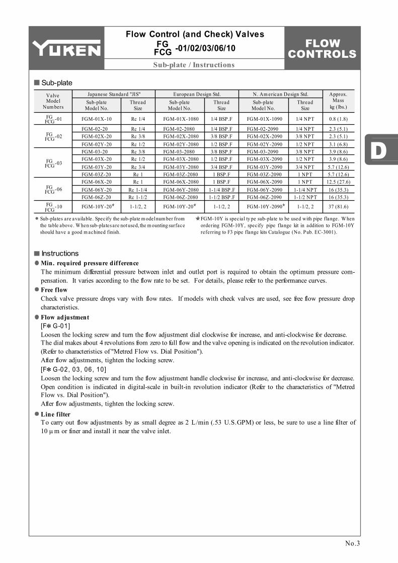
Mounting surface: F∗G-02: ISO 6263-AB-06-4-B F∗G-03: ISO 6263-AK-07-2-A
FLOW CONTROLS
Installation Drawings
FG FCG-02
FG FCG-03
116 (4.57)
145 (5.71)
Model No. C
Dim ensions m m (Inches)
96 (3.78)
125 (4.92)
D76.2
(3.00)101.6 (4.00)
E38.1
(1.50)50.8
(2.00)
F9.9
(.39)11.7 (.46)
H104.5 (4.11)
125 (4.92)
J82.6
(3.25)101.6 (4.00)
K44.3
(1.74)61.8
(2.43)
L24
(.94)29.8
(1.17)
N9.9
(.39)11.7 (.46)
P123
(4.84)152
(5.98)
Q69
(2.72)98
(3.86)
S40
(1.57)64
(2.52)
T23
(.91)41
(1.61)
U8.8
(.35)11
(.43)
V39
(1.54)63
(2.48)
X14
(.55)17.5 (.69)
W
1
2
Y
2 1 0 9 824 3
87
61
5.5(.22) Dia. Through 9(.35) Dia. Spotface 4 Places
32 4
INC.
Fully Extended
46(1.81)
Mounting Surface (O-Rings Furnished)
N
X
Locking Screw 2(.08) Hex. Soc.
Dia.
D
"V" Dia. Through "W " Dia. Spotface 4 Places
Controlled Flow Inlet or Reversed Free Flow Outlet Port
Flow Adjustment HandleControlled Flow Outlet or Reversed Free Flow Inlet Port
LK J
U
TS
Q
Locking Screw 2.5(.10) Hex. Soc.Tightening Torque: 0.25 - 0.3 Nm (2.2 - 2.7 IN. lbs.)
Revolution Indicator
81.5(3.21)66
(2.60)51
(2.01)25.5
(1.00)
7.5 (.30)
INC.Flow Adjustment Dial Controlled Flow Inlet or
Reversed Free Flow Outlet Port
Pressure Compensator Stroke Adjustment
(Only for FG FCG-01-∗ -N )
13(.5
1)D
ia.
16.5
(.6
5)31
(1
.22)
7.5
(.30)
43
(1.6
9)58
(2
.28)
3(.1
2)
Mounting Surface (O-Rings Furnished)
Locating Pin 4(.16) Dia.
5 (.20)
17 (.67)
44 (1.73)
45 (1.77)
53.5 (2.11)
Fully Extended84(3.31)
Controlled Flow Outlet or Reversed Free Flow Inlet Port
Locating Pin 6(.24) Dia. "Y" Places
CFully Extended
EF
H
Pressure Compensator Stroke Adjustment
(Only for FG FCG-∗ -∗ -N )
Revolution Indicator 14(.5
5)D
ia.
P
6 (.24)
22.5(.89) Dia.
FG/FCG-01-∗-∗-11/1190
Flow Control (and Check) Valves -01/02/03FG FCG
No.4
FG/FCG-02-30-∗-30/3090, FG/FCG-03-125-∗-30/3090
DIMENSIONS IN MILLIMETRES (INCHES)

Mounting surface: F∗G-06: ISO 6263-AP-08-2-A
FLOW CONTROLS
D
Installation Drawings
FG FCG-06
FG FCG-10
198 (7.80)
267 (10.51)
Model No. C
Dim ensions m m (Inches)
180 (7.09)
244 (9.61)
D17
(.67)23.5 (.93)
H146.1 (5.75)196.9 (7.75)
E73
(2.87)98.5
(3.88)
F174
(6.85)228
(8.98)
J133.4 (5.25)177.8 (7.00)
K99
(3.90)144.5 (5.69)
L44
(1.73)61
(2.40)
N20.3 (.80)
25 (.98)
P184
(7.24)
Q130
(5.12)160
(6.30)
S65
(2.56)85
(3.35)
U16
(.63)18
(.71)
V7
(.28)10
(.39)
W17.5 (.69)21.5 (.85)
X26
(1.02)32
(1.26)
Y9
(.35)7.5
(.30)
Z103
(4.06)135
(5.31)
a
214 (8.43)
105 (4.13)
137 (5.39)
T
21 1INC.
Fully Extended "C"
46(1.81)
Mounting Surface (O-Rings Furnished)
N
a
Locating Pin "V" Dia. 2 Places
Locking Screw 2(.08) Hex. Soc.
Dia.
DH
FE
"X" Dia. through "Y" Dia. Spotface 4 Places
Pressure Compensator Stroke Adjustment
(Only for FG FCG-∗ -∗ -N )
Controlled Flow Inlet or Reversed Free Flow Outlet Port
Only for Flow Control and Check ValvesZ
(FCG-∗ -∗ -N )
Flow Adjustment Handle
Controlled Flow Outlet or Reversed Free Flow Inlet Port
Revolution Indicator
W
PL
K J
U
TS
Q
FG/FCG-06-250-∗-30/3090 FG/FCG-10-500-∗-30/3090
No.5
Flow Control (and Check) Valves -06/10FG FCG
DIMENSIONS IN MILLIMETRES (INCHES)

FLOW CONTROLSInstallation Drawings
"A" Thd.Sub-plate Model Num bers "B" Thd. C D
"A" Thd.Sub-plate Model Num bers "B" Thd. C D
FGM-02-20 FGM-02-2080 FGM-02-2090 FGM-02X-20 FGM-02X-2080 FGM-02X-2090 FGM-02Y-20 FGM-02Y-2080 FGM-02Y-2090
Rc 1/4 1/4 BSP.F 1/4 NPT Rc 3/8
3/8 BSP.F 3/8 NPT Rc 1/2
1/2 BSP.F 1/2 NPT
5/16-18 UNC
11.0 (.43) 11.7 (.46) 11.0 (.43) 14.0 (.55) 15.2 (.60) 14.0 (.55) 14.0 (.55) 15.0 (.59) 14.0 (.55)
FGM-01X-10 FGM-01X-1080 FGM-01X-1090
Rc 1/4 1/4 BSP.F 1/4 NPT
M5 M5
No.10-24 UNC
14 (.55) 14 (.55) 15 (.59)
34.5 (1.36) 30.0 (1.18) 34.5 (1.36)
M8
5/16-18 UNC
M8
5/16-18 UNC
M8
18 (.71)
14 (.55)
18 (.71)
14 (.55)
18 (.71)
14 (.55)
E F H
54 (2.13)
51 (2.01)
11.1 (.44)
14 (.55)
25 (.98)
35 (1.38)
D
H
F
E
9 (.35)
18.5 (.73)
36 (1.42)
51 (2.01)
6 (.2
4)
5(.20) Dia. 8(.31) Deep
43
(1.6
9)55
(2
.17)
"B" Thd. "C" Deep 4 Places
6(.24) Dia. 2 Places
"A" Thd. (From Rear) 2 Places
16.5
(.6
5)14
(.5
5)
34.5
(1
.36)
5.5(.22) Dia. Through 9(.35) Dia. Spotface 4 Places
63 (2.48)
76 (2.99)
88 (3.46)
12.5 (.49)
6 (.24)
22 (.87)
17 (.67)
14
(.55)
7(.28) Dia. 10(.39) Deep
"B" Thd. "C" Deep 4 Places
"D" Dia. 2 Places
78
(3.0
7)10
6 (4
.17)
9.5 (.37)
31.9 (1.26)
54 (2.13)
76.2 (3.00)
79.4 (3.13)
8.8(.35) Dia. Through 14(.55) Dia. Spotface 4 Places
"A" Thd. (From Rear) 2 Places
16 (.63)
96 (3.78)120
(4.72)140
(5.51)
22 (.87)
10 (.39)
23.8
(.9
4)
11.1
(.4
4)
11.5
(.4
5)
52.4
(2
.06)
82.6
(3
.25)
FGM-01X-10/1080/1090
Sub-plate for Flow Control (and Check) Valves
No.6
FGM- -20/2080/209002 02X 02Y
DIMENSIONS IN MILLIMETRES (INCHES)

FLOW CONTROLS
D
Installation Drawings
"A" Thd.Sub-plate Model Num bers "B" Thd. C DFGM-03-20 FGM-03-2080 FGM-03-2090 FGM-03X-20 FGM-03X-2080 FGM-03X-2090 FGM-03Y-20 FGM-03Y-2080 FGM-03Y-2090 FGM-03Z-20 FGM-03Z-2080 FGM-03Z-2090
Rc 3/8 3/8 BSP.F 3/8 NPT Rc 1/2
1/2 BSP.F 1/2 NPT Rc 3/4
3/4 BSP.F 3/4 NPT
Rc 1 1 BSP.F 1 NPT
3/8-16 UNC
M10
E F H
75 (2.95)
20.6 (.81)
11.1 (.44)
3/8-16 UNC
M10
3/8-16 UNC
M10
3/8-16 UNC
M10
21 (.83)
18 (.71)
21 (.83)
18 (.71)
J
86.5 (3.41)
K
25 (.98)
14.0 (.55) 15.0 (.59) 14.0 (.55) 17.5 (.69) 19.0 (.75) 17.5 (.69)
70 (2.76)
25.6 (1.01)
16.1 (.63)
81.5 (3.21)
40 (1.57)23.0 (.91)
"A" Thd.Sub-plate Model Num bers "B" Thd. C DFGM-06X-20 FGM-06X-2080 FGM-06X-2090 FGM-06Y-20 FGM-06Y-2080 FGM-06Y-2090 FGM-06Z-20 FGM-06Z-2080 FGM-06Z-2090
Rc 1 1 BSP.F 1 NPT
Rc 1-1/4 1-1/4 BSP.F 1-1/4 NPT
Rc 1-1/2 1-1/2 BSP.F 1-1/2 NPT
5/8-11 UNC
M16
E F H
35 (1.38)
30 (1.18)
J K
34 (1.34)
99 (3.90)
23 (.91)
60 (2.36)
40 (1.57)
99 (3.90)
22.2 (.87)
104.8 (4.13)
18 (.71)
45 (1.77)
35 (1.38)
104.8 (4.13)
5/8-11 UNC
M16
5/8-11 UNC
M16
35 (1.38)
30 (1.18)
35 (1.38)
30 (1.18)
21 (.83)
18 (.71)
21 (.83)
18 (.71)
14.2
(.5
6)
20(.79) Dia. 15(.59) Deep 2 Places
"B" Thd. "C" Deep 4 Places
"A" Thd. (From Rear) 2 Places
11(.43) Dia. Through 17.5(.69) Dia. Spotface 4 Places
17(.67) Dia. 10(.39) Deep 2 Places
"B" Thd. "C" Deep 4 Places
17.5(.69) Dia. Through 26(1.02) Dia. Spotface 4 Places
"A" Thd. (From Rear) 2 Places
102.4(4.03)101.6(4.00)75(2.95)
EF
20.6 (.81)
0.8 (.03)
"D" Dia. 2 Places
101.
6 (4
.00)
130
(5.1
2)
20 (.79)K
11.1
(.4
4)
H
28.6
(1
.13)J
86.5
(3
.41)
125(4.92)146(5.75)168(6.61)
21.5(.85)11(.43)
146.1(5.75)
144.4(5.69)
D
104.8 (4.13)
E22.2 (.87)1.6
(.06)
52 (2.05)
29(1.14) Dia. 2 Places
24
(.94)
126
(4.9
6)17
4 (6
.85)
H
F
20.3
(.8
0)12
.7
(.50)
41.3
(1
.63)
104.
8 (4
.13)
133.
4 (5
.25)
180(7.09)212(8.35)250(9.84)
35(1.38)19(.75)
KJ
33.2 (1.31)
03 03X 03Y 03Z
FGM- -20/2080/2090
Sub-plate for Flow Control (and Check) Valves
No.7
06X 06Y 06Z
FGM- -20/2080/2090
DIMENSIONS IN MILLIMETRES (INCHES)

FLOW CONTROLSInstallation Drawings
FGM-10Y-20 FGM-10Y-2090
M20 3/4-10 UNC
M16 5/8-11 UNC
32 (1.26) 32 (1.26)
32 (1.26) 34 (1.34)
"A" Thd.Sub-plate Model Num bers "B" Thd. C D
34.9 (1.37)
73 (2.87)
1.6 (.06)
140 (5.51)
68.5 (2.70)
144.5 (5.69)
196.9 (7.75)
198.4 (7.81)
73
(2.8
7)73
(2
.87)
17.3
(.6
8)
"A" Thd. "C" Deep 4 Places
36
(1.4
2)29
(1
.14)
55.5
(2
.19)
144.
5 (5
.69)
177.
8 (7
.00)
11
(.43)
20(.79) Dia. 15(.59) Deep 2 Places
228
(8.9
8)25
0 (9
.84)
"B" Thd. "D" Deep 8 Places (From Rear)
43.5(1.71) Dia. 2 Places
73 (2.87)
48(1.89) Dia. 2 Places
244 (9.61)284
(11.18)334
(13.15)
45 (1.77)
25 (.98)
21.5(.85) Dia. Through 32(1.26) Dia. Spotface 4 Places
Pipe Flange
100
(3.9
4)SQ
.
80 (3.15)
50 (1.97)
FGM-10Y-20/2090
Sub-plate for Flow Control (and Check) Valves
No.8
DIMENSIONS IN MILLIMETRES (INCHES)

FLOW CONTROLS
D
Performance Characteristics
L/min8.2
U.S.GPM
8.07.84.24.03.8
0.0220.0200.018.0050
.0055
1.001.051.102.052.102.15
0 42 6 8 10 12 14 MPa
0 500 1000 1500 2000 PSI
Flow
Rat
e
Differential Pressure
0 5 10 15 20 21 MPa
0 1000 2000 PSIDifferential Pressure
3000
.0050
.0060
2.02.12.2
1.001.051.10
.00550.018
0.022
7.68.08.4
3.84.04.2
0.020
L/minU.S.GPM
Flow
Rat
e
0 4020 60 80 100 120 140 2 mm /s
0 100 300 500 SSUViscosity
160
700
0 4020 60 80 100 120 140 2 mm /s
100 300 500 SSUViscosity
160
7000
0 4020 60 80 100 120 140 2 mm /s
100 300 500 SSUViscosity
160
7000
0 4020 60 80 100 120 140 2 mm /s
100 300 500 SSUViscosity
160
7000
0 4020 60 80 100 120 140 2 mm /s
100 300 500 SSUViscosity
160
7000
.0140
8.00
0.047
0.053
28.530.031.5
7.68.08.4
0.050
L/minU.S.GPM
Flow
Rat
e 7.502.22.12.0
.0135
.0130
.0125
.90
323334
12.513.013.5
.953.3
3.7
119125131
47.550.052.5
3.5
L/minU.S.GPM
Flow
Rat
e
2.6
646668
384042
2.8
9
11
240250260
140150160
10
L/minU.S.GPM
Flow
Rat
e
2.4
13.0
130132134
525354
13.5
48
52
490500510
195200205
50
U.S.GPM
Flow
Rat
e
L/min
0 5 10 15 2021
MPa
0 1000 2000 PSIDifferential Pressure
3000
0 5 10 15 20 21 MPa
0 1000 2000 PSIDifferential Pressure
3000
0 5 10 15 20 21 MPa
0 1000 2000 PSIDifferential Pressure
3000
L/min32
U.S.GPM
3028
8.28.07.8
0.520.500.48
.130
.1352.052.102.15
7.58.0
Flow
Rat
e
8.5
L/min130
U.S.GPM
125120
555045
3.53.02.5
.8
.9
12131431
33
Flow
Rat
e
.7
250U.S.GPM
245240
155150145
1110
9
3840
64
66
Flow
Rat
e
2.752.50
65
L/min
500
U.S.GPM
510
490255250245
525048
6566
128
Flow
Rat
e
13.513.0
132
L/min
67
No.9
Flow Control (and Check)Valves -01/02/03/06/10FG FCG
Metred Flow vs. Differential Pressure Metred Flow vs. Viscosity-01FG
FCG -01FG FCG
-02FG FCG -02FG
FCG
-03FG FCG-03FG
FCG
-06FG FCG-06FG
FCG
-10FG FCG-10FG
FCG
FLOW CONTROLS
Performance Characteristics
0 1Dial Position
2 3 4 0 100Handle Position
200 300 400 500 0 100Handle Position
200 300 400 500
0 100Handle Position
200 300 400 500 600 0 100Handle Position
200 300 400 500 600
8
U.S.GPM
6
4
2
00
Flow
Rat
e
0.5
1.0
1.5
2.02.25
L /min
120100
0
80604020
30
0
20
10
35
U.S.GPML /min140
L/min
Flow
Rat
e 6
0
4
2
8U.S.GPM
25
0
10
30
5
2015
Flow
Rat
e 400
0
300
200
100
120100
0
80604020
140U.S.GPM
500
L /min
Flow
Rat
e 200
0
150
100
50
6050
0
40302010
70U.S.GPM
250
L /min
-01-4FG FCG
-01-8FG FCG
Flow
Rat
e
0
Flow Rate
Dif
fere
ntia
l Pre
ssur
e
0.7
0
0.6
0.4
0.2
100
PSI MPa
1 2 3 4 5 6 7 8
0 0.5 1.0 1.5 2.0 2.5U.S.GPM
80604020
0
L /min0
Flow Rate
5 10 15 20 25 30
0 1 2 5 7 8U.S.GPM
L /min
3 4 6
Dif
fere
ntia
l Pre
ssur
e
0
0.6
0.4
0.2
PSI MPa
80604020
0 Dif
fere
ntia
l Pre
ssur
e
0
1.51.20.9
PSI
200150100
500
0.60.3
MPa
0
Flow Rate
25 50 75 100 125
0 5 10 20 30 35U.S.GPM
L /min
15 25
0
Flow Rate
50 100 150 200 250
0 10 20 40 60 70U.S.GPM
L /min
30 50
0
Flow Rate
100 200 300 400 500
0 20 40 80 120 140U.S.GPM
L /min
60 100
Dif
fere
ntia
l Pre
ssur
e
1.0
0
0.60.40.2
125
PSI MPa
100755025
0
0.8
150
Dif
fere
ntia
l Pre
ssur
e
1.4
0
0.8
0.4
PSI MPa
10050
0
1.2200150
-01FG FCG
-02FG FCG -03FG
FCG
-06FG FCG -10FG
FCG
-01FG FCG -02FG
FCG -03FG FCG
-06FG FCG -10FG
FCG
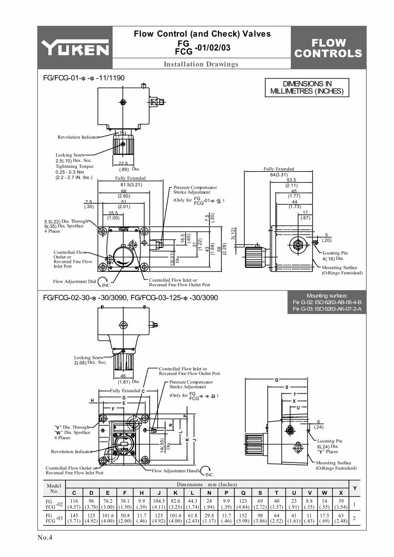
Flow Control (and Check) Valves -01/02/03/06/10FG FCG
No.10
Metred Flow vs. Dial Position
Min. Required Pressure Difference
FLOW CONTROLS
D
Performance Characteristics
0 4 62 8 10 12 14 L /min
Free Flow0 1.0 1.50.5 2.0 2.5 3.0 3.5 U.S.GPM4.0
0 10 20 30 40 50 L /min
Free Flow0 42 6 8 10 U.S.GPM1412
0 100 200 300 400 L /min
Free Flow0 4020 60 80 U.S.GPM100
0 50 100 150 200 L /min
Free Flow0 2010 30 40 U.S.GPM50
0 200 400 600 800 L /min
Free Flow0 10050 150 U.S.GPM200
0.5
00.1
0.2
0.3
0.4
PSI
0
20
40
60
80MPa
0.5
00.1
0.2
0.3
0.4
PSI
0
20
40
60
80MPa
1.0
00.2
0.4
0.6
0.8
PSI
0
25
75
100
125
50
150
MPa
0
0.2
0.4
0.6
PSI
0
25
75
100
50
MPa
1.0
00.2
0.4
0.6
0.8
PSI
025
75100
125
50
150
MPa
Pres
sure
Dro
p
P
Pres
sure
Dro
p
P
Pres
sure
Dro
p
PPr
essu
re D
rop
P
Pres
sure
Dro
p
P
Throttle Fully Open
Throttle Closed
Throttle Fully Open
Throttle Closed
Throttle Fully Open
Throttle ClosedThrottle Fully Open
Throttle Closed
Throttle Fully Open
Throttle Closed
Throttle Fully Open(FCG-01-8)
(FCG-01-4)
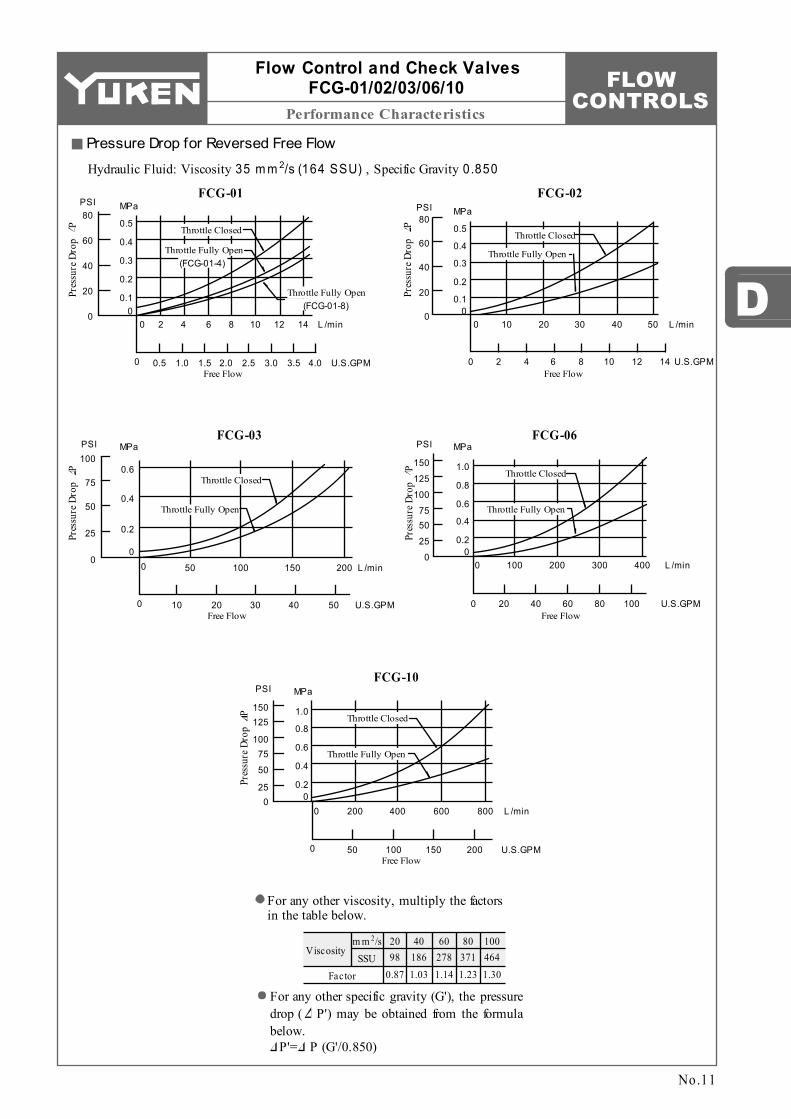
Viscosity2 m m /s
SSUFactor
20 98
0.87
40 186 1.03
60 278 1.14
80 371 1.23
100 464 1.30
No.11
Flow Control and Check ValvesFCG-01/02/03/06/10
Pressure Drop for Reversed Free Flow
Hydraulic Fluid: Viscosity 2 35 m m /s (164 SSU) , Specific Gravity 0.850
For any other viscosity, multiply the factors in the table below.
For any other specific gravity (G'), the pressure drop ( P') may be obtained from the formula below.
P'= P (G'/0.850)
FCG-01 FCG-02
FCG-03 FCG-06
FCG-10
FLOW CONTROLS
Spare Parts List
Item
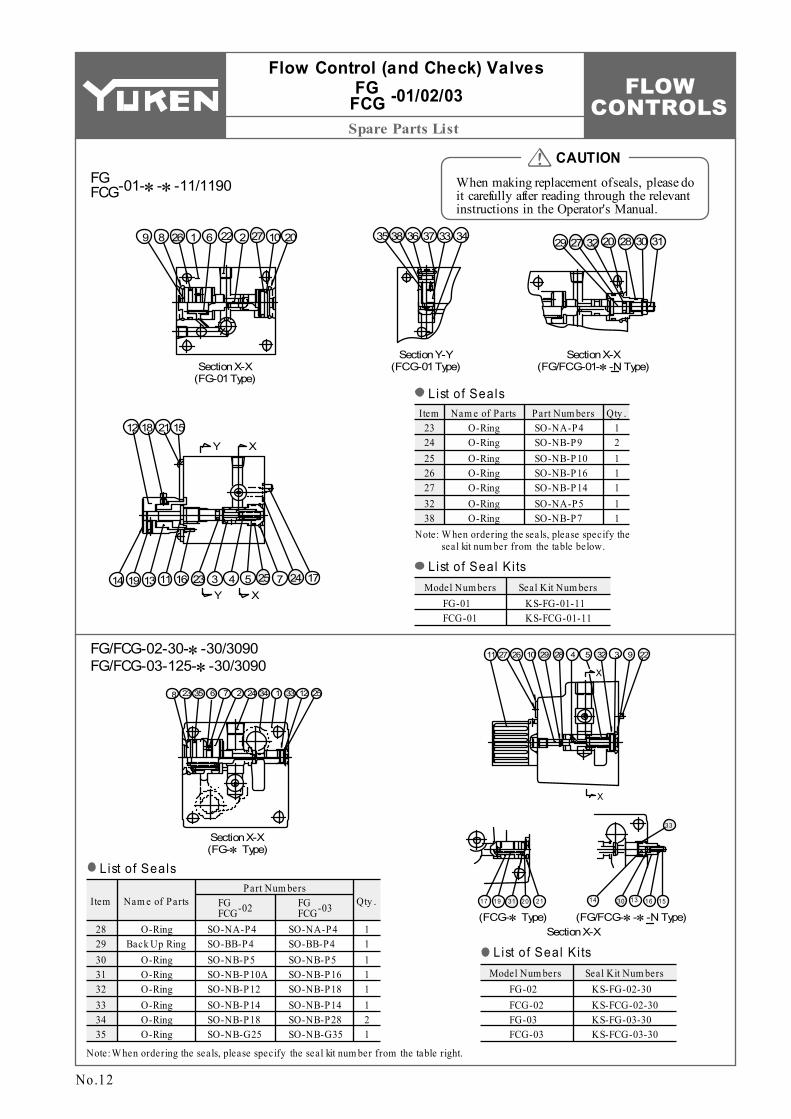
SO-NA-P4 SO-BB-P4 SO-NB-P5 SO-NB-P10A SO-NB-P12 SO-NB-P14 SO-NB-P18 SO-NB-G25
Nam e of Parts Qty .
O-Ring Back Up Ring
O-Ring O-Ring O-Ring O-Ring O-Ring O-Ring
1 1 1 1 1 1 2 1
28 29 30 31 32 33 34 35
Model Num bers Seal Kit Num bersFG-02 FCG-02 FG-03 FCG-03
Part Num bersFG FCG-02
KS-FG-02-30 KS-FCG-02-30 KS-FG-03-30 KS-FCG-03-30
FG FCG-03
ItemSO-NA-P4 SO-NB-P9 SO-NB-P10 SO-NB-P16 SO-NB-P14 SO-NA-P5 SO-NB-P7
Nam e of Parts Qty .O-Ring O-Ring O-Ring O-Ring O-Ring O-Ring O-Ring
1 2 1 1 1 1 1
23 24 25 26 27 32 38
Part Num bers
Model Num bers Seal Kit Num bersFG-01 FCG-01
KS-FG-01-11 KS-FCG-01-11
SO-NA-P4 SO-BB-P4 SO-NB-P5 SO-NB-P16 SO-NB-P18 SO-NB-P14 SO-NB-P28 SO-NB-G35
Section X-X (FG-01 Type)
Section Y-Y (FCG-01 Type)
Section X-X (FG/FCG-01-∗-N Type)
Section X-X (FG-∗ Type)
(FCG-∗ Type)Section X-X
(FG/FCG-∗-∗-N Type)
201027222612689
15211812
14 19 13 11 16 23 3 4 5 25 7 24 17
Y X
Y X
35 38 36 37 33 34 29 27 32 20 28 30 31
8 23 35 6 7 2 24 34 1 33 12 25
11 27 26 10 29 28 4 5 32 3 9 22
X
X
17 19 31 20 21 14 30 13 16 15
33
When making replacement of seals, please do it carefully after reading through the relevant instructions in the Operator's Manual.
CAUTION
List of Seals
Note:W hen ordering the seals, please specify the seal kit num ber from the table right.
List of Seal Ki ts
FG FCG-01-∗-∗-11/1190
Flow Control (and Check) Valves -01/02/03FG FCG
No.12
List of Seals
Note: W hen ordering the seals, please specify the seal kit num ber from the table below.
List of Seal Ki ts
FG/FCG-02-30-∗-30/3090 FG/FCG-03-125-∗-30/3090
FLOW CONTROLS
Spare Parts List
D
Item
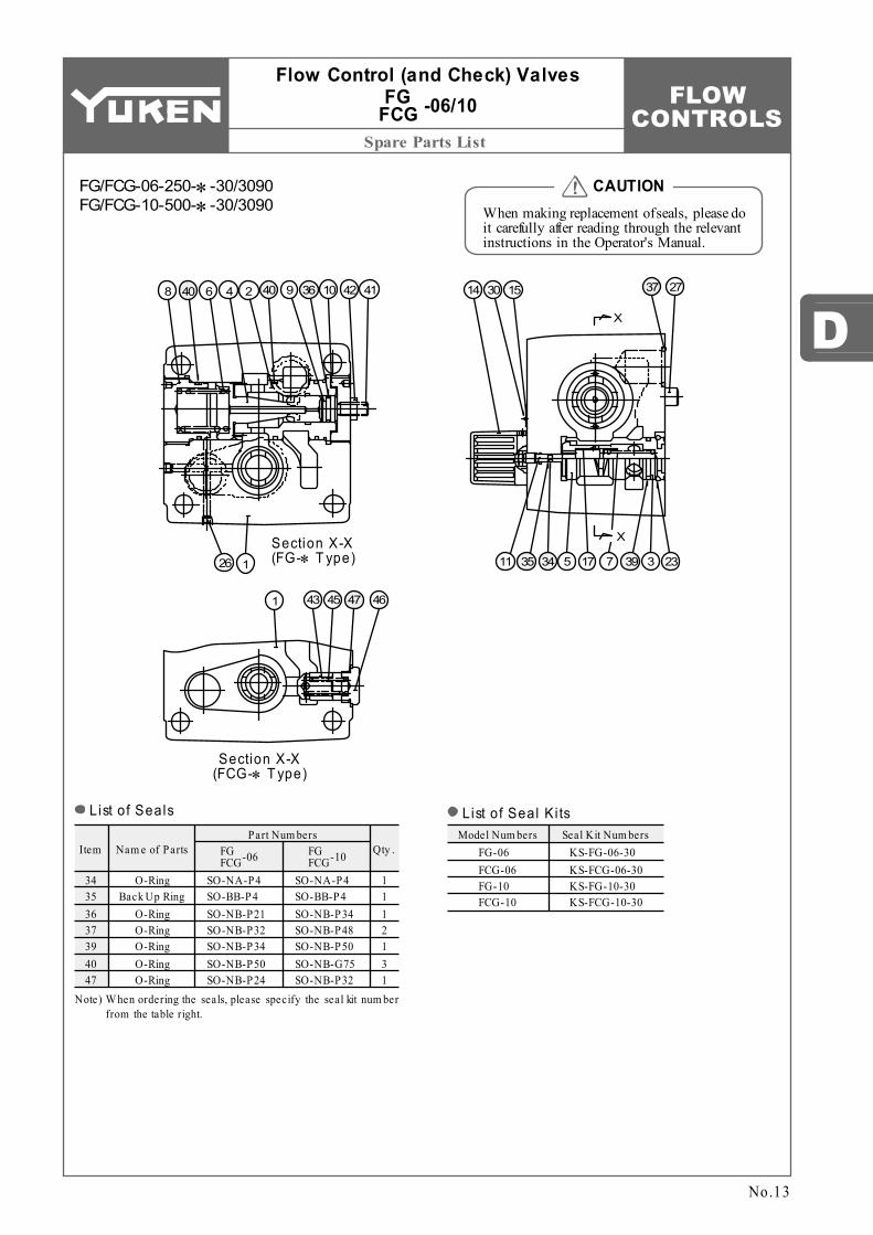
SO-NA-P4 SO-BB-P4 SO-NB-P21 SO-NB-P32 SO-NB-P34 SO-NB-P50 SO-NB-P24
Nam e of Parts Qty .
O-Ring Back Up Ring
O-Ring O-Ring O-Ring O-Ring O-Ring
1 1 1 2 1 3 1
34 35 36 37 39 40 47
Model Num bers Seal Kit Num bersFG-06 FCG-06 FG-10 FCG-10
Part Num bers
SO-NA-P4 SO-BB-P4 SO-NB-P34 SO-NB-P48 SO-NB-P50 SO-NB-G75 SO-NB-P32
FG FCG-06 KS-FG-06-30
KS-FCG-06-30 KS-FG-10-30 KS-FCG-10-30
FG FCG-10
Section X-X (FG-∗ T ype)
Section X-X (FCG-∗ T ype)
X
X
8 40 6 4 2 40 9 36 10 42 41
1 43 45 47 46
26 1
14 30 15 37 27
11 35 34 5 17 7 39 3 23
No.13
When making replacement of seals, please do it carefully after reading through the relevant instructions in the Operator's Manual.
CAUTION
List of Seals
Note) W hen ordering the seals, please specify the seal kit num ber from the table right.
List of Seal Ki ts
FG/FCG-06-250-∗-30/3090 FG/FCG-10-500-∗-30/3090
Flow Control (and Check) Valves -06/10FG FCG

FLOW CONTROLS
Specifications / Model Number Designation
Model Number Designation
Model Num bers
30 (7.9) 125 (33) 250 (66)
500 (132)
kg (lbs.)
Approx. Mass
MPa (PSI)
Min. P ilot P ressure
L /m in (U.S.GPM)
Max. Metred Flow Capacity
L /m in (U.S.GPM)
Min. Metred Flow Capacity
MPa (PSI)
Max. Operating Pressure
0.05 (.013) 0.2 (.053)
2 (.53) 4 (1.06)
13 (28.7) 17 (37.5) 32 (70.6) 61 (135)
21 (3050)
1.5 (220)
FHG/FHCG-02-30-∗-12∗ FHG/FHCG-03-125-∗-12∗ FHG/FHCG-06-250-∗-12∗ FHG/FHCG-10-500-∗-12∗
-12
Design Num ber
∗Design
Standards
12
-NPressure
Com pensator Stroke Adj .
N:Applicable only for Pres. Com pensator Stroke Adjustm ent (Option - Om it if not required)
-02 -30Max.
Metred FlowValve Size
02
03
06
10
30 : 30 (7.9)
125 : 125 (33)
500 : 500 (132)
Special Seals for Phos- phate Ester Ty pe Fluids (Om it if not re- quired)
F:FH:Pilot Operated Flow Control Valves
F- FHC
Special Seals
Series Num ber
FHC:Pilot Operated Flow Cont. & Check Valves
G
Ty pe of Mounting
G:Sub-plate Mounting
L /m in (U.S.GPM)
250 : 250 (66)
12
12
12
None:Japanese Std. "JIS"
90 :N.Am erican Design Std.
80 :European Design Std.
-OW ith No
P ilot Valve
-A100
Coil Ty pe
-NTy pe of
Electrical Connections
O:W ithout P ilot Valve
A C :A100 A120 A200 A240
D C :D12 D24 D48
A C D C :R100 R200
→
None:Term inal Box Ty pe
N:W ith P lug-in Connector (Din)
N:W ith P lug-in Connector (Din)
Graphic Sym bols
FHG FHCG
T P
A
O M
B A
O M
B
T P
No.14
Pilot Operated Flow Control (and Check) Valves
Specifications
Sub-plate Mounting -02/03/06/10FHG
FHCG
Either solenoid operated directional valve (DSG-01) or m odular valve (MSW -01) can be used as a pilot valve. If no pilot valve is required, there is no needs to specify the coil ty pe and the electrical connection ty pe of solenoid operated directional valve.

FLOW CONTROLS
Solenoid Ratings / Attachment / Option / Sub-plate
D
2.3 (5.1) 2.3 (5.1) 3.1 (6.8) 3.9 (8.6) 3.9 (8.6)
5.7 (12.6) 5.7 (12.6)
12.5 (27.6) 16 (35.3) 16 (35.3)
Valve Model
Num bers
-02FHG FHCG
-03FHG FHCG
-06FHG FHCG
-10FHG FHCG
Japanese Standard "JIS"Sub-plate
Model No. Thread Size
European Design Std.Sub-plate
Model No. Thread Size Sub-plate Model No. Thread Size
N. Am erican Design Std. Approx. Mass
kg (lbs.)
FGM-02-20 FGM-02X-20 FGM-02Y-20 FGM-03-20 FGM-03X-20 FGM-03Y-20 FGM-03Z-20 FGM-06X-20 FGM-06Y-20 FGM-06Z-20
FGM-10Y-20
Rc 1/4 Rc 3/8 Rc 1/2 Rc 3/8 Rc 1/2 Rc 3/4 Rc 1 Rc 1
Rc 1-1/4 Rc 1-1/2
1-1/2, 2
FGM-02-2080 FGM-02X-2080 FGM-02Y-2080 FGM-03-2080 FGM-03X-2080 FGM-03Y-2080 FGM-03Z-2080 FGM-06X-2080 FGM-06Y-2080 FGM-06Z-2080
FGM-10Y-20
1/4 BSP.F 3/8 BSP.F 1/2 BSP.F 3/8 BSP.F 1/2 BSP.F 3/4 BSP.F 1 BSP.F 1 BSP.F
1-1/4 BSP.F 1-1/2 BSP.F
1-1/2, 2
FGM-02-2090 FGM-02X-2090 FGM-02Y-2090 FGM-03-2090 FGM-03X-2090 FGM-03Y-2090 FGM-03Z-2090 FGM-06X-2090 FGM-06Y-2090 FGM-06Z-2090
FGM-10Y-2090
1/4 NPT 3/8 NPT 1/2 NPT 3/8 NPT 1/2 NPT 3/4 NPT 1 NPT 1 NPT
1-1/4 NPT 1-1/2 NPT
1-1/2, 2 37 (81.6)
100 100 110
240
200 200 220
12 24 48
100 200
50
60
50 60 50
60
50 60
A100
A120
A200
A240
D12 D24 D48
R100 R200
50/60
29
29
2.42 2.14 2.35 2.02 1.78 1.21 1.07 1.18 1.01 0.89
0.51 0.37 0.44 0.42 0.31 0.25 0.19 0.22 0.21 0.15 2.45 1.23 0.610.33 0.16
120
Electric Source
AC
DC (K Series)
AC DC Rectified→
Coil Ty pe Frequency (Hz) Source
RatingServiceable
Range Inrush (A) Holding (A) Power (W )
Voltage (V) Current & Power at Rated Voltage
80 - 110
90 - 120
96 - 132 108 - 144 160 - 220
180 - 240
192 - 264 216 - 288 10.8 - 13.2 21.6 - 26.4 43.2 - 52.8 90 - 110 180 - 220
Valve Model Num bersSocket Head Cap Screw
Japanese Std. "JIS" & European Design Std. N. Am erican Design Std.Qty .
FHG/FHCG-02 FHG/FHCG-03 FHG/FHCG-06 FHG/FHCG-10
M8 50 Lg. M10 75 Lg. M16 130 Lg. M20 160 Lg.
× 4 4 4 4
5/16-18 UNC 2 Lg. 3/8-16 UNC 3 Lg. 5/8-11 UNC 5 Lg. 3/4-10 UNC 6-1/2 Lg.
××××
×××
No.15
Sub-plate
Sub-plates are available. Specify the sub-plate m odel num ber from the table above. W hen sub-plates are not used, the m ounting surface should have a good m achined finish.FGM-10Y is special ty pe sub-plates to be used with pipe flange. W hen ordering FGM-10Y, specify the pipe flange kit in addition to FGM-10Y referring to F3 pipe flange kits Catalogue (No. Pub. EC-3001).
Pilot Operated Flow Control (and Check) Valves
-02/03/06/10FHG FHCG
Solenoid Ratings
Inrush current in the above table shows rm s values at m axim um stroke.
Attachment
Option
Can reduce jumping at the start of the actuator.
Mounting Bolts
Pres. compensator stroke adjustment
Sub-plates are com m on with flow control valves. For dim ensions, see pages 6 to 8.
The coil ty pe num bers in the shaded colum n are handled as optinal extras. In case these coils are required to be chosen, please confirm the tim e of delivery with us before ordering.

FLOW CONTROLS
1 3
2
44
2
4
1
3
Instructions
Time→
Flow
Rat
e→
OnOff OffSolenoid
Signal
No.16
Pilot Operated Flow Control (and Check) Valves
-02/03/06/10FHG FHCG
Instructions
While the solenoid operated directional valve on ( shown below), the flow rate is at the level set by the maximum flow adjustment screw and the actuator operates at the maximum speed setting. Turning the adjustment screw clock-wise causes the flow rate to decrease. While the solenoid operated directional valve off ( shown below), the flow rate is set by the minimum flow adjust-ment screw and the actuator operates at the minimum speed setting. Turning the adjustment screw clockwise causes the flow rate to increase. When the solenoid operated directional valve is turned on ( shown below), the flow rate is shifted from minimum to maximum and the actuator speed is also shifted likewise. The switching time can be set by the pilot flow adjustment dial (for acceleration). Turning the adjustment dial clockwise causes the pilot flow rate to decrease. When the solenoid operated directional valve is turned off ( shown below), the flow rate is shifted from maximum to minimum and the actuator speed is also shifted likewise. The switching time can be set by the pilot flow adjustment dial (for deceleration). Turning the adjustment dial clockwise causes the pilot flow rate to decrease.
Control patterns and flow rate adjustment
The minimum differential pressure between inlet and outlet port is required to obtain the optimum pressure com-pensation. It varies according to the flow rate to be set. For details, please refer to the performance curves.
Min. required pressure difference
Check valve pressure drops vary with flow rates. If models with check valves are used, see free flow pressure drop characteristics.
Free f low
To carry out flow adjustments by as small degree as 2 L/min (.53 U.S.GPM) or less, be sure to use a line filter of 10 µm or finer and install it near the valve inlet.
Line filter
To adjust flow rates, slacken the lock nut or the dial setting screw. After adjustments, tighten the lock nut or the dial.Tightening of f low adjustment screws and dials
FLOW CONTROLS
D
Performance Characteristics
0 10 155 20 25 30 35 40 45
0 1.0 1.75
mm
0.5 1.5 IN.
Flow
Rat
e
L/min
35
U.S.GPM
7
65
2
01
0
10
15
20
25
30
5
3
4
8
9
Cylinders Stroke
Min. Metred Flow Range
Max. Metred Flow Range
Min. Metred Flow Range
Max. Metred Flow Range
Min. Metred Flow Range
Max. Metred Flow Range
Min. Metred Flow Range
Max. Metred Flow Range
L/minU.S.GPM140
40
6080
100
120
200
Flow
Rat
e
30
20
0
35
10
0 10 155 20 25 30 35 40 45 mm
0 1.0 1.750.5 1.5 IN.Cylinders Stroke
0 10 155 20 25 30 35 40 45
0 1.0 1.75
mm
0.5 1.5 IN.
Flow
Rat
e
300U.S.GPM
60
50
40
0
100
50
100
150
200
250
20
30
70
80
Cylinders Stroke
L/min
0 10 155 20 25 30 35 40 45
0 1.0 1.75
mm
0.5 1.5 IN.
Flow
Rat
e
600U.S.GPM
100
75
50
0
250
100
200
300
400
500125
150
Cylinders Stroke
L/min
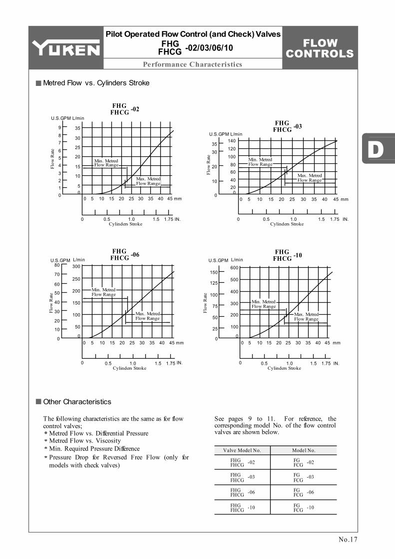
Valve Model No.
-02FHG FHCG
-03FHG FHCG
-06FHG FHCG
-10FHG FHCG
-02FG FCG
-03FG FCG
-06FG FCG
-10FG FCG
Model No.
No.17
Metred Flow vs. Cylinders Stroke
Other Characteristics
See pages 9 to 11. For reference, the corresponding model No. of the flow control valves are shown below.
The following characteristics are the same as for flow control valves;
Metred Flow vs. Differential PressureMetred Flow vs. ViscosityMin. Required Pressure DifferencePressure Drop for Reversed Free Flow (only for models with check valves)
FHG FHCG
Pilot Operated Flow Control (and Check) Valves
-02/03/06/10FHG FHCG
-02
FHG FHCG -03
FHG FHCG -06 FHG
FHCG -10

FLOW CONTROLS
Mounting surface: FH∗G-02: ISO 6263-AK-06-2-A FH∗G-03: ISO 6263-AM-07-2-A
Installation Drawings
-02
Model Num bers
127.4 (5.02)114.7 (4.52)
CDim ensions m m (Inches)
96 (3.78)
125 (4.92)
D76.2
(3.00)101.6 (4.00)
E9.9
(.39)11.7 (.46)
F100.6 (3.96)
125 (4.92)
H82.6
(3.25)101.6 (4.00)
J44.3
(1.74)61.8
(2.43)
K9
(.35)11.7 (.46)
L40
(1.57)64
(2.52)
N23
(.91)41
(1.61)
Q274.3
(10.80)303.3
(11.94)
S69
(2.72)98
(3.86)
U209
(8.23)238
(9.37)
X162
(6.38)191
(7.52)
Y129
(5.08)158
(6.22)
Z256
(10.08)285
(11.22)
V
Model Num bers
104 (4.09)
133 (5.24)
a
Dim ensions m m (Inches)
38.1 (1.50)50.8
(2.00)
d8.8
(.35)11
(.43)
e14
(.55)17.5 (.69)
f39
(1.54)63
(2.48)
h
1
2
j
FHG/FHCG-02-30-∗-∗-12 FHG/FHCG-02-30-∗-∗-1290 FHG/FHCG-03-125-∗-∗-12 FHG/FHCG-03-125-∗-∗-1290
Model Num bersRc 1/4
1/4 NPT Rc 1/4
1/4 NPT
nG 1/2
1/2 NPT G 1/2
1/2 NPT
t
FHG FHCG
-03FHG FHCG
-02FHG FHCG
-03FHG FHCG
SOL b
Fully Extended 331(13.03)Fully Extended
dC
Controlled Flow Inlet or Reversed Free Flow Outlet Port
"e" Dia. Through "f" Dia. Spotface 4 Places
Controlled Flow Outlet or Reversed Free Flow Inlet Port
EF
D
60
(2.3
6)
LH
K
J
45 (1.77)
45.5 (1.79)
DC/R:105(4.13)AC :95.7(3.77)
DC/R:55(2.17)AC :45.5(1.79)
Space Needed to Remove Solenoid-Each End
Electrical Conduit Connection "t" Thd. (Both End)
Manual Actuator 6(.24) Dia.
Pilot Line Tank Port "T" "n" Thd. (Rear) Pilot Line Pressure Port "P" "n" Thd.
INC.Pilot Flow Adj. Dial (For Deceleration)
90.3
(3
.56)
32
(1.2
6)D
ia.
40
(1.5
7)75
(2
.95)
Min. Flow Adjustment Screw 19(.75) Hex.
U INC.
(S)
N h
6 (.2
4)
Mounting Surface (O-Rings Furnished)
Locating Pin 6(.24) Dia. "j " Places
Pressure Compensator Stroke Adjustment(Only for FH∗G-∗ -∗ -N)
Q
Fully Extended20(.79) a
ZY
XV
Lock Nut 19(.75) Hex.
INC.Pilot Flow Adj. Dial (For Acceleration)
Max. Flow Adjustment Screw 19(.75) Hex.
INC.
No.18
Pilot Operated Flow Control (and Check) Valves
-02/03FHG FHCG
Terminal Box Type
Note: For dim ensions of the valve m ounting surface, see the installation drawing (P . 6 and 7) of the sub-plate used together.
FHG/FHCG-02-30-∗-∗-12/1290 FHG/FHCG-03-125-∗-∗-12/1290 DIMENSIONS IN
MILLIMETRES (INCHES)

FLOW CONTROLS
D
Installation Drawings
FHG/FHCG-02-30-∗-A∗-N
FHG/FHCG-03-125-∗-A∗-N
FHG/FHCG-02-30-∗-D∗-N
FHG/FHCG-03-125-∗-D∗-N
FHG/FHCG-02-30-∗-R∗-N
FHG/FHCG-03-125-∗-R∗-N
Model Num bersSS VV XX q
Rem arksDim ensions m m (Inches)
274 (10.79)
262 (10.31)
209 (8.23)
303 (11.93)
291 (11.46)
238 (9.37)
285 (11.22)
273 (10.75)
209 (8.23)
314 (12.36)
302 (11.89)
238 (9.37)
288 (11.34)
266.2 (10.48)
209 (8.23)
317 (12.48)
295.2 (11.62)
238 (9.37)
39 (1.54)
39 (1.54)
53 (2.09)
with AC Solenoid
with DC Solenoid
with AC DC Solenoid
→
Model Num bers
FHG/FHCG-02-30-∗-∗-N FHG/FHCG-03-125-∗-∗-N
Thread SizeJapanese Std. "JIS"
Design 12"n" Thd.
Rc 1/4
European Design Std. Design 1280
"n" Thd.
1/4 BSP.F
N.Am erican Design Std. Design 1290
"n" Thd.
1/4 NPT
No.19
SOL b
48.5 (1.91)
DC/R :105(4.13)AC :95.7(3.77)
Cable Departure
Pilot Line Tank Port "T" "m" Thd. (Rear) Pilot Line Pressure Port "P" "m" Thd.
Three positions of cable departure are available by loosening "Lock Nut" as shown. After location, tighten "Lock Nut" with torque in the range 10.3 to 11.3 Nm (91 - 100 IN.lbs.).
XX
VV(SS)
Cable Applicable: Outside Dia. ...... 8-10 mm (.31 - .39 IN.) Conductor Area ...... Not Exceeding 2 1.5 mm (.002 SQ. IN.)
DC/R :152(5.98)AC :142.7(5.62)
q
Pilot Operated Flow Control (and Check) Valves
-02/03FHG FHCG
Models with Plug-in Connector
FHG/FHCG-02-30-∗-∗-N-12/1280/1290 FHG/FHCG-03-125-∗-∗-N-12/1280/1290
For other dimensions, refer to "Terminal Box Type".
DIMENSIONS IN MILLIMETRES (INCHES)
FLOW CONTROLS
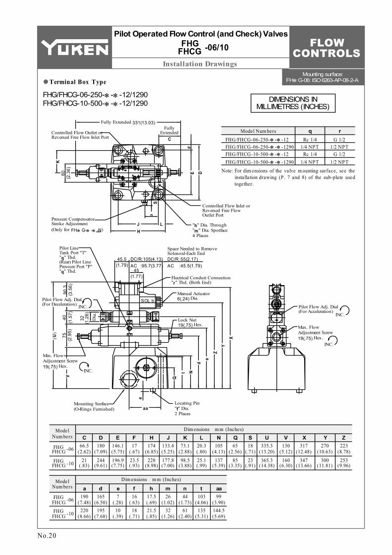
Mounting surface: FH∗G-06: ISO 6263-AP-08-2-A
Installation Drawings
Model Num bers
66.5 (2.62)
21 (.83)
CDim ensions m m (Inches)
180 (7.09)
244 (9.61)
D146.1 (5.75)196.9 (7.75)
E17
(.67)23.5 (.93)
F174
(6.85)228
(8.98)
H133.4 (5.25)177.8 (7.00)
J73.1
(2.88)98.5
(3.88)
K20.3 (.80)25.1 (.99)
L105
(4.13)137
(5.39)
N65
(2.56)85
(3.35)
Q18
(.71)23
(.91)
S335.3
(13.20)365.3
(14.38)
U317
(12.48)347
(13.66)
X Y223
(8.78)253
(9.96)
ZV
Model Num bers
190 (7.48)
220 (8.66)
a
Dim ensions m m (Inches)
165 (6.50)
195 (7.68)
d7
(.28)10
(.39)
e16
(.63)18
(.71)
f17.5 (.69)21.5 (.85)
h m
FHG/FHCG-06-250-∗-∗-12 FHG/FHCG-06-250-∗-∗-1290 FHG/FHCG-10-500-∗-∗-12 FHG/FHCG-10-500-∗-∗-1290
Model Num bersRc 1/4
1/4 NPT Rc 1/4
1/4 NPT
qG 1/2
1/2 NPT G 1/2
1/2 NPT
r
130 (5.12)
160 (6.30)
270 (10.63)
300 (11.81)
44 (1.73)
61 (2.40)
n26
(1.02)32
(1.26)
103 (4.06)
135 (5.31)
t99
(3.90)144.5 (5.69)
aa
-06FHG FHCG
-10FHG FHCG
-06FHG FHCG
-10FHG FHCG
SOL b
Fully Extended 331(13.03)Fully
ExtendedC
Controlled Flow Inlet or Reversed Free Flow Outlet Port
"h" Dia. Through "m" Dia. Spotface 4 Places
n
J
60
(2.3
6)
S
K
E
45 (1.77)
45.5 (1.79)
DC/R:105(4.13)AC :95.7(3.77)
DC/R :55(2.17)AC :45.5(1.79)
Space Needed to Remove Solenoid-Each End
Electrical Conduit Connection "r" Thd. (Both End)
Manual Actuator 6(.24) Dia.
Pilot Line Tank Port "T" "q" Thd. (Rear) Pilot Line Pressure Port "P" "q" Thd.
INC.Pilot Flow Adj. Dial (For Deceleration)
90.3
(3
.56)
32
(1.2
6)D
ia.
40
(1.5
7)75
(2
.95)
Min. Flow Adjustment Screw 19(.75) Hex.
V
INC.
(U)
Mounting Surface (O-Rings Furnished)
Locating Pin "f" Dia. 2 Places
Pressure Compensator Stroke Adjustment(Only for FH∗G-∗ -∗ -N)
Q
t
ZY
X
N
Lock Nut 19(.75) Hex.
INC.
Pilot Flow Adj. Dial (For Acceleration)
Max. Flow Adjustment Screw 19(.75) Hex.
INC.
Controlled Flow Outlet or Reversed Free Flow Inlet Port
D
F
LH
e
aa
da
No.20
Pilot Operated Flow Control (and Check) Valves
-06/10FHG FHCG
Terminal Box Type
Note: For dim ensions of the valve m ounting surface, see the installation drawing (P . 7 and 8) of the sub-plate used together.
FHG/FHCG-06-250-∗-∗-12/1290 FHG/FHCG-10-500-∗-∗-12/1290 DIMENSIONS IN
MILLIMETRES (INCHES)

FLOW CONTROLS
D
Installation Drawings
FHG/FHCG-06-250-∗-A∗-N
FHG/FHCG-10-500-∗-A∗-N
FHG/FHCG-06-250-∗-D∗-N
FHG/FHCG-10-500-∗-D∗-N
FHG/FHCG-06-250-∗-R∗-N
FHG/FHCG-10-500-∗-R∗-N
Model Num bersUU XX YY m
Rem arksDim ensions m m (Inches)
335 (13.19)
323 (12.72)
270 (10.63)
365 (14.37)
353 (13.90)
300 (11.81)
346 (13.62)
334 (13.15)
270 (10.63)
376 (14.80)
364 (14.33)
300 (11.81)
349 (13.74)
327.2 (12.88)
270 (10.63)
379 (14.92)
357.2 (14.06)
300 (11.81)
39 (1.54)
39 (1.54)
53 (2.09)
with AC Solenoid
with DC Solenoid
with AC DC Solenoid
→
Model Num bers
Thread Size
FHG/FHCG-06-250-∗-∗-N FHG/FHCG-10-500-∗-∗-N
Japanese Std. "JIS" Design 12"q" Thd.
Rc 1/4
European Design Std. Design 1280
"q" Thd.
1/4 BSP.F
N.Am erican Design Std. Design 1290
"q" Thd.
1/4 NPT
No.21
SOL b
48.5 (1.91)
DC/R :105(4.13)AC :95.7(3.77)
Cable DeparturePilot Line Tank Port "T" "q" Thd. (Rear) Pilot Line Pressure Port "P" "q" Thd.
Three positions of cable departure are available by loosening "Lock Nut" as shown. After location, tighten "Lock Nut" with torque in the range 10.3 to 11.3 Nm (91 - 100 IN.lbs.).
YY
XX(UU
)
Cable Applicable: Outside Dia. ...... 8-10 mm (.31 - .39 IN.) Conductor Area ...... Not Exceeding 2 1.5 mm (.002 SQ. IN.)
DC/R :152(5.98)AC :142.7(5.62)
m
Pilot Operated Flow Control (and Check) Valves
-06/10FHG FHCG
Models with Plug-in Connector
FHG/FHCG-06-250-∗-∗-N-12/1280/1290 FHG/FHCG-10-500-∗-∗-N-12/1280/1290
For other dimensions, refer to "Terminal Box Type".
DIMENSIONS IN MILLIMETRES (INCHES)

FLOW CONTROLS
Lead Wire Connection
Term inal Box Ty pe Plug-in Connector Ty pe
Ty pe of Electrical Conduit
Connection
Electric Source
Term inal Box Ty pe
Plug-in Connector
Ty pe
AC DC AC DC Rectified→
11
3 22
3
SOL. SOL. SOL.
SOL.
SOL.
SOL.
Ground
2-Power Supply
1-Power Supply
Indicator Light Indicator Light
Voltage-Surge Suppressor
Indicator LightVoltage-Surge Suppressor
Rectifier Circuit
Power Supply
CommonGround
Power Supply
CommonGround
Power Supply
CommonGround
Indicator Light (Integrated in "N1" model only)
1-Power Supply
Ground
2-Power Supply
1-Power Supply
Ground
2-Power Supply
Indicator Light (Integrated in "N1" model only)
Voltage-Surge Suppressor (Circuit composed in coil)
1-Power Supply
Ground
2-Power Supply
Voltage-Surge Suppressor
Rectifier Circuit
Indicator Light
Ground
Power Supply
SOL. b
Details of Receptacle
W ith DC solenoids, polarity is no question.
Electrical Circuit
No.22
Pilot Operated Flow Control (and Check) Valves
-02/03/06/10FHG FHCG
Do not perform wiring while the power is on. Doing so may result in electric shock, burns or death. Make the wiring properly. Improper wiring will cause an irregular movement of the machine, resulting in a grave accident.
DANGER

FLOW CONTROLS
Spare Parts List
D
Item
SO-NB-P20 SO-NB-P5 SO-NB-P10A SO-NB-P12 SO-NB-P14 SO-NB-P18 SO-NB-G25 SO-NB-P9 SO-NB-P10A SO-NA-P26 SO-BB-P26 SO-NB-P38
Nam e of Parts Qty .
O-Ring O-Ring O-Ring O-Ring O-Ring O-Ring O-Ring O-Ring O-Ring O-Ring
Back Up Ring O-Ring
1 1 1 1 1 2 1 2 2 2 4 2
29 30 31 32 33 34 35 57 58 59 60 61
Model Num bers Seal Kit Num bersFHG-02 FHCG-02 FHG-03 FHCG-03
Part Num bersFHG FHCG-02
KS-FHG-02-12 KS-FHCG-02-12 KS-FHG-03-12 KS-FHCG-03-12
FHG FHCG-03
SO-NB-P20 SO-NB-P5 SO-NB-P16 SO-NB-P18 SO-NB-P14 SO-NB-P28 SO-NB-G35 SO-NB-P9 SO-NB-P10A SO-NA-P26 SO-BB-P26 SO-NB-P38
Pilot Operated Flow Control (and Check) Valves
-02/03FHG FHCG
SOL b SOL b
63
62
50
52
58
54
5351
59
60
55
57
49
61
56
11
29
10
4
5
3
32
9
22
XX
34 23 35 7 8 6 2 24 33 25 121
1 17 19 31 21 20
14 33 30 13 16 15
63
(FHG-∗ T ype)Section X-X
(FHCG-∗ T ype) -∗-∗-N T ypeFHG FHCG
No.23
When making replacement of seals, please do it carefully after reading through the relevant instructions in the Operator's Manual.
CAUTION
List of Seals
Note) W hen ordering the seals, please specify the seal kit num ber from the table right. In addition to the above seals, seals for pilot valves are included in the seal kit.
List of Seal Ki ts
FHG/FHCG-02-30-∗-∗-12/1290 FHG/FHCG-03-125-∗-∗-12/1290
Terminal Box Type Models with Plug-in ConnectorFHG/FHCG-02-30-∗-∗-N-12/1280/1290 FHG/FHCG-03-125-∗-∗-N-12/1280/1290
Pi lot ValvesSee page 25 for the pilot valve model numbers to be used.

FLOW CONTROLS
Spare Parts List
Item
SO-NB-P20 SO-NB-P21 SO-NB-P32 SO-NB-P34 SO-NB-P50 SO-NB-P24 SO-NB-P9 SO-NB-P10A SO-NA-P26 SO-BB-P26 SO-NB-P38
Nam e of Parts Qty .
O-Ring O-Ring O-Ring O-Ring O-Ring O-Ring O-Ring O-Ring O-Ring
Back Up Ring O-Ring
1 1 2 1 3 1 2 2 2 4 2
35 36 37 39 40 47 57 58 59 60 61
Model Num bers Seal Kit Num bersFHG-06 FHCG-06 FHG-10 FHCG-10
Part Num bersFHG FHCG-06
KS-FHG-06-12 KS-FHCG-06-12 KS-FHG-10-12 KS-FHCG-10-12
FHG FHCG-10
SO-NB-P20 SO-NB-P34 SO-NB-P48 SO-NB-P50 SO-NB-G75 SO-NB-P32 SO-NB-P9 SO-NB-P10A SO-NA-P26 SO-BB-P26 SO-NB-P38
SOL b SOL b
(FHG-∗ T ype)Section X-X
(FHCG-∗ T ype)
6350
5258
5453
62
49575561
51
59605635
7
3923
14
11
35
17
3727
XX
26
1408
6
42
4036
910
4241
46
47
4345
1
63
Section X-X
When making replacement of seals, please do it carefully after reading through the relevant instructions in the Operator's Manual.
CAUTION
List of Seals
Note) W hen ordering the seals, please specify the seal kit num ber from the table right. In addition to the above seals, seals for pilot valves are included in the seal kit.
List of Seal Ki ts
FHG/FHCG-06-250-∗-∗-12/1290 FHG/FHCG-10-500-∗-∗-12/1290
Terminal Box Type Models with Plug-in ConnectorFHG/FHCG-06-250-∗-∗-N-12/1280/1290 FHG/FHCG-10-500-∗-∗-N-12/1280/1290
Pi lot ValvesSee page 25 for the pilot valve model numbers to be used.
Pilot Operated Flow Control (and Check) Valves
-06/10FHG FHCG
No.24
FLOW CONTROLS
Spare Parts List
D
Ty pe of Electrical
Conduit Connections
FHG/FHCG-02- FHG/FHCG-03- FHG/FHCG-06- FHG/FHCG-10-
Japanese Std. "JIS"
European Design Std.
N. Am erican Design Std.
30 125 250 500
-∗- -12 -∗- -12 -∗- -12 -∗- -12
FHG/FHCG-02- FHG/FHCG-03- FHG/FHCG-06- FHG/FHCG-10-
30 125 250 500
-∗- -1290 -∗- -1290 -∗- -1290 -∗- -1290
FHG/FHCG-02- FHG/FHCG-03- FHG/FHCG-06- FHG/FHCG-10-
30 125 250 500
-∗- -N-12 -∗- -N-12 -∗- -N-12 -∗- -N-12
FHG/FHCG-02- FHG/FHCG-03- FHG/FHCG-06- FHG/FHCG-10-
30 125 250 500
-∗- -N-1280 -∗- -N-1280 -∗- -N-1280 -∗- -N-1280
Japanese Std. "JIS"
FHG/FHCG-02- FHG/FHCG-03- FHG/FHCG-06- FHG/FHCG-10-
30 125 250 500
-∗- -N-1290 -∗- -N-1290 -∗- -N-1290 -∗- -N-1290
N. Am erican Design Std.
Valve Model Num bers
Pilot Valve Model Num bersItem No.62
Throttle and Check Modular Valves
Item No.63 Solenoid Operated Directional Valves
Rem arks
DSG-01-2B2- -60
Term inal Box
Ty pe
Plug-in Connector
Ty pe
DSG-01-2B2- -6090
DSG-01-2B2- -N-60
DSG-01-2B2- -N-60
DSG-01-2B2- -N-6090
MSW -01-X-5090
MSW -01-X-50
MSW -01-X-5090
MSW -01-X-50
MSW -01-X-50
No.25
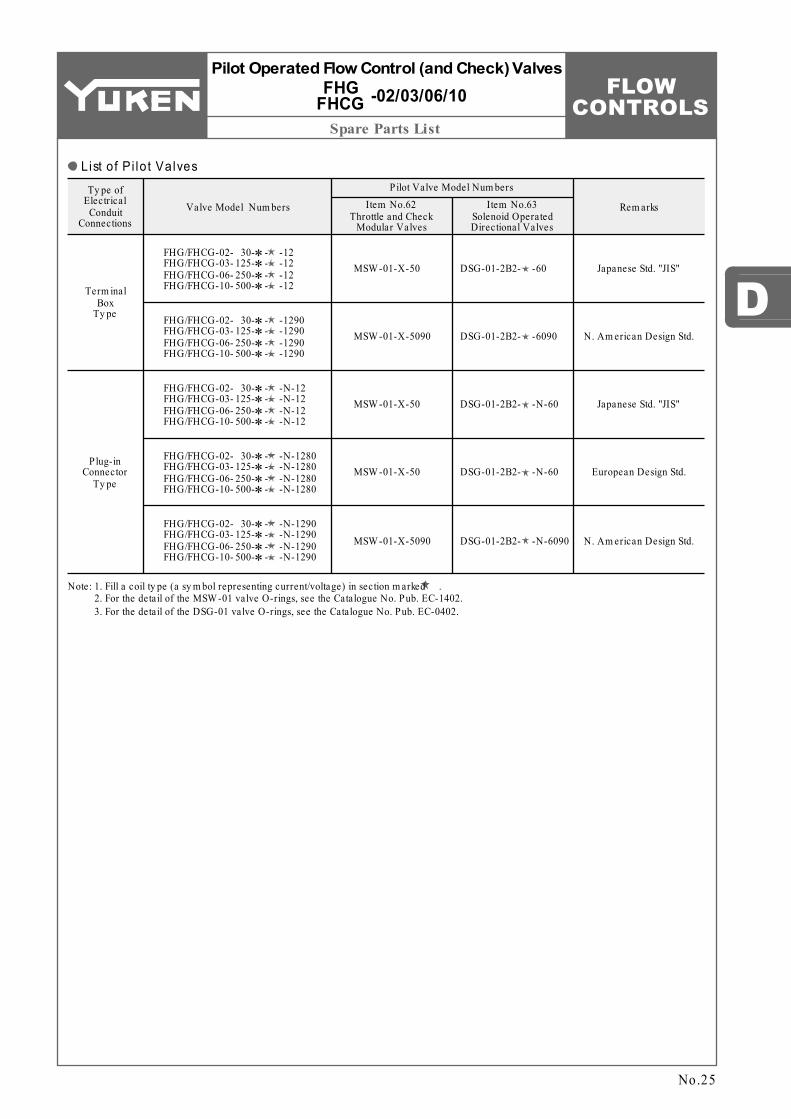
Pilot Operated Flow Control (and Check) Valves
-02/03/06/10FHG FHCG
List of Pi lo t Valves
Note: 1. 2. 3.
Fill a coil ty pe (a sy m bol representing current/voltage) in section m arked . For the detail of the MSW -01 valve O-rings, see the Catalogue No. Pub. EC-1402. For the detail of the DSG-01 valve O-rings, see the Catalogue No. Pub. EC-0402.
FLOW CONTROLS
1
1.
∗ ∗ ∗
∗
D
Model Number Designation / Specifications
F-Special Seals
FB G -03 -125 -10 ∗Series Num ber Ty pe of
MountingValve Size
Max. Metred Flow L /m in (U.S.GPM)
Design Num ber
Design Standards
03
06
10
10
10
10
125 : 125 (33)
250 : 250 (66)
500 : 500 (132)
F:Special Seals for Phosphate Ester Ty pe Fluids (Om it if not required)
FB:Flow Control and Relief Valves
G:Sub-plate Mounting Refer to
Max. Operating Pressure
Rated Flow
Metred Flow Range
Pressure Adjustm ent Range
Min. Pressure Difference Required between Inlet and Outlet Ports
MPa (PSI)
MPa (PSI)
L /m in (U.S.GPM)
L /m in (U.S.GPM)MPa (PSI)
P ilot Drain FlowL /m in (U.S.GPM)
Max. Drain Line and Tank Line Back Pressure
MPa (PSI)
Approx. Mass kg (lbs.)
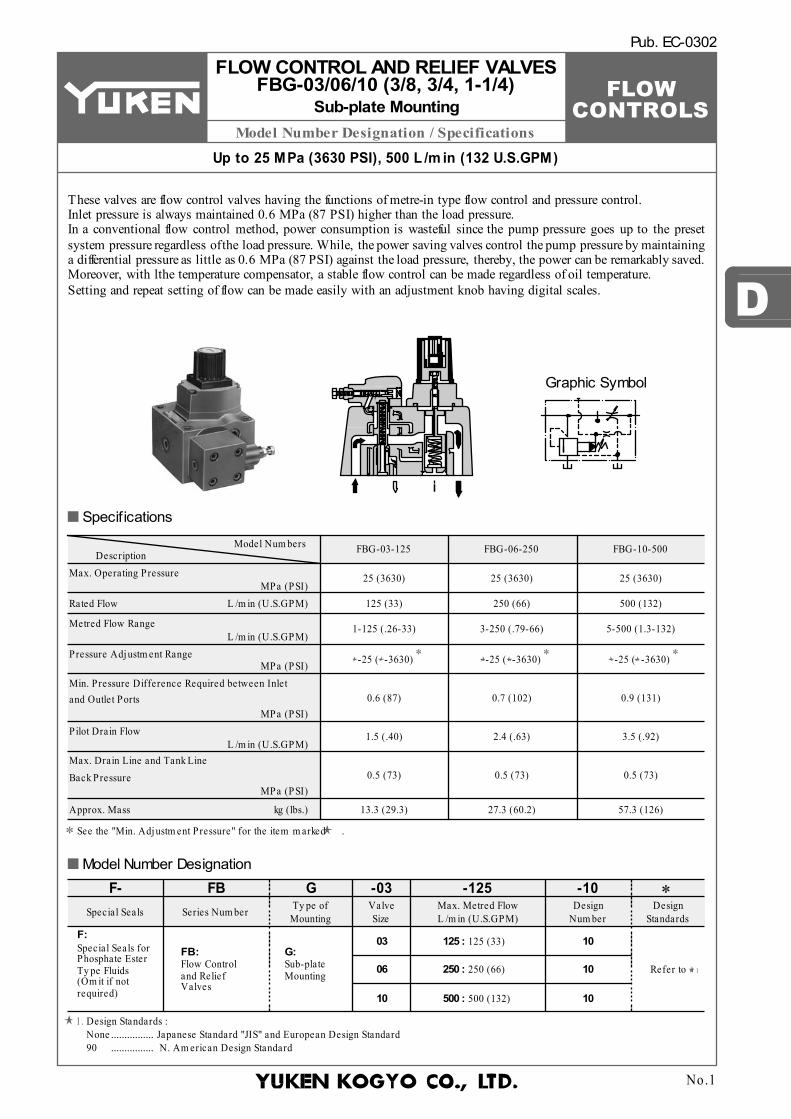
Model Num bersDescription FBG-03-125 FBG-06-250 FBG-10-500
25 (3630)
125 (33)
1-125 (.26-33)
-25 ( -3630) -25 ( -3630) -25 ( -3630)
3-250 (.79-66) 5-500 (1.3-132)
250 (66) 500 (132)
25 (3630) 25 (3630)
0.6 (87) 0.7 (102) 0.9 (131)
1.5 (.40) 2.4 (.63) 3.5 (.92)
0.5 (73) 0.5 (73) 0.5 (73)
13.3 (29.3) 27.3 (60.2) 57.3 (126)
No.1
Pub. EC-0302
Up to 25 MPa (3630 PSI), 500 L /m in (132 U.S.GPM)
FLOW CONTROL AND RELIEF VALVES FBG-03/06/10 (3/8, 3/4, 1-1/4)
Sub-plate Mounting
Design Standards :Japanese Standard "JIS" and European Design Standard N. Am erican Design Standard
................
................None 90
See the "Min. Adjustm ent Pressure" for the item m arked .
These valves are flow control valves having the functions of metre-in type flow control and pressure control. Inlet pressure is always maintained 0.6 MPa (87 PSI) higher than the load pressure. In a conventional flow control method, power consumption is wasteful since the pump pressure goes up to the preset system pressure regardless of the load pressure. While, the power saving valves control the pump pressure by maintaining a differential pressure as little as 0.6 MPa (87 PSI) against the load pressure, thereby, the power can be remarkably saved. Moreover, with lthe temperature compensator, a stable flow control can be made regardless of oil temperature. Setting and repeat setting of flow can be made easily with an adjustment knob having digital scales.
Graphic Symbol
Specifications
Model Number Designation

FLOW CONTROLSHydraulic Fluids / Instructions
W ater containing fluids
Sy nthetic fluids
Petroleum base oils
Use water-gly col fluid.
Use phosphate ester or poly ol ester fluid.W hen phosphate ester fluid is used, prefix "F-" to the m odel num ber because the special seals (fluororubber) are required to be used.
Use fluids equivalent to ISO VG32 or VG46.
EFBGM-03Y-10 Rc 3/4
Valve Model
Num bers
Valve Model Num bers Japanese Std. "JIS" and European Design Std.
Socket Head Cap ScrewN. Am erican Design Std.
EFBGM-03Y-1080 3/4 BSP.F
Sub-plate Model No.
Thread Size
Sub-plate Model No.
Thread Size
EFBGM-03Y-1090 3/4 NPT
Sub-plate Model No.
Thread Size
Japanese Standard "JIS" European Design Standard N. Am erican Standard Approx. Mass
kg (lbs.)
FBG-03
Qty .
M10 × 100 Lg.M16 × 130 Lg.M20 × 130 Lg.
3/8-16 UNC × 4 Lg.5/8-11 UNC × 5 Lg.3/4-10 UNC × 5 Lg.
444
FBG-03FBG-06FBG-10
EFBGM-03Z-10EFBGM-06X-10EFBGM-06Y-10EFBGM-10Y-10
Rc 1Rc 1
Rc 1-1/41-1/2, 2
EFBGM-03Z-1080EFBGM-06X-1080EFBGM-06Y-1080EFBGM-10Y-1080
1 BSP.F1 BSP.F
1-1/4 BSP.F1-1/2, 2
EFBGM-03Z-1090EFBGM-06X-1090EFBGM-06Y-1090EFBGM-10Y-1090
1 NPT1 NPT
1-1/4 NPT1-1/2, 2
6 (13.2)6 (13.2)
12.5 (27.6)16 (35.3)37 (81.6)
FBG-06
FBG-10
No.2
Flow Control and Relief Valves FBG-03/06/10
Fluid Types
Hydraulic Fluids
Any type of hydraulic fluids listed in the table below can be used.
Note: For use with hydraulic fluids other than those listed above, please consult your Yuken representatives in advance.
2 Viscosity ranging between 15 - 400 mm /s (77 - 1800 SSU). Oil temperatures between -15/+70°C (5 - 158°F). Use hydraulic fluids which satisfy the recommended viscosity and oil temperatures given above.
Due caution must be paid to maintaining control over contamination of the hydraulic fluids which may otherwise lead to breakdowns and shorten the life of the valves. Please maintain the degree of contamination within NAS 1638-Grade 12. Use 25 µm or finer line filter.
Control of Contamination
Flow adjustmentInstructions
Mounting BoltsAttachment
Sub-plate
Sub-plates are available. Specify the sub-plate m odel num ber from the table above. W hen sub-plates are not used, the m ounting surface should have a good m achined finish.
Loosen the locking screw and turn the flow adjustment handle clockwise to increase, and anti-clockwise to decrease. Open condition is indicated in digital-scale in built-in revolution indicator (Refer to characteristics of "Metred flow vs. Dial Position"). After flow adjustments, tighten the locking screw.
Pressure adjustmentTo adjust the pressure, loosen the lock nut and turn the pressure adjustment screw slowly clockwise to increase pressures or anti-clockwise to decrease pressure. After adjustments, do not forget to tighten the lock nut.
Drain port back pressureNote that any drain port back pressure is added to the minimum pressure. Connect the drain port, preferably with its back pressure minimized, directly to the oil tank.
Relief valve throughputWhen the relief valve throughput is small with pressure under control, the pressure setting may become unstable. Thus, hold the rate above 10 L/min (2.6 U.S.GPM) for nominal valve size 03 and 06 or above 15 L/min (4 U.S.GPM) for nominal valve size 10.
Line filterIn case of controlling flow rate of less than 2 L/min (.53 U.S.GPM), be sure to use a line filter of 10µm or finer at the valve inlet.
EFBGM-10Y is special ty pe sub-plates to be used with pipe flange. W hen ordering EFBGM-10Y, specify pipe flange in addition to EFBGM-10Y referring to F3 pipe flange catalogue (No. Pub. EC-3001).
Recommended Viscosity and Oil Temperatures

FLOW CONTROLS
D
Installation Drawings
EFBGM-03Y-10EFBGM-03Z-10EFBGM-03Y-1080EFBGM-03Z-1080EFBGM-03Y-1090EFBGM-03Z-1090
3/4 BSP.F 18 (.71)Rc 1/4
M10
Rc 3/4Rc 1
1 BSP.F3/4 NPT1 NPT
1/4 BSP.F
1/4 NPT 3/8-16 UNC 21 (.83)
11 (.43)
11.7 (.46)
11 (.43)
"A" Thd. "B" Thd.Thread Size
"C" Thd. D ESub-plate Model Num bers
21 3
187 (7.36)
133 (5.24)
85 (3.35)
6 (.24)
Locating Pin 6(.24) Dia. 2 Places
Mounting Surface (O-Rings Furnished)
41 (1.61)
Locking Screw 2(.08) Hex. Soc.
INC.
Flow Adjustment Handle 46(1.81) Dia.
Lock Nut 14(.55) Hex.
Pressure Adjustment Screw 14(.55) Hex.
INC.
Fully
Ext
ende
d 14
8 (5
.83)
11.7 (.46)
50 (1.97)
125 (4.92)
101.6 (4.00)
50.8 (2.00)
188 (7.40) Controlled Flow
Inlet Port
Drain Port
14.2
(.5
6)
61.8
(2
.43)
101.
6 (4
.00)
130
(5.1
2)
11(.43) Dia. Through 17.5(.69) Dia. Spotface 4 Places
Tank Port
Vent PortControlled Flow Outlet Port
25 (.98)
Revolution Indicator
59(2
.32)
80(3
.15)
101.
6(4.
00)
130(
5.12
)
100(
3.94
)
14.2
(.5
6)
20(.7
9)
23.8(.94)
50.8(2.00)77.8(3.06)
101.6(4.00)
102.4(4.03)125(4.92)11.7
(.46)0.8
(.03)
12.7
(.5
0)28
.6
(1.1
3)88
.9(3
.50)
95.3
(3.7
5)
106.8(4.20)146(5.75)168(6.61)
"C" Thd. "D" Deep 4 Places
11(.43) Dia. Through 17.5(.69) Dia. Spotface 4 Places
23(.91) Dia. 3 Places
7(.28) Dia. 7(.28) Deep 2 Places
"A" Thd. 3 Places (From Rear)
"B" Thd. (From Rear)
6(.24) Dia.
"E" Dia. "B" Thd.(From Rear)
22.2 (.87) 39.2
(1.54)
11 (.43)
20
(.79)
40
(1.5
7)
No.3
Flow Control and Relief Valves FBG-03
Sub-plateEFBGM-03Y/03Z-10/1080/1090
FBG-03-125-10/1090
DIMENSIONS IN MILLIMETRES (INCHES)

FLOW CONTROLSInstallation Drawings
Sub-plate Model No. B C D
Dim ensions m m (IN.)
103.3 (4.07)95 (3.74)
45 (1.77)60 (2.36)
35 (1.38)40 (1.57)
EFBGM-06XEFBGM-06Y
Sub-plate Model No. "E" Thd. "F" Thd. "H" Thd.
Thread Size"J" Thd. K L
m m (IN.)
EFBGM-06X-10EFBGM-06Y-10EFBGM-06X-1080EFBGM-06Y-1080EFBGM-06X-1090EFBGM-06Y-1090
Rc 1Rc 1-1/41 BSP.F
1-1/4 BSP.F1 NPT
1-1/4 NPT
Rc 3/8
3/8 BSP.F
3/8 NPT
Rc 1/4
1/4 BSP.F
1/4 NPT
M 16
M 16
5/8-11 UNC
30 (1.18)
30 (1.18)
35 (1.38)
14 (.55)15.2 (.60)
14 (.55)
21 3
219 (8.62)
165 (6.50)
107 (4.21)
7 (.28)
Locating Pin 16(.63) Dia. 2 Places
Mounting Surface (O-Rings Furnished)
62 (2.44)
Locking Screw 2(.08) Hex. Soc.
Flow Adjustment Handle 46(1.81) Dia. INC.
Lock Nut 14(.55) Hex.
Pressure Adjustment Screw 14(.55) Hex.
25 (.98)
Controlled Flow Outlet Port
Drain PortVent Port
Tank Port
17.5(.69) Dia. Through 26(1.02) Dia. Spotface 4 Places
Fully
Ext
ende
d 16
0 (6
.30)
50 (1.97)
16.9 (.67)
Revolution Indicator
73 (2.87)
146.1 (5.75)
180 (7.09)
247 (9.72)
Controlled Flow Inlet Port
20.3
(.8
0)
82
(3.2
3)13
3.4
(5.2
5)17
4 (6
.85)
1.6(.06)28.1(1.11)
73.1(2.88)118.1(4.65)
144.5(5.69)146.1(5.75)180(7.09)17
(.67)
16
(.63)
B12
6(4.
96)
174(
6.85
)24
(.9
4)
17.5(.69) Dia. Through 26(1.02) Dia. Spotface 4 Places
"J" Thd. "K" Deep 4 Places
29(1.14) Dia. 3 Places
17(.67) Dia. 10(.39) Deep 2 Places
3.7(
.15)
12.7
(.50)
41.3
(1.6
3)
85.7
(3.3
7)
107(
4.21
)13
3.4(
5.25
)20
.3
(.80)
"E" Thd. (From Rear) 3 Places
6.2(.24) Dia. "H" Thd. (From Rear)
33 (1.30)
19 (.75) 212(8.35)
250(9.84)"L" Dia. "F" Thd. (From Rear)
DC
INC.
No.4
Flow Control and Relief Valves FBG-06
Sub-plateEFBGM-06X/06Y-10/1080/1090
FBG-06-250-10/1090
DIMENSIONS IN MILLIMETRES (INCHES)

FLOW CONTROLS
D
Installation Drawings
Sub-plate Model No. "B" Thd. "C" Thd.
Thread Size
Rc 3/83/8 BSP.F3/8 NPT
Rc 1/41/4 BSP.F1/4 NPT
EFBGM-10Y-10EFBGM-10Y-1080EFBGM-10Y-1090
Sub-plate Model No.
EFBGM-10Y-10EFBGM-10Y-1080EFBGM-10Y-1090
"D" Thd. "E" Thd.F Hm m (IN.)
M20 M16
3/4-10 UNC 5/8-11 UNC
32 (1.26)
34 (1.34)
11 (.43)15.2 (.60)14 (.55)
21 3
10 (.39)
Locating Pin 18(.71) Dia. 2 Places
Mounting Surface (O-Rings Furnished)
70 (2.76)
Locking Screw 2(.08) Hex. Soc.
INC.
Flow Adjustment Handle 46(1.81) Dia.
Lock Nut 14(.55) Hex.
Pressure Adjustment Screw 14(.55) Hex.
INC.
Fully
Ext
ende
d 17
7 (6
.97)
23.5 (.93)
98.5 (3.88)
Controlled Flow Inlet Port
Drain Port
23
(.91)
115
(4.5
3)
21.5(.85) Dia. Through 32(1.26) Dia. Spotface 4 PlacesTank Port
Vent Port
Controlled Flow Outlet Port
25 (.98)
Revolution Indicator
177.
8(7.
00)
119(
4.69
)
36.1
(1
.42)
162(6.38)196.9(7.75)198.4(7.81)244(9.61)
1.6 (.06)
23.5 (.93)
23
(.91)
224
(8.8
2)
212(8.35)
334(13.15)
"D" Thd. "F" Deep 4 Places
21.5(.85) Dia. Through 32(1.26) Dia. Spotface 4 Places
43.5(1.71) Dia. 3 Places
25 (.98)
73 (2.87)
50
(1.9
7)80
(3
.15)
107 (4.21)
195 (7.68)
249 (9.80)
177.
8 (7
.00)
224
(8.8
2)
196.9 (7.75)
244 (9.61)
315 (12.40)
50 (1.97)
17.5
(.6
9)
55.5
(2
.19)
144.
5(5.
69)
250(
9.84
)
35 (1.38)
73 (2.87)
98.5 (3.88)
"E" Thd. "F" Deep 12 Places (From Rear)
20(.79) Dia. 15(.59) Deep 2 Places
29
(1.1
4)73
(2
.87)
"H" Dia. "B" Thd. (From Rear)
48(1.89) Dia. 3 Places (From Rear)
6.2(.24) Dia. "C" Thd. (From Rear)
284(11.18)
73 (2.87)72
(2.83)
43.5 (1.71)
Sling Fitting Screw "M8" Thd. 16(.63) Deep 2 Places
No.5
Flow Control and Relief Valves FBG-10
EFBGM-10Y-10/1080/1090
FBG-10-500-10/1090
Sub-plateDIMENSIONS IN
MILLIMETRES (INCHES)

FLOW CONTROLSPerformance Characteristics
FBG-03
1.0150
MPaPSI
0.8
0.6
0.4
0.20
125100
755025
0Min
. Adj
ustm
ent P
ress
ure
0 25 50 75 100 125
0 5 10 15 20 25 30 35
L /min
U.S.GPMFlow Rate
FBG-06
Min
. Adj
ustm
ent P
ress
ure
Flow Rate
250
70
L /min
U.S.GPM6050403020100
200150100500
1.4200MPaPSI
1.21.00.80.60.40.2
0
175150125100
755025
0
FBG-10
Min
. Adj
ustm
ent P
ress
ure
Flow Rate
1.4200MPaPSI
1.21.00.80.60.40.2
0
175150125100
755025
0500
140
L /min
U.S.GPM10060200
4003002001000
FBG-03
Metr
ed F
low
12030
L /minU.S.GPM
100
80
60
40
200
25
20
15
10
5
00 5 10 15 20
21
0 1000 2000 3000
MPa
PSILoad Pressure
FBG-06
Metr
ed F
low
Load Pressure
26070L /minU.S.GPM
250
200
150
100
50
0
60
50
40
30
20
10
00 5 10 15 20
21
0 1000 2000 3000
MPa
PSI
FBG-10
Metr
ed F
low
Load Pressure
20
3000
MPa
PSI
151050
200010000
560140
L /minU.S.GPM
480
400
320
240
160
800
120
100
80
60
40
20
0
Loading Pressure : 7 MPa(1020 PSI)
FBG-03
Flow
Rate
12535L /minU.S.GPM
100
75
50
25
0
30
25
20
15
10
5
0700
Dial Position Fully Open6005004003002001000
FBG-06
Flow
Rate
Dial Position Fully Open8508006004002000
25070L /minU.S.GPM
200
150
100
50
0
6050
40
3020
100
FBG-10
Flow
Rate
500140
L /minU.S.GPM
Dial Position Fully Open7006005004003002001000
400
200
300
100
0
120
100
80
60
40
20
0
No.6
Flow Control and Relief Valves FBG-03/06/10
Min. Adjustment Pressure
Load Pressure vs. Metred Flow
Metred Flow vs. Dial Position

FLOW CONTROLS
D
Spare Parts List
33343536373839404142
Back Up RingO-RingO-RingO-RingO-RingO-RingO-RingO-RingO-RingO-Ring
SO-BB-P4FBG-03
SO-NA-P4SO-NA-P9SO-NB-P9SO-NB-P11SO-NB-P28SO-NB-P32SO-NB-G30SO-NB-G50
SO-BB-P4FBG-06
SO-NA-P4SO-NA-P9SO-NB-P9SO-NB-P11SO-NB-P32SO-NB-P42SO-NB-P44SO-NB-G50
SO-BB-P4FBG-10
SO-NA-P4SO-NA-P9SO-NB-P11SO-NB-P11SO-NB-P48SO-NB-G55SO-NB-G60SO-NB-G50
SO-NB-P34 SO-NB-P50
1111132111
Qty .Part Num bers
Nam e of PartsItemModel Num bers
FBG-03FBG-06FBG-10
Seal Kit Num bersKS-FBG-03-10KS-FBG-06-10KS-FBG-10-10
Section X-X
X
X
X
X
2425414934332323
29
15
49
16
6
17
18
35
19
20
21
22
39 9 11 7 30 1 13 32 8
36 28 12 27
2 25 24
38
26
23 3 33 34 49 41 51 42 50 4 5 37 40
26
38
40
14
10
5
4
37
No.7
Flow Control and Relief Valves FBG-03/06/10
FBG-03-125-10/1090 FBG-06-250-10/1090 FBG-10-500-10/1090
List of Seals List of Seal Ki ts
Note: W hen ordering the seals, please specify the seal kit num ber from the table right.
When making replacement of seals, please do it carefully after reading through the relevant instructions in the Operator's Manual.
CAUTION
FBG-03
FBG-06,10

FLOW CONTROLS
D
Petroleum base oils
Synthetic fluids
Water containing fluids
Use fluids equivalent to ISO VG 32 or VG 46.Use phosphate ester or polyol ester fluid. When phosphate ester fluid is used, prefix "F-" to the model number because the special seals (fluororubber) are required to be used.Use water-glycol fluid.
Up to 25 MPa (3630 PSI), 500 L /m in (132 U.S.GPM)
No.1
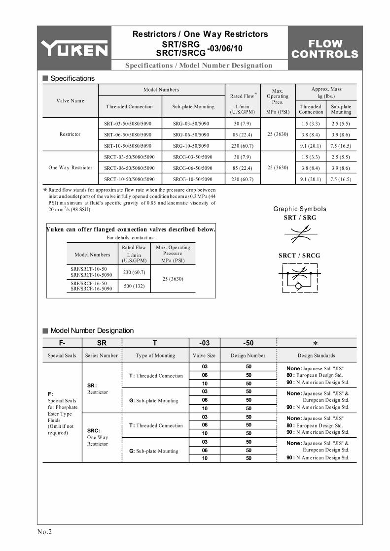
RESTRICTORSPub. EC-0303
SRT/SRG-03/06/10 (3/8, 3/4, 1-1/4)
Threaded Connections / Sub-plate Mounting
Restrictors One Way Restrictors
This valve is used to regulate an actuator speed in a circuit where line pressure is almost steady and small fluctuation of oil flow due to pressure changes is permitted. Integrated check valve allows reversed free flow from outlet to inlet port. Pressure balanced construction provides less effort in adjustment at high pressure.
Hydraulic Fluids
Recommended Viscosity and Temperatures2 Viscosity ranging between 15 - 400 mm /s (77 - 1800 SSU).
Oil temperatures between -15/+70°C (5 - 158°F). Use hydraulic fluids which satisfy the recommended viscosity and oil temperatures given above.
Control of ContaminationDue caution must be paid to maintaining control over contamination of the hydraulic fluids which may otherwise lead to breakdowns and shorten the life of the valves. Please maintain the degree of contamination within NAS 1638-Grade 12. Use 25 µm or finer line filter.
ONE WAY RESTRICTORSSRCT/SRCG-03/06/10 (3/8, 3/4, 1-1/4)
Fluid TypesAny type of hydraulic fluid listed in the table below can be used.
Note: For use with hy draulic fluids other than those listed above, please consult y our Yuken representatives in advance.
FLOW CONTROLS
Specifications / Model Number Designation
Specifications
Model Number Designation
Valve Nam e
SRT-03-50/5080/5090
SRT-06-50/5080/5090
SRT-10-50/5080/5090
SRCT-03-50/5080/5090
SRCT-06-50/5080/5090
SRCT-10-50/5080/5090
Restrictor
One W ay Restrictor
Model Num bers
Threaded Connection Sub-plate Mounting
Max. Operating
Pres.
MPa (PSI)L /m in
(U.S.GPM)
Rated Flow
Threaded Connection
Sub-plate Mounting
Approx. Masskg (lbs.)
30 (7.9)
85 (22.4)
230 (60.7)
30 (7.9)
85 (22.4)
230 (60.7)
1.5 (3.3)
3.8 (8.4)
9.1 (20.1)
1.5 (3.3)
3.8 (8.4)
9.1 (20.1)
Max. Operating Pressure
MPa (PSI)
Rated FlowL /m in
(U.S.GPM)Model Num bers
SRF/SRCF-10-50 SRF/SRCF-10-5090
25 (3630)
Special Seals for Phosphate Ester Ty pe Fluids (Om it if not required)
F:
03 06 10 03 06 10 03 06 10 03 06 10
RestrictorSR:
One W ay Restrictor
SRC:
Threaded ConnectionT:
Sub-plate MountingG:
Threaded ConnectionT:
Sub-plate MountingG:
50 50 50 50 50 50 50 50 50 50 50 50
F- SRSpecial Seals Series Num ber
TTy pe of Mounting
-50Design Num ber
∗Design Standards
-03Valve Size
None: Japanese Std. "JIS"80 : European Design Std.90 : N.Am erican Design Std.
None: Japanese Std. "JIS"80 : European Design Std.90 : N.Am erican Design Std.
SRG-03-50/5090
SRG-06-50/5090
SRG-10-50/5090
SRCG-03-50/5090
SRCG-06-50/5090
SRCG-10-50/5090
25 (3630)
25 (3630)
2.5 (5.5)
3.9 (8.6)
7.5 (16.5)
2.5 (5.5)
3.9 (8.6)
7.5 (16.5)
SRF/SRCF-16-50 SRF/SRCF-16-5090
230 (60.7)
500 (132)
None: Japanese Std. "JIS" & European Design Std.
90 : N.Am erican Design Std.
None: Japanese Std. "JIS" & European Design Std.
90 : N.Am erican Design Std.
Graphic Sym bolsSRT / SRG
SRCT / SRCG
Yuken can offer f langed connection valves described below.For details, contact us.
No.2
Restrictors / One Way Restrictors
Rated flow stands for approxim ate flow rate when the pressure drop between inlet and outlet ports of the valve in fully opened condition becom es 0.3 MPa (44 PSI) m axim um at fluid's specific gravity of 0.85 and kinem atic viscosity of
2 20 m m /s (98 SSU).
-03/06/10SRT/SRG SRCT/SRCG

FLOW CONTROLS
D
Attachment / Sub-plate / Instructions
1.6 (3.5) 1.6 (3.5) 2.4 (5.3) 3.0 (6.6)
4.8 (10.6) 5.7 (12.6)
Valve Model Num bers
SRG/SRCG-03 SRG/SRCG-06 SRG/SRCG-10
Socket Head Cap Screw
Japanese Std. "JIS" and European Design Std. N. Am erican Design Std.
Qty .
M10 × 45 Lg. M10 × 50 Lg. M10 × 55 Lg.
3/8-16 UNC × 1-3/4 Lg. 3/8-16 UNC × 2 Lg. 3/8-16 UNC × 2-1/4 Lg.
4 4 6
Valve Model
Num bers
-03SRG SRCG
-06SRG SRCG
-10SRG SRCG
Japanese Standard "JIS"Sub-plate
Model Num bersThread
Size
European Design StandardSub-plate
Model Num bersThread
Size
N. Am erican Design StandardSub-plate
Model Num bersThread
Size
Approx. Mass kg (lbs.)
CRGM-03-50 CRGM-03X-50 CRGM-06-50 CRGM-06X-50 CRGM-10-50 CRGM-10X-50
Rc 3/8 Rc 1/2 Rc 3/4 Rc 1 Rc 1-1/4 Rc 1-1/2
CRGM-03-5080 CRGM-03X-5080 CRGM-06-5080 CRGM-06X-5080 CRGM-10-5080 CRGM-10X-5080
3/8 BSP.F 1/2 BSP.F 3/4 BSP.F 1 BSP.F 1-1/4 BSP.F 1-1/2 BSP.F
CRGM-03-5090 CRGM-03X-5090 CRGM-06-5090 CRGM-06X-5090 CRGM-10-5090 CRGM-10X-5090
3/8 NPT 1/2 NPT 3/4 NPT 1 NPT 1-1/4 NPT 1-1/2 NPT
No.3
AttachmentMounting Bolts
Sub-plates are available. Specify the sub-plate model number from the table above. When sub-plates are not used, the mounting surface should have a good machined finish.
Sub-plate
Instructions
Slacken the lock nut and turn the flow adjustment knob anti-clockwise to throttle flow. After achieving satisfactory performance tighten the lock nut.
Restrictors / One Way Restrictors
Flow Adjustment
-03/06/10SRT/SRG SRCT/SRCG

FLOW CONTROLS
Installation Drawings
SRT/SRCT-03-50 SRT/SRCT-03-5080 SRT/SRCT-03-5090 SRT/SRCT-06-50 SRT/SRCT-06-5080 SRT/SRCT-06-5090 SRT/SRCT-10-50 SRT/SRCT-10-5080 SRT/SRCT-10-5090
Rc 3/8 3/8 BSP.F 3/8 NPT Rc 3/4
3/4 BSP.F 3/4 NPT Rc 1-1/4
1-1/4 BSP.F 1-1/4 NPT
"N" Thd.Thd. Size
Model Num bersDim ensions m m (Inches)
C D E F H J K L
72 (2.83)
100 (3.94)
138 (5.43)
36 (1.42)
50 (1.97)
69 (2.72)
44 (1.73)
58 (2.28)
80 (3.15)
150.5 (5.93)
180 (7.09)
227 (8.94)
53.5 (2.11)
66.5 (2.62)
86 (3.39)
38 (1.50)
62 (2.44)
80 (3.15)
46 (1.81)
64 (2.52)
82 (3.23)
22 (.87)
31 (1.22)
40 (1.57)
Dia.
Sq.
Sq.
Flow Adjustment Handle INC.
56(2.20)
D
CFu
lly E
xten
ded
F
H
"E" Dia.
Controlled Flow Inlet or Reversed Free Flow Outlet Port "N" Thd.
Controlled Flow Outlet or Reversed Free Flow Inlet Port "N" Thd.
KL
J
Dia.
Lock Nut 19(.75) Hex.
No.4
SRT/SRCT-03-50/5080/5090 SRT/SRCT-06-50/5080/5090 SRT/SRCT-10-50/5080/5090
Restrictors / One Way Restrictors-03/06/10SRT
SRCT
DIMENSIONS IN MILLIMETRES (INCHES)

FLOW CONTROLS
D
Mounting surface: ISO 5781-AG-06-2-A
Installation Drawings
Sub-plate Model Num bers
CRGM-03-50 CRGM-03-5080 CRGM-03-5090 CRGM-03X-50 CRGM-03X-5080 CRGM-03X-5090
Rc 3/8 3/8 BSP.F 3/8 NPT
Rc 1/2 1/2 BSP.F 1/2 NPT
"A" Thd. "B" Thd.
M10
3/8-16 UNC
M10
3/8-16 UNC
33.3 (1.31)
66.7 (2.63)
13(.51) Dia. 2 Places
"A" Thd. (From Rear) 2 Places
56 (2.20) Dia.
Flow Adjustment Handle INC.
Controlled Flow Outlet or Reversed Free Flow Inlet Port
Fully
Ext
ende
d15
0.5(
5.93
)
42.9
(1
.69)
32
(1.2
6)
31 (1.22)
Controlled Flow Inlet or Reversed Free Flow Outlet Port
11(.43) Dia. Through 17.5(.69) Dia. Spotface 4 Places 11.7
(.46)
33.3 (1.31)
66.7 (2.63)
90 (3.54)
Mounting Surface (O-Rings Furnished)
Locating Pin 6(.24) Dia.
6 (.24)
64 (2.52)
30 (1.18)
19.5
(.7
7)21
(.8
3)61
(2
.40) 82
(3
.23)
102
(4.0
2)
10
(.39)
7.1
(.28)
31.8
(1
.25)
35.7
(1
.41)
42.9
(1
.69)
7(.28) Dia. 10(.39) Deep
1.7 (.07)
70 (2.76)
10 (.39)
90 (3.54)
"B" Thd. 20(.79) Deep 4 Places8.8(.35) Dia. Through
14(.55) Dia. Spotface 4 Places
32 (1.26)
15 (.59)
90
(3.5
4)
Lock Nut 19(.75) Hex.
SRG/SRCG-03-50/5090
No.5
Restrictors / One Way Restrictors-03SRG
SRCG
CRGM- -50/5080/509003 03X
Sub-plate
DIMENSIONS IN MILLIMETRES (INCHES)
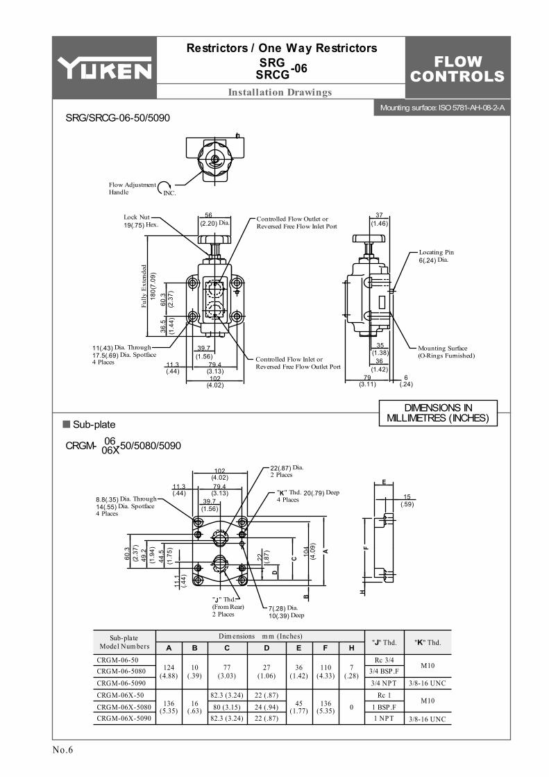
FLOW CONTROLS
Mounting surface: ISO 5781-AH-08-2-A
Installation Drawings
ADim ensions m m (Inches)
B C D E F HSub-plate
Model Num bers
CRGM-06-50 CRGM-06-5080 CRGM-06-5090 CRGM-06X-50 CRGM-06X-5080 CRGM-06X-5090
Rc 3/4 3/4 BSP.F 3/4 NPT
Rc 1 1 BSP.F 1 NPT
"J" Thd. "K" Thd.
M10
3/8-16 UNC
M10
3/8-16 UNC
124 (4.88)
136 (5.35)
10 (.39)
16 (.63)
77 (3.03)
27 (1.06)
82.3 (3.24) 80 (3.15)
82.3 (3.24)
22 (.87) 24 (.94) 22 (.87)
36 (1.42)
45 (1.77)
110 (4.33)
136 (5.35)
7 (.28)
0
E
39.7 (1.56)
79.4 (3.13)
22(.87) Dia. 2 Places
"J" Thd. (From Rear) 2 Places
56 (2.20) Dia.
Flow Adjustment Handle INC.
Controlled Flow Outlet or Reversed Free Flow Inlet Port
Fully
Ext
ende
d18
0(7.
09)
60.3
(2
.37)
36.5
(1
.44)
37 (1.46)
Controlled Flow Inlet or Reversed Free Flow Outlet Port
11(.43) Dia. Through 17.5(.69) Dia. Spotface 4 Places 11.3
(.44)
39.7 (1.56)
79.4 (3.13)102
(4.02)
Mounting Surface (O-Rings Furnished)
Locating Pin 6(.24) Dia.
6 (.24)
79 (3.11)
36 (1.42)
35 (1.38)
22
(.87) 10
4 (4
.09)
11.1
(.4
4)
44.5
(1
.75)
49.2
(1
.94)
60.3
(2
.37)
7(.28) Dia. 10(.39) Deep
11.3 (.44)
102 (4.02)
"K" Thd. 20(.79) Deep 4 Places8.8(.35) Dia. Through
14(.55) Dia. Spotface 4 Places
15 (.59)
Lock Nut 19(.75) Hex.
C
D
A
B
FH
SRG/SRCG-06-50/5090
Restrictors / One Way Restrictors-06SRG
SRCG
CRGM- -50/5080/509006 06X
No.6
DIMENSIONS IN MILLIMETRES (INCHES)Sub-plate

FLOW CONTROLS
Mounting surface: ISO 5781-AJ-10-2-A
D
Installation Drawings
ADim ensions m m (Inches)B E F
Sub-plate Model Num bers "H" Thd. "J" Thd.
C DCRGM-10-50 CRGM-10-5080 CRGM-10-5090 CRGM-10X-50 CRGM-10X-5080 CRGM-10X-5090
Rc 1-1/4 1-1/4 BSP.F 1-1/4 NPT Rc 1-1/2
1-1/2 BSP.F 1-1/2 NPT
M10
3/8-16 UNC
M10
3/8-16 UNC
150 (5.91)
177 (6.97)
12 (.47)
25.5 (1.00)
45 (1.77)
50 (1.97)
135 (5.31)
167 (6.57)
96 (3.78)
104 (4.09)
30 (1.18)
22 (.87)
48.4 (1.91)
96.8 (3.81)
28(1.10) Dia. 2 Places
"H" Thd. (From Rear) 2 Places
56 (2.20) Dia.
Flow Adjustment Handle INC.
Controlled Flow Outlet or Reversed Free Flow Inlet Port
Fully
Ext
ende
d22
7(8.
94)
84.1
(3
.31)
44
(1.7
3)
42 (1.65)
Controlled Flow Inlet or Reversed Free Flow Outlet Port
11(.43) Dia. Through 17.5(.69) Dia. Spotface 6 Places 11.1
(.44)
48.4 (1.91)
96.8 (3.81)119
(4.69)
Mounting Surface (O-Rings Furnished)
Locating Pin 6(.24) Dia.
6 (.24)
90 (3.54)
41 (1.61)
40 (1.57)
16.7
(.6
6)
42.1
(1
.66)62
.7
(2.4
7)
67.5
(2
.66)
7(.28) Dia. 10(.39) Deep
9.6 (.38)
116 (4.57)
12 (.47)
140 (5.51)
19 (.75)
42.1
(1
.66)
11(.43) Dia. Through 17.5(.69) Dia. Spotface 4 Places
"J" Thd. 20(.79) Deep 6 Places
84.1
(3
.31)
11.6 (.46)
120 (4.72)
21
(.83) 12
6 (4
.96)
C
D
A
B
F
E
Lock Nut 19(.75) Hex.
SRG/SRCG-10-50/5090
No.7
Restrictors / One Way Restrictors-10SRG
SRCG
CRGM- -50/5080/509010 10X
Sub-plateDIMENSIONS IN
MILLIMETRES (INCHES)
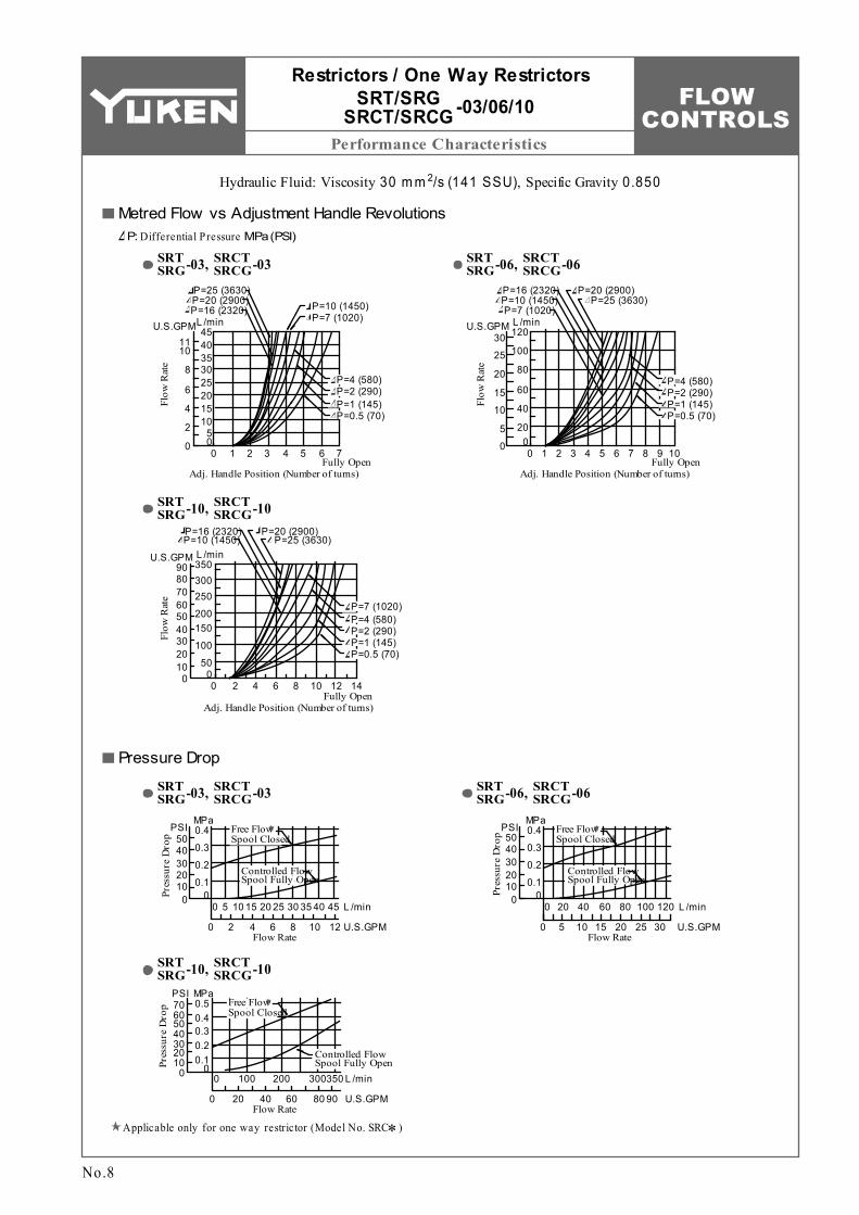
FLOW CONTROLS
Performance CharacteristicsFl
ow R
ate
4540353025201510
50
Flow
Rat
e
U.S.GPML /min
1110
8
6
4
2
0
P=16 (2320)P=20 (2900)P=25 (3630)
0 1 2 3 4 5 6 7
P=10 (1450)P=7 (1020)
P=4 (580)P=2 (290)P=1 (145)P=0.5 (70)
Fully OpenAdj. Handle Position (Number of turns)
0
Flow
Rat
e
U.S.GPM L /min30
25
20
15
10
5
0
120
100
80
60
40
20
Fully OpenAdj. Handle Position (Number of turns)
0 1 2 3 4 5 6 7 8 9 10
P=7 (1020)P=10 (1450)P=16 (2320) P=20 (2900)
P=25 (3630)
P=4 (580)P=2 (290)P=1 (145)P=0.5 (70)
Fully OpenAdj. Handle Position (Number of turns)
0 2 4 6 8 10 12 140
U.S.GPM L /min
0102030405060708090
300250
200150
100
50
350
P=10 (1450)P=16 (2320) P=20 (2900)
P=25 (3630)
P=4 (580)P=2 (290)P=1 (145)P=0.5 (70)
P=7 (1020)
0 40 455 10 15 20 25 30 35
0 2 4 6 8 10 12Flow Rate
Pres
sure
Dro
p
00.1
0.2
0.3
0.4
01020304050
U.S.GPM
L /min
MPaPSI Free Flow
Spool Closed
Controlled Flow Spool Fully Open
Free Flow Spool Closed
Controlled Flow Spool Fully Open
Flow RateU.S.GPM
L /min0 20 40 60 80 100 120
0 5 10 15 20 25 30
Pres
sure
Dro
p
00.1
0.2
0.3
0.4MPa
PSI
01020304050
Free Flow Spool Closed
Controlled Flow Spool Fully Open
0
0Flow Rate
U.S.GPM
L /min100 200 300350
20 40 60 80 90
0
MPa
0.10.20.30.40.5
Pres
sure
Dro
p
PSI
010203040506070
Restrictors / One Way Restrictors-03/06/10SRT/SRG
SRCT/SRCG
No.8
Hydraulic Fluid: Viscosity 2 30 m m /s (141 SSU), Specific Gravity 0.850
Metred Flow vs Adjustment Handle RevolutionsP: Differential Pressure MPa (PSI)
SRT SRG
SRCT SRCG-03, -03 SRT
SRGSRCT SRCG-06, -06
SRT SRG
SRCT SRCG-10, -10
Pressure Drop
SRT SRG
SRCT SRCG-03, -03 SRT
SRGSRCT SRCG-06, -06
SRT SRG
SRCT SRCG-10, -10
Applicable only for one way restrictor (Model No. SRC∗)

FLOW CONTROLS
D
Spare Parts List
Item
SO-NB-P7 SO-NB-P15 SO-NB-P20
Nam e of Parts Qty .
O-Ring O-Ring O-Ring
1 1 1
12 13 14
Model Num bers Seal Kit Num bersSRT/SRCT-03 SRT/SRCT-06 SRT/SRCT-10
Part Num bersSRT SRCT-03 KS-SRT-03-50
KS-SRT-06-50 KS-SRT-10-50SO-NB-P7
SO-NB-P21 SO-NB-P22.4
SRT SRCT-06
SO-NB-P7 SO-NB-P29 SO-NB-P36
SRT SRCT-10
Item
SO-NB-P7 SO-NB-P15 SO-NB-P20 SO-NB-P18
Nam e of Parts Qty .
O-Ring O-Ring O-Ring O-Ring
1 1 1 2
12 13 14 15
Model Num bers Seal Kit Num bersSRG/SRCG-03 SRG/SRCG-06 SRG/SRCG-10
Part Num bersSRG SRCG-03 KS-SRG-03-50
KS-SRG-06-50 KS-SRG-10-50SO-NB-P7
SO-NB-P21 SO-NB-P22.4 SO-NB-P28
SO-NB-P7 SO-NB-P29 SO-NB-P36 SO-NB-P32
SRG SRCG-10SRG
SRCG-06
For SRCT
For SRCG
17 16 10 94
15532
1412
11
186
7
1
138
10 17 18
94
16
51
2
14
611
20
713
8
19
15
12
3
No.9
List of Seals List of Seal Ki ts
SRT/SRCT-03-50/5080/5090 SRT/SRCT-06-50/5080/5090 SRT/SRCT-10-50/5080/5090
Note: W hen ordering the seals, please specify the seal kit num ber from the table right.
Restrictors / One Way Restrictors-03/06/10SRT/SRG
SRCT/SRCG
When making replacement of seals, please do it carefully after reading through the relevant instructions in the Operator's Manual.
CAUTION
SRG/SRCG-03-50/5090 SRG/SRCG-06-50/5090 SRG/SRCG-10-50/5090
List of Seals List of Seal Ki ts
Note: W hen ordering the seals, please specify the seal kit num ber from the table right.

FLOW CONTROLS
D
Specifications / Model Number Designation
P A B TTC1G-01
Solenoid Operated Directional Valve
P A B T P A B T P A B T
P A B T
P A B T
TC1G-03
Solenoid Operated Directional Valve
TC1G-03-C
Solenoid Operated Directional Valve
TC2G-01
Solenoid Operated Directional Valve
Solenoid Operated Directional Valve
TC2G-03
Solenoid Operated Directional Valve
TC2G-03-A
01
03
Valve SizeThrottle Modules
W ith Check Standard (Metre-out) Ty pe Metre-in Ty pe
Throttle and Check Modules
Standard Ty pe
Model Num bers Nom inal Flow L /m in (U.S.GPM)
Max Operating Pressure
MPa (PSI)
Approx. Mass
kg (lbs.)TC1G-01-40/4090 TC2G-01-40/4090 TC1G-03-∗-40/4090 TC2G-03-∗-40/4090
30 (7.9)
80 (21.1)25 (3630)
0.6 (1.3) 0.65 (1.4) 1.6 (3.5) 1.8 (4.0)
Series Num ber
F-: Special Seals for Phosphate Ester Ty pe Fluids (Om it if not required)
Special Seals
F- TC1
01
TC1: Throttle Module
GTy pe of
MountingValve Size
Design Num ber
Design Standards
-C ∗-03
None: Japanese Std. "JIS" and European Design Std.
90: N. Am erican Design Std.
-40Valve Ty pe
03
40
40
TC1: Throttle Module
TC2: Throttle and Check Module
TC2: Throttle and Check Module
G: Gasket Mounting
G: Gasket Mounting
None: Std. Ty pe
None: Std. (Metre-Out) Ty pe
None: Std. Ty peC: W ith Check Valve
None: Std. (Metre-Out) Ty pe
A: Metre-in Ty pe
Up to 25 MPa (3630 PSI), 80 L /m in (21.1 U.S.GPM)
No.1
THROTTLE MODULES TC1G-01 / 03 (1 / 8 , 3 / 8)
THROTTLE AND CHECK MODULES TC2G-01 / 03 (1 / 8 , 3 / 8)
Gasket Mounting
Pub. EC-0304
Used as pilot choke valves for solenoid controlled pilot operated directional valves and pilot operated directional valves.
Model Number Designation
Specifications
Graphic Sym bols

FLOW CONTROLS
Hydraulic Fluids / Attachment / Instructions
Solenoid Operated Directional valveThrottle m odule or Throttle and check m odule
Mounting bolt
Solenoid Operated Directional valveThrottle m odule or Throttle and check m odule
Mounting bolt
Petroleum base oils
Sy nthetic fluids
W ater containing fluids
Use fluids equivalent to ISO VG 32 or VG 46.
Use phosphate ester or poly ol ester fluid. W hen phosphate ester fluid is used, prefix "F-" to the m odel num ber because the special seals (fluororubber) are required to be used.
Use water-gly col fluid.
Solenoid Operated Directional Valve
Valve Model
Num bers
Socket Head Cap Screw
Qty .Japanese Std. "JIS" & European Design Std.
N. Am erican Design Std.
TC∗G-01
TC∗G-03
TC∗G-01
TC∗G-03
4
4
4
4
M5 × 70 Lg.
M6 × 70 Lg.
M5 × 95 Lg.
M6 × 100 Lg.
No. 10-24 UNC × 2-3/4 Lg.
1/4-20 UNC × 2-3/4 Lg.
No. 10-24 UNC × 3-3/4 Lg.
1/4-20 UNC × 4 Lg.
Throttle (and Check) Modules -01 / 03TC1G TC2G
No.2
Hydraulic Fluids
Note: For use with hydraulic fluids other than those listed above, please consult your Yuken representatives in advance.
Recommended Viscosity and Oil Temperatures2 Viscosity ranging between 15 - 400 mm /s (77 - 1800 SSU).
Oil temperatures between -15/+70°C (5 - 158°F). Use hydraulic fluids which satisfy the recommended viscosity and oil temperatures given above.
Fluid TypesAny type of hydraulic fluids listed in the table below can be used.
Attachment
Control of ContaminationDue caution must be paid to maintaining control over contamination of the hydraulic fluids which may otherwise lead to breakdowns and shorten the life of the valves. Please maintain the degree of contamination within NAS 1638-Grade 12. Use 25 µm or finer line filter.
Mounting BoltsIf mounting bolts are necessary, order suitable ones selected from the table below. If mounting bolts from other companies are used, their strength must be 8.8 or up ISO standards.
InstructionsFlow adjustmentSlacken the lock nut and turn the flow adjustment screw clockwise caused the flow rate to decrease After adjustment, be sure to tighten the lock nut.
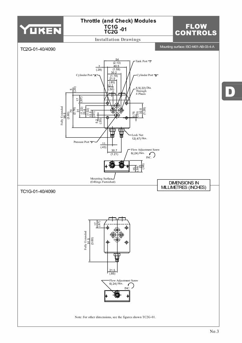
FLOW CONTROLS
Mounting surface: ISO 4401-AB-03-4-A
D
Installation Drawings
Lock Nut 12(.47) Hex.
32.5
(1.2
8)
0.75
(.03)
5.2
(.20)
15.5
(.61)25
.8(1
.02)31
(1.2
2)17 (.6
7)
70(2
.76)
96.5
(3.8
0)5
(.20)
15 (.59) 25 (.9
8)
Flow Adjustment Screw 6(.24) Hex.
INC.
21.5(.85)
17 (.67)
91.5
(3.6
0)
Fully
Ext
ende
d
Flow Adjustment Screw 6(.24) Hex.
INC.
30.7(1.21)
Mounting Surface (O-Rings Furnished)
11(.43)
Pressure Port "P"
Fully
Ext
ende
d
12.7(.50)
(.85)21.5(1.19)30.2
(1.59)40.5(2.13)
54
7(.28)
Cylinder Port "A" Cylinder Port "B"
Tank Port "T"
5.5(.22) Dia. Through 4 Places
No.3
Throttle (and Check) Modules -01TC1G
TC2G
TC2G-01-40/4090
TC1G-01-40/4090
Note: For other dim ensions, see the figures shown TC2G-01.
DIMENSIONS IN MILLIMETRES (INCHES)

FLOW CONTROLS
Mounting surface: ISO 4401-AC-05-4-A
Installation Drawings
3.2(.13)
16.7(.66)
27(1.06)
37.3(1.47)
50.8(2.00)
54(2.13)
19(.75)
92(3.62)
14.7(.58) 39.3
(1.55)
6.4
(.25)
21.4
(.84)
32.5
(1.2
8)
46(1
.81)
17 (.67)
5(.2
0)89
.5(3
.52)
120
(4.7
2)
Fully
Ext
ende
d
Pressure Port "P"
Cylinder Port "A"
Cylinder Port "B"
Tank Port "T"
Flow Adjustment Screw 7(.28) Hex.
INC.
Mounting Surface (O-Rings Furnished)
7(.28) Dia. Through 4 Places
TC2G-03 TC2G-03-A
........... .......
11(.43) 21(.83)
17 (.67)
5(.2
0)79
.5(3
.13)
110
(4.3
3)
Fully
Ext
ende
d
27(1.06) Flow Adjustment Screw
7(.28) Hex.INC.
Lock Nut 14(.55) Hex.
32(1
.26)
Throttle (and Check) Modules -03TC1G
TC2G
No.4
TC2G-03-40/4090TC2G-03-A-40/4090
TC1G-03-40/4090TC1G-03-C-40/4090
Note: For other dim ensions, see the figures shown TC2G-03.
W ith standard sub-plates, the left one of the two tank ports "T" is used but either one m ay be used.
DIMENSIONS IN MILLIMETRES (INCHES)

FLOW CONTROLS
D
Performance Characteristics
P2
P1 A1 B1
A2 B2
0 1 2 3 4 5 6 6.5
Adjustment Screw RevolutionsClosed Fully Open
0 2 4 6 8 10 11.5
Adjustment Screw RevolutionsClosed Fully Open
0 2 4 6 8 10 11.5
Adjustment Screw RevolutionsClosed Fully Open
0 105 15 20 25L/min
Flow Rate0 1 2 3 4 5 6
U.S.GPM7 8
30
0 4020 60 80L/min
Flow Rate
0 5 10 15 20U.S.GPM
25 27.5
100
30
U.S.GPM
25
20
15
10
2
4
5
6
7
8L/min
Flow
Rat
e
3
1
0
5
0
80
U.S.GPM
70
60
50
205
15
20
22.5
Flow
Rat
e
0
100
L/min
30
4010
80
U.S.GPM
70
60
50
205
15
20
22.5
Flow
Rat
e
0
10
0
30
4010
L/min
Differential Pressure
Differential Pressure
16 MPa (2320 PSI)
6.3 MPa (910 PSI)2.5 MPa (360 PSI)1.0 MPa (145 PSI)
0.4 MPa (60 PSI)
25 MPa (3630 PSI)
25 MPa (3630 PSI)16 MPa (2320 PSI)
6.3 MPa (910 PSI)2.5 MPa (360 PSI)
1.0 MPa (145 PSI)
0.4 MPa (60 PSI)
Differential Pressure
25 MPa (3630 PSI)
16 MPa (2320 PSI)
6.3 MPa (910 PSI)
2.5 MPa (360 PSI)1.0 MPa (145 PSI)
0.4 MPa (60 PSI)
2.0
0
0.5
1.5
PSI
0
200
250
300MPa
Pres
sure
Dro
p
P50
150
100
1.0
8
0
1
6
PSI
0
800
1000
1200MPa
Pres
sure
Dro
p
P
200
600
400
4
2
3
5
7
Throttle Fully Closed
→P2
Throttle Fully OpenP1
→A2A1
→B2B1
Throttle Fully Open→A1A2
→B1B2
→A1A2
→B1B2
P2
P1
P'2
P'1 A'1B'1
A2 B2
A1 B1A 2 B2
Throttle Fully Open
Throttle Fully Open
Throttle Fully Closed
→P'2P'1
→A1A2
Throttle Fully Open
→A'2A'1→B1B2 →B'2B'1
→A1A2 →A'2A'1→B1B2 →B'2B'1
→A2A1 →A'1A'2→B2B1 →B'1B'2
→P2P1
Viscosity2 m m /s
SSUFactor
15 77
0.81
20 98
0.87
30 141 0.96
40 186 1.03
50 232 1.09
60 278 1.14
70 324 1.19
80 371 1.23
90 417 1.27
100 464 1.30
No.5
Throttle (and Check) Modules -01 / 03TC1G TC2G
Metred Flow vs. Adjustment RevolutionsHydraulic Fluid: Viscosity 2 35 m m /s (164 SSU) , Specific Gravity 0.850
Pressure Drop
TC1G-01 TC2G-01
TC1G-01 TC2G-01
TC1G-03-∗ TC2G-03-∗
TC1G-03-C
TC1G-03 TC2G-03
For any other specific gravity (G'), the pressure drop ( P') may be obtained from the formula below.
P'= P (G'/0.850)
For any other viscosity, multiply the factors in the table below.

FLOW CONTROLS
Spare Parts List
789
10
O-RingO-RingO-Ring
Back Up Ring
Nam e of PartsItemTC1G-01 TC1G-03
Part Num bers Qty .
SO-NB-P9
SO-NA-P7SO-BB-P7
SO-NB-A014SO-NB-P10SO-NA-P9SO-BB-P9
5111
Model Num bersTC1G-01TC1G-03TC1G-03-C
KS-TC1G-01-40
KS-TC1G-03-40
Seal Kit Num bers
Nam e of PartsItemTC2G-01 TC2G-03
Part Num bersQty .
22232425
O-RingO-RingO-Ring
Back Up Ring
SO-NB-P9
SO-NA-P7SO-BB-P7
SO-NB-A014SO-NB-P10SO-NA-P9SO-BB-P9
5222
SO-NB-P10
Model Num bersTC2G-01TC2G-03TC2G-03-A
Seal Kit Num bersKS-TC2G-01-40
KS-TC2G-03-40
7 1 2 9 10 12 5 3 11
18 23 17 16 13 22 14 24 25 27 19 15 26
4 8 7 2 6 9 10 1 12 5 3 11
18 23 17 16 20 22 13 21 14 24 25 27
15
19
26
Throttle (and Check) Modules -01 / 03TC1G
TC2G
No.6
TC1G-01-40/4090TC1G-03-∗-40/4090
TC2G-01-40/4090TC2G-03-∗-40/4090
List of Seals List of Seal Ki ts
L ist of Seals List of Seal Ki ts
W ith TC1G-01, 4 O-Rings, Item , are used.W hen ordering the seals, please specify the seal kit num ber from the table right
7
W ith TC2G-01, 4 O-Rings, Item , are used.22
T C1G-01 T C1G-03
T C2G-01 T C2G-03
When making replacement of seals, please do it carefully after reading through the relevant instructions in the Operator's Manual.
CAUTION
Note:
W hen ordering the seals, please specify the seal kit num ber from the table rightNote:

FLOW CONTROLS
D
Specifications / Model Number Designation
Max. Flow L /min (U.S.GPM)
Max. Operating Pressure
MPa (PSI)
Model Numbers
Threaded Connection Sub-plate Mounting
Approx. Mass kg (lbs.)
Z∗GZ∗T
4.3 (9.5)
8.7 (19.2)
17 (37.5)
4.3 (9.5)
8.7 (19.2)
17 (37.5)
21 (3050)
30 (7.9)
80 (21.1)
200 (52.8)
ZG/ZCG-03-∗-∗-22/2290
ZG/ZCG-06-∗-∗-22/2290
ZG/ZCG-10-∗-∗-22/2290
ZT/ZCT-03-∗-∗-22/2280/
2290
ZT/ZCT-06-∗-∗-22/2280/
Series NumberSpecial Seals
F- ZC -TType of
MountingValve Size
Design Number
Design Standards
-22 ∗-CWith Adjustable Needle Valve for
By-Pass LineSpool Type
T -03
22
22
22
22
22
22
22
22
22
22
22
22
03
06
10
03
06
10
03
06
10
03
06
10
None:Japanese Std. "JIS"80:European Design Std.90:N. American Design Std.
None:Japanese Std. "JIS" &European Design Std.
90:N. American Design Std.
None:Japanese Std. "JIS"80:European Design Std.90:N. American Design Std.
None:Japanese Std. "JIS" &European Design Std.
90:N. American Design Std.
None:Normally Open TypeC:Normally Closed Type
None:Normally Open TypeC:Normally Closed Type
T:Threaded Connection
T:Threaded Connection
G:Sub-plate Mounting
G:Sub-plate Mounting
T:With Adjustable Needle Valve (Omit if not required)
T:With Adjustable Needle Valve (Omit if not required)
ZC:Deceleration and Check Valve
Z:Deceleration ValveF:
Special Seals for Phosphate Ester Type Fluids (Omit if not required)
Up to 21 MPa (3050 PSI), 200 L/min (52.8 U.S.GPM)
No.1
DECELERATION VALVES ZT / ZG-03 / 06 / 10 (3/8, 3/4, 1-1/4)
DECELERATION AND CHECK VALVES ZCT / ZCG-03 / 06 / 10 (3/8, 3/4, 1-1/4)
Threaded Connections / Sub-plate
Pub. EC-0305
These valves are available either with or without an integral check valve which allows free reverse flow. Flow rate through the valve is regulated by the movement of the spool, which is operated by a cam. When the spool is depressed, the flow is decreased in Normally Open type valves and increased in Normally Closed type valves. Their principal use is to control the speed of actuators in machine tools and similar applications.
Model Number Designation
Specifications
Normally Open Type Normally Closed Type
Graphic Symbols
ZT ZG -∗ ZT
ZG -∗-T ZT ZG -∗-C ZT
ZG -∗-T-C ZCT ZCG-∗-TZCT
ZCG-∗ -∗-C ZCT ZCG-∗-T-CZCT
ZCG
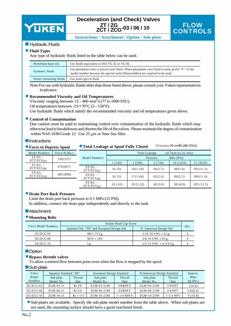
FLOW CONTROLS
Instructions / Attachment / Option / Sub-plate
Model Numbers Force N (lbs.)ZT/ZG
ZCT/ZCG-03
ZT/ZG ZCT/ZCG
-06
ZT/ZG ZCT/ZCG
-10
150 (337)
270 (607)
400 (899)
Model Numbers
Total Leakage
ZT/ZG ZCT/ZCG
-03
ZT/ZG ZCT/ZCG
-06
ZT/ZG ZCT/ZCG
-10
9 (.55)
9 (.55)
10 (.61)
Pressure
1 (145) 2 (290) 5 (730) 10 (1450) 21 (3050)
18 (1.10)
17 (1.04)
20 (1.22)
44 (2.7)
43 (2.6)
49 (3.0)
88 (5.4)
86 (5.2)
98 (6.0)
185 (11.3)
180 (11.0)
205 (12.5)
Valve Model NumbersJapanese Std. "JIS" and European Design Std. N. American Design Std.
Qty .Socket Head Cap Screw
ZG/ZCG-03
ZG/ZCG-06
ZG/ZCG-10
4
4
4
M8 × 75 Lg.
M10 × 100
Lg.
5/16-18 UNC × 3 Lg.
3/8-16 UNC × 4 Lg.
1/2-13 UNC × 4-3/4 Lg.
Valve Model
NumbersSub-plate
Model No.Thread
SizeThread
SizeThread
Size
Approx. Mass
kg (lbs.)Sub-plate
Model No.
Japanese Standard "JIS" European Design StandardSub-plate
Model No.
N.American Design Standard
ZG/ZCG-03
ZG/ZCG-06
ZG/ZCG-10
ZGM-03-21
ZGM-06-21
ZGM-10-21
ZGM-03-2180
ZGM-06-2180
ZGM-10-2180
ZGM-03-2190
ZGM-06-2190
ZGM-10-2190
2 (4.4)
3.8 (8.4)
9 (19.8)
3/8 NPT
3 /4 NPT
1-1/4 NPT
3/8 BSP.F
3/4 BSP.F
1-1/4 BSP.F
Rc 3/8
Rc 3/4
Rc 1-1/4
3 cm /min (cu.in./min)
MPa (PSI)
Petroleum base oils
Synthetic fluids
Water containing fluids
Use fluids equivalent to ISO VG 32 or VG 46.
Use phosphate ester or polyol ester fluid. When phosphate ester fluid is used, prefix "F-" to the model number because the special seals (fluororubber) are required to be used.
Use water-glycol fluid.
Deceleration (and Check) Valves
-03 / 06 / 10ZT / ZG ZCT / ZCG
No.2
InstructionsForce to Depress Spool Total Leakage at Spool Fully Closed [Viscosity: 2 20 mm/s (98 SSU)]
Drain Port Back PressureLimit the drain port back pressure to 0.1 MPa (15 PSI). In addition, connect the drain pipe independently and directly to the tank.
AttachmentMounting Bolts
Bypass throttle valvesTo allow a metred flow between ports even when the flow is stopped by the spool.
Option
Sub-plate
Sub-plates are available. Specify the sub-plate model number from the table above. When sub-plates are not used, the mounting surface should have a good machined finish.
Hydraulic Fluids
Note:For use with hydraulic fluids other than those listed above, please consult your Yuken representatives in advance.
Recommended Viscosity and Oil Temperatures2 Viscosity ranging between 15 - 400 mm /s (77 to 1800 SSU).
Oil temperatures between -15/+70°C (5 - 158°F). Use hydraulic fluids which satisfy the recommended viscosity and oil temperatures given above.
Fluid TypesAny type of hydraulic fluids listed in the table below can be used.
Control of ContaminationDue caution must be paid to maintaining control over contamination of the hydraulic fluids which may otherwise lead to breakdowns and shorten the life of the valves. Please maintain the degree of contamination within NAS 1638-Grade 12. Use 25 µm or finer line filter.

FLOW CONTROLS
D
Installation Drawings
Model Numbers
102 (4.02)
C
Dimensions mm (Inches)
Model NumbersDimensions mm (Inches)
D E F H J K L N P Q S T U V W
120 (4.72)
160 (6.30)
80 (3.15)
98 (3.86)
132 (5.20)
66 (2.60)
82 (3.23)
103 (4.06)
40 (1.57)
49 (1.93)
66 (2.60)
11 (.43)
11 (.43)
14 (.55)
82 (3.23)
106 (4.17)
140 (5.51)
60 (2.36)
84 (3.31)
112 (4.41)
41 (1.61)
57 (2.24)
75 (2.95)
X Y Z a b d e f g h j n t
20 (.79)
32 (1.26)
40 (1.57)
11 (.43)
11 (.43)
14 (.55)
141 (5.55)
176 (6.93)
224 (8.82)
58 (2.28)
81 (3.19)
106 (4.17)
40 (1.57)
57 (2.24)
75 (2.95)
56 (2.20)
65 (2.56)
80 (3.15)
25 (.98)
27 (1.06)
32 (1.26)
70 (2.76)
95 (3.74)
110 (4.33)
60 (2.36)
85 (3.35)
96 (3.78)
25 (.98)
32 (1.26)
40 (1.57)
35 (1.38)
50 (1.97)
55 (2.17)
18 (.71)
22 (.87)
28 (1.10)
6 (.24)
8 (.31)
10 (.39)
10 (.39)
13 (.51)
18 (.71)
2 (.08)
3 (.12)
3 (.12)
8 (.31)
10 (.39)
15 (.59)
2 (.08)
3 (.12)
3 (.12)
8 (.31)
10 (.39)
15 (.59)
8.8 (.35)
11 (.43)
13.5 (.53)
14 (.55)
17.5 (.69)
21 (.83)
24.5 (.96)
29 (1.14)
34 (1.34)
ZT/ZCT-03
ZT/ZCT-06
ZT/ZCT-10
ZT/ZCT-03
ZT/ZCT-06
ZT/ZCT-10
Model Numbers "q" Thd. "r" Thd.
ZT/ZCT-03-∗-∗-22
ZT/ZCT-03-∗-∗-
2280
ZT/ZCT-03-∗-∗-
2290
ZT/ZCT-06-∗-∗-22
ZT/ZCT-06-∗-∗-
2280
ZT/ZCT-06-∗-∗-
Rc 3/8
3/8 BSP.F
3 /8 NPT
Rc 3/4
3/4 BSP.F
3 /4 NPT
Rc 1-1/4
1-1/4 BSP.F
1-1/4 NPT
Rc 1/4
1/4 BSP.F
1 /4 NPT
Rc 1/4
1/4 BSP.F
1 /4 NPT
Rc 1/4
1/4 BSP.F
1 /4NPT
Model Numbers Por t "A"
Z T -∗
ZCT-∗
Controlled flow inlet
Controlled flow inlet or Reversed free flow outlet
Controlled flow outlet
Controlled flow outlet or Reversed free flow inlet
Por t "B"
Total Valve Spool Movement "d"
Seal Stroke "e"
"a" Dia. Roller
Limit the cam angle to 35°
Throttle Stroke "f"
Seal Stroke "g"
Throttle Stroke "h"
(Normally Closed)(Normally Open)
"j" Dia. "n" Dia. Spotface 4 Places
Drain Port "DR" "r" Thd. (Connect directly to the tank.)
Lock Nut 13(.51) Hex.
Port "A" (See table below) "q" Thd.Port "B" (See table below) "q" Thd.
Adjustable Needle Valve for By-Pass Line(Z∗T-∗-T) INC.
W
X
Y
20(.79)
bt
Z
F
E
D
C
H
J K
LN
P
VT
SU
Q
No.3
ZT/ZCT-03-∗-∗-22/2280/2290 ZT/ZCT-06-∗-∗-22/2280/2290 ZT/ZCT-10-∗-∗-22/2280/2290
Deceleration (and Check) Valves
-03 / 06 / 10ZT ZCT
DIMENSIONS IN MILLIMETRES (INCHES)

FLOW CONTROLS
Installation Drawings
Model NumbersC
Dimensions mm (Inches)
D E F H J K L N P Q S T
Model NumbersU
Dimensions mm (Inches)V X Y Z a b d e f g h
ZG/ZCG-03
ZG/ZCG-06
ZG/ZCG-10
102 (4.02)
120 (4.72)
160 (6.30)
80 (3.15)
98 (3.86)
132 (5.20)
66 (2.60)
82 (3.23)
103 (4.06)
40 (1.57)
49 (1.93)
66 (2.60)
11 (.43)
11 (.43)
14 (.55)
82 (3.23)
106 (4.17)
140 (5.51)
60 (2.36)
84 (3.31)
112 (4.41)
41 (1.61)
57 (2.24)
75 (2.95)
11 (.43)
11 (.43)
14 (.55)
141 (5.55)
176 (6.93)
224 (8.82)
56 (2.20)
65 (2.56)
80 (3.15)
25 (.98)
27 (1.06)
32 (1.26)
70 (2.76)
95 (3.74)
110 (4.33)
60 (2.36)
85 (3.35)
96 (3.78)
35 (1.38)
50 (1.97)
55 (2.17)
18 (.71)
22 (.87)
28 (1.10)
6 (.24)
8 (.31)
10 (.39)
10 (.39)
13 (.51)
18 (.71)
2 (.08)
3 (.12)
3 (.12)
8 (.31)
10 (.39)
15 (.59)
2 (.08)
3 (.12)
3 (.12)
8 (.31)
10 (.39)
15 (.59)
8.8 (.35)
11 (.43)
13.5 (.53)
14 (.55)
17.5 (.69)
21 (.83)
24.5 (.96)
29 (1.14)
34 (1.34)
Model Numbers Por t "A"
ZG-∗
ZCG-∗
Controlled flow inlet
Controlled flow inlet or Reversed free flow outlet
Controlled flow outlet
Controlled flow outlet or Reversed free flow inlet
Por t "B"
ZG/ZCG-03
ZG/ZCG-06
ZG/ZCG-10
Port "A" (See table below)
Port "B" (See table below)
"f" Dia. Through "g" Dia. Spotface 4 Places
Drain Port "DR" (Connect directly to the tank.)
Total Valve Spool Movement "Z"
Seal Stroke "a"
Throttle Stroke "b"
Seal Stroke "d"
Throttle Stroke "e"
(Normally Closed)(Normally Open)
"X" Dia. Roller
Limit the cam angle to 35°
Adjustable Needle Valve for By-Pass Line(Z∗G-∗-T) INC.
Lock Nut 13(.51) Hex.
Mounting Surface (O-Rings Furnished)
Locating Pin 6(.24) Dia.
NKJ
L
S
Q
P
F
E
D
C
H
V
h
Y
U
T20
(.79)6
(.24)
No.4
ZG/ZCG-03-∗-∗-22/2290 ZG/ZCG-06-∗-∗-22/2290 ZG/ZCG-10-∗-∗-22/2290
Deceleration (and Check) Valves
-03 / 06 / 10ZG ZCG
DIMENSIONS IN MILLIMETRES (INCHES)
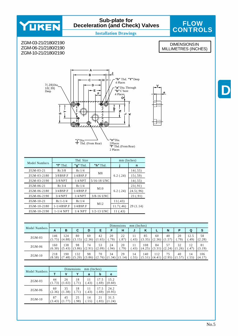
FLOW CONTROLS
D
Installation Drawings
Model Numbers
ZGM-03
ZGM-06
ZGM-10
Model Numbers
ZGM-03
ZGM-06
ZGM-10
CDimensions mm (Inches)
D E F H J K L N P Q SBA
Dimensions mm (Inches)
T V Y a b e
80 (3.15)
98 (3.86)
132 (5.20)
11 (.43)
11 (.43)
14 (.55)
60 (2.36)
84 (3.31)
112 (4.41)
40 (1.57)
57 (2.24)
75 (2.95)
20 (.79)
32 (1.26)
40 (1.57)
12.5 (.49)
12 (.47)
14 (.55)
58 (2.28)
81 (3.19)
106 (4.17)
44 (1.73)
60 (2.36)
87 (3.43)
26 (1.02)
35 (1.38)
45 (1.77)
18 (.71)
18 (.71)
25 (.98)
11 (.43)
11 (.43)
14 (.55)
17.5 (.69)
17.5 (.69)
21 (.83)
15.2 (0.60)
24.2 (0.95)
31.5 (1.24)
60 (2.36)
74 (2.91)
98 (3.86)
42 (1.65)
53 (2.09)
70 (2.76)
20 (.79)
24 (.94)
34 (1.34)
22 (.87)
20 (.79)
29 (1.14)
85 (3.35)
108 (4.25)
140 (5.51)
146 (5.75)
160 (6.30)
218 (8.58)
124 (4.88)
138 (5.43)
190 (7.48)
Model Numbers"f" Thd. "g" Thd. "h" Thd. j n
Thd. Size mm (Inches)
14 (.55)
15 (.59)
14 (.55)
23 (.91)
24.5 (.96)
23 (.91)
29 (1.14)
11 (.43)
11.7 (.46)
11 (.43)
6.2 (.24)
6.2 (.24)M8
M10
M12
5/16-18 UNC
3/8-16 UNC
1/2-13 UNC
ZGM-03-21
ZGM-03-2180
ZGM-03-2190
ZGM-06-21
ZGM-06-2180
ZGM-06-2190
ZGM-10-21
ZGM-10-2180
ZGM-10-2190
Rc 3/8
3/8 BSP.F
3 /8 NPT
Rc 3/4
3/4 BSP.F
3 /4 NPT
Rc 1-1/4
1-1/4 BSP.F
1-1/4 NPT
Rc 1/4
1/4 BSP.F
1 /4 NPT
Rc 1/4
1/4 BSP.F
1 /4 NPT
Rc 1/4
1/4 BSP.F
1 /4 NPT
"h" Thd. "Y" Deep 4 Places
"a" Dia. Through "b" C' bore 4 Places
7(.28) Dia. 10(.39) Deep
"j" Dia. "f" Thd. (From Rear)
"n" Dia. 2 Places "f" Thd. (From Rear) 2 Places
V
eFE
D
C H
B
AJ
Q
P
N
L KS
T
No.5
Sub-plate for Deceleration (and Check) Valves
ZGM-03-21/2180/2190 ZGM-06-21/2180/2190 ZGM-10-21/2180/2190
DIMENSIONS IN MILLIMETRES (INCHES)
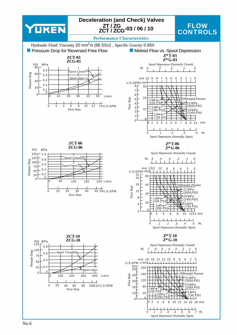
FLOW CONTROLS
Performance Characteristics
0 2010 30 40 50 L/min0
0.4
PSI
40
80MPa
Pres
sure
Dro
p
20
0
0.1
0.2
0.3
0.560
0 42 6 8 10 U.S.GPM12 14Flow Rate
0 10050 150 L/min
0 2010 30 40 U.S.GPM50 55Flow Rate
2000
0.8
PSI
100
150MPa
Pres
sure
Dro
p
75
0
0.2
0.4
0.6
1.0125
5025
0 200100 300 L/min
0 4020 60 80 U.S.GPM100110Flow Rate
4000
PSI
100
MPa
Pres
sure
Dro
p
75
0
0.2
0.4
0.6
125
50
25
0.8
Spool Closed
Spool Open
Spool Closed
Spool Open
Spool Closed
Spool Open
0 4 6 8 10 m m
0 .2 .3 IN..4
2 7 91 3 5
.1
0
20
3
8
Flow
Rat
e
2
0
10
30
5
76
4
1
L/minU.S.GPM10 6 4 2 0m m 8 3 19 7 5
.4 .2 0IN. .3 .1Spool Depression (Normally Closed)
Spool Depression (Normally Open)
0 4 6 8 10 m m
0 .2 .3 IN..4
2
.1
0
60
Flow
Rat
e
0
20
80
L/minU.S.GPM13 8 2m m 4 012 10 6
.5 .3IN. .4 .1
Spool Depression (Normally Closed)
Spool Depression (Normally Open)
.2 0
.5
1312
40
4
8
12
16
2022
0 4 6 8 10 m m
0 .2 .3 IN..4
2
.1
0
Flow
Rat
e
0
200
L/minU.S.GPM18 8 2m m 4 012 10 6
.7 .4IN. .5 .1Spool Depression (Normally Closed)
Spool Depression (Normally Open)
.2 0
.5
1812
.6 .3
14 16
.6 .7
10
30
20
40
5055
40
80
120
160
1416
Differential Pressure21 MPa (3050 PSI)10 MPa (1450 PSI)
1 MPa (145 PSI)
2 MPa (290 PSI)
5 MPa (730 PSI)
Differential Pressure21 MPa (3050 PSI)10 MPa (1450 PSI)1 MPa
(145 PSI)2 MPa (290 PSI)
5 MPa (730 PSI)
Differential Pressure21 MPa (3050 PSI)10 MPa (1450 PSI)
5 MPa (730 PSI)2 MPa
(290 PSI)
1 MPa (145 PSI)
Deceleration (and Check) Valves
-03 / 06 / 10ZT / ZG ZCT / ZCG
No.6
Pressure Drop for Reversed Free FlowHydraulic Fluid: Viscosity 2 20 mm /s (98 SSU) , Specific Gravity 0.850
Metred Flow vs. Spool DepressionZCT-03 ZCG-03
Z∗T-03 Z∗G-03
ZCT-06 ZCG-06
Z∗T-06 Z∗G-06
ZCT-10 ZCG-10
Z∗T-10 Z∗G-10

FLOW CONTROLS
D
Performance Characteristics
0 1 2 4Choke Adj. Position rev
3Fully
Closed
0 1 2 4Choke Adj. Position rev
3Fully
Closed
0 1 2 4Choke Adj. Position rev
3Fully
Closed
1
6
2.0
Flow
Rat
e
.5
0
2
7
1.5
L/minU.S.GPM
5
4
3
0
1.0
1
6
2.0
Flow
Rat
e
.5
0
2
7
1.5
L/minU.S.GPM
543
0
1.0
1
6
2.0
Flow
Rat
e
.5
0
2
7
1.5
L/minU.S.GPM
5
4
3
0
1.0
Differential Pressure
10 MPa (1450 PSI)
1 MPa (145 PSI)
2 MPa (290 PSI)
5 MPa (730 PSI)
21 MPa (3050 PSI)
Differential Pressure
10 MPa (1450 PSI)
1 MPa (145 PSI)
2 MPa (290 PSI)
5 MPa (730 PSI)
21 MPa (3050 PSI)
Differential Pressure
10 MPa (1450 PSI)
1 MPa (145 PSI)
2 MPa (290 PSI)
5 MPa (730 PSI)
21 MPa (3050 PSI)
No.7
Deceleration (and Check) Valves
-03 / 06 / 10ZT / ZG ZCT / ZCG
Metred Flow for Needle Valve
Hydraulic Fluid: Viscosity 2 20 mm /s (98 SSU) , Specific Gravity 0.850
ZT/ZCT-03-T ZG/ZCG-03-T
ZT/ZCT-06-T ZG/ZCG-06-T
ZT/ZCT-10-T ZG/ZCG-10-T

FLOW CONTROLS
Spare Parts List
Z T ZCT -06Z T
ZCT -03 Z T ZCT -10
Part NumbersQty .Name of PartsItem
2
1
1
1
1
17
18
19
20
21
O-Ring
O-Ring
O-Ring
O-Ring
Back Up Ring
SO-NB-P32
SO-NA-P20
SO-NB-P12
SO-NA-P5
SO-BB-P5
SO-NB-P36
SO-NA-P25
SO-NB-P18
SO-NA-P5
SO-BB-P5
SO-NB-P49
SO-NA-P32
SO-NB-
P22A
SO-NA-P5
Model Numbers Seal Kit Numbers
ZT-03
ZT-06
ZT-10
ZCT-
03
ZCT-
KS-ZT-03-22
KS-ZT-06-22
KS-ZT-10-22
KS-ZCT-03-
22
KS-ZCT-06-
ZG ZCG-03
Part NumbersQty .Name of PartsItem
2
2
1
1
1
1
1
18
19
20
21
22
23
24
O-Ring
O-Ring
O-Ring
O-Ring
O-Ring
O-Ring
Back Up Ring
SO-NB-P32
SO-NB-P18
SO-NA-P20
SO-NB-P9
SO-NB-P12
SO-NA-P5
SO-BB-P5
SO-NB-P49
SO-NB-P32
SO-NA-P32
SO-NB-P14
SO-NB-
P22A
SO-NA-P5
Model Numbers Seal Kit Numbers
ZG-03
ZG-06
ZG-10
ZCG-
03
ZCG-
KS-ZG-03-22
KS-ZG-06-22
KS-ZG-10-22
KS-ZCG-03-
22
KS-ZCG-06-
SO-NB-P36
SO-NB-P28
SO-NA-P25
SO-NB-P14
SO-NB-P18
SO-NA-P5
SO-BB-P5
ZG ZCG-06 ZG
ZCG-10
1 2 17 18 4 15 16 7 5 14
17
3
11 19 10 9 8 1
22
23
3
1
24
12
21
20
25
6
1 2 18 20 4 16 17 7 5 14
18
3
22 10 9 8 11 1
25
26
12
24
23
28
6
13
127
21
15
19
Deceleration (and Check) Valves
-03 / 06 / 10ZT / ZG ZCT / ZCG
No.8
When making replacement of seals, please do it carefully after reading through the relevant instructions in the Operator's Manual.
CAUTION
Note: When ordering the seals, please specify the seal kit number from the table right.
Note: When ordering the seals, please specify the seal kit number from the table right.
ZT/ZCT-03-∗-∗-22/2280/2290 ZT/ZCT-06-∗-∗-22/2280/2290 ZT/ZCT-10-∗-∗-22/2280/2290
With Check Valve (ZCT-∗)
With Adjustable Needle Valve for By-Pass Line
Z T ZCT -∗-T
List of Seals List of Seal Kits
List of Seals
List of Seal Kits
ZG/ZCG-03-∗-∗-22/2290 ZG/ZCG-06-∗-∗-22/2290 ZG/ZCG-10-∗-∗-22/2290
With Check Valve (ZCG-∗)
With Adjustable Needle Valve for By-Pass Line
ZG ZCG-∗-T

FLOW CONTROLS
1.
2.
1
1.
2
2
1 D
Specifications / Model Number Designation
Model Num bersMax. Flow
L /m in (U.S.GPM)
Metred Flow Range
L /m in (U.S.GPM)
Feed Fine Feed
Max. Reversed Free Flow
L /m in (U.S.GPM)
Max. Operat-
ing Pressure
MPa (PSI)
Approx. Mass
kg (lbs.)
1.6 (3.5)
2.6 (5.7)
2.7 (6.0)
6.5 (14.3)
9.2 (20.3)
14 (2030)
20 (5.3)
40 (10.6)
40 (10.6)
80 (21.1)
0.05-4 (.013-1.06)
0.05-4 (.013-1.06)
0.1-17 (.026-4.5)
0.03-4
0.05-8 (.013-2.1)
008-1.06)(.
[0.05-4][.013-1.06])(
0.03-8008-2.1)(.
[0.05-8][.013-2.1])(
0.05-4 (.013-1.06)
0.1-4 (.026-1.06)
0.1-8 (.026-2.1)
0.1-22 (.026-5.8)
0.1-22 (.026-5.8)
80 [40] (21.1 [10.6])
40 [40] (10.6 [10.6])
40 [40] (10.6 [10.6])
12 [4] (3.2 [1.06])
16 [8] (4.2 [2.1])
20 [12] (5.3 [3.2])
8 [4] (2.1 [1.06])
12 [8] (3.2 [2.1])
16 [12] (4.2 [3.2])UCF1G-01-4-A-∗-11∗
UCF1G-01-4-B-∗-11∗
UCF1G-01-4-C-∗-11∗
UCF1G-01-8-A-∗-11∗
UCF1G-01-8-B-∗-11∗
UCF1G-01-8-C-∗-11∗
UCF1G-03-4-∗-10∗
UCF1G-03-8-∗-10∗
UCF2G-03-4-∗-10∗
UCF2G-03-8-∗-10∗
UCF1G-04-30-30∗
UCF2G-04-30-30∗
Series Num ber
Special Seals
F- UCF1Ty pe of
MountingValve Size
Design Num ber
Design Stan- dards
∗Drain Connection
G -01 -4 -A -E -11Nom inal Metred
Flow L /m in (U.S.GPM)
Deceleration Valve Max. Flow
L /m in (U.S.GPM)A: 12B:C:
(3.2)8 (2.1)4 (1.06)
4: 48:
(1.06)8 (2.1)
4: 48:
(1.06)8 (2.1)
30:30 (7.9)
4: 48:
(1.06)8 (2.1)
30:30 (7.9)
None: Internal Drain
E: External Drain
None: External DrainNone: Internal
DrainE:External DrainNone: External Drain
11
10
30
30
10
01
03
04
03
04
Refer to
G:Gasket Mounting
G:Gasket Mounting
UCF1:Single Feed Control
UCF2:Double Feed Control
F-:Special Seals for Phosphate Ester Ty pe Fluids (Om it if not required)
Up to 14 MPa (2030 PSI), 80 L /m in (21.1 U.S.GPM)
No.1
FEED CONTROL VALVES UCF1G-01 / 03 / 04 (1/8, 3/8, 1/2)
UCF2G-03 / 04 (3/8, 1/2) Gasket Mounting
Pub. EC-0306
These valves are the combination of flow control valve, a deceleration valve and a check valve and used mainly for controlling rapid traverse and feed cycles machine tools. Switching from rapid traverse to feed is made by a cam operation, and fine feed control is accomplished by dial rotation regardless of pressure and oil temperature variation. Rapid return is free of cam actuation.
Specifications
The m axim um flow rates are values with the deceleration valve and the flow control valve fully open. The values in [ ] are m axim um flow rates with the deceleration valve fully open and the flow control valve fully closed.The values in [ ] are for pressures above 7 MPa (1020 PSI).
Model Number Designation
Design Standards:None. . . .. . . . . Japanese Standard "JIS" and European Design Standard90 . . .. . . . ..... N. Am erican Design Standard

FLOW CONTROLS
Graphic Symbols / Hydraulic Fluids / Attachment
Petroleum base oils
Sy nthetic fluids
W ater containing fluids
Use fluids equivalent to ISO VG 32 or VG 46.
Use phosphate ester or poly ol ester fluid. W hen phosphate ester fluid is used, prefix "F-" to the m odel num ber because the special seals (fluororubber) are required to be used.
Use water-gly col fluid.
Valve Model Num bers
Socket Head Cap ScrewQty .
Japanese Std. "JIS" & European Design Std. N. Am erican Design Std.4 4 4 4 4
UCF1G-01 UCF1G-03 UCF2G-03 UCF1G-04 UCF2G-04
M6 × 55 Lg. M6 × 55 Lg. M6 × 55 Lg.
M10 × 70 Lg. M10 × 70 Lg.
1/4-20 UNC × 2-1/4 Lg. 1/4-20 UNC × 2-1/4 Lg. 1/4-20 UNC × 2-1/4 Lg. 3/8-16 UNC × 2-3/4 Lg. 3/8-16 UNC × 2-3/4 Lg.
A B BA BA BA
BA BA
Feed Control Valves UCF1G-01 / 03 / 04
UCF2G-03 / 04
No.2
Hydraulic Fluids
Fluid TypesAny type of hydraulic fluids listed in the table below can be used.
Note: For use with hy draulic fluids other than those listed above, please consult y our Yuken representatives in advance.
Attachment
Mounting Bolts
Control of ContaminationDue caution must be paid to maintaining control over contamination of the hydraulic fluids which may otherwise lead to breakdowns and shorten the life of the valves. Please maintain the degree of contamination within NAS 1638-Grade 12. Use 25 µm or finer line filter.
Recommended Viscosity and Oil Temperatures2 Viscosity ranging between 15 - 400 mm /s (77 - 1800 SSU).
Oil temperatures between -15/+70°C (5 - 158°F). Use hydraulic fluids which satisfy the recommended viscosity and oil temperatures given above.
Graphic Sym bols
UCF1G-01-∗-EUCF1G-01-∗ UCF1G-03-∗ UCF1G-03-∗-E UCF1G-04
UCF2G-03-∗ UCF2G-03-∗-E UCF2G-04

FLOW CONTROLS
D
Instructions
Model Num bers
Internal drain ty pe External drain ty pe Internal drain ty pe External drain ty pe Internal drain ty pe External drain ty pe External drain ty pe External drain ty pe
Drain Ty pe Force N (lbs.)
UCF1G-01
UCF1G-03
UCF2G-03
UCF1G-04 UCF2G-04
100 (22.5) 80 (18.0)
170 (38.2) 90 (20.2)
170 (38.2) 130 (29.2) 170 (38.2) 170 (38.2)Model Num bers
Internal Drain Ty pe
External Drain Ty pe
UCF1G-01-∗ UCF1G-03-∗ UCF2G-03-∗UCF1G-01-∗-E UCF1G-03-∗-E UCF1G-04 UCF2G-03-∗-E UCF2G-04
Allowable Outlet Port Back Pres. MPa (PSI)
0.3 (44)
14 (2030)
No.3
Feed Control Valves UCF1G-01 / 03 / 04
UCF2G-03 / 04
InstructionsAllowable pressures at controlled f low outletIf internal drain types of UCF1G-01 or 03 or UCF2G-03 are used, use them in metre-out circuits in order to limit the valve outlet pressure to the valves shown below. In addition, external drain types can also be used in metre-in circuits.
Minimum required pressure differenceThe minimum pressure differential between inlet and outlet port is required to obtain the optimum pressure compensation. It varies accordingly to the flow rate to be set. For details, refer to the performance curve.
Spool push down levelLimit the spool push down level within the allowable maximum stroke range shown in the installation draw-ings.
Allowable drain port back pressureLimit to 0.1 MPa (15 PSI). In addition, connect the drain pipe independently and directly to the tank. (This applies only to external drain types.)
Required Force for Spool Push Down
Note:The push down forces are with the m axim um allowable pressure at the port concerned, which is controlled flow outlet "B" for internal drain ty pes or the drain port for internal drain ty pes.
Line filterTo carry out flow adjustments by as small degree as 2 L/min (.53 U. S. GPM) or less, be sure to use a line filter, 10 or less, near the valve inlet.
Flow adjustment
Loosen the locking screw and turn the flow adjustment dial clockwise for increase, and anti-clockwise for decrease. The dial makes about 4 revolutions from zero to full flow and the valve opening is indicated on the revolution indicator. After flow adjustment, tighten the locking screw.
[UCF1G-01, UCF∗G-03]
Loosen the locking screw and turn the flow adjustment handle clockwise to increase, and anti-clockwise to decrease. Open condition is indicated in digital-scale in built-in revolution indicator. After flow adjustment, tighten the locking screw.
[UCF∗G-04]

FLOW CONTROLS
Performance Chracteristics
0 2 4
Metred Flow
6 8 10 12 14 16 18 20
0 1 2 3 4 5 5.5 U.S.GPM
0.70.6
0.4
0.1
0.5
0.30.2
0
MPaPSI100
80
60
20
40
0
Dif
fere
ntia
l Pre
ssur
e 0.70.6
0.4
0.1
0.5
0.30.2
0
MPaPSI100
80
60
20
40
0
Dif
fere
ntia
l Pre
ssur
e
0 1 2
Metred Flow
3 4 5 6 7
0 .5 1.0 1.5 2.0 2.5 U.S.GPM
8 9 L/min
0.7
0.6
0.4
0.1
0.5
0.3
0.2
0
MPaPSI100
80
60
20
40
0
Dif
fere
ntia
l Pre
ssur
e 0.6
0.4
0.1
0.5
0.3
0.2
0
MPaPSI
80
60
20
40
0
Dif
fere
ntia
l Pre
ssur
e
0 1
Metred Flow
8
0 .5 1.0 1.5 2.0 U.S.GPM
2 3 4 5 6 7
L/min
L/min 0
Metred Flow
30
0 1 3 4 5 U.S.GPM
5 10 15 20 25 L/min
2 6 7 8
Feed Control Valves UCF1G-01 / 03 / 04
UCF2G-03 / 04
No.4
Min. Required Pressure Difference
UCF1G-01 UCF1G-03
UCF2G-03 -04UCF1G UCF2G

FLOW CONTROLS
D
Installation Drawings
Nam e of PortPort "A""B"
Drain port11.5 (.45) 3.5 (.14)
"X"
Nam e of PortPort "A""B"
Drain port11.5 (.45)
4 (.16)
"X"
76
8
6.5 (.25)Spool Movement 5.5 (.22)
Seal Stroke 1.5 (.06)Throttle Stroke
4 (.16)
17(.67)
11 (.43)
Dia. Roller
Limit the cam angle to 30°
Port "A" Controlled Flow Inlet or Reversed Free Flow Outlet Port
Locking Screw 2.5(.10) Hex. Soc. Tightening Torque: 0.25 - 0.3 Nm (2.2 - 2.7 IN. lbs.)
Revolution Indicator
Locating Pin. 4(.16) Dia.
Mounting Surface (O-Rings Furnished)
Mounting surface should have a good machined finish.
Max
. "X"
Dia
.
27(1
.06)
30(1
.18)
42.5
(1.6
7)
49(1
.93)63
(2.4
8)7
(.28)
20.5(.47)
(.81)
12
33(1.30)
50(1.97)
66(2.60)
80(3.15)
7(.28)
7(.28) Dia. Through 11(.43) Dia. Spotface
4 PlacesPort "B" Controlled Flow Outlet or Reversed Free Flow Inlet Port
INC.
Flow Adjustment Dial
Drain Port
44(1.73)45(1.77)
53(2.09)Fully Extended
84(3.31)
4(.16)
22.5
(.89)
Dia
.
4(.16)
16.4(.65)
15(.59)
Mounting surface should have a good machined finish.
Max
. "X"
Dia
.
Locating Pin. 4(.16) Dia.
Mounting Surface (O-Rings Furnished)
Locking Screw 2.5(.10) Hex. Soc. Tightening Torque: 0.25 - 0.3 Nm (2.2 - 2.7 IN. lbs.)
Revolution Indicator
7.0 (.27)Spool Movement 6.0 (.24)
Seal Stroke 1.5 (.06)Throttle Stroke4.5(.18)
Port "A" Controlled Flow Inlet or Reversed Free Outlet Port
11 (.43)
Dia. Roller
Limit the cam angle to 30°
13.5
(.53)
49(1
.93)
55(2
.17)
68(2
.68)
6.5
(.26)
29(1.14)
Fully Extended84(3.31)
51.5(2.03)
69(2.72)84(3.31)
104(4.09)117(4.61)
6.5(.26)
Port "B" Controlled Flow Outlet or Reversed Free Flow Inlet Port
7(.28) Dia. Through 11(.43) Dia. Spotface
4 Places
Drain PortINC.
Flow Adjustment Dial
28(1
.10)
31(1
.22)
89.5
(3.5
2)
28(1
.10)
13.5
(.53)
30(1
.18)
84(3
.31)
22.5
(.89)
Dia
.
54(2.13)45(1.77)
44(1.73)
4(.16)
16.4(.65)
18(.71) 4(.16)
41.5
(1.6
3)
Total Valve
Mounting Surface
Total Valve
Mounting Surface
No.5
UCF1G-01-∗-∗-∗-11/1190
UCF1G-03-∗-∗-10/1090
Only External drain ty pe (UCF1G-01-∗-∗-E) have a m achined finish.
Only external drain ty pe (UCF1G-03-∗-E) have a m achined finish.
Feed Control Valves UCF1G-01 / 03
DIMENSIONS IN MILLIMETRES (INCHES)

FLOW CONTROLS
Installation Drawings
Nam e of PortPort "A""B"
Drain port15.5 (.61) 8.5 (.33)
"X"
Nam e of PortPort "A""B"
Drain port11.5 (.45)
4 (.16)
"X"
1 2
9(.35) 8(.31)
Total Valve Spool MovementSeal Stroke 2(.08)
Throttle Stroke 6(.24)Port "A" Controlled Flow Inlet or Reversed Free Flow Outlet Port
18 (.71)
Dia. Roller
Limit the cam angle to 30°
Revolution Indicator
Port "B" Controlled Flow Outlet or Reversed Free Flow Inlet Port
11(.43) Dia. Through 17.5(.69) Dia. Spotface
4 Places
Drain Port
INC.
Flow Adjustment Handle 46(1.81) Dia.
Locking Screw 2(.08) Hex. Soc.
Two Locating Pins 6(.24) Dia.
Mounting Surface (O-Rings Furnished)
Mounting surface should have a good machined finish.
Max
. "X"
Dia
.10
55(2
.17)
67(2
.64)
76(2
.99)
96(3
.78)
(.39)
20(.7
9)
43(1
.69)
46(1
.81)
44(1
.73)
130
(5.1
2)
20(.79)
40(1.57)
60(2.36)
90(3.54)
140(5.51)
160(6.30)
10(.39)
123(4.84)
69(2.72)
55(2.17)
54(2.13)
24.5(.96)
28(1.10) 6(.24)
6(.24)
Fine Feed Stroke 1.8 (.07)
Throttle Stroke 2 (.08) 11 (.43)
Dia. Roller
Limit the cam angle to 30°
Feed Stroke 4.2 (.17)Total Valve Spool Movement9.0(.35)
7.5(.30)
Port "A" Controlled Flow Inlet or Reversed Free Flow Outlet Port
INC.
Fine Feed Flow Adjustment Dial
6.5
(.26)
13.5
(.53)
49(1
.93)
55(2
.17)
68(2
.68)
41.5
(1.6
3) 34(1
.34)
Port "B" Controlled Flow Outlet or Reversed Free Flow Inlet Port
13(.51)29
72(2.83)84(3.31)
104(4.09)117(4.61)
51.5(2.03)(1.14)
Drain Port
7(.28) Dia. Through 11(.43) Dia. Spotface
4 Places
27.5
(1.0
8)
90(3
.54)
28.5
(1.1
2)
INC.
Feed Flow Adjustment Dial
Max
. "X"
Dia
.
Locating Pin. 4(.16) Dia.
4(.16)
16.4
18(.71) 4(.16)
(.65)
Locking Screw 2.5(.10) Hex. Soc. Tightening Torque: 0.25 - 0.3 Nm (2.2 - 2.7 IN. lbs.)
Revolution Indicator
Fully Extended84(3.31)
54(2.13)
45(1.77)46(1.81)
Mounting Surface (O-Rings Furnished)
6.5(.26)
22.5
(.89)
Dia
.
Mounting surface should have a good machined finish.
Mounting Surface
Mounting Surface
Feed Control ValvesUCF2G-03 UCF1G-04
No.6
UCF1G-04-30-30/3090
Only external drain ty pe (UCF2G-03-∗-E) have a m achined finish.
UCF2G-03-∗-∗-10/1090
DIMENSIONS IN MILLIMETRES (INCHES)

FLOW CONTROLS
D
Installation Drawings
Nam e of PortPort "A" 18 (.71)
15.5 (.61) 8.5 (.33)
"X"
Drain portPort "B"
1 2 3 3 0 0
14(.55) 13(.51)
Total Valve Spool Movement
Fine Feed Stroke 4(.16)
Port "A" Controlled Flow Inlet or Reversed Free Flow Outlet Port
18 (.71)
Dia. Roller
Limit the cam angle to 30°
Revolution Indicator
Feed Stroke 4(.16)Throttle Stroke 5(.20)
10
22(.8
7)
57.5
(2.2
6)82
(3.2
3)
110(
4.33
)
(.39)
20(.7
9)
90(3
.54)
Port "B" Controlled Flow Outlet or Reversed Free Flow Inlet Port
INC.
Fine Feed Flow Adjustment Handle 46(1.81) Dia.
20(.79)
47(1.85)
65(2.56)
82(3.23)
170(6.69)
190(7.48)
10(.39)
123(4.84)
85(3.35)
INC.
Feed Flow Adjustment Handle 46(1.81) Dia.
Drain Port
11(.43) Dia. Through 17.5(.69) Dia. Spotface
4 Places
52(2
.05)
60(2
.36)
50(1
.97)
150
(5.9
1)
Locking Screw 2(.08) Hex. Soc.
24.5(.96)
31.5(1.24) 6(.24)
6(.24)
Two Locating Pins 6(.24) Dia.
Max
. "X"
Dia
.
Mounting surface should have a good machined finish.
Mounting Surface (O-Rings Furnished)
123(4.84)
69(2.72)
55(2.17)
54(2.13)
Mounting Surface
No.7
Feed Control Valves UCF2G-04
UCF2G-04-30-30/3090 DIMENSIONS IN MILLIMETRES (INCHES)
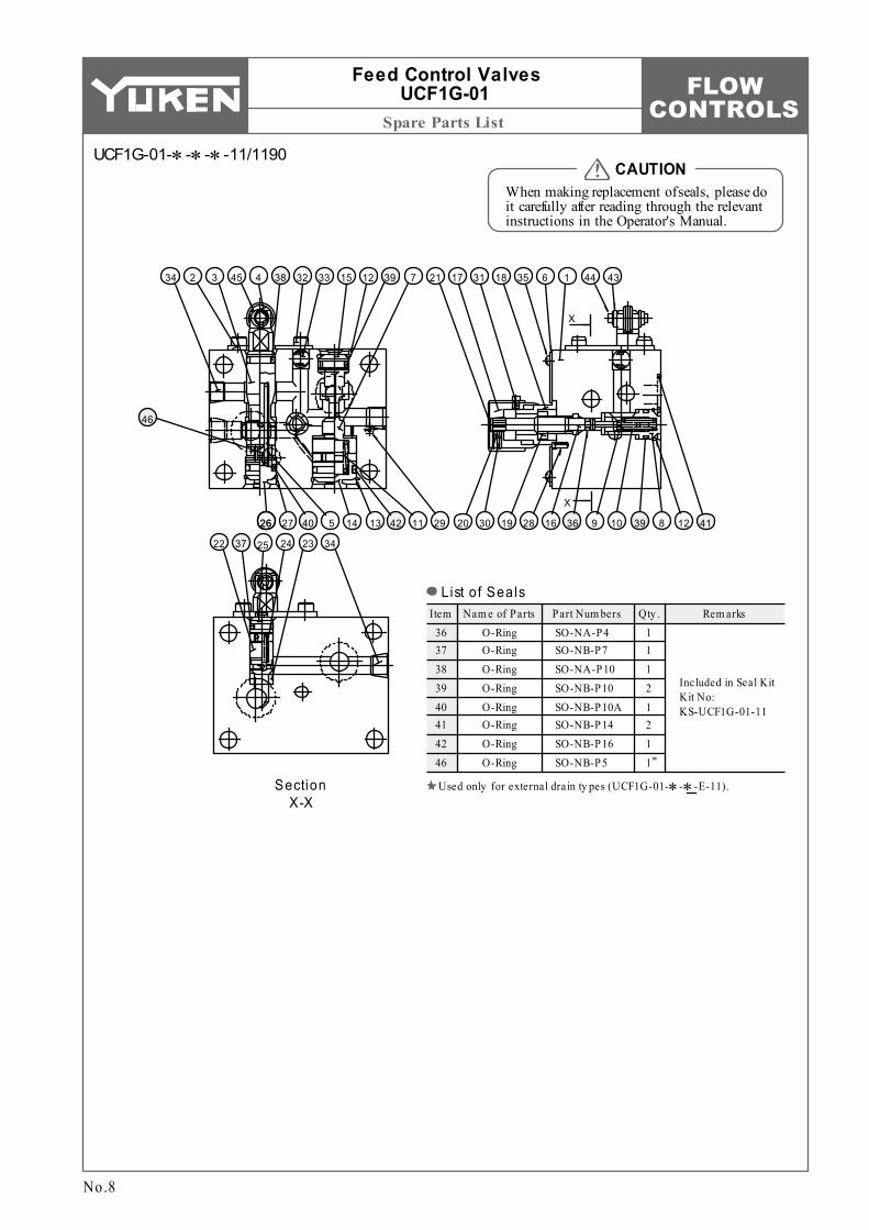
FLOW CONTROLSSpare Parts List
Item Nam e of Parts Part Num bers Qty . Rem arks36 37 38 39 40 41 42 46
O-Ring O-Ring O-Ring O-Ring O-Ring O-Ring O-Ring O-Ring
1 1 1 2 1 2 1 1
SO-NA-P4 SO-NB-P7 SO-NA-P10 SO-NB-P10 SO-NB-P10A SO-NB-P14 SO-NB-P16 SO-NB-P5
Included in Seal Kit Kit No: KS-UCF1G-01-11
Section X-X
22 37 25 24 23 34
26
21 17 31 18 35 6 1 44 43
20 30 19 28 16 36 9 10 39 8 12 41
X
X
26 27 40 5 14 13 42 11 29
46
34 2 3 45 4 38 32 33 15 12 39 7
No.8
Feed Control Valves UCF1G-01
When making replacement of seals, please do it carefully after reading through the relevant instructions in the Operator's Manual.
CAUTION
Used only for external drain ty pes (UCF1G-01-∗-∗-E-11).
List of Seals
UCF1G-01-∗-∗-∗-11/1190
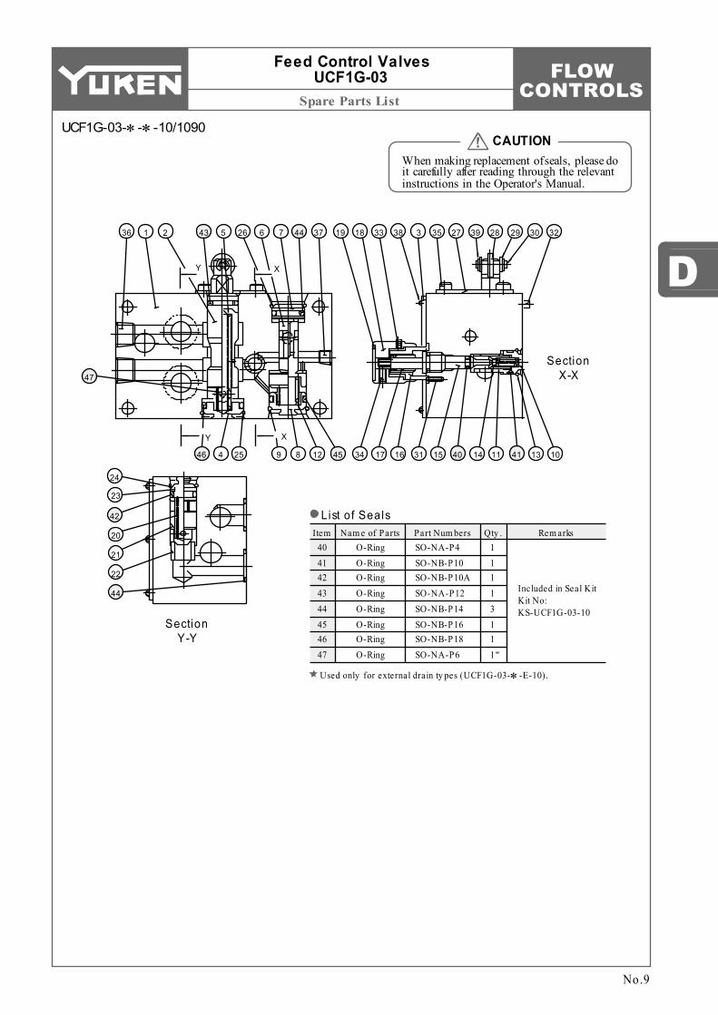
FLOW CONTROLS
D
Spare Parts List
Item Nam e of Parts Part Num bers Qty . Rem arks40 41 42 43 44 45 46 47
O-Ring O-Ring O-Ring O-Ring O-Ring O-Ring O-Ring O-Ring
1 1 1 1 3 1 1 1
SO-NA-P4 SO-NB-P10 SO-NB-P10A SO-NA-P12 SO-NB-P14 SO-NB-P16 SO-NB-P18 SO-NA-P6
Included in Seal Kit Kit No: KS-UCF1G-03-10
19 18 33 38 3 35 27 39 28 29 30 32
34 17 16 31 15 40 14 11 41 13 10
Y X
Y X
46 4 25 9 8 12 45
47
36 1 2 43 5 26 6 7 44 37
Section X-X
24
23
42
20
21
22
44
Section Y-Y
No.9
Feed Control Valves UCF1G-03
When making replacement of seals, please do it carefully after reading through the relevant instructions in the Operator's Manual.
CAUTION
List of Seals
Used only for external drain ty pes (UCF1G-03-∗-E-10).
UCF1G-03-∗-∗-10/1090

FLOW CONTROLS
1.
2.
1
2
Spare Parts List
Model Num bers Seal Kit Num bersUCF2G-03-∗-10∗ UCF2G-03-∗-E-10
KS-UCF2G-03-10 KS-UCF2G-03-E-10
Item Nam e of Parts Part Num bers Qty .37 38 39 40 41 42 43 44 45
O-Ring O-Ring O-Ring O-Ring O-Ring
Back Up Ring O-Ring O-Ring O-Ring
2 1 2 1 1 1 3 1 1
SO-NA-P4 SO-NB-P6 SO-NB-P10 SO-NB-P10A SO-NA-P12 SO-BB-P12 SO-NB-P14 SO-NB-P16 SO-NB-P21
28 30 19 9 7 35 5 27 6 34 31
29 18 13 32 37 14 16 39 21 38 15
3610431226141242
45 3 8 25 44 11 17 20Y X
YX
33 22 23 24 4 40 43
Section Y-Y
Section X-X
No.10
Feed Control Valves UCF2G-03
When making replacement of seals, please do it carefully after reading through the relevant instructions in the Operator's Manual.
CAUTION
Used only for external drain ty pes (UCF2G-03-∗-E-10∗).
List of Seals
UCF2G-03-∗-∗-10/1090
List of Seal Ki tsUsed only for internal drain ty pes (UCF2G-03-∗-10∗).
Note:W hen ordering the seals, please specify the seal kit num ber from the table left.

FLOW CONTROLS
D
Spare Parts List
Model Num bers Seal Kit Num bersUCF1G-04 UCF2G-04
KS-UCF1G-04-30 KS-UCF2G-04-30
Item Nam e of Parts Part Num bersQuantity
O-Ring O-Ring O-Ring O-Ring
SO-NA-P4 SO-BB-P4 SO-NB-P14 SO-NB-P10A SO-NB-P11 SO-NB-P12 SO-NB-P18 SO-NA-P20 SO-NB-P18 SO-NB-P22A SO-NB-G25 SO-NB-P34
33 34
35
36 37 38 39
41 42
40
UCF1G UCF2GO-Ring
Back Up Ring
O-Ring
O-Ring O-Ring
O-Ring
1 1 1
1 1 3 1 1
1 1
2 2
1 1 2 3 1
1 1 1
14 34 33 22 15 37 20 36 21
12 32 25 6 30 5 7 31 40 284 39 3 11 29 42 27 35 17 2 13
38 23 24 26 1 18 16 19 41
Y X
Y X
Section X-X
24
23
38
8
9
38
Section Y-Y
No.11
Feed Control Valves UCF1G-04 UCF2G-04
When making replacement of seals, please do it carefully after reading through the relevant instructions in the Operator's Manual.
CAUTIONUCF1G-04-30-30/3090
List of Seals
List of Seal Ki ts
Note:W hen ordering the seals, please specify the seal kit num ber from the table left.
UCF2G-04-30-30/3090
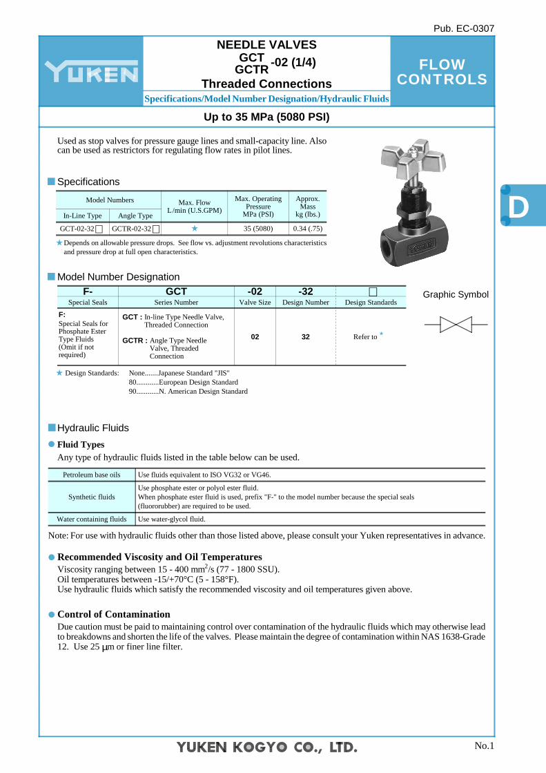
FLOW CONTROLS
D
Specifications/Model Number Designation/Hydraulic Fluids
Fluid Types
Hydraulic Fluids
Any type of hydraulic fluids listed in the table below can be used.
Note: For use with hydraulic fluids other than those listed above, please consult your Yuken representatives in advance.
Water containing fluids
Synthetic fluids
Petroleum base oils
Use water-glycol fluid.
Use phosphate ester or polyol ester fluid. When phosphate ester fluid is used, prefix "F-" to the model number because the special seals (fluororubber) are required to be used.
Use fluids equivalent to ISO VG32 or VG46.
In-Line Type
GCT-02-32∗Angle Type
GCTR-02-32∗
Model Numbers Max. Flow L/min (U.S.GPM)
Max. Operating Pressure
MPa (PSI)
Approx. Mass
kg (lbs.)
35 (5080) 0.34 (.75)
F- GCT -02 -32 ∗Special Seals Series Number Valve Size Design Number Design Standards
F:Special Seals for Phosphate Ester Type Fluids (Omit if not required)
GCT : In-line Type Needle Valve, Threaded Connection
GCTR : Angle Type Needle Valve, Threaded Connection
02 32 Refer to
No.1
NEEDLE VALVESGCT
GCTR -02 (1/4)
Up to 35 MPa (5080 PSI)
Pub. EC-0307
Specifications
Depends on allowable pressure drops. See flow vs. adjustment revolutions characteristics and pressure drop at full open characteristics.
Used as stop valves for pressure gauge lines and small-capacity line. Also can be used as restrictors for regulating flow rates in pilot lines.
Model Number Designation
2 Viscosity ranging between 15 - 400 mm /s (77 - 1800 SSU). Oil temperatures between -15/+70°C (5 - 158°F). Use hydraulic fluids which satisfy the recommended viscosity and oil temperatures given above.
Due caution must be paid to maintaining control over contamination of the hydraulic fluids which may otherwise lead to breakdowns and shorten the life of the valves. Please maintain the degree of contamination within NAS 1638-Grade 12. Use 25 µm or finer line filter.
Control of Contamination
Graphic Symbol
Threaded Connections
Recommended Viscosity and Oil Temperatures
Design Standards: None....... Japanese Standard "JIS" 80............European Design Standard 90............N. American Design Standard

FLOW CONTROLS
Installation Drawings / Adaptor
Adaptor
GCT-02-32GCT-02-3280GCT-02-3290
Rc 1/41/4 BSP.F1/4 NPT
50 (1.97)48 (1.89)50 (1.97)
25 (.98)24 (.94)25 (.98)
B Cmm (Inches)
"A" Thd.Model Numbers
GCTR-02-32GCTR-02-3280GCTR-02-3290
Rc 1/41/4 BSP.F1/4 NPT
25 (.98)24 (.94)25 (.98)
Bmm (Inches)
"A" Thd.Model Numbers
Used where pressure gauges are attached directly to needle valves. Equipped with pressure snubber for reducing harmful surges to protect pressure gauges. Adaptors are not accessories to needle valves. Order them referring to the table below For the models shown here, only Japanese standard specifications are available.
AG-02SAG-03SAG-04S
G 1/4G 3/8G 1/2
24 (.94)24 (.94)
27 (1.06)
14 (.55)16 (.63)18 (.71)
32 (1.26)35 (1.38)37 (1.46)
0.075 (.165)0.075 (.165)0.08 (.176)
B C LDimensions mm (Inches)
Thread Size "D" Thd.Adaptor Type Approx. Mass kg (lbs.)
Fully
Ext
ende
d 82
.5 (3
.25)
16
(.63)
C
B
Outlet Port (Adaptor Mounting Side) "A" Thd.
Lock Nut 24(.94) Hex.
M20 Thd.
Inlet Port "A" Thd.
50 (1.97)
Max
. 10(
.39)
21(.83) Dia.
24 (.94)
Fully
Ext
ende
d 82
.5 (3
.25)
16
(.63)
B
Outlet Port (Adaptor Mounting Side) "A" Thd.
Lock Nut 24(.94) Hex.
M20 Thd.
Inlet Port "A" Thd.
50 (1.97)
Max
.10(
.39)
21(.83) Dia.
24 (.94)
B
L B11
(.43)
R 1/4 Thd.
Pressure SnubberO-Ring (SO-NB-P7)
C "D" Thd.
No.2
Needle ValvesGCT
GCTR-02
Panel mounting dimensions
Panel mounting dimensions
GCT-02-32/3280/3290
GCTR-02-32/3280/3290
AG-02S AG-03S AG-04S
DIMENSIONS IN MILLIMETRES (INCHES)
DIMENSIONS IN MILLIMETRES (INCHES)
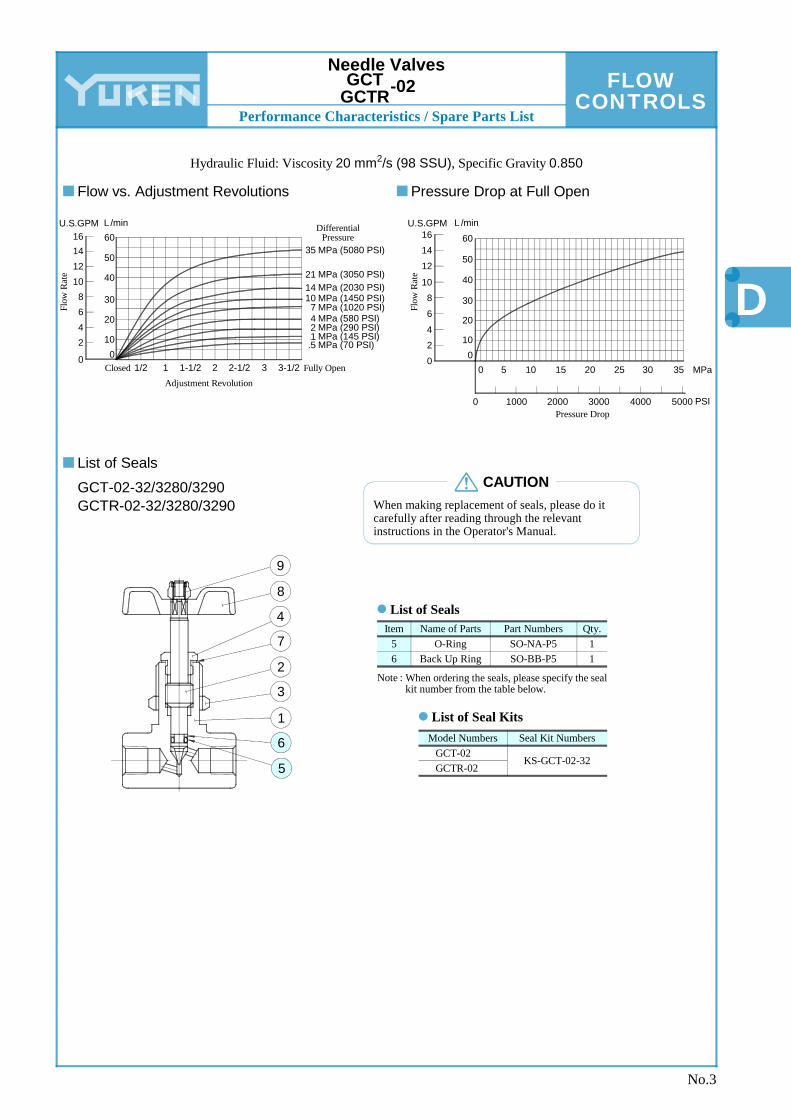
FLOW CONTROLS
D
Performance Characteristics / Spare Parts List
Item Name of Parts Part Numbers Qty.56
O-RingBack Up Ring
SO-NA-P5SO-BB-P5
11
Model Numbers Seal Kit NumbersGCT-02GCTR-02
KS-GCT-02-32
9
8
4
7
2
3
1
6
5
6016L /minU.S.GPM
50
40
30
20
100
141210
8642
0
Flow
Rat
e
3-1/2 Fully OpenAdjustment Revolution
32-1/221-1/211/2Closed
MPa (5080 PSI)35
MPa (3050 PSI)21MPa (2030 PSI)14MPa (1450 PSI)10MPa (1020 PSI)7MPa (580 PSI)4MPa (290 PSI)2MPa (145 PSI)1MPa (70 PSI).5
Differential Pressure 6016
L /minU.S.GPM
Flow
Rat
e
50
40
30
20
100
1412
1086420
Pressure Drop
0 5 10 15 20 25 30 35
0 1000 2000 3000 4000 5000
MPa
PSI
No.3
Needle ValvesGCT
GCTR-02
Hydraulic Fluid: Viscosity 2 20 mm /s (98 SSU), Specific Gravity 0.850
GCT-02-32/3280/3290 GCTR-02-32/3280/3290 When making replacement of seals, please do it
carefully after reading through the relevant instructions in the Operator's Manual.
CAUTION
List of Seals
Note : When ordering the seals, please specify the seal kit number from the table below.
List of Seal Kits
Flow vs. Adjustment Revolutions Pressure Drop at Full Open
List of Seals