Embed Size (px)
Citation preview

REFRIGERATION AND AIR CONDITIONING
Technical leaflet
Pilot Controlled Servo ValvesType ICS - Solenoid Valves and Pressure Regulating Valves
Technical leaflet Pilot controlled servo valves, type ICS
2 DKRCI.PD.HS0.A4.22 / 520H4816 © Danfoss A/S (IR / MKS), 09-2010
Contents Page
Introduction. . . . . . . . . . . . . . . . . . . . . . . . . . . . . . . . . . . . . . . . . . . . . . . . . . . . . . . . . . . . . . . . . . . . . . . . . . . . . . . . . . . . . . . .3
Features . . . . . . . . . . . . . . . . . . . . . . . . . . . . . . . . . . . . . . . . . . . . . . . . . . . . . . . . . . . . . . . . . . . . . . . . . . . . . . . . . . . . . . . . . . . .3
Design . . . . . . . . . . . . . . . . . . . . . . . . . . . . . . . . . . . . . . . . . . . . . . . . . . . . . . . . . . . . . . . . . . . . . . . . . . . . . . . . . . . . . . . . . . . . .4
Technical data . . . . . . . . . . . . . . . . . . . . . . . . . . . . . . . . . . . . . . . . . . . . . . . . . . . . . . . . . . . . . . . . . . . . . . . . . . . . . . . . . . . . . .4
The ICS Concept . . . . . . . . . . . . . . . . . . . . . . . . . . . . . . . . . . . . . . . . . . . . . . . . . . . . . . . . . . . . . . . . . . . . . . . . . . . . . . . . . . . .4
Function . . . . . . . . . . . . . . . . . . . . . . . . . . . . . . . . . . . . . . . . . . . . . . . . . . . . . . . . . . . . . . . . . . . . . . . . . . . . . . . . . . . . . . . . . . .6
Pilots and accessories for ICS . . . . . . . . . . . . . . . . . . . . . . . . . . . . . . . . . . . . . . . . . . . . . . . . . . . . . . . . . . . . . . . . . . . . . . . .8
Material specification - ICS 25, 32, 40, 50, 65, 80 . . . . . . . . . . . . . . . . . . . . . . . . . . . . . . . . . . . . . . . . . . . . . . . . . . . . . .9
Material specification - ICS 100, 125, 150. . . . . . . . . . . . . . . . . . . . . . . . . . . . . . . . . . . . . . . . . . . . . . . . . . . . . . . . . . . 10
Configuration examples . . . . . . . . . . . . . . . . . . . . . . . . . . . . . . . . . . . . . . . . . . . . . . . . . . . . . . . . . . . . . . . . . . . . . . . . . . 11
Ordering:
Assembled valves . . . . . . . . . . . . . . . . . . . . . . . . . . . . . . . . . . . . . . . . . . . . . . . . . . . . . . . . . . . . . . . . . . . . . . . . . . . . . 11
Accessories . . . . . . . . . . . . . . . . . . . . . . . . . . . . . . . . . . . . . . . . . . . . . . . . . . . . . . . . . . . . . . . . . . . . . . . . . . . . . . . . . . . 14
Spare parts . . . . . . . . . . . . . . . . . . . . . . . . . . . . . . . . . . . . . . . . . . . . . . . . . . . . . . . . . . . . . . . . . . . . . . . . . . . . . . . . . . . 16
Nominal capacities:
Liquid line with/without phase change . . . . . . . . . . . . . . . . . . . . . . . . . . . . . . . . . . . . . . . . . . . . . . . . . . . . . . . . 20
Pumped liquid line without phase change . . . . . . . . . . . . . . . . . . . . . . . . . . . . . . . . . . . . . . . . . . . . . . . . . . . . . 25
Wet suction line. . . . . . . . . . . . . . . . . . . . . . . . . . . . . . . . . . . . . . . . . . . . . . . . . . . . . . . . . . . . . . . . . . . . . . . . . . . . . . . 29
Dry suction line . . . . . . . . . . . . . . . . . . . . . . . . . . . . . . . . . . . . . . . . . . . . . . . . . . . . . . . . . . . . . . . . . . . . . . . . . . . . . . . 33
Discharge line . . . . . . . . . . . . . . . . . . . . . . . . . . . . . . . . . . . . . . . . . . . . . . . . . . . . . . . . . . . . . . . . . . . . . . . . . . . . . . . . 38
Dimensions and weights:
ICS 25 . . . . . . . . . . . . . . . . . . . . . . . . . . . . . . . . . . . . . . . . . . . . . . . . . . . . . . . . . . . . . . . . . . . . . . . . . . . . . . . . . . . . . . . . 43
ICS 32 . . . . . . . . . . . . . . . . . . . . . . . . . . . . . . . . . . . . . . . . . . . . . . . . . . . . . . . . . . . . . . . . . . . . . . . . . . . . . . . . . . . . . . . . 44
ICS 40 . . . . . . . . . . . . . . . . . . . . . . . . . . . . . . . . . . . . . . . . . . . . . . . . . . . . . . . . . . . . . . . . . . . . . . . . . . . . . . . . . . . . . . . . 45
ICS 50 . . . . . . . . . . . . . . . . . . . . . . . . . . . . . . . . . . . . . . . . . . . . . . . . . . . . . . . . . . . . . . . . . . . . . . . . . . . . . . . . . . . . . . . . 46
ICS 65/80 . . . . . . . . . . . . . . . . . . . . . . . . . . . . . . . . . . . . . . . . . . . . . . . . . . . . . . . . . . . . . . . . . . . . . . . . . . . . . . . . . . . . . 47
ICS 100 . . . . . . . . . . . . . . . . . . . . . . . . . . . . . . . . . . . . . . . . . . . . . . . . . . . . . . . . . . . . . . . . . . . . . . . . . . . . . . . . . . . . . . . 48
ICS 125-150. . . . . . . . . . . . . . . . . . . . . . . . . . . . . . . . . . . . . . . . . . . . . . . . . . . . . . . . . . . . . . . . . . . . . . . . . . . . . . . . . . . 49
Connections. . . . . . . . . . . . . . . . . . . . . . . . . . . . . . . . . . . . . . . . . . . . . . . . . . . . . . . . . . . . . . . . . . . . . . . . . . . . . . . . . . . . . . 50

Technical leaflet Pilot controlled servo valves, type ICS
© Danfoss A/S (IR /MKS), 09-2010 DKRCI.PD.HS0.A4.22 / 520H4816 3
Introduction
ICS servo valves belong to the ICV (Industrial Control Valve) family and are one of two product groups.
ICV types– ICS - Industrial Control Servo– ICM - Industrial Control Motor
The valve comprises three main components: valve body, function module and top cover.
ICS servo valves are pilot operated valves for regulating pressure, temperature and ON/OFF function in refrigeration systems. ICS valves are designed for low and high-pressure refrigerants.
ICS valves can be used on the high and low-pressure sides, in wet and dry suction lines and in liquid lines without phase change (i.e. where no expansion takes place in the valve).
The function of ICS valves is dependent on the pilot pressure applied from either a pilot valve or external pilot pressure source.
ICS 1 pilot has one pilot pressure connection and ICS 3 pilot has three pilot pressure connections.
The associated Danfoss pilot valves can be either screwed directly into the ICS valve or connected via an external pilot line. Several pilot valves can be used on one ICS valve to provide numerous variations in control functions.
The ICS valve top cover includes a pressure gauge connection port which can be used to monitor the valve inlet pressure when setting and adjusting the pilot valves.
The spindle in the top cover can be used for manually opening the ICS valve.
Features Designed for industrial refrigeration applications for a maximum working pressure of 754 psig / 52 bar g.
Applicable for all common refrigerants including R717 and R744 (CO2) and non corrosive gases/liquids to eliminate leak potential.
Direct coupled connections
Connection types include butt weld, socket weld, solder and threaded connections.
Low temperature steel body
Low weight and compact design.
V-port regulating cone ensures optimum regulating accuracy particularly at part load.
Function module has a QPQ surface treated insert and a steel piston ring ensuring precise control accuracy.
Modular Concept – Each valve body is available with several different connection types and sizes – Valve overhaul on ICS 25-80 is done by replacing the function module – Possible to convert ICS servo to ICM motor valve
Manual opening.
The ICS valve is a multifunction valve where several pilot valves can be mounted into the pilot ports.
Pressure gauge connection port to measure valve inlet pressure.
The top cover can be rotated into any possible position without affecting the operation of the valve.

Technical leaflet Pilot controlled servo valves, type ICS
4 DKRCI.PD.HS0.A4.22 / 520H4816 © Danfoss A/S (IR / MKS), 09-2010
Design ICS valves are designed as pilot operated valves requiring minimal pressure differential to open. If the pressure difference is 0 psi (0 bar), the ICS valve will be closed. If the pressure difference is 2.9 psi (0.2 bar) or more, the ICS valve will be fully open. At pressure differences between 1 psi (0.07 bar) and 2.9 psi (0.2 bar), the opening degree will be correspondingly proportional.
The ICS is available for use with either one or three pilot valves.
Two of the three pilot pressure connections (S1 and S2) are connected in series while the third (P) is connected in parallel to S1 and S2. This allows different combinations of pilot valves to be used, thus providing numerous variations in control functions.
There is a very wide range of connection types available with ICS valves.
ApprovalsThe ICV valve concept is designed to fulfill global refrigeration requirements.For specific approval information, please contact Danfoss.
The ICS valves are approved in accordance with the European standard specified in the Pressure Equipment Directive and are CE marked.For further details / restrictions - see Installation Instruction
Valve body and top cover material:Low temperature steel
ICS valves
Nominal bore DN≤ 25 (1 in.) DN 32-65 (11/4 - 2½ in.) DN 100-150 (4-6 in.)
Classified for Fluid group I
Category Article 3, paragraph 3 II III
Technical data Refrigerants Applicable to all common refrigerants including R717 and R744 (CO2) and non- corrosive gases/liquids. Use with flammable hydrocarbons cannot be recommended; please contact Danfoss.
Temperature range –76/+248°F(–60/+120°C).
Surface protection ICS 25-150:The external surface is zinc-chromated to provide good corrosion protection.
Pressure range The valve is designed for: Max. working pressure: 754 psig (52 bar) Opening differential pressure: Fully open: Min. 2.9 psig (0.2 bar) Max. Opening Pressure Differential (MOPD), solenoid valves only - at nominal conditions. – 10 W a.c. up to 305 psi (21 bar) – 20 W a.c. up to 580 psi (40 bar)
The ICS concept is developed around a modular principle. This gives the possibility of combining function modules and top covers with special valve body size that is available in a variety of connection possibilities.
The ICS Concept
There are eight valve bodies available.
ICV 25-80 ICV 100-125 ICV 150
Technical leaflet Pilot controlled servo valves, type ICS
© Danfoss A/S (IR /MKS), 09-2010 DKRCI.PD.HS0.A4.22 / 520H4816 5
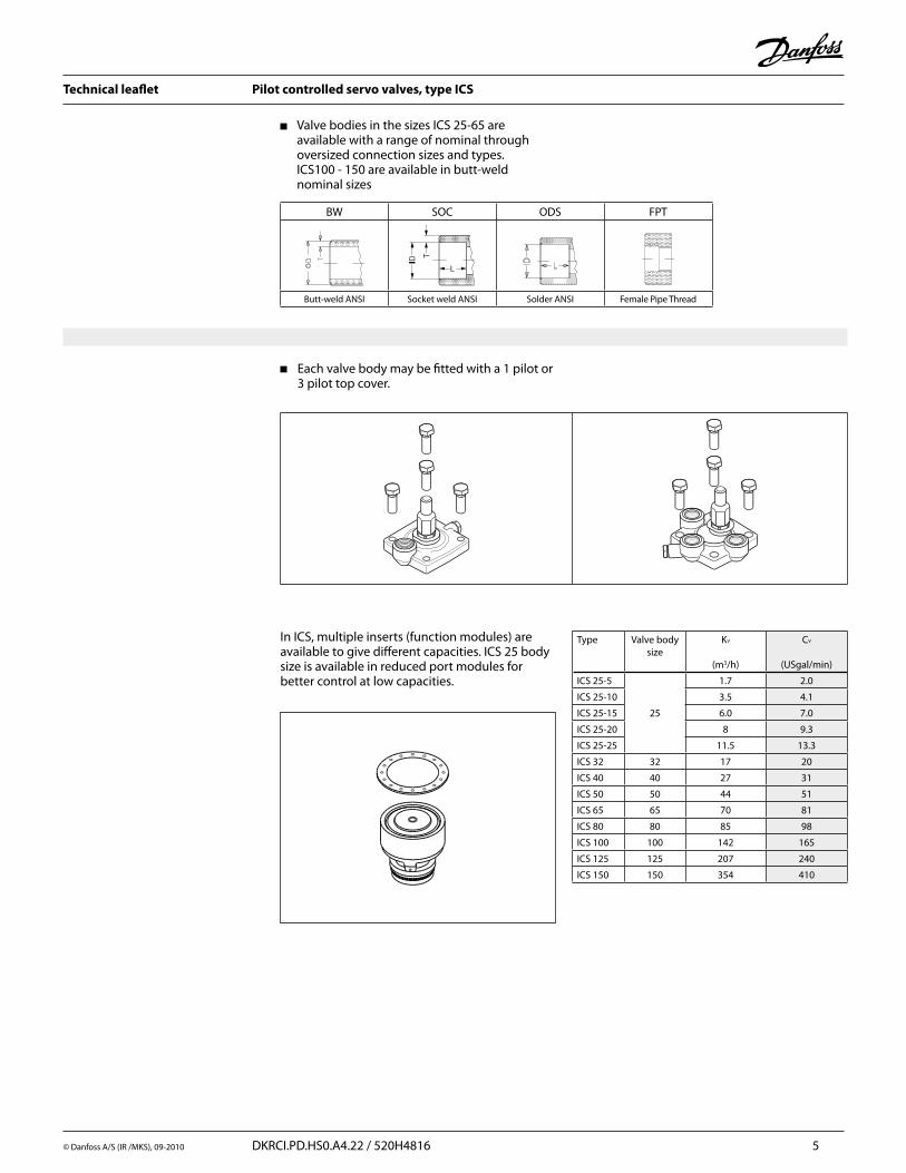
Valve bodies in the sizes ICS 25-65 are available with a range of nominal through oversized connection sizes and types. ICS100 - 150 are available in butt-weld nominal sizes
Each valve body may be fitted with a 1 pilot or 3 pilot top cover.
Type Valve bodysize
Kv
(m3/h)
Cv
(USgal/min)
ICS 25-5
25
1.7 2.0
ICS 25-10 3.5 4.1
ICS 25-15 6.0 7.0
ICS 25-20 8 9.3
ICS 25-25 11.5 13.3
ICS 32 32 17 20
ICS 40 40 27 31
ICS 50 50 44 51
ICS 65 65 70 81
ICS 80 80 85 98
ICS 100 100 142 165
ICS 125 125 207 240
ICS 150 150 354 410
In ICS, multiple inserts (function modules) are available to give different capacities. ICS 25 body size is available in reduced port modules for better control at low capacities.
BW SOC ODS FPT
Butt-weld ANSI Socket weld ANSI Solder ANSI Female Pipe Thread
Technical leaflet Pilot controlled servo valves, type ICS
6 DKRCI.PD.HS0.A4.22 / 520H4816 © Danfoss A/S (IR / MKS), 09-2010
Function
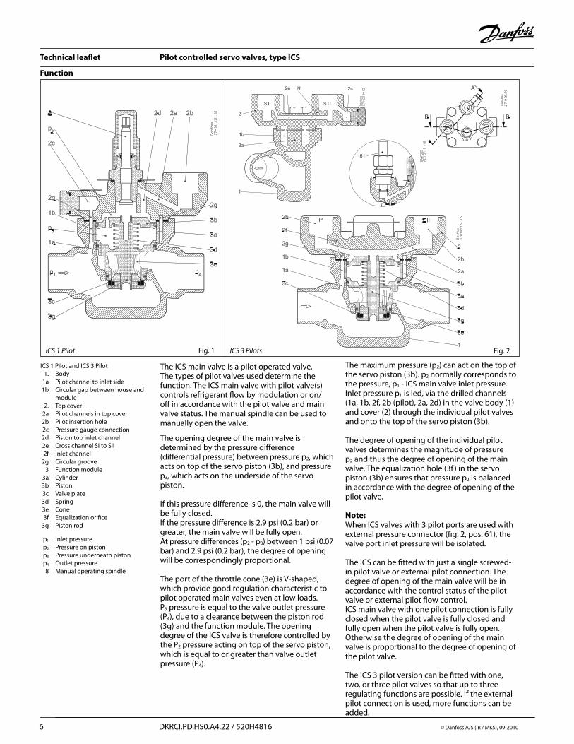
ICS 1 Pilot
The ICS main valve is a pilot operated valve. The types of pilot valves used determine the function. The ICS main valve with pilot valve(s) controls refrigerant flow by modulation or on/off in accordance with the pilot valve and main valve status. The manual spindle can be used to manually open the valve.
The opening degree of the main valve is determined by the pressure difference (differential pressure) between pressure p2, which acts on top of the servo piston (3b), and pressure p3, which acts on the underside of the servo piston.
If this pressure difference is 0, the main valve will be fully closed.If the pressure difference is 2.9 psi (0.2 bar) or greater, the main valve will be fully open. At pressure differences (p2 - p3) between 1 psi (0.07 bar) and 2.9 psi (0.2 bar), the degree of opening will be correspondingly proportional.
The port of the throttle cone (3e) is V-shaped, which provide good regulation characteristic to pilot operated main valves even at low loads. P3 pressure is equal to the valve outlet pressure (P4), due to a clearance between the piston rod (3g) and the function module. The opening degree of the ICS valve is therefore controlled by the P2 pressure acting on top of the servo piston, which is equal to or greater than valve outlet pressure (P4).
ICS 3 Pilots
ICS 1 Pilot and ICS 3 Pilot 1. Body 1a Pilot channel to inlet side 1b Circular gap between house and module 2. Top cover 2a Pilot channels in top cover 2b Pilot insertion hole 2c Pressure gauge connection 2d Piston top inlet channel 2e Cross channel SI to SII 2f Inlet channel 2g Circular groove 3 Function module 3a Cylinder 3b Piston 3c Valve plate 3d Spring 3e Cone 3f Equalization orifice 3g Piston rod
p1 Inlet pressure p2 Pressure on piston p3 Pressure underneath piston p4 Outlet pressure 8 Manual operating spindle
The maximum pressure (p2) can act on the top of the servo piston (3b). p2 normally corresponds to the pressure, p1 - ICS main valve inlet pressure.Inlet pressure p1 is led, via the drilled channels (1a, 1b, 2f, 2b (pilot), 2a, 2d) in the valve body (1) and cover (2) through the individual pilot valves and onto the top of the servo piston (3b).
The degree of opening of the individual pilot valves determines the magnitude of pressure p2 and thus the degree of opening of the main valve. The equalization hole (3f ) in the servo piston (3b) ensures that pressure p2 is balanced in accordance with the degree of opening of the pilot valve.
Note:When ICS valves with 3 pilot ports are used with external pressure connector (fig. 2, pos. 61), the valve port inlet pressure will be isolated.
The ICS can be fitted with just a single screwed-in pilot valve or external pilot connection. The degree of opening of the main valve will be in accordance with the control status of the pilot valve or external pilot flow control.ICS main valve with one pilot connection is fully closed when the pilot valve is fully closed and fully open when the pilot valve is fully open. Otherwise the degree of opening of the main valve is proportional to the degree of opening of the pilot valve.
The ICS 3 pilot version can be fitted with one, two, or three pilot valves so that up to three regulating functions are possible. If the external pilot connection is used, more functions can be added.
Fig. 2Fig. 1

Technical leaflet Pilot controlled servo valves, type ICS
© Danfoss A/S (IR /MKS), 09-2010 DKRCI.PD.HS0.A4.22 / 520H4816 7
In the ICS three pilot version, the pilot ports are related as follows:
The pilot valves fitted in ports SI and SII are connected in series.
The ICS 3 pilot operated main valve will be fully closed if just one of the series-connected pilot valves is closed. The main valve can only open if both pilot valves are open at the same time.
The pilot valve fitted in port P is connected in parallel to the pilot valves in ports SI and SII.
The ICS valve will be fully open if the pilot valve in P is fully open, irrespective of the degree of opening of pilot valves SI and SII.The ICS valve will be fully closed if the pilot valve in P is fully closed and at least one of the valves in SI or SII is fully closed at the same time. The relation between the pilot valves in ports SI, SII and P is shown in Table 1 below.
If the ICS is not fitted with three pilot valves, the unused port(s) must be sealed with a pilot cap A or a combination of pilot cap A and blanking plug B. If the pilot cap and blanking plug are fitted as an assembled unit, A + B, the channels from the specific port will be closed. (See Figure 1)
If only cap A is fitted, the channels from the ports in question will be open. If the degree of opening of the ICS main valve is not to be a function of the main valve inlet pressure, or if more than three regulating functions are required, ports SI, SII or P can be fitted with a nipple for the connection
of external pilot pressure. This applies to all ICS versions.
The pressure to which the external pilot line is connected will then determine the main valve function. Pilot valves installed in external lines must be mounted in a type CVH housing.
Depending on the function of the pilot valves, the ICS regulating characteristic becomes:
on/offproportionalintegral orcascade.
ICS main valves are therefore especially suitable for all forms of temperature and pressure regulating systems.
An overview of the types of pilot valves available can be found in Table 2 (on the following page), or technical leaflet: “Pilot valves for operated main valves” (RD4XC).
On the following pages, a number of standard configuration examples can be found. These are only for explanatory purpose. However, by using the literature regarding pilot valves these examples are easier to comprehend.
Function (continued)
Pilot valve port ICS valve
SI SII P
Open Open Closed Open
Open Open Open Open
Open Closed Closed Closed
Open Closed Open Open
Closed Open Closed Closed
Closed Open Open Open
Closed Closed Closed Closed
Closed Closed Open Open
Example (ICS with 3 pilot valves)
Pilot cap A Pilot cap A+Blanking plug B
Table 1
Figure 1
Figure 2
Technical leaflet Pilot controlled servo valves, type ICS
8 DKRCI.PD.HS0.A4.22 / 520H4816 © Danfoss A/S (IR / MKS), 09-2010
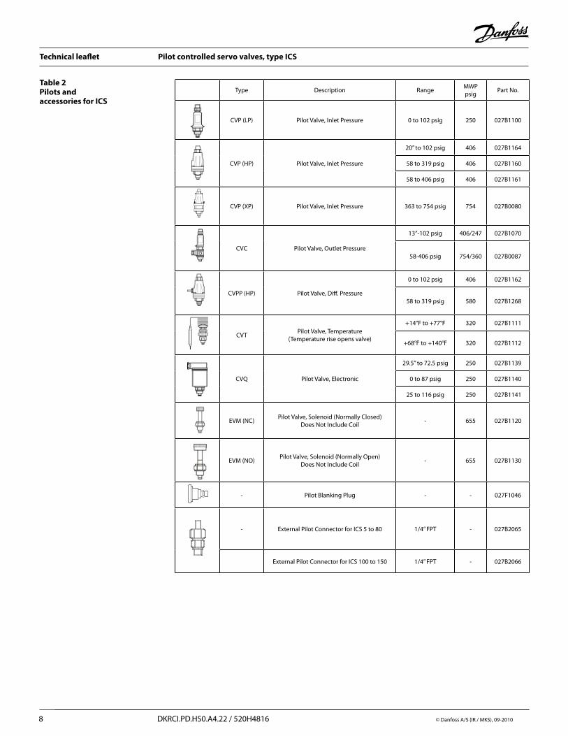
Type Description RangeMWP psig
Part No.
CVP (LP) Pilot Valve, Inlet Pressure 0 to 102 psig 250 027B1100
CVP (HP) Pilot Valve, Inlet Pressure
20” to 102 psig 406 027B1164
58 to 319 psig 406 027B1160
58 to 406 psig 406 027B1161
CVP (XP) Pilot Valve, Inlet Pressure 363 to 754 psig 754 027B0080
CVC Pilot Valve, Outlet Pressure
13”-102 psig 406/247 027B1070
58-406 psig 754/360 027B0087
CVPP (HP) Pilot Valve, Diff. Pressure
0 to 102 psig 406 027B1162
58 to 319 psig 580 027B1268
CVTPilot Valve, Temperature
(Temperature rise opens valve)
+14°F to +77°F 320 027B1111
+68°F to +140°F 320 027B1112
CVQ Pilot Valve, Electronic
29.5” to 72.5 psig 250 027B1139
0 to 87 psig 250 027B1140
25 to 116 psig 250 027B1141
EVM (NC)Pilot Valve, Solenoid (Normally Closed)
Does Not Include Coil- 655 027B1120
EVM (NO)Pilot Valve, Solenoid (Normally Open)
Does Not Include Coil- 655 027B1130
- Pilot Blanking Plug - - 027F1046
- External Pilot Connector for ICS 5 to 80 1/4” FPT - 027B2065
External Pilot Connector for ICS 100 to 150 1/4” FPT - 027B2066
Table 2 Pilots and accessories for ICS

Technical leaflet Pilot controlled servo valves, type ICS
© Danfoss A/S (IR /MKS), 09-2010 DKRCI.PD.HS0.A4.22 / 520H4816 9
Material specification - ICS 25, 32, 40, 50, 65, 80
No. Part Material EN ASTM JIS1 Body Low temperature steel G20Mn5QT, EN 10213-3 LCC A352 SCPL1 G51512 Top cover Low temperature steel G20Mn5QT, EN 10213-3 LCC A352 SCPL1 G51513 Function module
(assembled)3a o-ring Cloroprene (Neoprene)3b o-ring Cloroprene (Neoprene)A Cylinder SteelB Piston SteelC Valve plate PTFED Spring SteelE Cone Steel4 Gasket Fiber, non-asbestos5 Bolts Stainless steel A2-70, EN 1515-1 Grade B8 A320 A2-70, B 10546 Plug Steel7 Gasket Aluminium8 Manual operating
spindleSteel
9 Plug Steel10 Gasket Aluminium
Type ScrewICS 25 M12 × 30 A2-70 DIN 933ICS 32 M14 × 35 A2-70 DIN 933ICS 40 M14 × 40 A2-70 DIN 933ICS 50 M16 × 40 A2-70 DIN 933ICS 65 M16 × 50 A2-70 DIN 933
Type and size of Bolt (pos. 5)
M12 thread for removing function module
Technical leaflet Pilot controlled servo valves, type ICS
10 DKRCI.PD.HS0.A4.22 / 520H4816 © Danfoss A/S (IR / MKS), 09-2010
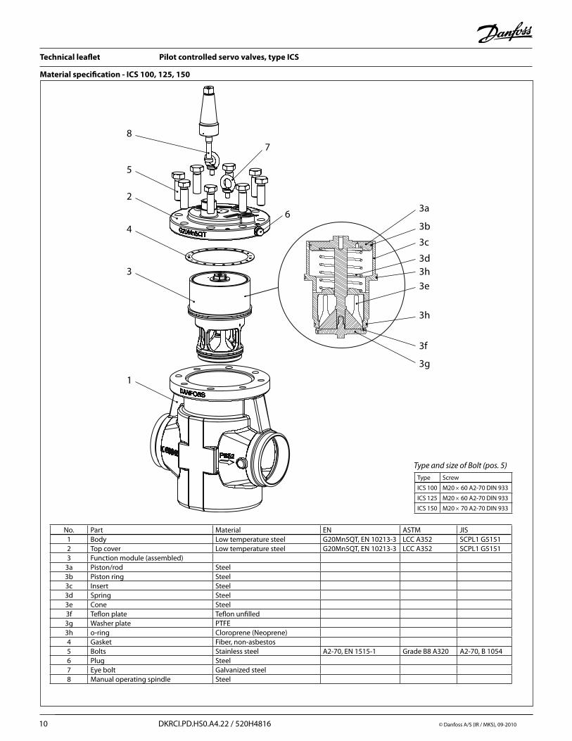
Material specification - ICS 100, 125, 150
No. Part Material EN ASTM JIS1 Body Low temperature steel G20Mn5QT, EN 10213-3 LCC A352 SCPL1 G51512 Top cover Low temperature steel G20Mn5QT, EN 10213-3 LCC A352 SCPL1 G51513 Function module (assembled)
3a Piston/rod Steel3b Piston ring Steel3c Insert Steel3d Spring Steel3e Cone Steel3f Teflon plate Teflon unfilled3g Washer plate PTFE3h o-ring Cloroprene (Neoprene)4 Gasket Fiber, non-asbestos5 Bolts Stainless steel A2-70, EN 1515-1 Grade B8 A320 A2-70, B 10546 Plug Steel7 Eye bolt Galvanized steel8 Manual operating spindle Steel
Type and size of Bolt (pos. 5)Type Screw
ICS 100 M20 × 60 A2-70 DIN 933
ICS 125 M20 × 60 A2-70 DIN 933
ICS 150 M20 × 70 A2-70 DIN 933
1
2
3
3a
3b
3c
3d
3e
3f
3g
3h
3h
4
5
6
78

Technical leaflet Pilot controlled servo valves, type ICS
© Danfoss A/S (IR /MKS), 09-2010 DKRCI.PD.HS0.A4.22 / 520H4816 11
Standard configurations
Steps for ordering valves assembled with pilots:Step 1: Determine the correct ICS valve size for your application using the nominal capacity selection tables on pages 20 to 42.Step 2: Specify the ICS type/size selected from the capacity tables.Step 3: Specify the configuration; consult Danfoss for configurations not listed, figures 3-14.Step 4: Specify connections type and size from Table 3, page 13.Step 5: Specify coil voltage and accessories where applicable.
Example for ordering: Dual inlet pressure regulator type ICS with ¾” Port size, 1” SOC connections and gauge valve with adapter for fitting into regulator.Item 1: ICS 25-20-D with 1” SOC connections (see Figure 11)Item 2: ¼” gauge valve with adapter, p/n 148B418062 (selected from ICS accessories)
Figure 3 - Solenoid Valve Products
On/off regulation1 × ICS 1 Pilot1 × EVM1 × coil
Figure 4 - STD Products
Constant pressure regulation - ICS sizes 5 to 80 are standard with CVP(LP) pilot range 0 to 102 psig. ICS sizes 100 to 150 are standard with CVP(HP) pilot range 20 in.HG to 102 psig.
1 × ICS 1 Pilot1 × CVP
Figure 5 - “O” Products
Outlet pressure regulation - Standard with CVC pilot range 13 in.HG to 102 psig. Does not include external pilot mounting set for connection between CVC pilot and the outlet of the valve.
1 × ICS 1 Pilot1 × CVC
Figure 6 - “T” Products
Thermostatic regulation - Standard with CVT pilot range +14°F to +77°F, which opens valve on temperature rise.
1 × ICS 1 Pilot1 × CVT
Figure 7 - “J” Products
Electronically controlled pressure regulation - Standard with CVQ pilot range 0 to 87 psig.
1 × ICS 1 Pilot1 × CVQ
Technical leaflet Pilot controlled servo valves, type ICS
12 DKRCI.PD.HS0.A4.22 / 520H4816 © Danfoss A/S (IR / MKS), 09-2010
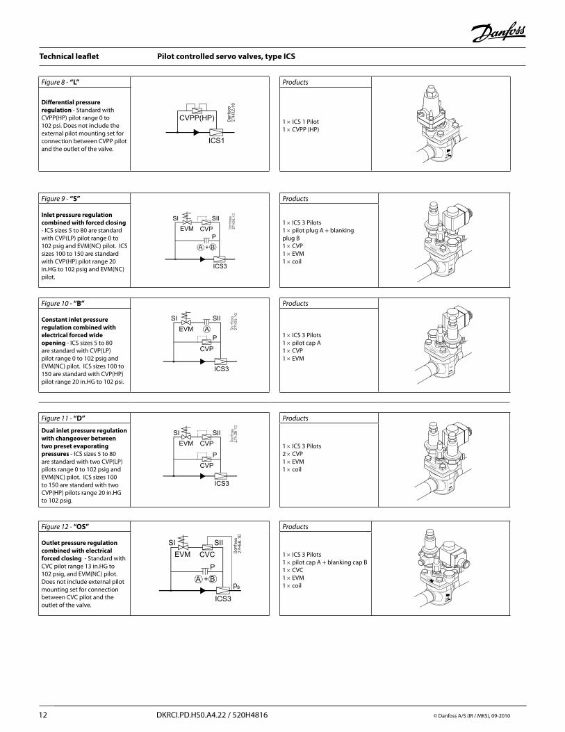
Figure 8 - “L” Products
Differential pressure regulation - Standard with CVPP(HP) pilot range 0 to 102 psi. Does not include the external pilot mounting set for connection between CVPP pilot and the outlet of the valve.
1 × ICS 1 Pilot1 × CVPP (HP)
Figure 9 - “S” Products
Inlet pressure regulation combined with forced closing - ICS sizes 5 to 80 are standard with CVP(LP) pilot range 0 to 102 psig and EVM(NC) pilot. ICS sizes 100 to 150 are standard with CVP(HP) pilot range 20 in.HG to 102 psig and EVM(NC) pilot.
1 × ICS 3 Pilots1 × pilot plug A + blanking plug B1 × CVP 1 × EVM1 × coil
Figure 10 - “B” Products
Constant inlet pressure regulation combined with electrical forced wide opening - ICS sizes 5 to 80 are standard with CVP(LP) pilot range 0 to 102 psig and EVM(NC) pilot. ICS sizes 100 to 150 are standard with CVP(HP) pilot range 20 in.HG to 102 psi.
1 × ICS 3 Pilots1 × pilot cap A1 × CVP1 × EVM
Figure 11 - “D” Products
Dual inlet pressure regulation with changeover between two preset evaporating pressures - ICS sizes 5 to 80 are standard with two CVP(LP) pilots range 0 to 102 psig and EVM(NC) pilot. ICS sizes 100 to 150 are standard with two CVP(HP) pilots range 20 in.HG to 102 psig.
1 × ICS 3 Pilots2 × CVP 1 × EVM1 × coil
Figure 12 - “OS” Products
Outlet pressure regulation combined with electrical forced closing - Standard with CVC pilot range 13 in.HG to 102 psig, and EVM(NC) pilot. Does not include external pilot mounting set for connection between CVC pilot and the outlet of the valve.
1 × ICS 3 Pilots1 × pilot cap A + blanking cap B1 × CVC1 × EVM1 × coil

Technical leaflet Pilot controlled servo valves, type ICS
© Danfoss A/S (IR /MKS), 09-2010 DKRCI.PD.HS0.A4.22 / 520H4816 13
Figure 13 - “BL” Products
Differential pressure regulation combined with electrical forced wide opening - Standard with CVPP(HP) pilot range 0 to 102 psi and EVM(NC) pilot. Does not include external pilot mounting set for connection between CVPP pilot and the outlet of the valve.
1 × ICS 3 Pilots1 × pilot cap A1 × CVPP (HP)1 × EVM1 × coil
Figure 14 - “JD” Products
Electronically controlled temperature regulation combined with electric forced closing and changeover to constant pressure regulation - ICS sizes 5 to 80 are standard with CVQ pilot range 0 to 87 psig, EVM(NC) pilot and CVP(LP) pilot range 0 to 102. ICS sizes 100 to 150 are standard with CVP (HP) range 20 in.HG to 102 psig and same CVQ and EVM.
1 × ICS 3 Pilots1 × CVQ1 × CVP1 × EVM1 × coil
Valve SizeNominal Size Flow
Coefficient Cv (Kv)
Connection Type and Size
Inches (mm) FPT SW BW ODS
ICS 25-5 3/16” (5) 2 (1.7) 3/4”, 1” 3/4”, 1” 3/4”, 1”, 1¼” 7/8”, 1-1/8”, 1-3/8”
ICS 25-10 3/8” (10) 4.1 (3.5) 3/4”, 1” 3/4”, 1” 3/4”, 1”, 1¼” 7/8”, 1-1/8”, 1-3/8”
ICS 25-15 5/8” (15) 7 (6.0) 3/4”, 1” 3/4”, 1” 3/4”, 1”, 1¼” 7/8”, 1-1/8”, 1-3/8”
ICS 25-20 3/4” (20) 9.3 (8.0) 3/4”, 1” 3/4”, 1” 3/4”, 1”, 1¼” 7/8”, 1-1/8”, 1-3/8”
ICS 25-25 1” (25) 13.3 (11.5) 1” 1” 1”, 1¼” 7/8”, 1-1/8”, 1-3/8”
ICS 32 1¼” (32) 20 (17) - 1¼” 1¼”, 1½” 1-3/8”, 1-5/8”
ICS 40 1½” (40) 31 (27) - 1-1/2” 1½”, 2” 1-5/8”
ICS 50 2” (50) 51 (44) - 2” 2”, 2½” 2-1/8”
ICS 65 2½” (65) 81 (70) - 2½” 2½”, 3” 2-5/8”
ICS 80 3” (100) 98 (85) - - 3” -
ICS 100 4” (100) 165 (142) - - 4” -
ICS 125 5” (125) 240 (207) - - 5” -
ICS 150 6” (150) 410 (354) - - 6” -
Table 3
Technical leaflet Pilot controlled servo valves, type ICS
14 DKRCI.PD.HS0.A4.22 / 520H4816 © Danfoss A/S (IR / MKS), 09-2010
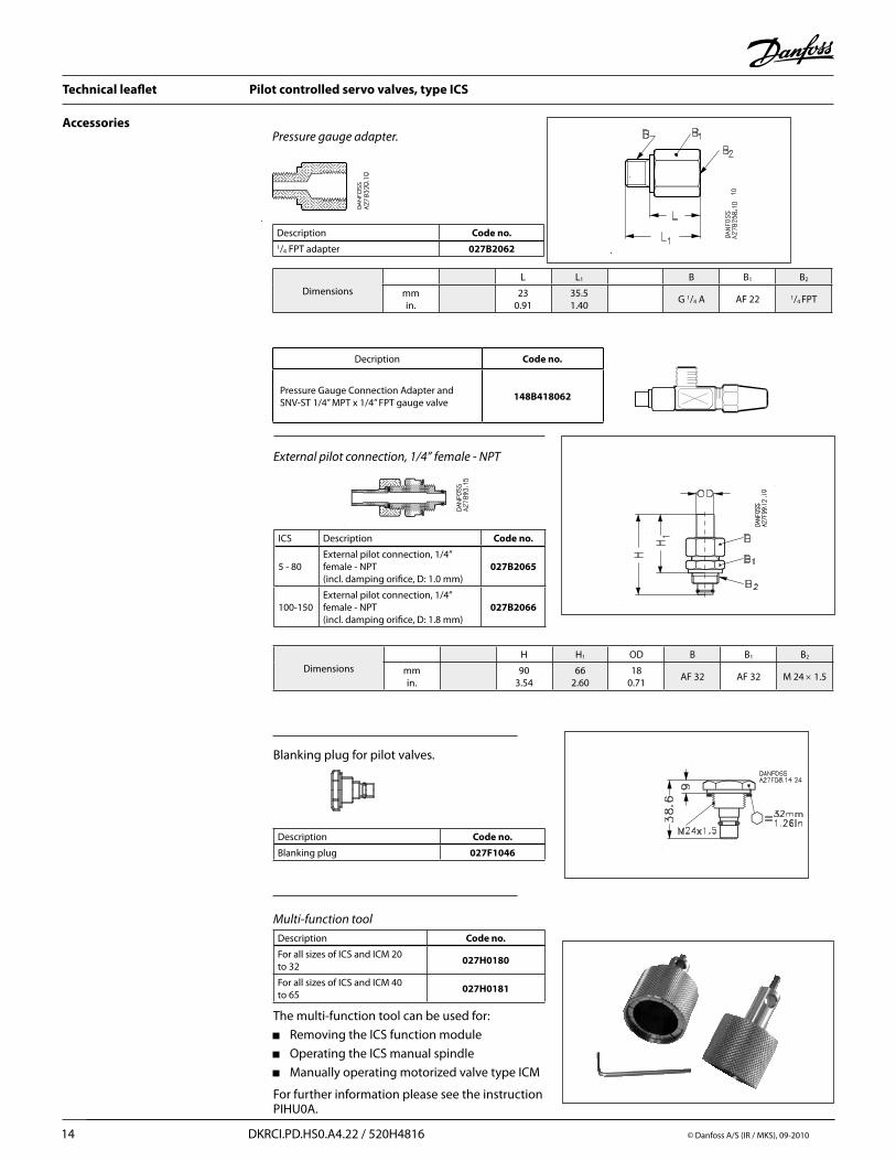
Pressure gauge adapter.
Description Code no.1/4 FPT adapter 027B2062
DimensionsL L1 B B1 B2
mmin.
230.91
35.51.40
G 1/4 A AF 22 1/4 FPT
Blanking plug for pilot valves.
Description Code no.
Blanking plug 027F1046
External pilot connection, 1/4’’ female - NPT
DimensionsH H1 OD B B1 B2
mmin.
903.54
662.60
180.71
AF 32 AF 32 M 24 × 1.5
ICS Description Code no.
5 - 80External pilot connection, 1/4’’ female - NPT(incl. damping orifice, D: 1.0 mm)
027B2065
100-150External pilot connection, 1/4’’ female - NPT(incl. damping orifice, D: 1.8 mm)
027B2066
Description Code no.
For all sizes of ICS and ICM 20 to 32
027H0180
For all sizes of ICS and ICM 40 to 65
027H0181
Multi-function tool
The multi-function tool can be used for:
Removing the ICS function module
Operating the ICS manual spindle
Manually operating motorized valve type ICM
For further information please see the instruction PIHU0A.
Accessories
Decription Code no.
Pressure Gauge Connection Adapter and SNV-ST 1/4” MPT x 1/4” FPT gauge valve
148B418062

Technical leaflet Pilot controlled servo valves, type ICS
© Danfoss A/S (IR /MKS), 09-2010 DKRCI.PD.HS0.A4.22 / 520H4816 15
Accessories
FlarePressure gauge connection, 1/4 in. flare (self-closing) Must not be used in R 717 plant.
Cutting ringPressure gauge connection
Description Code no.1/4 in. flare 027B2041
Dimensions B B1 B2
1/4 in. flaremmin.
G 1/4 A AF 19 1/4 in. flare
Description Code no.
Cutting ring connection, 6 mm Cutting ring connection, 10 mm
027B2063027B2064
Dimensions L L1 B B1 B2
6 mm mmin.
271.06
391.54
G 1/4 A AF 19 AF 14
10 mm mmin.
291.14
401.57
G 1/4 A AF 19 AF 14
Accessories Code Number
ICS 25 blank top cover 027H2174
ICS 32 blank top cover 027H3174
ICS 40 blank top cover 027H4174
ICS 50 blank top cover 027H5174
ICS 65 blank top cover 027H6174
ICS blank top covers including bolts and gasket
Technical leaflet Pilot controlled servo valves, type ICS
16 DKRCI.PD.HS0.A4.22 / 520H4816 © Danfoss A/S (IR / MKS), 09-2010
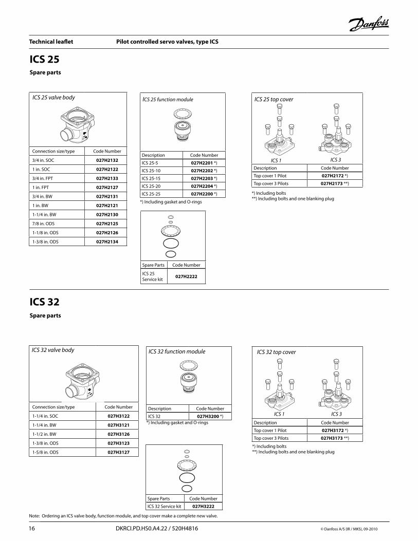
ICS 25
Description Code Number
ICS 25-5 027H2201 *)
ICS 25-10 027H2202 *)
ICS 25-15 027H2203 *)
ICS 25-20 027H2204 *)
ICS 25-25 027H2200 *)
ICS 25 function module
*) Including gasket and O-rings
Description Code Number
Top cover 1 Pilot 027H2172 *)
Top cover 3 Pilots 027H2173 **)
ICS 25 top cover
*) Including bolts**) Including bolts and one blanking plug
Spare Parts Code Number
ICS 25 Service kit
027H2222
Spare parts
ICS 1 ICS 3
ICS 32
Spare Parts Code Number
ICS 32 Service kit 027H3222
Spare parts
Description Code Number
ICS 32 027H3200 *)*) Including gasket and O-rings Description Code Number
Top cover 1 Pilot 027H3172 *)
Top cover 3 Pilots 027H3173 **)
ICS 32 function module ICS 32 top cover
ICS 1 ICS 3
*) Including bolts**) Including bolts and one blanking plug
Connection size/type Code Number
3/4 in. SOC 027H2132
1 in. SOC 027H2122
3/4 in. FPT 027H2133
1 in. FPT 027H2127
3/4 in. BW 027H2131
1 in. BW 027H2121
1-1/4 in. BW 027H2130
7/8 in. ODS 027H2125
1-1/8 in. ODS 027H2126
1-3/8 in. ODS 027H2134
Connection size/type Code Number
1-1/4 in. SOC 027H3122
1-1/4 in. BW 027H3121
1-1/2 in. BW 027H3126
1-3/8 in. ODS 027H3123
1-5/8 in. ODS 027H3127
Note: Ordering an ICS valve body, function module, and top cover make a complete new valve.
ICS 25 valve body
ICS 32 valve body

Technical leaflet Pilot controlled servo valves, type ICS
© Danfoss A/S (IR /MKS), 09-2010 DKRCI.PD.HS0.A4.22 / 520H4816 17
Connection size/type Code Number
1-1/2 in. SOC 027H4122
1-1/2 in. BW 027H4121
2 in. BW 027H4127
1-5/8 in. ODS 027H4124
Description Code Number
ICS 40 027H4200 *)*) Including gasket and O-rings
Description Code Number
Top cover 1 Pilot 027H4172 *)
Top cover 3 Pilots 027H4173 **)
Spare Parts Code Number
ICS 40 Service kit 027H4222
Spare parts
ICS 40 function module ICS 40 top cover
ICS 1 ICS 3
*) Including bolts**) Including bolts and one blanking plug
ICS 40
Connection size/type Code Number
2 in. SOC 027H5122
2 in. BW 027H5121
2-1/2 in. BW 027H5125
2-1/8 in. ODS 027H5123
ICS 50
Spare Parts Code Number
ICS 50 Service kit 027H5222
Spare parts
Description Code Number
ICS 50 027H5200 *)*) Including gasket and O-rings Description Code Number
Top cover 1 Pilot 027H5172 *)
Top cover 3 Pilots 027H5173 **
*) Including bolts**) Including bolts and one blanking plug
ICS 50 function module ICS 50 top cover
ICS 1 ICS 3
ICS 40 valve body
ICS 50 valve body

Technical leaflet Pilot controlled servo valves, type ICS
18 DKRCI.PD.HS0.A4.22 / 520H4816 © Danfoss A/S (IR / MKS), 09-2010
ICS size Connection size/type Code Number
ICS 65 2-1/2 in. SOC 027H6123
ICS 65 2-1/2 in. BW 027H6121
ICS 65/80 3 in. BW 027H6127
ICS 65 2-5/8 in. ODS 027H6125
Spare parts
ICS 65 / 80
Description Code Number
ICS 65 027H6200 *)
ICS 80 027H8200 *)
*) Including gasket and O-rings
*) Including bolts**) including bolts and one blanking plug
Spare Parts Code Number
ICS 65 service kit 027H6222
Service kit
ICS 65 and ICS 80 function module
ICS 1 ICS 3
Description Code Number
Top cover 1 Pilot 027H6172 *)
Top cover 3 Pilots 027H6173 **)
ICS 65 top cover
ICS 100-150 Spare parts
1
7
2
3
4
5
6
Inspection set A / Service kit
Consist of:Gasket (pos. 2)o-ring (pos. 3 and pos. 4)Alu gasket for pressure gaugeGasket for piloto-ring for pilot
Size Code number
ICS 100 027H7124
ICS 125 027H7144
ICS 150 027H7164
Maintenance set B
Consist of:Inspection set AValve plate (pos. 5) Piston ring (pos. 6)
Size Code number
ICS 100 027H7125
ICS 125 027H7145
ICS 150 027H7165
Replacement set C / Function Module
Consist of:Gasket (pos. 2)Function module (pos. 1)Alu gasket for pressure gaugeGasket for piloto-ring for pilot
Size Code number
ICS 100 027H7126
ICS 125 027H7146
ICS 150 027H7166
Other stems
Description Size Code number
Consist of:Cap (pos. 7)
ICS 100-150 148B4076
Packing gland ICS 100-150 148B4138
ICS 65/80 valve body
Technical leaflet Pilot controlled servo valves, type ICS
© Danfoss A/S (IR /MKS), 09-2010 DKRCI.PD.HS0.A4.22 / 520H4816 19
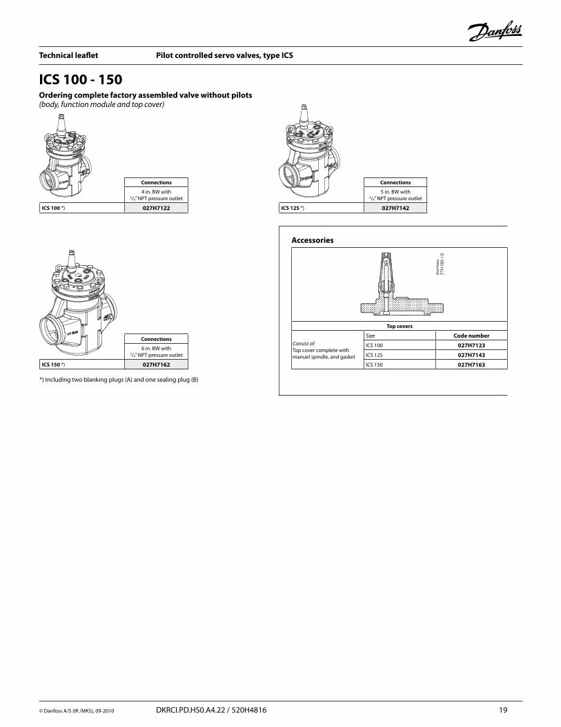
Ordering complete factory assembled valve without pilots (body, function module and top cover)
ICS 100 - 150
Connections
4 in. BW with 3/8” NPT pressure outlet
ICS 100 *) 027H7122
Connections
5 in. BW with 3/8” NPT pressure outlet
ICS 125 *) 027H7142
Connections
6 in. BW with 3/8” NPT pressure outlet
ICS 150 *) 027H7162
Accessories
Top covers
Consist of:Top cover complete with manuel spindle, and gasket
Size Code number
ICS 100 027H7123
ICS 125 027H7143
ICS 150 027H7163
*) Including two blanking plugs (A) and one sealing plug (B)

Technical leaflet Pilot controlled servo valves, type ICS
20 DKRCI.PD.HS0.A4.22 / 520H4816 © Danfoss A/S (IR / MKS), 09-2010
PumpLocation of valve in system (marked with grey)
Hot gas bypass & defrost line
Discharge line
Wet suction line
Dry suction line
Liquid line without phase change Liquid line with or without phase change
Nominal capacities Liquid line with/without phase change
GravityLocation of valve in system (marked with grey)
Hot gas bypass & defrost line
Discharge line
Wet suction line
Dry suction line
Liquid line without phase change Liquid line with or without phase change
DXLocation of valve in system (marked with grey)
Hot gas bypass & defrost line
Discharge line
Liquid line without phase change
Dry suction line
Technical leaflet Pilot controlled servo valves, type ICS
© Danfoss A/S (IR /MKS), 09-2010 DKRCI.PD.HS0.A4.22 / 520H4816 21
Liquid line with/without phase changeNominal capacities
Calculation example (R 717 capacities):
Running conditions in a plant are as follows: Te = –20°F Qo = 130 TR Liquid temperature = 50°F Max. ∆p = 4 psi
The capacity table is based on nominal condition (pressure drop ∆p = 3 psi, Tliq = 90°F)
Therefore the actual capacity must be corrected to nominal condition by means of correction factors.
Correction factor for ∆p 4 psi, f∆p = 0.87 Correction factor for liquid temperature fTliq = 0.92
Qn = Qo × f∆p × f Tliq = 130 × 0.87 × 0.92 = 104 TR
From the capacity table a ICS25-15 with Qn capacity 175 TR is selected.
Technical leaflet Pilot controlled servo valves, type ICS
22 DKRCI.PD.HS0.A4.22 / 520H4816 © Danfoss A/S (IR / MKS), 09-2010
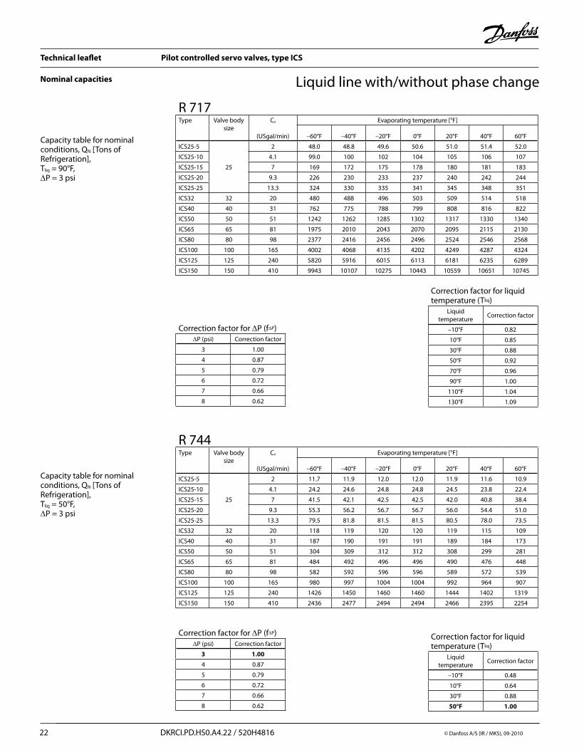
Liquid line with/without phase changeNominal capacities
Capacity table for nominal conditions, QN [Tons of Refrigeration], Tliq = 90°F, ∆P = 3 psi
Correction factor for ∆P (f∆P)∆P (psi) Correction factor
3 1.00
4 0.87
5 0.79
6 0.72
7 0.66
8 0.62
Correction factor for liquid temperature (Tliq)
Liquid temperature
Correction factor
–10°F 0.82
10°F 0.85
30°F 0.88
50°F 0.92
70°F 0.96
90°F 1.00
110°F 1.04
130°F 1.09
R 717Type Valve body
sizeCv
(USgal/min)
Evaporating temperature [°F]
–60°F –40°F –20°F 0°F 20°F 40°F 60°F
ICS25-5
25
2 48.0 48.8 49.6 50.6 51.0 51.4 52.0
ICS25-10 4.1 99.0 100 102 104 105 106 107
ICS25-15 7 169 172 175 178 180 181 183
ICS25-20 9.3 226 230 233 237 240 242 244
ICS25-25 13.3 324 330 335 341 345 348 351
ICS32 32 20 480 488 496 503 509 514 518
ICS40 40 31 762 775 788 799 808 816 822
ICS50 50 51 1242 1262 1285 1302 1317 1330 1340
ICS65 65 81 1975 2010 2043 2070 2095 2115 2130
ICS80 80 98 2377 2416 2456 2496 2524 2546 2568
ICS100 100 165 4002 4068 4135 4202 4249 4287 4324
ICS125 125 240 5820 5916 6015 6113 6181 6235 6289
ICS150 150 410 9943 10107 10275 10443 10559 10651 10745
Capacity table for nominal conditions, QN [Tons of Refrigeration], Tliq = 50°F, ∆P = 3 psi
Correction factor for liquid temperature (Tliq)
Liquid temperature
Correction factor
–10°F 0.48
10°F 0.64
30°F 0.88
50°F 1.00
R 744Type Valve body
sizeCv
(USgal/min)
Evaporating temperature [°F]
–60°F –40°F –20°F 0°F 20°F 40°F 60°F
ICS25-5
25
2 11.7 11.9 12.0 12.0 11.9 11.6 10.9
ICS25-10 4.1 24.2 24.6 24.8 24.8 24.5 23.8 22.4
ICS25-15 7 41.5 42.1 42.5 42.5 42.0 40.8 38.4
ICS25-20 9.3 55.3 56.2 56.7 56.7 56.0 54.4 51.0
ICS25-25 13.3 79.5 81.8 81.5 81.5 80.5 78.0 73.5
ICS32 32 20 118 119 120 120 119 115 109
ICS40 40 31 187 190 191 191 189 184 173
ICS50 50 51 304 309 312 312 308 299 281
ICS65 65 81 484 492 496 496 490 476 448
ICS80 80 98 582 592 596 596 589 572 539
ICS100 100 165 980 997 1004 1004 992 964 907
ICS125 125 240 1426 1450 1460 1460 1444 1402 1319
ICS150 150 410 2436 2477 2494 2494 2466 2395 2254
Correction factor for ∆P (f∆P)∆P (psi) Correction factor
3 1.00
4 0.87
5 0.79
6 0.72
7 0.66
8 0.62

Technical leaflet Pilot controlled servo valves, type ICS
© Danfoss A/S (IR /MKS), 09-2010 DKRCI.PD.HS0.A4.22 / 520H4816 23
Nominal capacities Liquid line with/without phase change
Capacity table for nominal conditions, QN [Tons of Refrigeration], Tliq = 90°F, ∆P = 3 psi
Correction factor for ∆P (f∆P)∆P (psi) Correction factor
3 1.00
4 0.87
5 0.79
6 0.72
7 0.66
8 0.62
Correction factor for liquid temperature (Tliq)
Liquid temperature
Correction factor
–10°F 0.64
10°F 0.68
30°F 0.74
50°F 0.81
70°F 0.89
90°F 1.00
110°F 1.15
130°F 1.35
R 134aType Valve body
sizeCv
(USgal/min)
Evaporating temperature [°F]
–40°F –20°F 0°F 20°F 40°F 60°F 80°F
ICS25-5
25
2 8.5 9.0 9.4 9.8 10.3 10.7 11.1
ICS25-10 4.1 17.5 18.4 19.4 20.3 21.2 22.0 22.8
ICS25-15 7 30.0 31.6 33.2 34.7 36.2 37.7 39.0
ICS25-20 9.3 40.0 42.1 44.3 46.3 48.4 50.3 52.0
ICS25-25 13.3 57.4 60.6 63.6 66.5 69.5 72.3 75.0
ICS32 32 20 85 89 94 98.5 103 107 111
ICS40 40 31 135 142 149 156 163 170 176
ICS50 50 51 220 232 244 255 266 277 287
ICS65 65 81 350 369 387 405 423 440 456
ICS80 80 98 421 443 466 487 509 530 549
ICS100 100 165 709 747 784 820 857 892 924
ICS125 125 240 1031 1086 1141 1193 1247 1297 1344
ICS150 150 410 1761 1855 1949 2038 2131 2216 2296
Capacity table for nominal conditions, QN [Tons of Refrigeration], Tliq = 90°F, ∆P = 3 psi
Correction factor for ∆P (f∆P)∆P (psi) Correction factor
3 1.00
4 0.87
5 0.79
6 0.72
7 0.66
8 0.62
Correction factor for liquid temperature (Tliq)
Liquid temperature
Correction factor
–10°F 0.52
10°F 0.57
30°F 0.63
50°F 0.72
70°F 0.83
90°F 1.00
110°F 1.29
130°F 1.92
R 404AType Valve body
sizeCv
(USgal/min)
Evaporating temperature [°F]
–60°F –40°F –20°F 0°F 20°F 40°F 60°F
ICS25-5
25
2 5.4 5.8 6.2 6.6 7.0 7.4 7.8
ICS25-10 4.1 11.0 11.9 12.8 13.7 14.5 15.3 16.0
ICS25-15 7 18.9 20.4 22.0 23.4 24.9 26.2 27.4
ICS25-20 9.3 25.2 27.2 29.2 31.3 33.0 35.0 36.5
ICS25-25 13.3 36.1 39.1 42.0 45.0 47.6 50.0 52.5
ICS32 32 20 53.5 57.8 62.0 66.4 70.4 74.0 77.6
ICS40 40 31 85.0 92.0 99.0 106 112 118 123
ICS50 50 51 138 150 161 172 182 192 201
ICS65 65 81 220 238 256 274 290 306 320
ICS80 80 98 265 287 308 329 348 367 385
ICS100 100 165 446 483 518 554 587 619 648
ICS125 125 240 649 702 754 806 853 900 942
ICS150 150 410 1109 1199 1288 1377 1458 1537 1609

Technical leaflet Pilot controlled servo valves, type ICS
24 DKRCI.PD.HS0.A4.22 / 520H4816 © Danfoss A/S (IR / MKS), 09-2010
Nominal capacities Liquid line with/without phase change
Capacity table for nominal conditions, QN [Tons of Refrigeration], Tliq = 90°F, ∆P = 3 psi
Correction factor for ∆P (f∆P)∆P (psi) Correction factor
3 1.00
4 0.87
5 0.79
6 0.72
7 0.66
8 0.62
Correction factor for liquid temperature (Tliq)
Liquid temperature
Correction factor
–10°F 0.73
10°F 0.77
30°F 0.82
50°F 0.87
70°F 0.93
90°F 1.00
110°F 1.09
130°F 1.20
R 22Type Valve body
sizeCv
(USgal/min)
Evaporating temperature [°F]
–60°F –40°F –20°F 0°F 20°F 40°F 60°F
ICS25-5
25
2 9.5 9.8 10.1 10.5 10.7 11.0 11.3
ICS25-10 4.1 19.5 20.2 20.9 21.5 22.1 22.7 23.2
ICS25-15 7 33.5 34.6 35.9 37.0 38.0 39.0 39.8
ICS25-20 9.3 44.5 46.2 47.8 49.2 50.6 52.0 53.0
ICS25-25 13.3 64.0 66.4 68.6 71.0 73.0 75.0 76.0
ICS32 32 20 95.0 98.0 101 105 108 110 112
ICS40 40 31 151 156 161 166 171 175 179
ICS50 50 51 245 254 263 271 279 285 291
ICS65 65 81 390 404 418 431 443 454 464
ICS80 80 98 470 486 502 519 533 546 558
ICS100 100 165 791 818 846 874 897 920 939
ICS125 125 240 1150 1190 1230 1271 1305 1338 1366
ICS150 150 410 1965 2033 2102 2171 2230 2286 2333
Technical leaflet Pilot controlled servo valves, type ICS
© Danfoss A/S (IR /MKS), 09-2010 DKRCI.PD.HS0.A4.22 / 520H4816 25
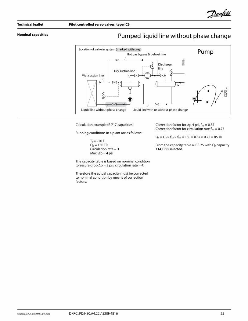
Nominal capacities
PumpLocation of valve in system (marked with grey)
Hot gas bypass & defrost line
Discharge line
Wet suction line
Dry suction line
Liquid line without phase change Liquid line with or without phase change
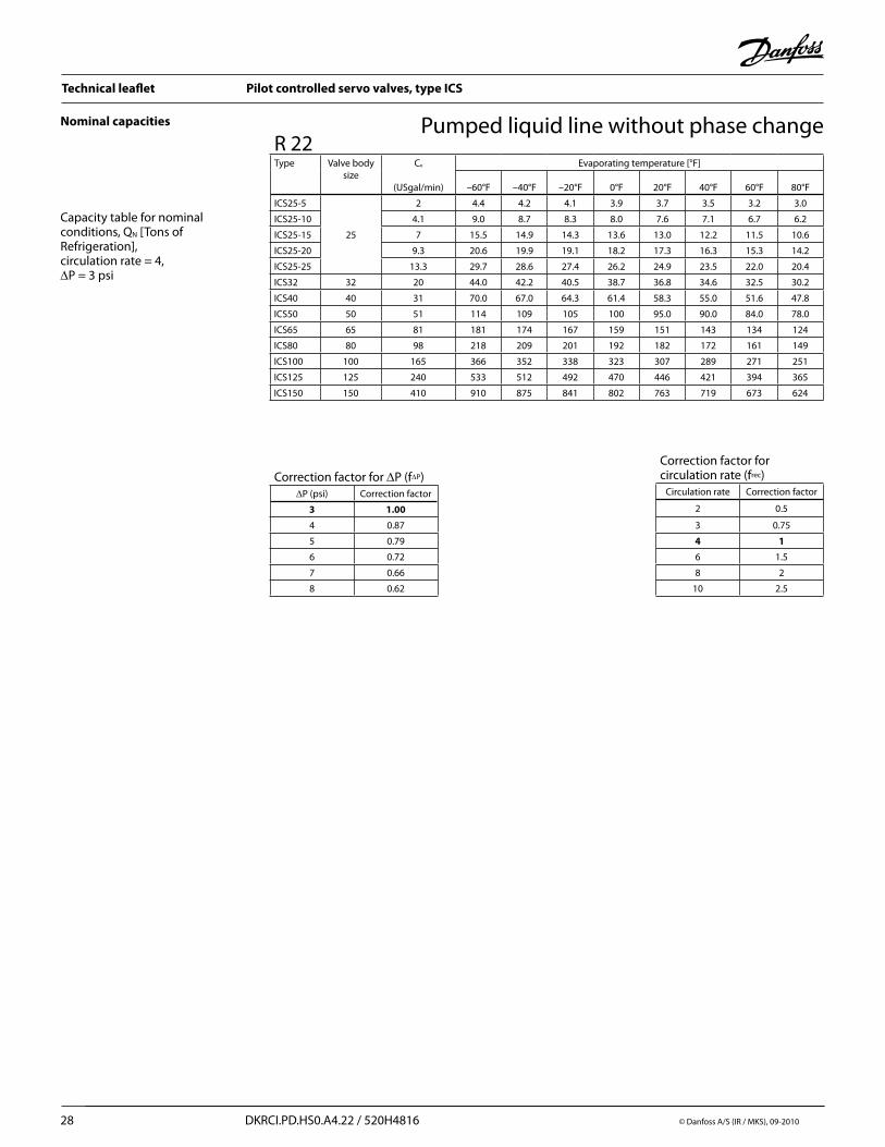
Pumped liquid line without phase change
Calculation example (R 717 capacities):
Running conditions in a plant are as follows: Te = –20 F Qo = 130 TR Circulation rate = 3 Max. ∆p = 4 psi
The capacity table is based on nominal condition (pressure drop ∆p = 3 psi, circulation rate = 4)
Therefore the actual capacity must be corrected to nominal condition by means of correction factors.
Correction factor for ∆p 4 psi, f∆p = 0.87Correction factor for circulation rate frec = 0.75
Qn = Qo × f∆p × frec = 130 × 0.87 × 0.75 = 85 TR
From the capacity table a ICS 25 with Qn capacity 114 TR is selected.

Technical leaflet Pilot controlled servo valves, type ICS
26 DKRCI.PD.HS0.A4.22 / 520H4816 © Danfoss A/S (IR / MKS), 09-2010
Nominal capacities
Capacity table for nominal conditions, QN [Tons of Refrigeration], circulation rate = 4,∆P = 3 psi
Pumped liquid line without phase changeR 717Type Valve body
sizeCv
(USgal/min)
Evaporating temperature [°F]
–60°F –40°F –20°F 0°F 20°F 40°F 60°F 80°F
ICS25-5
25
2 18.0 17.4 16.9 16.2 15.6 14.9 14.2 13.4
ICS25-10 4.1 37.0 35.9 34.7 33.4 32.0 30.6 29.6 27.6
ICS25-15 7 63.4 61.5 59.4 57.3 55.0 52.5 50.0 47.3
ICS25-20 9.3 84.5 82.0 79.3 76.3 73.3 70.0 66.6 63.0
ICS25-25 13.3 122 118 114 110 105 102 95.7 91.0
ICS32 32 20 180 174 169 162 156 149 142 134
ICS40 40 31 285 276 267 258 247 236 225 213
ICS50 50 51 465 451 436 420 403 385 366 347
ICS65 65 81 740 717 694 668 641 613 583 552
ICS80 80 98 891 863 835 804 771 738 703 664
ICS100 100 165 1499 1453 1406 1353 1298 1243 1183 1118
ICS125 125 240 2181 2113 2045 1968 1889 1808 1721 1627
ICS150 150 410 3726 3609 3493 3363 3226 3088 2941 2779
Correction factor for ∆P (f∆P)∆P (psi) Correction factor
3 1.00
4 0.87
5 0.79
6 0.72
7 0.66
8 0.62
Correction factor for circulation rate (frec)
Circulation rate Correction factor
2 0.5
3 0.75
4 1
6 1.5
8 2
10 2.5
Capacity table for nominal conditions, QN [Tons of Refrigeration], circulation rate = 4, ∆P = 3 psi
Correction factor for ∆P (f∆P)∆P (psi) Correction factor
3 1.00
4 0.87
5 0.79
6 0.72
7 0.66
8 0.62
Correction factor for circulation rate (frec)
Circulation rate Correction factor
2 0.5
3 0.75
4 1
6 1.5
8 2
10 2.5
R 744Type Valve body
sizeCv
(USgal/min)
Evaporating temperature [°F]
–60°F –40°F –20°F 0°F 20°F 40°F 60°F 80°F
ICS25-5
25
2 5.6 5.8 4.8 4.3 3.8 3.2 2.4 1.4
ICS25-10 4.1 11.4 10.7 9.8 8.8 7.8 6.5 5.0 2.8
ICS25-15 7 19.6 18.3 16.8 15.2 13.3 11.2 8.6 4.8
ICS25-20 9.3 26.1 24.4 22.4 20.2 17.7 14.9 11.4 6.3
ICS25-25 13.3 37.6 35.0 32.2 29.0 25.5 21.4 16.4 9.1
ICS32 32 20 55.5 51.8 47.6 43.0 37.7 31.6 24.2 13.5
ICS40 40 31 88.0 82.0 75.5 68.0 60.0 50.2 38.5 21.4
ICS50 50 51 144 134 123 111 98.0 82.0 62.7 35.0
ICS65 65 81 229 213 196 177 155 130 100 55.4
ICS80 80 98 275 260 236 213 187 157 120 67
ICS100 100 165 463 438 397 358 315 264 202 113
ICS125 125 240 674 637 578 521 458 384 294 164
ICS150 150 410 1152 1087 987 889 783 656 502 281

Technical leaflet Pilot controlled servo valves, type ICS
© Danfoss A/S (IR /MKS), 09-2010 DKRCI.PD.HS0.A4.22 / 520H4816 27
Nominal capacitiesPumped liquid line without phase change
Capacity table for nominal conditions, QN [Tons of Refrigeration], circulation rate = 4, ∆P = 3 psi
Correction factor for ∆P (f∆P)∆P (psi) Correction factor
3 1.00
4 0.87
5 0.79
6 0.72
7 0.66
8 0.62
Correction factor for circulation rate (frec)
Circulation rate Correction factor
2 0.5
3 0.75
4 1
6 1.5
8 2
10 2.5
R 134aType Valve body
sizeCv
(USgal/min)
Evaporating temperature [°F]
–40°F –20°F 0°F 20°F 40°F 60°F 80°F
ICS25-5
25
2 4.1 4.0 3.8 3.6 3.4 3.2 3.0
ICS25-10 4.1 8.5 8.1 7.7 7.4 7.0 6.6 6.1
ICS25-15 7 14.4 13.8 13.2 12.6 11.9 11.2 10.4
ICS25-20 9.3 19.2 18.4 17.6 16.7 15.8 14.9 13.8
ICS25-25 13.3 27.4 26.3 25.1 23.9 22.7 21.3 19.8
ICS32 32 20 41.2 39.5 37.8 35.9 34.1 32.0 29.8
ICS40 40 31 63.9 61.2 58.6 55.7 52.8 49.6 46.1
ICS50 50 51 105 101 96.3 91.6 86.9 81.5 75.9
ICS65 65 81 167 160 153 146 138 130 121
ICS80 80 98 202 194 185 176 167 157 146
ICS100 100 165 340 326 312 297 281 264 246
ICS125 125 240 495 475 453 432 409 384 357
ICS150 150 410 845 811 774 737 698 657 611
Capacity table for nominal conditions, QN [Tons of Refrigeration], circulation rate = 4, ∆P = 3 psi
Correction factor for ∆P (f∆P)∆P (psi) Correction factor
3 1.00
4 0.87
5 0.79
6 0.72
7 0.66
8 0.62
Correction factor for circulation rate (frec)
Circulation rate Correction factor
2 0.5
3 0.75
4 1
6 1.5
8 2
10 2.5
R 404AType Valve body
sizeCv
(USgal/min)
Evaporating temperature [°F]
–60°F –40°F –20°F 0°F 20°F 40°F 60°F 80°F
ICS25-5
25
2 3.6 3.5 3.2 3.0 2.9 2.7 2.4 2.2
ICS25-10 4.1 7.4 7.0 6.7 6.3 5.9 5.5 5.0 4.5
ICS25-15 7 12.5 12.1 11.4 10.8 10.1 9.4 8.6 7.7
ICS25-20 9.3 16.9 16.1 15.2 14.4 13.5 12.6 11.5 10.3
ICS25-25 13.3 24.2 23.2 21.9 20.7 19.4 18.0 16.5 14.7
ICS32 32 20 35.8 34.2 32.3 30.6 28.8 26.7 24.4 21.8
ICS40 40 31 57.0 54.4 51.3 48.6 45.6 42.5 38.8 34.6
ICS50 50 51 93.0 88.6 84.0 79.0 74.4 69.0 63.0 56.5
ICS65 65 81 147 141 133 126 118 110 101 90.0
ICS80 80 98 177 170 160 151 142 132 121 108
ICS100 100 165 299 286 270 255 240 223 203 182
ICS125 125 240 435 416 392 370 348 324 295 265
ICS150 150 410 742 711 670 633 595 554 505 453
Technical leaflet Pilot controlled servo valves, type ICS
28 DKRCI.PD.HS0.A4.22 / 520H4816 © Danfoss A/S (IR / MKS), 09-2010
Nominal capacities Pumped liquid line without phase change
Capacity table for nominal conditions, QN [Tons of Refrigeration], circulation rate = 4, ∆P = 3 psi
Correction factor for ∆P (f∆P)∆P (psi) Correction factor
3 1.00
4 0.87
5 0.79
6 0.72
7 0.66
8 0.62
Correction factor for circulation rate (frec)
Circulation rate Correction factor
2 0.5
3 0.75
4 1
6 1.5
8 2
10 2.5
R 22Type Valve body
sizeCv
(USgal/min)
Evaporating temperature [°F]
–60°F –40°F –20°F 0°F 20°F 40°F 60°F 80°F
ICS25-5
25
2 4.4 4.2 4.1 3.9 3.7 3.5 3.2 3.0
ICS25-10 4.1 9.0 8.7 8.3 8.0 7.6 7.1 6.7 6.2
ICS25-15 7 15.5 14.9 14.3 13.6 13.0 12.2 11.5 10.6
ICS25-20 9.3 20.6 19.9 19.1 18.2 17.3 16.3 15.3 14.2
ICS25-25 13.3 29.7 28.6 27.4 26.2 24.9 23.5 22.0 20.4
ICS32 32 20 44.0 42.2 40.5 38.7 36.8 34.6 32.5 30.2
ICS40 40 31 70.0 67.0 64.3 61.4 58.3 55.0 51.6 47.8
ICS50 50 51 114 109 105 100 95.0 90.0 84.0 78.0
ICS65 65 81 181 174 167 159 151 143 134 124
ICS80 80 98 218 209 201 192 182 172 161 149
ICS100 100 165 366 352 338 323 307 289 271 251
ICS125 125 240 533 512 492 470 446 421 394 365
ICS150 150 410 910 875 841 802 763 719 673 624

Technical leaflet Pilot controlled servo valves, type ICS
© Danfoss A/S (IR /MKS), 09-2010 DKRCI.PD.HS0.A4.22 / 520H4816 29
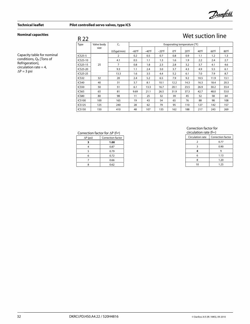
Nominal capacities Wet suction line
PumpLocation of valve in system (marked with grey)
Hot gas bypass & defrost line
Discharge line
Wet suction line
Dry suction line
Liquid line without phase change Liquid line with or without phase change
GravityLocation of valve in system (marked with grey)
Hot gas bypass & defrost line
Discharge line
Wet suction line
Dry suction line
Liquid line without phase change Liquid line with or without phase change
Calculation example (R 717 capacities):
An application has following running conditions: Te = –20 F Qo = 8 TR Circulation rate = 3 Max. ∆p = 4 psi
The capacity table is based on nominal condition (pressure drop ∆p = 3 psi, circulation rate = 4)
Therefore the actual capacity must be corrected to nominal condition by means of correction factors.
Correction factor for ∆p 4 psi, f∆p = 0.87Correction factor for circulation rate frec = 0.9
Qn = Qo × f∆p × frec = 8 × 0.87 × 0.9 = 6.3 TR
From the capacity table a ICS 25-20 with Qn capacity 6.8 TR is selected.

Technical leaflet Pilot controlled servo valves, type ICS
30 DKRCI.PD.HS0.A4.22 / 520H4816 © Danfoss A/S (IR / MKS), 09-2010
Wet suction lineNominal capacities
Capacity table for nominal conditions, QN [Tons of Refrigeration], circulation rate = 4,∆P = 3 psi
R 717Type Valve body
sizeCv
(USgal/min)
Evaporating temperature [°F]
–60°F –40°F –20°F 0°F 20°F 40°F 60°F 80°F
ICS25-5
25
2 0.6 1.1 1.4 1.8 2.2 2.6 3.0 3.5
ICS25-10 4.1 1.3 2.2 3.0 3.7 4.5 5.4 6.2 7.1
ICS25-15 7 2.3 3.7 5.1 6.4 7.8 9.2 10.7 12.2
ICS25-20 9.3 3.0 5.0 6.8 8.5 10.3 12.3 14.2 16.2
ICS25-25 13.3 4.4 7.1 9.7 12.2 14.9 17.6 20.4 23.3
ICS32 32 20 6.5 10.5 14.3 18.1 22.0 26.0 30.0 34.5
ICS40 40 31 10.3 16.8 22.8 28.8 35.0 41.4 48.0 55.0
ICS50 50 51 16.8 27.3 37.0 47.0 57.0 67.0 78.0 89.0
ICS65 65 81 26.8 43.5 59.0 75.0 91.0 107 124 142
ICS80 80 98 32 53 71 90 109 129 149 171
ICS100 100 165 53 88 120 151 184 217 251 288
ICS125 125 240 78 129 174 219 267 316 366 419
ICS150 150 410 133 220 297 375 456 540 625 716
Correction factor for ∆P (f∆P)∆P (psi) Correction factor
3 1.00
4 0.87
5 0.79
6 0.72
7 0.66
8 0.62
Correction factor for circulation rate (frec)
Circulation rate Correction factor
2 0.77
3 0.90
4 1
6 1.13
8 1.20
10 1.25
Capacity table for nominal conditions, QN [Tons of Refrigeration], circulation rate = 4, ∆P = 3 psi
Correction factor for ∆P (f∆P)∆P (psi) Correction factor
3 1.00
4 0.87
5 0.79
6 0.72
7 0.66
8 0.62
Correction factor for circulation rate (frec)
Circulation rate Correction factor
2 0.77
3 0.90
4 1
6 1.13
8 1.20
10 1.25
R 744Type Valve body
sizeCv
(USgal/min)
Evaporating temperature [°F]
–60°F –40°F –20°F 0°F 20°F 40°F 60°F 80°F
ICS25-5
25
2 1.5 1.7 2.0 2.2 2.3 2.4 2.4 1.8
ICS25-10 4.1 3.0 3.5 4.0 4.5 4.8 5.0 4.8 3.7
ICS25-15 7 5.2 6.0 6.9 7.7 8.2 8.6 8.3 6.4
ICS25-20 9.3 6.9 8.1 9.2 10.2 11.0 11.4 11.1 8.5
ICS25-25 13.3 10.0 11.6 13.2 14.7 15.8 16.4 15.9 12.3
ICS32 32 20 14.7 17.2 19.4 21.7 23.3 24.2 23.5 18.2
ICS40 40 31 23.3 27.3 31.0 34.5 37.0 38.5 37.3 28.8
ICS50 50 51 38.0 44.5 50.5 56.0 60.5 62.7 60.8 47.0
ICS65 65 81 60.5 71.0 80.0 89.0 96.0 100 96.7 75.0
ICS80 80 98 73 85 97 108 115 120 117 90
ICS100 100 165 123 143 163 181 194 202 196 151
ICS125 125 240 179 208 237 264 282 294 286 220
ICS150 150 410 305 355 405 451 483 502 488 375

Technical leaflet Pilot controlled servo valves, type ICS
© Danfoss A/S (IR /MKS), 09-2010 DKRCI.PD.HS0.A4.22 / 520H4816 31
Nominal capacities Wet suction line
Capacity table for nominal conditions, QN [Tons of Refrigeration], circulation rate = 4, ∆P = 3 psi
Correction factor for ∆P (f∆P)∆P (psi) Correction factor
3 1.00
4 0.87
5 0.79
6 0.72
7 0.66
8 0.62
Correction factor for circulation rate (frec)
Circulation rate Correction factor
2 0.77
3 0.90
4 1
6 1.13
8 1.20
10 1.25
R 134aType Valve body
sizeCv
(USgal/min)
Evaporating temperature [°F]
–40°F –20°F 0°F 20°F 40°F 60°F 80°F
ICS25-5
25
2 0.3 0.5 0.6 0.7 0.8 1.0 1.1
ICS25-10 4.1 0.6 1.0 1.2 1.5 1.7 2.0 2.2
ICS25-15 7 1.0 1.6 2.1 2.5 2.9 3.4 3.8
ICS25-20 9.3 1.4 2.2 2.8 3.3 3.9 4.5 5.1
ICS25-25 13.3 2.0 3.1 3.9 4.8 5.6 6.4 7.2
ICS32 32 20 3.0 4.7 5.9 7.2 8.4 9.7 10.9
ICS40 40 31 4.6 7.2 9.2 11.1 13.1 15.0 16.8
ICS50 50 51 7.6 11.9 15.1 18.3 21.5 24.6 27.7
ICS65 65 81 12.1 18.9 24.1 29.1 34.1 39.1 44.0
ICS80 80 98 15 23 29 35 41 48 53
ICS100 100 165 25 39 49 59 69 80 90
ICS125 125 240 36 57 71 86 100 117 130
ICS150 150 410 61 97 122 147 171 199 223
Capacity table for nominal conditions, QN [Tons of Refrigeration], circulation rate = 4, ∆P = 3 psi
Correction factor for ∆P (f∆P)∆P (psi) Correction factor
3 1.00
4 0.87
5 0.79
6 0.72
7 0.66
8 0.62
R 404AType Valve body
sizeCv
(USgal/min)
Evaporating temperature [°F]
–60°F –40°F –20°F 0°F 20°F 40°F 60°F 80°F
ICS25-5
25
2 0.4 0.5 0.7 0.8 0.9 1.0 1.1 1.2
ICS25-10 4.1 0.8 1.1 1.3 1.6 1.8 2.1 2.3 2.3
ICS25-15 7 1.4 1.9 2.3 2.7 3.2 3.6 3.9 2.5
ICS25-20 9.3 1.9 2.5 3.1 3.6 4.2 4.8 5.3 5.7
ICS25-25 13.3 2.8 3.6 4.4 5.2 6.0 6.8 7.5 8.1
ICS32 32 20 4.1 5.3 6.5 7.7 8.9 10.1 11.1 12.0
ICS40 40 31 6.5 8.5 10.3 12.2 14.2 16.0 17.7 19.1
ICS50 50 51 10.6 13.8 16.8 19.9 23.0 26.0 29.0 31.0
ICS65 65 81 16.9 22.0 26.7 31.7 36.7 41.5 46.0 49.5
ICS80 80 98 20 26 32 38 44 50 55 56
ICS100 100 165 34 44 55 64 74 84 93 95
ICS125 125 240 49 64 79 94 108 123 135 138
ICS150 150 410 84 110 136 160 185 209 231 236
Correction factor for circulation rate (frec)
Circulation rate Correction factor
2 0.77
3 0.90
4 1
6 1.13
8 1.20
10 1.25
Technical leaflet Pilot controlled servo valves, type ICS
32 DKRCI.PD.HS0.A4.22 / 520H4816 © Danfoss A/S (IR / MKS), 09-2010
Nominal capacities Wet suction line
Capacity table for nominal conditions, QN [Tons of Refrigeration], circulation rate = 4, ∆P = 3 psi
Correction factor for ∆P (f∆P)∆P (psi) Correction factor
3 1.00
4 0.87
5 0.79
6 0.72
7 0.66
8 0.62
R 22Type Valve body
sizeCv
(USgal/min)
Evaporating temperature [°F]
–60°F –40°F –20°F 0°F 20°F 40°F 60°F 80°F
ICS25-5
25
2 0.2 0.5 0.7 0.8 0.9 1.1 1.2 1.3
ICS25-10 4.1 0.5 1.1 1.3 1.6 1.9 2.2 2.4 2.7
ICS25-15 7 0.8 1.8 2.3 2.8 3.2 3.7 4.1 4.6
ICS25-20 9.3 1.1 2.4 3.0 3.7 4.3 4.9 5.5 6.1
ICS25-25 13.3 1.6 3.5 4.4 5.2 6.1 7.0 7.9 8.7
ICS32 32 20 2.4 5.2 6.5 7.9 9.2 10.5 11.9 13.1
ICS40 40 31 3.7 8.1 10.1 12.2 14.3 16.3 18.4 20.3
ICS50 50 51 6.1 13.3 16.7 20.1 23.5 26.9 30.2 33.4
ICS65 65 81 9.69 21.1 26.5 31.9 37.3 42.7 48.0 53.0
ICS80 80 98 11 25 32 39 45 52 58 64
ICS100 100 165 19 43 54 65 76 88 98 108
ICS125 125 240 28 62 79 95 110 127 142 157
ICS150 150 410 48 107 135 162 188 217 243 269
Correction factor for circulation rate (frec)
Circulation rate Correction factor
2 0.77
3 0.90
4 1
6 1.13
8 1.20
10 1.25
Technical leaflet Pilot controlled servo valves, type ICS
© Danfoss A/S (IR /MKS), 09-2010 DKRCI.PD.HS0.A4.22 / 520H4816 33
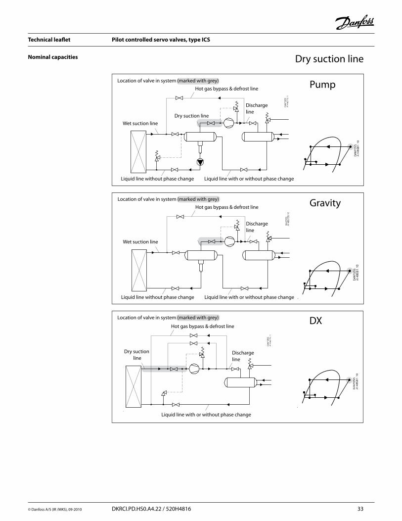
Nominal capacities Dry suction line
PumpLocation of valve in system (marked with grey)
Hot gas bypass & defrost line
Discharge line
Wet suction line
Dry suction line
Liquid line without phase change Liquid line with or without phase change
GravityLocation of valve in system (marked with grey)
Hot gas bypass & defrost line
Discharge line
Wet suction line
Liquid line without phase change Liquid line with or without phase change
DXLocation of valve in system (marked with grey)
Hot gas bypass & defrost line
Discharge line
Liquid line with or without phase change
Dry suction line

Technical leaflet Pilot controlled servo valves, type ICS
34 DKRCI.PD.HS0.A4.22 / 520H4816 © Danfoss A/S (IR / MKS), 09-2010
Nominal capacities Dry suction lineCalculation example (R 717 capacities):
An application has following running conditions: Te = 0°F Qo = 20 TR Tliq = 50°F Max. ∆p = 4 psi
The capacity table is based on nominal condition (pressure drop ∆p = 3 psi, Tliq = 90°F)
Therefore the actual capacity must be corrected to nominal condition by means of correction factors.
Correction factor for ∆p 4 psi, Tliq = 0.87Correction factor for liquid temperature fTliq = 0.92
Qn = Qo × f∆p × f Tliq = 20 × 0.87 × 0.92 = 16 TR
From the capacity table a ICS 25-25 with Qn capacity 18.7 TR is selected.
Technical leaflet Pilot controlled servo valves, type ICS
© Danfoss A/S (IR /MKS), 09-2010 DKRCI.PD.HS0.A4.22 / 520H4816 35
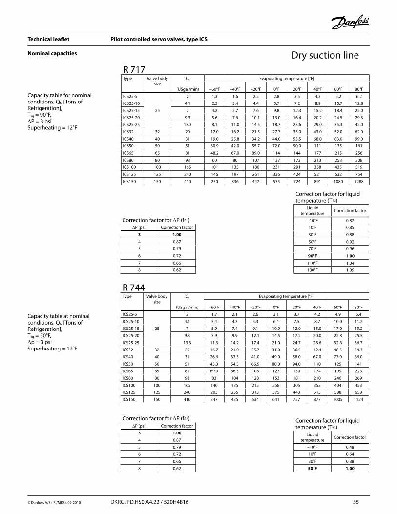
Nominal capacities Dry suction line
Capacity table for nominal conditions, QN [Tons of Refrigeration], Tliq = 90°F, ∆P = 3 psiSuperheating = 12°F
Correction factor for liquid temperature (Tliq)
Liquid temperature
Correction factor
–10°F 0.82
10°F 0.85
30°F 0.88
50°F 0.92
70°F 0.96
90°F 1.00
110°F 1.04
130°F 1.09
Correction factor for ∆P (f∆P)∆P (psi) Correction factor
3 1.00
4 0.87
5 0.79
6 0.72
7 0.66
8 0.62
R 717Type Valve body
sizeCv
(USgal/min)
Evaporating temperature [°F]
–60°F –40°F –20°F 0°F 20°F 40°F 60°F 80°F
ICS25-5
25
2 1.3 1.6 2.2 2.8 3.5 4.3 5.2 6.2
ICS25-10 4.1 2.5 3.4 4.4 5.7 7.2 8.9 10.7 12.8
ICS25-15 7 4.2 5.7 7.6 9.8 12.3 15.2 18.4 22.0
ICS25-20 9.3 5.6 7.6 10.1 13.0 16.4 20.2 24.5 29.3
ICS25-25 13.3 8.1 11.0 14.5 18.7 23.6 29.0 35.3 42.0
ICS32 32 20 12.0 16.2 21.5 27.7 35.0 43.0 52.0 62.0
ICS40 40 31 19.0 25.8 34.2 44.0 55.5 68.0 83.0 99.0
ICS50 50 51 30.9 42.0 55.7 72.0 90.0 111 135 161
ICS65 65 81 48.2 67.0 89.0 114 144 177 215 256
ICS80 80 98 60 80 107 137 173 213 258 308
ICS100 100 165 101 135 180 231 291 358 435 519
ICS125 125 240 146 197 261 336 424 521 632 754
ICS150 150 410 250 336 447 575 724 891 1080 1288
Correction factor for ∆P (f∆P)∆P (psi) Correction factor
3 1.00
4 0.87
5 0.79
6 0.72
7 0.66
8 0.62
Correction factor for liquid temperature (Tliq)
Liquid temperature
Correction factor
–10°F 0.48
10°F 0.64
30°F 0.88
50°F 1.00
Capacity table at nominal conditions, QN [Tons of Refrigeration], Tliq = 50°F, ∆p = 3 psiSuperheating = 12°F
R 744Type Valve body
sizeCv
(USgal/min)
Evaporating temperature [°F]
–60°F –40°F –20°F 0°F 20°F 40°F 60°F 80°F
ICS25-5
25
2 1.7 2.1 2.6 3.1 3.7 4.2 4.9 5.4
ICS25-10 4.1 3.4 4.3 5.3 6.4 7.5 8.7 10.0 11.2
ICS25-15 7 5.9 7.4 9.1 10.9 12.9 15.0 17.0 19.2
ICS25-20 9.3 7.9 9.9 12.1 14.5 17.2 20.0 22.8 25.5
ICS25-25 13.3 11.3 14.2 17.4 21.0 24.7 28.6 32.8 36.7
ICS32 32 20 16.7 21.0 25.7 31.0 36.5 42.4 48.5 54.3
ICS40 40 31 26.6 33.3 41.0 49.0 58.0 67.0 77.0 86.0
ICS50 50 51 43.3 54.3 66.5 80.0 94.0 110 125 141
ICS65 65 81 69.0 86.5 106 127 150 174 199 223
ICS80 80 98 83 104 128 153 181 210 240 269
ICS100 100 165 140 175 215 258 305 353 404 453
ICS125 125 240 203 255 313 375 443 513 588 658
ICS150 150 410 347 435 534 641 757 877 1005 1124
Technical leaflet Pilot controlled servo valves, type ICS
36 DKRCI.PD.HS0.A4.22 / 520H4816 © Danfoss A/S (IR / MKS), 09-2010
Nominal capacities Dry suction line
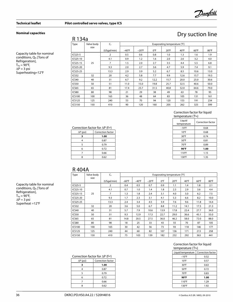
Capacity table for nominal conditions, QN [Tons of Refrigeration], Tliq = 90°F, ∆P = 3 psiSuperheating=12°F
Correction factor for ∆P (f∆P)∆P (psi) Correction factor
3 1.00
4 0.87
5 0.79
6 0.72
7 0.66
8 0.62
Correction factor for liquid temperature (Tliq)
Liquid temperature
Correction factor
–10°F 0.64
10°F 0.68
30°F 0.74
50°F 0.81
70°F 0.89
90°F 1.00
110°F 1.15
130°F 1.35
R 134aType Valve body
sizeCv
(USgal/min)
Evaporating temperature [°F]
–40°F –20°F 0°F 20°F 40°F 60°F 80°F
ICS25-5
25
2 0.5 0.6 0.8 1.0 1.3 1.6 1.9
ICS25-10 4.1 0.9 1.2 1.6 2.0 2.6 3.2 4.0
ICS25-15 7 1.5 2.0 2.7 3.5 4.4 5.5 6.8
ICS25-20 9.3 2.0 2.7 3.6 4.7 5.9 7.4 9.1
ICS25-25 13.3 2.9 3.9 5.2 6.7 8.5 10.6 13.0
ICS32 32 20 4.2 5.8 7.7 9.9 12.6 15.7 19.3
ICS40 40 31 6.7 9.2 12.2 15.7 20.0 25.0 30.6
ICS50 50 51 11.0 15.0 19.8 25.7 32.5 40.6 50.0
ICS65 65 81 17.4 23.7 31.5 40.8 52.0 64.6 79.0
ICS80 80 98 21 29 38 49 63 78 95
ICS100 100 165 36 48 64 83 105 131 161
ICS125 125 240 53 70 94 120 153 191 234
ICS150 150 410 90 120 160 205 262 325 399
Capacity table for nominal conditions, QN [Tons of Refrigeration], Tliq = 90°F, ∆P = 3 psiSuperheat =12°F
Correction factor for ∆P (f∆P)∆P (psi) Correction factor
3 1.00
4 0.87
5 0.79
6 0.72
7 0.66
8 0.62
Correction factor for liquid temperature (Tliq)Liquid temperature Correction factor
–10°F 0.52
10°F 0.57
30°F 0.63
50°F 0.72
70°F 0.83
90°F 1.00
110°F 1.29
130°F 1.92
R 404AType Valve body
sizeCv
(USgal/min)
Evaporating temperature [°F]
–60°F –40°F –20°F 0°F 20°F 40°F 60°F 80°F
ICS25-5
25
2 0.4 0.5 0.7 0.9 1.1 1.4 1.8 2.1
ICS25-10 4.1 0.7 1.0 1.4 1.8 2.3 2.9 3.6 4.4
ICS25-15 7 1.3 1.8 2.4 3.1 4.0 5.0 6.2 7.5
ICS25-20 9.3 1.7 2.3 3.1 4.1 5.3 6.6 8.2 10.0
ICS25-25 13.3 2.4 3.4 4.5 5.9 7.6 9.6 11.8 14.4
ICS32 32 20 3.6 5.0 6.7 8.8 11.2 14.1 17.5 21.3
ICS40 40 31 5.7 7.9 10.6 13.9 17.8 22.4 27.7 34.0
ICS50 50 51 9.3 12.9 17.3 22.7 29.0 36.6 45.1 55.0
ICS65 65 81 14.8 20.5 27.5 36.0 46.2 58.0 72.0 88.0
ICS80 80 98 18 25 33 43 55 70 87 105
ICS100 100 165 30 42 56 73 93 118 146 177
ICS125 125 240 44 60 82 107 136 171 213 258
ICS150 150 410 75 103 139 182 232 292 363 441

Technical leaflet Pilot controlled servo valves, type ICS
© Danfoss A/S (IR /MKS), 09-2010 DKRCI.PD.HS0.A4.22 / 520H4816 37
Nominal capacities Dry suction line
Capacity table for nominal conditions, QN [Tons of Refrigeration], Tliq = 90°F, ∆P = 3 psiSuperheat =12°F
Correction factor for ∆P (f∆P)∆P (psi) Correction factor
3 1.00
4 0.87
5 0.79
6 0.72
7 0.66
8 0.62
Correction factor for liquid temperature (Tliq)Liquid temperature Correction factor
–10°F 0.73
10°F 0.77
30°F 0.82
50°F 0.87
70°F 0.93
90°F 1.00
110°F 1.09
130°F 1.20
R 22Type Valve body
sizeCv
(USgal/min)
Evaporating temperature [°F]
–60°F –40°F –20°F 0°F 20°F 40°F 60°F 80°F
ICS25-5
25
2 0.5 0.7 0.8 1.1 1.3 1.6 2.0 2.3
ICS25-10 4.1 1.0 1.3 1.7 2.2 2.7 3.4 4.0 4.8
ICS25-15 7 1.7 2.3 3.0 3.8 4.7 5.7 6.9 8.2
ICS25-20 9.3 2.3 3.0 3.9 5.0 6.2 7.6 9.2 10.9
ICS25-25 13.3 3.2 4.3 5.6 7.2 8.9 10.9 13.1 15.6
ICS32 32 20 4.9 6.5 8.5 10.8 13.4 16.4 19.8 23.5
ICS40 40 31 7.5 10.1 13.1 16.7 20.8 25.4 30.6 36.4
ICS50 50 51 12.4 16.6 21.6 27.5 34.2 41.8 50.4 59.9
ICS65 65 81 19.7 26.4 34.3 43.6 54.3 66.4 80.0 95.1
ICS80 80 98 24 32 41 53 65 80 97 115
ICS100 100 165 40 54 69 89 110 135 163 193
ICS125 125 240 59 79 101 130 160 196 237 281
ICS150 150 410 100 134 172 222 273 335 405 480
Technical leaflet Pilot controlled servo valves, type ICS
38 DKRCI.PD.HS0.A4.22 / 520H4816 © Danfoss A/S (IR / MKS), 09-2010
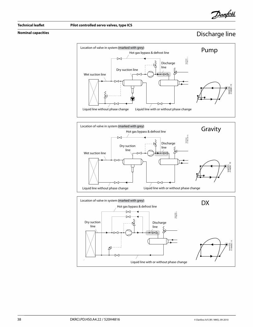
Nominal capacities Discharge line
Location of valve in system (marked with grey)
Hot gas bypass & defrost line
Discharge line
Wet suction line
Dry suction line
Liquid line without phase change Liquid line with or without phase change
Pump
Location of valve in system (marked with grey)Gravity
Location of valve in system (marked with grey)
Hot gas bypass & defrost line
Discharge line
Liquid line with or without phase change
Dry suction line
DX
Hot gas bypass & defrost line
Discharge line
Liquid line with or without phase change
Dry suction line
Liquid line without phase change
Wet suction line
Technical leaflet Pilot controlled servo valves, type ICS
© Danfoss A/S (IR /MKS), 09-2010 DKRCI.PD.HS0.A4.22 / 520H4816 39
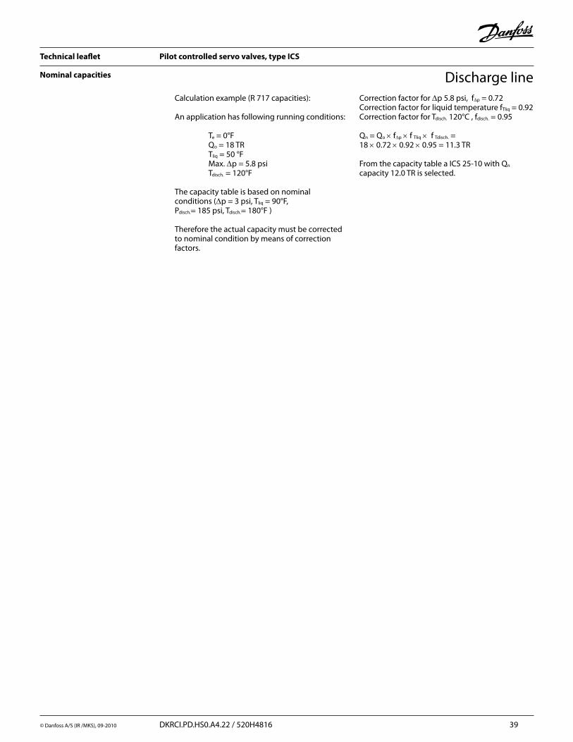
Nominal capacities Discharge lineCalculation example (R 717 capacities):
An application has following running conditions: Te = 0°F Qo = 18 TR Tliq = 50 °F Max. ∆p = 5.8 psi Tdisch. = 120°F
The capacity table is based on nominal conditions (∆p = 3 psi, Tliq = 90°F, Pdisch.= 185 psi, Tdisch.= 180°F )
Therefore the actual capacity must be corrected to nominal condition by means of correction factors.
Correction factor for ∆p 5.8 psi, f∆p = 0.72Correction factor for liquid temperature fTliq = 0.92Correction factor for Tdisch. 120°C , fdisch. = 0.95
Qn = Qo × f∆p × f Tliq × f Tdisch. = 18 × 0.72 × 0.92 × 0.95 = 11.3 TR From the capacity table a ICS 25-10 with Qn capacity 12.0 TR is selected.

Technical leaflet Pilot controlled servo valves, type ICS
40 DKRCI.PD.HS0.A4.22 / 520H4816 © Danfoss A/S (IR / MKS), 09-2010
Nominal capacities Discharge line
Capacity table for nominal conditions, QN [Tons of Refrigeration], Tliq = 90°F, ∆P = 2.9 psi, Pdisch. = 185 psi, Tdisch. = 180°FSuperheat = 12°F
Correction factor for discharge temperature (Tdisch).
Discharge temperature
Correction factor
120°F 0.95
140°F 0.97
180°F 1.00
200°F 1.02
210°F 1.02
230°F 1.04
250°F 1.06
Correction factor for liquid temperature (Tliq).
Liquid temperature
Correction factor
–10°F 0.82
10°F 0.85
30°F 0.88
50°F 0.92
70°F 0.96
90°F 1.00
110°F 1.04
130°F 1.09
R 717Type Valve body
sizeCv
(USgal/min)
Evaporating temperature [°F]
–60°F –40°F –20°F 0°F 20°F 40°F 60°F 80°F
ICS25-5
25
2 5.6 5.7 5.8 5.8 5.9 6.0 6.0 6.0
ICS25-10 4.1 11.4 11.6 11.8 12.0 12.1 12.3 12.3 12.4
ICS25-15 7 19.6 20.0 20.3 20.6 20.8 21.0 21.2 21.3
ICS25-20 9.3 26.2 26.6 27.0 27.4 27.8 28.0 28.2 28.3
ICS25-25 13.3 37.6 38.3 39.0 39.4 39.9 40.3 40.5 40.8
ICS32 32 20 55.5 56.5 57.5 58.3 59.0 59.5 60.0 60.3
ICS40 40 31 88.0 90.0 91.0 92.5 94.0 94.5 95.0 95.7
ICS50 50 51 144 146 149 151 153 154 155 156
ICS65 65 81 229 233 237 240 243 245 247 248
ICS80 80 98 275 280 285 289 292 295 297 298
ICS100 100 165 464 472 480 486 492 497 500 502
ICS125 125 240 674 687 698 707 716 723 727 731
ICS150 150 410 1152 1173 1192 1207 1223 1235 1242 1248
Correction factor for ∆P (f∆P)∆P (psi) Correction factor
3 1.00
4 0.87
5 0.79
6 0.72
7 0.66
8 0.62
Correction factor for discharge temperature (Tdisch).
Discharge temperature
Correction factor
120°F 0.95
140°F 0.97
180°F 1.00
200°F 1.02
210°F 1.02
230°F 1.04
250°F 1.05
Capacity table for nominal conditions, QN [Tons of Refrigeration], Tliq = 90°F, ∆P = 3 psiPdisch = 120 psi,Tdisch = 180°FSuperheat = 12°F
Correction factor for liquid temperature (Tliq).
Liquid temperature
Correction factor
–10°F 0.48
10°F 0.64
30°F 0.88
50°F 1.00
Correction factor for ∆P (f∆P)∆P (psi) Correction factor
3 1.00
4 0.87
5 0.79
6 0.72
7 0.66
8 0.62
R 744Type Valve body
sizeCv
(USgal/min)
Evaporating temperature [°F]
–60°F –40°F –20°F 0°F 20°F 40°F 60°F 80°F
ICS25-5
25
2 3.4 3.4 3.5 3.5 3.4 3.3 3.2 3.1
ICS25-10 4.1 6.9 7.0 7.1 7.1 7.0 6.8 6.6 6.4
ICS25-15 7 11.9 12.1 12.2 12.2 12.0 11.7 11.3 11.0
ICS25-20 9.3 15.8 16.1 16.2 16.2 16.0 15.6 15.1 14.7
ICS25-25 13.3 22.8 23.1 23.3 23.3 23.0 22.4 21.8 21.1
ICS32 32 20 33.7 34.1 34.5 34.5 34.0 33.1 32.2 31.2
ICS40 40 31 53.4 54.3 54.7 54.7 54.0 52.5 51.0 49.6
ICS50 50 51 87.0 88.4 89.0 89.0 88.0 85.5 83.3 80.8
ICS65 65 81 138 141 142 142 140 136 132 129
ICS80 80 98 167 169 171 171 168 164 159 154
ICS100 100 165 281 285 288 288 284 276 268 260
ICS125 125 240 408 414 419 419 412 401 389 378
ICS150 150 410 698 708 715 715 705 685 665 646

Technical leaflet Pilot controlled servo valves, type ICS
© Danfoss A/S (IR /MKS), 09-2010 DKRCI.PD.HS0.A4.22 / 520H4816 41
Discharge lineNominal capacities
Capacity table for nominal conditions, QN [Tons of Refrigeration], Tliq = 90°F, ∆P = 3 psiPdisch = 120 psi,Tdisch = 180°FSuperheat = 12°F
Correction factor for discharge temperature (Tdisch).
Discharge temperature
Correction factor
120°F 0.95
140°F 0.97
180°F 1.00
200°F 1.02
210°F 1.02
230°F 1.04
250°F 1.05
Correction factor for liquid temperature (Tliq).
Liquid temperature
Correction factor
–10°F 0.64
10°F 0.68
30°F 0.74
50°F 0.81
70°F 0.89
90°F 1.00
110°F 1.15
130°F 1.35
R 134aType Valve body
sizeCv
(USgal/min)
Evaporating temperature [°F]
–40°F –20°F 0°F 20°F 40°F 60°F 80°F
ICS25-5
25
2 1.4 1.5 1.5 1.6 1.7 1.7 1.8
ICS25-10 4.1 2.3 3.0 3.1 3.3 3.4 3.6 3.7
ICS25-15 7 4.9 5.1 5.4 5.6 5.9 6.1 6.3
ICS25-20 9.3 6.5 6.8 7.2 7.5 7.8 8.1 8.4
ICS25-25 13.3 9.3 9.8 10.3 10.8 11.3 11.7 12.1
ICS32 32 20 13.8 14.5 15.2 16.0 16.6 17.3 18.0
ICS40 40 31 21.9 23.0 24.2 25.3 26.5 27.5 28.5
ICS50 50 51 35.6 37.5 39.4 41.3 43.0 44.8 46.5
ICS65 65 81 56.7 59.7 62.9 65.7 68.5 71.3 74.0
ICS80 80 98 67 72 75 79 83 86 89
ICS100 100 165 113 121 127 133 139 144 150
ICS125 125 240 164 176 184 194 202 210 218
ICS150 150 410 280 301 315 331 345 358 372
Correction factor for ∆P (f∆P)∆P (psi) Correction factor
3 1.00
4 0.87
5 0.79
6 0.72
7 0.66
8 0.62
Capacity table for nominal conditions, QN [Tons of Refrigeration], Tliq = 90°F, ∆P = 3 psi,Pdisch = 120 psi, Tdisch = 180°FSuperheat = 12°F
Correction factor for discharge temperature (Tdisch).
Discharge temperature
Correction factor
120°F 0.95
140°F 0.97
180°F 1.00
200°F 1.02
210°F 1.02
230°F 1.04
250°F 1.05
Correction factor for liquid temperature (Tliq).
Liquid temperature
Correction factor
–10°F 0.52
10°F 0.57
30°F 0.63
50°F 0.72
70°F 0.83
90°F 1.00
110°F 1.29
130°F 1.92
R 404AType Valve body
sizeCv
(USgal/min)
Evaporating temperature [°F]
–60°F –40°F –20°F 0°F 20°F 40°F 60°F 80°F
ICS25-5
25
2 1.2 1.3 1.4 1.5 1.6 1.7 1.8 1.8
ICS25-10 4.1 2.5 2.7 2.9 3.1 3.3 3.5 3.7 3.8
ICS25-15 7 4.4 4.7 5.0 5.4 5.7 6.0 6.3 6.5
ICS25-20 9.3 5.8 6.2 6.7 7.2 7.6 8.0 8.4 8.7
ICS25-25 13.3 8.4 8.9 9.6 10.3 10.9 11.5 12.0 12.5
ICS32 32 20 12.4 13.2 14.2 15.2 16.1 17.0 17.8 18.4
ICS40 40 31 19.6 21.0 22.6 24.1 25.6 27.0 28.2 29.3
ICS50 50 51 32.0 34.2 36.8 39.3 41.7 44.0 46.0 47.7
ICS65 65 81 51.0 54.3 58.5 62.5 66.3 70.0 73.0 76.0
ICS80 80 98 61 65 70 75 80 84 88 91
ICS100 100 165 103 110 118 127 134 142 149 153
ICS125 125 240 149 160 172 184 195 206 216 223
ICS150 150 410 255 273 294 315 334 352 369 381
Correction factor for ∆P (f∆P)∆P (psi) Correction factor
3 1.00
4 0.87
5 0.79
6 0.72
7 0.66
8 0.62

Technical leaflet Pilot controlled servo valves, type ICS
42 DKRCI.PD.HS0.A4.22 / 520H4816 © Danfoss A/S (IR / MKS), 09-2010
Discharge lineNominal capacities
Capacity table for nominal conditions, QN [Tons of Refrigeration], Tliq = 90°F, ∆P = 3 psi,Pdisch = 120 psi, Tdisch = 180°FSuperheat = 12°F
Correction factor for discharge temperature (Tdisch).
Discharge temperature
Correction factor
120°F 0.95
140°F 0.97
180°F 1.00
200°F 1.02
210°F 1.02
230°F 1.04
250°F 1.05
Correction factor for liquid temperature (Tliq).
Liquid temperature
Correction factor
–10°F 0.73
10°F 0.77
30°F 0.82
50°F 0.87
70°F 0.93
90°F 1.00
110°F 1.09
130°F 1.20
R 22Type Valve body
sizeCv
(USgal/min)
Evaporating temperature [°F]
–60°F –40°F –20°F 0°F 20°F 40°F 60°F 80°F
ICS25-5
25
2 1.8 1.9 2.0 2.0 2.1 2.1 2.2 2.2
ICS25-10 4.1 3.7 3.9 4.0 4.1 4.3 4.4 4.5 4.6
ICS25-15 7 6.4 6.6 6.8 7.1 7.3 7.4 7.6 7.8
ICS25-20 9.3 8.5 8.8 9.1 9.4 9.6 9.9 10.1 10.3
ICS25-25 13.3 12.1 12.6 13.0 13.4 13.8 14.2 14.5 14.8
ICS32 32 20 18.2 18.9 19.6 20.2 20.7 21.3 21.8 22.2
ICS40 40 31 28.3 29.3 30.3 31.3 32.1 33.0 33.8 34.4
ICS50 50 51 46.5 48.2 49.9 51.4 52.9 54.3 55.5 56.7
ICS65 65 81 73.9 76.6 79.2 81.7 84.0 86.2 88.2 90.0
ICS80 80 98 89 93 96 99 102 104 107 109
ICS100 100 165 150 156 162 166 172 175 180 183
ICS125 125 240 218 227 235 242 250 255 262 267
ICS150 150 410 373 388 402 413 426 436 447 456
Correction factor for ∆P (f∆P)∆P (psi) Correction factor
3 1.00
4 0.87
5 0.79
6 0.72
7 0.66
8 0.62
Technical leaflet Pilot controlled servo valves, type ICS
© Danfoss A/S (IR /MKS), 09-2010 DKRCI.PD.HS0.A4.22 / 520H4816 43
ICS 3 Pilots
ICS 1 pilot
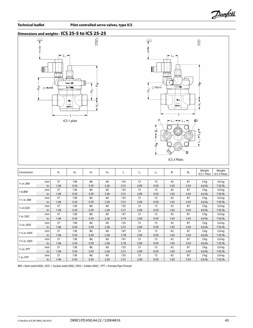
Dimensions and weights - ICS 25-5 to ICS 25-25
Connection H1 H2 H3 H4 L L1 L2 B1 B2Weight
ICS 1 PilotWeight
ICS 3 Pilots
3/4 in. BW mm 37 138 86 60 135 51 15 42 87 3 kg 3.6 kg
in. 1.46 5.43 3.39 2.36 5.31 2.00 0.59 1.65 3.43 6.6 lb. 7.92 lb.
1 in.BW mm 37 138 86 60 135 51 15 42 87 3 kg 3.6 kg
in. 1.46 5.43 3.39 2.36 5.31 2.00 0.59 1.65 3.43 6.6 lb. 7.92 lb.
11/4 in. BW mm 37 138 86 60 135 51 15 42 87 3 kg 3.6 kg
in. 1.46 5.43 3.39 2.36 5.31 2.00 0.59 1.65 3.43 6.6 lb. 7.92 lb.
3/4 in.SOCmm 37 138 86 60 135 51 15 42 87 3 kg 3.6 kg
in. 1.46 5.43 3.39 2.36 5.31 2.00 0.59 1.65 3.43 6.6 lb. 7.92 lb.
1 in. SOCmm 37 138 86 60 147 51 15 42 87 3 kg 3.6 kg
in. 1.46 5.43 3.39 2.36 5.79 2.00 0.59 1.65 3.43 6.6 lb. 7.92 lb.
7/8 in. ODSmm 37 138 86 60 135 51 15 42 87 3 kg 3.6 kg
in. 1.46 5.43 3.39 2.36 5.31 2.00 0.59 1.65 3.43 6.6 lb. 7.92 lb.
11/8 in. ODSmm 37 138 86 60 147 51 15 42 87 3 kg 3.6 kg
in. 1.46 5.43 3.39 2.36 5.78 2.00 0.59 1.65 3.43 6.6 lb. 7.92 lb.
13/8 in. ODSmm 37 138 86 60 147 51 15 42 87 3 kg 3.6 kg
in. 1.46 5.43 3.39 2.36 5.78 2.00 0.59 1.65 3.43 6.6 lb. 7.92 lb.
3/4 in. FPTmm 37 138 86 60 135 51 15 42 87 3 kg 3.6 kg
in. 1.46 5.43 3.39 2.36 5.31 2.00 0.59 1.65 3.43 6.6 lb. 7.92 lb.
1 in. FPTmm 37 138 86 60 135 51 15 42 87 3 kg 3.6 kg
in. 1.46 5.43 3.39 2.36 5.31 2.00 0.59 1.65 3.43 6.6 lb. 7.92 lb.
BW = Butt-weld ANSI ; SOC = Socket weld ANSI ; ODS = Solder ANSI ; FPT = Female Pipe Thread
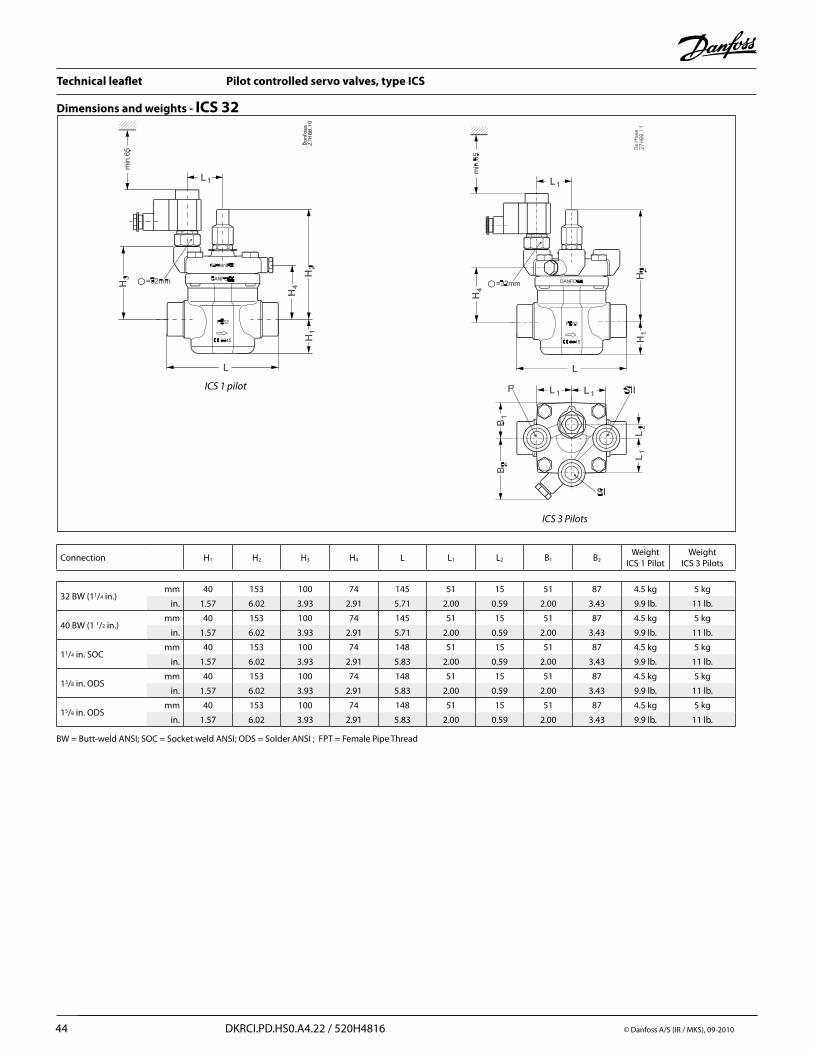
Technical leaflet Pilot controlled servo valves, type ICS
44 DKRCI.PD.HS0.A4.22 / 520H4816 © Danfoss A/S (IR / MKS), 09-2010
ICS 3 Pilots
ICS 1 pilot
Dimensions and weights - ICS 32
BW = Butt-weld ANSI; SOC = Socket weld ANSI; ODS = Solder ANSI ; FPT = Female Pipe Thread
Connection H1 H2 H3 H4 L L1 L2 B1 B2Weight
ICS 1 PilotWeight
ICS 3 Pilots
32 BW (11/4 in.)mm 40 153 100 74 145 51 15 51 87 4.5 kg 5 kg
in. 1.57 6.02 3.93 2.91 5.71 2.00 0.59 2.00 3.43 9.9 lb. 11 lb.
40 BW (1 1/2 in.)mm 40 153 100 74 145 51 15 51 87 4.5 kg 5 kg
in. 1.57 6.02 3.93 2.91 5.71 2.00 0.59 2.00 3.43 9.9 lb. 11 lb.
11/4 in. SOCmm 40 153 100 74 148 51 15 51 87 4.5 kg 5 kg
in. 1.57 6.02 3.93 2.91 5.83 2.00 0.59 2.00 3.43 9.9 lb. 11 lb.
13/8 in. ODSmm 40 153 100 74 148 51 15 51 87 4.5 kg 5 kg
in. 1.57 6.02 3.93 2.91 5.83 2.00 0.59 2.00 3.43 9.9 lb. 11 lb.
15/8 in. ODSmm 40 153 100 74 148 51 15 51 87 4.5 kg 5 kg
in. 1.57 6.02 3.93 2.91 5.83 2.00 0.59 2.00 3.43 9.9 lb. 11 lb.

Technical leaflet Pilot controlled servo valves, type ICS
© Danfoss A/S (IR /MKS), 09-2010 DKRCI.PD.HS0.A4.22 / 520H4816 45
ICS 3 Pilots
ICS 1 pilot
Dimensions and weights - ICS 40
Connection H1 H2 H3 H4 L L1 L2 B1 B2Weight
ICS 1 PilotWeight
ICS 3 Pilots
11/2 in. BWmm 49 159 105 78 160 51 15 54 87 5.9 kg 6.3 kg
in. 1.93 6.26 4.13 3.07 6.30 2.00 0.59 2.13 3.43 13.0 lb. 13.9 lb.
2 in. BW mm 49 159 105 78 180 51 15 54 87 5.9 kg 6.3 kg
in. 1.93 6.26 4.13 3.07 7.09 2.00 0.59 2.13 3.43 13.0 lb. 13.9 lb.
11/2 in. SOCmm 49 159 105 78 180 51 15 54 87 5.9 kg 6.3 kg
in. 1.93 6.26 4.13 3.07 7.09 2.00 0.59 2.13 3.43 13.0 lb. 13.9 lb.
15/8 in. ODSmm 49 159 105 78 180 51 15 54 87 5.9 kg 6.3 kg
in. 1.93 6.26 4.13 3.07 7.09 2.00 0.59 2.13 3.43 13.0 lb. 13.9 lb.
BW = Butt-weld ANSI; SOC = Socket weld ANSI; ODS = Solder ANSI; FPT = Female Pipe Thread
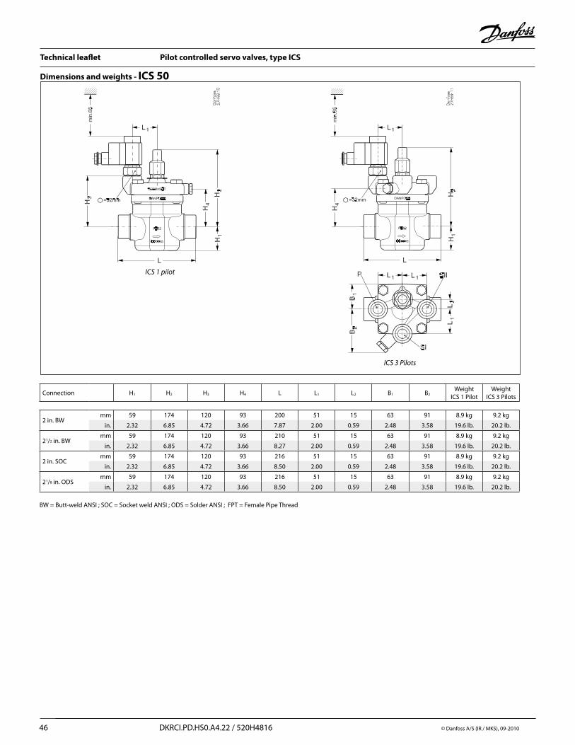
Technical leaflet Pilot controlled servo valves, type ICS
46 DKRCI.PD.HS0.A4.22 / 520H4816 © Danfoss A/S (IR / MKS), 09-2010
ICS 3 Pilots
ICS 1 pilot
Dimensions and weights - ICS 50
Connection H1 H2 H3 H4 L L1 L2 B1 B2Weight
ICS 1 PilotWeight
ICS 3 Pilots
2 in. BWmm 59 174 120 93 200 51 15 63 91 8.9 kg 9.2 kg
in. 2.32 6.85 4.72 3.66 7.87 2.00 0.59 2.48 3.58 19.6 lb. 20.2 lb.
21/2 in. BWmm 59 174 120 93 210 51 15 63 91 8.9 kg 9.2 kg
in. 2.32 6.85 4.72 3.66 8.27 2.00 0.59 2.48 3.58 19.6 lb. 20.2 lb.
2 in. SOCmm 59 174 120 93 216 51 15 63 91 8.9 kg 9.2 kg
in. 2.32 6.85 4.72 3.66 8.50 2.00 0.59 2.48 3.58 19.6 lb. 20.2 lb.
21/8 in. ODSmm 59 174 120 93 216 51 15 63 91 8.9 kg 9.2 kg
in. 2.32 6.85 4.72 3.66 8.50 2.00 0.59 2.48 3.58 19.6 lb. 20.2 lb.
BW = Butt-weld ANSI ; SOC = Socket weld ANSI ; ODS = Solder ANSI ; FPT = Female Pipe Thread

Technical leaflet Pilot controlled servo valves, type ICS
© Danfoss A/S (IR /MKS), 09-2010 DKRCI.PD.HS0.A4.22 / 520H4816 47
ICS 3 Pilots
ICS 1 pilot
Dimensions and weights - ICS 65 / 80
Connection H1 H2 H3 H4 L L1 L2 B1 B2Weight
ICS 1 PilotWeight
ICS 3 Pilots
21/2 in. BWmm 65 195 140 115 230 51 15 70 91 13.4 kg 13.5 kg
in. 2.56 7.68 5.51 4.53 9.06 2.00 0.59 2.76 3.58 29.48 lb. 29.7 lb.
3 in. BWmm 65 195 140 115 245 51 15 70 91 13.4 kg 13.5 kg
in. 2.56 7.68 5.51 4.53 9.65 2.00 0.59 2.76 3.58 29.48 lb. 29.7 lb.
21/2 in. SOCmm 65 195 140 115 230 51 15 70 91 13.4 kg 13.5 kg
in. 2.56 7.68 5.51 4.53 9.06 2.00 0.59 2.76 3.58 29.48 lb. 29.7 lb.
2 5/8 in. ODSmm 65 195 140 115 245 51 15 70 91 13.4 kg 13.5 kg
in. 2.56 7.68 5.51 4.53 9.65 2.00 0.59 2.76 3.58 29.48 lb. 29.7 lb.
BW = Butt-weld ANSI; SOC = Socket weld ANSI; ODS = Solder ANSI ; FPT = Female Pipe Thread
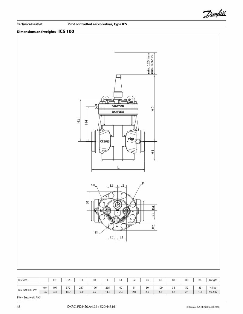
Technical leaflet Pilot controlled servo valves, type ICS
48 DKRCI.PD.HS0.A4.22 / 520H4816 © Danfoss A/S (IR / MKS), 09-2010
Dimensions and weights - ICS 100
ICS Size H1 H2 H3 H4 L L1 L2 L3 B1 B2 B3 B4 Weight
ICS 100 4 in. BWmm 109 372 237 196 295 60 51 50 109 38 52 33 45 kg
in. 4.3 14.7 9.3 7.7 11.6 2.4 2.0 2.0 4.3 1.5 2.1 1.3 99.2 lb.
BW = Butt-weld ANSI
H3
H1
H2
H4
min
. 125 m
mm
in.
4.9
2 in.
L
B4
L1 L2
B1
B3
B2
L1L3
PSll
Sl

Technical leaflet Pilot controlled servo valves, type ICS
© Danfoss A/S (IR /MKS), 09-2010 DKRCI.PD.HS0.A4.22 / 520H4816 49
Dimensions and weights - ICS 125-150
ICS size H1 H2 H3 H4 L L1 L2 L3 L4 B1 B2 B3 B4 Weight
ICS 125 5 in. BWmm 139 386 246 212 350 84 56 55 85 130 45 50 47 68 kg
in. 5.5 15.2 9.7 8.4 13.8 3.3 2.2 2.2 3.4 5.1 1.8 2.0 1.9 149.9 lb.
ICS 150, 6 in. BWmm 168 425 297 256 445 107 58 69 96 150 48 52 50 115 kg
in. 6.6 16.7 11.7 10.1 17.5 4.2 2.3 2.7 3.8 5.9 1.9 2.1 2.0 253.5 lb.
BW = Butt-weld ANSI
L
H1
H4
H2
H3
B3
B4
B1
L1 L2
L3 L4
B2
Sl
Sll
P
min
. 125 m
mm
in.
4.9
2 in.

Technical leaflet Pilot controlled servo valves, type ICS
50 DKRCI.PD.HS0.A4.22 / 520H4816 © Danfoss A/S (IR / MKS), 09-2010
Connections
BW: Butt-weld ANSI (B 36.10)
SOC: Socket welding ANSI (B 16.11)
Sizemm
Sizein.
ODmm
Tmm
ODin.
Tin.
Schedule
(20) 3/4 26.9 4.0 1.059 0.158 80
(25) 1 33.7 4.6 1.327 0.181 80
(32) 11/4 42.4 4.9 1.669 0.193 80
(40) 11/2 48.3 5.1 1.902 0.201 80
(50) 2 60.3 3.9 2.37 0.15 40
(65) 21/2 73.0 5.2 2.87 0.20 40
(80) 3 88.9 5.5 3.50 0.22 40
(100) 4 114.3 6 4.5 0.24
(125) 5 140.7 6.5 5.5 0.26
(150) 6 168.3 7.1 6.6 0.28
Sizemm
Sizein.
IDmm
Tmm
IDin.
Tin.
Lmm
Lin.
(20) 3/4 27.2 4.6 1.071 0.181 13 0.51
(25) 1 33.9 7.2 1.335 0.284 13 0.51
(32) 11/4 42.7 6.1 1.743 0.240 13 0.51
(40) 11/2 48.8 6.6 1.921 0.260 13 0.51
(50) 2 61.2 6.2 2.41 0.24 16 0.63
(65) 21/2 74 8.8 2.91 0.344 16 0.63
FPT: Female pipe thread, (ANSI/ASME B 1.20.1)
Sizemm
Sizein.
Inside pipe thread
(20) 3/4 (3/4 × 14 NPT)
(25) 1 (1 × 11.5 NPT)
(32) 11/4 (11/4 × 11.5 NPT)
ODS: Soldering (ANSI B 16.22) Sizein.
ID in.
Lin.
7/8 0.875 0.650
11/8 1.125 1.024
13/8 1.375 0.984
15/8 1.625 1.102
21/8 2.125 1.300
25/8 2.625 1.300
www.danfoss.us/Industrial_Refrigeration


