Embed Size (px)
Citation preview
Pillar Axiom 600
HardwareInstallation Guide

Part Number: 4420-00106-0600Pillar Axiom release 5.22011 October
Copyright © 2011, Oracle and/or its affiliates. All rights reserved.
This software and related documentation are provided under a license agreement containing restrictions onuse and disclosure and are protected by intellectual property laws. Except as expressly permitted in yourlicense agreement or allowed by law, you may not use, copy, reproduce, translate, broadcast, modify,license, transmit, distribute, exhibit, perform, publish or display any part, in any form, or by any means.Reverse engineering, disassembly, or decompilation of this software, unless required by law forinteroperability, is prohibited.
The information contained herein is subject to change without notice and is not warranted to be error-free. Ifyou find any errors, please report them to us in writing.
If this is software or related documentation that is delivered to the U.S. Government or anyone licensing it onbehalf of the U.S. Government, the following notice is applicable:
U.S. GOVERNMENT RIGHTS Programs, software, databases, and related documentation and technicaldata delivered to U.S. Government customers are "commercial computer software" or "commercial technicaldata" pursuant to the applicable Federal Acquisition Regulation and agency-specific supplementalregulations. As such, the use, duplication, disclosure, modification, and adaptation shall be subject to therestrictions and license terms set forth in the applicable Government contract, and, to the extent applicableby the terms of the Government contract, the additional rights set forth in FAR 52.227-19, CommercialComputer Software License (December 2007). Oracle USA, Inc., 500 Oracle Parkway, Redwood City, CA94065.
This software or hardware is developed for general use in a variety of information management applications.It is not developed or intended for use in any inherently dangerous applications, including applications thatmay create a risk of personal injury. If you use this software or hardware in dangerous applications, then youshall be responsible to take all appropriate fail-safe, backup, redundancy, and other measures to ensure itssafe use. Oracle Corporation and its affiliates disclaim any liability for any damages caused by use of thissoftware or hardware in dangerous applications.
Oracle and Java are registered trademarks of Oracle and/or its affiliates. Other names may be trademarks oftheir respective owners.
This software or hardware and documentation may provide access to or information on content, productsand services from third parties. Oracle Corporation and its affiliates are not responsible for and expresslydisclaim all warranties of any kind with respect to third-party content, products, and services. OracleCorporation and its affiliates will not be responsible for any loss, costs, or damages incurred due to youraccess to or use of third-party content, products, or services.
2

Copyright © 2011, Oracle et/ou ses affiliés. Tous droits réservés.
Ce logiciel et la documentation qui l’accompagne sont protégés par les lois sur la propriété intellectuelle. Ilssont concédés sous licence et soumis à des restrictions d’utilisation et de divulgation. Sauf disposition devotre contrat de licence ou de la loi, vous ne pouvez pas copier, reproduire, traduire, diffuser, modifier,breveter, transmettre, distribuer, exposer, exécuter, publier ou afficher le logiciel, même partiellement, sousquelque forme et par quelque procédé que ce soit. Par ailleurs, il est interdit de procéder à toute ingénierieinverse du logiciel, de le désassembler ou de le décompiler, excepté à des fins d’interopérabilité avec deslogiciels tiers ou tel que prescrit par la loi.
Les informations fournies dans ce document sont susceptibles de modification sans préavis. Par ailleurs,Oracle Corporation ne garantit pas qu’elles soient exemptes d’erreurs et vous invite, le cas échéant, à lui enfaire part par écrit.
Si ce logiciel, ou la documentation qui l’accompagne, est concédé sous licence au Gouvernement des Etats-Unis, ou à toute entité qui délivre la licence de ce logiciel ou l’utilise pour le compte du Gouvernement desEtats-Unis, la notice suivante s’applique :
U.S. GOVERNMENT RIGHTS. Programs, software, databases, and related documentation and technicaldata delivered to U.S. Government customers are "commercial computer software" or "commercial technicaldata" pursuant to the applicable Federal Acquisition Regulation and agency-specific supplementalregulations. As such, the use, duplication, disclosure, modification, and adaptation shall be subject to therestrictions and license terms set forth in the applicable Government contract, and, to the extent applicableby the terms of the Government contract, the additional rights set forth in FAR 52.227-19, CommercialComputer Software License (December 2007). Oracle America, Inc., 500 Oracle Parkway, Redwood City,CA 94065.
Ce logiciel ou matériel a été développé pour un usage général dans le cadre d’applications de gestion desinformations. Ce logiciel ou matériel n’est pas conçu ni n’est destiné à être utilisé dans des applications àrisque, notamment dans des applications pouvant causer des dommages corporels. Si vous utilisez celogiciel ou matériel dans le cadre d’applications dangereuses, il est de votre responsabilité de prendretoutes les mesures de secours, de sauvegarde, de redondance et autres mesures nécessaires à sonutilisation dans des conditions optimales de sécurité. Oracle Corporation et ses affiliés déclinent touteresponsabilité quant aux dommages causés par l’utilisation de ce logiciel ou matériel pour ce typed’applications.
Oracle et Java sont des marques déposées d’Oracle Corporation et/ou de ses affiliés.Tout autre nommentionné peut correspondre à des marques appartenant à d’autres propriétaires qu’Oracle.
Ce logiciel ou matériel et la documentation qui l’accompagne peuvent fournir des informations ou des liensdonnant accès à des contenus, des produits et des services émanant de tiers. Oracle Corporation et sesaffiliés déclinent toute responsabilité ou garantie expresse quant aux contenus, produits ou servicesémanant de tiers. En aucun cas, Oracle Corporation et ses affiliés ne sauraient être tenus pourresponsables des pertes subies, des coûts occasionnés ou des dommages causés par l’accès à descontenus, produits ou services tiers, ou à leur utilisation.
3
Table of Contents
Preface
Chapter 1 Before You BeginPillar Axiom 600 Series Components. . . . . . . . . . . . . . . . . . . . . . . . . . . . . . . . . . . . . . 21Customer-Supplied Equipment and Tools. . . . . . . . . . . . . . . . . . . . . . . . . . . . . . . . . . 23Safety Notice Conventions. . . . . . . . . . . . . . . . . . . . . . . . . . . . . . . . . . . . . . . . . . . . . 25
Chapter 2 Set Up the RackAbout Component Inspection. . . . . . . . . . . . . . . . . . . . . . . . . . . . . . . . . . . . . . . . . . . 26Rack Position. . . . . . . . . . . . . . . . . . . . . . . . . . . . . . . . . . . . . . . . . . . . . . . . . . . . . . . 28
About Multiple Rack Connections. . . . . . . . . . . . . . . . . . . . . . . . . . . . . . . . . . . . . . 28Adjust the Leveling Legs. . . . . . . . . . . . . . . . . . . . . . . . . . . . . . . . . . . . . . . . . . . . 33About Rack Stability. . . . . . . . . . . . . . . . . . . . . . . . . . . . . . . . . . . . . . . . . . . . . . . 35
About Component Placement. . . . . . . . . . . . . . . . . . . . . . . . . . . . . . . . . . . . . . . . . . . 39Configuration Limits for a Pillar Axiom 600 System. . . . . . . . . . . . . . . . . . . . . . . . . 39About Component Placement for One Slammer and SATA Bricks. . . . . . . . . . . . . . 41About Component Placement for One Slammer and FC Bricks. . . . . . . . . . . . . . . . 43About Component Placement for Two or Three Slammers and FC Bricks. . . . . . . . . 45About Component Placement for Four Slammers and 64 Bricks. . . . . . . . . . . . . . . . 47Pilot Rail Kit Parts. . . . . . . . . . . . . . . . . . . . . . . . . . . . . . . . . . . . . . . . . . . . . . . . . 49Install a Pair of Pilot Mounting Rails. . . . . . . . . . . . . . . . . . . . . . . . . . . . . . . . . . . . 50Slammer Rail Kit Parts. . . . . . . . . . . . . . . . . . . . . . . . . . . . . . . . . . . . . . . . . . . . . 53Install a Pair of Slammer Mounting Rails. . . . . . . . . . . . . . . . . . . . . . . . . . . . . . . . . 55Brick Rail Kit Parts. . . . . . . . . . . . . . . . . . . . . . . . . . . . . . . . . . . . . . . . . . . . . . . . 57Install a Pair of Brick Mounting Rails. . . . . . . . . . . . . . . . . . . . . . . . . . . . . . . . . . . . 58
Chapter 3 Install ComponentsAbout Power Distribution Unit Installation. . . . . . . . . . . . . . . . . . . . . . . . . . . . . . . . . . . 61
Install a 1U PDU. . . . . . . . . . . . . . . . . . . . . . . . . . . . . . . . . . . . . . . . . . . . . . . . . . 62Install a 2U PDU. . . . . . . . . . . . . . . . . . . . . . . . . . . . . . . . . . . . . . . . . . . . . . . . . . 64
Install a Pilot Management Controller. . . . . . . . . . . . . . . . . . . . . . . . . . . . . . . . . . . . . 66
4
Pilot Versions. . . . . . . . . . . . . . . . . . . . . . . . . . . . . . . . . . . . . . . . . . . . . . . . . . . . . . . 68Install a Slammer Storage Controller. . . . . . . . . . . . . . . . . . . . . . . . . . . . . . . . . . . . . . 71Install the Slammer Batteries. . . . . . . . . . . . . . . . . . . . . . . . . . . . . . . . . . . . . . . . . . . 73Install a Brick Storage Enclosure. . . . . . . . . . . . . . . . . . . . . . . . . . . . . . . . . . . . . . . . . 75Set the Identity of Bricks. . . . . . . . . . . . . . . . . . . . . . . . . . . . . . . . . . . . . . . . . . . . . . . 78Replace a Brick Storage Enclosure. . . . . . . . . . . . . . . . . . . . . . . . . . . . . . . . . . . . . . . 80
Delete All Clone LUNs. . . . . . . . . . . . . . . . . . . . . . . . . . . . . . . . . . . . . . . . . . . . . . 81Accept a Brick. . . . . . . . . . . . . . . . . . . . . . . . . . . . . . . . . . . . . . . . . . . . . . . . . . . . 82Create a Storage Domain. . . . . . . . . . . . . . . . . . . . . . . . . . . . . . . . . . . . . . . . . . . 83About Adding Bricks to a Storage Domain. . . . . . . . . . . . . . . . . . . . . . . . . . . . . . . 84Set a Storage Domain as the Primary. . . . . . . . . . . . . . . . . . . . . . . . . . . . . . . . . . . 86Move a Volume to Another Storage Domain. . . . . . . . . . . . . . . . . . . . . . . . . . . . . . 87
Chapter 4 Connect Data CablesAbout Cabling a Pillar Axiom 600 System. . . . . . . . . . . . . . . . . . . . . . . . . . . . . . . . . . 89Cable Handling Tips. . . . . . . . . . . . . . . . . . . . . . . . . . . . . . . . . . . . . . . . . . . . . . . . . . 92Clean Fiber Optic Cables. . . . . . . . . . . . . . . . . . . . . . . . . . . . . . . . . . . . . . . . . . . . . . 94Cabling Practices for the Pillar Axiom 600 System. . . . . . . . . . . . . . . . . . . . . . . . . . . . 95About Cable Connections Between Two Racks. . . . . . . . . . . . . . . . . . . . . . . . . . . . . 104About Cabling the SSF and PMI. . . . . . . . . . . . . . . . . . . . . . . . . . . . . . . . . . . . . . . . 105About Jumbo Frames. . . . . . . . . . . . . . . . . . . . . . . . . . . . . . . . . . . . . . . . . . . . . . . . 107Connect the Pilot to Your Management LAN. . . . . . . . . . . . . . . . . . . . . . . . . . . . . . . 108Connect the Pilot CUs. . . . . . . . . . . . . . . . . . . . . . . . . . . . . . . . . . . . . . . . . . . . . . . 110Connect a Slammer to the Data Network. . . . . . . . . . . . . . . . . . . . . . . . . . . . . . . . . . 112
Chapter 5 Connect Power CablesComponent Power Usage. . . . . . . . . . . . . . . . . . . . . . . . . . . . . . . . . . . . . . . . . . . . . 114PDU Outlet Amperage Limits. . . . . . . . . . . . . . . . . . . . . . . . . . . . . . . . . . . . . . . . . . 115About Power Cabling. . . . . . . . . . . . . . . . . . . . . . . . . . . . . . . . . . . . . . . . . . . . . . . . 117
Sample Power Cabling for One Slammer and Three Bricks. . . . . . . . . . . . . . . . . . 117Sample Power Cabling for One Slammer and 16 SATA Bricks. . . . . . . . . . . . . . . . 120
Connect Power Cables. . . . . . . . . . . . . . . . . . . . . . . . . . . . . . . . . . . . . . . . . . . . . . . 123
Chapter 6 Complete the InstallationPower On the System. . . . . . . . . . . . . . . . . . . . . . . . . . . . . . . . . . . . . . . . . . . . . . . . 125Verify the Front Status LEDs. . . . . . . . . . . . . . . . . . . . . . . . . . . . . . . . . . . . . . . . . . . 128Verify the Back Status LEDs. . . . . . . . . . . . . . . . . . . . . . . . . . . . . . . . . . . . . . . . . . . 133
8 Gb/s Fiber Channel (FC) HBA LED Status. . . . . . . . . . . . . . . . . . . . . . . . . . . . . 13610 Gb/s Ethernet HBA LED Status. . . . . . . . . . . . . . . . . . . . . . . . . . . . . . . . . . . . 137
Attach the Bezels. . . . . . . . . . . . . . . . . . . . . . . . . . . . . . . . . . . . . . . . . . . . . . . . . . . 138
5

About HBA Driver and Firmware Installation (SAN Only). . . . . . . . . . . . . . . . . . . . . . . 140About Switch Zone for HBA Set Up (SAN Only). . . . . . . . . . . . . . . . . . . . . . . . . . . . . 141Attach the Rack Doors and Panels. . . . . . . . . . . . . . . . . . . . . . . . . . . . . . . . . . . . . . 142Attach the Rack Side Panels. . . . . . . . . . . . . . . . . . . . . . . . . . . . . . . . . . . . . . . . . . . 143
Chapter 7 Initial ConfigurationPre-Configuration Checklist. . . . . . . . . . . . . . . . . . . . . . . . . . . . . . . . . . . . . . . . . . . . 144Start the Graphical User Interface. . . . . . . . . . . . . . . . . . . . . . . . . . . . . . . . . . . . . . . 146Rename the Bricks. . . . . . . . . . . . . . . . . . . . . . . . . . . . . . . . . . . . . . . . . . . . . . . . . . 149Troubleshoot a Failed Cable Connection. . . . . . . . . . . . . . . . . . . . . . . . . . . . . . . . . . 151About Pillar Axiom Path Manager Installation (SAN Only). . . . . . . . . . . . . . . . . . . . . . 152Reset the Primary System Administrator Password. . . . . . . . . . . . . . . . . . . . . . . . . . 153
Appendix A Slammer LED Startup Progress CodesAbout LED Startup Codes. . . . . . . . . . . . . . . . . . . . . . . . . . . . . . . . . . . . . . . . . . . . . 154About Slammer LED Codes. . . . . . . . . . . . . . . . . . . . . . . . . . . . . . . . . . . . . . . . . . . 155Slammer LED Startup and Halt Codes. . . . . . . . . . . . . . . . . . . . . . . . . . . . . . . . . . . . 156
Appendix B Safety StatementsAbout Safety Statements. . . . . . . . . . . . . . . . . . . . . . . . . . . . . . . . . . . . . . . . . . . . . 162Warning Notices. . . . . . . . . . . . . . . . . . . . . . . . . . . . . . . . . . . . . . . . . . . . . . . . . . . . 163
Electrical Warning in Other Languages. . . . . . . . . . . . . . . . . . . . . . . . . . . . . . . . . 163Lightning Activity Warning. . . . . . . . . . . . . . . . . . . . . . . . . . . . . . . . . . . . . . . . . . 166Lightning Warning in Other Languages. . . . . . . . . . . . . . . . . . . . . . . . . . . . . . . . . 166Power Supply Warning. . . . . . . . . . . . . . . . . . . . . . . . . . . . . . . . . . . . . . . . . . . . 167Power Supply Warning in Other Languages. . . . . . . . . . . . . . . . . . . . . . . . . . . . . 167Main Power Disconnect Warning. . . . . . . . . . . . . . . . . . . . . . . . . . . . . . . . . . . . . 169Power Disconnect Warning in Other Languages. . . . . . . . . . . . . . . . . . . . . . . . . . 169Installation Warning. . . . . . . . . . . . . . . . . . . . . . . . . . . . . . . . . . . . . . . . . . . . . . . 169Power Disconnect Warning. . . . . . . . . . . . . . . . . . . . . . . . . . . . . . . . . . . . . . . . . 170Warning Statement for Norway and Sweden. . . . . . . . . . . . . . . . . . . . . . . . . . . . . 170Restricted Access Area Warning. . . . . . . . . . . . . . . . . . . . . . . . . . . . . . . . . . . . . 171Restricted Access Warning in Other Languages. . . . . . . . . . . . . . . . . . . . . . . . . . 171Product Disposal Warning. . . . . . . . . . . . . . . . . . . . . . . . . . . . . . . . . . . . . . . . . . 172Product Disposal Warning in Other Languages. . . . . . . . . . . . . . . . . . . . . . . . . . . 173Jewelry Removal Warning. . . . . . . . . . . . . . . . . . . . . . . . . . . . . . . . . . . . . . . . . . 173Jewelry Removal Warning in Other Languages. . . . . . . . . . . . . . . . . . . . . . . . . . . 174Qualified Personnel Warning. . . . . . . . . . . . . . . . . . . . . . . . . . . . . . . . . . . . . . . . 175Warning Statement for Finland. . . . . . . . . . . . . . . . . . . . . . . . . . . . . . . . . . . . . . . 176Warning Statement for Sweden. . . . . . . . . . . . . . . . . . . . . . . . . . . . . . . . . . . . . . 176
6

Power Cabling Warning. . . . . . . . . . . . . . . . . . . . . . . . . . . . . . . . . . . . . . . . . . . . 176Power Cabling Warning in Other Languages. . . . . . . . . . . . . . . . . . . . . . . . . . . . . 177Supply Circuit Warning. . . . . . . . . . . . . . . . . . . . . . . . . . . . . . . . . . . . . . . . . . . . 178Supply Circuit Warning in Other Languages. . . . . . . . . . . . . . . . . . . . . . . . . . . . . 178Voltage Mismatch Warning. . . . . . . . . . . . . . . . . . . . . . . . . . . . . . . . . . . . . . . . . 179Voltage Mismatch Warning in Other Languages. . . . . . . . . . . . . . . . . . . . . . . . . . 179SELV Circuit Warning. . . . . . . . . . . . . . . . . . . . . . . . . . . . . . . . . . . . . . . . . . . . . 180SELV Circuit Warning in Other Languages. . . . . . . . . . . . . . . . . . . . . . . . . . . . . . 180Incorrect Connection Warning. . . . . . . . . . . . . . . . . . . . . . . . . . . . . . . . . . . . . . . 182Incorrect Connection Warning in Other Languages. . . . . . . . . . . . . . . . . . . . . . . . 182
Caution Notices. . . . . . . . . . . . . . . . . . . . . . . . . . . . . . . . . . . . . . . . . . . . . . . . . . . . 184
Appendix C Pillar Axiom Hardware SpecificationsAbout Hardware Specifications. . . . . . . . . . . . . . . . . . . . . . . . . . . . . . . . . . . . . . . . . 186About Pillar Axiom 600 Hardware Specifications. . . . . . . . . . . . . . . . . . . . . . . . . . . . . 187
System Power Requirements. . . . . . . . . . . . . . . . . . . . . . . . . . . . . . . . . . . . . . . . 187System Environmentals. . . . . . . . . . . . . . . . . . . . . . . . . . . . . . . . . . . . . . . . . . . . 188System Regulatory Agency Compliance. . . . . . . . . . . . . . . . . . . . . . . . . . . . . . . . 190System Packaging and Transportation. . . . . . . . . . . . . . . . . . . . . . . . . . . . . . . . . 195System Warranty. . . . . . . . . . . . . . . . . . . . . . . . . . . . . . . . . . . . . . . . . . . . . . . . . 195
About Pilot Hardware Specifications. . . . . . . . . . . . . . . . . . . . . . . . . . . . . . . . . . . . . 196Pilot Dimensions and Weight. . . . . . . . . . . . . . . . . . . . . . . . . . . . . . . . . . . . . . . . 196Pilot Power Characteristics. . . . . . . . . . . . . . . . . . . . . . . . . . . . . . . . . . . . . . . . . 196Pilot Regulatory Agency Compliance. . . . . . . . . . . . . . . . . . . . . . . . . . . . . . . . . . 197Pilot Packaging and Transportation. . . . . . . . . . . . . . . . . . . . . . . . . . . . . . . . . . . 198
About Slammer Hardware Specification. . . . . . . . . . . . . . . . . . . . . . . . . . . . . . . . . . . 199Slammer Dimensions and Weight. . . . . . . . . . . . . . . . . . . . . . . . . . . . . . . . . . . . . 199Slammer Power Characteristics. . . . . . . . . . . . . . . . . . . . . . . . . . . . . . . . . . . . . . 199Slammer Regulatory Agency Compliance. . . . . . . . . . . . . . . . . . . . . . . . . . . . . . . 200Slammer Packaging and Transportation. . . . . . . . . . . . . . . . . . . . . . . . . . . . . . . . 200Cable Length Limits for SAN Fibre Channel Connections. . . . . . . . . . . . . . . . . . . . 201Cable Length Limits for NAS Ethernet Connections. . . . . . . . . . . . . . . . . . . . . . . . 201
About Brick Hardware Specification. . . . . . . . . . . . . . . . . . . . . . . . . . . . . . . . . . . . . . 203Brick Dimensions and Weight. . . . . . . . . . . . . . . . . . . . . . . . . . . . . . . . . . . . . . . . 203Brick Power Characteristics. . . . . . . . . . . . . . . . . . . . . . . . . . . . . . . . . . . . . . . . . 203Brick Regulatory Agency Compliance. . . . . . . . . . . . . . . . . . . . . . . . . . . . . . . . . . 204Brick Packaging and Transportation. . . . . . . . . . . . . . . . . . . . . . . . . . . . . . . . . . . 205
Pillar Axiom 600 PDU Hardware Specification. . . . . . . . . . . . . . . . . . . . . . . . . . . . . . 206Pillar Rack Hardware Specification. . . . . . . . . . . . . . . . . . . . . . . . . . . . . . . . . . . . . . 208
7
Appendix D Expansion of a Pillar Axiom 600 System ConfigurationAbout Expanding a Pillar Axiom 600 Configuration. . . . . . . . . . . . . . . . . . . . . . . . . . . 211
Complete the Brick Pre-Installation Checklist. . . . . . . . . . . . . . . . . . . . . . . . . . . . 211Complete the Slammer Pre-Installation Checklist. . . . . . . . . . . . . . . . . . . . . . . . . 212About Additional Brick Storage Enclosures. . . . . . . . . . . . . . . . . . . . . . . . . . . . . . 213Add a New Brick Storage Enclosure. . . . . . . . . . . . . . . . . . . . . . . . . . . . . . . . . . . 214Verify a Newly Added Brick. . . . . . . . . . . . . . . . . . . . . . . . . . . . . . . . . . . . . . . . . 217About Additional Slammer Storage Controllers. . . . . . . . . . . . . . . . . . . . . . . . . . . 218Add a New Slammer Storage Controller. . . . . . . . . . . . . . . . . . . . . . . . . . . . . . . . 219Storage System Fabric (SSF) Cabling Reference. . . . . . . . . . . . . . . . . . . . . . . . . 220
Index. . . . . . . . . . . . . . . . . . . . . . . . . . . . . . . . . . . . . . . . . . . . . . . . . . . . . . . . . . . . . . 225
8
List of Figures
Figure 1 Floor plan for rack installation. . . . . . . . . . . . . . . . . . . . . . . . . . . . . . . . . . . . . . . 28
Figure 2 Sample 42U side panels. . . . . . . . . . . . . . . . . . . . . . . . . . . . . . . . . . . . . . . . . . . 29
Figure 3 Location of frame corners. . . . . . . . . . . . . . . . . . . . . . . . . . . . . . . . . . . . . . . . . . 30
Figure 4 Connection bracket installation. . . . . . . . . . . . . . . . . . . . . . . . . . . . . . . . . . . . . . 31
Figure 5 Roof baying plate attachment. . . . . . . . . . . . . . . . . . . . . . . . . . . . . . . . . . . . . . . 32
Figure 6 Adjacent anchor bolts at the front of the racks. . . . . . . . . . . . . . . . . . . . . . . . . . . 33
Figure 7 Rack leveling leg locations. . . . . . . . . . . . . . . . . . . . . . . . . . . . . . . . . . . . . . . . . 34
Figure 8 Leveling leg adjustment. . . . . . . . . . . . . . . . . . . . . . . . . . . . . . . . . . . . . . . . . . . 34
Figure 9 Attach anchor bolts to rack. . . . . . . . . . . . . . . . . . . . . . . . . . . . . . . . . . . . . . . . . 36
Figure 10 Position anti-tip brackets. . . . . . . . . . . . . . . . . . . . . . . . . . . . . . . . . . . . . . . . . . 36
Figure 11 Secure anti-tip brackets to the floor. . . . . . . . . . . . . . . . . . . . . . . . . . . . . . . . . . 37
Figure 12 Stabilizer plate attached to the rack base and floor. . . . . . . . . . . . . . . . . . . . . . . 38
Figure 13 42U racks containing one Slammer and up to 32 SATA Bricks. . . . . . . . . . . . . . 42
Figure 14 Fully loaded 42U rack for one Slammer and 15 FC Bricks. . . . . . . . . . . . . . . . . . 44
Figure 15 Fully loaded 42U racks for three Slammers and 32 FC Bricks. . . . . . . . . . . . . . . 46
Figure 16 Fully loaded 42U racks for four Slammers and 64 Bricks. . . . . . . . . . . . . . . . . . . 48
Figure 17 Scope hook attachment. . . . . . . . . . . . . . . . . . . . . . . . . . . . . . . . . . . . . . . . . . 51
Figure 18 Positioning spacer bar. . . . . . . . . . . . . . . . . . . . . . . . . . . . . . . . . . . . . . . . . . . 52
Figure 19 Pilot rail front attachment. . . . . . . . . . . . . . . . . . . . . . . . . . . . . . . . . . . . . . . . . 53
Figure 20 Scope hook attachment. . . . . . . . . . . . . . . . . . . . . . . . . . . . . . . . . . . . . . . . . . 55
Figure 21 Slammer rails installed in rack. . . . . . . . . . . . . . . . . . . . . . . . . . . . . . . . . . . . . . 56
9

Figure 22 Scope hook attachment. . . . . . . . . . . . . . . . . . . . . . . . . . . . . . . . . . . . . . . . . . 59
Figure 23 2U rack rails installed in rack. . . . . . . . . . . . . . . . . . . . . . . . . . . . . . . . . . . . . . . 60
Figure 24 Snap-in cage nut. . . . . . . . . . . . . . . . . . . . . . . . . . . . . . . . . . . . . . . . . . . . . . . 62
Figure 25 Securing a 1U PDU in the bottom of a rack. . . . . . . . . . . . . . . . . . . . . . . . . . . . 63
Figure 26 An installed PDU at the bottom of the rack. . . . . . . . . . . . . . . . . . . . . . . . . . . . . 63
Figure 27 Snap-in cage nut. . . . . . . . . . . . . . . . . . . . . . . . . . . . . . . . . . . . . . . . . . . . . . . 64
Figure 28 2U PDU layout and ear locations. . . . . . . . . . . . . . . . . . . . . . . . . . . . . . . . . . . . 64
Figure 29 Insertion of the upper Pilot CU. . . . . . . . . . . . . . . . . . . . . . . . . . . . . . . . . . . . . 67
Figure 30 Pilot CU (1450–00259–XX) (Back view). . . . . . . . . . . . . . . . . . . . . . . . . . . . . . . 68
Figure 31 Pilot CU (1450–00179–XX) (Back view). . . . . . . . . . . . . . . . . . . . . . . . . . . . . . . 69
Figure 32 Pilot CU (1450–00164–XX) Intel. . . . . . . . . . . . . . . . . . . . . . . . . . . . . . . . . . . . 69
Figure 33 Pilot CU (1450–00170–XX) MSI, non-RoHS. . . . . . . . . . . . . . . . . . . . . . . . . . . . 70
Figure 34 Pilot CU (1450-00268-XX and 1030-00005-XX). . . . . . . . . . . . . . . . . . . . . . . . . 70
Figure 35 Insertion of a Slammer. . . . . . . . . . . . . . . . . . . . . . . . . . . . . . . . . . . . . . . . . . . 72
Figure 36 Slammer bezel removal. . . . . . . . . . . . . . . . . . . . . . . . . . . . . . . . . . . . . . . . . . 73
Figure 37 Slammer battery insertion. . . . . . . . . . . . . . . . . . . . . . . . . . . . . . . . . . . . . . . . . 74
Figure 38 Insertion of a Brick. . . . . . . . . . . . . . . . . . . . . . . . . . . . . . . . . . . . . . . . . . . . . . 75
Figure 39 Brick ears. . . . . . . . . . . . . . . . . . . . . . . . . . . . . . . . . . . . . . . . . . . . . . . . . . . . 76
Figure 40 Brick front with the bezel removed. . . . . . . . . . . . . . . . . . . . . . . . . . . . . . . . . . . 76
Figure 41 ES module location. . . . . . . . . . . . . . . . . . . . . . . . . . . . . . . . . . . . . . . . . . . . . 78
Figure 42 Brick connections in strings. . . . . . . . . . . . . . . . . . . . . . . . . . . . . . . . . . . . . . . . 90
Figure 43 Pillar Axiom 600 back-end cabling overview. . . . . . . . . . . . . . . . . . . . . . . . . . . . 91
Figure 44 Pilot management cables. . . . . . . . . . . . . . . . . . . . . . . . . . . . . . . . . . . . . . . . 109
Figure 45 Pilot CU cabling. . . . . . . . . . . . . . . . . . . . . . . . . . . . . . . . . . . . . . . . . . . . . . . 110
Figure 46 Slammer network cables. . . . . . . . . . . . . . . . . . . . . . . . . . . . . . . . . . . . . . . . . 112
Figure 47 Pulizzi TPC2105-1 outlet amperage limits. . . . . . . . . . . . . . . . . . . . . . . . . . . . 115
Figure 48 Pulizzi TPC2104 outlet amperage limits. . . . . . . . . . . . . . . . . . . . . . . . . . . . . . 116
Figure 49 Pulizzi PC3365 outlet amperage limits. . . . . . . . . . . . . . . . . . . . . . . . . . . . . . . 116
10

Figure 50 Sample power cabling scheme with 230V power, 20A PDU. . . . . . . . . . . . . . . 118
Figure 51 Sample power cabling scheme with 115V on a TCP2105-1 PDU. . . . . . . . . . . . 119
Figure 52 Sample power cabling scheme with 230V (one circuit shown). . . . . . . . . . . . . . 121
Figure 53 Sample power cabling scheme with two 208V single phase PDU. . . . . . . . . . . 122
Figure 54 Secure Slammer batteries. . . . . . . . . . . . . . . . . . . . . . . . . . . . . . . . . . . . . . . . 125
Figure 55 Turn on Brick power. . . . . . . . . . . . . . . . . . . . . . . . . . . . . . . . . . . . . . . . . . . . 126
Figure 56 Turn on Pilot power. . . . . . . . . . . . . . . . . . . . . . . . . . . . . . . . . . . . . . . . . . . . 126
Figure 57 Turn on PDU power. . . . . . . . . . . . . . . . . . . . . . . . . . . . . . . . . . . . . . . . . . . . 127
Figure 58 Pilot bezel LEDs. . . . . . . . . . . . . . . . . . . . . . . . . . . . . . . . . . . . . . . . . . . . . . . 128
Figure 59 DC power switch at the back of the Pilot . . . . . . . . . . . . . . . . . . . . . . . . . . . . . 129
Figure 60 Slammer bezel LEDs. . . . . . . . . . . . . . . . . . . . . . . . . . . . . . . . . . . . . . . . . . . 131
Figure 61 Brick bezel LEDs. . . . . . . . . . . . . . . . . . . . . . . . . . . . . . . . . . . . . . . . . . . . . . 132
Figure 62 Pilot connectivity LEDs. . . . . . . . . . . . . . . . . . . . . . . . . . . . . . . . . . . . . . . . . . 133
Figure 63 Slammer connectivity LEDs. . . . . . . . . . . . . . . . . . . . . . . . . . . . . . . . . . . . . . 134
Figure 64 Brick LEDs. . . . . . . . . . . . . . . . . . . . . . . . . . . . . . . . . . . . . . . . . . . . . . . . . . . 135
Figure 65 Bezel hook on the right side of the bezel. . . . . . . . . . . . . . . . . . . . . . . . . . . . . 138
Figure 66 Press the ejector tabs to secure the bezel. . . . . . . . . . . . . . . . . . . . . . . . . . . . 139
Figure 67 Pillar Axiom Storage Services Manager log in screen. . . . . . . . . . . . . . . . . . . . 147
Figure 68 Logical Brick names in the GUI. . . . . . . . . . . . . . . . . . . . . . . . . . . . . . . . . . . . 149
Figure 69 Maximum tilt angles for stationary Pillar 42U racks. . . . . . . . . . . . . . . . . . . . . . 210
11
List of Tables
Table 1 Additional information resources for all systems. . . . . . . . . . . . . . . . . . . . . . . . . . 17
Table 2 Typography to mark certain content. . . . . . . . . . . . . . . . . . . . . . . . . . . . . . . . . . . 19
Table 3 Contacts at Pillar Data Systems. . . . . . . . . . . . . . . . . . . . . . . . . . . . . . . . . . . . . . 19
Table 4 Pillar Axiom 600 series components. . . . . . . . . . . . . . . . . . . . . . . . . . . . . . . . . . 21
Table 5 Required tools. . . . . . . . . . . . . . . . . . . . . . . . . . . . . . . . . . . . . . . . . . . . . . . . . . 23
Table 6 Required equipment and supplies. . . . . . . . . . . . . . . . . . . . . . . . . . . . . . . . . . . . 24
Table 7 Configuration limits for a Pillar Axiom 600 system. . . . . . . . . . . . . . . . . . . . . . . . . 40
Table 8 Brick configuration limits for the Pillar Axiom 600 system. . . . . . . . . . . . . . . . . . . 41
Table 9 Pilot rail kit parts . . . . . . . . . . . . . . . . . . . . . . . . . . . . . . . . . . . . . . . . . . . . . . . . . 49
Table 10 Slammer rail kit parts . . . . . . . . . . . . . . . . . . . . . . . . . . . . . . . . . . . . . . . . . . . . 54
Table 11 Brick rail kit parts . . . . . . . . . . . . . . . . . . . . . . . . . . . . . . . . . . . . . . . . . . . . . . . 57
Table 12 Effect of Storage Domains on Brick additions. . . . . . . . . . . . . . . . . . . . . . . . . . . 85
Table 13 Cabling principles (system level issues). . . . . . . . . . . . . . . . . . . . . . . . . . . . . . . 95
Table 14 Cabling principles (system size related issues). . . . . . . . . . . . . . . . . . . . . . . . . . 96
Table 15 Cabling principles (Slammer connection issues). . . . . . . . . . . . . . . . . . . . . . . . . 97
Table 16 Cabling principles (Brick connection issues). . . . . . . . . . . . . . . . . . . . . . . . . . . . 98
Table 17 Cabling principles (Mixing Brick types). . . . . . . . . . . . . . . . . . . . . . . . . . . . . . . . 99
Table 18 Cabling principles (FC Expansion Bricks). . . . . . . . . . . . . . . . . . . . . . . . . . . . . 100
Table 19 Cabling principles (Brick order in strings). . . . . . . . . . . . . . . . . . . . . . . . . . . . . 100
Table 20 Cabling principles (Brick balance in strings). . . . . . . . . . . . . . . . . . . . . . . . . . . . 101
Table 21 Cabling principles (Brick adds on strings). . . . . . . . . . . . . . . . . . . . . . . . . . . . . 101
12

Table 22 Pillar Axiom 600 electrical requirements. . . . . . . . . . . . . . . . . . . . . . . . . . . . . . 114
Table 23 LEDs on the Slammer bezel. . . . . . . . . . . . . . . . . . . . . . . . . . . . . . . . . . . . . . . 129
Table 24 8 Gb/s FC HBA LED status. . . . . . . . . . . . . . . . . . . . . . . . . . . . . . . . . . . . . . . 136
Table 25 10 Gb/s Ethernet HBA LED status. . . . . . . . . . . . . . . . . . . . . . . . . . . . . . . . . . 137
Table 26 Global system parameters. . . . . . . . . . . . . . . . . . . . . . . . . . . . . . . . . . . . . . . . 144
Table 27 Slammer LED boot block status codes. . . . . . . . . . . . . . . . . . . . . . . . . . . . . . . 156
Table 28 Slammer LED boot block error codes. . . . . . . . . . . . . . . . . . . . . . . . . . . . . . . . 157
Table 29 Slammer LED RAM loader codes. . . . . . . . . . . . . . . . . . . . . . . . . . . . . . . . . . . 159
Table 30 Slammer LED states after POST process completion. . . . . . . . . . . . . . . . . . . . 161
Table 31 Electrical warning in other languages . . . . . . . . . . . . . . . . . . . . . . . . . . . . . . . . 163
Table 32 Lightning warning in other languages. . . . . . . . . . . . . . . . . . . . . . . . . . . . . . . . 166
Table 33 Power supply warning in other languages. . . . . . . . . . . . . . . . . . . . . . . . . . . . . 167
Table 34 Power disconnect warning in other languages. . . . . . . . . . . . . . . . . . . . . . . . . . 169
Table 35 Installation warning in other languages. . . . . . . . . . . . . . . . . . . . . . . . . . . . . . . 169
Table 36 Warnings for Norway and Sweden. . . . . . . . . . . . . . . . . . . . . . . . . . . . . . . . . . 170
Table 37 Restricted access warning in other languages. . . . . . . . . . . . . . . . . . . . . . . . . . 171
Table 38 Product disposal warning in other languages. . . . . . . . . . . . . . . . . . . . . . . . . . . 173
Table 39 Jewelry removal warning in other languages. . . . . . . . . . . . . . . . . . . . . . . . . . . 174
Table 40 Qualified personnel warning in other languages. . . . . . . . . . . . . . . . . . . . . . . . . 175
Table 41 Warning statement for Finland. . . . . . . . . . . . . . . . . . . . . . . . . . . . . . . . . . . . . 176
Table 42 Warning statement for Sweden. . . . . . . . . . . . . . . . . . . . . . . . . . . . . . . . . . . . 176
Table 43 Power cabling warning in other languages. . . . . . . . . . . . . . . . . . . . . . . . . . . . 177
Table 44 Supply circuit warning in other languages. . . . . . . . . . . . . . . . . . . . . . . . . . . . . 178
Table 45 Voltage mismatch warning in other languages. . . . . . . . . . . . . . . . . . . . . . . . . . 179
Table 46 SELV circuit warning in other languages. . . . . . . . . . . . . . . . . . . . . . . . . . . . . . 180
Table 47 Connection warning in other languages. . . . . . . . . . . . . . . . . . . . . . . . . . . . . . 182
Table 48 Basic components of a Pillar Axiom 600 system. . . . . . . . . . . . . . . . . . . . . . . . 187
Table 49 System altitude specifications. . . . . . . . . . . . . . . . . . . . . . . . . . . . . . . . . . . . . . 188
13

Table 50 System temperature and humidity specifications. . . . . . . . . . . . . . . . . . . . . . . . 188
Table 51 System acoustics specification. . . . . . . . . . . . . . . . . . . . . . . . . . . . . . . . . . . . . 189
Table 52 System random vibration specifications. . . . . . . . . . . . . . . . . . . . . . . . . . . . . . 189
Table 53 Safety, quality, and environmental standards. . . . . . . . . . . . . . . . . . . . . . . . . . 190
Table 54 Electromagnetic (EM) emissions and immunity. . . . . . . . . . . . . . . . . . . . . . . . . 193
Table 55 Pilot dimensions and weight (both control units). . . . . . . . . . . . . . . . . . . . . . . . 196
Table 56 Pilot power characteristics (for each control unit). . . . . . . . . . . . . . . . . . . . . . . . 196
Table 57 Pilot safety and quality standards. . . . . . . . . . . . . . . . . . . . . . . . . . . . . . . . . . . 198
Table 58 Slammer dimensions and weight. . . . . . . . . . . . . . . . . . . . . . . . . . . . . . . . . . . 199
Table 59 Slammer power characteristics. . . . . . . . . . . . . . . . . . . . . . . . . . . . . . . . . . . . . 199
Table 60 Slammer safety and quality standards. . . . . . . . . . . . . . . . . . . . . . . . . . . . . . . 200
Table 61 Cable lengths limitations on Slammer FC ports. . . . . . . . . . . . . . . . . . . . . . . . . 201
Table 62 Cable lengths limitations (10 Gb/s optical short range). . . . . . . . . . . . . . . . . . . . 202
Table 63 Cable lengths limitations (Passive copper cables 10 Gb/s direct attach). . . . . . . 202
Table 64 Brick dimensions and weight. . . . . . . . . . . . . . . . . . . . . . . . . . . . . . . . . . . . . . 203
Table 65 Brick power characteristics. . . . . . . . . . . . . . . . . . . . . . . . . . . . . . . . . . . . . . . . 203
Table 66 Brick safety and quality standards. . . . . . . . . . . . . . . . . . . . . . . . . . . . . . . . . . 204
Table 67 PDU specifications. . . . . . . . . . . . . . . . . . . . . . . . . . . . . . . . . . . . . . . . . . . . . 206
Table 68 Rack specifications for a Pillar Axiom 600 system. . . . . . . . . . . . . . . . . . . . . . . 208
Table 69 Slammer cross connection configuration version 1 PIMs. . . . . . . . . . . . . . . . . . 221
Table 70 Slammer cross connection configuration version 2 PIMs. . . . . . . . . . . . . . . . . . 222
Table 71 Swapping head-of-string Brick cables. . . . . . . . . . . . . . . . . . . . . . . . . . . . . . . . 223
14
Preface
AudienceThis guide is for data center system administrators and Professional Servicesconsultants who install Oracle’s Pillar Axiom Storage System that come withmost components already installed in Pillar racks. We assume that youunderstand how to perform the following actions:
● Assemble hardware components
● Connect the components to the LAN and to power circuits
● Use a graphical user interface (GUI) in a web browser
This guide explains how to perform the following actions:
● Position and stabilize a populated rack in the data center
● Create rack bays
● Install hardware components.
● Connect the system to inlet power and to the networks
● Turn on the system
● Perform initial configuration
● Add additional Brick storage enclosures and Slammer storage controllers toexpand an existing Oracle Pillar Axiom 600 system
Before You Read This GuideBeing familiar with certain other technical documentation for Oracle’s PillarAxiom 600 helps you succeed in the use of this guide.
Before you install Oracle’s Pillar Axiom 600 system, you should be familiar withcertain basic characteristics of the environment in which you intend to install thesystem.
Preface
15
To review those basic environmental characteristics, refer to the followingresources that you completed earlier with the assistance of your Pillarrepresentative:
● Site Preparation Survey
● Storage Requirements SurveyIn addition to this guide, review the late-breaking information described in thePillar Axiom Customer Release Notes. That information includes importantinformation that was not available at the time this guide was published, including:
● Errata for technical documents (including this guide).
● Network requirements.
● Known issues.
● Various notations on the operation of Oracle’s Pillar Axiom 600 system.
There is also additional documentation in the Pillar Axiom 600 SSF CablingReference guide, which includes detailed information on the cabling of Bricks andSlammers in various configurations.
How This Guide Is OrganizedThis guide provides procedural and reference information to install the variouscomponents within an Oracle Pillar Axiom 600 system, power it on, and performthe initial configuration.
To perform any upgrade, you must contact the Pillar World Wide CustomerSupport Center. Upgrade procedures are beyond the scope of this guide.
The guide is divided into seven chapters and three appendices:
● Chapter 1 provides information on the Oracle Pillar Axiom 600 systemcomponents, equipment and tools required by the customer for theinstallation process, and safety notices.
● Chapter 2 provides information on setting up the rack, componentplacement plans for various system configurations, and installing mountingrails for the Slammers, the Bricks, and the Pilot.
● Chapter 3 provides information on the installation of power distribution units(PDUs), Slammers, Bricks, and the Pilot.
● Chapter 4 provides information on the data cable connections within theOracle Pillar Axiom 600 system.
Preface
16
● Chapter 5 provides information on the power cable connections within theOracle Pillar Axiom 600 system.
● Chapter 6 provides information on the final steps to complete theinstallation. This includes procedures on powering on the system, verifyingthe status of various LEDs, attaching bezels on the system components,and attaching rack doors and panels.
● Chapter 7 provides information on how to access the Pillar Axiom StorageServices Manager GUI and to perform the initial configuration.
● Appendix A provides information on the various LED codes and what theyindicate.
● Appendix B summarizes all warning and caution notices in various languages.
● Appendix C provides reference information on the hardware specificationsfor the Oracle Pillar Axiom 600 system and its various components.
● Appendix D provides information on adding additional Bricks to an OraclePillar Axiom 600 system and the associated cabling of those Bricks.
● Appendix E provides information on adding additional Slammers to anOracle Pillar Axiom 600 system and the associated cabling of thoseSlammers.
Related Documentation
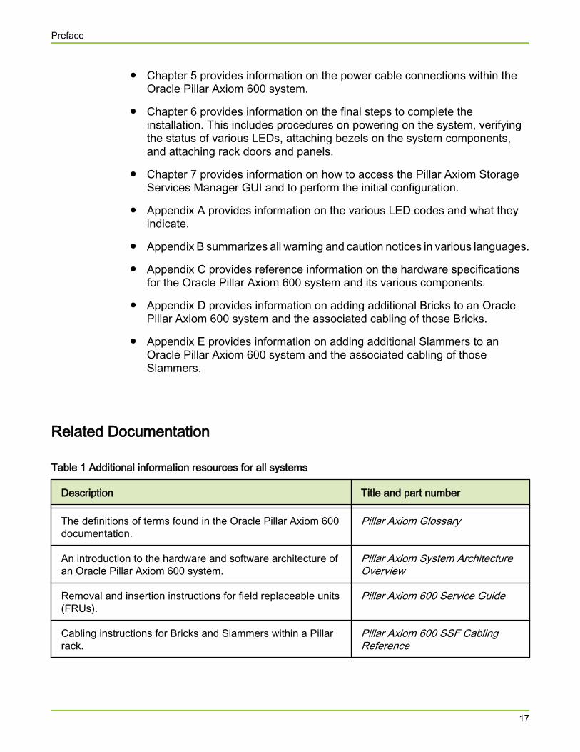
Table 1 Additional information resources for all systems
Description Title and part number
The definitions of terms found in the Oracle Pillar Axiom 600documentation.
Pillar Axiom Glossary
An introduction to the hardware and software architecture ofan Oracle Pillar Axiom 600 system.
Pillar Axiom System ArchitectureOverview
Removal and insertion instructions for field replaceable units(FRUs).
Pillar Axiom 600 Service Guide
Cabling instructions for Bricks and Slammers within a Pillarrack.
Pillar Axiom 600 SSF CablingReference
Preface
17
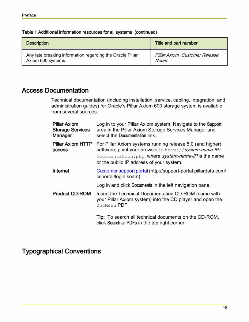
Table 1 Additional information resources for all systems (continued)
Description Title and part number
Any late breaking information regarding the Oracle PillarAxiom 600 systems.
Pillar Axiom Customer ReleaseNotes
Access DocumentationTechnical documentation (including installation, service, cabling, integration, andadministration guides) for Oracle’s Pillar Axiom 600 storage system is availablefrom several sources.
Pillar AxiomStorage ServicesManager
Log in to your Pillar Axiom system. Navigate to the Supportarea in the Pillar Axiom Storage Services Manager andselect the Documentation link.
Pillar Axiom HTTPaccess
For Pillar Axiom systems running release 5.0 (and higher)software, point your browser to http://system-name-IP/documentation.php, where system-name-IP is the nameor the public IP address of your system.
Internet Customer support portal (http://support-portal.pillardata.com/csportal/login.seam).
Log in and click Documents in the left navigation pane.Product CD-ROM Insert the Technical Documentation CD-ROM (came with
your Pillar Axiom system) into the CD player and open theDocMenu PDF.
Tip: To search all technical documents on the CD-ROM,click Search all PDFs in the top right corner.
Typographical Conventions
Preface
18
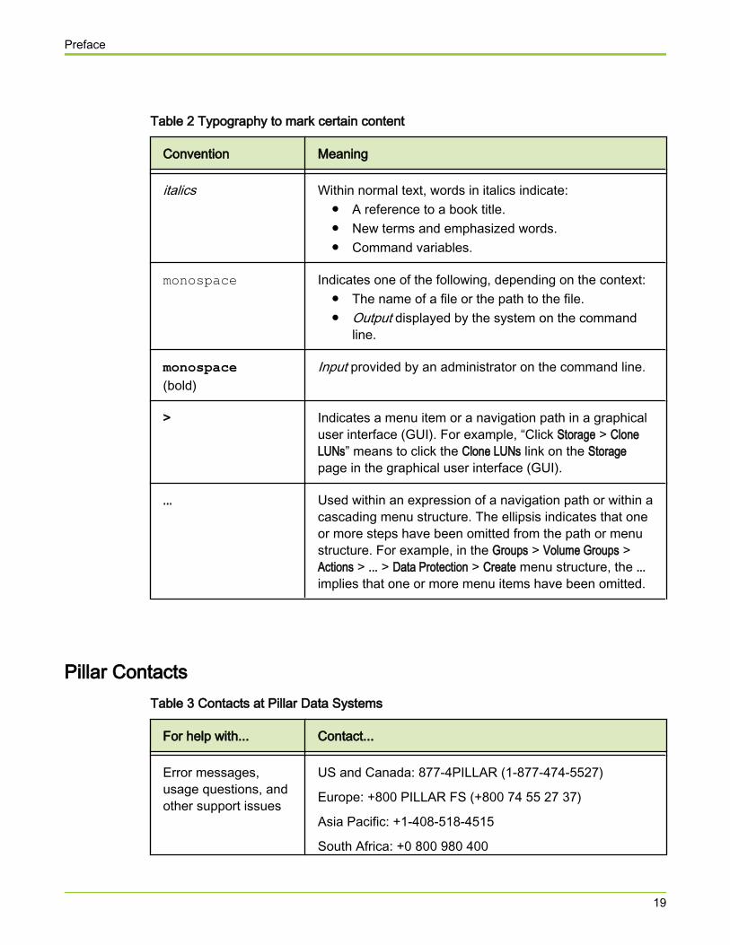
Table 2 Typography to mark certain content
Convention Meaning
italics Within normal text, words in italics indicate:● A reference to a book title.● New terms and emphasized words.● Command variables.
monospace Indicates one of the following, depending on the context:● The name of a file or the path to the file.● Output displayed by the system on the command
line.
monospace(bold)
Input provided by an administrator on the command line.
> Indicates a menu item or a navigation path in a graphicaluser interface (GUI). For example, “Click Storage > CloneLUNs” means to click the Clone LUNs link on the Storagepage in the graphical user interface (GUI).
... Used within an expression of a navigation path or within acascading menu structure. The ellipsis indicates that oneor more steps have been omitted from the path or menustructure. For example, in the Groups > Volume Groups >Actions > ... > Data Protection > Create menu structure, the ...implies that one or more menu items have been omitted.
Pillar ContactsTable 3 Contacts at Pillar Data Systems
For help with... Contact...
Error messages,usage questions, andother support issues
US and Canada: 877-4PILLAR (1-877-474-5527)
Europe: +800 PILLAR FS (+800 74 55 27 37)
Asia Pacific: +1-408-518-4515
South Africa: +0 800 980 400
Preface
19
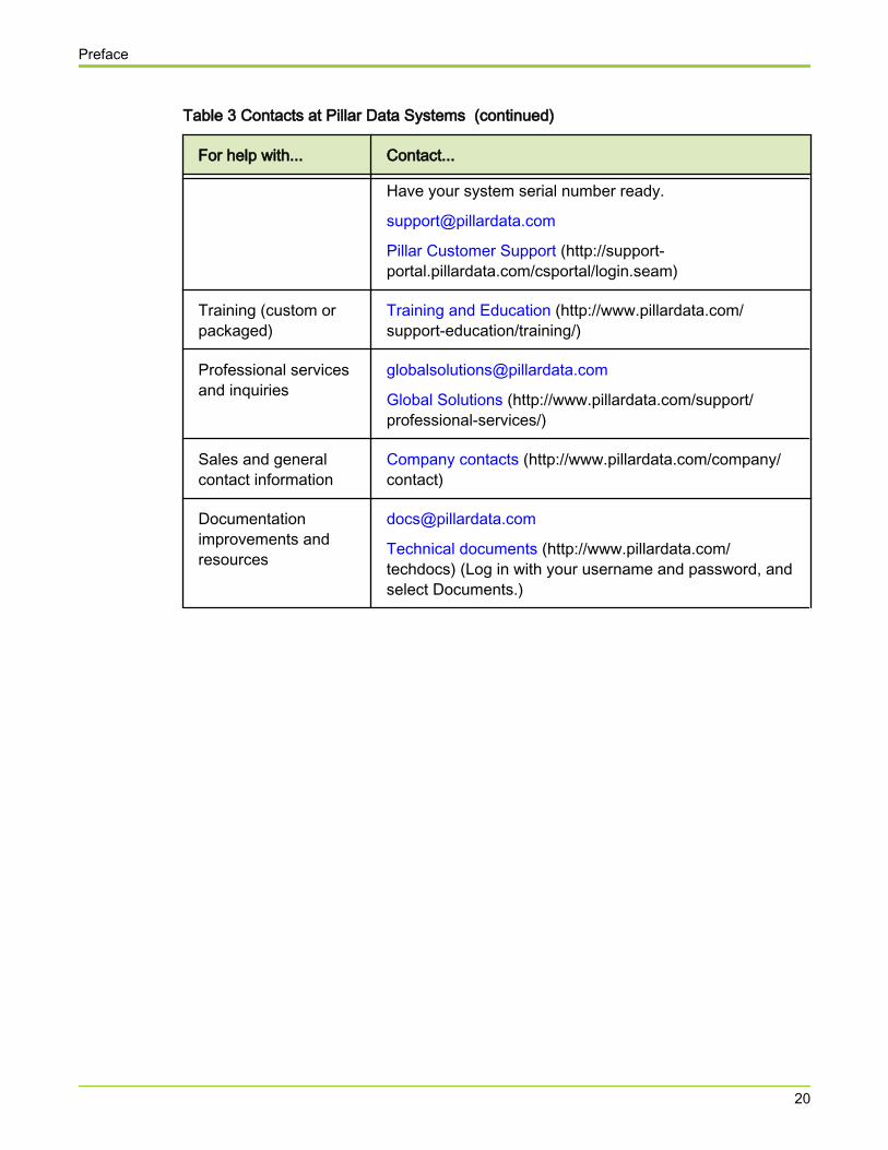
Table 3 Contacts at Pillar Data Systems (continued)
For help with... Contact...
Have your system serial number ready.
Pillar Customer Support (http://support-portal.pillardata.com/csportal/login.seam)
Training (custom orpackaged)
Training and Education (http://www.pillardata.com/support-education/training/)
Professional servicesand inquiries
Global Solutions (http://www.pillardata.com/support/professional-services/)
Sales and generalcontact information
Company contacts (http://www.pillardata.com/company/contact)
Documentationimprovements andresources
Technical documents (http://www.pillardata.com/techdocs) (Log in with your username and password, andselect Documents.)
Preface
20
CHAPTER 1
Before You Begin
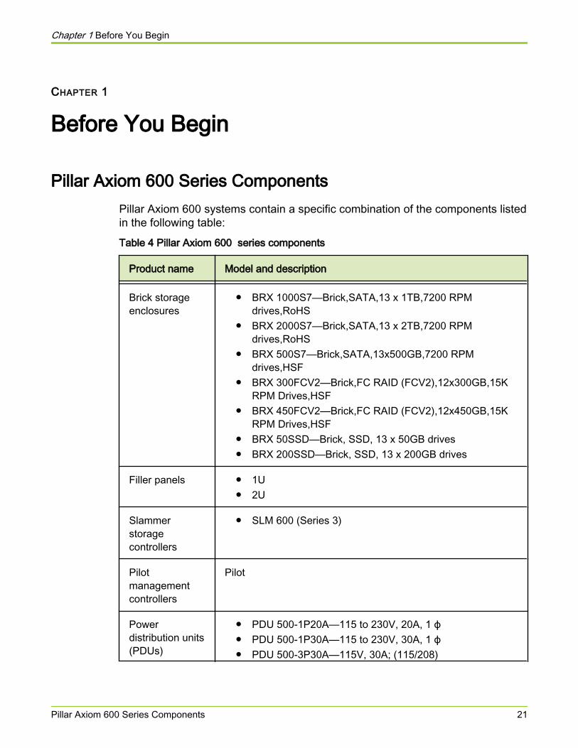
Pillar Axiom 600 Series ComponentsPillar Axiom 600 systems contain a specific combination of the components listedin the following table:Table 4 Pillar Axiom 600 series components
Product name Model and description
Brick storageenclosures
● BRX 1000S7—Brick,SATA,13 x 1TB,7200 RPMdrives,RoHS
● BRX 2000S7—Brick,SATA,13 x 2TB,7200 RPMdrives,RoHS
● BRX 500S7—Brick,SATA,13x500GB,7200 RPMdrives,HSF
● BRX 300FCV2—Brick,FC RAID (FCV2),12x300GB,15KRPM Drives,HSF
● BRX 450FCV2—Brick,FC RAID (FCV2),12x450GB,15KRPM Drives,HSF
● BRX 50SSD—Brick, SSD, 13 x 50GB drives● BRX 200SSD—Brick, SSD, 13 x 200GB drives
Filler panels ● 1U● 2U
Slammerstoragecontrollers
● SLM 600 (Series 3)
Pilotmanagementcontrollers
Pilot
Powerdistribution units(PDUs)
● PDU 500-1P20A—115 to 230V, 20A, 1 ϕ● PDU 500-1P30A—115 to 230V, 30A, 1 ϕ● PDU 500-3P30A—115V, 30A; (115/208)
Chapter 1 Before You Begin
Pillar Axiom 600 Series Components 21
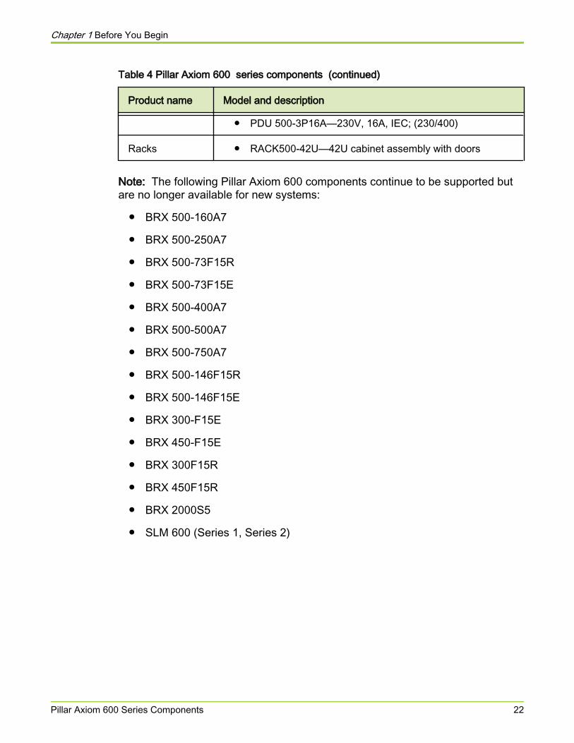
Table 4 Pillar Axiom 600 series components (continued)
Product name Model and description
● PDU 500-3P16A—230V, 16A, IEC; (230/400)
Racks ● RACK500-42U—42U cabinet assembly with doors
Note: The following Pillar Axiom 600 components continue to be supported butare no longer available for new systems:
● BRX 500-160A7
● BRX 500-250A7
● BRX 500-73F15R
● BRX 500-73F15E
● BRX 500-400A7
● BRX 500-500A7
● BRX 500-750A7
● BRX 500-146F15R
● BRX 500-146F15E
● BRX 300-F15E
● BRX 450-F15E
● BRX 300F15R
● BRX 450F15R
● BRX 2000S5
● SLM 600 (Series 1, Series 2)
Chapter 1 Before You Begin
Pillar Axiom 600 Series Components 22
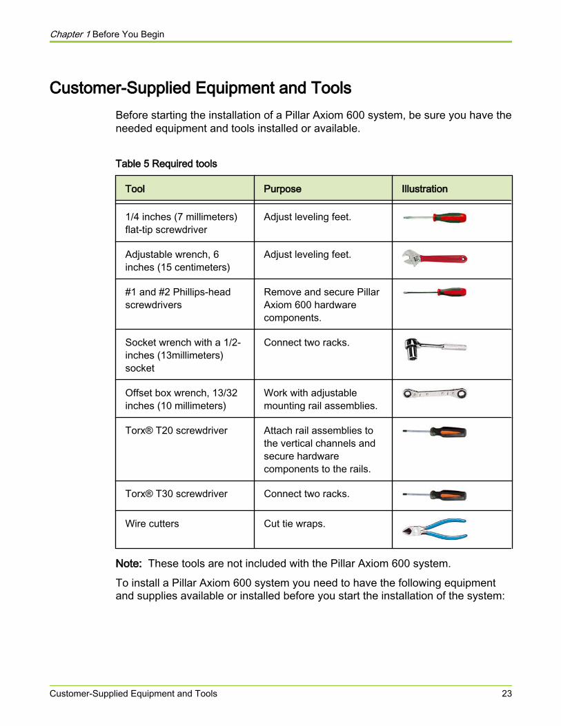
Customer-Supplied Equipment and ToolsBefore starting the installation of a Pillar Axiom 600 system, be sure you have theneeded equipment and tools installed or available.
Table 5 Required tools
Tool Purpose Illustration
1/4 inches (7 millimeters)flat-tip screwdriver
Adjust leveling feet.
Adjustable wrench, 6inches (15 centimeters)
Adjust leveling feet.
#1 and #2 Phillips-headscrewdrivers
Remove and secure PillarAxiom 600 hardwarecomponents.
Socket wrench with a 1/2-inches (13millimeters)socket
Connect two racks.
Offset box wrench, 13/32inches (10 millimeters)
Work with adjustablemounting rail assemblies.
Torx® T20 screwdriver Attach rail assemblies tothe vertical channels andsecure hardwarecomponents to the rails.
Torx® T30 screwdriver Connect two racks.
Wire cutters Cut tie wraps.
Note: These tools are not included with the Pillar Axiom 600 system.
To install a Pillar Axiom 600 system you need to have the following equipmentand supplies available or installed before you start the installation of the system:
Chapter 1 Before You Begin
Customer-Supplied Equipment and Tools 23
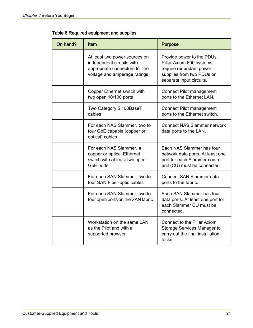
Table 6 Required equipment and supplies
On hand? Item Purpose
At least two power sources onindependent circuits withappropriate connectors for thevoltage and amperage ratings
Provide power to the PDUs.Pillar Axiom 600 systemsrequire redundant powersupplies from two PDUs onseparate input circuits.
Copper Ethernet switch withtwo open 10/100 ports
Connect Pilot managementports to the Ethernet LAN.
Two Category 5 100BaseTcables
Connect Pilot managementports to the Ethernet switch.
For each NAS Slammer, two tofour GbE capable (copper oroptical) cables
Connect NAS Slammer networkdata ports to the LAN.
For each NAS Slammer, acopper or optical Ethernetswitch with at least two openGbE ports
Each NAS Slammer has fournetwork data ports. At least oneport for each Slammer controlunit (CU) must be connected.
For each SAN Slammer, two tofour SAN Fiber-optic cables
Connect SAN Slammer dataports to the fabric.
For each SAN Slammer, two tofour open ports on the SAN fabric
Each SAN Slammer has fourdata ports. At least one port foreach Slammer CU must beconnected.
Workstation on the same LANas the Pilot and with asupported browser
Connect to the Pillar AxiomStorage Services Manager tocarry out the final installationtasks.
Chapter 1 Before You Begin
Customer-Supplied Equipment and Tools 24
Safety Notice Conventions
Hazard signal words conform to the American National Standards Institute(ANSI) Z535.4-2002 meanings. This guide uses the following conventions forsafety notices:
Caution Indicates a potentially hazardous situation that, if notavoided, may result in minor or moderate injury.
Warning Indicates a potentially hazardous situation that, if notavoided, could result in death or serious injury.
Danger Indicates an imminently hazardous situation that, if notavoided, will result in death or serious injury.
Important! To emphasize a point, to remind you of something, or to indicatepotential problems in the outcome of the in-process task.
A set of important safety notices apply throughout this guide. Read them beforeworking on a Pillar Axiom 600 system.
Related concepts• Safety Statements
Related references• Caution Notices• Warning Notices
Chapter 1 Before You Begin
Safety Notice Conventions 25
CHAPTER 2
Set Up the Rack
About Component InspectionEach Pillar Axiom 600 system is built to a customer's specifications and shippedin a single shipment. Check the components you received against the packingslip (or bill of lading), which lists everything that was shipped. If any componentsare missing, call 1-877-4PILLAR (474-5527) and report what was not included inyour shipment. Note how many pallets or containers you received, in case themissing components are in a container that simply has not yet arrived.
Caution A Brick weighs up to 65 pounds (29.5 kilograms). For safehandling, use two people to lift it.
Caution A Slammer weighs 94 pounds (42.6 kilograms). For safehandling, use two people to lift it.
Caution Before you handle a component, make sure that you havetaken electrostatic discharge (ESD) precautions:
● The minimum requirement is an anti-static wrist strapconnected to a hard ground. Pillar recommends thatyou remove components from their packaging andplace them on an ESD-qualified table that is equippedwith ground points for wrist straps.
● Static charges can build up rapidly on rolling carts. Ifyou transport a hardware component by cart, groundthe cart with a drag chain on an ESD floor. If there isno ESD cart available or ESD floor, ground yourselfbefore you touch a component that has beentransported on a cart.
After you remove the components from their packaging, inspect them for anydamage that may have occurred during shipping. If there is any damage:
1 Check your Terms of Sale to see who notifies the carrier.
2 Notify the carrier or the Pillar World Wide Customer Support Center, asappropriate, within 72 hours.
Chapter 2 Set Up the Rack
About Component Inspection 26
3 Record all damage.
4 Call the Pillar World Wide Customer Support Center to open a servicerequest for future insurance claims.
Tip: Check the packing materials to verify that you have retrieved all the smallparts before recycling.
Important! Pillar Axiom 600 system components are compatible with racks thatare compliant to the EIA-310-D standard. Pillar Axiom 600 Slammers and Bricksmay not install successfully into a rack that is not EIA-310-D compliant. Werecommend that Pillar racks be used to install Pillar Axiom 600 hardwarecomponents. When using non-Pillar racks, do not use Telco two-post racks.Instead, use a four-post rack that can support the weight load of a PillarAxiom 600 system. Additionally, be sure the non-Pillar rack has square mountingholes in the vertical channels. Round mounting holes are not acceptable.
Illustrations show a Pillar Axiom 600 42U rack or parts of it. If you have a non-Pillar rack, it should be similar.
Chapter 2 Set Up the Rack
About Component Inspection 27
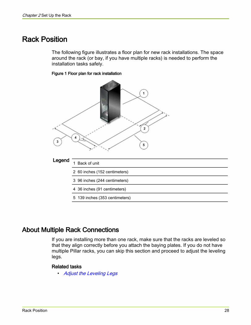
Rack PositionThe following figure illustrates a floor plan for new rack installations. The spacearound the rack (or bay, if you have multiple racks) is needed to perform theinstallation tasks safely.
Figure 1 Floor plan for rack installation
Legend 1 Back of unit
2 60 inches (152 centimeters)
3 96 inches (244 centimeters)
4 36 inches (91 centimeters)
5 139 inches (353 centimeters)
About Multiple Rack ConnectionsIf you are installing more than one rack, make sure that the racks are leveled sothat they align correctly before you attach the baying plates. If you do not havemultiple Pillar racks, you can skip this section and proceed to adjust the levelinglegs.
Related tasks• Adjust the Leveling Legs
Chapter 2 Set Up the Rack
Rack Position 28
Prepare the Racks
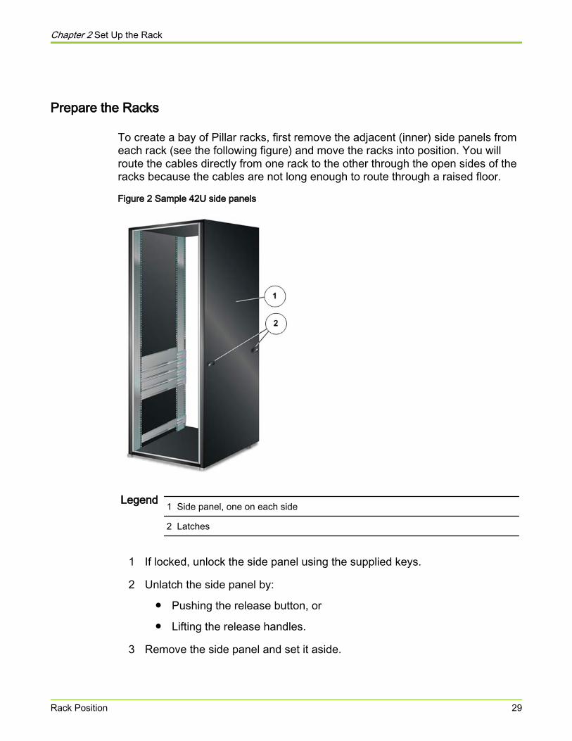
To create a bay of Pillar racks, first remove the adjacent (inner) side panels fromeach rack (see the following figure) and move the racks into position. You willroute the cables directly from one rack to the other through the open sides of theracks because the cables are not long enough to route through a raised floor.
Figure 2 Sample 42U side panels
Legend 1 Side panel, one on each side
2 Latches
1 If locked, unlock the side panel using the supplied keys.
2 Unlatch the side panel by:
● Pushing the release button, or
● Lifting the release handles.
3 Remove the side panel and set it aside.
Chapter 2 Set Up the Rack
Rack Position 29
4 Position the racks so that their open sides abut and their front sides are flush.
Attach the Connection Bracket
The connection bracket provides extra rigidity to the bay.
Important! Make sure that at least one of the racks is not anchored so you canadjust its position while you attach them together.
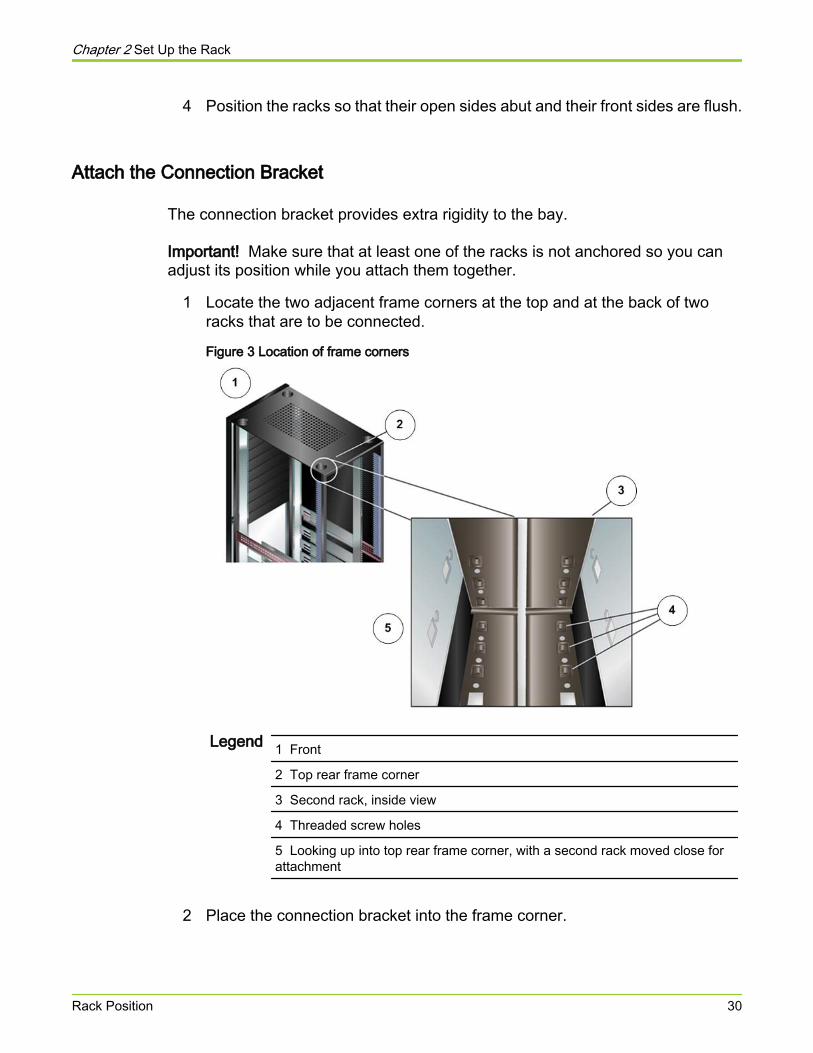
1 Locate the two adjacent frame corners at the top and at the back of tworacks that are to be connected.
Figure 3 Location of frame corners
Legend 1 Front
2 Top rear frame corner
3 Second rack, inside view
4 Threaded screw holes
5 Looking up into top rear frame corner, with a second rack moved close forattachment
2 Place the connection bracket into the frame corner.
Chapter 2 Set Up the Rack
Rack Position 30
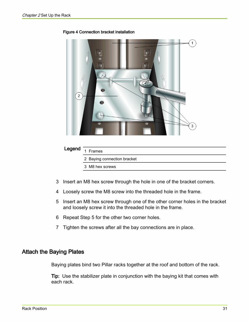
Figure 4 Connection bracket installation
Legend 1 Frames
2 Baying connection bracket
3 M8 hex screws
3 Insert an M8 hex screw through the hole in one of the bracket corners.
4 Loosely screw the M8 screw into the threaded hole in the frame.
5 Insert an M8 hex screw through one of the other corner holes in the bracketand loosely screw it into the threaded hole in the frame.
6 Repeat Step 5 for the other two corner holes.
7 Tighten the screws after all the bay connections are in place.
Attach the Baying Plates
Baying plates bind two Pillar racks together at the roof and bottom of the rack.
Tip: Use the stabilizer plate in conjunction with the baying kit that comes witheach rack.
Chapter 2 Set Up the Rack
Rack Position 31
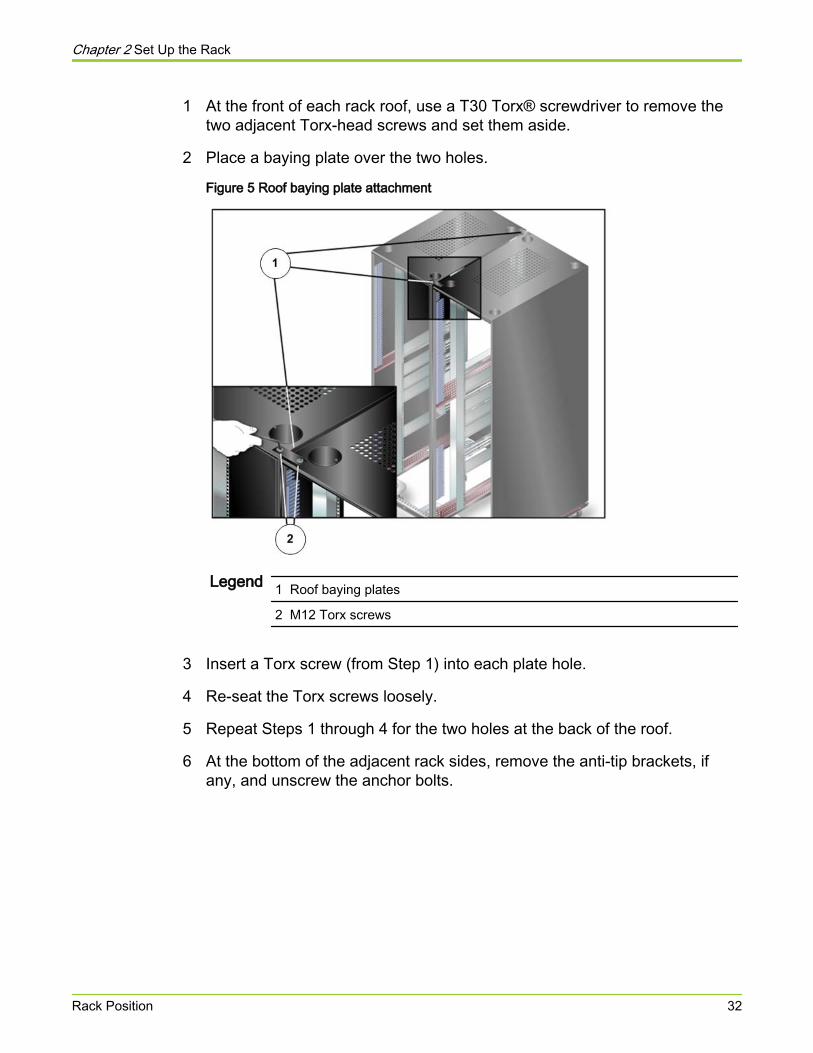
1 At the front of each rack roof, use a T30 Torx® screwdriver to remove thetwo adjacent Torx-head screws and set them aside.
2 Place a baying plate over the two holes.
Figure 5 Roof baying plate attachment
Legend 1 Roof baying plates
2 M12 Torx screws
3 Insert a Torx screw (from Step 1) into each plate hole.
4 Re-seat the Torx screws loosely.
5 Repeat Steps 1 through 4 for the two holes at the back of the roof.
6 At the bottom of the adjacent rack sides, remove the anti-tip brackets, ifany, and unscrew the anchor bolts.
Chapter 2 Set Up the Rack
Rack Position 32
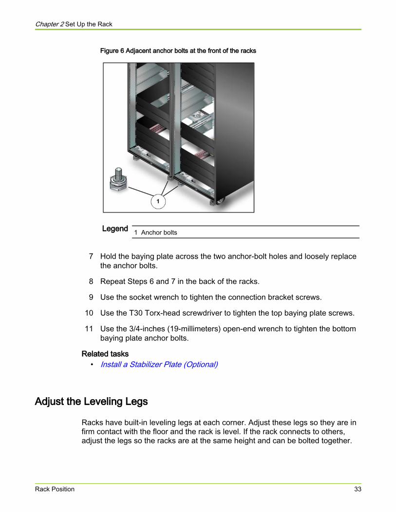
Figure 6 Adjacent anchor bolts at the front of the racks
Legend 1 Anchor bolts
7 Hold the baying plate across the two anchor-bolt holes and loosely replacethe anchor bolts.
8 Repeat Steps 6 and 7 in the back of the racks.
9 Use the socket wrench to tighten the connection bracket screws.
10 Use the T30 Torx-head screwdriver to tighten the top baying plate screws.
11 Use the 3/4-inches (19-millimeters) open-end wrench to tighten the bottombaying plate anchor bolts.
Related tasks• Install a Stabilizer Plate (Optional)
Adjust the Leveling Legs
Racks have built-in leveling legs at each corner. Adjust these legs so they are infirm contact with the floor and the rack is level. If the rack connects to others,adjust the legs so the racks are at the same height and can be bolted together.
Chapter 2 Set Up the Rack
Rack Position 33
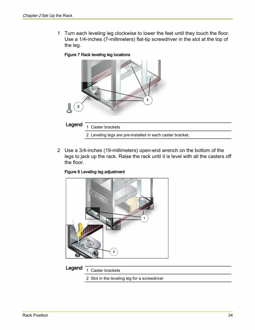
1 Turn each leveling leg clockwise to lower the feet until they touch the floor.Use a 1/4-inches (7-millimeters) flat-tip screwdriver in the slot at the top ofthe leg.
Figure 7 Rack leveling leg locations
Legend 1 Caster brackets
2 Leveling legs are pre-installed in each caster bracket.
2 Use a 3/4-inches (19-millimeters) open-end wrench on the bottom of thelegs to jack up the rack. Raise the rack until it is level with all the casters offthe floor.
Figure 8 Leveling leg adjustment
Legend 1 Caster brackets
2 Slot in the leveling leg for a screwdriver
Chapter 2 Set Up the Rack
Rack Position 34
Note: If you connect racks in a bay it is more important that the racks be atthe same height than level so that you can bolt them together.
About Rack StabilityAfter you move the rack to its final position and adjust the legs, you must stabilizeit to keep it from shifting when you install the components.
You can use any combination of the following actions to stabilize the rack:
● Attach anti-tip brackets and secure them to the floor.
● Attach a stabilizer plate and secure it to the floor.
● Install a seismic stabilization system.
Important! If the rack will be part of a bay of racks, attach the rack to the baybefore you install stabilizer plates or some other seismic stabilization system.
Related tasks• Install the Anti-Tip Brackets• Install a Stabilizer Plate (Optional)
About Anti-Tip BracketsOne stabilization option is to install the anti-tip brackets that are included with thesystem. Before you install the anti-tip brackets, consider:
● If you intend to bay the rack with another Pillar rack, you must use bayingplates on connecting corners. Baying plates prevent the use of anti-tipbrackets so you must stabilize the bay with stabilization plates.
● Make sure that the rack is in its final position before you secure anti-tipbrackets to the floor.
● Anti-tip brackets may require a sub-floor tie-down system if the floor hasremovable panels.
● For solid floors, drill holes into the floor and use appropriate anchor bolts tosecure the anti-tip brackets.
Important! If you intend to install an optional stabilizer plate, do not install thefront anti-tip brackets.
Chapter 2 Set Up the Rack
Rack Position 35
Install the Anti-Tip Brackets
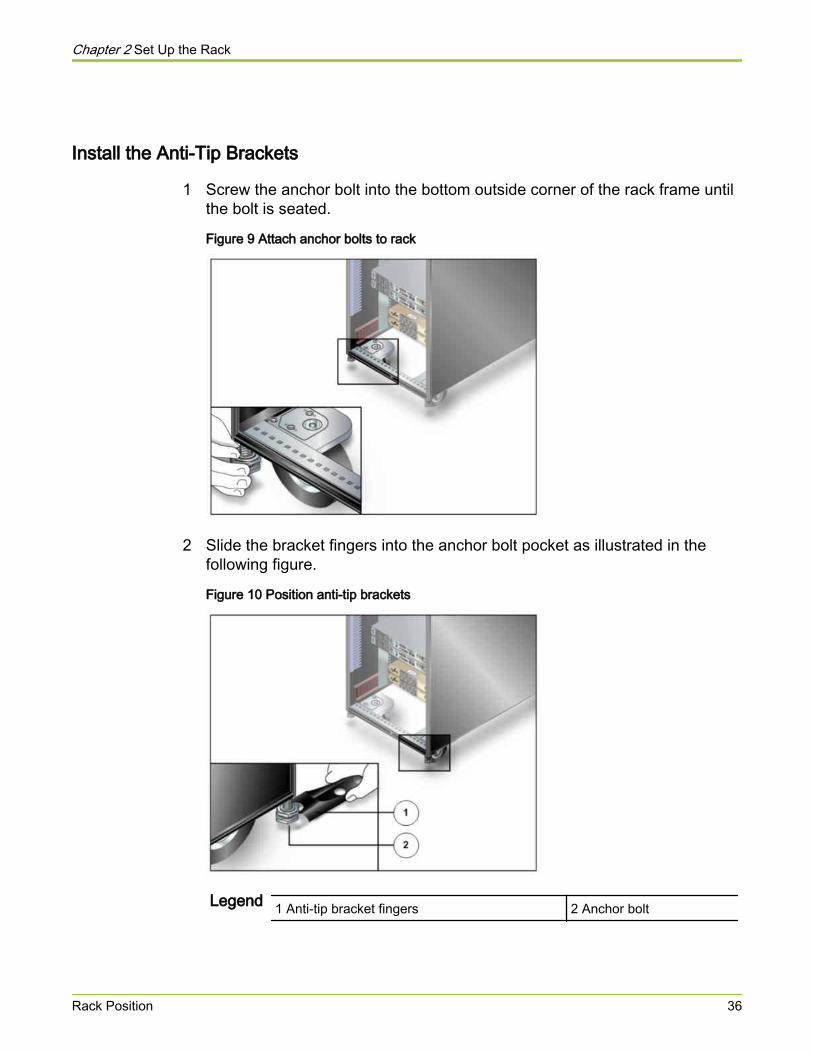
1 Screw the anchor bolt into the bottom outside corner of the rack frame untilthe bolt is seated.
Figure 9 Attach anchor bolts to rack
2 Slide the bracket fingers into the anchor bolt pocket as illustrated in thefollowing figure.
Figure 10 Position anti-tip brackets
Legend 1 Anti-tip bracket fingers 2 Anchor bolt
Chapter 2 Set Up the Rack
Rack Position 36
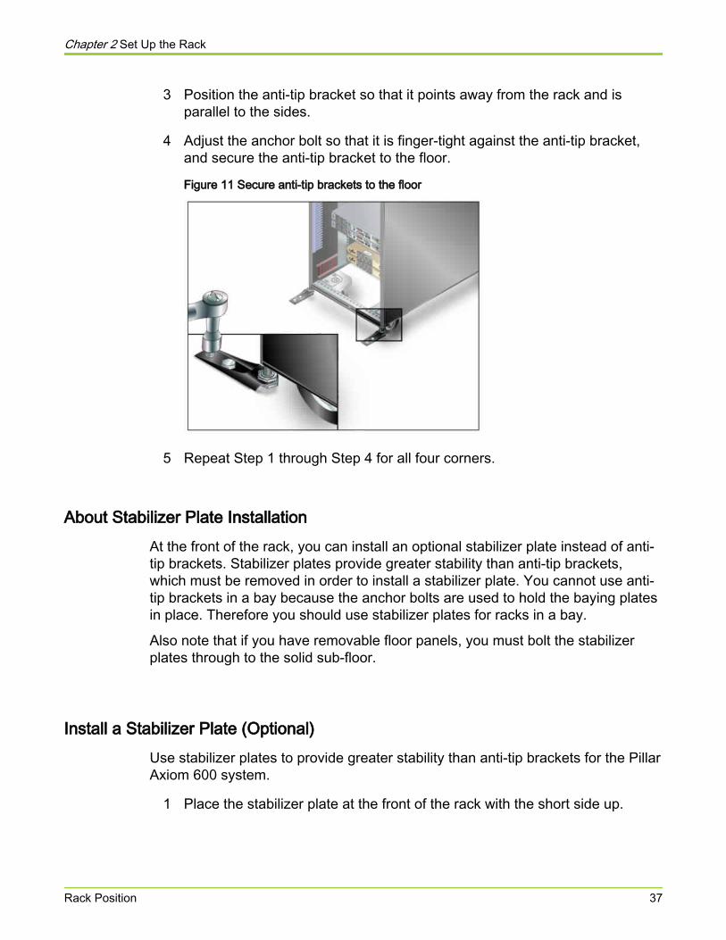
3 Position the anti-tip bracket so that it points away from the rack and isparallel to the sides.
4 Adjust the anchor bolt so that it is finger-tight against the anti-tip bracket,and secure the anti-tip bracket to the floor.
Figure 11 Secure anti-tip brackets to the floor
5 Repeat Step 1 through Step 4 for all four corners.
About Stabilizer Plate InstallationAt the front of the rack, you can install an optional stabilizer plate instead of anti-tip brackets. Stabilizer plates provide greater stability than anti-tip brackets,which must be removed in order to install a stabilizer plate. You cannot use anti-tip brackets in a bay because the anchor bolts are used to hold the baying platesin place. Therefore you should use stabilizer plates for racks in a bay.
Also note that if you have removable floor panels, you must bolt the stabilizerplates through to the solid sub-floor.
Install a Stabilizer Plate (Optional)Use stabilizer plates to provide greater stability than anti-tip brackets for the PillarAxiom 600 system.
1 Place the stabilizer plate at the front of the rack with the short side up.
Chapter 2 Set Up the Rack
Rack Position 37
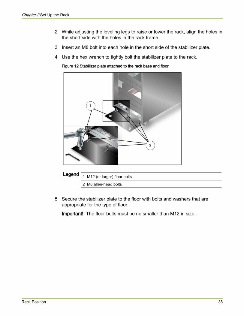
2 While adjusting the leveling legs to raise or lower the rack, align the holes inthe short side with the holes in the rack frame.
3 Insert an M8 bolt into each hole in the short side of the stabilizer plate.
4 Use the hex wrench to tightly bolt the stabilizer plate to the rack.
Figure 12 Stabilizer plate attached to the rack base and floor
Legend 1 M12 (or larger) floor bolts
2 M8 allen-head bolts
5 Secure the stabilizer plate to the floor with bolts and washers that areappropriate for the type of floor.
Important! The floor bolts must be no smaller than M12 in size.
Chapter 2 Set Up the Rack
Rack Position 38
About Component PlacementFor non-Pillar racks, all component rails must be installed before loadingcomponents into the racks.
Pillar racks come with the component rails pre-installed. If you have Pillar racks,you can install the components right away.
Install the component rails according to the component placement diagrams foryour system configuration. Install them in the order of:
● First, Pilot rails near the bottom of the rack, 2U above the PDUs.
● Second, Slammer rails above the Pilot rails.
● Third, Brick rails above the Slammer rails.
Caution Some Pillar Axiom 600 components weigh over 65pounds (29.5 kilograms). Make sure all rail components aretightly secured before loading the components to preventdamage and injury.
If you are building a rack that only contains Bricks, you should still start from thebottom.
Note: The physical location of the components in the Pillar Axiom 600 rack canvary if the system is installed in the field. Always check the cables at the back ofthe rack to validate the physical location of each Brick.
Note: After a new installation or a Brick upgrade, the physical and logical nameof a new Brick might not be the same. To avoid potential confusion, Pillarrecommends that you change the logical name of the Brick to match the physicalname.
Related concepts• About Component Placement for One Slammer and SATA Bricks• About Component Placement for One Slammer and FC Bricks• About Component Placement for Two or Three Slammers and FC Bricks• About Component Placement for Four Slammers and 64 Bricks
Configuration Limits for a Pillar Axiom 600 System
The minimum configuration of the Pillar Axiom 600 system is:
Chapter 2 Set Up the Rack
About Component Placement 39
● One Pilot
● One Slammer
● One Brick
The maximum configuration of the Pillar Axiom 600 system is:
● One Pilot
● Four Slammers
● 64 Bricks
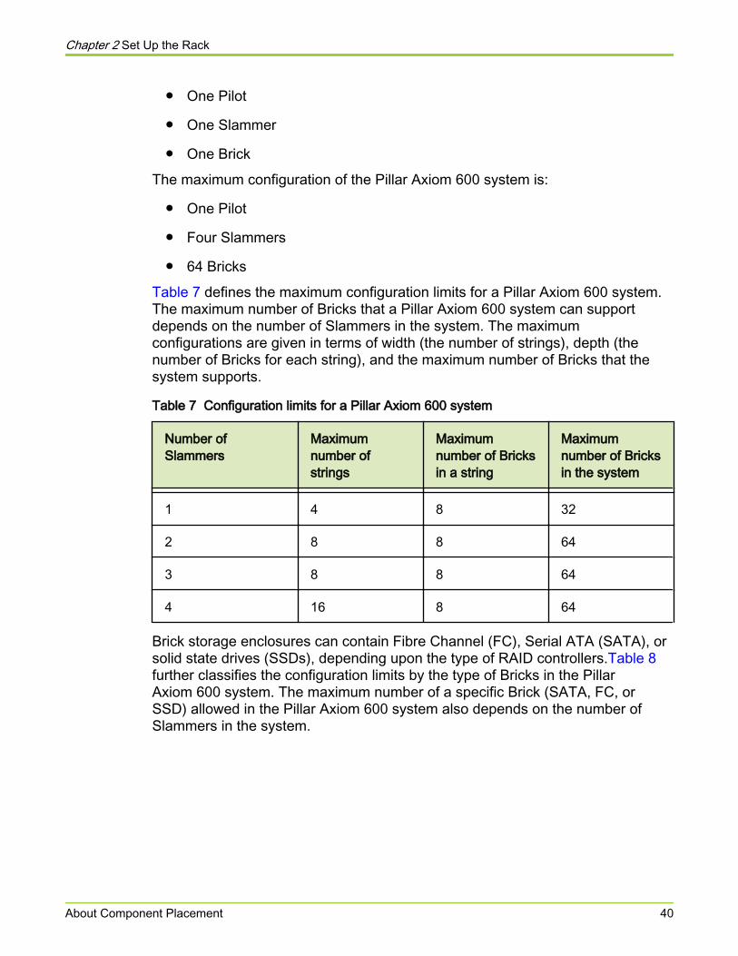
Table 7 defines the maximum configuration limits for a Pillar Axiom 600 system.The maximum number of Bricks that a Pillar Axiom 600 system can supportdepends on the number of Slammers in the system. The maximumconfigurations are given in terms of width (the number of strings), depth (thenumber of Bricks for each string), and the maximum number of Bricks that thesystem supports.
Table 7 Configuration limits for a Pillar Axiom 600 system
Number ofSlammers
Maximumnumber ofstrings
Maximumnumber of Bricksin a string
Maximumnumber of Bricksin the system
1 4 8 32
2 8 8 64
3 8 8 64
4 16 8 64
Brick storage enclosures can contain Fibre Channel (FC), Serial ATA (SATA), orsolid state drives (SSDs), depending upon the type of RAID controllers.Table 8further classifies the configuration limits by the type of Bricks in the PillarAxiom 600 system. The maximum number of a specific Brick (SATA, FC, orSSD) allowed in the Pillar Axiom 600 system also depends on the number ofSlammers in the system.
Chapter 2 Set Up the Rack
About Component Placement 40
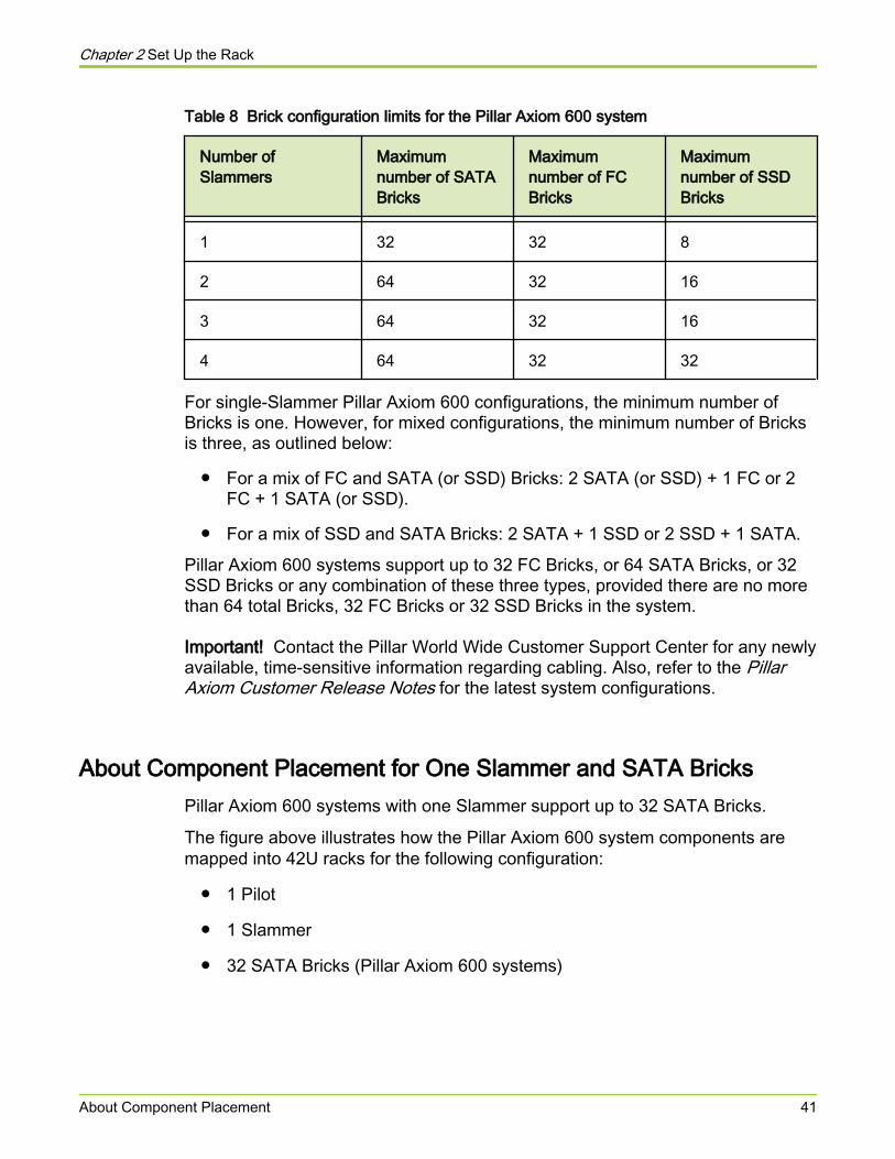
Table 8 Brick configuration limits for the Pillar Axiom 600 system
Number ofSlammers
Maximumnumber of SATABricks
Maximumnumber of FCBricks
Maximumnumber of SSDBricks
1 32 32 8
2 64 32 16
3 64 32 16
4 64 32 32
For single-Slammer Pillar Axiom 600 configurations, the minimum number ofBricks is one. However, for mixed configurations, the minimum number of Bricksis three, as outlined below:
● For a mix of FC and SATA (or SSD) Bricks: 2 SATA (or SSD) + 1 FC or 2FC + 1 SATA (or SSD).
● For a mix of SSD and SATA Bricks: 2 SATA + 1 SSD or 2 SSD + 1 SATA.
Pillar Axiom 600 systems support up to 32 FC Bricks, or 64 SATA Bricks, or 32SSD Bricks or any combination of these three types, provided there are no morethan 64 total Bricks, 32 FC Bricks or 32 SSD Bricks in the system.
Important! Contact the Pillar World Wide Customer Support Center for any newlyavailable, time-sensitive information regarding cabling. Also, refer to the PillarAxiom Customer Release Notes for the latest system configurations.
About Component Placement for One Slammer and SATA BricksPillar Axiom 600 systems with one Slammer support up to 32 SATA Bricks.
The figure above illustrates how the Pillar Axiom 600 system components aremapped into 42U racks for the following configuration:
● 1 Pilot
● 1 Slammer
● 32 SATA Bricks (Pillar Axiom 600 systems)
Chapter 2 Set Up the Rack
About Component Placement 41
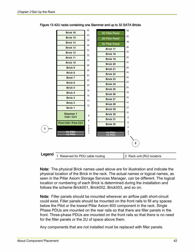
Figure 13 42U racks containing one Slammer and up to 32 SATA Bricks
Legend 1 Reserved for PDU cable routing 2 Rack unit (RU) locators
Note: The physical Brick names used above are for illustration and indicate thephysical location of the Brick in the rack. The actual names or logical names, asseen in the Pillar Axiom Storage Services Manager, can be different. The logicallocation or numbering of each Brick is determined during the installation andfollows the scheme Brick001, Brick002, Brick003, and so on.
Note: Filler panels should be mounted wherever an airflow path short-circuitcould exist. Filler panels should be mounted on the front rails to fill any spacesbelow the Pilot or the lowest Pillar Axiom 600 component in the rack. SinglePhase PDUs are mounted on the rear rails so that there are filler panels in thefront. Three-phase PDUs are mounted on the front rails so that there is no needfor the filler panels or the 2U of space above them.
Any components that are not installed must be replaced with filler panels.
Chapter 2 Set Up the Rack
About Component Placement 42
Note: 2U of space is reserved above the PDUs for cable routing. The numberand type of PDUs depends on the power supply. If more PDUs are needed, orwhen you need to add additional components into the rack (such as addinganother Slammer), then everything has to move up to make room, keepingthe 2U of reserved space, and moving any Bricks displaced at the top to the nextrack.
Note: In a system that is configured for the maximum number of Bricks, connectthe additional racks to the first rack before you install and cable the hardwarecomponents.
Related references• Cabling Practices for the Pillar Axiom 600 System
Related tasks• Rename the Bricks
About Component Placement for One Slammer and FC BricksPillar Axiom 600 systems with one Slammer support up to 15 Fibre Channel (FC)Bricks.
Install the hardware components in the rack as shown in the following figure. Anycomponents that are not installed must be replaced with filler panels.
The figure below illustrates how the Pillar Axiom 600 system components aremapped into a fully loaded 42U rack for the following configuration:
● 1 Pilot
● 1 Slammer
● 15 FC Bricks
Chapter 2 Set Up the Rack
About Component Placement 43
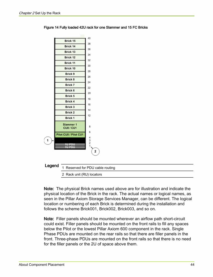
Figure 14 Fully loaded 42U rack for one Slammer and 15 FC Bricks
Legend 1 Reserved for PDU cable routing
2 Rack unit (RU) locators
Note: The physical Brick names used above are for illustration and indicate thephysical location of the Brick in the rack. The actual names or logical names, asseen in the Pillar Axiom Storage Services Manager, can be different. The logicallocation or numbering of each Brick is determined during the installation andfollows the scheme Brick001, Brick002, Brick003, and so on.
Note: Filler panels should be mounted wherever an airflow path short-circuitcould exist. Filler panels should be mounted on the front rails to fill any spacesbelow the Pilot or the lowest Pillar Axiom 600 component in the rack. SinglePhase PDUs are mounted on the rear rails so that there are filler panels in thefront. Three-phase PDUs are mounted on the front rails so that there is no needfor the filler panels or the 2U of space above them.
Chapter 2 Set Up the Rack
About Component Placement 44
Note: 2U of space is reserved above the PDUs for cable routing. The numberand type of PDUs depends on the power service. If more PDUs are needed, orwhen you need to add additional components into the rack (such as addinganother Slammer), then everything has to move up to make room, keeping the2U of reserved space, and moving any Bricks displaced at the top to the next rack.
Related concepts• About Component Placement for Two or Three Slammers and FC Bricks• About Component Placement for Four Slammers and 64 Bricks
Related references• Cabling Practices for the Pillar Axiom 600 System
Related tasks• Rename the Bricks
About Component Placement for Two or Three Slammers and FC BricksPillar Axiom 600 systems with two or three Slammers support up to 32 FC Bricks.
Note: This topic applies only to Pillar Axiom 600 systems.
Install the hardware components in the rack as shown in the following figure. Thisfigure illustrates how the Pillar Axiom 600 system components are mapped intofully loaded 42U racks for the following configuration:
● 1 Pilot
● 3 Slammers
● 32 FC Bricks
Chapter 2 Set Up the Rack
About Component Placement 45
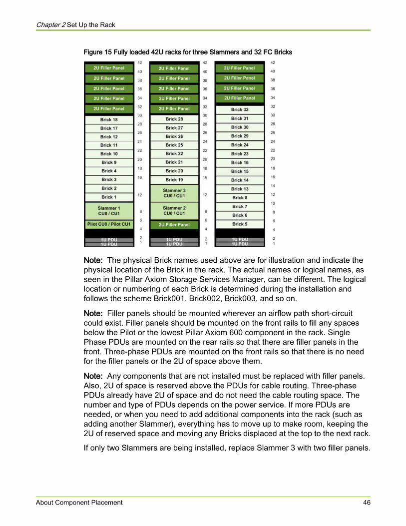
Figure 15 Fully loaded 42U racks for three Slammers and 32 FC Bricks
Note: The physical Brick names used above are for illustration and indicate thephysical location of the Brick in the rack. The actual names or logical names, asseen in the Pillar Axiom Storage Services Manager, can be different. The logicallocation or numbering of each Brick is determined during the installation andfollows the scheme Brick001, Brick002, Brick003, and so on.
Note: Filler panels should be mounted wherever an airflow path short-circuitcould exist. Filler panels should be mounted on the front rails to fill any spacesbelow the Pilot or the lowest Pillar Axiom 600 component in the rack. SinglePhase PDUs are mounted on the rear rails so that there are filler panels in thefront. Three-phase PDUs are mounted on the front rails so that there is no needfor the filler panels or the 2U of space above them.
Note: Any components that are not installed must be replaced with filler panels.Also, 2U of space is reserved above the PDUs for cable routing. Three-phasePDUs already have 2U of space and do not need the cable routing space. Thenumber and type of PDUs depends on the power service. If more PDUs areneeded, or when you need to add additional components into the rack (such asadding another Slammer), everything has to move up to make room, keeping the2U of reserved space and moving any Bricks displaced at the top to the next rack.
If only two Slammers are being installed, replace Slammer 3 with two filler panels.
Chapter 2 Set Up the Rack
About Component Placement 46
Note: In a system that is configured for the maximum number of Bricks, connectthe additional racks to the first rack before you install and cable the hardwarecomponents.
Related concepts• About Component Placement for Four Slammers and 64 Bricks• Sample Power Cabling for One Slammer and Three Bricks
Related references• Cabling Practices for the Pillar Axiom 600 System
Related tasks• Rename the Bricks
About Component Placement for Four Slammers and 64 BricksPillar Axiom 600 systems with four Slammers support up to 64 Serial ATA(SATA) Bricks, or a combination of up to 32 FC Bricks and 32 SATA Bricks in amixed system.
Note: This topic applies only to Pillar Axiom 600 systems.
Install the components in the rack as shown in the following figure, whichillustrates how the Pillar Axiom 600 system components are mapped into a fullyloaded 42U racks for the maximum configuration of:
● 1 Pilot
● 4 Slammers
● 64 Bricks
Chapter 2 Set Up the Rack
About Component Placement 47
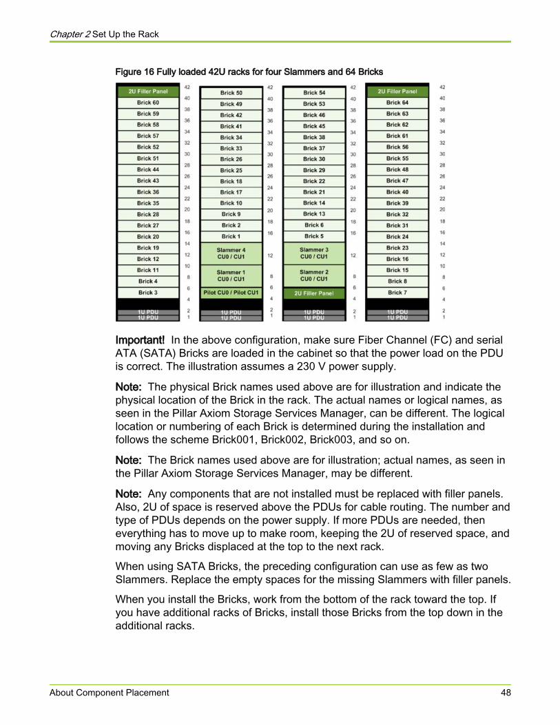
Figure 16 Fully loaded 42U racks for four Slammers and 64 Bricks
Important! In the above configuration, make sure Fiber Channel (FC) and serialATA (SATA) Bricks are loaded in the cabinet so that the power load on the PDUis correct. The illustration assumes a 230 V power supply.
Note: The physical Brick names used above are for illustration and indicate thephysical location of the Brick in the rack. The actual names or logical names, asseen in the Pillar Axiom Storage Services Manager, can be different. The logicallocation or numbering of each Brick is determined during the installation andfollows the scheme Brick001, Brick002, Brick003, and so on.
Note: The Brick names used above are for illustration; actual names, as seen inthe Pillar Axiom Storage Services Manager, may be different.
Note: Any components that are not installed must be replaced with filler panels.Also, 2U of space is reserved above the PDUs for cable routing. The number andtype of PDUs depends on the power supply. If more PDUs are needed, theneverything has to move up to make room, keeping the 2U of reserved space, andmoving any Bricks displaced at the top to the next rack.
When using SATA Bricks, the preceding configuration can use as few as twoSlammers. Replace the empty spaces for the missing Slammers with filler panels.
When you install the Bricks, work from the bottom of the rack toward the top. Ifyou have additional racks of Bricks, install those Bricks from the top down in theadditional racks.
Chapter 2 Set Up the Rack
About Component Placement 48
Note: In a system that is configured for the maximum number of Bricks, connectthe additional racks to the first rack before you install and cable the hardwarecomponents.
Related concepts• About Component Placement for Two or Three Slammers and FC Bricks
Related references• Cabling Practices for the Pillar Axiom 600 System
Related tasks• Rename the Bricks
Pilot Rail Kit Parts
Verify that the rail kit contains all the parts listed in the table.
Before installing a pair of Pilot rack rails, make sure you have:
● One Pilot rail kit with rails and scopes pre-attached
● #20 Torx wrench
● Socket wrench
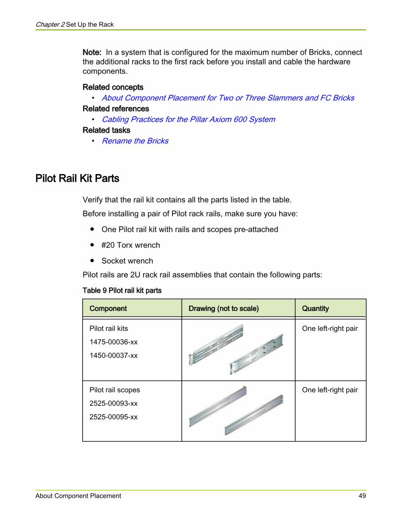
Pilot rails are 2U rack rail assemblies that contain the following parts:
Table 9 Pilot rail kit parts
Component Drawing (not to scale) Quantity
Pilot rail kits
1475-00036-xx
1450-00037-xx
One left-right pair
Pilot rail scopes
2525-00093-xx
2525-00095-xx
One left-right pair
Chapter 2 Set Up the Rack
About Component Placement 49
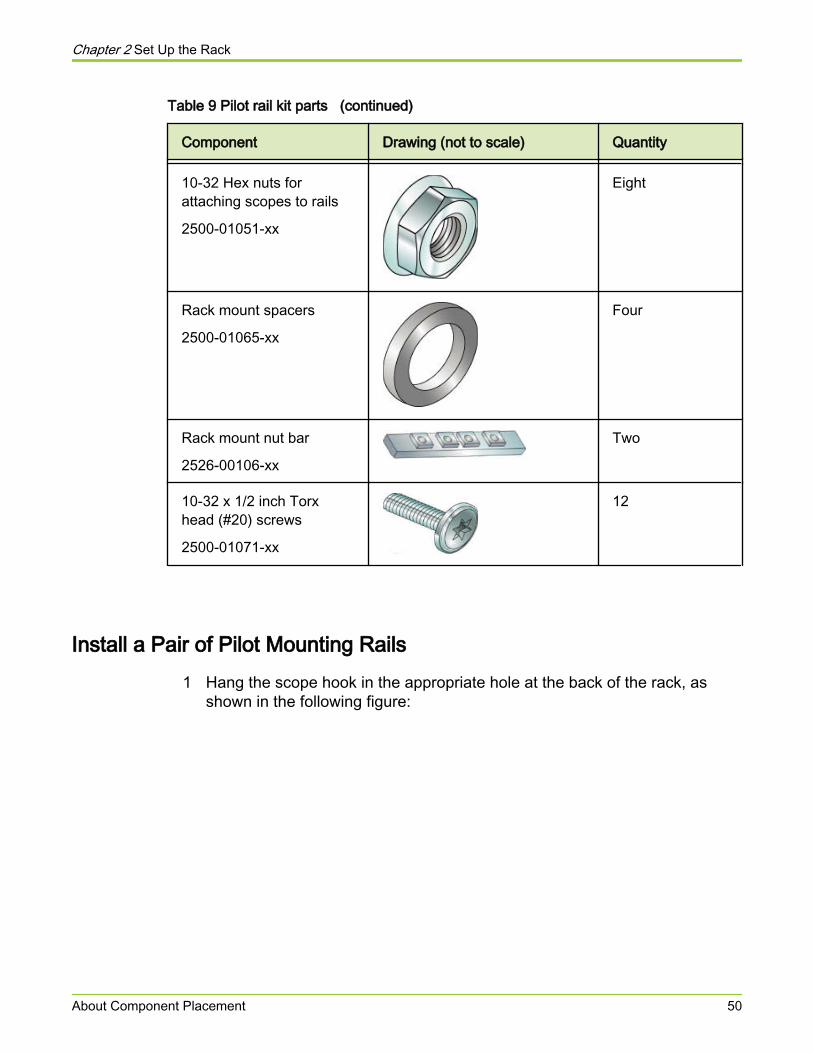
Table 9 Pilot rail kit parts (continued)
Component Drawing (not to scale) Quantity
10-32 Hex nuts forattaching scopes to rails
2500-01051-xx
Eight
Rack mount spacers
2500-01065-xx
Four
Rack mount nut bar
2526-00106-xx
Two
10-32 x 1/2 inch Torxhead (#20) screws
2500-01071-xx
12
Install a Pair of Pilot Mounting Rails1 Hang the scope hook in the appropriate hole at the back of the rack, as
shown in the following figure:
Chapter 2 Set Up the Rack
About Component Placement 50

Figure 17 Scope hook attachment
Legend 1 Vertical rail at back of rack
2 Rack unit (RU) 32
3 Scope hook
4 Bottom holes for each unit
5 RU 31
In the preceding figure, two labeled rack units, 31 and 32, are shown at theback of the rack.
● The bottom of unit 31 is just out of sight below its bottom hole.
● The scope hook is one-and-a-half units above the bottom of the rail.
● When you place the hook in the middle of unit 32, the bottom of therail lines up with the bottom of unit 31.
● A 2U Pilot rail would fill units 31-32 in the preceding illustration.
2 At the front of the rack, slide the rail scopes until the rail reaches the holesat the front.
The rail flange goes in front of the rack mount holes, and the four-holespacer bar goes behind, as shown in the figure in the next step.
Chapter 2 Set Up the Rack
About Component Placement 51
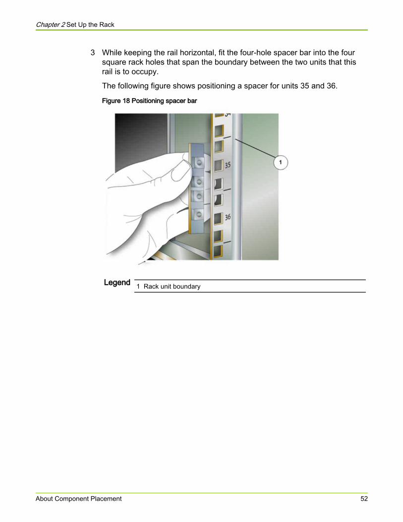
3 While keeping the rail horizontal, fit the four-hole spacer bar into the foursquare rack holes that span the boundary between the two units that thisrail is to occupy.
The following figure shows positioning a spacer for units 35 and 36.
Figure 18 Positioning spacer bar
Legend 1 Rack unit boundary
Chapter 2 Set Up the Rack
About Component Placement 52
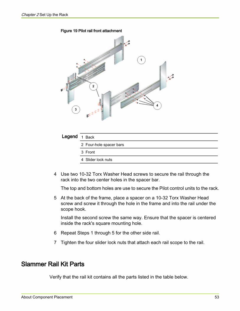
Figure 19 Pilot rail front attachment
Legend 1 Back
2 Four-hole spacer bars
3 Front
4 Slider lock nuts
4 Use two 10-32 Torx Washer Head screws to secure the rail through therack into the two center holes in the spacer bar.
The top and bottom holes are use to secure the Pilot control units to the rack.
5 At the back of the frame, place a spacer on a 10-32 Torx Washer Headscrew and screw it through the hole in the frame and into the rail under thescope hook.
Install the second screw the same way. Ensure that the spacer is centeredinside the rack's square mounting hole.
6 Repeat Steps 1 through 5 for the other side rail.
7 Tighten the four slider lock nuts that attach each rail scope to the rail.
Slammer Rail Kit Parts
Verify that the rail kit contains all the parts listed in the table below.
Chapter 2 Set Up the Rack
About Component Placement 53
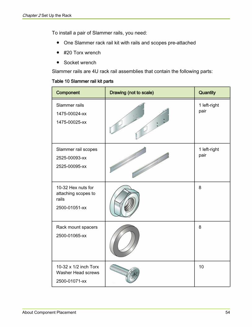
To install a pair of Slammer rails, you need:
● One Slammer rack rail kit with rails and scopes pre-attached
● #20 Torx wrench
● Socket wrench
Slammer rails are 4U rack rail assemblies that contain the following parts:
Table 10 Slammer rail kit parts
Component Drawing (not to scale) Quantity
Slammer rails
1475-00024-xx
1475-00025-xx
1 left-rightpair
Slammer rail scopes
2525-00093-xx
2525-00095-xx
1 left-rightpair
10-32 Hex nuts forattaching scopes torails
2500-01051-xx
8
Rack mount spacers
2500-01065-xx
8
10-32 x 1/2 inch TorxWasher Head screws
2500-01071-xx
10
Chapter 2 Set Up the Rack
About Component Placement 54
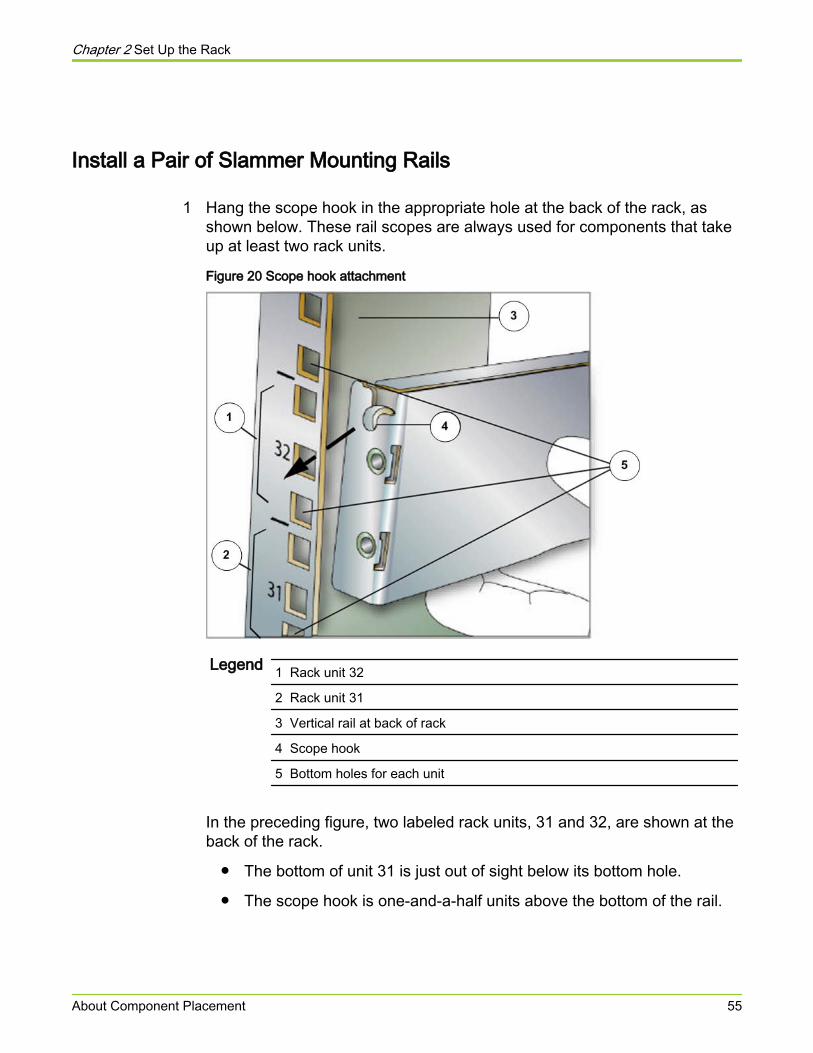
Install a Pair of Slammer Mounting Rails
1 Hang the scope hook in the appropriate hole at the back of the rack, asshown below. These rail scopes are always used for components that takeup at least two rack units.
Figure 20 Scope hook attachment
Legend 1 Rack unit 32
2 Rack unit 31
3 Vertical rail at back of rack
4 Scope hook
5 Bottom holes for each unit
In the preceding figure, two labeled rack units, 31 and 32, are shown at theback of the rack.
● The bottom of unit 31 is just out of sight below its bottom hole.
● The scope hook is one-and-a-half units above the bottom of the rail.
Chapter 2 Set Up the Rack
About Component Placement 55
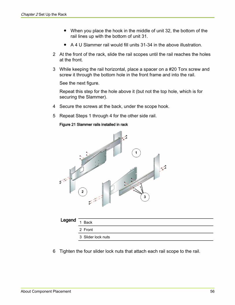
● When you place the hook in the middle of unit 32, the bottom of therail lines up with the bottom of unit 31.
● A 4 U Slammer rail would fill units 31-34 in the above illustration.
2 At the front of the rack, slide the rail scopes until the rail reaches the holesat the front.
3 While keeping the rail horizontal, place a spacer on a #20 Torx screw andscrew it through the bottom hole in the front frame and into the rail.
See the next figure.
Repeat this step for the hole above it (but not the top hole, which is forsecuring the Slammer).
4 Secure the screws at the back, under the scope hook.
5 Repeat Steps 1 through 4 for the other side rail.
Figure 21 Slammer rails installed in rack
Legend 1 Back
2 Front
3 Slider lock nuts
6 Tighten the four slider lock nuts that attach each rail scope to the rail.
Chapter 2 Set Up the Rack
About Component Placement 56
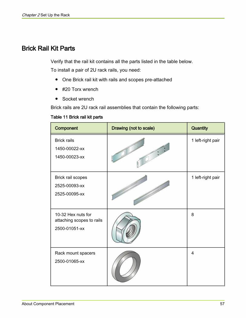
Brick Rail Kit Parts
Verify that the rail kit contains all the parts listed in the table below.
To install a pair of 2U rack rails, you need:
● One Brick rail kit with rails and scopes pre-attached
● #20 Torx wrench
● Socket wrench
Brick rails are 2U rack rail assemblies that contain the following parts:
Table 11 Brick rail kit parts
Component Drawing (not to scale) Quantity
Brick rails
1450-00022-xx
1450-00023-xx
1 left-right pair
Brick rail scopes
2525-00093-xx
2525-00095-xx
1 left-right pair
10-32 Hex nuts forattaching scopes to rails
2500-01051-xx
8
Rack mount spacers
2500-01065-xx
4
Chapter 2 Set Up the Rack
About Component Placement 57
Table 11 Brick rail kit parts (continued)
Component Drawing (not to scale) Quantity
10-32 x 1/2 inch Torxhead (#20) screws
2500-01071-xx
10
Related tasks• Install a Pair of Brick Mounting Rails
Install a Pair of Brick Mounting Rails1 Hang the scope hook in the appropriate hole at the back of the rack, as
shown below. These rail scopes are always used for components that takeup at least two rack units.
Chapter 2 Set Up the Rack
About Component Placement 58
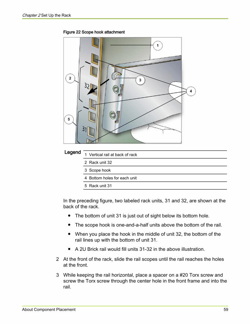
Figure 22 Scope hook attachment
Legend 1 Vertical rail at back of rack
2 Rack unit 32
3 Scope hook
4 Bottom holes for each unit
5 Rack unit 31
In the preceding figure, two labeled rack units, 31 and 32, are shown at theback of the rack.
● The bottom of unit 31 is just out of sight below its bottom hole.
● The scope hook is one-and-a-half units above the bottom of the rail.
● When you place the hook in the middle of unit 32, the bottom of therail lines up with the bottom of unit 31.
● A 2U Brick rail would fill units 31-32 in the above illustration.
2 At the front of the rack, slide the rail scopes until the rail reaches the holesat the front.
3 While keeping the rail horizontal, place a spacer on a #20 Torx screw andscrew the Torx screw through the center hole in the front frame and into therail.
Chapter 2 Set Up the Rack
About Component Placement 59
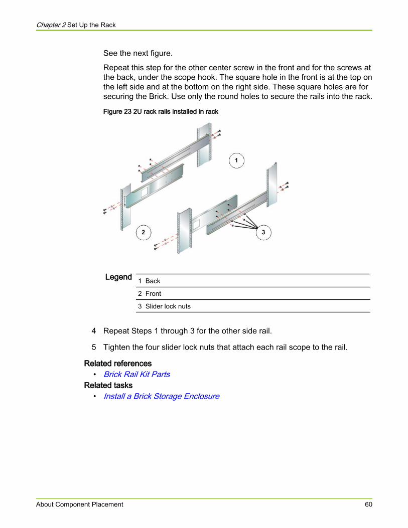
See the next figure.
Repeat this step for the other center screw in the front and for the screws atthe back, under the scope hook. The square hole in the front is at the top onthe left side and at the bottom on the right side. These square holes are forsecuring the Brick. Use only the round holes to secure the rails into the rack.
Figure 23 2U rack rails installed in rack
Legend 1 Back
2 Front
3 Slider lock nuts
4 Repeat Steps 1 through 3 for the other side rail.
5 Tighten the four slider lock nuts that attach each rail scope to the rail.
Related references• Brick Rail Kit Parts
Related tasks• Install a Brick Storage Enclosure
Chapter 2 Set Up the Rack
About Component Placement 60

CHAPTER 3
Install Components
About Power Distribution Unit InstallationMount power distribution units (PDUs) in the bottom units of the rack. The one-phase PDUs mount on the rear rack rails while the 2U three-phase PDUs mounton the front rails. The default configuration places up to four 1U 220V, 30A PDUsat the bottom of the rack.
Prerequisites:
● A 1U or 2U PDU
● Torx T20 screw driver
● Four snap-in cage nuts (for square mounting holes) or four clip-on cagenuts (for round mounting holes)
● Four 10-32 x 1/2" Torx Washer Head screws
Important! We strongly recommend that you use Pillar Axiom 600 PDUs. If youinstall non-Pillar PDUs, they must meet the PDU specification described in thePillar Axiom Site Preparation Survey and in the hardware specifications appendix.
Important! If the external power supplied to the Pillar Axiom 600 is 208V insteadof 230V, the number of components that can be powered by a single PDU isreduced. Because of the lower voltage of 208V circuits, use of this connectiontype lowers the number of Bricks that can be placed in a rack. Pillar recommendsusing 230V circuits instead.
Tip: Use a voltmeter to verify the voltage of the available power. The PillarAxiom 600 PDUs support multiple ranges of voltage and the current rating on thePDU breakers varies with the external available power. The external availablepower determines the number of Pillar Axiom 600 components that can beconnected to the PDU port groups or circuit breakers (CB). If the voltage of theinput power into the PDU is lower than the nominal rating of the PDU, the currentrating on the breakers is decreased to compensate the lower voltage of theavailable power. For example, a 15A breaker on a 230V PDU is rated at 12A ifthe voltage of the input available power into the PDU is 208V.
Chapter 3 Install Components
About Power Distribution Unit Installation 61
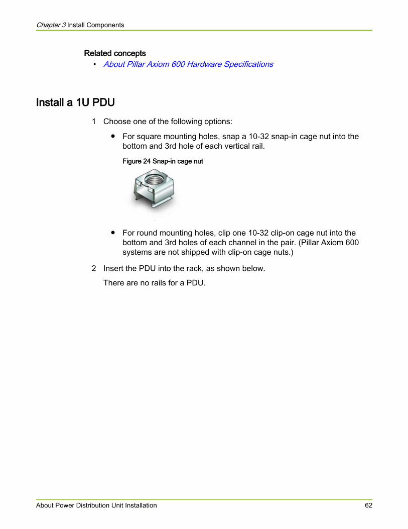
Related concepts• About Pillar Axiom 600 Hardware Specifications
Install a 1U PDU1 Choose one of the following options:
● For square mounting holes, snap a 10-32 snap-in cage nut into thebottom and 3rd hole of each vertical rail.
Figure 24 Snap-in cage nut
● For round mounting holes, clip one 10-32 clip-on cage nut into thebottom and 3rd holes of each channel in the pair. (Pillar Axiom 600systems are not shipped with clip-on cage nuts.)
2 Insert the PDU into the rack, as shown below.
There are no rails for a PDU.
Chapter 3 Install Components
About Power Distribution Unit Installation 62
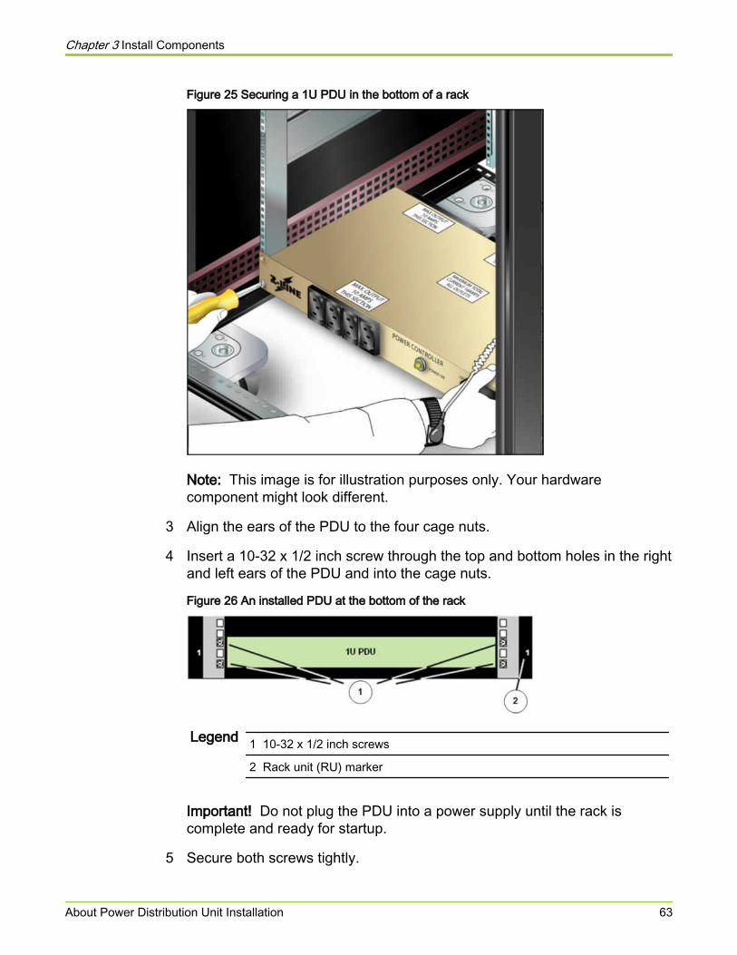
Figure 25 Securing a 1U PDU in the bottom of a rack
Note: This image is for illustration purposes only. Your hardwarecomponent might look different.
3 Align the ears of the PDU to the four cage nuts.
4 Insert a 10-32 x 1/2 inch screw through the top and bottom holes in the rightand left ears of the PDU and into the cage nuts.
Figure 26 An installed PDU at the bottom of the rack
Legend 1 10-32 x 1/2 inch screws
2 Rack unit (RU) marker
Important! Do not plug the PDU into a power supply until the rack iscomplete and ready for startup.
5 Secure both screws tightly.
Chapter 3 Install Components
About Power Distribution Unit Installation 63
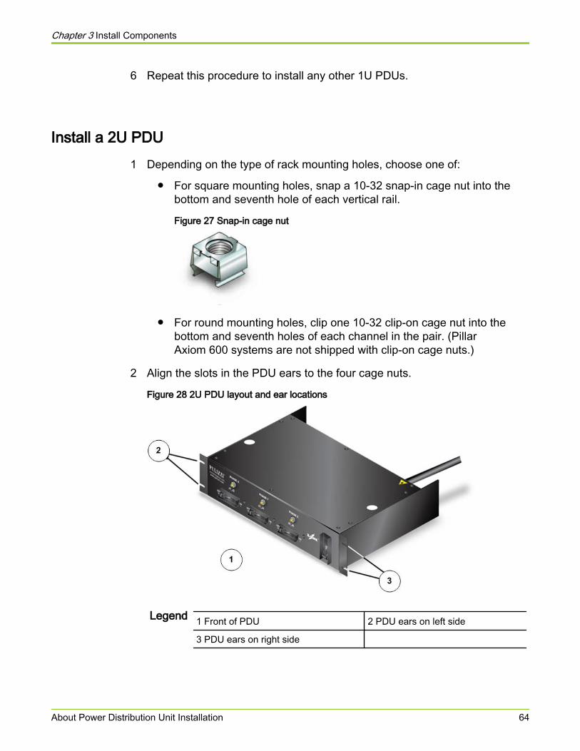
6 Repeat this procedure to install any other 1U PDUs.
Install a 2U PDU1 Depending on the type of rack mounting holes, choose one of:
● For square mounting holes, snap a 10-32 snap-in cage nut into thebottom and seventh hole of each vertical rail.
Figure 27 Snap-in cage nut
● For round mounting holes, clip one 10-32 clip-on cage nut into thebottom and seventh holes of each channel in the pair. (PillarAxiom 600 systems are not shipped with clip-on cage nuts.)
2 Align the slots in the PDU ears to the four cage nuts.
Figure 28 2U PDU layout and ear locations
Legend 1 Front of PDU 2 PDU ears on left side
3 PDU ears on right side
Chapter 3 Install Components
About Power Distribution Unit Installation 64

Note: This image is for illustration purposes only. Your hardwarecomponent might look different.
3 Insert a 10-32 x 1/2 inch screw through the bottom hole in the right and leftears of the PDU and into the cage nuts. Secure both screws tightly.
4 Repeat Step 3 for the top holes in both ears.
Important! Until you are instructed to do so, do not plug the PDU into aninlet power supply.
5 Repeat this procedure to install any other 2U PDUs.
Chapter 3 Install Components
About Power Distribution Unit Installation 65
Install a Pilot Management ControllerInstallation of the Pilot control units at the bottom of the rack, just above thepower distribution units (PDUs), is efficient and makes future expansion as easyas possible.
Required tools:
● Torx T20 screw driver
● Antistatic wrist strap
Warning Ensure that component distribution in the rack is balanced.Follow the hardware placement map to ensure this balance.Uneven distribution can cause hazardous instability. Therack must have stabilization plates or anti-tip bracketsinstalled so the rack does not tip when you install acomponent.
Warning Mounting rail assemblies must be used to support andsecure a Pilot in the rack. The mounting ears of a Pilotcontrol unit (CU) by themselves cannnot support the weightof the Pilot.
1 Put on an antistatic wrist strap, ground strap, or heel strap and attach thegrounding wire to ground.
2 From the front of the rack, place the back side of the first Pilot CU on thebottom mounting rails and slide the CU into place.
Important! When sliding a Pilot CU into the rack, keep the CU level to avoidbending the rail supports.
3 Insert the second Pilot CU above the first CU, as shown in the following figure:
Chapter 3 Install Components
Install a Pilot Management Controller 66
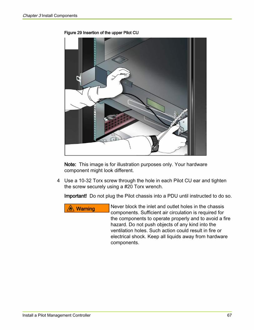
Figure 29 Insertion of the upper Pilot CU
Note: This image is for illustration purposes only. Your hardwarecomponent might look different.
4 Use a 10-32 Torx screw through the hole in each Pilot CU ear and tightenthe screw securely using a #20 Torx wrench.
Important! Do not plug the Pilot chassis into a PDU until instructed to do so.
Warning Never block the inlet and outlet holes in the chassiscomponents. Sufficient air circulation is required forthe components to operate properly and to avoid a firehazard. Do not push objects of any kind into theventilation holes. Such action could result in fire orelectrical shock. Keep all liquids away from hardwarecomponents.
Chapter 3 Install Components
Install a Pilot Management Controller 67
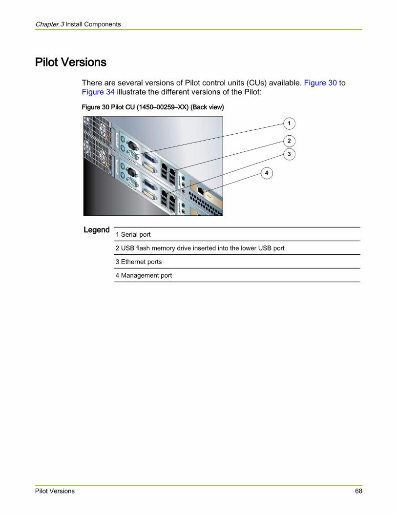
Pilot VersionsThere are several versions of Pilot control units (CUs) available. Figure 30 to Figure 34 illustrate the different versions of the Pilot:
Figure 30 Pilot CU (1450–00259–XX) (Back view)
Legend 1 Serial port
2 USB flash memory drive inserted into the lower USB port
3 Ethernet ports
4 Management port
Chapter 3 Install Components
Pilot Versions 68
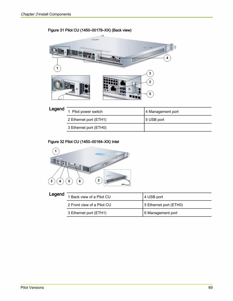
Figure 31 Pilot CU (1450–00179–XX) (Back view)
Legend 1 Pilot power switch 4 Management port
2 Ethernet port (ETH1) 5 USB port
3 Ethernet port (ETH0)
Figure 32 Pilot CU (1450–00164–XX) Intel
Legend 1 Back view of a Pilot CU 4 USB port
2 Front view of a Pilot CU 5 Ethernet port (ETH0)
3 Ethernet port (ETH1) 6 Management port
Chapter 3 Install Components
Pilot Versions 69
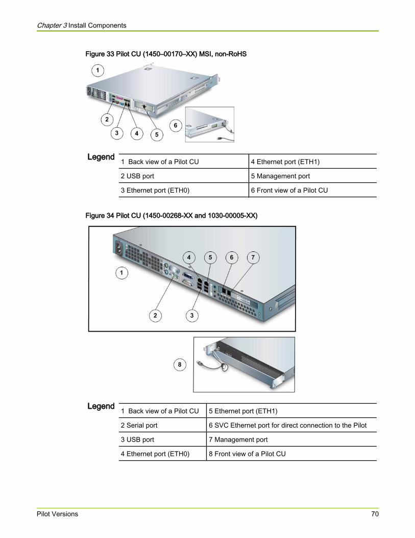
Figure 33 Pilot CU (1450–00170–XX) MSI, non-RoHS
Legend 1 Back view of a Pilot CU 4 Ethernet port (ETH1)
2 USB port 5 Management port
3 Ethernet port (ETH0) 6 Front view of a Pilot CU
Figure 34 Pilot CU (1450-00268-XX and 1030-00005-XX)
Legend 1 Back view of a Pilot CU 5 Ethernet port (ETH1)
2 Serial port 6 SVC Ethernet port for direct connection to the Pilot
3 USB port 7 Management port
4 Ethernet port (ETH0) 8 Front view of a Pilot CU
Chapter 3 Install Components
Pilot Versions 70

Install a Slammer Storage ControllerInstall the Slammers above the Pilot near the bottom of the rack.
Required tools:
● Torx T20 screw driver
● Antistatic wrist strap
Caution A Slammer weighs 94 pounds (42.6 kilograms). For safehandling, use two people to lift it.
Warning Ensure that component distribution in the rack is balanced.Follow the hardware placement map to ensure this balance.Uneven distribution can cause hazardous instability. Therack must have stabilization plates or anti-tip bracketsinstalled so the rack does not tip when you install acomponent.
1 Put on an antistatic wrist strap, ground strap, or heel strap and attach thegrounding wire to ground.
2 From the front side of the rack, set the back of the Slammer onto themounting rails and slide the Slammer into place.
Leave about one inch (2.5 centimeters) of clearance between the Slammerears and the vertical channels.
Important! When sliding the Slammer into the rack, keep the Slammer levelto avoid bending the rail supports, which would cause difficulty wheninserting a component below.
Chapter 3 Install Components
Install a Slammer Storage Controller 71
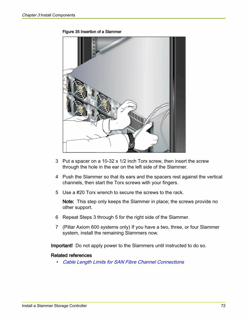
Figure 35 Insertion of a Slammer
3 Put a spacer on a 10-32 x 1/2 inch Torx screw, then insert the screwthrough the hole in the ear on the left side of the Slammer.
4 Push the Slammer so that its ears and the spacers rest against the verticalchannels, then start the Torx screws with your fingers.
5 Use a #20 Torx wrench to secure the screws to the rack.
Note: This step only keeps the Slammer in place; the screws provide noother support.
6 Repeat Steps 3 through 5 for the right side of the Slammer.
7 (Pillar Axiom 600 systems only) If you have a two, three, or four Slammersystem, install the remaining Slammers now.
Important! Do not apply power to the Slammers until instructed to do so.
Related references• Cable Length Limits for SAN Fibre Channel Connections
Chapter 3 Install Components
Install a Slammer Storage Controller 72

Install the Slammer BatteriesSlammer batteries are shipped separately.
1 Ensure the Install Before Date on the Slammer batteries have not expired.
The Install Before Date is printed on the label on top of the battery. If abattery is past the Install Before Date, contact the Pillar World WideCustomer Support Center.
2 Remove the front cover (bezel).
If the bezel is not attached, skip to Step 5.
3 Press the Slammer ejector tabs on the bezel to unlock them.
4 Lift both ejector tabs to disengage the bezel from the rack.
Figure 36 Slammer bezel removal
Legend 1 Ejector tab
2 Button
3 Disengage the bezel from the rack
5 Insert the batteries into the Slammer, but do not secure them until youcomplete the installation.
Tip: When you secure them, they start to discharge as they preserve datain memory. Because there is no data to preserve, you should wait until youare ready to power on the system before securing the batteries.
Chapter 3 Install Components
Install the Slammer Batteries 73
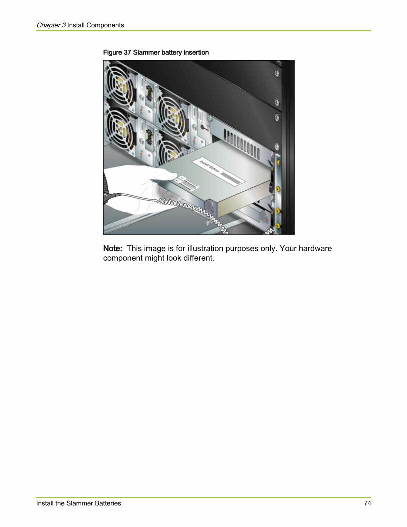
Figure 37 Slammer battery insertion
Note: This image is for illustration purposes only. Your hardwarecomponent might look different.
Chapter 3 Install Components
Install the Slammer Batteries 74
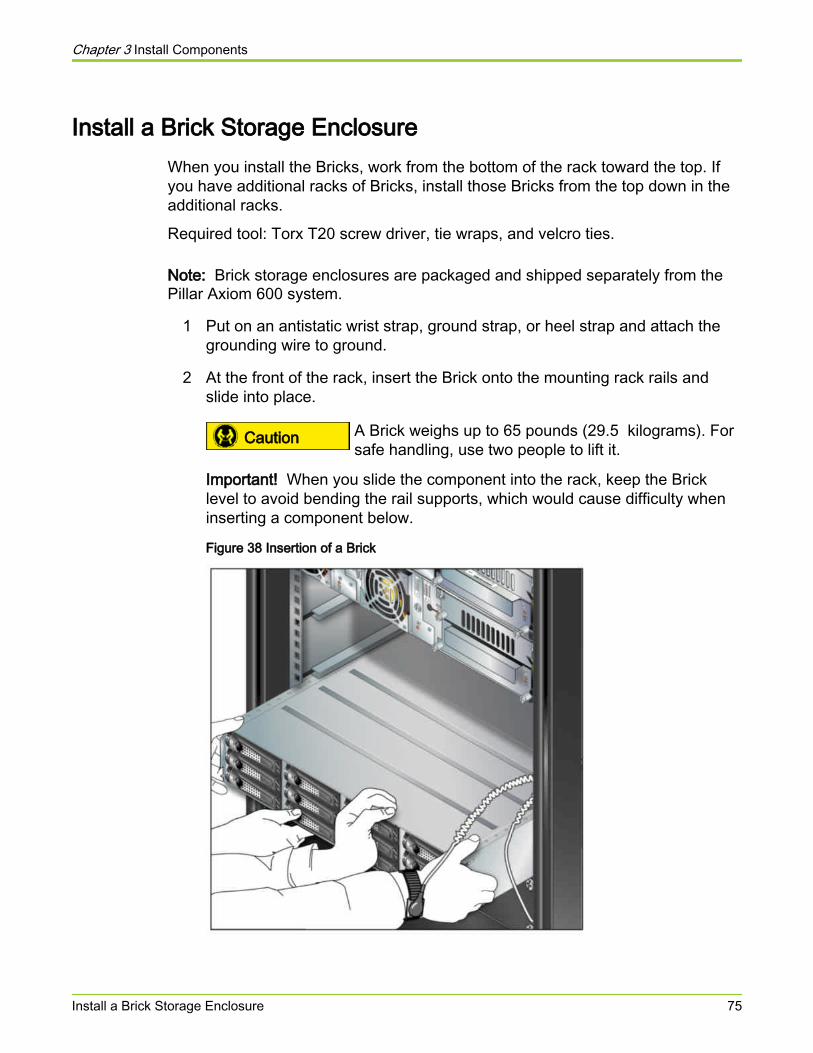
Install a Brick Storage EnclosureWhen you install the Bricks, work from the bottom of the rack toward the top. Ifyou have additional racks of Bricks, install those Bricks from the top down in theadditional racks.
Required tool: Torx T20 screw driver, tie wraps, and velcro ties.
Note: Brick storage enclosures are packaged and shipped separately from thePillar Axiom 600 system.
1 Put on an antistatic wrist strap, ground strap, or heel strap and attach thegrounding wire to ground.
2 At the front of the rack, insert the Brick onto the mounting rack rails andslide into place.
Caution A Brick weighs up to 65 pounds (29.5 kilograms). Forsafe handling, use two people to lift it.
Important! When you slide the component into the rack, keep the Bricklevel to avoid bending the rail supports, which would cause difficulty wheninserting a component below.
Figure 38 Insertion of a Brick
Chapter 3 Install Components
Install a Brick Storage Enclosure 75
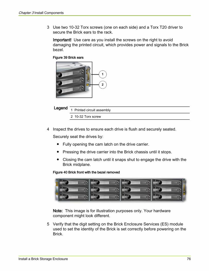
3 Use two 10-32 Torx screws (one on each side) and a Torx T20 driver tosecure the Brick ears to the rack.
Important! Use care as you install the screws on the right to avoiddamaging the printed circuit, which provides power and signals to the Brickbezel.
Figure 39 Brick ears
Legend 1 Printed circuit assembly
2 10-32 Torx screw
4 Inspect the drives to ensure each drive is flush and securely seated.
Securely seat the drives by:
● Fully opening the cam latch on the drive carrier.
● Pressing the drive carrier into the Brick chassis until it stops.
● Closing the cam latch until it snaps shut to engage the drive with theBrick midplane.
Figure 40 Brick front with the bezel removed
Note: This image is for illustration purposes only. Your hardwarecomponent might look different.
5 Verify that the digit setting on the Brick Enclosure Services (ES) moduleused to set the identity of the Brick is set correctly before powering on theBrick.
Chapter 3 Install Components
Install a Brick Storage Enclosure 76

6 If you have multiple Bricks, install them all now, even those that requireadditional racks.
7 Verify that the digit setting of the Brick is in the proper position. The digitsetting must be set to 0 for all Serial ATA (SATA), solid state drive (SSD),and Fiber Channel RAID (FCR) Bricks and to 1 for all Fiber ChannelExpansion (FCE) Bricks.
8 Ensure that both the power switches that are on the power distribution units(PDUs) are in the OFF position.
9 When connecting the color coded Wye power cables, ensure that eachBrick gets a power feed from two separate PDUs.
10 Connect the FC cables as indicated in the wiring diagrams included in thePillar Axiom 600 SSF Cabling Reference and power on the Bricks.
Related concepts• About Power Cabling
Related tasks• Set the Identity of Bricks• Power On the System• Connect Power Cables• Install a Pair of Brick Mounting Rails• Add a New Brick Storage Enclosure
Chapter 3 Install Components
Install a Brick Storage Enclosure 77
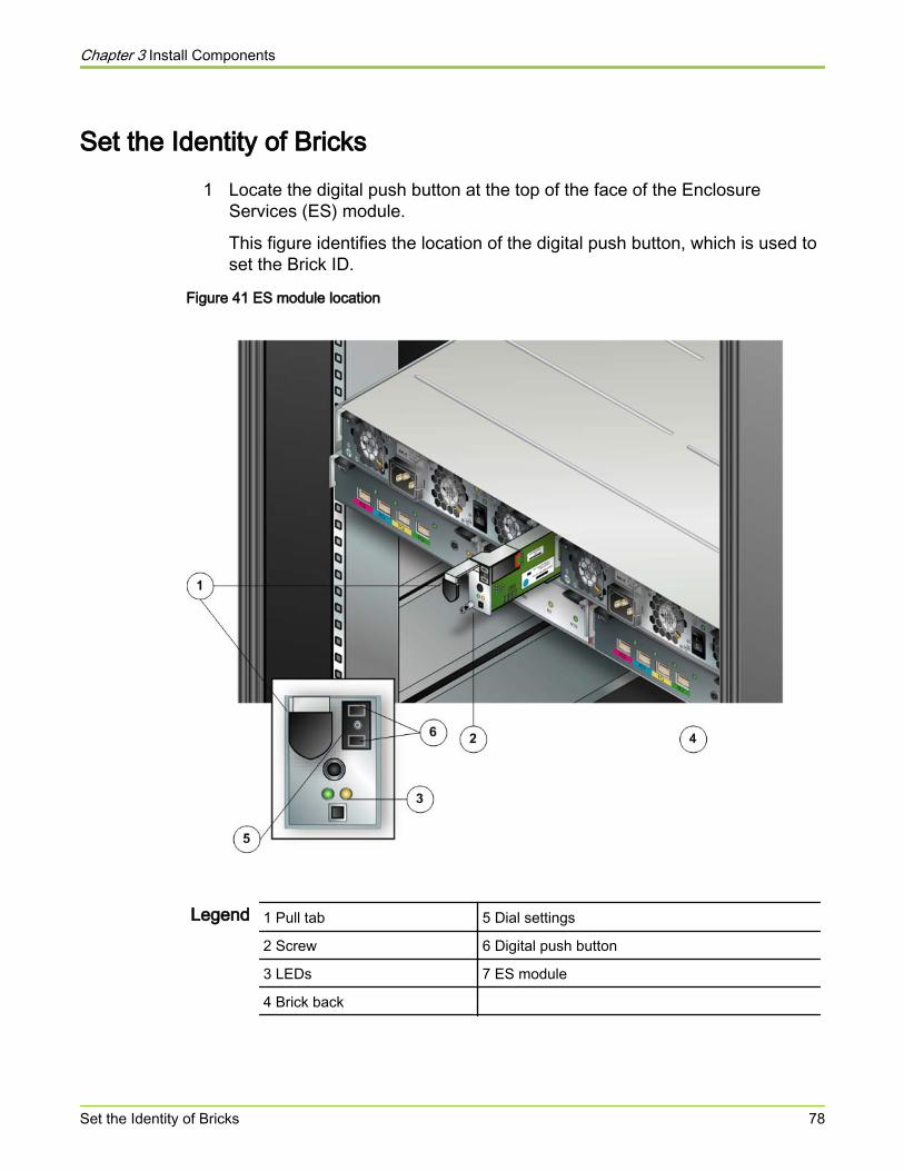
Set the Identity of Bricks1 Locate the digital push button at the top of the face of the Enclosure
Services (ES) module.
This figure identifies the location of the digital push button, which is used toset the Brick ID.
Figure 41 ES module location
Legend 1 Pull tab 5 Dial settings
2 Screw 6 Digital push button
3 LEDs 7 ES module
4 Brick back
Chapter 3 Install Components
Set the Identity of Bricks 78
The digit setting of the Brick is visible in the center of the digital push buttonand identifies the type of Brick.
2 Verify that the digit setting on the Brick Enclosure Services (ES) module isset correctly for the Brick before powering on the Brick.
Important! The digit setting for all Bricks (SATA, SSD, and FC RAID) is pre-set to 0. The digit setting for the FC Expansion Brick is pre-set to 1.However, the digit setting must always be verified during installation.Otherwise, the Pillar Axiom 600 system cannot bring the Brick online.
3 If the digit setting is not set correctly, push the button using a sharp object,such as the end of a paper clip or a small screwdriver to set the Brick ID.
The top button ( - ) decrements the counter and the bottom button ( + )increments the counter.
Important! Do not change the digit settings while the Brick is powered on.
Related tasks• Install a Brick Storage Enclosure
Chapter 3 Install Components
Set the Identity of Bricks 79
Replace a Brick Storage EnclosureYou can replace existing Bricks with new Bricks within a storage domain. Youmust migrate the volumes to the new Bricks because clones are not migratedwith the parent volumes when Bricks are replaced.
1 Delete the clones of existing volumes in the Bricks that must be replaced.
2 Create a minimum of one new Storage Domain.
3 Add the new Bricks to the Pillar Axiom 600 system.
4 Accept the newly added Bricks into the new Storage Domain.
5 Verify that the capacity from the new Bricks has been added successfully inthe Pillar Axiom 600 system.
6 If the Bricks that must be added are in the existing primary Storage Domain,make sure you add a minimum of two Bricks of the same Storage Class toa single new Storage Domain before you promote the new Storage Domainto primary.
Important! Before making a Storage Domain primary or migrating data to anew Storage Domain, add all the Bricks to the new Storage Domain. Failureto do so may cause performance issues because the Pillar Axiom 600system might not be able to stripe the data across the appropriate numberof Bricks for the Quality of Service (QoS) and Storage Class.
7 Make the new Storage Domain primary.
When the new Storage Domain is made primary, the persistence VLUN ismigrated from the old primary Storage Domain to the new primary StorageDomain. The migration uses Bricks in the following order: serial ATA(SATA), Fiber channel (FC), and solid state drive (SSD).
8 Migrate all the volumes on the old Bricks to the desired Storage Class in thenew Storage Domain.
Tip: For minimum impact to system performance, migrate one volume at atime.
9 Use the storage allocation CLI axiomcli storage_allocationcommand to ensure that all volumes have been migrated from the oldBricks that must be replaced.
Chapter 3 Install Components
Replace a Brick Storage Enclosure 80
Important! If you are replacing Bricks in the default or primary StorageDomain, use the storage allocation CLI axiomcli storage_allocationcommand to ensure that the persistence volume is not on the Bricks thatmust be powered down. The persistence volume must be on the Bricks inthe new primary Storage Domain.
A system alert is posted to confirm the removal of the Brick from the PillarAxiom 600 system configuration.
10 After verifying that all volumes, including the system configuration,persistence, and volumes have been migrated, power off all the Bricks inthe old Storage Domain.
11 Verify all storage and make sure that all the volumes are online beforedisconnecting and removing the old Bricks from the system configuration.
Note: The Pillar Axiom 600 system does not allow Bricks to be removed ifany resources are allocated on that Brick. If there are problems whileremoving the Bricks, contact the Pillar World Wide Customer SupportCenter for assistance.
12 Select and remove the old Storage Domain.
Note: The Pillar Axiom 600 system does not allow Storage Domains to beremoved if any resources are allocated on that Storage Domain. If there areproblems while removing the old Storage Domain, contact the Pillar WorldWide Customer Support Center for assistance.
Related concepts• About Adding Bricks to a Storage Domain
Related tasks• Move a Volume to Another Storage Domain• Set a Storage Domain as the Primary• Accept a Brick• Create a Storage Domain• Add a New Brick Storage Enclosure• Verify a Newly Added Brick• Delete All Clone LUNs
Delete All Clone LUNsWhen a collection of Clone LUNs that are derived from a common source LUNare no longer needed, you can delete the entire collection.
When you delete a collection of clones that have a common parent LUN, thesystem determines the most efficient and quickest order of deletion.
Chapter 3 Install Components
Replace a Brick Storage Enclosure 81
1 From the Configure tab, click Storage > SAN > LUNs.
2 Select the parent LUN of all of the Clone LUNs that you want to delete.
3 Choose Actions > Delete Clones.
Result:The system displays the Delete Clones dialog with a list of all the clonesthat will be deleted.
4 When prompted to confirm the deletion, click OK.
Accept a BrickWhen you add a Brick storage enclosure to an existing Pillar Axiom system, youracceptance of the Brick allows the system to add the storage provided by theBrick to the existing storage pool.
Prerequisites:
● The Pillar Axiom system is in a Normal state.
● The Brick has been cabled correctly according to the wiring diagrams in thePillar Axiom 600 SSF Cabling Reference.
● Both RAID controllers of the Brick have been powered on.
Note: After you power on a Brick, the system updates the Brick firmware.This update can take up to 15 minutes.
● A system alert exists that states that a Brick has been added to the system.
Typically, you respond to the system alert by either accepting or rejecting thenewly added Brick. If you delete the system alert and, as a consequence, do notaccept the Brick, you can perform the Accept Brick action at a later time. Thisaction mirrors the functionality of the Accept Brick alert.
The Brick to be accepted can be a new one from Pillar Manufacturing or anexisting one from a different Pillar Axiom system. A Brick from a different systemis referred to as a foreign Brick.
1 From the Monitor tab, click Hardware > Bricks.
2 Choose Actions > Accept Brick.
3 (Optional) Select a domain from Storage Domain drop-down list.
Chapter 3 Install Components
Replace a Brick Storage Enclosure 82
This list is active only when additional Storage Domains exist.
4 (Optional) Replace the default logical name for this newly added Brick witha name of your own choosing.
5 To accept the Brick into the system, click OK.Result:
While the Brick is being integrated into the system, the status of the Brickchanges from red to yellow to green. Also, the overall status of a foreignBrick is displayed as Foreign.
When the system completes the integration process, the system performsthe following additional actions:
● Generates a “Brick Accepted” event.
● Changes the health status of the Brick from Warning to Normal.
● Removes all system alerts that are related to the Brick addition.Note: If any system alerts remain, contact the Pillar World WideCustomer Support Center.
The Brick is now fully integrated into the Pillar Axiom system.
You can now begin utilizing the additional capacity provided by the newly addedBrick. The Monitor > Hardware > Bricks overview screen shows this capacity and theStorage Domain to which the Brick is assigned.
Create a Storage DomainStorage Domains allow you to assign logical volumes to a specific collection ofBricks. Such assignments can be made to reduce contention among volumes, toimplement different levels of security for those volumes, or both. StorageDomains allow administrators, for example, to partition storage for specific usersor departments in a public or private cloud storage environment.
When you create a Storage Domain for regular use, we recommend that youassign the following minimum number of Bricks to that domain:
● Two serial ATA (SATA) or solid state device (SSD) Bricks
● Three Fibre Channel (FC) Bricks
When you need to replace one or more Bricks in an existing domain, youtypically would create a new Storage Domain, assign Bricks to it, and then movethe logical volumes from the existing domain to the newly created domain. In this
Chapter 3 Install Components
Replace a Brick Storage Enclosure 83
scenario, you can create the new domain without any Bricks with the purpose ofassigning the Bricks later.
In the above scenario, if you are replacing Bricks in the current primary StorageDomain, for the new domain, we recommend that you have at least two Bricks ofthe same Storage Class, in the following order of preference:
● First, SATA.
● If not SATA, then FC.
● If not FC, then SSD.
Note: We recommend a minimum of two Bricks of the same Storage Class toensure that the Persistence VLUN, which contains the system configurationinformation, retains double redundancy.
A non-primary Storage Domain can contain only one Brick of any Storage Class.
Important! If you place only a single Brick of the lowest Storage Class in the newnon-primary domain and the domain is promoted to primary, the redundancy ofthe Persistence VLUN reverts to single redundancy.
1 From the Configure tab, click Groups > Storage Domains.
2 Choose Actions > Manage Storage Domains.
3 On the Storage Domains tab, click Create.
Result:A new row in the Storage Domains table appears.
4 In the blank Storage Domain field, enter the name of the new domain.
5 Click OK.
The new Storage Domain now appears in the list of domains.
After you create the Storage Domain, assign one or more Bricks to the domainso you can locate logical volumes in the domain. The number of Bricks that youadd to a domain directly affects the performance of that domain.
About Adding Bricks to a Storage DomainThe impact of adding a Brick to a Pillar Axiom system depends on whetheradministrator defined Storage Domains exist.
Chapter 3 Install Components
Replace a Brick Storage Enclosure 84
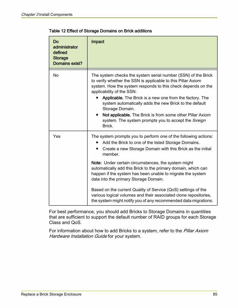
Table 12 Effect of Storage Domains on Brick additions
DoadministratordefinedStorageDomains exist?
Impact
No The system checks the system serial number (SSN) of the Brickto verify whether the SSN is applicable to this Pillar Axiomsystem. How the system responds to this check depends on theapplicability of the SSN:
● Applicable. The Brick is a new one from the factory. Thesystem automatically adds the new Brick to the defaultStorage Domain.
● Not applicable. The Brick is from some other Pillar Axiomsystem. The system prompts you to accept the foreignBrick.
Yes The system prompts you to perform one of the following actions:● Add the Brick to one of the listed Storage Domains.● Create a new Storage Domain with this Brick as the initial
member.
Note: Under certain circumstances, the system mightautomatically add this Brick to the primary domain, which canhappen if the system has been unable to migrate the systemdata into the primary Storage Domain.
Based on the current Quality of Service (QoS) settings of thevarious logical volumes and their associated clone repositories,the system might notify you of any recommended data migrations.
For best performance, you should add Bricks to Storage Domains in quantitiesthat are sufficient to support the default number of RAID groups for each StorageClass and QoS.
For information about how to add Bricks to a system, refer to the Pillar AxiomHardware Installation Guide for your system.
Chapter 3 Install Components
Replace a Brick Storage Enclosure 85
Set a Storage Domain as the PrimaryCircumstances can arise in which you might want to transfer the PersistenceVLUN, which contains the system configuration data, from the current primaryStorage Domain to a different domain.
Prerequisites:
● A non-primary Storage Domain.
● The following lists the minimum recommended number of Bricks in theorder of preference:
○ First, two serial ATA (SATA).
○ Second, two Fibre Channel (FC).
○ Third, two solid state device (SSD).
Note: If you have more than one Storage Class in the non-primary StorageDomain, the Pillar Axiom storage system migrates to SATA, if that class isavailable. If SATA is not available, the system migrates to FC, if that classis available. If SATA and FC are not available, the system migrates to SSD.
When the non-primary Storage Domain becomes the primary domain, theprevious primary domain loses its primary status and the system migrates thesystem data to the new primary domain. The administrator cannot cancel thisspecial data migration.
1 From the Configure tab, click Groups > Storage Domains.
2 Highlight the Storage Domain that you want to become the new primarydomain and choose Actions > Set as Primary Storage Domain.
3 To set the non-primary Storage Domain as the new primary domain, clickOK.
Result:The systems begins migrating all system configuration and persistence datato the new primary domain.
Important! After you click OK, you cannot cancel this data migration.
Chapter 3 Install Components
Replace a Brick Storage Enclosure 86
Important! After promoting a non-primary Storage Domain to primary, you shouldverify that the volume named PERSISTENCE has been moved to the Bricks inthe new primary domain. To verify proper migration, use the axiomclistorage_allocation command provided by the Pillar Axiom CLI application.When executing this command, include the -brick and -list options. Formore information, refer to the Pillar Axiom CLI Reference Guide.
Move a Volume to Another Storage DomainMove a logical volume to another Storage Domain when you want to remove theBricks on which the volume resides or reassign those Bricks to another StorageDomain.
The Storage Domain to which you want to reassign the logical volume mustcontain sufficient free capacity of the appropriate Storage Class to hold thelogical volume.
Note: Assigning logical volumes and Bricks to a Pillar Axiom Storage Domainmust be performed as separate actions.
Tip: To avoid performance issues caused by Brick striping, move the Bricks tothe Storage Domain before you move any volumes.
1 From the Configure tab, click Groups > Storage Domains.
2 Choose Actions > Manage Storage Domains.
3 On the Volumes tab, click the Storage Domain for the logical volume thatyou want to reassign.Result:A drop-down list appears in the Storage Domain column.
4 In the Storage Domain drop-down list, choose the Storage Domain to whichyou want to reassign the logical volume.
5 Click OK.Result:One of the following will occur:
● If the operation is successful, the system begins a background task tomigrate the volume to the new Storage Domain. Also, the systemreleases and reconditions the storage in the previous domain.
● If the operation is unsuccessful, the system does not migrate thevolume but instead displays an appropriate error dialog:
Chapter 3 Install Components
Replace a Brick Storage Enclosure 87

○ The target domain does not contain any Bricks in the appropriateStorage Class. To resolve, add to the target domain one or moreBricks of the appropriate Storage Class.
○ The target domain has insufficient free capacity in thecorresponding Storage Class. To resolve, remove unneededvolumes that consume capacity on the Bricks of that StorageClass.
Chapter 3 Install Components
Replace a Brick Storage Enclosure 88
CHAPTER 4
Connect Data Cables
About Cabling a Pillar Axiom 600 SystemThe Pillar Axiom 600 system is a scalable storage system that consists of a Pilotmanagement controller, at least one Slammer storage controller, and somenumber of Brick storage enclosures depending upon your system model.
Cabling the Pillar Axiom 600 systems consists of two parts:
● Front-end cabling, which involves connecting the Slammer to thecustomer's data network, and connecting the Pilot to the customer'smanagement network. The Pilot connection uses Ethernet. The Slammercable connections to the data network uses Fiber Channel (FC) or Ethernet,depending on the Slammer.
● Back-end cabling, which involves cabling the Storage System Fabric (SSF),sometimes referred to as the private interconnect, or simply PI, and theprivate management interface (PMI).
Pillar Axiom 600 systems transmit data among its hardware components (Bricks,Slammers, and the Pilot) through the SSF and PMI cabling.
The SSF cables provide the inter and intra-cabling connections between theBricks and the Slammers to support all data traffic, the cross connections amongthe Slammer control units (CUs), and the cross connections among the Brick CUs.
The fast Ethernet network between the Pilot and the Slammers in a PillarAxiom 600 system is called the PMI. The PMI also includes the crossconnections between the Slammer CUs as well as the cross connectionsbetween the Pilot CUs. These cross connections between the Pilot CUs permiteach CU to monitor the heartbeat of the other CU. The heartbeat connectionallows the passive Pilot CU to induce a failover, if the active Pilot CU fails.
The Pilot has no physical connection to the user data and, therefore, no cableconnection exists between the Pilot and the Bricks.
Bricks are connected together in Brick strings. The Brick at the head of the stringconnects to the Slammer. Each of the other Bricks in the string connect to theprevious Brick in the string. A Brick that is higher in a string is one that is closerto the Slammer or head of the string. A Brick that is lower in a string is one that isfurther from the Slammer or the head of the string.
Chapter 4 Connect Data Cables
About Cabling a Pillar Axiom 600 System 89
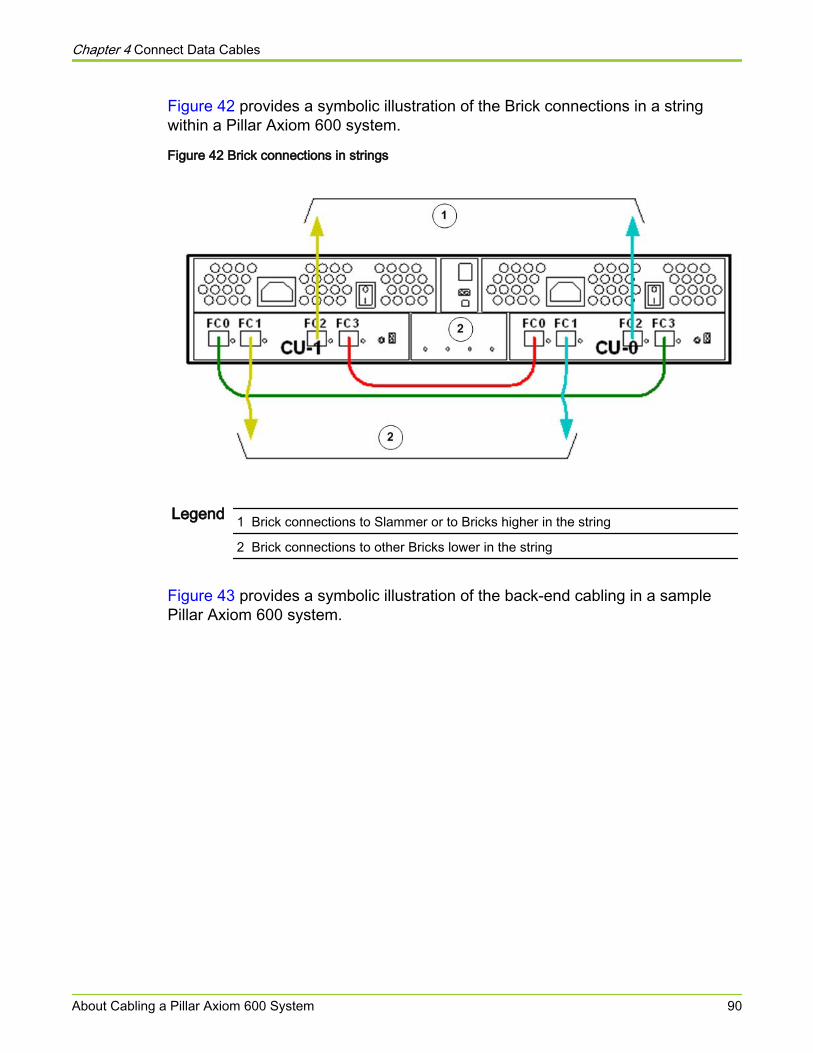
Figure 42 provides a symbolic illustration of the Brick connections in a stringwithin a Pillar Axiom 600 system.
Figure 42 Brick connections in strings
Legend 1 Brick connections to Slammer or to Bricks higher in the string
2 Brick connections to other Bricks lower in the string
Figure 43 provides a symbolic illustration of the back-end cabling in a samplePillar Axiom 600 system.
Chapter 4 Connect Data Cables
About Cabling a Pillar Axiom 600 System 90
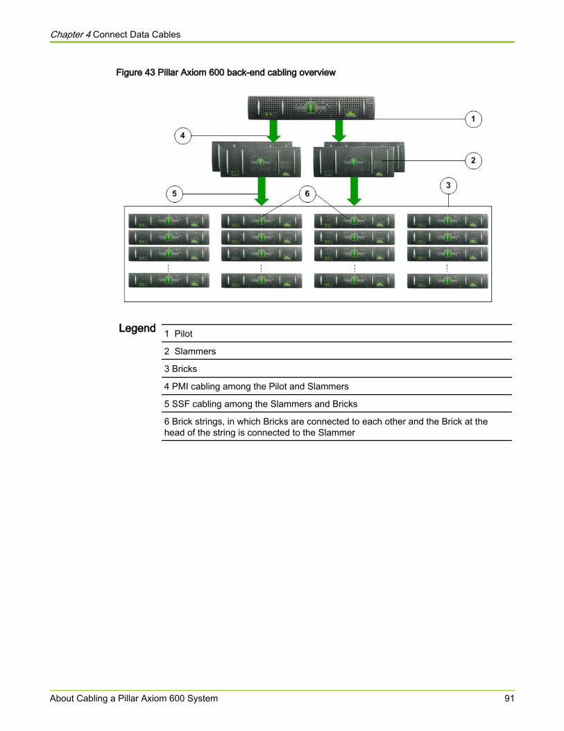
Figure 43 Pillar Axiom 600 back-end cabling overview
Legend 1 Pilot
2 Slammers
3 Bricks
4 PMI cabling among the Pilot and Slammers
5 SSF cabling among the Slammers and Bricks
6 Brick strings, in which Bricks are connected to each other and the Brick at thehead of the string is connected to the Slammer
Chapter 4 Connect Data Cables
About Cabling a Pillar Axiom 600 System 91
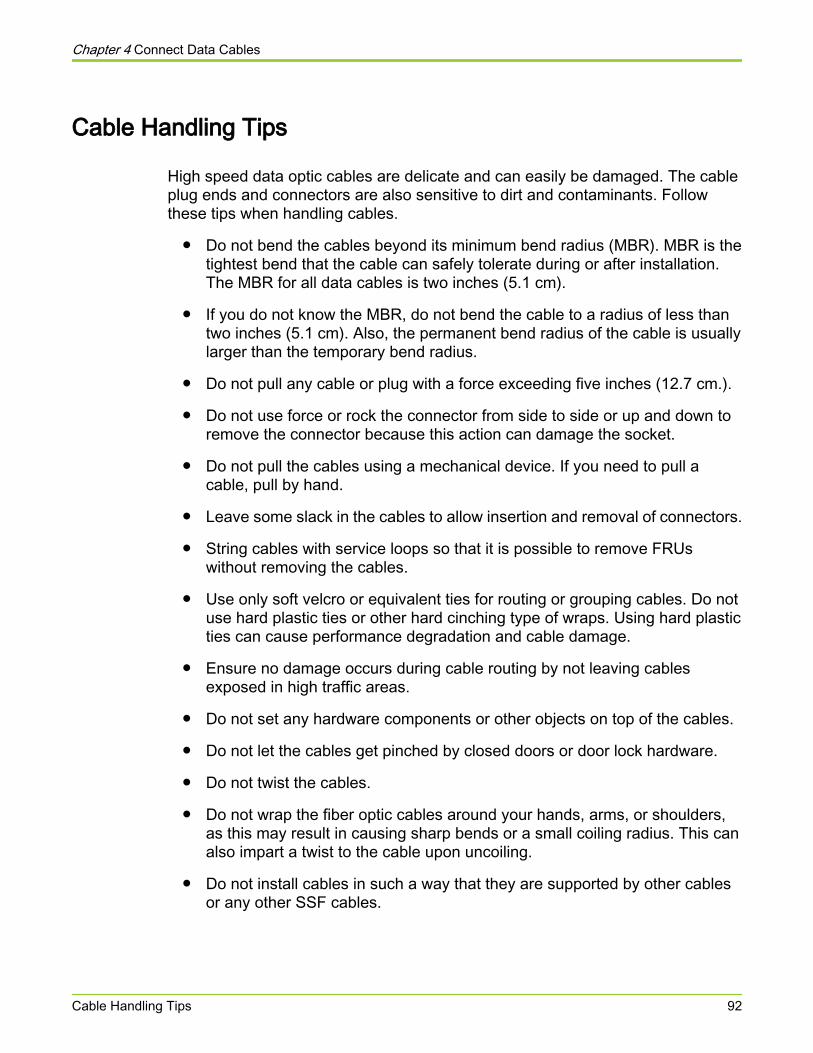
Cable Handling Tips
High speed data optic cables are delicate and can easily be damaged. The cableplug ends and connectors are also sensitive to dirt and contaminants. Followthese tips when handling cables.
● Do not bend the cables beyond its minimum bend radius (MBR). MBR is thetightest bend that the cable can safely tolerate during or after installation.The MBR for all data cables is two inches (5.1 cm).
● If you do not know the MBR, do not bend the cable to a radius of less thantwo inches (5.1 cm). Also, the permanent bend radius of the cable is usuallylarger than the temporary bend radius.
● Do not pull any cable or plug with a force exceeding five inches (12.7 cm.).
● Do not use force or rock the connector from side to side or up and down toremove the connector because this action can damage the socket.
● Do not pull the cables using a mechanical device. If you need to pull acable, pull by hand.
● Leave some slack in the cables to allow insertion and removal of connectors.
● String cables with service loops so that it is possible to remove FRUswithout removing the cables.
● Use only soft velcro or equivalent ties for routing or grouping cables. Do notuse hard plastic ties or other hard cinching type of wraps. Using hard plasticties can cause performance degradation and cable damage.
● Ensure no damage occurs during cable routing by not leaving cablesexposed in high traffic areas.
● Do not set any hardware components or other objects on top of the cables.
● Do not let the cables get pinched by closed doors or door lock hardware.
● Do not twist the cables.
● Do not wrap the fiber optic cables around your hands, arms, or shoulders,as this may result in causing sharp bends or a small coiling radius. This canalso impart a twist to the cable upon uncoiling.
● Do not install cables in such a way that they are supported by other cablesor any other SSF cables.
Chapter 4 Connect Data Cables
Cable Handling Tips 92
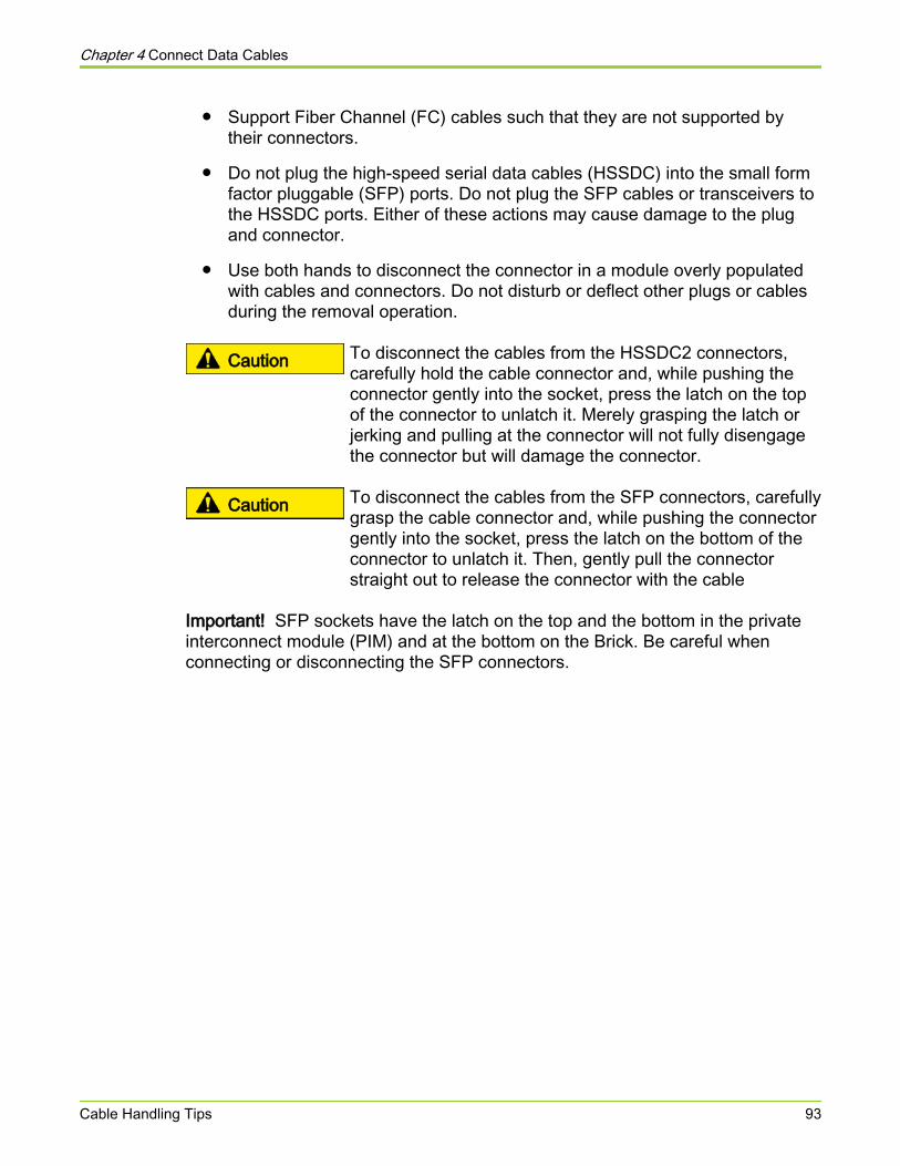
● Support Fiber Channel (FC) cables such that they are not supported bytheir connectors.
● Do not plug the high-speed serial data cables (HSSDC) into the small formfactor pluggable (SFP) ports. Do not plug the SFP cables or transceivers tothe HSSDC ports. Either of these actions may cause damage to the plugand connector.
● Use both hands to disconnect the connector in a module overly populatedwith cables and connectors. Do not disturb or deflect other plugs or cablesduring the removal operation.
Caution To disconnect the cables from the HSSDC2 connectors,carefully hold the cable connector and, while pushing theconnector gently into the socket, press the latch on the topof the connector to unlatch it. Merely grasping the latch orjerking and pulling at the connector will not fully disengagethe connector but will damage the connector.
Caution To disconnect the cables from the SFP connectors, carefullygrasp the cable connector and, while pushing the connectorgently into the socket, press the latch on the bottom of theconnector to unlatch it. Then, gently pull the connectorstraight out to release the connector with the cable
Important! SFP sockets have the latch on the top and the bottom in the privateinterconnect module (PIM) and at the bottom on the Brick. Be careful whenconnecting or disconnecting the SFP connectors.
Chapter 4 Connect Data Cables
Cable Handling Tips 93
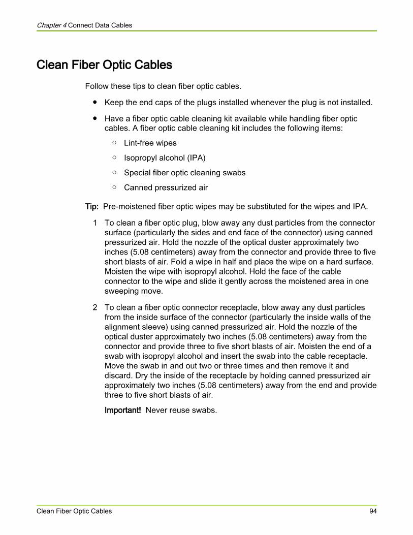
Clean Fiber Optic CablesFollow these tips to clean fiber optic cables.
● Keep the end caps of the plugs installed whenever the plug is not installed.
● Have a fiber optic cable cleaning kit available while handling fiber opticcables. A fiber optic cable cleaning kit includes the following items:
○ Lint-free wipes
○ Isopropyl alcohol (IPA)
○ Special fiber optic cleaning swabs
○ Canned pressurized air
Tip: Pre-moistened fiber optic wipes may be substituted for the wipes and IPA.
1 To clean a fiber optic plug, blow away any dust particles from the connectorsurface (particularly the sides and end face of the connector) using cannedpressurized air. Hold the nozzle of the optical duster approximately twoinches (5.08 centimeters) away from the connector and provide three to fiveshort blasts of air. Fold a wipe in half and place the wipe on a hard surface.Moisten the wipe with isopropyl alcohol. Hold the face of the cableconnector to the wipe and slide it gently across the moistened area in onesweeping move.
2 To clean a fiber optic connector receptacle, blow away any dust particlesfrom the inside surface of the connector (particularly the inside walls of thealignment sleeve) using canned pressurized air. Hold the nozzle of theoptical duster approximately two inches (5.08 centimeters) away from theconnector and provide three to five short blasts of air. Moisten the end of aswab with isopropyl alcohol and insert the swab into the cable receptacle.Move the swab in and out two or three times and then remove it anddiscard. Dry the inside of the receptacle by holding canned pressurized airapproximately two inches (5.08 centimeters) away from the end and providethree to five short blasts of air.
Important! Never reuse swabs.
Chapter 4 Connect Data Cables
Clean Fiber Optic Cables 94

Cabling Practices for the Pillar Axiom 600 SystemFollow these fundamental rules and guidelines for cabling Fiber Channel (FC),Serial ATA (SATA), and Solid State Drive (SSD) Bricks in a Pillar Axiom 600system.
All cabling rules and guidelines are categorized into three categories based onthe Pillar Axiom 600 system used. Cabling practices are also categorized basedon their impact on the system in case of non-compliance.
ALL: Rules that applyto all Pillar Axiom 600systems include:
Cabling requirements: Stringent requirements for thesystem to work. Non-negotiable and integral to thesystem design.Cabling rules: Stringent rules indicating functionallimitations of the system. If these rules are not followed,the system is considered unsupported.Cabling guidelines: Guidelines or best practices unlesscircumstances prevent strict adherence to thesecabling guidelines.
NEW: Rules that applyto new PillarAxiom 600 systemsand can be applied toall Pillar Axiom 600systems include:
Manufacturing practices: Documented proceduresfollowed by Pillar operations for new systems that alloweach Pillar Axiom 600 system to be configured in aconsistent manner.
FIELD: Rules thatapply to PillarAxiom 600 systems inthe field include:
Field practices: Practices that attempt to optimize highavailability, performance, troubleshooting and customerrequirements. However, field best practices cannotoverride cabling rules that apply to all systems. Pertainto Pillar Axiom 600 systems that exist in the field andwhose system configurations have evolved over timedue to numerous configuration modifications.
Table 13: Cabling principles (system level issues) defines the Pillar Axiom 600system characteristics that must be considered while cabling the Pillar Axiom 600system.
Table 13 Cabling principles (system level issues)
Cabling principle Applicability
The Storage System Fabric (SSF) in a Pillar Axiom 600 systemmust use either all copper or all optical connections. Note the
ALL
Chapter 4 Connect Data Cables
Cabling Practices for the Pillar Axiom 600 System 95
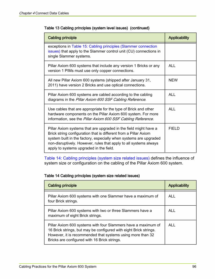
Table 13 Cabling principles (system level issues) (continued)
Cabling principle Applicability
exceptions in Table 15: Cabling principles (Slammer connectionissues) that apply to the Slammer control unit (CU) connections insingle Slammer systems.
Pillar Axiom 600 systems that include any version 1 Bricks or anyversion 1 PIMs must use only copper connections.
ALL
All new Pillar Axiom 600 systems (shipped after January 31,2011) have version 2 Bricks and use optical connections.
NEW
Pillar Axiom 600 systems are cabled according to the cablingdiagrams in the Pillar Axiom 600 SSF Cabling Reference.
ALL
Use cables that are appropriate for the type of Brick and otherhardware components on the Pillar Axiom 600 system. For moreinformation, see the Pillar Axiom 600 SSF Cabling Reference.
ALL
Pillar Axiom systems that are upgraded in the field might have aBrick string configuration that is different from a Pillar Axiomsystem built in the factory, especially when systems are upgradednon-disruptively. However, rules that apply to all systems alwaysapply to systems upgraded in the field.
FIELD
Table 14: Cabling principles (system size related issues) defines the influence ofsystem size or configuration on the cabling of the Pillar Axiom 600 system.
Table 14 Cabling principles (system size related issues)
Cabling principle Applicability
Pillar Axiom 600 systems with one Slammer have a maximum offour Brick strings.
ALL
Pillar Axiom 600 systems with two or three Slammers have amaximum of eight Brick strings.
ALL
Pillar Axiom 600 systems with four Slammers have a maximum of16 Brick strings, but may be configured with eight Brick strings.However, it is recommended that systems using more than 32Bricks are configured with 16 Brick strings.
ALL
Chapter 4 Connect Data Cables
Cabling Practices for the Pillar Axiom 600 System 96
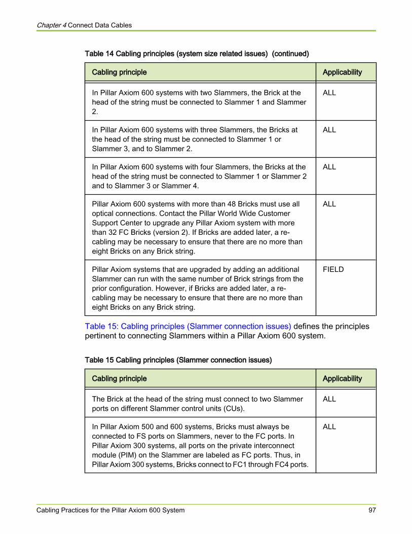
Table 14 Cabling principles (system size related issues) (continued)
Cabling principle Applicability
In Pillar Axiom 600 systems with two Slammers, the Brick at thehead of the string must be connected to Slammer 1 and Slammer2.
ALL
In Pillar Axiom 600 systems with three Slammers, the Bricks atthe head of the string must be connected to Slammer 1 orSlammer 3, and to Slammer 2.
ALL
In Pillar Axiom 600 systems with four Slammers, the Bricks at thehead of the string must be connected to Slammer 1 or Slammer 2and to Slammer 3 or Slammer 4.
ALL
Pillar Axiom 600 systems with more than 48 Bricks must use alloptical connections. Contact the Pillar World Wide CustomerSupport Center to upgrade any Pillar Axiom system with morethan 32 FC Bricks (version 2). If Bricks are added later, a re-cabling may be necessary to ensure that there are no more thaneight Bricks on any Brick string.
ALL
Pillar Axiom systems that are upgraded by adding an additionalSlammer can run with the same number of Brick strings from theprior configuration. However, if Bricks are added later, a re-cabling may be necessary to ensure that there are no more thaneight Bricks on any Brick string.
FIELD
Table 15: Cabling principles (Slammer connection issues) defines the principlespertinent to connecting Slammers within a Pillar Axiom 600 system.
Table 15 Cabling principles (Slammer connection issues)
Cabling principle Applicability
The Brick at the head of the string must connect to two Slammerports on different Slammer control units (CUs).
ALL
In Pillar Axiom 500 and 600 systems, Bricks must always beconnected to FS ports on Slammers, never to the FC ports. InPillar Axiom 300 systems, all ports on the private interconnectmodule (PIM) on the Slammer are labeled as FC ports. Thus, inPillar Axiom 300 systems, Bricks connect to FC1 through FC4 ports.
ALL
Chapter 4 Connect Data Cables
Cabling Practices for the Pillar Axiom 600 System 97
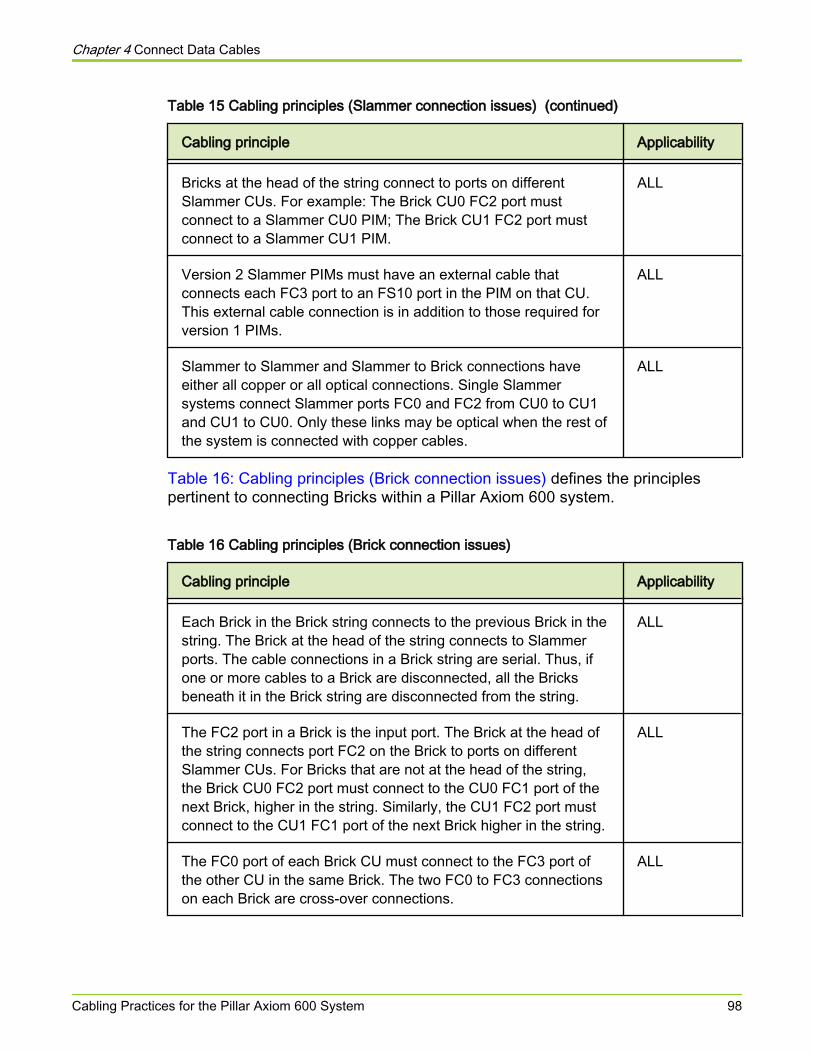
Table 15 Cabling principles (Slammer connection issues) (continued)
Cabling principle Applicability
Bricks at the head of the string connect to ports on differentSlammer CUs. For example: The Brick CU0 FC2 port mustconnect to a Slammer CU0 PIM; The Brick CU1 FC2 port mustconnect to a Slammer CU1 PIM.
ALL
Version 2 Slammer PIMs must have an external cable thatconnects each FC3 port to an FS10 port in the PIM on that CU.This external cable connection is in addition to those required forversion 1 PIMs.
ALL
Slammer to Slammer and Slammer to Brick connections haveeither all copper or all optical connections. Single Slammersystems connect Slammer ports FC0 and FC2 from CU0 to CU1and CU1 to CU0. Only these links may be optical when the rest ofthe system is connected with copper cables.
ALL
Table 16: Cabling principles (Brick connection issues) defines the principlespertinent to connecting Bricks within a Pillar Axiom 600 system.
Table 16 Cabling principles (Brick connection issues)
Cabling principle Applicability
Each Brick in the Brick string connects to the previous Brick in thestring. The Brick at the head of the string connects to Slammerports. The cable connections in a Brick string are serial. Thus, ifone or more cables to a Brick are disconnected, all the Bricksbeneath it in the Brick string are disconnected from the string.
ALL
The FC2 port in a Brick is the input port. The Brick at the head ofthe string connects port FC2 on the Brick to ports on differentSlammer CUs. For Bricks that are not at the head of the string,the Brick CU0 FC2 port must connect to the CU0 FC1 port of thenext Brick, higher in the string. Similarly, the CU1 FC2 port mustconnect to the CU1 FC1 port of the next Brick higher in the string.
ALL
The FC0 port of each Brick CU must connect to the FC3 port ofthe other CU in the same Brick. The two FC0 to FC3 connectionson each Brick are cross-over connections.
ALL
Chapter 4 Connect Data Cables
Cabling Practices for the Pillar Axiom 600 System 98

Table 16 Cabling principles (Brick connection issues) (continued)
Cabling principle Applicability
The FC1 port is Brick is the output port. The FC1 port on eachBrick CU is either left empty or connects to the FC2 port of thesame CU of the next Brick lower in the string.
ALL
FC RAID Bricks and SSD Bricks use Slammer ports in the sameorder as SATA Bricks. This cabling scheme fosters balanceamong the Brick strings while maintaining a predictableassignment of Bricks to strings. A given Brick should always beon a specific string with specific Slammer ports.
NEW
Cable labels on both ends of the cables are used to indicate portconnections for all cables.
NEW
Table 17: Cabling principles (Mixing Brick types) defines the principles that mustbe followed when mixing Brick types in strings within a Pillar Axiom 600 system.
Table 17 Cabling principles (Mixing Brick types)
Cabling principle Applicability
Brick strings may contain combinations of FC RAID Bricks, FCExpansion Bricks, SATA Bricks (version 2), and SSD Bricks.
ALL
SATA (version 1) Bricks must not be in the same string as an FCRAID Brick or a SATA Brick (version 2) or an SSD Brick. Thisguideline is strongly recommended to enhance supportability.Existing Pillar Axiom systems may not meet this guideline.Contact the Pillar World Wide Customer Support Center forguidance.
ALL
A Brick string may contain up to eight SATA Bricks (version 1 orversion 2), but they cannot be mixed. This guideline is stronglyrecommended to enhance supportability.
ALL
A Brick string may contain up to four FC RAID Bricks (version 1),each of which may optionally be connected to an FC ExpansionBrick. A Brick string may include up to eight FC Bricks (version 2).
ALL
A Brick string may contain up to two SSD Bricks. However, it isrecommended that only one SSD Brick is placed on a Brick string.
ALL
Chapter 4 Connect Data Cables
Cabling Practices for the Pillar Axiom 600 System 99
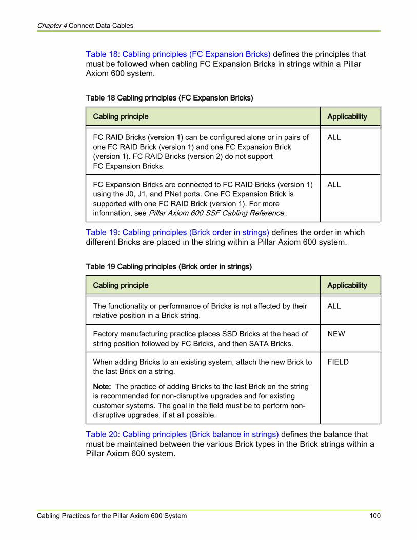
Table 18: Cabling principles (FC Expansion Bricks) defines the principles thatmust be followed when cabling FC Expansion Bricks in strings within a PillarAxiom 600 system.
Table 18 Cabling principles (FC Expansion Bricks)
Cabling principle Applicability
FC RAID Bricks (version 1) can be configured alone or in pairs ofone FC RAID Brick (version 1) and one FC Expansion Brick(version 1). FC RAID Bricks (version 2) do not supportFC Expansion Bricks.
ALL
FC Expansion Bricks are connected to FC RAID Bricks (version 1)using the J0, J1, and PNet ports. One FC Expansion Brick issupported with one FC RAID Brick (version 1). For moreinformation, see Pillar Axiom 600 SSF Cabling Reference..
ALL
Table 19: Cabling principles (Brick order in strings) defines the order in whichdifferent Bricks are placed in the string within a Pillar Axiom 600 system.
Table 19 Cabling principles (Brick order in strings)
Cabling principle Applicability
The functionality or performance of Bricks is not affected by theirrelative position in a Brick string.
ALL
Factory manufacturing practice places SSD Bricks at the head ofstring position followed by FC Bricks, and then SATA Bricks.
NEW
When adding Bricks to an existing system, attach the new Brick tothe last Brick on a string.
Note: The practice of adding Bricks to the last Brick on the stringis recommended for non-disruptive upgrades and for existingcustomer systems. The goal in the field must be to perform non-disruptive upgrades, if at all possible.
FIELD
Table 20: Cabling principles (Brick balance in strings) defines the balance thatmust be maintained between the various Brick types in the Brick strings within aPillar Axiom 600 system.
Chapter 4 Connect Data Cables
Cabling Practices for the Pillar Axiom 600 System 100
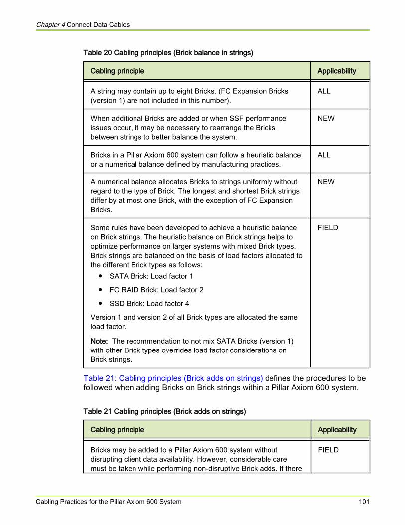
Table 20 Cabling principles (Brick balance in strings)
Cabling principle Applicability
A string may contain up to eight Bricks. (FC Expansion Bricks(version 1) are not included in this number).
ALL
When additional Bricks are added or when SSF performanceissues occur, it may be necessary to rearrange the Bricksbetween strings to better balance the system.
NEW
Bricks in a Pillar Axiom 600 system can follow a heuristic balanceor a numerical balance defined by manufacturing practices.
ALL
A numerical balance allocates Bricks to strings uniformly withoutregard to the type of Brick. The longest and shortest Brick stringsdiffer by at most one Brick, with the exception of FC ExpansionBricks.
NEW
Some rules have been developed to achieve a heuristic balanceon Brick strings. The heuristic balance on Brick strings helps tooptimize performance on larger systems with mixed Brick types.Brick strings are balanced on the basis of load factors allocated tothe different Brick types as follows:
● SATA Brick: Load factor 1
● FC RAID Brick: Load factor 2
● SSD Brick: Load factor 4
Version 1 and version 2 of all Brick types are allocated the sameload factor.
Note: The recommendation to not mix SATA Bricks (version 1)with other Brick types overrides load factor considerations onBrick strings.
FIELD
Table 21: Cabling principles (Brick adds on strings) defines the procedures to befollowed when adding Bricks on Brick strings within a Pillar Axiom 600 system.
Table 21 Cabling principles (Brick adds on strings)
Cabling principle Applicability
Bricks may be added to a Pillar Axiom 600 system withoutdisrupting client data availability. However, considerable caremust be taken while performing non-disruptive Brick adds. If there
FIELD
Chapter 4 Connect Data Cables
Cabling Practices for the Pillar Axiom 600 System 101
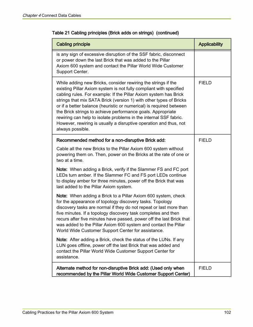
Table 21 Cabling principles (Brick adds on strings) (continued)
Cabling principle Applicability
is any sign of excessive disruption of the SSF fabric, disconnector power down the last Brick that was added to the PillarAxiom 600 system and contact the Pillar World Wide CustomerSupport Center.
While adding new Bricks, consider rewiring the strings if theexisting Pillar Axiom system is not fully compliant with specifiedcabling rules. For example: If the Pillar Axiom system has Brickstrings that mix SATA Brick (version 1) with other types of Bricksor if a better balance (heuristic or numerical) is required betweenthe Brick strings to achieve performance goals. Appropriaterewiring can help to isolate problems in the internal SSF fabric.However, rewiring is usually a disruptive operation and thus, notalways possible.
FIELD
Recommended method for a non-disruptive Brick add:
Cable all the new Bricks to the Pillar Axiom 600 system withoutpowering them on. Then, power on the Bricks at the rate of one ortwo at a time.
Note: When adding a Brick, verify if the Slammer FS and FC portLEDs turn amber. If the Slammer FC and FS port LEDs continueto display amber for three minutes, power off the Brick that waslast added to the Pillar Axiom system.
Note: When adding a Brick to a Pillar Axiom 600 system, checkfor the appearance of topology discovery tasks. Topologydiscovery tasks are normal if they do not repeat or last more thanfive minutes. If a topology discovery task completes and thenrecurs after five minutes have passed, power off the last Brick thatwas added to the Pillar Axiom 600 system and contact the PillarWorld Wide Customer Support Center for assistance.
Note: After adding a Brick, check the status of the LUNs. If anyLUN goes offline, power off the last Brick that was added andcontact the Pillar World Wide Customer Support Center forassistance.
FIELD
Alternate method for non-disruptive Brick add: (Used only whenrecommended by the Pillar World Wide Customer Support Center)
FIELD
Chapter 4 Connect Data Cables
Cabling Practices for the Pillar Axiom 600 System 102
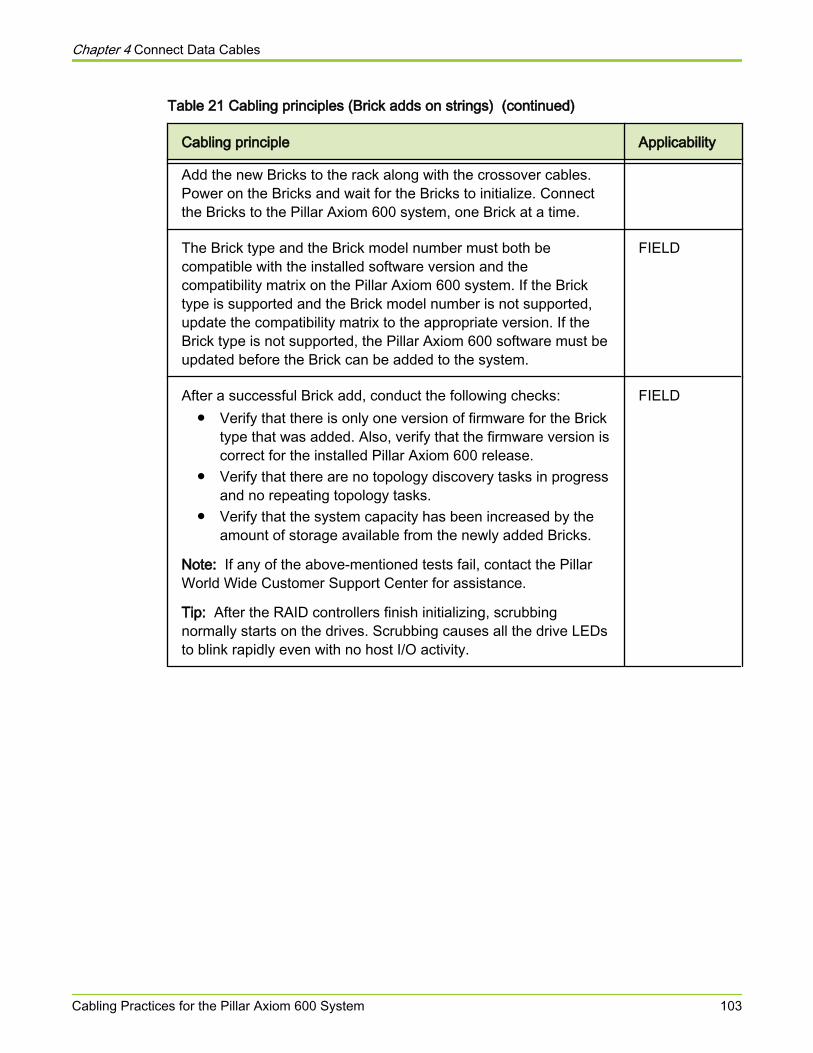
Table 21 Cabling principles (Brick adds on strings) (continued)
Cabling principle Applicability
Add the new Bricks to the rack along with the crossover cables.Power on the Bricks and wait for the Bricks to initialize. Connectthe Bricks to the Pillar Axiom 600 system, one Brick at a time.
The Brick type and the Brick model number must both becompatible with the installed software version and thecompatibility matrix on the Pillar Axiom 600 system. If the Bricktype is supported and the Brick model number is not supported,update the compatibility matrix to the appropriate version. If theBrick type is not supported, the Pillar Axiom 600 software must beupdated before the Brick can be added to the system.
FIELD
After a successful Brick add, conduct the following checks:● Verify that there is only one version of firmware for the Brick
type that was added. Also, verify that the firmware version iscorrect for the installed Pillar Axiom 600 release.
● Verify that there are no topology discovery tasks in progressand no repeating topology tasks.
● Verify that the system capacity has been increased by theamount of storage available from the newly added Bricks.
Note: If any of the above-mentioned tests fail, contact the PillarWorld Wide Customer Support Center for assistance.
Tip: After the RAID controllers finish initializing, scrubbingnormally starts on the drives. Scrubbing causes all the drive LEDsto blink rapidly even with no host I/O activity.
FIELD
Chapter 4 Connect Data Cables
Cabling Practices for the Pillar Axiom 600 System 103
About Cable Connections Between Two RacksNote: This topic applies only to Pillar Axiom 600 systems.
Be sure the two racks are bayed before you make connections between them.Route the FC cables directly from one rack to the other through the open sides.Do not route cables from rack to rack through the raised floor. The cablessupplied are not long enough.
When routing an FC cable from one rack to the other, route the cable through theplastic chase that is dedicated to FC cables on the right side of the rack (from theback). The FC chase to use depends on which side the racks join.
Important! Make sure the Fiber Channel (FC) cables do not cross over or get tooclose to the power supply cords. Keep them separated to minimize EMI (electro-magnetic interference).
Chapter 4 Connect Data Cables
About Cable Connections Between Two Racks 104
About Cabling the SSF and PMIBack-end cabling, which involves cabling the Storage System Fabric (SSF)(sometimes referred to as the private interconnect, or simply PI) and the privatemanagement interface (PMI).
The SSF cables provide the connections between the Bricks and the Slammersto support all data traffic. The PMI cables provide the connections between thePilot and the Slammers to support management traffic.
The SSF operates at 2 Gb/s (copper) or 4 Gb/s (optical) depending on thehardware that is configured on the Pillar Axiom 600 system and on the cablesand connectors that are used.
For the SSF back-end fabric to operate at 4 Gb/s, the following conditions mustbe met:
● Both control units (CUs) in all the Slammers must contain a combination ofonly version 2 PIMs .
● Both CUs in all the Bricks must contain only version 2 SATA RAIDcontrollers or version 2 FC RAID (FCR) controllers.
● All ports on the version 2 PIMs, version 2 SATA RAID controllers, andversion 2 FC RAID controllers (FCR) must contain only 4 Gb/s small form-factor pluggable (SFP) connectors.
● The patch cables connecting these 4 Gb/s SFPs must be optical.
Important! Pillar provides a set of SFPs for version 2 PIMs, version 2 SATARAID controllers, and version 2 FC RAID (FCR) controllers.
Important! Do not mix copper and optical cable connections on the Slammer inthe same Pillar Axiom 600 system.
Caution Use of any SFP or cable not provided by Pillar can lead toperformance and reliability issues when unqualified SFPsare used. Use of third party SFPs can also void the warrantyof your Pillar Axiom 600 system, if the third party SFP orcable is determined to be the cause of any problems withinthe Pillar Axiom 600 system.
If any of the following conditions are true, the back-end fabric operates at 2 Gb/s:
● A version 1 FC Brick is configured into the storage array.
● A version 1 SATA Brick or version 1PIM is included in the configuration.
Chapter 4 Connect Data Cables
About Cabling the SSF and PMI 105
● An HSSDC2 (high-speed serial data connection)-to-HSSDC2 copper cableis used.
● An SFP-to-SFP copper cable is used.
● An SFP-to-HSSDC2 hybrid copper cable is used.
Note: 2 Gb/s optical SFPs should not be inserted into any fabric port when theSSF is configured to run at 4 Gb/s. If such an SFP is inserted into a fabric port,the system disables the port, even after a restart of the Pillar Axiom 600 system.
Note: If the SSF is being configured for 4 Gb/s operation, the SFP modules mustbe installed prior to connecting the optical cables.
All of the possible SSF and PMI cable combinations are fully detailed in the PillarAxiom 600 SSF Cabling Reference for your system.
Related tasks• Connect the Pilot to Your Management LAN• Connect a Slammer to the Data Network
Chapter 4 Connect Data Cables
About Cabling the SSF and PMI 106
About Jumbo FramesYou can use large Internet Protocol (IP) frames, called jumbo frames, in a high-performance network to increase performance over long distances.
To implement jumbo frames, be sure that all Ethernet network interface cards(NICs) in all systems, Ethernet switches, local router interfaces, and all othernetwork devices on the same local networks as the Pillar Axiom 600 system arecapable of supporting jumbo frames and are configured for the same effectivemaximum transmission unit (MTU).
Refer to your switch documentation for information on prerequisite software andfirmware and for instructions on configuring the switch for jumbo frames. Refer tothe documentation for the NIC in all client systems and other network devices forinformation and restrictions on configuring jumbo frames.
The performance boost with jumbo frames is most noticeable for client systemswith slower processors or interrupt handlers that may benefit from the lowerinterrupt rate offered by jumbo frames. The increase in performance is mostnoticeable for single-client stream data transfers.
Chapter 4 Connect Data Cables
About Jumbo Frames 107
Connect the Pilot to Your Management LAN
Prerequisites:
● Two 100 BaseT ports for the public connection to the management network.For added redundancy, the two connections should be to separateswitches. The Pillar Axiom 600 system provides a standard Cat 5 RJ-45jack on each Pilot control unit (CU) for this connection.
● The external switch ports must be configured for auto-negation, if the PillarAxiom 600 system is also configured for auto-negation. If the externalswitch ports are manually set to a certain speed or a duplex setting, thePilot must be set to match those settings.
● Three IP addresses on the same subnet: one IP for each physical interfaceand one shared IP.
● If Pillar Axiom Path Manager (APM) is installed on a SAN host, that host willrequire an Ethernet interface for communication with the Pillar AxiomStorage Services Manager. Because APM communicates with the Pilotover secure, encrypted XML, the network configuration must permit theSAN host to reach the Pilot management IP Ethernet interfaces on port 26004.
The Pillar Axiom 600 system is shipped with the following default IP addressesand settings, with the Dynamic Host Configuration Protocol (DHCP) disabled:
● 10.0.0.1 (Default gateway)
● 10.0.0.2 (Shared IP)
● 10.0.0.3 (Pilot CU 0)
● 10.0.0.4 (Pilot CU 1)
● 255.255.255.0 (Netmask)
● Auto-negation: Enabled
Caution Do not connect the Pillar Axiom 600 Pilot managementinterfaces to any network unless you are sure that thedefault IP addresses of the Pillar Axiom 600 system are notcurrently in use on that network. Using the default PillarAxiom 600 IP addresses in your network can interfere withother workstations on the network as well as causeproblems when you configure the Pillar Axiom 600 system.
Chapter 4 Connect Data Cables
Connect the Pilot to Your Management LAN 108
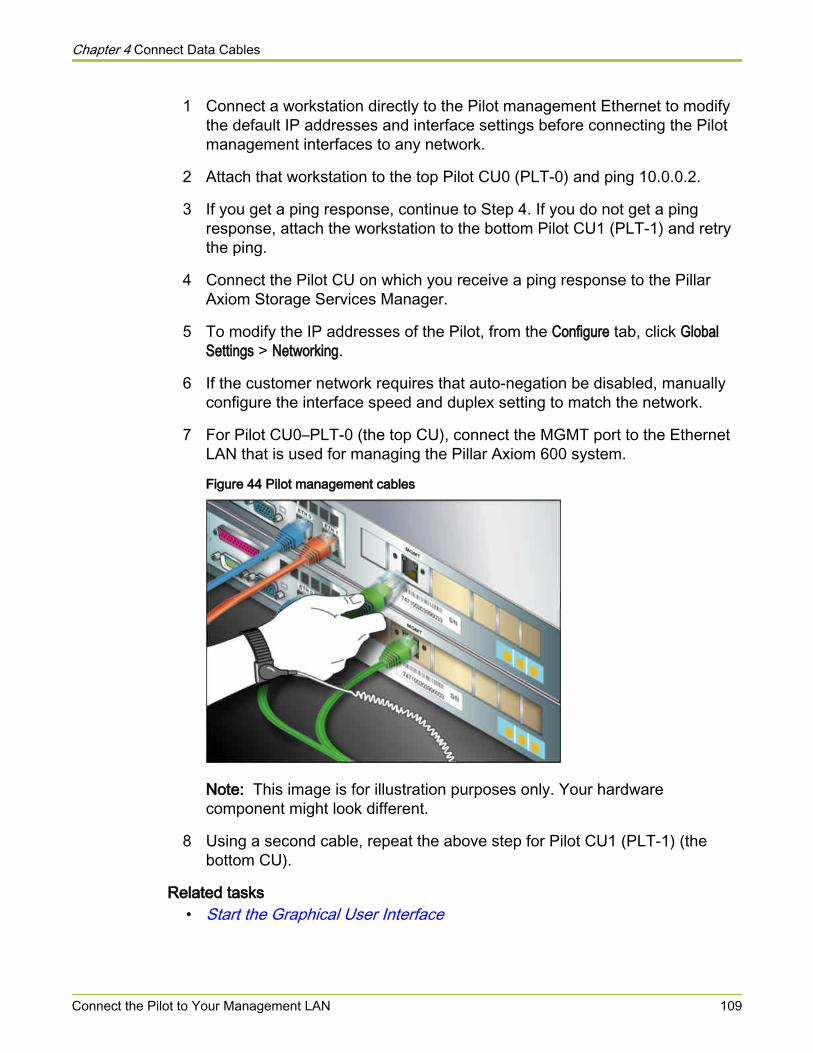
1 Connect a workstation directly to the Pilot management Ethernet to modifythe default IP addresses and interface settings before connecting the Pilotmanagement interfaces to any network.
2 Attach that workstation to the top Pilot CU0 (PLT-0) and ping 10.0.0.2.
3 If you get a ping response, continue to Step 4. If you do not get a pingresponse, attach the workstation to the bottom Pilot CU1 (PLT-1) and retrythe ping.
4 Connect the Pilot CU on which you receive a ping response to the PillarAxiom Storage Services Manager.
5 To modify the IP addresses of the Pilot, from the Configure tab, click GlobalSettings > Networking.
6 If the customer network requires that auto-negation be disabled, manuallyconfigure the interface speed and duplex setting to match the network.
7 For Pilot CU0–PLT-0 (the top CU), connect the MGMT port to the EthernetLAN that is used for managing the Pillar Axiom 600 system.
Figure 44 Pilot management cables
Note: This image is for illustration purposes only. Your hardwarecomponent might look different.
8 Using a second cable, repeat the above step for Pilot CU1 (PLT-1) (thebottom CU).
Related tasks• Start the Graphical User Interface
Chapter 4 Connect Data Cables
Connect the Pilot to Your Management LAN 109
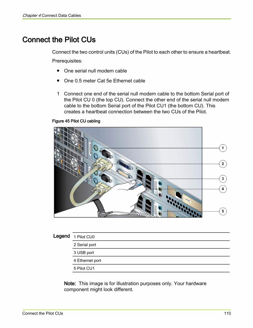
Connect the Pilot CUsConnect the two control units (CUs) of the Pilot to each other to ensure a heartbeat.
Prerequisites:
● One serial null modem cable
● One 0.5 meter Cat 5e Ethernet cable
1 Connect one end of the serial null modem cable to the bottom Serial port ofthe Pilot CU 0 (the top CU). Connect the other end of the serial null modemcable to the bottom Serial port of the Pilot CU1 (the bottom CU). Thiscreates a heartbeat connection between the two CUs of the Pilot.
Figure 45 Pilot CU cabling
Legend 1 Pilot CU0
2 Serial port
3 USB port
4 Ethernet port
5 Pilot CU1
Note: This image is for illustration purposes only. Your hardwarecomponent might look different.
Chapter 4 Connect Data Cables
Connect the Pilot CUs 110

2 Connect one end of the Ethernet cable to the Ethernet port (ETH0) of thePilot CU0 (the top CU). Connect the other end of the Ethernet cable to theEthernet port (ETH0) of the Pilot CU1 (the bottom CU). Refer to the PillarAxiom SSF Cabling Reference for more information.
3 Connect the Ethernet port (ETH1) of the top Pilot CU (PLT-0) to theEthernet port (ETH0) of the top Slammer CU (CU0) using a two meter Cat5e Ethernet cable. Also, connect the Ethernet port (ETH1) of the bottomPilot CU (PLT-1) to the Ethernet port (ETH2) of the bottom Slammer CU(CU1) using a two meter Cat 5e Ethernet cable. Refer to the Pillar AxiomSSF Cabling Reference for more information.
Chapter 4 Connect Data Cables
Connect the Pilot CUs 111
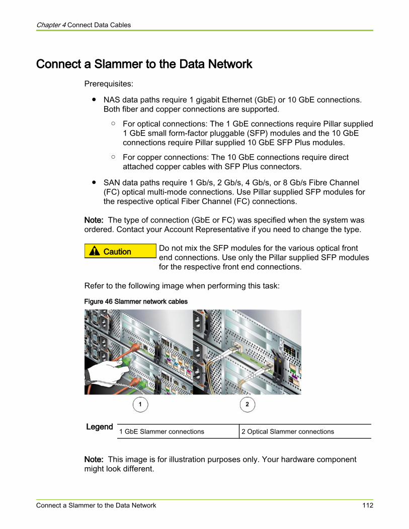
Connect a Slammer to the Data NetworkPrerequisites:
● NAS data paths require 1 gigabit Ethernet (GbE) or 10 GbE connections.Both fiber and copper connections are supported.
○ For optical connections: The 1 GbE connections require Pillar supplied1 GbE small form-factor pluggable (SFP) modules and the 10 GbEconnections require Pillar supplied 10 GbE SFP Plus modules.
○ For copper connections: The 10 GbE connections require directattached copper cables with SFP Plus connectors.
● SAN data paths require 1 Gb/s, 2 Gb/s, 4 Gb/s, or 8 Gb/s Fibre Channel(FC) optical multi-mode connections. Use Pillar supplied SFP modules forthe respective optical Fiber Channel (FC) connections.
Note: The type of connection (GbE or FC) was specified when the system wasordered. Contact your Account Representative if you need to change the type.
Caution Do not mix the SFP modules for the various optical frontend connections. Use only the Pillar supplied SFP modulesfor the respective front end connections.
Refer to the following image when performing this task:
Figure 46 Slammer network cables
Legend 1 GbE Slammer connections 2 Optical Slammer connections
Note: This image is for illustration purposes only. Your hardware componentmight look different.
Chapter 4 Connect Data Cables
Connect a Slammer to the Data Network 112
1 For SAN Slammers, connect FC cables from the network interface module(NIM) ports on the Slammer to any open data ports available on twoseparate FC network switches.
2 For NAS Slammers, connect a gigabit Ethernet (GbE) cable or a 10 gigabitEthernet (GbE) cable from each NIM port to an open data port on aseparate network switch.
Note: For both the SAN FC and NAS Ethernet connections, do not exceed themaximum recommended cable lengths.
Related concepts• About Cabling the SSF and PMI
Related references• Cable Length Limits for NAS Ethernet Connections• Cable Length Limits for SAN Fibre Channel Connections
Chapter 4 Connect Data Cables
Connect a Slammer to the Data Network 113
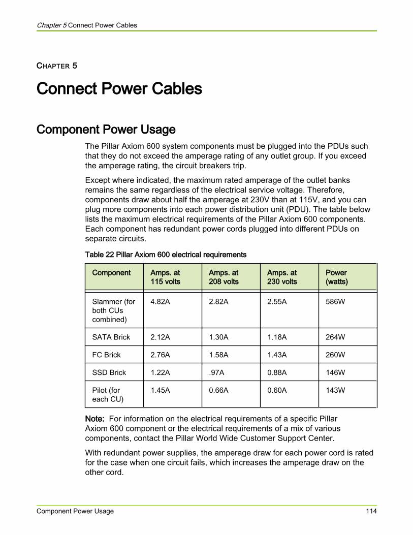
CHAPTER 5
Connect Power Cables
Component Power UsageThe Pillar Axiom 600 system components must be plugged into the PDUs suchthat they do not exceed the amperage rating of any outlet group. If you exceedthe amperage rating, the circuit breakers trip.
Except where indicated, the maximum rated amperage of the outlet banksremains the same regardless of the electrical service voltage. Therefore,components draw about half the amperage at 230V than at 115V, and you canplug more components into each power distribution unit (PDU). The table belowlists the maximum electrical requirements of the Pillar Axiom 600 components.Each component has redundant power cords plugged into different PDUs onseparate circuits.
Table 22 Pillar Axiom 600 electrical requirements
Component Amps. at115 volts
Amps. at208 volts
Amps. at230 volts
Power(watts)
Slammer (forboth CUscombined)
4.82A 2.82A 2.55A 586W
SATA Brick 2.12A 1.30A 1.18A 264W
FC Brick 2.76A 1.58A 1.43A 260W
SSD Brick 1.22A .97A 0.88A 146W
Pilot (foreach CU)
1.45A 0.66A 0.60A 143W
Note: For information on the electrical requirements of a specific PillarAxiom 600 component or the electrical requirements of a mix of variouscomponents, contact the Pillar World Wide Customer Support Center.
With redundant power supplies, the amperage draw for each power cord is ratedfor the case when one circuit fails, which increases the amperage draw on theother cord.
Chapter 5 Connect Power Cables
Component Power Usage 114
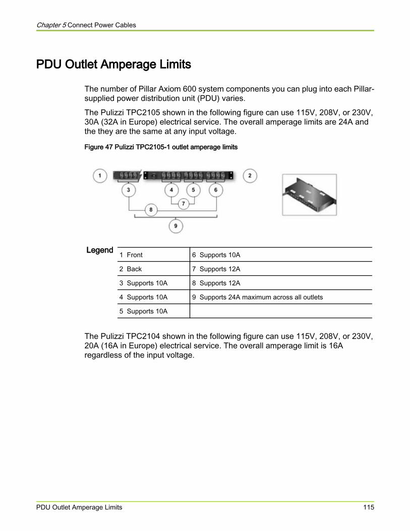
PDU Outlet Amperage Limits
The number of Pillar Axiom 600 system components you can plug into each Pillar-supplied power distribution unit (PDU) varies.
The Pulizzi TPC2105 shown in the following figure can use 115V, 208V, or 230V,30A (32A in Europe) electrical service. The overall amperage limits are 24A andthe they are the same at any input voltage.
Figure 47 Pulizzi TPC2105-1 outlet amperage limits
Legend 1 Front 6 Supports 10A
2 Back 7 Supports 12A
3 Supports 10A 8 Supports 12A
4 Supports 10A 9 Supports 24A maximum across all outlets
5 Supports 10A
The Pulizzi TPC2104 shown in the following figure can use 115V, 208V, or 230V,20A (16A in Europe) electrical service. The overall amperage limit is 16Aregardless of the input voltage.
Chapter 5 Connect Power Cables
PDU Outlet Amperage Limits 115
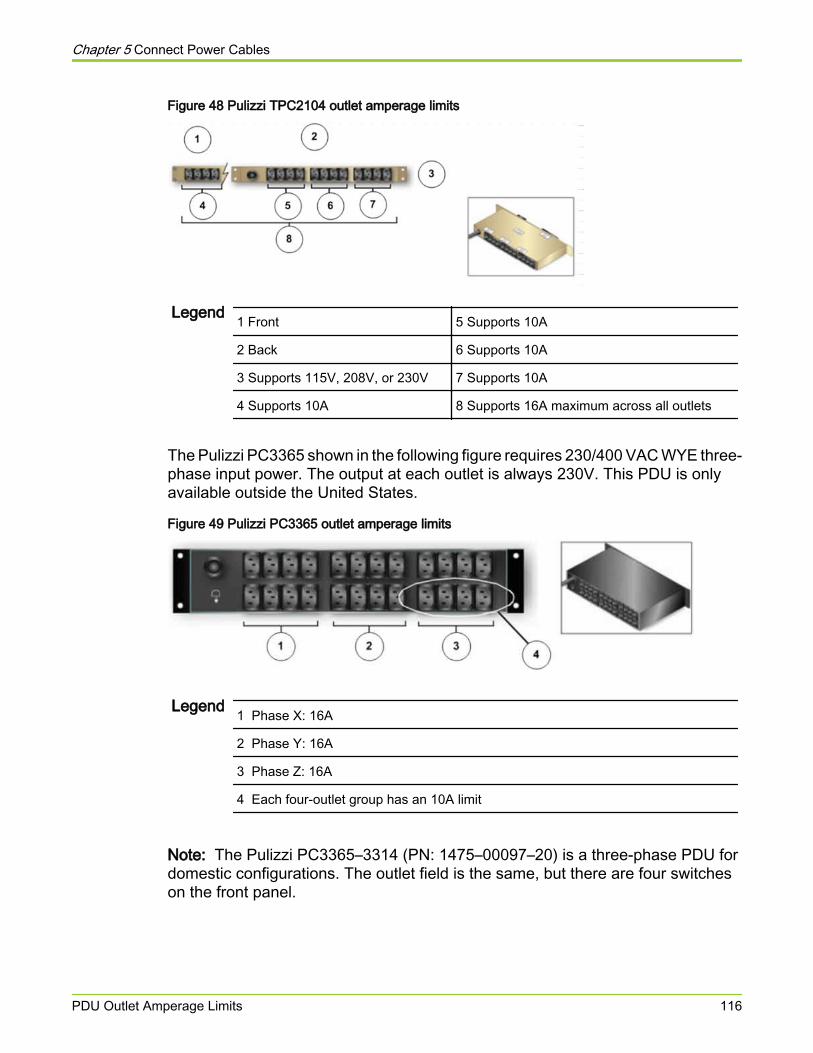
Figure 48 Pulizzi TPC2104 outlet amperage limits
Legend 1 Front 5 Supports 10A
2 Back 6 Supports 10A
3 Supports 115V, 208V, or 230V 7 Supports 10A
4 Supports 10A 8 Supports 16A maximum across all outlets
The Pulizzi PC3365 shown in the following figure requires 230/400 VAC WYE three-phase input power. The output at each outlet is always 230V. This PDU is onlyavailable outside the United States.
Figure 49 Pulizzi PC3365 outlet amperage limits
Legend 1 Phase X: 16A
2 Phase Y: 16A
3 Phase Z: 16A
4 Each four-outlet group has an 10A limit
Note: The Pulizzi PC3365–3314 (PN: 1475–00097–20) is a three-phase PDU fordomestic configurations. The outlet field is the same, but there are four switcheson the front panel.
Chapter 5 Connect Power Cables
PDU Outlet Amperage Limits 116

About Power CablingPillar Axiom 600 racks come with the Brick power cords or Wye power cables pre-installed in the rack with colored tie wraps. These Wye power cables are ready tobe plugged into the back of each Brick.
The Wye power cables are color-coded to indicate which PDU circuits will supplypower to the Brick component. All cords of the same color connect to one set ofpower distribution units (PDUs), while the other cords connect to the other set ofPDUs. When additional PDUs are added to the cabinet, additional colors areused. For example: All red Wye power cables are in one circuit and all blue Wyepower cables are in the other.
To understand the exact quantities of PDU's required for each system or for eachcabinet, contact the Pillar World Wide Customer Support Center.
Sample Power Cabling for One Slammer and Three BricksThe configuration in the figure below uses 230V power and two Pulizzi TPC 2104PDUs. The power cords for each component must connect to separate PDUs,connected to separate power circuits. A sample power cabling scheme such asthe one below would distribute the load within the limits of each outlet bank.
Chapter 5 Connect Power Cables
About Power Cabling 117
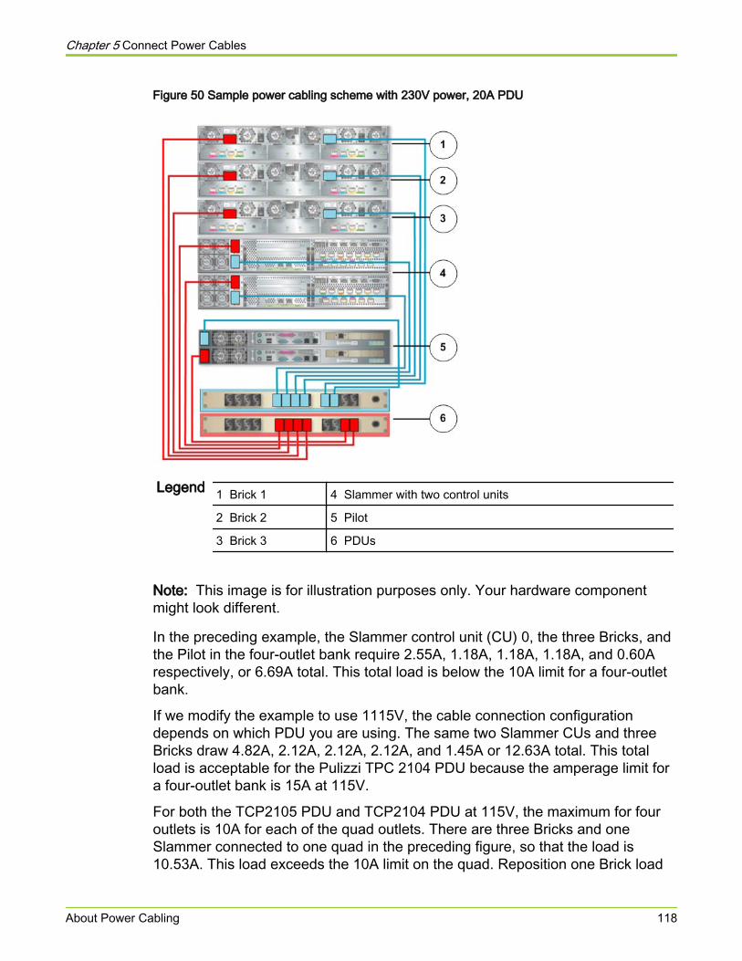
Figure 50 Sample power cabling scheme with 230V power, 20A PDU
Legend 1 Brick 1 4 Slammer with two control units
2 Brick 2 5 Pilot
3 Brick 3 6 PDUs
Note: This image is for illustration purposes only. Your hardware componentmight look different.
In the preceding example, the Slammer control unit (CU) 0, the three Bricks, andthe Pilot in the four-outlet bank require 2.55A, 1.18A, 1.18A, 1.18A, and 0.60Arespectively, or 6.69A total. This total load is below the 10A limit for a four-outletbank.
If we modify the example to use 1115V, the cable connection configurationdepends on which PDU you are using. The same two Slammer CUs and threeBricks draw 4.82A, 2.12A, 2.12A, 2.12A, and 1.45A or 12.63A total. This totalload is acceptable for the Pulizzi TPC 2104 PDU because the amperage limit fora four-outlet bank is 15A at 115V.
For both the TCP2105 PDU and TCP2104 PDU at 115V, the maximum for fouroutlets is 10A for each of the quad outlets. There are three Bricks and oneSlammer connected to one quad in the preceding figure, so that the load is10.53A. This load exceeds the 10A limit on the quad. Reposition one Brick load
Chapter 5 Connect Power Cables
About Power Cabling 118
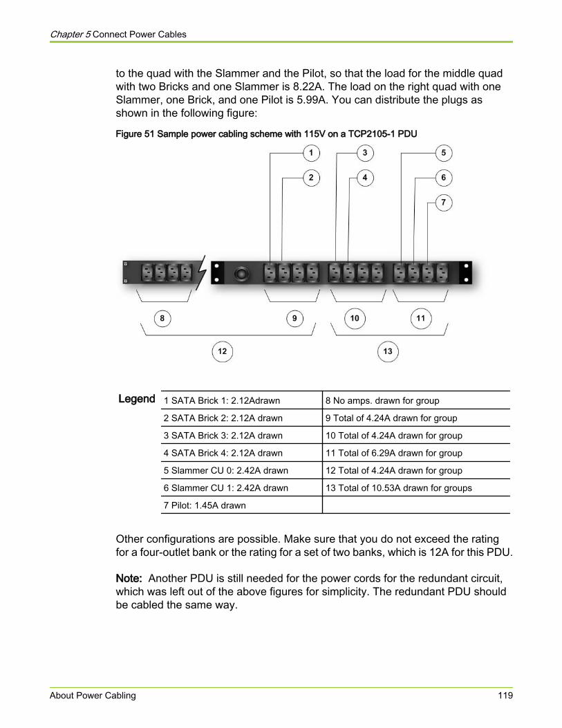
to the quad with the Slammer and the Pilot, so that the load for the middle quadwith two Bricks and one Slammer is 8.22A. The load on the right quad with oneSlammer, one Brick, and one Pilot is 5.99A. You can distribute the plugs asshown in the following figure:
Figure 51 Sample power cabling scheme with 115V on a TCP2105-1 PDU
Legend 1 SATA Brick 1: 2.12Adrawn 8 No amps. drawn for group
2 SATA Brick 2: 2.12A drawn 9 Total of 4.24A drawn for group
3 SATA Brick 3: 2.12A drawn 10 Total of 4.24A drawn for group
4 SATA Brick 4: 2.12A drawn 11 Total of 6.29A drawn for group
5 Slammer CU 0: 2.42A drawn 12 Total of 4.24A drawn for group
6 Slammer CU 1: 2.42A drawn 13 Total of 10.53A drawn for groups
7 Pilot: 1.45A drawn
Other configurations are possible. Make sure that you do not exceed the ratingfor a four-outlet bank or the rating for a set of two banks, which is 12A for this PDU.
Note: Another PDU is still needed for the power cords for the redundant circuit,which was left out of the above figures for simplicity. The redundant PDU shouldbe cabled the same way.
Chapter 5 Connect Power Cables
About Power Cabling 119

Note: The amperage requirements for an FC Brick is higher than a SATA Brickat 115V. The FC Bricks draw close to an additional one amp each. Configuringfor FC Bricks may require upgrading your PDU specification. If you have anyquestions about your PDU configuration contact the Pillar World Wide CustomerSupport Center.
Related references• Cabling Practices for the Pillar Axiom 600 System
Sample Power Cabling for One Slammer and 16 SATA BricksNote: This topic applies only to Pillar Axiom 600 systems.
One Slammer and 16 SATA Bricks (and a Pilot) represent a fully-loaded 42Urack. Split power cables (the plug end splits into two outlet ends) enable you toconnect two components to a single outlet in the PDU and reduce the density ofthe cabling.
Tip: The total amperage draw for each outlet bank is more important than whichBrick is plugged into which outlet. The following figure illustrates one way todistribute the load. Always try to balance the load among the outlet banks.
Chapter 5 Connect Power Cables
About Power Cabling 120

Figure 52 Sample power cabling scheme with 230V (one circuit shown)
Legend 1–16 (Brick 16 through Brick 1): SATA, 1.18A drawn 21 Total 7.08A drawn
17 Slammer CU 0: 1.275A drawn 22 Total 7.08A drawn
18 Slammer CU 1: 1.275A drawn 23 Total 3.145A drawn
19 Pilot: 0.60A drawn 24 Grand total 14.16A drawn
20 Total 4.72A drawn 25 Grand total 22.025A drawn
Important! If you use split power cables, as shown in the figure above, makesure the split cables power separate components. Do not use a split power cableto power two sides of the same component. The two sides need to be onseparate circuits, in case one side fails.
The amperage requirements for an FC Brick is higher than a SATA Brick.Configuring for FC Bricks may require upgrading your PDU specification. If youhave any questions about your PDU configuration, contact the Pillar World WideCustomer Support Center.
The following figure illustrates one way to distribute the load with one Slammerand 16 FC Bricks (and a Pilot).
Chapter 5 Connect Power Cables
About Power Cabling 121
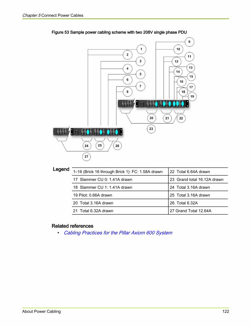
Figure 53 Sample power cabling scheme with two 208V single phase PDU
Legend 1–16 (Brick 16 through Brick 1): FC: 1.58A drawn 22 Total 6.64A drawn
17 Slammer CU 0: 1.41A drawn 23 Grand total 16.12A drawn
18 Slammer CU 1: 1.41A drawn 24 Total 3.16A drawn
19 Pilot: 0.66A drawn 25 Total 3.16A drawn
20 Total 3.16A drawn 26. Total 6.32A
21 Total 6.32A drawn 27 Grand Total 12.64A
Related references• Cabling Practices for the Pillar Axiom 600 System
Chapter 5 Connect Power Cables
About Power Cabling 122

Connect Power Cables
When you ordered your Pillar Axiom 600 system, you specified the type ofservice outlets (in terms of voltage, amperage, and phases) that you have at yourfacility. The plugs on the power distribution units (PDUs) that you ordered matchthat service.
If you are using Pillar racks, the system comes with components and PDUsalready installed in the rack. If you are using non-Pillar racks, you need to installthe hardware components and PDUs manually.
Caution Be sure to maintain reliable grounding of rack-mountedequipment. You should give particular attention to supplyconnections other than direct connections to the branchcircuit, such as connections to power strips.
1 Review the Pillar Axiom 600 power requirements.
2 Review the information about power cabling and verify that your PDUs meetthe electrical requirements.
3 Plug in your system components in such a way so that no PDU amperagelimits are exceeded.
4 Dress all power cables to the opposite side of the rack from any datacables.
We recommend dressing the power cables to the left side (when facing theback of the cabinet).
5 Secure the power cables to the rack such that they do not restrict theremoval of any other component.
Important! You should not turn on any power circuits until the installation iscomplete and all network cables are in place.
Caution Apply power to the Pilot only after the serial nullmodem cable and the Ethernet cable are connected tothe two Pilot Control Units (CUs).
Caution Do not apply power to the Pilot until you attach theserial cable and the Ethernet cable that connect thetwo Pilot Control Units (CUs) together.
Chapter 5 Connect Power Cables
Connect Power Cables 123

Related concepts• Component Power Usage• About Power Cabling
Related references• PDU Outlet Amperage Limits
Related tasks• Power On the System
Chapter 5 Connect Power Cables
Connect Power Cables 124

CHAPTER 6
Complete the Installation
Power On the SystemAs part of your site planning, you set up a separate circuit and power outlet foreach PDU. These outlets should be located within reach of the 15 ft (4.57 m)PDU power input cables.
1 Ensure the PDU circuit breakers are off.
2 Connect the PDUs to a facility power source. If the facility's main circuitbreakers are off, turn them on to supply power to the PDUs.
3 At the front of the system, use a #2 flathead or Phillips head screwdriver tosecure the Slammer batteries in place with the two attached screws.
Figure 54 Secure Slammer batteries
Note: This image is for illustration purposes only. Your hardwarecomponent might look different.
Chapter 6 Complete the Installation
Power On the System 125
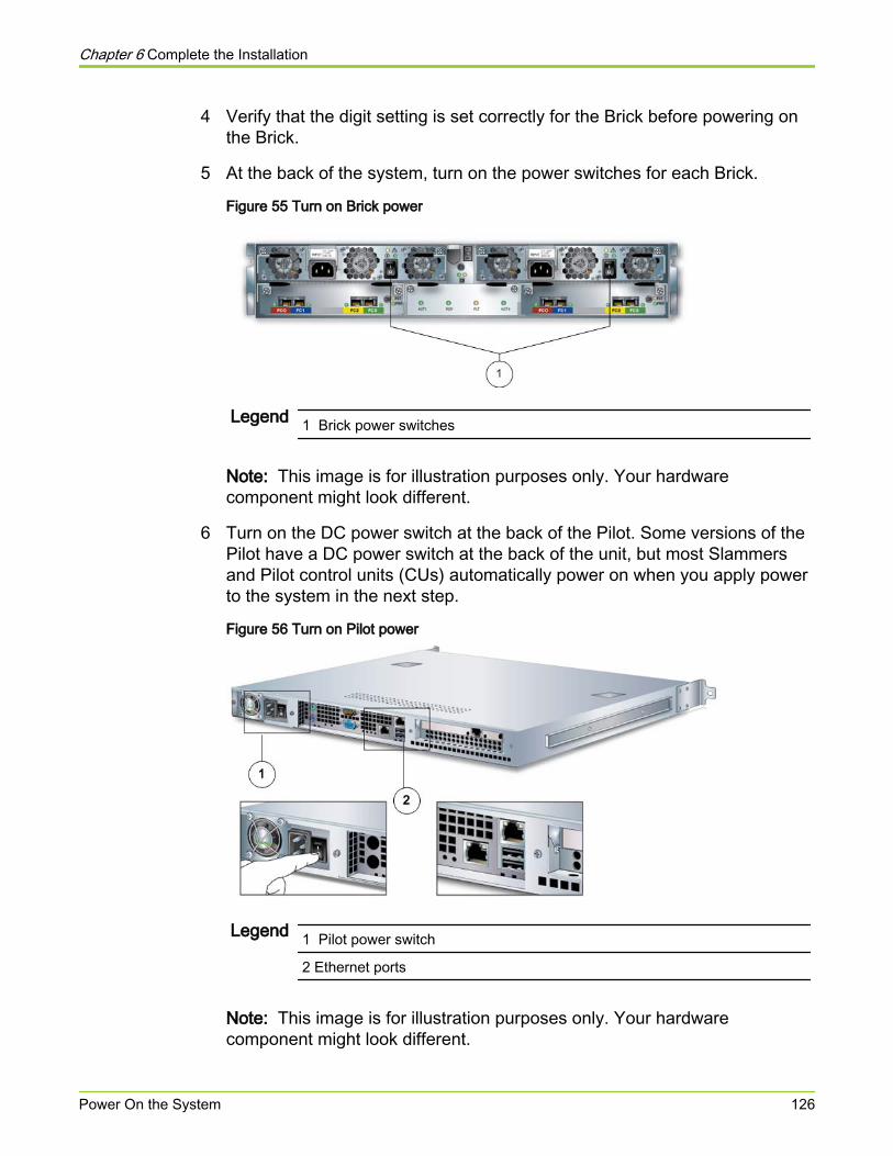
4 Verify that the digit setting is set correctly for the Brick before powering onthe Brick.
5 At the back of the system, turn on the power switches for each Brick.
Figure 55 Turn on Brick power
Legend 1 Brick power switches
Note: This image is for illustration purposes only. Your hardwarecomponent might look different.
6 Turn on the DC power switch at the back of the Pilot. Some versions of thePilot have a DC power switch at the back of the unit, but most Slammersand Pilot control units (CUs) automatically power on when you apply powerto the system in the next step.
Figure 56 Turn on Pilot power
Legend 1 Pilot power switch
2 Ethernet ports
Note: This image is for illustration purposes only. Your hardwarecomponent might look different.
Chapter 6 Complete the Installation
Power On the System 126
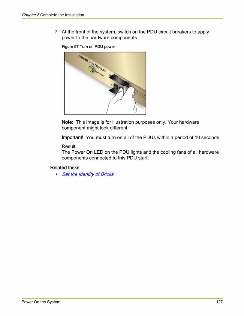
7 At the front of the system, switch on the PDU circuit breakers to applypower to the hardware components.
Figure 57 Turn on PDU power
Note: This image is for illustration purposes only. Your hardwarecomponent might look different.
Important! You must turn on all of the PDUs within a period of 10 seconds.
Result:The Power On LED on the PDU lights and the cooling fans of all hardwarecomponents connected to this PDU start.
Related tasks• Set the Identity of Bricks
Chapter 6 Complete the Installation
Power On the System 127
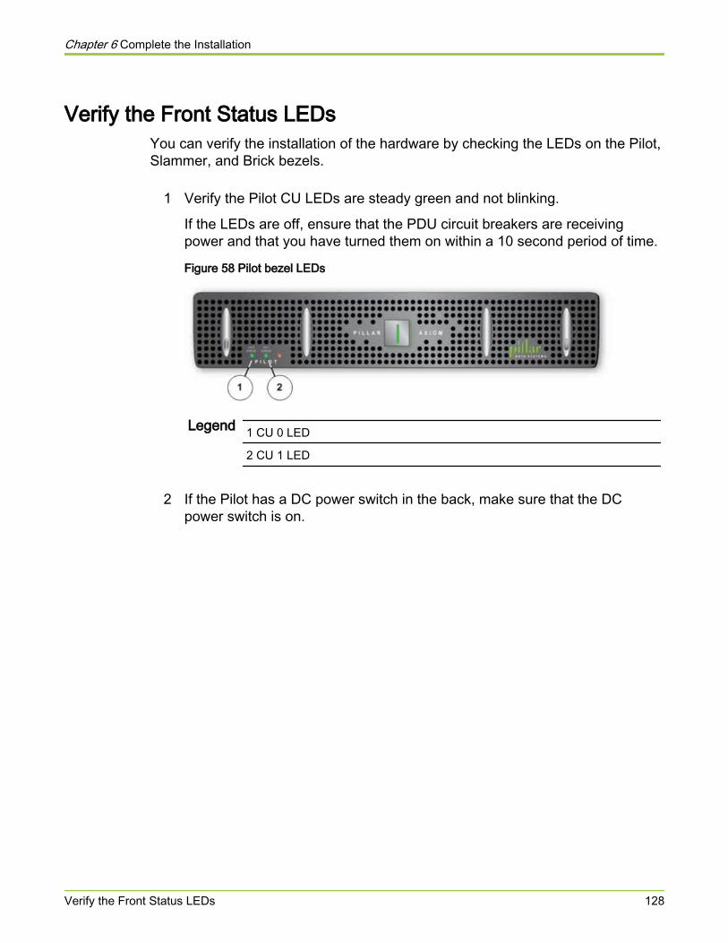
Verify the Front Status LEDsYou can verify the installation of the hardware by checking the LEDs on the Pilot,Slammer, and Brick bezels.
1 Verify the Pilot CU LEDs are steady green and not blinking.
If the LEDs are off, ensure that the PDU circuit breakers are receivingpower and that you have turned them on within a 10 second period of time.
Figure 58 Pilot bezel LEDs
Legend 1 CU 0 LED
2 CU 1 LED
2 If the Pilot has a DC power switch in the back, make sure that the DCpower switch is on.
Chapter 6 Complete the Installation
Verify the Front Status LEDs 128
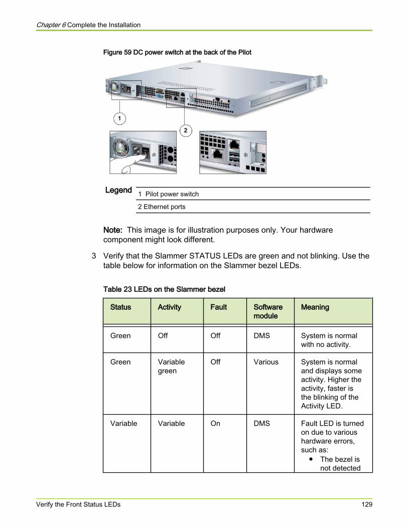
Figure 59 DC power switch at the back of the Pilot
Legend 1 Pilot power switch
2 Ethernet ports
Note: This image is for illustration purposes only. Your hardwarecomponent might look different.
3 Verify that the Slammer STATUS LEDs are green and not blinking. Use thetable below for information on the Slammer bezel LEDs.
Table 23 LEDs on the Slammer bezel
Status Activity Fault Softwaremodule
Meaning
Green Off Off DMS System is normalwith no activity.
Green Variablegreen
Off Various System is normaland displays someactivity. Higher theactivity, faster isthe blinking of theActivity LED.
Variable Variable On DMS Fault LED is turnedon due to varioushardware errors,such as:
● The bezel isnot detected
Chapter 6 Complete the Installation
Verify the Front Status LEDs 129
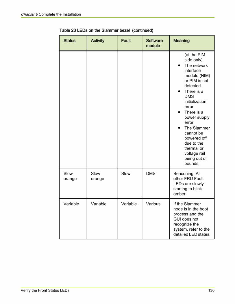
Table 23 LEDs on the Slammer bezel (continued)
Status Activity Fault Softwaremodule
Meaning
(at the PIMside only).
● The networkinterfacemodule (NIM)or PIM is notdetected.
● There is aDMSinitializationerror.
● There is apower supplyerror.
● The Slammercannot bepowered offdue to thethermal orvoltage railbeing out ofbounds.
Sloworange
Sloworange
Slow DMS Beaconing. Allother FRU FaultLEDs are slowlystarting to blinkamber.
Variable Variable Variable Various If the Slammernode is in the bootprocess and theGUI does notrecognize thesystem, refer to thedetailed LED states.
Chapter 6 Complete the Installation
Verify the Front Status LEDs 130

Figure 60 Slammer bezel LEDs
Legend 1 CU 0
2 CU 1
3 Fault LEDs
4 Activity LEDs
5 Status LEDs
4 Verify that the FAULT LEDs are off.
If they are on at this stage, it is usually because the bezel is not fully seated.
5 For each Brick, make sure that the CU 0 and CU 1 STATUS LEDs aregreen.
When there is no I/O activity on a Brick storage enclosure, the RAIDfirmware runs a background operation that scans all drives for media errors.If media errors are found, the firmware performs repair operations. Thisbackground activity causes the ACT LEDs to blink green on the idle systemor Brick. Such activity can take several hours to complete. When host I/Oresumes, this background operation stops. It resumes only when there areno further I/Os from a host. This ACT LED blink is inhibited for drive scrub.
Chapter 6 Complete the Installation
Verify the Front Status LEDs 131
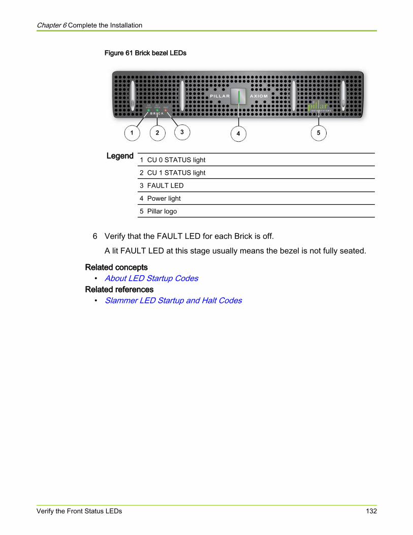
Figure 61 Brick bezel LEDs
Legend 1 CU 0 STATUS light
2 CU 1 STATUS light
3 FAULT LED
4 Power light
5 Pillar logo
6 Verify that the FAULT LED for each Brick is off.
A lit FAULT LED at this stage usually means the bezel is not fully seated.
Related concepts• About LED Startup Codes
Related references• Slammer LED Startup and Halt Codes
Chapter 6 Complete the Installation
Verify the Front Status LEDs 132
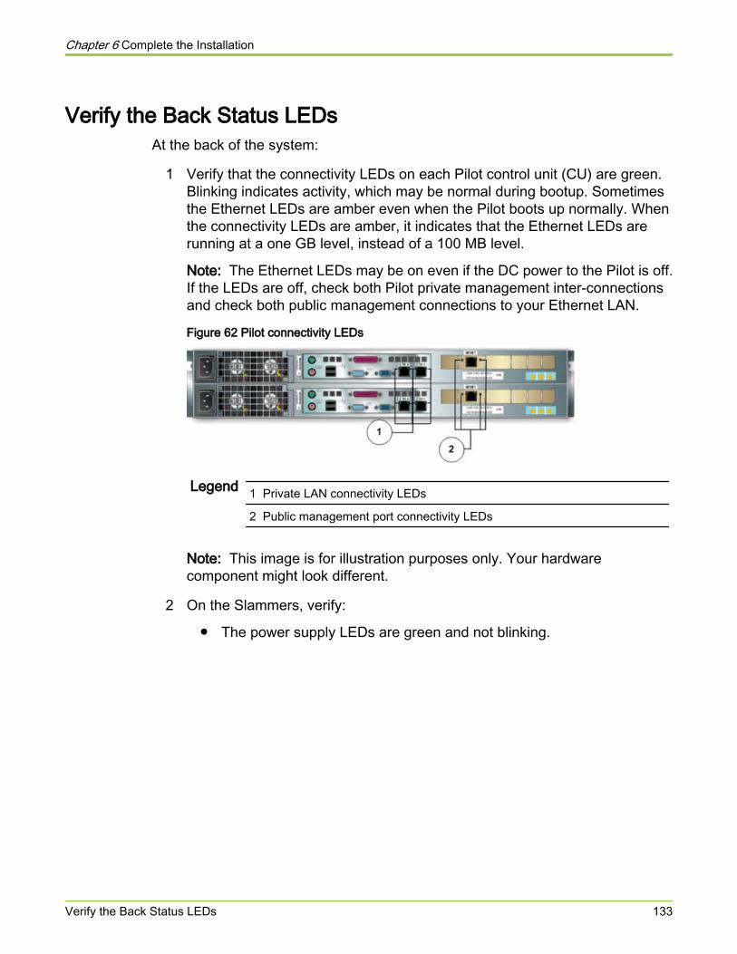
Verify the Back Status LEDsAt the back of the system:
1 Verify that the connectivity LEDs on each Pilot control unit (CU) are green.Blinking indicates activity, which may be normal during bootup. Sometimesthe Ethernet LEDs are amber even when the Pilot boots up normally. Whenthe connectivity LEDs are amber, it indicates that the Ethernet LEDs arerunning at a one GB level, instead of a 100 MB level.
Note: The Ethernet LEDs may be on even if the DC power to the Pilot is off.If the LEDs are off, check both Pilot private management inter-connectionsand check both public management connections to your Ethernet LAN.
Figure 62 Pilot connectivity LEDs
Legend 1 Private LAN connectivity LEDs
2 Public management port connectivity LEDs
Note: This image is for illustration purposes only. Your hardwarecomponent might look different.
2 On the Slammers, verify:
● The power supply LEDs are green and not blinking.
Chapter 6 Complete the Installation
Verify the Back Status LEDs 133
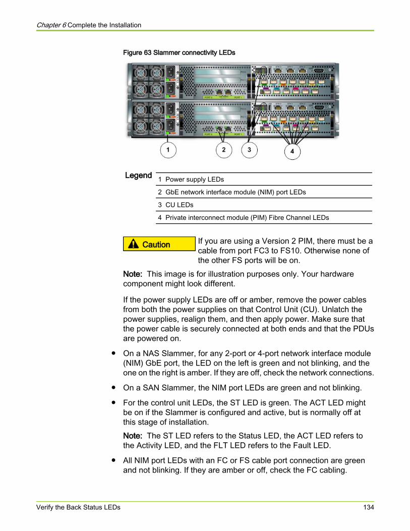
Figure 63 Slammer connectivity LEDs
Legend 1 Power supply LEDs
2 GbE network interface module (NIM) port LEDs
3 CU LEDs
4 Private interconnect module (PIM) Fibre Channel LEDs
Caution If you are using a Version 2 PIM, there must be acable from port FC3 to FS10. Otherwise none ofthe other FS ports will be on.
Note: This image is for illustration purposes only. Your hardwarecomponent might look different.
If the power supply LEDs are off or amber, remove the power cablesfrom both the power supplies on that Control Unit (CU). Unlatch thepower supplies, realign them, and then apply power. Make sure thatthe power cable is securely connected at both ends and that the PDUsare powered on.
● On a NAS Slammer, for any 2-port or 4-port network interface module(NIM) GbE port, the LED on the left is green and not blinking, and theone on the right is amber. If they are off, check the network connections.
● On a SAN Slammer, the NIM port LEDs are green and not blinking.
● For the control unit LEDs, the ST LED is green. The ACT LED mightbe on if the Slammer is configured and active, but is normally off atthis stage of installation.Note: The ST LED refers to the Status LED, the ACT LED refers tothe Activity LED, and the FLT LED refers to the Fault LED.
● All NIM port LEDs with an FC or FS cable port connection are greenand not blinking. If they are amber or off, check the FC cabling.
Chapter 6 Complete the Installation
Verify the Back Status LEDs 134
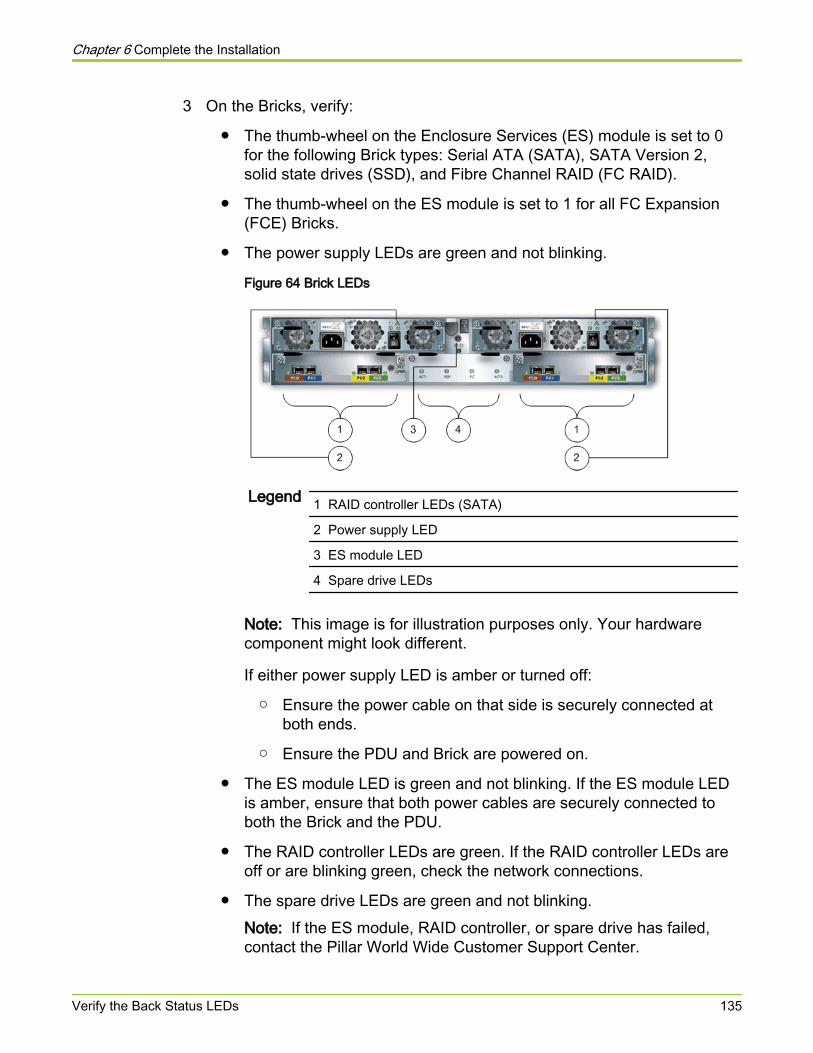
3 On the Bricks, verify:
● The thumb-wheel on the Enclosure Services (ES) module is set to 0for the following Brick types: Serial ATA (SATA), SATA Version 2,solid state drives (SSD), and Fibre Channel RAID (FC RAID).
● The thumb-wheel on the ES module is set to 1 for all FC Expansion(FCE) Bricks.
● The power supply LEDs are green and not blinking.
Figure 64 Brick LEDs
Legend 1 RAID controller LEDs (SATA)
2 Power supply LED
3 ES module LED
4 Spare drive LEDs
Note: This image is for illustration purposes only. Your hardwarecomponent might look different.
If either power supply LED is amber or turned off:
○ Ensure the power cable on that side is securely connected atboth ends.
○ Ensure the PDU and Brick are powered on.
● The ES module LED is green and not blinking. If the ES module LEDis amber, ensure that both power cables are securely connected toboth the Brick and the PDU.
● The RAID controller LEDs are green. If the RAID controller LEDs areoff or are blinking green, check the network connections.
● The spare drive LEDs are green and not blinking.Note: If the ES module, RAID controller, or spare drive has failed,contact the Pillar World Wide Customer Support Center.
Chapter 6 Complete the Installation
Verify the Back Status LEDs 135
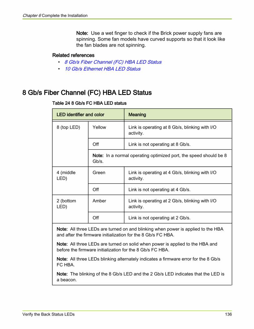
Note: Use a wet finger to check if the Brick power supply fans arespinning. Some fan models have curved supports so that it look likethe fan blades are not spinning.
Related references• 8 Gb/s Fiber Channel (FC) HBA LED Status• 10 Gb/s Ethernet HBA LED Status
8 Gb/s Fiber Channel (FC) HBA LED StatusTable 24 8 Gb/s FC HBA LED status
LED identifier and color Meaning
8 (top LED) Yellow Link is operating at 8 Gb/s, blinking with I/Oactivity.
Off Link is not operating at 8 Gb/s.
Note: In a normal operating optimized port, the speed should be 8Gb/s.
4 (middleLED)
Green Link is operating at 4 Gb/s, blinking with I/Oactivity.
Off Link is not operating at 4 Gb/s.
2 (bottomLED)
Amber Link is operating at 2 Gb/s, blinking with I/Oactivity.
Off Link is not operating at 2 Gb/s.
Note: All three LEDs are turned on and blinking when power is applied to the HBAand after the firmware initialization for the 8 Gb/s FC HBA.
Note: All three LEDs are turned on solid when power is applied to the HBA andbefore the firmware initialization for the 8 Gb/s FC HBA.
Note: All three LEDs blinking alternately indicates a firmware error for the 8 Gb/sFC HBA.
Note: The blinking of the 8 Gb/s LED and the 2 Gb/s LED indicates that the LED isa beacon.
Chapter 6 Complete the Installation
Verify the Back Status LEDs 136
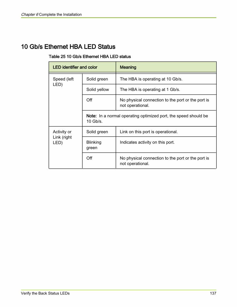
10 Gb/s Ethernet HBA LED StatusTable 25 10 Gb/s Ethernet HBA LED status
LED identifier and color Meaning
Speed (leftLED)
Solid green The HBA is operating at 10 Gb/s.
Solid yellow The HBA is operating at 1 Gb/s.
Off No physical connection to the port or the port isnot operational.
Note: In a normal operating optimized port, the speed should be10 Gb/s.
Activity orLink (rightLED)
Solid green Link on this port is operational.
Blinkinggreen
Indicates activity on this port.
Off No physical connection to the port or the port isnot operational.
Chapter 6 Complete the Installation
Verify the Back Status LEDs 137
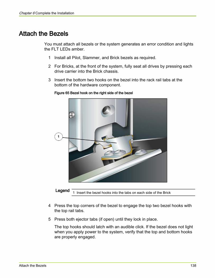
Attach the BezelsYou must attach all bezels or the system generates an error condition and lightsthe FLT LEDs amber.
1 Install all Pilot, Slammer, and Brick bezels as required.
2 For Bricks, at the front of the system, fully seat all drives by pressing eachdrive carrier into the Brick chassis.
3 Insert the bottom two hooks on the bezel into the rack rail tabs at thebottom of the hardware component.
Figure 65 Bezel hook on the right side of the bezel
Legend 1 Insert the bezel hooks into the tabs on each side of the Brick
4 Press the top corners of the bezel to engage the top two bezel hooks withthe top rail tabs.
5 Press both ejector tabs (if open) until they lock in place.
The top hooks should latch with an audible click. If the bezel does not lightwhen you apply power to the system, verify that the top and bottom hooksare properly engaged.
Chapter 6 Complete the Installation
Attach the Bezels 138
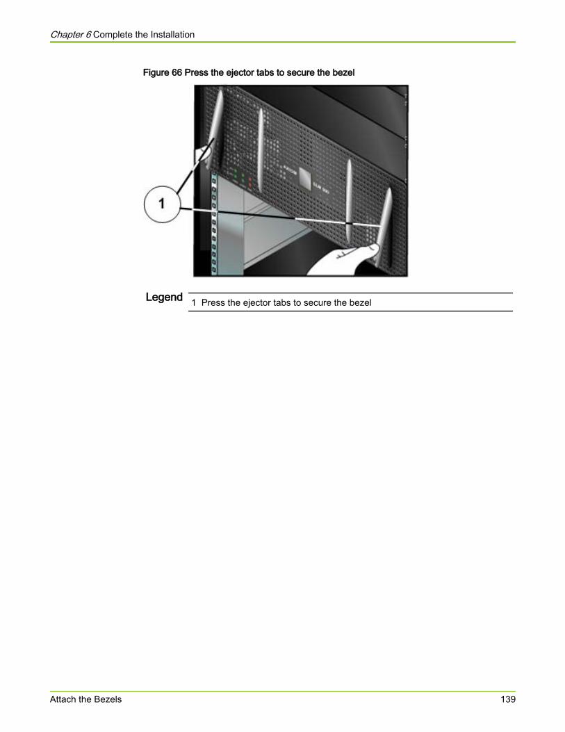
Figure 66 Press the ejector tabs to secure the bezel
Legend 1 Press the ejector tabs to secure the bezel
Chapter 6 Complete the Installation
Attach the Bezels 139

About HBA Driver and Firmware Installation (SAN Only)You must install FC HBAs in the SAN hosts, including any software required bythe HBAs, before you can access the LUNs on Pillar Axiom 600 servers.Complete the instructions from your HBA vendor to:
● Install the HBAs in the SAN hosts.
● Download required drivers and firmware.
● Install or update the computer BIOS on the SAN host, if required.
Note: Each 8 Gb/s Fiber Channel (FC) HBA has its own unique World WideName (WWN). This WWN must be used when updating the FC switchconfiguration and installing or replacing the 8 Gb/s FC HBA.
Note: If you intend to install the Pillar Axiom Path Manager software, refer to theappropriate Pillar Axiom Path Manager Installation Guide and Release Notes foryour particular platform.
Related concepts• About Pillar Axiom Path Manager Installation (SAN Only)
Chapter 6 Complete the Installation
About HBA Driver and Firmware Installation (SAN Only) 140
About Switch Zone for HBA Set Up (SAN Only)If appropriate, follow the instructions from your switch vendor to set up zones to:
● Permit host HBA ports to access the Slammer ports.
● Segregate network servers with different operating systems.
● Segregate network servers with different security requirements.
Note: The 8 Gb/s Fiber Channel (FC) HBA has its own unique World WideName (WWN). This WWN must be used to update any FC switch configurationdata.
Chapter 6 Complete the Installation
About Switch Zone for HBA Set Up (SAN Only) 141
Attach the Rack Doors and Panels
In this procedure, you reattach the front and back doors and both side panels tothe rack. These steps help to ensure the security and proper cooling of PillarAxiom 600 system components.
1 Based on the type of door hinge, reassemble the hinges.
2 Reattach the doors.
3 Reattach the door grounding straps on the rear door.
4 Lock the front and back doors to the rack (optional).
Chapter 6 Complete the Installation
Attach the Rack Doors and Panels 142
Attach the Rack Side Panels1 Hang the top of the panel on the top of the rack frame and latch the panel to
close it. If the racks are bayed, you must install only the outer two panels.
Important! Be sure not to pinch any cables that might have strayed fromtheir proper moorings.
2 Secure the panel appropriately using one of the following options:
● Engage the latch handle(s) and snap the panel into place.
● Screw the panels to the rack frame at the top and bottom.
3 Lock both side panels (optional).
Chapter 6 Complete the Installation
Attach the Rack Side Panels 143
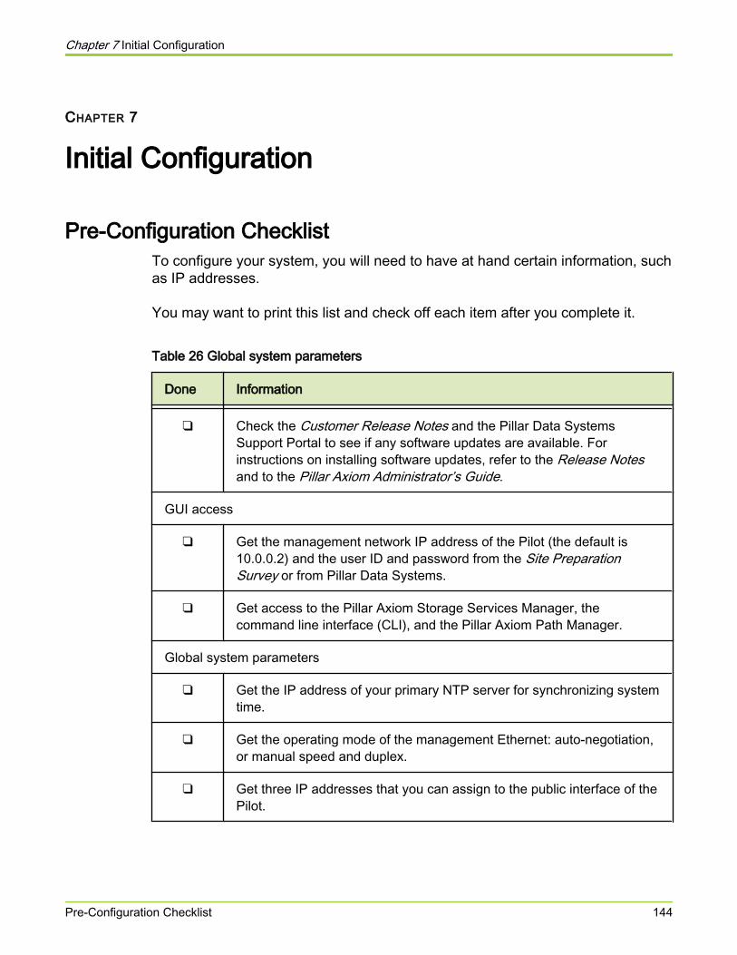
CHAPTER 7
Initial Configuration
Pre-Configuration ChecklistTo configure your system, you will need to have at hand certain information, suchas IP addresses.
You may want to print this list and check off each item after you complete it.
Table 26 Global system parameters
Done Information
❑ Check the Customer Release Notes and the Pillar Data SystemsSupport Portal to see if any software updates are available. Forinstructions on installing software updates, refer to the Release Notesand to the Pillar Axiom Administrator’s Guide.
GUI access
❑ Get the management network IP address of the Pilot (the default is10.0.0.2) and the user ID and password from the Site PreparationSurvey or from Pillar Data Systems.
❑ Get access to the Pillar Axiom Storage Services Manager, thecommand line interface (CLI), and the Pillar Axiom Path Manager.
Global system parameters
❑ Get the IP address of your primary NTP server for synchronizing systemtime.
❑ Get the operating mode of the management Ethernet: auto-negotiation,or manual speed and duplex.
❑ Get three IP addresses that you can assign to the public interface of thePilot.
Chapter 7 Initial Configuration
Pre-Configuration Checklist 144
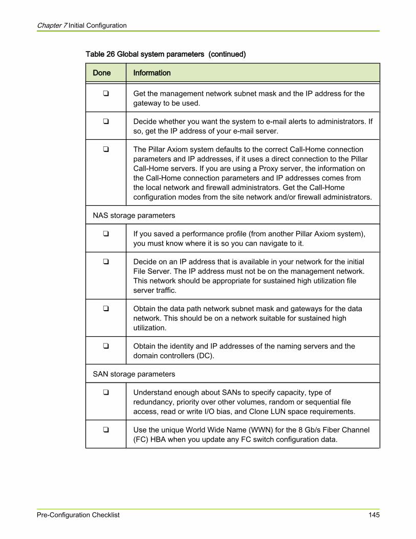
Table 26 Global system parameters (continued)
Done Information
❑ Get the management network subnet mask and the IP address for thegateway to be used.
❑ Decide whether you want the system to e-mail alerts to administrators. Ifso, get the IP address of your e-mail server.
❑ The Pillar Axiom system defaults to the correct Call‑Home connectionparameters and IP addresses, if it uses a direct connection to the PillarCall‑Home servers. If you are using a Proxy server, the information onthe Call‑Home connection parameters and IP addresses comes fromthe local network and firewall administrators. Get the Call‑Homeconfiguration modes from the site network and/or firewall administrators.
NAS storage parameters
❑ If you saved a performance profile (from another Pillar Axiom system),you must know where it is so you can navigate to it.
❑ Decide on an IP address that is available in your network for the initialFile Server. The IP address must not be on the management network.This network should be appropriate for sustained high utilization fileserver traffic.
❑ Obtain the data path network subnet mask and gateways for the datanetwork. This should be on a network suitable for sustained highutilization.
❑ Obtain the identity and IP addresses of the naming servers and thedomain controllers (DC).
SAN storage parameters
❑ Understand enough about SANs to specify capacity, type ofredundancy, priority over other volumes, random or sequential fileaccess, read or write I/O bias, and Clone LUN space requirements.
❑ Use the unique World Wide Name (WWN) for the 8 Gb/s Fiber Channel(FC) HBA when you update any FC switch configuration data.
Chapter 7 Initial Configuration
Pre-Configuration Checklist 145
Start the Graphical User Interface
The Pillar Axiom Storage Services Manager is a graphical user interface (GUI) tomanage the Pillar Axiom system. Access the GUI by connecting to the high-availability IP address of the Pilot, the default of which is 10.0.0.2.
Caution Do not connect the Pilot Management interfaces to thecustomer network without checking to make sure that thefollowing IP addresses: 10.0.0.2, 10.0.0.3, and 10.0.0.4 arenot already in use on the customer network.
Note: In most instances, you must directly connect a workstation to the PillarAxiom system to set the initial IP addresses to IP addresses that will be availableon the customer network.
1 Configure a workstation with an IP address in the range of 10.0.0.5 through10.0.0.254, a netmask of 255.255.255.0 and a default gateway of 10.0.0.1.
2 Connect to the top Pilot Control unit (CU) and attempt to ping 10.0.0.2 and10.0.0.3. If 10.0.0.3 responds to the ping, but 10.0.0.2 does not respond tothe ping, connect to the bottom Pilot CU and attempt to ping 10.0.0.2 and10.0.0.4. If neither Pilot CU responds to 10.0.0.2, contact the Pillar WorldWide Customer Support Center for assistance.
3 Download and install the GUI client for Windows, Linux, and Macintosh bytyping http://10.0.0.2 on your web browser and select Applications from thePillar Axiom software login screen.
4 Launch the Pillar Axiom Storage Services Manager application.
● For the Windows executable, double-click C:\Program Files\Pillar Data Systems\Pillar Axiom Storage ServicesManager.exe.
● For the Windows archive, run the runAxiomStorageManager.batbatch script.
● For Linux, run the runAxiomStorageManager.sh shell script.
Result:The login screen appears:
Chapter 7 Initial Configuration
Start the Graphical User Interface 146
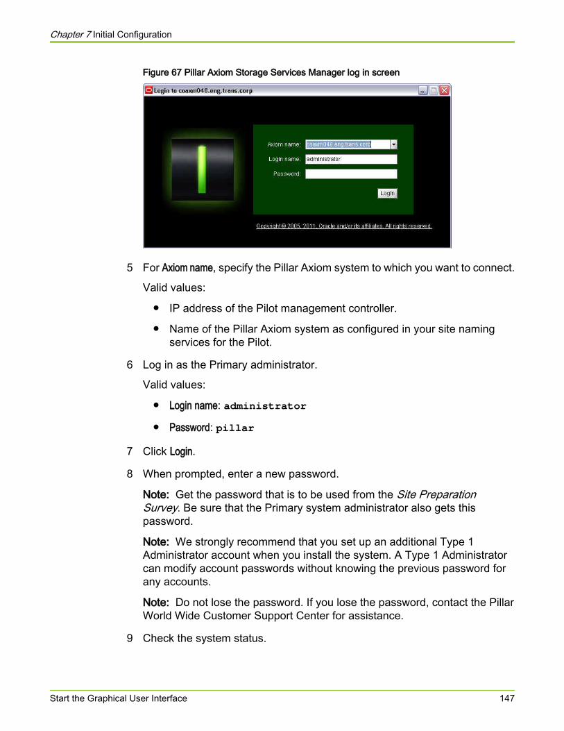
Figure 67 Pillar Axiom Storage Services Manager log in screen
5 For Axiom name, specify the Pillar Axiom system to which you want to connect.
Valid values:
● IP address of the Pilot management controller.
● Name of the Pillar Axiom system as configured in your site namingservices for the Pilot.
6 Log in as the Primary administrator.
Valid values:
● Login name: administrator● Password: pillar
7 Click Login.
8 When prompted, enter a new password.
Note: Get the password that is to be used from the Site PreparationSurvey. Be sure that the Primary system administrator also gets thispassword.
Note: We strongly recommend that you set up an additional Type 1Administrator account when you install the system. A Type 1 Administratorcan modify account passwords without knowing the previous password forany accounts.
Note: Do not lose the password. If you lose the password, contact the PillarWorld Wide Customer Support Center for assistance.
9 Check the system status.
Chapter 7 Initial Configuration
Start the Graphical User Interface 147
The system status is displayed in the bottom left corner of the status bar oftheGUI. A round green circle indicates that all hardware components in thePillar Axiom system have successfully started and are operating normally. Ifthe System Status icon is a yellow triangle (which indicates a warningcondition) or a red circle (which indicates a critical condition), click Monitor >Hardware and note which components do not display a green icon and do nothave a Normal status.
10 Confirm that all components are powered on and that all cables arecorrectly and securely connected.
If a cabling problem exists, the Pillar Axiom system might show the affectedcomponents with a warning status.
If a flashing upside down triangle appears in the lower left corner of the statusbar of the GUI, click on the triangle to see if an error exists. The Monitor > Hardwarescreen can assist you in identifying the error through the warning status icon forthe following:
● private management interface (PMI) links
● private interconnect wiring errors
● Pillar Axiom components
If there is a connection error, verify that the cables are all fully seated andproperly connected.
Refer to the Pillar Axiom SSF Cabling Reference for more information. If the errorpersists, contact the Pillar World Wide Customer Support Center.
Chapter 7 Initial Configuration
Start the Graphical User Interface 148
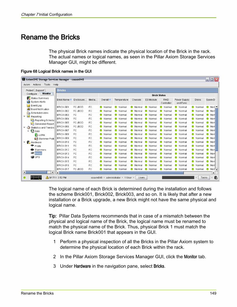
Rename the Bricks
The physical Brick names indicate the physical location of the Brick in the rack.The actual names or logical names, as seen in the Pillar Axiom Storage ServicesManager GUI, might be different.
Figure 68 Logical Brick names in the GUI
The logical name of each Brick is determined during the installation and followsthe scheme Brick001, Brick002, Brick003, and so on. It is likely that after a newinstallation or a Brick upgrade, a new Brick might not have the same physical andlogical name.
Tip: Pillar Data Systems recommends that in case of a mismatch between thephysical and logical name of the Brick, the logical name must be renamed tomatch the physical name of the Brick. Thus, physical Brick 1 must match thelogical Brick name Brick001 that appears in the GUI.
1 Perform a physical inspection of all the Bricks in the Pillar Axiom system todetermine the physical location of each Brick within the rack.
2 In the Pillar Axiom Storage Services Manager GUI, click the Monitor tab.
3 Under Hardware in the navigation pane, select Bricks.
Chapter 7 Initial Configuration
Rename the Bricks 149
4 In the Bricks overview pane, highlight the name of the Brick that you want tomodify.
5 (Optional) To identify physically the Brick you intend to rename, selectActions > Identify and, use the Identify dialog to flash the LEDs on the frontand back of the selected Brick.
6 After you have confirmed the physical Brick, select Actions > Modify Name.
7 In the Modify Brick dialog, click Components.
8 In the Brick Name field, type the new name of the selected Brick.
9 Click OK.
Result:The physical name of the Brick should now match the logical name.
10 Repeat this procedure for each Brick in the system.
11 After ensuring that all Bricks in the system have matching physical andlogical names, remove the temporary prefix “t” from each Brick name in theGUI.
Related concepts• About Component Placement for One Slammer and FC Bricks• About Component Placement for One Slammer and SATA Bricks• About Component Placement for Two or Three Slammers and FC Bricks• About Component Placement for Four Slammers and 64 Bricks
Chapter 7 Initial Configuration
Rename the Bricks 150

Troubleshoot a Failed Cable Connection1 To identify any cabling issues, from the Monitor tab, click System Alerts.
All cabling issues appear as system alerts.
2 To identify hardware components that do not have a normal status, clickHardware.
Note all the components that do not display the Green icon, which indicatesa Normal status.
3 If a single Pilot control unit (CU) and a single Slammer CU are in warningstatus, and that Slammer CU is connected to that Pilot CU, check theprivate management interconnect Ethernet cable.
4 On the Slammer and the Bricks, verify that each field replaceable unit(FRU) displays the Green icon, which indicates Normal status.
5 Select the I/O Port details on each FRU and note any connections that donot display a connected status. Verify the cable connections using the SSFCabling Reference. Contact the Pillar World Wide Customer Support Centerfor assistance after checking that all the cabling connections are correct asindicated in the Pillar Axiom 600 SSF Cabling Reference.
6 Contact the Pillar World Wide Customer Support Center for help indetermining whether you have a bad cable or port and which one is bad:
● Request a replacement FC cable for a bad cable.
● Request a replacement private interconnect module for a badSlammer port or a RAID controller for a bad Brick port.
Chapter 7 Initial Configuration
Troubleshoot a Failed Cable Connection 151
About Pillar Axiom Path Manager Installation (SAN Only)To operate your SAN system, you may optionally install the Pillar Axiom PathManager (APM) drivers and software on your SAN hosts. APM provides thesebenefits:
● Ensures your SAN host operating system does not interpret multiple pathsas multiple drives.
● Provides path failover.
● Streamlines system management.
Important! Configure the LUNs on the Pillar Axiom 600 system before you installthe APM system software on the SAN host.
Complete the procedures in the appropriate Pillar Axiom Path ManagerInstallation Guide and Release Notes to install the APM driver and software onthe SAN host.
Chapter 7 Initial Configuration
About Pillar Axiom Path Manager Installation (SAN Only) 152
Reset the Primary System Administrator PasswordIf you forget the Primary system administrator password, you can reset it.
1 Use a Type 1 Administrator account, if one exists, to reset the password. Asupport administrator cannot reset the Primary Administrator password.
2 If no Type 1 Administrator account is available, contact the Pillar WorldWide Customer Support Center for the encrypted file (for resetting thepassword), which may be placed in a USB key. Use the USB key as instructed.
Important! We strongly recommend that you set up an additional Type 1Administrator account when you install the system. Only a Type 1Administrator can modify account passwords without knowing the previouspassword for any accounts.
Chapter 7 Initial Configuration
Reset the Primary System Administrator Password 153

APPENDIX A
Slammer LED Startup Progress Codes
About LED Startup CodesWhen a Slammer is powered on, it goes through a sequence of actions.Generally, the time to finish these actions for a new installation is about 12 minutes.
The time to start up your system may be shorter or longer, depending on thenumber of configured entities (LUNs, Snap FSs, Clone LUNs, quotas, and so on)and, to some degree, on the configuration of Slammers and Bricks. Slammerscannot complete the startup sequence without the Pilot being powered on andfunctioning.
While a Slammer performs startup diagnostics and then waits for its runtimeimage to download from the Pilot:
● The Fault LED (FLT) is off.
● The Activity LED (ACT) is green and blinks fast.
● The Status LED (ST) is green and blinks slowly.
During the remainder of the startup process, FLT and ACT are off while STslowly blinks amber once each second. During this time, the GUI shows theSlammer to have a status of Booting 0xnnnn while the Pilot initializes theSlammer' s data services components.
When the Slammer successfully completes the startup sequence, ST is steadygreen.
Tip: If the front bezel Fault (FLT) LED or the private interconnect module (PIM)FLT LED is on steady and no other fault indicators on the Slammer are lit, thebezel may not be properly seated. Slammers always light FLT when the bezel isoff.
Tip: The FLT, ST, and ACT LED indicators are duplicated on the upper left of thePIM in the rear of the Pillar Axiom 600 system.
If the Slammer halts during startup, the three LEDs on the back of the chassis(FLT, ACT, and ST) or the three LEDs on the bezel (Status, Activity, and Fault)help you identify where the Slammer halted in the startup sequence.
Appendix A Slammer LED Startup Progress Codes
About LED Startup Codes 154

About Slammer LED CodesThe Slammer bezel has Fault, Status, and Activity LEDs that can display variouscolors and blink rates. These LEDs also appear on the private interface moduleat the back of the Slammer chassis, and are labeled FLT (Fault), ACT (Activity),and ST (Status).
These LEDs can:
● Be green or amber.
● Be on or off.
● Be steady, with no blinks.
● Blink rapidly—slightly more than two blinks for each sec (2.375Hz).
● Blink slowly—one blink for each 1.5 sec (0.67Hz).
Appendix A Slammer LED Startup Progress Codes
About Slammer LED Codes 155
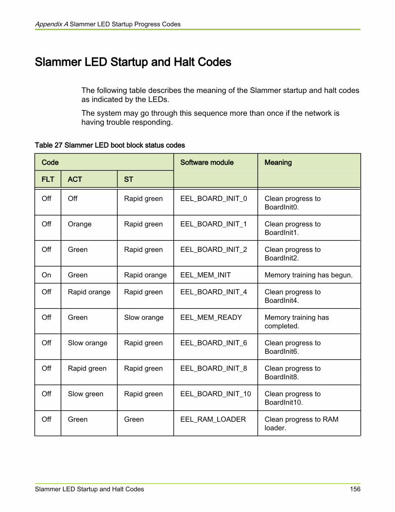
Slammer LED Startup and Halt Codes
The following table describes the meaning of the Slammer startup and halt codesas indicated by the LEDs.
The system may go through this sequence more than once if the network ishaving trouble responding.
Table 27 Slammer LED boot block status codes
Code Software module Meaning
FLT ACT ST
Off Off Rapid green EEL_BOARD_INIT_0 Clean progress toBoardInit0.
Off Orange Rapid green EEL_BOARD_INIT_1 Clean progress toBoardInit1.
Off Green Rapid green EEL_BOARD_INIT_2 Clean progress toBoardInit2.
On Green Rapid orange EEL_MEM_INIT Memory training has begun.
Off Rapid orange Rapid green EEL_BOARD_INIT_4 Clean progress toBoardInit4.
Off Green Slow orange EEL_MEM_READY Memory training hascompleted.
Off Slow orange Rapid green EEL_BOARD_INIT_6 Clean progress toBoardInit6.
Off Rapid green Rapid green EEL_BOARD_INIT_8 Clean progress toBoardInit8.
Off Slow green Rapid green EEL_BOARD_INIT_10 Clean progress toBoardInit10.
Off Green Green EEL_RAM_LOADER Clean progress to RAMloader.
Appendix A Slammer LED Startup Progress Codes
Slammer LED Startup and Halt Codes 156
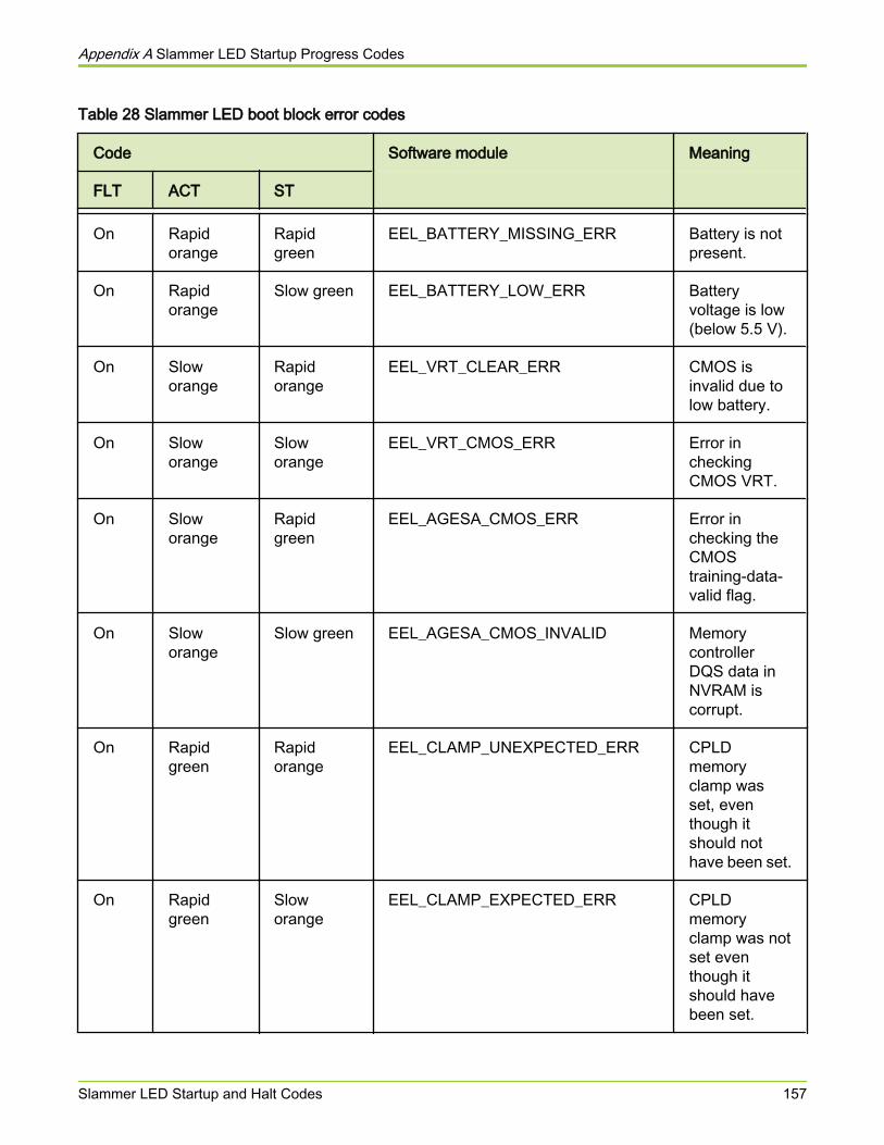
Table 28 Slammer LED boot block error codes
Code Software module Meaning
FLT ACT ST
On Rapidorange
Rapidgreen
EEL_BATTERY_MISSING_ERR Battery is notpresent.
On Rapidorange
Slow green EEL_BATTERY_LOW_ERR Batteryvoltage is low(below 5.5 V).
On Sloworange
Rapidorange
EEL_VRT_CLEAR_ERR CMOS isinvalid due tolow battery.
On Sloworange
Sloworange
EEL_VRT_CMOS_ERR Error incheckingCMOS VRT.
On Sloworange
Rapidgreen
EEL_AGESA_CMOS_ERR Error inchecking theCMOStraining-data-valid flag.
On Sloworange
Slow green EEL_AGESA_CMOS_INVALID MemorycontrollerDQS data inNVRAM iscorrupt.
On Rapidgreen
Rapidorange
EEL_CLAMP_UNEXPECTED_ERR CPLDmemoryclamp wasset, eventhough itshould nothave been set.
On Rapidgreen
Sloworange
EEL_CLAMP_EXPECTED_ERR CPLDmemoryclamp was notset eventhough itshould havebeen set.
Appendix A Slammer LED Startup Progress Codes
Slammer LED Startup and Halt Codes 157
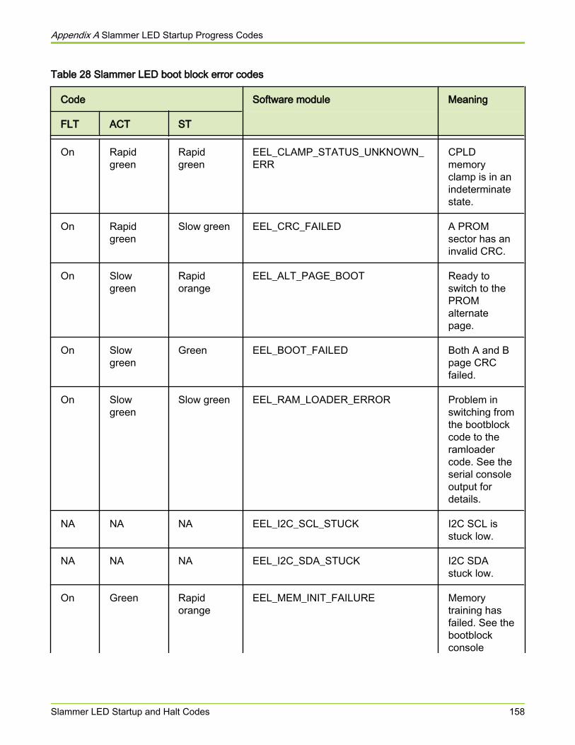
Table 28 Slammer LED boot block error codes
Code Software module Meaning
FLT ACT ST
On Rapidgreen
Rapidgreen
EEL_CLAMP_STATUS_UNKNOWN_ERR
CPLDmemoryclamp is in anindeterminatestate.
On Rapidgreen
Slow green EEL_CRC_FAILED A PROMsector has aninvalid CRC.
On Slowgreen
Rapidorange
EEL_ALT_PAGE_BOOT Ready toswitch to thePROMalternatepage.
On Slowgreen
Green EEL_BOOT_FAILED Both A and Bpage CRCfailed.
On Slowgreen
Slow green EEL_RAM_LOADER_ERROR Problem inswitching fromthe bootblockcode to theramloadercode. See theserial consoleoutput fordetails.
NA NA NA EEL_I2C_SCL_STUCK I2C SCL isstuck low.
NA NA NA EEL_I2C_SDA_STUCK I2C SDAstuck low.
On Green Rapidorange
EEL_MEM_INIT_FAILURE Memorytraining hasfailed. See thebootblockconsole
Appendix A Slammer LED Startup Progress Codes
Slammer LED Startup and Halt Codes 158
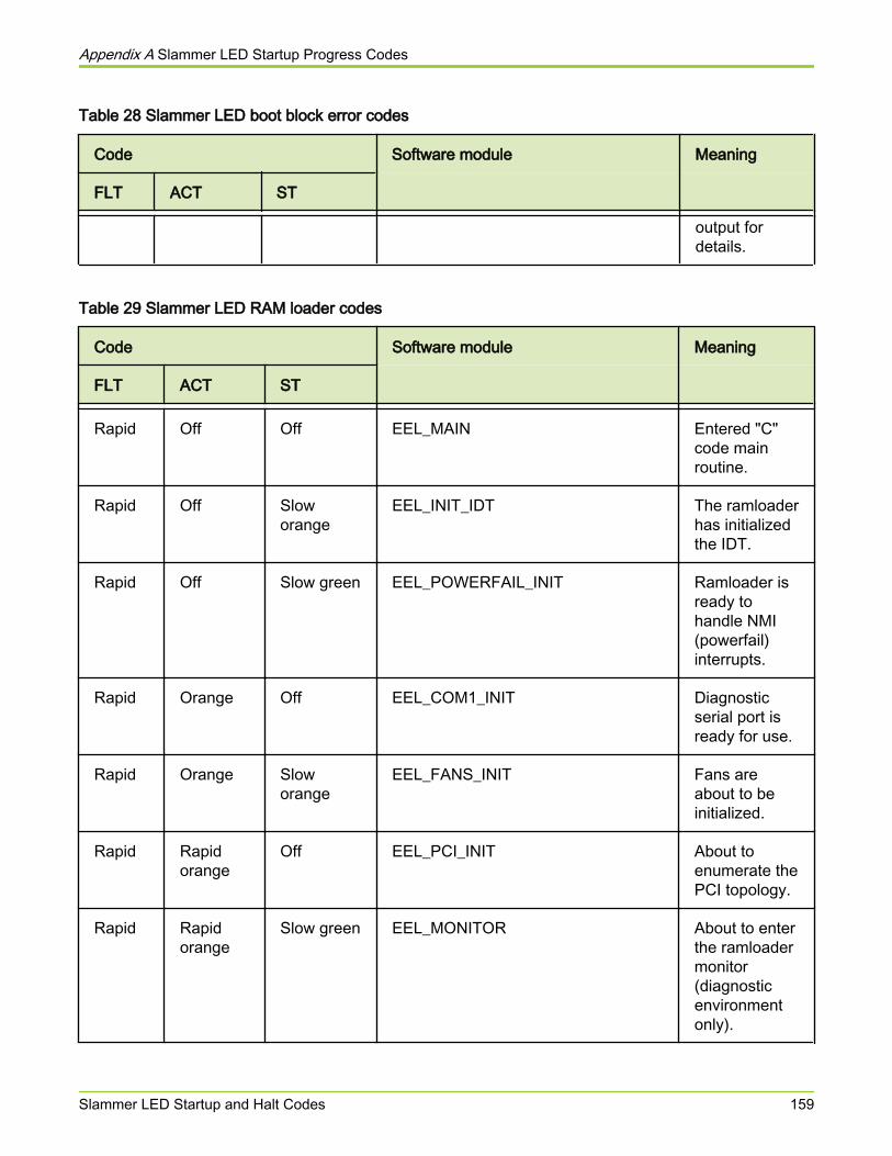
Table 28 Slammer LED boot block error codes
Code Software module Meaning
FLT ACT ST
output fordetails.
Table 29 Slammer LED RAM loader codes
Code Software module Meaning
FLT ACT ST
Rapid Off Off EEL_MAIN Entered "C"code mainroutine.
Rapid Off Sloworange
EEL_INIT_IDT The ramloaderhas initializedthe IDT.
Rapid Off Slow green EEL_POWERFAIL_INIT Ramloader isready tohandle NMI(powerfail)interrupts.
Rapid Orange Off EEL_COM1_INIT Diagnosticserial port isready for use.
Rapid Orange Sloworange
EEL_FANS_INIT Fans areabout to beinitialized.
Rapid Rapidorange
Off EEL_PCI_INIT About toenumerate thePCI topology.
Rapid Rapidorange
Slow green EEL_MONITOR About to enterthe ramloadermonitor(diagnosticenvironmentonly).
Appendix A Slammer LED Startup Progress Codes
Slammer LED Startup and Halt Codes 159
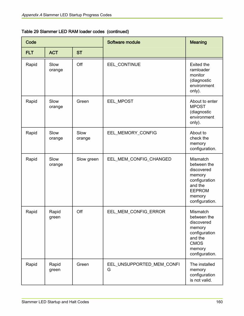
Table 29 Slammer LED RAM loader codes (continued)
Code Software module Meaning
FLT ACT ST
Rapid Sloworange
Off EEL_CONTINUE Exited theramloadermonitor(diagnosticenvironmentonly).
Rapid Sloworange
Green EEL_MPOST About to enterMPOST(diagnosticenvironmentonly).
Rapid Sloworange
Sloworange
EEL_MEMORY_CONFIG About tocheck thememoryconfiguration.
Rapid Sloworange
Slow green EEL_MEM_CONFIG_CHANGED Mismatchbetween thediscoveredmemoryconfigurationand theEEPROMmemoryconfiguration.
Rapid Rapidgreen
Off EEL_MEM_CONFIG_ERROR Mismatchbetween thediscoveredmemoryconfigurationand theCMOSmemoryconfiguration.
Rapid Rapidgreen
Green EEL_UNSUPPORTED_MEM_CONFIG
The installedmemoryconfigurationis not valid.
Appendix A Slammer LED Startup Progress Codes
Slammer LED Startup and Halt Codes 160
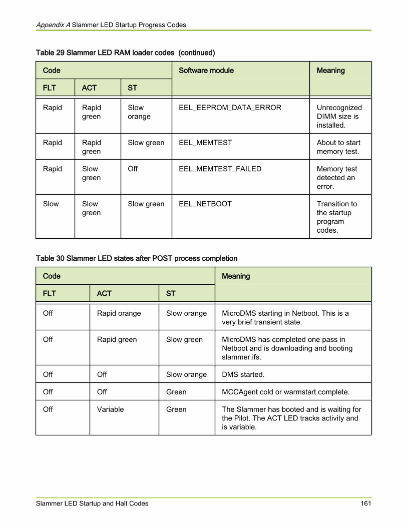
Table 29 Slammer LED RAM loader codes (continued)
Code Software module Meaning
FLT ACT ST
Rapid Rapidgreen
Sloworange
EEL_EEPROM_DATA_ERROR UnrecognizedDIMM size isinstalled.
Rapid Rapidgreen
Slow green EEL_MEMTEST About to startmemory test.
Rapid Slowgreen
Off EEL_MEMTEST_FAILED Memory testdetected anerror.
Slow Slowgreen
Slow green EEL_NETBOOT Transition tothe startupprogramcodes.
Table 30 Slammer LED states after POST process completion
Code Meaning
FLT ACT ST
Off Rapid orange Slow orange MicroDMS starting in Netboot. This is avery brief transient state.
Off Rapid green Slow green MicroDMS has completed one pass inNetboot and is downloading and bootingslammer.ifs.
Off Off Slow orange DMS started.
Off Off Green MCCAgent cold or warmstart complete.
Off Variable Green The Slammer has booted and is waiting forthe Pilot. The ACT LED tracks activity andis variable.
Appendix A Slammer LED Startup Progress Codes
Slammer LED Startup and Halt Codes 161

APPENDIX B
Safety Statements
About Safety Statements
For the Pillar Axiom 600 system, safety statements provide specific warning andcautionary notices about the electrical and weight properties that are associatedwith a Pillar Axiom 600 system and its hardware components.
Important! Procedures listed in the body of this document assume that theelectrical characteristics of the power supply to which Pillar Axiom 600 systemcomponents are connected comply with the technical specifications for thosecomponents.
Related concepts• About Pillar Axiom 600 Hardware Specifications
Appendix B Safety Statements
About Safety Statements 162

Warning Notices
Warning This hazard symbol means warning. You are in a situationthat could cause bodily injury. Before you work on anyequipment, be aware of the hazards that are involved withelectrical circuitry and be familiar with standard practices forpreventing accidents.
Electrical Warning in Other LanguagesTable 31 Electrical warning in other languages
Waarschuwing Dit waarschuwingssymbool betekent gevaar. U verkeert in eensituatie die lichamelijk letsel kan veroorzaken. Voordat u aanenige apparatuur gaat werken, dient u zich bewust te zijn vande bij elektrische schakelingen betrokken risico's en dient u opde hoogte te zijn van standaard maatregelen om ongelukkente voorkomen.
Varoitus Tämä varoitusmerkki merkitsee vaaraa. Olet tilanteessa, jokavoi johtaa ruumiinvammaan. Ennen kuin työskentelet minkäänlaitteiston parissa, ota selvää sähkökytkentöihin liittyvistävaaroista ja tavanomaisista onnettomuuksien ehkäisykeinoista.
Attention Ce symbole d'avertissement indique un danger. Vous voustrouvez dans une situation pouvant causer des blessures oudes dommages corporels. Avant de travailler sur unéquipement, soyez conscient des dangers posés par lescircuits électriques et familiarisez-vous avec les procédurescouramment utilisées pour éviter les accidents.
Warnung Dieses Warnsymbol bedeutet Gefahr. Sie befinden sich ineiner Situation, die zu einer Körperverletzung führen könnte.Bevor Sie mit der Arbeit an irgendeinem Gerät beginnen,seien Sie sich der mit elektrischen Stromkreisen verbundenenGefahren und der Standardpraktiken zur Vermeidung vonUnfällen bewußt.
Avvertenza Questo simbolo di avvertenza indica un pericolo. La situazionepotrebbe causare infortuni alle persone. Prima di lavorare suqualsiasi apparecchiatura, occorre conoscere i pericoli relativi
Appendix B Safety Statements
Warning Notices 163
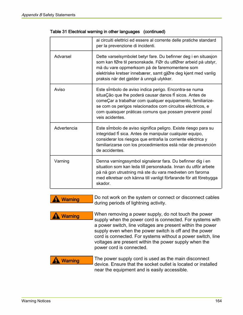
Table 31 Electrical warning in other languages (continued)
ai circuiti elettrici ed essere al corrente delle pratiche standardper la prevenzione di incidenti.
Advarsel Dette varselsymbolet betyr fare. Du befinner deg i en situasjonsom kan fØre til personskade. FØr du utfØrer arbeid på utstyr,må du vare oppmerksom på de faremomentene somelektriske kretser innebærer, samt gjØre deg kjent med vanligpraksis når det gjelder å unngå ulykker.
Aviso Este sÍmbolo de aviso indica perigo. Encontra-se numasituaÇão que lhe poderá causar danos fÍ sicos. Antes decomeÇar a trabalhar com qualquer equipamento, familiarize-se com os perigos relacionados com circuitos eléctricos, ecom quaisquer práticas comuns que possam prevenir possÍveis acidentes.
Advertencia Este sÍmbolo de aviso significa peligro. Existe riesgo para suintegridad fÍ sica. Antes de manipular cualquier equipo,considerar los riesgos que entraña la corriente eléctrica yfamiliarizarse con los procedimientos está ndar de prevenciónde accidentes.
Varning Denna varningssymbol signalerar fara. Du befinner dig i ensituation som kan leda till personskada. Innan du utför arbetepå nå gon utrustning må ste du vara medveten om farornamed elkretsar och känna till vanligt förfarande för att förebyggaskador.
Warning Do not work on the system or connect or disconnect cablesduring periods of lightning activity.
Warning When removing a power supply, do not touch the powersupply when the power cord is connected. For systems witha power switch, line voltages are present within the powersupply even when the power switch is off and the powercord is connected. For systems without a power switch, linevoltages are present within the power supply when thepower cord is connected.
Warning The power supply cord is used as the main disconnectdevice. Ensure that the socket outlet is located or installednear the equipment and is easily accessible.
Appendix B Safety Statements
Warning Notices 164
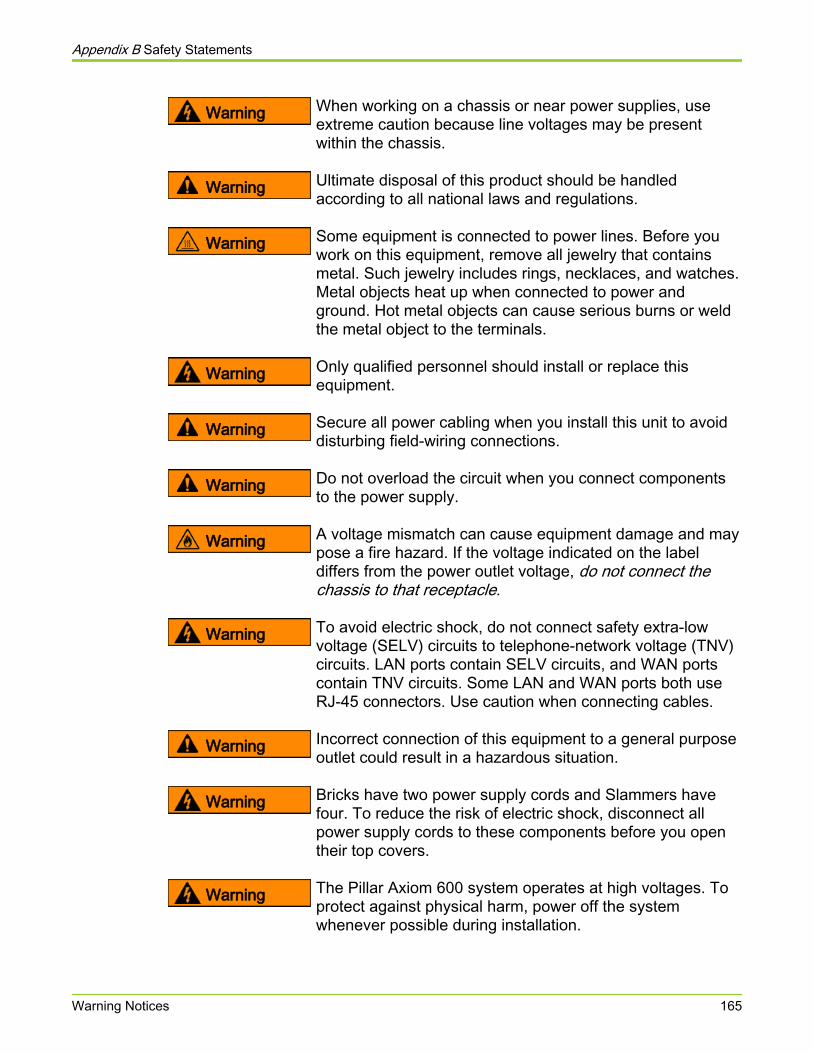
Warning When working on a chassis or near power supplies, useextreme caution because line voltages may be presentwithin the chassis.
Warning Ultimate disposal of this product should be handledaccording to all national laws and regulations.
Warning Some equipment is connected to power lines. Before youwork on this equipment, remove all jewelry that containsmetal. Such jewelry includes rings, necklaces, and watches.Metal objects heat up when connected to power andground. Hot metal objects can cause serious burns or weldthe metal object to the terminals.
Warning Only qualified personnel should install or replace thisequipment.
Warning Secure all power cabling when you install this unit to avoiddisturbing field-wiring connections.
Warning Do not overload the circuit when you connect componentsto the power supply.
Warning A voltage mismatch can cause equipment damage and maypose a fire hazard. If the voltage indicated on the labeldiffers from the power outlet voltage, do not connect thechassis to that receptacle.
Warning To avoid electric shock, do not connect safety extra-lowvoltage (SELV) circuits to telephone-network voltage (TNV)circuits. LAN ports contain SELV circuits, and WAN portscontain TNV circuits. Some LAN and WAN ports both useRJ-45 connectors. Use caution when connecting cables.
Warning Incorrect connection of this equipment to a general purposeoutlet could result in a hazardous situation.
Warning Bricks have two power supply cords and Slammers havefour. To reduce the risk of electric shock, disconnect allpower supply cords to these components before you opentheir top covers.
Warning The Pillar Axiom 600 system operates at high voltages. Toprotect against physical harm, power off the systemwhenever possible during installation.
Appendix B Safety Statements
Warning Notices 165
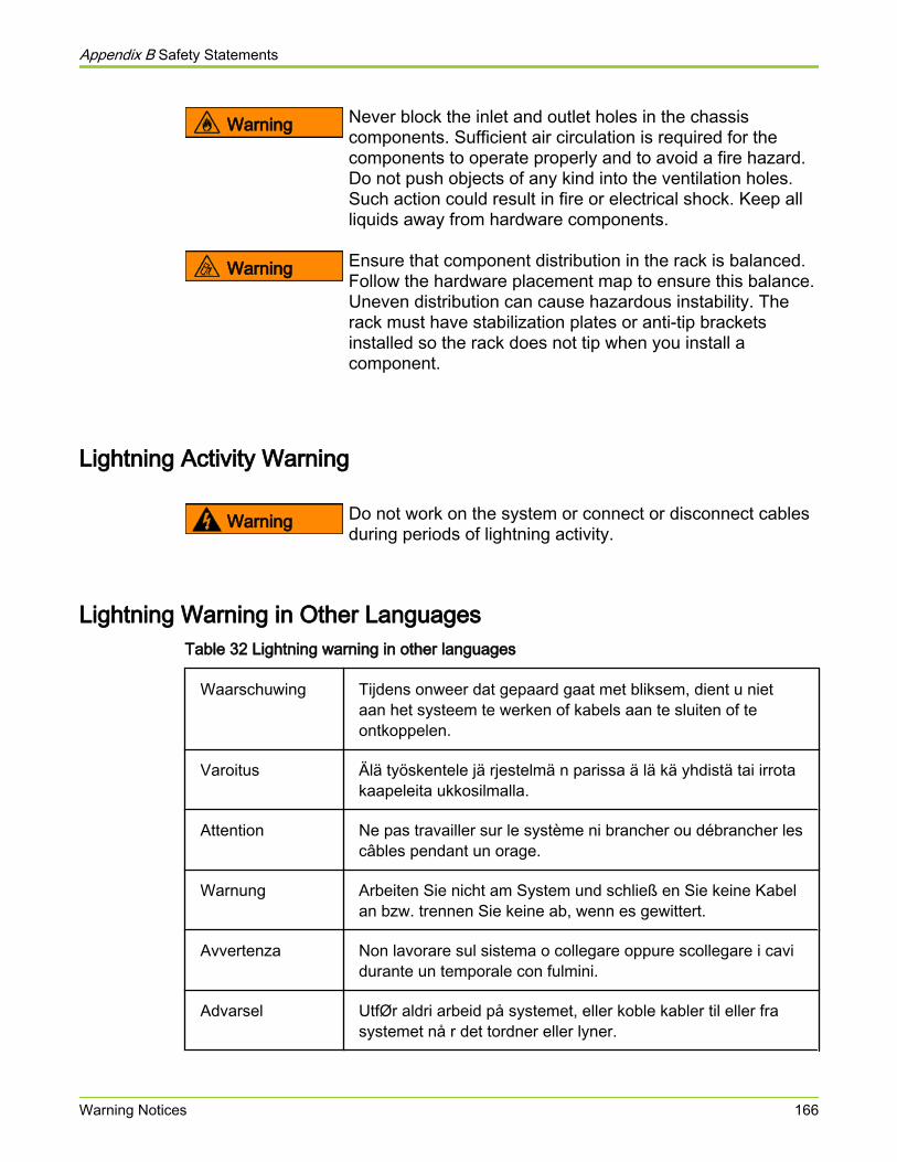
Warning Never block the inlet and outlet holes in the chassiscomponents. Sufficient air circulation is required for thecomponents to operate properly and to avoid a fire hazard.Do not push objects of any kind into the ventilation holes.Such action could result in fire or electrical shock. Keep allliquids away from hardware components.
Warning Ensure that component distribution in the rack is balanced.Follow the hardware placement map to ensure this balance.Uneven distribution can cause hazardous instability. Therack must have stabilization plates or anti-tip bracketsinstalled so the rack does not tip when you install acomponent.
Lightning Activity Warning
Warning Do not work on the system or connect or disconnect cablesduring periods of lightning activity.
Lightning Warning in Other LanguagesTable 32 Lightning warning in other languages
Waarschuwing Tijdens onweer dat gepaard gaat met bliksem, dient u nietaan het systeem te werken of kabels aan te sluiten of teontkoppelen.
Varoitus Älä työskentele jä rjestelmä n parissa ä lä kä yhdistä tai irrotakaapeleita ukkosilmalla.
Attention Ne pas travailler sur le système ni brancher ou débrancher lescâbles pendant un orage.
Warnung Arbeiten Sie nicht am System und schließ en Sie keine Kabelan bzw. trennen Sie keine ab, wenn es gewittert.
Avvertenza Non lavorare sul sistema o collegare oppure scollegare i cavidurante un temporale con fulmini.
Advarsel UtfØr aldri arbeid på systemet, eller koble kabler til eller frasystemet nå r det tordner eller lyner.
Appendix B Safety Statements
Warning Notices 166
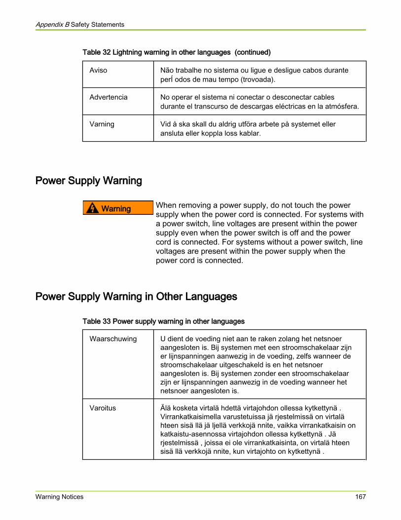
Table 32 Lightning warning in other languages (continued)
Aviso Não trabalhe no sistema ou ligue e desligue cabos duranteperÍ odos de mau tempo (trovoada).
Advertencia No operar el sistema ni conectar o desconectar cablesdurante el transcurso de descargas eléctricas en la atmósfera.
Varning Vid å ska skall du aldrig utföra arbete på systemet elleransluta eller koppla loss kablar.
Power Supply Warning
Warning When removing a power supply, do not touch the powersupply when the power cord is connected. For systems witha power switch, line voltages are present within the powersupply even when the power switch is off and the powercord is connected. For systems without a power switch, linevoltages are present within the power supply when thepower cord is connected.
Power Supply Warning in Other Languages
Table 33 Power supply warning in other languages
Waarschuwing U dient de voeding niet aan te raken zolang het netsnoeraangesloten is. Bij systemen met een stroomschakelaar zijner lijnspanningen aanwezig in de voeding, zelfs wanneer destroomschakelaar uitgeschakeld is en het netsnoeraangesloten is. Bij systemen zonder een stroomschakelaarzijn er lijnspanningen aanwezig in de voeding wanneer hetnetsnoer aangesloten is.
Varoitus Älä kosketa virtalä hdettä virtajohdon ollessa kytkettynä .Virrankatkaisimella varustetuissa jä rjestelmissä on virtalähteen sisä llä jä ljellä verkkojä nnite, vaikka virrankatkaisin onkatkaistu-asennossa virtajohdon ollessa kytkettynä . Järjestelmissä , joissa ei ole virrankatkaisinta, on virtalä hteensisä llä verkkojä nnite, kun virtajohto on kytkettynä .
Appendix B Safety Statements
Warning Notices 167
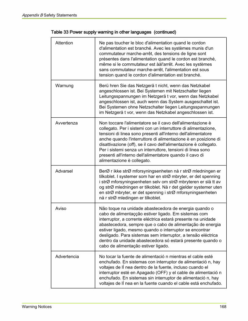
Table 33 Power supply warning in other languages (continued)
Attention Ne pas toucher le bloc d'alimentation quand le cordond'alimentation est branché. Avec les systèmes munis d'uncommutateur marche-arrêt, des tensions de ligne sontprésentes dans l'alimentation quand le cordon est branché,même si le commutateur est ààl'arrêt. Avec les systèmessans commutateur marche-arrêt, l'alimentation est soustension quand le cordon d'alimentation est branché.
Warnung Berü hren Sie das Netzgerä t nicht, wenn das Netzkabelangeschlossen ist. Bei Systemen mit Netzschalter liegenLeitungsspannungen im Netzgerä t vor, wenn das Netzkabelangeschlossen ist, auch wenn das System ausgeschaltet ist.Bei Systemen ohne Netzschalter liegen Leitungsspannungenim Netzgerä t vor, wenn das Netzkabel angeschlossen ist.
Avvertenza Non toccare l'alimentatore se il cavo dell'alimentazione ècollegato. Per i sistemi con un interruttore di alimentazione,tensioni di linea sono presenti all'interno dell'alimentatoreanche quando l'interruttore di alimentazione è en posizione didisattivazione (off), se il cavo dell'alimentazione è collegato.Per i sistemi senza un interruttore, tensioni di linea sonopresenti all'interno dell'alimentatore quando il cavo dialimentazione è collegato.
Advarsel BerØ r ikke strØ mforsyningsenheten nå r strØ mledningen ertilkoblet. I systemer som har en strØ mbryter, er det spenningi strØ mforsyningsenheten selv om strØ mbryteren er slå tt avog strØ mledningen er tilkoblet. Nå r det gjelder systemer utenen strØ mbryter, er det spenning i strØ mforsyningsenhetennå r strØ mledingen er tilkoblet.
Aviso Não toque na unidade abastecedora de energia quando ocabo de alimentaçção estiver ligado. Em sistemas cominterruptor, a corrente eléctrica estará presente na unidadeabastecedora, sempre que o cabo de alimentação de energiaestiver ligado, mesmo quando o interruptor se encontrardesligado. Para sistemas sem interruptor, a tensão eléctricadentro da unidade abastecedora só estará presente quando ocabo de alimentação estiver ligado.
Advertencia No tocar la fuente de alimentació n mientras el cable estéenchufado. En sistemas con interruptor de alimentació n, hayvoltajes de lÍ nea dentro de la fuente, incluso cuando elinterruptor esté en Apagado (OFF) y el cable de alimentació nenchufado. En sistemas sin interruptor de alimentació n, hayvoltajes de lÍ nea en la fuente cuando el cable está enchufado.
Appendix B Safety Statements
Warning Notices 168
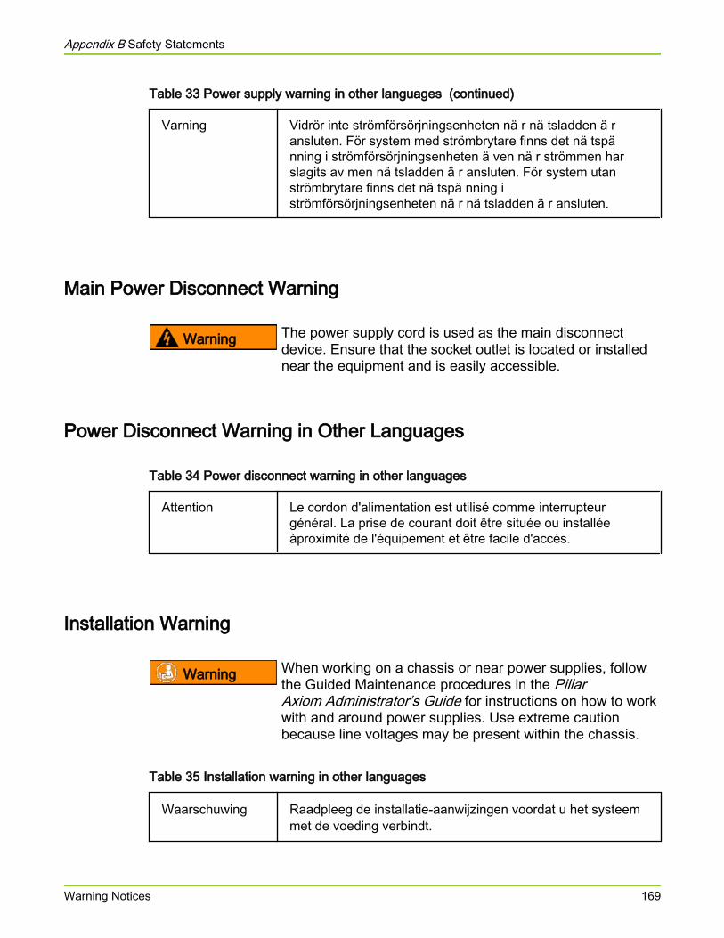
Table 33 Power supply warning in other languages (continued)
Varning Vidrör inte strömförsörjningsenheten nä r nä tsladden ä ransluten. För system med strömbrytare finns det nä tspänning i strömförsörjningsenheten ä ven nä r strömmen harslagits av men nä tsladden ä r ansluten. För system utanströmbrytare finns det nä tspä nning iströmförsörjningsenheten nä r nä tsladden ä r ansluten.
Main Power Disconnect Warning
Warning The power supply cord is used as the main disconnectdevice. Ensure that the socket outlet is located or installednear the equipment and is easily accessible.
Power Disconnect Warning in Other Languages
Table 34 Power disconnect warning in other languages
Attention Le cordon d'alimentation est utilisé comme interrupteurgénéral. La prise de courant doit être située ou installéeàproximité de l'équipement et être facile d'accés.
Installation Warning
Warning When working on a chassis or near power supplies, followthe Guided Maintenance procedures in the PillarAxiom Administrator’s Guide for instructions on how to workwith and around power supplies. Use extreme cautionbecause line voltages may be present within the chassis.
Table 35 Installation warning in other languages
Waarschuwing Raadpleeg de installatie-aanwijzingen voordat u het systeemmet de voeding verbindt.
Appendix B Safety Statements
Warning Notices 169
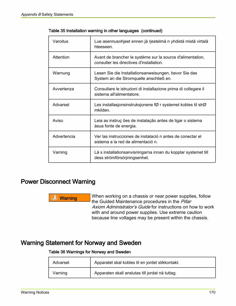
Table 35 Installation warning in other languages (continued)
Varoitus Lue asennusohjeet ennen jä rjestelmä n yhdistä mistä virtalähteeseen.
Attention Avant de brancher le système sur la source d'alimentation,consulter les directives d'installation.
Warnung Lesen Sie die Installationsanweisungen, bevor Sie dasSystem an die Stromquelle anschließ en.
Avvertenza Consultare le istruzioni di installazione prima di collegare ilsistema all'alimentatore.
Advarsel Les installasjonsinstruksjonene fØ r systemet kobles til strØmkilden.
Aviso Leia as instruç ões de instalação antes de ligar o sistemaàsua fonte de energia.
Advertencia Ver las instrucciones de instalació n antes de conectar elsistema a la red de alimentació n.
Varning Lä s installationsanvisningarna innan du kopplar systemet tilldess strömförsörjningsenhet.
Power Disconnect Warning
Warning When working on a chassis or near power supplies, followthe Guided Maintenance procedures in the PillarAxiom Administrator’s Guide for instructions on how to workwith and around power supplies. Use extreme cautionbecause line voltages may be present within the chassis.
Warning Statement for Norway and SwedenTable 36 Warnings for Norway and Sweden
Advarsel Apparatet skal kobles til en jordet stikkontakt.
Varning Apparaten skall anslutas till jordat nä tuttag.
Appendix B Safety Statements
Warning Notices 170
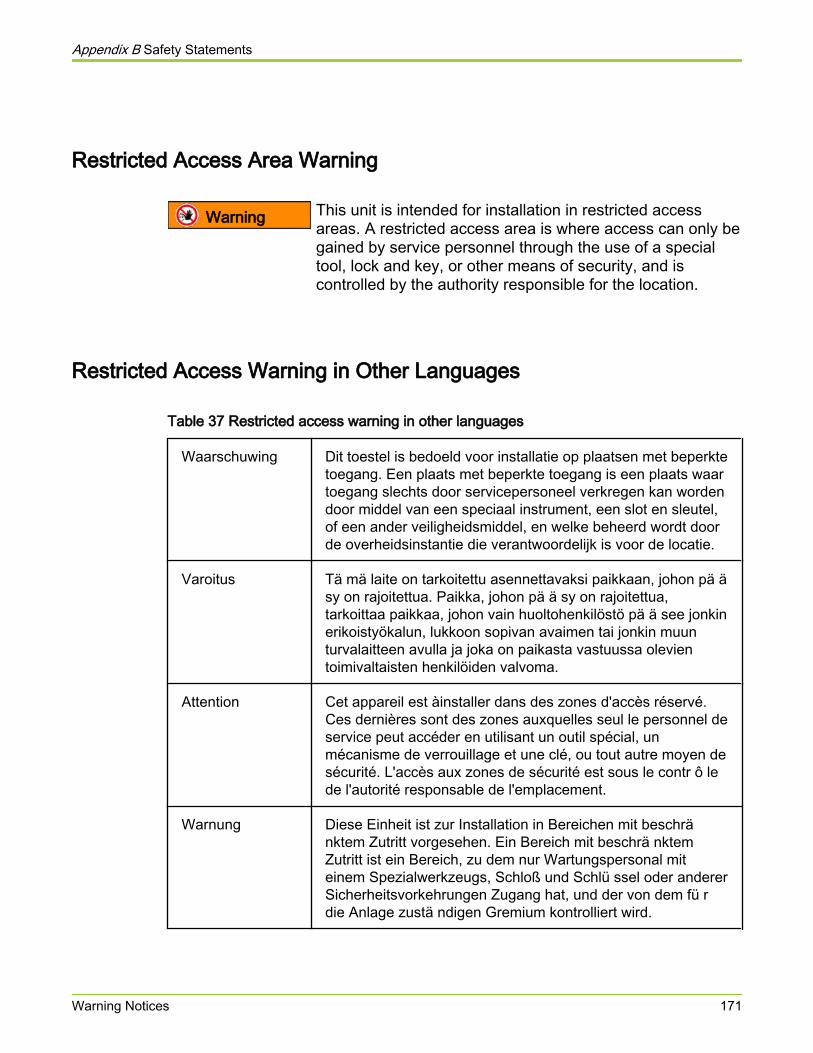
Restricted Access Area Warning
Warning This unit is intended for installation in restricted accessareas. A restricted access area is where access can only begained by service personnel through the use of a specialtool, lock and key, or other means of security, and iscontrolled by the authority responsible for the location.
Restricted Access Warning in Other Languages
Table 37 Restricted access warning in other languages
Waarschuwing Dit toestel is bedoeld voor installatie op plaatsen met beperktetoegang. Een plaats met beperkte toegang is een plaats waartoegang slechts door servicepersoneel verkregen kan wordendoor middel van een speciaal instrument, een slot en sleutel,of een ander veiligheidsmiddel, en welke beheerd wordt doorde overheidsinstantie die verantwoordelijk is voor de locatie.
Varoitus Tä mä laite on tarkoitettu asennettavaksi paikkaan, johon pä äsy on rajoitettua. Paikka, johon pä ä sy on rajoitettua,tarkoittaa paikkaa, johon vain huoltohenkilöstö pä ä see jonkinerikoistyökalun, lukkoon sopivan avaimen tai jonkin muunturvalaitteen avulla ja joka on paikasta vastuussa olevientoimivaltaisten henkilöiden valvoma.
Attention Cet appareil est àinstaller dans des zones d'accès réservé.Ces dernières sont des zones auxquelles seul le personnel deservice peut accéder en utilisant un outil spécial, unmécanisme de verrouillage et une clé, ou tout autre moyen desécurité. L'accès aux zones de sécurité est sous le contr ô lede l'autorité responsable de l'emplacement.
Warnung Diese Einheit ist zur Installation in Bereichen mit beschränktem Zutritt vorgesehen. Ein Bereich mit beschrä nktemZutritt ist ein Bereich, zu dem nur Wartungspersonal miteinem Spezialwerkzeugs, Schloß und Schlü ssel oder andererSicherheitsvorkehrungen Zugang hat, und der von dem fü rdie Anlage zustä ndigen Gremium kontrolliert wird.
Appendix B Safety Statements
Warning Notices 171
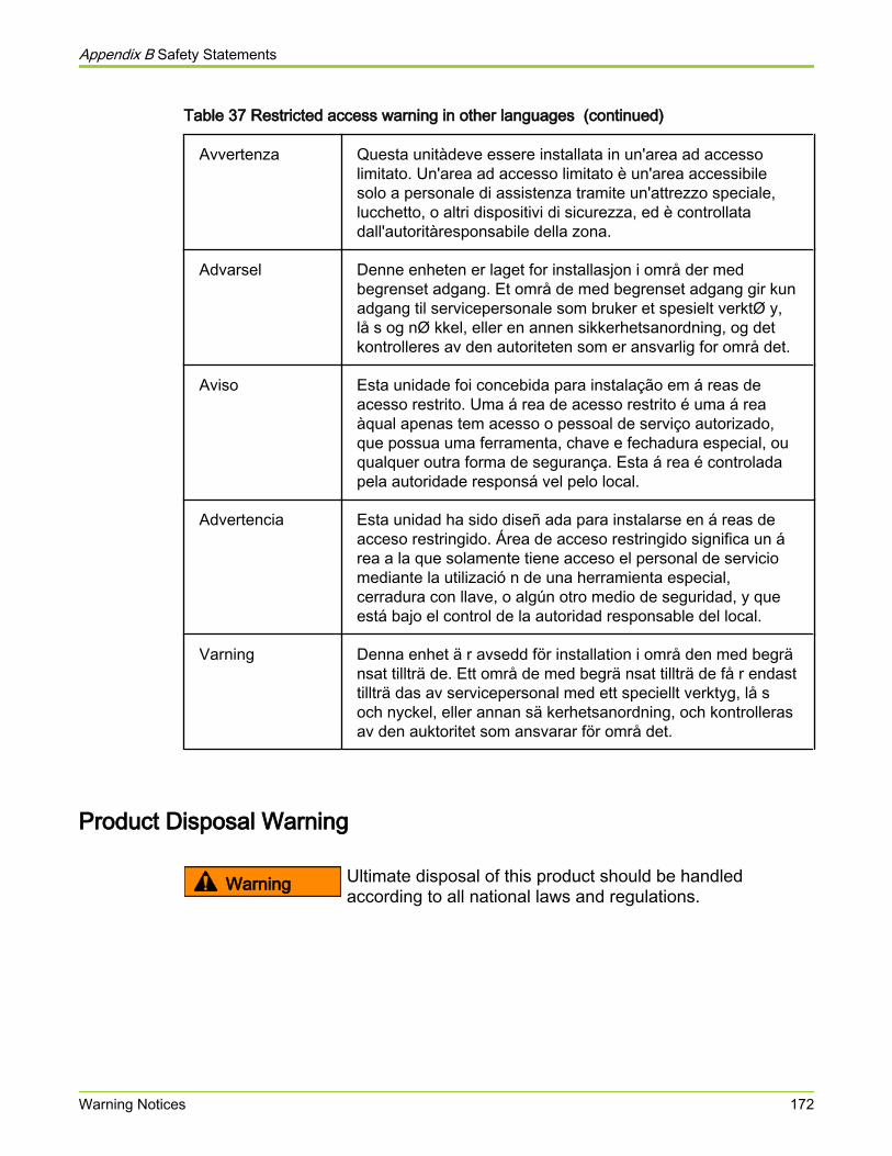
Table 37 Restricted access warning in other languages (continued)
Avvertenza Questa unitàdeve essere installata in un'area ad accessolimitato. Un'area ad accesso limitato è un'area accessibilesolo a personale di assistenza tramite un'attrezzo speciale,lucchetto, o altri dispositivi di sicurezza, ed è controllatadall'autoritàresponsabile della zona.
Advarsel Denne enheten er laget for installasjon i områ der medbegrenset adgang. Et områ de med begrenset adgang gir kunadgang til servicepersonale som bruker et spesielt verktØ y,lå s og nØ kkel, eller en annen sikkerhetsanordning, og detkontrolleres av den autoriteten som er ansvarlig for områ det.
Aviso Esta unidade foi concebida para instalação em á reas deacesso restrito. Uma á rea de acesso restrito é uma á reaàqual apenas tem acesso o pessoal de serviço autorizado,que possua uma ferramenta, chave e fechadura especial, ouqualquer outra forma de segurança. Esta á rea é controladapela autoridade responsá vel pelo local.
Advertencia Esta unidad ha sido diseñ ada para instalarse en á reas deacceso restringido. Área de acceso restringido significa un área a la que solamente tiene acceso el personal de serviciomediante la utilizació n de una herramienta especial,cerradura con llave, o algún otro medio de seguridad, y queestá bajo el control de la autoridad responsable del local.
Varning Denna enhet ä r avsedd för installation i områ den med begränsat tillträ de. Ett områ de med begrä nsat tillträ de få r endasttillträ das av servicepersonal med ett speciellt verktyg, lå soch nyckel, eller annan sä kerhetsanordning, och kontrollerasav den auktoritet som ansvarar för områ det.
Product Disposal Warning
Warning Ultimate disposal of this product should be handledaccording to all national laws and regulations.
Appendix B Safety Statements
Warning Notices 172

Product Disposal Warning in Other Languages
Table 38 Product disposal warning in other languages
Waarschuwing Dit produkt dient volgens alle landelijke wetten envoorschriften te worden afgedankt.
Varoitus Tä mä n tuotteen lopullisesta hä vittä misestä tulee huolehtiakaikkia valtakunnallisia lakeja ja sä ä nnöksiä noudattaen.
Attention La mise au rebut définitive de ce produit doit être effectuéeconformément àtoutes les lois et réglementations en vigueur.
Warnung Dieses Produkt muß den geltenden Gesetzen undVorschriften entsprechend entsorgt werden.
Avvertenza L'eliminazione finale di questo prodotto deve essere eseguitaosservando le normative italiane vigenti in materia.
Advarsel Endelig disponering av dette produktet må skje i henhold tilnasjonale lover og forskrifter.
Aviso A descartagem final deste produto deverá ser efectuada deacordo com os regulamentos e a legislação nacional.
Advertencia El desecho final de este producto debe realizarse seg\x9c ntodas las leyes y regulaciones nacionales.
Varning Slutlig kassering av denna produkt bör skötas i enlighet medlandets alla lagar och föreskrifter.
Jewelry Removal Warning
Warning Some equipment is connected to power lines. Before youwork on this equipment, remove all jewelry that containsmetal. Such jewelry includes rings, necklaces, and watches.Metal objects heat up when connected to power andground. Hot metal objects can cause serious burns or weldthe metal object to the terminals.
Appendix B Safety Statements
Warning Notices 173
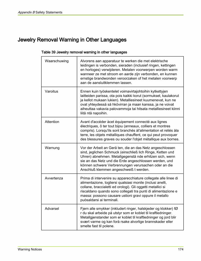
Jewelry Removal Warning in Other Languages
Table 39 Jewelry removal warning in other languages
Waarschuwing Alvorens aan apparatuur te werken die met elektrischeleidingen is verbonden, sieraden (inclusief ringen, kettingenen horloges) verwijderen. Metalen voorwerpen worden warmwanneer ze met stroom en aarde zijn verbonden, en kunnenernstige brandwonden veroorzaken of het metalen voorwerpaan de aansluitklemmen lassen.
Varoitus Ennen kuin työskentelet voimavirtajohtoihin kytkettyjenlaitteiden parissa, ota pois kaikki korut (sormukset, kaulakorutja kellot mukaan lukien). Metalliesineet kuumenevat, kun neovat yhteydessä sä hkövirran ja maan kanssa, ja ne voivataiheuttaa vakavia palovammoja tai hitsata metalliesineet kiinniliitä ntä napoihin.
Attention Avant d'accéder àcet équipement connecté aux lignesélectriques, ô ter tout bijou (anneaux, colliers et montrescompris). Lorsqu'ils sont branchés àl'alimentation et reliés àlaterre, les objets métalliques chauffent, ce qui peut provoquerdes blessures graves ou souder l'objet métallique aux bornes.
Warnung Vor der Arbeit an Gerä ten, die an das Netz angeschlossensind, jeglichen Schmuck (einschließ lich Ringe, Ketten undUhren) abnehmen. Metallgegenstä nde erhitzen sich, wennsie an das Netz und die Erde angeschlossen werden, undkönnen schwere Verbrennungen verursachen oder an dieAnschluß klemmen angeschweiß t werden.
Avvertenza Prima di intervenire su apparecchiature collegate alle linee dialimentazione, togliersi qualsiasi monile (inclusi anelli,collane, braccialetti ed orologi). Gli oggetti metallici siriscaldano quando sono collegati tra punti di alimentazione emassa: possono causare ustioni gravi oppure il metallopuòsaldarsi ai terminali.
Advarsel Fjern alle smykker (inkludert ringer, halskjeder og klokker) fØr du skal arbeide på utstyr som er koblet til kraftledninger.Metallgjenstander som er koblet til kraftledninger og jord blirsvært varme og kan forå rsake alvorlige brannskader ellersmelte fast til polene.
Appendix B Safety Statements
Warning Notices 174

Table 39 Jewelry removal warning in other languages (continued)
Aviso Antes de trabalhar em equipamento que esteja ligado a linhasde corrente, retire todas as jó ias que estiver a usar (incluindoanéis, fios e reló gios). Os objectos metá licos aquecerão emcontacto com a corrente e em contacto com a ligação àterra,podendo causar queimaduras graves ou ficarem soldadosaos terminais.
Advertencia Antes de operar sobre equipos conectados a lÍ neas dealimentació n, quitarse las joyas (incluidos anillos, collares yrelojes). Los objetos de metal se calientan cuando seconectan a la alimentació n y a tierra, lo que puede ocasionarquemaduras graves o que los objetos metá licos quedensoldados a los bornes.
Varning Tag av alla smycken (inklusive ringar, halsband ocharmbandsur) innan du arbetar på utrustning som ä r koppladtill kraftledningar. Metallobjekt hettas upp nä r de kopplas ihopmed ström och jord och kan förorsaka allvarliga brä nnskador;metallobjekt kan också sammansvetsas med kontakterna.
Qualified Personnel Warning
Warning Only qualified personnel should install or replace thisequipment.
Table 40 Qualified personnel warning in other languages
Waarschuwing Installatie en reparaties mogen uitsluitend door getraind enbevoegd personeel uitgevoerd worden.
Varoitus Ainoastaan koulutettu ja pä tevä henkilökunta saa asentaa taivaihtaa tä mä n laitteen.
Avertissement Tout installation ou remplacement de l'appareil doit êtreréalisé par du personnel qualifié et compétent.
Achtung Gerä t nur von geschultem, qualifiziertem Personal installierenoder auswechseln lassen.
Avvertenza Solo personale addestrato e qualificato deve essereautorizzato ad installare o sostituire questo apparecchio.
Appendix B Safety Statements
Warning Notices 175
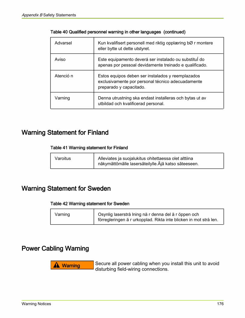
Table 40 Qualified personnel warning in other languages (continued)
Advarsel Kun kvalifisert personell med riktig opplæring bØ r montereeller bytte ut dette utstyret.
Aviso Este equipamento deverá ser instalado ou substituÍ doapenas por pessoal devidamente treinado e qualificado.
Atenció n Estos equipos deben ser instalados y reemplazadosexclusivamente por personal técnico adecuadamentepreparado y capacitado.
Varning Denna utrustning ska endast installeras och bytas ut avutbildad och kvalificerad personal.
Warning Statement for Finland
Table 41 Warning statement for Finland
Varoitus Alleviates ja suojalukitus ohitettaessa olet alttiinanãkymãttõmãlle lasersãteilylle.Ãjã katso sãteeseen.
Warning Statement for Sweden
Table 42 Warning statement for Sweden
Varning Osynlig laserstrå lning nä r denna del ä r öppen ochförregleringen ä r urkopplad. Rikta inte blicken in mot strå len.
Power Cabling Warning
Warning Secure all power cabling when you install this unit to avoiddisturbing field-wiring connections.
Appendix B Safety Statements
Warning Notices 176

Power Cabling Warning in Other Languages
Table 43 Power cabling warning in other languages
Waarschuwing Zet alle stroomkabels vast wanneer dit toestel wordtgeÏnstalleerd om te voorkomen dat de verbindingen van develdbedrading worden verstoord.
Varoitus Kiinnitä kaikki voimakaapelit tiukkaan tä tä laitettaasentaessasi, jotta vä ltä t kentä n johdinkytkentöjenvioittumista.
Attention Lors de l'installation de cet appareil, fixer tous les câ blesd'alimentation pour éviter de provoquer des perturbations auxraccordements des câ blages propres au site.
Warnung Bei der Installation dieser Einheit die Netzverkabelungbefestigen, um die Störung von Feldkabelanschlü ssen zuvermeiden.
Avvertenza In fase di installazione dell'unità, assicurare tutti i cablaggi dialimentazione per evitare di alterare i collegamenti degliavvolgimenti di campo.
Advarsel Nå r denne enheten installeres, må alle kraftledninger sikresfor å unngå at feltkabelkoblingene forstyrres.
Aviso Para evitar problemas com as ligaç ões de rede decampanha, prenda todos os cabos de corrente quandoinstalar esta unidade.
Advertencia Sujetar todo el cableado de alimentació n cuando se instaleeste equipo para evitar que se mezcle con las conexiones delcableado "in situ".
Varning Fä st allt starkströmskablage vid installation av denna enhetså att fä ltkopplingen inte rubbas.
Appendix B Safety Statements
Warning Notices 177
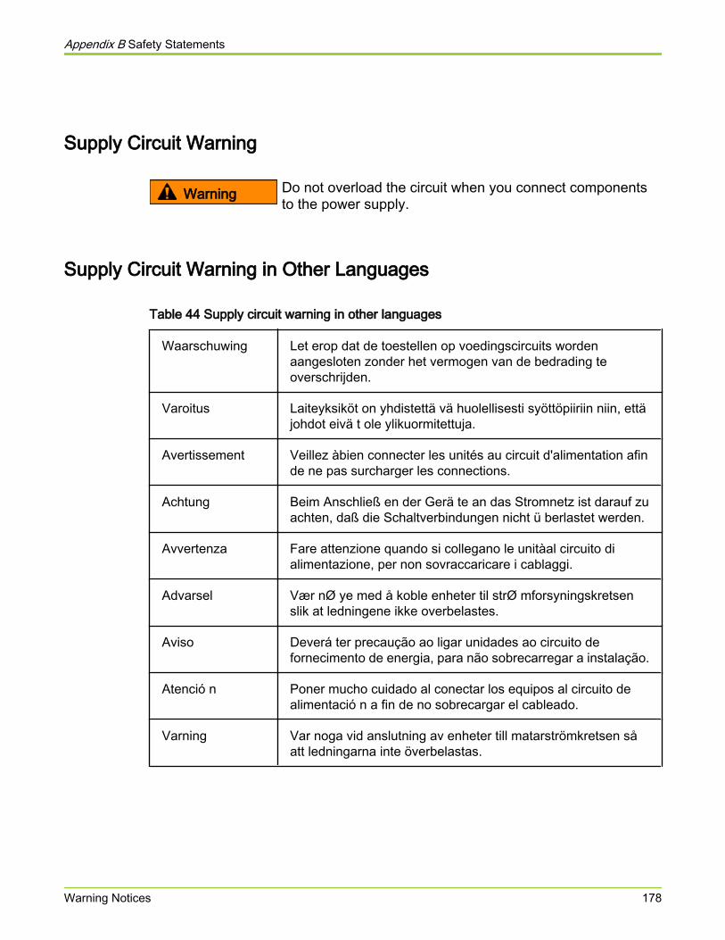
Supply Circuit Warning
Warning Do not overload the circuit when you connect componentsto the power supply.
Supply Circuit Warning in Other Languages
Table 44 Supply circuit warning in other languages
Waarschuwing Let erop dat de toestellen op voedingscircuits wordenaangesloten zonder het vermogen van de bedrading teoverschrijden.
Varoitus Laiteyksiköt on yhdistettä vä huolellisesti syöttöpiiriin niin, ettäjohdot eivä t ole ylikuormitettuja.
Avertissement Veillez àbien connecter les unités au circuit d'alimentation afinde ne pas surcharger les connections.
Achtung Beim Anschließ en der Gerä te an das Stromnetz ist darauf zuachten, daß die Schaltverbindungen nicht ü berlastet werden.
Avvertenza Fare attenzione quando si collegano le unitàal circuito dialimentazione, per non sovraccaricare i cablaggi.
Advarsel Vær nØ ye med å koble enheter til strØ mforsyningskretsenslik at ledningene ikke overbelastes.
Aviso Deverá ter precaução ao ligar unidades ao circuito defornecimento de energia, para não sobrecarregar a instalação.
Atenció n Poner mucho cuidado al conectar los equipos al circuito dealimentació n a fin de no sobrecargar el cableado.
Varning Var noga vid anslutning av enheter till matarströmkretsen såatt ledningarna inte överbelastas.
Appendix B Safety Statements
Warning Notices 178

Voltage Mismatch Warning
Warning A voltage mismatch can cause equipment damage and maypose a fire hazard. If the voltage indicated on the labeldiffers from the power outlet voltage, do not connect thechassis to that receptacle.
Voltage Mismatch Warning in Other Languages
Table 45 Voltage mismatch warning in other languages
Waarschuwing Aansluiting op een verkeerd voedingsvoltage kanbeschadiging van de apparatuur veroorzaken en totbrandgevaar leiden. Het chassis mag niet aangeslotenworden als de spanning die op het label staat aangegeven,anders is dan de spanning van het stopcontact.
Varoitus Erisuuruisten jä nnitteiden yhdistä minen voi aiheuttaalaitevaurion ja tulipalon vaaran. Jos tarraan merkitty jä nniteeroaa pistorasian jä nnitteestä , ä lä yhdistä asennuspohjaapistorasiaan.
Avertissement Une erreur de voltage risque d'endommager l'appareil etconstitue un risque d'incendie. Si la tension indiquée surl'étiquette est différente de la tension de l'alimentation, neconnectez en aucun cas le châ ssis àla prise.
Achtung Bei nicht ü bereinstimmender Spannung kann es zu Geräteschä den und Feuergefahr kommen. Wenn die auf demEtikett angegebene Spannung nicht mit derSteckdosenspannung ü bereinstimmt, schließ en Sie dasGerä t nicht an diese Steckdose an.
Avvertenza Una tensione inadeguata puõcausare danni all'apparecchio erischio di incendio. Se la tensione riportata sulla targhetta èdiversa da quella della presa di alimentazione, non collegarelo chassis a tale presa.
Advarsel Ulik spenning kan forå rsake skade på utstyret og inneb\xbere brannfare. Dersom spenningen på merkelappen er
Appendix B Safety Statements
Warning Notices 179
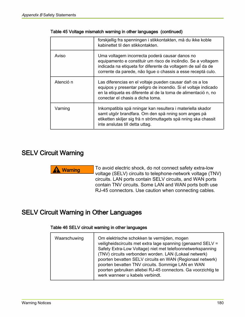
Table 45 Voltage mismatch warning in other languages (continued)
forskjellig fra spenningen i stikkontakten, må du ikke koblekabinettet til den stikkontakten.
Aviso Uma voltagem incorrecta poderá causar danos noequipamento e constituir um risco de incêndio. Se a voltagemindicada na etiqueta for diferente da voltagem de saÍ da decorrente da parede, não ligue o chassis a esse receptá culo.
Atenció n Las diferencias en el voltaje pueden causar dañ os a losequipos y presentar peligro de incendio. Si el voltaje indicadoen la etiqueta es diferente al de la toma de alimentació n, noconectar el chasis a dicha toma.
Varning Inkompatibla spä nningar kan resultera i materiella skadorsamt utgör brandfara. Om den spä nning som anges påetiketten skiljer sig frå n strömuttagets spä nning ska chassitinte anslutas till detta uttag.
SELV Circuit Warning
Warning To avoid electric shock, do not connect safety extra-lowvoltage (SELV) circuits to telephone-network voltage (TNV)circuits. LAN ports contain SELV circuits, and WAN portscontain TNV circuits. Some LAN and WAN ports both useRJ-45 connectors. Use caution when connecting cables.
SELV Circuit Warning in Other Languages
Table 46 SELV circuit warning in other languages
Waarschuwing Om elektrische schokken te vermijden, mogenveiligheidscircuits met extra lage spanning (genaamd SELV =Safety Extra-Low Voltage) niet met telefoonnetwerkspanning(TNV) circuits verbonden worden. LAN (Lokaal netwerk)poorten bevatten SELV circuits en WAN (Regionaal netwerk)poorten bevatten TNV circuits. Sommige LAN en WANpoorten gebruiken allebei RJ-45 connectors. Ga voorzichtig tewerk wanneer u kabels verbindt.
Appendix B Safety Statements
Warning Notices 180
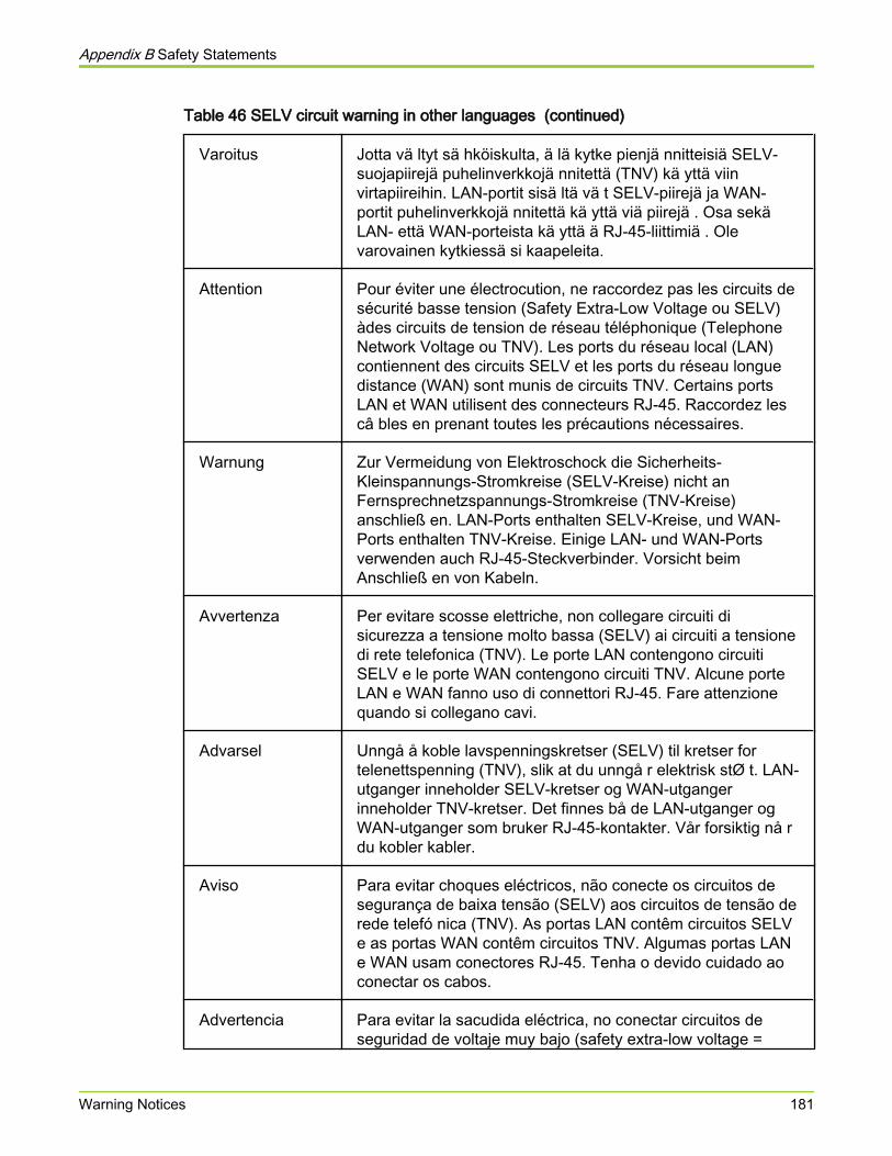
Table 46 SELV circuit warning in other languages (continued)
Varoitus Jotta vä ltyt sä hköiskulta, ä lä kytke pienjä nnitteisiä SELV-suojapiirejä puhelinverkkojä nnitettä (TNV) kä yttä viinvirtapiireihin. LAN-portit sisä ltä vä t SELV-piirejä ja WAN-portit puhelinverkkojä nnitettä kä yttä viä piirejä . Osa sekäLAN- että WAN-porteista kä yttä ä RJ-45-liittimiä . Olevarovainen kytkiessä si kaapeleita.
Attention Pour éviter une électrocution, ne raccordez pas les circuits desécurité basse tension (Safety Extra-Low Voltage ou SELV)àdes circuits de tension de réseau téléphonique (TelephoneNetwork Voltage ou TNV). Les ports du réseau local (LAN)contiennent des circuits SELV et les ports du réseau longuedistance (WAN) sont munis de circuits TNV. Certains portsLAN et WAN utilisent des connecteurs RJ-45. Raccordez lescâ bles en prenant toutes les précautions nécessaires.
Warnung Zur Vermeidung von Elektroschock die Sicherheits-Kleinspannungs-Stromkreise (SELV-Kreise) nicht anFernsprechnetzspannungs-Stromkreise (TNV-Kreise)anschließ en. LAN-Ports enthalten SELV-Kreise, und WAN-Ports enthalten TNV-Kreise. Einige LAN- und WAN-Portsverwenden auch RJ-45-Steckverbinder. Vorsicht beimAnschließ en von Kabeln.
Avvertenza Per evitare scosse elettriche, non collegare circuiti disicurezza a tensione molto bassa (SELV) ai circuiti a tensionedi rete telefonica (TNV). Le porte LAN contengono circuitiSELV e le porte WAN contengono circuiti TNV. Alcune porteLAN e WAN fanno uso di connettori RJ-45. Fare attenzionequando si collegano cavi.
Advarsel Unngå å koble lavspenningskretser (SELV) til kretser fortelenettspenning (TNV), slik at du unngå r elektrisk stØ t. LAN-utganger inneholder SELV-kretser og WAN-utgangerinneholder TNV-kretser. Det finnes bå de LAN-utganger ogWAN-utganger som bruker RJ-45-kontakter. Vår forsiktig nå rdu kobler kabler.
Aviso Para evitar choques eléctricos, não conecte os circuitos desegurança de baixa tensão (SELV) aos circuitos de tensão derede telefó nica (TNV). As portas LAN contêm circuitos SELVe as portas WAN contêm circuitos TNV. Algumas portas LANe WAN usam conectores RJ-45. Tenha o devido cuidado aoconectar os cabos.
Advertencia Para evitar la sacudida eléctrica, no conectar circuitos deseguridad de voltaje muy bajo (safety extra-low voltage =
Appendix B Safety Statements
Warning Notices 181
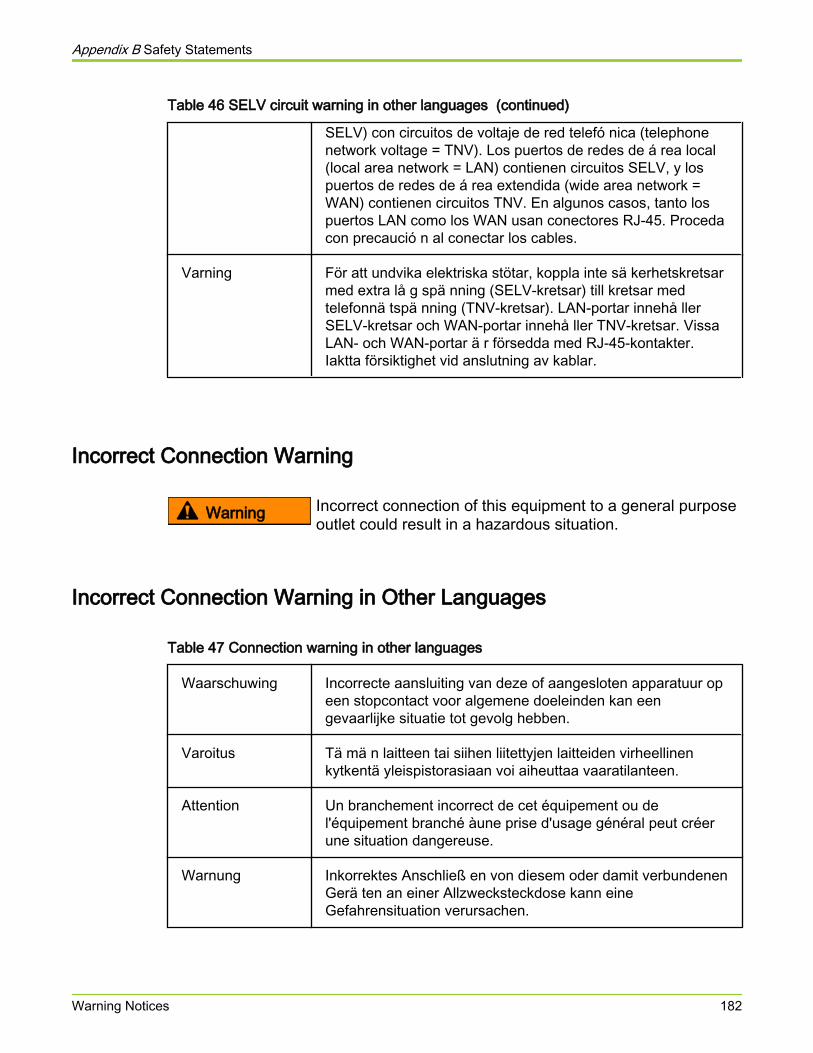
Table 46 SELV circuit warning in other languages (continued)
SELV) con circuitos de voltaje de red telefó nica (telephonenetwork voltage = TNV). Los puertos de redes de á rea local(local area network = LAN) contienen circuitos SELV, y lospuertos de redes de á rea extendida (wide area network =WAN) contienen circuitos TNV. En algunos casos, tanto lospuertos LAN como los WAN usan conectores RJ-45. Procedacon precaució n al conectar los cables.
Varning För att undvika elektriska stötar, koppla inte sä kerhetskretsarmed extra lå g spä nning (SELV-kretsar) till kretsar medtelefonnä tspä nning (TNV-kretsar). LAN-portar innehå llerSELV-kretsar och WAN-portar innehå ller TNV-kretsar. VissaLAN- och WAN-portar ä r försedda med RJ-45-kontakter.Iaktta försiktighet vid anslutning av kablar.
Incorrect Connection Warning
Warning Incorrect connection of this equipment to a general purposeoutlet could result in a hazardous situation.
Incorrect Connection Warning in Other Languages
Table 47 Connection warning in other languages
Waarschuwing Incorrecte aansluiting van deze of aangesloten apparatuur opeen stopcontact voor algemene doeleinden kan eengevaarlijke situatie tot gevolg hebben.
Varoitus Tä mä n laitteen tai siihen liitettyjen laitteiden virheellinenkytkentä yleispistorasiaan voi aiheuttaa vaaratilanteen.
Attention Un branchement incorrect de cet équipement ou del'équipement branché àune prise d'usage général peut créerune situation dangereuse.
Warnung Inkorrektes Anschließ en von diesem oder damit verbundenenGerä ten an einer Allzwecksteckdose kann eineGefahrensituation verursachen.
Appendix B Safety Statements
Warning Notices 182
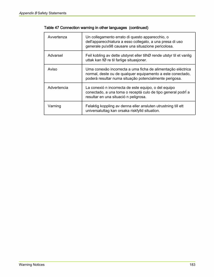
Table 47 Connection warning in other languages (continued)
Avvertenza Un collegamento errato di questo apparecchio, odell'apparecchiatura a esso collegato, a una presa di usogenerale pu\x98 causare una situazione pericolosa.
Advarsel Feil kobling av dette utstyret eller tilhØ rende utstyr til et vanliguttak kan fØ re til farlige situasjoner.
Aviso Uma conexão incorrecta a uma ficha de alimentação eléctricanormal, deste ou de qualquer equipamento a este conectado,poderá resultar numa situação potencialmente perigosa.
Advertencia La conexió n incorrecta de este equipo, o del equipoconectado, a una toma o receptá culo de tipo general podrÍ aresultar en una situació n peligrosa.
Varning Felaktig koppling av denna eller ansluten utrustning till ettuniversaluttag kan orsaka riskfylld situation.
Appendix B Safety Statements
Warning Notices 183
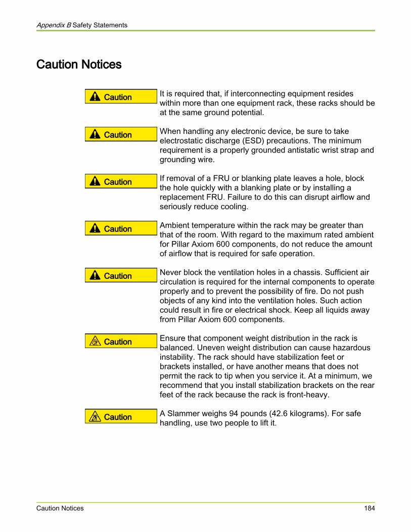
Caution Notices
Caution It is required that, if interconnecting equipment resideswithin more than one equipment rack, these racks should beat the same ground potential.
Caution When handling any electronic device, be sure to takeelectrostatic discharge (ESD) precautions. The minimumrequirement is a properly grounded antistatic wrist strap andgrounding wire.
Caution If removal of a FRU or blanking plate leaves a hole, blockthe hole quickly with a blanking plate or by installing areplacement FRU. Failure to do this can disrupt airflow andseriously reduce cooling.
Caution Ambient temperature within the rack may be greater thanthat of the room. With regard to the maximum rated ambientfor Pillar Axiom 600 components, do not reduce the amountof airflow that is required for safe operation.
Caution Never block the ventilation holes in a chassis. Sufficient aircirculation is required for the internal components to operateproperly and to prevent the possibility of fire. Do not pushobjects of any kind into the ventilation holes. Such actioncould result in fire or electrical shock. Keep all liquids awayfrom Pillar Axiom 600 components.
Caution Ensure that component weight distribution in the rack isbalanced. Uneven weight distribution can cause hazardousinstability. The rack should have stabilization feet orbrackets installed, or have another means that does notpermit the rack to tip when you service it. At a minimum, werecommend that you install stabilization brackets on the rearfeet of the rack because the rack is front-heavy.
Caution A Slammer weighs 94 pounds (42.6 kilograms). For safehandling, use two people to lift it.
Appendix B Safety Statements
Caution Notices 184

Caution Qualified personnel are advised to exercise great care at alltimes when they work on a Pillar Axiom 600 system.Remember to:
● Remove rings, watches, or other jewelry and necktiesbefore you begin any procedure.
● Use caution near fan assemblies; the moving partscan change speed unexpectedly.
● Use the correct tools for the job.
● Keep all paperwork up to date, complete, and accurate.
Caution The sum of the ratings of the components that plug into thePDU must be less than 80% of the current and powerratings of the PDU. Similarly, the current rating of the PDUmust be less than 80% of the rating for the building supplycircuit.
Caution A Brick weighs up to 65 pounds (29.5 kilograms). For safehandling, use two people to lift it.
Appendix B Safety Statements
Caution Notices 185

APPENDIX C
Pillar Axiom Hardware Specifications
About Hardware SpecificationsHardware specifications (sometimes called data sheets):
● Describe the system's operating environment.
● List the agency approvals.
● List physical attributes of the Pillar Axiom 600 system and its hardwarecomponents.
Appendix C Pillar Axiom Hardware Specifications
About Hardware Specifications 186
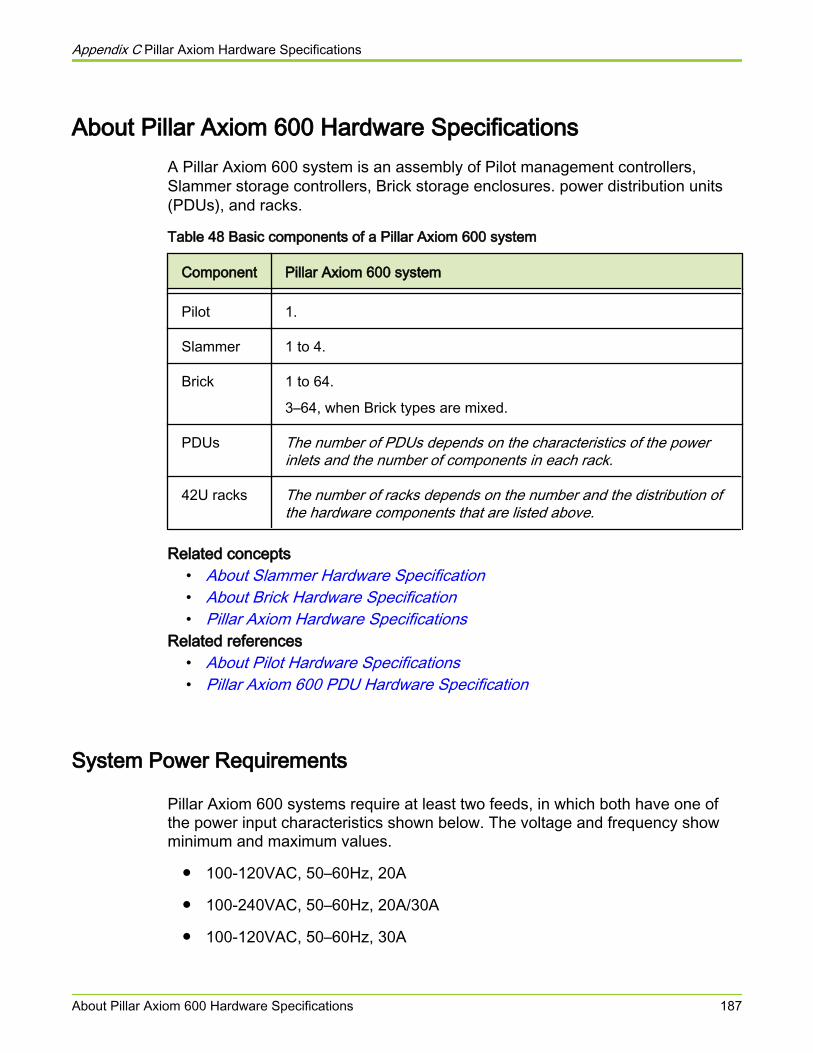
About Pillar Axiom 600 Hardware SpecificationsA Pillar Axiom 600 system is an assembly of Pilot management controllers,Slammer storage controllers, Brick storage enclosures. power distribution units(PDUs), and racks.
Table 48 Basic components of a Pillar Axiom 600 system
Component Pillar Axiom 600 system
Pilot 1.
Slammer 1 to 4.
Brick 1 to 64.
3–64, when Brick types are mixed.
PDUs The number of PDUs depends on the characteristics of the powerinlets and the number of components in each rack.
42U racks The number of racks depends on the number and the distribution ofthe hardware components that are listed above.
Related concepts• About Slammer Hardware Specification• About Brick Hardware Specification• Pillar Axiom Hardware Specifications
Related references• About Pilot Hardware Specifications• Pillar Axiom 600 PDU Hardware Specification
System Power Requirements
Pillar Axiom 600 systems require at least two feeds, in which both have one ofthe power input characteristics shown below. The voltage and frequency showminimum and maximum values.
● 100-120VAC, 50–60Hz, 20A
● 100-240VAC, 50–60Hz, 20A/30A
● 100-120VAC, 50–60Hz, 30A
Appendix C Pillar Axiom Hardware Specifications
About Pillar Axiom 600 Hardware Specifications 187

● 200-240VAC, 50–60Hz, 30A
● 230VAC, 16A or 32A (Europe)
● WYE-connected 3-phase:
○ USA: 120/208VAC, 50-60Hz, 30A
○ Europe: 230/400VAC, 50-60Hz, 16A
The total power required by a rack depends on the number and type of hardwarethat is in the rack.
System EnvironmentalsTable 49 System altitude specifications
Mode Elevation
Operational -200 to 10,000 feet (-61 to 3048 meters)
Non-operational
-200 to 40,000 feet (-61 to 12,192 meters)
Table 50 System temperature and humidity specifications
Mode Ambienttemperature
Non-condensinghumidity
Max wet bulbtemperature
Gradient
Operational Up to 7000feet elevation:
+41 to 104°F(+5 to 40°C)
Up to 10,000feet elevation:
+41 to 95°F(+5 to 35°C)
10–85%
10%/hrgradient
86°F
(30°C)
36°F/hr
(20°C/hr)
Non-operational
-22 to 158 °F
(-30 to 70 °C)
5–95%
10%/hrgradient
104°F
(40°C)
54°F/hr
(30°C/hr)
Appendix C Pillar Axiom Hardware Specifications
About Pillar Axiom 600 Hardware Specifications 188
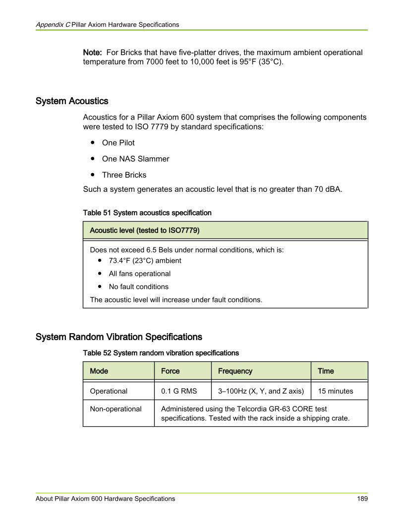
Note: For Bricks that have five-platter drives, the maximum ambient operationaltemperature from 7000 feet to 10,000 feet is 95°F (35°C).
System AcousticsAcoustics for a Pillar Axiom 600 system that comprises the following componentswere tested to ISO 7779 by standard specifications:
● One Pilot
● One NAS Slammer
● Three Bricks
Such a system generates an acoustic level that is no greater than 70 dBA.
Table 51 System acoustics specification
Acoustic level (tested to ISO7779)
Does not exceed 6.5 Bels under normal conditions, which is:● 73.4°F (23°C) ambient
● All fans operational
● No fault conditions
The acoustic level will increase under fault conditions.
System Random Vibration SpecificationsTable 52 System random vibration specifications
Mode Force Frequency Time
Operational 0.1 G RMS 3–100Hz (X, Y, and Z axis) 15 minutes
Non-operational Administered using the Telcordia GR-63 CORE testspecifications. Tested with the rack inside a shipping crate.
Appendix C Pillar Axiom Hardware Specifications
About Pillar Axiom 600 Hardware Specifications 189

System Regulatory Agency ComplianceAgency approvals are based on a Pillar Axiom 600 system that consists of:
● One Pilot
● Two Slammers
● Twelve Bricks
Related references• Regulatory Compliances• FCC Warning Statement• European Union Compliance Statement
Regulatory Compliances
The Pillar Axiom 600 system complies with the following regulatory agencyrequirements.
Table 53 Safety, quality, and environmental standards
Logo Standard
FCC (United States). This device complies withFCC Rules Part 15. Operation is subject to thefollowing two conditions:
1 This device may not cause harmfulinterference.
2 This device must accept any interferencethat may be received, includinginterference that may cause undesiredoperation.
CB Scheme by IECEE standard IEC60950-1-2.
Conformite Europeenne /DoC.
Appendix C Pillar Axiom Hardware Specifications
About Pillar Axiom 600 Hardware Specifications 190

Table 53 Safety, quality, and environmental standards (continued)
Logo Standard
UL and CSA under UL (cUL) and UL60950-1-2.
TUV/GS.
We offer customers a recycle program toproperly dispose of surplus products andproducts that have reached their end of life.Equipment that is returned to Pillar through thisprogram is disposed of in an environmentallysafe manner using processes that comply withthe WEEE (EU Directive on Waste Electricaland Electronic Equipment) regulations.
Pillar provides (on request) documentationabout product disposition when the recyclingprocess is complete. Upon request, Pillar alsoprovides a Certificate of Destruction, whichreleases the customer from further liability forthe equipment returned through the Recycleprogram.
Customers should contact Pillar World WideCustomer Support Center for information on thelogistics and location(s) of the approved recyclefacilities.
Our objectives are to ensure that our highproduct quality and reliability standards are metthrough the processes that have been verifiedand approved. This is achieved through ISO9001:2000 and the development anddeployment of Pb-free solder qualificationguidelines for components (RoHS),interconnects, and PCB, PCA reliability. Pillarwill continue to work with industry consortia todefine common qualification criteria. Pillar willapply Pb-free solder technologies to productdesigns as required by legislation.
ISO 9001:2000 Registered manufacturingprocess.
Appendix C Pillar Axiom Hardware Specifications
About Pillar Axiom 600 Hardware Specifications 191
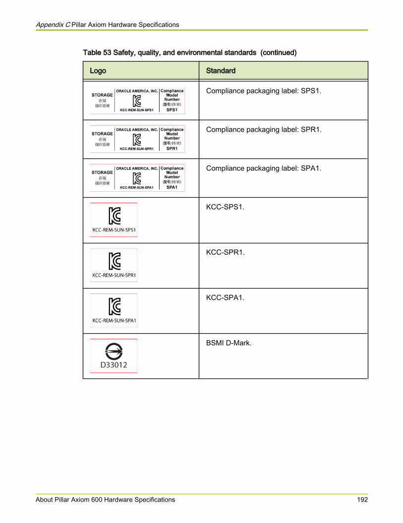
Table 53 Safety, quality, and environmental standards (continued)
Logo Standard
Compliance packaging label: SPS1.
Compliance packaging label: SPR1.
Compliance packaging label: SPA1.
KCC-SPS1.
KCC-SPR1.
KCC-SPA1.
BSMI D-Mark.
Appendix C Pillar Axiom Hardware Specifications
About Pillar Axiom 600 Hardware Specifications 192
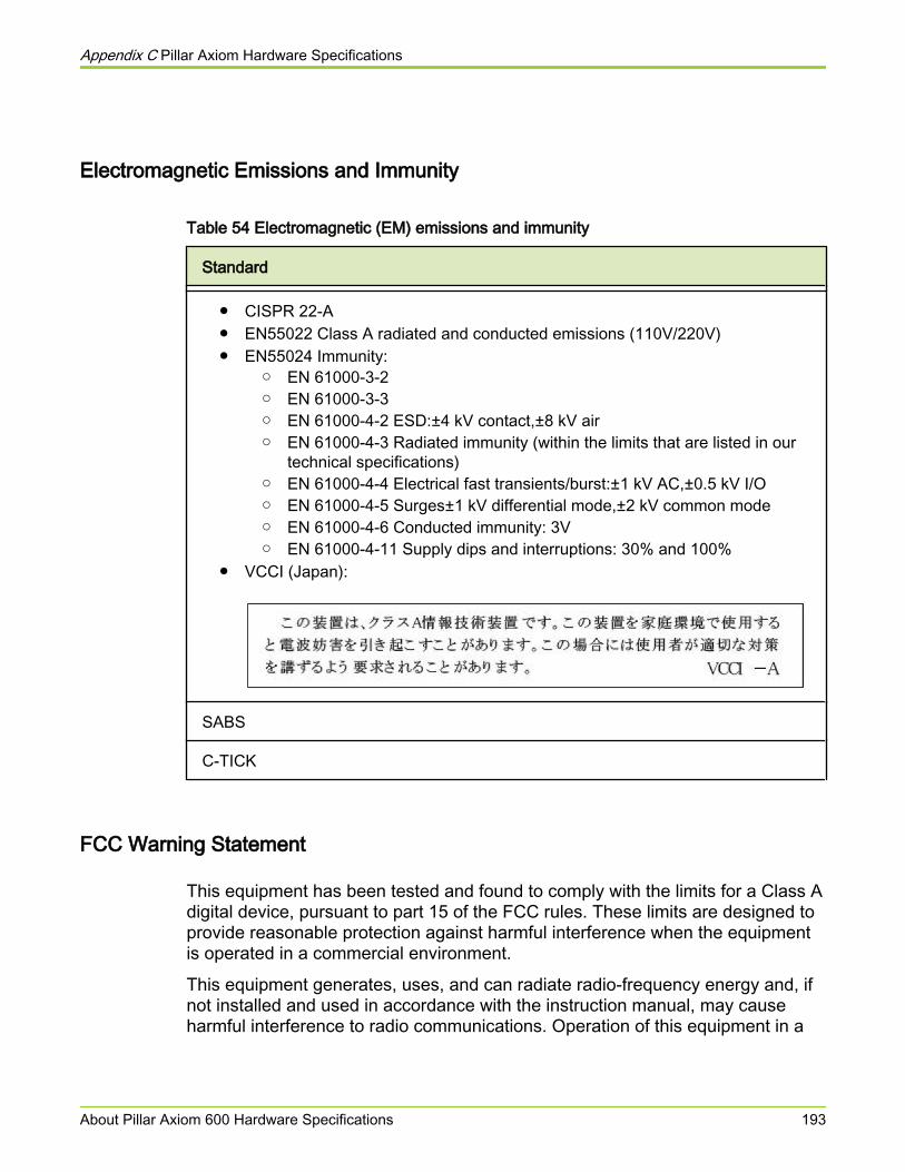
Electromagnetic Emissions and Immunity
Table 54 Electromagnetic (EM) emissions and immunity
Standard
● CISPR 22-A● EN55022 Class A radiated and conducted emissions (110V/220V)● EN55024 Immunity:
○ EN 61000-3-2○ EN 61000-3-3○ EN 61000-4-2 ESD:±4 kV contact,±8 kV air○ EN 61000-4-3 Radiated immunity (within the limits that are listed in our
technical specifications)○ EN 61000-4-4 Electrical fast transients/burst:±1 kV AC,±0.5 kV I/O○ EN 61000-4-5 Surges±1 kV differential mode,±2 kV common mode○ EN 61000-4-6 Conducted immunity: 3V○ EN 61000-4-11 Supply dips and interruptions: 30% and 100%
● VCCI (Japan):
SABS
C-TICK
FCC Warning Statement
This equipment has been tested and found to comply with the limits for a Class Adigital device, pursuant to part 15 of the FCC rules. These limits are designed toprovide reasonable protection against harmful interference when the equipmentis operated in a commercial environment.
This equipment generates, uses, and can radiate radio-frequency energy and, ifnot installed and used in accordance with the instruction manual, may causeharmful interference to radio communications. Operation of this equipment in a
Appendix C Pillar Axiom Hardware Specifications
About Pillar Axiom 600 Hardware Specifications 193

residential area is likely to cause harmful interference, in which case users will berequired to correct the interference at their own expense.
You can determine if your equipment causes interference by turning it off. If theinterference stops, it was probably caused by the equipment or one of itsperipheral devices. If the equipment causes interference to radio or televisionreception, try to correct the interference by using one or more of the followingmeasures:
● Turn the television or radio antenna until the interference stops.
● Move the equipment to one side or the other of the television or radio.
● Move the equipment farther away from the television or radio.
● Plug the equipment into an outlet that is on a different circuit from thetelevision or radio. (That is, make certain the equipment and the televisionor radio are on circuits that are controlled by different circuit breakers orfuses.)
Caution Changes or modifications that are not expresslyapproved by the party that is responsible forcompliance could void the user’s authority to operatethe equipment.
European Union Compliance Statement
This product is in conformity with the protection requirements of EC CouncilDirective 89/336/EEC on the approximation of the laws of the Member Statesrelating to electro-magnetic compatibility. The manufacturer cannot acceptresponsibility for any failure to satisfy the protection requirements that result froma non-recommended modification of the product.
This product has been tested and found to comply with the limits for Class AInformation Technology Equipment according to CISPR 22/European StandardEN 55022. The Limits for Class A equipment were derived for residentialenvironments to provide reasonable protection against interference with licensedcommunication equipment.
We have signed a Declaration of Conformity with the requirements of the Directive.
The following standards were applied:
1 Emissions: EN55022 (Class A radiated and conducted, 110V, 230V)
2 EMC: EN55024 (immunity):
● EN 61000-3-2
Appendix C Pillar Axiom Hardware Specifications
About Pillar Axiom 600 Hardware Specifications 194

● EN 61000-3-3
● EN 61000-4-2 ESD:±4 kV contact,±8 kV air touch
● EN 61000-4-3 Radiated immunity (within the limits that are listed inour technical specifications)
● EN 61000-4-4 Electrical fast transients/burst:±1 kV AC,±0.5 kV I/O
● EN 61000-4-5 Surges ±1 kV differential mode,±2 kV common mode
● EN 61000-4-6 Conducted immunity: 3V
● EN 61000-4-8 PFMF
● EN 61000-4-11 Supply dips and interruptions: 30% and 100%
System Packaging and Transportation
Packaging meets the following requirements:
● For packages under 150 lb—International Safe Transit Association (ISTA2A) Procedures 1 and 2.
● For packages over 150 lb—Network Equipment Building System (NEBS)core standards.
GR-63-CORE, Packaged Equipment Shock (4.3.1), Office Vibration (4.4.3)and Transportation Vibration (4.4.4).
System Warranty
Hardware components in a Pillar Axiom 600 system are covered by a three-yearwarranty.
Note: The hardware and software warranty for all Pillar Axiom 600 productsapplies to the system, not to individual components like Slammers and Brickswithin the system. Slammers and Bricks that are later added to expand a PillarAxiom 600 system are warranted to fall within the same renewal cycle as thePillar Axiom 600 system.
Appendix C Pillar Axiom Hardware Specifications
About Pillar Axiom 600 Hardware Specifications 195

About Pilot Hardware Specifications
A Pilot is an active management and provisioning front end as well as theadministrator interface to a Pillar Axiom 600 system.
Pilot Dimensions and WeightTable 55 Pilot dimensions and weight (both control units)
Attribute Value
Height 3.5 inches (8.9 centimeters); 2U
Width 17.7 inches (45.0 centimeters)
Depth 20-26 inches (50.8-66.0 centimeters)
Weight 40 pounds (18.1 kilograms)
Note: Pilots are available in multiple models of different physical dimensions.Make sure you do not install anything behind the Pilot control units (CUs) in therack, because you can get a replacement Pilot of any of the different dimensions.
Pilot Power CharacteristicsTable 56 Pilot power characteristics (for each control unit)
Power characteristic Value
Frequency 50 to 60Hz
AC voltage 100 to 240V
Current draw 1.5A at 115V
0.8A at 230V
143W
Maximum power consumption 143VA
Appendix C Pillar Axiom Hardware Specifications
About Pilot Hardware Specifications 196

Table 56 Pilot power characteristics (for each control unit) (continued)
Power characteristic Value
Maximum heat dissipation 750BTU/hr
AC plug type 2 IEC 320 connection
Pilot Regulatory Agency Compliance
This equipment has been tested and found to comply with the limits for a class Bdigital device, pursuant to part 15 of the FCC rules. These limits are designed toprovide reasonable protection against harmful interference when the equipmentis operated in a commercial environment.
This equipment generates, uses, and can radiate radio frequency energy and, ifnot installed and used in accordance with the instruction guide, may causeharmful interference to radio communications. Operation of this equipment in aresidential area is may cause harmful interference, in which case the user mustcorrect the interference at his own expense.
Notice 1
The changes or modifications not expressly approved by the party responsiblefor compliance could void the user's authority to operate the equipment.
Notice 2
Shielded interface cables and A.C. power cord, if any, must be used in order tocomply with the emission limits.
VOIR LA NOTICE D'INSTALLATION AVANT DE RACCORDER AU RESEAU.
Appendix C Pillar Axiom Hardware Specifications
About Pilot Hardware Specifications 197

Table 57 Pilot safety and quality standards
Logo Standard
FCC (United States). This device complies with FCC Rules Part 15 fora class B digital device.
Conformite Europeenne /DoC
Pilot Packaging and Transportation
Pilot packaging meets the following requirements:
● For packages under 150 lb—International Safe Transit Association (ISTA2A) Procedures 1 and 2.
● For packages over 150 lb—Network Equipment Building System (NEBS)core standards.
GR-63-CORE, Packaged Equipment Shock (4.3.1), Office Vibration (4.4.3)and Transportation Vibration (4.4.4).
Appendix C Pillar Axiom Hardware Specifications
About Pilot Hardware Specifications 198

About Slammer Hardware SpecificationSlammers are fully redundant controllers within a Pillar Axiom 600 system. ASlammer can be ordered as either a SAN or a NAS front end.
Slammer Dimensions and WeightTable 58 Slammer dimensions and weight
Attribute Value
Height 7 inches (17.78 centimeters); 4U
Width 17.72 inches (45 centimeters)
Depth 26–27 inches (66 centimeters)
Weight 94 pounds (42.6 kilograms)
Slammer Power Characteristics
Table 59 Slammer power characteristics
Power characteristic Value
Frequency 50–60Hz
AC voltage 100–240V
Maximum power consumption 568VA
Current draw Combined for both Slammer CUs:
4.72A at 115V2.46A at 230V
546W
Maximum heat dissipation 1864 BTU/hr
Appendix C Pillar Axiom Hardware Specifications
About Slammer Hardware Specification 199

Table 59 Slammer power characteristics (continued)
Power characteristic Value
AC plug type Four IEC 320 C13 connection
Slammer Regulatory Agency ComplianceSlammers comply with the following regulatory agency requirements.
Table 60 Slammer safety and quality standards
Logo Standard
FCC (United States). This device complies with FCC Rules Part 15.Operation is subject to the following two conditions:
1 This device may not cause harmful interference and2 This device must accept any interference that maybe received,
including interference that may cause undesired operation.
CB Scheme by IECEE standard IEC 60950, Third Edition (1999)
Conformite Europeenne /DoC
UL and CSA under UL (cUL)
TUV/GS
ISO 9001:2000 Registered manufacturing process
Slammer Packaging and Transportation
Packaging meets the following requirements:
● For packages under 150 lb—International Safe Transit Association (ISTA2A) Procedures 1 and 2.
Appendix C Pillar Axiom Hardware Specifications
About Slammer Hardware Specification 200
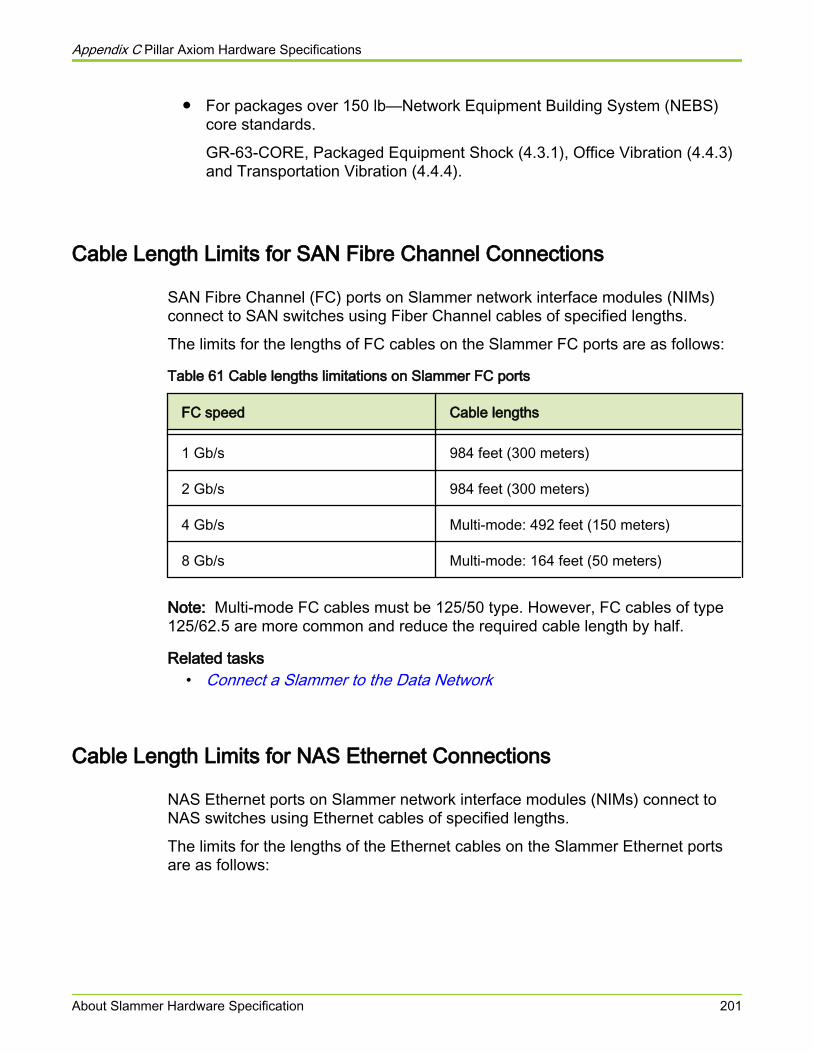
● For packages over 150 lb—Network Equipment Building System (NEBS)core standards.
GR-63-CORE, Packaged Equipment Shock (4.3.1), Office Vibration (4.4.3)and Transportation Vibration (4.4.4).
Cable Length Limits for SAN Fibre Channel Connections
SAN Fibre Channel (FC) ports on Slammer network interface modules (NIMs)connect to SAN switches using Fiber Channel cables of specified lengths.
The limits for the lengths of FC cables on the Slammer FC ports are as follows:
Table 61 Cable lengths limitations on Slammer FC ports
FC speed Cable lengths
1 Gb/s 984 feet (300 meters)
2 Gb/s 984 feet (300 meters)
4 Gb/s Multi-mode: 492 feet (150 meters)
8 Gb/s Multi-mode: 164 feet (50 meters)
Note: Multi-mode FC cables must be 125/50 type. However, FC cables of type125/62.5 are more common and reduce the required cable length by half.
Related tasks• Connect a Slammer to the Data Network
Cable Length Limits for NAS Ethernet Connections
NAS Ethernet ports on Slammer network interface modules (NIMs) connect toNAS switches using Ethernet cables of specified lengths.
The limits for the lengths of the Ethernet cables on the Slammer Ethernet portsare as follows:
Appendix C Pillar Axiom Hardware Specifications
About Slammer Hardware Specification 201
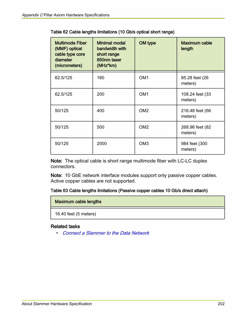
Table 62 Cable lengths limitations (10 Gb/s optical short range)
Multimode Fiber(MMF) opticalcable type corediameter(micrometers)
Minimal modalbandwidth withshort range850nm laser(MHz*km)
OM type Maximum cablelength
62.5/125 160 OM1 85.28 feet (26meters)
62.5/125 200 OM1 108.24 feet (33meters)
50/125 400 OM2 216.48 feet (66meters)
50/125 500 OM2 268.96 feet (82meters)
50/125 2000 OM3 984 feet (300meters)
Note: The optical cable is short range multimode fiber with LC-LC duplexconnectors.
Note: 10 GbE network interface modules support only passive copper cables.Active copper cables are not supported.
Table 63 Cable lengths limitations (Passive copper cables 10 Gb/s direct attach)
Maximum cable lengths
16.40 feet (5 meters)
Related tasks• Connect a Slammer to the Data Network
Appendix C Pillar Axiom Hardware Specifications
About Slammer Hardware Specification 202
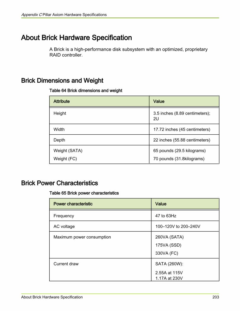
About Brick Hardware SpecificationA Brick is a high-performance disk subsystem with an optimized, proprietaryRAID controller.
Brick Dimensions and WeightTable 64 Brick dimensions and weight
Attribute Value
Height 3.5 inches (8.89 centimeters);2U
Width 17.72 inches (45 centimeters)
Depth 22 inches (55.88 centimeters)
Weight (SATA)
Weight (FC)
65 pounds (29.5 kilograms)
70 pounds (31.8kilograms)
Brick Power CharacteristicsTable 65 Brick power characteristics
Power characteristic Value
Frequency 47 to 63Hz
AC voltage 100–120V to 200–240V
Maximum power consumption 260VA (SATA)
175VA (SSD)
330VA (FC)
Current draw SATA (260W):
2.55A at 115V1.17A at 230V
Appendix C Pillar Axiom Hardware Specifications
About Brick Hardware Specification 203

Table 65 Brick power characteristics (continued)
Power characteristic Value
FC (330W)
3.35A at 115V1.49A at 230V
SSD (175W)
1.52A at 115V0.80A at 230V
Maximum heat dissipation 1127 BTU/hr
AC plug type Two IEC 320 connections
Brick Regulatory Agency Compliance
Pillar Axiom 600 Bricks comply with the following regulatory agency requirements.
Table 66 Brick safety and quality standards
Logo Standard
FCC (United States). This device complies with FCC Rules Part 15.Operation is subject to the following two conditions:
1 This device may not cause harmful interference and2 This device must accept any interference that maybe received,
including interference that may cause undesired operation.
CB Scheme by IECEE standard IEC 60950, Third Edition (1999)
Conformite Europeenne /DoC
UL and CSA under UL (cUL)
TUV/GS
Appendix C Pillar Axiom Hardware Specifications
About Brick Hardware Specification 204
Table 66 Brick safety and quality standards (continued)
Logo Standard
ISO 9001:2000 Registered manufacturing process
Brick Packaging and Transportation
Packaging meets the following requirements:
● For packages under 150 lb—International Safe Transit Association (ISTA2A) Procedures 1 and 2.
● For packages over 150 lb—Network Equipment Building System (NEBS)core standards.
GR-63-CORE, Packaged Equipment Shock (4.3.1), Office Vibration (4.4.3)and Transportation Vibration (4.4.4)
Appendix C Pillar Axiom Hardware Specifications
About Brick Hardware Specification 205
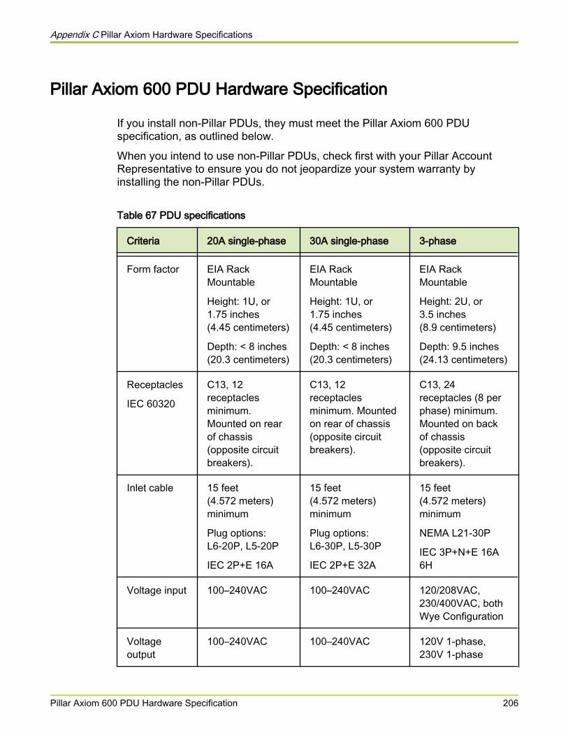
Pillar Axiom 600 PDU Hardware Specification
If you install non-Pillar PDUs, they must meet the Pillar Axiom 600 PDUspecification, as outlined below.
When you intend to use non-Pillar PDUs, check first with your Pillar AccountRepresentative to ensure you do not jeopardize your system warranty byinstalling the non-Pillar PDUs.
Table 67 PDU specifications
Criteria 20A single-phase 30A single-phase 3-phase
Form factor EIA RackMountable
Height: 1U, or1.75 inches(4.45 centimeters)
Depth: < 8 inches(20.3 centimeters)
EIA RackMountable
Height: 1U, or1.75 inches(4.45 centimeters)
Depth: < 8 inches(20.3 centimeters)
EIA RackMountable
Height: 2U, or3.5 inches(8.9 centimeters)
Depth: 9.5 inches(24.13 centimeters)
Receptacles
IEC 60320
C13, 12receptaclesminimum.Mounted on rearof chassis(opposite circuitbreakers).
C13, 12receptaclesminimum. Mountedon rear of chassis(opposite circuitbreakers).
C13, 24receptacles (8 perphase) minimum.Mounted on backof chassis(opposite circuitbreakers).
Inlet cable 15 feet(4.572 meters)minimum
Plug options:L6-20P, L5-20P
IEC 2P+E 16A
15 feet(4.572 meters)minimum
Plug options:L6-30P, L5-30P
IEC 2P+E 32A
15 feet(4.572 meters)minimum
NEMA L21-30P
IEC 3P+N+E 16A6H
Voltage input 100–240VAC 100–240VAC 120/208VAC,230/400VAC, bothWye Configuration
Voltageoutput
100–240VAC 100–240VAC 120V 1-phase,230V 1-phase
Appendix C Pillar Axiom Hardware Specifications
Pillar Axiom 600 PDU Hardware Specification 206
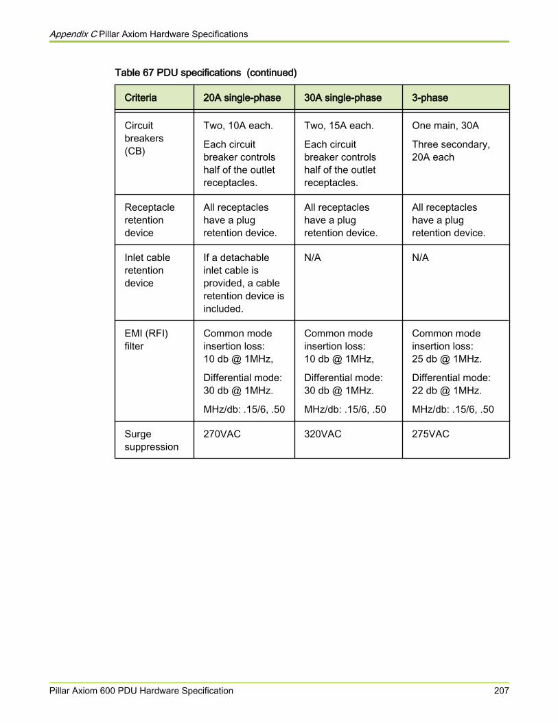
Table 67 PDU specifications (continued)
Criteria 20A single-phase 30A single-phase 3-phase
Circuitbreakers(CB)
Two, 10A each.
Each circuitbreaker controlshalf of the outletreceptacles.
Two, 15A each.
Each circuitbreaker controlshalf of the outletreceptacles.
One main, 30A
Three secondary,20A each
Receptacleretentiondevice
All receptacleshave a plugretention device.
All receptacleshave a plugretention device.
All receptacleshave a plugretention device.
Inlet cableretentiondevice
If a detachableinlet cable isprovided, a cableretention device isincluded.
N/A N/A
EMI (RFI)filter
Common modeinsertion loss:10 db @ 1MHz,
Differential mode:30 db @ 1MHz.
MHz/db: .15/6, .50
Common modeinsertion loss:10 db @ 1MHz,
Differential mode:30 db @ 1MHz.
MHz/db: .15/6, .50
Common modeinsertion loss:25 db @ 1MHz.
Differential mode:22 db @ 1MHz.
MHz/db: .15/6, .50
Surgesuppression
270VAC 320VAC 275VAC
Appendix C Pillar Axiom Hardware Specifications
Pillar Axiom 600 PDU Hardware Specification 207
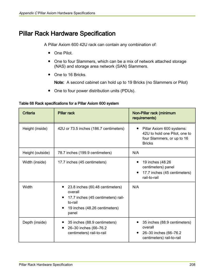
Pillar Rack Hardware SpecificationA Pillar Axiom 600 42U rack can contain any combination of:
● One Pilot.
● One to four Slammers, which can be a mix of network attached storage(NAS) and storage area network (SAN) Slammers.
● One to 16 Bricks.
Note: A second cabinet can hold up to 19 Bricks (no Slammers or Pilot)
● One to four power distribution units (PDUs).
Table 68 Rack specifications for a Pillar Axiom 600 system
Criteria Pillar rack Non-Pillar rack (minimumrequirements)
Height (inside) 42U or 73.5 inches (186.7 centimeters) ● Pillar Axiom 600 systems:42U to hold one Pilot, one tofour Slammers, or up to 16Bricks
Height (outside) 78.7 inches (199.9 centimeters) N/A
Width (inside) 17.7 inches (45 centimeters) ● 19 inches (48.26centimeters) panel
● 17.7 inches (45 centimeters)rail-to-rail
Width ● 23.8 inches (60.48 centimeters)overall
● 17.7 inches (45 centimeters) rail-to-rail
● 19 inches (48.26 centimeters)panel
N/A
Depth (inside) ● 35 inches (88.9 centimeters)● 26–30 inches (66–76.2
centimeters) rail-to-rail
● 35 inches (88.9 centimeters)overall
● 26–30 inches (66–76.2centimeters) rail-to-rail
Appendix C Pillar Axiom Hardware Specifications
Pillar Rack Hardware Specification 208
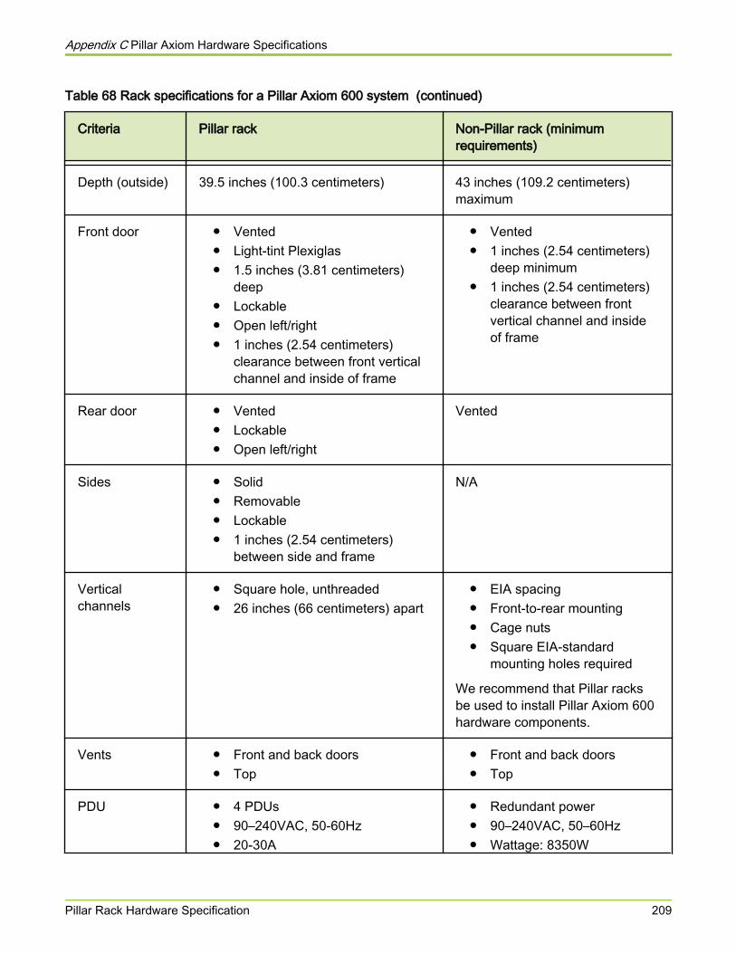
Table 68 Rack specifications for a Pillar Axiom 600 system (continued)
Criteria Pillar rack Non-Pillar rack (minimumrequirements)
Depth (outside) 39.5 inches (100.3 centimeters) 43 inches (109.2 centimeters)maximum
Front door ● Vented● Light-tint Plexiglas● 1.5 inches (3.81 centimeters)
deep● Lockable● Open left/right● 1 inches (2.54 centimeters)
clearance between front verticalchannel and inside of frame
● Vented● 1 inches (2.54 centimeters)
deep minimum● 1 inches (2.54 centimeters)
clearance between frontvertical channel and insideof frame
Rear door ● Vented● Lockable● Open left/right
Vented
Sides ● Solid● Removable● Lockable● 1 inches (2.54 centimeters)
between side and frame
N/A
Verticalchannels
● Square hole, unthreaded● 26 inches (66 centimeters) apart
● EIA spacing● Front-to-rear mounting● Cage nuts● Square EIA-standard
mounting holes required
We recommend that Pillar racksbe used to install Pillar Axiom 600hardware components.
Vents ● Front and back doors● Top
● Front and back doors● Top
PDU ● 4 PDUs● 90–240VAC, 50-60Hz● 20-30A
● Redundant power● 90–240VAC, 50–60Hz● Wattage: 8350W
Appendix C Pillar Axiom Hardware Specifications
Pillar Rack Hardware Specification 209
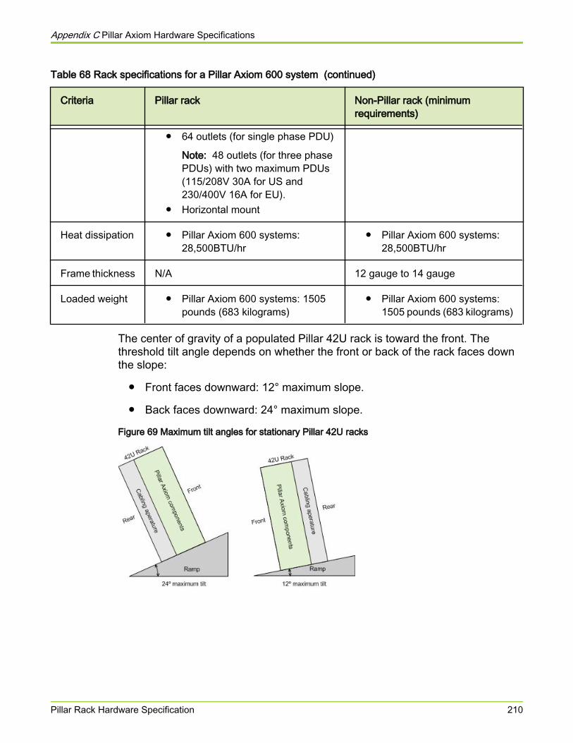
Table 68 Rack specifications for a Pillar Axiom 600 system (continued)
Criteria Pillar rack Non-Pillar rack (minimumrequirements)
● 64 outlets (for single phase PDU)
Note: 48 outlets (for three phasePDUs) with two maximum PDUs(115/208V 30A for US and230/400V 16A for EU).
● Horizontal mount
Heat dissipation ● Pillar Axiom 600 systems:28,500BTU/hr
● Pillar Axiom 600 systems:28,500BTU/hr
Frame thickness N/A 12 gauge to 14 gauge
Loaded weight ● Pillar Axiom 600 systems: 1505pounds (683 kilograms)
● Pillar Axiom 600 systems:1505 pounds (683 kilograms)
The center of gravity of a populated Pillar 42U rack is toward the front. Thethreshold tilt angle depends on whether the front or back of the rack faces downthe slope:
● Front faces downward: 12° maximum slope.
● Back faces downward: 24° maximum slope.
Figure 69 Maximum tilt angles for stationary Pillar 42U racks
Appendix C Pillar Axiom Hardware Specifications
Pillar Rack Hardware Specification 210
APPENDIX D
Expansion of a Pillar Axiom 600 SystemConfiguration
About Expanding a Pillar Axiom 600 ConfigurationYou can expand a Pillar Axiom 600 system configuration by adding the requirednumber of additional Brick storage enclosures and Slammer storage controllersto an existing Pillar Axiom 600 system.
A Pillar Axiom 600 can have a maximum number of four Slammers and 64 Bricksattached to the system. The Pillar Axiom 600 system allows you to start yourstorage system with a small configuration and later, scale up to largerconfigurations without a disruption to the data access.
Important! Leave the small form-factor pluggable (SFP) in the Slammer or Brickport and only disconnect the fibre optic cable if you remove an optical SFP cablethat is used in the Storage System Fabric (SSF) for troubleshooting purposes.Leaving the SFP in the Brick or Slammer port prevents the Pillar Axiom 600system from setting the port speed to the lower fabric speed of the copper cable.
Related tasks• Add a New Brick Storage Enclosure• Add a New Slammer Storage Controller
Complete the Brick Pre-Installation ChecklistPrior to adding new Bricks to a pre-existing Pillar Axiom 600 system, completethe tasks outlined in the pre-installation checklist.
● When ordering new Bricks, determine if you need additional powerdistribution units (PDUs) and to devise a cabling plan that specifies to whichPDU outlet each Brick power cable connects.
● When ordering cables, check the model type of existing Slammers andBricks and identify compatibility issues.
Appendix D Expansion of a Pillar Axiom 600 System Configuration
About Expanding a Pillar Axiom 600 Configuration 211
● Verify the placement limits for Bricks and Slammers on the rack due topower requirements and cable lengths.
● Verify that the placement of the Brick within the new or existing Brick stringfollows all cabling guidelines.
● Before the Bricks arrive, decide where you will install each Brick and PDU.
Add Bricks above the Slammers until they reach the top rack unit, and thenstart at the top of the next rack and work down. Place the PDUs at thebottom of the rack.
● Install new PDUs.Related references
• Cabling Practices for the Pillar Axiom 600 SystemRelated tasks
• Add a New Brick Storage Enclosure
Complete the Slammer Pre-Installation ChecklistPrior to adding new Slammers to a pre-existing Pillar Axiom 600 system,complete the tasks outlined in the pre-installation checklist.
● Inventory the Slammer and installation components to make sure you havethe correct cables and mounting hardware.
● When ordering cables, check the model type of existing Slammers andBricks and identify compatibility issues.
● Before beginning the installation, check the status of the system to ensurethat it is in the correct status, as follows:
○ All Fibre Channel status LEDs on Slammer and Brick ports withconnectors inserted are steady green, not amber or flashing green. Todetermine which LEDs reflect the status of a port, refer to the PillarAxiom Service Guide.
○ The System Status icon in the GUI is green for all components. TheSystem Status icon is on the left most position of the GUI status barand indicates the system status of all hardware components. For moreinformation, refer to the Pillar Axiom Administrator’s Guide.
○ No background tasks are running. Click Tasks on the status bar toopen the Tasks overview page.
○ There are no outstanding system alerts. Click on the System Alertsicon on the status bar to open the System Alerts overview page and to
Appendix D Expansion of a Pillar Axiom 600 System Configuration
About Expanding a Pillar Axiom 600 Configuration 212
respond to any alerts that require intervention. For more information,refer to the Pillar Axiom Administrator’s Guide.
○ No LUNs are offline, degraded, or in conservative mode. Check theappropriate status field in the GUI. For more information, refer to thePillar Axiom Administrator’s Guide.
Related references• Cable Length Limits for SAN Fibre Channel Connections• Cable Length Limits for NAS Ethernet Connections• Cable Length Limits for NAS Ethernet Connections• Cable Length Limits for SAN Fibre Channel Connections
Related tasks• Add a New Slammer Storage Controller
About Additional Brick Storage EnclosuresYou can add Bricks to expand a Pillar Axiom 600 system.
Addition of Bricks to the end of an existing Brick string in a Pillar Axiom 600system is non-disruptive.
Note: Addition of Bricks may be disruptive if additional power distribution units(PDUs) are required to fulfil power requirements. Addition of Bricks may also bedisruptive if the current layout of the hardware in the racks is changed to complywith the cable length limits for cables that are used for Slammer to Brick andBrick to Brick connections.
Note: If the installed software version does not support the new Bricks, the newBricks are not added to the Pillar Axiom 600 system. However, there is nodisruption to the data path of the existing Bricks. Contact the Pillar World WideCustomer Support Center to identify any software prerequisites to add additionalBricks.
For best results, ensure that the Pillar Axiom 600 system has the latest softwareversion installed before adding a Brick. If the existing racks are full, you mustinstall additional racks. Refer to the appropriate procedures in this guide to installmultiple racks and for correct component placement in the racks.
Appendix D Expansion of a Pillar Axiom 600 System Configuration
About Expanding a Pillar Axiom 600 Configuration 213
Add a New Brick Storage Enclosure
Caution While adding new Bricks, verify the status of each Brick asthe Brick is powered on to ensure that it has been added tothe Pillar Axiom 600 system configuration. Do not wait toconduct the status checks after a few Bricks have beenadded because doing the status check in a batch mightincrease the possibility of bringing other resources offline.
Caution While adding new Bricks, contact the Pillar World WideCustomer Support Center to determine the location of thesystem configuration database before disconnecting orpowering off any Bricks to avoid an emergency shutdown ofthe Pillar Axiom system and subsequent data corruption.
1 Install the new Bricks in the rack.
2 Cable the new Bricks as described in the Pillar Axiom 600 SSF CablingReference.
You do not need to power down the Pillar Axiom 600 system to cableadditional Bricks.
Note: When adding additional Bricks, there may be changes in the existingcabling of the Pillar Axiom 600 system. Refer to the Pillar Axiom 600 SSFCabling Reference for more information.
The Pillar Axiom 600 Slammer and Brick ports and cables are:
● HSSDC
● Small form-factor pluggable (SFP) copper
● SFP optical
The fibre cables available to cable a Pillar Axiom 600 system are:
● HSSDC — HSSDC for legacy connections
● HSSDC — SFP copper, where the SFP is part of the cable forconnecting legacy components
● SFP copper — SFP copper, where the SFP is part of the cable
● SFP optical — SFP optical, where the SFP is a separate componentfrom the cable
Appendix D Expansion of a Pillar Axiom 600 System Configuration
About Expanding a Pillar Axiom 600 Configuration 214
Note: The cables in any Pillar Axiom 600 system must be either all copperor all optical. The single exception is for single Slammer Pillar Axiom 600systems with all SFP Slammer ports. Use optical SFP cables for the hotwireconnections from ports CU0 FC0 to CU1 FC2 and the ports CU1 FC0 toCU0 FC2. Use copper cables for the rest of the Pillar Axiom 600 system.
Tip: The input data connection to a Brick RAID controller is the FC2 port,which is connected directly to a Slammer or to the next Brick upstream in aBrick string.
Tip: The output data connection on a Brick RAID controller is the FC1 port,which is left empty or connected to the next Brick downstream in a Brick string.
Tip: The FC0 and FC3 ports are crossover ports between the Brick RAIDcontrollers for redundancy. The FC0 port in each RAID controller isconnected to the FC3 port of the partner RAID controller.
Dress all the cables so that you can remove any components withoutdisconnecting a cable. Dress all power cables to the opposite side of therack from any data cables. We recommend dressing the power cables tothe left side (when facing the rear of the cabinet).
3 Make sure the power switches on the back of the new Bricks are off beforeconnecting the power cables.
4 Dress the power cables and plug them into the power distribution units(PDUs) according to the cabling plan you devised during the earlierpreparatory steps.
5 Verify that all drives are seated properly by pressing on each one to makesure it is fully seated.
They are seated correctly if they do not go in any further and none extendout more than the others.
6 Make sure the Pillar Axiom 600 system is powered on and all the newcables are in place.
Important! Ensure that the Pillar Axiom 600 system is in Normal status andthat there are no topology or hardware incompatibility errors or pendingsoftware system alerts or topology discovery tasks before you begin thenext step, so that the system can detect and integrate the new Brick.
7 Check the status of all the LUNs and make sure that they are fully online.No LUN or filesystem should be Offline, Partial Offline, Degraded, orConservative.
Appendix D Expansion of a Pillar Axiom 600 System Configuration
About Expanding a Pillar Axiom 600 Configuration 215
8 In the GUI, navigate to Support > Software Modules and check the SoftwareModules screen to make sure that there is only one revision of Brickfirmware for each Brick type.
9 Check and record the total system capacity.
10 Add power to one of the new Bricks.
Power on the Bricks connected directly to a Slammer first, then those thatare connected to the first group of Bricks, and so on.
Important! Do not power on the next Brick until the current Brick is verifiedto be successfully integrated.
11 If you see a system alert in the GUI to accept a foreign Brick, use anAdministrator account to accept the new Brick.
Result:
When you add a Brick storage enclosure to an existing Pillar Axiom 600system, the system begins the process to bring the Brick online. While thesystem is bringing the Brick online, you may see a series of error andwarning messages similar to these:
● Fibre Channel RAID Array Inaccessible: Occurs if the PillarAxiom 600 system needs to upgrade the firmware on the new Brick.The system loads the firmware then resets the RAID controllers toinstall the firmware.
● Fibre Channel Path to Brick Failed: Occurs if the PillarAxiom 600 system needs to upgrade the firmware.
● Software Update Succeeded: Occurs when the Pillar Axiom 600system needs to update the firmware as it verifies that the firmwareupdate is successful. This message does not indicate that the PillarAxiom 600 system software is updated but that the Brick firmware is atthe required level.
These messages are expected if the Pillar Axiom 600 has to upgrade thefirmware on the new Brick to match the installed firmware. During the bring-up process, the status of the Brick will go from red to yellow to green. Afterthe system completes the process, the Brick will show a Normal status andwill remove all system alerts related to adding the Brick.
Important! If any existing LUN or filesystem changes status as the Brick ispowered on, power off the new Brick immediately and contact the PillarWorld Wide Customer Support Center for assistance.
Important! If any system alerts remain, contact the Pillar World WideCustomer Support Center.
Appendix D Expansion of a Pillar Axiom 600 System Configuration
About Expanding a Pillar Axiom 600 Configuration 216
Important! It is normal for Topology tasks to appear while the Brick is beingadded to the internal fabric configuration. However, after powering on aBrick, if the Topology Discovery task completion percentage does notincrement or you repeatedly see Topology Discovery tasks, power off theBrick and contact the Pillar World Wide Customer Support Center forassistance.
12 In the GUI, verify that the new Brick is added to the system. If the Brick hasa status of Normal, there should be no system alerts for Topology errors orincompatible hardware or software and there should be no TopologyDiscovery tasks running.
13 After you complete the system alert to accept this Brick and after you haveverified that the RAID controller firmware version is correct, repeat Step 1through Step 12 for each new Brick.
After a Brick has been added, you should verify its operational status. The newBrick will appear in the GUI with a default Brick name that will be the nextassigned name in the sequence Brick001, Brick002, Brick003, and so on. Afterthe Brick is online, you can use the GUI to assign a more meaningful name. TheBrick status will transition from Booting, to Offline, and finally to Normal. If thefirmware must be upgraded, the Brick may repeat this sequence and mightdisplay a status of Unknown or Missing as the new firmware is installed.
Related references• Cabling Practices for the Pillar Axiom 600 System
Related tasks• Install a Brick Storage Enclosure• Set the Identity of Bricks• Complete the Brick Pre-Installation Checklist• Verify a Newly Added Brick
Verify a Newly Added BrickWhile adding new Bricks, verify the status of each Brick as the Brick is poweredon to ensure that it has been added to the Pillar Axiom 600 system configuration.Do not wait to conduct the status checks after a few Bricks have been addedbecause doing the status check in a batch might increase the possibility ofbringing other resources offline.
1 After the new Brick is powered on, verify the status of the LEDs. If the newBrick is directly cabled to the Slammer, verify that the FS port LEDs aresolid green. If the new Brick is connected to another Brick, verify that theFiber Channel (FC) port LEDs on the new Brick are solid green.
Appendix D Expansion of a Pillar Axiom 600 System Configuration
About Expanding a Pillar Axiom 600 Configuration 217
Note: If there is a cable plugged into the FC port, the port LED must besolid green but may flicker with activity. If there is no cable plugged into theFC port, the port LED must be blinking green at approximately a onesecond interval. The Fault LED must not be on. Drive activity LEDs may beon due to either storage initialization or drive scrub.
2 Check the status of all the LUNs and make sure that they are fully online.No LUN or filesystem should be Offline, Partial Offline, Degraded, orConservative.
3 In the GUI, navigate to Support > Software Modules to make sure that there isonly one revision of Brick firmware for each Brick type.
4 Verify that all Brick Firmware entries are the same (only one value foreach Brick type).
These entries are associated with the RAID controller type or model.
Note: For Brick Drive Firmware, it is acceptable to have more thanone entry.
5 If the RAID controller firmware is not updated, contact the Pillar World WideCustomer Support Center for assistance.
6 Verify that the capacity of the new Brick is added to the total systemcapacity and to the appropriate Storage Class. This increase willapproximately be ten times the size of a single drive in the Brick.
● If so, the Brick addition has succeeded and this task is complete.
● If not, an error occurred when adding the Brick. Continue with theremaining steps.
7 Contact the Pillar World Wide Customer Support Center for assistance.
Note: Power off a Brick only if there is an incomplete topology task or if thenew Brick causes FC faults or unless directed by the Pillar World WideCustomer Support Center.
Note: Disconnect a Brick only if there is a private interconnect (PI) issue.
Related tasks• Add a New Brick Storage Enclosure
About Additional Slammer Storage ControllersYou can add Slammers to expand a Pillar Axiom 600 system.
Appendix D Expansion of a Pillar Axiom 600 System Configuration
About Expanding a Pillar Axiom 600 Configuration 218
Adding a Slammer to a Pillar Axiom 600 system is non-disruptive. However,there are several caveats to adding a Slammer, while the Pillar Axiom 600system is in normal running status.
Caution If you want to power off or disconnect any Bricks to add newSlammers, contact the Pillar World Wide Customer SupportCenter to determine the location of the System RootConfiguration to avoid a system shutdown whiledisconnecting or powering off Bricks.
Note: A successful addition of Slammers might require system upgrades,especially when it is a new model.
During the process of adding a Slammer to a Pillar Axiom system, the healthchecks and command timeout features function in a restricted mode.
Additionally, if the existing racks are full, you must install additional racks andrelocate some Bricks to accommodate the new Slammers.
Because version 1 (13-port) and version 2 (16-port) Slammer privateinterconnect modules (PIMs) use different internal communication protocols,version 1 and version 2 PIMs cannot co-exist in the same Slammer chassis.However, a multi-Slammer Pillar Axiom 600 system can contain Slammers withversion 1 PIMs and Slammers with version 2 PIMs.
Add a New Slammer Storage Controller1 Using the GUI or command line interface (CLI), place the Pillar Axiom 600
system in Shutdown Status and verify that the system has successfully shutdown.
2 Physically add the new Slammer to the system.
3 Connect the Ethernet and Fibre Channel cables by following theinstructions in the Pillar Axiom 600 SSF Cabling Reference.
4 Attach the Slammer power connections to separate PDUs as shown in thePillar Axiom 600SSF Cabling Reference.
Note: When adding additional Slammers, there will be cabling changes.Refer to the Pillar Axiom 600 SSF Cabling Reference for more information.
Tip: Make sure the Slammer bezel is secure.
Appendix D Expansion of a Pillar Axiom 600 System Configuration
About Expanding a Pillar Axiom 600 Configuration 219
Note: When you power on the Slammer, verify that the LED status on thebezel and on the PIM are as indicated below. These LED status indicatethat the Slammer control units (CUs) passed the power on self test and areready to boot when the Pillar Axiom 600 system is started.
● ST: Blinking green
● ACT: Blinking green
● FLT: Off
5 Restart the Pillar Axiom 600 system.
Carefully observe the system health status to ensure that the Slammersproceed through startup and achieve a Normal status.
6 Check that the system recognizes the new Slammer.
The system adds the Slammer to the configuration and performs asuccessful startup to Normal status, with any firmware updates to theSlammer control unit (CU) completing successfully.
7 Check the Fibre Channel (FC) status LEDs on all ports on all Slammers andBricks. To determine which LEDs reflect the status of a port, refer to thePillar Axiom 600 Service Guide.
If there is a FC cable connected, the associated port status LED should besolid green and not amber or blinking green.
Related tasks• Complete the Slammer Pre-Installation Checklist
Storage System Fabric (SSF) Cabling ReferenceWhen adding an additional Slammer to a Pillar Axiom 600 system, you need tomove some Fibre Channel (FC) cables to different ports on the privateinterconnect module (PIM). The cable swapping differs depending on the PIM.
Appendix D Expansion of a Pillar Axiom 600 System Configuration
About Expanding a Pillar Axiom 600 Configuration 220
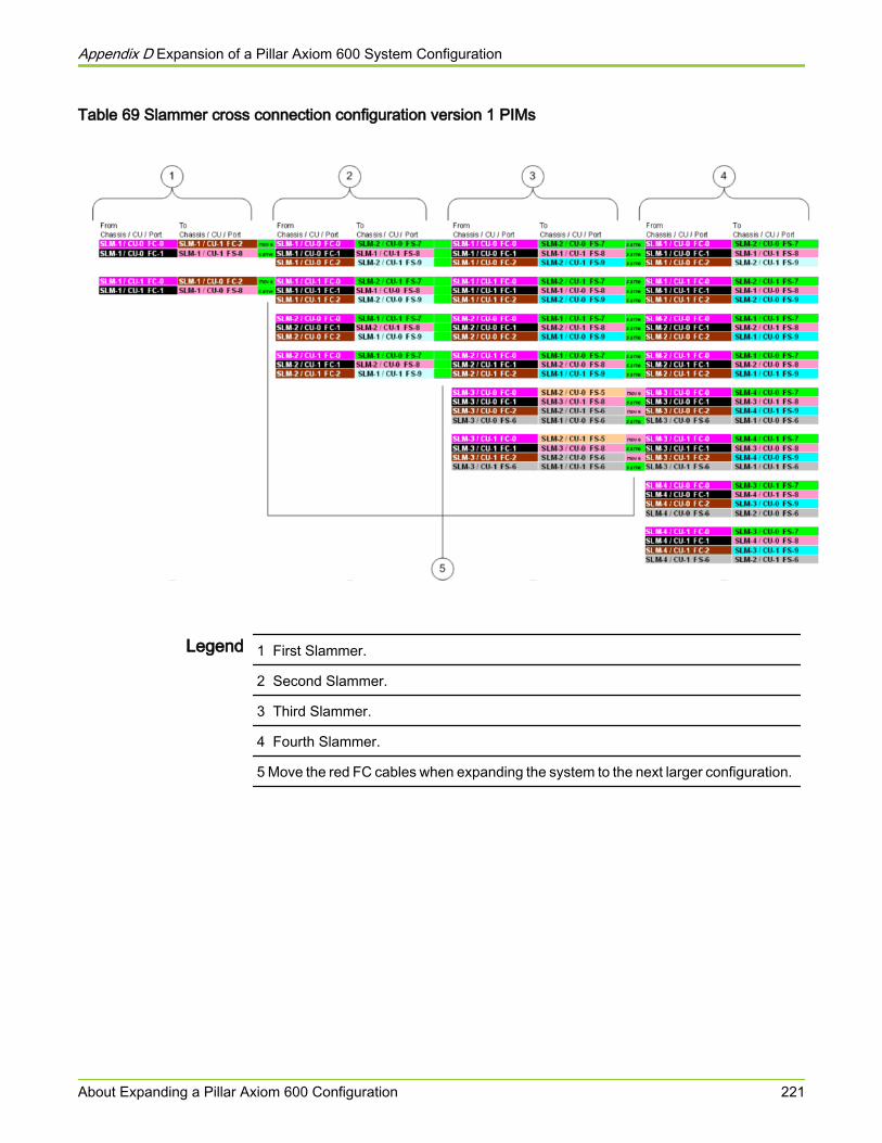
Table 69 Slammer cross connection configuration version 1 PIMs
Legend 1 First Slammer.
2 Second Slammer.
3 Third Slammer.
4 Fourth Slammer.
5 Move the red FC cables when expanding the system to the next larger configuration.
Appendix D Expansion of a Pillar Axiom 600 System Configuration
About Expanding a Pillar Axiom 600 Configuration 221
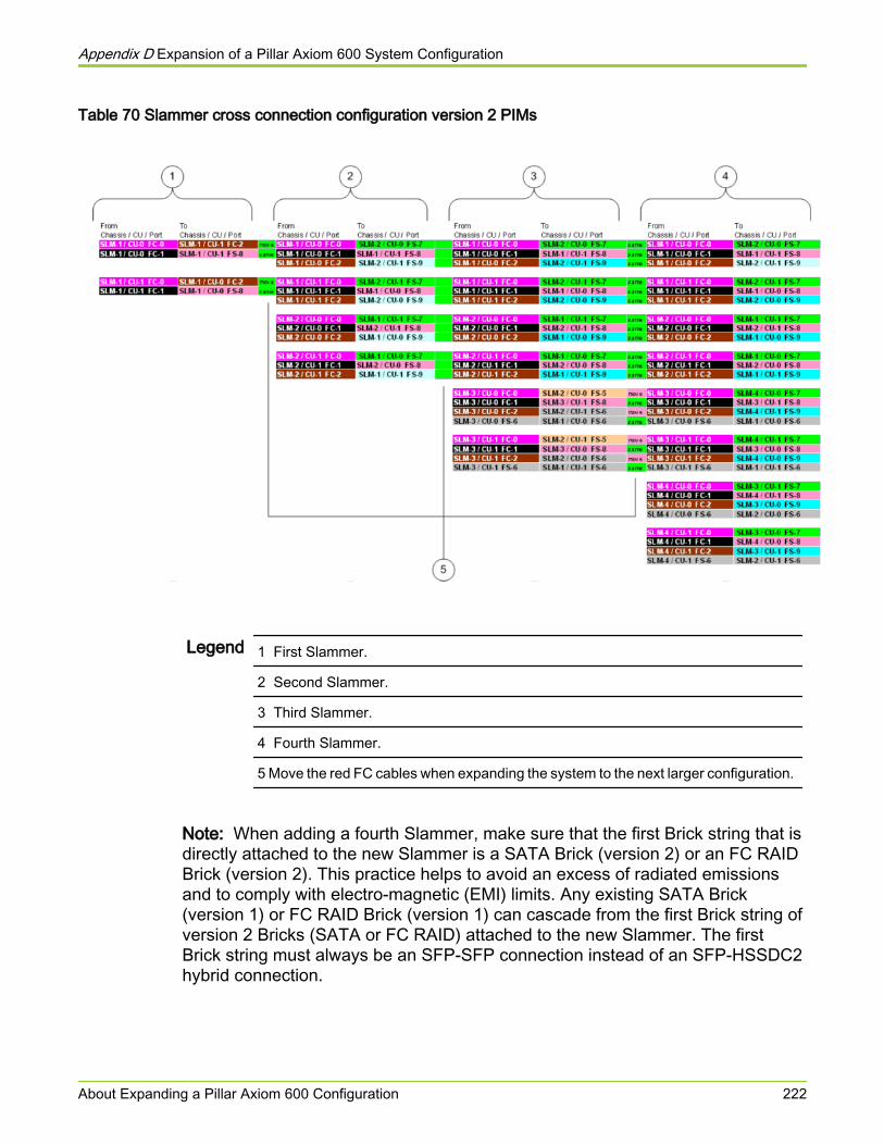
Table 70 Slammer cross connection configuration version 2 PIMs
Legend 1 First Slammer.
2 Second Slammer.
3 Third Slammer.
4 Fourth Slammer.
5 Move the red FC cables when expanding the system to the next larger configuration.
Note: When adding a fourth Slammer, make sure that the first Brick string that isdirectly attached to the new Slammer is a SATA Brick (version 2) or an FC RAIDBrick (version 2). This practice helps to avoid an excess of radiated emissionsand to comply with electro-magnetic (EMI) limits. Any existing SATA Brick(version 1) or FC RAID Brick (version 1) can cascade from the first Brick string ofversion 2 Bricks (SATA or FC RAID) attached to the new Slammer. The firstBrick string must always be an SFP-SFP connection instead of an SFP-HSSDC2hybrid connection.
Appendix D Expansion of a Pillar Axiom 600 System Configuration
About Expanding a Pillar Axiom 600 Configuration 222
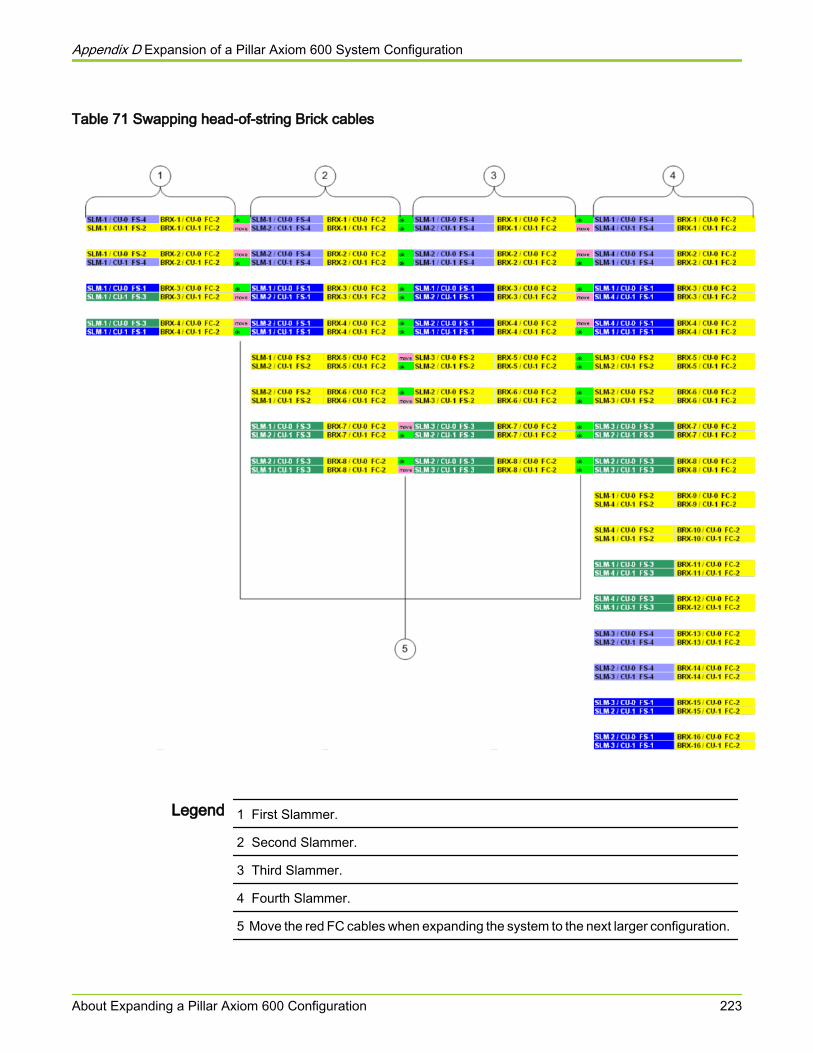
Table 71 Swapping head-of-string Brick cables
Legend 1 First Slammer.
2 Second Slammer.
3 Third Slammer.
4 Fourth Slammer.
5 Move the red FC cables when expanding the system to the next larger configuration.
Appendix D Expansion of a Pillar Axiom 600 System Configuration
About Expanding a Pillar Axiom 600 Configuration 223

Index
10 Gb/s Ethernet HBALED status 137
2U rack railsBricks 57Pilots 49
4U rack rails 538 Gb/s Ethernet HBA
LED status 136
Aaccept
Bricks 82acoustics specifications 189add
Bricks 82add (expand system)
Brick 214, 217Bricks 213Slammers 218
add Brickchecklist 211
add Bricks 211add Slammers 211additional resources 17altitude specifications 188amperage
component draw 123PDU limits 115
anti-tip bracketshow to
install 36
Bbatteries, Slammer
how toinstall 73
bays, rackattach baying plates 31interconnection bracket 30preparation 29
bezel attachment 138book organization 16boot-up time, system 154
bracket, rack connector 30Brick hardware components
expanding the system 213hardware specifications 203how to
add a new Brick 214install 75install rack rails 58power on 125replace 80set identity of Bricks 78test SSF connections 146verify a new Brick 217
placement1-Slammer systems 41, 432- and 3-Slammer systems 454-Slammer systems 47
rail kit parts 57Brick storage enclosures
cabling rules summary 95foreign 82how to
accept 82Bricks
how torename 149set identity 78
logical name 149physical name 149
BSMI D-Mark 190
Ccable connections (Fibre Channel)
swapping cables when expanding 220cable lengths 201cable swapping
when adding a Slammerhead-of-string Brick cables 223with version 1 PIMs 221with version 2 PIMs 222
cablesfiber optic, test for failure 151
224

cablingbest practices 95guidelines 95manufacturing practices 95Pillar Axiom 600 89private management interface (PMI) 89rules 95Storage System Fabric (SSF) 89
cabling, Pilot 110casters 33cautions
defined 25in English 184
CB Scheme by IECEE standard 190checklist
add Brick 211pre-installation 211
Clone LUN replicashow to
delete 81complete the installation
supply power 125test SSF configuration 146turn on the system 125
componentsPillar Axiom 600 89
components, Pillar Axiom 600 systemtechnical specifications 187
components, Pillar Axiom systemplacement in rack
1-Slammer systems 41, 432- and 3-Slammer systems 454-Slammer systems 47
supported hardware 21configuration limits
Pillar Axiom 600 39configuration, system
how totest 146
Conformite Europeenne /DoC 190connection bracket 30conservative mode 212contact information 19conventions
typographical 19create
Storage Domains 83cUL compliance 190customer supplied materials 23
Ddata sheets 186delete
Clone LUN replicas 81digital push button switch, ES module
how toset Brick identification 78
dimensions and weightBricks 203Pilots 196Slammers 199
distance limitationsNAS ports 201SAN ports 201
documentationaccessing 18conventions 25related to cabling 17suggestions 20
Eeducation programs 20EIA-310-D compliance, rack 27electrical safety issues
list of hazards (translated) 162electromagnetic emissions and immunity 193electrostatic discharge (ESD) 26environment, data center
Pillar Axiom system requirements 188equipment, required 23ES modules, Brick
location 78Ethernet 110Ethernet LAN 108European Union Compliance Statement 194expanding a system
add Bricks 211add Slammers 211cable swaps 220
Ffabric, test 146FC Bricks
placement1-Slammer systems 432- and 3-Slammer systems 45
FCC agencycompliance statement 190warning statement 193
fiber optic cableshandle 92test for failure 151
Fibre Channel (FC) Brickscabling rules summary 95
Fibre Channel switches 113foreign Bricks
225

definition 82
Ggigabit Ethernet switches 113graphical user interface (GUI)
how tologin 146
ground strapsdoor 142precautionary use of 26
Hhalt, Slammer
codes 156halt, system
evaluate Slammer LED codes 155Slammer LEDs identify problem 154
hardware specificationsacoustics 189altitude 188dimensions and weight
Bricks 203Pilots 196Slammers 199
humidity 188PDU 206power characteristics
Bricks 203Pilots 196Slammers 199
random vibration 189regulatory agency compliances
Bricks 204Pillar Axiom system 190Pilots 197Slammers 200
temperature 188hardware, Pillar Axiom
LED boot-up codes 154placement maps
1-Slammer systems 41, 432- and 3-Slammer systems 454-Slammer systems 47
specifications 186supported 21
hazard signal wordsdefinitions 25translated 162
helponline 19
host bus adapters (HBAs)installation 140
how to
cable PMI 89cable SSF 89handle fiber optic cables 92
humidity specifications 188
Iidentities
how toset for Bricks 78
installation procedurescable multiple racks 104connect PDUs to power 123create a rack bay
attach baying plates 31attach interconnection bracket 30
equipment, required 23install 2U rack rails 49, 57install 4U rack rails 53install Bricks 75install Pilots 66install Slammer batteries 73install Slammers 71power on the system 125set up the racks 26test SSF cables 146tools, required 23turn system on 125
IP addressesPilot 147
ISO 90012000 manufacturing process 190
Jjumbo frames, prerequisites for 107
KKCC-SPA1 190KCC-SPR1 190KCC-SPS1 190
LLED codes, Slammer
during halt 156during startup 156LED blink rates 155
LED statuses10 Gb/s Ethernet HBA 1378 Gb/s Ethernet HBA 136
leveling legs 33login (GUI) 146LUNs
how tomove to another Storage Domain 87
226

MMGMT ports, Pilot 109mixed Brick types
connection rules 95mounting rail kits
Brick 57Pilot 49Slammers 53
Nnetwork connections, customer
hardware requirementsPilot 108, 110Slammers 112
how toconnect the Pilot 108, 110connect the Slammers 112
network interface module (NIM)connects system to data path 112
non-disruptive upgradeBrick 213Slammer 219
notice conventions, safety 25
Oonline documents 18online help 19organization, book 16
Ppanel removal, rack 29password, administrator
give to Primary system administrator 146how to
reset 153PDUs
amperage limits 115hardware specifications 206how to
install 1U PDUs 62install 2U PDUs 64power on components 125
Pillar Axiom 600configuration limits 39
Pillar Axiom 600 systemhardware specifications 187
Pillar Axiom Path Manager (APM)about installation 152
Pillar Axiom storage systemhow to
connect to the data network 112connect to the management LAN 108connect to the Pilot CU 110
using jumbo frames 107warranty 195
Pillar Data SystemsSupport portal 20
Pilotversions 68
Pilot hardware componentshardware specifications 196how to
install 66install rack rails 50power on 125
IP address 146rail kit parts 49where to install 66
Pilot management controllersIP address 147
placement of components in rack1-Slammer systems 41, 432- and 3-Slammer systems 454-Slammer systems 47
position the Pillar Axiom racklevel the rack 33stabilize the rack 35
powercabling examples
sixteen Bricks 120three Bricks 117
characteristics (hardware components)Bricks 203Pilots 196Slammers 199
component usage 123feed requirements of the system 187
power on the system 125pre-installation
checklist 211primary Storage Domains
how totransfer primary status to another domain 86
private management interface (PMI)cabling 89
product support 20professional services 20progress codes, Slammer startup 155
Rrack bays
attach baying plates 31interconnection bracket 30
rack railshow to
install for Bricks 58
227

install for Pilots 50install for Slammers 55
racksdoors and panels 142EIA-310-D compliance 27how to
level 33stabilize using anti-tip brackets 36stabilize using stabilizer plates 37test SSF configuration 146
multiple 29power connection 123stabilization
methods 35stabilizer plates 37
recycling program 190regulatory agency compliances
electromagnetic emissions and immunity 193safety and quality standards
Bricks 204Pillar Axiom systems 190Pilots 197Slammers 200
related books 17replacement procedures
replace Bricks 80requisite reading 15RoHS compliance 190
Ssafety
notice conventions 25statements
translated 162safety and quality standards
Bricks 204Pillar Axiom systems 190Pilots 197Slammers 200
sales information 20SAN environments
APM installation 152SATA Bricks
placement in rack 41Serial ATA (SATA) Bricks
cabling rules summary 95Slammer hardware components
expanding the system 218hardware specifications 199how to
install 71install batteries 73install rack rails 55
power on 125test SSF connections 146
LED codeshalt 155, 156startup 156
LED status10 Gb/s Ethernet HBA 1378 Gb/s Ethernet HBA 136
mixing PIM versions 219placement maps
1-Slammer systems 41, 432- and 3-Slammer systems 454-Slammer systems 47
rail kit parts 53Slammer storage controllers
cable swaps when adding Slammershead-of-string Brick cables 223with version 1 PIMs 221with version 2 PIMs 222
Solid State Drive (SSD) Brickscabling rules summary 95
solutions (professional services) 20SPA1 190SPR1 190SPS1 190stabilization systems, rack
anti-tip brackets 36stabilizer plates 37
startuptime 154
startup, Slammercodes 156
Storage Domainseffect created by
adding a Brick 84how to
accept a Brick 82create 83move a logical volume 87transfer primary status to another domain 86
Storage System Fabric (SSF)cabling 89cabling rules summary 95how to
test configuration 146swapping cables when expanding 220
sub-floor tie-down system 35Support portal 20swapping cables when expanding a system 220switches, network
Fibre Channel 113gigabit Ethernet 113zone setup (SAN) 141
system alerts
228

accept Brick 214, 217system, Pillar Axiom
how totest the configuration 146
warranty 195
Ttechnical documents
accessing 18technical support 20temperature specifications 188tie-down system, sub-floor 35tools, required 23training programs 20turn on Pillar Axiom systems 125TUV/GS compliance 190typographical conventions 19
Vversions, hardware component
PIMs 219vibration specifications, system 189
Wwarnings
defined 25in English 163non-English translations 162
warranty information 195
229