Embed Size (px)
Citation preview

PILGRIM PERMOCOAT, INC.402 S.22nd Street, Tampa, FL 33605 (813) 248-3328 FAX# (813) 248-1076
www.pilgrimpermocoat.com
PILGRIM UWC LV is a two-component,100% solid, high strength, low viscosity, epoxy resin adhesive.Formulated to seal/bond both dry and damp cracks.
The UWC LV Cartridge Systemprovides point-of-use application to save time, material and minimize health hazards. The PILGRIM UWC LV Cartridge provides a unique method of handling, storing and dispensing of two component materials. Ideal for low to medium volume material users that wish to eliminate problems associated with the use of two component epoxy adhesive.
USES:Specifically designed for concrete crack injection, UWC LV provides degree of convenience, ease and speed of use, affords the contractor maximum efficiency. Recap cartridges for later use - only a new static mixing tip will need to be replaced. UWC LV is moisture insensitive; use on dry, damp or wet surfaces.
BENEFITS: TYPICAL PROPERTIES • No large capital expense • Eliminates material waste • Saves time • Rapid physical properties development • Eliminates aerated mix • No clean up solvent needed • Little operator skill needed • Low maintenance • Increased productivity • Unlimited, low cost dispense points
Florida DOT Type EFL APL # 926-004-006
Louisiana DOTASTM C881, Type 1, IV Grade 1 Class, B,C
Georgia DOT Type V
Gel Time, min. (LV / LV EPL) 20/180Viscosity, cps 180Water absorption, 24hr. 0.4%Heat Deflection Temp., °F 133Tensile Strength, ASTM D638 5,660 psiTensile Modulus, ASTM D 638 567,00psiShore D hardness, ASTM D2240 81Flexural Strength, ASTM D790 8,700 psiFlexural Modulus, 567,000 psiCompressive Strength, ASTM D695 9540 psi (72 hrs.)Bond Strength, ASTM C882 2775 psi2 day (moist Cure), 60°F
UWC LVPage 2
GENERAL RECOMMENDATION: Consult Pilgrim “Crack Injection Procedure” bulletin.
SURFACE PREPARATION:Concrete substrates must be - sound, clean, free from, dust, curing or parting compounds, oil, waxes, impregnations and foreign particles. Substrate temperature must not be below 40°F.
DISPENSE INSTRUCTIONS for Dual Cartridge Injection System (HP™ Pneumatic Gun)
1. Remove protective nose caps from cartridges. (Black)2. Attach static mixer, flow restrictor and nut.3. Load cartridge into air gun 4. Regulate input pressure to 40-60 psi. 5. Activate trigger to equalize pistons. Discard first 10 cc’s of material or continue.6. Attach Valve Assembly7. Attach connect-it to port.8. Activate trigger to dispense material.9. Close valve, leave mixer on and put back on the shelf. Allow mixer to act as a seal. Replace with new static mixer before reusing cartridge.
NOTE: Flush Valve Assembly with Pilgrim #5 CleanerEither air powered or manual, trigger-operated guns are available, specifically designed for use with the PILGRIM UWC LV cartridge . Note: Air powered is preferred when dispensing large volumes. Air power dispensing is required to meet Florida DOT injection specifications.
PACKAGING:18 ea. 450 ml cartridges/carton + 18 ea. 1/8” diameter static mixer with nuts.3 & 15 gallon units available for use in plural component meter mix injection machines.Consult Pilgrim for recommended injection machines.
CAUTION: Contains epoxy resins, organic amines. Toxic before cure. Avoid vapor inhalation, con-tact with skin, eyes. Consult Material Safety Data Sheets for complete information on safety and handling.
WARNING! Improper cartridge pressure may force material out of rear of cartridge! Use safety eye wear!
UWC LVPage 3
IDENTIFY CRACKSCracks are classified as structural and nonstructural. No sealing or repair of structural cracks shall be accomplished by the contractor without having a repair procedure approved in advance by the Engineer. Nonstructural cracks shall be sealed according to the criteria listed below. Structural cracks are those which are induced by external forces which produce internal stresses exceeding the tensile strength of the concrete, commonly referred to as working cracks and those caused by overloads. Nonstructural cracks are those which appear as a result of component materials characteristics, atmospheric effects and localized constraint effects, commonly called shrinkage cracks. In any case, the Engineer shall determine the classification of cracks. Mark cracks to be injected with colored chalk or marker.
SURFACE PREPARATIONPrior to injection, concrete surfaces adjacent to the cracks shall be prepared to expose clean, sound concrete. Grind surface of areas to be injected with a 4.5” diamond cup and grinder. Remove enough material to expose a clean sound substrate. After grinding blow surface with clean dry compressed air to remove loose materials.
INSTALLING INJECTION PORTSInjection ports may be installed as surface mount or drilled type ports. Drill ports are installed in 1/2” drilled holes approximately 3/4” in depth. Ensure ports are positioned directly over cracks that are to be injected. Surface mount ports can be anchored to concrete surfaces with EM 5-2 Gel or a “Crazy Glue Gel”. Care must be taken to ensure port anchoring material does not block path of injection resin to crack.
SURFACE SEALING (CRACKS)EM 5-2 Gel is designed as a surface sealing compound, supplied in 2 gallon units (Mix ratio, 1:1 by vol.) or in a two-component cartridge dispensed either manually or by air. Seal the surface of the cracks. EM 5-2 Gel can be applied either with a spatula or putty knife. The width of the surface sealing epoxy when applied, should extend a minimum one inches from the edge of each side of the crack. Apply a band of Gel at least 2 inches wide approx. 1/16” in depth making sure you get material around each port and evenly between ports. 1/16” thickness is recommended, to resist injection pressures. A very thin coat will not likely resist pressure and may fracture causing leaks. Allow gel to achieve an initial set of approx. 15 minutes before smoothing the surface with solvent. The solvent smoothing assures there are no pinholes or folds where leaking can occur. Around the ports create a small cone shape of the gel. Thorough sealing of the ports and crack surface is very important. Allow EM 5-2 Gel to cure for a period of 4-24 hours depending on substrate temperature before injectiong UWC LV epoxy.
INJECTIONStart injecting at the widest section of a horizontal crack. Vertical cracks are typically injected from bottom up. Attach Valve Assembly to static mixer. Lock “Connect-it” to port to begin injecting. Pump PILGRIM UWC LV into injection port via manual or pneumatic gun until resin begins to flow out of adjacent port. Port sealing plugs may then be installed before proceeding to next port. Repeat the process until all of the ports have been injected, and closed off. If necessary and time permits, re-inject previously injected ports by re-opening the port. This will ensure as much injection compound as possible, has been injected into the crack. This is particularly worthwhile doing, as injection compound initially injected, passes through the substrate via capillary action.
GENERAL CRACK INJECTION PROCEDURE
UWC LV Page 4
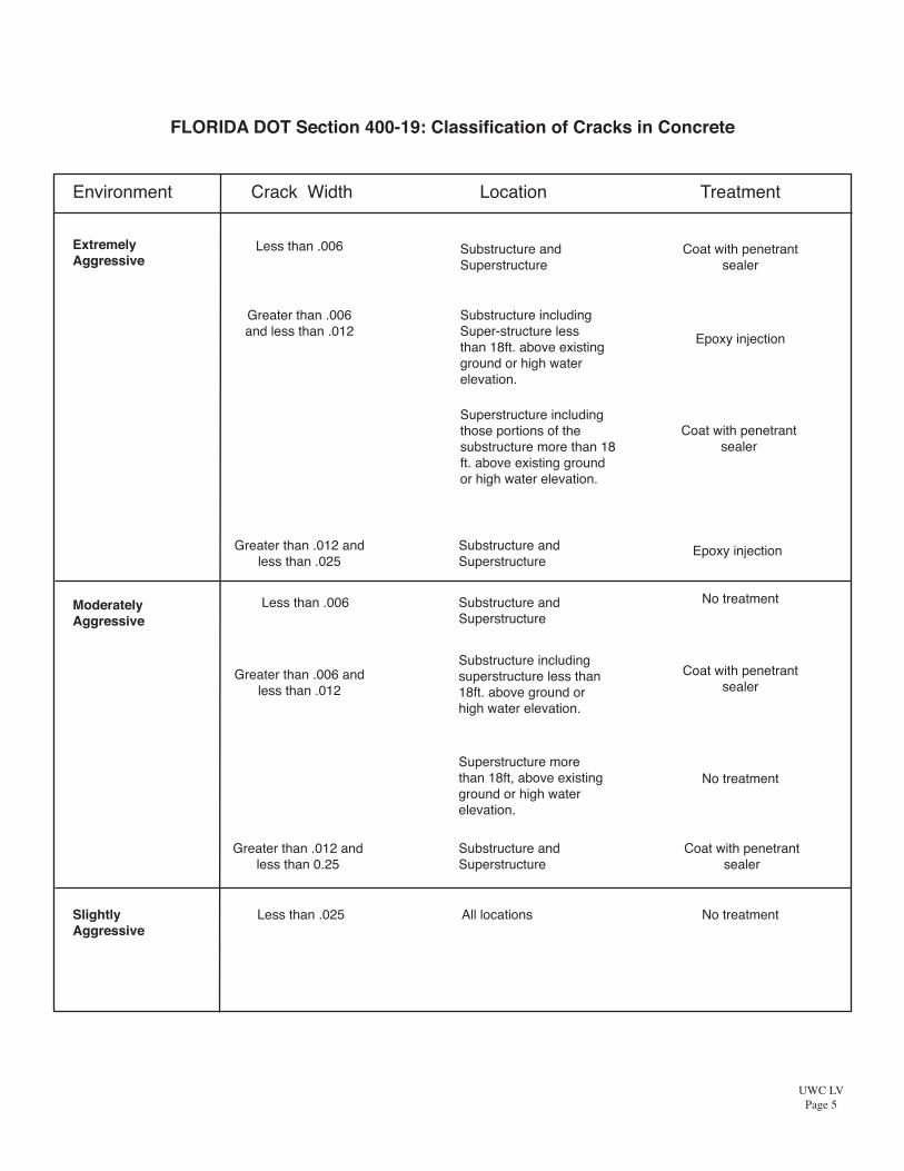
Environment Crack Width Location Treatment
ExtremelyAggressive
Less than .006
Substructure including Super-structure less than 18ft. above existing ground or high water elevation.
Epoxy injection
Superstructure including those portions of the substructure more than 18 ft. above existing ground or high water elevation.
Coat with penetrant sealer
Greater than .006 and less than .012
Substructure and Superstructure
Coat with penetrant sealer
Greater than .012 and less than .025
Substructure and Superstructure
Epoxy injection
Moderately Aggressive
Less than .006 Substructure and Superstructure
No treatment
Greater than .006 and less than .012
Substructure including superstructure less than 18ft. above ground or high water elevation.
Coat with penetrant sealer
Superstructure more than 18ft, above existing ground or high water elevation.
No treatment
Greater than .012 and less than 0.25
Substructure and Superstructure
Coat with penetrant sealer
Slightly Aggressive
Less than .025 All locations No treatment
FLORIDA DOT Section 400-19: Classification of Cracks in Concrete
UWC LVPage 5

Valve Assembly
125
100
75
50
25
10 20 30 40 50
Make: Cox
Model: PPA 300A
Test Range
Supply: 26 - 48
Applicator: 32 - 115
Pressu
reRe
ading
atPo
intof
Appli
catio
n(ps
i)
Supply Pressure Reading (psi)
Supply Pressure vs. tip PressureThe test range at supply point was 26 - 48 psi resulting in a tip pressure 32 -115 psi.The Cox gun is rated to 125 psi supply pressure. The following supply pressure resulting intip pressures has been extrapolated from Test lab’s report to demonstrate that with 75 psiair supplied, the resulting pressure is 200 psi.
Supply Pressure Tip Pressure20 3830 7040 9550 12060 14570 19080 220
Cut static mixer as shown beforeinserting into valve assembly.
Pilgrim recommends 40-60 psi supply pressure to pneumatic gun.
UWC LVPage 6