Embed Size (px)
Citation preview

AGRiCULTURE ROOM
PILE TRESTLES
on
Logging Railroads
by
J. S. Brandis
K R
Nov 24 195e
SCUOOL O DESTRY
OREGO1 STATE COLLEGE
OO«VÀLLIS, RIGOL4

PR FAO E
Of the average railroad, trestles constitute from
one to three percent of the total length. In railroad
logging in the Pacific Northwest today this percentege
is much greater. In years past the logging comoanies
had more of a selection of shows which they could log.
It was not necssary at that time to reach far back into
the hills, where the terrain as rough, to acouire a
high grade of timber. iThile today with the bétter shows
logged off, they must withstand costly construction due
to terrain features, in order to log the finer virgin
timber.
Many times the engineers find it less costly to
build a nile trestle, rather than to fill some of the
wide, deer ravines, or to contruct railroad many miles
around the head of the said ravine.
It is this single rrincinle, "chearer coast Of C0fl
struction1', that has made the nile trestle so norular
in logging railroads. The comparatively short time the
trestle is in use would not the construction of
a permanent stel bridge, or o costly fill.
The pile trestle most widely used on logging rail-
roads is knovm as the "five-pile-bent" trestle. This is
due to the heavy loads that are freouently passing over
these trestles.
This parer will endeavor to exnlain the construction,
and comparative costs of the pile trestles..

UETERAL
Generally pile-bents ae usd where the ground is
cuite soft, ad where the distance from the ground to
the rails is not too great. The one grave objection
to the high pi1e-testles is that the top end of the pile
is in the ground. The top is of the oorest timber and
decays more readily than the other timber.
Files should be at leant from 12 to 15 inches across
the butt after being cut off.
The recuirements of a iie are:
1. itraigh.t 2. oound 3. Live heart timber 4. Free from wind--bciças 5. Free of cracks, worm-holes, and all description
of decay. 6. .ree of large, loose, black or decayed knots. 7. It is much preferred to have the piling
stripped of the bark.
The timber used for piling depends largely uîon the
kind growing in the immediate vicinity.
The following ana listed in the order of their
du r a b i 1 :i ty:
1. Ped cedar 2. Red cypress 3. Fitch pine 4. Yellow pine 5. White pine 6. Redwood 7. lm
8. b'pruce 9. White oak
lO. Post oak 11. Red oak 12. Black oak 13. hemlock 14. Tainarac
rïuhe timber used for trestles in the Facific Northwest
is red cedar, iiouglas fir, and hemlock. The average life
of the cedai' trestle is 15 to 20 years, the Douglas fir,
B to 10 years, and the hemlock, 3 to 6 years. The
variation in the life of the bridge is mainly due to the
use of the trestle, and the climatic conditions in that area.

1)FINITION
1. TRISTL. A braced framevTork of t1nab'rs, piles, or
steeiwork, for carrying a road over denression.
2. PILI! TRESTLE. A structure in which the un right members
or supnorts are nues. O 3 BINT. The group of members forming a'single vertical
sunnort of a trestle, designsted as a nile bent where
the principal members are nues.
4. ±1ÏJR. The deviation from the vrtcal in upright
members of the bent.
5. UAP. The horizontel memhr unon the top of nues,
connecting them in the form of a bent.
6. SWAY ]3RAC.S. iviembers bolted or snikd to the bent
and extending diagonally across its fac3.
7. LONGITUDINAL STPLUTh OR GIRT$. stiff membes running
horizontally from bnt to bent.
8. bASH BPLAOE. liorizontal members secured to the posts
or piles of a bent.
9. bThINGRS. The longitudinal members extendihg from
bent to bent and supporting the ties.
lo. JAOR TRINGER. J. single line of stringers nlaced
outside the main stringers.
li. uIES. Transverse timbers resting on the stringers
and supnorting the rails.
12. GUiRD RjIL. Longitudinal members, either iron or
wood, secured on top of ties.
13. PACKING BLOCKS. 3mall members, usually wood, used to
secure the parts of a comnosite member in their proper

relative position.
14. PAUIING SPOOLS OR P±RaTOR. ma11 castings used in
connection with packing bolts to secure the several
parts of a composite mem.ber in their prooer relative
position.
15. iJRIFT BOLTh. j piece of round or sçluare iron of specified
length, with or without a head or point, driven as a
spike.
16. iiOVEL. n iron or wood pin, extending into. 'out not
through, two members of the structure to connect them.
17. HfliI. A small piece of wood or metal placed between
two members of a structure to bring them to a desired
relative position.
18. FIb H-PLATE. j short piece lappinga joint, secured
to the side of several members which are butt-jointed.
19. JiULK±LJD. Timber placed against the side of an end
bent for the purpose of retaining the embankment.

JIYJ67 3 7/a' 3,'l/J CJ2 t'cV&7
'1 1
i, "I

47

Trst1e Uonstruction
NGINiRING. In trestle construction the engineering
work consists of the prs1iminry work and location of
the trstle, making the pins for the trestle, and the
inspection and supervision of the construction.
PRELThIINkRY. Upon indication that a trestle will be
needed, the engineer runs the center line of the trestle
across the ravine. Levels are then run long the center
line to deteniline the percent c,f sloDe of the bridge,
and the percent nf slope at each fifty fot tation.
iiIDG FLJU\J. With the data collected, a profile of the
ravine is then drawn u. such a profile will include
the height and station of each bent. ith this profile,
the engineer then stakes out the location for each bent.
This profile furnishes the basis for an estimate
of the auantity of piling,
and iron neded to conmiete
INPEUTION I'U UP RVISION.
construction of the trestle
the trestle is built to the
standards.
his duties are:
3a.ps, stringern, ties, bracing
the trestle.
Upon the beginning of the
the engineer must see that
required sDecification. and
1. Line up bents. 2. Plumb bents from side of trestle. 3. cpot and line up piling in bent when being
placed for driving. 4, Test pile for bearing while being driven. 5. iieterrnine cut-off point on bent. 6. Record pile bearings and penetration. '7. dee that proper number and length of bracing
is used. S. et center line points on caps for deck placing. 9. check for proper laying of stringers.
10. oet center line on ties for laying of steel.

ihe parts of a trestle ar classified under two
main heads; namely, the "sub-structure" for that Dart
which is blo' th deck, and "surtructure" for all
which is above the caps.
The 'sub-stri.cture" includes the piling, caps, sway-
braces, sashes, towers, girts, and diagonal braces.
In the "super-structire" are included the stringers,
ties, guard rails, and often barrel Dlstform and vTalk
ways.
The most common pile trestle in logging i th five-
pile-bent trestle.
The center pile or plumb Due is driven straight
dawn on the center line of thetrestle. To either side
of the plumb pile are the track piles, which lean toirard
the plumb pile with a slope or batter of one inch per
Loot of height of the pile. The out2r piles, or batter
piles are sloped inward with a batter of two inches per
Loot of height of the pile.
xample: If, at the top. the centers of the nues
were spaced thirty-two inches enart . and the trestle
height was seventy-five feet, the center of the track
piles wculd be 10'? incher from the center of the plumb
pile. ihe center of the battr nues would be 182 inches
from the center of the plumb pile.
ujP. Caps are timbers laid acros the top of the five
piling of a single bent. They are fastened to each nile
with drift bolts. uaps are usually 12" x 12" x 14" or
12" x 14" x 14". 1t is upon these caps that the stringers
are placed. the caps allow an equal distribution of weight

on ail piles. 3RiOING. Bracing is used to support the bents of the
trstle against lateral and ide motion when under a load.
tiost commonly used are 3 x 10" boards vìrying in length
with their position on th trestle. ih grade most cononly used is number one common.
bwaT braces e diogonal biaces bet'een the
sashes on the bent. The sav br aces ori th front of the
bent run diagonally £rom the left dovmwsrd to the rirtht. ihe front of the bent being toward the origin of the bridge.
Often oì high bridges it is necessary to Dut d uble swars
between lovier sashes. As the name implies, the function
of the sway braces is to prevent sideward motion of the bridge as a load is passing over it. rì)hev are fastened
with boat-spilçes.
bASH BACo. Sashes are fastened horizontally across the front and btck of the bents at the intrval of everr
eighteen feet in height. iher also ere fastened with
boat-sDikes.
The longitudinal brAces of a trestle are the girt
and towers.
bTRINGRb are timber' spanning the pening bteeu bents. oize, number, and arrangement vary. iJsiiailv span at least two openings. In logging trestles usually hewn
logs are used.
±rrangemant of stringers fall into two classes; "chorded" and lapped.
UhORDED The stringers lay parallel -- end of one
butted agaiost the one irnmediatly before end inimediatly

after it. wthree on each cicle or six across each opening.
hen light stringers are used an extre one, "jack stringer",
is placed outside just below the guard rails.
The chorded stringer arrangement is superior in
that it lies directly unde' the rsils a .d also that it
suports the bridge longitudinally. -iowever, this tyDe
costs nearly double of what lapped deck costs. '
LAPPED The stringers are not butted hut angled off
the rail line. Only two stringers are under each rail
or four across each opening. span two oDelings. stringers
are usually 12" x 18".
Most cormuon are 8" x 8" x 10' and are Dlaced ori
stringers at right angles to the center line of the trestle.
3pacing is often " arert but 6" is much prefrea.
GUARD-RAILS are fe ., steried to both ends of the ties.
Usually use " x 8". If 6" x " are used they leave 5"
above the top of the ties. Often Dlaced on top of ties
near ends then use 4" x 4".
For two rur oses -- to prevent as best Dossible the
derailed rolling stock from leaving the trestle and to
keep ties in place.

0,4/'
Q1Á'1O - RAiL ' 77E o a TA'/4'EA'
¿/i.'E BRA C/#2d' O T TRE 6' TL E
TO WLP

Y/OADEz7 ¿7E04
LJL i
2TM'D,4ì?) LI1/PEZ Z7E0/Ç

PARALLEL LAP L7E04'

I9H'/4/2 c)'UPER -EL O/ O'/TFR /?4'Z 45' ó'S'622 O V&S
?AL flO'/T/O4! OF 04e'
W WJPER- ¿EV4' 770'V

Contract and Costs
The following are the contract and costs of a bridge
actually put in by one of the logging companies in north-
western Washington.
The timbers used for the piling on this bridge are
Douglas Fir,
Due to unforseen difficulties this bridge cost the contract-
or much more than he had anticipated. It also took hirn nearly
three times as long to complete the trestle as he had estimat-
ed.
As many of the trestles in the logging business are con-
tracted this example is being included in this thesis to
give the reader some idea of a practicle contract and cost
forms kept by the company.
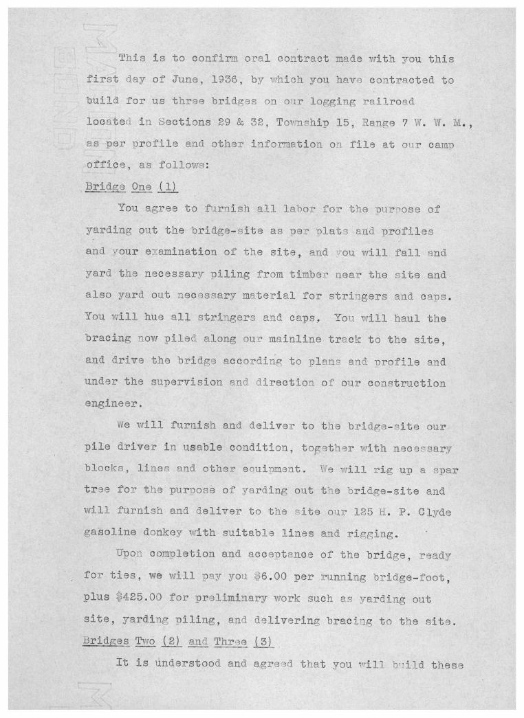
This is to confirm oral contract made vrith you this first day of June, 1936, by hich you have contracted to build for us three bridges on oir logging railroad located in sections 29 & 32, Toinship 15, Range 7 W. W. M.,
as per irofile and other information on file at onr camp
office, as follows:
Bridge One (1)
You. agree to firnish all labor for the purose of
yarding out the bridge-site as per olats and profiles and rour enamination of the site, and rau will fall and.
yard the necessary piling from timber near the site and
also yard out necessary material for striogers and caps. You will hue al]. stringers and caps. You. will haul the bracing now piled along our mainline track to the site, and drive the bridge according to Dlens and Drofile end
under the supervision and direction of our construction engineer.
íe vrill furnish and deliver to the bridge-cite our
pile driver in usable condition, together with necesary blocks, lines and other enuipment. We will rig up a spar tr3e for the purpose of yarding out the bridge-site and
will furnish and deliver to the gite our 125 H. F. Clyde
gasoline donkey with suitable lines and rigging.. Upon completion and acce-otance of the bridge, ready
for ties, we will pay you
plus 425.00 for prelimin site, yarding riling, and
i3ridges Two (2) and Thre It is understood and
6.00 per running bridge-foot, ry work such as yarding out
delivering bracing to the site. (3)
agreed that you will bild these
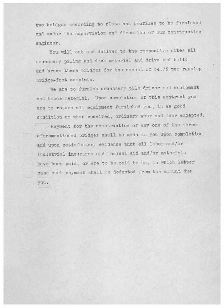
two bridges according to plats and profiles to be furnished
and under the supervision and direction of our construction
engineer.
You will cut and deliver to the respective sites all
necessary piling and dck mterial and drive nd bild
and brace these bridges for the amount of 4.75 per running
bridge-foot complete.
Ve are to furnish necessary pile driver on.d eciuipment
and brace material. Upon completion, of this contract you
are to return all equipment furnished you, in as good
c'ndition as wLen received, ordinary wear and tear enceted.
Painnent for the construction of any one of the three
aforementioned bridges shall be made to you upon coumletion
and upon satisfactory evidence that all labor and/or
industrial insurance and medical aid and/or materials
have been paid, or are to be paid by us, in which latter
case such pauant shall "e deducted from the amount due
you.

3 x 10 Bridge Bracing Boat Spikes
36270 572.43 27.3 Freight 15.00 17.80 reight 15.00 26.70
Freight 25.65 18.16 11820 168.79 9.28
$796.87 25.20 124. 37
Industrial Medical Payroll Insurance Aid
$47.10 $4.84 $0.42 11.12 1.19 0,11
$58.22 6.02 $0.53
Pullars account --- uirect Industrial Medical
Payroll Insurance Aid S. S.
$ 734.26 $ 68.96 $ 5.79 $15.42 807.90 111.06 11.25 20.42 164.69 88.98 8.58 19.33
Less- 872.81 106.50 10.06 22.61 1Er- 1077.11 375.50 'r3568 76.78 bridge- $3656.76 for2.. . . . -48.23
3608.53
Ties
$228.84 15.00
$243.84
Social e curia
'0.99 Ò.23
$1.22
Personal Account
; 45.05 1.52
29.76 75.00 28.23
106.64 77.97 67.55
431.?2

Tables of Comparative Costs
Often as an engineer you will find it necessary to
determine the most economical and practica way to carry
a railroad over a ravine, Two important factors should be
given close considtion. Firstly, the cost of constvnction
of a trestle as comuared to that of an emban1'nent, And
secondly, the lengbh of life the road is to be used as
compared to the diration of the life of the trestle, Many
times it may be found that the initial cost of a trestle
would be much less than that of an embankment, but if the
trestle must be replaced b3fore they are through using the
road, the cost of trestle may be greater than that of an
embankment.
The following tables are of use in deterrninin the com-
parative costs of trestles and embankments. Also the corn-
parative costs of the pile and frame trestles.

(S/7O W/A'G REL A T/I'E 00S'T2 0E EN6'%'VKA'EA'T ,1#D rA'EÓ'TLE /# /OOEÓOT JECT/OIrÓ /#OL//D/A/O Ñ&LS T/EJ, ,4,YO BILLA 8T OV ,'OAWER, Á#Z /PI/L, OWRL -RIIL ó, /1/I'D
T/E6' O/ti L IT TER

COS r 0E PILE ,4#9 FRAME TRE rr E C OAPL E TE, ZA/OL (/û/4'6 ZO0R 6Y6'TEA1S', POR DIPFEREiVr HE/GH7, z,y S'EOr/o,v6 O /00 FEET