Embed Size (px)
Citation preview

PID CURRENT CONTROL TECHNIQUE FOR THREE PHASE INDUCTION
MOTOR USING MATLAB SIMULINK AND ARDUINO
SUHAIRIYANTI BINTI MOHD YUSOFF
A project report submitted in partial
fulfillment of the requirement for the award of the
Master of Electrical Engineering
Faculty of Electrical and Electronic Engineering
Universiti Tun Hussein Onn Malaysia
JANUARY 2014

v
ABSTRACT
This project presents design and implementation of PID current control for
Induction motor. The PID controller is employed to control the output current of the
induction motor. Arduino board devices are used as a controller for the
implementation of the control system design. The PID controller is developed and
simulates using MATLAB/Simulink software. Hence, downloads to Arduino where
generates the PWM signal. The signals then send to the gate driver of a three phase
inverter to give a stable performance to the induction motor. The improvement of
performance is by comparing the actual measured currents of the motor with respect
to their reference current. The difference is then corrected thus minimizing the
current error. A simple hardware implementation of the PID current controller is
designed and experimental results are presented to demonstrate the validity of this
approach. The results are observed in three condition; simulation, open loop control
and close loop. It has been observed that the designed system has been successfully
implemented.

vi
ABSTRAK
Projek ini berkenaan dengan reka bentuk dan pelaksanaan kawalan arus PID
bagi motor aruhan. Alat pengawal PID digunakan untuk mengawal arus keluaran
pada motor aruhan. Peranti papan Arduino digunakan sebagai pengawal dalam
pelaksanaan reka bentuk system kawalan ini Pengawal PID dibina dan disimulasi
dengan menggunakan perisian MATLAB/Simulink. Kemudian,reka bentuk akan
dimuat turun kedalam Arduino yang mana menghasilkan isyarat PWM. Isyarat
kemudiannya dihantar kepada pemandu pintu bagi penyongsang tiga fasa untuk
memberikan prestasi yang stabil kepada motor aruhan. Peningkatan prestasi
dilakukan dengan membandingkan arus sebenar yang diukur pada motor dengan arus
rujukan. Perbezaan arus yang diukur dengan arus rujukan kemudiannya dibetulkan
bagi meminimumkan ralat arus. Satu perkakasan yang rigkas bagi pengawal arus PID
direka dan hasil ujikaji dinyatakan untuk menunjukkan kesahihan pendekatan ini.
Keputusan yang diperhatikan dalam tiga keadaan, simulasi, kawalan gegelung
terbuka dan kawalan gegelung tertutup. Ianya telah diperhatikan bahawa system yang
direka berjaya dilaksanakan.

vii
CONTENTS
TITLE i
DECLARATION ii
DEDICATION iii
ACKNOWLEDGEMENT iv
ABSTRACT v
CONTENTS vi
LIST OF TABLE ix
LIST OF FIGURE x
LIST OF SYMBOLS AND ABBREVIATIONS xiii
LIST OF APPENDICES xiv
CHAPTER 1 1
1.1 Project background 1
1.2 Problem statement 2
1.3 Project objectives 3
1.4 Scope project 3
CHAPTER 2 4
2.1 Electric motor 4
2.1.1 Induction motor 6
2.2 Inverter (DC to AC ) 9
2.2.1 Three phase inverter 9
2.3 Controller 13
2.3.1 Adaptive controller 13
2.4 Proposed controller 17

viii
2.5 Arduino 20
CHAPTER 3 22
3.1 Block diagram of project 22
3.2 Flow chart of system 23
3.3 Flow chart of project 24
3.4 Inverter design 25
3.5 Gate design 27
3.6 Controller design 30
3.7 Current sensor 33
3.8 Experiment set up 35
CHAPTER 4 36
4.1 Simulation from MATLAB/Simulink 36
4.2 Open loop control 39
4.3 Close loop control 42
CHAPTER 5 45
5.1 Conclusion 45
5.2 Recommendations 46
REFERENCES 47
APPENDIX 49

ix
LIST OF TABLE
NO TITLE PAGE
Table 3.1: List of components for three phase inverter 25
Table 3.2: Lists of components for gate driver circuit 27
Table 3.3: List of components for the current sensor 34

x
LIST OF FIGURE
NO TITLE PAGE
Figure 2.1: Types of motor 5
Figure 2.2: Induction motor 7
Figure 2.3: Three phase half bridge inverter 10
Figure 2.4: Three phase full bridge inverter 10
Figure 2.5: PWM illustration by the sine-triangle comparison method
(a) sine triangle comparison (b) switching pulses 11
Figure 2.6: Generation of the switching signals for top devices (a)
S11 (b) S21 (c) S31 11
Figure 2.7: Generation of the switching signals for bottom devices
(a) S12 (b) 12
Figure 2.8: Fuzzy logic block diagram 15
Figure 2.9: PID controller 19
Figure 2.10: Arduino board 20
Figure 3.1: Block diagram of the project 22
Figure 3.2: Flow chart of Project 23
Figure 3.3: Flow chart of project development 24
Figure 3.4: Schematic diagram of three phase inverter 25
Figure 3.5: PCB layout for three phase inverter 26
Figure 3.6: Hardware development for three phase inverter 26
Figure 3.7: The schematic diagram of the gate driver 28
Figure 3.8: PCB layout for gate driver 29
Figure 3.9: Hardware development for gate driver 29
Figure 3.10: The design of PID current controller 30
Figure 3.11: Parameters of PID controller 30
Figure 3.12: Graph to create the DAC function 31

xi
Figure 3.13: 20 Amp current transformer 33
Figure 3.14: The schematic diagram for the current sensor 33
Figure 3.15: PCB layout for current sensor 34
Figure 3.16: Experiment set up 35
Figure 4.1: PID current control developed in MATLAB/Simulink 37
Figure 4.2: The output waveform of PID current control 38
Figure 4.3: The output waveform of PWM generate 38
Figure 4.4: The design of open loop control 39
Figure 4.5: The output voltage waveform measure at current sensor
for open loop control 40
Figure 4.6: The output voltage waveform of PWM measure at output
gate driver for open loop control 41
Figure 4.7: The design of close loop control 42
Figure 4.8: The output waveform measured at current transformer
for close loop control 43
Figure 4.9 : The output waveform for PWM for close loop control 44

xii
LIST OF SYMBOLS AND ABBREVIATIONS
PID - Proportional Integral Derivative;
IM - Induction Motor;
PWM - Pulse Width Modulation;
S - Slip
- Synchronous Speed
- Slip Speed
- Rotor Speed
VSI - Voltage Source Inverter
CSI - Current Source Inverter
PMSM - Permanent Magnet Synchronous Motor
- Proportional Output
- Integral Output
- Derivative Output
- Proportional Gain
- Integral Gain
- Derivative Gain
IDE - Integrated Development Enviroment
ADC - Analog to Digital Converter
DAC - Digital to Analog Converter
HVDC - High Voltage Direct Current

xiii
LIST OF APPENDICES
APPENDIX TITLE PAGE
A Characteristic of Induction motor 49
B Parts and Equipment 50
C Data sheet 51
CHAPTER 1
INTRODUCTION
1.1 Project background
The induction motor is the most popular type of AC because of its simplicity and
ease of operation. The three-phase induction motors are the most widely used electric
motors in industry. They run at essentially constant speed from no-load to full-load.
However, the speed is frequency dependent and consequently these motors are not
easily adapted to speed control. Usually DC motors prefer when large speed
variations are required. Nevertheless, the three phase induction motors are simple,
rugged, low-priced, easy to maintain and can be manufactured with characteristics to
suit most industrial requirements.[1]
An induction motor is essentially a constant- speed motor when connected to
a constant-voltage and constant-frequency power supply. The operating speed is very
close to the synchronous speed. If the load torques increase, the speed drops by a
very small amount. It is very suitable use in substantially constant-speed drive
system. The speed control of induction motor is more important to achieve maximum
torque and efficiency.
Many controllers have been developed, that can be divided into two
classifications, passive and adaptive power controller. The example for passive
power controller is hysteresis, relay and sliding mode control and for adaptive power
controller is PID, fuzzy, and P-resonant controller. Each of them has their
advantages, such as simple structure and low maintenance cost.

2
Induction motor can be controlled with the help of PID controller with the use
current control technique. Because of major advantages of current control, this
method of control will control of instantaneous current waveform and high accuracy.
Therefore, it will be accepted as the industry-standard control for ac drives. PID
controllers are widely used in different industries for control of different plants and
have a reasonable performance [2]. Therefore, in this project PID controller is
choosing to control the performance of induction motor.
1.2 Problem statement
Recently more industrial product such as manufacturing equipment, transportation
and robot require high-speed or high-accuracy motion. Traditionally, dc motor has
been used in such adjustable-speed drive system. However, dc motors are expensive,
require frequency maintenance of commutates and brushes and are prohibitive in
hazardous atmospheres. Squirrel-cage induction motor are cheap, rugged, have no
commutates are suitable for high-speed application. Three phase induction motors
are the most widely used electric motors in industry for converting electrical power
into mechanical power. They are considered to be simple, rugged, robust, efficient
and suitable for applications in harsh environments. However, their controllability
remains a difficult task using conventional control methods. The control difficulty is
associated with the high nonlinearity of the motor‟s behavior, complexity of its
analytical model and presence of interactive multivariable structures.
The usual method of computation of mathematical model of a system is
difficult. When there are system parameter variations or environmental disturbance,
the behavior of the system is not satisfactory. Usually classical control is used in
electrical motor drives. The classical controller designed for high performance
increases the complexity of the design and hence the cost. Current source technique
is applied in this project for the speed control of induction motor to achieve
maximum torque with minimum loss.

3
1.3 Project objectives
The objectives of this project are listed as follows:
i. To developed PID controller to control system design.
ii. To simulate and design the PID control model by using MATLAB Simulink.
iii. To analyze the performance of PID controller by control the current of
induction motor.
iv. To implement the PID current control design to the hardware of induction
motor.
1.4 Scope project
In this project the scope of work will be undertaken in the following four
developmental stages:
i. Study of the control system of induction motor for current control based on
PID control.
ii. Perform simulation of PID controller. This simulation will be carried out on
MATLAB platform with Simulink as it user interface.
iii. Analyze the performance of PID controller.
iv. Development and implements the hardware of current control of induction
motor for PID control using Arduino
CHAPTER 2
LITERATURE REVIEW
2.1 Electric motor
The motor is a device that has brought about one of the biggest advancements in the
fields of engineering and technology ever since the invention of electricity. A motor
is an electro-mechanical device that converts electrical energy to mechanical energy.
Motor also a device that produces rotational force. The very basic principal of
functioning of an electrical motor lies on the fact that force is experienced in the
direction perpendicular to magnetic field and the current, when field and electric
current are made to interact with each other. Ever since the invention of motors, a lot
of advancements have taken place in this field of engineering and it has become a
subject of extreme importance for modern engineers. There are different types of
motor have been developed for different specific purposes.
Electric motors fall into two classes based on the power supply; they are
alternating current (AC) and direct current (DC). The most common types of
industrial motors are shown in Figure 2.1. Direct current (DC) power was central to
Thomas Edison‟s vision of how electricity should be supplied. DC power has
advantages in certain industrial applications and is still widely used. The advantages
of dc motors include excellent speed control and the ability to provide high torque at
low speeds. However, a majority of dc motors use brushes to transfer electrical
power to the motor armature. Brush assemblies not only require a larger motor, they
can also increase maintenance requirements. As brushes wear, they create a
housekeeping problem by generating carbon dust. Brushes are also sensitive to

5
contamination, especially in machines that contain silicone materials, and they must
be replaced periodically. There are four principal classes of dc motors: series wound,
shunt wound, compound wound, and permanent magnet. Series wound, shunt wound,
and compound wound motors all require brushes to supply current to the stator. The
differences between these motors are based on how the stator (field frame) and the
rotor (armature) are connected.[3]
Alternating current (AC) motors can be single-phase or three phase. In terms
of quantity, single-phase motors are the most common type, mainly because many
small motors are used for residential and commercial applications in which single-
phase power is readily available. However, several operating constraints on these
motors limit their widespread use in industrial applications. Integral single-phase
induction motors tend to pull large starting currents relative to the motor‟s size. In
general, they operate less efficiently than three-phase motors of comparable size, and
are not available in larger sizes. In contrast, three phase motors are used widely in
industrial applications. They consume more than half of all the electricity used in
industry. Three phase motors can be found in almost every industrial process, and
they often operate continuously to support production processes. These motors can
achieve high efficiencies with favorable torque and current characteristics. The
effectiveness and low cost of three-phase motors are major reasons why three-phase
power is used so widely in industry.
Figure 2.1: Types of motor

6
2.1.1 Induction motor
Generally, a simple three phase induction motor consists of a stator and a rotor
separated by a small air gap. The stator is the stationary part of the motor, and houses
three symmetrical windings with an angle of 120° between their axes. The rotor has
similar structure; however using windings in the rotor is less common. Instead, a
cage shaped from copper or aluminum bars called a squirrel-cage replaces the
windings.[4]
Induction motor is a type of asynchronous alternating current motor where
current is induced in the rotor winding by the magnetic field of the stator winding
means by electromagnetic induction. Therefore they do not require the sliding
electric contacts, such as a commutator or slip rings which are needed to transfer
current to the rotor winding in other types of motor such as the universal motor.
Rotor windings consist of short-circuited loops of conductors and are made in two
types namely the wound rotor and the squirrel-cage rotor.[5]
Induction motor also called a squirrel-cage motor. Induction motors have
much application in industry because of their low maintenance and robustness. In
case of three phase AC operation, most widely used motor is three phase induction
motor as this type of motor does not require any starting device because they are self-
starting induction motor.[6] The speed control of induction motor is more important
to achieve maximum torque and efficiency.[7]
The advantages of the three phase induction motor are stated below:
i. It has simple and rugged construction.
ii. It is relatively cheap.
iii. It requires little maintenance.
iv. It has high efficiency and reasonably good power factor.
v. It has self-starting torque.
Disadvantages of the three phase induction motor are stated below:
i. It is essentially a constant speed motor and its speed cannot be changed
easily.
ii. It starting torque is inferior to DC shunt motor.

7
The principle of operation of three phase induction motors is based on
creating a rotating magnetic field in the air gap between the stator and rotor. The
rotating field can be obtained by feeding the stator windings from a three phase
alternating current source. Thus, the currents in the windings generate are revolving
magnetic field having the same angular speed of the source frequency in the air gap.
Meanwhile, the continuous change in the stator field induces currents in the rotor‟s
squirrel-cage bars causing another field in the rotor. Both the rotor and stator fields
interact with each other in the air gap causing the rotor to rotate. The rotor flux lags
that of the stator causing the rotor speed to slip. The ratio of slip and synchronous
speeds is called the motor slip.
Where;
Figure 2.2: Induction motor
8
The control of induction motors is a difficult task. The system is nonlinear,
coupled and multivariable having two control inputs (stator voltages) and two output
variables (rotor speed and flux modulus), that are required to track the desired
reference trajectories. To ease difficulties, a field-orientation control as explained in
[8] is the most popular and widely used control strategy. Due to the high costs and
drawbacks of accurate flux sensors, an approach to estimate the flux by flux
estimators is more effective. This method is called the indirect field-orientation
control.[9]
In recent years, the control of the induction motor drive is an active research
area. The paper in [5] state that the speed control of induction motor (IM) using
proportional integral controller (PI controller) and proportional integral derivative
controller (PID controller) with the use of vector control technique. The conventional
PID controller is compared with the conventional PI controller for full load
condition. MATLAB simulation is carried out and results are investigated for speed
control of Induction Motor without any controller, with PI controller and with PID
controller on full load condition.[2]

9
2.2 Inverter (DC to AC )
Inverter is an electrical power converter that changes direct current (DC) to
alternating current (AC). The converted AC can be at any required voltage and
frequency with the use of appropriate transformers, switching, and control circuits.
Inverters are commonly used to supply AC power from DC sources such as solar
panels or batteries.[10]The word „inverter‟ in the context of power-electronics
denotes a class of power conversion circuits that operates from a dc voltage source or
a dc current source and converts it into ac voltage or current. The „inverter‟ does
reverse of what ac-to-dc „converter‟ does. „Inverter‟ is referred as a circuit that
operates from a stiff dc source and generates ac output. If the input dc is a voltage
source, the inverter is called a voltage source inverter (VSI). One can similarly think
of a current source inverter (CSI), where the input to the circuit is a current source.
The VSI circuit has direct control over „output (AC) voltage‟ whereas the CSI
directly controls „output (AC) current‟.[11]
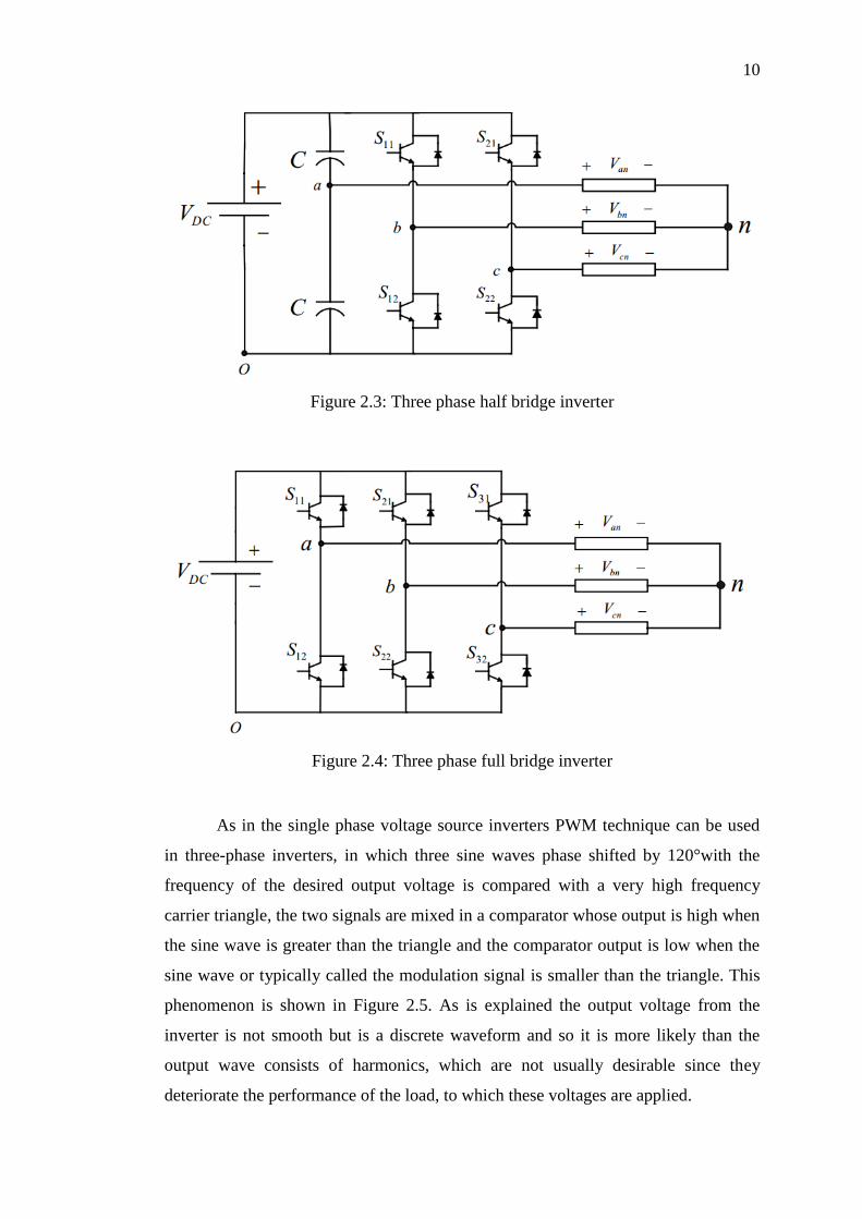
2.2.1 Three phase inverter
Three-phase inverters are used for variable-frequency drive applications and for high
power applications such as HVDC power transmission. A basic three-phase inverter
consists of three single-phase inverter switches each connected to one of the three
load terminals.[12] Three-phase counterparts of the single-phase half and full bridge
voltage source inverters are shown in Figures 2.3 and Figure 2.4. Single-phase VSIs
cover low-range power applications and three-phase VSIs cover medium to high
power applications. The main purpose of these topologies is to provide a three-phase
voltage source, where the amplitude, phase and frequency of the voltages can be
controlled.
The three-phase dc to ac voltage source inverters are extensively being used
in motor drives, active filters and unified power flow controllers in power systems
and uninterrupted power supplies to generate controllable frequency and ac voltage
magnitudes using various pulse width modulation (PWM) strategies. [10] The
standard three-phase inverter shown in Figure 2.4 has six switches the switching of
which depends on the modulation scheme.
10
Figure 2.3: Three phase half bridge inverter
Figure 2.4: Three phase full bridge inverter
As in the single phase voltage source inverters PWM technique can be used
in three-phase inverters, in which three sine waves phase shifted by 120°with the
frequency of the desired output voltage is compared with a very high frequency
carrier triangle, the two signals are mixed in a comparator whose output is high when
the sine wave is greater than the triangle and the comparator output is low when the
sine wave or typically called the modulation signal is smaller than the triangle. This
phenomenon is shown in Figure 2.5. As is explained the output voltage from the
inverter is not smooth but is a discrete waveform and so it is more likely than the
output wave consists of harmonics, which are not usually desirable since they
deteriorate the performance of the load, to which these voltages are applied.

11
Figure 2.5: PWM illustration by the sine-triangle comparison method (a) sine
triangle comparison (b) switching pulses
Figure 2.6: Generation of the switching signals for top devices (a) S11 (b) S21 (c)
S31

12
Figure 2.7: Generation of the switching signals for bottom devices (a) S12 (b)
S22 (c) S32
Three-phase bridge inverters are most commonly used in ac motor drives and
general-purpose ac supplied. Figure 2.6 and Figure 2.7 explain the generation of the
output voltages in six-step mode of operation. The circuit for the six-step VSI is as
shown in Figure 2.4, which consists of three half-bridges, which are mutually phase-
shifted by
π angle to generate the three phase voltages.
The advantage of inverter is to reduce the consumption of power by
converting direct current (DC) to alternating current (AC). This alternated power can
be maintained in any frequency or voltage with the use of an appropriate
transformers, circuits and switches to support the electrical equipment at home and
office. Disadvantages of inverter are not ideal for inductive AC and motor loads. It is
also sensitive electronics devices can be damaged by poor waveforms.

13
2.3 Controller
A controller is a device, possibly in the form of a chip, analogue electronics, or
computer, which monitors and physically alters the operating conditions of a given
dynamical system. Many controllers have been developed, that can be divided into
two classifications, passive and adaptive power controller. The example for passive
power controller is hysteresis, relay and sliding mode control and for adaptive power
controller is PID, fuzzy, and P-resonant controller. Each of them has their
advantages, such as simple structure and low maintenance cost.
2.3.1 Adaptive controller
Adaptive controller is a controller that can modify its behavior in response to
changes in the dynamics of the process and the disturbances. A great number of
industrial control loops are under adaptive control. These include a wide range of
applications in aerospace, process control, ship steering, robotics and other industrial
control systems.[6]
There are many reasons for adaptive control. The key factors are:
i. Variations in process dynamics. Parameters may vary due to nonlinear
actuators, changes in the operating conditions of the process, and no
satisfactory disturbances acting on the process.
ii. Variations in the character of the disturbances.
iii. Engineering efficiency.
Recently, much effort has been placed in adaptive control in both theory and
applications. Theory-wise, new controller design techniques are introduced to handle
nonlinear and time-varying uncertainties.[7] After a thorough review process, two
papers were selected.
From paper [13], a scheme for nonlinear plants with time-varying control
gains and time-varying plant coefficients is proposed and applied on a plant model
consisting of a Brunovsky type model with polynomials as approximations. The
methodology has been applied to the speed control of a permanent magnet
synchronous motor (PMSM) and proper tracking results have been achieved.

14
In paper [14] explains a novel multiple model adaptive controller for a class
of nonlinear system in parameter-strict-feedback form is proposed. It not only
improves the transient performance significantly, but also guarantees the stability of
all the states of the closed-loop system. A simulation example is proposed to
illustrate the effectiveness of the developed multiple model adaptive controller.
2.3.1.2 PID controller
The PID controller (proportional integral derivative controller) is widely used in
industrial control system. A PID controller calculates an “error” value as the
difference between the measured process variable and the desired set point. The PID
controller calculation involves three separate constants and is accordingly sometimes
called three-term control which the proportional, the integral and derivative values
are denoted by P, I and D. A proportional controller may not give steady state error
performance which is needed in the system. An integral controller may give steady
state error performance but it slows a system down. So the addition of a derivative
term helps to cure both of these problems.[9]
In the paper [15] explains a proposed method of computing Proportional,
Integral and Derivative (PID) parameters controller for vector control of induction
motor. The optimal parameters for current loop, flux loop, and speed loop as function
of required settling time and motor parameters will be computed by the proposed
method. The significant of the proposed method is that one factor (settling time) is
the only parameter required to be given by the user such that the method calculated
the PID parameter for each loop control. Simulation results show robustness of the
proposed method to system parameters variations.
The paper[16], the implementation and comparative study of dynamic
behavior of three phase induction motor with different control strategies such as PID
controller, Fuzzy Logic and Neural Network techniques. The system consist of three
phase variable frequency drive with gating signal are generated using PIC
microcontroller. The Simulink model of PID controller, fuzzy Logic and Neural
Network is developed in MATLAB environment. The real time response of all the
control strategies shows the Neural Network based control mechanism having
smooth and satisfactory system performance in terms of overshoot and settling time.

15
2.3.1.3 Fuzzy controller
A fuzzy control system is a control system based on fuzzy logic. Fuzzy means
uncertainty, fuzzy computes uncertainty by assigning values between 0 and 1
compared to conventional computation 0 or 1. This fuzzy logic involves computing
using knowledge base and rule base. In fuzzy systems, input variables are assigned
with a membership function. Each membership function is assigned with specified
values.[16] Fuzzy logic comprises of three stages which is fuzzification, fuzzy
inference and defuzzification as shown in Figure 2.8.[17] The advantages and
disadvantages of the fuzzy logic are stated below:
Advantages of fuzzy logic control include the following:
i. A large number of system variables can be evaluated.
ii. It similar to the way humans think because linguistic variable and not
numerical values are used
iii. It use permits a greater degree of uncertainty because the output is related to
the input, so better control is possible for some types of system, requires little
maintenance.
iv. It can be used for the solution of previously unsolved problems
v. It is more robust.
Some of the disadvantages of fuzzy logic include:
i. Extracting a model from a fuzzy system is difficult.
ii. Fuzzy systems require finer tuning before they are operational.[18]
Figure 2.8: Fuzzy logic block diagram

16
The paper [19] explains an intelligent speed control system based on fuzzy
logic for a voltage source PWM inverter-fed indirect vector controlled induction
motor drive. Traditional indirect vector control system of induction motor introduces
conventional PI regulator in outer speed loop; it is proved that the low precision of
the speed regulator debases the performance of the whole system. To overcome this
problem, replacement of PI controller by an intelligent controller based on fuzzy set
theory is proposed. The performance of the intelligent controller has been
investigated through digital simulation using MATLAB-SIMULINK package for
different operating conditions such as sudden change in reference speed and load
torque. The simulation results demonstrate that the performance of the proposed
controller is better than that of the conventional PI controller.
In paper [20], the speed control of induction motor is more important to
achieve maximum torque and efficiency. Various speed control techniques likes,
Direct Torque Control, Sensorless Vector Control and Field Oriented Control are
discussed in this paper. Soft computing technique – Fuzzy logic is applied in this
paper for the speed control of induction motor to achieve maximum torque with
minimum loss. The fuzzy logic controller is implemented using the Field Oriented
Control technique as it provides better control of motor torque with high dynamic
performance. The motor model is designed and membership functions are chosen
according to the parameters of the motor model. The simulated design is tested using
various tool boxes in MATLAB. The result concludes that the efficiency and
reliability of the proposed speed controller is good.

17
2.4 Proposed controller
This project proposed a PID controller to control the current of three phase induction
motor. The PID control scheme is named after its three correcting terms whose sum
constitutes the manipulated variable (MV) by equation,
( ) (2.1)
Proportional term of output ( ), Integral term of output ( ) and
Derivative term of output ( ) are the contributions to the output from the PID
controller from each of the three terms. The proportional term (sometimes called
gain) makes a change to the output that is proportional to the current error value. The
proportional response can be adjusted by multiplying the error by a constant ,
called the proportional gain. The proportional term is given by:
( ) (2.2)
If the proportional gain is too high, the system can become unstable In
contrast, a small gain results in a small output response to a large input error, and a
less responsive (or sensitive) controller. If the proportional gain is too low, the
control action may be too small when responding to system disturbances. In the
absence of disturbances, pure proportional control will not settle at its target value,
but will retain a steady state error that is a function of the proportional gain and the
process gain.
The contribution from the integral term (sometimes called reset) is
proportional to both the magnitude of the error and the duration of the error.
Summing the instantaneous error over time (integrating the error) gives the
accumulated offset that should have been corrected previously. The accumulated
error is then multiplied by the integral gain and added to the controller output. The
magnitude of the contribution of the integral term to the overall control action is
determined by the integral gain, .
∫ ( )
(2.3)
18
The integral term (when added to the proportional term) accelerates the
movement of the process towards set point and eliminates the residual steady –state
error that occurs with a proportional only controller. However, since the term is
responding to accumulated errors from the past, it can cause the present value to
overshoot the set point value (cross over the set point and then create deviation in the
other direction).
The rate of change of the process error is calculated by determining the slope
of the error over time (its first derivative with respect to time) and multiplying this
rate of change by the derivative gain, . The magnitude of the contribution of the
derivative term (sometimes called rate) to the overall control action is termed the
derivative gain, . The derivative term is given by:
( ) (2.4)
The derivative term slows the rate of change of the controller output and this
effect is most noticeable close to the controller set point. Hence, derivative control is
used to reduce the magnitude of the overshoot produced by the integral component
and improve the combined controller-process stability. However, differentiation of a
signal amplifies noise and thus this term in the controller is highly sensitive to noise
in the error term, and can cause a process to become unstable if the noise and the
derivative gain are sufficiently large.
The PID controller as shown in Figure 2.9 is implemented using the current
source technique as it provides better control of motor torque with high dynamic
performance. The main task of the control scheme in a current source is to force the
currents in a three-phase ac load to follow the reference signals. By comparing the
command and measured instantaneous values of the phase currents, the current
source generates the switching states for the converter power devices which decrease
the current errors Hence, in general, the current source implements two tasks which
is error compensation and modulation

19
Figure 2.9: PID controller
Advantages of PID controller include the following:
i. Very less oscillation.
ii. Low overshoot.
iii. Faster and no offset.
iv. An integral term gives zero steady state error for step input.
v. An derivative term often produce faster response.
Some of the disadvantages of PID controller include:
i. costly.
ii. difficult to configure and tune.
iii. Noise in derivative term.
20
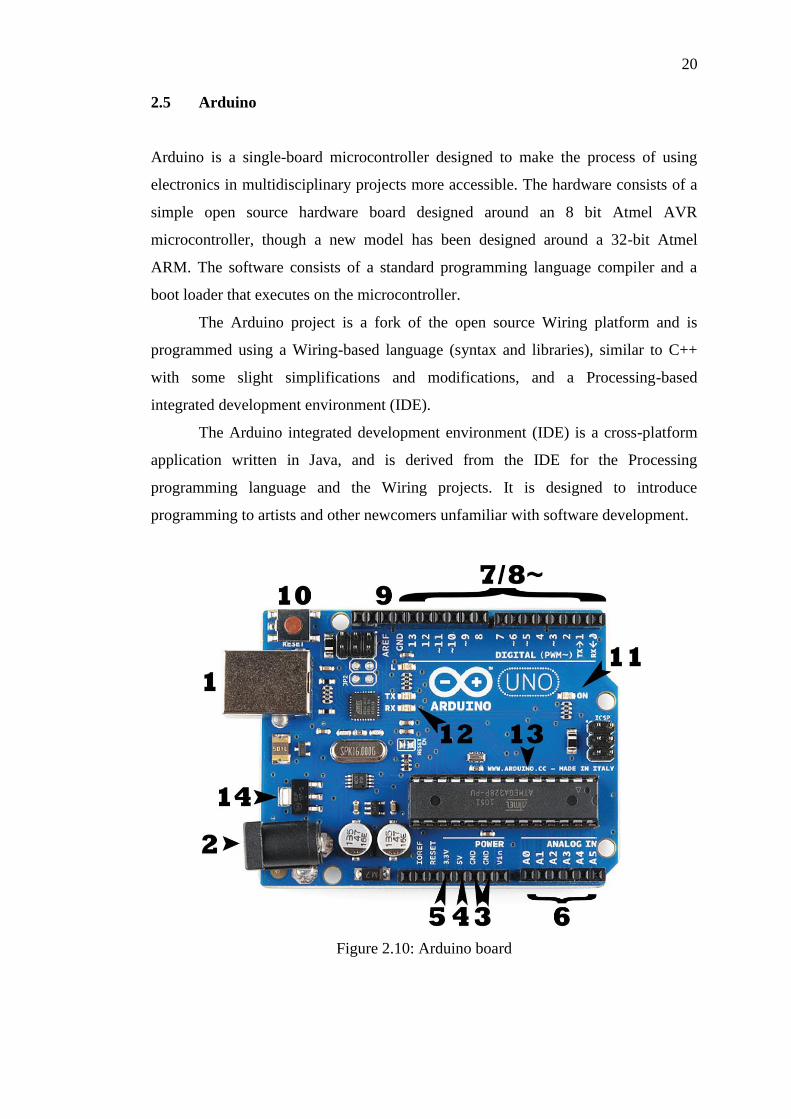
2.5 Arduino
Arduino is a single-board microcontroller designed to make the process of using
electronics in multidisciplinary projects more accessible. The hardware consists of a
simple open source hardware board designed around an 8 bit Atmel AVR
microcontroller, though a new model has been designed around a 32-bit Atmel
ARM. The software consists of a standard programming language compiler and a
boot loader that executes on the microcontroller.
The Arduino project is a fork of the open source Wiring platform and is
programmed using a Wiring-based language (syntax and libraries), similar to C++
with some slight simplifications and modifications, and a Processing-based
integrated development environment (IDE).
The Arduino integrated development environment (IDE) is a cross-platform
application written in Java, and is derived from the IDE for the Processing
programming language and the Wiring projects. It is designed to introduce
programming to artists and other newcomers unfamiliar with software development.
Figure 2.10: Arduino board

21
Some of the hardware provided on the Arduino board is:
i. USB (Power)
ii. Barrel jack (Power)
iii. Ground
iv. 5V supply
v. 3.3V supply
vi. Analog input
vii. Digital input
viii. PWM output
ix. Analog Ref input
x. Reset button
xi. Power indicator
xii. Rx,Tx indicator
xiii. Main IC
xiv. Voltage regulator

CHAPTER 3
METHODOLOGY
The work includes stages such as designing, simulation, implementation and
verification. The designing part involves using PROTEUS software for inverter and
gate design. Next, simulation is conducted using MATLAB/Simulink software for
controller design, download and implemented on the Arduino in the implementation
stages. The verification stage involves the testing of the controller design using a
hardware development to verify its correctness.
3.1 Block diagram of project
The Figure 3.1 shows the block diagram of the project that consists of 4 mains parts,
they are the DC source, the three phase inverter, the three phase induction motor as a
load and the controller.
Figure 3.1: Block diagram of the project
error
Ia Iref
DC
Source
3 phase
inverter
Adruino PID
controller
IM
Gate
Driver

23
The first part of the block diagram is the DC source to give the power for the
whole system. The second part is the three phase inverter. The general function of
the inverter is to convert the DC voltage to the AC voltage. In this system, the three
phase inverter will be used because the load is the three phase induction motor. The
six switch of switching inverter will be used because the PWM will be fed from the
controller.
In this motor control system, PID controller is used using the current source
control technique. The controller will compare the motor current with the reference
current. If there is an error, the controller will generate the pulse width modulation
(PWM) to feed into the three phase inverter and rescale the output to power up the
load. This process will continuous until the error approximately to zero to give high
performance of the induction motor.
3.2 Flow chart of system
Figure 3.2: Flow chart of Project

24
3.3 Flow chart of project
Figure 3.3: Flow chart of project development
Yes
No
Hardware part
Study the 3 phase inverter
Study the 3 phase IM
Upload to Adruino
PID control design
Derive mathematical
modeling of 3 phase IM
Study the structure of 3 phase
IM
Software part (MATLAB
simulink)
Write thesis
Hardware setup
Time response
meet
Observe performance of
controller
Start
End

REFERENCES
[1] P.C.Sen. “Prinsiple of Electric Machines And Power Electronics” Second
Edition.
[2]
[3]
[4]
Dr. Mohammed Y. Hassan, Ph. D. “Adaptive Control for the 4th
Class of
Control Engineering in the Control and Systems Engineering Department at the
University of Technology,CCE-CN445”.
Jasper Fischer, John Machelor and Rob Boteler “Improving Motor and Drive
System Performance” Department of Energy Office of Energy Efficiency and
Renewable Energy Industrial Technologies Program, September 2008.
Mohamed Elsharif “Comparison of Triangular and Gaussian Membership
Functions Performance for a Fuzzy PD Controller for an Induction Motor
Drive” Electrical and Computer Engineering, Dalhouse University, July,2009.
[5] Madhavi L. Mhaisgawali , S.P.Muley. “Speed Control of Induction Motor using
PI and PID Controller” IOSR Journal of Engineering (IOSRJEN) e-ISSN: 2250-
3021, p-ISSN: 2278-8719 Vol. 3, Issue 5 (May. 2013), ||V1 || PP 25-30.
[6] Mohd. Naim, Bindeshwar Singh, S. P. Singh, Rajneesh Mishra, Prem Nath
Verma, Dinesh Kumar, and Ravi Prakash Vishvakarma “Investigation of
Transient Performance of VSI- Fed IM Drives with SVPWM Technique Based
on P, PI, and PID Controllers” 2012 2nd
International Conference on Power,
Control and Embedded Systems.
[7]
[8]
[9]
Pundaleek. B. H., Manish G. Rathi, and Vijay Kumar M. G., “Speed control of
induction motor: fuzzy logic controller v/s PI controller,”International journal of
computer science and network security, vol. 10, no. 10, pp.223-230, Oct. 2010.
Andrej M. Trzynadlowski, “Control of Induction Motors”, Academic Press,
London, ( 2001).
Arbin Bin Ebrahim, “Adaptive Nonlinear Induction motor control”, Department
of Electrical and Computer, University of Alabama, 2007.

48
[10] K. Astrom, T. Hagglund, “PID Controllers: Theory, Design, and Tuning,”
Research Triangle Park, NC: Instrument society of America, 1995
[11]
[12]
[13]
[14]
Kharagpur, Introduction to Voltage Source Inverters Version 2 EE IIT.
Marian P. Kazmierkowski, Fellow, IEEE, and Luigi Malesani, Fellow, IEEE,
“Current Control Techniques for Three-Phase Voltage-Source PWM
Converters: A Survey”, IEEE transaction on industrial electronics,
Vol.45,No.5,October 1998
Alejandro Rincon and Fabiola Angulo, “Adaptive Control for Nonlinear
Systems with Time-Varying Control Gain”, Hindawi Publishing Corporation
Journal of Control Science and Engineering Volume 2012, Article ID 269346.
Haisen Ke and Jiang Li, “Adaptive Control for a Class of Nonlinear System
with Redistributed Models”, Hindawi Publishing Corporation Journal of Control
Science and Engineering Volume 2012, Article ID 409139
[15] Martino O Ajangnay “Optimal PID Controller Parameters for Vector Control of
Induction Motors” Electrical Engineering Department, Sudan University of
Science and Technology- Sudan..
[16]
[17]
[18]
T. D. Dongale, T.G. Kulkarni, S. R. Ghatage, R. R. Mudholkar “Implementation
and Comparative study of Three Phase Induction Motor Control Using PID
Controller,Fuzzy Logic and Neural Network Techniques” Department of
Electronics, Shivaji University,Kolhapur.
C.H.Salerno,A.T.LeaoandR.A.Araujo,"A fuzzy speed control for a three phase
induction motor,"inIEEEPortoPowerTechConf.,Porto,Portugal,2001,pp.5-10.
James A. Rehg, Glenn J. Sartori. “Industrial Electronics”, International Edition.
[19] P.Tripura and Y.Srinivasa Kishore Babu, “Fuzzy Logic Speed Control of Three
Phase Induction Motor Drive”, World Academy of Science, Engineering and
Technology 60 2011.
[20]
[21]
V. Chitra, and R. S. Prabhakar, “Induction Motor Speed Control using Fuzzy
Logic Controller”, World Academy of Science, Engineering and Technology 23
2006.
Norman S. Nise, "Control Systems Engineering",Fifth edition,2008