Embed Size (px)
Citation preview

PID Controls
(Part II)
Howie Choset(thanks to George Kantor and Wikipedia)
http://www.library.cmu.edu/ctms/ctms/examples/motor/motor.htm

Overview• Mass-Spring-Damper System
• Second order ODE– Definition
– Vary parameters
– Forcing functions
• Different feedback meaning– Proportional
– Derivative
• Control for Error – block diagram
• Integral Control
• Different Affects of Varying PID
• Feed Forward Term
• Vehicle Controls

Big Dog Quadruped
Boston Dynamics

Nathan Michael Quadrotors
Controls
Estimation

RC Airplane - Adaptive Control
Chowdhary G., Johnson E., Chandramohan R., Kimbrell M. S., Calise A.

Series Elastic Actuator

Mass Spring

Solutions/Responses
Let
Under-damped (0 < z < 1)Oscillation, damped natural frequencydecay

Step Response
,
As time goes on, x(t) goes to 1
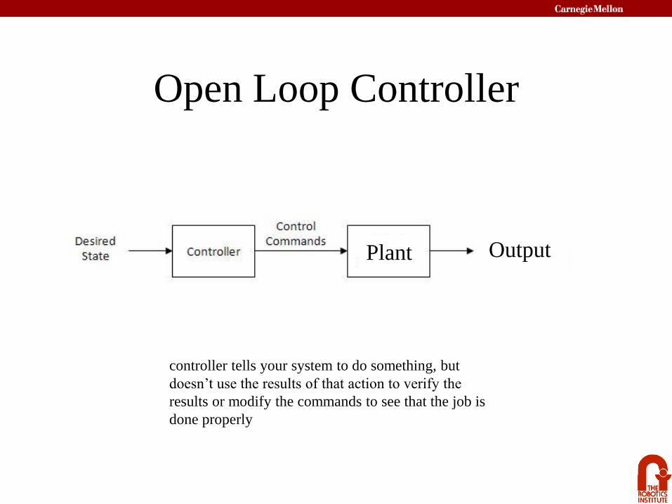
Open Loop Controller
controller tells your system to do something, but
doesn’t use the results of that action to verify the
results or modify the commands to see that the job is
done properly
Plant Output

Closed Loop Controller
Controller EvaluationSteady State Error
Rise Time (to get to ~90%)
Overshoot
Settling Time (Ring) (time to steady state)
Stability
Give it a velocity command
and get a velocity output
PlantController-
+Ref error voltage

Closed Loop Response (Proportional Feedback)
PlantController-
+R error voltage
Proportional Control
Easy to implement
Input/Output units agree
Improved rise time
Steady State Error (true)
P: Rise Time vs. Overshoot*
P: Rise Time vs. Settling time*P: Steady state error vs. other problems
pK
Voltage = Kp error *In some other systems, not mass-spring

Closed Loop Response (PI Feedback)
Plant-
+Ref error voltage
Proportional/Integral Control
Ip Ks
K1
No Steady State Error
Bigger Overshoot and Settling
Saturate counters/op-amps
P: Rise Time vs. Overshoot
P: Rise Time vs. Settling time
I: Steady State Error vs. Overshoot
Voltage = (Kp+1/s Ki) error
Ip Ks
K1

Closed Loop Response (PID Feedback)
Plant-
+R error voltage
Proportional/Integral/Differential
Quick response
Reduced Overshoot
Sensitive to high frequency noise
Hard to tune
P: Rise Time vs. Overshoot
P: Rise Time vs. Settling time
I: Steady State Error vs. Overshoot
D: Overshoot vs. Steady State Error
DIp sKKs
K 1
DIp sKKs
K 1
Voltage = (Kp+1/s Ki + sKd) error
Quick and Dirty Tuning
• Tune P to get the rise time you want
• Tune D to get the setting time you want
• Tune I to get rid of steady state error
• Repeat
• More rigorous methods – Ziegler Nichols, Self-tuning,
• Scary thing happen when you introduce the I term– Wind up (example with brick wall)
– Instability around set point

Feed ForwardDecouples steady state error correction from PID
To compute
Try different open loop inputs and measure output velocities
For each trial i,
Tweak from there.
bK
Plant-
+R errorController
++ volt
K
bK
i
bb
i
ii
b KKu
K avg , .
Volt

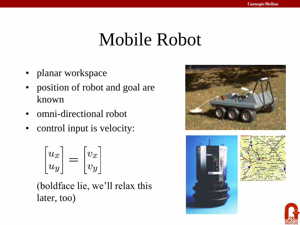
Mobile Robot
• planar workspace

Mobile Robot
• planar workspace
• position of robot and goal are
known

Mobile Robot
• planar workspace
• position of robot and goal are
known
• omni-directional robot

Mobile Robot
• planar workspace
• position of robot and goal are
known
• omni-directional robot
• control input is velocity:
Mobile Robot
• planar workspace
• position of robot and goal are
known
• omni-directional robot
• control input is velocity:
(boldface lie, we’ll relax this
later, too)

Proportional (P) Control:
• the equation above is called a control law
• kp is called the proportional gain
• kp is a tunable parameter
• physically, kp is the stiffness of the spring
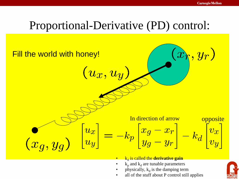
Proportional-Derivative (PD) control:
Fill the world with honey!
• kd is called the derivative gain
• kp and kd are tunable parameters
• physically, kd is the damping term
• all of the stuff about P control still applies
In direction of arrow opposite

Robot InputsSo far we’ve assumed something like
But really, we control the velocities of the left and
right wheels, which can easily be mapped to forward
and turning velocities:

Nonholonomic Constraints
The equations of motion using these controls are:
The fact that the robot can’t move sideways is a
nonholonomic constraint (we will see this again).

The Problem:
P or PD control won’t work.
No smooth control law will!

A Simple Solution:
Like a rigid trailor
hitch (not driving
to point)

A Simple Solution (cont.):
If we ignore orientation:
so we can implement the PD control law as:
p
p
Did not get rid of nh constraint, but moved it to something we don’t care about
(theta, angular and linear velocities) - trailor hitch story

Follow a straight line with differential drive
or at least get to a point
Make both wheels spin the same speed
asynchronous – false start
wheels can have slight differences (radius, etc)
Make sure both wheels spin the same amount and speed
false start
Error can be difference in wheel velocities or accrued distances

Line following
More complicated control laws – track orientation
m1vref = vref + K1 * thetaerror + K2 * offset error
m2vref = vref - K1 * thetaerror - K2 * offset error
offset

Really, there is a sensor

Encoders

Encoders – Incremental
LED Photoemitter
Photodetector
Encoder disk

Encoders - Incremental

Encoders - Incremental
• Quadrature (resolution enhancing)
To be continued
• Maps • Bayesian Localization