Embed Size (px)
DESCRIPTION
Pica
Citation preview

Pica8, Inc.
1032 Elwell Court, Suite 105
Palo Alto, CA. 94303
+1 (650) 614-5838
www.pica8.com
PicOS Routing and
Switching Configuration
Guide
October, 2014
Version: 16
© Copyright 2014 Pica8 Inc. Pica8 is a registered trademark of Pica8 Incorporated, PicOS is a trademark
of Pica8 Incorporated. All rights reserved. All other trademarks are property of their respective owners.

Contents
Supported Layer 2 and Layer 3 Protocols 13
Mode Selection, Configuration Backup and Painless Upgrade 14
System Management Configuration 15
File Management Configuration 16
Layer 2 Switching Configuration 17
Layer 3 Routing Configuration 19
IPv4/IPv6 BGP Configuration 20
Multicast Configuration 21
QoS Configuration 22
WRED Configuration 23
Installing New Software on PicOS 24
Zero Touch Provisioning 25
40G Changes to 4*10G in l2/l3 26
Configuration Appendix 27

OpenFlow Configurations in Crossflow Mode 28
Supported Layer 2 and Layer 3 Protocols 29
Mode Selection, Configuration Backup and Painless Upgrade 32
Overview 32
License 32
Terminology 32
Licenses 33
Speed 33
Mode 33
Accessing your Hardware ID 33
Installing the License 34
License Display 36
License Remove 37
Default Login 37
Modify the Pica8 Mode via an interactive Script 39
Modify the Pica8 Mode via the Pica8 Configuration File 40
Trouble shooting the PicOS Mode 40
l2/L3 Configuration backup 41
Painless upgrade 41
System Management Configuration 44
System Management Overview 44
From Linux Shell to L2_L3 Shell 46
Operation Mode and Configuration Mode 46
Commit Failed and Exit Discard 46
Commit confirmed 47
Configuring DHCP and a Static IP Address 47
Configuring DHCP relay 48
Configuring DHCP option82 49
Configuring DHCP snooping 50
Configuring a User Account 50

Configuring Authentication_Authorization_Accounting 51
Configuring SSH and Telnet Parameters 54
Configuring the Log-in ACL 55
Configuring NTP and the Time zone Parameter 55
Configuring the linux-config-unreliable 56
Configuring IPFIX 57
Configuring sFlow 57
Configuring SNMP 59
Configuring the Syslog Log Level 60
Configuring the Syslog Disk and Syslog host 61
Updating the PicOS Software and Platform 62
Displaying System Information 63
Technical Support 67
Flushing ARP and the Neighbor Table 68
Rebooting the System 68
Displaying the Debugging Message 69
System Management Command List 69
File Management Configuration 75
Managing Configuration Files 75
Additional file management commands 77
Additional file function to changing directory 79
Displaying Your Current Configuration 79
Displaying Your configuration of setting 79
Rolling Back a Configuration 80
Management Configuration Files 81
Saving, Applying, Executing and Loading Configuration Files 83
Bash "linux shell" 84
Upgrade 85
Set alias set_vlans as "PicOS commands" 88
File Management Command List 89

Layer 2 Switching Configuration 90
Physical Ethernet Port Configuration 91
Shutting down the Ethernet port 91
Configuring the MTU and Rate-limit 91
Enabling Port Flow Control 92
Split 40GE Ports in 4x10GE Ports 92
Configuring Port Speed 93
Basic Port Configuration 93
Configuring the access/trunk mode 93
Configuring the Native VLANID 94
Adding a Port to a VLAN 95
Creating a VLAN with in the VLAN range 96
VLAN Configuration Example 96
Configuring Switch A 96
Configuring Switch B 97
Static MAC entries and Dynamic MAC Address Learning 98
Configuring a static MAC entry and managing the FDB 99
Port Security Configuration 99
Enabling Port Security 99
Configuring the Maximum Number of Secure Dynamically Learned MAC Addresses 100
Configuring Static Secure MAC Addresses on a Port 100
Configuring Port Security with Sticky MAC Addresses on a Port 101
Configuring Secure MAC Address Aging Time 101
Configuring Port Security Violation Mode on a Port 102
Configuring Port Security Auto-recovery Time 102
Recovering the Port in Error-discard 102
Configuring Port Security Block Mode on a Port 103
Displaying Port Security Settings 103
Disabling Port Security 104
Cut-through Switching Method 105
Configuring your Switch to Store-and-Forward Method 105
Static Link Aggregation Configuration 106
Configuring static LAGs 106
Displaying static LAG information 106
Advanced-resilient Laghash Configuration and Example 106
Advance Laghash Configuration and Example 107
Laghash Configuration and Example 108
Link Aggregation Control Protocol (LACP) Configuration 108
Configuring LACP LAGs 109
Displaying LACP LAG information 109

MLAG Configuration Guide 109
Important things to know about MLAG 110
Configuring MLAG domain-id 110
Configuring MLAG system-id 111
Configuring MLAG peer 111
Configuring MLAG priority 111
Configuring MLAG hello-interval 112
Configuring a Basic MLAG step-by-step procedure 112
Configuring a Basic MLAG example 113
Configuring Switch A with Static and LACP LAG 113
Configuring an Aggregation Interface to VLAN Members 114
Configure the L3 interface IP address 115
Configuring the domain-id and system-id for the MLAG domain. 115
Configuring the peer IP address and the peer-link for the MLAG domain peer 115
Configuring Switch B with Static and LACP LAG 115
Configuring an Aggregation Interface to VLAN Members 116
Configure the L3 interface IP address 117
Configuring the domain-id and system-id for the MLAG domain 117
Configuring the peer IP address and the peer-link for the MLAG domain peer 117
Configuring Switch C with LACP and LAG 117
Configuring an Aggregation Interface to VLAN Members 118
Configuring Server A with NIC1 and NIC2 as Static LAG 119
View the MLAG internal and neighbor status of Switch A 119
View the MLAG internal and neighbor status of Switch B 119
Configuring a MLAG domain with MSTP example 119
Configuring Switch A with LACP LAG 120
Configuring an Aggregation Interface to VLAN Members 121
Configure the L3 interface IP address 121
Configuring the domain-id and system-id for the MLAG domain. 122
Configuring the peer IP address and the peer-link for the MLAG domain peer 122
Configuring Switch B with LACP LAG 122
Configuring an Aggregation Interface to VLAN Members 123
Configure the L3 interface IP address 124
Configuring the domain-id and system-id for the MLAG domain 124
Configuring the peer IP address and the peer-link for the MLAG domain peer 124
Configuring Switch C and Switch D with LACP LAG 124
Configuring Switch C and Switch D an aggregation interface add to VLAN Members
125
View the MLAG internal and neighbor status of Switch A 125
View the MSTP status of Switch A 126
View the MLAG internal and neighbor status of Switch B 126
View the MSTP status of Switch B 126
Storm Control in Ethernet Port Configuration 126
Configuring Storm Control 127

Configuring LLDP (Link Layer Discovery Protocol) 127
Configuring the LLDP mode 127
Selecting optional TLVs 128
Displaying LLDP information 128
Configuring other parameters 128
Q-in-Q Basic Port Configuration 128
Configuring the Q-in-Q tunneling internal/external mode 129
Configuring Q-in-Q tunneling to map ingress VLANs to service VLANs 129
Configuring Q-in-Q tunneling egress pop service VLANs 131
Q-in-Q Configuration Example 133
Configuration on Provider A 133
Configuration on Provider B 137
MSTP Configuration 141
Enabling spanning tree mode in MSTP 141
Configuring basic global parameters of MSTP 141
Configuring MSTP interface parameters 143
Configuring the BPDU Filter 143
Configuring BPDU root guard 143
Configuring BPDU TCN-guard 144
Disabling/enabling MSTP 144
PVST Configuration 145
Enabling spanning tree mode in PVST 145
Configuring basic VLAN parameters of PVST 146
Configuring PVST interface parameters 146
Configuring the interface mode 146
Disabling/enabling PVST on one VLAN 147
Disabling/enabling PVST 148
MSTP Configuration Example 150
Configuring Switch A 151
Configuring Switch B 152
Configuring Switch C 154
Configuring Switch D 154
Configuring Switch E 155
Configuring Switch A 159
Configuring Switch B 160
Configuring Switch C 162
Configuring Switch D 164
Configuring Switch E 166
PVST Configuration Example 168
Configuring Switch A 168
Configuring Switch B 169
Configuring Switch C 170
Configuring Switch D 171

Configuring Mirroring 172
Configuring Mirroring to Analyze Traffic 173
Configuring Mirroring Guide 173
Configuring a port as mirroring port 173
Configuring mirroring on egress port or ingress port 173
Configure monitor the flows of egress port 174
Mirroring Configuration Example 174
Buffer Management Configuration 176
Configuring burst mode for a specified port 176
Configuring "cell" and "packet" for a specified port 176
BPDU Tunneling Configuration 177
Configuring BPDU tunneling for STP on an interface 177
Configuring destination multicast MAC address for BPDU packets 177
BPDU Tunneling Configuration Example 177
Configuration on Provider A 178
Configuration on Provider B 179
Configuring Flex Links Preemption Delay 180
Configuring the preemption mode 180
Showing Flex Links on all interfaces 181
Unidirectional Link Dectection Configuration 181
Configuring UDLD mode 181
Enable UDLD globally or on specific port 181
Configuring UDLD message-interval 181
Display UDLD information 182
Configuring IPv6 RA Guard 182
Configuring "trusted-port" 183
Displaying RA guards 183
L2 Switching Command List 184
Layer 3 Routing Configuration 193
Layer 3 VLAN Interface Configuration 193
ARP Configuration 194
Dynamic ARP Inspection---DAI 195
Static Routing Configuration 197
Static Routing Configuration Example 199
RIPv2 Routing Protocol Configuration 202
RIPv2 Routing Configuration Example 203

OSPF Routing Protocol Configuration 206
OSPF Routing Basic Configuration Example 208
OSPF Configuration Example_ NSSA_Stub_Normal 212
OSPF Stub Area_NSSA Summary 215
OSPF Virtual Link Configuration Guide 215
OSPF Area Range Configuration Guide 220
Importing an External Route into an OSPF Area 222
BFD Protocol Configuration 224
BFD Basic Configuration Example 226
Configuring ECMP (Equal-Cost Multipath Routing) 229
Configuring VRRP (Virtual Router Redundancy Protocol) 231
IPv6 Neighbor Configuration 232
IPv6 Static Routing Configuration 233
OSPFv3 Routing Protocol Configuration 234
ACL and Filter Configuration 235
Configuring Control Plane Security policer 237
L3 Routing Command List 239
IPv4/IPv6 BGP Configuration 250
IPv4 BGP configuration 251
BGP Configuration Guide 251
BGP Basic Configuration Example 257
BGP Route Reflector Configuration Example 264
BGP Confederation Configuration Example 269
BGP Load Balancing Configuration Example 275
IPv6 BGP Configuration 281
IPv6 BGP introduction 281
Building Peering Sessions 282
EBGP Peering 284
IBGP Peering 291
Establish bgp peer use 4-byte-as-number 299
Sources of routing updates 306
Injecting Information Dynamically into BGP 306
Injecting Information Statically into BGP 315
BGP attributes 319
The NEXT_HOP Attribute 319

The AS_PATH Attribute 325
The LOCAL_PREF Attribute 327
The MULTI_EXIT_DISC Attribute 332
The COMMUNITY Attribute 336
BGP-4 aggregation 347
Synchronization 355
Controlling large-scale Autonomous system 360
Confederations 360
Route Reflectors 364
Redundancy and Load Balancing 376
Designing Stable Internets 388
Multicast Configuration 398
IGMP Snooping Configuration 398
IGMP Configuration 399
399
Configuring IGMP parameters for the IGMP interface 399
400
Configuring an IGMPv3 interface 400
400
Joining and leaving a group; displaying group information 400
PIM-SM Configuration 401
PIM-SM Configuration Example 402
Multicast Command List 405
QoS Configuration 408
Configuring SP 408
Configuring WFQ 409
Configuring WRR 410
QoS Command List 411
.QoS Configuration 411
QoS Configuration Guide 411
QoS Principle 413
SP Configuration Example 414
WRR configuration Example 416
WFQ Configuration Example 418
WRED Configuration 421

WRED Configuration Guide 421
WRED Principle 422
WRED Configuration Example 422
Installing New Software on PicOS 425
Install GCC on PicOS 425
Install Puppet on PicOS 427
Zero Touch Provisioning 429
Activate or Deactivate ZTP 429
ZTP (Zero Touch Provisioning) 429
Pica8 ZTP API: 433
40G Changes to 4*10G in l2/l3 436
40G Changes to 4*10G in L2/L3 mode on P-5101 436
In L2/L3 mode configure 436
QSFP (8 x 40G+40*10G) 436
SFP (72x 10G) 439
40G Changes to 4*10G in L2/L3 mode on P-5401 443
In L2/L3 mode configure 443
QSFP (32 x 40G) 443
SFP-64 (16 x 40G + 64 x 10G) 445
SFP (8 x 40G + 96 x 10G) 449
Configuration Appendix 456
Other Command List 456
OpenFlow Configurations in Crossflow Mode 457
CrossFlow Mode Introduction 457
command 459
Examples 459
Basic configurations 459

PicOS Routing and Switching Configuration Guide
12
PicOS supports Layer 2 switching protocols (STP, RSTP, MSTP, MAC learning, Q-in-Q) and Layer
3 routing protocols (static routing, RIPv2, OSPF, IGMP, PIM-SM, IPv6). This guide provides
instructions and examples for configuring switches and controllers. This guide is intended for
system administrators and assumes a working knowledge of Layer 2 and Layer 3 protocols.

PicOS Routing and Switching Configuration Guide
13
Supported Layer 2 and Layer 3 Protocols

PicOS Routing and Switching Configuration Guide
14
Mode Selection, Configuration Backup and
Painless Upgrade
Overview
License
Default Login
Modify the Pica8 Mode via an interactive Script
Modify the Pica8 Mode via the Pica8 Configuration File
Trouble shooting the PicOS Mode
l2/L3 Configuration backup
Painless upgrade

PicOS Routing and Switching Configuration Guide
15
System Management Configuration
System Management Overview
From Linux Shell to L2_L3 Shell
Operation Mode and Configuration Mode
Commit Failed and Exit Discard
Commit confirmed
Configuring DHCP and a Static IP Address
Configuring DHCP relay
Configuring DHCP option82
Configuring DHCP snooping
Configuring a User Account
Configuring Authentication_Authorization_Accounting
Configuring SSH and Telnet Parameters
Configuring the Log-in ACL
Configuring NTP and the Time zone Parameter
Configuring the linux-config-unreliable
Configuring IPFIX
Configuring sFlow
Configuring SNMP
Configuring the Syslog Log Level
Configuring the Syslog Disk and Syslog host
Updating the PicOS Software and Platform
Displaying System Information
Technical Support
Flushing ARP and the Neighbor Table
Rebooting the System
Displaying the Debugging Message
System Management Command List

PicOS Routing and Switching Configuration Guide
16
File Management Configuration
Managing Configuration Files
Displaying Your Current Configuration
Displaying Your configuration of setting
Rolling Back a Configuration
Management Configuration Files
Saving, Applying, Executing and Loading Configuration Files
Bash "linux shell"
Upgrade
Set alias set_vlans as "PicOS commands"
File Management Command List

PicOS Routing and Switching Configuration Guide
17
Layer 2 Switching Configuration
Physical Ethernet Port Configuration
Basic Port Configuration
Static MAC entries and Dynamic MAC Address Learning
Port Security Configuration
Cut-through Switching Method
Static Link Aggregation Configuration
Advanced-resilient Laghash Configuration and Example
Advance Laghash Configuration and Example
Laghash Configuration and Example
Link Aggregation Control Protocol (LACP) Configuration
MLAG Configuration Guide
Configuring a Basic MLAG step-by-step procedure
Configuring a Basic MLAG example
Configuring Switch A with Static and LACP LAG
Configuring Switch B with Static and LACP LAG
Configuring Switch C with LACP and LAG
Configuring Server A with NIC1 and NIC2 as Static LAG
Configuring a MLAG domain with MSTP example
Configuring Switch A with LACP LAG
Configuring Switch B with LACP LAG
Configuring an Aggregation Interface to VLAN Members
Configuring Switch C and Switch D with LACP LAG
Storm Control in Ethernet Port Configuration
Configuring LLDP (Link Layer Discovery Protocol)
Q-in-Q Basic Port Configuration
MSTP Configuration
PVST Configuration
PVST Configuration Example
Configuring Mirroring
Configuring Mirroring Guide
Buffer Management Configuration

PicOS Routing and Switching Configuration Guide
18
BPDU Tunneling Configuration
Unidirectional Link Dectection Configuration
Configuring IPv6 RA Guard
L2 Switching Command List

PicOS Routing and Switching Configuration Guide
19
Layer 3 Routing Configuration
Layer 3 VLAN Interface Configuration
ARP Configuration
Dynamic ARP Inspection---DAI
Static Routing Configuration
Static Routing Configuration Example
RIPv2 Routing Protocol Configuration
RIPv2 Routing Configuration Example
OSPF Routing Protocol Configuration
OSPF Routing Basic Configuration Example
OSPF Configuration Example_ NSSA_Stub_Normal
OSPF Stub Area_NSSA Summary
OSPF Virtual Link Configuration Guide
OSPF Area Range Configuration Guide
Importing an External Route into an OSPF Area
BFD Protocol Configuration
BFD Basic Configuration Example
Configuring ECMP (Equal-Cost Multipath Routing)
Configuring VRRP (Virtual Router Redundancy Protocol)
IPv6 Neighbor Configuration
IPv6 Static Routing Configuration
OSPFv3 Routing Protocol Configuration
ACL and Filter Configuration
Configuring Control Plane Security policer
L3 Routing Command List

PicOS Routing and Switching Configuration Guide
20
IPv4/IPv6 BGP Configuration
IPv4 BGP configuration
BGP Configuration Guide
BGP Basic Configuration Example
BGP Route Reflector Configuration Example
BGP Confederation Configuration Example
BGP Load Balancing Configuration Example
IPv6 BGP Configuration
IPv6 BGP introduction
Building Peering Sessions
EBGP Peering
IBGP Peering
Establish bgp peer use 4-byte-as-number
Sources of routing updates
Injecting Information Dynamically into BGP
Injecting Information Statically into BGP
BGP attributes
The NEXT_HOP Attribute
The AS_PATH Attribute
The LOCAL_PREF Attribute
The MULTI_EXIT_DISC Attribute
The COMMUNITY Attribute
BGP-4 aggregation
Synchronization
Controlling large-scale Autonomous system
Confederations
Route Reflectors
Redundancy and Load Balancing
Designing Stable Internets

PicOS Routing and Switching Configuration Guide
21
Multicast Configuration
IGMP Snooping Configuration
IGMP Configuration
PIM-SM Configuration
PIM-SM Configuration Example
Multicast Command List
PicOS Routing and Switching Configuration Guide
22
QoS Configuration
Configuring SP
Configuring WFQ
Configuring WRR
QoS Command List
.QoS Configuration
QoS Configuration Guide
QoS Principle
SP Configuration Example
WRR configuration Example
WFQ Configuration Example

PicOS Routing and Switching Configuration Guide
23
WRED Configuration
WRED Configuration Guide
WRED Principle
WRED Configuration Example

PicOS Routing and Switching Configuration Guide
24
Installing New Software on PicOS
Install GCC on PicOS
Install Puppet on PicOS

PicOS Routing and Switching Configuration Guide
25
Zero Touch Provisioning
Activate or Deactivate ZTP
ZTP (Zero Touch Provisioning)
ZTP API description

PicOS Routing and Switching Configuration Guide
26
40G Changes to 4*10G in l2/l3
40G Changes to 4*10G in L2/L3 mode on P-5101
40G Changes to 4*10G in L2/L3 mode on P-5401

PicOS Routing and Switching Configuration Guide
27
Configuration Appendix
Other Command List

PicOS Routing and Switching Configuration Guide
28
OpenFlow Configurations in Crossflow Mode
The PicOS documents are available on our Pica8 website:
http://www.pica8.com/portal/

PicOS Routing and Switching Configuration Guide
29
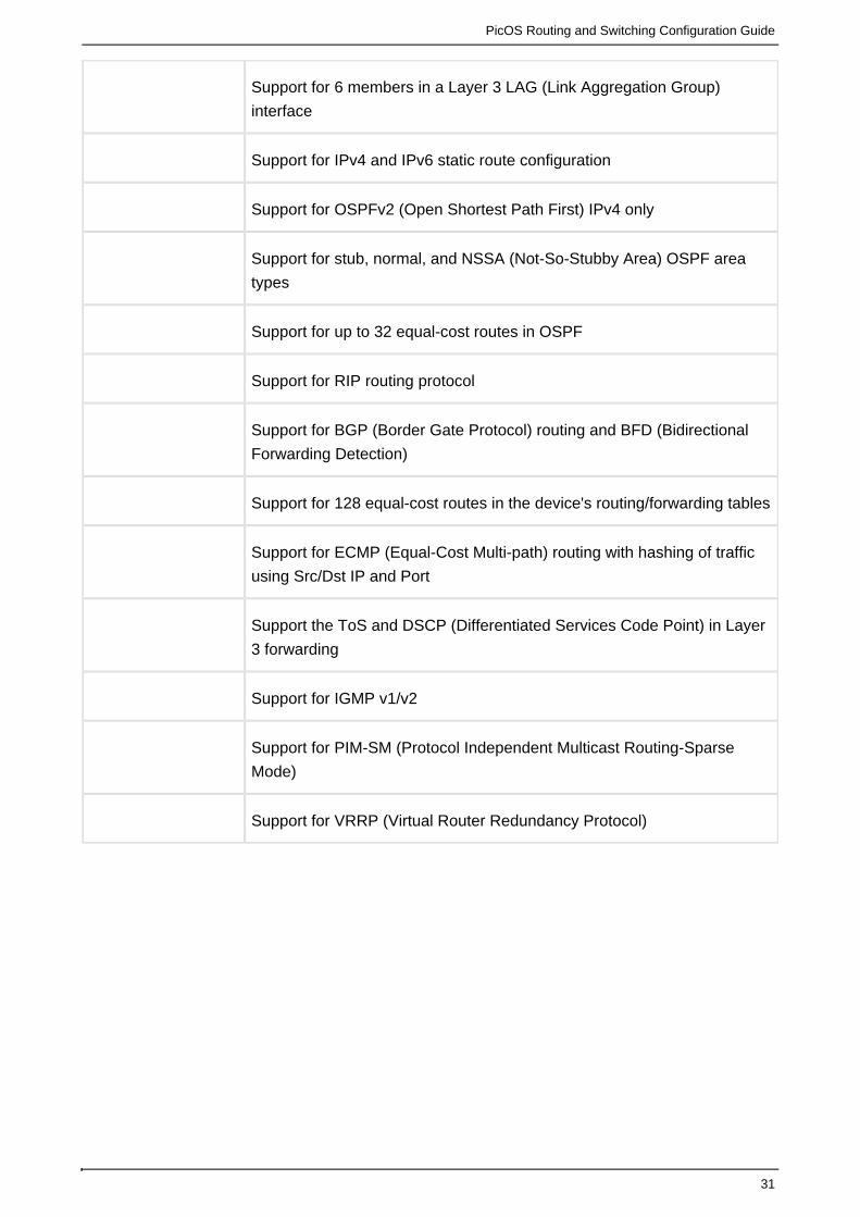
Supported Layer 2 and Layer 3 Protocols
Table 1 summarizes the supported protocols.
Table 1 Supported Layer 2 and Layer 3 Protocols
Category Features
System
Management&
Administration
Support for clock/date setting and NTP (Network Time Protocol)
Support for inbound IP access via any routed interface
Support for DHCP (Dynamic Host Configuration Protocol); DHCP client,
DHCP relay, DHCP Option82, and DHCP snooping
Support for multiple local user accounts
Support for SSHv2 (Secure Shell) protocol
Ability to enable debugging for a specific module
Support for Read Only and Read Write access SNMP (Simple Network
Management Protocol)
Support for IPFIX (IP Flow Information Export), monitors data flow in
specified server
Device
Configuration,
Software, and File
Management
Support the ability to save the configuration to flash on the device
Support for configuration versioning and rollback; compares the two
configurations for differences
Ability to import/export configuration files, device software, and logs from
a file on a remote server (tftp/scp as options)
Ping and Trace route tool from CLI (command line interface)
SSH and telnet tool from CLI

PicOS Routing and Switching Configuration Guide
30
Ability to view and configure MAC/ARP (Address Resolution Protocol)
table information
Layer 2 Forwarding
and Protocol
Support for LLDP (Link Layer Discovery) protocols for detecting devices
on a link
Support for LACP (Link Aggregation Control) protocol and hashing of
traffic using src/Dst (Source/Destination) MAC address, Src/Dst IP
address, and Layer 4 port information and flag
Support for 802.1q trunked interfaces, for both single and LAG (Link
Aggregation Group) interfaces
Support for 802.1q tagged/untagged interfaces and native tags
Support for Q-in-Q
Support for Jumbo Frame
Support for 802.1d STP (Spanning Tree Protocol)
Support for 802.1w RSTP (Rapid STP) and PVST (Per-VLAN STP)
Support for 802.1s MSTP (Multiple Spanning Tree protocol)
Support for functionality of BPDU (Bridge Protocol Data Unit) Guard /
Filter/UDLD (Unidirectional Link Detection)
Support for storm-control for unicast, multicast, broadcast
Support for ingress/egress port mirroring
Support for802.1p in Layer 2 forwarding
Support for Flow control per-interface
Support for IGMP (Internet Group Management Protocol) snooping
enable per-VLAN
Support for IGMP snooping query per-VLAN
Layer 3 Forwarding
and Routing Protocol
Full support for dual stacked IPv4 and IPv6 addressing.
PicOS Routing and Switching Configuration Guide
31
Support for 6 members in a Layer 3 LAG (Link Aggregation Group)
interface
Support for IPv4 and IPv6 static route configuration
Support for OSPFv2 (Open Shortest Path First) IPv4 only
Support for stub, normal, and NSSA (Not-So-Stubby Area) OSPF area
types
Support for up to 32 equal-cost routes in OSPF
Support for RIP routing protocol
Support for BGP (Border Gate Protocol) routing and BFD (Bidirectional
Forwarding Detection)
Support for 128 equal-cost routes in the device's routing/forwarding tables
Support for ECMP (Equal-Cost Multi-path) routing with hashing of traffic
using Src/Dst IP and Port
Support the ToS and DSCP (Differentiated Services Code Point) in Layer
3 forwarding
Support for IGMP v1/v2
Support for PIM-SM (Protocol Independent Multicast Routing-Sparse
Mode)
Support for VRRP (Virtual Router Redundancy Protocol)

PicOS Routing and Switching Configuration Guide
32
Mode Selection, Configuration Backup and
Painless Upgrade
Overview
License
Default Login
Modify the Pica8 Mode via an interactive Script
Modify the Pica8 Mode via the Pica8 Configuration File
Trouble shooting the PicOS Mode
l2/L3 Configuration backup
Painless upgrade
Overview
This chapter describes the boot process and the mode selection. Pica8 switches run in two
different modes:
Open vSwitch mode (OVS)
Layer 2 / Layer 3 mode (L2/L3)
In OVS mode, the L2/L3 daemon is not running; only OVS is accessible.
License
PicOS multi-tier licensing allows you to install just the features you need or all the features
provided by PicOS. A license must be installed to enable all switch ports. Download your license at
.http://license.pica8.com/
NOTE: If no license is installed, only the first 4 ports are active.
Terminology
For clarity, the following terms are used throughout this licensing section.
Base License–This license is required on any switch
Bundle–The license that includes all PicOS features. That is, it all three licensesbundles
Evaluation License–There is evaluation license per se. You can evaluate PicOS withoutno
a license, however only the first 4 ports are active (and the management port)
Hardware ID–This ID is needed when you download a license. You can view your switch ID
by executing the license show command license -s
Mode–There are two license modes: switch license and site license

PicOS Routing and Switching Configuration Guide
33
Type–There are two speed types; 1G and 10G
Licenses
Each license contains unique features. The licenses are:
Base
Network Linux, Layer 2, Multi-chassis Link Aggregation (MLAG), Simple Network Management
Protocol (SNMP), Security, Zero Touch Provisioning (ZTP)and Static Route. This license is
required.
Layer 3
Open Shortest Path First (OSPF), Border Gateway Protocol (BGP), Protocol-Independent Multicast
(PIM), Network Address Translation (NAT), Virtual Extensible LAN (VXLAN)
OpenFlow
Open vSwitch Database Management Protocol (OVSDB), OpenFlow releases 1.3 and 1.4, MPLS,
CrossFlow, VXLAN and CrossFlow
Base, Layer 3, and OpenFlow
This license bundles all the PicOS features into one license
Speed
There are two speeds available for each license.
1GE platform with 52*1GE or 48*1GE+4*10GE
10GE platform with 48*10GE + 4*40GE or 32*40GE
Mode
Switch--Use this to install your license on one switch only
Site--Use this to install the same license on all of your switches at your site
Accessing your Hardware ID
You must have your hardware ID number to download a license. A utility generates your switch's
hardware ID using the license show command license -s
admin@PicOS-OVS$license -sNo license installed. Use below information to create a license.Type: 1GEHardware ID: E385-FB53-4D57-05EB

PicOS Routing and Switching Configuration Guide
34
Installing the License
Customers can download the generated license file and copy it to /etc/picos/. In the following
example, the license file js.lic could be generated according to either switch based or site based
and the type is IGE and the feature is Base Product & Layer3 & Open Flow. Hardware ID is unique
for each switch. The switch cannot update a newer PicOS version whose built date is later than the
expired date of the license.
Switch based:
{
"Type": "1GE",
"Feature":["Open Flow", "Base Product", "Layer3"],
"Hardware ID":"8A68-A7AC-D702-70D2",
"Expire Date":"2020-10-28"
}
Site based:
{
"Type": "1GE",
"Feature":["Open Flow", "Base Product", "Layer3"],
"Mode":"site",
"Site Name":"CompanyA",
"Expire Date":"2020-10-28"
}
The license file is js.lic and it can be installed by the new utility, license, with option -i.

PicOS Routing and Switching Configuration Guide
35
admin@XorPlus$cd /etc/picosadmin@XorPlus$lltotal 32drwxrwxr-x 2 root xorp 4096 Feb 4 22:00 ./drwxrwxr-x 60 root xorp 4096 Feb 4 21:56 ../-rw-rw-r-- 1 root xorp 26 Feb 4 18:27 fs_status-rw-r--r-- 1 root root 399 Feb 4 21:59 js.lic-rw-rw-r-- 1 root xorp 247 Sep 4 2014 license.conf-rw-rw-r-- 1 root xorp 183 Aug 10 2014 p2files.lst-rw-rw-r-- 1 root xorp 488 Feb 4 18:28 picos_start.conf-rw-r--r-- 1 root root 251 Feb 4 22:00 public.keyadmin@XorPlus$sudo license -i js.licInstall successfully.admin@XorPlus$lltotal 32drwxrwxr-x 2 root xorp 4096 Feb 4 22:00 ./drwxrwxr-x 60 root xorp 4096 Feb 4 21:56 ../-rw-rw-r-- 1 root xorp 26 Feb 4 18:27 fs_status-rw-rw-r-- 1 root xorp 247 Sep 4 2014 license.conf-rw-rw-r-- 1 root xorp 183 Aug 10 2014 p2files.lst-rw-r--r-- 1 root root 382 Feb 4 22:00 pica.lic-rw-rw-r-- 1 root xorp 488 Feb 4 18:28 picos_start.conf-rw-r--r-- 1 root root 251 Feb 4 22:00 public.key-rw-r--r-- 1 root root 251 Feb 4 22:00 switch-public.keyadmin@XorPlus$
If public.key cannot be found:
admin@XorPlus$sudo license -i js.licInstall failed: Cannot find public key.
If license file does not exist :
admin@XorPlus$sudo license -i js.licInstall failed: No such file or directory.
If the header or the key is disrupted:
admin@XorPlus$sudo license -i js.licInstall failed: License or KEY is disrupted.
If license format is invalid:
admin@XorPlus$sudo license -i js.licInstall failed: License format error.
If license file is not compatible with this switch(verify failed):
admin@XorPlus$sudo license -i js.licInstall failed: Invalid license.

PicOS Routing and Switching Configuration Guide
36
License Display
Switch based:
admin@XorPlus$license -s{ "Type": "1GE", "Feature": ["Open Flow", "Base Product", "Layer3"], "Expire Date": "2020-10-28", "Hardware ID": "8A68-A7AC-D702-70D2"}
Site based:
admin@XorPlus$license -s{ "Type": "1GE", "Feature": ["Base Product", "Layer3", "Open Flow"], "Expire Date": "2020-10-28", "Hardware ID": "8A68-A7AC-D702-70D2", "Site Name": " google "}
If license is invalid:
admin@XorPlus$license -sInvalid license. Use below information to create a license.Type: 1GEHardware ID: 8A68-A7AC-D702-70D2admin@PicOS-OVS$
If no license had been installed:
admin@XorPlus$license -sNo license installed. Use below information to create a license.Type: 1GEHardware ID: 8A68-A7AC-D702-70D2admin@PicOS-OVS$

PicOS Routing and Switching Configuration Guide
37
License Remove
admin@XorPlus$lltotal 32drwxrwxr-x 2 root xorp 4096 Feb 4 22:00 ./drwxrwxr-x 60 root xorp 4096 Feb 4 21:56 ../-rw-rw-r-- 1 root xorp 26 Feb 4 18:27 fs_status-rw-rw-r-- 1 root xorp 247 Sep 4 2014 license.conf-rw-rw-r-- 1 root xorp 183 Aug 10 2014 p2files.lst-rw-r--r-- 1 root root 382 Feb 4 22:00 pica.lic-rw-rw-r-- 1 root xorp 488 Feb 4 18:28 picos_start.conf-rw-r--r-- 1 root root 251 Feb 4 22:00 public.key-rw-r--r-- 1 root root 251 Feb 4 22:00 switch-public.keyadmin@XorPlus$pwd/etc/picosadmin@XorPlus$admin@XorPlus$license -radmin@XorPlus$lltotal 28drwxrwxr-x 2 root xorp 4096 Feb 4 22:05 ./drwxrwxr-x 60 root xorp 4096 Feb 4 21:56 ../-rw-rw-r-- 1 root xorp 26 Feb 4 18:27 fs_status-rw-rw-r-- 1 root xorp 247 Sep 4 2014 license.conf-rw-rw-r-- 1 root xorp 183 Aug 10 2014 p2files.lst-rw-rw-r-- 1 root xorp 488 Feb 4 18:28 picos_start.conf-rw-r--r-- 1 root root 251 Feb 4 22:00 public.key-rw-r--r-- 1 root root 251 Feb 4 22:00 switch-public.keyadmin@XorPlus$
If license is modified or removed, the switch should be reboot and then new license can be
efficient.
Default Login
PicOS has two modes:
L2/L3 Mode (used for minimal Open vSwitch and traditional L2/L3). This is the default mode.
Open vSwitch mode. In this mode the Switch is completely dedicated to Open vSwitch.
The system has two default users: root and admin. The default password for admin is pica8, but by
default the password has expired (so a first user connecting the switch will have to enter a new
password, and new password should have at least 6 characters). Login admin/pica8 will bring the
user in Linux shell in L2/L3 Mode and can use command "cli" launch the L2/L3 CLI. The root
account password is locked (non-existent). This means that users would have to use "sudo" to get
root privilege.

PicOS Routing and Switching Configuration Guide
38
XorPlus login: adminPassword: (input default password "pica8")You are required to change your password immediately (root enforced)Changing password for admin.(current) UNIX password: (input "pica8" again)Enter new UNIX password: (input new password: the new password should be noless than six)Retype new UNIX password: (input new password again)admin@XorPlus$admin@XorPlus$admin@XorPlus$cliSynchronizing configuration...OK.Pica8 PicOS Version 2.3.0Welcome to PicOS L2/L3 on XorPlusXorPlus>
If user update the PicOS with saved configuration, we supposed that the user has changed the
password, and it is saved in the configuration file. Then we should not force the user to re-set the
password again. If user update the PicOS without saved configuration, then user need to set the
password.
Saving the configuration and upgrading, user login should not to re-set the password:
XorPlus login: adminPassword: (input the password before upgrading you used)admin@XorPlus$admin@XorPlus$cliSynchronizing configuration...OK.Pica8 PicOS Version 2.3.0Welcome to PicOS L2/L3 on XorPlusXorPlus>
When users forget the password, the password recovery process (throught the console port) is
described in the related documentation.
By default, Telnet services is disable and SSH is enable.
Admin user login via ssh:
Pica8@dev:~$ ssh 192.168.50.10 -l [email protected]'s password:admin@XorPlus$
Admin user login via telnet:
Pica8@dev:~$ telnet 192.168.50.10Trying 192.168.50.10...telnet: Unable to connect to remote host: Connection refused
By default, login with root to telnet or ssh is forbidden. You can enable telnet or ssh root-login allow
if you need.
Enable telnet root-login allow:

PicOS Routing and Switching Configuration Guide
39
XorPlus# set system services telnet root-login allowXorPlus# commitMerging the configuration.Commit OK.Save done.
Enable ssh root-login allow:
XorPlus# set system services ssh root-login allowXorPlus# commitMerging the configuration.Commit OK.Save done.
Modify the Pica8 Mode via an interactive Script
Another option to modify the PicOS mode (OVS or L2/L3) is to use the built-in interactive script that
will modify the PicOS configuration file automatically.
You have to log as root user and use the command "picos_boot". The switch will display the
software menu as follows:
XorPlus login: adminPassword: admin@XorPlus$sudo picos_boot Please configure the default system start-up options:(Press other key if no change)[1] PicOS L2/L3[2] PicOS Open vSwitch/OpenFlow[3] No start-up options * defaultEnter your choice (1,2,3):
Option 1, PicOS L2/L3 is XorPlus. When you choose option1, after a reboot PicOS will load
XorPlus.
Option 2, Open vSwitch (OVS), is an open source project ported to PicOS (refer to PicOS OVS
Configuration Guide for details) when you choose option2, after a reboot PicOS will load Open
vSwitch.
An alternative to reboot the switch is to reload the PicOS service.
To restart the PicOS service, use the command:
service picos restart
This configuration guide is describing the behavior of PicOS in L2/L3 Mode (Option 1).
In L2/L3 mode, the login session should look like the following:
PicOS Routing and Switching Configuration Guide
40
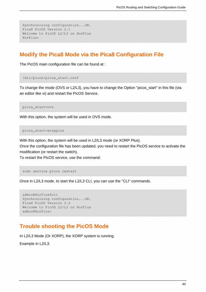
Synchronizing configuration...OK.Pica8 PicOS Version 2.1Welcome to PicOS L2/L3 on XorPlus XorPlus>
Modify the Pica8 Mode via the Pica8 Configuration File
The PicOS main configuration file can be found at :
/etc/picos/picos_start.conf
To change the mode (OVS or L2/L3), you have to change the Option "picos_start" in this file (via
an editor like vi) and restart the PicOS Service.
picos_start=ovs
With this option, the system will be used in OVS mode.
picos_start=xorpplus
With this option, the system will be used in L2/L3 mode (or XORP Plus).
Once the configuration file has been updated, you need to restart the PicOS service to activate the
modification (or restart the switch).
To restart the PicOS service, use the command:
sudo service picos restart
Once in L2/L3 mode, to start the L2/L3 CLI, you can use the "CLI" commands.
admin@XorPlus$cliSynchronizing configuration...OK.Pica8 PicOS Version 2.4Welcome to PicOS L2/L3 on XorPlusadmin@XorPlus>
Trouble shooting the PicOS Mode
In L2/L3 Mode (Or XORP), the XORP system is running.
Example in L2/L3:

PicOS Routing and Switching Configuration Guide
41
admin@XorPlus$ps aux | grep xorp | grep -v greproot 16383 0.0 1.2 18100 6596 ? S Jan29 5:26 xorp_policyroot 16385 0.3 2.5 34980 13380 ? Ss Jan29 99:20 /pica/bin/xorp_rtrmgr -d -Llocal0.info -P /var/run/xorp_rtrmgr.pid admin@XorPlus$ps aux | grep ovs | grep -v grep
In OVS Mode, only the OVS daemon is running.
adnib@Fabric-TOR1#ps aux | grep xorp | grep -v grepadmin@Fabric-TOR1#admin@Fabric-TOR1#admin@Fabric-TOR1#ps aux | grep ovs | grep -v greproot 19982 0.1 0.6 19316 3392 ? S Feb14 7:45 ovsdb-server/ovs/ovs-vswitchd.conf.db --remote=ptcp:6653:172.16.0.205--remote=punix:/ovs/var/run/openvswitch/db.sockroot 19984 5.5 2.4 28504 12772 ? Sl Feb14 398:02 ovs-vswitchd--pidfile=ovs-vswitchd.pid --overwrite-pidfileroot 19997 0.0 1.2 25632 6360 ? S Feb14 0:00 ovs-vswitchd: worker process forpid 19984
l2/L3 Configuration backup
The L2/L3 configuration is stored in /pica/config/pica_startup.boot.
admin@XorPlus$admin@XorPlus$cd /pica/config/admin@XorPlus$lsadmin pica.conf.06 pica.conf.13 pica.conf.20 pica.conf.27 pica.conf.34 pica.conf.41 pica.conf.48pica.conf pica.conf.07 pica.conf.14 pica.conf.21 pica.conf.28 pica.conf.35 pica.conf.42 pica.conf.49pica.conf.01 pica.conf.08 pica.conf.15 pica.conf.22 pica.conf.29 pica.conf.36 pica.conf.43 pica_startup.bootpica.conf.02 pica.conf.09 pica.conf.16 pica.conf.23 pica.conf.30 pica.conf.37 pica.conf.44pica.conf.03 pica.conf.10 pica.conf.17 pica.conf.24 pica.conf.31 pica.conf.38 pica.conf.45pica.conf.04 pica.conf.11 pica.conf.18 pica.conf.25 pica.conf.32 pica.conf.39 pica.conf.46pica.conf.05 pica.conf.12 pica.conf.19 pica.conf.26 pica.conf.33 pica.conf.40 pica.conf.47
From version PicOS 2.1, the configuration file will be automatically saved.
Painless upgrade

PicOS Routing and Switching Configuration Guide
42
Deprecated commands mechanism:The command structure of Xorp will make some change when release a new version image, not just add newcommands, some commands may be removed or replaced by new commands. Our goal is to make the commandstructure more structured and easier for users. So some commands will be marked as deprecated nodes since version2.4. When a command is replaced by a new command, the old one is marked as deprecated node, both these twocommands can be worked on this version, but the old command can’t be auto- completed by tab key or showing by “?”.The old command need to be typed manually when you want to use it. The old one will be removed in the next version.So you need to remove the deprecated nodes when you prepare to upgrade to next version.If there are some deprecated nodes in your configuration, then you will get some information when you commitconfiguration in CLI.
Note: the deprecated nodes must be removed before upgrading to next version.
For example:
1)
On version 2.4, the command of “interface management-ethernet” has been deprecated, replaced
by “system management-ethernet”, both these two command can work on version 2.4, and the
“interface management-ethernet” will be removed on version 2.5.
2)
When you set “interface management -ethernet” in CLI, you will get the following information:
Configure node "interface management-ethernet" has been deprecated in version 2.4, please use
"system management-ethernet" instead.
Note: The prompted information will not disappear until you removed the deprecated commands.
3) Upgrade
When upgrade image from an old verison from a new one with configuration save, then there will
be some configuration nodes have been marked as deprecated in the new version, then you will
get some notice information when you commit in CLI.
For example, upgrade from 2.3 to 2.4 with configuration saved, after upgrading and removing vlan:
XorPlus# delete vlans vlan-id 111Deleting: 111 {}OK XorPlus# commit Commit OK.Configure node "interface management-ethernet" has been deprecated in version2.4, please use "system management-ethernet" instead.Configure node "system syslog host" has been deprecated in version 2.4,please use "system syslog server-ip" instead.Configure node "system syslog port-number" has been deprecated in version2.4, please use "system syslog server-ip" instead.Configure node "system syslog port-protocol" has been deprecated in version2.4, please use "system syslog server-ip" instead.Save done.XorPlus#

PicOS Routing and Switching Configuration Guide
43
Note:1) When upgrading image from an old version to a new one with the configuration which has deprecated nodes,upgrading will be failed. You should remove the deprecated nodes on the configuration tree and then upgrading again.2) We do not support painless upgrading by discontinuous version upgrade, for example from 2.3 to 2.5. If you want toupdate to a discontinuous version, please do not save the configuration.
Deprecated nodes list in version 2.4:Configure node “interface management-ethernet, "system syslog host", "system syslog port-number" and "systemsyslog port-protocol" have been deprecated in version 2.4.
For more information about the deprecated node list, please see:http://203.195.202.125:8080/display/picos24sp/Configuring+DHCP+and+a+Static+IP+Addresshttp://203.195.202.125:8080/display/picos24sp/Configuring+the+Syslog+Disk+and+Syslog+host

PicOS Routing and Switching Configuration Guide
44
System Management Configuration
System Management Overview
From Linux Shell to L2_L3 Shell
Operation Mode and Configuration Mode
Commit Failed and Exit Discard
Commit confirmed
Configuring DHCP and a Static IP Address
Configuring DHCP relay
Configuring DHCP option82
Configuring DHCP snooping
Configuring a User Account
Configuring Authentication_Authorization_Accounting
Configuring SSH and Telnet Parameters
Configuring the Log-in ACL
Configuring NTP and the Time zone Parameter
Configuring the linux-config-unreliable
Configuring IPFIX
Configuring sFlow
Configuring SNMP
Configuring the Syslog Log Level
Configuring the Syslog Disk and Syslog host
Updating the PicOS Software and Platform
Displaying System Information
Technical Support
Flushing ARP and the Neighbor Table
Rebooting the System
Displaying the Debugging Message
System Management Command List
System Management Overview
This chapter describes the different ways to configure PicOS and walk you through the CLI
configuration.

PicOS Routing and Switching Configuration Guide
45
There are 2 CLIs to configure PicOS:
1) The Linux CLI
2) The PicOS CLI
The Linux CLI is a standard debian based bash shell.
A good Bash tutorial can be found at this address:
http://www.tldp.org/LDP/Bash-Beginners-Guide/html/
PicOS added some commands to the standard Bash shell:
Version - This is to give the PicOS version running on the switch
admin@XorPlus$versionCopyright (C) 2009-2014 Pica8, Inc.===================================Hardware Model : P-5101Linux System Version/Revision : 2.5/17907Linux System Released Date : 10/14/2014L2/L3 Version/Revision : 2.5/17907L2/L3 Released Date : 10/14/2014OVS/OF Version/Revision : 2.5/17907OVS/OF Released Date : 10/14/2014
cli - command to move to the PicOS command or launch PicOS CLI commands from the Linux
shell.
admin@XorPlus$cliSynchronizing configuration...OK.Pica8 PicOS Version 2.5Welcome to PicOS L2/L3 on XorPlusadmin@XorPlus>
In the above example the cli command is used to move to the PicOS CLI.
admin@XorPlus$cli -c "show version" Synchronizing configuration...OK.Pica8 PicOS Version 2.5Welcome to PicOS L2/L3 on XorPlusadmin@XorPlus> Execute command: show version.Copyright (C) 2009-2014 Pica8, Inc.===================================Base ethernet MAC Address : 48:6e:73:01:00:01Hardware Model : P-5101Linux System Version/Revision : 2.5/17907Linux System Released Date : 10/14/2014L2/L3 Version/Revision : 2.5/17907L2/L3 Released Date : 10/14/2014
In the above command the cli command is used to launch a command of the picOS CLI from the
Linux shell.

PicOS Routing and Switching Configuration Guide
46
From Linux Shell to L2_L3 Shell
Once in the Linux shell, you can use the command "pica_sh" or "cli" (under /pica/bin) to launch the
L2/L3 CLI (or XORP CLI).
admin@Lima$admin@Lima$cliSynchronizing configuration...OK.Pica8 PicOS Version 2.3Welcome to PicOS L2/L3 on LimaLima> Lima> Lima>
From the L2/L3 CLI (or XORP CLI) to come back to the Linux Shell, you can use the "exit"
command.
XorPlus> exitadmin@XorPlus$
Operation Mode and Configuration Mode
Operation mode
By default, the switch's operation mode is activated when it starts up.
Welcome to PicOS L2/L3on XorPlus
XorPlus>
Configuration mode
Activate the configuration mode by entering the configure command. For the remainder of this
document, be sure to enter the configuration mode if you see the XorPlus# prompt.
XorPlus> configure Entering configuration mode.There are no other users in configuration mode.XorPlus#
Commit Failed and Exit Discard
Exiting the configuration mode uncommitted configurationswithout
Switch to the execution mode from the configuration mode any uncommittedwithout
configurations.
XorPlus# exitXorPlus>

PicOS Routing and Switching Configuration Guide
47
Exiting the configuration mode uncommitted configurationswith
Use the exit discard command to enter the execution mode from the configuration mode with any
uncommitted or failed committed configurations.
XorPlus# set interface gigabit-ethernet ge-1/1/1 disable trueXorPlus# exitERROR: There are uncommitted changes.Use "commit" to commit the changes, or "exit discard" to discard them.XorPlus# exit discard XorPlus>
Commit confirmed
User can commit a candidate configuration before this configuration become permanent. By using
"commit confirmed", the system will apply the configuration for ten minutes default. After ten
minutes, the system will roll back to the configuration automatically before user "commit
confirmed". User can configure the roll back time in the CLI, default it is 10 minutes.
Default configure
By default, it will be automatically rolled back to the previous configuration after 600 seconds.
XorPlus# set vlans vlan-id 2XorPlus# commit confirmed Merging the configuration.Will be automatically rolled back in 600 seconds unless confirmed by newcommit.Commit OK.XorPlus#
Modify the rollback confirmation time
XorPlus# set vlans vlan-id 3XorPlus# commit confirmed 100Merging the configuration.Will be automatically rolled back in 100 seconds unless confirmed by newcommit.Commit OK.XorPlus#
Configuring DHCP and a Static IP Address
Enabling DHCP
By default, DHCP is enabled on the management interface eth0. You can enable DHCP manually
with the following CLI command:

PicOS Routing and Switching Configuration Guide
48
XorPlus# set system management-ethernet eth0 address dhcpXorPlus# comCommit OK.Save done.XorPlus#
Configuring a static IP address and gateway
Configure your management interface eth0 with static IP address.
XorPlus# set system management-ethernet eth0 address 10.10.50.139/24XorPlus# set system management-ethernet eth0 gateway 10.10.50.1XorPlus# commit Commit OK.Save done.
Configure node “interface management-ethernet” has been has been deprecated in version 2.4.
Configuring DHCP relay
Enabling DHCP relay in a VLAN interface
When you enable DHCP relay in a VLAN interface, the switch will relay the received DHCP request
to the specified DHCP server via routing. Normally, the port connects to a DHCP servertrusted
should be a trusted port. You should configure the port using the option.trust true

PicOS Routing and Switching Configuration Guide
49
XorPlus# set vlans vlan-id 2XorPlus# set vlans vlan-id 3XorPlus# set interface gigabit-ethernet ge-1/1/1 family ethernet-switchingnative-vlan-id 2XorPlus# set interface gigabit-ethernet ge-1/1/2 family ethernet-switchingnative-vlan-id 3XorPlus# set vlans vlan-id 2 l3-interface vlan-2XorPlus# set vlans vlan-id 3 l3-interface vlan-3XorPlus# commitWaiting for merging configuration.Commit OK.Save done.XorPlus# set vlan-interface interface vlan-2vif vlan-2 address 192.168.1.1prefix-length 24XorPlus# set vlan-interface interface vlan-3vif vlan-3 address 192.168.2.1prefix-length 24XorPlus# commitWaiting for merging configuration.Commit OK.Save done.XorPlus# set protocols dhcp relay vlan-interface vlan-2 disable falseXorPlus# set protocols dhcp relay vlan-interface vlan-2 dhcp-server-address1192.168.2.100XorPlus# set protocols dhcp snooping port ge-1/1/2 trust trueXorPlus# commitWaiting for merging configuration.Commit OK.Save done.
Configuring DHCP option82
Option82 is a relay agent used to specify the DHCP client location information. The DHCP
option82 is disabled by default. To enable option82, use the option, then use the disable false
command to set the DHCP port information.circuit-id
Enable DHCP option82
XorPlus# set protocols dhcp option82 disable falseXorPlus# commit Merging the configuration.Commit OK.Save done.XorPlus#
Modify the circuit-id of option82
XorPlus# set protocols dhcp relay port ge-1/1/3 circuit-id v100XorPlus# commit Merging the configuration.Commit OK.Save done.XorPlus#

PicOS Routing and Switching Configuration Guide
50
Configuring DHCP snooping
DHCP snooping creates a mapping table which includes the IP address, the MAC address, and the
port number. DHCP snooping is disabled by default. The steps below explain how to enable DHCP
snooping, configure the DHCP snooping binding file, trust port (by default the port is untrusted),
and timeout.
Enable DHCP snooping
XorPlus# set protocols dhcp snooping disable falseXorPlus# commit Commit OK.Save done.XorPlus#
Configure DHCP snooping binding file and timeout
XorPlus# set protocols dhcp snooping binding file /tmp/run/dhcp_bind //syncthe dhcp snooping table to diskXorPlus# set protocols dhcp snooping binding timeout 8XorPlus# comMerging the configuration.Commit OK.Save done.
Configure DHCP snooping trust port
XorPlus# set protocols dhcp snooping port ge-1/1/2 trust true //(DHCP replyis trusted), usually, the port connect to DHCP server should be enable this. XorPlus# commitMerging the configuration.Commit OK.Save done.
Display the DHCP snooping table of host information
XorPlus# run show dhcp snooping Total count: 1MAC Address IP Address Port VLAN ID VLAN Interface ----------------- --------------- --------- ------- --------------- 00:1d:09:fa:a1:b4 192.168.1.10 ge-1/1/1 2 vlan2
Configuring a User Account
There are two types of user accounts: super-user and read-only. The newly created user account,
by default, is read-only.
Creating a user class and password

PicOS Routing and Switching Configuration Guide
51
XorPlus# set system login user ychen authentication plain-text-password pica8XorPlus#set system login user ychen class super-userXorPlus# commitCommit OK.Save done.XorPlus#
Configuring a telnet announcement
XorPlus# set system login announcement "welcome the switch-1101"XorPlus# commit Waiting for merging configuration.Commit OK.Save done.XorPlus#
Configuring Authentication_Authorization_Accounting
PicOS supports Authentication/Authorization/Accounting (AAA). A user is authenticated by the
AAA server (referred to as "admin" in our guide) and then can configure the switch. PicOS
supports TACACS+ and RADIUS protocols. RADIUS supports only two levels: read-only and
super-user.
Configure the local switch and server as shown below:
Configuring AAA in the switch
Configure the tacacs enable
XorPlus# set system aaa tacacs-plus disable false XorPlus# set system aaa tacacs-plus key pica8 XorPlus# set system aaa tacacs-plus server-ip 10.10.53.53 XorPlus# commitCommit OK.Save done.XorPlus# set system aaa tacacs-plus authorization trueXorPlus# set system aaa tacacs-plus accounting trueXorPlus# commit
Configure the radius enable

PicOS Routing and Switching Configuration Guide
52 1.
XorPlus# set system aaa radius authorization disable falseXorPlus# set system aaa radius authorization server-ip 10.10.50.41 shared-keytesting123XorPlus# commit Merging the configuration.Commit OK.Save done.XorPlus#XorPlus# set system aaa radius accounting disable falseXorPlus# set system aaa radius accounting server-ip 10.10.50.41 shared-keytesting123XorPlus# commit Merging the configuration.Commit OK.Save done.XorPlus#
Displaying AAA information
XorPlus# show system aaa tacacs-plusWaiting for building configuration.authorization: trueaccounting: trueserver-ip 10.10.53.53key: "pica8" XorPlus# show system aaa radius Building the configuration.authorization {disable: falseserver-ip 10.10.50.41 {shared-key: "testing123"}}accounting {disable: falseserver-ip 10.10.50.41 {shared-key: "testing123"}}XorPlus#
Configuring the AAA server
Configure the AAA server configuration file as follows:
Tacacs server configuration:
key = pica8

PicOS Routing and Switching Configuration Guide
53
1. Accounting File
accounting file = /var/tmp/acctfile
default authentication = file /etc/passwd
user = admin {
member = admins
}
group = admins {
global = cleartext "password"
service = exec {
default attribute = permit
}
}
user = operator {
global = cleartext "operator"
service = exec {
default attribute = permit
}
}
user = ychen {
global = cleartext "ychen"
member = admins
service = exec {
default attribute = permit
}
}
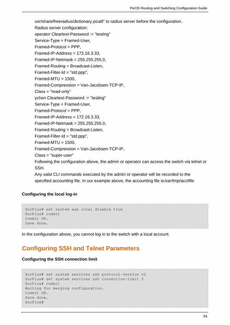
Add "/
PicOS Routing and Switching Configuration Guide
54
1.
usr/share/freeradius/dictionary.pica8" to radius server before the configuration.
Radius server configuration:
operator Cleartext-Password := "testing"
Service-Type = Framed-User,
Framed-Protocol = PPP,
Framed-IP-Address = 172.16.3.33,
Framed-IP-Netmask = 255.255.255.0,
Framed-Routing = Broadcast-Listen,
Framed-Filter-Id = "std.ppp",
Framed-MTU = 1500,
Framed-Compression = Van-Jacobsen-TCP-IP,
Class = "read-only"
ychen Cleartext-Password := "testing"
Service-Type = Framed-User,
Framed-Protocol = PPP,
Framed-IP-Address = 172.16.3.33,
Framed-IP-Netmask = 255.255.255.0,
Framed-Routing = Broadcast-Listen,
Framed-Filter-Id = "std.ppp",
Framed-MTU = 1500,
Framed-Compression = Van-Jacobsen-TCP-IP,
Class = "super-user"
Following the configuration above, the admin or operator can access the switch via telnet or
SSH.
Any valid CLI commands executed by the admin or operator will be recorded to the
specified accounting file. In our example above, the accounting file is ./var/tmp/acctfile
Configuring the local log-in
XorPlus# set system aaa local disable trueXorPlus# commitCommit OK.Save done.
In the configuration above, you cannot log in to the switch with a local account.
Configuring SSH and Telnet Parameters
Configuring the SSH connection limit
XorPlus# set system services ssh protocol-version v2 XorPlus# set system services ssh connection-limit 5XorPlus# commit Waiting for merging configuration.Commit OK.Save done.XorPlus#

PicOS Routing and Switching Configuration Guide
55
Disabling telnet service
XorPlus# set system services telnet disable trueXorPlus# commit Waiting for merging configuration.Commit OK.Save done.XorPlus#
Enabling and disabling inband service
By default, SSH and telnet with inband interfaces are disabled. You can enable inband services by
entering the command below:
XorPlus# set system inband enable trueXorPlus# commit Waiting for merging configuration.Commit OK.Save done.XorPlus#
Configuring the Log-in ACL
Configuring the log-in ACL
Configure the ALC to control whether remote hosts within specified subnetworks are allowed to log
in to the system. In our example, remote hosts from both subnetworks that we configured may log
in.
XorPlus# set system login-acl network 192.168.1.0/24XorPlus# set system login-acl network 192.168.100.100/32XorPlus#XorPlus# commit Waiting for merging configuration.Commit OK.Save done.XorPlus#
Configuring NTP and the Time zone Parameter
Configuring the NTP server IP address
The L2/L3 switch synchronizes with the NTP server only when the configuration commands are
committed using the command. You can change the NTP server's IP address, as showncommit
below:

PicOS Routing and Switching Configuration Guide
56
XorPlus# set system ntp-server-ip 192.168.10.100XorPlus# commit Waiting for merging configuration.Commit OK.Save done.XorPlus#
Configuring the time zone
Configure the time zone as follows (we selected Pacific/Kosrae for our example):
XorPlus# set system timezone Pacific/KosraeXorPlus# commit Waiting for merging configuration.Commit OK.Save done.XorPlus#
Configuring the system clock
XorPlus> set date 2012.01.01-23:59Sun Jan 1 23:59:00 UTC 2012XorPlus>.
The clock will be set in the hardware.
Configuring the linux-config-unreliable
PicOS support that clarify the synchronization between Linux shell and xorp.
when chang the linux-config-unreliable, please commit it firstly, and then set other system settings.Do not commit the linux-config-unreliable and system delta at the same time.
You can choose Bash control or xorp control. By default, xorp control in system. As shown below:
1 Xorp control:
XorPlus# set system linux-config-unreliable trueXorPlus# commitCommit OK.Save done.XorPlus# show system linux-config-unreliable: true services { telnet { disable: false } } log-level: "trace"
2) Bash control:

PicOS Routing and Switching Configuration Guide
57
XorPlus# set system linux-config-unreliable falseXorPlus# commitCommit OK.Save done.XorPlus# show system linux-config-unreliable: false log-level: "trace"
When you choose bash control, the system settings should be set in bash, not from xorp,
otherwise the system command should be set in xorp.
For example:
XorPlus# show system linux-config-unreliable: false log-level: "trace"XorPlus# set system hostname pica8XorPlus# commitThe system is managed by linuxCommit failed.XorPlus#
Only the following system commands should always be set in PicOS even system is under bash control:system aaa tacacs-plussystem log-levelsystem log-facility
when changing the system control right from xorp control to Bash control, the xorp configurations related to system willbe removed from configuration tree automatically. When changing from Bash conrtol to xopr control, the configurationrelated to system will be read and added into xorp configuration tree automatically.
Configuring IPFIX
Configuring IPFIX parameters
By default, IPFIX is disabled. You can enable IPFIX and configure its parameters as shown below.
Make sure the switch can connect to the IPFIX collector server correctly.
XorPlus# set protocols ipfix collector 192.168.2.10 udp-port 9999XorPlus# set protocols ipfix interfaces ingress ge-1/1/1XorPlus# commit Waiting for merging configuration.Commit OK.Save done.XorPlus#
Configuring sFlow
Globally enabling sFlow

PicOS Routing and Switching Configuration Guide
58
By default, sFlow is disabled. You can enable sFlow and configure its' parameters. Verify that the
switch can connect to the sFlow collector server, and configure the sFlow and agent-id
at the same time that you enable sFlow, as shown below:source-address
XorPlus# set protocols sflow disable falseXorPlus# set protocols sflow agent-id 10.10.50.248XorPlus# set protocols sflow source-address 10.10.50.248XorPlus# commitWaiting for merging configuration.Commit OK.Save done.XorPlus#
Configuring sFlow parameters
You can configure global parameters for sFlow, including agent-id, collector IP, polling-interval,
sampling-rate, and source-address.
XorPlus# set protocols sflow agent-id 10.10.50.248XorPlus# set protocols sflow collector 10.10.50.221 udp-port 6343XorPlus# set protocols sflow polling-interval 30XorPlus# set protocols sflow sampling-rate ingress 2000XorPlus# set protocols sflow sampling-rate egress 2000XorPlus# set protocols sflow header-len 128XorPlus# set protocols sflow source-address 10.10.50.248XorPlus# commit Waiting for merging configuration.Commit OK.Save done.XorPlus# run show sflow sFlow : EnabledAgent ID : 10.10.50.248Source Address : 10.10.50.248Sample rate ingress: 1:2000Sample rate egress : 1:2000Polling interval : 30 secondsHeader Length : 128XorPlus#XorPlus# run show sflow collector Collector address UDP-port No of Samples----------------- -------- -------------10.10.50.221 6343 5336XorPlus#
Configuring sFlow on a specific interface
You can configure sFlow parameters on a specific interface:
In the current version, sFlow samples only the ingress traffic of each interface. You can monitor the
traffic with sFlow Trend as follows:

PicOS Routing and Switching Configuration Guide
59
Figure 2-1.sFlowTrendtools.
Configuring SNMP
Configuring SNMP parameters
By default, SNMP is disabled. You can enable SNMP and configure its parameters (e.g.
community, contact, location) as shown below:
XorPlus# set protocols snmp community Pica8-data-centerXorPlus# set protocols snmp community Pica8-data-center authorizationread-onlyXorPlus# set protocols snmp contact [email protected]# set protocols snmp location BeijingXorPlus# set protocols snmp trap-group targets 10.10.1.1XorPlus# set protocols snmp trap-group version v2XorPlus# commit Waiting for merging configuration.Commit OK.Save done.XorPlus#
Configuring an SNMP ACL
By default, all hosts can the information of the switch. Configure an SNMP ACL tosnmpwalk
control which hosts within the subnetwork can snmpwalk the switch.

PicOS Routing and Switching Configuration Guide
60
XorPlus# set system snmp-acl network 1.1.1.0/24XorPlus# set system snmp-acl network 2.2.2.0/24XorPlus# commit Waiting for merging configuration.Commit OK.Save done.XorPlus#
Configuring SNMPset
Users can use "snmpset"(OID1.3.6.1.4.1.35098.2.0.0) to load a configuration and can use
"snmpset"(OID 1.3.6.1.4.1.35098.2.1.0) to delete or load a configuration. However, only set&delete
commands can be included in the command batch (which is OID 1.3.6.1.4.1.35098.2.1.0). Other
commands are invalid and ignored. Note that clearing a dependent configuration is not allowed.
XorPlus# set protocols snmp community private authorization read-writeXorPlus# commit Waiting for merging configuration.Commit OK.Save done.
Examples of snmpset application (using one server):
(a) using snmpset to load a filter configuration
root@dev:~# snmpset -v 2c -c private IP .1.3.6.1.4.1.35098.2.0.0 s"tftp:1.1.5.1:/pica8/acl.conf"iso.3.6.1.4.1.35098.2.0.0 = STRING: "tftp:1.1.5.1:/pica8/acl.conf"
(b) using snmpset to delete a filter configuration
root@dev:~# snmpset -v 2c -c private IP .1.3.6.1.4.1.35098.2.1.0 s"tftp:1.1.5.1:/pica8/delete-acl.conf"iso.3.6.1.4.1.35098.2.0.0 = STRING: "tftp:1.1.5.1:/pica8/delete-acl.conf"
Configuring the Syslog Log Level
Configuring the syslog level
Listed in order from most severe to least severe; there are five system syslog levels: Fatal, Error,
Warning, Info, and Trace. By default, the system is set to the Warning level. You can, of course,
change the log level.
In the example below, the system logs messages from Info, Warning, Error, and Fatal levels since
the system syslog level is set to Info.

PicOS Routing and Switching Configuration Guide
61
XorPlus# set system log-level infoXorPlus# commit Waiting for merging configuration.Commit OK.Save done.XorPlus# You can display the log messages on the console screen by entering thefollowing command: XorPlus# exitXorPlus> syslog monitor on If the switch's syslog level is Trace, the trace options of the modulesshould be turned on, as illustrated below. You can also turn on the OSPFtrace options for debugging. XorPlus# set protocols ospf4 traceoptions flag all disable falseXorPlus# set system log-level traceXorPlus# commit Waiting for merging configuration.Commit OK.Save done.XorPlus# exitXorPlus> syslog monitor on
Configuring the SNMP logging facility
In accordance with the syslog standard, the logging facility can be configured as [0, 7].
XorPlus# set system log-facility 0XorPlus# commit Waiting for merging configuration.Commit OK.Save done.XorPlus#Oct 17 15:22:42 XorPlus local0.warn : admin logined the switchOct 17 15:22:50 XorPlus local0.warn pica_sh: Tacacs send acct body sendfailed: wrote -1 of 127: Connection refused XorPlus# set system log-facility 2XorPlus# commit Waiting for merging configuration.Commit OK.Save done.XorPlus#
Oct 17 15:22:42 XorPlus local2.warn : admin logined the switch
Configuring the Syslog Disk and Syslog host
Configuring the syslog host
After you configure the syslog server IP address, the log files will be sent to the syslog server.

PicOS Routing and Switching Configuration Guide
62
XorPlus# set system syslog server-ip 192.168.1.1 ?Possible completions: <[Enter]> Execute this command port Remote syslog server port protocol Remote syslog server protocolXorPlus# set system syslog server-ip 192.168.1.1 protocol tcpXorPlus# commit Commit OK.Save done.XorPlus#
Configure node "system syslog host", "system syslog port-number" and "system syslog port-protocol" have beendeprecated in version 2.4.
Configuring syslog for local storage
You can configure syslog messages to be stored in RAM or in a local SD card.
XorPlus# set system syslog local-file diskXorPlus# commit Waiting for merging configuration.Commit OK.Save done.XorPlus#XorPlus# set system syslog local-file ramXorPlus# commit Waiting for merging configuration.Commit OK.Save done.XorPlus#
Updating the PicOS Software and Platform
You can separate the system's PicOS Platform and PicOS Software and update them respectively.
Generally, rootfs.tar.gz will include both the PicOS Platform and PicOS Software, and pica.tar.gz
will include only the PicOS Software.
Displaying the system version
XorPlus# run show version Copyright (C) 2009-2013 Pica8, Inc.Base ethernet MAC Address : 08:9e:01:61:65:80Hardware model : P-3290PicOS Version : 2.2Revision ID : 10863
Updating the PicOS Software
Step1: Get the pica image and md5 file. (Then modify the md5 file's file name according to
)pica.tar.gz

PicOS Routing and Switching Configuration Guide
63
XorPlus> file tftp get remote-file pica_bin.tar.gz local-file pica.tar.gzip-address 1.1.5.6Start to get the 'picos.tar.gz' to '/cftmp/rootfs.tar.gz'.Waiting......Done!XorPlus> file tftp get remote-file pica_bin.tar.gz.md5 local-filepica.tar.gz.md5 ip-address 1.1.5.6Start to get the 'pica_bin.tar.gz.md5' to '/cftmp/pica.tar.gz.md5'.Waiting......Done!XorPlus>
Step2:Reboot the switch.
XorPlus# run request system reboot
The image will be placed under the local installation directory ( ). The system will/cftmp
decompress pica.tar.gz automatically when rebooted, updating only the PicOS Software.
Updating the PicOS Platform
Step1:Get the image and md5 file . (Then modify the md5 file's file name according to
)rootfs.tar.gz
XorPlus> file tftp get remote-file picos.tar.gz local-file rootfs.tar.gzip-address 1.1.5.6Start to get the 'picos.tar.gz' to '/cftmp/rootfs.tar.gz'.Waiting......Done!XorPlus> file tftp get remote-file picos.tar.gz.md5 local-filerootfs.tar.gz.md5 ip-address 1.1.5.6Start to get the 'picos.tar.gz.md5' to '/cftmp/rootfs.tar.gz.md5'.Waiting......Done!XorPlus>
Step2:Reboot the switch.(Best to back up configuration file" "/pica/config/pica_startup.bootto directory to avoiding missing file before rebooting)/cftmp
XorPlus# run request system reboot
The image will be placed under the local installation directory ( ). The system will/cftmp
decompress automatically when rebooted, updating both the PicOS Platform androotfs.tar.gz
PicOS Software. In version 2.2 , we support using shell script to upgrade. (Please consult
picos-2.2.0-image-upgrade-guide)
Displaying System Information
You can display your system's information, including fan, power supply unit, and serial number
information.

PicOS Routing and Switching Configuration Guide
64
Displaying the system fan
XorPlus>show system fan Sensor Temperature:Sensor 1 Temperature : 42 CentigradeSensor 2 Temperature : 39 CentigradeSensor 3 Temperature : 46 CentigradeSensor 4 Temperature : 33 CentigradeFan Status:Fan 1 speed = 12529 RPM, PWM = 79Fan 2 speed = 12413 RPM, PWM = 79Fan 3 speed = 12300 RPM, PWM = 79
Displaying the system power supply unit
XorPlus> show system rpsu RPSU 1:TEMPERATURE_1 : N/ARPSU 2:TEMPERATURE_1 : 38.00 CentigradeTEMPERATURE_2 : 40.00 CentigradeFAN_SPEED : 10784.0 RPMFAN_PWM : 60
Displaying the system serial number
XorPlus> show system serial-number MotherBoard Serial Number : QTFCXI2460009RPSU 1 Serial Number : N/ARPSU 2 Serial Number : 601G10103C370ZGSFP te-1/1/49 :Vendor Name : PICA8 Serial Number : 78613B10987 Module Type : SR/850nmCable Length : 80mSFP te-1/1/50 :Vendor Name : JESS-LINK Serial Number : 12344D0001 Cable Length : 5mSFP te-1/1/51 :Vendor Name : DELTA Serial Number : 084109000017 Module Type : SR/850nmCable Length : 80mSFP te-1/1/52 :Vendor Name : JESS-LINK Serial Number : 12344D0002 Cable Length : 5m
Displaying additional system information
XorPlus# run show system temperature Temperature: 39 C /102FXorPlus#

PicOS Routing and Switching Configuration Guide
65
XorPlus# run show system uptime 01:21:33 up 50 min, load average: 0.04, 0.06, 0.07XorPlus#XorPlus# run show system cpu-usage Cpu usage: 15%XorPlus#XorPlus# run show system dateMon Jan 13 18:11:04 UTC 2014XorPlus# XorPlus# run show system memory-usage total used free shared buffers cachedMem: 515808 185468 330340 0 10320 68312-/+ buffers/cache: 106836 408972Swap: 0 0 0XorPlus# XorPlus# run show system name XorPlusXorPlus#XorPlus# run show system ntp-status Please start the ntp server first!XorPlus#XorPlus# run show system osLinux XorPlus 2.6.27 #1 Thu Feb 13 00:42:23 CST 2014 ppc GNU/LinuxXorPlus# run show system processes brief PID TTY STAT TIME COMMAND1 ? Ss 0:01 init [2] 2 ? S< 0:00 [kthreadd]3 ? S< 0:00 [ksoftirqd/0]4 ? S< 0:00 [watchdog/0]5 ? S< 0:02 [events/0]6 ? S< 0:00 [khelper]48 ? S< 0:00 [kblockd/0]55 ? S< 0:00 [ata/0]56 ? S< 0:00 [ata_aux]58 ? S< 0:00 [kseriod]99 ? S 0:00 [pdflush]101 ? S< 0:00 [kswapd0]147 ? S< 0:00 [aio/0]156 ? S< 0:00 [nfsiod]831 ? S< 0:00 [ftld]853 ? S< 0:00 [rpciod/0]857 ? S< 0:00 [kjournald]2222 ? S 0:00 [pdflush]2356 ? Ss 0:00 /usr/sbin/cron -L 02387 ? Ss 0:00 /usr/sbin/xinetd -pidfile /var/run/xinetd.pid -stayalive-inetd_compat -inetd_ipv62501 ? S 0:03 pica_cardmgr2503 ? S 0:59 pica_sif2649 ? S 0:05 pica_lacp2664 ? Ss 0:00 dhclient -pf /run/dhclient.eth0.pid -lf/var/lib/dhcp/dhclient.eth0.leases eth02666 ? Sl 18:06 pica_lcmgr2672 ? S 0:04 pica_login3166 ? Sl 0:00 /usr/sbin/rsyslogd -c53457 ? S 0:35 pica_mstp3462 ? S 0:02 xorp_policy3464 ? Ss 1:03 /pica/bin/xorp_rtrmgr -d -L local0.info -P/var/run/xorp_rtrmgr.pid3500 tty1 Ss+ 0:00 /sbin/getty 38400 tty13507 tty2 Ss+ 0:00 /sbin/getty 38400 tty23508 tty3 Ss+ 0:00 /sbin/getty 38400 tty33761 ttyS0 Ss+ 0:00 /sbin/getty -s -L ttyS0 115200 ansi4050 ? S 0:57 ovs-vswitchd

PicOS Routing and Switching Configuration Guide
66
4422 ? Ss 0:00 in.telnetd: 10.10.50.164423 pts/0 Ss 0:00 login -h 10.10.50.16 -p4424 pts/0 S+ 0:00 -bash4434 pts/0 S+ 0:03 /pica/bin/pica_sh6451 ? Ss 0:00 in.telnetd: 10.10.50.186452 pts/1 Ss 0:00 login -h 10.10.50.18 -p6460 pts/1 S+ 0:00 -bash6469 pts/1 R+ 0:03 /pica/bin/pica_sh15113 pts/1 R 0:00 ps aXorPlus# run show system rollback ?Possible completions:compare Show the difference between tow rolled back configurationsfile Show rolled back configuration filelist Show rolled back file listXorPlus# run show system rollback compare to 023c3< /Last commit : Mon Jan 13 14:13:01 2014 by admin/—> /Last commit : Mon Jan 13 14:11:54 2014 by admin/83,86d82< crossflow {< enable: true< local-control: true< }95,98d90< crossflow {< enable: true< local-control: true< }510,514d501< controller 1 {< protocol: "tcp"< address: 10.10.50.47< port: 6633< }XorPlus#XorPlus# run show system rollback file 02/XORP Configuration File, v1.0//* Copyright (C) 2009-2013 Pica8, Inc.*//Last commit : Mon Jan 13 14:11:54 2014 by admin//PicOS Version : 2.2//Version Checksum: 24226776f6bc5622030e3b7959d612bf/interface {ecmp {max-path: 4hash-mapping {field {ingress-interface {disable: true}vlan {disable: true}ip-protocol {disable: true}ip-source {disable: false}ip-destination {disable: false}port-source {

PicOS Routing and Switching Configuration Guide
67
disable: false}port-destination {disable: false}}}}aggregate-balancing {.....................................................................XorPlus# run show system rollback list -rw-rw-r-- 1 root xorp 23478 Jul 7 22:55 /pica/config/pica.conf-rw-rw-r-- 1 root xorp 23595 Jul 7 22:28 /pica/config/pica.conf.01-rw-rw-r-- 1 admin xorp 23595 Jul 7 22:27 /pica/config/pica.conf.02-rw-rw-r-- 1 root xorp 23595 Jul 7 22:26 /pica/config/pica.conf.03XorPlus# run show system users admin pts/0 Jan 13 14:19 (10.10.50.16)admin pts/1 Jan 13 15:03 (10.10.50.18)XorPlus#XorPlus# run show system core-dumps total 0XorPlus#XorPlus# run show system connections Active Internet connections (servers and established)Proto Recv-Q Send-Q Local Address Foreign Address State User Inode tcp 0 0 127.0.0.1:49152 0.0.0.0:* LISTEN 0 6787 tcp 0 0 127.0.0.1:60833 0.0.0.0:* LISTEN 0 5715 tcp 0 0 127.0.0.1:51714 0.0.0.0:* LISTEN 11 31043 tcp 0 0 127.0.0.1:42179 0.0.0.0:* LISTEN 0 6789 tcp 0 0 127.0.0.1:56484 0.0.0.0:* LISTEN 0 5711 tcp 0 0 127.0.0.1:51044 0.0.0.0:* LISTEN 0 5705 tcp 0 0 127.0.0.1:40421 0.0.0.0:* LISTEN 0 6764 tcp 0 0 127.0.0.1:56263 0.0.0.0:* LISTEN 0 6822 XorPlus# run show system boot-messages Copyright (c) 2009-2014 Pica8 Inc. All rights reserved.Up time: 18:19:41 revision: 2.6.27 Using MPC85xx CDS machine descriptionMemory CAM mapping: CAM0=256Mb, CAM1=256Mb, CAM2=0Mb residual: 0MbLinux version 2.6.27 (root@dev-16-new) (gcc version 4.2.2) #1 Thu Feb 1300:42:23 CST 2014Found legacy serial port 0 for /soc8541@e0000000/serial@4500mem=e0004500, taddr=e0004500, irq=0, clk=330000000, speed=0Found legacy serial port 1 for /soc8541@e0000000/serial@4600mem=e0004600, taddr=e0004600, irq=0, clk=330000000, speed=0
Technical Support
Execute the diagnostic command, , to send the information to Pica8 Supportsshow tech_support
and receive a diagnostic report back from Pica8 technical support.
Executing the diagnostic command
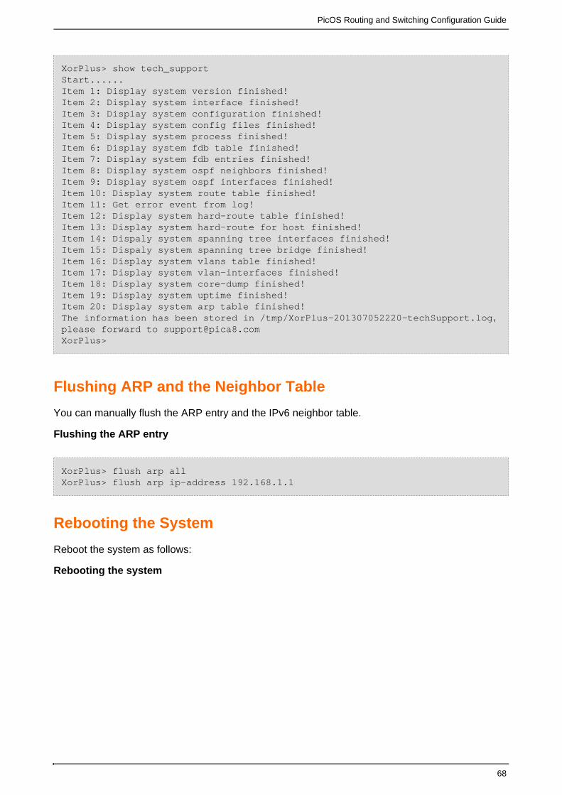
PicOS Routing and Switching Configuration Guide
68
XorPlus> show tech_support Start...... Item 1: Display system version finished!Item 2: Display system interface finished!Item 3: Display system configuration finished!Item 4: Display system config files finished!Item 5: Display system process finished!Item 6: Display system fdb table finished!Item 7: Display system fdb entries finished!Item 8: Display system ospf neighbors finished!Item 9: Display system ospf interfaces finished!Item 10: Display system route table finished!Item 11: Get error event from log!Item 12: Display system hard-route table finished!Item 13: Display system hard-route for host finished!Item 14: Dispaly system spanning tree interfaces finished!Item 15: Dispaly system spanning tree bridge finished!Item 16: Display system vlans table finished!Item 17: Display system vlan-interfaces finished!Item 18: Display system core-dump finished!Item 19: Display system uptime finished!Item 20: Display system arp table finished! The information has been stored in /tmp/XorPlus-201307052220-techSupport.log,please forward to [email protected]>
Flushing ARP and the Neighbor Table
You can manually flush the ARP entry and the IPv6 neighbor table.
Flushing the ARP entry
XorPlus> flush arp allXorPlus> flush arp ip-address 192.168.1.1
Rebooting the System
Reboot the system as follows:
Rebooting the system

PicOS Routing and Switching Configuration Guide
69
XorPlus>request system reboot U-Boot 1.3.0 (Apr 11 2011 - 10:41:10) CPU: 8541, Version: 1.1, (0x80720011)Core: E500, Version: 2.0, (0x80200020)Clock Configuration:CPU: 825 MHz, CCB: 330 MHz,DDR: 165 MHz, LBC: 41 MHzL1: D-cache 32 kB enabledI-cache 32 kB enabledI2C: readyDRAM: InitializingDDR: 512 MBFLASH: 32 MBL2 cache 256KB: enabledSet ethaddr MAC address = 60:eb:69:d2:9c:d8In: serialOut: serialErr: serialNet: TSEC0IDE: Bus 0: OK Device 0: Model: TRANSCEND Firm: 20091130 Ser#: 20100723 C4130E83Type: Hard DiskCapacity: 1911.6 MB = 1.8 GB (3915072 x 512)
Displaying the Debugging Message
You can configure the debugging message in your current window.
Syslog monitor on
XorPlus> syslog monitor on Nov 21 2000 22:27:39 XorPlus local0.warn : [SIF]Interface ge-1/1/3, changedstate to upNov 21 2000 22:27:41 XorPlus local0.warn : root logined the switchNov 21 2000 22:41:18 XorPlus local0.info xinetd[1102]: START: telnet pid=7650from=10.10.50.16Nov 21 2000 22:41:23 XorPlus authpriv.debug login[7651]:pam_unix(login:account): account admin has password changed in futureNov 21 2000 22:41:26 XorPlus local0.warn : admin logined the switchNov 21 2000 22:55:58 XorPlus local0.info xinetd[1102]: START: telnet pid=8039from=10.10.51.16Nov 21 2000 22:56:01 XorPlus authpriv.debug login[8040]:pam_unix(login:account): account root has password changed in futureNov 21 2000 23:31:13 XorPlus local0.info xinetd[1102]: START: telnet pid=9028from=10.10.50.16Nov 21 2000 23:31:16 XorPlus authpriv.debug login[9029]:pam_unix(login:account): account admin has password changed in futureNov 21 2000 23:31:21 XorPlus local0.warn : admin logined the switchXorPlus>
System Management Command List
cls
commit

PicOS Routing and Switching Configuration Guide
70
delete interface management-ethernet eth0 address
delete interface management-ethernet eth0 gateway
delete system aaa local disable
delete system aaa radius accounting disable
delete system aaa radius authorization disable
delete system aaa tacacs-plus accounting
delete system aaa tacacs-plus auth-type
delete system aaa tacacs-plus authorization
delete system aaa tacacs-plus disable
delete system aaa tacacs-plus key
delete system aaa tacacs-plus port-number
delete system hostname
delete system inband enable
delete system log-facility
delete system log-level
delete system login announcement
delete system login user admin authentication plain-text-password
delete system login user admin class
delete system login user operator authentication plain-text-password
delete system login user operator class
delete system login user root authentication plain-text-password
delete system login user root class
delete system services ssh connection-limit
delete system services ssh disable
delete system services ssh rate-limit
delete system services ssh root-login
delete system services telnet connection-limit
delete system services telnet disable
delete system services telnet rate-limit
delete system syslog host
delete system syslog local-file
delete system syslog port-number
delete system syslog port-protocol
exit configuration-mode
exit discard
help apply
help commit
help create
help delete
help execute
help exit configuration-mode
help exit discard
help help
help load
help quit

PicOS Routing and Switching Configuration Guide
71
help rollback
help run
help save
help set
help show all
help status
help top
help up
quit
run clear log bozo
run clear log all
run request system reboot
run set cli idle-timeout <int>
run set cli terminal ansi
run set cli terminal linux
run set cli terminal vt100
run set cli terminal xterm
run set date bozo
run set management-ethernet-speed eth0 <auto>|<int>
run show all_config
run show cli history
run show log date bozo
run show log last-rows <int>
run show running_config
run show system boot-messages
run show system connections
run show system core-dumps
run show system cpu-usage
run show system date
run show system fan
run show system memory-usage
run show system name
run show system ntp-status
run show system os
run show system processes brief
run show system processes detail
run show system rollback compare to <int>
run show system rollback file <int>
run show system rollback list
run show system rpsu
run show system serial-number
run show system temperature
run show system uptime
run show system users
run show task

PicOS Routing and Switching Configuration Guide
72
run show tech_support
run show version
run start shell sh
run syslog monitor off
run syslog monitor on
run telnet <ip-address>
set interface management-ethernet eth0 address <ip-address/netmask>
set interface management-ethernet eth0 gateway <ip-address>
set protocols dhcp option82 disable true
set protocols dhcp relay port bozo circuit-id bozo
set protocols dhcp relay vlan-interface bozo dhcp-server-address1 <ip-address>
set protocols dhcp relay vlan-interface bozo dhcp-server-address2 <ip-address>
set protocols dhcp relay vlan-interface bozo dhcp-server-address3 <ip-address>
set protocols dhcp relay vlan-interface bozo dhcp-server-address4 <ip-address>
set protocols dhcp relay vlan-interface bozo disable true
set protocols dhcp snooping binding file bozo
set protocols dhcp snooping binding timeout <int>
set protocols dhcp snooping disable true
set protocols dhcp snooping port bozo trust true
set protocols dhcp traceoptions flag all disable trueset protocols igmp disable true
set protocols sflow agent-id <ip-address>
set protocols sflow collector <ip-address> udp-port <int>
set protocols sflow disable true
set protocols sflow header-len <int>
set protocols sflow interface bozo disable true
set protocols sflow interface bozo header-len <int>
set protocols sflow interface bozo polling-interval <int>
set protocols sflow interface bozo sampling-rate egress <int>
set protocols sflow interface bozo sampling-rate ingress <int>
set protocols sflow polling-interval <int>
set protocols sflow sampling-rate egress <int>
set protocols sflow sampling-rate ingress <int>
set protocols sflow source-address <ip-address>
set protocols sflow traceoptions flag all disable true
set protocols snmp community bozo authorization read-only
set protocols snmp community bozo authorization read-write
set protocols snmp community bozo clients <ip-address>
set protocols snmp contact bozo
set protocols snmp location bozo
set protocols snmp traceoptions flag all disable true
set protocols snmp traceoptions flag general disable true
set protocols snmp traceoptions flag pdu disable true
set protocols snmp trap-group targets <ip-address>
set protocols snmp trap-group version v1
set protocols snmp trap-group version v2set protocols spanning-tree enable true

PicOS Routing and Switching Configuration Guide
73
set system aaa local disable true
set system aaa radius accounting disable true
set system aaa radius accounting server-ip <ip-address> port <int>
set system aaa radius accounting server-ip <ip-address> shared-key bozo
set system aaa radius accounting server-ip <ip-address> timeout <int>
set system aaa radius authorization disable true
set system aaa radius authorization server-ip <ip-address> port <int>
set system aaa radius authorization server-ip <ip-address> shared-key bozo
set system aaa radius authorization server-ip <ip-address> timeout <int>
set system aaa tacacs-plus accounting true
set system aaa tacacs-plus auth-type ascii
set system aaa tacacs-plus auth-type chap
set system aaa tacacs-plus auth-type pap
set system aaa tacacs-plus authorization true
set system aaa tacacs-plus disable true
set system aaa tacacs-plus key bozo
set system aaa tacacs-plus port-number <int>
set system aaa tacacs-plus server-ip <ip-address>
set system hostname bozo
set system inband enable true
set system log-facility <int>
set system log-level error
set system log-level fatal
set system log-level info
set system log-level trace
set system log-level warning
set system login announcement bozo
set system login user bozo authentication plain-text-password bozo
set system login user bozo class read-only
set system login user bozo class super-user
set system login user admin authentication plain-text-password bozo
set system login user admin class read-only
set system login user admin class super-user
set system login user operator authentication plain-text-password bozo
set system login user operator class read-only
set system login user operator class super-user
set system login user root authentication plain-text-password bozo
set system login user root class read-only
set system login user root class super-user
set system login-acl network <ip-address/netmask>
set system login-acl network <ipv6-address/netmask>
set system ntp-server-ip <ip-address>
set system remote-config allow-client <ip-address/netmask>
set system services ssh connection-limit <int>
set system services ssh disable true

PicOS Routing and Switching Configuration Guide
74
set system services ssh protocol-version v2
set system services ssh rate-limit <int>
set system services ssh root-login allow
set system services ssh root-login deny
set system services telnet connection-limit <int>
set system services telnet disable true
set system services telnet rate-limit <int>
set system snmp-acl network <ip-address/netmask>
set system syslog host <ip-address>
set system syslog local-file disk
set system syslog local-file ram
set system syslog port-number <int>
set system syslog port-protocol tcp
set system syslog port-protocol udp
show all interface management-ethernet eth0
show all system aaa local
show all system aaa radius accounting
show all system aaa radius authorization
show all system aaa tacacs-plus
show all system inband
show all system login user admin authentication
show all system login user operator authentication
show all system login user root authentication
show all system services ssh
show all system services telnet
show all system syslog
show interface management-ethernet eth0
show system aaa local
show system aaa radius accounting
show system aaa radius authorization
show system aaa tacacs-plus
show system inband
show system login user admin authentication
show system login user operator authentication
show system login user root authentication
show system services ssh
show system services telnet
show system syslog
status
top

PicOS Routing and Switching Configuration Guide
75
File Management Configuration
This chapter describes the configuration files and how to save, rollback, and manage them.
With our provided scripts, you can configure multiple switches from a centralized management
server.
Managing Configuration Files
Displaying Your Current Configuration
Displaying Your configuration of setting
Rolling Back a Configuration
Management Configuration Files
Saving, Applying, Executing and Loading Configuration Files
Bash "linux shell"
Upgrade
Set alias set_vlans as "PicOS commands"
File Management Command List
Managing Configuration Files
You can copy, delete, or rename any configuration files in the system, but do delete the systemnot
files.
Listing directory files
You can display the files of a specified directory:

PicOS Routing and Switching Configuration Guide
76
XorPlus> file list /drwxr-xr-x 2 root xorp 4096 Sep 25 00:54 bindrwxr-xr-x 2 root xorp 4096 Sep 24 06:21 bootdrwxr-xr-x 2 root xorp 4096 Sep 23 17:05 cftmp-rwxr-xr-x 1 root xorp 40559 Sep 23 17:05 config.bcmdrwxr-xr-x 4 root root 4096 Sep 25 00:54 devdrwxr-xr-x 7 root xorp 4096 Sep 25 00:55 etcdrwxr-xr-x 4 root xorp 4096 Sep 24 06:21 liblrwxrwxrwx 1 root root 11 Sep 24 06:21 linuxrc -> bin/busyboxdrwxr-xr-x 5 root xorp 4096 Sep 24 06:21 mntdrwxr-xr-x 2 root xorp 4096 Sep 23 17:05 optdrwxr-xr-x 5 root xorp 4096 Sep 24 06:21 ovsdrwxr-xr-x 14 root xorp 4096 Sep 24 06:23 picadr-xr-xr-x 52 root root 0 Jan 1 1970 proc-rwxr-xr-x 1 root xorp 59012 Sep 23 17:05 rc.socdrwxr-xr-x 2 root xorp 4096 Sep 24 06:21 sbindrwxr-xr-x 11 root root 0 Jan 1 1970 sysdrwxrwxrwx 8 root xorp 1024 Sep 25 00:55 tmpdrwxr-xr-x 7 root xorp 4096 Sep 24 06:22 usrdrwxr-xr-x 7 root xorp 4096 Sep 24 06:23 varXorPlus> file list /tmpdrwxrwxr-x 5 root xorp 1024 Sep 25 00:54 homedrwxrwxr-x 2 root xorp 1024 Sep 25 00:54 logdrwx------ 2 root root 12288 Sep 25 00:54 lost+founddrwxrwxr-x 3 root xorp 1024 Sep 25 00:55 rundrwxrwxr-x 2 root xorp 1024 Sep 25 00:54 snmpdrwxrwxr-x 2 root xorp 1024 Sep 25 00:56 system
Displaying file contents
Display the contents of a specified file:

PicOS Routing and Switching Configuration Guide
77
-- 1 root root 410 Sep 24 06:23 boot.lst-rw-rw-r-- 1 root xorp 16006 Sep 24 07:44 pica.conf-rw-rw-r-- 1 root xorp 16003 Sep 24 07:22 pica.conf.01-rw-rw-r-- 1 root xorp 15826 Sep 24 07:19 pica.conf.02-rw-rw-r--1 root xorp 15536 Sep 24 07:18 pica.conf.03-rw-rw-r-- 1 root xorp 15915 Sep 24 07:18 pica.conf.04-rw-rw-r-- 1 root xorp 15567 Sep 24 07:09 pica.conf.05-rw-rw-r-- 1 root xorp 15188 Sep 24 06:44 pica.conf.06-rw-rw-r-- 1 root xorp 14953 Sep 24 06:35 pica.conf.07drwxrwxrwx 2 root root 4096 Sep 24 06:25 rootXorPlus> file show /pica/config/pica.conf/*XORP Configuration File, v1.0*/interface {ecmp {max-path: 4hash-mapping {field {ingress-interface {disable: false}vlan {disable: false}ip-protocol {disable: false}ip-source {disable: false}ip-destination {disable: false}port-source {disable: false}port-destination {disable: false}}}}
Additional file management commands
You can also copy, archive, and checksum, compare, rename, and sync files.
XorPlus> file list /pica/config

PicOS Routing and Switching Configuration Guide
78
-rw-r--r-- 1 root root 410 Sep 24 06:23 boot.lst-rw-rw-r-- 1 root xorp 16006 Sep 24 07:44 pica.conf-rw-rw-r-- 1 root xorp 16003 Sep 24 07:22 pica.conf.01-rw-rw-r-- 1 root xorp 15826 Sep 24 07:19 pica.conf.02-rw-rw-r-- 1 root xorp 15536 Sep 24 07:18 pica.conf.03-rw-rw-r-- 1 root xorp 15915 Sep 24 07:18 pica.conf.04-rw-rw-r-- 1 root xorp 15567 Sep 24 07:09 pica.conf.05-rw-rw-r-- 1 root xorp 15188 Sep 24 06:44 pica.conf.06-rw-rw-r-- 1 root xorp 14953 Sep 24 06:35 pica.conf.07drwxrwxrwx 2 root root 4096 Sep 24 06:25 rootXorPlus> file copy /pica/config/pica.conf Possible completions:<destination-file> Copy files to and from the routerXorPlus> file copy /pica/config/pica.conf /pica/config/ychen.confXorPlus> file list /pica/config-rw-r--r-- 1 root root 410 Sep 24 06:23 boot.lst-rw-rw-r-- 1 root xorp 16006 Sep 24 07:44 pica.conf-rw-rw-r-- 1 root xorp 16003 Sep 24 07:22 pica.conf.01-rw-rw-r-- 1 root xorp 15826 Sep 24 07:19 pica.conf.02-rw-rw-r-- 1 root xorp 15536 Sep 24 07:18 pica.conf.03-rw-rw-r-- 1 root xorp 15915 Sep 24 07:18 pica.conf.04-rw-rw-r-- 1 root xorp 15567 Sep 24 07:09 pica.conf.05-rw-rw-r-- 1 root xorp 15188 Sep 24 06:44 pica.conf.06-rw-rw-r-- 1 root xorp 14953 Sep 24 06:35 pica.conf.07drwxrwxrwx 2 root root 4096 Sep 24 06:25 root-rw-rw-r-- 1 root root 16006 Sep 25 02:22 ychen.confXorPlus>XorPlus> file rename /pica/config/ychen.conf /pica/config/ychen-1.confXorPlus> file list /pica/config-rw-r--r-- 1 root root 410 Sep 24 06:23 boot.lst-rw-rw-r-- 1 root xorp 16006 Sep 24 07:44 pica.conf-rw-rw-r-- 1 root xorp 16003 Sep 24 07:22 pica.conf.01-rw-rw-r-- 1 root xorp 15826 Sep 24 07:19 pica.conf.02-rw-rw-r-- 1 root xorp 15536 Sep 24 07:18 pica.conf.03-rw-rw-r-- 1 root xorp 15915 Sep 24 07:18 pica.conf.04-rw-rw-r-- 1 root xorp 15567 Sep 24 07:09 pica.conf.05-rw-rw-r-- 1 root xorp 15188 Sep 24 06:44 pica.conf.06-rw-rw-r-- 1 root xorp 14953 Sep 24 06:35 pica.conf.07drwxrwxrwx 2 root root 4096 Sep 24 06:25 root-rw-rw-r-- 1 root root 16006 Sep 25 02:22 ychen-1.confXorPlus>XorPlus> file checksum /pica/config/ychen-1.conf3559192236 16006 /pica/config/ychen-1.confXorPlus>XorPlus> file syncXorPlus>XorPlus> file compare /pica/config/pica.conf /pica/config/pica.conf.01XorPlus> file compare /pica/config/pica.conf /pica/config/pica.conf.013c3< /*Last commit : Mon Jan 13 14:13:01 2014 by admin*/---> /*Last commit : Mon Jan 13 14:12:26 2014 by admin*/510,514d509< controller 1 {< protocol: "tcp"< address: 10.10.50.47< port: 6633< }

PicOS Routing and Switching Configuration Guide
79
Additional file function to changing directory
You can change the current directory, its function like "pwd" or "cd".
XorPlus> file cwd Current working directory: /tmp/home/admin XorPlus>XorPlus> file cwd /pica/configXorPlus> file cwd Current working directory: /pica/config XorPlus>
Displaying Your Current Configuration
In L2/L3, you can display your non-default configuration with the commands. The commandshow
of " " can display the current configuration's default value. If you want to know the defaultshow all
configuration, you can view the pica_default.boot file. The command of " "show running-config
can show the configuration active on the system.
XorPlus# show vlans {vlan-id 200 {}}XorPlus#XorPlus# show allvlans {vlan-id 200 {description: ""vlan-name: "default"l3-interface: ""}}
XorPlus> show running-config vlans { vlan-id 200 { } }
Displaying Your configuration of setting
This command can display which your configuration have set and which you will "set".
XorPlus# show | display setset interface ethernet-switching-options analyzer test input ingress ge-1/1/2set interface ethernet-switching-options analyzer test input egress ge-1/1/2set interface ethernet-switching-options analyzer test output "ge-1/1/3"

PicOS Routing and Switching Configuration Guide
80
XorPlus# show | display set set vlans vlan-id 11 set vlans vlan-id 22XorPlus# XorPlus# set vlans vlan-id 33XorPlus# set vlans vlan-id 44XorPlus# set vlans vlan-id 55XorPlus# show | display set set vlans vlan-id 11 set vlans vlan-id 22> set vlans vlan-id 33> set vlans vlan-id 44> set vlans vlan-id 55XorPlus# comMerging the configuration.Commit OK.Save done.# show | display set set vlans vlan-id 11 set vlans vlan-id 22 set vlans vlan-id 33 set vlans vlan-id 44 set vlans vlan-id 55XorPlus#
Rolling Back a Configuration
Each time you commit a configuration in L2/L3, a rollback configuration file is created. For
example, if you commit the configuration 10 times, then ~ is created. Youpica.conf.01 pica.conf.10
can rollback to any one of these configurations when necessary.
The maximum rollback file is limited to 50. The current configuration is located in .pica.conf
XorPlus# rollback 1XorPlus# Loading config file...Config file was loaded successfully.XorPlus# commit Merging the configuration.Commit OK.Save done.XorPlus#
Displaying the different between the current config with destination config file
XorPlus# show | compare rollback 2 [edit vlans]----------------------------------------------------------------------------------------+vlan-id3 {+}XorPlus#

PicOS Routing and Switching Configuration Guide
81
Management Configuration Files
You can display, copy, delete, rename, or compare the configuration files as shown below.
. The fileRecover your Current Configuration to the Default Configuration pica_startup.bootdenotes the startup and default configuration file. In current version, you should delete the
file and then rebooting, After restarting, it will recover to the defaultpica_startup.bootconfiguration
XorPlus# run file delete /pica/config/pica_startup.bootXorPlus# run request system reboot
denotes the current configuration file.pica.conf

PicOS Routing and Switching Configuration Guide
82
XorPlus> file list pica/config-rw-r-r-- 1 root root 344 Apr 1 02:27 boot.lst-rw-rw-r-- 1 root xorp 10750 Apr 9 09:20 pica.conf-rw-rw-r-- 1 root xorp 10749 Apr 9 09:17 pica.conf.01-rw-rw-r-- 1 root xorp 10619 Apr 9 09:15 pica.conf.02-rw-rw-r-- 1 root xorp 10023 Apr 9 08:56 pica.conf.03-rw-rw-r-- 1 root xorp 9902 Apr 9 08:56 pica.conf.04-rw-rw-r-- 1 root xorp 10238 Apr 9 08:43 pica.conf.05-rw-rw-r-- 1 root xorp 10057 Apr 9 08:43 pica.conf.06-rw-rw-r-- 1 root xorp 11796 Apr 9 08:37 pica.conf.07-rw-rw-r-- 1 root xorp 11796 Apr 9 07:05 pica.conf.08-rw-rw-r-- 1 root xorp 11364 Apr 9 07:02 pica.conf.09-rw-rw-r-- 1 root xorp 10057 Apr 9 07:02 pica.conf.10-rw-rw-r-- 1 root xorp 9625 Apr 9 07:02 pica.conf.11-rw-rw-r-- 1 root xorp 9322 Apr 9 07:02 pica.conf.12-rw-rw-r-- 1 root xorp 10599 Apr 9 06:34 pica.conf.13-rw-rw-r-- 1 root xorp 9947 Apr 9 06:34 pica.conf.14-rw-rw-r-- 1 root xorp 9947 Apr 9 06:34 pica.conf.15-rw-rw-r-- 1 root xorp 9848 Apr 9 06:34 pica.conf.16-rw-rw-r-- 1 root xorp 9947 Apr 9 06:34 pica.conf.17-rw-rw-r-- 1 root xorp 10599 Apr 9 06:33 pica.conf.18-rw-rw-r-- 1 root xorp 9912 Apr 9 06:33 pica.conf.19-rw-rw-r-- 1 root xorp 9702 Apr 9 06:33 pica.conf.20-rw-rw-r-- 1 root xorp 10604 Apr 8 07:47 pica.conf.21-rw-rw-r-- 1 root xorp 10402 Apr 8 07:47 pica.conf.22-rw-rw-r-- 1 root xorp 10402 Apr 8 07:27 pica.conf.23-rw-rw-r-- 1 root xorp 10390 Apr 8 06:47 pica.conf.24-rw-rw-r-- 1 root xorp 10392 Apr 8 06:32 pica.conf.25-rw-rw-r-- 1 root xorp 10023 Apr 8 06:25 pica.conf.26-rw-rw-r-- 1 root xorp 10024 Apr 8 06:08 pica.conf.27-rw-rw-r-- 1 root xorp 10305 Apr 8 03:27 pica.conf.28-rw-rw-r-- 1 root xorp 9774 Apr 8 03:21 pica.conf.29-rw-rw-r-- 1 root xorp 9958 Apr 8 03:20 pica.conf.30-rw-rw-r-- 1 root xorp 9854 Apr 8 03:16 pica.conf.31-rw-rw-r-- 1 root xorp 9567 Apr 8 03:08 pica.conf.32-rw-rw-r-- 1 root xorp 9498 Apr 8 02:57 pica.conf.33-rw-rw-r-- 1 root xorp 9257 Apr 7 10:52 pica.conf.34-rw-rw-r-- 1 root xorp 9073 Apr 7 10:52 pica.conf.35-rw-rw-r-- 1 root xorp 9311 Apr 7 10:46 pica.conf.36-rw-rw-r-- 1 root xorp 9149 Apr 7 10:45 pica.conf.37-rw-rw-r-- 1 root xorp 10750 Apr 9 09:32 pica_startup.bootdrwxrwxrwx 2 root root 4096 Apr 1 02:28 rootXorPlus>XorPlus> file compare /pica/config/pica.conf /pica/config/pica.conf.013c3< /*Last commit : Mon Jan 13 14:13:01 2014 by admin*/---> /*Last commit : Mon Jan 13 14:12:26 2014 by admin*/510,514d509< controller 1 {< protocol: "tcp"< address: 10.10.50.47< port: 6633< }XorPlus>

PicOS Routing and Switching Configuration Guide
83
Saving, Applying, Executing and Loading Configuration Files
You can the current configuration to a file and load or apply it later. You can save loadoverrideonly a complete configuration file as your new configuration file; however, you can anload mergeincomplete configuration file to your current running configuration. Use the command toexecuteload the configuration. Note that only set, delete and commit commands are included in the
command batch. Other commands are invalid and therefore ignored.
XorPlus# save ychen.confSave done.XorPlus# load override ychen.configPossible completions:<text> Local file nameychen.conf Size: 10750, Last changed: Sat Apr 9 09:52:11 2011 XorPlus# load override ychen.conf XorPlus# Loading config file...Config file was loaded successfully.XorPlus# commit Merging the configuration.Commit OK.Save done.XorPlus#XorPlus# load merge ychen.configPossible completions:<text> Local file nameychen.conf Size: 10750, Last changed: Sat Apr 9 09:52:11 2011 XorPlus# Applying config file...Config file was applied successfully.XorPlus# commit Commit OK.Save done.XorPlus#XorPlus# execute ?Possible completions:<text> Local file nameYchen1.conf Size: 10750, Last changed: Sat Apr 9 09:52:11 2011XorPlus# execute ychen1.conf Waiting for merging configuration.Commit OK.Save done.XorPlus#
The file of ychen.conf content like this:

PicOS Routing and Switching Configuration Guide
84
firewall {filter f33 {sequence 1 {from {destination-mac-address: 22:22:22:22:22:22}then {action: "forward"}}input {interface "ge-1/1/1"}}}
The file of ychen1.conf content like this:
delete firewall filter f33commit
Bash "linux shell"
You can execute Linux commands in the PicOS CLI. e.g. display the process of system, create directory, or commands added by other third party software.
XorPlus# run bash "ps" PID TTY TIME CMD5289 ttyS0 00:00:00 bash5301 ttyS0 00:00:03 pica_sh7725 ttyS0 00:00:00 psXorPlus# run bash "pwd"/tmp/home/adminXorPlus>
If the command require multiple parameters, you have to use quotation marks. Here is an example
from the Configuration mode, to check the system configuration file.
TelAviv# run bash "cat /pica/config/pica.conf"/*XORP Configuration File, v1.0*//* Copyright (C) 2009-2013 Pica8, Inc.*//*Last commit : Fri May 9 12:43:39 2014 by admin*//*PicOS Version : 2.3*//*Version Checksum: 6b1435290092ce1b89fb98c06e20e66c*/[...]

PicOS Routing and Switching Configuration Guide
85
Upgrade
Upgrading image via shell
By default, there is a shell script named with "upgrade.sh" in " " directory, users can/pica/bin/shellexecute this script by command " " in bash. This script will upgrade the image and back upupgradeconfiguration files automatically. You should according to e topico-2.3.0-image-upgrade-guid
change the image if you need to downgrade. Or you can get the image and md5 file to /cftmp
directory, then rebooting to downgrade (You should back up the configuration file manually if you
need).
Usage:
admin@XorPlus$sudo upgradeUSAGEUpgrade system with local new imageSYNOPSISupgrade image_name [no-md5-check]DESCRIPTIONimage_name - Image should be saved in /cftmpno-md5-check - Disable check of the image file for MD5
Steps:
1) Downloading new image to /cftmp dir. (By default this script will checking image MD5, it needs
MD5 file in /cftmp directory, you can use the parameter of "no-md5-check" to disable MD5
checking, otherwise the script will abort)
2) Synchronize. (After downloading image, you should synchronize the data by the command
"sync" in bash, avoiding losing data and some errors)
3) Executing upgrade script. (The image_name should be consistent with the platform, otherwise
the script will abort)
For example (P-3295 switch):
A: upgrading and checking MD5
admin@XorPlus$upgrade picos-2.2.1-P3295-13912.tar.gzUpgrading P-3295Upgrade P-3295 startedChecking MD5 of imageMD5 Check OK!Back up PicOS configuration files/ovs/ovs-vswitchd.conf.db /pica/config/pica_startup.bootConfig files saved locally as/cftmp/[email protected] in 10 seconds!reboot now!
B: only upgrading, not checking MD5

PicOS Routing and Switching Configuration Guide
86
admin@XorPlus$upgrade picos-2.2.1-P3295-13912.tar.gz no-md5-checkUpgrading P-3295Upgrade P-3295 startedBack up PicOS configuration files/ovs/ovs-vswitchd.conf.db /pica/config/pica_startup.bootConfig files saved locally as/cftmp/[email protected] in 10 seconds!reboot now!
Upgrading image via dpkg (Debin Package)
Users can only upgrade the software of PicOS L2/L3 or OVS without rebooting the switch if you
need. User need to get the debin packages from remote host to /cftmp directory firestly, then install
the debin package.
For example (P-3295 switch):
A: install the pica-switching.deb

PicOS Routing and Switching Configuration Guide
87
admin@XorPlus$sudo [email protected]:/home/3295/release/pica8/pronto3295/pica-switching-2.0.6.14792-P3295.deb /cftmpThe authenticity of host '1.1.1.1 (1.1.1.1)' can't be established.ECDSA key fingerprint is da:f8:57:72:dc:a0:53:94:4d:22:33:03:b3:6b:e5:e7.Are you sure you want to continue connecting (yes/no)? yesWarning: Permanently added '1.1.1.1' (ECDSA) to the list of known [email protected]'s password: pica-switching-2.0.6.14792-P3295.deb 100% 35MB 3.2MB/s 00:11 admin@XorPlus$cd /cftmp/admin@XorPlus$lspica-switching-2.0.6.14792-P3295.debadmin@XorPlus$admin@XorPlus$versionCopyright (C) 2009-2014 Pica8, Inc.===================================Hardware Model : P-3295PicOS Version : 2.0.6Software Revision : 14790admin@XorPlus$admin@XorPlus$sudo dpkg -i pica-switching-2.0.6.14792-P3295.debSelecting previously unselected package picos-switching.(Reading database ... 16653 files and directories currently installed.)Unpacking picos-switching (from pica-switching-2.0.6.14792-P3295.deb) ...[....] Stopping: PicOS L2/L3...............................................Setting up picos-switching (2.0.6-14792) ...[....] Starting: PicOS L2/L3.......................admin@XorPlus$admin@XorPlus$versionCopyright (C) 2009-2014 Pica8, Inc.===================================Hardware Model : P-3295PicOS Version : 2.0.6Software Revision : 14792admin@XorPlus$admin@XorPlus$cliSynchronizing configuration...OK.Pica8 PicOS Version 2.0.6Welcome to PicOS L2/L3 on XorPlusXorPlus> show version Copyright (C) 2009-2014 Pica8, Inc.Base ethernet MAC Address : 08:9e:01:62:d5:61Hardware Model : P-3295PicOS Version : 2.0.6Revision ID : 14792
B: install the pica-ovs.deb

PicOS Routing and Switching Configuration Guide
88
admin@PicOS-OVS$admin@PicOS-OVS$sudo [email protected]:/home/3295/release/pica8/pronto3295/pica-ovs-2.0.6.14792-P3295.deb /cftmpThe authenticity of host '1.1.1.1 (1.1.1.1)' can't be established.ECDSA key fingerprint is da:f8:57:72:dc:a0:53:94:4d:22:33:03:b3:6b:e5:e7.Are you sure you want to continue connecting (yes/no)? yesWarning: Permanently added '1.1.1.1' (ECDSA) to the list of known [email protected]'s password:pica-ovs-2.0.6.14792-P3295.deb 100% 9635KB 9.4MB/s 00:01 admin@PicOS-OVS$admin@PicOS-OVS$cd /cftmp/admin@PicOS-OVS$lspica-ovs-2.0.6.14792-P3295.deb pica-switching-2.0.6.14792-P3295.debadmin@PicOS-OVS$admin@PicOS-OVS$versionCopyright (C) 2009-2014 Pica8, Inc.===================================Hardware Model : P-3295PicOS Version : 2.0.6Software Revision : 14790admin@PicOS-OVS$admin@PicOS-OVS$sudo dpkg -i pica-ovs-2.0.6.14792-P3295.deb(Reading database ... 17228 files and directories currently installed.)Preparing to replace picos-ovs 2.0.6-14972 (usingpica-ovs-2.0.6.14792-P3295.deb) ...[....] Stopping web server: lighttpd.[....] Stopping: PicOS Open vSwitch/OpenFlow.Unpacking replacement picos-ovs ...Setting up picos-ovs (2.0.6-14972) ...[....] Stopping enhanced syslogd: rsyslogd.[....] Starting enhanced syslogd: rsyslogd.[....] Stopping internet superserver: xinetd.[....] Restarting OpenBSD Secure Shell server: sshd.[....] Starting: PicOS Open vSwitch/OpenFlow.[....] Starting web server: lighttpd.admin@PicOS-OVS$versionCopyright (C) 2009-2014 Pica8, Inc.===================================Hardware Model : P-3295PicOS Version : 2.0.6Software Revision : 14792
Set alias set_vlans as "PicOS commands"
User can configure an alias for a PicOS command. This CLI is also support multiple parameter. In
other word, user can user the parameter in PicOS CLI e.g. $1,$2…., which will be used in alias
command.

PicOS Routing and Switching Configuration Guide
89
XorPlus# set alias set_vlans as "set vlans vlan-id $1"XorPlus# commit Merging the configuration.Commit OK.Save done.XorPlus# set_vlans 10XorPlus# commit Merging the configuration.Commit OK.Save done.XorPlus# set alias set_vlans_interface as " set vlans vlan-id $1 vlan-name$2"XorPlus# commit Merging the configuration.Commit OK.Save done.XorPlus# set_vlans_interface 20 vlan20XorPlus# commit Merging the configuration.Commit OK.Save done.
File Management Command List
execute bozo
load bozo
rollback
run bash <command>
run file archive bozo bozo bozo
run file checksum bozo
run file compare bozo bozo
run file copy bozo bozo
run file cwd bozo
run file delete bozo
run file list bozo
run file rename bozo bozo
run file show bozo
run file sync
run file tftp get remote-file bozo local-file bozo ip-address <ip-address>
run file tftp put local-file bozo remote-file bozo ip-address <ip-address>
save bozo
set alias bozo pattern bozo

PicOS Routing and Switching Configuration Guide
90
Layer 2 Switching Configuration
This chapter describes the configuration steps of Layer 2 switching, including MAC address
learning, LLDP, LACP, 802.1Q VLAN, flow control, mirroring, storm control, and the Spanning Tree
Protocol (STP/RSTP/MSTP).
Physical Ethernet Port Configuration
Basic Port Configuration
Static MAC entries and Dynamic MAC Address Learning
Port Security Configuration
Cut-through Switching Method
Static Link Aggregation Configuration
Advanced-resilient Laghash Configuration and Example
Advance Laghash Configuration and Example
Laghash Configuration and Example
Link Aggregation Control Protocol (LACP) Configuration
MLAG Configuration Guide
Configuring a Basic MLAG step-by-step procedure
Configuring a Basic MLAG example
Configuring Switch A with Static and LACP LAG
Configuring Switch B with Static and LACP LAG
Configuring Switch C with LACP and LAG
Configuring Server A with NIC1 and NIC2 as Static LAG
Configuring a MLAG domain with MSTP example
Configuring Switch A with LACP LAG
Configuring Switch B with LACP LAG
Configuring an Aggregation Interface to VLAN Members
Configuring Switch C and Switch D with LACP LAG
Storm Control in Ethernet Port Configuration
Configuring LLDP (Link Layer Discovery Protocol)
Q-in-Q Basic Port Configuration
MSTP Configuration
PVST Configuration
PVST Configuration Example
Configuring Mirroring

PicOS Routing and Switching Configuration Guide
91
Configuring Mirroring Guide
Buffer Management Configuration
BPDU Tunneling Configuration
Unidirectional Link Dectection Configuration
Configuring IPv6 RA Guard
L2 Switching Command List
Physical Ethernet Port Configuration
You can enable (or disable) the Ethernet port, and configure the Ethernet port's MTU, rate-limit,
flow control and change the qe-interface mode.
Shutting down the Ethernet port
Configuring the MTU and Rate-limit
Enabling Port Flow Control
Split 40GE Ports in 4x10GE Ports
Configuring Port Speed
Shutting down the Ethernet port
XorPlus# set interface gigabit-ethernet ge-1/1/1disable trueXorPlus# commit Waiting for merging configuration.Commit OK.Save done.XorPlus#
Configuring the MTU and Rate-limit
XorPlus# set interface gigabit-ethernet ge-1/1/1 rate-limiting egresskilobits 10000XorPlus# set interface gigabit-ethernet ge-1/1/1 mtu 1200XorPlus# commit Waiting for merging configuration.Commit OK.Save done.XorPlus#

PicOS Routing and Switching Configuration Guide
92
Enabling Port Flow Control
XorPlus# set interface gigabit-ethernet ge-1/1/1 ether-options flow-controltrueXorPlus# commit Waiting for merging configuration.Commit OK.Save done.XorPlus#
Split 40GE Ports in 4x10GE Ports
You can split 40GE ports to multiple 10GE ports using a split cable.
This is done by enable the SFP mode on the relevant port. You can find detail of this command in
the .command reference guide
XorPlus# set interface qe-interface-mode SFPXorPlus# comMerging the configuration.Commit OK.Save done.Qe interface mode changes, please reboot system to make it effect!XorPlus#XorPlus# set interface qe-interface-mode QSFP XorPlus# commit Merging the configuration.Commit OK.Save done.Qe interface mode changes, please reboot system to make it effect!XorPlus#

PicOS Routing and Switching Configuration Guide
93
Configuring Port Speed
XorPlus# run show interface gigabit-ethernet ge-1/1/1 detailPhysical interface: ge-1/1/1, Enabled, Physical link is UpInterface index: 1Link-level type: Ethernet, MTU: 1514, Speed: 1Gb/s, Duplex: FullSource filtering: Disabled, Flow control: Enabled, Auto-negotiation: EnabledInterface flags: Hardware-Down SNMP-Traps Internal: 0x0Interface rate limit ingress:0, egress:0Current address: c8:0a:a9:04:49:19, Hardware address: c8:0a:a9:04:49:19Traffic statistics:Input Packets............................35748Output Packets...........................35143881241Input Octets.............................3923150Output Octets............................2266956387852MAC statistics:Multicast packets RX and TX..............199565932Broadcast packets RX and TX..............4968094Undersize packets RX and TX..............0Fragments packets RX and TX..............0Packets RX and TX 64 Octets..............35088774487Packets RX and TX 65-127 Octets..........27771Packets RX and TX 128-255 Octets.........2574126Packets RX and TX 256-511 Octets.........52540605Packets RX and TX 512-1023 Octets........0Packets RX and TX 1024-1518 Octets.......0XorPlus# run clear interface statistics all
Basic Port Configuration
VLAN tagging (IEEE 802.1Q) is a networking standard that defines the VLAN. You can configure a
port as a trunk or access port. With the native VLAN ID, you can add the port (in trunk mode) to
more than one VLAN.
Access ports belong to native VLANs, while trunk ports belong to more than one VLAN including
the native VLAN.
Configuring the access/trunk mode
XorPlus# set interface gigabit-ethernet ge-1/1/1 family ethernet-switchingport-mode accessXorPlus# set interface gigabit-ethernet ge-1/1/2 family ethernet-switchingport-mode trunkXorPlus# commit Waiting for merging configuration.Commit OK.Save done.XorPlus#
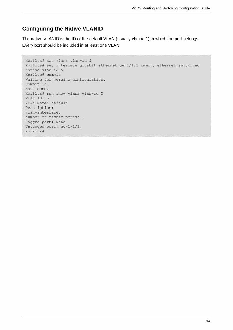
PicOS Routing and Switching Configuration Guide
94
Configuring the Native VLANID
The native VLANID is the ID of the default VLAN (usually vlan-id 1) in which the port belongs.
Every port should be included in at least one VLAN.
XorPlus# set vlans vlan-id 5XorPlus# set interface gigabit-ethernet ge-1/1/1 family ethernet-switchingnative-vlan-id 5XorPlus# commit Waiting for merging configuration.Commit OK.Save done.XorPlus# run show vlans vlan-id 5VLAN ID: 5VLAN Name: default Description: vlan-interface: Number of member ports: 1 Tagged port: NoneUntagged port: ge-1/1/1, XorPlus#

PicOS Routing and Switching Configuration Guide
95
Adding a Port to a VLAN
XorPlus# set vlans vlan-id 5XorPlus# set vlans vlan-id 6XorPlus# set vlans vlan-id 7XorPlus# set interface gigabit-ethernet ge-1/1/2 family ethernet-switchingport-mode trunkXorPlus# set interface gigabit-ethernet ge-1/1/2 family ethernet-switchingvlan members 5XorPlus# set interface gigabit-ethernet ge-1/1/2 family ethernet-switchingvlan members 6XorPlus# set interface gigabit-ethernet ge-1/1/2 family ethernet-switchingvlan members 7XorPlus# commit Waiting for merging configuration.Commit OK.Save done.XorPlus# run show vlans VlanID Tag Interfaces------ -------- ------------------------------------------------------1 tagged untagged ge-1/1/2, ge-1/1/3, ge-1/1/4, ge-1/1/5, ge-1/1/6, ge-1/1/7, ge-1/1/8, ge-1/1/9, ge-1/1/10, ge-1/1/11, ge-1/1/12, ge-1/1/13, ge-1/1/14, ge-1/1/15, ge-1/1/16, ge-1/1/17, ge-1/1/18, ge-1/1/19, ge-1/1/20, ge-1/1/21, ge-1/1/22, ge-1/1/23, ge-1/1/24, ge-1/1/25, ge-1/1/26, ge-1/1/27, ge-1/1/28, ge-1/1/29, ge-1/1/30, ge-1/1/31, ge-1/1/32, ge-1/1/33, ge-1/1/34, ge-1/1/35, ge-1/1/36, ge-1/1/37, ge-1/1/38, ge-1/1/39, ge-1/1/40, ge-1/1/41, ge-1/1/42, ge-1/1/43, ge-1/1/44, ge-1/1/45, ge-1/1/46, ge-1/1/47, ge-1/1/48, te-1/1/49, te-1/1/50, te-1/1/51, te-1/1/52, 5 tagged ge-1/1/2, untagged ge-1/1/16 tagged ge-1/1/2, untagged 7 tagged ge-1/1/2,untagged XorPlus#

PicOS Routing and Switching Configuration Guide
96
Creating a VLAN with in the VLAN range
You can create VLANs within the VLAN range, and then add ports to theseVLANs. XorPlus# set vlans vlan-id 2-4094XorPlus# set interface gigabit-ethernet ge-1/1/1 family ethernet-switchingport-mode trunkXorPlus# set interface gigabit-ethernet ge-1/1/1 family ethernet-switchingvlan members 1-4094XorPlus# set interface gigabit-ethernet ge-1/1/2 family ethernet-switchingvlan members 1-4094XorPlus# set interface gigabit-ethernet ge-1/1/3 family ethernet-switchingvlan members 1-4094XorPlus# commit Waiting for merging configuration.Commit OK.Save done.XorPlus#
VLAN Configuration Example
In the following topology, the VLANs are configured for each switch.
Figure 4-1.VLAN configuration.
Configuring Switch A
For Switch A, you should configure ge-1/1/1~ge-1/1/4 as access port sand te-1/1/49 as the trunk
port, because the10Gbit link will trunk the traffic of VLAN-2 and VLAN-3.

PicOS Routing and Switching Configuration Guide
97
XorPlus# set vlans vlan-id 2XorPlus# set vlans vlan-id 3XorPlus# set interface gigabit-ethernet ge-1/1/1 family ethernet-switchingport-mode accessXorPlus# set interface gigabit-ethernet ge-1/1/1 family ethernet-switchingnative-vlan-id 2XorPlus# set interface gigabit-ethernet ge-1/1/2 family ethernet-switchingport-mode accessXorPlus# set interface gigabit-ethernet ge-1/1/2 family ethernet-switchingnative-vlan-id 2XorPlus# set interface gigabit-ethernet ge-1/1/3 family ethernet-switchingport-mode accessXorPlus# set interface gigabit-ethernet ge-1/1/3 family ethernet-switchingnative-vlan-id 3XorPlus# set interface gigabit-ethernet ge-1/1/4 family ethernet-switchingport-mode accessXorPlus# set interface gigabit-ethernet ge-1/1/4 family ethernet-switchingnative-vlan-id 3XorPlus#set interface gigabit-ethernet te-1/1/49 family ethernet-switchingport-mode trunkXorPlus#set interface gigabit-ethernet te-1/1/49 family ethernet-switchingvlan members 2XorPlus#set interface gigabit-ethernet te-1/1/49 family ethernet-switchingvlan members 3XorPlus# commit Waiting for merging configuration.Commit OK.Save done.XorPlus#XorPlus# run show vlans VlanID Tag Interfaces------ -------- ------------------------------------------------------1 tagged untagged ge-1/1/5, ge-1/1/6, ge-1/1/7, ge-1/1/8, ge-1/1/9, ge-1/1/10, ge-1/1/11, ge-1/1/12, ge-1/1/13, ge-1/1/14, ge-1/1/15, ge-1/1/16, ge-1/1/17, ge-1/1/18, ge-1/1/19, ge-1/1/20, ge-1/1/21, ge-1/1/22, ge-1/1/23, ge-1/1/24, ge-1/1/25, ge-1/1/26, ge-1/1/27, ge-1/1/28, ge-1/1/29, ge-1/1/30, ge-1/1/31, ge-1/1/32, ge-1/1/33, ge-1/1/34, ge-1/1/35, ge-1/1/36, ge-1/1/37, ge-1/1/38, ge-1/1/39, ge-1/1/40, ge-1/1/41, ge-1/1/42, ge-1/1/43, ge-1/1/44, ge-1/1/45, ge-1/1/46, ge-1/1/47, ge-1/1/48, te-1/1/49, te-1/1/50, te-1/1/51, te-1/1/52, 2 tagged te-1/1/49, untagged ge-1/1/1, ge-1/1/2, 3 tagged te-1/1/49, untagged ge-1/1/3, ge-1/1/4, XorPlus#
Configuring Switch B
For Switch B, configure ge-1/1/1~ge-1/1/4 as access port sand te-1/1/49 as the trunk port, because
the 10Gbit link will trunk the traffic ofVLAN-2 and VLAN-3.

PicOS Routing and Switching Configuration Guide
98
XorPlus# set vlans vlan-id 2XorPlus# set vlans vlan-id 3XorPlus# set interface gigabit-ethernet ge-1/1/1 family ethernet-switchingport-mode accessXorPlus# set interface gigabit-ethernet ge-1/1/1 family ethernet-switchingnative-vlan-id 2XorPlus# set interface gigabit-ethernet ge-1/1/2 family ethernet-switchingport-mode accessXorPlus# set interface gigabit-ethernet ge-1/1/2 family ethernet-switchingnative-vlan-id 2XorPlus# set interface gigabit-ethernet ge-1/1/3 family ethernet-switchingport-mode accessXorPlus# set interface gigabit-ethernet ge-1/1/3 family ethernet-switchingnative-vlan-id 3XorPlus# set interface gigabit-ethernet ge-1/1/4 family ethernet-switchingport-mode accessXorPlus# set interface gigabit-ethernet ge-1/1/4 family ethernet-switchingnative-vlan-id 3XorPlus#set interface gigabit-ethernet te-1/1/49 family ethernet-switchingport-mode trunkXorPlus#set interface gigabit-ethernet te-1/1/49 family ethernet-switchingvlan members 2XorPlus#set interface gigabit-ethernet te-1/1/49 family ethernet-switchingvlan members 3XorPlus# commit Waiting for merging configuration.Commit OK.Save done.XorPlus#XorPlus# run show vlans VlanID Tag Interfaces------ -------- ------------------------------------------------------1 tagged untagged ge-1/1/5, ge-1/1/6, ge-1/1/7, ge-1/1/8, ge-1/1/9, ge-1/1/10, ge-1/1/11, ge-1/1/12, ge-1/1/13, ge-1/1/14, ge-1/1/15, ge-1/1/16, ge-1/1/17, ge-1/1/18, ge-1/1/19, ge-1/1/20, ge-1/1/21, ge-1/1/22, ge-1/1/23, ge-1/1/24, ge-1/1/25, ge-1/1/26, ge-1/1/27, ge-1/1/28, ge-1/1/29, ge-1/1/30, ge-1/1/31, ge-1/1/32, ge-1/1/33, ge-1/1/34, ge-1/1/35, ge-1/1/36, ge-1/1/37, ge-1/1/38, ge-1/1/39, ge-1/1/40, ge-1/1/41, ge-1/1/42, ge-1/1/43, ge-1/1/44, ge-1/1/45, ge-1/1/46, ge-1/1/47, ge-1/1/48, te-1/1/49, te-1/1/50, te-1/1/51, te-1/1/52, 2 tagged te-1/1/49, untagged ge-1/1/1, ge-1/1/2, 3 tagged te-1/1/49, untagged ge-1/1/3, ge-1/1/4,
Static MAC entries and Dynamic MAC Address Learning
You can configure a static MAC entry in the FDB, and manage dynamic MAC address learning (for
example, configuring aging time or deleting the dynamic MAC addresses entry).

PicOS Routing and Switching Configuration Guide
99
Configuring a static MAC entry and managing the FDB
XorPlus# set interface gigabit-ethernet ge-1/1/1 static-ethernet-switchingmac-address 22:22:22:22:22:22 vlan 1XorPlus# set interface ethernet-switching-options mac-table-aging-time 60XorPlus# commit Waiting for merging configuration.Commit OK.Save done.XorPlus# run show ethernet-switching table Total entries in switching table: 2Static entries in switching table: 0Dynamic entries in switching table: 2VLAN MAC address Type Age Interfaces---- ----------------- ------- ---- ----------1 00:22:be:96:f2:83 Dynamic 60 ge-1/1/1 1 00:22:be:96:f2:84 Dynamic 60 ge-1/1/2 XorPlus# run clear ethernet-switching table allXorPlus# run show ethernet-switching table Total entries in switching table: 0Static entries in switching table: 0Dynamic entries in switching table: 0VLAN MAC address Type Age Interfaces---- ----------------- ------- ---- ---------- XorPlus#
Port Security Configuration
Port security is a layer two traffic control feature on Pica8 switches. It enables an administrator
configure individual switch ports to allow only a specified number of source MAC addresses
ingressing the port. Port security enables the switch administrator to prevent unauthorized devices
from gaining access to the network. Port security is normally enabled on access layer switches for
this purpose.
Enabling Port Security
Port security is not enabled in default. It can be enabled with default parameters by issuing a single
command on an interface:
XorPlus# set interface gigabit-ethernet ge-1/1/1 port-security mac-limit 10XorPlus# commit Merging the configuration.Commit OK.Save done.XorPlus#

PicOS Routing and Switching Configuration Guide
100
Configuring the Maximum Number of Secure Dynamically Learned MAC
Addresses
Users can use port security with dynamically learned MAC addresses to restrict a port's ingress
traffic by limiting the MAC addresses that are allowed to send traffic into the port.
XorPlus# set interface gigabit-ethernet ge-1/1/1 port-security mac-limit 5XorPlus# commit Merging the configuration.Commit OK.Save done.XorPlus# XorPlus# run show port-security address Secure Mac Address Table-----------------------------------------------------Vlan MAC Address Type Interfaces ---- ----------------- ------- ---------- 1 00:00:11:11:11:11 dynamic ge-1/1/1 1 00:00:11:11:11:12 dynamic ge-1/1/1 1 00:00:11:11:11:13 dynamic ge-1/1/1 1 00:00:11:11:11:14 dynamic ge-1/1/1 1 00:00:11:11:11:15 dynamic ge-1/1/1 -----------------------------------------------------MAC age time :300sXorPlus#
Configuring Static Secure MAC Addresses on a Port
Users can use port security with static MAC addresses to restrict a port's ingress traffic by limiting
the MAC addresses that are allowed to send traffic into the port.

PicOS Routing and Switching Configuration Guide
101
XorPlus# set interface gigabit-ethernet ge-1/1/1 port-security mac-address00:00:23:23:23:23 vlan 1XorPlus# set interface gigabit-ethernet ge-1/1/1 port-security mac-address00:00:23:23:23:24 vlan 1XorPlus# set interface gigabit-ethernet ge-1/1/1 port-security mac-address00:00:23:23:23:25 vlan 1XorPlus# set interface gigabit-ethernet ge-1/1/1 port-security mac-address00:00:23:23:23:26 vlan 1XorPlus# set interface gigabit-ethernet ge-1/1/1 port-security mac-address00:00:23:23:23:27 vlan 1XorPlus# commit Merging the configuration.Commit OK.Save done.XorPlus# XorPlus# run show port-security address Secure Mac Address Table-----------------------------------------------------Vlan MAC Address Type Interfaces ---- ----------------- ------- ---------- 1 00:00:23:23:23:23 static ge-1/1/1 1 00:00:23:23:23:24 static ge-1/1/1 1 00:00:23:23:23:25 static ge-1/1/1 1 00:00:23:23:23:26 static ge-1/1/1 1 00:00:23:23:23:27 static ge-1/1/1 -----------------------------------------------------MAC age time :300s XorPlus#
Configuring Port Security with Sticky MAC Addresses on a Port
Port security with sticky MAC addresses retains dynamically learned MAC addresses when the link
is down, and restores the MAC addresses when the link ups.
XorPlus# set interface gigabit-ethernet ge-1/1/1 port-security sticky trueXorPlus# commit Merging the configuration.Commit OK.Save done.XorPlus#
Configuring Secure MAC Address Aging Time
The aging time is global whether port security configuring or not.
XorPlus# set interface ethernet-switching-options mac-table-aging-time 100XorPlus# commit Merging the configuration.Commit OK.Save done.XorPlus#

PicOS Routing and Switching Configuration Guide
102
Configuring Port Security Violation Mode on a Port
Port security can be configured to take one of four actions upon detecting a violation:
(default) - Frames from MAC addresses other than the allowed addresses are dropped;protect
traffic from allowed addresses is permitted to pass normally; - Like protect mode, butrestrict
generates a syslog message and increases the violation counter; - The interface isshutdown
placed into the error-discard state, blocking all traffic; - The interface is placedshutdown-temp
into the error-discard state and blocking all traffic temporarily, then after 20 seconds (default), the
interface is up.
XorPlus# set interface gigabit-ethernet ge-1/1/1 port-security violation ?Possible completions:protect Drop packets with unknown source addressesrestrict Drop packets with unknown source addresses and log violationshutdown Disable interfaceshutdown-temp Disable interface temporarily(20 seconds for the default)XorPlus# set interface gigabit-ethernet ge-1/1/1 port-security violationrestrict XorPlus# commit Merging the configuration.Commit OK.Save done.XorPlus#
Configuring Port Security Auto-recovery Time
When the port security violation mode configured to shutdown-temp, users can configure the
recovery interval by this command:
XorPlus# set interface ethernet-switching-options port-error-discard timeout30XorPlus# commit Merging the configuration.Commit OK.Save done.XorPlus#
Recovering the Port in Error-discard
When the port security violation mode configured to shutdown, the port will be placed into the
error-discard state after detecting a violation, users can recover the port by this command:
XorPlus# run clear port-security port-error Clear done.XorPlus#

PicOS Routing and Switching Configuration Guide
103
Configuring Port Security Block Mode on a Port
Port security can be configured to take one of five block actions:
– All traffic are not permitted to forward normally on egress; – Broadcast packets willall broadcast
be blocked on egress, but unknown uni/multi cast addresses can forwards normally; –multicast
Only the multicast packets will be dropped; - The unknown uni/multi cast packetsuni-multi-cast
will be blocked on egress; - Only the unknown unicast packets will be dropped.unicast
XorPlus# set interface gigabit-ethernet ge-1/1/1 port-security block ?Possible completions:all Block broadcast and unknow addressesbroadcast Block broadcast addressmulticast Block unknow multicast addressesuni-multi-cast Block unknow uni/multi cast addressesunicast Block unknow unicast addressesXorPlus# set interface gigabit-ethernet ge-1/1/1 port-security blockbroadcast XorPlus# commit Merging the configuration.Commit OK.Save done.XorPlus#
Displaying Port Security Settings
To display port security settings, enter this command:

PicOS Routing and Switching Configuration Guide
104
XorPlus# run show port-security address Secure Mac Address Table-----------------------------------------------------Vlan MAC Address Type Interfaces ---- ----------------- ------- ---------- 1 00:00:11:11:11:11 dynamic ge-1/1/1 1 00:00:11:11:11:12 dynamic ge-1/1/1 1 00:00:11:11:11:13 dynamic ge-1/1/1 1 00:00:11:11:11:14 dynamic ge-1/1/1 1 00:00:11:11:11:15 dynamic ge-1/1/1 1 00:00:23:23:23:23 static ge-1/1/1 1 00:00:23:23:23:24 static ge-1/1/1 1 00:00:23:23:23:25 static ge-1/1/1 1 00:00:23:23:23:26 static ge-1/1/1 1 00:00:23:23:23:27 static ge-1/1/1 -----------------------------------------------------MAC age time :100sXorPlus# run show port-security brief System MAC limit : 32767 Secure port DynamicMacLim CurrentAddr ViolationCount Action -------------------------------------------------------------------------------ge-1/1/15 10 213940 restrict -------------------------------------------------------------------------------
XorPlus#XorPlus# run show port-security interface gigabit-ethernet ge-1/1/1 Interface ge-1/1/1----------------------------------------Port security : enabledViolation action : restrictBlock type : broadcastSticky : trueDynamic MAC limit : 5Total MAC addresses : 10Configured MAC addresses : 5Sticky MAC addresses : 5Security violation count : 286062XorPlus#
Disabling Port Security
To disable port security, users should enter this command:

PicOS Routing and Switching Configuration Guide
105
XorPlus# delete interface gigabit-ethernet ge-1/1/1 port-security Deleting: port-security {mac-limit: 5violation: "restrict"mac-address 00:00:23:23:23:23 {vlan 1 {}}mac-address 00:00:23:23:23:24 {vlan 1 {}}mac-address 00:00:23:23:23:25 {vlan 1 {}}mac-address 00:00:23:23:23:26 {vlan 1 {}}mac-address 00:00:23:23:23:27 {vlan 1 {}}sticky: trueblock: "broadcast"} OK XorPlus# commit Merging the configuration.Commit OK.Save done.XorPlus#
Cut-through Switching Method
By default, the switch forwards the packets in a cut-through switching method. That is, the switch
begins forwarding a packet before the entire frame is received; normally as soon as the destination
address is processed. This reduces latency and error handling is performed by the destination
devices. You can configure the switch to store-and-forward method with the commands below.
Configuring your Switch to Store-and-Forward Method
XorPlus# set interface cut_through_mode falseXorPlus# commit Waiting for merging configuration.Commit OK.Save done.XorPlus#

PicOS Routing and Switching Configuration Guide
106
Static Link Aggregation Configuration
You can configure up to 48 LAGs in L2/L3, and each LAG can have up to 8 member ports.
Both static and LACP LAGs can support the hashing of traffic using the Src/Dst MAC address, the
Src/DstIP address, and Layer 4 port information.
If all member ports of a LAN are link-down, the LAG will be link-down. The LAG will become
link-up when at least one member port is link-up.
The logical function and configuration of LAGs are same as those of a physical port.
Configuring static LAGs
XorPlus# set interface aggregate-ethernet ae1XorPlus# set interface gigabit-ethernet ge-1/1/1 ether-options 802.3ad ae1XorPlus# set interface gigabit-ethernet ge-1/1/2 ether-options 802.3ad ae1XorPlus# set interface gigabit-ethernet ge-1/1/3 ether-options 802.3ad ae1XorPlus# set interface gigabit-ethernet ge-1/1/4 ether-options 802.3ad ae1XorPlus# commit Waiting for merging configuration.Commit OK.Save done.XorPlus#
Displaying static LAG information
XorPlus# run show interface aggregate-ethernet ae1 Physical interface: ae1, Enabled, Physical link is UpInterface index: 53Link-level type: Ethernet, MTU: 1514, Speed: Auto, Duplex: AutoSource filtering: Disabled, Flow control: Enabled, Auto-negotiation: EnabledInterface flags: Hardware-Down SNMP-Traps Internal: 0x0Current address: c8:0a:a9:9e:14:9f, Hardware address: c8:0a:a9:9e:14:9fTraffic statistics:Input Packets............................176Output Packets...........................16Input Octets.............................12888Output Octets............................1594Aggregated link protocol: STATICMembers Status Port Speed--------- -------- ----------ge-1/1/1 Down Auto ge-1/1/2 Down Auto ge-1/1/3 Up Auto ge-1/1/4 Up Auto
Advanced-resilient Laghash Configuration and Example
Configure the laghash mode as advanced-resilient.In default,the hash-mapping field disable false
all.The user can configure the hash-mapping field a ccording to the situation.When one port in the
lag down,the traffic in the other ports will not .redistribution

PicOS Routing and Switching Configuration Guide
107
Configuration
set interface aggregate-ethernet ae10 hash-mapping mode advanced-resilient
Example
1.Configure one lag with three ports
set interface gigabit-ethernet ge-1/1/1 ether-options 802.3ad ae10 set interface gigabit-ethernet ge-1/1/2 ether-options 802.3ad ae10 set interface gigabit-ethernet ge-1/1/3 ether-options 802.3ad ae10
2.Configure the lag hash mode ethernet-destination-only
set interface aggregate-ethernet ae10 hash-mapping mode advanced-resilient
3.Configure the hash-mapping field
set interface aggregate-balancing hash-mapping field ip-destination disablefalse set interface aggregate-balancing hash-mapping field ip-source disablefalse
Advance Laghash Configuration and Example
Configure the laghash mode as advanced.In default,the hash-mapping field disable false all.The
user can configure the hash-mapping field a ccording to the situation.When the port in the lag
down,the traffic redistribution.
Configuration
set interface aggregate-ethernet ae1 hash-mapping mode advance
Example
1.Configure one lag with three ports
set interface gigabit-ethernet ge-1/1/1 ether-options 802.3ad ae10 set interface gigabit-ethernet ge-1/1/2 ether-options 802.3ad ae10 set interface gigabit-ethernet ge-1/1/3 ether-options 802.3ad ae10
2.Configure the lag hash mode ethernet-destination-only
set interface aggregate-ethernet ae10 hash-mapping mode advance
3.Configure the hash-mapping field

PicOS Routing and Switching Configuration Guide
108
set interface aggregate-balancing hash-mapping fieldethernet-destination-address disable false set interface aggregate-balancing hash-mapping fieldethernet-source-address disable false
Laghash Configuration and Example
Configure the laghash mode as ethernet-destination-only.When the lag receive the packets with
increasing destination-mac-address,the traffic hash.
Configuration
set interface aggregate-ethernet ae1 hash-mapping modeethernet-destination-only
Example
1.Configure one lag with three ports
set interface gigabit-ethernet ge-1/1/1 ether-options 802.3ad ae10 set interface gigabit-ethernet ge-1/1/2 ether-options 802.3ad ae10 set interface gigabit-ethernet ge-1/1/3 ether-options 802.3ad ae10
2.Configure the lag hash mode ethernet-destination-only
set interface aggregate-ethernet ae10 hash-mapping modeethernet-destination-only
3.send destination-mac-address increasing packets to the lag ae10
Link Aggregation Control Protocol (LACP) Configuration
LACP (802.3ad) provides the dynamic link aggregation function.
The LACPDU includes the LACP system priority, the system MAC, the port priority and I.D. The
port, included in the LACP LAG, will transmit the LACPDU to its neighbors.
The configuration of the LACP LAG is similar to that of the static LAG.
denotes that the LAG is up only when no fewer than the defined number ofmin-selected-port
ports are up. Below, our defined number is 4.

PicOS Routing and Switching Configuration Guide
109
Configuring LACP LAGs
XorPlus# set interface aggregate-ethernet ae1aggregated-ether-options lacpenable trueXorPlus# set interface aggregate-ethernet ae1 aggregated-ether-optionsmin-selected-port 4XorPlus# set interface gigabit-ethernet ge-1/1/1 ether-options 802.3ad ae1XorPlus# set interface gigabit-ethernet ge-1/1/2 ether-options 802.3ad ae1XorPlus# set interface gigabit-ethernet ge-1/1/3 ether-options 802.3ad ae1XorPlus# set interface gigabit-ethernet ge-1/1/4 ether-options 802.3ad ae1XorPlus# commit Waiting for merging configuration.Commit OK.Save done.XorPlus#
Displaying LACP LAG information
XorPlus# run show interface aggregate-ethernet ae1 Physical interface: ae1, Enabled, Physical link is DownInterface index: 53Description: Link-level type: Ethernet, MTU: 1514, Speed: Auto, Duplex: AutoSource filtering: Disabled, Flow control: Enabled, Auto-negotiation: EnabledInterface flags: Hardware-Down SNMP-Traps Internal: 0x0Current address: 60:eb:69:d2:9c:d7, Hardware address: 60:eb:69:d2:9c:d7Traffic statistics:5 sec input rate 0 bits/sec, 0 packets/sec5 sec output rate 0 bits/sec, 0 packets/secInput Packets............................0Output Packets...........................0Input Octets.............................0Output Octets............................0Aggregated link protocol: LACPMinimum number of selected ports: 4Members Status Port Speed--------- ---------- ----------ge-1/1/1 up(active) Auto ge-1/1/2 up(active) Auto ge-1/1/3 up(active) Auto ge-1/1/4 up(active) Auto
MLAG Configuration Guide
Traditionally, an aggregation interface is a logical interface that is used to increase the bandwidth
or availability by users of more than one physical interface in a switch. Multi-chassis LAG (MLAG)
can form a logical aggregation interface to multiple switches.

PicOS Routing and Switching Configuration Guide
110
In Figure 1-1, switch A and C are connected by link A; switch B and C is connected by link B. In
switch C, link A and B has formed an aggregation interface to balance the traffic. In the meanwhile,
switch A and B has formed a MLAG using link A and B. For communication, such as MAC entries,
between the members of the MLAG and are learned by the MLAG must need be synchronized. In
Figure 1 synchronization between switch A and B, and link C are used to connect switch A and B
as the channel interface. The number of links which connect switch A and C or B and C cannot be
more than 1.
Important things to know about MLAG
There are two issues in the MLAG: MAC entry synchronization and broadcast traffic control. MAC
entry synchronization means that the MAC entry learned by the interface must be synchronized by
the peer switch. In current version, we only support 2 nodes in a MLAG and use L2 traffic to
communicate between the nodes.
Figure 1-1
Configuring MLAG domain-id
The command assigns an MLAG ID to an aggregation interface. MLAG neighbordomain-id
switches form an MLAG when each switch configures the same MLAG-ID to an aggregation
interface. Only one MLAG domain-id can be assigned to an aggregation interface. The same
MLAG domain-id cannot be assigned to more than one aggregation interface.

PicOS Routing and Switching Configuration Guide
111
XorPlus# set interface aggregate-ethernet ae22 aggregated-ether-options mlagdomain-id 1XorPlus# commitWaiting for merging configuration.Commit OK.Save done.XorPlus#
Configuring MLAG system-id
The command specifies the local chassis system's MAC address for an MLAG domainsystem-id
and is used in LACP aggregation as source system MAC address.
XorPlus# set interface aggregate-ethernet ae22 aggregated-ether-options mlagsystem-ide8:9a:8f:50:3d:30XorPlus# commit Waiting for merging configuration.Commit OK.Save done.XorPlus#
Configuring MLAG peer
The command specifies the neighbor's IP address for a MLAG domain. The MLAGpeer
synchronized messages is sent to the neighbor IP address.
XorPlus# set interface aggregate-ethernet ae22 aggregated-ether-options mlagpeer 10.0.0.1peer-link "ae24"XorPlus# commit Waiting for merging configuration.Commit OK.Save done.XorPlus#
Configuring MLAG priority
The priority use master/slave negotiation between the two neighbor switch. The commandpriority
assigns a MLAG domain.

PicOS Routing and Switching Configuration Guide
112
XorPlus# set interface aggregate-ethernet ae22 aggregated-ether-options mlagpriority 4096XorPlus# commit Waiting for merging configuration.Commit OK.Save done.XorPlus# set protocols bgp peer 192.168.49.1 export send-networkXorPlus# commit Waiting for merging configuration.Commit OK.Save done.XorPlus#
Configuring MLAG hello-interval
The command configures the hello message, in both directions, between MLAGhello-interval
neighbors. If the neighbor switch is pinged four times, and the hello-interval does not receive the
message, the MLAG neighbor switches revert to their independent state.
XorPlus# set interface aggregate-ethernet ae22 aggregated-ether-options mlaghello-interval 60XorPlus# commit Waiting for merging configuration.Commit OK.Save done.XorPlus#
Configuring a Basic MLAG step-by-step procedure

PicOS Routing and Switching Configuration Guide
113
1.
2.
3.
4.
5.
6.
7.
8.
Configure the number of LAGs on Switch C. Add member interfaces to the aggregated
ethernet interfaces on Switch C.
Configure the number of MLAG member LAGs on both Switch A and Switch B. Add member
interfaces to the aggregated ethernet interfaces on on both Switch A and Switch B.
Configure the number of MLAG peer-link LAGs on both Switch A and Switch B. Add
member interfaces to the aggregated ethernet interfaces on on both Switch A and Switch B.
Configure the L3 interface IP address on both Switch A and Switch B for peer-to-peer
communication.
Configure the same domain-id number on both MLAG peers on Switch A and Switch B.
Configure not the same system-id on both MLAG peers on Switch A and Switch B.
Configure the peer IP address for MLAG peer connect on both Switch A and Switch B.
Configure the LAGs for MLAG peer-link connects on both Switch A and Switch B.
Configuring a Basic MLAG example
Figure 2 illustrates MLAG configured between Switch A and Switch B; the MLAG connections
between the neighboring switches as well as two Network Devices.
The MLAG switches connect through a LACP LAG to Switch C.
The MLAG switches connect through a static LAG to Server A.
Figure 2
Configuring Switch A with Static and LACP LAG

PicOS Routing and Switching Configuration Guide
114
XorPlus# set interface aggregate-ethernet ae1 aggregated-ether-options lacpenable trueXorPlus# set interface aggregate-ethernet ae2XorPlus# set interface aggregate-ethernet ae3XorPlus# commitWaiting for merging configuration.Commit OK.Save done.XorPlus#XorPlus# set interface gigabit-ethernet ge-1/1/1 ether-options 802.3ad ae1XorPlus# set interface gigabit-ethernet ge-1/1/2 ether-options 802.3ad ae2XorPlus# set interface gigabit-ethernet te-1/1/49 ether-options 802.3ad ae3XorPlus# set interface gigabit-ethernet te-1/1/50 ether-options 802.3ad ae3XorPlus# commitWaiting for merging configuration.Commit OK.Save done.XorPlus#
Configuring an Aggregation Interface to VLAN Members
XorPlus# set protocols spanning-tree enable falseXorPlus# set vlans vlan-id 15XorPlus# set vlans vlan-id 16XorPlus# set vlans vlan-id 4094 l3-interface 4094XorPlus# commitWaiting for merging configuration.Commit OK.Save done.XorPlus#XorPlus# set interface aggregate-ethernet ae1 family ethernet-switchingport-mode trunkXorPlus# set interface aggregate-ethernet ae1 family ethernet-switching vlanmembers 15XorPlus# set interface aggregate-ethernet ae1 family ethernet-switching vlanmembers 16XorPlus# set interface aggregate-ethernet ae2 family ethernet-switchingport-mode trunkXorPlus# set interface aggregate-ethernet ae2 family ethernet-switching vlanmembers 15XorPlus# set interface aggregate-ethernet ae2 family ethernet-switching vlanmembers 16XorPlus# set interface aggregate-ethernet ae3 family ethernet-switchingport-mode trunkXorPlus# set interface aggregate-ethernet ae3 family ethernet-switching vlanmembers 15XorPlus# set interface aggregate-ethernet ae3 family ethernet-switching vlanmembers 16XorPlus# commitWaiting for merging configuration.Commit OK.Save done.XorPlus#

PicOS Routing and Switching Configuration Guide
115
Configure the L3 interface IP address
XorPlus# set vlan-interface interface 4094 vif 4094 address 10.10.0.1prefix-length 24XorPlus# commitWaiting for merging configuration.Commit OK.Save done.XorPlus#
Configuring the domain-id and system-id for the MLAG domain.
XorPlus# set interface aggregate-ethernet ae1 aggregated-ether-options mlagdomain-id 1XorPlus# set interface aggregate-ethernet ae1 aggregated-ether-options mlagsystem-id e8:9a:8f:50:3d:30XorPlus# commitWaiting for merging configuration.Commit OK.Save done.XorPlus#XorPlus# set interface aggregate-ethernet ae2 aggregated-ether-options mlagdomain-id 2XorPlus# set interface aggregate-ethernet ae2 aggregated-ether-options mlagsystem-id e8:9a:8f:50:3d:30XorPlus# commitWaiting for merging configuration.Commit OK.Save done.XorPlus#
Configuring the peer IP address and the peer-link for the MLAG domain peer
XorPlus# set interface aggregate-ethernet ae1 aggregated-ether-options mlagpeer10.10.0.2peer-link "ae3"XorPlus# set interface aggregate-ethernet ae2 aggregated-ether-options mlagpeer10.10.0.2peer-link "ae3"XorPlus# commitWaiting for merging configuration.Commit OK.Save done.XorPlus#
Configuring Switch B with Static and LACP LAG

PicOS Routing and Switching Configuration Guide
116
XorPlus# set interface aggregate-ethernet ae1 aggregated-ether-options lacpenable trueXorPlus# set interface aggregate-ethernet ae2XorPlus# set interface aggregate-ethernet ae3XorPlus# commitWaiting for merging configuration.Commit OK.Save done.XorPlus#XorPlus# set interface gigabit-ethernet ge-1/1/1 ether-options 802.3ad ae1XorPlus# set interface gigabit-ethernet ge-1/1/2 ether-options 802.3ad ae2XorPlus# set interface gigabit-ethernet te-1/1/49 ether-options 802.3ad ae3XorPlus# set interface gigabit-ethernet te-1/1/50 ether-options 802.3ad ae3XorPlus# commitWaiting for merging configuration.Commit OK.Save done.XorPlus#
Configuring an Aggregation Interface to VLAN Members
XorPlus# set protocols spanning-tree enable falseXorPlus# set vlans vlan-id 15XorPlus# set vlans vlan-id 16XorPlus# set vlans vlan-id 4094 l3-interface 4094XorPlus# commitWaiting for merging configuration.Commit OK.Save done.XorPlus#XorPlus# set interface aggregate-ethernet ae1 family ethernet-switchingport-mode trunkXorPlus# set interface aggregate-ethernet ae1 family ethernet-switching vlanmembers 15XorPlus# set interface aggregate-ethernet ae1 family ethernet-switching vlanmembers 16XorPlus# set interface aggregate-ethernet ae2 family ethernet-switchingport-mode trunkXorPlus# set interface aggregate-ethernet ae2 family ethernet-switching vlanmembers 15XorPlus# set interface aggregate-ethernet ae2 family ethernet-switching vlanmembers 16XorPlus# set interface aggregate-ethernet ae3 family ethernet-switchingport-mode trunkXorPlus# set interface aggregate-ethernet ae3 family ethernet-switching vlanmembers 15XorPlus# set interface aggregate-ethernet ae3 family ethernet-switching vlanmembers 16XorPlus# commitWaiting for merging configuration.Commit OK.Save done.XorPlus#

PicOS Routing and Switching Configuration Guide
117
Configure the L3 interface IP address
XorPlus# set vlan-interface interface 4094 vif 4094 address 10.10.0.2prefix-length 24XorPlus# commitWaiting for merging configuration.Commit OK.Save done.XorPlus#
Configuring the domain-id and system-id for the MLAG domain
XorPlus# set interface aggregate-ethernet ae1 aggregated-ether-options mlagdomain-id 1XorPlus# set interface aggregate-ethernet ae1 aggregated-ether-options mlagsystem-id c8:0a:a9:9e:14:a4XorPlus# commitWaiting for merging configuration.Commit OK.Save done.XorPlus#XorPlus# set interface aggregate-ethernet ae2 aggregated-ether-options mlagdomain-id 2XorPlus# set interface aggregate-ethernet ae2 aggregated-ether-options mlagsystem-id c8:0a:a9:9e:14:a4XorPlus# commitWaiting for merging configuration.Commit OK.Save done.
Configuring the peer IP address and the peer-link for the MLAG domain peer
XorPlus# set interface aggregate-ethernet ae1 aggregated-ether-options mlagpeer10.10.0.1peer-link "ae3"XorPlus# set interface aggregate-ethernet ae2 aggregated-ether-options mlagpeer10.10.0.1peer-link "ae3"XorPlus# commitWaiting for merging configuration.Commit OK.Save done.XorPlus#
Configuring Switch C with LACP and LAG

PicOS Routing and Switching Configuration Guide
118
XorPlus# set interface aggregate-ethernet ae1 aggregated-ether-options lacpenable trueXorPlus# commitWaiting for merging configuration.Commit OK.Save done.XorPlus#XorPlus# set interface gigabit-ethernet ge-1/1/1 ether-options 802.3ad ae1XorPlus# set interface gigabit-ethernet ge-1/1/2 ether-options 802.3ad ae1XorPlus# commitWaiting for merging configuration.Commit OK.Save done.
Configuring an Aggregation Interface to VLAN Members
XorPlus# set protocols spanning-tree enable falseXorPlus# set vlans vlan-id 15XorPlus# set vlans vlan-id 16XorPlus# commitWaiting for merging configuration.Commit OK.Save done.XorPlus#XorPlus# set interface aggregate-ethernet ae1 family ethernet-switchingport-mode trunkXorPlus# set interface aggregate-ethernet ae1 family ethernet-switching vlanmembers 15XorPlus# set interface aggregate-ethernet ae1 family ethernet-switching vlanmembers 16XorPlus# commitWaiting for merging configuration.Commit OK.Save done.XorPlus#

PicOS Routing and Switching Configuration Guide
119
Configuring Server A with NIC1 and NIC2 as Static LAG
View the MLAG internal and neighbor status of Switch A
SwitchA# run show mlag internal Domain-id Local-LAG Flood MAC-sync State Role--------------------------------------------------------2 ae1 false true FULL MASTER1 ae2 false true FULL MASTER SwitchA# run show mlag peer 1Peer System-id State Link-status--------------------------------------------------------10.10.0.2c8:0a:a9:9e:14:a4 FULL UP SwitchA# run show mlag peer 2Peer System-id State Link-status--------------------------------------------------------10.10.0.2c8:0a:a9:9e:14:a4 FULL UP XorPlus#
View the MLAG internal and neighbor status of Switch B
SwitchB# run show mlag internal Domain-id Local-LAG Flood MAC-sync State Role--------------------------------------------------------2 ae1 false true FULL MASTER1 ae2 false true FULL MASTER SwitchB# run show mlag peer 1Peer System-id State Link-status--------------------------------------------------------10.10.0.1e8:9a:8f:50:3d:30 FULL UP SwitchB# run show mlag peer 2Peer System-id State Link-status--------------------------------------------------------10.10.0.1e8:9a:8f:50:3d:30 FULL UP XorPlus#
Configuring a MLAG domain with MSTP example
Figure 2 illustrates MLAG configured between Switch A and Switch B; the MLAG connections
between the neighboring switches as well as two Network Devices.
The MLAG switches connect through a LACP LAG to Switch C.
The MLAG switches connect through a LACP LAG to Switch D.
Figure 3

PicOS Routing and Switching Configuration Guide
120
Configuring Switch A with LACP LAG
XorPlus# set interface aggregate-ethernet ae1 aggregated-ether-options lacpenable trueXorPlus# set interface aggregate-ethernet ae2aggregated-ether-options lacpenable trueXorPlus# set interface aggregate-ethernet ae3XorPlus# commitWaiting for merging configuration.Commit OK.Save done.XorPlus#XorPlus# set interface gigabit-ethernet ge-1/1/1 ether-options 802.3ad ae1XorPlus# set interface gigabit-ethernet ge-1/1/2 ether-options 802.3ad ae2XorPlus# set interface gigabit-ethernet te-1/1/49 ether-options 802.3ad ae3XorPlus# set interface gigabit-ethernet te-1/1/50 ether-options 802.3ad ae3XorPlus# commitWaiting for merging configuration.Commit OK.Save done.XorPlus#

PicOS Routing and Switching Configuration Guide
121
Configuring an Aggregation Interface to VLAN Members
XorPlus# set protocols spanning-tree enable falseXorPlus# set vlans vlan-id 15XorPlus# set vlans vlan-id 16XorPlus# set vlans vlan-id 4094 l3-interface 4094XorPlus# commitWaiting for merging configuration.Commit OK.Save done.XorPlus#XorPlus# set interface aggregate-ethernet ae1 family ethernet-switchingport-mode trunkXorPlus# set interface aggregate-ethernet ae1 family ethernet-switching vlanmembers 15XorPlus# set interface aggregate-ethernet ae1 family ethernet-switching vlanmembers 16XorPlus# set interface aggregate-ethernet ae2 family ethernet-switchingport-mode trunkXorPlus# set interface aggregate-ethernet ae2 family ethernet-switching vlanmembers 15XorPlus# set interface aggregate-ethernet ae2 family ethernet-switching vlanmembers 16XorPlus# set interface aggregate-ethernet ae3 family ethernet-switchingport-mode trunkXorPlus# set interface aggregate-ethernet ae3 family ethernet-switching vlanmembers 15XorPlus# set interface aggregate-ethernet ae3 family ethernet-switching vlanmembers 16XorPlus# commitWaiting for merging configuration.Commit OK.Save done.XorPlus#
Configure the L3 interface IP address
XorPlus# set vlan-interface interface 4094 vif 4094 address 10.10.0.1prefix-length 24XorPlus# commitWaiting for merging configuration.Commit OK.Save done.XorPlus#

PicOS Routing and Switching Configuration Guide
122
Configuring the domain-id and system-id for the MLAG domain.
XorPlus# set interface aggregate-ethernet ae1 aggregated-ether-options mlagdomain-id 1XorPlus# set interface aggregate-ethernet ae1 aggregated-ether-options mlagsystem-id e8:9a:8f:50:3d:30XorPlus# commitWaiting for merging configuration.Commit OK.Save done.XorPlus#XorPlus# set interface aggregate-ethernet ae2 aggregated-ether-options mlagdomain-id 2XorPlus# set interface aggregate-ethernet ae2 aggregated-ether-options mlagsystem-id e8:9a:8f:50:3d:30XorPlus# commitWaiting for merging configuration.Commit OK.Save done.XorPlus#
Configuring the peer IP address and the peer-link for the MLAG domain peer
XorPlus# set interface aggregate-ethernet ae1 aggregated-ether-options mlagpeer10.10.0.2peer-link "ae3"XorPlus# set interface aggregate-ethernet ae2 aggregated-ether-options mlagpeer10.10.0.2peer-link "ae3"XorPlus# commitWaiting for merging configuration.Commit OK.Save done.XorPlus#
Configuring Switch B with LACP LAG

PicOS Routing and Switching Configuration Guide
123
XorPlus# set interface aggregate-ethernet ae1 aggregated-ether-options lacpenable trueXorPlus# set interface aggregate-ethernet ae2aggregated-ether-options lacpenable trueXorPlus# set interface aggregate-ethernet ae3XorPlus# commitWaiting for merging configuration.Commit OK.Save done.XorPlus#XorPlus# set interface gigabit-ethernet ge-1/1/1 ether-options 802.3ad ae1XorPlus# set interface gigabit-ethernet ge-1/1/2 ether-options 802.3ad ae2XorPlus# set interface gigabit-ethernet te-1/1/49 ether-options 802.3ad ae3XorPlus# set interface gigabit-ethernet te-1/1/50 ether-options 802.3ad ae3XorPlus# commitWaiting for merging configuration.Commit OK.Save done.XorPlus#
Configuring an Aggregation Interface to VLAN Members
XorPlus# set protocols spanning-tree enable falseXorPlus# set vlans vlan-id 15XorPlus# set vlans vlan-id 16XorPlus# set vlans vlan-id 4094 l3-interface 4094XorPlus# commitWaiting for merging configuration.Commit OK.Save done.XorPlus#XorPlus# set interface aggregate-ethernet ae1 family ethernet-switchingport-mode trunkXorPlus# set interface aggregate-ethernet ae1 family ethernet-switching vlanmembers 15XorPlus# set interface aggregate-ethernet ae1 family ethernet-switching vlanmembers 16XorPlus# set interface aggregate-ethernet ae2 family ethernet-switchingport-mode trunkXorPlus# set interface aggregate-ethernet ae2 family ethernet-switching vlanmembers 15XorPlus# set interface aggregate-ethernet ae2 family ethernet-switching vlanmembers 16XorPlus# set interface aggregate-ethernet ae3 family ethernet-switchingport-mode trunkXorPlus# set interface aggregate-ethernet ae3 family ethernet-switching vlanmembers 15XorPlus# set interface aggregate-ethernet ae3 family ethernet-switching vlanmembers 16XorPlus# commitWaiting for merging configuration.Commit OK.Save done.XorPlus#

PicOS Routing and Switching Configuration Guide
124
Configure the L3 interface IP address
XorPlus# set vlan-interface interface 4094 vif 4094 address 10.10.0.2prefix-length 24XorPlus# commitWaiting for merging configuration.Commit OK.Save done.XorPlus#
Configuring the domain-id and system-id for the MLAG domain
XorPlus# set interface aggregate-ethernet ae1 aggregated-ether-options mlagdomain-id 1XorPlus# set interface aggregate-ethernet ae1 aggregated-ether-options mlagsystem-id c8:0a:a9:9e:14:a4XorPlus# commitWaiting for merging configuration.Commit OK.Save done.XorPlus#XorPlus# set interface aggregate-ethernet ae2 aggregated-ether-options mlagdomain-id 2XorPlus# set interface aggregate-ethernet ae2 aggregated-ether-options mlagsystem-id c8:0a:a9:9e:14:a4XorPlus# commitWaiting for merging configuration.Commit OK.Save done.XorPlus#
Configuring the peer IP address and the peer-link for the MLAG domain peer
XorPlus# set interface aggregate-ethernet ae1 aggregated-ether-options mlagpeer10.10.0.1peer-link "ae3"XorPlus# set interface aggregate-ethernet ae2 aggregated-ether-options mlagpeer10.10.0.1peer-link "ae3"XorPlus# commitWaiting for merging configuration.Commit OK.Save done.XorPlus#
Configuring Switch C and Switch D with LACP LAG

PicOS Routing and Switching Configuration Guide
125
XorPlus# set interface aggregate-ethernet ae1 aggregated-ether-options lacpenable trueXorPlus# commitWaiting for merging configuration.Commit OK.Save done.XorPlus#XorPlus# set interface gigabit-ethernet ge-1/1/1 ether-options 802.3ad ae1XorPlus# set interface gigabit-ethernet ge-1/1/2 ether-options 802.3ad ae1XorPlus# commitWaiting for merging configuration.Commit OK.Save done.XorPlus#
Configuring Switch C and Switch D an aggregation interface add to VLAN
Members
XorPlus# set protocols spanning-tree enable falseXorPlus# set vlans vlan-id 15XorPlus# set vlans vlan-id 16XorPlus# commitWaiting for merging configuration.Commit OK.Save done.XorPlus#XorPlus# set interface aggregate-ethernet ae1 family ethernet-switchingport-mode trunkXorPlus# set interface aggregate-ethernet ae1 family ethernet-switching vlanmembers 15XorPlus# set interface aggregate-ethernet ae1 family ethernet-switching vlanmembers 16XorPlus# commitWaiting for merging configuration.Commit OK.Save done.XorPlus#
View the MLAG internal and neighbor status of Switch A
SwitchA# run show mlag internal Domain-id Local-LAG Flood MAC-sync State Role--------------------------------------------------------2 ae1 false true FULL MASTER1 ae2 false true FULL MASTER SwitchA# run show mlag peer 1Peer System-id State Link-status--------------------------------------------------------10.10.0.2c8:0a:a9:9e:14:a4 FULL UP SwitchA# run show mlag peer 2Peer System-id State Link-status--------------------------------------------------------10.10.0.2c8:0a:a9:9e:14:a4 FULL UP XorPlus#

PicOS Routing and Switching Configuration Guide
126
View the MSTP status of Switch A
SwitchA# run show spanning-tree mstp interface MSTP Spanning Tree Interface Status for instance 0Interface Port ID Designated Designated Bridge Ext Port Int Port State RolePort ID ID Cost Cost---------- --------- ---------- ----------------------- --------- ------------------------ --------------- ae1 128.53 128.53 0.e8:9a:8f:50:3d:30 20000 20000 FORWARDING DESIGNATEDae2 128.54 128.54 0.e8:9a:8f:50:3d:30 20000 20000 FORWARDING DESIGNATED ae3 128.55 128.55 0.e8:9a:8f:50:3d:30 2000 2000 FORWARDING EDGE
View the MLAG internal and neighbor status of Switch B
SwitchB# run show mlag internal Domain-id Local-LAG Flood MAC-sync State Role--------------------------------------------------------2 ae1 false true FULL MASTER1 ae2 false true FULL MASTER SwitchB# run show mlag peer 1Peer System-id State Link-status--------------------------------------------------------10.10.0.1e8:9a:8f:50:3d:30 FULL UP SwitchB# run show mlag peer 2Peer System-id State Link-status--------------------------------------------------------10.10.0.1e8:9a:8f:50:3d:30 FULL UP XorPlus#
View the MSTP status of Switch B
SwitchA# run show spanning-tree mstp interface MSTP Spanning Tree Interface Status for instance 0Interface Port ID Designated Designated Bridge Ext Port Int Port State RolePort ID ID Cost Cost---------- --------- ---------- ----------------------- --------- ------------------------ --------------- ae1 128.53 128.53 0.e8:9a:8f:50:3d:30 20000 20000 FORWARDING DESIGNATEDae2 128.54 128.54 0.e8:9a:8f:50:3d:30 20000 20000 FORWARDING DESIGNATED ae3 128.55 128.55 0.e8:9a:8f:50:3d:30 2000 2000 FORWARDING EDGE
Storm Control in Ethernet Port Configuration
You can configure unicast, multicast, and broadcast storm control in packets per second.

PicOS Routing and Switching Configuration Guide
127
Configuring Storm Control
XorPlus# set interface gigabit-ethernet ge-1/1/1 storm-control broadcast pps10000XorPlus# set interface gigabit-ethernet ge-1/1/1 storm-control multicastpps10000XorPlus# commit Waiting for merging configuration.Commit OK.Save done.XorPlus#
Configuring LLDP (Link Layer Discovery Protocol)
LLDP is a standard link-layer discovery protocol which can broadcast its capability, IP address, ID,
and interface name as TLVs (Type/Length/Value) in LLDP PDUs (Link Layer Discovery Protocol
Data Units).
An LLDP PDU includes 4 basic TLVs and several optional TLVs. Basic TLVs include the Chassis
ID, Port ID, TTL and End TLVs.
In L2/L3, you can select the following optional TLVs:
Table 3-1. Supported TLVs of L2/L3.
TLV Name Description
mac-phy-cfg MAC address of the system
management-address Management IP address of the system
port-description The port description of system
port-vlan The VLAN ID of the port
system-capabilities System capability (e.g. switching, routing)
system-description System description
system-name System name
Configuring the LLDP mode
LLDP supports 4 modes: TxRx, Tx_only, Rx_only, and Disabled. In TxRx mode, the system
transmits receives LLDPDUs. In Tx_only, the system only transmits LLDPDUs. In Rx_only, theand
system only receives LLDPDUs. In Disabled, the system will not transmit or receive any LLDPDUs.
You can configure the system as shown below:

PicOS Routing and Switching Configuration Guide
128
XorPlus# set protocols lldp enable trueXorPlus# set protocols lldp interface te-1/1/1 working-mode tx_rx XorPlus# commit Waiting for merging configuration.Commit OK.Save done.XorPlus#
Selecting optional TLVs
XorPlus# set protocols lldp tlv-select mac-phy-cfg trueXorPlus# set protocols lldp tlv-select management-address trueXorPlus# set protocols lldp tlv-select port-description true XorPlus# set protocols lldp tlv-select system-capabilities trueXorPlus# commit Waiting for merging configuration.Commit OK.Save done.XorPlus#
Displaying LLDP information
XorPlus# show protocols lldpWaiting for building configuration.enable: truetlv-select {}
Configuring other parameters
You can configure other parameters in a similar manner; for example, advertisement-interval,
hold-time-multiplier, reinit-delay, and transmit-delay.
Q-in-Q Basic Port Configuration
Q-in-Q tunneling allows service providers on Ethernet access networks to extend a Layer2
Ethernet connection between two customer sites. You can also use Q-in-Q tunneling to segregate
or bundle customer traffic into fewer VLANs, or different VLANs, by adding another layer of 802.1Q
tags.
Q-in-Q tunneling is useful when you have overlapping VLAN IDs, because the 802.1Q VLAN tags
are prepended by the service VLAN tag. The L2/L3implementation of Q-in-Q tunneling supports
the IEEE 802.1ad standard.
The Q-in-Q tunneling external mode belongs to basic Q-in-Q, while the Q-in-Q tunneling internal
mode belongs to selective Q-in-Q.

PicOS Routing and Switching Configuration Guide
129
Configuring the Q-in-Q tunneling internal/external mode
By default, Q-in-Q is disabled. You can enable it as shown below:
XorPlus# set interface gigabit-ethernet ge-1/1/1 family ethernet-switchingdot1q-tunneling internalXorPlus# set interface gigabit-ethernet ge-1/1/2 family ethernet-switchingdot1q-tunneling modeexternal XorPlus# commitWaiting for merging configuration.Commit OK.Save done.XorPlus#
Configuring Q-in-Q tunneling to map ingress VLANs to service VLANs
Selective Q-in-Q tunneling allows you to add different customer VLAN tags, based on different
service VLAN tags.

PicOS Routing and Switching Configuration Guide
130
XorPlus# set vlans vlan-id 100XorPlus# set vlans vlan-id 200XorPlus# set vlans vlan-id 300XorPlus# commit Waiting for merging configuration.Commit OK.Save done.XorPlus# set interface gigabit-ethernet ge-1/1/1 family ethernet-switchingport-mode trunkXorPlus# set interface gigabit-ethernet ge-1/1/1 family ethernet-switchingvlan members 100XorPlus# set interface gigabit-ethernet ge-1/1/1 family ethernet-switchingvlan members 200XorPlus# set interface gigabit-ethernet ge-1/1/1 family ethernet-switchingvlan members 300XorPlus# set interface gigabit-ethernet ge-1/1/1 family ethernet-switchingdot1q-tunnelingmodeinternal XorPlus# set vlans dot1q-tunneling ingress t1 from untag enabled trueXorPlus# set vlans dot1q-tunneling ingress t1 then customer-vlan 10XorPlus# set vlans dot1q-tunneling ingress t1 then service-vlan 100XorPlus# set interface gigabit-ethernet ge-1/1/1 family ethernet-switchingdot1q-tunneling ingress t1XorPlus# commit XorPlus# set vlans dot1q-tunneling ingress t2 from one-tag customer-vlan-list20XorPlus# set vlans dot1q-tunneling ingress t2 then service-vlan 200XorPlus# set interface gigabit-ethernet ge-1/1/1 family ethernet-switchingdot1q-tunneling ingress t2XorPlus# commit XorPlus# set vlans dot1q-tunneling ingress t3 from one-tag customer-vlan-list30XorPlus# set vlans dot1q-tunneling ingress t3 then service-vlan 300XorPlus# set interface gigabit-ethernet ge-1/1/1 family ethernet-switchingdot1q-tunneling ingress t3XorPlus# commitWaiting for merging configuration.Commit OK.Save done.XorPlus#XorPlus# run show interface gigabit-ethernet ge-1/1/1 dot1q-tunnelingDot1q Tunneling Mode: none, Ether Type: 0x8100Ingress: t1Untagged-type Enabled: trueOne-tagged-type Customer Vlan: Double-tagged-type Service Vlan: 0New Service Vlan: 100New Customer Vlan: 10Ingress: t2Untagged-type Enabled: falseOne-tagged-type Customer Vlan: 20Double-tagged-type Service Vlan: 0New Service Vlan: 200New Customer Vlan: 0Ingress: t3Untagged-type Enabled: falseOne-tagged-type Customer Vlan: 30Double-tagged-type Service Vlan: 0New Service Vlan: 300New Customer Vlan: 0XorPlus#

PicOS Routing and Switching Configuration Guide
131
Configuring Q-in-Q tunneling egress pop service VLANs
Selective Q-in-Q tunneling allows you to delete different customer VLAN tags, based on different
service VLAN tags.

PicOS Routing and Switching Configuration Guide
132
XorPlus# set vlans vlan-id 100XorPlus# set vlans vlan-id 200XorPlus# set vlans vlan-id 300XorPlus# commit Waiting for merging configuration.Commit OK.Save done.XorPlus# set interface gigabit-ethernet ge-1/1/1 family ethernet-switchingport-mode trunkXorPlus# set interface gigabit-ethernet ge-1/1/1 family ethernet-switchingvlan members 100XorPlus# set interface gigabit-ethernet ge-1/1/1 family ethernet-switchingvlan members 200XorPlus# set interface gigabit-ethernet ge-1/1/1 family ethernet-switchingvlan members 300XorPlus# set interface gigabit-ethernet ge-1/1/1 family ethernet-switchingnative-vlan-id 100 XorPlus# set interface gigabit-ethernet ge-1/1/1 family ethernet-switchingdot1q-tunneling mode internalXorPlus# commit XorPlus# set vlans dot1q-tunneling egress t1 from customer-vlan 10XorPlus# set vlans dot1q-tunneling egress t1 from service-vlan 100XorPlus# set vlans dot1q-tunneling egress t1 then action noneXorPlus# set interface gigabit-ethernet ge-1/1/1 family ethernet-switchingdot1q-tunneling egress t1XorPlus# commit XorPlus# set vlans dot1q-tunneling egress t2 from customer-vlan 20XorPlus# set vlans dot1q-tunneling egress t2 from service-vlan 200XorPlus# set vlans dot1q-tunneling egress t2 then action oneXorPlus# set interface gigabit-ethernet ge-1/1/1 family ethernet-switchingdot1q-tunneling egress t2XorPlus# commit XorPlus# set vlans dot1q-tunneling egress t3 from customer-vlan 30XorPlus# set vlans dot1q-tunneling egress t3 from service-vlan 300XorPlus# set vlans dot1q-tunneling egress t3 then action oneXorPlus# set interface gigabit-ethernet ge-1/1/1 family ethernet-switchingdot1q-tunneling egress t3XorPlus# commitWaiting for merging configuration.Commit OK.Save done.XorPlus#XorPlus# run show interface gigabit-ethernet ge-1/1/1 dot1q-tunnelingDot1q Tunneling Mode: internal, Ether Type: 0x8100Egress: t1Service Vlan: 100Customer Vlan: 10Action: Strip both tagsEgress: t2Service Vlan: 200Customer Vlan: 20Action: Retain the customer vlan tagEgress: t3Service Vlan: 300Customer Vlan: 30Action: Retain the customer vlan tagXorPlus#
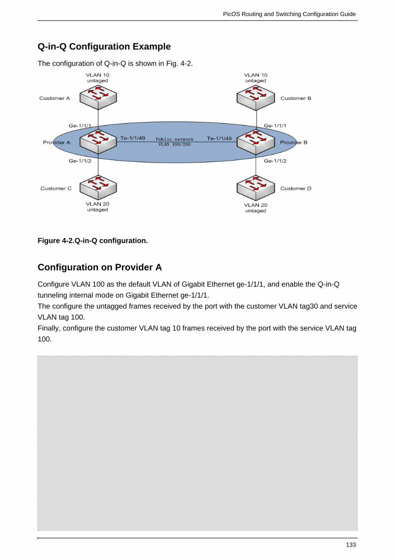
PicOS Routing and Switching Configuration Guide
133
Q-in-Q Configuration Example
The configuration of Q-in-Q is shown in Fig. 4-2.
Figure 4-2.Q-in-Q configuration.
Configuration on Provider A
Configure VLAN 100 as the default VLAN of Gigabit Ethernet ge-1/1/1, and enable the Q-in-Q
tunneling internal mode on Gigabit Ethernet ge-1/1/1.
The configure the untagged frames received by the port with the customer VLAN tag30 and service
VLAN tag 100.
Finally, configure the customer VLAN tag 10 frames received by the port with the service VLAN tag
100.

PicOS Routing and Switching Configuration Guide
134
XorPlus# set vlans vlan-id 100XorPlus# commit Waiting for merging configuration.Commit OK.Save done.XorPlus# set interface gigabit-ethernet ge-1/1/1 family ethernet-switchingnative-vlan-id 100 XorPlus# set vlans dot1q-tunneling ingress t1 from untag enabled trueXorPlus# set vlans dot1q-tunneling ingress t1 then customer-vlan 30XorPlus# set vlans dot1q-tunneling ingress t1 then service-vlan 100XorPlus# set interface gigabit-ethernet ge-1/1/1 family ethernet-switchingdot1q-tunneling ingress t1XorPlus# commit XorPlus# set vlans dot1q-tunneling ingress t2 from one-tag customer-vlan-list10XorPlus# set vlans dot1q-tunneling ingress t2 then service-vlan 100XorPlus# set interface gigabit-ethernet ge-1/1/1 family ethernet-switchingdot1q-tunneling ingress t2XorPlus# commit XorPlus# set vlans dot1q-tunneling egress t3 from customer-vlan 10XorPlus# set vlans dot1q-tunneling egress t3 from service-vlan 100XorPlus# set vlans dot1q-tunneling egress t3 then action oneXorPlus# set interface gigabit-ethernet ge-1/1/1 family ethernet-switchingdot1q-tunneling egress t3XorPlus# commit XorPlus# set vlans dot1q-tunneling egress t4 from customer-vlan 30XorPlus# set vlans dot1q-tunneling egress t4 from service-vlan 100XorPlus# set vlans dot1q-tunneling egress t4 then action noneXorPlus# set interface gigabit-ethernet ge-1/1/1 family ethernet-switchingdot1q-tunneling egress t4XorPlus# set interface gigabit-ethernet ge-1/1/1 family ethernet-switchingdot1q-tunneling modeinternalXorPlus# commitWaiting for merging configuration.Commit OK.Save done.XorPlus# run show interface gigabit-ethernet ge-1/1/1 dot1q-tunnelingDot1q Tunneling Mode: internal, Ether Type: 0x8100Ingress: t1Untagged-type Enabled: trueOne-tagged-type Customer Vlan: Double-tagged-type Service Vlan: 0New Service Vlan: 100New Customer Vlan: 30Ingress: t2Untagged-type Enabled: falseOne-tagged-type Customer Vlan: 10Double-tagged-type Service Vlan: 0New Service Vlan: 100New Customer Vlan: 0Egress: t3Service Vlan: 100Customer Vlan: 10Action: Retain the customer vlan tagEgress: t4Service Vlan: 100Customer Vlan: 30Action: Strip both tagsXorPlus#

PicOS Routing and Switching Configuration Guide
135
Configure VLAN 200 as the default VLAN of Gigabit Ethernet ge-1/1/2, and enable the Q-in-Q
tunneling internal mode on Gigabit Ethernet ge-1/1/2.
Then configure the untagged frames received by the port with the customer VLAN tag 30 and
service VLAN tag 200.
Finally configure the customer VLAN tag 20 frames, received by the port with the service VLAN
Tag 200.

PicOS Routing and Switching Configuration Guide
136
XorPlus# set vlans vlan-id 200XorPlus# commit Waiting for merging configuration.Commit OK.Save done.XorPlus# set interface gigabit-ethernet ge-1/1/2 family ethernet-switchingnative-vlan-id 200 XorPlus# set vlans dot1q-tunneling ingress t5 from untag enabled trueXorPlus# set vlans dot1q-tunneling ingress t5 then customer-vlan 30XorPlus# set vlans dot1q-tunneling ingress t5 then service-vlan 200XorPlus# set interface gigabit-ethernet ge-1/1/2 family ethernet-switchingdot1q-tunneling ingress t5XorPlus# commit XorPlus# set vlans dot1q-tunneling ingress t6 from one-tag customer-vlan-list20XorPlus# set vlans dot1q-tunneling ingress t6 then service-vlan 200XorPlus# set interface gigabit-ethernet ge-1/1/2 family ethernet-switchingdot1q-tunneling ingress t6XorPlus# commit XorPlus# set vlans dot1q-tunneling egress t7 from customer-vlan 20XorPlus# set vlans dot1q-tunneling egress t7 from service-vlan 200XorPlus# set vlans dot1q-tunneling egress t7 then action oneXorPlus# set interface gigabit-ethernet ge-1/1/2 family ethernet-switchingdot1q-tunneling egress t7XorPlus# commit XorPlus# set vlans dot1q-tunneling egress t8 from customer-vlan 30XorPlus# set vlans dot1q-tunneling egress t8 from service-vlan 200XorPlus# set vlans dot1q-tunneling egress t8 then action noneXorPlus# set interface gigabit-ethernet ge-1/1/2 family ethernet-switchingdot1q-tunneling egress t8XorPlus# set interface gigabit-ethernet ge-1/1/2 family ethernet-switchingdot1q-tunneling modeinternal XorPlus# commitWaiting for merging configuration.Commit OK.Save done.XorPlus# run show interface gigabit-ethernet ge-1/1/2 dot1q-tunnelingDot1q Tunneling Mode: internal, Ether Type: 0x8100Ingress: t5Untagged-type Enabled: trueOne-tagged-type Customer Vlan: Double-tagged-type Service Vlan: 0New Service Vlan: 200New Customer Vlan: 30Ingress: t6Untagged-type Enabled: falseOne-tagged-type Customer Vlan: 20Double-tagged-type Service Vlan: 0New Service Vlan: 200New Customer Vlan: 0Egress: t7Service Vlan: 200Customer Vlan: 20Action: Retain the customer vlan tagEgress: t8Service Vlan: 200Customer Vlan: 30Action: Strip both tagsXorPlus#

PicOS Routing and Switching Configuration Guide
137
Configure VLAN 100/200 as the trunk port of Gigabit Ethernet te-1/1/49, and enable the Q-in-Q
tunneling internal mode.
XorPlus# set interface gigabit-ethernet te-1/1/49 family ethernet-switchingport-mode trunkXorPlus# set interface gigabit-ethernet te-1/1/49 family ethernet-switchingvlan members 100XorPlus# set interface gigabit-ethernet te-1/1/49 family ethernet-switchingvlan members 200XorPlus# set interface gigabit-ethernet te-1/1/49 family ethernet-switchingdot1q-tunneling modeinternalXorPlus# commitWaiting for merging configuration.Commit OK.Save done.XorPlus# run show interface gigabit-ethernet te-1/1/49 dot1q-tunnelingDot1q Tunneling Mode: internal, Ether Type: 0x8100
Configuration on Provider B
Configure VLAN 100 as the default VLAN of Gigabit Ethernet ge-1/1/1, and enable the Q-in-Q
tunneling internal mode on Gigabit Ethernet ge-1/1/1.
The configure the untagged frames received by the port with the customer VLAN tag 30 and
service VLAN tag 100.
Finally, configure the customer VLAN tag 10 frames received by the port with the service VLAN tag
100.

PicOS Routing and Switching Configuration Guide
138
XorPlus# set vlans vlan-id 100XorPlus# commit Waiting for merging configuration.Commit OK.Save done.XorPlus# set interface gigabit-ethernet ge-1/1/1 family ethernet-switchingnative-vlan-id 100 XorPlus# set vlans dot1q-tunneling ingress t1 from untag enabled trueXorPlus# set vlans dot1q-tunneling ingress t1 then customer-vlan 30XorPlus# set vlans dot1q-tunneling ingress t1 then service-vlan 100XorPlus# set interface gigabit-ethernet ge-1/1/1 family ethernet-switchingdot1q-tunneling ingress t1XorPlus# commit XorPlus# set vlans dot1q-tunneling ingress t2 from one-tag customer-vlan-list10XorPlus# set vlans dot1q-tunneling ingress t2 then service-vlan 100XorPlus# set interface gigabit-ethernet ge-1/1/1 family ethernet-switchingdot1q-tunneling ingress t2XorPlus# commit XorPlus# set vlans dot1q-tunneling egress t3 from customer-vlan 10XorPlus# set vlans dot1q-tunneling egress t3 from service-vlan 100XorPlus# set vlans dot1q-tunneling egress t3 then action oneXorPlus# set interface gigabit-ethernet ge-1/1/1 family ethernet-switchingdot1q-tunneling egress t3XorPlus# commit XorPlus# set vlans dot1q-tunneling egress t4 from customer-vlan 30XorPlus# set vlans dot1q-tunneling egress t4 from service-vlan 100XorPlus# set vlans dot1q-tunneling egress t4 then action noneXorPlus# set interface gigabit-ethernet ge-1/1/1 family ethernet-switchingdot1q-tunneling egress t4XorPlus# set interface gigabit-ethernet ge-1/1/1 family ethernet-switchingdot1q-tunneling modeinternal XorPlus# commitWaiting for merging configuration.Commit OK.Save done.XorPlus# run show interface gigabit-ethernet ge-1/1/1 dot1q-tunnelingDot1q Tunneling Mode: internal, Ether Type: 0x8100Ingress: t1Untagged-type Enabled: trueOne-tagged-type Customer Vlan: Double-tagged-type Service Vlan: 0New Service Vlan: 100New Customer Vlan: 30Ingress: t2Untagged-type Enabled: falseOne-tagged-type Customer Vlan: 10Double-tagged-type Service Vlan: 0New Service Vlan: 100New Customer Vlan: 0Egress: t3Service Vlan: 100Customer Vlan: 10Action: Retain the customer vlan tagEgress: t4Service Vlan: 100Customer Vlan: 30Action: Strip both tagsXorPlus#

PicOS Routing and Switching Configuration Guide
139
Configure VLAN 200 as the default VLAN of Gigabit Ethernet ge-1/1/2, and enable the Q-in-Q
tunneling internal mode on Gigabit Ethernet 1/1/2.
Then configure the untagged frames received by the port with the customer VLAN tag 30 and
service VLAN tag 200.
Finally, configure the customer VLAN tag 20 frames received by the port with the service VLAN
Tag 200.

PicOS Routing and Switching Configuration Guide
140
XorPlus# set vlans vlan-id 200XorPlus# commit Waiting for merging configuration.Commit OK.Save done.XorPlus# set interface gigabit-ethernet ge-1/1/2 family ethernet-switchingnative-vlan-id 200 XorPlus# set vlans dot1q-tunneling ingress t5 from untag enabled trueXorPlus# set vlans dot1q-tunneling ingress t5 then customer-vlan 30XorPlus# set vlans dot1q-tunneling ingress t5 then service-vlan 200XorPlus# set interface gigabit-ethernet ge-1/1/2 family ethernet-switchingdot1q-tunneling ingress t5XorPlus# commit XorPlus# set vlans dot1q-tunneling ingress t6 from one-tag customer-vlan-list20XorPlus# set vlans dot1q-tunneling ingress t6 then service-vlan 200XorPlus# set interface gigabit-ethernet ge-1/1/2 family ethernet-switchingdot1q-tunneling ingress t6XorPlus# commit XorPlus# set vlans dot1q-tunneling egress t7 from customer-vlan 20XorPlus# set vlans dot1q-tunneling egress t7 from service-vlan 200XorPlus# set vlans dot1q-tunneling egress t7 then action oneXorPlus# set interface gigabit-ethernet ge-1/1/2 family ethernet-switchingdot1q-tunneling egress t7XorPlus# commit XorPlus# set vlans dot1q-tunneling egress t8 from customer-vlan 30XorPlus# set vlans dot1q-tunneling egress t8 from service-vlan 200XorPlus# set vlans dot1q-tunneling egress t8 then action noneXorPlus# set interface gigabit-ethernet ge-1/1/2 family ethernet-switchingdot1q-tunneling egress t8XorPlus# set interface gigabit-ethernet ge-1/1/2 family ethernet-switchingdot1q-tunneling mode internal XorPlus# commitWaiting for merging configuration.Commit OK.Save done.XorPlus# run show interface gigabit-ethernet ge-1/1/2 dot1q-tunnelingDot1q Tunneling Mode: internal, Ether Type: 0x8100Ingress: t5Untagged-type Enabled: trueOne-tagged-type Customer Vlan: Double-tagged-type Service Vlan: 0New Service Vlan: 200New Customer Vlan: 30Ingress: t6Untagged-type Enabled: falseOne-tagged-type Customer Vlan: 20Double-tagged-type Service Vlan: 0New Service Vlan: 200New Customer Vlan: 0Egress: t7Service Vlan: 200Customer Vlan: 20Action: Retain the customer vlan tagEgress: t8Service Vlan: 200Customer Vlan: 30Action: Strip both tagsXorPlus#

PicOS Routing and Switching Configuration Guide
141
Configure VLAN 100/200 as the trunk port of Gigabit Ethernet te-1/1/49, and enable the Q-in-Q
tunneling internal mode.
XorPlus# set interface gigabit-ethernet te-1/1/49 family ethernet-switchingport-mode trunkXorPlus# set interface gigabit-ethernet te-1/1/49 family ethernet-switchingvlan members 100XorPlus# set interface gigabit-ethernet te-1/1/49 family ethernet-switchingvlan members 200XorPlus# set interface gigabit-ethernet te-1/1/49 family ethernet-switchingdot1q-tunneling modeinternalXorPlus# commitWaiting for merging configuration.Commit OK.Save done.XorPlus# run show interface gigabit-ethernet te-1/1/49 dot1q-tunnelingDot1q Tunneling Mode: internal, Ether Type: 0x8100XorPlus#
MSTP Configuration
802.1D, 802.1w, and 802.1s are spanning tree protocols that can avoid the loop in Layer2. You
can configure the parameters of MSTP, including bridge-priority, forward-delay, max-age, and
hello-time interval.
Enabling spanning tree mode in MSTP
XorPlus# set protocols spanning-tree force-version 3XorPlus# commitWaiting for merging configuration.Commit OK.Save done.XorPlus#
Configuring basic global parameters of MSTP
When configuring global parameters, make sure to set the forward delay to greater than
Max-Age/2 + 1, or the commit will fail.
XorPlus# set protocols spanning-tree mstp bridge-priority 4096XorPlus# set protocols spanning-tree mstp forward-delay 20XorPlus# set protocols spanning-tree mstp hello-time 2XorPlus# set protocols spanning-tree mstp max-age 20XorPlus# set protocols spanning-tree mstp max-hops 8XorPlus# set protocols spanning-tree mstp configuration-name test1XorPlus# commitWaiting for merging configuration.Commit OK.Save done.XorPlus# run show spanning-tree mstp bridge Bridge Spanning Tree Parameters

PicOS Routing and Switching Configuration Guide
142
Enabled Protocol: MSTPRoot ID: 4096.08:9e:01:39:1a:feExternal Root Path Cost: 0CIST Regional Root ID: 4096.08:9e:01:39:1a:feRoot Port: CIST Internal Root Path Cost: 0Hello Time: 2Maximum Age: 20Forward Delay: 20Remaining Hops: 8Bridge Configuration Name: test1Bridge Configuration Digest: ac36177f50283cd4b83821d8ab26de62Number of Topology Changes: 13Time Since Last Topology Change: 0 days 00:00:31Local ParametersBridge ID: 4096.08:9e:01:39:1a:feHello Time: 2Maximum Age: 20Forward Delay: 20Remaining Hops: 8XorPlus#XorPlus# set vlans vlan-id 100XorPlus# set vlans vlan-id 200XorPlus# set vlans vlan-id 300XorPlus# set vlans vlan-id 400XorPlus# commit Waiting for merging configuration.Commit OK.Save done.XorPlus# set protocols spanning-tree mstp msti 1XorPlus# set protocols spanning-tree mstp msti 2XorPlus# commitWaiting for merging configuration.Commit OK.Save done.XorPlus# set protocols spanning-tree mstp msti 1 vlan 100XorPlus# set protocols spanning-tree mstp msti 1 vlan 200XorPlus# set protocols spanning-tree mstp msti 2 vlan 300XorPlus# set protocols spanning-tree mstp msti 2 vlan 400XorPlus# commit Waiting for merging configuration.Commit OK.Save done.XorPlus#XorPlus# run show spanning-tree mstp bridge Bridge Spanning Tree ParametersEnabled Protocol: MSTPRoot ID: 4096.08:9e:01:39:1a:feExternal Root Path Cost: 0CIST Regional Root ID: 4096.08:9e:01:39:1a:feRoot Port: CIST Internal Root Path Cost: 0Hello Time: 2Maximum Age: 20Forward Delay: 20Remaining Hops: 8Bridge Configuration Name: test1Bridge Configuration Digest: 8b5d98ca042bad0d7fa5f18744f4755dMsti 1 Member VLANs:100, 200, Msti 2 Member VLANs:300, 400, Number of Topology Changes: 14

PicOS Routing and Switching Configuration Guide
143
Time Since Last Topology Change: 0 days 00:02:49Local ParametersBridge ID: 4096.08:9e:01:39:1a:feHello Time: 2Maximum Age: 20Forward Delay: 20Remaining Hops: 8XorPlus#
Configuring MSTP interface parameters
XorPlus# set protocols spanning-tree mstp interface ge-1/1/1external-path-cost 30000XorPlus# set protocols spanning-tree mstp interface ge-1/1/1internal-path-cost 10000XorPlus# set protocols spanning-tree mstp interface ge-1/1/1 edge trueXorPlus# set protocols spanning-tree mstp interface ge-1/1/1 modepoint-to-point XorPlus# set protocols spanning-tree mstp interface ge-1/1/1 port-priority100XorPlus# commitWaiting for merging configuration.Commit OK.Save done.XorPlus# run show spanning-tree mstp interface Spanning Tree Interface Parameters for Instance 0Interface Port ID Designated Designated Bridge Ext Port Int Port State RolePort ID ID Cost Cost---------- --------- ---------- ----------------------- --------- ------------------- ------ge-1/1/1 96.1 96.1 8192.08:9e:01:39:1a:fe 30000 10000 FORWARDING EDGE
Configuring the BPDU Filter
The BPDU filter prevents the bridge from using BPDUs for STP calculations. The switch then
ignores any BPDUs that it receives.
XorPlus# set protocols spanning-tree mstp interface ge-1/1/1 bpdu-filter trueXorPlus# commit Waiting for merging configuration.Commit OK.Save done.XorPlus#
Configuring BPDU root guard
If a switch port receives a higher bridge-priority BPDU, it will ignore the BPDU and keep the current
root-bridge as the root-bridge.

PicOS Routing and Switching Configuration Guide
144
XorPlus# set protocols spanning-tree mstp interface ge-1/1/1 root-guard trueXorPlus# commit Waiting for merging configuration.Commit OK.Save done.XorPlus#
Configuring BPDU TCN-guard
When a port is configured with TCN-guard, the port does not process or propagate any topology
change information received on the configured port.
XorPlus# set protocols spanning-tree mstp interface ge-1/1/1 tcn-guard trueXorPlus# commit Waiting for merging configuration.Commit OK.Save done.XorPlus#
Disabling/enabling MSTP
If you disable MSTP, the port will stay in forwarding status and cease to send BPDUs.

PicOS Routing and Switching Configuration Guide
145
XorPlus# set protocols spanning-tree enable falseXorPlus# commitWaiting for merging configuration.Commit OK.Save done.XorPlus# XorPlus# run show spanning-tree mstp interface Spanning Tree Interface Parameters for Instance 0Interface Port ID Designated Designated Bridge Ext Port Int Port State RolePort ID ID Cost Cost--------- ------- ---------- ----------------------- -------- ------------------ -------------ge-1/1/1 96.1 96.1 8192.08:9e:01:39:1a:fe 30000 10000 FORWARDING MSTPDISABLEDge-1/1/2 128.2 128.2 8192.08:9e:01:39:1a:fe 20000 20000 FORWARDING MSTPDISABLEDge-1/1/13 128.13 128.13 8192.08:9e:01:39:1a:fe 20000 20000 FORWARDING MSTPDISABLED XorPlus# set protocols spanning-tree enable trueXorPlus# commitWaiting for merging configuration.Commit OK.Save done.XorPlus# XorPlus# run show spanning-tree mstp interface Spanning Tree Interface Parameters for Instance 0Interface Port ID Designated Designated Bridge Ext Port Int Port State RolePort ID ID Cost Cost--------- ------- ---------- ----------------------- -------- ------------------ -----------ge-1/1/1 96.1 96.1 8192.08:9e:01:39:1a:fe 30000 10000 FORWARDING EDGE ge-1/1/2 128.2 128.2 8192.08:9e:01:39:1a:fe 20000 20000 FORWARDING EDGE ge-1/1/13 128.13 128.13 8192.08:9e:01:39:1a:fe 20000 20000 FORWARDINGDESIGNATED
PVST Configuration
802.1D, 802.1w, and 802.1s are spanning tree protocols that \avoid the loop in Layer2. You can
configure the parameters of PVST, including bridge-priority, forward-delay, max-age, and
hello-time interval.
Enabling spanning tree mode in PVST
XorPlus# set protocols spanning-tree force-version 4XorPlus# commitWaiting for merging configuration.Commit OK.Save done.XorPlus#

PicOS Routing and Switching Configuration Guide
146
Configuring basic VLAN parameters of PVST
When configuring basic VLAN parameters, set the forward delay to greater than Max-Age/2 + 1, or
the commit will fail.
XorPlus# set protocols spanning-tree pvst vlan 2 bridge-priority 4096XorPlus# set protocols spanning-tree pvst vlan 2 forward-delay 20XorPlus# set protocols spanning-tree pvst vlan 2 hello-time 4XorPlus# set protocols spanning-tree pvst vlan 2 max-age 30XorPlus# commitWaiting for merging configuration.Commit OK.Save done.XorPlus# XorPlus# run show spanning-tree pvst bridge vlan 2PVST Bridge Parameters for VLAN 2Root Bridge: 4098.08:9e:01:61:65:71Root Cost: 0Root Port: Hello Time: 4Max Age: 30Forward Delay: 20Time Since Last Topology Change: 0 days 00:02:55Local ParametersBridge ID: 4098.08:9e:01:61:65:71Hello Time: 4Maximum Age: 30Forward Delay: 20
Configuring PVST interface parameters
XorPlus# set protocols spanning-tree pvst vlan 2 interface ge-1/1/1 path-cost555555XorPlus# set protocols spanning-tree pvst vlan 2 interface ge-1/1/1port-priority 200XorPlus# commitWaiting for merging configuration.Commit OK.Save done.XorPlus# run show spanning-tree pvst interface vlan 2Rapid PVST+ Spanning Tree Interface Status for VLAN 2Interface Port ID Designated Designated Bridge Port Cost State RolePort ID ID---------- --------- ---------- ----------------------- --------- -------------------------ge-1/1/1 192.1 192.1 4098.08:9e:01:61:65:71 555555 FORWARDING EDGE
Configuring the interface mode
You can configure the interface mode as point-to-point or shared.

PicOS Routing and Switching Configuration Guide
147
XorPlus# set protocols spanning-tree pvst interface ge-1/1/1 modepoint-to-point XorPlus# commitWaiting for merging configuration.Commit OK.Save done.XorPlus# set protocols spanning-tree pvst interface ge-1/1/1 mode shared XorPlus# commitWaiting for merging configuration.Commit OK.Save done.XorPlus#
Disabling/enabling PVST on one VLAN
You can disable or enable the spanning tree protocol PVST on a single designated VLAN.

PicOS Routing and Switching Configuration Guide
148
XorPlus# set protocols spanning-tree pvst vlan 2 enable falseXorPlus# commitWaiting for merging configuration.Commit OK.Save done.XorPlus#XorPlus# run show spanning-tree pvst bridge vlan 2PVST Bridge Parameters for VLAN 2Root Bridge: 32769.08:9e:01:61:65:71Root Cost: 0Root Port: Hello Time: 2Max Age: 20Forward Delay: 15Time Since Last Topology Change: 15804 days 23:00:11Local ParametersBridge ID: 32769.08:9e:01:61:65:71Hello Time: 2Maximum Age: 20Forward Delay: 15XorPlus# set protocols spanning-tree pvst vlan 2 enable trueXorPlus# commitWaiting for merging configuration.Commit OK.Save done.XorPlus# XorPlus# run show spanning-tree pvst bridge vlan 2PVST Bridge Parameters for VLAN 2Root Bridge: 4098.08:9e:01:61:65:71Root Cost: 0Root Port: Hello Time: 4Max Age: 30Forward Delay: 20Time Since Last Topology Change: 0 days 00:00:21Local ParametersBridge ID: 4098.08:9e:01:61:65:71Hello Time: 4Maximum Age: 30Forward Delay: 20XorPlus#
Disabling/enabling PVST
You cannot disable the spanning tree protocol PVST with just the command. Toenable false
disable PVST, configure the spanning tree mode in MSTP/RSTP/STP and then disable thefirst
spanning tree. After the spanning tree is disabled, the port will stay in "forwarding" status and
cease to send BPDUs.

PicOS Routing and Switching Configuration Guide
149
XorPlus# set protocols spanning-tree enable falseXorPlus# commitWaiting for merging configuration.Commit Failed102 Command failed Cannot disable spanning tree under PVST mode[XorPlus#XorPlus# exit discard XorPlus> configure Entering configuration mode.There are no other users in configuration mode.XorPlus# XorPlus# set protocols spanning-tree force-version 2XorPlus# commitWaiting for merging configuration.Commit OK.Save done.XorPlus# set protocols spanning-tree enable falseXorPlus# commitWaiting for merging configuration.Commit OK.Save done.XorPlus# XorPlus# set protocols spanning-tree force-version 4XorPlus# commitWaiting for merging configuration.Commit OK.Save done.XorPlus# set protocols spanning-tree enable trueXorPlus# commitWaiting for merging configuration.Commit OK.Save done.XorPlus#XorPlus# run show spanning-tree Bridge Spanning Tree ParametersEnabled Protocol: PVSTRoot ID: 32769.08:9e:01:61:65:71Root Path Cost: 0Designated Bridge ID: 32769.08:9e:01:61:65:71Root Port: Hello Time: 2Maximum Age: 20Forward Delay: 15Number of Topology Changes: 1Time Since Last Topology Change: 0 days 00:00:09Local ParametersBridge ID: 32769.08:9e:01:61:65:71Hello Time: 2Maximum Age: 20Forward Delay: 15

PicOS Routing and Switching Configuration Guide
150
MSTP Configuration Example
There are two examples of MSTP configuration. In our first example, VLAN 100 is mapped to
MSTI-1, and VLAN 200 is mapped to MSTI-2. The entire topology belongs to only one MSTP
domain, named . Switch A is the root of the network.region1
To achieve load balancing, VLAN 100 should be in MSTI-1 (Fig. 4-4), and VLAN 200 should be in
MSTI-2 (Fig. 4-5).
Figure 4-3.MSTP configuration.
Figure 4-4. MSTI-1 topology for VLAN 100.

PicOS Routing and Switching Configuration Guide
151
Figure 4-5. MSTI-2 topology for VLAN 200.
Configuring Switch A
For Switch A, configure ge-1/1/1~ge-1/1/3 as trunk ports, and as members of VLAN 100 and VLAN
200.

PicOS Routing and Switching Configuration Guide
152
XorPlus# set vlans vlan-id 100XorPlus# set vlans vlan-id 200XorPlus# set interface gigabit-ethernet ge-1/1/1 family ethernet-switchingport-mode trunk XorPlus# set interface gigabit-ethernet ge-1/1/1 family ethernet-switchingvlan members 100XorPlus# set interface gigabit-ethernet ge-1/1/1 family ethernet-switchingvlan members 200XorPlus# set interface gigabit-ethernet ge-1/1/2 family ethernet-switchingport-mode trunk XorPlus# set interface gigabit-ethernet ge-1/1/2 family ethernet-switchingvlan members 100XorPlus# set interface gigabit-ethernet ge-1/1/2 family ethernet-switchingvlan members 200XorPlus# set interface gigabit-ethernet ge-1/1/3 family ethernet-switchingport-mode trunk XorPlus# set interface gigabit-ethernet ge-1/1/3 family ethernet-switchingvlan members 100XorPlus# set interface gigabit-ethernet ge-1/1/3 family ethernet-switchingvlan members 200XorPlus# commit Waiting for merging configuration.Commit OK.Save done.XorPlus#XorPlus# set protocols spanning-tree mstp msti 1 vlan 100XorPlus# set protocols spanning-tree mstp msti 2 vlan 200XorPlus# set protocols spanning-tree mstp configuration-name region1XorPlus# commit Waiting for merging configuration.Commit OK.Save done.XorPlus# To make sure that Switch A is the root of the network and the regional rootof MSTI-1, configure it as the higher priority. XorPlus# set protocols spanning-tree mstp bridge-priority 0XorPlus# commit Waiting for merging configuration.Commit OK.Save done.XorPlus# set protocols spanning-tree mstp msti 1 bridge-priority 4096XorPlus# commitWaiting for merging configuration.Commit OK.Save done.XorPlus#
Configuring Switch B
Configure ge-1/1/1~ge-1/1/3 as trunk ports, and as members of VLAN 100 and VLAN 200.

PicOS Routing and Switching Configuration Guide
153
XorPlus# set vlans vlan-id 100XorPlus# set vlans vlan-id 200XorPlus# set interface gigabit-ethernet ge-1/1/1 family ethernet-switchingport-mode trunk XorPlus# set interface gigabit-ethernet ge-1/1/1 family ethernet-switchingvlan members 100XorPlus# set interface gigabit-ethernet ge-1/1/1 family ethernet-switchingvlan members 200XorPlus# set interface gigabit-ethernet ge-1/1/2 family ethernet-switchingport-mode trunk XorPlus# set interface gigabit-ethernet ge-1/1/2 family ethernet-switchingvlan members 100XorPlus# set interface gigabit-ethernet ge-1/1/2 family ethernet-switchingvlan members 200XorPlus# set interface gigabit-ethernet ge-1/1/3 family ethernet-switchingport-mode trunk XorPlus# set interface gigabit-ethernet ge-1/1/3 family ethernet-switchingvlan members 100XorPlus# set interface gigabit-ethernet ge-1/1/3 family ethernet-switchingvlan members 200XorPlus#XorPlus# commit Waiting for merging configuration.Commit OK.Save done.XorPlus#XorPlus# set protocols spanning-tree mstp msti 1 vlan 100XorPlus# set protocols spanning-tree mstp msti 2 vlan 200XorPlus# set protocols spanning-tree mstp configuration-name region1XorPlus# commit Waiting for merging configuration.Commit OK.Save done.XorPlus#
To verify that Switch B is the regional root of MSTI-2, and that ge-1/1/2 and ge-1/1/3 are in
blocking status in MSTI-1, configure a higher MSTI-2 priority, and a large value for
internal-path-cost in MSTI-1.
XorPlus# set protocols spanning-tree mstp msti 2 bridge-priority 4096XorPlus# commitWaiting for merging configuration.Commit OK.Save done.XorPlus#XorPlus# set protocols spanning-tree mstp msti 1 interface ge-1/1/2 cost10000000XorPlus# set protocols spanning-tree mstp msti 1 interface ge-1/1/3 cost10000000XorPlus# commit Waiting for merging configuration.Commit OK.Save done.XorPlus#

PicOS Routing and Switching Configuration Guide
154
Configuring Switch C
Configure ge-1/1/1~ge-1/1/2 as trunk ports, and as members of VLAN 100 and VLAN 200.
XorPlus# set vlans vlan-id 100XorPlus# set vlans vlan-id 200XorPlus# set interface gigabit-ethernet ge-1/1/1 family ethernet-switchingport-mode trunk XorPlus# set interface gigabit-ethernet ge-1/1/1 family ethernet-switchingvlan members 100XorPlus# set interface gigabit-ethernet ge-1/1/1 family ethernet-switchingvlan members 200XorPlus# set interface gigabit-ethernet ge-1/1/2 family ethernet-switchingport-mode trunk XorPlus# set interface gigabit-ethernet ge-1/1/2 family ethernet-switchingvlan members 100XorPlus# set interface gigabit-ethernet ge-1/1/2 family ethernet-switchingvlan members 200XorPlus#XorPlus# commit Waiting for merging configuration.Commit OK.Save done.XorPlus#XorPlus# set protocols spanning-tree mstp msti 1 vlan 100XorPlus# set protocols spanning-tree mstp msti 2 vlan 200XorPlus# set protocols spanning-tree mstp configuration-name region1XorPlus# commit Waiting for merging configuration.Commit OK.Save done.XorPlus#
To set ge-1/1/1 and ge-1/1/2 in forwarding status in MSTI-1, configure a lower value for
internal-path-cost.
To set ge-1/1/1 in blocking status in MSTI-2, configure a higher value for internal-path-cost.
XorPlus# set protocols spanning-tree mstp msti 1 interface ge-1/1/1 cost 1000XorPlus# set protocols spanning-tree mstp msti 1 interface ge-1/1/2 cost 1000XorPlus# commit Waiting for merging configuration.Commit OK.Save done.XorPlus# set protocols spanning-tree mstp msti 2 interface ge-1/1/1 cost100000 XorPlus# commit Waiting for merging configuration.Commit OK.Save done.XorPlus#
Configuring Switch D
Configure ge-1/1/1~ge-1/1/2 as trunk ports, and as members of VLAN 100 and VLAN 200.

PicOS Routing and Switching Configuration Guide
155
XorPlus# set vlans vlan-id 100XorPlus# set vlans vlan-id 200XorPlus# set interface gigabit-ethernet ge-1/1/1 family ethernet-switchingport-mode trunk XorPlus# set interface gigabit-ethernet ge-1/1/1 family ethernet-switchingvlan members 100XorPlus# set interface gigabit-ethernet ge-1/1/1 family ethernet-switchingvlan members 200XorPlus# set interface gigabit-ethernet ge-1/1/2 family ethernet-switchingport-mode trunk XorPlus# set interface gigabit-ethernet ge-1/1/2 family ethernet-switchingvlan members 100XorPlus# set interface gigabit-ethernet ge-1/1/2 family ethernet-switchingvlan members 200XorPlus#XorPlus# commit Waiting for merging configuration.Commit OK.Save done.XorPlus#XorPlus# set protocols spanning-tree mstp msti 1 vlan 100XorPlus# set protocols spanning-tree mstp msti 2 vlan 200XorPlus# set protocols spanning-tree mstp configuration-name region1XorPlus# commit Waiting for merging configuration.Commit OK.Save done.XorPlus#
To set ge-1/1/1 in blocking status in MSTI-2 and ge-1/1/2 in blocking status in MSTI-1, configure a
large value for internal-path-cost.
XorPlus# set protocols spanning-tree mstp msti 2 interface ge-1/1/1 cost10000000XorPlus# commit Waiting for merging configuration.Commit OK.Save done.XorPlus# set protocols spanning-tree mstp msti 1 interface ge-1/1/2 cost10000000XorPlus# commit Waiting for merging configuration.Commit OK.Save done.XorPlus#
Configuring Switch E
Configure ge-1/1/1~ge-1/1/2 as trunk ports, and as members of VLAN 100 and VLAN 200.

PicOS Routing and Switching Configuration Guide
156
XorPlus# set vlans vlan-id 100XorPlus# set vlans vlan-id 200XorPlus# set interface gigabit-ethernet ge-1/1/1 family ethernet-switchingport-mode trunk XorPlus# set interface gigabit-ethernet ge-1/1/1 family ethernet-switchingvlan members 100XorPlus# set interface gigabit-ethernet ge-1/1/1 family ethernet-switchingvlan members 200XorPlus# set interface gigabit-ethernet ge-1/1/2 family ethernet-switchingport-mode trunk XorPlus# set interface gigabit-ethernet ge-1/1/2 family ethernet-switchingvlan members 100XorPlus# set interface gigabit-ethernet ge-1/1/2 family ethernet-switchingvlan members 200XorPlus#XorPlus# commit Waiting for merging configuration.Commit OK.Save done.XorPlus#XorPlus# set protocols spanning-tree mstp msti 1 vlan 100XorPlus# set protocols spanning-tree mstp msti 2 vlan 200XorPlus# set protocols spanning-tree mstp configuration-name region1XorPlus# commit Waiting for merging configuration.Commit OK.Save done.XorPlus#
To set ge-1/1/1 and ge-1/1/2 in forwarding status in MSTI-2, configure a lower value for
internal-path-cost.
To set ge-1/1/2 in blocking status in MSTI-1, configure a large value for internal-path-cost.
XorPlus# set protocols spanning-tree mstp msti 2 interface ge-1/1/1 cost 1000XorPlus# set protocols spanning-tree mstp msti 2 interface ge-1/1/2 cost 1000XorPlus# commit Waiting for merging configuration.Commit OK.Save done.XorPlus# set protocols spanning-tree mstp msti 1 interface ge-1/1/2 cost10000000XorPlus# commit Waiting for merging configuration.Commit OK.Save done.XorPlus#
In the second example, there are two regions. In region 1, VLAN 100 is mapped to MSTI-1, VLAN
200 is mapped to MSTI-2, and VLAN 300 is mapped to MSTI-3. In region 2, VLAN 200 is mapped
to MSTI-2, and VLAN 400 is mapped to MSTI-4. Switch A is the root of the entire network. The
topologies of the VLANs are presented in Fig. 4-6 through 4-10.

PicOS Routing and Switching Configuration Guide
157
Figure 4-6. MSTP configuration.
Figure 4-7.Topologyfor VLAN 100.

PicOS Routing and Switching Configuration Guide
158
Figure 4-8.Topologyfor VLAN 200.
Figure 4-9.Topologyfor VLAN 300.

PicOS Routing and Switching Configuration Guide
159
Figure 4-10.Topologyfor VLAN 400.
Configuring Switch A
For Switch A, configure ge-1/1/1~ge-1/1/2 as trunk ports, and as members of VLAN 100, VLAN
200, VLAN 300, and VLAN 400.

PicOS Routing and Switching Configuration Guide
160
XorPlus# set vlans vlan-id 100XorPlus# set vlans vlan-id 200XorPlus# set vlans vlan-id 300XorPlus# set vlans vlan-id 400XorPlus# set interface gigabit-ethernet ge-1/1/1 family ethernet-switchingport-mode trunk XorPlus# set interface gigabit-ethernet ge-1/1/1 family ethernet-switchingvlan members 100XorPlus# set interface gigabit-ethernet ge-1/1/1 family ethernet-switchingvlan members 200XorPlus# set interface gigabit-ethernet ge-1/1/1 family ethernet-switchingvlan members 300XorPlus# set interface gigabit-ethernet ge-1/1/1 family ethernet-switchingvlan members 400XorPlus# set interface gigabit-ethernet ge-1/1/2 family ethernet-switchingport-mode trunk XorPlus# set interface gigabit-ethernet ge-1/1/2 family ethernet-switchingvlan members 100XorPlus# set interface gigabit-ethernet ge-1/1/2 family ethernet-switchingvlan members 200 XorPlus# set interface gigabit-ethernet ge-1/1/2 family ethernet-switchingvlan members 300XorPlus# set interface gigabit-ethernet ge-1/1/2 family ethernet-switchingvlan members 400XorPlus# commit Waiting for merging configuration.Commit OK.Save done.XorPlus#XorPlus# set protocols spanning-tree mstp msti 1 vlan 100XorPlus# set protocols spanning-tree mstp msti 2 vlan 200XorPlus# set protocols spanning-tree mstp msti 3 vlan 300XorPlus# set protocols spanning-tree mstp configuration-name region1XorPlus# commit Waiting for merging configuration.Commit OK.Save done.XorPlus# To verify that Switch A is the root of the network and the regional root ofMSTI-1, configure it as the higher priority. XorPlus# set protocols spanning-tree mstp bridge-priority 0XorPlus# commit Waiting for merging configuration.Commit OK.Save done.XorPlus# set protocols spanning-tree mstp msti 1 bridge-priority 4096XorPlus# commitWaiting for merging configuration.Commit OK.Save done.XorPlus#
Configuring Switch B
Configure ge-1/1/1~ge-1/1/3 as trunk ports, and as members of VLAN 100, VLAN 200, VLAN 300,
and VLAN 400.

PicOS Routing and Switching Configuration Guide
161
XorPlus# set vlans vlan-id 100XorPlus# set vlans vlan-id 200XorPlus# set vlans vlan-id 300XorPlus# set vlans vlan-id 400XorPlus# set interface gigabit-ethernet ge-1/1/1 family ethernet-switchingport-mode trunk XorPlus# set interface gigabit-ethernet ge-1/1/1 family ethernet-switchingvlan members 100XorPlus# set interface gigabit-ethernet ge-1/1/1 family ethernet-switchingvlan members 200XorPlus# set interface gigabit-ethernet ge-1/1/1 family ethernet-switchingvlan members 300XorPlus# set interface gigabit-ethernet ge-1/1/1 family ethernet-switchingvlan members 400XorPlus# set interface gigabit-ethernet ge-1/1/2 family ethernet-switchingport-mode trunk XorPlus# set interface gigabit-ethernet ge-1/1/2 family ethernet-switchingvlan members 100XorPlus# set interface gigabit-ethernet ge-1/1/2 family ethernet-switchingvlan members 200XorPlus# set interface gigabit-ethernet ge-1/1/2 family ethernet-switchingvlan members 300XorPlus# set interface gigabit-ethernet ge-1/1/2 family ethernet-switchingvlan members 400XorPlus# set interface gigabit-ethernet ge-1/1/3 family ethernet-switchingport-mode trunk XorPlus# set interface gigabit-ethernet ge-1/1/3 family ethernet-switchingvlan members 100XorPlus# set interface gigabit-ethernet ge-1/1/3 family ethernet-switchingvlan members 200XorPlus# set interface gigabit-ethernet ge-1/1/3 family ethernet-switchingvlan members 300XorPlus# set interface gigabit-ethernet ge-1/1/3 family ethernet-switchingvlan members 400XorPlus#XorPlus# commit Waiting for merging configuration.Commit OK.Save done.XorPlus#XorPlus# set protocols spanning-tree mstp msti 1 vlan 100XorPlus# set protocols spanning-tree mstp msti 2 vlan 200XorPlus# set protocols spanning-tree mstp msti 3 vlan 300XorPlus# set protocols spanning-tree mstp configuration-name region1XorPlus# commit Waiting for merging configuration.Commit OK.Save done.XorPlus#
To verify that Switch B is the regional root of MSTI-2, and that ge-1/1/1 is in blocking status in
MSTI-3 configure a higher MSTI-2 priority, and a large value for internal-path-cost in MSTI-3.

PicOS Routing and Switching Configuration Guide
162
XorPlus# set protocols mstp msti 2 bridge-priority 4096XorPlus# commitWaiting for merging configuration.Commit OK.Save done.XorPlus#XorPlus# set protocols mstp msti 3 interface ge-1/1/1 cost 10000000XorPlus# commit Waiting for merging configuration.Commit OK.Save done.XorPlus#
Configuring Switch C
Configure ge-1/1/1~ge-1/1/3 as trunk ports, and as members of VLAN 100, VLAN 200, VLAN 300,
and VLAN 400.

PicOS Routing and Switching Configuration Guide
163
XorPlus# set vlans vlan-id 100XorPlus# set vlans vlan-id 200XorPlus# set vlans vlan-id 300XorPlus# set vlans vlan-id 400XorPlus# set interface gigabit-ethernet ge-1/1/1 family ethernet-switchingport-mode trunk XorPlus# set interface gigabit-ethernet ge-1/1/1 family ethernet-switchingvlan members 100XorPlus# set interface gigabit-ethernet ge-1/1/1 family ethernet-switchingvlan members 200XorPlus# set interface gigabit-ethernet ge-1/1/1 family ethernet-switchingvlan members 300XorPlus# set interface gigabit-ethernet ge-1/1/1 family ethernet-switchingvlan members 400XorPlus# set interface gigabit-ethernet ge-1/1/2 family ethernet-switchingport-mode trunk XorPlus# set interface gigabit-ethernet ge-1/1/2 family ethernet-switchingvlan members 100XorPlus# set interface gigabit-ethernet ge-1/1/2 family ethernet-switchingvlan members 200XorPlus# set interface gigabit-ethernet ge-1/1/2 family ethernet-switchingvlan members 300XorPlus# set interface gigabit-ethernet ge-1/1/2 family ethernet-switchingvlan members 400XorPlus# set interface gigabit-ethernet ge-1/1/3 family ethernet-switchingport-mode trunk XorPlus# set interface gigabit-ethernet ge-1/1/3 family ethernet-switchingvlan members 100XorPlus# set interface gigabit-ethernet ge-1/1/3 family ethernet-switchingvlan members 200XorPlus# set interface gigabit-ethernet ge-1/1/3 family ethernet-switchingvlan members 300XorPlus# set interface gigabit-ethernet ge-1/1/3 family ethernet-switchingvlan members 400XorPlus#XorPlus# commit Waiting for merging configuration.Commit OK.Save done.XorPlus#XorPlus# set protocols spanning-tree mstp msti 1 vlan 100XorPlus# set protocols spanning-tree mstp msti 2 vlan 200XorPlus# set protocols spanning-tree mstp msti 3 vlan 300XorPlus# set protocols spanning-tree mstp configuration-name region1XorPlus# commit Waiting for merging configuration.Commit OK.Save done.XorPlus#
To verify that Switch C is the regional root of MSTI-3, ge-1/1/1 is in blocking status in MSTI-2, and
that ge-1/1/2 is in blocking status in MSTI-1, you should configure a higher MSTI-3 priority, and
large values for internal-path-costs of ge-1/1/1 in MSTI-2 and ge-1/1/2 in MSTI-1.

PicOS Routing and Switching Configuration Guide
164
XorPlus# set protocols spanning-tree mstp msti 3 bridge-priority 4096XorPlus# commitWaiting for merging configuration.Commit OK.Save done.XorPlus#XorPlus# set protocols spanning-tree mstp msti 2 interface ge-1/1/1 cost10000000XorPlus# set protocols spanning-tree mstp msti 1 interface ge-1/1/2 cost10000000XorPlus# commit Waiting for merging configuration.Commit OK.Save done.XorPlus#
Configuring Switch D
Configure ge-1/1/1~ge-1/1/3 as trunk ports, and as members of VLAN 100, VLAN 200, VLAN 300,
and VLAN 400.

PicOS Routing and Switching Configuration Guide
165
XorPlus# set vlans vlan-id 100XorPlus# set vlans vlan-id 200XorPlus# set vlans vlan-id 300XorPlus# set vlans vlan-id 400XorPlus# set interface gigabit-ethernet ge-1/1/1 family ethernet-switchingport-mode trunk XorPlus# set interface gigabit-ethernet ge-1/1/1 family ethernet-switchingvlan members 100XorPlus# set interface gigabit-ethernet ge-1/1/1 family ethernet-switchingvlan members 200XorPlus# set interface gigabit-ethernet ge-1/1/1 family ethernet-switchingvlan members 300XorPlus# set interface gigabit-ethernet ge-1/1/1 family ethernet-switchingvlan members 400XorPlus# set interface gigabit-ethernet ge-1/1/2 family ethernet-switchingport-mode trunk XorPlus# set interface gigabit-ethernet ge-1/1/2 family ethernet-switchingvlan members 100XorPlus# set interface gigabit-ethernet ge-1/1/2 family ethernet-switchingvlan members 200XorPlus# set interface gigabit-ethernet ge-1/1/2 family ethernet-switchingvlan members 300XorPlus# set interface gigabit-ethernet ge-1/1/2 family ethernet-switchingvlan members 400XorPlus# set interface gigabit-ethernet ge-1/1/3 family ethernet-switchingport-mode trunk XorPlus# set interface gigabit-ethernet ge-1/1/3 family ethernet-switchingvlan members 100XorPlus# set interface gigabit-ethernet ge-1/1/3 family ethernet-switchingvlan members 200XorPlus# set interface gigabit-ethernet ge-1/1/3 family ethernet-switchingvlan members 300XorPlus# set interface gigabit-ethernet ge-1/1/3 family ethernet-switchingvlan members 400XorPlus#XorPlus# commit Waiting for merging configuration.Commit OK.Save done.XorPlus#XorPlus# set protocols spanning-tree mstp msti 2 vlan 200XorPlus# set protocols spanning-tree mstp msti 4 vlan 400XorPlus# set protocols spanning-tree mstp configuration-name region2XorPlus# commit Waiting for merging configuration.Commit OK.Save done.XorPlus#
To verify that Switch D is the regional root of MSTI-2 and the root of CIST, configure a higher
MSTI-2 priority and bridge priority.

PicOS Routing and Switching Configuration Guide
166
XorPlus# set protocols spanning-tree mstp bridge-priority 16384XorPlus# commit Waiting for merging configuration.Commit OK.Save done.XorPlus# set protocols spanning-tree mstp msti 2 bridge-priority 4096XorPlus# commit Waiting for merging configuration.Commit OK.Save done.XorPlus#
Configuring Switch E
Configure ge-1/1/1~ge-1/1/3 as trunk ports, and as members of VLAN 100, VLAN 200, VLAN 300,
and VLAN 400.

PicOS Routing and Switching Configuration Guide
167
XorPlus# set vlans vlan-id 100XorPlus# set vlans vlan-id 200XorPlus# set vlans vlan-id 300XorPlus# set vlans vlan-id 400XorPlus# set interface gigabit-ethernet ge-1/1/1 family ethernet-switchingport-mode trunk XorPlus# set interface gigabit-ethernet ge-1/1/1 family ethernet-switchingvlan members 100XorPlus# set interface gigabit-ethernet ge-1/1/1 family ethernet-switchingvlan members 200XorPlus# set interface gigabit-ethernet ge-1/1/1 family ethernet-switchingvlan members 300XorPlus# set interface gigabit-ethernet ge-1/1/1 family ethernet-switchingvlan members 400XorPlus# set interface gigabit-ethernet ge-1/1/2 family ethernet-switchingport-mode trunk XorPlus# set interface gigabit-ethernet ge-1/1/2 family ethernet-switchingvlan members 100XorPlus# set interface gigabit-ethernet ge-1/1/2 family ethernet-switchingvlan members 200XorPlus# set interface gigabit-ethernet ge-1/1/2 family ethernet-switchingvlan members 300XorPlus# set interface gigabit-ethernet ge-1/1/2 family ethernet-switchingvlan members 400XorPlus# set interface gigabit-ethernet ge-1/1/3 family ethernet-switchingport-mode trunk XorPlus# set interface gigabit-ethernet ge-1/1/3 family ethernet-switchingvlan members 100XorPlus# set interface gigabit-ethernet ge-1/1/3 family ethernet-switchingvlan members 200XorPlus# set interface gigabit-ethernet ge-1/1/3 family ethernet-switchingvlan members 300XorPlus# set interface gigabit-ethernet ge-1/1/3 family ethernet-switchingvlan members 400XorPlus#XorPlus# commit Waiting for merging configuration.Commit OK.Save done.XorPlus#XorPlus# set protocols spanning-tree mstp msti 2 vlan 200XorPlus# set protocols spanning-tree mstp msti 4 vlan 400XorPlus# set protocols spanning-tree mstp configuration-name region2XorPlus# commit Waiting for merging configuration.Commit OK.Save done.XorPlus#
To verify that Switch E is the regional root of MSTI-4, configure a higher MSTI-4 priority.
XorPlus# set protocols spanning-tree mstp msti 4 bridge-priority 4096XorPlus# commit Waiting for merging configuration.Commit OK.Save done.XorPlus#

PicOS Routing and Switching Configuration Guide
168
PVST Configuration Example
The following topology is an example of a PVST configuration. Switches A and B are in the
aggregation layer, and switches C and D are in the access layer. Configure switch A as the root
bridge of VLAN 100 and VLAN 200, switch B as the root bridge of VLAN 300, and switch C as the
root bridge of VLAN 400.
Figure 4-11. PVST configuration.
Configuring Switch A
For Switch A, configure ge-1/1/1~ge-1/1/3 as trunk ports, and ge-1/1/1 as a member of VLANs
100, 200, 300, and 400; ge-1/1/2 as a member of VLANs 200 and 300; and ge-1/1/3 as a member
of VLANs 100 and 200.

PicOS Routing and Switching Configuration Guide
169
XorPlus# set vlans vlan-id 100XorPlus# set vlans vlan-id 200XorPlus# set vlans vlan-id 300XorPlus# set vlans vlan-id 400XorPlus# set interface gigabit-ethernet ge-1/1/1 family ethernet-switchingport-mode trunk XorPlus# set interface gigabit-ethernet ge-1/1/1 family ethernet-switchingvlan members 100XorPlus# set interface gigabit-ethernet ge-1/1/1 family ethernet-switchingvlan members 200XorPlus# set interface gigabit-ethernet ge-1/1/1 family ethernet-switchingvlan members 300XorPlus# set interface gigabit-ethernet ge-1/1/1 family ethernet-switchingvlan members 400XorPlus# set interface gigabit-ethernet ge-1/1/2 family ethernet-switchingport-mode trunk XorPlus# set interface gigabit-ethernet ge-1/1/2 family ethernet-switchingvlan members 200XorPlus# set interface gigabit-ethernet ge-1/1/2 family ethernet-switchingvlan members 300XorPlus# set interface gigabit-ethernet ge-1/1/3 family ethernet-switchingport-mode trunk XorPlus# set interface gigabit-ethernet ge-1/1/3 family ethernet-switchingvlan members 100XorPlus# set interface gigabit-ethernet ge-1/1/3 family ethernet-switchingvlan members 200XorPlus# commit Waiting for merging configuration.Commit OK.Save done.XorPlus#XorPlus# set protocols spanning-tree force-version 4XorPlus# commit Waiting for merging configuration.Commit OK.Save done.XorPlus#
To verify that Switch A is the root bridge of VLANs 100 and 200, configure VLANs 100 and 200 as
the higher priority.
XorPlus# set protocols spanning-tree pvst vlan 100 bridge-priority 0 XorPlus# set protocols spanning-tree pvst vlan 200 bridge-priority 0 XorPlus# commit Waiting for merging configuration.Commit OK.Save done.XorPlus#
Configuring Switch B
Configure ge-1/1/1~ge-1/1/3 as trunk ports, and ge-1/1/1 as a member of VLANs 100, 200, 300,
and 400; ge-1/1/2 as a member of VLANs 100 and 200; and ge-1/1/3 as a member of VLANs 200
and 300.

PicOS Routing and Switching Configuration Guide
170
XorPlus# set vlans vlan-id 100XorPlus# set vlans vlan-id 200XorPlus# set vlans vlan-id 300XorPlus# set vlans vlan-id 400XorPlus# set interface gigabit-ethernet ge-1/1/1 family ethernet-switchingport-mode trunk XorPlus# set interface gigabit-ethernet ge-1/1/1 family ethernet-switchingvlan members 100XorPlus# set interface gigabit-ethernet ge-1/1/1 family ethernet-switchingvlan members 200XorPlus# set interface gigabit-ethernet ge-1/1/1 family ethernet-switchingvlan members 300XorPlus# set interface gigabit-ethernet ge-1/1/1 family ethernet-switchingvlan members 400XorPlus# set interface gigabit-ethernet ge-1/1/2 family ethernet-switchingport-mode trunk XorPlus# set interface gigabit-ethernet ge-1/1/2 family ethernet-switchingvlan members 100XorPlus# set interface gigabit-ethernet ge-1/1/2 family ethernet-switchingvlan members 200XorPlus# set interface gigabit-ethernet ge-1/1/3 family ethernet-switchingport-mode trunk XorPlus# set interface gigabit-ethernet ge-1/1/3 family ethernet-switchingvlan members 200XorPlus# set interface gigabit-ethernet ge-1/1/3 family ethernet-switchingvlan members 300XorPlus# commit Waiting for merging configuration.Commit OK.Save done.XorPlus#XorPlus# set protocols spanning-tree force-version 4XorPlus# commit Waiting for merging configuration.Commit OK.Save done.XorPlus#
To verify that Switch B is the root bridge of VLAN 300, configure VLAN 300 as the higher priority.
XorPlus# set protocols spanning-tree pvst vlan 300 bridge-priority 0 XorPlus# commit Waiting for merging configuration.Commit OK.Save done.XorPlus#
Configuring Switch C
Configure ge-1/1/1~ge-1/1/3 as trunk ports, and ge-1/1/1 as a member of VLANs 200 and
400,ge-1/1/2 as a member of VLANs 100 and 200, and ge-1/1/3 as a member of VLANs 100 and
200.

PicOS Routing and Switching Configuration Guide
171
XorPlus# set vlans vlan-id 100XorPlus# set vlans vlan-id 200XorPlus# set vlans vlan-id 400XorPlus# set interface gigabit-ethernet ge-1/1/1 family ethernet-switchingport-mode trunk XorPlus# set interface gigabit-ethernet ge-1/1/1 family ethernet-switchingvlan members 200XorPlus# set interface gigabit-ethernet ge-1/1/1 family ethernet-switchingvlan members 400XorPlus# set interface gigabit-ethernet ge-1/1/2 family ethernet-switchingport-mode trunk XorPlus# set interface gigabit-ethernet ge-1/1/2 family ethernet-switchingvlan members 100XorPlus# set interface gigabit-ethernet ge-1/1/2 family ethernet-switchingvlan members 200XorPlus# set interface gigabit-ethernet ge-1/1/3 family ethernet-switchingport-mode trunk XorPlus# set interface gigabit-ethernet ge-1/1/3 family ethernet-switchingvlan members 100XorPlus# set interface gigabit-ethernet ge-1/1/3 family ethernet-switchingvlan members 200XorPlus# commit Waiting for merging configuration.Commit OK.Save done.XorPlus#XorPlus# set protocols spanning-tree force-version 4XorPlus# commit Waiting for merging configuration.Commit OK.Save done.XorPlus#
To verify that Switch C is the root bridge of VLAN 400, configure VLAN 400 as the higher priority.
XorPlus# set protocols spanning-tree pvst vlan 400 bridge-priority 0 XorPlus# commit Waiting for merging configuration.Commit OK.Save done.XorPlus#
Configuring Switch D
Configure ge-1/1/1~ge-1/1/3 as trunk ports, and ge-1/1/1 as a member of VLANs 200 and 400,
ge-1/1/2 as a member of VLANs 200 and 300, and ge-1/1/3 as a member of VLANs 200 and 300.

PicOS Routing and Switching Configuration Guide
172
XorPlus# set vlans vlan-id 200XorPlus# set vlans vlan-id 300XorPlus# set vlans vlan-id 400XorPlus# set interface gigabit-ethernet ge-1/1/1 family ethernet-switchingport-mode trunk XorPlus# set interface gigabit-ethernet ge-1/1/1 family ethernet-switchingvlan members 200XorPlus# set interface gigabit-ethernet ge-1/1/1 family ethernet-switchingvlan members 400XorPlus# set interface gigabit-ethernet ge-1/1/2 family ethernet-switchingport-mode trunk XorPlus# set interface gigabit-ethernet ge-1/1/2 family ethernet-switchingvlan members 200XorPlus# set interface gigabit-ethernet ge-1/1/2 family ethernet-switchingvlan members 300XorPlus# set interface gigabit-ethernet ge-1/1/3 family ethernet-switchingport-mode trunk XorPlus# set interface gigabit-ethernet ge-1/1/3 family ethernet-switchingvlan members 200XorPlus# set interface gigabit-ethernet ge-1/1/3 family ethernet-switchingvlan members 300XorPlus# commit Waiting for merging configuration.Commit OK.Save done.XorPlus#XorPlus# set protocols spanning-tree force-version 4XorPlus# commit Waiting for merging configuration.Commit OK.Save done.XorPlus#
Configuring Mirroring
You can configure one (1) mirror to analyze traffic. Configure the source/destination port (also
referred to as the input/output port).
: The output(mirroring) port can belong to any VLAN, and will not participate in Layer2 orNote
Layer3 forwarding.

PicOS Routing and Switching Configuration Guide
173
Configuring Mirroring to Analyze Traffic
XorPlus# set interface ethernet-switching-options analyzer 111 input egressge-1/1/1 XorPlus# set interface ethernet-switching-options analyzer 111 input ingressge-1/1/1 XorPlus# set interface ethernet-switching-options analyzer 111 input egressge-1/1/2XorPlus# set interface ethernet-switching-options analyzer 111 input ingressge-1/1/2XorPlus# set interface ethernet-switching-options analyzer 111 outputge-1/1/3XorPlus# commit Waiting for merging configuration.Commit OK.Save done.XorPlus# run show analyzer 111 Analyzer name: 111 Output interface: <ge-1/1/3>Ingress monitored interfaces: <ge-1/1/1><ge-1/1/2>Egress monitored interfaces: <ge-1/1/1><ge-1/1/2>XorPlus#
Configuring Mirroring Guide
You can configure a port as mirroring port,which port can analyze the traffic of egress port or
ingress port.
Configuring a port as mirroring port
When you configure mirroring,you must configure a port as mirror firstly.
XorPlus# set interface ethernet-switching-options analyzer 111 outputge-1/1/1XorPlus# commitWaiting for merging configuration.Commit OK.Save done.
Configuring mirroring on egress port or ingress port
After configure a port as mirroring port,we should use it to monitor the flows of egress port or
ingress port.
Configure monitor the flows of ingress port:

PicOS Routing and Switching Configuration Guide
174
XorPlus# set interface ethernet-switching-options analyzer 111 input ingressge-1/1/2XorPlus# commitWaiting for merging configuration.Commit OK.Save done.
Configure monitor the flows of egress port
XorPlus# set interface ethernet-switching-options analyzer 111 input egressge-1/1/3XorPlus# commitWaiting for merging configuration.Commit OK.Save done.
Mirroring Configuration Example
As shown in Fig 1,ge-1/1/1 is ingress port, and ge-1/1/2 is egress port,ge-1/1/3 is mirroring port.In
this example,the mirroring port can analyze the flows of egress port and ingress port.

PicOS Routing and Switching Configuration Guide
175
1.
2.
3.
4.
5.
6.
Fig 1. Configure Mirroring
Configure mirroring port
Configure mirroring port,this port can be used for analyzing the traffic of egress or ingress port.In
this example,ge-1/1/3 is mirroring port.
XorPlus# set interface ethernet-switching-options analyzer 111 outputge-1/1/3XorPlus# commitWaiting for merging configuration.Commit OK.Save done
Configuring mirroring on egress or ingress port
Configuring mirroring on egress or ingress port.In this example,the egress port is ge-1/1/2,the
ingress port is ge-1/1/1.
XorPlus# set interface ethernet-switching-options analyzer 111 input ingressge-1/1/1XorPlus# set interface ethernet-switching-options analyzer 111 input egressge-1/1/2XorPlus# commitWaiting for merging configuration.Commit OK.Save done.
Generate traffic
PC1 sends traffic to PC2.The expected result is that PC3 can monitor the traffic from the ingress
port ge-1/1/1 and the engress port ge-1/1/2.
Note:
The mirroring port can belong to any VLAN,and this port can both trunk port or access port,
and will not participate in Layer2 or Layer3 forwarding.
The egress port or ingress port can be access port or trunk port.
When you send untagged packets,the priority of mirroring is higher than adding tag.
When you receive tagged packets,the priority of mirroring is higher than removing tag.
The mirroring port can also analyze BPDU/LACP/LLDP packets.
When you configure ACL for ingress/egress port,the priority of mirroring is higher than filter.

PicOS Routing and Switching Configuration Guide
176
Buffer Management Configuration
The switch provides a buffer for traffic to avoid dropping packets. You can configure "cell"burst
and "packet" to control buffer management. In general, you do not need to configure parameters
for "cell" and "packet," because the switch contains their default parameters.
You can, however, configure the switch to be in burst mode for burst traffic, which will dynamically
allocate the "cell" and "packet" for each port and queue.
Configuring burst mode for a specified port
XorPlus# set interface ethernet-switching-options bufferburst-mode enabletrueXorPlus# commit Waiting for merging configuration.Commit OK.Save done.XorPlus#
Configuring "cell" and "packet" for a specified port
XorPlus# set interface ethernet-switching-options buffer cell queue 1guaranteed-ratio 10XorPlus#set interface ethernet-switching-options buffer cell queue 1shared-ratio 30XorPlus# set interface ethernet-switching-options buffer cell shared-ratio 50XorPlus# set interface ethernet-switching-options buffer celltotal-shared-ratio 80XorPlus# commit Waiting for merging configuration.Commit OK.Save done.XorPlus#XorPlus# set interface ethernet-switching-options buffer packet queue 1guaranteed-ratio 10XorPlus#set interface ethernet-switching-options buffer packet queue 1shared-ratio 40XorPlus# set interface ethernet-switching-options buffer packet shared-ratio60XorPlus# set interface ethernet-switching-options buffer packettotal-shared-ratio 80XorPlus# commit Waiting for merging configuration.Commit OK.Save done.XorPlus#

PicOS Routing and Switching Configuration Guide
177
BPDU Tunneling Configuration
As a Layer2 tunneling technology, BPDU tunneling enables Layer2 protocol packets from
geographically dispersed customer networks to be transparently transmitted over specific tunnels
across a service provider network.
Configuring BPDU tunneling for STP on an interface
XorPlus# set interface gigabit-ethernet ge-1/1/37 family ethernet-switchingbpdu-tunneling protocol stpXorPlus# commitWaiting for merging configuration.Commit OK.Save done.XorPlus#
Configuring destination multicast MAC address for BPDU packets
XorPlus# set interface bpdu-tunneling destination-mac 01:0E:00:00:00:01XorPlus# commitWaiting for merging configuration.Commit OK.Save done.XorPlus#
BPDU Tunneling Configuration Example
In the following topology, we provide an example of configuring BPDU tunneling.

PicOS Routing and Switching Configuration Guide
178
Figure4-12. BPDU Tunneling Configuration.
Configuration on Provider A
Configure VLAN 100 as the default VLAN of Gigabit Ethernet ge-1/1/1, and enable BPDU tunneling
on Gigabit Ethernet ge-1/1/1.
XorPlus# set vlans vlan-id 100XorPlus# commit Waiting for merging configuration.Commit OK.Save done.XorPlus# set interface gigabit-ethernet ge-1/1/1 family ethernet-switchingnative-vlan-id 100XorPlus# set interface gigabit-ethernet ge-1/1/1 family ethernet-switchingbpdu-tunnelingprotocol stpXorPlus# commitWaiting for merging configuration.Commit OK.Save done.XorPlus#
Configure VLAN 200 as the default VLAN of Gigabit Ethernet ge-1/1/2, and enable BPDU tunneling
on Gigabit Ethernet ge-1/1/2.
XorPlus# set vlans vlan-id 200XorPlus# commit Waiting for merging configuration.Commit OK.Save done.XorPlus# set interface gigabit-ethernet ge-1/1/2 family ethernet-switchingnative-vlan-id 200XorPlus# set interface gigabit-ethernet ge-1/1/2 family ethernet-switchingbpdu-tunnelingprotocol stpXorPlus# commitWaiting for merging configuration.Commit OK.Save done.XorPlus#
Configure VLAN 200 as the default VLAN of Gigabit Ethernet te-1/1/49.
XorPlus# set interface gigabit-ethernet te-1/1/49 family ethernet-switchingport-mode trunkXorPlus# set interface gigabit-ethernet te-1/1/49 family ethernet-switchingvlan members 100XorPlus# set interface gigabit-ethernet te-1/1/49 family ethernet-switchingvlan members 200XorPlus# commitWaiting for merging configuration.Commit OK.Save done.

PicOS Routing and Switching Configuration Guide
179
Configure the destination multicast MAC address for BPDUs as 01:0E:00:00:00:1.
XorPlus# set interface bpdu-tunneling destination-mac 01:0E:00:00:00:01XorPlus# commitWaiting for merging configuration.Commit OK.Save done.XorPlus#
Configuration on Provider B
Configure VLAN 100 as the default VLAN of Gigabit Ethernet ge-1/1/1, and enable BPDU tunneling
on Gigabit Ethernet ge-1/1/1.
XorPlus# set vlans vlan-id 100XorPlus# commit Waiting for merging configuration.Commit OK.Save done.XorPlus# set interface gigabit-ethernet ge-1/1/1 family ethernet-switchingnative-vlan-id 100XorPlus# set interface gigabit-ethernet ge-1/1/1 family ethernet-switchingbpdu-tunnelingprotocol stpXorPlus# commitWaiting for merging configuration.Commit OK.Save done.XorPlus#
Configure VLAN 200 as the default VLAN of Gigabit Ethernet ge-1/1/2, and enable BPDU tunneling
on Gigabit Ethernet ge-1/1/2.
XorPlus# set vlans vlan-id 200XorPlus# commit Waiting for merging configuration.Commit OK.Save done.XorPlus# set interface gigabit-ethernet ge-1/1/2 family ethernet-switchingnative-vlan-id 200XorPlus# set interface gigabit-ethernet ge-1/1/2 family ethernet-switchingbpdu-tunnelingprotocol stpXorPlus# commitWaiting for merging configuration.Commit OK.Save done.XorPlus#
Configure VLAN 200 as the default VLAN of Gigabit Ethernet te-1/1/49.
XorPlus# set interface gigabit-ethernet te-1/1/49 family ethernet-switchingport-mode trunk

PicOS Routing and Switching Configuration Guide
180
XorPlus# set interface gigabit-ethernet te-1/1/49 family ethernet-switchingvlan members 100XorPlus# set interface gigabit-ethernet te-1/1/49 family ethernet-switchingvlan members 200XorPlus# commitWaiting for merging configuration.Commit OK.Save done.
Configure the destination multicast MAC address for BPDUs as 01:0E:00:00:00:1.
XorPlus# set interface bpdu-tunneling destination-mac 01:0E:00:00:00:01XorPlus# commitWaiting for merging configuration.Commit OK.Save done.XorPlus#
Configuring Flex Links Preemption Delay
You can configure two physical ports or two LAGs as Flex Links, or one physical port and one LAG
as Flex Links.
XorPlus# set interface gigabit-ethernet ge-1/1/1 backup-port interface ae1XorPlus# commitWaiting for merging configuration.Commit OK.Save done.XorPlus# set interface gigabit-ethernet ge-1/1/1 backup-port delay 10 XorPlus# commitWaiting for merging configuration.Commit OK.Save done.XorPlus# set interface aggregate-ethernet ae2 backup-port interface ae3XorPlus# commitWaiting for merging configuration.Commit OK.Save done.
Configuring the preemption mode
By default, the preemption mode is "forced," and the active interface is preferred. Beyond that, you
can configure the "bandwidth" or "off" mode. The "bandwidth" mode calls for a higher bandwidth
interface, and the "off" mode turns off preemption.
XorPlus# set interface gigabit-ethernet ge-1/1/1 backup-port mode bandwidth XorPlus# commitWaiting for merging configuration.Commit OK.Save done.XorPlus#

PicOS Routing and Switching Configuration Guide
181
Showing Flex Links on all interfaces
You can view the state of your Flex Links interfaces:
XorPlus# run show interface flexlink Active Interface Backup Interface Mode Delay(seconds)----------------- ----------------- --------- --------------ge-1/1/1(up) ge-1/1/2(standby) bandwidth 10XorPlus#
Unidirectional Link Dectection Configuration
Unidirectional Link Dectection (UDLD) supports two modes of operation: normal (the default) and
aggressive. In normal mode, UDLD can detect unidirectional links due to misconnected interfaces.
In aggressive mode, UDLD can also detect unidirectional links due to one-way traffic, twisted-pair
links and misconnected interfaces. You can enable UDLD globally or on specific ports.
Configuring UDLD mode
XorPlus# set protocols udld aggressive trueXorPlus# commit Merging the configuration.Commit OK.Save done.XorPlus# set protocols udld interface ge-1/1/1 aggressive trueXorPlus# commit Merging the configuration.Commit OK.Save done.XorPlus#
Enable UDLD globally or on specific port
XorPlus# set protocols udld disable falseXorPlus# commit Commit OK.Save done.XorPlus# set protocols udld interface ge-1/1/1 disable falseXorPlus# commit Commit OK.Save done.XorPlus#
Configuring UDLD message-interval
XorPlus# set protocols udld message-interval 20XorPlus# commit Commit OK.
PicOS Routing and Switching Configuration Guide
182
Save done.XorPlus#
Display UDLD information
XorPlus# run show udld Interface ge-1/1/1----------------------------------------Udld enabled, aggressive modeCurrent bidirectional state: undeterminedCurrent phase: linkdownMessage interval: 7sTimeout interval: 5s
Interface ge-1/1/2----------------------------------------Udld enabled, aggressive modeCurrent bidirectional state: undeterminedCurrent phase: linkdownMessage interval: 7sTimeout interval: 5s
Interface ge-1/1/3----------------------------------------Udld enabled, aggressive modeCurrent bidirectional state: undeterminedCurrent phase: linkdownMessage interval: 7sTimeout interval: 5s
Configuring IPv6 RA Guard
When the switch receives an ingress router advertisement (RA) message, it will attempt to match
the message via the RA guard. If the ingress port has the RA guard applied but is not a trusted
port, the applied VLAN ID will be matched first. If the RA tag is matched with the VLAN ID, the RA
guard will continue matching conditions to determine whether to forward or drop the RA message.
If the RA tag is matched with the VLAN ID, the applied interface will be matched (followed bynot
the subsequent conditions).
You can configure the RA guard policy using hop-limit, managed-config-flag, other-config-flag,
prefix, source-ipv6-addr, and source-mac-addr options.
XorPlus# set protocols neighbour ra-guard 1 hop-limit 1XorPlus# set protocols neighbour ra-guard 1 managed-config-flag falseXorPlus# commitWaiting for merging configuration.Commit OK.Save done.XorPlus# set protocols neighbour ra-guard 2 prefix 2001:1:1:1::/64XorPlus# commitWaiting for merging configuration.Commit OK.Save done.XorPlus# set protocols neighbour ra-guard 3 source-mac-addr 22:22:22:22:22:22

PicOS Routing and Switching Configuration Guide
183
XorPlus# commitWaiting for merging configuration.Commit OK.Save done.XorPlus#
Configuring "trusted-port"
You can apply the RA guard to physical interfaces, LAGs, or VLANs; no more than one RA guard
can be applied to one interface. The RAs will be forwarded only if all conditions are matched, but if
"trusted-port" has been configured for the RA guard, then RAs will be forwarded on the trusted port
regardless.
XorPlus# set protocols neighbour ra-guard term 1 interface ge-1/1/1XorPlus# set protocols neighbour ra-guard term 1 interface ae1XorPlus# set protocols neighbour ra-guard term 1 vlan-id 2XorPlus# commitWaiting for merging configuration.Commit OK.Save done.XorPlus#set protocols neighbour ra-guard trusted-port ge-1/1/1XorPlus# commitWaiting for merging configuration.Commit OK.Save done.XorPlus# set protocols neighbour ra-guard term 2 vlan-id 3XorPlus# commitWaiting for merging configuration.Commit OK.Save done.XorPlus#
Displaying RA guards
XorPlus# run show raguard Raguard: 1cur hop limit : 1..10managed configuration : Unsetother configuration : Setsource mac address :22:22:22:22:22:22source ipv6 address :fe80::/64prefix :2001:1:1:1::/64interface : ge-1/1/1, ae1vlan : 2packet dropped: 0packet total : 0 Raguard: 2vlan : 3packet dropped: 0packet total : 0 trusted port:

PicOS Routing and Switching Configuration Guide
184
ge-1/1/1 XorPlus#
L2 Switching Command List
delete interface aggregate-balancing hash-mapping field ethernet-destination-address disable
delete interface aggregate-balancing hash-mapping field ethernet-source-address disable
delete interface aggregate-balancing hash-mapping field ethernet-type disable
delete interface aggregate-balancing hash-mapping field ingress-interface disable
delete interface aggregate-balancing hash-mapping field ip-destination disable
delete interface aggregate-balancing hash-mapping field ip-protocol disable
delete interface aggregate-balancing hash-mapping field ip-source disable
delete interface aggregate-balancing hash-mapping field port-destination disable
delete interface aggregate-balancing hash-mapping field port-source disable
delete interface aggregate-balancing hash-mapping field vlan disable
delete interface cut-through-mode
delete interface gigabit-ethernet <port> description
delete interface gigabit-ethernet <port> disable
delete interface gigabit-ethernet <port> mtu
delete interface gigabit-ethernet <port> power-preemphasis-level
delete interface gigabit-ethernet <port> snmp-trap
delete interface gigabit-ethernet <port> speed
delete protocols lacp priority
delete protocols spanning-tree enable
delete protocols spanning-tree force-version
delete vlans vlan-id <int> description
delete vlans vlan-id <int> l3-interface
delete vlans vlan-id <int> vlan-name
request mstp mcheck
run clear ethernet-switching table all
run clear ethernet-switching table <port>
run clear interface statistics all
run clear interface statistics <port>
run clear lacp statistics gigabit-ethernet <port>
run clear spanning-tree statistics <port>
run show analyzer
run show ethernet-switching interfaces brief
run show ethernet-switching interfaces detail
run show ethernet-switching interfaces <port> brief
run show ethernet-switching interfaces <port> detail
run show ethernet-switching table brief
run show ethernet-switching table detail
run show ethernet-switching table interfaces <port> brief
run show ethernet-switching table interfaces <port> detail
run show ethernet-switching table multicast brief

PicOS Routing and Switching Configuration Guide
185
run show ethernet-switching table multicast detail
run show ethernet-switching table multicast interfaces <port> brief
run show ethernet-switching table multicast interfaces <port> detail
run show interface bpdu-tunneling
run show interface brief
run show interface detail
run show interface diagnostics optics all
run show interface diagnostics optics <port>
run show interface flexlink
run show interface gigabit-ethernet <port> brief
run show interface gigabit-ethernet <port> detail
run show interface gigabit-ethernet <port> dot1q-tunneling
run show interface management-ethernet eth0
run show lacp internal gigabit-ethernet <port>
run show lacp neighbor gigabit-ethernet <port>
run show lacp statistics gigabit-ethernet <port>
run show mlag internal <int>
run show mlag neighbour <int>
run show mroute
run show neighbors brief
run show neighbors management-ethernet eth0
run show raguard name bozo
run show spanning-tree mstp bridge cist
run show spanning-tree mstp interface cist
run show spanning-tree pvst bridge vlan <int>
run show spanning-tree pvst interface vlan <int>
run show spanning-tree rstp bridge
run show spanning-tree rstp interface
run show spanning-tree statistics interface <port>
run show spanning-tree stp bridge
run show spanning-tree stp interface
run show vlans brief
run show vlans detail
run show vlans vlan-id <int>
set firewall filter bozo input interface bozo
set firewall filter bozo input vlan-interface bozo
set firewall filter bozo output interface bozo
set firewall filter bozo output vlan-interface bozo
set firewall filter bozo sequence <int> description bozo
set firewall filter bozo sequence <int> from destination-address-ipv4 <ip-address/netmask>
set firewall filter bozo sequence <int> from destination-address-ipv6 <ipv6-address/netmask>
set firewall filter bozo sequence <int> from destination-mac-address <mac-address>
set firewall filter bozo sequence <int> from destination-port <int>
set firewall filter bozo sequence <int> from ether-type <int>
set firewall filter bozo sequence <int> from ip trust-mode dscp

PicOS Routing and Switching Configuration Guide
186
set firewall filter bozo sequence <int> from ip trust-mode inet-precedence
set firewall filter bozo sequence <int> from ip value <int>
set firewall filter bozo sequence <int> from protocol icmp code <int>
set firewall filter bozo sequence <int> from protocol icmp type <int>
set firewall filter bozo sequence <int> from protocol igmp
set firewall filter bozo sequence <int> from protocol ip
set firewall filter bozo sequence <int> from protocol ospf
set firewall filter bozo sequence <int> from protocol others <int>
set firewall filter bozo sequence <int> from protocol tcp flags ack true
set firewall filter bozo sequence <int> from protocol tcp flags fin true
set firewall filter bozo sequence <int> from protocol tcp flags psh true
set firewall filter bozo sequence <int> from protocol tcp flags rst true
set firewall filter bozo sequence <int> from protocol tcp flags syn true
set firewall filter bozo sequence <int> from protocol tcp flags tcp-established true
set firewall filter bozo sequence <int> from protocol tcp flags tcp-initial true
set firewall filter bozo sequence <int> from protocol tcp flags urg true
set firewall filter bozo sequence <int> from protocol udp
set firewall filter bozo sequence <int> from source-address-ipv4 <ip-address/netmask>
set firewall filter bozo sequence <int> from source-address-ipv6 <ipv6-address/netmask>
set firewall filter bozo sequence <int> from source-mac-address <mac-address>
set firewall filter bozo sequence <int> from source-port <int>
set firewall filter bozo sequence <int> from vlan <int>
set firewall filter bozo sequence <int> log interval <int>
set firewall filter bozo sequence <int> then action discard
set firewall filter bozo sequence <int> then action forward
set firewall system-output disable true
set firewall traceoptions disable true
set interface aggregate-balancing hash-mapping field ethernet-destination-address disable true
set interface aggregate-balancing hash-mapping field ethernet-source-address disable true
set interface aggregate-balancing hash-mapping field ethernet-type disable true
set interface aggregate-balancing hash-mapping field ingress-interface disable true
set interface aggregate-balancing hash-mapping field ip-destination disable true
set interface aggregate-balancing hash-mapping field ip-protocol disable true
set interface aggregate-balancing hash-mapping field ip-source disable true
set interface aggregate-balancing hash-mapping field port-destination disable true
set interface aggregate-balancing hash-mapping field port-source disable true
set interface aggregate-balancing hash-mapping field vlan disable true
set interface aggregate-ethernet bozo aggregated-ether-options flow-control true
set interface aggregate-ethernet bozo aggregated-ether-options lacp enable true
set interface aggregate-ethernet bozo aggregated-ether-options min-selected-port <int>
set interface aggregate-ethernet bozo aggregated-ether-options mlag disable true
set interface aggregate-ethernet bozo aggregated-ether-options mlag hello-interval <int>
set interface aggregate-ethernet bozo aggregated-ether-options mlag mac <mac-address>
set interface aggregate-ethernet bozo aggregated-ether-options mlag mlag-id <int>
set interface aggregate-ethernet bozo aggregated-ether-options mlag neighbour <mac-address>

PicOS Routing and Switching Configuration Guide
187
channel bozo
set interface aggregate-ethernet bozo aggregated-ether-options mlag node-id <int>
set interface aggregate-ethernet bozo aggregated-ether-options mlag priority <int>
set interface aggregate-ethernet bozo backup-port delay <int>
set interface aggregate-ethernet bozo backup-port interface bozo
set interface aggregate-ethernet bozo backup-port mode bandwidth
set interface aggregate-ethernet bozo backup-port mode forced
set interface aggregate-ethernet bozo backup-port mode off
set interface aggregate-ethernet bozo description bozo
set interface aggregate-ethernet bozo disable true
set interface aggregate-ethernet bozo family ethernet-switching dot1q-tunneling egress bozo
set interface aggregate-ethernet bozo family ethernet-switching dot1q-tunneling ether-type 0x8100
set interface aggregate-ethernet bozo family ethernet-switching dot1q-tunneling ether-type 0x88a8
set interface aggregate-ethernet bozo family ethernet-switching dot1q-tunneling ether-type 0x9100
set interface aggregate-ethernet bozo family ethernet-switching dot1q-tunneling ether-type 0x9200
set interface aggregate-ethernet bozo family ethernet-switching dot1q-tunneling ingress bozo
set interface aggregate-ethernet bozo family ethernet-switching dot1q-tunneling mode external
set interface aggregate-ethernet bozo family ethernet-switching dot1q-tunneling mode internal
set interface aggregate-ethernet bozo family ethernet-switching dot1q-tunneling mode none
set interface aggregate-ethernet bozo family ethernet-switching native-vlan-id <int>
set interface aggregate-ethernet bozo family ethernet-switching port-mode access
set interface aggregate-ethernet bozo family ethernet-switching port-mode trunk
set interface aggregate-ethernet bozo family ethernet-switching vlan members bozo
set interface aggregate-ethernet bozo hash-mapping field ethernet-destination-address disable
true
set interface aggregate-ethernet bozo hash-mapping field ethernet-source-address disable true
set interface aggregate-ethernet bozo hash-mapping field ethernet-type disable true
set interface aggregate-ethernet bozo hash-mapping field ingress-interface disable true
set interface aggregate-ethernet bozo hash-mapping field ip-destination disable true
set interface aggregate-ethernet bozo hash-mapping field ip-protocol disable true
set interface aggregate-ethernet bozo hash-mapping field ip-source disable true
set interface aggregate-ethernet bozo hash-mapping field port-destination disable true
set interface aggregate-ethernet bozo hash-mapping field port-source disable true
set interface aggregate-ethernet bozo hash-mapping field vlan disable true
set interface aggregate-ethernet bozo hash-mapping mode advance
set interface aggregate-ethernet bozo hash-mapping mode ethernet-destination-only
set interface aggregate-ethernet bozo hash-mapping mode ethernet-source-destination
set interface aggregate-ethernet bozo hash-mapping mode ethernet-source-only
set interface aggregate-ethernet bozo hash-mapping mode ip-destination-only
set interface aggregate-ethernet bozo hash-mapping mode ip-source-destination
set interface aggregate-ethernet bozo hash-mapping mode ip-source-only
set interface aggregate-ethernet bozo mtu <int>
set interface aggregate-ethernet bozo snmp-trap true
set interface aggregate-ethernet bozo static-ethernet-switching mac-address <mac-address> vlan
<int>

PicOS Routing and Switching Configuration Guide
188
set interface aggregate-ethernet bozo storm-control broadcast pps <int>
set interface aggregate-ethernet bozo storm-control multicast pps <int>
set interface aggregate-ethernet bozo storm-control unicast pps <int>
set interface cut-through-mode true
set interface bpdu-tunneling destination-mac <mac-address>
set interface ethernet-switching-options analyzer bozo input egress bozo
set interface ethernet-switching-options analyzer bozo input ingress bozo
set interface ethernet-switching-options analyzer bozo output bozo
set interface ethernet-switching-options buffer queue-limit <int>
set interface ethernet-switching-options mac-table-aging-time <int>
set interface gigabit-ethernet <port> backup-port delay <int>
set interface gigabit-ethernet <port> backup-port interface bozo
set interface gigabit-ethernet <port> backup-port mode bandwidth
set interface gigabit-ethernet <port> backup-port mode forced
set interface gigabit-ethernet <port> backup-port mode off
set interface gigabit-ethernet <port> description bozo
set interface gigabit-ethernet <port> disable true
set interface gigabit-ethernet <port> ether-options 802.3ad ae1
set interface gigabit-ethernet <port> ether-options flow-control true
set interface gigabit-ethernet <port> family ethernet-switching bpdu-tunneling protocol stp
set interface gigabit-ethernet <port> family ethernet-switching dot1q-tunneling egress bozo
set interface gigabit-ethernet <port> family ethernet-switching dot1q-tunneling ether-type 0x8100
set interface gigabit-ethernet <port> family ethernet-switching dot1q-tunneling ether-type 0x88a8
set interface gigabit-ethernet <port> family ethernet-switching dot1q-tunneling ether-type 0x9100
set interface gigabit-ethernet <port> family ethernet-switching dot1q-tunneling ether-type 0x9200
set interface gigabit-ethernet <port> family ethernet-switching dot1q-tunneling ingress bozo
set interface gigabit-ethernet <port> family ethernet-switching dot1q-tunneling mode external
set interface gigabit-ethernet <port> family ethernet-switching dot1q-tunneling mode internal
set interface gigabit-ethernet <port> family ethernet-switching dot1q-tunneling mode none
set interface gigabit-ethernet <port> family ethernet-switching native-vlan-id <int>
set interface gigabit-ethernet <port> family ethernet-switching port-mode access
set interface gigabit-ethernet <port> family ethernet-switching port-mode trunk
set interface gigabit-ethernet <port> family ethernet-switching vlan members bozo
set interface gigabit-ethernet <port> mtu <int>
set interface gigabit-ethernet <port> power-preemphasis-level <int>
set interface gigabit-ethernet <port> rate-limiting egress kilobits <int>
set interface gigabit-ethernet <port> rate-limiting ingress kilobits <int>
set interface gigabit-ethernet <port> snmp-trap true
set interface gigabit-ethernet <port> speed <auto>|<int>
set interface gigabit-ethernet <port> static-ethernet-switching mac-address <mac-address> vlan
<int>
set interface gigabit-ethernet <port> storm-control broadcast pps <int>
set interface gigabit-ethernet <port> storm-control multicast pps <int>
set interface gigabit-ethernet <port> storm-control unicast pps <int>
set interface gigabit-ethernet <port> wred queue <int> drop_probability <int>

PicOS Routing and Switching Configuration Guide
189
set interface gigabit-ethernet <port> wred queue <int> ecn_thresh <int>
set interface gigabit-ethernet <port> wred queue <int> enable true
set interface gigabit-ethernet <port> wred queue <int> max_thresh <int>
set interface gigabit-ethernet <port> wred queue <int> min_thresh <int>
set protocols lacp interface bozo priority <int>
set protocols lacp priority <int>
set protocols lacp traceoptions flag all disable true
set protocols lacp traceoptions flag configuration disable true
set protocols lacp traceoptions flag message-in disable true
set protocols lacp traceoptions flag message-out disable true
set protocols lacp traceoptions flag state-change disable true
set protocols lldp advertisement-interval <int>
set protocols lldp enable true
set protocols lldp hold-time-multiplier <int>
set protocols lldp interface bozo status bozo
set protocols lldp reinit-delay <int>
set protocols lldp tlv-select mac-phy-cfg true
set protocols lldp tlv-select management-address true
set protocols lldp tlv-select port-description true
set protocols lldp tlv-select port-vlan true
set protocols lldp tlv-select system-capabilities true
set protocols lldp tlv-select system-description true
set protocols lldp tlv-select system-name true
set protocols lldp traceoptions flag all disable true
set protocols lldp traceoptions flag configuration disable true
set protocols lldp traceoptions flag message-in disable true
set protocols lldp traceoptions flag message-out disable true
set protocols lldp traceoptions flag state-change disable true
set protocols lldp transmit-delay <int>set protocols neighbour aging-time <int>
set protocols neighbour ra-guard term bozo from hop-limit <int>
set protocols neighbour ra-guard term bozo from managed-config-flag true
set protocols neighbour ra-guard term bozo from other-config-flag true
set protocols neighbour ra-guard term bozo from prefix <ipv6-address/netmask>
set protocols neighbour ra-guard term bozo from source-ipv6-addr <ipv6-address/netmask>
set protocols neighbour ra-guard term bozo from source-mac-addr <mac-address>
set protocols neighbour ra-guard term bozo interface bozo
set protocols neighbour ra-guard term bozo vlan-id <int>
set protocols neighbour ra-guard trusted-port bozo
set protocols spanning-tree force-version <int>
set protocols spanning-tree mstp bridge-priority <int>
set protocols spanning-tree mstp configuration-name bozo
set protocols spanning-tree mstp forward-delay <int>
set protocols spanning-tree mstp hello-time <int>
set protocols spanning-tree mstp interface bozo bpdu-filter true
set protocols spanning-tree mstp interface bozo edge true

PicOS Routing and Switching Configuration Guide
190
set protocols spanning-tree mstp interface bozo external-path-cost <int>
set protocols spanning-tree mstp interface bozo internal-path-cost <int>
set protocols spanning-tree mstp interface bozo manual-forwarding true
set protocols spanning-tree mstp interface bozo mode point-to-point
set protocols spanning-tree mstp interface bozo mode shared
set protocols spanning-tree mstp interface bozo port-priority <int>
set protocols spanning-tree mstp interface bozo root-guard true
set protocols spanning-tree mstp interface bozo tcn-guard true
set protocols spanning-tree mstp max-age <int>
set protocols spanning-tree mstp max-hops <int>
set protocols spanning-tree mstp msti <int> bridge-priority <int>
set protocols spanning-tree mstp msti <int> interface bozo cost <int>
set protocols spanning-tree mstp msti <int> interface bozo port-priority <int>
set protocols spanning-tree mstp msti <int> vlan <int>
set protocols spanning-tree mstp revision-level <int>
set protocols spanning-tree pvst interface bozo mode point-to-point
set protocols spanning-tree pvst interface bozo mode shared
set protocols spanning-tree pvst vlan <int> bridge-priority <int>
set protocols spanning-tree pvst vlan <int> enable true
set protocols spanning-tree pvst vlan <int> forward-delay <int>
set protocols spanning-tree pvst vlan <int> hello-time <int>
set protocols spanning-tree pvst vlan <int> interface bozo path-cost <int>
set protocols spanning-tree pvst vlan <int> interface bozo port-priority <int>
set protocols spanning-tree pvst vlan <int> max-age <int>
set protocols spanning-tree rstp bridge-priority <int>
set protocols spanning-tree rstp forward-delay <int>
set protocols spanning-tree rstp hello-time <int>
set protocols spanning-tree rstp interface bozo bpdu-filter true
set protocols spanning-tree rstp interface bozo edge true
set protocols spanning-tree rstp interface bozo mode point-to-point
set protocols spanning-tree rstp interface bozo mode shared
set protocols spanning-tree rstp interface bozo path-cost <int>
set protocols spanning-tree rstp interface bozo port-priority <int>
set protocols spanning-tree rstp interface bozo root-guard true
set protocols spanning-tree rstp interface bozo tcn-guard true
set protocols spanning-tree rstp max-age <int>
set protocols spanning-tree stp bridge-priority <int>
set protocols spanning-tree stp forward-delay <int>
set protocols spanning-tree stp hello-time <int>
set protocols spanning-tree stp interface bozo bpdu-filter true
set protocols spanning-tree stp interface bozo edge true
set protocols spanning-tree stp interface bozo mode point-to-point
set protocols spanning-tree stp interface bozo mode shared
set protocols spanning-tree stp interface bozo path-cost <int>
set protocols spanning-tree stp interface bozo port-priority <int>

PicOS Routing and Switching Configuration Guide
191
set protocols spanning-tree stp interface bozo root-guard true
set protocols spanning-tree stp interface bozo tcn-guard true
set protocols spanning-tree stp max-age <int>
set protocols spanning-tree traceoptions interface bozo all disable true
set protocols spanning-tree traceoptions interface bozo bridge-detection-machine disable true
set protocols spanning-tree traceoptions interface bozo configuration disable true
set protocols spanning-tree traceoptions interface bozo events disable true
set protocols spanning-tree traceoptions interface bozo message-in disable true
set protocols spanning-tree traceoptions interface bozo message-out disable true
set protocols spanning-tree traceoptions interface bozo port-information-machine disable true
set protocols spanning-tree traceoptions interface bozo port-migration-machine disable true
set protocols spanning-tree traceoptions interface bozo port-receive-machine disable true
set protocols spanning-tree traceoptions interface bozo port-role-selection-machine disable true
set protocols spanning-tree traceoptions interface bozo port-role-transition-machine disable true
set protocols spanning-tree traceoptions interface bozo port-state-transition-machine disable true
set protocols spanning-tree traceoptions interface bozo port-transmit-machine disable true
set protocols spanning-tree traceoptions interface bozo state-machine-variables disable true
set protocols spanning-tree traceoptions interface bozo timers disable true
set protocols spanning-tree traceoptions interface bozo topology-change-machine disable trueset
protocols
set protocols udld aggressive true
set protocols udld disable true
set protocols udld interface bozo aggressive true
set protocols udld interface bozo disable true
set protocols udld message-interval <int>
set protocols udld traceoptions all disable true
set protocols udld traceoptions configuration disable true
set protocols udld traceoptions event disable true
set protocols udld traceoptions packet disable true
set protocols udld traceoptions raw-packet disable true
set protocols udld traceoptions state-change disable true
set protocols vrrp interface bozo vif bozo vrid <int> disable true
set vlans dot1q-tunneling egress bozo from service-vlan <int>
set vlans dot1q-tunneling egress bozo then action change
set vlans dot1q-tunneling egress bozo then action none
set vlans dot1q-tunneling egress bozo then action one
set vlans dot1q-tunneling egress bozo then action two
set vlans dot1q-tunneling egress bozo then service-vlan <int>
set vlans dot1q-tunneling ingress bozo from double-tag service-vlan <int>
set vlans dot1q-tunneling ingress bozo from one-tag customer-vlan-list bozo
set vlans dot1q-tunneling ingress bozo from untag enabled true
set vlans dot1q-tunneling ingress bozo then customer-vlan <int>
set vlans dot1q-tunneling ingress bozo then service-vlan <int>set vlans traceoptions flag all disable
true
set vlans vlan-id <int> description bozo

PicOS Routing and Switching Configuration Guide
192
set vlans vlan-id <int> l3-interface bozo
set vlans vlan-id <int> vlan-name bozo
set vlans vlan-id bozo description bozo
set vlans vlan-id bozo l3-interface bozo
set vlans vlan-id bozo vlan-name bozo
show all interface aggregate-balancing hash-mapping field ethernet-destination-address
show all interface aggregate-balancing hash-mapping field ethernet-source-address
show all interface aggregate-balancing hash-mapping field ethernet-type
show all interface aggregate-balancing hash-mapping field ingress-interface
show all interface aggregate-balancing hash-mapping field ip-destination
show all interface aggregate-balancing hash-mapping field ip-protocol
show all interface aggregate-balancing hash-mapping field ip-source
show all interface aggregate-balancing hash-mapping field port-destinatio
show all interface aggregate-balancing hash-mapping field port-source
show all interface aggregate-balancing hash-mapping field vlan
show all interface gigabit-ethernet <port>
show all protocols lacp
show all protocols spanning-tree
show all vlans vlan-id <int>
show interface aggregate-balancing hash-mapping field ethernet-destination-address
show interface aggregate-balancing hash-mapping field ethernet-source-address
show interface aggregate-balancing hash-mapping field ethernet-type
show interface aggregate-balancing hash-mapping field ingress-interface
show interface aggregate-balancing hash-mapping field ip-destination
show interface aggregate-balancing hash-mapping field ip-protocol
show interface aggregate-balancing hash-mapping field ip-source
show interface aggregate-balancing hash-mapping field port-destination
show interface aggregate-balancing hash-mapping field port-source
show interface aggregate-balancing hash-mapping field vlan
show interface gigabit-ethernet <port>
show protocols lacp
show protocols spanning-tree
show vlans vlan-id <int>

PicOS Routing and Switching Configuration Guide
193
Layer 3 Routing Configuration
This chapter describes the configuration steps of Layer 3 routing, including static routing, RIPv2,
OSPFv2, VRRP, and ECMP.
Layer 3 VLAN Interface Configuration
ARP Configuration
Dynamic ARP Inspection---DAI
Static Routing Configuration
Static Routing Configuration Example
RIPv2 Routing Protocol Configuration
RIPv2 Routing Configuration Example
OSPF Routing Protocol Configuration
OSPF Routing Basic Configuration Example
OSPF Configuration Example_ NSSA_Stub_Normal
OSPF Stub Area_NSSA Summary
OSPF Virtual Link Configuration Guide
OSPF Area Range Configuration Guide
Importing an External Route into an OSPF Area
BFD Protocol Configuration
BFD Basic Configuration Example
Configuring ECMP (Equal-Cost Multipath Routing)
Configuring VRRP (Virtual Router Redundancy Protocol)
IPv6 Neighbor Configuration
IPv6 Static Routing Configuration
OSPFv3 Routing Protocol Configuration
ACL and Filter Configuration
Configuring Control Plane Security policer
L3 Routing Command List
Layer 3 VLAN Interface Configuration
The Layer 3 interface is a VLAN interface. You should create a VLAN and a VLAN interface before
configuring the Layer 3 interface.
You can configure the IP address and prefix length for the VLAN interface.
When all the member ports in the VLAN are link-down, the VLAN interface will be link-down. The
VLAN interface will be link-up when at least one of the member ports are link-up.

PicOS Routing and Switching Configuration Guide
194
XorPlus# set vlans vlan-id 2XorPlus# set vlans vlan-id 3XorPlus# set interface gigabit-ethernet ge-1/1/1 family ethernet-switchingnative-vlan-id 2XorPlus# set interface gigabit-ethernet ge-1/1/2 family ethernet-switchingnative-vlan-id 3XorPlus# set vlans vlan-id 2 l3-interface vlan-2XorPlus# set vlans vlan-id 3 l3-interface vlan-3XorPlus# commitWaiting for merging configuration.Commit OK.Save done.XorPlus# set vlan-interface interface vlan-2 vif vlan-2 address 192.168.1.1prefix-length 24XorPlus# set vlan-interface interface vlan-3 vif vlan-3 address 192.168.2.1prefix-length 24XorPlus# commitWaiting for merging configuration.Commit OK.Save done.XorPlus# run show vlan-interface vlan-2 Hwaddr C8:0A:A9:9E:14:9F, Vlan:2, State:DOWN Inet addr: 192.168.1.1/24fe80::ca0a:a9ff:fe9e:149f/64Traffic statistics:IPv4 Input Packets............................0IPv4 Forwarding Packets.......................0IPv6 Input Packets............................0IPv6 Forwarding Packets.......................0 vlan-3 Hwaddr C8:0A:A9:9E:14:9F, Vlan:3, State:UP Inet addr: 192.168.2.1/24fe80::ca0a:a9ff:fe9e:149f/64Traffic statistics:IPv4 Input Packets............................0IPv4 Forwarding Packets.......................0IPv6 Input Packets............................0IPv6 Forwarding Packets.......................0 XorPlus#
ARP Configuration
Configuring ARP aging time
In the default setting, the ARP aging time is 1200 seconds.
XorPlus# set protocols arp aging-time 600XorPlus# commit Waiting for merging configuration.Commit OK.Save done.XorPlus#
Configuring a static ARP entry

PicOS Routing and Switching Configuration Guide
195
XorPlus# set vlans vlan-id 2XorPlus# set interface gigabit-ethernet ge-1/1/1 family ethernet-switchingnative-vlan-id 2XorPlus# set vlans vlan-id 2 l3-interface vlan-2XorPlus# set vlan-interface interface vlan-2 address 192.168.1.1prefix-length 24XorPlus# commitWaiting for merging configuration.Commit OK.Save done.XorPlus#set protocols arp interface vlan-2 address 192.168.1.1 mac-address22:22:22:22:22:22XorPlus# commitWaiting for merging configuration.Commit OK.Save done.XorPlus#
Dynamic ARP Inspection---DAI
DAI is a security feature that validates ARP packets in a network. DAI intercepts, and discards
ARP packets with invalid IP-to-MAC address bindings. This capability protects the network from
some man-in-the-middle attacks.
DAI ensures that only valid ARP requests and responses are relayed. The switch performs these
activities:
•Intercepts all ARP requests and responses on untrusted ports
•Verifies that each of these intercepted packets has a valid IP-to-MAC address binding before
updating the local ARP cache or before forwarding the packet to the appropriate destination
•Drops invalid ARP packets
DAI determines the validity of an ARP packet based on valid IP-to-MAC address bindings stored in
a trusted database, the DHCP snooping binding database. This database is built by DHCP
snooping if DHCP snooping is enabled on the VLANs and on the switch. If the ARP packet is
received on a trusted interface, the switch forwards the packet without any checks. On untrusted
interfaces, the switch forwards the packet only if it is valid.
DAI associates a trust state with each interface on the switch. Packets arriving on trusted
interfaces bypass all DAI validation checks, and those arriving on untrusted interfaces undergo the
DAI validation process.
In a typical network configuration, you configure all switch ports connected to host ports as
untrusted and configure all switch ports connected to switches as trusted. With this configuration,
all ARP packets entering the network from a given switch bypass the security check. No other
validation is needed at any other place in the VLAN or in the network.
When configuring DAI, follow these guidelines and restrictions:
•DAI is an ingress security feature; it does not perform any egress checking.
•DAI is not effective for hosts connected to switches that do not support DAI or that do not have
this feature enabled. Because man-in-the-middle attacks are limited to a single Layer 2 broadcast
domain, separate the domain with DAI checks from the one with no checking. This action secures
the ARP caches of hosts in the domain enabled for DAI.
•DAI depends on the entries in the DHCP snooping binding database to verify IP-to-MAC address
bindings in incoming ARP requests and ARP responses. Make sure to enable DHCP snooping to
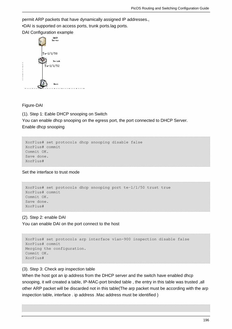
PicOS Routing and Switching Configuration Guide
196
permit ARP packets that have dynamically assigned IP addresses.,
•DAI is supported on access ports, trunk ports.lag ports.
DAI Configuration example
Figure-DAI
(1). Step 1: Eable DHCP snooping on Switch
You can enable dhcp snooping on the egress port, the port connected to DHCP Server.
Enable dhcp snooping
XorPlus# set protocols dhcp snooping disable falseXorPlus# commit Commit OK.Save done.XorPlus#
Set the interface to trust mode
XorPlus# set protocols dhcp snooping port te-1/1/50 trust trueXorPlus# commit Commit OK.Save done.XorPlus#
(2). Step 2: enable DAI
You can enable DAI on the port connect to the host
XorPlus# set protocols arp interface vlan-900 inspection disable falseXorPlus# commit Merging the configuration.Commit OK.XorPlus#
(3). Step 3: Check arp inspection table
When the host got an ip address from the DHCP server and the switch have enabled dhcp
snooping, it will created a table, IP-MAC-port binded table , the entry in this table was trusted ,all
other ARP packet will be discarded not in this table(The arp packet must be according with the arp
inspection table, interface . ip address .Mac address must be identified )

PicOS Routing and Switching Configuration Guide
197
XorPlus# run show arp inspection Total count : 1Interface DAI Address HW Address --------- -------- --------------- -----------------vlan-900 Enabled 192.168.9.5 0:1e:c9:bb:d3:35
Static Routing Configuration
In L2/L3, all routing entries will be configured to the ASIC switching chip if the outgoing
VLAN-interface is link-up, and the outgoing physical port is learning.
Traffic that can be routed will have a route entry in the RIB and the ARP of the next hop; the
outgoing interface should be link-up. The traffic will then be soft-routed (i.e., routed by the switch's
CPU).
When the switch learns the MAC address of the next-hop, the switch will forward the traffic with
the ASIC chip.
Confgure static route
XorPlus# set vlans vlan-id 2XorPlus# set vlans vlan-id 3XorPlus# set interface gigabit-ethernet ge-1/1/1 family ethernet-switchingnative-vlan-id 2XorPlus# set interface gigabit-ethernet ge-1/1/2 family ethernet-switchingnative-vlan-id 3XorPlus# set vlans vlan-id 2 l3-interface vlan-2XorPlus# set vlans vlan-id 3 l3-interface vlan-3XorPlus# commitWaiting for merging configuration.Commit OK.Save done.XorPlus# set vlan-interface interface vlan-2 vif vlan-2 address 192.168.1.1prefix-length 24XorPlus# set vlan-interface interface vlan-3 vif vlan-2 address 192.168.2.1prefix-length 24XorPlus# set protocols static route 10.10.1.0/24 next-hop 192.168.2.5XorPlus# commitWaiting for merging configuration.Commit OK.Save done.XorPlus# run show route table ipv4 unicast final 10.10.1.0/24 [static(1)/1]> to 192.168.2.5 viavlan-3/vlan-3192.168.1.0/24 [connected(0)/0]> via vlan-2/vlan-2192.168.2.0/24 [connected(0)/0]> via vlan-3/vlan-3XorPlus#XorPlus# run show route forward-route ipv4 all Destination NetMask NextHopMac Port --------------- --------------- ----------------- ---------10.10.1.0 255.255.255.0 00:1E:68:37:EF:7D ge-1/1/2192.168.1.0 255.255.255.0 C8:0A:A9:04:49:28 connected192.168.2.0 255.255.255.0 C8:0A:A9:04:49:28 connected

PicOS Routing and Switching Configuration Guide
198
With the command, all the route entries in the ASIC chip will beshow route forward-routeipv4 all
displayed. Following the command, all routes in the RIB of theshow route table ipv4 unicastfinal
kernel will be displayed.
Confgure max-route-limit
Before configuring max-route-limit, check the forward-route table:
XorPlus# run show route forward-route ipv4 allDestination NetMask NextHopMac Port --------------- --------------- ----------------- ---------192.168.1.0 255.255.255.0 04:7D:7B:62:93:FF connected192.168.2.0 255.255.255.0 04:7D:7B:62:93:FF connected192.168.3.0 255.255.255.0 04:7D:7B:62:93:FF connected192.168.20.0 255.255.255.0 04:7D:7B:62:93:FF connected192.168.100.0 255.255.255.0 04:7D:7B:62:93:FF connectedTotal route count:5XorPlus#XorPlus# run show route forward-route ipv6 allDestination NetMask NextHopMac Port --------------------------------------- --------------------------------------- ----------------- ---------5001:: ffff:ffff:ffff:ffff:: 04:7D:7B:62:93:FF connected2001:: ffff:ffff:ffff:ffff:: 04:7D:7B:62:93:FF connected7001:: ffff:ffff:ffff:ffff:: C8:0A:A9:AE:0A:66 te-1/1/3 6001:: ffff:ffff:ffff:ffff:: C8:0A:A9:AE:0A:66 te-1/1/3 Total route count:4XorPlus#
After configuring max-route-limit:
XorPlus# set interface max-route-limit 1 XorPlus# commMerging the configuration.Commit OK.Save done.Maximum of route limit changes, please reboot system to make it effect!XorPlus#
Check the forward-route table:
XorPlus# run show route forward-route ipv4 allDestination NetMask NextHopMac Port --------------- --------------- ----------------- ---------192.168.1.0 255.255.255.0 04:7D:7B:62:93:FF connected192.168.2.0 255.255.255.0 04:7D:7B:62:93:FF connected192.168.3.0 255.255.255.0 04:7D:7B:62:93:FF connected192.168.20.0 255.255.255.0 04:7D:7B:62:93:FF connected192.168.100.0 255.255.255.0 04:7D:7B:62:93:FF connectedTotal route count:5XorPlus#XorPlus# run show route forward-route ipv6 all

PicOS Routing and Switching Configuration Guide
199
Destination NetMask NextHopMac Port --------------------------------------- --------------------------------------- ----------------- ---------5001:: ffff:ffff:ffff:ffff:: 04:7D:7B:62:93:FF connected2001:: ffff:ffff:ffff:ffff:: 04:7D:7B:62:93:FF connectedTotal route count:2XorPlus#
Note: The switch support 12k ipv4 routes most and 6k ipv6 routes most, one ipv6 route is equal to
two ipv4 routes. The directly-connected routes are not excepted to route limit.
Static Routing Configuration Example
An example of configuration with static routing is shown in Fig. 5-1.
Host A and Host B should be able to communicate with each other.
Host A and Host B should be able to communicate with the gateway (e.g., access Internet).
Figure 5-1. Static routing configuration.
Configuring Switch A
For Switch A, you should configure 3 VLAN interfaces for networks 10.10.1.1/24, 10.10.3.1/24, and
10.10.6.1/24. You should also configure a static route to10.10.2.0/24, and a default route.
XorPlus# set vlans vlan-id 2XorPlus# set vlans vlan-id 3XorPlus# set vlans vlan-id 4XorPlus# set interface gigabit-ethernet ge-1/1/1 family ethernet-switchingnative-vlan-id 2XorPlus# set interface gigabit-ethernet ge-1/1/2 family ethernet-switchingnative-vlan-id 3XorPlus# set interface gigabit-ethernet ge-1/1/3 family ethernet-switchingnative-vlan-id 4

PicOS Routing and Switching Configuration Guide
200
XorPlus# set vlans vlan-id 2 l3-interface vlan-2XorPlus# set vlans vlan-id 3 l3-interface vlan-3XorPlus# set vlans vlan-id 4 l3-interface vlan-4XorPlus# commitWaiting for merging configuration.Commit OK.Save done.XorPlus# set vlan-interface interface vlan-2 vif vlan-2 address 10.10.1.1prefix-length 24XorPlus# set vlan-interface interface vlan-3 vif vlan-2 address 10.10.3.1prefix-length 24XorPlus# set vlan-interface interface vlan-4vif vlan-2 address 10.10.6.1prefix-length 24XorPlus# set protocols static route 10.10.2.0/24 next-hop 10.10.6.2XorPlus# set protocols static route 0.0.0.0/0 next-hop 10.10.3.2XorPlus# commitWaiting for merging configuration.Commit OK.Save done.XorPlus#
You can verify the route entry in the RIB as follows:
XorPlus# run show route table ipv4 unicast final0.0.0.0/0 [static(1)/1]> to 10.10.3.2 via vlan-3/vlan-310.10.2.0/24[static(1)/1]> to 10.10.6.2 via vlan-4/vlan-410.10.1.0/24 [connected(0)/0]> via vlan-2/vlan-210.10.3.0/24 [connected(0)/0]> via vlan-3/vlan-310.10.6.0/24 [connected(0)/0]> via vlan-4/vlan-4XorPlus#
Configuring Switch B
Configure 3 VLAN interfaces for networks 10.10.2.1/24, 10.10.4.1/24, and 10.10.6.2/24. Then
configure a static route to 10.10.1.0/24, and a default route.
XorPlus# set vlans vlan-id 2XorPlus# set vlans vlan-id 3XorPlus# set vlans vlan-id 4XorPlus# set interface gigabit-ethernet ge-1/1/1 family ethernet-switchingnative-vlan-id 2XorPlus# set interface gigabit-ethernet ge-1/1/2 family ethernet-switchingnative-vlan-id 3XorPlus# set interface gigabit-ethernet ge-1/1/3 family ethernet-switchingnative-vlan-id 4XorPlus# set vlans vlan-id 2 l3-interface vlan-2XorPlus# set vlans vlan-id 3 l3-interface vlan-3XorPlus# set vlans vlan-id 4 l3-interface vlan-4XorPlus# commitWaiting for merging configuration.Commit OK.Save done.

PicOS Routing and Switching Configuration Guide
201
XorPlus# set vlan-interface interface vlan-2 vif vlan-2 address 10.10.2.1prefix-length 24XorPlus# set vlan-interface interface vlan-3 vif vlan-2 address 10.10.4.1prefix-length 24XorPlus# set vlan-interface interface vlan-4vif vlan-2 address 10.10.6.1prefix-length 24XorPlus# set protocols static route 10.10.1.0/24 next-hop 10.10.6.1XorPlus# set protocols static route 0.0.0.0/0 next-hop 10.10.4.2XorPlus# commitWaiting for merging configuration.Commit OK.Save done.XorPlus#
You can verify the route entry in the RIB:
XorPlus# run show route table ipv4 unicast final0.0.0.0/0 [static(1)/1]> to 10.10.4.2 via vlan-3/vlan-310.10.1.0/24[static(1)/1]> to 10.10.6.1 via vlan-4/vlan-410.10.2.0/24 [connected(0)/0]> via vlan-2/vlan-210.10.4.0/24 [connected(0)/0]> via vlan-3/vlan-310.10.6.0/24 [connected(0)/0]> via vlan-4/vlan-4XorPlus#
Configuring Switch C
Configure 3 VLAN interfaces for networks 10.10.3.2/24, 10.10.4.2/24, and 10.10.5.2/24. Then
configure a static route to 10.10.1.0/24, and a default route.
XorPlus# set vlans vlan-id 2XorPlus# set vlans vlan-id 3XorPlus# set vlans vlan-id 4XorPlus# set interface gigabit-ethernet ge-1/1/1 family ethernet-switchingnative-vlan-id 2XorPlus# set interface gigabit-ethernet ge-1/1/2 family ethernet-switchingnative-vlan-id 3XorPlus# set interface gigabit-ethernet ge-1/1/3 family ethernet-switchingnative-vlan-id 4XorPlus# set vlans vlan-id 2 l3-interface vlan-2XorPlus# set vlans vlan-id 3 l3-interface vlan-3XorPlus# set vlans vlan-id 4 l3-interface vlan-4XorPlus# commitWaiting for merging configuration.Commit OK.Save done.XorPlus# set vlan-interface interface vlan-2vif vlan-2 address 10.10.3.2prefix-length 24XorPlus# set vlan-interface interface vlan-3vif vlan-3 address 10.10.4.2prefix-length 24XorPlus# set vlan-interface interface vlan-4vif vlan-4 address 10.10.5.2prefix-length 24XorPlus# set protocols static route 10.10.1.0/24 next-hop 10.10.3.1

PicOS Routing and Switching Configuration Guide
202
XorPlus# set protocols static route 10.10.2.0/24 next-hop 10.10.4.1XorPlus# set protocols static route 10.10.6.0/24 next-hop 10.10.3.1XorPlus# set protocols static route 0.0.0.0/0 next-hop 10.10.5.1XorPlus# commitWaiting for merging configuration.Commit OK.Save done.XorPlus#
You can verify the route entry in the RIB:
XorPlus# run show route table ipv4 unicast final0.0.0.0/0 [static(1)/1]> to 10.10.5.1 via vlan-4/vlan-410.10.1.0/24[static(1)/1]> to 10.10.3.1 via vlan-2/vlan-210.10.2.0/24[static(1)/1]> to 10.10.4.1 via vlan-3/vlan-310.10.6.0/24[static(1)/1]> to 10.10.3.1 via vlan-2/vlan-210.10.3.0/24 [connected(0)/0]> via vlan-2/vlan-210.10.4.0/24 [connected(0)/0]> via vlan-3/vlan-310.10.5.0/24 [connected(0)/0]> via vlan-4/vlan-4XorPlus#
RIPv2 Routing Protocol Configuration
In L2/L3, RIPv2 is supported.
A policy statement is used to specify which route entry will be distributed. For example, you can
distribute the static route or the connected route to a neighbor. You can also specify the distributed
route metric.
You can configure the RIPv2 interface parameters (accept-default-route, advertise-default-route,
deletion-delay, request-interval, update-interval).
XorPlus# set vlans vlan-id 2XorPlus# set interface gigabit-ethernet ge-1/1/1 family ethernet-switchingnative-vlan-id 2XorPlus# set vlans vlan-id 2 l3-interface vlan-2XorPlus# set vlan-interface interface vlan-2vif vlan-2 address 192.168.1.1prefix-length 24XorPlus# commitWaiting for merging configuration.Commit OK.Save done.XorPlus# set vlans vlan-id 3XorPlus# set vlans vlan-id 3 l3-interface vlan-3XorPlus# set interface gigabit-ethernet ge-1/1/2 family ethernet-switchingnative-vlan-id 3XorPlus# set vlan-interface interface vlan-3vif vlan-3 address 192.168.2.1prefix-length 24XorPlus# set protocols static route 9.9.9.0/24 next-hop 192.168.2.2XorPlus# commitWaiting for merging configuration.

PicOS Routing and Switching Configuration Guide
203
Commit OK.Save done.XorPlus# set policy policy-statement connected-to-rip term export fromprotocol connectedXorPlus# set policy policy-statement connected-to-rip term export then metric0XorPlus# set policy policy-statement static-to-rip term export from protocolstaticXorPlus# set policy policy-statement static-to-rip term export then metric 1XorPlus# commitWaiting for merging configuration.Commit OK.Save done.XorPlus# set protocols rip interface vlan-2vif vlan-2 address 192.168.1.1XorPlus# set protocols rip export "connected-to-rip,static-to-rip"XorPlus# commitWaiting for merging configuration.Commit OK.Save done.XorPlus#
You can verify the RIP configuration:
XorPlus# run show rip status all * RIP on vlan-2vlan-2 192.168.1.1 Status: enabledXorPlus#XorPlus# run show rip statistics all * RIP on vlan-2vlan-2 192.168.1.1 Status: enabled Counter Value -------------------------------- ---------------- Requests Sent 7 Updates Sent 6 Triggered Updates Sent 1 Non-RIP Updates Sent 0 Total Packets Received 0 Request Packets Received 0 Update Packets Received 0 Bad Packets Received 0 Authentication Failures 0 Bad Routes Received 0 Non-RIP Requests Received 0
RIPv2 Routing Configuration Example
An example of configuring RIPv2 is shown in Fig. 5-2.
Host A and Host B should be able to communicate with each other with an RIP route.
Host A and Host B should be able to communicate with the gateway (e.g., access Internet) with
RIP.

PicOS Routing and Switching Configuration Guide
204
Figure 5-2. RIPv2 routing configuration.
Configuring Switch A
For Switch A, configure 2 VLAN interfaces for networks 10.10.1.1/24 and 10.10.3.1/24. You should
also configure an RIP interface in network 10.10.3.1/24. Switch A should accept the default route,
which is advertised by Switch C.
XorPlus# set vlans vlan-id 2XorPlus# set vlans vlan-id 3XorPlus# set interface gigabit-ethernet ge-1/1/1 family ethernet-switchingnative-vlan-id 2XorPlus# set interface gigabit-ethernet ge-1/1/2 family ethernet-switchingnative-vlan-id 3XorPlus# set vlans vlan-id 2 l3-interface vlan-2XorPlus# set vlans vlan-id 3 l3-interface vlan-3XorPlus# set vlan-interface interface vlan-2vif vlan-2 address 10.10.1.1prefix-length 24XorPlus# set vlan-interface interface vlan-3vif vlan-3 address 10.10.3.1prefix-length 24XorPlus# commitWaiting for merging configuration.Commit OK.Save done.XorPlus# set policy policy-statement connected-to-rip term export fromprotocol connectedXorPlus# set policy policy-statement connected-to-rip term export then metric0XorPlus# commitWaiting for merging configuration.Commit OK.Save done.XorPlus# set protocols rip interface vlan-3 address 10.10.3.1XorPlus# set protocols rip export "connected-to-rip"XorPlus# set protocols rip interface vlan-3vif vlan-3 address 10.10.3.1accept-default-route trueXorPlus# commitWaiting for merging configuration.Commit OK.Save done.XorPlus#

PicOS Routing and Switching Configuration Guide
205
Configuring Switch B
Configure 2 VLAN interfaces for networks 10.10.1.1/24 and 10.10.3.1/24. Then configure an RIP
interface in network 10.10.3.1/24. Switch B should accept the default route, which is advertised by
Switch C.
XorPlus# set vlans vlan-id 2XorPlus# set vlans vlan-id 3XorPlus# set interface gigabit-ethernet ge-1/1/1 family ethernet-switchingnative-vlan-id 2XorPlus# set interface gigabit-ethernet ge-1/1/2 family ethernet-switchingnative-vlan-id 3XorPlus# set vlans vlan-id 2 l3-interface vlan-2XorPlus# set vlans vlan-id 3 l3-interface vlan-3XorPlus# set vlan-interface interface vlan-2vif vlan-2 address 10.10.2.1prefix-length 24XorPlus# set vlan-interface interface vlan-3vif vlan-2 address 10.10.4.1prefix-length 24XorPlus# commitWaiting for merging configuration.Commit OK.Save done.XorPlus# set policy policy-statement connected-to-rip term export fromprotocol connectedXorPlus# set policy policy-statement connected-to-rip term export then metric0XorPlus# commitWaiting for merging configuration.Commit OK.Save done.XorPlus# set protocols rip interface vlan-3vif vlan-3 address 10.10.4.1XorPlus# set protocols rip export "connected-to-rip"XorPlus# set protocols rip interface vlan-3vif vlan-3 address 10.10.4.1accept-default-route trueXorPlus# commitWaiting for merging configuration.Commit OK.Save done.XorPlus#
Configuring Switch C
Configure 3 VLAN interfaces for networks 10.10.3.2/24, 10.10.4.2/24, and 10.10.5.2/24. You
should also configure a default route and 2 RIP interfaces.
XorPlus# set vlans vlan-id 2XorPlus# set vlans vlan-id 3XorPlus# set vlans vlan-id 4XorPlus# set interface gigabit-ethernet ge-1/1/1 family ethernet-switchingnative-vlan-id 2XorPlus# set interface gigabit-ethernet ge-1/1/2 family ethernet-switchingnative-vlan-id 3XorPlus# set interface gigabit-ethernet ge-1/1/3 family ethernet-switchingnative-vlan-id 4

PicOS Routing and Switching Configuration Guide
206
XorPlus# set vlans vlan-id 2 l3-interface vlan-2XorPlus# set vlans vlan-id 3 l3-interface vlan-3XorPlus# set vlans vlan-id 4 l3-interface vlan-4XorPlus# commitWaiting for merging configuration.Commit OK.Save done.XorPlus# set vlan-interface interface vlan-2vif vlan-2 address 10.10.3.2prefix-length 24XorPlus# set vlan-interface interface vlan-3vif vlan-3 address 10.10.4.2prefix-length 24XorPlus# set vlan-interface interface vlan-4vif vlan-4 address 10.10.5.2prefix-length 24XorPlus# set protocols static route 0.0.0.0/0 next-hop 10.10.5.1XorPlus# set protocols rip interface vlan-2vif vlan-2 address 10.10.3.2XorPlus# set protocols rip interface vlan-2vif vlan-2 address 10.10.3.2advertise-default-route trueXorPlus# set protocols rip interface vlan-3vif vlan-3 address 10.10.4.2XorPlus# set protocols rip interface vlan-3vif vlan-3 address 10.10.4.2advertise-default-route trueXorPlus# set protocols rip export "connected-to-rip"XorPlus# commitWaiting for merging configuration.Commit OK.Save done.XorPlus#
Verifying the RIP Configuration
You can verify the RIP configuration of the switches as shown below. (In our example, we verify
the RIP peer and the RIP route table in Switch A.)
XorPlus# run show rip peer Address Interface State Hello Rx Hello Tx Last Hello--------------- --------------- ------ ---------- ---------- ----------10.10.3.2vlan-3/vlan-3 Up 0 0 00:41:44 XorPlus#XorPlus# run show route table ipv4 unicast rip 0.0.0.0/0[rip(120)/1]> to 10.10.3.2 via vlan-3/vlan-310.10.2.0/24 [rip(120)/1]> to 10.10.3.2 via vlan-3/vlan-310.10.4.0/24 [rip(120)/1]> to 10.10.3.2 via vlan-3/vlan-3
OSPF Routing Protocol Configuration
In L2/L3, OSPFv2 is supported.
XorPlus supports normal areas, stub areas, and not-so-stubby areas (NSSAs) in OSPF.
Configuring the router ID

PicOS Routing and Switching Configuration Guide
207
The router ID should be configured first when you configure OSPF.
The router ID is a string similar to the IP address, and should be unique in the OSPF domain. You
should not change the router ID after completing the configuration.
XorPlus# set protocols ospf4 router-id 1.1.1.1XorPlus# commitWaiting for merging configuration.Commit OK.Save done
.
Configuring an OSPF area and area-type
Area 0.0.0.0 is the backbone area of OSPF; each OSPF domain should have the area 0.0.0.0.
Area types include normal, stub, and NSSA.
XorPlus# set protocols ospf4 area 0.0.0.0 area-type normalXorPlus# set protocols ospf4 area 1.1.1.1 area-type stubXorPlus# set protocols ospf4 area 2.2.2.2 area-type nssaXorPlus# commitWaiting for merging configuration.Commit OK.Save done.XorPlus#
Configuring OSPF interfaces
After configuring an OSPF area, configure OSPF interfaces in the area. These interfaces will
transmit and receive LSAs to calculate the route.
XorPlus# set vlans vlan-id 2 l3-interface vlan-2XorPlus# set vlans vlan-id 3 l3-interface vlan-3XorPlus# set vlan-interface interface vlan-2 vif vlan-2 address 10.10.60.10prefix-length 24XorPlus# set vlan-interface interface vlan-3 vif vlan-3 address 10.10.61.10prefix-length 24XorPlus# set interface gigabit-ethernet ge-1/1/1 family ethernet-switchingnative-vlan-id 2XorPlus# set interface gigabit-ethernet ge-1/1/2 family ethernet-switchingnative-vlan-id 3XorPlus# set protocols ospf4 area 0.0.0.0 interface vlan-2 vif vlan-2 address10.10.60.10XorPlus# set protocols ospf4 area 0.0.0.0 interface vlan-3 vif vlan-3 address10.10.61.10XorPlus# set protocols ospf4 router-id 1.1.1.1XorPlus# commitWaiting for merging configuration.Commit OK.Save done.XorPlus#XorPlus# run show ospf4 interface Interface State Area DR ID BDR ID Nbrs--------- -------- --------------- --------------- --------------- ----

PicOS Routing and Switching Configuration Guide
208
vlan-2 DR 0.0.0.0 1.1.1.1 0.0.0.0 0 vlan-3 DR 0.0.0.0 1.1.1.1 0.0.0.0 0
Configuring additional OSPF interface parameters
You can also configure additional OSPF interface parameters (hello interval, interface-cost, static
neighbor, priority, retransmit-interval, router-dead-interval, transmit-delay).
XorPlus# set protocols ospf4 area 0.0.0.0 interface vlan-2 vif vlan-2 address10.10.60.10 hello-interval 5XorPlus# set protocols ospf4 area 0.0.0.0 interface vlan-2 vif vlan-2 address10.10.60.10 interface-cost 8XorPlus# set protocols ospf4 area 0.0.0.0 interface vlan-2 vif vlan-2 address10.10.60.10 transmit-delay 2XorPlus# commitWaiting for merging configuration.Commit OK.Save done.XorPlus#XorPlus# run show ospf4 interface detail Interface vlan-2/vlan-2, State DR, Area 0.0.0.0DR ID 1.1.1.1, BDR ID 0.0.0.0, Nbrs 0Network Type BROADCAST, Address 10.10.60.10, Mask 255.255.255.0, Cost 8DR addr 10.10.60.10, BDR addr 0.0.0.0, Priority 128Hello 10, Dead 40, ReXmit 5, NORMAL
OSPF Routing Basic Configuration Example
Fig.5-3 presents an example of configuring OSPF routing. Switch A and Switch B are located in
the backbone area, 0.0.0.0. There are two non-backbone areas, 1.1.1.1 and 2.2.2.2.
Switch D will obtain the routes of networks 10.10.1.0/24, 10.10.3.0/24, and 10.10.9.0/24,through
the
LSAs sent from its neighbors. Switch C will obtain the routes of networks 10.10.1.0/24,
10.10.2.0/24, and 10.10.8.0/24, according to LSAs sent from its neighbors.
Figure 5-3. OSPF basic routing configuration.

PicOS Routing and Switching Configuration Guide
209
Configuring Switch A
For switch A, configure 2 VLAN interfaces for networks 10.10.1.1/24 and 10.10.2.1/24. You should
also configure area 0.0.0.0, which includes network 10.10.1.1/24, and area 0.0.0.1, which includes
network 10.10.2.1/24.
XorPlus# set vlans vlan-id 2XorPlus# set vlans vlan-id 3XorPlus# set interface gigabit-ethernet ge-1/1/1 family ethernet-switchingnative-vlan-id 2XorPlus# set interface gigabit-ethernet ge-1/1/2 family ethernet-switchingnative-vlan-id 3XorPlus# set vlans vlan-id 2 l3-interface vlan-2XorPlus# set vlans vlan-id 3 l3-interface vlan-3XorPlus# set vlan-interface interface vlan-2vif vlan-2 address 10.10.1.1prefix-length 24XorPlus# set vlan-interface interface vlan-3vif vlan-3 address 10.10.2.1prefix-length 24XorPlus# commitWaiting for merging configuration.Commit OK.Save done.XorPlus# set protocols ospf4 router-id 1.1.1.1XorPlus# set protocols ospf4 area 0.0.0.0 interface vlan-2vif vlan-2 address10.10.1.1XorPlus# set protocols ospf4 area 0.0.0.1 interface vlan-3vif vlan-3 address10.10.2.1XorPlus# commitWaiting for merging configuration.Commit OK.Save done.XorPlus#
Configuring Switch B
Configure 2 VLAN interfaces for networks 10.10.1.2/24 and 10.10.3.1/24. Then configure area
0.0.0.0, which includes network 10.10.1.2/24, and area 0.0.0.3, which includes network
10.10.3.1/24.
XorPlus# set vlans vlan-id 2XorPlus# set vlans vlan-id 3XorPlus# set interface gigabit-ethernet ge-1/1/1 family ethernet-switchingnative-vlan-id 2XorPlus# set interface gigabit-ethernet ge-1/1/2 family ethernet-switchingnative-vlan-id 3XorPlus# set vlans vlan-id 2 l3-interface vlan-2XorPlus# set vlans vlan-id 3 l3-interface vlan-3XorPlus# set vlan-interface interface vlan-2vif vlan-2 address 10.10.1.2prefix-length 24XorPlus# set vlan-interface interface vlan-3vif vlan-3 address 10.10.3.1prefix-length 24XorPlus# commitWaiting for merging configuration.Commit OK.Save done.
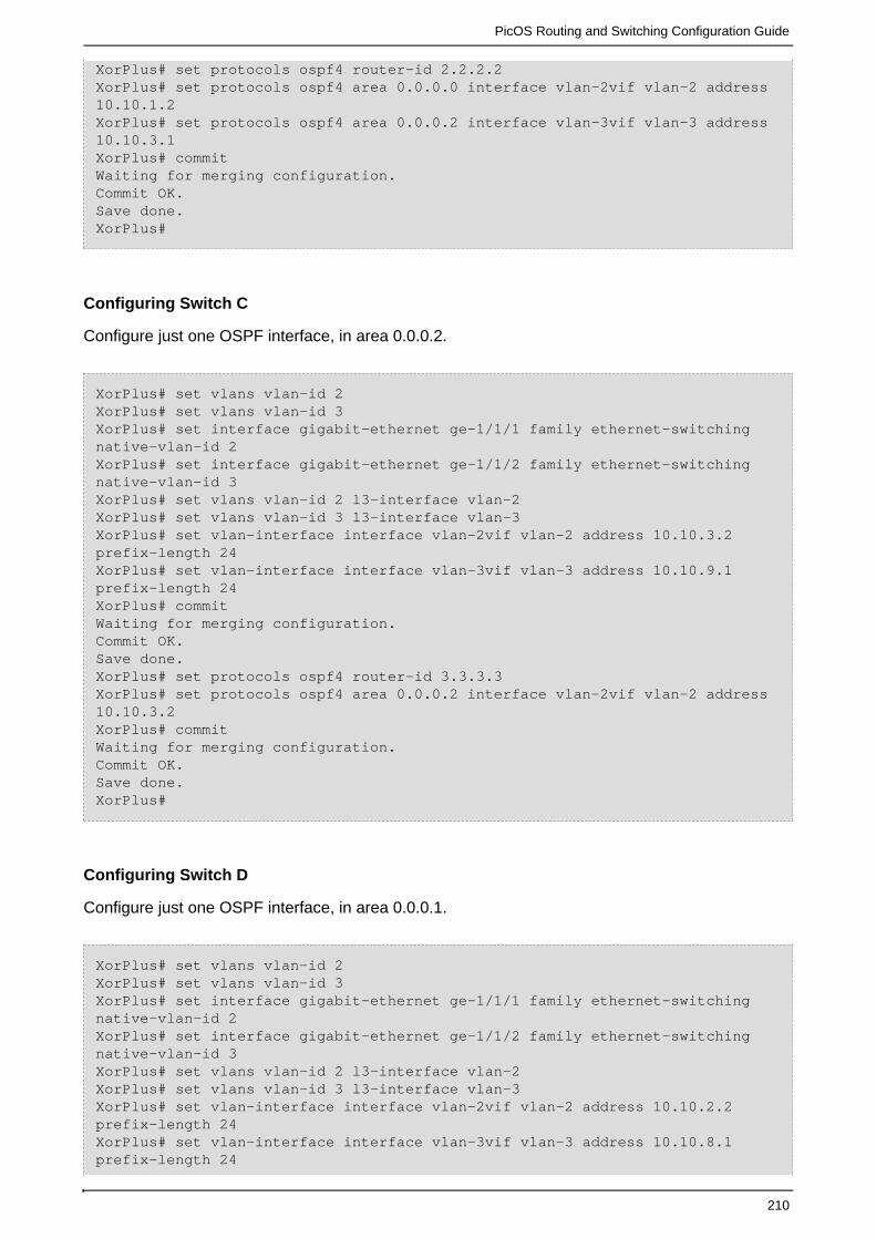
PicOS Routing and Switching Configuration Guide
210
XorPlus# set protocols ospf4 router-id 2.2.2.2XorPlus# set protocols ospf4 area 0.0.0.0 interface vlan-2vif vlan-2 address10.10.1.2XorPlus# set protocols ospf4 area 0.0.0.2 interface vlan-3vif vlan-3 address10.10.3.1XorPlus# commitWaiting for merging configuration.Commit OK.Save done.XorPlus#
Configuring Switch C
Configure just one OSPF interface, in area 0.0.0.2.
XorPlus# set vlans vlan-id 2XorPlus# set vlans vlan-id 3XorPlus# set interface gigabit-ethernet ge-1/1/1 family ethernet-switchingnative-vlan-id 2XorPlus# set interface gigabit-ethernet ge-1/1/2 family ethernet-switchingnative-vlan-id 3XorPlus# set vlans vlan-id 2 l3-interface vlan-2XorPlus# set vlans vlan-id 3 l3-interface vlan-3XorPlus# set vlan-interface interface vlan-2vif vlan-2 address 10.10.3.2prefix-length 24XorPlus# set vlan-interface interface vlan-3vif vlan-3 address 10.10.9.1prefix-length 24XorPlus# commitWaiting for merging configuration.Commit OK.Save done.XorPlus# set protocols ospf4 router-id 3.3.3.3XorPlus# set protocols ospf4 area 0.0.0.2 interface vlan-2vif vlan-2 address10.10.3.2XorPlus# commitWaiting for merging configuration.Commit OK.Save done.XorPlus#
Configuring Switch D
Configure just one OSPF interface, in area 0.0.0.1.
XorPlus# set vlans vlan-id 2XorPlus# set vlans vlan-id 3XorPlus# set interface gigabit-ethernet ge-1/1/1 family ethernet-switchingnative-vlan-id 2XorPlus# set interface gigabit-ethernet ge-1/1/2 family ethernet-switchingnative-vlan-id 3XorPlus# set vlans vlan-id 2 l3-interface vlan-2XorPlus# set vlans vlan-id 3 l3-interface vlan-3XorPlus# set vlan-interface interface vlan-2vif vlan-2 address 10.10.2.2prefix-length 24XorPlus# set vlan-interface interface vlan-3vif vlan-3 address 10.10.8.1prefix-length 24

PicOS Routing and Switching Configuration Guide
211
XorPlus# commitWaiting for merging configuration.Commit OK.Save done.XorPlus# set protocols ospf4 router-id 4.4.4.4XorPlus# set protocols ospf4 area 0.0.0.1 interface vlan-2vif vlan-2 address10.10.2.2XorPlus# commitWaiting for merging configuration.Commit OK.Save done.XorPlus#
Verifying the OSPF configuration
You can verify the OSPF configuration of a switch by checking its OSPF neighbor.
Below, switch A has two OSPF neighbor interfaces, 10.10.1.2 and 10.10.2.2.
XorPlus# run show ospf4 neighbor Address Interface State Router ID Pri Dead--------------- --------------------- -------- --------------- ----- ----10.10.1.2vlan-2/vlan-2 Full 2.2.2.2 1 32 10.10.2.2vlan-3/vlan-3 Full 4.4.4.4 1 32 Then check the OSPF database as shown below: XorPlus# run show ospf4 database OSPF link state database, Area 0.0.0.0Type ID Adv Rtr Seq Age Opt Cksum Len------- ---------------- --------------- ---------- ---- — ------ —Router *1.1.1.1 1.1.1.1 0x8000025a 394 0x2 0xf2bb 48 Network *10.10.1.1 1.1.1.1 0x80000180 394 0x2 0xc0b9 32 Network *10.10.2.1 1.1.1.1 0x80000180 394 0x2 0xc0b9 32Router 2.2.2.2 2.2.2.2 0x8000023e 339 0x2 0x3024 36 Network 10.10.3.1 2.2.2.2 0x80000180 394 0x2 0xc0b9 32Router 3.3.3.33.3.3.3 0x8000023e 339 0x2 0x3024 36Network 10.10.9.1 3.3.3.3 0x80000180 394 0x2 0xc0b9 32Router 4.4.4.44.4.4.4 0x8000023e 339 0x2 0x3024 36Network 10.10.8.1 4.4.4.4 0x80000180 394 0x2 0xc0b9 32 OSPF link state database, Area 0.0.0.2Type ID Adv Rtr Seq Age Opt Cksum Len------- ---------------- --------------- ---------- ---- — ------ —Router *1.1.1.1 1.1.1.1 0x8000025a 394 0x2 0xf2bb 48 Network *10.10.1.1 1.1.1.1 0x80000180 394 0x2 0xc0b9 32 Network *10.10.2.1 1.1.1.1 0x80000180 394 0x2 0xc0b9 32Router 2.2.2.2 2.2.2.2 0x8000023e 339 0x2 0x3024 36 Network 10.10.3.1 2.2.2.2 0x80000180 394 0x2 0xc0b9 32Router 3.3.3.33.3.3.3 0x8000023e 339 0x2 0x3024 36 Network 10.10.9.1 3.3.3.3 0x80000180 394 0x2 0xc0b9 32Router 4.4.4.44.4.4.4 0x8000023e 339 0x2 0x3024 36Network 10.10.8.1 4.4.4.4 0x80000180 394 0x2 0xc0b9 32 Finally, you can check the OSPF route in the RIB of switch A. XorPlus#XorPlus# run show route table ipv4 unicast osfp 10.10.3.0/24 [ospf(110)/2]> to 10.10.1.2 via vlan-2/vlan-2

PicOS Routing and Switching Configuration Guide
212
OSPF Configuration Example_ NSSA_Stub_Normal
The configurations of an OSPF NSSA and a stub area are shown in Fig. 5-4.
Switch D will obtain the routes of networks 10.10.1.0/24, 10.10.3.0/24, and 10.10.9.0/24,
according to the
LSAs received from its neighbors. Switch C will obtain the routes of networks 10.10.1.0/24,
10.10.2.0/24, and10.10.8.0/24, according to the LSAs received from its neighbors.
The figure below does not include RIP or BGP configurations.
Figure 5-4. OSPF NSSA, stub area configurations.
Configuring Switch A
For switch A, configure 2 VLAN interfaces for networks 10.10.1.1/24 and 10.10.2.1/24. You should
also configure area 0.0.0.0, which includes network 10.10.1.1/24,and area 0.0.0.1, which includes
network 10.10.2.1/24.
XorPlus# set vlans vlan-id 2XorPlus# set vlans vlan-id 3XorPlus# set interface gigabit-ethernet ge-1/1/1 family ethernet-switchingnative-vlan-id 2XorPlus# set interface gigabit-ethernet ge-1/1/2 family ethernet-switchingnative-vlan-id 3XorPlus# set vlans vlan-id 2 l3-interface vlan-2XorPlus# set vlans vlan-id 3 l3-interface vlan-3XorPlus# set vlan-interface interface vlan-2vif vlan-2 address 10.10.1.1prefix-length 24XorPlus# set vlan-interface interface vlan-3vif vlan-3 address 10.10.2.1prefix-length 24XorPlus# commitWaiting for merging configuration.Commit OK.Save done.XorPlus# set protocols ospf4 router-id 1.1.1.1XorPlus# set protocols ospf4 area 0.0.0.0 interface vlan-2vif vlan-2 address10.10.1.1

PicOS Routing and Switching Configuration Guide
213
XorPlus# set protocols ospf4 area 0.0.0.1 interface vlan-3vif vlan-3 address10.10.2.1XorPlus# set protocols ospf4 area 0.0.0.1 area-type nssaXorPlus# commitWaiting for merging configuration.Commit OK.Save done.XorPlus#
Configuring Switch B
Configure 2 VLAN interfaces for networks 10.10.1.2/24 and 10.10.3.1/24. Then configure area
0.0.0.0, which includes network 10.10.1.2/24, and stub area 0.0.0.3, which includes network
10.10.3.1/24.
XorPlus# set vlans vlan-id 2XorPlus# set vlans vlan-id 3XorPlus# set interface gigabit-ethernet ge-1/1/1 family ethernet-switchingnative-vlan-id 2XorPlus# set interface gigabit-ethernet ge-1/1/2 family ethernet-switchingnative-vlan-id 3XorPlus# set vlans vlan-id 2 l3-interface vlan-2XorPlus# set vlans vlan-id 3 l3-interface vlan-3XorPlus# set vlan-interface interface vlan-2vif vlan-2 address 10.10.1.2prefix-length 24XorPlus# set vlan-interface interface vlan-3vif vlan-3 address 10.10.3.1prefix-length 24XorPlus# commitWaiting for merging configuration.Commit OK.Save done.XorPlus# set protocols ospf4 router-id 2.2.2.2XorPlus# set protocols ospf4 area 0.0.0.0 interface vlan-2vif vlan-2 address10.10.1.2XorPlus# set protocols ospf4 area 0.0.0.2 interface vlan-3vif vlan-3 address10.10.3.1XorPlus# set protocols ospf4 area 0.0.0.2area-type stubXorPlus# commitWaiting for merging configuration.Commit OK.Save done.XorPlus#
Configuring Switch C
Configure just one OSPF interface, in area 0.0.0.2.
XorPlus# set vlans vlan-id 2XorPlus# set vlans vlan-id 3XorPlus# set interface gigabit-ethernet ge-1/1/1 family ethernet-switchingnative-vlan-id 2XorPlus# set interface gigabit-ethernet ge-1/1/2 family ethernet-switchingnative-vlan-id 3XorPlus# set vlans vlan-id 2 l3-interface vlan-2XorPlus# set vlans vlan-id 3 l3-interface vlan-3

PicOS Routing and Switching Configuration Guide
214
XorPlus# set vlan-interface interface vlan-2vif vlan-2 address 10.10.3.2prefix-length 24XorPlus# set vlan-interface interface vlan-3vif vlan-3 address 10.10.9.1prefix-length 24XorPlus# commitWaiting for merging configuration.Commit OK.Save done.XorPlus# set protocols ospf4 router-id 3.3.3.3XorPlus# set protocols ospf4 area 0.0.0.2 interface vlan-2vif vlan-2 address10.10.3.2XorPlus# set protocols ospf4 area 0.0.0.2area-type stubXorPlus# commitWaiting for merging configuration.Commit OK.Save done.XorPlus#
Configuring Switch D
Configure just one OSPF interface, in area 0.0.0.1. Switch D should import the RIP or BGP route
from the RIB, and distribute it to other areas.
XorPlus# set vlans vlan-id 2XorPlus# set vlans vlan-id 3XorPlus# set interface gigabit-ethernet ge-1/1/1 family ethernet-switchingnative-vlan-id 2XorPlus# set interface gigabit-ethernet ge-1/1/2 family ethernet-switchingnative-vlan-id 3XorPlus# set vlans vlan-id 2 l3-interface vlan-2XorPlus# set vlans vlan-id 3 l3-interface vlan-3XorPlus# set vlan-interface interface vlan-2vif vlan-2 address 10.10.2.2prefix-length 24XorPlus# set vlan-interface interface vlan-3vif vlan-3 address 10.10.8.1prefix-length 24XorPlus# commitWaiting for merging configuration.Commit OK.Save done.XorPlus# set policy policy-statement rip-ospf term rip from protocol ripXorPlus# set policy policy-statement rip-ospf term rip then external-type 2XorPlus# commitWaiting for merging configuration.Commit OK.Save done.XorPlus# set protocols ospf4 router-id 4.4.4.4XorPlus# set protocols ospf4 area 0.0.0.1 interface vlan-2vif vlan-2 address10.10.2.2XorPlus# set protocols ospf4 area 0.0.0.1 area-type nssaXorPlus# set protocols ospf4 export rip-ospfXorPlus# commitWaiting for merging configuration.Commit OK.Save done.XorPlus#

PicOS Routing and Switching Configuration Guide
215
OSPF Stub Area_NSSA Summary
By default external routes and inter-area routes will be injected into stub areas or NSSAs. You can
utilize the parameter to prevent external orinter-area routes from beingsummaries disable true
injected into stub areas or NSSAs. You can also use set protocols ospf4 area <area-id>
to create a default route entry.default-lsa disable false
Figure 5-5. OSPF Stub area/NSSA summary: area 1.1.1.1 should be a stub area or an NSSA
Configuring Switch A
XorPlus# set vlans vlan-id 500 l3-interface vlan-500 XorPlus# set vlan-interface interface vlan-500 vif vlan-500 address192.168.1.2 prefix-length 30XorPlus# set interface gigabit-ethernet te-1/1/49 family ethernet-switchingnative-vlan-id 500XorPlus# set protocols ospf4 router-id 1.1.1.1XorPlus# set protocols ospf4 area 0.0.0.0 interface vlan-500 vif vlan-500address 192.168.1.2XorPlus# commitWaiting for merging configuration.Commit OK.Save Done.XorPlus#
OSPF Virtual Link Configuration Guide
The single backbone area (area 0.0.0.0) cannot be disconnected, or certain areas of the
Autonomous System will become unreachable. To establish and maintain connectivity of the
backbone, virtual links can be configured through non-backbone areas. Virtual links serve to
connect physically separate components of the backbone.
The two endpoints of a virtual link are Area Border Routers (ARBs). The virtual link must be
configured in both routers. The configuration information in each router consists of the other virtual
endpoint (the other ARB), and the non-backbone area that the two routers have in common (called
the transit area). Virtual links cannot be configured through stub areas.
Enable OSPF on Switch A, B, C, and D at the beginning. There is no route entry from the
backbone area (0.0.0.0) to area 2.2.2.2.
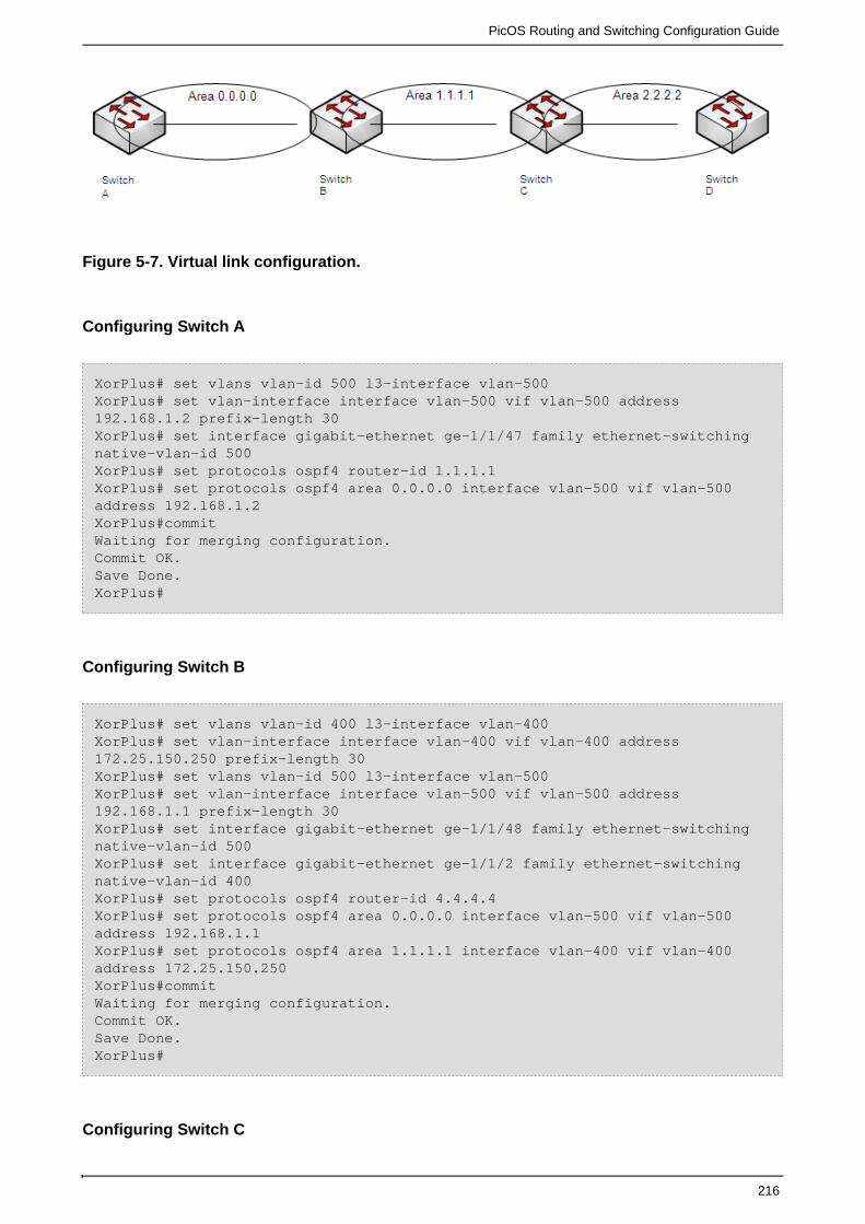
PicOS Routing and Switching Configuration Guide
216
Figure 5-7. Virtual link configuration.
Configuring Switch A
XorPlus# set vlans vlan-id 500 l3-interface vlan-500 XorPlus# set vlan-interface interface vlan-500 vif vlan-500 address192.168.1.2 prefix-length 30XorPlus# set interface gigabit-ethernet ge-1/1/47 family ethernet-switchingnative-vlan-id 500 XorPlus# set protocols ospf4 router-id 1.1.1.1 XorPlus# set protocols ospf4 area 0.0.0.0 interface vlan-500 vif vlan-500address 192.168.1.2 XorPlus#commitWaiting for merging configuration.Commit OK.Save Done.XorPlus#
Configuring Switch B
XorPlus# set vlans vlan-id 400 l3-interface vlan-400 XorPlus# set vlan-interface interface vlan-400 vif vlan-400 address172.25.150.250 prefix-length 30XorPlus# set vlans vlan-id 500 l3-interface vlan-500 XorPlus# set vlan-interface interface vlan-500 vif vlan-500 address192.168.1.1 prefix-length 30XorPlus# set interface gigabit-ethernet ge-1/1/48 family ethernet-switchingnative-vlan-id 500 XorPlus# set interface gigabit-ethernet ge-1/1/2 family ethernet-switchingnative-vlan-id 400XorPlus# set protocols ospf4 router-id 4.4.4.4XorPlus# set protocols ospf4 area 0.0.0.0 interface vlan-500 vif vlan-500address 192.168.1.1XorPlus# set protocols ospf4 area 1.1.1.1 interface vlan-400 vif vlan-400address 172.25.150.250XorPlus#commitWaiting for merging configuration.Commit OK.Save Done.XorPlus#
Configuring Switch C

PicOS Routing and Switching Configuration Guide
217
XorPlus# set vlans vlan-id 300 l3-interface vlan-300 XorPlus# set vlan-interface interface vlan-300 vif vlan-300 address172.25.150.246 prefix-length 30XorPlus# set vlans vlan-id 400 l3-interface vlan-400 XorPlus# set vlan-interface interface vlan-400 vif vlan-400 address172.25.150.249 prefix-length 30XorPlus# set interface gigabit-ethernet te-1/1/49 family ethernet-switchingnative-vlan-id 300 XorPlus# set interface gigabit-ethernet te-1/1/51 family ethernet-switchingnative-vlan-id 400 XorPlus# set protocols ospf4 router-id 3.3.3.3XorPlus# set protocols ospf4 area 2.2.2.2 interface vlan-300 vif vlan-300address 172.25.150.246 XorPlus# set protocols ospf4 area 1.1.1.1 interface vlan-400 vif vlan-400address 172.25.150.249XorPlus#commitWaiting for merging configuration.Commit OK.Save Done.XorPlus#
Configuring Switch D
XorPlus# set vlans vlan-id 300 l3-interface vlan-300 XorPlus# set vlan-interface interface vlan-300 vif vlan-300 address172.25.150.245 prefix-length 30XorPlus# set interface gigabit-ethernet te-1/1/49 family ethernet-switchingnative-vlan-id 300XorPlus# set protocols ospf4 router-id 2.2.2.2XorPlus# set protocols ospf4 area 2.2.2.2 interface vlan-300 vif vlan-300address 172.25.150.245XorPlus#commitWaiting for merging configuration.Commit OK.Save Done.XorPlus#
Enable virtual links on the Area Border Routers (Switch B and Switch C). After this step, there will
be a route entry from the backbone area, 0.0.0.0, to area 2.2.2.2.
Configuring Switch B
XorPlus# set protocols ospf6 area 0.0.0.0 virtual-link 3.3.3.3 transmit-area1.1.1.1XorPlus#commitWaiting for merging configuration.Commit OK.Save Done.XorPlus#
Configuring Switch C

PicOS Routing and Switching Configuration Guide
218
XorPlus# set protocols ospf6 area 0.0.0.0 virtual-link 4.4.4.4 transmit-area1.1.1.1XorPlus#commitWaiting for merging configuration.Commit OK.Save Done.XorPlus#
Checking an IPv6 OSPF
Check ipv6 ospf neighbor on Switch B
XorPlus# run show ospf4 neighbor Address Interface State Router ID Pri Dead--------------------- -------- --------------- ----- ----192.168.1.2 vlan-500/vlan-500 Full 1.1.1.1 128 34 172.25.150.249 vlan-400/vlan-400 Full 3.3.3.3 128 36 172.25.150.249 vlink/3.3.3.3 Init 3.3.3.3 0 0
Configuring Switch B
XorPlus# set vlans vlan-id 500 l3-interface vlan-500XorPlus# set vlan-interface interface vlan-500 vif vlan-500 address192.168.1.1 prefix-length 30XorPlus# set interface gigabit-ethernet te-1/1/49 family ethernet-switchingnative-vlan-id 500XorPlus# set protocols ospf4 router-id 4.4.4.4XorPlus# set protocols ospf4 area 0.0.0.0 interface vlan-100 vif vlan-500address 192.168.1.1XorPlus# set vlans vlan-id 400 l3-interface vlan-400XorPlus# set vlan-interface interface vlan-400 vif vlan-400 address172.25.150.250 prefix-length 30XorPlus# set interface gigabit-ethernet te-1/1/49 family ethernet-switchingnative-vlan-id 400XorPlus# set protocols ospf4 area 0.0.0.0 interface vlan-400 vif vlan-400address 172.25.150.250XorPlus#commitWaiting for merging configuration.Commit OK.Save Done.XorPlus#
Configuring Switch C
XorPlus# set vlans vlan-id 400 l3-interface vlan-400XorPlus# set vlan-interface interface vlan-400 vif vlan-400 address172.25.150.249 prefix-length 30XorPlus# set interface gigabit-ethernet te-1/1/49 family ethernet-switchingnative-vlan-id 400XorPlus# set protocols ospf4 router-id 3.3.3.3XorPlus# set protocols ospf4 area 0.0.0.0 interface vlan-400 vif vlan-400address 172.25.150.249

PicOS Routing and Switching Configuration Guide
219
XorPlus#commitWaiting for merging configuration.Commit OK.Save Done.XorPlus#
Configuring area 1.1.1.1 as a stub area or NSSA
XorPlus# set protocols ospf4 area 1.1.1.1 area-type <normal | stub | nssa>XorPlus# commitWaiting for merging configuration.Commit OK.Save done.XorPlus#
Check route table on DUT3,there will be route entry to backbone area 192.168.1.0/30
XorPlus# run show route forward-route ipv4 all Destination NetMask NextHopMac Port--------------- ----------------- ---------172.25.150.248 255.255.255.252 08:9E:01:62:D5:61 connected192.168.1.0 255.255.255. 252 60:EB:69:9B:BE:31 te-1/1/51Total route count:2
Disabling the summary function on ABR(DUT2 area 1.1.1.1)
XorPlus# set protocols ospf4 area 1.1.1.1 summaries disable trueXorPlus# commitWaiting for merging configuration.Commit OK.Save done.XorPlus#
Check route table on DUT3,the route entry to backone area was lost
XorPlus# run show route forward-route ipv4 all Destination NetMask NextHopMac Port--------------- ----------------- ---------172.25.150.248 255.255.255.252 08:9E:01:62:D5:61 connectedTotal route count:1
Enabel default-lsa function on ABR(DUT2)
XorPlus# run show route forward-route ipv4 all Destination NetMask NextHopMac Port--------------- ----------------- ---------172.25.150.248 255.255.255.252 08:9E:01:62:D5:61 connected0.0.0.0 0.0.0.0 60:EB:69:9B:BE:31 te-1/1/51Total route count:2

PicOS Routing and Switching Configuration Guide
220
OSPF Area Range Configuration Guide
OSPF should aggregate the route entries from the backbone area into a non-backbone area, or
from a non-backbone area into the backbone area. Route aggregation works only on the ABR.
You can use the "advertise disable" parameter to restrain ABR route aggregation. The ABR will
generate route aggregation by default after you configure , and the packet is routed toarea-range
the best (the longest or most specific) match.
Figure 5-6. OSPF area range configuration.
Configuring Switch A
XorPlus# set vlans vlan-id 500 l3-interface vlan-500 XorPlus# set vlan-interface interface vlan-500 vif vlan-500 address192.168.1.2 prefix-length 30XorPlus# set interface gigabit-ethernet te-1/1/49 family ethernet-switchingnative-vlan-id 500XorPlus# set protocols ospf4 router-id 1.1.1.1XorPlus# set protocols ospf4 area 0.0.0.0 interface vlan-500 vif vlan-500address 192.168.1.2XorPlus#commitWaiting for merging configuration.Commit OK.Save Done.XorPlus#
Configuring Switch B
XorPlus# set vlans vlan-id 500 l3-interface vlan-500XorPlus# set vlan-interface interface vlan-500 vif vlan-500 address192.168.1.1 prefix-length 30XorPlus# set interface gigabit-ethernet te-1/1/49 family ethernet-switchingnative-vlan-id 500XorPlus# set protocols ospf4 router-id 4.4.4.4XorPlus# set protocols ospf4 area 0.0.0.0 interface vlan-100 vif vlan-500address 192.168.1.1XorPlus# set vlans vlan-id 400 l3-interface vlan-400XorPlus# set vlan-interface interface vlan-400 vif vlan-400 address172.25.150.250 prefix-length 30XorPlus# set interface gigabit-ethernet te-1/1/49 family ethernet-switching

PicOS Routing and Switching Configuration Guide
221
native-vlan-id 400XorPlus# set protocols ospf4 area 0.0.0.0 interface vlan-400 vif vlan-400address 172.25.150.250XorPlus#commitWaiting for merging configuration.Commit OK.Save Done.XorPlus#
Configuring Switch C
XorPlus# set vlans vlan-id 400 l3-interface vlan-400XorPlus# set vlan-interface interface vlan-400 vif vlan-400 address172.25.150.249 prefix-length 30XorPlus# set interface gigabit-ethernet te-1/1/49 family ethernet-switchingnative-vlan-id 400XorPlus# set protocols ospf4 router-id 3.3.3.3XorPlus# set protocols ospf4 area 0.0.0.0 interface vlan-400 vif vlan-400address 172.25.150.249XorPlus#commitWaiting for merging configuration.Commit OK.Save Done.XorPlus#
Checking the route table on Switch C
There will be a 30-bit route entry,192.168.1.0/30.
XorPlus# run show route forward-route ipv4 all Destination NetMask NextHopMac Port --------------- --------------- ----------------- ---------172.25.150.248 255.255.255.252 08:9E:01:62:D5:61 connected192.168.1.0 255.255.255. 252 60:EB:69:9B:BE:31 te-1/1/51Total route count:2
Configuring area-range on ABR(DUT2)
XorPlus# set protocols ospf4 area 0.0.0.0 area-range 192.168.1.0/24 advertisetrueXorPlus# commitWaiting for merging configuration.Commit OK.Save done.XorPlus#
Checking the route table on DUT3
The route entry 192.168.1.0/30 will be replaced by 192.168.1.0/24.

PicOS Routing and Switching Configuration Guide
222
XorPlus# run show route forward-route ipv4 all Destination NetMask NextHopMac Port --------------- --------------- ----------------- ---------172.25.150.248 255.255.255.252 08:9E:01:62:D5:61 connected192.168.1.0 255.255.255. 0 60:EB:69:9B:BE:31 te-1/1/51Total route count:2
Importing an External Route into an OSPF Area
Figure 5-8. Importing an external route into an OSPF area.
Configuring Switch A
XorPlus# set vlans vlan-id 500 l3-interface vlan-500 XorPlus# set vlan-interface interface vlan-500 vif vlan-500 address192.168.1.2 prefix-length 30XorPlus# set interface gigabit-ethernet ge-1/1/47 family ethernet-switchingnative-vlan-id 500 XorPlus# set protocols ospf4 router-id 1.1.1.1 XorPlus# set protocols ospf4 area 0.0.0.0 interface vlan-500 vif vlan-500address 192.168.1.2 XorPlus#commitWaiting for merging configuration.Commit OK.Save Done.XorPlus#
Configuring Switch B
XorPlus# set vlans vlan-id 400 l3-interface vlan-400 XorPlus# set vlan-interface interface vlan-400 vif vlan-400 address172.25.150.250 prefix-length 30XorPlus# set vlans vlan-id 500 l3-interface vlan-500 XorPlus# set vlan-interface interface vlan-500 vif vlan-500 address192.168.1.1 prefix-length 30XorPlus# set interface gigabit-ethernet ge-1/1/48 family ethernet-switchingnative-vlan-id 500 XorPlus# set interface gigabit-ethernet ge-1/1/2 family ethernet-switchingnative-vlan-id 400XorPlus# set protocols ospf4 router-id 4.4.4.4XorPlus# set protocols ospf4 area 0.0.0.0 interface vlan-500 vif vlan-500address 192.168.1.1XorPlus# set protocols ospf4 area 1.1.1.1 interface vlan-400 vif vlan-400address 172.25.150.250

PicOS Routing and Switching Configuration Guide
223
1.
2.
3.
XorPlus#commitWaiting for merging configuration.Commit OK.Save Done.XorPlus#
Configuring Switch C
XorPlus# set vlans vlan-id 300 l3-interface vlan-300 XorPlus# set vlan-interface interface vlan-300 vif vlan-300 address172.25.150.246 prefix-length 30XorPlus# set vlans vlan-id 400 l3-interface vlan-400 XorPlus# set vlan-interface interface vlan-400 vif vlan-400 address172.25.150.249 prefix-length 30XorPlus# set interface gigabit-ethernet te-1/1/49 family ethernet-switchingnative-vlan-id 300 XorPlus# set interface gigabit-ethernet te-1/1/51 family ethernet-switchingnative-vlan-id 400 XorPlus# set protocols ospf4 router-id 3.3.3.3XorPlus# set protocols ospf4 area 2.2.2.2 interface vlan-300 vif vlan-300address 172.25.150.246 XorPlus# set protocols ospf4 area 1.1.1.1 interface vlan-400 vif vlan-400address 172.25.150.249XorPlus#commitWaiting for merging configuration.Commit OK.Save Done.XorPlus#
Configuring an external route import policy on Switch C
Configure external static route.
XorPlus# set protocols static route 192.168.6.0/24 next-hop172.25.150.245XorPlus# commitWaiting for merging configuration.Commit OK.Save done.XorPlus#
Configure policy to import external route
XorPlus# set policy policy-statement static term 1 from protocol staticXorPlus# set policy policy-statement static then acceptXorPlus# commitWaiting for merging configuration.Commit OK.Save done.XorPlus#
Using policy on ospf

PicOS Routing and Switching Configuration Guide
224
3.
4.
XorPlus# set protocols ospf4 export staticXorPlus# commitWaiting for merging configuration.Commit OK.Save done.XorPlus#
Check route table on Switch A , there will be route entry 192.168.6.0/24
XorPlus# run show route forward-route ipv4 all Destination NetMask NextHopMac Port --------------- --------------- ----------------- ---------192.168.1.0 255.255.255.252 C8:0A:A9:AE:0A:66 connected172.25.150.248 255.255.255.252 60:EB:69:9B:BE:31 te-1/1/47192.168.6.0 255.255.255.0 60:EB:69:9B:BE:31 te-1/1/47Total route count:3
BFD Protocol Configuration
BFD supports for OSPF, BGP, static route and ECMP.
Configuring the mode
There are two BFD modes: active and passive.
The BFD will send protocol messages initiatively in active mode, and passively in passive mode.
XorPlus# set protocols bfd mode active XorPlus# commit Merging the configuration.Commit OK.Save done.XorPlus# set protocols bfd mode passive XorPlus# commit Commit OK.Save done.XorPlus#
Configuring detect-multiplier, min-receive-interval and min-transmit-interval
Detect-multiplier: a detection timeout multiple, it is used in calculating detection timeout time by the
detector; min-receive-interval: the minimum sending interval of the BFD packet supported by the
local side; min-transmit-interval: the minimum receiving interval of the BFD packet supported by
the local side.
XorPlus# set protocols bfd interface vlan25 detect-multiplier 5XorPlus# set protocols bfd interface vlan25 min-transmit-interval 1000XorPlus# set protocols bfd interface vlan25 min-receive-interval 2000XorPlus# commit Merging the configuration.

PicOS Routing and Switching Configuration Guide
225
Commit OK.Save done.XorPlus#
Enable BFD on L3 interface
Enable BFD on the VLAN interface.
XorPlus# set protocols bfd interface vlan25 disable falseXorPlus# commit Commit OK.Save done.XorPlus#
Enable BFD supporting for OSPF4
Enable BFD to support for protocol OSPF4.
XorPlus# set protocols ospf4 area 1.1.1.1 interface vlan-25 vif vlan-25address 125.125.25.6 bfd disable falseXorPlus# commit Merging the configuration.Commit OK.Save done.XorPlus#
Enable BFD supporting for OSPF6
Enable BFD to support for protocol OSPF6.
XorPlus# set protocols ospf6 area 1.1.1.1 interface vlan-23 vif vlan-23 bfddisable falseXorPlus# commit Merging the configuration.Commit OK.Save done.XorPlus#
Enable BFD supporting for BGP
Enable BFD to support for protocol BGP.
XorPlus# set protocols bgp peer 125.125.25.1 bfd disable falseXorPlus# commit Merging the configuration.Commit OK.XorPlus#

PicOS Routing and Switching Configuration Guide
226
Enable BFD supporting for static route
Enable BFD to support for protocol static route.
XorPlus# set protocols static route 201.201.20.0/24 next-hop 113.113.13.1XorPlus# set protocols static route 201.201.20.0/24 bfd trueXorPlus# commit Commit OK.Save done.XorPlus#
Enable BFD supporting for ECMP
Enable BFD to support for protocol ECMP.
XorPlus# set protocols static route 201.201.20.0/24 next-hop 113.113.13.1XorPlus# set protocols static route 201.201.20.0/24 bfd trueXorPlus# commit Commit OK.Save done.XorPlus# set protocols static route 201.201.20.0/24 qualified-next-hop115.115.15.1 bfd trueXorPlus# set protocols static route 201.201.20.0/24 qualified-next-hop115.115.15.1 metric 1XorPlus# commit Commit OK.Save done.XorPlus#
BFD Basic Configuration Example
Fig.5-9 presents an example of configuring BFD supporting for OSPF4. Switch A and Switch B are
located in the backbone area, 0.0.0.0.
Figure 5-9. BFD basic configuration.
Configuring Switch A

PicOS Routing and Switching Configuration Guide
227
For switch A, configure one VLAN interface for networks123.123.10.1/24. You should also
configure area 0.0.0.0, which includes network 123.123.10.1/24 and 123.123.10.6/24, and enable
BFD on OSPF4 and VLAN interface.
XorPlus# set vlans vlan-id 10XorPlus# set vlans vlan-id 10 l3-interface vlan10XorPlus# set interface gigabit-ethernet ge-1/1/1 family ethernet-switchingnative-vlan-id 10XorPlus# set vlan-interface interface vlan10 vif vlan10 address 123.123.10.1prefix-length 24XorPlus# commit Merging the configuration.Commit OK.Save done.XorPlus# set protocols ospf4 router-id 1.1.1.1XorPlus# set protocols ospf4 area 0.0.0.0 interface vlan10 vif vlan10 address123.123.10.1 bfd disable falseXorPlus# commit Merging the configuration.Commit OK.Save done.XorPlus# set protocols bfd interface vlan10 disable falseXorPlus# commit Merging the configuration.Commit OK.Save done.XorPlus#
Configuring Switch B
For switch B, configure one VLAN interface for networks123.123.10.6/24. You should also
configure area 0.0.0.0, which includes network 123.123.10.1/24 and 123.123.10.6/24, and enable
BFD on OSPF4 and VLAN interface.
XorPlus# set vlans vlan-id 10XorPlus# set vlans vlan-id 10 l3-interface vlan-10XorPlus# set interface gigabit-ethernet ge-1/1/1 family ethernet-switchingnative-vlan-id 10XorPlus# set vlan-interface interface vlan-10 vif vlan-10 address123.123.10.6 prefix-length 24XorPlus# commit Merging the configuration.Commit OK.Save done.XorPlus# set protocols ospf4 router-id 2.2.2.2XorPlus# set protocols ospf4 area 0.0.0.0 interface vlan-10 vif vlan-10address 123.123.10.6 bfd disable falseXorPlus# commit Merging the configuration.Commit OK.Save done.XorPlus# set protocols bfd interface vlan-10 disable falseXorPlus# commit Merging the configuration.

PicOS Routing and Switching Configuration Guide
228
Commit OK.Save done.XorPlus#
Verifying the BFD configuration
You can verify the BFD configuration of a switch by checking its BFD neighbor.
XorPlus# run show bfd neighbor ipv4Detect Transmit Local Address Remote Address Interface State Time(ms) Interval(ms) Multiplier--------------- --------------- --------- --------- -------- ----------------------123.123.10.1 123.123.10.6 vlan10 Up 1500 500 3 XorPlus#
Fig.5-10 presents an example of configuring BFD supporting for static route.
Figure 5-10. BFD basicconfiguration
Configuring Switch A
For switch A, configure one VLAN interface for networks123.123.10.1/24. You should also
configure static route whose next hop direct to network 123.123.10.6/24, and enable BFD on static
route and VLAN interface.
XorPlus# set vlans vlan-id 10XorPlus# set vlans vlan-id 10 l3-interface vlan10XorPlus# set interface gigabit-ethernet ge-1/1/1 family ethernet-switchingnative-vlan-id 10XorPlus# set vlan-interface interface vlan10 vif vlan10 address 123.123.10.1prefix-length 24XorPlus# commit Merging the configuration.Commit OK.Save done.XorPlus# set protocols static route 200.200.10.0/24 next-hop 123.123.10.6XorPlus# set protocols static route 200.200.10.0/24 bfd trueXorPlus# commit Merging the configuration.Commit OK.Save done.XorPlus# set protocols bfd interface vlan10 disable falseXorPlus# commit Merging the configuration.

PicOS Routing and Switching Configuration Guide
229
Commit OK.Save done.XorPlus#
Configuring Switch B
For switch B, configure one VLAN interface for networks123.123.10.6/24. You should also
configure static route whose next hop direct to network 123.123.10.1/24, and enable BFD on static
route and VLAN interface.
XorPlus# set vlans vlan-id 10XorPlus# set vlans vlan-id 10 l3-interface vlan-10XorPlus# set interface gigabit-ethernet ge-1/1/1 family ethernet-switchingnative-vlan-id 10XorPlus# set vlan-interface interface vlan-10 vif vlan-10 address123.123.10.6 prefix-length 24XorPlus# commit Merging the configuration.Commit OK.Save done.XorPlus# set protocols static route 178.178.10.0/24 next-hop 123.123.10.1XorPlus# set protocols static route 178.178.10.0/24 bfd trueXorPlus# commit Merging the configuration.Commit OK.Save done.XorPlus# set protocols bfd interface vlan-10 disable falseXorPlus# commit Merging the configuration.Commit OK.Save done.XorPlus#
Verifying the BFD configuration
You can verify the BFD configuration of a switch by checking its BFD neighbor.
XorPlus# run show bfd neighbor ipv4Detect Transmit Local Address Remote Address Interface State Time(ms) Interval(ms) Multiplier--------------- --------------- --------- --------- -------- ----------------------123.123.10.1 123.123.10.6 vlan10 Up 1500 500 3 XorPlus#
Configuring ECMP (Equal-Cost Multipath Routing)
In L2/L3, ECMP is supported. The maximum ECMP outgoing port group is 4*128. If you configure
each ECMP route to have up to 4 equal-cost paths, for example, then the maximum ECMP
outgoing port group support is 128. If you configure each ECMP route to have up to 16 equal-cost
paths, the maximum ECMP outgoing port group support is 32. Several different ECMP routes can
share the same outgoing port group.
After configuring the ECMP equal-cost path maximum, reboot the switch to make it available.

PicOS Routing and Switching Configuration Guide
230
Configuring the equal-cost path maximum
XorPlus# set interface ecmp path_max 8XorPlus# commit Waiting for merging configuration.Commit OK.Save done.ECMP max path changes, please reset the box!XorPlus# run request system reboot The system is going down NOW!Sending SIGTERM to all processesSending SIGKILL to all processesRequesting system rebootRestarting system.rstcr compatible register does not exist!uses the mpc8541's gpio to do a reset.U-Boot 1.3.0 (Sep 8 2010 - 17:20:00)CPU: 8541, Version: 1.1, (0x80720011)Core: E500, Version: 2.0, (0x80200020)Clock Configuration:CPU: 825 MHz, CCB: 330 MHz,DDR: 165 MHz, LBC: 41 MHzL1: D-cache 32 kB enabledI-cache 32 kB enabledI2C: readyDRAM: Initializing
Configuring static ECMP routing
XorPlus# set vlans vlan-id 2XorPlus# set vlans vlan-id 3XorPlus# set vlans vlan-id 4XorPlus# set interface gigabit-ethernet ge-1/1/3 family ethernet-switchingnative-vlan-id 2XorPlus# set interface gigabit-ethernet ge-1/1/4 family ethernet-switchingnative-vlan-id 3XorPlus# set interface gigabit-ethernet ge-1/1/5 family ethernet-switchingnative-vlan-id 4XorPlus# set vlans vlan-id 2 l3-interface vlan-2XorPlus# set vlans vlan-id 3 l3-interface vlan-3XorPlus# set vlans vlan-id 4 l3-interface vlan-4XorPlus# set vlan-interface interface vlan-2 address 10.10.60.10prefix-length 24XorPlus# set vlan-interface interface vlan-3 address 10.10.61.10prefix-length 24XorPlus# set vlan-interface interface vlan-4 address 10.10.62.10prefix-length 24XorPlus# commitWaiting for merging configuration.Commit OK.Save done.XorPlus# set protocols static route 10.10.51.0/24 next-hop 10.10.61.20XorPlus# set protocols static route 10.10.51.0/24 qualified-next-hop10.10.62.20 metric 1XorPlus# commit

PicOS Routing and Switching Configuration Guide
231
Waiting for merging configuration.Commit OK.Save done.XorPlus# You can che
ck the static ECMP route for 10.10.51.0/24 in the RIB.
XorPlus# run show route table ipv4 unicast final 10.10.51.0/24 [static(1)/1]> to 10.10.61.20 via vlan-3/vlan-310.10.51.0/24 [static(1)/1]> to 10.10.62.20 via vlan-4/vlan-410.10.60.0/24 [connected(0)/0]> via vlan-2/vlan-210.10.61.0/24 [connected(0)/0]> via vlan-3/vlan-310.10.62.0/24 [connected(0)/0]> via vlan-4/vlan-4
Configuring ECMP hash fields
In the default setting, all fields are hashed by "ip-source," "port-destination," "port-source," and
"vlan". You can enable additional fields as shown below:
XorPlus# set interface ecmp hash-mapping field ingress-interface disablefalseXorPlus# set interface ecmp hash-mapping field ip-destination disable falseXorPlus# set interface ecmp hash-mapping field ip-protocol disable falseXorPlus# set interface ecmp hash-mapping field ip-source disable falseXorPlus# set interface ecmp hash-mapping field port-destination disable falseXorPlus# set interface ecmp hash-mapping field port-source disable falseXorPlus# set interface ecmp hash-mapping field vlan disable falseXorPlus# commit Waiting for merging configuration.Commit OK.Save done.XorPlus#
Configuring VRRP (Virtual Router Redundancy Protocol)
In L2/L3, VRRP is supported, for both preempt and non-preempt parameters.
Configuring VRRP
In the configuration below, a virtual router with IP 192.168.1.5/24 has been created. You can
configure VRRP preemption and the VRRP priority.
XorPlus# set vlans vlan-id 2XorPlus# set vlans vlan-id 3XorPlus# set interface gigabit-ethernet ge-1/1/2 family ethernet-switchingnative-vlan-id 2

PicOS Routing and Switching Configuration Guide
232
XorPlus# set interface gigabit-ethernet ge-1/1/3 family ethernet-switchingnative-vlan-id 3XorPlus# set vlans vlan-id 2 l3-interface vlan-2XorPlus# set vlans vlan-id 3 l3-interface vlan-3XorPlus# set vlan-interface interface vlan-2 vif vlan-2 address 192.168.1.1prefix-length 24XorPlus# set vlan-interface interface vlan-3 vif vlan-3 address 192.168.2.1prefix-length 24XorPlus# commitWaiting for merging configuration.Commit OK.Save done.XorPlus# set protocols vrrp interface vlan-2 vrid 1XorPlus# set protocols vrrp interface vlan-2 vif vlan-2 vrid 1 ip 192.168.1.5prefix-length 24XorPlus# set protocols vrrp interface vlan-2 vif vlan-2 vrid 1 preempt trueXorPlus# set protocols vrrp interface vlan-2 vif vlan-2 vrid 1 priority 100XorPlus# commitWaiting for merging configuration.Commit OK.Save done.XorPlus# You can c
check the VRRP configuration.
XorPlus# run show vrrp vlan-2Interface vlan-2Vif vlan-2VRID 1State masterMaster IP 192.168.1.1XorPlus#
IPv6 Neighbor Configuration
Configuring the IPv6 neighbor aging time
You can configure the IPv6 neighbor aging time. The neighbor will be removed after the timer has
expired.
XorPlus# set protocols neighbour aging-time 480XorPlus# commitWaiting for merging configuration.Commit OK.Save done.XorPlus#
Configuring a static IPv6 neighbor
You can configure a static IPv6 neighbor in a specified interface.
XorPlus# set vlans vlan-id 2 l3-interface vlan-2XorPlus# set protocols neighbour interface vlan-2 vif vlan-2 address 2001::01

PicOS Routing and Switching Configuration Guide
233
mac-address 22:22:22:22:22:22XorPlus# commitWaiting for merging configuration.Commit OK.Save done.XorPlus# run show ipv6-neighbors static aging-time(seconds): 480Address HW Address Interface--------------------------------------- ----------------- ---------2001::1 22:22:22:22:22:22 vlan-2 XorPlus#
Configuring IPv6 router advertisement
You can manually enable router advertisement messages.
XorPlus# set vlans vlan-id 2 l3-interface vlan-2XorPlus# set vlan-interface interface vlan1 router-advertisement disablefalseXorPlus# commitWaiting for merging configuration.Commit OK.Save done.XorPlus#
IPv6 Static Routing Configuration
In L2/L3, IPv6 static routing is supported. The IPv6 for OSPFv3 and RIPng will be supported soon.
In P-3290 and P-3780, you should configure the link-local IPv6 address, otherwise all the IPv6
interfaces will share the same link-local address. This problem will be fixed in a future version.
Configuring a static route for IPv6
You can configure the link-local address and global address for a VLAN interface.
XorPlus# set vlans vlan-id 2XorPlus# set vlans vlan-id 3XorPlus# set interface gigabit-ethernet ge-1/1/3 family ethernet-switchingnative-vlan-id 2XorPlus# set interface gigabit-ethernet ge-1/1/4 family ethernet-switchingnative-vlan-id 3XorPlus# set vlans vlan-id 2 l3-interface vlan-2XorPlus# set vlans vlan-id 3 l3-interface vlan-3XorPlus# set vlan-interface interface vlan-2vif vlan-2 address2001:db8:3c4d:5:60:ff:73:87 prefix-length 64XorPlus# set vlan-interface interface vlan-2vif vlan-2 addressfe80::ca0a:a9ff:fe04:4931 prefix-length 64XorPlus# set vlan-interface interface vlan-3vif vlan-3 address2001:db8:3c4d:6:0:ff:73:87 prefix-length 64XorPlus# set vlan-interface interface vlan-3vif vlan-3 addressfe80::ca0a:a9ff:4:4932 prefix-length 64XorPlus# commitWaiting for merging configuration.Commit OK.

PicOS Routing and Switching Configuration Guide
234
Save done.XorPlus# set protocols static route 2001:db8:3c4d:7::/64 next-hop2001:db8:3c4d:5:60:d6ff:73:89XorPlus# commitWaiting for merging configuration.Commit OK.Save done.XorPlus#
Then verify the IPv6 static route in the RIB:
XorPlus# run show route table ipv6 unicast final 2001:db8:3c4d:5::/64[connected(0)/0]> via vlan-2/vlan-22001:db8:3c4d:6::/64[connected(0)/0]> via vlan-3/vlan-3fe80::/64 [connected(0)/0]> via vlan-3/vlan-3fe80::/64 [connected(0)/0]> via vlan-2/vlan-2
OSPFv3 Routing Protocol Configuration
In XorPlus, OSPFv3 is supported.
Configuring the router ID
XorPlus# set protocols ospf6 instance-id 1
XorPlus# commit
Waiting for merging configuration.
Commit OK.
Save done.
Configuring an OSPF area and area-type
Area 0.0.0.0 is the backbone area of OSPF; each OSPF domain should have the area 0.0.0.0.
Area types includes normal, stub, and NSSA.
XorPlus# set protocols ospf6 area 0.0.0.0 area-type normalXorPlus# set protocols ospf6 area 1.1.1.1 area-type stubXorPlus# set protocols ospf6 area 2.2.2.2 area-type nssaXorPlus# commitWaiting for merging configuration.Commit OK.Save done.XorPlus#
Configuring OSPF interfaces

PicOS Routing and Switching Configuration Guide
235
XorPlus# set vlans vlan-id 2 l3-interface vlan-2XorPlus# set vlans vlan-id 3 l3-interface vlan-3XorPlus# set vlan-interface interface vlan-2 vif vlan-2 address 2001::15prefix-length 64XorPlus# set vlan-interface interface vlan-3 vif vlan-3 address 2002::15prefix-length 64XorPlus# set interface gigabit-ethernet ge-1/1/1 family ethernet-switchingnative-vlan-id 2XorPlus# set interface gigabit-ethernet ge-1/1/2 family ethernet-switchingnative-vlan-id 3XorPlus# set protocols ospf6 area 0.0.0.0 interface vlan-2 vif vlan-2 address2001::15XorPlus# set protocols ospf6 area 0.0.0.0 interface vlan-3 vif vlan-3 address2002::15XorPlus# set protocols ospf6 instance-id 1XorPlus# set protocols ospf6 router-id 1.1.1.1XorPlus# commit Waiting for merging configuration.Commit OK.Save done.XorPlus#XorPlus# run show ospf6 interface Interface State Area DR ID BDR ID Nbrs--------- -------- --------------- --------------- --------------- ----vlan-2 Down 0.0.0.0 0.0.0.0 0.0.0.0 0 vlan-3 Down 0.0.0.0 0.0.0.0 0.0.0.0 0
Configuring additional OSPF interface parameters
You can also configure additional OSPF interface parameters (hello-interval, interface-cost, static
neighbor, priority, retransmit-interval, router-dead-interval, and transmit-delay).
XorPlus# set protocols ospf6 area 0.0.0.0 interface vlan-2 vif vlan-2hello-interval 10XorPlus# set protocols ospf6 area 0.0.0.0 interface vlan-2 vif vlan-2interface-cost 8XorPlus# set protocols ospf6 area 0.0.0.0 interface vlan-2 vif vlan-2transmit-delay 2XorPlus# commit Waiting for merging configuration.Commit OK.Save done.XorPlus#
ACL and Filter Configuration
In L2/L3, ACLs support destination-address-ipv4, destination-address-ipv6,
destination-mac-address, destination-port, ether-type, ip, protocol, source-address-ipv4,
source-address-ipv6, source-mac-address, source-port, and vlan-id.
TCP flags are also supported. These ACLs can be applied to physical ports, LAG ports, and VLAN
interfaces. One ACL can be applied to multiple ports (the properties of the ports can be same or
different), but only one port can be matched to one ACL.

PicOS Routing and Switching Configuration Guide
236
Configuring ACLs
XorPlus# set firewall filter bad-net sequence bad-1 from source-address-ipv41.1.1.0/24 XorPlus# set firewall filter bad-net sequence bad-1 then action discard XorPlus# set firewall filter bad-net sequence bad-2 from source-address-ipv41.1.2.0/24 XorPlus# set firewall filter bad-net sequence bad-2 then action discard XorPlus# commit Waiting for merging configuration.Commit OK.Save done.XorPlus#XorPlus# set firewall filter bad-net input interface ge-1/1/1 XorPlus# commit Waiting for merging configuration.Commit OK.Save done.XorPlus# set firewall filter bad-net input interface ae1 XorPlus# commit Waiting for merging configuration.Commit OK.Save done.XorPlus#
When the switch receives a packet in ingress and egress, it will attempt to match ACLs by
sequence number, with smaller values representing higher priorities. If the matched ACL's action is
"forward" or "discard," the switch will forward or discard the packet and will not match the
remaining ACLs. If there is no matching ACL, the packet will be dropped.
Configuring ACLs in VLANs
Every member port in the VLAN interface will be applied with the ACLs configured in the VLAN
interface.
XorPlus# set firewall filter bad-net sequence bad-1 from source-address-ipv41.1.1.0/24 XorPlus# set firewall filter bad-net sequence bad-1 then action discard XorPlus# set firewall filter bad-net sequence bad-2 from source-address-ipv41.1.2.0/24 XorPlus# set firewall filter bad-net sequencebad-2 then action discard XorPlus# commit Waiting for merging configuration.Commit OK.Save done.XorPlus#XorPlus# set firewall filter bad-netinput vlan-interface vlan-2XorPlus# commit Waiting for merging configuration.Commit OK.Save done.XorPlus#
Configuring ACL discard TCP ACK

PicOS Routing and Switching Configuration Guide
237
You can configure ACL TCP flags
(ACK/FIN/PSH/RST/SYN/URG/TCP-ESTABLISHED/TCP-INITIAL) to specify what action
(forward/discard) to perform on which packets (true/false).
XorPlus# set firewall filter bad-net sequence bad-1 then action discard XorPlus# set firewall filter bad-net sequence bad-1 from protocol tcp flagsack trueXorPlus# commitWaiting for merging configuration.Commit OK.Save done.XorPlus# set firewall filter bad-net output interface ge-1/1/1 XorPlus# commitWaiting for merging configuration.Commit OK.Save done.XorPlus#
Configuring ACL logging for match statistics
XorPlus# set firewall filter bad-net sequence bad-1 then action discard XorPlus# set firewall filter bad-net sequence bad-1 fromdestination-address-ipv4 192.168.100.0/24XorPlus# commitWaiting for merging configuration.Commit OK.Save done.XorPlus# set firewall filter bad-net input interface ge-1/1/1XorPlus# commitWaiting for merging configuration.Commit OK.Save done.XorPlus# set firewall filter bad-net sequence bad-1 log interval 10XorPlus# commitWaiting for merging configuration.Commit OK.Save done.XorPlus#XorPlus# run syslog monitor onXorPlus#
Configuring Control Plane Security policer
Control plane security is an application of firewall policer on switches PicOS that allows the
configuration of firewall policies that rate limit the traffic handled by the main CPU of the network
device. This protects the control plane of the switch from direct denial-of-service attacks. With
Control plane security, these firewall policies are configured to permit, block, or rate limit the
packets handled by the main CPU.
Control plane security can be applied in management interface and inbound interface. Create
firewall filter on the ASIC to protect the Control Plane and modify the IPFilter for inband interface,
and create IPFilter configure for management interface.

PicOS Routing and Switching Configuration Guide
238
Control Plane security Rate Limits and Actions Examples:
Filter class Rate-limit(pps) Conform Action Exceed Action
ARP 100 Transmit Drop
ICMP 100 Transmit Drop
OSPF null Transmit Transmit
BGP null Transmit Transmit
ssh null Transmit Transmit
telnet null Transmit Transmit
Tacacs null Transmit Transmit
ntp null Transmit Transmit
snmp null Transmit Transmit
default 200 Transmit Drop
Configuring Control Plane Security policer
set firewall policer 100pps if-exceeding rate-limit 100set firewall policer 100pps if-exceeding burst-limit 5set firewall policer 100pps then action discardset firewall policer 200pps if-exceeding rate-limit 200set firewall policer 200pps if-exceeding burst-limit 10set firewall policer 200pps then action discardConfiguring Control Plane Security filterset firewall filter f1 sequence 0 from ether-type 2054set firewall filter f1 sequence 0 then policer 100ppsset firewall filter f1 sequence 1 from protocol icmpset firewall filter f1 sequence 1 then policer 100ppsset firewall filter f1 sequence 2 from protocol ospfset firewall filter f1 sequence 2 from destination-address-ipv4 224.0.0.5/32set firewall filter f1 sequence 2 then action forwardset firewall filter f1 sequence 3 from protocol ospfset firewall filter f1 sequence 3 from destination-address-ipv4 224.0.0.5/32set firewall filter f1 sequence 3 then action forwardset firewall filter f1 sequence 4 from protocol tcpset firewall filter f1 sequence 4 from source-port 179set firewall filter f1 sequence 4 then action forwardset firewall filter f1 sequence 5 from protocol tcpset firewall filter f1 sequence 5 from destination-port 179set firewall filter f1 sequence 5 then action forwardset firewall filter f1 sequence 6 from protocol tcpset firewall filter f1 sequence 6 from source-port 22

PicOS Routing and Switching Configuration Guide
239
set firewall filter f1 sequence 6 then action forwardset firewall filter f1 sequence 7 from protocol tcpset firewall filter f1 sequence 7 from destination-port 22set firewall filter f1 sequence 7 then action forwardset firewall filter f1 sequence 8 from protocol tcpset firewall filter f1 sequence 8 from source-port 23set firewall filter f1 sequence 8 then action forwardset firewall filter f1 sequence 9 from protocol tcpset firewall filter f1 sequence 9 from destination-port 23set firewall filter f1 sequence 9 then action forwardset firewall filter f1 sequence 10 from protocol tcpset firewall filter f1 sequence 10 from source-port 49set firewall filter f1 sequence 10 then action forwardset firewall filter f1 sequence 11 from protocol tcpset firewall filter f1 sequence 11 from destination-port 49set firewall filter f1 sequence 11 then action forwardset firewall filter f1 sequence 12 from protocol udpset firewall filter f1 sequence 12 from source-port 123set firewall filter f1 sequence 12 then action forwardset firewall filter f1 sequence 13 from protocol udpset firewall filter f1 sequence 13 from destination-port 123set firewall filter f1 sequence 13 then action forwardset firewall filter f1 sequence 14 from protocol udpset firewall filter f1 sequence 14 from source-port 161set firewall filter f1 sequence 14 then action forwardset firewall filter f1 sequence 15 from protocol udpset firewall filter f1 sequence 15 from destination-port 161set firewall filter f1 sequence 15 then action forwardset firewall filter f1 sequence 16 from protocol udpset firewall filter f1 sequence 16 from source-port 162set firewall filter f1 sequence 16 then action forwardset firewall filter f1 sequence 17 from protocol udpset firewall filter f1 sequence 17 from destination-port 162set firewall filter f1 sequence 17 then action forwardset firewall filter f1 sequence 100 fromset firewall filter f1 sequence 100 then policer 200pps
L3 Routing Command List
delete interface ecmp hash-mapping field ingress-interface disable
delete interface ecmp hash-mapping field ip-destination disable
delete interface ecmp hash-mapping field ip-protocol disable
delete interface ecmp hash-mapping field ip-source disable
delete interface ecmp hash-mapping field port-destination disable
delete interface ecmp hash-mapping field port-source disable
delete interface ecmp hash-mapping field vlan disable
delete interface ecmp max-path
delete vlan-interface loopback address 127.0.0.1 prefix-length
delete vlan-interface loopback address ::1 prefix-length
run clear arp all
run clear arp ip-address <ip-address>
run clear neighbor all
run clear neighbor ipv6-address <ipv6-address>
run clear vlan-interface statistics loopback
run flush arp all

PicOS Routing and Switching Configuration Guide
240
run flush arp ip-address <ip-address>
run flush neighbor all
run flush neighbor ipv6-address <ipv6-address>
run ping <ip-address> <int> deadline <int> source 0x1 interval <int> tos <int> ttl <int> size <int>
run ping <ip-address> <int> interval <int>
run ping <ip-address> <int> pattern <int>
run ping <ip-address> <int> size <int>
run ping <ip-address> <int> source 0x1
run ping <ip-address> <int> tos <int>
run ping <ip-address> <int> ttl <int>
run ping6 <ipv6-address> <int> deadline <int> source 0x1 interval <int> ttl <int> size <int>
run ping6 <ipv6-address> <int> interval <int>
run ping6 <ipv6-address> <int> pattern <int>
run ping6 <ipv6-address> <int> size <int>
run ping6 <ipv6-address> <int> source 0x1
run ping6 <ipv6-address> <int> ttl <int>
run show arp brief
run show arp inspection brief
run show arp management-ethernet eth0
run show policy network4-list
run show policy policy-statement
run show route admin distance ipv4 unicast
run show route admin distance ipv6 unicast
run show route forward-host brief
run show route forward-host ipv4 <ip-address>
run show route forward-host ipv4 all
run show route forward-host ipv6 <ip-address>
run show route forward-host ipv6 all
run show route forward-route brief
run show route forward-route ipv4 <ip-address/netmask>
run show route forward-route ipv4 all
run show route forward-route ipv6 <ip-address/netmask>
run show route forward-route ipv6 all
run show route table ipv4 unicast connected brief
run show route table ipv4 unicast connected detail
run show route table ipv4 unicast connected terse
run show route table ipv4 unicast ebgp brief
run show route table ipv4 unicast ebgp detail
run show route table ipv4 unicast ebgp terse
run show route table ipv4 unicast final brief
run show route table ipv4 unicast final detail
run show route table ipv4 unicast final terse
run show route table ipv4 unicast ibgp brief
run show route table ipv4 unicast ibgp detail
run show route table ipv4 unicast ibgp terse

PicOS Routing and Switching Configuration Guide
241
run show route table ipv4 unicast ospf brief
run show route table ipv4 unicast ospf detail
run show route table ipv4 unicast ospf terse
run show route table ipv4 unicast ospf winners brief
run show route table ipv4 unicast ospf winners detail
run show route table ipv4 unicast ospf winners terse
run show route table ipv4 unicast rip brief
run show route table ipv4 unicast rip detail
run show route table ipv4 unicast rip terse
run show route table ipv4 unicast rip winners brief
run show route table ipv4 unicast rip winners detail
run show route table ipv4 unicast rip winners terse
run show route table ipv4 unicast static brief
run show route table ipv4 unicast static detail
run show route table ipv4 unicast static terse
run show route table ipv6 unicast connected brief
run show route table ipv6 unicast connected detail
run show route table ipv6 unicast connected terse
run show route table ipv6 unicast ebgp brief
run show route table ipv6 unicast ebgp detail
run show route table ipv6 unicast ebgp terse
run show route table ipv6 unicast final brief
run show route table ipv6 unicast final detail
run show route table ipv6 unicast final terse
run show route table ipv6 unicast ibgp brief
run show route table ipv6 unicast ibgp detail
run show route table ipv6 unicast ibgp terse
run show route table ipv6 unicast ospf brief
run show route table ipv6 unicast ospf detail
run show route table ipv6 unicast ospf terse
run show route table ipv6 unicast ospf winners brief
run show route table ipv6 unicast ospf winners detail
run show route table ipv6 unicast ospf winners terse
run show route table ipv6 unicast ripng brief
run show route table ipv6 unicast ripng detail
run show route table ipv6 unicast ripng terse
run show route table ipv6 unicast ripng winners brief
run show route table ipv6 unicast ripng winners detail
run show route table ipv6 unicast ripng winners terse
run show route table ipv6 unicast static brief
run show route table ipv6 unicast static detail
run show route table ipv6 unicast static terse
run show vlan-interface brief
run show vlan-interface interface loopback
run traceroute <ip-address>

PicOS Routing and Switching Configuration Guide
242
run traceroute6 <ipv6-address>
set interface ecmp hash-mapping field ingress-interface disable true
set interface ecmp hash-mapping field ip-destination disable true
set interface ecmp hash-mapping field ip-protocol disable true
set interface ecmp hash-mapping field ip-source disable true
set interface ecmp hash-mapping field port-destination disable true
set interface ecmp hash-mapping field port-source disable true
set interface ecmp hash-mapping field vlan disable true
set interface ecmp max-path <int>
set policy as-path-list bozo elements bozo
set policy community-list bozo elements bozo
set policy network4-list bozo network <ip-address/netmask> modifier bozo
set policy network6-list bozo network <ipv6-address/netmask> modifier bozo
set policy policy-statement bozo term bozo from as-path bozo
set policy policy-statement bozo term bozo from as-path-list bozo
set policy policy-statement bozo term bozo from community bozo
set policy policy-statement bozo term bozo from community-list bozo
set policy policy-statement bozo term bozo from external-type <int>
set policy policy-statement bozo term bozo from localpref <int>
set policy policy-statement bozo term bozo from med <int>
set policy policy-statement bozo term bozo from metric <int>
set policy policy-statement bozo term bozo from neighbor <ip-address>
set policy policy-statement bozo term bozo from network4 <ip-address/netmask>
set policy policy-statement bozo term bozo from network4-list bozo
set policy policy-statement bozo term bozo from network6 <ipv6-address/netmask>
set policy policy-statement bozo term bozo from network6-list bozo
set policy policy-statement bozo term bozo from nexthop4 <ip-address>
set policy policy-statement bozo term bozo from nexthop6 <ipv6-address>
set policy policy-statement bozo term bozo from origin <int>
set policy policy-statement bozo term bozo from prefix-length4 <int>
set policy policy-statement bozo term bozo from prefix-length6 <int>
set policy policy-statement bozo term bozo from protocol bgp
set policy policy-statement bozo term bozo from protocol connected
set policy policy-statement bozo term bozo from protocol ospf4
set policy policy-statement bozo term bozo from protocol ospf6
set policy policy-statement bozo term bozo from protocol ripng
set policy policy-statement bozo term bozo from protocol static
set policy policy-statement bozo term bozo from tag <int>
set policy policy-statement bozo term bozo then accept
set policy policy-statement bozo term bozo then aggregate-brief-mode true
set policy policy-statement bozo term bozo then aggregate-prefix-len <int>
set policy policy-statement bozo term bozo then as-path-expand <int>
set policy policy-statement bozo term bozo then as-path-prepend <int>
set policy policy-statement bozo term bozo then community bozo
set policy policy-statement bozo term bozo then community-add bozo

PicOS Routing and Switching Configuration Guide
243
set policy policy-statement bozo term bozo then community-del bozo
set policy policy-statement bozo term bozo then external-type <int>
set policy policy-statement bozo term bozo then localpref <int>
set policy policy-statement bozo term bozo then med <int>
set policy policy-statement bozo term bozo then med-remove true
set policy policy-statement bozo term bozo then metric <int>
set policy policy-statement bozo term bozo then nexthop4 <ip-address>
set policy policy-statement bozo term bozo then nexthop4-var peer-address
set policy policy-statement bozo term bozo then nexthop4-var self
set policy policy-statement bozo term bozo then nexthop6 <ipv6-address>
set policy policy-statement bozo term bozo then nexthop6-var peer-address
set policy policy-statement bozo term bozo then nexthop6-var self
set policy policy-statement bozo term bozo then origin <int>
set policy policy-statement bozo term bozo then reject
set policy policy-statement bozo term bozo then tag <int>
set policy policy-statement bozo term bozo to as-path bozo
set policy policy-statement bozo term bozo to as-path-list bozo
set policy policy-statement bozo term bozo to community bozo
set policy policy-statement bozo term bozo to external-type <int>
set policy policy-statement bozo term bozo to localpref <int>
set policy policy-statement bozo term bozo to med <int>
set policy policy-statement bozo term bozo to metric <int>
set policy policy-statement bozo term bozo to neighbor <ip-address>
set policy policy-statement bozo term bozo to network4 <ip-address/netmask>
set policy policy-statement bozo term bozo to network4-list bozo
set policy policy-statement bozo term bozo to network6 <ipv6-address/netmask>
set policy policy-statement bozo term bozo to network6-list bozo
set policy policy-statement bozo term bozo to nexthop4 <ip-address>
set policy policy-statement bozo term bozo to nexthop6 <ipv6-address>
set policy policy-statement bozo term bozo to origin <int>
set policy policy-statement bozo term bozo to prefix-length4 <int>
set policy policy-statement bozo term bozo to prefix-length6 <int>
set policy policy-statement bozo term bozo to tag <int>
set policy policy-statement bozo term bozo to was-aggregated true
set policy policy-statement bozo then accept
set policy policy-statement bozo then reject
set protocols arp aging-time <int>
set protocols arp interface bozo address <ip-address> mac-address <mac-address>
set protocols arp interface bozo inspection disable true
set protocols arp interface bozo proxy disable true
set protocols arp traceoptions disable true
set protocols bfd interface bozo detect-multiplier <int>
set protocols bfd interface bozo disable true
set protocols bfd interface bozo min-echo-receive-interval <int>
set protocols bfd interface bozo min-receive-interval <int>

PicOS Routing and Switching Configuration Guide
244
set protocols bfd interface bozo min-transmit-interval <int>
set protocols bfd mode active
set protocols bfd mode passive
set protocols bfd traceoptions flag config disable true
set protocols bfd traceoptions flag event disable true
set protocols bfd traceoptions flag fsm disable true
set protocols bfd traceoptions flag packet disable true
set protocols bfd traceoptions flag raw-packet disable true
set protocols ipfix interfaces egress <port>
set protocols ipfix interfaces ingress <port>
set protocols ipfix traceoptions flag all disable true
set protocols neighbour interface bozo address <ipv6-address> mac-address <mac-address>
set protocols neighbour interface bozo proxy disable true
set protocols neighbour traceoptions disable true
set protocols ospf4 area <ip-address> area-range <ip-address/netmask> advertise true
set protocols ospf4 area <ip-address> area-type normal
set protocols ospf4 area <ip-address> area-type nssa
set protocols ospf4 area <ip-address> area-type stub
set protocols ospf4 area <ip-address> default-lsa disable true
set protocols ospf4 area <ip-address> default-lsa metric <int>
set protocols ospf4 area <ip-address> interface bozo link-type broadcast
set protocols ospf4 area <ip-address> interface bozo link-type p2m
set protocols ospf4 area <ip-address> interface bozo link-type p2p
set protocols ospf4 area <ip-address> interface bozo vif bozo address <ip-address> authentication
md5 <int> end-time bozo
set protocols ospf4 area <ip-address> interface bozo vif bozo address <ip-address> authentication
md5 <int> max-time-drift <int>
set protocols ospf4 area <ip-address> interface bozo vif bozo address <ip-address> authentication
md5 <int> max-time-drift <int>
set protocols ospf4 area <ip-address> interface bozo vif bozo address <ip-address> authentication
md5 <int> password bozo
set protocols ospf4 area <ip-address> interface bozo vif bozo address <ip-address> authentication
md5 <int> start-time bozo
set protocols ospf4 area <ip-address> interface bozo vif bozo address <ip-address> authentication
simple-password bozo
set protocols ospf4 area <ip-address> interface bozo vif bozo address <ip-address> bfd disable
true
set protocols ospf4 area <ip-address> interface bozo vif bozo address <ip-address> disable true
set protocols ospf4 area <ip-address> interface bozo vif bozo address <ip-address> hello-interval
<int>
set protocols ospf4 area <ip-address> interface bozo vif bozo address <ip-address> interface-cost
<int>
set protocols ospf4 area <ip-address> interface bozo vif bozo address <ip-address> neighbor
<ip-address> router-id <ip-address>
set protocols ospf4 area <ip-address> interface bozo vif bozo address <ip-address> passive

PicOS Routing and Switching Configuration Guide
245
disable true
set protocols ospf4 area <ip-address> interface bozo vif bozo address <ip-address> passive host
true
set protocols ospf4 area <ip-address> interface bozo vif bozo address <ip-address> priority <int>
set protocols ospf4 area <ip-address> interface bozo vif bozo address <ip-address>
retransmit-interval <int>
set protocols ospf4 area <ip-address> interface bozo vif bozo address <ip-address>
router-dead-interval <int>
set protocols ospf4 area <ip-address> interface bozo vif bozo address <ip-address> transmit-delay
<int>
set protocols ospf4 area <ip-address> summaries disable true
set protocols ospf4 area <ip-address> virtual-link <ip-address> authentication md5 <int> end-time
bozo
set protocols ospf4 area <ip-address> virtual-link <ip-address> authentication md5 <int>
max-time-drift <int>
set protocols ospf4 area <ip-address> virtual-link <ip-address> authentication md5 <int>
max-time-drift <int>
set protocols ospf4 area <ip-address> virtual-link <ip-address> authentication md5 <int> password
bozo
set protocols ospf4 area <ip-address> virtual-link <ip-address> authentication md5 <int> start-time
bozo
set protocols ospf4 area <ip-address> virtual-link <ip-address> authentication simple-password
bozo
set protocols ospf4 area <ip-address> virtual-link <ip-address> hello-interval <int>
set protocols ospf4 area <ip-address> virtual-link <ip-address> retransmit-interval <int>
set protocols ospf4 area <ip-address> virtual-link <ip-address> router-dead-interval <int>
set protocols ospf4 area <ip-address> virtual-link <ip-address> transmit-area <ip-address>
set protocols ospf4 area <ip-address> virtual-link <ip-address> transmit-delay <int>
set protocols ospf4 export bozo
set protocols ospf4 import bozo
set protocols ospf4 ip-router-alert true
set protocols ospf4 rfc1583-compatibility true
set protocols ospf4 router-id <ip-address>
set protocols ospf4 traceoptions flag adjacency-event disable true
set protocols ospf4 traceoptions flag all disable true
set protocols ospf4 traceoptions flag config disable true
set protocols ospf4 traceoptions flag database-description disable true
set protocols ospf4 traceoptions flag event disable true
set protocols ospf4 traceoptions flag flooding disable true
set protocols ospf4 traceoptions flag hello disable true
set protocols ospf4 traceoptions flag lsa-ack disable true
set protocols ospf4 traceoptions flag lsa-generation disable true
set protocols ospf4 traceoptions flag lsa-request disable true
set protocols ospf4 traceoptions flag lsa-update disable true
set protocols ospf4 traceoptions flag packets disable true

PicOS Routing and Switching Configuration Guide
246
set protocols ospf4 traceoptions flag retransmission disable true
set protocols ospf4 traceoptions flag route disable true
set protocols ospf4 traceoptions flag spt disable true
set protocols ospf4 traceoptions flag timer disable true
set protocols ospf6 area <ip-address> area-range <ipv6-address/netmask> advertise true
set protocols ospf6 area <ip-address> area-type normal
set protocols ospf6 area <ip-address> area-type nssa
set protocols ospf6 area <ip-address> area-type stub
set protocols ospf6 area <ip-address> default-lsa disable true
set protocols ospf6 area <ip-address> default-lsa metric <int>
set protocols ospf6 area <ip-address> interface bozo link-type broadcast
set protocols ospf6 area <ip-address> interface bozo link-type p2m
set protocols ospf6 area <ip-address> interface bozo link-type p2p
set protocols ospf6 area <ip-address> interface bozo vif bozo address <ipv6-address> disable true
set protocols ospf6 area <ip-address> interface bozo vif bozo bfd disable true
set protocols ospf6 area <ip-address> interface bozo vif bozo disable true
set protocols ospf6 area <ip-address> interface bozo vif bozo hello-interval <int>
set protocols ospf6 area <ip-address> interface bozo vif bozo interface-cost <int>
set protocols ospf6 area <ip-address> interface bozo vif bozo neighbor <ipv6-address> router-id
<ip-address>
set protocols ospf6 area <ip-address> interface bozo vif bozo passive true
set protocols ospf6 area <ip-address> interface bozo vif bozo priority <int>
set protocols ospf6 area <ip-address> interface bozo vif bozo retransmit-interval <int>
set protocols ospf6 area <ip-address> interface bozo vif bozo router-dead-interval <int>
set protocols ospf6 area <ip-address> interface bozo vif bozo transmit-delay <int>
set protocols ospf6 export bozo
set protocols ospf6 import bozo
set protocols ospf6 instance-id <int>
set protocols ospf6 ip-router-alert true
set protocols ospf6 router-id <ip-address>
set protocols ospf6 traceoptions flag adjacency-event disable true
set protocols ospf6 traceoptions flag all disable true
set protocols ospf6 traceoptions flag config disable true
set protocols ospf6 traceoptions flag database-description disable true
set protocols ospf6 traceoptions flag event disable true
set protocols ospf6 traceoptions flag flooding disable true
set protocols ospf6 traceoptions flag hello disable true
set protocols ospf6 traceoptions flag lsa-ack disable true
set protocols ospf6 traceoptions flag lsa-generation disable true
set protocols ospf6 traceoptions flag lsa-request disable true
set protocols ospf6 traceoptions flag lsa-update disable true
set protocols ospf6 traceoptions flag packets disable true
set protocols ospf6 traceoptions flag retransmission disable true
set protocols ospf6 traceoptions flag route disable true
set protocols ospf6 traceoptions flag spt disable true

PicOS Routing and Switching Configuration Guide
247
set protocols ospf6 traceoptions flag timer disable true
set protocols pimsm4 bootstrap cand-bsr scope-zone <ip-address/netmask> bsr-priority <int>
set protocols rip export bozo
set protocols rip import bozo
set protocols rip interface bozo vif bozo address <ip-address> accept-default-route true
set protocols rip interface bozo vif bozo address <ip-address> accept-non-rip-requests true
set protocols rip interface bozo vif bozo address <ip-address> advertise-default-route true
set protocols rip interface bozo vif bozo address <ip-address> authentication md5 <int> end-time
bozo
set protocols rip interface bozo vif bozo address <ip-address> authentication md5 <int> password
bozo
set protocols rip interface bozo vif bozo address <ip-address> authentication md5 <int> start-time
bozo
set protocols rip interface bozo vif bozo address <ip-address> authentication simple-password
bozo
set protocols rip interface bozo vif bozo address <ip-address> deletion-delay <int>
set protocols rip interface bozo vif bozo address <ip-address> disable true
set protocols rip interface bozo vif bozo address <ip-address> horizon none
set protocols rip interface bozo vif bozo address <ip-address> horizon split-horizon-poison-rever
set protocols rip interface bozo vif bozo address <ip-address> interpacket-delay <int>
set protocols rip interface bozo vif bozo address <ip-address> metric <int>
set protocols rip interface bozo vif bozo address <ip-address> passive true
set protocols rip interface bozo vif bozo address <ip-address> request-interval <int>
set protocols rip interface bozo vif bozo address <ip-address> request-interval <int>
set protocols rip interface bozo vif bozo address <ip-address> route-timeout <int>
set protocols rip interface bozo vif bozo address <ip-address> triggered-delay <int>
set protocols rip interface bozo vif bozo address <ip-address> triggered-jitter <int>
set protocols rip interface bozo vif bozo address <ip-address> update-interval <int>
set protocols rip interface bozo vif bozo address <ip-address> update-jitter <int>
set protocols rip traceoptions flag all disable true
set protocols static interface-route <ip-address/netmask> metric <int>
set protocols static interface-route <ip-address/netmask> next-hop-interface bozo
set protocols static interface-route <ip-address/netmask> next-hop-router <ip-address>
set protocols static interface-route <ip-address/netmask> next-hop-vif bozo
set protocols static interface-route <ip-address/netmask> qualified-next-hop-interface bozo
qualified-next-hop-vif bozo metric <int>
set protocols static interface-route <ip-address/netmask> qualified-next-hop-interface bozo
qualified-next-hop-vif bozo next-hop-router <ip-address
set protocols static interface-route <ipv6-address/netmask> metric <int>
set protocols static interface-route <ipv6-address/netmask> next-hop-interface bozo
set protocols static interface-route <ipv6-address/netmask> next-hop-router <ipv6-address>
set protocols static interface-route <ipv6-address/netmask> next-hop-vif bozo
set protocols static interface-route <ipv6-address/netmask> qualified-next-hop-interface bozo
qualified-next-hop-vif bozo metric <int>
set protocols static interface-route <ipv6-address/netmask> qualified-next-hop-interface bozo

PicOS Routing and Switching Configuration Guide
248
qualified-next-hop-vif bozo next-hop-router <ipv6-address>
set protocols static route <ip-address/netmask> bfd true
set protocols static route <ip-address/netmask> metric <int>
set protocols static route <ip-address/netmask> next-hop <ip-address>
set protocols static route <ip-address/netmask> qualified-next-hop <ip-address> bfd true
set protocols static route <ip-address/netmask> qualified-next-hop <ip-address> metric <int>
set protocols static route <ipv6-address/netmask> bfd true
set protocols static route <ipv6-address/netmask> metric <int>
set protocols static route <ipv6-address/netmask> next-hop <ipv6-address>
set protocols static route <ipv6-address/netmask> qualified-next-hop <ipv6-address> bfd true
set protocols static route <ipv6-address/netmask> qualified-next-hop <ipv6-address> metric <int>
set protocols static traceoptions flag all disable true
set protocols vrrp interface bozo vif bozo vrid <int> interval <int>
set protocols vrrp interface bozo vif bozo vrid <int> ip <ip-address> prefix-length <int>
set protocols vrrp interface bozo vif bozo vrid <int> preempt true
set protocols vrrp interface bozo vif bozo vrid <int> priority <int>
set vlan-interface interface bozo router-advertisement disable true
set vlan-interface interface bozo vif bozo address <ip-address> prefix-length <int>
set vlan-interface interface bozo vif bozo address <ipv6-address> prefix-length <int>
set vlan-interface interface bozo vif bozo description bozo
set vlan-interface loopback address 127.0.0.1 prefix-length <int>
set vlan-interface loopback address ::1 prefix-length <int>
set vlan-interface loopback address <ip-address> prefix-length <int>
set vlan-interface loopback address <ipv6-address> prefix-length <int>
set vlan-interface traceoptions flag rib disable true
set vlan-interface traceoptions flag xrl disable trueset vlans dot1q-tunneling egress bozo from
customer-vlan <int>
show all interface ecmp hash-mapping field ingress-interface
show all interface ecmp hash-mapping field ip-destination
show all interface ecmp hash-mapping field ip-protocol
show all interface ecmp hash-mapping field ip-source
show all interface ecmp hash-mapping field port-destination
show all interface ecmp hash-mapping field port-source
show all interface ecmp hash-mapping field vlan
show all multicast-interface
show all policy
show all vlan-interface loopback address 127.0.0.1
show all vlan-interface loopback address ::1
show interface ecmp hash-mapping field ingress-interface
show interface ecmp hash-mapping field ip-destination
show interface ecmp hash-mapping field ip-protocol
show interface ecmp hash-mapping field ip-source
show interface ecmp hash-mapping field port-destination
show interface ecmp hash-mapping field port-source
show interface ecmp hash-mapping field vlan

PicOS Routing and Switching Configuration Guide
249
show policy
show vlan-interface loopback address 127.0.0.1
show vlan-interface loopback address ::1

PicOS Routing and Switching Configuration Guide
250
IPv4/IPv6 BGP Configuration
BGP protocol
IPv4 BGP configuration
BGP Configuration Guide
BGP Basic Configuration Example
BGP Route Reflector Configuration Example
BGP Confederation Configuration Example
BGP Load Balancing Configuration Example
IPv6 BGP Configuration
IPv6 BGP introduction
Building Peering Sessions
EBGP Peering
IBGP Peering
Establish bgp peer use 4-byte-as-number
Sources of routing updates
Injecting Information Dynamically into BGP
Injecting Information Statically into BGP
BGP attributes
The NEXT_HOP Attribute
The AS_PATH Attribute
The LOCAL_PREF Attribute
The MULTI_EXIT_DISC Attribute
The COMMUNITY Attribute
BGP-4 aggregation
Synchronization
Controlling large-scale Autonomous system
Confederations
Route Reflectors
Redundancy and Load Balancing
Designing Stable Internets

PicOS Routing and Switching Configuration Guide
251
IPv4 BGP configuration
IPv4 BGP configuration
BGP Configuration Guide
Configuring a BGP router ID
The router ID should be configured first when you configure BGP. The router ID is a string similar
to the IP address, and is the identifier of a BGP router in an AS. You should not change the router
ID after completing the configuration.
By default, the BGP router ID is not configured.
XorPlus# set protocols bgp bgp-id 1.1.1.1XorPlus# commitWaiting for merging configuration.Commit OK.Save done.XorPlus#
Configuring BGP local-AS
The local AS (autonomous system) should be configured first when you configure BGP.
The AS_Path attribute records all the AS's that a route passes through from the source to the
destination, following the order of vectors.
XorPlus# set protocols bgp local-as 100XorPlus# commit Waiting for merging configuration.Commit OK.Save done.XorPlus#
Configuring external BGP peering
If the AS number of the specified peer is different from the local AS number during the
configuration of BGP peers, an EBGP peer is configured.
To establish point-to-point connections between peer autonomous systems, configure a BGP
session on each interface of a point-to-point link. Generally, such sessions are made at network
exit points with neighboring hosts outside the AS.
XorPlus# set protocols bgp local-as 100XorPlus# set protocols bgp peer 192.168.49.1 as 200XorPlus# set protocols bgp peer 192.168.49.1 next-hop-self trueXorPlus# set protocols bgp peer 192.168.49.1 local-ip 192.168.49.2XorPlus# commit Waiting for merging configuration.Commit OK.

PicOS Routing and Switching Configuration Guide
252
Save done.XorPlus#
Configuring internal BGP peering
If the AS number of the specified peer is the same as the local AS number during the configuration
of BGP peers, an IBGP peer is configured.
XorPlus# set protocols bgp local-as 100XorPlus# set protocols bgp peer 192.168.49.1 as 100XorPlus# set protocols bgp peer 192.168.49.1 next-hop-self trueXorPlus# set protocols bgp peer 192.168.49.1 local-ip 192.168.49.2XorPlus# commit Waiting for merging configuration.Commit OK.Save done.XorPlus#
Configuring the BGP Local Preference
Internal BGP (IBGP) sessions use a metric called the local preference, which is carried in IBGP
update packets in the path attribute LOCAL_PREF. When an autonomous system (AS) has
multiple routes to another AS, the local preference indicates the degree of preference for one route
over the other routes. Expectedly, the route with the highest local preference value is preferred.
XorPlus# set policy policy-statement send-network term t1 from network4172.168.200.0/24XorPlus# set policy policy-statement send-network term t1 from protocol bgpXorPlus# set policy policy-statement send-network term t1 then localpref 200XorPlus# commit Waiting for merging configuration.Commit OK.Save done.XorPlus# set protocols bgp peer 192.168.49.1 export send-networkXorPlus# commit Waiting for merging configuration.Commit OK.Save done.XorPlus#
Configuring BGP MED
The multi-exit discriminator (MED) helps determine the optimal route for the incoming traffic of an
AS, and is similar to the metric used in IGP. When a BGP device obtains multiple routes to the
same destination address but with different next hops from EBGP peers, the BGP device selects
the route with the smallest MED value as the optimal route.
XorPlus# set policy policy-statement send-network term t1 from network4172.168.200.0/24XorPlus# set policy policy-statement send-network term t1 from protocol bgp

PicOS Routing and Switching Configuration Guide
253
XorPlus# set policy policy-statement send-network term t1 then med 200XorPlus# commit Waiting for merging configuration.Commit OK.Save done.XorPlus# set protocols bgp peer 192.168.49.1 export send-networkXorPlus# commit Waiting for merging configuration.Commit OK.Save done.XorPlus#
Configuring BGP next hop
When an Autonomous System Boundary Router (ASBR) forwards the route learned from an
EBGP peer to an IBGP peer, the ASBR, by default, does not change the next hop of the route.
When the IBGP peer receives this route, it finds the next hop unreachable, sets the route to
inactive, and does not use this route to guide traffic forwarding.
To enable the IBGP peer to use this route to guide traffic forwarding, configure the ASBR to set its
IP address as the next hop of the route when the ASBR forwards this route to the IBGP peer. After
the IBGP peer receives this route from the ASBR, it finds the next hop of the route reachable, sets
the route to active, and uses this route to guide traffic forwarding.
When a BGP route changes, BGP needs to iterate the indirect next hop of the route again. If no
restriction is imposed on the iterated route, BGP may iterate the next hop to an incorrect
forwarding path, causing traffic loss. Configure routing policy-based route iteration to prevent traffic
loss.
XorPlus# set protocols bgp local-as 100XorPlus# set protocols bgp peer 192.168.49.1 as 100XorPlus# set protocols bgp peer 192.168.49.1 next-hop-self trueXorPlus# set protocols bgp peer 192.168.49.1 local-ip 192.168.49.2XorPlus# commit Waiting for merging configuration.Commit OK.Save done.XorPlus#
Configuring BGP route reflectors
To ensure the connectivity between IBGP peers within an AS, you need to establish fullmesh
connections between the IBGP peers. When there are many IBGP peers, it is costly to establish a
fullymeshed network. A route reflector (RR) can solve this problem.
A cluster ID can help prevent routing loops between multiple RRs within a cluster, and between
clusters. When a cluster has multiple RRs, the same cluster ID must be configured for all RRs
within the cluster.
If full-mesh IBGP connections are established between clients of multiple RRs, route reflection
between clients is not required and wastes bandwidth resources. In this case, prohibit route
reflection between clients to reduce the network burden.
Within an AS, an RR transmits routing information and forwards traffic. When an RR connects to a

PicOS Routing and Switching Configuration Guide
254
large number of clients and non-clients, many CPU resources are consumed if the RR transmits
routing information and forwards traffic simultaneously. This also reduces route transmission
efficiency. To improve route transmission efficiency, prohibit BGP from adding preferred routes to
IP routing tables on the RR, enabling the RR to only transmit routing information.
XorPlus# set protocols bgp local-as 100XorPlus# set protocols bgp peer 192.168.49.1 as 100XorPlus# set protocols bgp peer 192.168.49.1 next-hop-self trueXorPlus# set protocols bgp peer 192.168.49.1 local-ip 192.168.49.2XorPlus# commit Waiting for merging configuration.Commit OK.Save done.XorPlus#XorPlus# set protocols bgp route-reflector cluster-id 16.16.16.16XorPlus# set protocols bgp route-reflector disable falseXorPlus# set protocols bgp peer 192.168.49.1 client trueXorPlus# commit Waiting for merging configuration.Commit OK.Save done.XorPlus#
Configuring BGP confederations
A confederation divides an AS into sub-AS's, which establish EBGP connections. Within each
sub-AS, IBGP peers establish fullmesh connections or have an RR configured. On a large BGP
network, configuring a confederation can reduce the number of IBGP connections, simplify routing
policy management, and improve route advertisement efficiency.
XorPlus# set protocols bgp local-as 65533XorPlus# set protocols bgp peer 192.168.49.1 as 65533XorPlus# set protocols bgp peer 192.168.49.1 next-hop-self trueXorPlus# set protocols bgp peer 192.168.49.1 local-ip 192.168.49.2XorPlus# commit Waiting for merging configuration.Commit OK.Save done.XorPlus#XorPlus# set protocols bgp confederation identifier 2000XorPlus# set protocols bgp confederation disable falseXorPlus# set protocols bgp peer 192.168.49.1 confederation-member trueXorPlus# commit Waiting for merging configuration.Commit OK.Save done.XorPlus#
Configuring the BGP connect timer
Hold timers can be configured for all peers. The proper maximum interval at which Keep alive
messages are sent is one third the hold time.

PicOS Routing and Switching Configuration Guide
255
XorPlus# set protocols bgp peer 192.168.49.1 holdtime 30XorPlus# commit Waiting for merging configuration.Commit OK.Save done.XorPlus#
Configuring MD5 authentication for TCP connections
Configure Message Digest5 (MD5) authentication on a TCP connection between two BGP peers.
The two peers must have the same configured password to establish TCP connections.
XorPlus# set protocols bgp peer 192.168.11.10 md5-password pica8XorPlus# commit Waiting for merging configuration.Commit OK.Save done.XorPlus#
Configuring EBGP fast-external-fallover
This feature allows BGP to immediately respond to a fault on an interface, and delete the direct
EBGP sessions on the interface without waiting for the hold timer to expire. It implements rapid
BGP network convergence.
By default, EBGP fast-external-fallover is disabled.
XorPlus# set protocols bgp fast-external-fallover disable falseXorPlus# commit Waiting for merging configuration.Commit OK.Save done.XorPlus#
Configuring BGP route summarization
BGP supports automatic route summarization and manual route summarization. Manual route
summarization takes precedence over automatic route summarization.
Configure automatic route summarization as follows:
XorPlus# set protocols bgp auto-summary trueXorPlus# commit Waiting for merging configuration.Commit OK.Save done.XorPlus#
bgp auto-summary true summarizes the routes exported by BGP.
To configure manual route summarization:

PicOS Routing and Switching Configuration Guide
256
XorPlus# set protocols bgp aggregate network4 192.168.1.0/24 suppress-detailtrueXorPlus# commit Waiting for merging configuration.Commit OK.Save done.XorPlus#
Configuring BGP to advertise default routes to peers
The BGP device can be configured to send only a default route, with the local address as the next
hop address, to its peer, regardless of whether there are default routes in the local routing table.
XorPlus# set protocols bgp peer 192.168.11.10 default-route-advertise XorPlus# commit Waiting for merging configuration.Commit OK.Save done.XorPlus#
Configuring BGP to remove private AS numbers
Private autonomous system (AS) numbers that range from 64512 to 65535 are used to conserve
globally unique AS numbers. BGP can remove private AS numbers from updates to a peer.
XorPlus# set protocols bgp peer 192.168.11.10 public-as-onlyXorPlus# commit Waiting for merging configuration.Commit OK.Save done.XorPlus#
Configuring BGP AS loop
Repeated local AS numbers are allowed in routes. In the default setting, however, repeated local
AS numbers are not allowed.
XorPlus# set protocols bgp peer 192.168.11.10 allow-as-loop trueXorPlus# commit Waiting for merging configuration.Commit OK.Save done.XorPlus#
Configuring BGP load balancing

PicOS Routing and Switching Configuration Guide
257
If multiple paths to a destination exist, you can configure load balancing over such paths to
improve link utilization.
Enable BGP load balancing:
XorPlus# set protocols bgp multipath disable falseXorPlus# commit Waiting for merging configuration.Commit OK.Save done.XorPlus#
BGP will not load balance across multiple paths by default. This is acceptable if you are
multi-homed to a single AS, but what if you are multi-homed to different AS path? In that case, you
cannot load balance across theoretically equal paths. Enter the BGP multipath path-relax
command:
XorPlus# set protocols bgp multipath path-relax trueXorPlus# commit Waiting for merging configuration.Commit OK.Save done.XorPlus#
BGP Basic Configuration Example
As shown in Fig. 5-9, BGP runs between switches. An EBGP connection is established between
Switch A and Switch B, and IBGP fullmesh connections are established between Switch B, Switch
C, and Switch D.
Configure IBGP connections between Switch B, Switch C, and Switch D.
Configure an EBGP connection between Switch A and Switch B.
Figure 5-9. BGP configuration.

PicOS Routing and Switching Configuration Guide
258
Configuring Switch A
Configure the VLAN that each interface belongs to.
XorPlus# set vlans vlan-id 10 l3-interface 10XorPlus# set vlans vlan-id 20 l3-interface 20XorPlus# commitWaiting for merging configuration.Commit OK.Save done.XorPlus#XorPlus# set interface gigabit-ethernet ge-1/1/1 family ethernet-switchingnative-vlan-id 10XorPlus# set interface gigabit-ethernet ge-1/1/2 family ethernet-switchingnative-vlan-id 20XorPlus# commitWaiting for merging configuration.Commit OK.Save done.XorPlus#
Configure the VLAN interfaces and assign them IP addresses.
XorPlus# set vlan-interface interface 10 vif 10 address 192.168.10.1prefix-length 24XorPlus# set vlan-interface interface 20 vif 20 address 192.168.20.1prefix-length 24XorPlus# commitWaiting for merging configuration.Commit OK.Save done.XorPlus#
Configure an EBGP connection.
XorPlus# set protocols bgp bgp-id 1.1.1.1XorPlus# set protocols bgp local-as 100XorPlus# set protocols bgp peer 192.168.20.2 as 200XorPlus# set protocols bgp peer 192.168.20.2 local-ip 192.168.20.1XorPlus# set protocols bgp peer 192.168.20.2 next-hop-self trueXorPlus# commitWaiting for merging configuration.Commit OK.Save done.XorPlus#
Configuring Switch B
Configure the VLAN that each interface belongs to.
XorPlus# set vlans vlan-id 20 l3-interface 20XorPlus# set vlans vlan-id 30 l3-interface 30XorPlus# set vlans vlan-id 40 l3-interface 40XorPlus# commit

PicOS Routing and Switching Configuration Guide
259
Waiting for merging configuration.Commit OK.Save done.XorPlus#XorPlus# set interface gigabit-ethernet ge-1/1/2 family ethernet-switchingnative-vlan-id 20XorPlus# set interface gigabit-ethernet ge-1/1/3 family ethernet-switchingnative-vlan-id 30XorPlus# set interface gigabit-ethernet ge-1/1/4 family ethernet-switchingnative-vlan-id 40XorPlus# commitWaiting for merging configuration.Commit OK.Save done.XorPlus#
Configure the VLAN interfaces and assign them IP addresses.
XorPlus# set vlan-interface interface 20 vif 20 address 192.168.20.2prefix-length 24XorPlus# set vlan-interface interface 30 vif 30 address 192.168.30.1prefix-length 24XorPlus# set vlan-interface interface 40 vif 40 address 192.168.40.1prefix-length 24XorPlus# commitWaiting for merging configuration.Commit OK.Save done.XorPlus#
Configure EBGP and IBGP connections.
XorPlus# set protocols bgp bgp-id 2.2.2.2XorPlus# set protocols bgp local-as 200XorPlus# set protocols bgp peer 192.168.20.1 as 100XorPlus# set protocols bgp peer 192.168.20.1 local-ip 192.168.20.2XorPlus# set protocols bgp peer 192.168.20.1 next-hop-self trueXorPlus# set protocols bgp peer 192.168.30.2 as 200XorPlus# set protocols bgp peer 192.168.30.2 local-ip 192.168.30.1XorPlus# set protocols bgp peer 192.168.30.2 next-hop-self trueXorPlus# set protocols bgp peer 192.168.40.2 as 200XorPlus# set protocols bgp peer 192.168.40.2 local-ip 192.168.40.1XorPlus# set protocols bgp peer 192.168.40.2 next-hop-self trueXorPlus# commitWaiting for merging configuration.Commit OK.Save done.XorPlus#
Configuring Switch C
Configure the VLAN that each interface belongs to.
XorPlus# set vlans vlan-id 40 l3-interface 40XorPlus# set vlans vlan-id 50 l3-interface 50XorPlus# commit

PicOS Routing and Switching Configuration Guide
260
Waiting for merging configuration.Commit OK.Save done.XorPlus# set interface gigabit-ethernet ge-1/1/4 family ethernet-switchingnative-vlan-id 40XorPlus# set interface gigabit-ethernet ge-1/1/5 family ethernet-switchingnative-vlan-id 50XorPlus# commitWaiting for merging configuration.Commit OK.Save done.XorPlus#
Configure the VLAN interfaces and assign them IP addresses.
XorPlus# set vlan-interface interface 40 vif 40 address 192.168.40.2prefix-length 24XorPlus# set vlan-interface interface 50 vif 50 address 192.168.50.2prefix-length 24XorPlus# commitWaiting for merging configuration.Commit OK.Save done.XorPlus#
Configure an IBGP connection.
XorPlus# set protocols bgp bgp-id 3.3.3.3XorPlus# set protocols bgp local-as 200XorPlus# set protocols bgp peer 192.168.40.1 as 200XorPlus# set protocols bgp peer 192.168.40.1 local-ip 192.168.40.2XorPlus# set protocols bgp peer 192.168.40.1 next-hop-self trueXorPlus# set protocols bgp peer 192.168.50.1 as 200XorPlus# set protocols bgp peer 192.168.50.1 local-ip 192.168.50.2XorPlus# set protocols bgp peer 192.168.50.1 next-hop-self trueXorPlus# commitWaiting for merging configuration.Commit OK.Save done.XorPlus#
Configuring Switch D
Configure the VLAN that each interface belongs to.
XorPlus# set vlans vlan-id 30 l3-interface 30XorPlus# set vlans vlan-id 50 l3-interface 50XorPlus# commitWaiting for merging configuration.Commit OK.Save done.XorPlus# set interface gigabit-ethernet ge-1/1/3 family ethernet-switchingnative-vlan-id 30XorPlus# set interface gigabit-ethernet ge-1/1/5 family ethernet-switchingnative-vlan-id 50XorPlus# commit

PicOS Routing and Switching Configuration Guide
261
Waiting for merging configuration.Commit OK.Save done.XorPlus#
Configure the VLAN interfaces and assign them IP addresses.
XorPlus# set vlan-interface interface 30 vif 40 address 192.168.30.2prefix-length 24XorPlus# set vlan-interface interface 50 vif 50 address 192.168.50.1prefix-length 24XorPlus# commitWaiting for merging configuration.Commit OK.Save done.XorPlus#
Configure an IBGP connection.
XorPlus# set protocols bgp bgp-id 4.4.4.4XorPlus# set protocols bgp local-as 200XorPlus# set protocols bgp peer 192.168.30.1 as 200XorPlus# set protocols bgp peer 192.168.30.1 local-ip 192.168.30.2XorPlus# set protocols bgp peer 192.168.30.1 next-hop-self trueXorPlus# set protocols bgp peer 192.168.50.2 as 200XorPlus# set protocols bgp peer 192.168.50.2 local-ip 192.168.50.1XorPlus# set protocols bgp peer 192.168.50.2 next-hop-self trueXorPlus# commitWaiting for merging configuration.Commit OK.Save done.XorPlus#
Viewing BGP peer statuses on Switch B
XorPlus# run show bgp peers detail Peer 2: local 192.168.10.2/179 remote 192.168.10.1/179Peer ID: 1.1.1.1Peer State: ESTABLISHEDAdmin State: STARTNegotiated BGP Version: 4Peer AS Number: 100Updates Received: 20, Updates Sent: 2Messages Received: 634, Messages Sent: 611Time since last received update: 1685 secondsNumber of transitions to ESTABLISHED: 1Time since last entering ESTABLISHED state: 15995 secondsRetry Interval: 120 secondsHold Time: 90 seconds, Keep Alive Time: 30 secondsConfigured Hold Time: 90 seconds, Configured Keep Alive Time: 30 secondsMinimum AS Origination Interval: 0 secondsMinimum Route Advertisement Interval: 0 seconds Peer 2: local 192.168.30.1/179 remote 192.168.30.2/179Peer ID: 4.4.4.4Peer State: ESTABLISHEDAdmin State: START

PicOS Routing and Switching Configuration Guide
262
Negotiated BGP Version: 4Peer AS Number: 100Updates Received: 20, Updates Sent: 2Messages Received: 634, Messages Sent: 611Time since last received update: 1685 secondsNumber of transitions to ESTABLISHED: 1Time since last entering ESTABLISHED state: 15995 secondsRetry Interval: 120 secondsHold Time: 90 seconds, Keep Alive Time: 30 secondsConfigured Hold Time: 90 seconds, Configured Keep Alive Time: 30 secondsMinimum AS Origination Interval: 0 secondsMinimum Route Advertisement Interval: 0 seconds Peer 3: local 192.168.40.1/179 remote 192.168.40.2/179Peer ID: 3.3.3.3Peer State: ESTABLISHEDAdmin State: STARTNegotiated BGP Version: 4Peer AS Number: 100Updates Received: 20, Updates Sent: 2Messages Received: 634, Messages Sent: 611Time since last received update: 1685 secondsNumber of transitions to ESTABLISHED: 1Time since last entering ESTABLISHED state: 15995 secondsRetry Interval: 120 secondsHold Time: 90 seconds, Keep Alive Time: 30 secondsConfigured Hold Time: 90 seconds, Configured Keep Alive Time: 30 secondsMinimum AS Origination Interval: 0 secondsMinimum Route Advertisement Interval: 0 secondsXorPlus#
Configuring Switch A to advertise route 192.168.10.0/24
XorPlus# set policy policy-statement direct-to-bgp term t1 from protocolconnected XorPlus# set policy policy-statement direct-to-bgp term t1 from network4192.168.10.0/24XorPlus# set policy policy-statement direct-to-bgp term t1 then accept XorPlus# commitWaiting for merging configuration.Commit OK.Save done.XorPlus#XorPlus# set protocols bgp export direct-to-bgpXorPlus# commitWaiting for merging configuration.Commit OK.Save done.XorPlus#
View the BGP routing table of Switch B:
XorPlus# run show bgp routes Status Codes: * valid route, > best routeOrigin Codes: i IGP, e EGP, ? incomplete Prefix Nexthop Peer AS Path
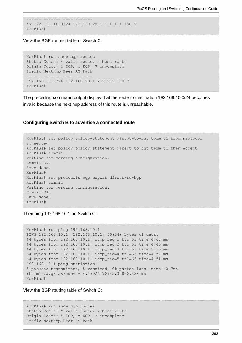
PicOS Routing and Switching Configuration Guide
263
------ ------- ---- -------*> 192.168.10.0/24 192.168.20.1 1.1.1.1 100 ?XorPlus#
View the BGP routing table of Switch C:
XorPlus# run show bgp routes Status Codes: * valid route, > best routeOrigin Codes: i IGP, e EGP, ? incomplete Prefix Nexthop Peer AS Path------ ------- ---- -------192.168.10.0/24 192.168.20.1 2.2.2.2 100 ?XorPlus#
The preceding command output display that the route to destination 192.168.10.0/24 becomes
invalid because the next hop address of this route is unreachable.
Configuring Switch B to advertise a connected route
XorPlus# set policy policy-statement direct-to-bgp term t1 from protocolconnected XorPlus# set policy policy-statement direct-to-bgp term t1 then accept XorPlus# commitWaiting for merging configuration.Commit OK.Save done.XorPlus#XorPlus# set protocols bgp export direct-to-bgpXorPlus# commitWaiting for merging configuration.Commit OK.Save done.XorPlus#
Then ping 192.168.10.1 on Switch C:
XorPlus# run ping 192.168.10.1PING 192.168.10.1 (192.168.10.1) 56(84) bytes of data.64 bytes from 192.168.10.1: icmp_req=1 ttl=63 time=4.68 ms64 bytes from 192.168.10.1: icmp_req=2 ttl=63 time=4.46 ms64 bytes from 192.168.10.1: icmp_req=3 ttl=63 time=5.35 ms64 bytes from 192.168.10.1: icmp_req=4 ttl=63 time=4.52 ms64 bytes from 192.168.10.1: icmp_req=5 ttl=63 time=4.51 ms 192.168.10.1 ping statistics —5 packets transmitted, 5 received, 0% packet loss, time 4017msrtt min/avg/max/mdev = 4.460/4.709/5.358/0.338 msXorPlus#
View the BGP routing table of Switch C:
XorPlus# run show bgp routes Status Codes: * valid route, > best routeOrigin Codes: i IGP, e EGP, ? incomplete Prefix Nexthop Peer AS Path

PicOS Routing and Switching Configuration Guide
264
------ ------- ---- -------192.168.10.0/24 192.168.20.1 2.2.2.2 100 ?*> 192.168.20.0/24 192.168.40.1 2.2.2.2?*>192.168.30.0/24 192.168.40.1 2.2.2.2?XorPlus#
BGP Route Reflector Configuration Example
The IBGP network should be formed without interrupting fullmesh BGP connections between
Switch B, Switch C, and Switch D, and call for simplified device configuration and management.
Configure Switch B, Switch C, and Switch D to have IBGP connections. Between Switch A and
Switch B should be an EBGP connection.
Configure Switch C as a route reflector with clients Switch B and Switch D.
Figure 5-10. BGP route reflector.
Configuring Switch A
Configure the VLAN that each interface belongs to.
XorPlus# set vlans vlan-id 10 l3-interface 10XorPlus# set vlans vlan-id 20 l3-interface 20XorPlus# commitWaiting for merging configuration.Commit OK.Save done.XorPlus#XorPlus# set interface gigabit-ethernet ge-1/1/1 family ethernet-switchingnative-vlan-id 10XorPlus# set interface gigabit-ethernet ge-1/1/2 family ethernet-switchingnative-vlan-id 20XorPlus# commitWaiting for merging configuration.Commit OK.Save done.XorPlus#

PicOS Routing and Switching Configuration Guide
265
Configure the VLAN interfaces and assign them IP addresses.
XorPlus# set vlan-interface interface 10 vif 10 address 192.168.10.1prefix-length 24XorPlus# set vlan-interface interface 20 vif 20 address 192.168.20.1prefix-length 24XorPlus# commitWaiting for merging configuration.Commit OK.Save done.XorPlus#
Configure an EBGP connection.
XorPlus# set protocols bgp bgp-id 1.1.1.1XorPlus# set protocols bgp local-as 100XorPlus# set protocols bgp peer 192.168.20.2 as 200XorPlus# set protocols bgp peer 192.168.20.2 local-ip 192.168.20.1XorPlus# set protocols bgp peer 192.168.20.2 next-hop-self trueXorPlus# commitWaiting for merging configuration.Commit OK.Save done.XorPlus#
Configuring Switch B
Configure the VLAN that each interface belongs to.
XorPlus# set vlans vlan-id 20 l3-interface 20XorPlus# set vlans vlan-id 40 l3-interface 40XorPlus# commitWaiting for merging configuration.Commit OK.Save done.XorPlus#XorPlus# set interface gigabit-ethernet ge-1/1/2 family ethernet-switchingnative-vlan-id 20XorPlus# set interface gigabit-ethernet ge-1/1/4 family ethernet-switchingnative-vlan-id 40XorPlus# commitWaiting for merging configuration.Commit OK.Save done.XorPlus#
Configure the VLAN interfaces and assign them IP addresses.
XorPlus# set vlan-interface interface 20 vif 20 address 192.168.20.2prefix-length 24XorPlus# set vlan-interface interface 40 vif 40 address 192.168.40.1prefix-length 24XorPlus# commitWaiting for merging configuration.
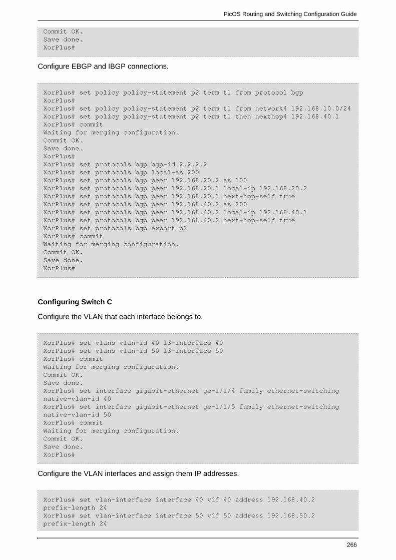
PicOS Routing and Switching Configuration Guide
266
Commit OK.Save done.XorPlus#
Configure EBGP and IBGP connections.
XorPlus# set policy policy-statement p2 term t1 from protocol bgpXorPlus#XorPlus# set policy policy-statement p2 term t1 from network4 192.168.10.0/24XorPlus# set policy policy-statement p2 term t1 then nexthop4 192.168.40.1 XorPlus# commit Waiting for merging configuration.Commit OK.Save done.XorPlus#XorPlus# set protocols bgp bgp-id 2.2.2.2XorPlus# set protocols bgp local-as 200XorPlus# set protocols bgp peer 192.168.20.2 as 100XorPlus# set protocols bgp peer 192.168.20.1 local-ip 192.168.20.2XorPlus# set protocols bgp peer 192.168.20.1 next-hop-self trueXorPlus# set protocols bgp peer 192.168.40.2 as 200XorPlus# set protocols bgp peer 192.168.40.2 local-ip 192.168.40.1XorPlus# set protocols bgp peer 192.168.40.2 next-hop-self trueXorPlus# set protocols bgp export p2XorPlus# commitWaiting for merging configuration.Commit OK.Save done.XorPlus#
Configuring Switch C
Configure the VLAN that each interface belongs to.
XorPlus# set vlans vlan-id 40 l3-interface 40XorPlus# set vlans vlan-id 50 l3-interface 50XorPlus# commitWaiting for merging configuration.Commit OK.Save done.XorPlus# set interface gigabit-ethernet ge-1/1/4 family ethernet-switchingnative-vlan-id 40XorPlus# set interface gigabit-ethernet ge-1/1/5 family ethernet-switchingnative-vlan-id 50XorPlus# commitWaiting for merging configuration.Commit OK.Save done.XorPlus#
Configure the VLAN interfaces and assign them IP addresses.
XorPlus# set vlan-interface interface 40 vif 40 address 192.168.40.2prefix-length 24XorPlus# set vlan-interface interface 50 vif 50 address 192.168.50.2prefix-length 24

PicOS Routing and Switching Configuration Guide
267
XorPlus# commitWaiting for merging configuration.Commit OK.Save done.XorPlus#
Configure an IBGP connection.
XorPlus# set protocols bgp bgp-id 3.3.3.3XorPlus# set protocols bgp local-as 200XorPlus# set protocols bgp peer 192.168.40.1 as 200XorPlus# set protocols bgp peer 192.168.40.1 local-ip 192.168.40.2XorPlus# set protocols bgp peer 192.168.40.1 next-hop-self trueXorPlus# set protocols bgp peer 192.168.50.1 as 200XorPlus# set protocols bgp peer 192.168.50.1 local-ip 192.168.50.2XorPlus# set protocols bgp peer 192.168.50.1 next-hop-self trueXorPlus# commitWaiting for merging configuration.Commit OK.Save done.XorPlus#
Configure IBGP connections for the route reflector clients.
XorPlus# set protocols bgp route-reflector cluster-id 3.3.3.3 XorPlus# set protocols bgp route-reflector disable falseXorPlus# set protocols bgp peer 192.168.40.1 client trueXorPlus# set protocols bgp peer 192.168.50.1 client trueXorPlus# commitWaiting for merging configuration.Commit OK.Save done.XorPlus#
Configuring Switch D
Configure the VLAN that each interface belongs to.
XorPlus# set vlans vlan-id 30 l3-interface 30XorPlus# set vlans vlan-id 50 l3-interface 50XorPlus# commitWaiting for merging configuration.Commit OK.Save done.XorPlus# set interface gigabit-ethernet ge-1/1/3 family ethernet-switchingnative-vlan-id 30XorPlus# set interface gigabit-ethernet ge-1/1/5 family ethernet-switchingnative-vlan-id 50XorPlus# commitWaiting for merging configuration.Commit OK.Save done.XorPlus#
Configure the VLAN interfaces and assign them IP addresses.

PicOS Routing and Switching Configuration Guide
268
XorPlus# set vlan-interface interface 30 vif 30 address 192.168.30.2prefix-length 24XorPlus# set vlan-interface interface 50 vif 50 address 192.168.50.1prefix-length 24XorPlus# commitWaiting for merging configuration.Commit OK.Save done.XorPlus#
Configure an IBGP connection.
XorPlus# set protocols bgp bgp-id 4.4.4.4XorPlus# set protocols bgp local-as 200XorPlus# set protocols bgp peer 192.168.30.1 as 200XorPlus# set protocols bgp peer 192.168.30.1 local-ip 192.168.30.2XorPlus# set protocols bgp peer 192.168.30.1next-hop-self trueXorPlus# set protocols bgp peer 192.168.50.2 as 200XorPlus# set protocols bgp peer 192.168.50.2 local-ip 192.168.50.1XorPlus# set protocols bgp peer 192.168.50.2 next-hop-self trueXorPlus# commitWaiting for merging configuration.Commit OK.Save done.XorPlus#
Verifying configurations
View the BGP routing table of Switch B:
XorPlus# run show bgp routes Status Codes: * valid route, > best routeOrigin Codes: i IGP, e EGP, ? incomplete Prefix Nexthop Peer AS Path------ ------- ---- -------*> 192.168.10.0/24 192.168.20.11.1.1.1200 ?XorPlus#
View the BGP routing table of Switch D:
XorPlus# run show bgp routes detail 192.168.10.0/24From peer: 3.3.3.3Route: Not UsedOrigin: INCOMPLETEAS Path: 200Nexthop: 192.168.40.1Multiple Exit Discriminator: 0Local Preference: 100Originator ID: 2.2.2.2Cluster List: 3.3.3.3

PicOS Routing and Switching Configuration Guide
269
BGP Confederation Configuration Example
Configure a BGP confederation on each switch in AS 200 to divide AS 200 into two sub-AS's: AS
65010 and AS 65011. To reduce the number of IBGP connections, three switches in AS 65010
establish fullmesh IBGP connections.
Configure BGP confederation members Switch A, Switch B, Switch C, and Switch D. Between
Switch A and Switch D is an EBGP connection within AS 200.
Configure Switch A to connect without AS 200 to Switch E.
Figure 5-11. BGP confederation configuration.
Configuring Switch A
Configure the VLAN that each interface belongs to.
XorPlus# set vlans vlan-id 20 l3-interface 20XorPlus# set vlans vlan-id 30 l3-interface 30XorPlus# set vlans vlan-id 40 l3-interface 40XorPlus# set vlans vlan-id 60 l3-interface 60XorPlus# commitWaiting for merging configuration.Commit OK.Save done.XorPlus# set interface gigabit-ethernet ge-1/1/2 family ethernet-switchingnative-vlan-id 20XorPlus# set interface gigabit-ethernet ge-1/1/3 family ethernet-switchingnative-vlan-id 30XorPlus# set interface gigabit-ethernet ge-1/1/4 family ethernet-switching

PicOS Routing and Switching Configuration Guide
270
native-vlan-id 40XorPlus# set interface gigabit-ethernet ge-1/1/6 family ethernet-switchingnative-vlan-id 60XorPlus# commitWaiting for merging configuration.Commit OK.Save done.XorPlus#
Configure the VLAN interfaces and assign them IP addresses.
XorPlus# set vlan-interface interface 20 vif 20 address 192.168.20.2prefix-length 24XorPlus# set vlan-interface interface 30 vif 30 address 192.168.30.1prefix-length 24XorPlus# set vlan-interface interface 40 vif 40 address 192.168.40.1prefix-length 24XorPlus# set vlan-interface interface 60 vif 60 address 192.168.60.1prefix-length 24XorPlus# commitWaiting for merging configuration.Commit OK.Save done.XorPlus#
Configure EBGP and IBGP connections within confederation AS 200.
XorPlus# set protocols bgp bgp-id 2.2.2.2XorPlus# set protocols bgp local-as 65010XorPlus# protocols bgp confederation identifier 200XorPlus# protocols bgp confederation disable falseXorPlus# set protocols bgp peer 192.168.30.2 as 65010XorPlus# set protocols bgp peer 192.168.30.2 local-ip 192.168.30.1XorPlus# set protocols bgp peer 192.168.30.2 next-hop-self trueXorPlus# set protocols bgp peer 192.168.30.2 confederation-member trueXorPlus# set protocols bgp peer 192.168.40.2 as 65010XorPlus# set protocols bgp peer 192.168.40.2 local-ip 192.168.40.1XorPlus# set protocols bgp peer 192.168.40.2 next-hop-self trueXorPlus# set protocols bgp peer 192.168.40.2 confederation-member trueXorPlus# set protocols bgp peer 192.168.60.2 as 65011XorPlus# set protocols bgp peer 192.168.60.2 local-ip 192.168.60.1XorPlus# set protocols bgp peer 192.168.60.2 next-hop-self trueXorPlus# set protocols bgp peer 192.168.60.2 confederation-member trueXorPlus# commitWaiting for merging configuration.Commit OK.Save done.XorPlus#
Configure an EBGP connection without confederation AS 200.
XorPlus# set protocols bgp peer 192.168.20.2 as 100XorPlus# set protocols bgp peer 192.168.20.1 local-ip 192.168.20.2XorPlus# set protocols bgp peer 192.168.20.1 next-hop-self trueXorPlus# commitWaiting for merging configuration.

PicOS Routing and Switching Configuration Guide
271
Commit OK.Save done.XorPlus#
Configuring Switch B
Configure the VLAN that each interface belongs to.
XorPlus# set vlans vlan-id 40 l3-interface 40XorPlus# set vlans vlan-id 50 l3-interface 50XorPlus# commitWaiting for merging configuration.Commit OK.Save done.XorPlus# set interface gigabit-ethernet ge-1/1/4 family ethernet-switchingnative-vlan-id 40XorPlus# set interface gigabit-ethernet ge-1/1/5 family ethernet-switchingnative-vlan-id 50XorPlus# commitWaiting for merging configuration.Commit OK.Save done.XorPlus#
Configure the VLAN interfaces and assign them IP addresses.
XorPlus# set vlan-interface interface 40 vif 40 address 192.168.40.2prefix-length 24XorPlus# set vlan-interface interface 50 vif 50 address 192.168.50.2prefix-length 24XorPlus# commitWaiting for merging configuration.Commit OK.Save done.XorPlus#
Configure an IBGP connection within confederation AS 200.
XorPlus# set protocols bgp bgp-id 3.3.3.3XorPlus# set protocols bgp local-as 65010XorPlus# protocols bgp confederation identifier 200XorPlus# protocols bgp confederation disable falseXorPlus# set protocols bgp peer 192.168.40.1 as 65010XorPlus# set protocols bgp peer 192.168.40.1 local-ip 192.168.40.2XorPlus# set protocols bgp peer 192.168.40.1 next-hop-self trueXorPlus# set protocols bgp peer 192.168.40.1 confederation-member trueXorPlus# set protocols bgp peer 192.168.50.1 as 65010XorPlus# set protocols bgp peer 192.168.50.1 local-ip 192.168.50.2XorPlus# set protocols bgp peer 192.168.50.1 next-hop-self trueXorPlus# set protocols bgp peer 192.168.50.1 confederation-member trueXorPlus# commitWaiting for merging configuration.Commit OK.Save done.XorPlus#

PicOS Routing and Switching Configuration Guide
272
Configuring Switch C
Configure the VLAN that each interface belongs to.
XorPlus# set vlans vlan-id 30 l3-interface 30XorPlus# set vlans vlan-id 50 l3-interface 50XorPlus# commitWaiting for merging configuration.Commit OK.Save done.XorPlus# set interface gigabit-ethernet ge-1/1/3 family ethernet-switchingnative-vlan-id 30XorPlus# set interface gigabit-ethernet ge-1/1/5 family ethernet-switchingnative-vlan-id 50XorPlus# commitWaiting for merging configuration.Commit OK.Save done.XorPlus#
Configure the VLAN interfaces and assign them IP addresses.
XorPlus# set vlan-interface interface 30 vif 40 address 192.168.30.2prefix-length 24XorPlus# set vlan-interface interface 50 vif 50 address 192.168.50.1prefix-length 24XorPlus# commitWaiting for merging configuration.Commit OK.Save done.XorPlus#
Configure an IBGP connection within confederation AS 200.
XorPlus# set protocols bgp bgp-id 4.4.4.4XorPlus# set protocols bgp local-as 65010XorPlus# protocols bgp confederation identifier 200XorPlus# protocols bgp confederation disable falseXorPlus# set protocols bgp peer 192.168.30.1 as 65010XorPlus# set protocols bgp peer 192.168.30.1 local-ip 192.168.30.2XorPlus# set protocols bgp peer 192.168.30.1 next-hop-self trueXorPlus# set protocols bgp peer 192.168.30.1 confederation-member trueXorPlus# set protocols bgp peer 192.168.50.2 as 65010XorPlus# set protocols bgp peer 192.168.50.2 local-ip 192.168.50.1XorPlus# set protocols bgp peer 192.168.50.2 next-hop-self trueXorPlus# set protocols bgp peer 192.168.50.2 confederation-member trueXorPlus# commitWaiting for merging configuration.Commit OK.Save done.XorPlus#
Configuring Switch D

PicOS Routing and Switching Configuration Guide
273
Configure the VLAN that each interface belongs to.
XorPlus# set vlans vlan-id 60 l3-interface 60XorPlus# commitWaiting for merging configuration.Commit OK.Save done.XorPlus# set interface gigabit-ethernet ge-1/1/6 family ethernet-switchingnative-vlan-id 60XorPlus# commitWaiting for merging configuration.Commit OK.Save done.XorPlus#
Configure the VLAN interfaces and assign them IP addresses.
XorPlus# set vlan-interface interface 60 vif 60 address 192.168.60.2prefix-length 24XorPlus# commitWaiting for merging configuration.Commit OK.Save done.XorPlus#
Configure an EBGP connection within confederation AS 200.
XorPlus# set protocols bgp bgp-id 5.5.5.5XorPlus# set protocols bgp local-as 65011XorPlus# protocols bgp confederation identifier 200XorPlus# protocols bgp confederation disable falseXorPlus# set protocols bgp peer 192.168.60.2 as 65010XorPlus# set protocols bgp peer 192.168.60.2 local-ip 192.168.60.1XorPlus# set protocols bgp peer 192.168.60.2 next-hop-self trueXorPlus# set protocols bgp peer 192.168.60.2 confederation-member trueXorPlus# commitWaiting for merging configuration.Commit OK.Save done.XorPlus#
Configuring Switch E
Configure the VLAN that each interface belongs to.
XorPlus# set vlans vlan-id 10 l3-interface 10XorPlus# set vlans vlan-id 20 l3-interface 20XorPlus# commitWaiting for merging configuration.Commit OK.Save done.XorPlus# set interface gigabit-ethernet ge-1/1/1 family ethernet-switchingnative-vlan-id 10XorPlus# set interface gigabit-ethernet ge-1/1/2 family ethernet-switching

PicOS Routing and Switching Configuration Guide
274
native-vlan-id 20XorPlus# commitWaiting for merging configuration.Commit OK.Save done.XorPlus#
Configure the VLAN interfaces and assign them IP addresses.
XorPlus# set vlan-interface interface 10 vif 10 address 192.168.10.1prefix-length 24XorPlus# set vlan-interface interface 20 vif 20 address 192.168.20.1prefix-length 24XorPlus# commitWaiting for merging configuration.Commit OK.Save done.XorPlus#
Configure an EBGP connection.
XorPlus# set protocols bgp bgp-id 1.1.1.1XorPlus# set protocols bgp local-as 100XorPlus# set protocols bgp peer 192.168.20.2 as 200XorPlus# set protocols bgp peer 192.168.20.2 local-ip 192.168.20.1XorPlus# set protocols bgp peer 192.168.20.2 next-hop-self trueXorPlus# commitWaiting for merging configuration.Commit OK.Save done.XorPlus#
Verifying the configuration
View the BGP routing table of Switch B:
XorPlus# run show bgp routes detail 192.168.10.0/24From peer: 2.2.2.2Route: Not UsedOrigin: INCOMPLETEAS Path: 100Nexthop: 192.168.20.1Multiple Exit Discriminator: 0Local Preference: 100 View the BGP routing table of Switch D: XorPlus# run show bgp routes detail 192.168.10.0/24From peer: 15.15.15.15Route: Not UsedOrigin: INCOMPLETEAS Path: (65010) 100Nexthop: 192.168.30.2Local Preference: 100

PicOS Routing and Switching Configuration Guide
275
BGP Load Balancing Configuration Example
Configure load balancing on Switch A.
Configure EBGP connections between Switch B and Switch A, and between Switch B and Switch
D.
Configure EBGP connections between Switch C and Switch A, and between Switch C and Switch
D.
Figure 5-12. BGP load balancing.
Configuring Switch A
Configure the VLAN that each interface belongs to.
XorPlus# set vlans vlan-id 30 l3-interface vlan30XorPlus# set vlans vlan-id 40 l3-interface vlan40XorPlus# commitWaiting for merging configuration.Commit OK.Save done.XorPlus#XorPlus# set interface gigabit-ethernet ge-1/1/1 family ethernet-switchingnative-vlan-id 30XorPlus# set interface gigabit-ethernet ge-1/1/2 family ethernet-switchingnative-vlan-id 40XorPlus# commitWaiting for merging configuration.Commit OK.Save done.XorPlus#
Configure the VLAN interfaces and assign them IP addresses.
XorPlus# set vlan-interface interface vlan30 vif vlan30 address 192.168.30.1prefix-length 24XorPlus# set vlan-interface interface vlan40 vif vlan40 address 192.168.40.1

PicOS Routing and Switching Configuration Guide
276
prefix-length 24XorPlus# commitWaiting for merging configuration.Commit OK.Save done.XorPlus#
Configure an EBGP connection.
XorPlus# set protocols bgp bgp-id 1.1.1.1XorPlus# set protocols bgp local-as 100XorPlus# set protocols bgp peer 192.168.30.2 as 200XorPlus# set protocols bgp peer 192.168.30.2 local-ip 192.168.30.1XorPlus# set protocols bgp peer 192.168.40.2 as 300XorPlus# set protocols bgp peer 192.168.40.2 local-ip 192.168.30.1XorPlus# commitWaiting for merging configuration.Commit OK.Save done.XorPlus#
Configuring Switch B
Configure the VLAN that each interface belongs to.
XorPlus# set vlans vlan-id 20 l3-interface vlan20XorPlus# set vlans vlan-id 30 l3-interface vlan30XorPlus# commitWaiting for merging configuration.Commit OK.Save done.XorPlus#XorPlus# set interface gigabit-ethernet ge-1/1/1 family ethernet-switchingnative-vlan-id 30XorPlus# set interface gigabit-ethernet ge-1/1/2 family ethernet-switchingnative-vlan-id 20XorPlus# commitWaiting for merging configuration.Commit OK.Save done.XorPlus#
Configure the VLAN interfaces and assign them IP addresses.
XorPlus# set vlan-interface interface vlan20 vif vlan20 address 192.168.20.2prefix-length 24XorPlus# set vlan-interface interface vlan30 vif vlan30 address 192.168.30.2prefix-length 24XorPlus# commitWaiting for merging configuration.Commit OK.Save done.XorPlus#
Configure an EBGP connection.

PicOS Routing and Switching Configuration Guide
277
XorPlus# set protocols bgp bgp-id 2.2.2.2XorPlus# set protocols bgp local-as 200XorPlus# set protocols bgp peer 192.168.20.1 as 400XorPlus# set protocols bgp peer 192.168.20.1 local-ip 192.168.20.2XorPlus# set protocols bgp peer 192.168.30.1 as 100XorPlus# set protocols bgp peer 192.168.30.2 local-ip 192.168.30.2XorPlus# commitWaiting for merging configuration.Commit OK.Save done.XorPlus#
Configuring Switch C
Configure the VLAN that each interface belongs to.
XorPlus# set vlans vlan-id 40 l3-interface 40XorPlus# set vlans vlan-id 50 l3-interface 50XorPlus# commitWaiting for merging configuration.Commit OK.Save done.XorPlus# set interface gigabit-ethernet ge-1/1/2 family ethernet-switchingnative-vlan-id 40XorPlus# set interface gigabit-ethernet ge-1/1/3 family ethernet-switchingnative-vlan-id 50XorPlus# commitWaiting for merging configuration.Commit OK.Save done.XorPlus#
Configure the VLAN interfaces and assign them IP addresses.
XorPlus# set vlan-interface interface vlan40 vif vlan40 address 192.168.40.2prefix-length 24XorPlus# set vlan-interface interface vlan50 vif vlan50 address 192.168.50.2prefix-length 24XorPlus# commitWaiting for merging configuration.Commit OK.Save done.XorPlus# Configure an EBGP connection. XorPlus# set protocols bgp bgp-id 3.3.3.3XorPlus# set protocols bgp local-as 300XorPlus# set protocols bgp peer 192.168.40.1 as 100XorPlus# set protocols bgp peer 192.168.40.1 local-ip 192.168.40.2XorPlus# set protocols bgp peer 192.168.50.1 as 400XorPlus# set protocols bgp peer 192.168.50.1 local-ip 192.168.50.2XorPlus# commitWaiting for merging configuration.Commit OK.Save done.XorPlus#

PicOS Routing and Switching Configuration Guide
278
Configuring Switch D
Configure the VLAN that each interface belongs to.
XorPlus# set vlans vlan-id 10 l3-interface vlan10XorPlus# set vlans vlan-id 20 l3-interface vlan20XorPlus# set vlans vlan-id 50 l3-interface vlan50XorPlus# commitWaiting for merging configuration.Commit OK.Save done.XorPlus# set interface gigabit-ethernet ge-1/1/1 family ethernet-switchingnative-vlan-id 10XorPlus# set interface gigabit-ethernet ge-1/1/2 family ethernet-switchingnative-vlan-id 20XorPlus# set interface gigabit-ethernet ge-1/1/3 family ethernet-switchingnative-vlan-id 50XorPlus# commitWaiting for merging configuration.Commit OK.Save done.XorPlus#
Configure the VLAN interfaces and assign them IP addresses.
XorPlus# set vlan-interface interface vlan10 vif vlan10 address 192.168.10.1prefix-length 24XorPlus# set vlan-interface interface vlan20 vif vlan20 address 192.168.20.1prefix-length 24XorPlus# set vlan-interface interface vlan50 vif vlan50 address 192.168.50.1prefix-length 24XorPlus# commitWaiting for merging configuration.Commit OK.Save done.XorPlus#
Configure an EBGP connection.
XorPlus# set protocols bgp bgp-id 4.4.4.4XorPlus# set protocols bgp local-as 400XorPlus# set protocols bgp peer 192.168.20.2 as 200XorPlus# set protocols bgp peer 192.168.20.2 local-ip 192.168.20.1XorPlus# set protocols bgp peer 192.168.50.2 as 300XorPlus# set protocols bgp peer 192.168.50.2 local-ip 192.168.50.1XorPlus# commitWaiting for merging configuration.Commit OK.Save done.XorPlus#
Viewing BGP peer statuses on Switch B

PicOS Routing and Switching Configuration Guide
279
XorPlus# run show bgp peers detail Peer 2: local 192.168.20.2/179 remote 192.168.20.1/39912Peer ID: 1.1.1.1Peer State: ESTABLISHEDAdmin State: STARTNegotiated BGP Version: 4Peer AS Number: 100Updates Received: 20, Updates Sent: 2Messages Received: 634, Messages Sent: 611Time since last received update: 1685 secondsNumber of transitions to ESTABLISHED: 1Time since last entering ESTABLISHED state: 15995 secondsRetry Interval: 120 secondsHold Time: 90 seconds, Keep Alive Time: 30 secondsConfigured Hold Time: 90 seconds, Configured Keep Alive Time: 30 secondsMinimum AS Origination Interval: 0 secondsMinimum Route Advertisement Interval: 0 seconds Peer 2: local 192.168.30.2/16808 remote 192.168.30.1/179Peer ID: 4.4.4.4Peer State: ESTABLISHEDAdmin State: STARTNegotiated BGP Version: 4Peer AS Number: 100Updates Received: 20, Updates Sent: 2Messages Received: 634, Messages Sent: 611Time since last received update: 1685 secondsNumber of transitions to ESTABLISHED: 1Time since last entering ESTABLISHED state: 15995 secondsRetry Interval: 120 secondsHold Time: 90 seconds, Keep Alive Time: 30 secondsConfigured Hold Time: 90 seconds, Configured Keep Alive Time: 30 secondsMinimum AS Origination Interval: 0 secondsMinimum Route Advertisement Interval: 0 seconds
Viewing BGP peer statuses on Switch C
XorPlus# run show bgp peers detail Peer 2: local 192.168.40.2/179 remote 192.168.40.1/38815Peer ID: 1.1.1.1Peer State: ESTABLISHEDAdmin State: STARTNegotiated BGP Version: 4Peer AS Number: 100Updates Received: 20, Updates Sent: 2Messages Received: 634, Messages Sent: 611Time since last received update: 1685 secondsNumber of transitions to ESTABLISHED: 1Time since last entering ESTABLISHED state: 15995 secondsRetry Interval: 120 secondsHold Time: 90 seconds, Keep Alive Time: 30 secondsConfigured Hold Time: 90 seconds, Configured Keep Alive Time: 30 secondsMinimum AS Origination Interval: 0 secondsMinimum Route Advertisement Interval: 0 seconds Peer 2: local 192.168.50.2/49923 remote 192.168.50.1/179Peer ID: 4.4.4.4Peer State: ESTABLISHEDAdmin State: STARTNegotiated BGP Version: 4Peer AS Number: 100

PicOS Routing and Switching Configuration Guide
280
Updates Received: 20, Updates Sent: 2Messages Received: 634, Messages Sent: 611Time since last received update: 1685 secondsNumber of transitions to ESTABLISHED: 1Time since last entering ESTABLISHED state: 15995 secondsRetry Interval: 120 secondsHold Time: 90 seconds, Keep Alive Time: 30 secondsConfigured Hold Time: 90 seconds, Configured Keep Alive Time: 30 secondsMinimum AS Origination Interval: 0 secondsMinimum Route Advertisement Interval: 0 seconds
Configuring Switch D to advertise route 192.168.10.0/24
Configure Switch A to enable BGP multipath:
XorPlus# set protocols bgp multipath disable falseXorPlus# commitWaiting for merging configuration.Commit OK.Save done.XorPlus#
Configure Switch D to advertise route 192.168.10.0/24:
XorPlus# set policy policy-statement direct-to-bgp term t1 from protocolconnected XorPlus# set policy policy-statement direct-to-bgp term t1 from network4192.168.10.0/24XorPlus# set policy policy-statement direct-to-bgp term t1 then accept XorPlus# commitWaiting for merging configuration.Commit OK.Save done.XorPlus#XorPlus# set protocols bgp export direct-to-bgpXorPlus# commitWaiting for merging configuration.Commit OK.Save done.XorPlus#
View the BGP routing table of Switch A:
XorPlus# run show bgp routes Status Codes: * valid route, > best routeOrigin Codes: i IGP, e EGP, ? incomplete Prefix Nexthop Peer AS Path------ ------- ---- -------*> 192.168.10.0/24 192.168.30.2 2.2.2.2 200 400 ?192.168.10.0/24 192.168.40.2 3.3.3.3 200 400 ?XorPlus#
As expected, Switch A is not load balancing because it does not view the paths as "equal," but as
different AS paths.

PicOS Routing and Switching Configuration Guide
281
Configuring BGP multipath path-relax on Switch A
XorPlus# set protocols bgp multipath path-relax trueXorPlus# commit Waiting for merging configuration.Commit OK.Save done.XorPlus#
View the BGP routing table and IP routing table of Switch A:
XorPlus# run show bgp routes Status Codes: * valid route, > best routeOrigin Codes: i IGP, e EGP, ? incomplete Prefix Nexthop Peer AS Path------ ------- ---- -------*> 192.168.10.0/24 192.168.30.2 2.2.2.2 200 400 ?*> 192.168.10.0/24 192.168.40.2 3.3.3.3 200 400 ?XorPlus# XorPlus# run show route table ipv4 unicast ebgp 192.168.10.0/24 [ebgp(20)/0]> to 192.168.30.2 via vlan30/vlan30192.168.10.0/24 [ebgp(20)/0]> to 192.168.40.2 via vlan40/vlan40XorPlus# XorPlus#
IPv6 BGP Configuration
IPv6 BGP configuration
IPv6 BGP introduction
BGP is a path vector protocol used to carry routing information between autonomous systems.The
term path vector comes from the fact that BGP routing information carries a sequence of AS
numbers that identifies the path of ASs that a network prefix has traversed. The path information
associated with the prefix is used to enable loop prevention.
BGP uses TCP as its transport protocol (port 179). This ensures that all the transport reliability
(such as retransmission) is taken care of by TCP and does not need to be implemented in BGP,
thereby simplifying the complexity associated with designing reliability into the protocol itself.
Routers that run a BGP routing process are often referred to as BGP speakers. Two BGP
speakers that form a TCP connection between one another for the purpose of exchanging routing
information are referred to as neighbors or peers. Peer routers exchange open messages to
determine the connection parameters.These messages are used to communicate values such as
the BGP speaker's version number.

PicOS Routing and Switching Configuration Guide
282
BGP also provides a mechanism to gracefully close a connection with a peer. In other words,in the
event of a disagreement between the peers, be it resultant of configuration,incompatibility, operator
intervention, or other circumstances, a NOTIFICATION error message is sent, and the peer
connection does not get established or is torn down if it's already established. The benefit of this
mechanism is that both peers understand that the connection could not be established or
maintained and do not waste resources that would otherwise be required to maintain or blindly
reattempt to establish the connection. The graceful close mechanism simply ensures that all
outstanding messages, primarily NOTIFICATION error messages, are delivered before the TCP
session is closed.
Initially, when a BGP session is established between a set of BGP speakers, all candidate BGP
routes are exchanged, After the session has been established and the initial route exchange has
occurred, only incremental updates are sent as network information changes.
Routes are advertised between a pair of BGP routers in UPDATE messages. The UPDATE
message contains, among other things, a list of <length, prefix> tuples that indicate the list of
destinations that can be reached via a BGP speaker. The UPDATE message also contains the
path attributes, which include such information as the degree of preference for a particular route
and the list of ASs that the route has traversed.
In the event that a route becomes unreachable, a BGP speaker informs its neighbors by
withdrawing the invalid route. withdrawn routes are part of the UPDATE message. These routes
are no longer available for use. If information associated with a route has changed, or a new path
for the same prefix has been selected, a withdrawal is not required; it is enough to just advertise a
replacement route.
If no routing changes occur, the routers exchange only KEEPALIVE packets.
KEEPALIVE messages are sent periodically between BGP neighbors to ensure that the connection
is kept alive. KEEPALIVE packets (19 bytes each) should not cause any strain on the router CPU
or link bandwidth, because they consume a minimal amount of bandwidth.
Building Peering Sessions
Commands References:
XorPlus#set protocols bgp bgp-id <ipv4 address>
Note:This command is to configure a bgp-id , it indicate a bgp router uniquely.
XorPlus#set protocols bgp local-as <as-number>
Note :This commad it to configure a as-number ,it tell us which as the bgp router in ,it should be
expressed use a two-byte length digit or use a 4-byte length digit <0-4294967295> or
<0..65535>.<0..65535>.
XorPlus# set protocols bgp peer <peer-ipv6-address> as <peer-as-number>

PicOS Routing and Switching Configuration Guide
283
Note :This command is to specify an bgp peer and it’s as-number.
XorPlus# set protocols bgp peer <peer-ipv6-address> local-ip<local-ipv6-address>
Note :This command is to specify the local ipv6 address for bgp peer session.
XorPlus# set protocols bgp peer <peer-ipv6-address> ipv6-unicast <true/false>
Note : IPV6 bgp route will be propagated to it’s bgp peer after enable ipv6-unicast.
XorPlus# set protocols bgp peer <peer-ipv6-address> ipv4-unicast <true/false>
Note :The ipv4 bgp route entry should be propagated via bgp update packet , ipv4-unicast was
disabled by default.
XorPlus# set protocols bgp peer <peer-ipv6-address> default-route-advertisedisable <true/false>
Note : It will advertise a default route entry to it’s bgp peer after you enabled
default-route-advertise.
XorPlus# set protocols bgp peer <peer-ipv6-address> allow-as-loop<true/false>
Note :It will receive the bgp route entry with it’s own as number , by default ,the bgp route entry
with it’s own as number will be droped for prevent loops.
XorPlus# set protocols bgp peer <peer-ipv6-address> holdtime <0 or 3-65535>
Note :This command is to set the hold-timer value ,and the keepavlive timer will be holdtime/3
,holdtime should be 0 , it means ,the bgp peering session will not expired any more ,and holdtime
also should be the digit 3-65535.
XorPlus# set protocols bgp peer <peer-ipv6-address> md5-password <text>
Note :This command is to configure a md5-password ,the two peers must have the same
md5-password.
XorPlus# set protocols bgp peer <peer-ipv6-address> next-hop-self<true/false>
Note :This command is to enable next-hop-self when you configure IBGP peer session ,the
next-hop will be set it’s own ipv6 address after you enabled next-hop-self.

PicOS Routing and Switching Configuration Guide
284
XorPlus# set protocols bgp peer <peer-ipv6-address> prefix-limit maximum<1-12000>
Note :This command is to set the maximum bgp route entry limit for one bgp peer.
XorPlus# set protocols bgp peer <peer-ipv6-address> public-as-only<true/false>
Note :The private as-number will be removed from the as-path if the private as number in the
as-path after you enabled public-as-only.
EBGP Peering
EBGP Peering:
Directly connected peer
Non-Directly connected peer
Establish ebgp peer use loopback interface
(1)Directly connected peer
Figure 1-4
Step 1:Configure bgp-id and local-as
SwitchA:
XorPlus# set protocols bgp bgp-id 6.6.6.6XorPlus# set protocols bgp local-as "6"
SwitchB:
XorPlus# set protocols bgp bgp-id 9.9.9.9XorPlus# set protocols bgp local-as "9"
Step 2:Configure bgp peer
SwitchA:
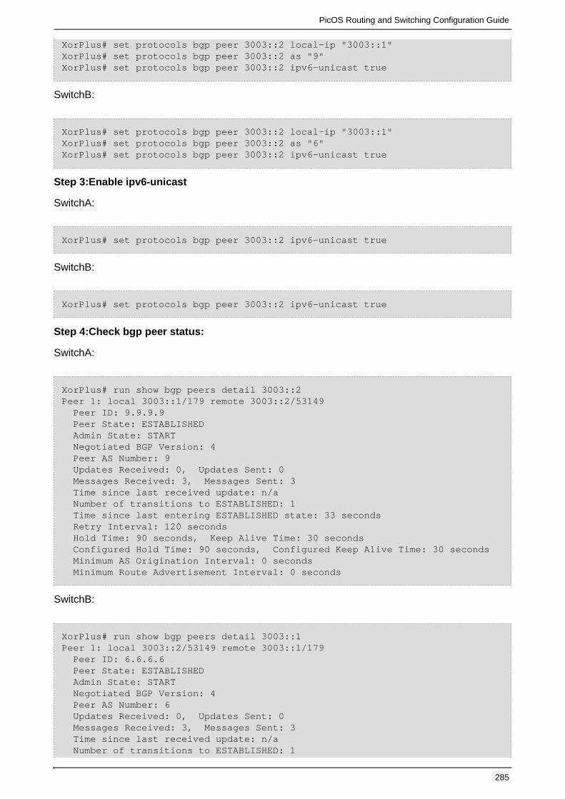
PicOS Routing and Switching Configuration Guide
285
XorPlus# set protocols bgp peer 3003::2 local-ip "3003::1"XorPlus# set protocols bgp peer 3003::2 as "9"XorPlus# set protocols bgp peer 3003::2 ipv6-unicast true
SwitchB:
XorPlus# set protocols bgp peer 3003::2 local-ip "3003::1"XorPlus# set protocols bgp peer 3003::2 as "6"XorPlus# set protocols bgp peer 3003::2 ipv6-unicast true
Step 3:Enable ipv6-unicast
SwitchA:
XorPlus# set protocols bgp peer 3003::2 ipv6-unicast true
SwitchB:
XorPlus# set protocols bgp peer 3003::2 ipv6-unicast true
Step 4:Check bgp peer status:
SwitchA:
XorPlus# run show bgp peers detail 3003::2Peer 1: local 3003::1/179 remote 3003::2/53149 Peer ID: 9.9.9.9 Peer State: ESTABLISHED Admin State: START Negotiated BGP Version: 4 Peer AS Number: 9 Updates Received: 0, Updates Sent: 0 Messages Received: 3, Messages Sent: 3 Time since last received update: n/a Number of transitions to ESTABLISHED: 1 Time since last entering ESTABLISHED state: 33 seconds Retry Interval: 120 seconds Hold Time: 90 seconds, Keep Alive Time: 30 seconds Configured Hold Time: 90 seconds, Configured Keep Alive Time: 30 seconds Minimum AS Origination Interval: 0 seconds Minimum Route Advertisement Interval: 0 seconds
SwitchB:
XorPlus# run show bgp peers detail 3003::1Peer 1: local 3003::2/53149 remote 3003::1/179 Peer ID: 6.6.6.6 Peer State: ESTABLISHED Admin State: START Negotiated BGP Version: 4 Peer AS Number: 6 Updates Received: 0, Updates Sent: 0 Messages Received: 3, Messages Sent: 3 Time since last received update: n/a Number of transitions to ESTABLISHED: 1

PicOS Routing and Switching Configuration Guide
286
Time since last entering ESTABLISHED state: 41 seconds Retry Interval: 120 seconds Hold Time: 90 seconds, Keep Alive Time: 30 seconds Configured Hold Time: 90 seconds, Configured Keep Alive Time: 30 seconds Minimum AS Origination Interval: 0 seconds Minimum Route Advertisement Interval: 0 seconds
(2) Establish EBGP via non-direct-connected interfaces
Figure 1-5
Step 1:SwitchA SwitchB SwitchC Enable OSPFV3
SwitchA:
XorPlus#set protocols ospf6 instance-id 1XorPlus#set protocols ospf6 router-id 9.9.9.9XorPlus#set protocols ospf6 area 0.0.0.0 interface vlan500 vif vlan500address 5005::1XorPlus#set protocols ospf6 area 0.0.0.0 interface vlan300 vif vlan300address 3003::2
SwitchB:
XorPlus#set protocols ospf6 instance-id 1XorPlus#set protocols ospf6 router-id 6.6.6.6XorPlus#set protocols ospf6 area 0.0.0.0 interface vlan100 vif vlan100address 1001::1XorPlus#set protocols ospf6 area 0.0.0.0 interface vlan300 vif vlan300address 3003::1
SwitchC:
XorPlus#set protocols ospf6 instance-id 1XorPlus#set protocols ospf6 router-id 26.26.26.26XorPlus#set protocols ospf6 area 0.0.0.0 interface vlan100 vif vlan100address 1001::2

PicOS Routing and Switching Configuration Guide
287
Step 2:Check ospfv3 status on SwitchB
XorPlus# run show ospf6 neighborAddress Interface State Router ID Pri Dead--------------------------------------- --------------------- -------- --------------- ----- ----fe80::ca0a:a9ff:204:4928 vlan100/vlan100 Full 26.26.26.26 128 35 fe80::ca0a:a9ff:5ae:a66 vlan300/vlan300 Full 9.9.9.9 128 38
Note:Two ospf6 neighbor all established
Step 3:Check the route table on SwitchA SwitchC
Note:there should be 3003::/64 route entry on SwitchC,and 1001::/64 should in SwitchA’s route
table:
SwitchA:
XorPlus# run show route forward-route ipv6 allDestination NetMask NextHopMac Port --------------------------------------- --------------------------------------- ----------------- ---------2001:: ffff:ffff:ffff:ffff:: C8:0A:A9:AE:0A:66 connected4001:: ffff:ffff:ffff:ffff:: C8:0A:A9:AE:0A:66 connected3003:: ffff:ffff:ffff:ffff:: C8:0A:A9:AE:0A:66 connected1001:: ffff:ffff:ffff:ffff:: 04:7D:7B:62:93:FF te-1/1/466006:: ffff:ffff:ffff:ffff:: C8:0A:A9:AE:0A:66 connected5005:: ffff:ffff:ffff:ffff:: C8:0A:A9:AE:0A:66 connected1001:: ffff:ff00:: 04:7D:7B:62:93:FF te-1/1/46
SwitchC:
XorPlus# run show route forward-route ipv6 allDestination NetMask NextHopMac Port --------------------------------------- --------------------------------------- ----------------- ---------3003:: ffff:ffff:ffff:ffff:: 04:7D:7B:62:93:FF te-1/1/496006:: ffff:ffff:ffff:ffff:: C8:0A:A9:04:49:28 connected2002:: ffff:ffff:ffff:ffff:: C8:0A:A9:04:49:28 connected5005:: ffff:ffff:ffff:ffff::

PicOS Routing and Switching Configuration Guide
288
04:7D:7B:62:93:FF te-1/1/491001:: ffff:ff00:: C8:0A:A9:04:49:28 connected
Step 4:Configure EBGP on SwitchA SwitchC
SwitchA:
XorPlus#set protocols bgp bgp-id 9.9.9.9XorPlus#set protocols bgp local-as "9"XorPlus#set protocols bgp peer 1001::2 local-ip "3003::2"XorPlus#set protocols bgp peer 1001::2 as "26"XorPlus#set protocols bgp peer 1001::2 ipv6-unicast true
SwitchC:
XorPlus#set protocols bgp bgp-id 26.26.26.26XorPlus#set protocols bgp local-as "26"XorPlus#set protocols bgp peer 3003::2 local-ip "1001::2"XorPlus#set protocols bgp peer 3003::2 as "9"XorPlus#set protocols bgp peer 3003::2 ipv6-unicast true
Step 5:Check bgp peer status
XorPlus# run show bgp peers detailPeer 1: local 3003::2/60737 remote 1001::2/179 Peer ID: 26.26.26.26 Peer State: ESTABLISHED Admin State: START Negotiated BGP Version: 4 Peer AS Number: 26 Updates Received: 0, Updates Sent: 0 Messages Received: 2, Messages Sent: 2 Time since last received update: n/a Number of transitions to ESTABLISHED: 2 Time since last entering ESTABLISHED state: 13 seconds Retry Interval: 120 seconds Hold Time: 90 seconds, Keep Alive Time: 30 seconds Configured Hold Time: 90 seconds, Configured Keep Alive Time: 30 seconds Minimum AS Origination Interval: 0 seconds Minimum Route Advertisement Interval: 0 seconds
(3)Establish ebgp peer use loopback interface

PicOS Routing and Switching Configuration Guide
289
Figure 1-6
Step 1:Configure loopback interface
SwitchA:
XorPlus# set vlan-interface loopback address 6666::6 prefix-length 128
SwitchB:
XorPlus# set vlan-interface loopback address 9999::9 prefix-length 128
Step 2:Configure static route on SwitchA SwitchB
SwitchA:
XorPlus#set protocols static route 9999::9/128 next-hop 3003::2XorPlus# run show route forward-host ipv6 allAddress HWaddress Port --------------------------------------- ----------------- ---------9999::9 C8:0A:A9:AE:0A:66 te-1/1/463003::2 C8:0A:A9:AE:0A:66 te-1/1/466666::6 04:7D:7B:62:93:FF connected
SwitchB:
XorPlus# set protocols static route 6666::6/128 next-hop 3003::1XorPlus# run show route forward-host ipv6 allAddress HWaddress Port --------------------------------------- ----------------- ---------3003::1 04:7D:7B:62:93:FF te-1/1/469999::9 C8:0A:A9:AE:0A:66 connected6666::6 04:7D:7B:62:93:FF te-1/1/46
Step 3: Configure bgp-id and local-as
Note :The two parameters must commit at the same time it will commit failed if lack either of the
two
SwitchA:

PicOS Routing and Switching Configuration Guide
290
XorPlus#set protocols bgp bgp-id 6.6.6.6XorPlus#set protocols bgp local-as "6"
SwitchB:
XorPlus#set protocols bgp bgp-id 9.9.9.9XorPlus#set protocols bgp local-as "9"
Step 4:Configure one bgp peer
SwitchA:
XorPlus#set protocols bgp peer 9999::9 local-ip "6666::6"XorPlus#set protocols bgp peer 9999::9 as "9"
SwitchB:
XorPlus#set protocols bgp peer 6666::6 local-ip "9999::9"XorPlus#set protocols bgp peer 6666::6 as "6
Step 5:Enable ipv6-unicast
SwitchA:
XorPlus# set protocols bgp peer 9999::9 ipv6-unicast true
SwitchB:
XorPlus# set protocols bgp peer 6666::6 ipv6-unicast true
Step 6:Check bgp peer status
SwitchA:
XorPlus# run show bgp peers detail 9999::9Peer 1: local 6666::6/33573 remote 9999::9/179 Peer ID: 9.9.9.9 Peer State: ESTABLISHED Admin State: START Negotiated BGP Version: 4 Peer AS Number: 9 Updates Received: 1, Updates Sent: 0 Messages Received: 48, Messages Sent: 48 Time since last received update: 1218 seconds Number of transitions to ESTABLISHED: 4 Time since last entering ESTABLISHED state: 1238 seconds Retry Interval: 120 seconds Hold Time: 90 seconds, Keep Alive Time: 30 seconds Configured Hold Time: 90 seconds, Configured Keep Alive Time: 30 seconds Minimum AS Origination Interval: 0 seconds Minimum Route Advertisement Interval: 0 seconds

PicOS Routing and Switching Configuration Guide
291
SwitchB:
XorPlus# run show bgp peers detail 6666::6Peer 1: local 9999::9/179 remote 6666::6/33573 Peer ID: 6.6.6.6 Peer State: ESTABLISHED Admin State: START Negotiated BGP Version: 4 Peer AS Number: 6 Updates Received: 0, Updates Sent: 1 Messages Received: 48, Messages Sent: 51 Time since last received update: n/a Number of transitions to ESTABLISHED: 4 Time since last entering ESTABLISHED state: 1236 seconds Retry Interval: 120 seconds Hold Time: 90 seconds, Keep Alive Time: 30 seconds Configured Hold Time: 90 seconds, Configured Keep Alive Time: 30 seconds Minimum AS Origination Interval: 0 seconds Minimum Route Advertisement Interval: 0 seconds
IBGP Peering
IBGP Peering:
Directly connected peer
Non-Directly connected peer
Establish bgp peer use loopback interface
(1)Directly connected peer
Figure 1-1
Step 1:Configure bgp-id and local-as
Note :The two parameters must commit at the same time it will commit failed if lack either of the
two
SwitchA:
XorPlus#set protocols bgp bgp-id 6.6.6.6XorPlus#set protocols bgp local-as "9"

PicOS Routing and Switching Configuration Guide
292
SwitchB:
XorPlus#set protocols bgp bgp-id 9.9.9.9XorPlus#set protocols bgp local-as "9"
Step 2:Configure one bgp peer
SwitchA:
XorPlus#set protocols bgp peer 3003::2 local-ip "3003::1"XorPlus#set protocols bgp peer 3003::2 as "9"
SwitchB:
XorPlus#set protocols bgp peer 3003::1 local-ip "3003::2"XorPlus#set protocols bgp peer 3003::1 as "9"
Step 3:Enable ipv6-unicast
SwitchA:
XorPlus#set protocols bgp peer 3003::2 ipv6-unicast true
SwitchB:
XorPlus#set protocols bgp peer 3003::1 ipv6-unicast true
Step 4:Enable next-hop-self
SwitchA:
XorPlus#set protocols bgp peer 3003::2 next-hop-self true
SwitchB:
XorPlus#set protocols bgp peer 3003::1 next-hop-self true
Step 5:Check bgp peer status on SwitchA SwitchB
SwitchA:
XorPlus# run show bgp peers detail 3003::2Peer 1: local 3003::1/179 remote 3003::2/39351

PicOS Routing and Switching Configuration Guide
293
Peer ID: 9.9.9.9 Peer State: ESTABLISHED Admin State: START Negotiated BGP Version: 4 Peer AS Number: 9 Updates Received: 1, Updates Sent: 0 Messages Received: 27, Messages Sent: 26 Time since last received update: 669 seconds Number of transitions to ESTABLISHED: 1 Time since last entering ESTABLISHED state: 669 seconds Retry Interval: 120 seconds Hold Time: 90 seconds, Keep Alive Time: 30 seconds Configured Hold Time: 90 seconds, Configured Keep Alive Time: 30 seconds Minimum AS Origination Interval: 0 seconds Minimum Route Advertisement Interval: 0 secondsXorPlus#
SwitchB:
XorPlus# run show bgp peers detail 3003::1Peer 1: local 3003::2/39351 remote 3003::1/179 Peer ID: 6.6.6.6 Peer State: ESTABLISHED Admin State: START Negotiated BGP Version: 4 Peer AS Number: 9 Updates Received: 0, Updates Sent: 1 Messages Received: 25, Messages Sent: 27 Time since last received update: n/a Number of transitions to ESTABLISHED: 5 Time since last entering ESTABLISHED state: 643 seconds Retry Interval: 120 seconds Hold Time: 90 seconds, Keep Alive Time: 30 seconds Configured Hold Time: 90 seconds, Configured Keep Alive Time: 30 seconds Minimum AS Origination Interval: 0 seconds Minimum Route Advertisement Interval: 0 seconds
(2) Non-Directly connected peer
Figure 1-2

PicOS Routing and Switching Configuration Guide
294
Step 1:SwitchA SwitchB SwitchC Enable OSPFV3
SwitchA:
XorPlus#set protocols ospf6 instance-id 1XorPlus#set protocols ospf6 router-id 9.9.9.9XorPlus#set protocols ospf6 area 0.0.0.0 interface vlan500 vif vlan500address 5005::1XorPlus#set protocols ospf6 area 0.0.0.0 interface vlan300 vif vlan300address 3003::2
SwitchB:
XorPlus#set protocols ospf6 instance-id 1XorPlus#set protocols ospf6 router-id 6.6.6.6XorPlus#set protocols ospf6 area 0.0.0.0 interface vlan100 vif vlan100address 1001::1XorPlus#set protocols ospf6 area 0.0.0.0 interface vlan300 vif vlan300address 3003::1
SwitchC:
XorPlus#set protocols ospf6 instance-id 1XorPlus#set protocols ospf6 router-id 26.26.26.26XorPlus#set protocols ospf6 area 0.0.0.0 interface vlan100 vif vlan100address 1001::2
Step 2:Check ospfv3 status on SwitchB
XorPlus# run show ospf6 neighborAddress Interface State Router ID Pri Dead--------------------------------------- --------------------- -------- --------------- ----- ----fe80::ca0a:a9ff:204:4928 vlan100/vlan100 Full 26.26.26.26 128 35 fe80::ca0a:a9ff:5ae:a66 vlan300/vlan300 Full 9.9.9.9 128 38
Note:Two ospf6 neighbor all established
Step 3:Check the route table on SwitchA SwitchC
Note:there should be 3003::/64 route entry on SwitchC,and 1001::/64 should in SwitchA’s
route table:
SwitchA:
XorPlus# run show route forward-route ipv6 allDestination NetMask NextHopMac Port

PicOS Routing and Switching Configuration Guide
295
--------------------------------------- --------------------------------------- ----------------- ---------2001:: ffff:ffff:ffff:ffff:: C8:0A:A9:AE:0A:66 connected4001:: ffff:ffff:ffff:ffff:: C8:0A:A9:AE:0A:66 connected3003:: ffff:ffff:ffff:ffff:: C8:0A:A9:AE:0A:66 connected1001:: ffff:ffff:ffff:ffff:: 04:7D:7B:62:93:FF te-1/1/466006:: ffff:ffff:ffff:ffff:: C8:0A:A9:AE:0A:66 connected5005:: ffff:ffff:ffff:ffff:: C8:0A:A9:AE:0A:66 connected1001:: ffff:ff00:: 04:7D:7B:62:93:FF te-1/1/46
SwitchC:
XorPlus# run show route forward-route ipv6 allDestination NetMask NextHopMac Port --------------------------------------- --------------------------------------- ----------------- ---------3003:: ffff:ffff:ffff:ffff:: 04:7D:7B:62:93:FF te-1/1/496006:: ffff:ffff:ffff:ffff:: C8:0A:A9:04:49:28 connected2002:: ffff:ffff:ffff:ffff:: C8:0A:A9:04:49:28 connected5005:: ffff:ffff:ffff:ffff:: 04:7D:7B:62:93:FF te-1/1/491001:: ffff:ff00:: C8:0A:A9:04:49:28 connected
Step 4:Configure IBGP on SwitchA SwitchC
SwitchA:
XorPlus#set protocols bgp bgp-id 9.9.9.9XorPlus#set protocols bgp local-as "9"XorPlus#set protocols bgp peer 1001::2 local-ip "3003::2"XorPlus#set protocols bgp peer 1001::2 as "9"XorPlus#set protocols bgp peer 1001::2 ipv6-unicast true
SwitchC:
XorPlus#set protocols bgp bgp-id 26.26.26.26XorPlus#set protocols bgp local-as "9"XorPlus#set protocols bgp peer 3003::2 local-ip "1001::2"XorPlus#set protocols bgp peer 3003::2 as "9"XorPlus#set protocols bgp peer 3003::2 ipv6-unicast true
Step 5:Check bgp peer status
SwitchA:

PicOS Routing and Switching Configuration Guide
296
XorPlus# run show bgp peers detailPeer 1: local 3003::2/179 remote 1001::2/49225 Peer ID: 26.26.26.26 Peer State: ESTABLISHED Admin State: START Negotiated BGP Version: 4 Peer AS Number: 9 Updates Received: 0, Updates Sent: 0 Messages Received: 2, Messages Sent: 2 Time since last received update: n/a Number of transitions to ESTABLISHED: 1 Time since last entering ESTABLISHED state: 23 seconds Retry Interval: 120 seconds Hold Time: 90 seconds, Keep Alive Time: 30 seconds Configured Hold Time: 90 seconds, Configured Keep Alive Time: 30 seconds Minimum AS Origination Interval: 0 seconds Minimum Route Advertisement Interval: 0 seconds
Note:As the peer 3003::2 could be connected via ospf6,there are route table for network
3003::/64
(3)Establish bgp peer use loopback interface
Figure 1-3
Step 1:Configure loopback interface
SwitchA:
XorPlus#set vlan-interface loopback address 6666::6 prefix-length 128
SwitchB:
XorPlus# set vlan-interface loopback address 9999::9 prefix-length 128
Step 2:Configure static route on SwitchA SwitchB
SwitchA:

PicOS Routing and Switching Configuration Guide
297
XorPlus#set protocols static route 9999::9/128 next-hop 3003::2XorPlus# run show route forward-host ipv6 allAddress HWaddress Port --------------------------------------- ----------------- ---------9999::9 C8:0A:A9:AE:0A:66 te-1/1/463003::2 C8:0A:A9:AE:0A:66 te-1/1/466666::6 04:7D:7B:62:93:FF connected
SwitchB:
XorPlus# set protocols static route 6666::6/128 next-hop 3003::1XorPlus# run show route forward-host ipv6 allAddress HWaddress Port --------------------------------------- ----------------- ---------3003::1 04:7D:7B:62:93:FF te-1/1/469999::9 C8:0A:A9:AE:0A:66 connected6666::6 04:7D:7B:62:93:FF te-1/1/46
Step 3: Configure bgp-id and local-as
Note :The two parameters must commit at the same time it will commit failed if lack either of the
two
SwitchA:
XorPlus#set protocols bgp bgp-id 6.6.6.6XorPlus#set protocols bgp local-as "9"
SwitchB:
XorPlus#set protocols bgp bgp-id 9.9.9.9XorPlus#set protocols bgp local-as "9"
Step 4:Configure bgp peer
SwitchA:
XorPlus#set protocols bgp peer 9999::9 local-ip "6666::6"XorPlus#set protocols bgp peer 9999::9 as "9"
SwitchB:
XorPlus#set protocols bgp peer 6666::6 local-ip "9999::9"XorPlus#set protocols bgp peer 6666::6 as "9
Step 5:Enable ipv6-unicast
SwitchA:
XorPlus# set protocols bgp peer 9999::9 ipv6-unicast true

PicOS Routing and Switching Configuration Guide
298
SwitchB:
XorPlus# set protocols bgp peer 6666::6 ipv6-unicast true
Step 6:Enable next-hop-self
SwitchA:
XorPlus#set protocols bgp peer 3003::2 next-hop-self true
SwitchB:
XorPlus#set protocols bgp peer 3003::1 next-hop-self true
Step 7:check bgp peer status
SwitchA:
XorPlus# run show bgp peers detail 9999::9Peer 1: local 6666::6/60097 remote 9999::9/179 Peer ID: 9.9.9.9 Peer State: ESTABLISHED Admin State: START Negotiated BGP Version: 4 Peer AS Number: 9 Updates Received: 0, Updates Sent: 0 Messages Received: 3, Messages Sent: 3 Time since last received update: n/a Number of transitions to ESTABLISHED: 3 Time since last entering ESTABLISHED state: 38 seconds Retry Interval: 120 seconds Hold Time: 90 seconds, Keep Alive Time: 30 seconds Configured Hold Time: 90 seconds, Configured Keep Alive Time: 30 seconds Minimum AS Origination Interval: 0 seconds Minimum Route Advertisement Interval: 0 secondsXorPlus#
SwitchB:
XorPlus# run show bgp peers detail 6666::6Peer 1: local 9999::9/179 remote 6666::6/60097 Peer ID: 6.6.6.6 Peer State: ESTABLISHED Admin State: START Negotiated BGP Version: 4 Peer AS Number: 9 Updates Received: 0, Updates Sent: 0 Messages Received: 4, Messages Sent: 5 Time since last received update: n/a Number of transitions to ESTABLISHED: 3 Time since last entering ESTABLISHED state: 62 seconds Retry Interval: 120 seconds Hold Time: 90 seconds, Keep Alive Time: 30 seconds

PicOS Routing and Switching Configuration Guide
299
Configured Hold Time: 90 seconds, Configured Keep Alive Time: 30 seconds Minimum AS Origination Interval: 0 seconds Minimum Route Advertisement Interval: 0 seconds
Establish bgp peer use 4-byte-as-number
Case 1:One peer enable 4-byte-as-number , Another peer didn’t enable 4-byte-as-number
Figure 1-7
Step 1:Enable 4-Byte-AS-Number on SwitchB
SwitchB:
XorPlus# set protocols bgp enable-4byte-as-numbers true
Step 2:Configure bgp-id and local-as
SwitchA:
XorPlus#set protocols bgp bgp-id 9.9.9.9XorPlus#set protocols bgp local-as "9"
SwitchB:
XorPlus#set protocols bgp bgp-id 6.6.6.6XorPlus#set protocols bgp local-as "6.0"
Step 3:Configure bgp peer
Note :You must use a special as number 23456 , if local didn’t enable 4-Byte-AS-Number,but it’s
peer already enable 4-Byte-AS-Number.
SwitchA:
XorPlus#set protocols bgp peer 3003::1 local-ip "3003::2"XorPlus#set protocols bgp peer 3003::1 as "23456"XorPlus#set protocols bgp peer 3003::1 ipv6-unicast true

PicOS Routing and Switching Configuration Guide
300
SwitchB:
XorPlus#set protocols bgp peer 3003::2 local-ip "3003::1"XorPlus#set protocols bgp peer 3003::2 as "9"XorPlus#set protocols bgp peer 3003::2 ipv6-unicast true
Step 4:Check bgp peer status
SwitchA:
XorPlus# run show bgp peers detail 3003::1Peer 1: local 3003::2/56968 remote 3003::1/179 Peer ID: 6.6.6.6 Peer State: ESTABLISHED Admin State: START Negotiated BGP Version: 4 Peer AS Number: 23456 Updates Received: 0, Updates Sent: 0 Messages Received: 5, Messages Sent: 5 Time since last received update: n/a Number of transitions to ESTABLISHED: 5 Time since last entering ESTABLISHED state: 87 seconds Retry Interval: 120 seconds Hold Time: 90 seconds, Keep Alive Time: 30 seconds Configured Hold Time: 90 seconds, Configured Keep Alive Time: 30 seconds Minimum AS Origination Interval: 0 seconds Minimum Route Advertisement Interval: 0 seconds
SwitchB:
XorPlus# run show bgp peers detail 3003::2Peer 1: local 3003::1/179 remote 3003::2/56968 Peer ID: 9.9.9.9 Peer State: ESTABLISHED Admin State: START Negotiated BGP Version: 4 Peer AS Number: 9 Updates Received: 0, Updates Sent: 0 Messages Received: 5, Messages Sent: 6 Time since last received update: n/a Number of transitions to ESTABLISHED: 5 Time since last entering ESTABLISHED state: 100 seconds Retry Interval: 120 seconds Hold Time: 90 seconds, Keep Alive Time: 30 seconds Configured Hold Time: 90 seconds, Configured Keep Alive Time: 30 seconds Minimum AS Origination Interval: 0 seconds Minimum Route Advertisement Interval: 0 seconds
Step 5:SwitchB Distribute a bgp route entry , then check the bgp route table on SwitchA
SwitchB BGP route table:
XorPlus# run show bgp routes ipv6Status Codes: * valid route, > best routeOrigin Codes: i IGP, e EGP, ? incomplete

PicOS Routing and Switching Configuration Guide
301
Prefix Nexthop Peer AS Path ---------------------------- ------------------------ --------------- ------------*> 9999::9/128 3003::2 0.0.0.0 ?XorPlus# run show bgp routes ipv6 detail9999::9/128 From peer: 0.0.0.0 Route: Winner Origin: INCOMPLETE AS Path: Nexthop: 3003::2 Local Preference: 100XorPlus#
SwitchA BGP route table:
XorPlus# run show bgp routes ipv6Status Codes: * valid route, > best routeOrigin Codes: i IGP, e EGP, ? incomplete
Prefix Nexthop Peer AS Path ---------------------------- ------------------------ --------------- ------------*> 9999::9/128 3003::1 6.6.6.6 23456 ?XorPlus# run show bgp routes ipv6 detail9999::9/128 From peer: 6.6.6.6 Route: Winner Origin: INCOMPLETE AS Path: 23456 Nexthop: 3003::1 Multiple Exit Discriminator: 0 Local Preference: 100 AS4 Path: 6.0XorPlus#
Note : We can see that ,the as-path is 23456 the bgp route entry came from SwitchB, as SwitchA
didn’t support 4-Byte-AS-Number.
Case 2:Two peer all enable 4-byte-as-number
Figure 1-8
Step 1:Enable 4-Byte-AS-Number on SwitchA SwitchB

PicOS Routing and Switching Configuration Guide
302
SwitchA:
XorPlus# set protocols bgp enable-4byte-as-numbers true
SwitchB:
XorPlus# set protocols bgp enable-4byte-as-numbers true
Step 2:Configure bgp-id and 4-Byte-AS-Number
SwitchA:
XorPlus#set protocols bgp bgp-id 9.9.9.9XorPlus#set protocols bgp local-as "1.0"
SwitchB:
XorPlus#set protocols bgp bgp-id 6.6.6.6XorPlus#set protocols bgp local-as "1.1"
Step 3:Configure BGP Peer
SwitchA:
XorPlus#set protocols bgp peer 3003::1 local-ip "3003::2"XorPlus#set protocols bgp peer 3003::1 as "1.1"XorPlus#set protocols bgp peer 3003::1 ipv6-unicast true
SwitchB:
XorPlus#set protocols bgp peer 3003::2 local-ip "3003::1"XorPlus#set protocols bgp peer 3003::2 as "1.0"XorPlus#set protocols bgp peer 3003::2 ipv6-unicast true
Step 4:Check BGP Peer Status
SwitchA:
XorPlus# run show bgp peers detail 3003::1Peer 1: local 3003::2/50552 remote 3003::1/179 Peer ID: 6.6.6.6 Peer State: ESTABLISHED Admin State: START Negotiated BGP Version: 4 Peer AS Number: 65537 Updates Received: 0, Updates Sent: 0 Messages Received: 5, Messages Sent: 5 Time since last received update: n/a Number of transitions to ESTABLISHED: 7 Time since last entering ESTABLISHED state: 89 seconds Retry Interval: 120 seconds Hold Time: 90 seconds, Keep Alive Time: 30 seconds

PicOS Routing and Switching Configuration Guide
303
Configured Hold Time: 90 seconds, Configured Keep Alive Time: 30 seconds Minimum AS Origination Interval: 0 seconds Minimum Route Advertisement Interval: 0 seconds
SwitchB:
XorPlus# run show bgp peers detail 3003::2Peer 1: local 3003::1/179 remote 3003::2/50552 Peer ID: 9.9.9.9 Peer State: ESTABLISHED Admin State: START Negotiated BGP Version: 4 Peer AS Number: 65536 Updates Received: 0, Updates Sent: 0 Messages Received: 6, Messages Sent: 7 Time since last received update: n/a Number of transitions to ESTABLISHED: 7 Time since last entering ESTABLISHED state: 120 seconds Retry Interval: 120 seconds Hold Time: 90 seconds, Keep Alive Time: 30 seconds Configured Hold Time: 90 seconds, Configured Keep Alive Time: 30 seconds Minimum AS Origination Interval: 0 seconds Minimum Route Advertisement Interval: 0 seconds
Step 5:SwitchB distribute one bgp route entry to SwitchB,then check the bgp route table:
Swit chB BGP route table:
XorPlus# run show bgp routes ipv6Status Codes: * valid route, > best routeOrigin Codes: i IGP, e EGP, ? incomplete
Prefix Nexthop Peer AS Path ---------------------------- ------------------------ --------------- ------------*> 9999::9/128 3003::2 0.0.0.0 ?XorPlus# run show bgp routes ipv6 detail9999::9/128 From peer: 0.0.0.0 Route: Winner Origin: INCOMPLETE AS Path: Nexthop: 3003::2 Local Preference: 100XorPlus#
SwitchA BGP route table:
XorPlus# run show bgp routes ipv6Status Codes: * valid route, > best routeOrigin Codes: i IGP, e EGP, ? incomplete
Prefix Nexthop Peer AS Path ---------------------------- ------------------------ --------------- ------------*> 9999::9/128 3003::1 6.6.6.6

PicOS Routing and Switching Configuration Guide
304
1.1 ?XorPlus# run show bgp routes ipv6 detail9999::9/128 From peer: 6.6.6.6 Route: Winner Origin: INCOMPLETE AS Path: 1.1 Nexthop: 3003::1 Multiple Exit Discriminator: 0 Local Preference: 100
Case 3:Two peer all enable 4-byte-as-number
Figure 1-9
Step 1:Enable 4-Byte-AS-Number on SwitchA SwitchB
SwitchA:
XorPlus# set protocols bgp enable-4byte-as-numbers true
SwitchB:
XorPlus# set protocols bgp enable-4byte-as-numbers true
Step 2:Configure bgp-id and 4-Byte-AS-Number
SwitchA:
XorPlus#set protocols bgp bgp-id 9.9.9.9XorPlus#set protocols bgp local-as "65536"
SwitchB:
XorPlus#set protocols bgp bgp-id 6.6.6.6XorPlus#set protocols bgp local-as "65537"
Step 3:Configure BGP Peer
SwitchA:

PicOS Routing and Switching Configuration Guide
305
XorPlus#set protocols bgp peer 3003::1 local-ip "3003::2"XorPlus#set protocols bgp peer 3003::1 as "65537"XorPlus#set protocols bgp peer 3003::1 ipv6-unicast true
SwitchB:
XorPlus#set protocols bgp peer 3003::2 local-ip "3003::1"XorPlus#set protocols bgp peer 3003::2 as "65536"XorPlus#set protocols bgp peer 3003::2 ipv6-unicast true
Step 4:Check BGP Peer Status
SwitchA:XorPlus# run show bgp peers detail 3003::1Peer 1: local 3003::2/179 remote 3003::1/52689 Peer ID: 6.6.6.6 Peer State: ESTABLISHED Admin State: START Negotiated BGP Version: 4 Peer AS Number: 65537 Updates Received: 1, Updates Sent: 0 Messages Received: 4, Messages Sent: 4 Time since last received update: 32 seconds Number of transitions to ESTABLISHED: 9 Time since last entering ESTABLISHED state: 32 seconds Retry Interval: 120 seconds Hold Time: 90 seconds, Keep Alive Time: 30 seconds Configured Hold Time: 90 seconds, Configured Keep Alive Time: 30 seconds Minimum AS Origination Interval: 0 seconds Minimum Route Advertisement Interval: 0 seconds
SwitchB:
XorPlus# run show bgp peers detail 3003::2Peer 1: local 3003::1/52689 remote 3003::2/179 Peer ID: 9.9.9.9 Peer State: ESTABLISHED Admin State: START Negotiated BGP Version: 4 Peer AS Number: 65536 Updates Received: 0, Updates Sent: 1 Messages Received: 4, Messages Sent: 4 Time since last received update: n/a Number of transitions to ESTABLISHED: 9 Time since last entering ESTABLISHED state: 53 seconds Retry Interval: 120 seconds Hold Time: 90 seconds, Keep Alive Time: 30 seconds Configured Hold Time: 90 seconds, Configured Keep Alive Time: 30 seconds Minimum AS Origination Interval: 0 seconds Minimum Route Advertisement Interval: 0 seconds
Step 5:SwitchB distribute one bgp route entry to SwitchB,then check the bgp route table:
Swit chB BGP route table:

PicOS Routing and Switching Configuration Guide
306
XorPlus# run show bgp routes ipv6Status Codes: * valid route, > best routeOrigin Codes: i IGP, e EGP, ? incomplete
Prefix Nexthop Peer AS Path ---------------------------- ------------------------ --------------- ------------*> 9999::9/128 3003::2 0.0.0.0 ?XorPlus#XorPlus#XorPlus# run show bgp routes ipv6 detail9999::9/128 From peer: 0.0.0.0 Route: Winner Origin: INCOMPLETE AS Path: Nexthop: 3003::2 Local Preference: 100
SwitchA BGP route table:
XorPlus# run show bgp routes ipv6Status Codes: * valid route, > best routeOrigin Codes: i IGP, e EGP, ? incomplete
Prefix Nexthop Peer AS Path ---------------------------- ------------------------ --------------- ------------*> 9999::9/128 3003::1 6.6.6.6 1.1 ?XorPlus# run show bgp routes ipv6 detail9999::9/128 From peer: 6.6.6.6 Route: Winner Origin: INCOMPLETE AS Path: 1.1 Nexthop: 3003::1 Multiple Exit Discriminator: 0 Local Preference: 100
Sources of routing updates
Routes can be injected dynamically or statically into BGP. The choice of method depends on the
number and stability of routes.
Injecting Information Dynamically into BGP
Configuration Commands References:
XorPlus# set policy policy-statement <Policy-name> term <Term-name> fromprotocol <bgp/connected/ospf4/ospf6/rip/static>
Note :This command is to specify a policy name and specify a protocol you want to operate.

PicOS Routing and Switching Configuration Guide
307
XorPlus# set policy policy-statement <Policy-name> term <Term-name> then<action>
Note :This command is to specify a action for the policy-name.
XorPlus# set protocols bgp export <Policy-name>
Note :This command is to export a special policy which you have defined by the Policy-name.
XorPlus# set protocols bgp peer <Peer-IPV6-Address> export <Policy-Name>
Note :This command is to export the defined Policy on a special BGP Peer ,and the exported bgp
route just propagate to this special BGP Peer.
We should Injecting information Dynamically into BGP via Route Policy,
And we just could use export routing policy to injecting external route information daynamically into
BGP ,You should reference the section Routing Plicy for more detail about policy.
Configure Example 1:
The following example show that the policy applied on the global of bgp.
Figure 1-10
Step 1:SwitchA SwitchB enable ospfv3
SwitchA:
XorPlus# set protocols ospf6 instance-id 1XorPlus# set protocols ospf6 router-id 1.1.1.1XorPlus# set protocols ospf6 area 0.0.0.0 interface vlan500 vif vlan500address 5005::2
SwitchB:
XorPlus# set protocols ospf6 instance-id 1XorPlus# set protocols ospf6 router-id 9.9.9.9XorPlus# set protocols ospf6 area 0.0.0.0 interface vlan500 vif vlan500address 5005::1

PicOS Routing and Switching Configuration Guide
308
Step 2:Check ospfv3 neighbor status on SwitchB:
Note :OSPFv3 have been established.
XorPlus# run show ospf6 neighborAddress Interface State Router ID Pri Dead--------------------------------------- --------------------- -------- --------------- ----- ----fe80::200:5ff:fe6c:f993 vlan500/vlan500 Full 1.1.1.1 0 37
Step 3:SwitchA propagate two ospfv3 route to SwitchB,then check ospf route table on
SwitchB
Note :We can see two ospfv3 route entry: 8888::/64 8888:0:0:1::/64
XorPlus# run show route table ipv6 unicast ospf8888::/64 [ospf(110)/1] > to fe80::200:5ff:fe6c:f993 via vlan500/vlan5008888:0:0:1::/64 [ospf(110)/1] > to fe80::200:5ff:fe6c:f993 via vlan500/vlan500XorPlus# run show route forward-route ipv6 allDestination NetMask NextHopMac Port --------------------------------------- --------------------------------------- ----------------- ---------3003:: ffff:ffff:ffff:ffff:: C8:0A:A9:AE:0A:66 connected5005:: ffff:ffff:ffff:ffff:: C8:0A:A9:AE:0A:66 connected4001:: ffff:ffff:ffff:ffff:: 04:7D:7B:62:93:FF te-1/1/462001:: ffff:ffff:ffff:ffff:: C8:0A:A9:AE:0A:66 connected8888:: ffff:ffff:ffff:ffff:: 00:00:05:6C:F9:93 te-1/1/448888:0:0:1:: ffff:ffff:ffff:ffff:: 00:00:05:6C:F9:93 te-1/1/44
Step 4:SwitchB SwtichC Enable IBGP
SwitchB:
XorPlus# set protocols bgp bgp-id 9.9.9.9XorPlus# set protocols bgp local-as "9"XorPlus# set protocols bgp peer 3003::1 local-ip "3003::2"XorPlus# set protocols bgp peer 3003::1 as "9"XorPlus# set protocols bgp peer 3003::1 ipv6-unicast trueXorPlus# set protocols bgp peer 3003::1 next-hop-self true
SwitchC:
XorPlus# set protocols bgp bgp-id 6.6.6.6XorPlus# set protocols bgp local-as "9"XorPlus# set protocols bgp peer 3003::2 local-ip "3003::1"

PicOS Routing and Switching Configuration Guide
309
XorPlus# set protocols bgp peer 3003::2 as "9"XorPlus# set protocols bgp peer 3003::2 ipv6-unicast trueXorPlus# set protocols bgp peer 3003::2 next-hop-self true
Step 5:Check bgp peer status
SwitchB:
XorPlus# run show bgp peers detail 3003::1Peer 1: local 3003::2/50235 remote 3003::1/179 Peer ID: 6.6.6.6 Peer State: ESTABLISHED Admin State: START Negotiated BGP Version: 4 Peer AS Number: 9 Updates Received: 2, Updates Sent: 0 Messages Received: 6, Messages Sent: 4 Time since last received update: 63 seconds Number of transitions to ESTABLISHED: 3 Time since last entering ESTABLISHED state: 63 seconds Retry Interval: 120 seconds Hold Time: 90 seconds, Keep Alive Time: 30 seconds Configured Hold Time: 90 seconds, Configured Keep Alive Time: 30 seconds Minimum AS Origination Interval: 0 seconds Minimum Route Advertisement Interval: 0 seconds
SwitchC:
XorPlus# run show bgp peers detail 3003::2Peer 1: local 3003::1/179 remote 3003::2/50235 Peer ID: 9.9.9.9 Peer State: ESTABLISHED Admin State: START Negotiated BGP Version: 4 Peer AS Number: 9 Updates Received: 0, Updates Sent: 2 Messages Received: 6, Messages Sent: 9 Time since last received update: n/a Number of transitions to ESTABLISHED: 4 Time since last entering ESTABLISHED state: 109 seconds Retry Interval: 120 seconds Hold Time: 90 seconds, Keep Alive Time: 30 seconds Configured Hold Time: 90 seconds, Configured Keep Alive Time: 30 seconds Minimum AS Origination Interval: 0 seconds Minimum Route Advertisement Interval: 0 seconds
Step 6:Check bgp route table on SwitchB , the bgp route table should be NULL
XorPlus# run show bgp routes ipv6Status Codes: * valid route, > best routeOrigin Codes: i IGP, e EGP, ? incomplete
Prefix Nexthop Peer AS Path ---------------------------- ------------------------ --------------- ------------XorPlus#

PicOS Routing and Switching Configuration Guide
310
Step 7:Configure a policy to Injecting ospfv3 route entry into IPV6 BGP on SwitchB
SwitchB:
XorPlus# set policy policy-statement ospfintobgp term 1 from protocol ospf6 XorPlus# set policy policy-statement ospfintobgp term 1 then accept
Step 8:Apply the policy Step 6 defined to BGP
Note :The ospfv3 route entry will be injecting into bgp route table after apply the policy on BGP
SwitchB:
XorPlus# set protocols bgp export ospfintobgpXorPlus# commitMerging the configuration.Commit OK.Save done.XorPlus# run show bgp routes ipv6Status Codes: * valid route, > best routeOrigin Codes: i IGP, e EGP, ? incomplete
Prefix Nexthop Peer AS Path ---------------------------- ------------------------ --------------- ------------*> 8888::/64 fe80::200:5ff:fe6c:f993 0.0.0.0 ?*> 8888:0:0:1::/64 fe80::200:5ff:fe6c:f993 0.0.0.0 ?
SwitchC:
XorPlus# run show bgp routes ipv6Status Codes: * valid route, > best routeOrigin Codes: i IGP, e EGP, ? incomplete
Prefix Nexthop Peer AS Path ---------------------------- ------------------------ --------------- ------------*> 8888::/64 3003::2 9.9.9.9 ?*> 8888:0:0:1::/64 3003::2 9.9.9.9 ?XorPlus#
Configure Example 2:
The following example show that the policy appied on the special peer ,BGP route entry will just
propagate to this special bgp peer ,not propagate to other bgp peer beside this one.

PicOS Routing and Switching Configuration Guide
311
Figure 1-11
Step 1:SwitchA SwitchB enable ospfv3
SwitchA:
XorPlus#set protocols ospf6 instance-id 1XorPlus#set protocols ospf6 router-id 1.1.1.1XorPlus#set protocols ospf6 area 0.0.0.0 interface vlan500 vif vlan500address 5005::2
SwitchB:
XorPlus#set protocols ospf6 instance-id 1XorPlus#set protocols ospf6 router-id 9.9.9.9XorPlus#set protocols ospf6 area 0.0.0.0 interface vlan500 vif vlan500address 5005::1
Step 2:Check ospfv3 neighbor status on SwitchB:
Note :OSPFv3 have been established.
XorPlus# run show ospf6 neighborAddress Interface State Router ID Pri Dead--------------------------------------- --------------------- -------- --------------- ----- ----fe80::200:5ff:fe6c:f993 vlan500/vlan500 Full 1.1.1.1 0 37
Step 3:SwitchA propagate two ospfv3 route to SwitchB,then check ospf route table on
SwitchB

PicOS Routing and Switching Configuration Guide
312
Note :We can see two ospfv3 route entry: 8888::/64 8888:0:0:1::/64.
XorPlus# run show route table ipv6 unicast ospf8888::/64 [ospf(110)/1] > to fe80::200:5ff:fe6c:f993 via vlan500/vlan5008888:0:0:1::/64 [ospf(110)/1] > to fe80::200:5ff:fe6c:f993 via vlan500/vlan500XorPlus# run show route forward-route ipv6 allDestination NetMask NextHopMac Port --------------------------------------- --------------------------------------- ----------------- ---------3003:: ffff:ffff:ffff:ffff:: C8:0A:A9:AE:0A:66 connected5005:: ffff:ffff:ffff:ffff:: C8:0A:A9:AE:0A:66 connected4001:: ffff:ffff:ffff:ffff:: 04:7D:7B:62:93:FF te-1/1/462001:: ffff:ffff:ffff:ffff:: C8:0A:A9:AE:0A:66 connected8888:: ffff:ffff:ffff:ffff:: 00:00:05:6C:F9:93 te-1/1/448888:0:0:1:: ffff:ffff:ffff:ffff:: 00:00:05:6C:F9:93 te-1/1/44
Step 4:SwitchB SwitchC Enable EBGP,SwitchB SwitchD Enable EBGP
SwitchB:
XorPlus#set protocols bgp bgp-id 9.9.9.9XorPlus#set protocols bgp local-as "9"XorPlus#set protocols bgp peer 3003::1 local-ip "3003::2"XorPlus#set protocols bgp peer 3003::1 as "6"XorPlus#set protocols bgp peer 3003::1 ipv6-unicast trueXorPlus#set protocols bgp peer 4004::2 local-ip "4004::1"XorPlus#set protocols bgp peer 4004::2 as "100"XorPlus#set protocols bgp peer 4004::2 ipv6-unicast true
SwitchC:
XorPlus#set protocols bgp bgp-id 6.6.6.6XorPlus#set protocols bgp local-as "6"XorPlus#set protocols bgp peer 3003::2 local-ip "3003::1"XorPlus#set protocols bgp peer 3003::2 as "9"XorPlus#set protocols bgp peer 3003::2 ipv6-unicast true
SwitchD:
XorPlus#set protocols bgp bgp-id 100.100.100.100XorPlus#set protocols bgp local-as 100XorPlus#set protocols bgp peer 4004::1 local-ip "4004::2"XorPlus#set protocols bgp peer 4004::1 as 9XorPlus#set protocols bgp peer 4004::1 ipv6-unicast true
Step 5:Check bgp peer status on SwitchB

PicOS Routing and Switching Configuration Guide
313
Note :We can see that bgp peer all established.
SwitchB:
XorPlus# run show bgp peers detail 3003::1Peer 1: local 3003::2/179 remote 3003::1/41512 Peer ID: 6.6.6.6 Peer State: ESTABLISHED Admin State: START Negotiated BGP Version: 4 Peer AS Number: 6 Updates Received: 0, Updates Sent: 5 Messages Received: 56, Messages Sent: 62 Time since last received update: n/a Number of transitions to ESTABLISHED: 5 Time since last entering ESTABLISHED state: 1426 seconds Retry Interval: 120 seconds Hold Time: 90 seconds, Keep Alive Time: 30 seconds Configured Hold Time: 90 seconds, Configured Keep Alive Time: 30 seconds Minimum AS Origination Interval: 0 seconds Minimum Route Advertisement Interval: 0 secondsXorPlus# run show bgp peers detail 4004::2Peer 1: local 4004::1/34116 remote 4004::2/179 Peer ID: 100.100.100.100 Peer State: ESTABLISHED Admin State: START Negotiated BGP Version: 4 Peer AS Number: 100 Updates Received: 1, Updates Sent: 0 Messages Received: 8, Messages Sent: 7 Time since last received update: 120 seconds Number of transitions to ESTABLISHED: 2 Time since last entering ESTABLISHED state: 144 seconds Retry Interval: 120 seconds Hold Time: 90 seconds, Keep Alive Time: 30 seconds Configured Hold Time: 90 seconds, Configured Keep Alive Time: 30 seconds Minimum AS Origination Interval: 0 seconds Minimum Route Advertisement Interval: 0 secondsXorPlus#
Step 6:Check bpg route table on SwitchB SwitchC SwitchD,they all should be NULL
SwitchB:
XorPlus# run show bgp routes ipv6Status Codes: * valid route, > best routeOrigin Codes: i IGP, e EGP, ? incomplete
Prefix Nexthop Peer AS Path ---------------------------- ------------------------ --------------- ------------
SwitchC:
XorPlus# run show bgp routes ipv6Status Codes: * valid route, > best routeOrigin Codes: i IGP, e EGP, ? incomplete

PicOS Routing and Switching Configuration Guide
314
Prefix Nexthop Peer AS Path ---------------------------- ------------------------ --------------- ------------
SwitchD:
XorPlus# run show bgp routes ipv6Status Codes: * valid route, > best routeOrigin Codes: i IGP, e EGP, ? incomplete Prefix Nexthop Peer AS Path ---------------------------- ------------------------ --------------- ------------
Step 7:Configure a policy to Injecting ospfv3 route entry into IPV6 BGP on SwitchB
SwitchB:
XorPlus# set policy policy-statement ospfintobgp term 1 from protocol ospf6 XorPlus# set policy policy-statement ospfintobgp term 1 then accept
Step 8:Apply the policy on the special bgp peer
Note :BGP route will just propagate to the special bgp peer ,will not propagate to other bgp peer , if
we apply the policy on peer 3003::1 ,so the bgp route will propagated to SwitchC ,but will not
propagate to peer 4004::2 on SwitchD ,so we can see the bgp route entry on SwitchC,but the bgp
route table on SwitchD still be NULL.
SwitchB:
XorPlus# set protocols bgp peer 3003::1 export ospfintobgpXorPlus# commitMerging the configuration.Commit OK.Save done.XorPlus# run show bgp routes ipv6Status Codes: * valid route, > best routeOrigin Codes: i IGP, e EGP, ? incomplete
Prefix Nexthop Peer AS Path ---------------------------- ------------------------ --------------- ------------*> 8888::/64 fe80::200:5ff:fe6c:f993 0.0.0.0 ?*> 8888:0:0:1::/64 fe80::200:5ff:fe6c:f993 0.0.0.0 ?XorPlus#
SwitchC:
XorPlus# run show bgp routes ipv6Status Codes: * valid route, > best routeOrigin Codes: i IGP, e EGP, ? incomplete

PicOS Routing and Switching Configuration Guide
315
Prefix Nexthop Peer AS Path ---------------------------- ------------------------ --------------- ------------*> 8888::/64 3003::2 9.9.9.9 9?*> 8888:0:0:1::/64 3003::2 9.9.9.9 9?
Note :The bgp route table just propagate to peer 3003::1,so we can see the bgp route entry
from peer 3003::2
SwitchD:
XorPlus# run show bgp routes ipv6Status Codes: * valid route, > best routeOrigin Codes: i IGP, e EGP, ? incomplete
Prefix Nexthop Peer AS Path ---------------------------- ------------------------ --------------- ------------XorPlus#
Note :The bgp route entry didn’t propagate to peer 4004::2,so the bgp route table is null on
SwitchD.
Injecting Information Statically into BGP
Listing prefixes with the network command has the same drawbacks as dynamic
redistribution. If a route that is listed with the network command goes down, BGP will send an
update; if the route comes back, BGP will send another update. If this behavior continues,the IGP
instability will translate into BGP instabilities. The only way around this is to use a combination of
statically defined prefixes in conjunction with the network command. This will ensure that the
prefixes will always remain in the IP routing tables and will always be advertised.
Configuration Commands References:
XorPlus# set protocols bgp network6 <IPV6-Network>
Note :This command is to advertise a special IPV6 Network statically.

PicOS Routing and Switching Configuration Guide
316
Figure 1-12
Step 1:SwitchA SwitchB enable ospfv3
SwitchA:
XorPlus# set protocols ospf6 instance-id 1XorPlus# set protocols ospf6 router-id 1.1.1.1XorPlus# set protocols ospf6 area 0.0.0.0 interface vlan500 vif vlan500address 5005::2
SwitchB:
XorPlus# set protocols ospf6 instance-id 1XorPlus# set protocols ospf6 router-id 9.9.9.9XorPlus# set protocols ospf6 area 0.0.0.0 interface vlan500 vif vlan500address 5005::1
Step 2:Check ospfv3 neighbor status on SwitchB:
Note :OSPFv3 have been established.
XorPlus# run show ospf6 neighborAddress Interface State Router ID Pri Dead--------------------------------------- --------------------- -------- --------------- ----- ----fe80::200:5ff:fe6c:f993 vlan500/vlan500 Full 1.1.1.1 0 37
Step 3:SwitchA propagate two ospfv3 route to SwitchB,then check ospf route table on
SwitchB
Note :We can see two ospfv3 route entry: 8888::/64 8888:0:0:1::/64.
XorPlus# run show route table ipv6 unicast ospf8888::/64 [ospf(110)/1] > to fe80::200:5ff:fe6c:f993 via vlan500/vlan5008888:0:0:1::/64 [ospf(110)/1] > to fe80::200:5ff:fe6c:f993 via vlan500/vlan500 XorPlus# run show route forward-route ipv6 all

PicOS Routing and Switching Configuration Guide
317
Destination NetMask NextHopMac Port --------------------------------------- --------------------------------------- ----------------- ---------3003:: ffff:ffff:ffff:ffff:: C8:0A:A9:AE:0A:66 connected5005:: ffff:ffff:ffff:ffff:: C8:0A:A9:AE:0A:66 connected4001:: ffff:ffff:ffff:ffff:: 04:7D:7B:62:93:FF te-1/1/462001:: ffff:ffff:ffff:ffff:: C8:0A:A9:AE:0A:66 connected8888:: ffff:ffff:ffff:ffff:: 00:00:05:6C:F9:93 te-1/1/448888:0:0:1:: ffff:ffff:ffff:ffff:: 00:00:05:6C:F9:93 te-1/1/44
Step 4:SwitchB SwitchC Enable EBGP,SwitchB SwitchD Enable EBGP
SwitchB:
XorPlus# set protocols bgp bgp-id 9.9.9.9XorPlus# set protocols bgp local-as "9"XorPlus# set protocols bgp peer 3003::1 local-ip "3003::2"XorPlus# set protocols bgp peer 3003::1 as "6"XorPlus# set protocols bgp peer 3003::1 ipv6-unicast true
SwitchC:
XorPlus# set protocols bgp bgp-id 6.6.6.6XorPlus# set protocols bgp local-as "6"XorPlus# set protocols bgp peer 3003::2 local-ip "3003::1"XorPlus# set protocols bgp peer 3003::2 as "9"XorPlus# set protocols bgp peer 3003::2 ipv6-unicast true
Step 5:Check bgp peer status on SwitchB
Note :We can see that bgp peer all established.
SwitchB:
XorPlus# run show bgp peers detail 3003::1Peer 1: local 3003::2/179 remote 3003::1/41512 Peer ID: 6.6.6.6 Peer State: ESTABLISHED Admin State: START Negotiated BGP Version: 4 Peer AS Number: 6 Updates Received: 0, Updates Sent: 5 Messages Received: 56, Messages Sent: 62 Time since last received update: n/a Number of transitions to ESTABLISHED: 5 Time since last entering ESTABLISHED state: 1426 seconds Retry Interval: 120 seconds Hold Time: 90 seconds, Keep Alive Time: 30 seconds Configured Hold Time: 90 seconds, Configured Keep Alive Time: 30 seconds Minimum AS Origination Interval: 0 seconds Minimum Route Advertisement Interval: 0 seconds

PicOS Routing and Switching Configuration Guide
318
Step 6:Check bpg route table on SwitchB SwitchC SwitchD,they all should be NULL
SwitchB:
XorPlus# run show bgp routes ipv6Status Codes: * valid route, > best routeOrigin Codes: i IGP, e EGP, ? incomplete
Prefix Nexthop Peer AS Path ---------------------------- ------------------------ --------------- ------------
SwitchC:
XorPlus# run show bgp routes ipv6Status Codes: * valid route, > best routeOrigin Codes: i IGP, e EGP, ? incomplete
Prefix Nexthop Peer AS Path ---------------------------- ------------------------ --------------- ------------
Step 7:Injecting a special network into bgp via “Network” command
Note :We inject network 8888::/64 into bgp via network command and the network 8888::/64 is
reachable, as the entry 8888::/64 is in ospfv3 route table.
XorPlus# set protocols bgp network6 8888::/64
Step 8:Check bgp roué table on SwitchB SwitchC
SwitchB:
XorPlus# run show bgp routes ipv6Status Codes: * valid route, > best routeOrigin Codes: i IGP, e EGP, ? incomplete
Prefix Nexthop Peer AS Path ---------------------------- ------------------------ --------------- ------------*> 8888::/64 :: 0.0.0.0 i
SwitchC:
XorPlus# run show bgp routes ipv6Status Codes: * valid route, > best routeOrigin Codes: i IGP, e EGP, ? incomplete
Prefix Nexthop Peer AS Path ---------------------------- ------------------------ ---------------

PicOS Routing and Switching Configuration Guide
319
------------*> 8888::/64 3003::2 9.9.9.9 9i
Step 9:SwitchA withdrawn the route entry 8888::/64
As the network 8888::/64 is not reachable, So the network will not install into bgp route table.
SwitchB ospfv3 route table:
XorPlus# run show route table ipv6 unicast ospfXorPlus#
SwitchB bgp route table:
XorPlus# run show bgp routes ipv6Status Codes: * valid route, > best routeOrigin Codes: i IGP, e EGP, ? incomplete
Prefix Nexthop Peer AS Path ---------------------------- ------------------------ --------------- ------------XorPlus#
BGP attributes
In this section, we will discuss how the different BGP attributes are used.
The NEXT_HOP Attribute
(1)Configure Example 1:
Case 1:The NEXT_HOP will be the NEXT_HOP of the external Neighbor
As the following example illustrated, SwitchA distribute 7777::/64 to SwitchB, we can see the
next_hop is 5005::02 on SwitchB, and the next_hop also 5005::2 on SwitchC, but it will not active
as SwitchC didn’t know how to reach 5005::2 ,So you must tell SwitchC how to reach the next_hop
5005::2 via IGP.

PicOS Routing and Switching Configuration Guide
320
Figure 1-13
Step 1:SwitchA SwitchB Enable EBGP ,SwitchB SwitchC Enable IGP
SwitchA:
XorPlus# set protocols bgp bgp-id 33.33.33.33XorPlus# set protocols bgp local-as 10XorPlus# set protocols bgp peer 5005::1 local-ip "5005::2"XorPlus# set protocols bgp peer 5005::1 as 9XorPlus# set protocols bgp peer 5005::1 ipv6-unicast true
SwitchB:
XorPlus# set protocols bgp bgp-id 9.9.9.9XorPlus# set protocols bgp local-as "9"XorPlus# set protocols bgp peer 3003::1 local-ip "3003::2"XorPlus# set protocols bgp peer 3003::1 as "9"XorPlus# set protocols bgp peer 3003::1 ipv6-unicast trueXorPlus# set protocols bgp peer 5005::2 local-ip "5005::1"XorPlus# set protocols bgp peer 5005::2 as "10"XorPlus# set protocols bgp peer 5005::2 ipv6-unicast true
SwitchC:
XorPlus# set protocols bgp bgp-id 6.6.6.6XorPlus# set protocols bgp local-as "9"XorPlus# set protocols bgp peer 3003::2 local-ip "3003::1"XorPlus# set protocols bgp peer 3003::2 as "9"XorPlus# set protocols bgp peer 3003::2 ipv6-unicast true
Step 2:SwitchA propagate a bgp route entry 7777::/64 to SwitchB
Note :Check the bgp route table on SwitchB, The next_hop should be 5005::2. And the next_hop
also is 5005::2 and it’s not reachable on SwitchC, So the bgp route entry 7777::/64 is inactive.
SwitchB:
XorPlus# run show bgp routes ipv6Status Codes: * valid route, > best routeOrigin Codes: i IGP, e EGP, ? incomplete Prefix Nexthop Peer AS Path ---------------------------- ------------------------ --------------- ------------*> 7777::/64 5005::2 33.33.33.33 10 i
SwitchC:
XorPlus# run show bgp routes ipv6Status Codes: * valid route, > best routeOrigin Codes: i IGP, e EGP, ? incomplete

PicOS Routing and Switching Configuration Guide
321
Prefix Nexthop Peer AS Path ---------------------------- ------------------------ --------------- ------------* 7777::/64 5005::2 9.9.9.9 10 i
Step 3:Configure a static route to the destination 5005::2/64,and specify the next_hop
3003::1/64 on SwitchC
SwitchC:
XorPlus# set protocols static route 5005::/64 next-hop 3003::2XorPlus# run show route forward-route ipv6 allDestination NetMask NextHopMac Port --------------------------------------- --------------------------------------- ----------------- ---------2001:: ffff:ffff:ffff:ffff:: 04:7D:7B:62:93:FF connected3003:: ffff:ffff:ffff:ffff:: 04:7D:7B:62:93:FF connected5005:: ffff:ffff:ffff:ffff:: C8:0A:A9:AE:0A:66 te-1/1/467777:: ffff:ffff:ffff:ffff:: C8:0A:A9:AE:0A:66 te-1/1/46
Step 4:Check bgp route table on SwitchC,the bgp route entry 7777::/64 already active as the
next_hop 5005:;2 was reachable and it is install into route table.
XorPlus# run show bgp routes ipv6Status Codes: * valid route, > best routeOrigin Codes: i IGP, e EGP, ? incomplete Prefix Nexthop Peer AS Path ---------------------------- ------------------------ --------------- ------------*> 7777::/64 5005::2 9.9.9.9 10 iXorPlus#XorPlus# run show route forward-route ipv6 allDestination NetMask NextHopMac Port --------------------------------------- --------------------------------------- ----------------- ---------2001:: ffff:ffff:ffff:ffff:: 04:7D:7B:62:93:FF connected3003:: ffff:ffff:ffff:ffff:: 04:7D:7B:62:93:FF connected5005:: ffff:ffff:ffff:ffff:: C8:0A:A9:AE:0A:66 te-1/1/467777:: ffff:ffff:ffff:ffff:: C8:0A:A9:AE:0A:66 te-1/1/46
(2)Configure Example 2:
Case 2:

PicOS Routing and Switching Configuration Guide
322
Use the “set protocols bgp peer <Peer-IPV6-Address> next-hop-self true” command to force the
router to advertise itself.
Figure 1-14
Step 1:SwitchA SwitchB Enable EBGP ,SwitchB SwitchC Enable IGP
SwitchA:
XorPlus# set protocols bgp bgp-id 33.33.33.33XorPlus# set protocols bgp local-as 10XorPlus# set protocols bgp peer 5005::1 local-ip "5005::2"XorPlus# set protocols bgp peer 5005::1 as 9XorPlus# set protocols bgp peer 5005::1 ipv6-unicast true
SwitchB:
XorPlus# set protocols bgp bgp-id 9.9.9.9XorPlus# set protocols bgp local-as "9"XorPlus# set protocols bgp peer 3003::1 local-ip "3003::2"XorPlus# set protocols bgp peer 3003::1 as "9"XorPlus# set protocols bgp peer 3003::1 ipv6-unicast trueXorPlus# set protocols bgp peer 5005::2 local-ip "5005::1"XorPlus# set protocols bgp peer 5005::2 as "10"XorPlus# set protocols bgp peer 5005::2 ipv6-unicast true
SwitchC:
XorPlus# set protocols bgp bgp-id 6.6.6.6XorPlus# set protocols bgp local-as "9"XorPlus# set protocols bgp peer 3003::2 local-ip "3003::1"XorPlus# set protocols bgp peer 3003::2 as "9"XorPlus# set protocols bgp peer 3003::2 ipv6-unicast true
Step 2:SwitchA propagate a bgp route entry 7777::/64 to SwitchB
Note :Check the bgp route table on SwitchB, The next_hop should be 5005::2.
And the next_hop also is 5005::2 and it’s not reachable on SwitchC, So the bgp route entry
7777::/64 is inactive.
SwitchB:

PicOS Routing and Switching Configuration Guide
323
XorPlus# run show bgp routes ipv6Status Codes: * valid route, > best routeOrigin Codes: i IGP, e EGP, ? incomplete
Prefix Nexthop Peer AS Path ---------------------------- ------------------------ --------------- ------------*> 7777::/64 5005::2 33.33.33.33 10 i
SwitchC:
XorPlus# run show bgp routes ipv6Status Codes: * valid route, > best routeOrigin Codes: i IGP, e EGP, ? incomplete
Prefix Nexthop Peer AS Path ---------------------------- ------------------------ --------------- ------------* 7777::/64 5005::2 9.9.9.9 10 i
Step 3:Enable Next-hop-self on SwitchB
Note :After enable next-hop-self on SwitchB, the next-hop will be forced to modified by itself ipv6
address.
SwitchB:
XorPlus# set protocols bgp peer 3003::1 next-hop-self trueXorPlus# commitMerging the configuration.Commit OK.Save done.XorPlus# run show bgp routes ipv6Status Codes: * valid route, > best routeOrigin Codes: i IGP, e EGP, ? incomplete
Prefix Nexthop Peer AS Path ---------------------------- ------------------------ --------------- ------------*> 7777::/64 5005::2 33.33.33.33 10 i
SwitchC:
XorPlus# run show bgp routes ipv6Status Codes: * valid route, > best routeOrigin Codes: i IGP, e EGP, ? incomplete
Prefix Nexthop Peer AS Path ---------------------------- ------------------------ ---------------

PicOS Routing and Switching Configuration Guide
324
------------*> 7777::/64 3003::2 9.9.9.9 10 i
Note :We can see that the next-hop have been set as 3003::2.
(3)Configure Example 3:
Case 3:The NEXT_HOP always is the peer ipv6 address who advertise it.
Figure 1-15
Step 1:SwitchA SwitchB Enable EBGP
SwitchA:
XorPlus# set protocols bgp bgp-id 33.33.33.33XorPlus# set protocols bgp local-as 10XorPlus# set protocols bgp peer 5005::1 local-ip "5005::2"XorPlus# set protocols bgp peer 5005::1 as 9XorPlus# set protocols bgp peer 5005::1 ipv6-unicast true
SwitchB:
XorPlus# set protocols bgp bgp-id 9.9.9.9XorPlus# set protocols bgp local-as "9"XorPlus# set protocols bgp peer 5005::2 local-ip "5005::1"XorPlus# set protocols bgp peer 5005::2 as "10"XorPlus# set protocols bgp peer 5005::2 ipv6-unicast true
Step 2:SwitchA propagate a bgp route entry 7777::/64 to SwitchB
Note :Check the bgp route table on SwitchB, The next_hop should be 5005::2.
SwitchB:
XorPlus# run show bgp routes ipv6Status Codes: * valid route, > best routeOrigin Codes: i IGP, e EGP, ? incomplete
Prefix Nexthop Peer AS Path

PicOS Routing and Switching Configuration Guide
325
---------------------------- ------------------------ --------------- ------------*> 7777::/64 5005::2 33.33.33.33 10 i
The AS_PATH Attribute
AS_PATH is a list of as number that the bgp route passed ,Router will electe the shortest
AS_PATH as the best path when other attribute is the same .
If you use private as-number(64512-65534),we can remove the private as-number from the
AS_PATH to prevent the leakage of private AS numbers into the Internet.
Figure 1-16
Step 1:SwitchA SwitchB Enable EBGP,SwitchB SwitchC Enable EBGP,and SwitchA use a
private as-number 65534
SwitchA:
XorPlus# set protocols bgp bgp-id 33.33.33.33XorPlus# et protocols bgp local-as 10XorPlus# set protocols bgp peer 5005::1 local-ip "5005::2"XorPlus# set protocols bgp peer 5005::1 as 65534XorPlus# set protocols bgp peer 5005::1 ipv6-unicast true
SwitchB:
XorPlus# set protocols bgp bgp-id 9.9.9.9XorPlus# set protocols bgp local-as "65534"XorPlus# set protocols bgp peer 5005::2 local-ip "5005::1"XorPlus# set protocols bgp peer 5005::2 as "10"XorPlus# set protocols bgp peer 5005::2 ipv6-unicast trueXorPlus# set protocols bgp peer 3003::1 local-ip "3003::2"XorPlus# set protocols bgp peer 3003::1 as "6"XorPlus# set protocols bgp peer 3003::1 ipv6-unicast true
SwitchC:
XorPlus# set protocols bgp bgp-id 6.6.6.6XorPlus# set protocols bgp local-as "6"

PicOS Routing and Switching Configuration Guide
326
XorPlus# set protocols bgp peer 3003::2 local-ip "3003::1"XorPlus# set protocols bgp peer 3003::2 as "65534"XorPlus# set protocols bgp peer 3003::2 ipv6-unicast true
Step 2:Check bgp peer status on SwitchB:
SwitchB:
XorPlus# run show bgp peers detail 3003::1Peer 1: local 3003::2/50985 remote 3003::1/179 Peer ID: 6.6.6.6 Peer State: ESTABLISHED Admin State: START Negotiated BGP Version: 4 Peer AS Number: 6 Updates Received: 0, Updates Sent: 1 Messages Received: 4, Messages Sent: 5 Time since last received update: n/a Number of transitions to ESTABLISHED: 8 Time since last entering ESTABLISHED state: 69 seconds Retry Interval: 120 seconds Hold Time: 90 seconds, Keep Alive Time: 30 seconds Configured Hold Time: 90 seconds, Configured Keep Alive Time: 30 seconds Minimum AS Origination Interval: 0 seconds Minimum Route Advertisement Interval: 0 secondsXorPlus# run show bgp peers detail 5005::2Peer 1: local 5005::1/36229 remote 5005::2/179 Peer ID: 33.33.33.33 Peer State: ESTABLISHED Admin State: START Negotiated BGP Version: 4 Peer AS Number: 10 Updates Received: 1, Updates Sent: 0 Messages Received: 9, Messages Sent: 8 Time since last received update: 156 seconds Number of transitions to ESTABLISHED: 3 Time since last entering ESTABLISHED state: 156 seconds Retry Interval: 120 seconds Hold Time: 90 seconds, Keep Alive Time: 30 seconds Configured Hold Time: 90 seconds, Configured Keep Alive Time: 30 seconds Minimum AS Origination Interval: 0 seconds Minimum Route Advertisement Interval: 0 seconds
Step 3:SwitchA propagate a bgp route entry 7777::/64
Note :The as-path should be 65534 on SwitchB,and the as-path should be 9 65534 on SwitchC.
SwitchB:
XorPlus# run show bgp routes ipv6Status Codes: * valid route, > best routeOrigin Codes: i IGP, e EGP, ? incomplete
Prefix Nexthop Peer AS Path ---------------------------- ------------------------ --------------- ------------*> 7777::/64 5005::2 33.33.33.33 10 i

PicOS Routing and Switching Configuration Guide
327
SwitchC:
XorPlus# run show bgp routes ipv6Status Codes: * valid route, > best routeOrigin Codes: i IGP, e EGP, ? incomplete
Prefix Nexthop Peer AS Path ---------------------------- ------------------------ --------------- ------------*> 7777::/64 3003::2 9.9.9.9 65534 10 i
Step 4:Rove private as-number from AS_PATH
Note :The private as-number should be removed from as-path after enable public-as-only ,And it
just remove the private as-number when the private as-number is it’s own.
SwitchB:
XorPlus# set protocols bgp peer 3003::1 public-as-only trueXorPlus# commitMerging the configuration.Commit OK.Save done.XorPlus# run show bgp routes ipv6Status Codes: * valid route, > best routeOrigin Codes: i IGP, e EGP, ? incomplete
Prefix Nexthop Peer AS Path ---------------------------- ------------------------ --------------- ------------*> 7777::/64 5005::2 33.33.33.33 10 iXorPlus#
SwitchC:
XorPlus# run show bgp routes ipv6Status Codes: * valid route, > best routeOrigin Codes: i IGP, e EGP, ? incomplete
Prefix Nexthop Peer AS Path ---------------------------- ------------------------ --------------- ------------*> 7777::/64 3003::2 9.9.9.9 10 iXorPlus#
The LOCAL_PREF Attribute
Commands References:

PicOS Routing and Switching Configuration Guide
328
XorPlus# set protocols bgp local-preference <0- 4294967295>
Note :This command is to set the value of local-preference It also affects the BGP decision
process. If multiple paths for the same prefix are available, the path with the larger local preference
value is preferred. LOCAL_PREF is an AS-wide attribute at the highest level of the BGP decision
process; it is considered before the AS path length. A longer path with a larger local preference is
preferred over a shorter path with a smaller local preference.
Figure 1-17
Step 1:Configure BGP as TOPO displayed
SwitchA:
XorPlus# set protocols bgp bgp-id 6.6.6.6XorPlus# set protocols bgp local-as 9XorPlus# set protocols bgp peer 1001::2 local-ip "1001::1"XorPlus# set protocols bgp peer 1001::2 as "9"XorPlus# set protocols bgp peer 1001::2 ipv6-unicast trueXorPlus# set protocols bgp peer 3003::2 local-ip "3003::1"XorPlus# set protocols bgp peer 3003::2 as "9"XorPlus# set protocols bgp peer 3003::2 ipv6-unicast true
SwitchB:

PicOS Routing and Switching Configuration Guide
329
XorPlus# set protocols bgp bgp-id 26.26.26.26XorPlus# set protocols bgp local-as "9"XorPlus# set protocols bgp peer 1001::1 local-ip "1001::2"XorPlus# set protocols bgp peer 1001::1 as 9XorPlus# set protocols bgp peer 1001::1 next-hop-self trueXorPlus# set protocols bgp peer 1001::1 ipv6-unicast trueXorPlus# set protocols bgp peer 2002::2 local-ip "2002::1"XorPlus# set protocols bgp peer 2002::2 as "12"XorPlus# set protocols bgp peer 2002::2 ipv6-unicast true
SwitchC:
XorPlus# set protocols bgp bgp-id 9.9.9.9XorPlus# set protocols bgp local-as "9"XorPlus# set protocols bgp peer 3003::1 local-ip "3003::2"XorPlus# set protocols bgp peer 3003::1 as 9XorPlus# set protocols bgp peer 3003::1 next-hop-self trueXorPlus# set protocols bgp peer 3003::1 ipv6-unicast trueXorPlus# set protocols bgp peer 5005::2 local-ip "5005::1"XorPlus# set protocols bgp peer 5005::2 as "10"XorPlus# set protocols bgp peer 5005::2 ipv6-unicast true
SwitchD:
XorPlus# set protocols bgp bgp-id 44.44.44.44XorPlus# set protocols bgp local-as 12XorPlus# set protocols bgp peer 2002::1 local-ip "2002::2"XorPlus# set protocols bgp peer 2002::1 as 9XorPlus# set protocols bgp peer 2002::1 ipv6-unicast true
SwitchE:
XorPlus# set protocols bgp bgp-id 33.33.33.33XorPlus# set protocols bgp local-as 10XorPlus# set protocols bgp peer 5005::1 local-ip "5005::2"XorPlus# set protocols bgp peer 5005::1 as 9XorPlus# set protocols bgp peer 5005::1 ipv6-unicast true
Step 2:SwitchD SwitchE propagate bgp route entry 9999::/64 to SwitchB SwitchC
Note:check the bgp route table on SwitchA.
SwitchB:
XorPlus# run show bgp routes ipv6Status Codes: * valid route, > best routeOrigin Codes: i IGP, e EGP, ? incomplete Prefix Nexthop Peer AS Path ---------------------------- ------------------------ --------------- ------------*> 9999::/64 2002::2 44.44.44.44 12 i
SwitchC:

PicOS Routing and Switching Configuration Guide
330
XorPlus# run show bgp routes ipv6Status Codes: * valid route, > best routeOrigin Codes: i IGP, e EGP, ? incomplete Prefix Nexthop Peer AS Path ---------------------------- ------------------------ --------------- ------------*> 9999::/64 5005::2 33.33.33.33 10 i
SwitchA:
XorPlus# run show bgp routes ipv6Status Codes: * valid route, > best routeOrigin Codes: i IGP, e EGP, ? incomplete Prefix Nexthop Peer AS Path ---------------------------- ------------------------ --------------- ------------* 9999::/64 1001::2 26.26.26.26 12 i*> 9999::/64 3003::2 9.9.9.9 10 iXorPlus# run show bgp routes ipv6 detail9999::/64 From peer: 9.9.9.9 Route: Winner Origin: IGP AS Path: 10 Nexthop: 3003::2 Local Preference: 1009999::/64 From peer: 26.26.26.26 Route: Not Used Origin: IGP AS Path: 12 Nexthop: 1001::2 Local Preference: 100XorPlus#
Note:We can see that the Local-Preference all is 100 the two bgp route entry.
Step 3:Modify the Local-Preference value on SwitchB
SwitchB:
XorPlus# set protocols bgp local-preference 200
SwitchA:
XorPlus# run show bgp routes ipv6Status Codes: * valid route, > best routeOrigin Codes: i IGP, e EGP, ? incomplete

PicOS Routing and Switching Configuration Guide
331
Prefix Nexthop Peer AS Path ---------------------------- ------------------------ --------------- ------------* 9999::/64 3003::2 9.9.9.9 10 i*> 9999::/64 1001::2 26.26.26.26 12 iXorPlus# run show bgp routes ipv6 detail9999::/64 From peer: 9.9.9.9 Route: Not Used Origin: IGP AS Path: 10 Nexthop: 3003::2 Local Preference: 1009999::/64 From peer: 26.26.26.26 Route: Winner Origin: IGP AS Path: 12 Nexthop: 1001::2 Local Preference: 200XorPlus#
Note:We can see that the best route is come from SwitchB,as the bgp route entry from SwitchB
have bigger Local-Preference value,it will select the bgp route entry with smaller Local-Preference
value if other attribute all have the same priority.
Step 4:Modify the Local-Preference bigger than SwitchB on SwitchC
SwitchC:
XorPlus# set protocols bgp local-preference 300
SwitchA:
XorPlus# run show bgp routes ipv6Status Codes: * valid route, > best routeOrigin Codes: i IGP, e EGP, ? incomplete Prefix Nexthop Peer AS Path ---------------------------- ------------------------ --------------- ------------* 9999::/64 1001::2 26.26.26.26 12 i*> 9999::/64 3003::2 9.9.9.9 10 iXorPlus# run show bgp routes ipv6 detail9999::/64 From peer: 9.9.9.9 Route: Winner Origin: IGP AS Path: 10 Nexthop: 3003::2 Local Preference: 3009999::/64 From peer: 26.26.26.26

PicOS Routing and Switching Configuration Guide
332
Route: Not Used Origin: IGP AS Path: 12 Nexthop: 1001::2 Local Preference: 200XorPlus#
Note :We can see that the bgp speaker select the bgp route entry with bigger Local-Preference.
The MULTI_EXIT_DISC Attribute
This section demonstrates how MED can be used by one AS to influence routing decisions of
another AS.
Figure 1-18
Step 1:Configure BGP as TOPO displayed
SwitchA:
XorPlus#set protocols bgp bgp-id 6.6.6.6XorPlus#set protocols bgp local-as "6"XorPlus#set protocols bgp peer 1001::2 local-ip "1001::1"XorPlus#set protocols bgp peer 1001::2 as "9"XorPlus#set protocols bgp peer 1001::2 ipv6-unicast trueXorPlus#set protocols bgp peer 3003::2 local-ip "3003::1"XorPlus#set protocols bgp peer 3003::2 as "9"XorPlus#set protocols bgp peer 3003::2 ipv6-unicast true
SwitchB:
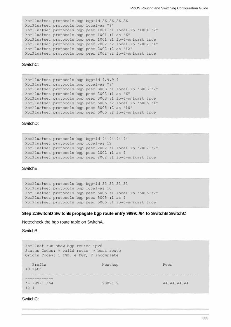
PicOS Routing and Switching Configuration Guide
333
XorPlus#set protocols bgp bgp-id 26.26.26.26XorPlus#set protocols bgp local-as "9"XorPlus#set protocols bgp peer 1001::1 local-ip "1001::2"XorPlus#set protocols bgp peer 1001::1 as "6"XorPlus#set protocols bgp peer 1001::1 ipv6-unicast trueXorPlus#set protocols bgp peer 2002::2 local-ip "2002::1"XorPlus#set protocols bgp peer 2002::2 as "12"XorPlus#set protocols bgp peer 2002::2 ipv6-unicast true
SwitchC:
XorPlus#set protocols bgp bgp-id 9.9.9.9XorPlus#set protocols bgp local-as "9"XorPlus#set protocols bgp peer 3003::1 local-ip "3003::2"XorPlus#set protocols bgp peer 3003::1 as "6"XorPlus#set protocols bgp peer 3003::1 ipv6-unicast trueXorPlus#set protocols bgp peer 5005::2 local-ip "5005::1"XorPlus#set protocols bgp peer 5005::2 as "10"XorPlus#set protocols bgp peer 5005::2 ipv6-unicast true
SwitchD:
XorPlus#set protocols bgp bgp-id 44.44.44.44XorPlus#set protocols bgp local-as 12XorPlus#set protocols bgp peer 2002::1 local-ip "2002::2"XorPlus#set protocols bgp peer 2002::1 as 9XorPlus#set protocols bgp peer 2002::1 ipv6-unicast true
SwitchE:
XorPlus#set protocols bgp bgp-id 33.33.33.33XorPlus#set protocols bgp local-as 10XorPlus#set protocols bgp peer 5005::1 local-ip "5005::2"XorPlus#set protocols bgp peer 5005::1 as 9XorPlus#set protocols bgp peer 5005::1 ipv6-unicast true
Step 2:SwitchD SwitchE propagate bgp route entry 9999::/64 to SwitchB SwitchC
Note:check the bgp route table on SwitchA.
SwitchB:
XorPlus# run show bgp routes ipv6Status Codes: * valid route, > best routeOrigin Codes: i IGP, e EGP, ? incomplete Prefix Nexthop Peer AS Path ---------------------------- ------------------------ --------------- ------------*> 9999::/64 2002::2 44.44.44.44 12 i
SwitchC:

PicOS Routing and Switching Configuration Guide
334
XorPlus# run show bgp routes ipv6Status Codes: * valid route, > best routeOrigin Codes: i IGP, e EGP, ? incomplete Prefix Nexthop Peer AS Path ---------------------------- ------------------------ --------------- ------------*> 9999::/64 5005::2 33.33.33.33 10 i
SwitchA:
XorPlus# run show bgp routes ipv6Status Codes: * valid route, > best routeOrigin Codes: i IGP, e EGP, ? incomplete Prefix Nexthop Peer AS Path ---------------------------- ------------------------ --------------- ------------* 9999::/64 1001::2 26.26.26.26 912 i*> 9999::/64 3003::2 9.9.9.9 910 iXorPlus#XorPlus# run show bgp routes ipv6 dePossible completions: <IPNet> Print BGP IPv6 routes of specified prefix detail Print detailed BGP IPv6 routesXorPlus# run show bgp routes ipv6 detail9999::/64 From peer: 9.9.9.9 Route: Winner Origin: IGP AS Path: 9 10 Nexthop: 3003::2 Multiple Exit Discriminator: 0 Local Preference: 1009999::/64 From peer: 26.26.26.26 Route: Not Used Origin: IGP AS Path: 9 12 Nexthop: 1001::2 Multiple Exit Discriminator: 0 Local Preference: 100
Note:We can see that the MED all is 0 the two bgp route entry.
Step 3:Modify the MED value on SwitchC
SwitchC:
XorPlus# set protocols bgp med 100
SwitchA:
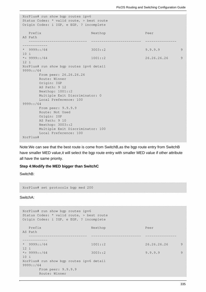
PicOS Routing and Switching Configuration Guide
335
XorPlus# run show bgp routes ipv6Status Codes: * valid route, > best routeOrigin Codes: i IGP, e EGP, ? incomplete Prefix Nexthop Peer AS Path ---------------------------- ------------------------ --------------- ------------* 9999::/64 3003::2 9.9.9.9 910 i*> 9999::/64 1001::2 26.26.26.26 912 iXorPlus# run show bgp routes ipv6 detail9999::/64 From peer: 26.26.26.26 Route: Winner Origin: IGP AS Path: 9 12 Nexthop: 1001::2 Multiple Exit Discriminator: 0 Local Preference: 1009999::/64 From peer: 9.9.9.9 Route: Not Used Origin: IGP AS Path: 9 10 Nexthop: 3003::2 Multiple Exit Discriminator: 100 Local Preference: 100XorPlus#
Note:We can see that the best route is come from SwitchB,as the bgp route entry from SwitchB
have smaller MED value,it will select the bgp route entry with smaller MED value if other attribute
all have the same priority.
Step 4:Modify the MED bigger than SwitchC
SwitchB:
XorPlus# set protocols bgp med 200
SwitchA:
XorPlus# run show bgp routes ipv6Status Codes: * valid route, > best routeOrigin Codes: i IGP, e EGP, ? incomplete Prefix Nexthop Peer AS Path ---------------------------- ------------------------ --------------- ------------* 9999::/64 1001::2 26.26.26.26 912 i*> 9999::/64 3003::2 9.9.9.9 910 iXorPlus# run show bgp routes ipv6 detail9999::/64 From peer: 9.9.9.9 Route: Winner

PicOS Routing and Switching Configuration Guide
336
Origin: IGP AS Path: 9 10 Nexthop: 3003::2 Multiple Exit Discriminator: 100 Local Preference: 1009999::/64 From peer: 26.26.26.26 Route: Not Used Origin: IGP AS Path: 9 12 Nexthop: 1001::2 Multiple Exit Discriminator: 200 Local Preference: 100
Note :We can see that the bgp speaker select the bgp route entry with smaller MED.
The COMMUNITY Attribute
Commands References:
XorPlus#set protocols bgp peer <Peer-ipv6-address> advertise communitydisable <true/false>
Note :This Comand is to enable bgp speaker to advertise well known community attribute
NO_EXPORT (0xFFFFFF01) NO_ADVERTISE (0xFFFFFF02) NO_EXPORT_SUBCONFED
(0xFFFFFF03).
XorPlus#set protocols bgp peer <Peer-ipv6-address> advertise community-extdisable <true/false>
Note :This Command is to enable bgp speaker advertise unkown community attribute.
A community is a group of destinations which share some common property.Each autonomous
system administrator may define which communities a destination belongs to. By default, all
destinations belong to the general Internet community.
the COMMUNITIES path attribute is an optional transitive attribute of variable length. The attribute
consists of a set of four octet values, each of which specify a community. All routes with this
attribute belong to the communities listed in the attribute.
The COMMUNITIES attribute has Type Code 8.
Communities are treated as 32 bit values, however for administrative assignment, the following
presumptions may be made:
The community attribute values ranging from 0x0000000 through 0x0000FFFF and 0xFFFF0000
through 0xFFFFFFFF are hereby reserved.The rest of the community attribute values shall be
encoded using an autonomous system number in the first two octets. The semantics of the final
two octets may be defined by the autonomous system (e.g. AS690 may define research,
educational and commercial community values that may be used for policy routing as defined by
the operators of that AS using community attribute values 0x02B20000 through 0x02B2FFFF).

PicOS Routing and Switching Configuration Guide
337
A BGP speaker may use this attribute to control which routing information it accepts, prefers or
distributes to other neighbors.
A BGP speaker receiving a route that does not have the COMMUNITIES path attribute may
append this attribute to the route when propagating it to its peers.
A BGP speaker receiving a route with the COMMUNITIES path attribute may modify this attribute
according to the local policy.
Aggregation
If a range of routes is to be aggregated and the resultant aggregates attribute section does not
carry the ATOMIC_AGGREGATE attribute, then
the resulting aggregate should have a COMMUNITIES path attribute which contains all
communities from all of the aggregated routes.
Well-known Communities
The following communities have global significance and their operations shall be implemented in
any community-attribute-aware BGP speaker.
NO_EXPORT (0xFFFFFF01):
All routes received carrying a communities attribute containing this value MUST NOT be advertised
outside a BGP confederation boundary (a stand-alone autonomous system that
is not part of a confederation should be considered a confederation itself).
NO_ADVERTISE (0xFFFFFF02)
All routes received carrying a communities attribute containing this value MUST NOT be advertised
to other BGP peers.
NO_EXPORT_SUBCONFED (0xFFFFFF03)
All routes received carrying a communities attribute containing this value MUST NOT be advertised
to external BGP peers (this includes peers in other members autonomous
systems inside a BGP confederation).
Because communities are not propagated to internal or external BGP neighbors by default, the
command “set protocols bgp peer <peer-ipv6-address> advertise community-ext disable true ” and
“set protocols bgp peer <peer-ipv6-address> advertise community disable true” in order for the
assigned community to be sent out.
(1)Configure Example 1:
The following example is to show you that ,7777::/64 will not advertise to EBGP peer,8888::/64 will
not advertise to any bgp peer(IBGP,EBGP) ,and 9999::/64 will not advertise to EBGP bgp peer
(include confederation ebgp peer).

PicOS Routing and Switching Configuration Guide
338
Figure 1-19
Step 1:SwitchA SwitchB Enable EBGP,SwitchB SwitchC Enable EBGP,SwitchB SwitchD
Enable IBGP
SwitchA:
XorPlus#set protocols bgp bgp-id 33.33.33.33XorPlus#set protocols bgp local-as 10XorPlus#set protocols bgp peer 5005::1 local-ip 5005::2XorPlus#set protocols bgp peer 5005::1 as 9XorPlus#set protocols bgp peer 5005::1 ipv6-unicast true
SwitchB:
XorPlus#set protocols bgp bgp-id 9.9.9.9XorPlus#set protocols bgp local-as 9XorPlus#set protocols bgp peer 3003::1 local-ip 3003::2XorPlus#set protocols bgp peer 3003::1 as 6XorPlus#set protocols bgp peer 3003::1 public-as-only trueXorPlus#set protocols bgp peer 3003::1 advertise community disable falseXorPlus#set protocols bgp peer 3003::1 ipv6-unicast trueXorPlus#set protocols bgp peer 4004::2 local-ip 4004::1XorPlus#set protocols bgp peer 4004::2 as 9XorPlus#set protocols bgp peer 4004::2 next-hop-self trueXorPlus#set protocols bgp peer 4004::2 ipv6-unicast trueXorPlus#set protocols bgp peer 5005::2 local-ip 5005::1XorPlus#set protocols bgp peer 5005::2 as 10XorPlus#set protocols bgp peer 5005::2 ipv6-unicast true
SwitchC:
XorPlus#set protocols bgp bgp-id 6.6.6.6XorPlus#set protocols bgp local-as 6

PicOS Routing and Switching Configuration Guide
339
XorPlus#set protocols bgp peer 3003::2 local-ip 3003::1XorPlus#set protocols bgp peer 3003::2 as 9XorPlus#set protocols bgp peer 3003::2 ipv6-unicast true
SwitchD:
XorPlus#set protocols bgp bgp-id 100.100.100.100XorPlus#set protocols bgp local-as 9XorPlus#set protocols bgp peer 4004::1 local-ip 4004::2XorPlus#set protocols bgp peer 4004::1 as 9XorPlus#set protocols bgp peer 4004::1 next-hop-self trueXorPlus#set protocols bgp peer 4004::1 ipv6-unicast true
Step 2:SwitchA propagate three bgp route entry to SwitchB
Note :SwitchA propagate three bgp route entry 7777::/64 with community NO_EXPORT ,it will not
advertise to any EBGP peer,8888::/64 with community NO_ADVERTISE, 9999::/64 will not
advertise to any bgp peer,with community NO_EXPORT_SUBCONFED ,it will not advertise to any
ebgp peer include confederation ebgp peer.So SwitchC will receive no bgp route entry ,as SwitchB
and SwitchC is EBGP peer,but SwitchD will receive 7777::/64 and 9999::/64,because,SwitchB and
SwitchD is IBGP peer,as 8888::/64 with community NO_ADVERTISE ,it will not advertise to any
bgp peer,so SwitchD just can’t receive 8888::/64.
SwitchB bgp route table:
XorPlus# run show bgp routes ipv6Status Codes: * valid route, > best routeOrigin Codes: i IGP, e EGP, ? incomplete Prefix Nexthop Peer AS Path ---------------------------- ------------------------ --------------- ------------*> 7777::/64 5005::2 33.33.33.33 10 i*> 8888::/64 5005::2 33.33.33.33 10 i*> 9999::/64 5005::2 33.33.33.33 10 iXorPlus# run show bgp routes ipv6 detail7777::/64 From peer: 33.33.33.33 Route: Winner Origin: IGP AS Path: 10 Nexthop: 5005::2 Local Preference: 300 Community: 0xffffff01[NO_EXPORT]8888::/64 From peer: 33.33.33.33 Route: Winner Origin: IGP AS Path: 10 Nexthop: 5005::2 Local Preference: 300 Community: 0xffffff02[NO_ADVERTISE]9999::/64

PicOS Routing and Switching Configuration Guide
340
From peer: 33.33.33.33 Route: Winner Origin: IGP AS Path: 10 Nexthop: 5005::2 Local Preference: 300 Community: 0xffffff03[NO_EXPORT_SUBCONFED]XorPlus#
SwitchC bgp route table:
XorPlus# run show bgp routes ipv6Status Codes: * valid route, > best routeOrigin Codes: i IGP, e EGP, ? incomplete Prefix Nexthop Peer AS Path ---------------------------- ------------------------ --------------- ------------XorPlus#
SwitchD bgp route table:
XorPlus# run show bgp routes ipv6Status Codes: * valid route, > best routeOrigin Codes: i IGP, e EGP, ? incomplete Prefix Nexthop Peer AS Path ---------------------------- ------------------------ --------------- ------------*> 7777::/64 4004::1 9.9.9.9 10 i*> 9999::/64 4004::1 9.9.9.9 10 iXorPlus# run show bgp routes ipv6 detail7777::/64 From peer: 9.9.9.9 Route: Winner Origin: IGP AS Path: 9 10 Nexthop: 4004::1 Local Preference: 3009999::/64 From peer: 9.9.9.9 Route: Winner Origin: IGP AS Path: 9 10 Nexthop: 4004::1 Local Preference: 300XorPlus#
Step 3:Enable advertise community on SwitchB

PicOS Routing and Switching Configuration Guide
341
Note :Community value will not advertise to it’s bgp peer by default,but we can Enable bgp speaker
to advertise community to it’s bgp peer,the command “set protocols bgp peer <peer-ipv6-address>
advertise community-ext disable true ” will advertise unkown community to it’s bgp peer and the
command “set protocols bgp peer <peer-ipv6-address> advertise community disable true” will
advertise well-known community to it’s bgp peer.
SwitchB:
XorPlus# set protocols bgp peer 4004::2 advertise community disable false
Note :The community will be sent out after Enable advertise community .
Step 4:Check the community value of the bgp route entry on SwitchD
SwitchD:
XorPlus# run show bgp routes ipv6Status Codes: * valid route, > best routeOrigin Codes: i IGP, e EGP, ? incomplete Prefix Nexthop Peer AS Path ---------------------------- ------------------------ --------------- ------------*> 7777::/64 4004::1 9.9.9.9 10 i*> 9999::/64 4004::1 9.9.9.9 10 iXorPlus# run show bgp routes ipv6 detail7777::/64 From peer: 9.9.9.9 Route: Winner Origin: IGP AS Path: 9 10 Nexthop: 4004::1 Local Preference: 300 Community: 0xffffff01[NO_EXPORT]9999::/64 From peer: 9.9.9.9 Route: Winner Origin: IGP AS Path: 9 10 Nexthop: 4004::1 Local Preference: 300 Community: 0xffffff03[NO_EXPORT_SUBCONFED]XorPlus#
Note :We can see the community after Step 3
(2)Configure Example 2:
This example is to show you that,the bgp route entry with Community
NO_EXPORT_SUBCONFED will not advertise to EBGP peer include Confederation EBGP
peer.The more detail information about Conderation please reference the section Confederation.
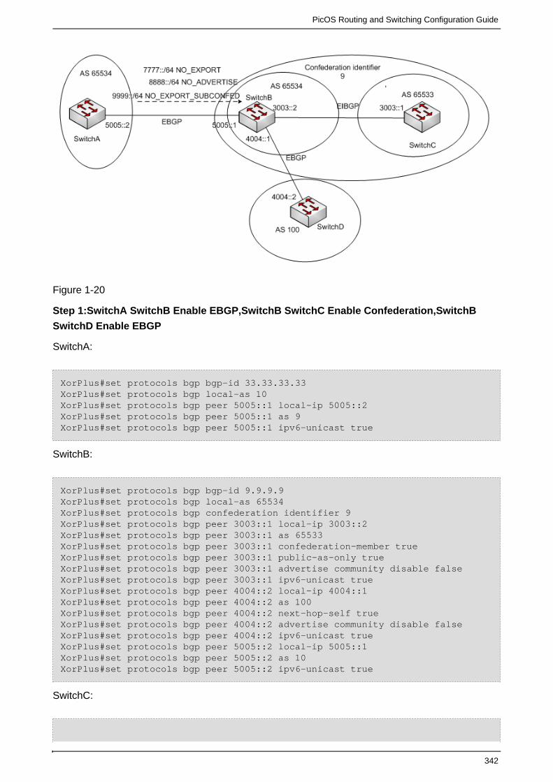
PicOS Routing and Switching Configuration Guide
342
Figure 1-20
Step 1:SwitchA SwitchB Enable EBGP,SwitchB SwitchC Enable Confederation,SwitchB
SwitchD Enable EBGP
SwitchA:
XorPlus#set protocols bgp bgp-id 33.33.33.33XorPlus#set protocols bgp local-as 10XorPlus#set protocols bgp peer 5005::1 local-ip 5005::2XorPlus#set protocols bgp peer 5005::1 as 9XorPlus#set protocols bgp peer 5005::1 ipv6-unicast true
SwitchB:
XorPlus#set protocols bgp bgp-id 9.9.9.9XorPlus#set protocols bgp local-as 65534XorPlus#set protocols bgp confederation identifier 9XorPlus#set protocols bgp peer 3003::1 local-ip 3003::2XorPlus#set protocols bgp peer 3003::1 as 65533XorPlus#set protocols bgp peer 3003::1 confederation-member trueXorPlus#set protocols bgp peer 3003::1 public-as-only trueXorPlus#set protocols bgp peer 3003::1 advertise community disable falseXorPlus#set protocols bgp peer 3003::1 ipv6-unicast trueXorPlus#set protocols bgp peer 4004::2 local-ip 4004::1XorPlus#set protocols bgp peer 4004::2 as 100XorPlus#set protocols bgp peer 4004::2 next-hop-self trueXorPlus#set protocols bgp peer 4004::2 advertise community disable falseXorPlus#set protocols bgp peer 4004::2 ipv6-unicast trueXorPlus#set protocols bgp peer 5005::2 local-ip 5005::1XorPlus#set protocols bgp peer 5005::2 as 10XorPlus#set protocols bgp peer 5005::2 ipv6-unicast true
SwitchC:

PicOS Routing and Switching Configuration Guide
343
XorPlus#set protocols bgp bgp-id 6.6.6.6XorPlus#set protocols bgp local-as 65533XorPlus#set protocols bgp peer 3003::2 local-ip 3003::1XorPlus#set protocols bgp peer 3003::2 as 65534XorPlus#set protocols bgp peer 3003::2 confederation-member trueXorPlus#set protocols bgp peer 3003::2 ipv6-unicast true
SwitchD:
XorPlus#set protocols bgp bgp-id 100.100.100.100XorPlus#set protocols bgp local-as 100XorPlus#set protocols bgp peer 4004::1 local-ip 4004::2XorPlus#set protocols bgp peer 4004::1 as 9XorPlus#set protocols bgp peer 4004::1 ipv6-unicast true
Step 2:SwitchA propagate three bgp route to SwitchB
Note : SwitchA propagate three bgp route entry to SwitchB :7777::/64 with community
NO_EXPORT ,8888::/64 with community NO_ADVERTISE 9999::/64 with community
NO_EXPORT_SUBCONFED,7777::/64 will not advertise to EBGP Peer,so SwitchD will not receive
this bgp route entry,But SwitchC will receive this entry,8888::/64 will not advertise to any BGP
Peer,so SwitchC SwitchD all will not receive this entry,9999::/64 will not advertise to EBGP
Peer,include Confederation EBGP Peer,so SwitchC SwitchD all will not receive this entry.
SwitchB bgp route table:
XorPlus# run show bgp routes ipv6Status Codes: * valid route, > best routeOrigin Codes: i IGP, e EGP, ? incomplete Prefix Nexthop Peer AS Path ---------------------------- ------------------------ --------------- ------------*> 7777::/64 5005::2 33.33.33.33 10 i*> 8888::/64 5005::2 33.33.33.33 10 i*> 9999::/64 5005::2 33.33.33.33 10 iXorPlus# run show bgp routes ipv6 detail7777::/64 From peer: 33.33.33.33 Route: Winner Origin: IGP AS Path: 10 Nexthop: 5005::2 Local Preference: 300 Community: 0xffffff01[NO_EXPORT]8888::/64 From peer: 33.33.33.33 Route: Winner Origin: IGP AS Path: 10 Nexthop: 5005::2 Local Preference: 300 Community: 0xffffff02[NO_ADVERTISE]9999::/64
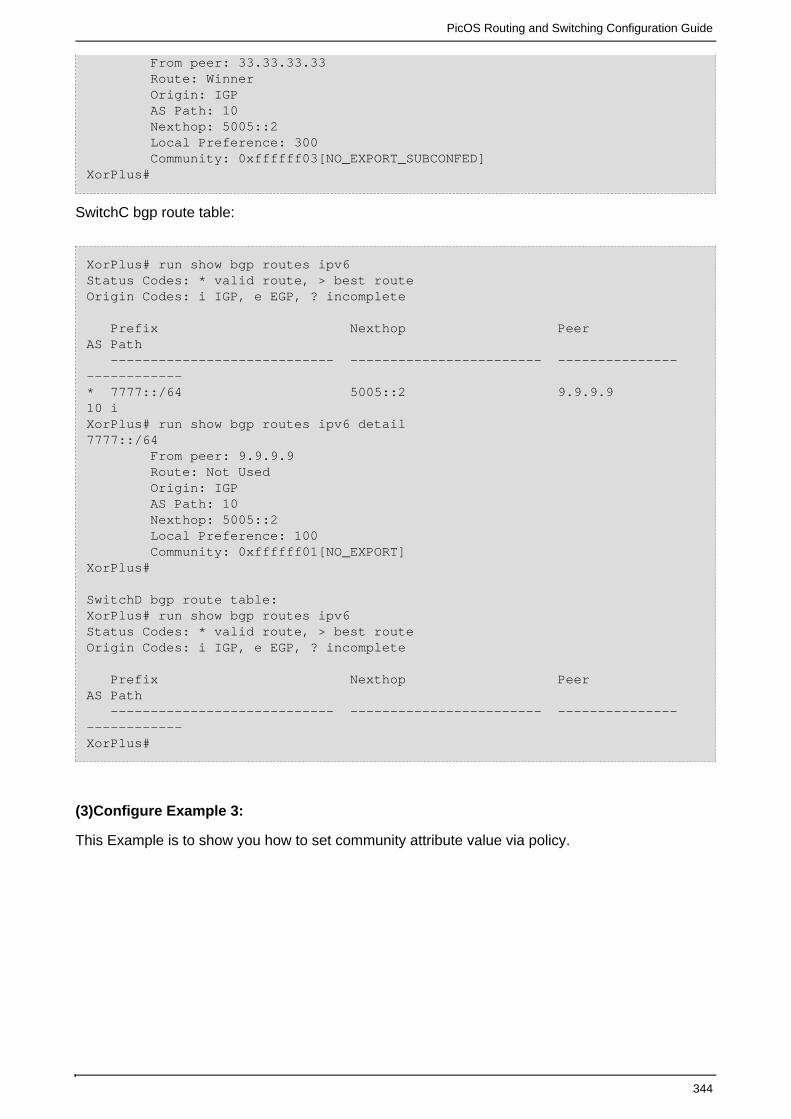
PicOS Routing and Switching Configuration Guide
344
From peer: 33.33.33.33 Route: Winner Origin: IGP AS Path: 10 Nexthop: 5005::2 Local Preference: 300 Community: 0xffffff03[NO_EXPORT_SUBCONFED]XorPlus#
SwitchC bgp route table:
XorPlus# run show bgp routes ipv6Status Codes: * valid route, > best routeOrigin Codes: i IGP, e EGP, ? incomplete
Prefix Nexthop Peer AS Path ---------------------------- ------------------------ --------------- ------------* 7777::/64 5005::2 9.9.9.9 10 iXorPlus# run show bgp routes ipv6 detail7777::/64 From peer: 9.9.9.9 Route: Not Used Origin: IGP AS Path: 10 Nexthop: 5005::2 Local Preference: 100 Community: 0xffffff01[NO_EXPORT]XorPlus#
SwitchD bgp route table:XorPlus# run show bgp routes ipv6Status Codes: * valid route, > best routeOrigin Codes: i IGP, e EGP, ? incomplete
Prefix Nexthop Peer AS Path ---------------------------- ------------------------ --------------- ------------XorPlus#
(3)Configure Example 3:
This Example is to show you how to set community attribute value via policy.

PicOS Routing and Switching Configuration Guide
345
Figure 1-21
Step 1:SwitchA SwitchB Establish OSPFV3
Note :SwitchA SwitchB Establish ospv3 and SwitchA propagate one ospfv3 route 8888::/64 to
SwitchB.
SwitchA:
XorPlus#set protocols ospf6 instance-id 1XorPlus#set protocols ospf6 router-id 1.1.1.1XorPlus#set protocols ospf6 area 0.0.0.0 interface vlan500 vif vlan500address 5005::2
SwitchB:
XorPlus#set protocols ospf6 instance-id 1XorPlus#set protocols ospf6 router-id 9.9.9.9XorPlus#set protocols ospf6 area 0.0.0.0 interface vlan500 vif vlan500address 5005::1
Step 2:SwitchB SwitchC Establish EBGP
SwitchB:
XorPlus#set protocols bgp bgp-id 9.9.9.9XorPlus#set protocols bgp local-as "9"XorPlus#set protocols bgp peer 3003::1 local-ip "3003::2"XorPlus#set protocols bgp peer 3003::1 as "6"XorPlus#set protocols bgp peer 3003::1 ipv6-unicast true
SwitchC:
XorPlus#set protocols bgp bgp-id 6.6.6.6XorPlus#set protocols bgp local-as "6"XorPlus#set protocols bgp peer 3003::2 local-ip "3003::1"XorPlus#set protocols bgp peer 3003::2 as "9"XorPlus#set protocols bgp peer 3003::2 ipv6-unicast true
Step 3:Check ospf route table on SwitchB:

PicOS Routing and Switching Configuration Guide
346
XorPlus# run show route table ipv6 unicast ospf8888::/64 [ospf(110)/1] > to fe80::200:5ff:fe6c:f993 via vlan500/vlan5008888:0:0:1::/64 [ospf(110)/1] > to fe80::200:5ff:fe6c:f993 via vlan500/vlan500
Step 4:Configure a policy to export ospfv3 into bgp and set community 9:6 to this bgp route
entry
SwitchB:
XorPlus#set policy policy-statement ospfintobgp term 1 from protocol "ospf6"XorPlus#set policy policy-statement ospfintobgp term 1 to origin 2XorPlus#set policy policy-statement ospfintobgp term 1 then community "9:6"
Step 5:Apply the policy to BGP on SwitchB
Note : The unknow community will not advertise to it’s bgp peer,so you must enable “advertise
community-ext”.
SwitchB:
XorPlus#set protocols bgp export ospfintobgpXorPlus#set protocols bgp peer 3003::1 advertise community-ext disable false
Step 6:Check the community of the bgp route table on SwitchC,it should be 9:6
SwitchC:
XorPlus# run show bgp routes ipv6Status Codes: * valid route, > best routeOrigin Codes: i IGP, e EGP, ? incomplete
Prefix Nexthop Peer AS Path ---------------------------- ------------------------ --------------- ------------*> 8888::/64 3003::2 9.9.9.9 9?XorPlus# run show bgp routes ipv6 detail8888::/64 From peer: 9.9.9.9 Route: Winner Origin: INCOMPLETE AS Path: 9 Nexthop: 3003::2 Multiple Exit Discriminator: 0 Local Preference: 100 Community: 0x90006[9:6]XorPlus#

PicOS Routing and Switching Configuration Guide
347
BGP-4 aggregation
Command References:
XorPlus# set protocols bgp aggregate network6 <IPV6-Network>
Note :This command is to set ipv6 route aggregation.the route with different MED value shouldn’t
be aggregated.
XorPlus# set protocols bgp aggregate network6 <IPV6-Network> suppress-detail<true/false>
Note :This command is to enable or disable suppress-detail bgp route entry ,The detail bgp route
entry were suppressed by default.
XorPlus#set protocols bgp aggregate network6 <IPV6-Network> brief-mode<true/false>
Note :This command is to create AS_SET when the bgp route entry have different AS_PATH
before aggregation.
The following examples demonstrate different methods of aggregation that are seen on the
Internet. The way aggregates are formed and advertised and whether they carry with them
more-specific routes will influence traffic patterns and sizes of BGP routing tables.Remember that
aggregation applies to routes that exist in the BGP routing table. An aggregate can be sent if at
least one more-specific route of that aggregate exists in the BGP table.
Route aggregation at border or core routers can also reduce the potential unpleasant side effects
associated with IGP injection into BGP. With aggregation, multiple route entries are injected into
BGP as a summary aggregate. Single route instability in any single element of the aggregate does
not affect the stability of the aggregate itself.
IPV6 BGP just support manual aggregation ,auto-summary just for IPV4 BGP.
(1) Aggregate Only, Suppressing the More-Specific by default
Note :The specific route entry will be suppressed after configure route aggregation by default.

PicOS Routing and Switching Configuration Guide
348
Figure 1-22
Step 1:Configure BGP as topo showed
SwitchA:
XorPlus# set protocols bgp bgp-id 33.33.33.33XorPlus# set protocols bgp local-as 10XorPlus# set protocols bgp peer 5005::1 local-ip 5005::2XorPlus# set protocols bgp peer 5005::1 as 9XorPlus# set protocols bgp peer 5005::1 ipv6-unicast true
SwitchB:
XorPlus# set protocols bgp bgp-id 9.9.9.9XorPlus# set protocols bgp local-as 9XorPlus# set protocols bgp peer 6006::2 local-ip 6006::1XorPlus# set protocols bgp peer 6006::2 as 9XorPlus# set protocols bgp peer 6006::2 next-hop-self trueXorPlus# set protocols bgp peer 6006::2 ipv6-unicast trueXorPlus# set protocols bgp peer 3003::1 local-ip 3003::2XorPlus# set protocols bgp peer 3003::1 as 6XorPlus# set protocols bgp peer 3003::1 ipv6-unicast trueXorPlus# set protocols bgp peer 5005::2 local-ip 5005::1XorPlus# set protocols bgp peer 5005::2 as 10XorPlus# set protocols bgp peer 5005::2 ipv6-unicast true
SwitchC:
XorPlus# set protocols bgp bgp-id 44.44.44.44XorPlus# set protocols bgp local-as 12XorPlus# set protocols bgp peer 2002::1 local-ip 2002::2XorPlus# set protocols bgp peer 2002::1 as 9XorPlus# set protocols bgp peer 2002::1 ipv6-unicast true
SwitchD:

PicOS Routing and Switching Configuration Guide
349
XorPlus# set protocols bgp bgp-id 26.26.26.26XorPlus# set protocols bgp local-as 9XorPlus# set protocols bgp peer 1001::1 local-ip 1001::2XorPlus# set protocols bgp peer 1001::1 as 6XorPlus# set protocols bgp peer 1001::1 ipv6-unicast trueXorPlus# set protocols bgp peer 2002::2 local-ip 2002::1XorPlus# set protocols bgp peer 2002::2 as 12XorPlus# set protocols bgp peer 2002::2 ipv6-unicast trueXorPlus# set protocols bgp peer 6006::1 local-ip 6006::2XorPlus# set protocols bgp peer 6006::1 as 9XorPlus# set protocols bgp peer 6006::1 next-hop-self trueXorPlus# set protocols bgp peer 6006::1 ipv6-unicast true
SwitchE:
XorPlus# set protocols bgp bgp-id 6.6.6.6XorPlus# set protocols bgp local-as 6XorPlus# set protocols bgp peer 1001::2 local-ip 1001::1XorPlus# set protocols bgp peer 1001::2 as 9XorPlus# set protocols bgp peer 1001::2 ipv6-unicast trueXorPlus# set protocols bgp peer 3003::2 local-ip "3003::1"XorPlus# set protocols bgp peer 3003::2 as 9XorPlus# set protocols bgp peer 3003::2 ipv6-unicast trueXorPlus# set protocols bgp peer 4004::2 local-ip 4004::1XorPlus# set protocols bgp peer 4004::2 as 100XorPlus# set protocols bgp peer 4004::2 ipv6-unicast true
SwitchF:
XorPlus# set protocols bgp bgp-id 100.100.100.100XorPlus# set protocols bgp local-as 100XorPlus# set protocols bgp peer 4004::1 local-ip 4004::2XorPlus# set protocols bgp peer 4004::1 as 6XorPlus# set protocols bgp peer 4004::1 ipv6-unicast true
Step 2:SwitchA propagate bgp route entry 9999::/64 to SwitchB,SwitchC propagate bgp
route entry 9999:0:0:1::/64 to SwitchD
Note :Check bgp route table on SwitchE,there should be two bgp route entry from different as-path.
SwitchE:
XorPlus# run show bgp routes ipv6Status Codes: * valid route, > best routeOrigin Codes: i IGP, e EGP, ? incomplete Prefix Nexthop Peer AS Path ---------------------------- ------------------------ --------------- ------------*> 9999:0:0:1::/64 3003::2 9.9.9.9 912 i*> 9999::/64 1001::2 26.26.26.26 910 i* 9999:0:0:1::/64 1001::2 26.26.26.26 912 iXorPlus#

PicOS Routing and Switching Configuration Guide
350
SwitchF:
XorPlus# run show bgp routes ipv6Status Codes: * valid route, > best routeOrigin Codes: i IGP, e EGP, ? incomplete Prefix Nexthop Peer AS Path ---------------------------- ------------------------ --------------- ------------*> 9999:0:0:1::/64 4004::1 6.6.6.6 69 12 i*> 9999::/64 4004::1 6.6.6.6 69 10 iXorPlus#
Step 3:Configuure Route aggregation on SwitchE
Note :The specific route entry was suppressed by default,and you can cancel suppress specific
route by command “set protocols bgp aggregate network6 <IPV6-Network> suppress-detail false”
SwitchE:
XorPlus# set protocols bgp aggregate network6 9999::/40
Check bgp route table on SwitchF:
XorPlus# run show bgp routes ipv6Status Codes: * valid route, > best routeOrigin Codes: i IGP, e EGP, ? incomplete Prefix Nexthop Peer AS Path ---------------------------- ------------------------ --------------- ------------*> 9999::/40 4004::1 6.6.6.6 6iXorPlus# XorPlus# run show bgp routes ipv6 detail9999::/40 From peer: 6.6.6.6 Route: Winner Origin: IGP AS Path: 6 Nexthop: 4004::1 Multiple Exit Discriminator: 0 Local Preference: 100 Aggregator: 6.6.6.6
Note :We can see the aggregated ipv6 network 9999::/40 on SwitchF,and the Aggregator is 6.6.6.6
who create this aggregated network and the as-path is the as number that who create this
aggregated network.
Step 4:Disable suppress-detail

PicOS Routing and Switching Configuration Guide
351
Note : In some cases, more-specific routes, in addition to the aggregate, need to be passed
(leaked) to a neighboring AS. This is usually done in ASs multihomed to a single provider. An AS
(the provider) that gets the more-specific routes would be able to make a better decision about
which way to reach the route.
SwitchE:
XorPlus# set protocols bgp aggregate network6 9999::/40 suppress-detail false
Check the bgp route table on SwitchF:
XorPlus# run show bgp routes ipv6Status Codes: * valid route, > best routeOrigin Codes: i IGP, e EGP, ? incomplete Prefix Nexthop Peer AS Path ---------------------------- ------------------------ --------------- ------------*> 9999::/40 4004::1 6.6.6.6 6i*> 9999:0:0:1::/64 4004::1 6.6.6.6 69 12 i*> 9999::/64 4004::1 6.6.6.6 69 10 iXorPlus#XorPlus# run show bgp routes ipv6 detail9999::/40 From peer: 6.6.6.6 Route: Winner Origin: IGP AS Path: 6 Nexthop: 4004::1 Multiple Exit Discriminator: 0 Local Preference: 100 Aggregator: 6.6.6.69999::/64 From peer: 6.6.6.6 Route: Winner Origin: IGP AS Path: 6 9 10 Nexthop: 4004::1 Multiple Exit Discriminator: 0 Local Preference: 1009999:0:0:1::/64 From peer: 6.6.6.6 Route: Winner Origin: IGP AS Path: 6 9 12 Nexthop: 4004::1 Multiple Exit Discriminator: 0 Local Preference: 100
Note :We can see that the specific route entry didn’t suppressed after disable suppress-detail.
(2)Loss of Information Inside Aggregates

PicOS Routing and Switching Configuration Guide
352
Aggregation causes loss of granularity. The detailed information that exists in the specific prefixes
will be lost when summarized in the form of aggregates. The purpose of an AS_SET is to attempt
to preserve the attributes carried in the specific routes in a mathematical SET that gives a better
idea of the elements of the aggregate.
Note :This example is to show you creat as_set when the as_path is different before the bgp route
entry were aggregated.It will not creat as_set by default.
Figure 1-23
Step 1:Configure BGP as topo showed
SwitchA:
XorPlus# set protocols bgp bgp-id 33.33.33.33XorPlus# set protocols bgp local-as 10XorPlus# set protocols bgp peer 5005::1 local-ip 5005::2XorPlus# set protocols bgp peer 5005::1 as 9XorPlus# set protocols bgp peer 5005::1 ipv6-unicast true
SwitchB:
XorPlus# set protocols bgp bgp-id 9.9.9.9XorPlus# set protocols bgp local-as 9XorPlus# set protocols bgp peer 6006::2 local-ip 6006::1XorPlus# set protocols bgp peer 6006::2 as 9XorPlus# set protocols bgp peer 6006::2 next-hop-self trueXorPlus# set protocols bgp peer 6006::2 ipv6-unicast trueXorPlus# set protocols bgp peer 3003::1 local-ip 3003::2XorPlus# set protocols bgp peer 3003::1 as 6XorPlus# set protocols bgp peer 3003::1 ipv6-unicast trueXorPlus# set protocols bgp peer 5005::2 local-ip 5005::1XorPlus# set protocols bgp peer 5005::2 as 10XorPlus# set protocols bgp peer 5005::2 ipv6-unicast true
SwitchC:

PicOS Routing and Switching Configuration Guide
353
XorPlus# set protocols bgp bgp-id 44.44.44.44XorPlus# set protocols bgp local-as 12XorPlus# set protocols bgp peer 2002::1 local-ip 2002::2XorPlus# set protocols bgp peer 2002::1 as 9XorPlus# set protocols bgp peer 2002::1 ipv6-unicast true
SwitchD:
XorPlus# set protocols bgp bgp-id 26.26.26.26XorPlus# set protocols bgp local-as 9XorPlus# set protocols bgp peer 1001::1 local-ip 1001::2XorPlus# set protocols bgp peer 1001::1 as 6XorPlus# set protocols bgp peer 1001::1 ipv6-unicast trueXorPlus# set protocols bgp peer 2002::2 local-ip 2002::1XorPlus# set protocols bgp peer 2002::2 as 12XorPlus# set protocols bgp peer 2002::2 ipv6-unicast trueXorPlus# set protocols bgp peer 6006::1 local-ip 6006::2XorPlus# set protocols bgp peer 6006::1 as 9XorPlus# set protocols bgp peer 6006::1 next-hop-self trueXorPlus# set protocols bgp peer 6006::1 ipv6-unicast true
SwitchE:
XorPlus# set protocols bgp bgp-id 6.6.6.6XorPlus# set protocols bgp local-as 6XorPlus# set protocols bgp peer 1001::2 local-ip 1001::1XorPlus# set protocols bgp peer 1001::2 as 9XorPlus# set protocols bgp peer 1001::2 ipv6-unicast trueXorPlus# set protocols bgp peer 3003::2 local-ip "3003::1"XorPlus# set protocols bgp peer 3003::2 as 9XorPlus# set protocols bgp peer 3003::2 ipv6-unicast trueXorPlus# set protocols bgp peer 4004::2 local-ip 4004::1XorPlus# set protocols bgp peer 4004::2 as 100XorPlus# set protocols bgp peer 4004::2 ipv6-unicast true
SwitchF:
XorPlus# set protocols bgp bgp-id 100.100.100.100XorPlus# set protocols bgp local-as 100XorPlus# set protocols bgp peer 4004::1 local-ip 4004::2XorPlus# set protocols bgp peer 4004::1 as 6XorPlus# set protocols bgp peer 4004::1 ipv6-unicast true
Step 2:SwitchA propagate bgp route entry 9999::/64 to SwitchB,SwitchC propagate bgp
route entry 9999:0:0:1::/64 to SwitchD
Note :Check bgp route table on SwitchE,there should be two bgp route entry from different as-path.
SwitchE:
XorPlus# run show bgp routes ipv6Status Codes: * valid route, > best routeOrigin Codes: i IGP, e EGP, ? incomplete Prefix Nexthop Peer AS Path ---------------------------- ------------------------ ---------------

PicOS Routing and Switching Configuration Guide
354
------------*> 9999:0:0:1::/64 3003::2 9.9.9.9 912 i*> 9999::/64 1001::2 26.26.26.26 910 i* 9999:0:0:1::/64 1001::2 26.26.26.26 912 iXorPlus#
SwitchF:
XorPlus# run show bgp routes ipv6Status Codes: * valid route, > best routeOrigin Codes: i IGP, e EGP, ? incomplete Prefix Nexthop Peer AS Path ---------------------------- ------------------------ --------------- ------------*> 9999:0:0:1::/64 4004::1 6.6.6.6 69 12 i*> 9999::/64 4004::1 6.6.6.6 69 10 iXorPlus#
Step 3:Configuure Route aggregation on SwitchE
Note :The bgp speaker will not create AS_SET by default,you can enable the bgp speaker create
AS_SET via command “set protocols bgp aggregate network6 <IPV6-Network> brief-mode false”.
SwitchE:
XorPlus# set protocols bgp aggregate network6 9999::/40
Check bgp route table on SwitchF:
XorPlus# run show bgp routes ipv6Status Codes: * valid route, > best routeOrigin Codes: i IGP, e EGP, ? incomplete Prefix Nexthop Peer AS Path ---------------------------- ------------------------ --------------- ------------*> 9999::/40 4004::1 6.6.6.6 6iXorPlus#XorPlus# run show bgp routes ipv6 detail9999::/40 From peer: 6.6.6.6 Route: Winner Origin: IGP AS Path: 6 Nexthop: 4004::1 Multiple Exit Discriminator: 0 Local Preference: 100 Aggregator: 6.6.6.6

PicOS Routing and Switching Configuration Guide
355
Note :We can see the aggregated ipv6 network 9999::/40 on SwitchF,and the Aggregator is 6.6.6.6
who create this aggregated network and the as-path is the as number that who create this
aggregated network.
Step 4:Create AS_SET
Note :It will not Create AS_SET by default.
SwitchE:
XorPlus# set protocols bgp aggregate network6 9999::/40 brief-mode false
Check the bgp route table on SwitchF:
XorPlus# run show bgp routes ipv6Status Codes: * valid route, > best routeOrigin Codes: i IGP, e EGP, ? incomplete Prefix Nexthop Peer AS Path ---------------------------- ------------------------ --------------- ------------*> 9999::/40 4004::1 6.6.6.6 6{9 10} iXorPlus#XorPlus# run show bgp routes ipv6 detail9999::/40 From peer: 6.6.6.6 Route: Winner Origin: IGP AS Path: 6 {9 10} Nexthop: 4004::1 Multiple Exit Discriminator: 0 Local Preference: 100 Aggregator: 6.6.6.6
Synchronization
Commands Reference:
XorPlus# set protocols bgp synchronization <true/false>
Note :This command is to Enable or Disable synchronization , synchronization is disabled by
default.
By definition, the default behavior of BGP requires that it must be synchronized with the IGP before
BGP may advertise transit routes to external ASs. It is important that your AS be consistent about
the routes it advertises to avoid unnecessarily black-holing traffic. For example, if an IBGP speaker
were to advertise a route to an external peer before all routers within your AS had learned about
the route through the IGP, your AS could receive traffic to destinations for which some of the
routers might not yet have the information to reach.

PicOS Routing and Switching Configuration Guide
356
Whenever a router receives an update about a destination from an IBGP peer, the router tries to
verify internal reachability for that destination before advertising it to other EBGP peers.The router
does this by checking the destination prefix first to see if a route to the next-hop router exists and
second to see if a destination prefix in the IGP exists. This router check indicates whether
non-BGP routers can deliver traffic to that destination. Assuming that the IGP recognizes that
destination, the router announces it to other EBGP peers. Otherwise, the router treats the
destination prefix as not being synchronized with the IGP and does not advertise it.
The BGP rule states that a BGP router should not advertise to external neighbors destinations
learned from IBGP neighbors unless those destinations are also known via an IGP. This is known
as synchronization. If a router knows about these destinations via an IGP, it assumes that the route
has already been propagated inside the AS, and internal reachability is ensured.
The consequence of injecting BGP routes inside an IGP is costly. Redistributing routes from BGP
into the IGP will result in major overhead on the internal routers, primarily from an IGP scalability
perspective, because (as discussed earlier) IGPs are not designed to handle that many routes.
Besides, carrying all external routes inside an AS is not necessary. Routing can easily be
accomplished by having internal non-BGP routers default to one of the BGP routers.Of course, this
will result in suboptimal routing because there is no guarantee that the shortest path for each route
will be used, but this cost is minimal compared to maintaining thousands of routes inside the AS.
Of course, managing default routes in a situation such as this can be extremely complex and may
very well result in routing loops.
Most BGP implementations, however, offer a software knob that lets the network operator disable
synchronization. As you might suspect, configuring “set protocols bgp synchronization false” will
tell BGP to override the synchronization requirement and allow it to advertise routes learned via
IBGP, irrespective of the existence of an IGP route. In practice, most situations allow
synchronization to be safely turned off on border routers, assuming that all transit routers in the AS
are running fully meshed IBGP. In this situation, internal reachability is guaranteed because a route
that is learned via EBGP on any border router will automatically be passed on via BGP to all transit
routers.
That said, by far the most common configuration in Internet-connected networks is to disable BGP
synchronization and rely on a full mesh of IBGP routers. The thought of injecting tens of thousands
of routes into an IGP is quite frightening.

PicOS Routing and Switching Configuration Guide
357
Figure-1 1-24
Step 1:SwitchB SwitchC SwitchD Establish ospfv3
SwitchB:
XorPlus#set protocols ospf6 instance-id 1XorPlus#set protocols ospf6 router-id 9.9.9.9XorPlus#set protocols ospf6 area 0.0.0.0 interface vlan600 vif vlan600address 6006::1
SwitchC:
XorPlus#set protocols ospf6 instance-id 1XorPlus#set protocols ospf6 router-id 6.6.6.6XorPlus#set protocols ospf6 area 0.0.0.0 interface vlan100 vif vlan100address 1001::1
SwitchD:
XorPlus#set protocols ospf6 instance-id 1XorPlus#set protocols ospf6 router-id 26.26.26.26XorPlus#set protocols ospf6 area 0.0.0.0 interface vlan100 vif vlan100address 1001::2XorPlus#set protocols ospf6 area 0.0.0.0 interface vlan600 vif vlan600address 6006::2
Step 2:SwitchA SwitchB establish EBGP,SwitchB SwitchC establish IGP,SwitchC SwitchE
establish EBGP
SwitchA:
XorPlus#set protocols bgp bgp-id 33.33.33.33XorPlus#set protocols bgp local-as 1XorPlus#set protocols bgp peer 5005::1 local-ip 5005::2XorPlus#set protocols bgp peer 5005::1 as 2XorPlus#set protocols bgp peer 5005::1 ipv6-unicast true

PicOS Routing and Switching Configuration Guide
358
SwitchB:
XorPlus#set protocols bgp bgp-id 9.9.9.9XorPlus#set protocols bgp local-as "2"XorPlus#set protocols bgp peer 1001::1 local-ip "6006::1"XorPlus#set protocols bgp peer 1001::1 as "2"XorPlus#set protocols bgp peer 1001::1 ipv6-unicast trueXorPlus#set protocols bgp peer 5005::2 local-ip "5005::1"XorPlus#set protocols bgp peer 5005::2 as "1"XorPlus#set protocols bgp peer 5005::2 ipv6-unicast true
SwitchC:
XorPlus#set protocols bgp bgp-id 6.6.6.6XorPlus#set protocols bgp local-as "2"XorPlus#set protocols bgp peer 6006::1 local-ip "1001::1"XorPlus#set protocols bgp peer 6006::1 as "2"XorPlus#set protocols bgp peer 6006::1 next-hop-self trueXorPlus#set protocols bgp peer 6006::1 ipv6-unicast trueXorPlus#set protocols bgp peer 4004::2 local-ip "4004::1"XorPlus#set protocols bgp peer 4004::2 as "3"XorPlus#set protocols bgp peer 4004::2 ipv6-unicast true
SwitchE:
XorPlus#set protocols bgp bgp-id 100.100.100.100XorPlus#set protocols bgp local-as 3XorPlus#set protocols bgp peer 4004::1 local-ip 4004::2XorPlus#set protocols bgp peer 4004::1 as 2XorPlus#set protocols bgp peer 4004::1 ipv6-unicast true
Step 3:Enable Synchronization on SwitchC
Note :If the route entry couldn’t reachable via IGP,it will not install into bgp route table.
SwitchC:
XorPlus# set protocols bgp synchronization true
Check SwitchB bgp route table:
XorPlus# run show bgp routes ipv6Status Codes: * valid route, > best routeOrigin Codes: i IGP, e EGP, ? incomplete Prefix Nexthop Peer AS Path ---------------------------- ------------------------ --------------- ------------*> 9999::/64 5005::2 33.33.33.33 1iXorPlus#
Check SwitchC bgp route table:

PicOS Routing and Switching Configuration Guide
359
XorPlus# run show bgp routes ipv6Status Codes: * valid route, > best routeOrigin Codes: i IGP, e EGP, ? incomplete
Prefix Nexthop Peer AS Path ---------------------------- ------------------------ --------------- ------------XorPlus#
Check the ospfv3 route table:
XorPlus# run show route table ipv6 unicast ospf6006::/64 [ospf(110)/2] > to fe80::ca0a:a9ff:304:4928 via vlan100/vlan100
Note :We can see that, the bgp route table is null,as the bgp route entry 9999::/64 didn’t in IGP
route table,so It will not install into bgp route table.
Step 4:Configure a policy export the bgp route entry 9999::/64 into ospfv3 on SwitchB
SwitchB:
XorPlus#set policy policy-statement bgpintoospf term 1 from protocol "bgp"XorPlus#set policy policy-statement bgpintoospf term 1 then acceptXorPlus# set protocols ospf6 export bgpintoospf
Check the ospfv3 route table on SwitchC
SwitchC ospfv3 route table:
XorPlus# run show route table ipv6 unicast ospf6006::/64 [ospf(110)/2] > to fe80::ca0a:a9ff:304:4928 via vlan100/vlan100XorPlus# run show route table ipv6 unicast ospf6006::/64 [ospf(110)/2] > to fe80::ca0a:a9ff:304:4928 via vlan100/vlan1009999::/64 [ospf(110)/3] > to fe80::ca0a:a9ff:304:4928 via vlan100/vlan100
Step 5:Check the bgp route table on SwitchC
Note :The bgp route entry 9999::/64 should have install into bgp route table as the route entry
9999::/64 have been in OSPFV3 route table.
SwitchC BGP route table:
XorPlus# run show bgp routes ipv6Status Codes: * valid route, > best routeOrigin Codes: i IGP, e EGP, ? incomplete Prefix Nexthop Peer AS Path ---------------------------- ------------------------ --------------- ------------

PicOS Routing and Switching Configuration Guide
360
* 9999::/64 5005::2 9.9.9.9 1i
Controlling large-scale Autonomous system
Route reflectors—
A method of managing expanding mesh requirements in large autonomous systems (ASs) by
using selected routers as focal points for internal BGP sessions.
Confederations—
A method of managing expanding mesh requirements in large ASs by creating sub-ASs.
Confederations
Commadns References:
XorPlus# set protocols bgp confederation disable [true/false]
Note:This Command is to enable/disable bgp confederation.
XorPlus# set protocols bgp confederation identifier[confederation-identifier]
Note:This Command is to configure a bgp confederation identifier, It’s used for establish EBPG
Peer, It’s an 2-byte or 4-byte AS number.
XorPlus# set protocols bgp peer [Peer-IPV6 address] confederation-member[true/false]
Note:This Command is to specify one bgp peer as a confederation member.
XorPlus# set protocols bgp local-as [AS-Nunmber]
Note:This Command is to configure a private local-as number,used for establish internal
confederation EBGP.
A confederation is another way to deal with the explosion of an IBGP mesh within an AS.As with
route reflection, confederations are recommended only for cases in which IBGP peering involves a
large number of IBGP peering sessions per router.
BGP confederations are based on the concept that an AS can be broken into multiple
sub-ASs.Inside each sub-AS, all the rules of IBGP apply. All BGP routers inside the sub-AS, for
example, must be fully meshed. Because each sub-AS has a different AS number, external BGP
must run between them. Although EBGP is used between sub-ASs, routing inside the
confederation behaves like IBGP routing in a single AS. In other words, the next hop, MED,and
local preference information is preserved when crossing the sub-AS boundaries. To the outside
world, a confederation looks like a single AS.

PicOS Routing and Switching Configuration Guide
361
All the sub-ASs are shielded from the outside world and can be given any AS numbers. The
numbers could be chosen from the private AS range (64512 to 65534, as designated in RFC 1930)
in order not to use up any formal AS numbers.
As mentioned previously, inside the sub-AS an IBGP full mesh is used. EBGP is used between the
sub-ASs as well as between the confederation itself and outside ASs.
Confederations can easily detect routing loops inside the whole AS because EBGP is run between
sub-ASs. The AS path list is a loop-avoidance mechanism used to detect routing updates leaving
one sub-AS and attempting to reenter the same sub-AS. A routing update that tries to reenter a
sub-AS it originated from will be detected because the sub-AS will see its own sub-AS number
listed in the update's AS path.
Figure 2-5
Step 1:SwitchB SwitchC SwitchD configure as confederation menber
SwitchB:
XorPlus# set protocols bgp bgp-id 9.9.9.9XorPlus# set protocols bgp local-as "65531"XorPlus# set protocols bgp confederation identifier "6"XorPlus# set protocols bgp peer 3003::1 local-ip "3003::2"XorPlus# set protocols bgp peer 3003::1 as "65531"XorPlus# set protocols bgp peer 3003::1 next-hop-self trueXorPlus# set protocols bgp peer 3003::1 confederation-member trueXorPlus# set protocols bgp peer 3003::1 ipv6-unicast true
SwitchC:

PicOS Routing and Switching Configuration Guide
362
XorPlus# set protocols bgp bgp-id 6.6.6.6XorPlus# set protocols bgp local-as "65531"XorPlus# set protocols bgp confederation identifier "6"XorPlus# set protocols bgp peer 1001::2 local-ip "1001::1"XorPlus# set protocols bgp peer 1001::2 as "65532"XorPlus# set protocols bgp peer 1001::2 next-hop-self trueXorPlus# set protocols bgp peer 1001::2 client trueXorPlus# set protocols bgp peer 1001::2 confederation-member trueXorPlus# set protocols bgp peer 1001::2 ipv6-unicast trueXorPlus# set protocols bgp peer 3003::2 local-ip "3003::1"XorPlus# set protocols bgp peer 3003::2 as "65531"XorPlus# set protocols bgp peer 3003::2 next-hop-self trueXorPlus# set protocols bgp peer 3003::2 confederation-member trueXorPlus# set protocols bgp peer 3003::2 ipv6-unicast true
SwitchD:
XorPlus# set protocols bgp bgp-id 26.26.26.26XorPlus# set protocols bgp local-as "65532"XorPlus# set protocols bgp confederation identifier "6"XorPlus# set protocols bgp peer 1001::1 local-ip "1001::2"XorPlus# set protocols bgp peer 1001::1 as "65531"XorPlus# set protocols bgp peer 1001::1 next-hop-self trueXorPlus# set protocols bgp peer 1001::1 confederation-member trueXorPlus# set protocols bgp peer 1001::1 ipv6-unicast true
Step 2:SwitchA SwitchB configure EBGP,SwitchC SwitchE configue EBGP
SwitchA:
XorPlus# set protocols bgp bgp-id 33.33.33.33XorPlus# set protocols bgp local-as 10XorPlus# set protocols bgp peer 5005::1 local-ip "5005::2"XorPlus# set protocols bgp peer 5005::1 as 6XorPlus# set protocols bgp peer 5005::1 ipv6-unicast true
SwitchB:
XorPlus# set protocols bgp peer 5005::2 local-ip "5005::1"XorPlus# set protocols bgp peer 5005::2 as "10"XorPlus# set protocols bgp peer 5005::2 ipv6-unicast true
SwitchD:
XorPlus# set protocols bgp peer 4004::2 local-ip "4004::1"XorPlus# set protocols bgp peer 4004::2 as 100XorPlus# set protocols bgp peer 4004::2 next-hop-self trueXorPlus# set protocols bgp peer 4004::2 ipv6-unicast true
SwitchE:
XorPlus# set protocols bgp bgp-id 100.100.100.100XorPlus# set protocols bgp local-as 100

PicOS Routing and Switching Configuration Guide
363
XorPlus# set protocols bgp peer 4004::1 local-ip "4004::2"XorPlus# set protocols bgp peer 4004::1 as 6XorPlus# set protocols bgp peer 4004::1 ipv6-unicast true
Step 3:SwitchA distribute one bgp route entry, then check the bgp route table on SwitchB
SwitchC SwitchD SwitchE
SwitchB bgp route table:
XorPlus# run show bgp routes ipv6Status Codes: * valid route, > best routeOrigin Codes: i IGP, e EGP, ? incomplete Prefix Nexthop Peer AS Path ---------------------------- ------------------------ --------------- ------------*> 9999::/64 5005::2 33.33.33.33 10 iXorPlus# run show bgp routes ipv6 detail9999::/64 From peer: 33.33.33.33 Route: Winner Origin: IGP AS Path: 10 Nexthop: 5005::2 Local Preference: 100XorPlus#
SwitchC bgp route table:
XorPlus# run show bgp routes ipv6Status Codes: * valid route, > best routeOrigin Codes: i IGP, e EGP, ? incomplete Prefix Nexthop Peer AS Path ---------------------------- ------------------------ --------------- ------------*> 9999::/64 3003::2 9.9.9.9 10 iXorPlus# run show bgp routes ipv6 detail9999::/64 From peer: 9.9.9.9 Route: Winner Origin: IGP AS Path: 10 Nexthop: 3003::2 Local Preference: 100XorPlus#
SwitchD bgp route table:
XorPlus# run show bgp routes ipv6Status Codes: * valid route, > best routeOrigin Codes: i IGP, e EGP, ? incomplete Prefix Nexthop Peer AS Path ---------------------------- ------------------------ ---------------

PicOS Routing and Switching Configuration Guide
364
------------*> 9999::/64 1001::1 6.6.6.6 (65531) 10 iXorPlus# run show bgp routes ipv6 detail9999::/64 From peer: 6.6.6.6 Route: Winner Origin: IGP AS Path: (65531) 10 Nexthop: 1001::1 Local Preference: 100XorPlus#
Note:We can see that the as-path include the Confederation ebgp as number 65531
SwitchE bgp route table:
XorPlus# run show bgp routes ipv6Status Codes: * valid route, > best routeOrigin Codes: i IGP, e EGP, ? incomplete Prefix Nexthop Peer AS Path ---------------------------- ------------------------ --------------- ------------*> 9999::/64 4004::1 6.6.6.6 6 10iXorPlus# run show bgp routes ipv6 detail9999::/64 From peer: 6.6.6.6 Route: Winner Origin: IGP AS Path: 6 10 Nexthop: 4004::1 Local Preference: 100XorPlus#
Note:We can see taht ,the Confederation as number 65531 was removed from the as-path when it
outbound the AS to it’s EBGP Peer.
Route Reflectors
Route Reflectors Commands References:
XorPlus# set protocols bgp route-reflector disable [true/false]
Note:This Command is to enable/disable route-reflectors.
XorPlus# set protocols bgp route-reflector cluster-id [cluster-id]
Note:This Command is to specify a cluster-id.
XorPlus# set protocols bgp peer [bgp peer id] client [true/false]

PicOS Routing and Switching Configuration Guide
365
Note:This Command is to specify one bgp peer as RR’s Client.
In some Internet service provider (ISP) networks, the internal BGP mesh can become quite large
(more than 100 internal BGP sessions per router), which strongly suggests that some new peering
mechanism be implemented. The concept is based on the idea of specifying a route reflector
router to act as a focal point for internal BGP sessions. Multiple (client) BGP routersconcentration
can peer with a central server (the route reflector), and then route reflectors peer with one another.
Although the BGP rule states that routes learned via one IBGP speaker can't be advertised to
another IBGP speaker, route reflection allows the route reflector servers to "reflect" routes as
described later, thereby relaxing the IBGP full-mesh constraints.
The route reflector is a router that performs the route reflection function. The IBGP peers of the
route reflector fall under two categories— and A route reflector and its clientsclients nonclients.
form a All peers of the route reflector that are not part of the cluster are nonclients.cluster.
Nonclients (standard IBGP speakers) are still required to be fully meshed with one another and the
route reflector because they follow the normal IBGP advertisement rules, although they no longer
need to peer with the clients of the route reflectors. Clients should not peer with internal speakers
outside their associated cluster.
The route reflector function is implemented only on the route reflector; all clients and nonclients are
normal BGP peers that have no notion of the route reflector. Route reflector clients are considered
as such only because the route reflector lists them as clients.
Any route reflector that receives multiple routes for the same destination employs the usual BGP
decision process to pick the overall best path. The best path would be propagated inside the AS
based on the following rules of operation:
If the route is received from a nonclient peer, reflect to clients only.
If the route is received from a client peer, reflect to all nonclient peers and also to client
peers.
If the route is received from an EBGP peer, reflect to all client and nonclient peers.
Because route reflection is a concept that applies only internally to an AS, routers external to the
AS, which would receive UPDATEs via EBGP, are considered nonclients and follow normal
nonclient behavior with respect to sending and receiving UPDATEs.
The Route Reflector Preserves IBGP Attributes
The route reflector concept does not change IBGP behavior—the route reflector is not allowed to
modify the attributes of the reflected IBGP routes. The NEXT_HOP attribute, for example, remains
the same when an IBGP route is exchanged between RRs. This is necessary to avoid loops inside
the AS.
Avoiding Loops
BGP relies on the information in the AS path to facilitate loop detection. A BGP update that
attempts to reenter the AS it was originated from will be dropped by the border router of the source
AS With the introduction of route reflectors, there is a potential for routing loops within an AS. A

PicOS Routing and Switching Configuration Guide
366
routing update that leaves a cluster may reenter the cluster. Loops inside the AS cannot be
detected by the traditional AS path approach because routing updates do not have an originating
AS path signature. Therefore, when route reflectors are deployed, BGP offers two extra measures
for loop avoidance inside the AS—using an ORIGINATOR_ID and using a CLUSTER_LIST.
Using an ORIGINATOR_ID
The ORIGINATOR_ID is a 4-byte, optional, nontransitive BGP attribute (type code 9). This attribute
carries the ROUTER_ID of the route's originator in the local AS and is to be added to the UPDATE
message by the route reflector. If the update comes back to the originator because of poor
configuration, the originator should discard it.
The CLUSTER_LIST
The CLUSTER_LIST is an optional, nontransitive BGP attribute (type code 10). Each clusteris
represented with a CLUSTER_ID.A CLUSTER_LIST is a sequence of CLUSTER_IDs that contain
path information regarding the list of clusters that an UPDATE has traversed. When a route
reflector sends a route from its clients to nonclients outside the cluster, it appends the local
CLUSTER_ID to the CLUSTER_LIST, or creates the list if one is not present. If the route reflector
receives an UPDATE whose CLUSTER_LIST contains the local CLUSTER_ID value, the UPDATE
message should be discarded. Thus, the CLUSTER_LIST provides loop avoidance inside an AS,
whereas the AS_PATH list, discussed earlier, facilitates loop avoidance for UPDATEs traversing
multiple, external ASs.
(1)Configure Example 1:
Figure 2-1
Step 1:Configure IBGP
SwitchA:
XorPlus# set protocols bgp bgp-id 6.6.6.6XorPlus# set protocols bgp local-as "6"XorPlus# set protocols bgp peer 3003::2 local-ip "3003::1"

PicOS Routing and Switching Configuration Guide
367
XorPlus# set protocols bgp peer 3003::2 as "6"XorPlus# set protocols bgp peer 3003::2 next-hop-self trueXorPlus# set protocols bgp peer 3003::2 ipv6-unicast true
SwitchB:
XorPlus# set protocols bgp bgp-id 9.9.9.9XorPlus# set protocols bgp local-as "6"XorPlus# set protocols bgp peer 3003::1 local-ip "3003::2"XorPlus# set protocols bgp peer 3003::1 as "6"XorPlus# set protocols bgp peer 3003::1 next-hop-self trueXorPlus# set protocols bgp peer 3003::1 ipv6-unicast true
Step 2:Configure SwitchA as RR and configure Cluster-ID
XorPlus# set protocols bgp route-reflector disable falseXorPlus# set protocols bgp route-reflector cluster-id 6.6.6.6
Step 3:Specify One bgp peer as RR’s Client
XorPlus# set protocols bgp peer 3003::2 client true
Step 4:Check bgp peer status:
SwitchA:
XorPlus# run show bgp peers detailPeer 2: local 3003::1/179 remote 3003::2/33239 Peer ID: 9.9.9.9 Peer State: ESTABLISHED Admin State: START Negotiated BGP Version: 4 Peer AS Number: 6 Updates Received: 1, Updates Sent: 6 Messages Received: 102, Messages Sent: 108 Time since last received update: 2611 seconds Number of transitions to ESTABLISHED: 4 Time since last entering ESTABLISHED state: 2611 seconds Retry Interval: 120 seconds Hold Time: 90 seconds, Keep Alive Time: 30 seconds Configured Hold Time: 90 seconds, Configured Keep Alive Time: 30 seconds Minimum AS Origination Interval: 0 seconds Minimum Route Advertisement Interval: 0 seconds
SwitchB:
XorPlus# run show bgp peers detailPeer 1: local 3003::2/33239 remote 3003::1/179 Peer ID: 6.6.6.6 Peer State: ESTABLISHED Admin State: START Negotiated BGP Version: 4 Peer AS Number: 6 Updates Received: 6, Updates Sent: 1

PicOS Routing and Switching Configuration Guide
368
Messages Received: 123, Messages Sent: 118 Time since last received update: 1079 seconds Number of transitions to ESTABLISHED: 9 Time since last entering ESTABLISHED state: 2988 seconds Retry Interval: 120 seconds Hold Time: 90 seconds, Keep Alive Time: 30 seconds Configured Hold Time: 90 seconds, Configured Keep Alive Time: 30 seconds Minimum AS Origination Interval: 0 seconds Minimum Route Advertisement Interval: 0 seconds
(2)Configure Example 2:
BGP Reflector Configuration examples.
1.RR will propagate bgp route to all it’s Client and Non-client peer:
Figure 2-2
Step 1:Configure IBGP on SwitchA SwitchB SwitchC SwitchD
SwitchA:
XorPlus# set protocols bgp bgp-id 6.6.6.6XorPlus# set protocols bgp local-as "6"XorPlus# set protocols bgp peer 1001::2 local-ip "1001::1"XorPlus# set protocols bgp peer 1001::2 as "6"XorPlus# set protocols bgp peer 1001::2 next-hop-self trueXorPlus# set protocols bgp peer 1001::2 ipv6-unicast trueXorPlus# set protocols bgp peer 3003::2 local-ip "3003::1"XorPlus# set protocols bgp peer 3003::2 as "6"XorPlus# set protocols bgp peer 3003::2 next-hop-self trueXorPlus# set protocols bgp peer 3003::2 ipv6-unicast trueXorPlus# set protocols bgp peer 4004::2 local-ip "4004::1"XorPlus# set protocols bgp peer 4004::2 as "6"XorPlus# set protocols bgp peer 4004::2 next-hop-self trueXorPlus# set protocols bgp peer 4004::2 ipv6-unicast true

PicOS Routing and Switching Configuration Guide
369
SwitchB:
XorPlus# set protocols bgp bgp-id 9.9.9.9XorPlus# set protocols bgp local-as "6"XorPlus# set protocols bgp peer 3003::1 local-ip "3003::2"XorPlus# set protocols bgp peer 3003::1 as "6"XorPlus# set protocols bgp peer 3003::1 next-hop-self trueXorPlus# set protocols bgp peer 3003::1 ipv6-unicast true
SwitchC:
XorPlus# set protocols bgp bgp-id 10.10.10.10XorPlus# set protocols bgp local-as "6"XorPlus# set protocols bgp peer 4004::1 local-ip "4004::2"XorPlus# set protocols bgp peer 4004::1 as "6"XorPlus# set protocols bgp peer 4004::1 next-hop-self trueXorPlus# set protocols bgp peer 4004::1 ipv6-unicast true
SwitchD:
XorPlus# set protocols bgp bgp-id 26.26.26.26XorPlus# set protocols bgp local-as "6"XorPlus# set protocols bgp peer 1001::1 local-ip "1001::2"XorPlus# set protocols bgp peer 1001::1 as "6"XorPlus# set protocols bgp peer 1001::1 next-hop-self trueXorPlus# set protocols bgp peer 1001::1 ipv6-unicast true
Step 2:Configure SwitchA as RR and configure Cluster-ID
XorPlus# set protocols bgp route-reflector disable falseXorPlus# set protocols bgp route-reflector cluster-id 6.6.6.6
Step 3:Specify SwitchB SwitchC as RR’s Client
XorPlus# set protocols bgp peer 3003::2 client trueXorPlus# set protocols bgp peer 4004::2 client true
Step 4:SwitchB distribute a bgp route,then RR will propagate to all it’s client(SwitchC) and
non-client(SwitchD)
SwitchB bgp route table:
XorPlus# run show bgp routes ipv6Status Codes: * valid route, > best routeOrigin Codes: i IGP, e EGP, ? incomplete Prefix Nexthop Peer AS Path ---------------------------- ------------------------ --------------- ------------*> 9999::/64 5005::2 33.33.33.33 10 iSwitch A bgp route table:XorPlus# run show bgp routes ipv6

PicOS Routing and Switching Configuration Guide
370
Status Codes: * valid route, > best routeOrigin Codes: i IGP, e EGP, ? incomplete Prefix Nexthop Peer AS Path ---------------------------- ------------------------ --------------- ------------*> 9999::/64 3003::2 9.9.9.9 10 i
Check the bgp route table of SwitchC,we can see that the Client got a bgp route entry from RR.
SwitchC bgp route table:
XorPlus# run show bgp routes ipv6 detail9999::/64 From peer: 6.6.6.6 Route: Winner Origin: IGP AS Path: 10 Nexthop: 4004::1 Multiple Exit Discriminator: 1000 Local Preference: 100 Originator ID: 9.9.9.9 Cluster List: 6.6.6.6
Check the bgp route table of SwitchD,we can see that Non-Client(SwitchD) got a bgp route entry
from RR
SwitchD bgp route table:
XorPlus# run show bgp routes ipv6Status Codes: * valid route, > best routeOrigin Codes: i IGP, e EGP, ? incomplete Prefix Nexthop Peer AS Path ---------------------------- ------------------------ --------------- ------------*> 9999::/64 1001::1 6.6.6.6 10 iXorPlus# run show bgp routes ipv6 detail9999::/64 From peer: 6.6.6.6 Route: Winner Origin: IGP AS Path: 10 Nexthop: 1001::1 Multiple Exit Discriminator: 1000 Local Preference: 100 Originator ID: 9.9.9.9 Cluster List: 6.6.6.6
(3)Configure Example 3:
2.A route from a nonclient peer is advertised to all clients.it means the route entry from a non-client
peer will not advertised to RR’s non-client peer:

PicOS Routing and Switching Configuration Guide
371
Figure 2-3
Step 1:Configure IBGP on SwitchA SwitchB SwitchC SwitchD
SwitchA:
XorPlus# set protocols bgp bgp-id 9.9.9.9XorPlus# set protocols bgp local-as "6"XorPlus# set protocols bgp peer 3003::1 local-ip "3003::2"XorPlus# set protocols bgp peer 3003::1 as "6"XorPlus# set protocols bgp peer 3003::1 next-hop-self trueXorPlus# set protocols bgp peer 3003::1 ipv6-unicast true
SwitchB:
XorPlus# set protocols bgp bgp-id 6.6.6.6XorPlus# set protocols bgp local-as "6"XorPlus# set protocols bgp peer 1001::2 local-ip "1001::1"XorPlus# set protocols bgp peer 1001::2 as "6"XorPlus# set protocols bgp peer 1001::2 next-hop-self trueXorPlus# set protocols bgp peer 1001::2 ipv6-unicast trueXorPlus# set protocols bgp peer 3003::2 local-ip "3003::1"XorPlus# set protocols bgp peer 3003::2 as "6"XorPlus# set protocols bgp peer 3003::2 next-hop-self trueXorPlus# set protocols bgp peer 3003::2 ipv6-unicast trueXorPlus# set protocols bgp peer 4004::2 local-ip "4004::1"XorPlus# set protocols bgp peer 4004::2 as "6"XorPlus# set protocols bgp peer 4004::2 next-hop-self trueXorPlus# set protocols bgp peer 4004::2 ipv6-unicast true
SwitchC:
XorPlus# set protocols bgp bgp-id 26.26.26.26XorPlus# set protocols bgp local-as "6"

PicOS Routing and Switching Configuration Guide
372
XorPlus# set protocols bgp peer 1001::1 local-ip "1001::2"XorPlus# set protocols bgp peer 1001::1 as "6"XorPlus# set protocols bgp peer 1001::1 next-hop-self trueXorPlus# set protocols bgp peer 1001::1 ipv6-unicast true
SwitchD:
XorPlus# set protocols bgp bgp-id 10.10.10.10XorPlus# set protocols bgp local-as "6"XorPlus# set protocols bgp peer 4004::1 local-ip "4004::2"XorPlus# set protocols bgp peer 4004::1 as "6"XorPlus# set protocols bgp peer 4004::1 next-hop-self trueXorPlus# set protocols bgp peer 4004::1 ipv6-unicast true
Step 2:Enable route-reflector on SwitchB and specify SwitchC as it’s client
XorPlus# set protocols bgp route-reflector disable falseXorPlus# set protocols bgp route-reflector cluster-id 6.6.6.6XorPlus# set protocols bgp peer 1001::2 client true
Step 3:SwitchA distribute two bgp route entry,then check the bgp route table on SwitchB
SwitchC SwitchD,we can see that SwitchB will not advertise these bgp route entry to it’s
non-client peer(SwitchD)
SwitchB bgp route table:
XorPlus# run show bgp routes ipv6Status Codes: * valid route, > best routeOrigin Codes: i IGP, e EGP, ? incomplete Prefix Nexthop Peer AS Path ---------------------------- ------------------------ --------------- ------------*> 9999::/64 3003::2 9.9.9.9 10 i*> 9999:0:0:1::/64 3003::2 9.9.9.9 10 iXorPlus# run show bgp routes ipv6 detail9999::/64 From peer: 9.9.9.9 Route: Winner Origin: IGP AS Path: 10 Nexthop: 3003::2 Local Preference: 1009999:0:0:1::/64 From peer: 9.9.9.9 Route: Winner Origin: IGP AS Path: 10 Nexthop: 3003::2 Local Preference: 100XorPlus#
SwitchC bgp route table:

PicOS Routing and Switching Configuration Guide
373
XorPlus# run show bgp routes ipv6Status Codes: * valid route, > best routeOrigin Codes: i IGP, e EGP, ? incomplete Prefix Nexthop Peer AS Path ---------------------------- ------------------------ --------------- ------------*> 9999::/64 1001::1 6.6.6.6 10 i*> 9999:0:0:1::/64 1001::1 6.6.6.6 10 iXorPlus# run show bgp routes ipv6 detail9999::/64 From peer: 6.6.6.6 Route: Winner Origin: IGP AS Path: 10 Nexthop: 1001::1 Local Preference: 100 Originator ID: 9.9.9.9 Cluster List: 6.6.6.69999:0:0:1::/64 From peer: 6.6.6.6 Route: Winner Origin: IGP AS Path: 10 Nexthop: 1001::1 Local Preference: 100 Originator ID: 9.9.9.9 Cluster List: 6.6.6.6XorPlus#
SwitchD bgp route table:
XorPlus# run show bgp routes ipv6Status Codes: * valid route, > best routeOrigin Codes: i IGP, e EGP, ? incomplete Prefix Nexthop Peer AS Path ---------------------------- ------------------------ --------------- ------------
Note:The bgp route table on SwitchD should be NULL,as the bgp route entry from non-client will
not advertise to it’s non-client peer.
(4)Configure Example 4:
3.Multistage bgp reflector:

PicOS Routing and Switching Configuration Guide
374
Figure 2-4
Step 1:Configure IBGP on SwitchA SwitchB SwitchC
SwitchA:
XorPlus# set protocols bgp bgp-id 9.9.9.9XorPlus# set protocols bgp local-as "6"XorPlus# set protocols bgp peer 3003::1 local-ip "3003::2"XorPlus# set protocols bgp peer 3003::1 as "6"XorPlus# set protocols bgp peer 3003::1 next-hop-self trueXorPlus# set protocols bgp peer 3003::1 ipv6-unicast true
SwitchB:
XorPlus# set protocols bgp bgp-id 6.6.6.6XorPlus# set protocols bgp local-as "6"XorPlus# set protocols bgp peer 1001::2 local-ip "1001::1"XorPlus# set protocols bgp peer 1001::2 as "6"XorPlus# set protocols bgp peer 1001::2 next-hop-self trueXorPlus# set protocols bgp peer 1001::2 ipv6-unicast trueXorPlus# set protocols bgp peer 3003::2 local-ip "3003::1"XorPlus# set protocols bgp peer 3003::2 as "6"XorPlus# set protocols bgp peer 3003::2 next-hop-self trueXorPlus# set protocols bgp peer 3003::2 ipv6-unicast true
SwitchC:
XorPlus# set protocols bgp bgp-id 26.26.26.26XorPlus# set protocols bgp local-as "6"

PicOS Routing and Switching Configuration Guide
375
XorPlus# set protocols bgp peer 1001::1 local-ip "1001::2"XorPlus# set protocols bgp peer 1001::1 as "6"XorPlus# set protocols bgp peer 1001::1 next-hop-self trueXorPlus# set protocols bgp peer 1001::1 ipv6-unicast true
Step 2:Configure SwitchA as first-level RR ,SwitchB is SwitchA’s Client
SwitchA:
XorPlus# set protocols bgp route-reflector disable falseXorPlus# set protocols bgp route-reflector cluster-id 9.9.9.9XorPlus# set protocols bgp peer 3003::1 client true
Step 3:Configure SwitchB as the second-level RR,SwitchC is SwitchB’s Client
SwitchB:
XorPlus# set protocols bgp route-reflector disable falseXorPlus# set protocols bgp route-reflector cluster-id 6.6.6.6XorPlus# set protocols bgp peer 1001::2 client true
Step 4:SwitchA got a bgp route entry from an EBGP peer,then check the bgp route table on
SwitchA SwitchB SwitchC,
SwitchA bgp route table:
XorPlus# run show bgp routes ipv6Status Codes: * valid route, > best routeOrigin Codes: i IGP, e EGP, ? incomplete Prefix Nexthop Peer AS Path ---------------------------- ------------------------ --------------- ------------*> 9999::/64 5005::2 33.33.33.33 10 iXorPlus# run show bgp routes ipv6 detail9999::/64 From peer: 33.33.33.33 Route: Winner Origin: IGP AS Path: 10 Nexthop: 5005::2 Multiple Exit Discriminator: 1000 Local Preference: 100XorPlus#
Check the bgp route table of SwitchB,we can see the router-id of SwitchA
SwitchB bgp route table:
XorPlus# run show bgp routes ipv6Status Codes: * valid route, > best routeOrigin Codes: i IGP, e EGP, ? incomplete Prefix Nexthop Peer AS Path ---------------------------- ------------------------ ---------------

PicOS Routing and Switching Configuration Guide
376
------------*> 9999::/64 3003::2 9.9.9.9 10 iXorPlus# run show bgp routes ipv6 detail9999::/64 From peer: 9.9.9.9 Route: Winner Origin: IGP AS Path: 10 Nexthop: 3003::2 Multiple Exit Discriminator: 1000 Local Preference: 100 Originator ID: 33.33.33.33 Cluster List: 9.9.9.9XorPlus#
Check the bgp route table of SwitchC,we can see that the router-id of SwitchB was add into cluster
list
SwitchC bgp route table:
XorPlus# run show bgp routes ipv6Status Codes: * valid route, > best routeOrigin Codes: i IGP, e EGP, ? incomplete Prefix Nexthop Peer AS Path ---------------------------- ------------------------ --------------- ------------*> 9999::/64 1001::1 6.6.6.6 10 iXorPlus# run show bgp routes ipv6 detail9999::/64 From peer: 6.6.6.6 Route: Winner Origin: IGP AS Path: 10 Nexthop: 1001::1 Multiple Exit Discriminator: 1000 Local Preference: 100 Originator ID: 33.33.33.33 Cluster List: 6.6.6.6, 9.9.9.9XorPlus#
Redundancy and Load Balancing
BGP Load Balance Commands references:
XorPlus# set protocols bgp multipath disable [true/false]
Note:This command is to enable/disable Load Balance when it have multiple connections to the
same destination and all the bgp route entry have the same as-path values.
XorPlus# set protocols bgp multipath path-relax [true/false]

PicOS Routing and Switching Configuration Guide
377
Note:This command is to enable/disable path-relax ,when it have multiple connections to the same
destination and they have the different as-path,if you enable path-relax,they also could form Load
Balance.
Under normal conditions, when a BGP speaker receives identical paths for a prefix from an
adjacent AS, only one path will be selected as the best path (normally the one with the lowest BGP
ROUTER_ID value) and will be installed in the routing table. If BGP multipath is enabled, multiple
paths can be installed in the IP routing table,By default,just all the bgp route have the same
as-paths ,they can form Load Balance,but if you enable path-relax,the bgp route have the different
as-paths,they also can form Load Balance.
(1)Configure example 1:Redundancy
when a BGP speaker receives identical paths for a prefix from an adjacent AS, only one path will
be selected as the best path and will be installed in the routing table,When the primary failed,the
backup one will be selected as the best path and will be installed in the routing table.
Figure 3-1
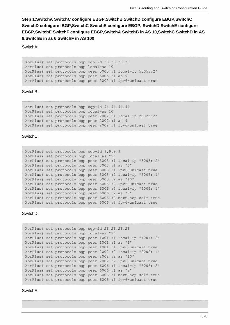
PicOS Routing and Switching Configuration Guide
378
Step 1:SwitchA SwitchC configure EBGP,SwitchB SwitchD configure EBGP,SwitchC
SwitchD cofnigure IBGP,SwitchC SwitchE configure EBGP, SwitchD SwitchE configure
EBGP,SwitchE SwitchF configure EBGP,SwitchA SwitchB in AS 10,SwitchC SwitchD in AS
9,SwitchE in as 6,SwitchF in AS 100
SwitchA:
XorPlus# set protocols bgp bgp-id 33.33.33.33XorPlus# set protocols bgp local-as 10XorPlus# set protocols bgp peer 5005::1 local-ip 5005::2"XorPlus# set protocols bgp peer 5005::1 as 9XorPlus# set protocols bgp peer 5005::1 ipv6-unicast true
SwitchB:
XorPlus# set protocols bgp bgp-id 44.44.44.44XorPlus# set protocols bgp local-as 10XorPlus# set protocols bgp peer 2002::1 local-ip 2002::2"XorPlus# set protocols bgp peer 2002::1 as 9XorPlus# set protocols bgp peer 2002::1 ipv6-unicast true
SwitchC:
XorPlus# set protocols bgp bgp-id 9.9.9.9XorPlus# set protocols bgp local-as "9"XorPlus# set protocols bgp peer 3003::1 local-ip "3003::2"XorPlus# set protocols bgp peer 3003::1 as "6"XorPlus# set protocols bgp peer 3003::1 ipv6-unicast trueXorPlus# set protocols bgp peer 5005::2 local-ip "5005::1"XorPlus# set protocols bgp peer 5005::2 as "10"XorPlus# set protocols bgp peer 5005::2 ipv6-unicast trueXorPlus# set protocols bgp peer 6006::2 local-ip "6006::1"XorPlus# set protocols bgp peer 6006::2 as "9"XorPlus# set protocols bgp peer 6006::2 next-hop-self trueXorPlus# set protocols bgp peer 6006::2 ipv6-unicast true
SwitchD:
XorPlus# set protocols bgp bgp-id 26.26.26.26XorPlus# set protocols bgp local-as "9"XorPlus# set protocols bgp peer 1001::1 local-ip "1001::2"XorPlus# set protocols bgp peer 1001::1 as "6"XorPlus# set protocols bgp peer 1001::1 ipv6-unicast trueXorPlus# set protocols bgp peer 2002::2 local-ip "2002::1"XorPlus# set protocols bgp peer 2002::2 as "10"XorPlus# set protocols bgp peer 2002::2 ipv6-unicast trueXorPlus# set protocols bgp peer 6006::1 local-ip "6006::2"XorPlus# set protocols bgp peer 6006::1 as "9"XorPlus# set protocols bgp peer 6006::1 next-hop-self trueXorPlus# set protocols bgp peer 6006::1 ipv6-unicast true
SwitchE:

PicOS Routing and Switching Configuration Guide
379
XorPlus# set protocols bgp bgp-id 6.6.6.6XorPlus# set protocols bgp local-as "6"XorPlus# set protocols bgp peer 1001::2 local-ip "1001::1"XorPlus# set protocols bgp peer 1001::2 as "9"XorPlus# set protocols bgp peer 1001::2 ipv6-unicast trueXorPlus# set protocols bgp peer 3003::2 local-ip "3003::1"XorPlus# set protocols bgp peer 3003::2 as "9"XorPlus# set protocols bgp peer 3003::2 ipv6-unicast trueXorPlus# set protocols bgp peer 4004::2 local-ip "4004::1"XorPlus# set protocols bgp peer 4004::2 as "100"XorPlus# set protocols bgp peer 4004::2 ipv6-unicast true
SwitchF:
XorPlus# set protocols bgp bgp-id 100.100.100.100XorPlus# set protocols bgp local-as 100XorPlus# set protocols bgp peer 4004::1 local-ip "4004::2"XorPlus# set protocols bgp peer 4004::1 as 6XorPlus# set protocols bgp peer 4004::1 ipv6-unicast true
Step 2:SwitchA SwitchB distribute bgp route entry 9999::/64,then check the bgp route table
on SwitchC SwitchD,SwitchE
SwitchC BGP route table:
XorPlus# run show bgp routes ipv6Status Codes: * valid route, > best routeOrigin Codes: i IGP, e EGP, ? incomplete Prefix Nexthop Peer AS Path ---------------------------- ------------------------ --------------- ------------*> 9999::/64 5005::2 33.33.33.33 10 i* 9999::/64 6006::2 26.26.26.26 10 i
SwitchD bgp route table:
XorPlus# run show bgp routes ipv6Status Codes: * valid route, > best routeOrigin Codes: i IGP, e EGP, ? incomplete Prefix Nexthop Peer AS Path ---------------------------- ------------------------ --------------- ------------* 9999::/64 6006::1 9.9.9.9 10 i*> 9999::/64 2002::2 44.44.44.44 10 i
SwichE BGP route table:
XorPlus# run show bgp routes ipv6Status Codes: * valid route, > best routeOrigin Codes: i IGP, e EGP, ? incomplete

PicOS Routing and Switching Configuration Guide
380
Prefix Nexthop Peer AS Path ---------------------------- ------------------------ --------------- ------------*> 9999::/64 3003::2 9.9.9.9 910 i* 9999::/64 1001::2 26.26.26.26 910 i
Step 3.The primary link down,then the bgp route entry from the backup link will be the best
route ,then check the bgp route table on SwitchE
XorPlus# run show bgp routes ipv6Status Codes: * valid route, > best routeOrigin Codes: i IGP, e EGP, ? incomplete Prefix Nexthop Peer AS Path ---------------------------- ------------------------ --------------- ------------*> 9999::/64 1001::2 26.26.26.26 910 i
(2)Configure example 2:Load Balance(bgp route have the same as-apth)
when a BGP speaker receives identical paths for a prefix from an adjacent AS,If BGP multipath is
enabled, multiple paths can be installed in the IP routing table.

PicOS Routing and Switching Configuration Guide
381
Figure 3-2
Step 1:SwitchA SwitchC configure EBGP,SwitchB SwitchD configure EBGP,SwitchC
SwitchD cofnigure IBGP,SwitchC SwitchE configure EBGP, SwitchD SwitchE configure
EBGP,SwitchE SwitchF configure EBGP,SwitchA SwitchB in AS 10,SwitchC SwitchD in AS
9,SwitchE in as 6,SwitchF in AS 100
SwitchA:
XorPlus# set protocols bgp bgp-id 33.33.33.33XorPlus# set protocols bgp local-as 10XorPlus# set protocols bgp peer 5005::1 local-ip 5005::2"XorPlus# set protocols bgp peer 5005::1 as 9XorPlus# set protocols bgp peer 5005::1 ipv6-unicast true
SwitchB:

PicOS Routing and Switching Configuration Guide
382
XorPlus# set protocols bgp bgp-id 44.44.44.44XorPlus# set protocols bgp local-as 10XorPlus# set protocols bgp peer 2002::1 local-ip 2002::2"XorPlus# set protocols bgp peer 2002::1 as 9XorPlus# set protocols bgp peer 2002::1 ipv6-unicast true
SwitchC:
XorPlus# set protocols bgp bgp-id 9.9.9.9XorPlus# set protocols bgp local-as "9"XorPlus# set protocols bgp peer 3003::1 local-ip "3003::2"XorPlus# set protocols bgp peer 3003::1 as "6"XorPlus# set protocols bgp peer 3003::1 ipv6-unicast trueXorPlus# set protocols bgp peer 5005::2 local-ip "5005::1"XorPlus# set protocols bgp peer 5005::2 as "10"XorPlus# set protocols bgp peer 5005::2 ipv6-unicast trueXorPlus# set protocols bgp peer 6006::2 local-ip "6006::1"XorPlus# set protocols bgp peer 6006::2 as "9"XorPlus# set protocols bgp peer 6006::2 next-hop-self trueXorPlus# set protocols bgp peer 6006::2 ipv6-unicast true
SwitchD:
XorPlus# set protocols bgp bgp-id 26.26.26.26XorPlus# set protocols bgp local-as "9"XorPlus# set protocols bgp peer 1001::1 local-ip "1001::2"XorPlus# set protocols bgp peer 1001::1 as "6"XorPlus# set protocols bgp peer 1001::1 ipv6-unicast trueXorPlus# set protocols bgp peer 2002::2 local-ip "2002::1"XorPlus# set protocols bgp peer 2002::2 as "10"XorPlus# set protocols bgp peer 2002::2 ipv6-unicast trueXorPlus# set protocols bgp peer 6006::1 local-ip "6006::2"XorPlus# set protocols bgp peer 6006::1 as "9"XorPlus# set protocols bgp peer 6006::1 next-hop-self trueXorPlus# set protocols bgp peer 6006::1 ipv6-unicast true
SwitchE:
XorPlus# set protocols bgp bgp-id 6.6.6.6XorPlus# set protocols bgp local-as "6"XorPlus# set protocols bgp peer 1001::2 local-ip "1001::1"XorPlus# set protocols bgp peer 1001::2 as "9"XorPlus# set protocols bgp peer 1001::2 ipv6-unicast trueXorPlus# set protocols bgp peer 3003::2 local-ip "3003::1"XorPlus# set protocols bgp peer 3003::2 as "9"XorPlus# set protocols bgp peer 3003::2 ipv6-unicast trueXorPlus# set protocols bgp peer 4004::2 local-ip "4004::1"XorPlus# set protocols bgp peer 4004::2 as "100"XorPlus# set protocols bgp peer 4004::2 ipv6-unicast true
SwitchF:
XorPlus# set protocols bgp bgp-id 100.100.100.100XorPlus# set protocols bgp local-as 100

PicOS Routing and Switching Configuration Guide
383
XorPlus# set protocols bgp peer 4004::1 local-ip "4004::2"XorPlus# set protocols bgp peer 4004::1 as 6XorPlus# set protocols bgp peer 4004::1 ipv6-unicast true
Step 2:SwitchA SwitchB distribute bgp route entry 9999::/64,then check the bgp route table
on SwitchC SwitchD,SwitchE.
SwitchC BGP route table:
XorPlus# run show bgp routes ipv6Status Codes: * valid route, > best routeOrigin Codes: i IGP, e EGP, ? incomplete Prefix Nexthop Peer AS Path ---------------------------- ------------------------ --------------- ------------*> 9999::/64 5005::2 33.33.33.33 10 i* 9999::/64 6006::2 26.26.26.26 10 i
SwitchD bgp route table:
XorPlus# run show bgp routes ipv6Status Codes: * valid route, > best routeOrigin Codes: i IGP, e EGP, ? incomplete Prefix Nexthop Peer AS Path ---------------------------- ------------------------ --------------- ------------* 9999::/64 6006::1 9.9.9.9 10 i*> 9999::/64 2002::2 44.44.44.44 10 i
SwichE BGP route table:
XorPlus# run show bgp routes ipv6Status Codes: * valid route, > best routeOrigin Codes: i IGP, e EGP, ? incomplete Prefix Nexthop Peer AS Path ---------------------------- ------------------------ --------------- ------------*> 9999::/64 3003::2 9.9.9.9 910 i* 9999::/64 1001::2 26.26.26.26 910 i
Step 3.Enable Multipath on SwitchE then check bgp route table,it will form Load Balance,as
the two bgp route entry have the same as-path
XorPlus#set protocols bgp multipath disable false
SwitchE BGP route table:

PicOS Routing and Switching Configuration Guide
384
XorPlus# run show bgp routes ipv6Status Codes: * valid route, > best routeOrigin Codes: i IGP, e EGP, ? incomplete Prefix Nexthop Peer AS Path ---------------------------- ------------------------ --------------- ------------*> 9999::/64 1001::2 26.26.26.26 910 i*> 9999::/64 3003::2 9.9.9.9 910 iXorPlus# run show route forward-route ipv6 allDestination NetMask NextHopMac Port --------------------------------------- --------------------------------------- ----------------- ---------2001:: ffff:ffff:ffff:ffff:: 04:7D:7B:62:93:FF connected4004:: ffff:ffff:ffff:ffff:: 04:7D:7B:62:93:FF connected1001:: ffff:ffff:ffff:ffff:: 04:7D:7B:62:93:FF connected3003:: ffff:ffff:ffff:ffff:: 04:7D:7B:62:93:FF connected9999:: ffff:ffff:ffff:ffff:: C8:0A:A9:AE:0A:66 te-1/1/469999:: ffff:ffff:ffff:ffff:: C8:0A:A9:04:49:28 te-1/1/48
(3)Configure example 3:Load Balance(bgp route have different as-path)
when a BGP speaker receives identical paths for a prefix from an adjacent AS,If BGP multipath is
enabled, multiple paths can be installed in the IP routing table:

PicOS Routing and Switching Configuration Guide
385
Figure 3-3
1)..Step 1:SwitchA SwitchC configure EBGP,SwitchB SwitchD configure EBGP,SwitchC
SwitchD cofnigure IBGP,SwitchC SwitchE configure EBGP, SwitchD SwitchE configure
EBGP,SwitchE SwitchF configure EBGP,SwitchA in AS 10, SwitchB in AS 12,SwitchC
SwitchD in AS 9,SwitchE in as 6,SwitchF in AS 100
SwitchA:
XorPlus# set protocols bgp bgp-id 33.33.33.33XorPlus# set protocols bgp local-as 10XorPlus# set protocols bgp peer 5005::1 local-ip 5005::2"XorPlus# set protocols bgp peer 5005::1 as 9XorPlus# set protocols bgp peer 5005::1 ipv6-unicast true
SwitchB:
XorPlus# set protocols bgp bgp-id 44.44.44.44XorPlus# set protocols bgp local-as 12XorPlus# set protocols bgp peer 2002::1 local-ip 2002::2"

PicOS Routing and Switching Configuration Guide
386
XorPlus# set protocols bgp peer 2002::1 as 9XorPlus# set protocols bgp peer 2002::1 ipv6-unicast true
SwitchC:
XorPlus# set protocols bgp bgp-id 9.9.9.9XorPlus# set protocols bgp local-as "9"XorPlus# set protocols bgp peer 3003::1 local-ip "3003::2"XorPlus# set protocols bgp peer 3003::1 as "6"XorPlus# set protocols bgp peer 3003::1 ipv6-unicast trueXorPlus# set protocols bgp peer 5005::2 local-ip "5005::1"XorPlus# set protocols bgp peer 5005::2 as "10"XorPlus# set protocols bgp peer 5005::2 ipv6-unicast trueXorPlus# set protocols bgp peer 6006::2 local-ip "6006::1"XorPlus# set protocols bgp peer 6006::2 as "9"XorPlus# set protocols bgp peer 6006::2 next-hop-self trueXorPlus# set protocols bgp peer 6006::2 ipv6-unicast true
SwitchD:
XorPlus# set protocols bgp bgp-id 26.26.26.26XorPlus# set protocols bgp local-as "9"XorPlus# set protocols bgp peer 1001::1 local-ip "1001::2"XorPlus# set protocols bgp peer 1001::1 as "6"XorPlus# set protocols bgp peer 1001::1 ipv6-unicast trueXorPlus# set protocols bgp peer 2002::2 local-ip "2002::1"XorPlus# set protocols bgp peer 2002::2 as "12"XorPlus# set protocols bgp peer 2002::2 ipv6-unicast trueXorPlus# set protocols bgp peer 6006::1 local-ip "6006::2"XorPlus# set protocols bgp peer 6006::1 as "9"XorPlus# set protocols bgp peer 6006::1 next-hop-self trueXorPlus# set protocols bgp peer 6006::1 ipv6-unicast true
SwitchE:
XorPlus# set protocols bgp bgp-id 6.6.6.6XorPlus# set protocols bgp local-as "6"XorPlus# set protocols bgp peer 1001::2 local-ip "1001::1"XorPlus# set protocols bgp peer 1001::2 as "9"XorPlus# set protocols bgp peer 1001::2 ipv6-unicast trueXorPlus# set protocols bgp peer 3003::2 local-ip "3003::1"XorPlus# set protocols bgp peer 3003::2 as "9"XorPlus# set protocols bgp peer 3003::2 ipv6-unicast trueXorPlus# set protocols bgp peer 4004::2 local-ip "4004::1"XorPlus# set protocols bgp peer 4004::2 as "100"XorPlus# set protocols bgp peer 4004::2 ipv6-unicast true
SwitchF:
XorPlus# set protocols bgp bgp-id 100.100.100.100XorPlus# set protocols bgp local-as 100XorPlus# set protocols bgp peer 4004::1 local-ip "4004::2"XorPlus# set protocols bgp peer 4004::1 as 6XorPlus# set protocols bgp peer 4004::1 ipv6-unicast true

PicOS Routing and Switching Configuration Guide
387
Step 2:SwitchA SwitchB distribute bgp route entry 9999::/64,then check the bgp route table
on SwitchC SwitchD,SwitchE
SwitchC BGP route table:
XorPlus# run show bgp routes ipv6Status Codes: * valid route, > best routeOrigin Codes: i IGP, e EGP, ? incomplete Prefix Nexthop Peer AS Path ---------------------------- ------------------------ --------------- ------------* 9999::/64 6006::2 26.26.26.26 12 i*> 9999::/64 5005::2 33.33.33.33 10 i
SwitchD BGP route table:
XorPlus# run show bgp routes ipv6Status Codes: * valid route, > best routeOrigin Codes: i IGP, e EGP, ? incomplete Prefix Nexthop Peer AS Path ---------------------------- ------------------------ --------------- ------------* 9999::/64 6006::1 9.9.9.9 10 i*> 9999::/64 2002::2 44.44.44.44 12 i
SwitchE BGP route table:
XorPlus# run show bgp routes ipv6Status Codes: * valid route, > best routeOrigin Codes: i IGP, e EGP, ? incomplete Prefix Nexthop Peer AS Path ---------------------------- ------------------------ --------------- ------------*> 9999::/64 3003::2 9.9.9.9 910 i* 9999::/64 1001::2 26.26.26.26 912 i
Step 3:Enable Multipath and enable path-relax on SwitchE(as the two bgp route have
different as-path,if it want to form Load Balance,it must enable path-relax and enable
multipath at the same time), then check the bgp route talbe on SwitchE,it will form Load
Balance.
XorPlus# set protocols bgp multipath disable falseXorPlus# set protocols bgp multipath path-relax trueXorPlus# run show bgp routes ipv6Status Codes: * valid route, > best routeOrigin Codes: i IGP, e EGP, ? incomplete

PicOS Routing and Switching Configuration Guide
388
Prefix Nexthop Peer AS Path ---------------------------- ------------------------ --------------- ------------*> 9999::/64 1001::2 26.26.26.26 912 i*> 9999::/64 3003::2 9.9.9.9 910 iXorPlus# run show route forward-route ipv6 allDestination NetMask NextHopMac Port --------------------------------------- --------------------------------------- ----------------- ---------2001:: ffff:ffff:ffff:ffff:: 04:7D:7B:62:93:FF connected4004:: ffff:ffff:ffff:ffff:: 04:7D:7B:62:93:FF connected1001:: ffff:ffff:ffff:ffff:: 04:7D:7B:62:93:FF connected3003:: ffff:ffff:ffff:ffff:: 04:7D:7B:62:93:FF connected9999:: ffff:ffff:ffff:ffff:: C8:0A:A9:AE:0A:66 te-1/1/469999:: ffff:ffff:ffff:ffff:: C8:0A:A9:04:49:28 te-1/1/48
Step 4:Check the bgp route table on SwitchF,the bgp route entry was got from SwitchE,and
it’s the first one arrived SwitchE
XorPlus# run show bgp routes ipv6Status Codes: * valid route, > best routeOrigin Codes: i IGP, e EGP, ? incomplete Prefix Nexthop Peer AS Path ---------------------------- ------------------------ --------------- ------------*> 9999::/64 4004::1 6.6.6.6 6 912 i
Designing Stable Internets
(1)Route Dampening
Route Dampening Command Reference:
XorPlus# set protocols bgp damping disable [true/false]
Note :This command is to Enable/Disable route dampening.
XorPlus# set protocols bgp damping half-life [1-45 minutes]
Note :This Command is to set the A configurable numeric value that describes the amount of time
that must elapse to reduce the penalty by one-half ,the default value is 15 minutes.

PicOS Routing and Switching Configuration Guide
389
XorPlus# set protocols bgp damping max-suppress [1-720 minutes]
Note :This Command is to set the max-suppress timer ,It’s default value is 60 minutes.
XorPlus# set protocols bgp damping reuse [1-20000 seconds]
Note : This Commands is to set A configurable numeric value that is compared with the penalty. If
the penalty is less than the reuse limit, a suppressed route that is up will no longer be suppressed,
the default value is 750.
XorPlus# set protocols bgp damping suppress [1-20000 seconds]
Note : This Commands is to set A numeric value that is compared with the penalty. If the penalty is
greater than the suppress limit, the route is suppressed ,the default value is 3000.
Another mechanism for controlling route instability is A route that appears androute dampening.
disappears intermittently causes BGP UPDATE and WITHDRAWN messages to be repeatedly
propagated on the Internet. The tremendous amount of routing traffic generated can use up all the
link's bandwidth and drive up CPU utilization of routers.
Dampening categorizes routes as well either or A well-behaved route showsbehaved ill behaved.
a high degree of stability during an extended period of time. On the other hand, an illbehaved route
experiences a high level of instability in a short period of time. Ill-behaved routes should be
penalized in a way that is proportional to the route's expected future instability. An unstable route
should be suppressed (not advertised) until there is some degree of confidence that the route has
become stable.
A route's recent history is used as a basis for estimating future stability. To track a route history, it
is essential to track the number of times the route has flapped over a period of time.Under route
dampening, each time a route flaps, it is given a penalty. Whenever the penalty reaches a
predefined threshold, the route is suppressed. The route can continue to accrue penalties even
after it is suppressed. The more frequently a route oscillates in a short amount of time, the faster
the route is suppressed.
Similar criteria are put in place to unsuppress a route and start readvertising it. An algorithm is
implemented to decay (reduce) the penalty value exponentially.
•Penalty—
An incremented numeric value that is assigned to a route each time it flaps.
•Half-life—
A configurable numeric value that describes the amount of time that must elapse to reduce the
penalty by one-half.
•Suppress limit—
A numeric value that is compared with the penalty. If the penalty is greater than the suppress limit,
the route is suppressed.
•Reuse limit—

PicOS Routing and Switching Configuration Guide
390
A configurable numeric value that is compared with the penalty. If the penalty is less than the reuse
limit, a suppressed route that is up will no longer be suppressed.
• max-suppress timer—
It is the maximum time the bgp route was suppressed.
The following figure illustrates the process of assessing a penalty to a route every time it flaps. The
penalty is exponentially decayed according to parameters such as the half-life. The half-life
parameter can be changed by the administrator to reflect the oscillation history of a route: A longer
half-life might be desirable for a route that has a habit of oscillating frequently. A larger half-life
value would cause the penalty to decay more slowly, which translates into a route's being
suppressed longer.
Figure 4-1 Route Dampening Penalty Assessment
Configure Example 1:
Figure 4-2
Step 1:SwitchA SwitchB Establishing EBGP
SwitchA:

PicOS Routing and Switching Configuration Guide
391
XorPlus# set protocols bgp bgp-id 9.9.9.9XorPlus# set protocols bgp local-as "9"XorPlus# set protocols bgp peer 3003::1 local-ip "3003::2"XorPlus# set protocols bgp peer 3003::1 as "6"XorPlus# set protocols bgp peer 3003::1 ipv6-unicast true
SwitchB:
XorPlus# set protocols bgp bgp-id 6.6.6.6XorPlus# set protocols bgp local-as "6"XorPlus# set protocols bgp peer 3003::2 local-ip "3003::1"XorPlus# set protocols bgp peer 3003::2 as "9"XorPlus# set protocols bgp peer 3003::2 ipv6-unicast true
Step 2:SwitchA propagate a bgp route entry 9999::/64 to SwitchB,then check the bgp route
table on SwitchB
SwitchB BGP route table:
XorPlus# run show bgp routes ipv6Status Codes: * valid route, > best routeOrigin Codes: i IGP, e EGP, ? incomplete Prefix Nexthop Peer AS Path ---------------------------- ------------------------ --------------- ------------*> 9999::/64 3003::2 9.9.9.9 910 iXorPlus# run show bgp routes ipv6 deatilInvalid IPNetXorPlus# run show bgp routes ipv6 detail9999::/64 From peer: 9.9.9.9 Route: Winner Origin: IGP AS Path: 9 10 Nexthop: 3003::2 Multiple Exit Discriminator: 0 Local Preference: 100XorPlus#
Step 3:Enable BGP Route Dampening on SwitchB
XorPlus#set protocols bgp damping disable false
Note:The default half-life: 15 ,The default max-suppress: 60 ,The default reuse: 750,The default
suppress: 3000.
XorPlus# run show bgp routes ipv6Status Codes: * valid route, > best routeOrigin Codes: i IGP, e EGP, ? incomplete Prefix Nexthop Peer AS Path ---------------------------- ------------------------ --------------- ------------

PicOS Routing and Switching Configuration Guide
392
*> 9999::/64 3003::2 9.9.9.9 910 iXorPlus# run show bgp routes ipv6 detail9999::/64 From peer: 9.9.9.9 Route: Winner Origin: IGP AS Path: 9 10 Nexthop: 3003::2 Multiple Exit Discriminator: 0 Local Preference: 100XorPlus#
Step 4:Withdrawn and update the bgp route entry on SwitchA and repeat the operation three
times , then check the bgp route table ,the bgp route entry should be suppressed after the
third times.
The first time:
SwitchB BGP route table:
XorPlus# run show bgp routes ipv6Status Codes: * valid route, > best routeOrigin Codes: i IGP, e EGP, ? incomplete Prefix Nexthop Peer AS Path ---------------------------- ------------------------ --------------- ------------*> 9999::/64 3003::2 9.9.9.9 910 iXorPlus# run show bgp routes ipv6 detail9999::/64 From peer: 9.9.9.9 Route: Winner Origin: IGP AS Path: 9 10 Nexthop: 3003::2 Multiple Exit Discriminator: 0 Local Preference: 100XorPlus#
The Second time:
XorPlus# run show bgp routes ipv6Status Codes: * valid route, > best routeOrigin Codes: i IGP, e EGP, ? incomplete Prefix Nexthop Peer AS Path ---------------------------- ------------------------ --------------- ------------*> 9999::/64 3003::2 9.9.9.9 910 iXorPlus# run show bgp routes ipv6 detail9999::/64 From peer: 9.9.9.9 Route: Winner Origin: IGP AS Path: 9 10 Nexthop: 3003::2
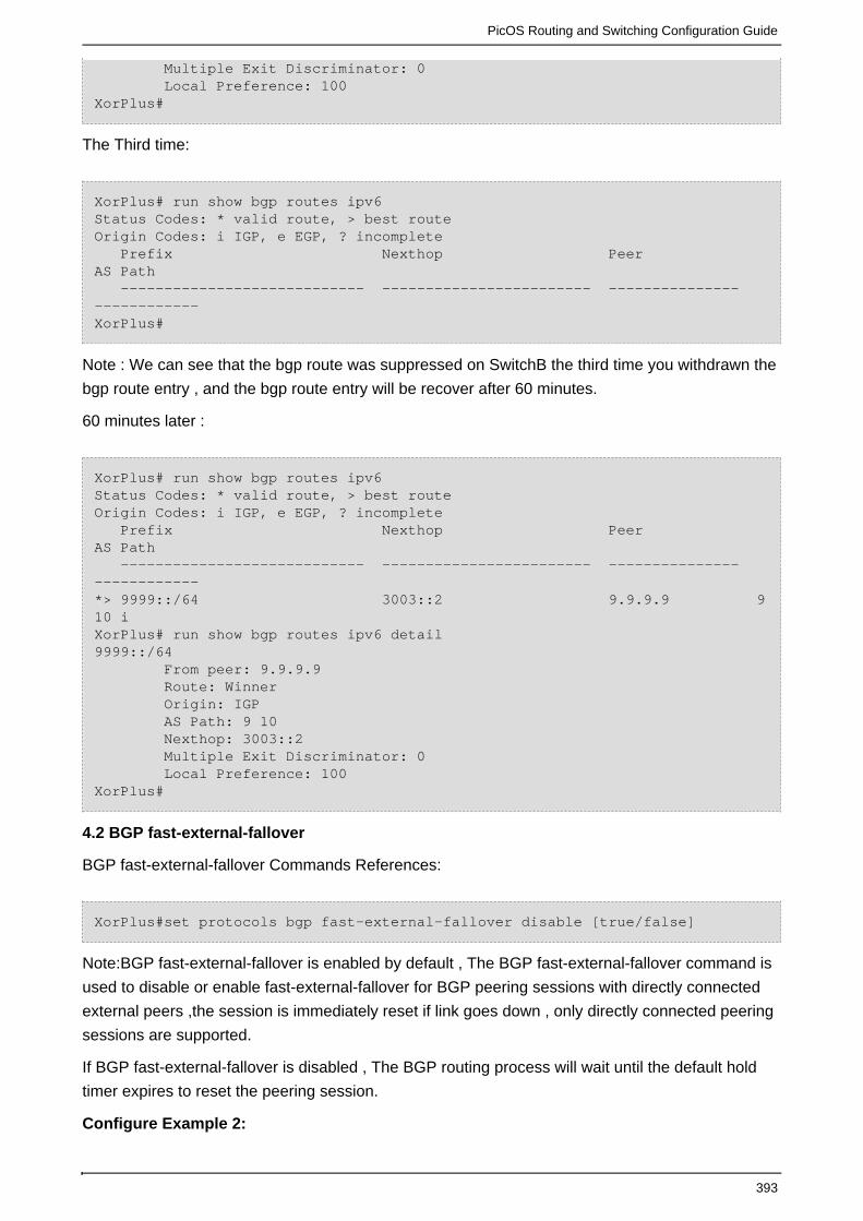
PicOS Routing and Switching Configuration Guide
393
Multiple Exit Discriminator: 0 Local Preference: 100XorPlus#
The Third time:
XorPlus# run show bgp routes ipv6Status Codes: * valid route, > best routeOrigin Codes: i IGP, e EGP, ? incomplete Prefix Nexthop Peer AS Path ---------------------------- ------------------------ --------------- ------------XorPlus#
Note : We can see that the bgp route was suppressed on SwitchB the third time you withdrawn the
bgp route entry , and the bgp route entry will be recover after 60 minutes.
60 minutes later :
XorPlus# run show bgp routes ipv6Status Codes: * valid route, > best routeOrigin Codes: i IGP, e EGP, ? incomplete Prefix Nexthop Peer AS Path ---------------------------- ------------------------ --------------- ------------*> 9999::/64 3003::2 9.9.9.9 910 iXorPlus# run show bgp routes ipv6 detail9999::/64 From peer: 9.9.9.9 Route: Winner Origin: IGP AS Path: 9 10 Nexthop: 3003::2 Multiple Exit Discriminator: 0 Local Preference: 100XorPlus#
4.2 BGP fast-external-fallover
BGP fast-external-fallover Commands References:
XorPlus#set protocols bgp fast-external-fallover disable [true/false]
Note:BGP fast-external-fallover is enabled by default , The BGP fast-external-fallover command is
used to disable or enable fast-external-fallover for BGP peering sessions with directly connected
external peers ,the session is immediately reset if link goes down , only directly connected peering
sessions are supported.
If BGP fast-external-fallover is disabled , The BGP routing process will wait until the default hold
timer expires to reset the peering session.
Configure Example 2:

PicOS Routing and Switching Configuration Guide
394
Figure 4-3
Step 1:SwitchA SwitchB Establishing EBGP
SwitchA:
XorPlus# set protocols bgp bgp-id 9.9.9.9XorPlus# set protocols bgp local-as "9"XorPlus# set protocols bgp peer 3003::1 local-ip "3003::2"XorPlus# set protocols bgp peer 3003::1 as "6"XorPlus# set protocols bgp peer 3003::1 ipv6-unicast true
SwitchB:
XorPlus# set protocols bgp bgp-id 6.6.6.6XorPlus# set protocols bgp local-as "6"XorPlus# set protocols bgp peer 3003::2 local-ip "3003::1"XorPlus# set protocols bgp peer 3003::2 as "9"XorPlus# set protocols bgp peer 3003::2 ipv6-unicast true
Then check bgp peer status on SwitchA SwitchB:
SwitchA:
XorPlus# run show bgp peers detailPeer 1: local 3003::2/179 remote 3003::1/38709 Peer ID: 6.6.6.6 Peer State: ESTABLISHED Admin State: START Negotiated BGP Version: 4 Peer AS Number: 6 Updates Received: 0, Updates Sent: 7 Messages Received: 10, Messages Sent: 17 Time since last received update: n/a Number of transitions to ESTABLISHED: 2 Time since last entering ESTABLISHED state: 230 seconds Retry Interval: 120 seconds Hold Time: 90 seconds, Keep Alive Time: 30 seconds Configured Hold Time: 90 seconds, Configured Keep Alive Time: 30 seconds Minimum AS Origination Interval: 0 seconds Minimum Route Advertisement Interval: 0 seconds
SwitchB:

PicOS Routing and Switching Configuration Guide
395
XorPlus# run show bgp peers detailPeer 2: local 3003::1/38709 remote 3003::2/179 Peer ID: 9.9.9.9 Peer State: ESTABLISHED Admin State: START Negotiated BGP Version: 4 Peer AS Number: 9 Updates Received: 7, Updates Sent: 0 Messages Received: 18, Messages Sent: 11 Time since last received update: 227 seconds Number of transitions to ESTABLISHED: 1 Time since last entering ESTABLISHED state: 255 seconds Retry Interval: 120 seconds Hold Time: 90 seconds, Keep Alive Time: 30 seconds Configured Hold Time: 90 seconds, Configured Keep Alive Time: 30 seconds Minimum AS Origination Interval: 0 seconds Minimum Route Advertisement Interval: 0 seconds
Step 2:Shutdown the link BGP peer connected then check the bgp peer status,the bgp peer
will be down immediately as bgp fast-external-fallover is enable by default.
XorPlus# set interface gigabit-ethernet te-1/1/46 disable trueXorPlus# commitMerging the configuration.Commit OK.Save done.XorPlus# run show bgp peers detail 3003::2Peer 1: local 3003::1/179 remote 3003::2/179 Peer ID: none Peer State: CONNECT Admin State: START Negotiated BGP Version: n/a Peer AS Number: 9 Updates Received: 0, Updates Sent: 0 Messages Received: 0, Messages Sent: 0 Time since last received update: n/a Number of transitions to ESTABLISHED: 1 Time since last in ESTABLISHED state: 11 seconds Retry Interval: 120 seconds Hold Time: n/a, Keep Alive Time: n/a Configured Hold Time: 90 seconds, Configured Keep Alive Time: 30 seconds Minimum AS Origination Interval: 0 seconds Minimum Route Advertisement Interval: 0 secondsXorPlus#
Step 3:Up the Link bgp peer connected and disable bgp fast-external-fallover on SwitchA
XorPlus# set interface gigabit-ethernet te-1/1/46 disable falseXorPlus# commitMerging the configuration.Commit OK.Save done.XorPlus# set protocols bgp fast-external-fallover disable trueXorPlus# commitMerging the configuration.Commit OK.Save done.XorPlus#XorPlus# run show bgp peers detail 3003::2

PicOS Routing and Switching Configuration Guide
396
Peer 1: local 3003::1/52347 remote 3003::2/179 Peer ID: 9.9.9.9 Peer State: ESTABLISHED Admin State: START Negotiated BGP Version: 4 Peer AS Number: 9 Updates Received: 1, Updates Sent: 0 Messages Received: 3, Messages Sent: 2 Time since last received update: 4 seconds Number of transitions to ESTABLISHED: 2 Time since last entering ESTABLISHED state: 4 seconds Retry Interval: 120 seconds Hold Time: 90 seconds, Keep Alive Time: 30 seconds Configured Hold Time: 90 seconds, Configured Keep Alive Time: 30 seconds Minimum AS Origination Interval: 0 seconds Minimum Route Advertisement Interval: 0 seconds
Step 4:Shutdown the link bgp peer connected,then check the bgp peer status,the bgp peer
will not down immediately but it will goes down after 90 seconds
XorPlus# set interface gigabit-ethernet te-1/1/46 disable trueXorPlus# commitMerging the configuration.Commit OK.Save done.XorPlus# run show bgp peers detail 3003::2Peer 1: local 3003::1/52347 remote 3003::2/179 Peer ID: 9.9.9.9 Peer State: ESTABLISHED Admin State: START Negotiated BGP Version: 4 Peer AS Number: 9 Updates Received: 1, Updates Sent: 0 Messages Received: 7, Messages Sent: 7 Time since last received update: 139 seconds Number of transitions to ESTABLISHED: 2 Time since last entering ESTABLISHED state: 139 seconds Retry Interval: 120 seconds Hold Time: 90 seconds, Keep Alive Time: 30 seconds Configured Hold Time: 90 seconds, Configured Keep Alive Time: 30 seconds Minimum AS Origination Interval: 0 seconds Minimum Route Advertisement Interval: 0 secondsXorPlus#
90 seconds later :
XorPlus# run show bgp peers detail 3003::2Peer 1: local 3003::1/179 remote 3003::2/179 Peer ID: none Peer State: ACTIVE Admin State: START Negotiated BGP Version: n/a Peer AS Number: 9 Updates Received: 0, Updates Sent: 0 Messages Received: 0, Messages Sent: 0 Time since last received update: n/a Number of transitions to ESTABLISHED: 2 Time since last in ESTABLISHED state: 34 seconds Retry Interval: 120 seconds

PicOS Routing and Switching Configuration Guide
397
Hold Time: n/a, Keep Alive Time: n/a Configured Hold Time: 90 seconds, Configured Keep Alive Time: 30 seconds Minimum AS Origination Interval: 0 seconds Minimum Route Advertisement Interval: 0 secondsXorPlus#

PicOS Routing and Switching Configuration Guide
398
Multicast Configuration
This chapter describes IGMP, PIM-SM, and IGMP Snooping configurations.
IGMP Snooping Configuration
IGMP Configuration
PIM-SM Configuration
PIM-SM Configuration Example
Multicast Command List
IGMP Snooping Configuration
In L2/L3, IGMPv2 Snooping and IGMPv2Snooping Querier are both supported.
IGMP snooping basic configuration
In the default setting, the switch disables IGMP snooping. You should globally enable IGMP per
VLAN.
XorPlus# set protocols igmp-snooping enable trueXorPlus# set protocols igmp-snooping vlan-id 1 enable trueXorPlus# set protocols igmp-snooping vlan-id 1 mrouter interface ge-1/1/3XorPlus# set protocols igmp-snooping vlan-id 1 querier other-querier-timer 1XorPlus# set protocols igmp-snooping vlan-id 1 static group 238.255.0.1interface ge-1/1/2XorPlus# commitWaiting for merging configuration.Commit OK.Save done.XorPlus# run show igmp-snooping vlan 1Vlan 1:----------------------------------------------IGMP snooping : EnabledIGMPv2 fast leave : DisabledIGMP querier state : DisabledIGMP querier source ip address : 0.0.0.0IGMP other querier timer : 1IGMP querier version : 2 XorPlus#
IGMP snooping querier
For multicast traffic in Layer2, enable an IGMP snooping querier in the VLAN.
XorPlus# set protocols igmp-snooping vlan-id 1 querier enable trueXorPlus# set protocols igmp-snooping vlan-id 1 querier address 10.10.1.1XorPlus# set protocols igmp-snooping vlan-id 1 querier version 2XorPlus# commitWaiting for merging configuration.Commit OK.

PicOS Routing and Switching Configuration Guide
399
Save done.XorPlus#XorPlus# run show igmp-snooping querier Vlan IP Address IGMP Version-------- ------------------ ------------1 10.10.1.1 v2 XorPlus#
IGMP Configuration
In XorPlus, IGMPv1/v2/v3 is supported.
Configuring an IGMP interface
Enable the multicast interface before enabling the IGMP interface.
XorPlus# set vlans vlan-id 2 l3-interface vlan2XorPlus# set vlans vlan-id 3 l3-interface vlan3XorPlus# set interface gigabit-ethernet ge-1/1/1 family ethernet-switchingnative-vlan-id 2XorPlus# set interface gigabit-ethernet ge-1/1/2 family ethernet-switchingnative-vlan-id 3XorPlus# set vlan-interface interface vlan2 vif vlan2 address 10.10.60.10prefix-length 24XorPlus# set vlan-interface interface vlan3 vif vlan3 address 10.10.61.10prefix-length 24XorPlus# commitWaiting for merging configuration.Commit OK.Save done.XorPlus# set multicast-interface interface vlan2 vif vlan2disable falseXorPlus# set multicast-interface interface vlan3 vif vlan2 disable falseXorPlus# commitWaiting for merging configuration.Commit OK.Save done.XorPlus# set protocols igmp interface vlan2 vif vlan2XorPlus# set protocols igmp interface vlan3 vif vlan3XorPlus# commitWaiting for merging configuration.Commit OK.Save done.XorPlus#XorPlus# run show igmp interface Interface State Querier Timeout Version Groups ------------ -------- --------------- --------- --------- --------vlan2 UP 10.10.60.10 None 2 2 vlan3 UP 10.10.61.10 None 2 2 XorPlus#
Configuring IGMP parameters for the IGMP interface
XorPlus# set protocols igmp interface vlan2 vif vlan2query-interval 4XorPlus# set protocols igmp interface vlan2 vifvlan2query-last-member-interval 3

PicOS Routing and Switching Configuration Guide
400
XorPlus# set protocols igmp interface vlan2 vif vlan2query-response-interval100XorPlus# commitWaiting for merging configuration.Commit OK.Save done.XorPlus#
Configuring an IGMPv3 interface
You can configure IGMPv3 in a specified interface.
XorPlus# set protocols igmp interface vlan3 vif vlan3version 3XorPlus# commitWaiting for merging configuration.Commit OK.Save done.XorPlus# run show igmp interface Interface State Querier Timeout Version Groups ------------ -------- --------------- --------- --------- --------vlan2 UP 10.10.60.10 None 2 2 vlan3 UP 10.10.61.10 None 3 2
Joining and leaving a group; displaying group information
If you send an IGMPv2 report to VLAN 2, and an IGMPv3 report to VLAN 3, for example, you can
display the group information of the switch. You should not have to worry about 224.0.0.2,
224.0.0.22, etc., which are used for the system (e.g. OSPF, RIP).
XorPlus# run show igmp group Interface Group Source LastReported Timeout V State------------ --------------- --------------- ------------ ------- - -----vlan2 224.0.0.2 0.0.0.0 10.10.60.10 92 2 E vlan2 224.0.0.22 0.0.0.0 10.10.60.10 101 2 E vlan2 238.255.0.1 0.0.0.0 10.10.60.100 61 2 E vlan3 224.0.0.2 0.0.0.0 10.10.61.10 205 3 E vlan3 224.0.0.22 0.0.0.0 10.10.61.10 205 3 E vlan3 238.255.0.2 0.0.0.0 10.10.61.100 0 3 I vlan3 238.255.0.2 20.20.20.20 10.10.61.100 257 3 F
If you send a Ieaving message for the above group, the specified group will be removed.
XorPlus# run show igmp group Interface Group Source LastReported Timeout V State------------ --------------- --------------- ------------ ------- - -----vlan2 224.0.0.2 0.0.0.0 10.10.60.10 88 2 E vlan2 224.0.0.22 0.0.0.0 10.10.60.10 105 2 E vlan3 224.0.0.2 0.0.0.0 10.10.61.10 227 3 E vlan3 224.0.0.22 0.0.0.0 10.10.61.10 227 3 E XorPlus#
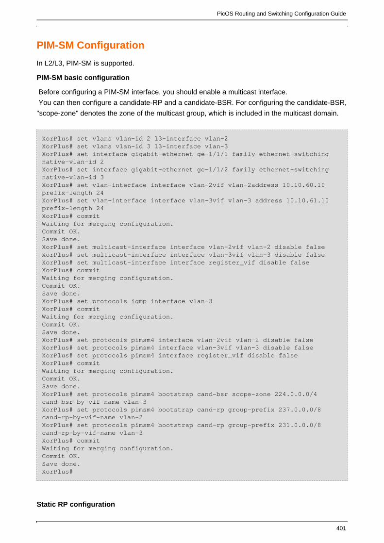
PicOS Routing and Switching Configuration Guide
401
PIM-SM Configuration
In L2/L3, PIM-SM is supported.
PIM-SM basic configuration
Before configuring a PIM-SM interface, you should enable a multicast interface.
You can then configure a candidate-RP and a candidate-BSR. For configuring the candidate-BSR,
"scope-zone" denotes the zone of the multicast group, which is included in the multicast domain.
XorPlus# set vlans vlan-id 2 l3-interface vlan-2XorPlus# set vlans vlan-id 3 l3-interface vlan-3XorPlus# set interface gigabit-ethernet ge-1/1/1 family ethernet-switchingnative-vlan-id 2XorPlus# set interface gigabit-ethernet ge-1/1/2 family ethernet-switchingnative-vlan-id 3XorPlus# set vlan-interface interface vlan-2vif vlan-2address 10.10.60.10prefix-length 24XorPlus# set vlan-interface interface vlan-3vif vlan-3 address 10.10.61.10prefix-length 24XorPlus# commitWaiting for merging configuration.Commit OK.Save done.XorPlus# set multicast-interface interface vlan-2vif vlan-2 disable falseXorPlus# set multicast-interface interface vlan-3vif vlan-3 disable falseXorPlus# set multicast-interface interface register_vif disable falseXorPlus# commitWaiting for merging configuration.Commit OK.Save done.XorPlus# set protocols igmp interface vlan-3XorPlus# commitWaiting for merging configuration.Commit OK.Save done.XorPlus# set protocols pimsm4 interface vlan-2vif vlan-2 disable falseXorPlus# set protocols pimsm4 interface vlan-3vif vlan-3 disable falseXorPlus# set protocols pimsm4 interface register_vif disable falseXorPlus# commitWaiting for merging configuration.Commit OK.Save done.XorPlus# set protocols pimsm4 bootstrap cand-bsr scope-zone 224.0.0.0/4cand-bsr-by-vif-name vlan-3XorPlus# set protocols pimsm4 bootstrap cand-rp group-prefix 237.0.0.0/8cand-rp-by-vif-name vlan-2XorPlus# set protocols pimsm4 bootstrap cand-rp group-prefix 231.0.0.0/8cand-rp-by-vif-name vlan-3XorPlus# commitWaiting for merging configuration.Commit OK.Save done.XorPlus#
Static RP configuration

PicOS Routing and Switching Configuration Guide
402
You can also configure static RP instead of BSR or dynamic RP.
XorPlus# set protocols pimsm4 static-rps rp 10.10.60.10 group-prefix238.0.0.0/8 rp-priority 10XorPlus# commitWaiting for merging configuration.Commit OK.Save done.XorPlus#
PIM-SM Configuration Example
In the following topology, Switch B is the C-BSR and C-RP. Host A is a receiver for multicast traffic,
and Host B is a multicast source that will send the multicast traffic.
You'll need to configure ge-1/1/2 as an IGMP interface in switch A for Host A.
In this example, the static route in the RIB will be used by PIM-SM.
Figure 8-1. PIM-SM multicast routing configuration.
Configuring Switch A
For switch A, configure ge-1/1/2 as an IGMP interface, andge-1/1/1 as a PIM-SM interface.
XorPlus# set vlans vlan-id 2 l3-interface vlan-2XorPlus# set vlans vlan-id 3 l3-interface vlan-3XorPlus# set interface gigabit-ethernet ge-1/1/1 family ethernet-switchingnative-vlan-id 2XorPlus# set interface gigabit-ethernet ge-1/1/2 family ethernet-switchingnative-vlan-id 3XorPlus# set vlan-interface interface vlan-2vif vlan-2 address 10.10.1.1prefix-length 24XorPlus# set vlan-interface interface vlan-3vif vlan-3 address 10.10.3.1prefix-length 24XorPlus# commitWaiting for merging configuration.Commit OK.
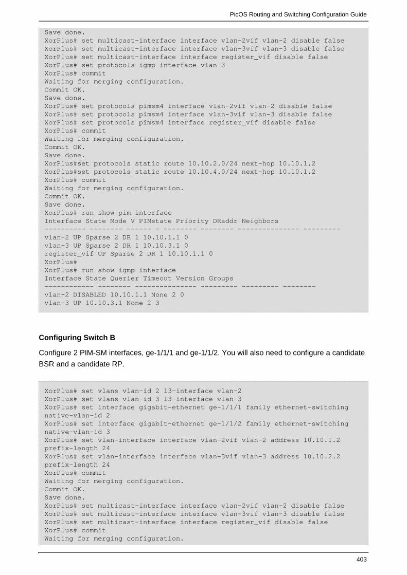
PicOS Routing and Switching Configuration Guide
403
Save done.XorPlus# set multicast-interface interface vlan-2vif vlan-2 disable falseXorPlus# set multicast-interface interface vlan-3vif vlan-3 disable falseXorPlus# set multicast-interface interface register_vif disable falseXorPlus# set protocols igmp interface vlan-3XorPlus# commitWaiting for merging configuration.Commit OK.Save done.XorPlus# set protocols pimsm4 interface vlan-2vif vlan-2 disable falseXorPlus# set protocols pimsm4 interface vlan-3vif vlan-3 disable falseXorPlus# set protocols pimsm4 interface register_vif disable falseXorPlus# commitWaiting for merging configuration.Commit OK.Save done.XorPlus#set protocols static route 10.10.2.0/24 next-hop 10.10.1.2XorPlus#set protocols static route 10.10.4.0/24 next-hop 10.10.1.2XorPlus# commitWaiting for merging configuration.Commit OK.Save done.XorPlus# run show pim interface Interface State Mode V PIMstate Priority DRaddr Neighbors---------- -------- ------ - -------- -------- --------------- ---------vlan-2 UP Sparse 2 DR 1 10.10.1.1 0 vlan-3 UP Sparse 2 DR 1 10.10.3.1 0 register_vif UP Sparse 2 DR 1 10.10.1.1 0 XorPlus#XorPlus# run show igmp interface Interface State Querier Timeout Version Groups ------------ -------- --------------- --------- --------- --------vlan-2 DISABLED 10.10.1.1 None 2 0 vlan-3 UP 10.10.3.1 None 2 3
Configuring Switch B
Configure 2 PIM-SM interfaces, ge-1/1/1 and ge-1/1/2. You will also need to configure a candidate
BSR and a candidate RP.
XorPlus# set vlans vlan-id 2 l3-interface vlan-2XorPlus# set vlans vlan-id 3 l3-interface vlan-3XorPlus# set interface gigabit-ethernet ge-1/1/1 family ethernet-switchingnative-vlan-id 2XorPlus# set interface gigabit-ethernet ge-1/1/2 family ethernet-switchingnative-vlan-id 3XorPlus# set vlan-interface interface vlan-2vif vlan-2 address 10.10.1.2prefix-length 24XorPlus# set vlan-interface interface vlan-3vif vlan-3 address 10.10.2.2prefix-length 24XorPlus# commitWaiting for merging configuration.Commit OK.Save done.XorPlus# set multicast-interface interface vlan-2vif vlan-2 disable falseXorPlus# set multicast-interface interface vlan-3vif vlan-3 disable falseXorPlus# set multicast-interface interface register_vif disable falseXorPlus# commitWaiting for merging configuration.

PicOS Routing and Switching Configuration Guide
404
Commit OK.Save done.XorPlus# set protocols pimsm4 interface vlan-2vif vlan-2 disable falseXorPlus# set protocols pimsm4 interface vlan-3vif vlan-3 disable falseXorPlus# set protocols pimsm4 interfaceregister_vif disable falseXorPlus# commitWaiting for merging configuration.Commit OK.Save done.XorPlus# set protocols pimsm4 bootstrap cand-bsr scope-zone 224.0.0.0/4cand-bsr-by-vif-name vlan-3XorPlus# set protocols pimsm4 bootstrap cand-rp group-prefix 238.0.0.0/8cand-rp-by-vif-name vlan-2XorPlus# commitWaiting for merging configuration.Commit OK.Save done.XorPlus#set protocols static route 10.10.3.0/24 next-hop 10.10.1.1XorPlus#set protocols static route 10.10.4.0/24 next-hop 10.10.2.1XorPlus# commitWaiting for merging configuration.Commit OK.Save done.XorPlus# run show pim bootstrap Active zones:BSR Pri LocalAddress Pri State Timeout SZTimeout10.10.2.2 1 10.10.2.2 1 Elected 19 -1Expiring zones:BSR Pri LocalAddress Pri State Timeout SZTimeoutXorPlus#XorPlus# run show pim rps RP Type Pri Holdtime Timeout ActiveGroups GroupPrefix ------------- ------- — -------- ------- ------------ ---------------- 10.10.1.2 bootstrap 192 150 -1 0 238.0.0.0/8 XorPlus#
Configuring Switch C
Configure 2 PIM-SM interfaces, ge-1/1/1 and ge-1/1/2.You will also need to configure a candidate
BSR and a candidate RP.
XorPlus# set vlans vlan-id 2 l3-interface vlan-2XorPlus# set vlans vlan-id 3 l3-interface vlan-3XorPlus# set interface gigabit-ethernet ge-1/1/1 family ethernet-switchingnative-vlan-id 2XorPlus# set interface gigabit-ethernet ge-1/1/2 family ethernet-switchingnative-vlan-id 3XorPlus# set vlan-interface interface vlan-2vif vlan-2 address 10.10.2.1prefix-length 24XorPlus# set vlan-interface interface vlan-3vif vlan-3 address 10.10.4.1prefix-length 24XorPlus# commitWaiting for merging configuration.Commit OK.Save done.XorPlus# set multicast-interface interface vlan-2vif vlan-2 disable falseXorPlus# set multicast-interface interface vlan-3vif vlan-3 disable falseXorPlus# set multicast-interface interface register_vif disable falseXorPlus# commit

PicOS Routing and Switching Configuration Guide
405
Waiting for merging configuration.Commit OK.Save done.XorPlus# set protocols pimsm4 interface vlan-2vif vlan-2 disable falseXorPlus# set protocols pimsm4 interface vlan-3vif vlan-3 disable falseXorPlus# set protocols pimsm4 interface register_vif disable falseXorPlus# commitWaiting for merging configuration.Commit OK.Save done.XorPlus# set protocols static route 10.10.1.0/24 next-hop 10.10.2.2XorPlus# set protocols static route 10.10.3.0/24 next-hop 10.10.2.2XorPlus# commitWaiting for merging configuration.Commit OK.Save done.XorPlus#XorPlus# run show pim interface Interface State Mode V PIMstate Priority DRaddr Neighbors---------- -------- ------ - -------- -------- --------------- ---------vlan-2 UP Sparse 2 DR 1 10.10.2.1 0 vlan-3 UP Sparse 2 DR 1 10.10.4.1 0 register_vif UP Sparse 2 DR 1 10.10.2.1 0 XorPlus#
Multicast Command List
run show multicast dataflow
run show multicast interface address
set multicast-interface interface bozo vif bozo disable true
set multicast-interface traceoptions flag all disable trueset open-flow allowed-versions
openflow-v1.0 disable true
set protocols igmp interface bozo vif bozo disable true
set protocols igmp interface bozo vif bozo enable-ip-router-alert-option-check true
set protocols igmp interface bozo vif bozo query-interval <int>
set protocols igmp interface bozo vif bozo query-last-member-interval <int>
set protocols igmp interface bozo vif bozo query-response-interval <int>
set protocols igmp interface bozo vif bozo robust-count <int>
set protocols igmp interface bozo vif bozo version <int>
set protocols igmp traceoptions flag all disable true
set protocols igmp traceoptions flag event disable true
set protocols igmp traceoptions flag leave disable true
set protocols igmp traceoptions flag query disable true
set protocols igmp traceoptions flag report disable true
set protocols igmp-snooping enable true
set protocols igmp-snooping last-member-query-count <int>
set protocols igmp-snooping last-member-query-interval <int>
set protocols igmp-snooping max-response-time <int>
set protocols igmp-snooping query-interval <int>
set protocols igmp-snooping report-suppression true
set protocols igmp-snooping robustness-variable <int>

PicOS Routing and Switching Configuration Guide
406
set protocols igmp-snooping router-aging-time <int>
set protocols igmp-snooping traceoptions flag all disable true
set protocols igmp-snooping traceoptions flag config disable true
set protocols igmp-snooping traceoptions flag input disable true
set protocols igmp-snooping traceoptions flag output disable true
set protocols igmp-snooping traceoptions flag state-machine disable true
set protocols igmp-snooping vlan-id <int> enable true
set protocols igmp-snooping vlan-id <int> fast-leave true
set protocols igmp-snooping vlan-id <int> mrouter interface bozo
set protocols igmp-snooping vlan-id <int> querier address <ip-address>
set protocols igmp-snooping vlan-id <int> querier enable true
set protocols igmp-snooping vlan-id <int> querier other-querier-timer <int>
set protocols igmp-snooping vlan-id <int> querier version <int>
set protocols igmp-snooping vlan-id <int> static group <ip-address> interface bozoset protocols
ipfix collector <ip-address> udp-port <int>
set protocols pimsm4 bootstrap cand-bsr scope-zone <ip-address/netmask> cand-bsr-by-vif-addr
<ip-address>
set protocols pimsm4 bootstrap cand-bsr scope-zone <ip-address/netmask> cand-bsr-by-vif-name
bozo
set protocols pimsm4 bootstrap cand-bsr scope-zone <ip-address/netmask> hash-mask-len <int>
set protocols pimsm4 bootstrap cand-rp group-prefix <ip-address/netmask> cand-rp-by-vif-addr
<ip-address>
set protocols pimsm4 bootstrap cand-rp group-prefix <ip-address/netmask> cand-rp-by-vif-name
bozo
set protocols pimsm4 bootstrap cand-rp group-prefix <ip-address/netmask> is-scope-zone true
set protocols pimsm4 bootstrap cand-rp group-prefix <ip-address/netmask> rp-holdtime <int>
set protocols pimsm4 bootstrap cand-rp group-prefix <ip-address/netmask> rp-priority <int>
set protocols pimsm4 bootstrap disable true
set protocols pimsm4 disable true
set protocols pimsm4 interface bozo vif bozo alternative-subnet <ip-address/netmask>
set protocols pimsm4 interface bozo vif bozo disable true
set protocols pimsm4 interface bozo vif bozo dr-priority <int>
set protocols pimsm4 interface bozo vif bozo hello-period <int>
set protocols pimsm4 interface bozo vif bozo hello-triggered-delay <int>
set protocols pimsm4 static-rps rp <ip-address> group-prefix <ip-address/netmask> hash-mask-len
<int>
set protocols pimsm4 static-rps rp <ip-address> group-prefix <ip-address/netmask> rp-priority
<int>
set protocols pimsm4 switch-to-spt-threshold bytes <int>
set protocols pimsm4 switch-to-spt-threshold disable true
set protocols pimsm4 switch-to-spt-threshold interval <int>
set protocols pimsm4 traceoptions flag all disable true
set protocols pimsm4 traceoptions flag bsr disable true
set protocols pimsm4 traceoptions flag event disable true
set protocols pimsm4 traceoptions flag join-prune disable true

PicOS Routing and Switching Configuration Guide
407
set protocols pimsm4 traceoptions flag mroute disable true
set protocols pimsm4 traceoptions flag neighbor disable true
set protocols pimsm4 traceoptions flag register disable true
set protocols pimsm4 traceoptions flag rp disable true
show multicast-interface

PicOS Routing and Switching Configuration Guide
408
QoS Configuration
This chapter describes Layer2 and Layer3 QoS configurations.
Configuring SP
Configuring WFQ
Configuring WRR
QoS Command List
.QoS Configuration
QoS Configuration Guide
QoS Principle
SP Configuration Example
WRR configuration Example
WFQ Configuration Example
Configuring SP
In L2/L3, 802.1p, DSCP, and COS QoS are supported.
You should first create forwarding classes, which determine the queue number of the specified
traffic type.
Define your QoS classifiers (by specifying the associated forwarding class) and include the
trust-mode. Map the code-point in the forwarding class.
Finally, apply each classifier to its specified ports.
Configuring priority queuing
XorPlus# set class-of-service forwarding-class best-effort local-priority 3XorPlus# set class-of-service forwarding-class rt-traffic local-priority 0XorPlus# set class-of-service forwarding-class normal-traffic local-priority2XorPlus# commit Waiting for merging configuration.Commit OK.Save done.XorPlus#
Configuring classifiers with IEEE 802.1/DSCP/ToS
XorPlus# set class-of-service classifier c1 trust-mode ieee-802.1XorPlus# set class-of-service classifier c1 forwarding-class best-effortcode-point 3XorPlus# set class-of-service classifier c2 trust-mode dscpXorPlus# set class-of-service classifier c2 forwarding-class rt-trafficcode-point 10

PicOS Routing and Switching Configuration Guide
409
XorPlus# commit Waiting for merging configuration.Commit OK.Save done.
Applying classifiers to specified ports
XorPlus# set class-of-service interface ge-1/1/1 classifier c1XorPlus# set class-of-service interface ge-1/1/2 classifier c2XorPlus# commit Waiting for merging configuration.Commit OK.Save done.
Configuring WFQ
Configuring scheduler
XorPlus# set class-of-service scheduler s1 mode WFQXorPlus# set class-of-service scheduler s2 mode WFQXorPlus# set class-of-service scheduler s1 weight 1XorPlus# set class-of-service scheduler s2 weight 2XorPlus# commit
Configuring priority queuing
XorPlus# set class-of-service forwarding-class f1 local-priority 1XorPlus# set class-of-service forwarding-class f2 local-priority 2XorPlus# commit
Configuring classifiers with IEEE 802.1/DSCP/ToS
XorPlus# set class-of-service classifier c1 trust-mode ieee-802.1XorPlus# set class-of-service classifier c1 forwarding-class f1 scheduler s1XorPlus# set class-of-service classifier c1 forwarding-class f1 code-point 1XorPlus# set class-of-service classifier c2 trust-mode ieee-802.1XorPlus# set class-of-service classifier c2 forwarding-class f2 scheduler s2XorPlus# set class-of-service classifier c2 forwarding-class f2 code-point 3XorPlus# set class-of-service classifier c3 trust-mode ieee-802.1XorPlus# set class-of-service classifier c3 forwarding-class f1 scheduler s1XorPlus# set class-of-service classifier c3 forwarding-class f2 scheduler s2XorPlus# commit
Applying classifiers to specified ports
XorPlus# set class-of-service interface ge-1/1/1 classifier c1XorPlus# set class-of-service interface ge-1/1/2 classifier c2

PicOS Routing and Switching Configuration Guide
410
XorPlus# set class-of-service interface ge-1/1/3 classifier c3XorPlus# commitXorPlus# set interface gigabit-ethernet ge-1/1/3 static-ethernet-switchingmac-address 22:00:00:00:00:00 vlan 1XorPlus# commit
Configuring WRR
Configuring scheduler
XorPlus# set class-of-service scheduler s1 mode WRRXorPlus# set class-of-service scheduler s2 mode WRRXorPlus# set class-of-service scheduler s1 weight 1XorPlus# set class-of-service scheduler s2 weight 2XorPlus# commit
Configuring priority queuing
XorPlus# set class-of-service forwarding-class f1 local-priority 1XorPlus# set class-of-service forwarding-class f2 local-priority 2XorPlus# commit
Configuring classifiers with IEEE 802.1/DSCP/ToS
XorPlus# set class-of-service classifier c1 trust-mode ieee-802.1XorPlus# set class-of-service classifier c1 forwarding-class f1 scheduler s1XorPlus# set class-of-service classifier c1 forwarding-class f1 code-point 1XorPlus# set class-of-service classifier c2 trust-mode ieee-802.1XorPlus# set class-of-service classifier c2 forwarding-class f2 scheduler s2XorPlus# set class-of-service classifier c2 forwarding-class f2 code-point 3XorPlus# set class-of-service classifier c3 trust-mode ieee-802.1XorPlus# set class-of-service classifier c3 forwarding-class f1 scheduler s1XorPlus# set class-of-service classifier c3 forwarding-class f2 scheduler s2XorPlus# commit
Applying classifiers to specified ports
XorPlus# set class-of-service interface ge-1/1/1 classifier c1XorPlus# set class-of-service interface ge-1/1/2 classifier c2XorPlus# set class-of-service interface ge-1/1/3 classifier c3XorPlus# commitXorPlus# set interface gigabit-ethernet ge-1/1/3 static-ethernet-switchingmac-address 22:00:00:00:00:00 vlan 1XorPlus# commit

PicOS Routing and Switching Configuration Guide
411
QoS Command List
set class-of-service classifier bozo forwarding-class bozo code-point <int>
set class-of-service classifier bozo forwarding-class bozo scheduler bozo
set class-of-service classifier bozo trust-mode dscp
set class-of-service classifier bozo trust-mode ieee-802.1
set class-of-service classifier bozo trust-mode inet-precedence
set class-of-service forwarding-class bozo local-priority <int>
set class-of-service interface bozo classifier bozo
set class-of-service scheduler bozo guaranteed-rate 8
set class-of-service scheduler bozo mode SP
set class-of-service scheduler bozo mode WFQ
set class-of-service scheduler bozo mode WRR
set class-of-service scheduler bozo weight <int>
set class-of-service traceoptions flag all disable trueset firewall filter bozo description bozo
.QoS Configuration
In L2/L3, 802.1p, DSCP, and COS, QoS are supported. The QoS Strategy only effective when
congestion.
QoS Configuration Guide
Configuring a scheduler
A scheduler should be configured firstly when you configure QoS,which determine the QoS
working mode and weight,the working mode can be SP,WRR or WFQ, and the weight is 1 to 15.
SP is strict priority queue,when two PCs send 100% traffic to a same PC,all packets from lower
priority PC will be discarded.The default working mode is SP.
WRR is weighted round robin queue,under this mode,you can configure weight,if PCA and PCB
send 100% traffic to a same PCC,the PCC will receive packets from PCA and PCB according to
the weight proportion in the corresponding queue.
WFQ is a weighted fair queuing.Under this mode,user can configure guaranteed-rate and
weight,and the guaranteed is only available in WFQ mode.If PCA and PCB send 100% traffic to a
same PCC,the PCC will receive packets from PCA and PCB according to the weight proportion
and the guaranteed-rate in the corresponding queue.
XorPlus# set class-of-service scheduler s1 mode WRRXorPlus# set class-of-service scheduler s1 weight 3XorPlus# commitMerging the configuration.Commit OK.Save done.

PicOS Routing and Switching Configuration Guide
412
XorPlus# set class-of-service scheduler s1 mode WFQXorPlus# set class-of-service scheduler s1 weight 4XorPlus# set class-of-service scheduler s1 guaranteed-rate 8XorPlus# commitMerging the configuration.Commit OK.Save done.
Configuring a forwarding class
A forwarding class should be configured after scheduler when you configure QoS,which determine
the queue number of the specified traffic type.The effect local-priority is 0 to 7.
XorPlus# set class-of-service forwarding-class f1 local-priority 3XorPlus# commitMerging the configuration.Commit OK.Save done.
Configuring a classifier with IEEE 802.1/DSCP/ToS
A classifier should be configured firstly,which is used to specify associated forwarding class.User
can select different classifier trust mode,such as IEEE 802.1,DSCP or ToS,according to the need.It
decides priority trust model.Configure trust mode IEEE 802.1 as follows:
XorPlus# set class-of-service classifier c1 trust-mode ieee-802.1XorPlus# commitMerging the configuration.Commit OK.Save done.
Configuring classifier relevant to forwarding class
After configure a classifier trust mode,you can configure the classifier relevant to specify forwarding
class.and code point and scheduler should be configured at the same time.The code-point is
match with the forwarding class local-priority,it means that when the flow match specified code
point,the flow will enter specified queue.When the classifier trust mode is IEEE 802.1 or ToS,the
code point is 0 to 7;when the classifier trust mode is dscp,the code point is 0 to 63.How to
configure scheduler refers to configure scheduler above.
XorPlus# set class-of-service classifier c1 forwarding-class f1 code-point 5XorPlus# set class-of-service classifier c1 forwarding-class f1 scheduler s1XorPlus# commit

PicOS Routing and Switching Configuration Guide
413
Merging the configuration.Commit OK.Save done.
Configure classifier to specified port
After configure as above,the classifier should be applied to specified ports.It determinds the port
priority trust model,data stream and queue matching rules,the scheduling model,weight and
guaranteed-rate.When the classifier configures scheduler,the classifier should be used in egress
port;and when the classifier configures code point,the classifier should be used in ingress port.
XorPlus# set class-of-service interface ge-1/1/1 classifier c1XorPlus# commitWaiting for merging configuration.Commit OK.Save done.
QoS Principle
SP queue principle
When the scheduler mode is SP,the egress port has eight queues,they are the queue
7,6,5,4,3,2,1,0.And the queue 7 is highest priority,queue 0 is lowest priority.That is,the priority
decrease successively.
Its advantage is that can give priority to transmissions of key business group.Howerer,this
scheduler mode also exists disadvantages. During congestion conditions, if higher priority queue
has groups for a long time,the low priority queues won't get service all the time.
WRR principle
The full name of WRR is Weighted Round Robin. In order to ensure that every queue has certain
servicing time, WRR use robin scheduling algorithm between the queues. When the scheduler
mode is WRR, every queue can have a weighted value, that is also known as scheduling weight.
Scheduling weight means that when the engress port schedules the queue messages how much it
uses the proportion of scheduling resources. Scheduling unit is Kbps.The example of WRR
scheduling algorithm as follows:
On the 1000Mbps engress port,the scheduling weights of eight queues are 5, 4, 3, 3, 2, 1, 1,1,this
can ensure the lowest priority queue can get bandwidth at least, calculation method is as follows:
1/(5+4+3+3+2+1+1+1)*1000Mbps=50Mbps.
This can avoid that the packets in low priority queue can not get service for a long time.
Its advantage is as follows:Althought the queue scheduling uses robin scheduling,every queue do
not distribute fixed service time—if a queue is empty,the next queue should be scheduled
immediately.In this way, it makes full use of bandwidth resources.
When you use WRR scheduling mode, you can define your own weighted value for each queue.
WFQ principle

PicOS Routing and Switching Configuration Guide
414
The full name of WFQ is Weighted Fair Queueing,it is similar to WRR.The only different between
WFQ and WRR is that the scheduling mode WFQ supports minimum bandwidth guarantee,this
scheduling scheme is more flexible.
By configuring minimum guarantee bandwidth,it assures every queue working in WFQ mode has
minimum bandwidth guarantee.In addition,the distributable bandwidth allocates according to the
weight proportion in the corresponding queue.The distributable bandwidth calculates method is as
follows:
distributable bandwidth = total bandwidth - minimum bandwidth.
The example of WFQ scheduling algorithm as follows:
Assuming that the total bandwidth of the engress port is 100M,there are 3 flows in the queue of this
port.Their scheduling weighted value are 1,2,4;the minimum bandwidth guarantee of these 3 flows
are 10000Kbps,10000Kbps,20000Kbps. The proportions of each flow are 10%,10%,20%.
distributable bandwidth = 100M-(10M+10M+20M)=60M.The proportion of distributable bandwidth is
60%
total distributable bandwidth = the sum of each flow weighted value.In this example,the total
distributable bandwidth is 7(that is 1+2+4).
The formula to calculate the proportion of distributable bandwidth which is occupied by each flow
as follows:
the proportion of distributable bandwidth = (the own weight of flow + 1)/( distributable
bandwidth).The proportions of the distributable bandwidth for each flow are 1/7, 2/7, 4/7.
The bandwidth ratio of the flows is (10%+60%*(1/7)) : (10%+60%*(2/7)) : (20%+60%*(4/7)),that is
13:19:38.
SP Configuration Example
As shown in Fig 1,ge-1/1/1 and ge-1/1/2 are ingress port,ge-1/1/3 is engress port.Use default
scheduling model, priority trust model is IEEE 802.1.

PicOS Routing and Switching Configuration Guide
415
Fig 1. Configure SP
Configure two forwarding-classes
Configure forwarding-class f1 and f2,and their local-priority.
XorPlus# set class-of-service forwarding-class f1 local-priority 3XorPlus# set class-of-service forwarding-class f2 local-priority 6XorPlus# commit Waiting for merging configuration.Commit OK.Save done.
Configuring classifier
Configure classifier c1 and c2,and its trust mode.And configure classifier relevant to forwarding
class and code point.
XorPlus# set class-of-service classifier c1 trust-mode ieee-802.1XorPlus# set class-of-service classifier c1 forwarding-class f1 code-point 5XorPlus# set class-of-service classifier c2 trust-mode ieee-802.1XorPlus# set class-of-service classifier c2 forwarding-class f2 code-point 7XorPlus# commit Waiting for merging configuration.Commit OK.Save done.

PicOS Routing and Switching Configuration Guide
416
Apply classifiers to specified ports
Configure classifier c1 apply to port ge-1/1/1,classifier c2 apply to port ge-1/1/2.
XorPlus# set class-of-service interface ge-1/1/1 classifier c1XorPlus# set class-of-service interface ge-1/1/2 classifier c2XorPlus# commit Waiting for merging configuration.Commit OK.Save done.
Generate traffic
PC1 and PC2 gemerate traffic which are match with the corresponding classifier. Port PC1 and
PC2 send 100% traffic to PC3 at the same time.
The expected result is that PC3 only can receive packets from PC2.
WRR configuration Example
As shown in Fig 2,ge-1/1/1 and ge-1/1/2 are ingress port,ge-1/1/3 is engress port.Use WRR
scheduling model, priority trust model is IEEE 802.1.

PicOS Routing and Switching Configuration Guide
417
Fig 2. Configure WRR
Configure scheduler
Configure two scheduler s1 and s2,and their mode are WRR.And configure that scheduler s1
weight is 1,scheduler s2 weight is 3.
XorPlus# set class-of-service scheduler s1 mode WRRXorPlus# set class-of-service scheduler s2 mode WRRXorPlus# set class-of-service scheduler s1 weight 1XorPlus# set class-of-service scheduler s2 weight 3XorPlus# commitWaiting for merging configuration.Commit OK.Save done.
Configure two forwarding-classes
Configure forwarding-class f1 and f2,and their local-priority.
XorPlus# set class-of-service forwarding-class f1 local-priority 3XorPlus# set class-of-service forwarding-class f2 local-priority 6XorPlus# commit Waiting for merging configuration.Commit OK.Save done.
Configuring classifier
Configure classifier c1,c2 and c3,and its trust mode.And configure classifier relevant to forwarding
class.and c3 is used to engress port ge-1/1/3,it should contains scheduler not contains code
point;c1 and c2 are used to ingress port,they should contains code point not contains scheduler.
XorPlus# set class-of-service classifier c1 trust-mode ieee-802.1XorPlus# set class-of-service classifier c1 forwarding-class f1 code-point 5XorPlus# set class-of-service classifier c2 trust-mode ieee-802.1XorPlus# set class-of-service classifier c2 forwarding-class f2 code-point 7XorPlus# set class-of-service classifier c3 trust-mode ieee-802.1XorPlus# set class-of-service classifier c3 forwarding-class f1 scheduler s1XorPlus# set class-of-service classifier c3 forwarding-class f2 scheduler s2XorPlus# commit Waiting for merging configuration.Commit OK.Save done.

PicOS Routing and Switching Configuration Guide
418
Apply classifiers to specified ports
Configure classifier c1 apply to port ge-1/1/1,classifier c2 apply to port ge-1/1/2 and classifier c3
apply to port ge-1/1/3.
XorPlus# set class-of-service interface ge-1/1/1 classifier c1XorPlus# set class-of-service interface ge-1/1/2 classifier c2XorPlus# set class-of-service interface ge-1/1/3 classifier c3XorPlus# commit Waiting for merging configuration.Commit OK.Save done.
Generate traffic
PC1 and PC2 gemerate traffic which are match with the corresponding classifier. PC1 and PC2
send 100% traffic to PC3 at the same time.
The expected result is that PC3 can receive packets from PC1 and PC2,and their rate is 1:3,that is
the weight proportion in the corresponding queue.
WFQ Configuration Example
As shown in Fig 3,ge-1/1/1 and ge-1/1/2 are ingress port,ge-1/1/3 is egress port.Use WFQ
scheduling model, priority trust model is IEEE 802.1.The bandwidth is 100Mbps.
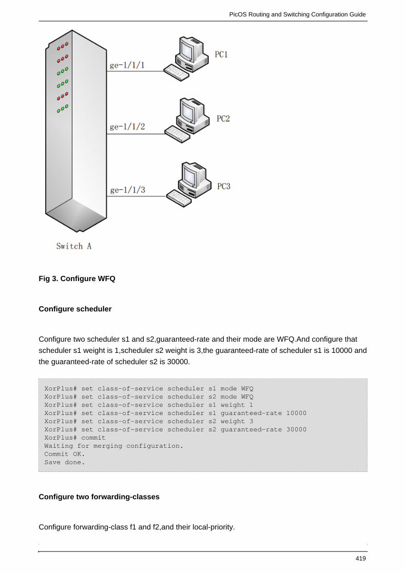
PicOS Routing and Switching Configuration Guide
419
Fig 3. Configure WFQ
Configure scheduler
Configure two scheduler s1 and s2,guaranteed-rate and their mode are WFQ.And configure that
scheduler s1 weight is 1,scheduler s2 weight is 3,the guaranteed-rate of scheduler s1 is 10000 and
the guaranteed-rate of scheduler s2 is 30000.
XorPlus# set class-of-service scheduler s1 mode WFQXorPlus# set class-of-service scheduler s2 mode WFQXorPlus# set class-of-service scheduler s1 weight 1XorPlus# set class-of-service scheduler s1 guaranteed-rate 10000XorPlus# set class-of-service scheduler s2 weight 3XorPlus# set class-of-service scheduler s2 guaranteed-rate 30000XorPlus# commitWaiting for merging configuration.Commit OK.Save done.
Configure two forwarding-classes
Configure forwarding-class f1 and f2,and their local-priority.

PicOS Routing and Switching Configuration Guide
420
XorPlus# set class-of-service forwarding-class f1 local-priority 3XorPlus# set class-of-service forwarding-class f2 local-priority 6XorPlus# commit Waiting for merging configuration.Commit OK.Save done.
Configuring classifier
Configure classifier c1,c2 and c3,and its trust mode.And configure classifier relevant to forwarding
class.and c3 is used to egress port ge-1/1/3,it should contains scheduler not contains code
point;c1 and c2 are used to ingress port,they should contains code point not contains scheduler.
XorPlus# set class-of-service classifier c1 trust-mode ieee-802.1XorPlus# set class-of-service classifier c1 forwarding-class f1 code-point 5XorPlus# set class-of-service classifier c2 trust-mode ieee-802.1XorPlus# set class-of-service classifier c2 forwarding-class f2 code-point 7XorPlus# set class-of-service classifier c3 trust-mode ieee-802.1XorPlus# set class-of-service classifier c3 forwarding-class f1 scheduler s1XorPlus# set class-of-service classifier c3 forwarding-class f2 scheduler s2XorPlus# commit Waiting for merging configuration.Commit OK.Save done.
Apply classifiers to specified ports
Configure classifier c1 apply to port ge-1/1/1,classifier c2 apply to port ge-1/1/2 and classifier c3
apply to port ge-1/1/3.
XorPlus# set class-of-service interface ge-1/1/1 classifier c1XorPlus# set class-of-service interface ge-1/1/2 classifier c2XorPlus# set class-of-service interface ge-1/1/3 classifier c3XorPlus# commit Waiting for merging configuration.Commit OK.Save done.
Generate traffic
PC1 and PC2 gemerate traffic which are match with the corresponding classifier. PC1 and PC2
send 100% traffic to PC3 at the same time.
The expected result is that PC3 can receive packets from PC1 and PC2,and their rate is about
1:3,that is the weight proportion and the guaranteed-rate in the corresponding queue.

PicOS Routing and Switching Configuration Guide
421
1.
2.
3.
WRED Configuration
The traditional packet loss strategy is tail-drop, which strategy can cause TCP’s global
synchronization problem.In order to avoiding TCP’s global synchronization problem,users can use
WRED(Weighted Random Early Detection) and WRED should be configure on egress port.When
one TCP connection messages are discarded or start to slow sending,other TCP connections still
have high sending rate.This strategy can improve bandwidth utilization.
WRED Configuration Guide
User can enable or disable WRED as follows:
admin@XorPlus# set interface gigabit-ethernet ge-1/1/1 wred queue 3 enable true
admin@XorPlus# commit
Commit OK.
Save done.
admin@XorPlus# set interface gigabit-ethernet ge-1/1/1 wred queue 3 enable false
admin@XorPlus# commit
Commit OK.
Save done.
In the WRED algorithm, configure upper and lower limits for each queue, which is applied to deal
with the message in the queues as follows:
When the queue length is less than the lower limit, the messages can not be discard;
When the queue length is more than the upper limit, all messages will be discard;
When the queue length is between upper and lower limits, the messages will be discarded
randomly.The longer the queue, the higher discarding probability, but there is a maximum
discarding probability.
Configure upper limits:
admin@XorPlus# set interface gigabit-ethernet ge-1/1/1 wred queue 3 max_thresh 400
admin@XorPlus# commit
Commit OK.
Save done.
Configure lowers limits:
admin@XorPlus# set interface gigabit-ethernet ge-1/1/1 wred queue 3 min_thresh 200
admin@XorPlus# commit
Commit OK.

PicOS Routing and Switching Configuration Guide
422
Save done.
User can configure discarding probability,which is discarding probability when the queue length is
between upper and lower limits.The configure as follows:
admin@XorPlus# set interface gigabit-ethernet ge-1/1/1 wred queue 3 drop_probability 50
admin@XorPlus# commit
Commit OK.
Save done.
The drop_probability 50 above shows that the discarding probability is 50%.
User can configure ecn_thresh,which value is 1 or 0,1 stands for enable ecn_thresh,0 stands for
disable ecn_thresh. Configure ecn_thresh as follows:
admin@XorPlus# set interface gigabit-ethernet ge-1/1/1 wred queue 7 ecn_thresh 1
admin@XorPlus# commit
Commit OK.
Save done.
WRED Principle
When users enable WRED,the packets discard on egress port,when users disable WRED,the
packets discard on ingress port.
When enable ecn_thresh, if users sending packets with the last two bits of tos is 01 or 10,and
when the packets out from output interface,the field of low cost and reserved will be changed to 1.
When disable ecn_thresh,the last two bits of tos can not be changed.
WRED Configuration Example
As shown in Fig 1,ge-1/1/1 and ge-1/1/2 are ingress port,ge-1/1/3 is egress port.User configures
WRED on egress port ge-1/1/3.

PicOS Routing and Switching Configuration Guide
423
Fig 1. Configure WRED
Configure enable WRED
admin@XorPlus# set interface gigabit-ethernet ge-1/1/3 wred queue 3 enabletrueadmin@XorPlus# commitCommit OK.Save done.
Configuring upper limits and lower limits
admin@XorPlus# set interface gigabit-ethernet ge-1/1/3 wred queue 3max_thresh 400admin@XorPlus# set interface gigabit-ethernet ge-1/1/3 wred queue 3min_thresh 200admin@XorPlus# commitCommit OK.Save done.
Configuring discarding probability
admin@XorPlus# set interface gigabit-ethernet ge-1/1/1 wred queue 3drop_probability 50admin@XorPlus# commitCommit OK.Save done.
Configuring enable ecn_thresh

PicOS Routing and Switching Configuration Guide
424
admin@XorPlus# set interface gigabit-ethernet ge-1/1/3 wred queue 7ecn_thresh 1admin@XorPlus# commitCommit OK.Save done.
Note:The WRED usually combines with QoS.

PicOS Routing and Switching Configuration Guide
425
Installing New Software on PicOS
PicOS is using a standard and non modified Debian Linux distribution. This means that is is very
easy to install new package or software on top of the existing PicOS packages using the standard
.Debian packages systems
Here are some examples of installation.
Install GCC on PicOS
Install Puppet on PicOS
Install GCC on PicOS
Updating the software list on the source server
admin@XorPlus$sudo apt-get updateHit http://ftp.tw.debian.org stable Release.gpgHit http://ftp.tw.debian.org stable ReleaseHit http://ftp.tw.debian.org stable/main powerpc PackagesHit http://ftp.tw.debian.org stable/main Translation-enReading package lists... Doneadmin@XorPlus$
Installing new software
admin@XorPlus$sudo apt-get install makeReading package lists... DoneBuilding dependency tree Reading state information... DoneSuggested packages:make-docThe following NEW packages will be installed:make0 upgraded, 1 newly installed, 0 to remove and 0 not upgraded.Need to get 399 kB of archives.After this operation, 1165 kB of additional disk space will be used.WARNING: The following packages cannot be authenticated!makeAuthentication warning overridden.Get:1 http://ftp.tw.debian.org/debian/ stable/main make powerpc 3.81-8.2 [399kB]Fetched 399 kB in 6s (64.1 kB/s) Selecting previously unselected package make.(Reading database ... 16155 files and directories currently installed.)Unpacking make (from .../make_3.81-8.2_powerpc.deb) ...Processing triggers for man-db ...fopen: Permission deniedSetting up make (3.81-8.2) ...admin@XorPlus$ admin@XorPlus$sudo apt-get install pythonReading package lists... DoneBuilding dependency tree Reading state information... DoneThe following extra packages will be installed:

PicOS Routing and Switching Configuration Guide
426
file libexpat1 libmagic1 mime-support python-minimal python2.7python2.7-minimalSuggested packages:python-doc python-tk python2.7-doc binutils binfmt-supportThe following NEW packages will be installed:file libexpat1 libmagic1 mime-support python python-minimal python2.7python2.7-minimal0 upgraded, 8 newly installed, 0 to remove and 0 not upgraded.Need to get 5045 kB of archives.After this operation, 18.3 MB of additional disk space will be used.Do you want to continue [Y/n]? YWARNING: The following packages cannot be authenticated!libmagic1 libexpat1 file mime-support python2.7-minimal python2.7python-minimal pythonAuthentication warning overridden.Get:1 http://ftp.tw.debian.org/debian/ stable/main libmagic1 powerpc 5.11-2[201 kB]Get:2 http://ftp.tw.debian.org/debian/ stable/main libexpat1 powerpc 2.1.0-1[142 kB]Get:3 http://ftp.tw.debian.org/debian/ stable/main file powerpc 5.11-2 [51.7kB]Get:4 http://ftp.tw.debian.org/debian/ stable/main mime-support all 3.52-1[35.5 kB]Get:5 http://ftp.tw.debian.org/debian/ stable/main python2.7-minimal powerpc2.7.3-6 [1753 kB]Get:6 http://ftp.tw.debian.org/debian/ stable/main python2.7 powerpc 2.7.3-6[2639 kB] Get:7 http://ftp.tw.debian.org/debian/ stable/main python-minimal all 2.7.3-4[42.6 kB] Get:8 http://ftp.tw.debian.org/debian/ stable/main python all 2.7.3-4 [180kB] Fetched 5045 kB in 18s (267 kB/s) Selecting previously unselected package libmagic1:powerpc.(Reading database ... 16189 files and directories currently installed.)Unpacking libmagic1:powerpc (from .../libmagic1_5.11-2_powerpc.deb) ...Selecting previously unselected package libexpat1:powerpc.Unpacking libexpat1:powerpc (from .../libexpat1_2.1.0-1_powerpc.deb) ...Selecting previously unselected package file.Unpacking file (from .../file_5.11-2_powerpc.deb) ...Selecting previously unselected package mime-support.Unpacking mime-support (from .../mime-support_3.52-1_all.deb) ...Selecting previously unselected package python2.7-minimal.Unpacking python2.7-minimal (from .../python2.7-minimal_2.7.3-6_powerpc.deb)...Selecting previously unselected package python2.7.Unpacking python2.7 (from .../python2.7_2.7.3-6_powerpc.deb) ...Selecting previously unselected package python-minimal.Unpacking python-minimal (from .../python-minimal_2.7.3-4_all.deb) ...Selecting previously unselected package python.Unpacking python (from .../python_2.7.3-4_all.deb) ...Processing triggers for man-db ...fopen: Permission deniedSetting up libmagic1:powerpc (5.11-2) ...Setting up libexpat1:powerpc (2.1.0-1) ...Setting up file (5.11-2) ...Setting up mime-support (3.52-1) ...Setting up python2.7-minimal (2.7.3-6) ...Linking and byte-compiling packages for runtime python2.7...Setting up python2.7 (2.7.3-6) ...Setting up python-minimal (2.7.3-4) ...Setting up python (2.7.3-4) ...admin@XorPlus$ admin@XorPlus$sudo apt-get install g++

PicOS Routing and Switching Configuration Guide
427
Reading package lists... DoneBuilding dependency tree Reading state information... DoneThe following extra packages will be installed:g+-4.6 libstdc+6-4.6-devSuggested packages:g+-multilib g-4.6-multilib gcc-4.6-doc libstdc6-4.6-dbg libstdc+6-4.6-docThe following NEW packages will be installed:g++ g+-4.6 libstdc+6-4.6-dev0 upgraded, 3 newly installed, 0 to remove and 17 not upgraded.Need to get 0 B/8383 kB of archives.After this operation, 24.4 MB of additional disk space will be used.Do you want to continue [Y/n]? YWARNING: The following packages cannot be authenticated!libstdc+6-4.6-dev g-4.6 g+Authentication warning overridden.Selecting previously unselected package libstdc++6-4.6-dev.(Reading database ... 19555 files and directories currently installed.)Unpacking libstdc+6-4.6-dev (from .../libstdc+6-4.6-dev_4.6.3-14_powerpc.deb)...Selecting previously unselected package g++-4.6.Unpacking g+-4.6 (from .../g+-4.6_4.6.3-14_powerpc.deb) ...Selecting previously unselected package g++.Unpacking g++ (from .../g++_4%3a4.6.3-8_powerpc.deb) ...Processing triggers for man-db ...Setting up libstdc++6-4.6-dev (4.6.3-14) ...Setting up g++-4.6 (4.6.3-14) ...Setting up g++ (4:4.6.3-8) ...update-alternatives: using /usr/bin/g++ to provide /usr/bin/c++ (c++) in automodeadmin@XorPlus$
Install Puppet on PicOS
Step 1 - Use the correct repository for the specific application and CPU on the switch. Pica8
support can help in the choice of repository.
admin@Roma$sudo more /etc/apt/sources.list | grep -v "#"deb http://ftp.debian-ports.org/debian/ unstable main
For a typical puppet installation we advice to use the latest standard debian repo.
Step 2 - Update the debian packages on PicOS
admin@XorPlus$sudo apt-get updateHit http://ftp.tw.debian.org stable Release.gpgHit http://ftp.tw.debian.org stable ReleaseHit http://ftp.tw.debian.org stable/main powerpc PackagesHit http://ftp.tw.debian.org stable/main Translation-enReading package lists... Doneadmin@XorPlus$
Step 3 - Install puppet client and configure it
sudo apt-get install puppet
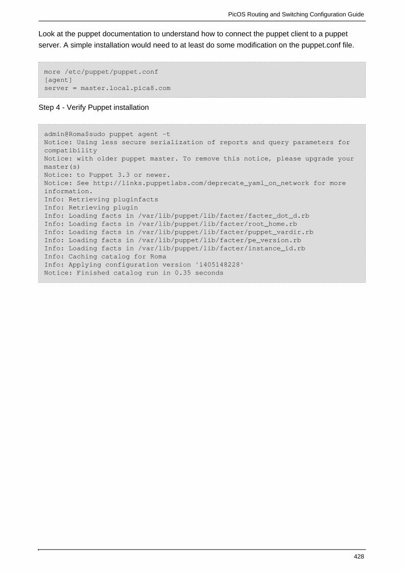
PicOS Routing and Switching Configuration Guide
428
Look at the to understand how to connect the puppet client to a puppetpuppet documentation
server. A simple installation would need to at least do some modification on the puppet.conf file.
more /etc/puppet/puppet.conf[agent]server = master.local.pica8.com
Step 4 - Verify Puppet installation
admin@Roma$sudo puppet agent -tNotice: Using less secure serialization of reports and query parameters forcompatibilityNotice: with older puppet master. To remove this notice, please upgrade yourmaster(s) Notice: to Puppet 3.3 or newer.Notice: See http://links.puppetlabs.com/deprecate_yaml_on_network for moreinformation.Info: Retrieving pluginfactsInfo: Retrieving pluginInfo: Loading facts in /var/lib/puppet/lib/facter/facter_dot_d.rbInfo: Loading facts in /var/lib/puppet/lib/facter/root_home.rbInfo: Loading facts in /var/lib/puppet/lib/facter/puppet_vardir.rbInfo: Loading facts in /var/lib/puppet/lib/facter/pe_version.rbInfo: Loading facts in /var/lib/puppet/lib/facter/instance_id.rbInfo: Caching catalog for RomaInfo: Applying configuration version '1405148228'Notice: Finished catalog run in 0.35 seconds

PicOS Routing and Switching Configuration Guide
429
Zero Touch Provisioning
ZTP (Zero touch provisioning) is a functionality to help deploy a switch without manual intervention.
Activate or Deactivate ZTP
ZTP (Zero Touch Provisioning)
ZTP API description
Activate or Deactivate ZTP
There are multiple ways to activate or Deactivate ZTP. ZTP is always enable by default on a
switch. If ZTP is not disabled, it will try to download a new script every time the device is rebooted
which is usually not acceptable.
The first Way to disable ZTP is via the ZTP script itself using the .ZTP API description
To disable ZTP via the Linux shell, you can either use the
admin@Lima$sudo /usr/sbin/ztp-config Please configure the default PicOS ZTP options: (Press other key if no change) [1] PicOS ZTP enabled [2] PicOS ZTP disabled * defaultEnter your choice (1,2):1PicOS ZTP is enabled.admin@Lima$
Or modify the PicOS configuration file.
admin@Lima$more /etc/picos/picos_start.conf | grep ztpztp_disable=false
The "ztp_disable" option should be to "false" to enable ZTP or "true" to disable ZTP.
ZTP (Zero Touch Provisioning)
ZTP (Zero touch provisioning) is the process of configuring a Switch without human intervention.
As simple as Rack, Connect and Power-on.
ZTP Process: switch connected TFTP server

PicOS Routing and Switching Configuration Guide
430
1.
2.
3.
4.
5.
6.
7.
8.
When the switch boots up, a DHCP client will be started by debian service, then ZTP will gets three
options: tftp-server-name, boot-file-name and log-servers. If the log-servers option is set, ZTP will
send the log of ZTP to the server and local syslog at the same time. Then it starts a TFTP client to
get a upgrade script with name defined in boot-file-name from TFTP server. This upgrade script is
used to define all upgrade procedures. The provision script is an shell script, ZTP will automatically
run this script after download it from TFTP server.
A typical pica8 provision target may include the following several tasks:
back up L2/L3 configuration file, OVS configuration database, and boot list file
back up user data files and application configuration files
download PicOS image from TFTP server
upgrade PicOS image
reboot into new image
update PicOSonfiguration files
start PicOS application (XorPlus or OVS)
PicOS application configuration
Upgrade process flow chart
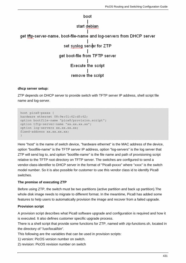
PicOS Routing and Switching Configuration Guide
431
dhcp server setup:
ZTP depends on DHCP server to provide switch with TFTP server IP address, shell script file
name and log-server.
host pica8-pxxxx {hardware ethernet 08:9e:01:62:d5:62;option bootfile-name "pica8/provision.script";option tftp-server-name "xx.xx.xx.xx";option log-servers xx.xx.xx.xx;fixed-address xx.xx.xx.xx;}
Here "host" is the name of switch device, "hardware ethernet" is the MAC address of the device,
option "bootfile-name" is the TFTP server IP address, option "log-servers" is the log server that
ZTP will send log to, and option "bootfile-name" is the file name and path of provisioning script
relative to the TFTP root directory on TFTP server. The switches are configured to send a
vendor-class-identifier to DHCP server in the format of "Pica8-pxxxx" where "xxxx" is the switch
model number. So it is also possible for customer to use this vendor class id to identify Pica8
switches.
The premise of executing ZTP
Before using ZTP, the switch must be two partitions (active partition and back up partition).The
whole disk image needs to migrate to different format. In the meantime, Pica8 has added some
features to help users to automatically provision the image and recover from a failed upgrade.
Provision script
A provision script describes what Pica8 software upgrade and configuration is required and how it
is executed. It also defines customer specific upgrade process.
There is a shell script that provide some functions for ZTP, named with ztp-functions.sh, located in
the directory of "/usr/local/bin".
This following are the variables that can be used in provision scripts:
1) version: PicOS version number on switch.
2) revision: PicOS revision number on switch

PicOS Routing and Switching Configuration Guide
432
3) sn: switch serial number
4) eth0_mac: the MAC address of eth0
5) switch_mac: the MAC address of switch
Appendix:
Sample Provision Script
#!/bin/bashsource /usr/local/bin/ztp-functions.shif [ "$revision" != "xxxxxx" ]; thentftp_get_picos_image pica8/picos-xxxxxx-P3295.tar.gzif [ $? -ne 0 ]; thenexit 1firebootelse#start l2/l3 modepicos_l2l3_startif [ $? -ne 0 ]; thenexit 1fi#load xorp configurationl2l3_load_config pica8/xorp_cfg.cliif [ $? -ne 0 ]; thenexit 1fi#stop l2/l3 modepicos_l2l3_stopif [ $? -ne 0 ]; thenexit 1fi#start ovs modepicos_ovs_start 192.168.2.50/24 192.168.2.1if [ $? -ne 0 ]; thenexit 1fi#load ovs configurationovs_load_config 192.168.2.50/24 192.168.2.1 pica8/ovs_cfg.cliif [ $? -ne 0 ]; thenexit 1fi#stop ovs modepicos_ovs_stop if [ $? -ne 0 ]; thenexit 1fifi
Example of xorp_cfg.cli:
show version;configure;run show vlans;set vlans vlan-id 20;commit;set vlansvlan-id 30;commit
Example of ovs_cfg.cli:
ovs-vsctl add-br br0 - set bridge br0 datapath_type=pica8ovs-vsctl set Bridge br0 stp_enable=true

PicOS Routing and Switching Configuration Guide
433
ovs-vsctl add-port br0 ge-1/1/1 - set interface ge-1/1/1 type=pica8ovs-vsctl add-port br0 ge-1/1/2 - set interface ge-1/1/2 type=pica8ovs-ofctl add-flow br0 in_port=1,actions=output:2ovs-ofctl add-flow br0 in_port=2,actions=output:1
Pica8 ZTP API:
API interface for auto-provision scripts in : /usr/local/bin/ztp-functions.sh
This following are the functions that can be used in provision scripts:
1) ztp_disable
meaning: disable ZTP auto-run when switch boot up
parameter: No
return value: 0 when succeed, 1 when failed
2) ztp_enable
meaning: enable ZTP auto-run when switch boot up
parameter: No
return value: 0 when succeed, 1 when failed
3) add_remote_syslog_server <ip-address>
meaning: add remote syslog server
parameter : the IP address of remote syslog server
return value: 0 when succeed, 1 when failed
4) remove_remote_syslog_server
meaning: remove remote syslog server
parameter : No
return value: 0 when succeed, 1 when failed
5) picos_config <Number> <ip-address> <gateway-ip>
meaning: set the configuration for PicOS service
parameter 1: the server selected, 1 for PicOS L2/L3, 2 for OVS, 3 for none service
parameter 2: a static IP and netmask for the switch (e.g. 128.0.0.10/24) when parameter 1 is set to
2
parameter 3: the gateway IP (e.g. 172.168.1.2) when parameter 1 is set to 2
return value: 0 when succeed, 1 when failed
6) picos_start_stop <action>
meaning: the action of PicOS service
parameter 1: start: start the PicOS service
stop: stop the PicOS service
restart: restart the PicOS service
status: get the status of PicOS service
return value: 0 when succeed, 1 when failed
7) picos_l2l3_start
meaning: start PicOS L2/L3
parameter: No
return value: 0 when succeed, 1 when failed

PicOS Routing and Switching Configuration Guide
434
8) picos_l2l3_restart
meaning: restart PicOS L2/L3
parameter: No
return value: 0 when succeed, 1 when failed
9) picos_l2l3_stop
meaning: stop PicOS L2/L3
parameter: No
return value: 0 when succeed, 1 when failed
10) picos_ovs_start <ip-address> <gateway-ip>
meaning: start PicOS OVS, parameters are needed if PicOS is not set in OVS mode.
parameter 1: eth0 ip address and netmask, 192.168.0.2/24
parameter 2:gataway ip
return value: 0 when succeed, 1 when failed
11) picos_ovs_restart <ip-address> <gateway-ip>
meaning: restart PicOS OVS, parameters are needed if PicOS is not set in OVS mode.
parameter 1: eth0 ip address and netmask, 192.168.0.2/24
parameter 2:gataway ip
return value: 0 when succeed, 1 when failed
12) picos_ovs_stop
meaning: stop PicOS L2/L3
parameter:No
return value: 0 when succeed, 1 when failed
13) tftp_get_file <file-name> <file-name> <ip-address>
meaning: get file from TFTP server
parameter 1: file name in TFTP server
parameter 2: file name with path in local;
parameter 3: TFTP server IP address
return value: 0 when succeed, 1 when failed
14) tftp_get_l2l3_config_file <file-name> <ip-address>
meaning: get PicOS L2/L3 configuration from TFTP server
parameter 1: configuration file name with path on TFTP sever
parameter 2: sever ip address, if this is not set, it will use the TFTP server IP address got from
DHCP server by DHCP client
return value: 0 when succeed, 1 when failed
15) tftp_get_ovs_config_file <file-name> <ip-address>
meaning: get PicOS OVS configuration file
parameter 1: configuration file name with path on TFTP sever
parameter 2: sever ip address, if this is not set, it will use the TFTP server IP address got from
DHCP server by DHCP client
return value: 0 when succeed, 1 when failed
16) tftp_get_picos_config_file <file-name> <ip-address>
meaning: get PicOS configuration file from TFTP server
parameter 1: configuration file name with path on TFTP sever

PicOS Routing and Switching Configuration Guide
435
parameter 2: sever ip address, if this is not set, it will use the TFTP server IP address got from
DHCP server by DHCP client
return value: 0 when succeed, 1 when failed
17) tftp_get_picos_image <file-name> <ip-address>
meaning: get PicOS image from TFTP server
parameter 1: image file name with path on TFTP sever
parameter 2: sever ip address, if this is not set, it will use the TFTP server IP address got from
DHCP server by DHCP client
return value: 0 when succeed, 1 when failed
18) tftp_get_pica_image <file-name> <ip-address>
meaning: get Pica Image from TFTP server
parameter 1: image file name with path on TFTP sever
parameter 2: sever ip address, if this is not set, it will use the TFTP server IP address got from
DHCP server by DHCP client
return value: 0 when succeed, 1 when failed
19) l2l3_cmd_shell <commands>
meaning: run an CLI command of PicOS L2/L3
parameter 1: the command
return value: 0 when succeed, 1 when failed
20) l2l3_load_config <file-name> <ip-address>
meaning: get a file with PicOS L2/L3 CLI commands list, and execute these commands.
parameter 1: command file name with path on TFTP sever
parameter 2: sever ip address, if this is not set, it will use the TFTP server IP address got from
DHCP server by DHCP client
return value: 0 when succeed, 1 when failed
21) ovs_cmd_shell <commands>
meaning: run an OVS command
parameter 1: the command
return value: 0 when succeed, 1 when failed
22) ovs_load_config <ip-address> <gateway-ip> <file-name> <ip-address>
meaning: get a file with PicOS OVS commands list , and execute these commands.
parameter 1: if PicOS is not set to OVS, then it should be eth0 ip address and netmask,
192.168.0.2/24, otherwise “ ”
parameter 2: if PicOS is not set to OVS, then gateway IP, otherwise “ ”
parameter 3: file name with path on TFTP server
parameter 4: sever ip address, if this is not set, it will use the TFTP server IP address got from
DHCP server by DHCP client
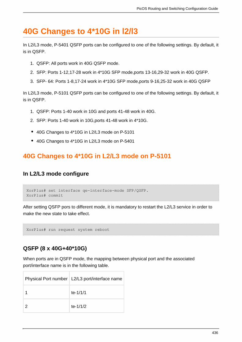
PicOS Routing and Switching Configuration Guide
436
1.
2.
3.
1.
2.
40G Changes to 4*10G in l2/l3
In L2/L3 mode, P-5401 QSFP ports can be configured to one of the following settings. By default, it
is in QSFP.
QSFP: All ports work in 40G QSFP mode.
SFP: Ports 1-12,17-28 work in 4*10G SFP mode,ports 13-16,29-32 work in 40G QSFP.
SFP- 64: Ports 1-8,17-24 work in 4*10G SFP mode,ports 9-16,25-32 work in 40G QSFP
In L2/L3 mode, P-5101 QSFP ports can be configured to one of the following settings. By default, it
is in QSFP.
QSFP: Ports 1-40 work in 10G and ports 41-48 work in 40G.
SFP: Ports 1-40 work in 10G,ports 41-48 work in 4*10G.
40G Changes to 4*10G in L2/L3 mode on P-5101
40G Changes to 4*10G in L2/L3 mode on P-5401
40G Changes to 4*10G in L2/L3 mode on P-5101
In L2/L3 mode configure
XorPlus# set interface qe-interface-mode SFP/QSFP.XorPlus# commit
After setting QSFP pors to different mode, it is mandatory to restart the L2/L3 service in order to
make the new state to take effect.
XorPlus# run request system reboot
QSFP (8 x 40G+40*10G)
When ports are in QSFP mode, the mapping between physical port and the associated
port/interface name is in the following table.
Physical Port number L2/L3 port/interface name
1 te-1/1/1
2 te-1/1/2

PicOS Routing and Switching Configuration Guide
437
3 te-1/1/3
4 te-1/1/4
5 te-1/1/5
6 te-1/1/6
7 te-1/1/7
8 te-1/1/8
9 te-1/1/9
10 te-1/1/10
11 te-1/1/11
12 te-1/1/12
13 te-1/1/13
14 te-1/1/14
15 te-1/1/15
16 te-1/1/16
17 te-1/1/17
18 te-1/1/18
19 te-1/1/19
20 te-1/1/20
21 te-1/1/21
22 te-1/1/22
23 te-1/1/23
24 te-1/1/24

PicOS Routing and Switching Configuration Guide
438
25 te-1/1/25
26 te-1/1/26
27 te-1/1/27
28 te-1/1/28
29 te-1/1/29
30 te-1/1/30
31 te-1/1/31
32 te-1/1/32
33 te-1/1/33
34 te-1/1/34
35 te-1/1/36
36 te-1/1/37
37 te-1/1/38
39 te-1/1/39
40 te-1/1/40
41 qe -1/1/41
42 qe -1/1/42
43 qe -1/1/43
44 qe -1/1/44
45 qe -1/1/45
46 qe -1/1/46
47 qe -1/1/47

PicOS Routing and Switching Configuration Guide
439
48 qe -1/1/48
SFP (72x 10G)
When ports are in SFP mode, the mapping between physical port and the associated port/interface
name is in the following table.
Physical Port number L2/L3 port/interface name
1 te-1/1/1
2 te-1/1/2
3 te-1/1/3
4 te-1/1/4
5 te-1/1/5
6 te-1/1/6
7 te-1/1/7
8 te-1/1/8
9 te-1/1/9
10 te-1/1/10
11 te-1/1/11
12 te-1/1/12
13 te-1/1/13
14 te-1/1/14
15 te-1/1/15
16 te-1/1/16
17 te-1/1/17

PicOS Routing and Switching Configuration Guide
440
18 te-1/1/18
19 te-1/1/19
20 te-1/1/20
21 te-1/1/21
22 te-1/1/22
23 te-1/1/23
24 te-1/1/24
25 te-1/1/25
26 te-1/1/26
27 te-1/1/27
28 te-1/1/28
29 te-1/1/29
30 te-1/1/30
31 te-1/1/31
32 te-1/1/32
33 te-1/1/33
34 te-1/1/34
35 te-1/1/36
36 te-1/1/37
37 te-1/1/38
39 te-1/1/39
40 te-1/1/40

PicOS Routing and Switching Configuration Guide
441
41 4 x 10G
te -1/1/41
te -1/1/42
te -1/1/43
te -1/1/44
42 4 x 10G
te -1/1/45
te -1/1/46
te -1/1/47
te -1/1/48
43 4 x 10G
te -1/1/49
te -1/1/50
te -1/1/51
te -1/1/52
44 4 x 10G
te -1/1/53
te -1/1/54
te -1/1/55
te -1/1/56
45 4 x 10G
te -1/1/57

PicOS Routing and Switching Configuration Guide
442
te -1/1/58
te -1/1/59
te -1/1/60
46 4 x 10G
te -1/1/61
te -1/1/62
te -1/1/63
te -1/1/64
47 4 x 10G
te -1/1/65
te -1/1/66
te -1/1/67
te -1/1/68
48 4 x 10G
te -1/1/69
te -1/1/70
te -1/1/71
te -1/1/72
Note:On P-5101 do not support the mode of SFP-64.

PicOS Routing and Switching Configuration Guide
443
40G Changes to 4*10G in L2/L3 mode on P-5401
In L2/L3 mode configure
XorPlus# set interface qe-interface-mode SFP/SFP-64/QSFP.XorPlus# commit
After setting QSFP pors to different mode, it is mandatory to restart the L2/L3 service in order to
make the new state to take effect.
XorPlus# run request system reboot
QSFP (32 x 40G)
When ports are in QSFP mode, the mapping between physical ports and the logical
ports/interfaces name are in the following table.
Physical Port number L2/L3 port/interface name
1 qe-1/1/1
2 qe-1/1/2
3 qe-1/1/3
4 qe-1/1/4
5 qe-1/1/5
6 qe-1/1/6
7 qe-1/1/7
8 qe-1/1/8
9 qe-1/1/9
10 qe-1/1/10
11 qe-1/1/11
12 qe-1/1/12

PicOS Routing and Switching Configuration Guide
444
13 qe-1/1/13
14 qe-1/1/14
15 qe-1/1/15
16 qe-1/1/16
17 qe-1/1/17
18 qe-1/1/18
19 qe-1/1/19
20 qe-1/1/20
21 qe-1/1/21
22 qe-1/1/22
23 qe-1/1/23
24 qe-1/1/24
25 qe-1/1/25
26 qe-1/1/26
27 qe-1/1/27
28 qe-1/1/28
29 qe-1/1/29
30 qe-1/1/30
31 qe-1/1/31
32 qe-1/1/32

PicOS Routing and Switching Configuration Guide
445
SFP-64 (16 x 40G + 64 x 10G)
When ports are in SFP-64 mode, the mapping between physical ports and the logical
ports/interfaces names are in the following table.
Physical Port number L2/L3 port/interface name
1 4 x 10G
te-1/1/1
te-1/1/2
te-1/1/3
te-1/1/4
2 4 x 10G
te-1/1/5
te-1/1/6
te-1/1/7
te-1/1/8
3 4 x 10G
te-1/1/9
te-1/1/10
te-1/1/11
te-1/1/12
4 4 x 10G
te-1/1/13
te-1/1/14

PicOS Routing and Switching Configuration Guide
446
te-1/1/15
te-1/1/16
5 4 x 10G
te-1/1/17
te-1/1/18
te-1/1/19
te-1/1/20
6 4 x 10G
te-1/1/21
te-1/1/22
te-1/1/23
te-1/1/24
7 4 x 10G
te-1/1/25
te-1/1/26
te-1/1/27
te-1/1/28
8 4 x 10G
te-1/1/29
te-1/1/30
te-1/1/31
te-1/1/32

PicOS Routing and Switching Configuration Guide
447
9 qe-1/1/9
10 qe-1/1/10
11 qe-1/1/11
12 qe-1/1/12
13 qe-1/1/13
14 qe-1/1/14
15 qe-1/1/15
16 qe-1/1/16
17 4 x 10G
te-1/1/33
te-1/1/34
te-1/1/35
te-1/1/36
18 4 x 10G
te-1/1/37
te-1/1/38
te-1/1/39
te-1/1/40
19 4 x 10G
te-1/1/41
te-1/1/42
te-1/1/43

PicOS Routing and Switching Configuration Guide
448
te-1/1/44
20 4 x 10G
te-1/1/45
te-1/1/46
te-1/1/47
te-1/1/48
21 4 x 10G
te-1/1/49
te-1/1/50
te-1/1/51
te-1/1/52
22 4 x 10G
te-1/1/53
te-1/1/54
te-1/1/55
te-1/1/56
23 4 x 10G
te-1/1/57
te-1/1/58
te-1/1/59
te-1/1/60
24 4 x 10G

PicOS Routing and Switching Configuration Guide
449
te-1/1/61
te-1/1/62
te-1/1/63
te-1/1/64
25 qe-1/1/25
26 qe-1/1/26
27 qe-1/1/27
28 qe-1/1/28
29 qe-1/1/29
30 qe-1/1/30
31 qe-1/1/31
32 qe-1/1/32
SFP (8 x 40G + 96 x 10G)
When ports are in SFP mode, the mapping between physical ports and the logical ports/interfaces
name are in the following table.
Physical Port number L2/L3 port/interface name
1 4 x 10G
te-1/1/1
te-1/1/2
te-1/1/3
te-1/1/4
2 4 x 10G

PicOS Routing and Switching Configuration Guide
450
te-1/1/5
te-1/1/6
te-1/1/7
te-1/1/8
3 4 x 10G
te-1/1/9
te-1/1/10
te-1/1/11
te-1/1/12
4 4 x 10G
te-1/1/13
te-1/1/14
te-1/1/15
te-1/1/16
5 4 x 10G
te-1/1/17
te-1/1/18
te-1/1/19
te-1/1/20
6 4 x 10G
te-1/1/21
te-1/1/22

PicOS Routing and Switching Configuration Guide
451
te-1/1/23
te-1/1/24
7 4 x 10G
te-1/1/25
te-1/1/26
te-1/1/27
te-1/1/28
8 4 x 10G
te-1/1/29
te-1/1/30
te-1/1/31
te-1/1/32
9 4 x 10G
te-1/1/33
te-1/1/34
te-1/1/35
te-1/1/36
10 4 x 10G
te-1/1/37
te-1/1/38
te-1/1/39
te-1/1/40

PicOS Routing and Switching Configuration Guide
452
11 4 x 10G
te-1/1/41
te-1/1/42
te-1/1/43
te-1/1/44
12 4 x 10G
te-1/1/45
te-1/1/46
te-1/1/47
te-1/1/48
13 qe-1/1/13
14 qe-1/1/14
15 qe-1/1/15
16 qe-1/1/16
17 4 x 10G
te-1/1/49
te-1/1/50
te-1/1/51
te-1/1/52
18 4 x 10G
te-1/1/53
te-1/1/54

PicOS Routing and Switching Configuration Guide
453
te-1/1/55
te-1/1/56
19 4 x 10G
te-1/1/57
te-1/1/58
te-1/1/59
te-1/1/60
20 4 x 10G
te-1/1/61
te-1/1/62
te-1/1/63
te-1/1/64
21 4 x 10G
te-1/1/65
te-1/1/66
te-1/1/67
te-1/1/68
22 4 x 10G
te-1/1/69
te-1/1/70
te-1/1/71
te-1/1/72

PicOS Routing and Switching Configuration Guide
454
23 4 x 10G
te-1/1/73
te-1/1/74
te-1/1/75
te-1/1/76
24 4 x 10G
te-1/1/77
te-1/1/78
te-1/1/79
te-1/1/80
25 4 x 10G
te-1/1/81
te-1/1/82
te-1/1/83
te-1/1/84
26 4 x 10G
te-1/1/85
te-1/1/86
te-1/1/87
te-1/1/88
27 4 x 10G
te-1/1/89

PicOS Routing and Switching Configuration Guide
455
te-1/1/90
te-1/1/91
te-1/1/92
28 4 x 10G
te-1/1/93
te-1/1/94
te-1/1/95
te-1/1/96
29 qe-1/1/29
30 qe-1/1/30
31 qe-1/1/31
32 qe-1/1/32

PicOS Routing and Switching Configuration Guide
456
Configuration Appendix
Other Command List
Other Command List
set interface traceoptions flag config disable true
set interface traceoptions flag ethernet-switching-options disable true
set interface traceoptions flag mlag-trace disable true
set interface traceoptions flag neighbor-event disable true
set interface traceoptions flag packets disable true
set interface traceoptions flag route-event disable true
set interface traceoptions flag static-ethernet-switching disable true
set interface traceoptions line-card statistic disable true
set interface traceoptions line-card trace-level all disable true
set interface traceoptions line-card trace-level api debug disable true
set interface traceoptions line-card trace-level api error disable true
set interface traceoptions line-card trace-level api information disable true
set interface traceoptions line-card trace-level api warning disable true
set interface traceoptions line-card trace-level sdk debug disable true
set interface traceoptions line-card trace-level sdk error disable true
set interface traceoptions line-card trace-level sdk information disable true
set interface traceoptions line-card trace-level sdk warning disable true
set interface traceoptions line-card trace-level xrl debug disable true
set interface traceoptions line-card trace-level xrl error disable true
set interface traceoptions line-card trace-level xrl information disable true
set interface traceoptions line-card trace-level xrl warning disable true
set interface traceoptions line-card trace-type all disable true
set interface traceoptions line-card trace-type configuration disable true
set interface traceoptions line-card trace-type link-change disable true
set interface traceoptions line-card trace-type mac-update disable true
set interface traceoptions line-card trace-type packet disable true
set interface traceoptions line-card trace-type packet-receive disable true
set interface traceoptions line-card trace-type packet-transmit disable true
set interface traceoptions line-card trace-type statistic disable true

PicOS Routing and Switching Configuration Guide
457
1.
2.
3.
OpenFlow Configurations in Crossflow Mode
This chapter describes the configurations of OpenFlow via the CrossFlow Mode. The Crossflow
mode is the capacity to mixed tradtional L2/L3 and Openflow protocols simultaneously on the same
physical switch.
The Crossflow mode has been improved in PicOS 2.4. Now all the OVS commands are available and there is a featureparity between the OVS mode and the L2/L3 mode.
CrossFlow Mode Introduction
In CrossFlow mode switches can achieve all functions that exist in OVS mode: including basic flow
function, meter, group, multi-table, Q-in Q, mpls, pbb, GRE, mirror, ECMP, etc...
Like PicOS OVS mode, in crossflow mode OpenFlow v1.0, OFv1.1, OFv1.2, OF1.3 and OFv1.4
are supported. You can configure any supported version in the CLI.
In PicOS2.4, ports in the switch are either legacy or crossflow ports. In a crossflow port, PicOS
just support disable in version PicOS2.4, the protocol packet will not be processed inlocal-control
the local protocol stack. If enabled, represents the port is legacy port.local-control
As above figure, switch ports working status in crossflow mode is shown. crossflow port modes can
be summarized as follows:
Crossflow mode & local-control-off & disable l2/l3 mode:
The port is totally controlled by controller
All broadcast turned off & auto learning turned off
Packet forwarded by looking up the TCAM table

PicOS Routing and Switching Configuration Guide
458
1.
2.
3.
Crossflow mode & local-control-off & enable l2/l3 mode
The port is totally controlled by controller
All broadcast turned off & auto learning turned off
Packet forwarded by looking up the FIB (FDB/routing table) and TCAM table
In CrossFlow mode, user can enable l2/l3 mode as PicOS OVS multi-table function. If the l2/l3
mode enabled, the FIB table resource will be shared by legacy ports and crossflow ports and data
traffic cannot mix between the different type ports. User can special portallocate the resource for
as following command.
set interface stm openflow-table 1000set interface stm mac-table 20000set interface max-route-limit 10000
The first command 'set interface stm openflow-table 1000' means allocate the TCAM resource for
crossflow port;
The second command 'set interface stm mac-table 20000 ' means allocate the FDB table resource
for legacy port, and the rest of resource for crossflow port.
The last command 'set interface max-route-limit 10000' means allocate the route table resource for
legacy port, and the rest of resource for crossflow port.
As the following figure. In crossflow mode, traffic can be only forwarded in the OpenFlow domain
or only forwarded in the Legacy network domain (as shown in the following figures).
The configurations of crossflow mode are different from those in OVS.The followings is some
examples in crossflow mode. In Xorplus system,it is responsible for setting which ports belonged to
XOVS ,and creating vlans. As for the port Properties, and vlans ports belonged to,ovs is in charge.

PicOS Routing and Switching Configuration Guide
459
limitations of hybrid : Before configure the interface to crossflow enable true, you should clear the
configurations of this interface that you have done in Xorplus.But now we have not do the
limitations.
command
admin@XorPlus# set xovs enable trueadmin@XorPlus# commitadmin@XorPlus# set interface gigabit-ethernet ge-1/1/1 crossflow enable trueadmin@XorPlus# set interface gigabit-ethernet ge-1/1/1 crossflowlocal-control falseadmin@XorPlus# set vlans vlan-id 2,2000,4094admin@XorPlus# commit
commands in linux.
admin@XorPlus$ovs-vsctl list pica8admin@XorPlus$ovs-vsctl add-br br0 -- set bridge br0 datapath_type=pica8admin@XorPlus$ovs-vsctl add-port br0 ge-1/1/1 vlan_mode=trunk tag=1trunks=2000,4094 -- set Interface ge-1/1/1 type=pica8admin@XorPlus$ovs-vsctl add-port br0 ge-1/1/2 vlan_mode=trunk tag=1trunks=2000,4094 -- set Interface ge-1/1/2 type=pica8admin@XorPlus$ovs-vsctl add-port br0 ge-1/1/3 vlan_mode=trunk tag=1trunks=2000,4094 -- set Interface ge-1/1/3 type=pica8
Examples
Basic configurations
topology
steps
(1) enable crossflow for two ports
admin@XorPlus# set xovs enable trueadmin@XorPlus# commitadmin@XorPlus# set interface gigabit-ethernet te-1/1/1 crossflow enabletrueadmin@XorPlus# set interface gigabit-ethernet te-1/1/1 crossflowlocal-control falseadmin@XorPlus# set interface gigabit-ethernet te-1/1/2 crossflow enabletrueadmin@XorPlus# set interface gigabit-ethernet te-1/1/2 crossflowlocal-control falseadmin@XorPlus#set vlans vlan-id 1,2 ,10,20admin@XorPlus# commit

PicOS Routing and Switching Configuration Guide
460
(2)exit the Xorplus system then enter linux system
admin@XorPlus#exit admin@XorPlus>exitadmin@XorPlus$
(3)create a new bridge named br0.
admin@XorPlus$ovs-vsctl add-br br0 -- set bridge br0 datapath_type=pica8
(4)add ports to br0.
admin@XorPlus$ovs-vsctl add-port br0 te-1/1/1 vlan_mode=trunk tag=1trunks=2,10,20 -- set Interface te-1/1/1 type=pica8admin@XorPlus$ovs-vsctl add-port br0 te-1/1/2 vlan_mode=trunk tag=1trunks=2,10,20 -- set Interface te-1/1/2 type=pica8
(5) add a flow
admin@XorPlus$ovs-ofctl add-flow br0 in_port=1,actions=output:2
(6)Send packets to te-1/1/1
Send untag packets to te-1/1/1 that matching this flow, then te-1/1/2 will forward the packets (with
no vlan);Send packets with vlan 2 to te-1/1/1,then te-1/1/2 will forward the packets (with vlan 2).
Flow priority configurations
topology
(1)enable crossflow for two ports
admin@XorPlus# set xovs enable trueadmin@XorPlus# commitadmin@XorPlus# set interface gigabit-ethernet te-1/1/1 crossflow enabletrueadmin@XorPlus# set interface gigabit-ethernet te-1/1/1 crossflowlocal-control falseadmin@XorPlus# set interface gigabit-ethernet te-1/1/2 crossflow enabletrueadmin@XorPlus# set interface gigabit-ethernet te-1/1/2 crossflowlocal-control falseadmin@XorPlus#set vlans vlan-id 1,2 ,10,20admin@XorPlus# commit
(2)exit the Xorplus system then enter linux system
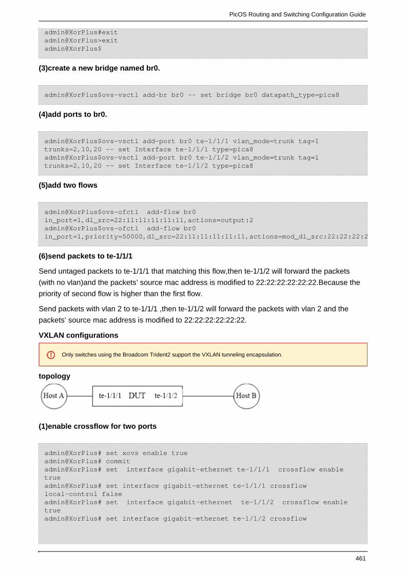
PicOS Routing and Switching Configuration Guide
461
admin@XorPlus#exit admin@XorPlus>exitadmin@XorPlus$
(3)create a new bridge named br0.
admin@XorPlus$ovs-vsctl add-br br0 -- set bridge br0 datapath_type=pica8
(4)add ports to br0.
admin@XorPlus$ovs-vsctl add-port br0 te-1/1/1 vlan_mode=trunk tag=1trunks=2,10,20 -- set Interface te-1/1/1 type=pica8admin@XorPlus$ovs-vsctl add-port br0 te-1/1/2 vlan_mode=trunk tag=1trunks=2,10,20 -- set Interface te-1/1/2 type=pica8
(5)add two flows
admin@XorPlus$ovs-ofctl add-flow br0in_port=1,dl_src=22:11:11:11:11:11,actions=output:2admin@XorPlus$ovs-ofctl add-flow br0in_port=1,priority=50000,dl_src=22:11:11:11:11:11,actions=mod_dl_src:22:22:22:22:22:22,output:2
(6)send packets to te-1/1/1
Send untaged packets to te-1/1/1 that matching this flow,then te-1/1/2 will forward the packets
(with no vlan)and the packets’ source mac address is modified to 22:22:22:22:22:22.Because the
priority of second flow is higher than the first flow.
Send packets with vlan 2 to te-1/1/1 ,then te-1/1/2 will forward the packets with vlan 2 and the
packets’ source mac address is modified to 22:22:22:22:22:22.
VXLAN configurations
Only switches using the Broadcom Trident2 support the VXLAN tunneling encapsulation.
topology
(1)enable crossflow for two ports
admin@XorPlus# set xovs enable trueadmin@XorPlus# commitadmin@XorPlus# set interface gigabit-ethernet te-1/1/1 crossflow enabletrueadmin@XorPlus# set interface gigabit-ethernet te-1/1/1 crossflowlocal-control falseadmin@XorPlus# set interface gigabit-ethernet te-1/1/2 crossflow enabletrueadmin@XorPlus# set interface gigabit-ethernet te-1/1/2 crossflow

PicOS Routing and Switching Configuration Guide
462
local-control falseadmin@XorPlus#set vlans vlan-id 1,2 ,10,20admin@XorPlus# commit
(2)exit the Xorplus system then enter linux system
admin@XorPlus#exit admin@XorPlus>exitadmin@XorPlus$
(3)create a new bridge named br0.
admin@XorPlus$ovs-vsctl add-br br0 -- set bridge br0 datapath_type=pica8
(4)add ports to br0.
admin@XorPlus$ovs-vsctl add-port br0 qe-1/1/1 vlan_mode=trunk tag=1trunks=2,10,20 -- set Interface qe-1/1/1 type=pica8admin@XorPlus$ovs-vsctl add-port br0 qe-1/1/2 vlan_mode=trunk tag=1trunks=2,10,20 -- set Interface qe-1/1/2 type=pica8
(5)add a VXLAN port named vxlan1 on qe-1/1/2
admin@XorPlus$ovs-vsctl add-port br0 vxlan1 – set interface vxlan1type=pica8_vxlan options:remote_ip=10.10.10.2 options:local_ip=10.10.10.1options:vlan=1 options:vnid=1122867 options:udp_dst_port=4789 options:src_mac=C8:0A:A9:04:49:1A options:dst_mac=C8:0A:A9:9E:14:A5 options:egress_port=qe-1/1/2
(6)add a flow
admin@XorPlus$ovs-ofctl add-flow br0 in_port=1,actions=output:4097
FDB configurations
topology
(1)enable crossflow for two ports
(2)exit the Xorplus system then enter linux system
admin@XorPlus# set xovs enable trueadmin@XorPlus# commitadmin@XorPlus# set interface gigabit-ethernet te-1/1/1 crossflow enabletrueadmin@XorPlus# set interface gigabit-ethernet te-1/1/1 crossflowlocal-control false

PicOS Routing and Switching Configuration Guide
463
admin@XorPlus# set interface gigabit-ethernet te-1/1/2 crossflow enabletrueadmin@XorPlus# set interface gigabit-ethernet te-1/1/2 crossflowlocal-control falseadmin@XorPlus#set vlans vlan-id 1,2 ,10,20admin@XorPlus# commitadmin@XorPlus#exit admin@XorPlus>exitadmin@XorPlus$
(3)create a new bridge named br0.
admin@XorPlus$ovs-vsctl add-br br0 -- set bridge br0 datapath_type=pica8
(4)add ports to br0.
admin@XorPlus$ovs-vsctl add-port br0 qe-1/1/1 vlan_mode=trunk tag=1trunks=2,10,20 -- set Interface qe-1/1/1 type=pica8admin@XorPlus$ovs-vsctl add-port br0 qe-1/1/2 vlan_mode=trunk tag=1trunks=2,10,20 -- set Interface qe-1/1/2 type=pica8
(5)set table 1 to FDB table
admin@XorPlus$ovs-vsctl set-l2-mode true 1
(6)add a flow
admin@XorPlus$ovs-ofctl add-flow br0table=1,dl_dst=22:22:22:22:22:22,dl_vlan=10,actions=output:2
Flows must match dl_dst,dl_vlan and output port if they want to be stroed in FDB table. Table
number of FDB table is 251 by default.Users can specify another table as the FDB table instead of
the 251,using this command If you want flows to be ovs-vsctl set-l2-mode true [table number]. stored in ROUTE table ,flows must match dl_dst,dl_vlan,dl_type,nw_dst,and mod_dl_dst in
action,and the default table number of ROUTE is 252.Using command ovs-vsctl set-l3-mode trueto set route table.[table number]

PicOS Routing and Switching Configuration Guide
464