Embed Size (px)
Citation preview

IN DEGREE PROJECT MECHANICAL ENGINEERING,FIRST CYCLE, 15 CREDITS
, STOCKHOLM SWEDEN 2018
PicassoCNC plotter
LINUS PERSSON
NATALIJA ZIVANOVIC
KTH ROYAL INSTITUTE OF TECHNOLOGYSCHOOL OF INDUSTRIAL ENGINEERING AND MANAGEMENT

Picasso
CNC plotter
NATALIJA ZIVANOVIC OCH LINUS PERSSON
Bachelor’s Thesis at ITMSupervisor: Nihad SubasicExaminer: Nihad Subasic
TRITA-ITM-EX 2018:62

AbstractIn today’s society, CNC machines are used for various pur-poses. In this project, a CNC plotter is created to analyzehow the performance of the plotter differs when using twodifferent motors: a DC motor controlled by a potentiome-ter in the horizontal direction and a stepper motor in thevertical direction. A CNC plotter is built and used to dotests in order to answer the research question. The resultsshow that a DC motor with a potentiometer is more precisethan a stepper motor and the mean value of the relative er-rors in the vertical direction is always higher. The valuesdiffer with 1 percentage point to 3 percentage points. Thedifference in the performance of the two motors depend onseveral factors and one of the main factors is considered tobe the fact that the stepper motor sometimes skips steps.
Keywords: Mechatronics, CNC, Plotter, Potentiometer, Step-per motor, DC motor

ReferatPicasso
I dagens samhälle används CNC-maskiner för olika ända-mål. I detta projekt skapades en CNC-plotter för att ana-lysera hur plotterns prestanda skiljer sig vid användning avtvå olika motorer: en DC motor kontrollerad av en poten-tiometer i horisontell riktning och en stegmotor i vertikalriktning. En CNC-plotter byggdes och användes för genom-förande av tester för att kunna svara på forskningsfrågan.Resultaten visar att en DC motor med en potentiometer ärmer exakt än en stegmotor och medelvärdet av de relativafelen i vertikala riktningen är alltid högre. Värdena skiljersig från 1 procentenhet till 3 procentenheter. Skillnaden iprestanda för de två motorerna beror på flera faktorer ochen av huvudfaktorerna anses vara det faktum att stegmo-torn ibland hoppar över steg.
Nyckelord: Mekatronik, CNC, Plotter, Potentiometer, Steg-motor, DC motor

Acknowledgements
We would like to thank our supervisor and examiner Nihad Subasic for the intro-duction into the field of mechatronics and giving us the foundation of knowledgeon which this project is built. A thanks goes out to the teachers assistants JohanEhrenfors, Ruben Svensson, Martin Gylling and Stanislav Minko for advice on howto make reality of our ideas and giving a helping hand when we ran into problems.A big thanks to Staffan Qvarnström for helping us with electrical solutions and anequally big thanks to Tomas Östberg for helping us with all the mechanical solu-tions. This project would not have been possible if it were not for these people.
Linus Persson and Natalija ZivanovicStockholm, May 2018

Contents
1 Introduction 31.1 Background . . . . . . . . . . . . . . . . . . . . . . . . . . . . . . . . 31.2 Purpose . . . . . . . . . . . . . . . . . . . . . . . . . . . . . . . . . . 31.3 Scope . . . . . . . . . . . . . . . . . . . . . . . . . . . . . . . . . . . 4
2 Theory 52.1 DC Motor . . . . . . . . . . . . . . . . . . . . . . . . . . . . . . . . . 52.2 Arduino . . . . . . . . . . . . . . . . . . . . . . . . . . . . . . . . . . 52.3 Stepper motor . . . . . . . . . . . . . . . . . . . . . . . . . . . . . . 6
2.3.1 General . . . . . . . . . . . . . . . . . . . . . . . . . . . . . . 62.3.2 Permanent magnet . . . . . . . . . . . . . . . . . . . . . . . . 62.3.3 Stepper motors in CNC-machines . . . . . . . . . . . . . . . . 7
2.4 Potentiometer . . . . . . . . . . . . . . . . . . . . . . . . . . . . . . . 72.5 H-bridge . . . . . . . . . . . . . . . . . . . . . . . . . . . . . . . . . . 82.6 Absolute and relative error . . . . . . . . . . . . . . . . . . . . . . . 9
3 Demonstration 113.1 Problem formulation . . . . . . . . . . . . . . . . . . . . . . . . . . . 113.2 Electronics . . . . . . . . . . . . . . . . . . . . . . . . . . . . . . . . 11
3.2.1 Microcontroller . . . . . . . . . . . . . . . . . . . . . . . . . . 123.2.2 Memory . . . . . . . . . . . . . . . . . . . . . . . . . . . . . . 123.2.3 DC motor and stepper motor . . . . . . . . . . . . . . . . . . 123.2.4 H-bridge . . . . . . . . . . . . . . . . . . . . . . . . . . . . . . 133.2.5 Potentiometer . . . . . . . . . . . . . . . . . . . . . . . . . . . 133.2.6 Servo . . . . . . . . . . . . . . . . . . . . . . . . . . . . . . . 13
3.3 Software . . . . . . . . . . . . . . . . . . . . . . . . . . . . . . . . . . 133.3.1 Generating coordinates . . . . . . . . . . . . . . . . . . . . . 133.3.2 Motor control . . . . . . . . . . . . . . . . . . . . . . . . . . . 13
3.4 Hardware . . . . . . . . . . . . . . . . . . . . . . . . . . . . . . . . . 153.4.1 Frame . . . . . . . . . . . . . . . . . . . . . . . . . . . . . . . 153.4.2 Y-axis . . . . . . . . . . . . . . . . . . . . . . . . . . . . . . . 153.4.3 X-axis . . . . . . . . . . . . . . . . . . . . . . . . . . . . . . . 15
3.5 Z-axis . . . . . . . . . . . . . . . . . . . . . . . . . . . . . . . . . . . 16

4 Application testing 194.1 Approach . . . . . . . . . . . . . . . . . . . . . . . . . . . . . . . . . 194.2 Testing and error measurement . . . . . . . . . . . . . . . . . . . . . 194.3 Results . . . . . . . . . . . . . . . . . . . . . . . . . . . . . . . . . . . 20
5 Discussion and conclusion 25
Bibliography 27
A Program code (C/C++) 29
B Program code (Python) 35
C Schematic of L298 H-Bridge circuit 43
D Excel table 45
E Datasheets 47

List of Figures
2.1 Stator and rotor arrangement. [1] . . . . . . . . . . . . . . . . . . . . . . 72.2 Rotary potentiometer. In the figure, rotary contact is named wiper. [3] . 82.3 Demonstration of a linear potentiometer. [2] . . . . . . . . . . . . . . . . 82.4 H-bridge. [13] . . . . . . . . . . . . . . . . . . . . . . . . . . . . . . . . . 9
3.1 Connection diagram of the electronics made in the program Fritzing. . . 123.2 Flow chart of the Arduino program made on draw.io website. . . . . . . 143.3 The assembly made in Solid Edge. . . . . . . . . . . . . . . . . . . . . . 153.4 X- and Z-axis assembly (3.4a) and holder for X- axis (3.4b) . . . . . . . 163.5 Z-axis assembly made in Solid Edge. . . . . . . . . . . . . . . . . . . . . 17
4.1 Plotter setup for testing. . . . . . . . . . . . . . . . . . . . . . . . . . . . 204.2 Test number one: drawing of 50 mm long lines. . . . . . . . . . . . . . . 214.3 Results of the first test. . . . . . . . . . . . . . . . . . . . . . . . . . . . 214.4 Test number two: drawing of a heart. . . . . . . . . . . . . . . . . . . . 224.5 Results of the second test. . . . . . . . . . . . . . . . . . . . . . . . . . . 224.6 Test number three: drawing of 16 mm and 40 mm long lines. . . . . . . 224.7 Results of the third test. . . . . . . . . . . . . . . . . . . . . . . . . . . . 234.8 Test number four: drawing of 128 mm long lines. . . . . . . . . . . . . . 234.9 Results of the fourth test. . . . . . . . . . . . . . . . . . . . . . . . . . . 23

List of Abbreviations
CNC Computer Numerical Control
DC Direct Current
IDE Integrated Development Environment
PWM Pulse-Width Modulation
RPM Revolutions Per Minute
SD Secure Digital
USB Universal Serial Bus
1


Chapter 1
Introduction
1.1 Background
Computer numerical controlled (CNC) machine use numerical calculation to con-trol a tool. In the 1980s, CNC machines became the central element in differentsystems, due to an increase of various parts in the production that were requiredto be produced. By developing CNC machines, the production of these small partswas made efficient and fast. The purpose of making CNC machine was to enablethe mass production and therefore save money and time. [15]
A CNC plotter is a simplified model of the machines described above. The functionis not to process material but rather to draw figures on paper. It requires the sameprecision in the horizontal and vertical directions but instead of controlling a toolin the up and down direction, a pen is controlled. This project will focus on howprecise the drawing can be made in comparison to the input coordinates. Through-out the project, the DC motor controlled direction and the stepper motor directionwill be called the X- and Y- directions respectively.
1.2 Purpose
The aim of the following project is to analyze how the performance of a CNC plotterdiffers when using a DC motor with a potentiometer compared to using a steppermotor. The CNC plotter receives coordinates of a digital drawing and draws a pic-ture on a sheet of paper using the stepper motor in the Y-direction and DC motorwith potentiometer in the X-direction. The length of the lines drawn in the X- andY- directions are then compared to the input distance in order to study the twodifferent methods of controlling the plotter. The following question is researched:
How does the resolution of a drawing drawn by a CNC controlled pen differ inthe X- and Y- directions when one direction is controlled by a stepper motor andthe other by a DC motor with a potentiometer?
3

CHAPTER 1. INTRODUCTION
1.3 ScopeIn order to answer the question some limitations have to be imposed. The mech-anism of the CNC plotter consists of many different parts that need to cooperatewell. As it can be a challenge to make the parts cooperate well, some simplificationsof the mechanical construction are done.
As the microcontroller used to control the plotter is limited in computational powerthe motors will only be moving one at the time. This means that no diagonal linesnor circles will be drawn, only straight lines.
4

Chapter 2
Theory
2.1 DC Motor
DC motor is the type of electric motor that uses direct current as power. A DCmotor consists of a static part called stator and a rotating part known as commuta-tor. The stator consists of a permanent magnet with a north and south poles, andbetween these two poles there is the commutator containing a wire through whicha current passes. Around the wire, an induced magnetic field occurs which is thenrepelled by one pole of the permanent magnet and simultaneously attracted by theother pole. The more windings that the commutator consists of, the smoother turnsthe motor, because the commutator then always has a magnetic drive. [9]
2.2 Arduino
Arduino is a common open-source electronic platform used in various projects: fromeasier school projects to more advanced scientific projects. It is based on hardwarewhich is easy to use and an IDE software. The Arduino has an ability to read aninput and turn it into an output. The input may consist of a light sensor thatreceives light as an input or a button that is activated when pressed. The outputcould be a light that turns on a light or a movement of a motor. The programminglanguage used in Arduino is C based. An Arduino is open source, which means itcan be built independently and adapted to the needs of the use. The software is,as well, open source. Arduino is based on the ATMega microcontroller. [4]
An Arduino board is divided in two parts: a hardware part and a software part.The hardware part made from many different components such as a microproces-sor, USB plug and digital pins which are combined to make Arduino operate. Thesoftware part consists of an IDE that interprets the code that the user writes andconverts it to the plotter language that the Arduino reads. The IDE also providesserial communication between the Arduino and the connected computer. [5]
5

CHAPTER 2. THEORY
2.3 Stepper motor
2.3.1 General
Stepper motors works in a different way compared to DC motors which gives theman advantage in certain situations. Due to the construction of the stepper motor, itonly turns as much as it’s told through an electric signal. It is useful for applicationswhere knowing the exact position and the amount of turns the motor has made ismore important than RPM and torque. Such applications could be CNC machines,CD drives or motion tracking. Anything involving precise movements could benefitfrom using stepper motors.
A stepper motor has a negligible acceleration and retardation stage whereas a DCmotor do not. On top of that it can turn just as easily with a heavy load comparedto a light load. At last a stepper motor is open loop, which means it does not requireany feedback system to know what position the shaft is at. [6] This however meansthat the stepper motor doesn’t know if a step has been skipped. A missed step willresult in the program thinking it is done spinning, when the motor in reality hasn’treached its target yet.
The fundamental construction of the stepper motor is a shaft connected rotor coreand a stator with poles facing inwards toward the rotor. Around the stator polesthere are copper wire windings to create electromagnets which are activated by asquare signal making the rotor turn in steps. Stepper motors are divided into threedifferent categories depending on their construction: Variable Reluctance, Perma-nent Magnet, and Hybrid (combination of both). [6]
2.3.2 Permanent magnet
The permanent magnet stepper motor uses, as the name suggests, a permanentmagnet as a rotor. When a current is run through the first winding (winding Ain Figure 2.1), it will produce a magnetic field which will attract a pole of thepermanent magnet. The current is subsequently run through the second winding(B in Figure 2.1) and the permanent magnet will re-align to the new magnetic field.In addition to this, if the currents direction is changed, the rotor can be rotatedboth clockwise and counter-clockwise. [12]
6
2.4. POTENTIOMETER
Figure 2.1: Stator and rotor arrangement. [1]
2.3.3 Stepper motors in CNC-machines
Unlike a DC motor, a stepper motor requires a certain signal to operate. This meansa microcontroller (See chapter 2.2) is needed. The microcontroller will proceed tosend a waveform to the stepper motor. A typical waveform that will drive thestepper motor is two square-waves fed to the stator winding 90 degrees out ofphase. A wave like this will, when fed a current, make winding A a south pole andattract the north pole of the rotor. A step will occur when the waveform continuesand feeds a current through winding B and make the attached stator produce amagnetic field that attracts the north pole of the rotor. [7]
2.4 Potentiometer
In order to precisely control motion of a machine or a robot a potentiometer canbe used. Potentiometer is an electronic device that uses change in resistance tomeasure position. This electronic device is today widely used in most advancedtechnologies, robotics and medicinal application. Potentiometers have been used indifferent applications for more than a century and their characteristics and capabil-ities have been improved recently. [10]
A potentiometer is a three terminal resistor with a contact that forms a voltagedivider. It acts as a variable resistor if two terminals are connected respectively topower supply and ground. [11] There are two different type of potentiometers: po-tentiometers with a rotary contact and potentiometers with slide contact. A rotarycontact makes a rotation when something attached to it is moving and the slidingcontact does a sliding movement. In Figure 2.2 and Figure 2.3 the two differenttypes of potentiometers are demonstrated. [14]
7

CHAPTER 2. THEORY
Figure 2.2: Rotary potentiometer. In the figure, rotary contact is named wiper. [3]
Figure 2.3: Demonstration of a linear potentiometer. [2]
A key characterizer of potentiometers are ther linearity. Linearity is definedas proportional difference between the output voltage and calculated voltage. Theaccuracy of a potentiometer depends on the size of the track and the total resistance.Accuracy is best when the track size is big and the resistance is low. [10]
2.5 H-bridge
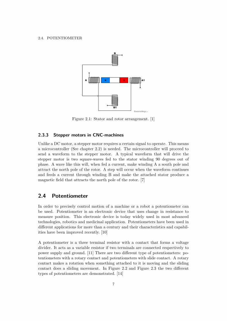
An H-bridge is an electronic circuit designed to give bi-directional control of a DCmotor [13]. It is built from four transistors and four diodes configured as shown inFigure 2.4 .
By changing the states of the transistors, current can be made to flow in bothdirections through the motor thus making it rotate in both directions.
8
2.6. ABSOLUTE AND RELATIVE ERROR
Figure 2.4: H-bridge. [13]
2.6 Absolute and relative errorAbsolute error is defined as the difference between the approximation and the exactvalue. Absolute error is calculated by subtracting the approximated value from theexact value and calculating the absolute value of that subtraction. For instance, ifa0 is an approximation to a, the absolute error is calculated by:
∆a = |a0 − a| (2.1)
Relative error is a relation between the error and the exact value and is calculatedby dividing the error with the exact value. [8] It is calculated by:
|a0 − a|a
(2.2)
9


Chapter 3
Demonstration
3.1 Problem formulationIn order to reach the goal of this project, which was to design a CNC plotter thatconverts a digital drawing to a drawing on a sheet of paper, the following problemshad to be solved:
• Convert a digital drawing into coordinates and define the algorithms that usethe coordinates to control the motors and movement of the plotter
• Design the mechanical construction of the plotter
• Create an H-bridge that is suitable for the stepper motor
• Calibrate the plotter
3.2 ElectronicsTo control and drive the CNC plotter, the following electronics were used:
• Two different H-bridges
• One stepper motor
• One DC motor
• Potentiometer
• Micro SD card module
• One servo
The datasheets of the electronic devices are available in Appendix E.
11

CHAPTER 3. DEMONSTRATION
3.2.1 MicrocontrollerTo control the CNC plotter an Arduino was used. The digital outputs of the Ar-duino were connected to a Micro SD card module, servo, stepper motor, DC motor,and the two H-bridges. A potentiometer was connected to the analog input on theArduino. The Micro SD card module, servo, and potentiometer were connectedto 5V output on Arduino while the two H-bridges were connected to 12 V. Theconnection diagram of electronics is shown in Figure 3.1.
Figure 3.1: Connection diagram of the electronics made in the program Fritzing.
3.2.2 MemoryTo store the coordinates that control the movement of the CNC plotter an SD cardwas used. Coordinates were uploaded on the SD card and the card itself was pluggedinto the Arduino with the Micro SD card module.
3.2.3 DC motor and stepper motorThe CNC plotter was driven by two motors: a DC motor which drove the pen inthe X-direction and a stepper motor which drove the pen in the Y-direction. TheDC motor was a GR 22 Brushed DC motor with a gear box from Dunkermotorenand the stepper motor was a TS3214N61 from Tamagawa Seiki C.O.
12
3.3. SOFTWARE
3.2.4 H-bridge
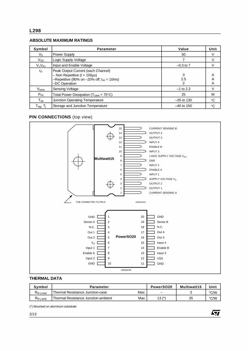
In order to control the motors, two H-bridges which received a PWM signal from theArduino were used. The H-bridge used for the DC motor was L293DNE from TexasInstruments. L293DNE was simply connected to the motor without the need of anyother electrical components. The other H-bridge, L298N from ST Microelectronics,used for the stepper motor, was soldered on a circuit board together with some otherelectrical components: diodes, capacitors, and a linear regulator. The schematicsof the circuit is available in Appendix C.
3.2.5 Potentiometer
The Potentiometer used to control the DC motor was a 3590S-2-103L from Bournswith a resistance of 10 kOhm. It is a rotary potentiometer with a maximum of 10turns. The Arduino interpreted the signal from potentiometer as a value from 0 to1024.
3.2.6 Servo
An SG90 Micro servo from Tower Pro was used to move the pen up and down. Aservo was suitable due to it’s ability to move to a certain position and hold saidposition regardless of external forces.
3.3 Software
3.3.1 Generating coordinates
To generate the coordinates a Python script shown in Appendix B was used. Theprogram allowed the user to draw a picture directly on the computer screen andgenerated coordinates of the drawing as a .ngc file. The file was thereafter uploadedon the SD card which was then read by the Arduino and the coordinates could beused to control the two movements in the X- and Y- directions. As the pen couldonly draw straight lines in either the X- or Y- directions, the program was madeso that the user could easily draw straight lines. The coordinates were generateddepending on where the user clicked.
3.3.2 Motor control
An algorithm written in C language controlled the movement of the CNC plotterand is shown in Appendix A. The coordinates were loaded on to the Micro SD-cardread by the Arduino and used to calculate the distance that the pen should movein the X- and Y- directions. The pen was also moving in the Z-direction (up anddown) and the coordinates that control the movement in the Z-direction were alsoprovided in the file with the coordinates. As the file with coordinates was readby the Arduino, the microcontroller decided which motor should move. If there
13

CHAPTER 3. DEMONSTRATION
was a position difference in the X-direction, the DC motor would move until thepotentiometer had rotated a certain number of revolutions. The distance of themovement in the X-direction was therefore translated to values that the Arduinoreceived from the potentiometer. When a certain value on the potentiometer wasreached, the DC motor was stopped by the microcontroller.
For the movement of the stepper motor, only the amount of steps were sent tocontrol the motor. A distance in the Y-direction was calculated and that valuecontrolled how many steps the stepper motor should move. In the Z-direction, onlytwo different movements were made by the servo, which resulted in the pen beingup or down. A flow chart of the programs decision making can be seen in Figure3.2
Figure 3.2: Flow chart of the Arduino program made on draw.io website.
14

3.4. HARDWARE
3.4 Hardware
3.4.1 FrameThe frame of the plotter consisted of four wooden corners with two holes each andfour axles on to which the X-axis and Y-axis assemblies were attached. An assemblyof the construction is available in Figure 3.3. The holes were perpendicular to eachother and were fitted with axles connecting every corner, resulting in a square frameof adjustable size. To hold the board (not shown in the figure) which servers as adrawing surface, four clamps were attached to the Y-axis axles of the frame. Theclamps each had a bracket for the drawing surface to rest on.
Figure 3.3: The assembly made in Solid Edge.
3.4.2 Y-axisA stepper motor was driving the Y-axis. The stepper motor was attached to a 3Dprinted holder which in turn was attached to the frame. On the opposite side therewas a pulley on another holder and between the motor and the pulley a belt wasfastened. The belt was subsequently attached to the X-axis assembly to move it inthe Y-direction.
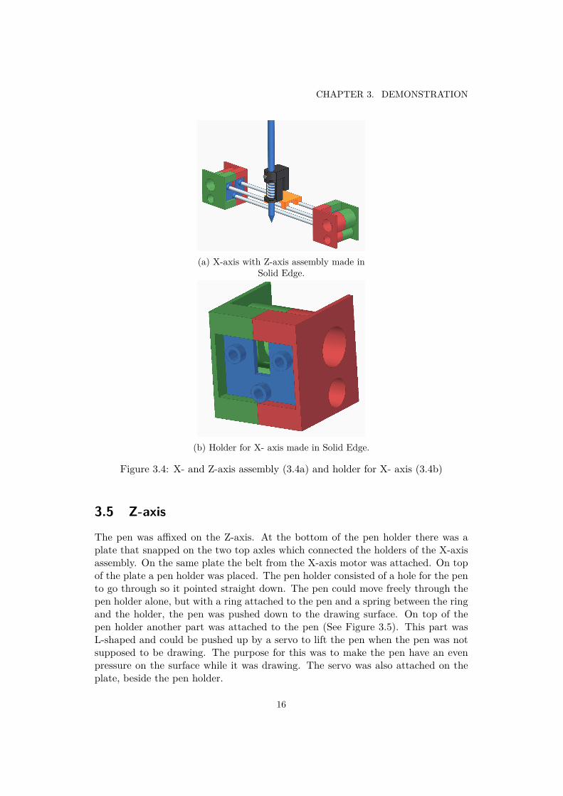
3.4.3 X-axisThe X-axis assembly consisted of two 3D printed holders. One holder was for themotor and the other for the potentiometer. A belt was fastened between the twoholders. Three axles also connected the holders, the axles were configured in anupside down triangle pattern. The two top axles were holding the Z-axis assembly(as shown in Figure 3.4a) and the bottom axle was where the belt from the Y-axiswas attached. One of the two holders was shown in Figure 3.4b and consisted ofthree parts, two mirrored sides and a front plate.
15
CHAPTER 3. DEMONSTRATION
(a) X-axis with Z-axis assembly made inSolid Edge.
(b) Holder for X- axis made in Solid Edge.
Figure 3.4: X- and Z-axis assembly (3.4a) and holder for X- axis (3.4b)
3.5 Z-axis
The pen was affixed on the Z-axis. At the bottom of the pen holder there was aplate that snapped on the two top axles which connected the holders of the X-axisassembly. On the same plate the belt from the X-axis motor was attached. On topof the plate a pen holder was placed. The pen holder consisted of a hole for the pento go through so it pointed straight down. The pen could move freely through thepen holder alone, but with a ring attached to the pen and a spring between the ringand the holder, the pen was pushed down to the drawing surface. On top of thepen holder another part was attached to the pen (See Figure 3.5). This part wasL-shaped and could be pushed up by a servo to lift the pen when the pen was notsupposed to be drawing. The purpose for this was to make the pen have an evenpressure on the surface while it was drawing. The servo was also attached on theplate, beside the pen holder.
16

3.5. Z-AXIS
Figure 3.5: Z-axis assembly made in Solid Edge.
17


Chapter 4
Application testing
4.1 ApproachTo measure the performance of the CNC plotter, tests were done. Four differenttests were made: three where the pen was drawing straight lines of different lengthsin the X- and Y- directions and one where a drawing of a specific shape was made.The results of the tests are presented in section 4.2. The setup of the plotter formaking the tests is presented in section 4.1.
4.2 Testing and error measurementThe plotter setup is demonstrated in Figure 4.1 and the four different drawings arerepresented in Section 4.2. The drawings are thereafter measured and compared tothe desired drawings. For every movement of the pen in the X- and Y- directions,there was a desired distance and an achieved distance. All data was put in an Excelfile in which the error, absolute error, relative error, and mean value of the relativeerrors were calculated for the four tests. The Excel table with calculations for thesecond test is available in Appendix D.
19

CHAPTER 4. APPLICATION TESTING
Figure 4.1: Plotter setup for testing.
4.3 Results
The first test was to draw three vertical and horizontal lines of length 50 mm. Thedrawing is presented in Figure 4.2. Comparing the lines in the X- and Y- directions,results are obtained in a graph which is available in Figure 4.3. In all graphs, thedesired distance is the data presented by the blue dots and the drawn distance isthe data presented by the orange dots.
In the second test, a drawing of a heart- shaped figure was made. This drawingis presented in Figure 4.4 and the graphs with the results are presented in Figure4.5. In third test, lines were drawn once again. This time, the lines were of length16 and 40 mm in each direction. The drawing is presented in Figure 4.6 and theresults in Figure 4.7.
The fourth and last test consisted of drawing longer lines, this time of length 128mm. The fourth drawing is presented in Figure 4.8 and the results of the last testare presented in Figure 4.9. The last line in the Y-direction (the shortest one) inFigure 4.8 is not included in the graph or calculation of the mean value of the rela-tive error. The error is a result of an irregular error produced by the stepper motorand therefore not relevant.
20

4.3. RESULTS
Figure 4.2: Test number one: drawing of 50 mm long lines.
Figure 4.3: Results of the first test.
21

CHAPTER 4. APPLICATION TESTING
Figure 4.4: Test number two: drawing of a heart.
Figure 4.5: Results of the second test.
Figure 4.6: Test number three: drawing of 16 mm and 40 mm long lines.
22

4.3. RESULTS
Figure 4.7: Results of the third test.
Figure 4.8: Test number four: drawing of 128 mm long lines.
Figure 4.9: Results of the fourth test.
23

CHAPTER 4. APPLICATION TESTING
According to the four tests, the biggest mean value of the relative error was mea-sured in the Y-direction. Also, the biggest value in the X-direction was obtainedin the second test and was 0.049 and the lowest one of value 0 was obtained in thefirst test. For the Y- direction, the lowest value of 0.01 was also obtained in thefirst test but the highest value of 0.065 was obtained in the third test.
Besides the mean value of the relative errors, there was also an absolute errormeasured for every particular distance in the four tests. The biggest absolute errorin the X-direction was measured in the third test and had a value of 2mm. In theY-direction, the highest absolute error was obtained in the fourth test and had avalue of 60.5 mm.
24

Chapter 5
Discussion and conclusion
The aim of the project was to investigate how the performance of a CNC plotterdiffers when using two different motors: a DC motor controlled by a potentiome-ter in the X-direction and a stepper motor in the Y-direction. This investigationwas made by building a CNC plotter and doing various tests to answer the researchquestion. Considering the results, a conclusion that a DC motor together with a po-tentiometer is more precise than a stepper motor could be made. The tests showedthat the mean value of the relative errors produced by the stepper motor in theY-direction was bigger than the mean value of the relative errors produced by a DCmotor with a potentiometer in the X-direction for all four tests. The mean valuesof the relative errors in the two directions differed between 1 percentage point to 3percentage points, with the value in the Y-direction always higher.
In order to analyze the difference in performance, some error sources will be dis-cussed. One possible error source was that the stepper motor occasionally skippedsteps and therefore ran a shorter distance than it was supposed to do, which couldbe seen in the results. This error was unpredictable and happened occasionally.The main disadvantage of using a stepper motor was that the motor itself did notreceive information if it skipped a step, while potentiometer always had a valuefor the position and therefore information about the amount of steps succeeded. Ifthere was a temporary stop and DC motor was not able to run for a moment, it stillmade the amount of turns that it was supposed to make since the potentiometercontrols the DC motor and stops it only when potentiometer has made a certainamount of rotations. An alternative solution to this problem is to use a controllerfor the stepper motor. The stepper motor would then do the total amount of stepsit was supposed to do, even if it skipped some steps on the way.
There were few data points where the drawn Y-distance was longer than the desiredY-distance. The elongation was relatively short though and can be explained bythe pen getting a nudge when the servo raised it up. Taking test number two asexample, at first glance it may have looked like the Y-direction is more accurate,
25

CHAPTER 5. DISCUSSION AND CONCLUSION
but taking a closer look at the individual lines, the length differs. This differencehappens to cancel out the error. The fact that the errors in the positive and negativedirections cancelled out can be explained by an uneven Y-axis. A contributing fac-tor to the stepper motor being less accurate could be the load it had to drive. Thestepper motor had a bigger load than the DC motor, which may have contributedto the skipping of steps.
The DC motor in combination with the potentiometer proved more accurate andconsistent than the stepper motor. The DC motor and the potentiometer had prob-lems with both running too short and too far which can be explained by how fastthe microcontroller was able to update and react to the value of the potentiome-ter. In the second test, the pen did not stop at the start point in the X-direction,and at first glance was less accurate than in the Y-direction. Looking yet again atthe individual lines the error was smaller than in the vertical case (Y-direction) foreach line. The error in the horizontal case (X-direction) was not always shorter andtherefore the propagation of error would not cancel out.
Considering the construction, there were some parts of it that surely had an im-pact on the performance of the two motors. The frame that was supposed to be ofrectangular shape was not perfect, but it could be adjusted manually to achieve thebest rectangular shape possible. If the frame was oblique, it could make the move-ment in the X- or Y- directions more difficult since the oblique shape caused partsto collide and create a higher friction. Another disadvantage of the construction isthat the center of the belt which was driving the plate in the X-direction was notattached in the center of the DC motor, which made the movement in the X-axisslightly uneven.
26

Bibliography
[1] Stepper motor, 2017. Retreived: 2018-03-29.http://www.electronicwings.com/sensors-modules/stepper-motor.
[2] Linear potentiometer. Retreived: 2018-05-07.https://forum.arduino.cc/index.php?topic=410604.0.
[3] Rotary potentiometer. Retreived: 2018-05-07.https://randomnerdtutorials.com/electronics-basics-how-a-potentiometer-works.
[4] ARDUINO IDE 1.8.2. What is arduino. Retreived: 2018-04-03.https://www.arduino.cc/en/Guide/Introduction.
[5] Yusuf Abdullahi Badamasi. The working principle of an arduino. 21, Dec 2014.http://ieeexplore.ieee.org/document/6997578/.
[6] R. Condit. Stepping motors fundamentals. Technical report, University ofIowa: Microchip Technology Inc., 2004.
[7] M. Grant. Quick Start for Beginners to Drive a Stepper Motor. FreescaleSemiconductor, Inc, 06 2005.
[8] Bertil Westergren Lennart Råde. Mathematics Handbook for Science and En-gineering, volume 5. Studentlitteratur AB, 2004.
[9] Hans Johansson m.fl. Elektroteknik. KTH,Institutionen för Maskinkonstruk-tion, Mekatronik, 2013.
[10] A. Othman, N. Hamzah, Z. Hussain, R. Baharudin, A. D. Rosli, and A. I. C.Ani. Design and development of an adjustable angle sensor based on rotarypotentiometer for measuring finger flexion. In 2016 6th IEEE InternationalConference on Control System, Computing and Engineering (ICCSCE), pages569–574, Nov 2016.
[11] N. Rathee, A. Gupta, S. Singh, R. Devasia, and A. Bansal. Digital resistancebox: An approach to generate desired value of resistance by automaticallyvarying the potentiometer. In 2016 IEEE 1st International Conference on
27

BIBLIOGRAPHY
Power Electronics, Intelligent Control and Energy Systems (ICPEICES), pages1–4, July 2016.
[12] D. J. Robinson. Dynamic analysis of permanent magnet stepping motors.Technical report, NASA Lewis Research Center, Cleveland, OH, United States,03 1969.
[13] Andras Tantos. H-bridges – the basics, 2011. Retreived: 2018-02-14. http://www.modularcircuits.com/blog/articles/h-bridge-secrets/h-bridges-the-basics/.
[14] T. Tosun, D. Edgar, C. Liu, T. Tsabedze, and M. Yim. Paintpots: Low cost,accurate, highly customizable potentiometers for position sensing. In 2017IEEE International Conference on Robotics and Automation (ICRA), pages1212–1218, May 2017.
[15] X.W. Xu and S.T. Newman. Making cnc machine tools more open, interop-erable and intelligent—a review of the technologies. Computers in Industry,57(2):141 – 152, 2006.
28

Appendix A
Program code (C/C++)
Appendix A contains the code used to control the motors. The basics of the steppermotor control are written by two students in the course MF133X: Simon Erlandssonand Gustaf Burman and modified by Linus Persson and Natalija Zivanovic to fulfillthe tasks of this project.
29

APPENDIX A. PROGRAM CODE (C/C++)
/** Program by Linus Persson and Natalija Zivanovic* Last edit : 2018 -05 -15** Purpose of the program is to move a pen in x , y and up and down .* The program assumes one dc motor and one stepper motor for* x and y respectively and a servo for up and down* Coordinates are read from an SD card , which are* then passed through functions to move the motors .** Stepper motor functions by Simon Erlandsson and Gustav Burman*/
/*SD card read / write
* MOSI - pin 11* MISO - pin 12* CLK - pin 13* CS - pin 4* These pins are default when including the SD card libraries* and does not have to be defined as INPUT / OUTPUT in void setup ()
*/
// Include libraries . Two for SD card read / write and one for Servo control .#i n c l u d e <SPI . h>#i n c l u d e <SD. h>#i n c l u d e <Servo . h>
F i l e myFile ; // create file object to read / write to the SD card .Servo myservo ; // create servo object to control a servo .
int pos = 3 5 ; // Start position of the servo .int maxsnurr =100; // End position of the servo .int pwm=3; // The pin to control the PWM signal to the DC motor .int DC1=9; // DC motor pin , decides which way the motor rotates .int DC2=2; // DC motor pin , decides which way the motor rotates .int potent iometerPin = 0 ; // The potentiometer is read from analog input pin 0.int potent iometerValue = 0 ; // Starting value of the potientiometer .int potVal ;
// Initialize variables for calculating the movement of the pen .float xtarget , ytarget , z t a r g e t ;float x=0, y=0, z =0;float xdis t , yd i s t , z d i s t ;
// Create arrays to control the stepper motor .int array1 [ 4 ] = 1 , 0 , 1 , 0 ;int array2 [ 4 ] = 1 , 0 , 0 , 1 ;int array3 [ 4 ] = 0 , 1 , 0 , 1 ;int array4 [ 4 ] = 0 , 1 , 1 , 0 ;int i d l e [ 4 ] = 0 , 0 , 0 , 0 ;
// A variable to make sure the program only reads// from the SD card when there is something to read from it .int s t a t e = 1 ;
void setup ( ) // Open serial communications and wait for port to open :S e r i a l . begin ( 9 6 0 0 ) ;while ( ! S e r i a l )
; // wait for serial port to connect .S e r i a l . p r i n t ( " Initializing SD card ... " ) ;
// Check to see if the SD card could be read , abort program if it couldn ’t.if ( ! SD. begin ( 4 ) )
S e r i a l . p r i n t l n ( " initialization failed !" ) ;return ;
S e r i a l . p r i n t l n ( " card initialized ." ) ;
30

// Open the file and attach it to the myFile object .myFile = SD. open ( " drawing . ngc " ) ;
// Set pins 5 -8 to OUTPUT for stepper motor control .pinMode ( 5 ,OUTPUT) ;pinMode ( 6 ,OUTPUT) ;pinMode ( 7 ,OUTPUT) ;pinMode ( 8 ,OUTPUT) ;
// Set pins for pwm and DC motor to output ( pins 2, 3 and 9).pinMode (pwm, OUTPUT) ;pinMode (DC1, OUTPUT) ;pinMode (DC2, OUTPUT) ;// Array to put the values of the control of the stepper motor .int array [ 4 ] = 0 , 0 , 0 , 0 ;myservo . attach ( 1 0 ) ; // attaches the servo on pin 10 to the servo object .analogWrite ( 3 , 1 0 0 ) ; // Set the pwm signal to 100.
// The function to move the stepper motor one way .// It takes inputs for how many steps it should take ,// and the delay between the steps .void stepForward ( int steps , int ms_delay )
for ( int i = 0 ; i < s t e p s ; i ++) // Loop for the amount of steps .
s e t C o n t r o l ( array1 ) ; // Sets the output pins according to array1 .// Waits for the set amount of milliseconds .// The lower this value is , the faster the motor willdelay ( ms_delay ) ; r o t a t e .s e t C o n t r o l ( array2 ) ; // Sets the output pins according to array2 .delay ( ms_delay ) ;s e t C o n t r o l ( array3 ) ;de lay ( ms_delay ) ;s e t C o n t r o l ( array4 ) ;de lay ( ms_delay ) ;
s e t C o n t r o l ( i d l e ) ; // Turn off all the pins to let the motor cool down .
// This function works the same way as stepForward , but in reverse .void stepBackward ( int steps , int ms_delay )
for ( int i = 0 ; i < s t e p s ; i ++)// The difference from stepForward is that it goes from array4 to array1// instead of array1 to array4 .
s e t C o n t r o l ( array4 ) ;de lay ( ms_delay ) ;s e t C o n t r o l ( array3 ) ;de lay ( ms_delay ) ;s e t C o n t r o l ( array2 ) ;de lay ( ms_delay ) ;s e t C o n t r o l ( array1 ) ;de lay ( ms_delay ) ;
s e t C o n t r o l ( i d l e ) ;
// Set the pins of the stepper motor the correct value to make it rotate .void s e t C o n t r o l ( int array [ 4 ] )
for ( int i =0; i <4; i ++) // Loop thruogh the input array .// If the value in the array is a 1, set the output to LOW .
if ( array [ i ]==1)
d i g i t a l W r i t e ( i +5,LOW) ;else // If the value in the array is a 0, set the output to HIGH .
d i g i t a l W r i t e ( i +5,HIGH ) ;
31

APPENDIX A. PROGRAM CODE (C/C++)
// The function to control the DC motor .void controlDC ( float d i s t )// Initialize variable to see how far left it is to travel .
int d i f f e r e n s =0;
// Read the value of the potentiometer ,// this will be kept the same until the funciton is called again .
int p o t I n i t i a l = analogRead ( 0 ) ;
// Check which direction the motor is supposed to turn .if ( d i s t <0)// Start the motor .
d i g i t a l W r i t e (DC1,HIGH ) ;d i g i t a l W r i t e (DC2,LOW) ;
// Keep the motors spinning as long as the// potentiometer hasn ’t hit the target .
while ( d i f f e r e n s < −d i s t )// Read the potentiometer .
potVal = analogRead ( 0 ) ;
// Print the potentiometer value for debugging .// Serial . println ( potVal );
// Calculate how far the motor has moved .d i f f e r e n s=potVal−p o t I n i t i a l ;
// This is the same approach of calculating as previous lines ,// but for rotating in the other direction .
else if ( d i s t >0)d i g i t a l W r i t e (DC1,LOW) ;d i g i t a l W r i t e (DC2,HIGH ) ;while ( d i f f e r e n s < d i s t )
potVal = analogRead ( 0 ) ;S e r i a l . p r i n t l n ( potVal ) ;d i f f e r e n s=p o t I n i t i a l −potVal ;
// When the motor has hit its target , turn it off .d i g i t a l W r i t e (DC1,LOW) ;d i g i t a l W r i t e (DC2,LOW) ;
void loop ( ) // Only read while there is something to read .
if ( myFile . a v a i l a b l e ( ) )
// Read from the SD card where to gox t a r g e t = myFile . p a r s e F l o a t ( ) ;y t a r g e t = myFile . p a r s e F l o a t ( ) ;z t a r g e t = myFile . p a r s e F l o a t ( ) ;// Calculate the distance to go . x ,y and z is the current position .x d i s t = xtarget −x ;y d i s t = ytarget −y ;z d i s t = z t a r g e t −z ;
if ( z d i s t <0) // If zdist <0 the pen is supposed to go down .myservo . w r i t e ( 3 5 ) ; // Move the pen down .
else if ( z d i s t >0) // if zdist >0 the pen is supposed to go up .myservo . w r i t e ( 1 0 0 ) ; // Move the pen up .
// Do the DC motor movement , the factor is to calibrate the motor .controlDC ( x d i s t ∗ 2 . 5 5 ) ;
// Check to see which way to move the stepper motor .if ( yd i s t >0)
stepForward ( y d i s t ∗ 1 . 3 , 2 5 ) ; // Move the stepper motor . else
32

stepBackward ( y d i s t ∗ 1 . 3 ∗( −1) ,25) ;
// Update the current position for the next loop .x=x t a r g e t ;y=y t a r g e t ;z=z t a r g e t ;
else // If there is nothing left on the file from the SD card , this part is run .
// Check to see if it ’s the first loop after the ending of the SD card file .if ( s t a t e )
S e r i a l . p r i n t ( " End of file " ) ; // If it is , print end of file .myFile . c l o s e ( ) ; // And close the file
// Set state to 0 so the ending part of the code is just ran once .s t a t e = 0 ;
33


Appendix B
Program code (Python)
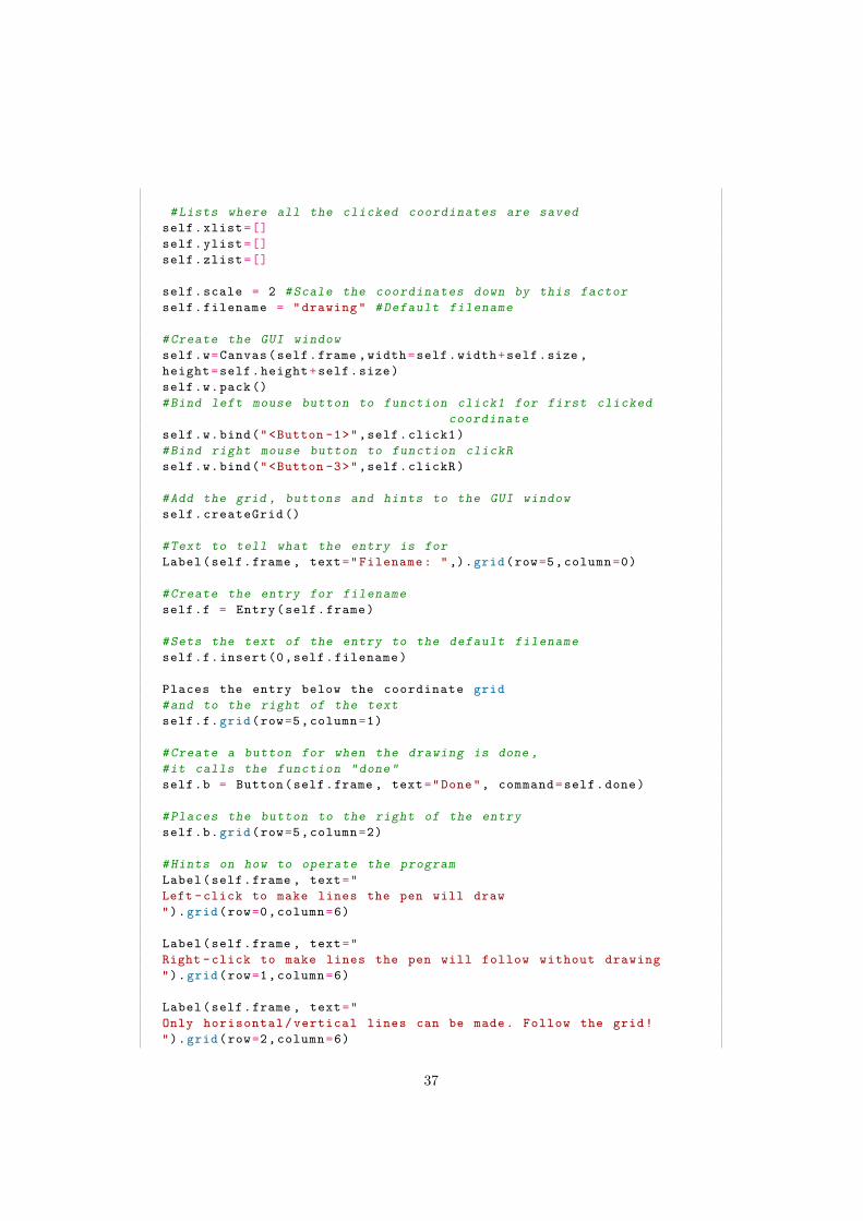
Appendix B contains the code written in Python that is used to draw the coordinatesthat the plotter will follow. The code is written by Linus Persson.
35

APPENDIX B. PROGRAM CODE (PYTHON)
# Program made by Linus Persson for Picasso CNC plotter# Purpose of the program is to simplify making coordinates# for the Picasso CNC plotter to read# Last edit: 2018 -05 -15
from tkinter import * # Import GUI library
def export (app): #The function to export the input coordinates into afile
#open a file with the specified filename in a subfolder named Koordsfile = open(" koords \\"+app. filename +".ngc","w")
#Write the first line.#To make sure the first thing done is to raise the pen ,#if it happens to be downfile.write("0.0 0.0 5.0\n")
#Make a string that will tell the Arduino to go to the#first position from the input coordinates with pen upstring = str(app.xlist[0]) + " " + str(app.ylist[0]) + " 5.0"
#Put previous string into the filefile.write( string +’\n’)
#Loop through all the coordinatesfor i in range(0,len(app.xlist)):
string =str(app.xlist[i])+" "+str(app.ylist[i])+" "+str(app.zlist[i])
#Add the coordinates to the filefile.write( string +’\n’)
#Make the pen go up at the last coordinatestring = str(app.xlist[-1]) + " " + str(app.ylist[-1]) + " 5.0"file.write( string +’\n’)
#Make the pen go back to starting positionfile.write("0.0 0.0 5.0\n")file.close ()#Close file
class App: #The GUI class
def __init__ (self , master ):# Define GUI windowself. background = "white"self.width = 256self. height = 256self.frame = Frame( master )self.frame.pack ()
self.size = 16 #Size of the grid
self.xcor=0 # Pressed x coordinateself.ycor=0 # Pressed y coordinate
36
#Lists where all the clicked coordinates are savedself.xlist=[]self.ylist=[]self.zlist=[]
self.scale = 2 #Scale the coordinates down by this factorself. filename = " drawing " # Default filename
# Create the GUI windowself.w= Canvas (self.frame ,width=self.width+self.size ,height =self. height +self.size)self.w.pack ()#Bind left mouse button to function click1 for first clicked
coordinateself.w.bind("<Button -1>",self. click1 )#Bind right mouse button to function clickRself.w.bind("<Button -3>",self. clickR )
#Add the grid , buttons and hints to the GUI windowself. createGrid ()
#Text to tell what the entry is forLabel(self.frame , text=" Filename : " ,).grid(row=5, column =0)
# Create the entry for filenameself.f = Entry(self.frame)
#Sets the text of the entry to the default filenameself.f. insert (0,self. filename )
Places the entry below the coordinate grid#and to the right of the textself.f.grid(row=5, column =1)
# Create a button for when the drawing is done ,#it calls the function "done"self.b = Button (self.frame , text="Done", command =self.done)
# Places the button to the right of the entryself.b.grid(row=5, column =2)
#Hints on how to operate the programLabel(self.frame , text="Left - click to make lines the pen will draw").grid(row=0, column =6)
Label(self.frame , text="Right -click to make lines the pen will follow without drawing").grid(row=1, column =6)
Label(self.frame , text="Only horisontal / vertical lines can be made. Follow the grid!").grid(row=2, column =6)
37

APPENDIX B. PROGRAM CODE (PYTHON)
#Puts the GUI in a looproot. mainloop ()
# Creates the grid on which the user click#The grid depends on the size of the window and the size variable ,#where size is how many pixels wide the grid should be#There will only be created a grid that will fit the windowdef createGrid (self):
for x in range(0,round (self.width/self.size)):for y in range(0,round (self. height /self.size)):
# Creates the gridself.w. create_rectangle (x*self.size+self.size/2,y*self.size+self.size/2,x*self.size+self.size+self.size/2,y*self.size+self.size+self.size/2,fill="white",outline ="black")
# Places the grid to the top left of the GUI windowself.w.grid(row=0, column =0, rowspan =5, columnspan =5,padx=5,pady=5)
#The function to be called when user is donedef done(self):
self. filename = self.f.get () #Save the filenameself.f. delete (0,END) # Remove the filename writtenself.f. insert (0," drawing ") #Reset it to drawingself.w. delete (ALL) # Delete all the drawn coordinatesself. createGrid () #And make a new empty grid
#Bind left click to function for first clicked coordinateself.w.bind("<Button -1>",self. click1 )
#Call the export functionexport (self)
# Delete all saved coordinates to make the program#ready for a new set of coordinatesfor i in range(0,len(self.xlist)):
self.xlist.pop ()self.ylist.pop ()self.zlist.pop ()
#The function to be called when a user right clicks#It’s when the user wants to move the pen across the paper# without drawing anythingdef clickR (self ,event):
#Saves the coordinate of the closest grid intersection#the user clicked in the x directionxcornew = event.x - event.x%self.size+self.size/2
#Saves the coordinate of the closest grid intersection#the user clicked in the y directionycornew = event.y - event.y%self.size+self.size/2
38

dx = self.xcor- xcornew #Save the change in the x directiondy = self.ycor- ycornew #Save the change in the y direction
#Check to see which direction that changed the most#and then set the least changed to the old value#This is to only draw horizontal and vertical linesif dx>=0 and dy>=0:
if dx>dy:ycornew =self.ycor
else:xcornew =self.xcor
elif dx<0 and dy>0:if abs(dx)>abs(dy):
ycornew =self.ycorelse:
xcornew =self.xcorelif dx<0 and dy<0:
if abs(dx)>abs(dy):ycornew =self.ycor
else:xcornew =self.xcor
elif dx>0 and dy<0:if abs(dx)>abs(dy):
ycornew =self.ycorelse:
xcornew =self.xcor
#Check to see if the clicked coordinate differ from the last# Several coordinate entries at the same spot is not wantedif xcornew == self.xcor and ycornew ==self.ycor:
print(" skipped ") # prints to console window for debugging
else: #If the coordinate is a new one#Print where was clicked for debuggingprint(" clicked2 at",xcornew , ycornew )
# Create a green line for user feedbackevent. widget . create_line (
self.xcor ,self.ycor ,xcornew ,ycornew ,fill="green",width=2,arrow="last")
self.xcor= xcornew # Update last clicked coordinateself.ycor= ycornew # Update last clicked coordinate
#Add the x coordinate to the list of coordinatesself.xlist. append (self.xcor/self.scale)#Add the y coordinate to the list of coordinatesself.ylist. append (self.ycor/self.scale)
39

APPENDIX B. PROGRAM CODE (PYTHON)
#Add a 5 to represent the pen being in up positionself.zlist. append (5)
#The function to be called when the user clicks the first coordinatedef click1 (self ,event):
#Same calculation as in clickRself.xcor = event.x - event.x%self.size+self.size/2self.ycor = event.y - event.y%self.size+self.size/2print(" clicked1 at",self.xcor ,self.ycor) # Debugging
#Add the x coordinate to the list of coordinatesself.xlist. append (self.xcor/self.scale)#Add the y coordinate to the list of coordinatesself.ylist. append (self.ycor/self.scale)#Add a 0 to represent the pen being in down positionself.zlist. append (0)
#Sets the left mouse button to call the function#for subsequent coordinate clicksevent. widget .bind("<Button -1>",self. click3 )
# Create a circle to show where was clickedself.w. create_oval (self.xcor-2,self.ycor-2,self.xcor+2,self.ycor+2,fill="red")
#The function to be called when a user left clicks#It’s when the user wants to move the pen across the paper and draw#This function works the same as ClickR with minor differencesdef click3 (self ,event):
xcornew = event.x - event.x%self.size+self.size/2ycornew = event.y - event.y%self.size+self.size/2dx = self.xcor- xcornewdy = self.ycor- ycornewif dx>=0 and dy>=0:
if dx>dy:ycornew =self.ycor
else:xcornew =self.xcor
elif dx<0 and dy>0:if abs(dx)>abs(dy):
ycornew =self.ycorelse:
xcornew =self.xcorelif dx<0 and dy<0:
if abs(dx)>abs(dy):ycornew =self.ycor
else:xcornew =self.xcor
elif dx>0 and dy<0:if abs(dx)>abs(dy):
40

ycornew =self.ycorelse:
xcornew =self.xcor
if xcornew == self.xcor and ycornew ==self.ycor:print(" skipped ")
else:print(" clicked2 at",xcornew , ycornew )
#The created line is redevent. widget . create_line (self.xcor ,self.ycor ,xcornew ,ycornew ,fill="red",width=2,arrow="last")
self.xcor= xcornewself.ycor= ycornew
self.xlist. append (self.xcor/self.scale)self.ylist. append (self.ycor/self.scale)
# Appends a 0 to represent the pen in down positionself.zlist. append (0)
root = Tk() # Create a tkinter objectapp = App(root) #Send the object to the app class.
41


Appendix C
Schematic of L298 H-Bridge circuit
In Appendix C, the schematic of the circuit made for the L298 H-bridge is presented.Provided by Martin Gylling.
115
214
1 2 3
C1
C2
C3
D1 D2
D3
D4
D5D
6
D7D8
DIG
ITAL
IC1
IC2
MO
TO
R_A
MO
TO
R_B
VCC
0.1 uF
0.1 uF
470 u
F
1N
4004
1N4004
1N
4004
1N
4004
1N
4004
1N
4004
1N4004
1N4004
L298
7805TV
22-2
3-2
021
22-2
3-2
021
22-2
3-2
021
43


Appendix D
Excel table
Appendix D contains the excel table showing the calculations done for the testnumber two.
45

APPENDIX D. EXCEL TABLE
46

Appendix E
Datasheets
In Appendix E, datasheets of the electric components are presented.
47

L298
Jenuary 2000
DUAL FULL-BRIDGE DRIVER
Multiwatt15
ORDERING NUMBERS : L298N (Multiwatt Vert.) L298HN (Multiwatt Horiz.)
L298P (PowerSO20)
BLOCK DIAGRAM
.OPERATING SUPPLY VOLTAGE UP TO 46 V.TOTAL DC CURRENT UP TO 4 A . LOW SATURATION VOLTAGE.OVERTEMPERATURE PROTECTION.LOGICAL "0" INPUT VOLTAGE UP TO 1.5 V(HIGH NOISE IMMUNITY)
DESCRIPTION
The L298 is an integrated monolithic circuit in a 15-lead Multiwatt and PowerSO20 packages. It is ahigh voltage, high current dual full-bridge driver de-signed to accept standard TTL logic levels and driveinductive loads such as relays, solenoids, DC andstepping motors. Two enable inputs are provided toenable or disable the device independently of the in-put signals. The emitters of the lower transistors ofeach bridge are connected together and the corre-sponding external terminal can be used for the con-
nection of an external sensing resistor. An additionalsupply input is provided so that the logic works at alower voltage.
PowerSO20
®
1/13
PIN CONNECTIONS (top view)
GND
Input 2 VSS
N.C.
Out 1
VS
Out 2
Input 1
Enable A
Sense A
GND 10
8
9
7
6
5
4
3
2
13
14
15
16
17
19
18
20
12
1
11 GND
D95IN239
Input 3
Enable B
Out 3
Input 4
Out 4
N.C.
Sense B
GND
ABSOLUTE MAXIMUM RATINGS
Symbol Parameter Value Unit
VS Power Supply 50 V
VSS Logic Supply Voltage 7 V
VI,Ven Input and Enable Voltage –0.3 to 7 V
IO Peak Output Current (each Channel)– Non Repetitive (t = 100µs)–Repetitive (80% on –20% off; ton = 10ms)–DC Operation
32.52
AAA
Vsens Sensing Voltage –1 to 2.3 V
Ptot Total Power Dissipation (Tcase = 75°C) 25 W
Top Junction Operating Temperature –25 to 130 °CTstg, Tj Storage and Junction Temperature –40 to 150 °C
THERMAL DATA
Symbol Parameter PowerSO20 Multiwatt15 Unit
Rth j-case Thermal Resistance Junction-case Max. – 3 °C/W
Rth j-amb Thermal Resistance Junction-ambient Max. 13 (*) 35 °C/W
(*) Mounted on aluminum substrate
1
2
3
4
5
6
7
9
10
11
8
ENABLE B
INPUT 3
LOGIC SUPPLY VOLTAGE VSS
GND
INPUT 2
ENABLE A
INPUT 1
SUPPLY VOLTAGE VS
OUTPUT 2
OUTPUT 1
CURRENT SENSING A
TAB CONNECTED TO PIN 8
13
14
15
12
CURRENT SENSING B
OUTPUT 4
OUTPUT 3
INPUT 4
D95IN240A
Multiwatt15
PowerSO20
L298
2/13

PIN FUNCTIONS (refer to the block diagram)
MW.15 PowerSO Name Function
1;15 2;19 Sense A; Sense B Between this pin and ground is connected the sense resistor tocontrol the current of the load.
2;3 4;5 Out 1; Out 2 Outputs of the Bridge A; the current that flows through the loadconnected between these two pins is monitored at pin 1.
4 6 VS Supply Voltage for the Power Output Stages.A non-inductive 100nF capacitor must be connected between thispin and ground.
5;7 7;9 Input 1; Input 2 TTL Compatible Inputs of the Bridge A.
6;11 8;14 Enable A; Enable B TTL Compatible Enable Input: the L state disables the bridge A(enable A) and/or the bridge B (enable B).
8 1,10,11,20 GND Ground.
9 12 VSS Supply Voltage for the Logic Blocks. A100nF capacitor must beconnected between this pin and ground.
10; 12 13;15 Input 3; Input 4 TTL Compatible Inputs of the Bridge B.
13; 14 16;17 Out 3; Out 4 Outputs of the Bridge B. The current that flows through the loadconnected between these two pins is monitored at pin 15.
– 3;18 N.C. Not Connected
ELECTRICAL CHARACTERISTICS (VS = 42V; VSS = 5V, Tj = 25°C; unless otherwise specified)
Symbol Parameter Test Conditions Min. Typ. Max. Unit
VS Supply Voltage (pin 4) Operative Condition VIH +2.5 46 V
VSS Logic Supply Voltage (pin 9) 4.5 5 7 V
IS Quiescent Supply Current (pin 4) Ven = H; IL = 0 Vi = L Vi = H
1350
2270
mAmA
Ven = L Vi = X 4 mA
ISS Quiescent Current from VSS (pin 9) Ven = H; IL = 0 Vi = L Vi = H
247
3612
mAmA
Ven = L Vi = X 6 mA
ViL Input Low Voltage(pins 5, 7, 10, 12)
–0.3 1.5 V
ViH Input High Voltage(pins 5, 7, 10, 12)
2.3 VSS V
IiL Low Voltage Input Current(pins 5, 7, 10, 12)
Vi = L –10 µA
IiH High Voltage Input Current(pins 5, 7, 10, 12)
Vi = H ≤ VSS –0.6V 30 100 µA
Ven = L Enable Low Voltage (pins 6, 11) –0.3 1.5 V
Ven = H Enable High Voltage (pins 6, 11) 2.3 VSS V
Ien = L Low Voltage Enable Current(pins 6, 11)
Ven = L –10 µA
Ien = H High Voltage Enable Current(pins 6, 11)
Ven = H ≤ VSS –0.6V 30 100 µA
VCEsat (H) Source Saturation Voltage IL = 1AIL = 2A
0.95 1.352
1.72.7
VV
VCEsat (L) Sink Saturation Voltage IL = 1A (5)IL = 2A (5)
0.85 1.21.7
1.62.3
VV
VCEsat Total Drop IL = 1A (5)IL = 2A (5)
1.80 3.24.9
VV
Vsens Sensing Voltage (pins 1, 15) –1 (1) 2 V
L298
3/13

Featuresn Bushingmountn OptionalARpinfeaturen Plasticormetalshaftandbushingsn Wirewoundn SolderlugsorPCpinsn Sealable(Fullbodyseal)
n DesignedforuseinHMIapplications
n RoHScompliant*
3590-PrecisionPotentiometer
*RoHSDirective2002/95/ECJan.27,2003includingannexandRoHSRecast2011/65/EUJune8,2011.Specificationsaresubjecttochangewithoutnotice.Usersshouldverifyactualdeviceperformanceintheirspecificapplications.Theproductsdescribedhereinandthisdocumentaresubjecttospecificdisclaimersassetforthonthelastpageofthisdocument,andatwww.bourns.com/legal/disclaimer.pdf.
Electrical Characteristics1
Standard Resistance Range.........................................................................................................................................................200 to 100 K ohmsTotal Resistance Tolerance .................................................................................................................................................................................±5 %Independent Linearity ....................................................................................................................................................................................±0.25 %Effective Electrical Angle ................................................................................................................................................................ 3600 ° +10 °, -0 ° Absolute Minimum Resistance ...................................................................................................... 1 ohm or 0.1 % maximum (whichever is greater)Noise .................................................................................................................................................................................100 ohms ENR maximumDielectric Withstanding Voltage (MIL-STD-202, Method 301) Sea Level ............................................................................................................................................................................... 1,500 VAC minimumPower Rating (Voltage Limited By Power Dissipation or 450 VAC, Whichever is Less) +40 °C ..........................................................................................................................................................................................................2 watts +125 °C ......................................................................................................................................................................................................... 0 wattInsulation Resistance (500 VDC) ......................................................................................................................................1,000 megohms minimumResolution.............................................................................................................................................................. See recommended part numbers
Environmental Characteristics1
Operating Temperature Range .......................................................................................................................................................-40 °C to +125 °CStorage Temperature Range ..........................................................................................................................................................-55 °C to +125 °CTemperature Coefficient Over Storage Temperature Range 2 .........................................................................................±50 ppm/°C maximum/unitVibration ............................................................................................................................................................................................................. 15 G Wiper Bounce .................................................................................................................................................................0.1 millisecond maximumShock.................................................................................................................................................................................................................. 50 G Wiper Bounce .................................................................................................................................................................0.1 millisecond maximumLoad Life .....................................................................................................................................................................................1,000 hours, 2 watts Total Resistance Shift .................................................................................................................................................................... ±2 % maximumRotational Life (No Load).................................................................................................................................................1,000,000 shaft revolutions Total Resistance Shift .................................................................................................................................................................... ±5 % maximumMoisture Resistance (MIL-STD-202, Method 103, Condition B) Total Resistance Shift .................................................................................................................................................................... ±2 % maximumIP Rating Sealed Versions (-3, -4, -7, and -8) .................................................................................................................................................................IP 65 Unsealed Versions (-1 -2, -5, and -6) ..............................................................................................................................................................IP 40Moisture Sensitivity Level .........................................................................................................................................................................................1ESD Classification (HBM)..................................................................................................................................................................................... N/A
Mechanical Characteristics1
Stop Strength...............................................................................................................................................................45 N-cm (64 oz.-in.) minimumMechanical Angle ........................................................................................................................................................................... 3600 ° +10 °, -0 °Torque Starting & Running ...........................................................................................................................0.85 N-cm (1.2 oz.-in.) maximum (unsealed) 1.41 N-cm (2.0 oz.-in.) maximum (sealed) Mounting .............................................................................................................................................................. 55-80 N-cm (5-7 lb.-in.) (plastic) 90-113 N-cm (8-10 in.-lb.) (metal)Shaft Runout.......................................................................................................................................................................0.13 mm (0.005 in.) T.I.R.Lateral Runout ....................................................................................................................................................................0.20 mm (0.008 in.) T.I.R.Shaft End Play ....................................................................................................................................................................0.25 mm (0.010 in.) T.I.R.Shaft Radial Play ................................................................................................................................................................0.13 mm (0.005 in.) T.I.R.Pilot Diameter Runout ........................................................................................................................................................0.08 mm (0.003 in.) T.I.R.Backlash .............................................................................................................................................................................................1.0 ° maximumWeight ........................................................................................................................................................................................ Approximately 19 GTerminals ................................................................................................................................................................................ Solder lugs or PC pinsSoldering Condition Manual Soldering............................................96.5Sn/3.0Ag/0.5Cu solid wire or no-clean rosin cored wire; 370 °C (700 °F) max. for 3 seconds Wave Soldering .....................................................................96.5Sn/3.0Ag/0.5Cu solder with no-clean flux; 260 °C (500 °F) max. for 5 seconds Wash processes ....................................................................................................................................................................... Not recommendedMarking ......................Manufacturer’s name and part number, resistance value and tolerance, linearity tolerance, wiring diagram, and date code.Ganging (Multiple Section Potentiometers) .......................................................................................................................................1 cup maximumHardware ............................................................................................. One lockwasher and one mounting nut is shipped with each potentiometer.
NOTE: For Anti-rotation pin add 91 after configuration dash number. Example: -2 becomes -291 to add AR pin.1 At room ambient: +25 °C nominal and 50 % relative humidity nominal, except as noted. 2 Consult manufacturer for complete specification details for resistances below 1k ohms.
*RoH
SCOMPLIANT
LEADFR
EE
*RoH
SCOMPLIANT
VERSIO
NS
AVAILABLE
LEADFR
EE
VERSIO
NSARE
RoHSCOMPLIA
NT*

12.19 ± 0.51(.480 ± .020)
SOLDER LUGTERMINAL
PC PIN TERMINALTHICKNESS
1.63 ± 0.38(.064 ± .015)
.305 ± .003(.012 ± .0001)
0.86(.034)
3 PLCS.
3.30 ± 0.38(.130 ± .015)
2.54(.100)
3 PLCS.
12.19 ± 0.51(.480 ± .020)
3590-PrecisionPotentiometer
Product Dimensions
Specificationsaresubjecttochangewithoutnotice.Usersshouldverifyactualdeviceperformanceintheirspecificapplications.Theproductsdescribedhereinandthisdocumentaresubjecttospecificdisclaimersassetforthonthelastpageofthisdocument,andatwww.bourns.com/legal/disclaimer.pdf.
21
3BUSHING DIAMETER(SEE PART NUMBERS)
SHAFT DIAMETER(SEE PART NUMBERS)
1 3
CCW CW
CW
2
12.70 (.500) MOUNTING SURFACE
15.54 (.612)
RECOMMENDED PC BOARD MOUNTING HOLE LOCATIONS
FMS
5.08 ± .38(.200 ± .015)
6.99 ± .38(.275 ± .015)
5.08 ± .38(.200 ± .015)
10.31 + .00/- .13(.406+.000/-.005)
.25(.010) 1.19
(.047)7.92(.312)
.81(.032)
20.62 ± .81(.812 ± .032)
18.6 ± .4(.732 ± .015)
12.2(.48)
11.81(.465)
DIA.22.22 ± .38(.875 ±.015)
DIA.
HOLE DIAMETER2.08
(.082)
5.08(.200)
5.08(.200)
6.99(.275)
TOLERANCES: EXCEPT WHERE NOTED .508 .127DECIMALS: .XX ±
(.02), .XXX ±
(.005)FRACTIONS: ±1/64 MMDIMENSIONS:
(IN.)
R MAX.
*SEENOTE
12.70 ±0.25 (.500 ± .010) MOUNTING SURFACE
15.54 (.612)
12.2(.480)
11.81(.465)
DIA.22.22 ± .38(.875 ±.015)
DIA.
R MAX.
2
31
BUSHING DIA. (SEEPART NUMBERS)
*SEENOTE .76 ± .25
.030 ± .010
SHAFT DIA. (SEEPART NUMBERS)
*BUSHING THREAD SPECIFICATIONS: -1, -2, -3, -4 .... 3/8-32 UNF -5, -6, -7, -8 .... M9 x 0.75-7H
5.08 ± .38(.200 ± .015)
6.99 ± .38(.275 ± .015)
10.31 +.00/-.10(.406 +.000/-.004)
R
5.08 ± .38(.200 ± .015)
.25(.010)
7.93(.312)
.81(.032)
20.63 ± .81(.812 ± .032)
.81 ± .25(.032 ± .010)
18.59 ± .38(.732 ± .015)
-2, -4, -6, -8 Configurations-1, -3, -5, -7 Configurations
Recommended PCB Layout
21 3 BUSHING DIAMETER
(SEE PART NUMBERS)
SHAFT DIAMETER(SEE PART NUMBERS)
1 3
CCW CW
CW
2
12.70 (.500) MOUNTING SURFACE
15.54 (.612)
RECOMMENDED PC BOARD MOUNTING HOLE LOCATIONS
FMS
5.08 ± .38(.200 ± .015)
6.99 ± .38(.275 ± .015)
5.08 ± .38(.200 ± .015)
10.31 + .00/- .13(.406+.000/-.005)
.25(.010) 1.19
(.047)7.92(.312)
.81(.032)
20.62 ± .81(.812 ± .032)
18.6 ± .4(.732 ± .015)
12.2(.48)
11.81(.465)
DIA.22.22 ± .38(.875 ±.015)
DIA.
HOLE DIAMETER2.08
(.082)
5.08(.200)
5.08(.200)
6.99(.275)
TOLERANCES: EXCEPT WHERE NOTED .508 .127DECIMALS: .XX ±
(.02), .XXX ±
(.005)FRACTIONS: ±1/64 MMDIMENSIONS:
(IN.)
R MAX.
Schematic
21 3 BUSHING DIAMETER
(SEE PART NUMBERS)
SHAFT DIAMETER(SEE PART NUMBERS)
1 3
CCW CW
CW
2
12.70 (.500) MOUNTING SURFACE
15.54 (.612)
RECOMMENDED PC BOARD MOUNTING HOLE LOCATIONS
FMS
5.08 ± .38(.200 ± .015)
6.99 ± .38(.275 ± .015)
5.08 ± .38(.200 ± .015)
10.31 + .00/- .13(.406+.000/-.005)
.25(.010) 1.19
(.047)7.92(.312)
.81(.032)
20.62 ± .81(.812 ± .032)
18.6 ± .4(.732 ± .015)
12.2(.48)
11.81(.465)
DIA.22.22 ± .38(.875 ±.015)
DIA.
HOLE DIAMETER2.08
(.082)
5.08(.200)
5.08(.200)
6.99(.275)
TOLERANCES: EXCEPT WHERE NOTED .508 .127DECIMALS: .XX ±
(.02), .XXX ±
(.005)FRACTIONS: ±1/64 MMDIMENSIONS:
(IN.)
R MAX.
Terminal Styles
“P” Terminal Style
“S” Terminal Style
12.19 ± 0.51(.480 ± .020)
SOLDER LUGTERMINAL
PC PIN TERMINALTHICKNESS
1.63 ± 0.38(.064 ± .015)
.305 ± .003(.012 ± .0001)
0.86(.034)
3 PLCS.
3.30 ± 0.38(.130 ± .015)
2.54(.100)
3 PLCS.
12.19 ± 0.51(.480 ± .020)
12.70 ±0.25 (.500 ± .010) MOUNTING SURFACE
15.54 (.612)
12.2(.480)
11.81(.465)
DIA.22.22 ± .38(.875 ±.015)
DIA.
R MAX.
2
31
BUSHING DIA. (SEEPART NUMBERS)
*SEENOTE .76 ± .25
.030 ± .010
SHAFT DIA. (SEEPART NUMBERS)
*BUSHING THREAD SPECIFICATIONS: -1, -2, -3, -4 .... 3/8-32 UNF -5, -6, -7, -8 .... M9 x 0.75-7H
5.08 ± .38(.200 ± .015)
6.99 ± .38(.275 ± .015)
10.31 +.00/-.10(.406 +.000/-.004)
R
5.08 ± .38(.200 ± .015)
.25(.010)
7.93(.312)
.81(.032)
20.63 ± .81(.812 ± .032)
.81 ± .25(.032 ± .010)
18.59 ± .38(.732 ± .015)

3590-PrecisionPotentiometer
Panel Thickness Dimensions
(For Bushing Mount Only)
PANEL
POT
LOCKWASHER
HEX NUT
2.46 - 3.81(.097 - .150)
1.60 +.08/-.03(.063 +.003/-.001)
10.44 ± .07(.411 ± .003)
DIA.
DIA.
ADDITIONAL HOLE FORANTI-ROTATION PIN
MM(INCHES)
DIMENSIONS:
Anti-rotation pin hole is shown at six o'clock position for reference only. The actual location is determined by the customer's application. Refer to the front view of the potentiometer to see the location of the optional A/R pin.
Panel thickness and hole diameters arerecommended for best fit. However, customersmay adjust the dimensions to suit their specificapplication.
TOLERANCES: ±
7.42(.292)R
0.127(.005)
Specificationsaresubjecttochangewithoutnotice.Usersshouldverifyactualdeviceperformanceintheirspecificapplications.Theproductsdescribedhereinandthisdocumentaresubjecttospecificdisclaimersassetforthonthelastpageofthisdocument,andatwww.bourns.com/legal/disclaimer.pdf.
REV. 11/17
Shaft & Bushing Configurations
(Bushing - DxL, Shaft - D):(-1) Plastic Bushing (3/8 ” x 5/16 ”) and Shaft (.2480 + .001, - .002)(-2) Metal Bushing (3/8 ” x 5/16 ”) and Shaft (.2497 + .0000, - .0009)(-3) Sealed, Plastic Bushing (3/8 ” x 5/16 ”) and Shaft (.2480 + .001, - .002)(-4) Sealed, Metal Bushing (3/8 ” x 5/16 ”) and Shaft (.2497 + .0000, - .0009)(-5) Metric, Plastic Bushing (9 mm x 7.94 mm) and Shaft (6 mm + 0, - .076 mm)(-6) Metric, Metal Bushing (9 mm x 7.94 mm) and Shaft (6 mm + 0, - .023 mm)(-7) Metric, Sealed, Plastic Bushing (9 mm x 7.94 mm) and Shaft (6 mm + 0, - .076 mm)(-8) Metric, Sealed, Metal Bushing (9 mm x 7.94 mm) and Shaft (6 mm + 0, - .023 mm)
BOLDFACE LISTINGS ARE IN STOCK AND READILY AVAILABLE THROUGH DISTRIBUTION. FOR OTHER OPTIONS CONSULT FACTORY.
ROHS IDENTIFIER: L = COMPLIANT
Recommended Part Numbers(Printed Circuit) (Solder Lug) (Solder Lug) Resistance (Ω) Resolution (%)3590P-2-102L 3590S-2-102L 3590S-1-102L 1,000 .0293590P-2-202L 3590S-2-202L 3590S-1-202L 2,000 .0233590P-2-502L 3590S-2-502L 3590S-1-502L 5,000 .0253590P-2-103L 3590S-2-103L 3590S-1-103L 10,000 .0203590P-2-203L 3590S-2-203L 3590S-1-203L 20,000 .0193590P-2-503L 3590S-2-503L 3590S-1-503L 50,000 .0133590P-2-104L 3590S-2-104L 3590S-1-104L 100,000 .009

SG90 9 g Micro Servo
Tiny and lightweight with high output power. Servo can rotate approximately 180 degrees
(90 in each direction), and works just like the standard kinds but smaller. You can use any
servo code, hardware or library to control these servos. Good for beginners who want to make
stuff move without building a motor controller with feedback & gear box, especially since it
will fit in small places. It comes with a 3 horns (arms) and hardware.
Specifications
• Weight: 9 g
• Dimension: 22.2 x 11.8 x 31 mm approx.
• Stall torque: 1.8 kgf·cm
• Operating speed: 0.1 s/60 degree
• Operating voltage: 4.8 V (~5V)
• Dead band width: 10 µs
• Temperature range: 0 ºC – 55 ºC

Position "0" (1.5 ms pulse) is middle, "90" (~2
ms pulse) is all the way to the left.
ms pulse) is middle, "90" (~2 ms pulse) is all the way to the right, "
the left.
ms pulse) is all the way to the right, "-90" (~1

26 | Visit www.dunkermotoren.com for further product information/ Besuchen Sie www.dunkermotoren.de für weitere Produktinformationen Visit www.dunkermotoren.com for further product information/ Besuchen Sie www.dunkermotoren.de für weitere Produktinformationen | 27
» Permanent magnet DC motor » Mechanical commutation through multi bar commutator provides long lifetime
» Operation in both directions of rotation » Sleeve bearing at motor shaft is standard » Optionally with ball bearing, custom shaft length and diameter, special winding
» On request a torque-optimized variant is available
» Gleichstrommotor mit Permanentmagneten » Mechanische Kommutierung über vielteiligen Kollektor bietet lange Lebensdauer
» Drehrichtung Rechts-/ Linkslauf » Motorwelle gleitgelagert ist Standard » Optional kugelgelagert, abweichende Wellenlängen und -durchmesser, Sonderwicklung
» Auf Anfrage ist eine Drehmoment optimierte Variante verfügbar
Dimensions in mm/ Maßzeichnung in mm
Data/ Technische Daten GR 22Nominal voltage/Nennspannung VDC 12 24
Nominal current/Nennstrom A*) 0.47 0.23
Nominal torque/Nennmoment Ncm*) 0.47 0.48
Nominal speed/Nenndrehzahl rpm*) 5000 4600
Friction torque/Reibungsmoment Ncm*) 0.1 0.1
Stall torque/Anhaltemoment Ncm**) 1.4 1.4
No load speed/Leerlaufdrehzahl rpm*) 8700 8100
Nominal output power/Dauerabgabeleistung W**) 2.5 2.3
Maximum output power/Maximale Abgabeleistung W 3.2 3
Torque constant/Drehmomentkonstante Ncm A-1* * *) 1.3 3.2
Terminal Resistance/Anschluß widerstand Ω 10.53 44.4
Terminal inductance/Anschlußinduktivität mH 5.3 22.2
Starting current/Anlaufstrom A**) 1.14 0.54
No load current/Leerlaufstrom A**) 0.14 0.07
Rotor inertia/Rotor Trägheitsmoment gcm2 2.4 2.4
Weight of motor/Motorgewicht kg 0.05 0.05
GR 22, 24VGR 22, 12V
GR 22 | cont. 2.5 W, peak 3.2 W GR 22 | cont. 2.5 W, peak 3.2 W
Modular System/ Modulares Baukastensystem
» Brakes & Encoder/ Bremsen & Anbauten
MG 2, Page/ Seite 222 RE 22, Page/ Seite 218
» Controller/ Regelelektroniken RS 200 BGE 6005 A, Page/ Seite 179 BGE 6010 A, Page/ Seite 180 » Accessories/ Zubehör Connector with screw terminals for RS 200/ Stecker mit Schraubklemmen für RS 200, Page/ Seite 224
PLG 24MG 2
GR 22
Shaft/ Welle front/ vorne2.5 x 13 mm
0.2 0.4 0.8 1 1.2 1.4 Ncm
14000
12000
10000
8000
6000
4000
2000
0
50
60
70
40
30
20
10
0
2.8
2.4
1.0
0.8
0.6
0.4
0.2
0 rate
d sp
eed/
Dreh
zahl
n
(rpm
)
ecie
ncy/
Wirk
ungs
grad
η
(%)
curre
nt/S
trom
I (
A)
M N
N = f (M )
J = f (M )
η
R = 20 ° C
W=100K
0.2 0.4 0.8 1 1.2 1.4 Ncm
14000
12000
10000
8000
6000
4000
2000
0
50
60
70
40
30
20
10
0
0.7
0.6
0.5
0.4
0.3
0.2
0.1
0 rate
d sp
eed/
Dreh
zahl
n
(rpm
)
ecie
ncy/
Wirk
ungs
grad
η
(%)
curre
nt/S
trom
I (
A)M N
N = f (M )
J = f (M )
η
R = 20 ° C
W=100K
Characteristic diagram/ Belastungskennlinien In accordance with/ Belastungskennlinien gezeichnet nach EN 60034
Preference/ Vorzugsreihe On request/ auf Anfrage
RE 22
» Planetary gearbox/ Planetengetriebe PLG 24, Page/ Seite 189
GR
/G m
otor
s

2
1
7
10
9
15
3
6
11
14
1A
1,2EN
2A
3A
3,4EN
4A
1Y
2Y
3Y
4Y
Product
Folder
Sample &Buy
Technical
Documents
Tools &
Software
Support &Community
L293, L293DSLRS008D –SEPTEMBER 1986–REVISED JANUARY 2016
L293x Quadruple Half-H Drivers1 Features 3 Description
The L293 and L293D devices are quadruple high-1• Wide Supply-Voltage Range: 4.5 V to 36 V
current half-H drivers. The L293 is designed to• Separate Input-Logic Supply provide bidirectional drive currents of up to 1 A at• Internal ESD Protection voltages from 4.5 V to 36 V. The L293D is designed
to provide bidirectional drive currents of up to 600-mA• High-Noise-Immunity Inputsat voltages from 4.5 V to 36 V. Both devices are• Output Current 1 A Per Channel (600 mA for designed to drive inductive loads such as relays,L293D) solenoids, DC and bipolar stepping motors, as well as
• Peak Output Current 2 A Per Channel (1.2 A for other high-current/high-voltage loads in positive-L293D) supply applications.
• Output Clamp Diodes for Inductive Transient Each output is a complete totem-pole drive circuit,Suppression (L293D) with a Darlington transistor sink and a pseudo-
Darlington source. Drivers are enabled in pairs, with2 Applications drivers 1 and 2 enabled by 1,2EN and drivers 3 and 4
enabled by 3,4EN.• Stepper Motor DriversThe L293 and L293D are characterized for operation• DC Motor Driversfrom 0°C to 70°C.• Latching Relay Drivers
Device Information(1)
PART NUMBER PACKAGE BODY SIZE (NOM)L293NE PDIP (16) 19.80 mm × 6.35 mmL293DNE PDIP (16) 19.80 mm × 6.35 mm
(1) For all available packages, see the orderable addendum atthe end of the data sheet.
Logic Diagram
1
An IMPORTANT NOTICE at the end of this data sheet addresses availability, warranty, changes, use in safety-critical applications,intellectual property matters and other important disclaimers. PRODUCTION DATA.

HEAT SINK AND
GROUNDHEAT SINK AND
GROUND
1
2
3
4
5
6
7
8
16
15
14
13
12
11
10
9
1,2EN
1A
1Y
2Y
2A
VCC2
VCC1
4A
4Y
3Y
3A
3,4EN
L293, L293Dwww.ti.com SLRS008D –SEPTEMBER 1986–REVISED JANUARY 2016
5 Pin Configuration and Functions
NE Package16-Pin PDIP
Top View
Pin FunctionsPIN
TYPE DESCRIPTIONNAME NO.1,2EN 1 I Enable driver channels 1 and 2 (active high input)<1:4>A 2, 7, 10, 15 I Driver inputs, noninverting<1:4>Y 3, 6, 11, 14 O Driver outputs3,4EN 9 I Enable driver channels 3 and 4 (active high input)
Device ground and heat sink pin. Connect to printed-circuit-board ground plane with multipleGROUND 4, 5, 12, 13 — solid viasVCC1 16 — 5-V supply for internal logic translationVCC2 8 — Power VCC for drivers 4.5 V to 36 V
Copyright © 1986–2016, Texas Instruments Incorporated Submit Documentation Feedback 3
Product Folder Links: L293 L293D
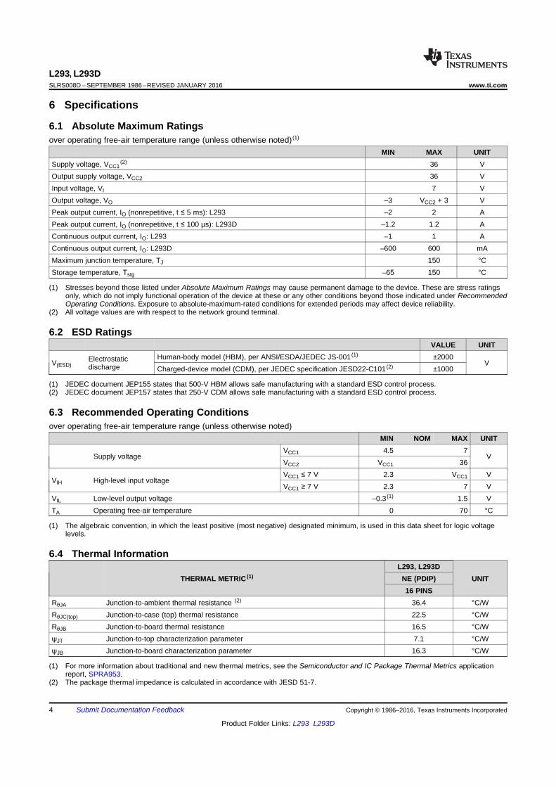
L293, L293DSLRS008D –SEPTEMBER 1986–REVISED JANUARY 2016 www.ti.com
6 Specifications
6.1 Absolute Maximum Ratingsover operating free-air temperature range (unless otherwise noted) (1)
MIN MAX UNITSupply voltage, VCC1
(2) 36 VOutput supply voltage, VCC2 36 VInput voltage, VI 7 VOutput voltage, VO –3 VCC2 + 3 VPeak output current, IO (nonrepetitive, t ≤ 5 ms): L293 –2 2 APeak output current, IO (nonrepetitive, t ≤ 100 µs): L293D –1.2 1.2 AContinuous output current, IO: L293 –1 1 AContinuous output current, IO: L293D –600 600 mAMaximum junction temperature, TJ 150 °CStorage temperature, Tstg –65 150 °C
(1) Stresses beyond those listed under Absolute Maximum Ratings may cause permanent damage to the device. These are stress ratingsonly, which do not imply functional operation of the device at these or any other conditions beyond those indicated under RecommendedOperating Conditions. Exposure to absolute-maximum-rated conditions for extended periods may affect device reliability.
(2) All voltage values are with respect to the network ground terminal.
6.2 ESD RatingsVALUE UNIT
Human-body model (HBM), per ANSI/ESDA/JEDEC JS-001 (1) ±2000ElectrostaticV(ESD) Vdischarge Charged-device model (CDM), per JEDEC specification JESD22-C101 (2) ±1000
(1) JEDEC document JEP155 states that 500-V HBM allows safe manufacturing with a standard ESD control process.(2) JEDEC document JEP157 states that 250-V CDM allows safe manufacturing with a standard ESD control process.
6.3 Recommended Operating Conditionsover operating free-air temperature range (unless otherwise noted)
MIN NOM MAX UNITVCC1 4.5 7
Supply voltage VVCC2 VCC1 36VCC1 ≤ 7 V 2.3 VCC1 V
VIH High-level input voltageVCC1 ≥ 7 V 2.3 7 V
VIL Low-level output voltage –0.3 (1) 1.5 VTA Operating free-air temperature 0 70 °C
(1) The algebraic convention, in which the least positive (most negative) designated minimum, is used in this data sheet for logic voltagelevels.
6.4 Thermal InformationL293, L293D
THERMAL METRIC (1) NE (PDIP) UNIT16 PINS
RθJA Junction-to-ambient thermal resistance (2) 36.4 °C/WRθJC(top) Junction-to-case (top) thermal resistance 22.5 °C/WRθJB Junction-to-board thermal resistance 16.5 °C/WψJT Junction-to-top characterization parameter 7.1 °C/WψJB Junction-to-board characterization parameter 16.3 °C/W
(1) For more information about traditional and new thermal metrics, see the Semiconductor and IC Package Thermal Metrics applicationreport, SPRA953.
(2) The package thermal impedance is calculated in accordance with JESD 51-7.
4 Submit Documentation Feedback Copyright © 1986–2016, Texas Instruments Incorporated
Product Folder Links: L293 L293D

5
3
1
0
2
−50 0 50
4
100
TA − Ambient Temperature − °C
With Infinite Heat Sink
Free Air
Heat Sink With θJA = 25°C/W
150
PT
OT
−P
ow
er
Dis
sip
ati
on
−W
L293, L293Dwww.ti.com SLRS008D –SEPTEMBER 1986–REVISED JANUARY 2016
6.5 Electrical Characteristicsover operating free-air temperature range (unless otherwise noted)
PARAMETER TEST CONDITIONS MIN TYP MAX UNIT
L293: IOH = −1 AVOH High-level output voltage VCC2 – 1.8 VCC2 – 1.4 V
L293D: IOH = − 0.6 A
L293: IOL = 1 AVOL Low-level output voltage 1.2 1.8 V
L293D: IOL = 0.6 A
VOKH High-level output clamp voltage L293D: IOK = –0.6 A VCC2 + 1.3 V
VOKL Low-level output clamp voltage L293D: IOK = 0.6 A 1.3 V
A 0.2 100IIH High-level input current VI = 7 V µA
EN 0.2 10
A –3 –10IIL Low-level input current VI = 0 µA
EN –2 –100
All outputs at high level 13 22
All outputs at low level 35 60ICC1 Logic supply current IO = 0 mAAll outputs at high 8 24impedance
All outputs at high level 14 24
All outputs at low level 2 6ICC2 Output supply current IO = 0 mAAll outputs at high 2 4impedance
6.6 Switching Characteristicsover operating free-air temperature range (unless otherwise noted) VCC1 = 5 V, VCC2 = 24 V, TA = 25°C
PARAMETER TEST CONDITIONS MIN TYP MAX UNIT
L293NE, L293DNE 800Propagation delay time, low-to-tPLH nshigh-level output from A input L293DWP, L293N L293DN 750
L293NE, L293DNE 400Propagation delay time, high-to-tPHL nslow-level output from A input L293DWP, L293N L293DN 200CL = 30 pF,See Figure 2L293NE, L293DNE 300Transition time, low-to-high-leveltTLH nsoutput L293DWP, L293N L293DN 100
L293NE, L293DNE 300Transition time, high-to-low-leveltTHL nsoutput L293DWP, L293N L293DN 350
6.7 Typical Characteristics
Figure 1. Maximum Power Dissipation vs Ambient Temperature
Copyright © 1986–2016, Texas Instruments Incorporated Submit Documentation Feedback 5
Product Folder Links: L293 L293D

Output
CL = 30 pF
(see Note A)
VCC1
Input
3 V
TEST CIRCUIT
t tf r
3 V
0
tPHL
VOH
tTHL tTLH
VOLTAGE WAVEFORMS
tPLH
Output
Input
VOL
tw
NOTES: A. CL includes probe and jig capacitance.
B. The pulse generator has the following characteristics: tr ≤ 10 ns, tf ≤ 10 ns, tw = 10 µs, PRR = 5 kHz, ZO = 50 Ω.
Pulse
Generator
(see Note B)
5 V 24 V
VCC2
A
EN
Y90% 90%
50%
10%
50%
10%
90% 90%
50%
10%
50%
10%
L293, L293DSLRS008D –SEPTEMBER 1986–REVISED JANUARY 2016 www.ti.com
7 Parameter Measurement Information
Figure 2. Test Circuit and Voltage Waveforms
6 Submit Documentation Feedback Copyright © 1986–2016, Texas Instruments Incorporated
Product Folder Links: L293 L293D

1
0
3
4
5
6
7
89
10
11
12
13
14
15
161
21
0
1
1
0
2
4
3
M
M
M
1
0
1
0
1
0
VCC2
VCC1
L293, L293Dwww.ti.com SLRS008D –SEPTEMBER 1986–REVISED JANUARY 2016
8 Detailed Description
8.1 OverviewThe L293 and L293D are quadruple high-current half-H drivers. These devices are designed to drive a wide arrayof inductive loads such as relays, solenoids, DC and bipolar stepping motors, as well as other high-current andhigh-voltage loads. All inputs are TTL compatible and tolerant up to 7 V.
Each output is a complete totem-pole drive circuit, with a Darlington transistor sink and a pseudo-Darlingtonsource. Drivers are enabled in pairs, with drivers 1 and 2 enabled by 1,2EN and drivers 3 and 4 enabled by3,4EN. When an enable input is high, the associated drivers are enabled, and their outputs are active and inphase with their inputs. When the enable input is low, those drivers are disabled, and their outputs are off and inthe high-impedance state. With the proper data inputs, each pair of drivers forms a full-H (or bridge) reversibledrive suitable for solenoid or motor applications.
On the L293, external high-speed output clamp diodes should be used for inductive transient suppression. Onthe L293D, these diodes are integrated to reduce system complexity and overall system size. A VCC1 terminal,separate from VCC2, is provided for the logic inputs to minimize device power dissipation. The L293 and L293Dare characterized for operation from 0°C to 70°C.
8.2 Functional Block Diagram
Output diodes are internal in L293D.
8.3 Feature DescriptionThe L293x has TTL-compatible inputs and high voltage outputs for inductive load driving. Current outputs can getup to 2 A using the L293.
Copyright © 1986–2016, Texas Instruments Incorporated Submit Documentation Feedback 7
Product Folder Links: L293 L293D

TRITA -ITM-EX 2018:62
www.kth.se