Embed Size (px)
Citation preview

PIC16F87710-bit 8-channelAnalog-to-Digital Converter
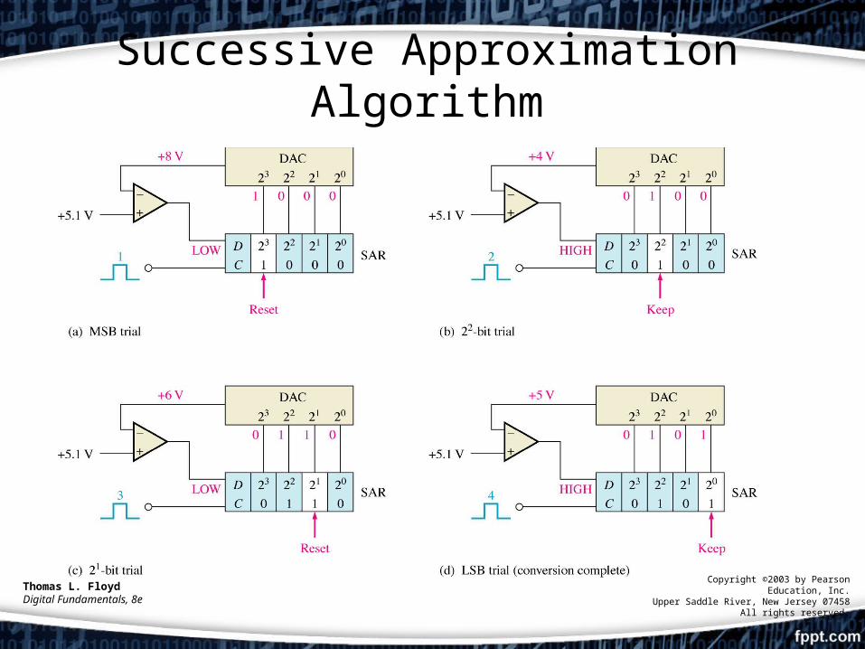
Successive Approximation Algorithm
Thomas L. FloydDigital Fundamentals, 8e
Copyright ©2003 by Pearson Education, Inc.Upper Saddle River, New Jersey 07458
All rights reserved.

PIC16F877 ADC Characteristics
• 10-bit resolution• 8 channel selection by multiplexing• Successive approximation algorithm• Interrupt option• 0V minimum voltage, 5V maximum voltage• Reference voltage selection

ADC Block Diagram

ADCON0 Register

ADCON1 Register
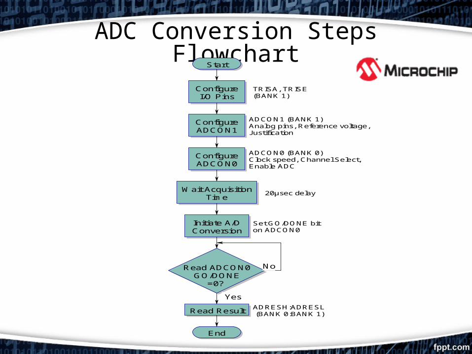
ADC Conversion Steps FlowchartStart
ConfigureI/O Pins
ConfigureADCON1
ConfigureADCON0
Wait AcquisitionTime
Initiate A/DConversion
Read ADCON0GO/DONE
=0?
Read Result
End
Yes
No
20µsec delay
Set GO/DONE biton ADCON0
ADCON1 (BANK 1)Analog pins, Reference voltage,Justification
ADCON0 (BANK 0)Clock speed, Channel Select,Enable ADC
TRISA, TRISE(BANK 1)
ADRESH:ADRESL (BANK 0:BANK 1)

MikroC for PIC ADC Function
unsigned int adc_rd;
void main() { TRISA = 0x02; // Set RA1 pin as input while (1) { adc_rd = ADC_Read(1);// gets ADC value from channel 1 }}
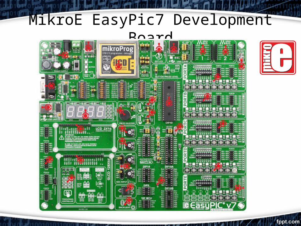
MikroE EasyPic7 Development Board