Embed Size (px)
Citation preview

PIAGGIO WOULD LIKE TO THANK YOU
for choosing one of its products. We have prepared this manual to help you to get the very best from your vehicle. Please read it carefully before ridingthe vehicle for the first time. It contains information, tips and precautions for using your vehicle. It also describes features, details and devices to assureyou that you have made the right choice. We believe that if you follow our suggestions, you will soon get to know your new scooter and it will serve youwell for a long time to come. This booklet forms an integral part of the vehicle; should the vehicle be sold, it must be transferred to the new owner.
ZIP 50 - 100 4T
Ed. 03_10/2012
The instructions given in this booklet are intended to provide a clear, simple guide to using your scooter; details are also given of routine maintenanceprocedures and regular checks that should be carried out on the vehicle at and Authorized PIAGGIO Dealer or Service Centre. The booklet alsocontains instructions for simple repairs. Any operations not specifically described in this booklet require the use of special tools and/or particular technicalknowledge: to carry out these operations refer to any authorized PIAGGIO Dealer of Service Centre.
2
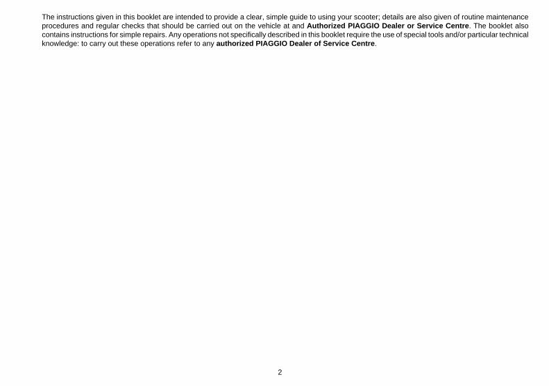
Personal safety
Failure to completely observe these instructions will result in serious risk of personalinjury.
Safeguarding the environment
Sections marked with this symbol indicate the correct use of the vehicle to prevent dam-aging the environment.
Vehicle intactness
The incomplete or non-observance of these regulations leads to the risk of seriousdamage to the vehicle and sometimes even the invalidity of the guarantee.
The signs that you see on this page are very important. They are used to highlight partsof the booklet that should be read with particular care. The different symbols are usedto make each topic in the manual simple and quick to locate.
3

4
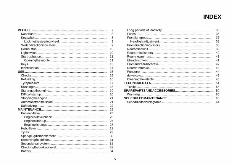
INDEX
VEHICLE...................................................................................... 7Dashboard................................................................................ 8Keyswitch.................................................................................. 8
Lockingthesteeringwheel....................................................... 9Switchdirectionindicators.......................................................... 9Hornbutton................................................................................ 10Lightswitch................................................................................ 10Start-upbutton........................................................................... 11
Openingthesaddle................................................................. 11Keys.......................................................................................... 13Identification.............................................................................. 14
USE.............................................................................................. 15Checks...................................................................................... 16Refuelling.................................................................................. 16Tyrepressure............................................................................. 17Runningin.................................................................................. 18Startinguptheengine.................................................................. 19Difficultstartup........................................................................... 20Stoppingtheengine.................................................................... 21Automatictransmission.............................................................. 21Safedriving................................................................................ 22
MAINTENANCE........................................................................... 25Engineoillevel............................................................................ 26
Engineoillevelcheck............................................................... 26Engineoiltop-up..................................................................... 27Engineoilchange.................................................................... 27
Huboillevel................................................................................ 28Tyres......................................................................................... 29Sparkplugdismantlement.......................................................... 30Removingtheairfilter.................................................................. 31Secondaryairsystem................................................................. 32Checkingthebrakeoillevel.......................................................... 33Battery....................................................................................... 34
Long periods of inactivity.......................................................... 35Fuses........................................................................................ 36Frontlightgroup.......................................................................... 37
Headlightadjustment.............................................................. 38Frontdirectionindicators............................................................. 38Rearopticalunit.......................................................................... 39Rearturnindicators..................................................................... 40Rear-viewmirrors....................................................................... 41Idleadjustment........................................................................... 41Frontandreardiscbrake.............................................................. 42Reardrumbrake......................................................................... 43Puncture.................................................................................... 44delveicolo.................................................................................. 45Cleaningthevehicle.................................................................... 45
TECHNICALDATA....................................................................... 51Toolkit....................................................................................... 58
SPAREPARTSANDACCESSORIES........................................... 59Warnings................................................................................... 60
SCHEDULEDMAINTENANCE..................................................... 63Scheduledservicingtable........................................................... 64
5

6

ZIP 50 - 100 4T
Chap. 01Vehicle
7

01_01
Dashboard (01_01)
A = Speedometer
B = Low fuel warning light
C = Turn indicator warning light
D = Preset warning light
F = Starter button
G = Odometer
H = High-beam headlight warning light
I = Horn button
L = Turn indicator switch
M = Headlight switch
01_02
Keyswitch (01_02)
LOCK = Ignition to earth, extractable key, steering lock engaged.
OFF = Ignition to earth, extractable key, steering lock disengaged.
ON = Ready to start, steering lock disengaged, key cannot be extracted.
In the position«ON» and «OFF» it is possible to open the front glove-box pushing thekey switch, in position LOCK the glove-box is closed.
8
1 Ve
hicl
e

01_03
Lockingthesteeringwheel (01_03)
Turn the handlebar to the left (as far as it will go), turn the key to «LOCK» and removethe key.
CAUTION
DO NOT TURN THE KEY TO «LOCK» OR «KEY OFF» WHILE RIDING.
01_04
Switchdirectionindicators (01_04)
0 = Turn indicators off.
D = Turn indicators on (right side)
S = Turn indicators on (left side)
The positions «D» and «S» are unstable. The switch lever «B» always returns to«0». Push the lever to switch off the turn indicators.
9
1 Vehicle

01_05
Hornbutton (01_05)
Horn button «F»
01_06
Lightswitch (01_06)
0 = Low-beam and tail light
1 = High-beam and tail light
10
1 Ve
hicl
e

01_07
Start-upbutton (01_07)
Starter button "G"
Openingthesaddle (01_08, 01_09, 01_10)
Insert the key into the saddle lock «A», turn it counterclockwise and tip the saddleforward.In this scooter, the saddle height can be adjusted to three positions thanks to a rack«C» assembled on the saddle hinge and to the stroke buffers «B».
Adjustments:rack low position-buffer position 1rack medium height-buffer position 2rack high position- buffer position 3
11
1 Vehicle

01_08
01_09
Insert the key in lock «A», turn it anticlockwise and tip the saddle forward.After having tipped the saddle, place the helmet as shown in the figure.
12
1 Ve
hicl
e

01_10
01_11
Keys (01_11)
The vehicle is supplied with two keys (one spare) which serve to start the engine andunlock the saddle compartment. The keys are accompanied by a tag marked with theidentification code to be quoted when ordering duplicates.
WARNING
WE RECOMMEND KEEPING THE DUPLICATE KEY TOGETHER WITH ITS CODEIN A SAFE PLACE AND NOT ON THE VEHICLE
13
1 Vehicle

01_12
01_13
Identification (01_12, 01_13)
The identification numbers consist of a prefix stamped on the chassis and on the en-gine, followed by a number. They must be quoted when ordering spare parts. Werecommend that you check that the prefix and chassis number stamped on the vehiclecorrespond with those in the vehicle documents.
CAUTION
PLEASE REMIND THAT ALTERING IDENTIFICATION REGISTRATION NUM-BERS CAN LEAD TO SERIOUS PENAL SANCTIONS (IMPOUNDING OF THEVEHICLE, ETC.).
14
1 Ve
hicl
e

ZIP 50 - 100 4T
Chap. 02Use
15

Checks
Before using the vehicle, check:
1. that the fuel tank is full.
2. The oil level in the rear hub.
3. engine oil level (see section «Engine oil level»).
4. That tyres are properly inflated.
5. correct functioning of headlights, rear taillight and turn indicators.
6. The correct functioning of the front and rear brakes.
7. The fluid level in the front brake pump tank.
02_01
Refuelling (02_01, 02_02)
Fill fuel tank«A» with unleaded petrol (minimum octane rating = 95).When the fuel reaches the reserve level, the warning light fitted on the instrumentpanel lights up.
CAUTION
SHUT OFF THE ENGINE BEFORE REFUELLING WITH PETROL. PETROL ISHIGHLY FLAMMABLE. DO NOT LET PETROL SPILL FROM THE TANK OR WHILEREFUELLING
CAUTION
DO NOT BRING NAKED FLAMES OR CIGARETTES NEAR THE MOUTH OF THEFUEL TANK: FIRE HAZARD. ALSO AVOID INHALING HARMFUL VAPOURS.
16
2 U
se

02_02
CAUTION
USING OILS OTHER THAN THOSE RECOMMENDED CAN SHORTEN THE LIFEOF THE ENGINE.
CharacteristicFuel tank
In plastic, with a capacity of ~ 7.5 l (approximate value, including ~ 1.2 l reserve)
Main and supplementary fuel tank (including ~ 1.2 l reserve) (100 cc)
~ 7 l
Tyrepressure
CAUTION
TYRE PRESSURE SHOULD BE CHECKED WHEN TYRES ARE COLD.INCOR-RECT TYRE PRESSURE CAUSES ABNORMAL TYRE WEAR AND MAKES RID-ING DANGEROUS.
TYRES MUST BE REPLACED WHEN THE TREAD REACHES THE WEAR LIMITSSET FORTH BY LAW.
CharacteristicFront tyre pressure
Front wheel: 1.3 bar
Rear tyre pressure
17
2 Use

Rear wheel: 1.6 bar
Rear tyre pressure (rider and luggage)
Rear wheel (rider and luggage): 1.8 bar
Tyre pressure (100 cc)
Front wheel: 1.3 bar
Rear wheel: 1.6 ÷ 1.8 bar
02_03
Runningin (02_03)
WARNING
DURING THE FIRST 1000 KM DO NOT RIDE THE VEHICLE OVER 80% OF ITSMAXIMUM SPEED. AVOID TWISTING THE THROTTLE GRIP FULLY OR KEEP-ING A CONSTANT SPEED ALONG LONG SECTIONS OF ROAD. AFTER THEFIRST 1000 KM, GRADUALLY INCREASE SPEED UNTIL REACHING THE MAX-IMUM PERFORMANCE.
18
2 U
se

02_04
Startinguptheengine (02_04)
The vehicle is fitted with direct drive automatic transmission. Therefore, always startthe engine with the throttle grip slightly twisted; to start-off from stationary position,progressively twist the throttle grip.
The vehicle is equipped with a fuel valve and a starter which switch on automaticallyas soon as the engine is started.
To start it up, it is necessary to:
1: Put the scooter on its stand "E"; check that the rear wheel is off the ground.
2: Keep the throttle grip slightly twisted.
3: Insert the key in ignition switch «D» and turn it to «ON»; when turning the key to«ON», the fuel reserve warning light turns on for a few seconds indicating the correctfunctioning of the bulb.
4: Push the starter button «A» after pulling the rear brake lever «B» or the front brakelever «C».
CAUTION
DO NOT CARRY OUT THESE OPERATIONS IN CLOSED AREAS SINCE EX-HAUST GASES ARE TOXIC.
CAUTION
ALWAYS PLACE THE VEHICLE ON ITS STAND BEFORE KICK STARTING.
19
2 Use

02_05
Difficultstartup (02_05)
If there is a problem you can follow the instructions below:
1. Engine flooded. Place the vehicle on its centre stand and check that the rear wheelis off the ground. Open the throttle fully and press the starter button for five secondsand then stop for five seconds. If the engine does not start after a few attempts, letthe engine sit for a few minutes and then repeat the above operations. In any case donot operate the starter motor longer than 20" in an attempt to start the engine.
2. In the case of battery inefficiency. Place the vehicle on stand «E»; make surethat the rear wheel is off the ground, turn the key switch «D» to «ON».
3. Empty fuel tank. After refuelling the scooter, start the engine by pressing the starterbutton «A» with the throttle at a minimum to provide maximum aspiration for the tap.If the scooter fails to start even after taking the steps described above, contact anAuthorised Piaggio Service Centre.
CAUTION
ALWAYS PLACE THE VEHICLE ON ITS STAND BEFORE KICK STARTING.
WARNING
TAMPERING MAY CAUSE SERIOUS ENGINE MALFUNCTION.
AS THE CARBURETTOR IS FITTED WITH AN ACCELERATOR PUMP DO NOTENGAGE THE ACCELERATOR WITH THE ENGINE OFF IN ORDER TO AVOIDFLOODING SPECIALLY IN HOT WEATHER.
20
2 U
se

02_06
Stoppingtheengine (02_06)
Stop acceleration, then turn the key switch «D» to «OFF » to stop the engine (ex-tractable key).
02_07
Automatictransmission (02_07)
To ensure simple, pleasurable riding, the vehicle is equipped with automatic trans-mission with regulator and centrifugal clutch. The system is designed to give the bestpossible performance in terms of both acceleration and consumption, on level groundand uphill, thanks to the adjustments made to engine speed and transmitted torque.If you have to stop on an uphill slope (traffic lights, traffic jam, etc.) only use the braketo keep the vehicle still, leaving the motor running at idling speed. Using the motor tokeep the vehicle still can cause the clutch to overheat. This problem is due to thefriction of the clutch parts on the clutch bell. It is therefore recommended to avoidconditions of prolonged clutch slippage leading to clutch overheating (for example, aswell as the situation described above, riding uphill fully laden on steep slopes or start-ing off on slopes greater than 25%, etc.):
1. Do not continue riding in such conditions.
2. Let the clutch cool down with the motor at idling speed for a few minutes
21
2 Use

Safedriving (02_08)
WARNING
SOME SIMPLE TIPS ARE PROVIDED BELOW WHICH WILL ENABLE YOU TOUSE YOUR VEHICLE ON A DAILY BASIS MORE EASILY AND SAFELY.<
02_08
Your ability and your knowledge of the vehicle form the basis of safe riding. We rec-ommend trying out the vehicle in traffic-free zones to get to know your vehiclecompletely.ALWAYS DRIVE WITHIN YOUR LIMITS
1. Before riding off, remember to put on your helmet and fasten it correctly.
2. Reduce speed and ride cautiously on uneven roads.
3. Remember that after riding on a long stretch of wet road without using the brakes,the braking effect is initially lower. Under these conditions, it is a good idea to operatethe brakes from time to time.
4. Do not brake hard on a wet surface, on dirt tracks or on any slippery road surface.
5. If you have to brake, use both brakes in order to divide the braking action betweenboth wheels.
6. Avoid starting off by mounting the vehicle while it is still resting on its stand. In anycase, the rear wheel should not be turning when it comes into contact with the ground,in order to avoid abrupt departures.
7. If the vehicle is used on roads covered with sand, mud, snow mixed with salt, etc.,clean the brake disc frequently with mild detergent in order to prevent abrasive sub-stances from building up within the holes, which can result in early wear of the brakepads.
22
2 U
se
8. Any elaboration that modifies the vehicle's performances, such as tampering withoriginal structural parts is strictly forbidden by law, and renders the vehicle not con-forming to the approved type and therefor dangerous to ride.
CAUTION
RIDING UNDER THE INFLUENCE OF ALCOHOL, DRUGS OR CERTAIN MEDI-CINES CAN BE EXTREMELY DANGEROUS FOR ONESELF AND FOR OTHERS.
CAUTION
ANY ELABORATION THAT MODIFIES THE VEHICLE'S PERFORMANCES, SUCHAS TAMPERING WITH ORIGINAL STRUCTURAL PARTS IS STRICTLY FORBID-DEN BY LAW, AND RENDERS THE VEHICLE NO LONGER CONFORMING TOTHE APPROVED TYPE AND DANGEROUS FOR RIDING.
23
2 Use

24
2 U
se

ZIP 50 - 100 4T
Chap. 03Maintenance
25

Engineoillevel
In 4T engines, the engine oil is used to lubricate the distribution elements, the benchbearings and the thermal group. An insufficient quantity of oil can seriously dam-age the engine. In all 4T engines the decay of oil characteristics as well as someconsumption is normal. Consumption can particularly reflect the conditions of use (i.e.when driving at 'full acceleration' all the time, oil consumption increases).In order to avoid problems, it is advisable to control oil level every time thevehicle is used.
03_01
03_02
Engineoillevelcheck (03_01, 03_02)
Check oil level every time the vehicle is used, with the engine cold. The level shouldbe between the MAX and MIN marks on the oil level dipstick «A » shown in the figure;the stand should be firm on an even surface during the check.
If the check is carried out after the vehicle has been used, and therefore with a hotengine, the level line will be lower; in order to carry out a correct check, wait at least10 minutes after the engine has been stopped so as to get the correct level.
Check by pushing the dipstick all the way into the hole.
CAUTION
RUNNING THE ENGINE WITH INSUFFICIENT LUBRICATION OR WITH THE IN-ADEQUATE LUBRICANTS ACCELERATES WEAR AND TEAR OF THE MOVINGPARTS AND CAN CAUSE IRRETRIEVABLE DAMAGE.
CharacteristicEngine oil
Capacity: ~ 850 cm³
26
3 M
aint
enan
ce

Engineoiltop-up
Always check oil level before carrying out top-ups and add oil without exceeding theMAX level. An engine oil check-up and top-up should be carried out every 3,000 kmat an Authorised Piaggio Service Centre.
03_03
Engineoilchange (03_03)
Change oil and clean the filter after every 6,000 km at an Authorised Service Cen-tre. Empty the engine by draining the oil through drainage cap «C» with a cold engine.First unscrew the cap-dipstick used to check engine oil level, then cap «C» and takeout the mesh filter. After cleaning and mounting again the mesh filter, screw cap «C»and fill with oil the hole of the cap-dipstick used to check engine oil level. Then startthe vehicle, leave it running for a few minutes and switch it off: 5 minutes later checkoil level and, if necessary, add oil without exceeding the MAX level. Only use newoil of the recommend type for oil top-ups and change.
CAUTION
USED OILS CONTAIN SUBSTANCES HARMFUL TO THE ENVIRONMENT. FOROIL CHANGE, CONTACT AN AUTHORISED SERVICE CENTRE WHICH IS EQUIP-PED TO DISPOSE OF USED OILS IN AN ENVIRONMENTALLY FRIENDLY ANDLEGAL WAY.
Recommended productseni i-Ride PG 5W-40
Synthetic based lubricant for high-performance four-stroke engines.JASO MA, MA2 - API SL - ACEA A3
27
3 Maintenance
03_04
03_05
03_06
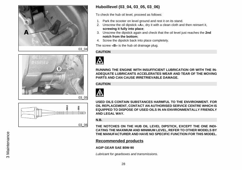
Huboillevel (03_04, 03_05, 03_06)
To check the hub oil level, proceed as follows:
1. Park the scooter on level ground and rest it on its stand.2. Unscrew the oil dipstick «A», dry it with a clean cloth and then reinsert it,
screwing it fully into place;3. Unscrew the dipstick again and check that the oil level just reaches the 2nd
notch from the bottom;4. Screw the dipstick back into place completely.
The screw «B» is the hub oil drainage plug.
CAUTION
RUNNING THE ENGINE WITH INSUFFICIENT LUBRICATION OR WITH THE IN-ADEQUATE LUBRICANTS ACCELERATES WEAR AND TEAR OF THE MOVINGPARTS AND CAN CAUSE IRRETRIEVABLE DAMAGE.
CAUTION
USED OILS CONTAIN SUBSTANCES HARMFUL TO THE ENVIRONMENT. FOROIL REPLACEMENT, CONTACT AN AUTHORISED SERVICE CENTRE WHICH ISEQUIPPED TO DISPOSE OF USED OILS IN AN ENVIRONMENTALLY FRIENDLYAND LEGAL WAY.
N.B.
THE NOTCHES ON THE HUB OIL LEVEL DIPSTICK, EXCEPT THE ONE INDI-CATING THE MAXIMUM AND MINIMUM LEVEL, REFER TO OTHER MODELS BYTHE MANUFACTURER AND HAVE NO SPECIFIC FUNCTION FOR THIS MODEL.
Recommended productsAGIP GEAR SAE 80W-90
Lubricant for gearboxes and transmissions.
28
3 M
aint
enan
ce

API GL-4
CharacteristicRear hub oil
Quantity: approx. 85 cc
03_07
Tyres (03_07)
Periodically check the inflation pressure of each tyre. Tyres have tread wear indicatorsand must be replaced as soon as these indicators are visible on the tread; should thisoccur, go to an authorised workshop or to a workshop properly equipped for refitting.
CAUTION
TYRE PRESSURE SHOULD BE CHECKED WHEN TYRES ARE COLD.INCOR-RECT TYRE PRESSURE CAUSES ABNORMAL TYRE WEAR AND MAKES RID-ING DANGEROUS.
TYRES MUST BE REPLACED WHEN THE TREAD REACHES THE WEAR LIMITSSET FORTH BY LAW.
CharacteristicFront tyre pressure
Front wheel: 1.3 bar
Tyre pressure (100 cc)
Front wheel: 1.3 bar
Rear wheel: 1.6 ÷ 1.8 bar
29
3 Maintenance
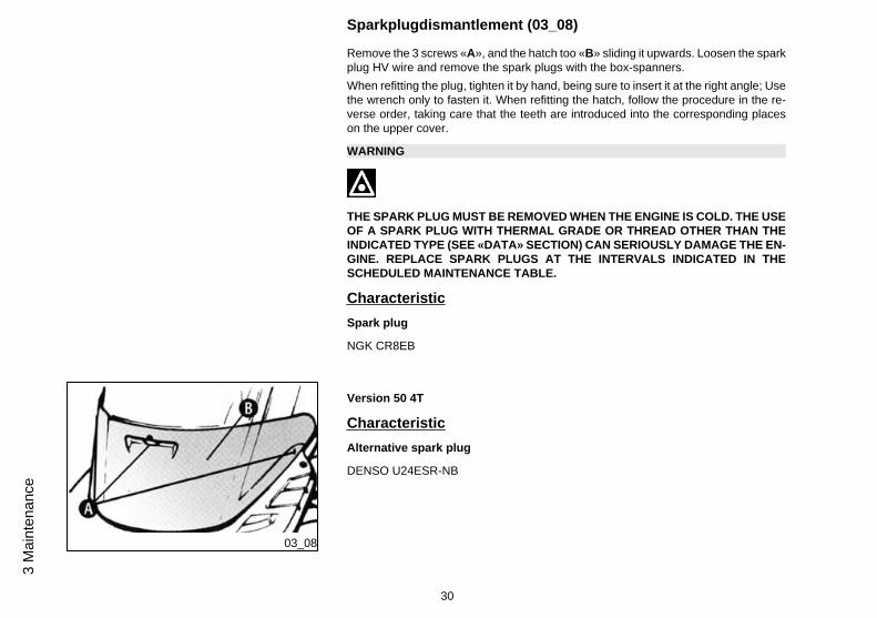
Sparkplugdismantlement (03_08)
Remove the 3 screws «A», and the hatch too «B» sliding it upwards. Loosen the sparkplug HV wire and remove the spark plugs with the box-spanners.When refitting the plug, tighten it by hand, being sure to insert it at the right angle; Usethe wrench only to fasten it. When refitting the hatch, follow the procedure in the re-verse order, taking care that the teeth are introduced into the corresponding placeson the upper cover.
WARNING
THE SPARK PLUG MUST BE REMOVED WHEN THE ENGINE IS COLD. THE USEOF A SPARK PLUG WITH THERMAL GRADE OR THREAD OTHER THAN THEINDICATED TYPE (SEE «DATA» SECTION) CAN SERIOUSLY DAMAGE THE EN-GINE. REPLACE SPARK PLUGS AT THE INTERVALS INDICATED IN THESCHEDULED MAINTENANCE TABLE.
CharacteristicSpark plug
NGK CR8EB
03_08
Version 50 4T
CharacteristicAlternative spark plug
DENSO U24ESR-NB
30
3 M
aint
enan
ce

03_09
Removingtheairfilter (03_09)
Take out the air cleaner cover «D» after having unscrewed the 6 fixing screws, thentake out the filter. Clean with water and shampoo, then dry with compressed air andimmerse in a mix of oil and petrol at a ratio of 50%. Then gently squeeze the filterelement between your hands, leave it to dry and mount it again.
CAUTION
IN CASE OF RIDING ON DUSTY ROADS IT IS ADVISABLE TO CLEAN THE AIRFILTER MORE FREQUENTLY THAN INDICATED IN THE RELEVANT CHAPTERON SCHEDULED MAINTENANCE.
Recommended productsAGIP FILTER OIL
Special product for the treatment of foam filters.-
31
3 Maintenance

03_10
Secondaryairsystem (03_10)
Remove the three screws «A» on the cover of the secondary air system housing.Detach the housing cover and remove the filter and the sponge «B». wash the spongewith water and a neutral soap, dry with a clean cloth and short blasts of compressedair. While cleaning the filter, check the good condition of the reed valve C and mountit back in place on the housing.
Before closing the cover of the SAS housing, check the good condition of the sealingO-ring; replace it if damaged or deformed.
N.B.
The reed valve can be inserted in only one direction on the SAS housing
CAUTION
CONTACT AN AUTHORISED PIAGGIO SERVICE CENTRE TO CARRY OUTTHESE OPERATIONS.
32
3 M
aint
enan
ce

03_11
03_12
Checkingthebrakeoillevel (03_11, 03_12)
The brake fluid reservoir is fitted with a sight-glass "A"; the amount of brake fluid seenthrough this glass shows the level of fluid contained in the reservoir.When the sight glass «A» is full, the level inside the reservoir exceeds the Min mark,when it is partially full, the level is slightly below the Min, when it is completely empty,the level is below the minimum.
The brake fluid level may fall due to wear on the brake pads. Should the level be belowthe minimum, the customer is advised to contact an Authorised Piaggio ServiceCentre for a thorough check of the braking system. To adjust the level follow theinstructions below. Unscrew the screw «B» and remove the plastic cover, unscrewthe 2 screws «C», lift the brake fluid reservoir cover«D» and add as much fluid asnecessary, (the fluid level must always be above the minimum level mark).Check these levels with the reservoir in a horizontal position, i.e. with the handlebarsstraight and the scooter perfectly level. Do not tilt the vehicle.
CAUTION
TOP-UPS SHOULD ONLY BE CARRIED OUT WITH DOT4 CLASSIFIED BRAKEFLUID.
CAUTION
THE BRAKING CIRCUIT FLUID IS HIGHLY CORROSIVE. THEREFORE, WHENTOPPING UP, AVOID LETTING IT COME INTO CONTACT WITH THE PAINTEDPARTS OF THE VEHICLE. THE BRAKING CIRCUIT FLUID IS HYGROSCOPIC,THAT IS, IT ABSORBS HUMIDITY FROM THE SURROUNDING AIR. IF MOISTURECONTAINED IN THE BRAKE FLUID EXCEEDS A CERTAIN VALUE, THIS WILLRESULT IN INEFFICIENT BRAKING.
33
3 Maintenance
WARNING
IN NORMAL CLIMATIC CONDITIONS IT IS ADVISABLE TO REPLACE THEABOVE-MENTIONED FLUID EVERY 2 YEAR. NEVER USE BRAKE FLUID CON-TAINED IN CONTAINERS WHICH ARE ALREADY OPEN OR PARTIALLY USED.
03_13
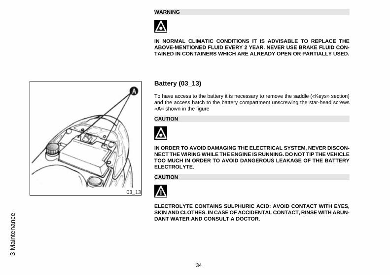
Battery (03_13)
To have access to the battery it is necessary to remove the saddle («Keys» section)and the access hatch to the battery compartment unscrewing the star-head screws«A» shown in the figure
CAUTION
IN ORDER TO AVOID DAMAGING THE ELECTRICAL SYSTEM, NEVER DISCON-NECT THE WIRING WHILE THE ENGINE IS RUNNING. DO NOT TIP THE VEHICLETOO MUCH IN ORDER TO AVOID DANGEROUS LEAKAGE OF THE BATTERYELECTROLYTE.
CAUTION
ELECTROLYTE CONTAINS SULPHURIC ACID: AVOID CONTACT WITH EYES,SKIN AND CLOTHES. IN CASE OF ACCIDENTAL CONTACT, RINSE WITH ABUN-DANT WATER AND CONSULT A DOCTOR.
34
3 M
aint
enan
ce

WARNING
USED BATTERIES ARE HARMFUL FOR THE ENVIRONMENT. COLLECTIONAND DISPOSAL SHOULD BE CARRIED OUT IN COMPLIANCE WITH REGULA-TIONS IN FORCE.
Long periods of inactivity
Battery performance will be poor if the vehicle is not used for a long time. This is theresult of the natural phenomenon of battery discharging, and may be due to residualabsorption by vehicle components with constant power consumption. Poor batteryperformance may also be due to environmental conditions and the cleanliness of thepoles. In order to avoid difficult starts and/or irreversible damage to the battery, followany of these steps:
- At least once a month start the engine and run it slightly above idle speed for 10-15minutes. This keeps all the engine components, as well as the battery, in good workingorder.
- Take your vehicle to a garage (as indicated in the «Vehicle not used for extendedperiods» section) to have the battery removed. Have the battery cleaned, chargedfully and stored in a dry, ventilated place. Recharge at least once every twomonths.
N.B.
THE BATTERY MUST BE CHARGED WITH A CURRENT EQUAL TO 1/10 OF THERATED CAPACITY OF THE BATTERY AND FOR NOT LONGER THAN 10 HOURS.CONTACT AN AUTHORISED SERVICE CENTRE TO CARRY OUT THIS OPERA-TION SAFELY. WHEN REFITTING THE BATTERY MAKE SURE THE LEADS ARECORRECTLY CONNECTED TO THE TERMINALS.
35
3 Maintenance
WARNING
DO NOT DISCONNECT THE BATTERY CABLES WITH THE ENGINE RUNNING,THIS CAN CAUSE IRREPARABLE DAMAGE TO THE VEHICLE'S ELECTRONICCONTROL UNIT.
WARNING
USED BATTERIES ARE HARMFUL FOR THE ENVIRONMENT. COLLECTIONAND DISPOSAL SHOULD BE CARRIED OUT IN COMPLIANCE WITH REGULA-TIONS IN FORCE.
03_14
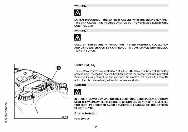
Fuses (03_14)
The electrical system is protected by a plug fuse «B» located to the left of the batterycompartment. The ignition system, headlight and the rear light are not fuse-protected.Before replacing a blown fuse, find and solve the problem that caused it to blow. Donot replace the fuse with any alternative form of conductor
CAUTION
IN ORDER TO AVOID DAMAGING THE ELECTRICAL SYSTEM, NEVER DISCON-NECT THE WIRING WHILE THE ENGINE IS RUNNING. DO NOT TIP THE VEHICLETOO MUCH IN ORDER TO AVOID DANGEROUS LEAKAGE OF THE BATTERYELECTROLYTE.
CharacteristicFuse (100 cc)
36
3 M
aint
enan
ce

10A
03_15
03_16
Frontlightgroup (03_15, 03_16)
To have access to the headlight bulbs, it is necessary to remove the rear part of thehandlebar cover as follows:
Unscrew the rear-view mirror after loosening the screw «A» located under the corre-sponding rubber protection.Unscrew the 3 screws «B» as well.
Position the screwdriver between the front and rear handlebar cover, and leveringgently, release the right and left attachments. After removing the bulb holder joints,move the bulb holder counterclockwise and remove it from its seat. To remove thebulb from the bulb holder push and rotate the bulb counterclockwise.
USE A SCREWDRIVER WITH A WORKING END APPROPRIATE TO THE SCREWSIZE TO AVOID DAMAGING THE PAINTWORK.
Electric characteristicBulbs
1 bulb per high-/low-beam light
37
3 Maintenance

03_17
03_18
Headlightadjustment (03_17, 03_18)
Position the unloaded vehicle a flat surface and at 10 m away from a white screenlocated in the dark. Make sure that the vehicle is perpendicular to the screen. Draw ahorizontal line on the screen at a height of 83 ÷ 85 cm from the ground.Start the engine, turn on the headlight, turn on the low-beam light and orientate it sothat the horizontal borderline between the dark and the light area is not higher thanthe horizontal line drawn on the screen. To remove the headlight, unscrew the screw«A» located below it.
Before adjusting the headlight, check that the tyres have the correct pressure as in-dicated in the «Tyres» section
03_19
Frontdirectionindicators (03_19)
To replace the bulb of the front turn indicators unscrew the 4 fixing screws «C». Totake out the bulb from the bulb holder, rotate the bulb holder clockwise and remove itfrom its seat. To remove the bulb, push and rotate it counterclockwise.
38
3 M
aint
enan
ce

03_20
03_21
Rearopticalunit (03_20, 03_21)
Remove both screws «E» and take out the light, then remove the tail light bulbs fol-lowing the same instructions as for the rear turn indicators; for the stop light, push androtate the bulb counterclockwise.
39
3 Maintenance

03_22
03_23
Rearturnindicators (03_22, 03_23)
To replace the rear turn indicator lamp, unscrew the 4 fixing screws «D» of the glass,to remove it, pull the cable harness and then the bulb.
40
3 M
aint
enan
ce

03_24
Rear-viewmirrors (03_24)
To adjust the stem position, lift the rubber protection and loosen the nut «A» with anopen wrench (opening 13 mm); adjust the stem to the best position and tighten thescrew.
03_25
Idleadjustment (03_25)
To adjust the idle speed it is necessary to actuate the screw «D» located in the car-burettor. It is necessary to actuate on both set screws«E» to adjust the clearance ofthe throttle control transmission. Adjust the idle speed with the rear wheel off theground (vehicle on stand) and with a warm engine: screw and unscrew the knob-typehead screw until reaching a regular rpm: i.e, without letting the engine move the rearwheel.
This operation should be carried out at an Authorised PIAGGIO Service Centre.
SHOULD THERE BE PROBLEMS DURING THE IDLE SPEED ADJUSTMENT OP-ERATION, IT MAY BE NECESSARY TO ADJUST THE LEVEL OF EXHAUSTEMISSIONS (CO). TURN TO AN AUTHORISED PIAGGIO SERVICE CENTRE TOCARRY OUT THESE OPERATIONS.
41
3 Maintenance

CAUTION
WHEN ADJUSTING IDLE SPEED, PAY SPECIAL ATTENTION NOT TO TOUCHTHE CATALYTIC MUFFLER TO AVOID BURNS.
CharacteristicIdle speed
1900÷2100 rpm
Engine idle speed (100 cc)
~ 1500 ± 150 rpm
03_26
Frontandreardiscbrake (03_26)
The brake disc and pad wear is automatically compensated, therefore it has no effecton the functioning of the front and rear brakes. For this reason it is not necessary toadjust the brakes. An excessively elastic brake lever stroke may indicate the presenceof air in the braking circuit or an irregular brake operation. In this case, particularlyconsidering the importance of the brakes in terms of safety, it is strongly recommendedthat you take the vehicle to an Authorised Service Centre as soon as possible forthe appropriate checks.
WARNING
CHECK BRAKE PADS FOR WEAR ON A REGULAR BASIS (AS INDICATED INTHE SCHEDULE MAINTENANCE TABLES). IF THE THICKNESS OF ONE ORBOTH PADS IS IN THE REGION OF 1.5 MM, BOTH PADS MUST BE CHANGED.IT IS RECOMMENDED TO CARRY OUT THIS OPERATION AT AN AUTHORISEDSERVICE CENTRE AS SOON AS POSSIBLE.
42
3 M
aint
enan
ce

AFTER FITTING NEW BRAKE PADS DO NOT USE THE VEHICLE UNTIL YOUHAVE ACTIVATED THE BRAKE LEVER REPEATEDLY TO POSITION THE PADSAND RESTORE THE LEVER STROKE TO ITS CORRECT POSITION.
CAUTION
BRAKING SHOULD BEGIN AFTER ABOUT 1/3 OF THE BRAKE LEVER STROKE.
03_27
Reardrumbrake (03_27)
Actuate on the set screw «A» indicated on the figure bearing in mind that the wheelmust rotate freely when the control lever is in neutral.
CAUTION
BRAKING SHOULD BEGIN AFTER ABOUT 1/3 OF THE BRAKE LEVER STROKE.
43
3 Maintenance
03_28
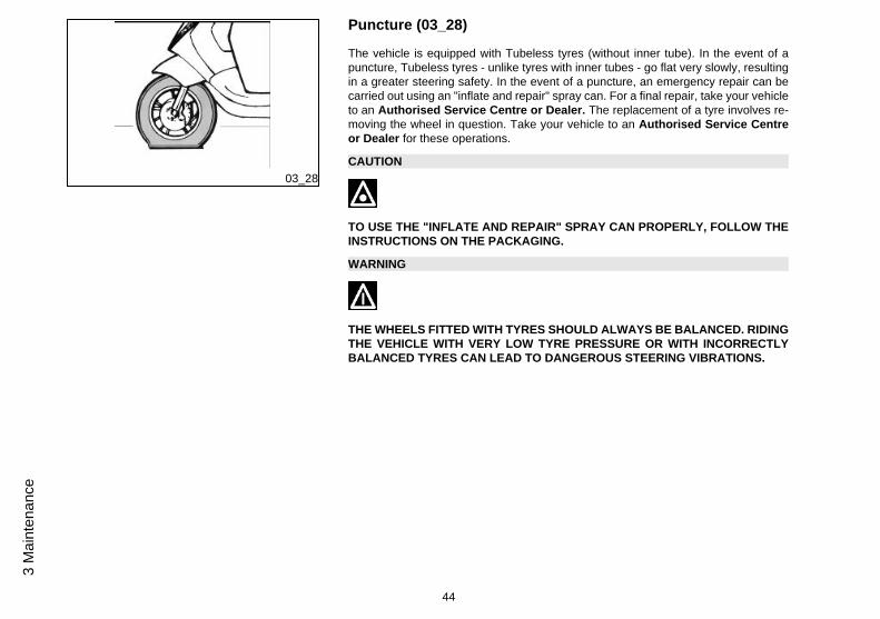
Puncture (03_28)
The vehicle is equipped with Tubeless tyres (without inner tube). In the event of apuncture, Tubeless tyres - unlike tyres with inner tubes - go flat very slowly, resultingin a greater steering safety. In the event of a puncture, an emergency repair can becarried out using an "inflate and repair" spray can. For a final repair, take your vehicleto an Authorised Service Centre or Dealer. The replacement of a tyre involves re-moving the wheel in question. Take your vehicle to an Authorised Service Centreor Dealer for these operations.
CAUTION
TO USE THE "INFLATE AND REPAIR" SPRAY CAN PROPERLY, FOLLOW THEINSTRUCTIONS ON THE PACKAGING.
WARNING
THE WHEELS FITTED WITH TYRES SHOULD ALWAYS BE BALANCED. RIDINGTHE VEHICLE WITH VERY LOW TYRE PRESSURE OR WITH INCORRECTLYBALANCED TYRES CAN LEAD TO DANGEROUS STEERING VIBRATIONS.
44
3 M
aint
enan
ce

03_29
delveicolo (03_29)
We recommend carrying out the following operations:1. General cleaning of the vehicle.
2. With the engine off and the piston at the bottom dead centre position, remove thespark plug, and pour 1÷ 2 cm³ of recommended oil through its opening. Press theengine start pedal 3 or 4 times letting the engine perform a few revolutions slowly,then replace the spark plug.
3. Drain off all the vehicle fuel; spread antirust grease on the unpainted metal parts;keep the wheels off the ground, by resting the chassis on two wooden wedges.
4. For the battery, follow the procedures described in the «Battery» section.
5. Drain the petrol from the carburettor float chamber through the bleed cap.
Recommended productseni i-Ride PG 5W-40
Synthetic based lubricant for high-performance four-stroke engines.JASO MA, MA2 - API SL - ACEA A3
03_30
Cleaningthevehicle (03_30)
Use a low pressure jet of water to soften the caked dirt and mud deposited on thepainted surfaces. Once softened, sponge off mud and dirt using a car body spongesoaked in a car body shampoo and water solution (2-4% of car shampoo in water).Then rinse with abundant water, and dry with a shammy cloth. For the engine exterior,use petrol, a brush and clean cloths. Petrol can damage paintwork. Remember thatany polishing with silicone wax must always be preceded by washing.
45
3 Maintenance

WARNING
To avoid the appearance of oxidations, wash the vehicle every time it is used incertain areas or in special conditions of:
· Environmental / seasonal conditions: use of salt, de-icer chemical products onthe road in winter.
· Air pollution: city and/or industrial areas.
· Salinity and humidity of the atmosphere: marine areas, hot and wet weather.
WARNING
. Prevent deposits from remaining on the bodywork, industrial and pollutantresidual dust, tar spots, dead insects, bird droppings, etc.
· Do not park the vehicle under the trees. In some seasons, in fact, residues,resins, fruits or leaves may fall from the trees, containing chemicals that areharmful to the paintwork.
CAUTION
DETERGENTS POLLUTE WATER. THEREFORE THE VEHICLE SHOULD BEWASHED IN AN AREA EQUIPPED FOR THE COLLECTION AND PURIFICATIONOF THE LIQUIDS USED.
46
3 M
aint
enan
ce

WARNING
NEVER WASH THE VEHICLE UNDER DIRECT SUNLIGHT, ESPECIALLY IN SUM-MER WHEN THE BODYWORK IS STILL HOT, AS THE CAR SHAMPOO MAY DRYBEFORE BEING RINSED OFF, AND COULD DAMAGE THE PAINTWORK. NEVERUSE RAGS SOAKED IN PETROL OR DIESEL OIL TO CLEAN THE PAINTED ORPLASTIC SURFACES, IN ORDER TO PREVENT THEM LOSING THEIR SHINEAND MECHANICAL CHARACTERISTICS.
WARNING
WHEN WASHING THE ENGINE WITH A HIGH-PRESSURE WATER JET:
• ONLY USE FAN SPRAY JETS.• DO NOT PLACE THE NOZZLE CLOSER THAN 60 CM.• DO NOT USE WATER AT TEMPERATURES OVER 40° C.• DO NOT DIRECT THE JETS DIRECTLY TO CARBURETTOR, WIRINGS, SLOTDIFFUSERS ON THE TRANSMISSION COVER AND SCROLL COVER.
START-UP PROBLEMSNo fuel in tank Refuel
Filters, jets or carburettor bodydirty or clogged.
Contact an Authorised ServiceCentre.
Insufficient battery charge Kick-start. Recharge the battery.
47
3 Maintenance

IGNITION PROBLEMS
No spark from spark plug. Due tothe presence of high voltage, thischeck should only be carried out byan expert.
Check that the electrodes areproperly adjusted (0.7÷ 0.8 mm).Check that the electrodes areclean (use pure petrol and a metalbrush or an emery cloth). Checkthe spark plug insulator: Replacethe spark plug if the insulator iscracked or broken. If the spark plugis in good conditions, contact anAuthorised Service Centre.
LACK OF COMPRESSION
Spark plug loose. Loose cylinderhead, worn piston retaining rings.Incorrect valve clearance
Contact an Authorised PiaggioService Centre
HIGH CONSUMPTION AND LOW PERFORMANCEAir filter blocked or dirty. Clean with water and shampoo and
impregnate with petrol and specificoil («Air filter removal» section)
48
3 M
aint
enan
ce

INSUFFICIENT BRAKINGOil on drum or disc. Worn Pads/Shoes
Contact an Authorised ServiceCentre
Rear brake incorrectly adjusted.Air in the front brakes circuit
Turn to an Authorised PiaggioService Centre
INEFFICIENT SUSPENSIONOil leak; worn limit switch bumpers;worn shock absorber attachmentpoints
Contact an Authorised ServiceCentre
AUTOMATIC TRANSMISSION PROBLEMSDeteriorated roller housing or belt. Contact an Authorised Service
Centre.
INCREASED EXHAUST NOISEDeterioration of the SAS systemand/or of the tab
Contact an Authorised ServiceCentre.
49
3 Maintenance

50
3 M
aint
enan
ce

ZIP 50 - 100 4T
Chap. 04Technicaldata
51

TECHNICAL DATA
Engine Single-cylinder, four-stroke
Bore x stroke 39 X 41.8 mm
Engine capacity 49.93 cm³
Compression ratio 11.5 :1
Ignition advance (before TDC) 8° at 1800 to 2000 rpm
24° at 5000 to 6000 rpm
Spark plug NGK CR8EB
Alternative spark plug DENSO U24ESR-NB
Depression carburettor KEIHIN CVK Ø 18 mm
valve clearance intake: 0.10 mm - exhaust: 0.10mm
Max. speed According to current legislation
DATA
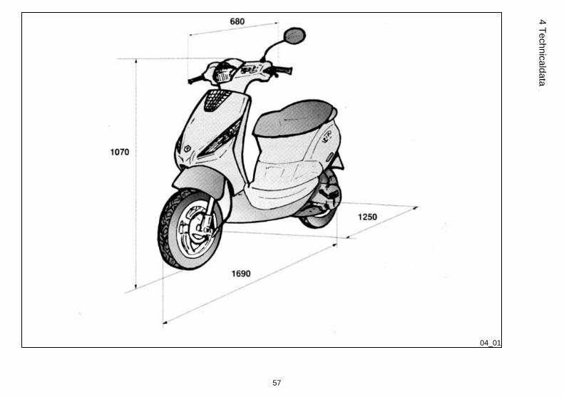
Overall length 1690 mm
Overall width 680 mm
Maximum height 1070 mm
Wheelbase 1250 mm
52
4 Te
chni
cald
ata

Fuel supply Gravity feed, unleaded petrol,through carburettor.
Lubrication Engine lubrication with lobe pump(inside the crankcase) controlledby chain and double filter: meshand centrifugal.
Cooling Forced-circulation air cooling.
Transmission With automatic expandable pulleyvariator, torque server, V-belt,automatic clutch, gear reductionunit.
Fuel tank In plastic, with a capacity of ~ 7.5 l(approximate value, including ~ 1.2l reserve)
Front suspension with telescopic fork.
Rear suspension fitted with spring and coaxialhydraulic shock absorber. Chassisto engine support with swingingarm.
Front wheel With 2.15 X 10" rims
Rear wheel With 3 X 10" rims
Front tyre 100/80-10"
Rear tyre 120/70-10"
Exhaust muffler Absorption type.
Electronic ignition Electronic ignition device withincorporated HV coil.
Chassis Single spar and stamped sheets.
53
4 Technicaldata

Front brake disc brake with hydraulic control(lever on the right side of thehandlebar).
Rear brake Drum brake with expanding shoes,controlled mechanically (lever onthe left side of the handlebar ).
Kerb weight in running order 84 kg
Maximum load Driver only.
Engine oil Capacity: approx. 850 cm³
Engine oil (change) 850 cm³
Rear hub oil Quantity: approx. ~80 cm³
TECHNICAL DATA 100ENGINE Single-cylinder, four-stroke
Bore 50 mm
Compression ratio 10.5 ÷ 11.5 : 1
Ignition advance (before TDC) 8° at 1800 to 2000 rpm
24° at 5000 to 6000 rpm
Spark plug NGK CR8EB
Depression carburettor KEIHIN CVK Ø 18 mm
Engine idle speed (100 cc) ~ 1500 ± 150 rpm
valve clearance intake: 0.10 mm - exhaust: 0.10mm
54
4 Te
chni
cald
ata

Max. speed According to current legislation
TECHNICAL DATA 100Width 735 mm
Length 1880 mm
Maximum height 1150 mm
Wheelbase 1340 mm
Fuel system Gravity feed, with unleaded petrol(with a minimum octane rating of95) with carburettor.
Lubrication engine lubrication with lobe pump(inside the crankcase) controlledby chain and double filter: meshand centrifugal.
Cooling Forced-circulation air cooling.
TRANSMISSION With continuously variabletransmission, torque server, V belt,automatic clutch, gear reductionunit.
Main and supplementary fuel tank(including ~ 1.2 l reserve) (100 cc)
~ 7 l
Front suspension Mechanical telescopic fork with 30mm stems.
Front tyre size 100/80-10''
Rear tyre size 120/70-10''
55
4 Technicaldata

Tyre pressure (100 cc) Front wheel: 1.3 bar
Rear wheel: 1.6 ÷ 1.8 bar
Ignition type Capacitive discharge electronicignition, with incorporated HV coil
Chassis type Welded tubular steel chassis withstamped sheet reinforcements
Front brake Disc (220 mm diameter) withhydraulic control (lever on the rightside of the handlebar).
Rear brake Drum brake (140 mm diameter)with expanding shoes,mechanically operated
Engine oil ~ 850 cc (recommended oil:SELENIA HI SCOOTER 4 Tech)
Rear hub (100 cc) approx. 80 cm³
56
4 Te
chni
cald
ata
04_01
57
4 Technicaldata

Toolkit
Wrenches: one box-spanner; one twin screwdriver. The tools are located under thesaddle. In order to take out the tools from the case release the lever and remove theclamp.
58
4 Te
chni
cald
ata

ZIP 50 - 100 4T
Chap. 05Sparepartsanda
ccessories
59

05_01
Warnings (05_01, 05_02)
WARNING
IT IS RECOMMENDED THAT "ORIGINAL PIAGGIO SPARE PARTS" BE USED,AS THESE ARE THE ONLY ONES OFFERING YOU THE SAME QUALITY AS-SURANCE AS THOSE INITIALLY FITTED ON THE VEHICLE.
IT SHOULD BE REMEMBERED THAT USING NON-ORIGINAL SPARE PARTSCAUSES YOUR WARRANTY RIGHTS TO EXPIRE.
WARNING
PIAGGIO MARKETS ITS OWN LINE OF ACCESSORIES THAT ARE RECOG-NISED AND GUARANTEED FOR USE. IT IS THEREFORE ESSENTIAL TO CON-TACT AN AUTHORISED DEALER OR SERVICE CENTRE IN ORDER TO CHOOSEAND FIT ACCESSORIES CORRECTLY. THE USE OF NON-ORIGINAL ACCES-SORIES MAY AFFECT THE STABILITY AND OPERATION OF YOUR VEHICLEAND REDUCE SAFETY LEVELS WITH POTENTIAL RISKS FOR THE RIDER.
60
5 Sp
arep
arts
anda
cces
sorie
s

05_02
61
5 Sparepartsandaccessories

62
5 Sp
arep
arts
anda
cces
sorie
s

ZIP 50 - 100 4T
Chap. 06Scheduledmaint
enance
63

06_01
Scheduledservicingtable (06_01)
Adequate maintenance is fundamental to ensuring long-lasting, optimum operationand performance of your vehicle.
To this end, a series of checks and maintenance operations (at the owner's expense)have been suggested, which are included in the summary table on the following page.Any minor faults should be reported without delay to an Authorised Service Centreor Dealer without waiting until the next scheduled service to solve it.
It is indispensable to have your vehicle serviced to the prescribed intervals of time,even if you have not reached the predicted mileage. Punctual vehicle servicing isnecessary for the correct use of the guarantee. For any further information concerningWarranty procedures and 'Scheduled Maintenance', please refer to the 'WarrantyBooklet'.
SCHEDULED MAINTENANCE TABLEKm x 1000 1 3 6 9 12 15 18 21 24 27 30 33 36 39 42 45 48 51 54 57 60
Safety fasteners I I I I I I
Spark plug R R R R R R R R R R
Drive belt I R I R I R I R I R
Throttle control A A A A A A
Tyre condition andwear I I I I I
Air filter C C C C C
Oil filter (mesh) C C C C C C C C C C
Solenoid filter C C C C C C C C C C
Valve clearance I I I I I I
64
6 Sc
hedu
ledm
aint
enan
ce

Km x 1000 1 3 6 9 12 15 18 21 24 27 30 33 36 39 42 45 48 51 54 57 60
Electrical system andbattery I I I I I I I I I I I
Cylinder ventilationsystem I I
Brake levers L L L L L L
Brake oil level (*) I I I I I I I I I I I
Hub oil level R I R I R I R I R I R
Engine oil R I R I R I R I R I R I R I R I R I R I R
Brake Pads/Shoes I I I I I I I I I I I
Tyre pressure I I I I I I I I I I I
Headlight A A A A A
Vehicle road test I I I I I I I I I I I
Idle speed A A A A A A
Odometer gear L L L L L
CVT rollers I R I R I R I R I R
Suspension I I I I I
Steering A A A A A A
Transmission L L L L L
I: CHECK AND CLEAN, ADJUST, LUBRICATE OR REPLACE IF NECESSARY.
C: CLEAN, R:REPLACE, A: ADJUST, L:LUBRICATE
* Replace every 2 years
65
6 Scheduledmaintenance

Scheduledservicingtable (06_01)
Adequate maintenance is fundamental to ensuring long-lasting, optimum operationand performance of your vehicle.
To this end, a series of checks and maintenance operations (at the owner's expense)have been suggested, which are included in the summary table on the following page.Any minor faults should be reported without delay to an Authorised Service Centreor Dealer without waiting until the next scheduled service to solve it.
It is indispensable to have your vehicle serviced to the prescribed intervals of time,even if you have not reached the predicted mileage. Punctual vehicle servicing isnecessary for the correct use of the guarantee. For any further information concerningWarranty procedures and 'Scheduled Maintenance', please refer to the 'WarrantyBooklet'.
EVERY 3000 KMEngine oil - level check/ top-up
Air filter - clean
EVERY 2 YEARSBrake fluid - change
AFTER 1,000 KM OR 4 MONTHS
Hub oil - change
66
6 Sc
hedu
ledm
aint
enan
ce

Valve clearance - check
idle rpm (*) - adjustment
Throttle lever - adjustment
Steering - adjustment
Brake levers - greasing
Brake pads - check for condition and wear
Brake fluid level - check
Safety fasteners - check
Electrical system and battery - check
Tyre pressure - check
Vehicle test and brake test - Road test
(*) See instructions in «Idle speed adjustment» section
AT 6000 KM OR 12 MONTHS, 18000, 30000, 42000, 54000AND 66000 KM
Engine oil - change
Hub oil level - control
oil filter - cleaning
CVT rollers - check or replacement
Brake pads - check for condition and wear
Brake fluid level - check
67
6 Scheduledmaintenance

Electrical system and battery - check
Tyre pressure and wear - check
Tyre pressure - check
Vehicle test and brake test - Road test
AT 12000 KM OR 24 MONTHS AND 60000 KM
Engine oil - change
Hub oil level - control
Spark plug / electrode gap - replacement
oil filter - cleaning
idle rpm (*) - adjustment
Throttle lever - adjustment
CVT rollers - check or replacement
Drive belt - replacement
Odometer gear - greasing
Steering - adjustment
Brake levers - greasing
Brake pads - check for condition and wear
Brake fluid level - check
Transmission - lubrication
Safety fasteners - check
68
6 Sc
hedu
ledm
aint
enan
ce

Suspension - check
Electrical system and battery - check
Headlight - adjustment
Tyre pressure and wear - check
Tyre pressure - check
SAS box (sponge) (**) - cleaning
Vehicle test and brake test - Road test
(*) See instructions in «Idle speed adjustment» section
(**) See regulations in the «Secondary air system» section
AFTER 24000 KM AND 48000 KM
Engine oil - change
Hub oil - change
Spark plug / electrode gap - replacement
oil filter - cleaning
Valve clearance - check
idle rpm (*) - adjustment
Throttle lever - adjustment
CVT rollers - check or replacement
Drive belt - replacement
Cylinder ventilation system - check
69
6 Scheduledmaintenance

Odometer gear - greasing
Steering - adjustment
Brake levers - greasing
Brake pads - check for condition and wear
Brake fluid level - check
Transmission - lubrication
Safety fasteners - check
Suspension - check
Electrical system and battery - check
Headlight - adjustment
Tyre pressure and wear - check
Tyre pressure - check
SAS box (sponge) (**) - cleaning
Vehicle test and brake test - Road test
(*) See instructions in «Idle speed adjustment» section
(**) See regulations in the «Secondary air system» section
AFTER 36000 KM
Engine oil - change
Hub oil level - control
Spark plug / electrode gap - replacement
70
6 Sc
hedu
ledm
aint
enan
ce

oil filter - cleaning
idle rpm (*) - adjustment
Throttle lever - adjustment
CVT rollers - check or replacement
Drive belt - replacement
Odometer gear - greasing
Steering - adjustment
Brake levers - greasing
Brake pads - check for condition and wear
Brake fluid hoses - replacement
Brake fluid level - check
Transmission - lubrication
Safety fasteners - check
Suspension - check
Electrical system and battery - check
Headlight - adjustment
Tyre pressure and wear - check
Tyre pressure - check
SAS box (sponge) (**) - cleaning
Vehicle test and brake test - Road test
(*) See instructions in «Idle speed adjustment» section
(**) See regulations in the «Secondary air system» section
71
6 Scheduledmaintenance

AFTER 72000 KM
Engine oil - change
Hub oil - change
Spark plug / electrode gap - replacement
oil filter - cleaning
Valve clearance - check
idle rpm (*) - adjustment
Throttle lever - adjustment
CVT rollers - check or replacement
Drive belt - replacement
Cylinder ventilation system - check
Odometer gear - greasing
Steering - adjustment
Brake levers - greasing
Brake pads - check for condition and wear
Brake fluid hoses - replacement
Brake fluid level - check
Transmission - lubrication
Safety fasteners - check
Suspension - check
Electrical system and battery - check
Headlight - adjustment
72
6 Sc
hedu
ledm
aint
enan
ce

Tyre pressure and wear - check
Tyre pressure - check
SAS box (sponge) (**) - cleaning
Vehicle test and brake test - Road test
(*) See instructions in «Idle speed adjustment» section
(**) See regulations in the «Secondary air system» section
RECOMMENDED PRODUCTS TABLEProduct Description Specifications
AGIP GEAR SAE 80W-90 Lubricant for gearboxes and transmissions. API GL-4
AGIP BRAKE 4 Brake fluid. Synthetic fluid SAE J 1703 -FMVSS 116 - DOT3/4 - ISO 4925 - CUNA NC 956 DOT 4
eni i-Ride PG 5W-40 Synthetic based lubricant for high-performancefour-stroke engines.
JASO MA, MA2 - API SL - ACEA A3
AGIP FILTER OIL Special product for the treatment of foamfilters.
-
AGIP GREASE MU3 Yellow-brown, lithium-base, medium-fibremultipurpose grease.
ISO L-X-BCHA 3 - DIN 51 825 K3K -20
AGIP GP 330 Water repellent stringy calcium spray grease. R.I.D./A.D.R. 2 10°b) 2 R.I.Na. 2.42 - I.A.T.A.2 - I.M.D.G. class 2 UN 1950 Page 9022 EM25-89
73
6 Scheduledmaintenance

74
6 Sc
hedu
ledm
aint
enan
ce

TABLE OF CONTENTS
BBattery: 34
CChecks: 16
FFuses: 36
IIdentification: 14
KKeys: 13
MMaintenance: 25
PPuncture: 44
RRefuelling: 16
TToolkit: 58Tyres: 29
VVehicle: 7
75

The descriptions and images in this publication are given for illustrative purposes only and are not binding. While the basic characteristics as described and illustrated in this booklet remain unchanged,Piaggio & C. S.p.A. reserves the right, at any time and without being required to update this publication beforehand, to make any changes to components, parts or accessories, which it considers
necessary to improve the product or which are required for manufacturing or construction reasons.
Not all versions/models shown in this publication are available in all countries. The availability of each model should be checked at the official PIAGGIO sales network.
© Copyright 2012 - Piaggio & C. S.p.A. All rights reserved. Reproduction of this publication in whole or in part is prohibited.
Piaggio & C. S.p.A. Viale Rinaldo Piaggio, 25 - 56025 PONTEDERA (PI), Italy
www.piaggio.com