Embed Size (px)
Citation preview

PHYSICS PROJECT REPORT
LOGIC AND GATE
Name:
Class: 12
Roll No.

INDEX
S. No. Topic 1. Acknowledgement 2. Certificate
3. Introduction 4. Basic Terminology
5. Basic Gates 6. AND Gate
7. Digital Circuit Consisting AND Gate8. Working of AND Gate
9. Bibliography

ACKNOWLEDGEMNT

CERTIFICATE

INTRODUCTIN A logic gate can be defined as digital circuit which either allows a signal to pass through or stops it. These gates are related to Boolean Algebra. These gates allow signals to pass through them only when some logic is satisfied. A semiconductor diode (P‐N junction) acts as a closed switch when it is forward biased, i.e. it allows current to pass through it. It acts as an open circuit when it is reversed biased, i.e. it allows very little or no current to pass through it. This unique property of diode is employed in the design of logic gates and the circuits.

BASIC TERMINOLOGY
Signal Information converted in electrical form and suitable for transmission is called a signal. There are two types of signals:‐ i) Analog signal ii) Digital signal
• Analog signal Analog signals are continuous variation of voltage or current. They are essentially single‐valued function of time. Sine wave is fundamental analog signal.
• Digital signal Digital signal are those which can take only discrete step wise values. Binary system that is extensively used in digital electronics employs just two levels of a signal. ‘O’ corresponds to low level and ‘1’ corresponds to high level of voltage or current.


• Digital circuit The electrical circuit which uses only digital signals is called digital circuit.
• Logic gate A digital circuit which allows a signal to pass through it or stops is called a gate. When such gate allows the signal to pass through only when some logical condition is satisfied, they are called logic gates. Each logic gate follows certain logical relationship between input and output voltage. It is used in calculators, etc.
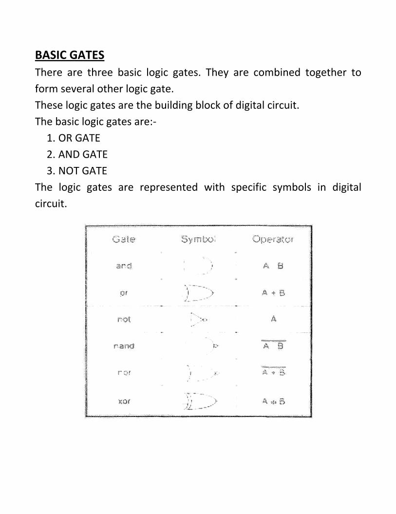
BASIC GATES There are three basic logic gates. They are combined together to form several other logic gate. These logic gates are the building block of digital circuit. The basic logic gates are:‐ 1. OR GATE 2. AND GATE 3. NOT GATE
The logic gates are represented with specific symbols in digital circuit.

• Truth Table It is a table that shows all possible input combinations and the corresponding output combination for a logic gate.
1. OR GATE The symbolic diagram of ‘OR GATE’ with two inputs and the truth table is shown:
2. NOT GATE The symbolic diagram of ‘NOT GATE’ with one input and the truth table is shown:

AND GATE The symbolic diagram of ‘AND GATE’ with two inputs and the truth table is shown:

The Boolean expression for AND GATE is Y=A.B the gate only gives output when both the switches A and B are closed.
The simplified AND gate shown above has two inputs, switch A and B. The bulb Q will only light if both switches are closed. This will allow current to flow through the bulb, illuminating the filament.

BIBLIOGRAPHY 1. NCERT Class 12th physics Textbook
2. Concept of Physics by Resnick and Halliday
3. Concept of Physics by H C Verma
4. www.google.co.in
5. www.play‐hookey.com


![[solutions manual] [instructors] physics by resnick halliday krane, 5th ed vol 2](https://img.dokumen.tips/doc/110x75/568ca6b61a28ab186d926ff9/solutions-manual-instructors-physics-by-resnick-halliday-krane-5th-ed.jpg)


![[Solutions Manual] Instructors] Physics by Resnick Halliday Krane 5th Ed. Vol 1](https://img.dokumen.tips/doc/110x75/54ea1b444a795910478b4d6d/solutions-manual-instructors-physics-by-resnick-halliday-krane-5th-ed-vol-1.jpg)

