Embed Size (px)
Citation preview

Physics of UltrasoundTI Precision Labs – Ultrasonic Sensing
Presented by Akeem WhiteheadPrepared by Akeem Whitehead

Definition of Ultrasound
2
0 20 200 2k 20k 200k 2M 20M 200M
Earthq
uake
Human
heari
ng
Animal
heari
ng
Water le
vel s
ensin
g
Liquid
Iden
tifica
tion
Non-de
struc
tive t
estin
g
Acous
tic m
icros
copy
Medica
l diag
nosti
cs
Automoti
ve pa
rk as
sist
Volcan
o
UltrasoundAudibleInfrasound
>20kHz
Ultrasound is defined as:• sound waves with a frequency above
the upper limit of human hearing at 20kHz.
• having physical properties that are identical to audible sound.
• a frequency some animals use for navigation and echo location.
This content will focus on ultrasonic systems that use transducers operating between 20kHz up to several GHz.
Sound Frequency Spectrum
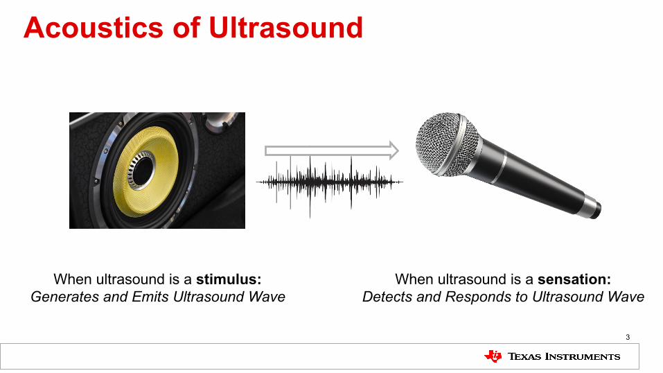
Acoustics of Ultrasound
3
When ultrasound is a stimulus:Generates and Emits Ultrasound Wave
When ultrasound is a sensation:Detects and Responds to Ultrasound Wave

Sound PropagationUltrasound propagates as:• longitudinal waves in air, water, plasma• transverse waves in solids
The transducer’s vibrating diaphragm is the source of the ultrasonic wave. As the source vibrates, the vibrations propagate away at the speed of sound to form a measureable ultrasonic wave.
The particles of the medium only transport the vibration of the ultrasonic wave, but do not travel with the wave. The medium can cause waves to be reflected, refracted, or attenuated over time.
An ultrasonic wave cannot travel through a vacuum.
λ
Direction of Wave Propagation
Particles at Rest
Longitudinal Wave
Transverse Wave
Direction of Particle Motion is Perpendicular
Direction of Particle Motion is Parallel
4

Acoustic PropertiesUltrasonic propagation is affected by:
1. Relationship between density, pressure, and temperature to determine the speed of sound.
2. Motion of the transmission medium itself can increase or decrease the speed of sound.
3. Medium viscosity determines the rate at which sound attenuates.
5
100
90
80
70
60
50
40
30
20
10
0
Geo
met
ric A
ltitu
de (k
m)
Density (kg/m3)
Pressure (kN/m2)
Speed of sound (m/s)
Temperature (K)
0 0.5 1 1.5
0 50 100 150
200 250 300 350
150 200 250 300
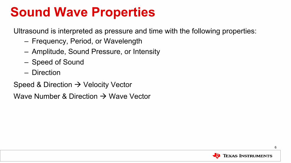
Sound Wave PropertiesUltrasound is interpreted as pressure and time with the following properties:
– Frequency, Period, or Wavelength– Amplitude, Sound Pressure, or Intensity– Speed of Sound– Direction
Speed & Direction à Velocity VectorWave Number & Direction à Wave Vector
6

Speed of Sound• The speed of sound depends on the medium the
waves pass through, and is a fundamental property of the material. Use the Newton–Laplace equation to solve for speed of sound:
𝒄 =𝑲𝒔
𝝆
– where Ks is the elastic bulk modulus, c is the velocity of sound, and ρ is the density.
• The physical properties and the speed of sound change with ambient conditions, such as temperature and humidity.
– In 20 °C air, at sea level, the speed of sound is approximately 343 m/s, and be calculated using the formula:
𝒗 = 𝟑𝟑𝟏 + (𝟎. 𝟔 ×𝑻)– where v is velocity and T is temperature in Celsius
7
TemperatureT (°C)
Speed of soundc (m/s)
Density of airρ (kg/m3)
Acoustic Impedancez0 (Pa·s/m)
35 351.88 1.1455 403.230 349.02 1.1644 406.525 346.13 1.1839 409.420 343.21 1.2041 413.315 340.27 1.2250 416.910 337.31 1.2466 420.55 334.32 1.2690 424.30 331.30 1.2922 428.0−5 328.25 1.3163 432.1−10 325.18 1.3413 436.1−15 322.07 1.3673 440.3−20 318.94 1.3943 444.6−25 315.77 1.4224 449.1
Effects of Temperature On Air
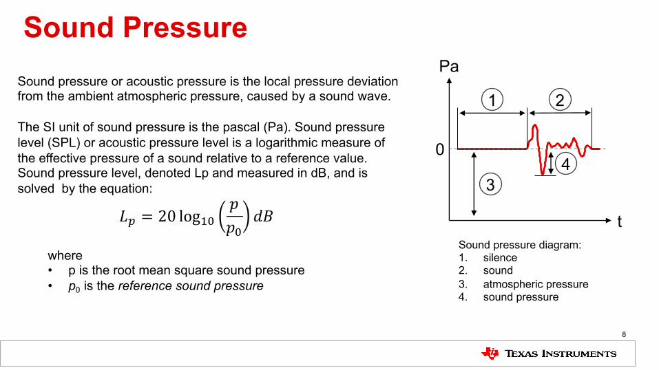
Sound Pressure
Sound pressure diagram:1. silence2. sound3. atmospheric pressure4. sound pressure
Sound pressure or acoustic pressure is the local pressure deviation from the ambient atmospheric pressure, caused by a sound wave.
The SI unit of sound pressure is the pascal (Pa). Sound pressure level (SPL) or acoustic pressure level is a logarithmic measure of the effective pressure of a sound relative to a reference value. Sound pressure level, denoted Lp and measured in dB, and is solved by the equation:
where• p is the root mean square sound pressure• p0 is the reference sound pressure
8
1 2
34
0
Pa
t𝐿! = 20 log"#𝑝𝑝#
𝑑𝐵

Acoustic Attenuation• When sound travels through a
medium, its sound pressure diminishes with distance.
• Scattering and absorption of the sound wave are real-world attenuation factors.– Scattering is the reflection of the
sound in directions other than its original direction of propagation
– Absorption is the conversion of the sound energy to other forms of energy.
9
-100
-90
-80
-70
-60
-50
-40
-30
-20
-10
0
0.1 1 10
Atte
nuat
ion
(dB
)
Distance (m)
Attenuation Characteristics of Sound Pressure by Distance
200 kHz80kHz40 kHz20 kHz

Acoustic ImpedanceAcoustic impedance is a measure of the opposition that a system presents to the acoustic flow resulting of an acoustic pressure applied to the system. The acoustic impedance (Z) of a material is defined as the product of its density (p) and acoustic velocity (V): Z = pV
Acoustic impedance is important in:• the determination of acoustic transmission and
reflection at the boundary of two materials having different acoustic impedances.
• the design of ultrasonic transducers.• assessing absorption of sound in a medium.
10
Material Density(kgm-3)
Speed of Sound(kgm-1)
Acoustic Impedance(kgm-2s-1 x 10⁶)
Air 1.3 330 0.000429
Sponge 100 750 0.075
Water 1000 1450 1.45
Soft Tissue 1050 1500 1.58
Aluminum 2700 6320 17.1
Steel 7800 5900 46.02
Iron 7700 5900 45.43
Gold 19320 3240 62.6
Acoustic Impedance by Material

Impedance MismatchThis difference in Z is commonly referred to as the impedance mismatch. The greater the impedance mismatch, the greater the percentage of energy that will be reflected at the interface or boundary between one medium and another.
When the acoustic impedances of the materials on both sides of the boundary are known, the fraction of the incident wave intensity that is reflected can be calculated with the equation below. The value produced is known as the reflection coefficient.
𝑅𝑒𝑓𝑙𝑒𝑐𝑡𝑖𝑜𝑛 𝐶𝑜𝑒𝑓𝑓𝑖𝑐𝑖𝑒𝑛𝑡 = 𝑅 =𝑍! − 𝑍"𝑍! + 𝑍"
!
11
Reflection Coefficient Examples

RADAR or SONAR Cross SectionRADAR or SONAR Cross Section (RCS or SCS) is the measure of a target's ability to reflect radar signals in the direction of the radar receiver. The conceptual definition of RCS includes the fact that not all of the radiated energy falls on the target.
A target’s RCS (σ) can be visualized as the product of three factors:σ = Projected cross section x Reflectivity x Directivity• Reflectivity: The percent of intercepted power reradiated (scattered) by the target• Directivity: The ratio of the power scattered back in the radar's direction to the power that would
have been backscattered had the scattering been uniform in all directions (i.e. isotropically)12

To find more ultrasonic sensing technical resources and search products, visit ti.com/ultrasonic
13