Embed Size (px)
Citation preview

2
CBSE Board Paper 2018-19 Set - 1
General Instructions:
1. All questions are compulsory. There are 27 questions in all. 2. This question paper has four sections: Section A, Section B,
Section C and Section D. 3. Section A contains five questions of one mark each, Section B
contains seven questions of two marks each, Section C contains twelve questions of three marks each, and Section D contains three questions of five marks each.
4. There is no overall choice. However, an internal choice(s) has been provided in two questions of one mark, two questions of two marks, four questions of three marks and three questions of five marks weightage. You have to attempt only one of the choices in such questions.
5. You may use the following values of physical constants wherever necessary: c = 3 × 10⁸ m/s
h = 6.63 × 10⁻³⁴ Js
e = 1.6 × 10⁻¹⁹ C
μo = 4π × 10–7 T m A–1
ε0 = 8.854 × 10⁻¹² C2 N-1 m-2
o
1
4= 9 × 10⁹ N m2 C–2
me = 9.1 × 10⁻³¹ kg
mass of neutron = 1.675 × 10⁻²⁷ kg
mass of proton = 1.673 × 10⁻²⁷ kg
Avogadro’s number = 6.023 × 10²³ per gram mole
Boltzmann constant = 1.38 × 10⁻²³ JK–1
Time allowed: 3 Hours Max Marks: 70
3
1. Draw the pattern of electric field lines, when a point charge – Q is kept near an uncharged conducting plate.
Section A
1
2. How does the mobility of electrons in a conductor change, if the potential difference applied across the conductor is doubled, keeping the length and temperature of the conductor constant?
1
3. Define the term “threshold frequency”, in the context of photoelectric emission.
1
Define the term “Intensity” in photon picture of electromagnetic radiation.
OR
4. What is the speed of light in a denser medium of polarizing angle 30°?
1
5. In sky wave mode of propagation, why is the frequency range of transmitting signals restricted to less than 30 MHz?
1
OR
On what factors does the range of coverage in ground wave propagation depend?

4
Section B
6. Two bulbs are rated (P1, V) and (P2, V). If they are connected (i) in series and (ii) in parallel across a supply V, find the power dissipated in the two combinations in terms of P1 and P2.
2
7. Calculate the radius of curvature of an equi-concave lens of refractive index 1.5, when it is kept in a medium of refractive index 1.4, to have a power of –5D?
2
OR
An equilateral glass prism has a refractive index 1.6 in air. Calculate the angle of minimum deviation of the prism, when kept in a medium of refractive index 4 √2/5.
8. A particle and a proton of the same kinetic energy are in turn allowed to pass through a magnetic field → B, acting normal to the direction of motion of the particles. Calculate the ratio of radii of the circular paths described by them.
2
9. State Bohr’s quantization condition of angular momentum. Calculate the shortest wavelength of the Brackett series and state to which part of the electromagnetic spectrum does it belong.
2

5
OR
Calculate the orbital period of the electron in the first excited state of hydrogen atom.
10. Why a signal transmitted from a TV tower cannot be
received beyond a certain distance? Write the expression for the optimum separation between the receiving and the transmitting antenna.
2
11. Why is wave theory of electromagnetic radiation not able to explain photo electric effect? How does photon picture resolve this problem?
2
12. Plot a graph showing variation of de Broglie wavelength (γ) associated with a charged particle of mass m, versus 1/ √V, where V is the potential difference through which the particle is accelerated. How does this graph give us the information regarding the magnitude of the charge of the particle?
2

6
Section C
13. (a) Draw the equipotential surfaces corresponding to a uniform electric field in the z-direction.
(b) Derive an expression for the electric potential at any point along the axial line of an electric dipole.
3
OR
14. Using Kirchhoff’s rules, calculate the current through the 40 Ω and 20 Ω resistors in the following circuit:
3
What is end error in a metre bridge? How is it overcome? The resistances in the two arms of the metre bridge are R = 5 Ω and S respectively. When the resistance S is shunted with an equal resistance, the new balance length found to be 1.5 l1 , where l1 is the initial balancing length. Calculate the value of S.

7
15. (a) Identify the part of the electromagnetic spectrum used in (i) radar and (ii) eye surgery. Write their frequency range.
(b) Prove that the average energy density of the oscillating electric field is equal to that of the oscillating magnetic field.
3
16. Define the term wave front. Using Huygens’s wave theory, verify the law of reflection.
3
OR
Define the term, “refractive index” of a medium. Verify Snell’s law of refraction when a plane wave front is propagating from a denser to a rarer medium.
17. (a) Define mutual inductance and write its S.I. unit.
(b) A square loop of side ‘a’ carrying a current I2 is kept at distance x from an infinitely long straight wire carrying a current I1 as shown in the figure. Obtain the expression for the resultant force acting on the loop.
3

8
18. (a) Derive the expression for the torque acting on a current carrying loop placed in a magnetic field.
(b) Explain the significance of a radial magnetic field when a current carrying coil is kept in it.
3
19. Draw a labelled ray diagram of an astronomical telescope in the near point adjustment position. A giant refracting telescope at an observatory has an objective lens of focal length 15 m and an eyepiece of focal length 1.0 cm. If this telescope is used to view the Moon, find the diameter of the image of the Moon formed by the objective lens. The diameter of the Moon is 3.48 × 10⁶ m, and the radius of lunar orbit is 3.8 × 10⁸ m.
3
20. (a) State Gauss’s law for magnetism. Explain its significance.
(b) Write the four important properties of the magnetic field lines due to a bar magnet.
3
OR
Write three points of differences between para-, dia- and ferro- magnetic materials, giving one example for each.

9
21. Define the term ‘decay constant’ of a radioactive sample. The rate of disintegration of a given radioactive nucleus is 10000 disintegrations/s and 5,000 disintegrations/s after 20 hr. and 30 hr. respectively from start. Calculate the half-life and initial number of nuclei at t = 0.
3
22. (a) Three photo diodes D1, D2 and D3 are made of semiconductors having band gaps of 2.5 eV, 2 eV and 3 eV respectively. Which of them will not be able to detect light of wavelength 600 nm?
(b) Why photodiodes are required to operate in reverse bias? Explain.
3
23. (a) Describe briefly the functions of the three segments of n-p-n transistor.
(b) Draw the circuit arrangement for studying the output characteristics of n-p-n transistor in CE configuration. Explain how the output characteristics is obtained.
3
OR
Draw the circuit diagram of a full wave rectifier and explain its working. Also, give the input and output waveforms.
24. (a) If A and B represent the maximum and minimum
amplitudes of an amplitude modulated wave, write the expression for the modulation index in terms of A & B.
(b) A message signal of frequency 20 kHz and peak voltage 10 V is used to modulate a carrier of frequency 2 MHz and peak voltage of 15 V. Calculate the modulation index. Why the modulation index is generally kept less than one?
3

10
Section D
25. (a) In a series LCR circuit connected across an ac source of variable frequency, obtain the expression for its impedance and draw a plot showing its variation with frequency of the ac source.
(b) What is the phase difference between the voltages across inductor and the capacitor at resonance in the LCR circuit?
(c) When an inductor is connected to a 200 V dc voltage, a current of 1A flows through it. When the same inductor is connected to a 200 V, 50 Hz ac source, only 0.5 A current flows. Explain, why? Also, calculate the self-inductance of the inductor.
5
OR
(a) Draw the diagram of a device which is used to decrease high ac voltage into a low ac voltage and state its working principle. Write four sources of energy loss in this device.
(b) A small town with a demand of 1200 kW of electric power at 220 V is situated 20 km away from an electric plant generating power at 440 V. The resistance of the two-wire line carrying power is 0.5 Ω per km. The town gets the power from the line through a 4000-220 V step-down transformer at a sub-station in the town. Estimate the line power loss in the form of heat.

11
26. (a) Describe any two characteristic features which distinguish between interference and diffraction phenomena. Derive the expression for the intensity at a point of the interference pattern in Young’s double slit experiment.
(b) In the diffraction due to a single slit experiment, the aperture of the slit is 3 mm. If monochromatic light of wavelength 620 nm is incident normally on the slit, calculate the separation between the first order minima and the 3rd order maxima on one side of the screen. The distance between the slit and the screen is 1.5 m.
5
OR
(a) Under what conditions is the phenomenon of total internal reflection of light observed? Obtain the relation between the critical angle of incidence and the refractive index of the medium.
(b) Three lenses of focal lengths +10 cm, –10 cm and +30 cm are arranged coaxially as in the figure given below. Find the position of the final image formed by the combination.

12
27. (a) Describe briefly the process of transferring the charge between the two plates of a parallel plate capacitor when connected to a battery. Derive an expression for the energy stored in a capacitor.
(b) A parallel plate capacitor is charged by a battery to a potential difference V. It is disconnected from battery and then connected to another uncharged capacitor of the same capacitance. Calculate the ratio of the energy stored in the combination to the initial energy on the single capacitor.
5
OR
(a) Derive an expression for the electric field at any point on the equatorial line of an electric dipole.
(b) Two identical point charges, q each, are kept 2m apart in air. A third point charge Q of unknown magnitude and sign is placed on the line joining the charges such that the system remains in equilibrium. Find the position and nature of Q.

13
Set - 2
2. When unpolarized light is incident on the interface separating the rarer medium and the denser medium, Brewster angle is found to be 60°. Determine the refractive index of the denser medium.
1
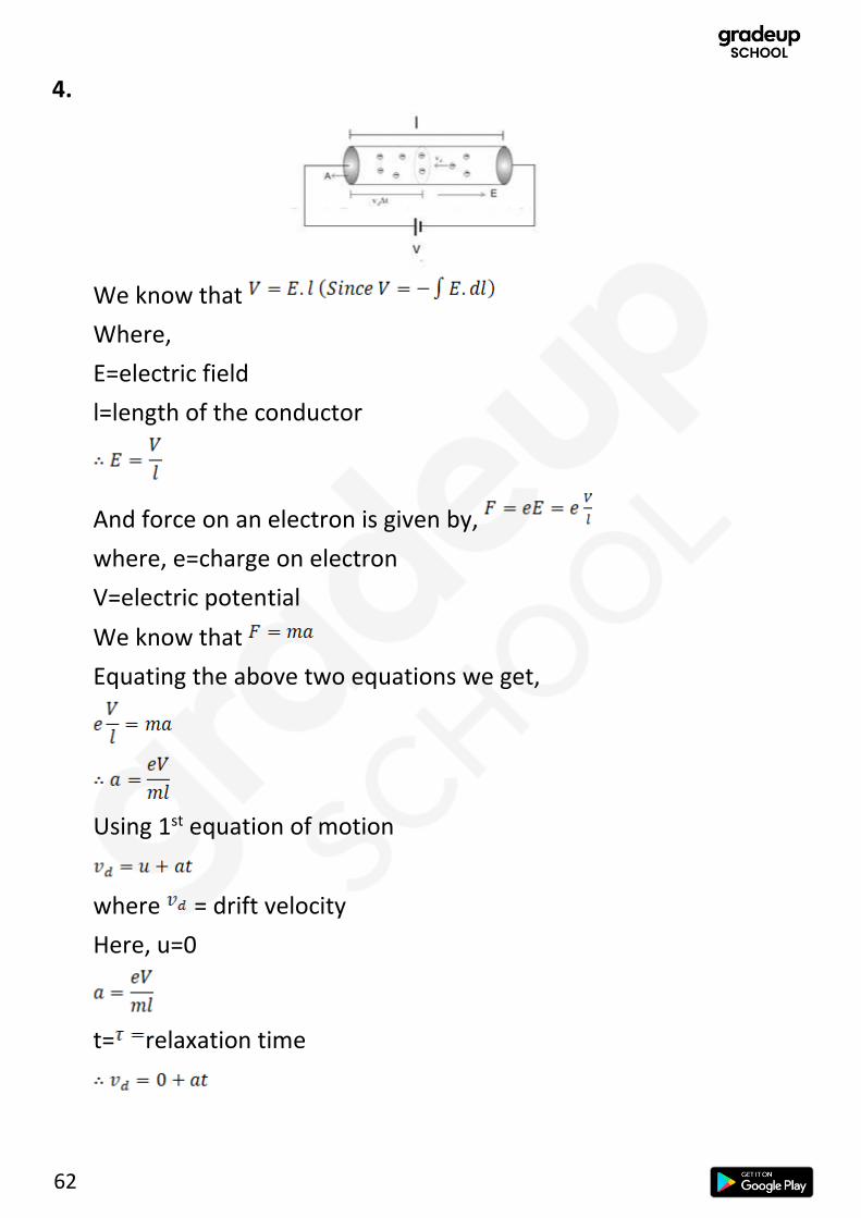
4. When a potential difference is applied across the ends of a conductor, how is the drift velocity of the electrons related to the relaxation time?
1
5. Draw the equipotential surfaces due to an isolated point charge.
1
6. Explain with the help of Einstein’s photo electric equation any two observed features in photoelectric effect which cannot be explained by wave theory.
2
7. A deuteron and an alpha particle having same momentum are in turn allowed to pass through a magnetic field B , acting normal to the direction of motion of the particles. Calculate the ratio of the radii of the circular paths described by them.
2

14
11. (a) Plot a graph showing variation of DE Broglie wavelength (λ) associated with a charged particle of mass
m, versus V, where V is the accelerating potential.
(b) An electron, a proton and an alpha particle have the same kinetic energy. Which one has the shortest wavelength?
2
13. (a) State the underlying principle of a moving coil galvanometer.
(b) Give two reasons to explain why a galvanometer cannot as such be used to measure the value of the current in a given circuit.
(c) Define the terms: (i) voltage sensitivity and (ii) current sensitivity of a galvanometer.
3
15. (a) Draw equipotential surfaces corresponding to the electric field that uniformly increases in magnitude along with the z-directions.
(b) Two charges – q and + q are located at points (0, 0, – a) and (0, 0, a). What is the electrostatic potential at the points (0, 0, + z) and (x, y, 0)?
3
17. (a) Write the relation between half-life and average life of a radioactive nucleus.
(b) In a given sample two isotopes A and B are initially present in the ratio of 1:2. Their half-lives are 60 years and 30 years respectively. How long will it take so that the sample has these isotopes in the ratio of 2:1?
3

15
19. (a) Define the term ‘self-inductance’ of a coil. Write its S.I. unit.
(b) A rectangular loop of sides a and b carrying current I2 is kept at a distance ‘a’ from an infinitely long straight wire carrying current I1 as shown in the figure.
Obtain an expression for the resultant force acting on the loop.
3

16
Set - 3
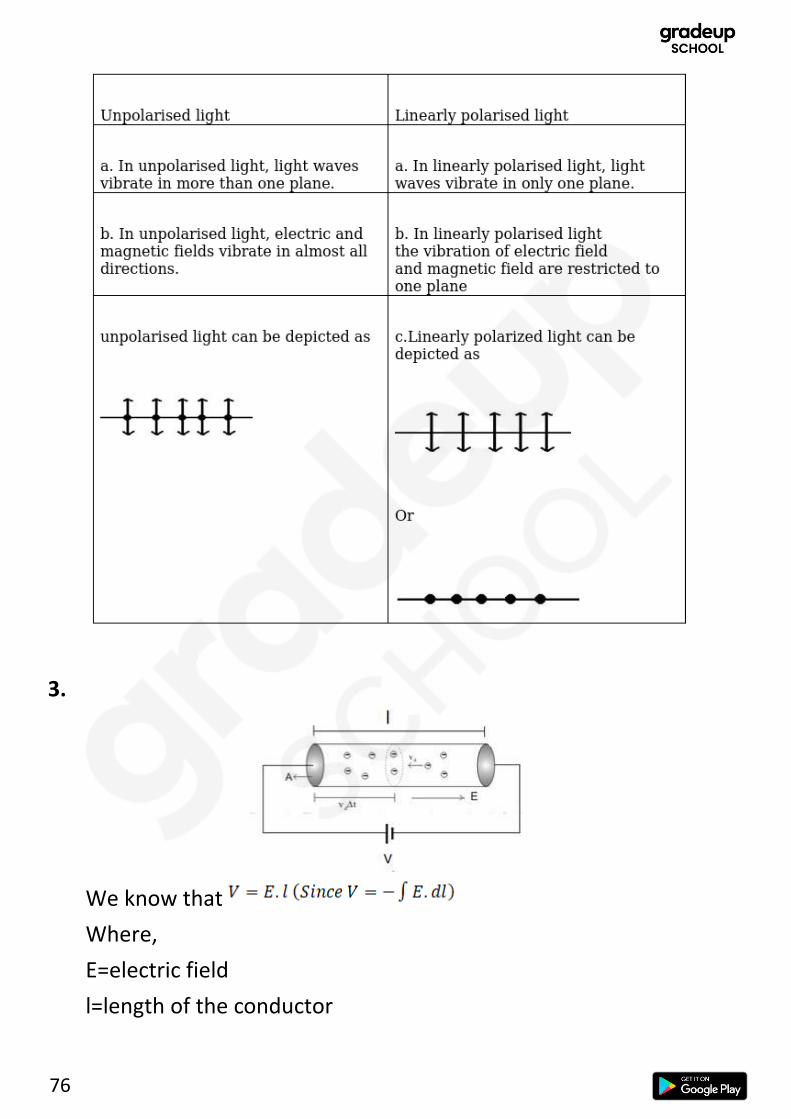
1. Distinguish between unpolarized and linearly polarized light.
1
3. How is the drift velocity in a conductor affected with the rise in temperature?
1
5. Draw the pattern of electric field lines when a point charge +q is kept near an uncharged conducting plate.
1
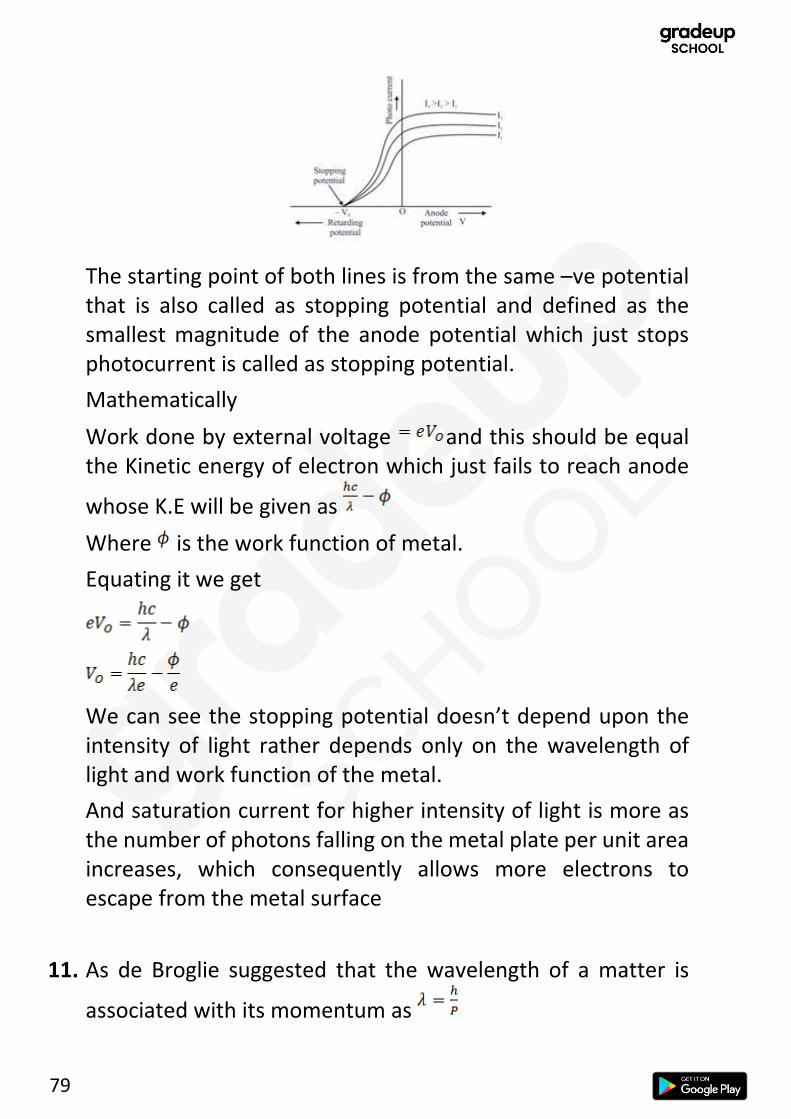
6. (a) Define the terms, (i) threshold frequency and (ii) stopping potential in photoelectric effect.
(b) Plot a graph of photocurrent versus anode potential for a radiation of frequency v and intensities I1 and I2 (I1 < I2).
2
11. Obtain the expression for the ratio of the de-Broglie wavelengths associated with the electron orbiting in the second and third excited states of hydrogen atom.
2
12. A charged particle q is moving in the presence of a magnetic field B which is inclined to an angle 30° with the direction of the motion of the particle. Draw the trajectory followed by the particle in the presence of the field and explain how the particle describes this path.
2

17
13. (a) Explain briefly how Rutherford scattering of α-particle by a target nucleus can provide information on the size of the nucleus.
(b) Show that density of nucleus is independent of its mass number A.
3
14. State the underlying principle of a cyclotron. Explain its working with the help of a schematic diagram. Obtain the expression for cyclotron frequency.
3
15. Two infinitely long straight wires A1 and A2 carrying currents I and 2I flowing in the same directions are kept ‘d’ distance apart. Where should a third straight wire A3 carrying current 1.5 I be placed between A1 and A2 so that it experiences no net force due to A1 and A2? Does the net force acting on A3 depend on the current flowing through it?
3
16. (a) Draw the equipotential surfaces due to an electric dipole.
(b) Derive an expression for the electric field due to a dipole of dipole moment ⃗pat a point on its perpendicular bisector.
3

18
1. The -ve Q charge would induce charges on the conducting plate. The side of the plate towards the charge would have net positive charge (+Q) and the other side would have net negative charge (-Q). Note that the electric field lines start from positive charge and end at a negative charge. Thus, the electric filed lines would look like:
2. If the drift velocity of the electrons is . Then, the mobility is
where E is the electric field strength.
Also, if the electron density is n, area of cross section is A, then
Also,
Solutions (Set-1)
Section A (Solutions)

19
Combining all, we get
Now,
where d is the length of conductor.
Thus,
Hence, mobility is independent of the voltage applied. Thus, it remains same.
3. For a given photosensitive material, threshold frequency is the minimum frequency of radiation that is required for photoelectric emission from the material.
Intensity is a measure number of photons passing through a given cross section per unit area.
4. Polarizing angle of incidence,
If the polarising angle of incidence is and the refractive index is μ, then they are related by:
Also, we know that
OR

20
where c is the speed of light and v is the speed of light in the medium.
5. In sky wave mode of propagation, electromagnetic waves reflect back from the ionosphere. Electromagnetic waves of frequencies higher than 30 MHz penetrate the ionosphere and escape.
The maximum range of coverage depends on the transmitted power and frequency.
6. Concepts/Formulas Used:
Resistors in Series:
Section B (Solutions)
OR
21
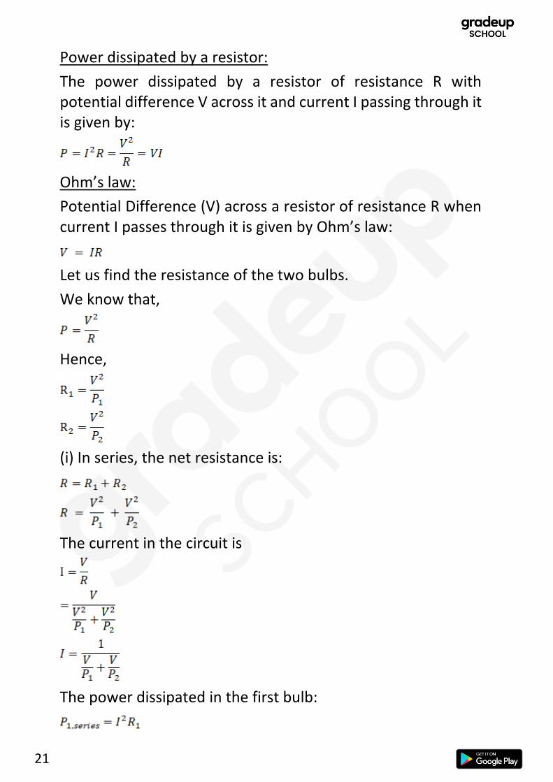
Power dissipated by a resistor:
The power dissipated by a resistor of resistance R with potential difference V across it and current I passing through it is given by:
Ohm’s law:
Potential Difference (V) across a resistor of resistance R when current I passes through it is given by Ohm’s law:
Let us find the resistance of the two bulbs.
We know that,
Hence,
(i) In series, the net resistance is:
The current in the circuit is
The power dissipated in the first bulb:

22
The power dissipated in the first bulb:
(ii) In parallel, the potential through both is V. Hence the power is the same as the rated power i.e. P1 and P2.
7. We know that the focus of a lens is given by:
where f is the focal length of the lens and R1 and R2 are the radius of the refracting surface on the side of the object and on the other side respectively.
Let the radius be R.
and
Power of the lens, P = 5D = 5 m-1
Refractive index, n = 1.6
We know that,
23
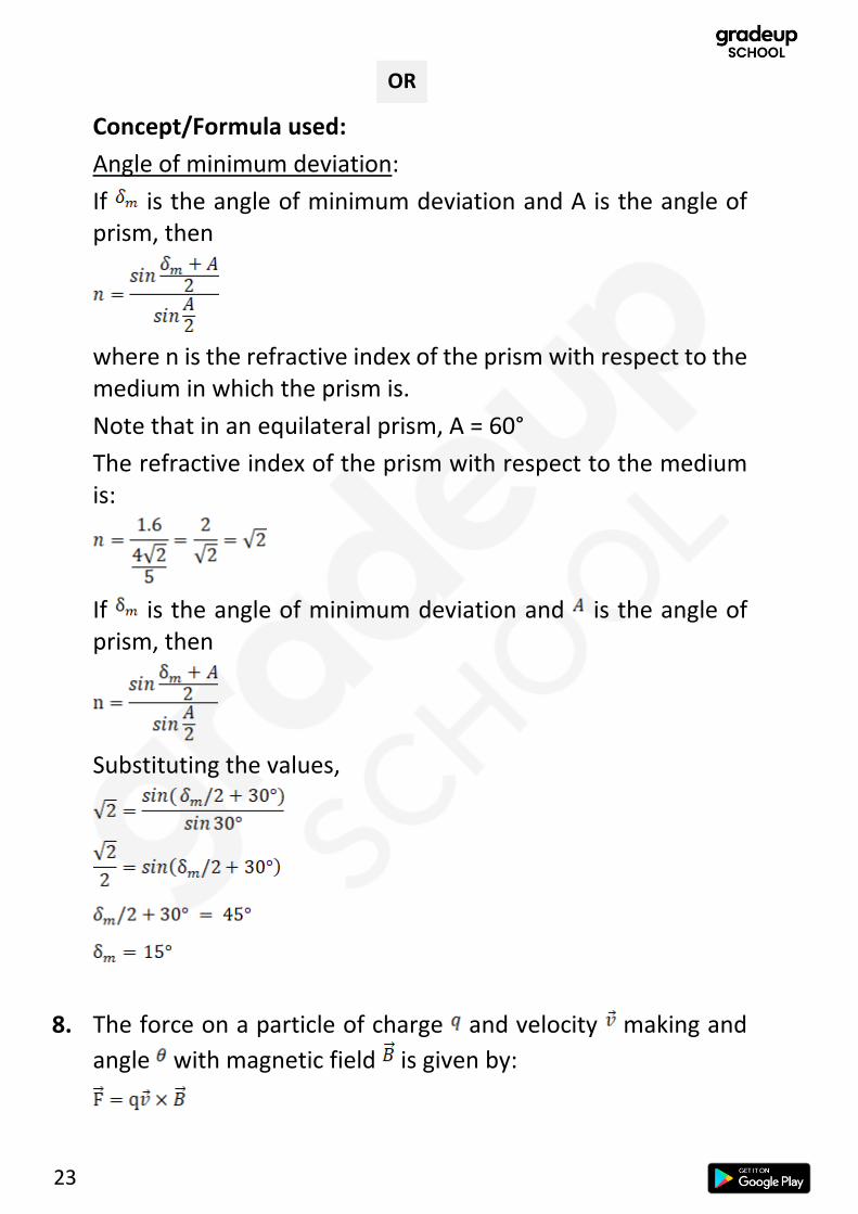
Concept/Formula used:
Angle of minimum deviation:
If is the angle of minimum deviation and A is the angle of prism, then
where n is the refractive index of the prism with respect to the medium in which the prism is.
Note that in an equilateral prism, A = 60°
The refractive index of the prism with respect to the medium is:
If is the angle of minimum deviation and is the angle of prism, then
Substituting the values,
8. The force on a particle of charge and velocity making and
angle with magnetic field is given by:
OR

24
The magnitude of the force when the magnetic field is normal to velocity is given by:
As the force is perpendicular to the velocity, (resultant of cross product), it can only change the direction and not the speed of the particle. Hence, it will move in a circle. Let r be the radius of this circular path. The centripetal force is given by:
Equating (1) and (2), we get
We know that the kinetic energy is given by:
Substituting in (3), we have
⇒
Now,
The ratio of mass of alpha particle to the mass of proton is 4:1.
The ratio of the charge on alpha particle to the charge on proton is 2:1.
Taking the ration of the radii, we have
⇒
The ratio of the radii of is 1.

25
9. Bohr’s quantization condition: The angular momentum of an electron in an orbit around the hydrogen atom has to be an integral multiple of Planck’s constant divided by twice π. Mathematically,
The wavelength can be calculated in case of Brackett series by the formula:
For the wavelength to be shortest, n has to be maximum i.e. ∞
Hence,
It is between 700 nm and 1mm which is the range of infrared. Hence, it belongs to the infrared part of the spectrum.
Let the radius of the shell of the first exited state be r and the speed of electron in the second exited stated be v.
Note that the ground state is n=1 and the first exited state is n=2 .
The angular momentum of the electron in the first exited state (n=2) is
Now, the force on the electron is given by coulomb’s law:
where is the magnitude of charge on electron.
OR

26
The centripetal force on electron is:
The coulomb force acts as centripetal force. Hence,
Substituting the value of v from (1) in (2).
10. The curvature of the earth limits the distance up to which a signal can be transmitted by a tower.
If the height of the transmitting antenna is h and the radius of the earth is R, then the optimum distance d between the receiving and the transmitting antenna is given by:
11. It was experimentally observed that below a certain threshold frequency, no photoelectrons were emitted. It was also observed that the maximum kinetic energy of the electrons varied linearly with the frequency of radiation and was independent of intensity of incoming radiation. There was no time lag between when the photon is absorbed and when the photoelectron is emitted. Increasing the intensity increased the photocurrent.
The wave theory predicts that the electrons would absorb the energy continuously. The greater the intensity, the greater the energy per unit area. Thus, greater should be the kinetic

27
energy of the electrons emitted. However, this is not the case. Moreover, after a period of time, enough energy should be absorbed to eject the electron. Thus, threshold frequency should not exist.
In the photon picture, each electron absorbs one photon. If the frequency is high enough, then the energy of the photon ( ) is enough to eject the electron. By conservation of energy,
where W0 is the minimum energy required to free the electron. We can see that as the frequency increases, the maximum kinetic energy increases, in agreement with experimental results. Also, as intensity increases, the number of photons per unit area increase and so does the emitted photoelectrons; this results into increase in photocurrent.
Thus, the wave theory of light fails to explain the photoelectric effect whereas the photon picture of light is able to explain this effect.
12. Consider a particle of mass m, charge q . Let it be accelerated through a potential difference V to gain speed v and Kinetic energy KE.
Now, we can rearrange the expression to get
The de-Broglie wavelength is given by the equation:
Substituting the value of , we get

28
This analogous to the equation of a straight line passing through the origin: y = mx where m is the slope of the line.
Hence, we can see that if we plot the graph of λ vs V , we would get a straight line with slope:
On rearranging,
Hence, as we know , and we can determine S from the graph, we can calculate the magnitude of charge on the particle.
The graph is drawn below:

29
13. (a) Note that the electric field is always perpendicular to the equipotential surface. Hence, the equipotential surfaces are going to be infinite plane sheets parallel to the x-y plane.
Also, the electric field strength is proportional to the distance between the surfaces. Hence, the surfaces will be evenly spaced.
(b)
Let charge +q and -q be separated by distance 2a. Let origin be at the centre of the two charges. Consider any arbitrary point P (x,0).
Let ra be the distance of point P from the positive charge and rb be the distance of the point P from the negative charge.
The electric potential at point P is given by:
We have two cases:
Section C (Solutions)

30
Case I: and
Now,
and
Case II: and
Now,
and
Case III: and
Now,
and

31
Case IV:
and
14. Concept/Formula used:
Kirchhoff’s junction rule:
The sum of currents entering a junction is equal to the sum of currents leaving it.
Kirchhoff’s loop rule:
The sum of potential differences around a closed loop is zero
Let us label the circuit with currents in accordance with Kirchhoff’s junction rule.
Using Kirchhoff’s loop rule on ABCDA,

32
Using Kirchhoff’s loop rule on CDEFC,
Subtracting (2) from (1), we get
Substituting the value of I2 in (1), we get
Hence, there is no current through the 40Ω resistor and 4A current flows through the 20Ω resistor.
It might be the case that the zero of the ruler doesn’t align with the starting end of the wire. This causes a type of zero error known as end error.
We can determine this error by using known values of P and Q. We can theoretically calculate the distance from A at which the free end of the galvanometer be connected to get zero
OR

33
deflection. We can also experimentally read the distance on the ruler. Subtracting the theoretical value from the reading will give us the zero error.
Concept/Formula used:
Consider a meter bridge shown below.
The resistance S can be found by:
Now,
We know that
After we put an equal resistance, we have
Substituting in (1), we get

34
15. (a) (i) Radio waves are used in radar. Frequency range: 500kHz to 1000MHz
(ii) UV rays are used in eye surgery. Frequency range: 3 × 10¹⁶Hz to 8 × 10¹⁴ Hz.
(b) Concepts/Formulas Used:
Energy stored by electric field:
The energy density of electric field with electric field strength E is given by:
where ϵ0 is the permittivity of free space.
Energy stored by magnetic field:
The energy density of magnetic field with magnetic field strength B is given by:
where μ0 is the magnetic permeability of free space.
Electromagnetic waves:
The oscillating electric field and magnetic field of an electromagnetic field wave travelling in the +z direction are in +x and +y directions and are given by:
where k is the wave number given by
where λ is the wavelength of the wave.
Also,
where c is the speed of light in vacuum.
and

35
Let the electromagnetic field move in +z direction.
Then the electric filed is given by:
Now, the energy density is given by:
Taking the average,
The brackets mean average. We must find the average of the above sin term in brackets. The average is not just over time but also over space. Thus, we will need to integrate twice. However, we can see that both position(z) and time (t) are simply arguments in the sine squared term. We can simply find the average of sine squared term over to .
Now,
The magnetic field is given by:
Now, the energy density is given by:

36
Taking the average,
Using, and
We can see that
16. (First Choice)
A wave front is a surface of constant phase.
Let a plane wave AB be incident on a reflecting surface MN at an angle of incidence i . Let v be the speed of the wave. Let be the time it takes by the wave front to advance from B to C.
Then,

37
We want to draw the reflected wave front. Draw a sphere of radius vt centred at A. Now, the tangent plane to this sphere passing through point C gives the refracted wave front in accordance with Huygens’ principle.
Note that and
Consider triangles EAC and BAC,
By RHS,
Thus,
Hence, the angle of incidence and the angle of reflection are equal.
The refractive index of a medium is defined as the ratio of the speed of light in vacuum to the speed of light in the medium.
Let the surface PP’ separate medium 1 and medium 2. Note that medium 1 is optically denser than medium 2. Let the speed of light be and in medium 1 and medium 2 respectively. Note that .
A plane wave AB propagates and hits the interface at an angle . Let be the time taken be the wave front to travel the
distance BC.
OR

38
We wish draw the refracted wave front. With A as centre, we draw a sphere of radius . Take the surface tangent to the sphere passing through point C as the refracted wave front. Let the surface be tangent to the sphere at E.
In ABC,
Also, in AEC,
Dividing the two equations, we get
⇒
17. (a) Mutual inductance is the property of two coils that opposes the change in current in one coil.
There are two Coils: coil 1 and coil 2 with the number of turns N1 and N2. The magnetic flux across them is and respectively. Let the current through coil 1 be and current through coil 2 be . Then, the mutual-inductance is given by:
(b) Concepts/Formulas used:
Force between two wires:

39
If two straight infinite parallel conducting wires with current
and are separated by a distance , then force per unit length of each wire is given by:
where is the magnetic permeability of free space.
If the wires carry currents in the same direction, they attract and if they carry currents in opposite direction, they repel.
By symmetry, and must be equal. Hence, they cancel out.
Now,
Also,
The total force is
⇒
18. Consider a loop ABCD in a uniform magnetic field with strength . Let the magnetic field make an angle with the normal of
the loop. Let the current through the loop be .

40
The force acting on the arms BC and AD are equal and opposite. Also, they are collinear. Hence, they produce no torque.
Now, consider force and on arms AB and CD respectively.
Their direction is given by the right-hand rule. These two forces are not collinear. The net torque is given by:
where A is the area of the coil.
The magnetic moment of the loop is given by:
where the direction of the area vector is given by the right-
hand thumb rule. We can see that the angle between and is .
Thus,

41
(b) From the previous section,
Even though this result was derived for a rectangular loop, it is true in general for any current-carrying loop in a magnetic field. We can see that the torque ( ) is maximum when . It is zero when . A radial magnetic field ensures that the angle is always irrespective of the rotation of the coil. Hence, the torque is always maximum even if the coil rotates.
19. Concepts/Formulas used:
The lens equation:
The lens formula is:
where f is the focal length, u is the object distance and v is the image distance. All quantities are measured with the cartesian sign convention (the sign convention in NCERT).
We have,

42
To find the image position, we can take the
Object distance,
Focal length,
Using the lens equation,
(As the object distance is very much larger than the focal length, we can take it as infinity)
Now,
The objective lens forms the image of the moon.
Diameter of the moon/Height of the object .
Let the diameter of the image be
We know that,
The negative sign indicates that the image is inverted. Hence, the diameter of the image of the moon is 13.7 cm.
20. (a) Gauss’s law for magnetism states that there the total magnetic flux through a closed surface is always zero.
Mathematically, . This is the same as saying that monopoles do not exist.
(b) The magnetic field lines due to a bar magnetic have the following four properties:

43
(i) The magnetic field lines due to a bar magnet form continuous closed loops.
(ii) The magnetic field lines due to a bar magnet never intersect each other.
(iii) The tangent to the field line at a given point gives the direction of magnetic field at that point.
(iv) The number of field lines crossing per unit area is proportional to the magnitude of the magnetic field.
OR

44
21. Formulas Used:
Radioactive Decay:
The number of nuclei be . Let be the decay constant.
If the initial decay rate is then the decay rate at time is:
Note that
Half-life is the time taken for the sample to be halved and is given by:
Decay constant of a radioactive substance is the ratio of the rate of change of the number nuclei at any given time in the sample to the number of nuclei in the sample at that time.
We know that
Substituting the given values, we have,
Dividing the equations, we have
Taking natural log on both sides, we have
The half-life is:
Now, let us find

45
Note that
Now,
= 2.08 × 10⁹ nuclei
22. (a) Formulas Used:
Energy of a photon:
The energy of a photon of wavelength is given by:
where is the Planck’s constant and is the speed of light in vacuum
The energy of a photon of light of the given wavelength is:
The diodes with band gaps larger than the energy of the photon won’t detect the photon. The answer is D1 and D3 .
(b) It is easier to observe change in current with change in light intensity in reverse bias.

46
23. (a)
The three parts of the transistor are:
(i) Emitter: It is of moderate size and heavily doped. It supplies a large number of majority carriers for the current flow through the transistor.
(ii) Base: This is the central segment. It is very thin and lightly doped.
(iii) Collector: This segment collects a major portion of the majority carriers supplied by the emitter. The collector side is moderately doped and larger in size as compared to the emitter.
(b)
When a transistor is used in CE configuration, the input is between the base and the emitter and the output is between the collector and the emitter. The variation of the base current
with the base-emitter voltage is called the input characteristic. Similarly, the variation of the collector current
with the collector-emitter voltage is called the output

47
characteristic. The output characteristic is obtained by observing the variation of as is varied keeping constant.
A curve is plotted between the base current against the base-emitter voltage The collector-emitter voltage is kept fixed while studying the dependence of on .
Suppose the input voltage to A with respect to the centre tap at any instant is positive. It is clear that, at that instant, voltage at B being out of phase will be negative as shown in. So, diode D1 gets forward biased and conducts (while D2 being reverse biased is not conducting). Hence, during this positive half cycle
OR

48
we get an output current (and an output voltage across the load resistor RL) In the course of the ac cycle when the voltage at A becomes negative with respect to centre tap, the voltage at B would be positive. In this part of the cycle diode D1 would not conduct but diode D2 would, giving an output current and output voltage (across RL) during the negative half cycle of the input ac. Thus, we get output voltage during both the positive as well as the negative half of the cycle.
Each diode rectifies only for half the cycle, but the two do so for alternate cycles. Thus, the output between their common terminals and the centre tap of the transformer becomes a full-wave rectifier output.
24. (a)
Given,
Maximum amplitude,
Minimum amplitude,
Let the amplitude of the message signal be and the carrier wave be .
Now, we know that
Adding (1) and (2), we get
Subtracting (2) from (1), we get

49
The modulation index is given by
(b) We have,
The modulation index is kept less than unity to avoid distortion
of the signal.
25. (a) Let an inductor of inductance L, a resistance of resistance R and a capacitor of capacitance C be connected in series across an ac source of frequency f.
Let the current vary as
Where I is the current amplitude and
We know that the potential difference across the resistor is given by:
Section D

50
where VRm is the maximum potential across the capacitor and
We know that the potential difference across the capacitor is given by:
where VCm is the maximum potential across the capacitor
We know that the potential difference across the inductor is given by:
where VLm is the maximum potential across the capacitor and
Drawing the phasor diagram,
We can find the total potential difference across the three components by adding them. We do scalar addition for these potentials. This is same as adding the horizontal components of the phasors. Hence, we can do the vector addition of the phasors to get a new phasor V. The horizontal component of this phasor will give us the total potential difference across the three components.

51
Now, using the Pythagoras theorem, we have
Substituting , and , we have
Impedance, Z, is defined as
Hence,
(b) Note that the phase angle is the term inside the sine or the cosine.
The phase angle for the capacitor is
and the phase angle for the inductor is
Clearly,
Hence, the phase difference is π radians or 180°.
(c) In a DC circuit, an inductor acts as a short circuit. Hence, it has negligible resistance. However, in an ac circuit, an inductor provides significant resistance known as inductive reactance. Thus, the current reduces.
Let us try to find the self-inductance.
Note that the inductor has some resistance. Hence, it can be thought of as an ideal inductor in series with a resistor.
In the first circuit,
The resistance is given by:
52
(Note that the inductor acts as a short circuit)
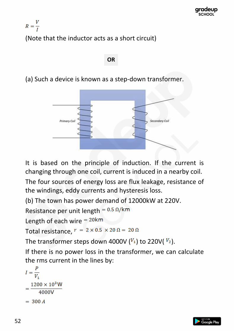
(a) Such a device is known as a step-down transformer.
It is based on the principle of induction. If the current is changing through one coil, current is induced in a nearby coil.
The four sources of energy loss are flux leakage, resistance of the windings, eddy currents and hysteresis loss.
(b) The town has power demand of 12000kW at 220V.
Resistance per unit length
Length of each wire
Total resistance,
The transformer steps down 4000V ( ) to 220V( ).
If there is no power loss in the transformer, we can calculate the rms current in the lines by:
OR

53
The power loss in the lines is
26. (a)
Consider two coherent sources of light S1 and S2. The two sources of light will produce an interference pattern on the screen GG’. Consider a point P on the screen. Let be the phase difference due to the path difference S2P - S1P.

54
The electric filed from the light at each of the sources S1 and S2 can be written as,
where each source of light has maximum electric filed strength
.
At P, by principle of superposition,
As intensity is the square of the amplitude,
Note that . Hence,
(b) Given,
Size of aperture,
Wavelength of light,
Distance from screen,
Distance of first order minima from centre = 𝑥1 =𝜆𝐷
𝑎
Distance of third order maxima from the centre = 𝑥2 =7𝐷𝜆
2𝑎
Distance between third order maxima and first order minima
= 𝑥2 − 𝑥1
=7𝐷𝜆
2𝑎−
𝜆𝐷
𝑎=
5𝐷𝜆
2𝑎
=5×1.5×620×10−9
2×3×10−3 = 7.75 × 10⁻⁴𝑚
(a) The conditions for total internal reflection are:
OR

55
(i) Light must be trying to travel from optically denser medium to optically rarer medium.
(ii) The angle of incidence must be greater than a certain angle known as critical angle.
Derivation:
Suppose light is travelling from medium 1 to medium 2. When light strikes the surface separating the media, some of it refracts and some of it reflects. If we keep increasing the angle of incidence, the refracted ray becomes parallel to the surface. This value of angle of incidence is known as the critical angle. If we increase the angle of incidence, even further, we will have a reflected ray and no refracted ray. Thus, we will have total internal reflection.
Let us consider the condition when the angle of incidence is equal to critical angle, .
By Snell’s law,
where and are the refractive indices of medium 1 and medium 2 respectively. Let be the refractive index of 1 with respect to 2.
Thus, we have obtained the required relation.

56
(b) Concepts/Formulas used:
The lens equation:
The lens formula is:
where f is the focal length, u is the object distance and v is the image distance. All quantities are measured with the cartesian sign convention (the sign convention in NCERT).
Let us consider the lenses one by one.
The first lens forms an image of the given object.
Here,
Object distance,
Focal length,
Using the lens equation,
The image I1 formed by the first lens acts as an object for the second lens.
Here,
Object distance,
Focal length,
57
Let us now consider the third lens. It is a converging lens as it has a positive focal point. An object at infinity would have its image at the focal point (either of the focal points as the object is in either direction).
Hence, the final image is formed at 30cm from the third lens at either side.
27. (a) Suppose an uncharged capacitor of capacitance is connected in series with a switch and a battery of emf . The switch is initially open. Then, the switch is closed at . Initially, the capacitor acts as a short circuit. The current flows and deposits charge in the capacitor. The plate with the positive terminal of the battery loose electron and the other plate gains electron. Due to this build-up of charges, potential difference across the capacitor build up. When this potential difference is equal to the emf of the battery, the capacitor is said to be fully charged and the capacitor acts like an open switch.
At time t, the capacitor has charge . Let the potential difference across the plates be given by:
A small charge is being transferred from one plate to another. The work in this process is given by:
Integrating, we get

58
Using ,
This work done is stored as energy on the capacitor.
(b) Let the capacitance of the capacitor be .
The energy stored by the capacitor when it is charged is given by:
The charge on the capacitor is
Now, when the capacitor is connected to the other capacitor, they both get the same charge in equilibrium by symmetry. As the total charge remains the same, the charge on each capacitor is
Now, the energy stored is
The ratio is:

59
Let charges and be separated by a distance . Let point P be any point on the equatorial line of the dipole. Let it be a distance form the line joining the two charges.
Now,
The electric field at P due to the charges is:
The vertical components will cancel out. We need to add the horizontal components. Hence,
Let be the unit vector in the direction of the dipole moment (from positive charge to negative charge).
Now, by trigonometry,
OR

60
If ,
(b) All charges must be in equilibrium. As the coulomb force
depends upon distance and by symmetry, the charge Q must be in the middle of the two charges. For the forces to balance on the q’s, Q must have opposite sign to that of q.

61
2.
Brewster angle (θp) is given to be 60˚.
Brewster law states that the tangent of the polarizing angle of incidence (Brewster angle) of a transparent medium is equal to the refractive index of the medium.
Mathematically,
Where, =Brewster’s angle
=relative refractive index of denser medium with respect to rarer medium
Now,
(since the medium is air)
Solutions (Set-2)
62
4.
We know that
Where,
E=electric field
l=length of the conductor
And force on an electron is given by,
where, e=charge on electron
V=electric potential
We know that
Equating the above two equations we get,
Using 1st equation of motion
where = drift velocity
Here, u=0
t= relaxation time

63
Since e, V, m, l are constant.
∴ vd ∝ t
5. For positive point charge,
As the electric field due to an isolated charge is given by
where,
From the equation we can see that electric field decreases with increase in radius.
For equipotential surface the distance of spheres from point charge increases as E decreases.
For negative point charge,
6. The major establishment from the photoelectric effect was, light also shows particle nature.

64
a. Einstein said that, light consists of photons (small packets of energy). When a beam of photons interacts with electron, then it no longer exists after transferring all the energy to electron and is used to knock out the electron.
Some amount of energy is used as Work function is used and rest is converted into kinetic energy of electron
where,
hν =energy of proton
h=Planck’s constant
frequency of proton
=work function
=kinetic energy of electron
b. Greater intensity has no effect on kinetic energy of an electron. This cannot be explained by wave theory. Also wave theory cannot explain the existence of threshold energy too.
7. Deuteron(+e,2mp)
-particle(+2e,4mp)
Deuteron has charge of +e and mass 2mp where mp is the mass of proton.
-particle has charge of +2e and mass 4mp.
We know that force on a charged particle due to magnetic field is given by
where, q=charge
v=velocity
B=magnetic field

65
v and B are perpendicular in this case
Since here because
..........(1)
We can observe the trajectory is circular due to centrifugal force
Fc whose magnitude is given by
...........(2)
Equating 1 and 2
Rearranging we get,
Since momentum p=mv
Now,
For -particle
where q=2e
so,
For Deuteron
where q=e
so,
Now according to question,

66
11. a. Before plotting the graph, we should know the relation between accelerating potential and de-Broglie wavelength.
According to de-Broglie,
where, p=momentum
h=Planck’s constant
λ=wavelength of the matter
Squaring both sides multiplying on both sides.
.......(1)
As we know the kinetic energy gained by the particle is due to accelerating potential.
The energy gain is given by, .............(2)
where V= accelerating potential
Equating 1 and 2
............. (3)
where c=

67
This type of equation gives hyperbolic graph,
b. According to question all three particles electron, proton and alpha particle have the same kinetic energy. Hence kinetic energy is constant.
Also, from equation (3)
we can establish that,
Since qV is the gain in kinetic energy so we can write it as K.E
Therefore, now since the electron has the lowest mass, so λ for an electron is maximum followed by proton then alpha particle.
So, has the shortest wavelength.
13. (a) The underlying principle for the working of a moving coil galvanometer is that when a current-carrying conductor is placed inside a magnetic field, it experiences magnetic force. When the coil is suspended in uniform magnetic field it experiences torque. Due to this the coil rotates and hence the

68
deflection in the coil of the moving coil galvanometer is directly proportional to the current flowing through the coil.
(b)A galvanometer cannot as such be used to measure the value of the current in a given circuit because
i. A galvanometer is very sensitive device. It gives full scale deflection even for current of small orders (like some microamperes). Hence it will not measure the current of higher orders if connected as such in the circuit.
ii. A galvanometer offers large resistance and it is connected in series in the circuit. Hence, the change in the value of current in the circuit can be measured by increasing the resistance of the circuit.
(c)(i) voltage sensitivity –voltage sensitivity is defined as the deflection of the coil of a moving coil galvanometer when a unit potential difference is applied across the two terminals of the galvanometer.
voltage sensitivity,
where I=current
R=resistance of galvanometer
(ii) current sensitivity - The current sensitivity is defined as the deflection of the coil of a moving coil galvanometer when a unit current flow through it.
current sensitivity,

69
15. a.
Here
As,
For equipotential surfaces where E is increasing uniformly d should decrease uniformly.
The equipotential surfaces will be parallel to x-y plane.
b.
Electric potential at (0,0, +z)
Electric potential at (0,0, +z) due to –q charge,
where, and r=z+a
Electric potential at (0,0, +z) due to +q charge,

70
where, and r=z-a
Therefore, net potential,
At (x, y,0) and as xy plane is denoted by z=0, the distance for –q and +q will be same at xy plane.
xy plane is equipotential surface with magnitude 0.
17. (a) We know that in radioactive decay
... (1)
where N(t)=no. of particles after t time
N0=no. of particles in starting of radioactive decay
λ= decay constant
Half-life of a radioactive substance is defined as the time taken
for the substance to reduce to /2.
Taking log on both sides,
And theory of average life is,
71
where, S is sum of all particle lives which were there during the period t to t+dt
Therefore, sum of lives of
As,
As,
(b)
Initially for A no. Of particles is No and for B 2No
And half-life of A is 60 years, 30 years for B.
Decay constant of A =
And Decay constant of B =
Using the eq. Of radioactive decay
i.e.
According to question for A after some time no. Of particles of A becomes as twice of no. Of particles of B

72
And
Dividing both equations, we get
Taking log both sides, we get
Substituting the value of decay constant of A and B respectively we get
19. Self-inductance-
Where,
𝞍=magnetic flux
I=current flowing
where L=coefficient of self-inductance.
When I= 1A
So, from general understanding, we can say that self-inductance is related to the magnetic flux of a coil when the unit current is flowing through it.
In other words, self-inductance is the emf induced in the coil when the rate of change of current in the coil is 1ampere/second.

73
S.I. unit of self-inductance is Henry(H).
b.
We know the magnetic field due to an infinitely long current-carrying wire is given by
where H/m
i = current carried by infinite wire
r = perpendicular distance of wire to the point
Force on a straight wire is given by,
Using right-hand rule, we can find the direction of the magnetic field for I1.
According to Fleming's right-hand rule, the thumb, forefinger and middle finger of the right hand are stretched perpendicular to each other as shown in the illustration shown below, and if the thumb represents the direction of the movement of conductor, fore-finger represents direction of the magnetic field, then the middle finger represents direction of the induced current.

74
In the square magnetic field is acting in the downward direction.
Now, for side AB l is +y direction, B is downward, is in x-direction and magnitude of the force is,
⇒
in –ve x-direction.
As for BC and AD forces are equal but opposite in direction so they will cancel out each other.
And for side CD, l is -y-direction, B is downward, is in +x direction and magnitude of the force is,
⇒
in +ve x-direction.
So, net force will be in –ve x-direction,

75
1. We know light is an electromagnetic wave whose direction of
propagation is perpendicular to magnetic field and electric field and they both are also mutually perpendicular.
So, a light wave may have direction of its electric field and magnetic field changing i.e. they are vibrating in more than one direction.
This is because the source of the electromagnetic wave that is vibrating charges, which is vibrating in a variety of directions hence their electric field and magnetic field is regularly and alternately changing.
And almost all the light sources generate unpolarized light in which electric and magnetic fields vibrates in almost all directions.
And when the direction of vibration of electric field and magnetic field are restricted to one plane then it is called plane polarized light.
And the process of converting unpolarized light into a polarized light is known as polarization.
It can be achieved through various methods
i-Polarization by reflection
ii-Polarization by refraction
iii-Polarization by scattering
Solutions (Set-3)
76
3.
We know that
Where,
E=electric field
l=length of the conductor

77
And force on an electron is given by,
where, e=charge on electron
V=electric potential
We know that
Equating the above two equations we get,
Using 1st equation of motion
where = drift velocity
Here, u=0
t= relaxation time
Since e, V, m, l are constant.
Increasing the temperature will increase the kinetic energy of electrons. As kinetic energy will increase the collisions will increase and hence relaxation time will decrease and since relaxation time is directly proportional to drift velocity hence drift velocity will also decrease.

78
5.
One side of conducting plate will have –ve charge induced at one surface of plate because of +ive charge q and the electric field lines will be perpendicular to the surface because the surface is equipotential and as the plate was uncharged at starting to maintain the neutrality of conducting plate +ive charge will be induced on the other side of plate.
6. (a)(i) Threshold frequency- Threshold frequency is defined as the minimum frequency that is required for emission of electrons from a metal surface when electromagnetic radiation falls on the metal surface.
(ii)Stopping potential-
Stopping potential is the necessary potential applied externally to prevent the most energetic electron from reaching the endplate.
(b) Explanation:
79
The starting point of both lines is from the same –ve potential that is also called as stopping potential and defined as the smallest magnitude of the anode potential which just stops photocurrent is called as stopping potential.
Mathematically
Work done by external voltage and this should be equal the Kinetic energy of electron which just fails to reach anode
whose K.E will be given as
Where is the work function of metal.
Equating it we get
We can see the stopping potential doesn’t depend upon the intensity of light rather depends only on the wavelength of light and work function of the metal.
And saturation current for higher intensity of light is more as the number of photons falling on the metal plate per unit area increases, which consequently allows more electrons to escape from the metal surface
11. As de Broglie suggested that the wavelength of a matter is
associated with its momentum as

80
Where P is the momentum of matter (mv)
And h is Planck’s constant i.e.
The velocity of an electron following Bohr model is given by
Where Z is the atomic number of hydrogen-like species
And n is the orbit in which the electron is revolving
Speed of electron in 2nd excited state will be
As Z = 1
And n =3
So, momentum in a 2nd excited state will be
P= mv
Therefore then,
Now for 3rd excited state
Speed of electron in a 3rd excited state will be
As Z = 1
And n =4
So, momentum in a 3rd excited state will be
P= mv

81
So,
12. As we know the force on a charged particle in a magnetic field
is given by
Where q = charge of the particle,
v = velocity of particle and B is the magnetic field in that region.
The force exerted on a charged particle in a magnetic field only exist if the velocity of the particle is perpendicular to the direction of the magnetic field as the equation suggest.
If velocity has a component along B, this component remains unchanged as the motion along the magnetic field will not be affected by the magnetic field. The motion in a plane perpendicular to B is as before a circular one, thereby producing a helical motion
Thus, the described path will be helical as shown in the figure and the velocity's parallel component will make the particle move along the direction of the field.

82
13. a) In Rutherford famous gold foil experiment most of the -particle pass through the foil undeflected signifying most of the space inside the atom should be empty, and many of them get deflected by a very small angle implying that the nature of the charge inside the atom (nucleus) that is located at the
center of the atom should be the same as the -particles i.e.
positive. Out of 10000 -particle, one of them gets deflected for almost 1800 that means the particles retraces its path telling something very dense is situated at the center of the atom.
b) Let the volume of the nucleus be V the mass of the nucleus be M and the mass of nucleus be m
we know the volume of the sphere is
and density ( )
As we know where r0 lies in between 1.2 fermis to 1.5 fermi
(mass of nucleus)
As we know the mass of the nucleus is A times mass of nucleons (m)
Equating mass of nucleus, we get
We can see that nuclear density is independent of mass number (A)

83
14.
Principle- Cyclotron is a device that works on the principle that a charged particle moving with a certain velocity in a direction perpendicular to the magnetic field experience Lorentz force, as a result, the particle describes a circular motion.
A charged particle can be accelerated to very high energy by making it pass through a moderate electric field a number of times. This can be done with the help of perpendicular magnetic field which throws the charged particle into the circular motion, the frequency of which does not depend on the speed of the particle and radius of the circular orbit.
The combination of the crossed; electric and magnetic field is used to increase the energy of charged particle. Cyclotron uses the fact that the frequency of revolution of the charged particle in a magnetic field is independent of its energy.
Inside the Dees, the particle is shielded from the electric field and magnetic field acts on the particle and makes it move in circular path.
Every time the particle moves from one Dee to another Dee, it comes under the influence of electric field which ensures increase of energy of the particle as the sign of electric field changes alternately.
The increased energy increases due to radius of the circular path. So accelerated particles move in spiral path.

84
Working-When a positive charge q of mass m is emitted from the source it is accelerated towards the Dee having a negative potential .Due to normal magnetic field, the ions experiences magnetic force and moves in a circular path .When the charged particle arrives at the gap between the Dee the polarities of the Dee changes and the in the gap the charged particles gains extra velocity and is then transferred to the another Dee making a circular path with a greater radius. In this way the charged particles keep moving in the two Dees each time increasing in velocity and radius of path. When it reaches its maximum radius, the charged particle comes out of the Dee with high velocity and hits the deflection plate T.
Suppose the charge on the positive ion is +q, its mass ‘m’ and strength of magnetic field is B.
Let, at any time, the radius of circular path is ‘r’ and speed of positive ion is ‘v’.
Then, equating the Lorentz’s force and centripetal force we get,
time taken to complete circle of radius ‘r’ is,
Substituting the value of r, we get,
⇒
We know that, T= . So, substituting the value in above equation we get,

85
This is the required expression.
15. We know the force per unit length on two infinitely current-
carrying wires if given by
Where Ia is current-carrying by wire A and Ib respectively
And d is the distance between parallel wires.
Force per unit length on wire A3 due to A1 In –ve x-direction
And Force per unit length on wire A3 due to A2
In +ive x direction
So, for no net force on A3 both equations should be equal
at x = the net force on A3 will be zero.
Also, the net force acting on A3 depends upon the magnitude of the current flowing through it as we can conclude through the formula. However, its direction doesn’t affect our answer because one of A1 or A2 will cancel the effects produced by the wire A3.

86
16. (a) A pair of two charges equal in magnitude and opposite in signs separated by a very small distance is known as an electric dipole.
For equipotential surfaces where E is increasing uniformly d should decrease uniformly that's why the equipotential surfaces are compactly arranged closer to the charges and we can see that the electric field lines are always perpendicular to the equipotential surface.
(b) Solution:
we know that the electric field is given by,
Here, r=
and
From the figure, we can see that the sine components get mutually cancelled and the cosine components can be added.
Now we get,

87
Since magnitudes are same,
.......(1)
Now,
Substituting the values in equation 1 we get,
Now dipole moment =2qa
Now
So, a can be eliminated in the denominator.
This is the required equation and the direction of the electric
field will be opposite to the direction of the electric dipole.


