Embed Size (px)
Citation preview

This document consists of 17 printed pages and 3 blank pages.
DC (NF/SW) 24990/4© UCLES 2010 [Turn over
UNIVERSITY OF CAMBRIDGE INTERNATIONAL EXAMINATIONSInternational General Certificate of Secondary Education
*3428909673*
PHYSICS 0625/31
Paper 3 Extended October/November 2010
1 hour 15 minutes
Candidates answer on the Question Paper.
No Additional Materials are required.
READ THESE INSTRUCTIONS FIRST
Write your Centre number, candidate number and name on all the work you hand in.Write in dark blue or black pen.You may use a pencil for any diagrams, graphs or rough working.Do not use staples, paper clips, highlighters, glue or correction fluid.DO NOT WRITE IN ANY BARCODES.
Answer all questions.You may lose marks if you do not show your working or if you do not use appropriate units.Take the weight of 1 kg to be 10 N (i.e. acceleration of free fall = 10 m / s2).
At the end of the examination, fasten all your work securely together.The number of marks is given in brackets [ ] at the end of each question or part question.
www.theallpapers.com

2
0625/31/O/N/10© UCLES 2010
1 An object of weight W is suspended by two ropes from a beam, as shown in Fig. 1.1.
60°
W
86.6 N
50.0 N30°
Fig. 1.1
The tensions in the ropes are 50.0 N and 86.6 N, as shown.
(a) In the space below, draw a scale diagram to find the resultant of the two tensions.
Use a scale of 1.0 cm = 10 N.
Clearly label the resultant. [3]
www.theallpapers.com

3
0625/31/O/N/10© UCLES 2010 [Turn over
(b) From your diagram, find the value of the resultant.
resultant = ......................................................... [1]
(c) State the direction in which the resultant is acting.
............................................................................................................................................. [1]
(d) State the value of W. W = ......................................................... [1]
[Total: 6]
2 A car travels around a circular track at constant speed.
(a) Why is it incorrect to describe the circular motion as having constant velocity?
............................................................................................................................................. [1]
(b) A force is required to maintain the circular motion.
(i) Explain why a force is required.
...........................................................................................................................................
...........................................................................................................................................
..................................................................................................................................... [2]
(ii) In which direction does this force act?
..................................................................................................................................... [1]
(iii) Suggest what provides this force.
..................................................................................................................................... [1]
[Total: 5]
www.theallpapers.com

4
0625/31/O/N/10© UCLES 2010
3 Fig. 3.1 shows a hydraulic lift in a car repair workshop.
hydraulic fluid
4 pistons, eachof area 0.02 m2
piston A, area 0.01 m2
car support
Fig. 3.1
The hydraulic fluid transmits the pressure, caused by piston A, equally to each of the four pistons holding up the car supports. The pressure throughout the fluid is the same.
A force of 1000 N on piston A is just enough to raise the car.
(a) Using values from Fig. 3.1, find
(i) the pressure caused by piston A on the fluid,
pressure = ......................................................... [2]
(ii) the total upward force caused by the fluid.
force = ......................................................... [3]
www.theallpapers.com

5
0625/31/O/N/10© UCLES 2010 [Turn over
(b) The weight of each of the two car supports is 1000 N.
Calculate the mass of the car.
mass = ......................................................... [2]
[Total: 7]
www.theallpapers.com
6
0625/31/O/N/10© UCLES 2010
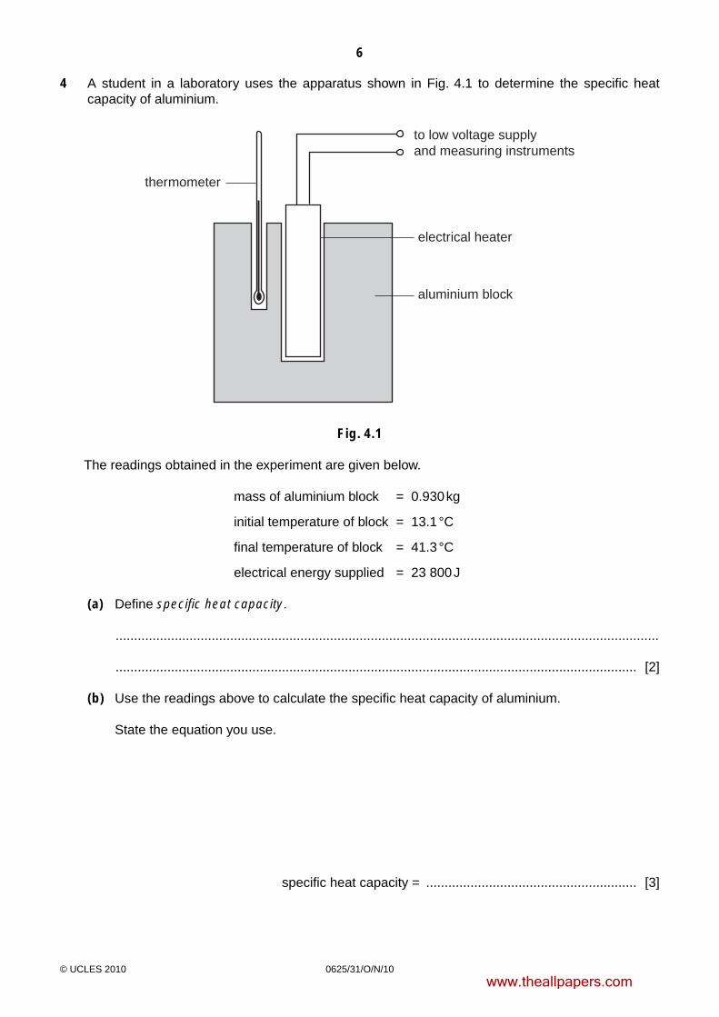
4 A student in a laboratory uses the apparatus shown in Fig. 4.1 to determine the specific heat capacity of aluminium.
to low voltage supplyand measuring instruments
electrical heater
thermometer
aluminium block
Fig. 4.1
The readings obtained in the experiment are given below.
mass of aluminium block = 0.930 kg
initial temperature of block = 13.1 °C
final temperature of block = 41.3 °C
electrical energy supplied = 23 800 J
(a) Define specific heat capacity.
...................................................................................................................................................
............................................................................................................................................. [2]
(b) Use the readings above to calculate the specific heat capacity of aluminium.
State the equation you use.
specific heat capacity = ......................................................... [3]
www.theallpapers.com
7
0625/31/O/N/10© UCLES 2010 [Turn over
(c) Because the student knows it is good scientific practice to repeat readings, after a short time he carries out the experiment again, supplying the same quantity of electrical energy.
This time the temperature readings are:
initial temperature of block = 41.0 °C
final temperature of block = 62.1 °C
(i) Use these figures to calculate a second value for the specific heat capacity of aluminium.
specific heat capacity = ......................................................... [1]
(ii) The student did not make any mistakes when taking the readings.
Suggest why the second value for the specific heat capacity of the aluminium is greater than the first.
...........................................................................................................................................
..................................................................................................................................... [2]
(d) Suggest two ways of improving the experiment in order to give as accurate a result as possible.
1. ...............................................................................................................................................
...................................................................................................................................................
2. ...............................................................................................................................................
.............................................................................................................................................. [2]
[Total: 10]
www.theallpapers.com
8
0625/31/O/N/10© UCLES 2010
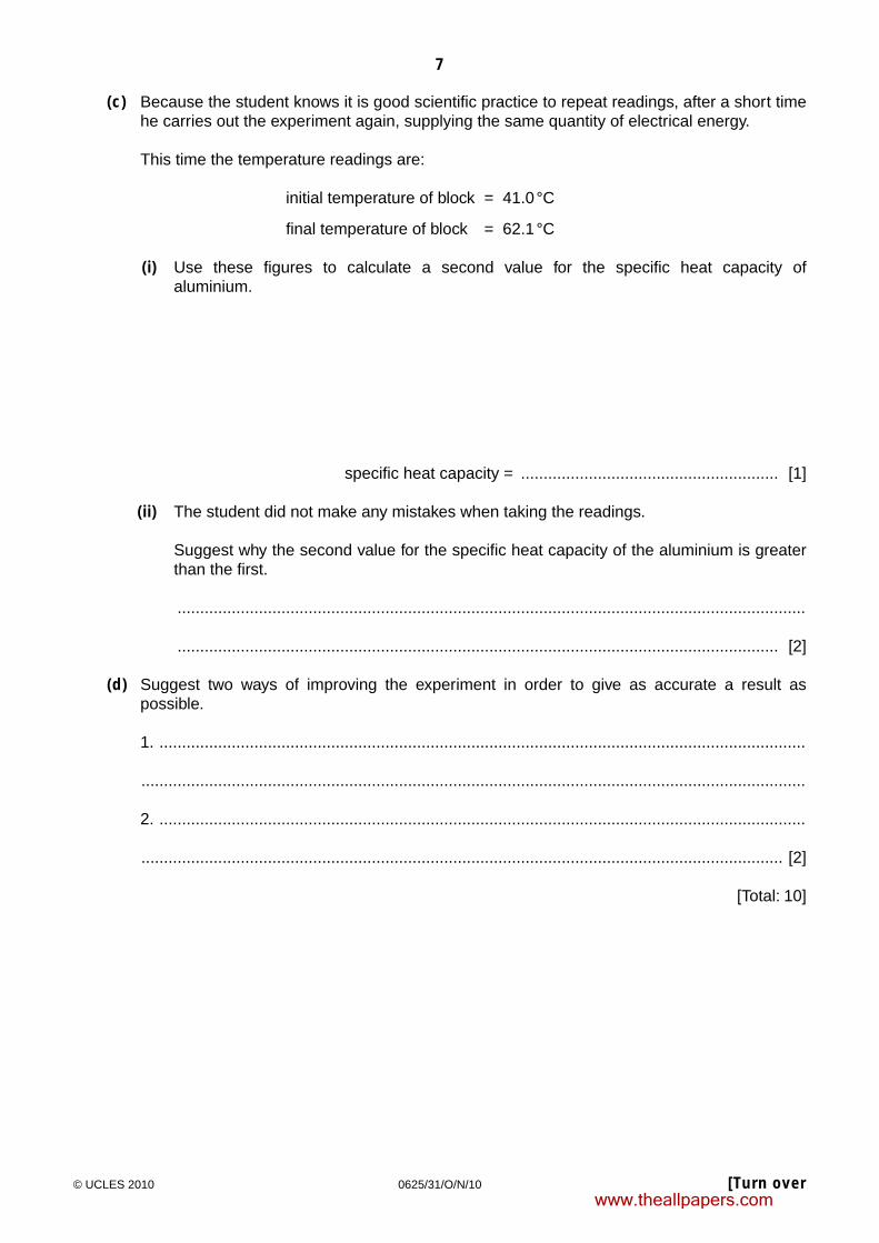
5 Fig. 5.1 shows a model cable-car system. It is driven by an electric motor coupled to a gear system.
2.0 m
6.0 m
gears
electricmotor
modelcable-carsmooth
pulley
Fig. 5.1
The model cable-car has a mass of 5.0 kg and is lifted from the bottom pulley to the top pulley in 40 s. It stops automatically at the top.
(a) Calculate
(i) the average speed of the cable-car,
average speed = .......................................................... [2]
(ii) the gravitational potential energy gained by the cable-car,
gravitational potential energy gained = .......................................................... [2]
www.theallpapers.com

9
0625/31/O/N/10© UCLES 2010 [Turn over
(iii) the useful output power of the driving mechanism.
power = ......................................................... [2]
(b) How would the electrical power input to the motor compare with your answer to (a)(iii)?
............................................................................................................................................. [1]
[Total: 7]
www.theallpapers.com

10
0625/31/O/N/10© UCLES 2010
6 Fig. 6.1 shows part of the path of a ray of light PQ travelling in an optical fibre.
glass
P
R
Q
Fig. 6.1
PQ undergoes total internal reflection at Q.
(a) Explain what is meant by total internal reflection, and state the conditions under which it occurs.
...................................................................................................................................................
...................................................................................................................................................
...................................................................................................................................................
...................................................................................................................................................
............................................................................................................................................. [3]
(b) Carefully complete the path of the ray of light, until it reaches the end R of the optical fibre. [2]
[Total: 5]
www.theallpapers.com

11
0625/31/O/N/10© UCLES 2010 [Turn over
7 (a) The following list contains the names of types of energy transfer by means of waves.
γ-rays, infra-red, radio/TV/microwaves, sound, visible light, X-rays
(i) Which one of these is not a type of electromagnetic wave?
..................................................................................................................................... [1]
(ii) State the nature of the wave you have named in (a)(i).
..................................................................................................................................... [1]
(iii) The remaining names in the list are all regions of the electromagnetic spectrum, but one region is missing.
Name the missing region.
..................................................................................................................................... [1]
(b) A television station emits waves with a frequency of 2.5 × 10⁸ Hz. Electromagnetic waves travel at a speed of 3.0 × 10⁸ m / s.
Calculate the wavelength of the waves emitted by this television station. State the equation you use.
wavelength = ......................................................... [3]
[Total: 6]
www.theallpapers.com
12
0625/31/O/N/10© UCLES 2010
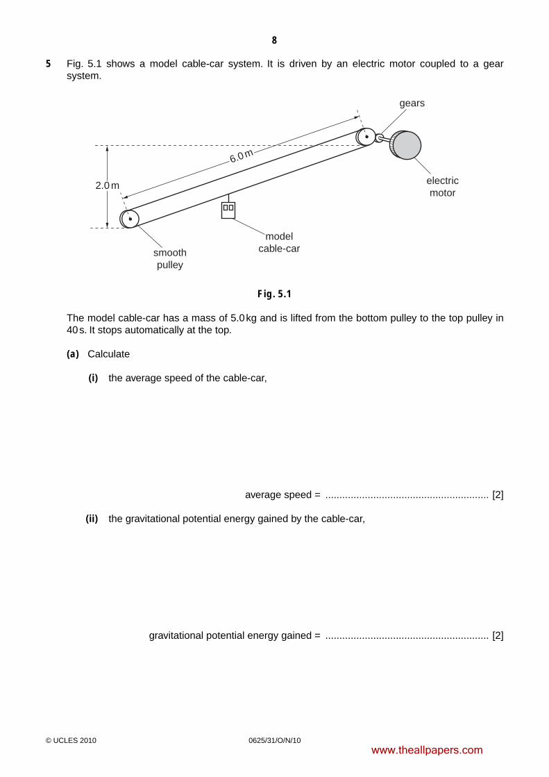
8 The circuit in Fig. 8.1 contains a 2.0 V cell, whose resistance you should ignore. There are also three resistors, a 3-position switch, an ammeter and another component, P.
20.0
5.0
SA
B
C
P
2.0 V
A
Fig. 8.1
(a) State the name of component P. .......................................................... [1]
(b) Deduce the resistance of the circuit when switch S is
(i) in position A,
resistance = ......................................................... [1]
(ii) in position B.
resistance = ......................................................... [3]
www.theallpapers.com

13
0625/31/O/N/10© UCLES 2010 [Turn over
(c) Describe and explain what is seen on the ammeter when S is moved to position C.
...................................................................................................................................................
...................................................................................................................................................
...................................................................................................................................................
............................................................................................................................................. [2]
(d) With S in position A, calculate how long it takes for the circuit to transfer 320 J of electrical energy to other forms.
time taken = ......................................................... [3]
[Total: 10]
www.theallpapers.com

14
0625/31/O/N/10© UCLES 2010
BLANK PAGE
www.theallpapers.com

15
0625/31/O/N/10© UCLES 2010 [Turn over
9 In Fig. 9.1, A and B are two conductors on insulating stands. Both A and B were initially uncharged.
A B
X Y
Fig. 9.1
(a) Conductor A is given the positive charge shown on Fig. 9.1.
(i) On Fig. 9.1, mark the signs of the charges induced at end X and at end Y of conductor B. [1]
(ii) Explain how these charges are induced.
...........................................................................................................................................
...........................................................................................................................................
..................................................................................................................................... [3]
(iii) Explain why the charges at X and at Y are equal in magnitude.
...........................................................................................................................................
...........................................................................................................................................
..................................................................................................................................... [1]
(b) B is now connected to earth by a length of wire.
Explain what happens, if anything, to
(i) the charge at X,
...........................................................................................................................................
..................................................................................................................................... [1]
(ii) the charge at Y.
...........................................................................................................................................
..................................................................................................................................... [2]
[Total: 8]
www.theallpapers.com

16
0625/31/O/N/10© UCLES 2010
10 Emissions from a radioactive source pass through a hole in a lead screen and into a magnetic field, as shown in Fig. 10.1.
3 cm
C
B
magnetic fieldinto paper
radioactivesource
leadscreen
A
Fig. 10.1
Radiation detectors are placed at A, B and C. They give the following readings:
A B C
32 counts / min 543 counts / min 396 counts / min
The radioactive source is then completely removed, and the readings become:
A B C
33 counts / min 30 counts / min 31 counts / min
(a) Explain why there are still counts being recorded at A, B and C, even when the radioactive source has been removed, and give the reason for them being slightly different.
...................................................................................................................................................
...................................................................................................................................................
...................................................................................................................................................
............................................................................................................................................. [2]
www.theallpapers.com

17
0625/31/O/N/10© UCLES 2010 [Turn over[Turn over
(b) From the data given, deduce the type of emission being detected, if any, at A, at B and at C when the radiation source is present.
State the reasons for your answers.
detector at A .............................................................................................................................
...................................................................................................................................................
............................................................................................................................................. [2]
detector at B .............................................................................................................................
...................................................................................................................................................
............................................................................................................................................. [3]
detector at C .............................................................................................................................
...................................................................................................................................................
............................................................................................................................................. [3]
[Total: 10]
www.theallpapers.com

18
0625/31/O/N/10© UCLES 2010
11 When no circuit is connected to the input of a cathode-ray oscilloscope (CRO), there is a horizontal trace across the middle of the screen.
Fig. 11.1 shows three circuits, each connected to a CRO.
On the grid alongside each circuit, draw the trace that might be seen on the screen of the CRO.
battery CRO+
–
a.c. supply
a.c. supply
CRO
CRO
[6]Fig. 11.1
[Total: 6]
www.theallpapers.com

19
0625/31/O/N/10© UCLES 2010
BLANK PAGE
www.theallpapers.com

20
0625/31/O/N/10© UCLES 2010
Permission to reproduce items where third-party owned material protected by copyright is included has been sought and cleared where possible. Every reasonable effort has been made by the publisher (UCLES) to trace copyright holders, but if any items requiring clearance have unwittingly been included, the publisher will be pleased to make amends at the earliest possible opportunity.
University of Cambridge International Examinations is part of the Cambridge Assessment Group. Cambridge Assessment is the brand name of University of Cambridge Local Examinations Syndicate (UCLES), which is itself a department of the University of Cambridge.
BLANK PAGE
www.theallpapers.com