Embed Size (px)
Citation preview
Hardware Manual
Rx Only
Physician ProgrammerFor Medtronic Neurological Neurostimulators
7432
195232_e_004.qxd 12/21/01 11:18 AM Page 1

195232_e_004.qxd 12/21/01 11:18 AM Page 2

Contents
Introduction. . . . . . . . . . . . . . . . . . . . . . 1Warning . . . . . . . . . . . . . . . . . . . . . . . 2Precautions . . . . . . . . . . . . . . . . . . . . 2
Programming System Description . . . . 4Programmer Console Displays . . . . . . 4
Lower Display . . . . . . . . . . . . . . . . 5Upper Display . . . . . . . . . . . . . . . . 5Viewing Angle and ContrastAdjustment. . . . . . . . . . . . . . . . . . . 6
Keyboard Functions . . . . . . . . . . . . . . 7
Setting Up the System . . . . . . . . . . . . . 8
Battery Information. . . . . . . . . . . . . . . . 12Programmer Console Batteries. . . . . . 12Printer Batteries . . . . . . . . . . . . . . . . . 15
Maintenance and HandlingInformation . . . . . . . . . . . . . . . . . . . . . . 18
Replacing the Printer Paper Roll. . . . . 18Replacing the Printer Ink Pen . . . . . . . 21Cleaning Instructions . . . . . . . . . . . . . 23Sterilization . . . . . . . . . . . . . . . . . . . . 23Service . . . . . . . . . . . . . . . . . . . . . . . 23
System Specifications . . . . . . . . . . . . . 24The Programmer Console . . . . . . . . . 26The Software Cartridge . . . . . . . . . . . 27The Programming Head . . . . . . . . . . . 28The Printer. . . . . . . . . . . . . . . . . . . . . 29The Carrying Case. . . . . . . . . . . . . . . 30
Glossary . . . . . . . . . . . . . . . . . . . . . . . . 31
Special Notice . . . . . . . . . . . . . . . . . . . . 32
Limited Warranty. . . . . . . . . . . . . . . . . . 33
195232_e_004.qxd 12/21/01 11:18 AM Page 3

195232_e_004.qxd 12/21/01 11:18 AM Page 4
Introduction
The Medtronic® Model 7432 Physician Programmer isdesigned for use by a physician to noninvasivelyprogram Medtronic neurostimulators. In addition tostimulation mode and parameter value programmingcapabilities, the physician programmer receives andprocesses telemetry signals transmitted from theneurostimulators. See the appropriate MemoryMod®
Software Cartridge technical manual for specificparameter and mode programming capabilities.
The physician programmer is an advancedmicroprocessor-based device with functions andoperations controlled by software contained withinplug-in cartridges called MemoryMod SoftwareCartridges. This interchangeable software featureallows the programmer console capabilities to beexpanded as new neurostimulators and programmingfunctions become available. New software cartridges
are easy to install and allow the physicianprogrammer to be kept current in a rapidly changingtechnical environment.
To accommodate the flexibility of the replaceablesoftware system, the technical instructions for theprogrammer are divided into two parts. The first partis this manual, which describes the programmersystem “hardware” and provides service informationfor changing the batteries, replacing the printer paper,etc. This manual is designed to fit in the programmerstorage case and should be kept with the system.
The second part is a separate technical manualsupplied with each software cartridge. The “software”manual describes specific applications and functionswhich are controlled by that particular softwarecartridge. Software cartridges are programmed byMedtronic and cannot be reprogrammed by the user.Refer to the appropriate software cartridge technicalmanual for specific instructions.
1
195232_e_004.qxd 12/21/01 11:18 AM Page 1

WarningDevice Compatibility—The Physician Programmermust be used only for programming the Medtronicneurostimulators listed as applicable units. A list ofapplicable model numbers is included in the softwarecartridge technical manual supplied with eachsoftware cartridge. The physician programmer is notcompatible with programmable devices made by othermanufacturers.
PrecautionsPreparation for Programming—Programmingshould be done only after careful study of theneurostimulator or system technical manual. Refer tothe neurostimulator or system technical manual fordetails of neurostimulator operation and a completelist of indications, contraindications, warnings, andprecautions.
Reprogramming—DO NOT make large changes inthe programmable parameters. Parameter changesshould be made gradually and in small increments orundesirable stimulation could result.
Operating Temperature—If the physicianprogrammer was transported or stored attemperatures above or below the specified operatingtemperature range (listed in “System Specifications”),the physician programmer should be allowed tostabilize at a temperature within the range specifiedbefore it is used for programming.
Programming Different Neurostimulator Models—The Model 7432 Physician Programmer must beturned off and turned back on before attempting toprogram a different neurostimulator model (forexample, if programming a Soletra Model 7426neurostimulator immediately after programming anItrel II Model 7424 neurostimulator). If theprogrammer is not turned off and on, the programmer
2
195232_e_004.qxd 12/21/01 11:18 AM Page 2
will display “NO TELEMETRY, POSITION HEAD ANDTRY AGAIN” and the software will not allow thedifferent neurostimulator to be programmed.
Programming Head Placement—If the programminghead is not properly aligned over the neurostimulator,programmed parameters may not change. Theprogramming head must be held steady over theneurostimulator for at least three seconds after thePROGRAM key is pressed.
3
195232_e_004.qxd 12/21/01 11:18 AM Page 3
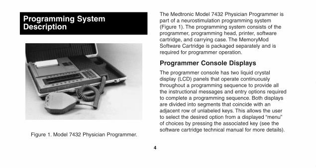
Figure 1. Model 7432 Physician Programmer.
The Medtronic Model 7432 Physician Programmer ispart of a neurostimulation programming system(Figure 1). The programming system consists of theprogrammer, programming head, printer, softwarecartridge, and carrying case. The MemoryModSoftware Cartridge is packaged separately and isrequired for programmer operation.
Programmer Console DisplaysThe programmer console has two liquid crystaldisplay (LCD) panels that operate continuouslythroughout a programming sequence to provide allthe instructional messages and entry options requiredto complete a programming sequence. Both displaysare divided into segments that coincide with anadjacent row of unlabeled keys. This allows the userto select the desired option from a displayed “menu”of choices by pressing the associated key (see thesoftware cartridge technical manual for more details).
4
Programming SystemDescription
195232_e_004.qxd 12/21/01 11:18 AM Page 4

The interaction of the upper and lower displays andthe associated keys will guide the user through acomplete programming sequence.
Lower Display
The lower display consists of two lines of 40characters each. During a programming sequence,this display typically shows instructional messages orprompts on the first line and a list of appropriatechoices on the second line. Graphics along the bottomborder of the display divide it into eight segmentswhich coincide with eight multi-function or “soft” keyslocated below the display. Some informational messagesrequire both lines of the display.
Upper Display
The top line of the upper display is designed primarilyto display the neurostimulator parameter values asobtained by telemetry. The appropriate parameterdesignations appear at fixed locations within theoutlined sections of the display. These sectionscoincide with the ten parameter selection keyslocated above the display. The lower line of the upperdisplay is used for prompts and selection messages.
5
195232_e_004.qxd 12/21/01 11:18 AM Page 5
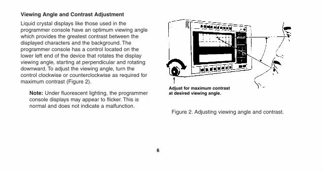
Viewing Angle and Contrast Adjustment
Liquid crystal displays like those used in theprogrammer console have an optimum viewing anglewhich provides the greatest contrast between thedisplayed characters and the background. Theprogrammer console has a control located on thelower left end of the device that rotates the displayviewing angle, starting at perpendicular and rotatingdownward. To adjust the viewing angle, turn thecontrol clockwise or counterclockwise as required formaximum contrast (Figure 2).
Note: Under fluorescent lighting, the programmerconsole displays may appear to flicker. This isnormal and does not indicate a malfunction.
Figure 2. Adjusting viewing angle and contrast.
6
Adjust for maximum contrastat desired viewing angle.
195232_e_004.qxd 12/21/01 11:18 AM Page 6

Keyboard FunctionsAll functions of the programmer console aremicroprocessor controlled according to the entriesmade on the programmer console keyboard.Functional layout of the keyboard (Figure 3) dividesthe keys into three groups as follows:
• ten keys across the top are used with the upperdisplay to select a parameter for programming
• eight keys across the bottom are used with thelower display to select the parameter value, orspecial function
• twelve dedicated function keys and the on/off keyto the right of the display are used to select orinitiate a specific function.
Note: Pressing an inactive key will not result inany programming or item selection.
Figure 3. Keyboard functional layout.
7
Upper Display Keys
Lower Display Keys
FunctionKeys
195232_e_004.qxd 12/21/01 11:18 AM Page 7

Setting Up the System
Figure 4. Inserting software cartridge.
To set up the physician programmer:
1. Install the programmer console batteries. Fordetailed instructions, refer to “Battery Information.”
2. Insert the software cartridge (Figure 4) so that thecartridge is flush with the body of the programmerconsole.
Note: The cartridge locking tab must face thefront of the programmer.
3. Plug the programming head cable into the RFHEAD socket on the top of the programmerconsole (Figure 5). The plug and jack are color-coded blue for easy identification.
8
MemoryMod®
SoftwareCartridge
CartridgeLocking Tab
195232_e_004.qxd 12/21/01 11:18 AM Page 8

Figure 5. Attaching programming head.
4. Press the Power ON/OFF key on the programmerconsole.
Note: The physician programmer has an ACadapter receptacle and AC/BATT switch. If theprogrammer console appears to be nonfunctional,ensure that this switch on the back of theprogrammer console is set to BATT.
5. Set the gain control switch located at the base ofthe programming head (Figure 6) to H (high). H isthe most sensitive setting and is optimum for mostsituations. If the “interference” message isdisplayed on the console, reduce the sensitivity byturning the gain control switch one positioncounterclockwise, toward L (low). If the “notelemetry” message is displayed, increase thesensitivity by turning the gain control switch oneposition clockwise, toward H.
9
BlueProgrammingHead (RF HEAD)Cable Outlet
Back of ConsoleProgrammer
Printer CableOutlet
Blue ProgrammingHead Cable Plug
195232_e_004.qxd 12/21/01 11:18 AM Page 9

Note: If adjustment of the gain control switchdoes not eliminate the effect of interference,identify and eliminate the source of interference.An alternative is to move the physicianprogrammer to a different location and reset thegain control switch to H (high).
Figure 6. Programming head.
6. Install the printer batteries. Batteries are packagedseparately inside the shipping package. Forinstructions on battery installation and replacement,refer to “Battery Information.”
7. Install the printer ink pen. Printer ink pens arestored in a plastic cylinder just above thebatteries. For information on printer ink peninstallation and replacement, refer to “Replacingthe Printer Ink Pen.”
8. Plug the printer cable into the PRINTER socket onthe top of the programmer console (Figure 7). Theplug and jack are color-coded gray for easyidentification.
Note: The programmer console may be operatedwithout the printer if no permanent record of aprogramming procedure is desired.
10
POSITIONHEADIndicator
REVIEWKey
RF Cable
Programming Head
PROGRAMKey
Gain ControlSwitch
195232_e_004.qxd 12/21/01 11:18 AM Page 10

Figure 7. Attaching printer.
9. Press ON/OFF on the printer (Figure 8).
Note: The physician programmer has an ACadapter receptacle and AC/BATT switch. If theprinter appears to be nonfunctional, ensure thatthis switch on the side of the printer is set toBATT.
Figure 8. Printer.
10. Press the function key PRINTER ON/OFF on theprogrammer console to enable the print function.
11
ProgrammingHead Cable Outlet
Gray PrinterCable Outlet
Gray PrinterCable PlugBack of the
Programmer Console
Controls:• ON/OFF• PAPER
ADVANCE• PEN
CHANGE
Paper Supply
Power On Indicator
Battery Compartment
AuxiliaryReceptacle
PrinterCable
195232_e_004.qxd 12/21/01 11:18 AM Page 11
Programmer Console BatteriesAlways replace all three programmer consolebatteries at the same time with 9-volt alkalinebatteries (Energizer 522 or equivalent). Thesebatteries, when fresh, should last through at least 200full programming transmissions.
When the batteries near depletion, the messagePROGRAMMER BATTERIES LOW appears briefly onthe lower display. When this message first appears,the batteries should have enough power to lastthrough 20 more full programming transmissions. Ifbattery voltage drops further, to the point wherecomplete battery depletion is imminent, the messageBATTERY CHANGE REQUIRED appears on thelower display. Except for a power off keystroke, theprogrammer console will not respond to commands
when this message appears. The batteries must bechanged to restore programmer console function.
To change the programmer console batteries:
1. Remove the battery access panel (Figure 9) bysliding it in the direction of the programmerconsole bottom as shown. Slide the panelcompletely free of the programmer console.
#Caution: Do not rest the programmer console onits left end when changing the batteries because itmay damage the viewing angle and contrastcontrol.
Battery Information
12
195232_e_004.qxd 12/21/01 11:18 AM Page 12

Figure 9. Removing battery access panel.
2. Remove the three depleted batteries and installthree new batteries electrode end first (Figure 10).
Note: Polarity need not be observed whenbatteries are installed. The programmer consoleadjusts automatically to the polarity of theinstalled batteries.
3. Replace the battery access panel by inserting thesmooth end (with arrowhead) into the grooves inthe programmer console case. Press each of thebatteries into the programmer console whilesliding the panel to its closed position.
13
BatteryAccessPanel
195232_e_004.qxd 12/21/01 11:18 AM Page 13

Figure 10. Inserting programmer console batteries.
4. Verify programmer console operation with the newbatteries by pressing the Power ON/OFF key onthe programmer console.
Note: The physician programmer has an ACadapter receptacle and AC/BATT switch. If theprogrammer console appears to be nonfunctional,ensure that this switch on the back of theprogrammer console is set to BATT.
14
Batteries (3)
195232_e_004.qxd 12/21/01 11:18 AM Page 14
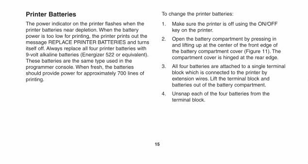
Printer BatteriesThe power indicator on the printer flashes when theprinter batteries near depletion. When the batterypower is too low for printing, the printer prints out themessage REPLACE PRINTER BATTERIES and turnsitself off. Always replace all four printer batteries with9-volt alkaline batteries (Energizer 522 or equivalent).These batteries are the same type used in theprogrammer console. When fresh, the batteriesshould provide power for approximately 700 lines ofprinting.
To change the printer batteries:
1. Make sure the printer is off using the ON/OFFkey on the printer.
2. Open the battery compartment by pressing inand lifting up at the center of the front edge ofthe battery compartment cover (Figure 11). Thecompartment cover is hinged at the rear edge.
3. All four batteries are attached to a single terminalblock which is connected to the printer byextension wires. Lift the terminal block andbatteries out of the battery compartment.
4. Unsnap each of the four batteries from theterminal block.
15
195232_e_004.qxd 12/21/01 11:18 AM Page 15
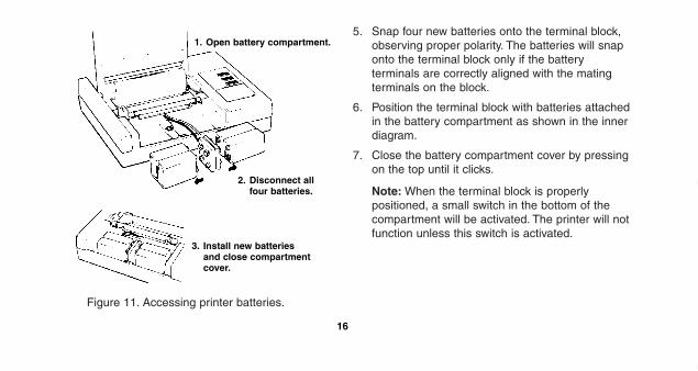
Figure 11. Accessing printer batteries.
5. Snap four new batteries onto the terminal block,observing proper polarity. The batteries will snaponto the terminal block only if the batteryterminals are correctly aligned with the matingterminals on the block.
6. Position the terminal block with batteries attachedin the battery compartment as shown in the innerdiagram.
7. Close the battery compartment cover by pressingon the top until it clicks.
Note: When the terminal block is properlypositioned, a small switch in the bottom of thecompartment will be activated. The printer will notfunction unless this switch is activated.
16
1. Open battery compartment.
2. Disconnect allfour batteries.
3. Install new batteriesand close compartmentcover.
195232_e_004.qxd 12/21/01 11:18 AM Page 16

8. To verify printer function, press the printerON/OFF key and make sure the Power Onindicator remains steadily lit. Press and hold thePAPER ADVANCE key for several seconds andmake sure the paper advances properly.
Note: The printer has an AC adapter receptacleand AC/BATT switch. If the printer appears to benonfunctional, ensure that this switch on the sideof the printer is set to BATT.
17
195232_e_004.qxd 12/21/01 11:18 AM Page 17

Figure 12. Replacing printer paper.
Replacing the Printer Paper RollWhen the printer paper supply runs low or runs out, anew roll should be installed. Printer paper rolls areavailable from Medtronic, Inc. Order Medtronic PartNumber 6064.
To replace the printer paper roll:
1. Tear off any excess paper protruding from the topof the printer.
2. Lift up on the wire paper roll retainer at the backedge of the paper roll compartment (Figure 12).The wire retainer is hinged at the front edge of thepaper roll compartment.
Maintenance and HandlingInformation
18
Paper RollSpindle
Insert paper intoslot above metalcrosspiece as shown.
Retainer
195232_e_004.qxd 12/21/01 11:18 AM Page 18

3. Lift the paper spool out of the compartment. Ifany paper is still in the printer, cut the expendedpaper roll free from the printer. Then, turn theprinter on and press the paper feed key toadvance the remaining paper strip out of theprinter.
4. Remove the spindle from the expended paperroll. Discard the old paper roll.
5. Free the end of a new paper roll. It may benecessary to trim the end of the paper so it iseven and square.
6. Holding the paper roll so the paper unrolls fromthe bottom side of the roll, feed the end of thepaper through the slot at the front of the paperroll compartment.
Note: The wire retainer must be raised enoughto permit paper to feed.
7. Turn the printer on. Then, press and hold thePAPER ADVANCE key while simultaneouslyfeeding paper through the slot in the paper rollcompartment until the paper is engaged.
8. Continue advancing the paper until severalinches emerge from the top of the printer.
Note: If the paper is not feeding straight, makesure the paper wire retainer is not mashed down.Apply appropriate pressure to the emergingpaper to correct the alignment.
19
195232_e_004.qxd 12/21/01 11:18 AM Page 19

9. Insert the spindle into the new paper roll andposition the paper roll in the compartment. Theends of the spindle should rest in the indentationsof the printer housing (Figure 13).
Figure 13. Paper properly replaced.
10. Close the wire paper roll retainer over the paperroll.
#Caution: If the retainer is left in an uprightposition, the printer case will crack when thecarrying case lid is closed.
Note: Handling the paper roll may leavefingerprints which will cause intermittent printing.If intermittent printing occurs following installationof a new roll, advance the paper several inches.
20
Paper
195232_e_004.qxd 12/21/01 11:18 AM Page 20

Figure 14. Replacing printer pen.
Replacing the Printer Ink PenIf the printer begins to print too lightly, skips letters, ordoesn’t print at all, it is probably time to replace theprinter pen. New printer pens are available fromMedtronic, Inc. Order Medtronic part number 6061.
To replace the printer pen:
1. Turn the printer on and press the PEN CHANGEkey. This moves the pen carriage to a lockedposition at the right end of the printer platen toallow pen replacement.
2. Open the compartment cover by lifting up on thefront edge of the cover to access the pen. Thecompartment cover is hinged at the rear edge.
21
1 2
3 4
195232_e_004.qxd 12/21/01 11:18 AM Page 21
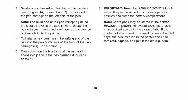
3. Gently press forward on the plastic pen ejectionlever (Figure 14, frames 1 and 2). It is located onthe pen carriage on the left side of the pen.
Note: The blunt end of the pen will spring up asthe ejection lever is pressed forward. Grasp thepen with your thumb and forefinger as it is ejectedor it may fall into the printer.
4. To install a new pen, insert the writing end of thepen into the pen guide hole at the front of the pencarriage (Figure 14, frame 3).
5. Press down on the blunt end of the pen until itsnaps into place in the pen carriage (Figure 14,frame 4).
6. IMPORTANT: Press the PAPER ADVANCE key toreturn the pen carriage to its normal operatingposition and close the battery compartment.
Note: Spare pens may be stored in the printer.However, to prevent ink evaporation, spare pensmust be kept sealed in the storage tube. If theprinter is to be stored or unused for more than 2-3days, the pen installed in the printer should beremoved, capped, and put in the storage tube.
22
195232_e_004.qxd 12/21/01 11:18 AM Page 22
Cleaning InstructionsThe programmer console and accessories may becleaned with a damp sponge or cloth moistened withwater, mild detergent, or alcohol. Be careful not toallow excessive moisture into the printer, programmerconsole, or programming head.
#Caution: DO NOT immerse the programmerconsole or programming head in any liquid. DONOT clean the programmer console orprogramming head with aromatic or chlorinatedhydrocarbons.
SterilizationThe components of the physician programmer mustnot be sterilized or permanent damage could result.
Note: The programming head may be placed in asterile bag for use in the operating room duringneurostimulator implantation.
ServiceThe Medtronic Model 7432 Physician Programmerhas been carefully engineered, manufactured, andquality tested to provide long, trouble-free service.Should repair or service be necessary, contact yourMedtronic representative.
A serial number identifying each physicianprogrammer is provided on a nontransferable decallocated inside the programmer console batterycompartment. Correspondence regarding any deviceshould refer to the device model number and serialnumber.
Note: The physician programmer has AC adapterreceptacles and AC/BATT switches. If theprogrammer console or printer appear to be non-functional, ensure that the switch on the back ofthe programmer console and the switch on theside of the printer are set to BATT beforecontacting Medtronic for service.
23
195232_e_004.qxd 12/21/01 11:18 AM Page 23

System Specifications
The Medtronic® Model 7432 Physician Programmerand its accessories make up a neurostimulationprogramming system. The system consists of theprogrammer console, programming head, printer,carrying case, and a separate MemoryMod SoftwareCartridge. The model numbers and part numbers ofthe physician programmer and its accessories arelisted in Table 1.
24
195232_e_004.qxd 12/21/01 11:18 AM Page 24

Table 1. Physician Programmer System Components.
System Component or Part Medtronic Model or Part No.
Programmer Console Model 7432
Batteries, 9-volt alkaline (3) Part 161118-6
Software Cartridge (packaged separately) Model 74XX*, 30XX*
Programming Head Model 7432V
Printer Model 7451
Batteries, 9-volt alkaline (4) Part 161118-6
Paper Roll, 4.5 inches Part 6064
Pen (4 supplied) Part 6061
Carrying Case Part 6063
* Each software cartridge has an identifying model number.
25
195232_e_004.qxd 12/21/01 11:18 AM Page 25

The Programmer ConsoleThe programmer console is a battery-powered devicedesigned to noninvasively program the adjustablefunctions of Medtronic neurostimulators. Theprogrammer console can receive and processtelemetry signals from neurostimulators with telemetrycapabilities.
All keys controlling operation of the system are laidout in three functional groups around two liquidcrystal displays (LCDs) on the face of theprogrammer console. Other external features include:two sockets on the top edge of the programmerconsole for connecting the printer and programminghead; a control knob on the left-hand edge foradjusting the display viewing angle; a battery accesspanel on the right-hand edge; and a compartment inthe upper left-hand corner for a MemoryMod SoftwareCartridge.
A switch labeled AC/BATT is also located on the topedge of the programmer console. This switch must bein the BATT position to operate the programmer usingthe batteries. The jack near the switch is for theMedtronic Model 9740 AC Adapter. Do not use thisjack for anything other than the Model 9740 ACAdapter.
The programmer console is powered by three,commercially available, 9-volt alkaline batteries. Foradditional information about the programmer console,see Table 2.
26
195232_e_004.qxd 12/21/01 11:18 AM Page 26

Table 2. Physical Characteristics.
Power Source Three 9-volt alkaline batteries (Energizer 522 or equivalent)
Battery Life with fresh batteries, approximately200 nominal parameter programming transmissions
Weight 1.2 lb. (0.53 kg) with batteries
Dimensions 2 x 4.3 x 11.5 in.(5 x 10.9 x 29.2 cm.)
Operating Temperature 50°F to 100°F(10°C to 43°C)
Storage Temperature 22°F to 150°F(-30°C to 66°C)
The Software CartridgeAll the software (preestablished programs) whichcontrol programmer console operation are containedwithin a cartridge that plugs into the programmer. Theprogrammer console cannot be operated without aMemoryMod Software Cartridge.
The interchangeability of this software cartridge allows expansion of the programmer consoleapplications to new neurostimulators and functionalcapabilities as they become available. MemoryModSoftware Cartridges are supplied separately. Asoftware cartridge technical manual is supplied witheach software cartridge detailing the programmerconsole’s functions and applications when used withthat cartridge.
Each software cartridge has an identifying modelnumber linking it to the supporting technical manual.The software cartridge plugs into the top of theprogrammer console.
27
195232_e_004.qxd 12/21/01 11:18 AM Page 27

The Programming HeadThe Medtronic Model 7432V Programming Head mustbe connected to the programmer console and heldover the neurostimulator during a programmingtransmission and telemetry reception. Theprogramming head contains transceiver componentsincluding a radio-frequency (RF) transmitting andreceiving antenna.
A gain switch at the base of the programming headenables the user to improve telemetry reception. Ithas five positions ranging from L (low) to H (high).The presence of electrical interference strong enoughto interrupt reception of telemetry from theneurostimulator can affect the operation ofprogramming confirmation.
Communication between the programmer consoleand the neurostimulator for both programming andtelemetry is via transmission of binary-coded RFpulses. The PROGRAM and REVIEW keys on theprogramming head may be used as alternatives tothose keys on the programmer console.
During each programming sequence, a red indicatoron the programming head (and programmer console)labeled POSITION HEAD comes on to indicate thatthe programming head must be centered over theneurostimulator prior to initiating a programmingtransmission.
The programming head plugs into the RF HEADsocket located on the top of the programmer console.The plug and socket are color-coded blue.
28
195232_e_004.qxd 12/21/01 11:18 AM Page 28

The PrinterThe Medtronic Model 7451 Printer plugs into theprogrammer console to provide a hard copy of eachuse of the programmer console. The printer has bothalphanumeric and graphic printing capabilities.Information printed includes telemetered mode andparameter settings and battery status. An informationheading is automatically included on the printout.
The printer uses a replaceable cartridge-type ink penand prints on 4 1/2 inch-wide paper fed from areplaceable roll. Thermal (heat sensitive) paper is notused. The printer is self-powered by four, 9-voltalkaline batteries of the same type as those used inthe programmer console. The printer has a built-inmemory for storing data that accumulates when thedata is received faster than it can be printed. Thisfeature allows the user to continue a programmingsequence without interruption even though the printermay lag behind the operation.
The printer has three controls: ON/OFF key, PAPERADVANCE key, and PEN CHANGE key that allowsreplacement of the pen cartridge. The printer will notrespond to commands from the programmer consoleunless the printer power is turned on. An amberindicator above the ON/OFF key indicates when theprinter power is on. The indicator flashes when theprinter batteries are low and should be replaced. Theprinter paper can be advanced by pressing andholding the PAPER ADVANCE key.
The printer plugs into the PRINTER socket on the topof the programmer console. The plug and socket arecolor-coded gray. The programmer console may beoperated without the printer if desired. A switchlabeled AC/BATT is located along the right-hand edgeof the printer. This switch must be in the BATTposition to operate the printer using the batteries. Thejack near the switch is for the Medtronic Model 9740AC Adapter. Do not use this jack for anything otherthan the Model 9740 AC Adapter.
29
195232_e_004.qxd 12/21/01 11:18 AM Page 29

The Carrying CaseThe carrying case provides a means of storing andtransporting the physician programmer. It forms aconvenient base from which the system may beoperated. The system components may remainconnected to the programmer console during storageso the system is always ready for use.
The case lid may be removed after the case has beenopened by first pressing down on the hinge catch(Figure 15) and then sliding the lid to the right todisengage the hinge pins. The case bottom may thenbe “nested” in the case lid. The programmer consoleand/or printer may be removed from the carrying casefor use if desired. Figure 15. Removing case lid.
30
1. Press hinge catch.
2. Slide lid to the right. 3. Position lid under case bottom for storage.
195232_e_004.qxd 12/21/01 11:18 AM Page 30

Glossary
Direct Transmission Keys—Keys which cause asignal to be sent to the neurostimulator when theprogramming head is properly positioned.
Interference—Anything that reduces theeffectiveness of a programming transmission.
Nominal Parameters—The settings that provide areasonable starting point for determining a patient’sstimulation threshold.
Parameter—A condition that can be varied to controlthe stimulation felt by the patient.
Telemetry—An RF (radio-frequency) type ofreciprocal communication for the purpose of verifyingneurostimulator parameter settings.
31
195232_e_004.qxd 12/21/01 11:18 AM Page 31

The Medtronic® Model 7432 Physician Programmer(Programmer) consists of the programming head,programmer console, printer, and accessories. TheProgrammer is designed to program the stimulationparameters of the Medtronic neurostimulators. Theprogramming functions of the Programmer are notcompatible with any other devices. Medtronic makesno claim or warranties as to the effectiveness of theProgrammer as a prescriptive tool to the physician.
Special Notice
32
195232_e_004.qxd 12/21/01 11:18 AM Page 32

Medtronic® Neurological EquipmentLimited Warranty(U.S. Customers Only)A. This Limited Warranty provides the following
assurance to the purchaser of the Medtronic®
Model 7432 Physician Programmer, hereafterreferred to as “Equipment”:
(1) Should the Equipment fail to function withinnormal tolerances due to a defect inmaterials or workmanship within a period ofone (1) year, commencing with the deliveryof the Equipment to the purchaser,Medtronic will at its option: (a) repair orreplace any part or parts of the Equipment;(b) issue a credit to the purchaser equal to
the Purchase Price, as defined in SubsectionA(2), against the purchase of thereplacement Equipment or (c) provide afunctionally comparable replacementEquipment at no charge.
(2) As used herein, Purchase Price shall meanthe lesser of the net invoiced price of theoriginal, or current functionally comparable,or replacement Equipment.
B. To qualify for Limited Warranty set forth inSection A(1), the following conditions must bemet:
(1) The Equipment must be returned toMedtronic within thirty (30) days afterdiscovery of the defect, (Medtronic may, atits option, repair the Equipment on site).
LIMITED WARRANTY
33
195232_e_004.qxd 12/21/01 11:18 AM Page 33

(2) The Equipment must not have been repairedor altered outside of Medtronic's factory inany way which, in the judgment of Medtronic,affects its stability and reliability. TheEquipment must not have been subjected tomisuse, abuse or accident.
C. This Limited Warranty is limited to its expressterms. In particular:
(1) Except as expressly provided by this LimitedWarranty, MEDTRONIC IS NOTRESPONSIBLE FOR ANY DIRECT,INCIDENTAL OR CONSEQUENTIALDAMAGES BASED ON ANY DEFECT,FAILURE OR MALFUNCTION OF THEEQUIPMENT, WHETHER THE CLAIM ISBASED ON WARRANTY, CONTRACT,TORT OR OTHERWISE.
(2) This Limited Warranty is made only to thepurchaser of the Equipment. AS TO ALLOTHERS, MEDTRONIC MAKES NOWARRANTY, EXPRESS OR IMPLIED,INCLUDING, BUT NOT LIMITED TO, ANYIMPLIED WARRANTY OFMERCHANTABILITY OR FITNESS FOR APARTICULAR PURPOSE WHETHERARISING FROM STATUTE, COMMON LAW,CUSTOM OR OTHERWISE. NO EXPRESSOR IMPLIED WARRANTY TO THE PATIENTSHALL EXTEND BEYOND THE PERIODSPECIFIED IN A(1) ABOVE. THIS LIMITEDWARRANTY SHALL BE THE EXCLUSIVEREMEDY AVAILABLE TO ANY PERSON.
(3) The exclusions and limitations set out aboveare not intended to, and should not beconstrued so as to contravene mandatoryprovisions of applicable law. If any part orterm of this Limited Warranty is held to be
34
195232_e_004.qxd 12/21/01 11:18 AM Page 34

illegal, unenforceable or in conflict withapplicable law by a court of competentjurisdiction, the validity of the remainingportions of the Limited Warranty shall not beaffected, and all rights and obligations shallbe construed and enforced as if this LimitedWarranty did not contain the particular partor term held to be invalid. This LimitedWarranty gives the purchaser specific legalrights. The purchaser may also have otherrights which vary from state to state.
(4) No person has any authority to bindMedtronic to any representation, condition orwarranty except this Limited Warranty.
*This Limited Warranty is provided by Medtronic, Inc., 710 MedtronicParkway, Minneapolis, MN 55432-5604, USA. It applies only in theUnited States. Areas outside the United States should contact their localMedtronic representative for exact terms of the Limited Warranty.
35
195232_e_004.qxd 12/21/01 11:18 AM Page 35

195232_e_004.qxd 12/21/01 11:18 AM Page 36

195232_e_004.qxd 12/21/01 11:18 AM Page 37

195232_e_004.qxd 12/21/01 11:18 AM Page 38

195232_e_004.qxd 12/21/01 11:18 AM Page 39

Medtronic, Inc.710 Medtronic Parkway Minneapolis, MN 55432-5604USAInternet: www.medtronic.comTel. 763-505-5000Toll-free 1-800-328-0810Fax 763-505-1000
© Medtronic, Inc. 2002All Rights Reserved
195232004
195232_e_004.qxd 1/15/02 10:31 AM Page 40