Embed Size (px)
Citation preview

PHYSICAL REVIEW E 102, 022701 (2020)
Homeotropic liquid crystal device employing vertically aligned carbonnanotube arrays as the alignment agent
Rajratan Basu * and Lukas J. AtwoodDepartment of Physics, Soft Matter and Nanomaterials Laboratory, The United States Naval Academy, Annapolis, Maryland 21402, USA
(Received 4 June 2020; accepted 28 July 2020; published 17 August 2020)
Vertically aligned carbon nanotube (VA-CNT) arrays were grown on several chromium (Cr)-coated glasssubstrates using a plasma-enhanced chemical vapor deposition system. The CNTs were 2 μm long and had asite density of 2 × 109 cm−2 on the substrates. Two VA-CNT slides on Cr glass substrates were put togetherto design a homeotropic electro-optic liquid crystal (LC) device. A negative dielectric anisotropic LC was usedin the device. The π -π stacking interaction between the LC and the VA-CNTs allows the LC material to alignhomeotropically in the cell. When an external electric field was applied using the transparent conducting Crlayers, the LC achieves a planar orientation above a threshold field. These results successfully demonstratethe optical, electro-optical operations, and the field-induced dynamic response of a homeotropic LC deviceemploying the VA-CNT arrays as the homeotropic-alignment agent. This study significantly advances the rangeand understanding of nanostructured surfaces that provide vertical alignment of LCs.
DOI: 10.1103/PhysRevE.102.022701
I. INTRODUCTION
In vertical-alignment (VA) liquid crystal (LC) cells (alsocalled homeotropic LC cells), the LC material is initiallyaligned perpendicular to the substrates, and the application ofan electric field perpendicular to the substrates can reorientthe LC parallel to the substrate. This operation requires theLC material to be negative dielectric anisotropic so that itcan align perpendicular to the electric field. These VA liquidcrystal displays (LCDs) have many advantages compared tothe traditional planar-nematic displays, such as a deeper blackbackground, a higher on-axis contrast ratio, a rubbing-freeprocess, a wider viewing angle, and simultaneous usability ofreflective and transmissive modes [1,2].
Conventionally, polyimide (PI) layers are used as thevertical-alignment agent in standard VA-LCDs [3], wherethe LC molecules align with the vertical part of the alkylside chains of the PI layers. Consequently, the nematic phaseachieves a homeotropic director profile inside the device[4]. However, these organic PI alignment layers have somedisadvantages. For example, the PI layers are responsive toUV light and high temperature, and therefore, the alignmentcharacteristics are affected when the PI-based LC devicesare exposed to UV light and high temperature [5,6]. Thus,various inorganic alignment agents have been utilized recentlyin electro-optic LC devices. For example, planar alignment ofLC was achieved using graphene [7–9], hexagonal boron ni-tride [10–12], and tungsten diselenide [13]; vertical alignmentof LC was achieved using nanoporous anodic aluminum oxidefilms [14,15], ZnO nanorod and nanowire arrays [6,16,17], apillarlike structure with 2–3-μm pitch [18], and SiOx films[19]. Photoaligning films are also very robust and possess ex-
cellent vertical-aligning properties [20]. Therefore, studyingand understanding the alignment phenomena of the LC ondifferent nanostructured substrates is an important avenue infundamental research and may have potential applications indesigning novel LC devices. In this work, we have studiedthe LC alignment on an inorganic nanostructured surface,vertically aligned carbon nanotube (VA-CNT) arrays, andused them as the alignment agent to design an electro-optichomeotropic LC device.
II. EXPERIMENTS, RESULTS, AND DISCUSSION
In this section, we present (A) the fabrication of theVA-CNT arrays-based homeotropic LC cell, (B) the electro-optical effect of the LC in the cell, and (C) the dynamicelectro-optic switching response of the cell.
A. Fabrication of the homeotropic electro-optic LC cellemploying the VA-CNT arrays
A plasma-enhanced chemical vapor deposition (PECVD)system at the facilities at NanoLab, Inc. [21] (Waltham,Massachusetts, USA) was commercially employed to growVA-CNT arrays on chromium (Cr) coated glass substrates. Forgrowing the VA-CNT arrays, the glass substrates were firstcoated with a Cr adhesion layer (2 nm) and then overcoatedwith nickel nanoparticles. In the PECVD system, the CNTsgrow vertically from the substrate surface, and the CNTsare freestanding. The CNT length is related to the pro-cessing time, and the diameter depends primarily on thenickel particle size. The PECVD grown CNTs had multi-layer graphitic sidewalls and a hollow core. Each CNT tipwas capped with a nickel nanoparticle. The PECVD systemwas tuned to produce the VA-CNT arrays with a CNT sitedensity of 2 × 109 cm−2, length 1.4–2 μm, and diameter
2470-0045/2020/102(2)/022701(6) 022701-1 Published by the American Physical Society
RAJRATAN BASU AND LUKAS J. ATWOOD PHYSICAL REVIEW E 102, 022701 (2020)
1µm
(a) (c)
Cr coated glass slide
CNT
LC
PA
DARKSTATE
Voltage OFF
(e)
PA BRIGHT
STATE
Voltage ON
(f)
1 cm
1 cm
(d)
(b)
1µm
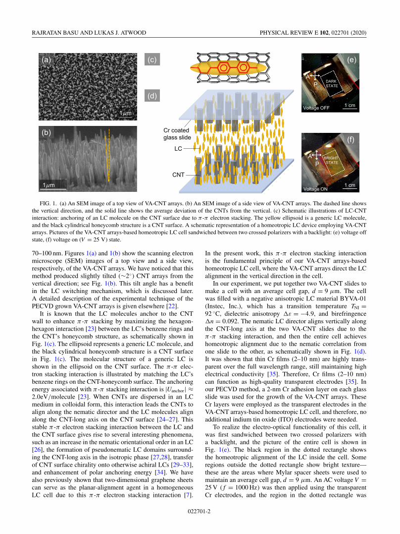
FIG. 1. (a) An SEM image of a top view of VA-CNT arrays. (b) An SEM image of a side view of VA-CNT arrays. The dashed line showsthe vertical direction, and the solid line shows the average deviation of the CNTs from the vertical. (c) Schematic illustrations of LC-CNTinteraction: anchoring of an LC molecule on the CNT surface due to π -π electron stacking. The yellow ellipsoid is a generic LC molecule,and the black cylindrical honeycomb structure is a CNT surface. A schematic representation of a homeotropic LC device employing VA-CNTarrays. Pictures of the VA-CNT arrays-based homeotropic LC cell sandwiched between two crossed polarizers with a backlight: (e) voltage offstate, (f) voltage on (V = 25 V) state.
70–100 nm. Figures 1(a) and 1(b) show the scanning electronmicroscope (SEM) images of a top view and a side view,respectively, of the VA-CNT arrays. We have noticed that thismethod produced slightly tilted (∼2◦) CNT arrays from thevertical direction; see Fig. 1(b). This tilt angle has a benefitin the LC switching mechanism, which is discussed later.A detailed description of the experimental technique of thePECVD grown VA-CNT arrays is given elsewhere [22].
It is known that the LC molecules anchor to the CNTwall to enhance π -π stacking by maximizing the hexagon-hexagon interaction [23] between the LC’s benzene rings andthe CNT’s honeycomb structure, as schematically shown inFig. 1(c). The ellipsoid represents a generic LC molecule, andthe black cylindrical honeycomb structure is a CNT surfacein Fig. 1(c). The molecular structure of a generic LC isshown in the ellipsoid on the CNT surface. The π -π elec-tron stacking interaction is illustrated by matching the LC’sbenzene rings on the CNT-honeycomb surface. The anchoringenergy associated with π -π stacking interaction is |Uanchor| ≈2.0eV/molecule [23]. When CNTs are dispersed in an LCmedium in colloidal form, this interaction leads the CNTs toalign along the nematic director and the LC molecules alignalong the CNT-long axis on the CNT surface [24–27]. Thisstable π -π electron stacking interaction between the LC andthe CNT surface gives rise to several interesting phenomena,such as an increase in the nematic orientational order in an LC[26], the formation of pseudonematic LC domains surround-ing the CNT-long axis in the isotropic phase [27,28], transferof CNT surface chirality onto otherwise achiral LCs [29–33],and enhancement of polar anchoring energy [34]. We havealso previously shown that two-dimensional graphene sheetscan serve as the planar-alignment agent in a homogeneousLC cell due to this π -π electron stacking interaction [7].
In the present work, this π -π electron stacking interactionis the fundamental principle of our VA-CNT arrays-basedhomeotropic LC cell, where the VA-CNT arrays direct the LCalignment in the vertical direction in the cell.
In our experiment, we put together two VA-CNT slides tomake a cell with an average cell gap, d = 9 μm. The cellwas filled with a negative anisotropic LC material BYVA-01(Instec, Inc.), which has a transition temperature TNI =92 ◦C, dielectric anisotropy �ε = −4.9, and birefringence�n = 0.092. The nematic LC director aligns vertically alongthe CNT-long axis at the two VA-CNT slides due to theπ -π stacking interaction, and then the entire cell achieveshomeotropic alignment due to the nematic correlation fromone slide to the other, as schematically shown in Fig. 1(d).It was shown that thin Cr films (2–10 nm) are highly trans-parent over the full wavelength range, still maintaining highelectrical conductivity [35]. Therefore, Cr films (2–10 nm)can function as high-quality transparent electrodes [35]. Inour PECVD method, a 2-nm Cr adhesion layer on each glassslide was used for the growth of the VA-CNT arrays. TheseCr layers were employed as the transparent electrodes in theVA-CNT arrays-based homeotropic LC cell, and therefore, noadditional indium tin oxide (ITO) electrodes were needed.
To realize the electro-optical functionality of this cell, itwas first sandwiched between two crossed polarizers witha backlight, and the picture of the entire cell is shown inFig. 1(e). The black region in the dotted rectangle showsthe homeotropic alignment of the LC inside the cell. Someregions outside the dotted rectangle show bright texture—these are the areas where Mylar spacer sheets were used tomaintain an average cell gap, d = 9 μm. An AC voltage V =25 V ( f = 1000 Hz) was then applied using the transparentCr electrodes, and the region in the dotted rectangle was
022701-2

HOMEOTROPIC LIQUID CRYSTAL DEVICE EMPLOYING … PHYSICAL REVIEW E 102, 022701 (2020)
0 5 10 15 20 25 30 35 40
0
0.2
0.4
0.6
0.8
1
LC-BYVA-01 in VA-CNT cell LC-E7 in VA-CNT cell
ecnattimsnarT dezila
mroN
Vrms (V)
0 5 10 15 20 25 30 35 400
0.2
0.4
0.6
0.8
1
LC-BYVA-01in commercial VA cell
Nor
mal
ized
Tra
nsm
ittan
ce
Vrms (V)
PA
50µm
25 VP
A
50µm
14 VP
A
50µm
10 VP
A
50µm
5 VP
A
50µm
4.2 VP
A
50µm
3.8 VP
A
50µm
0 V
(d)
E = 0
E
(b)
(c)
(a)
FIG. 2. (a) The normalized transmittance of negative anisotropic LC-BYVA01 and positive anisotropic LC E7 in the VA-CNT arrays-based homeotropic cell (at T = 22 ◦C), listed in the legend, as a function of applied AC voltage ( f = 1000 Hz); inset: negative anisotropicLC-BYVA01 in a commercial VA cell. Schematic representations of (b) voltage on and (c) voltage off state of LC-BYVA01 in the VA-CNTarrays-based homeotropic cell. (d) Seven separate micrographs of the VA-CNT arrays-based homeotropic cell filled with LC-BYVA01 underthe crossed-polarized optical microscope at different applied voltages.
found to turn bright, as shown in Fig. 1(f), which indicatesthe reorientation mechanism of the LC from homeotropic toplanar state on the application of the voltage. A little variationin brightness and color in the dotted rectangle in Fig. 1(f)indicates a slight variation in the cell gap.
B. Electro-optical effect of LC in the VA-CNT arrays-basedhomeotropic LC cell
Now that we have established that the VA-CNT arrays-based homeotropic LC cell exhibits the required electro-optical effect, we have carried out the voltage-dependenttransmittance experiment [1]. This experiment was conductedusing an optical setup where the cell was mounted on arotational stage between two crossed polarizers. A 5-mWHe-Ne laser beam of wavelength 633 nm was sent throughthe polarizer, the VA-CNT arrays-based homeotropic LC cell,the crossed analyzer, and into a photodetector, which was fedinto a DC voltmeter to measure the transmitted intensity.
An AC voltage V = 40 V ( f = 1000 Hz) was first appliedacross the cell to change the LC to planar orientation, and thenthe cell was rotated using the rotational stage to receive themaximum transmitted intensity at the DC voltmeter. This wasdone to ensure that when the LC achieved planar orientationon the application of the voltage, the nematic director n̂ in thecell was oriented at 45◦ with respect to the crossed polarizers.Then the AC voltage was turned off. Next, the applied ACvoltage ( f = 1000 Hz) across the cell was gradually rampedup from 0 to 40 V, and the change in the transmitted intensitywas recorded from the DC voltmeter. The same experimentwas also carried out under the crossed polarized microscopewith a white light source, and several micrographs of theVA-CNT arrays-based homeotropic LC cell at different ap-
plied voltages were taken. When the applied voltage acrossthe cell exceeds the Fréedericksz threshold value, the di-rector n̂ rotates from the initial homeotropic orientation toplanar orientation, and the LC’s effective birefringence, 〈�n〉changes as a function of the applied voltage. In our opticalsetup, the director n̂ was oriented at 45° with the crossedpolarizers at high voltage. Therefore, if Io is the intensity of theplane-polarized light incident on the VA-CNT arrays-basedhomeotropic cell, then the transmitted optical intensity I at theexit of the analyzer shows an oscillatory behavior according tothe equation [1,36]
I = IOsin2
(πd〈�n〉
λ
), (1)
where λ is the wavelength of the laser beam and d is the cellgap.
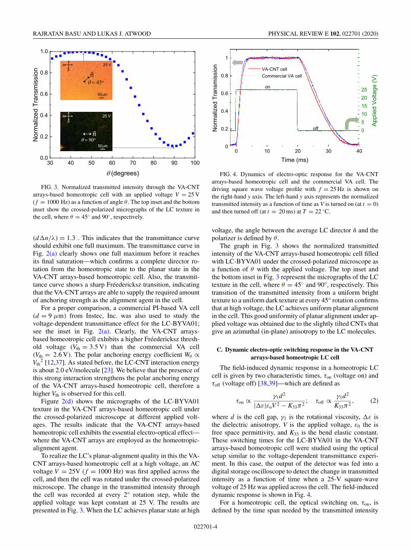
Figure 2 represents the electro-optical effect of the VA-CNT arrays-based homeotropic LC cell. Figure 2(a) ex-hibits the normalized transmittance (i.e., normalized I/Io) ofnegative anisotropic LC-BYVA01 and positive anisotropicLC E7 in the VA-CNT arrays-based homeotropic cell as afunction of the applied AC voltage. Note that LC-BYVA01,being negative anisotropic, exhibits the oscillatory responsein the homeotropic cell, according to Eq. (1), as it undergoeshomeotropic to planar orientation. One the other hand, thepositive anisotropic LC E7 shows a featureless behavior asit is already parallel to the external field in the homeotropiccell.
The number of oscillations (i.e., the number of maximaduring a complete reorientation of the director) in the trans-mittance vs voltage curve in Fig. 2(a) is given by (d�n/λ)[35]. Using �n = 0.092 for LC-BYVA-01, λ = 633 nm forthe He-Ne laser, and the LC cell gap, d = 9 μm, we obtain
022701-3
RAJRATAN BASU AND LUKAS J. ATWOOD PHYSICAL REVIEW E 102, 022701 (2020)
FIG. 3. Normalized transmitted intensity through the VA-CNTarrays-based homeotropic cell with an applied voltage V = 25 V( f = 1000 Hz) as a function of angle θ . The top inset and the bottominset show the crossed-polarized micrographs of the LC texture inthe cell, where θ = 45◦ and 90◦, respectively.
(d�n/λ) = 1.3 . This indicates that the transmittance curveshould exhibit one full maximum. The transmittance curve inFig. 2(a) clearly shows one full maximum before it reachesits final saturation—which confirms a complete director ro-tation from the homeotropic state to the planar state in theVA-CNT arrays-based homeotropic cell. Also, the transmit-tance curve shows a sharp Fréedericksz transition, indicatingthat the VA-CNT arrays are able to supply the required amountof anchoring strength as the alignment agent in the cell.
For a proper comparison, a commercial PI-based VA cell(d = 9 μm) from Instec, Inc. was also used to study thevoltage-dependent transmittance effect for the LC-BYVA01;see the inset in Fig. 2(a). Clearly, the VA-CNT arrays-based homeotropic cell exhibits a higher Fréedericksz thresh-old voltage (Vth = 3.5 V) than the commercial VA cell(Vth = 2.6 V). The polar anchoring energy coefficient Wθ ∝Vth
2 [12,37]. As stated before, the LC-CNT interaction energyis about 2.0 eV/molecule [23]. We believe that the presence ofthis strong interaction strengthens the polar anchoring energyof the VA-CNT arrays-based homeotropic cell, therefore ahigher Vth is observed for this cell.
Figure 2(d) shows the micrographs of the LC-BYVA01texture in the VA-CNT arrays-based homeotropic cell underthe crossed-polarized microscope at different applied volt-ages. The results indicate that the VA-CNT arrays-basedhomeotropic cell exhibits the essential electro-optical effect—where the VA-CNT arrays are employed as the homeotropic-alignment agent.
To realize the LC’s planar-alignment quality in this the VA-CNT arrays-based homeotropic cell at a high voltage, an ACvoltage V = 25V ( f = 1000 Hz) was first applied across thecell, and then the cell was rotated under the crossed-polarizedmicroscope. The change in the transmitted intensity throughthe cell was recorded at every 2° rotation step, while theapplied voltage was kept constant at 25 V. The results arepresented in Fig. 3. When the LC achieves planar state at high
0 10 20 30 400
0.2
0.4
0.6
0.8
1
VA-CNT cell Commercial VA cell
noissimsnarT dezila
mroN
Time (ms)
0510152025
App
lied
Vol
tage
(V)
on
off
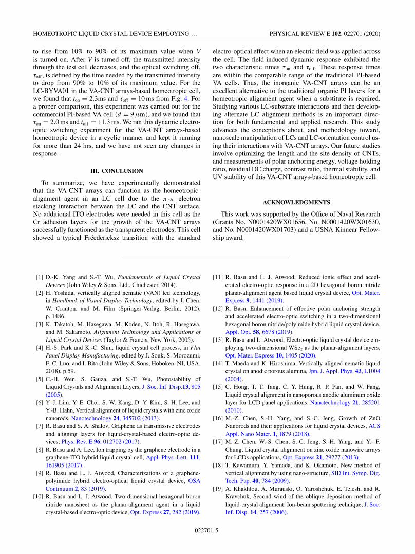
FIG. 4. Dynamics of electro-optic response for the VA-CNTarrays-based homeotropic cell and the commercial VA cell. Thedriving square wave voltage profile with f = 25 Hz is shown onthe right-hand y axis. The left-hand y axis represents the normalizedtransmitted intensity as a function of time as V is turned on (at t = 0)and then turned off (at t = 20 ms) at T = 22 ◦C.
voltage, the angle between the average LC director n̂ and thepolarizer is defined by θ .
The graph in Fig. 3 shows the normalized transmittedintensity of the VA-CNT arrays-based homeotropic cell filledwith LC-BYVA01 under the crossed-polarized microscope asa function of θ with the applied voltage. The top inset andthe bottom inset in Fig. 3 represent the micrographs of the LCtexture in the cell, where θ = 45◦ and 90°, respectively. Thistransition of the transmitted intensity from a uniform brighttexture to a uniform dark texture at every 45° rotation confirmsthat at high voltage, the LC achieves uniform planar alignmentin the cell. This good uniformity of planar alignment under ap-plied voltage was obtained due to the slightly tilted CNTs thatgive an azimuthal (in-plane) anisotropy to the LC molecules.
C. Dynamic electro-optic switching response in the VA-CNTarrays-based homeotropic LC cell
The field-induced dynamic response in a homeotropic LCcell is given by two characteristic times, τon (voltage on) andτoff (voltage off) [38,39]—which are defined as
τon ∝ γ1d2
|�ε|εoV 2 − K33π2; τoff ∝ γ1d2
K33π2, (2)
where d is the cell gap, γ1 is the rotational viscosity, �ε isthe dielectric anisotropy, V is the applied voltage, ε0 the isfree space permittivity, and K33 is the bend elastic constant.These switching times for the LC-BYVA01 in the VA-CNTarrays-based homeotropic cell were studied using the opticalsetup similar to the voltage-dependent transmittance experi-ment. In this case, the output of the detector was fed into adigital storage oscilloscope to detect the change in transmittedintensity as a function of time when a 25-V square-wavevoltage of 25 Hz was applied across the cell. The field-induceddynamic response is shown in Fig. 4.
For a homeotropic cell, the optical switching on, τon, isdefined by the time span needed by the transmitted intensity
022701-4
HOMEOTROPIC LIQUID CRYSTAL DEVICE EMPLOYING … PHYSICAL REVIEW E 102, 022701 (2020)
to rise from 10% to 90% of its maximum value when Vis turned on. After V is turned off, the transmitted intensitythrough the test cell decreases, and the optical switching off,τoff , is defined by the time needed by the transmitted intensityto drop from 90% to 10% of its maximum value. For theLC-BYVA01 in the VA-CNT arrays-based homeotropic cell,we found that ton = 2.3ms and τoff = 10 ms from Fig. 4. Fora proper comparison, this experiment was carried out for thecommercial PI-based VA cell (d = 9 μm), and we found thatτon = 2.0 ms and toff = 11.3 ms. We ran this dynamic electro-optic switching experiment for the VA-CNT arrays-basedhomeotropic device in a cyclic manner and kept it runningfor more than 24 hrs, and we have not seen any changes inresponse.
III. CONCLUSION
To summarize, we have experimentally demonstratedthat the VA-CNT arrays can function as the homeotropic-alignment agent in an LC cell due to the π -π electronstacking interaction between the LC and the CNT surface.No additional ITO electrodes were needed in this cell as theCr adhesion layers for the growth of the VA-CNT arrayssuccessfully functioned as the transparent electrodes. This cellshowed a typical Fréedericksz transition with the standard
electro-optical effect when an electric field was applied acrossthe cell. The field-induced dynamic response exhibited thetwo characteristic times τon and τoff . These response timesare within the comparable range of the traditional PI-basedVA cells. Thus, the inorganic VA-CNT arrays can be anexcellent alternative to the traditional organic PI layers for ahomeotropic-alignment agent when a substitute is required.Studying various LC-substrate interactions and then develop-ing alternate LC alignment methods is an important direc-tion for both fundamental and applied research. This studyadvances the conceptions about, and methodology toward,nanoscale manipulation of LCs and LC-orientation control us-ing their interactions with VA-CNT arrays. Our future studiesinvolve optimizing the length and the site density of CNTs,and measurements of polar anchoring energy, voltage holdingratio, residual DC charge, contrast ratio, thermal stability, andUV stability of this VA-CNT arrays-based homeotropic cell.
ACKNOWLEDGMENTS
This work was supported by the Office of Naval Research(Grants No. N0001420WX01656, No. N0001420WX01630,and No. N0001420WX01703) and a USNA Kinnear Fellow-ship award.
[1] D.-K. Yang and S.-T. Wu, Fundamentals of Liquid CrystalDevices (John Wiley & Sons, Ltd., Chichester, 2014).
[2] H. Yoshida, vertically aligned nematic (VAN) lcd technology,in Handbook of Visual Display Technology, edited by J. Chen,W. Cranton, and M. Fihn (Springer-Verlag, Berlin, 2012),p. 1486.
[3] K. Takatoh, M. Hasegawa, M. Koden, N. Itoh, R. Hasegawa,and M. Sakamoto, Alignment Technology and Applications ofLiquid Crystal Devices (Taylor & Francis, New York, 2005).
[4] H.-S. Park and K.-C. Shin, liquid crystal cell process, in FlatPanel Display Manufacturing, edited by J. Souk, S. Morozumi,F.-C. Luo, and I. Bita (John Wiley & Sons, Hoboken, NJ, USA,2018), p 59.
[5] C.-H. Wen, S. Gauza, and S.-T. Wu, Photostability ofLiquid Crystals and Alignment Layers, J. Soc. Inf. Disp.13, 805(2005).
[6] Y. J. Lim, Y. E. Choi, S.-W. Kang, D. Y. Kim, S. H. Lee, andY.-B. Hahn, Vertical alignment of liquid crystals with zinc oxidenanorods, Nanotechnology 24, 345702 (2013).
[7] R. Basu and S. A. Shalov, Graphene as transmissive electrodesand aligning layers for liquid-crystal-based electro-optic de-vices, Phys. Rev. E 96, 012702 (2017).
[8] R. Basu and A. Lee, Ion trapping by the graphene electrode in agraphene-ITO hybrid liquid crystal cell, Appl. Phys. Lett. 111,161905 (2017).
[9] R. Basu and L. J. Atwood, Characterizations of a graphene-polyimide hybrid electro-optical liquid crystal device, OSAContinuum 2, 83 (2019).
[10] R. Basu and L. J. Atwood, Two-dimensional hexagonal boronnitride nanosheet as the planar-alignment agent in a liquidcrystal-based electro-optic device, Opt. Express 27, 282 (2019).
[11] R. Basu and L. J. Atwood, Reduced ionic effect and accel-erated electro-optic response in a 2D hexagonal boron nitrideplanar-alignment agent based liquid crystal device, Opt. Mater.Express 9, 1441 (2019).
[12] R. Basu, Enhancement of effective polar anchoring strengthand accelerated electro-optic switching in a two-dimensionalhexagonal boron nitride/polyimide hybrid liquid crystal device,Appl. Opt. 58, 6678 (2019).
[13] R. Basu and L. Atwood, Electro-optic liquid crystal device em-ploying two-dimensional WSe2 as the planar-alignment layers,Opt. Mater. Express 10, 1405 (2020).
[14] T. Maeda and K. Hiroshima, Vertically aligned nematic liquidcrystal on anodic porous alumina, Jpn. J. Appl. Phys. 43, L1004(2004).
[15] C. Hong, T. T. Tang, C. Y. Hung, R. P. Pan, and W. Fang,Liquid crystal alignment in nanoporous anodic aluminum oxidelayer for LCD panel applications, Nanotechnology 21, 285201(2010).
[16] M.-Z. Chen, S.-H. Yang, and S.-C. Jeng, Growth of ZnONanorods and their applications for liquid crystal devices, ACSAppl. Nano Mater. 1, 1879 (2018).
[17] M.-Z. Chen, W.-S. Chen, S.-C. Jeng, S.-H. Yang, and Y.- F.Chung, Liquid crystal alignment on zinc oxide nanowire arraysfor LCDs applications, Opt. Express 21, 29277 (2013).
[18] T. Kawamura, Y. Yamada, and K. Okamoto, New method ofvertical alignment by using nano-structure, SID Int. Symp. Dig.Tech. Pap. 40, 784 (2009).
[19] A. Khakhlou, A. Murauski, O. Yaroshchuk, E. Telesh, and R.Kravchuk, Second wind of the oblique deposition method ofliquid-crystal alignment: Ion-beam sputtering technique, J. Soc.Inf. Disp. 14, 257 (2006).
022701-5

RAJRATAN BASU AND LUKAS J. ATWOOD PHYSICAL REVIEW E 102, 022701 (2020)
[20] V. G. Chigrinov, V. M. Kozenkov, and H.-S. Kwok, Photoalign-ment of Liquid Crystalline Materials: Physics and Applications(John Wiley & Sons, Ltd., Chichester, 2008).
[21] www.nano-lab.com.[22] R. Löffler, M. Häffner, G. Visanescu, H. Weigand, X. Wang,
D. Zhang, M. Fleischer, A. J. Meixner, J. Fortágh, andD. P. Kern, Optimization of plasma-enhanced chemical va-por deposition parameters for the growth of individual ver-tical carbon nanotubes as field emitters, Carbon 49, 4197(2011).
[23] K. A. Park, S. M. Lee, S. H. Lee, and Y. H. Lee, Anchoring aliquid crystal molecule on a single-walled carbon nanotube, J.Phys. Chem. C 111, 1620 (2007).
[24] M. D. Lynch and D. L. Patrick, Organizing carbon nanotubeswith liquid crystals, Nano Lett. 2, 1197 (2002).
[25] I. Dierking, G. Scalia, and P. Morales, Liquid crystal–carbon nanotube dispersions, J. Appl. Phys. 97, 044309(2005).
[26] R. Basu and G. S. Iannacchione, Orientational coupling en-hancement in a carbon nanotube dispersed liquid crystal, Phys.Rev. E 81, 051705 (2010).
[27] R. Basu and A. Garvey, Insulator-to-conductor transition inliquid crystal-carbon nanotube nanocomposites, J. Appl. Phys.120, 164309 (2016).
[28] R. Basu and G. S. Iannacchione, Nematic anchoring on carbonnanotubes, Appl. Phys. Lett. 95, 173113 (2009).
[29] R. Basu, K. Boccuzzi, S. Ferjani, and C. Rosenblatt, Carbonnanotube induced chirality in an achiral liquid crystal, Appl.Phys. Lett. 97, 121908 (2010).
[30] R. Basu, R. G. Petschek, and C. Rosenblatt, Nematic electro-clinic effect in a carbon nanotube doped achiral liquid crystal,Phys. Rev. E 83, 041707 (2011).
[31] P. Kalakonda, R. Basu, I. R. Nemitz, C. Rosenblatt, and G. S.Iannacchione, Studies of nanocomposites of carbon nanotubesand a negative dielectric anisotropy liquid crystal, J. Chem.Phys. 140, 104908 (2014).
[32] R. Basu, C.-L. Chen, and C. Rosenblatt, Carbon nanotube-induced macroscopic helical twist in an achiral nematic liquidcrystal, J. Appl. Phys. 109, 083518 (2011).
[33] R. Basu, C. Rosenblatt, and R. Lemieux, Chiral inductionin thioester and oxoester liquid crystals by dispersed carbonnanotubes, Liq. Cryst. 39, 199 (2012).
[34] Y. Lu and L. C. Chien, Carbon nanotube doped liquid crystalOCB cells: Physical and electro-optical properties, Opt. Express16, 12777 (2008).
[35] D.S. Ghosh, L. Martinez, S. Giurgola, P. Vergani, and V.Pruneri, Widely transparent electrodes based on ultrathin met-als, Opt. Lett. 34, 325 (2009).
[36] L.M. Blinov and V.G. Chigrinov, Electro-optic Effects in LiquidCrystal Materials (Springer-Verlag, New York, 1996).
[37] R. Basu, Enhancement of polar anchoring strength in agraphene-nematic suspension and its effect on nematic electro-optic switching, Phys. Rev. E 96, 012707 (2017).
[38] S.-T. Wu and D.-K. Yang, Fast response liquid crystals, inReflective Liquid Crystal Displays (Wiley, Chichester, 2010).
[39] H. Wang, T. X. Wu, X. Zhu, and S.-T. Wu, Correlations betweenliquid crystal director reorientation and optical response time ofa homeotropic cell, J. Appl. Phys. 95, 5502 (2004).
022701-6