Embed Size (px)
Citation preview

47 Molter Street
Cranston, Rhode Island 02910-1032
401-781-6100 • [email protected] • www.technic.com
Application Notes
Physical Properties of Electrodeposited Nickel
The mechanical properties of electrodeposited nickel are influenced by the operating variables - pH, temperature, and cathode current density. The constituents of the solution, if their concentrations are not kept within specified limits and relatively small amounts of metallic impurities, may also affect mechanical properties. The properties are interrelated and steps taken to increase the hardness of the deposit usually increase its strength and lower its ductility. The refinement of crystal structure, for example by the use of organic addition agents, is accompanied by increased hardness and tensile strength, and reduced ductility. The influence of operating variables on some of the properties of nickel deposited from Watts and conventional nickel sulfamate solutions are related in Tables 1 and 2. Deposits from these types of nickel baths are affected differently by the same variables. For example, in the Watts, solution tensile strength is relatively independent of plating solution temperature, pH and cathode current density; it increases with increasing nickel and chloride in solution. In the sulfamate solution, tensile strength decreases with
increasing temperature to 50 C, increases with increasing pH, and decreases with increasing cathode current density, it decreases slightly with increasing nickel and chloride in solution. The operating variables, as well as the specific constituents, affect the properties of electrodeposited nickel. Summaries of typical physical properties of deposits from various nickel bath formulations are included in Table 3. In addition, the mechanical properties, especially the percent elongation or ductility, are affected by the thickness of the electrodeposited nickel used in determining the properties. The ductility increases with increasing nickel thickness up to about 250 micrometers after which it becomes relatively constant. This was shown in the classic work by Zentner, Brenner and Jennings (1952) for deposits from Watts solutions and is true for nickel deposits from sulfamate solutions. Mechanical testing should be done at the thickness of interest even though it may be more convenient to test thick deposits. (Note: ASTM B489-85 specifies metal deposit thickness of 25 to 40 micrometers, or 1.0 to 1.8 mils thick) The properties of nickel electrodeposited from sulfamate solutions can be affected by uncontrolled anode behavior, which results in the oxidation of the sulfamate anion. The oxidation products can lower the internal stress and increase the sulfur content of the deposits. The extent to which these changes in internal stress and sulfur content affect the ultimate tensile strength and per cent elongation of sulfamate nickel electrodeposits has been studied (Chart, 1977). Nickel sulfamate deposits with tensile internal stress were obtained from conventional solutions; the stress was stable at 50MPa (7,252 psi). (The solution contained 70 g/l of nickel metal as the sulfamate, 0.1 g/l of chloride added as nickel chloride
hexahydrate, and 35 g/l boric acid. The pH was 4.0, temperature 60 C, and cathode current density 540 A/m
2 (58 ASF); the bath was operated with air agitation.)
After the tensively stressed deposits were prepared over a range of thicknesses, similar compressively stressed deposits were prepared by including a platinum foil anode in the circuit and passing 1 to 2 per cent of the total current through the auxiliary anode; the current density on the auxiliary anode was 2.7 A/m
2. This procedure gave deposits with an internal stress that was 71 MPa in compression.
The ultimate tensile strength varies with nickel thickness but becomes stable above 250 micrometers. The strength of the compressively stressed deposits is greater than that of the tensively stressed deposits.
Annealing at 371 C for 2 hours lowers the tensile strength of the compressively stressed and tensively stressed deposits to approximately equal values. Annealing at the higher temperature lowers the tensile strength even further, but the decrease is significantly greater in the case of the compressively stressed deposits.
The work established that the oxidation products formed at an insoluble platinum anode in sulfamate solutions lower internal stress and result in the codeposition of sulfur. The codeposition of small amounts of sulfur affects the mechanical properties of electroformed nickel especially at high temperatures. It is important to control the anode behavior to achieve consistent results in electroforming from sulfamate solutions.
Internal Stress The control of internal stress is extremely important in electroforming. Internal stress refers to forces created within an electrodeposit because of the electro crystallization process and/or the codeposition of impurities such as hydrogen, sulfur and other elements. The forces are either tensile (contractile) or compressive (expansive) in nature; rarely are electrodeposits free of some degree of internal stress. Excessive tensile or compressive stress can cause the following problems: 1) distortion of the electroform when it is separated from the mandrel; 2) difficulty of separating the electroform from the mandrel; 3) curling, peeling or separation of the electroform prematurely from the mandrel; and 4) buckling and blistering of the deposit that is usually indicative of high compressive stress. Internal stress is influenced by the nature and composition of the nickel plating solution (see Table 4). The all-chloride solution produces deposits with the highest internal stresses. Nickel sulfamate solutions without chlorides produce deposits with the lowest internal stresses. As discussed, organic additives can be used to control internal stress of electrodeposited nickel, but these additives invariably introduce sulfur they must be used with caution and due consideration. Sulfur codeposited with nickel increases its hardness and strength, and reduces ductility. Sulfur affects the high
temperature properties adversely, and nickel deposits with sulfur cannot be heated above 200 C without becoming embrittled. The codeposition of small amounts of manganese has been shown to prevent embrittlement of sulfur-containing nickel electrodeposits and allows heating above that temperature. The concentrated nickel sulfamate process discussed above can be operated at high current densities to yield deposits with very low or zero internal stresses, the techniques being shown to be effective with nickel as well as nickel-cobalt alloy electroforming. Internal stress is controlled by specifying the electrolyte and maintaining its purity, and by using specific organic addition agents in controlled concentrations. Control of current density and the other operating variables is also important.
Ductility There are two commonly used test methods used to evaluate the ductility of electrodeposits. The first of these has its origin for the control of decorative bright or semi bright nickel plating where full bright deposits tended to become brittle due to excessive sulfur codeposition. The test (ISO 1456 or ASTM B489-85) is conveniently carried out by cutting a test strip 150 mm long and 10 mm wide (6 x ½ inches) from a larger sheet of brass or cold rolled steel, which has been plated with 25 – 40 micrometers (1 to 1.8 mils) of nickel deposit. The test strip is bent, with the plated surface outermost, through 180 degrees over a mandrel of 0.203 inches (13/64 inch) until the two ends of the test strip are parallel. If no cracks pass completely across the convex surface when examined a 10-x magnification, the plating has an elongation greater than 8 percent. (Note: See Table 5 for the relationship between the diameter of bend radius and percent elongation) The second, less commonly used method, is uniaxial tension or pull testing. Although this test can provide both measurements of internal stress and ductility, the preparation of foil test specimens is demanding and the test equipment is generally not available in any but the largest companies. The results from the uniaxial pull testing of foils cannot be compared directly with the same deposits as measured by the bend test method. Ductility measurements based on the bend test include the base substrate as an integral part of the test. In fact, it would be assumed that bend test results done in separate facilities using different substrate alloys and or thicknesses would produce different results. Hence, the unspecified range of the specification call out in Mil QQ-N-290A and ASTM B489-85 requiring greater than 8 percent elongation. Although it is possible to produce foils that will pass the 8 percent minimum requirement, typical results, especially those baths containing additives are lower. As is the
case with the bend test method, foils of differing thickness and produced on different substrates will have different elongations. Note: Table 7 Compares of elongation test results made from the same nickel electrolytes and measured with different test procedures. The ductility shows greater variation with thickness than does the ultimate tensile strength. The ductility is greater for the tensively stressed deposits than for the compressive ones in the as-plated condition.
Annealing at 371 C increases the ductility of both types of deposits. Annealing at 760 C increases the ductility of the tensively stressed deposits, but lowers the ductility of the compressively stressed ones to values below the as-plated ones. The measurements of ultimate tensile strength and percent elongation (ductility) were made by standard uniaxial tension testing. The deposits were also analyzed chemically. The tensively stressed deposits contained less than 1 part per million sulfur, whereas the compressive deposits contained about 40 parts per million sulfur. Metallographic and electron microprobe analyses
conducted after annealing showed brittle failure in compressive deposits heated at 760 C, as well as high sulfur (380 to 500 ppm) contents in grain boundaries.
Hardness The hardness of a metal is not a function of a single property of the material, but rather a combination of properties that we refer to as hardness. Although hardness is not a fundamental property of materials, it is useful in general metallurgy as a control test that may be correlated with other properties that are more difficult or expensive to determine. In the case of electrodeposits, published evidence would indicate that hardness values cannot be well correlated with the tensile properties of the same deposit. The correlation between the hardness of a deposit and its brightness has been systematically investigated and concludes that there is only a casual relationship and the exceptions to it are more numerous and significant than the apparent increase in brightness with increase in hardness. The hardness of a metal is indicative of its resistance to abrasion and ware, i.e., the higher the hardness the higher the resistance. Although the correlation may not be exact, this is one of the best reasons for being interested in the hardness of electrodeposited metals. The hardness of electrodeposits is influenced by the conditions of deposition, both the solution composition and the conditions for deposition. This is particularly true for nickel and indicates the care that should be taken during the plating operation if the hardness of the deposit is to be controlled. The most common method to determine hardness of electrodeposits is based on resistance to penetration by a loaded indenter. The hardness numbers obtained with any of these indenters are dependant upon the load applied the friction relationship between the indenter and the metal, the geometry of the indenter, the work hardening of the sample during mounting, etc. These many variables become particularly important when the size of the indent is small as is the typical case with electrodeposited metal coatings. It is important, therefore, to specify the technique and conditions whenever specifying hardness values for electrodeposited coatings. If the surface of the coating is too rough for observation and measurement of the indent, or if the deposit is too thin to avoid the anvil effect (less than fifteen times the length of the indent), it is necessary to prepare a metallographic cross section of the deposit. (Note: See the procedure for the preparation of samples for hardness analysis) Table 4 relates the thickness of deposits, which are required to avoid the anvil effect when measuring the hardness of deposits for various loads with a Knoop indenter for metals of several hardness’s. When the hardness of a cross section is measured, it is necessary that the short diagonal of the Knoop indent fall within the coating with at least one half the width of the indent to spare. If this condition is not met, the load being used must be reduced appropriately. Illustrative data for selected nickel solutions is given in figure 1.
Grain Size The ductility, the tensile strength and other properties of metals are often influenced by grain size. However, there are very few useful correlations between the grain size of a deposit and other physical properties. There are some results, which indicate that, at least in a general way, the tensile strength of
electroplated deposits increases with increasing hardness, unfortunately there are also numerous exceptions. There is reasonably good evidence that ductility and grain size are not uniformly related in electrodeposits. It has been suggested that the brightness of a deposit is intimately related to the grain size, i.e., the smaller the grain size the brighter the deposit. At least in the case of nickel it has been established that there is no correlation between grain size and brightness. Brightness is a surface effect and not a bulk property of the deposit. Studies with the electron microscope reveal that for brightness the shape and packing of grains is more important than the absolute size. References: Di Bari, G.A., “Electroforming”, Electroplating Engineering Handbook – Fourth Edition, Edited by L.J. Durney, Van Nostrand Reinhold Company Inc New York 1984. Zetner, J., Brenner, A. and Jennings, C.W., “Physical Properties of Electrodeposited Metals Part I Nickel”, Plating 39 (8) 865-927 (1952). Safranek, W.H., “The Properties of Electrodeposited Metals and Alloys – A Handbook”, Second Edition, American Electroplaters and Surface Finishers Society, Orlando Florida, 1986. “Practical Nickel Plating” – Second Edition, International Nickel Company Inc., New York, N.Y. 1959 ASTM B 489-85 (Reapproved 1998) “Standard Practice for Bend Test for Ductility of Electrodeposited and Autocatalytically Deposited Metal Coatings on Metal” ASTM 100 Barr Harbor Drive, West Conshohocken, PA 19428 Rev. Initial 8/22/03
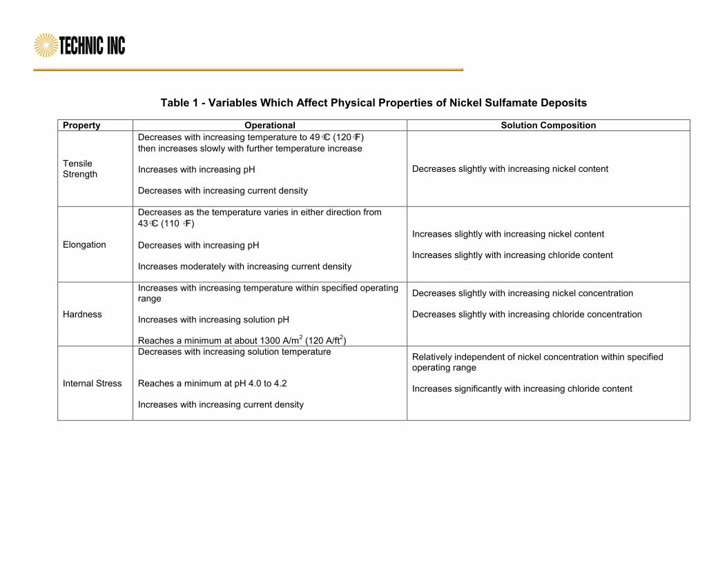
Table 1 - Variables Which Affect Physical Properties of Nickel Sulfamate Deposits
Property Operational Solution Composition
Tensile Strength
Decreases with increasing temperature to 49C (120F)
then increases slowly with further temperature increase Increases with increasing pH Decreases with increasing current density
Decreases slightly with increasing nickel content
Elongation
Decreases as the temperature varies in either direction from
43C (110 F)
Decreases with increasing pH Increases moderately with increasing current density
Increases slightly with increasing nickel content Increases slightly with increasing chloride content
Hardness
Increases with increasing temperature within specified operating range Increases with increasing solution pH Reaches a minimum at about 1300 A/m
2 (120 A/ft
2)
Decreases slightly with increasing nickel concentration Decreases slightly with increasing chloride concentration
Internal Stress
Decreases with increasing solution temperature Reaches a minimum at pH 4.0 to 4.2 Increases with increasing current density
Relatively independent of nickel concentration within specified operating range Increases significantly with increasing chloride content
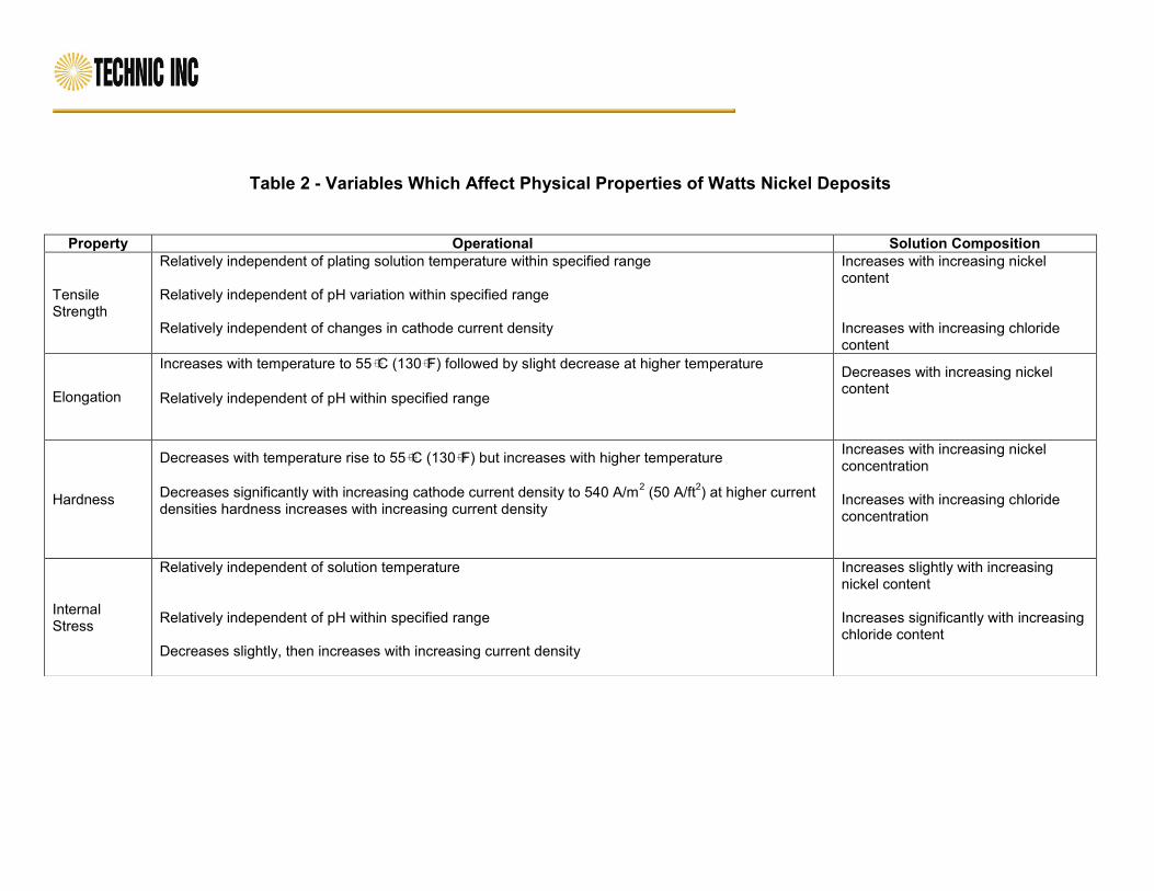
Table 2 - Variables Which Affect Physical Properties of Watts Nickel Deposits
Property Operational Solution Composition
Tensile Strength
Relatively independent of plating solution temperature within specified range Relatively independent of pH variation within specified range Relatively independent of changes in cathode current density
Increases with increasing nickel content Increases with increasing chloride content
Elongation
Increases with temperature to 55C (130F) followed by slight decrease at higher temperature
Relatively independent of pH within specified range
Decreases with increasing nickel content
Hardness
Decreases with temperature rise to 55C (130F) but increases with higher temperature
Decreases significantly with increasing cathode current density to 540 A/m
2 (50 A/ft
2) at higher current
densities hardness increases with increasing current density
Increases with increasing nickel concentration Increases with increasing chloride concentration
Internal Stress
Relatively independent of solution temperature Relatively independent of pH within specified range Decreases slightly, then increases with increasing current density
Increases slightly with increasing nickel content Increases significantly with increasing chloride content

Table 3 - Nickel Electroplating Solutions
And Typical Properties of Deposits
Electrolyte Composition 1
Watts Nickel Standard Sulfamate
Conc. Sulfamate Typical Semi-
Bright 2
NiSO4.6H2O 225-300 300
Ni (SO3NH2)2.4H2O 315-450 500-650
NiCl2.6H2O 37-53 0-22 0-22 35
H3BO3 30-45 30-45 30-45 45
Operating Conditions
Temperature C 44-66 32-60 32-60 54
Agitation Air-Mechanical Air-Mechanical Air-Mechanical Air-Mechanical
Current A/dm2 3-11 0.5-32 0.5-32 3.0 - 10
Anodes Nickel Nickel Nickel Nickel
pH 3.0-4.2 3.5-4.5 3.5-4.5 3.5-4.5
Mechanical Properties
Tensile MPa 345-485 415-620 415-620 -
Elongation % 15-25 10-25 10-25 8-20
Vickers 100g 130-200 170-230 170-230 300-400
Internal Stress MPa 125-185 tensile 0-85 tensile 0-55 tensile3 35-150
Notes: 1. Surfactant agents formulated for nickel plating are added to control pitting 2. Proprietary additives are required for semi-bright deposits 3. Near zero stress may be obtained at various combinations of current density and temperature. 4. Reference: Typical full bright deposit properties, elongation 2-5%, Vickers Hardness 100 gram 600-800, Internal Stress MPa 12-25 compressive
Table 4 - Typical Internal Stress for Nickel Plating Solutions
Nickel Electrolyte Internal Stress MPa
Watts 110-210
Watts with Hydrogen Peroxide 275 or more
All Chloride 205-310
Fluoborate 100-175
Fluoborate with Hydrogen Peroxide 100-175
Sulfamate, no chloride 0-55
Sulfamate, with chloride 55-85
All Sulfate 110-140
Notes: 1.0 MPa equals 145.04 psi
1 pascal = Newton square meter = 0.00015 psi 1.0 psi = 6,895 Pascal
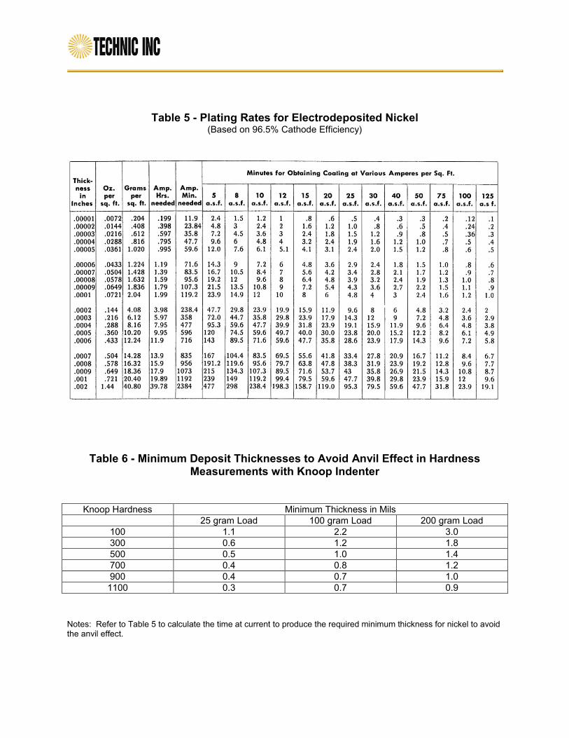
Table 5 - Plating Rates for Electrodeposited Nickel (Based on 96.5% Cathode Efficiency)
Table 6 - Minimum Deposit Thicknesses to Avoid Anvil Effect in Hardness
Measurements with Knoop Indenter
Knoop Hardness Minimum Thickness in Mils
25 gram Load 100 gram Load 200 gram Load
100 1.1 2.2 3.0
300 0.6 1.2 1.8
500 0.5 1.0 1.4
700 0.4 0.8 1.2
900 0.4 0.7 1.0
1100 0.3 0.7 0.9
Notes: Refer to Table 5 to calculate the time at current to produce the required minimum thickness for nickel to avoid the anvil effect.

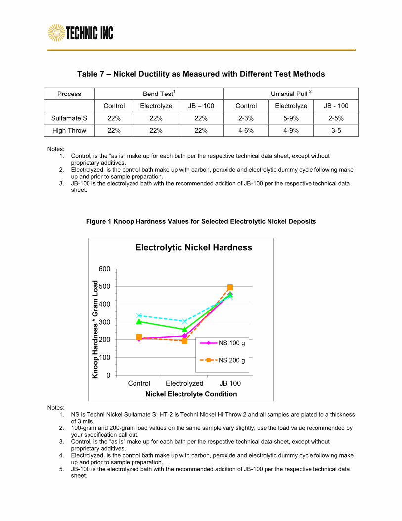
Table 7 – Nickel Ductility as Measured with Different Test Methods
Process Bend Test1 Uniaxial Pull
2
Control Electrolyze JB – 100 Control Electrolyze JB - 100
Sulfamate S 22% 22% 22% 2-3% 5-9% 2-5%
High Throw 22% 22% 22% 4-6% 4-9% 3-5
Notes:
1. Control, is the “as is” make up for each bath per the respective technical data sheet, except without proprietary additives.
2. Electrolyzed, is the control bath make up with carbon, peroxide and electrolytic dummy cycle following make up and prior to sample preparation.
3. JB-100 is the electrolyzed bath with the recommended addition of JB-100 per the respective technical data sheet.
Figure 1 Knoop Hardness Values for Selected Electrolytic Nickel Deposits
Notes: 1. NS is Techni Nickel Sulfamate S, HT-2 is Techni Nickel Hi-Throw 2 and all samples are plated to a thickness
of 3 mils. 2. 100-gram and 200-gram load values on the same sample vary slightly; use the load value recommended by
your specification call out. 3. Control, is the “as is” make up for each bath per the respective technical data sheet, except without
proprietary additives. 4. Electrolyzed, is the control bath make up with carbon, peroxide and electrolytic dummy cycle following make
up and prior to sample preparation. 5. JB-100 is the electrolyzed bath with the recommended addition of JB-100 per the respective technical data
sheet.
0
100
200
300
400
500
600
Control Electrolyzed JB 100
Kn
oo
p H
ard
ne
ss
* G
ram
Lo
ad
Nickel Electrolyte Condition
Electrolytic Nickel Hardness
NS 100 g
NS 200 g
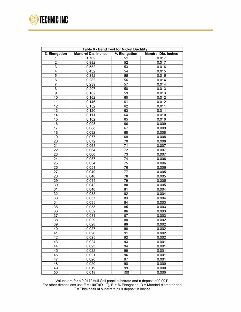
Table 6 - Bend Test for Nickel Ductility
% Elongation Mandrel Dia. inches % Elongation Mandrel Dia. inches
1 1.782 51 0.017
2 0.882 52 0.017
3 0.582 53 0.016
4 0.432 54 0.015
5 0.342 55 0.015
6 0.282 56 0.014
7 0.239 57 0.014
8 0.207 58 0.013
9 0.182 59 0.013
10 0.162 60 0.012
11 0.146 61 0.012
12 0.132 62 0.011
13 0.120 63 0.011
14 0.111 64 0.010
15 0.102 65 0.010
16 0.095 66 0.009
17 0.088 67 0.009
18 0.082 68 0.008
19 0.077 69 0.008
20 0.072 70 0.008
21 0.068 71 0.007
22 0.064 72 0.007
23 0.060 73 0.007
24 0.057 74 0.006
25 0.054 75 0.006
26 0.051 76 0.006
27 0.049 77 0.005
28 0.046 78 0.005
29 0.044 79 0.005
30 0.042 80 0.005
31 0.040 81 0.004
32 0.038 82 0.004
33 0.037 83 0.004
34 0.035 84 0.003
35 0.033 85 0.003
36 0.032 86 0.003
37 0.031 87 0.003
38 0.029 88 0.002
39 0.028 89 0.002
40 0.027 90 0.002
41 0.026 91 0.002
42 0.025 92 0.002
43 0.024 93 0.001
44 0.023 94 0.001
45 0.022 95 0.001
46 0.021 96 0.001
47 0.020 97 0.001
48 0.020 98 0.000
49 0.019 99 0.000
50 0.018 100 0.000
Values are for a 0.017" Hull Cell panel substrate and a deposit of 0.001"
For other dimensions use E = 100T/(D +T), E = % Elongation, D = Mandrel diameter and T = Thickness of substrate plus deposit in inches