Embed Size (px)
Citation preview
Physical Environment of the
National Reactor Testing Station,
Idaho A Summary
GEOLOGICAL SURVEY PROFESSIONAL PAPER 725-A
Prepared in cooperation with the
U.S. Atomic Energy Commission

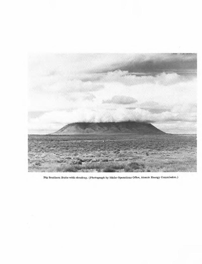
Big Southern Butte with cloudcap. (Photograph by Idaho Operations Office, Atomic Energy Commission.)

PHYSICAL ENVIRONMENT OF THE
NATIONAL REACTOR TESTING STATION,IDAHO A SUMMARY

Physical Environment of the
National Reactor Testing Station,
Idaho A SummaryBy RAYMOND L. NACE, MORRIS DEUTSCH, and PAUL T. VOEGELI
Edited by SEYMOUR SUBITZKY
GEOLOGY, HYDROLOGY, AND WASTE MANAGEMENT AT THE
NATIONAL REACTOR TESTING STATION, IDAHO
GEOLOGICAL SURVEY PROFESSIONAL PAPER 725-A
Prepared in cooperation with the
U.S. Atomic Energy Commission
UNITED STATES GOVERNMENT PRINTING OFFICE, WASHINGTON : 1972
UNITED STATES DEPARTMENT OF THE INTERIOR
ROGERS C. B. MORTON, Secretary
GEOLOGICAL SURVEY
V. E. McKelvey, Director
Library of Congress catalog-card No. 72-600043
For sale by the Superintendent of Documents, U.S. Government Printing OfficeWashington, D.C. 20402 - Price $1 (paper cover)
Stock Number 2401-2084

PREFACE
Since 1948, on behalf of the U.S. Atomic Energy Commission, the U.S. Geological Survey has made comprehensive hydrogeologic studies at the National Reactor Testing Station (NETS), between Idaho Falls and Arco, Idaho, in connection with construction, operation, and environmental safety of the station. The NRTS consists of about 890 square miles of so-called sagebrush desert and basalt fields on the Snake River Plain of southern Idaho. The plain is a major geo graphic, geologic, and economic segment of southern Idaho, and the water is a principal natural resource of that part of the State. The use of water, disposal of waste, and other operations on the NRTS depend on and affect part of a very large body of underground water in the Snake River Plain.
The Survey has collected, compiled, and analyzed a considerable amount of basic geologic and hydrologic information on and near the station. Specific hydro- logic problems of the station concern the chemical suit ability of the perennial water supply and its adequacy for plant operations in addition to other uses on the Snake River Plain. Other problems concern the loca tion and orientation of reactor facilities so as to avoid contamination of their own water supplies: the loca tions, spacing, and pumping rates of wells; control and safe disposition of radioactive liquid wastes; feasible remedial actions in the event of accidents that might endanger water supplies; and protection of the water supplies of the Snake River Plain from excessive depletion, contamination, or other damage. Hence, the most efficient use of the NRTS and the creation thereby of the least possible hazard to the resources and human activities in the Snake River Plain depend partly on the availability and use of detailed information about the hydrogeologic and geochemical environments of the station.
Many preliminary and special reports were compiled on the results of early basic geologic and hydrologic investigations (1948-59). Overall results of the investi gations were assembled in three detailed reports: (1) "Purpose, History, and Scope of the Investigations," (2) "Geography and Geology," (3) "Hydrology and Water Resources." These earlier reports were furnished to the Commission and were released for public inspec
tion to the open file. However, these reports were reproduced only in small number in order to meet the early needs of the Commission and of its contractors to carry out construction and reactor-testing programs. These reports contain considerable basic information on the geology, hydrology, water resources, and waste- disposal technology of basaltic rocks and associated sedimentary materials underlying a part of the Snake River Plain. Therefore, they contain background infor mation on the hydrogeologic environment that is neces sary for preparation of other reports on studies made since 1959. Hence, publication of the results of the earlier investigations in a more readily available form seems desirable.
This professional paper series on the National Reac tor Testing Station, Idaho, will consist initially of these earlier reports which were prepared under the supervision of R. L. Nace the principal author. Other geologists and engineers who have assisted in pre paring these reports are J. T. Barraclough, N. B. Crow, Morris Deutsch, F. E. Fennerty, K. H. Fowler, J. E. Jones, S. L. Jones, I. S. McQueen, A. E. Peckham, H. E. Skibitzke, R. O. Smith, J. W. Stewart, C. V. Theis, W. I. Travis, P. T. Voegeli, W. C. Walton, and S. W. West. Some of them are coauthors of sections in this series, as indicated in the table of contents of the respective chapters. This report (chapter A) describes the planning and operational phases of the hydrogeo logic investigative program from its inception in 1948 to 1959, the physical environment, and the reactor facil ities of the station. Subsequent parts of the series will include information on geology, hydrology, and radio active waste management.
Except where necessary for the purposes of this report, compilations of hydrologic data have not been brought up to date. Current hydrologic data on ground-water levels, streamflow, water use, water quality, and information on radioactive waste are avail able for consultation in the offices of the Geological Survey, Idaho Falls, Idaho. Other publications of the Geological Survey contain results of some recent studies on the station. Additional research reports will be forthcoming.


CONTENTS
Preface
Abstract
Introduction, by Raymond L. Nace ____________________Purpose and scope of the investigation ____________Location and extent of the area __________________Previous investigations __________________________Methods of investigation _________________________
Basic investigations __________________________Geologic mapping ________________________Test drilling ____________________________Geophysical exploration __________________Canvass of wells and observations of water
levels __ __________________Spirit leveling ___________________________Surface-water investigations _________Chemical and radiometric analyses of water
Laboratory work ____________________________Research ____________________________________
Well-numbering system __________________
Acknowledgments and personnel
Geographic environment, by Raymond L. Nace, Morris Deutsch, and Paul T. Voegeli ___________________
General geologic setting _________________________Physiographic setting ____________________________
Surface drainage ____________________________Landforms __________________________________
Volcanic features ____________________Alluvial features ________________________Lake floors and playas __________________Eolian features __________________________
Climate, by Raymond L. Nace ____________________Temperature ________________________________Precipitation ______________ _________
Torrential rain __________________________Humidity and evaporation ___________________Wind and dust ______________________________Barometric pressure _________________________
Ground conditions, by Raymond L. Nace __________Freezing and thawing _____________.__ Soil temperature ____________________________Rock temperature ___________________________
Ground air and ground ice _____________Soil moisture _____________________
Fine sediments _________________________Coarse sediments ________________
Economic development _______________,Population centers _____.__________________Transportation _________________________Agriculture and private industry _.__________
Page v
Al
234466777
10
10101111121214141818181920202121222222232324252526262727
PageWater use _____________________ A27
Private water use _____ 27Water use on the National Reactor Testing Station_ 28
Sewage disposal ___________ _ 29
References cited __________________________ 29
Appendix Reactors and related facilities on the National Reactor Testing Station, by Seymour Subitzky andRaymond L. Nace ______ _ 32
Test Reactor Area _____________ 32Materials Testing Reactor _ 32Engineering Test Reactor __ _ 32Engineering Test Reactor Critical Facility 32Advanced Test Reactor __ 33Advanced Test Reactor Critical Facility _ 33Hot-Cell Facility _____ 33Nuclear Physics Research Facility 33Metallurgical Research Facility _____ _ 33Reactor Service Building __ 33Reactivity Measurement Facility _ 33Advanced Reactivity Measurement Facility 33Coupled Fast Reactivity Measurement Facility. 33Gamma Irradiation Facility 33
Idaho Chemical Processing Plant Area 33Waste-Calcining Facility __ __ 34Experimental Facilities _ 34Waste-disposal building _ _ 34
Experimental Breeder Reactor I (West) Area 34Argonne Fast Source Reactor __ 34Boiling-Water Reactor 1 34Boiling-Water Reactor 2 __ 34Boiling-Water Reactor 3 __________ 35Boiling-Water Reactor 4 35Boiling-Water Reactor 5 _ 35Experimental Breeder Reactor I _ 35Zero Power Reactor 3 __ 35
Experimental Breeder Reactor II (East) Area 35Experimental Breeder Ractor II 35Transient Reactor Test Facility __ 35Fuel Cycle Facility __ 35Zero Power Plutonium Reactor 35
Auxiliary Reactor Area __ 36Gas-Cooled Reactor Experiment _ 36Nuclear Effects Reactor _ _ 36
Naval Reactor Test Facility _ 36Submarine Prototype Reactor 36Large Ship Reactor ____ __ 36Expended Core Facility _ 36Natural Circulation Reactor _ 36
Special Power Excursion Reactor Test Area 36Special Power Excursion Reactor Test I 36
VII

VIII CONTENTS
Page
Appendix Reactors and related facilities on the National Reactor Testing Station, by Seymour Subitzky and Raymond L. Nace Continued
Special Power Excursion Reactor Test Area Con.Special Power Excursion Reactor Test II ____ A36
Special Power Excursion Reactor Test III ___ 36
Special Power Excursion Reactor Test IV ___ 37
Power Burst Facility ________________ 37
Central Facilities Area _________________ 37
Page
Appendix Reactors and related facilities on the National Reactor Testing Station, by Seymour Subitzky and Raymond L. Nace Continued
Test Area North ______________________ ASTInitial Engineering Test Facility ____-Field Engineering Test Facility ____.Low Power Test Facility ________-
Organic Reactor Area ______________.Organic Moderated Reactor Experiment
Burial ground ________________ .
373737373737
ILLUSTRATIONS
Page
PLATE 1. Relief map of southeastern Idaho showing physiographic setting of the National Reactor Testing Station In pocket
FIGURE 1. Index map showing location of the National Reactor Testing Station and its facilities _____ A42. Map showing land acquisitions ____________________________________________________ 63. Sketch showing well-numbering system ____________ _____ ___________ 9
4 6. Aerial photographs:4. Birch Creek playa and beach and bar deposits of ancient Terreton Lake ________ 155. Big Lost River channels and playas south of Howe Point __________________ _ 166. Windrows of drifted sand east of Circular Butte ________ ________________ 17
7. Graph showing moisture content of playa and lake beds in sees. 14 and 23, T. 6 N., R. 31 E 258. Graph showing volume of waste and curies of radioactivity disposed of in the National Reactor Testing Sta
tion burial ground ______________________ _________________________________ 38
TABLES
Page
TABLE 1. Miscellaneous basaltic lava vents in the National Reactor Testing Station _____ A132. Location and altitude of weather stations on the central Snake River Plain 183. Monthly and annual normal temperatures at the Central Facilities Area and Test Area North weather stations
on the National Reactor Testing Station ________ __ _ 194. Monthly precipitation at the Central Facilities Area and Test Area North weather stations on the National Re
actor Testing Station ___________________________ __________ 195. Monthly and annual averages and extremes of relative humidity at the Central Facilities Area weather sta
tion, January 1956 through December 1961 ______ 206. Moisture content of Terreton Lake beds and playa sediments, northern part of National Reactor Testing
Station _______________________________________________________ 257. Moisture content of Terreton lake beds and playa sediments, Birch Creek playa and vicinity 268. Populations of principal communities within 50-mile radius of the Central Facilities Area 269. Land area and irrigation, by counties, in or near the National Reactor Testing Station, 1964 28
10. Water use at permanent facilities on the National Reactor Testing Station 28
GEOLOGY, HYDROLOGY, AND WASTE MANAGEMENT AT THE
NATIONAL REACTOR TESTING STATION, IDAHO
PHYSICAL ENVIRONMENT OF THE NATIONAL REACTOR TESTINGSTATION, IDAHO-A SUMMARY
By RAYMOND L. NACE, MORRIS DEUTSCH, and PAUL T. VOEGELI Edited bv SEYMOUR SUBITZKY
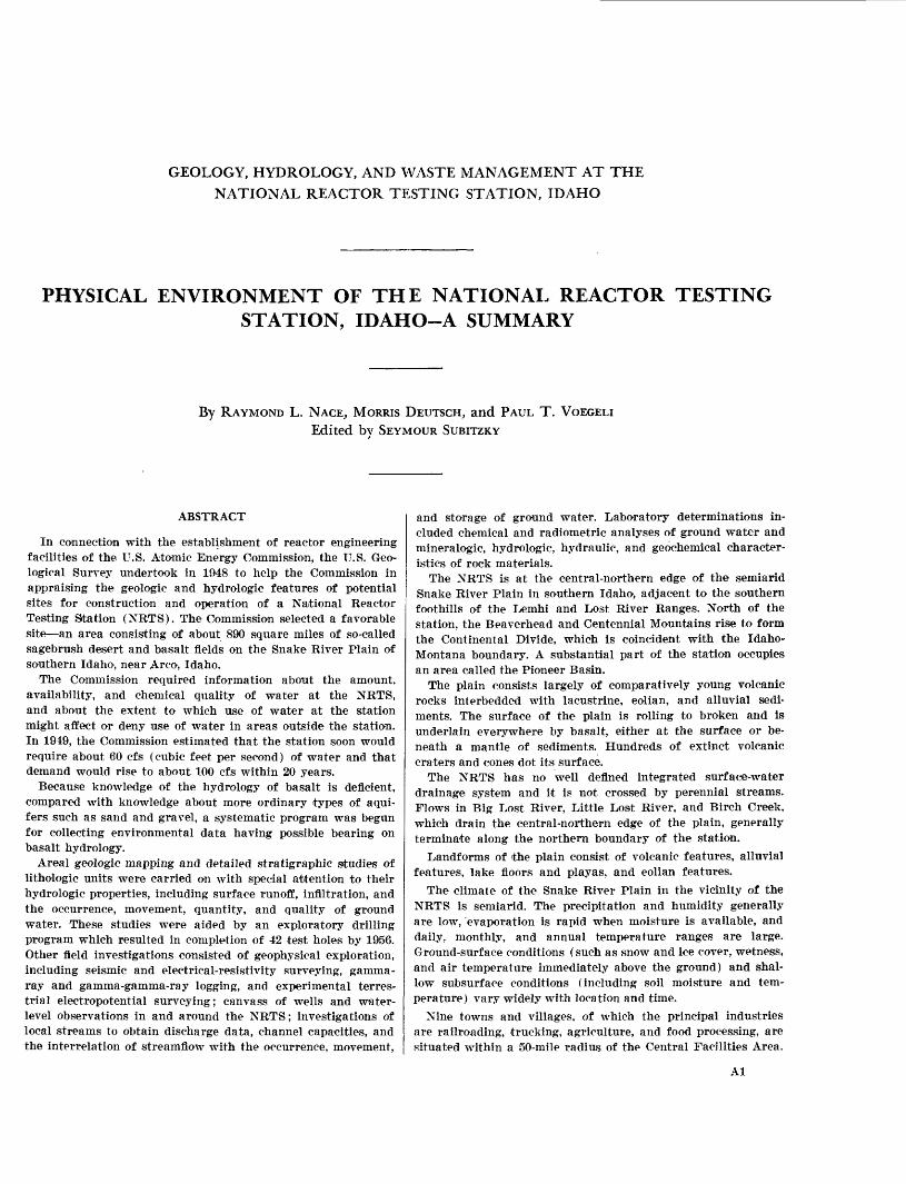
ABSTRACT
In connection with the establishment of reactor engineering facilities of the U.S. Atomic Energy Commission, the U.S. Geo logical Survey undertook in 1948 to help the Commission in appraising the geologic and hydrologic features of potential sites for construction and operation of a National Reactor Testing Station (NRTS). The Commission selected a favorable site an area consisting of about 890 square miles of so-called sagebrush desert and basalt fields on the Snake River Plain of southern Idaho, near Arco, Idaho.
The Commission required information about the amount, availability, and chemical quality of water at the NRTS, and about the extent to which use of water at the station might affect or deny use of water in areas outside the station. In 1949, the Commission estimated that the station soon would require about 60 cfs (cubic feet per second) of water and that demand would rise to about 100 cfs within 20 years.
Because knowledge of the hydrology of basalt is deficient, compared with knowledge about more ordinary types of aqui fers such as sand and gravel, a systematic program was begun for collecting environmental data having possible bearing on basalt hydrology.
Areal geologic mapping and detailed stratigraphic studies of lithologic units were carried on with special attention to their hydrologic properties, including surface runoff, infiltration, and the occurrence, movement, quantity, and quality of ground water. These studies were aided by an exploratory drilling program which resulted in completion of 42 test holes by 1956. Other field investigations consisted of geophysical exploration, including seismic and electrical-resistivity surveying, gamma- ray and gamma-gamma-ray logging, and experimental terres trial electropotential surveying; canvass of wells and water- level observations in and around the NRTS; investigations of local streams to obtain discharge data, channel capacities, and the interrelation of streamfiow with the occurrence, movement,
and storage of ground water. Laboratory determinations in cluded chemical and radiometric analyses of ground water and mineralogic, hydrologic, hydraulic, and geochemical character istics of rock materials.
The NRTS is at the central-northern edge of the semiarid Snake River Plain in southern Idaho, adjacent to the southern foothills of the Lemhi and Lost River Ranges. North of the station, the Beaverhead and Centennial Mountains rise to form the Continental Divide, which is coincident with the Idaho- Montana boundary. A substantial part of the station occupies an area called the Pioneer Basin.
The plain consists largely of comparatively young volcanic rocks interbedded with lacustrine, eolian, and alluvial sedi ments. The surface of the plain is rolling to broken and is underlain everywhere by basalt, either at the surface or be neath a mantle of sediments. Hundreds of extinct volcanic craters and cones dot its surface.
The NRTS has no well defined integrated surface-water drainage system and it is not crossed by perennial streams. Flows in Big Lost River, Little Lost River, and Birch Creek, which drain the central-northern edge of the plain, generally terminate along the northern boundary of the station.
Landforms of the plain consist of volcanic features, alluvial features, lake floors and playas, and eolian features.
The climate of the Snake River Plain in the vicinity of the NRTS is semiarid. The precipitation and humidity generally are low, evaporation is rapid when moisture is available, and daily, monthly, and annual temperature ranges are large. Ground-surface conditions (such as snow and ice cover, wetness, and air temperature immediately above the ground) and shal low subsurface conditions (including soil moisture and tem perature) vary widely with location and time.
Nine towns and villages, of which the principal industries are railroading, trucking, agriculture, and food processing, are situated within a 50-mile radius of the Central Facilities Area.
Al

A2 GEOLOGY, HYDROLOGY, WASTE MANAGEMENT, NATIONAL REACTOR TESTING STATION, IDAHO
On the uninhabited part of the plain, sheep and cattle grazing are the principal agricultural industries. The area is accessible by rail, highway, and air, and the station is traversed by all- weather paved highways.
Since 1949, various nuclear reactors have been operated and engineering facilities have been constructed within the station. These have been distributed into nine major program function areas; namely, Test Reactor Area, Idaho Chemical Processing Plant Area, Experimental Breeder Reactor-I (West) Area, Experimental Breeder Reactor-II (East) Area, Auxiliary Reactor Area, Naval Reactors Facility, Special Power Excur sion Reactor Test Area, Central Facilities Area, and Test Area North. As of 1969, 22 reactors were operating or operable, and 26 had been dismantled, transferred, or were put on a standby status; 22 engineering facilities were in use, two were inactive, and two reactors were under construction.
Public water supply systems in small communities near the NRTS use ground water. Stock, rural domestic, and industrial water supplies also are chiefly ground water. Crop irrigation is chiefly with surface water, but extensive irrigation develop ment with ground water has occurred on the Snake River Plain since 1946.
Water for use on the NRTS ordinarily is obtained from wells, chiefly for reactor cooling and moderating, as a cooling and shielding medium for temporary storage of spent nuclear-fuel elements, washing and decontaminating machinery and equip ment, chemical processing, landscape maintenance, culinary and sanitary use, and fire protection. As of 1968, annual pump- age was about 2 billion gallons, of which about 50 percent was consumptively used.
INTRODUCTION
By RAYMOND L. NACE
The U.S. Geological Survey (in 1948) undertook to aid the Atomic Energy Commission in appraising the geologic and hydrologic features of potential sites for certain Commission facilities. For one major facility, the National Reactor Testing Station (NETS), the choice from about 40 suggested sites was narrowed to two near Fort Peck, Mont., and near Arco, Idaho. In November 1948, A. M. Piper then technical super visor and coordinator of activities of the Water Resources Division of the Geological Survey in cooper ation with the Commission made a brief study of the Fort Peck site. In December of that year (1948), Piper and Nace made a rapid reconnaissance of an area between Arco and Blackfoot, Idaho. The Commission's plans at that time envisioned a facility whose water requirements would be about 60 cubic feet per second (cfs) within a few years and about 100 cfs within 20 years. On January 2, 1949, Piper submitted a report (unpublished) indicating a favorable geologic and geographic environment and an adequate supply of chemically suitable water.
Roger S. Warner, Jr., then Director of Engineering for the Commission, notified the Geological Survey
early in January 1949 that the Commission had re tained the engineering firm of Smith, Hynchman, and Grylls, Inc., of Detroit, Midi., to make comparative engineering evaluations of the Fort Peck and Idaho sites. In mid-January, this firm called a conference in Pocatello, Idaho, with representatives of the Commis sion, the Geological Survey, and the firm of Alvord, Burdick, and Howson, of Chicago, 111., for the purpose of pooling and evaluating available information about the geology, water supply, and other characteristics of the Idaho area. Specific concern was with the regional geologic and geographic environment, foundation con ditions for heavy structures, the local factors that might influence the water supply for reactors, and the probable effects of reactor operations on the overall water supply of the Snake River Plain. Those present at the conference were R. S. Warner and J. K. Pickard (Atomic Energy Commission); A. M. Piper, Lynn Crandall, and R. L. Nace (Geological Survey); George Giguere, David Banta, W. S. McKenzie, and P. Cnare (Smith, Hynchman, and Grylls, Inc.) ; and special consultants H. T. Stearns and D. H. Maxwell.
After this early planning conference, H. T. Stearns and Survey personnel observed the performance of two wells located at the Naval Proving Ground. (See fig. 2.) The performance of these wells was mediocre by common standards for the Snake River Plain, but on the basis of general knowledge it was believed pos sible to obtain the desired amount of water from properly constructed wells. The estimated initial water requirement in 1949 was 1.5 cfs, increasing to 23 cfs in 1955. About 75 percent of the maximum use was expected to be nonconsumptive. The station area con templated in 1949 was 400,000 acres. The present area of the station is about 571,800 acres. Water samples were collected from scattered locations on the Snake River Plain, and the results of chemical analyses of these were submitted to the Commission by Piper by the end of January 1949.
The final report of Smith, Hynchman, and Grylls, Inc. (1949), giving a comparative evaluation of the Fort Peck and Pocatello sites, was submitted to the Commission on March 26,1949. The specific conclusions were preponderantly in favor of the Idaho site. Some basic requirements for the site were as follows:
1. Thoroughly dependable water supply.2. Isolation from heavily populated areas.3. Geologic conditions suitable for the founding of
large, heavy structures.4. Nearby sources of manpower, materials, electric
power, and rail transportation.5. Small earthquake risk.

PHYSICAL ENVIRONMENT-A SUMMARY A3
6. Climatic conditions favorable to construction dur ing most of the year and favorable to year-round operation of the facilities.
7. Adequate surface and subsurface drainage.8. Few regional and local problems affecting adequate
security control.9. Suitable conditions for reasonably safe storage of
liquid waste.
Shortly after the consultants' report was submitted, the Commission approved the Idaho site and made arrangements to take over the Naval Proving Ground, which was already in use within the desired area. The desired boundaries of the station soon were defined, and in April, negotiations for a water right were begun with the Idaho State Reclamation Engineer.
Early in May the author designated two alternate locations for a demonstration water well on the sta tion. The U.S. Navy, agent for the Commission, let a drilling contract for the site chosen by the Commis sion. The well was completed early in August and test pumped shortly thereafter. The average pumping rate was 1.4 cfs with a drawdown of about 15 feet. The well, though one of the poorer of those now on the NRTS, was considerably better than either of the old Navy wells, and confidence in the water supply was established. This well later became the source of water for the Experimental Breeder Reactor-I area.
On the basis of information available in May 1949 and the projected needs for information, at the request of the Commission the Geological Survey proposed a systematic, comprehensive study of the hydrogeology of the NRTS. In June the Commission accepted the proposal in substance for work to begin in fiscal year 1950.
During the early period we believed that develop ment of the NRTS would proceed gradually from small-scale construction early in 1950 to construction on a larger scale within several years. The investi gative proposal suggested a plan whereby, within 2 or 3 years, the Geological Survey would have completed a general geologic and hydrologic study and would have released a general report. Work thereafter would have been on specialized and advanced problems. By that plan much basic geologic and hydrologic data would have been accumulated and embodied in reports in advance of extensive construction. However, the rate of construction soon was accelerated by the Commission, and the work of the Survey, therefore, necessarily was arranged to aid plans for specific con struction sites. About 30 short interim reports dealt with construction-site characteristics, pumping tests, summaries of data, and selection of well sites. The
basic work lagged because all operations were essen tially simultaneous.
PURPOSE AND SCOPE OF THE INVESTIGATION
The primary purpose of the studies on the NRTS was to determine the sources and quantity of ground- water replenishment; the quality and quantity of ground-water perennially available for pumpage in specified areas; and the course, rate of underflow, and destination of specified segments of the ground-water body and also to assess various problems of low- level radioactive liquid waste disposal on or in the ground. Specific subjects of concern included the types and amounts of radioactive and nonradioactive liquid wastes that are or may be disposed of at the station; solid-waste disposal; ground-water development and use; operational and health hazards within the station resulting from waste disposal in or on the ground; health hazards beyond the boundaries of the NRTS and where contaminated ground water might enter domestic, municipal, irrigation, and hydropower water systems. Geology and ground-water hydrology are factors in all those problems.
The Commission requires information about the amount, availability, and chemical quality of waiter at the NRTS and about the extent to which use of water on the station may affect or deny use of water in areas outside the station. Because the potential influence of NRTS operations on the ground-water resources of the plain is very large ground water is pumped for irri gation, industrial, municipal, and rural domestic sup plies the Commission must be concerned with both local and broad regional problems of the hydrology, geology, and geochemistry.
Investigation of ground-water geology and hydrol ogy of the station by the U.S. Geological Survey was started under the general direction of the late A. N. Sayre, former Chief of the Branch of Ground Water, Washington, D.C. Technical supervision and coordina tion of hydrologic studies by the Geological Survey for the Atomic Energy Commission was by C. V. Theis, staff scientist, Water Resources Division, Albu querque, N. Mex. Work in Idaho was supervised by R. L. Nace, then district geologist, Boise, Idaho, until June 30, 1956. From 1956 to 1959, work was supervised by M. J. Mundorff and H. A. Waite, former district geologists, Branch of Ground Water. Current (1970) continuing work is under the general supervision of P. C. Benedict, Regional Research Hydrologist, Water Resources Division, Menlo Park, Calif. From 1959 to 1965, geohydrologic studies at the station were directly supervised successively by P. H. Jones and D. A.
GEOLOGY, HYDROLOGY, WASTE MANAGEMENT, NATIONAL REACTOR TESTING STATION, IDAHO
Morris, former project chiefs. Since 1965, these studies have been supervised by J. T. Barraclough.
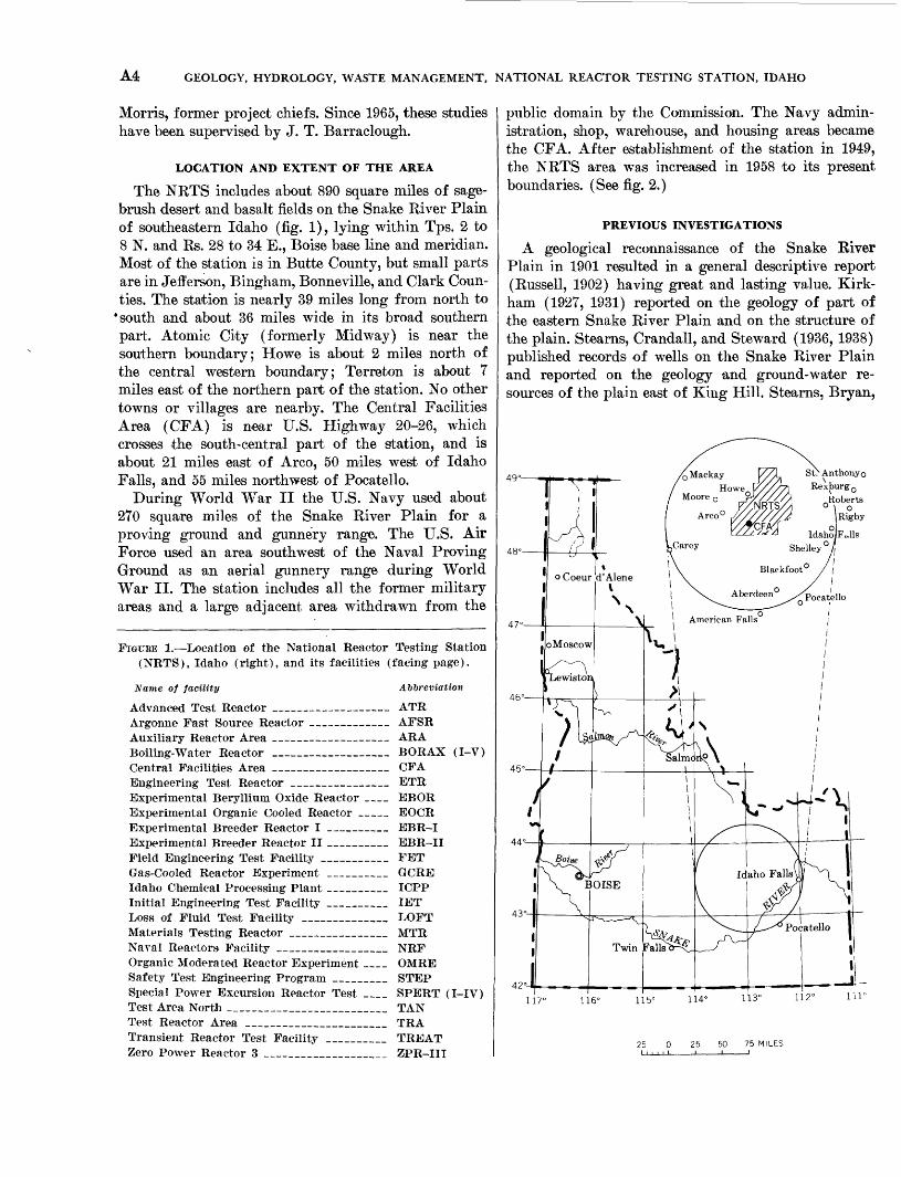
LOCATION AND EXTENT OF THE AREA
The NETS includes about 890 square miles of sage brush desert and basalt fields on the Snake River Plain of southeastern Idaho (fig. 1), lying within Tps. 2 to 8 N. and Rs. 28 to 34 E., Boise base line and meridian. Most of the station is in Butte County, but small parts are in Jefferson, Bingham, Bonneville, and Clark Coun ties. The station is nearly 39 miles long from north to
* south and about 36 miles wide in its broad southern part. Atomic City (formerly Midway) is near the southern boundary; Howe is about 2 miles north of the central western boundary; Terreton is about 7 miles east of the northern part of the station. No other towns or villages are nearby. The Central Facilities Area (CFA) is near U.S. Highway 20-26, which crosses the south-central part of the station, and is about 21 miles east of Arco, 50 miles west of Idaho Falls, and 55 miles northwest of Pocatello.
During World War II the U.S. Navy used about 270 square miles of the Snake River Plain for a proving ground and gunnery range. The U.S. Air Force used an area southwest of the Naval Proving Ground as an aerial gunnery range during World War II. The station includes all the former military areas and a large adjacent area withdrawn from the
FIGURE 1. Location of the National Reactor Testing Station (NRTS), Idaho (right), and its facilities (facing page).
Name of facility Abbreviation
Advanced Test Reactor __________ ATRArgonne Fast Source Reactor AFSR Auxiliary Reactor Area ___ ARABoiling-Water Reactor ____________ BORAX (I-V) Central Facilities Area ____________ CFA Engineering Test Reactor __________ ETRExperimental Beryllium Oxide Reactor __ EBOR Experimental Organic Cooled Reactor ___ EOCR Experimental Breeder Reactor I ______ EBR-I Experimental Breeder Reactor II ______ EBR-II Field Engineering Test Facility _______ FET Gas-Cooled Reactor Experiment ______ GCRE Idaho Chemical Processing Plant ______ ICPP Initial Engineering Test Facility ______ IET Loss of Fluid Test Facility _________ LOFT Materials Testing Reactor __________ MTR Naval Reactors Facility ____________ NRF Organic Moderated Reactor Experiment __ OMRE Safety Test Engineering Program ______ STEP Special Power Excursion Reactor Test __ SPERT (I-IV) Test Area North _________________ TAN Test Reactor Area _______________ TRA Transient Reactor Test Facility ______ TREAT Zero Power Reactor 3 _____________ ZPR-III
public domain by the Commission. The Navy admin istration, shop, warehouse, and housing areas became the CFA. After establishment of the station in 1949, the NRTS area was increased in 1958 to its present boundaries. (See fig. 2.)
PREVIOUS INVESTIGATIONS
A geological reconnaissance of the Snake River Plain in 1901 resulted in a general descriptive report (Russell, 1902) having great and lasting value. Kirk- ham (1927, 1931) reported on the geology of part of the eastern Snake River Plain and on the structure of the plain. Stearns, Crandall, and Steward (1936, 1938) published records of wells on the Snake River Plain and reported on the geology and ground-water re sources of the plain east of King Hill. Stearns, Bryan,
42
117° 116° 115° 114° 113° 112° Hl c
0 25 50 75 MILES

PHYSICAL ENVIRONMENT-A SUMMARY A5
and Crandall (1939) studied the geology and water resources of the Mud Lake basin, including part of what is now the NETS. Keports by Nace (1948) and by Crosthwaite and Scott (1956) contain useful infor mation about the geology and hydrology of part of the
Snake River Plain. A station-evaluation report on the NETS was prepared by the architectural and engi neering firm of Smith, Hynchman, and Grylls, Inc. (1949). During 1949-50 the U.S. Army Corps of Engi neers (1950), did shallow test boring on several
113-00'
44° 00
43°30'h
National Reactor Testing Station boundary
Mountain front
_CFAFacility of National
Reactor Testing Station (see list on facing page)

A6 GEOLOGY, HYDROLOGY, WASTE MANAGEMENT, NATIONAL REACTOR TESTING STATION, IDAHO
METHODS OF INVESTIGATIONpotential construction sites, established altitude-control points for topographic mapping, and provided other engineering services for the Commission. Walker (1964) reported on the subsurface geology of the NRTS, and Mundorff, Crosthwaite, and Kilburn (1964) studied the occurrence, quantity, and quality of ground water for irrigation in the upper Snake River basin.
EXPLANATION
BASIC INVESTIGATIONS
Knowledge about the hydrology of basalt is deficient compared with that about more ordinary types of aquifers such as gravel and sand. Throughout the in vestigations we systematically collected data having possible bearing on basalt hydrology. The test drilling,
44°00'
Addition, 1958 (about 140,500 acres)
Total area: about 571,800 acres
FIGURE 2. Map of the National Reactor Testing Station showing land acquisitions.

PHYSICAL ENVIRONMENT-A SUMMARY A7
for example, yielded qualitative information on water bearing properties of the rock, such as rock porosity and formational porosity, the distribution of porosity and of various internal rock structures, the distribution of permeable and nonpermeable zones, and the occur rence and distribution of old buried soil zones, caliche layers, and weathered zones in the basalt, all of which affect water-bearing properties of the rock.
Pumping tests of wells help to determine the hy draulic properties of the aquifer. Once these hydraulic data are obtained, they can be plotted, analyzed, and interpreted by standard methods to derive hydraulic coefficients for the formations. Whether the standard methods applicable to granular aquifers could be ap plied to basalt aquifers and correctly portray their hydraulic properties was not known.
Study of outcrops is another means to obtain basic data related to the hydrology of basalt. Stratigraphic sections were measured and described in detail from widely separated parts of the Snake Kiver Plain, and freehand sketches were made of the physical character istics of the basalt.
The data from all types of field investigations were analyzed and interpreted jointly by geologists and en gineers in an effort to determine and describe the hy draulic properties of the aquifer. Those properties affect the yield, drawdown, and pumping lift of pumped wells, and they control the movement of waste liquid that is disposed of at the surface, in the zone of aeration, or directly in the zone of saturation.
GEOLOGIC MAPPING
Early in the investigation we made a general areal examination of the NETS to classify the types of geo logic materials present, and in October 1949 we began systematic mapping, completing it in June 1953. Each geologic unit was studied in detail, with special atten tion to characteristics that would affect its hydrologic properties. Interim special geologic maps were pre pared where needed for construction sites. Samples of rocks, sediments, and fossils were collected for labora tory study. Field notes, on file in the Idaho Falls office of the Water Kesources Division, were prepared for each area mapped. These notes contain descriptions of the topography; the type and distribution of geologic units; the estimated and measured thicknesses of over burden; the occurrence of volcanic vents; the locations from which soil, sediment, and rock samples were col lected ; and the few locations where fossils were found.
TEST DRILLING
Exploratory drilling was an essential part of basic studies on the geohydrology of the station. The pur
poses were (1) to determine the character, subsurface distribution, physical interrelations, and water-bearing properties of the rocks and sediments from the surface downward into the zone of saturation, (2) to obtain samples of those materials for analysis and study, (3) to define ground-water conditions in terms of the loca tion, depth beneath the land surface, quantity, tempera ture, and chemical quality of the ground water and the configuration of the water table, (4) to aid study of the velocity and direction of ground-water underflow, and (5) to establish in and near the NETS a network of test wells which could be used as water-level obser vation wells and chemical and radiometric monitoring points.
GEOPHYSICAL EXPLORATION
Geophysical exploration by seismic and electrical- resistivity surveying was done only in small sample areas, and little useful information was obtained. The results of gamma-ray and gamma-gamma-ray logging of drill holes were quite satisfactory, and logs were made of 27 test holes and wells (1952-53). Study of the movement of ground water, using experimental terrestrial electropotential methods, was attempted with equipment especially designed and constructed by the Geological Survey for use at the NETS. Owing to the low electrical conductivity of the basalt and the generally dry overburden, high voltage had to be ap plied to the ground and the pickup apparatus had to be extremely sensitive.
The experimental apparatus was operated intermit tently during several months, and a subsequent ap praisal suggested the possibility of introducing through a test hole a salt solution which should move as a well-defined narrow thread of saline water down the water-table gradient away from the well. This should cause a downstream bulge in the equipotential lines around the injection well. The field experiment was not successful.
CANVASS OF WELLS AND OBSERVATIONS OF WATER LEVELS
Eecords of wells and water levels are basic to prac tically all ground-water field studies. Before 1949 there were very few wells on or near the NETS, and little hydrologic information was available. Approximate logs and performance records were available for the two production wells on the Naval Proving Ground. Wells at Atomic City, Cerro Grande, several stock wells on the Snake Eiver Plain, and several abandoned holes on the NETS yielded little hydrologic informa tion other than the depth to water. Because little hy drologic information was available on existing wells

A8 GEOLOGY, HYDROLOGY, WASTE MANAGEMENT, NATIONAL REACTOR TESTING STATION, IDAHO
in the NUTS and adjacent area, a complete canvass of existing wells in the central Snake Eiver Plain and the peripheral inhabited area east of Minidoka, west of Mud Lake, and north of the Snake River was neces sary. Data obtained gave a general picture of the regional occurrence of ground water and of the config uration and position of the water table and aided choice of locations for test holes and observation wells. A few wells were selected for periodic measurement of water levels, and the test holes, in addition to their other uses, provided a network of observation wells in and near the station. Recording gages were operated in two to 21 wells for periods up to several years. Each test hole when completed was added to the net work of observation wells, and the network grew from several wells late in 1949 to 41 wells (5 with recording gages) in 1950 and to nearly 50 wells at the peak of the field study in 1953. By 1968, the network of govern ment and private wells had expanded to about 110 ob servation and production wells, including wells in the vicinities of Cerro Grande, Arc/), Howe, Mud Lake, and Terreton. As a result of the operation of a compara tively large number of observation wells for several years during which weekly and monthly measurements were made in many wells, the water-level fluctuation patterns are so well delineated that the information essential for present purposes can be obtained from a few gages at key locations, supplemented by periodic measurements in additional wells and test holes.
SPIRIT LEVELING
Leveling was done to determine land-surface alti tudes at well and test sites in order to compute the alti tude of the water table, to establish local permanent altitude-reference marks near each test site, and to tie the altitude data to the vertical-control grid of second- order bench marks in the NRTS. Most of the level lines to sites outside the NRTS were started from U.S. Coast and Geodetic Survey bench marks. All altitudes are reported with reference to the mean sea-level datum of 1929, Pacific Northwest adjustment of 1947.
Most of the leveling was by spirit level and con forms to third-order leveling standards of the Geo logical Survey (Douglas, 1929). The altitudes of a few wells at remote locations on the plain were de termined trigonometrically by transit-stadia traverse from bench marks.
SURFACE-WATER INVESTIGATIONS
The discharge of the Big Lost River below Arco and the disposition of the water that reaches the NRTS are significant topics. The Survey has operated a gag
ing station several miles downstream from Arco since August 1946. The Commission has sponsored this sta tion since October 1, 1952, when it was rebuilt and modernized. Ten temporary measuring stations, estab lished within the NRTS during the high-runoff period of 1951-53, yielded information about percolation losses in the channel of the river. The discharge data are useful in connection with the following problems: the amount of discharge the river channel can accom modate without breaking out onto the flood plain in the NRTS, the probable effects on the NRTS of an upstream cloudburst or dam failure, and the amount of water contributed by the river to ground-water recharge within the station.
Seepage losses from the river received special at tention because the rate of infiltration of natural water in the flood-plain gravel may be indicative of expectable infiltration rates in waste-disposal works in similar gravel. Also, study of correlative and later water- table fluctuations gave clues to the time required for water to move from the land surface to the water table.
CHEMICAL AND RADIO-METRIC ANALYSES OF WATER
Chemical and radiometric analyses were made of water from wells and test holes on the station, from widely scattered private wells as far as about 70 miles west of the NRTS in Gooding and Jerome Counties, and from a few springs in the valley of the Snake River. Information about the chemical quality and in dustrial utility of water was needed directly in con nection with the operating designs for facilities. Chemical data are useful also in the study of ground- water recharge and movement. Background (natural) radioactivity is of special interest because of its bearing on possible future changes in the radioactivity of the water. Water sampling was begun in 1949 and con tinued through the present (1970). Radiometric an alyses were made of water from all test holes, all wells on the NRTS, and from many wells in the adjoining part of the Snake River Plain. For the past several years, most of the radiometric monitoring has been done by the Commission.
LABORATORY WORK
Laboratory work, chiefly of routine and standard nature, was done for many phases of the field studies in connection with permeability of geologic materials, infiltration and percolation, aquifer hydraulics, ion- exchange properties of sediments and basalt, especially in relation to reactor waste, and geochemical stability of solid and semisolid radioactive waste buried in the zone of aeration. Chemical and radiometric analyses of

PHYSICAL ENVIRONMENT-A SUMMARY A9
samples of water from the testing station and from outlying parts of the Snake Eiver Plain were made in laboratories of the Geological Survey in Portland, Oreg.; Salt Lake City, Utah; and Washington, D.C. Base-exchange tests of sediments were made in the laboratory of the Geological Survey in Washington, D.C. The mineralogic composition of clay and silt samples was determined by X-ray diffraction analysis. Petrographic study of consolidated volcanic rocks was by standard methods in the same laboratory.
Grain-size analyses on about 480 samples of sedi ments from the station were made by standard methods in field laboratories of the Geological Survey on the site and in Boise, Idaho.
Specialized tests of disturbed and undisturbed sam ples of fine sediments were made in the laboratory of the Geological Survey at Denver, Colo. Samples were collected from all areas where sediment is the principal geologic material or where detailed study was neces sary for special purposes. Tests included the mechan ical composition, saturated permeability, moisture content, Atterberg limits, and related physical properties.
RESEARCH
Early hydrogeologic studies of the basalt terrane and its interrelated fine-grained sedimentary bodies at the NETS posed several basic problems in hydrology and geochemistry with special reference to pumping of ground water and the disposal of liquid waste. The problems in those fields at the NETS are not unique, but their existence lends emphasis to the unsatisfac tory status of information about such problems as the following:
1. Saturated permeability of very fine and very coarse sediments occurring at the land surface and in the zone of aeration.
2. Infiltration rate through the very fine sediments and the effect on that rate of physical and chem ical changes induced by waste materials in aqueous solutions.
3. Course and rate of percolation of water and waste liquids in the zone of aeration in sediments and in basalt.
4. Hydraulic properties of basalt.5. Ion-exchange properties of sediments and basalt,
especially in relation to reactor waste.6. Geochemical stability of solid and semisolid radio
active waste buried in the zone of aeration.
Owing to the more immediate demands for basic in formation of less specialized nature, little progress was
made from 1949 to 1959 in research in the above fields, most effort having been devoted to the collection of basic information and conventional types of work. From the strictly scientific point of view (disregarding the operational handicap), that situation has been satisfactory because most of the basic information is needed also for research.
WELL-NUMBERING SYSTEM
The well-numbering system used in Idaho indicates the locations of wells within the official rectangular subdivisions of the public lands, with reference to the Boise base line and meridian. The first two segments of a number designate the township and range. The third segment gives the section number and is followed by two letters and a numeral, which indicate the quarter section, the 40-acre tract, and the serial number of the well within the tract. Quarter sections are let tered a, b, c, and d in counterclockwise order, from the northeast quarter of each section. Within the quarter sections, 40-aore tracts are lettered in the same manner. Well 2N-31E-35dcl is in the SW^SE^ sec. 35, T. 2 N., B. 31 E., and is the well first visited in that tract. The method of numbering is illustrated in figure 3.
R.I E. 2 29 30 31 32
BASE LINE
R. 31 E. Sec. 35
2N-31E-35dc 1
FIGURE 3. Well-numbering system.

A10 GEOLOGY, HYDROLOGY, WASTE MANAGEMENT, NATIONAL REACTOR TESTING STATION, IDAHO
ACKNOWLEDGMENTS AND PERSONNEL
Valuable assistance and information were provided to the Geological Survey by the Commission through out the study. Special debts for administrative assist ance are acknowledged to L. E. Johnston and A. C. Johnson, successive managers of the Idaho Operations Office, to A. R. Lee, information officer, and to A. E. Gorman, formerly of the Reactor Development Divi sion, Washington, D.C. The Engineering and Con struction Division of the Idaho Operations office, represented by F. M. Leppich, F. E. Smith, A. L. Bila- deau, and L. M. Hale, was very helpful at all times in technical problems. R. E. Georgi, Director of Security, and his staff have been most helpful in security prob lems. Dr. G. V. Beard and Percy Griffiths, of the Health Physics Division, were most helpful in chemi cal and radiometric studies of water. Important clima- tological data were furnished by P. A. Humphrey and E. M. Wilkins of the U.S. Weather Bureau, who also reviewed and criticized the section on climate. W. G. Strasser and R. L. Strasser, of the R. J. Strasser Drilling Co., and C. P. Cope, of the Cope Drilling and Pump Co., provided useful information about drilling techniques, test-hole construction, and drilling charac teristics of the earth materials. The Geological Survey is indebted to the many residents on the Snake River Plain, who supplied logs and other information about their irrigation, domestic, and stock wells.
The variety and scope of geologic, hydrologic, and geochemical problems on the NRTS exceed the ordi nary scope of individual competence. Therefore, per sonnel from several branches of the Geological Survey contributed special services. C. S. Ross, R. A. Bailey, and Charles Milton studied and reported on the petrol ogy of consolidated rocks; the late Dorothy Carroll and Hildreth Schultz determined ion-exchange capaci ties of fine sediments; J. C. Hathaway and Carol J. Parker made X-ray diffraction determinations of the mineralogic composition of fine sediments. The late Helen Duncan identified the invertebrate fossils. J. C. Wright made a field reconnaissance on the Snake River Plain and suggested means for the correlation of basalt flows. H. Cecil Spicer directed electrical- resistivity and seismic surveys of small areas in the NRTS. H. E. Skibitzke, assisted by A. E. Robinson, designed and installed equipment for electropotential surveying.
Much of the data and many of the illustrations used in various parts of this report were compiled by Morris Deutsch and P. T. Voegeli, assisted by J. R. Jones, S. L. Jones, N. B. Crow, A. E. Peckham, and R. O. Smith. Also, the assistance of field personnel
assigned to the Boise district who participated in geologic mapping, test drilling, and collection of hydrologic data is greatly appreciated. Preliminary notes for parts of the report were prepared by Morris Deutsch and P. T. Voegeli. Final compilation and writing of the entire report was by R. L. Naee. Seymour Subitzky revised and edited the report for publication.
GEOGRAPHIC ENVIRONMENTBy RAYMOND L. NACE, MORRIS DEUTSCH, and PAUL T. VOEGELI
GENERAL GEOLOGIC SETTING
The Snake River Plain is a broad structural depres sion, produced at least partly by downward warping of the earth's crust. The depression has been called the Snake River downwarp (Kirkham, 1931). In reality it is a huge graben flanked by normal faults on the north and south. The principal regional geologic fea tures of the plain were described by Stearns, Crandall, and Steward (1938). Briefly, consolidated ancient rocks form a troughlike floor at great depth beneath the plain. A widespread accumulation of interlocking basalt flows (including intercalated lacustrine and alluvial sediments), called the Snake River Group, and an older sequence of silicic volcanic rocks compose a trough filling that is many hundreds perhaps thou sands of feet thick. Alluvial and lacustrine sediments overlie the basalt at some places, and a mantle of wind blown sediments is almost ubiquitous.
The NRTS is at the northern-central edge of the basalt plain. Basalt underlies the entire station but is mantled by sediments in large areas. The principal types of geologic materials that occur at the surface in the NRTS are basalt, alluvium, lake beds, slope- wash sediments and talus, silicic volcanic rocks, and ancient sedimentary rocks. Much of the station area is formed by exposures of geologically young basalt flows in which the original forms have been little changed since the time of their emplacement.
The alluvial sediments range in mechanical compo sition from boulder gravel to silty clay. Flood-plain alluvium occupies a belt along either side of the Big Lost River, beginning about at the Union Pacific Rail road in T. 2 N., R. 28 E., and extending northward to playa basins in the northern part of the station. Alluvial-fan deposits of Birch Creek occupy the north western corner of the NRTS. Smaller alluvial fans and cones encroach from the west onto parts of the western edge of the station.
A substantial area in the northern part of the sta tion is occupied by lake beds. Slope-wash sediments and talus occur at scattered localities. Windblown silt
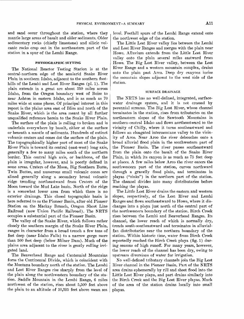
PHYSICAL ENVIRONMENT-A SUMMARY All
and sand occur throughout the station, where they mantle large areas of basalt and older sediments. Older sedimentary rocks (chiefly limestone) and silicic vol canic rocks crop out in the northeastern part of the station in a spur of the Lemhi Kange.
PHYSIOGRAPHIC SETTING
The National Beactor Testing Station is at the central-northern edge of the semiarid Snake River Plain in southern Idaho, adjacent to the southern foot hills of the Lemhi and Lost River Ranges (pi. 1). The plain extends in a great arc about 350 miles across Idaho, from the Oregon boundary west of Boise to near Ashton in eastern Idaho, and is as much as 70 miles wide at some places. Of principal interest in this report is the plains area east of Bliss and north of the Snake River, which is the area meant by all further unqualified reference herein to the Snake River Plain.
The surface of the plain is rolling to broken and is underlain everywhere by basalt, either at the surface or beneath a mantle of sediments. Hundreds of extinct volcanic craters and cones dot the surface of the plain. The topographically higher part of most of the Snake River Plain is toward its central (east-west) long axis, generally a few to many miles south of the northern border. This central high axis, or backbone, of the plain is irregular, however, and is poorly defined in some areas. Craters of the Moon, Big Southern Butte, Twin Buttes, and numerous small volcanic cones are alined generally along a secondary broad volcanic ridge trending northeastward from Craters of the Moon toward the Mud Lake basin. North of the ridge is a somewhat lower area from which there is no exterior drainage. This closed topographic basin is here referred to as the Pioneer Basin, after old Pioneer Station on the Mackay Branch, Oregon Short Line Railroad (now Union Pacific Railroad). The NRTS occupies a substantial part of the Pioneer Basin.
The valley of the Snake River, which follows rather closely the southern margin of the Snake River Plain, ranges in character from a broad trench a few tens of feet deep (near Idaho Falls) to a narrow gorge more than 500 feet deep (below Milner Dam). Much of the plains area adjacent to the river is gently rolling irri gated land.
The Beaverhead Range and Centennial Mountains form the Continental Divide, which is coincident with the Montana boundary north of the station. The Lemhi and Lost River Ranges rise sharply from the level of the plain along the northwestern boundary of the sta tion. Saddle Mountain in the Lemhi Range, 6 miles northwest of the station, rises about 5,500 feet above the plain to an altitude of 10,325 feet above mean sea
level. Foothill spurs of the Lemhi Range extend onto the northwest edge of the station.
The Little Lost River valley lies between the Lemhi and Lost River Ranges and merges with the plain near Howe. Alluvium extends from the Little Lost River valley onto the plain several miles eastward from Howe. The Big Lost River valley, between the Lost River Range and a western mountain complex, drains onto the plain past Arco. Deep dry canyons incise the mountain slopes adjacent to the west side of the station.
SURFACE DRAINAGE
The NRTS has no well-defined, integrated, surface- water drainage system, and it is not crossed by perennial streams. The Big Lost River, whose channel terminates in the station, rises from tributaries on the northeastern slopes of the Sawtooth Mountains in southern-central Idaho and flows northeastward to the vicinity of Chilly, where it turns southeastward and follows an elongated intermontane valley to the vicin ity of Arco. Near Arco the river debouches onto a broad alluvial flood plain in the southwestern part of the Pioneer Basin. The river passes southeastward from the plain onto the basalt of the Snake River Plain, in which its canyon is as much as 75 feet deep at places. A few miles below Arco the river enters the southwestern part of the station, curves northward through a gravelly flood plain, and terminates in playas ("sinks") in the northern part of the station. The channel divides into many distributaries before reaching the playas.
The Little Lost River drains the eastern and western slopes, respectively, of the Lost River and Lemhi Ranges and flows southeastward to Howe, where it dis charges into a playa just north of the central part of the northwestern boundary of the station. Birch Creek rises between the Lemhi and Beaverhead Ranges. Its channel, the lower reach of which is normally dry, trends south-southeastward and terminates in alluvial- fan distributaries near the northern boundary of the station. Within historic time, water from Birch Creek reportedly reached the Birch Creek playa (fig. 1) dur ing seasons of high runoff. For many years, however, the lower reach of the channel has been dry, owing to upstream diversions of water for irrigation.
No well-defined tributary channels join the Big Lost River channel in the Pioneer Basin. Part of the NRTS area drains ephemerally by rill and sheet flood into the Little Lost River playa, and part drains similarly into the Birch Creek and the Big Lost River playas. Much of the area of the station drains locally into small playas.

A12 GEOLOGY, HYDROLOGY, WASTE MANAGEMENT, NATIONAL REACTOR TESTING STATION, IDAHO
Ephe'meral runoff from the mountain slopes near the NETS flows only a short distance onto the plain before sinking into the ground along the western and northern edges of the station. Precipitation on the NKTS is very light, and there is little runoff, even locally, except during heavy local rainstorms or rapid snow melting. Some water enters the ground directly through permeable basalt and gravel, and some gathers in puddles from which part of it evaporates. Areas covered by soil and dune sand probably take up most precipitation as soil moisture.
LANDFORMS
The landforms of the Snake River Plain affect the suitability of the area chosen for the reactor-testing station, and they also disclose important facts about the geologic history of the plain. Specifically, land- forms and altitude strongly affect the climate, espe cially precipitation an important factor in a study of the sources and amount of recharge to the ground- water body on which the station depends for its water supply. The importance of topography in relation to climate was briefly summarized by Humphrey and Wilkins (1953) as follows:
Topography is very important to the climatology of the NRTS, particularly with respect to surface winds. Other effects of topography, or geographical location, are more mod erate temperatures than would otherwise be expected from the altitude and latitude, the dryness, and the large daily range of temperature. The Divide, to the north and east, holds back many cold, but relatively shallow, continental air masses which are diverted eastward. All air masses that enter the Snake River Plain must first cross a mountain barrier, regard less of the direction from which they enter. Because they are subject to lifting, these masses usually precipitate moisture over the mountains and enter the Plain sufficiently dry to give the region its desertlike characteristics. This dryness and the infrequency of low cloudiness permit intense solar heating of the ground during the day and rapid radiational cooling at night. The lower density of the air due to the altitude of the Plain also favors transmission of heat radiation. These factors all combine to give a large daily range of temperature near the ground which results in nearly simultaneous changes in most of the other meteorological elements as well.
The Snake River Plain was formed largely by the eruption and emplacement of great masses of volcanic rock. Weathering and erosion have modified only slightly the original emplacement forms of the vol canic materials. Because of the importance of the landforms on the plain, these are described below in some detail.
VOLCANIC FEATURES
Twin Buttes are the most prominent topographic features within the NRTS. Big Southern Butte, a
composite acidic volcanic cone several miles south of the station, is the most prominent single feature on the entire plain. The altitude of the plain in the south western part of the station is about 5,500 feet above mean sea level. East Twin Butte ("Little Twin Butte," "East Butte") and West Twin Butte ("Middle Butte") rise 1,100 and 800 feet respectively above the plain. Big Southern Butte ("Big Butte," "Big Western Butte") towers nearly half a mile above the level of the plain, reaching an altitude of 7,576 feet. Cedar Butte, a composite volcanic cone south of the station and near Big Southern Butte, was the source of one of the most recent lava flows that encroached on the NRTS.
Studies of recent lava flows on the station suggest that these flows may be from a rift zone trend ing southeast from Cedar Butte (G. H. Chase, oral commun., 1970). A tongue of this lava, having a maxi mum width of about 2 miles, extends northward from the southern boundary of the station more than 3 miles into T. 2 N., R. 30 E. The surface of this flow is marked by long, sinuous to ropy ridges in the basalt.
Craters of the Moon National Monument, an area of very young lava flows and prominent landmarks, is about 15 miles west of the southwest corner of the station.
Small lava domes and scattered volcanic cones are local landmarks on the station. Circular Butte, a small lava dome in sec. 24, T. 6 N., R. 32 E., and sec. 19, T. 6 N., R. 33 E., is the most prominent physiographic feature of the northern NRTS. It is about 250 feet high with a base diameter of a mile and a half. The rim of the butte encircles a rudely circular crater about 800 to 900 feet across and about 20 feet deep. Antelope Butte, an asymmetric cone in sees. 5 and 6, T. 7 N., R. 33 E., is about 150 feet high and has a base diameter of about a mile. A breached crater near the highest point of the butte is about 250 feet wide, 2,000 feet long, and 25 feet deep. Numerous other cones and craters occur throughout the NRTS and are especially numerous in the southwestern and southeastern parts. Twenty-two well-defined cones and groups of cones, craters, and irregular vents are listed in table 1. Numerous other small or obscure vents probably are present at the surface, and many older vents doubtless are buried by later flows and sediments.
The surface of the plain in the NRTS slopes gen erally northward, and at some places basalt flows lap against the foothills of the Lemhi and Lost River Ranges. In detail the rolling basalt surfaces commonly are rough and broken.
Long, sinuous ridges of basalt, ordinarily not more than 10 feet high, are common in basalt flows in the

PHYSICAL ENVIRONMENT-A SUMMARY A13
TABLE 1. Miscellaneous basaltic lava vents m the National Reactor Testing Station
Location Type
Height above plain
(feet) Remarks
T. 5 N., R. 31 E., center sec. 15______Cone and crater
center sec. 23 ______Possibly a fissure vent __
30
30
Cone formed by low rim less than 20 ft high, surrounding an irregular depression about 2,000 ft long, 500-700 ft wide, and 10-15 ft deep. A parasitic cone ("The Teat") occurs on the side of the crater, rising about 50 ft above the crater rim.
W l/z sec. 24 ______Group of cones
Craterlike depression about 2,000 ft long, 500 ft wide and 10-15 ft deep. Edges of crater rise about 15 ft above level of plain.
2-15 Field of about 100 small spatter cones less than 20 ft high, forming an arc, concave to the west, extending more than a mile along a basalt ridge.
T. 4 N., R. 30 E., E % sec. 16 ______Cone and crater _____ 30 "State Butte", a local landmark. Crater about500 ft long, 500 ft wide, and 20 ft deep.
T. 4 N., R. 33 E., NB%SW% sec. 20 _____ do __________ 70 Crater about 2,500 ft long, 2,500 ft wide, and35 ft deep.
T. 3 N., R. 28 E., NW^4 sec. 17 _________ do __________ 200 Crater about 2,000 ft long, 700 ft wide, and80 ft deep.
NW^4NE^4 sec. 30 _____ do __________ 15 Crater about 30 ft deep. T. 3 N., R. 29 E., NE1̂ sec. 4 _________ do __________ 50 Crater about 2,000 ft long, 600 ft wide, and 35
ft deep. NW^NW^ sec. 13 _____ do __________ 35 Crater about 150 ft long, 100 ft wide, and 15
ft deep.T. 2 N., R. 28 E., NW% sec. 2 _________ do __________ 50 Two cinder cones on crater floor. Crater about
30 ft deep. Triangulation station "Lavatoo" on one of cones,
sec. 17 and Four lava cones and one 10-70 Line of cones trending northwest. Two of conessec. 20. cinder cone. are covered with scoria and cinders.
^ sec. 18 ____l_Cone and crater __ 100 Crater containing two cinder cones. Triangula tion station "Jaggy" is on one of these,
near W ^ cor. Cones ____________ 15 A group of three small cones.sec. 18.
near NW cor. Cone _____ 50sec. 27.
T. 2 N., R. 29 E., center sec. 32 _____Cone and two craters _ 100 Craters each about 500 ft long, 200 ft wide, and20 ft deep.
T. 2 N., R. 30 E., SW^SE^ sec. 35 __Cone and crater _____ 80 Breached crater. T. 2 N., R. 31 E., SE}£ sec. 34 ______Cone _____________ 50
center sec. 36 _____Cone and crater _____ 15 Crater about 1,800 ft long, 800 ft wide and 40ft deep.
T. 2 N., R. 32 E., SW}£ sec. 1 ______.,_ do __________ 50 Crater about 20 ft deep.sec. 4 ___Cinder cone ________ 40 sec. 20 __Cone and crater _____ 80 Crater about 1,000 ft long, 500 ft wide, and 30
ft deep.^ sec. 36 _________ do __________ 50 Crater about 1,000 ft long, 500 ft wide, and 20
ft deep.
southern and eastern parts of the station, especially along the edges of flow sheets. The rock along the crests of most of these ridges is extensively fractured. Probably such ridges were formed in more than one way. A few irregular large masses of basalt occur in various attitudes in a small area near the eastern boundary of the station a few miles north of U.S. Highway 20. The mode of emplacement of these masses is not apparent.
Single basalt flows commonly have at their forward (outer) margin a characteristic border ridge. An
example of these ridges is in sec. 31, T. 5 N., R. 33 E. The ridge has more than 70 feet of relief in a hori zontal distance of 400 feet. Relief on other ridges in the eastern NRTS ranges from a few feet to 60 feet.
Three large caverns (lava tubes) in the basalt within the station are open to the surface where parts of their roofs collapsed. A tube in sec. 25, T. 3 N., R. 32 E., is about 700 feet long, 100 feet wide, and 60 feet deep. The middle 400 feet of the roof has col lapsed. Another large tube is in sec. 13, T. 2 N., R. 32 E., about a mile east of East Twin Butte. The visi-
A14 GEOLOGY, HYDROLOGY, WASTE MANAGEMENT, NATIONAL REACTOR TESTING STATION, IDAHO
ble part of the tube is about 35 feet long and 10 feet deep. Only about 10 square feet of the roof has col lapsed. A third lava tube is in sec. 16, T. 2 N., R. 32 E., between the Twin Buttes. The roof has collapsed in two places, leaving a natural bridge. The height of the tube is about 18 feet, and the width is about 30 feet. The walls of lava tubes characteristically are uneven but have a smoothed appearance. Commonly small stalactitelike fingers of lava project from the tube ceilings.
ALLUVIAL FEATURES
Ephemeral runoff from mountains adjacent to the NETS formed a belt of large alluvial fans that encroach on the western part of the station. The fans slope generally southeastward to eastward, having maximum gradients of about 100 feet per mile. On the station the fans at most places lap over basalt layers. Individual fans are drained by radial systems of shal low channels, few of which exceed 10 feet in depth. Alluvial fans and talus cones also cover small areas adjacent to the slopes of East Twin and West Twin Buttes.
The alluvial fan of Birch Creek extends southeast ward from the Birch Creek Valley, between the Beaverhead and Lemhi Ranges, and occupies a trian gular area in the extreme northern part of the NRTS. The fan slopes southeastward about 50 feet per mile within the station boundaries and laps eastward onto the sloping flanks of Antelope Butte. An intricate pat tern of channel scars less than 3 feet deep marks the surface of the fan, on which the most distinct channels are near the western margin. Small gravel mounds, about 2 feet high and less than 30 feet in diameter, are scattered over the fan. On the west and southwest the fan overlaps basalt at some places and at other places merges with local fans on the flanks of the Lemhi Mountains. Southward, the 'alluvium seems to grade into lake beds of Pleistocene age.
The Big Lost River channel winds northeastward about 30 miles through the NRTS on a flat alluvial plain a few feet to about 5 miles wide. The plain slopes northward about 20 feet per mile near the southwestern corner of the station but less than a foot per mile in the northern central part. The most marked break in the gradient is in the vicinity of State Butte in sec. 16, T. 4 N., R. 30 E. On the north, the alluvial plain merges with the bottom of ancient Terreton Lake. Abandoned channels are numerous on the alluvial plain, and much of the newest channel is braided. Meander scars and remnants of flood-plain terraces are present on the plain, especially south of U.S. High way 20-26. The flood plain is underlain largely by alluvium deposited by the Big Lost River and by a
few short ephemeral tributaries. Basalt crops out in a few short sections of the channel and at a few places on the flood plain. The alluvial plain is bounded at some places by the edges of basalt flows and ridges; elsewhere it merely merges with the basalt plain and playa floors. Features produced by modern stream action in the area are chiefly depositional, and there is no surface evidence of important erosion by the Big Lost River before deposition of the alluvium. South east of Arco the river occupies a basalt-walled canyon as much as 75 feet deep, but in the NRTS the main channel is incised to a lesser depth. Some abandoned channels in alluvium near the present main channel seem to be quite fresh; others have been almost obscured by wind erosion and deposition. The aban doned channels make an intricately branching and anastomosing pattern on the flood plain.
The relative freshness of channel scars and other features and the relative density and vigor of vegeta tion indicate that the alluvial plain was formed in three stages. On successively older parts of the plain the channel scars are more obscure, and the stand of vegetation is more dense than on younger parts. Also, older parts of the plain are marked in a few places by low gravel mounds 2 to 4 feet high and as much as 75 feet across at the base. The origin of the mounds is not known.
LAKE FLOORS AND PLAYA8
The bottom of a large former lake, ancient Lake Terreton, represented by nearly level surfaces under lain by lake sediments in low areas between basalt and alluvial deposits, includes about 35 square miles of the northern part of the NRTS. Lake-bottom deposits occur in additional areas where they are covered by later sediments. The maximum relief on exposed lake beds is about 26 feet, and the highest altitude, about 4,800 feet, is at the inferred shoreline. The lake bottom is generally featureless, but associated beach lines, bars, spits, and hooks locally are conspicuous (fig. 4). The bars and related features range in height from 4 to 25 feet. One sinuous bar is about 5 miles long; the rest are shorter, some being but a few yards long. Braided and abandoned channels of the Big Lost River and of Birch Creek are incised 1 to 10 feet in the lake floor.
Some low areas on the floor of ancient Terreton Lake are modern playas. Four principal playas with well-defined boundaries are interconnected by shallow channels with a maximum depth of about 6 feet. At the inlet to each playa there is a small delta. Birch Creek playa, the northernmost and largest of the four, occupies an area of about 5 square miles centered around sec. 14, T. 6 N., R. 21 E. This playa, the termi nus of both Birch Creek and the Big Lost River, is

PHYSICAL ENVIRONMENT-A SUMMARY A15
FIGURE 4. Birch Creek playa and beach and bar deposits of ancient Terreton Lake. Giant earth-crack patterns show in south and west parts of playa. (Photograph by Aero Service Corp.; scale, 1 inch equals about 1,500 feet.)

A16 GEOLOGY, HYDROLOGY, WASTE MANAGEMENT, NATIONAL REACTOR TESTING STATION, IDAHO
a^pg^»«p?»3
FIGURE 5. Big Lost River channels and playas south of Howe Point. (Photograph by Aero Service Corp.; scale, 1 inch equalsabout 1,500 feet.)
PHYSICAL ENVIRONMENT-A SUMMARY A17
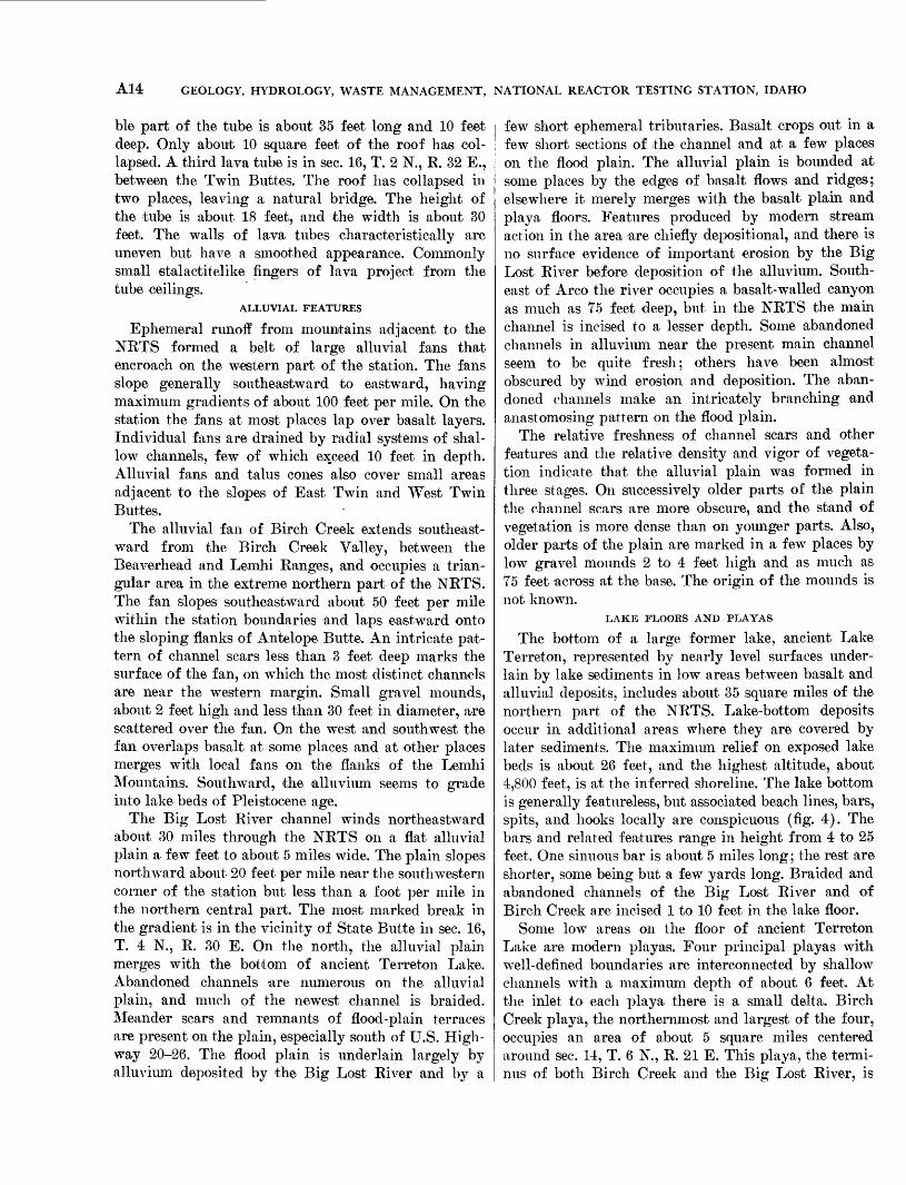
FIGURE 6. Windrows of drifted sand east of Circular Butte. (Photograph by Aero Service Corp.; scale, 1inch equals about 1,540 feet.)
A18 GEOLOGY, HYDROLOGY, WASTE MANAGEMENT, NATIONAL REACTOR TESTING STATION, IDAHO
bordered chiefly by bars and dunes. The lowest altitude on the playa floor is 4,774 feet, near the center of sec. 14, T. 6 N., E. 31 E. The three other playas are adja cent to the channel of the Big Lost Eiver upstream from Birch Creek playa, The lowest altitude on the floor of the first (farthest upstream) Big Lost Eiver playa (fig. 5) is 4,783 feet. The playa of the Little Lost Eiver is isolated. Other small playas are scattered throughout the station and receive only local runoff.
EOLIAN FEATURES
Unconsolidated windblown material mantles large areas of the NETS. The thickness and distribution of the mantle are influenced strongly by irregularities of the surface on which it rests. In the northeastern part of the NETS, numerous longitudinal dunes less than 8 feet high occupy narrow subparallel strips that trend northeastward (fig. 6). A group of active large dunes is in sees. 3 and 4, T. 5 N., E. 31 E., a few hundred feet west of Lincoln Boulevard. These dunes are up to 25 feet high and are roughly crescentic in plan, with con cave faces sloping about 30° NE. Elsewhere on the station, especially on irregular basalt surfaces and adjacent to flow fronts, patches of sand having irregu lar form and thickness are common.
CLIMATE
By RAYMOND L. NACE
Climate not only is a critical factor in construction and operation on the NETS but is also a principal fac tor in the hydrologic cycle. Personnel of the U.S. Weather Bureau (changed to National Weather Serv ice in 1970) have studied and reported on the climate of the NETS in detail. In this report, therefore, treat ment of climate is limited to general features that are directly related to water resources and related prob lems. Climatologic data collected by the U.S. Weather Bureau in 1949-54 at micronet stations in the NETS (Humphrey and Wilkins, 1953) showed that varia tions in weather and climate within the NETS are insignificant; consequently most of the micronet sta tions were discontinued. Since 1894, climatologic data have been collected at regular weather stations on the Snake Eiver Plain and adjacent areas. Descriptions of these weather stations are given in table 2 and their locations are shown on plate 1.
Currently, climatologic data are obtained regularly on the NETS at only two stations, one at the CFA and another at Test Area North (TAN).
The climate of the Snake Eiver Plain in the vicinity of the NETS is semiarid. Precipitation and humidity generally are low, and evaporation is rapid when mois ture is available. Daily, monthly, and annual tem-
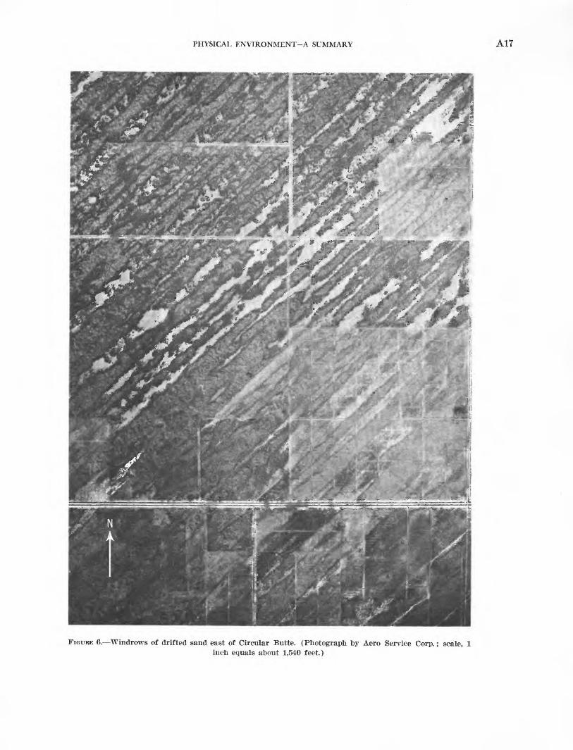
TABLE 2. Location and altitude of weather stations on the central Snake River Plain
Station
Idaho Falls 42 NW.1 _. Idaho Falls 46 WDubois Airport, CAA 2
Facility. Hamer 4 NWIdaho Falls Airport,
CAA 2 Facility.
Pocatello Airport, WB 3 Facility.
Springfield 1 SE _Aberdeen Experiment
Station.
Location
._43° 50' N., 112° 41' W43° 32' N., 112° 57' W44° 10' N., 112° 13' W _
. 43° 59' N., 112° 15' W _43° 31' N., 112° 04' W
._43° 11' N., 112° 21' W __42° 55' N., 112° 36' W
._43° 04' N., 112° 41' W _42° 56' N., 112° 50' W __
._43° 38' N., 113° 18' W _
._43° 47' N., 113° 00' W
Altitude above
mean sea level (feet)
_ 4,7804,933
__ 5,122
4,796__ 4,840
_ 4,503__ 4,444
_ __ 4,4054,400
__ 5,325_ 4,820
1 From Apr. 1, 1950, to Oct. 17, 1952, this station was at 43° 56' N., 112" 39' W., about 7 miles NNE. of the present location and at an altitude of 4,800 ft above mean sea level.
2 Civil Aeronautics Administration (changed to Federal Aviation Agency in 1958).
3 Weather Bureau (changed to National Weather Service in 1970).
perature ranges are large. Winds commonly are gentle to fresh. The range of weather conditions in successive years and groups of years is very wide. For example, January and February 1949 probably were the most severe winter months in southeastern Idaho during the period of record since 1893. The winter of 1951-52 was almost as severe. January 1953, on the other hand, was the mildest January in 60 years of record, with an average daily mean temperature of 30.0°F, com pared with a "normal" mean of 15.7°F in the CFA (Humphrey and Wilkins, 1953). Owing to such wide variation in yearly extremes, a year of "normal" weather on the Snake Eiver Plain is rare.
TEMPERATURE
The diurnal change of temperature on the NETS ranges from about 2°F to about 60°F. The common daily ranges of temperature are about 25° to 40° in winter and somewhat greater in summer. Temperature generally rises rapidly after sunrise, continuing up ward to midafternoon, after which it falls. After sunset the drop to minimum level is rapid. The monthly range of temperatures is about 50° to 75°, and the annual range is about 135°. The highest tem perature of record was 102°, and the lowest was 35°, both at the TAN station in the northern NETS. It is estimated (Humphrey and Wilkins, 1953, p. II-4) that the extreme high and low temperatures in the NETS (occurring only once in many years) are about -45° and 105°. The distribution of monthly and annual normal temperatures at the CFA and TAN
PHYSICAL ENVIRONMENT-A SUMMARY A19
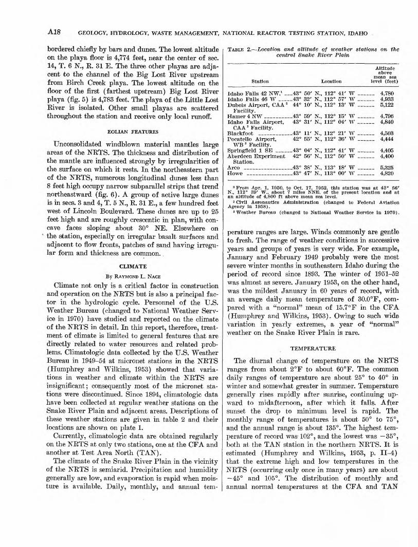
weather stations are given in table 3 (Yanskey and others, 1966).
Soil-surface temperatures on the NETS are as high as 140° in summer and 81° in winter (January maxi mum of record). The average daily high soil-surface temperature in January, the coldest month, is appreciably above freezing between 35° and 40° (Humphreyand Wilkins, 1953, p. II-3). It is especially significant that on sunny winter days thawing usually occurs on exposed surfaces even though the air temperature is well below freezing. The winter thawing of soil at the surface may be directly related to certain conditions concerning soil moisture and downward percolation of moisture.
TABLE 3. Monthly and annual normal temperatures, in degrees Fahrenheit, based on 1931 through 1960 data at the CFA and, TAN weather stations on the NRTS
[From records of U.S. Weather Bureau (changed in 1970 to National Weather Service) ]
Degree- Maximum Minimum Average day
CPA
January _ _ _ _ _ 27.5 3.2 15.4 1538February ______ 32.7 8.0 20.4 1249March __ _ _ _ 42.2 17.8 30.0 1085April _ _ __ __ 57.5 29.2 43.3 651May _ ___ _ 67.5 37.7 52.6 391June _ _ _ _ _ 75.9 43.6 59.8 192July ____ _ 87.9 50.1 69.0 16 August _ _ _ 85.7 47.4 66.6 34September __ _ 74.9 38.0 56.5 270October _ __ 61.5 28.2 44.9 623November _ _ 43.0 16.5 29.8 1056December _ _ _ 32.6 8.9 20.8 1370Annual _ _ 57.4 27.4 42.4 8475
TAN
January _ 26.5 0.2 13.4 1600February _ _ _ _ 32.2 5.6 18.9 1291March __ _ 42.4 16.1 29.3 1107April ____ _ 58.2 27.9 43.1 657May __ _ _ _ 68.7 36.6 52.7 388June _ _ _ 76.9 42.7 59.8 192July _ _ _ 89.0 49.2 69.1 16August _ _ 86.4 46.3 66.4 40September 75.5 36.7 56.1 282October _ _ _ 61.6 26.6 44.1 648November _ 41.9 14.2 28.1 3107December _ _ 31.3 6.3 18.8 1432Annual _ 57.6 25.7 41.7 8760
PRECIPITATION
Precipitation on the NETS occurs as dew, rain, hail, and snow. Owing to large yearly variations in seasonal weather, the period of record for the NRTS probably does not accurately show the "normal" or average amount of precipitation. Hence the values shown in table 4 were derived by the U.S. Weather Bureau by adjusting NRTS records to records from other stations on the plain for the base period, 1931-60 (Yanskey and others, 1966) .
TABLE 4. Monthly precipitation, in inches of water, at the CFA and TAN weather stations on the NRTS
[Highest, data through December 1964; normal, data based on 1931- 60 base period ; annual considers only full calendar year ; lowest, CFA, considers only full calendar year ; lowest, TAN, data through December 1964. From records of the U.S. Weather Bureau (changed in 1970 to National Weather Service)]
Average Highest Lowest Normal
CFA, January 1950 through December 1963
January _ _ 0.68 1.15 Trace 0.73February ______ .85 2.40 0.21 .77March _ .54 1.05 .12 .62April __ _ _ __ .65 2.50 .03 .51May _ _ __ ___ 1.41 4.42 .28 1.10June ___ _ __ 1.14 2.84 .02 1.09July . . .29 .72 Trace .26August _ _ __ _ .66 2.17 .02 .48September _____ .65 3.52 Trace .35October _ __ _ .43 1.53 .00 .66November _ .39 1.53 Trace .41December _ ___ .58 3.43 .12 .59Annual _____ 8.24 14.40 5.25 7.57
TAN, April 1950 through December 1963
January _ _ _ 0.52 0.84 Trace 0.55February _____ .57 1.83 0.08 .49Mnwh 49 1 07 TVflPf* 4f>
April .58 1.85 .01 .49May _ _ __ _ 1.37 5.04 .10 .88June _ ___ __ 1.19 3.35 .09 1.24TIT ITT ^H "1 QQ Tl'Q f*£* 44-
August __ _ _ .64 1.81 .06 .49September _ __ .71 2.51 .00 .63October _ _ .29 1.14 .00 .41November _ _ .33 1.42 .00 .33December .59 2.43 .07 .61Annual __ _ _ __ 7.85 15.60 4.37 7.02
Summer precipitation on the NRTS is largely by moderate to heavy rain showers, often quite local in their distribution. Thus, during short periods, cumu lative precipitation commonly is quite different at localities only a few miles apart. Chance local varia tions also produce differing annual totals at neighbor ing stations. Over a period of time, however, local variations tend to balance each other, and the amount of precipitation is almost uniform throughout the NRTS (Wilkins, E. M., oral commun., December 1954). Average precipitation is about 7.5 inches a year, which probably is also a fairly representative average value for a large part of the central Snake River Plain.
On the average, all months have precipitation, May and June having the highest, about 1 inch each. November has the least, with less than half an inch. January has the most days with precipitation, 11 to 17 days, and September the fewest, 0 to 6 days (Humphrey and Wilkins, 1953, p. VI-2). Comparative studies indicate that the maximum expectable rate of precipitation is about 1 inch per hour and about 2 inches in 24 hours ; this would occur as summer rain.
In average winters the maximum snow depth on the NRTS is 6 to 12 inches, though drifts 6 to 8 feet high

A20 GEOLOGY, HYDROLOGY, WASTE MANAGEMENT, NATIONAL REACTOR TESTING STATION, IDAHO
are apt to form when snow is available. In exceptional years the depth of snow on the NRTS is 1 to 2 feet, according to observations of the Weather Bureau. During the winter of 1951-52 Geological Survey field parties reported average depths of about 3 feet in seemingly nondrifted snow at some places.
During the winter of 1950-51 snow covered the ground at the NUTS for 72 days, and in the winter of 1951-52, for 131 days. Snowfall at the CFA ranged from 22.0 inches during 23 days in the winter of1950-51 to 30.4 inches during 53 days in the winter of1951-52. The water equivalent of these snowfalls was 2.1 and 3.05 inches, respectively.
TORRENTIAL RAIN
Occasional heavy thundershowers occur on the NETS, especially in midsummer, but cloudbursts are rare. Torrential rains occur occasionally in mountains and valleys west of the station, and under some circumstances, runoff from torrential rains is of con cern to the Atomic Energy Commission. Early minor control measures were applied to the Big Lost River within the NRTS because torrential rains occur occa sionally on the watershed. These consisted of channel straightening and deepening and raising river embank ments locally within the station. A flood diversion dam was constructed in 1958 at the site of the old town of Pioneer near the southwestern corner of the station to regulate high flows from occasional torrential rain.
HUMIDITY AND EVAPORATION
Relative humidity is a function of temperature, and the diurnal range of humidity, like that of tempera ture, is large. Relative humidity on the NRTS during all months of the year often is 100 percent after the marked nightly drop in temperature. On the other hand, relative humidity during the day sometimes is only a few percent in summer, and values as low as 5 to 10 percent are common. Average monthly and annual relative humidities at the CFA weather station are shown in table 5.
Information about evaporation rates is not available, but the average rate undoubtedly is relatively high when moisture is available because the low average humidity and strong prevailing winds both promote evaporation. Few natural open-water surfaces occur in the NRTS, but evaporation of shallow soil moisture and snow probably is high. The evaporation rate is important in connection with the design and operation of open-surface liquid-waste disposal facilities.
The nearest Weather Bureau evaporation stations on the Snake River Plain are at Aberdeen Experiment
TABLE 5. Monthly and annual averages and extremes of relative humidity, in percent, at the CFA weather station, January 1956 through December 1961
[All values based on hourly average readings except as indicated. From records of U.S. Weather Bureau (changed in 1970 to National Weather Sendee) ]
Average 1 Average maximum
AbsoluteAverage 1 minimum Maximum Minimum
January _ February _ MarchApril _ __TVIfl v
July _______August _ ____ September __ October ____ November _ December ___
68 70584446363031 3848 60 68 50
87 89 848183735965 7482 86 89 79
47 42 342322161615 18 24 30 40 27
100 100 100100100100
92100 100 100 100 100 100
15 14 14
88644 6 6
10 16 4
1 Computed from an hourly rather than a daily summary by month. Therefore, the indicated values will be a few percent higher for the maximums and a few percent lower for the minimums than would be the case if average maximums and minimums were computed from daily values.
Station and at Minidoka Dam, where class-A land pans are operated during 6 months each year. Evapo ration at those stations during May to October aver ages about 54 and 56 inches, respectively. The full-year total from land pans probably would be on the order of 60 to 62 inches. Evaporation from land pans exceeds that from open-water surfaces, and an adjusted value was obtained by applying a coefficient of 0.69 (see Follansbee, 1934) to the land-pan total. The coefficient was derived by Follansbee from a study of certain reservoirs in southern Idaho. The rate of evaporation from open-water surfaces varies with the size and shape of the surface, wind movement, average humid ity, and other factors. A reasonably approximate value for the NRTS probably is obtainable by assuming a rate about the same as those at the Minidoka Dam and the Aberdeen Experiment Station. On that basis, applying the Follansbee coefficient, annual evaporation from large open-water surfaces on the NRTS probably would be on the order of 41 to 43 inches, of which 85 to 90 percent would be during May to October.
Information is lacking about the rate of evaporation (including transpiration) in areas occupied by native plains vegetation. Sage and certain grasses thrive on the plain where precipitation is only 6 to 8 inches a year, and it seems likely that evaporation is on the order of 6 to 7 inches of water a year about equal to the average amount of precipitation on the NRTS. Inasmuch as precipitation is fairly well distributed throughout the year and there is no exterior surface drainage, most of the water probably restores soil

PHYSICAL ENVIRONMENT-A SUMMARY A21
moisture and is consumed by evaporation wherever soil cover on the basalt is adequate.
WIND AND DUST
The transporting and abrasive capacity of the wind are functions of wind speed. Wind direction and speed affect the size, form, and position of windblown de posits. The duration and velocity of winds affect the rate of moisture evaporation.
Graphic wind roses prepared by the U.S. Weather Bureau, based on continuous observations, show that the prevailing wind on the NETS at all times of the year is from the southwest quadrant. The degree of predominance of the southwest winds, however, varies noticeably in different parts of the plain, owing to variations in local topography and proximity to moun tains. For example, at the CFA the wind at the 20-foot level is from the southwest quadrant about 50 percent of the time, from the northeast about 30 percent, and from the northwest and southeast only about 20 per cent. In contrast, at the TAN station in the northern part of the NUTS the wind is out of the southwest quadrant only about 30 percent of the time, and there is a more uniform distribution of frequencies in other quadrants. Humphrey and Wilkins (1953, p. IV-4) noted that simultaneous winds at the north and the south areas may be from opposite directions and that the line where the change of direction occurs may be north of the Pole-line road.
The area north of the Pole-line road is topographi cally more varied than most areas on the NETS, and the local topography undoubtedly influences local wind direction. The form and occurrence of active and recently active windblown deposits in the central northern part of the NETS and nearby (see fig. 6) show that the prevailing southwest wind there is suffi ciently dominant that physiographic effects of other winds are obscure or absent. Thus, physiographic evi dence indicates that wind data for the CFA are more representative of the NETS as a whole than are the data from the northern station.
On the average, wind speeds on the NETS exceed 15 mph (miles per hour) about 5 to 6 hours per day. Peak gusts at these average speeds are 21 to 22 mph, which are sufficient to pick up and transport dust and snow. Dust stirred up by vehicles and construction activity is transported readily by slower winds. The maximum hourly wind speeds for various months range from 19 to 89 mph, and peak gust speeds range from 24 to 78 mph. Eecent windblown deposits and active dunes, especially in the north-central part of the NETS, indicate that erosive winds have been active in the area for a long time.
Much of the soil on the NETS, even where the sub soil is gravel, contains an appreciable amount of silt and clay, which form a soil crust when dried after a rain. Where this crust is undisturbed, it resists ordinary wind erosion. Thus, dust clouds rarely originate in virgin parts of the NETS. Where the soil crust is broken by traffic and construction, the soil is unstable, and even moderate winds raise dust clouds.
According to records of the Weather Bureau, the amount of dust in the air at TAN ranges from 0.014 mg m"3 (milligrams per cubic meter) when there is total snow cover in the aim to 0.15 mg m"3 dust devils prevalent. During 1,759 air-sampling hours, mostly during the windiest parts of days, the average concentration of dust was 0.07 mg m"3 . During July and August 1952 the concentrations ranged from 0.04 to 0.05 mg in"3 . At the CFA the dust concentration was 0.77 mg m"3 at the same time that the high of 0.15 mg m"3 occurred at the TAN. These facts accent the importance of ground-surface protection, espe cially where the soil is excavated for burial of wastes or where construction and vehicular activity are considerable.
Surface soil and sediment from all parts of the NETS contain small to large fractions of clay and silt, which is the fraction most apt to be picked up by ordinary winds. Fine sand commonly is drifted by ordinary wind, and winds in dust devils will move even small pebbles. Observations by the Weather Bureau show that winds averaging 16 mph in velocity, with gusts up to about 20 mph or more, cause visible dustiness. Dust-favoring winds occur about 10 percent of the time, and the ground condition favors dustiness about half the time. The frequency of dustiness thus is aboiit 5 percent of the time, chiefly in afternoons from April through October.
BAROMETRIC PRESSURE
Water levels in wells on the NETS fluctuate in response to changes of barometric pressure. Some wells are quite sensitive and their water-level changes caused by barometric fluctuations exceed those caused by pumping and other factors. Many wells that are not tightly cased to the water table form avenues of air circulation through which the ground breathes in response to barometric changes. The circulating air affects the operation of water-level recording instru ments. For these reasons barometric fluctuations have considerable importance in hydrologic studies, and a correction must be made for them in the records of water-level fluctuations obtained during pumping tests.
The barometer at the CFA is at an altitude of 4,933 feet above mean sea level. The TAN barometer is

A22 GEOLOGY, HYDROLOGY, WASTE MANAGEMENT, NATIONAL REACTOR TESTING STATION, IDAHO
about 120 feet lower, and barometric pressure there is about 3.05 millimeters of mercury greater than at the CFA. Barometric-pressure differences, other than those caused by altitude, probably are negligible on the NETS; that is, at a given time the pressure is reason ably uniform throughout the station.
Extreme limits of the barometric pressure at the CFA station are about 609.6 and 660.4 mm of mercury. Diurnal pressure changes caused by atmospheric tidal effects are so small that they are almost hidden by the changes caused by moving pressure systems. (Humphrey and Wilkins, 1953, p. V-l).
Fluctuations of barometric pressure, rather than absolute values, are of concern in studies of water-level fluctuations. Inasmuch as the fluctuations and trends during the period studied are the only fluctuations of value in that study, the average, high, and low baro metric pressures of record have no special value for this report and are not summarized herein.
GROUND CONDITIONS
By RAYMOND L. NACE
The Weather Bureau regularly observes and records ground-surface conditions on the NETS, such as snow cover, wetness or dryness, presence of ice and slush, and the air temperature immediately above the ground surface. Additional observations have been made by the Geological Survey of shallow subsurface ground conditions, including soil moisture and temperature. The soil temperature and ground-level air temperature affect the melting of snow, surface runoff, penetration of water in the ground, and the amount and behavior of soil moisture.
FREEZING AND THAWING
July is the only month of the year in which air temperatures recorded at the CFA station have not fallen below freezing during the 15 years of weather observations. Freezing temperatures were very rare in August, however, and occurred on only 1 to 6 days in June and 6 to 7 days in September. Conversely, thawing temperatures in winter were surprisingly common. Three to 10 thawing days occurred in Janu ary, the coldest month, and during November through March the temperature fluctuated above and below freezing on 50 to 90 days. Thus snow is apt to melt sporadically throughout the winter on the NETS.
Spring thawing at times yields more water than is needed to restore soil moisture or than is able to filter into frozen soil. The excess may run off into local basins or evaporate, but some of the water percolates downward and recharges ground water. Eecharge is especially apt to occur if a heavy snow cover is
retained until a spring thaw turns the so-called desert into a morass of mud and melt-water puddles. One such thaw occurred late in February 1950. Every local topographic hollow became a fresh-water pond, and many playa basins contained small lakes with water a few inches to 4 or 5 feet deep. Eunoff on local slopes at some places ranged from a maze of rills to veritable sheets of water. Eyegrass Flat, a playa astride U.S. Highway 20, 4.5 miles east of the CFA, was filled with water to a level nearly a foot above the road surface and probably more than 5 feet deep. At several other localities between Eyegrass Flat and Atomic City, the road was inundated.
Floods of the type described are uncommon, but their recurrence is attested by water-laid sediments in small basins throughout the basalt area. The water disappears from these basins more rapidly than is possible by evaporation alone. Obviously, much of the ponded water becomes soil moisture, and an appreci able excess undoubtedly percolates to the zone of saturation and recharges ground water.
In the dry, cool climate of the Snake Eiver Plain, chemical weathering of rock and soil is very slow. Mechanical weathering by insolation and frost pry is relatively rapid, and these processes comminute the volcanic rocks and annually loosen the soil. Blocks of lava in the talus slopes around West Twin Butte, for example, doubtless were loosened from the butte by frost pry and insolation. Frost heave at times is a significant problem in the maintenance of roads and building foundations.
SOIL TEMPERATURE
Generally low humidity, infrequent cloudiness, and moderate atmospheric density permit rather intense insolation of soil and rock surfaces during the day and rapid heat radiation at night. The diurnal range in the temperature of soil and rock surfaces in the NETS therefore is large. Owing to the generally poor con ductivity of soil and rock, however, the diurnal varia tions of temperature do not extend very deeply. The range of temperature is small at a depth of a few inches and is barely detectable by ordinary devices at a depth of a few feet.
Observations by the Geological Survey on subsurface temperatures included operation of a continuously recording thermograph for more than a year adjacent to well 3N-29E-14adl, near the Materials Testing Eeactor site. The thermometer bulb was buried at a depth of 2.7 feet (the limit of the extension cable). Detailed records of the temperature at 3-hour intervals are available in the District Office, Water Eesources Division, U.S. Geological Survey, Boise, Idaho.
PHYSICAL ENVIRONMENT-A SUMMARY A23
The thermometer bulb was in the zone of weak diurnal and relatively strong annual change. In gen eral, the soil temperature was highest during the night, usually between 3:00 a.m. and 6 a.m. The time of maximum temperature at the given depth lagged 9 to 18 hours behind that of maximum air temperature, which occurs most commonly about 3 p.m.
The diurnal range of soil temperatures at 2.7 feet was 1° to 3°F in summer and about 1° to 2° in winter. The total range during the year was 45°, from a maxi mum of 75° on August 2, 1953, to a low of about 30° at various times in December and early January. Although there are gaps in the record, the soil temper ature at the depth of the installation appears to be above 42° (the mean annual air temperature) from about mid-March to late November.
Inasmuch as the instrument was not calibrated, the record of soil temperature is only approximate. At the depth and site of the thermometer installation, the soil temperature seemingly did not fall much below freez ing, and during much of the winter the temperature was above freezing. In ordinary winters, ground like that at the observation station probably is seldom continu ously frozen below the depth of 3 feet. The tempera ture in other kinds of soil, with differing moisture content and vegetative cover, undoubtedly differs appreciably from that at the observation station. The subsurface temperature in basalt probably differs even more markedly.
The temperature and moisture content of the soil affect infiltration and deep percolation of water. Frozen ground transmits little or no water downward. Dry ground at freezing temperature accepts some moisture which, on freezing, reduces the permeability. Ground ice reduces or eliminates the hydraulic perme ability of the soil, which rejects potential soil moisture and ground-water recharge. The rejected water may run off or be ponded on the frozen ground.
ROCK TEMPERATURE
Kock temperatures undoubtedly differ materially from those of soil on the flood plain of the Big Lost River, especially in areas where the rock is exposed to the atmosphere. Fractures and other megascopic voids in the basalt allow interchange of ground air and atmospheric air, and the temperature, at least of the shell of subsurface blocks of basalt, probably varies more widely and rapidly than soil temperature at the same depth. Other factors also tend to cause a con siderable range of temperature in the rock. The basalt is dark to black in color, and exposed rock tends to absorb more solar heat than ordinary lighter colored
soil. Soil, on the other hand, has the higher heat con ductivity, which is even greater when the soil is moist. Thus, in summer the rock may be hotter than soil at the surface, but the decrease of temperature with depth is more rapid in the upper part of the rock. The spe cific heat of basalt and ordinary sediments does not differ markedly, but the basalt, being dense, stores more heat per unit volume. In the rock, residual sum mer heat carried over to winter would tend to melt snow more rapidly on rock than on soil, and an appre ciable amount of melting would be from below. The circumstances probably are comparable to those on a blacktop road where both upper and lower surfaces of a coating of ice commonly melt during thawing weather.
GROUND AIR AND GROUND ICE
Air circulation in the ground commonly creates tem perature inversions, and rock at freezing temperature occurs at places below warmer rock and soil. Where permeable rock is widely exposed to the atmosphere, ground-air circulation is minor, probably chiefly by convection, by wind pressure, and by changes in baro metric pressure. Rapid and extensive air circulation occurs in permeable rock that is overlain by tight rock or soil if the permeable zone has a surface outcrop or is tapped by a well or other opening. Rising atmos pheric pressure forces air into the rock, and falling pressure allows it to move out.
The phenomenon of "blowing and sucking" wells was mentioned long ago by Hay (1895) who found it to be generally known on the Great Plains. The air currents caused whistling and moaning noises in wells, the pitch varying with the size and form of the aperture. It was noted that the blowing noise always preceded a storm of some kind, and the sucking oc curred after a storm. The alternate blowing* and suck ing before and after storms accords with the known phenomena of low pressure and high pressure masses of air associated with storms. Temperature is a factor in the phenomena because variations in atmospheric pres sure ultimately depend on variations in temperature.
Barometric circulation of ground air is a character istic phenomenon on the Snake River Plain and is very noticeable in many breached lava tubes and in most deep wells that are not cased to the water table. The wind velocity through constricted openings probably ranges up to 15 mph when atmospheric pressure is changing rapidly. Some wells blow so hard at times that drilling water cannot be poured in but must be fed to the bottom of the hole with a hose, pipe, or bailer.

A24 GEOLOGY, HYDROLOGY, WASTE MANAGEMENT, NATIONAL REACTOR TESTING STATION, IDAHO
Ground ice occurs on the Snake Eiver Plain in so- called caves (breached lava tubes), in depressions on basalt flows, and in sheltered areas in broken, blocky basalt. The amount of ice in some caverns varies sea sonally and is said to wax and wane in climatic cycles. Concerning cave ice in Craters of the Moon National Monument, Stearns (1928, p. 18-19) said:
Water and ice also occur in the lava caves or tubes where drafts of cold air freeze any water that percolates into them. The freezing period covers about seven months in the year, and during the remaining months there is a gradual wasting away of the ice. Even during the summer days the temperature of the interior of the caves does not rise above 40° F.; hence melting proceeds very slowly.
Lay observers report that in some caves on the Snake Kiver Plain the ice completely disappears in the winter but re-forms in summer. Very likely ground ice forms in several ways, and its seasonal changes also probably are varied. For example, irrespective of the rock tem perature, ice will not form unless moisture is available. The low summer air temperature in caves suggests that the summer rock temperature is about the same as the mean annual atmospheric temperature. Although cold winter air reduces the rock to freezing temperature, water might not be available to form ground ice until surface snow melts in the spring. Ground ice formed from vadose water in the spring might persist until fall or winter. Disappearance of ground ice during winter may be by sublimation. Barometric circulation of ground air probably plays an important part in the formation of cave ice.
Another unusual phenomenon on the plain, seem ingly controlled by air circulation and subsurface temperature, is ponding of water in bowllike depress ions on the surfaces of basalt flows. Numerous pools were observed from the air during a flight in the spring of 1949, several weeks after most snow had dis appeared from the plain. The water pools were on a relatively young basalt flow south of the Union Pacific Railroad, several miles south of Atomic City. The pools ranged in diameter up to 10 or 15 feet; water in them may be several feet deep at times. A plausible explanation for the occurrence of the pools is that winter rock temperatures at shallow depth are below freezing. Melt water from snow enters the cold rock and freezes, forming an impermeable ice pan filling all the interstices in an appreciable thickness and area of rock. Residual melt water perches in a pool on top of the ice, and thereafter the ice melts only slowly. The sheltered position of the deeper depressions, which are in shadow during part of the sunshine hours, and the reflection of solar heat from the water surface dur ing hours when the angle of incidence is low inhibit
melting. Evaporation of the water also is slow because the ponds are sheltered from wind. Hence, many pools of water persist for days or weeks, depending on com binations of factors. Some pools may be perennial. The presence of deer on Cedar Butte near the observed pools of water seems to indicate the presence of some nearby perennial source of water. Numerous pools in blocky lava flows in Craters of the Moon National Monument were described by Stearns (1928). Ponded water was not observed on basalt in the NRTS, and detailed study of the phenomenon was not made.
SOIL MOISTURE
Yearly variations in precipitation on the NRTS have been noted and consist of alternate dry and less-dry groups of years. Precipitation records for southern Idaho show that rainfall was relatively low from 1950 to 1960, but 1960 through 1964 was an exceptionally wet period. Climatic variations may be accompanied by cumulative changes in soil moisture. Evidence such as large vertical earth cracks in the vicinity of the Birch Creek playa indicates that desiccation is occurring there, but the desiccation may be from strictly local causes such as lack of water from Birch Creek. Geo logic evidence shows, however, that other desiccation periods occurred during the recent past.
Preliminary study has been made of soil moisture and desiccation in the northern part of the NRTS. Labora tory measurements were made in the Materials Labora tory, NRTS, of soil moisture in 13 samples of clay and silt from excavations in earth-crack areas of the Birch Creek playa. The Survey measured soil moisture in 44 additional samples from the same area. The laboratory determinations were accurate for the samples as de livered, but the circumstances of collection may have caused the moisture content of samples to differ from that of undisturbed sediments in place.
The very fine sediments of the Birch Creek playa and ancient Terreton Lake are high in porosity and moisture-retention capacity but are nearly imperme able. Moisture does not penetrate the sediments read ily, and infiltration probably is chiefly through mud cracks, animal burrows, and root holes. Once wetted, the sediment below the superficial layer tends to hold moisture tenaciously, but the surface, layer dries read ily and is broken by ordinary mud cracks. Cumulative desiccation and shrinkage is the inferred cause of the development of large earth cracks in the Birch Creek playa and vicinity. The earth cracks will be described in detail, in a subsequent chapter on geology in this report series.

PHYSICAL ENVIRONMENT-A SUMMARY A25
FINE SEDIMENTS
Samples were collected from three clamshell ex cavations that intercepted earth cracks. In one exca vation at the TAN area the earth cracks were new, and water had entered the ground through the cracks only a few weeks before the sampling, which was from depths of 13 to 50.2 feet. The moisture content ranged from 6.5 to 27.7 percent (table 6). The amount of moisture in at least some of these samples un doubtedly was increased by recent additions of water through cracks. In the normal sediment in place, the distribution of moisture probably is more uniform at a given depth, whereas in the samples of disturbed sed iment, variations seemed to be random. Very likely the amount of moisture in undisturbed sediment a few feet below the surface in the TAN" area ranged from about 5 to 10 percent.
Sediment samples from excavations through old and new earth-crack areas in the Birch Creek playa were more uniform in moisture content, which ranged from 12.5 to 17.1 percent. These values may not be repre sentative of the playa sediments as a whole because samples from auger holes outside the earth-crack areas have generally lower moisture contents.
TABLE 6. Moisture content of Terreton lake beds and playa sediments, northern part of NRTS
[Disturbed grab samples from open pits. Analyses by Materials Laboratory, NRTS]
Date of col lection (1953)
Depth below
surface Source of sample (feet)
Percent age of
moisture (by
weight)
Samples from excavation through new earth cracks, TAN area
Oct. 27
27
Nov. 3
19
19 Dec. 14
15
Samples from
NOV. 27
Dec. 2
2
Sample from
Dec. 9
North wall of excavation, 2.5ft from east crack.
North wall of excavation, 3.5ft. from east crack.
North wall of excavation, 5 ft from northeast crack.
East wall of excavation, 5 ftsouth of northeast crack.
_______ do __________West wall of excavation, 4
in. south of west crack.West wall of excavation, 5
in. south of west crack.excavation through old earth cracks
SE%SW% sec. 14, T. 6 N., R. 31
East wall of excavation, 2 ftnorth of east crack.
Material filling north crack in excavation.
West wall of excavation ___
excavation through new earth cracks SW%SW% sec 14, T. 6 N., R. 31
East wall of excavation, 2ft south of east crack.
13
21
30
37
40 50
50.2
in Birch E.
10
16
20
in Birch E.
10
14.6
14.3
13.6
6.5
27.7 10.3
6.9
Creek playa,
12.5
16.4
17.1
Creek playa,
16.3
5 10 15 20
DEPTH OF SAMPLE, IN FEET BELOW LAND SURFACE
FIGURE 7. Moisture content of playa and lake beds in sees. 14 and 23^ T. 6 N., R. 31 E.
Samples from two auger holes in sees. 14 and 23, T. 6 N., E. 31 E., were more carefully collected and probably fairly represent moisture conditions at the sampling sites. The auger hole in sec. 23 was on the embankment formed by a silt bar deposited in an ancient lake. The auger hole in sec. 14 was 6 feet from an earth crack, and the samples contain somewhat more moisture than those from sec. 23, probably be cause more moisture sinks into the playa floor than in the embankments. The results of laboratory tests are summarized in table 7 and are shown graphically in figure 7. The results do not disclose any obvious systematic variation of moisture content with depth, but there is a general downward increase, especially in the samples from sec. 14. The vertical distribution in moisture content undoubtedly varies with the sea sons. Further study on variation of moisture content of fine sediments with depth and time is needed.
COARSE SEDIMENTS
Practically no information is available about mois ture in the coarse sediments. At most places the coarse gravel in the flood plain of the Big Lost Kiver is loose and unconsolidated, but in some gravel pits and other excavations there is a lightly cemented zone of gravel

A26 GEOLOGY, HYDROLOGY, WASTE MANAGEMENT, NATIONAL REACTOR TESTING STATION, IDAHO
TABLE 7. Moisture content of Terreton lake beds sediments, Birch Creek playa and vicinity
[Auger-hole samples. Analyses by Hydrologic Laboratory Survey, Denver, Colo.]
Laboratory No. of sample (series
1954 :Id)
Depth below
surface Nature of sample (feet)
and playa
Geological
Moisture content (percent of dry weight)
NW% sec. 14, T. 6 N., R. 31 E.
1
2 3 4 5
67 8 9
10
11
12 13 14 15
16 17 18 19 20
21 22 23 24 25
Silt, light-yellow to brown, 0.5 structureless.
__ __ do _ _ 1__ do __ _ _ 2
_ do _ _ 3Silt, clayey with platy 4.5
structure. Specific grav ity, 2.74.
____ do ___ 5Silt, light-yellow to brown 6
__ __ _ do __ 7do 8
Silt, light-yellow to brown. 9 Specific gravity 2.74.
Silt, very fine sandy at 10.5 10 to 11 ft.
Silt, light-yellow to brown 11 do _ _ 12
___ do _ 13__ _ __ do _ 14
Silt, light-yellow to brown 15 do _.__ 16
_ __ do __ _ 17do __ _ 18
__ __ _ do __ 19
do _ __ 20__ do 21
do _ _ 22___ _ do _ 23
Silt, light-yellow to brown. 23.8 Specific gravity, 2.74.
'6.4
8.7 8.1 8.1
2 7.6
9.28.9 8.8 9.7
3 9.8
7.4
11.2 12.5 10.9 10.4
11.1 11.0 9.2
10.8 4 12.5
9.1 9.8
11.2 13.9
5 16.3
NE%NW% sec. 23, T. 6 N., R. 31 E.
26
27 28 29 30
31 32 33 34 35
36 37 38 39 40
41 42 43 44
Silt, light-yellowish brown, 0.5 coarse, granular.
_ do _ _ _ 1do 2do 3do _ __ _ 4
_ _ do 5_ _ _ do __ _ 6_ _ _ do _ 7
Fine sand at 8.5 ft 8Silt at 9.5 ft 9
Fine sand at 10.5 ft 10Silt at 11.5 ft 11Silt I9
_ _ do _ 13 do _ 14
do 16Silt (limey layer at 17.0 ft) 18 Silt 20
5.1
7.8 7.7 8.8 7.9
8.7 8.0 8.2 8.5 6.1
8.8 7.5 7.2 7.4 7.4
7.38.8 9.8 7.3
i 2 3 4 5 Centrifuge moisture equivalents, in percent:
2 io!e!3 11.0. 4 17.0. 5 16.4.
whose top is 8 to 15 feet below the land surface. The cement is calcium carbonate, probably a residue from evaporated soil moisture. The cemented zone may be the zone below which moisture ordinarily does not reach and in which minerals leached from the shal lower zone are deposited during evaporation. However, moisture is present in a silty-clay layer that is common at the base of the gravel, resting on basalt. In several excavations the silty clay, beneath 30 and more feet of gravel, was sufficiently moist to be somewhat plastic.
ECONOMIC DEVELOPMENT
POPULATION CENTERS
Within a 50-mile radius of the CFA (fig. 1) there are eight towns and villages having populations of more than 300 (table 8), and the total town popula tion within that radius is somewhat more than 50,000. The total town and rural population in the circular area probably approaches 90,000. Important towns near this area and their populations in 1960 are Pocatello (28,799), Eexburg (4,784), St. Anthony (2,700) and Rigby (2,281). Population centers on the Snake Eiver Plain are widely spaced, and most of the plain around the NETS is uninhabited.
Most government and contractor personnel employed on the NETS reside in Idaho Falls, Blackfoot, Poca tello, and Arco. Atomic City, an unincorporated village near the southeast corner of the NETS, has a population of about 50, largely transient. Howe, an unincorporated crossroad trading center near the central-western boundary of the NETS, has about 50 inhabitants. Terreton and Mud Lake villages, on State Highway 28 in the southern part of the Mud Lake basin, are trading centers for local farmers and head quarters for a few small businesses. The population of Terreton is about 60.
TABLE 8. Populations of principal communities within 50-mileradius of the Central Facilities Area in 19^0, 1950, and 1960
[From U.S. Census of Population, 1940, 1950, 1960 (U.S. Bureau of Census, 1963)]
Community 1940 1950 1960
Aberdeen _ _ 1,016 1,486 1,484Arco _ _ _ _ - 548 961 1,562Blackfoot _ _ 3,681 5,180 7,378Idaho Falls _ 15,024 19,218 33,161Mackay _ 776 760 652Moore _ , *300 256 358Roberts _ . 319 341 422Shelley _ - 1,751 1,856 2,612
23,415 30,058 47,629
1 Unofficial estimate.

PHYSICAL ENVIRONMENT-A SUMMARY A2T
TRANSPORTATION
The National Eeactor Testing Station is accessible by rail, highway, and air. The Mackay Branch of the Union Pacific Railroad crosses the southwestern part of the NETS, and a government freight spur extends to the CFA. The nearest commercial passenger airport, at Idaho Falls, is served by two scheduled lines and by charter-plane companies.
The NETS is traversed by all-weather paved high ways, and both the public and government road nets have been improved and extended. constantly during development of the station. The principal regional road net is shown in figure 1.
AGRICULTURE AND PRIVATE INDUSTRY
Sheep and cattle grazing are the principal agricul tural industries on the uninhabited basalt plain. Parts of the plain are dry-farmed, but that industry is pre carious because of scanty and uncertain rainfall. The principal dry-farm crop is wheat. Irrigation agricul ture is extensive in favorable areas, as in the valleys of the Big Lost and Little Lost Eivers and Birch Creek, in the Mud Lake basin, and in a wide belt bordering the Snake Eiver. Small grain and row crops are widely cultivated. In recent years, irrigation has spread into formerly undeveloped parts of the plain proper, being based on the large ground-water supply which for merly was virtually unexploited.
Within a 50-mile radius of the CFA there is very little industrial development. Most towns are shipping centers for farm products, and the principal industries are railroading, trucking, and food processing. Other industries include beet-sugar manufacture, potato packing and dehydration, seed and food packing, food freezing, flour milling, and many others. Thirty-six industrial plants in the area employ 25 to 500 people each, but most plants employ less than 250. Nine of the plants operate only seasonally. Pocatello, which is outside the 50-mile zone, is the largest industrial cen ter in Idaho. The Mud Lake basin contains a large migratory waterfowl refuge. Conservation and exploi tation of wildlife is one of the principal activities of Idaho.
Early in the century the Utah Construction Co. made an abortive attempt to irrigate a large area in the Pioneer basin, including part of the present NETS. The irrigation plan depended on water from the Big Lost River, but the supply was inadequate and the part of the project on the NETS was abandoned. The ruins of a small diversion dam on the Big Lost Eiver near old Pioneer Station, well-preserved canals and ditches, and old cultivation scars on the Big Lost Eiver flood
plain in the southern NETS are all that remain of the project. Old canals leading from the Mud Lake basin to the area south of Circular Butte were constructed by the Second Owsley Canal Co. to irrigate a part of the plain. That project also was abandoned because of the shortage of surface water.
Small tracts of land on the NETS were homesteaded several decades ago, and a few tracts were patented. Sporadic nonresident dryfarming was practiced lo cally, as on Eyegrass Flat, but the area occupied by the NETS was uninhabited and mainly undeveloped before World War II. The principal activity was sea sonal grazing of sheep and cattle. At present (1969) stock grazing in selected areas is the only activity on the NETS not related to reactor development.
WATER USE
PRIVATE WATER USE
All public water-supply systems in communities near the NETS use ground water. Stock, rural domestic, and industrial water supplies also are chiefly ground water. Much irrigation is with surface water, but ex tensive agricultural development with ground water has occurred on the Snake Eiver Plain since 1946. No reliable data are available on the volume of ground- water pumpage, but little is pumped in the vicinity of the NETS. There are large developments in the Mud Lake basin and in a belt extending from Idaho Falls to Blackfoot and Springfield. The directions and dis tances to these developments are such that they do not compete with pumping on the NETS. Uses of ground water farther downstream, as on the North Side Pump ing Division of the Minidoka reclamation project, on private lands in Gooding, Jerome, and Lincoln County, and for private development of the springs in the Snake Elver valley below Milner Dam, are only in directly competitive with use on the NETS.
A nearby area of potentially substantial irrigation with ground water is in the Little Lost Eiver valley near Howe. The total acreage of potential development in the lower part of the valley is about 21,400. Large new developments and use of ground water on the plain may lead to competition in the future.
The Little Lost Eiver valley contributes an unknown but substantial amount of ground-water replenishment to the NETS area. Mundorff, Crosthwaite, and Kilburn (1964) estimated 150,000 acre-feet per year of under flow from Little Lost Eiver valley to the Snake Eiver Plain aquifer system. Irrigators could not, by pump ing, intercept all ground water that moves from the Little Lost Eiver valley to the NETS, but strategically

A28 GEOLOGY, HYDROLOGY, WASTE MANAGEMENT, NATIONAL REACTOR TESTING STATION, IDAHO
located numerous wells might intercept about 30 to 40 percent of the water (Mundorff, and others, 1964). The full undeveloped irrigable area of 21,400 acres would have a consumptive-use requirement of about 40,000 acre-feet a year. Depletion of ground-water underflow by that amount might have a noticeable effect on water levels in nearby parts of the NETS.
The extent of irrigation in counties adjacent to the NETS, according to the 1964 U.S. Census of Agricul ture (U.S. Bureau of Census, 1967), is summarized in table 9. A breakdown of ground-water and surface- water irrigation is not available. The estimated area irrigated with ground water in those counties in 1964 was about 175,000 acres; pumpage was about 555,000 acre-feet of water, equivalent to an average flow of about 1,850 cfs during a 150-day irrigation season. Much of that pumping is in localities far from the NETS.
TABLE 9. Land area and irrigation, by counties, in or near the NRT8, 1964
Item Bingham Bonneville Butte Jefferson
Land area :Approximate
total acres__In farms _ acres _Irrigated _ acres _
Water used per irrigatedacre ____ acre-ft _
Total wateruse __ _acre-ft _
1,326,080968,939248,233
6.2
1,540,000
1,166,080497,825133,892
5.2
696,000
Gross total water use in the four counties _ ____
1,433,600154,893
39,673
3.4
135,000
_ acre-ft _
696,960338,848155,602
7.7
1,100,000
3,471,000
WATER USE ON THE NATIONAL REACTOR TESTING
STATION
Water for use on the NETS ordinarily is obtained from wells. The chief uses are for reactor cooling and moderating, as a shielding and cooling medium for the temporary storage of spent nuclear-fuel elements, for washing and decontaminating machinery and
TABLE 10. Water use at permanent facilities on the NRT8
[Data in thousands of gallons. From records of the Atomic Energy Commission: ARA, Auxiliary Reactor Area; CFA, Central Facilities Area; BBR, Experimental Breeder Reactor; EOCR, Experimental Organic Cooled Reactor; ICPP, Idaho Chemical Processing Plant; NRF, Naval Reactors Facility; OMRE, Organic Moderated Reactor Experiment; SPERT, Special Power Excursion Reactor Test; TAN, Test Area North ; TRA, Test Reactor Area]
Facility
TRA ____ _ _____ ________CFA ___ __ __ ____________TAN _ __ _ ______ __EOCR __________ __ ____OMRE __ __ _ _ ________ICPP _ __ ______ _____EBR-I _ ____ _ _ ________EBR-II ____________ _ _NRF ____ _ _ ____ __SPERT ___________ _____ARA ____ _ _______ _Fire Station 1, 2 ____ _ __Fire Station 2 _ _ _Experimental dairy farm
Yearly total _ _
Facility
TRA ____ _ _ _ _ _ _CFA _ _ _ _ _ _ _ _TAN _______ _ _ _EOCR _ _ _ _ OMRE _ _ICPP _ _ _ _ _EBR-I _ __ _ _ _EBR-IINRFSPERT _ARA ______Fire Station 1, 2 _Fire Station 2Experimental dairv farm
Yearly total
*1952
____ 73,939- - 13,022
64,05324,845
4,941
180,800
1961
_ _ 691,519.1101,737.9115,407.8
KA K-| 0 ft
317,321.22,424.0
12,862.2554,318.0
14,655.93 16,979.9
1,187.5
1,882,926.3
1953
224,76152,824
343,59094,550
40,377
756,102
1962
709,028.7109,378.385,334.3
48,951.8387,912.9
1,540.817,970.186,113.311,219.63 4,725.0
1,012.4
1,463,187.2
1954
350,51173,93218,631
224,9207,201
87,212
762,407
1963
658,684.485,466.471,851.69,237.7
94 ^Q7 8
327,339.242,318.627,013.989,352.816,665.018,861.31,548.9
1,372,910.6
1955
314,10680,22041,798
373,00036,162
95,598
940,884
1964
673,012.095,023.852,250.116,767.0
359,858.2175,064.734,532.3
387,933.019,562.94,951.81,114.6
1,820,070.4
2 1959
314,524.944,471.048,721.2
14,827.8162,269.085,610.9
220.8171,013.0
2,880.23,316.7
180.3
848,035.8
1965
807,070.0100,772.475,616.820,727.3
478,837.318,652.464,105.9
270,828.010,974.0
7,674.9
1,128.730,800.0
1,887,187.7
1960
647,133.9108,810.3143,579.2
50,929.7283,177.7
15,730.514,251.0
372,007.07,745.8
26,699.42,112.3
1,672,176.8
1966
942,048.0103,410.460,144.725,624.0
379,528.615,051.788,307.9
357,829.011,348.7
7,629.4
627.831,300.0
2,022,850.2
1 Only partial record available (September-December).2 Only partial record available (July-December).3 Only partial record available.

PHYSICAL ENVIRONMENT-A SUMMARY A29
equipment, for chemical processing, landscape main tenance, culinary and sanitation facilities, and fire pro tection. A small amount of water for road construction is obtained from the Big Lost River when the channel contains water at convenient times and places.
Water requirements differ for each facility. Pumpage from wells is metered at all permanent installations. At the start of operations on the station (1952), total annual pumpage for all facilities was as much as 181 million gallons (table 10). With increased uses of water for new construction and other purposes, pump- age in 1966 was about 2 billion gallons, equivalent to a continuous discharge rate of nearly 3,800 gallons per minute or somewhat more than 8 cfs. This amount is negligible compared with that for other uses of water on the plain and with the perennial yield of the aquifer.
Ground-water pumpage at facilities on the station is summarized in table 10. Almost half of the water pumped in the general area of the central facilities installations is returned to the ground through wells and ponds; however, in some areas on the station, the percentage of water returned is as follows:
AreaPercentage
(1S6S)
TAN ________________________________ 46 NRF ________________________________ 10 EBR-II ____________________________<1
Returned water from lawn irrigation, unreported leak age, and other unmonitored water losses are not in cluded. Records indicate that, as of 1966, 41 percent of all ground-water pumpage was returned to the ground as waste.
SEWAGE DISPOSAL
Rural communities near the NRTS do not have municipal sewage systems, and sewage disposal is to septic tanks, cesspools, and drain fields. Larger towns on the plain, such as Rexburg, Idaho Falls, Blackfoot, and Pocatello have public sewer systems. The Rigby system discharges effluent from an Imhoff tank. Pri vate sewage disposal in the ground is sufficiently re mote and small in volume that it creates no known health hazard to the NRTS water supply. All sewage on the NRTS is treated, and only clear effluent is dis charged to the ground. At the CFA and at all plant facilities except the TAN, sewage effluent is discharged to leaching beds or other shallow ground structures. The treated effluent from plant facilities in the TAN is discharged to the water table through drilled wells.
REFERENCES CITED
Crosthwaite, E. G.. and Scott, R. C., 1956, Ground water in the North Side Pumping Division of the Minidoka Project, Idaho: U.S. Geol. Survey Circ. 371, 20 p., 1 pi., 9 figs.
Douglas, E. M., 1929, Leveling, in Birdseye, C. H., Topographic instructions of the United States Geological Survey: U.S. Geol. Survey Bull. 788, p. 117-160.
Follansbee, Robert, 1934, Evaporation from reservoir surfaces: Am. Soc. Civil Engineers Trans., v. 99, no. 1871, p. 704-715.
Hay, Robert E., 1895, Water resources of a portion of the Great Plains, U.S. Geol. Survey 16th Ann Rept., pt. 2, p. 535-588.
Humphrey, P. A., and Wilkins, E. M., 1953, Engineering clima tology of the ANP site, National Reactor Testing Station: U.S. Weather Bur., p. 1-1 XIV-2, April.
Kirkham, V. R. D., 1927, A geologic reconnaissance of Clark and Jefferson and parts of Butte, Custer, Fremont, Lemhi, and Madison Counties, Idaho: Idaho Bur. Mines and Geology, Pamph. 17, 47 p., 4 pis.
1931, Snake River downwarp: Jour. Geology, v. 39, p. 473-479.
McCaslin, J. W., and Savignac, B. F., 1969, Operation of the NRTS burial ground [Prepared for meeting of National Academy of Science Committee on Radioactive Waste Management, Idaho Falls, Idaho, April 17-18, 1969] : Idaho Falls, Idaho, Idaho Nuclear Corporation (NRTS) 10 p.
Mundorff, M. J., Crosthwaite, E. G., and Kilburn, Chabot, 1964, Ground water for irrigation in the Snake River basin in Idaho: U.S. Geol. Survey Water-Supply Paper 1654, 224 p., 6 pis., 54 figs.
Nace, R. L., 1948, Preliminary report on ground water in Mini doka County, Idaho, with special reference to the North Side Pumping Division of the Minidoka Project: 71 p., 1 pi., 3 figs. Published in Congressional Documents, 1950, U.S. 81st Gong., 2d sess., H. Doc. 721, p. 157-207, 4 figs.
Russell, I. C., 1902, Geology and water resources of the Snake River Plains of Idaho: U.S. Geol. Survey Bull. 199, 187 p., 25 pis., 6 figs.
Smith, Hynchman, and Grylls, Inc., 1949, Survey report. Fort Peck, Montana and Pocatello, Idaho sites [prepared for the United States Atomic Energy Commission] : Detroit, Mich., 149 p., 23 pis., app.
Stearns, H. T., 1928, Craters of the Moon National Monument, Idaho: Idaho Bur. Mines and Geology Bull. 13, 57 p., 21 pis.
Stearns, H. T., Crandall, Lynn, and Steward, W. G., 1936, Rec ords of wells on the Snake River Plain, southeastern Idaho : U.S. Geol. Survey Water-Supply Paper 775, 139 p.
1938, Geology and ground-water resources of the Snake River Plain in southeastern Idaho: U.S. Geol. Survey Water-Supply Paper 774, 268 p., 31 pis., 16 figs.
Stearns, H. T., Bryan, L. L., and Crandall, Lynn, 1939, Geology and water resources of the Mud Lake region, Idaho: U.S. Geol. Survey Water-Supply Paper 818, 125 p., 13 pis., 9 figs.
U.S. Army Corps of Engineers, 1950, Engineering services furnished the Atomic Energy Commission, Arco, Idaho: Completion rept., 24 p., 22 pis.
U.S. Atomic Energy Commission, 1969, National Reactor Test ing Station, U.S. Atomic Energy Commission, Idaho Falls, Idaho : U.S. Atomic Energy Comm., 37 p.

A30 GEOLOGY, HYDROLOGY, WASTE MANAGEMENT, NATIONAL REACTOR TESTING STATION, IDAHO
U.S. Bureau of Census, 1963, Census of population, 1960, num ber of inhabitants: Washington, U.S. Govt. Printing Office, v. 1, pt. A, chap. 14, Idaho, p. 14: 18-19.
U.S. Bureau of Census, 1967, Census of agriculture, 1964, sta tistics for the State and counties: Washington, U.S. Govt. Printing Office, v. 1, pt. 39, Idaho, 331 p.
Walker, E. H., 1964, Subsurface geology of the National Reac tor Testing Station, Idaho: U.S. Geol. Survey Bull. 1133-E, 22 p., 2 pis., 2 figs.
Yanskey, G. R., Markee, E. H., Jr., and Richter, A. P., 1966, Climatography of the National Reactor Testing Station: Environmental Sci. Services Adm., IDO-12048, 213 p.

APPENDIX

REACTORS AND RELATED FACILITIES ON THE NATIONAL REACTOR TESTING STATION
By SEYMOITB SUBITZKY and RAYMOND L. NACE
The following information on nuclear-energy facilities and their operation is considered necessary for a general apprecia tion of the potential impact of the NRTS and its operations on the hydrologic and geologic environment. The control and dis posal of radioactive wastes, for example, are especially im portant problems, and the general nature of each facility is a necessary concern to those studying waste-disposal practices and plans.
Since 1949, various nuclear reactors have been operated and engineering facilities have been constructed within the station. About 2 to 15 miles of unoccupied area separates most of the reactor plants and other engineering installations. The installations within the station are distributed in nine major program function areas. These are: Test Reactor Area, Idaho Chemical Processing Plant Area, Experimental Breeder Reac- tor-I (West) Area, Experimental Breeder Reactor-II (East) Area, Auxiliary Reactor Area, Naval Reactors Facility, Special Power Excursion Reactor Test Area, Central Facilities Area, and Test Area North. As of 1969, 22 reactors were operating or operable; 26 had been dismantled, transferred, or were put on a standby status. In addition, 22 engineering facilities were in use, two were inactive, and two reactors were under construction.
The following descriptions of the reactors and engineering facilities have been adapted chiefly from a report on opera tions at the NRTS (U.S. Atomic Energy Commission, 1969). Many but not all reactor sites and engineering facilities herein mentioned are shown on the location map of the station (fig. 1).
TEST REACTOR AREA
The Test Reactor Area (TRA) provides extensive facilities for testing the performance of reactor materials and equipment components in environments of high neutron flux, and essential data is thus obtained for improved reactor designs. The primary purpose of the TRA is for the Commission's reactor develop ment programs; however, the test irradiation facilities occa sionally are made available to educational, research, industrial, and commercial installations as well as to other Government agencies.
MATERIALS TESTING REACTOR
The choice of core structural materials and fuel elements of every reactor designed in this country since 1952 has been influenced by information obtained from tests in the oldest of the NRTS testing reactors, the Materials Testing Reactor (MTR). High flux radiation fields available in the reactor made possible greatly accelerated screening tests which were of immediate benefit to reactor design. At the operating level achieved in 1955, the thermal-neutron flux averaged 2.5 XlO14 n cm~2 sec'1 (neutrons per square centimeter per second) but could be doubled. The fast-neutron flux averaged 1.3X10" n cm"2 sec"1.
Successful operation of the MTR resulted in a whole family of plate-type reactor, including the Engineering Test Reactor described below. In its early stages, the MTR contributed vitally to development work on pressurized water reactors, organic reactors, and liquid-metal fuel reactors.
Almost every conceivable material has been irradiated in the MTR, either statically in capsules or dynamically in loops. The reactor initially was operated at 30 mw (megawatts) (thermal) until September 1955, when the thermal output was increased to 40 mw. The increase made more high-flux space available and shortened irradiation periods in some cases.
During August 1958, the MTR became the first reactor to be operated using plutonium-239 as fuel at power levels up to 30 mw, the original power of the reactor. The MTR, now nearing the end of its second decade of service, has logged in excess of 125,000 operating hours and more than 19,000 neutron- irradiation experiments and tests.
Water flows through the reactor vessel at 25,000 gpm (gallons per minute) to carry off heat. The water is obtained from three deep wells with electrically powered shaft-turbine pumps. Waste water with low-level radioactivity is discharged to the environment through open-surface infiltration ponds in gravel and through a deep well.
ENGINEERING TEST REACTOR
The Engineering Test Reactor (ETR) is situated next to the MTR. In 1956, it became the Commission's largest and most advanced test research facility with an operating power level of 175 mw (thermal). The ETR was placed in operation September 19, 1957, and full power was achieved in April 1958. The ETR grew out of the urgent need, largely within the Commission's activities, for more high-flux testing space, more stable flux, a greater variety of fluxes than was available at the MTR, and also "through-the-core" facilities. The bulk of this need was for evaluation of fuel, coolant, and moderator characteristics and compatibilities under environments similar to those which would exist in many potential types of reactors. The ETR provides several radiation spaces, up to 9 by 9 by 36 inches, within the high-flux area of. the core itself perhaps the major departure from the MTR. The thermal-neutron flux in the reactor is an average of 3 to 5 X 10" n cm"2 sec"1 and a maximum of 6 X 10". The fast-neutron flux averages 1.5XlO15 n cm"2 sec"1 and can reach a maximum of 1.9X10¹⁵.
The reactor is cooled by 60,000 gpm of water. The primary water system absorbs the reactor heat and, in turn, liberates it through four banks of three heat exchangers each (in parallel) to a secondary water system which, in turn, dissipates the heat to the atmosphere through a conventional cooling tower.
ENGINEERING TEST REACTOR CRITICAL FACILITY
The Engineering Test Reactor Critical Facility (ETRC) was first operated on May 20, 1957. A full-scale, low-power facsimile of the ETR, the critical facility is used to determine in advance the nuclear characteristics of experiments pro gramed for the high-power test reactor. Prior to every new loading of the ETR, the experiments as well as the fuel ar-
A32

PHYSICAL ENVIRONMENT-A SUMMARY A33
rangements are mocked up in the ETRC to check the accuracy of such calculations as the neutron flux pattern and excess reactivity for the new loading. The ETRC performs necessary low-power testing without interrupting full-power operation of the ETR, except for the time needed to refuel and change experiments.
ADVANCED TEST REACTOR
Construction began in November 1981 on the Advanced Test Reactor (ATR), and the first nuclear startup, at zero power, was achieved in July 1967. It is the world's largest test reactor, with a design operating thermal power level of 250,000 kw (thermal).
Situated within 200 yards of the MTR, the ATR is designed for use in developing advanced naval reactor cores and ad vanced fuel systems and materials for the civilian power and space programs. The ATR is a light-water-moderated and cooled system which employs the fiux concentration principle (flux traps) to achieve higher neutron flux levels, where needed, without the requirement of higher power density. It is designed to produce approximately 30,000 watts of power per gram of uranium-235 from test fuel specimens, compared with about 10,000 watts per gram from fuel specimens in the ETR.
The design includes separately cooled and controlled flux- concentration zones, each providing unperturbed thermal- neutron fluxes of >5X10¹⁴ n cm"2 sec"1 and epithermal fluxes of >1015 n cm-2 sec-1.
ADVANCED TEST REACTOR CRITICAL FACILITY
The Advanced Test Reactor Critical Facility (ATRC) went into operation May 19, 1964, and it performs the same func tions for the Advanced Test Reactor that the ETRC does for the ETR.
Though designed to permit continuous operation at 5,000 watts, the ATRC is operated routinely at about 500 watts. By using the ATRC, the necessary low-power testing of experi ments does not have to be performed in the 250-mw ATR, and thus valuable time in the big reactor is conserved for actual irradiation experiments at full power. The ATRC is used also to verify the safety of the proposed experiments before placing them in the high-power reactor.
HOT-CELL FACILITY
This Hot-Cell Facility provides support for the MTR-ETR irradiation program. It is capable of handling up to 20,000 curies of 1 to 3 Mev (million electron volts) gamma radiation. Each of three hot cells in the facility is equipped with re motely operated machine tools, measuring instruments, and manipulators to permit metallurgical testing of samples irra diated in the test reactors.
NUCLEAR PHYSICS RESEARCH FACILITY
The Nuclear Physics Research Facility is used for experi ments which require sufficiently high neutron fluxes to produce reactions large enough to measure or to shorten the length of the experiment.
METALLURGICAL RESEARCH FACILITY
The reactor fuels and materials development program is concerned with the development and fabrication of new fuel
compositions and their irradiation behavior. A complete fabrication facility, the Metallurgical Research Facility, is available for use in preparing experimental nuclear samples for this program. Ceramics, cements, and high-strength, high- temperature, corrosion-resistant aluminum alloys have been prepared and tested.
REACTOR SERVICE BUILDING
The Reactor Service Building in the Test Reactor Area provides space for assembling and pretesting of experimental apparatus before insertion in the test reactor.
REACTIVITY MEASUREMENT FACILITY
The Reactivity Measurement Facility (RMF), a detector- reactor which measured reactivity changes in materials irradi ated in the MTR-ETR, was operated for more than 8 years. It was used to assay new and spent fuel elements and to assist in scheduling experiments by evaluating reactivity losses and fiux depressions caused by inpile apparatus. The RMF started operating on February 11, 1954, and was retired April 10, 1962.
ADVANCED REACTIVITY MEASUREMENT FACILITY
The Advanced Reactivity Measurement Facility (ARMF-I) which went critical on October 10, 1960, in a specially constructed building east of the MTR, augments the station's capabilities for precise determination of nuclear characteristics of reactor fuels and materials. The ARMF-II, an improved facility in the same tank, achieved criticality on December 14, 1962. The facility has advanced capabilities for precise deter mination of nuclear characteristics of reactor fuels and materials.
COUPLED FAST REACTIVITY MEASUREMENT FACILITY
The Coupled Fast Reactivity Measurement Facility (CFRMF) was the ARMF-II reactor which was modified late in 1968 to provide fast reactor physics information. The new facility is being used to study differential cross sections and to test calculational methods in fast reactors.
GAMMA IRRADIATION FACILITY
The Gamma Irradiation Facility (GIF), situated just outside the MTR-ETR exclusion area, is a water-filled canal 17 feet deep, 40 feet long, and 6 feet wide where experiments requir ing high gamma fluxes can be performed. Gamma fields as high as 20 million roentgens per hour are provided by using spent MTR fuel elements as sources. This facility has been widely used in investigations concerned with food preservation, radiation effects on plastics and other materials, and for sterili zation of heat-sensitive chemicals.
IDAHO CHEMICAL PROCESSING PLANT AREA
The Idaho Chemical Processing Plant (ICPP), which has been operated since 1953, is a multipurpose facility capable of recovering unburned U-235 from enriched uranium fuel ele ments discharged from research, test, propulsion, and power

A34 GEOLOGY, HYDROLOGY, WASTE MANAGEMENT, NATIONAL REACTOR TESTING STATION, IDAHO
reactors. It has been used both as a production facility and as an engineering-scale process demonstration facility. Although its main processing load has been aluminum-uranium alloy fuels (such as those of the MTR), the first successful process ing of significant quantities of fuel elements clad with zir conium and stainless steel took place here.
Most of the waste-fission products from fuel elements of all NRTS reactors ultimately appears at the ICPP in aqueous solutions. These are held temporarily in 300,000-gallon under ground stainless-steel tanks. Fuel elements from other AEC installations also are processed, and the waste-management problem is especially important at this plant.
After temporary storage in underground tanks, the high-level liquid wastes are reduced by an experimental calcining proc ess to a solid form for safer and more economical storage. This process has been in operation since 1963.
Two deep wells equipped with electrically driven shaft turbines supply water to the plant. Waste liquid having low- level radioactivity is discharged to a deep disposal well.
WASTE-CALCINING FACILITY
The Waste-Calcining Facility (WCF) is the first plant-scale facility to use successfully the fiuidized bed principle for reducing highly radioactive waste solutions to a solid form which requires only one-ninth as much storage space as the liquid. In the fluidized-bed process, waste solution is sprayed into a chamber containing heated, nearly spherical granules about the size of coarse sand. As the size of the particles increases, the violent agitation continuously chips small frag ments off some of the granules. Some of these fragments are carried as fine dust into the calciner's off-gas, cleanup system, and the rest either remain in the chamber to form seed for new granules or to go with the solid product (nonfragmented granules) by airstream through shielded underground tubes to buried storage bins. This facility permits full-scale studies of fixation of radioactive materials aimed at minimizing storage and surveillance costs, measuring radioactive-decay heat gen eration, and developing methods of heat removal from stored solid wastes.
During its first "hot" run (December 8, 1963, to October 10, 1964), the WCF converted 511,000 gallons of liquid wastes into approximately 56,800 gallons of granular solids. Its second "hot" run began April 1, 1966, and continued through March 24,1968. A third run started August 14, 1968, and ended June 4,1969. During these three runs, a total of 1,850,000 gallons of highly radioactive liquid wastes was converted to approxi mately 194,500 gallons of solids.
EXPERIMENTAL FACILITIES
The Experimental Facilities available in the chemical proc essing area consist of the following: Multicurie cell in a shielded cave for small-scale chemical operations at full radi ation levels; analytical facilities for process control and support of the process development activities; and developmental facilities to permit investigations at laboratory scale of proc esses that will be required for newer high temperature reactor fuels as well as improvements on processes already in use. A chemical engineering laboratory in the ICPP area was moved in 1967 from the Central Facilities Area, about 3 miles away. It is designed for solvent-extraction and fuel-element dissolu tion studies on nonradio active materials for processes prior to
"hot" operations. Also, new equipment is tested prior to instal lation on radioactive systems; and a "hot" pilot plant is used for final testing of new processes and for obtaining data on new decontamination methods.
WASTE-DISPOSAL BUILDING
Gaseous and low-level liquid wastes are treated at the waste-disposal building to prevent them from being a hazard to the environment. In addition to filtration of gaseous wastes, there are provisions for storage of some gases to permit decay of the radioactive components before release to the atmosphere. There are also facilities for separation of the radioactive noble gases, krypton-85 and xenon-133. Low-level liquid wastes are concentrated by evaporation, and the concentrates are stored in underground stainless steel tanks.
EXPERIMENTAL BREEDER REACTOR I (WEST) AREA
In the Experimental Breeder Reactor-I Area (EBR-I), situated in the southwest part of the station, eight different re actors have provided test data since 1952. First construction work by the Commission at the NRTS commenced in this area in May 1949 with the drilling of the EBR-I well. Thus, the EBR-I, completed in April 1951, was the first major facility to be constructed at the newly established NRTS.
ARGONNE FAST SOURCE REACTOR
The Argonne Fast Source Reactor (AFSR), operated by the Commission's Argonne National Laboratory, is an experimental reactor used in the study of the physics of fast breeder reactors. It was placed in operation during October 1959 and has a design power of 1 kw. The reactor serves chiefly as a source of neutrons to be used in the development of improved instru ments and techniques for measurements in the neutron energy range characteristic of fast reactors. Also, it is designed to aug ment studies of fast-reactor physics being carried out in the Zero Power Critical Facility 3 (ZPR-III). In addition to studies of fast-reactor neutron spectra, the reactor is utilized for developing and checking out new detectors as required in fast-power-reactor experiments, for preparing radioactive metal lic foils used in developing counting and radiochemical tech niques, and for checking out complex experimental systems in advance of their use in ZPR-III or other reactors.
BOILING-WATER REACTOR 1
The Boiling-Water Reactor 1 (BORAX-I) was the first in a series of five NRTS reactors which pioneered intensive work on boiling-water reactors wherein the coolant moderator boils in the reactor core and passes saturated steam directly to a turbine for power generation.
BORAX-I was constructed in 1953 to demonstrate the fea sibility of this type of reactor concept. The facility was delib erately allowed to run away and destroy itself in July 1954 in order to determine its inherent safety under extreme conditions.
BOILING-WATER REACTOR 2
Boiling-Water Reactor 2 (BORAX-II) was constructed late in 1954 for further tests and new core combinations that used varying degrees of uranium-235 enrichment in the metal fuel plates. The power level was 6 mw (thermal).

PHYSICAL ENVIRONMENT-A SUMMARY A35
BOILING-WATER REACTOR 3
Boiling-Water Reactor 3 (BORAX-III), operated in 1955, was designed for 15 mw (thermal) as compared with 1.4 mw (thermal) in BORAX-I, and with a 2,000-kwe (kilowatt- electrical) turbine generator to investigate the use of boiling- water reactors for generating electric power. Of historic sig nificance is the fact that this reactor was the first to generate all the electricity for a town. On July 17, 1955, it produced sufficient power experimentally to serve the town of Arco, Idaho. The reactor generated approximately 2,000 kwe (kilo watts electrical) over a period of about 2 hours, distributed as follows: 500 kwe to light Arco, 500 kwe to power the BORAX facility, and 1,000 kwe to power the Central Facili ties Area at NRTS.
BOILING-WATER REACTOR 4
Boiling-Water Reactor 4 (BORAX-IV) was operated from December 1956 until June 1958. This reactor, having a design capacity of 20 mw (thermal), was used principally to test high- thermal-capacity fuel elements made from mixed oxides (ce ramics) of uranium and thorium.
BOILING-WATER REACTOR 5
Boiling-Water Reactor 5 (BORAX-V), having a design power of 40 mw (thermal), provided a facility to demonstrate the safety aspects and feasibility of an integral nuclear super heat system. BORAX-V achieved criticality February 9, 1962, and on October 10, 1963, produced superheated (dry) steam wholly by nuclear means for the first time. The reactor dem onstrated that improved efficiency from manufactured steam is obtainable by incorporating a number of superheat fuel assemblies in the reactor core lattice. A final experiment in BORAX-V demonstrated that operation with an experimentally defective fuel element in the superheat core caused negligible contamination to turbogenerator equipment. The reactor was placed on standby status in September 1964.
EXPERIMENTAL BREEDER REACTOR I
Construction of the Experimental Breeder Reactor I (EBR- I), the first reactor to be completed on the NRTS, was begun
-in 1949. The reactor was designed to test whether plutonium, an atomic fuel, can be generated more rapidly than uranium, the basic fuel, is consumed, and whether it is feasible to gen erate electrical power with heat transformed from nuclear energy.
The first electric power converted from heat of nuclear reac tions was generated at the plant on December 21, 1951. The reactor supplied 1,400 kw of heat "and 170 kw of electricity. The feasibility of breeding nuclear fuel was demonstrated by the EBR-I in 1953. Operating experience at EBR-I provided data needed for designing an electrical-power-generating reac tor. The EBR-I was decommissioned in April 1964 and on Au gust 26, 1966, it was officially designated as a Registered National Historic Landmark.
Water for EBR-I was provided by a deep well equipped with a submersible turbine pump. Little or no radioactive liquid waste was discharged from the plant, and no high-level waste.
ZERO POWER REACTOR 3
Zero Power Reactor 3 (ZPR-III) is a facility for determin ing the accuracy of predicted critical-mass geometries, and it
is used to determine critical measurements in connection with various loadings for the makeup of fast-reactor core designs.
EXPERIMENTAL BREEDER REACTOR II (EAST) AREA
The Experimental Breeder Reactor II (EBR-II) Area is situated at the extreme southeastern edge of the station, 20 miles from EBR-I. It consists of three primary reactor facil ities, EBR-II, the Transient Reactor Test Facility (TREAT), and the Zero Power Plutonium Reactor (ZPPR).
EXPERIMENTAL BREEDER REACTOR II
EBR-II, which achieved initial criticality on September 30, 1961, is an unmoderated, heterogeneous, sodium-cooled reactor and powerplant. The reactor was designed as a prototype fast breeder reactor to demonstrate the engineering feasibility of this concept for power generation and also to breed plutonium fuel for use in future power reactors. It is designed for a thermal output of 62,500 kw and a gross electrical capacity of 20,000 kw.
A major objective is to demonstrate the feasibility of opera tion on recycled fuel. By remote-control methods, the spent fuel will be processed on the spot and refabricated into new fuel elements in a specially developed melt-refining process in a fully integrated, closed-cycle plant.
EBR-II achieved "wet" criticality (that is, with the core submerged in liquid sodium coolant) on November 11, 1963, and began to generate power on August 13, 1964, at which time it produced 8,000 kw of electricity from 30,000 mw of heat slightly less than half its design capacity.
TRANSIENT REACTOR TEST FACILITY
The Transient Reactor Test Facility (TREAT) is designed to produce short, extreme pulses of nuclear energy with result ant temperatures high enough to permit meltdown studies of samples of fuel elements and components intended for use in fast reactors. The reactor became operative in February 1959. TREAT is fueled with uranium oxide uniformly dispersed in graphite. Early studies with this graphite-moderated, air- cooled reactor were aimed at determining the effect of extreme pulses of energy on prototype fuel pins for EBR-II. A program of metal-water reaction studies also is under way.
FUEL CYCLE FACILITY
The Fuel Cycle Facility (FCF) was used until 1968 to de velop new concepts for reprocessing and refabricating fuels for .breeder reactors. The FCF is now devoted entirely to examination of materials and fuels irradiated in connection with the development of the liquid metal fast breeder reactor.
ZERO POWER PLUTONIUM REACTOR
The Zero Power Plutonium Reactor (ZPPR) is a low-power test facility similar to, but larger than, ZPR-III. Situated about 1,000 feet southeast of EBR-II, the new reactor is a major facility for the development of the liquid metal fast breeder reactor. Experiments conducted in ZPPR provide reactor physics information for designing and developing large plutonium-fueled fast breeder reactors. Construction of ZPPR started in August 1966 and operation began on April 18, 1969.
A36 GEOLOGY, HYDROLOGY, WASTE MANAGEMENT, NATIONAL REACTOR TESTING STATION, IDAHO
AUXILIARY REACTOR AREA
Work in the Auxiliary Reactor Area (ARA) was aimed at perfecting small reactors designed to meet military require ments such as compactness, lightweight, portability, or mobil ity. Since January 1966, work in the ARA has been devoted to verifying the performance of various engineered safety systems proposed for large nuclear powerplants and to developing re search on the instrumentation needs of reactors.
GAS-COOLED REACTOR EXPERIMENT
The Gas-Cooled Reactor Experiment (GCRE), placed in standby status on April 6, 1961, was a water-moderated, nitrogen-cooled, direct- and closed-cycle reactor capable of gen erating 2,200 kw of heat, but no electricity. The reactor achieved criticality February 23, 1960. The GCRE also has been used in training of both military and civilian personnel in the opera tion and maintenance of gas-cooled reactor systems.
NUCLEAR EFFECTS REACTOR
The Nuclear Effects Reactor achieved criticality on August 28, 1968. It is used to test the performance of new detection instruments under development for reactor control purposes. Another use is to determine the heat transfer and fast-neutron irradiation effects in fuels and structural materials. It is a small pulsed reactor that supplies bursts of high-intensity fast neutrons and gamma radiation.
NAVAL REACTOR TEST FACILITY
Four major installations compose the Naval Reactor Facil ity (NRF). These are the Submarine Prototype Reactor (SIW), the Large Ship Reactor (AIW), the Expended Core Facility (EOF), and the Natural Circulation Facility (S5G).
SUBMARINE PROTOTYPE REACTOR
Nuclear power in the U.S. Navy had its inception with the development of the Submarine Prototype Reactor at the NRF. Formerly called the Submarine Thermal Reactor (STR), it is now simply the SIW (Ship 1, Westinghouse). It is operated for the Commission and the U.S. Navy by Westinghouse Elec tric Corp. The SIW facility still houses the prototype reactor of the Nautilus, although the testing program has changed from one of simulating the Nautilus' powerplant to one of testing advance design equipment, developing prototypes of new systems for current nuclear projects, and obtaining data for future naval vessel powerplants.
Water for the plant is supplied by two deep wells equipped with electrically driven shaft turbines. Low-level radioactive waste water is discharged to a covered leaching bed.
LARGE SHIP REACTOR
The Large Ship Reactor (AIW) is a prototype facility that consists basically of a dual pressurized water-reactor plant within a section of a steel hull of a large surface ship. The first of the prototype's two pressurized water reactors achieved criticality in October 1958. Full power operation of the first reactor plant was achieved in January 1959 and reactor 2 went critical in July 1959. On September 15, 1959, both reactor plants began operating at full power for the first time. Wes
tinghouse Electric Corp. operates the AIW for the Commission and the U.S. Navy.
EXPENDED CORE FACILITY
The Expended Core Facility (ECF), also operated for the Commission and the U.S. Navy by Westinghouse, handles the dismantling and analysis of expended cores from naval reactors, preparatory to shipment to the Idaho Chemical Processing Plant for recovery of unconsumed uranium in the spent fuel. Part of the building contains deep, water-filled pits for safe underwater disassembly and preparation of the radioactive fuel.
NATURAL CIRCULATION REACTOR
The land prototype Natural Circulation Reactor (S5G) plant is situated immediately south of the large ship reactor (AIW). The purpose of the facility is to develop a ship reactor which uses natural convection to circulate the reactor cooling water rather than a pressurized system requiring pumps and other auxiliary equipment. Design and development work for the S5G was done at the Knolls Atomic Power Laboratory, Schenectady, N.Y., which is operated for the Commission by General Electric Co.
SPECIAL POWER EXCURSION REACTOR TEST AREA
The Special Power Excursion Reactor (SPERT) program was designed to test the performance and behavior of reactors under extreme operating conditions of temperature, pressure, and coolant flow on cores of differing designs. All operations are conducted from a central control building, one-half of a mile from the reactors.
SPECIAL POWER EXCURSION REACTOR TEST I
Special Power Excursion Reactor Test I (SPERT-I) was placed in operation June 11, 1955, and decommissioned in the fall of 1964. It was an open-tank, light-water-moderated reac tor that originally used 92-percent-enriched uranium fuel.
WTater for the installation is obtained from a well equipped with a shaft-turbine pump. At this facility, a very small amount of sewage effluent and waste water is disposed of in a seepage pit.
SPECIAL POWER EXCURSION REACTOR TEST II
The Special Power Excursion Reactor Test II (SPERT-II) sustained initial criticality on March 11, 1960. This facility consists of a pressurized water reactor having coolant flow systems designed for operation with either light or heavy water at pressures up to 375 psi (pounds per square inch), temperatures up to 400°F, and flow rates up to 20,000 gpm. SPERT-II is fueled with 93-percent-enriched uranium.
SPECIAL POWER EXCURSION REACTOR TEST III
The Special Power Excursion Reactor Test III (SPERT-III) was placed in operation on December 19, 1958. It provides the widest practical range of control over three variables: temper ature, pressure, and coolant flow. Pressures from atmospheric to 2,500 psi, water temperatures from 68° to 668°F, coolant flow rates ranging from 0 to 20,000 gpm and heat removal

PHYSICAL ENVIRONMENT-A SUMMARY A37
capacities up to 60,000 kw for periods of 30 minutes are attainable. The reactor is fueled with 4.8-percent-enriched uranium.
SPECIAL POWER EXCURSION REACTOR TEST IV
The Special Power Excursion Reactor Test IV (SPERT- IV) was completed in October 1961, and criticality was achieved on July 24, 1962. This is an open-tank, twin-pool facility which permits detailed studies of reactor stability as affected by varying conditions, including forced coolant flow, height of water above the core, hydrostatic head, and other hydrodynamic effects.
POWER BURST FACILITY
Construction was started on the Power Burst Facility (PBF) near the old SPERT-I site in October 1965. This new facility is designed primarily to produce intense power bursts capable of melting test fuel samples without damage to the facility itself. A pressurized water loop through the PBF core will permit the testing of irradiated fuel samples (ones containing highly radioactive fission products) in a controlled environ ment. It will also have the capability to operate at steady-state power levels up to 20,000 kw for short periods before initiation of a power burst.
CENTRAL FACILITIES AREA
The common needs of the variqus technical installations at the NRTS are met by a Central Facilities Area (CFA) which has been developed at the site of the former Naval Proving Grounds headquarters. CFA facilities include: medical dis pensary, central security headquarters, Health Services Lab oratory, and Fire Station 1. Other centralized operations include a technical library, cafeteria, craft shops, warehouses, a trans portation system, and a chemical engineering and developmental laboratory.
TEST AREA NORTH
Test Area North (TAN) was originally the site of the Air craft Nuclear Propulsion Project (ANPP). The hub of activi ties of TAN is the Technical Service Facility (TSF). Here are several large service shops, including a high bay area which has unique capabilities for remote handling of intensively radioactive materials involving either delicate and precise work or massive industrial-size operations.
Other existing facilities of TAN include the following: Initial Engineering Test Facility, Field Engineering Test Facility, and Low Power Test Facility.
INITIAL ENGINEERING TEST FACILITY
The Initial Engineering Test Facility (IET) is connected with the service shops by a four-track railroad which permits reactor experiments to be shuttled back and forth by means of a shielded locomotive or double-width fiatcars for testing and post-test analysis. This unique capability, which includes a complete reactor control system into which reactor assemblies can be plugged for experimental purposes, has made the IET especially valuable for safety testing, particularly as part of an extension to the SPERT program known as the Safety Test Engineering Program (STEP).
FIELD ENGINEERING TEST FACILITY
The Field Engineering Test Facility (FET), 1 mile north west of IET, is a large hangarlike structure that is being adapted as another testing complex under the STEP pro gram. Scheduled for the FET facility is the so-called Loss of Fluid Test (LOFT). This experiment is designed to study the efficacy of engineered safeguards in water-cooled power reactors by deliberately initiating a running power burst caused by a major coolant pipe rupture.
LOW POWER TEST FACILITY
Installed in one cell of the Low Power Test Facility (I/PTF) is the Cavity Reactor Critical Experiment (CRCE), a nuclear mockup of a reactor having complete spatial separation of its low-fuel-density core and surrounding moderator. The overall purpose of CRCE is to demonstrate the feasibility of a nuclear rocket system in which hydrogen would be: (1) introduced into the cavity between the moderator of the reactor and its core of gaseous uranium hexafluoride (UF8 ), (2) heated by nuclear fission, and (3) expelled through a nozzle to produce thrust.
The aim is to achieve higher impulse or thrust per pound of propellant gas by ejecting much lighter gas; for example, pure hydrogen instead of a combustion product as with solid core nuclear rockets.
In the second cell of the LPTF is the Thermal Reactor Idaho Test Station (THRITS) which serves as a thermal neu tron source for a variety of short-term tests. It has a core of polyethylene interspersed with enriched uranium foil.
Other experiments operated in LPTF consist of the so-called 710 reactor, a proposed fast-spectrum refractory metal reactor which involves the concept of using metals such as tungsten and tantalum in developing a compact, very high temperature reactor for generating power in space. This work was carried on from March 1962 to 1968 but has been discontinued. In addition to the 710 reactor experiment, the so-called 630-A reactor experiment was operated to explore the feasibility of an air-cooled, water-moderated system for nuclear-powered merchant ships. This experiment was discontinued in 1964.
ORGANIC REACTOR AREA
ORGANIC MODERATED REACTOR EXPERIMENT
The Organic Moderated Reactor Experiment (OMRE) was constructed and operated for several years to demonstrate the technical and economic feasibility of using a liquid hydrocarbon as both the coolant and moderator. Primary purpose of the reactor was to study the radiation and thermal stability of the organic materials used and the associated changes in physical properties that would occur under actual operating conditions.
OMRE achieved initial criticality September 17, 1957, with full-power operation beginning in February 1958. The reactor generated from 5 to 15 mw of heat. Criticality was achieved with a second core on May 9, 1959. After accomplishing its primary purpose, OMRE was discontinued in April 1963.
BURIAL GROUND
A burial ground for radioactive solid and semisolid wastes is situated in the central southern part of the NRTS near the Big

A38 GEOLOGY, HYDROLOGY, WASTE MANAGEMENT, NATIONAL REACTOR TESTING STATION, IDAHO
Lost River. Two types of terrain openings are prepared for ground burial the trench and the pit.
Routinely produced contaminated solid material and some semisolid chemical wastes are buried in either sealed metal drums, thin metal boxes, or cardboard cartons. More than 95 percent of the NRTS total volume of solid waste is collected in cardboard cartons 2 by 2 by 3 feet. A small fraction of the total volume of solid waste is transported unpackaged to the burial ground. This is usually construction trash such as wood and metal. The volume and amount of radioactivity, in curies,1 of the wastes disposed of in the burial ground are shown in figure 8. The operation of the station burial ground, methods of transporting waste, and the general classification of waste material are described in a report by McCaslin and Savignac (1969).
*A curie Is a measure of radioactivity equivalent to 3.700X101' disintegrations per second.
o o1955 '56 '57 '58 '59 '60 '61 '62 '63 '64 '65 '66 '67 1968
FIGURE 8. Annual volumes of waste and curies of radioac tivity disposed of in the NRTS burial ground. (Modified from McCaslin and Savignac, 1969.)
U.S. GOVERNMENT PRINTING OFFICE: 1972 O 455-878