Embed Size (px)
DESCRIPTION
too good to understand
Citation preview

CBSE Class-12 Physics Quick Revision Notes
Chapter-02: Electrostatic Potential and Capacitance
• Electrostatic Potential at a Point:
It is the work done by per unit charge by an external agency, in bringing a charge from
infinity to that point.
• Electrostatic Potential due to a Charge at a Point:
0
2( )
4
QV r
rπε=
• The electrostatic potential at a point with position vector r due to a point dipole of dipole
moment p place at the origin is
2
0
1 .( )
4
p rV r
rπε=
The result is true also for a dipole (with charges –q and q separated by 2a) for r >> a.
• For a charge configuration q1, q2, …… qn with position vectors r1, r2, ….rn, the potential at
a point P is given by the superposition principle,
1 2
0 1 2
1.....
4n
p p np
qq qV
r r rπε
= + + +
where r1p is the distance between q1, and P, as and so on.
• Electrostatics Potential Energy Stored in a System of Charges:
It is the work done (by an external agency) in assembling the charges at their locations.
• Electrostatic Potential Energy of Two Charges q1, q2, at r1, r2:
1 2
0 12
1
4
q qU
rπε=
where r12 is distance between q1 and q2
• Potential Energy of a Charge q in an External Potential:
V(r)= qV(r)
• Potential Energy of a Dipole of Dipole Moment p in a Uniform Electric Field:
E = –p.E.
• Equipotential Surface:
An equipotential surface is a surface over which potential has a constant value.
a) For a point charge, concentric spheres centered at a location of the charge are
equipotential surfaces.
b) The electric field E at a point is perpendicular to the equipotential surface through
the point.
c) E is in the direction of the steepest decrease of potential.
• Capacitance C of a System of Two Conductors Separated by an Insulator:
It is defined as,
Q
CV
=
HEMM
U SAHU IN
STITUTES

where Q and – Q are the charges on the two conductors V is the potential difference
between them.
• Capacitance is determined purely geometrically, by the shapes, sizes, and relative
positions of the two conductors.
• Capacitance C of a parallel plate capacitor (with vacuum between the plates):
0
AC
dε=
where A is the area of each plate and d the separation between them.
• For capacitors in the series combination:
The total capacitance C is
1 2 3
1 1 1 1....
C C C C= + + +
• For capacitors in the parallel combination:
The total capacitance C is
1 2 3 ......C C C C= + + +
where C1, C2, C3... are individual capacitances
• The energy U stored in a capacitor of capacitance C, with charge Q and voltage V:
2
21 1 1
2 2 2
QU QV CV
C= = =
• The electric energy density (energy per unit volume) in a region with electric
field:
20(1/ 2) Eε
• The potential difference between the conductor (radius ro) inside & outside
spherical shell (radius R):
00 0
1 1( ) ( )
4
qr R
r Rφ φ
πε
− = −
which is always positive.
• When the medium between the plates of a capacitor filled with an insulating
substance:
Changes observed are as follows:
i. Polarization of the medium gives rise to a field in the opposite direction.
ii. The net electric field inside the insulating medium is reduced.
iii. Potential difference between the plates is thus reduced.
iv. Capacitance C increases from its value when there is no medium (vacuum).
where K is the dielectric constant of the insulating substance.
• Electrostatic Shielding:
A conductor has a cavity with no charge inside the cavity, then no matter what happens
outside the conductor. Even if there are intense electric fields outside the conductor, the
cavity inside has, shielding whatever is inside the cavity from whatever is outside the
cavity. This is called electrostatic shielding.
HEMM
U SAHU IN
STITUTES
CBSE Class-12 Physics Quick Revision Notes
Chapter-03: Current Electricity
• Electrical Conductivity:
It is the inverse of specific resistance for a conductor whereas the specific resistance is
the resistance of unit cube of the material of the conductor.
21 ne
m
τσρ
= =
Where σ is the conductivity and ρ is resistivity.
• SI Unit of Conductivity:
The SI unit of conductivity is mhom-1.
• Current through a given area of a conductor:
It is the net charge passing per unit time through the area.
• Current Density Vector:
The current density vector J
gives current per unit area flowing through area A∆ when
it is held normal to the direction of charge flow. Note that the direction of J
is in the
direction of current flow.
• Current Density:
Current density j gives the amount of charge flowing per second per unit area normal to
the flow.
dJ nqV=
where n is the number density (number per unit volume) of charge carriers each of
charge q and vd is the drift velocity of the charge carriers. For electrons q = –e. If j is
normal to a cross – sectional area A and is constant over the area, the magnitude of the
current I through the area is dneV A .
• Mobility:
Mobility is defined to be the magnitude of drift velocity per unit electric field.
dV
Eµ =
Now, dq
q EV
m
τ=
where q is the electric charge of the current carrier and mq is its mass.
q
q
mτµ
∴ =
Thus, mobility is a measure of response of a charge carrier to a given external electric
field.
HEMM
U SAHU IN
STITUTES

• Resistivity:
Resistivity ρ is defined to be reciprocal of conductivity.
1ρσ
=
It is measured in ohm-metre ( )Qm .
• Resistivity as a function of temperature:
It is given as,
0 0[1 ( )]T T Tρ ρ α= + −
Where α is the temperature coefficient of resistivity and Tρ is the resistivity of the
material at temperature T.
• Ranges of Resistivity:
a) Metals have low resistivity: Range of ρ varies from 10–8 Ω m to 10–6 Ω m.
b) Insulators like glass and rubber have high resistivity: Range of ρ varies from 1022 to
1024 times greater than that of metals.
c) Semiconductors like Si and Ge lie roughly in the middle range of resistivity on a
logarithmic scale.
• Total resistance in Series and in Parallel
(a) Total resistance R of n resistors connected in series is given by R = R1 + R2 + … + Rn
(b) Total resistance R of n resistors connected in parallel is given by
1 2
1 1 1 1......
nR R R R= + + +
• If the mass of a charge carrier is large, then for a given field E
, its acceleration will be
small and will contribute very little to the electric current.
• Electrical Conductivity:
When a conducting substance is brought under the influence of an electric field E
, free
charges (e.g. free electrons in metals) move under the influence of this field in such a
manner, that the current density J
due to their motion is proportional to the applied
electric field.
J Eσ=
where σ is a constant of proportionality called electrical conductivity. This statement is
one possible form of Ohm’s law.
• Consider a cylindrical material with cross
sectional area A and length L through which a
current is passing along the length and normal to
the area A, then, since J
and E
are in the same
direction,
J E
JAL ELA
σσ
==
Where A is cross sectional area and L is length of
HEMM
U SAHU IN
STITUTES

the material through which a current is passing along the length, normal to the area A.
But, JA = I, the current through the area A and EL = V1 - V2, the potential difference across
the ends of the cylinder denoting V1-V2 as V,
ILV RI
Aσ= =
Where L
RAσ
= is called resistance of the material. In this form, Ohm's law can be stated
as a linear relationship between the potential drop across a substance and the current
passing through it.
• Measuring resistance:
R is measured in ohm ( ( )Ω ), where 1
1V
AΩ =
• EMF:
Emf (Electromotive force) is the name given to a non-electrostatic agency. Typically, it is
a battery, in which a chemical process achieves this task of doing work in driving the
positive charge from a low potential to a high potential. The effect of such a source is
measured in terms of work done per unit charge in moving a charge once around the
circuit. This is denoted by ∈ .
• Significance of Ohm’s Law:
Ohm’s law is obeyed by many substances, but it is not a fundamental law of nature. It
fails if
a) V depends on I non- linearly. Example is when ρ increases with I (even if
temperature is kept fixed).
b) The relation between V and I depends on the sign of V for the same absolute value of
V.
c) The relation between V and I is non- unique. For e.g., GaAs
An example of (a) & (b) is of a rectifier
• When a source of emf ( ( )ε ) is connected to an external resistance R, the voltage Vext
across R is given by
extV IR RR r
ε= =+
Where r is the internal resistance of the source.
• Kirchhoff's First Rule:
At any junction of several circuit elements, the sum of currents entering the junction
must equal the sum of currents leaving it.
In the above junction, current I enters it and currents I1 and
I2 leave it. Then,
I = I1 + I2
This is a consequence of charge conservation and
assumption that currents are steady, that is no charge piles
up at the junction.
HEMM
U SAHU IN
STITUTES

• Kirchhoff's Second Rule:
The algebraic sum of changes in potential around any closed resistor loop must be zero.
This is based on the principle that electrostatic forces alone cannot do any work in a
closed loop, since this work is equal to potential difference, which is zero, if we start at
one point of the loop and come back to it.
This gives: (R1 + R2) I1 + R3 I3 + R4 I4 = 0
• In case of current loops:
i) Choose any closed loop in the network and designate a direction (in this example
counter clockwise) to traverse the loop.
ii) Go around the loop in the designated direction, adding emf's and potential
differences. An emf is counted as positive when it is traversed (-) to (+) and
negative in the opposite case i.e., from (+) to (-). An IR term is counted negative if
the resistor is traversed in the same direction of the assumed current, and
positive if in the opposite direction.
iii) Equate the total sum to zero.
• Wheatstone Bridge:
Wheatstone bridge is an arrangement of four resistances R1, R2, R3, R4. The null point
condition is given by,
31
2 4
RR
R R∴ =
This is also known as the balanced condition. If
R1, R2, R3 are known, R4 can be determined.
24 3
1
RR R
R
=
• In a balanced condition of the meter bridge,
1
1
1
1
100
(100 )
lR P
S Q l
SlR
l
σ= =−
∴ =−
HEMM
U SAHU IN
STITUTES

Where σ is the resistance per unit length of wire and 1l is the length of wire from one
end where null point is obtained.
• Potentiometer:
The potentiometer is a device to compare
potential differences. Since the method
involves a condition of no current flow, the
device can be used to measure potential
differences; internal resistance of a cell and
compare emf’s of two sources.
• Potential Gradient:
The potential gradient of the wire in a
potentiometer depends on the current in the
wire.
• If an emf 1∈ is balanced against length 1l , then
1 1lρ∈ =
Similarly, if 2∈ is balanced against 2l , then
2 2lρ∈ =
The comparison of emf’s of the two cells is given by,
1 1
2 2
l
l
∈∴ =∈
HEMM
U SAHU IN
STITUTES

CBSE Class-12 Physics Quick Revision Notes
Chapter-04: Moving Charges and Magnetism
• Force on a Straight Conductor:
Force F on a straight conductor of length l and carrying a steady current I placed in a
uniform external magnetic field B,
F IlxB=
• Lorentz Force:
Force on a charge q moving with velocity v in the presence of magnetic and electric fields
B and E.
( )F q vxB E= +
• Magnetic Force:
The magnetic force ( )BF q vxB=
is normal to V
and work done by it is zero.
• Cyclotron:
A charge q executes a circular orbit in a plane normal with frequency called the
cyclotron frequency given by,
2c
qBv
mπ=
This cyclotron frequency is independent of the particle’s speed and radius.
• Biot – Savart Law:
It asserts that the magnetic field d B
due to an element dl
carrying a steady current I at
a point P at a distance r from the current element is,
034
dlxrd B I
r
µ=Π
• Magnetic Field due to Circular Coil:
Magnetic field due to circular coil of radius R carrying a current I at an axial distance X
from the centre is 2
02 2 3/22( )
IRB
X R
µ=+
At the centre of the coil,
0
2
IB
R
µ=
• Ampere’s Circuital Law:
For an open surface S bounded by a loop C, then the Ampere’s law states that
0.C
B dl Iµ=∫
where I refers to the current passing through S.
• If B is directed along the tangent to every point on the perimeter them
HEMM
U SAHU IN
STITUTES

0 eBL Iµ=
Where Ie is the net current enclosed by the closed circuit.
• Magnetic Field:
Magnetic field at a distance R from a long, straight wire carrying a current I is given by,
0
2
IB
R
µ=
The field lines are circles concentric with the wire.
• Magnetic field B inside a long Solenoid carrying a current I:
0B nIµ=
Where n is the number of turns per unit length.
• For a toriod,
0
2
NIB
r
µ=Π
Where N is the total numbers of turns and r is the average radius.
• Magnetic Moment of a Planar Loop:
Magnetic moment m of a planar loop carrying a current I, having N closely wound turns,
and an area A, is
m NI A=
• Direction of m
is given by the Right – Hand Thumb Rule:
Curl and palm of your right hand along the loop with the fingers pointing in the direction
of the current, the thumb sticking out gives the direction of
( )m and A
• Loop placed in a Uniform Magnetic Field:
a) When this loop is placed in a uniform magnetic field B,
Then, the force F on it is, F = 0
And the torque on it is, mxBτ =
In a moving coil galvanometer, this torque is balanced by a counter torque due to a
spring, yielding.
ABk NIφ =
where φ is the equilibrium deflection and k the torsion constant of the spring.
• Magnetic Moment in an Electron:
An electron moving around the central nucleus has a magnetic moment lµ , given by
2l
el
mµ =
where l is the magnitude of the angular momentum of the circulating electron about the
central nucleus.
• Bohr Magneton:
The smallest value of lµ is called the Bohr magneton μB
μB = 9.27 x 10⁻²⁴ J/T
HEMM
U SAHU IN
STITUTES

CBSE Class-12 Physics Quick Revision Notes
Chapter-06: Electromagnetic Induction
• Magnetic Flux:
Magnetic flux through a plane of area dA placed in a uniform
magnetic field B
.B d Aφ = ∫
If the surface is closed, then
.B d Aφ = ∫
This is because magnetic lines of force are closed lines and
free magnetic poles do not exist.
• Faraday’s Law:
a) First Law: whenever there is a change in the magnetic flux linked with a circuit with
time, an induced emf is produced in the circuit which lasts as long as the change in
magnetic flux continues.
b) Second Law: According to this law,
Induced emf, d
Edt
φ ∝
• Lenz’s Law:
The direction of the induced emf or current in the circuit is such that it opposes the
cause due to which it is produced, so that,
dE N
dt
φ = −
Where N is the number of turns in coil
Lenz’s law is based on energy conservation.
• Induced EMF and Induced Current:
a) Induced EMF,
dE N
dt
φ= −
2 1( )N
t
φ φ−= −
b) Induced current,
( )2 1
E N dI
R R dt
N
R t
φ
φ φ
= = −
−= −
Charge depends only on net change in flux does not depends on time.
• Induced Emf due to Linear Motion of a Conducting Rod in a Uniform Magnetic Field
The induced emf,
HEMM
U SAHU IN
STITUTES

.( )E l vxB= −
If , e v and B
are perpendicular to each other, then
E Bvl=
• Induced EMF due to Rotation of a Conducting Rod in a Uniform Magnetic Field:
The induced emf,
2 21
2E B l B nl BAnω π= = =
Where n is the frequency of rotation of the conducting rod.
• Induced EMF due to Rotation of a Metallic Disc in a Uniform Magnetic Field:
2 21
2OAE B R B R n BAnω π= = =
• Induced EMF, Current and Energy Conservation in a Rectangular Loop Moving in a
Non – Uniform Magnetic Field with a Constant Velocity:
a) The net increase in flux crossing through the coil in time Δt is,
2 1( )B B lv tφ∆ = − ∆
b) Induced emf in the coil is,
1 2( )E B B lv= −
c) If the resistance of the coil is R, then the induced current in the coil is,
1 2( )B BEI lv
R R
−= =
d) Resultant force acting on the coil is
1 2( )( towards left)F Il B B= −
e) The work done against the resultant force 2 2
21 2( ) joule
l vW B B t
R= − ∆
Energy supplied in this process appears in the form of heat energy in the circuit.
f) Energy supplied due to flow of current I in time Δt is, 2H I R t= ∆
2 22
1 2 ( ) joulel v
Or H B B tR
= − ∆
Or H = W
• Rotation of Rectangular Coil in a Uniform Magnetic Field:
a) Magnetic flux linked with coil
cos
=BAN cos t
BANφ θω
=
b) Induced emf in the coil
0sin sind
E BAN t E tdt
φ ω ω ω= = =
c) Induced current in the coil.
HEMM
U SAHU IN
STITUTES

0
sin
sin
E BANI t
R RE
tR
ω ω
ω
= =
=
d) Both Emf and current induced in the coil are alternating
• Self-Induction and Self Inductance:
a) The phenomenon in which an induced emf is produced by changing the current in a coil
is called self in induction.
or
L=
I LI
orI
φ φφ
∝ =
( / )
dIE L
dtE
LdI dt
= −
=−
where L is a constant, called self inductance or coefficient of self – induction.
b) Self inductance of a circular coil 2 2
0 0
2 2
N R N AL
R
µ π µ= =
c) Self inductance of a solenoid 2
0 N AL
l
µ=
d) Two coils of self – inductances L1 and L2, placed far away (i.e., without coupling) from
each other.
i) For series combination:
1 2....... nL L L L= +
ii) For parallel combination:
1 2
1 1 1 1....
nL L L L= + + +
• Mutual Induction and Mutual Inductance:
a) On changing the current in one coil, if the magnetic flux linked with a second coil
changes and induced emf is produced in that coil, then this phenomenon is called mutual
induction.
2 1 2 1 or I MIφ φ∝ =
Or 2
1
MI
φ=
2 12
d dIE M
dt dt
φ= − = −
HEMM
U SAHU IN
STITUTES

2
1( / )
EM
dI dt=
−
Therefore, M12 = M21 = M
b) Mutual inductance two coaxial solenoids
0 1 2N N AM
l
µ=
c) If two coils of self- inductance L1 and L2 are wound over each other, the mutual
inductance is,
1 2M K L L=
Where K is called coupling constant.
d) Mutual inductance for two coils wound in same direction and connected in series
1 2 2L L L M= + +
e) Mutual inductance for two coils wound in opposite direction and connected in series
1 2 2L L L M= + −
f) Mutual inductance for two coils in parallel 2
1 2
1 2 2
L L ML
L L M
−=+ ±
• Energy Stored in an Inductor:
2max
1
2BU LI=
• Magnetic Energy Density: 2
02B
BU
µ=
• Eddy Current:
When a conductor is moved in a magnetic field, induced currents are generated in the
whole volume of the conductor. These currents are called eddy currents.
• Transformer:
a) It is a device which changes the magnitude of alternating voltage or current.
s s
p p
E nK
E n= =
b) For ideal transformer:
p s
s p
I n
I n=
c) In an ideal transformer:
p p s sE I E I=
d) In step – up transformer:
or K > 1
E and Is p
s p s p
n n
E I
>
> <
HEMM
U SAHU IN
STITUTES

e) In step – down transformer:
or K < 1
E and Is p
s p s p
n n
E I
<
< >
f) Efficiency
100%s s
p p
E Ix
E Iη =
• Generator or Dynamo:
It is a device by which mechanical energy is converted into electrical energy. It is based
on the principle of electromagnetic induction.
• Different Types of Generator:
a) AC Generator
It consists of field magnet, armature, slip rings and brushes.
b) DC Generator
It consists of field magnet, armature, commutator and brushes.
• Motor:
It is a device which converts electrical energy into mechanical energy.
Back emf e ω∝
Current flowing in the coil,
ba
b a
E ei
RE e i R
−=
= +
Where R is the resistance of the coil.
Out put Power = a bi e
Efficiency,
100%be
Eη = ×
HEMM
U SAHU IN
STITUTES

CBSE Class-12 Physics Quick Revision Notes
Chapter-07: Alternating Current
• Alternating Current:
The current whose magnitude changes with time and direction reverses periodically is
called alternating current. a) Alternating emf E and current I at any time am given by:
0 sinE E tω=
Where 0E NBAω=
0 sin( )I I tω φ= −
Where 0
NBAI
R
ω=
22 n
T
πω π= =
Where T is the time period.
• Values of Alternating Current and Voltage
a) Instantaneous value:
It is the value of alternating current and voltage at an instant t.
b) Peak value:
Maximum values of voltage E0 and current I0 in a cycle are called peak values.
c) Mean value:
For complete cycle,
0
0
10
10
T
T
E EdtT
I IdtT
< >= =
< >= =
∫
∫
Mean value for half cycle: 02mean
EE
π=
d) Root – mean- square (rms) value:
2 1/2 00 0
2 1/2 00 0
( ) 0.707 70.7%2
( ) 0.707 70.7%2
rms
rms
EE E E E
II I I I
= < > = = =
= < > = = =
RMS values are also called apparent or effective values.
• Phase difference Between the EMF (Voltage) and the Current in an AC Circuit
a) For pure resistance:
The voltage and the current are in same phase i.e. phase difference 0φ =
b) For pure inductance:
HEMM
U SAHU IN
STITUTES

The voltage is ahead of current by 2
πi.e. phase difference
2
πφ = + .
c) For pure capacitance:
The voltage lags behind the current by 2
π i.e. phase difference
2
πφ = −
• Reactance:
a) 0
0
Reactance
X = / 2rms
rms
E EE
I I Iπ= = ±
b) Inductive reactance
X = L=2 nLL ω π
c) Capacitive reactance
1 1X =
2C C nCω π=
• Impedance:
Impedance is defined as,
0
0
rms
rms
E EEZ
I I Iφ= = =
Where φ is the phase difference of the voltage E relative to the current I.
a) For L – R series circuit:
2 2 2 2RL LZ R X R Lω= + = +
1tan tanL L
orR R
ω ωφ φ − = =
b) For R – C series circuit:
22 2 2 1
RC CZ R X RCω
= + = +
1
tanCR
φω
= Or 1 1tan
CRφ
ω− =
c) For L – C series circuit:
2 2( )LCR L CZ R X X= + −
22 1
R LC
ωω
= + −
1
tanL
CR
ωωφ
− =
Or
1
1
tanL
CR
ωωφ −
− =
• Conductance:
Reciprocal of resistance is called conductance.
HEMM
U SAHU IN
STITUTES

1G mho
R=
• Power in and AC Circuit:
a) Electric power = (current in circuit) x (voltage in circuit)
P = IE
b) Instantaneous power:
Pinst = Einst x Iinst
c) Average power:
0 0
1cos cos
2av rms rmsP E I E Iφ φ= =
d) Virtual power (apparent power):
0 0
1
2 rms rmsE I E I= =
• Power Factor:
a) Power factor
cos av
v
P R
P Zφ = =
b) For pure inductance
Power factor, cos =1φ
c) For pure capacitance
Power factor, cos =0φ
d) For LCR circuit
22
Power factor, cos =1
R
R LC
φ
ωω
+ −
1
X LC
ωω
= −
• Wattless Current:
The component of current differing in phase by 2
πrelative to the voltage, is called
wattles current.
• The rms value of wattless current:
0
0
sin2
sin2
rms
I
I XI
Z
φ
φ
=
= =
HEMM
U SAHU IN
STITUTES
• Choke Coil:
a) An inductive coil used for controlling alternating current whose self- inductance is
high and resistance in negligible, is called choke coil.
b) The power factor of this coil is approximately zero.
• Series Resonant Circuit
a) When the inductive reactance (XL) becomes equal to the capacitive reactance (XC) in
the circuit, the total impedance becomes purely resistive (Z=R).
b) In this state, the voltage and current are in same phase (φ = 0), the current and
power are maximum and impedance is minimum. This state is called resonance.
c) At resonance,
1r
r
LC
ωω
=
Hence, resonance frequency is,
1
2rf
LCπ=
d) In resonance, the power factor of the circuit is one.
• Half – Power Frequencies:
Those frequencies f1 and f2 at which the power is half of the maximum power (power at
resonance), i.e., f1 and f2 are called half – power frequencies.
max
max
max
1
2
2
2
P P
II
PP
=
=
∴ =
• Band – Width:
a) The frequency interval between half – power frequencies is called band – width.
2 1 Bandwidth f = f f∴ ∆ −
b) For a series LCR resonant circuit,
1f =
2
R
Lπ∆
• Quality Factor (Q):
( )2 1
Maximum energy stored2
Energy dissipated per cycle
2 Maximum energy stored
Mean power dissipated
1r r r
r
Q
T
Or
L f fQ
R CR f f f
π
π
ωω
= ×
= ×
= = = =− ∆
HEMM
U SAHU IN
STITUTES

CBSE Class-12 Physics Quick Revision Notes
Chapter-08: Electromagnetic Waves
• Displacement Current:
It is due to time-varying electric field is,
0E
d
di
dt
φε=
Displacement current acts as a source of magnetic field in exactly the same way as conduction current.
• Electromagnetic Waves:
a) Electromagnetic waves are produced only by charges that are accelerating, since acceleration is absolute, and not a relative phenomenon.
b) An electric charge oscillating harmonically with frequencyυ , produces electromagnetic waves of the same frequencyυ .
c) An electric dipole is a basic source of electromagnetic waves. d) Electromagnetic waves with wavelength of the order of a few metres were first
produced and detected in the laboratory by Hertz in 1887. He thus verified a basic prediction of Maxwell’s equations.
• Oscillation of Electric and Magnetic Fields:
These oscillate sinusoidally in space and time in an electromagnetic wave. The oscillating electric and magnetic fields, E and B are perpendicular to each other and to the direction of propagation of the electromagnetic wave.
• For a wave of frequency υ , wavelength λ , propagating along z-direction,
0
0 0
0
0 0
( ) sin( )
sin 2 sin 2
( ) sin( )
sin 2 sin 2
X
Y
E E t E kz t
z z tE vt E
T
B B t B kz t
z z tB vt B
T
ω
π πλ λ
ω
π πλ λ
= = −
= − = −
= = −
= − = −
They are related by o
o
Ec
B=
• Relation between 0µ and 0ε :
The speed c of electromagnetic wave in vacuum is related to 0µ and 0ε (the free space
permeability and permittivity constants) as
0 01/C µ ε=
• The value of c equals the speed of light obtained from optical measurements. Light is an electromagnetic wave; c is, therefore, also the speed of light. Electromagnetic waves other than light also have the same velocity c in free space.
HEMM
U SAHU IN
STITUTES

• Speed of Light:
The speed of light, or of electromagnetic waves in a material medium is
1/v µε= Where µ is the permeability of the medium and ε its permittivity
• Electromagnetic waves carry energy as they travel through space and this energy is shared equally by the electric and magnetic fields.
• Energy Per Unit Volume:
If in a region of space in which there exist electric and magnetic fields and E B
, there exists Energy Density (Energy per unit volume) associated with these fields is,
2 20
0
1
2 2U E B
εµ
= +
where we are assuming that the concerned space consists of vacuum only.
• Electromagnetic waves transport momentum as well. When these waves strike a surface, a pressure is exerted on the surface.
• If total energy transferred to a surface in time t is U, total momentum delivered to this surface is p = U/c.
• Electromagnetic Spectrum:
The spectrum of electromagnetic waves stretches, in principle, over an infinite range of wavelengths. The classification of electromagnetic waves according to frequency is the electromagnetic spectrum. There is no sharp division between one kind of wave and the next.
• The classification has more to do with the way these waves are produced and detected.
• Different Regions of Spectrum:
Different regions are known by different names;γ -rays, X-rays, ultraviolet rays, visible
rays, infrared rays, microwaves and radio waves in order of increasing wavelength from 10-2 Å or 10-12 m to 106 m. (a)Radio Waves:
These are produced by accelerated motion of charges in wires.
These are used in radio and television communication systems.
These are generally in the frequency range from 500 kHz to about 1000 MHz.
(b)Microwaves:
These are short wavelength radio waves with frequencies in the gigahertz range.
Due to their short wavelengths, they are suitable for radar systems used in aircraft navigation.
Microwave ovens use them for cooking.
(c) Infrared Waves:
These are produced by hot bodies and molecules.
They lie in the low frequency or long wavelength end of the visible spectrum.
(d)Visible Light:
HEMM
U SAHU IN
STITUTES

The spectrum runs from about 4 x 10¹⁴ Hz to about 7 x 10¹⁴ Hz.
Our eyes are sensitive to this range of wavelengths.
(e)Ultraviolet light:
It covers wavelengths ranging from 400 nm to 0.6 nm.
The sun is an important source of UV rays.
(f) X-rays:
These cover the range 10 nm to about 10-4 nm.
(g)Gamma Rays: These lie in the upper frequency range of the spectrum, and have wavelengths in
the range 10-10 m to 10-14 m.
HEM
MU S
AHU INSTIT
UTES

CBSE Class-12 Physics Quick Revision Notes
Chapter-11: Dual Nature of Radiation and Matter
• Electric Discharge:
The passage of an electric current through a gas is called electric discharge.
• Discharge Tube:
A hard glass tube along with the necessary arrangement, which is used to study the
passage of electric discharge through gases at low pressure, is called a discharge tube.
• Cathode Rays:
Cathode rays are the stream of negatively charged particles, electrons which are shot out
at a high speed from the cathode of a discharge tube at pressure below 0.01 mm of Hg.
• Work Function:
The minimum amount of energy required by an electron to just escape from the metal
surface is known as work function of the metal.
0 0 0W hvφ= =
• Electron Emission:
The minimum amount of energy required by an electron to just escape from the metal
surface is known as work function of the metal.
• Thermionic Emission:
Here electrons are emitted from the metal surface with the help of thermal energy.
• Field or Cold Cathode Emission:
Electrons are emitted from a metal surface by subjecting it to a very high electric field.
• Photoelectric Emission:
Electrons emitted from a metal surface with the help of suitable electromagnetic
radiations.
• Secondary Emission:
Electrons are ejected from a metal surface by striking over its fast moving electrons.
• Forces Experienced by an Electron in Electric and Magnetic Fields:
a) Electric field: The force FE experienced by an electron e in an electric field of
strength (intensity) E is given by,
FE = eE
b) Magnetic field: The force experienced by an electron e in a magnetic field of strength
B weber/m2 is given by
FB=Bev
where v is the velocity with which the electron moves in the electric field and the
magnetic field, perpendicular to the direction of motion.
c) If the magnetic field is parallel to the direction of motion of electron, then, FB = 0.
• Photoelectric Effect:
The phenomenon of emission of electrons from the surface of substances (mainly
metals), when exposed to electromagnetic radiations of suitable frequency, is called
photoelectric effect and the emitted electrons are called photoelectrons.
HEMM
U SAHU IN
STITUTES

• Maximum K. E of the Photoelectrons Emitted from the Metal Surface:
max 0 0K eV hv φ= = − (Einstein’s Photoelectric equation)
• Cut Off or Stopping Potential:
The value of the retarding potential at which the photoelectric current becomes zero is
called cut off or stopping potential for the given frequency of the incident radiation.
• Threshold Frequency:
The minimum value of the frequency of incident radiation below which the photoelectric
emission stops altogether is called threshold frequency.
• Laws of Photoelectric Effect:
a) For a given metal and a radiation of fixed frequency, the number of photoelectrons
emitted is proportional to the intensity of incident radiation.
b) For every metal, there is a certain minimum frequency below which no
photoelectrons are emitted, howsoever high is the intensity of incident radiation.
This frequency is called threshold frequency.
c) For the radiation of frequency higher than the threshold frequency, the maximum
kinetic energy of the photoelectrons is directly proportional to the frequency of
incident radiation and is independent of the intensity of incident radiation.
d) The photoelectric emission is an instantaneous process.
HEMM
U SAHU IN
STITUTES

• Einstein’s Theory of Photoelectric Effect:
a) Einstein explained photoelectric effect with the help of Planck’s quantum theory.
b) When a radiation of frequency ν is incident on a metal surface, it is absorbed in the
form of discrete packets of energy called quanta or photons.
c) A part of energy hν of the photon is used in removing the electrons from the metal
surface and remaining energy is used in giving kinetic energy to the photoelectron.
d) Einstein’s photoelectric equation is,
20
1
2KE mv hv w= = −
Where wo is the work function of the metal.
e) If 0ν is the threshold frequency, then 0 0w hν=
20
1( )
2KE mv h ν ν= = −
f) All the experimental observations can be explained on the basis Einstein’s
photoelectric equation.
• Compton Shift:
It is the phenomenon of increase in the wavelength of X-ray photons which occurs when
these radiations are scattered on striking an electron. The difference in the wavelength
of scattered and incident photons is called Compton shift, which is given by
( )0
1 cosh
m Cλ φ∆ = −
Whereφ is the angle of scattering of the X-ray photon and m0 is the rest mass of the
electron.
• Charge and Mass of an Electron by Thompson’s Method:
a) J. J. Thomson devised an experiment to determine the velocity (v) and the ratio of
the charge (e) to the mass (m) i.e., e
m of cathode rays.
b) In this method, electric field E
and magnetic field B
are applied on the cathode rays.
c) In the region where they are applied perpendicular to each other and to the
direction of motion of cathode rays,
Force due to electric field, FE = Force due to magnetic field FB,
EeE Bev V
B= ⇒ =
Also,
2 2 2
/e E V d Vx
m B R B R B lLd= = =
Where V = Potential difference between the two electrodes (i.e., P and Q), d =
distance between the two electrodes, R = radius of circular arc in the presence of
magnetic field B, x = shift of the electron beam on the screen, l = length of the field
and L = distance between the centre of the field and the screen.
HEMM
U SAHU IN
STITUTES

• Milliken’s Oil Drop Method:
a) This method helps to determine the charge on the electron.
b) Let ρ be the density of oil, σ is the density of the medium in which oil drop
moves and η the coefficient of viscosity of the medium, then the radius r of the
drop is
( )09
2
Vr
g
ηρ σ
=−
Where v0 is the terminal velocity of the drop under the effect of gravity alone.
c) At the terminal velocity v0, the force due to viscosity becomes equal to the electric
weight of the body.
d) The charge on oil drop is
( )1 0 018 ( )
2
V V Vq
E g
πη ηρ σ
+=−
Where v1 is the terminal velocity of the drop under the influence of electric field
and gravity and E is the applied electric field.
• Photocell:
a) It is an arrangement which converts light energy into electric energy.
b) It works on the principle of photoelectric effect.
c) It is used in cinematography for the reproduction of sound.
• Dual Nature of Radiation:
Light has dual nature. It manifests itself as a wave in diffraction, interference,
polarization, etc., while it shows particle nature in photoelectric effect, Compton
scattering, etc.
• Dual Nature of Matter:
a) As there is complete equivalence between matter (mass) and radiation (energy) and
the principle of symmetry is always obeyed, de Broglie suggested that moving
particles like protons, neutrons, electrons, etc., should be associated with waves
known as de Broglie waves and their wavelength is called de Broglie wavelength.
b) The de Broglie wavelength of a particle of mass m moving with velocity v is given by,
h h
p mvλ = =
Where h is Planck’s constant.
• Davison and Germer Experiment:
This experiment help to confirm the existence of de Broglie waves associated with
electrons.
• De Broglie Wavelength of an Electron:
The wavelength associated with an electron bean accelerated through a potential. 012.3
2
hA
meV Vλ = =
HEMM
U SAHU IN
STITUTES

• de Broglie wavelength associated with the particle of momentum p is,
h h
p mvλ = =
1.22nm
Vλ =
Where V is the magnitude of accelerating potential.
• Heisenberg Uncertainty Principle:
. / 2x p h π∆ ∆ ≈
Where x∆ is uncertainty in position & p∆ is uncertainty in momentum
• Electron Microscope:
a) It is a device which makes use of accelerated electron beams to study very minute
objects like viruses, microbes and the crystal structure of solids.
b) It has a magnification of 5~ 10 .
• David-Germar Electron Diffraction Arrangement:
HEMM
U SAHU IN
STITUTES

CBSE Class-12 Physics Quick Revision Notes
Chapter-15: Communication Systems
• Elements of Communication:
• Two Basic Modes of Communication:
a) Point to point
b) Broadcast
• Point to Point Mode of Communication:
Here, communication takes place over a link between a single transmitter and a receiver.
Telephony is an example of such a mode of communication.
• Broadcast Mode of Communication:
Here, there are a large number of receivers corresponding to a single transmitter. Radio
and television are examples of broadcast mode of communication.
• Analog Mode of Transmission:
An analog message is physical quantity that varies with time usually in a smooth and
continuous fashion.
• Digital Mode of Transmission:
A digital message is an ordered sequence of symbols selected from a finite set of discrete
elements.
• Operational advantages of digital communication system over analog
communication systems:
1. An improved security message.
2. Increased immunity to noise and external interference.
3. A common format for encoding different kinds of message signals for the purpose of
transmission.
4. Flexibility in configuration digital communication system.
• Basic Terminology used in Electronic Communication Systems:
Transducer, signal, noise, transmitter, receiver, attenuation, amplification, range,
bandwidth, modulation, demodulation, repeater
• Undesirable Effects in the Source of Signal Transmission:
Attenuation, distortion, interference and noise are the undesirable effects in the source
of signal transmission.
• Bandwidth of Signals:
HEMM
U SAHU IN
STITUTES
a) The speech signal requires a bandwidth of 2800 Hz (3100 Hz – 300 Hz) for
commercial telephonic communication.
b) For frequencies produced by musical instruments, the audible range of frequencies
extends from 20 Hz to 20 kHz.
c) Video signals for transmission of pictures require about 4.2 MHz of bandwidth.
d) A TV signal contains both voice and picture and is usually allocated 6 MHz of
bandwidth for transmission.
• Bandwidth of Transmission Medium:
The commonly used transmission media are wire, free space and fiber optic cable.
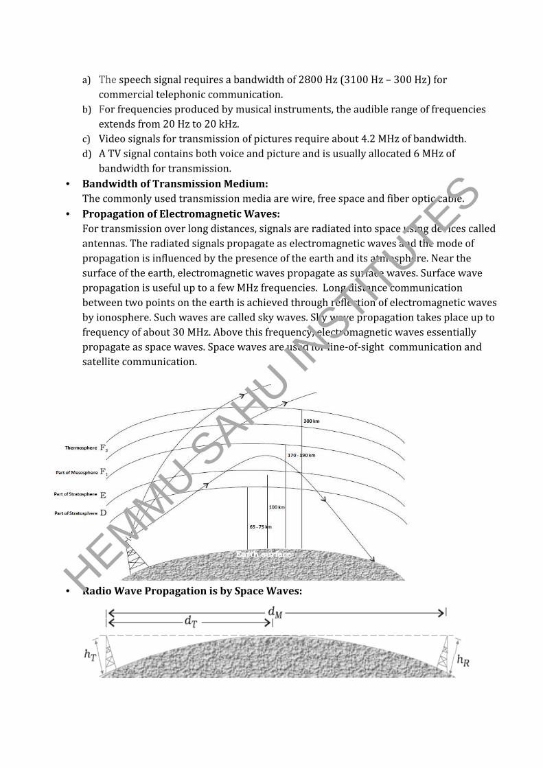
• Propagation of Electromagnetic Waves:
For transmission over long distances, signals are radiated into space using devices called
antennas. The radiated signals propagate as electromagnetic waves and the mode of
propagation is influenced by the presence of the earth and its atmosphere. Near the
surface of the earth, electromagnetic waves propagate as surface waves. Surface wave
propagation is useful up to a few MHz frequencies. Long distance communication
between two points on the earth is achieved through reflection of electromagnetic waves
by ionosphere. Such waves are called sky waves. Sky wave propagation takes place up to
frequency of about 30 MHz. Above this frequency, electromagnetic waves essentially
propagate as space waves. Space waves are used for line-of-sight communication and
satellite communication.
• Radio Wave Propagation is by Space Waves:
HEMM
U SAHU IN
STITUTES

• Modulation:
The process of changing some characteristic such as amplitude, frequency or phase of a
carrier wave in accordance with the intensity of the signal is known as modulation.
• Types of Modulation:
a) Amplitude modulation
b) Frequency modulation
c) Phase modulation.
• Amplitude Modulation:
The amplitude of the carrier wave changes according to the intensity of the signal. The
amplitude variation of the carrier wave is at the signal frequency sf .
• Production of Amplitude Modulated Wave:
Amplitude modulated waves can be produced by application of the message signal and
the carrier wave to a non-linear device, followed by a band pass filter.
• Modulation Factor:
The ratio of change of amplitude of carrier wave to the amplitude of normal carrier wave
is called modulation factor (m).
• Classification of Pulse Modulation:
Pulse modulation could be classified as: Pulse Amplitude Modulation (PAM), Pulse
Duration Modulation (PDM) or Pulse Width Modulation (PWM) and Pulse Position
Modulation (PPM).
• Demodulation:
Demodulation is the process of recovering the signal intelligence from a modulated
carrier wave.
• Transmitter:
• Receiver:
HEMM
U SAHU IN
STITUTES

• Detection of an AM signal:
AM detection, which is the process of recovering the modulating signal from an AM
waveform, is carried out using a rectifier and an envelope detector.
• Internet:
It permits communication and sharing of all types of information between any two or
more computers connected through a large and complex network.
The application includes,
a) E- mail
b) File transfer
c) WWW
d) E- commerce
e) Chat
• Mobile Telephony:
The concept of this system is to divide the service area into a suitable number of cells
centred on an office called MTSO (Mobile Telephone Switching Office). Each cell contains
a low-power transmitter called a base station and caters to a large number of mobile
receivers (popularly called cell phones). When a mobile receiver crosses the coverage
area of one base station, it is necessary for the mobile user to be transferred to another
base station. This procedure is called handover or handoff.
• Facsimile (FAX):
It scans the contents of a document (as an image, not text) to create electronic signals.
These signals are then sent to the destination (another FAX machine) in an orderly
manner using telephone lines.Then the signals are reconverted into a replica of the
original document. HEMM
U SAHU IN
STITUTES