Embed Size (px)
Citation preview
Special Issue of International Journal of Advances in Applied
Science and Engineering (IJAEAS)
ISSN (P): 2348-1811; ISSN (E): 2348-182X
Vol. 4, Issue 1,2, March 2017, 48-55
© IIST
Special Issue of International Journal of Advances in Engineering and Applied Science (IJAEAS) Vol-4 Iss-3,4, 2017
48
PHOTOVOLTAIC POWER PLANT PERFORMANCE FOR TWO STAGE
INVERTER BASED GRID UNDER GRID FAULTS
M.SUBRAMANYAM, G.SESHADRI
1Assistant Professor, Dept. of EEE ,2 Professor, Dept. of EEE
SIETK, Puttur,Andhra Pradesh, India
ABSTRACT: Grid-connected distributed generation sources interfaced with voltage source inverters (VSIs) need to be disconnected from the grid under: 1)
excessive dc-link voltage; 2) excessive ac currents; and 3) loss of grid-voltage synchronization. In this paper, the control of two-stage grid-connected VSIs in
photovoltaic (PV) power plants is developed to address the issue of inverter disconnecting under various grid faults. Inverter control incorporates reactive power
support in the case of voltage sags based on the grid codes’ (GCs) requirements to ride-through the faults and support the grid voltages. A case study of a 1-MW
system simulated in MATLAB/Simulink software is used to illustrate the proposed control. Problems that may occur during grid faults along with associated
remedies are discussed. The results presented illustrate the capability of the system to ride-through different types of grid faults.
INDEX TERMS DC–DC converter, fault-ride-through, photo- voltaic (PV) systems, power system faults, reactive power support.
I.INTRODUCTION
FAULT STUDIES areimportantinlarge-scalegrid-
connectedrenewableenergysystemsandhavebeen reported in
the technical literature. However, most of these studies
focused on grid-connected wind power plants [1], [2]. In the
case of grid-connected photovoltaic (PV) power plants
(GCPPPs), research reported thus far focused on fault-ride-
through (FRT) capability [3], [4]. Specifically, a three-phase
current-source inverter (CSI) configuration was investigated
under various fault conditions in [5] and [6], in which the out-
put currents remain limited under all types of faults due to the
implementation of a current-source model for the inverter.
However, this configuration may lead to instability under
dynamic conditions [7]. Three-phase voltage source inverters
(VSIs) are used in grid-connected power conversion systems.
Due to the increasing number of these systems, the control of
the VSIs is required to operate and support the grid based
on the grid codes (GCs) during voltage disturbances and
unbalanced conditions.
Among several studies for unbalanced voltage sags, a
method was introduced in [8] to mitigate the peak output
currents of a 4.5-kVA PV system in non-faulty phases.
Another study in[9] presented a proportional-resonant(PR)
current controller for the current limiter to ensure sinusoidal
output current waveforms and avoid over-current. However,
in the mentioned studies, reactive power support was not
considered. In [10], a study dealing with the control of the
positive and negative sequences was performed. Two parallel
controllers were implemented, one for each sequence. The
study demonstrated the dynamic limitations of using this
control configuration due to the delays produced in the
current control loops. A study was reported in [11] for the
control of the dc side of the inverter, which shows the impact
of various types of faults on the voltage and current of the PV
array.
Some of studies are based both categories can provide
FRT capability, the passive methods have the drawbacks of
requiring additional components and dissipating significant
power during the voltage sag processes. In the application of
GCPPPs with the configurations of single-stage conversion,
some research were done in [18] and [19] evaluating the FRT
issues of both ac and dc sides of the inverter under unbalanced
voltage conditions. However, in the application of a two-
stage conversion no paper so far has proposed a

Photovoltaic Power Plant Performance For Two Stage Inverter Based Grid Under Grid Faults
Special Issue of International Journal of Advances in Engineering and Applied Science (IJAEAS) Vol-4 Iss-3,4, 2017
49
comprehensive strategy to protect the inverter during voltage
sags while providing reactive power support to the grid. All
the designs and modifications for the inverter in both the
single- and two-stage conversions have to accommodate
various types of faults and address FRT capability based on
the GCs [20]. PV inverter disconnection under grid faults
occurs due to mainly three factors: 1) excessive dc-link
voltage; 2) excessive ac currents; and 3) loss of grid voltage
synchronization, which may conflict with the FRT capability.
In this paper, the control strategy introduced in [18] for
a single-stage conversion is used, although the voltage sag
detection and reactive power control is modified based on
individual measurements of the grid voltages. The main
objective of this paper is to introduce new control strategies
for the two-stage conversion in GCPPPs that allow the
inverter to remain connected to the grid under various types
of faults while injecting reactive power to meet the required
GCs. Some selected simulation results for single- and two-
stage configurations are presented to confirm the
effectiveness of the proposed control strategies.
II.GRID CODES
As the German GCs are the most comprehensive codes
for the different power levels of PV installations and
integration technologies [21], this paper follows these codes
as a basis for the discussions. During voltage sags, the
GCPPP should sup- port the grid voltage by injecting reactive
current. The amount of reactive current is determined based
on the droop control defined as follows:
'nLqref I|de|droopi
for
%10E
de
n
L
and droop > 2 (1)
where droop is a constant value, del is the amount of voltage
drop, and 'nI
is the rated current of the PV inverter in dq
coordinates, i.e., n'n I3I
, where In is the rated rms line
current of the inverter. The amount of voltage drop deLis
obtained based on the lowest rms value of the line-to-line
voltages of the three phases at the terminal of the GCPPP, i.e.,
eLmin shown in Fig. 1. The rms voltage is obtained using the
following expression:
dteLT
1e 2t
TtLrms
, with 2
TT
(2)
Where eL is the instantaneous line-to-line voltage, Twis the
window width for the rms value calculation, and T is the grid
voltage period, which is equal to 20 ms for a grid frequency
of 50 Hz. The resulting control diagram for the reactive
current generation is depicted in Fig. 1.
Fig. 1. Droop control diagram for the reactive current
reference provision.
Fig. 2.Diagram of the two-stage conversion-based GCPPP.
III. CASE STUDY FOR A TWO -STAGE
CONVERSION
A two-stage GCPPP includes a dc–dc converter between the
PV arrays and the inverter. In high-power GCPPPs, more than
one dc–dc converter can be included, one per each PV array.
Despite having several dc–dc converters, these systems will
be referred anyway as two-stage GCPPPs. In two-stage
GCPPPs, the MPP tracking (MPPT) is performed by the dc–
dc converter and the dc-link voltage is regulated by the
inverter.
During voltage sag, if no action is taken in the control
of the dc–dc converter, the power from the PV modules is not
reduced and therefore, the dc-link voltage keeps rising and
may exceed the maximum limit. Hence, the system is not self-
protected during grid fault conditions. A specific control
action has to be taken to reduce the power generated by the
PV modules and provide the two-stage GCPPP with FRT
capability.
A simple method to provide dc-link overvoltage
protection consists on shutting down the dc–dc converter
when the dc voltage rises above a certain limit. The dc–dc
converter can be reactivated when the dc-link voltage is
below a certain value using a hysteresis controller. In the
solutions proposed in this paper, the dc-link voltage is
controlled during the voltage sag process and there is no
significant increase in the dc-link voltage during this
transient.
The diagram of the case study for a two-stage GCPPP is
shown in Fig. 2. It consists of a 1-MVA inverter and 10
parallel 100-kW dc–dc boost converters.

Photovoltaic Power Plant Performance For Two Stage Inverter Based Grid Under Grid Faults
Special Issue of International Journal of Advances in Engineering and Applied Science (IJAEAS) Vol-4 Iss-3,4, 2017
50
Fig 3. Control diagram of the dc–dc converter.
In two-stage GCPPPs, the PV voltage v pv is controlled
by the duty cycle (d) of the dc–dc converter. The reference
for the PV voltage is given by the MPPT, as shown in Fig. 3.
A feed-forward strategy is applied to improve the
dynamics of the dc-link voltage. The strategy is based on the
assumption that the PV generated power is equal to the
injected power into the grid, i.e.,
ipvvpv= ed id+ eqiq (3)
Where ipv and v pv are the PV current and voltage,
respectively, and ed and eq are the d and q grid voltage
components extracted by the PLL. Since the PLL forces the
eq component to be zero, the estimated d current component
is obtained as
d
pvpv
estde
Vii (4)
In two-stage GCPPPs, three different ways to limit the dc-
link voltage under fault conditions are proposed: 1) short-
circuiting the PV array by turning ON the switch of the dc–
dc converter throughout the voltage sag duration; 2) leaving
the PV array open by turning OFFthe switch of the dc–dc
converter; and 3) changing the control of the dc–dc converter
to inject less power from the PV arrays when compared with
the prefault operating conditions.
It should be mentioned that in all the configurations including
single-stage conversion, the MPPT is disabled during the
voltage sag condition and the voltage reference of pre-fault
condition (Vmpp) is considered. Once the fault ends, the MPPT
is reactivated. In the two-stage topology, the first two
solutions explained next stop transferring energy from the PV
arrays to the dc bus, whereas the dc bus keeps regulated at the
reference value by the voltage control loop. In the third
method, the MPPT is disconnected and the PV operating
point moves to a lower power level to avoid overvoltage in
the dc-link. Therefore, no matter the MPPT technique is
voltage or current controlled and the algorithms implemented
for the MPPT, the performance of the proposed methods
during the voltage sag condition remains the same because
the MPPT is disconnected during the voltage sag.
Fig 4. Current path when short-circuiting
the PV panels.
Fig. 5.Short-circuiting the PV panels: (a) grid voltages; (b)
grid currents; and (c) dc-link voltage when applying a 60%
SLG voltage sag at MV side of the transformer.
A. Short-Circuiting the PV Panels
In this method, the dc–dc converter switch is ON (d =
1) throughout the voltage sag, as shown in Fig. 4.
Consequently, no power is transferred from the PV modules
to the dc-link. Since Vpv is zero, the feed-forward term id-est in
(4) defines a fast transition to zero at the beginning of the
voltage sag, accelerating the overall dynamic of the
controller. Fig. 5 shows some results for an SLG voltage sag
with a 60% voltage drop at MV side occurred from t = 0.1 s
to t = 0.3 s. The generated power of the PV arrays and also
the injected active and reactive power into the grid are shown
in Fig.6. During the voltage sag, the dc-link voltage remains
relatively constant, iref becomes almost zero with some
ripples, and only iqref is injected during the fault period.
Consequently, the current limiter does not have to be
activated in this case. Under unbalanced voltage sags, the
output power contains a second-order harmonic [31], which
will produce dc-link voltage ripples at the same frequency.
Fig.6.Short-circuitingthePVpanels:
(a)overall generated power; (b) injected active power; and (c)
reactive power to the grid.
B. Opening the Circuit of the PV Panels
Another option to avoid transferring power from the
PV modules to the dc-link is to keep the dc–dc converter
switch OFF throughout the voltage sag (d = 0), as shown in
Photovoltaic Power Plant Performance For Two Stage Inverter Based Grid Under Grid Faults
Special Issue of International Journal of Advances in Engineering and Applied Science (IJAEAS) Vol-4 Iss-3,4, 2017
51
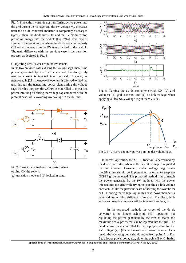
Fig. 7. Since, the inverter is not transferring active power into
the grid during the voltage sag, the PV voltage Vpv increases
until the dc–dc converter inductor is completely discharged
(ipv=0). Then, the diode turns OFFand the PV modules stop
providing energy into the dc-link [Fig. 7(b)]. This case is
similar to the previous one where the diode was continuously
ON and no current from the PV was provided to the dc-link.
The main difference with the previous case is the transition
process, as depicted in Fig. 8.
C. Injecting Less Power From the PV Panels
In the two previous cases, during the voltage sags, there is no
power generated by the PV panels and therefore, only
reactive current is injected into the grid. However, as
mentioned in [21], the network operator is allowed to feed the
grid through the generating power plant during the voltage
sags. For this purpose, the GCPPP is controlled to inject less
power into the grid during the voltage sag compared with the
prefault case, while avoiding overvoltage in the dc-link.
.
Fig.7.Current paths in dc–dc converter when
turning ON the switch:
(a) transition mode and (b) locked in state.
Fig. 8. Turning the dc–dc converter switch ON: (a) grid
voltages; (b) grid currents; and (c) dc-link voltage when
applying a 60% SLG voltage sag at theMV side.
Fig 9. P−V curve and new power point under voltage sags.
In normal operation, the MPPT function is performed by
the dc–dc converter, whereas the dc-link voltage is regulated
by the inverter. However, under voltage sag, some
modifications should be implemented in order to keep the
GCPPP grid-connected. The proposed method tries to match
the power generated by the PV modules with the power
injected into the grid while trying to keep the dc-link voltage
constant. Unlike the previous cases of keeping the switch ON
or OFF during the voltage sag, in this case, power balance is
achieved for a value different from zero. Therefore, both
active and reactive currents will be injected into the grid.
In the proposed method, the target of the dc–dc
converter is no longer achieving MPP operation but
regulating the power generated by the PVs to match the
maximum active power that can be injected into the grid. The
dc–dc converter is controlled to find a proper value for the
PV voltage (vpv )that achieves such power balance. As a
result, the operating point should move from point A in Fig.
9 to a lower power point, e.g., either the points B or C. In this
Photovoltaic Power Plant Performance For Two Stage Inverter Based Grid Under Grid Faults
Special Issue of International Journal of Advances in Engineering and Applied Science (IJAEAS) Vol-4 Iss-3,4, 2017
52
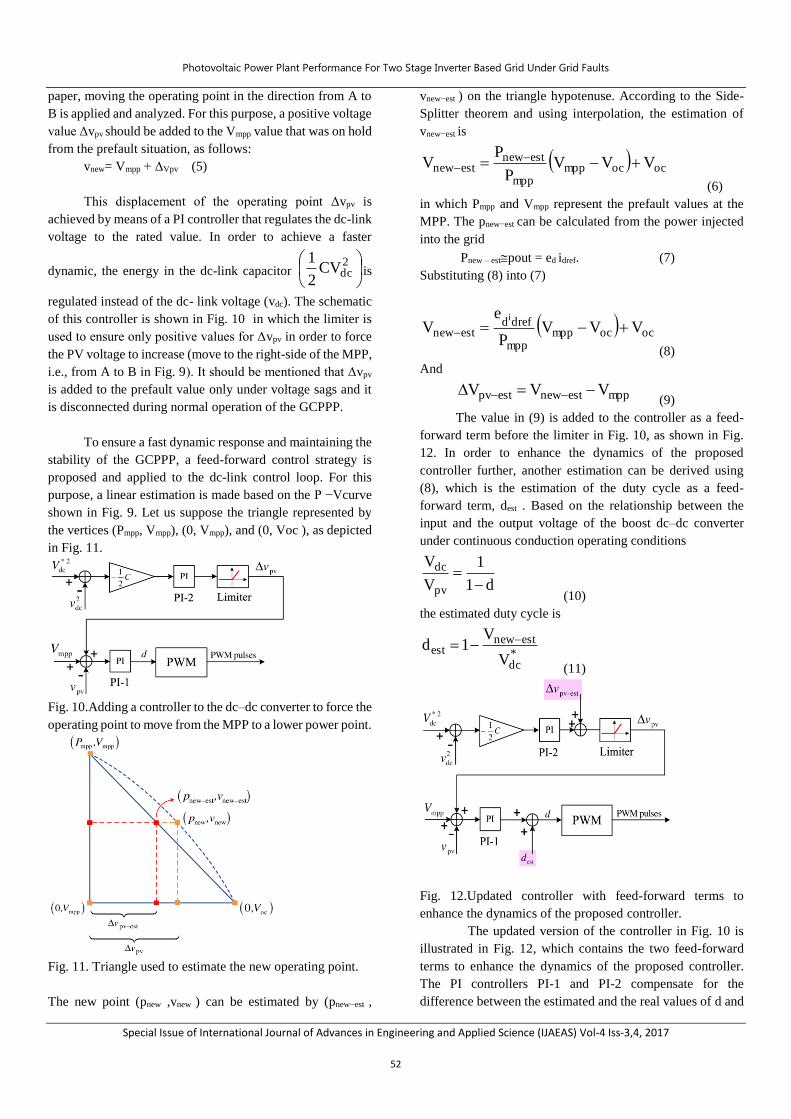
paper, moving the operating point in the direction from A to
B is applied and analyzed. For this purpose, a positive voltage
value Δvpv should be added to the Vmpp value that was on hold
from the prefault situation, as follows:
vnew= Vmpp + ΔVpv (5)
This displacement of the operating point Δvpv is
achieved by means of a PI controller that regulates the dc-link
voltage to the rated value. In order to achieve a faster
dynamic, the energy in the dc-link capacitor
2dcCV
2
1is
regulated instead of the dc- link voltage (vdc). The schematic
of this controller is shown in Fig. 10 in which the limiter is
used to ensure only positive values for Δvpv in order to force
the PV voltage to increase (move to the right-side of the MPP,
i.e., from A to B in Fig. 9). It should be mentioned that Δvpv
is added to the prefault value only under voltage sags and it
is disconnected during normal operation of the GCPPP.
To ensure a fast dynamic response and maintaining the
stability of the GCPPP, a feed-forward control strategy is
proposed and applied to the dc-link control loop. For this
purpose, a linear estimation is made based on the P −Vcurve
shown in Fig. 9. Let us suppose the triangle represented by
the vertices (Pmpp, Vmpp), (0, Vmpp), and (0, Voc ), as depicted
in Fig. 11.
Fig. 10.Adding a controller to the dc–dc converter to force the
operating point to move from the MPP to a lower power point.
Fig. 11. Triangle used to estimate the new operating point.
The new point (pnew ,vnew ) can be estimated by (pnew−est ,
vnew−est ) on the triangle hypotenuse. According to the Side-
Splitter theorem and using interpolation, the estimation of
vnew−est is
ococmppmpp
estnewestnew VVV
P
PV
(6)
in which Pmpp and Vmpp represent the prefault values at the
MPP. The pnew−est can be calculated from the power injected
into the grid
Pnew – estpout = ed idref. (7)
Substituting (8) into (7)
ococmppmpp
drefdestnew VVV
P
eV
i
(8)
And
mppestnewestpv VVV (9)
The value in (9) is added to the controller as a feed-
forward term before the limiter in Fig. 10, as shown in Fig.
12. In order to enhance the dynamics of the proposed
controller further, another estimation can be derived using
(8), which is the estimation of the duty cycle as a feed-
forward term, dest . Based on the relationship between the
input and the output voltage of the boost dc–dc converter
under continuous conduction operating conditions
d1
1
V
V
pv
dc
(10)
the estimated duty cycle is
*dc
estnewest
V
V1d
(11)
Fig. 12.Updated controller with feed-forward terms to
enhance the dynamics of the proposed controller.
The updated version of the controller in Fig. 10 is
illustrated in Fig. 12, which contains the two feed-forward
terms to enhance the dynamics of the proposed controller.
The PI controllers PI-1 and PI-2 compensate for the
difference between the estimated and the real values of d and
Photovoltaic Power Plant Performance For Two Stage Inverter Based Grid Under Grid Faults
Special Issue of International Journal of Advances in Engineering and Applied Science (IJAEAS) Vol-4 Iss-3,4, 2017
53
Δvpv , respectively.
The only unknown variable in (8) is idref. The reason is
that in the proposed method, during the voltage sag, the dc-
link control loop stops adjusting the active current reference
and instead regulates the input voltage of the dc–dc converter
(vpv ). The method proposed in this paper to estimate idref is
the following .If Pinis the power generated by the PV array
qrefiq
ref'diin eeP (12)
and since eq is zero, the estimated active current reference is
d
inestdref
e
P'i (13)
The maximum acceptable value for the drefi can be
obtained based on the pre-fault value of Pin , i.e., Pmpp and ed,
as follows:
d
mppestdref
e
P'i (14)
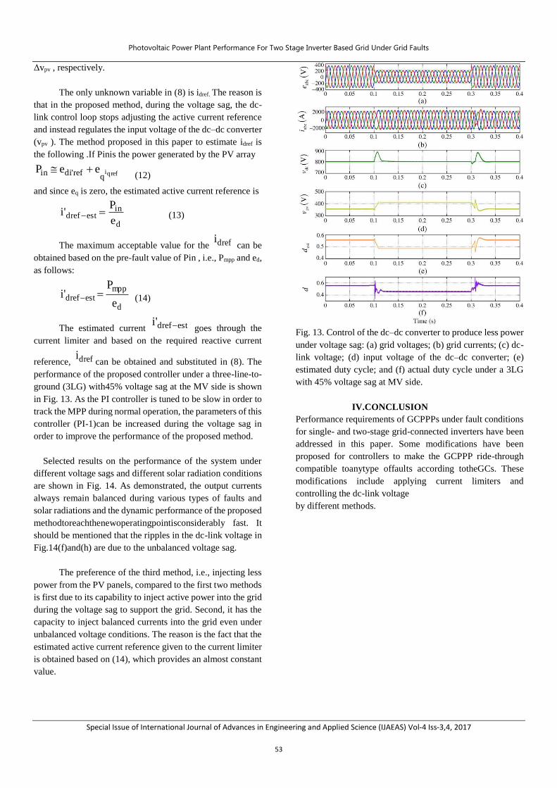
The estimated current estdref'i goes through the
current limiter and based on the required reactive current
reference, drefican be obtained and substituted in (8). The
performance of the proposed controller under a three-line-to-
ground (3LG) with45% voltage sag at the MV side is shown
in Fig. 13. As the PI controller is tuned to be slow in order to
track the MPP during normal operation, the parameters of this
controller (PI-1)can be increased during the voltage sag in
order to improve the performance of the proposed method.
Selected results on the performance of the system under
different voltage sags and different solar radiation conditions
are shown in Fig. 14. As demonstrated, the output currents
always remain balanced during various types of faults and
solar radiations and the dynamic performance of the proposed
methodtoreachthenewoperatingpointisconsiderably fast. It
should be mentioned that the ripples in the dc-link voltage in
Fig.14(f)and(h) are due to the unbalanced voltage sag.
The preference of the third method, i.e., injecting less
power from the PV panels, compared to the first two methods
is first due to its capability to inject active power into the grid
during the voltage sag to support the grid. Second, it has the
capacity to inject balanced currents into the grid even under
unbalanced voltage conditions. The reason is the fact that the
estimated active current reference given to the current limiter
is obtained based on (14), which provides an almost constant
value.
Fig. 13. Control of the dc–dc converter to produce less power
under voltage sag: (a) grid voltages; (b) grid currents; (c) dc-
link voltage; (d) input voltage of the dc–dc converter; (e)
estimated duty cycle; and (f) actual duty cycle under a 3LG
with 45% voltage sag at MV side.
IV.CONCLUSION
Performance requirements of GCPPPs under fault conditions
for single- and two-stage grid-connected inverters have been
addressed in this paper. Some modifications have been
proposed for controllers to make the GCPPP ride-through
compatible toanytype offaults according totheGCs. These
modifications include applying current limiters and
controlling the dc-link voltage
by different methods.

Photovoltaic Power Plant Performance For Two Stage Inverter Based Grid Under Grid Faults
Special Issue of International Journal of Advances in Engineering and Applied Science (IJAEAS) Vol-4 Iss-3,4, 2017
54
Fig. 14. Control of the dc–dc converter to produce less power
under voltage sag
It is concluded that for the single-stage configuration, the
dc-link voltage is naturally limited and therefore, the GCPPP
is self-protected, whereas in the two-stage configuration it is
not. Three methods have been proposed for the two-stage
configuration to make the GCPPP able to withstand any type
of faults according to the GCs with- out being disconnected.
The first two methods are based on not generating any power
from the PV arrays during the voltage sags, whereas the third
method changes the power point of the PV arrays to inject
less power into the grid compared with the pre-fault
condition. The validity of all the proposed methods to ride-
through voltage sags has been demonstrated by multiple case
studies performed by simulations.
V. REFERENCES
[1] L. Trillaet al., “Modeling and validation of DFIG 3-
MW wind turbine using field test data of balanced and
unbalanced voltage sags,” IEEE Trans. Sustain.
Energy, vol. 2, no. 4, pp. 509–519, Oct. 2011.
[2] M. Popat, B. Wu, and N. Zargari, “Fault ride-through
capability of cascaded current-source converter-based
offshore wind farm,” IEEE Trans. Sustain. Energy,
vol. 4, no. 2, pp. 314–323, Apr. 2013.
[3] A. Marinopouloset al., “Grid integration aspects of
large solar PV instal- lations: LVRT capability and
reactive power/voltage support require-ments,” in
Proc. IEEE Trondheim PowerTech, Jun. 2011, pp. 1–
8.
[4] G.Islam,A.Al-Durra, S.M.Muyeen, and J.Tamura,
“Lowvoltage ride through capability enhancement of
grid connected large scale photovoltaic system,” in
Proc. 37th Annu. Conf. IEEE Ind. Electron. Soc.
(IECON), Nov. 2011, pp. 884–889.
[5] P. Dash and M. Kazerani, “Dynamic modeling and
performance analysis of a grid-connected current-
source inverter-based photovoltaic system,”IEEE
Trans. Sustain. Energy, vol. 2, no. 4, pp. 443–450, Oct.
2011.
[6] A. Yazdaniet al., “Modeling guidelines and a
benchmark for power sys- tem simulation studies of
three-phase single-stage photovoltaic systems,” IEEE
Trans. Power Del., vol. 26, no. 2, pp. 1247–1264, Apr.
2011.
[7] A. Radwan and Y.-R.Mohamed, “Analysis and active
suppression of ac- and dc-side instabilities in grid-
connected current-source converter-based
photovoltaic system,” IEEE Trans. Sustain. Energy,
vol. 4, no. 3, pp. 630–642, Jul. 2013.
[8] J. Miret, M. Castilla, A. Camacho, L. Garcia de
Vicuna, and J. Matas,
“Controlschemeforphotovoltaicthree-phase
inverterstominimize peak currents during unbalanced
grid-voltage sags,” IEEE Trans. Power Electron., vol.
27, no. 10, pp. 4262–4271, Oct. 2012.
[9] G. Azevedo, P. Rodriguez, M. Cavalcanti, G.
Vazquez, and F. Neves, “New control strategy to allow
the photovoltaic systems operation under grid faults,”
in Proc. Brazilian Power Electron. Conf. (COBEP),
Sep. 2009, pp. 196–201.
[10] M. Mirhosseini, J. Pou, B. Karanayil, and V. G.
Agelidis, “Positive- and negative-sequence control of
grid-connected photovoltaic systems under
unbalanced voltage conditions,” in Proc. Australasian
Univ. Power Eng. Conf. (AUPEC), Sep. 2013, pp. 1–

Photovoltaic Power Plant Performance For Two Stage Inverter Based Grid Under Grid Faults
Special Issue of International Journal of Advances in Engineering and Applied Science (IJAEAS) Vol-4 Iss-3,4, 2017
55
6.
[11] H. Seo, C. Kim, Y. M. Yoon, and C. Jung, “Dynamics
of grid-connected photovoltaic system at fault
conditions,” in Proc. Transmiss. Distrib. Conf. Expo.
Asia Pacific, Oct. 2009, pp. 1–4.
[12] A. Leon, J. Mauricio, and J. Solsona, “Fault ride-
through enhancement of DFIG-based wind generation
considering unbalanced and distorted conditions,”
IEEE Trans. Energy Convers., vol. 27, no. 3, pp. 775–
783, Sep. 2012.
[13] D. Campos-Gaona, E. Moreno-Goytia, and O. Anaya-
Lara, “Fault ride- through improvement of DFIG-WT
by integrating atwo-degrees-of- freedom internal
model control, in “Proc. IEEE Trans. Ind. Electron.,
vol. 60, no. 3, pp. 1133–1145, Mar. 2013.
[14] G. Pannell, B. Zahawi, D. Atkinson, and P.
Missailidis, “Evaluation of the performance of a dc-
link brake chopper as a DFIG low-voltage fault-ride-
through device,” IEEE Trans. Energy Convers., vol.
28, no. 3, pp. 535–542, Sep. 2013.
[15] B. Silva, C. Moreira, H. Leite, and J. Lopes, “Control
strategies for ac fault ride through in multiterminal
HVDC grids,” IEEE Trans. Power Del., vol. 29, no. 1,
pp. 395–405, Feb. 2014.
[16] I. Erlich, C. Feltes, and F. Shewarega, “Enhanced
voltage drop control by VSC; HVDC systems for
improving wind farm fault ridethrough capability,”
IEEE Trans. Power Del., vol. 29, no. 1, pp. 378–385,
Feb.2014.
![vlsi & embedded systems lab - SIETK ECE DEPARTMENT · 2018. 7. 16. · SIETK, ECE [VLSI & EMBEDDED SYSTEMS LAB] 2 (15A04712) VLSI & EMBEDDED SYSTEMS LABORATORY Note: The students](https://img.dokumen.tips/doc/110x75/60a68df82b16b22c09239fcb/vlsi-embedded-systems-lab-sietk-ece-department-2018-7-16-sietk-ece.jpg)